Embed Size (px)
Citation preview
TTI Testing Ltd
Unit 2, Hithercroft Road, Wallingford, Oxfordshire, OX10 9DG, UK
www.tti-testing.com
Inspection and testing of failed tow wire rope from tug ALP Forward
FINAL REPORT
TTI Reference number TTI-IMLR-2016-5284
Date Rev. Description Prepared by Authorised by 06/01/17 0 for issue to client 19/03/17 1 Following review
Distribution: Attention: TTI Testing Ltd (author, file) MAIB
ALP Forward wire rope failure - Final Report
i
Summary
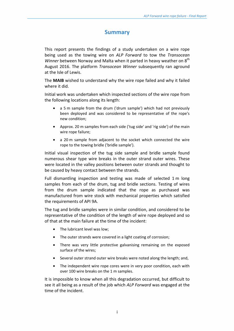
This report presents the findings of a study undertaken on a wire rope being used as the towing wire on ALP Forward to tow the Transocean Winner between Norway and Malta when it parted in heavy weather on 8th August 2016. The platform Transocean Winner subsequently ran aground at the Isle of Lewis.
The MAIB wished to understand why the wire rope failed and why it failed where it did.
Initial work was undertaken which inspected sections of the wire rope from the following locations along its length:
• a 5 m sample from the drum ('drum sample') which had not previously been deployed and was considered to be representative of the rope's new condition;
• Approx. 20 m samples from each side ('tug side' and 'rig side') of the main wire rope failure;
• a 20 m sample from adjacent to the socket which connected the wire rope to the towing bridle ('bridle sample').
Initial visual inspection of the tug side sample and bridle sample found numerous shear type wire breaks in the outer strand outer wires. These were located in the valley positions between outer strands and thought to be caused by heavy contact between the strands.
Full dismantling inspection and testing was made of selected 1 m long samples from each of the drum, tug and bridle sections. Testing of wires from the drum sample indicated that the rope as purchased was manufactured from wire stock with mechanical properties which satisfied the requirements of API 9A.
The tug and bridle samples were in similar condition, and considered to be representative of the condition of the length of wire rope deployed and so of that at the main failure at the time of the incident:
• The lubricant level was low;
• The outer strands were covered in a light coating of corrosion;
• There was very little protective galvanising remaining on the exposed surface of the wires;
• Several outer strand outer wire breaks were noted along the length; and,
• The independent wire rope cores were in very poor condition, each with over 100 wire breaks on the 1 m samples.
It is impossible to know when all this degradation occurred, but difficult to see it all being as a result of the job which ALP Forward was engaged at the time of the incident.
ALP Forward wire rope failure - Final Report
ii
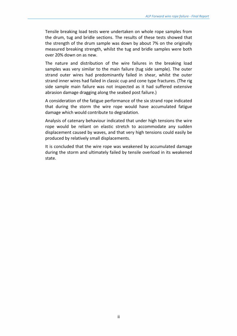
Tensile breaking load tests were undertaken on whole rope samples from the drum, tug and bridle sections. The results of these tests showed that the strength of the drum sample was down by about 7% on the originally measured breaking strength, whilst the tug and bridle samples were both over 20% down on as new.
The nature and distribution of the wire failures in the breaking load samples was very similar to the main failure (tug side sample). The outer strand outer wires had predominantly failed in shear, whilst the outer strand inner wires had failed in classic cup and cone type fractures. (The rig side sample main failure was not inspected as it had suffered extensive abrasion damage dragging along the seabed post failure.)
A consideration of the fatigue performance of the six strand rope indicated that during the storm the wire rope would have accumulated fatigue damage which would contribute to degradation.
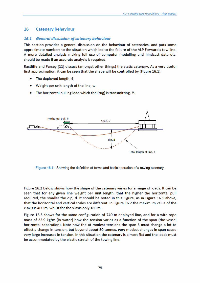
Analysis of catenary behaviour indicated that under high tensions the wire rope would be reliant on elastic stretch to accommodate any sudden displacement caused by waves, and that very high tensions could easily be produced by relatively small displacements.
It is concluded that the wire rope was weakened by accumulated damage during the storm and ultimately failed by tensile overload in its weakened state.
ALP Forward wire rope failure - Final Report
iii
Contents
Glossary .............................................................................................................................. v
1 Introduction ................................................................................................................ 1
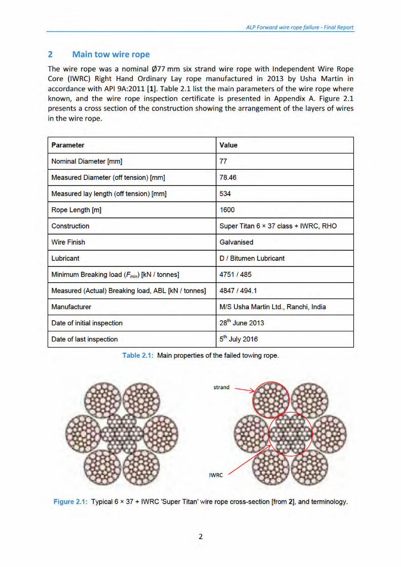
2 Main tow wire rope ..................................................................................................... 2
3 The towing arrangement and sample location ............................................................ 4
4 Delivery of samples ..................................................................................................... 7
4.1 Delivery of the drum sample ....................................................................................... 7
4.2 Delivery of the tug side and rig side samples .............................................................. 8
5 Initial inspection of samples ...................................................................................... 11
5.1 Initial inspection of drum sample .............................................................................. 11
5.2 Initial inspection of tug side sample .......................................................................... 12
5.3 Initial inspection of rig side sample ........................................................................... 15
6 Initial cutting schedule .............................................................................................. 18
6.1 Cutting schedule for drum sample ............................................................................ 18
6.2 Cutting schedule for tug side sample ........................................................................ 18
6.3 Cutting schedule for rig side sample ......................................................................... 18
7 Delivery of bridle sample........................................................................................... 20
8 Initial inspection of additional sample ....................................................................... 21
8.1 Initial inspection of bridle sample ............................................................................. 21
8.2 Proposed cutting schedule for bridle sample ............................................................ 22
9 Wire rope breaking strength measurement ............................................................... 23
9.1 Test equipment .......................................................................................................... 23
9.2 Results of the breaking load tests ............................................................................. 25
10 Strip down inspection of 1 m samples ....................................................................... 31
10.1 Strip down inspection of Drum Sample ................................................................. 31
10.2 Strip down inspection of the tug side sample ....................................................... 40
10.3 Strip down inspection of the bridle sample ........................................................... 48
10.4 Measurements made on strip down samples ....................................................... 57
ALP Forward wire rope failure - Final Report
iv
11 Inspection of tug side failure ..................................................................................... 58 12 Mechanical tests on individual wires ......................................................................... 61
12.1 Tensile tests ........................................................................................................... 63
12.2 Torsion tests ........................................................................................................... 64
12.3 Reverse bend test .................................................................................................. 64
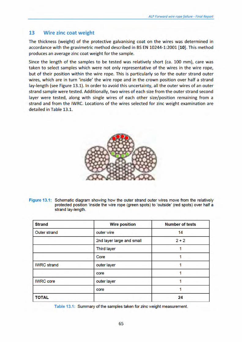
13 Wire zinc coat weight ................................................................................................ 65
14 Results of the mechanical tests ................................................................................. 66
15 Results of the zinc coat weight measurement ........................................................... 71
16 Catenary behaviour ................................................................................................... 75
16.1 General discussion of catenary behaviour............................................................. 75
16.2 Approximate calculation of maximum loads in the towing wire rope .................. 78
16.2.1 Characterisation of the wire rope ...................................................................... 78
16.2.2 Definition of the model ...................................................................................... 79
16.2.3 Calculation of peak loads ................................................................................... 80
16.3 Fatigue loading ....................................................................................................... 81
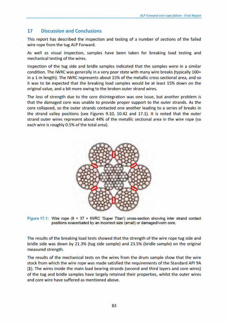
17 Discussion and Conclusions ....................................................................................... 83
18 References ................................................................................................................ 86
Appendices ....................................................................................................................... 87
Appendix A - Tow wire inspection certificate .................................................................... 88
Appendix B - Calibration certificate for the 14,000 kN test machine ................................. 90
Appendix C - Certificates for the break load tests ............................................................. 96
Appendix D – Calibration certificate for 250 kN tensile machine ....................................... 99
Appendix E - Results of the mechanical testing on rope wires .......................................... 102
Appendix F - Results of the average zinc coat weight measurement ................................ 112
ALP Forward wire rope failure - Final Report
v
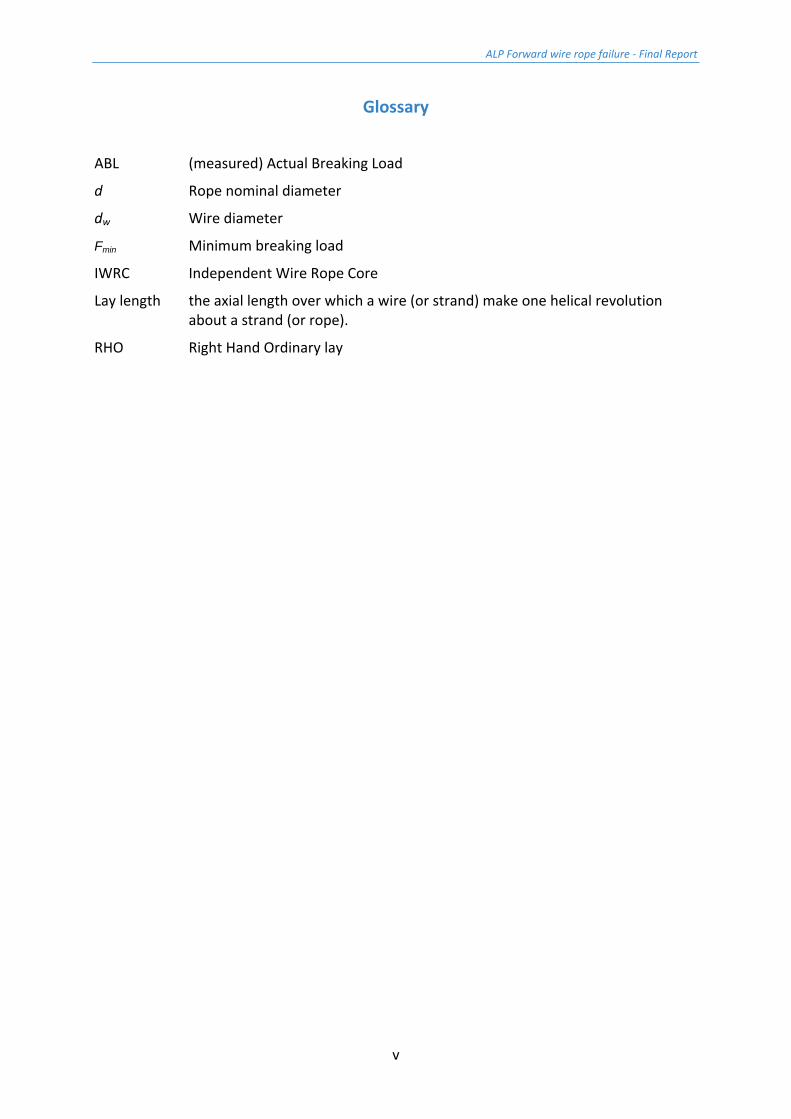
Glossary
ABL (measured) Actual Breaking Load
d Rope nominal diameter
dw Wire diameter
Fmin Minimum breaking load
IWRC Independent Wire Rope Core
Lay length the axial length over which a wire (or strand) make one helical revolution about a strand (or rope).
RHO Right Hand Ordinary lay
ALP Forward wire rope failure - Final Report
1
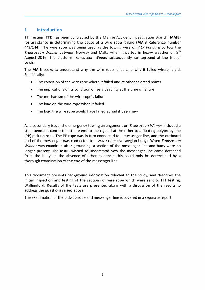
1 Introduction TTI Testing (TTI) has been contracted by the Marine Accident Investigation Branch (MAIB) for assistance in determining the cause of a wire rope failure (MAIB Reference number 4/3/144). The wire rope was being used as the towing wire on ALP Forward to tow the Transocean Winner between Norway and Malta when it parted in heavy weather on 8th August 2016. The platform Transocean Winner subsequently ran aground at the Isle of Lewis.
The MAIB seeks to understand why the wire rope failed and why it failed where it did. Specifically:
• The condition of the wire rope where it failed and at other selected points
• The implications of its condition on serviceability at the time of failure
• The mechanism of the wire rope’s failure
• The load on the wire rope when it failed
• The load the wire rope would have failed at had it been new
As a secondary issue, the emergency towing arrangement on Transocean Winner included a steel pennant, connected at one end to the rig and at the other to a floating polypropylene (PP) pick-up rope. The PP rope was in turn connected to a messenger line, and the outboard end of the messenger was connected to a wave-rider (Norwegian buoy). When Transocean Winner was examined after grounding, a section of the messenger line and buoy were no longer present. The MAIB wished to understand how the messenger line came detached from the buoy. In the absence of other evidence, this could only be determined by a thorough examination of the end of the messenger line.
This document presents background information relevant to the study, and describes the initial inspection and testing of the sections of wire rope which were sent to TTI Testing, Wallingford. Results of the tests are presented along with a discussion of the results to address the questions raised above.
The examination of the pick-up rope and messenger line is covered in a separate report.
ALP Forward wire rope failure - Final Report
3
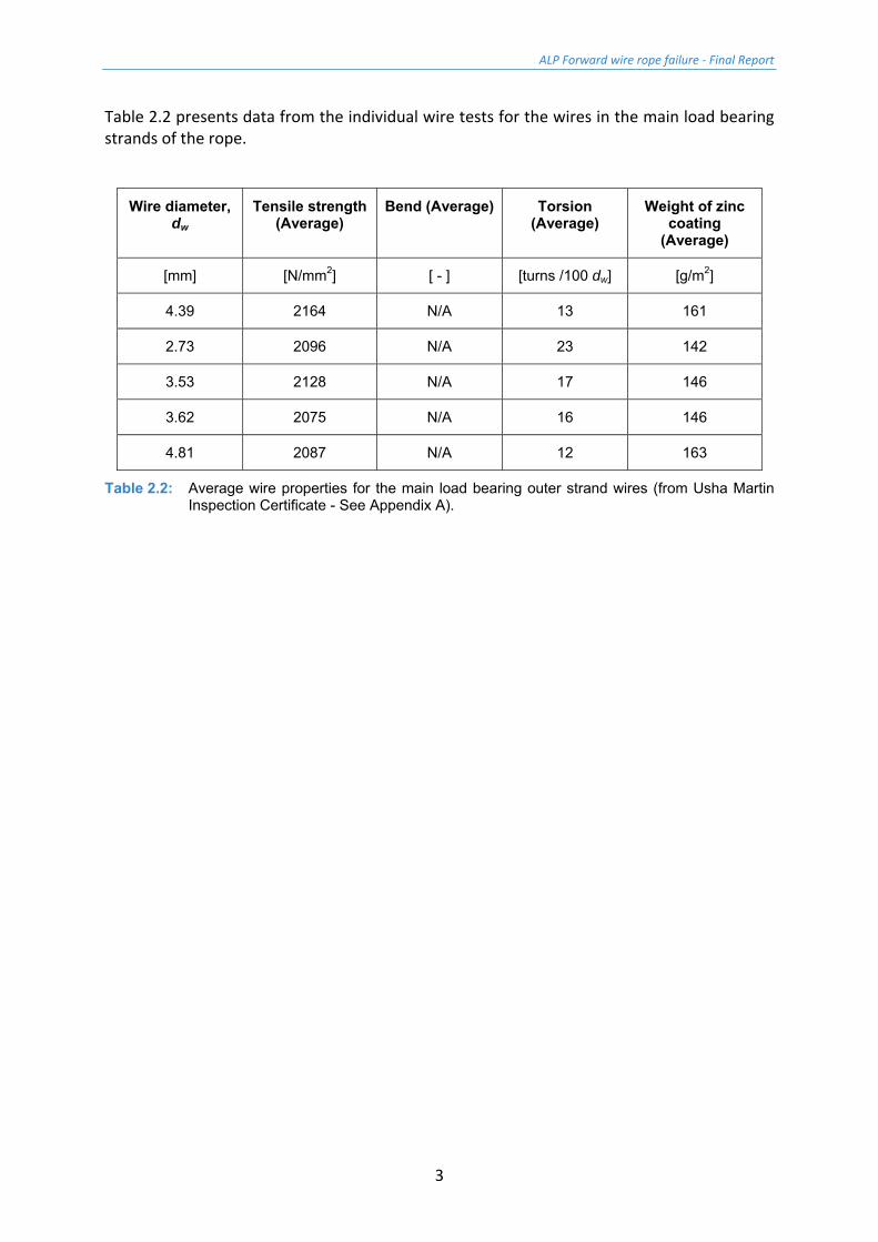
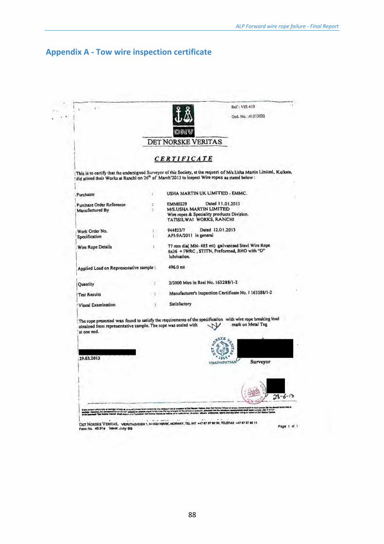
Table 2.2 presents data from the individual wire tests for the wires in the main load bearing strands of the rope.
Wire diameter, dw
Tensile strength (Average)
Bend (Average) Torsion (Average)
Weight of zinc coating
(Average)
[mm] [N/mm2] [ - ] [turns /100 dw] [g/m2]
4.39 2164 N/A 13 161
2.73 2096 N/A 23 142
3.53 2128 N/A 17 146
3.62 2075 N/A 16 146
4.81 2087 N/A 12 163
Table 2.2: Average wire properties for the main load bearing outer strand wires (from Usha Martin Inspection Certificate - See Appendix A).

ALP Forward wire rope failure - Final Report
5
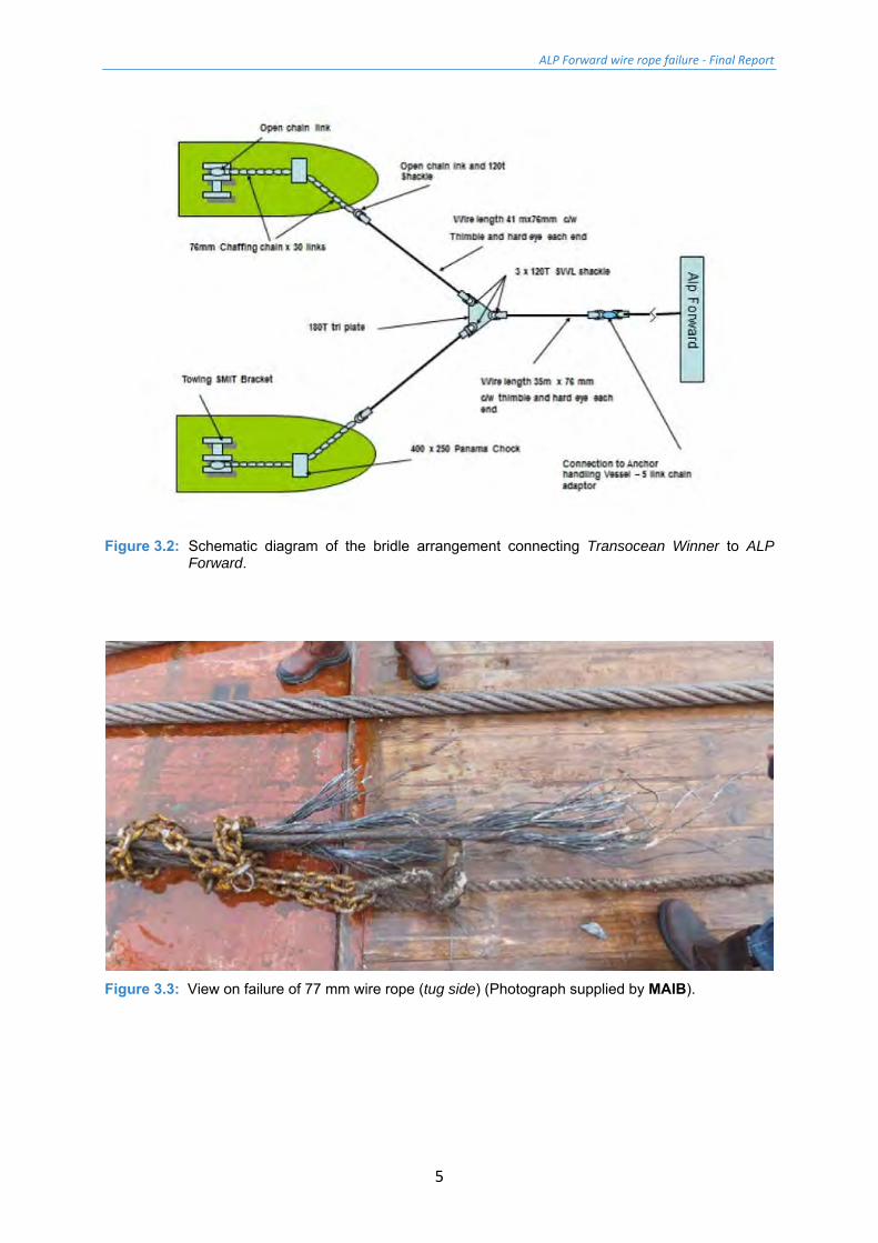
Figure 3.2: Schematic diagram of the bridle arrangement connecting Transocean Winner to ALP
Forward.
Figure 3.3: View on failure of 77 mm wire rope (tug side) (Photograph supplied by MAIB).
ALP Forward wire rope failure - Final Report
6
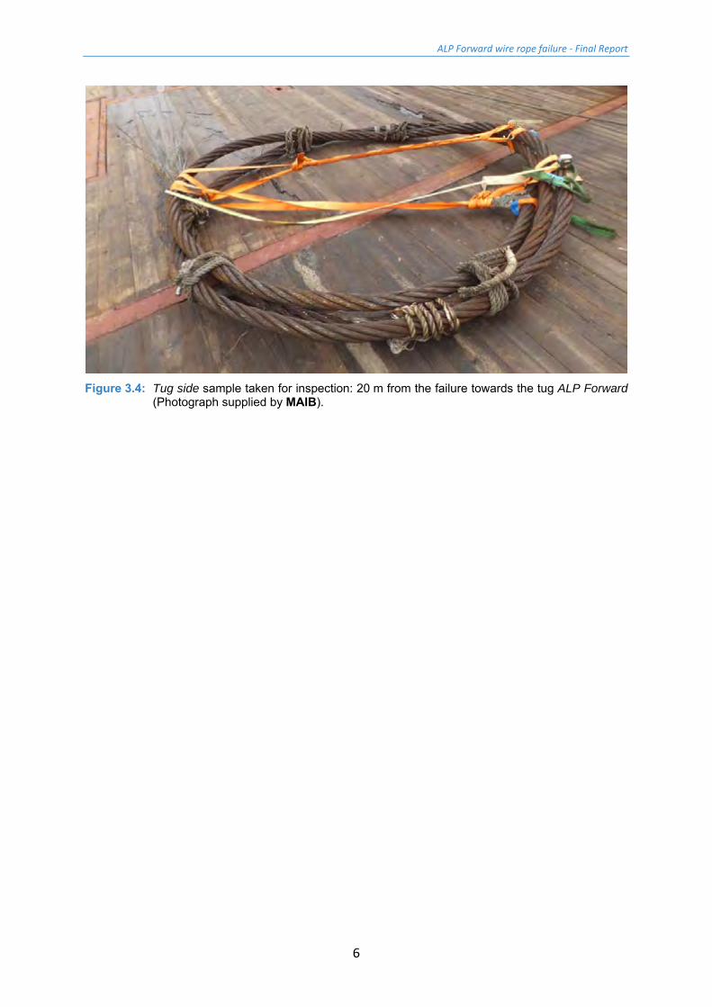
Figure 3.4: Tug side sample taken for inspection: 20 m from the failure towards the tug ALP Forward
(Photograph supplied by MAIB).
ALP Forward wire rope failure - Final Report
7
4 Delivery of samples
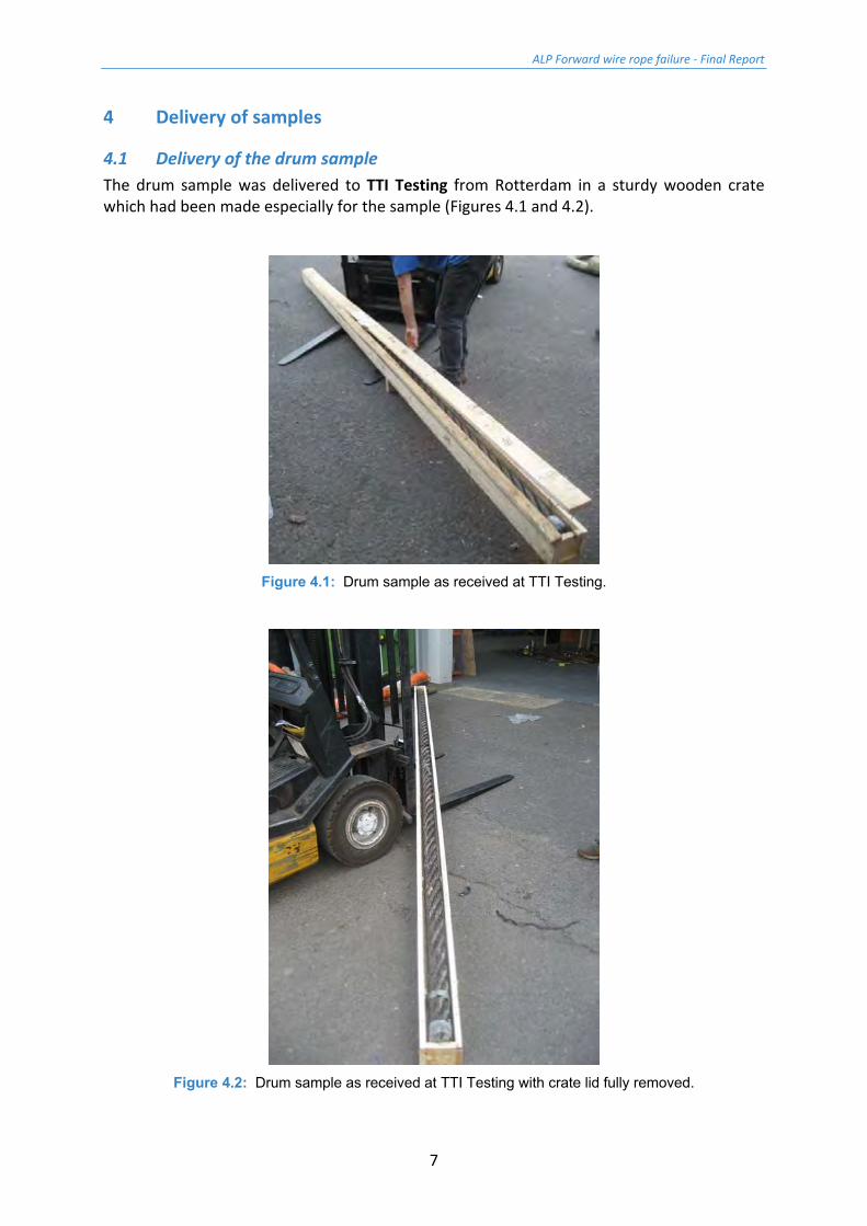
4.1 Delivery of the drum sample The drum sample was delivered to TTI Testing from Rotterdam in a sturdy wooden crate which had been made especially for the sample (Figures 4.1 and 4.2).
Figure 4.1: Drum sample as received at TTI Testing.
Figure 4.2: Drum sample as received at TTI Testing with crate lid fully removed.
ALP Forward wire rope failure - Final Report
8
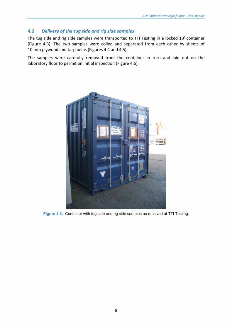
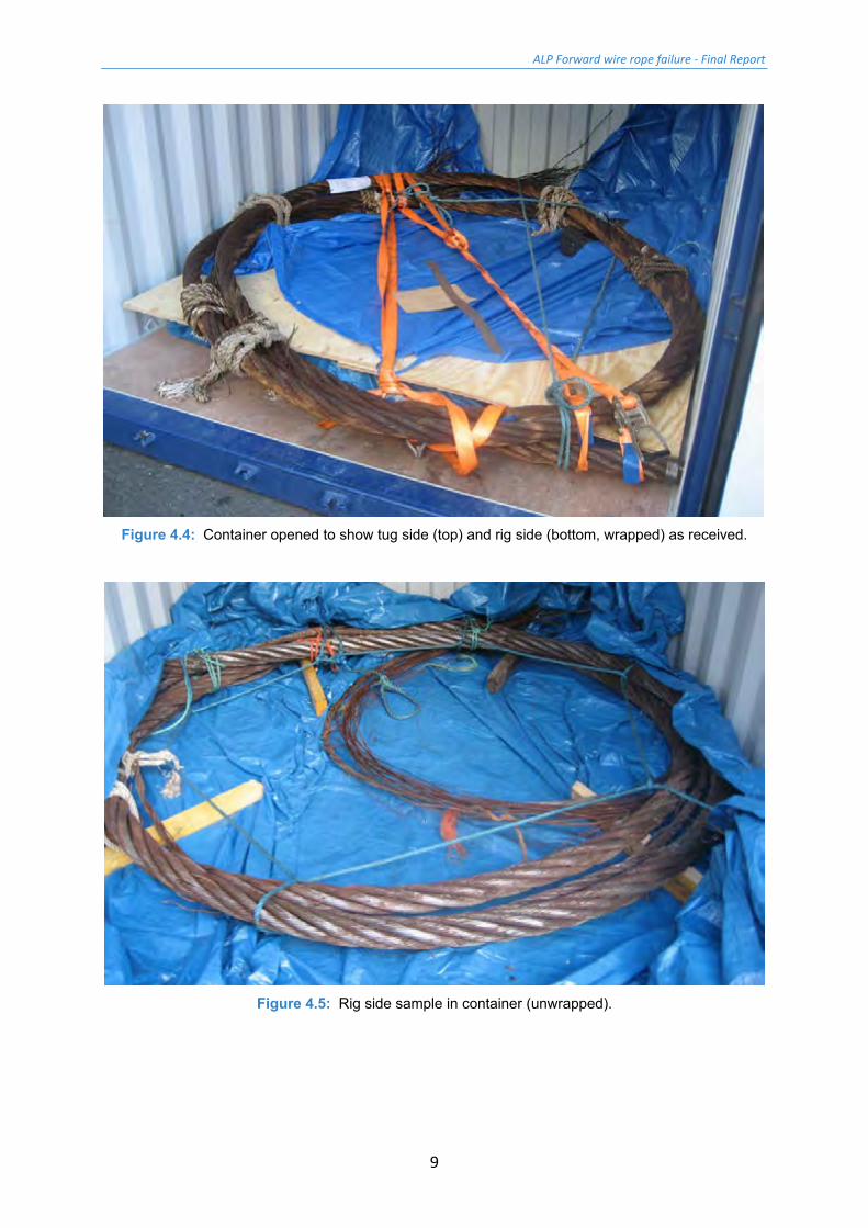
4.2 Delivery of the tug side and rig side samples The tug side and rig side samples were transported to TTI Testing in a locked 10' container (Figure 4.3). The two samples were coiled and separated from each other by sheets of 10 mm plywood and tarpaulins (Figures 4.4 and 4.5).
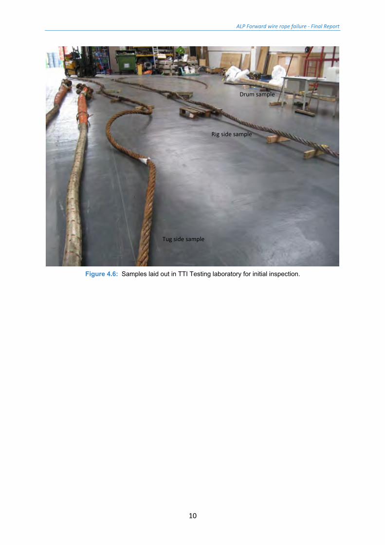
The samples were carefully removed from the container in turn and laid out on the laboratory floor to permit an initial inspection (Figure 4.6).
Figure 4.3: Container with tug side and rig side samples as received at TTI Testing.
ALP Forward wire rope failure - Final Report
9
Figure 4.4: Container opened to show tug side (top) and rig side (bottom, wrapped) as received.
Figure 4.5: Rig side sample in container (unwrapped).
ALP Forward wire rope failure - Final Report
10
Figure 4.6: Samples laid out in TTI Testing laboratory for initial inspection.
Tug side sample
Rig side sample
Drum sample

ALP Forward wire rope failure - Final Report
11
5 Initial inspection of samples
5.1 Initial inspection of drum sample Figure 5.1 shows the general condition of the drum sample as received. Generally the sample was well lubricated particularly in the outer strand valleys. Where present the lubricant was glossy and black in appearance, and as new. There were also some grey deposits of what were thought to be mud or silt. It is not known at what stage these were deposited on the wire rope. Superficial corrosion was noted on the surface of the wires.
Mid-length along the sample was found an area of crushing damage on one of the strands. Whilst not ideal, it is thought that this damage would not adversely affect the breaking strength of the sample as the damage should 'pull out' under the high loads.
Figure 5.1: General condition of the drum sample as received.
Figure 5.2: Area of crushing damage found on the drum sample (mid-length).

ALP Forward wire rope failure - Final Report
14
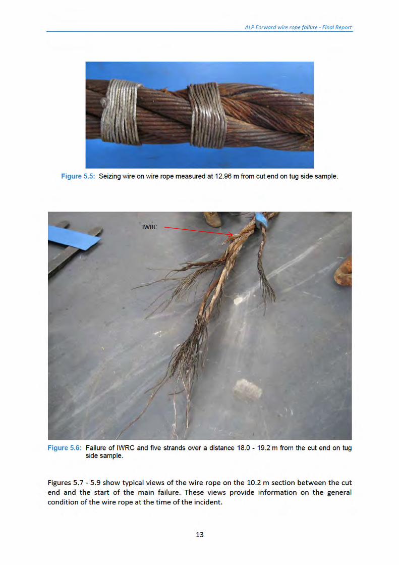
It is immediately noted that the lubricant between the strands is missing, the protective galvanising seems low or lost, and the wires (the outside of the wire rope) are covered in what appears to be superficial corrosion. Wire breaks were noted distributed along the 10 m length, both along and around the wire rope circumference. In all 40 visible breaks were counted (there may well have been more), all of which initiated at the inter-strand contact region of the wire rope and appeared to be shear type in nature. Beyond 10 m from the cut end there were many more wire breaks.
A more detailed assessment of the condition of the tug side sample was made on the full inspection of a 1 m sample, including mechanical tests on the wires.
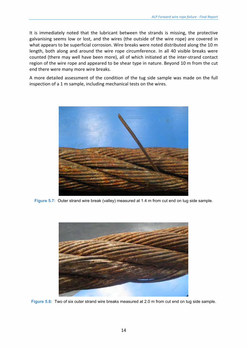
Figure 5.7: Outer strand wire break (valley) measured at 1.4 m from cut end on tug side sample.
Figure 5.8: Two of six outer strand wire breaks measured at 2.0 m from cut end on tug side sample.
ALP Forward wire rope failure - Final Report
15
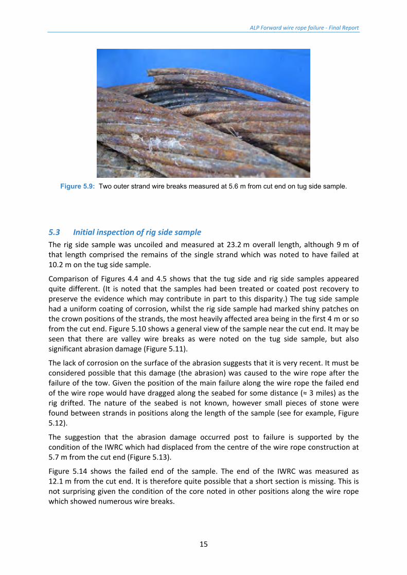
Figure 5.9: Two outer strand wire breaks measured at 5.6 m from cut end on tug side sample.
5.3 Initial inspection of rig side sample The rig side sample was uncoiled and measured at 23.2 m overall length, although 9 m of that length comprised the remains of the single strand which was noted to have failed at 10.2 m on the tug side sample.
Comparison of Figures 4.4 and 4.5 shows that the tug side and rig side samples appeared quite different. (It is noted that the samples had been treated or coated post recovery to preserve the evidence which may contribute in part to this disparity.) The tug side sample had a uniform coating of corrosion, whilst the rig side sample had marked shiny patches on the crown positions of the strands, the most heavily affected area being in the first 4 m or so from the cut end. Figure 5.10 shows a general view of the sample near the cut end. It may be seen that there are valley wire breaks as were noted on the tug side sample, but also significant abrasion damage (Figure 5.11).
The lack of corrosion on the surface of the abrasion suggests that it is very recent. It must be considered possible that this damage (the abrasion) was caused to the wire rope after the failure of the tow. Given the position of the main failure along the wire rope the failed end of the wire rope would have dragged along the seabed for some distance (≈ 3 miles) as the rig drifted. The nature of the seabed is not known, however small pieces of stone were found between strands in positions along the length of the sample (see for example, Figure 5.12).
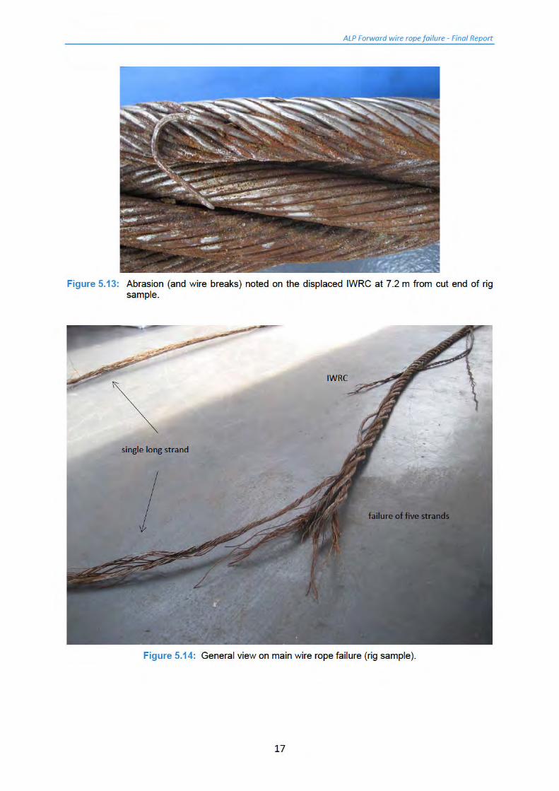
The suggestion that the abrasion damage occurred post to failure is supported by the condition of the IWRC which had displaced from the centre of the wire rope construction at 5.7 m from the cut end (Figure 5.13).
Figure 5.14 shows the failed end of the sample. The end of the IWRC was measured as 12.1 m from the cut end. It is therefore quite possible that a short section is missing. This is not surprising given the condition of the core noted in other positions along the wire rope which showed numerous wire breaks.
ALP Forward wire rope failure - Final Report
16
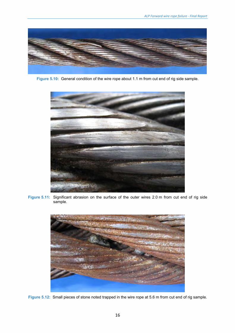
Figure 5.10: General condition of the wire rope about 1.1 m from cut end of rig side sample.
Figure 5.11: Significant abrasion on the surface of the outer wires 2.0 m from cut end of rig side
sample.
Figure 5.12: Small pieces of stone noted trapped in the wire rope at 5.6 m from cut end of rig sample.
ALP Forward wire rope failure - Final Report
18
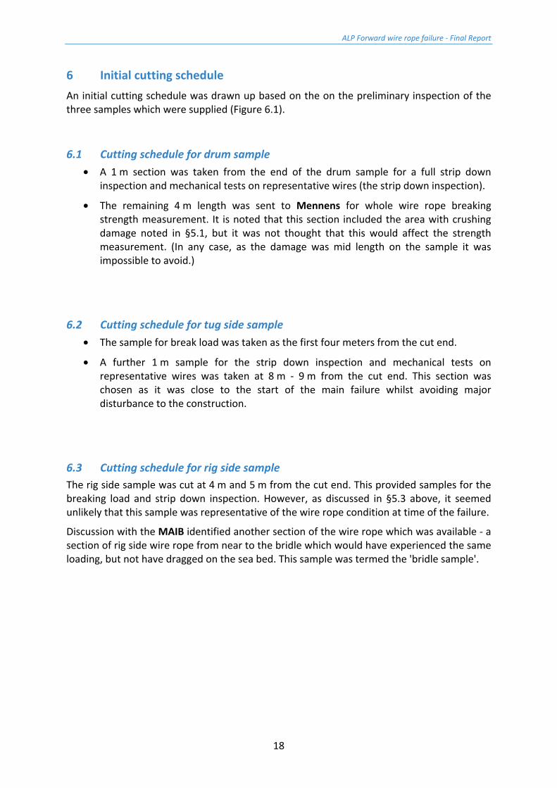
6 Initial cutting schedule An initial cutting schedule was drawn up based on the on the preliminary inspection of the three samples which were supplied (Figure 6.1).
6.1 Cutting schedule for drum sample • A 1 m section was taken from the end of the drum sample for a full strip down
inspection and mechanical tests on representative wires (the strip down inspection).
• The remaining 4 m length was sent to Mennens for whole wire rope breaking strength measurement. It is noted that this section included the area with crushing damage noted in §5.1, but it was not thought that this would affect the strength measurement. (In any case, as the damage was mid length on the sample it was impossible to avoid.)
6.2 Cutting schedule for tug side sample • The sample for break load was taken as the first four meters from the cut end.
• A further 1 m sample for the strip down inspection and mechanical tests on representative wires was taken at 8 m - 9 m from the cut end. This section was chosen as it was close to the start of the main failure whilst avoiding major disturbance to the construction.
6.3 Cutting schedule for rig side sample The rig side sample was cut at 4 m and 5 m from the cut end. This provided samples for the breaking load and strip down inspection. However, as discussed in §5.3 above, it seemed unlikely that this sample was representative of the wire rope condition at time of the failure.
Discussion with the MAIB identified another section of the wire rope which was available - a section of rig side wire rope from near to the bridle which would have experienced the same loading, but not have dragged on the sea bed. This sample was termed the 'bridle sample'.
ALP Forward wire rope failure - Final Report
20
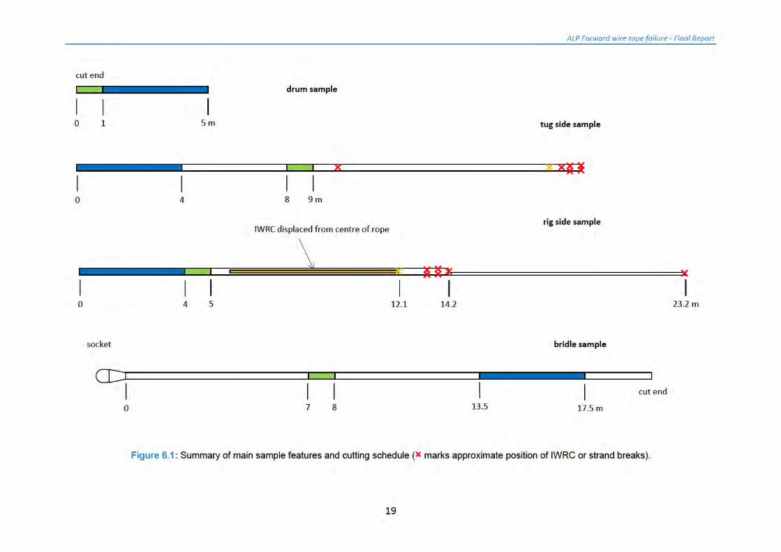
7 Delivery of bridle sample The bridle sample was delivered to TTI Testing from Montrose coiled in a 10 ft half height container, protected by a tarpaulin. It was carefully removed from the container and placed in the laboratory for inspection (Figure 7.1).
Figure 7.1: Bridle sample as received at TTI Testing complete with closed spelter socket.
ALP Forward wire rope failure - Final Report
21
8 Initial inspection of additional sample
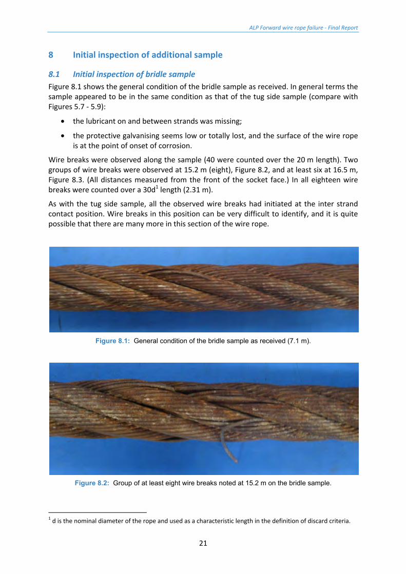
8.1 Initial inspection of bridle sample Figure 8.1 shows the general condition of the bridle sample as received. In general terms the sample appeared to be in the same condition as that of the tug side sample (compare with Figures 5.7 - 5.9):
• the lubricant on and between strands was missing;
• the protective galvanising seems low or totally lost, and the surface of the wire rope is at the point of onset of corrosion.
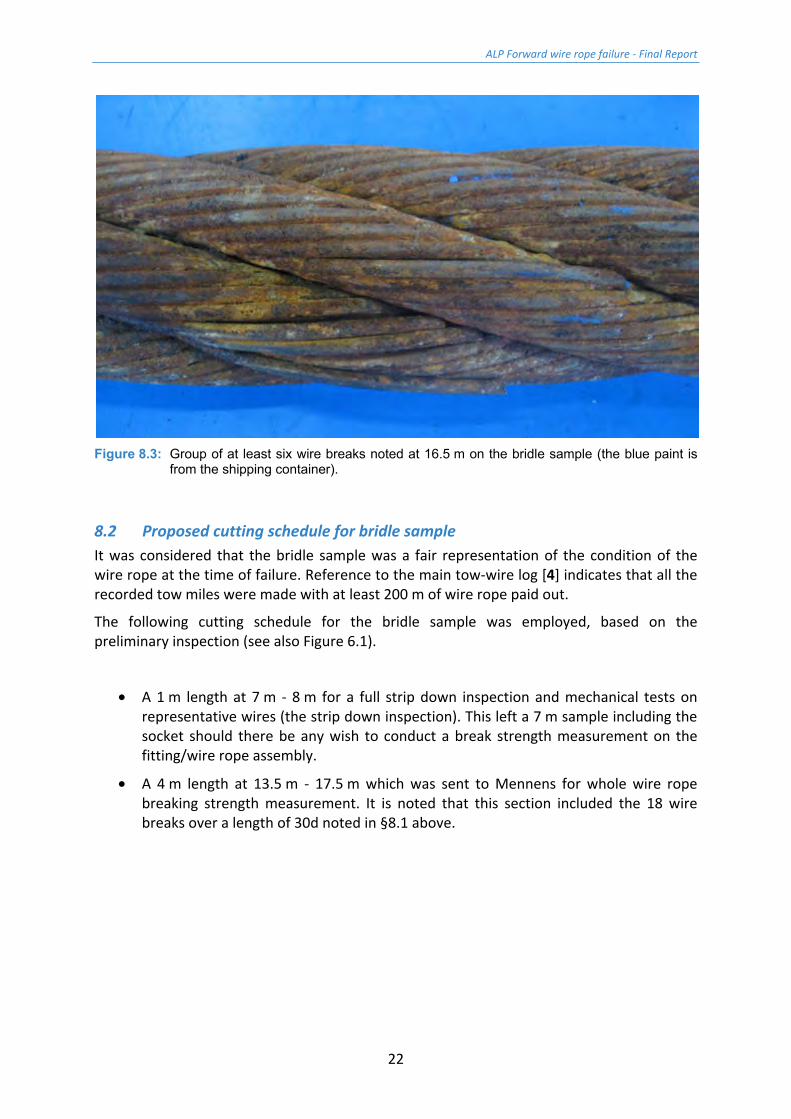
Wire breaks were observed along the sample (40 were counted over the 20 m length). Two groups of wire breaks were observed at 15.2 m (eight), Figure 8.2, and at least six at 16.5 m, Figure 8.3. (All distances measured from the front of the socket face.) In all eighteen wire breaks were counted over a 30d1 length (2.31 m).
As with the tug side sample, all the observed wire breaks had initiated at the inter strand contact position. Wire breaks in this position can be very difficult to identify, and it is quite possible that there are many more in this section of the wire rope.
Figure 8.1: General condition of the bridle sample as received (7.1 m).
Figure 8.2: Group of at least eight wire breaks noted at 15.2 m on the bridle sample.
1 d is the nominal diameter of the rope and used as a characteristic length in the definition of discard criteria.
ALP Forward wire rope failure - Final Report
22
Figure 8.3: Group of at least six wire breaks noted at 16.5 m on the bridle sample (the blue paint is
from the shipping container).
8.2 Proposed cutting schedule for bridle sample It was considered that the bridle sample was a fair representation of the condition of the wire rope at the time of failure. Reference to the main tow-wire log [4] indicates that all the recorded tow miles were made with at least 200 m of wire rope paid out.
The following cutting schedule for the bridle sample was employed, based on the preliminary inspection (see also Figure 6.1).
• A 1 m length at 7 m - 8 m for a full strip down inspection and mechanical tests on representative wires (the strip down inspection). This left a 7 m sample including the socket should there be any wish to conduct a break strength measurement on the fitting/wire rope assembly.
• A 4 m length at 13.5 m - 17.5 m which was sent to Mennens for whole wire rope breaking strength measurement. It is noted that this section included the 18 wire breaks over a length of 30d noted in §8.1 above.
ALP Forward wire rope failure - Final Report
23
9 Wire rope breaking strength measurement
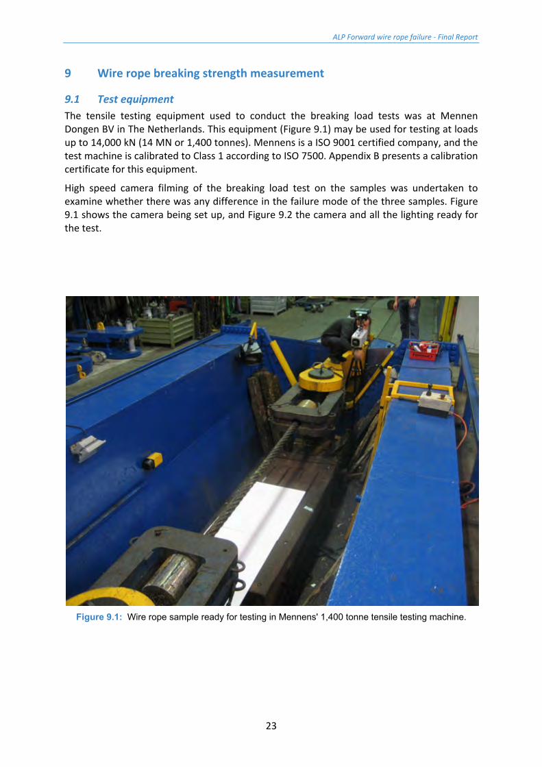
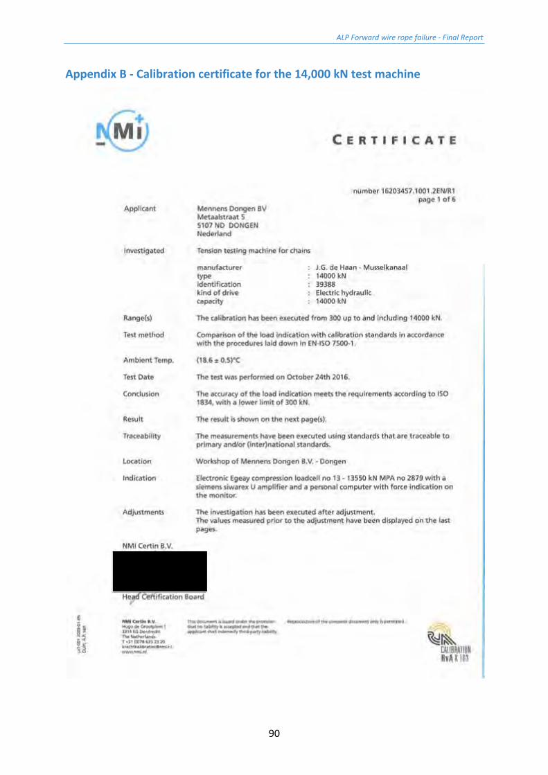
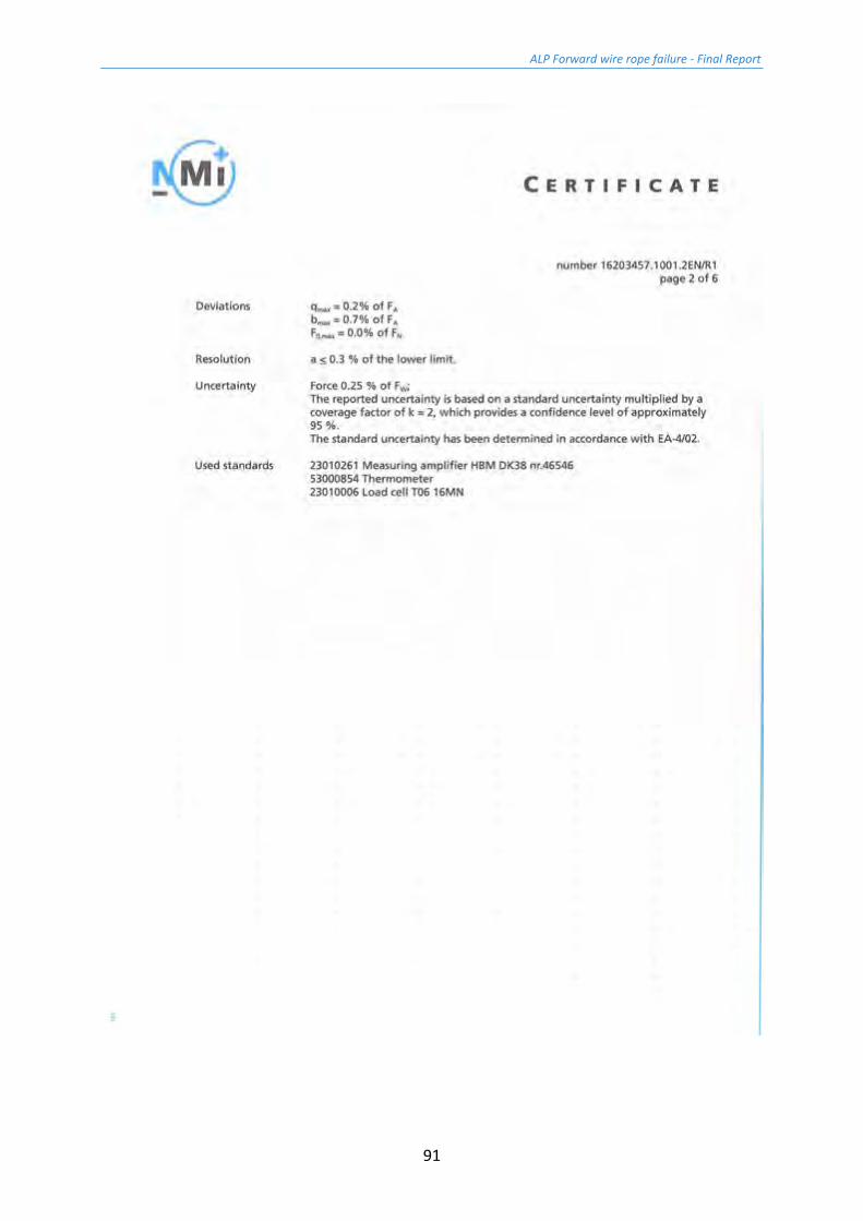
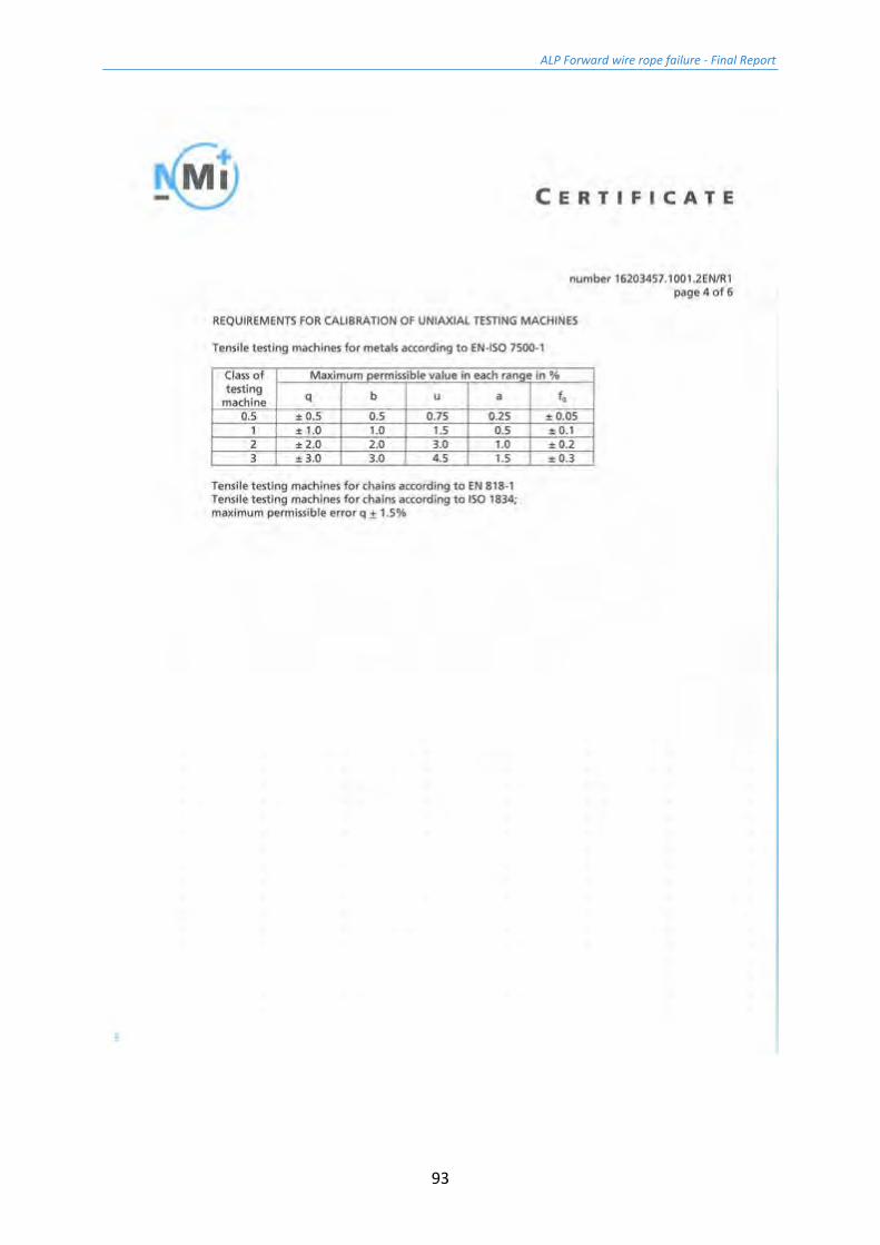
9.1 Test equipment The tensile testing equipment used to conduct the breaking load tests was at Mennen Dongen BV in The Netherlands. This equipment (Figure 9.1) may be used for testing at loads up to 14,000 kN (14 MN or 1,400 tonnes). Mennens is a ISO 9001 certified company, and the test machine is calibrated to Class 1 according to ISO 7500. Appendix B presents a calibration certificate for this equipment.
High speed camera filming of the breaking load test on the samples was undertaken to examine whether there was any difference in the failure mode of the three samples. Figure 9.1 shows the camera being set up, and Figure 9.2 the camera and all the lighting ready for the test.
Figure 9.1: Wire rope sample ready for testing in Mennens' 1,400 tonne tensile testing machine.

ALP Forward wire rope failure - Final Report
24
Figure 9.2: Wire rope sample ready for testing with high speed filming equipment in place.
ALP Forward wire rope failure - Final Report
25
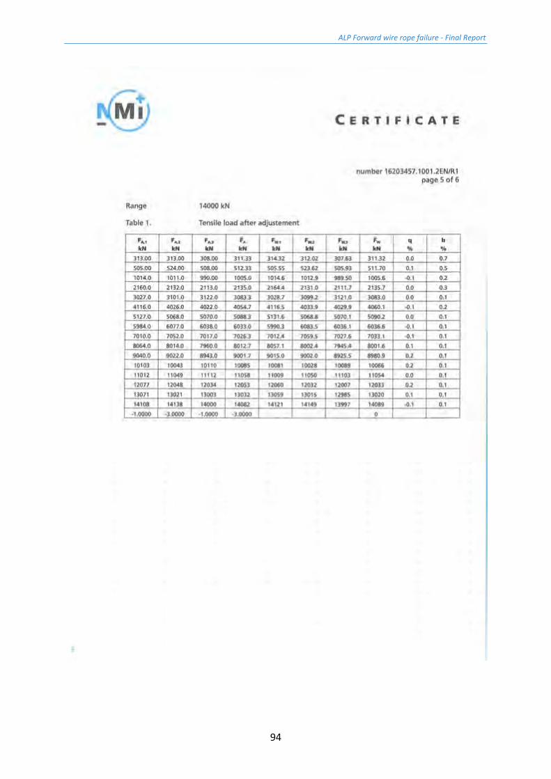
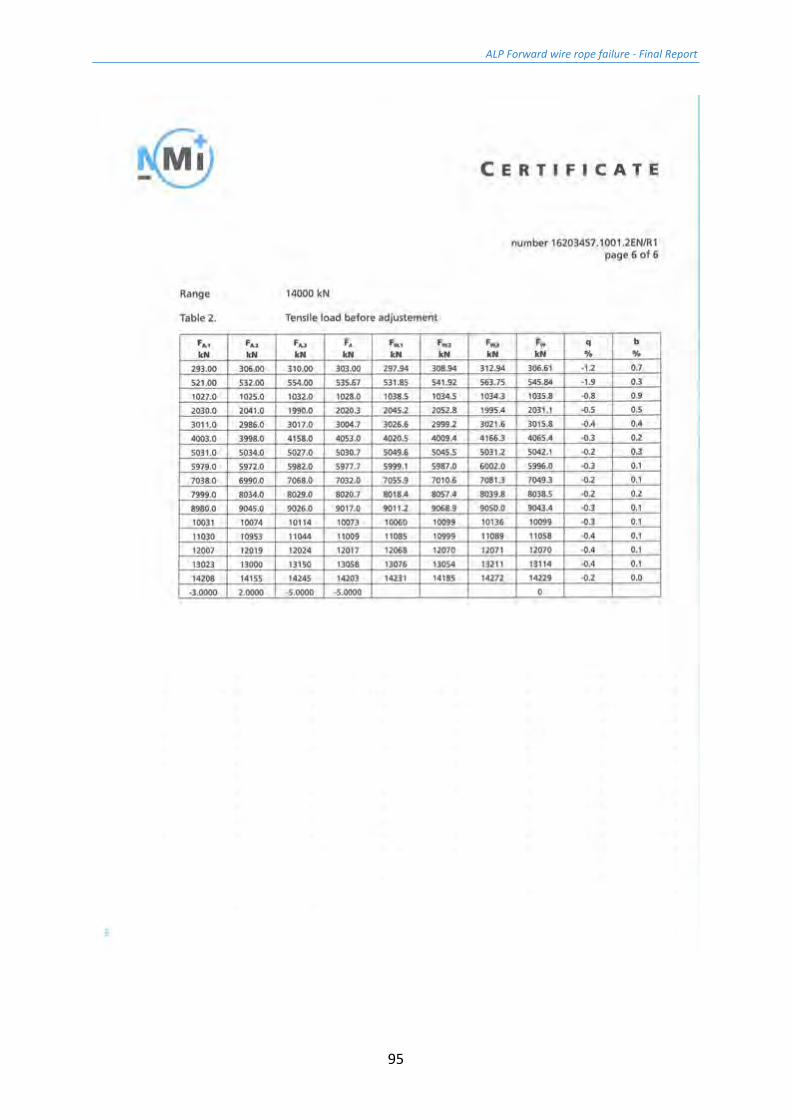
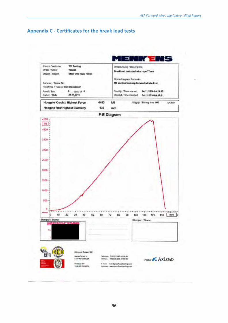
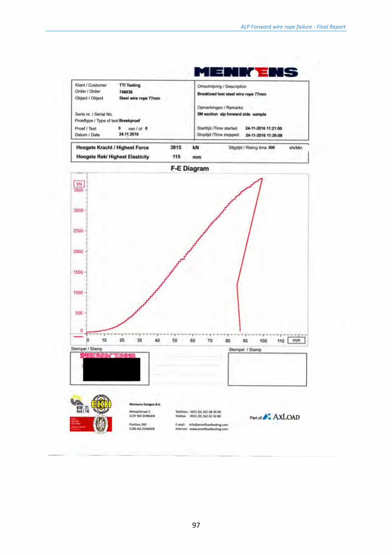
9.2 Results of the breaking load tests Table 9.1 presents the results of the breaking strength measurements conducted on the three samples. Appendix C presents the Mennens tests reports for these tests.
Sample Breaking load [kN] Breaking load [%Fmin] Breaking load [%ABL]
Drum 4,493 94.4 92.7
Tug side 3,815 80.2 78.7
Bridle 3,707 77.9 76.5
Table 9.1: Results of the breaking strength measurement on the three wire rope samples.
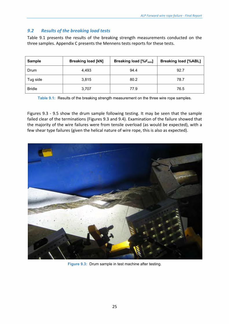
Figures 9.3 - 9.5 show the drum sample following testing. It may be seen that the sample failed clear of the terminations (Figures 9.3 and 9.4). Examination of the failure showed that the majority of the wire failures were from tensile overload (as would be expected), with a few shear type failures (given the helical nature of wire rope, this is also as expected).
Figure 9.3: Drum sample in test machine after testing.

ALP Forward wire rope failure - Final Report
26
Figure 9.4: Drum sample failure clear of termination.
Figure 9.5: Drum sample detailed view on failure region.
ALP Forward wire rope failure - Final Report
27
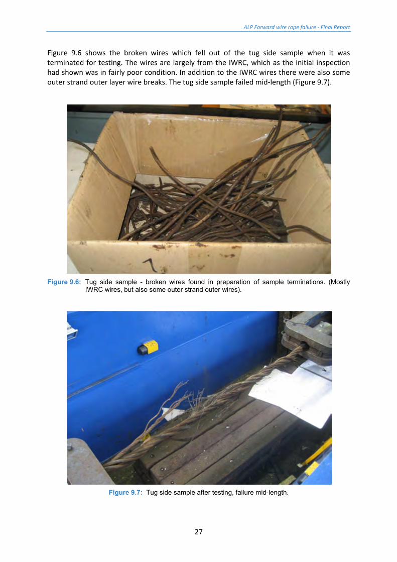
Figure 9.6 shows the broken wires which fell out of the tug side sample when it was terminated for testing. The wires are largely from the IWRC, which as the initial inspection had shown was in fairly poor condition. In addition to the IWRC wires there were also some outer strand outer layer wire breaks. The tug side sample failed mid-length (Figure 9.7).
Figure 9.6: Tug side sample - broken wires found in preparation of sample terminations. (Mostly
IWRC wires, but also some outer strand outer wires).
Figure 9.7: Tug side sample after testing, failure mid-length.
ALP Forward wire rope failure - Final Report
28
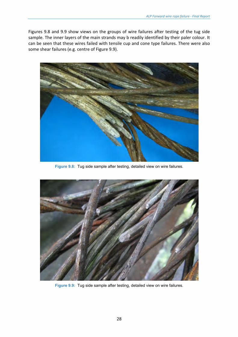
Figures 9.8 and 9.9 show views on the groups of wire failures after testing of the tug side sample. The inner layers of the main strands may b readily identified by their paler colour. It can be seen that these wires failed with tensile cup and cone type failures. There were also some shear failures (e.g. centre of Figure 9.9).
Figure 9.8: Tug side sample after testing, detailed view on wire failures.
Figure 9.9: Tug side sample after testing, detailed view on wire failures.
ALP Forward wire rope failure - Final Report
29
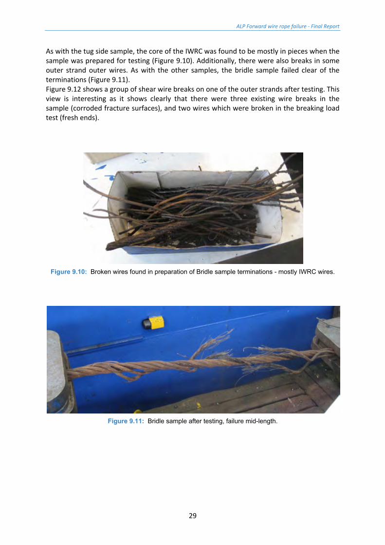
As with the tug side sample, the core of the IWRC was found to be mostly in pieces when the sample was prepared for testing (Figure 9.10). Additionally, there were also breaks in some outer strand outer wires. As with the other samples, the bridle sample failed clear of the terminations (Figure 9.11). Figure 9.12 shows a group of shear wire breaks on one of the outer strands after testing. This view is interesting as it shows clearly that there were three existing wire breaks in the sample (corroded fracture surfaces), and two wires which were broken in the breaking load test (fresh ends).
Figure 9.10: Broken wires found in preparation of Bridle sample terminations - mostly IWRC wires.
Figure 9.11: Bridle sample after testing, failure mid-length.

ALP Forward wire rope failure - Final Report
30
Figure 9.12: Bridle sample after testing, detailed view on wire failures (old - rusty ends, new - shiny).
ALP Forward wire rope failure - Final Report
31
10 Strip down inspection of 1 m samples Sections 1 m long were selected for visual inspection and mechanical testing of representative wires from across the wire rope construction. As noted above, the rig side sample had suffered too much post failure damage to permit a fair assessment of the condition of the wire rope at the time of the incident, thus the following samples were inspected:
• Drum sample;
• Tug side sample; and,
• Bridle sample.
The visual inspection of the samples was in line with the criteria set out in BS ISO 4309:2010 [5], and paid particular attention to corrosion, lubrication and mechanical damage.
Tests were performed on wires taken from positions throughout the wire rope cross section to assess:
• Tensile strength;
• Torsions to failure;
• Reverse bends to failure; and,
• Residual zinc coat weight.
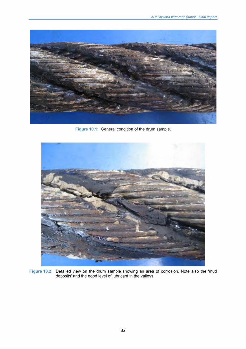
10.1 Strip down inspection of Drum Sample Figure 10.1 shows the general condition of the drum sample. The crown position of the sample was lacking in lubricant, and there were areas of white zinc oxide associated with loss of galvanic protection. In some areas light corrosion was noted (Figure 10.2). There were also patches of what appeared to be mud. It is not known when this was deposited on the wire rope surface.
In the valley positions between strands the lubricant level was very good, but it was hard and glassy in appearance. It is noted that the wire rope inspection certificate states that the lubricant is 'D / bitumin lube', so it is likely that this lubricant is the original as manufactured.
Figure 10.3 shows the sample with two outer strands removed to reveal the IWRC. It may be seen that the lubricant level on the IWRC is very low, and what lubricant there is, is dry.
ALP Forward wire rope failure - Final Report
32
Figure 10.1: General condition of the drum sample.
Figure 10.2: Detailed view on the drum sample showing an area of corrosion. Note also the 'mud
deposits' and the good level of lubricant in the valleys.

ALP Forward wire rope failure - Final Report
33
Figure 10.3: Drum sample with two outer strands removed to show the condition of the IWRC - the
lubricant level is very low. Note also the light corrosion on the outer strand (top right) and the glassy bitumous lubricant in the valley positions (of the outer strands).
Figure 10.4 shows an outer strand after removal from the wire rope sample and partially cleaned. Sections of lubricant have been left in place to highlight the difference in residual galvanising levels between the section of strand normally on the outside of the wire rope, and that facing towards the IWRC.
Figure 10.4: Drum sample outer strand partially cleaned to show the difference in residual
galvanising levels for sections on the inside and outside of the wire rope.
ALP Forward wire rope failure - Final Report
34
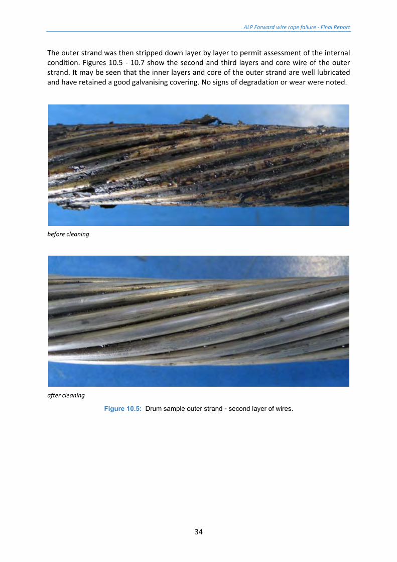
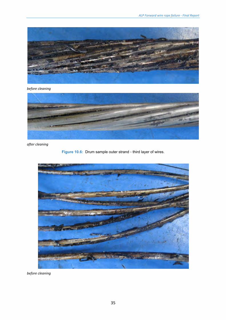
The outer strand was then stripped down layer by layer to permit assessment of the internal condition. Figures 10.5 - 10.7 show the second and third layers and core wire of the outer strand. It may be seen that the inner layers and core of the outer strand are well lubricated and have retained a good galvanising covering. No signs of degradation or wear were noted.
before cleaning
after cleaning
Figure 10.5: Drum sample outer strand - second layer of wires.
ALP Forward wire rope failure - Final Report
35
before cleaning
after cleaning
Figure 10.6: Drum sample outer strand - third layer of wires.
before cleaning
ALP Forward wire rope failure - Final Report
36
after cleaning
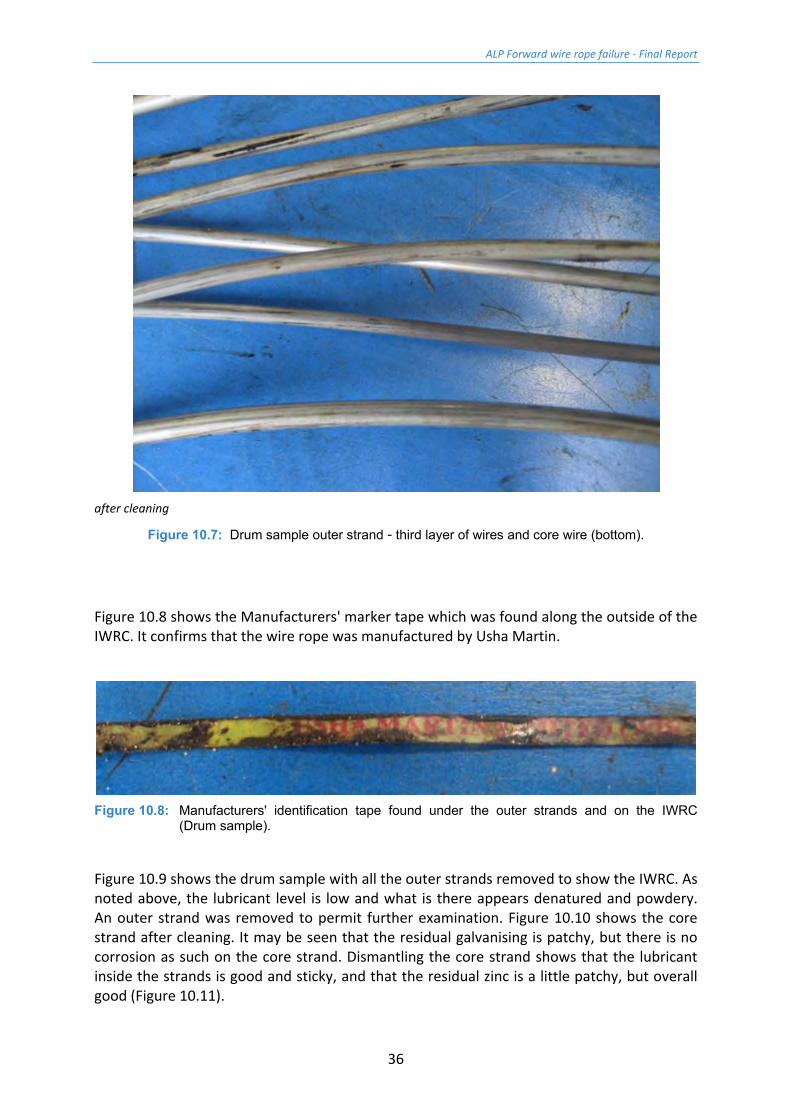
Figure 10.7: Drum sample outer strand - third layer of wires and core wire (bottom).
Figure 10.8 shows the Manufacturers' marker tape which was found along the outside of the IWRC. It confirms that the wire rope was manufactured by Usha Martin.
Figure 10.8: Manufacturers' identification tape found under the outer strands and on the IWRC
(Drum sample).
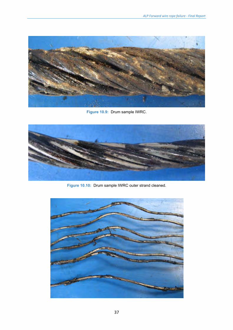
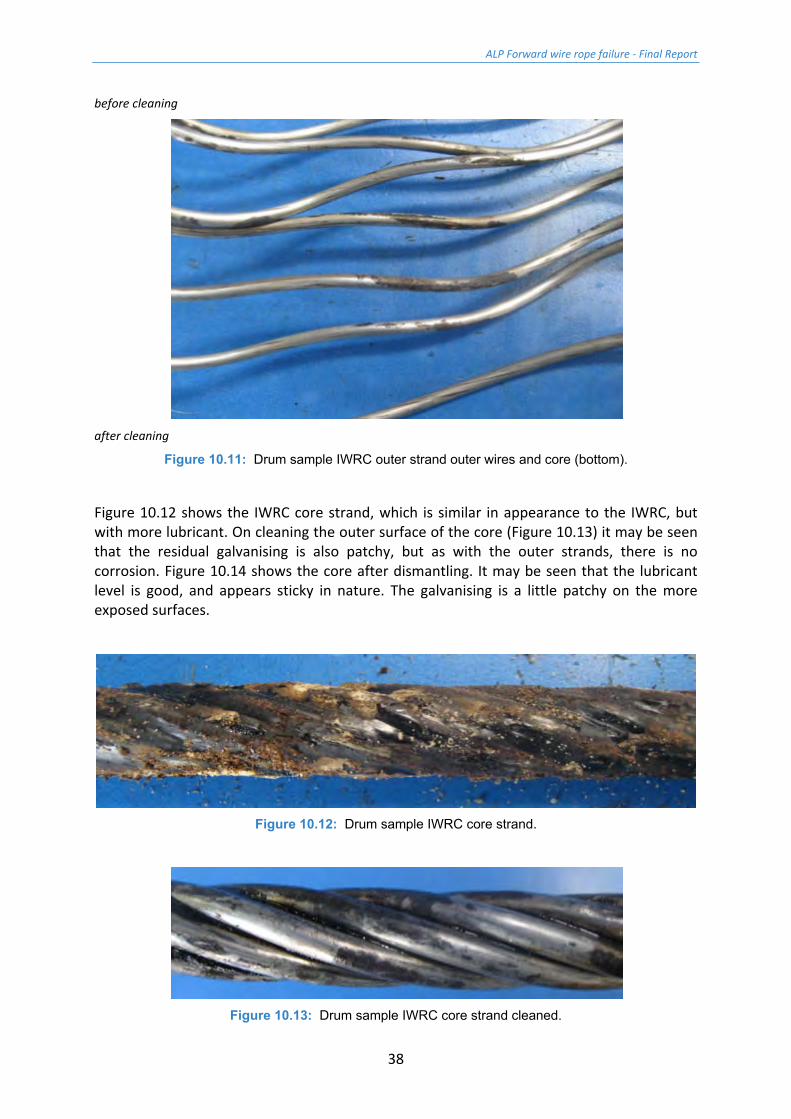
Figure 10.9 shows the drum sample with all the outer strands removed to show the IWRC. As noted above, the lubricant level is low and what is there appears denatured and powdery. An outer strand was removed to permit further examination. Figure 10.10 shows the core strand after cleaning. It may be seen that the residual galvanising is patchy, but there is no corrosion as such on the core strand. Dismantling the core strand shows that the lubricant inside the strands is good and sticky, and that the residual zinc is a little patchy, but overall good (Figure 10.11).
ALP Forward wire rope failure - Final Report
37
Figure 10.9: Drum sample IWRC.
Figure 10.10: Drum sample IWRC outer strand cleaned.
ALP Forward wire rope failure - Final Report
38
before cleaning
after cleaning
Figure 10.11: Drum sample IWRC outer strand outer wires and core (bottom).
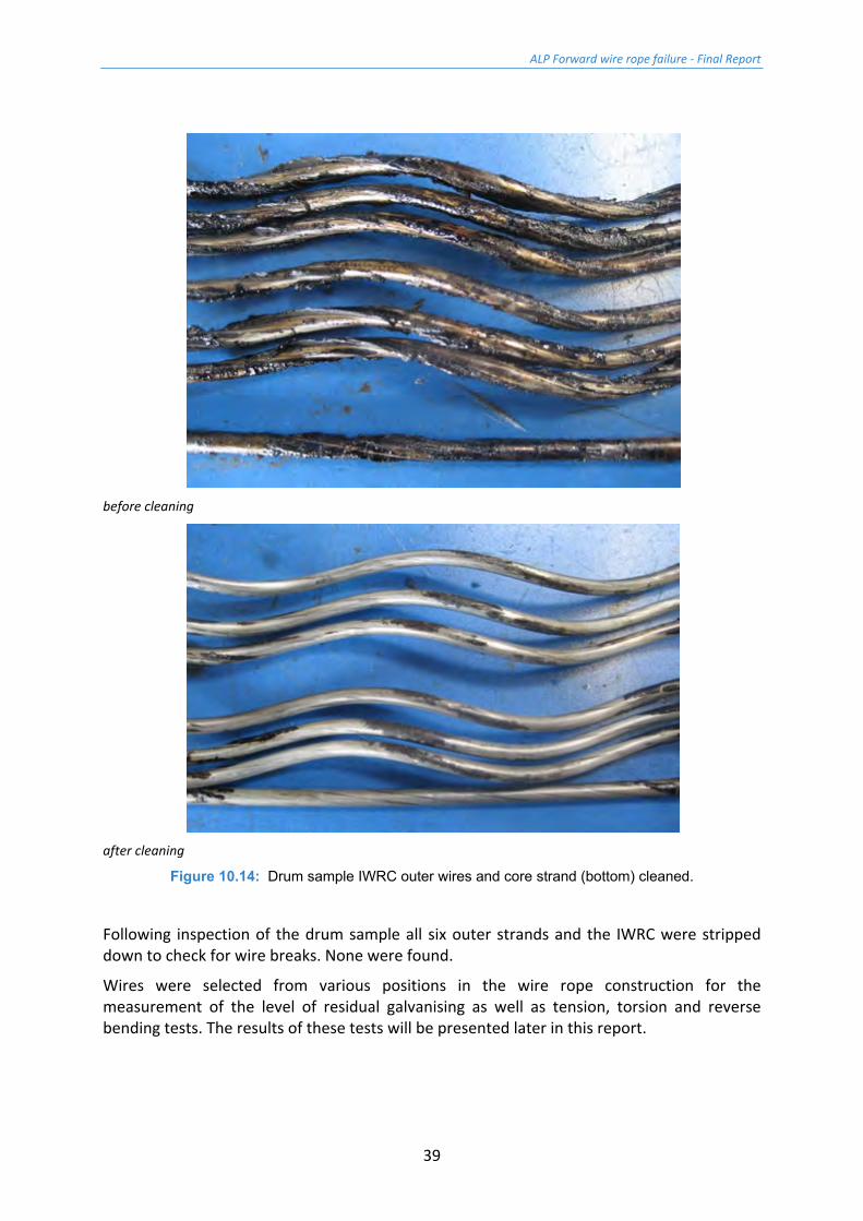
Figure 10.12 shows the IWRC core strand, which is similar in appearance to the IWRC, but with more lubricant. On cleaning the outer surface of the core (Figure 10.13) it may be seen that the residual galvanising is also patchy, but as with the outer strands, there is no corrosion. Figure 10.14 shows the core after dismantling. It may be seen that the lubricant level is good, and appears sticky in nature. The galvanising is a little patchy on the more exposed surfaces.
Figure 10.12: Drum sample IWRC core strand.
Figure 10.13: Drum sample IWRC core strand cleaned.
ALP Forward wire rope failure - Final Report
39
before cleaning
after cleaning
Figure 10.14: Drum sample IWRC outer wires and core strand (bottom) cleaned.
Following inspection of the drum sample all six outer strands and the IWRC were stripped down to check for wire breaks. None were found.
Wires were selected from various positions in the wire rope construction for the measurement of the level of residual galvanising as well as tension, torsion and reverse bending tests. The results of these tests will be presented later in this report.
ALP Forward wire rope failure - Final Report
40
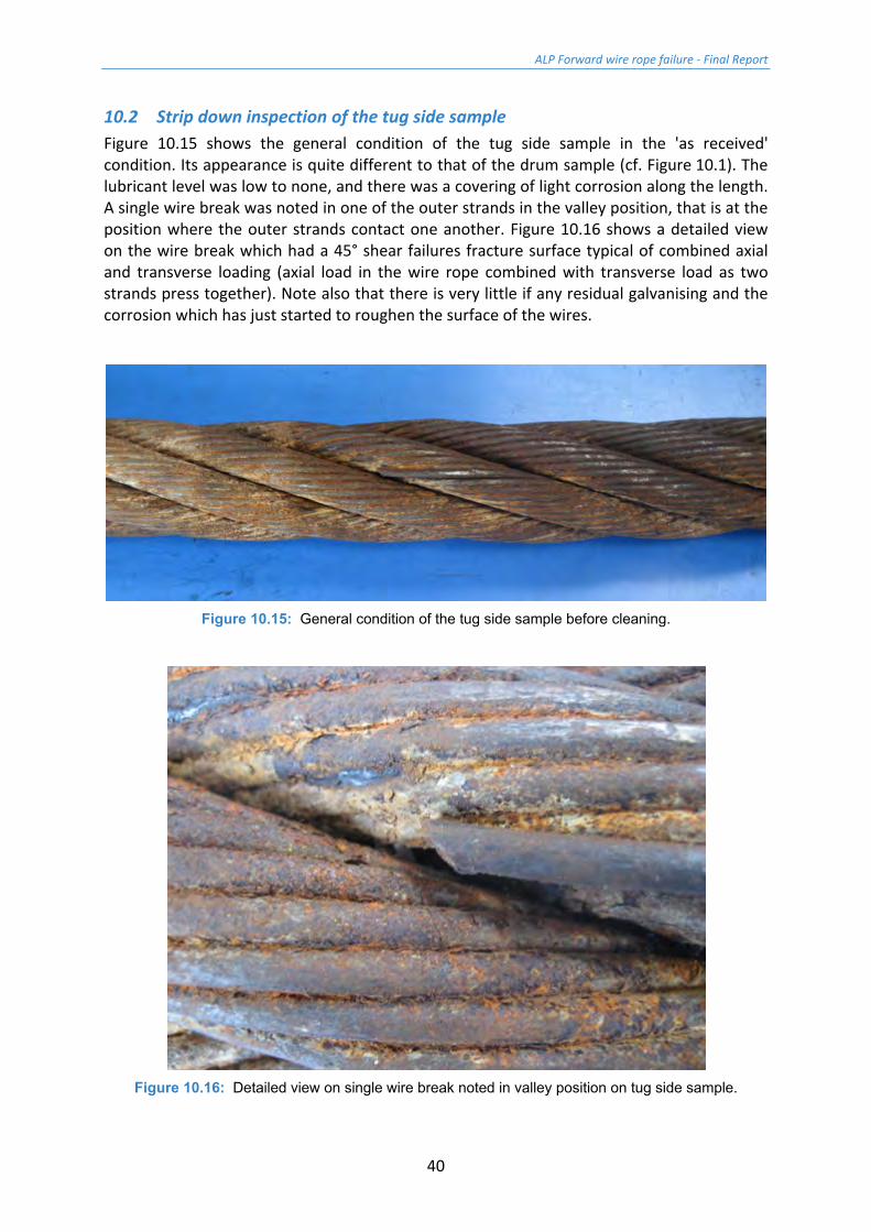
10.2 Strip down inspection of the tug side sample Figure 10.15 shows the general condition of the tug side sample in the 'as received' condition. Its appearance is quite different to that of the drum sample (cf. Figure 10.1). The lubricant level was low to none, and there was a covering of light corrosion along the length. A single wire break was noted in one of the outer strands in the valley position, that is at the position where the outer strands contact one another. Figure 10.16 shows a detailed view on the wire break which had a 45° shear failures fracture surface typical of combined axial and transverse loading (axial load in the wire rope combined with transverse load as two strands press together). Note also that there is very little if any residual galvanising and the corrosion which has just started to roughen the surface of the wires.
Figure 10.15: General condition of the tug side sample before cleaning.
Figure 10.16: Detailed view on single wire break noted in valley position on tug side sample.
ALP Forward wire rope failure - Final Report
41
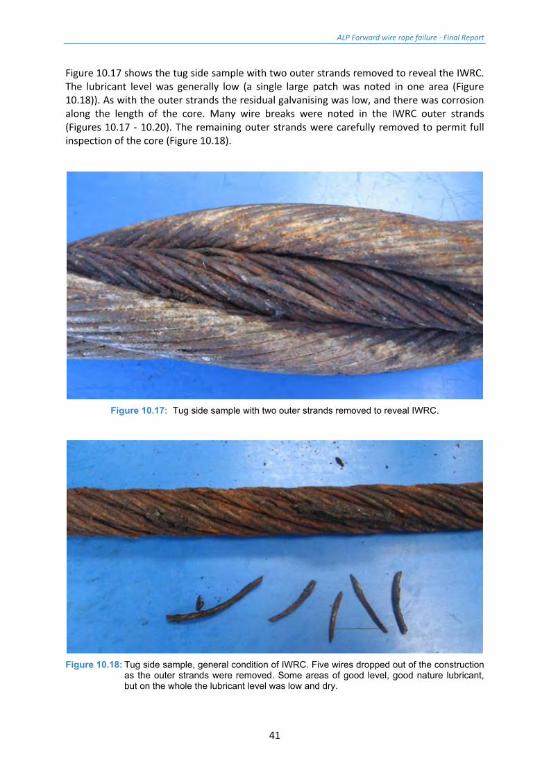
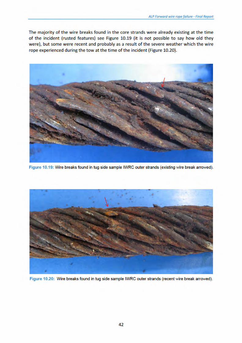
Figure 10.17 shows the tug side sample with two outer strands removed to reveal the IWRC. The lubricant level was generally low (a single large patch was noted in one area (Figure 10.18)). As with the outer strands the residual galvanising was low, and there was corrosion along the length of the core. Many wire breaks were noted in the IWRC outer strands (Figures 10.17 - 10.20). The remaining outer strands were carefully removed to permit full inspection of the core (Figure 10.18).
Figure 10.17: Tug side sample with two outer strands removed to reveal IWRC.
Figure 10.18: Tug side sample, general condition of IWRC. Five wires dropped out of the construction
as the outer strands were removed. Some areas of good level, good nature lubricant, but on the whole the lubricant level was low and dry.

ALP Forward wire rope failure - Final Report
43
Figure 10.21 shows the IWRC with two strands removed to show the core. The lubricant level was much better than on the outer strands, but it was dry and flaky (Figure 10.22). There did not appear to be much corrosion - the main feature noted was that the whole core strand was broken through in several places. Once the outer strands were all removed it could be seen that the core strand was broken through completely in five places (Figure 10.23), as well as having other wire breaks along its length.
Figure 10.21: Tug side sample, IWRC with two strands removed to show core. Core strand broken
through. Good level of lubricant.
Figure 10.22: Tug side sample, dry lubricant which dropped out of the wire rope.
ALP Forward wire rope failure - Final Report
44
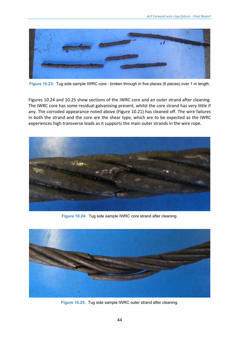
Figure 10.23: Tug side sample IWRC core - broken through in five places (6 pieces) over 1 m length.
Figures 10.24 and 10.25 show sections of the IWRC core and an outer strand after cleaning. The IWRC core has some residual galvanising present, whilst the core strand has very little if any. The corroded appearance noted above (Figure 10.21) has cleaned off. The wire failures in both the strand and the core are the shear type, which are to be expected as the IWRC experiences high transverse loads as it supports the main outer strands in the wire rope.
Figure 10.24: Tug side sample IWRC core strand after cleaning.
Figure 10.25: Tug side sample IWRC outer strand after cleaning.
ALP Forward wire rope failure - Final Report
45
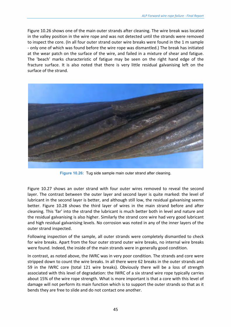
Figure 10.26 shows one of the main outer strands after cleaning. The wire break was located in the valley position in the wire rope and was not detected until the strands were removed to inspect the core. (In all four outer strand outer wire breaks were found in the 1 m sample - only one of which was found before the wire rope was dismantled.) The break has initiated at the wear patch on the surface of the wire, and failed in a mixture of shear and fatigue. The 'beach' marks characteristic of fatigue may be seen on the right hand edge of the fracture surface. It is also noted that there is very little residual galvanising left on the surface of the strand.
Figure 10.26: Tug side sample main outer strand after cleaning.
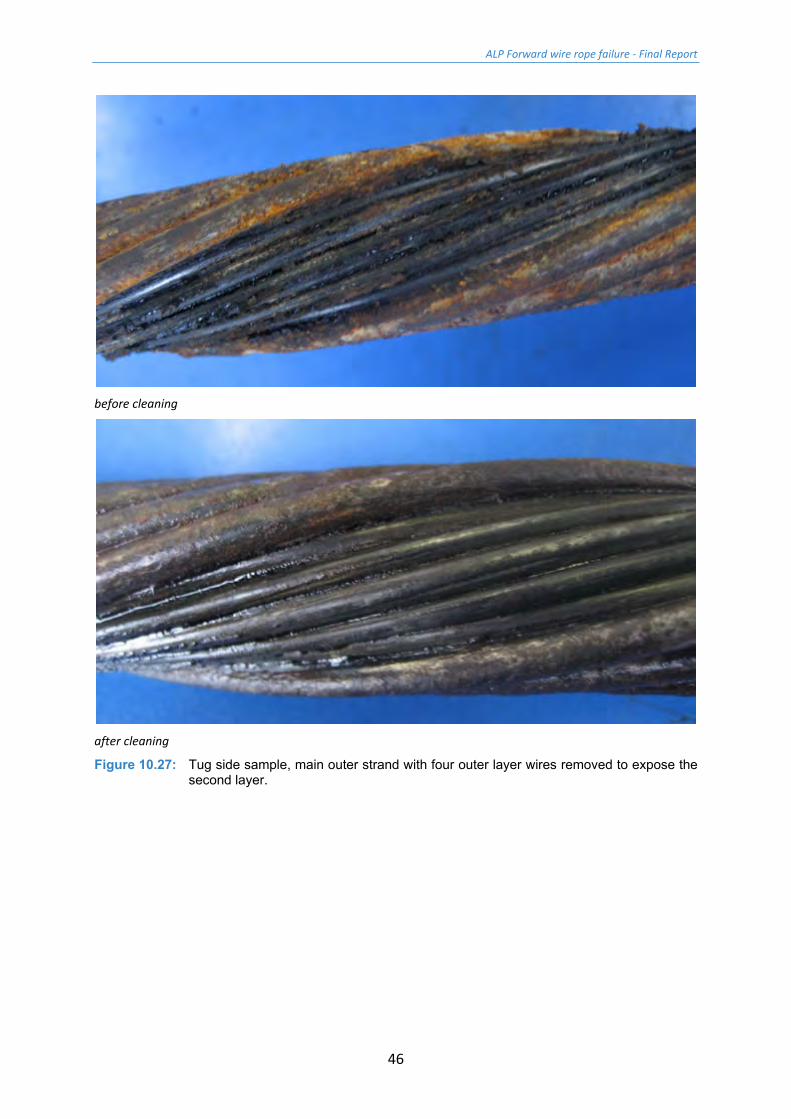
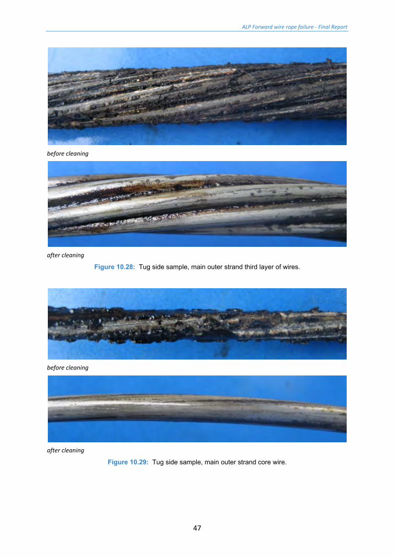
Figure 10.27 shows an outer strand with four outer wires removed to reveal the second layer. The contrast between the outer layer and second layer is quite marked: the level of lubricant in the second layer is better, and although still low, the residual galvanising seems better. Figure 10.28 shows the third layer of wires in the main strand before and after cleaning. This 'far' into the strand the lubricant is much better both in level and nature and the residual galvanising is also higher. Similarly the strand core wire had very good lubricant and high residual galvanising levels. No corrosion was noted in any of the inner layers of the outer strand inspected.
Following inspection of the sample, all outer strands were completely dismantled to check for wire breaks. Apart from the four outer strand outer wire breaks, no internal wire breaks were found. Indeed, the inside of the main strands were in generally good condition.
In contrast, as noted above, the IWRC was in very poor condition. The strands and core were stripped down to count the wire breaks. In all there were 62 breaks in the outer strands and 59 in the IWRC core (total 121 wire breaks). Obviously there will be a loss of strength associated with this level of degradation: the IWRC of a six strand wire rope typically carries about 15% of the wire rope strength. What is more important is that a core with this level of damage will not perform its main function which is to support the outer strands so that as it bends they are free to slide and do not contact one another.
ALP Forward wire rope failure - Final Report
46
before cleaning
after cleaning
Figure 10.27: Tug side sample, main outer strand with four outer layer wires removed to expose the second layer.
ALP Forward wire rope failure - Final Report
47
before cleaning
after cleaning
Figure 10.28: Tug side sample, main outer strand third layer of wires.
before cleaning
after cleaning
Figure 10.29: Tug side sample, main outer strand core wire.
ALP Forward wire rope failure - Final Report
48
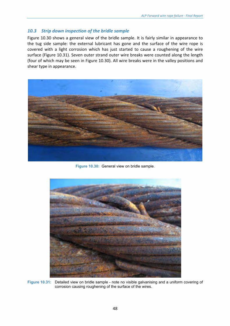
10.3 Strip down inspection of the bridle sample Figure 10.30 shows a general view of the bridle sample. It is fairly similar in appearance to the tug side sample: the external lubricant has gone and the surface of the wire rope is covered with a light corrosion which has just started to cause a roughening of the wire surface (Figure 10.31). Seven outer strand outer wire breaks were counted along the length (four of which may be seen in Figure 10.30). All wire breaks were in the valley positions and shear type in appearance.
Figure 10.30: General view on bridle sample.
Figure 10.31: Detailed view on bridle sample - note no visible galvanising and a uniform covering of
corrosion causing roughening of the surface of the wires.

ALP Forward wire rope failure - Final Report
49
Figures 10.32 and 10.33 show the bridle sample with two outer strands removed to expose the IWRC. It may be seen that in some areas the lubricant was a quite a high level, if somewhat denatured (Figure 10.32), whilst in other places along the core the level was low (Figure 10.33).
Figure 10.32: Bridle sample with two outer strands removed - area of good lubrication on IWRC.
Figure 10.33: Bridle sample with two outer strands removed - area of low lubrication on IWRC.
ALP Forward wire rope failure - Final Report
50
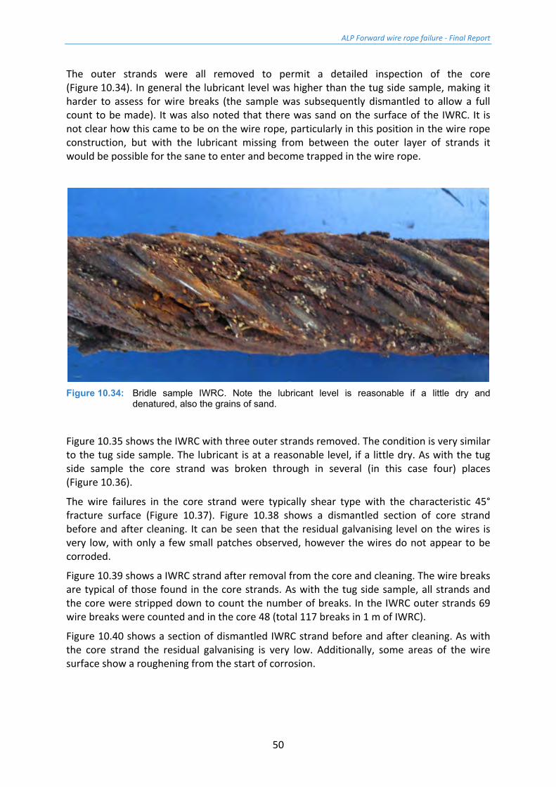
The outer strands were all removed to permit a detailed inspection of the core (Figure 10.34). In general the lubricant level was higher than the tug side sample, making it harder to assess for wire breaks (the sample was subsequently dismantled to allow a full count to be made). It was also noted that there was sand on the surface of the IWRC. It is not clear how this came to be on the wire rope, particularly in this position in the wire rope construction, but with the lubricant missing from between the outer layer of strands it would be possible for the sane to enter and become trapped in the wire rope.
Figure 10.34: Bridle sample IWRC. Note the lubricant level is reasonable if a little dry and
denatured, also the grains of sand.
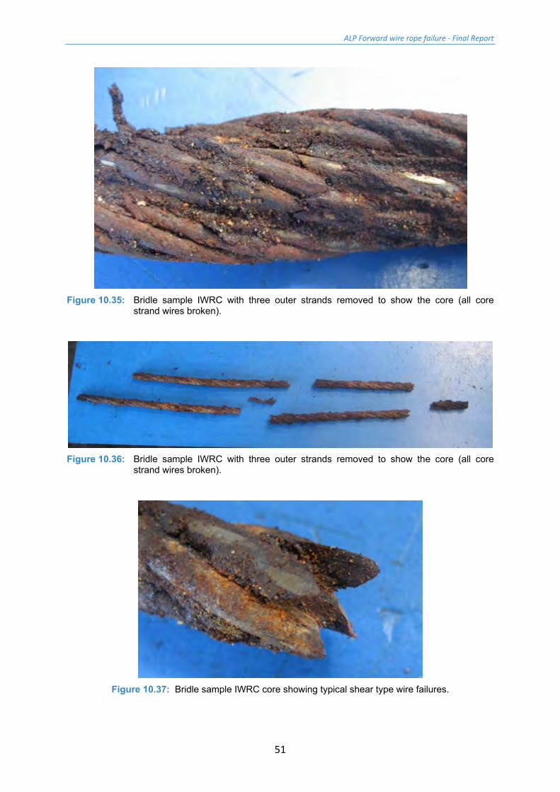
Figure 10.35 shows the IWRC with three outer strands removed. The condition is very similar to the tug side sample. The lubricant is at a reasonable level, if a little dry. As with the tug side sample the core strand was broken through in several (in this case four) places (Figure 10.36).
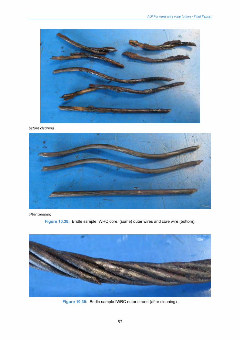
The wire failures in the core strand were typically shear type with the characteristic 45° fracture surface (Figure 10.37). Figure 10.38 shows a dismantled section of core strand before and after cleaning. It can be seen that the residual galvanising level on the wires is very low, with only a few small patches observed, however the wires do not appear to be corroded.
Figure 10.39 shows a IWRC strand after removal from the core and cleaning. The wire breaks are typical of those found in the core strands. As with the tug side sample, all strands and the core were stripped down to count the number of breaks. In the IWRC outer strands 69 wire breaks were counted and in the core 48 (total 117 breaks in 1 m of IWRC).
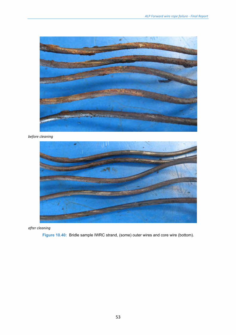
Figure 10.40 shows a section of dismantled IWRC strand before and after cleaning. As with the core strand the residual galvanising is very low. Additionally, some areas of the wire surface show a roughening from the start of corrosion.
ALP Forward wire rope failure - Final Report
51
Figure 10.35: Bridle sample IWRC with three outer strands removed to show the core (all core
strand wires broken).
Figure 10.36: Bridle sample IWRC with three outer strands removed to show the core (all core
strand wires broken).
Figure 10.37: Bridle sample IWRC core showing typical shear type wire failures.
ALP Forward wire rope failure - Final Report
52
before cleaning
after cleaning
Figure 10.38: Bridle sample IWRC core, (some) outer wires and core wire (bottom).
Figure 10.39: Bridle sample IWRC outer strand (after cleaning).
ALP Forward wire rope failure - Final Report
53
before cleaning
after cleaning
Figure 10.40: Bridle sample IWRC strand, (some) outer wires and core wire (bottom).
ALP Forward wire rope failure - Final Report
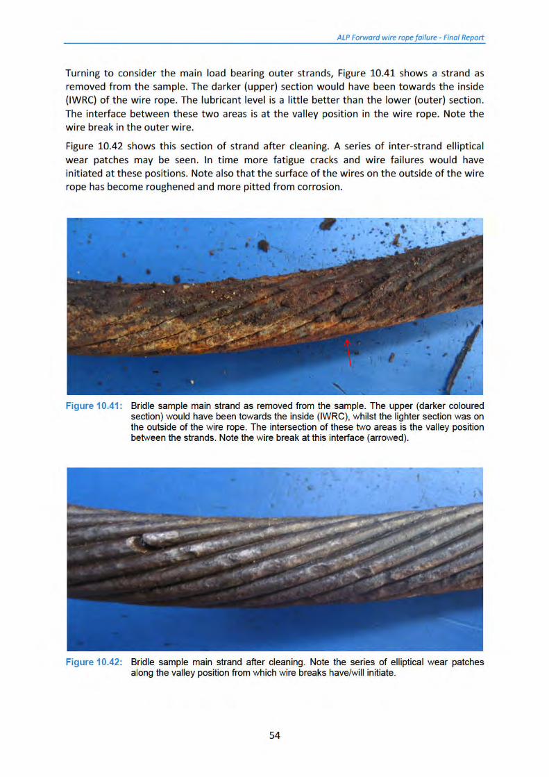
55
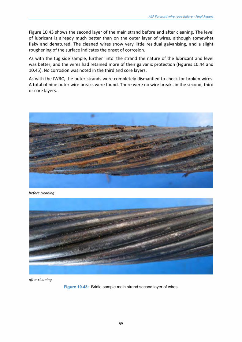
Figure 10.43 shows the second layer of the main strand before and after cleaning. The level of lubricant is already much better than on the outer layer of wires, although somewhat flaky and denatured. The cleaned wires show very little residual galvanising, and a slight roughening of the surface indicates the onset of corrosion.
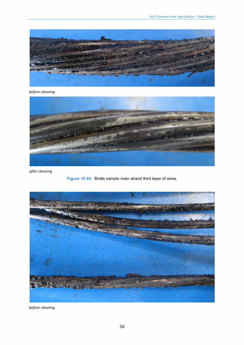
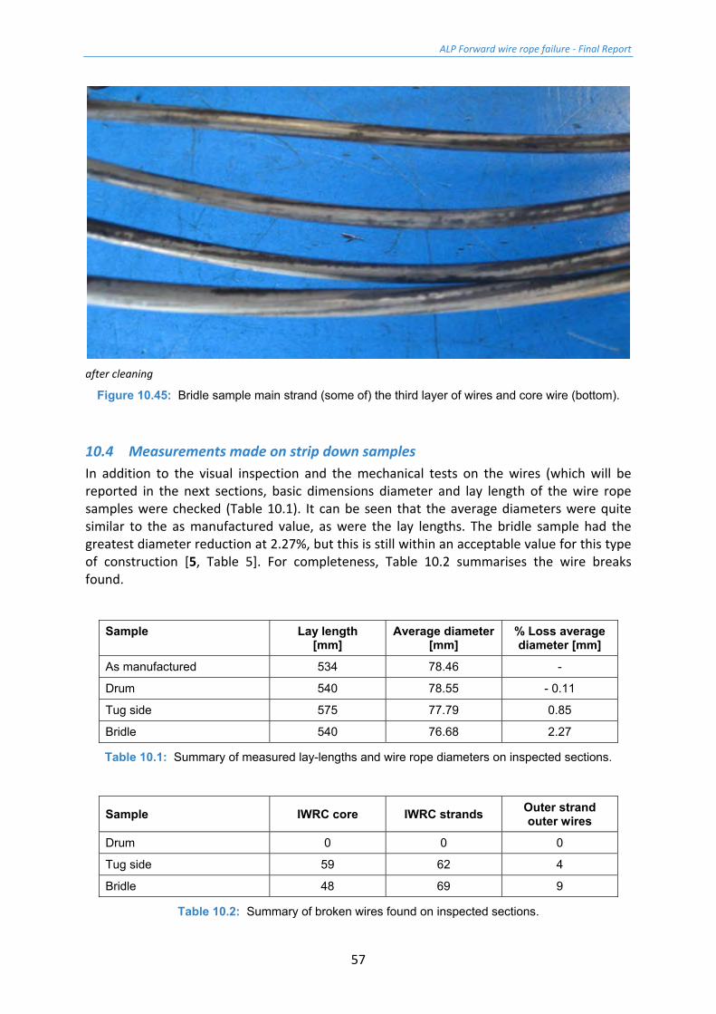
As with the tug side sample, further 'into' the strand the nature of the lubricant and level was better, and the wires had retained more of their galvanic protection (Figures 10.44 and 10.45). No corrosion was noted in the third and core layers.
As with the IWRC, the outer strands were completely dismantled to check for broken wires. A total of nine outer wire breaks were found. There were no wire breaks in the second, third or core layers.
before cleaning
after cleaning
Figure 10.43: Bridle sample main strand second layer of wires.
ALP Forward wire rope failure - Final Report
56
before cleaning
after cleaning
Figure 10.44: Bridle sample main strand third layer of wires.
before cleaning
ALP Forward wire rope failure - Final Report
57
after cleaning
Figure 10.45: Bridle sample main strand (some of) the third layer of wires and core wire (bottom).
10.4 Measurements made on strip down samples In addition to the visual inspection and the mechanical tests on the wires (which will be reported in the next sections, basic dimensions diameter and lay length of the wire rope samples were checked (Table 10.1). It can be seen that the average diameters were quite similar to the as manufactured value, as were the lay lengths. The bridle sample had the greatest diameter reduction at 2.27%, but this is still within an acceptable value for this type of construction [5, Table 5]. For completeness, Table 10.2 summarises the wire breaks found.
Sample Lay length [mm]
Average diameter [mm]
% Loss average diameter [mm]
As manufactured 534 78.46 -
Drum 540 78.55 - 0.11
Tug side 575 77.79 0.85
Bridle 540 76.68 2.27
Table 10.1: Summary of measured lay-lengths and wire rope diameters on inspected sections.
Sample IWRC core IWRC strands Outer strand outer wires
Drum 0 0 0
Tug side 59 62 4
Bridle 48 69 9
Table 10.2: Summary of broken wires found on inspected sections.
ALP Forward wire rope failure - Final Report
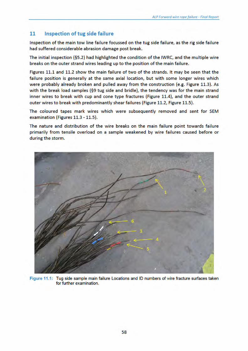
59
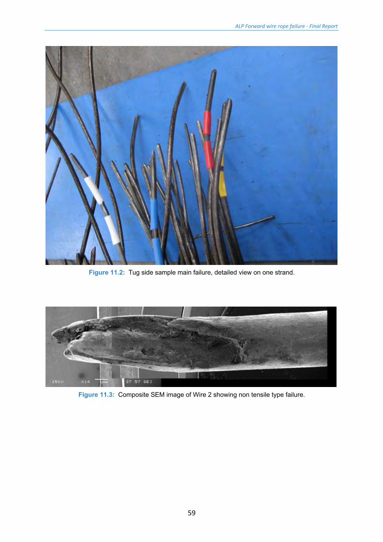
Figure 11.2: Tug side sample main failure, detailed view on one strand.
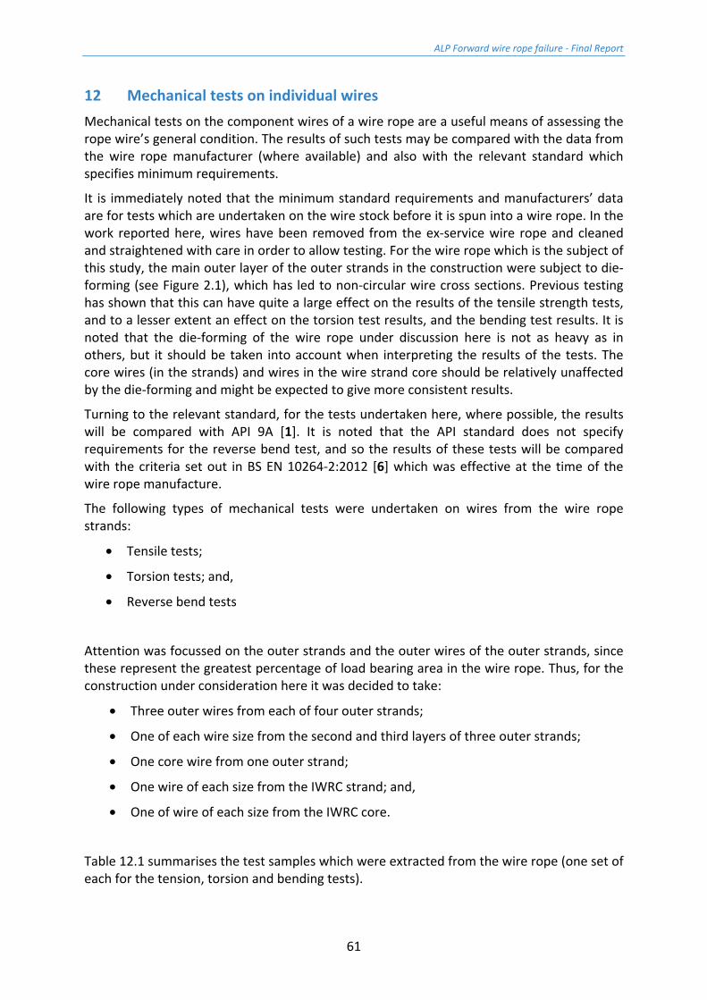
Figure 11.3: Composite SEM image of Wire 2 showing non tensile type failure.

ALP Forward wire rope failure - Final Report
60
Figure 11.4: SEM image of tensile (cup and cone) failure of Wire 6 (outer strand second layer large
wire).
Figure 11.5: SEM image of shear failure of Wire 4 (outer strand outer wire).
ALP Forward wire rope failure - Final Report
61
12 Mechanical tests on individual wires Mechanical tests on the component wires of a wire rope are a useful means of assessing the rope wire’s general condition. The results of such tests may be compared with the data from the wire rope manufacturer (where available) and also with the relevant standard which specifies minimum requirements.
It is immediately noted that the minimum standard requirements and manufacturers’ data are for tests which are undertaken on the wire stock before it is spun into a wire rope. In the work reported here, wires have been removed from the ex-service wire rope and cleaned and straightened with care in order to allow testing. For the wire rope which is the subject of this study, the main outer layer of the outer strands in the construction were subject to die-forming (see Figure 2.1), which has led to non-circular wire cross sections. Previous testing has shown that this can have quite a large effect on the results of the tensile strength tests, and to a lesser extent an effect on the torsion test results, and the bending test results. It is noted that the die-forming of the wire rope under discussion here is not as heavy as in others, but it should be taken into account when interpreting the results of the tests. The core wires (in the strands) and wires in the wire strand core should be relatively unaffected by the die-forming and might be expected to give more consistent results.
Turning to the relevant standard, for the tests undertaken here, where possible, the results will be compared with API 9A [1]. It is noted that the API standard does not specify requirements for the reverse bend test, and so the results of these tests will be compared with the criteria set out in BS EN 10264-2:2012 [6] which was effective at the time of the wire rope manufacture.
The following types of mechanical tests were undertaken on wires from the wire rope strands:
• Tensile tests;
• Torsion tests; and,
• Reverse bend tests
Attention was focussed on the outer strands and the outer wires of the outer strands, since these represent the greatest percentage of load bearing area in the wire rope. Thus, for the construction under consideration here it was decided to take:
• Three outer wires from each of four outer strands;
• One of each wire size from the second and third layers of three outer strands;
• One core wire from one outer strand;
• One wire of each size from the IWRC strand; and,
• One of wire of each size from the IWRC core.
Table 12.1 summarises the test samples which were extracted from the wire rope (one set of each for the tension, torsion and bending tests).
ALP Forward wire rope failure - Final Report
62
Strand Wire position Number of tests
Outer strand 1* outer wire 3
2nd layer large and small 1 + 1
Third layer 1
Core 1
Outer strand 2* outer wire 3
2nd layer large and small 1 + 1
Third layer 1
Outer strand 3* outer wire 3
2nd layer large and small 1 + 1
Third layer 1
Outer strand 4* outer wire 3
IWRC strand outer layer 1
core 1
IWRC core outer layer 1
core 1
TOTAL 26
*Note the strand numbers are completely arbitrary, strands were selected at random
Table 12.1: Summary of the samples taken from the wire rope for tensile, torsion and bend testing.
ALP Forward wire rope failure - Final Report
63
12.1 Tensile tests Tensile tests were undertaken on individual wires removed from the strands disassembled under §12. Especial care was taken when selecting samples from the very outer layers of the wire rope to avoid those which might have been subject to undue mechanical damage (e.g. abrasion).
Testing was conducted in accordance with ISO 10425:2003 [7] Annex B.
The wires were removed from the wire rope construction, labelled and cleaned. Following cleaning they were straightened as much as practical by bending in the soft jaws of a vice or through a specially designed jig. It is noted that whilst the wires were straightened as much as possible, they were not perfectly straight. Hence it was not possible to measure their elongation to failure as the initial part of the load-stroke relationship was affected by the final wire straightening under load.
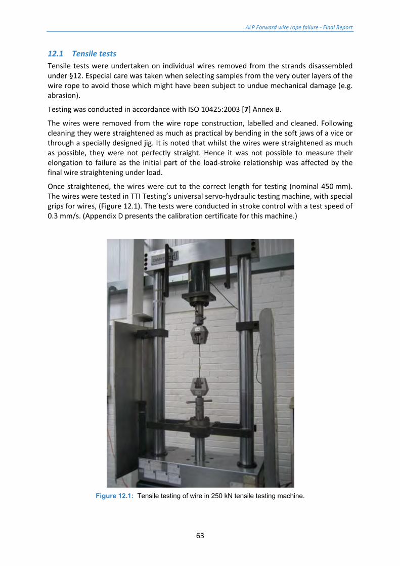
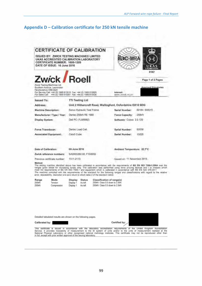
Once straightened, the wires were cut to the correct length for testing (nominal 450 mm). The wires were tested in TTI Testing’s universal servo-hydraulic testing machine, with special grips for wires, (Figure 12.1). The tests were conducted in stroke control with a test speed of 0.3 mm/s. (Appendix D presents the calibration certificate for this machine.)
Figure 12.1: Tensile testing of wire in 250 kN tensile testing machine.

ALP Forward wire rope failure - Final Report
64
12.2 Torsion tests Torsion tests were undertaken on a set of wires as detailed in Table 12.1. The tests were conducted in accordance with ISO 7800:2012 [8]. As is permitted by the standard, a gauge length of 300 mm was used for all tests, the results being scaled to provide a number of turns to failure for a length of 100dw (where dw is the wire diameter).
12.3 Reverse bend test Reverse bend tests were undertaken on a set of wires as detailed in Table 12.1. The tests were conducted in accordance with ISO 7801:1984 [9].
ALP Forward wire rope failure - Final Report
66
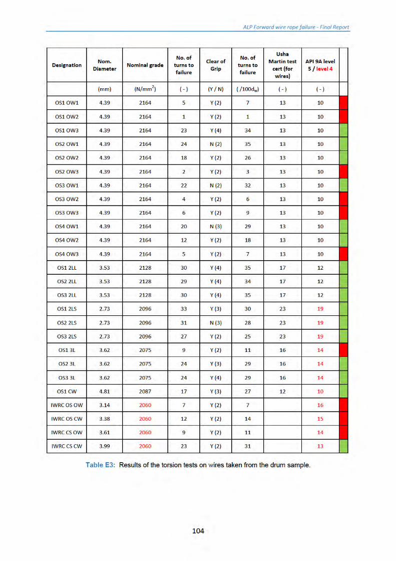
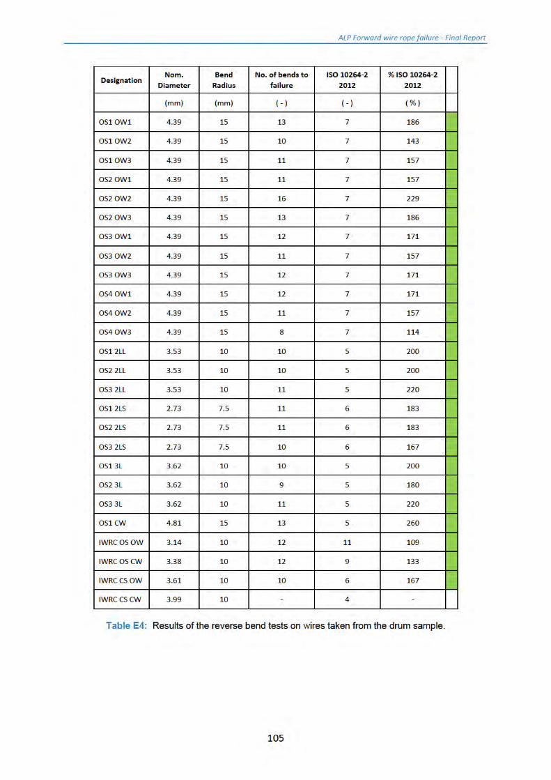
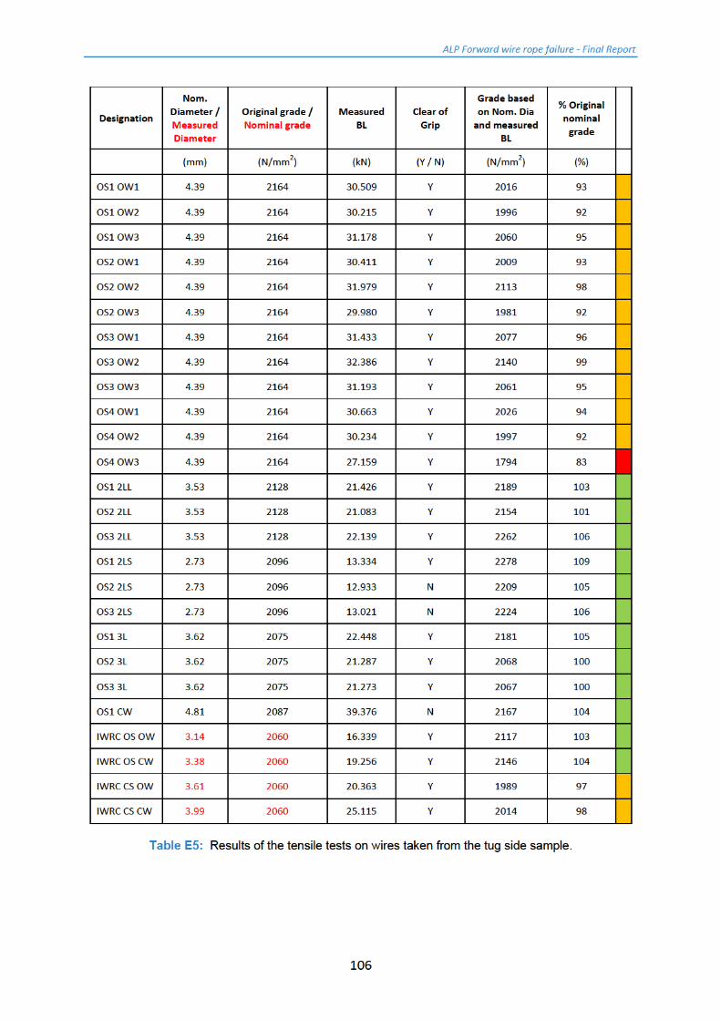
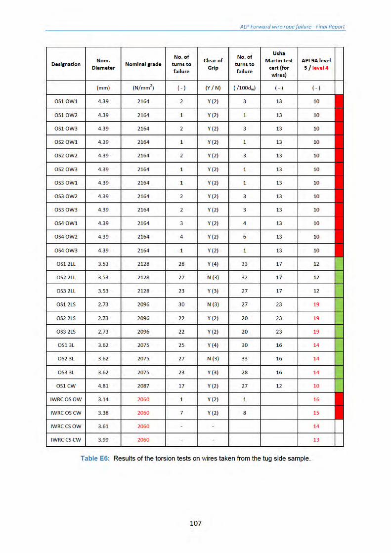
14 Results of the mechanical tests Full results of the mechanical testing (tensile, torsion and reverse bend) are presented in a series of Tables in Appendix E.
Considering first the results of the tests undertaken on the drum sample wires:
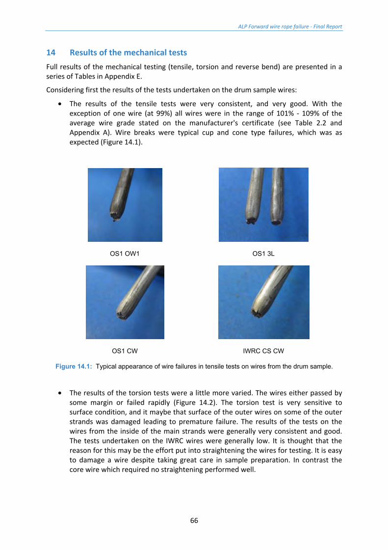
• The results of the tensile tests were very consistent, and very good. With the exception of one wire (at 99%) all wires were in the range of 101% - 109% of the average wire grade stated on the manufacturer's certificate (see Table 2.2 and Appendix A). Wire breaks were typical cup and cone type failures, which was as expected (Figure 14.1).
OS1 OW1 OS1 3L
OS1 CW IWRC CS CW
Figure 14.1: Typical appearance of wire failures in tensile tests on wires from the drum sample.
• The results of the torsion tests were a little more varied. The wires either passed by some margin or failed rapidly (Figure 14.2). The torsion test is very sensitive to surface condition, and it maybe that surface of the outer wires on some of the outer strands was damaged leading to premature failure. The results of the tests on the wires from the inside of the main strands were generally very consistent and good. The tests undertaken on the IWRC wires were generally low. It is thought that the reason for this may be the effort put into straightening the wires for testing. It is easy to damage a wire despite taking great care in sample preparation. In contrast the core wire which required no straightening performed well.

ALP Forward wire rope failure - Final Report
67
Figure 14.2: Appearance of wire failures in torsion tests on wires from the drum sample. (Top
OS OW1 (7 turns/100dw), bottom OS CW (27 turns/100dw)).
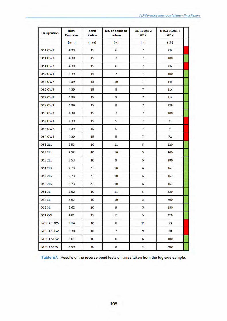
• The reverse bend test (in addition to the torsion test) is means of assessing a wire's ductility. The API 9A [1] does not have a minimum requirement for wires tested in this manner, so the requirements of Standard 10264-2 [6] have been used. All the wires in the reverse bend tests satisfied the minimum requirements of the Standard. This would suggest that the wire material was ductile, but in the torsion tests the surface had been damaged.
Turning to the tug side sample:
• The results of the tensile tests on the outer strand outer wires were consistently all a bit low (one at 83%, others at 92% to 99%), (Figure 14.3). The results of the tests on the main strand inner wires were all very good (100% to 109%). The IWRC wires were in the range 97% to 104% of the assumed original grade.
OS1 OW2 OS1 CW
Figure 14.3: Typical appearance of wire failures in tensile tests on wires from the tug side sample.
ALP Forward wire rope failure - Final Report
68
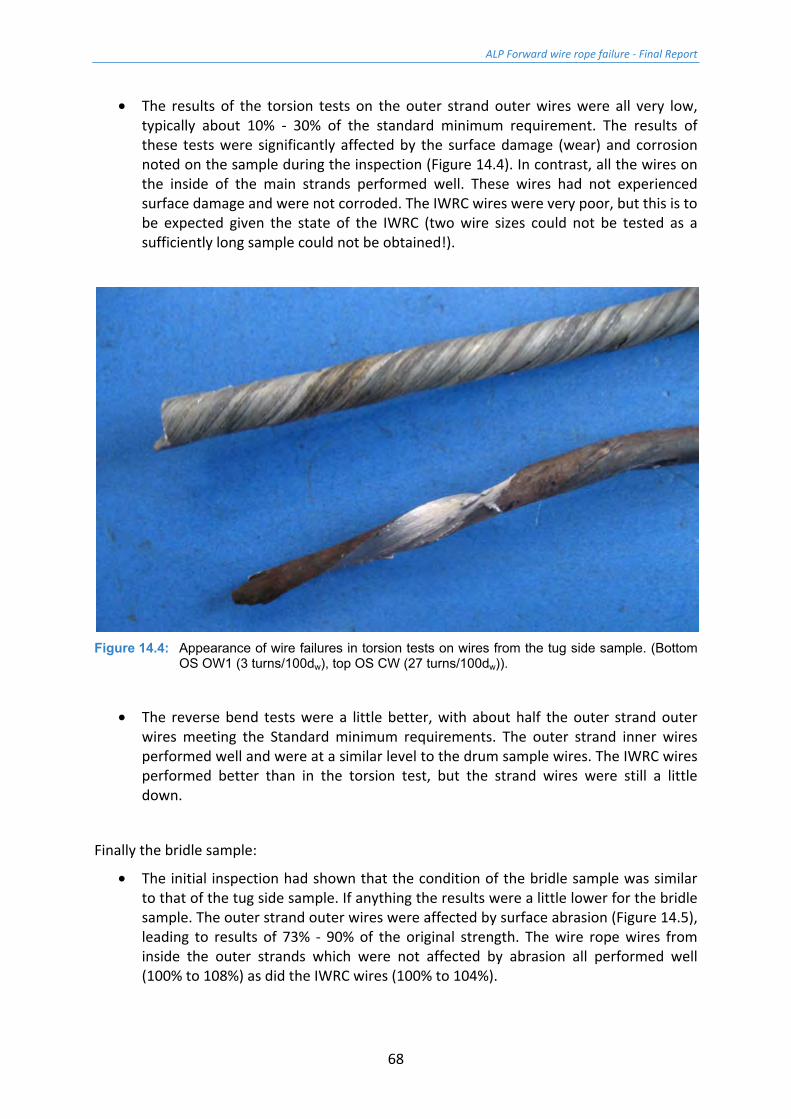
• The results of the torsion tests on the outer strand outer wires were all very low, typically about 10% - 30% of the standard minimum requirement. The results of these tests were significantly affected by the surface damage (wear) and corrosion noted on the sample during the inspection (Figure 14.4). In contrast, all the wires on the inside of the main strands performed well. These wires had not experienced surface damage and were not corroded. The IWRC wires were very poor, but this is to be expected given the state of the IWRC (two wire sizes could not be tested as a sufficiently long sample could not be obtained!).
Figure 14.4: Appearance of wire failures in torsion tests on wires from the tug side sample. (Bottom
OS OW1 (3 turns/100dw), top OS CW (27 turns/100dw)).
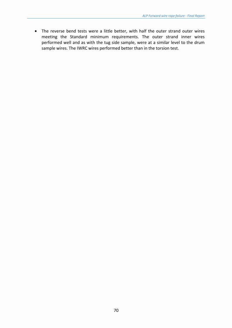
• The reverse bend tests were a little better, with about half the outer strand outer wires meeting the Standard minimum requirements. The outer strand inner wires performed well and were at a similar level to the drum sample wires. The IWRC wires performed better than in the torsion test, but the strand wires were still a little down.
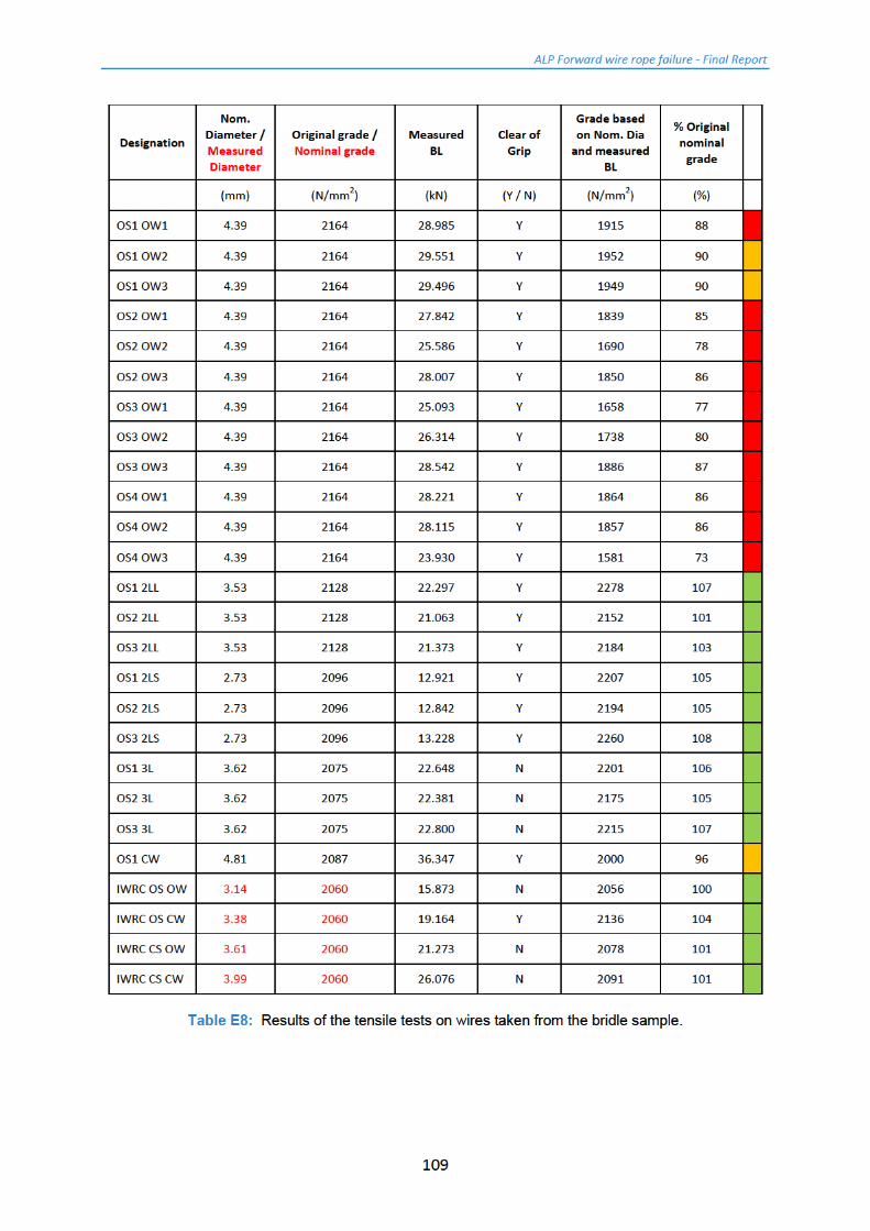
Finally the bridle sample:
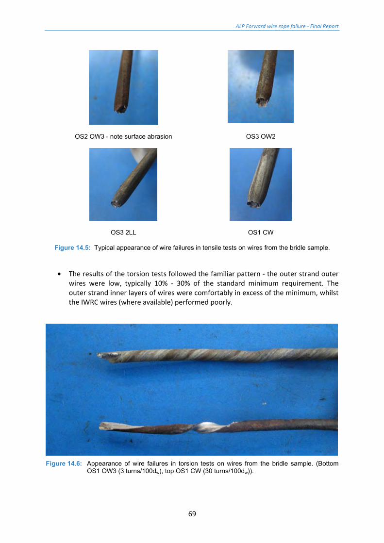
• The initial inspection had shown that the condition of the bridle sample was similar to that of the tug side sample. If anything the results were a little lower for the bridle sample. The outer strand outer wires were affected by surface abrasion (Figure 14.5), leading to results of 73% - 90% of the original strength. The wire rope wires from inside the outer strands which were not affected by abrasion all performed well (100% to 108%) as did the IWRC wires (100% to 104%).
ALP Forward wire rope failure - Final Report
69
OS2 OW3 - note surface abrasion OS3 OW2
OS3 2LL OS1 CW
Figure 14.5: Typical appearance of wire failures in tensile tests on wires from the bridle sample.
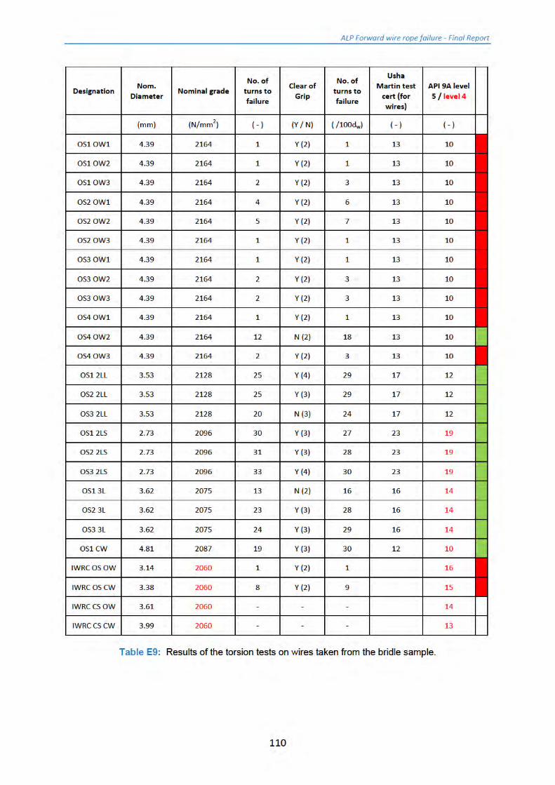
• The results of the torsion tests followed the familiar pattern - the outer strand outer wires were low, typically 10% - 30% of the standard minimum requirement. The outer strand inner layers of wires were comfortably in excess of the minimum, whilst the IWRC wires (where available) performed poorly.
Figure 14.6: Appearance of wire failures in torsion tests on wires from the bridle sample. (Bottom
OS1 OW3 (3 turns/100dw), top OS1 CW (30 turns/100dw)).
ALP Forward wire rope failure - Final Report
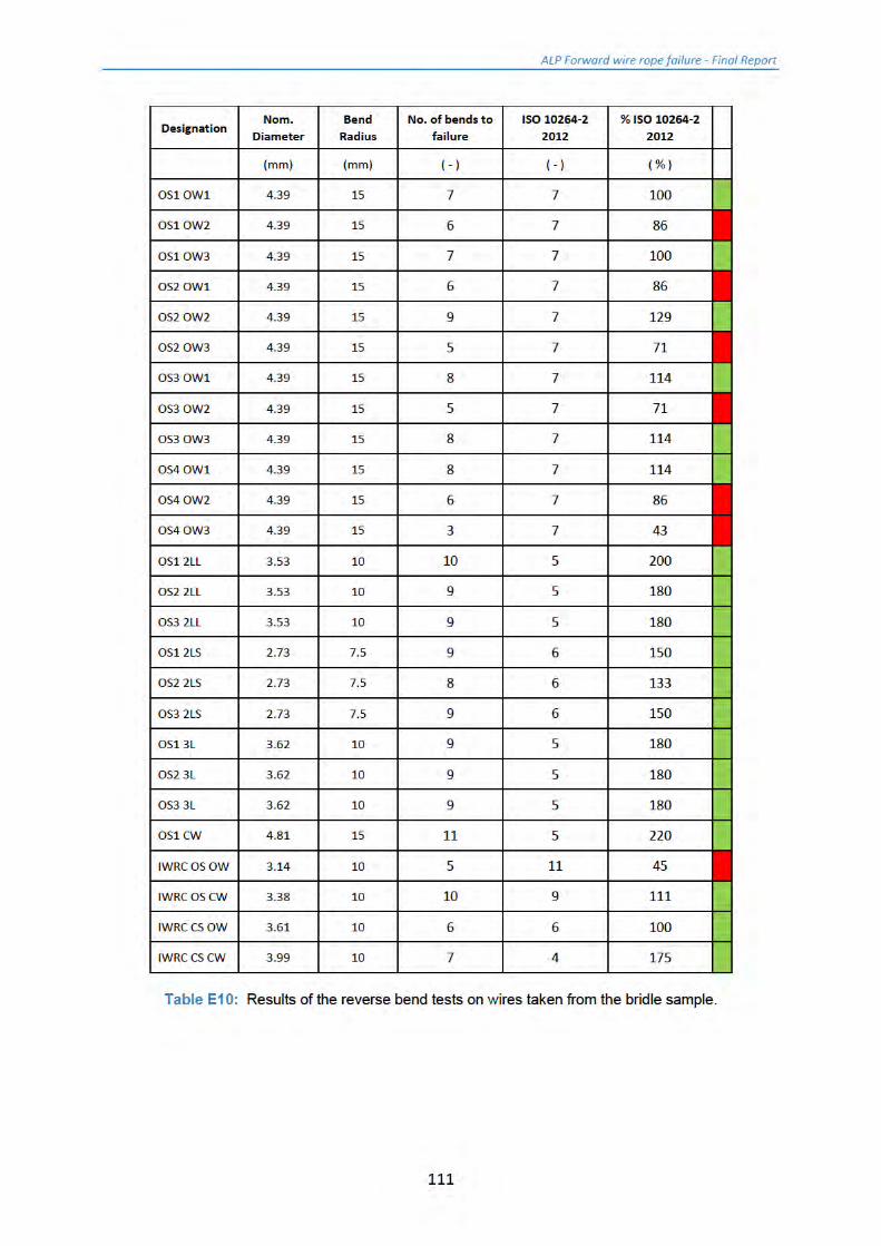
70
• The reverse bend tests were a little better, with half the outer strand outer wires meeting the Standard minimum requirements. The outer strand inner wires performed well and as with the tug side sample, were at a similar level to the drum sample wires. The IWRC wires performed better than in the torsion test.

ALP Forward wire rope failure - Final Report
71
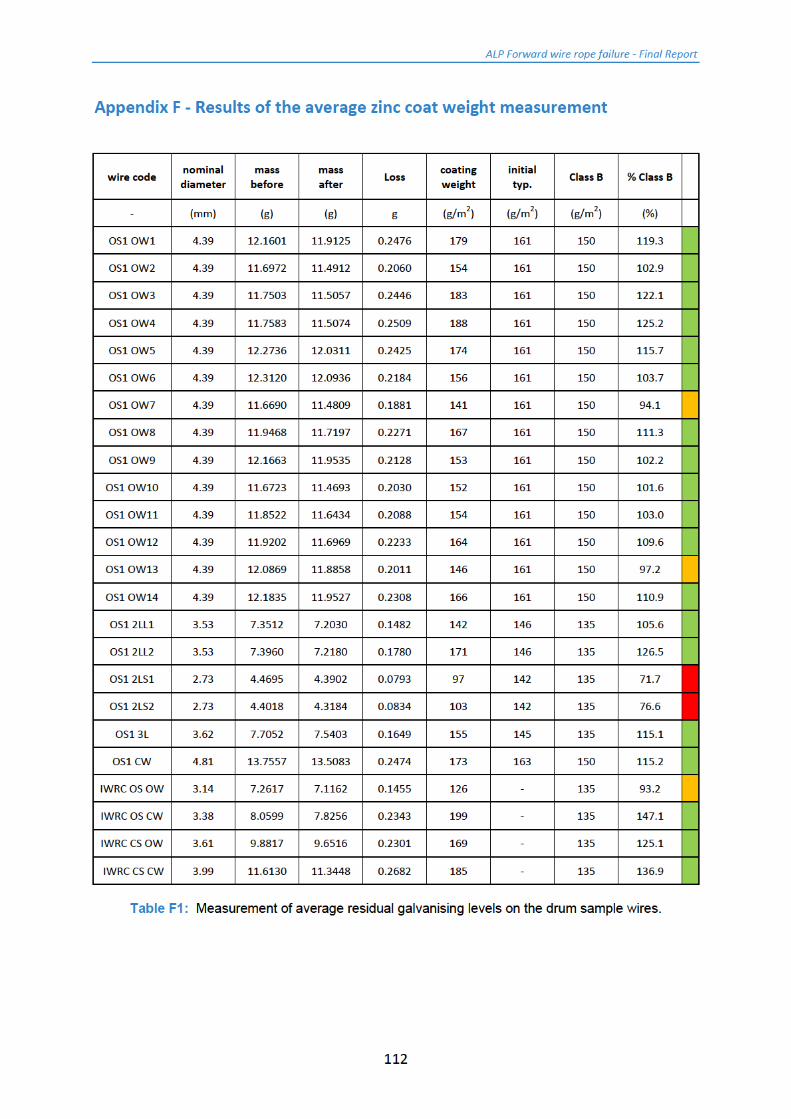
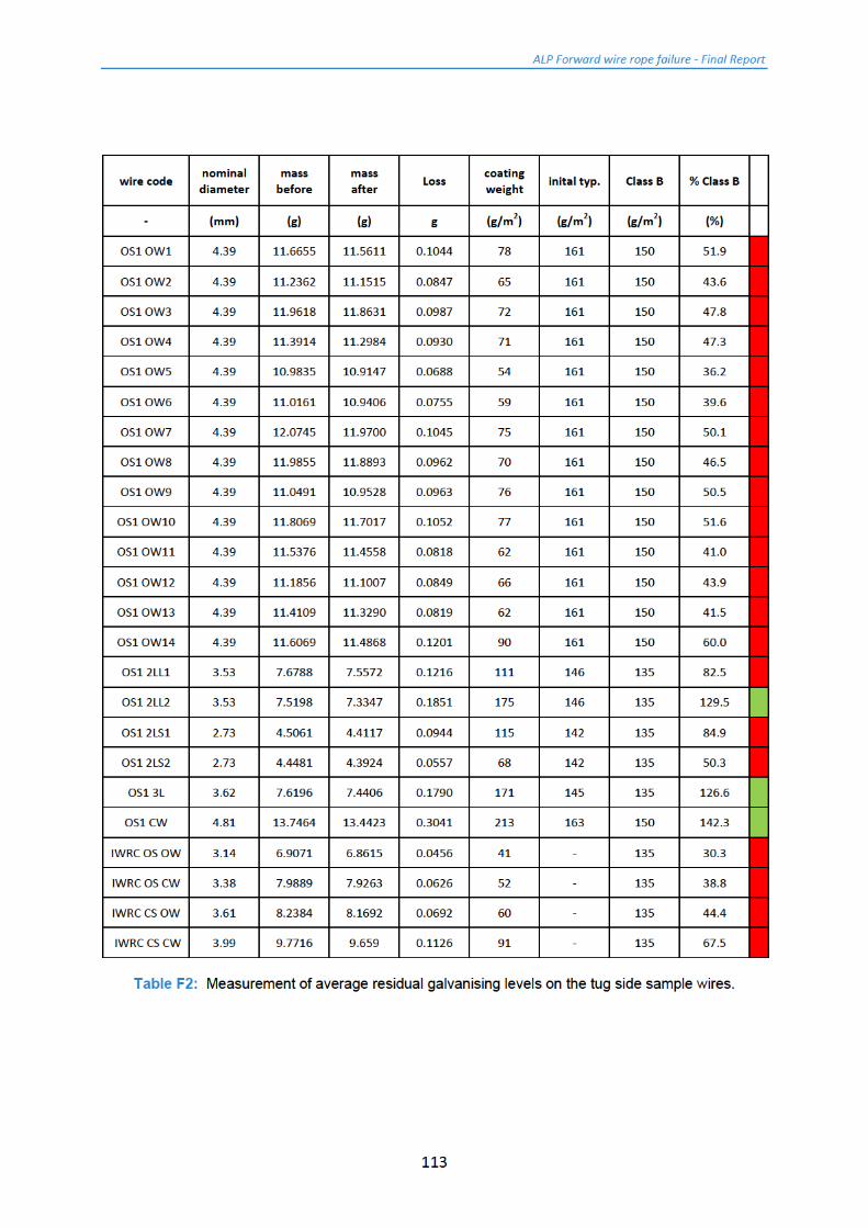
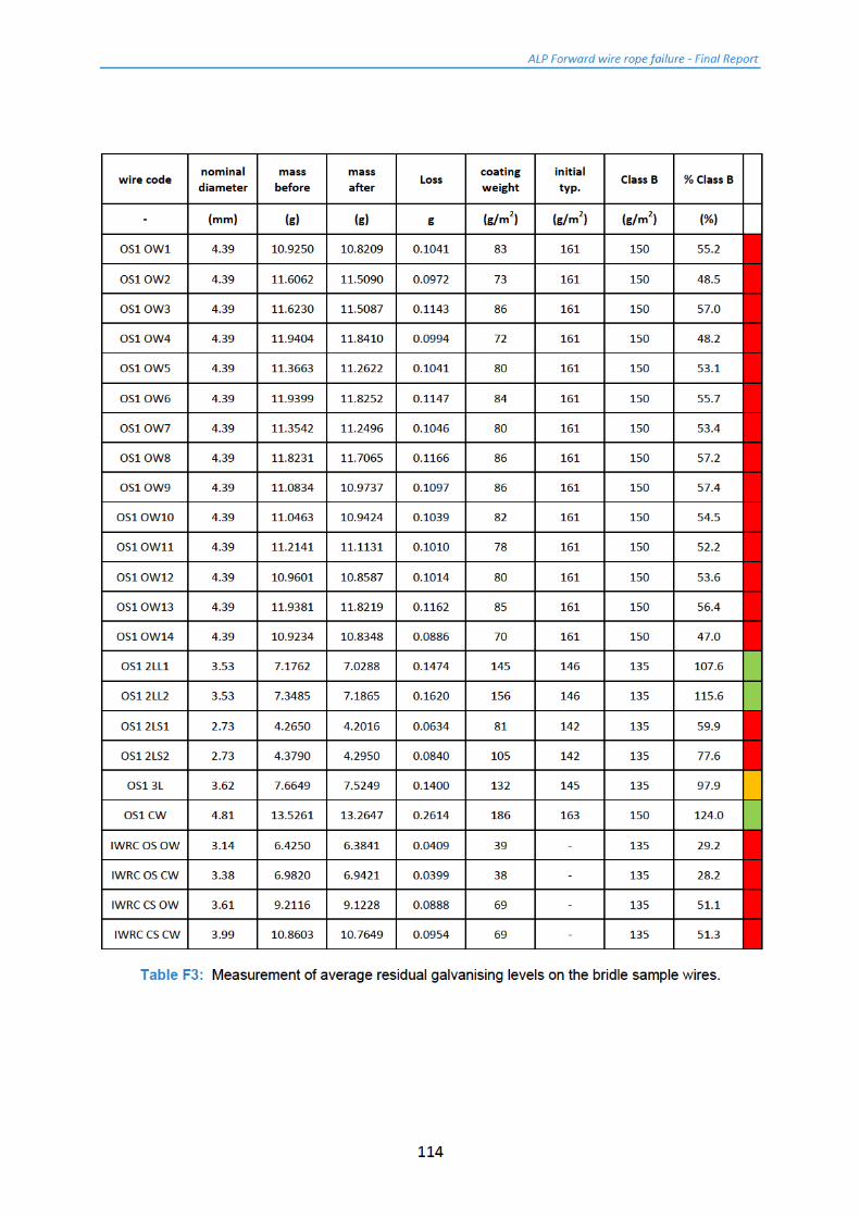
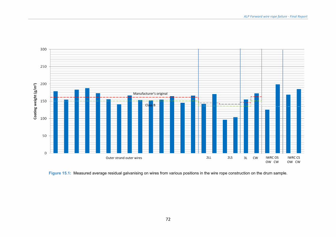
15 Results of the zinc coat weight measurement Full sets of results for the three samples are presented in Appendix F. For ease of reference the results have been plotted in a series of bar charts (Figures 15.1 to 15.3).
With reference to Figure 15.1, in addition to the results of the tests, the chart also shows the original level (from the Manufacturer's certificate (Appendix A and Table 2.2), as well as the API 9A [1] Class B requirement.
It may be seen that as expected, the average coat weights on the drum sample are at the Class B requirements.
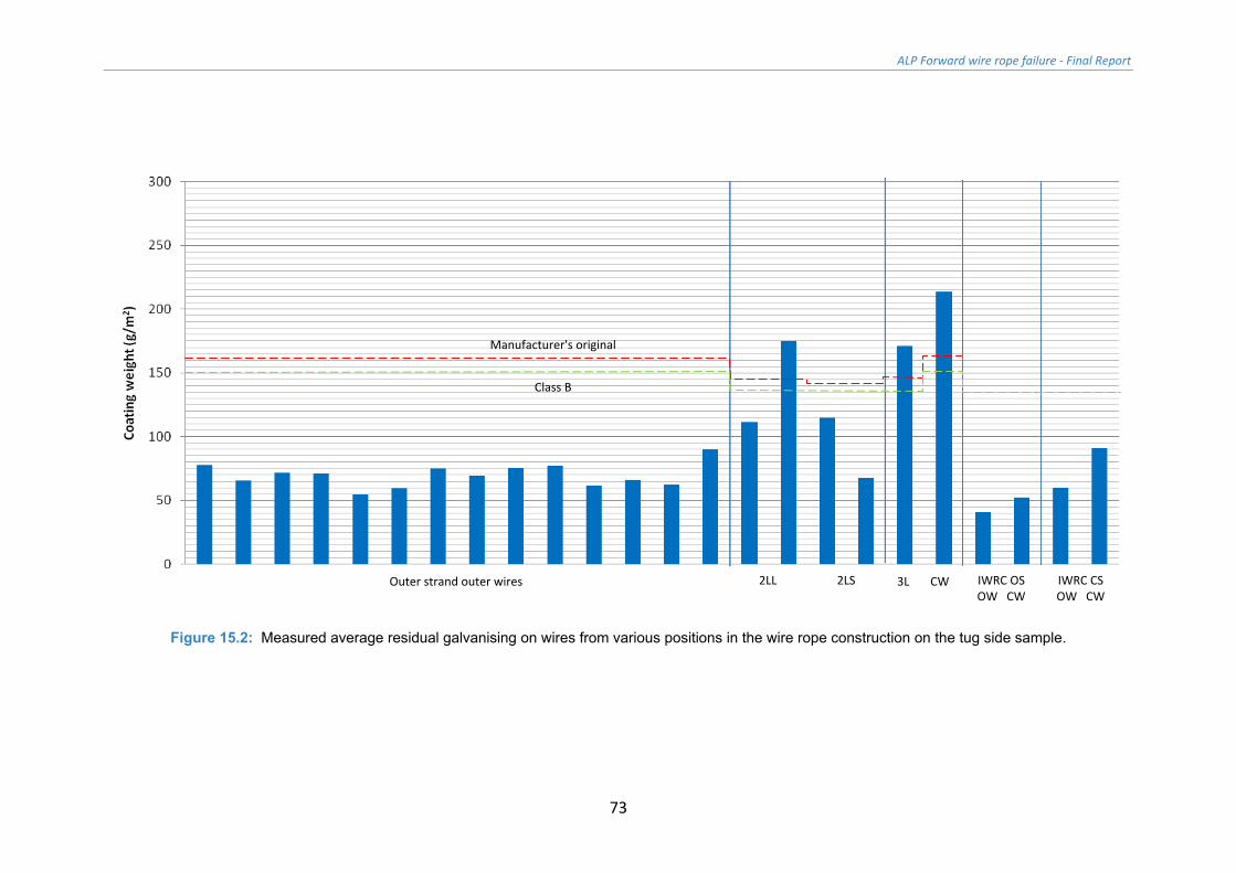
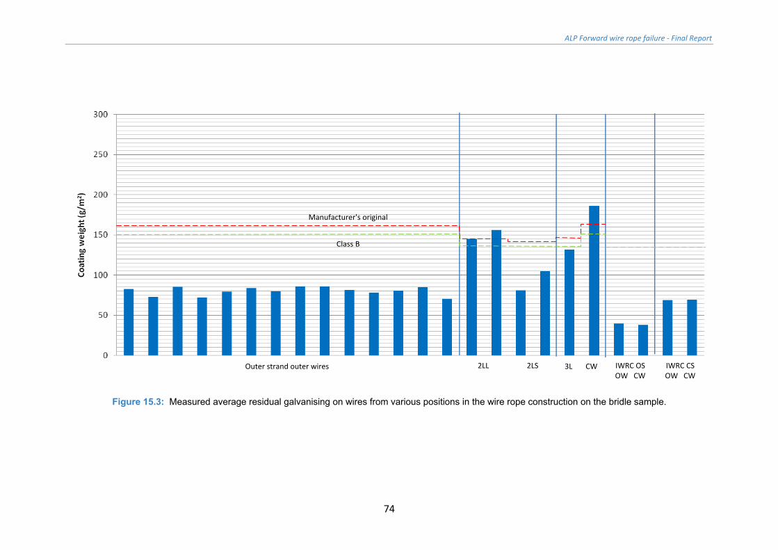
The outer wires of the outer strands of both the tug side and bridle samples are both well down. Remember that the coat weight measurement is an average figure, and does not distinguish any distribution - so a wire may be corroding on an exposed section and protected on the section towards the inside of the wire rope.
The relatively protected main strand inner layers had good levels of zinc, while the coatings on the IWRC wires were very low. These findings are in line with those of the visual inspection.
ALP Forward wire rope failure - Final Report
72
Figure 15.1: Measured average residual galvanising on wires from various positions in the wire rope construction on the drum sample.
Outer strand outer wires 2LL 2LS 3L CW IWRC OS OW CW
IWRC CS OW CW
Manufacturer's original
Class B
ALP Forward wire rope failure - Final Report
73
Figure 15.2: Measured average residual galvanising on wires from various positions in the wire rope construction on the tug side sample.
Outer strand outer wires 2LL 2LS 3L CW IWRC OS OW CW
IWRC CS OW CW
Manufacturer's original
Class B
ALP Forward wire rope failure - Final Report
74
Figure 15.3: Measured average residual galvanising on wires from various positions in the wire rope construction on the bridle sample.
Outer strand outer wires 2LL 2LS 3L CW IWRC OS OW CW
IWRC CS OW CW
Manufacturer's original
Class B
ALP Forward wire rope failure - Final Report
76
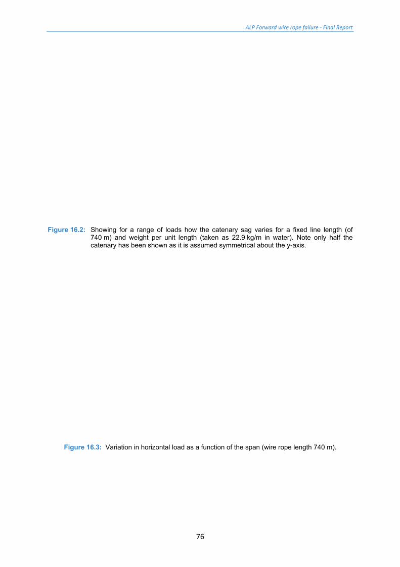
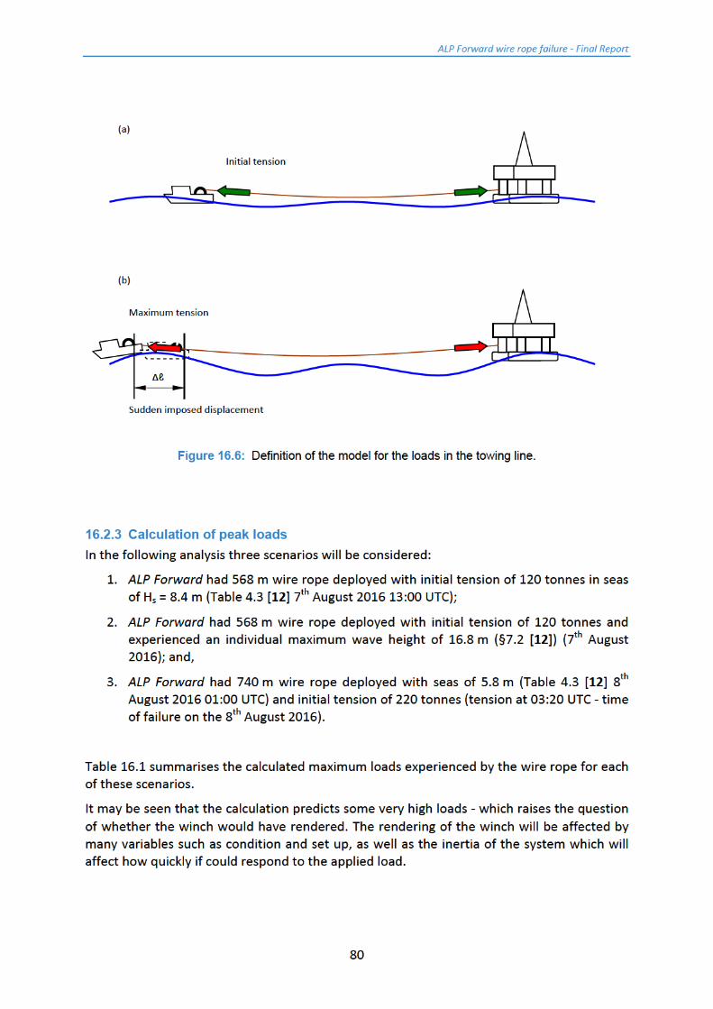
Figure 16.2: Showing for a range of loads how the catenary sag varies for a fixed line length (of
740 m) and weight per unit length (taken as 22.9 kg/m in water). Note only half the catenary has been shown as it is assumed symmetrical about the y-axis.
Figure 16.3: Variation in horizontal load as a function of the span (wire rope length 740 m).
ALP Forward wire rope failure - Final Report
79
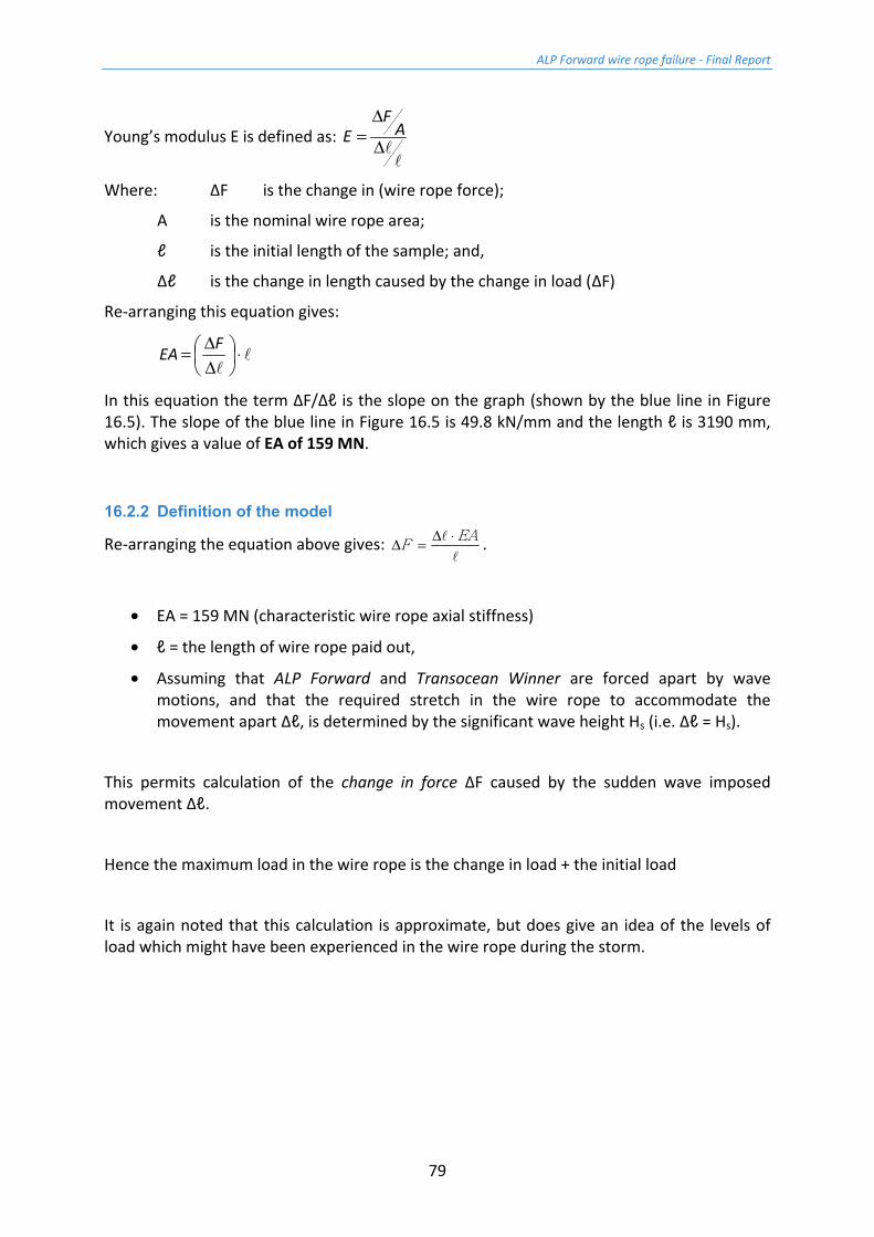
Young’s modulus E is defined as: Δ
Δ= A
FE
Where: ΔF is the change in (wire rope force);
A is the nominal wire rope area;
ℓ is the initial length of the sample; and,
Δℓ is the change in length caused by the change in load (ΔF)
Re-arranging this equation gives:
⋅
ΔΔ= FEA
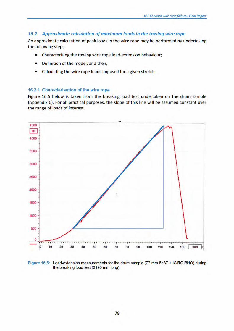
In this equation the term ΔF/Δℓ is the slope on the graph (shown by the blue line in Figure 16.5). The slope of the blue line in Figure 16.5 is 49.8 kN/mm and the length ℓ is 3190 mm, which gives a value of EA of 159 MN.
16.2.2 Definition of the model
Re-arranging the equation above gives:
EAF
⋅Δ=Δ .
• EA = 159 MN (characteristic wire rope axial stiffness)
• ℓ = the length of wire rope paid out,
• Assuming that ALP Forward and Transocean Winner are forced apart by wave motions, and that the required stretch in the wire rope to accommodate the movement apart Δℓ, is determined by the significant wave height Hs (i.e. Δℓ = Hs).
This permits calculation of the change in force ΔF caused by the sudden wave imposed movement Δℓ.
Hence the maximum load in the wire rope is the change in load + the initial load
It is again noted that this calculation is approximate, but does give an idea of the levels of load which might have been experienced in the wire rope during the storm.
ALP Forward wire rope failure - Final Report
81
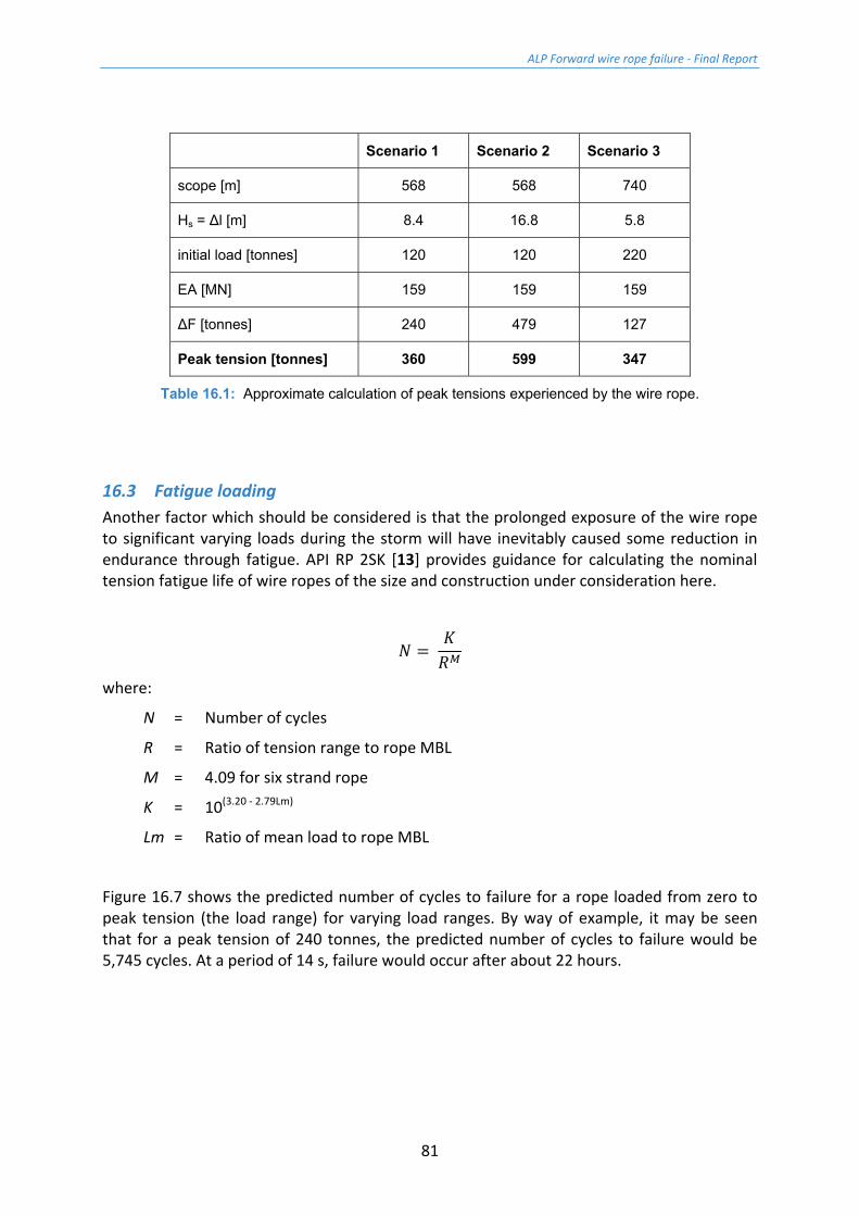
Scenario 1 Scenario 2 Scenario 3
scope [m] 568 568 740
Hs = Δl [m] 8.4 16.8 5.8
initial load [tonnes] 120 120 220
EA [MN] 159 159 159
ΔF [tonnes] 240 479 127
Peak tension [tonnes] 360 599 347
Table 16.1: Approximate calculation of peak tensions experienced by the wire rope.
16.3 Fatigue loading Another factor which should be considered is that the prolonged exposure of the wire rope to significant varying loads during the storm will have inevitably caused some reduction in endurance through fatigue. API RP 2SK [13] provides guidance for calculating the nominal tension fatigue life of wire ropes of the size and construction under consideration here.
=
where:
N = Number of cycles
R = Ratio of tension range to rope MBL
M = 4.09 for six strand rope
K = 10(3.20 - 2.79Lm)
Lm = Ratio of mean load to rope MBL
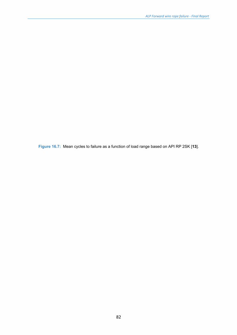
Figure 16.7 shows the predicted number of cycles to failure for a rope loaded from zero to peak tension (the load range) for varying load ranges. By way of example, it may be seen that for a peak tension of 240 tonnes, the predicted number of cycles to failure would be 5,745 cycles. At a period of 14 s, failure would occur after about 22 hours.
ALP Forward wire rope failure - Final Report
82
Figure 16.7: Mean cycles to failure as a function of load range based on API RP 2SK [13].

ALP Forward wire rope failure - Final Report
84
It is considered that the outer strand outer wires have additionally been affected by the onset of corrosion - the lubricant was generally missing or low/denatured. It is noted that had the wire rope been assessed under the criteria of ISO 4309:2010 [5], then it would have been subject to immediate discard.
In fact the condition of the wire rope is so poor as to raise the question of its condition when last inspected in July 2016 [4]. It is noted that the wire rope was re-socketed in July 2016 - given the condition of the bridle sample IWRC when terminated for break test, it might prove informative to remove and examine the spelter socket on the wire rope.
Turning to consider the sorts of loads which the wire rope might have experienced during the storm, an approximate calculation assuming a maximum wave height of 16.8 m indicates a load of the order of 599 tonnes. This load is well in excess of the measured tug side sample BL of 389 tonnes, and above the wire rope Fmin (485 tonnes) and the measured ABL of 494.1 tonnes. Given this estimate, it is not surprising the wire rope failed. It is quite possible that the wire rope would have failed even if it had been as new.
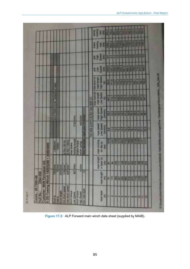
It is noted that the load stated above assumes that the winch drum would not have slipped or rendered. Details of the winch drum are not known, but a data sheet (Figure 17.2) indicates that with 740 m paid out the brake holding load was about 1725 kN or 176 tonnes. It has been reported that the winch had been rendering and loads of 180 - 220 tonnes had been recorded [3]. It is possible that a shock load might be applied to the wire rope so quickly that the drum did not have time to accelerate.
In addition to setting the winch to render, another option to help manage the loads on the wire rope would be to extend the scope of the towing line. Whilst it is not ideal to drag a wire rope along the seabed, in cases of extreme need it would be preferable to do this so as to help avoid breaking the line.
In conclusion, this study has shown that the 77 mm wire rope installed on the ALP Forward in May 2014 satisfied the requirements of API 9A [1]. Although the tow wire log [4] states that the line is regularly washed and greased during recovery, it is far from clear that this process is effective - the lubricant on the tug side and bridle samples were very low and the wire rope has started to corrode. (Generally speaking it is preferable to avoid re-greasing a wet wire rope as this can trap moisture in the wire rope accelerating corrosion. It is possible that this has happened to the wire rope examined here.) The condition of the core was very poor.
It is likely that the rope had become further degraded through fatigue damage during the earlier part of the storm, and finally broke due to a one off overload.
Breaking load tests on sections of wire rope from either side of the main failure suggest that at the time of the incident the wire rope strength was down by 21.3% to about 389 tonnes.
ALP Forward wire rope failure - Final Report
85
Figure 17.2: ALP Forward main winch data sheet (supplied by MAIB).
ALP Forward wire rope failure - Final Report
86
18 References 1 API 9A Specification for wire rope, 26th edition, May 2011, Reaffirmed April 2016,
published American Petroleum Institute.
2 Usha Martin Wire Rope Hand Book Published by Usha Martin (ushamartin.com) p75.
3 Pers. Comm. data supplied by MAIB (Capt. Emma Tiller) in .xls spread sheet 'Towline'.
4 ALP Maritime Services, Main tow-wire log .xls spread sheet forwarded by MAIB file name 'Updated Tow Wire Record Alp Forward.xls'.
5 BS ISO 4309:2010 Cranes – wire ropes – care and maintenance, inspection and discard, International Standards Organisation, 4th Edition, August 2010, ISBN: 978 0 580 59980 4.
6 BS EN 10264-2:2012 Steel wire and wire products – Steel wire for ropes Part 2: Cold drawn non alloyed steel wire for ropes for general applications, British Standards Institution, 2012.
7 ISO 10425:2003 Steel wire ropes for the petroleum and natural gas industries – minimum requirements and terms of acceptance, International Standards Organisation, August 2003.
8 ISO 7800:2012 Metallic materials – Wire – Simple torsion test, International Standards Organisation, March 2012.
9 ISO 7801:1984 Metallic materials – Wire – Reverse bend test, International Standards Organisation, May 1984.
10 BS EN 10244-1:2001 Steel wire and wire products – non-ferrous metallic coatings on steel wire – Part 1: General principles, British Standards Institution, 2001.
11 Ractliffe, A.T. and Parsey, M.R. Man-made-fibre ropes for marine use, Trans North East Coast Institution of Engineers and Shipbuilders (NECIES) 101 (1985) pp 183-197.
12 Stretch, R. Met Office Marine Weather Data report compiled for MAIB Reference msc/08/16/056, 30th August 2016, §7.2.
13 API RP 2SK Design and analysis of stationkeeping systems for floating structures, 3rd edition October 2005, Addendum 2008, published American Petroleum Institute.
ALP Forward wire rope failure - Final Report
87
Appendices
Appendix A - Tow wire inspection certificate
Appendix B - Calibration certificate for the 14,000 kN test machine
Appendix C - Certificates for the break load tests
Appendix D - Calibration certificate for 250 kN tensile machine
Appendix E - Results of the mechanical testing on rope wires
Appendix F - Results of the average zinc coat weight measurement
ALP Forward wire rope failure - Final Report
88
Appendix A - Tow wire inspection certificate

ALP Forward wire rope failure - Final Report
89
ALP Forward wire rope failure - Final Report
90
Appendix B - Calibration certificate for the 14,000 kN test machine
ALP Forward wire rope failure - Final Report
91

ALP Forward wire rope failure - Final Report
92
ALP Forward wire rope failure - Final Report
93
ALP Forward wire rope failure - Final Report
94
ALP Forward wire rope failure - Final Report
95
ALP Forward wire rope failure - Final Report
96
Appendix C - Certificates for the break load tests
ALP Forward wire rope failure - Final Report
97

ALP Forward wire rope failure - Final Report
98
ALP Forward wire rope failure - Final Report
99
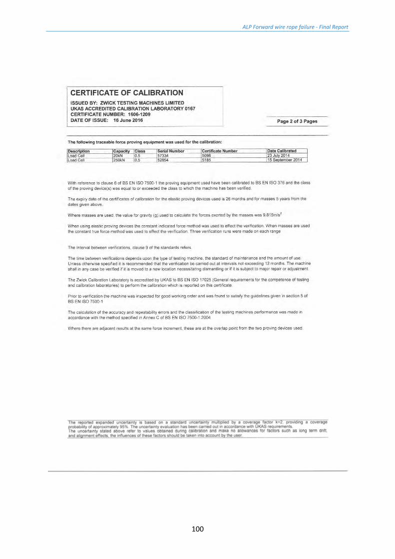
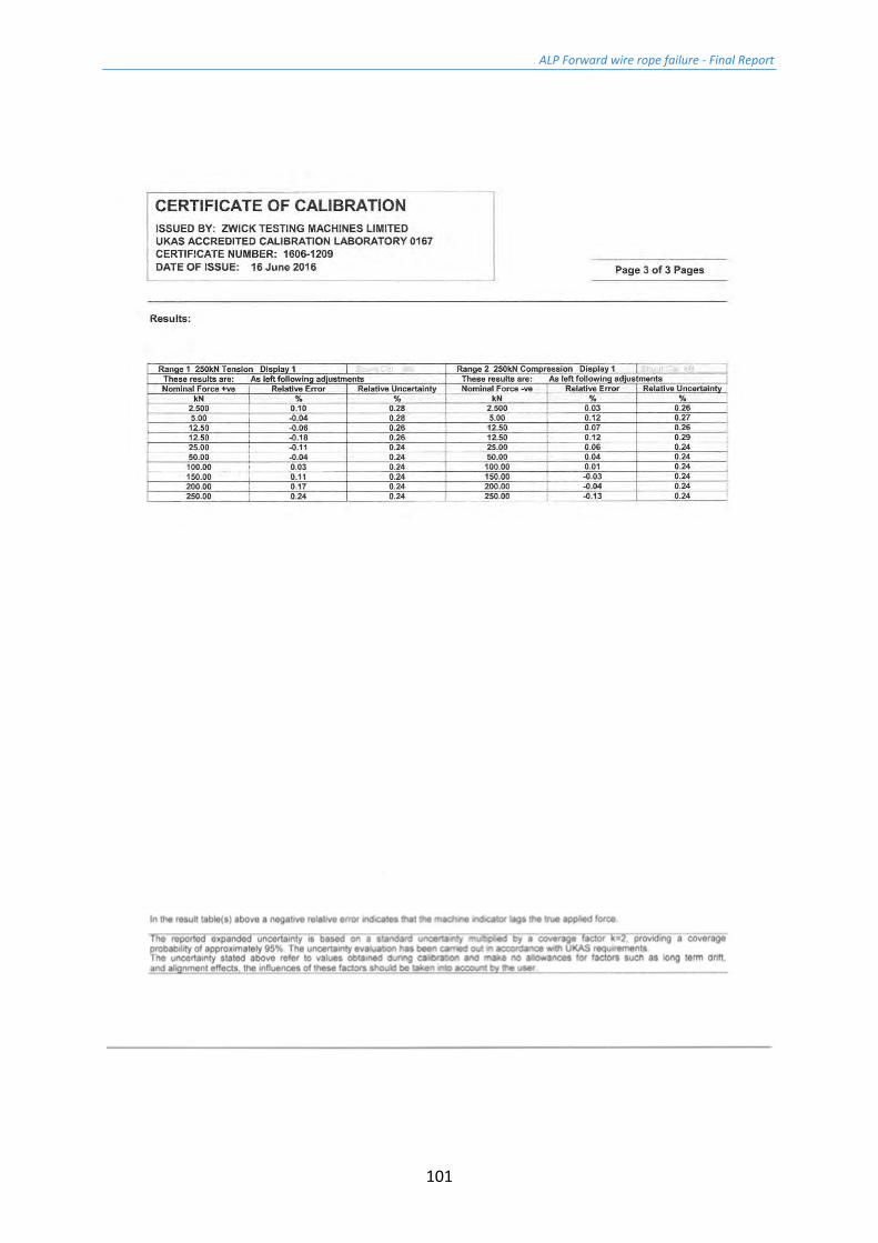
Appendix D – Calibration certificate for 250 kN tensile machine
ALP Forward wire rope failure - Final Report
100
ALP Forward wire rope failure - Final Report
101
ALP Forward wire rope failure - Final Report
102
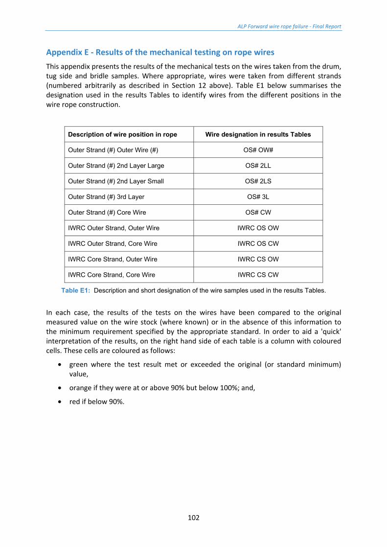
Appendix E - Results of the mechanical testing on rope wires This appendix presents the results of the mechanical tests on the wires taken from the drum, tug side and bridle samples. Where appropriate, wires were taken from different strands (numbered arbitrarily as described in Section 12 above). Table E1 below summarises the designation used in the results Tables to identify wires from the different positions in the wire rope construction.
Description of wire position in rope Wire designation in results Tables
Outer Strand (#) Outer Wire (#) OS# OW#
Outer Strand (#) 2nd Layer Large OS# 2LL
Outer Strand (#) 2nd Layer Small OS# 2LS
Outer Strand (#) 3rd Layer OS# 3L
Outer Strand (#) Core Wire OS# CW
IWRC Outer Strand, Outer Wire IWRC OS OW
IWRC Outer Strand, Core Wire IWRC OS CW
IWRC Core Strand, Outer Wire IWRC CS OW
IWRC Core Strand, Core Wire IWRC CS CW
Table E1: Description and short designation of the wire samples used in the results Tables.
In each case, the results of the tests on the wires have been compared to the original measured value on the wire stock (where known) or in the absence of this information to the minimum requirement specified by the appropriate standard. In order to aid a 'quick' interpretation of the results, on the right hand side of each table is a column with coloured cells. These cells are coloured as follows:
• green where the test result met or exceeded the original (or standard minimum) value,
• orange if they were at or above 90% but below 100%; and,
• red if below 90%.