Embed Size (px)
Citation preview

MODULI LINEARILINEAR MODULES
TT SERIESUso e manutenzione - Use and maintenance

Inserire il beccuccio dell’erogatore negli appositi ingrassatori. A - Pattini B - ChiocciolaRipetere l’operazione ogni 100 km o 6 mesi d’uso.
Insert the tip of the oil can in the specific grease nipples. A - Linear block B - Ball screw nutRepeat this operation every 100 km or 6 months of use.
Tipo di lubrificante: grasso a base di sapone di Litio della classe No 2Type of lubricant: Lithium soap grease of class No 2.
Quantità di lubrificante necessaria per la rilubrificazione dei carrelli:Quantity of lubricant necessary for linear block re-lubrication:
Con presenza di condizioni particolarmente stressanti (carichi elevati, impurità eccessive, etc.) richiedere ulteriori informazioni.For specially stressed applications or difficult environemental conditions, lubrication should be carried out more frequently.
TT 100 1 unità/unit: gTT 155 2 unità/unit: gTT 225 4 unità/unit: gTT 310 6 unità/unit: g
A
A
B
Ingrassaggio - Lubrication

Viti a ricircoloLe chiocciole usate per le tavole lineari El.More serie TT devono essere rilubrificate ogni 50 ·106 giri. Quindi utilizzando la tabella di conversione seguente a seconda del passo della vite, dovranno essere rilubrificate al raggiungimento del percorso lineare (in km) indicato.
Ball screwsThe ball screw nuts of El.More TT -series linear stages must bere-lubricated every 50 ·106 revolutions. Therefore, using the following conversion table, according to the lead of the screw, they must be re-lubricated on reaching the linear travel (in km) indicated.
Tipo/TypeQuantità [g] per ingrassatore
Quantity [g] for greasse nipple
12-05 0,3
12-10 0,3
16-05 0,6
16-10 0,8
20-05 0,9
20-20 1,7
25-05 1,4
25-10 1,7
25-25 2,4
32-05 2,3
32-10 2,8
32-32 3,7
Tabella di comparazione n° giri/percorso lineareN° turn/linear path comparision table
Giri / Turns 50 ·106
Passo / Lead 5 250 km
Passo / Lead 10 500 km
Passo / Lead 20 1000 km
Passo / Lead 25 1250 km
Passo / Lead 32 1600 km
Ingrassaggio - Lubrication

Codifica - CodificationCODE CREATOR è un programma che assiste il cliente nella configura-zione delle unità lineari El.More e nella creazione dei giusti codici per l’ordine. E’ possibile accedere facilmente al programma dalla pagina web www.elmore.it selezionando il tasto “CODE CREATOR” e seguendo il pro-cesso autoguidato. In conclusione al procedimento di codifica è possibile mandare una richiesta d’offerta automatica semplicemente registrandosi nel sito.
CODE CREATOR is an assistant software that helps the customers to con-figure El.More linear units, providing the right codes for orders. You can easily open the software going to the web page www.elmore.it and cli-cking on “CODE CREATOR” button. Following the process is also possible to send a quotation inquiry after the registration on the web site.
CODE CREATOR è un programma che assiste il cliente nellaconfigurazione delle unità lineari EL.MORE e nella creazione deigiusti codici per l'ordine.E' possibile accedere facilmente al programma dalla paginaweb www.elmore.it selezionando il tasto "CODE CREATOR" eseguendo il processo autoguidato.In conclusione al procedimento di codifica è possibile mandareuna richiesta d'offerta automatica ad EL.MORE semplicementeregistrandosi nel sito.
CODE CREATOR is an assistant software that help the custo-mers to configure EL.MORE linear units, providing the rightcodes for orders.You can easily open the software going to the web pagewww.elmore.it and clicking on "CODE CREATOR" button. Following the process is also possible to send a quotationinquiry directly to EL.MORE after the registration on the web site.
Codifica - Codification50
@ Nota: tutti i disegni riprodotti nel presente stampato sono disponibili sul sito www.elmore.it in formato CAD
TT 1 5 1 6 1 0 5 N 0 3 4 0 1 A
TagliaSize
Diametro viteB/S diameter 08121516202532
Passo / Lead 01051016202532
PrecisioneAccuracy 5 = ISO 57 = ISO 7
PrecaricoPreload
N = Non precaricato (con gioco)Not preloaded (backlash)
P = PrecaricatoPreloaded
Lunghezza totale (mm)Total lenght (mm)
SerieSerie
IL CODE CREATOR THE "CODE CREATOR"
Impaginato SERIE TT.qxp 23/07/08 20.04 Pagina 50
PassoLead
Diametro viteBall Screw diameter
PrecisioneAccuracy
Lunghezza totaleTotal lenght
VersioneType
1A = Standard
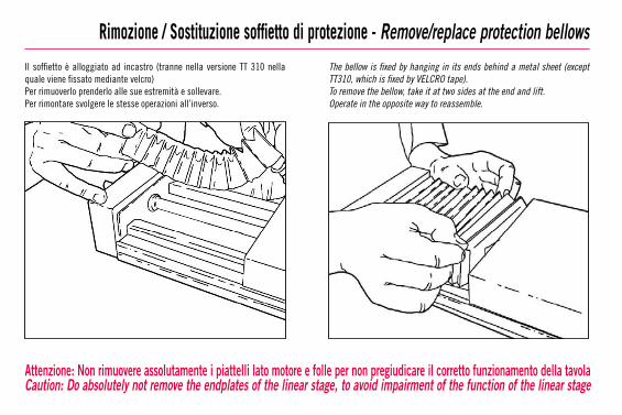
Rimozione / Sostituzione soffietto di protezione - Remove/replace protection bellowsIl soffietto è alloggiato ad incastro (tranne nella versione TT 310 nella quale viene fissato mediante velcro)Per rimuoverlo prenderlo alle sue estremità e sollevare.Per rimontare svolgere le stesse operazioni all’inverso.
The bellow is fixed by hanging in its ends behind a metal sheet (except TT310, which is fixed by VELCRO tape).To remove the bellow, take it at two sides at the end and lift.Operate in the opposite way to reassemble.
Attenzione: Non rimuovere assolutamente i piattelli lato motore e folle per non pregiudicare il corretto funzionamento della tavolaCaution: Do absolutely not remove the endplates of the linear stage, to avoid impairment of the function of the linear stage

Sostituzione proximity con connessione standard - Replacement of proximity switch with standard connection
Attenzione: Non rimuovere assolutamente i piattelli lato motore e folle per non pregiudicare il corretto funzionamento della tavola
1 • Rimuovere la vite di fissaggio del proximity.2 • Rimuovere la piastrina passacavi all’esterno dell’unità.3 • Rimuovere e sostituire il proximity avendo ben cura di ripristinare, come in origine, i collegamenti e la posizione dei cavi all’interno dell’apposita guida. Riposizionare il dado sagomato per fissare il nuovo proximity ripristinando la posizione originaria Rimontare la piastrina passacavi.
Dipendentemente dall’installazione è possibile che si rendano necessari il taglio e la sostituzione del cavo di collegamento al proximity o il dis-saldaggio del vecchio con ricollegamento mediante saldatura del nuovo.
1 • Unscrew and remove the fixing screw of the proximity switch.2 • Remove the fixing cable plate outside of the unit.3 • Remove and replace the proximity switch paying attention that the connections and the location of the cables in the slots are as they were in their or iginal condit ion. Replace the T-nut to fix the proximity switch in its original position. Replace the fixing cable plate.
Depending on the installation, it may be possible to cut and to replace the cable by unsoldering it and to re-solder new cables.
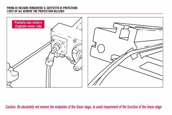
Caution: Do absolutely not remove the endplates of the linear stage, to avoid impairment of the function of the linear stage
PRIMA DI INIZIARE RIMUOVERE IL SOFFIETTO DI PROTEZIONEFIRST OF ALL REMOVE THE PROTECTION BELLOWS
Piattello lato motoreEndplate motor side

Sostituzione proximity con connettore - Replacement of proximity switch with connector
Attenzione: Non rimuovere assolutamente i piattelli lato motore e folle per non pregiudicare il corretto funzionamento della tavola
4 • Rimuovere la piastrina portaconnettore all’esterno dell’unità.5 • Rimuovere e sostituire il proximity avendo ben cura di ripristinare, come in origine, i collegamenti e la posizione dei cavi all’interno dell’apposita guida. Riposizionare il dado sagomato per fissare il nuovo proximity ripristinando la posizione originaria Rimontare la piastrina portaconnettore.
Dipendentemente dall’installazione è possibile che si rendano necessari il taglio e la sostituzione del cavo di collegamento al proximity o il dis-saldaggio del vecchio con ricollegamento mediante saldatura del nuovo.
4 • Remove the plate portaconnettore outside the unit.5 • Remove and replace the proximity switch paying attention that the connections and the location of the cables in the slots are as they were in their or iginal condit ion. Replace the T-nut to fix the proximity switch in its original position. Replace the connector plate.
Depending on the installation, it may be possible to cut and to replace the cable by unsoldering it and to re-solder new cables.
Piattello lato motoreEndplate motor side

Caution: Do absolutely not remove the endplates of the linear stage, to avoid impairment of the function of the linear stage
PRIMA DI INIZIARE RIMUOVERE IL SOFFIETTO DI PROTEZIONE ED EFFETTUARE L’OPERAZIONE AL PUNTO 1FIRST OF ALL REMOVE THE PROTECTION BELLOWS AND CARRY OUT THE OPERATION INDICATED UNDER POINT 1
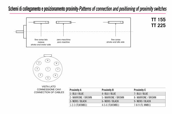
Schemi di collegamento e posizionamento proximity-Patterns of connection and positioning of proximity switches
C
asroc enifanihccam orezfine corsa latomotore
stroke end motor side
VISTA LATO
stroke end idle side
CONNESSIONE CAVICONNECTION OF CABLES
BA
92 8
3
5
7
64
1
zero machine
Proximity A Proximity B Proximity C1- BLU / BLUE 4- BLU / BLUE 7- BLU / BLUE2- MARRONE / BROWN 5- MARRONE / BROWN 8- MARRONE / BROWN3- NERO / BLACK 6- NERO / BLACK 9- NERO / BLACK1-2-3 (TLW3MB1) 4-5-6 (TLW3MB1) 7-8-9 (TL WMB1)
TT 155TT 225
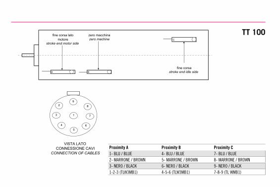
motore
VISTA LATO
A B
C
zero macchina
fine corsa
fine corsa lato
92 8
3
5
7
64
1
stroke end idle side
CONNESSIONE CAVICONNECTION OF CABLES
stroke end motor side zero machine
Proximity A Proximity B Proximity C1- BLU / BLUE 4- BLU / BLUE 7- BLU / BLUE2- MARRONE / BROWN 5- MARRONE / BROWN 8- MARRONE / BROWN3- NERO / BLACK 6- NERO / BLACK 9- NERO / BLACK1-2-3 (TLW3MB1) 4-5-6 (TLW3MB1) 7-8-9 (TL WMB1)
TT 100

PRECAUZIONE NELL’INSTALLAZIONE E NEGLI SPOSTAMENTI.ATTREZZATURA DI PESO NOTEVOLE.PRECAUTIONS TO BE TAKEN WHEN INSTALLINGOR MOVING. HEAVY EQUIPMENT.
NON SOVRACCARICARE. NON SOTTOPORRE ASOLLECITAZIONI DI TORSIONE.DO NOT OVERLOAD. AVOID TORSIONAL STRESS.
NON LASCIARE ESPOSTO AGLI AGENTI ATMOSFERICI.AVOID EXPOSURE TO ATMOSPHERE AGENTS.
PRIMA DI MONTARE IL MOTORE SUL RIDUTTORE SI CONSI-GLIA DI ESEGUIRE UN PRECOLLAUDO DEL MOTORE STESSO SENZA COLLEGAMENTO AL RIDUTTORE.BEFORE ASSEMBLING THE MOTOR ON THE REDUCTION UNIT, IT IS ADVISABLE TO PRE-TEST THE MOTOR WITHOUT CONNECTING THIS TO THE REDUCTION UNIT.
EVITARE DANNEGGIAMENTI. NON INTERVENIRE CON ATTREZZI INADEGUATI.AVOID DAMAGE. ALWAYS USE APPROPRIATE TOOLS.
ATTENZIONE ALLE PARTI IN MOVIMENTO. NON APPOGGIARE OGGETTI SULL’ASSE.PAY ATTENTION TO MOVING PARTS. DO NOT REST OBJECTS ON THE AXIS.
INSTALLAZIONI SPECIALI: VERIFICARE LA PROFONDITÀ DELLE FILETTATURE SULLE PARTI IN MOVIMENTO.SPECIAL INSTALLATIONS: CHECK DEPTH OF THREADS ONMOVING PARTS.
Avvertenze - Warnings
PER ULTERIORI INFORMAZIONI SULLE CARATTERISTICHE TECNICHE FARE RIFERIMENTO AI NOSTRI STAMPATI SPECIFICI.FOR FURTHER INFORMATION REGARDING TECHNICAL CHARACTERISTICS, REFER TO OUR SPECIFIC DOCUMENTATION.
La società Rollon non si assume responsabilità per danni in seguito ad errata interpretazione delle stesse. La società Rollon si riserva il diritto di modifi-care i propri prodotti in base alle esigenze di miglioramento tecnico degli stessi.The Rollon Company shall not be held responsable for damages resulting from incorrect interpretaion of the same. The Rollon company reserves the right to modify its products according to technical improvement requirements.
Rollon S.r.l.Via Trieste, 26 I-20871 Vimercate (MI)Phone: (+39) 039 62 59 1 - Fax: (+39) 039 62 59 205E-Mail: [email protected] - www.rollon.com
TT 0
7/20
12