Embed Size (px)
Citation preview
___________________________________________________________________________1
PROFIBUS-DP TSX PBY 100 module Contents
Section Page
1 General presentation of PROFIBUS-DP 1/1
1.1 General 1/1
1.2 Glossary 1/2
1.3 System architecture and components 1/31.3-1 General architecture and protocol 1/31.3-2 Multi-master architecture 1/41-3-3 PROFIBUS-FMS 1/41.3-4 PROFIBUS-DP characteristics and services 1/51.3-5 I/O modules 1/61.3-6 PROFIBUS-DP station addressing 1/6
1.4 Operating mode 1/7
1.5 Performance 1/81.5-1 Data transfer capacity 1/81.5-2 Network cycle 1/81.5-3 Application response time 1/10
2 Description of the TSX PBY100 module 2/1
2.1 Description 2/12.1-1 General description 2/12.1-2 Connection 2/2
2.2 Indicators on the front of the module 2/3
2.3 Compatibility 2/4
___________________________________________________________________________
2
PROFIBUS-DP TSX PBY 100 module Contents
Section Page2.4 Mounting the module on a rack 2/5
2.5 Standard / Characteristics / Operating conditions 2/72.5-1 Standards 2/72.5-2 Characteristics 2/72.5-3 Operating conditions 2/8
3 Software setup 3/1
3.1 Description 3/1
3.2 Principle 3/2
3.3 Configuration 3/33.3-1 Declaration of the TSX PBY 100 module and access to
application-specific screens 3/33.3-2 Configuration screen 3/33.3-3 Data provided by the user 3/53.3-4 Data resulting from decoding the *.CNF text file 3/53.3-5 I/O logic addressing 3/83.3-6 Configuring a module 3/10
3.4 User interface 3/123.4-1 PROFIBUS-DP language objects 3/123.4-2 TSX PBY100 module language objects 3/143.4-3 TSX PBY100 module error codes 3/15
3.5 PROFIBUS-DP diagnostics 3/173.5-1 Diagnostic command 3/183.5-2 Diagnostic examples 3/19
___________________________________________________________________________3
PROFIBUS-DP TSX PBY 100 module Contents
Section Page3.6 Debugging 3/23
3.6-1 Debug screen 3/243.6-2 PROFIBUS-DP module Designation window 3/243.6-3 PROFIBUS-DP Diagnostics Window 3/253.6-4 Displaying PROFIBUS-DP slave devices 3/263.6-5 Icon for accessing SyCon-PB software 3/263.6-6 Displaying the master module configuration 3/263.6-7 PROFIBUS-DP slave x data 3/27
3.7 Module configuration documentation file 3/28
4 Diagnostics 4/1
4.1 Diagnostics using the module status LEDs 4/1
4.2 Downgraded application modes 4/24.2-1 Transmission medium faults 4/24.2-2 TSX PBY 100 master module faults 4/24.2-3 Slave faults 4/34.2-4 PLC CPU general faults 4/34.2-5 Resetting the outputs after loading an application 4/3
4.3 Lists of diagnostic variables 4/44.3-1 Master diagnostics 4/44.3-2 List of the diagnostics available 4/64.3-3 Compact diagnostics of all the slaves 4/64.3-4 Slave diagnostics 4/74.3-5 General information about a slave 4/84.3-6 Slave configuration data 4/9
4.4 Typical faults 4/10
5 Index 5/1
___________________________________________________________________________
4
PROFIBUS-DP TSX PBY 100 module Contents
Section Page
General presentation of PROFIBUS-DP 1
___________________________________________________________________________1 / 1
Section 11 General presentation of PROFIBUS-DP
1.1 General
This manual is intended for users who wish to install the TSX PBY100PROFIBUS-DP master communication module on TSX Premium.
PROFIBUS-DP is a serial link fieldbus for sensors and actuators which conforms toindustrial environment requirements.
It is particularly suitable for rapid data exchange between PLCs and remote devices.
Devices such as I/O modules are available :
• compact Classic TIO slaves :- "classic" discrete inputs- "classic" discrete outputs
• DEA203 modular slaves
• Momentum modular slaves :
- discrete inputs- discrete outputs- discrete I/O- analog I/O
Installation of the PROFIBUS-DP bus is described in the PROFIBUS-DP installationmanual, reference 840 USE 468 00.
1 / 2___________________________________________________________________________
1.2 Glossary
DP Decentralized Periphery (remote I/O) : PROFIBUS-DPtransmission medium for I/O data transfer
Master class1 Device which initializes, monitors I/O data transfer andslave diagnostics on the bus. Several active master class1devices can be installed on the bus and each one controlsits own slaves.
I/O Inputs/Outputs
OF Optional Function : PL7 message function block
PROFIBUS Process Fieldbus
SyCon-PB Hilscher PC software for configuring the PROFIBUS-DPbus.
General presentation of PROFIBUS-DP 1
___________________________________________________________________________1 / 3
1.3 System architecture and components
1.3-1 General architecture and protocol
General architecture of PROFIBUS-DP
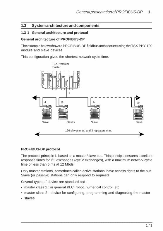
The example below shows a PROFIBUS-DP fieldbus architecture using the TSX PBY 100module and slave devices.
This configuration gives the shortest network cycle time.
PROFIBUS-DP protocol
The protocol principle is based on a master/slave bus. This principle ensures excellentresponse times for I/O exchanges (cyclic exchanges), with a maximum network cycletime of less than 5 ms at 12 Mbds.
Only master stations, sometimes called active stations, have access rights to the bus.Slave (or passive) stations can only respond to requests.
Several types of device are standardized :
• master class 1 : in general PLC, robot, numerical control, etc
• master class 2 : device for configuring, programming and diagnosing the master
• slaves
TSX Premiummaster
Slave
1
4 18 6 66
SlaveSlaves Slave
126 slaves max. and 3 repeaters max.
1 / 4___________________________________________________________________________
1.3-2 Multi-master architecture
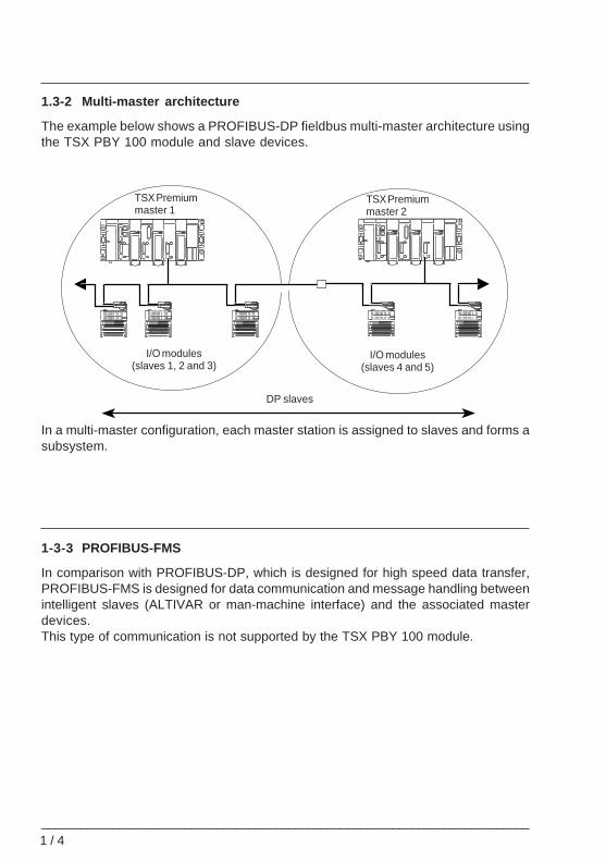
The example below shows a PROFIBUS-DP fieldbus multi-master architecture usingthe TSX PBY 100 module and slave devices.
In a multi-master configuration, each master station is assigned to slaves and forms asubsystem.
1-3-3 PROFIBUS-FMS
In comparison with PROFIBUS-DP, which is designed for high speed data transfer,PROFIBUS-FMS is designed for data communication and message handling betweenintelligent slaves (ALTIVAR or man-machine interface) and the associated masterdevices.This type of communication is not supported by the TSX PBY 100 module.
I/O modules(slaves 1, 2 and 3)
I/O modules(slaves 4 and 5)
TSX Premiummaster 1
TSX Premiummaster 2
DP slaves
General presentation of PROFIBUS-DP 1
___________________________________________________________________________1 / 5
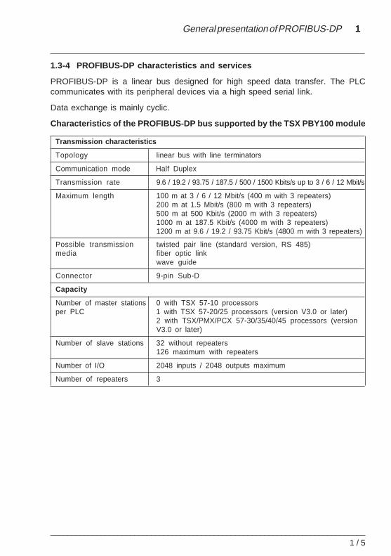
1.3-4 PROFIBUS-DP characteristics and services
PROFIBUS-DP is a linear bus designed for high speed data transfer. The PLCcommunicates with its peripheral devices via a high speed serial link.
Data exchange is mainly cyclic.
Characteristics of the PROFIBUS-DP bus supported by the TSX PBY100 module
Transmission characteristics
Topology linear bus with line terminators
Communication mode Half Duplex
Transmission rate 9.6 / 19.2 / 93.75 / 187.5 / 500 / 1500 Kbits/s up to 3 / 6 / 12 Mbit/s
Maximum length 100 m at 3 / 6 / 12 Mbit/s (400 m with 3 repeaters)200 m at 1.5 Mbit/s (800 m with 3 repeaters)500 m at 500 Kbit/s (2000 m with 3 repeaters)1000 m at 187.5 Kbit/s (4000 m with 3 repeaters)1200 m at 9.6 / 19.2 / 93.75 Kbit/s (4800 m with 3 repeaters)
Possible transmission twisted pair line (standard version, RS 485)media fiber optic link
wave guide
Connector 9-pin Sub-D
Capacity
Number of master stations 0 with TSX 57-10 processorsper PLC 1 with TSX 57-20/25 processors (version V3.0 or later)
2 with TSX/PMX/PCX 57-30/35/40/45 processors (versionV3.0 or later)
Number of slave stations 32 without repeaters126 maximum with repeaters
Number of I/O 2048 inputs / 2048 outputs maximum
Number of repeaters 3
1 / 6___________________________________________________________________________
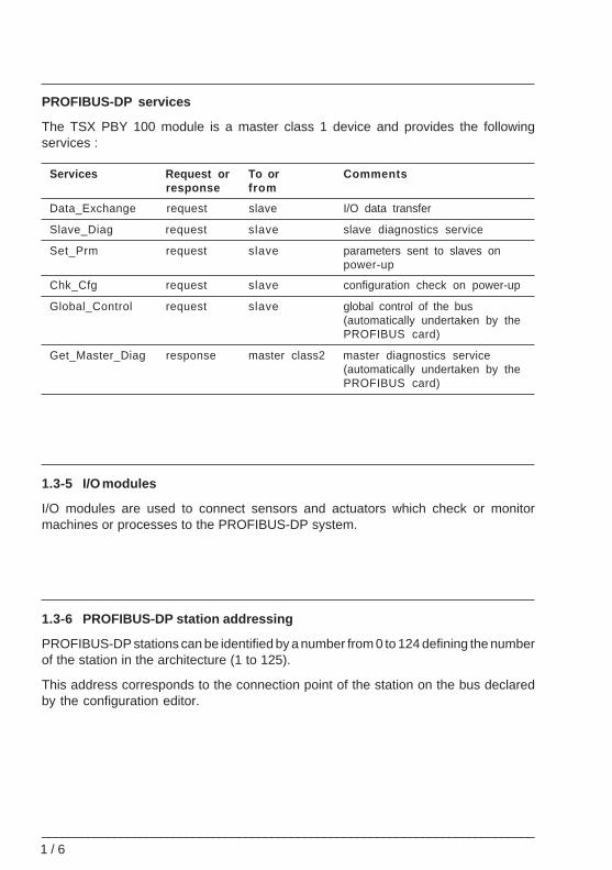
PROFIBUS-DP services
The TSX PBY 100 module is a master class 1 device and provides the followingservices :
Services Request or To or Commentsresponse from
Data_Exchange request slave I/O data transfer
Slave_Diag request slave slave diagnostics service
Set_Prm request slave parameters sent to slaves onpower-up
Chk_Cfg request slave configuration check on power-up
Global_Control request slave global control of the bus(automatically undertaken by thePROFIBUS card)
Get_Master_Diag response master class2 master diagnostics service(automatically undertaken by thePROFIBUS card)
1.3-5 I/O modules
I/O modules are used to connect sensors and actuators which check or monitormachines or processes to the PROFIBUS-DP system.
1.3-6 PROFIBUS-DP station addressing
PROFIBUS-DP stations can be identified by a number from 0 to 124 defining the numberof the station in the architecture (1 to 125).
This address corresponds to the connection point of the station on the bus declaredby the configuration editor.
General presentation of PROFIBUS-DP 1
___________________________________________________________________________1 / 7
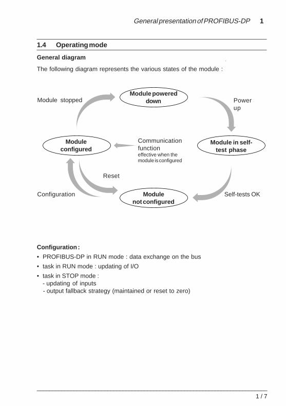
1.4 Operating mode
General diagram
The following diagram represents the various states of the module :
Configuration :
• PROFIBUS-DP in RUN mode : data exchange on the bus
• task in RUN mode : updating of I/O
• task in STOP mode :- updating of inputs- output fallback strategy (maintained or reset to zero)
Powerup
Module stopped
Communicationfunctioneffective when themodule is configured
Configuration Self-tests OK
Reset
Module powereddown
Moduleconfigured
Modulenot configured
Module in self-test phase
1 / 8___________________________________________________________________________
1.5 Performance
1.5-1 Data transfer capacity
The following table summarizes the size of data which can be sent :
Data Min Max
Image of the inputs in words (%IW) for the configuration - 242 (total)
Image of the outputs in words (%QW) for the configuration - 242 (total)
Maximum size of all the configuration data - 16 Kbytes
Configuration data per slave in bytes 31 250
Diagnostic data per slave in bytes 6 244
Limitations
This module requires slaves with less than 250 bytes of configuration data and less than244 bytes of diagnostic data.
It can be used to store the configuration data of 125 devices with a maximum total sizeof 16 Kbytes.
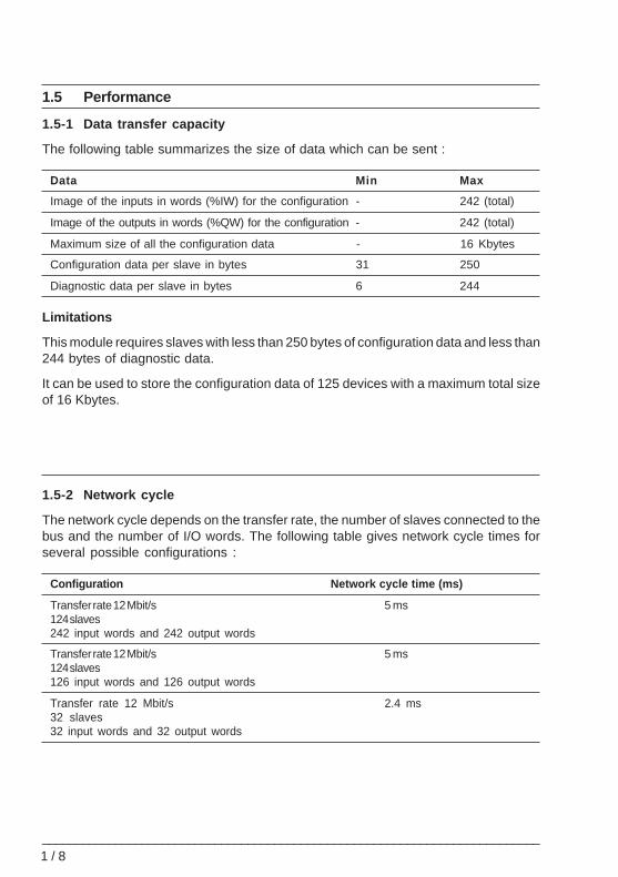
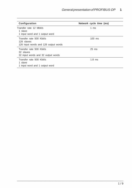
1.5-2 Network cycle
The network cycle depends on the transfer rate, the number of slaves connected to thebus and the number of I/O words. The following table gives network cycle times forseveral possible configurations :
Configuration Network cycle time (ms)
Transfer rate 12 Mbit/s 5 ms124 slaves242 input words and 242 output words
Transfer rate 12 Mbit/s 5 ms124 slaves126 input words and 126 output words
Transfer rate 12 Mbit/s 2.4 ms32 slaves32 input words and 32 output words
General presentation of PROFIBUS-DP 1
___________________________________________________________________________1 / 9
Configuration Network cycle time (ms)
Transfer rate 12 Mbit/s 1 ms1 slave1 input word and 1 output word
Transfer rate 500 Kbit/s 100 ms126 slaves126 input words and 126 output words
Transfer rate 500 Kbit/s 25 ms32 slaves32 input words and 32 output words
Transfer rate 500 Kbit/s 1.8 ms1 slave1 input word and 1 output word
1 / 1 0___________________________________________________________________________
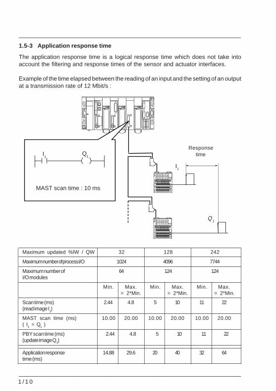
1.5-3 Application response time
The application response time is a logical response time which does not take intoaccount the filtering and response times of the sensor and actuator interfaces.
Example of the time elapsed between the reading of an input and the setting of an outputat a transmission rate of 12 Mbit/s :
Maximum updated %IW / QW 32 128 242
Maximum number of process I/O 1024 4096 7744
Maximum number of 64 124 124I/O modules
Min. Max. Min. Max. Min. Max.= 2*Min. = 2*Min. = 2*Min.
Scan time (ms) 2.44 4.8 5 10 11 22(read image I
1)
MAST scan time (ms) 10.00 20.00 10.00 20.00 10.00 20.00( I1 = Q1 )
PBY scan time (ms) 2.44 4.8 5 10 11 22(update image Q1)
Application response 14.88 29.6 20 40 32 64time (ms)
Responsetime
MAST scan time : 10 ms
I1Q1
I1
Q1
Description of the TSX PBY100 module 2
___________________________________________________________________________2 / 1
Section 22 Description of the TSX PBY100 module
2.1 Description
2.1-1 General description
The TSX PBY 100 module can be installed on a standard or extendableTSX PREMIUM rack. The module can operate with the following PLCs :
• TSX 57-20/...
• PMX 57-20/...
• PCX 57-35/...
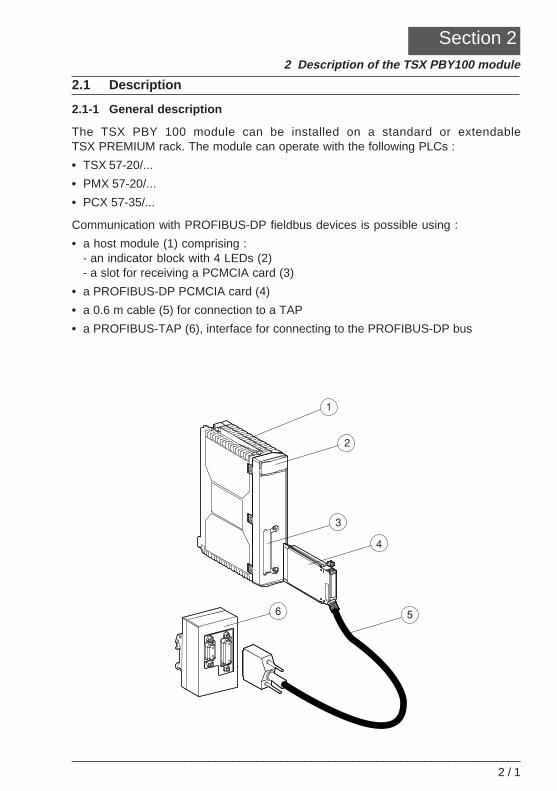
Communication with PROFIBUS-DP fieldbus devices is possible using :
• a host module (1) comprising :- an indicator block with 4 LEDs (2)- a slot for receiving a PCMCIA card (3)
• a PROFIBUS-DP PCMCIA card (4)
• a 0.6 m cable (5) for connection to a TAP
• a PROFIBUS-TAP (6), interface for connecting to the PROFIBUS-DP bus
2 / 2___________________________________________________________________________
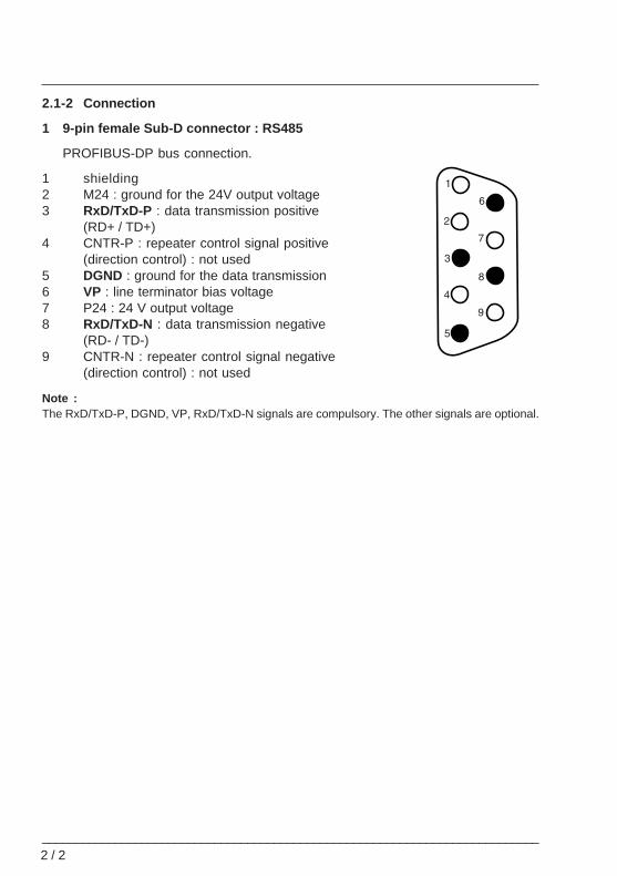
2.1-2 Connection
1 9-pin female Sub-D connector : RS485
PROFIBUS-DP bus connection.
1 shielding2 M24 : ground for the 24V output voltage3 RxD/TxD-P : data transmission positive
(RD+ / TD+)4 CNTR-P : repeater control signal positive
(direction control) : not used5 DGND : ground for the data transmission6 VP : line terminator bias voltage7 P24 : 24 V output voltage8 RxD/TxD-N : data transmission negative
(RD- / TD-)9 CNTR-N : repeater control signal negative
(direction control) : not used
Note :The RxD/TxD-P, DGND, VP, RxD/TxD-N signals are compulsory. The other signals are optional.
Description of the TSX PBY100 module 2
___________________________________________________________________________2 / 3
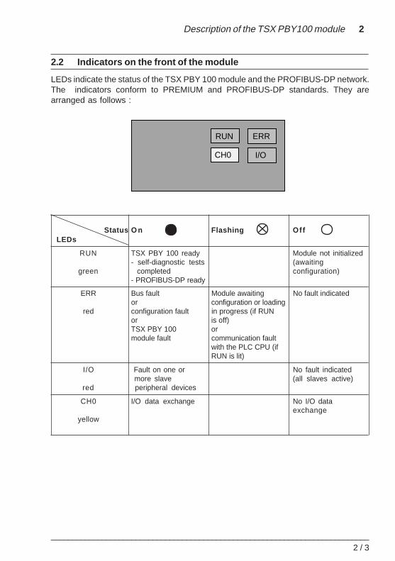
2.2 Indicators on the front of the module
LEDs indicate the status of the TSX PBY 100 module and the PROFIBUS-DP network.The indicators conform to PREMIUM and PROFIBUS-DP standards. They arearranged as follows :
Status O n Flashing Of fLEDs
RUN TSX PBY 100 ready Module not initialized- self-diagnostic tests (awaiting
green completed configuration)- PROFIBUS-DP ready
ERR Bus fault Module awaiting No fault indicatedor configuration or loading
red configuration fault in progress (if RUNor is off)TSX PBY 100 ormodule fault communication fault
with the PLC CPU (ifRUN is lit)
I/O Fault on one or No fault indicated more slave (all slaves active)
red peripheral devices
CH0 I/O data exchange No I/O dataexchange
yellow
ERR
I/O
RUN
CH0
2 / 4___________________________________________________________________________
2.3 Compatibility
Hardware
The TSX PBY 100 module requires the use of a PREMIUM PLC version V3.0 onwards :
• TSX 57-20/25 (only one module can be used)
• TSX/PMX/PCX 57-30/35/40/45 (two modules can be used with version V3.3 or later)
The TSX PBY 100 host module is a master class 1 device and can be integrated intoa multi-master configuration. It is compatible with the following communicationmethods :
• master-slave
• logical token ring
Software
The TSX PBY 100 module is compatible with SyCon-PB configuration softwareV2.5.0.0 and PL7 software from version V3.0 onwards.
Both these programs run under Windows 95 or NT V4.0.
Description of the TSX PBY100 module 2
___________________________________________________________________________2 / 5
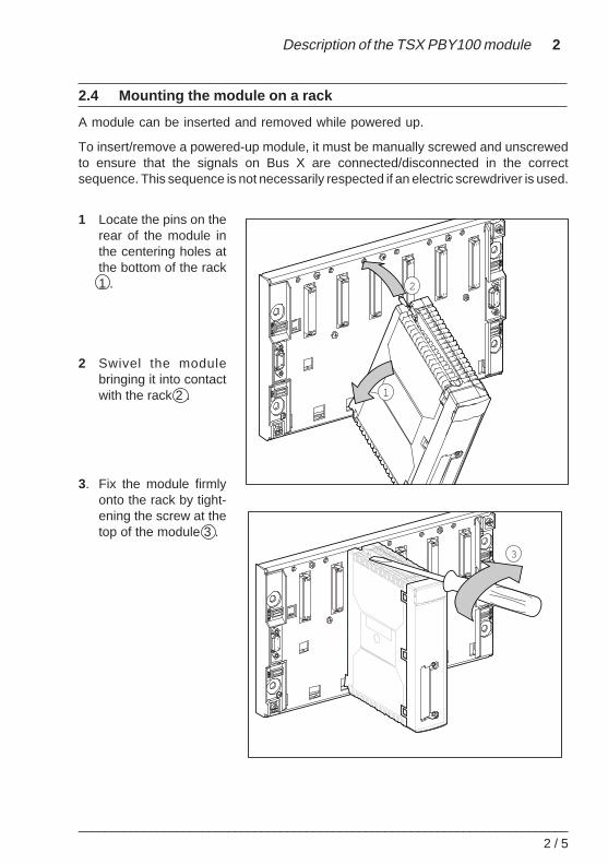
2.4 Mounting the module on a rack
A module can be inserted and removed while powered up.
To insert/remove a powered-up module, it must be manually screwed and unscrewedto ensure that the signals on Bus X are connected/disconnected in the correctsequence. This sequence is not necessarily respected if an electric screwdriver is used.
1 Locate the pins on therear of the module inthe centering holes atthe bottom of the rack1 .
2 Swivel the modulebringing it into contactwith the rack 2 .
3. Fix the module firmlyonto the rack by tight-ening the screw at thetop of the module 3 .
1
2
3
2 / 6___________________________________________________________________________
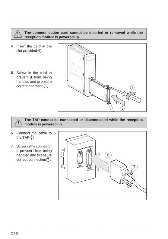
The communication card cannot be inserted or removed while thereception module is powered up.
4 Insert the card in theslot provided 4 .
5 Screw in the card toprevent it from beinghandled and to ensurecorrect operation 5 .
The TAP cannot be connected or disconnected while the receptionmodule is powered up.
6 Connect the cable tothe TAP 6 .
7 Screw in the connectorto prevent it from beinghandled and to ensurecorrect connection 7 .
4
5
Description of the TSX PBY100 module 2
___________________________________________________________________________2 / 7
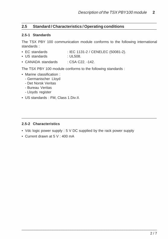
2.5 Standard / Characteristics / Operating conditions
2.5-1 Standards
The TSX PBY 100 communication module conforms to the following internationalstandards :
• EC standards : IEC 1131-2 / CENELEC (50081-2).• US standards : UL508.
• CANADA standards : CSA C22. -142.
The TSX PBY 100 module conforms to the following standards :
• Marine classification :- Germanischer Lloyd- Det Norsk Veritas- Bureau Veritas- Lloyds register
• US standards : FM, Class 1.Div.II.
2.5-2 Characteristics
• Vdc logic power supply : 5 V DC supplied by the rack power supply
• Current drawn at 5 V : 400 mA
2 / 8___________________________________________________________________________
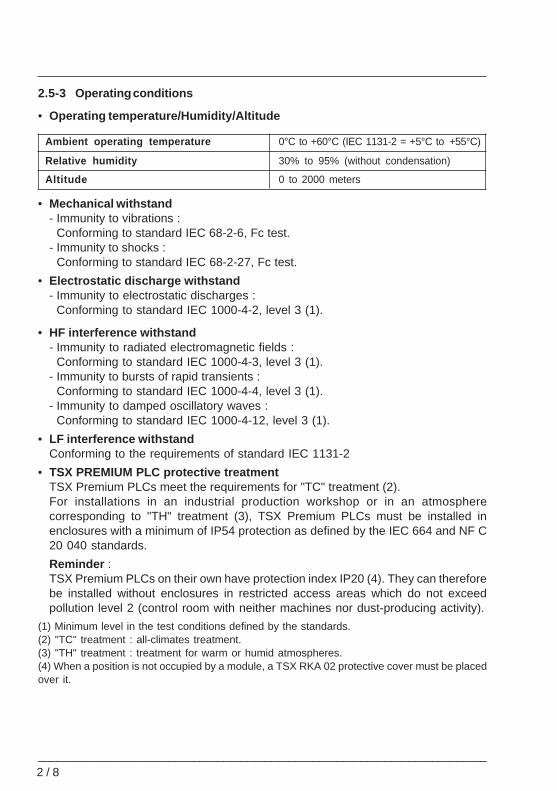
2.5-3 Operating conditions
• Operating temperature/Humidity/Altitude
Ambient operating temperature 0°C to +60°C (IEC 1131-2 = +5°C to +55°C)
Relative humidity 30% to 95% (without condensation)
Altitude 0 to 2000 meters
• Mechanical withstand- Immunity to vibrations :
Conforming to standard IEC 68-2-6, Fc test.- Immunity to shocks :
Conforming to standard IEC 68-2-27, Fc test.
• Electrostatic discharge withstand- Immunity to electrostatic discharges :
Conforming to standard IEC 1000-4-2, level 3 (1).
• HF interference withstand- Immunity to radiated electromagnetic fields :
Conforming to standard IEC 1000-4-3, level 3 (1).- Immunity to bursts of rapid transients :
Conforming to standard IEC 1000-4-4, level 3 (1).- Immunity to damped oscillatory waves :
Conforming to standard IEC 1000-4-12, level 3 (1).
• LF interference withstandConforming to the requirements of standard IEC 1131-2
• TSX PREMIUM PLC protective treatmentTSX Premium PLCs meet the requirements for "TC" treatment (2).For installations in an industrial production workshop or in an atmospherecorresponding to "TH" treatment (3), TSX Premium PLCs must be installed inenclosures with a minimum of IP54 protection as defined by the IEC 664 and NF C20 040 standards.
Reminder :TSX Premium PLCs on their own have protection index IP20 (4). They can thereforebe installed without enclosures in restricted access areas which do not exceedpollution level 2 (control room with neither machines nor dust-producing activity).
(1) Minimum level in the test conditions defined by the standards.(2) "TC" treatment : all-climates treatment.(3) "TH" treatment : treatment for warm or humid atmospheres.(4) When a position is not occupied by a module, a TSX RKA 02 protective cover must be placedover it.
Description of the TSX PBY100 module 2
___________________________________________________________________________2 / 9
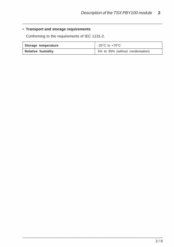
• Transport and storage requirements
Conforming to the requirements of IEC 1131-2.
Storage temperature -25°C to +70°C
Relative humidity 5% to 95% (without condensation)

2 / 1 0___________________________________________________________________________
Software setup 3
___________________________________________________________________________3 / 1
Section 33 Software setup
3.1 Description
This section describes the various configuration, control and diagnostic possibilitiesfor a PROFIBUS-DP application.
The PROFIBUS-DP fieldbus and the master and slave devices can only be configuredusing the Hilscher SyCon-PB configuration tool supplied by Schneider and itsdocumentation, reference TLX FBC M.
Any intervention on a module connected to PROFIBUS-DP requires the use of thissoftware. The user is advised to consult the software documentation.
3 / 2___________________________________________________________________________
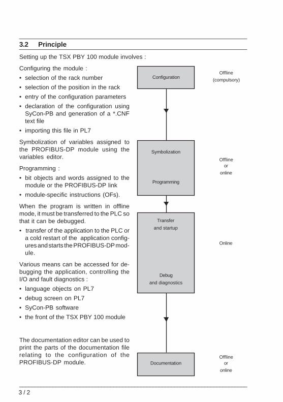
3.2 Principle
Setting up the TSX PBY 100 module involves :
Configuring the module :
• selection of the rack number
• selection of the position in the rack
• entry of the configuration parameters
• declaration of the configuration usingSyCon-PB and generation of a *.CNFtext file
• importing this file in PL7
Symbolization of variables assigned tothe PROFIBUS-DP module using thevariables editor.
Programming :
• bit objects and words assigned to themodule or the PROFIBUS-DP link
• module-specific instructions (OFs).
When the program is written in offlinemode, it must be transferred to the PLC sothat it can be debugged.
• transfer of the application to the PLC ora cold restart of the application config-ures and starts the PROFIBUS-DP mod-ule.
Various means can be accessed for de-bugging the application, controlling theI/O and fault diagnostics :
• language objects on PL7
• debug screen on PL7
• SyCon-PB software
• the front of the TSX PBY 100 module
The documentation editor can be used toprint the parts of the documentation filerelating to the configuration of thePROFIBUS-DP module.
Offline
(compulsory)
Offlineor
online
Offlineor
online
Online
Configuration
Symbolization
Documentation
Transfer
and startup
Debug
and diagnostics
Programming
Software setup 3
___________________________________________________________________________3 / 3
3.3 Configuration
3.3-1 Declaration of the TSX PBY 100 module and access to application-specific screens
Declaration of the TSX PBY 100 module
To declare a TSX PBY 100 module, consult the PL7 TSX PREMIUM application-specific documentation.
Access to application-specific screens
Using the mouse, double-click on the TSX PBY 100 graphic module to access theapplication-specific screens. The first screen is Configuration .
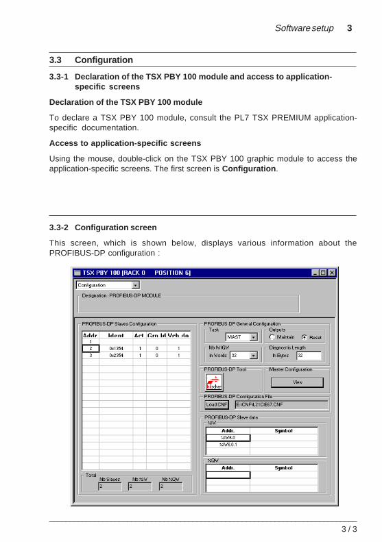
3.3-2 Configuration screen
This screen, which is shown below, displays various information about thePROFIBUS-DP configuration :
3 / 4___________________________________________________________________________
The configuration screen can be used to display :
• a PROFIBUS-DP Slaves Configuration drop-down list of pre-configuredPROFIBUS-DP slave devices
• a PROFIBUS-DP General Configuration window
• an icon used to run the SyCon-PB software : this can be accessed provided that thesoftware is installed with the machine offline
• a View button for displaying the configuration of the bus and the master device
• a PROFIBUS-DP Configuration File window, providing access to the configuration*.CNF text file
• a PROFIBUS-DP Slave Data window
There are two types of data :
• data provided by the user :- the type of task- the number of IW/QW- the output status when the task is in STOP mode- the number of diagnostic bytes
• data resulting from decoding the *.CNF text file from the configuration softwaredescribed in :- the PROFIBUS-DP slave configuration drop-down list- the slave x device information block
If the TSX PBY 100 module has never been configured, all fields are empty and themodule operates using the following default values :
• type of task : Mast
• number of IW/QW : 128
• outputs reset when the task is in STOP mode
• number of diagnostic bytes : 32
Software setup 3
___________________________________________________________________________3 / 5
3.3-3 Data provided by the user
General Parameter Blocks
In the Task field, select the type of system task which will control the PROFIBUS-DPfieldbus : MAST or FAST.In the Outputs field, select the output behavior when the task is in STOP mode :Maintain or Reset .In the Nb IW\QW field, select the number of words used for the inputs and outputs : 32,64, 128, 242.In the Diagnostic Length field, select the length in bytes of the diagnostics from 6 to244 bytes (32 by default). The size configured must be sufficient to contain the largestdiagnostics of the bus. If it is too small, the slave concerned will not be active on thebus because its diagnostics will be invalid.
To optimize performance, select a minimum number of I/O words and diagnostic byteswhich should nevertheless be compatible with the actual bus configuration.
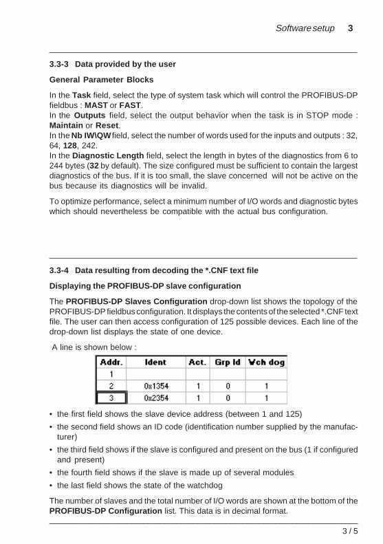
3.3-4 Data resulting from decoding the *.CNF text file
Displaying the PROFIBUS-DP slave configuration
The PROFIBUS-DP Slaves Configuration drop-down list shows the topology of thePROFIBUS-DP fieldbus configuration. It displays the contents of the selected *.CNF textfile. The user can then access configuration of 125 possible devices. Each line of thedrop-down list displays the state of one device.
A line is shown below :
• the first field shows the slave device address (between 1 and 125)
• the second field shows an ID code (identification number supplied by the manufac-turer)
• the third field shows if the slave is configured and present on the bus (1 if configuredand present)
• the fourth field shows if the slave is made up of several modules
• the last field shows the state of the watchdog
The number of slaves and the total number of I/O words are shown at the bottom of thePROFIBUS-DP Configuration list. This data is in decimal format.
3 / 6___________________________________________________________________________
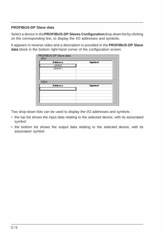
PROFIBUS-DP Slave data
Select a device in the PROFIBUS-DP Slaves Configuration drop-down list by clickingon the corresponding line, to display the I/O addresses and symbols.
It appears in reverse video and a description is provided in the PROFIBUS-DP Slavedata block in the bottom right-hand corner of the configuration screen.
Two drop-down lists can be used to display the I/O addresses and symbols :
• the top list shows the input data relating to the selected device, with its associatedsymbol
• the bottom list shows the output data relating to the selected device, with itsassociated symbol
Software setup 3
___________________________________________________________________________3 / 7
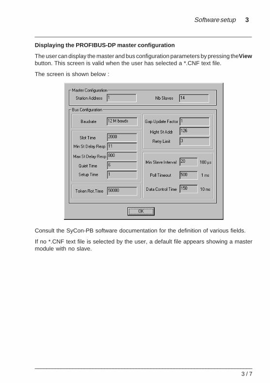
Displaying the PROFIBUS-DP master configuration
The user can display the master and bus configuration parameters by pressing the Viewbutton. This screen is valid when the user has selected a *.CNF text file.
The screen is shown below :
Consult the SyCon-PB software documentation for the definition of various fields.
If no *.CNF text file is selected by the user, a default file appears showing a mastermodule with no slave.
3 / 8___________________________________________________________________________
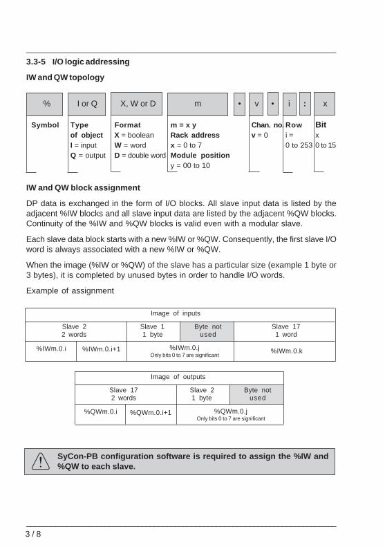
3.3-5 I/O logic addressing
IW and QW topology
IW and QW block assignment
DP data is exchanged in the form of I/O blocks. All slave input data is listed by theadjacent %IW blocks and all slave input data are listed by the adjacent %QW blocks.Continuity of the %IW and %QW blocks is valid even with a modular slave.
Each slave data block starts with a new %IW or %QW. Consequently, the first slave I/Oword is always associated with a new %IW or %QW.
When the image (%IW or %QW) of the slave has a particular size (example 1 byte or3 bytes), it is completed by unused bytes in order to handle I/O words.
Example of assignment
SyCon-PB configuration software is required to assign the %IW and%QW to each slave.
Image of inputs
Slave 22 words
Slave 11 byte
Slave 171 word
Byte notused
%IWm.0.i %IWm.0.i+1 %IWm.0.jOnly bits 0 to 7 are significant
%IWm.0.k
Image of outputs
Slave 172 words
Slave 21 byte
Byte notused
%QWm.0.i %QWm.0.i+1 %QWm.0.jOnly bits 0 to 7 are significant
% I or Q X, W or D m • v • i : x
Symbol Type Format m = x y Chan. no. Row Bitof object X = boolean Rack address v = 0 i = xI = input W = word x = 0 to 7 0 to 253 0 to 15Q = output D = double word Module position
y = 00 to 10
!
Software setup 3
___________________________________________________________________________3 / 9
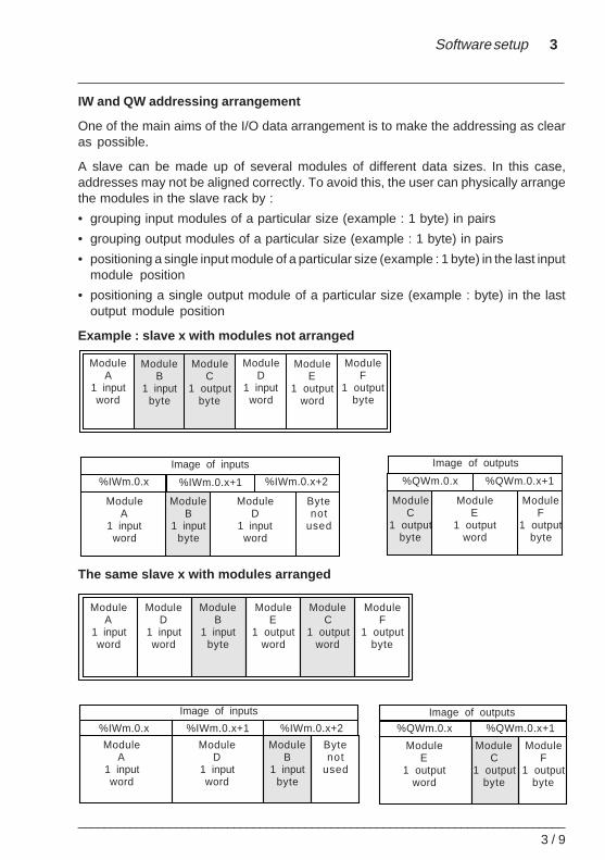
IW and QW addressing arrangement
One of the main aims of the I/O data arrangement is to make the addressing as clearas possible.
A slave can be made up of several modules of different data sizes. In this case,addresses may not be aligned correctly. To avoid this, the user can physically arrangethe modules in the slave rack by :
• grouping input modules of a particular size (example : 1 byte) in pairs
• grouping output modules of a particular size (example : 1 byte) in pairs
• positioning a single input module of a particular size (example : 1 byte) in the last inputmodule position
• positioning a single output module of a particular size (example : byte) in the lastoutput module position
Example : slave x with modules not arranged
The same slave x with modules arranged
ModuleA
1 inputword
ModuleB
1 inputbyte
ModuleC
1 outputbyte
ModuleD
1 inputword
ModuleE
1 outputword
ModuleF
1 outputbyte
Image of inputs Image of outputs
%IWm.0.x %QWm.0.x %QWm.0.x+1%IWm.0.x+1 %IWm.0.x+2
ModuleC
1 outputbyte
ModuleF
1 outputbyte
ModuleA
1 inputword
ModuleB
1 inputbyte
ModuleD
1 inputword
Bytenot
used
ModuleE
1 outputword
ModuleA
1 inputword
ModuleD
1 inputword
ModuleB
1 inputbyte
ModuleE
1 outputword
ModuleC
1 outputword
ModuleF
1 outputbyte
Image of inputs Image of outputs
%IWm.0.x %QWm.0.x %QWm.0.x+1%IWm.0.x+1 %IWm.0.x+2
ModuleF
1 outputbyte
ModuleC
1 outputbyte
ModuleE
1 outputword
ModuleA
1 inputword
ModuleD
1 inputword
ModuleB
1 inputbyte
Bytenot
used
3 / 1 0___________________________________________________________________________
3.3-6 Configuring a module
General configuration of PROFIBUS-DP
Before selecting a *.CNF text file, it is necessary to perform the following operations(default values are shown in bold) :
• the field for the type of task : MAST or FAST
• the state of the outputs when the task is in STOP mode : Maintain or Reset
• the size of words %IW and %QW updated on each PLC scan : 32, 64, 128 or 242words (128 : default value, 128 for the % IW and 128 for the % QW)
• the byte size for slave diagnostics (the value can vary from 6 to 244, 32 by default)
*.CNF text configuration file
SyCon-PB software is required for configuring :
• the fieldbus topology
• the memory allocation : addressing of each image module in the %IW and %QWregisters
• group definitions
• special functions
• exporting a *.CNF text file
SyCon-PB software can be directly accessed via the icon on the configuration screen.
After configuration, SyCon-PB software generates a *.CNF text file. This file describesthe behavior of the application and all the configuration information to be sent to themodule before starting the PROFIBUS-DP fieldbus.
Software setup 3
___________________________________________________________________________3 / 1 1
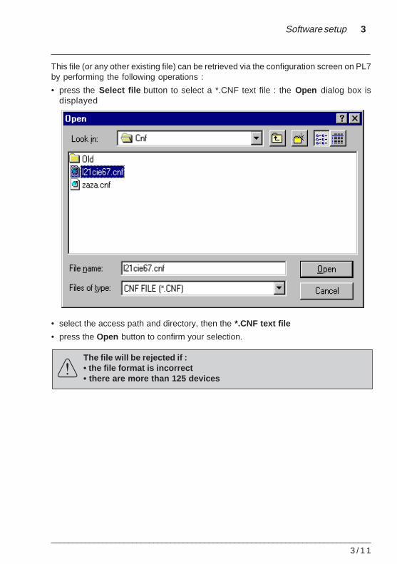
This file (or any other existing file) can be retrieved via the configuration screen on PL7by performing the following operations :
• press the Select file button to select a *.CNF text file : the Open dialog box isdisplayed
• select the access path and directory, then the *.CNF text file
• press the Open button to confirm your selection.
The file will be rejected if :• the file format is incorrect• there are more than 125 devices
3 / 1 2___________________________________________________________________________
3.4 User interface
This section describes all the language objects which can be displayed or modified bythe application program as well as all the tools used for data exchange.
For all language objects common to communication modules, consult the PL7 Micro /Junior, TSX Micro / Premium, communication documentation.
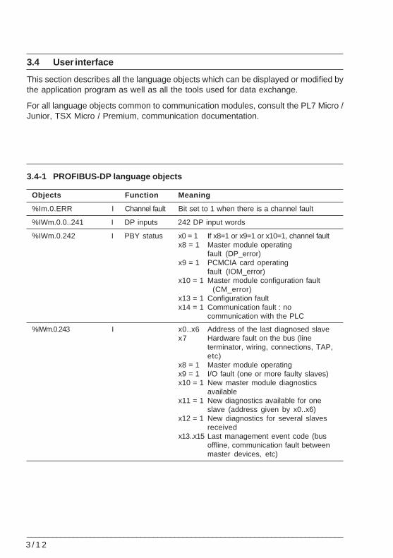
3.4-1 PROFIBUS-DP language objects
Objects Function Meaning
%Im.0.ERR I Channel fault Bit set to 1 when there is a channel fault
%IWm.0.0..241 I DP inputs 242 DP input words
%IWm.0.242 I PBY status x0 = 1 If x8=1 or x9=1 or x10=1, channel faultx8 = 1 Master module operating
fault (DP_error)x9 = 1 PCMCIA card operating
fault (IOM_error)x10 = 1 Master module configuration fault
(CM_error)x13 = 1 Configuration faultx14 = 1 Communication fault : no
communication with the PLC
%IWm.0.243 I x0..x6 Address of the last diagnosed slavex7 Hardware fault on the bus (line
terminator, wiring, connections, TAP,etc)
x8 = 1 Master module operatingx9 = 1 I/O fault (one or more faulty slaves)x10 = 1 New master module diagnostics
availablex11 = 1 New diagnostics available for one
slave (address given by x0..x6)x12 = 1 New diagnostics for several slaves
receivedx13..x15 Last management event code (bus
offline, communication fault betweenmaster devices, etc)
Software setup 3
___________________________________________________________________________3 / 1 3
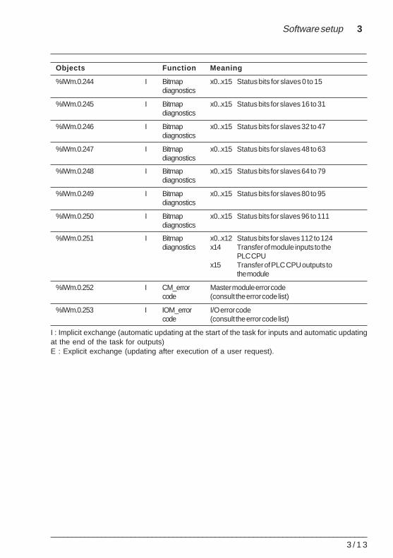
Objects Function Meaning
%IWm.0.244 I Bitmap x0..x15 Status bits for slaves 0 to 15diagnostics
%IWm.0.245 I Bitmap x0..x15 Status bits for slaves 16 to 31diagnostics
%IWm.0.246 I Bitmap x0..x15 Status bits for slaves 32 to 47diagnostics
%IWm.0.247 I Bitmap x0..x15 Status bits for slaves 48 to 63diagnostics
%IWm.0.248 I Bitmap x0..x15 Status bits for slaves 64 to 79diagnostics
%IWm.0.249 I Bitmap x0..x15 Status bits for slaves 80 to 95diagnostics
%IWm.0.250 I Bitmap x0..x15 Status bits for slaves 96 to 111diagnostics
%IWm.0.251 I Bitmap x0..x12 Status bits for slaves 112 to 124diagnostics x14 Transfer of module inputs to the
PLC CPUx15 Transfer of PLC CPU outputs to
the module
%IWm.0.252 I CM_error Master module error codecode (consult the error code list)
%IWm.0.253 I IOM_error I/O error codecode (consult the error code list)
I : Implicit exchange (automatic updating at the start of the task for inputs and automatic updatingat the end of the task for outputs)E : Explicit exchange (updating after execution of a user request).
3 / 1 4___________________________________________________________________________
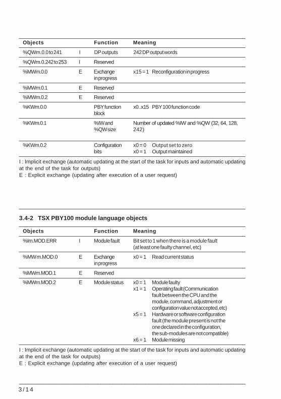
Objects Function Meaning
%QWm.0.0 to 241 I DP outputs 242 DP output words
%QWm.0.242 to 253 I Reserved
%MWm.0.0 E Exchange x15 = 1 Reconfiguration in progressin progress
%MWm.0.1 E Reserved
%MWm.0.2 E Reserved
%KWm.0.0 PBY function x0..x15 PBY 100 function codeblock
%KWm.0.1 %IW and Number of updated %IW and %QW (32, 64, 128,%QW size 242)
%KWm.0.2 Configuration x0 = 0 Output set to zerobits x0 = 1 Output maintained
I : Implicit exchange (automatic updating at the start of the task for inputs and automatic updatingat the end of the task for outputs)E : Explicit exchange (updating after execution of a user request)
3.4-2 TSX PBY100 module language objects
Objects Function Meaning
%Im.MOD.ERR I Module fault Bit set to 1 when there is a module fault(at least one faulty channel, etc)
%MW m.MOD.0 E Exchange x0 = 1 Read current statusin progress
%MWm.MOD.1 E Reserved
%MWm.MOD.2 E Module status x0 = 1 Module faultyx1 = 1 Operating fault (Communication
fault between the CPU and themodule, command, adjustment orconfiguration value not accepted, etc)
x5 = 1 Hardware or software configurationfault (the module present is not theone declared in the configuration,the sub-modules are not compatible)
x6 = 1 Module missing
I : Implicit exchange (automatic updating at the start of the task for inputs and automatic updatingat the end of the task for outputs)E : Explicit exchange (updating after execution of a user request)
Software setup 3
___________________________________________________________________________3 / 1 5
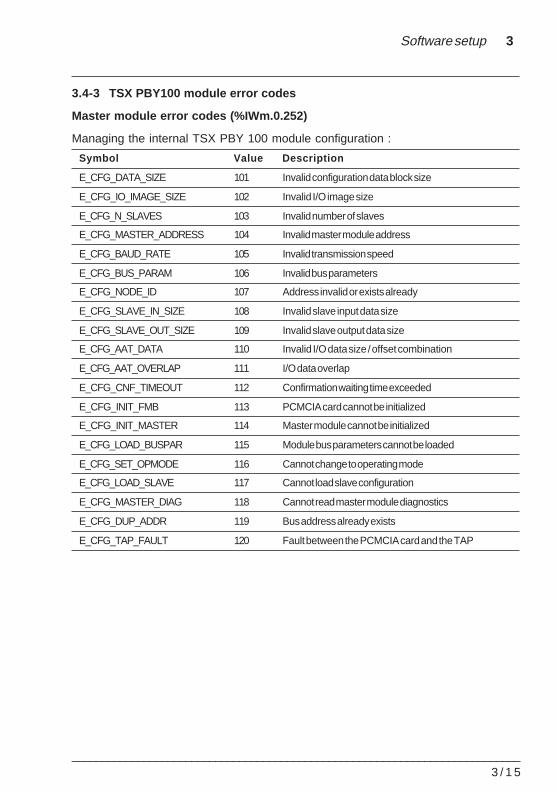
3.4-3 TSX PBY100 module error codes
Master module error codes (%IWm.0.252)
Managing the internal TSX PBY 100 module configuration :
Symbol Value Description
E_CFG_DATA_SIZE 101 Invalid configuration data block size
E_CFG_IO_IMAGE_SIZE 102 Invalid I/O image size
E_CFG_N_SLAVES 103 Invalid number of slaves
E_CFG_MASTER_ADDRESS 104 Invalid master module address
E_CFG_BAUD_RATE 105 Invalid transmission speed
E_CFG_BUS_PARAM 106 Invalid bus parameters
E_CFG_NODE_ID 107 Address invalid or exists already
E_CFG_SLAVE_IN_SIZE 108 Invalid slave input data size
E_CFG_SLAVE_OUT_SIZE 109 Invalid slave output data size
E_CFG_AAT_DATA 110 Invalid I/O data size / offset combination
E_CFG_AAT_OVERLAP 111 I/O data overlap
E_CFG_CNF_TIMEOUT 112 Confirmation waiting time exceeded
E_CFG_INIT_FMB 113 PCMCIA card cannot be initialized
E_CFG_INIT_MASTER 114 Master module cannot be initialized
E_CFG_LOAD_BUSPAR 115 Module bus parameters cannot be loaded
E_CFG_SET_OPMODE 116 Cannot change to operating mode
E_CFG_LOAD_SLAVE 117 Cannot load slave configuration
E_CFG_MASTER_DIAG 118 Cannot read master module diagnostics
E_CFG_DUP_ADDR 119 Bus address already exists
E_CFG_TAP_FAULT 120 Fault between the PCMCIA card and the TAP
3 / 1 6___________________________________________________________________________
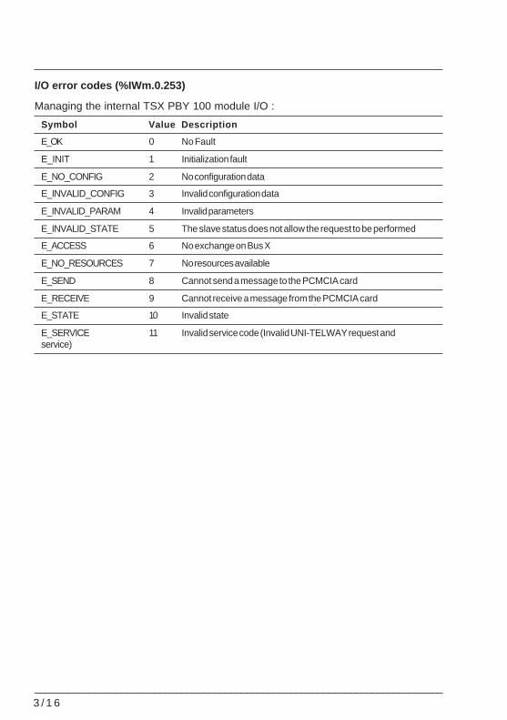
I/O error codes (%IWm.0.253)
Managing the internal TSX PBY 100 module I/O :
Symbol Value Description
E_OK 0 No Fault
E_INIT 1 Initialization fault
E_NO_CONFIG 2 No configuration data
E_INVALID_CONFIG 3 Invalid configuration data
E_INVALID_PARAM 4 Invalid parameters
E_INVALID_STATE 5 The slave status does not allow the request to be performed
E_ACCESS 6 No exchange on Bus X
E_NO_RESOURCES 7 No resources available
E_SEND 8 Cannot send a message to the PCMCIA card
E_RECEIVE 9 Cannot receive a message from the PCMCIA card
E_STATE 10 Invalid state
E_SERVICE 11 Invalid service code (Invalid UNI-TELWAY request andservice)
Software setup 3
___________________________________________________________________________3 / 1 7
3.5 PROFIBUS-DP diagnostics
PROFIBUS-DP diagnostic functions are used to quickly locate and identify faults ondevices connected to the bus. Diagnostic messages are exchanged on PROFIBUS-DPby the TSX PBY 100 master module.
There are four types of diagnostics :
• Master diag : complete diagnostics of the TSX PBY 100 master module
• Slave diag : complete diagnostics of a single slave
• Compressed diag : complete diagnostics of all slaves
• list of diagnostics available for each slave
Each of these diagnostics can be read by PL7 software or by any other PC used fordebugging.
3 / 1 8___________________________________________________________________________
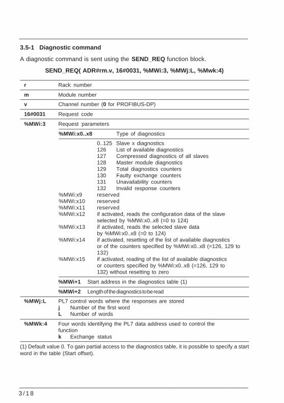
3.5-1 Diagnostic command
A diagnostic command is sent using the SEND_REQ function block.
SEND_REQ( ADR#rm.v, 16#0031, %MWi:3, %MWj:L, %Mwk:4)
r Rack number
m Module number
v Channel number (0 for PROFIBUS-DP)
16#0031 Request code
%MWi:3 Request parameters
%MWi:x0..x8 Type of diagnostics
0..125 Slave x diagnostics126 List of available diagnostics127 Compressed diagnostics of all slaves128 Master module diagnostics129 Total diagnostics counters130 Faulty exchange counters131 Unavailability counters132 Invalid response counters
%MWi:x9 reserved%MWi:x10 reserved%MWi:x11 reserved%MWi:x12 if activated, reads the configuration data of the slave
selected by %MWi:x0..x8 (=0 to 124)%MWi:x13 if activated, reads the selected slave data
by %MWi:x0..x8 (=0 to 124)%MWi:x14 if activated, resetting of the list of available diagnostics
or of the counters specified by %MWi:x0..x8 (=126, 129 to132)
%MWi:x15 if activated, reading of the list of available diagnosticsor counters specified by %MWi:x0..x8 (=126, 129 to132) without resetting to zero
%MWi+1 Start address in the diagnostics table (1)
%MWi+2 Length of the diagnostics to be read
%MWj:L PL7 control words where the responses are storedj Number of the first wordL Number of words
%MWk:4 Four words identifying the PL7 data address used to control thefunctionk Exchange status
(1) Default value 0. To gain partial access to the diagnostics table, it is possible to specify a startword in the table (Start offset).
Software setup 3
___________________________________________________________________________3 / 1 9
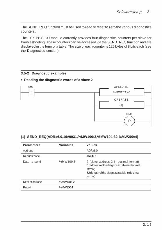
The SEND_REQ function must be used to read or reset to zero the various diagnosticscounters.
The TSX PBY 100 module currently provides four diagnostics counters per slave fortroubleshooting. These counters can be accessed via the SEND_REQ function and aredisplayed in the form of a table. The size of each counter is 126 bytes of 8 bits each (seethe Diagnostics section).
3.5-2 Diagnostic examples
• Reading the diagnostic words of a slave 2
(1) SEND_REQ(ADR#6.0,16#0031,%MW100:3,%MW104:32,%MW200:4)
Parameters Variables Values
Address ADR#6.0
Request code 16#0031
Data to send %MW100:3 2 (slave address 2 in decimal format)0 (address of the diagnostic table in decimalformat)32 (length of the diagnostic table in decimalformat)
Reception zone %MW104:32
Report %MW200:4
p %MW203:=6
OPERATE
OPERATE
(1)
%M0
%M0
R
3 / 2 0___________________________________________________________________________
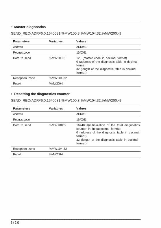
• Master diagnostics
SEND_REQ(ADR#6.0,16#0031,%MW100:3,%MW104:32,%MW200:4)
Parameters Variables Values
Address ADR#6.0
Request code 16#0031
Data to send %MW100:3 126 (master code in decimal format)0 (address of the diagnostic table in decimalformat32 (length of the diagnostic table in decimalformat)
Reception zone %MW104:32
Report %MW200:4
• Resetting the diagnostics counter
SEND_REQ(ADR#6.0,16#0031,%MW100:3,%MW104:32,%MW200:4)
Parameters Variables Values
Address ADR#6.0
Request code 16#0031
Data to send %MW100:3 16#4081(initialization of the total diagnosticscounter in hexadecimal format)0 (address of the diagnostic table in decimalformat)32 (length of the diagnostic table in decimalformat)
Reception zone %MW104:32
Report %MW200:4
Software setup 3
___________________________________________________________________________3 / 2 1
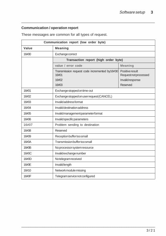
Communication / operation report
These messages are common for all types of request.
Communication report (low order byte)
Value Meaning
16#00 Exchange correct
Transaction report (high order byte)
value / error code Meaning
Transmission request code incremented by16#30 Positive result16#01 Request not processed
16#02 Invalid response
16#03 Reserved
16#01 Exchange stopped on time-out
16#02 Exchange stopped on user request (CANCEL)
16#03 Invalid address format
16#04 Invalid destination address
16#05 Invalid management parameter format
16#06 Invalid specific parameters
16#07 Problem sending to destination
16#08 Reserved
16#09 Reception buffer too small
16#0A Transmission buffer too small
16#0B No processor system resource
16#0C Invalid exchange number
16#0D No telegram received
16#0E Invalid length
16#10 Network module missing
16#0F Telegram service not configured
3 / 2 2___________________________________________________________________________
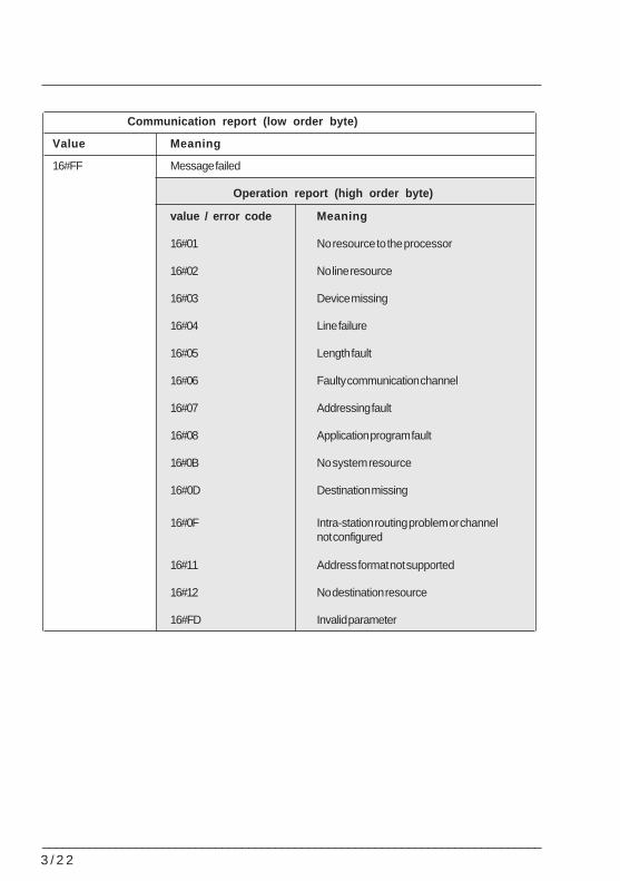
Communication report (low order byte)
Value Meaning
16#FF Message failed
Operation report (high order byte)
value / error code Meaning
16#01 No resource to the processor
16#02 No line resource
16#03 Device missing
16#04 Line failure
16#05 Length fault
16#06 Faulty communication channel
16#07 Addressing fault
16#08 Application program fault
16#0B No system resource
16#0D Destination missing
16#0F Intra-station routing problem or channelnot configured
16#11 Address format not supported
16#12 No destination resource
16#FD Invalid parameter
Software setup 3
___________________________________________________________________________3 / 2 3
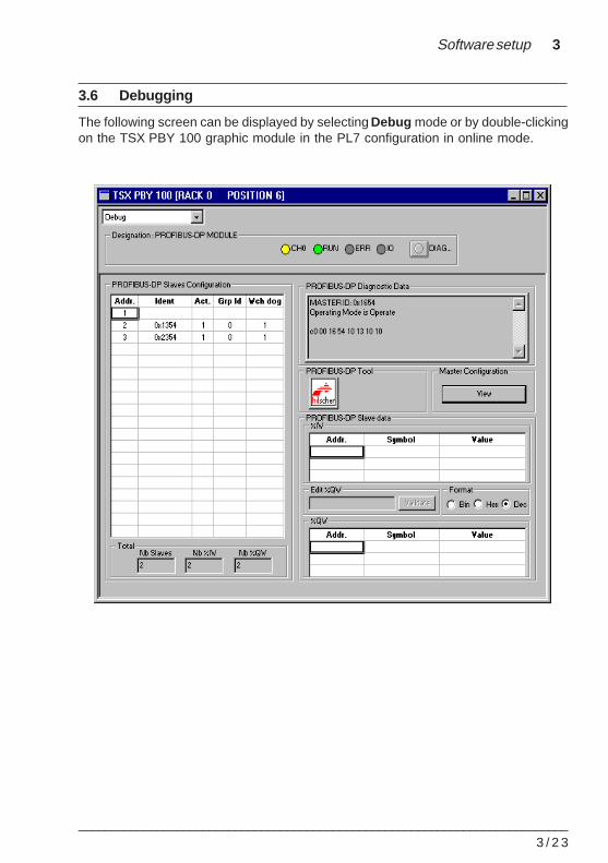
3.6 Debugging
The following screen can be displayed by selecting Debug mode or by double-clickingon the TSX PBY 100 graphic module in the PL7 configuration in online mode.
3 / 2 4___________________________________________________________________________
3.6-1 Debug screen
The debug screen displays the following information :
• a Designation : PROFIBUS-DP module window
• a PROFIBUS-DP Diagnostic Data window
• a PROFIBUS-DP Slaves Configuration drop-down list
• an icon for accessing SyCon-PB software
• a View button
• a PROFIBUS-DP Slave Data window.
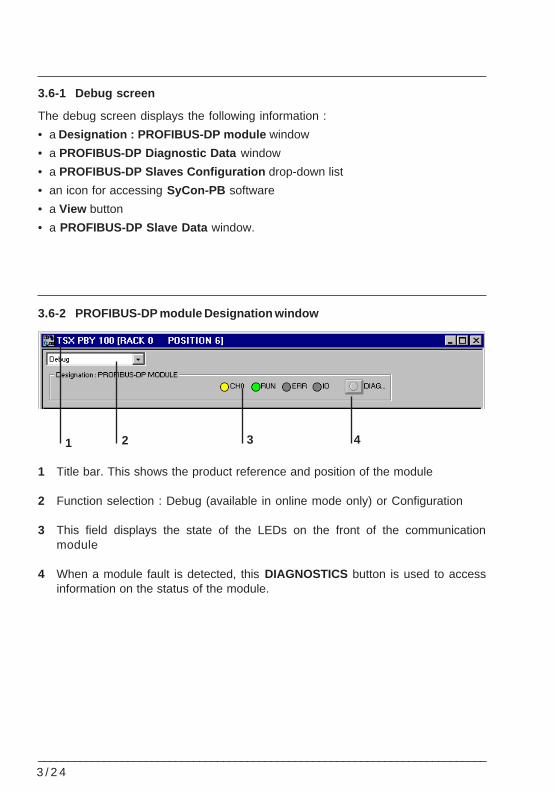
3.6-2 PROFIBUS-DP module Designation window
1 Title bar. This shows the product reference and position of the module
2 Function selection : Debug (available in online mode only) or Configuration
3 This field displays the state of the LEDs on the front of the communicationmodule
4 When a module fault is detected, this DIAGNOSTICS button is used to accessinformation on the status of the module.
4321
Software setup 3
___________________________________________________________________________3 / 2 5
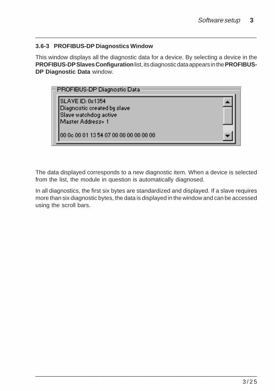
3.6-3 PROFIBUS-DP Diagnostics Window
This window displays all the diagnostic data for a device. By selecting a device in thePROFIBUS-DP Slaves Configuration list, its diagnostic data appears in the PROFIBUS-DP Diagnostic Data window.
The data displayed corresponds to a new diagnostic item. When a device is selectedfrom the list, the module in question is automatically diagnosed.
In all diagnostics, the first six bytes are standardized and displayed. If a slave requiresmore than six diagnostic bytes, the data is displayed in the window and can be accessedusing the scroll bars.
3 / 2 6___________________________________________________________________________
3.6-4 Displaying PROFIBUS-DP slave devices
When a device is faulty, its corresponding line in the PROFIBUS-DP Configurationdrop-down list is shown in red.
3.6-5 Icon for accessing SyCon-PB software
If the SyCon-PB tool is installed on the station, the user can run the software by clickingon the following icon :
Note :
The TSX PBY 100 V1.0 module can only be configured using the SyCon-PB tool.
3.6-6 Displaying the master module configuration
As in configuration mode, information on the master module can be displayed bypressing the View button.
Software setup 3
___________________________________________________________________________3 / 2 7
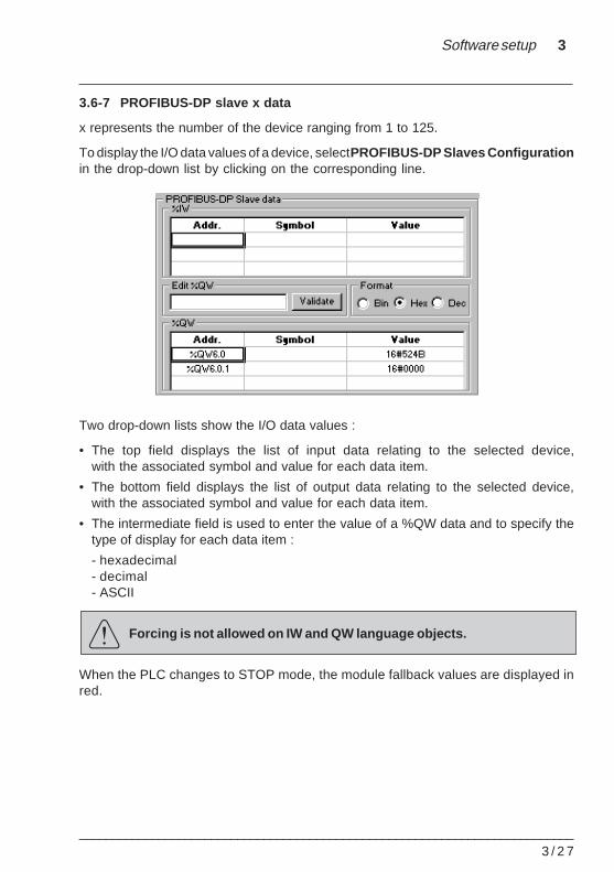
3.6-7 PROFIBUS-DP slave x data
x represents the number of the device ranging from 1 to 125.
To display the I/O data values of a device, select PROFIBUS-DP Slaves Configurationin the drop-down list by clicking on the corresponding line.
Two drop-down lists show the I/O data values :
• The top field displays the list of input data relating to the selected device,with the associated symbol and value for each data item.
• The bottom field displays the list of output data relating to the selected device,with the associated symbol and value for each data item.
• The intermediate field is used to enter the value of a %QW data and to specify thetype of display for each data item :
- hexadecimal- decimal- ASCII
Forcing is not allowed on IW and QW language objects.
When the PLC changes to STOP mode, the module fallback values are displayed inred.
3 / 2 8___________________________________________________________________________
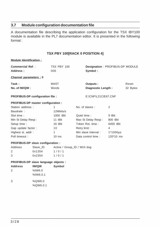
3.7 Module configuration documentation file
A documentation file describing the application configuration for the TSX IBY100module is available in the PL7 documentation editor. It is presented in the followingformat :
TSX PBY 100[RACK 0 POSITION 4]
Module Identification :
Commercial Ref . : TSX PBY 100 Designation : PROFIBUS-DP MODULE
Address : 006 Symbol :
Channel parameters : 0
Task : MAST Outputs : Reset
No. of IW/QW : Words Diagnostic Length : 32 Bytes
PROFIBUS-DP configuration file : E:\CNF\L21CIE67.CNF
PROFIBUS-DP master configuration :Station address : 1 No. of slaves : 2
Baudrate : 12Mbits/s
Slot time : 1000 tBit Quiet time : 9 tBit
Min St Delay Resp : 11 tBit Max St Delay Resp : 800 tBit
Setup time : 16 tBit Token Rot. time : 6459 tBit
Gap update factor : 10 Retry limit : 4
Highest st. addr : 1 Min slave interval : 1*1000µs
Poll timeout : 10 ms Data control time : 120*10 ms
PROFIBUS-DP slave configuration :Address Slave_ID Active / Group_ID / Wch dog
2 0x1354 1 / 0 / 1
3 0x2354 1 / 0 / 1
PROFIBUS-DP slave language objects :Address IW/QW Symbol2 %IW6.0
%IW6.0.1
3 %QW6.0
%QW6.0.1
Diagnostics 4
___________________________________________________________________________4 / 1
Section 44 Diagnostics
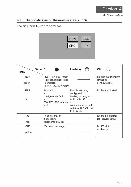
4.1 Diagnostics using the module status LEDs
The diagnostic LEDs are as follows :
Status On Flashing OffLEDs
RUN TSX PBY 100 ready Module not initialized- self-diagnostic tests (awaiting
green completed configuration)- PROFIBUS-DP ready
ERR Bus fault Module awaiting No fault indicatedor configuration orconfiguration fault loading in progress
red or (if RUN is off)TSX PBY 100 module orfault communication fault
with the PLC CPU (ifRUN is lit)
I/O Fault on one or No fault indicatedmore slave (all slaves active)
red peripheral devices
CH0 I/O data exchange No I/O dataexchange
yellow
ERR
I/O
RUN
CH0
4 / 2___________________________________________________________________________
4.2 Downgraded application modes
4.2-1 Transmission medium faults
Communication fault when launching PROFIBUS-DP
This fault may be due to incorrect configuration or a faulty cable. In this case, the busremains in a non operational state and the slaves remain in a startup error state.
An error code is generated by the TSX PBY 100 master module as a diagnostic item.All the slave diagnostic bits remain in their error state. The ERR LED is lit, and the otherLEDs are not.
Communication fault during operation
If a fault occurs while exchanges are in progress, an error code is generated by the TSXPBY 100 master module as a diagnostic item. In this case, the slaves change to theirpreconfigured error state after the watchdog time has elapsed.
The slave diagnostic bits are enabled to indicate the unavailability of slaves andresetting of the inputs. The TSX PBY 100 module records the diagnostics and informsthe CPU of their availability via %IWMm.0.129:x10..x12.
4.2-2 TSX PBY 100 master module faults
When a fault is detected, exchanges of data, commands and diagnostics are inter-rupted. After the watchdog time has elapsed, an error code is generated as a diagnosticitem.
If the exchanges are interrupted, the slave diagnostic bits are enabled to indicate theunavailability of slaves and resetting of the inputs. The ERR LED is lit, and the otherLEDs are not.
Diagnostics 4
___________________________________________________________________________4 / 3
4.2-3 Slave faults
When the exchanges are in progress, a slave fault is indicated by a new diagnostic item.If communication is still established, the slave generates the diagnostic item, otherwiseit is generated by the TSX PBY 100 master module.
The slave diagnostic bits are enabled to indicate its unavailability and resetting of itsinputs. The TSX PBY 100 module records the diagnostics and informs the CPU of theiravailability via %IWMm.0.129:x10..x12.
If one or more slaves are faulty, the bus cycle slows down. Acknowledg-ment of a diagnostic item and resetting the inputs may require severalPLC scans.
4.2-4 PLC CPU general faults
In the event of a communication fault between the CPU and the TSX PBY 100 module,all the outputs are set to their error state (maintain or fallback) and the inputs are reset.The ERR LED flashes to indicate the communication fault between the PLC CPU andthe TSX PBY 100 module.
Diagnostic data transfers between master and slave are not affected.
4.2-5 Resetting the outputs after loading an application
For slow speeds (less than 500 Kbit/s) and a long watchdog time, the slaves willmaintain the states of the outputs throughout the duration of the watchdog.
For slow speeds (less than 500Kbit/s) and a deactivated watchdog, the states of theslave outputs will be maintained until the application has finished loading.
4 / 4___________________________________________________________________________
4.3 Lists of diagnostic variables
4.3-1 Master diagnostics
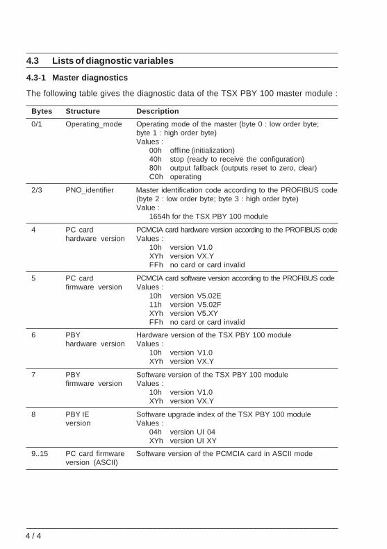
The following table gives the diagnostic data of the TSX PBY 100 master module :
Bytes Structure Description
0/1 Operating_mode Operating mode of the master (byte 0 : low order byte;byte 1 : high order byte)Values :
00h offline (initialization)40h stop (ready to receive the configuration)80h output fallback (outputs reset to zero, clear)C0h operating
2/3 PNO_identifier Master identification code according to the PROFIBUS code(byte 2 : low order byte; byte 3 : high order byte)Value :
1654h for the TSX PBY 100 module
4 PC card PCMCIA card hardware version according to the PROFIBUS codehardware version Values :
10h version V1.0XYh version VX.YFFh no card or card invalid
5 PC card PCMCIA card software version according to the PROFIBUS codefirmware version Values :
10h version V5.02E11h version V5.02FXYh version V5.XYFFh no card or card invalid
6 PBY Hardware version of the TSX PBY 100 modulehardware version Values :
10h version V1.0XYh version VX.Y
7 PBY Software version of the TSX PBY 100 modulefirmware version Values :
10h version V1.0XYh version VX.Y
8 PBY IE Software upgrade index of the TSX PBY 100 moduleversion Values :
04h version UI 04XYh version UI XY
9..15 PC card firmware Software version of the PCMCIA card in ASCII modeversion (ASCII)
Diagnostics 4
___________________________________________________________________________4 / 5
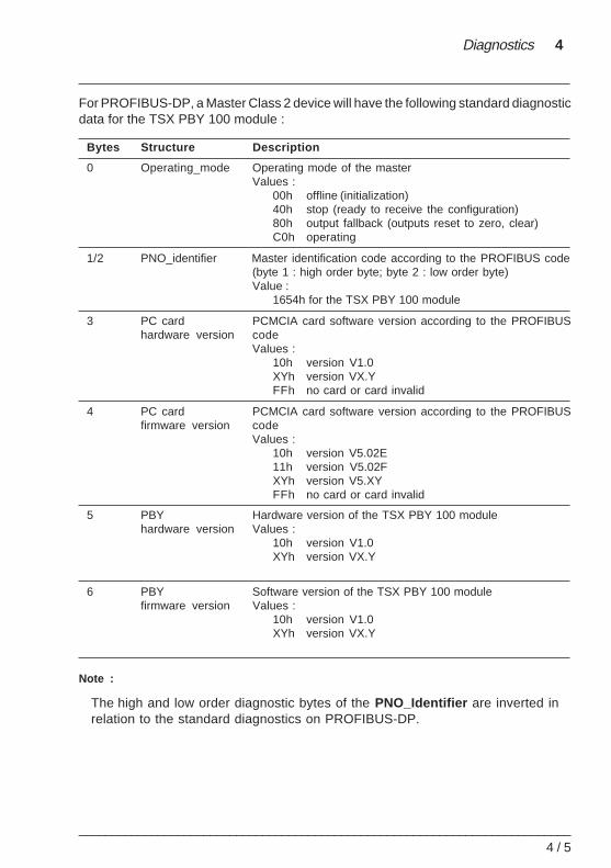
For PROFIBUS-DP, a Master Class 2 device will have the following standard diagnosticdata for the TSX PBY 100 module :
Bytes Structure Description
0 Operating_mode Operating mode of the masterValues :
00h offline (initialization)40h stop (ready to receive the configuration)80h output fallback (outputs reset to zero, clear)C0h operating
1/2 PNO_identifier Master identification code according to the PROFIBUS code(byte 1 : high order byte; byte 2 : low order byte)Value :
1654h for the TSX PBY 100 module
3 PC card PCMCIA card software version according to the PROFIBUShardware version code
Values :10h version V1.0XYh version VX.YFFh no card or card invalid
4 PC card PCMCIA card software version according to the PROFIBUSfirmware version code
Values :10h version V5.02E11h version V5.02FXYh version V5.XYFFh no card or card invalid
5 PBY Hardware version of the TSX PBY 100 modulehardware version Values :
10h version V1.0XYh version VX.Y
6 PBY Software version of the TSX PBY 100 modulefirmware version Values :
10h version V1.0XYh version VX.Y
Note :
The high and low order diagnostic bytes of the PNO_Identifier are inverted inrelation to the standard diagnostics on PROFIBUS-DP.
4 / 6___________________________________________________________________________
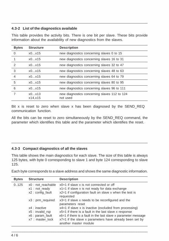
4.3-2 List of the diagnostics available
This table provides the activity bits. There is one bit per slave. These bits provideinformation about the availability of new diagnostics from the slaves.
Bytes Structure Description
0 x0...x15 new diagnostics concerning slaves 0 to 15
1 x0...x15 new diagnostics concerning slaves 16 to 31
2 x0...x15 new diagnostics concerning slaves 32 to 47
3 x0...x15 new diagnostics concerning slaves 48 to 63
4 x0...x15 new diagnostics concerning slaves 64 to 79
5 x0...x15 new diagnostics concerning slaves 80 to 95
6 x0...x15 new diagnostics concerning slaves 96 to 111
7 x0...x13 new diagnostics concerning slaves 112 to 124x14,x15 not used
Bit x is reset to zero when slave x has been diagnosed by the SEND_REQ communication function.
All the bits can be reset to zero simultaneously by the SEND_REQ command, theparameter which identifies this table and the parameter which identifies the reset.
4.3-3 Compact diagnostics of all the slaves
This table shows the main diagnostics for each slave. The size of this table is always125 bytes, with byte 0 corresponding to slave 1 and byte 124 corresponding to slave125.
Each byte corresponds to a slave address and shows the same diagnostic information.
Bytes Structure Description
0..125 x0 : not_reachable x0=1 if slave x is not connected or offx1 : not_ready x1=1 if slave x is not ready for data exchangex2 : config_fault x2=1 if configuration fault on slave x when the test is
requestedx3 : prm_required x3=1 if slave x needs to be reconfigured and the
parameters resetx4 : inactive x4=1 if slave x is inactive (excluded from processing)x5 : invalid_rsp x5=1 if there is a fault in the last slave x responsex6 : param_fault x6=1 if there is a fault in the last slave x parameter messagex7 : master_lock x7=1 if the slave x parameters have already been set by
another master module
Diagnostics 4
___________________________________________________________________________4 / 7
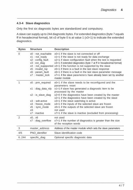
4.3-4 Slave diagnostics
Only the first six diagnostic bytes are standardized and compulsory.
A slave can supply up to 244 diagnostic bytes. For extended diagnostics (byte 7 equalsff in hexadecimal format), bit x3 of byte 0 is at value 1 (x3=1) to indicate the extendeddiagnostics.
Bytes Structure Description
0 x0 : not_reachable x0=1 if the slave is not connected or offx1 : not_ready x1=1 if the slave is not ready for data exchangex2 : config_fault x2=1 if slave configuration fault when the test is requestedx3 : ext_diag x3=1 if extended diagnostics (byte 7 at ff in hexadecimal format)x4 : not_suppported x4=1 if the function is not supported by the slavex5 : invalid_rsp x5=1 if there is a fault in the last slave responsex6 : param_fault x6=1 if there is a fault in the last slave parameter messagex7 : master_lock x7=1 if the slave parameters have already been set by another
master module
1 x0 : prm_required x0=1 if the slave needs to be reconfigured and theparameters reset
x1 : diag_data_rdy x1=1 if slave has generated a diagnostic item to beprocessed by the master
x2 : is_slave_diag x2=0 if the diagnostics have been created by the masterx2=1 if the diagnostics have been created by the slave
x3 : wdt-active x3=1 if the slave watchdog is activex4 : freeze_mode x4=1 if the inputs of the selected slave are frozenx5 : sync_mode x5=1 if the outputs of the selected slave are frozenx6 not usedx7 : inactive x7=1 if the slave is inactive (excluded from processing)
2 x0.. x6 not usedx7 : diag_overflow x7=1 if the number of diagnostics is greater than the size
of the reception words
3 master_address Address of the master module which sets the slave parameters
4/5 PNO_identifier Slave identification code
6..244 specific_diag Optional specific diagnostic data
4 / 8___________________________________________________________________________
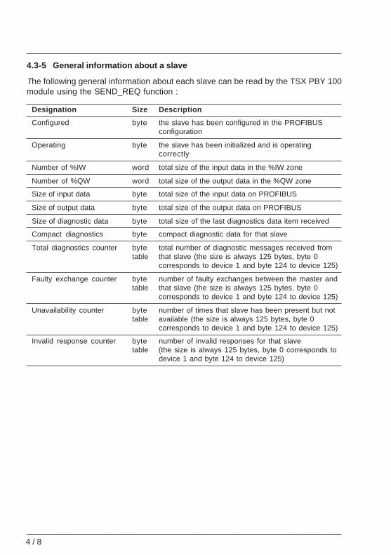
4.3-5 General information about a slave
The following general information about each slave can be read by the TSX PBY 100module using the SEND_REQ function :
Designation Size Description
Configured byte the slave has been configured in the PROFIBUSconfiguration
Operating byte the slave has been initialized and is operatingcorrectly
Number of %IW word total size of the input data in the %IW zone
Number of %QW word total size of the output data in the %QW zone
Size of input data byte total size of the input data on PROFIBUS
Size of output data byte total size of the output data on PROFIBUS
Size of diagnostic data byte total size of the last diagnostics data item received
Compact diagnostics byte compact diagnostic data for that slave
Total diagnostics counter byte total number of diagnostic messages received fromtable that slave (the size is always 125 bytes, byte 0
corresponds to device 1 and byte 124 to device 125)
Faulty exchange counter byte number of faulty exchanges between the master andtable that slave (the size is always 125 bytes, byte 0
corresponds to device 1 and byte 124 to device 125)
Unavailability counter byte number of times that slave has been present but nottable available (the size is always 125 bytes, byte 0
corresponds to device 1 and byte 124 to device 125)
Invalid response counter byte number of invalid responses for that slavetable (the size is always 125 bytes, byte 0 corresponds to
device 1 and byte 124 to device 125)
Diagnostics 4
___________________________________________________________________________4 / 9
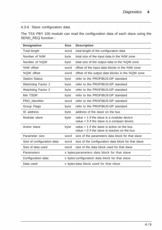
4.3-6 Slave configuration data
The TSX PBY 100 module can read the configuration data of each slave using theSEND_REQ function :
Designation Size Description
Total length word total length of the configuration data
Number of %IW byte total size of the input data in the %IW zone
Number of %QW byte total size of the output data in the %QW zone
%IW offset word offset of the input data blocks in the %IW zone
%QW offset word offset of the output data blocks in the %QW zone
Station Status byte refer to the PROFIBUS-DP standard
Watchdog Factor 1 byte refer to the PROFIBUS-DP standard
Watchdog Factor 2 byte refer to the PROFIBUS-DP standard
Min TSDR byte refer to the PROFIBUS-DP standard
PNO_Identifier word refer to the PROFIBUS-DP standard
Group Flags byte refer to the PROFIBUS-DP standard
ID address byte address of the slave on the bus
Modular slave byte value = 1 if the slave is a modular devicevalue = 0 if the slave is a compact device
Active slave byte value = 1 if the slave is active on the busvalue = 0 if the slave is inactive on the bus
Parameter size word size of the parameters data block for that slave
Size of configuration data word size of the configuration data block for that slave
Size of data used word size of the data block used for that slave
Parameters x bytes parameters data block for that slave
Configuration data x bytes configuration data block for that slave
Data used x bytes data block used for that slave
4 / 1 0___________________________________________________________________________
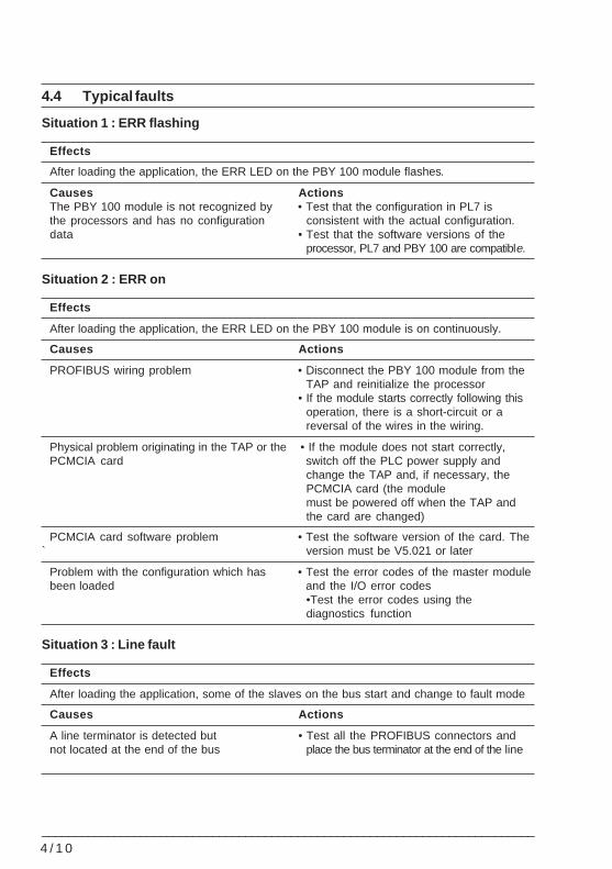
4.4 Typical faults
Situation 1 : ERR flashing
Effects
After loading the application, the ERR LED on the PBY 100 module flashes.
Causes ActionsThe PBY 100 module is not recognized by • Test that the configuration in PL7 isthe processors and has no configuration consistent with the actual configuration.data • Test that the software versions of the
processor, PL7 and PBY 100 are compatible.
Situation 2 : ERR on
Effects
After loading the application, the ERR LED on the PBY 100 module is on continuously.
Causes Actions
PROFIBUS wiring problem • Disconnect the PBY 100 module from theTAP and reinitialize the processor
• If the module starts correctly following thisoperation, there is a short-circuit or areversal of the wires in the wiring.
Physical problem originating in the TAP or the • If the module does not start correctly,PCMCIA card switch off the PLC power supply and
change the TAP and, if necessary, thePCMCIA card (the modulemust be powered off when the TAP andthe card are changed)
PCMCIA card software problem • Test the software version of the card. The` version must be V5.021 or later
Problem with the configuration which has • Test the error codes of the master modulebeen loaded and the I/O error codes
•Test the error codes using thediagnostics function
Situation 3 : Line fault
Effects
After loading the application, some of the slaves on the bus start and change to fault mode
Causes Actions
A line terminator is detected but • Test all the PROFIBUS connectors andnot located at the end of the bus place the bus terminator at the end of the line
Diagnostics 4
___________________________________________________________________________4 / 1 1
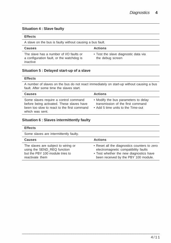
Situation 4 : Slave faulty
Effects
A slave on the bus is faulty without causing a bus fault.
Causes Actions
The slave has a number of I/O faults or • Test the slave diagnostic data viaa configuration fault, or the watchdog is the debug screeninactive
Situation 5 : Delayed start-up of a slave
Effects
A number of slaves on the bus do not react immediately on start-up without causing a busfault. After some time the slaves start.
Causes Actions
Some slaves require a control command • Modify the bus parameters to delaybefore being activated. These slaves have transmission of the first commandbeen too slow to react to the first command • Add 5 time units to the Time-outwhich was sent.
Situation 6 : Slaves intermittently faulty
Effects
Some slaves are intermittently faulty.
Causes Actions
The slaves are subject to wiring or • Reset all the diagnostics counters to zerousing the SEND_REQ function electromagnetic compatibility faultsbut the PBY 100 module tries to • Test whether the new diagnostics havereactivate them been received by the PBY 100 module.
4 / 1 2___________________________________________________________________________
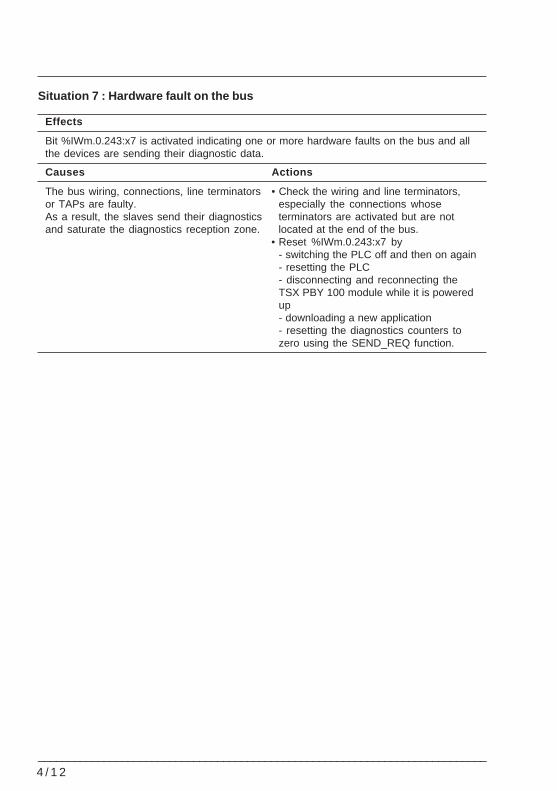
Situation 7 : Hardware fault on the bus
Effects
Bit %IWm.0.243:x7 is activated indicating one or more hardware faults on the bus and allthe devices are sending their diagnostic data.
Causes Actions
The bus wiring, connections, line terminators • Check the wiring and line terminators,or TAPs are faulty. especially the connections whoseAs a result, the slaves send their diagnostics terminators are activated but are notand saturate the diagnostics reception zone. located at the end of the bus.
• Reset %IWm.0.243:x7 by- switching the PLC off and then on again- resetting the PLC- disconnecting and reconnecting theTSX PBY 100 module while it is poweredup- downloading a new application- resetting the diagnostics counters tozero using the SEND_REQ function.
Index
___________________________________________________________________________5/1
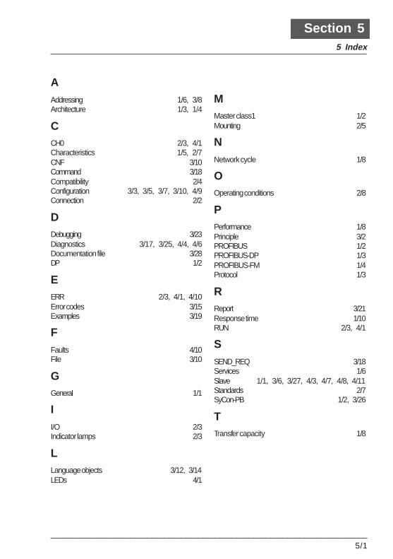
Section 55 Index
AAddressing 1/6, 3/8Architecture 1/3, 1/4
CCH0 2/3, 4/1Characteristics 1/5, 2/7CNF 3/10Command 3/18Compatibility 2/4Configuration 3/3, 3/5, 3/7, 3/10, 4/9Connection 2/2
DDebugging 3/23Diagnostics 3/17, 3/25, 4/4, 4/6Documentation file 3/28DP 1/2
EERR 2/3, 4/1, 4/10Error codes 3/15Examples 3/19
FFaults 4/10File 3/10
GGeneral 1/1
II/O 2/3Indicator lamps 2/3
LLanguage objects 3/12, 3/14LEDs 4/1
MMaster class1 1/2Mounting 2/5
NNetwork cycle 1/8
OOperating conditions 2/8
PPerformance 1/8Principle 3/2PROFIBUS 1/2PROFIBUS-DP 1/3PROFIBUS-FM 1/4Protocol 1/3
RReport 3/21Response time 1/10RUN 2/3, 4/1
SSEND_REQ 3/18Services 1/6Slave 1/1, 3/6, 3/27, 4/3, 4/7, 4/8, 4/11Standards 2/7SyCon-PB 1/2, 3/26
TTransfer capacity 1/8

5/2___________________________________________________________________________