Embed Size (px)
Citation preview

TSRimmersion probes
Controlling devices with magnetically operated reed contacts,
for automatic control,regulation and signalling of liquid levels
3-1-0F-1
Jola Spezialschalter GmbH & Co. KGKlostergartenstr. 11 • 67466 Lambrecht (Germany)
Tel. +49 6325 188-01 • Fax +49 6325 6396• www.jola-info.de

3-1-1
TSR immersion probes
Subject to deviations from the diagrams and technical data.
The units described in this documentation may only be installed, connected and started up by suitably qualified personnel!
The details in this brochure are product specification descriptionsand do not constitute assured properties in the legal sense.
Contents Page
General information 3-1-2
Switching examples and circuit diagrams 3-1-3
TypeProbe tube Float
Material Ø Material Dimensions
TSR/./ED/P
stainless steel316 Ti
12 mm
PP53 mm Ø x 50 mm 3-1-5
TSR/./ED/PK 29 mm Ø x 50 mm 3-1-5
TSR/./ED/E8
stainless steel316 Ti
72 mm Ø 3-1-7
TSR/./ED/E2 44.5 mm Ø x 52 mm 3-1-7
TSR/./ED/E7 52 mm Ø x 88 mm 3-1-7
TSR/./ED/E5 98 mm Ø 3-1-9
TSR/./EW/E5 20 mm 98 mm Ø 3-1-9
TSR/./P/PPP
14 mmPP
53 mm Ø x 50 mm 3-1-11
TSR/./P/PG 16 mm 89 mm Ø x 60 mm 3-1-11
TSR/./PVDF/DPVDF
14 mmPVDF
53 mm Ø x 50 mm 3-1-13
TSR/./PVDF/W 16 mm 89 mm Ø x 60 mm 3-1-13
TSR/./TiD/Ti7
titanium
12 mm
titanium
44.5 mm Ø x 52 mm 3-1-15
TSR/./TiW/Ti419 or
20 mm79 mm Ø x 95 mm 3-1-15
TSR/0/ED/E6stainless steel
316 Ti12 mm
stainless steel316 Ti
44.5 mm Ø x 47.5 mm 3-1-17
DK3 switching bowls 3-1-18
Questionnaire for inquiries and orders 3-1-19

3-1-2
TSR immersion probes
Magnetically operated automatic liquid level controls
Construction and operating principle of TSR immersion probes
The TSR immersion probes have a probe tube with built-in reed contacts. The
float is fitted with a permanent magnet and moves freely up and down the probe
tube, activating the reed contacts as it rises and falls.
It should be noted that reed contacts do not lock but that they switch only for as
long as they are influenced by the magnetic field. Once the float passes beyond a
contact upwards or downwards, the latter returns to its original position. However,
the contacts can be made to hold by using collars to limit the motion of the float.
For use outside potentially explosive atmospheres, the costumer can choose
the model TSR/3/... or TSR/1/... (not suitable for the type TSR/0/ED/E6, see page3-1-17):
Caution!
If a TSR immersion probe is to be used with a KR protection relay, you must choosethe model TSR/1/... .
We recommend this apparatus combination.
Type TSR/3/... TSR/1/...
Application
Switching voltageSwitching currentSwitching capacity
for applicationsup to max. 250 V
AC/DC 24 V – 250 VAC 100 mA – 2 A (0.4 A)
max. 100 VA
for light currentapplications
AC/DC 1 V – 42 VAC 1 mA – 500 mA
max. 20 VA
VDE marks licences
––––
+
Instruction for working with inductive loads:
When using the TSR types with inductive loads, a RC combination of 0.22 µF + 220 Ωmust be connected in parallel to the magnetic coil of the contactor.

3-1-3
Specimen application 1: Automatic emptying of a tankThe float rises with the liquid to the maximum level and trips the “make” (= normally open)contact which in turn activates the contactor solenoid, serving, for example, to set a pumpin operation. Liquid is pumped out. When the minimum level is reached, the “break” (= nor-mally closed) contact at the bottom is activated, thus interrupting the contactor holding cir-cuit. The arrangement is therefore exactly the same as with ON-OFF pushbuttons.
Specimen application 2: Automatic filling of a tankThe float falls with the liquid to the minimum level and trips the “make” (= normally open)contact which in turn activates the contactor solenoid, serving, for example, to set a pumpin operation. Liquid is then pumped in. When the maximum level is reached, the upper“break” (= normally closed) contact is activated, thus interrupting the contactor holding cir-cuit. The arrangement is therefore exactly the same as with ON-OFF pushbuttons.
Examples of standard operation Standard operations with 1 float and a collar fitted above the upper contact.
The collar fitted at the top stops the float at the upper contact, so that the latter cannot beoverrun. If this collar was not fitted, it is conceivable that, in the case of a short power failure and freely entering liquid, for example, the contact for “Pump ON” or the alarm contact would be overrun during the short power failure without the pump being switched onor an alarm signal being given. This could then lead to an overflow.For the same reasons, the probe tube should be of such a length that when the floatreaches the lower contact, it rests on the lower holding washer or collar (For information onthe recommended distances between contact and end of probe tube, see the technical dataof the individual TSR models under “Minimum distances”).
Standard operations with 2 or more floats
The use of an additional float together with the corresponding collar ensures that not onlythe uppermost and lowest but also another important contact is held when the liquid levelrises above or falls below the level at which the contact is set. Depending on the desiredswitching function, it is possible to use several floats together with the corresponding collars.
When fixing the levels at which the contacts are to be set, care should be taken to ensure that wherever a float is stopped at a contact by a collar, the minimum distanceto an adjacent contact activated by another, separate float should be increased invarying degrees, depending on the model of floats planned. Please consult us regarding exact spacing!
Recommended contact protection relays: 2 x KR ..
Recommended contact protection relays: 2 x KR ..
Alarm= make contact (NO contact)
Pump ON= make contact (NO contact)
Pump ON= make contact (NO contact)
Pump OFF= break contact (NC contact)
Pump OFF= break contact (NC contact)
EMERGENCY OFF= break contact (NC contact)
EMERGENCY OFF= break contact (NC contact)
Recommended contact protection relays: 2 x KR ..
Recommended contact protection relays: 2 x KR ..
Alarm= make contact (NO contact)Pump ON= make contact (NO contact)
Pump ON= make contact (NO contact)
Pump OFF= break contact (NC contact)
Pump OFF= break contact (NC contact)

3-1-4
Basic circuit diagram for emptying Basic circuit diagram for filling
using a TSR for 2 pumps
using a TSR for 2 pumps with a common switch-off contact
The above contact positions correspond to a liquid level situated between the respective switch-on and switch-off points.
TSRimmersion probe
on
off
TSR immersion probe
on
off
using a TSR
TSR immersion probe
pump 2on
pump 1on
pump 2off
pump 1off
pump 1 pump 2 pump 1pump 2
TSR immersion probe
pump 1off
pump 2off
pump 1on
pump 2on
pump 1 pump 2
TSRimmersion probe
pump 1on
pump 2on
pumps1+2off
pump 1 pump 2
pumps1+2 off
pump 1on
pump 2on
TSRimmersion probe

Technical data TSR/3/ED/P TSR/3/ED/PKTSR/1/ED/P TSR/1/ED/PK
Probe tube: material stainless steel 316 Tidiameter 12 mmlength acc. to customer’s specification, however max. 3,000 mm
Screw-in nipple G1/2 , on request G1, G1, on request G1/2 ,on request G11/2 or G2;
on request with reducing nipple made of malleablecast iron R11/2 or R2 conical
Float PP,53 mm Ø x 50 mm 29 mm Ø x 50 mm
(mounting possible through (mounting possible througha G/R2 socket ) a G1 socket)
Float suitable for use inmedia with a specific gravity ≥ 0.8 g/cm³ ≥ 0.85 g/cm³
Terminal box PP, A 307, 120 x 80 x 55 mm, protection class IP65,with max. 12 terminals;
other terminal boxes on request;with free connecting cable on request
Mounting orientation vertical
Temperature range − 20°C to + 80°C
Pressure resistance at + 20° C max. 2 bar
Contacts reed contacts: make (NO), break (NC) or changeover (OC)
Max. number of contacts 3
Min. distances to beobserved (based on liquidswith a specific gravity of1 g/cm³):• from the nipple sealing
surface to the uppercontact approx. 70 mm approx. 70 mm
• between contacts approx. 80 mm approx. 80 mm• from the lower contact to
the end of the probe tube(when float is falling) approx. 40 mm approx. 50 mm
Also available with angled probe tube for mounting from the side
3-1-5
The above equipment will be manufactured in accordance with your specifications
For inquiries or orders, please complete the questionnaire on page 3-1-19
TSR/... immersion probes with• probe tube made of stainless steel• float made of PP
Option for TSR/1/... immersion probes: diodes or resistors
Type TSR/3/ED/.. TSR/1/ED/..
Application
Switching voltageSwitching currentSwitching capacity
for applicationsup to max. 250 V
AC/DC 24 V – 250 VAC 100 mA – 2 A (0.4 A)
max. 100 VA
for light currentapplications
AC/DC 1 V – 42 VAC 1 mA – 500 mA
max. 20 VA

3-1-6
Mounting accessories:
Square flange made of stainless steel 316 Ti,PP or PVDF for immersion probes with G1screw-in nipple, counterflange on request
Float for TSR/./ED/P
Float for TSR/./ED/PK
Ø 50Ø 16
50
50
Ø 53
Ø 29Ø 13.3
120 x 80 x 55
SW 41
Ø 12
15
20
G1
120 x 80 x 55
SW 41
Ø 12
15
20
G1/2
TSR/3/ED/P TSR/3/ED/PK
TSR/./ED/P TSR/./ED/PK

Technical data TSR/3/ED/E8 TSR/3/ED/E2 TSR/3/ED/E7TSR/1/ED/E8 TSR/1/ED/E2 TSR/1/ED/E7
Probe tube: material stainless steel 316 Tidiameter 12 mmlength acc. to customer’s specification, however max. 3,000 mm
Screw-in nipple G1/2 , on request G1, G11/2 or G2;–––– on request with reducing nipple
made of malleable cast ironR11/2 conical R2 conical
Float stainless steel 316 Ti, 72 mm Ø 44.5 mm Ø x 52 mm 52 mm Ø x 88 mm
mounting possible through aG/R11/2 socket G/R2 socket
Float suitable for use inmedia with a specific gravity ≥ 0.7 g/cm³ ≥ 0.95 g/cm³ ≥ 0.7 g/cm³
Terminal box PP, A 307, 120 x 80 x 55 mm, protection class IP65, for max. 12 terminals;
other terminal boxes on request;with free connecting cable on request
Mounting orientation vertical
Temperature range − 20°C to + 100°C; on request: − 20°C to + 130°C
Pressure resistance at + 20°C max. 12 bar, higher pressure resistance on request
Contacts reed contacts: make (NO), break (NC) or changeover (OC)
Max. number of contacts 3
Min. distances to beobserved (based on liquidswith a specific gravity of 1 g/cm³):• from the nipple sealing
surface to the uppercontact approx. 80 mm approx. 70 mm approx. 80 mm
• between contacts approx. 80 mm approx. 80 mm approx. 80 mm• from the lower contact to
the end of the probe tube(when float is falling) approx. 60 mm approx. 60 mm approx. 70 mm
Also available with angled probe tube for mounting from the side
3-1-7
TSR/... immersion probes with• probe tube made of stainless steel• float made of stainless steel
For inquiries or orders, please complete the questionnaire on page 3-1-19
The above equipment will be manufactured in accordance with your specifications
Option for TSR/1/... immersion probes: diodes or resistors
Type TSR/3/ED/E. TSR/1/ED/E.
Application
Switching voltageSwitching currentSwitching capacity
for applicationsup to max. 250 V
AC/DC 24 V – 250 VAC 100 mA – 2 A (0.4 A)
max. 100 VA
for light currentapplications
AC/DC 1 V – 42 VAC 1 mA – 500 mA
max. 20 VA

3-1-8
TSR/3/ED/E8 TSR/3/ED/E2 TSR/3/ED/E7
120 x 80 x 55
SW 41
Ø 12
15
20
G1/2
Mounting accessories:
Square flange made of stainless steel 316 Ti, PP orPVDF for immersion probes
with G1 screw-in nipple, counterflange on request
Float forTSR/./ED/E8
Float forTSR/./ED/E2
Float forTSR/./ED/E7
Ø 42Ø 15
52
Ø 44.5
Ø 72
71
Ø 15.2Ø 70
Ø 52
88
Ø 16Ø 50

Technical data TSR/3/ED/E5 TSR/3/EW/E5TSR/1/ED/E5 TSR/1/EW/E5
Probe tube: material stainless steel 316 Tidiameter 12 mm 20 mmlength acc. to customer’s specification, however
max. 3,000 mm max. 6,000 mmScrew-in nipple G1/2 , on request G1, G1,
on request G11/2 or G2;on request with reducing nipple made of malleable
cast iron R11/2 or R2 conicalFloat stainless steel 316 Ti,
98 Ø mm 98 Ø mm or 97 mm Ø x 80 mm
(heat-resistant versionwith float E4)
Float suitable for use inmedia with a specific gravity ≥ 0.7 g/cm³Terminal box PP, A 307, 120 x 80 x 55 mm,
protection class IP65, with max. 12 terminals;other terminal boxes on request;
with free connection cable on requestMounting orientation verticalTemperature range − 20°C to + 100°C − 20°C to + 100°C ;
on request:− 20°C to + 130°C
Pressure resistance at + 20°C max. 12 bar, max. 12 bar
(heat-resistant version:max. 3 bar),
higher pressure resistance on requestContacts reed contacts: make (NO), break (NC) or changeover (OC)Max. number of contacts 3 6,
more on requestMin. distances to beobserved (based on liquidswith a specific gravity of1 g/cm³):• from the nipple sealing
surface to the uppercontact approx. 90 mm approx. 90 mm
• between contacts approx. 80 mm approx. 80 mm• from the lower contact to
the end of the probe tube(when float is falling) approx. 60 mm approx. 70 mm
Also available with angled probe tube for mounting from the side
3-1-9
TSR/... immersion probes with• probe tube made of stainless steel• float made of stainless steel
For inquiries or orders, please complete the questionnaire on page 3-1-19
The above equipment will be manufactured in accordance with your specifications
Type TSR/3/E./E5 TSR/1/E./E5
Application
Switching voltageSwitching currentSwitching capacity
for applicationsup to max. 250 V
AC/DC 24 V – 250 VAC 100 mA – 2 A (0.4 A)
max. 100 VA
for light currentapplications
AC/DC 1 V – 42 VAC 1 mA – 500 mA
max. 20 VA
3-1-10
TSR/3/EW/E5TSR/3/ED/E5
Ø 96
96
Ø 98
Ø 23
120 x 80 x 55
SW 41
Ø 20
15
20
G1
120 x 80 x 55
SW 41
Ø 12
15
20
G1/2
TSR/./ED/E5 TSR/./EW/E5
Float forTSR/./ED/E5
and TSR/./EW/E5

Technical data TSR/3/P/P TSR/3/P/PGTSR/1/P/P TSR/1/P/PG
Probe tube: material PP,–––– on request, with metal
inner tube to strengthenthe plastic probe tube
diameter 14 mm 16 mmlength according to customer’s specifications, however
max. 1,000 mm, max. 2,000 mm,taking into account the max. temperature in the tank and
possible liquid turbulencesScrew-in nipple G1, G1,
on request: G2Float PP,
53 mm Ø x 50 mm 89 mm Ø x 60 mm(mounting possible through a
G2 socket)Float suitable for use in media with a specific gravity ≥ 0.8 g/cm³Terminal box PP, A 307, 120 x 80 x 55 mm, protection class IP65,
with max. 12 terminals; other terminal boxes on request;with free connecting cable on request
Mounting orientation verticalTemperature rangetaking into account theprobe tube length:– max. 2,000 mm –––– 0°C to + 35°C– max. 1,500 mm –––– 0°C to + 40°C– max. 1,000 mm 0°C to + 50°C– max. 750 mm 0°C to + 60°C– max. 500 mm 0°C to + 75°C– max. 400 mm 0°C to + 80°CPressure resistance at + 20°C max. 2 barContacts reed contacts: make (NO), break (NC) or changeover (OC)Max. number of contacts:• without inner tube 3 6• with inner tube –––– 3Min. distances to beobserved (based on liquidswith a specific gravity of1 g/cm³):• from the nipple sealing
surface to the uppercontact approx. 70 mm approx. 80 mm
• between contacts approx. 80 mm approx. 80 mm• from the lower contact to
the end of the probe tube(when float is falling) approx. 60 mm approx. 50 mm
3-1-11
TSR/... immersion probes with• probe tube made of PP• float made of PP
The above equipment will be manufactured in accordance with your specifications
For inquiries or orders, please complete the questionnaire on page 3-1-19
Type TSR/3/P/P TSR/1/P/PG
Application
Switching voltageSwitching currentSwitching capacity
for applicationsup to max. 250 V
AC/DC 24 V – 250 VAC 100 mA – 2 A (0.4 A)
max. 100 VA
for light currentapplications
AC/DC 1 V – 42 VAC 1 mA – 500 mA
max. 20 VA

3-1-12
TSR/3/P/P TSR/3/P/PG
Float forTSR/./P/P
Float forTSR/./P/PG
Mounting accessories:
Square flange made of PP for immersion probes with
G1 screw-in nipple,counterflange on request
Ø 50Ø 53
Ø 16
50
Ø 19Ø 89
60
120 x 80 x 55
SW 41
Ø 16
15
20
G1
120 x 80 x 55
SW 41
Ø 14
15
20
G1
TSR/./P/P TSR/./P/PG

Technical data TSR/3/PVDF/D TSR/3/PVDF/WTSR/1/PVDF/D TSR/1/PVDF/W
Probe tube: material PVDF,–––– on request, with metal
inner tube to strengthenthe plastic probe tube
diameter 14 mm 16 mmlength according to customer’s specifications, however
max. 1,000 mm, max. 2,000 mm,taking into account the max. temperature in the tank and
possible liquid turbulencesScrew-in nipple G1, G1,
on request: G2Float PVDF,
53 mm Ø x 50 mm 89 mm Ø x 60 mm(mounting possible through a
G2 socket)Float suitable for use inmedia with a specific gravity ≥ 1 g/cm³ ≥ 1 g/cm³Terminal box PP, A 307, 120 x 80 x 55 mm, protection class IP65,
with max. 12 terminals; other terminal boxes on request;with free connecting cable on request
Mounting orientation verticalTemperature rangetaking into account theprobe tube length:– max. 2,000 mm –––– 0°C to + 40°C– max. 1,500 mm –––– 0°C to + 45°C– max. 1,000 mm 0°C to + 55°C– max. 750 mm 0°C to + 70°C– max. 500 mm 0°C to + 80°CPressure resistance at + 20°C max. 2 barContacts reed contacts: make (NO), break (NC) or changeover (OC)Max. number of contacts:• without inner tube 3 6• with inner tube –––– 3Min. distances to beobserved (based on liquidswith a specific gravity of1 g/cm³):• from the nipple sealing
surface to the uppercontact approx. 80 mm approx. 80 mm
• between contacts approx. 80 mm approx. 80 mm• from the lower contact to
the end of the probe tube(when float is falling) approx. 70 mm approx. 65 mm
3-1-13
TSR/... immersion probes with• probe tube made of PVDF• float made of PVDF
Type TSR/3/PVDF/. TSR/1/PVDF/.
Application
Switching voltageSwitching currentSwitching capacity
for applicationsup to max. 250 V
AC/DC 24 V – 250 VAC 100 mA – 2 A (0.4 A)
max. 100 VA
for light currentapplications
AC/DC 1 V – 42 VAC 1 mA – 500 mA
max. 20 VA
The above equipment will be manufactured in accordance with your specifications
For inquiries or orders, please complete the questionnaire on page 3-1-19

3-1-14
TSR/3/PVDF/D TSR/3/PVDF/W
Float for TSR/./PVDF/D
Float for TSR/./PVDF/W
Mounting accessories:
Square flange made of PVDF forimmersion probes with
G1 screw-in nipple,counterflange on request
Ø 50Ø 53
Ø 16
50
Ø 19Ø 89
60
120 x 80 x 55
SW 41
Ø 16
15
20
G1
120 x 80 x 55
SW 41
Ø 14
15
20
G1
TSR/./PVDF/D TSR/./PVDF/W

Technical data TSR/3/TiD/Ti7 TSR/3/TiW/Ti4TSR/1/TiD/Ti7 TSR/1/TiW/Ti4
Probe tube: material titaniumdiameter 12 mm 19 or 20 mmlength according to customer’s specifications, however
max. 3,000 mm max. 6,000 mm
Screw-in nipple G1/2 G1
Float titanium,44.5 mm Ø x 52 mm 79 mm Ø x 95 mm
Float suitable for use inmedia with a specific gravity ≥ 0.95 g/cm³ ≥ 0.7 g/cm³
Terminal box PP, A 307, 120 x 80 x 55 mm, protection class IP65, with max. 12 terminals;
other terminal boxes on request;with free connecting cable on request
Mounting orientation vertical
Temperature range − 20°C to + 100°C
Pressure resistanceat + 20°C max. 10 bar, max. 7 bar,
higher pressure resistance on request
Contacts reed contacts: make (NO), break (NC) or changeover (OC)
Max. number of contacts 3 6,more on request
Min. distances to beobserved (based on liquidswith a specific gravity of1 g/cm³):• from the nipple sealing
surface to the uppercontact approx. 70 mm approx. 90 mm
• between contacts approx. 80 mm approx. 80 mm• from the lower contact to
the end of the probe tube(when float is falling) approx. 60 mm approx. 75 mm
Also available with angled probe tube for mounting from the side
3-1-15
TSR/... immersion probes with• probe tube made of titanium• float made of titanium
The above equipment will be manufactured in accordance with your specifications
For inquiries or orders, please complete the questionnaire on page 3-1-19
Option for TSR/1/... immersion probes: diodes or resistors
Type TSR/3/Ti./Ti. TSR/1/Ti./Ti.
Application
Switching voltageSwitching currentSwitching capacity
for applicationsup to max. 250 V
AC/DC 24 V – 250 VAC 100 mA – 2 A (0.4 A)
max. 100 VA
for light currentapplications
AC/DC 1 V – 42 VAC 1 mA – 500 mA
max. 20 VA

3-1-16
TSR/1/TiW/Ti4TSR/1/TiD/Ti7
120 x 80 x 55
SW 41
Ø 19 or Ø 20
15
20
G1
120 x 80 x 55
SW 41
Ø 12
15
20
G1/2
TSR/./TiD/Ti7 TSR/./TiW/Ti4
Float forTSR/./TiD/Ti7
Float forTSR/./TiW/Ti4
Ø 42Ø 44.5
Ø 14
52
Ø 77Ø 79
Ø 23
95

3-1-17
TSR/0/ED/E6 immersion probe with• probe tube made of stainless steel• float made of stainless steel with mini-contacts for small contact distancesand/or a higher number of contacts
Ø 42
Ø 15
44.5
47.5
Float forTSR/0/ED/E6
For inquiries or orders, please complete the questionnaire on page 3-1-19
120 x 80 x 55
15
20
The above equipment will be manufactured in accordance with your specifications
Types TSR/0/ED/E6
ApplicationSwitching voltageSwitching current
Switching capacity
for light current applicationsAC/DC 1 V - 42 V
AC 1 mA - 100 mAmax. 2 VA
SW 41
G1/2
Ø 12
Technical data TSR/0/ED/E6
Probe tube: material stainless steel Tidiameter 12 mmlength acc. to customer’s specifications,
however max. 3,000 mmScrew-in nipple G½, on request G1, G1½ or G2;
on request with reducing nipple made ofmalleable cast iron R1½ or R2 conical
Float stainless steel 316 Ti, 44.5 mm Ø x 47.5 mm (mounting possiblethrough a G/R1½ socket)
Float suitable for use inmedia with a specificgravity ≥ 0.95 g/cm³Terminal box PP, A 307, 120 x 80 x 55 mm,
protection class IP65, with max.12 terminals; other boxes on request
Mounting orientation verticalTemperature range − 20°C to + 100°CPressure resistanceto + 20°C max. 12 barContacts reed contacts:
make (NO), break (NC) or changeover (OC)
Max. number of contacts 6Min. distances to beobserved (based on liquids with a specificgravity of 1 g/cm³):• from the nipple sealing
surface to the uppercontact approx. 50 mm
• between contacts approx. 20 mm• from the lower contact
to the end of the probetube (when float is falling) approx. 50 mm
Also available with angled probe tube for mountingfrom the side

3-1-18
DK 3 switching bowls
For lateral mounting on tanks or pipelines, suitable for TSR immersion probes.
The use of a switching bowl is necessary wherever heavy turbulences would impede or pre-vent the operation of an immersion probe inside a tank or where these units cannot be installed for reasons of space.
Technical data DK 3
Material stainless steel 316 Ti; other materials on request
Diameter 102 mm
Height according to customer’s specifications
Socket size according to customer’s specifications; on request: flanges of any dimensions
Distance betweensockets (or flanges) according to customer’s specifications
~ 27
80
20ac
cord
ing
to c
usto
mer
’s s
peci
ficat
ions
acco
rdin
g to
cus
tom
er’s
spe
cific
atio
ns
120t = 55
O-RingØ 105 x Ø 4
holes circleØ 130 8 x Ø 9
G1/2
15
30
506
6
Ø 150
2
*)
G 1/2
Ø 102
S Ø 72
Upper switch-ing point atleast 110 mmbelow thenipple sealing surface
DK 3 switching bowl: standard model
Other dimensions on request.
15064
G1 /2
50
6 6
~ 39
0
280
165
250
100
SW27
SW17M8
40
50
18
Ø 102
DIN7081
DK 3 switching bowl:special design with gauge glass and
4 sockets
*) according to customer’s specifications
3-1-19 07/2015
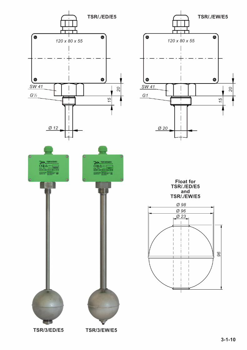
1
2
3
4
5
6
Distance from thesealing surfaceof the screw-innipple in mm
Switchingfunction (e.g. highalarm, pump ON,pump OFF etc.)
If float has aworking direction:
rising = ↑↑falling = ↓↓
Contact type:make = NObreak = NC
changeover = OC
Dim
en
sio
n G
+ D
Dim
. D
*D
ime
nsio
n G
Immersion probes will be manufactured according tocustomer’s specifications. It is therefore not possible to
return these special designs.
Desired probe tube length (dimension G):
Please mark desired floats and collars on the probe tube!
* = specify dimension D, otherwise 20 mm.
Desired type of immersion probe: TSR/..................
Desired options:
For inquiries or orders, please complete the following questionnaire:
Desired switching functions(max./min. indication, pump orvalve ON/OFF, filling or emptying,run-dry or overflow protection):
Tank dimensions and installationconditions(attach sketch if necessary):
Type of liquid: Specific gravity:
Viscosity: Temperature: Working pressure:
Desired version (please tick off):
TSR/3/... TSR/1/...
Switching voltage AC/DC 24 V – 250 V AC/DC 1 V – 42 VSwitching current AC 100 mA – 2 A (0.4 A) AC1 mA – 500 mASwitching capacity max. 100 VA max. 20 VA
TSR/0/ED/E 6