Embed Size (px)
Citation preview

TSPWG M 3-260-03.00-2 30 OCT 2017
TRI-SERVICE PAVEMENTS WORKING
GROUP (TSPWG) MANUAL
INSPECTION OF TRIM PAD ANCHOR
SYSTEMS
APPROVED FOR PUBLIC RELEASE; DISTRIBUTION UNLIMITED

TSPWG M 3-260-03.00-2 30 OCT 2017
i
TRI-SERVICE PAVEMENTS WORKING GROUP MANUAL (TSPWG M)
INSPECTION OF TRIM PAD ANCHOR SYSTEMS
Any copyrighted material included in this TSPWG Manual is identified at its point of use. Obtain permission of the copyright holder prior to using the copyrighted material apart from this TSPWG Manual. U.S. ARMY CORPS OF ENGINEERS NAVAL FACILITIES ENGINEERING COMMAND AIR FORCE CIVIL ENGINEER CENTER (Preparing Activity) Record of Changes (changes are indicated by \1\ ... /1/) Change No. Date Location
This TSPWG Manual supersedes ETL 00-2, dated 1 February 2000.

TSPWG M 3-260-03.00-2 30 OCT 2017
ii
FOREWORD This Tri-Service Pavements Working Group Manual supplements guidance found in other Unified Facilities Criteria, Unified Facility Guide Specifications, and Service-specific publications. All construction outside of the United States is also governed by Status of forces Agreements (SOFA), Host Nation Funded Construction Agreements (HNFA), and, in some instances, Bilateral Infrastructure Agreements (BIA). Therefore, ensure compliance with the more stringent of these documents, protocols, agreements, specifications, and criteria, as applicable. This manual provides guidance and procedures for inspection and testing of trim pad anchor blocks. This guidance is referenced in technical publications found on the Whole Building Design Guide. It is not intended to take the place of Service-specific doctrine, technical orders (TOs), field manuals, technical manuals, handbooks, Tactic Techniques or Procedures (TTPs), or contract specifications. Use this manual with these other documents to help ensure pavement repairs meet mission requirements. TSPWG Manuals are living documents and will be periodically reviewed, updated, and made available to users as part of the Services’ responsibility for providing technical criteria for military construction, maintenance, repair, or operations. Headquarters, U.S. Army Corps of Engineers (HQUSACE), Naval Facilities Engineering Command (NAVFAC), and Air Force Civil Engineer Center (AFCEC) are responsible for administration of this document. Technical content of this TSPWG Manual is the responsibility of the Tri-Service Pavements Working Group (TSPWG). Contact the preparing activity for document interpretation. Send recommended changes with supporting rationale to the respective Service TSPWG member. TSPWG Manuals are effective upon issuance and are distributed only in electronic media from the following source:
• Whole Building Design Guide web site http://dod.wbdg.org/. Check hard copies of TSPWG Manuals printed from electronic media against the current electronic version prior to use to ensure they are current.

TSPWG M 3-260-03.00-2 30 OCT 2017
iii
TRI-SERVICE PAVEMENTS WORKING GROUP MANUAL (TSPWG M) NEW SUMMARY SHEET
Description of Changes: This update converts USAF ETL 00-2, Inspection and Testing of Trim Pad Anchor Blocks, to a TSPWG Manual. The content was reorganized for ease of understanding and locating information. Reasons for Changes: To ensure the material is available to all Services. Impact: There is no cost impact. This publication results in the following benefits:
• Supplemental information on the inspection of trim pad anchors will be available to all Services.
• Maintenance and/or upgrading of this supplemental information will include inputs from all Services.
Note: The use of the name or mark of any specific manufacturer, commercial product, commodity, or service in this publication does not imply endorsement by the Department of Defense (DOD).

TSPWG M 3-260-03.00-2 30 OCT 2017
iv
CONTENTS
CHAPTER 1 INTRODUCTION ........................................................................................ 1
1-1 BACKGROUND. ............................................................................................... 1 1-2 PURPOSE. ....................................................................................................... 2 1-3 SCOPE. ............................................................................................................ 2 1-4 REFERENCES. ................................................................................................ 2
CHAPTER 2 ANCHOR BLOCK DESCRIPTIONS .......................................................... 3 2-1 ANCHOR BLOCK DESCRIPTIONS. ................................................................ 3
2-1.1 Omnidirectional Anchor. ................................................................................ 3 2-1.2 Bidirectional Anchor. ..................................................................................... 3
2-2 FAILURE MODES ANALYSIS.......................................................................... 4 CHAPTER 3 INSPECTION AND TESTING .................................................................. 13
3-1 SAFETY PRECAUTIONS. .............................................................................. 13 3-1.1 Test Setup Assembly. ................................................................................. 13 3-1.2 Aircraft Tie-down Failure. ........................................................................... 13 3-1.3 Test Setup Failure. ...................................................................................... 13 3-1.4 Communications Plan. ................................................................................ 13 3-1.5 Safety Equipment. ....................................................................................... 13
3-2 INSPECTION. ................................................................................................. 13 3-3 Testing. .......................................................................................................... 14
3-3.1 Background. ................................................................................................ 14 3-3.2 Requirements. ............................................................................................. 14 3-3.3 Procedure. ................................................................................................... 14
APPENDIX A REFERENCES ....................................................................................... 29 APPENDIX B BEST PRACTICES ................................................................................ 30 APPENDIX C GLOSSARY ........................................................................................... 34
FIGURES
Figure 2-1. Geometry of Anchor Connection. .......................................................... 7 Figure 3-1. Layout with Forklift. .............................................................................. 14 Figure 3-2. Layout with Crane. ............................................................................... 15 Figure 3-3. Layout Slings. ...................................................................................... 15 Figure 3-4. Measure Tell-tales. .............................................................................. 16 Figure 3-5. Connecting Sling to Anchor with Shackle. ........................................... 16 Figure 3-6. Connect Load Cell. .............................................................................. 17 Figure 3-7. Shackle Slings Together. ..................................................................... 17 Figure 3-8. Steel Plate. .......................................................................................... 18 Figure 3-9. Position Plate with Forklift. ................................................................... 18 Figure 3-10. Connect Sling to Steel Plate. ............................................................. 19 Figure 3-11. Align Slings with Forklift. .................................................................... 19 Figure 3-12. Assemble Anchor Bolts. ..................................................................... 20 Figure 3-13. Use Forklift to Hold Plate while Anchoring. ........................................ 21 Figure 3-14. Drill Holes and Install Anchors at Back of Plate. ................................ 22 Figure 3-15. Install Seven Anchors at Back of Plate. ............................................. 22

TSPWG M 3-260-03.00-2 30 OCT 2017
v
Figure 3-16. Complete Installation of Anchors. ...................................................... 23 Figure 3-17. Measuring Slings. .............................................................................. 23 Figure 3-18. Protective Sheath for Sling. ............................................................... 24 Figure 3-19. Crane Hook and Shackle with Sling in Protective Sheath. ................ 24 Figure 3-20. Digital Dial Indicator with Magnetic Base. .......................................... 25 Figure 3-21. Digital Load Cell Remote Display. ..................................................... 25 Figure 3-22. Magnetic Angle Reader on Load Cell. ............................................... 26 Figure 3-23. Sling Tell-tales. .................................................................................. 28
TABLES
Table 1-1. Rated Values of Thrust for Various Aircraft. ........................................... 1 Table 2-1. Failure Modes. ........................................................................................ 4 Table 2-2. Factors of Safety for the F-4. ................................................................ 11 Table 2-3. Factors of Safety for the F-15. .............................................................. 11 Table 2-4. Factors of Safety for the F-22. .............................................................. 12 Table 3-1. Minimum Number of Anchors Required. ............................................... 20

TSPWG M 3-260-03.00-2 30 OCT 2017
1
CHAPTER 1 INTRODUCTION
1-1 BACKGROUND.
Most fighter aircraft use aircraft anchor blocks during power checks and routine maintenance procedures. Many existing aircraft anchor blocks were designed to withstand loads associated with F-4 operations but are being used to support the operation of aircraft with higher thrusts, such as the F-15. While catastrophic failure of an anchor block has not been reported, the stability of the existing anchor block design under increased thrust from newer aircraft has been questioned, particularly with the introduction of the F-22 (see Table 1-1). Therefore, inspection and testing of anchor blocks is recommended if it was designed and constructed with a working load of 133 kilonewtons (kN) (30,000 lbf). It is important to note that while some aircraft have two engines, standard protocol is, at the time of the publishing of this TSPWG Manual, to only power up one engine at a time when utilizing the trim pad. Furthermore, the trim pad anchors were originally designed with a factor of safety of 2 between the proof load and working load. In other words, it is assumed the anchor working load (loaded by one engine) is one-half of the load at which it is tested (proof loaded). Also note that at the time of this publication, the F-35 (JSF) Technical Order (T.O.) does not require the use of an anchor when performing engine trim operations and checks; however, field personnel have stated they do utilize trim pad anchors with the F-35 for other functions.
Table 1-1. Rated Values of Thrust for Various Aircraft.
Aircraft Engine(s) No. Engines
Rated Thrust per Engine per Aircraft
F-4 Phantom J79-GE-17 2 79.6 kN 17,900 lbf
159 kN 35,800 lbf
F-15 A/B/C/D Eagle F100-P-220 2 105.7 kN 23,770 lbf
211 kN 47,540 lbf
F-15 E Strike Eagle F100-P-229 2 129 kN 29,000 lbf
258 kN 58,000 lbf
F-16 A/B/C/D/N Fighting Falcon
F100-PW-229 F110-GE-129 1 129 kN
29,000 lbf 129 kN 29,000 lbf
F/A-18 A/B/C/D F404-GE-400 2 71 kN 16,000 lbf
142 kN 32,000 lb
F-22 Raptor F119-P-100 2 156.7 kN 35,000 lbf
311 kN 70,000 lbf
F-35 Lightning JSF F135-PW-100 1 191 kN 43,000 lbf
191 kN 43,000 lbf

TSPWG M 3-260-03.00-2 30 OCT 2017
2
1-2 PURPOSE.
This TSPWG Manual provides guidance and procedures for inspection and testing of trim pad anchor blocks. Tests can be conducted by base personnel. The Air Force Civil Engineer Center has a team of trained personnel with the major equipment components to perform these tests; however, their availability is limited and testing by this team will be considered only under extreme circumstances.
1-3 SCOPE.
This TSPWG Manual provides an inspection protocol for the testing of trim pad anchors. Additional guidance on requirements for the testing can be found in AFI 32-1041, Pavement Evaluation Program. The procedure described in this TSPWG Manual does not certify anchors; it proof loads them. The proof load applied is approximately twice the thrust of a single engine of the aircraft that will use the anchor. This allows a factor of safety for dynamic loads and fatigue life. If the anchor is designed and constructed (with the proper quality control [QC]) in accordance with ETL 01-10, Design and Construction of High-Capacity Trim Pad Anchoring Systems, or in accordance with UFC 3-260-01, Airfield and Heliport Planning and Design, an anchor test is not required as part of any civil engineering Air Force departmental publication or UFC. It is recommended that bases/units contract to proof load anchors that are constructed through their own contract where they cannot provide the proper quality assurance evaluation/quality control (QAE/QC) or where they alter the design of the anchor from that shown in ETL 01-10 or UFC 3-260-01. If you cannot perform the testing via contract or other means and require support from AFCEC to proof load the anchor, request AFCEC proof load support through the major command installation mission support center (MAJCOM IMSC) detachment representative or the AFCEC Reachback Center at [email protected].
Conduct recurring (annual) inspections (not proof loading) to verify the anchor components are in good condition. Check steel parts for rust, deformation, cracks, or anything that reduces the cross-sectional area; this changes the factor of safety. Check the concrete for spalling around the anchor bolt and cracks through the slab. Check the dimensions of the slab to ensure it meets design size.
1-4 REFERENCES.
Appendix A contains the list of references used in this TSPWG Manual.

TSPWG M 3-260-03.00-2 30 OCT 2017
3
CHAPTER 2 ANCHOR BLOCK DESCRIPTIONS
2-1 ANCHOR BLOCK DESCRIPTIONS.
There are primarily two types of anchor blocks: omnidirectional and bidirectional. Prior to January 2001, their designs were based on an applied load of 267 kN (60,000 lbf). Note there are anchors on airfields which have been and are being designed to lower loads, usually for propeller-driven or remotely piloted aircraft, but these are usually marked with the lower working load.
2-1.1 Omnidirectional Anchor.
This design comprises a steel rod, threaded at the top to accept a nut, embedded in a concrete block. The steel rod is 127 millimeters (5 inches) in diameter; the concrete block is 3 meters (10 feet) on each side and 0.9 meter (3 feet) thick. A steel collar, held in place by three washers and the nut, connects the aircraft to the anchor rod. Because the collar is free to rotate 360 degrees on the anchor rod, this type of anchor is omnidirectional and the aircraft can be connected at any orientation to the anchor block.
2-1.2 Bidirectional Anchor.
This design is bidirectional, i.e., the aircraft can pull only in one of two directions, which are 180 degrees apart (opposite). The nominal dimensions of the concrete block are the same as the omnidirectional anchor: 3 meters by 3 meters by 0.9 meter (10 feet by 10 feet by 3 feet). The steel portion of the anchor consists of a built-up beam section embedded in the concrete. A 64-millimeter (2.5 inch) -diameter rod that bends 180 degrees at its center forms a loop with two legs that extend approximately 0.9 meter (3 feet). A 152-millimeter (6 inch) -wide, 25-millimeter (1 inch) -thick steel plate is welded between the two legs to form the web, and two 102-millimeter (4 inch) -wide, 25-millimeter (1 inch) -thick plates are welded to the outside edge of each leg to form the flanges. Although the concrete block can be either square or octagonal, the anchor itself is still bidirectional due to the orientation of the anchor loop.

TSPWG M 3-260-03.00-2 30 OCT 2017
4
2-2 FAILURE MODES ANALYSIS.
Table 2-1. Failure Modes.
Site Cause
Connecting hardware Shear, bearing, or tensile yielding
Steel anchor components Shear bending
Concrete anchor block Bearing Concrete slabs Compression buckling Steel-concrete interface Pullout (shear failure) Anchor-slab interface Rotation (shear failure)
2-2.1
Failure of the aircraft anchors can result from material failure in the steel connecting hardware (anchor-to-aircraft), the steel components that transfer the load to the concrete anchor, the concrete anchor itself, or the adjoining concrete slabs. In the connecting hardware, failure could result from tensile yielding, shear, or bearing failure. The steel anchor components could fail in shear or bending, or combined shear and bending. The concrete anchor could fail in bearing as a result of the compressive stress imparted by the steel anchor components. The adjoining slabs could fail in compression or by buckling when loaded along the edge by the anchor block.
2-2.2
In addition to material failure in the individual components, the entire anchor block could be unstable and fail as a unit by rotation or horizontal translation. A shear failure at the material interfaces may also occur. At the steel-concrete interface, this failure could result in pullout of the steel anchor component, leaving the concrete anchor block in place. At the anchor block-slab interface, the failure could result in rotation of the entire anchor block unit. 2-2.3
A theoretical analysis was conducted for each anchor type. Factors of safety for each failure mode were calculated. These analyses are described below. Factors of safety for the F-4, F-15 and F-22 are shown in Tables 2-2, 2-3, and 2-4.

TSPWG M 3-260-03.00-2 30 OCT 2017
5
2-2.3.1 Omnidirectional Anchor.
2-2.3.1.1 Connecting Hardware (Collar) – Shear.
A 51-millimeter (2 inch) thick collar connects the aircraft to the anchor. Although the dimensions are not clear on the design drawings, it was assumed that the collar is 51 millimeters thick (2 inches) and 229 millimeters (9 inches) wide at its widest point, which is at the centerline of the 127-millimeter (5 inch) -diameter hole. For double shear at the back of the collar, the total shear area is conservatively assumed to be 5161 square millimeters (8 square inches). For ASTM 588 steel with a yield stress (σy) of 345 megapascals (MPa) (50 kip per square inch [ksi]), the yield stress in shear (τy) can be conservatively assumed as 172.4 MPa (25 ksi). The load at which the collar begins to yield in shear is then approximately 890 kN (200 kip). For an applied load of 311 kN (70 kip), the factor of safety against shear failure in the collar is then 2.9.
2-2.3.1.2 Connecting Hardware (Collar) – Bearing.
The bearing area for the anchor rod on the collar is 6452 square millimeters (10 square inches). Using the yield stress as the ultimate bearing stress, the ultimate bearing force for the collar is 2224 kN (500 kip) and the factor of safety for a 311 kN (70 kip) load is 7.1.
Note: Bearing stress on the collar at the front connector will be more critical if the hole is smaller. Check this area if a smaller diameter connector is used for the connection to the aircraft tailhook.
2-2.3.1.3 Connecting Hardware (Collar) – Tensile Yielding.
The least cross-sectional area for tensile yielding of the collar is conservatively estimated at 5161 square millimeters (8 square inches). For a yield stress of 345 MPa (50 ksi), the yield load in tension would be 1779 kN (400 kip). For an applied load of 311 kN (70 kip), the factor of safety against tensile failure in the collar would then be 5.7.
2-2.3.1.4 Steel Components (Bar) – Shear.
The cross-sectional area of the steel bar is 12,664.5 square millimeters (19.63 square inches). Assuming the yield stress under pure shear (τy) is approximately 159 MPa (23 ksi), the yield shear load would therefore be 2011 kN (452 kip). For an applied load of 311 kN (70 kip), the factor of safety against shear failure in the bar is 6.5.
2-2.3.1.5 Steel Components (Bar) – Bending.
The bending moment and shear forces in the rod will be a function of the applied load as well as the distribution of reaction stress from the concrete along the length of the bar. Finite element analyses of the entire block indicate that practically all of the reaction occurs within a few millimeters of the embedded depth of the rod in the concrete block; likewise, the bending moment rapidly decreases. By conservatively

TSPWG M 3-260-03.00-2 30 OCT 2017
6
assuming a moment arm of 102 millimeters (4 inches), the factor of safety against yielding the bar under bending alone would then be approximately 2.2.
2-2.3.1.6 Concrete Anchor – Bearing.
Finite element analyses indicated that practically all of the reaction occurs within the first few inches of the imbedded depth of the bar. The finite element models did not include the 2.5 centimeter by 28 centimeter by 30 centimeter (1 inch by 11 inch by 12 inch) plates shown in the drawings because it was unclear how the load would be transferred to the concrete block. Without the plates, stress concentrations near the top surface were close to the compressive strength of the concrete. For concrete, the ultimate bearing stress is typically 85 percent of the compressive strength, or approximately 23,442 kilopascals (kPa) (3400 pounds per square inch [psi]) for concrete with a compressive strength (fc′) of 27,579 kPa (4000 psi). If this plate is effective in distributing the lateral load to the concrete anchor block, up to a depth of 7.6 centimeters (3 inches), (as was noted in the finite element models), the resulting factor of safety, based on an averaged stress against bearing failure in the concrete anchor block, would be approximately 1.6.
2-2.3.1.7 Concrete Slabs – Bearing.
For an adjoining slab that is 254 millimeters (10 inches) thick and 3.05 meters (10 feet) wide, the bearing stress on the slab edge will be approximately 414 kPa (60 psi) for a horizontally applied load of 311 kN (70 kip). This estimate is conservative since it ignores the contribution of the underlying soil to the sliding resistance of the anchor block. For concrete, the ultimate bearing stress is typically 85 percent of the compressive strength, so this mode of failure is not of concern. If the slabs consist of concrete with a compressive strength (fc′) of 27,579 kPa (4,000 psi), the factor of safety against bearing failure along the slab edge will be 55.
2-2.3.1.8 Concrete Slabs – Buckling.
A simple but conservative analysis of the buckling of the concrete slab indicates that it is not a significant design concern.
2-2.3.1.9 Steel-Concrete Interface – Pullout (Shear Failure).
A simple but conservative analysis of the steel-concrete interface indicates that pullout is not a significant design concern.
2-2.3.1.10 Anchor-Slab Interface - Rotation (Shear Failure).
The rotation of the entire anchor block would require a shear failure at the connections to the adjacent concrete slabs. These slabs are tied to the anchor block with No. 8 tie bars, which are 25 millimeters (1 inch) in diameter, 0.61 meter (2 feet) long, and spaced at 305 millimeters (12 inches) on center. Ignoring any shear resistance due to aggregate interlock, and considering only the tie bars on the edges perpendicular to the direction of pull, the total shear area is 10,135 square millimeters

TSPWG M 3-260-03.00-2 30 OCT 2017
7
(15.71 square inches). Assuming ultimate shear strength of 207 MPa (30 ksi) for the tie bars, the ultimate resisting couple due only to the tie bars is 3195 kilonewton meters (28,275 kip⋅inches). Assuming that the anchor block is 0.9 meter (3 feet) thick, the maximum moment about the center of gravity due to a load of 311 kN (70 kip), applied at the surface, is 142 kilonewton meters (1260 kip⋅inches). Therefore, the factor of safety against rotation of the entire anchor block is 22. The contribution of the underlying soil to the overturning resistance has been ignored, since including the contribution of the soil will increase the stability against overturning of the anchor block.
2-2.3.2 Bidirectional Anchor.
The forces imposed on the anchor block by the aircraft are a function of the thrust of the aircraft and the direction of pull on the anchor. Figure 2-1 shows the geometry of a typical anchor, with the angle β representing the angle between the horizontal and the direction of the applied force P. Given the typical geometry of the anchor block, adjoining slabs, and the aircraft tailhook, the angle β is not likely to exceed 20 degrees (0 degrees < β < 20 degrees). The angle of application that is most critical depends on the mode of failure being investigated, so the most critical case (within this range) for each mode of failure was used in each analysis.
Figure 2-1. Geometry of Anchor Connection.
2-2.3.2.1 Connecting Hardware (Link) – Shear.
A 51-millimeter (2 inch) -diameter wire rope link is used to connect the aircraft to the anchor. The cross-sectional area is 2026 square millimeters (3.14 square inches), and for double shear, the total shear area is 4052 square millimeters (6.28 square inches). Assuming that the wire rope link has yield strength of 483 MPa (70 ksi), the shear load for the link to yield is 979 kN (220 kip). For an applied load of 311 kN (70 kip), the factor of safety against shear failure in the connector link is 3.1.
2-2.3.2.2 Connecting Hardware (Link) – Bearing (Contact Stress Analysis).
For the bidirectional anchor, the connection to the aircraft is made via a 51-millimeter (2 inch) -diameter wire rope link. A theoretical analysis of the contact stresses that will develop between the link and the 63.5-millimeter (2.5 inch) -diameter steel anchor loop was performed. The results indicate that extremely high contact stresses are a result

TSPWG M 3-260-03.00-2 30 OCT 2017
8
of the small contact area between the steel anchor loop and the wire rope link. In reality, the double curved steel components probably are not manufactured to tolerances that so small a contact area would result. Even if these tolerances were achieved, it seems likely that these stress concentrations would result in limited plastic yielding at the initial contact point, but that stress redistribution would bring the contact stresses within an acceptable range. Accurate representation of this behavior is not possible without more information about the contact mechanism and a detailed nonlinear finite element analysis. For this reason, a factor of safety is not calculated.
2-2.3.2.3 Connecting Hardware (Link) - Tensile Yielding.
The cross-sectional area of the 51-millimeter (2 inch) -diameter wire rope link is 2026 square millimeters (3.14 square inches). Assuming that the wire rope link has a yield strength of 483 MPa (70 ksi) and that both legs of the link carry load equally until yielding, the tensile load for the link to yield would be 1,957 kN (440 kip). For an applied load of 311 kN (70 kip), the factor of safety against tensile failure in the connector link is 6.3.
2-2.3.2.4 Steel Components (Loop) – Shear.
The maximum shear force in the steel loop is equal to the applied load if the direction of the applied load is horizontal (β=0). The shear force in the steel loop cannot exceed the applied load, so for shear, the critical case is a horizontally applied load. The diameter of the steel loop is 63.5 millimeters (2.5 inches), so the cross-sectional area is 3,167 square millimeters (4.91 square inches). Using high-tensile-strength steel alloy with a yield strength (σy) of 483 MPa (70 ksi) would correspond to a factor of safety against shear failure of 2.5.
2-2.3.2.5 Steel Components (Loop) – Bending (Curved Beam Analysis).
The bending stresses in the steel loop exposed above the surface of the concrete were estimated by performing a curved beam analysis of the steel loop. In this analysis, the loop was assumed to be rigidly anchored into the concrete (no displacement). The resulting stresses can be calculated for any angle of application β.
• The tensile stress in the steel loop is a function of both the normal force and the bending moment in the loop. The maximum normal force in the loop occurs at the surface of the concrete and increases as the angle β increases. For β = 20°, the maximum normal force is 94.7 kN (21.3 kip). The maximum moment in the steel loop also occurs at the surface of the concrete, and increases as the angle β increases in the range between 0 degrees and 20 degrees. For β = 20°, the maximum moment is 7.3 kilonewton meters (64.8 kip⋅inches).
• The diameter of the steel loop is 63.5 millimeters (2.5 inches), so the cross-sectional area is 3,167 square millimeters (4.91 square inches). The moment of inertia for one leg of the loop is 798,123 millimeter4

TSPWG M 3-260-03.00-2 30 OCT 2017
9
(1.9175 inch4). Thus, the maximum tensile stress in the steel loop is 321 MPa (46.6 ksi). Using yield strength of 483 MPa (70 ksi), would result in a factor of safety against failure in bending for the steel loop of 1.5.
• The built-up beam section has a cross-sectional area of 15,368 square millimeters (23.82 square inches) and a moment of inertia of 203,120,728 millimeter4 (488 inch4), not including any welds. Since the area and moment of inertia of the built-up section are much greater than those for the loop, the bending in the loop will be more critical.
2-2.3.2.6 Concrete Anchor – Bearing.
The front face of the built-up beam section is 102 millimeters (4 inches) wide and 0.61 meter (2 feet) long. A finite element model was used to determine the reaction stresses between the concrete and steel interface. The bearing stresses observed indicate that most of the reaction results in the top few inches of concrete, with a maximum bearing stress of approximately 20,684 kPa (3,000 psi). For concrete, the ultimate bearing stress is typically 85 percent of the compressive strength, or approximately 23,442 kPa (3,400 psi) for concrete with a compressive strength (fc′) of 27,579 kPa (4,000 psi). Using this value and the finite element results, the factor of safety against bearing failure in the concrete anchor block would be 1.1. If higher strength concrete is used for the anchor block, the factor of safety will increase proportionally.
2-2.3.2.7 Concrete Slabs – Bearing.
For an adjoining slab that is 254 millimeters (10 inches) thick and 3 meters (10 feet) wide, the bearing stress on the slab edge will be approximately 413.7 kPa (60 psi) for a horizontal applied load of 311 kN (70 kip). This estimate is conservative since it ignores the contribution of the underlying soil to the sliding resistance of the anchor block. For concrete, the ultimate bearing stress is typically 85 percent of the compressive strength, so this mode of failure is not of concern. If the slabs consist of concrete with a compressive strength (fc′) of 27,579 kPa (4,000 psi), the factor of safety against bearing failure along the slab edge will be 55.
2-2.3.2.8 Concrete Slabs – Buckling.
A simple but conservative analysis of the buckling of the concrete slab indicates that it is not a significant design concern.
2-2.3.2.9 Steel-Concrete Interface - Pullout (Shear Failure).
For the built-up steel anchor to pull out of the concrete anchor block, three failures have to occur. First, the three horizontal bars that pass through the grout holes in the web of the built-up beam have to fail in shear. Second, the welds that attach the base plate of the built-up section have to fail. Third, the maximum shear resistance between the steel and the concrete has to be exceeded along the interface.

TSPWG M 3-260-03.00-2 30 OCT 2017
10
• The horizontal bars are No. 8 rebar and are 0.61 meter (2 feet long), and pass through the web section, which is 25 millimeters (1 inch) thick. The cross-sectional area of each bar is 510 square millimeters (0.79 square inch).
• Each bar is loaded in double shear, so the total shear area in the rebar is 3039 square millimeters (4.71 square inches). The ultimate shear strength of the rebar is approximately 207 MPa (30 ksi). The ultimate shear force then is 627 kN (141 kip). For an applied load of 311 kN (70 kip) at 20 degrees to the horizontal, the vertical pullout force is 107 kN (24 kip), so the factor of safety against pullout is 5.9.
2-2.3.2.10 Anchor-Slab Interface - Rotation (Shear Failure).
The rotation of the entire anchor block would require a shear failure at the connections to the adjacent concrete slabs. These slabs are tied to the anchor block with No. 8 tie bars, which are 25 millimeters (1 inch) in diameter, 0.61 meter (2 feet) long, and spaced at 305 millimeters (12 inches) on center. Ignoring any shear resistance due to aggregate interlock, and considering only the tie bars on the edges perpendicular to the direction of pull, the total shear area is 10,135 square millimeters (15.71 square inches). Assuming ultimate shear strength of 207 MPa (30 ksi) for the tie bars, the ultimate resisting couple due only to the tie bars is 3195 kilonewton meters (28,275 kip⋅inches). Assuming that the anchor block is 0.9 meter (3 feet) thick, the maximum moment about the center of gravity, due to a load of 311 kN (70 kip) applied at the surface, is 142 kilonewton meters (1,260 kip⋅inches). Therefore, the factor of safety against rotation of the entire anchor block is 22. The contribution of the underlying soil to the overturning resistance has been ignored, since including the contribution of the soil will increase the stability against overturning of the anchor block.

TSPWG M 3-260-03.00-2 30 OCT 2017
11
Table 2-2. Factors of Safety for the F-4.
Failure Mode Factor of Safety Omnidirectional Bidirectional Connecting Hardware
Shear 5.6 6.0 Bearing 13.8 ** Tensile yielding 11.1 12.2
Steel Components Shear 12.6 4.9 Bending 4.3 2.9
Concrete Anchor Bearing 3.1 2.2 Concrete Slabs
Compression * * Buckling * *
Pullout at Steel-Concrete Interface 23.6 11.5
Rotation at Anchor-Slab Interface 44 44 * Very large factor of safety was calculated. ** Reliable factor of safety cannot be calculated.
Table 2-3. Factors of Safety for the F-15.
Failure Mode Factor of Safety Omnidirectional Bidirectional Connecting Hardware
Shear 4.3 4.6 Bearing 10.6 ** Tensile yielding 8.5 9.4
Steel Components Shear 9.7 3.7 Bending 3.3 2.2
Concrete Anchor Bearing 2.4 1.7 Concrete Slabs
Compression * * Buckling * *
Pullout at Steel-Concrete Interface 18.1 8.8
Rotation at Anchor-Slab Interface 33 33 * Very large factor of safety was calculated. ** Reliable factor of safety cannot be calculated.

TSPWG M 3-260-03.00-2 30 OCT 2017
12
Table 2-4. Factors of Safety for the F-22.
Failure Mode Factor of Safety Omnidirectional Bidirectional Connecting Hardware
Shear 2.9 3.1 Bearing 7.1 ** Tensile yielding 5.7 6.3
Steel Components Shear 6.5 2.5 Bending 2.2 1.5
Concrete Anchor Bearing 1.6 1.1 Concrete Slabs
Compression * * Buckling * *
Pullout at Steel-Concrete Interface 12.1 5.9
Rotation at Anchor-Slab Interface 22 22 * Very large factor of safety was calculated. ** Reliable factor of safety cannot be calculated.

TSPWG M 3-260-03.00-2 30 OCT 2017
13
CHAPTER 3 INSPECTION AND TESTING
3-1 SAFETY PRECAUTIONS.
3-1.1 Test Setup Assembly.
All components of this test setup are heavy and cumbersome. Ensure personnel are briefed on proper lifting techniques. Pinching and cuts caused by exposed metal surfaces are also hazards. Provide and wear the safety equipment in paragraph 3-1.5.
3-1.2 Aircraft Tie-down Failure.
Remove all aircraft and equipment from the run area before testing. Establish a 15.2-meter (50 foot) -radius clear zone.
3-1.3 Test Setup Failure.
All components in the test setup have been rated for at least 445 kN (100,000 lbf) of load. However, do not load the system beyond twice the working load of the anchor or 445 kN (100,000 lbf), whichever is lower. Proof load to twice the working load. For F-15 or F-22, test (proof load) to 311 kN (70,000 lbf) if checking to ensure an existing trim pad can be used for these aircraft. For F-35, test to 400 kN (90,000 lbf).
WARNING: Work behind a shield such as a vehicle.
3-1.4 Communications Plan.
Explain the procedure and verify verbal and non-verbal (hand signals) communication with the equipment (mobile crane/forklift) operator and bystanders.
3-1.5 Safety Equipment.
• Safety glasses (required)
• Hearing protection (required)
• Steel-toed boots (required)
• Work gloves (required)
• Hard hat (when utilizing overhead cranes)
3-2 INSPECTION.
Check the steel parts for rust, deformation, cracks, or anything that reduces the cross-sectional area. This could significantly change the factor of safety. Check the concrete for spalling around the anchor bolt and cracks through the slab. Check the dimensions of the slab to ensure it meets design size. The most commonly reported problem when using the trim pad was cracking in connections near the aircraft tail

TSPWG M 3-260-03.00-2 30 OCT 2017
14
hook rather than the anchor block. Document using the Inspection Record Sheet in Appendix B.
3-3 TESTING.
3-3.1 Background.
The following test procedure was modified from General Dynamics Technical Report 16PR7084, Revision A, Flight Line Run Station Aircraft Engine Run Tie-down Proof-Load Test. This report established a test setup and procedures for aircraft anchor testing that proved successful over dozens of tests in the late 1980s and early 1990s.
3-3.2 Requirements.
A typical anchor test can be completed in one full day. A team can usually prepare and test three anchors and out-brief in a normal five-day workweek. The initial cost for equipment and supplies is approximately $45,000. A list of components can be found in Appendix B. Maintain and calibrate the test equipment in accordance with manufacturers’ specifications in order to accomplish safe, accurate tests.
3-3.3 Procedure.
3-3.3.1
Clear aircraft anchor area of all unnecessary personnel. Place warning flags, chains, or cones to establish a minimum radius of 15.2 meters (50 feet) from any of the components under tension.
3-3.3.2
Attach one end of a 445 kN (100,000 lbf) working load round-sling to the aircraft anchor to be tested using a shackle assembly. Figure 3-1 shows a typical three sling (1 long + 1 medium + 1 short) layout, and Figure 3-2 shows a typical two sling (1 long + 1 short or medium) layout.
Figure 3-1. Layout with Forklift.

TSPWG M 3-260-03.00-2 30 OCT 2017
15
Figure 3-2. Layout with Crane.
3-3.3.2.1
Fill out the check list (Appendix B). Use one new check list per anchor.
3-3.3.2.2
Move storage containers and anchor plate to test area.
3-3.3.2.3
Position anchor plate (due to excessive weight, use a forklift).
3-3.3.2.4
Lay out slings.
• Use two different sized (length) slings if you do not use the lift head.
• Use three different sized (length) slings if you need to extend sling/test length.
Figure 3-3. Layout Slings.
TSPWG M 3-260-03.00-2 30 OCT 2017
16
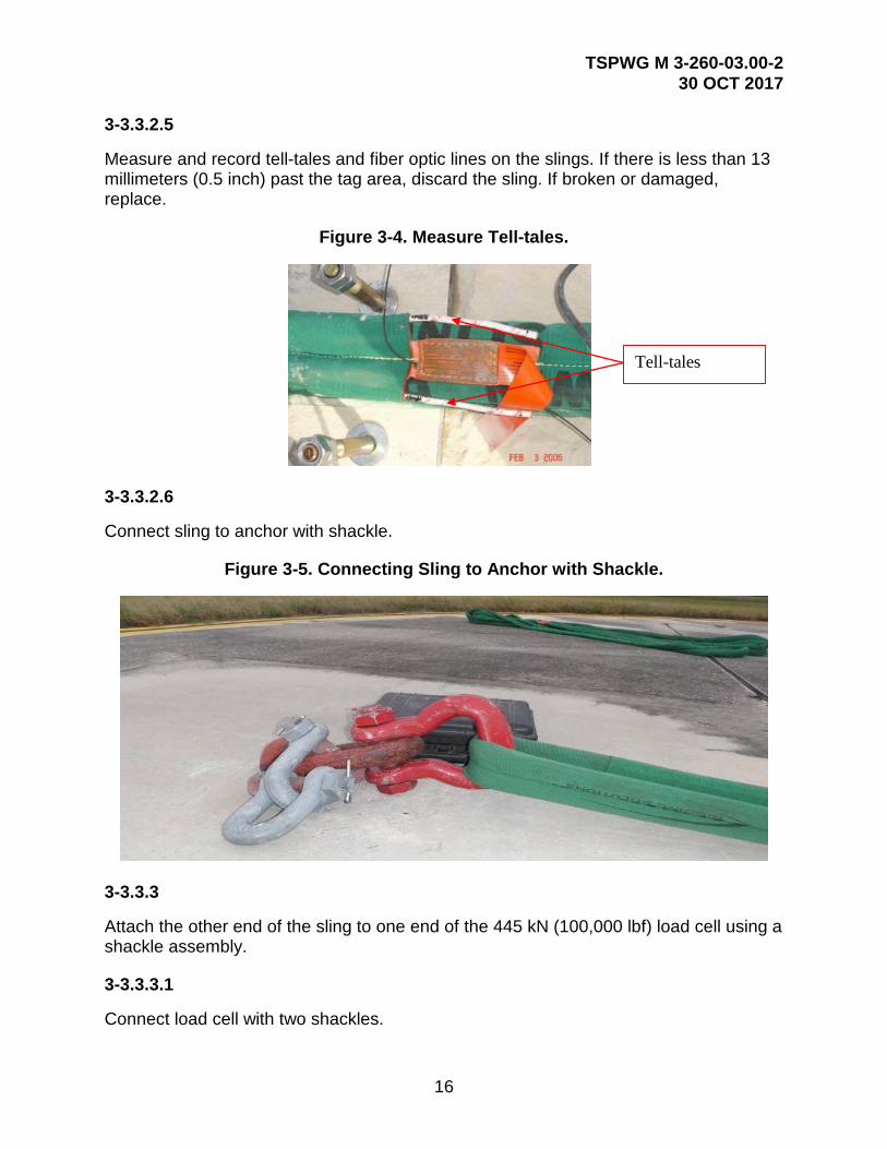
3-3.3.2.5
Measure and record tell-tales and fiber optic lines on the slings. If there is less than 13 millimeters (0.5 inch) past the tag area, discard the sling. If broken or damaged, replace.
Figure 3-4. Measure Tell-tales.
3-3.3.2.6
Connect sling to anchor with shackle.
Figure 3-5. Connecting Sling to Anchor with Shackle.
3-3.3.3
Attach the other end of the sling to one end of the 445 kN (100,000 lbf) load cell using a shackle assembly.
3-3.3.3.1
Connect load cell with two shackles.
Tell-tales

TSPWG M 3-260-03.00-2 30 OCT 2017
17
3-3.3.3.2
Locate load cell at furthest connection point from center lifting point. Do not connect/attach immediately to anchor or plate.
Figure 3-6. Connect Load Cell.
3-3.3.4
Attach another sling to the opposite end of the 445 kN (100,000 lbf) load cell using a shackle assembly.
3-3.3.4.1
Connect slings together with shackles, if needed.
Figure 3-7. Shackle Slings Together.

TSPWG M 3-260-03.00-2 30 OCT 2017
18
Figure 3-8. Steel Plate.
3-3.3.5
Attach the sling to the steel plate (Figure 3-8) using a shackle assembly.
3-3.3.5.1
Position steel plate (remove any dunnage used to raise the plate).
Figure 3-9. Position Plate with Forklift.

TSPWG M 3-260-03.00-2 30 OCT 2017
19
3-3.3.5.2
Connect sling to steel plate.
Figure 3-10. Connect Sling to Steel Plate.
3-3.3.5.3
Straddle forklift over sling assembly; push plate with forklift tines to apply 8.9 ± 2.2 kN (2000 ± 500 lbf) of load. Note the load on the slings will relax (Figure 3-11).
• Push on steel lip, not the front of the plate.
• Read pressure from the remote or directly from the load cell. Ensure load cell has been zeroed prior to applying tension.
• Ensure fork tips are on a downward angle. Figure 3-11. Align Slings with Forklift.

TSPWG M 3-260-03.00-2 30 OCT 2017
20
3-3.3.6
After removing all slack from the system, anchor the steel plate to concrete pavement using 19-millimeter (0.75 inch) -diameter, 152-millimeter (6 inch) -long steel bolts. Use 254-millimeter (10 inch) -long bolts to anchor in concrete pavement that is overlaid with asphalt (not preferred). Table 3-1 provides the minimum number of anchors required for differing maximum proof loads.
Table 3-1. Minimum Number of Anchors Required.
Maximum Proof Load in Kips
Minimum Number of Anchors
100 13 90 12 80 11 70 9 60 8 50 7
3-3.3.6.1
Assemble anchor bolts.
• Bolt, washer, nut.
• Use two nuts, one to strike with the sledgehammer and one to stay on the anchor bolt. Ensure top nut is flush with top of bolt to eliminate cross-threading.
Figure 3-12. Assemble Anchor Bolts.

TSPWG M 3-260-03.00-2 30 OCT 2017
21
3-3.3.6.2
Drill hole for anchor bolt.
• Ensure hammer drill is plumb. Drill straight down through the pavement to full potential of bit or reaching base course (whichever occurs first). This ensures the bolts can be hammered below the top of the pavement upon completion of testing.
• Drill hole in increments, remove bit and debris, re-start drill operations. This will aid in preventing the bit from binding in the pavement.
Figure 3-13. Use Forklift to Hold Plate while Anchoring.
3-3.3.6.3
Drive one bolt into the hole and secure nut.
• Install and secure anchor bolt before moving to next hole. This ensures holes stay aligned and eliminates plate movement.

TSPWG M 3-260-03.00-2 30 OCT 2017
22
Figure 3-14. Drill Holes and Install Anchors at Back of Plate.
Note: Plate had to be centered over joint, center bolt wasn’t used
3-3.3.6.4
Secure all seven bolts in the back of the plate.
Figure 3-15. Install Seven Anchors at Back of Plate.
3-3.3.6.5
Remove forks and check pressure on load cell.
3-3.3.6.6
Drill and put in the rest of the eight bolts.

TSPWG M 3-260-03.00-2 30 OCT 2017
23
Figure 3-16. Complete Installation of Anchors.
3-3.3.7
Measure anchor being tested to steel plate to find the center point.
Figure 3-17. Measuring Slings.
3-3.3.8
Position crane or forklift.
3-3.3.9
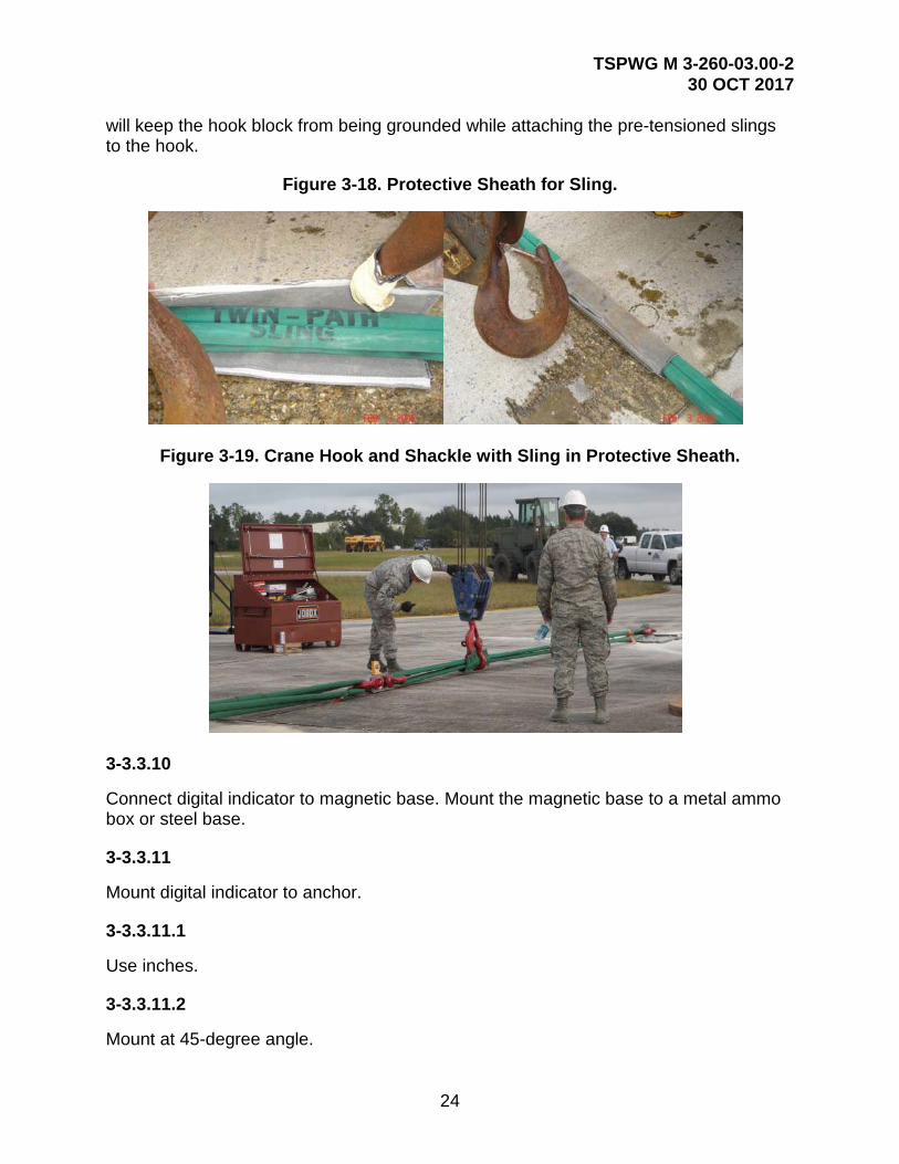
Use protective sheath on slings at contact points with crane/shackle or forks. Put slings on crane or forklift. It is best to use a shackle as a lifting point for crane operations. This
TSPWG M 3-260-03.00-2 30 OCT 2017
24
will keep the hook block from being grounded while attaching the pre-tensioned slings to the hook.
Figure 3-18. Protective Sheath for Sling.
Figure 3-19. Crane Hook and Shackle with Sling in Protective Sheath.
3-3.3.10
Connect digital indicator to magnetic base. Mount the magnetic base to a metal ammo box or steel base.
3-3.3.11
Mount digital indicator to anchor.
3-3.3.11.1
Use inches.
3-3.3.11.2
Mount at 45-degree angle.

TSPWG M 3-260-03.00-2 30 OCT 2017
25
3-3.3.11.3
Zero out with the gauge rod depressed halfway.
Figure 3-20. Digital Dial Indicator with Magnetic Base.
3-3.3.12
If the load cell is equipped with the remote readout cable, connect it.
Figure 3-21. Digital Load Cell Remote Display.
3-3.3.13
Relocate monitoring personnel behind a vehicle placed between them and the test setup.
3-3.3.14
Load the system by raising the sling at the protective sheath using an 111 kN (25,000 lbf) forklift or a crane. The engineering technician operating the forklift raises the lifting head until he reaches the load increment designated by the supervising engineer. The

TSPWG M 3-260-03.00-2 30 OCT 2017
26
load is held for two (2) minutes. The supervising engineer records the deflection measurement provided by the second technician and checks the test assembly.
3-3.3.14.1
Using crane or forklift, pull to 44.5 kN (10,000 lbf) on the load cell. (Ensure all ground personnel are at a stand-off distance 1.5 times the total length of utilized slings.)
3-3.3.14.2
Use magnetic angle reader on load cell. Do not exceed 11 degrees sling angle.
Figure 3-22. Magnetic Angle Reader on Load Cell.
3-3.3.14.3
To keep load at 44.5 kN (10,000 lbf), you may have to bump up crane or forklift.
3-3.3.14.4
Start stop-watch.
3-3.3.14.5
At 30 seconds, take load cell reading and record.
3-3.3.14.6
At 1:00, take load cell reading and record.
3-3.3.14.7
At 1:30, take load cell reading and record.
3-3.3.14.8
At 2:00, take load cell reading and record.
TSPWG M 3-260-03.00-2 30 OCT 2017
27
3-3.3.14.9
Take dial gauge reading and record.
3-3.3.15
Increase the load sequentially until the desired ultimate load is reached.
3-3.3.15.1
Raise the load to 89 kN (20,000 lbf) and repeat above timed steps and record.
3-3.3.15.2
Continue in 44.5 kN (10,000 lbf) increments until reaching 445 kN (100,000 lbf) or desired maximum load.
WARNING: Do not load the system beyond twice the working load of the anchor or 445 kN (100,000 lbf), whichever is lower.
3-3.3.16
Maintain the desired ultimate load (twice the working load) for ten (10) minutes. Record measurements including:
• Vertical distance from the pavement to the apex of the assembly.
• Horizontal distance from the “eye” of the steel plate to the apex.
• Horizontal distance from the eye of the steel plate to eye of the anchor.
3-3.3.17
Following the ten-minute holding at desired ultimate load, slowly lower the slings to unload the system and remove slings from crane or forks.
3-3.3.17.1
Disconnect load cell immediately upon test completion. The slings are at a relaxed tension at this point but will regain shape/tension quickly. Attempting to disconnect the slings/load cell after they have re-tensioned is difficult and dangerous.
3-3.3.17.2
If the slings have re-tensioned before you have disconnected them or the load cell then reassemble to the test setup, raise the slings to the peak load minus 44.5 kN (10 kips), hold for five minutes, lower the slings, and immediately disconnect the load cell.

TSPWG M 3-260-03.00-2 30 OCT 2017
28
3-3.3.18
After all tension is released from the system, inspect the aircraft anchor carefully for damage or deformation. Take final deflection measurements. Measure and record tell-tales on slings (there must be no less than 1.3 millimeters [0.05 inch] past tag area).
Figure 3-23. Sling Tell-tales.
3-3.3.19
Disassemble the test setup in reverse order from the assembly process.
3-3.3.19.1
The load cell should already be disconnected. It should have been disconnected immediately upon test completion and lowering of the sling. The slings regain tension quickly. Attempting to disconnect the slings/load cell after they have re-tensioned is difficult and dangerous. If the slings have re-tensioned before you have disconnected them then raise the slings to the peak load minus 10 kips and hold for five minutes. Lower the slings and immediately disconnect the load cell.
3-3.3.19.2
Remove slings/shackles/hardware; return to storage containers (do not pack wet slings).
3-3.3.19.3
Remove anchor plate and countersink anchor bolts to allow holes to be filled with a sealant material compatible with the pavement.
3-3.3.19.4
Clean and pack all slings, hardware, tools, etc. in storage containers.

TSPWG M 3-260-03.00-2 30 OCT 2017
29
APPENDIX A REFERENCES
AIR FORCE
AFI 32-1041, Pavement Evaluation Program, http://www.e-publishing.af.mil/
ETL 01-10, Design and Construction of High-Capacity Trim Pad Anchoring Systems, https://www.wbdg.org/ffc/af-afcec/engineering-technical-letters-afetl
JOINT
UFC 3-260-01, Airfield and Heliport Planning and Design, https://www.wbdg.org/ffc/dod/unified-facilities-criteria-ufc
AMERICAN SOCIETY FOR TESTING AND MATERIALS (ASTM):
Annual Book of ASTM Standards, https://www.astm.org/BOOKSTORE/BOS/index.html
ASTM A588/A588M, Standard Specification for High-Strength Low-Alloy Structural Steel, up to 50 ksi [345 MPa] Minimum Yield Point, with Atmospheric Corrosion Resistance, https://www.astm.org/standards/a588.htm
GENERAL DYNAMICS CORPORATION
Technical Report 16PR7084, Revision A, Flight Line Run Station Aircraft Engine Run Tie-down Proof-Load Test, by Basis A. Korolenko, 4 March 1998
TSPWG M 3-260-03.00-2 30 OCT 2017
30
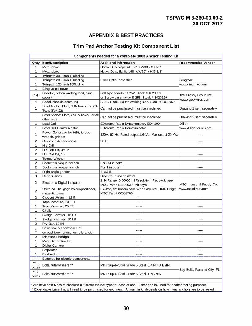
APPENDIX B BEST PRACTICES
Trim Pad Anchor Testing Kit Component List
Qnty Item/Description Additional information Recommended Vendor1 Metal jobox Heavy Duty slope lid L60" x W30 x 39 1/2" -----1 Metal jobox Heavy Duty, flat lid L48" x W30" x H33 3/8" -----1 Twinpath 393 inch 100k sling1 Twinpath 285 inch 100k sling1 Twinpath 120 inch 100k sling1 Sling velcro cover
* 4 Shackle, 50 ton working load, sling saver *
Bolt type shackle S-252, Stock # 1020551or Screw pin shackle S-253, Stock # 1020629
4 Spool, shackle centering S-255 Spool, 50 ton working load, Stock # 1020957
1 Steel Anchor Plate, 1 IN holes, for 70k Tests (F/A 22) Can not be purchased, must be machined Drawing 1 sent seperately
1 Steel Anchor Plate, 3/4 IN holes, for all other tests Can not be purchased, must be machined Drawing 2 sent seperately
1 Load Cell EDxtreme Radio Dynamometer, EDx-100k1 Load Cell Communicator EDxtreme Radio Communicator
1 Power Generator for Hiliti, torque wrench, grinder 120V, 60 Hz, Rated output 1.6kVa, Max output 20 kVa -----
2 Outdoor extension cord 50 FT -----1 Hilti Drill -----2 Hilti Drill Bit, 3/4 in -----2 Hilti Drill Bit, 1 in -----1 Torque Wrench -----2 Socket for torque wrench For 3/4 in bolts -----2 Socket for torque wrench For 1 in bolts -----1 Right-angle grinder 4-1/2 IN -----3 Grinder discs Discs for grinding metal -----
2 Electronic Digital Indicator 1 IN Range, 0.00005 IN Resolution, Flat back typeMSC Part # 81192932, Mitutoyo
2 Universal Dial gage holder/positioner, magentic base
Flexbar, flat bottom base w/fine adjustor, 16IN HeightMSC Part # 06581706
2 Cresent Wrench, 12 IN ----- -----1 Tape Measure, 100 FT ----- -----1 Tape Measure, 25 FT ----- -----1 Chalk ----- -----1 Sledge Hammer, 12 LB ----- -----1 Sledge Hammer, 20 LB ----- -----2 Pry Bar, 18 IN ----- -----
1 Basic tool set composed of screwdrivers, wrenches, pilers, etc. ----- -----
2 Minature Flashlight ----- -----1 Magnetic protractor ----- -----1 Digital Camera ----- -----1 Stopwatch ----- -----1 First Aid Kit ----- -----
----- Batteries for electric components ----- -----** 5
boxes Bolts/nuts/washers ** MKT Sup-R-Stud Grade 5 Steel, 3/4IN x 8 1/2IN
** 5 boxes Bolts/nuts/washers ** MKT Sup-R-Stud Grade 5 Steel, 1IN x 9IN
Components needed for a complete 100k Anchor Testing Kit
** Expendable items that will need to be purchased for each test. Amount in kit depends on how many anchors are to be tested.
Dillionwww.dillion-force.com
Slingmaxwww.slingmax.com
The Crosby Group Inc.www.cgedwards.com
* We have both types of shackles but prefer the bolt type for ease of use. Either can be used for anchor testing purposes.
Fiber Optic Inspection
MSC Industrial Supply Co.www.mscdirect.com
Bay Bolts, Panama City, FL

TSPWG M 3-260-03.00-2 30 OCT 2017
31
Trim Pad Anchor Testing Check List
Date:___________ Location:____________________________________________Start Time: ___________________ End Time: ________________________Working Load: _____________________ Ultimate Load: ____________________
ANCHOR TESTING SEQUENCEAttach & align shackles, slings, load cell, lift head (if used) & steel anchor plate. Ensure the lift head (if used) is centered.Measure tell-tales (there should be no less than 1/2" past tag area).Document tell-tale length of sling 1 (pre-test).Document tell-tale length of sling 2 (pre-test). Document tell-tale length of sling 3 (pre-test). Pretension system using forklift to shift steel plate. Apply 600 to 2000 lbs. Document pretension load (pre-securing).Maintain forklift pressure on plate while securing steel anchor plate.Assemble Anchor bolts.Drill holes for the 7 anchors at the back of the plate.Drive and secure the 7 anchors at the back of the plate.Remove the fork lift. Drill holes for the 8 anchors at the front of the plate.Drive and secure the 8 anchors at the front of the plate.Document pretension load (post-securing).Ensure that system is securely fastened.Place front vehicle tire on back end of anchored steel plate if anchored in asphalt. Measure entire length of system.Document overall length of system. Identify the center point of system.Document center point location.Ensure the protective sheath (if used) is located at the center point.Rig crane (or forklift) to apply load to the system at center point.Mount digital dial gauge to anchor. Zero dial gauge.Connect remote load cell readout cable if applicable.Move personnel behind protective shield.Document actual load cell reading.
Begin loading. Load to 22 kips hold for two minutes then record load & deflections.Increase load by 10 kips hold for two minutes. Record load and deflection.Repeat load increase in increments of 10 kips or to the ultimate load.
At the ultimate load hold the load for 10 minutes then record load and deflections. Unload slings. Inspect for damage. Document any damage.Document tell-tale length of sling 1 (post-test).Document tell-tale length of sling 2 (post-test).Document tell-tale length of sling 3 (post-test). Disassemble the test setup.Remove the anchor plate, counter sink the anchor bolts, fill holes with sealant. Clean area, tools and slings. Pack all slings, hardware, and tools in the storage containers.
TRIM PAD ANCHOR TESTING CHECK LIST
*Shaded boxes are provided for the entry of data

TSPWG M 3-260-03.00-2 30 OCT 2017
32
Trim Pad Anchor Testing Inspection Record Sheet
YES NO QUESTION1. Do any of the steel components of the anchor system exhibit rust,deformation, cracks, or any other defect that reduces the cross-sectionalarea?2. Does the anchor block or surrounding concrete slab exhibit spalling orcracking?3. Does the anchor block or surrounding concrete slab exhibit anyevidence of upheaval?4. Does spalling and/or cracking exist at the interface of the steel anchoreye and the concrete anchor block?5. Has the anchor been evaluated and/or inspected previously?6. Has any maintenance been done to the anchor since its lastevaluation/inspection?7. Have any of the connections been replaced since the lastevaluation/inspection?8. If these connections are commercially available shackles, are themanufacturer’s data and rating certification for the shackles available?
9. What is the main aircraft that uses the trim pad anchor? ______________
10. What is the typical trim operation used (e.g., single engine only)? ______
11. How many trim operations does the anchor support annually? _________
12. Have there been any significant environmental events since the lastevaluation/inspection that could have compromised the anchor’sintegrity (e.g., flooding, earthquakes)?
OBSERVATIONS/COMMENTS:
Signature:__________________________________ Printed Name/Rank:__________________________
TRIM PAD ANCHOR TESTING INSPECTION RECORD SHEET
Working Load: _________________ Ultimate Load: _____________________Start Time: ___________________ End Time: ________________________Date:___________ Location:_____________________________________________

TSPWG M 3-260-03.00-2 30 OCT 2017
33
Trim Pad Anchor Testing Data Sheet
Date:___________ Location:___________________________________________Start Time: ___________________ End Time: ________________________Working Load: _____________________Ultimate Load: ____________________LOAD CELL (lbf) CRANE LOAD (lbf) TIME (min) DIAL GAUGE READING
TRIM PAD ANCHOR TESTING DATA SHEET

TSPWG M 3-260-03.00-2 30 OCT 2017
34
APPENDIX C GLOSSARY
C-1 ACRONYMS AND ABBREVIATIONS
AFCEC Air Force Civil Engineer Center
AFI Air Force Instruction
ASTM American Society for Testing and Materials
ETL Air Force Engineering Technical Letter
kip 1,000-pound (453.6-kilogram) load
kN kilonewtons
kPa kilopascals
ksi kips per square inch
lbf pound force
mm millimeters
MPa megapascal
N newtons
psi pound per square inch
UFC Unified Facilities Criteria


![HDA Design anchor - Motek AS€¦ · Anchor bolt Nominal tensile strength f uk [N/mm²] 800 800 800 ... HDA Design anchor 09 / 2012 77 Anchor TE 24 a) TE 25 a) Anchor Anchor. HDA](https://img.pdfslide.us/doc/110x75/5b34310d7f8b9a436d8bbdfd/hda-design-anchor-motek-as-anchor-bolt-nominal-tensile-strength-f-uk-nmm.jpg)