Embed Size (px)
Citation preview
TSM23S/QIntegrated Step-Servo Motor
Hardware Manual
920-0081B3/16/2017

2920-0081B3/16/2017
TSM23S/Q Hardware Manual
Contents1 Introduction ........................................................................4
1.1 Features .................................................................................41.2 Block Diagram .......................................................................51.3 Safety Instructions .................................................................6
2 Getting Started ..................................................................72.1 Installing Software .................................................................72.2 Mounting the Hardware .........................................................72.3 Choosing a Power Supply .....................................................8
2.3.1 Voltage ................................................................................... 82.3.2 Regeneration Clamp ............................................................... 82.3.3 Current .................................................................................... 9
3 Installation/Connections ....................................................123.1 Connecting the Power Supply ...............................................123.2 Connecting the TSM23S/Q Communications ........................13
3.2.1 Connecting to the PC using RS-232 ....................................... 133.2.2 Connecting to a Host using RS-485 ........................................ 14
3.3 Inputs and Outputs ................................................................163.3.1 Connector Pin Diagram ........................................................... 163.3.2 STEP & DIR Digital Inputs ....................................................... 173.3.3 X3/X4/X5/X6 Digital Input ........................................................ 183.3.4 X7/X8 Digital Input ................................................................... 193.3.5 AIN Input .................................................................................. 193.3.6 Programmable Output Y1/Y2/Y3 ............................................. 203.3.7 Programmable Output Y4 ........................................................ 21
4 Troubleshooting .................................................................22
5 Reference Materials ..........................................................235.1 Torque-Speed Curves ............................................................235.2 Mechanical Outlines ..............................................................245.3 Technical Specifications .........................................................255.4 SCL Command Reference ....................................................265.5 Optional Accessories .............................................................28
6 Contacting Applied Motion Products ..................................32
3 920-0081B3/16/2017
TSM23S/Q Hardware Manual
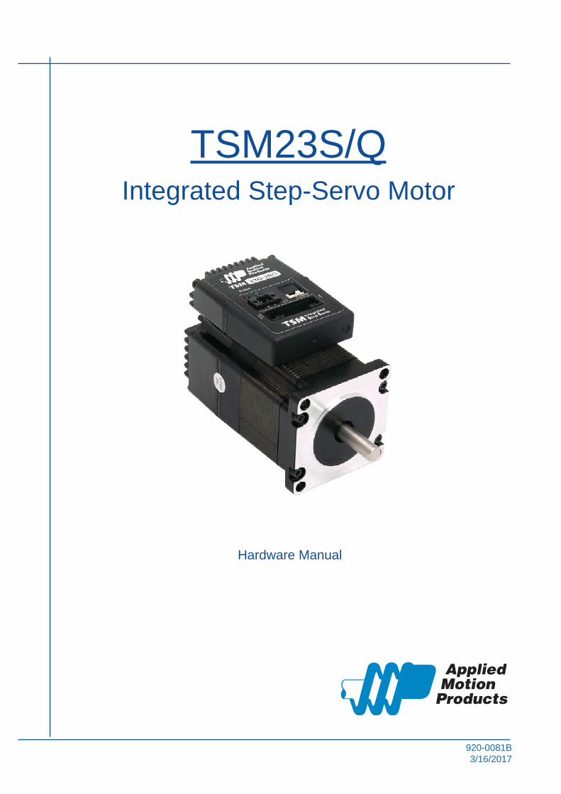
ModelCommunications
RS-232 RS-485 Modbus/RTU
TSM23S-2AG
TSM23S-2RG
TSM23S-3AG
TSM23S-3RG
TSM23Q-2AG
TSM23Q-2RG
TSM23Q-3AG
TSM23Q-3RG

4920-0081B3/16/2017
TSM23S/Q Hardware Manual
1 IntroductionThank you for selecting the Applied Motion Products TSM23S/Q Integrated Motor.The TSM line of integrated step-servo motors combines servo technology with an integrated motor to create a product with exceptional feature and broad capability. We hope our commitment to performance, quality and economy will result in a successful motion control project.
1.1 Features• Programmable, Digital servo driver and motor in an integrated package• Operates from a 12 to 70 volt DC power supply• Control Modes:
Torque Control* Analog input* SCL commanded
Velocity Control* Digital input Control Velocity * Analog velocity * SCL Commanded Velocity (Jogging)
Position Control* Digital Signal type
Step & DirectionCW & CCW pulse
A/B Quadrature* Analog Position* Serial Commanded Position
Q Programming(Q Verision only)* Stand alone operation
• Communications:RS-232 , RS-485 or Modbus/RTU
• 5000 line (20,000 counts/rev) encoder feedback• Available torque:
TSM23-2G: Up to 1.0 N•m Continuous(1.3 N•m Boost)TSM23-3G: Up to 1.5N•m Continuous(2.0 N•m Boost)TSM23-4G: Up to 1.5N•m Continuous(2.0 N•m Boost)
• I/O:8 optically isolated digital inputs, with adjustable bandwidth digital noise rejection filter, 5 to 24 volts 4 optically isolated digital output, 30V/100 mA max.1 analog input for speed and position control, 0 to 5 voltsDifferential encoder outputs (A±, B±, Z±), 26C31 line driver, 20 mA sink or source max
• Technological advances:Full servo control, Closed loopEfficient, Accurate, Fast, SmoothIntelligent, Compact

5 920-0081B3/16/2017
TSM23S/Q Hardware Manual
1.2 Block Diagram
A+A -B+B -
Z+Z-
LineDriverEncoder Outputs
Block Diagram
MOSFETPWMPower
Amplifier
12 - 70 VDC External
Power Supply
VoltageTempDetect
OverCurrentDetect
motor
encoder
5 Volt DCPower Supply
DSPDriver
Controller
3.3VDCInternalLogic
Supply
TSM23S/Q
I/O C
onne
ctor
+
+5VDC (100mA max)
GND
Status
AIN
OpticalIso
RS-232 or RS-485
Com
mC
onn
Pow
erC
onn
GND
+5V
RS-232RXD,+5V,TXD,GND,GND
orRS-485
RX+,RX-,TX+,TX-,GND
-
X1X2X3X4X5X6X7X8
Y1Y2Y3Y4
OpticalISO

6920-0081B3/16/2017
TSM23S/Q Hardware Manual
1.3 Safety InstructionsOnly qualified personnel should transport, assemble, install, operate, or maintain this equipment. Properly qualified personnel are persons who are familiar with the transport, assembly, installation, operation, and maintenance of motors, and who meet the appropriate qualifications for their jobs.
To minimize the risk of potential safety problems, all applicable local and national codes regulating the installation and operation of equipment should be followed. These codes may vary from area to area and it is the responsibility of the operating personnel to determine which codes should be followed, and to verify that the equipment, installation, and operation are in compliance with the latest revision of these codes.
Equipment damage or serious injury to personnel can result from the failure to follow all applicable codes and standards. Applied Motion Products does not guarantee the products described in this publication are suitable for a particular application, nor do they assume any responsibility for product design, installation, or operation.
• Read all available documentation before assembly and operation. Incorrect handling of the products referenced in this manual can result in injury and damage to persons and machinery. All technical information concerning the installation requirements must be strictly adhered to.
• It is vital to ensure that all system components are connected to earth ground. Electrical safety is impossible without a low-resistance earth connection.
• This product contains electrostatically sensitive components that can be damaged by incorrect handling. Follow qualified anti-static procedures before touching the product.
• During operation keep all covers and cabinet doors shut to avoid any hazards that could possibly cause severe damage to the product or personal health.
• During operation, the product may have components that are live or have hot surfaces.
• Never plug in or unplug the Integrated Motor while the system is live. The possibility of electric arcing can cause damage.
Be alert to the potential for personal injury. Follow recommended precautions and safe operating practices emphasized with alert symbols. Safety notices in this manual provide important information. Read and be familiar with these instructions before attempting installation, operation, or maintenance. The purpose of this section is to alert users to the possible safety hazards associated with this equipment and the precautions necessary to reduce the risk of personal injury and damage to equipment. Failure to observe these precautions could result in serious bodily injury, damage to the equipment, or operational difficulty.

7 920-0081B3/16/2017
TSM23S/Q Hardware Manual
2 Getting StartedThe following items are needed:
• a 12 - 70 Volt DC power supply, see the section below entitled “Choosing a Power Supply” for help in choosing the right one
• a small flat blade screwdriver for tightening the connectors (included)
• a PC running Microsoft Windows XP, Vista, or Windows 7 or 8
• an Applied Motion Products programming cable (included with RS-232 Models; RS-485 converters are available from Applied Motion Products)
2.1 Installing SoftwareBefore utilizing the TSM23S/Q Integrated Step-Servo Motor and Step-Servo Quick Tuner Software in an application, the following steps are necessary:
• Install the Step-Servo Quick Tuner software from the Applied Motion Products website.
• Connect the drive to the PC using the programming cable. When using RS-485, it must be setup in a 4-Wire configuration (see “Connecting to a host using RS-485” below.)
• Connect the drive to the power supply. See instructions below.
• Launch the software by clicking Start...Programs...Applied Motion Products.
• Apply power to the drive.
• The software will recognize the drive and display the model and firmware version. At this point, it is ready for use.
2.2 Mounting the HardwareAs with any step motor, the TSM23S/Q must be mounted so as to provide maximum heat sinking and airflow. Keep enough space around the Integrated Motor to allow for airflow.
• Never use the drive where there is no airflow or where other devices cause the surrounding air to be more than 40°C (104°F).
• Never put the drive where it can get wet.
• Never use the drive where metal or other electrically conductive particles can infiltrate the drive.
• Always provide airflow around the drive.

8920-0081B3/16/2017
TSM23S/Q Hardware Manual
2.3 Choosing a Power SupplyThe main considerations when choosing a power supply are the voltage and current requirements for the application.
2.3.1 Voltage
The TSM23S/Q is designed to give optimum performance between 24 and 48 Volts DC. Choosing the voltage depends on the performance needed and motor/drive heating that is acceptable and/or does not cause a drive over-temperature. Higher voltages will give higher speed performance but will cause the TSM23S/Q to produce higher temperatures. Using power supplies with voltage outputs that are near the drive maximum may significantly reduce the operational duty-cycle.
The extended range of operation can be as low as 10 VDC minimum to as high as 75 VDC maximum. When operating below 18 VDC, the power supply input may require larger capacitance to prevent under-voltage and internal-supply alarms. Current spikes may make supply readings erratic. The supply input cannot go below 10 VDC for reliable operation. Absolute minimum power supply input is 10 VDC. If the Input supply drops below 10 VDC the low voltage alarm will be triggered. This will not fault the drive.
Absolute maximum power supply input is 75 VDC at which point an over-voltage alarm and fault will occur. When using a power supply that is regulated and is near the drive maximum voltage of 75 VDC, a voltage clamp may be required to prevent over-voltage when regeneration occurs. When using an unregulated power supply, make sure the no-load voltage of the supply does not exceed the drive’s maximum input voltage of 75 VDC.
2.3.2 Regeneration Clamp
If a regulated power supply is being used, there may be a problem with regeneration. When a load decelerates rapidly from a high speed, some of the kinetic energy of the load is transferred back to the power supply, possibly tripping the over-voltage protection of a regulated power supply, causing it to shut down. This problem can be solved with the use of an Applied Motion Products RC880 Regeneration Clamp. It is recommended that an RC880 initially be installed in an application. If the “regen” LED on the RC880 never flashes, the clamp is not necessary.
RC880 Regen Clamp
LEDs
Green - Power
Red - Regen on

9 920-0081B3/16/2017
TSM23S/Q Hardware Manual
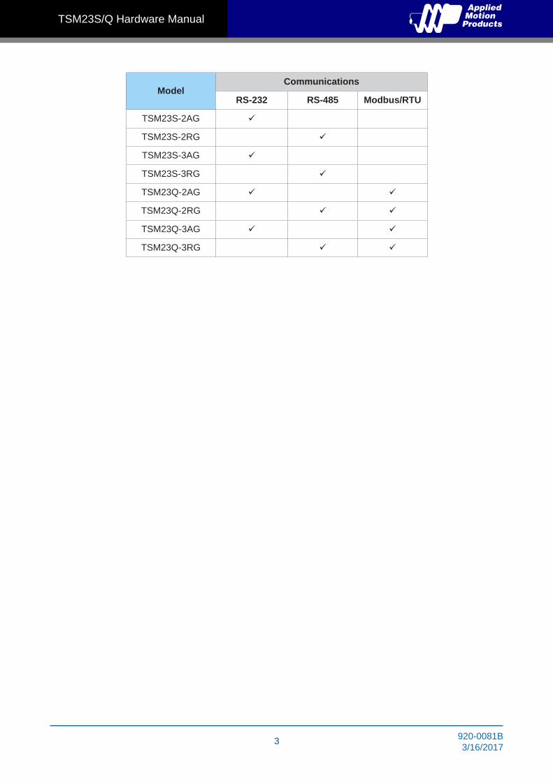
2.3.3 Current
The maximum supply currents required by the TSM23S/Q are shown in the charts below at different power supply voltage inputs. The TSM23S/Q power supply current is lower than the winding currents because it uses switching amplifiers to convert a high voltage and low current into lower voltage and higher current. The more the power supply voltage exceeds the motor voltage, the less current will be required from the power supply.
It is important to note that the current draw is significantly different at higher speeds depending on the torque load to the motor. Estimating how much current is necessary may require a good analysis of the load the motor will encounter.
0
0.5
1
1.5
2
2.5
3
3.5
0
0.3
0.6
0.9
1.2
1.5
0 10 20 30 40 50
Torq
ue(N
.m)
Speed(RPS)
TSM23-2G 24V Power
Am
ps
ContinuousTorque
BoostSupply Current
Full LoadNo Load
0
0.5
1
1.5
2
2.5
3
3.5
0
0.3
0.6
0.9
1.2
1.5
0 10 20 30 40 50
Torq
ue(N
.m)
Speed(RPS)
TSM23-2G 48V Power
Am
ps
ContinuousTorque
BoostSupply Current
Full LoadNo Load

10920-0081B3/16/2017
TSM23S/Q Hardware Manual
0
0.5
1
1.5
2
2.5
3
3.5
0
0.3
0.6
0.9
1.2
1.5
0 10 20 30 40 50
Torq
ue(N
.m)
Speed(RPS)
TSM23-2G 70V Power
Am
ps
ContinuousTorque
BoostSupply Current
Full LoadNo Load
0
0.5
1
1.5
2
2.5
3
3.5
0
0.5
1
1.5
2
2.5
0 10 20 30 40 50
Torq
ue(N
.m)
Speed(RPS)
TSM23-3G 24V Power
Am
psContinuous
Torque
BoostSupply Current
Full LoadNo Load
0
0.5
1
1.5
2
2.5
3
3.5
0
0.5
1
1.5
2
2.5
0 10 20 30 40 50
Torq
ue(N
.m)
Speed(RPS)
TSM23-3G 48V Power
Am
ps
ContinuousTorque
BoostSupply Current
Full LoadNo Load
11 920-0081B3/16/2017
TSM23S/Q Hardware Manual
0
0.5
1
1.5
2
2.5
3
3.5
0
0.5
1
1.5
2
2.5
0 10 20 30 40 50
Torq
ue(N
.m)
Speed(RPS)
TSM23-3G 70V Power
Am
ps
ContinuousTorque
BoostSupply Current
Full LoadNo Load
12920-0081B3/16/2017
TSM23S/Q Hardware Manual
3 Installation/Connections
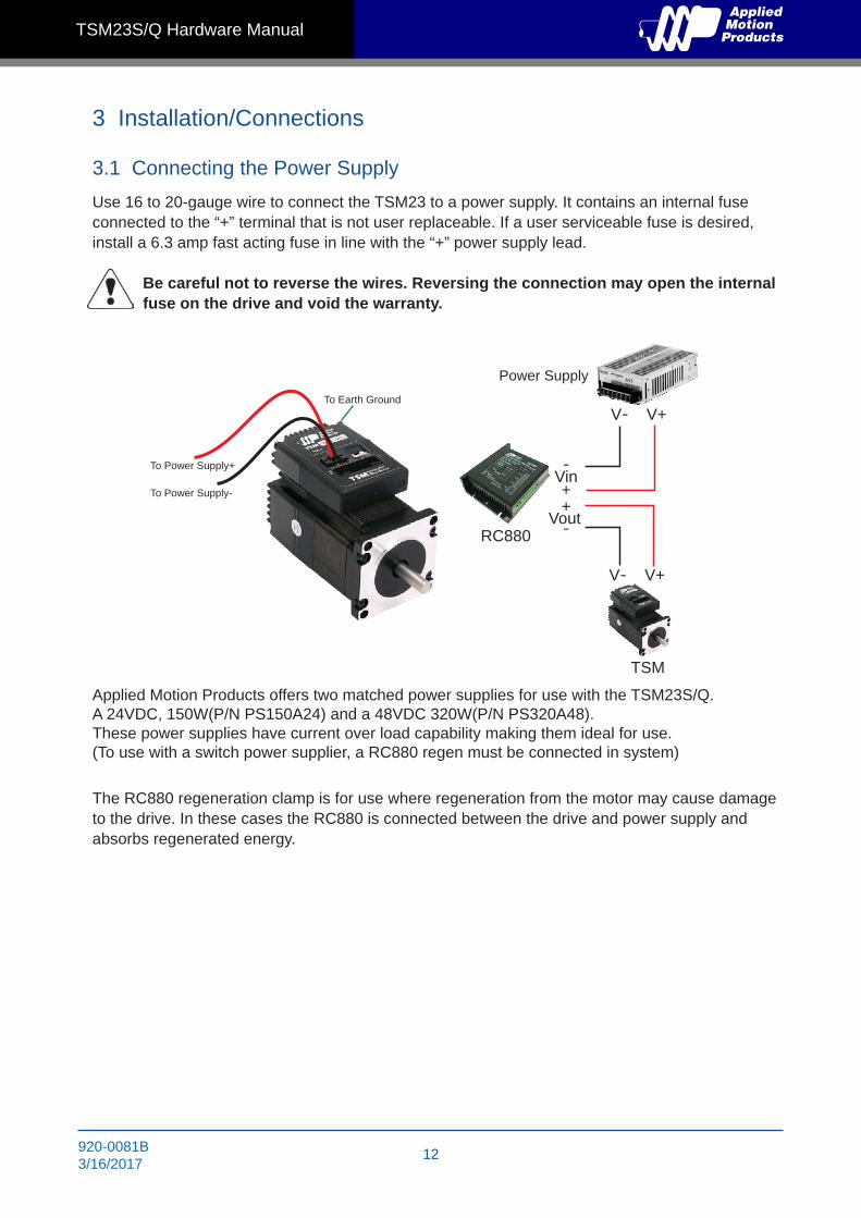
3.1 Connecting the Power SupplyUse 16 to 20-gauge wire to connect the TSM23 to a power supply. It contains an internal fuse connected to the “+” terminal that is not user replaceable. If a user serviceable fuse is desired, install a 6.3 amp fast acting fuse in line with the “+” power supply lead.
Be careful not to reverse the wires. Reversing the connection may open the internal fuse on the drive and void the warranty.
Applied Motion Products offers two matched power supplies for use with the TSM23S/Q. A 24VDC, 150W(P/N PS150A24) and a 48VDC 320W(P/N PS320A48). These power supplies have current over load capability making them ideal for use.(To use with a switch power supplier, a RC880 regen must be connected in system)
The RC880 regeneration clamp is for use where regeneration from the motor may cause damage to the drive. In these cases the RC880 is connected between the drive and power supply and absorbs regenerated energy.
To Power Supply-
To Power Supply+
To Earth Ground
RC880
TSM
V- V+
V- V+
Vin-+
Vout+-
Power Supply

13 920-0081B3/16/2017
TSM23S/Q Hardware Manual
3.2 Connecting the TSM23S/Q CommunicationsThe TSM23S/Q is available with two types of serial communications, RS-232 (TSM23S/Q -AG) or RS-485 (TSM23S/Q -RG). Each type requires a different hardware connection for interface to a PC or other Host system. The RS-232 version comes with a cable that will provide the interface to an RS-232 port through a DB9 style connector. The RS-485 version requires the user to provide both the cabling and the RS-485 interface. Below are descriptions of how to interface both of these serial communication types to a PC.
3.2.1 Connecting to the PC using RS-232
Locate the TSM23S/Q within 1.5 meters of the PC. Plug the DB9 connector of the communication cable that came with the drive into the serial port of the PC. Plug the small end into the crimp style connector on the TSM23S/Q . Secure the cable to the PC with the screws on the DB9 connector.
Note: If the PC does not have an RS-232 serial port, a USB Serial Converter will be needed.You can contact Applied Motion Products to buy a USB to RS-232 converter.
The RS-232 circuitry does not have any extra electrical “hardening” and care should be taken when connecting to the RS-232 port as hot plugging could result in circuit failure. If this is a concern the RS-485 version should be used.
GND
TX
+5V
RX

14920-0081B3/16/2017
TSM23S/Q Hardware Manual
3.2.2 Connecting to a Host using RS-485
RS-485 communication allows connection of more than one drive to a single host PC, PLC, HMI or other computer. It also allows the communication cable to be long (more than 300 meters or 1000 feet). The use of Category 5 cable is recommended as it is widely used for computer networks, inexpensive, easily obtained and certified for quality and data integrity.
The TSM23S/Q can be used with either Two-Wire or Four-Wire RS-485 implementation. The connection can be point-to-point (i.e. one drive and one host) or a multi-drop network (one host and up to 32 drives).
NOTE: To use the TSM23S/Q RS-485 version with the Step-Servo Quick Tuner software, it must be connected in the Four-Wire configuration (see below)
RS-485 Connector Diagram
Four-Wire Configuration
Four-Wire Systems utilize separate transmit and receive wires. One pair of wires must connect the host’s transmit signals to each drive’s RX+ and RX- terminals. The other pair connects the drive’s TX+ and TX- terminals to the host’s receive signals. A logic ground terminal is provided on each drive and can be used to keep all drives at the same ground potential. This terminal connects internally to the DC power supply return (V-), so if all the drives on the RS-485 network are powered from the same supply, only one drive’s GND terminal should be connected to the host computer ground, others’ GND terminal must not connect the logic grounds.
Because the host in a four-wire system never needs to disable its transmitter, software is simplified. Some converters make this process very difficult to implement and can delay communications.
NOTE: If the PC does not have an RS-485 serial port, a converter is required. You can contact Applied Motion Products to buy a USB to RS-485 converter.
RX+RX-TX+TX-GND
to PC GNDto PC RX-to PC RX+to PC TX-to PC TX+
Drive #1 Drive #2 Drive #N
RX+RX-TX+TX-GND
RX+RX-TX+TX-GND
RX+RX-TX+TX-GND
120Ω
RX+RX-
15 920-0081B3/16/2017
TSM23S/Q Hardware Manual
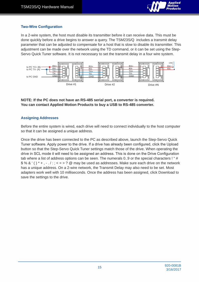
Two-Wire Configuration
In a 2-wire system, the host must disable its transmitter before it can receive data. This must be done quickly before a drive begins to answer a query. The TSM23S/Q includes a transmit delay parameter that can be adjusted to compensate for a host that is slow to disable its transmitter. This adjustment can be made over the network using the TD command, or it can be set using the Step-Servo Quick Tuner software. It is not necessary to set the transmit delay in a four wire system.
NOTE: If the PC does not have an RS-485 serial port, a converter is required. You can contact Applied Motion Products to buy a USB to RS-485 converter.
Assigning Addresses
Before the entire system is wired, each drive will need to connect individually to the host computer so that it can be assigned a unique address.
Once the drive has been connected to the PC as described above, launch the Step-Servo Quick Tuner software. Apply power to the drive. If a drive has already been configured, click the Upload button so that the Step-Servo Quick Tuner settings match those of the drive. When operating the drive in SCL mode it will need to be assigned an address. This is done on the Drive Configuration tab where a list of address options can be seen. The numerals 0..9 or the special characters ! “ # $ % & ‘ ( ) * + , - . / : ; < = > ? @ may be used as addresses. Make sure each drive on the network has a unique address. On a 2-wire network, the Transmit Delay may also need to be set. Most adapters work well with 10 milliseconds. Once the address has been assigned, click Download to save the settings to the drive.
to PC GND
to PC TX- (A)to PC TX+ (B)
Drive #1 Drive #2 Drive #N
RX+RX-TX+TX-GND
RX+RX-TX+TX-GND
RX+RX-TX+TX-GND
120Ω
RX+RX-

16920-0081B3/16/2017
TSM23S/Q Hardware Manual
3.3 Inputs and OutputsThe TSM23S/Q has three types of inputs:
• High speed digital inputs for step & direction commands or encoder following, 5 to 24 volt logic
• Low speed digital input for other signals, 5 to 24 volt logic
• Analog input for analog speed and positioning modes
All drives include 8 digital inputs and 1 analog input
• X1/STEP & X2/DIR are high-speed digital inputs for commanding position. Quadrature signals from encoders can also be used. When not being used for the Step & Direction function these inputs can be used for CW & CCW step, (start/stop)/direction (oscillator mode), or general purpose input
• X3 & X4 are low speed software programmable input and can be used for Motor Enable/Disable and Alarm/Fault Reset function, or general purpose input
• X5/X6/X7/X8 are low speed software programmable input and can be used for CW/CCW Jog, CW/CCW Limit, Speed 1/Speed 2 (oscillator mode), or general purpose input
• AIN is an analog input for a velocity or position command signal. It can accept 0-5 volts and has gain, filtering, offset and dead-band settings.
3.3.1 Connector Pin Diagram
A-B-Z-Y4-YCOMY2X8-X7-GND+5VX6X4DIR-STEP-
A+B+Z+
Y4+Y3Y1
X8+X7+AIN
XCOMX5X3
DIR+STEP+
27 28
1 2
17 920-0081B3/16/2017
TSM23S/Q Hardware Manual
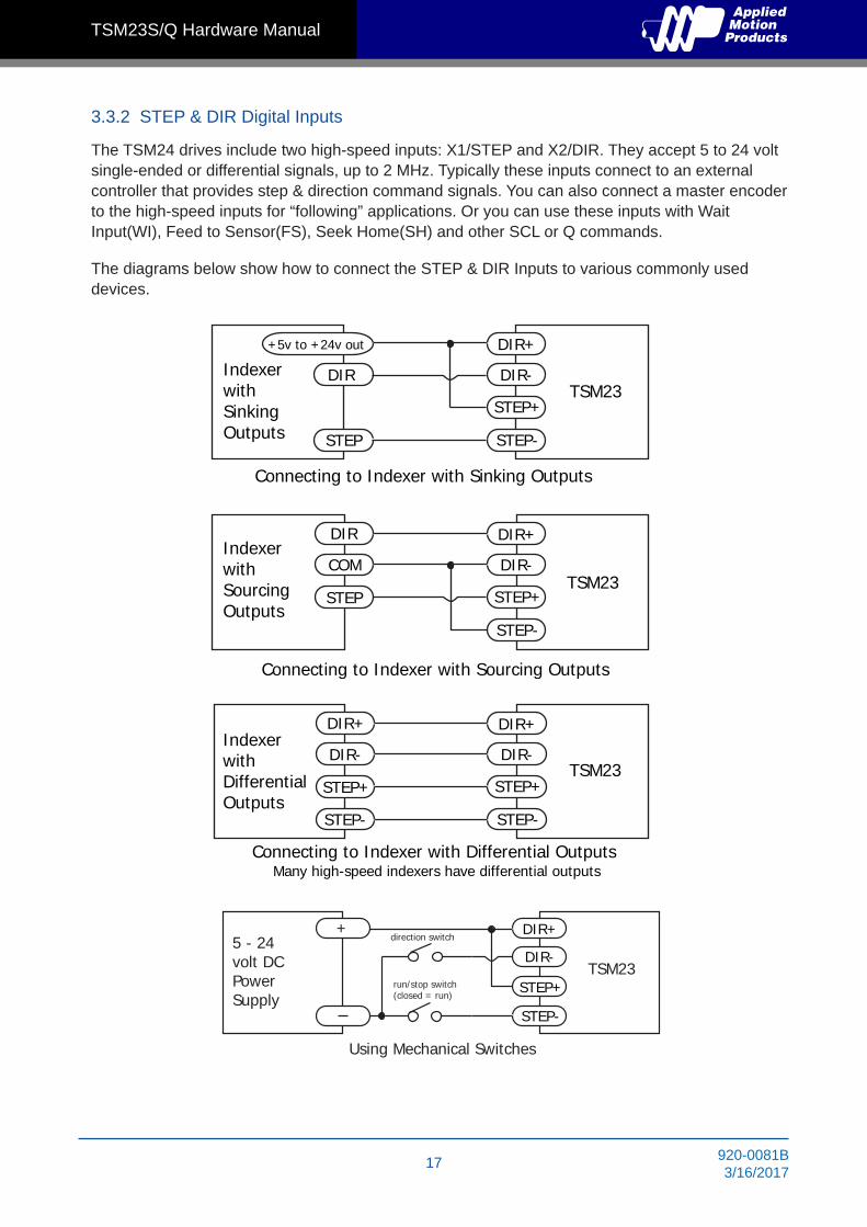
3.3.2 STEP & DIR Digital Inputs
The TSM24 drives include two high-speed inputs: X1/STEP and X2/DIR. They accept 5 to 24 volt single-ended or differential signals, up to 2 MHz. Typically these inputs connect to an external controller that provides step & direction command signals. You can also connect a master encoder to the high-speed inputs for “following” applications. Or you can use these inputs with Wait Input(WI), Feed to Sensor(FS), Seek Home(SH) and other SCL or Q commands.
The diagrams below show how to connect the STEP & DIR Inputs to various commonly used devices.
+5v to +24v out
DIR
STEP
DIR+
DIR-
STEP+
STEP-
Indexer with SinkingOutputs
Connecting to Indexer with Sinking Outputs
TSM23
DIR
COM
STEP
IndexerwithSourcingOutputs
DIR+
DIR-
STEP+
STEP-
Connecting to Indexer with Sourcing Outputs
TSM23
DIR+
DIR-
STEP+
DIR+
DIR-
STEP+
STEP-STEP-
Indexer withDifferentialOutputs
Connecting to Indexer with Differential OutputsMany high-speed indexers have differential outputs
TSM23
DIR+
DIR-
STEP+
STEP-
5 - 24volt DCPowerSupply
Using Mechanical Switches
+direction switch
run/stop switch(closed = run)
TSM23

18920-0081B3/16/2017
TSM23S/Q Hardware Manual
3.3.3 X3/X4/X5/X6 Digital Input
While the STEP and DIR inputs are designed for high-speed digital input operation, the X3/X4/X5/X6 input are designed for low speed digital input operation between 5 and 24 volts optically Isolated Single-ended input. They can be used with sourcing or sinking signals, 5 to 24 volts. This allows connection to PLCs, sensors, relays and mechanical switches. Because the input circuits are isolated, they require a source of power. If you are connecting to a PLC, you should be able to get power from the PLC power supply. If you are using relays or mechanical switches, you will need a 5-24 V power supply.
What is COM?
“Common” is an electronics term for an electrical connection to a common voltage. Sometimes “common” means the same thing as “ground”, but not always. In the case of the TSM23 drives, if you are using sourcing (PNP) input signals, then you will want to connect COM to ground (power supply -). If you are using sinking (NPN) signals, then COM must connect to power supply +.
Note: If current is flowing into or out of an input, the logic state of that input is low or closed. If no current is flowing, or the input is not connected, the logic state is high or open.
The diagrams below show how to connect X3/X4/X5/X6 input to various commonly used devices.
5-24VDC
0VDC
XCOM
X3
X4
X5
X6
User Control Drives
5-24VDC
XCOM
X3
X4
Drives
0VDC
+
-
NPNSensor
5-24VDC
XCOM
X3
Drives
+
-
PNPSensor
0VDC
19 920-0081B3/16/2017
TSM23S/Q Hardware Manual
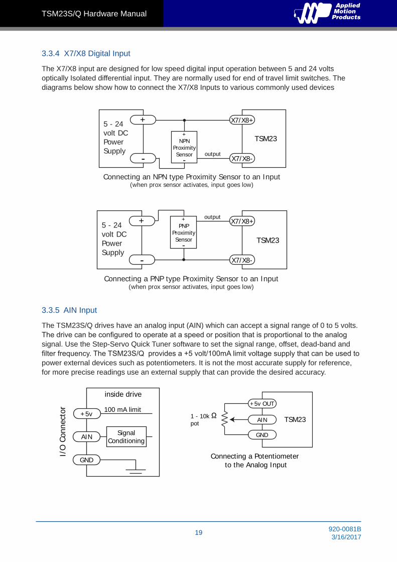
3.3.4 X7/X8 Digital Input
The X7/X8 input are designed for low speed digital input operation between 5 and 24 volts optically Isolated differential input. They are normally used for end of travel limit switches. The diagrams below show how to connect the X7/X8 Inputs to various commonly used devices
3.3.5 AIN Input
The TSM23S/Q drives have an analog input (AIN) which can accept a signal range of 0 to 5 volts. The drive can be configured to operate at a speed or position that is proportional to the analog signal. Use the Step-Servo Quick Tuner software to set the signal range, offset, dead-band and filter frequency. The TSM23S/Q provides a +5 volt/100mA limit voltage supply that can be used to power external devices such as potentiometers. It is not the most accurate supply for reference, for more precise readings use an external supply that can provide the desired accuracy.
5 - 24 volt DCPower Supply
Connecting an NPN type Proximity Sensor to an Input(when prox sensor activates, input goes low)
X7/X8+
X7/X8-
+
-
+NPN
ProximitySensor
-output
TSM23
5 - 24 volt DCPower Supply
Connecting a PNP type Proximity Sensor to an Input(when prox sensor activates, input goes low)
X7/X8+
X7/X8-
+
-
+PNP
ProximitySensor
-
output
TSM23
+5v
AIN
GND
100 mA limit
SignalConditioning
inside drive
rotcennoC O/I
Ω
+5v OUT
AIN
GND
1 - 10kpot TSM23
Connecting a Potentiometer to the Analog Input

20920-0081B3/16/2017
TSM23S/Q Hardware Manual
3.3.6 Programmable Output Y1/Y2/Y3
The TSM23S/Q drives feature three optically isolated digital outputs (Y1 to Y3). Y1, Y2 and Y3 share a common terminal YCOM.
• Y1 can be set to signal a fault condition. • Y2 can be set to indicate whether the motor is in position(dynamic).• Y3 can be set to control a motor brake.These outputs can also be turned on and off by program instructions like Set Output (SO). The output can be used to drive LEDs, relays and the inputs of other electronic devices like PLCs and counters. Diagrams of various connection types follow.
Do not connect the outputs to more than 30 volts. The current through each output terminal must not exceed 100mA.
5-24VDC
0VDC
Y1
YCOM
Y2
Y3
User Control Drives
Y1
YCOM
Y2
Y3
Load+
-
5-24VDCPower Supply

21 920-0081B3/16/2017
TSM23S/Q Hardware Manual
3.3.7 Programmable Output Y4
TSM23S/Q drives feature one optically isolated digital output Y4. The Y4+(collector) and Y4-(emitter) terminals of the transistor are available at the connector. This allow the output to be configured for current sourcing or sinking.
Y4 can be set to provide an output frequency proportional to motor speed (tach signal) or to provide a timing output (50 pulses/rev) or to indicate whether the motor is in position(static)
Diagrams of various connection types follow.
Do not connect the output to more than 30 volts. The current through the output terminal must not exceed 100mA.
+
-
Y4+
Y4-
5 - 24 volt DCPower Supply
Connecting a Sinking Output
Load
TSM23
COM
IN
Y4+
Y4-
PLC
Connecting a Sourcing Output
5 - 24VDCPower Supply
TSM23
+-
+
-
5 - 24 volt DCPower Supply
Driving a Relay
Y4+
Y4-
relay
1N4935 suppresion diode
TSM23

22920-0081B3/16/2017
TSM23S/Q Hardware Manual
4 TroubleshootingLED Error Codes
The TSM23S/Q uses red and green LEDs to indicate status. When the motor is enabled, the green LED flashes slowly. When the green LED is solid, the motor is disabled. Errors are indicated by combinations of red and green flashes as shown below. This feature can be disabled for certain warnings but not for alarms. See software manual for information on how to do this and which warnings may be masked.
Code Error
Solid green no alarm,motor disabled
Flashing green no alarm,motor enabled
1 red,1 green motor stall (optional encoder only)
2 red,1 green ccw limit
2 red,2 green cw limit
3 red,1 green drive overheating
3 red,2 green internal voltage out of range
3 red,3 green blank Q segment
4 red,1 green power supply overvoltage or excess regen
4 red,2 green power supply undervoltage
4 red,3 green flash memory backup error
5 red,1 green Over current/short circuit
6 red,1 green Open motor winding
6 red,2 green bad encoder signal (optional encoder only)
7 red,1 green communication error
7 red,2 green flash memory error

23 920-0081B3/16/2017
TSM23S/Q Hardware Manual
5 Reference Materials
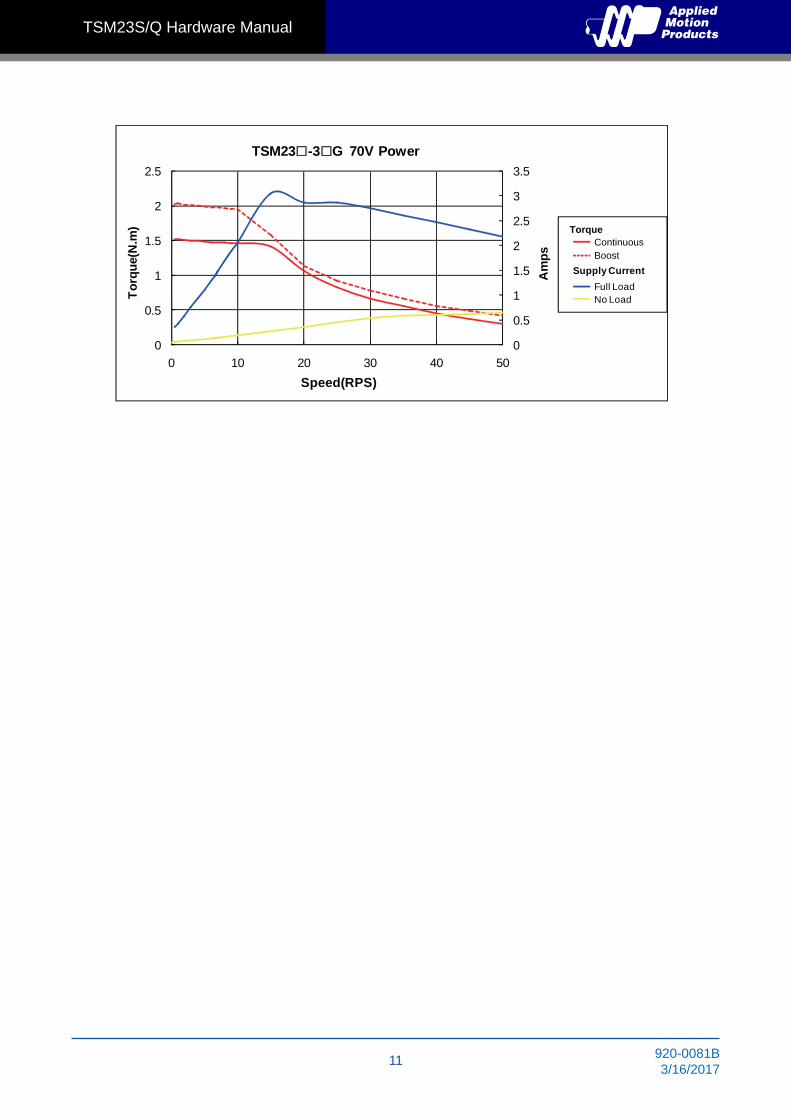
5.1 Torque-Speed Curves
Note: all torque curves were measured at 20,000 steps/rev.
Note: 5 amp rating is continuous, 7.5 amp rating is boost
0
0.3
0.6
0.9
1.2
1.5
0 10 20 30 40 50
Torq
ue(N
·m)
Speed(rps)
Continuous
Boost
24V 48V 70V
24V 48V 70VTSM23-2G
Continuous
Boost
24V 48V 70V
24V 48V 70V
0
0.5
1
1.5
2
2.5
0 10 20 30 40 50
Torq
ue(N
·m)
Speed(rps)
TSM23-3G

24920-0081B3/16/2017
TSM23S/Q Hardware Manual
5.2 Mechanical Outlines
Unit:mmModel Length (L) Length (M)
TSM23S/Q-2G 95.6 24.6TSM23S/Q-3G 117.6 46.6TSM23S/Q-4G
L±120
24
7.5
Flat
Ø8
Ø38
.1
M
7
4-Ø5.1
56.4 Max.
56.4
Max
.
47.1
4
47.14
88
75
1.6
50.9

25 920-0081B3/16/2017
TSM23S/Q Hardware Manual
5.3 Technical Specifications
Power AmplifierAmplifier Type Dual H-Bridge, 4 Quadrant
Current Control 4 state PWM at 20 KHz
Output Torque TSM23S/Q-2G: Up to 1.0N•m Continuous(1.3 N•m Boost)TSM23S/Q-3G: Up to 1.5N•m Continuous(2.0 N•m Boost)TSM23S/Q-4G: Up to
Power Supply External 12 - 70 VDC power supply required
Protection Over-voltage, under-voltage, over-temp, motor/wiring shorts (phase-to-phase, phase-to-ground)
ControllerElectronic Gearing Software selectable from 200 to 51200 steps/rev in increments of 2 steps/rev
Encoder Resolution 20000 counts/rev
Speed Range Up to 3600rpm
Filters Digital input noise filter, Analog input noise filter, Smoothing filter, PID filter, Notch filter
Non-Volatile Storage Configurations are saved in FLASH memory on-board the DSP
Modes of Operation TSM23S: Step & direction, CW/CCW pulse, A/B quadrature pulse, velocity (oscillator, joystick), streaming commands(SCL)TSM23Q: All TSM23S modes of operation plus stored Q program execution
Digital Inputs
Digital Inputs Adjustable bandwidth digital noise rejection filter on all inputs X1/X2: Optically isolated, 5-24 volt. Minimum pulse width = 250 ns, Maximum pulse frequency = 2 MHzFunction: Pulse/Direction, CW/CCW Pulse, A/B quadrature (encoder following), (start/stop)/direction (oscillator mode), or general purpose input X3/X4 : Optically isolated, 5-24 volt. Minimum pulse width = 100 μs, Maximum pulse ffrequency = 5 KHzFunction: Servo on/off, Alarm/Fault Reset, or general purpose inputX5/X6/X7/X8: Optically isolated, 5-24 volt. Minimum pulse width = 100 μs, Maximum pulse frequency = 5 KHzFunction: CW/CCW Limit, Speed 1/Speed 2 (oscillator mode), or general purpose input
Digital Outputs
Y1/Y2/Y3/Y4: Optically isolated, 30V/100mA max Open Collector Output.
Function: Alarm/Fault, In Position(dynamic/static), Brake Control, Tach out, Timing out, or general purpose usage
Encoder Output Standard Line driver outputs, including A+/A-/B+/B-/Z+/Z- are supported
Analog Input AIN referenced to GND. Range = 0 to 5 VDC. Resolution = 12 bits
CommunicationInterface RS-232 , RS-485 or Modbus/RTU
PhysicalAmbilent Temperature 0 to 40°C (32 to 104°F) When mounted to a suitable heatsink
Humdity 90% Max., non-condensing
MassTSM23S/Q-2G: 850 gTSM23S/Q-3G: 1200 gTSM23S/Q-4G:
Rotor InertiaTSM23S/Q-2G:260 g•cm2
TSM23S/Q-3G:460 g•cm2
TSM23S/Q-4G:

26920-0081B3/16/2017
TSM23S/Q Hardware Manual
5.4 SCL Command Reference The Serial Command Language (SCL) was developed to give users a simple way to control a motor drive via a serial port. This eliminates the need for separate motion controllers or indexers to supply Pulse and Direction signals to the drive. It also provides an easy way to interface to a variety of other industrial devices such as PLCs and HMIs, which often have standard or optional serial ports for communicating to other devices. Some examples of typical host devices might be:
• A Windows based PC running Applied Motion Products software• An industrial PC running a custom or other proprietary software application• A PLC with an ASCII module/serial port for sending text strings• An HMI with a serial connection for sending text strings
SCL commands control the motion of the step motor, use of the inputs and outputs, and configure aspects of the drive such as motor current and microstep resolution.
In SCL mode, the TSM23S/Q receives commands from the host, executing them immediately or sending them to a command buffer and then executing them directly from the buffer. It cannot, however, create a stored program for stand-alone operation. For that function, the TSM23Q is needed.
The communications protocol of SCL is simple in that the host initiates all communication, with one exception. The only time the drive will initiate communication is at power-up. At that time, the drive will send an identifier to tell the software which drive is connected and what the firmware version is.
There are two types of SCL commands: buffered and immediate. Buffered commands are loaded into and then executed out of the drive’s command buffer. Buffered commands are executed one at a time and in sequential order. The buffer can be filled with commands without the host controller needing to wait for a specific command to execute before sending the next command. Special buffer commands enable the buffer to be loaded and to pause for a desired time.
Immediate commands are not buffered, but are executed immediately, running in parallel with a buffered command if necessary. Immediate commands are designed to access the drive at any time and can be sent as often as needed. This allows a host controller to get information from the drive at a high rate, most often for checking drive status or motor position.
The basic structure of a command packet from the host to the drive is always a text string followed by a carriage return. The text string is composed of the command itself, followed by any required parameters. A carriage return denotes the end of transmission to the drive.
The syntax of the command is
XXAB<cr>
where XX designates the command (always composed of 2 uppercase letters), and A and B define the possible parameters. These parameters can vary in length, can be letters or numbers, and are often optional. Once a drive receives the <cr> (carriage return), it will determine whether or not it understood the command-if it did, it will either execute or buffer the command. The drive can also be programmed ahead of time to send a response as to whether or not it understood the command as well as any error code.

27 920-0081B3/16/2017
TSM23S/Q Hardware Manual
Some SCL commands transfer data to the drive for immediate or later use. These data values are stored in data registers and remain there until new commands change the values or power is removed from the drive. Some data registers in a drive are Read-Only and contain predefined information about the drive which can also be read through SCL commands.
Because of the intense nature of serial communications required in host mode applications, there is a serial communication Protocol (PR) command available that will adjust a drive’s serial communications protocol to best fit an application. Typically this command is used when configuring a drive and saved as part of the startup parameters. But it can be used at any time to dynamically alter the serial communications.
The Host Command Reference contains the complete command listing as well as instructions on connecting and configuring the TSM23S/Q for use in SCL mode, using the Data Registers and the Protocol command. It also contains detailed information on:
• Host Serial Communications
• Host Serial Connections
• Alarm and Status Codes
• Working with Inputs and Outputs
The Host Command Reference is available from the Applied Motion Products website at http://www.applied-motion.com under the SCL Utility download section.

28920-0081B3/16/2017
TSM23S/Q Hardware Manual
5.5 Optional AccessoriesPower Supplies
Applied Motion Products recommends using the following switching power supplies
P/N: PS150A24 150W, 24VDC
11.5MAX
3-M4 L=4mm
LED
V ADJ.
CN3
9
1
2
3
4
5
6
7
25
117 28
12.5
25
44
170152
65 45
4-M4 L=4mm
89.5
49.5
18
63
99
21
P/N: PS320A48 320W, 48VDC
5 4
8 1
199157
4-M4 L=4mm
Air flow direction FAN
4MAX
18
11.5MAX
8
63 99
18
5
V ADJ.
CN3
LED
1
2
3
4
5
6
7
9.5
4-M4 L=4mm
12.5
25 130
522512
.5

29 920-0081B3/16/2017
TSM23S/Q Hardware Manual
Regeneration Clamp
P/N: RC880
76
45
94 85 85
28.6
When using a regulated power supply you may encounter a problem with regeneration. The kinetic energy caused by regeneration is transferred back to the power supply. This can trip the overvoltage protection of a switching power supply, causing it to shut down.
Applied Motion Products offers the RC880 “regeneration clamp” to solve this problem. If in doubt, use an RC880 for the first installation. If the “regen” LED on the RC880 never flashes, you don’t need the clamp.
USB Serial Adapter P/N: 8500-003
USB to RS-232 P/N: 3004-235 (Optional)
30920-0081B3/16/2017
TSM23S/Q Hardware Manual
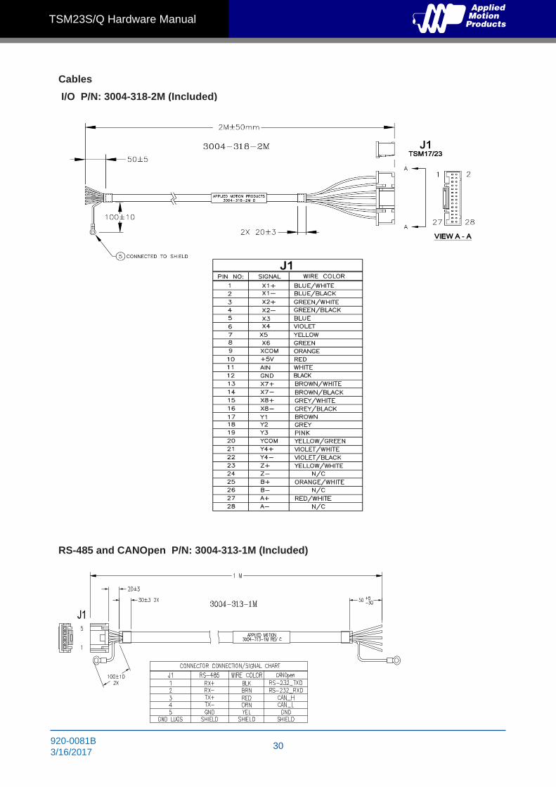
Cables
I/O P/N: 3004-318-2M (Included)
RS-485 and CANOpen P/N: 3004-313-1M (Included)

31 920-0081B3/16/2017
TSM23S/Q Hardware Manual
SERIAL P/N: 3004-294 (Included)
Mating Connectors
Description Model Supplier Description Model Supplier
Power RS232Connector 1615780000 Weidmuller Housing ZER-04V-S JST
I/O Pin, Connector SZE-002T-P0.3 JSTHousing PUDP-28V-S JST RS-485 & CANOpen
Pin, Connector SPUD-001T-P0.5 JST Housing ZER-05V-S JSTPin, Connector SZE-002T-P0.3 JST
Connector 5452570 Housing PUDP-28V-S
Housing ZER-04V-S/ZER-05V-S Pin connectors SPUD-001T-P0.5
Pin
Conector: SZE-002T-P0.3

32920-0081B3/16/2017
TSM23S/Q Hardware Manual
6 Contacting Applied Motion Products404 Westridge Dr.Watsonville, CA 95076, USA1-800-525-1609Tel (831) 761-6555www.applied-motion.com