Embed Size (px)
Citation preview

CASTLE INC PO BOX 750236 PETALUMA CA 94975
WWW.CASTLEUSA.COM
Owners Manual
TSM-22 Pocket Hole Machine
CASTLE, INC.

CASTLE, INC TSM-22 OWNERS MANUAL V1.0 Page 2 of 41
CASTLE, INC TSM-22 OWNERS MANUAL V1.0 Page 3 of 41
Table of Contents
1 INTRODUCTION ............................................................................................................................. 5
1.1 DEFINITION OF TERMS ................................................................................................................ 5
1.2 IDENTIFICATION OF OPERATING FEATURES AND CONTROLS ......................................................... 6
1.3 MANUAL CONTENTS NOTICE ....................................................................................................... 8
2 MACHINE SAFETY ......................................................................................................................... 9
2.1 SAFETY RULES .......................................................................................................................... 9
2.2 INVENTORY .............................................................................................................................. 10
2.3 MACHINE REQUIREMENTS ........................................................................................................ 11
3 SETTING UP YOUR TSM-22 ....................................................................................................... 12
3.1 INSTALLING THE WORK TOP ..................................................................................................... 14
3.2 INSTALLING THE GAS SPRING ................................................................................................... 15
3.3 INITIAL CONFIGURATION ........................................................................................................... 16
4 ADJUSTMENTS ............................................................................................................................ 19
4.1 ROUTER FEED RATE ADJUSTMENT ........................................................................................... 19
4.2 POCKET WEB ADJUSTMENT ...................................................................................................... 20
4.3 POCKET DEPTH ADJUSTMENT................................................................................................... 21
4.4 DRILL FEED RATE ADJUSTMENT ............................................................................................... 22
4.5 PILOT DRILL DEPTH ADJUSTMENT ............................................................................................ 23
4.6 PILOT DRILL HEIGHT ADJUSTMENT ........................................................................................... 24
5 OPERATION ................................................................................................................................. 25
6 SERVICE AND MAINTENANCE .................................................................................................. 27
6.1 TOOL CHANGES ....................................................................................................................... 27
6.2 ROUTER BIT ............................................................................................................................ 27
6.3 PILOT DRILL BIT ....................................................................................................................... 28
6.4 GENERAL MACHINE MAINTENANCE ........................................................................................... 28
6.5 MOTORS AND BITS ................................................................................................................... 29
7 TROUBLESHOOTING .................................................................................................................. 31
7.1 DRY CYCLE TEST ..................................................................................................................... 31
7.2 SAFETY SWITCH (STOCK SENSE) .............................................................................................. 33
7.3 FOOT SWITCH .......................................................................................................................... 34

CASTLE, INC TSM-22 OWNERS MANUAL V1.0 Page 4 of 41
7.4 PRESSURE REGULATOR ........................................................................................................... 35
7.5 ROUTER STOP SWITCH ............................................................................................................ 36
7.6 DRILL STOP SWITCH ................................................................................................................ 37
7.7 SERIAL NUMBER LOG ............................................................................................................... 38
8 WARRANTY INFORMATION ....................................................................................................... 39
8.1 WARRANTY .............................................................................................................................. 39
8.2 30-DAY REFUND POLICY .......................................................................................................... 40
8.3 WARRANTY SERVICE POLICY .................................................................................................... 40
8.4 WARRANTY PART REPLACEMENT ............................................................................................. 40
CASTLE, INC TSM-22 OWNERS MANUAL V1.0 Page 5 of 41
1 Introduction
Thank you for making the Castle TSM-22 Screw Pocket Machine (Toe Screw Mortise) the latest
addition to your shop. Since 1985 our goal is to manufacture and develop machines that make
cabinetmaking and casework easier, faster, and more profitable for woodworking professionals.
This machine represents our patented screw pocket cutting technology. Castle machines are
made in Petaluma, California and are manufactured to the highest standards using local vendors
wherever possible.
The Castle model TSM-22 is designed for use on a wide variety of materials. The machine
performs well in hardwoods, softwoods, melamine, particleboard and MDF. The machine will
work on materials varying in thickness from ½” to 1 ¾”.
This instruction manual is intended for use by any one working with this machine. It should be
kept available for immediate reference so that all operations can be performed with maximum
efficiency and safety.
Warning: Do not attempt to perform maintenance or operate this machine until you have
read and understand the information contained in this manual.
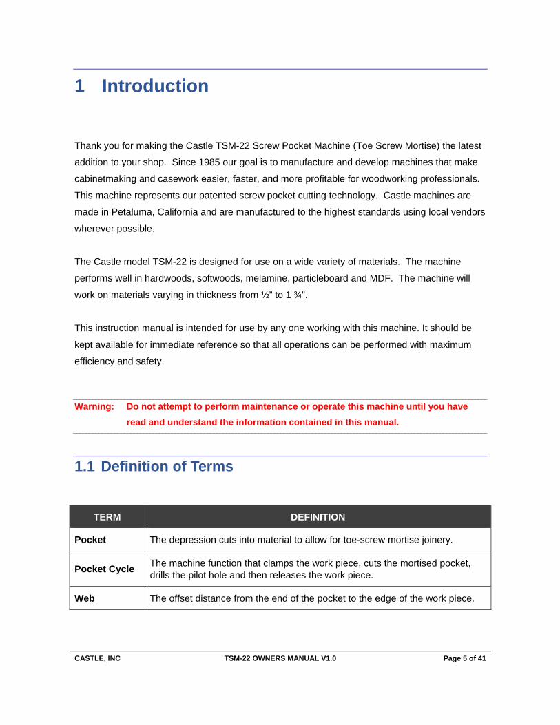
1.1 Definition of Terms
TERM DEFINITION
Pocket The depression cuts into material to allow for toe-screw mortise joinery.
Pocket Cycle The machine function that clamps the work piece, cuts the mortised pocket, drills the pilot hole and then releases the work piece.
Web The offset distance from the end of the pocket to the edge of the work piece.
CASTLE, INC TSM-22 OWNERS MANUAL V1.0 Page 6 of 41
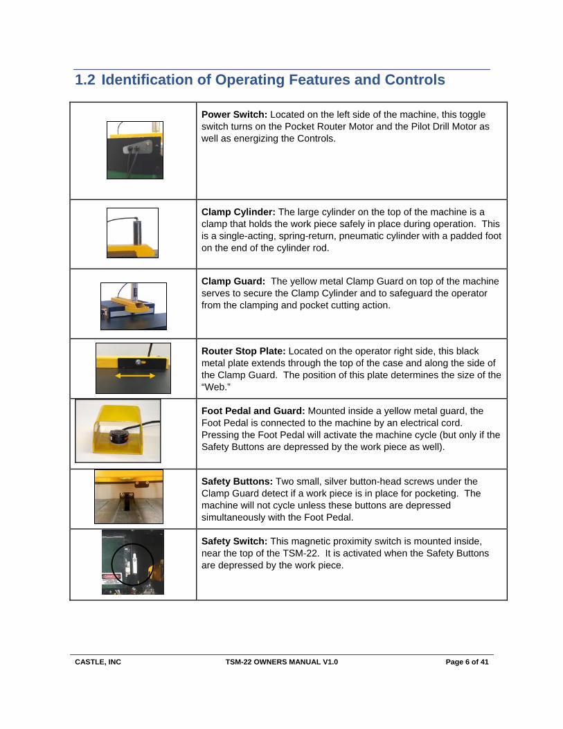
1.2 Identification of Operating Features and Controls
Power Switch: Located on the left side of the machine, this toggle switch turns on the Pocket Router Motor and the Pilot Drill Motor as well as energizing the Controls.
Clamp Cylinder: The large cylinder on the top of the machine is a clamp that holds the work piece safely in place during operation. This is a single-acting, spring-return, pneumatic cylinder with a padded foot on the end of the cylinder rod.
Clamp Guard: The yellow metal Clamp Guard on top of the machine serves to secure the Clamp Cylinder and to safeguard the operator from the clamping and pocket cutting action.
Router Stop Plate: Located on the operator right side, this black metal plate extends through the top of the case and along the side of the Clamp Guard. The position of this plate determines the size of the “Web.”
Foot Pedal and Guard: Mounted inside a yellow metal guard, the Foot Pedal is connected to the machine by an electrical cord. Pressing the Foot Pedal will activate the machine cycle (but only if the Safety Buttons are depressed by the work piece as well).
Safety Buttons: Two small, silver button-head screws under the Clamp Guard detect if a work piece is in place for pocketing. The machine will not cycle unless these buttons are depressed simultaneously with the Foot Pedal.
Safety Switch: This magnetic proximity switch is mounted inside, near the top of the TSM-22. It is activated when the Safety Buttons are depressed by the work piece.
CASTLE, INC TSM-22 OWNERS MANUAL V1.0 Page 7 of 41
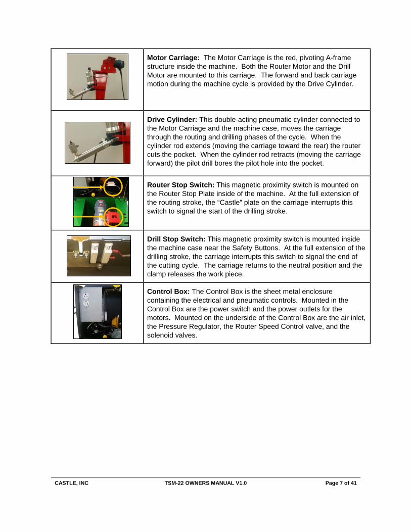
Motor Carriage: The Motor Carriage is the red, pivoting A-frame structure inside the machine. Both the Router Motor and the Drill Motor are mounted to this carriage. The forward and back carriage motion during the machine cycle is provided by the Drive Cylinder.
Drive Cylinder: This double-acting pneumatic cylinder connected to the Motor Carriage and the machine case, moves the carriage through the routing and drilling phases of the cycle. When the cylinder rod extends (moving the carriage toward the rear) the router cuts the pocket. When the cylinder rod retracts (moving the carriage forward) the pilot drill bores the pilot hole into the pocket.
Router Stop Switch: This magnetic proximity switch is mounted on the Router Stop Plate inside of the machine. At the full extension of the routing stroke, the “Castle” plate on the carriage interrupts this switch to signal the start of the drilling stroke.
Drill Stop Switch: This magnetic proximity switch is mounted inside the machine case near the Safety Buttons. At the full extension of the drilling stroke, the carriage interrupts this switch to signal the end of the cutting cycle. The carriage returns to the neutral position and the clamp releases the work piece.
Control Box: The Control Box is the sheet metal enclosure containing the electrical and pneumatic controls. Mounted in the Control Box are the power switch and the power outlets for the motors. Mounted on the underside of the Control Box are the air inlet, the Pressure Regulator, the Router Speed Control valve, and the solenoid valves.
CASTLE, INC TSM-22 OWNERS MANUAL V1.0 Page 8 of 41
1.3 Manual Contents Notice
This manual is not fully comprehensive. It may not convey every possible safety and operational
problem that may arise while using this machine. The manual will cover many of the basic and
specific safety procedures needed in a shop environment.
All federal and state laws and any regulations having jurisdiction, covering the safety
requirements for use of this machine, take precedence over the statements in this manual.
Users of this machine must adhere to all such regulations.
Most national and international standards that may apply to your machines and accessories
contain requirements for manuals. These change from time to time and will require constant
monitoring to assure that your products and manuals are in compliance.
Castle products and the information in this manual are the proprietary property of Castle, Inc. or
its licensers, and may not be copied, disclosed, or used for any purpose not expressly
authorized by the owner thereof.
Since Castle, Inc. constantly strives to improve all of its products, we reserve the right to change
this manual and hardware mentioned therein at any time without notice.

CASTLE, INC TSM-22 OWNERS MANUAL V1.0 Page 9 of 41
2 Machine Safety
The Castle Model TSM-22 pocket machine was designed with operator safety as a priority. This
machine was carefully prepared for shipment at our factory. Upon receipt of this machine,
inspect for shipping damage. Report any damage IMMEDIATELY to the freight company, your
Castle dealer and to Castle, Inc. DO NOT attempt to operate this machine if you observe any
physical damage. If you detect any damage to your machine contact Castle, Inc. at 800-282-
8338 for instructions.
2.1 Safety Rules
The Castle Model TSM-22 Pocket Machine was designed with operator safety as a priority,
which is why Castle highly recommends the following:
1. USE CAUTION WHEN OPERATING THIS MACHINE! Only skilled operators should
use this machine, or be within ten feet when the machine is in operation.
2. Read the Operator Manual carefully before operating. An Operator Manual should be
attached to this machine. It contains important information and warnings concerning the
use and operation of this machine. Improper use of this machine may result in serious
injuries to persons and property.
3. Always wear protective eyewear when operating or standing near an operating machine.
4. Be certain that this machine is properly grounded before operating it.
5. Keep all body parts away from the moving parts of this machine whether it is in operation
or at rest.
6. Do not place hands or fingers between the work piece and the clamp or near the cutters
at any time. Always use a securing device when undertaking close work.
7. Do not wear gloves or loose clothing (such as sweaters, jackets, or jewelry) when
operating or standing near an operating machine.

CASTLE, INC TSM-22 OWNERS MANUAL V1.0 Page 10 of 41
8. Keep two hands on the work piece when initiating a pocket cycle on this machine.
9. Before attempting adjustments, maintenance, or repair, TURN OFF this machine,
disconnect it from its power source and air supply. Wait for all motion to stop.
Failure to disconnect this machine from its power source and air supply or wait for all
motion to stop could result in electrocution or injury.
10. Always keep the area around this machine clean and uncluttered. Poor housekeeping
could result in slips, falls, or other injuries.
11. Concentrate at all times. Failure to pay attention to the task at hand is the cause of
most accidents.
2.2 Inventory
With your Castle machine you should have received the following:
CASTLE TSM-21 POCKET CUTTER MACHINES HARDWARE PACK
Part # Part Description Qty
S90022 TSM-22 Operator Manual with Warranty Activation Card 1
Router Wrench Bosch 1617 2
Trimmer Wrench Bosch PR10E 2
B00622 #2x 6” Square Driver Bit 1
G00234 Bit Gauge 1
G00101 Door Spring 1
F14125 ¼ x 20 Bolt 1
H00141 T-Handle 1
F51616 5/16 SAE Flat Washer 4
F51699 5/16 -18 Nylon Locknut 2
H24002 Gas Spring – 20.12” Extended 1
F14553 ¼-20 x 1-1/4 FH Socket Head Cap Screw 6
F01420 ¼-20 Nylon Locknut 9
F01410 1/4 SAE Flat Washer 9
F44100 ¼-20 X 1 FH Socket Head Cap Screw 1
M24010 Stainless Lid Plate 1
F14340 ¼-20 x ¾ Carriage Bolt 2
T00532 Allen Hex L-Key – 5/32” 1
H55202 Rare Earth Magnet 1

CASTLE, INC TSM-22 OWNERS MANUAL V1.0 Page 11 of 41
2.3 Machine Requirements
Power Supply: 115 VAC ± 10%, 60 Hz, 20 Amp Service
Warning: Do not use an extension cord. Using an extension cord to power your TSM-22 may void
your warranty!
Air Supply: 80psi (minimum), 150psi (maximum) 1.5cfm; Minimum ¼” ID air line
Warning: Failure to provide an adequate supply of CLEAN, DRY air may void your warranty!
Dust Collection: The TSM-22 will function better with proper dust collection attached. A vent
for this purpose has been provided. Attaching dust collection will prolong motor life by keeping
the router motors cooler and free from sawdust buildup.
Warning: Failure to clean sawdust from your machine may void your warranty!

CASTLE, INC TSM-22 OWNERS MANUAL V1.0 Page 12 of 41
3 Setting Up Your TSM-22
Caution: Always use eye protection when operating power equipment.
Your Castle TSM-22 Pocket Cutter was set up and tested for proper operation at the factory.
It is normal to find a small amount of sawdust in the TSM-22 from this process.
Verify that the Power Switch is turned off. Remove the Power Cord and Foot Pedal from
inside the machine.
Remove the swivel elbow from the black urethane hose by pushing the floating ring toward
the elbow and pulling the hose at the same time.
Thread the elbow into the top of the Clamp Cylinder. It is pre-primed and self-sealing. Point
it toward the rear of the machine and firmly push the hose back into the fitting. (Fig 1)
Connect a clean, dry air supply to the left side of the machine with a minimum supply of
80psi. (Fig 2) Using an air supply of less than 80psi will result in insufficient clamping force,
which can cause material shifting and possible injury to the operator.
We strongly recommend that you use an inline filter/water trap.
Fig 1 Fig 2

CASTLE, INC TSM-22 OWNERS MANUAL V1.0 Page 13 of 41
Warning: Do not introduce lubricants, oils, or solvents into the pneumatic system. Irreparable
damage to pneumatic seals and components may occur. Using lubricants in the pneu-
matics of your TSM-22 may void your Warranty!
Inspect the U-Bolts on the carriage (Fig 3), making sure that the motors are secure and tight.
Using the wrenches located inside the rear of the machine make sure the router bit and the
drill bit are secure in the respective collets. (Fig 4)
Fig 3
Fig 4
CASTLE, INC TSM-22 OWNERS MANUAL V1.0 Page 14 of 41
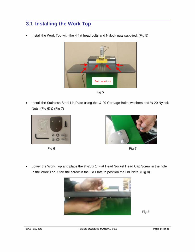
3.1 Installing the Work Top
Install the Work Top with the 4 flat head bolts and Nylock nuts supplied. (Fig 5)
Install the Stainless Steel Lid Plate using the ¼-20 Carriage Bolts, washers and ¼-20 Nylock
Nuts. (Fig 6) & (Fig 7)
Lower the Work Top and place the ¼-20 x 1’ Flat Head Socket Head Cap Screw in the hole
in the Work Top. Start the screw in the Lid Plate to position the Lid Plate. (Fig 8)
Bolt Locations
Fig 5
Fig 6 Fig 7
Fig 8

CASTLE, INC TSM-22 OWNERS MANUAL V1.0 Page 15 of 41
Once the Lid Plate has been positioned, reach up inside the
case through the front door opening to secure the Nylock Nuts
for the Lid Plate. (Fig 9)
A magnet has been provided to secure the Allen wrench to the
case in a convenient location for quick access during tooling
changes. (Fig 10)
3.2 Installing the Gas Spring
Remove the plastic covers on the studs and insert the
stud on the bottom of the gas spring into the hole
located on the bottom of the Case Right as shown.
Secure the stud using a 5/16” Washer and Nylock Nut
provided on the inside of the case. (Fig 12)
Fig 9
Fig 10
Fig 11
Fig 12

CASTLE, INC TSM-22 OWNERS MANUAL V1.0 Page 16 of 41
Raise the Case Top and place the stud located at the top of the
gas spring through the hole shown. Secure with a 5/16” washer
and Nylock Nut. (Fig 13)
Lower the lid and secure the Work Top with the ¼-20 Flat
Head Socket Head Cap Screw. (Fig 14)
Plug the machine into a grounded 115VAC, 20-amp outlet.
3.3 Initial Configuration
Now that the machine is connected to a power source and air supply, it is suggested that you
test the machine’s controls for proper function.
Caution: Read the Operator Manual carefully before operating. Make sure that you have followed all assembly and installation instructions correctly. Make sure that you are familiar with the functions described in the rest of the manual as well. Failure to fol-low this warning may result in serious injuries to persons and property.
Turn on the Power Switch. (Fig 15)
Power Switch
Fig 13
Fig 14
Fig 15

CASTLE, INC TSM-22 OWNERS MANUAL V1.0 Page 17 of 41
Place a piece of scrap wood under the Clamp Guard against the Face Plate to depress the
Safety Buttons (Fig 16).
Be sure to keep your hands clear of the clamp, and then step on the Foot Pedal. A full cycle
should take 1½ to 2 seconds.
Inspect the pocket. If the drilled hole is off center (Fig 17), it can be centered using the
adjusting nut on the Pilot Hole Adjustment Nut just below the drill motor. (Fig 18)
Caution: Do not overtighten the adjustment nut. Overtightening may cause an uneven bias to the pilot hole position.
Tightening the nut moves the drill tip left relative to the operator. Adjust accordingly.
Pilot HoleAlignment Nut
Fig 16
Fig 17 Fig 18
CASTLE, INC TSM-22 OWNERS MANUAL V1.0 Page 18 of 41
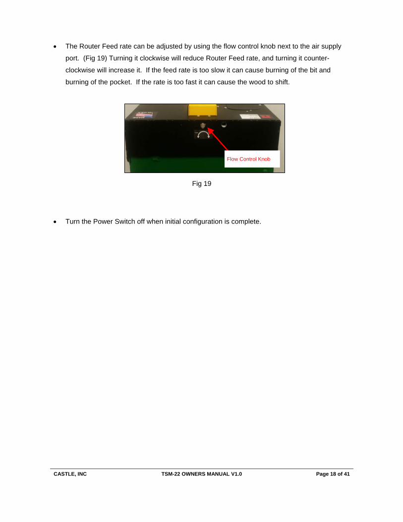
The Router Feed rate can be adjusted by using the flow control knob next to the air supply
port. (Fig 19) Turning it clockwise will reduce Router Feed rate, and turning it counter-
clockwise will increase it. If the feed rate is too slow it can cause burning of the bit and
burning of the pocket. If the rate is too fast it can cause the wood to shift.
Turn the Power Switch off when initial configuration is complete.
Flow Control Knob
Fig 19

CASTLE, INC TSM-22 OWNERS MANUAL V1.0 Page 19 of 41
4 Adjustments
4.1 Router Feed Rate Adjustment
The Router Feed Rate Adjustment knob is located right next to the air inlet port on the back side
of the machine. (Fig 20) The adjustment knob only affects the cutting stroke of the pocket
router.
Fig 20
Turning the knob clockwise selects a slower Feed Rate. Turning the knob counter-clockwise
selects a faster Feed Rate. A suggested Router Feed Rate Adjustment for hardwoods such as
oak or maple is described as follows:
Loosen the jam nut on the threaded stem and spin the nut counter-clockwise.
Turn the knob clockwise until it reaches a mechanical stop.
Turn the knob counter-clockwise two full revolutions.
Adjust slower or faster in small increments as required.
Tighten the jam nut.
Note: If the work piece shifts noticeably during the Pocket Cycle, this usually means the Router Feed Rate is faster than the tooling’s ability to clear the Pocket. In general the desired Feed Rate is slower for harder, denser materials.
CASTLE, INC TSM-22 OWNERS MANUAL V1.0 Page 20 of 41
4.2 Pocket Web Adjustment
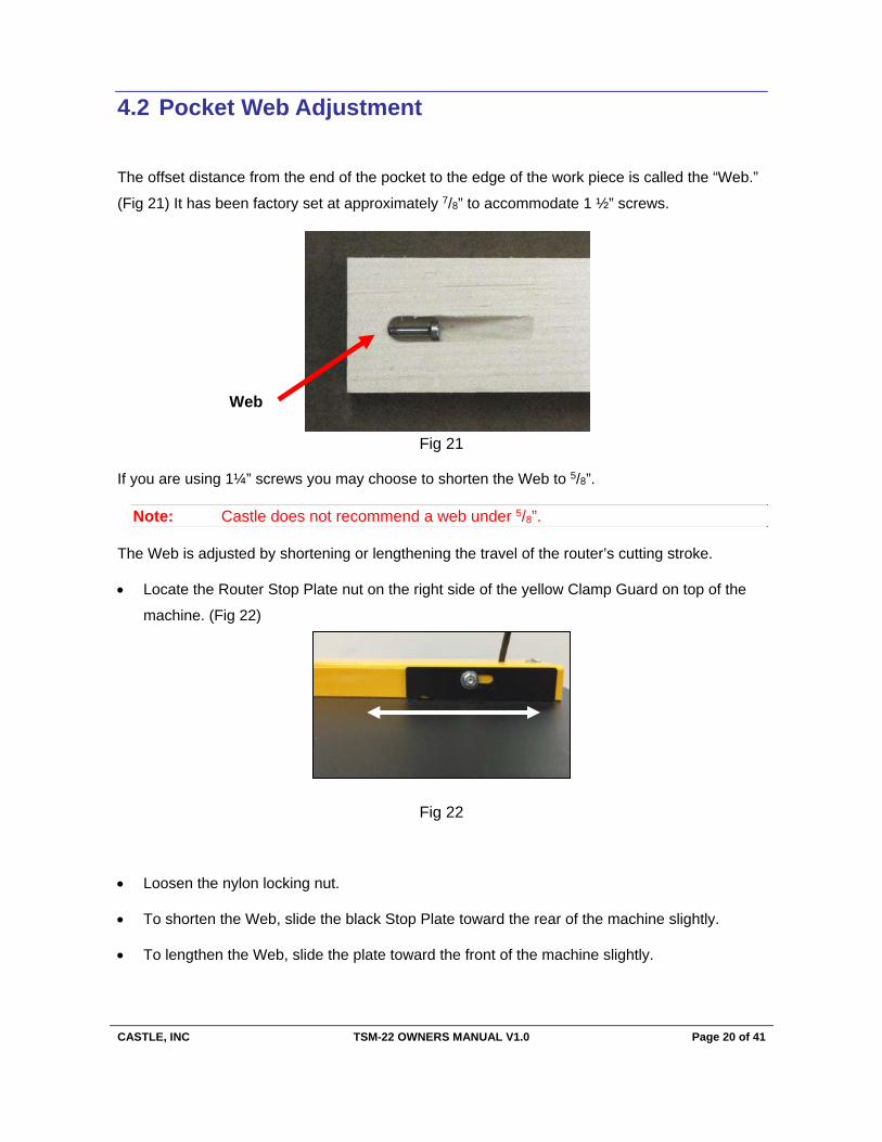
The offset distance from the end of the pocket to the edge of the work piece is called the “Web.”
(Fig 21) It has been factory set at approximately 7/8” to accommodate 1 ½” screws.
Fig 21
If you are using 1¼” screws you may choose to shorten the Web to 5/8”.
Note: Castle does not recommend a web under 5/8”.
The Web is adjusted by shortening or lengthening the travel of the router’s cutting stroke.
Locate the Router Stop Plate nut on the right side of the yellow Clamp Guard on top of the
machine. (Fig 22)
Fig 22
Loosen the nylon locking nut.
To shorten the Web, slide the black Stop Plate toward the rear of the machine slightly.
To lengthen the Web, slide the plate toward the front of the machine slightly.
Web

CASTLE, INC TSM-22 OWNERS MANUAL V1.0 Page 21 of 41
Note: When the desired position has achieved, tighten the nylon locking nut secure-ly to prevent shifting during operation. Subsequent adjustment of the Router Stop Switch may also be necessary (Page 31).
4.3 Pocket Depth Adjustment
The router bit for cutting the pocket is inserted into the router collet at the factory for a distance
of 1 1/8” from the tip of the bit to the collet. This setting cuts at an optimal depth of approximately 3/8” for material between 5/8” and 7/8” thickness.
To cut a shallower pocket (in ½” material for example):
Place a shim with a known thickness on the work top and place your work piece over it.
To cut a shallower pocket:
Loosen the motor collet and slide the bit to the desired exposure. (If the bit does not move
easily, try gently tapping on the bit near the collet with a wrench.)
Secure the collet.
For your convenience, a blank Bit Gauge (Fig 23) is included with your
machine so that you may scribe a mark to record the depth that is most
suitable for your purposes. Refer to the “Pilot Drill Depth Adjustment” for
this procedure.
Fig 23
CASTLE, INC TSM-22 OWNERS MANUAL V1.0 Page 22 of 41
4.4 Drill Feed Rate Adjustment
The stroke speed with which the machine drills the pilot hole (and clamps the work piece) is
solely a function of the air pressure set at the internal Pressure Regulator. There is no separate
adjustment knob.
Note: If the Drill Feed Rate is so fast that the machine shakes violently during the Pocket Cycle or if the Drill Feed Rate is so slow that the Pocket Cycle is significantly longer than two seconds, then it may be necessary to adjust the Pressure Regulator. Do not adjust the internal Pressure Regulator unless absolutely necessary.
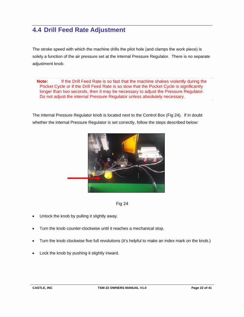
The internal Pressure Regulator knob is located next to the Control Box (Fig 24). If in doubt
whether the internal Pressure Regulator is set correctly, follow the steps described below:
Fig 24
Unlock the knob by pulling it slightly away.
Turn the knob counter-clockwise until it reaches a mechanical stop.
Turn the knob clockwise five full revolutions (it’s helpful to make an index mark on the knob.)
Lock the knob by pushing it slightly inward.
CASTLE, INC TSM-22 OWNERS MANUAL V1.0 Page 23 of 41
4.5 Pilot Drill Depth Adjustment
The Pilot Drill operation works best when the drill depth is adjusted so that the drill bit just barely
breaks into the pocket. If the drill bit extends farther than necessary, it can cause shorter bit life
and over-size holes. The drill bit is set at the factory for a length of approximately 1 13/16” from tip
to drill motor collet (this is a suitable distance for the factory default 7/8” Web). As a general rule,
if the Web is decreased, then the Pilot Drill depth should also be decreased.
To adjust the Pilot Bit Depth:
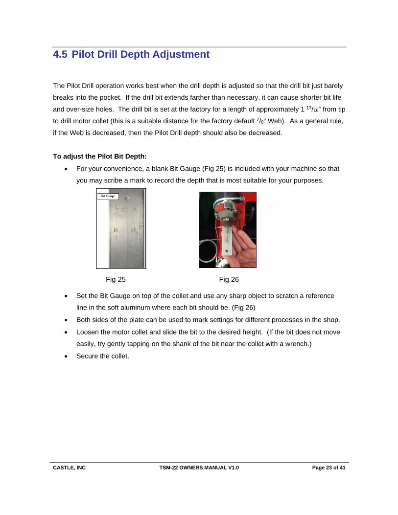
For your convenience, a blank Bit Gauge (Fig 25) is included with your machine so that
you may scribe a mark to record the depth that is most suitable for your purposes.
Fig 25 Fig 26
Set the Bit Gauge on top of the collet and use any sharp object to scratch a reference
line in the soft aluminum where each bit should be. (Fig 26)
Both sides of the plate can be used to mark settings for different processes in the shop.
Loosen the motor collet and slide the bit to the desired height. (If the bit does not move
easily, try gently tapping on the shank of the bit near the collet with a wrench.)
Secure the collet.
CASTLE, INC TSM-22 OWNERS MANUAL V1.0 Page 24 of 41
4.6 Pilot Drill Height Adjustment
The position of the Pilot Hole can be raised or lowered slightly to accommodate various
thickness in work pieces or various pocket depths.
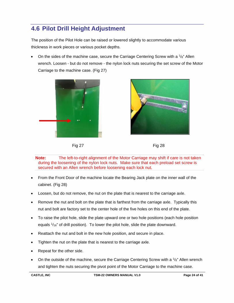
On the sides of the machine case, secure the Carriage Centering Screw with a 1/8” Allen
wrench. Loosen - but do not remove - the nylon lock nuts securing the set screw of the Motor
Carriage to the machine case. (Fig 27)
Fig 27 Fig 28
Note: The left-to-right alignment of the Motor Carriage may shift if care is not taken during the loosening of the nylon lock nuts. Make sure that each preload set screw is secured with an Allen wrench before loosening each lock nut.
From the Front Door of the machine locate the Bearing Jack plate on the inner wall of the
cabinet. (Fig 28)
Loosen, but do not remove, the nut on the plate that is nearest to the carriage axle.
Remove the nut and bolt on the plate that is farthest from the carriage axle. Typically this
nut and bolt are factory set to the center hole of the five holes on this end of the plate.
To raise the pilot hole, slide the plate upward one or two hole positions (each hole position
equals 1/16” of drill position). To lower the pilot hole, slide the plate downward.
Reattach the nut and bolt in the new hole position, and secure in place.
Tighten the nut on the plate that is nearest to the carriage axle.
Repeat for the other side.
On the outside of the machine, secure the Carriage Centering Screw with a 1/8” Allen wrench
and tighten the nuts securing the pivot point of the Motor Carriage to the machine case.

CASTLE, INC TSM-22 OWNERS MANUAL V1.0 Page 25 of 41
5 Operation
Caution: Read the Operator Manual carefully before operating. Make sure that you are familiar with the functions described in the rest of the manual as well. Failure to follow this warning may result in serious injuries to persons and property.
Warning: Always use eye protection when operating power equipment.
With the Power Switch turned off, reach through the door opening in the front of the case to
pull the carriage forward and push it back to be sure it actuate the carriage to insure it moves
freely without impediment. (Fig 17). Neither the router bit nor the drill bit should be
protruding from the machine while at rest.
Place the Foot Pedal in front of the machine in a safe and comfortable position (Fig 30).
Turn the Power Switch on (Fig 31).
Fig 29
Fig 30 Fig 31

CASTLE, INC TSM-22 OWNERS MANUAL V1.0 Page 26 of 41
Place the work piece to be pocketed on the Work Top. Slide it under the Clamp Guard and
firmly push it against the face plate of the machine to press the Safety Buttons. (Fig 32).
Be sure to keep your hands clear of the clamp, then press and release the Foot Pedal to
activate the cutting cycle.
The pocket will be cut at the point directly under the center of the Clamp Cylinder.
When the Pocket Cycle has been completed the Clamp Foot will automatically release the
material.
A typical machine cycle will take from 1½ to 2 seconds to complete.
Reposition the same work piece or a new work piece under the Clamp Guard, then press
and release the Foot Pedal again to activate the next cutting cycle.
Be sure to turn off the Power Switch when you are finished.
If the machine fails to cycle properly, call Castle at (800) 282-8338
Fig 32
CASTLE, INC TSM-22 OWNERS MANUAL V1.0 Page 27 of 41
6 Service and Maintenance
6.1 Tool Changes
Caution: Do not attempt to change tooling with compressed air power supplied to the machine!
6.2 Router Bit
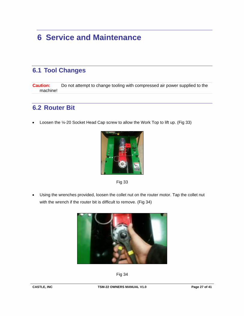
Loosen the ¼-20 Socket Head Cap screw to allow the Work Top to lift up. (Fig 33)
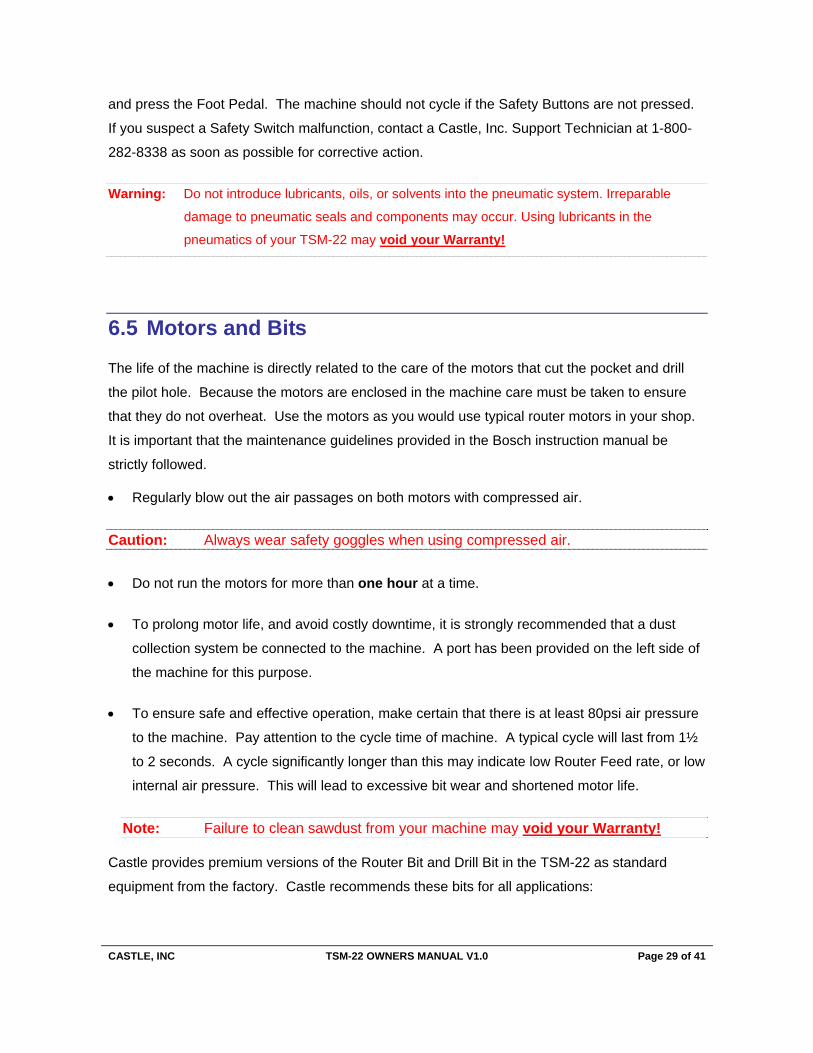
Using the wrenches provided, loosen the collet nut on the router motor. Tap the collet nut
with the wrench if the router bit is difficult to remove. (Fig 34)
Fig 33
Fig 34

CASTLE, INC TSM-22 OWNERS MANUAL V1.0 Page 28 of 41
6.3 Pilot Drill Bit
Loosen the ¼-20 Socket Head Cap screw to open the Work Top.
Using the Collet Wrenches provided, loosen the Collet Nut. Tap the Collet Nut if necessary
to loosen the bit from the collet.
Fig 35
Using the bit gauge provided, install a fresh drill bit to the depth indicated by the score mark
on the gauge and tighten the collet nut. (Fig 35)
6.4 General Machine Maintenance
The model TSM-22 requires some maintenance. To ensure the productivity and longevity of
your Castle Pocket Cutter, it is essential to follow a few simple steps. How often these steps are
performed depends upon the number of hours the machine is operated each day. As a general
rule, operators should visually inspect the machine at the start of each work shift in the following
manner:
Check the Power Cord and the Foot Switch cord for wear or damage.
Ensure that the Router Bit and the Drill Bit are clean, sharp, and undamaged.
Keep the Router and Drill Motors free from dust build up.
Check for proper Safety Switch function. To protect the bits in case of failure, place a piece of
material under the clamp foot, but not pressed against the Safety Buttons. Turn the machine on
CASTLE, INC TSM-22 OWNERS MANUAL V1.0 Page 29 of 41
and press the Foot Pedal. The machine should not cycle if the Safety Buttons are not pressed.
If you suspect a Safety Switch malfunction, contact a Castle, Inc. Support Technician at 1-800-
282-8338 as soon as possible for corrective action.
Warning: Do not introduce lubricants, oils, or solvents into the pneumatic system. Irreparable
damage to pneumatic seals and components may occur. Using lubricants in the
pneumatics of your TSM-22 may void your Warranty!
6.5 Motors and Bits
The life of the machine is directly related to the care of the motors that cut the pocket and drill
the pilot hole. Because the motors are enclosed in the machine care must be taken to ensure
that they do not overheat. Use the motors as you would use typical router motors in your shop.
It is important that the maintenance guidelines provided in the Bosch instruction manual be
strictly followed.
Regularly blow out the air passages on both motors with compressed air.
Caution: Always wear safety goggles when using compressed air.
Do not run the motors for more than one hour at a time.
To prolong motor life, and avoid costly downtime, it is strongly recommended that a dust
collection system be connected to the machine. A port has been provided on the left side of
the machine for this purpose.
To ensure safe and effective operation, make certain that there is at least 80psi air pressure
to the machine. Pay attention to the cycle time of machine. A typical cycle will last from 1½
to 2 seconds. A cycle significantly longer than this may indicate low Router Feed rate, or low
internal air pressure. This will lead to excessive bit wear and shortened motor life.
Note: Failure to clean sawdust from your machine may void your Warranty!
Castle provides premium versions of the Router Bit and Drill Bit in the TSM-22 as standard
equipment from the factory. Castle recommends these bits for all applications:

CASTLE, INC TSM-22 OWNERS MANUAL V1.0 Page 30 of 41
Part No Part Description Function
B00338 Solid Carbide, 3/8” Rough Mill, Three Flute Bit
Routs pocket – Works in all materials, especially particle board, plywood, MDF, Melamine, etc.
B02964 TiN Coated, 9/64” Brad and Spur Bit
Drills pilot hole – Works well in all materials. TiN coating provides longer life than standard bits.
B00438 Cobalt Steel, 3/8” Rough Mill, Four Flute (RM-38)
An alternative when cutting pockets exclusively in solid woods such as maple, oak, ash or alder. The B00438 will cut in any material, however exposure to glue and resin found in particle board, plywood, MDF, Melamine, etc. will lead to premature wear on the bit.
B00964
9/64” Brad and Spur Bit w/ 1/4” Shank (CDB-964)
An economic alternative based on the geometry of our premium TiN coated pilot bit.
B01964 9/64” Split Point Bit w/ 1/4” Shank
An alternative to the B00964. The split point construction is stiffer and is preferred in plywood and tightly grained hard woods.
B00764 7/64” Split Point Bit w/ 1/4” Shank An alternative for smaller diameter pilot hole
B00316 3/16” Split Point Bit w/ 1/4” Shank
An alternative for larger diameter pilot hole
To purchase bits feel free to contact your local Castle dealer or contact our Parts Department
TOLL FREE at 800-282-8338 or visit our website at www.castleusa.com for information and
pricing on tooling and accessory products for your TSM-22.
Scan with QR code reader for our Web Store:

CASTLE, INC TSM-22 OWNERS MANUAL V1.0 Page 31 of 41
7 Troubleshooting
Warning: Electrical Hazard: Do not attempt to service Control Box components. Contact a Castle
Support Technician for proper service information.
7.1 Dry Cycle Test
Dry Cycling is an extremely useful troubleshooting technique if your Pocket Machine’s
performance and cycling sequence seem irregular or questionable. It affords the opportunity to
closely observe the mechanical, electrical, and pneumatic systems without routing pockets or
drilling holes.
Locate the ON/OFF switches on the motor housings and turn them off.
Connect air and power to the machine. Turn the machine’s Power Switch ON.
Place a piece of scrap wood on the Table Top but do not cover the router slot. Align the
piece with one of the Safety Buttons so that the button can be depressed but the piece will
not block the path of the router bit or the drill bit.
Start a Pocket Cycle by pressing the scrap of wood against one of the Safety Buttons and
stepping on the Foot Pedal. Observe the following actions in the described order:
The Clamp Foot extends to rest partly on the wood scrap while the router bit extends toward the
rear of the Table Top slot. Almost immediately the router bit returns beneath the slot and the
drill bit extends forward through the Pilot Hole under the Clamp Guard. Almost immediately the
drill bit retracts while the Clamp Foot releases the wood scrap. (The Clamp Foot will not release
until the final drill stroke is complete.)

CASTLE, INC TSM-22 OWNERS MANUAL V1.0 Page 32 of 41
Scan with QR reader to watch.
Total elapsed time: approximately two seconds.
Or view on the web at - http://tinyurl.com/kdgsfvl
1. If the cycle does not begin, inspect the Power Switch, the machine power cord, the Safety Switch (page 34), or the Foot Switch (page 35). Make sure that your air sup-ply is connected to the machine and inspect the internal Pressure Regulator (page 36).
2. If the Clamp Foot begins to extend but suddenly retracts and there is no further cycle motion, inspect the Drill Stop Switch (page 38).
3. If the Clamp Foot extends but the router does not, inspect or reset the Router Feed Rate Adjustment (page 19)
4. If the router extends at an excessive rate, inspect or reset the Router Feed Rate Ad-justment (page 19).
5. If the Clamp Foot extends but the cycle stalls with the router extended or if the cycle skips over the router stroke entirely, inspect the Router Stop Switch (page 37).
6. If the router retracts and the drill extends at an excessive rate, inspect or reset the internal Pressure Regulator (page 36).
7. If the cycle stalls with the drill extended inspect the Drill Stop Switch (page 38).
8. If the cycle takes significantly longer than two seconds to complete, inspect the Air Supply, the Pressure Regulator (page 36), or the Router Feed Rate Adjustment (page 19).
9. If the Dry Cycle is successful, but a regular cycle fails when routing pockets and drill-ing holes, inspect the Tooling (pages 28, 29), or the Motor Operation (Bosch instruc-tion manual).
10. After Dry Cycling is completed, turn the Power Switch OFF and turn the motor switches ON.
The list of possible behaviors described in Steps 5 through 13 is by no means exhaustive.
Careful observation and description of the cycle behavior is essential when troubleshooting or
seeking Technical Support.
CASTLE, INC TSM-22 OWNERS MANUAL V1.0 Page 33 of 41
7.2 Safety Switch (Stock Sense)
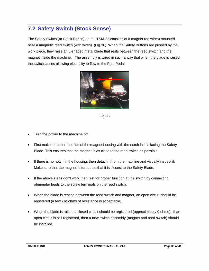
The Safety Switch (or Stock Sense) on the TSM-22 consists of a magnet (no wires) mounted
near a magnetic reed switch (with wires). (Fig 36) When the Safety Buttons are pushed by the
work piece, they raise an L-shaped metal blade that rests between the reed switch and the
magnet inside the machine. The assembly is wired in such a way that when the blade is raised
the switch closes allowing electricity to flow to the Foot Pedal.
Turn the power to the machine off.
First make sure that the side of the magnet housing with the notch in it is facing the Safety
Blade. This ensures that the magnet is as close to the reed switch as possible.
If there is no notch in the housing, then detach it from the machine and visually inspect it.
Make sure that the magnet is turned so that it is closest to the Safety Blade.
If the above steps don't work then test for proper function at the switch by connecting
ohmmeter leads to the screw terminals on the reed switch.
When the blade is resting between the reed switch and magnet, an open circuit should be
registered (a few kilo ohms of resistance is acceptable).
When the blade is raised a closed circuit should be registered (approximately 0 ohms). If an
open circuit is still registered, then a new switch assembly (magnet and reed switch) should
be installed.
Fig 36
CASTLE, INC TSM-22 OWNERS MANUAL V1.0 Page 34 of 41
7.3 Foot Switch
Designed to work in series with the Safety Switch, the Foot Switch is a simple mechanical micro-
switch operated by a spring-loaded pedal. At rest the switch condition should be normally open.
Closing the switch begins the cycle.
Turn the power to the machine off.
Turn the Foot Pedal and guard over and remove the two small screws that hold the pedal to
the base.
Use a flat tip screwdriver to pry the pedal free from the yellow guard (it is held by a silicone
caulk).
Using a Flat head or Phillips screw driver, remove the two screws on the left and right side of
the pedal. This will allow the pedal to come apart exposing the switch underneath.
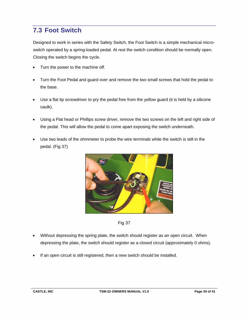
Use two leads of the ohmmeter to probe the wire terminals while the switch is still in the
pedal. (Fig 37)
Fig 37
Without depressing the spring plate, the switch should register as an open circuit. When
depressing the plate, the switch should register as a closed circuit (approximately 0 ohms).
If an open circuit is still registered, then a new switch should be installed.
CASTLE, INC TSM-22 OWNERS MANUAL V1.0 Page 35 of 41
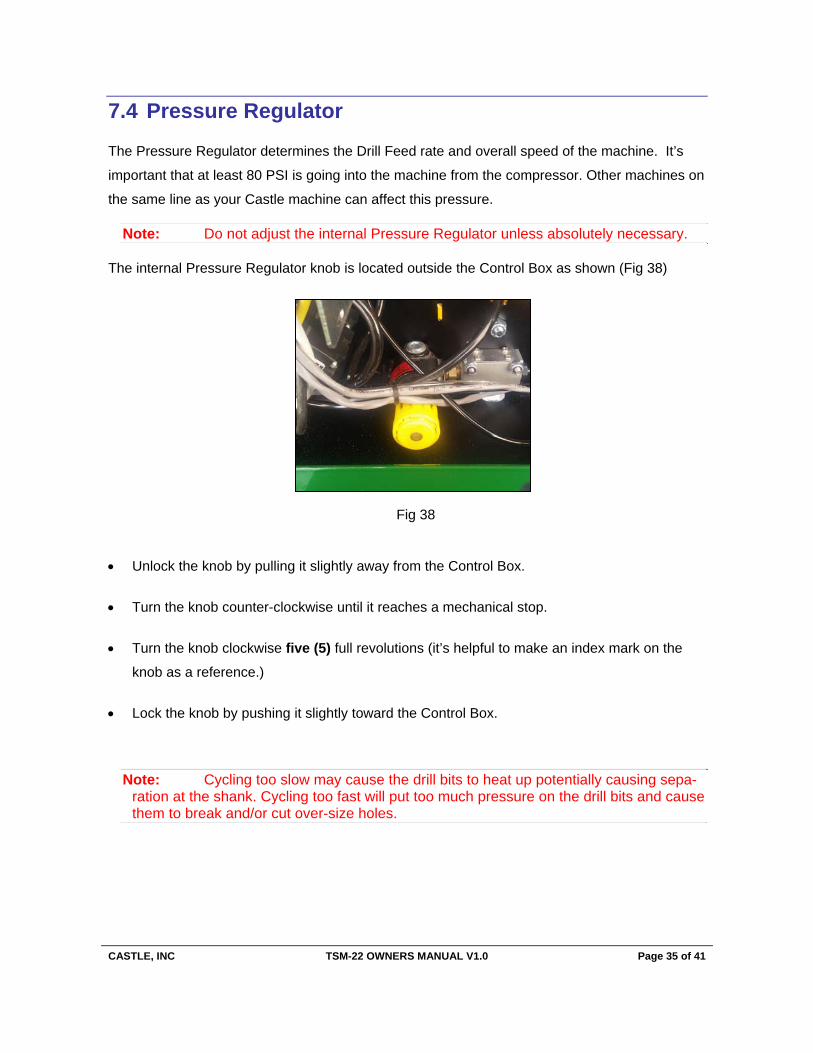
7.4 Pressure Regulator
The Pressure Regulator determines the Drill Feed rate and overall speed of the machine. It’s
important that at least 80 PSI is going into the machine from the compressor. Other machines on
the same line as your Castle machine can affect this pressure.
Note: Do not adjust the internal Pressure Regulator unless absolutely necessary.
The internal Pressure Regulator knob is located outside the Control Box as shown (Fig 38)
Unlock the knob by pulling it slightly away from the Control Box.
Turn the knob counter-clockwise until it reaches a mechanical stop.
Turn the knob clockwise five (5) full revolutions (it’s helpful to make an index mark on the
knob as a reference.)
Lock the knob by pushing it slightly toward the Control Box.
Note: Cycling too slow may cause the drill bits to heat up potentially causing sepa-ration at the shank. Cycling too fast will put too much pressure on the drill bits and cause them to break and/or cut over-size holes.
Fig 38

CASTLE, INC TSM-22 OWNERS MANUAL V1.0 Page 36 of 41
7.5 Router Stop Switch
The Router Stop Switch consists of a magnet (no wires) mounted near a magnetic reed switch
(with wires) on the Router Stop Plate. At the full extension of the routing stroke, a tab on the
Motor Carriage interrupts this switch to signal the start of the drilling stroke. If the clamp doesn’t
release and the pilot drill hasn’t come out, then the Router Stop Switch may require a simple
adjustment.
Open the front door of the machine and observe if the Motor Carriage has stalled with the
router fully extended into the pocket. If the carriage is fully extended then it’s likely that the
magnet is too close to the reed switch.
Turn the power to the machine off and loosen the screw that secures the work top down. Lift
up the work top
Loosen the two lower screws on the Router Stop Plate and slide the magnet (no wires)
approximately a 1/16” further away from the reed switch. (Fig 39)
Fig 39
Turn on the power to the machine and make a test pocket.
If the router still stalls in the pocket test with a continuity tester as described in Section 7.2
Safety Switch (page 33). If no continuity registers, a new switch assembly is needed.

CASTLE, INC TSM-22 OWNERS MANUAL V1.0 Page 37 of 41
7.6 Drill Stop Switch
The Drill Stop Switch consists of a magnet (no wires) mounted near a magnetic reed switch (with
wires) mounted inside the machine case near the Safety Buttons. (Fig 40) At the full extension
of the drilling stroke, the carriage interrupts this switch to signal the end of the drilling stroke and
the end of the cycle. If the clamp doesn’t release and the pilot drill won’t retract, then the
magnet is too close to the reed switch.
Turn the power to the machine off.
Loosen the socket cap screw that secures the work top and lift up the work top.
Loosen, but do not remove, the screws (Fig 41) that secure the magnet and the reed switch
to the machine case. Although the mounts are not slotted, spread the magnet and the reed
switch as far from each other as possible, then retighten the screws.
Turn on the power to the machine and make a test pocket.
Fig 40
Fig 41

CASTLE, INC TSM-22 OWNERS MANUAL V1.0 Page 38 of 41
If the drill still stalls in the pocket, loosen and remove the screws that secure the magnet and
the reed switch to the machine case.
Make sure that the side of the magnet housing with the notch in it is facing away from the
reed switch. This ensures that the magnet is as far from the reed switch as possible.
If there is no notch in the housing, then detach it from the machine and visually inspect it.
Make sure that the magnet is turned so that it is farthest from the reed switch.
If possible, use a small file or drill bit to slot the mounting holes on the plastic housings, and
then reinstall the magnet and the reed switch.
If the drill still stalls in the pocket, test with a continuity tester as described in Section 7.2
Safety Switch (page 33). If no continuity registers, a new switch assembly will be needed.
7.7 Serial Number Log
SERIAL NUMBER LOG
MANUFACTURER PART NUMBER SERIAL NO.
Castle, Inc A00022 – TSM-21 Pocket Hole Machine
Robert Bosch Co. E21610 – Bosch PR10E 1.0 HP Motor
Robert Bosch Co. E21617 – Bosch 1617 2.25 HP Motor
PURCHASE DATE:
CASTLE, INC TSM-22 OWNERS MANUAL V1.0 Page 39 of 41
8 Warranty Information
8.1 Warranty
Castle, Inc. uses only the highest quality materials available for the construction of our
machines. Your TSM-22 is warranted for one (1) full year from the date of purchase against
workmanship or material defects under normal use and service. Castle, Inc. is not responsible
for failures or injuries due to negligence, misuse, alteration, unauthorized service, or accidents.
Owners of new machines are obligated to contact their dealer AND Castle before contracting for,
or attempting warranty repairs or service.
If Castle or dealer technicians determine that reasonably simple adjustments or tests are
necessary in delivering remedy to a failed machine, owners of warrantied machines are
obligated to exercise due diligence while assisting in the execution of these simple adjustments
or tests.
When a problem cannot be resolved via telephone support, Castle will, at its expense, send
replacement parts and instructions to the purchaser necessary to cure the defect. Castle will not
be responsible for providing labor on repairs that are deemed reasonable for the owner to
accomplish. Castle, Inc., at its sole discretion, will elect to either repair (by a Castle technician
or dealer technician) or replace a machine in the case of warranty issues that exceed
reasonable owner repair expectations. Alternatively, Castle will factory repair any machine
provided the machine is returned to Castle, shipping prepaid, within the warranty period.
Castle will not, under any circumstances, be liable for consequential, incidental, special
or exemplary damages, or for loss of time, revenue or production. Further, Castle
disclaims any warranty, expressed or implied, as to the merchantability or fitness of a
Castle product for any particular purpose.
CASTLE, INC TSM-22 OWNERS MANUAL V1.0 Page 40 of 41
8.2 30-Day Refund Policy
Any Castle machine that is un-altered and in almost new condition may be returned by the
purchaser, for any reason, within 30 days of the purchase date for a full refund. Please contact
your Castle authorized dealer for more information.
8.3 Warranty Service Policy
In the event that the End User requires service, support, or assistance, End Users are expected
to first contact the Dealer, Distributor, or Reseller (DDR) from whom the Castle machine was
purchased.
Castle does not employ on-site service technicians. On-site technical support and service are to
be provided by the DDR or by an authorized Castle agent. If a DDR cannot provide on-site
technical support and service, the DDR is expected to partner with an authorized Castle agent.
Owners of new machines are obligated to contact the DDR and Castle before contracting for or
attempting repairs and service.
If Castle or DDR support professionals determine that reasonably simple adjustments or tests
are necessary in delivering remedy to a failed machine, owners of warranted machines are
obligated to exercise due diligence while assisting in the execution of these simple adjustments
or tests.
8.4 Warranty Part Replacement
8.4.1 New product (within 30 days)
Castle is obliged to provide replacement parts at no charge.
Castle is obliged to ship overnight if requested by End User.

CASTLE, INC TSM-22 OWNERS MANUAL V1.0 Page 41 of 41
8.4.2 30 days to 12 months
Castle is obliged to provide replacement parts at no charge.
Castle is obliged to ship UPS 2-day if requested by End User.
If needed next-day, the End User will be charged to cover difference.
Certain original parts and assemblies are expected to be returned by the End User if Castle is
providing replacements. Castle will initiate an RMA and provide pre-paid shipping for these
returned items. In order to protect Castle’s assets, the customer will be billed for replacement
parts if the returned parts are not received at the Castle factory within 30 days of the End User’s
receipt of the replacement parts.