Embed Size (px)
Citation preview
1
TSHARC™ Win CE Drivers Manual Windows® CE version 5.0
RS-232, USB & PS/2 Rev 1.18a
Document Revision and Copyright Document Name: WinCE50DriversMan032409 Document Date: April 22, 2009 Copyright Microchip Technology, 1995 – 2009, All rights reserved. TSHARC™ is the exclusive trademarks of Microchip Technology Contact Information Microchip Technology 9055 North 51st Street Suite: H Brown Deer, Wisconsin 53223 www.microchip.com/TSHARC Phone: 414-355-4675 Fax: 414-355-4775
2
1. Table of Contents1. Table of Contents ..................................................................................................................... 2 2. Table of Figures ....................................................................................................................... 3 3. Introduction ............................................................................................................................... 4
Before you Begin ......................................................................................................................... 4 Supported Features ..................................................................................................................... 4 Supported Processors ................................................................................................................. 4 RS-232 Specific Information ........................................................................................................ 4
Port Assignment ....................................................................................................................... 4 Baud Rate Configurations ........................................................................................................ 4
PS/2 Specific Information ............................................................................................................. 4 USB Specific Information ............................................................................................................. 4
4. Running the TSHARC Microsoft Installer File .......................................................................... 5 Welcome Screen .......................................................................................................................... 5 License Agreement ...................................................................................................................... 6 Select Installation Folder .............................................................................................................. 7
Browsing Folder Location ......................................................................................................... 7 Verifying Disk Space ................................................................................................................ 8
Confirm Installation ...................................................................................................................... 8 Install Status Screen .................................................................................................................... 9 Driver Updates Report ................................................................................................................. 9 Installation Complete ................................................................................................................. 10 Driver File Locations .................................................................................................................. 10
5. Adding a TSHARC Driver Component to an OS .................................................................... 11 Launch "Platform Builder 5.0" .................................................................................................... 11 Board Support Package Selection ............................................................................................. 12 Design Templates ...................................................................................................................... 13 Application and Media Selection ................................................................................................ 14 Networking and Communications .............................................................................................. 15 Completing Platform Builder Wizard .......................................................................................... 15 Adding the TSHARC Catalog ..................................................................................................... 16
6. Configuring TSHARC Controller ............................................................................................ 17 Changing the Number of Calibration Points .............................................................................. 17
Method 1: ............................................................................................................................... 17 Method 2: ............................................................................................................................... 17
Calibrating the Controller ........................................................................................................... 17 Windows CE Calibration Registry Entries .................................................................................. 17 Enabling Right-Click Emulation.................................................................................................. 18
Method 1 ................................................................................................................................ 18 Method 2 ................................................................................................................................ 18
Configuring Right-Click Emulation ............................................................................................. 18 Disabling Right-Click Emulation ................................................................................................. 18 Changing Calibration Timeout Values ....................................................................................... 19
Method 1: ............................................................................................................................... 19 Method 2: ............................................................................................................................... 19
Configure Touch Beep ............................................................................................................... 19 Method 1: ............................................................................................................................... 19 Method 2 ................................................................................................................................ 20
Enable/Disable Touch Beep ...................................................................................................... 20 Enable .................................................................................................................................... 20 Disable.................................................................................................................................... 20 Loud Beep .............................................................................................................................. 20 Soft Beep ................................................................................................................................ 20
3
Changing the mouse event stream rate ..................................................................................... 20 Method 1: ............................................................................................................................... 20 Method 2: ............................................................................................................................... 20
7. TSHARC Component Removal .............................................................................................. 21 Removing a TSHARC Driver Components from an OS Design ............................................ 21 Removing TSHARC Driver Components from the Catalog ................................................... 21
8. Additional Set-Up Notes ......................................................................................................... 21 Establish Communication with Target CE Device ..................................................................... 21 Saving registry settings to Persistent Storage ........................................................................... 21
Method 1: ............................................................................................................................... 21 Method 2: ............................................................................................................................... 21
Aygshell Component - Effect on Right-Click Emulation ............................................................. 22 Troubleshooting TSHARC CE Driver ......................................................................................... 22
9. Notes ...................................................................................................................................... 23
2. Table of Figures Figure 1: TSHARC CE 5.0.msi Welcome ........................................................................................ 5 Figure 2: End User License Agreement .......................................................................................... 6 Figure 3: Select Installation Folder .................................................................................................. 7 Figure 4: Browse for Folder ............................................................................................................. 7 Figure 5: Disk Cost View ................................................................................................................. 8 Figure 6: Confirm Installation ........................................................................................................... 8 Figure 7: Install Status Screen ........................................................................................................ 9 Figure 8: Changes Made Since Previous Version ........................................................................... 9 Figure 9: Installation Complete ...................................................................................................... 10 Figure 10: Welcome to the Platform Wizard Screen ..................................................................... 11 Figure 11: Board Support Package Selection Screen ................................................................... 12 Figure 12: Platform Configuration Selection .................................................................................. 13 Figure 13: Application and Media Selection .................................................................................. 14 Figure 14: Networking and Communications ................................................................................ 15 Figure 15: Completed Platform Wizard ......................................................................................... 15 Figure 16: Adding TSHARC Component ....................................................................................... 16
4
3. Introduction Before you Begin
• Platform Builder 5.0 must already be installed and configured on your Windows development system.
• Please be sure no instances of Platform Builder 5.0 are currently running. • Navigate your system to find the TSHARCCE50V118a.MSI executable file.
Supported Features 3, 4, 7, and 20 Point Calibration Right-Click Emulation Hardware Beep Support Configurable Data Stream Rate Supported Processors Hampshire has recompiled the source code for the TSHARC WinCE driver to support the following processors. ARMV4I MIPSII MIPSII_FP MIPSIV MIPSIV_FP SH4 X86 RS-232 Specific Information Port Assignment The driver loads based on the "Port" value entry within the "TSHARCS.reg" file. This value corresponds with the available port.
• "Port"=dword: 1” assigns the port to the first available port defined in the “platform.reg” file.
• "Port" ="dword: 2" assigns the port to the second available port defined in the “platform.reg” file.
Baud Rate Configurations If using a TSHARC® controller using other than a 9600 baud rate, the baud rate may be changed via the “Baud” registry entry. This may also be found in the “TSHARCS.REG” file. TSHARC controllers are 9600 Baud by default. PS/2 Specific Information The 8042 input driver must be included in the OS Design in order for the TSHARC PS/2 driver to function on CE device. USB Specific Information The USB host controller and the UHCI component must be installed in order for USB to function. These components are added automatically after adding the "USB TSHARC Touch Screen Driver" component to the OS Design.
5
4. Running the TSHARC Microsoft Installer File
Welcome Screen
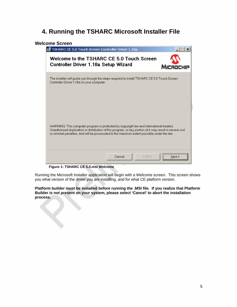
Figure 1: TSHARC CE 5.0.msi Welcome
Running the Microsoft Installer application will begin with a Welcome screen. This screen shows you what version of the driver you are installing, and for what CE platform version. Platform builder must be installed before running the .MSI file. If you realize that Platform Builder is not present on your system, please select ‘Cancel’ to abort the installation process.
6
License Agreement
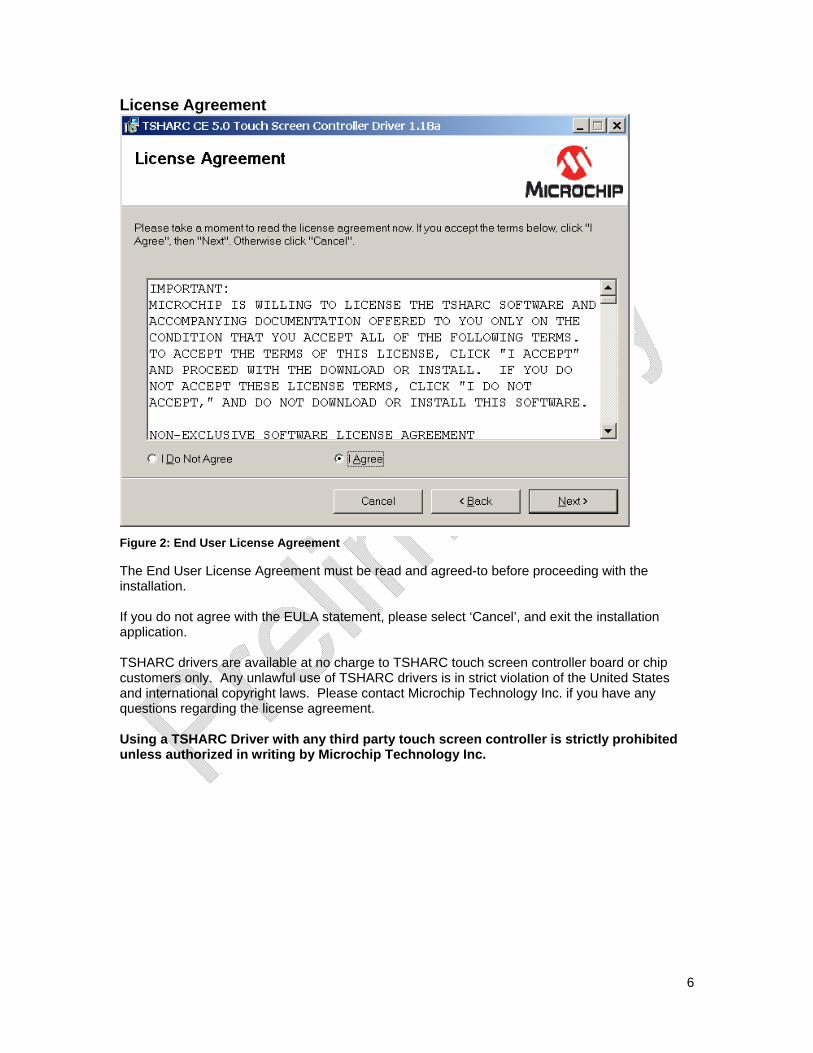
Figure 2: End User License Agreement
The End User License Agreement must be read and agreed-to before proceeding with the installation. If you do not agree with the EULA statement, please select ‘Cancel’, and exit the installation application. TSHARC drivers are available at no charge to TSHARC touch screen controller board or chip customers only. Any unlawful use of TSHARC drivers is in strict violation of the United States and international copyright laws. Please contact Microchip Technology Inc. if you have any questions regarding the license agreement. Using a TSHARC Driver with any third party touch screen controller is strictly prohibited unless authorized in writing by Microchip Technology Inc.
7
Select Installation Folder
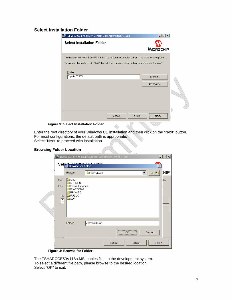
Figure 3: Select Installation Folder
Enter the root directory of your Windows CE installation and then click on the “Next” button. For most configurations, the default path is appropriate. Select “Next” to proceed with installation. Browsing Folder Location
Figure 4: Browse for Folder
The TSHARCCE50V118a.MSI copies files to the development system. To select a different file path, please browse to the desired location. Select “OK” to exit.
8
Verifying Disk Space
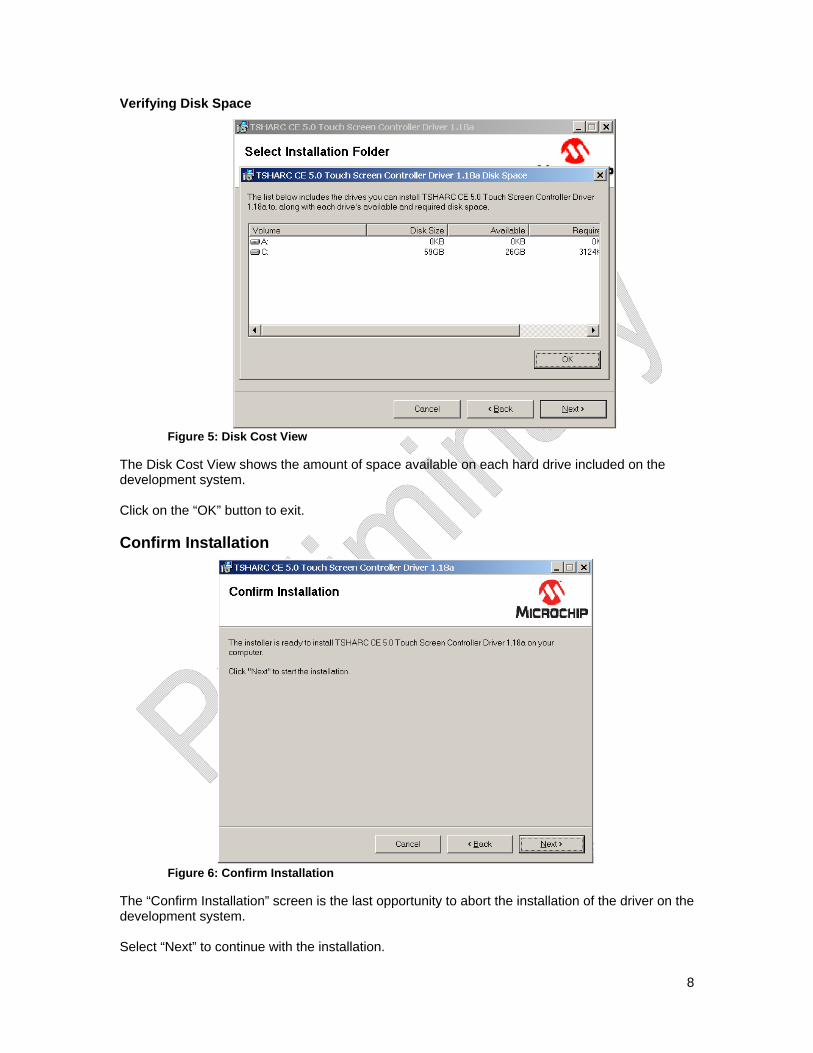
Figure 5: Disk Cost View
The Disk Cost View shows the amount of space available on each hard drive included on the development system. Click on the “OK” button to exit. Confirm Installation
Figure 6: Confirm Installation
The “Confirm Installation” screen is the last opportunity to abort the installation of the driver on the development system. Select “Next” to continue with the installation.
9
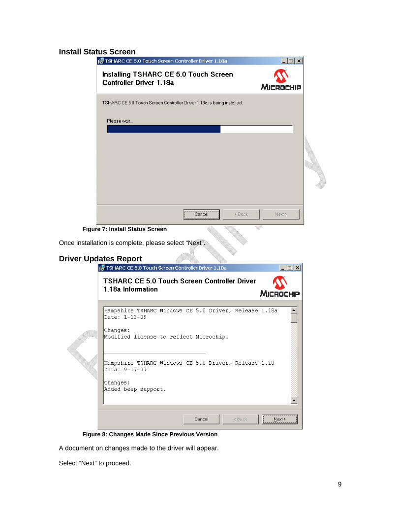
Install Status Screen
Figure 7: Install Status Screen
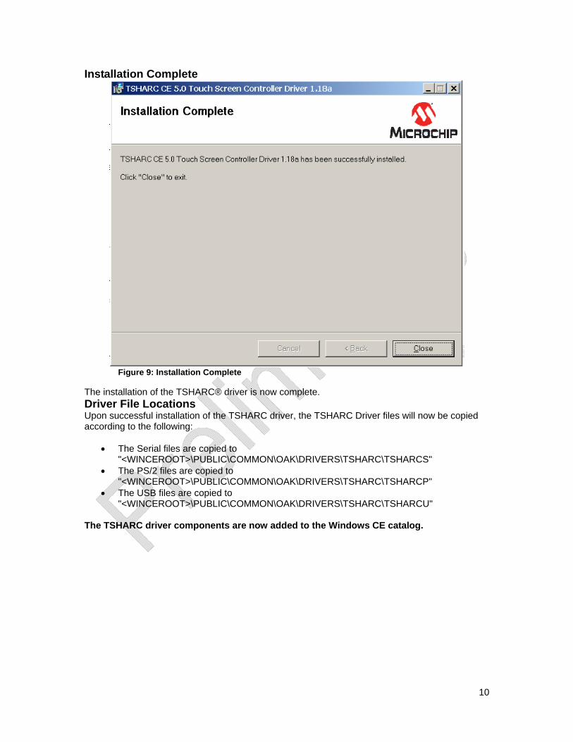
Once installation is complete, please select “Next”. Driver Updates Report
Figure 8: Changes Made Since Previous Version
A document on changes made to the driver will appear. Select “Next” to proceed.
10
Installation Complete
Figure 9: Installation Complete
The installation of the TSHARC® driver is now complete. Driver File Locations Upon successful installation of the TSHARC driver, the TSHARC Driver files will now be copied according to the following:
• The Serial files are copied to "<WINCEROOT>\PUBLIC\COMMON\OAK\DRIVERS\TSHARC\TSHARCS"
• The PS/2 files are copied to "<WINCEROOT>\PUBLIC\COMMON\OAK\DRIVERS\TSHARC\TSHARCP"
• The USB files are copied to "<WINCEROOT>\PUBLIC\COMMON\OAK\DRIVERS\TSHARC\TSHARCU"
The TSHARC driver components are now added to the Windows CE catalog.
11
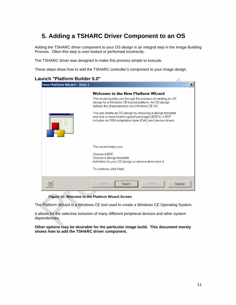
5. Adding a TSHARC Driver Component to an OS Adding the TSHARC driver component to your OS design is an integral step in the Image Building Process. Often this step is over-looked or performed incorrectly. The TSHARC driver was designed to make this process simple to execute. These steps show how to add the TSHARC controller’s component to your image design. Launch "Platform Builder 5.0"
Figure 10: Welcome to the Platform Wizard Screen
The Platform Wizard is a Windows CE tool used to create a Windows CE Operating System. It allows for the selective inclusion of many different peripheral devices and other system dependencies. Other options may be desirable for the particular image build. This document merely shows how to add the TSHARC driver component.
12
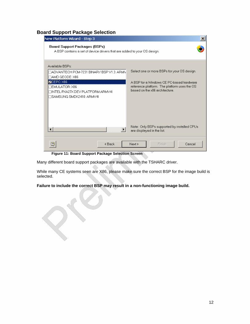
Board Support Package Selection
Figure 11: Board Support Package Selection Screen
Many different board support packages are available with the TSHARC driver. While many CE systems seen are X86, please make sure the correct BSP for the image build is selected. Failure to include the correct BSP may result in a non-functioning image build.
13
Design Templates
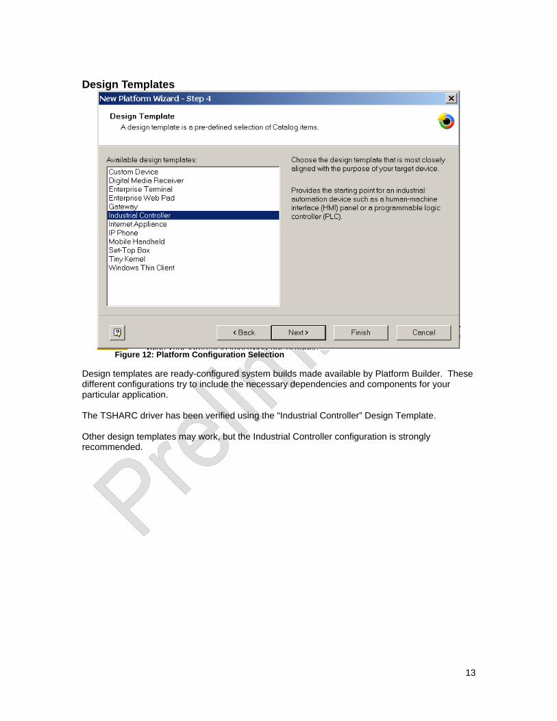
Figure 12: Platform Configuration Selection
Design templates are ready-configured system builds made available by Platform Builder. These different configurations try to include the necessary dependencies and components for your particular application. The TSHARC driver has been verified using the “Industrial Controller” Design Template. Other design templates may work, but the Industrial Controller configuration is strongly recommended.
14
Application and Media Selection
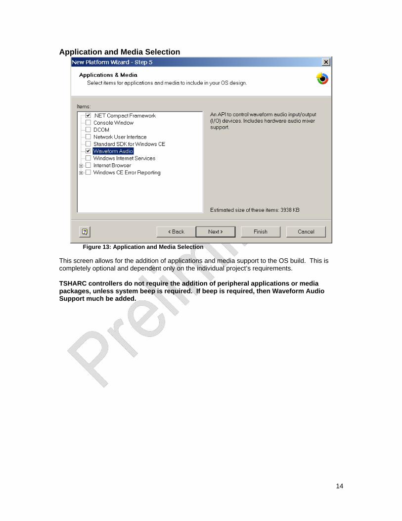
Figure 13: Application and Media Selection
This screen allows for the addition of applications and media support to the OS build. This is completely optional and dependent only on the individual project’s requirements. TSHARC controllers do not require the addition of peripheral applications or media packages, unless system beep is required. If beep is required, then Waveform Audio Support much be added.
15
Networking and Communications
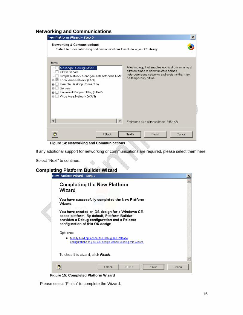
Figure 14: Networking and Communications
If any additional support for networking or communications are required, please select them here. Select “Next” to continue. Completing Platform Builder Wizard
Figure 15: Completed Platform Wizard
Please select “Finish” to complete the Wizard.
16
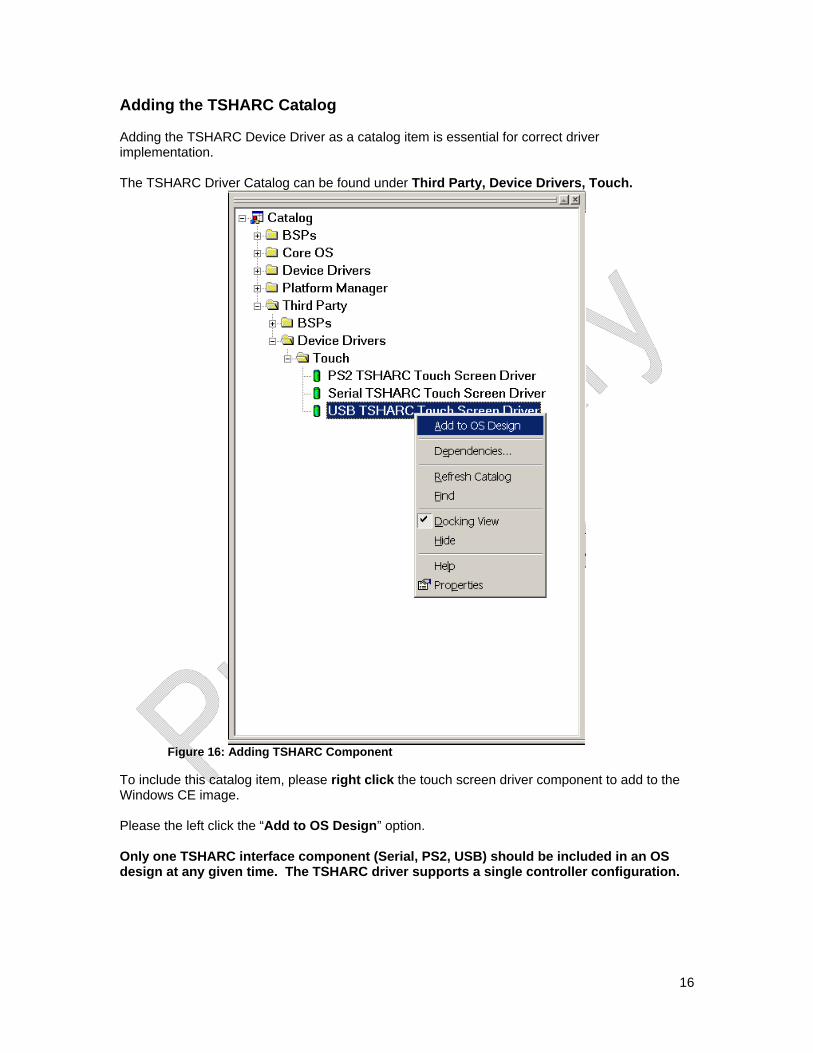
Adding the TSHARC Catalog Adding the TSHARC Device Driver as a catalog item is essential for correct driver implementation. The TSHARC Driver Catalog can be found under Third Party, Device Drivers, Touch.
Figure 16: Adding TSHARC Component
To include this catalog item, please right click the touch screen driver component to add to the Windows CE image. Please the left click the “Add to OS Design” option. Only one TSHARC interface component (Serial, PS2, USB) should be included in an OS design at any given time. The TSHARC driver supports a single controller configuration.
17
6. Configuring TSHARC Controller Changing the Number of Calibration Points Method 1: • In "Platform Builder 5.0", click on the FileView tab • Double click on the appropriate registry file <WINCEROOT>\PUBLIC\COMMON\OAK
o If Serial \DRIVERS\TSHARC\TSHARCS\TSHARCS.reg
o If PS/2 \DRIVERS\TSHARC\TSHARCP\TSHARCP.reg
o If USB \DRIVERS\TSHARC\TSHARCU\TSHARCU.reg
• Change the value of "CalType" appropriately o For 3-point calibration, set value to "dword:3" o For 4-point calibration, set value to "dword:4" o For 7-point calibration, set value to "dword:7" o For 20-point calibration, set value to "dword:14"
• Rebuild and recreate run-time image. Method 2:
• Using a registry editor for the target device, change the “CalType” registry item located within the “HKEY_LOCAL_MACHINE\SOFTWARE\Hampshire\CurrentVersion\CalType” branch according to the following:
o For 3-point calibration, set value to "dword:3" o For 4-point calibration, set value to "dword:4" o For 7-point calibration, set value to "dword:7" o For 20-point calibration, set value to "dword:14"
• Browse to the “Windows” directory using Windows Explorer and double-click the shortcut “TouchIOCTL”. This will cause current TSHARC driver to re-read and apply the new registry settings.
Calibrating the Controller
• Select the Start menu • Under the “Programs” group select “TSHARC Calibration” • Touch all targets with activator tip for at least a couple seconds each.
The points used for the calibration is determined by the “CalType” registry entry described in section “Changing the Calibration Type” below. If no shortcut is present under “Programs” group, a shortcut to the calibration application may be found in under the “Windows” directory on the CE Device. Windows CE Calibration Registry Entries Calibration parameters are created by Hcecal after calibration and are stored in the registry under the following key: [HKEY_LOCAL_MACHINE\SOFTWARE\Hampshire\CurrentVersion\Global] Upon boot, if the registry entries are not located, the driver defaults to a default un-calibrated state.
18
Enabling Right-Click Emulation Method 1
• In "Platform Builder 5.0", click on the “FileView” tab • Double click on the appropriate registry file <WINCEROOT>\PUBLIC\COMMON\OAK
o If Serial \DRIVERS\TSHARC\TSHARCS\TSHARCS.reg
o If PS/2 \DRIVERS\TSHARC\TSHARCP\TSHARCP.reg
o If USB \DRIVERS\TSHARC\TSHARCU\TSHARCU.reg • Remove the semi-colons (uncomment) from the last four lines of the file. • Rebuild and recreate run-time image.
Method 2
• Using a registry editor for the target device, change the “xEventArea”, “yEventArea” and “RightClickTime” registry items located within the “HKEY_LOCAL_MACHINE\SOFTWARE\Hampshire\CurrentVersion\Global” branch according to the description of what these values are responsible for in the next paragraph.
• Browse to the “Windows” directory using Windows Explorer and double-click the shortcut “TouchIOCTL”. This will cause current TSHARC driver to re-read and apply the new registry settings.
Configuring Right-Click Emulation There are three entries that can be configured for right-click emulation found at [HKEY_LOCAL_MACHINE\SOFTWARE\Hampshire\CurrentVersion\Global]
• "xEventArea" • "yEventArea" • "RightClickTime"
The "RightClickTime" is the time elapsed (measured in clock ticks) on a touch that is within an area on the screen (the event area) before a right-click event is sent. The "xEventArea" and "yEventArea" entries are horizontal and vertical components of the area that a touch remains in for a time specified by "RightClickTime" before a right-click event is sent. The Values for "xEventArea" and "yEventArea” entries can range from between 0x0000 and 0xFFFF. The "xEventArea" and "yEventArea" are relative to the touch screen coordinates rather than the screen coordinates.
To determine the values for xEventArea and yEventArea, the following formula may be used: xEventArea = 65535 * (desired_event_area_width / width_of_touchscreen) yEventArea = 65535 * (desired_event_area_height / height_of_touchscreen) These values must be entered in hexadecimal for the Registry entry.
Disabling Right-Click Emulation To disable Right-Click emulation, “RightClickTime” should have of value or zero, or the registry entries “xEventArea”, “yEventArea”, and “RightClickTime” can be removed or kept absent from the registry.
19
Changing Calibration Timeout Values There are two timeout values that are adjustable in the registry that correspond to the timeout value when first launching the calibration application (“CalTimeIn”) and the timeout value after touching all of the calibration points(“CalTimeOut”). If the countdown timer for “CalTimeIn” expires, the calibration application simply exits. If the counter for “CalTimeOut” expires then the calibration application reverts the calibration settings to the previous settings. The default value “CalTimeIn” is 15 seconds and the default value for “CalTimeOut” is 90 seconds. Method 1:
• In "Platform Builder 5.0 ", click on the “FileView” tab • Double click on the appropriate registry file <WINCEROOT>\PUBLIC\COMMON\OAK
o If Serial \DRIVERS\TSHARC\TSHARCS\TSHARCS.reg
o If PS/2 \DRIVERS\TSHARC\TSHARCP\TSHARCP.reg
o If USB \DRIVERS\TSHARC\TSHARCU\TSHARCU.reg • Add the following lines to the end of the file:
[HKEY_LOCAL_MACHINE\SOFTWARE\Hampshire\CurrentVersion\Global] "CalTimeIn"=dword:F “CalTimeOut”=dword:5A
• Rebuild and recreate run-time image. Method 2:
• Using a registry editor for the target device, change the “CalTimeIn”, “CalTimeOut” registry items located within the “HKEY_LOCAL_MACHINE\SOFTWARE\Hampshire\CurrentVersion\Global” branch according to timeout value(s) that are desired.
• Browse to the “Windows” directory using Windows Explorer and double-click the shortcut “TouchIOCTL”. This will cause current TSHARC driver to re-read and apply the new registry settings.
Configure Touch Beep Method 1: The following lines may be added to the "tsharcs.reg", "tsharcu.reg" or "tsharcp.reg" file. [HKEY_LOCAL_MACHINE\SOFTWARE\Hampshire\CurrentVersion\Global] "usewincebeep"=dword:1 The "Volume & Sounds" control panel applet uses the "PanelState" registry to store its settings. If "usewincebeep"=1 This value is queried on touch-down and changes made in the control panel can be observed immediately. If the "usewincebeep"=2 This value is queried on touch up. Also, changes in the control panel applet will not be observed until the second touch. The follow entry is needed to make the option to configure taps in the "Volume & Sounds" control panel applet visible: [HKEY_LOCAL_MACHINE\ControlPanel] "Screen"=dword:3
20
Method 2 The Beep can also be configured using the Windows CE "Volume & Sounds" control panel applet. To use this applet, set the "usewincebeep" entry to a DWORD value of one or two in the "HKEY_LOCAL_MACHINE\SOFTWARE\Hampshire\CurrentVersion\Global" registry branch. Enable/Disable Touch Beep Enable To enable the beep add the registry value "beepEnabled" and set it to one. Disable To disable the beep, exclude the "beepEnabled" registry value or set to zero. Loud Beep To make the beep loud, add the registry value "beepIsLoud" and set it to one. Soft Beep To make the beep soft, exclude the "beepIsLoud" registry value or set to zero. Changing the mouse event stream rate When the mouse cursor moves and changes state as a result of a touch, the TSHARC CE driver sends a series of mouse events to the Windows CE event queue. If the mouse events are sent too fast, other CE applications and background process may take longer to process their own events while the touch screen is being touched. For this reason, a new feature has been added to the TSHARC Serial and USB drivers to allow adjustment of the speed at which the driver sends mouse events. The default value is a minimum duration 16 clock ticks for every mouse packet (except for pen up and pen down packets which are always processed immediately). For slower embedded devices, it may be desirable to increase this value to decrease to rate at which mouse packets are sent. For faster devices, it may be desirable to decrease this value to increase the rate at which mouse packets are sent. Method 1:
• In "Platform Builder 5.0", click on the FileView tab • Double click on the appropriate registry file <WINCEROOT>\PUBLIC\COMMON\OAK
o If Serial \DRIVERS\TSHARC\TSHARCS\TSHARCS.reg
o If PS/2 \DRIVERS\TSHARC\TSHARCP\TSHARCP.reg
o If USB \DRIVERS\TSHARC\TSHARCU\TSHARCU.reg • Add the following lines:
[HKEY_LOCAL_MACHINE\SOFTWARE\Hampshire\CurrentVersion\Global] "mouseMoveThreshold"=dword:10 Method 2:
• Using a registry editor for the target device, add or change the “mouseMoveThreshold”, registry item located within the “HKEY_LOCAL_MACHINE\SOFTWARE\Hampshire\CurrentVersion\Global” branch to the desired minimum duration length to be applied for every mouse stream packet.
• Browse to the “Windows” directory using Windows Explorer and double-click the shortcut “TouchIOCTL”. This will cause current TSHARC driver to re-read and apply the new registry settings.
21
7. TSHARC Component Removal Removing a TSHARC Driver Components from an OS Design
• Click on the "OSDesignView" tab. • Browse to "Device Drivers->Input Devices". • Right-click on the appropriate TSHARC component:
o If Serial, right-click on "Serial TSHARC Touch Screen Driver" o If PS/2, right-click on "PS2 TSHARC Touch Screen Driver" o If USB, right-click on "USB TSHARC Touch Screen Driver"
• Left-click "Delete". Removing TSHARC Driver Components from the Catalog
• Open the Windows Control Panel. • Double-click on Add/Remove Programs icon. • Select the “TSHARC CE 5.0 Touch Screen Controller Driver 1.18” item. • Click on the "Remove" Button.
The TSHARC driver components are now removed from the Catalog. To remove the TSHARC files as well, the directory "<WINCEROOT>\PUBLIC\COMMON\OAK\DRIVERS\TSHARC” now can safely be deleted.
8. Additional Set-Up Notes Establish Communication with Target CE Device To modify the registry, add a file, or to use any of Platform Builders tools on existing target CE system, the ActiveSync tool is very necessary for making changes on a target CE device. To connect via ActiveSync, there are multiple communication mechanisms available to connect to the target device. Usually, the easiest way to communicate with the target device is to attach a NULL modem cable between the CE device and other computer that is used for debugging, download the latest ActiveSync application, and then in the windows directory of the CE device, there is usually the executable file "repllog". Double-click this application from Windows Explorer and the device will connect to the debugging computer. For detailed instructions on different ways to communicate with a Windows CE, please see Microsoft’s documentation. Saving registry settings to Persistent Storage After calibrating the touch screen controller the calibration registry settings are automatically saved to the persistent storage if persistent storage is setup correctly on the CE device. However, if the TSHARC registry settings are edited using a registry editor or third-party application, the new registry settings may be saved using two methods. Method 1: Click “Start->Suspend” on the Windows CE target. Method 2: If changing the registry settings programmatically, call RegFlushKey() function in source code after making registry modifications.
22
Aygshell Component - Effect on Right-Click Emulation Windows CE has a shell extension called "aygshell" that is meant to be used with touch screen. If the touch screen is touched and held in the same region of the screen, black dots will appear and a right click will occur in the same area that is being touch. The issue with using this is component is that appears to be no way to disable this component once it has been included in the CE target image. Also, this component conflicts with the right-click feature of the driver. To remove this component, search for the "aygshell" component and remove this from the target image. A clean build should then be done to ensure it is properly removed. If this component is component is included in the target image, it may be configured as follows:
• The "HKEY_LOCAL_MACHINE\System\GWE\Commctrl" registry subkey stores settings that affect common controls.
• UseLongDelayForGestures : DWORD • There is no default setting. This value controls the recognition delay used by
SHRecognizeGesture. If this value is set to 1, then the delay is 800 ms. Otherwise, the delay is 400 ms There is no way to disable this feature.
Troubleshooting TSHARC CE Driver In some cases there may be conflicting devices or an invalid configuration on a target CE system. In this case, it may be difficult to determine if the TSHARC driver is correctly being loaded. To see if the TSHARC CE driver is being loaded and if there are any relevant messages being outputted due to an invalid configuration, it is often useful to see the kernel debug output from the target system. Very often on Windows CE devices, there is a COM port available for kernel debugging. If there is such a COM port, attach a NULL modem cable between the CE device and other computer that is used for debugging. On the computer that is used for debugging, set the terminal application to 38400-N-8-1. If there is a successful communication with the device, first output from the boot loader will be seen followed by output from the CE operating system. There will be kernel debug messages from the TSHARC driver if the target system is correctly configured.
23
9. Notes
24
Microchip Technology Inc 9055 N. 51st Street Unit H
Brown Deer, WI 53223 Main Phone: 414-355-4675 Main Fax: 414-355-4775
www.microchip.com/TSHARC
Copyright Microchip Technology Inc 1996 – 2009 Microchip® and TSHARC™ are trademarks of Microchip Technology Inc
All rights reserved.