Embed Size (px)
Citation preview
ETSI TS 143 064 V15.0.0 (2018-07)
Digital cellular telecommunications system (Phase 2+) (GSM); General Packet Radio Service (GPRS);
Overall description of the GPRS radio interface; Stage 2
(3GPP TS 43.064 version 15.0.0 Release 15)
TECHNICAL SPECIFICATION
GLOBAL SYSTEM FOR MOBILE COMMUNICATIONS
R
ETSI
ETSI TS 143 064 V15.0.0 (2018-07)13GPP TS 43.064 version 15.0.0 Release 15
Reference RTS/TSGR-0643064vf00
Keywords GSM
ETSI
650 Route des Lucioles F-06921 Sophia Antipolis Cedex - FRANCE
Tel.: +33 4 92 94 42 00 Fax: +33 4 93 65 47 16
Siret N° 348 623 562 00017 - NAF 742 C
Association à but non lucratif enregistrée à la Sous-Préfecture de Grasse (06) N° 7803/88
Important notice
The present document can be downloaded from: http://www.etsi.org/standards-search
The present document may be made available in electronic versions and/or in print. The content of any electronic and/or print versions of the present document shall not be modified without the prior written authorization of ETSI. In case of any
existing or perceived difference in contents between such versions and/or in print, the only prevailing document is the print of the Portable Document Format (PDF) version kept on a specific network drive within ETSI Secretariat.
Users of the present document should be aware that the document may be subject to revision or change of status. Information on the current status of this and other ETSI documents is available at
https://portal.etsi.org/TB/ETSIDeliverableStatus.aspx
If you find errors in the present document, please send your comment to one of the following services: https://portal.etsi.org/People/CommiteeSupportStaff.aspx
Copyright Notification
No part may be reproduced or utilized in any form or by any means, electronic or mechanical, including photocopying and microfilm except as authorized by written permission of ETSI.
The content of the PDF version shall not be modified without the written authorization of ETSI. The copyright and the foregoing restriction extend to reproduction in all media.
© ETSI 2018.
All rights reserved.
DECTTM, PLUGTESTSTM, UMTSTM and the ETSI logo are trademarks of ETSI registered for the benefit of its Members. 3GPPTM and LTETM are trademarks of ETSI registered for the benefit of its Members and
of the 3GPP Organizational Partners. oneM2M logo is protected for the benefit of its Members.
GSM® and the GSM logo are trademarks registered and owned by the GSM Association.
ETSI
ETSI TS 143 064 V15.0.0 (2018-07)23GPP TS 43.064 version 15.0.0 Release 15
Intellectual Property Rights Essential patents
IPRs essential or potentially essential to normative deliverables may have been declared to ETSI. The information pertaining to these essential IPRs, if any, is publicly available for ETSI members and non-members, and can be found in ETSI SR 000 314: "Intellectual Property Rights (IPRs); Essential, or potentially Essential, IPRs notified to ETSI in respect of ETSI standards", which is available from the ETSI Secretariat. Latest updates are available on the ETSI Web server (https://ipr.etsi.org/).
Pursuant to the ETSI IPR Policy, no investigation, including IPR searches, has been carried out by ETSI. No guarantee can be given as to the existence of other IPRs not referenced in ETSI SR 000 314 (or the updates on the ETSI Web server) which are, or may be, or may become, essential to the present document.
Trademarks
The present document may include trademarks and/or tradenames which are asserted and/or registered by their owners. ETSI claims no ownership of these except for any which are indicated as being the property of ETSI, and conveys no right to use or reproduce any trademark and/or tradename. Mention of those trademarks in the present document does not constitute an endorsement by ETSI of products, services or organizations associated with those trademarks.
Foreword This Technical Specification (TS) has been produced by ETSI 3rd Generation Partnership Project (3GPP).
The present document may refer to technical specifications or reports using their 3GPP identities, UMTS identities or GSM identities. These should be interpreted as being references to the corresponding ETSI deliverables.
The cross reference between GSM, UMTS, 3GPP and ETSI identities can be found under http://webapp.etsi.org/key/queryform.asp.
Modal verbs terminology In the present document "shall", "shall not", "should", "should not", "may", "need not", "will", "will not", "can" and "cannot" are to be interpreted as described in clause 3.2 of the ETSI Drafting Rules (Verbal forms for the expression of provisions).
"must" and "must not" are NOT allowed in ETSI deliverables except when used in direct citation.
ETSI
ETSI TS 143 064 V15.0.0 (2018-07)33GPP TS 43.064 version 15.0.0 Release 15
Contents Intellectual Property Rights ................................................................................................................................ 2
Foreword ............................................................................................................................................................. 2
Modal verbs terminology .................................................................................................................................... 2
Foreword ............................................................................................................................................................. 7
1 Scope ........................................................................................................................................................ 8
2 References ................................................................................................................................................ 8
3 Abbreviations, symbols and definitions ................................................................................................... 9
3.1 Abbreviations ..................................................................................................................................................... 9
3.2 Symbols ............................................................................................................................................................ 11
3.2a Restrictions ....................................................................................................................................................... 11
3.2b Definitions ........................................................................................................................................................ 11
3.3 Network and mobile station capabilities .......................................................................................................... 11
3.3.1 General ........................................................................................................................................................ 11
3.3.2 EGPRS mobile station ................................................................................................................................ 12
3.3.3 Dual Transfer Mode .................................................................................................................................... 12
3.3.4 Downlink dual carrier configuration ........................................................................................................... 12
3.3.5 Reduced Latency TBF ................................................................................................................................ 12
3.3.5.1 Fast Ack/Nack Reporting procedure ..................................................................................................... 12
3.3.5.2 RTTI configuration ............................................................................................................................... 13
3.3.6 EGPRS2 mobile station .............................................................................................................................. 14
3.3.6.1 EGPRS2 in the downlink ...................................................................................................................... 14
3.3.6.1.1 EGPRS2-A and EGPRS2-B in the downlink. ................................................................................. 14
3.3.6.2 EGPRS2 in the uplink ........................................................................................................................... 14
3.3.6.2.1 EGPRS2-A and EGPRS2-B in the uplink ....................................................................................... 14
3.3.7 Downlink multi carrier configuration ......................................................................................................... 14
3.3.8 Power Efficient Operation (PEO) ............................................................................................................... 15
3.3.8.1 General .................................................................................................................................................. 15
3.3.9 Extended Coverage GSM for Internet of Things (EC-GSM-IoT) .............................................................. 15
3.3.9.1 General .................................................................................................................................................. 15
3.3.9.2 Extended coverage ................................................................................................................................ 16
3.3.9.2.1 General ............................................................................................................................................ 16
3.3.9.2.2 Extended coverage improvement for MS with low output power ................................................... 17
3.3.9.3 Energy efficient operation ..................................................................................................................... 17
3.3.9.4 Improved security ................................................................................................................................. 18
3.3.9.5 Restricted Use of Enhanced Coverage .................................................................................................. 18
3.3.9.6 Energy Efficient Paging Reception with EC Paging Indication channel (EC-PICH) ........................... 19
3.3.9.7 Deferred System Information Acquisition ............................................................................................ 19
3.3.10 Overlaid CDMA ......................................................................................................................................... 20
4 Packet data logical channels ................................................................................................................... 20
4.1 General ............................................................................................................................................................. 20
4.2 Packet Common Control Channel (PCCCH) and Compact (CPCCCH) .......................................................... 20
4.2.1 Packet Random Access Channel (PRACH) and Compact Packet Random Access Channel (CPRACH) - uplink only ............................................................................................................................ 20
4.2.2 Packet Paging Channel (PPCH) and Compact Packet Paging Channel (CPPCH) - downlink only ........... 20
4.2.3 Packet Access Grant Channel (PAGCH) and Compact Packet Access Grant Channel (CPAGCH) - downlink only ............................................................................................................................................. 20
4.3 Packet Broadcast Control Channel (PBCCH) and Compact Packet Broadcast Control Channel (CPBCCH) - downlink only ............................................................................................................................. 21
4.4 Packet Traffic Channels ................................................................................................................................... 21
4.4.1 Packet Data Traffic Channel (PDTCH, EC-PDTCH) ................................................................................. 21
4.5 Packet Dedicated Control Channels ................................................................................................................. 21
4.5.1 Packet Associated Control Channel (PACCH, EC-PACCH) ..................................................................... 21
4.5.2 Packet Timing advance Control Channel, uplink (PTCCH/U) ................................................................... 21
4.5.3 Packet Timing advance Control Channel, downlink (PTCCH/D) .............................................................. 21
ETSI
ETSI TS 143 064 V15.0.0 (2018-07)43GPP TS 43.064 version 15.0.0 Release 15
4.6 MBMS Common Control Channels ................................................................................................................. 21
4.6.1 MBMS Packet Random Access Channel (MPRACH) - uplink only .......................................................... 21
5 Mapping of packet data logical channels onto physical channels .......................................................... 22
5.1 General ............................................................................................................................................................. 22
5.2 Packet Common Control Channels (PCCCH and CPCCCH) .......................................................................... 23
5.2.1 Packet Random Access Channel (PRACH and CPRACH) ........................................................................ 23
5.2.2 Packet Paging Channel (PPCH and CPPCH) ............................................................................................. 23
5.2.3 Packet Access Grant Channel (PAGCH and CPAGCH) ............................................................................ 23
5.2.4 Void ............................................................................................................................................................ 24
5.2a MBMS Common Control Channels (MPRACH) ............................................................................................. 24
5.2b Extended Coverage Common Control Channels (EC-CCCH) ......................................................................... 24
5.2b.1 General ........................................................................................................................................................ 24
5.2b.2 Extended Coverage Random Access Channel (EC-RACH) ....................................................................... 24
5.2b.3 Extended Coverage Paging Channel (EC-PCH) ......................................................................................... 24
5.2b.4 Extended Coverage Access Grant Channel (EC-AGCH) ........................................................................... 24
5.2b.5 Extended Coverage Paging Indication Channel (EC-PICH) ....................................................................... 24
5.3 Packet Broadcast Control Channel (PBCCH and CPBCCH) ........................................................................... 24
5.3a Compact Frequency Correction Channel (CFCCH) ......................................................................................... 25
5.3b Compact Synchronization Channel (CSCH) .................................................................................................... 25
5.3c Extended Coverage Broadcast Control Channel (EC-BCCH) ......................................................................... 25
5.4 Packet Timing advance Control Channel (PTCCH) ......................................................................................... 25
5.5 Packet Traffic Channels ................................................................................................................................... 25
5.5.1 Packet Data Traffic Channel (PDTCH) ...................................................................................................... 25
5.5.1a Extended Coverage Packet Data Traffic Channel (EC-PDTCH) ................................................................ 26
5.5.2 Packet Associated Control Channel (PACCH) ........................................................................................... 26
5.5.2a Extended Coverage Packet Associated Control Channel (EC-PACCH) .................................................... 26
5.6 Downlink resource sharing ............................................................................................................................... 27
5.7 Uplink resource sharing .................................................................................................................................... 27
6 Radio Interface (Um).............................................................................................................................. 27
6.1 Radio Resource management principles ........................................................................................................... 27
6.1.1 Allocation of resources for the GPRS ......................................................................................................... 27
6.1.1.0 General .................................................................................................................................................. 27
6.1.1.1 Master-Slave concept ............................................................................................................................ 27
6.1.1.2 Capacity on demand concept................................................................................................................. 28
6.1.1.3 Procedures to support capacity on demand ........................................................................................... 28
6.1.1.4 Release of PDCH not carrying PCCCH ................................................................................................ 29
6.1.2 Multiframe structure for PDCH .................................................................................................................. 29
6.1.2a Multiframe structure for Compact PDCH ................................................................................................... 33
6.1.2b Multiframe structure for PDCH/H .............................................................................................................. 34
6.1.3 Scheduling of PBCCH information. ........................................................................................................... 34
6.1.4 SMS cell broadcast ..................................................................................................................................... 35
6.1.5 MS Multislot Capability ............................................................................................................................. 35
6.2 Radio Resource operating modes ..................................................................................................................... 35
6.2.1 Packet idle mode ......................................................................................................................................... 35
6.2.2 Packet transfer mode ................................................................................................................................... 36
6.2.3 Dual transfer mode...................................................................................................................................... 36
6.2.3a Broadcast/Multicast receive mode .............................................................................................................. 36
6.2.4 Correspondence between Radio Resource operating modes and Mobility Management States ................. 37
6.2.5 Transitions between RR operating modes .................................................................................................. 37
6.3 Layered overview of radio interface ................................................................................................................. 38
6.4 Physical RF Layer ............................................................................................................................................ 39
6.5 Physical Link Layer.......................................................................................................................................... 39
6.5.1 Layer Services ............................................................................................................................................ 39
6.5.2 Layer Functions .......................................................................................................................................... 39
6.5.3 Service Primitives ....................................................................................................................................... 40
6.5.4 Radio Block Structure ................................................................................................................................. 40
6.5.4.1 Radio Block structure for data transfer for GPRS ................................................................................. 40
6.5.4.2 Radio Block structure for data transfer for EC-GSM-IoT and for EGPRS with FANR not activated ................................................................................................................................................ 41
6.5.4.3 Radio Block structure for data transfer for EGPRS with FANR activated or for EGPRS2 .................. 41
ETSI
ETSI TS 143 064 V15.0.0 (2018-07)53GPP TS 43.064 version 15.0.0 Release 15
6.5.4.4 Radio Block structure for control message transfer .............................................................................. 42
6.5.4.4.1 General format (CS-1) ..................................................................................................................... 42
6.5.4.4.2 Format for downlink control message for RTTI configuration (MCS-0) ........................................ 42
6.5.4.4.3 Format for alternative uplink control message for DLMC configuration (CS-3) ............................ 42
6.5.4.4.4 Format for control message for EC-GSM-IoT (EC-PACCH) ......................................................... 43
6.5.5 Channel Coding .......................................................................................................................................... 43
6.5.5.0 General .................................................................................................................................................. 43
6.5.5.1 Channel coding for PDTCH .................................................................................................................. 44
6.5.5.1.1 Channel coding for GPRS PDTCH ................................................................................................. 44
6.5.5.1.2 Channel coding for EGPRS PDTCH and EC-GSM-IoT EC-PDTCH ............................................. 46
6.5.5.1.3 Channel coding for EGPRS2 PDTCH ............................................................................................. 53
6.5.5.2 Channel coding for PACCH, EC-PACCH, PBCCH, PAGCH, EC-AGCH, PPCH, EC-PCH and PTCCH .................................................................................................................................................. 75
6.5.5.2a Channel coding for CPBCCH, CPAGCH, CPPCH and CSCH ............................................................ 77
6.5.5.3 Channel Coding for the PRACH, CPRACH and MPRACH ................................................................. 77
6.5.5.3.1 Coding of the 8 data bit Packet Access Burst .................................................................................. 77
6.5.5.3.2 Coding of the 11 data bit Packet Access Burst ................................................................................ 77
6.5.6 Cell Re-selection ......................................................................................................................................... 78
6.5.6.0 General .................................................................................................................................................. 78
6.5.6.1 Measurements for Cell Re-selection ..................................................................................................... 78
6.5.6.2 Broadcast Information ........................................................................................................................... 78
6.5.6.3 Optional measurement reports and network controlled cell re-selection .............................................. 79
6.5.6.4 Network Assisted Cell Change ............................................................................................................. 79
6.5.7 Timing Advance ......................................................................................................................................... 80
6.5.7.0 General .................................................................................................................................................. 80
6.5.7.1 Initial timing advance estimation .......................................................................................................... 80
6.5.7.2 Continuous timing advance update ....................................................................................................... 80
6.5.7.2.1 Mapping on the multiframe structure .............................................................................................. 81
6.5.8 Power control procedure ............................................................................................................................. 83
6.5.8.0 General .................................................................................................................................................. 83
6.5.8.1 MS output power ................................................................................................................................... 83
6.5.8.2 BTS output power ................................................................................................................................. 83
6.5.8.3 Measurements at MS side ..................................................................................................................... 84
6.5.8.3.0 General ............................................................................................................................................ 84
6.5.8.3.1 Deriving the C value ........................................................................................................................ 84
6.5.8.3.2 Derivation of Channel Quality Report ............................................................................................. 84
6.5.8.4 Measurements at BSS side .................................................................................................................... 85
6.5.9 Scheduling the MS activities during the PTCCH and idle frames .............................................................. 85
6.5.10 Discontinuous Reception (DRX) ................................................................................................................ 86
6.6 Medium Access Control and Radio Link Control Layer .................................................................................. 87
6.6.1 Layer Services ............................................................................................................................................ 87
6.6.2 Layer Functions .......................................................................................................................................... 87
6.6.3 Service Primitives ....................................................................................................................................... 88
6.6.4 Model of Operation ..................................................................................................................................... 88
6.6.4.0 General .................................................................................................................................................. 88
6.6.4.1 Multiplexing MSs on the same PDCH .................................................................................................. 93
6.6.4.1.1 Uplink State Flag: Dynamic Allocation .......................................................................................... 93
6.6.4.1.1.1 Multiplexing of GPRS, EGPRS or EGPRS2 MSs ..................................................................... 93
6.6.4.1.1.2 Multiplexing of GPRS, EGPRS and EGPRS2 MSs ................................................................... 94
6.6.4.1.2 Void ................................................................................................................................................. 94
6.6.4.1.3 Exclusive Allocation ....................................................................................................................... 94
6.6.4.1.4 Fixed Uplink Allocation (FUA) ...................................................................................................... 94
6.6.4.1.4.1 Multiplexing of GPRS, EGPRS, EC-GSM-IoT and EGPRS2 MSs ........................................... 94
6.6.4.2 Temporary Block Flow ......................................................................................................................... 95
6.6.4.3 Temporary Flow Identity ...................................................................................................................... 95
6.6.4.4 Medium Access modes ......................................................................................................................... 95
6.6.4.5 Acknowledged mode for RLC/MAC operation .................................................................................... 95
6.6.4.5.1 GPRS ............................................................................................................................................... 95
6.6.4.5.2 EGPRS, EGPRS2 and EC-GSM-IoT .............................................................................................. 96
6.6.4.6 Unacknowledged mode for RLC/MAC operation ................................................................................ 96
6.6.4.6a Non-persistent mode for RLC/MAC operation ..................................................................................... 96
6.6.4.7 Mobile Originated Packet Transfer ....................................................................................................... 97
ETSI
ETSI TS 143 064 V15.0.0 (2018-07)63GPP TS 43.064 version 15.0.0 Release 15
6.6.4.7.1 Uplink Access .................................................................................................................................. 97
6.6.4.7.1.1 On the (EC-)(P)RACH ............................................................................................................... 97
6.6.4.7.1.2 On the main DCCH .................................................................................................................... 99
6.6.4.7.2 Dynamic/Extended Dynamic allocation ........................................................................................ 100
6.6.4.7.2.1 Uplink Packet Transfer ............................................................................................................ 100
6.6.4.7.2.2 Release of the Resources ......................................................................................................... 101
6.6.4.7.3 Void ............................................................................................................................................... 102
6.6.4.7.4 Exclusive Allocation ..................................................................................................................... 102
6.6.4.7.4a Fixed Uplink Allocation ................................................................................................................ 102
6.6.4.7.5 Contention Resolution ................................................................................................................... 103
6.6.4.8 Mobile Terminated Packet Transfer .................................................................................................... 103
6.6.4.8.1 Packet Paging ................................................................................................................................ 103
6.6.4.8.2 Downlink Packet Transfer ............................................................................................................. 104
6.6.4.8.3 Release of the Resources ............................................................................................................... 106
6.6.4.8.4 Packet Paging Notification ............................................................................................................ 106
6.6.4.9 Simultaneous Uplink and Downlink Packet Transfer ......................................................................... 107
6.6.4.9.1 MS Does Not Support Multiple TBF Procedures .......................................................................... 107
6.6.4.9.2 MS Supports Multiple TBF Procedures ........................................................................................ 107
6.7 Abnormal cases in GPRS MS Ready State .................................................................................................... 108
6.8 Void ................................................................................................................................................................ 108
6.9 MBMS Data Transfer ..................................................................................................................................... 108
Annex A (informative): Bibliography ................................................................................................. 109
Annex B (informative): Multiple TBF Feature .................................................................................. 110
B.1 General ........................................................................................................................................................... 110
B.2 Multiple TBF capability ................................................................................................................................. 110
B.3 Multiple TBF procedures ............................................................................................................................... 111
B.3.1 Data multiplexing options ......................................................................................................................... 111
B.3.1.1 Single TBF per upper layer flow ......................................................................................................... 111
B.3.1.2 DL TBF sharing .................................................................................................................................. 111
B.3.1.3 Explicit UL TBF switching ................................................................................................................. 111
B.3.2 RLC/MAC Signalling ............................................................................................................................... 111
B.3.3 TBF establishment .................................................................................................................................... 111
B.3.3.1 TFI allocation ...................................................................................................................................... 111
B.3.3.2 Single TBF request / establishment ..................................................................................................... 112
B.3.3.3 Multiple TBF establishment / reconfiguration .................................................................................... 112
B.3.3.3.1 Multiple uplink TBF request / establishment ................................................................................ 112
B.3.3.3.2 Multiple downlink TBF establishment ................................................................................................ 113
B.3.3.3.3 Usage of multiple TBF assignment messages ............................................................................... 113
B.4 RLC/MAC Timers .......................................................................................................................................... 114
B.4.1 TBF timers ................................................................................................................................................ 114
B.4.2 Contention resolution timer ...................................................................................................................... 114
B.5 CSN.1 coding of multiple TBF messages ...................................................................................................... 114
B.5.1 MULTIPLE TBF UPLINK ASSIGNMENT message .............................................................................. 114
B.5.2 MULTIPLE TBF DOWNLINK ASSIGNMENT message ...................................................................... 115
B.5.3 MULTIPLE TBF TIMESLOT RECONFIGURE message ...................................................................... 116
Annex C (informative): Change history ............................................................................................. 117
History ............................................................................................................................................................ 122
ETSI
ETSI TS 143 064 V15.0.0 (2018-07)73GPP TS 43.064 version 15.0.0 Release 15
Foreword This Technical Specification has been produced by the 3rd Generation Partnership Project (3GPP).
The contents of the present document are subject to continuing work within the TSG and may change following formal TSG approval. Should the TSG modify the contents of the present document, it will be re-released by the TSG with an identifying change of release date and an increase in version number as follows:
Version x.y.z
where:
x the first digit:
1 presented to TSG for information;
2 presented to TSG for approval;
3 or greater indicates TSG approved document under change control.
y the second digit is incremented for all changes of substance, i.e. technical enhancements, corrections, updates, etc.
z the third digit is incremented when editorial only changes have been incorporated in the document.
ETSI
ETSI TS 143 064 V15.0.0 (2018-07)83GPP TS 43.064 version 15.0.0 Release 15
1 Scope The present document provides the overall description for lower-layer functions of the General Packet Radio Service (GPRS and EGPRS)) radio interface (Um). ). Within this TS the term GPRS refers to GPRS and EGPRS unless explicitly stated otherwise.
The overall description provides the following information:
- The services offered to higher-layer functions,
- The distribution of required functions into functional groups,
- A definition of the capabilities of each functional group,
- Service primitives for each functional group, including a description of what services and information flows are to be provided, and
- A model of operation for information flows within and between the functions.
The present document is applicable to the following GPRS Um functional layers:
- Radio Link Control functions,
- Medium Access Control functions, and
- Physical Link Control functions.
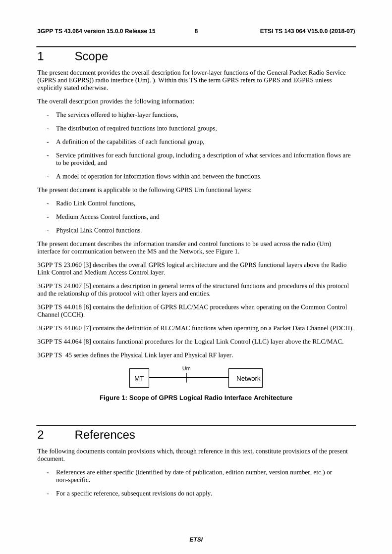
The present document describes the information transfer and control functions to be used across the radio (Um) interface for communication between the MS and the Network, see Figure 1.
3GPP TS 23.060 [3] describes the overall GPRS logical architecture and the GPRS functional layers above the Radio Link Control and Medium Access Control layer.
3GPP TS 24.007 [5] contains a description in general terms of the structured functions and procedures of this protocol and the relationship of this protocol with other layers and entities.
3GPP TS 44.018 [6] contains the definition of GPRS RLC/MAC procedures when operating on the Common Control Channel (CCCH).
3GPP TS 44.060 [7] contains the definition of RLC/MAC functions when operating on a Packet Data Channel (PDCH).
3GPP TS 44.064 [8] contains functional procedures for the Logical Link Control (LLC) layer above the RLC/MAC.
3GPP TS 45 series defines the Physical Link layer and Physical RF layer.
Figure 1: Scope of GPRS Logical Radio Interface Architecture
2 References The following documents contain provisions which, through reference in this text, constitute provisions of the present document.
- References are either specific (identified by date of publication, edition number, version number, etc.) or non-specific.
- For a specific reference, subsequent revisions do not apply.
NetworkMT
Um
ETSI
ETSI TS 143 064 V15.0.0 (2018-07)93GPP TS 43.064 version 15.0.0 Release 15
- For a non-specific reference, the latest version applies. In the case of a reference to a 3GPP document (including a GSM document), a non-specific reference implicitly refers to the latest version of that document in the same Release as the present document.
[1] 3GPP TR 21.905: "Vocabulary for 3GPP Specifications".
[2] 3GPP TS 22.060: "General Packet Radio Service (GPRS); Stage 2".
[3] 3GPP TS 23.060: "General Packet Radio Service (GPRS); Service description; Stage 2".
[4] 3GPP TS 44.004: "Digital cellular telecommunications system; Layer 1; General requirements".
[5] 3GPP TS 24.007: "Mobile radio interface signalling layer 3 General aspects"
[6] 3GPP TS 44.018: "Mobile radio interface layer 3 specification; Radio Resource Control Protocol"
[7] 3GPP TS 44.060: "Radio Link Control/Medium Access Control (RLC/MAC) protocol".
[8] 3GPP TS 44.064: "General Packet Radio Service (GPRS); Logical Link Control (LLC)".
[9] 3GPP TS 44.065: "General Packet Radio Service (GPRS); Subnetwork Dependent Convergence Protocol (SNDCP)".
[10] 3GPP TS 45.001: "Physical layer on the radio path, General description".
[11] 3GPP TS 45.002: "Multiplexing and multiple access on the radio path".
[12] 3GPP TS 45.003: "Channel coding".
[13] 3GPP TS 45.004: "Modulation".
[14] 3GPP TS 45.005: "Radio transmission and reception".
[15] 3GPP TS 45.008: "Radio subsystem link control".
[16] 3GPP TS 45.010: "Radio subsystem synchronisation".
[17] 3GPP TS 43.246: "Multimedia Broadcast Multicast Service (MBMS) in the GERAN; Stage 2".
[18] 3GPP TS 23.682: “Architecture enhancements to facilitate communications with packet data networks and applications”.
[19] 3GPP TS 24.008: “Mobile radio interface Layer 3 specification; Core network protocols; Stage 3”.
[20] 3GPP TS 43.020: "Security related network functions".
[21] 3GPP TS 48.018: "BSS GPRS Protocol (BSSGP)".
3 Abbreviations, symbols and definitions
3.1 Abbreviations In addition to abbreviations in 3GPP TR 21.905 [1] and 3GPP TS 22.060 [2] the following abbreviations apply:
ARQ Automatic Repeat reQuest BCS Block Check Sequence BEC Backward Error Correction BH Block Header BTTI Basic Transmission Time Interval CC Coverage Class CCN Cell Change Notification CFCCH Compact Frequency Correction Channel CPAGCH Compact Packet Access Grant Channel CPBCCH Compact Packet Broadcast Control Channel CPCCCH Compact Packet Common Control Channel
ETSI
ETSI TS 143 064 V15.0.0 (2018-07)103GPP TS 43.064 version 15.0.0 Release 15
CPPCH Compact Packet Paging Channel CPRACH Compact Packet Random Access Channel CSCH Compact Synchronization Channel CS-i GPRS Coding Scheme i CU Cell Update DAS-i EGPRS2 Downlink level A modulation and coding Scheme i DBS-i EGPRS2 Downlink level B modulation and coding Scheme i DLMC Downlink Multi Carrier DTM Dual Transfer Mode eDRX Extended Discontinuous Reception EC Extended Coverage EGPRS Enhanced GPRS EGPRS2 Enhanced GPRS phase 2 EC-GSM-IoT Extended Coverage GSM for Internet of Things EC SI EC-GSM-IoT System Information ESAB Extended Synchronization Access Burst EDAB Extended Dual slot Access Burst eTFI Extended Temporary Flow Identity FANR Fast Ack/Nack Reporting FBI Final Block Indicator FH Frame Header GGSN Gateway GPRS Support Node HCS Header Check Sequence HSR Higher Symbol Rate IR Incremental Redundancy LLC Logical Link Control MAC Medium Access Control MBMS Multimedia Broadcast/Multicast Service MCS-i EGPRS Modulation and Coding Scheme i MPRACH MBMS Packet Random Access Channel NSS Network and Switching Subsystem PACCH Packet Associate Control Channel PAGCH Packet Access Grant Channel PAN Piggy-backed Ack/Nack PBCCH Packet Broadcast Control Channel PC Power Control PCCCH Packet Common Control Channel PCS PAN Check Sequence PDCH Packet Data Channel PDTCH Packet Data Traffic Channel PDU Protocol Data Unit PEO Power Efficient Operation PFC Packet Flow Context PFI Packet Flow Indentifier PL Physical Link PPCH Packet Paging Channel PRACH Packet Random Access Channel PSI Packet System Information PSM Power Saving Mode PTCCH Packet Timing Advance Control Channel p-t-m point-to-multipoint RLC Radio Link Control RTTI Reduced Transmission Time Interval SGSN Serving GPRS Support Node SNDC Subnetwork Dependent Convergence TA Timing Advance TBF Temporary Block Flow TFI Temporary Flow Identity TTI Transmission Time Interval UAS-i EGPRS2 Uplink level A modulation and coding Scheme i UBS-i EGPRS2 Uplink level B modulation and coding Scheme i USF Uplink State Flag
ETSI
ETSI TS 143 064 V15.0.0 (2018-07)113GPP TS 43.064 version 15.0.0 Release 15
3.2 Symbols For the purposes of the present document, the following symbols apply:
Gb Interface between an SGSN and a BSC. Um Interface between MS and GPRS fixed network part. The Um interface is the GPRS network
interface for providing packet data services over the radio to the MS.
3.2a Restrictions Independently of what is stated elsewhere in this and other 3GPP specifications, mobile station support for PBCCH and PCCCH is optional for A/Gb-mode of operation. The network shall never enable PBCCH and PCCCH.
3.2b Definitions Blind Physical Layer Transmissions: Repetitions performed on physical layer by blindly, without feedback from the receiving end, transmitting multiple instances of the same block. To maximize the processing gain at the receiver, phase coherency at the transmitter between blind transmissions transmitted within the same TDMA frame is required, see 3GPP TS 45.005 [14].
Coverage Class: A predetermined number of blind physical layer transmissions used by Extended Coverage logical channels, EC-channels, to be able to support a certain level of extended coverage. The number of blind physical layer transmissions may differ between logical channels for the same coverage class. A Coverage Class defines a maximum coverage limit supported in EC operation, see 3GPP TS 45.005 [14]. Four Coverage Classes are defined.
EC operation: An EC-GSM-IoT capable MS in a cell supporting EC-GSM-IoT may enable EC operation, in which case CS domain services are disabled. When EC operation is enabled the MS uses FCCH and EC-SCH for synchronization purposes, EC-BCCH for acquisition of EC System Information (EC SI), EC-CCCH for monitoring EC-PCH in idle mode, EC-CCCH for packet access procedures, or, if indicated by the network CCCH, and enables relaxed mobility related requirements. In packet transfer mode the MS is assigned EC-PDTCH(s) and an associated EC-PACCH in EC TBF operation mode.
Extended coverage: Coverage level exceeding the reference sensitivity and reference interference performance of GPRS/EGPRS, see 3GPP TS 45.005 [14].
Fixed Uplink Allocation: Static allocation of resources in the uplink over one or more TTIs, using one or more PDCH, that does not make use of USF based allocation (see 3GPP TS 44.018 [6] and 3GPP TS 44.060 [7]).
Power Efficient Operation: A PEO capable MS that has successfully negotiated the use of eDRX or PSM (see 3GPP TS 23.060 [3]) may enable PEO in a cell that supports PEO in which case it enables the use of relaxed mobility related requirements (see 3GPP TS 45.008 [15]) and the use of the ‘PEO One Phase Access Request’. A cell that supports PEO supports the use of relaxed mobility related requirements and EGPRS PACKET CHANNEL REQUEST messages indicating ‘PEO One Phase Access Request’.
Relaxed mobility related requirements: A relaxed set of MS requirements related to mobility, used when Power Efficient Operation (PEO) or EC operation is enabled. The requirements are relaxed compared to the ones applicable for a MS that has not enabled PEO or EC operation, and include e.g. reduced monitoring of neighbour cells, reduced monitoring of System Information and less frequent triggering of measurements for cell reselection.
3.3 Network and mobile station capabilities
3.3.1 General
In addition to GPRS specific definitions which can be found in 3GPP TS 22.060 [2] and 3GPP TS 23.060 [3] the following apply.
When referring to radio resources (i.e. physical channels) provided by the network to the mobile station, the term "assignment" refers to granting of resources on a semi-static basis, whereas "allocation" refers to the dynamically changing permission to use those resources that have been "assigned" to it and are shared with other users. An exception applies when granting resources using Fixed Uplink Allocation where only the term “allocation” is used. In this case, resources are assigned and allocated by the same message.
Multislot Capability: the capability of the mobile station to support Multislot Configurations.
ETSI
ETSI TS 143 064 V15.0.0 (2018-07)123GPP TS 43.064 version 15.0.0 Release 15
Multislot Class: a value which implicitly determines the Multislot Capability of the mobile station.
Multislot Configuration: the set of receive and transmit timeslots assigned to the MS.
3.3.2 EGPRS mobile station
An EGPRS mobile station is a GPRS mobile station with additional capabilities for new radio access protocol features and new modulation and coding schemes. An EGPRS mobile station shall comply with GPRS requirements and the additional requirements defined for an EGPRS mobile station. The support of EGPRS is optional for the mobile station and the network.
An EGPRS mobile station may additionally indicate support for EGPRS2 in uplink and/or downlink direction. In this case an EGPRS mobile station supports additional modulation and coding schemes, and may also support higher symbol rate, see sub-clause 3.3.6. The support of EGPRS2 is optional for the mobile station and the network.
An EGPRS mobile station may additionally indicate the support of Reduced Latency. In this case an EGPRS mobile station may be assigned a TBF with FANR activated either in BTTI configuration or in RTTI configuration, see sub-clause 3.3.5. The support of Reduced Latency is optional for the mobile station and the network.
3.3.3 Dual Transfer Mode
In dual transfer mode, the mobile station is assigned resources providing an RR connection and one or more Temporary Block Flows on one or more physical channels. This feature is optional for the mobile station and the network. It is only applicable for a mobile station supporting GPRS, EGPRS or EGPRS2. Dual transfer mode is a subset of class A mode of operation, which is only possible if there is radio resource assignment co-ordination in the network.
3.3.4 Downlink dual carrier configuration
In a downlink dual carrier configuration, one or more PDCHs are assigned to a single MS on each of two different radio frequency channels on either the uplink or downlink, or both. On the downlink, radio blocks may be allocated on both radio frequency channels in any radio block period. On the uplink, radio blocks shall not be allocated on both radio frequency channels in any given radio block period.
NOTE: A radio frequency channel in this context is defined by the frequency parameter(s) ARFCN for a non-hopping radio frequency channel or MA, MAIO and HSN for a hopping radio frequency channel.
A downlink dual carrier configuration shall support multislot configurations either for packet switched connections or dual transfer mode. For a Dual Transfer Mode capable MS which supports Downlink Dual Carrier, support of Downlink Dual Carrier configurations for Dual Transfer Mode is optional.
Downlink dual carrier is not supported in GPRS mode.
3.3.5 Reduced Latency TBF
A TBF applying Reduced Latency shall operate according to all EGPRS/EGPRS2 requirements, unless otherwise stated, with the Fast Ack/Nack Reporting procedure (see sub-clause 3.3.5.1). In addition, a TBF applying Reduced Latency is characterized by either RTTI configuration or BTTI configuration (see sub-clause 3.3.5.2).
3.3.5.1 Fast Ack/Nack Reporting procedure
The Fast Ack/Nack reporting procedure (FANR) refers to the possibility to include, in a radio block for data transfer sent in one direction, piggy-backed ack/nack information relative to a TBF with FANR activated in the other direction.
This is achieved by inserting a fixed-size piggy-backed ack/nack (PAN) field in the radio block. When a PAN field is inserted, a suitable Puncturing Scheme variant for the modulation and coding schemes in use is chosen, so that the RLC data field and the PAN field fit together in the radio block along with the RLC/MAC header. The presence of the PAN field, is signalled by the PAN indicator bit in the RLC/MAC header. When this bit is set the receiver shall use the corresponding Puncturing Scheme variant of the CPS indicated in the RLC/MAC header to decode the RLC data field.
If a mobile station is assigned a TBF with FANR activated, all concurrent TBFs assigned to the mobile station shall have FANR activated irrespective of the RLC/MAC mode of each TBF (acknowledged mode, non-persistent mode or unacknowledged mode).
Fast Ack/Nack reporting is not supported in GPRS TBF mode.
ETSI
ETSI TS 143 064 V15.0.0 (2018-07)133GPP TS 43.064 version 15.0.0 Release 15
3.3.5.2 RTTI configuration
In RTTI configuration, a radio block consisting of four bursts is sent using two PDCHs, i.e. a PDCH-pair, in each of two consecutive TDMA frames. In RTTI configuration, the time to transmit a radio block is half of a basic radio block period.
NOTE: The term “basic radio block period” refers the time needed to transmit a radio block on one PDCH using BTTI configuration i.e. four TDMA frames, while the term “reduced radio block period” refers the time needed to transmit a radio block on a PDCH-pair using RTTI configuration, i.e. two TDMA frames.
In RTTI configuration, a downlink TBF assignment consists of a number of PDCH-pairs, each PDCH-pair comprising two PDCHs. In a downlink dual carrier configuration (see sub-clause 3.3.4), up to 8 PDCH-pairs may be assigned per TBF. In a single carrier configuration up to 4 PDCH-pairs may be assigned per TBF. Two PDCHs constituting a downlink PDCH-pair need not be contiguous.
In RTTI configuration, an uplink TBF assignment consists of up to four PDCH-pairs. The two PDCHs constituting an uplink PDCH-pair need not be contiguous.
The PACCH shall have the same TTI configuration as the TBF with which it is associated.
In each direction PDCH-pairs cannot be assigned so that they are partially overlapped, i.e. two different PDCH-pairs cannot have one PDCH in common.
For an uplink TBF in RTTI configuration USFs can be sent in one of two ways:
- RTTI USFs: a USF is sent in one reduced radio block period, i.e. a USF is mapped on four bursts transmitted on a downlink PDCH-pair during two consecutive TDMA frames. The USF allocates resources for one or four uplink radio blocks in the next reduced radio block period(s), depending on the value of USF_GRANULARITY.
- BTTI USFs: two USFs are sent in a basic radio block period. One USF is mapped on four bursts transmitted on the first PDCH of a downlink PDCH-pair during four consecutive TDMA frames. This USF allocates resources for one or four uplink radio blocks in the first 2 TDMA frames of the next basic radio block period(s), depending on the value of USF_GRANULARITY. A second USF is mapped on four bursts transmitted on the second PDCH of a downlink PDCH-pair during four consecutive TDMA frames. This USF allocates resources for one or four uplink radio blocks in the second 2 TDMA frames of the next basic radio block period(s), depending on the value of USF_GRANULARITY.
For each TBF, the network signals the corresponding TTI configuration (i.e. either basic or reduced) at TBF establishment/ reconfiguration. In case of RTTI configuration, the network also signals at uplink TBF establishment/reconfiguration the USF mode (i.e. either RTTI or BTTI) to be used for that TBF.
For each assigned uplink PDCH-pair, the network may signal at TBF establishment/reconfiguration the “corresponding downlink PDCH-pair”, i.e. the DL PDCH-pair where USFs and PACCH/D are monitored. The timeslot numbers of the PDCHs constituting an uplink PDCH-pair may be different from those of the PDCHs constituting the corresponding downlink PDCH-pair. If no indication is provided, the corresponding downlink PDCH-pair will be the one with the same timeslot numbers as the uplink PDCH-pair.
On a given downlink PDCH-pair all USFs shall be sent with the same USF mode.
For a given mobile station, in each direction, the same TTI configuration shall be used for all TBFs (and PACCHs) assigned with one or more PDCH(s) in common in that direction. If a TBF is assigned on completely different PDCH(s) the TTI used may be different.
For a given mobile station, different uplink TBFs may use different USF modes if assigned on completely different PDCH(s).
A PDCH may be shared between RTTI TBF and BTTI TBF (assigned to different mobile stations). Alternatively, both PDCHs forming a PDCH-pair may be assigned to only support RTTI TBFs.
RTTI configuration is not supported in GPRS TBF mode.
ETSI
ETSI TS 143 064 V15.0.0 (2018-07)143GPP TS 43.064 version 15.0.0 Release 15
3.3.6 EGPRS2 mobile station
An EGPRS2 mobile station is an EGPRS mobile station supporting additional modulation and coding schemes on the downlink and/or the uplink. An EGPRS2 mobile station shall comply with GPRS requirements and the additional requirements defined for an EGPRS mobile station. The support of EGPRS2 is optional for the mobile station and the network.
EGPRS2 features can be supported independently in the downlink and in the uplink.
An EGPRS2 mobile station may additionally indicate the support of Reduced Latency. In this case an EGPRS2 mobile station may be assigned a TBF applying Reduced Latency, see sub-clause 3.3.5. The support of Reduced Latency is optional for the mobile station and the network.
3.3.6.1 EGPRS2 in the downlink
A mobile station supporting EGPRS2 in the downlink supports additional modulation and coding schemes on the downlink.
3.3.6.1.1 EGPRS2-A and EGPRS2-B in the downlink.
Two levels of support are defined for the EGPRS2 feature in the downlink: EGPRS2-A and EGPRS2-B. EGPRS2-A includes additional modulation and coding schemes. EGPRS2-B includes additional modulation and coding schemes as well as a higher symbol rate. For a MS, support of EGPRS2-B in the downlink implies support of EGPRS2-A in the downlink.
3.3.6.2 EGPRS2 in the uplink
A mobile station supporting EGPRS2 in the uplink supports additional modulation and coding schemes on the uplink.
3.3.6.2.1 EGPRS2-A and EGPRS2-B in the uplink
Two levels of support are defined for the EGPRS2 feature in the uplink: EGPRS2-A and EGPRS2-B. EGPRS2-A includes additional modulation and coding schemes. EGPRS2-B includes additional modulation and coding schemes as well as a higher symbol rate. For a MS, support of EGPRS2-B in the uplink implies support of EGPRS2-A in the uplink.
3.3.7 Downlink multi carrier configuration
In a downlink multi carrier configuration, one or more PDCHs are assigned to a single MS on each of up to 16 different downlink radio frequency channels, depending on the MS capability. On the downlink, radio blocks may be allocated on all assigned radio frequency channels in any given radio block period. On the uplink, radio blocks shall only be allocated on one radio frequency channel in any given radio block period.
NOTE: A radio frequency channel in this context is defined by the frequency parameter(s) ARFCN for a non-hopping radio frequency channel or MA, MAIO and HSN for a hopping radio frequency channel.
The MS shall monitor the assigned PDCHs on the assigned and selected radio frequency channels in a DLMC configuration. Which radio frequency channels that are selected depends on the maximum carrier separation supported by the MS and the ARFCNs of the radio frequency channels in a given radio block period.
A MS indicating support for downlink multi carrier may optionally indicate support for non-contigous intra-band reception and /or inter-band receception. In case of inter-band reception radio frequency channels are assigned in two different frequency bands. Inter band reception is only supported in multiband operatation. In non-contigous intra-band reception the assigned radio frequency channels are grouped into two separate groups during each TDMA frame, where the carrier separation indicated by the maximum bandwidth applies in each group.For a MS in Downlink Multi Carrier configuration, fallback to reception of a single radio frequency channel, irrespective of the number of assigned radio frequency channels is performed with regular periodicity.
A downlink multi carrier configuration shall support multislot configurations for packet swiched connections.
Dual Transfer Mode is not supported in downlink multi carrier configurations.
Downlink multi carrier is not supported in GPRS mode.
ETSI
ETSI TS 143 064 V15.0.0 (2018-07)153GPP TS 43.064 version 15.0.0 Release 15
3.3.8 Power Efficient Operation (PEO)
3.3.8.1 General
Power Efficient Operation (PEO) is used by a MS to reduce its power consumption through the use of relaxed mobility related requirements and extended DRX (eDRX) or Power Saving Mode (PSM). A PEO capable MS shall support at least one of eDRX or PSM. When eDRX or PSM has been successfully negotiated a PEO capable MS can choose to enable PEO in a cell that supports PEO in which case it enables the use of relaxed mobility related requirements and use the EGPRS PACKET CHANNEL REQUEST message indicating ‘PEO One Phase Access Request’ when attempting packet access.
The mobility related requirements for a MS that has enabled PEO are relaxed compared to a MS that has not enabled PEO, and are referred to as relaxed mobility related requirements. The relaxation includes:
- No periodic measurements of the serving and non-serving cells are required.
- Measurements of only the serving cell need to be performed before each time the paging block is monitored or each uplink transmission;
- Measurements for cell reselection are only triggered if at least one, out of a set of criteria used to determine the suitability of the serving cell, is fulfilled based on the measurements of the serving cell.
- Fewer non-serving cells, compared to MS not in PEO, need to be considered in measurements for cell reselection;
- System Information (SI) acquisition required only before each time the paging block is monitored or each uplink transmission and in this case only if more than 24 h have passed since last acquisition, or, a change in SI is detected;
- Only autonomous cell reselection supported in idle mode;
- No mobility related procedures need to be supported in packet transfer mode and no neighbour cell measurements need to be performed when in packet transfer mode.
For more detailed procedures, see 3GPP TS 45.008.
A cell indicates its support of PEO in the SI13 Rest Octets IE, see 3GPP TS 44.018 [6]. In this case it supports the reception of an EGPRS PACKET CHANNEL REQUEST message indicating ‘PEO One Phase Access Request’ (see 3GPP TS 44.018 [6] and 3GPP TS 44.060 [7]) from a MS attempting packet access.
When eDRX is supported, the number of blocks per 51-multiframe reserved for AGCH is subject to the requirement that all cells in the routing area shall have the same number of paging blocks per 51-multiframe (see 3GPP TS 45.002 [11]). DTM is not supported in PEO.
Support of PEO is optional for the MS and the network.The MS shall disable PEO in case it enters a cell that does not support PEO. The MS may also disable PEO (see 3GPP TS 45.008 [15]) at any time, in which case it operates as if it was in a cell that does not support PEO. A MS that chooses to disable PEO shall disable the use of relaxed mobility related requirements and the EGPRS PACKET CHANNEL REQUEST message indicating ‘PEO One Phase Access Request’.
PEO makes use of a 9 bit BSIC wherein the 6 bit BSIC is supplemented with a 3 bit Radio frequency Colour Code with the purpose to help distinguish between cells in tight frequency reuse networks.
3.3.9 Extended Coverage GSM for Internet of Things (EC-GSM-IoT)
3.3.9.1 General
EC-GSM-IoT is an evolution of EGPRS providing a streamlined protocol implementation, reducing MS complexity while supporting energy efficient operation with extended coverage compared to GPRS/EGPRS. EC-GSM-IoT also mandates the use of an improved security framework by both the network and the mobile station.
EC-GSM-IoT makes use of a 9 bit BSIC wherein the 6 bit BSIC is supplemented with a 3 bit Radio frequency Colour Code with the purpose to help distinguish between cells in tight frequency reuse networks.
ETSI
ETSI TS 143 064 V15.0.0 (2018-07)163GPP TS 43.064 version 15.0.0 Release 15
EC-GSM-IoT makes use of Fixed Uplink Allocation for allocating uplink resources for EC-PDTCHs and hence does not support USF based uplink allocation.
No simultaneous uplink and downlink packet transfer is supported.
A MS that has enabled EC operation makes use of EC-channels (e.g. EC-PDTCH), except for the FCCH. An EC-GSM-IoT MS shall also support RACH and AGCH, in addition to EC-RACH and EC-AGCH. RACH and AGCH can be used by the MS when in GPRS/EGPRS coverage range (CC1, see subclause 3.3.9.2) if indicated by the network. EC-channels are used in idle mode as well as in packet transfer mode. The MS shall disable EC operation in case it enters a cell that does not support EC-GSM-IoT. The MS may also disable EC operation (see 3GPP TS 45.008) at any time, in which case it operates as if it was in a cell that does not support EC-GSM-IoT. The MS shall inform the network that EC operation has been disabled by e.g. a cell update. A MS that has disabled EC operation is no longer subject to the relaxed mobility related requirements (see sub-clause 3.3.9.3).
An EC-GSM-IoT mobile station need not comply with GPRS requirements, but shall comply with EGPRS requirements unless otherwise stated, see 3GPP TS 45.005 [14].
An EC-GSM-IoT mobile station need only support EC operation. The mobile station can optionally also support other PS services, such as GPRS, EGPRS and/or EGPRS2, or CS related services.
EC-GSM-IoT supports overload control by PLMN specific barring in the EC SI (see 3GPP TS 44.018 [6]) and optionally by using the Implicit Reject Status field within the EC-SCH (see 3GPP TS 44.018 [6]).
EC-GSM-IoT shall not be operated in reduced latency TBF mode, see subclause 3.3.5, nor shall it support the Fast Ack/Nack reporting procedure.
DTM is not supported in EC operation.
The EGPRS modulation and coding schemes for PDTCH are reused for EC-PDTCH. The EC-BCCH and EC-RACH CC1 to CC4 re-uses the same coding scheme as the BCCH and RACH respectively. Modified coding schemes, or specific coding schemes, are defined for EC-SCH, EC-PCH, EC-AGCH, EC-RACH CC5 and EC-PACCH, see 3GPP TS 45.003 [12].
The support of EC-GSM-IoT is optional for the mobile station and the network.
A MS that supports EC-GSM-IoT shall support Overlaid CDMA (see subclause 3.3.10).
The presence of EC-SCH indicates that a cell supports EC-CCCH and therefore allows an EC-GSM-IoT mobile station to camp on it.
A MS supporting EC-GSM-IoT as well as the network may support the restricted use of enhanced coverage (see subclause 3.3.9.5).
3.3.9.2 Extended coverage
3.3.9.2.1 General
EC-GSM-IoT MS is able to operate in extended coverage in both uplink and downlink, which is defined as improved MS and BTS sensitivity and interference performance. The feature has been designed to improve coverage by 20 dB and also the interference level by 20 dB compared to GPRS/EGPRS.
A predefined number of logical channel specific blind physical layer transmissions is used to support a certain level of extended coverage. For some logical channels, the number of blind physical layer transmissions can vary depending on the coverage extension required. Four different Coverage Classes are defined, each one approximated with a level of extended coverage compared to GPRS/EGPRS (see table 3.3.9.2-1), denoted as CC1, CC2, CC3 and CC4 respectively. In case of significant coverage extension, a fixed predefined number of blind physical layer transmissions is applied per logical channel. This number of blind physical layer transmissions, used by CC2, CC3 and CC4, may differ between logical channels for the same Coverage Class. Different Coverage Classes can be used on uplink and downlink. Logical channels supporting operation in extended coverage are referred to as EC-channels. Also the FCCH channel is considered to be operable in the extended coverage range aimed for by EC-GSM-IoT, and is hence used for synchronization purposes.
Blind physical layer transmissions should on the EC-PDTCH be used together with type II hybrid ARQ to achieve the approximate coverage level shown in Table 3.3.9.2-1.
ETSI
ETSI TS 143 064 V15.0.0 (2018-07)173GPP TS 43.064 version 15.0.0 Release 15
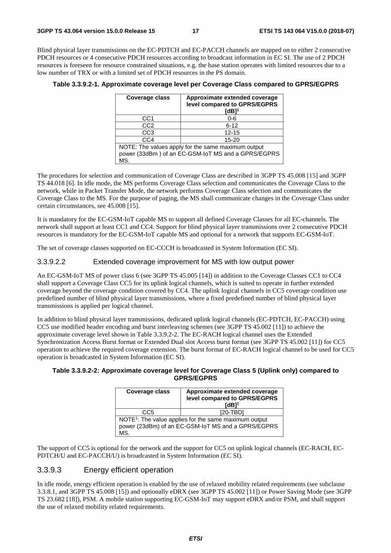
Blind physical layer transmissions on the EC-PDTCH and EC-PACCH channels are mapped on to either 2 consecutive PDCH resources or 4 consecutive PDCH resources according to broadcast information in EC SI. The use of 2 PDCH resources is foreseen for resource constrained situations, e.g. the base station operates with limited resources due to a low number of TRX or with a limited set of PDCH resources in the PS domain.
Table 3.3.9.2-1. Approximate coverage level per Coverage Class compared to GPRS/EGPRS
Coverage class Approximate extended coverage level compared to GPRS/EGPRS
[dB]1 CC1 0-6 CC2 6-12 CC3 12-15 CC4 15-20
NOTE: The values apply for the same maximum output power (33dBm ) of an EC-GSM-IoT MS and a GPRS/EGPRS MS.
The procedures for selection and communication of Coverage Class are described in 3GPP TS 45.008 [15] and 3GPP TS 44.018 [6]. In idle mode, the MS performs Coverage Class selection and communicates the Coverage Class to the network, while in Packet Transfer Mode, the network performs Coverage Class selection and communicates the Coverage Class to the MS. For the purpose of paging, the MS shall communicate changes in the Coverage Class under certain circumstances, see 45.008 [15].
It is mandatory for the EC-GSM-IoT capable MS to support all defined Coverage Classes for all EC-channels. The network shall support at least CC1 and CC4. Support for blind physical layer transmissions over 2 consecutive PDCH resources is mandatory for the EC-GSM-IoT capable MS and optional for a network that supports EC-GSM-IoT.
The set of coverage classes supported on EC-CCCH is broadcasted in System Information (EC SI).
3.3.9.2.2 Extended coverage improvement for MS with low output power
An EC-GSM-IoT MS of power class 6 (see 3GPP TS 45.005 [14]) in addition to the Coverage Classes CC1 to CC4 shall support a Coverage Class CC5 for its uplink logical channels, which is suited to operate in further extended coverage beyond the coverage condition covered by CC4. The uplink logical channels in CC5 coverage condition use predefined number of blind physical layer transmissions, where a fixed predefined number of blind physical layer transmissions is applied per logical channel.
In addition to blind physical layer transmissions, dedicated uplink logical channels (EC-PDTCH, EC-PACCH) using CC5 use modified header encoding and burst interleaving schemes (see 3GPP TS 45.002 [11]) to achieve the approximate coverage level shown in Table 3.3.9.2-2. The EC-RACH logical channel uses the Extended Synchronization Access Burst format or Extended Dual slot Access burst format (see 3GPP TS 45.002 [11]) for CC5 operation to achieve the required coverage extension. The burst format of EC-RACH logical channel to be used for CC5 operation is broadcasted in System Information (EC SI).
Table 3.3.9.2-2: Approximate coverage level for Coverage Class 5 (Uplink only) compared to GPRS/EGPRS
Coverage class Approximate extended coverage level compared to GPRS/EGPRS
[dB]1 CC5 [20-TBD]
NOTE1: The value applies for the same maximum output power (23dBm) of an EC-GSM-IoT MS and a GPRS/EGPRS MS.
The support of CC5 is optional for the network and the support for CC5 on uplink logical channels (EC-RACH, EC-PDTCH/U and EC-PACCH/U) is broadcasted in System Information (EC SI).
3.3.9.3 Energy efficient operation
In idle mode, energy efficient operation is enabled by the use of relaxed mobility related requirements (see subclause 3.3.8.1, and 3GPP TS 45.008 [15]) and optionally eDRX (see 3GPP TS 45.002 [11]) or Power Saving Mode (see 3GPP TS 23.682 [18]), PSM. A mobile station supporting EC-GSM-IoT may support eDRX and/or PSM, and shall support the use of relaxed mobility related requirements.
ETSI
ETSI TS 143 064 V15.0.0 (2018-07)183GPP TS 43.064 version 15.0.0 Release 15
The paging monitoring procedure is also optimized compared to GPRS/EGPRS where
- A two burst block is used on EC-PCH (compared to a four burst block in EGPRS/GPRS), with the possibility to decode it after only one burst has been received.
- Early suspension of paging block reception is possible, by inclusion of the DL CC in downlink messages, as well as by using different training sequences depending on which CC the EC-CCCH/D block is intended for. For the former case, a MS that has selected a lower CC than what is indicated by DL CC can suspend the monitoring for the remainder of the EC-CCCH/D block. For the latter case, a MS that has selected CC2, CC3 or CC4 and that detects, through TSC detection, that CC1 is transmitted, can suspend reception for the remainder of the EC-CCCH/D block of the selected CC.
In packet transfer mode, energy efficient operation is enabled by e.g. the following functionality:
- As for EC-PCH in idle mode, a two burst block is also used on EC-AGCH minimizing reception time when in good radio conditions;
- Only one phase access is defined in EC operation;
- Efficient contention resolution that reduces the transmission time from the MS, by the use of a reduced TLLI;
- Early suspension of downlink reception possible, by inclusion of the DL CC in downlink messages;
- EC-PACCH on the downlink is possible to decode after only one burst has been received;
- Energy efficient initial resource allocation by inclusion of measured radio conditions in the channel request message;
- No neighbor cells monitoring
3.3.9.4 Improved security
EC-GSM-IoT mandates the use of an improved security framework by both the network and the mobile station, see 3GPP TS 43.020 [20]. In this context it should be noted that integrity protection has been limited to LLC unacknowledged operation [8].
3.3.9.5 Restricted Use of Enhanced Coverage
Use of enhanced coverage, requiring extensive network resources including radio resources, may be restricted by the network for a given subscriber. An EC-GSM-IoT capable MS that supports restricted use of enhanced coverage, indicates this support during the GPRS Attach and Routing Area Update procedures (see 3GPP TS 23.060 [3] and 3GPP TS 24.008 [19]. The network supporting restricted use of enhanced coverage provides the mobile station with the applicable restriction in the GPRS Attach Accept and Routing Area Update Accept.
If the use of enhanced coverage is not restricted:
- The mobile station continues without modification of its operation, i.e. EC operation if camping on a EC-GSM-IoT supporting cell and (E)GPRS operation if camping on a non-EC-GSM-IoT supporting cell.
Otherwise, if the use of enhanced coverage is restricted:
- If after applying the offset for Enhanced Coverage Authorization the MS can still use EC operation it remains in the serving cell (i.e. cell reselection is not necessary).
- If after applying the offset for Enhanced Coverage Authorization, if a mobile station in idle mode is unable to remain in EC operation in its serving cell it performs cell reselection with modified cell reselection parameters for an EC-GSM-IoT supporting cell, based on the offset for Enhanced Coverage Authorization, according to 3GPP TS 45.008 [15], being broadcasted in (EC) System Information, according to 3GPP TS 44.018 [6]. The offset effectively yields a desensitization of the mobile station in regard to each EC-GSM-IoT supporting cell, corresponding to the signalled range of 5 to 20 dB, but not further than normal coverage. Cell reselection to each non-EC-GSM-IoT supporting cell is left unchanged.
- For an MS in packet transfer mode with an ongoing downlink or uplink EC TBF, the network may need to adapt the downlink or uplink Coverage Class according to observed radio conditions and implementation based
ETSI
ETSI TS 143 064 V15.0.0 (2018-07)193GPP TS 43.064 version 15.0.0 Release 15
criteria. For this purpose, the BSS needs to be informed by the SGSN about whether the subscriber is authorized for use of enhanced coverage (see 3GPP TS 48.018 [21]) in order to identify if adaptation to a higher Coverage Class is enabled. For this purpose SGSN shall have the latest EC restriction information.
- In case where the network decides to discontinue the use of enhanced coverage restriction for a MS for which the Ready timer is not running initiates the packet paging procedure at the BSS (see 3GPP TS 48.018 [21]), which sends a paging request to the mobile station camping either on a non-EC-GSM-IoT supporting cell or an EC-GSM-IoT supporting cell and thereby informs the MS about the removed restriction for use of enhanced coverage (see 3GPP TS 44.018 [6]). This paging request is sent using the appropriate Downlink Coverage Class based on the previously sent information from the mobile station to ensure proper reception. The mobile station sends a paging response acknowledging reception of the paging request and performs cell reselection, as applicable for an EC-GSM-IoT supporting cell, this is needed in scenarios where MS would be using low coverage class due to coverage restriction and once restriction is removed the MS should be able to move to appropriate higher coverage class.
- In case where the network decides to discontinue the use of enhanced coverage restriction for a MS for which the Ready timer is running the SGSN may initiate the transmission of a DL-UNITDATA PDU cotaining a zero length LLC-PDU (see 3GPP TS 48.018 [21]) that’s used only in BSS and is not propagated towards mobile.,
- SGSN also sends the EC restriction information in all DL_UNITDATA_PDUs for EC capable mobiles.
3.3.9.6 Energy Efficient Paging Reception with EC Paging Indication channel (EC-PICH)
The network may configure EC Paging Indication Channel (EC-PICH) for MS in higher coverage class condition (CC3 or CC4) which occurs prior to the EC-CCCH/D blocks corresponding to the paging block of the MS to optimise the energy consumption for paging reception. Separate EC-PICH blocks are used for paging indication for CC3 and CC4 MS (see 3GPP TS 45.002 [11]). EC-PICH block for CC4 contains paging indication for single paging block of CC4 within four 51 multiframes, whereas EC-PICH block for CC3 serves for indicating a page to at least one CC3 MS per two 51-multiframes. The MS in CC3 or CC4 coverage condition checks the EC-PICH block corresponding to its paging block before listening to the paging block (see 3GPP TS 45.002). If the EC-PICH block indicates that no paging message is scheduled in the corresponding EC-CCCH/D block, the MS enters into sleep mode until the next paging occasion after completion of current (e)DRX cycle thus reducing energy consumption due to avoiding reading multiple repetitions of the EC-CCCH/D block of the higher coverage class which may or not contain a matching page.
The support of EC-PICH logical channel is broadcasted in EC System Information. An MS supporting EC-PICH indicates its capability support to the network.
3.3.9.7 Deferred System Information Acquisition
In order to reduce energy consumption in packet idle mode, the network may broadcast information to assist the MS to apply deferred system information acquisition (see 3GPP TS 45.008 [15]).
To this purpose it reconfigures EC System Information type 2 for a cell to include an Idle Mode Mobility cell group description comprising cells, geographically adjacent or close to each other, with shared cell parameters related to cell (re)selection, Routing Area assignment, paging monitoring, DL Coverage class selection, mobility support and cell barring and assigns it a broadcast frequency list containing BCCH carriers allocated in these cells. To better match cell deployments, some cell parameters may deviate from the common values and are separately indicated on a per cell basis (see 3GPP TS 44.018 [6]).
To allow for different settings of shared cell parameters in geographic adjacent areas, different Idle Mode Mobility cell groups are defined with an identifier to distinguish one from the other, thus providing a spatially definite assignment of cells to Idle Mode Mobility cell groups. Since values of shared or non-shared cell parameters in a particular Idle Mode Mobility cell group are subject to change in time, a change mark is assigned to the Idle Mode Mobility cell group. An increment of the change mark for a particular Idle Mode Mobility cell group hence indicates to the MS to acquire the complete EC SI in the serving cell.
To enable fast detection if a cell is part of a specific Idle Mode Mobility cell group or not, the MS identifies from EC-SCH reception the Idle Mode Mobility cell group identifier and the related change mark. Thus, an MS reselecting to a cell in the same IMM cell group as the last serving cell has read the EC-SCH and decoded both the IMM cell group identifier and the IMM cell group change mark. If both values match with those of the last serving cell, it will not need to read the EC-BCCH for this cell prior to the decision for cell reselection, neither after cell reselection to this cell for subsequent cell reselections and for paging monitoring in packet idle mode. Only in case a valid page is received, that
ETSI
ETSI TS 143 064 V15.0.0 (2018-07)203GPP TS 43.064 version 15.0.0 Release 15
requires to send a paging response, or the MS needs to perform an uplink data transmission, or a timeout since the last reading of the complete EC SI in a different than the current serving cell is expired, the MS is required to read the complete EC System Information in the current serving cell.
The network may choose to deactivate deferred SI acquisition in network deployments for which EC System Information needs to be reconfigured more frequently or for which adjacent cells' idle mode mobility parameters differ too much. The support of deferred system information acquisition is broadcasted in EC System Information.
3.3.10 Overlaid CDMA
To minimize the impact on uplink capacity from blind physical layer transmissions, up to four mobile stations can be assigned to simultaneously transmit on the same physical channel on the uplink. The technique is referred to as Overlaid CDMA and can be used on uplink channels EC-PDTCH and EC-PACCH. Orthogonality between MSs is achieved through orthogonal codes, corresponding to a set of phase shifts to be applied on a per transmitted burst basis over the blind physical layer transmissions within each TDMA frame. A constant phase shifts shall be applied to each of the transmitted burst, see 3GPP TS 45.002 [11] and 3GPP TS 45.004 [13]. In case blind physical layer transmissions on the uplink are mapped to two consecutive PDCH resources, two mobile stations can be assigned to simultaneously transmit on the same physical channel by using Overlaid CDMA. Support of Overlaid CDMA is mandatory for a MS that supports EC-GSM-IoT and optional for a network that supports EC-GSM-IoT.
4 Packet data logical channels NOTE: The text in this clause is informative. The normative text is in 3GPP TS 45.002 [11]. Where there is a
conflict between these descriptions, the normative text has precedence.
4.1 General This subclause describes the packet data logical channels that are supported by the radio subsystem. The packet data logical channels are mapped onto the physical channels that are dedicated to packet data.
The physical channel dedicated to packet data traffic is called a Packet Data Channel (PDCH).
4.2 Packet Common Control Channel (PCCCH) and Compact (CPCCCH)
PCCCH and CPCCCH comprises logical channels for common control signalling used for packet data as described in the following subclauses. (See sub-clause 3.2a).
4.2.1 Packet Random Access Channel (PRACH) and Compact Packet Random Access Channel (CPRACH) - uplink only
PRACH and CPRACH are used by MS to initiate uplink transfer for sending data or signalling information. Packet Access burst and Extended Packet Access burst are used on PRACH. Extended Packet Access burst is used on CPRACH.
4.2.2 Packet Paging Channel (PPCH) and Compact Packet Paging Channel (CPPCH) - downlink only
PPCH and CPPCH are used to page an MS prior to downlink packet transfer. PPCH and CPPCH use paging groups in order to allow usage of DRX mode. PPCH can be used for paging of both circuit switched and packet data services. The paging for circuit switched services on PPCH is applicable for class A and B GPRS MSs in Network operation mode I, see 3GPP TS 23.060 [3].
4.2.3 Packet Access Grant Channel (PAGCH) and Compact Packet Access Grant Channel (CPAGCH) - downlink only
PAGCH and CPAGCH are used in the packet transfer establishment phase to send resource assignment to an MS prior to packet transfer.
ETSI
ETSI TS 143 064 V15.0.0 (2018-07)213GPP TS 43.064 version 15.0.0 Release 15
4.3 Packet Broadcast Control Channel (PBCCH) and Compact Packet Broadcast Control Channel (CPBCCH) - downlink only
PBCCH and CPBCCH broadcast packet data specific System Information. If PBCCH is not allocated, the packet data specific system information is broadcast on BCCH. For Compact, CPBCCH shall be allocated. CPBCCH and BCCH are mutually exclusive. (See sub-clause 3.2a).
4.4 Packet Traffic Channels
4.4.1 Packet Data Traffic Channel (PDTCH, EC-PDTCH)
PDTCH is a channel allocated for data transfer. It is temporarily dedicated to one MS or to a group of MSs in the case of p-t-m transmission. In the multislot operation, one MS or a group of MSs may use multiple PDTCHs in parallel for individual packet transfer.
All packet data traffic channels are uni-directional, either uplink (PDTCH/U), for a mobile originated packet transfer or downlink (PDTCH/D) for a mobile terminated packet transfer.
A packet data traffic channel supporting operation in extended coverage is referred to as Extended Coverage PDTCH (EC-PDTCH).
4.5 Packet Dedicated Control Channels
4.5.1 Packet Associated Control Channel (PACCH, EC-PACCH)
PACCH conveys signalling information related to a given MS. The signalling information includes e.g. acknowledgements and power control information. PACCH carries also resource assignment and reassignment messages, comprising the assignment of a capacity for PDTCH(s) and for further occurrences of PACCH. The PACCH shares resources with PDTCHs, that are currently assigned to one MS. Additionally, a MS that is currently involved in packet transfer, can be paged for circuit switched services on PACCH.
A Packet Associated Control Channel supporting operation in extended coverage is referred to as Extended Coverage PACCH (EC-PACCH). The EC-PACCH shall not be used to page a MS in extended coverage for circuit switched services.
4.5.2 Packet Timing advance Control Channel, uplink (PTCCH/U)
PTCCH/U is used to transmit random access burst to allow estimation of the timing advance for one MS in packet transfer mode.
PTCCH/U shall not be used for DTM.
PTCCH/U shall not be used for a mobile station in EC operation.
4.5.3 Packet Timing advance Control Channel, downlink (PTCCH/D)
PTCCH/D is used to transmit timing advance information updates to several MS. One PTCCH/D is paired with several PTCCH/U’s.
PTCCH/D shall be ignored by MS operating in DTM.
PTCCH/D shall be ignored by a mobile station in EC operation.
4.6 MBMS Common Control Channels
4.6.1 MBMS Packet Random Access Channel (MPRACH) - uplink only
The MPRACH is used by the MS during the initial counting procedure for MBMS (see 3GPP TS 44.060). Packet Access burst and Extended Packet Access burst are used on MPRACH.
ETSI
ETSI TS 143 064 V15.0.0 (2018-07)223GPP TS 43.064 version 15.0.0 Release 15
5 Mapping of packet data logical channels onto physical channels
NOTE: The text in this clause is informative. The normative text is in 3GPP TS 45.002 [11]. Where there is a conflict between these descriptions, the normative text has precedence.
5.1 General Different packet data logical channels can be mapped to the same physical channel (i.e. PDCH). The sharing of the physical channel is based on blocks of 4 consecutive bursts of one specific PDCH in 4 consecutive TDMA frames (for basic TTI configuration) or 2 bursts on each PDCH within a PDCH pair in 2 consecutive TDMA frames (for a reduced TTI configuration), except for PTCCH. In case of EC operation, when using blind physical layer transmissions on EC-PDTCH and EC-PACCH, a variation of the BTTI configuration is used wherein the sharing of the physical channels is different depending on the Coverage Class and the number of PDCHs assigned to an EC TBF (determined based on whether the network supports the allocation of 2 or 4 consecutive PDCHs, see 3GPP TS 44.018 [6]), and
- for an EC TBF assigned four consecutive PDCHs, is for:
- CC2 based on blocks of 16 bursts of 4 PDCHs in 4 consecutive TDMA frames
- CC3 based on blocks of 32 bursts of 4 PDCHs over 8 or 9 TDMA frames (depending on idle frame placement)
- CC4 based on blocks of 64 bursts of 4 PDCHs over 16 or 17 TDMA frames (depending on idle frame placement)
- CC5 in uplink based on blocks of 192 bursts of 4 PDCHs over 52 TDMA frames.
- for an EC TBF assigned two consecutive PDCHs, is for:
- CC2 based on blocks of 16 bursts of 2 PDCHs over 8 or 9 TDMA frames (depending on idle frame placement)
- CC3 based on blocks of 32 bursts of 2 PDCHs over 16 or 17 TDMA frames (depending on idle frame placement).
- CC4 based on blocks of 64 bursts of 2 PDCHs over 34 TDMA frames
- CC5 in uplink based on blocks of 192 bursts of 2 PDCHs over two 52 TDMA frames.
When blind physical layer transmissions are used on EC-PDTCH, the BTTI mapping of the four bursts of a radio block onto four consecutive TDMA frames is used and repeated on two or four PDCHs and (for the higher Coverage Classes) during multiple basic TTIs.
As an exception, when an uplink EC TBF is mapped onto two consecutive PDCHs, another variation of the BTTI configuration is used wherein the blind physical layer transmissions on an EC-PDTCH are applied on a burst level, i.e., all blind physical layer transmissions of one burst in a radio block are transmitted before the blind physical layer transmissions of the next burst in the radio block are transmitted (see sub-clause 6.1.2 and 3GPP TS 45.003 [12]). The latter is referred to as compact burst mapping.
The TBFs using reduced TTI and the TBFs using basic TTI sharing the same physical channel need to coexist within the overall block structure specified for the basic TTI. As such, for each assigned PDCH pair corresponding to a reduced TTI TBF, two consecutive reduced TTI radio blocks must be allocated within the time period spanned by a single radio block sent using the basic TTI. Each of the two reduced TTI radio blocks in this block structure could be allocated to different MSs or one of the reduced TTI blocks could be empty if not needed. The mapping in frequency of PDCH on to the physical channel shall be as defined in 3GPP TS 45.002 [11].
A PDCH may be either full-rate (PDCH/F) or half-rate (PDCH/H). PDCH/H is only applicable to DTM. See 3GPP TS 45.002 [11]. PDCH/H is not applicable for a reduced TTI configuration.
GPRS, EGPRS and EGPRS2 employ the same physical layer, except for the PDTCH. EC-GSM-IoT employs a different physical layer by the use of logical channels supporting extended coverage, EC-channels. EC-GSM-IoT will also make use of FCCH for synchronization purposes and may also make use of RACH and AGCH CC1 has been selected, which employs the same physical layer as GPRS, EGPRS and EGPRS2.
ETSI
ETSI TS 143 064 V15.0.0 (2018-07)233GPP TS 43.064 version 15.0.0 Release 15
On PRACH, CPRACH, MPRACH, EC-RACH and PTCCH/U, access bursts are used. On EC-RACH CC5, Extended Synchronization Access Bursts or Extended Dual slot Access Bursts are used (see 3GPP TS 45.002 [11]). On all other packet data logical channels, radio blocks comprising 4 normal bursts are used. The only exception is some messages on uplink (EC-)PACCH which comprise 4 consecutive access bursts (to increase robustness).
5.2 Packet Common Control Channels (PCCCH and CPCCCH) At a given time, the logical channels of the PCCCH are mapped on different physical resources than the logical channels of the CCCH.
The PCCCH and CPCCCH do not have to be allocated permanently in the cell. Whenever the PCCCH is not allocated, the CCCH shall be used to initiate a packet transfer. For Compact, CPCCCH shall be allocated.
One given MS may use only a subset of the PCCCH and CPCCCH, the subset being mapped onto one physical channel (i.e. PDCH).
The PCCCH, when it exists:
- is mapped on one or several physical channels according to a 52-multiframe, In that case the PCCCH, PBCCH and PDTCH share same physical channels (PDCHs).
The existence and location of the PCCCH shall be broadcast on the cell. (See sub-clause 3.2a).
Since GSM phase 1 and phase 2 MS can only see and use the CCCH, the use on the PCCCH can be optimised for GPRS e.g. a PRACH of 11 bits can be used on uplink.
For Compact, one radio frequency channel of the cell allocation shall be used to carry synchronization information and the CPBCCH, this shall be known as the primary Compact carrier. All other radio frequency channels of the cell allocation shall be known as secondary Compact carriers.
For primary and secondary Compact carriers, CPCCCHs shall be allocated on only one timeslot (which is associated with a time group as defined in 3GPP TS 45.002 [11]). This time group is known as the serving time group and rotates over odd timeslot numbers as follows: 7, 5, 3, 1, 7, 5, …. The CPCCCH is mapped according to a Compact 52-multiframe and the serving time group rotation occurs between frame numbers (FN) mod 52 = 3 and 4.
5.2.1 Packet Random Access Channel (PRACH and CPRACH)
The PRACHand CPRACH are mapped on one or several physical channels. The physical channels on which the PRACH is mapped are derived by the MS from information broadcast on the PBCCH or BCCH. The physical channels on which the CPRACH is mapped are derived by the MS from information broadcast on the CPBCCH.
PRACH and CPRACH are determined by the Uplink State Flag marked as free that is broadcast continuously on the corresponding downlink (see subclause 6.6.4.1). Additionally, a predefined fixed part of the multiframe structure for PDCH can be used as PRACH or CPRACH only and the information about the mapping on the physical channel is broadcast on PBCCH or CPBCCH. During those time periods an MS does not have to monitor the USF that is simultaneously broadcast on the downlink.
5.2.2 Packet Paging Channel (PPCH and CPPCH)
The PPCH and CPPCH are mapped on one or several physical channels. The exact mapping on each physical channel follows a predefined rule (see subclause 6.1.2), as it is done for the PCH.
The physical channels on which the PPCH or CPPCH are mapped, as well as the rule that is followed on the physical channels, are derived by the MS from information broadcast on the PBCCH or CPBCCH.
5.2.3 Packet Access Grant Channel (PAGCH and CPAGCH)
The PAGCH and CPAGCH are mapped on one or several physical channels. The exact mapping on each physical channel follows a predefined rule (see subclause 6.1.2).
The physical channels on which the PAGCH or CPAGCH are mapped, as well as the rule that is followed on the physical channels, are derived by the MS from information broadcast on the PBCCH or CPBCCH.
ETSI
ETSI TS 143 064 V15.0.0 (2018-07)243GPP TS 43.064 version 15.0.0 Release 15
5.2.4 Void
5.2a MBMS Common Control Channels (MPRACH) The MPRACH is mapped on one physical channel. The physical channel on which the MPRACH is mapped is indicated to the MS by the network.
The network indicates the value of the USF associated with the MPRACH on a particular PDCH in the notification message. The MPRACH is determined by the Uplink State Flag, which is broadcast on the corresponding downlink (see subclause 6.6.4.1), marked as the value indicated by the network.
5.2b Extended Coverage Common Control Channels (EC-CCCH)
5.2b.1 General
The logical channels of the EC-CCCH are mapped on different physical resources than the logical channels of the CCCH.
The existence of the EC-CCCH is indicated by the presence of the EC-SCH.
The EC-CCCH is mapped on one or several physical channels according to a 51-multiframe structure.
5.2b.2 Extended Coverage Random Access Channel (EC-RACH)
The EC-RACH is mapped on one or several physical channels. The physical channel(s) on which the EC-RACH is mapped are derived by the MS from the EC SI broadcasted on the EC-BCCH, see 3GPP TS 45.002 [11].
Depending on the EC SI information a MS will transmit the EC-RACH using a 1 TS or 2 TS EC-RACH mapping, see 3GPP TS 45.002 [11].
5.2b.3 Extended Coverage Paging Channel (EC-PCH)
The EC-PCH is mapped on one or several physical channels. The exact mapping on each physical channel follows a predefined rule, see 3GPP TS 45.002 [11].
The physical channels on which the EC-PCH is mapped, are derived by the MS from the EC SI broadcasted on the EC-BCCH, see 3GPP TS 45.002 [11].
5.2b.4 Extended Coverage Access Grant Channel (EC-AGCH)
The EC-AGCH is mapped on one or several physical channels. The exact mapping on each physical channel follows a predefined rule, as it is done for the AGCH, see 3GPP TS 45.002 [11].
The physical channels on which the EC-AGCH is mapped, as well as the rule that is followed on the physical channels, are derived by the MS from the EC SI broadcasted on the EC-BCCH, see 3GPP TS 45.002 [11].
5.2b.5 Extended Coverage Paging Indication Channel (EC-PICH)
The EC-PICH is mapped on one or several physical channels. The exact mapping on each physical channel follows a predefined rule see 3GPP TS 45.002 [11].
The EC-PICH provides the paging indication for specific paging blocks in the paging multiframe for higher coverage classes CC3 and CC4, see 3GPP TS 45.002 [11].
5.3 Packet Broadcast Control Channel (PBCCH and CPBCCH) The PBCCH and CPBCCH shall be mapped on one or several physical channels. The exact mapping on each physical channel follows a predefined rule (see subclause 6.1.2), as it is done for the BCCH. For Compact, CPBCCH shall be allocated. CPBCCH and BCCH are mutually exclusive.
ETSI
ETSI TS 143 064 V15.0.0 (2018-07)253GPP TS 43.064 version 15.0.0 Release 15
The existence of the PCCCH, and consequently the existence of the PBCCH, is indicated on the BCCH. (See sub-clause 3.2a).
For Compact, one radio frequency channel of the cell allocation shall be used to carry synchronization information and the CPBCCH, this shall be known as the primary Compact carrier. All other radio frequency channels of the cell allocation shall be known as secondary Compact carriers.
The CPBCCH shall be mapped on only one timeslot (which is associated with a time group as defined in 3GPP TS 45.002 [11]). This time group is known as the serving time group and rotates over odd timeslot numbers as follows: 7, 5, 3, 1, 7, 5, …. The CPBCCH is mapped according to a Compact 52-multiframe and the serving time group rotation occurs between frame numbers (FN) mod 52 = 3 and 4. The exact mapping follows a predefined rule (see subclause 6.1.2).
5.3a Compact Frequency Correction Channel (CFCCH) The CFCCH is the same as the FCCH with one exception ⎯ the FCCH is mapped onto a 51-multiframe as defined in 3GPP TS 45.002 [11].
5.3b Compact Synchronization Channel (CSCH) The CSCH is similar to the SCH. The major difference is that the SCH is mapped onto a 51-multiframe as defined in 3GPP TS 45.002 [11]. This results in a different layout for the reduced TDMA frame number (RFN).
5.3c Extended Coverage Broadcast Control Channel (EC-BCCH)
The EC-BCCH shall be mapped on one or more physical channels. The exact mapping on each physical channel follows a predefined rule, see 3GPP TS 45.002.
The existence of the EC-BCCH is indicated by the presence of the EC-SCH.
5.4 Packet Timing advance Control Channel (PTCCH) Two defined frames of multiframe are used to carry PTCCH (see subclause 6.1.2). The exact mapping of PTCCH/U sub-channels and PTCCH/D shall be as defined in 3GPP TS 45.002 [11].
On PTCCH/U, access bursts are used. On PTCCH/D, four normal bursts comprising a radio block are used.
In a downlink dual or multi carrier configuration, an MS shall be assigned a PTCCH/D channel and a PTCCH/U sub-channel on one radio frequency channel only.
5.5 Packet Traffic Channels
5.5.1 Packet Data Traffic Channel (PDTCH)
A PDTCH is mapped onto one physical channel (PDCH) or, in the case of RTTI configurations (see subclause 3.3.5), two physical channels (PDCH-pair).
For one TBF, up to eight PDCHs or four PDCH-pairs, with different timeslot numbers but with the same frequency parameters, may be assigned to one MS at the same time. In the case of p-t-m transmission for MBMS, up to five downlink PDCH/Fs, with different timeslot numbers but with the same frequency parameters, may be assigned for one broadcast or multicast session.
In the case of a downlink dual carrier configuration, up to 16 PDCHs or eigth PDCH-pairs may be assigned to one TBF at the same time.
In case of a downlink multi carrier configuration, up to 16 carriers corresponding to 128 PDCH or 64 PDCH-pairs may be assigned to one TBF at the same time.
ETSI
ETSI TS 143 064 V15.0.0 (2018-07)263GPP TS 43.064 version 15.0.0 Release 15
5.5.1a Extended Coverage Packet Data Traffic Channel (EC-PDTCH)
An EC-PDTCH is mapped onto one or, in case blind physical layer transmissions are used, four consecutive physical channel(s) (i.e. PDCHs) and shall always use basic TTI configuration.
For one EC TBF, one to eight PDCHs, with different timeslot numbers but with the same frequency parameters, may be assigned to one MS at the same time when CC1 is used (i.e. with no blind physical layer transmissions) in the direction of the TBF. When blind physical layer transmissions are used, an EC TBF is mapped onto four PDCHs where the PDCHs shall be consecutive.
5.5.2 Packet Associated Control Channel (PACCH)
PACCH is dynamically allocated on a radio block basis on the same physical channel(s) used for carrying PDTCHs. However, one block PACCH allocation is also used on the physical channel carrying only PCCCH, when the MS is polled to acknowledge the initial assignment message.
PACCH is of a bi-directional nature, i.e. it can dynamically be allocated both on the uplink and on the downlink regardless on whether the corresponding PDCH assignment is for uplink or downlink.
The PACCH shall have the same TTI configuration as the TBF with which it is associated.
If an MS is assigned one or more PDCH(s) /PDCH pair(s) on the uplink then, in the case of dynamic allocation (see subclause 6.6.4.4) the corresponding downlink timeslots/PDCH pair(s) have to be continuously monitored by the MS for possible occurrences of PACCH; in the case of extended dynamic allocation (see subclause 6.6.4.4), only the downlink timeslot/PDCH pair(s) corresponding to the lowest numbered assigned uplink timeslot has to be continuously monitored by the MS for possible occurrences of PACCH. The MS can use an uplink allocation for sending PACCH blocks whenever needed.
In case of a downlink dual carrier configuration, PACCH blocks may be sent on the downlink on both radio frequency channels simultaneously.
In case of a downlink multi carrier configuration, PACCH blocks may be sent on all assigned downlink radio frequency channels simultaneously.
If an MS is assigned one or more PDCH(s) /PDCH pair(s) on the downlink, every occurrence of an uplink PACCH block is determined by polling in one of the preceding downlink blocks (transferred on the same PDCH(s)). The network can use the downlink assignment for sending PACCH blocks whenever needed.
NOTE: Further requirements on PACCH operation are contained in 3GPP TS 44.060.
5.5.2a Extended Coverage Packet Associated Control Channel (EC-PACCH)
An EC-PACCH is mapped onto one or four physical channel(s) (i.e. PDCHs) and shall always use basic TTI configuration. The number of physical channels to use is dependent on the Coverage Class used in the direction the EC-PACCH is transmitted, see 3GPP TS 45.002 [11].
On the uplink, Fixed Uplink Allocation of EC-PDTCH is used, see subclause 6.6.4.1.4. This implies that the MS shall not monitor the USF on the DL PDCH for uplink allocation. For the duration of the Fixed Uplink Allocation the MS shall not monitor any downlink timeslots for EC-PACCH. After the duration of the Fixed Uplink Allocation, downlink timeslot(s) are monitored by the MS for possible occurrences of EC-PACCH. During the Fixed Uplink Allocation the MS shall not use the allocated uplink resources for sending EC-PACCH blocks. Uplink EC-PACCH blocks shall only be sent by the MS when preceded by polling in downlink block(s).
On the downlink, dynamic allocation of EC-PDTCH is used. If an MS is assigned one or more PDCH(s) on the downlink, every uplink allocation of an EC-PACCH block is determined by polling related control parameters in the preceding downlink block(s). The network can use the downlink assignment for sending EC-PACCH blocks whenever needed.
NOTE: Further requirements on EC-PACCH operation are contained in 3GPP TS 44.060.
ETSI
ETSI TS 143 064 V15.0.0 (2018-07)273GPP TS 43.064 version 15.0.0 Release 15
5.6 Downlink resource sharing Different packet data logical channels can be multiplexed on the downlink on the same physical channel (i.e. PDCH). See details in 3GPP TS 45.002 [11]. The type of message which is indicated in the radio block header allows differentiation between the logical channels. Additionally, the MS identity allows differentiation between PDTCHs and PACCHs assigned to different MSs. The MS identity also allows differentiation between TBFs and p-t-m MBMS bearers.
In addition, in dual transfer mode the network may dedicate a PDCH exclusively to an MS (i.e. the only PDTCH mapped onto that PDCH will be the one assigned to that MS). Even in the case of exclusive allocation, the network shall use the MS identity and the type of message in the radio block header.
5.7 Uplink resource sharing Different packet data logical channels can be multiplexed on the uplink of the same physical channel (i.e. PDCH). See details in 3GPP TS 45.002 [11]. The type of message which is indicated in the radio block header, allows differentiation between the logical channels. Additionally, the MS identity allows differentiation between PDTCHs and PACCHs assigned to different MSs.
In addition, in dual transfer mode the network may dedicate a PDCH exclusively to one MS.
6 Radio Interface (Um) The logical architecture of the GPRS Um interface can be described using a reference model consisting of functional layers as shown in Figure 3. Layering provides a mechanism for partitioning communications functions into manageable subsets.
Communication between the MS and the Network occurs at the Physical RF, Physical Link, Radio Link Control/Medium Access Control (RLC/MAC), Logical Link Control (LLC) and Subnetwork Dependent Convergence layers.
6.1 Radio Resource management principles
6.1.1 Allocation of resources for the GPRS
6.1.1.0 General
A cell supporting GPRS may allocate resources on one or several physical channels in order to support the GPRS traffic. Those physical channels (i.e. PDCHs), shared by the GPRS MSs, are taken from the common pool of physical channels available in the cell. The allocation of physical channels to circuit switched services and GPRS is done dynamically according to the "capacity on demand" principles described below.
Common control signalling required by GPRS in the initial phase of the packet transfer is conveyed on PCCCH, when allocated, or on CCCH. This allows the operator to have capacity allocated specifically to GPRS in the cell only when a packet is to be transferred.
For Compact, common control signaling required by the mobile station in the initial phase of the packet transfer is conveyed on CPCCCH.
For EC-GSM-IoT, common control signaling required by the mobile station in the initial phase of the packet transfer is conveyed on EC-CCCH or CCCH.
6.1.1.1 Master-Slave concept
At least one PDCH, acting as a master, accommodates packet common control channels that carry all the necessary control signalling for initiating packet transfer (i.e. PCCCH), whenever that signalling is not carried by the existing CCCH, as well as user data and dedicated signalling (i.e. PDTCH and PACCH). Other PDCHs, acting as slaves, are used for user data transfer and for dedicated signalling.

ETSI
ETSI TS 143 064 V15.0.0 (2018-07)283GPP TS 43.064 version 15.0.0 Release 15
For Compact, one radio frequency channel of the cell allocation shall be used to carry synchronization information and the CPBCCH, this shall be known as the primary Compact carrier. All other radio frequency channels of the cell allocation shall be known as secondary Compact carriers.
For the primary Compact carrier, timeslot numbers (TN) 1, 3, 5, and 7, acting as a master, accommodate packet common control channels that carry all necessary control signalling for initiating packet transfer as well as user data and dedicated signalling (i.e., PDTCH and PACCH). TNs 0, 2, 4, and 6, acting as slaves, are used for user data transfer and for dedicated signalling.
For the secondary Compact carrier(s) carrying CPCCCH, timeslot numbers (TN) 1, 3, 5, and 7, acting as a master, accommodate packet common control channels that carry all necessary control signalling for initiating packet transfer as well as user data and dedicated signalling. TNs 0, 2, 4, and 6, acting as slaves, are used for user data transfer and for dedicated signalling.
For the secondary Compact carrier(s) not carrying CPCCCH, timeslot numbers (TN) 0 through 7, acting as slaves, are used for user data transfer and for dedicated signalling.
6.1.1.2 Capacity on demand concept
The GPRS does not require permanently allocated PDCHs. The allocation of capacity for GPRS can be based on the needs for actual packet transfers which is here referred to as the "capacity on demand" principle. The operator can, as well, decide to dedicate permanently or temporarily some physical resources (i.e. PDCHs) for the GPRS traffic.
When the PDCHs are congested due to the GPRS traffic load and more resources are available in the cell, the Network can allocate more physical channels as PDCHs.
However, the existence of PDCH(s) does not imply the existence of PCCCH or EC-CCCH.
When no PCCCH or EC-CCCH is allocated in a cell, all GPRS attached MSs camp on the CCCH.
In response to a Packet Channel Request sent on CCCH from the MS that wants to transmit GPRS packets, the network can assign resources on PDCH(s) for the uplink transfer. After the transfer, the MS returns to CCCH.
When PCCCH is allocated in a cell, all GPRS attached MSs camp on it. PCCCH can be allocated either as the result of the increased demand for packet data transfers or whenever there are enough available physical channels in a cell (to increase the quality of service). The information about PCCCH is broadcast on BCCH. When the PCCCH capacity is inadequate, it is possible to allocate additional PCCCH resources on one or several PDCHs. If the network releases the last PCCCH, the MS performs cell re-selection.
For Compact, CPBCCH shall be allocated. CPBCCH is a stand-alone packet control channel for Compact. CPCCCH shall be allocated. The information about CPCCCH is broadcast on CPBCCH. When CPCCCH capacity is inadequate, it is possible to allocate additional CPCCCH resources on primary and secondary Compact carriers.
When EC-CCCH is allocated in a cell, all GPRS attached MSs that have enabled EC operation shall camp on it.
6.1.1.3 Procedures to support capacity on demand
The number of allocated PDCHs in a cell can be increased or decreased according to demand. The following principles can be used for the allocation:
- Load supervision:
A load supervision function may monitor the load of the PDCHs and the number of allocated PDCHs in a cell can be increased or decreased according to demand. Load supervision function may be implemented as a part of the Medium Access Control (MAC) functionality. The common channel allocation function located in BSC is used for the GSM services.
- Dynamic allocation of PDCHs:
Unused channels can be allocated as PDCHs to increase the overall quality of service for GPRS.
Upon resource demand for other services with higher priority, de-allocation of PDCHs can take place.
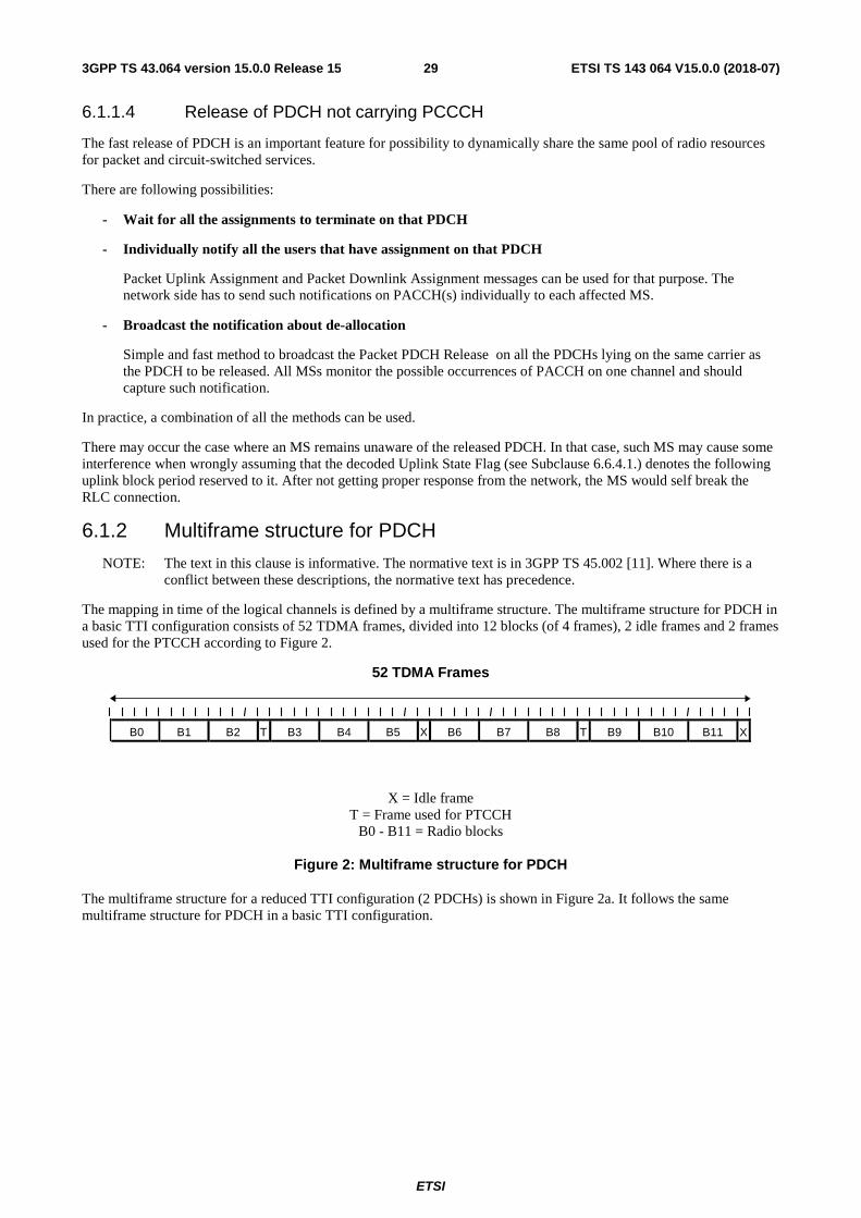
ETSI
ETSI TS 143 064 V15.0.0 (2018-07)293GPP TS 43.064 version 15.0.0 Release 15
6.1.1.4 Release of PDCH not carrying PCCCH
The fast release of PDCH is an important feature for possibility to dynamically share the same pool of radio resources for packet and circuit-switched services.
There are following possibilities:
- Wait for all the assignments to terminate on that PDCH
- Individually notify all the users that have assignment on that PDCH
Packet Uplink Assignment and Packet Downlink Assignment messages can be used for that purpose. The network side has to send such notifications on PACCH(s) individually to each affected MS.
- Broadcast the notification about de-allocation
Simple and fast method to broadcast the Packet PDCH Release on all the PDCHs lying on the same carrier as the PDCH to be released. All MSs monitor the possible occurrences of PACCH on one channel and should capture such notification.
In practice, a combination of all the methods can be used.
There may occur the case where an MS remains unaware of the released PDCH. In that case, such MS may cause some interference when wrongly assuming that the decoded Uplink State Flag (see Subclause 6.6.4.1.) denotes the following uplink block period reserved to it. After not getting proper response from the network, the MS would self break the RLC connection.
6.1.2 Multiframe structure for PDCH
NOTE: The text in this clause is informative. The normative text is in 3GPP TS 45.002 [11]. Where there is a conflict between these descriptions, the normative text has precedence.
The mapping in time of the logical channels is defined by a multiframe structure. The multiframe structure for PDCH in a basic TTI configuration consists of 52 TDMA frames, divided into 12 blocks (of 4 frames), 2 idle frames and 2 frames used for the PTCCH according to Figure 2.
52 TDMA Frames
X = Idle frame T = Frame used for PTCCH
B0 - B11 = Radio blocks
Figure 2: Multiframe structure for PDCH
The multiframe structure for a reduced TTI configuration (2 PDCHs) is shown in Figure 2a. It follows the same multiframe structure for PDCH in a basic TTI configuration.
B0 B1 B2 T B3 B4 B5 X B6 B7 B8 T B9 B10 B11 X
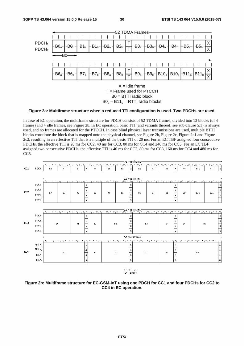
ETSI
ETSI TS 143 064 V15.0.0 (2018-07)303GPP TS 43.064 version 15.0.0 Release 15
Figure 2a: Multiframe structure when a reduced TTI configuration is used. Two PDCHs are used.
In case of EC operation, the multiframe structure for PDCH consists of 52 TDMA frames, divided into 12 blocks (of 4 frames) and 4 idle frames, see Figure 2b. In EC operation, basic TTI (and variants thereof, see sub-clause 5.1) is always used, and no frames are allocated for the PTCCH. In case blind physical layer transmissions are used, multiple BTTI blocks constitute the block that is mapped onto the physical channel, see Figure 2b, Figure 2c, Figure 2c1 and Figure 2c2, resulting in an effective TTI that is a multiple of the basic TTI of 20 ms. For an EC TBF assigned four consecutive PDCHs, the effective TTI is 20 ms for CC2, 40 ms for CC3, 80 ms for CC4 and 240 ms for CC5. For an EC TBF assigned two consecutive PDCHs, the effective TTI is 40 ms for CC2, 80 ms for CC3, 160 ms for CC4 and 480 ms for CC5.
Figure 2b: Multiframe structure for EC-GSM-IoT using one PDCH for CC1 and four PDCHs for CC2 to CC4 in EC operation.
X = Idle frameT = Frame used for PTCCH
B0 = BTTI radio blockB0a – B11b = RTTI radio blocks
PDCH1
PDCH2B0a B0b B1a B1b B2a B2b
TT
B3a B3b B4a B4b B5a B5bXX
B6a B6b B7a B7b B8a B8bTT
B9a B9b B10a B10b B11a B11bXX
52 TDMA Frames
B0
B3X X XB4 B5 B6 B7 B8 B9 B10B0 B1 B2 B11 X
52 multiframe
CC1 PDCH1
B3
X X X
B4 B5 B6 B7 B8 B9 B10B0 B1 B2 B11
X
52 multiframe
CC2
PDCH1
X X X XPDCH2
X X X X
X X X X
PDCH3
PDCH4
B1
X X X
B2 B3 B4 B4 B5B0 B1
X
52 multiframe
X = Idle frame
BY = Block Y
CC3
PDCH1
X X X XPDCH2
X X X X
X X X X
PDCH3
PDCH4
B0
X X X
B1 B1 B2 B2B0
X
52 multiframe
CC4
PDCH1
X X X XPDCH2
X X X X
X X X X
PDCH3
PDCH4
0 1 2 3 4 5 6 7 8 9 10 11 12 13 14 15 16 17 18 19 20 21 22 23 24 25 26 27 28 29 30 31 32 33 34 35 36 37 38 39 40 41 42 43 44 45 46 47 48 49 50 51
0 1 2 3 4 5 6 7 8 9 10 11 12 13 14 15 16 17 18 19 20 21 22 23 24 25 26 27 28 29 30 31 32 33 34 35 36 37 38 39 40 41 42 43 44 45 46 47 48 49 50 51
0 1 2 3 4 5 6 7 8 9 10 11 12 13 14 15 16 17 18 19 20 21 22 23 24 25 26 27 28 29 30 31 32 33 34 35 36 37 38 39 40 41 42 43 44 45 46 47 48 49 50 51
0 1 2 3 4 5 6 7 8 9 10 11 12 13 14 15 16 17 18 19 20 21 22 23 24 25 26 27 28 29 30 31 32 33 34 35 36 37 38 39 40 41 42 43 44 45 46 47 48 49 50 51
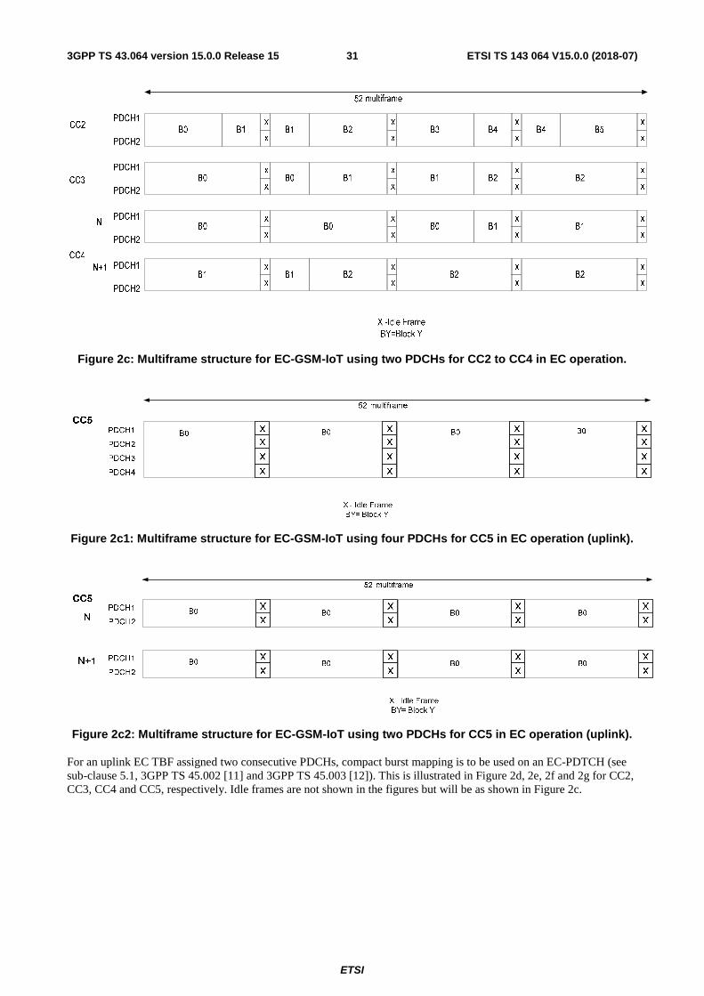
ETSI
ETSI TS 143 064 V15.0.0 (2018-07)313GPP TS 43.064 version 15.0.0 Release 15
Figure 2c: Multiframe structure for EC-GSM-IoT using two PDCHs for CC2 to CC4 in EC operation.
Figure 2c1: Multiframe structure for EC-GSM-IoT using four PDCHs for CC5 in EC operation (uplink).
Figure 2c2: Multiframe structure for EC-GSM-IoT using two PDCHs for CC5 in EC operation (uplink).
For an uplink EC TBF assigned two consecutive PDCHs, compact burst mapping is to be used on an EC-PDTCH (see sub-clause 5.1, 3GPP TS 45.002 [11] and 3GPP TS 45.003 [12]). This is illustrated in Figure 2d, 2e, 2f and 2g for CC2, CC3, CC4 and CC5, respectively. Idle frames are not shown in the figures but will be as shown in Figure 2c.
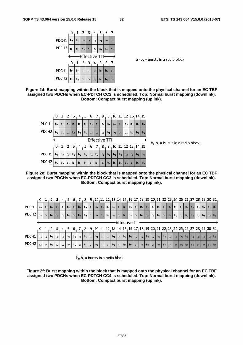
ETSI
ETSI TS 143 064 V15.0.0 (2018-07)323GPP TS 43.064 version 15.0.0 Release 15
Figure 2d: Burst mapping within the block that is mapped onto the physical channel for an EC TBF assigned two PDCHs when EC-PDTCH CC2 is scheduled. Top: Normal burst mapping (downlink).
Bottom: Compact burst mapping (uplink).
Figure 2e: Burst mapping within the block that is mapped onto the physical channel for an EC TBF assigned two PDCHs when EC-PDTCH CC3 is scheduled. Top: Normal burst mapping (downlink).
Bottom: Compact burst mapping (uplink).
Figure 2f: Burst mapping within the block that is mapped onto the physical channel for an EC TBF assigned two PDCHs when EC-PDTCH CC4 is scheduled. Top: Normal burst mapping (downlink).
Bottom: Compact burst mapping (uplink).
b0-b3 = bursts in a radio blockEffective TTI
b0 b1 b2 b3 b0 b1 b2 b3
b0 b1 b2 b3 b0 b1 b2 b3PDCH1
PDCH2
PDCH1
PDCH2
b0 b1 b2 b3b0 b1 b2 b3
b0 b1 b2 b3b0 b1 b2 b3
0 1 2 3 4 5 6 7
0 1 2 3 4 5 6 7
b0-b3 = bursts in a radio blockEffective TTI
b0 b1 b2 b3 b0 b1 b2 b3
b0 b1 b2 b3 b0 b1 b2 b3PDCH1
PDCH2
PDCH1
PDCH2
b0 b1 b2 b3 b0 b1 b2 b3
b0 b1 b2 b3 b0 b1 b2 b3
0 1 2 3 4 5 6 7 8 9 10 11 12 13 14 15
0 1 2 3 4 5 6 7 8 9 10 11 12 13 14 15
b3 b3
b3 b3
b2 b2
b2 b2
b0 b1b0 b1
b0 b1b0 b1
b0 b1b0 b1
b0 b1b0 b1
b2 b2
b2 b2
b3 b3
b3 b3
b0-b3 = bursts in a radio block
Effective TTI
PDCH1
PDCH2
PDCH1
PDCH2
b0 b1 b2 b3 b0 b1 b2 b3
b0 b1 b2 b3 b0 b1 b2 b3
b0 b1 b2 b3 b0 b1 b2 b3
b0 b1 b2 b3 b0 b1 b2 b3
b0 b1 b2 b3 b0 b1 b2 b3
b0 b1 b2 b3 b0 b1 b2 b3
b0 b1 b2 b3 b0 b1 b2 b3
b0 b1 b2 b3 b0 b1 b2 b3
b0 b0
b0 b0
b0 b0
b0 b0
b1 b1
b1 b1
b1 b1
b1 b1
b2 b2
b2 b2
b2 b2
b2 b2
b3 b3
b3 b3
b3 b3
b3 b3
b0 b0
b0 b0
b0 b0
b0 b0
b1 b1
b1 b1
b1 b1
b1 b1
b2 b2
b2 b2
b2 b2
b2 b2
b3 b3
b3 b3
b3 b3
b3 b3
0 1 2 3 4 5 6 7 8 9 10 11 12 13 14 15 16 17 18 19 20 21 22 23 24 25 26 27 28 29 30 31
0 1 2 3 4 5 6 7 8 9 10 11 12 13 14 15 16 17 18 19 20 21 22 23 24 25 26 27 28 29 30 31
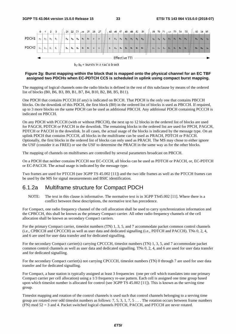
ETSI
ETSI TS 143 064 V15.0.0 (2018-07)333GPP TS 43.064 version 15.0.0 Release 15
Figure 2g: Burst mapping within the block that is mapped onto the physical channel for an EC TBF assigned two PDCHs when EC-PDTCH CC5 is scheduled in uplink using compact burst mapping.
The mapping of logical channels onto the radio blocks is defined in the rest of this subclause by means of the ordered list of blocks (B0, B6, B3, B9, B1, B7, B4, B10, B2, B8, B5, B11).
One PDCH that contains PCCCH (if any) is indicated on BCCH. That PDCH is the only one that contains PBCCH blocks. On the downlink of this PDCH, the first block (B0) in the ordered list of blocks is used as PBCCH. If required, up to 3 more blocks on the same PDCH can be used as additional PBCCH. Any additional PDCH containing PCCCH is indicated on PBCCH.
On any PDCH with PCCCH (with or without PBCCH), the next up to 12 blocks in the ordered list of blocks are used for PAGCH, PDTCH or PACCH in the downlink. The remaining blocks in the ordered list are used for PPCH, PAGCH, PDTCH or PACCH in the downlink. In all cases, the actual usage of the blocks is indicated by the message type. On an uplink PDCH that contains PCCCH, all blocks in the multiframe can be used as PRACH, PDTCH or PACCH. Optionally, the first blocks in the ordered list of blocks can only used as PRACH. The MS may chose to either ignore the USF (consider it as FREE) or use the USF to determine the PRACH in the same way as for the other blocks.
The mapping of channels on multiframes are controlled by several parameters broadcast on PBCCH.
On a PDCH that neither contains PCCCH nor EC-CCCH, all blocks can be used as PDTCH or PACCH, or, EC-PDTCH or EC-PACCH. The actual usage is indicated by the message type.
Two frames are used for PTCCH (see 3GPP TS 45.002 [11]) and the two idle frames as well as the PTCCH frames can be used by the MS for signal measurements and BSIC identification.
6.1.2a Multiframe structure for Compact PDCH
NOTE: The text in this clause is informative. The normative text is in 3GPP TS45.002 [11]. Where there is a conflict between these descriptions, the normative text has precedence.
For Compact, one radio frequency channel of the cell allocation shall be used to carry synchronization information and the CPBCCH, this shall be known as the primary Compact carrier. All other radio frequency channels of the cell allocation shall be known as secondary Compact carriers.
For the primary Compact carrier, timeslot numbers (TN) 1, 3, 5, and 7 accommodate packet common control channels (i.e., CPBCCH and CPCCCH) as well as user data and dedicated signalling (i.e., PDTCH and PACCH). TNs 0, 2, 4, and 6 are used for user data transfer and for dedicated signalling.
For the secondary Compact carrier(s) carrying CPCCCH, timeslot numbers (TN) 1, 3, 5, and 7 accommodate packet common control channels as well as user data and dedicated signalling. TNs 0, 2, 4, and 6 are used for user data transfer and for dedicated signalling.
For the secondary Compact carrier(s) not carrying CPCCCH, timeslot numbers (TN) 0 through 7 are used for user data transfer and for dedicated signalling.
For Compact, a base station is typically assigned at least 3 frequencies (one per cell which translates into one primary Compact carrier per cell allocation) using a 1/3 frequency re-use pattern. Each cell is assigned one time group based upon which timeslot number is allocated for control (see 3GPP TS 45.002 [11]). This is known as the serving time group.
Timeslot mapping and rotation of the control channels is used such that control channels belonging to a serving time group are rotated over odd timeslot numbers as follows: 7, 5, 3, 1, 7, 5 … . The rotation occurs between frame numbers (FN) mod 52 = 3 and 4. Packet switched logical channels PDTCH, PACCH, and PTCCH are never rotated.
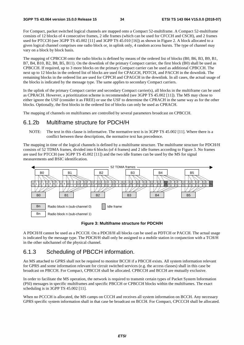
ETSI
ETSI TS 143 064 V15.0.0 (2018-07)343GPP TS 43.064 version 15.0.0 Release 15
For Compact, packet switched logical channels are mapped onto a Compact 52-multiframe. A Compact 52-multiframe consists of 12 blocks of 4 consecutive frames, 2 idle frames (which can be used for CFCCH and CSCH), and 2 frames used for PTCCH (see 3GPP TS 45.002 [11] and 3GPP TS 45.010 [16]) as shown in Figure 2. A block allocated to a given logical channel comprises one radio block or, in uplink only, 4 random access bursts. The type of channel may vary on a block by block basis.
The mapping of CPBCCH onto the radio blocks is defined by means of the ordered list of blocks (B0, B6, B3, B9, B1, B7, B4, B10, B2, B8, B5, B11). On the downlink of the primary Compact carrier, the first block (B0) shall be used as CPBCCH. If required, up to 3 more blocks on the primary Compact carrier can be used as additional CPBCCH. The next up to 12 blocks in the ordered list of blocks are used for CPAGCH, PDTCH, and PACCH in the downlink. The remaining blocks in the ordered list are used for CPPCH and CPAGCH in the downlink. In all cases, the actual usage of the blocks is indicated by the message type. The same applies to secondary Compact carriers.
In the uplink of the primary Compact carrier and secondary Compact carrier(s), all blocks in the multiframe can be used as CPRACH. However, a prioritization scheme is recommended (see 3GPP TS 45.002 [11]). The MS may chose to either ignore the USF (consider it as FREE) or use the USF to determine the CPRACH in the same way as for the other blocks. Optionally, the first blocks in the ordered list of blocks can only be used as CPRACH.
The mapping of channels on multiframes are controlled by several parameters broadcast on CPBCCH.
6.1.2b Multiframe structure for PDCH/H
NOTE: The text in this clause is informative. The normative text is in 3GPP TS 45.002 [11]. Where there is a conflict between these descriptions, the normative text has precedence.
The mapping in time of the logical channels is defined by a multiframe structure. The multiframe structure for PDCH/H consists of 52 TDMA frames, divided into 6 blocks (of 4 frames) and 2 idle frames according to Figure 3. No frames are used for PTCCH (see 3GPP TS 45.002 [11]) and the two idle frames can be used by the MS for signal measurements and BSIC identification.
Figure 3: Multiframe structure for PDCH/H
A PDCH/H cannot be used as a PCCCH. On a PDCH/H all blocks can be used as PDTCH or PACCH. The actual usage is indicated by the message type. The PDCH/H shall only be assigned to a mobile station in conjunction with a TCH/H in the other subchannel of the physical channel.
6.1.3 Scheduling of PBCCH information.
An MS attached to GPRS shall not be required to monitor BCCH if a PBCCH exists. All system information relevant for GPRS and some information relevant for circuit switched services (e.g. the access classes) shall in this case be broadcast on PBCCH. For Compact, CPBCCH shall be allocated. CPBCCH and BCCH are mutually exclusive.
In order to facilitate the MS operation, the network is required to transmit certain types of Packet System Information (PSI) messages in specific multiframes and specific PBCCH or CPBCCH blocks within the multiframes. The exact scheduling is in 3GPP TS 45.002 [11].
When no PCCCH is allocated, the MS camps on CCCH and receives all system information on BCCH. Any necessary GPRS specific system information shall in that case be broadcast on BCCH. For Compact, CPCCCH shall be allocated.
Bn Idle frameRadio block n (sub-channel 0)
52 TDMA frames
B0 B1 B2 B3 B4 B5
B0 B1 B2 B3 B4 B5
0 1 2 3 4 5 6 7 8 9 10 11 12 13 14 15 16 17 18 19 20 21 22 23 24 25 26 27 28 29 30 31 32 33 34 35 36 37 38 39 40 41 42 43 44 45 46 47 48 49 50 51
Bn Radio block n (sub-channel 1)
ETSI
ETSI TS 143 064 V15.0.0 (2018-07)353GPP TS 43.064 version 15.0.0 Release 15
6.1.4 SMS cell broadcast
The MS reading of the primary and extended CBCH is occasionally interrupted by MS idle mode procedures when the MS is GPRS attached and in packet idle mode.
6.1.5 MS Multislot Capability
The mobile station informs the network of its multislot capability by declaring its multislot class. This implicitly determines a set of parameters that together define (see 3GPP TS 45.002 [11]):
- The minimum time the network should allow the MS between a transmit and receive operations for purposes of re-tuning and/or monitoring.
- Limits on the number of timeslots that the mobile station is capable of receiving and/or transmitting in a TDMA frame.
The MS declares a multislot class for GPRS and, if supported, EGPRS. If EGPRS2 or EC-GSM-IoT is supported, the multislot class for EGPRS2 and EC-GSM-IoT is the same as for EGPRS.
For EC-GSM-IoT the number of timeslots that the MS is capable of receiving or transmitting in a TDMA frame for the declared multislot class is only applicable when blind physical layer transmissions are not used, i.e. when the MS is in CC1 in downlink and/or uplink. When blind physical layer transmissions are used (see subclause 3.3.9.2), the MS shall support four timeslots for transmission or reception, irrespective of the declared multislot class.
For EC-GSM-IoT the MS is restricted to either transmit or receive during a TDMA frame. No concurrent TBFs in uplink and downlink are therefore supported by EC-GSM-IoT. There is no requirement on downlink monitoring during an ongoing TBF for EC-GSM-IoT, and considering that the MS is restricted to either transmit or receive during a TDMA frame, the minimum times between transmit and receive operations for re-tuning and/or monitoring as defined in 3GPP TS 45.002 do not apply to EC-GSM-IoT.
In downlink dual carrier and multi carrier configurations:
- The maximum number of timeslots in a TDMA frame that the MS can receive is implicitly specified by the applicable multislot class, according to 3GPP TS 45.002 [11].
- The MS signals to the network whether it supports some reduced value relative to this maximum.
Furthermore, in downlink dual carrier configurations the DTM EGPRS multislot class applies when Dual Transfer Mode is used, otherwise the EGPRS multislot class applies.
6.2 Radio Resource operating modes Radio Resource (RR) management procedures are characterised by two different RR operating modes. Each mode describes a certain amount of functionality and information allocated. RR procedures and RR operating modes are specified in 3GPP TS 24.007 [5].
6.2.1 Packet idle mode
Packet idle mode is not applicable to an MS supporting DTM that has an ongoing RR connection. An MS that supports DTM, that has an ongoing RR connection and that has no assigned packet resource is in dedicated mode.
In packet idle mode no Temporary Block Flow (see subclause 6.6.4.2) exists. Upper layers can require the transfer of LLC PDUs which, implicitly, may trigger the establishment of one or more TBFs and transition to packet transfer mode.
In packet idle mode, an MS capable of multiple TBF operation may request the establishment of one or more uplink TBFs during a two-phase access.
In packet idle mode, the MS listens to the PBCCH and to the paging sub-channel for the paging group the MS belongs to in idle mode. If PCCCH is not present in the cell, the mobile station listens to the BCCH and to the relevant paging sub-channels.
While operating in packet idle mode, a mobile station belonging to GPRS MS class A may simultaneously enter the different RR service modes defined in 3GPP TS 44.018 [6]. A mobile station belonging to either of GPRS MS class B
ETSI
ETSI TS 143 064 V15.0.0 (2018-07)363GPP TS 43.064 version 15.0.0 Release 15
or C leaves both packet idle mode and packet transfer modes before entering dedicated mode, group receive mode or group transmit mode. A MS that has enabled EC operation or PEO belongs to GPRS MS class B or GPRS MS class C mode of operation (see TS 44.018 [6]).
6.2.2 Packet transfer mode
Packet transfer mode is not applicable to a mobile station supporting DTM that has an ongoing RR connection. A DTM mobile station with an ongoing RR connection and with packet resources assigned is in dual transfer mode (see 6.2.3).
In packet transfer mode, the mobile station is assigned radio resources providing one or more Temporary Block Flows where each TBF may operate on one or more physical channels. Continuous transfer of one or more LLC PDUs is possible. Concurrent TBFs (i.e. one uplink TBF and one downlink TBF) may be established in opposite directions when a mobile station does not support multiple TBF procedures. Multiple concurrent uplink and downlink TBFs may be established when a mobile station does support multiple TBF procedures. Transfer of LLC PDUs in RLC acknowledged, RLC unacknowledged or RLC non-persistent mode is provided. If a mobile station supports multiple TBF procedures and has two or more ongoing TBFs they shall use either GPRS TBF mode or EGPRS TBF mode (i.e. mixing of GPRS and EGPRS TBF modes shall not be supported).
When selecting a new cell, a mobile station leaves the packet transfer mode, enters the packet idle mode where it switches to the new cell, reads the system information and may then resume to packet transfer mode in the new cell.
While operating in packet transfer mode, a mobile station belonging to GPRS MS class A may simultaneously enter the different RR service modes defined in 3GPP TS 44.018. A mobile station belonging to either of GPRS MS class B or C leaves both packet idle mode and packet transfer modes before entering dedicated mode, group receive mode or group transmit mode. A MS that has enabled EC operation or PEO belongs to GPRS MS class B or GPRS MS class C mode of operation (see TS 44.018 [6]).
6.2.3 Dual transfer mode
In dual transfer mode, the MS has an ongoing RR connection and is assigned radio resource providing one or more Temporary Block Flows where each TBF may operate on one or more physical channels. Continuous transfer of one or more LLC PDUs is possible. Concurrent TBFs (i.e. one uplink TBF and one downlink TBF) may be established in opposite directions. Multiple concurrent uplink and downlink TBFs may be established for a mobile station that supports multiple TBF procedures. Transfer of LLC PDUs in RLC acknowledged, RLC unacknowledged or RLC non-persistent mode is provided.
While in dual transfer mode the MS performs all the tasks of dedicated mode. In addition, upper layers can require:
- the release of all the packet resources, which triggers the transition to dedicated mode.
- the release of the RR resources, which triggers the transition to idle mode and packet idle mode.
When handed over to a new cell, the MS leaves the dual transfer mode, enters the dedicated mode where it switches to the new cell, may read the system information messages sent on the SACCH and may then enter dual transfer mode in the new cell.
Dual transfer mode shall not be used when a MS has enabled EC operation or PEO.
6.2.3a Broadcast/Multicast receive mode
In broadcast/multicast receive mode, the mobile station is assigned radio resources providing one or more p-t-m radio bearers for the reception of MBMS sessions; each p-t-m bearer may operate on one or more physical channels. Transfer of upper layer PDUs in RLC non-persistent mode is provided.
In broadcast/multicast receive mode, the MS listens to the PBCCH and to the paging sub-channel on the PCCCH for the paging group the MS belongs to in packet idle mode. If PBCCH is not present in the cell, the mobile station listens to the BCCH and to the relevant paging sub-channels on the CCCH for the paging group the MS belongs to. However, if the mobile station listens to an MBMS p-t-m bearer for which the network has indicated that system information and paging messages are sent on the PACCH, the MS does not have to listen to the (P)BCCH and, if the MS has an MS_ID on that MBMS p-t-m bearer as well, to the paging sub-channels.
When selecting a new cell, a mobile station leaves the broadcast/multicast receive mode and enters the packet idle mode. After switching to the new cell, the MS may resume the reception of the MBMS session before completing the
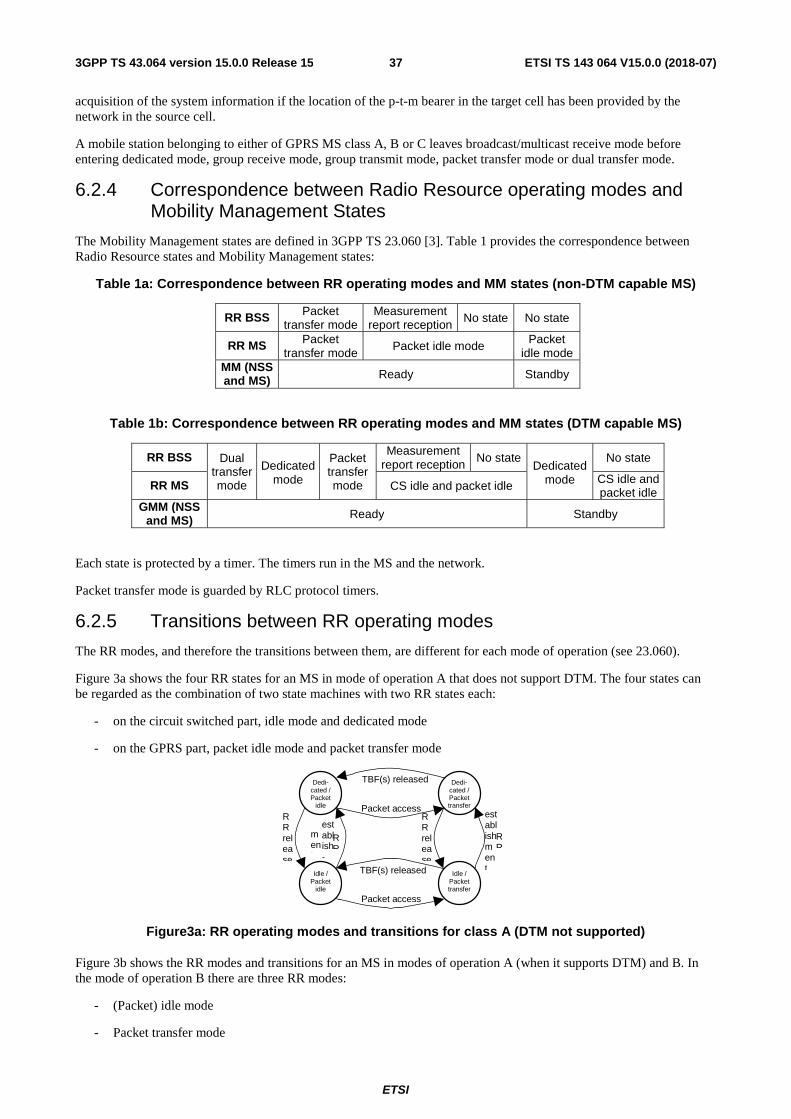
ETSI
ETSI TS 143 064 V15.0.0 (2018-07)373GPP TS 43.064 version 15.0.0 Release 15
acquisition of the system information if the location of the p-t-m bearer in the target cell has been provided by the network in the source cell.
A mobile station belonging to either of GPRS MS class A, B or C leaves broadcast/multicast receive mode before entering dedicated mode, group receive mode, group transmit mode, packet transfer mode or dual transfer mode.
6.2.4 Correspondence between Radio Resource operating modes and Mobility Management States
The Mobility Management states are defined in 3GPP TS 23.060 [3]. Table 1 provides the correspondence between Radio Resource states and Mobility Management states:
Table 1a: Correspondence between RR operating modes and MM states (non-DTM capable MS)
RR BSS Packet transfer mode
Measurement report reception No state No state
RR MS Packet transfer mode Packet idle mode Packet
idle mode MM (NSS and MS) Ready Standby
Table 1b: Correspondence between RR operating modes and MM states (DTM capable MS)
RR BSS Dual transfer mode
Dedicated
mode
Packet transfer mode
Measurement report reception No state
Dedicated mode
No state
RR MS CS idle and packet idle CS idle and packet idle
GMM (NSS and MS) Ready Standby
Each state is protected by a timer. The timers run in the MS and the network.
Packet transfer mode is guarded by RLC protocol timers.
6.2.5 Transitions between RR operating modes
The RR modes, and therefore the transitions between them, are different for each mode of operation (see 23.060).
Figure 3a shows the four RR states for an MS in mode of operation A that does not support DTM. The four states can be regarded as the combination of two state machines with two RR states each:
- on the circuit switched part, idle mode and dedicated mode
- on the GPRS part, packet idle mode and packet transfer mode
Dedi- cated / Packet transfer
Idle / Packet transfer
Dedi- cated / Packet
idle
Idle / Packet
idle
RR release
RR
establishment
Packet access
TBF(s) released
Packet access
TBF(s) released
RR release
RR
establish-
ment
Figure3a: RR operating modes and transitions for class A (DTM not supported)
Figure 3b shows the RR modes and transitions for an MS in modes of operation A (when it supports DTM) and B. In the mode of operation B there are three RR modes:
- (Packet) idle mode
- Packet transfer mode
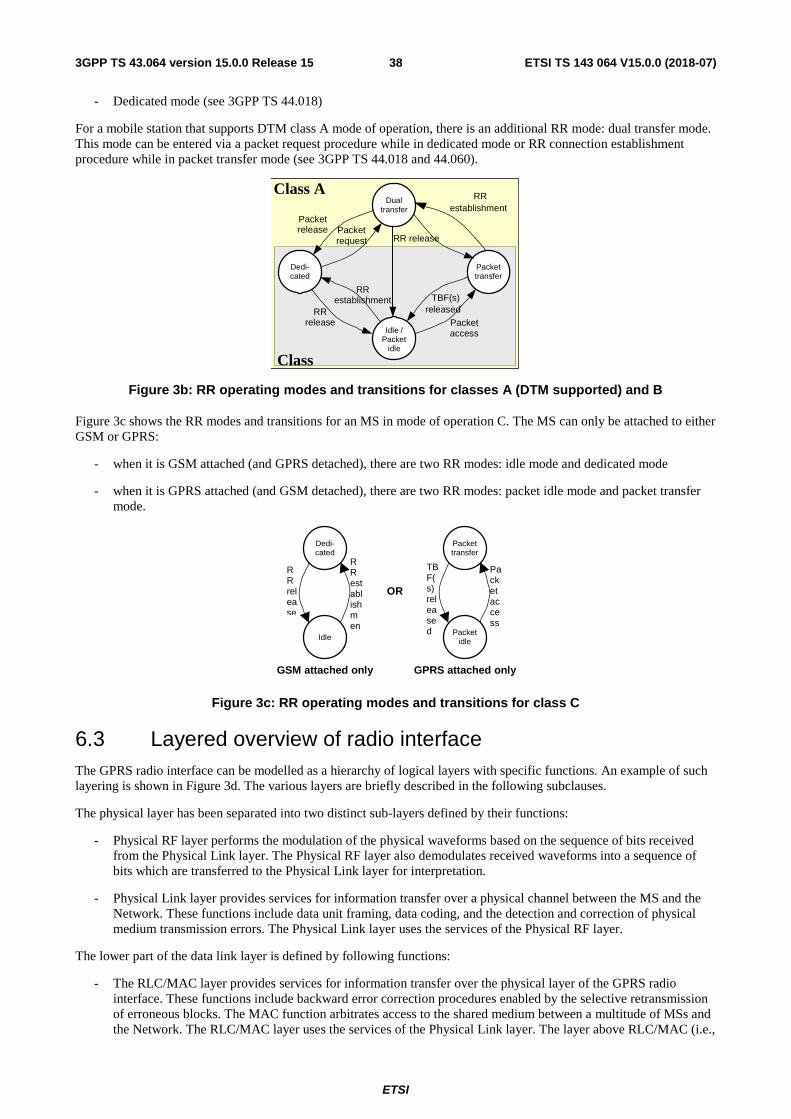
ETSI
ETSI TS 143 064 V15.0.0 (2018-07)383GPP TS 43.064 version 15.0.0 Release 15
- Dedicated mode (see 3GPP TS 44.018)
For a mobile station that supports DTM class A mode of operation, there is an additional RR mode: dual transfer mode. This mode can be entered via a packet request procedure while in dedicated mode or RR connection establishment procedure while in packet transfer mode (see 3GPP TS 44.018 and 44.060).
Class A
Class
Packet transfer
Idle / Packet
idle
Packet access
Dedi- cated
Dual transfer
RR release
TBF(s) released
Packet request
Packet release
RR establishment
RR release
RR establishment
Figure 3b: RR operating modes and transitions for classes A (DTM supported) and B
Figure 3c shows the RR modes and transitions for an MS in mode of operation C. The MS can only be attached to either GSM or GPRS:
- when it is GSM attached (and GPRS detached), there are two RR modes: idle mode and dedicated mode
- when it is GPRS attached (and GSM detached), there are two RR modes: packet idle mode and packet transfer mode.
Packet transfer
Packet idle
Dedi- cated
Idle
RR release
RR establishment
Packet access
TBF(s) released
OR
GSM attached only GPRS attached only
Figure 3c: RR operating modes and transitions for class C
6.3 Layered overview of radio interface The GPRS radio interface can be modelled as a hierarchy of logical layers with specific functions. An example of such layering is shown in Figure 3d. The various layers are briefly described in the following subclauses.
The physical layer has been separated into two distinct sub-layers defined by their functions:
- Physical RF layer performs the modulation of the physical waveforms based on the sequence of bits received from the Physical Link layer. The Physical RF layer also demodulates received waveforms into a sequence of bits which are transferred to the Physical Link layer for interpretation.
- Physical Link layer provides services for information transfer over a physical channel between the MS and the Network. These functions include data unit framing, data coding, and the detection and correction of physical medium transmission errors. The Physical Link layer uses the services of the Physical RF layer.
The lower part of the data link layer is defined by following functions:
- The RLC/MAC layer provides services for information transfer over the physical layer of the GPRS radio interface. These functions include backward error correction procedures enabled by the selective retransmission of erroneous blocks. The MAC function arbitrates access to the shared medium between a multitude of MSs and the Network. The RLC/MAC layer uses the services of the Physical Link layer. The layer above RLC/MAC (i.e.,
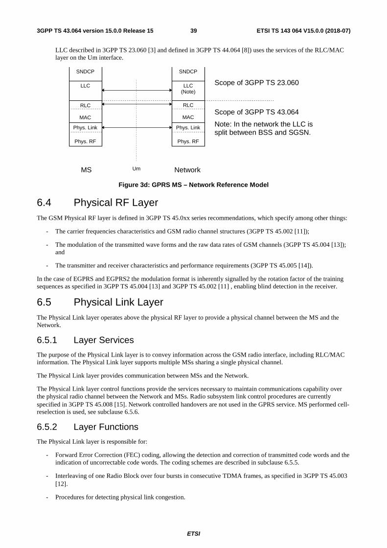
ETSI
ETSI TS 143 064 V15.0.0 (2018-07)393GPP TS 43.064 version 15.0.0 Release 15
LLC described in 3GPP TS 23.060 [3] and defined in 3GPP TS 44.064 [8]) uses the services of the RLC/MAC layer on the Um interface.
Um Network
SNDCP
LLC (Note)
RLC
MAC Phys. Link
Phys. RF
SNDCP
LLC
RLC
MAC Phys. Link
Phys. RF
MS
Scope of 3GPP TS 23.060
Scope of 3GPP TS 43.064
Note: In the network the LLC is split between BSS and SGSN.
Figure 3d: GPRS MS – Network Reference Model
6.4 Physical RF Layer The GSM Physical RF layer is defined in 3GPP TS 45.0xx series recommendations, which specify among other things:
- The carrier frequencies characteristics and GSM radio channel structures (3GPP TS 45.002 [11]);
- The modulation of the transmitted wave forms and the raw data rates of GSM channels (3GPP TS 45.004 [13]); and
- The transmitter and receiver characteristics and performance requirements (3GPP TS 45.005 [14]).
In the case of EGPRS and EGPRS2 the modulation format is inherently signalled by the rotation factor of the training sequences as specified in 3GPP TS 45.004 [13] and 3GPP TS 45.002 [11] , enabling blind detection in the receiver.
6.5 Physical Link Layer The Physical Link layer operates above the physical RF layer to provide a physical channel between the MS and the Network.
6.5.1 Layer Services
The purpose of the Physical Link layer is to convey information across the GSM radio interface, including RLC/MAC information. The Physical Link layer supports multiple MSs sharing a single physical channel.
The Physical Link layer provides communication between MSs and the Network.
The Physical Link layer control functions provide the services necessary to maintain communications capability over the physical radio channel between the Network and MSs. Radio subsystem link control procedures are currently specified in 3GPP TS 45.008 [15]. Network controlled handovers are not used in the GPRS service. MS performed cell-reselection is used, see subclause 6.5.6.
6.5.2 Layer Functions
The Physical Link layer is responsible for:
- Forward Error Correction (FEC) coding, allowing the detection and correction of transmitted code words and the indication of uncorrectable code words. The coding schemes are described in subclause 6.5.5.
- Interleaving of one Radio Block over four bursts in consecutive TDMA frames, as specified in 3GPP TS 45.003 [12].
- Procedures for detecting physical link congestion.
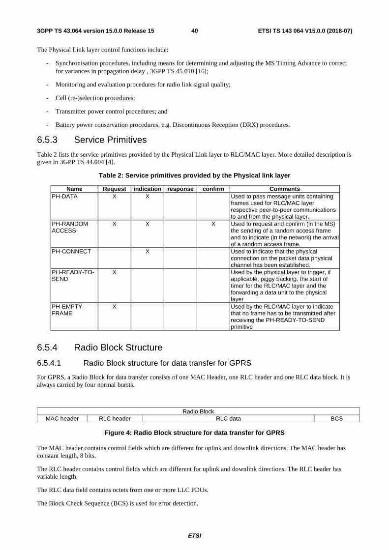
ETSI
ETSI TS 143 064 V15.0.0 (2018-07)403GPP TS 43.064 version 15.0.0 Release 15
The Physical Link layer control functions include:
- Synchronisation procedures, including means for determining and adjusting the MS Timing Advance to correct for variances in propagation delay , 3GPP TS 45.010 [16];
- Monitoring and evaluation procedures for radio link signal quality;
- Cell (re-)selection procedures;
- Transmitter power control procedures; and
- Battery power conservation procedures, e.g. Discontinuous Reception (DRX) procedures.
6.5.3 Service Primitives
Table 2 lists the service primitives provided by the Physical Link layer to RLC/MAC layer. More detailed description is given in 3GPP TS 44.004 [4].
Table 2: Service primitives provided by the Physical link layer
Name Request indication response confirm Comments PH-DATA X X Used to pass message units containing
frames used for RLC/MAC layer respective peer-to-peer communications to and from the physical layer.
PH-RANDOM ACCESS
X X X Used to request and confirm (in the MS) the sending of a random access frame and to indicate (in the network) the arrival of a random access frame.
PH-CONNECT X Used to indicate that the physical connection on the packet data physical channel has been established.
PH-READY-TO-SEND
X Used by the physical layer to trigger, if applicable, piggy backing, the start of timer for the RLC/MAC layer and the forwarding a data unit to the physical layer
PH-EMPTY-FRAME
X Used by the RLC/MAC layer to indicate that no frame has to be transmitted after receiving the PH-READY-TO-SEND primitive
6.5.4 Radio Block Structure
6.5.4.1 Radio Block structure for data transfer for GPRS
For GPRS, a Radio Block for data transfer consists of one MAC Header, one RLC header and one RLC data block. It is always carried by four normal bursts.
Radio Block MAC header RLC header RLC data BCS
Figure 4: Radio Block structure for data transfer for GPRS
The MAC header contains control fields which are different for uplink and downlink directions. The MAC header has constant length, 8 bits.
The RLC header contains control fields which are different for uplink and downlink directions. The RLC header has variable length.
The RLC data field contains octets from one or more LLC PDUs.
The Block Check Sequence (BCS) is used for error detection.
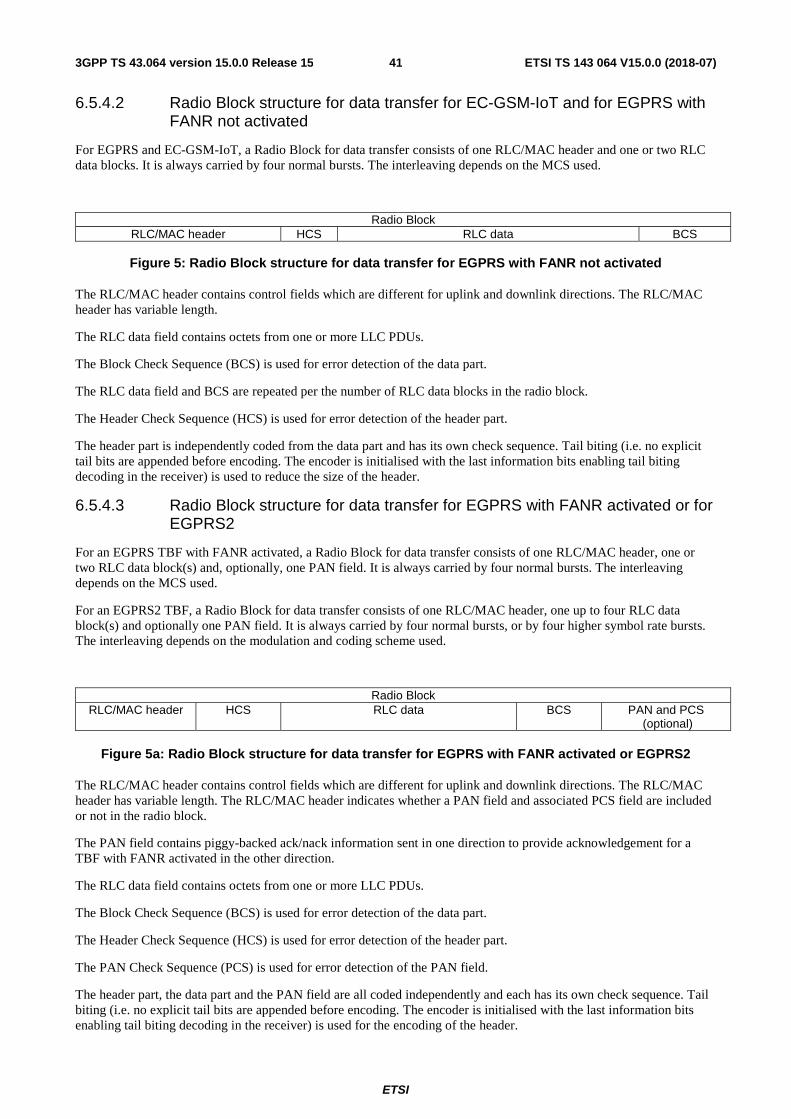
ETSI
ETSI TS 143 064 V15.0.0 (2018-07)413GPP TS 43.064 version 15.0.0 Release 15
6.5.4.2 Radio Block structure for data transfer for EC-GSM-IoT and for EGPRS with FANR not activated
For EGPRS and EC-GSM-IoT, a Radio Block for data transfer consists of one RLC/MAC header and one or two RLC data blocks. It is always carried by four normal bursts. The interleaving depends on the MCS used.
Radio Block RLC/MAC header HCS RLC data BCS
Figure 5: Radio Block structure for data transfer for EGPRS with FANR not activated
The RLC/MAC header contains control fields which are different for uplink and downlink directions. The RLC/MAC header has variable length.
The RLC data field contains octets from one or more LLC PDUs.
The Block Check Sequence (BCS) is used for error detection of the data part.
The RLC data field and BCS are repeated per the number of RLC data blocks in the radio block.
The Header Check Sequence (HCS) is used for error detection of the header part.
The header part is independently coded from the data part and has its own check sequence. Tail biting (i.e. no explicit tail bits are appended before encoding. The encoder is initialised with the last information bits enabling tail biting decoding in the receiver) is used to reduce the size of the header.
6.5.4.3 Radio Block structure for data transfer for EGPRS with FANR activated or for EGPRS2
For an EGPRS TBF with FANR activated, a Radio Block for data transfer consists of one RLC/MAC header, one or two RLC data block(s) and, optionally, one PAN field. It is always carried by four normal bursts. The interleaving depends on the MCS used.
For an EGPRS2 TBF, a Radio Block for data transfer consists of one RLC/MAC header, one up to four RLC data block(s) and optionally one PAN field. It is always carried by four normal bursts, or by four higher symbol rate bursts. The interleaving depends on the modulation and coding scheme used.
Radio Block RLC/MAC header HCS RLC data BCS PAN and PCS
(optional)
Figure 5a: Radio Block structure for data transfer for EGPRS with FANR activated or EGPRS2
The RLC/MAC header contains control fields which are different for uplink and downlink directions. The RLC/MAC header has variable length. The RLC/MAC header indicates whether a PAN field and associated PCS field are included or not in the radio block.
The PAN field contains piggy-backed ack/nack information sent in one direction to provide acknowledgement for a TBF with FANR activated in the other direction.
The RLC data field contains octets from one or more LLC PDUs.
The Block Check Sequence (BCS) is used for error detection of the data part.
The Header Check Sequence (HCS) is used for error detection of the header part.
The PAN Check Sequence (PCS) is used for error detection of the PAN field.
The header part, the data part and the PAN field are all coded independently and each has its own check sequence. Tail biting (i.e. no explicit tail bits are appended before encoding. The encoder is initialised with the last information bits enabling tail biting decoding in the receiver) is used for the encoding of the header.
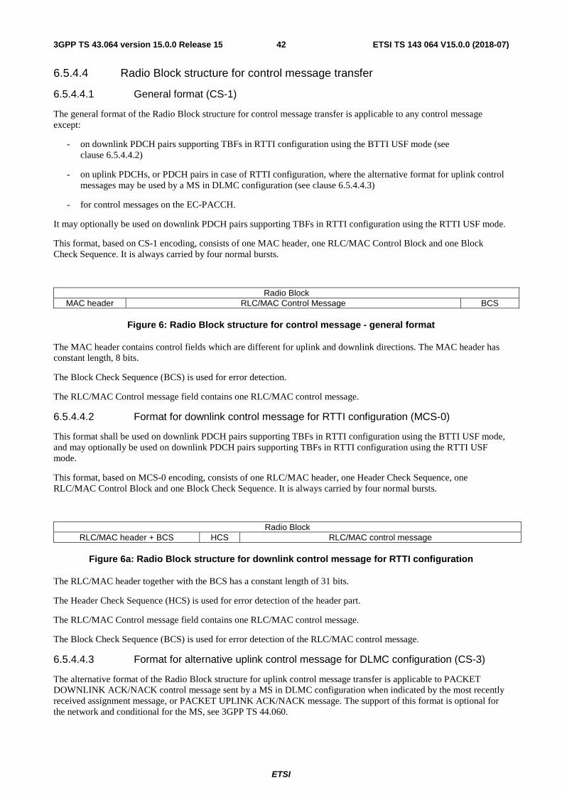
ETSI
ETSI TS 143 064 V15.0.0 (2018-07)423GPP TS 43.064 version 15.0.0 Release 15
6.5.4.4 Radio Block structure for control message transfer
6.5.4.4.1 General format (CS-1)
The general format of the Radio Block structure for control message transfer is applicable to any control message except:
- on downlink PDCH pairs supporting TBFs in RTTI configuration using the BTTI USF mode (see clause 6.5.4.4.2)
- on uplink PDCHs, or PDCH pairs in case of RTTI configuration, where the alternative format for uplink control messages may be used by a MS in DLMC configuration (see clause 6.5.4.4.3)
- for control messages on the EC-PACCH.
It may optionally be used on downlink PDCH pairs supporting TBFs in RTTI configuration using the RTTI USF mode.
This format, based on CS-1 encoding, consists of one MAC header, one RLC/MAC Control Block and one Block Check Sequence. It is always carried by four normal bursts.
Radio Block MAC header RLC/MAC Control Message BCS
Figure 6: Radio Block structure for control message - general format
The MAC header contains control fields which are different for uplink and downlink directions. The MAC header has constant length, 8 bits.
The Block Check Sequence (BCS) is used for error detection.
The RLC/MAC Control message field contains one RLC/MAC control message.
6.5.4.4.2 Format for downlink control message for RTTI configuration (MCS-0)
This format shall be used on downlink PDCH pairs supporting TBFs in RTTI configuration using the BTTI USF mode, and may optionally be used on downlink PDCH pairs supporting TBFs in RTTI configuration using the RTTI USF mode.
This format, based on MCS-0 encoding, consists of one RLC/MAC header, one Header Check Sequence, one RLC/MAC Control Block and one Block Check Sequence. It is always carried by four normal bursts.
Radio Block RLC/MAC header + BCS HCS RLC/MAC control message
Figure 6a: Radio Block structure for downlink control message for RTTI configuration
The RLC/MAC header together with the BCS has a constant length of 31 bits.
The Header Check Sequence (HCS) is used for error detection of the header part.
The RLC/MAC Control message field contains one RLC/MAC control message.
The Block Check Sequence (BCS) is used for error detection of the RLC/MAC control message.
6.5.4.4.3 Format for alternative uplink control message for DLMC configuration (CS-3)
The alternative format of the Radio Block structure for uplink control message transfer is applicable to PACKET DOWNLINK ACK/NACK control message sent by a MS in DLMC configuration when indicated by the most recently received assignment message, or PACKET UPLINK ACK/NACK message. The support of this format is optional for the network and conditional for the MS, see 3GPP TS 44.060.
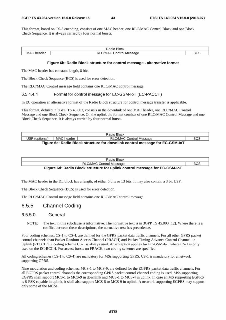
ETSI
ETSI TS 143 064 V15.0.0 (2018-07)433GPP TS 43.064 version 15.0.0 Release 15
This format, based on CS-3 encoding, consists of one MAC header, one RLC/MAC Control Block and one Block Check Sequence. It is always carried by four normal bursts.
Radio Block MAC header RLC/MAC Control Message BCS
Figure 6b: Radio Block structure for control message - alternative format
The MAC header has constant length, 8 bits.
The Block Check Sequence (BCS) is used for error detection.
The RLC/MAC Control message field contains one RLC/MAC control message.
6.5.4.4.4 Format for control message for EC-GSM-IoT (EC-PACCH)
In EC operation an alternative format of the Radio Block structure for control message transfer is applicable.
This format, defined in 3GPP TS 45.003, consists in the downlink of one MAC header, one RLC/MAC Control Message and one Block Check Sequence. On the uplink the format consists of one RLC/MAC Control Message and one Block Check Sequence. It is always carried by four normal bursts.
Radio Block USF (optional) MAC header RLC/MAC Control Message BCS
Figure 6c: Radio Block structure for downlink control message for EC-GSM-IoT
Radio Block RLC/MAC Control Message BCS
Figure 6d: Radio Block structure for uplink control message for EC-GSM-IoT
The MAC header in the DL block has a length, of either 5 bits or 13 bits. It may also contain a 3 bit USF.
The Block Check Sequence (BCS) is used for error detection.
The RLC/MAC Control message field contains one RLC/MAC control message.
6.5.5 Channel Coding
6.5.5.0 General
NOTE: The text in this subclause is informative. The normative text is in 3GPP TS 45.003 [12]. Where there is a conflict between these descriptions, the normative text has precedence.
Four coding schemes, CS-1 to CS-4, are defined for the GPRS packet data traffic channels. For all other GPRS packet control channels than Packet Random Access Channel (PRACH) and Packet Timing Advance Control Channel on Uplink (PTCCH/U), coding scheme CS-1 is always used. An exception applies for EC-GSM-IoT where CS-1 is only used on the EC-BCCH. For access bursts on PRACH, two coding schemes are specified.
All coding schemes (CS-1 to CS-4) are mandatory for MSs supporting GPRS. CS-1 is mandatory for a network supporting GPRS.
Nine modulation and coding schemes, MCS-1 to MCS-9, are defined for the EGPRS packet data traffic channels. For all EGPRS packet control channels the corresponding GPRS packet control channel coding is used. MSs supporting EGPRS shall support MCS-1 to MCS-9 in downlink and MCS-1 to MCS-4 in uplink. In case an MS supporting EGPRS is 8-PSK capable in uplink, it shall also support MCS-5 to MCS-9 in uplink. A network supporting EGPRS may support only some of the MCSs.

ETSI
ETSI TS 143 064 V15.0.0 (2018-07)443GPP TS 43.064 version 15.0.0 Release 15
For EC-GSM-IoT, the same nine modulation and coding schemes as for EGPRS are defined for the packet data traffic channels, with the exception that only one puncturing scheme is used for MCS-1 and MCS-2, and only two puncturing schemes are used for MCS-3 and MCS-4. For packet associated control channel a specific coding scheme is used, see 3GPP TS 45.003. MSs supporting EC-GSM-IoT shall support MCS-1 to MCS-4 in downlink and uplink. In case an MS supporting EC-GSM-IoT is 8-PSK capable, it shall also support MCS-5 to MCS-9 in downlink and uplink. A network supporting EC-GSM-IoT may support only some of the MCSs, but shall support MCS-1.
Eight modulation and coding schemes, DAS-5 to DAS-12, are defined for the EGPRS2-A packet data traffic channels for the downlink. Eight modulation and coding schemes, DBS-5 to DBS-12, are defined for the EGPRS2-B packet data traffic channels for the downlink. Four EGPRS modulation and coding schemes, MCS-1 to MCS-4, are also used for downlink EGPRS2.
Five modulation and coding schemes, UAS-7 to UAS-11, are defined for the EGPRS2-A packet data traffic channels for the uplink. Six EGPRS modulation and coding schemes, MCS-1 to MCS-6, are also used for uplink EGPRS2-A. Eight modulation and coding schemes, UBS-5 to UBS-12, are defined for the EGPRS2-B packet data traffic channels for the uplink. Four EGPRS modulation and coding schemes, MCS-1 to MCS-4, are also used for uplink EGPRS2-B.
MSs supporting EGPRS2-A in the downlink shall support all of DAS-5 to DAS-12. MSs supporting EGPRS2-B in the downlink shall support all of DBS-5 to DBS-12, in addition to DAS-5 to DAS-12. MSs supporting EGPRS2-A in the uplink shall support all of UAS-7 to UAS-11. MSs supporting EGPRS2-B in the uplink shall support all of UBS-5 to UBS-12, in addition to UAS-7 to UAS-11. For all EGPRS2 packet control channels, the corresponding GPRS control channel coding is used. MSs supporting EGPRS2 in the downlink and/or the uplink shall support EGPRS.
A network supporting EGPRS2 may support only some of the modulation and coding schemes, DAS-5 to DAS-12, DBS-5 to DBS-12, UAS-7 to UAS-11, and UBS-5 to UBS-12.
For all EGPRS2 packet control channels in BTTI configuration, the corresponding GPRS packet control channel coding is used.
In RTTI configuration, the PACCH in the uplink shall be always encoded using CS-1 and the PACCH in the downlink may be encoded using MCS-0 or CS-1. MCS-0 shall be used for PACCH in the downlink associated with TBF using RTTI configuration which shares PDCH(s) with TBF(s) using BTTI configuration.
6.5.5.1 Channel coding for PDTCH
6.5.5.1.1 Channel coding for GPRS PDTCH
Four different coding schemes, CS-1 to CS-4, are defined for the GPRS Radio Blocks carrying RLC data blocks. The block structures of the coding schemes are shown in Figure 7 and Figure 8.
Figure 7: Radio Block structure for CS-1 to CS-3
rate 1/2 convolutional coding
puncturing
456 bits
USF BCS
Radio Block
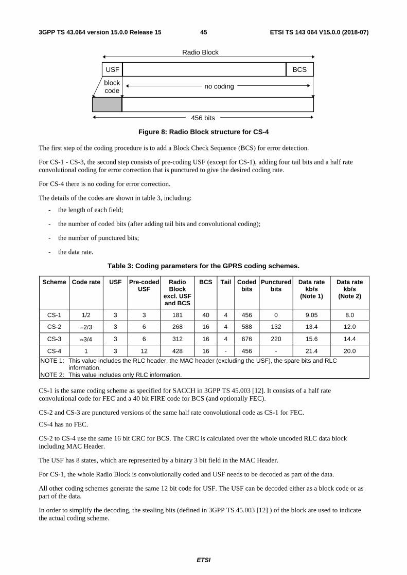
ETSI
ETSI TS 143 064 V15.0.0 (2018-07)453GPP TS 43.064 version 15.0.0 Release 15
Figure 8: Radio Block structure for CS-4
The first step of the coding procedure is to add a Block Check Sequence (BCS) for error detection.
For CS-1 - CS-3, the second step consists of pre-coding USF (except for CS-1), adding four tail bits and a half rate convolutional coding for error correction that is punctured to give the desired coding rate.
For CS-4 there is no coding for error correction.
The details of the codes are shown in table 3, including:
- the length of each field;
- the number of coded bits (after adding tail bits and convolutional coding);
- the number of punctured bits;
- the data rate.
Table 3: Coding parameters for the GPRS coding schemes.
Scheme Code rate USF Pre-coded USF
Radio Block
excl. USF and BCS
BCS Tail Coded bits
Punctured bits
Data rate kb/s
(Note 1)
Data rate kb/s
(Note 2)
CS-1 1/2 3 3 181 40 4 456 0 9.05 8.0
CS-2 ≈2/3 3 6 268 16 4 588 132 13.4 12.0
CS-3 ≈3/4 3 6 312 16 4 676 220 15.6 14.4
CS-4 1 3 12 428 16 - 456 - 21.4 20.0
NOTE 1: This value includes the RLC header, the MAC header (excluding the USF), the spare bits and RLC information.
NOTE 2: This value includes only RLC information. CS-1 is the same coding scheme as specified for SACCH in 3GPP TS 45.003 [12]. It consists of a half rate convolutional code for FEC and a 40 bit FIRE code for BCS (and optionally FEC).
CS-2 and CS-3 are punctured versions of the same half rate convolutional code as CS-1 for FEC.
CS-4 has no FEC.
CS-2 to CS-4 use the same 16 bit CRC for BCS. The CRC is calculated over the whole uncoded RLC data block including MAC Header.
The USF has 8 states, which are represented by a binary 3 bit field in the MAC Header.
For CS-1, the whole Radio Block is convolutionally coded and USF needs to be decoded as part of the data.
All other coding schemes generate the same 12 bit code for USF. The USF can be decoded either as a block code or as part of the data.
In order to simplify the decoding, the stealing bits (defined in 3GPP TS 45.003 [12] ) of the block are used to indicate the actual coding scheme.
blockcode
no coding
456 bits
USF BCS
Radio Block

ETSI
ETSI TS 143 064 V15.0.0 (2018-07)463GPP TS 43.064 version 15.0.0 Release 15
6.5.5.1.2 Channel coding for EGPRS PDTCH and EC-GSM-IoT EC-PDTCH
Nine different modulation and coding schemes, MCS-1 to MCS-9, are defined for the EGPRS and EC-GSM-IoT Radio Blocks carrying RLC data blocks. The block structures of the coding schemes are shown from Figure 10 to Figure 18 and in Table 4. A general description of the MCSs is given in Figure 9.
The MCSs are divided into different families A, B and C. Each family has a different basic unit of payload: 37 (and 34), 28 and 22 octets respectively. Different code rates within a family are achieved by transmitting a different number of payload units within one Radio Block. For families A and B, 1, 2 or 4 payload units are transmitted, for family C, only 1 or 2 payload units are transmitted.
When 4 payload units are transmitted (MCS-7, MCS-8 and MCS-9), these are split into two separate RLC blocks (i.e. with separate sequence numbers and BCSs). These blocks in turn are interleaved over two bursts only, for MCS-8 and MCS-9. For MCS-7, these blocks are interleaved over four bursts. All the other MCSs carry one RLC block which is interleaved over four bursts. When switching to MCS-3 or MCS-6 from MCS-8, 6 padding octets are added to the data octets.

ETSI
ETSI TS 143 064 V15.0.0 (2018-07)473GPP TS 43.064 version 15.0.0 Release 15
Figure 9: General description of the Modulation and Coding Schemes for EGPRS
To ensure strong header protection, the header part of the Radio Block is independently coded from the data part of the Radio Block (8 bit CRC calculated over the header -excl. USF- for error detection, followed by rate 1/3 convolutional coding –and eventually puncturing- for error correction). Three different header formats are used, one for MCS-7, MCS-8 and MCS-9, one for MCS-5 and MCS-6 and one for MCS-1 to MCS-4. The two first formats are for 8PSK modes, the difference being in the number of Sequence Numbers carried (2 for MCS-7, -8 and -9, 1 for MCS-5 and –6). The third format is common to all GMSK modes. The header is always interleaved over four bursts. See 3GPP TS 44.060 [7] for more details.
The following figures show the coding and puncturing for all the Modulation and Coding Schemes, for downlink traffic. For TBFs with FANR activated, the figures refer to the case when no PAN field is included.
NOTE: The USF and SB fields shown in Figures 10 to 18 may be mapped in another way when RTTI configuration is used with BTTI USFs, see 3GPP TS 45.002 for details.
37 octets 37 octets 37 octets 37 octets
MCS-3
MCS-6
MCS-9
Family A
6 + 31 octets 37 octets
MCS-31st part
MCS-6
MCS-8
Family Apadding
37 octets
MCS-32nd part
6 + 31 octets
34 octets 34 octets 34 octets 34 octets
28 octets 28 octets 28 octets 28 octets
MCS-2
MCS-5
MCS-7
Family B
22 octets 22 octets
MCS-1
MCS-4
Family C
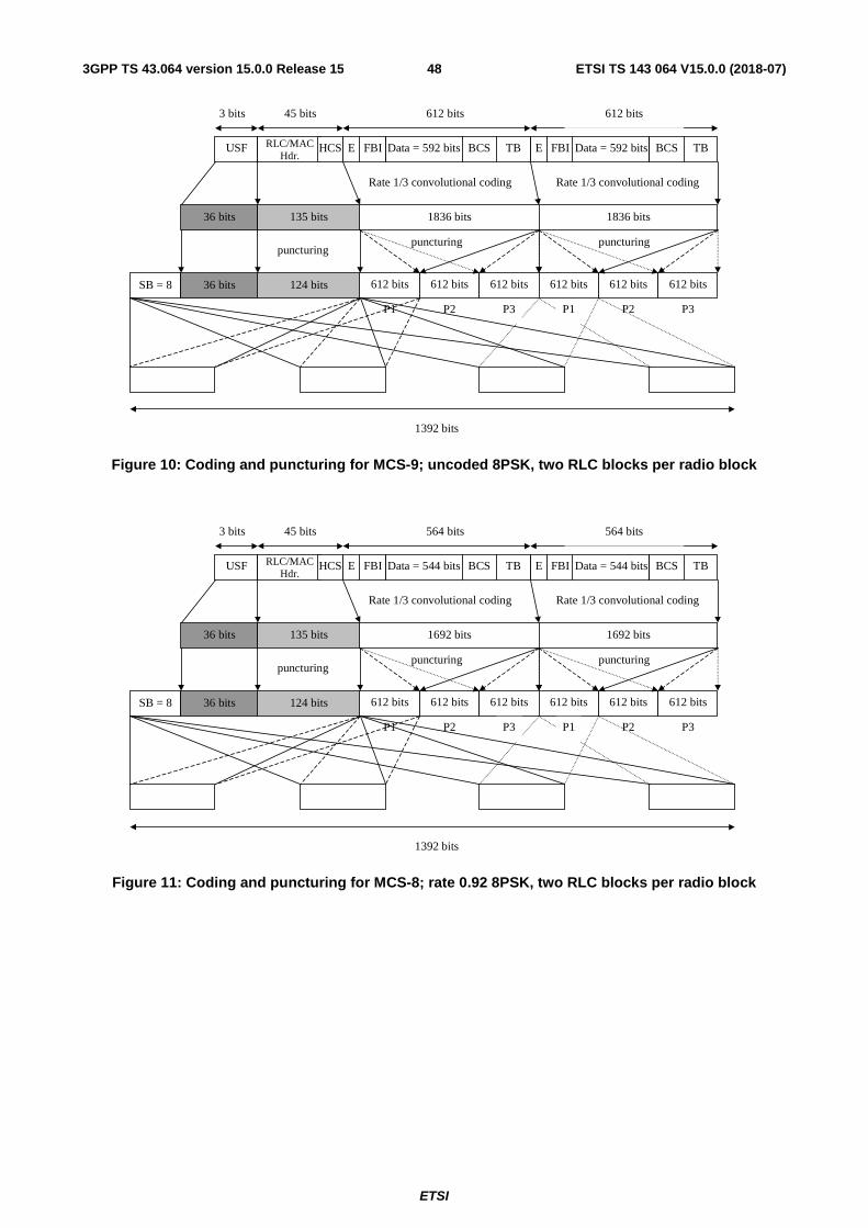
ETSI
ETSI TS 143 064 V15.0.0 (2018-07)483GPP TS 43.064 version 15.0.0 Release 15
Figure 10: Coding and puncturing for MCS-9; uncoded 8PSK, two RLC blocks per radio block
Figure 11: Coding and puncturing for MCS-8; rate 0.92 8PSK, two RLC blocks per radio block
P2 P3P1 P2
puncturingpuncturing
1836 bits
USF RLC/MACHdr.
36 bits
Rate 1/3 convolutional coding
135 bits
612 bits
612 bits124 bits36 bitsSB = 8
1392 bits
45 bits
Data = 592 bits BCS TB
612 bits
612 bits 612 bits
1836 bits
Rate 1/3 convolutional coding
FBIEData = 592 bits BCS TBFBIE
612 bits 612 bits 612 bits
P3 P1
3 bits
HCS
puncturing
P2 P3P1 P2
puncturingpuncturing
1692 bits
USF RLC/MACHdr.
36 bits
Rate 1/3 convolutional coding
135 bits
564 bits
612 bits124 bits36 bitsSB = 8
1392 bits
45 bits
Data = 544 bits BCS TB
564 bits
612 bits 612 bits
1692 bits
Rate 1/3 convolutional coding
FBIEData = 544 bits BCS TBFBIE
612 bits 612 bits 612 bits
P3 P1
3 bits
HCS
puncturing
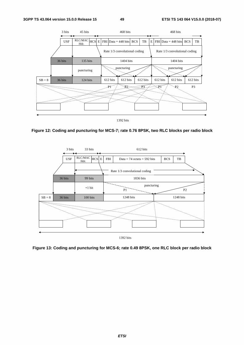
ETSI
ETSI TS 143 064 V15.0.0 (2018-07)493GPP TS 43.064 version 15.0.0 Release 15
Figure 12: Coding and puncturing for MCS-7; rate 0.76 8PSK, two RLC blocks per radio block
Figure 13: Coding and puncturing for MCS-6; rate 0.49 8PSK, one RLC block per radio block
P2 P3P1 P2
puncturingpuncturing
1404 bits
USF RLC/MACHdr.
36 bits
Rate 1/3 convolutional coding
135 bits
468 bits
612 bits124 bits36 bitsSB = 8
1392 bits
45 bits
Data = 448 bits BCS TB
468 bits
612 bits 612 bits
1404 bits
Rate 1/3 convolutional coding
FBIEData = 448 bits BCS TBFBIE
612 bits 612 bits 612 bits
P3 P1
3 bits
HCS
puncturing
P2P1puncturing
1836 bits
USF RLC/MACHdr.
Data = 74 octets = 592 bits BCS
36 bits
Rate 1/3 convolutional coding
99 bits
612 bits
1248 bits100 bits36 bitsSB = 8
1392 bits
33 bits
TBE FBIHCS
3 bits
1248 bits
+1 bit
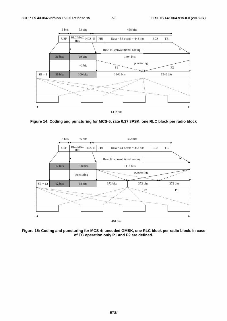
ETSI
ETSI TS 143 064 V15.0.0 (2018-07)503GPP TS 43.064 version 15.0.0 Release 15
Figure 14: Coding and puncturing for MCS-5; rate 0.37 8PSK, one RLC block per radio block
Figure 15: Coding and puncturing for MCS-4; uncoded GMSK, one RLC block per radio block. In case of EC operation only P1 and P2 are defined.
P2P1puncturing
1404 bits
USF RLC/MACHdr.
Data = 56 octets = 448 bits BCS
36 bits
Rate 1/3 convolutional coding
99 bits
468 bits
1248 bits100 bits36 bitsSB = 8
1392 bits
33 bits
TBE FBIHCS
3 bits
1248 bits
+1 bit
P1 P3P2
puncturing
1116 bits
USF RLC/MACHdr.
Data = 44 octets = 352 bits BCS
12 bits
Rate 1/3 convolutional coding
108 bits
372 bits
372 bits68 bits12 bitsSB = 12
464 bits
36 bits
TBE FBIHCS
3 bits
372 bits 372 bits
puncturing
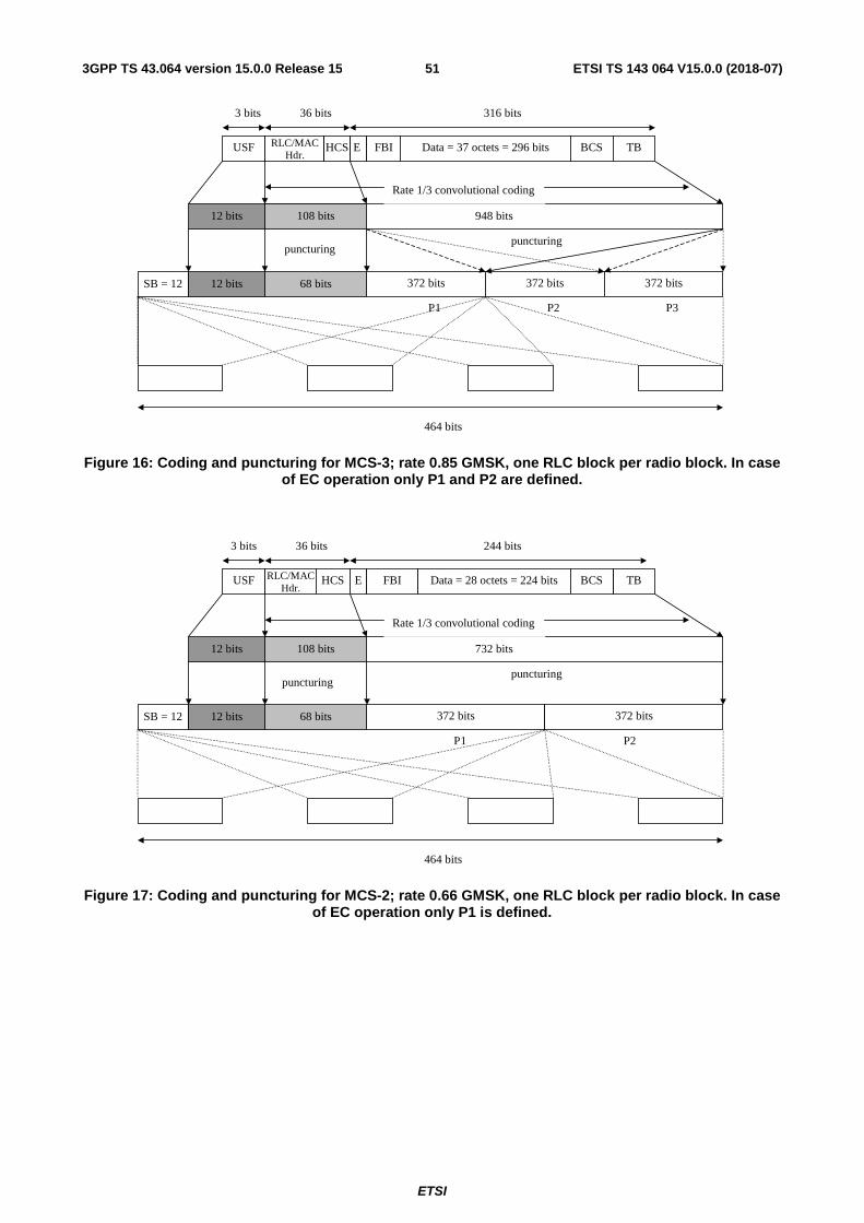
ETSI
ETSI TS 143 064 V15.0.0 (2018-07)513GPP TS 43.064 version 15.0.0 Release 15
Figure 16: Coding and puncturing for MCS-3; rate 0.85 GMSK, one RLC block per radio block. In case of EC operation only P1 and P2 are defined.
Figure 17: Coding and puncturing for MCS-2; rate 0.66 GMSK, one RLC block per radio block. In case of EC operation only P1 is defined.
P1 P3P2
puncturing
948 bits
USF RLC/MACHdr.
Data = 37 octets = 296 bits BCS
12 bits
Rate 1/3 convolutional coding
108 bits
316 bits
372 bits68 bits12 bitsSB = 12
464 bits
36 bits
TB E FBIHCS
3 bits
372 bits 372 bits
puncturing
P1 P2
puncturing
732 bits
USF RLC/MAC Hdr.
Data = 28 octets = 224 bits TB
12 bits
Rate 1/3 convolutional coding
108 bits
244 bits
372 bits 68 bits 12 bits SB = 12
464 bits
36 bits
BCS
puncturing
HCS E FBI
3 bits
372 bits
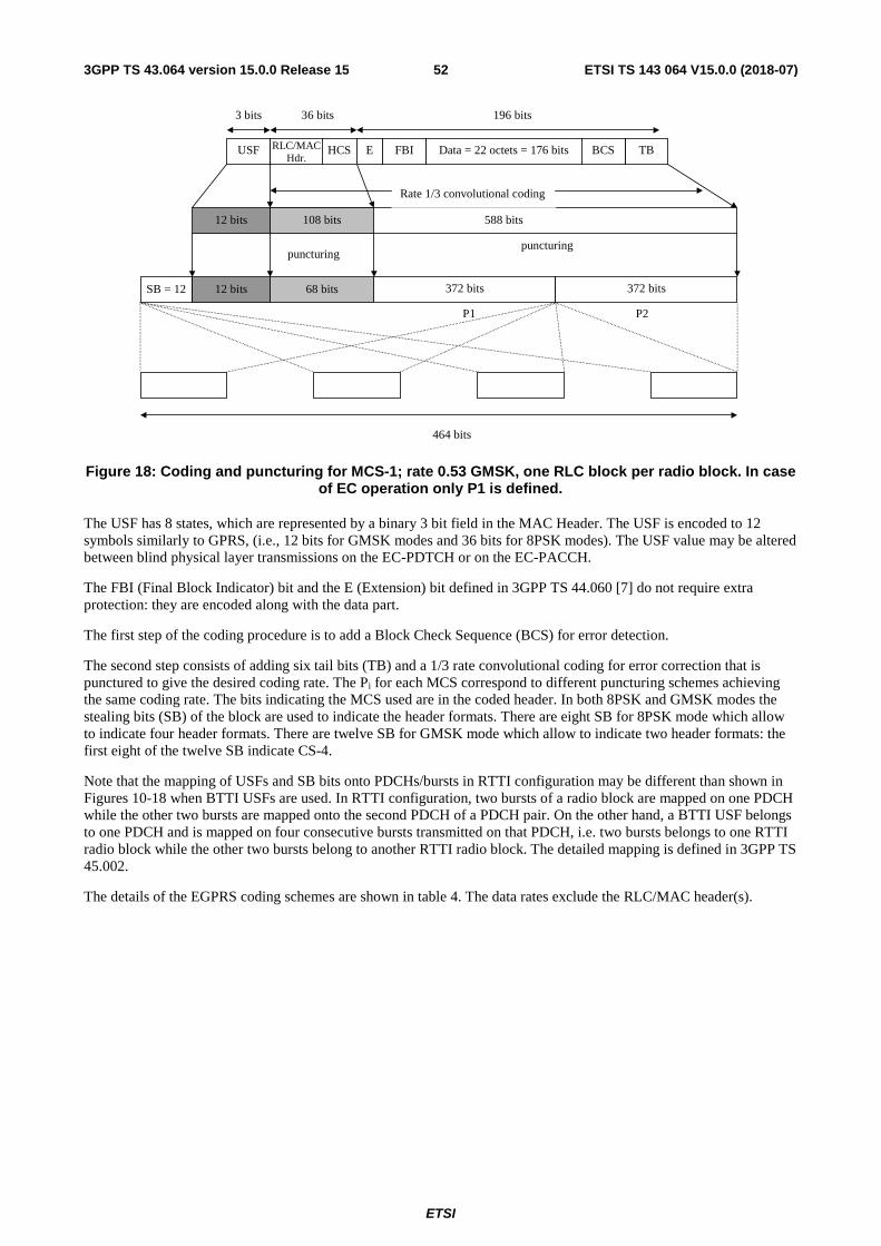
ETSI
ETSI TS 143 064 V15.0.0 (2018-07)523GPP TS 43.064 version 15.0.0 Release 15
Figure 18: Coding and puncturing for MCS-1; rate 0.53 GMSK, one RLC block per radio block. In case of EC operation only P1 is defined.
The USF has 8 states, which are represented by a binary 3 bit field in the MAC Header. The USF is encoded to 12 symbols similarly to GPRS, (i.e., 12 bits for GMSK modes and 36 bits for 8PSK modes). The USF value may be altered between blind physical layer transmissions on the EC-PDTCH or on the EC-PACCH.
The FBI (Final Block Indicator) bit and the E (Extension) bit defined in 3GPP TS 44.060 [7] do not require extra protection: they are encoded along with the data part.
The first step of the coding procedure is to add a Block Check Sequence (BCS) for error detection.
The second step consists of adding six tail bits (TB) and a 1/3 rate convolutional coding for error correction that is punctured to give the desired coding rate. The Pi for each MCS correspond to different puncturing schemes achieving the same coding rate. The bits indicating the MCS used are in the coded header. In both 8PSK and GMSK modes the stealing bits (SB) of the block are used to indicate the header formats. There are eight SB for 8PSK mode which allow to indicate four header formats. There are twelve SB for GMSK mode which allow to indicate two header formats: the first eight of the twelve SB indicate CS-4.
Note that the mapping of USFs and SB bits onto PDCHs/bursts in RTTI configuration may be different than shown in Figures 10-18 when BTTI USFs are used. In RTTI configuration, two bursts of a radio block are mapped on one PDCH while the other two bursts are mapped onto the second PDCH of a PDCH pair. On the other hand, a BTTI USF belongs to one PDCH and is mapped on four consecutive bursts transmitted on that PDCH, i.e. two bursts belongs to one RTTI radio block while the other two bursts belong to another RTTI radio block. The detailed mapping is defined in 3GPP TS 45.002.
The details of the EGPRS coding schemes are shown in table 4. The data rates exclude the RLC/MAC header(s).
P1 P2
puncturing
588 bits
USF RLC/MACHdr.
Data = 22 octets = 176 bits TB
12 bits
Rate 1/3 convolutional coding
108 bits
196 bits
372 bits68 bits12 bitsSB = 12
464 bits
36 bits
BCS
puncturing
HCS E FBI
3 bits
372 bits
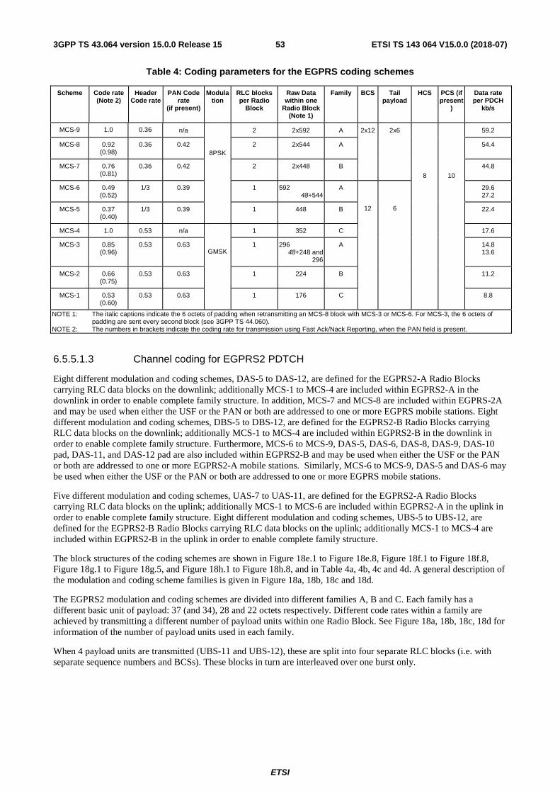
ETSI
ETSI TS 143 064 V15.0.0 (2018-07)533GPP TS 43.064 version 15.0.0 Release 15
Table 4: Coding parameters for the EGPRS coding schemes
Scheme Code rate (Note 2)
Header Code rate
PAN Code rate
(if present)
Modulation
RLC blocks per Radio
Block
Raw Data within one
Radio Block (Note 1)
Family BCS Tail payload
HCS PCS (if present
)
Data rate per PDCH
kb/s
MCS-9 1.0 0.36 n/a
8PSK
2 2x592 A 2x12 2x6
8
10
59.2
MCS-8 0.92 (0.98)
0.36 0.42 2 2x544 A 54.4
MCS-7 0.76 (0.81)
0.36 0.42 2 2x448 B 44.8
MCS-6 0.49 (0.52)
1/3 0.39 1 592 48+544
A
12
6
29.6 27.2
MCS-5 0.37 (0.40)
1/3 0.39 1 448 B 22.4
MCS-4 1.0 0.53 n/a
GMSK
1 352 C 17.6
MCS-3 0.85 (0.96)
0.53 0.63 1 296 48+248 and
296
A 14.8 13.6
MCS-2 0.66 (0.75)
0.53 0.63 1 224 B 11.2
MCS-1 0.53 (0.60)
0.53 0.63 1 176 C 8.8
NOTE 1: The italic captions indicate the 6 octets of padding when retransmitting an MCS-8 block with MCS-3 or MCS-6. For MCS-3, the 6 octets of padding are sent every second block (see 3GPP TS 44.060).
NOTE 2: The numbers in brackets indicate the coding rate for transmission using Fast Ack/Nack Reporting, when the PAN field is present.
6.5.5.1.3 Channel coding for EGPRS2 PDTCH
Eight different modulation and coding schemes, DAS-5 to DAS-12, are defined for the EGPRS2-A Radio Blocks carrying RLC data blocks on the downlink; additionally MCS-1 to MCS-4 are included within EGPRS2-A in the downlink in order to enable complete family structure. In addition, MCS-7 and MCS-8 are included within EGPRS-2A and may be used when either the USF or the PAN or both are addressed to one or more EGPRS mobile stations. Eight different modulation and coding schemes, DBS-5 to DBS-12, are defined for the EGPRS2-B Radio Blocks carrying RLC data blocks on the downlink; additionally MCS-1 to MCS-4 are included within EGPRS2-B in the downlink in order to enable complete family structure. Furthermore, MCS-6 to MCS-9, DAS-5, DAS-6, DAS-8, DAS-9, DAS-10 pad, DAS-11, and DAS-12 pad are also included within EGPRS2-B and may be used when either the USF or the PAN or both are addressed to one or more EGPRS2-A mobile stations. Similarly, MCS-6 to MCS-9, DAS-5 and DAS-6 may be used when either the USF or the PAN or both are addressed to one or more EGPRS mobile stations.
Five different modulation and coding schemes, UAS-7 to UAS-11, are defined for the EGPRS2-A Radio Blocks carrying RLC data blocks on the uplink; additionally MCS-1 to MCS-6 are included within EGPRS2-A in the uplink in order to enable complete family structure. Eight different modulation and coding schemes, UBS-5 to UBS-12, are defined for the EGPRS2-B Radio Blocks carrying RLC data blocks on the uplink; additionally MCS-1 to MCS-4 are included within EGPRS2-B in the uplink in order to enable complete family structure.
The block structures of the coding schemes are shown in Figure 18e.1 to Figure 18e.8, Figure 18f.1 to Figure 18f.8, Figure 18g.1 to Figure 18g.5, and Figure 18h.1 to Figure 18h.8, and in Table 4a, 4b, 4c and 4d. A general description of the modulation and coding scheme families is given in Figure 18a, 18b, 18c and 18d.
The EGPRS2 modulation and coding schemes are divided into different families A, B and C. Each family has a different basic unit of payload: 37 (and 34), 28 and 22 octets respectively. Different code rates within a family are achieved by transmitting a different number of payload units within one Radio Block. See Figure 18a, 18b, 18c, 18d for information of the number of payload units used in each family.
When 4 payload units are transmitted (UBS-11 and UBS-12), these are split into four separate RLC blocks (i.e. with separate sequence numbers and BCSs). These blocks in turn are interleaved over one burst only.
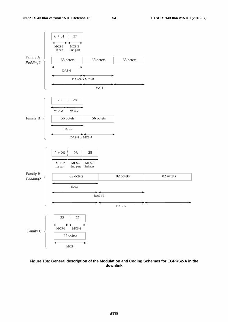
ETSI
ETSI TS 143 064 V15.0.0 (2018-07)543GPP TS 43.064 version 15.0.0 Release 15
1st part
Family A Padding6
2nd part
6 + 31 37
MCS-3 MCS-3
68 octets
DAS-6
68 octets
DAS-9 or MCS-8
68 octets
DAS-11
Family B Padding2
DAS-7
DAS-10
MCS-2 MCS-2
82 octets
2 + 26 28
MCS-2
28
1st part 2nd part 3rd part
82 octets 82 octets
DAS-12
Family C
MCS-4
MCS-1 MCS-1
22 22
44 octets
Family B
DAS-5
DAS-8 or MCS-7
56 octets
MCS-2 MCS-2
28 28
56 octets
Figure 18a: General description of the Modulation and Coding Schemes for EGPRS2-A in the downlink
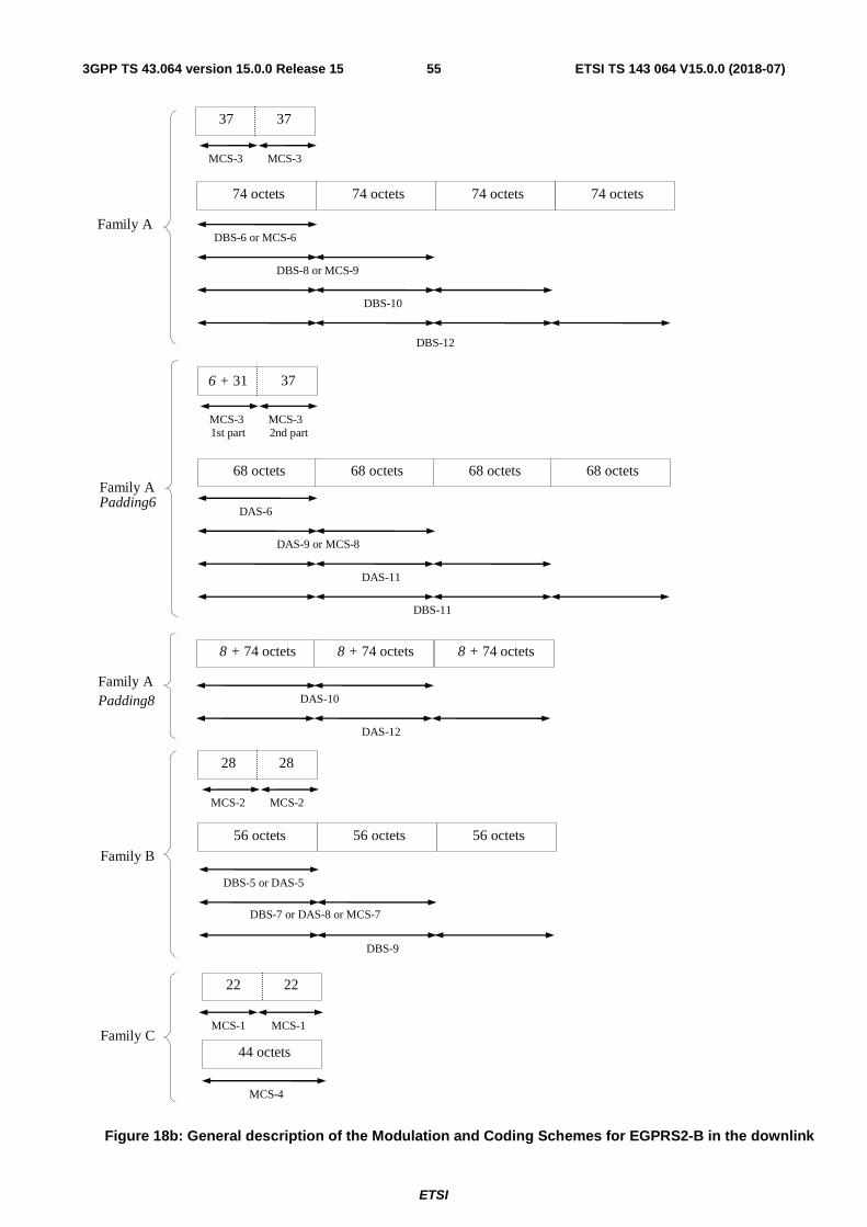
ETSI
ETSI TS 143 064 V15.0.0 (2018-07)553GPP TS 43.064 version 15.0.0 Release 15
1st part
Family A Padding6
2nd part
6 + 31 37
MCS-3 MCS-3
68 octets
DAS-6
68 octets
DAS-9 or MCS-8
68 octets 68 octets
DAS-11
DBS-11
Family A Padding8
8 + 74 octets 8 + 74 octets
DAS-10
8 + 74 octets
DAS-12
Family A
74 octets 74 octets
DBS-6 or MCS-6
74 octets
DBS-8 or MCS-9
DBS-10
DBS-12
MCS-3 MCS-3
37 37
74 octets
Family B
DBS-5 or DAS-5
DBS-7 or DAS-8 or MCS-7
DBS-9
56 octets 56 octets
MCS-2 MCS-2
28 28
56 octets
Family C
MCS-4
MCS-1 MCS-1
22 22
44 octets
Figure 18b: General description of the Modulation and Coding Schemes for EGPRS2-B in the downlink
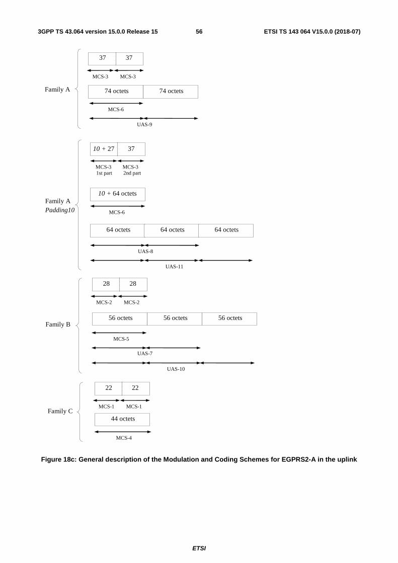
ETSI
ETSI TS 143 064 V15.0.0 (2018-07)563GPP TS 43.064 version 15.0.0 Release 15
1st part
Family A Padding10
2nd part
10 + 27 37
MCS-3 MCS-3
64 octets
MCS-6
64 octets
UAS-8
64 octets
UAS-11
10 + 64 octets
Family C
MCS-4
MCS-1 MCS-1
22 22
44 octets
Family A 74 octets
MCS-6
UAS-9
MCS-3 MCS-3
37 37
74 octets
Family B
MCS-5
UAS-7
UAS-10
MCS-2 MCS-2
28 28
56 octets 56 octets 56 octets
Figure 18c: General description of the Modulation and Coding Schemes for EGPRS2-A in the uplink
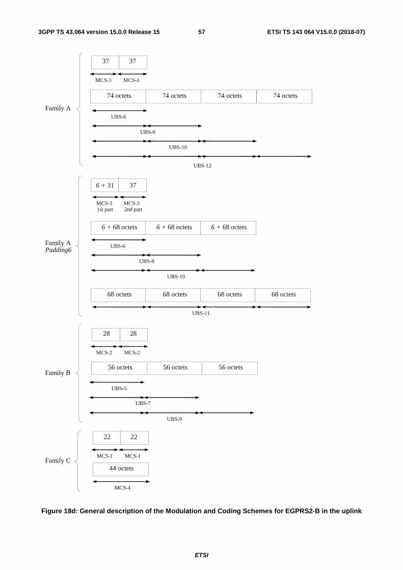
ETSI
ETSI TS 143 064 V15.0.0 (2018-07)573GPP TS 43.064 version 15.0.0 Release 15
1st part
Family A Padding6
2nd part
6 + 31 37
MCS-3 MCS-3
6 + 68 octets
UBS-6
6 + 68 octets
UBS-8
6 + 68 octets
UBS-10
UBS-11
68 octets 68 octets 68 octets 68 octets
Family C
MCS-4
MCS-1 MCS-1
22 22
44 octets
Family B
UBS-5
UBS-7
UBS-9
56 octets 56 octets
MCS-2 MCS-2
28 28
56 octets
Family A
74 octets 74 octets
UBS-6
74 octets
UBS-8
UBS-10
UBS-12
74 octets
MCS-3 MCS-3
37 37
Figure 18d: General description of the Modulation and Coding Schemes for EGPRS2-B in the uplink
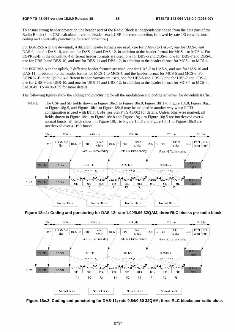
ETSI
ETSI TS 143 064 V15.0.0 (2018-07)583GPP TS 43.064 version 15.0.0 Release 15
To ensure strong header protection, the header part of the Radio Block is independently coded from the data part of the Radio Block (8 bit CRC calculated over the header -excl. USF- for error detection, followed by rate 1/3 convolutional coding and eventually puncturing for error correction).
For EGPRS2-A in the downlink, 4 different header formats are used, one for DAS-5 to DAS-7, one for DAS-8 and DAS-9, one for DAS-10, and one for DAS-11 and DAS-12, in addition to the header format for MCS-1 to MCS-4. For EGPRS2-B in the downlink, 4 different header formats are used, one for DBS-5 and DBS-6, one for DBS-7 and DBS-8, one for DBS-9 and DBS-10, and one for DBS-11 and DBS-12, in addition to the header format for MCS-1 to MCS-4.
For EGPRS2-A in the uplink, 2 different header formats are used, one for UAS-7 to UAS-9, and one for UAS-10 and UAS-11, in addition to the header format for MCS-1 to MCS-4, and the header format for MCS-5 and MCS-6. For EGPRS2-B in the uplink, 4 different header formats are used, one for UBS-5 and UBS-6, one for UBS-7 and UBS-8, one for UBS-9 and UBS-10, and one for UBS-11 and UBS-12, in addition to the header format for MCS-1 to MCS-4. See 3GPP TS 44.060 [7] for more details.
The following figures show the coding and puncturing for all the modulation and coding schemes, for downlink traffic.
NOTE: The USF and SB fields shown in Figure 18e.1 to Figure 18e.8, Figure 18f.1 to Figure 18f.8, Figure 18g.1 to Figure 18g.5, and Figure 18h.1 to Figure 18h.8 may be mapped in another way when RTTI configuration is used with BTTI USFs, see 3GPP TS 45.002 for details. Unless otherwise marked, all fields shown in Figure 18e.1 to Figure 18e.8 and Figure 18g.1 to Figure 18g.5 are interleaved over 4 normal bursts; all fields shown in Figure 18f.1 to Figure 18f.8 and Figure 18h.1 to Figure 18h.8 are interleaved over 4 HSR bursts.
Figure 18e.1: Coding and puncturing for DAS-12; rate 1.00/0.96 32QAM, three RLC blocks per radio block
Figure 18e.2: Coding and puncturing for DAS-11; rate 0.84/0.80 32QAM, three RLC blocks per radio block
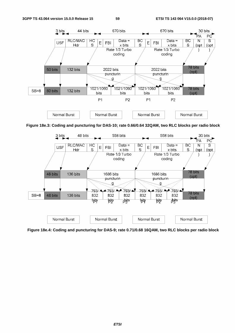
ETSI
ETSI TS 143 064 V15.0.0 (2018-07)593GPP TS 43.064 version 15.0.0 Release 15
Figure 18e.3: Coding and puncturing for DAS-10; rate 0.66/0.64 32QAM, two RLC blocks per radio block
Figure 18e.4: Coding and puncturing for DAS-9; rate 0.71/0.68 16QAM, two RLC blocks per radio block
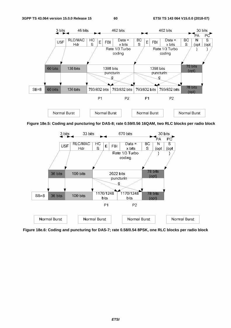
ETSI
ETSI TS 143 064 V15.0.0 (2018-07)603GPP TS 43.064 version 15.0.0 Release 15
Figure 18e.5: Coding and puncturing for DAS-8; rate 0.59/0.56 16QAM, two RLC blocks per radio block
Figure 18e.6: Coding and puncturing for DAS-7; rate 0.58/0.54 8PSK, one RLC blocks per radio block
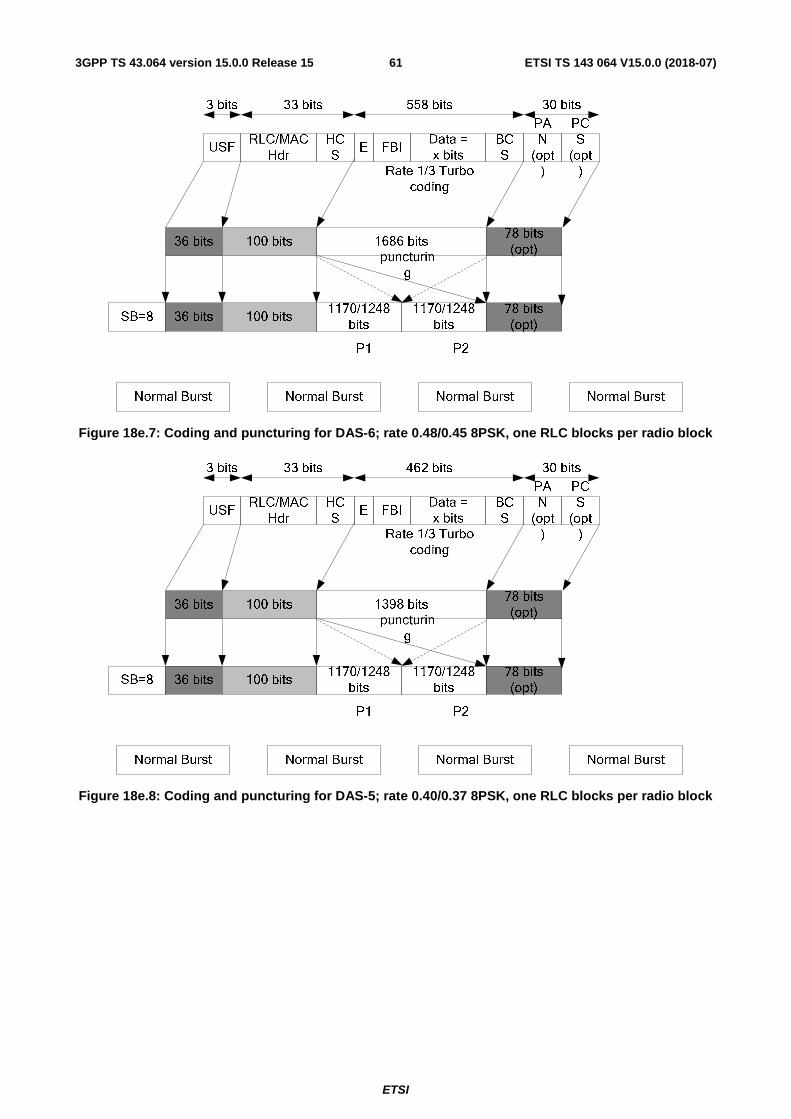
ETSI
ETSI TS 143 064 V15.0.0 (2018-07)613GPP TS 43.064 version 15.0.0 Release 15
Figure 18e.7: Coding and puncturing for DAS-6; rate 0.48/0.45 8PSK, one RLC blocks per radio block
Figure 18e.8: Coding and puncturing for DAS-5; rate 0.40/0.37 8PSK, one RLC blocks per radio block
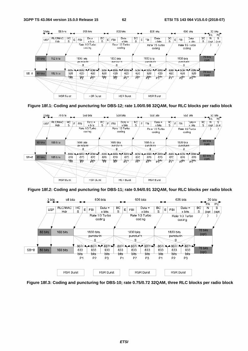
ETSI
ETSI TS 143 064 V15.0.0 (2018-07)623GPP TS 43.064 version 15.0.0 Release 15
Figure 18f.1: Coding and puncturing for DBS-12; rate 1.00/0.98 32QAM, four RLC blocks per radio block
Figure 18f.2: Coding and puncturing for DBS-11; rate 0.94/0.91 32QAM, four RLC blocks per radio block
Figure 18f.3: Coding and puncturing for DBS-10; rate 0.75/0.72 32QAM, three RLC blocks per radio block

ETSI
ETSI TS 143 064 V15.0.0 (2018-07)633GPP TS 43.064 version 15.0.0 Release 15
Figure 18f.4: Coding and puncturing for DBS-9; rate 0.74/0.71 16QAM, three RLC blocks per radio block
Figure 18f.5: Coding and puncturing for DBS-8; rate 0.63/0.60 16QAM, two RLC blocks per radio block
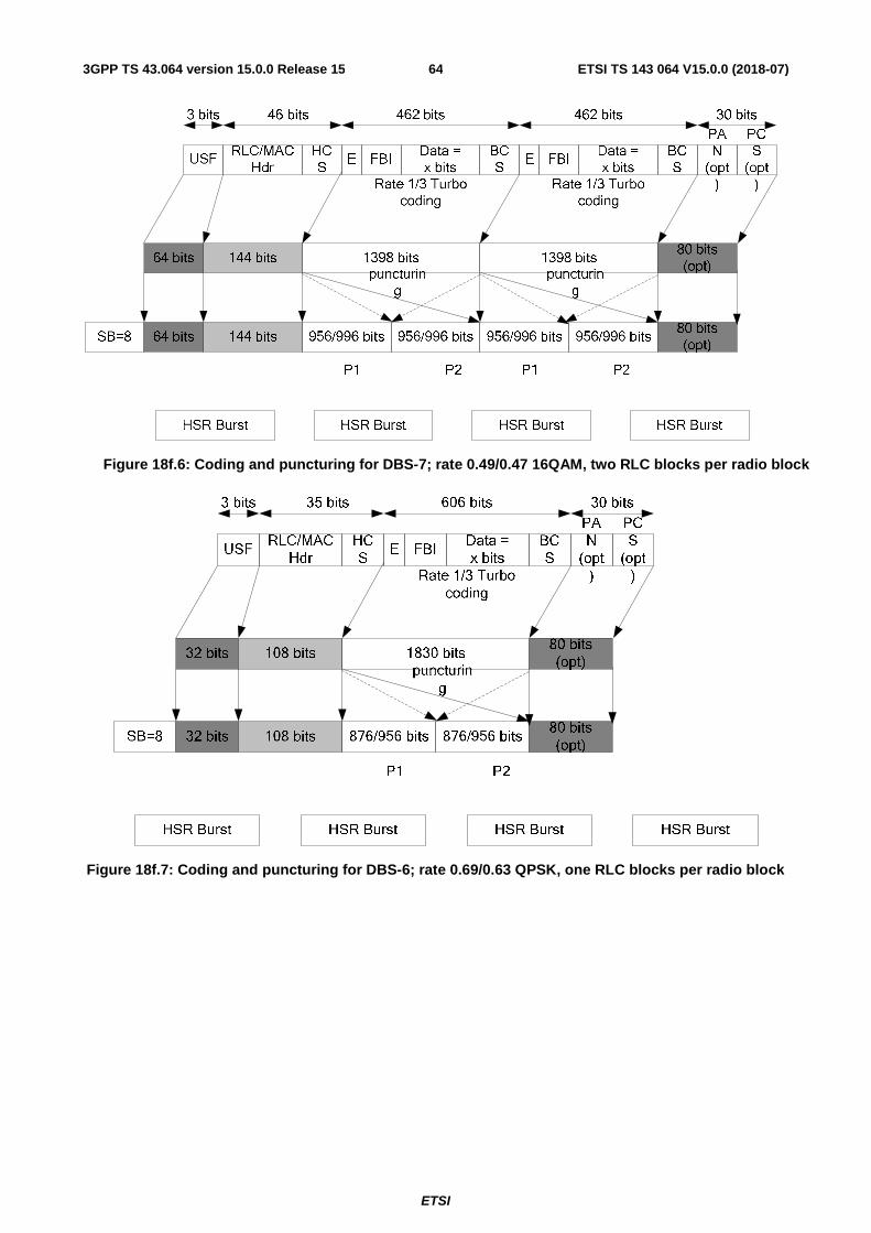
ETSI
ETSI TS 143 064 V15.0.0 (2018-07)643GPP TS 43.064 version 15.0.0 Release 15
Figure 18f.6: Coding and puncturing for DBS-7; rate 0.49/0.47 16QAM, two RLC blocks per radio block
Figure 18f.7: Coding and puncturing for DBS-6; rate 0.69/0.63 QPSK, one RLC blocks per radio block
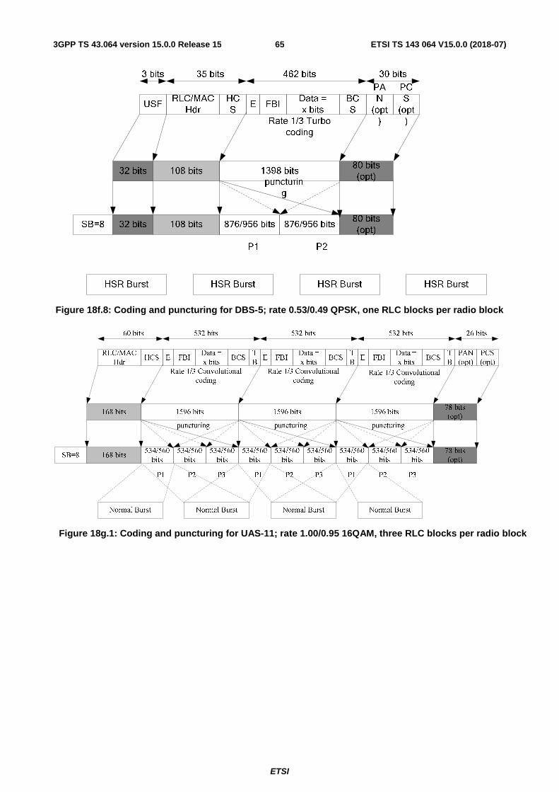
ETSI
ETSI TS 143 064 V15.0.0 (2018-07)653GPP TS 43.064 version 15.0.0 Release 15
Figure 18f.8: Coding and puncturing for DBS-5; rate 0.53/0.49 QPSK, one RLC blocks per radio block
Figure 18g.1: Coding and puncturing for UAS-11; rate 1.00/0.95 16QAM, three RLC blocks per radio block
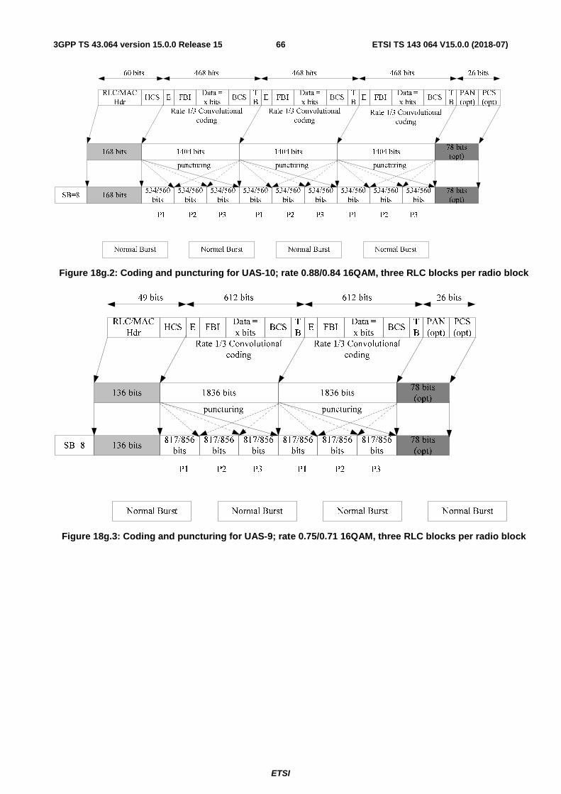
ETSI
ETSI TS 143 064 V15.0.0 (2018-07)663GPP TS 43.064 version 15.0.0 Release 15
Figure 18g.2: Coding and puncturing for UAS-10; rate 0.88/0.84 16QAM, three RLC blocks per radio block
Figure 18g.3: Coding and puncturing for UAS-9; rate 0.75/0.71 16QAM, three RLC blocks per radio block
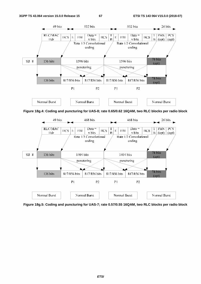
ETSI
ETSI TS 143 064 V15.0.0 (2018-07)673GPP TS 43.064 version 15.0.0 Release 15
RLC/MAC
HdrHCS E FBI
Data =
x bitsBCS
T
BE FBI
Data =
x bitsBCS
T
B
136 bits 817/856 bits
PAN
(opt)
PCS
(opt)
78 bits
(opt)
Normal Burst Normal Burst Normal Burst Normal Burst
SB=8 136 bits 1596 bits78 bits
(opt)
817/856 bits
Rate 1/3 Convolutional
coding
Rate 1/3 Convolutional
coding
puncturing
817/856 bits
1596 bits
817/856 bits
puncturing
49 bits 26 bits532 bits 532 bits
P1 P2 P1 P2
Figure 18g.4: Coding and puncturing for UAS-8; rate 0.65/0.62 16QAM, two RLC blocks per radio block
RLC/MAC
HdrHCS E FBI
Data =
x bitsBCS
T
BE FBI
Data =
x bitsBCS
T
B
136 bits 817/856 bits
PAN
(opt)
PCS
(opt)
78 bits
(opt)
Normal Burst Normal Burst Normal Burst Normal Burst
SB=8 136 bits 1404 bits78 bits
(opt)
817/856 bits
Rate 1/3 Convolutional
coding
Rate 1/3 Convolutional
coding
puncturing
817/856 bits
1404 bits
817/856 bits
puncturing
49 bits 26 bits468 bits 468 bits
P1 P2 P1 P2
Figure 18g.5: Coding and puncturing for UAS-7; rate 0.57/0.55 16QAM, two RLC blocks per radio block

ETSI
ETSI TS 143 064 V15.0.0 (2018-07)683GPP TS 43.064 version 15.0.0 Release 15
RLC/MAC
HdrHCS E FBI
Data =
x bitsBCS
T
BE FBI
Data =
x bitsBCS
T
BE FBI
Data =
x bitsBCS
T
B
208 bits635/615
bits
PAN
(opt)
PCS
(opt)
80 bits
(opt)
HSR Burst HSR Burst HSR Burst HSR Burst
SB=8
208 bits 1836 bits80 bits
(opt)
635/615
bits
635/615
bits
Rate 1/3 Convolutional
coding
Rate 1/3 Convolutional
codingRate 1/3 Convolutional
coding
puncturing
635/615
bits
1836 bits
635/615
bits
635/615
bits
puncturing
635/615
bits
1836 bits
635/615
bits
635/615
bits
puncturing
72 bits 26 bits618 bits 618 bits 618 bits
P1 P2 P3 P1 P2 P3 P1 P2 P3
635/615
bits
1836 bits
635/615
bits
635/615
bits
puncturing
P1 P2 P3
E FBIData =
x bitsBCS
T
B
618 bits
Rate 1/3 Convolutional
coding
Figure 18h.1: Coding and puncturing for UBS-12; rate 1.00/0.96 32QAM, four RLC blocks per radio block
RLC/MAC
HdrHCS E FBI
Data =
x bitsBCS
T
BE FBI
Data =
x bitsBCS
T
BE FBI
Data =
x bitsBCS
T
B
208 bits635/615
bits
PAN
(opt)
PCS
(opt)
80 bits
(opt)
HSR Burst HSR Burst HSR Burst HSR Burst
SB=8
208 bits 1692 bits80 bits
(opt)
635/615
bits
635/615
bits
Rate 1/3 Convolutional
coding
Rate 1/3 Convolutional
codingRate 1/3 Convolutional
coding
puncturing
635/615
bits
1692 bits
635/615
bits
635/615
bits
puncturing
635/615
bits
1692 bits
635/615
bits
635/615
bits
puncturing
72 bits 26 bits580 bits 580 bits 580 bits
P1 P2 P3 P1 P2 P3 P1 P2 P3
635/615
bits
1692 bits
635/615
bits
635/615
bits
puncturing
P1 P2 P3
E FBIData =
x bitsBCS
T
B
580 bits
Rate 1/3 Convolutional
coding
Figure 18h.2: Coding and puncturing for UBS-11; rate 0.92/0.89 32QAM, four RLC blocks per radio block
Figure 18h.3: Coding and puncturing for UBS-10; rate 0.74/0.71 32QAM, three RLC blocks per radio block
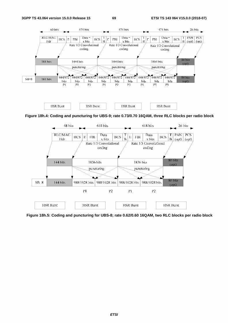
ETSI
ETSI TS 143 064 V15.0.0 (2018-07)693GPP TS 43.064 version 15.0.0 Release 15
Figure 18h.4: Coding and puncturing for UBS-9; rate 0.73/0.70 16QAM, three RLC blocks per radio block
Figure 18h.5: Coding and puncturing for UBS-8; rate 0.62/0.60 16QAM, two RLC blocks per radio block
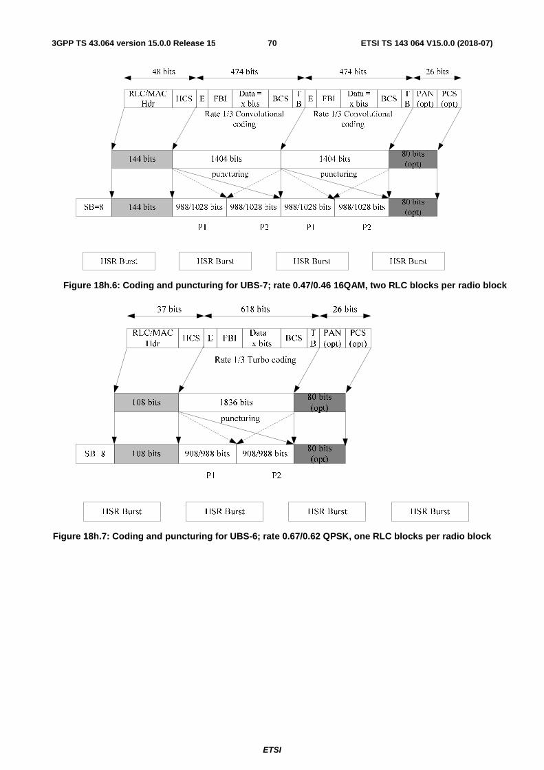
ETSI
ETSI TS 143 064 V15.0.0 (2018-07)703GPP TS 43.064 version 15.0.0 Release 15
Figure 18h.6: Coding and puncturing for UBS-7; rate 0.47/0.46 16QAM, two RLC blocks per radio block
Figure 18h.7: Coding and puncturing for UBS-6; rate 0.67/0.62 QPSK, one RLC blocks per radio block
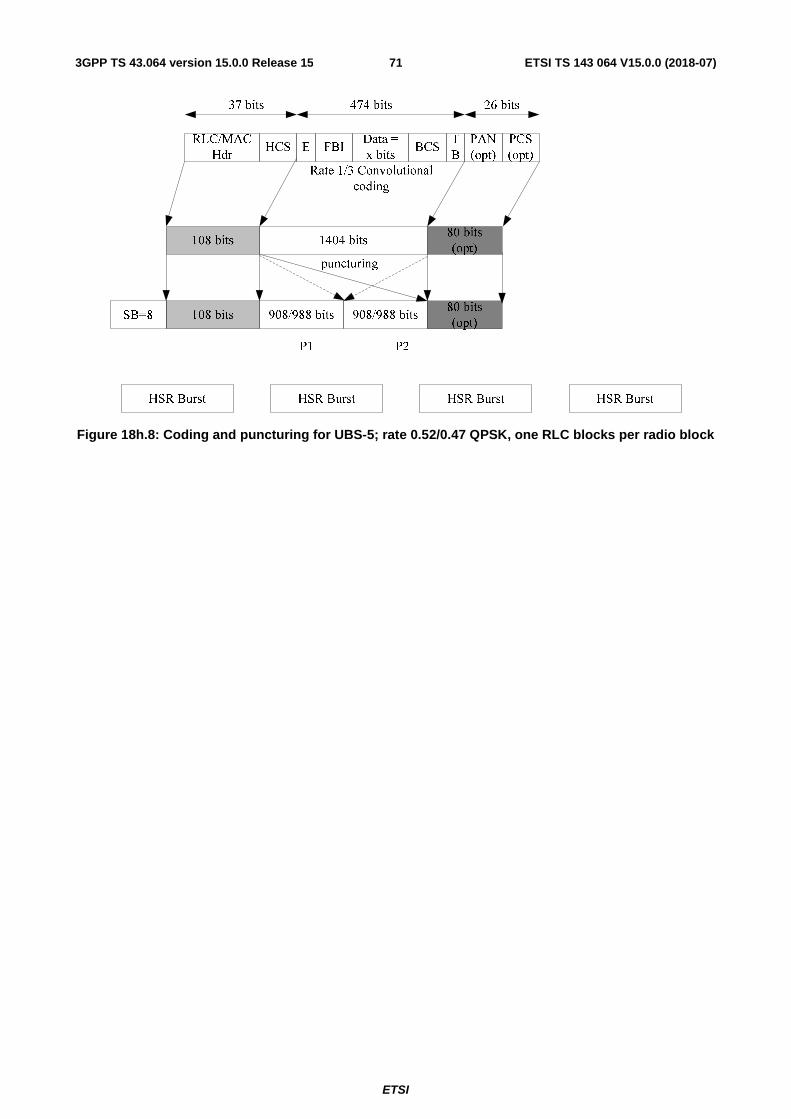
ETSI
ETSI TS 143 064 V15.0.0 (2018-07)713GPP TS 43.064 version 15.0.0 Release 15
Figure 18h.8: Coding and puncturing for UBS-5; rate 0.52/0.47 QPSK, one RLC blocks per radio block
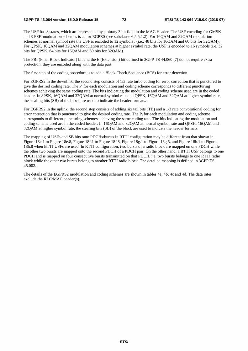
ETSI
ETSI TS 143 064 V15.0.0 (2018-07)723GPP TS 43.064 version 15.0.0 Release 15
The USF has 8 states, which are represented by a binary 3 bit field in the MAC Header. The USF encoding for GMSK and 8-PSK modulation schemes is as for EGPRS (see subclause 6.5.5.1.2). For 16QAM and 32QAM modulation schemes at normal symbol rate the USF is encoded to 12 symbols , (i.e., 48 bits for 16QAM and 60 bits for 32QAM). For QPSK, 16QAM and 32QAM modulation schemes at higher symbol rate, the USF is encoded to 16 symbols (i.e. 32 bits for QPSK, 64 bits for 16QAM and 80 bits for 32QAM).
The FBI (Final Block Indicator) bit and the E (Extension) bit defined in 3GPP TS 44.060 [7] do not require extra protection: they are encoded along with the data part.
The first step of the coding procedure is to add a Block Check Sequence (BCS) for error detection.
For EGPRS2 in the downlink, the second step consists of 1/3 rate turbo coding for error correction that is punctured to give the desired coding rate. The Pi for each modulation and coding scheme corresponds to different puncturing schemes achieving the same coding rate. The bits indicating the modulation and coding scheme used are in the coded header. In 8PSK, 16QAM and 32QAM at normal symbol rate and QPSK, 16QAM and 32QAM at higher symbol rate, the stealing bits (SB) of the block are used to indicate the header formats.
For EGPRS2 in the uplink, the second step consists of adding six tail bits (TB) and a 1/3 rate convolutional coding for error correction that is punctured to give the desired coding rate. The Pi for each modulation and coding scheme corresponds to different puncturing schemes achieving the same coding rate. The bits indicating the modulation and coding scheme used are in the coded header. In 16QAM and 32QAM at normal symbol rate and QPSK, 16QAM and 32QAM at higher symbol rate, the stealing bits (SB) of the block are used to indicate the header formats.
The mapping of USFs and SB bits onto PDCHs/bursts in RTTI configuration may be different from that shown in Figure 18e.1 to Figure 18e.8, Figure 18f.1 to Figure 18f.8, Figure 18g.1 to Figure 18g.5, and Figure 18h.1 to Figure 18h.8 when BTTI USFs are used. In RTTI configuration, two bursts of a radio block are mapped on one PDCH while the other two bursts are mapped onto the second PDCH of a PDCH pair. On the other hand, a BTTI USF belongs to one PDCH and is mapped on four consecutive bursts transmitted on that PDCH, i.e. two bursts belongs to one RTTI radio block while the other two bursts belong to another RTTI radio block. The detailed mapping is defined in 3GPP TS 45.002.
The details of the EGPRS2 modulation and coding schemes are shown in tables 4a, 4b, 4c and 4d. The data rates exclude the RLC/MAC header(s).
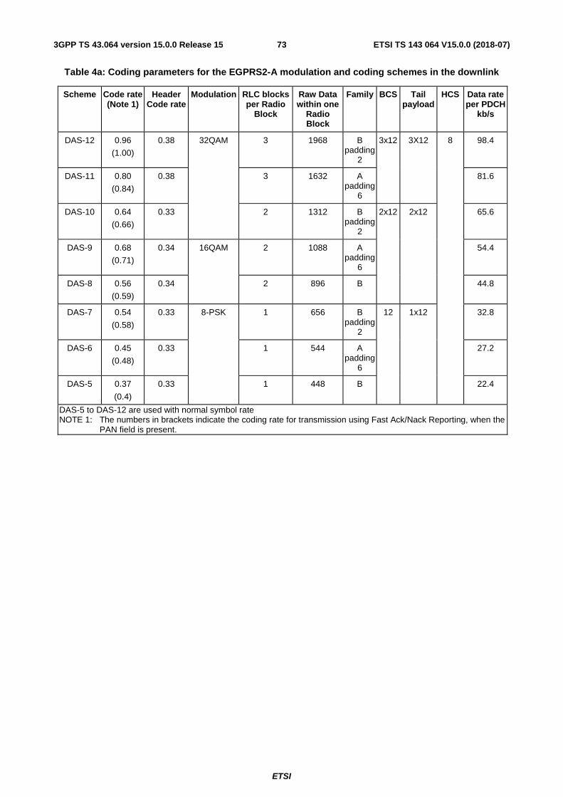
ETSI
ETSI TS 143 064 V15.0.0 (2018-07)733GPP TS 43.064 version 15.0.0 Release 15
Table 4a: Coding parameters for the EGPRS2-A modulation and coding schemes in the downlink
Scheme Code rate (Note 1)
Header Code rate
Modulation RLC blocks per Radio
Block
Raw Data within one
Radio Block
Family BCS Tail payload
HCS Data rate per PDCH
kb/s
DAS-12 0.96
(1.00)
0.38 32QAM 3 1968 B padding
2
3x12 3X12 8 98.4
DAS-11 0.80
(0.84)
0.38 3 1632 A padding
6
81.6
DAS-10 0.64
(0.66)
0.33 2 1312 B padding
2
2x12 2x12 65.6
DAS-9 0.68
(0.71)
0.34 16QAM 2 1088 A padding
6
54.4
DAS-8 0.56
(0.59)
0.34 2 896 B 44.8
DAS-7 0.54
(0.58)
0.33 8-PSK 1 656 B padding
2
12 1x12 32.8
DAS-6 0.45
(0.48)
0.33 1 544 A padding
6
27.2
DAS-5 0.37
(0.4)
0.33 1 448 B 22.4
DAS-5 to DAS-12 are used with normal symbol rate NOTE 1: The numbers in brackets indicate the coding rate for transmission using Fast Ack/Nack Reporting, when the
PAN field is present.
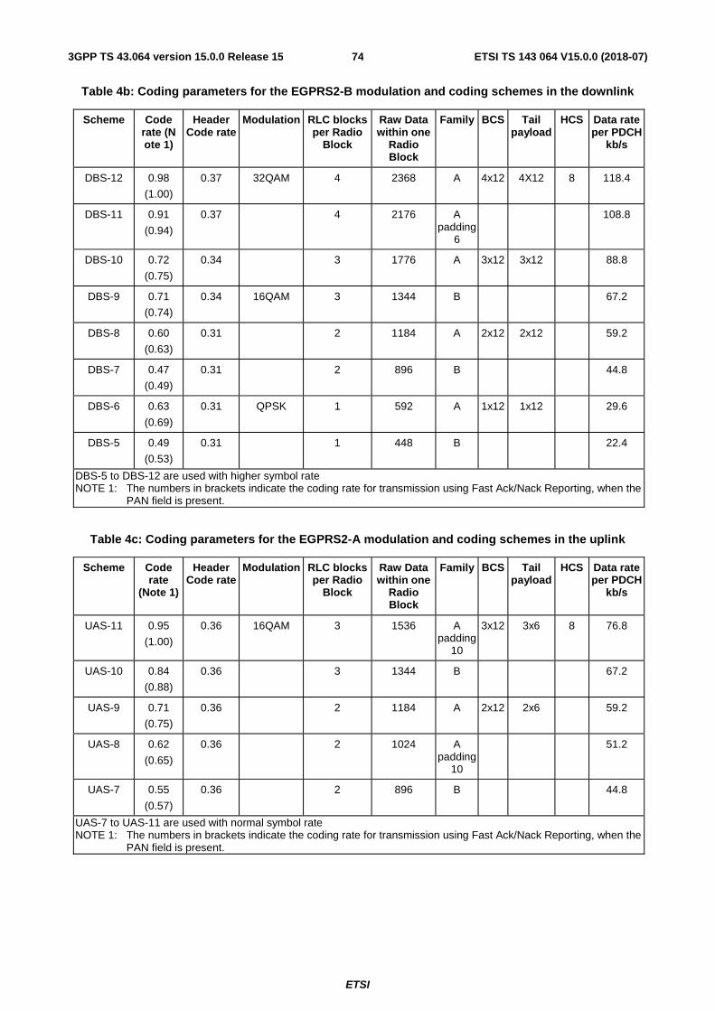
ETSI
ETSI TS 143 064 V15.0.0 (2018-07)743GPP TS 43.064 version 15.0.0 Release 15
Table 4b: Coding parameters for the EGPRS2-B modulation and coding schemes in the downlink
Scheme Code rate (N ote 1)
Header Code rate
Modulation RLC blocks per Radio
Block
Raw Data within one
Radio Block
Family BCS Tail payload
HCS Data rate per PDCH
kb/s
DBS-12 0.98
(1.00)
0.37 32QAM 4 2368 A 4x12 4X12 8 118.4
DBS-11 0.91
(0.94)
0.37 4 2176 A padding
6
108.8
DBS-10 0.72
(0.75)
0.34 3 1776 A 3x12 3x12 88.8
DBS-9 0.71
(0.74)
0.34 16QAM 3 1344 B 67.2
DBS-8 0.60
(0.63)
0.31 2 1184 A 2x12 2x12 59.2
DBS-7 0.47
(0.49)
0.31 2 896 B 44.8
DBS-6 0.63
(0.69)
0.31 QPSK 1 592 A 1x12 1x12 29.6
DBS-5 0.49
(0.53)
0.31 1 448 B 22.4
DBS-5 to DBS-12 are used with higher symbol rate NOTE 1: The numbers in brackets indicate the coding rate for transmission using Fast Ack/Nack Reporting, when the
PAN field is present.
Table 4c: Coding parameters for the EGPRS2-A modulation and coding schemes in the uplink
Scheme Code rate
(Note 1)
Header Code rate
Modulation RLC blocks per Radio
Block
Raw Data within one
Radio Block
Family BCS Tail payload
HCS Data rate per PDCH
kb/s
UAS-11 0.95
(1.00)
0.36 16QAM 3 1536 A padding
10
3x12 3x6 8 76.8
UAS-10 0.84
(0.88)
0.36 3 1344 B 67.2
UAS-9 0.71
(0.75)
0.36 2 1184 A 2x12 2x6 59.2
UAS-8 0.62
(0.65)
0.36 2 1024 A padding
10
51.2
UAS-7 0.55
(0.57)
0.36 2 896 B 44.8
UAS-7 to UAS-11 are used with normal symbol rate NOTE 1: The numbers in brackets indicate the coding rate for transmission using Fast Ack/Nack Reporting, when the
PAN field is present.
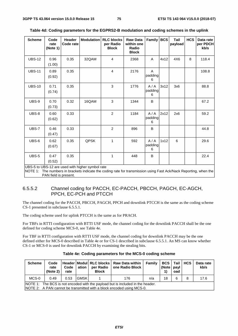
ETSI
ETSI TS 143 064 V15.0.0 (2018-07)753GPP TS 43.064 version 15.0.0 Release 15
Table 4d: Coding parameters for the EGPRS2-B modulation and coding schemes in the uplink
Scheme Code rate
(Note 1)
Header Code rate
Modulation RLC blocks per Radio
Block
Raw Data within one
Radio Block
Family BCS Tail payload
HCS Data rate per PDCH
kb/s
UBS-12 0.96
(1.00)
0.35 32QAM 4 2368 A 4x12 4X6 8 118.4
UBS-11 0.89
(0.92)
0.35 4 2176 A padding
6
108.8
UBS-10 0.71
(0.74)
0.35 3 1776 A / A padding
6
3x12 3x6 88.8
UBS-9 0.70
(0.73)
0.32 16QAM 3 1344 B 67.2
UBS-8 0.60
(0.62)
0.33 2 1184 A / A padding
6
2x12 2x6 59.2
UBS-7 0.46
(0.47)
0.33 2 896 B 44.8
UBS-6 0.62
(0.67)
0.35 QPSK 1 592 A / A padding
6
1x12 6 29.6
UBS-5 0.47
(0.52)
0.35 1 448 B 22.4
UBS-5 to UBS-12 are used with higher symbol rate NOTE 1: The numbers in brackets indicate the coding rate for transmission using Fast Ack/Nack Reporting, when the
PAN field is present.
6.5.5.2 Channel coding for PACCH, EC-PACCH, PBCCH, PAGCH, EC-AGCH, PPCH, EC-PCH and PTCCH
The channel coding for the PACCH, PBCCH, PAGCH, PPCH and downlink PTCCH is the same as the coding scheme CS-1 presented in subclause 6.5.5.1.
The coding scheme used for uplink PTCCH is the same as for PRACH.
For TBFs in RTTI configuration with BTTI USF mode, the channel coding for the downlink PACCH shall be the one defined for coding scheme MCS-0, see Table 4e.
For TBF in RTTI configuration with RTTI USF mode, the channel coding for downlink PACCH may be the one defined either for MCS-0 described in Table 4e or for CS-1 described in subclause 6.5.5.1. An MS can know whether CS-1 or MCS-0 is used for downlink PACCH by examining the stealing bits.
Table 4e: Coding parameters for the MCS-0 coding scheme
Scheme Code rate
(Note 2)
Header Code rate
Modulation
RLC blocks per Radio
Block
Raw Data within one Radio Block
Family BCS (Note
1)
Tail payload
HCS Data rate kb/s
MCS-0 0.49 0.53 GMSK 1 176 n/a 18 6 8 17.6
NOTE 1: The BCS is not encoded with the payload but is included in the header. NOTE 2: A PAN cannot be transmitted with a block encoded using MCS-0.

ETSI
ETSI TS 143 064 V15.0.0 (2018-07)763GPP TS 43.064 version 15.0.0 Release 15
puncturing
546 bits
USF RLC/MAC Hdr (Note 1) Control block = 22 octets = 176 bits TB
12 bits
Rate 1/3 convolutional coding
108 bits
182 bits
372 bits 68 bits12 bitsSB = 12
464 bits
36 bits
puncturing
HCS
3 bits
NOTE 1: Includes the BCS for the control block
Figure 18i: Coding and puncturing for MCS-0
The channel coding for EC-PACCH, EC-AGCH and EC-PCH is described in table 4f and shown in figure 18j, 18k and 18l. The EC-PCH and EC-AGCH are defined as two burst block format with a single burst transmitted two times. EC-PACCH is defined as a four burst block format with a single burst transmitted four times. The code rate in table 4f is based on code rate for a single burst.
Table 4f: Coding parameters for EC-PACCH/D, EC-PACCH/U, EC-PCH and EC-AGCH.
Logical channel Code rate Direction Modulation Raw Data within one
Radio Block
Family BCS Tail payload
Repeated bursts per
block
EC-PACCH/D 0,86 DL GMSK 80 n/a 18 - 4 EC-PACCH/U 0,71 UL GMSK 64 n/a 18 - 4
EC-PCH / EC-AGCH
0,91 DL GMSK 88 n/a 18 - 2
USF Control block BCS
Radio block
SB
1/3 convolutional codeBlock code
Puncturing
SB
464
Figure 18j: Coding and puncturing for EC-PACCH/D.
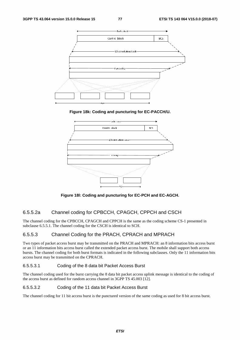
ETSI
ETSI TS 143 064 V15.0.0 (2018-07)773GPP TS 43.064 version 15.0.0 Release 15
Control block BCS
Radio block
1/3 convolutional code
Puncturing
464
Figure 18k: Coding and puncturing for EC-PACCH/U.
Control block BCS
Radio block
1/3 convolutional code
Puncturing
232
Figure 18l: Coding and puncturing for EC-PCH and EC-AGCH.
6.5.5.2a Channel coding for CPBCCH, CPAGCH, CPPCH and CSCH
The channel coding for the CPBCCH, CPAGCH and CPPCH is the same as the coding scheme CS-1 presented in subclause 6.5.5.1. The channel coding for the CSCH is identical to SCH.
6.5.5.3 Channel Coding for the PRACH, CPRACH and MPRACH
Two types of packet access burst may be transmitted on the PRACH and MPRACH: an 8 information bits access burst or an 11 information bits access burst called the extended packet access burst. The mobile shall support both access bursts. The channel coding for both burst formats is indicated in the following subclauses. Only the 11 information bits access burst may be transmitted on the CPRACH.
6.5.5.3.1 Coding of the 8 data bit Packet Access Burst
The channel coding used for the burst carrying the 8 data bit packet access uplink message is identical to the coding of the access burst as defined for random access channel in 3GPP TS 45.003 [12].
6.5.5.3.2 Coding of the 11 data bit Packet Access Burst
The channel coding for 11 bit access burst is the punctured version of the same coding as used for 8 bit access burst.
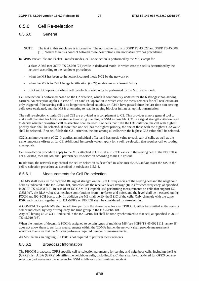
ETSI
ETSI TS 143 064 V15.0.0 (2018-07)783GPP TS 43.064 version 15.0.0 Release 15
6.5.6 Cell Re-selection
6.5.6.0 General
NOTE: The text in this subclause is informative. The normative text is in 3GPP TS 43.022 and 3GPP TS 45.008 [15]. Where there is a conflict between these descriptions, the normative text has precedence.
In GPRS Packet Idle and Packet Transfer modes, cell re-selection is performed by the MS, except for
- a class A MS (see 3GPP TS 22.060 [2] ) while in dedicated mode in which case the cell is determined by the network according to the handover procedures;
- when the MS has been set in network control mode NC2 by the network or
- when the MS is in Cell Change Notification (CCN) mode (see subclause 6.5.6.4)
- PEO and EC operation where cell re-selection need only be performed by the MS in idle mode.
Cell reselection is performed based on the C2 criterion, which is continuously updated for the 6 strongest non-serving carriers. An exception applies in case of PEO and EC operation in which case the measurements for cell reselection are only triggered if the serving cell is no longer considered suitable, or if 24 h have passed since the last time non-serving cells were evaluated, and the MS is attempting to read its paging block or initiate an uplink transmission.
The cell re-selection criteria C31 and C32 are provided as a complement to C2. This provides a more general tool to make cell planning for GPRS as similar to existing planning in GSM as possible. C31 is a signal strength criterion used to decide whether prioritised cell re-selection shall be used. For cells that fulfil the C31 criterion, the cell with highest priority class shall be selected. If more than one cell has the highest priority, the one of those with the highest C32 value shall be selected. If no cell fulfils the C31 criterion, the one among all cells with the highest C32 value shall be selected.
C32 is an improvement of C2. It applies an individual offset and hysteresis value to each pair of cells, as well as the same temporary offsets as for C2. Additional hysteresis values apply for a cell re-selection that requires cell or routing area update.
Cell re-selection procedure apply to the MSs attached to GPRS if a PBCCH exists in the serving cell. If the PBCCH is not allocated, then the MS shall perform cell re-selection according to the C2 criteria.
In addition, the network may control the cell re-selection as described in subclause 6.5.6.3 and/or assist the MS in the cell re-selection procedure as described in subclause 6.5.6.4.
6.5.6.1 Measurements for Cell Re-selection
The MS shall measure the received RF signal strength on the BCCH frequencies of the serving cell and the neighbour cells as indicated in the BA-GPRS list, and calculate the received level average (RLA) for each frequency, as specified in 3GPP TS 45.008 [15]. In case of an EC-GSM-IoT capable MS performing measurements on cells that support EC-GSM-IoT, the RLA value shall exclude contributions from interferers and noise, and the level shall be measured on the FCCH and EC-SCH bursts only. In addition the MS shall verify the BSIC of the cells. Only channels with the same BSIC as broadcast together with BA-GPRS on PBCCH shall be considered for re-selection.
A COMPACT capable MS shall in addition perform the above tasks for any CPBCCH, either transmitted in the serving cell or indicated, by way of frequency and time group in the BA-GPRS list. Any cell having a CPBCCH indicated in the BA-GPRS list shall be time synchronized to that cell, as specified in 3GPP TS 45.010 [16].
When the number of downlink PDCHs assigned to certain types of multislot MS (see 3GPP TS 45.002 [11] , annex B) does not allow them to perform measurements within the TDMA frame, the network shall provide measurement windows to ensure that the MS can perform a required number of measurements.
An MS that has an ongoing EC TBF is not required to perform measurements.
6.5.6.2 Broadcast Information
The PBCCH broadcasts GPRS specific cell re-selection parameters for serving and neighbour cells, including the BA (GPRS) list. A BA (GPRS) identifies the neighbour cells, including BSIC, that shall be considered for GPRS cell (re-selection (not necessary the same as for GSM in Idle or circuit switched mode)).
ETSI
ETSI TS 143 064 V15.0.0 (2018-07)793GPP TS 43.064 version 15.0.0 Release 15
The EC-BCCH broadcasts EC-GSM-IoT specific cell re-selection parameters for serving and neighbour cell, including a 9 bit BSIC for each neighbour cell supporting EC-GSM-IoT.
6.5.6.3 Optional measurement reports and network controlled cell re-selection
It shall be possible for the network to order the mobile stations to send measurement reports to the network and to suspend its normal cell re-selection, and instead to accept decisions from the network. This applies to both Packet idle mode and Packet transfer mode. An exception is the case of a MS that has enabled EC operation or PEO in which case only NC0 shall be used.
The degree to which the mobile station shall resign its radio network control shall be variable, and be ordered in detail by the parameter NETWORK_CONTROL_ORDER.
Two sets of parameters are broadcast on PBCCH and are valid in Packet transfer and Packet idle modes respectively. NETWORK_CONTROL_ORDER can also be sent individually to an MS on PACCH, in which case it overrides the broadcast parameter.
When a class A mobile station is simultaneously involved in a circuit switched service and in a GPRS transfer, the network controlled cell re-selection procedures (NC1 or NC2 modes of operation) should not be used.
In this case, handover for the circuit switched service has precedence over GPRS network controlled cell re-selection, and the MS shall stop sending measurement reports and ignore cell change orders.
6.5.6.4 Network Assisted Cell Change
The Network Assisted Cell Change option adds a possibility to
a) minimize the service outage time for an MS in the cell re-selection process,
b) delay the cell re-selection until complete RLC-SDUs have been transferred.
This is achieved without forcing the MS into either mode NC1 or NC2 and consequently eliminates the need to load the radio path with measurement reports (see subclause 6.5.6.3).
The procedures related to Network Assisted Cell Change are optional for the network and mandatory for an MS. An exception is the case of a MS that has enabled EC operation or PEO in which case it shall not use Network Assisted Cell Change.
Network Assisted Cell Change consists mainly of two parts
- One part that can assist an MS in packet transfer mode with neighbour cell system information required for initial packet access after a cell change;
- One part in which the mobile station notifies the network when the cell change criteria is fulfilled and delays the cell re-selection a short time to let the network respond with neighbour cell system information (CCN mode procedures).
A mobile station in Packet Transfer mode may receive neighbour cell system information on PACCH. The neighbour cell information may consist of PSI1, PSI2 and PSI14 if a PBCCH is allocated in the target cell, or SI3, SI13 and SI1 (if available) if no PBCCH is allocated. The information shall be stored by the mobile station and is valid for 30 seconds. During that period the MS may use the information for initial access when entering the addressed neighbour cell.
The neighbour cell system information is contained in the Packet Neighbour Cell Data message.
The network indicates use of CCN on BCCH and PBCCH. If indicated or individually ordered by the network and when the MS is in packet transfer mode and in NC0 or NC1 mode but not in dedicated mode or in dual transfer mode, the MS shall enable CCN. When enabled, and when the criteria for cell re-selection are fulfilled, the MS shall enter CCN mode and notify the network. While in CCN mode the MS shall not change cell.
In the notification to the network, the MS shall report a proposed cell identity and measurement results for the proposed and for other neighbour cells if available. The MS shall leave the CCN mode when either
- The network responds with a Packet Cell Change Continue or a Packet Cell Change Order message or
- A certain time has elapsed or
ETSI
ETSI TS 143 064 V15.0.0 (2018-07)803GPP TS 43.064 version 15.0.0 Release 15
- The MS enters Packet Idle Mode or
- The criteria for camping on the old cell is no longer fulfilled (see 3GPP TS 45.008).
If the MS is in NC2 mode, dedicated mode or in dual transfer mode, the CCN mode is not applicable.
6.5.7 Timing Advance
6.5.7.0 General
NOTE: The text in this subclause is informative. The normative text is in 3GPP TS 44.060 [7] and 3GPP TS 45.010 [16]. Where there is a conflict between these descriptions, the normative text has precedence.
The timing advance procedure is used to derive the correct value for timing advance that the MS has to use for the uplink transmission of radio blocks. This procedure is not used in dual transfer mode, in which case the timing advance procedures for dedicated mode are used.
The timing advance procedure comprises two parts:
- initial timing advance estimation;
- continuous timing advance update.
6.5.7.1 Initial timing advance estimation
The initial timing advance estimation is based on the single access burst carrying the Packet Channel Request, or in case of EC operation when using blind physical layer transmissions, on the access bursts carrying the Packet Channel Request.
The Packet Uplink Assignment or Packet Downlink Assignment then carries the estimated timing advance value to the MS. This value shall be used by the MS for the uplink transmissions until the continuous timing advance update provides a new value (see subclause 6.5.7.2.). Two special cases exist:
- when Packet Queuing Notification is used the initial estimated timing advance may become too old to be sent in the Packet Downlink (/Uplink) Assignment
- when Packet Downlink (/Uplink) Assignment is to be sent without prior paging (i.e., in the Ready state), no valid timing advance value may be available.
Then the network has three options:
- Packet Polling Request can then be used to trigger the transmission of Packet Control Acknowledgement. This message can be formatted as four access burst from which the timing advance can be estimated.
- Packet Downlink (/Uplink) Assignment can be sent without timing advance information. In that case it is indicated to the MS that it can only start the uplink transmission after the timing advance is obtained by the continuous timing advance update procedure.
- The poll bit in the Packet Downlink (/Uplink) Assignment message can be set to trigger the transmission of Packet Control Acknowledgement. This can be used if System information indicates that acknowledgement is access bursts.
For the case where timing advance information is not provided in the assignment message, the mobile is not allowed to send normal bursts on the uplink until it receives a valid timing advance either in Packet Timing Advance/Power Control message or through the continuous timing advance procedure.
6.5.7.2 Continuous timing advance update
MS in Packet transfer mode shall use the continuous timing advance update procedure. The continuous timing advance update procedure is carried on the PTCCH assigned to the MS.
For uplink packet transfer, within the Packet Uplink Assignment, the MS is assigned Timing Advance Index (TAI) and the PTCCH.
For downlink packet transfer, within the Packet Downlink Assignment, the MS is assigned Timing Advance Index (TAI) and the PTCCH.
ETSI
ETSI TS 143 064 V15.0.0 (2018-07)813GPP TS 43.064 version 15.0.0 Release 15
The TAI specifies the PTCCH sub-channel used by the MS.
On the uplink, the MS shall send in the assigned PTCCH access burst, which is used by the network to derive the timing advance.
The network analyses the received access burst and determines new timing advance values for all MSs performing the continuous timing advance update procedure on that PDCH. The new timing advance values shall be sent via a downlink signalling message (TA-message) on PTCCH/D. Network can send timing advance information also in Packet Timing Advance/Power Control and Packet Uplink Ack/Nack messages on PACCH.
In case of EC operation, the continuous timing advance update procedure and the PTCCH are not used. Instead, the EC-PACCH can be used by the network to send timing advance information.
6.5.7.2.1 Mapping on the multiframe structure
Figure 19 shows the mapping of the uplink access bursts and downlink TA-messages on groups of eight 52-multiframes:
- the TAI value shows the position where a slot is reserved for a MS to send an access burst (e.g. T1 means 52-multiframe number n and idle slot number 2). TAI value defines the used PTCCH sub-channel.
- every second PDCH multiframe starts a downlink TA-message.
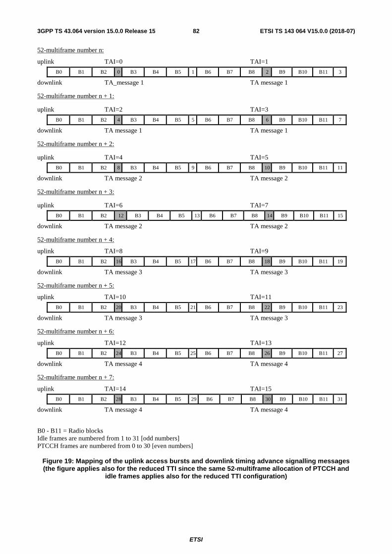
ETSI
ETSI TS 143 064 V15.0.0 (2018-07)823GPP TS 43.064 version 15.0.0 Release 15
52-multiframe number n:
uplink TAI=0 TAI=1
B0 B1 B2 0 B3 B4 B5 1 B6 B7 B8 2 B9 B10 B11 3
downlink TA_message 1 TA message 1
52-multiframe number n + 1:
uplink TAI=2 TAI=3
B0 B1 B2 4 B3 B4 B5 5 B6 B7 B8 6 B9 B10 B11 7
downlink TA message 1 TA message 1
52-multiframe number n + 2:
uplink TAI=4 TAI=5
B0 B1 B2 8 B3 B4 B5 9 B6 B7 B8 10 B9 B10 B11 11
downlink TA message 2 TA message 2
52-multiframe number n + 3:
uplink TAI=6 TAI=7
B0 B1 B2 12 B3 B4 B5 13 B6 B7 B8 14 B9 B10 B11 15
downlink TA message 2 TA message 2
52-multiframe number n + 4:
uplink TAI=8 TAI=9
B0 B1 B2 16 B3 B4 B5 17 B6 B7 B8 18 B9 B10 B11 19
downlink TA message 3 TA message 3
52-multiframe number n + 5:
uplink TAI=10 TAI=11
B0 B1 B2 20 B3 B4 B5 21 B6 B7 B8 22 B9 B10 B11 23
downlink TA message 3 TA message 3
52-multiframe number n + 6:
uplink TAI=12 TAI=13
B0 B1 B2 24 B3 B4 B5 25 B6 B7 B8 26 B9 B10 B11 27
downlink TA message 4 TA message 4
52-multiframe number n + 7:
uplink TAI=14 TAI=15
B0 B1 B2 28 B3 B4 B5 29 B6 B7 B8 30 B9 B10 B11 31
downlink TA message 4 TA message 4
B0 - B11 = Radio blocks Idle frames are numbered from 1 to 31 [odd numbers] PTCCH frames are numbered from 0 to 30 [even numbers]
Figure 19: Mapping of the uplink access bursts and downlink timing advance signalling messages (the figure applies also for the reduced TTI since the same 52-multiframe allocation of PTCCH and
idle frames applies also for the reduced TTI configuration)
ETSI
ETSI TS 143 064 V15.0.0 (2018-07)833GPP TS 43.064 version 15.0.0 Release 15
The BTS shall update the timing advance values in the next TA-message following the access burst. To illustrate this, an MS that transmits an access burst in frames numbered 0, 2, 4, or 6 receives its updated timing advance value in TA message 2. This MS can also find this updated timing advance value in subsequent TA messages 3, 4, and 1, but only has to read these if TA message 2 was not received correctly.
An MS entering the Transfer state shall ignore the TA-messages until the MS has sent its first access burst. This is to avoid the use of timing advance values, derived from access bursts sent by the MS that previously used the same TAI.
6.5.8 Power control procedure
6.5.8.0 General
Power control shall be supported in order to improve the spectrum efficiency and to reduce the power consumption in the MS.
For the uplink, the MS shall follow a flexible power control algorithm, which the network can optimise through a set of parameters. It can be used for both open loop and closed loop power control.
For the downlink, the power control is performed in the BTS. Therefore, there is no need to specify the actual algorithms, but information about the downlink performance is needed. Therefore the MSs have to transfer Channel Quality Reports to the BTS.
For the detailed specification of power control see 3GPP TS 45.008 [15].
In a downlink dual carrier or multi carrier configuration, power control shall be applied on the uplink, to all radio frequency channels independently.
6.5.8.1 MS output power
The MS shall calculate the RF output power value, PCH, to be used on each individual uplink PDCH assigned to the MS:
PCH = min((Γ0 - ΓCH - α * (C + 48), PMAX)
where
ΓCH is an MS and channel specific power control parameter. It is sent to the MS in any resource assigning message. Further, the network can, at any time during a packet transfer, send new ΓCH values to the MS on the downlink (EC-)PACCH.
Γ0 is a frequency band dependent constant.
α∈[0,1] is a system parameter. Its default value is broadcast on the PBCCH. Further, MS and channel specific values can be sent to the MS together with ΓCH.
C is the received signal level at the MS.
PMAX is the maximum allowed output power in the cell.
All power values are expressed in dBm.
PCH is not used to determine the output power when accessing the cell on PRACH or RACH , in which case PMAX shall be used.
6.5.8.2 BTS output power
The BTS shall use constant power on those PDCH radio blocks which contain PBCCH or which may contain PPCH. This power may be lower than the output power used on BCCH. The difference shall be broadcast on PBCCH.
On the other PDCH radio blocks, downlink power control may be used. Thus, a procedure may be implemented in the network to control the power of the downlink transmission based on the Channel Quality Reports.
The network shall ensure that the output power is sufficient for the MS for which the RLC block is intended as well as the MS(s) for which the USF is intended, and that for each MS in packet transfer mode, at least one downlink RLC block per multiframe is transmitted with an output power that is sufficient for that MS, on a block monitored by that MS.
ETSI
ETSI TS 143 064 V15.0.0 (2018-07)843GPP TS 43.064 version 15.0.0 Release 15
For EC-GSM-IoT the BTS shall use constant power on the FCCH, EC-BCCH and EC-SCH.
6.5.8.3 Measurements at MS side
6.5.8.3.0 General
A procedure shall be implemented in the MS to monitor periodically the downlink Rx signal level and quality from its serving cell. An exception applies to a MS in PEO or EC operation where relaxed mobility related requirements apply, see 3GPP TS 45.008.
6.5.8.3.1 Deriving the C value
This subclause comprises information about how the MS shall derive the C value in the power control equation.
The MS shall periodically measure the received signal strength.
In packet idle mode, the MS shall measure the signal strength of the PCCCH or, if PCCCH is not existing, the BCCH.
In packet transfer mode, the MS shall measure the signal strength on BCCH. The same measurements as for cell re-selection are used (see 6.5.6.1.). Alternatively, if indicated by a broadcast parameter, the MS shall measure the signal strength on one of the PDCHs in BTTI configuration or on one of the PDCH-pairs in RTTI configuration where the MS receives PACCH. This method is suitable in the case where BCCH is in another frequency band than the used PDCHs. It requires that constant output power is used on all downlink PDCH blocks.
The MS shall measure the signal strength of each radio block monitored by the MS. The C value is achieved by filtering the signal strength with a running average filter. The filtering shall normally be continuous between the RR modes. In case there is a transition of the RR mode, the filtering shall be restarted if there is no valid C value during the previous RR mode (see 3GPP TS 45.008 [15]). The different filter parameters for the packet modes are broadcast on PBCCH or, if PBCCH does not exist, on BCCH.
The variance of the received signal level within each block shall also be calculated. The filtered value SIGN_VAR shall be included in the channel quality report.
In case of EC-GSM-IoT, the MS can operate in extended coverage. In this case, the received signal strength could to a large extent be represented by the thermal noise and/or interference, and hence received signal strength shall exclude contributions from other sources such as interference and noise. For EC-GSM-IoT the measurement of the C value is implementation dependent, but shall be based on bursts of the FCCH and EC-SCH channels.
6.5.8.3.2 Derivation of Channel Quality Report
The channel quality is measured as the interference signal level during the idle frames of the multiframe, when the serving cell is not transmitting.
In packet transfer mode, the MS shall measure the interference signal strength of all eight channels (slots) on the same carrier as the assigned PDCHs.
Some of the idle frames and PTCCH frames shall be used for this, while the others are required for BSIC identification and the timing advance procedure, see subclause 6.5.9.
The MS may not be capable of measuring all eight channels when allocated some configurations of channels. The MS shall measure as many channels as its allocation allows considering its multislot capability.
The slots that the MS measures on can be either idle or used by SACCH or PTCCH, depending on the channel type (TCH or PDCH).. The MS shall therefore, for each slot, take the minimum signal strength of one idle frame and one PTCCH frame. Thus the SACCH frames are avoided (except for a TCH/H with two MSs) and only the interference is measured.
The interference, γCH , is achieved by filtering the measured interference in a running average filter. The filter parameters are broadcast on PBCCH or, if PBCCH does not exist, on BCCH.
In packet transfer mode the MS shall transfer the 8 γCH values and the RXQUAL, SIGN_VAR and C values (see subclause 6.5.8.3.1) to the network in the Channel Quality Report included in the (EGPRS) PACKET DOWNLINK ACK/NACK message. In packet transfer mode, for a MS in EC operation, the MS shall transfer RXQUAL, and C values to the network in the Channel Quality Report included in the EC PACKET DOWNLINK ACK/NACK.
ETSI
ETSI TS 143 064 V15.0.0 (2018-07)853GPP TS 43.064 version 15.0.0 Release 15
In a downlink dual carrier configuration, channel quality measurements shall be performed for each radio frequency channel independently. Depending on the amount of information requested by the network (e.g. whether or not per-timeslot information is required) the MS may not be able to include channel quality measurements for both radio frequency channels within the EGPRS PACKET DOWNLINK ACK/NACK message. In this case, the MS shall include channel quality measurements for the radio frequency channel on which the poll was received.
In a downlink multi carrier configuration, channel quality measurements may be performed for each radio frequency channel, or each Unique Frequency Parameter Set, UFPS, independently. A UFPS is determined either by a Mobile Allocation (i.e. multiple carriers assigned the same Mobile Allocation belongs to the same UFPS), or alternatively, a fixed ARFCN. For carrier based reporting, principles that apply in Downlink Dual carrier configuration applies also for Downlink Multi Carrier configuration. For UFPS based reporting the MS shall always include channel quality measurements for the UFPS corresponding to the radio frequency channel on which the poll was received. If there is room in the message the MS may report additional UFPS (if any). Depending on the amount of information requested by the network, in case of UFPS based reporting, the MS may not be able to include channel quality measurements for all UFPSs within the applicable EGPRS PACKET DOWNLINK ACK/NACK DLMC message.
The channel quality measurements shall be performed based on radio blocks (see 3GPP TS 45.008 [15]).
In BTTI configuration, if ordered by the network, the MS shall report the measurements performed on BTTI channel (PDCH, i.e. timeslot) in the EGPRS PACKET DOWNLINK ACK/NACK message EGPRS PACKET DOWNLINK ACK/NACK Type 2 message, EGPRS PACKET DOWNLINK ACK/NACK Type 3 message, or EGPRS PACKET DOWNLINK ACK/NACK DLMC message.
In RTTI configuration, if ordered by the network, the MS shall report the measurements performed on RTTI channel (PDCH-pair, i.e. timeslot pair) in the EGPRS PACKET DOWNLINK ACK/NACK message or EGPRS PACKET DOWNLINK ACK/NACK Type 2 message, EGPRS PACKET DOWNLINK ACK/NACK Type 3 message, or EGPRS PACKET DOWNLINK ACK/NACK DLMC message.
6.5.8.4 Measurements at BSS side
A procedure shall be implemented in the BSS to monitor the uplink Rx signal level and quality on each uplink PDCH, active as well as inactive.
The BSS shall also measure the Rx signal level and the quality of a specific MS packet transfer.
6.5.9 Scheduling the MS activities during the PTCCH and idle frames
The MS shall use the PTCCH and idle frames of the PDCH multiframe for the following tasks:
- BSIC identification for cell re-selection (6.5.6.1)
- Continuous timing advance procedures (6.5.7.2)
- Interference measurements for power control (6.5.8.3.2)
It is not necessary to exactly specify the scheduling of these tasks.
The PTCCH frames used for timing advance signalling is stated in 6.5.7.2.1. During the frames when the MS receives TA-messages it can also make interference measurements. During the frames when the MS transmits access bursts it may also be possible to make measurements on some channels.
The MS shall schedule the BSIC identification as efficiently as possible, using the remaining PTCCH frames and the idle frames and also considering the requirements for interference measurements. When the MS is synchronised to a BTS, it knows the timing of the SCH. Therefore, only a few certain frames are required for BSIC identification. In those frames it may also be possible to make measurements on some channels. When the MS shall synchronise to a new BTS, it has to prioritise that task. It may then use half of the PTCCH and idle frames, i.e. the same amount as available for circuit switched connections.
The remaining PTCCH and idle frames shall be used for interference measurements.
An MS in PEO or EC operation need not perform the above mentioned activities during the PTCCH and idle frames.
ETSI
ETSI TS 143 064 V15.0.0 (2018-07)863GPP TS 43.064 version 15.0.0 Release 15
6.5.10 Discontinuous Reception (DRX)
NOTE: The text in this subclause is informative. The normative text is in 3GPP TS 45.002 [11]. Where there is a conflict between these descriptions, the normative text has precedence.
DRX (sleep mode) shall be supported when the MS is in Packet Idle mode. DRX is independent from MM states Ready and Standby.
Negotiation of DRX parameters is per MS. An MS may choose to use DRX or not together with some operating parameters. The following parameters are established:
- DRX/non-DRX indicator It indicates whether the MS uses DRX or not.
- DRX period A conditional parameter for MSs using DRX to determine the right paging group. The DRX period is defined by the parameter SPLIT_PG_CYCLE or BS_PA_MFRMS (see Table 5). An exception is the case of a MS that has enabled eDRX in which case the DRX period is defined by the eDRX cycle value negotiated by the MS with the network using NAS signaling (see 3GPP TS 24.008 and 3GPP TS 45.002).
- Non-DRX timer A conditional parameter for MSs using DRX to determine the time period within which the non-DRX mode is kept after leaving the Transfer state. The support for this feature is optional on the network side and the information about the maximum supported value for the timer in the cell is broadcast on PBCCH.
An MS in DRX mode is only required to monitor the radio blocks defined by its paging group as defined in 3GPP TS 45.002 [11].
Paging group definition based on SPLIT_PG_CYCLE is optional on CCCH for both BTS and MS. If not supported, the definition based on BS_PA_MFRMS shall be used. The parameters used to define the paging group for GPRS are shown in the Table 5, together with the corresponding GSM parameters. BS_PCC_CHANS is the number of PDCHs containing PCCCH. For Compact, BS_PCC_CHANS is the number of radio frequency channels per cell carrying CPCCCHs including the radio frequency channel carrying the CPBCCH.
For a MS that has enabled eDRX, the parameters used to define the paging group on a given (EC-)CCCH are IMSI, (EC-)PCH blocks per 51-multiframe and the number of 51-MF associated with its negotiated eDRX cycle (see 3GPP TS 45.002). For EC operation the downlink Coverage Class is also part of the parameter set that defines the paging group.
An MS in non-DRX mode is required to monitor all the radio blocks where PCCCH or (for Compact) CPCCCH may be mapped on the PDCH defined by its paging group.
When page for circuit-switched services is conveyed on PPCH, it follows the same scheduling principles as the page for packet data. The same is valid for scheduling of resource assignments for downlink packet transfers for MSs in Ready State (i.e. where no paging is performed).
NOTE: Paging reorganisation may be supported in the same way as for circuit switched GSM.
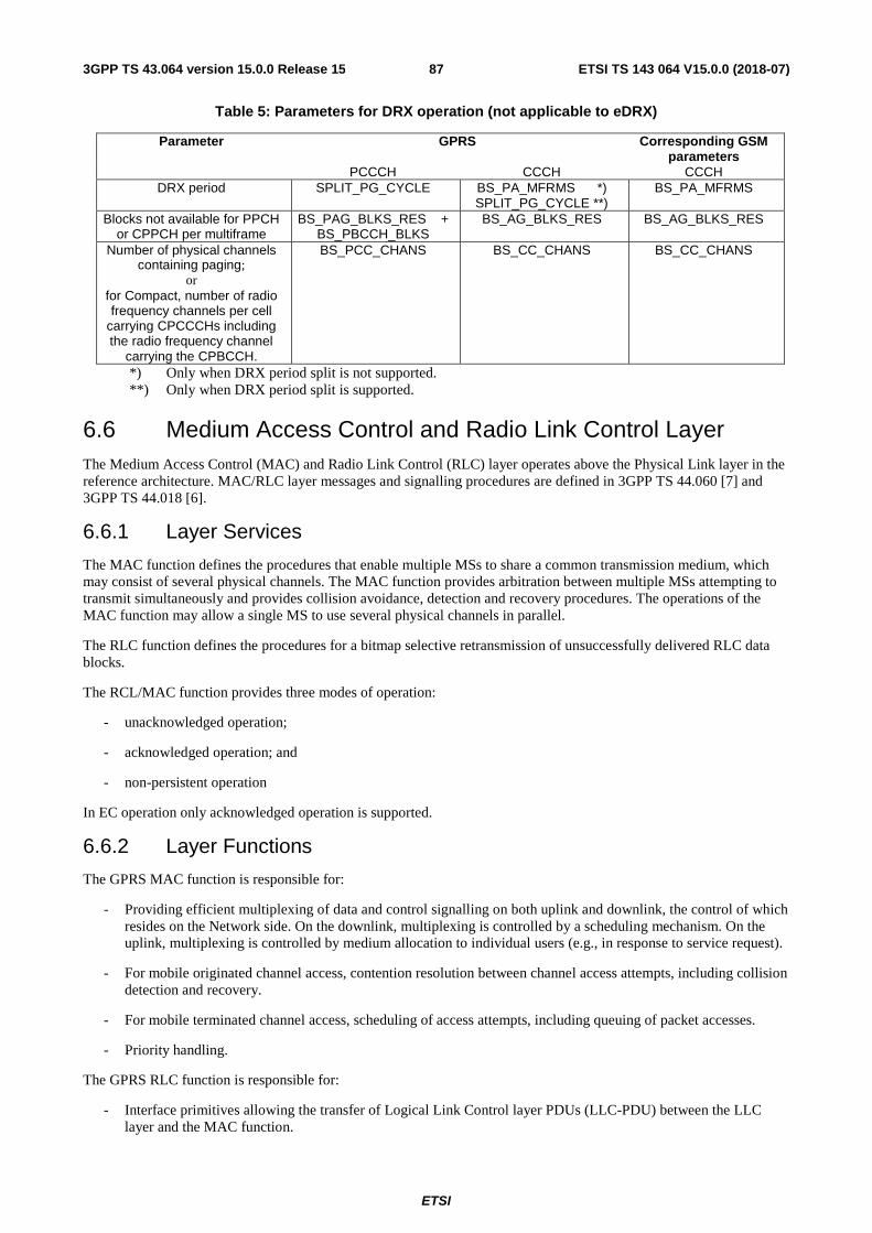
ETSI
ETSI TS 143 064 V15.0.0 (2018-07)873GPP TS 43.064 version 15.0.0 Release 15
Table 5: Parameters for DRX operation (not applicable to eDRX)
Parameter GPRS Corresponding GSM parameters
PCCCH CCCH CCCH DRX period SPLIT_PG_CYCLE BS_PA_MFRMS *)
SPLIT_PG_CYCLE **) BS_PA_MFRMS
Blocks not available for PPCH or CPPCH per multiframe
BS_PAG_BLKS_RES + BS_PBCCH_BLKS
BS_AG_BLKS_RES BS_AG_BLKS_RES
Number of physical channels containing paging;
or for Compact, number of radio frequency channels per cell
carrying CPCCCHs including the radio frequency channel
carrying the CPBCCH.
BS_PCC_CHANS BS_CC_CHANS BS_CC_CHANS
*) Only when DRX period split is not supported. **) Only when DRX period split is supported.
6.6 Medium Access Control and Radio Link Control Layer The Medium Access Control (MAC) and Radio Link Control (RLC) layer operates above the Physical Link layer in the reference architecture. MAC/RLC layer messages and signalling procedures are defined in 3GPP TS 44.060 [7] and 3GPP TS 44.018 [6].
6.6.1 Layer Services
The MAC function defines the procedures that enable multiple MSs to share a common transmission medium, which may consist of several physical channels. The MAC function provides arbitration between multiple MSs attempting to transmit simultaneously and provides collision avoidance, detection and recovery procedures. The operations of the MAC function may allow a single MS to use several physical channels in parallel.
The RLC function defines the procedures for a bitmap selective retransmission of unsuccessfully delivered RLC data blocks.
The RCL/MAC function provides three modes of operation:
- unacknowledged operation;
- acknowledged operation; and
- non-persistent operation
In EC operation only acknowledged operation is supported.
6.6.2 Layer Functions
The GPRS MAC function is responsible for:
- Providing efficient multiplexing of data and control signalling on both uplink and downlink, the control of which resides on the Network side. On the downlink, multiplexing is controlled by a scheduling mechanism. On the uplink, multiplexing is controlled by medium allocation to individual users (e.g., in response to service request).
- For mobile originated channel access, contention resolution between channel access attempts, including collision detection and recovery.
- For mobile terminated channel access, scheduling of access attempts, including queuing of packet accesses.
- Priority handling.
The GPRS RLC function is responsible for:
- Interface primitives allowing the transfer of Logical Link Control layer PDUs (LLC-PDU) between the LLC layer and the MAC function.
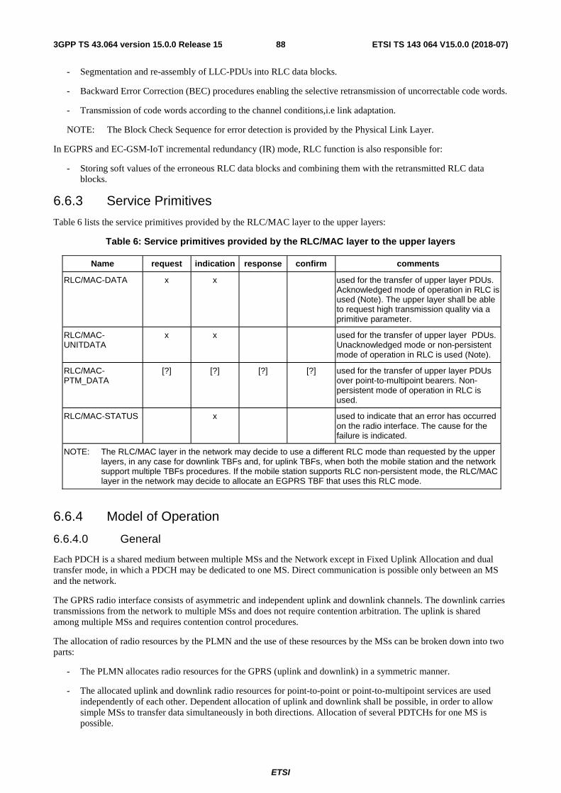
ETSI
ETSI TS 143 064 V15.0.0 (2018-07)883GPP TS 43.064 version 15.0.0 Release 15
- Segmentation and re-assembly of LLC-PDUs into RLC data blocks.
- Backward Error Correction (BEC) procedures enabling the selective retransmission of uncorrectable code words.
- Transmission of code words according to the channel conditions,i.e link adaptation.
NOTE: The Block Check Sequence for error detection is provided by the Physical Link Layer.
In EGPRS and EC-GSM-IoT incremental redundancy (IR) mode, RLC function is also responsible for:
- Storing soft values of the erroneous RLC data blocks and combining them with the retransmitted RLC data blocks.
6.6.3 Service Primitives
Table 6 lists the service primitives provided by the RLC/MAC layer to the upper layers:
Table 6: Service primitives provided by the RLC/MAC layer to the upper layers
Name request indication response confirm comments
RLC/MAC-DATA x x used for the transfer of upper layer PDUs. Acknowledged mode of operation in RLC is used (Note). The upper layer shall be able to request high transmission quality via a primitive parameter.
RLC/MAC-UNITDATA
x x used for the transfer of upper layer PDUs. Unacknowledged mode or non-persistent mode of operation in RLC is used (Note).
RLC/MAC- PTM_DATA
[?] [?] [?] [?] used for the transfer of upper layer PDUs over point-to-multipoint bearers. Non-persistent mode of operation in RLC is used.
RLC/MAC-STATUS x used to indicate that an error has occurred on the radio interface. The cause for the failure is indicated.
NOTE: The RLC/MAC layer in the network may decide to use a different RLC mode than requested by the upper layers, in any case for downlink TBFs and, for uplink TBFs, when both the mobile station and the network support multiple TBFs procedures. If the mobile station supports RLC non-persistent mode, the RLC/MAC layer in the network may decide to allocate an EGPRS TBF that uses this RLC mode.
6.6.4 Model of Operation
6.6.4.0 General
Each PDCH is a shared medium between multiple MSs and the Network except in Fixed Uplink Allocation and dual transfer mode, in which a PDCH may be dedicated to one MS. Direct communication is possible only between an MS and the network.
The GPRS radio interface consists of asymmetric and independent uplink and downlink channels. The downlink carries transmissions from the network to multiple MSs and does not require contention arbitration. The uplink is shared among multiple MSs and requires contention control procedures.
The allocation of radio resources by the PLMN and the use of these resources by the MSs can be broken down into two parts:
- The PLMN allocates radio resources for the GPRS (uplink and downlink) in a symmetric manner.
- The allocated uplink and downlink radio resources for point-to-point or point-to-multipoint services are used independently of each other. Dependent allocation of uplink and downlink shall be possible, in order to allow simple MSs to transfer data simultaneously in both directions. Allocation of several PDTCHs for one MS is possible.
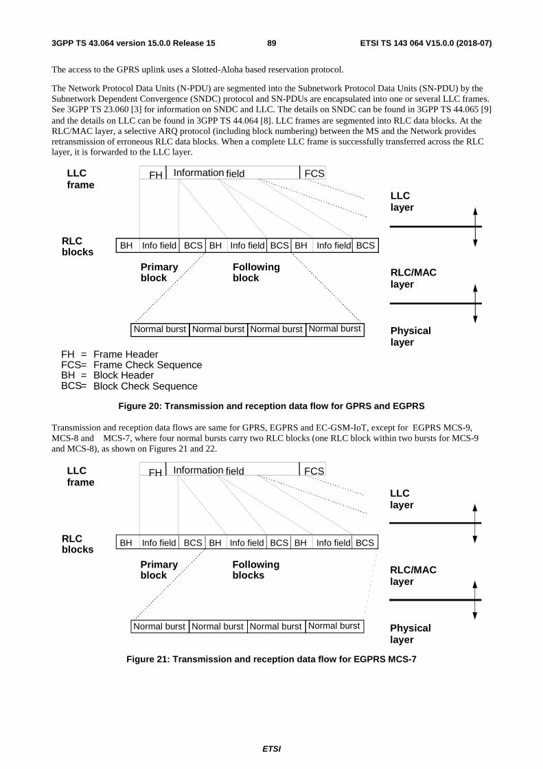
ETSI
ETSI TS 143 064 V15.0.0 (2018-07)893GPP TS 43.064 version 15.0.0 Release 15
The access to the GPRS uplink uses a Slotted-Aloha based reservation protocol.
The Network Protocol Data Units (N-PDU) are segmented into the Subnetwork Protocol Data Units (SN-PDU) by the Subnetwork Dependent Convergence (SNDC) protocol and SN-PDUs are encapsulated into one or several LLC frames. See 3GPP TS 23.060 [3] for information on SNDC and LLC. The details on SNDC can be found in 3GPP TS 44.065 [9] and the details on LLC can be found in 3GPP TS 44.064 [8]. LLC frames are segmented into RLC data blocks. At the RLC/MAC layer, a selective ARQ protocol (including block numbering) between the MS and the Network provides retransmission of erroneous RLC data blocks. When a complete LLC frame is successfully transferred across the RLC layer, it is forwarded to the LLC layer.
Normal burst Normal burst Normal burst Normal burst
BH
FH
LLClayer
RLC/MAClayer
Physicallayer
Information field FCS
Info fieldBH BCSRLCblocks
LLCframe
Primaryblock
Followingblock
Info field BCS Info field BH BCS
FH = Frame HeaderFCS=BH =BCS= Block Check Sequence
Frame Check SequenceBlock Header
Figure 20: Transmission and reception data flow for GPRS and EGPRS
Transmission and reception data flows are same for GPRS, EGPRS and EC-GSM-IoT, except for EGPRS MCS-9, MCS-8 and MCS-7, where four normal bursts carry two RLC blocks (one RLC block within two bursts for MCS-9 and MCS-8), as shown on Figures 21 and 22.
Figure 21: Transmission and reception data flow for EGPRS MCS-7
Normal burst Normal burst Normal burst Normal burst
BH
FH
LLClayer
RLC/MAClayer
Physicallayer
Information field FCS
Info fieldBH BCSRLCblocks
LLCframe
Primaryblock
Followingblocks
Info field BCS Info field BH BCS
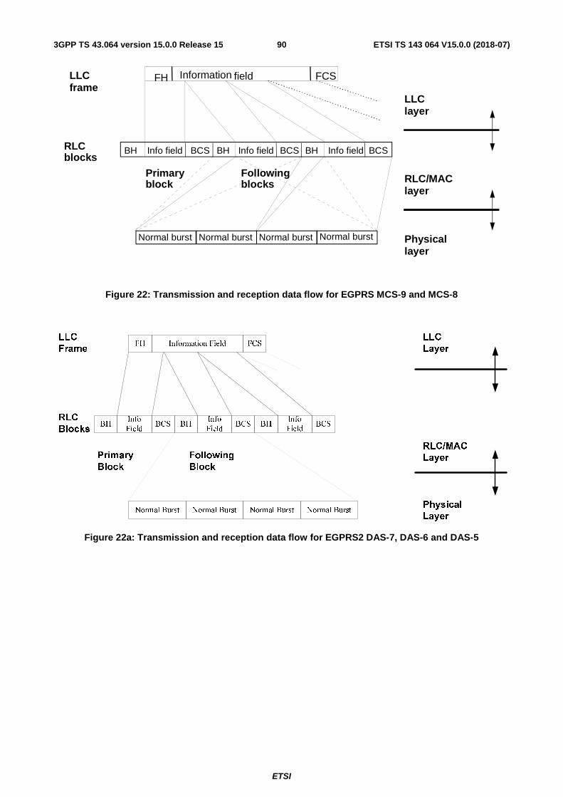
ETSI
ETSI TS 143 064 V15.0.0 (2018-07)903GPP TS 43.064 version 15.0.0 Release 15
Figure 22: Transmission and reception data flow for EGPRS MCS-9 and MCS-8
Normal Burst Normal Burst Normal Burst Normal Burst
FH Information Field FCS
BHInfo
FieldBCS
LLC
Frame
RLC
BlocksBH
Info
FieldBCS BH
Info
FieldBCS
LLC
Layer
RLC/MAC
Layer
Physical
Layer
Primary
Block
Following
Block
Figure 22a: Transmission and reception data flow for EGPRS2 DAS-7, DAS-6 and DAS-5
Normal burst Normal burst Normal burst Normal burst
BH
FH
LLClayer
RLC/MAClayer
Physicallayer
Information field FCS
Info fieldBH BCSRLCblocks
LLCframe
Primaryblock
Followingblocks
Info field BCS Info field BH BCS
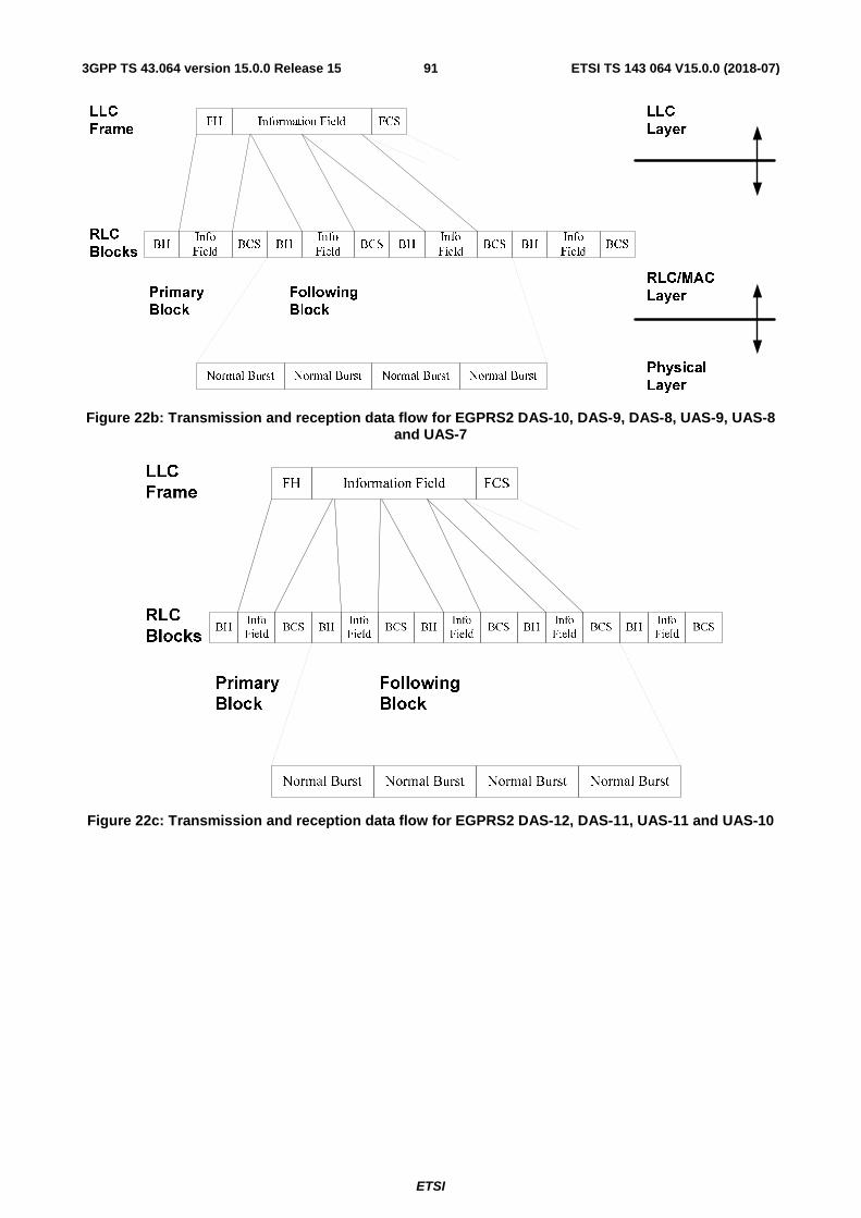
ETSI
ETSI TS 143 064 V15.0.0 (2018-07)913GPP TS 43.064 version 15.0.0 Release 15
Normal Burst Normal Burst Normal Burst Normal Burst
FH Information Field FCS
BHInfo
FieldBCS
LLC
Frame
RLC
BlocksBH
Info
FieldBCS BH
Info
FieldBCS
LLC
Layer
RLC/MAC
Layer
Physical
Layer
Primary
Block
Following
Block
BHInfo
FieldBCS
Figure 22b: Transmission and reception data flow for EGPRS2 DAS-10, DAS-9, DAS-8, UAS-9, UAS-8 and UAS-7
Figure 22c: Transmission and reception data flow for EGPRS2 DAS-12, DAS-11, UAS-11 and UAS-10
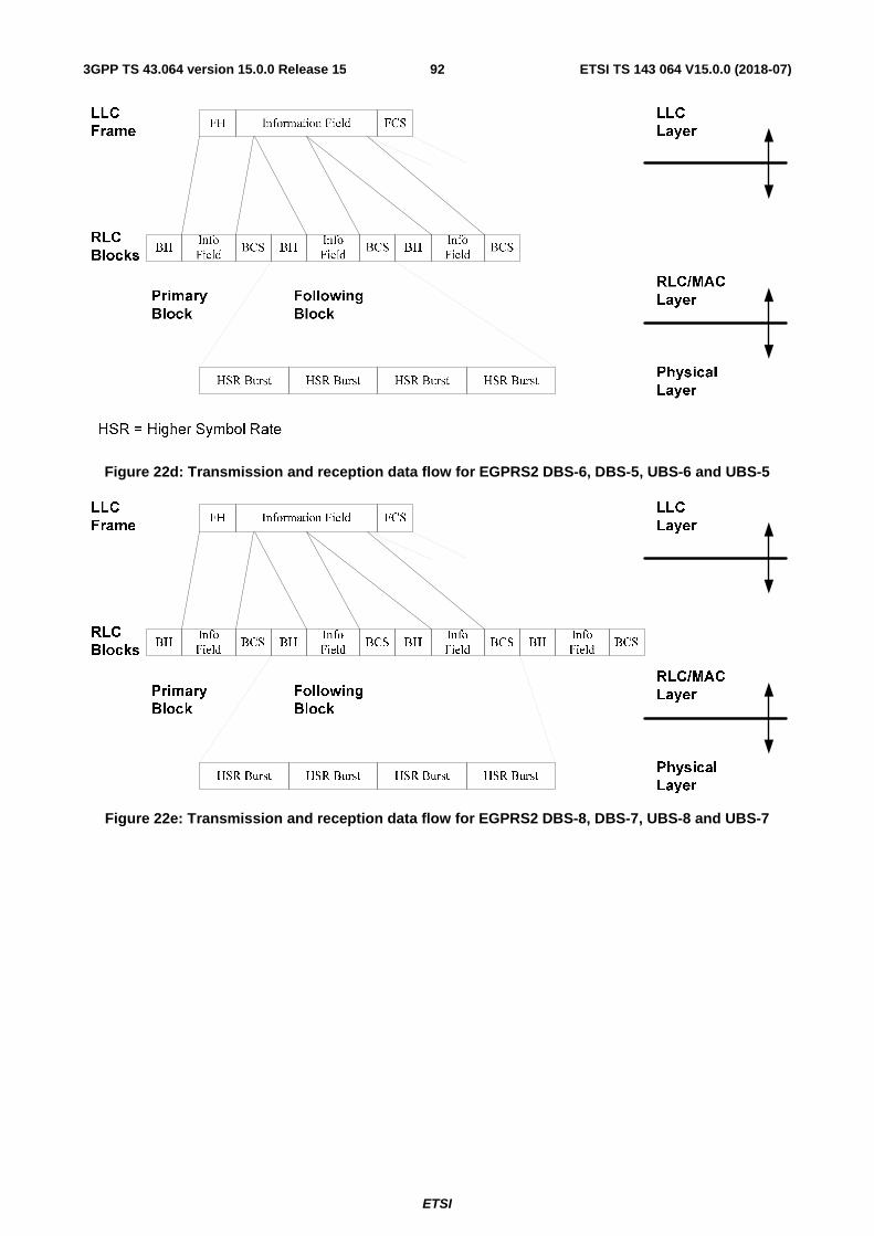
ETSI
ETSI TS 143 064 V15.0.0 (2018-07)923GPP TS 43.064 version 15.0.0 Release 15
Figure 22d: Transmission and reception data flow for EGPRS2 DBS-6, DBS-5, UBS-6 and UBS-5
HSR Burst HSR Burst HSR Burst HSR Burst
FH Information Field FCS
BHInfo
FieldBCS
LLC
Frame
RLC
BlocksBH
Info
FieldBCS BH
Info
FieldBCS
LLC
Layer
RLC/MAC
Layer
Physical
Layer
Primary
Block
Following
Block
BHInfo
FieldBCS
Figure 22e: Transmission and reception data flow for EGPRS2 DBS-8, DBS-7, UBS-8 and UBS-7
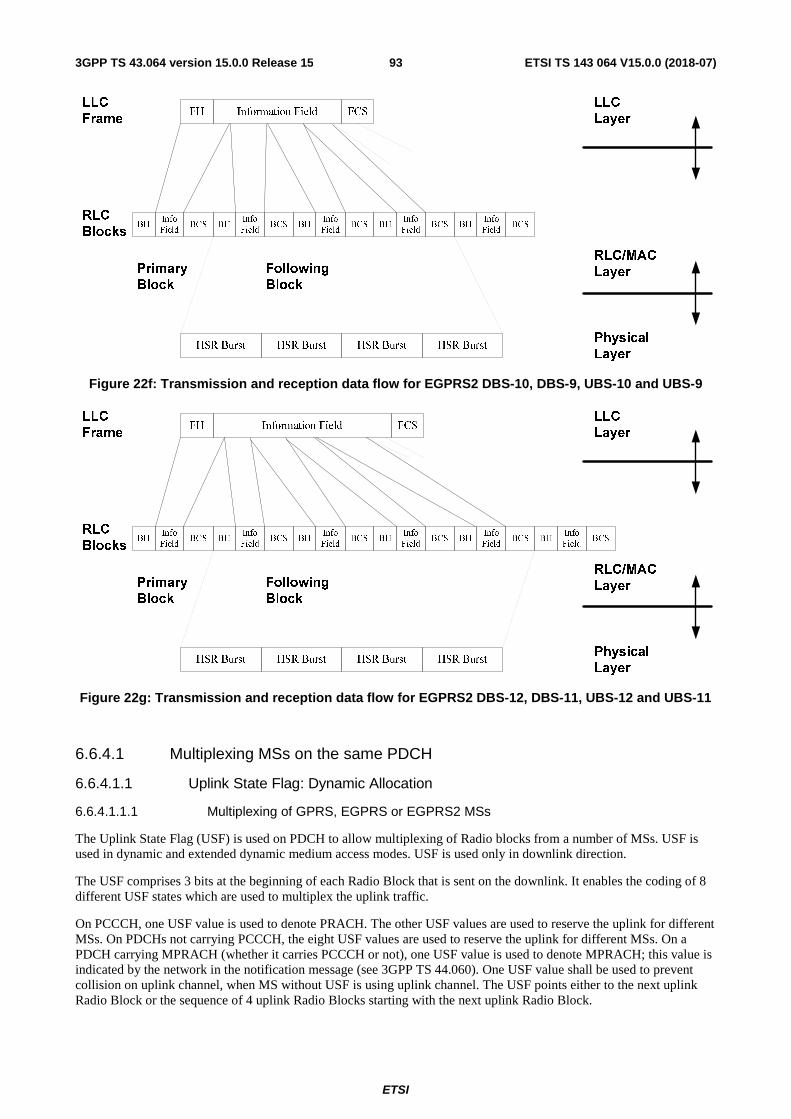
ETSI
ETSI TS 143 064 V15.0.0 (2018-07)933GPP TS 43.064 version 15.0.0 Release 15
HSR Burst HSR Burst HSR Burst HSR Burst
FH Information Field FCS
BHInfo
FieldBCS
LLC
Frame
RLC
Blocks
LLC
Layer
RLC/MAC
Layer
Physical
Layer
Primary
Block
Following
Block
BHInfo
FieldBCS BH
Info
FieldBCS BH
Info
FieldBCS BH
Info
FieldBCS
Figure 22f: Transmission and reception data flow for EGPRS2 DBS-10, DBS-9, UBS-10 and UBS-9
HSR Burst HSR Burst HSR Burst HSR Burst
FH Information Field FCS
BHInfo
FieldBCS
LLC
Frame
RLC
Blocks
LLC
Layer
RLC/MAC
Layer
Physical
Layer
Primary
Block
Following
Block
BHInfo
FieldBCS BH
Info
FieldBCS BH
Info
FieldBCS BH
Info
FieldBCS BH
Info
FieldBCS
Figure 22g: Transmission and reception data flow for EGPRS2 DBS-12, DBS-11, UBS-12 and UBS-11
6.6.4.1 Multiplexing MSs on the same PDCH
6.6.4.1.1 Uplink State Flag: Dynamic Allocation
6.6.4.1.1.1 Multiplexing of GPRS, EGPRS or EGPRS2 MSs
The Uplink State Flag (USF) is used on PDCH to allow multiplexing of Radio blocks from a number of MSs. USF is used in dynamic and extended dynamic medium access modes. USF is used only in downlink direction.
The USF comprises 3 bits at the beginning of each Radio Block that is sent on the downlink. It enables the coding of 8 different USF states which are used to multiplex the uplink traffic.
On PCCCH, one USF value is used to denote PRACH. The other USF values are used to reserve the uplink for different MSs. On PDCHs not carrying PCCCH, the eight USF values are used to reserve the uplink for different MSs. On a PDCH carrying MPRACH (whether it carries PCCCH or not), one USF value is used to denote MPRACH; this value is indicated by the network in the notification message (see 3GPP TS 44.060). One USF value shall be used to prevent collision on uplink channel, when MS without USF is using uplink channel. The USF points either to the next uplink Radio Block or the sequence of 4 uplink Radio Blocks starting with the next uplink Radio Block.
ETSI
ETSI TS 143 064 V15.0.0 (2018-07)943GPP TS 43.064 version 15.0.0 Release 15
6.6.4.1.1.2 Multiplexing of GPRS, EGPRS and EGPRS2 MSs
The GPRS, EGPRS and EGPRS2 MSs can be multiplexed dynamically on the same PDCH by utilising the USF. When uplink resources are assigned to a GPRS mobile station or an EGPRS/EGPRS2 mobile station using a multislot configuration only compatible with its GPRS multislot class, the network must use GMSK, i.e. CS-1 to CS-4, MCS-0, or MCS-1 to MCS-4, and the USF must point to the sequence of four uplink Radio Blocks starting with the next uplink Radio Block.
The dynamic allocation using USF granularity requires that a GPRS MS can read the USF in an EGPRS GMSK block. This is enabled by setting the stealing bits in the EGPRS GMSK blocks to indicate CS-4. The coding and interleaving of the USF is done as defined for CS-4. This leads to:
1. A standard GPRS MS will be able to detect the USF in EGPRS GMSK blocks. The risk that the rest of the block will be misinterpreted as valid information is assumed to be low.
2. An EGPRS MS can not differentiate CS-4 blocks and EGPRS GMSK blocks by only looking at the stealing bits. This is however not needed for USF detection, since the USF is signalled in the same way. Further, assuming that the EGPRS MS knows if it is in EGPRS or standard GPRS mode, it will only have to try to decode the remainder of the GMSK blocks in one way in order to determine if they were aimed for it.
An EGPRS mobile station shall be able to decode the USF that allocates the uplink to that mobile station irrespective of which of the modulation and coding schemes CS-1 to CS-4, MCS-0, MCS-1 to MCS-9, or DAS-5 to DAS-7 that is used.
A mobile station supporting EGPRS2-A in the downlink shall be able to decode the USF that allocates the uplink to that mobile station irrespective of which of the modulation and coding schemes CS-1 to CS-4, MCS-0, MCS-1 to MCS-9, or DAS-5 to DAS-12 that is used.
A mobile station supporting EGPRS2-B in the downlink shall be able to decode the USF that allocates the uplink to that mobile station irrespective of which of the modulation and coding schemes CS-1 to CS-4, MCS-0, MCS-1 to MCS-9, DAS-5 to DAS-12, or DBS-5 to DBS-12 that is used.
For mobile station synchronization reasons, if GPRS, EGPRS or EGPRS2 mobile stations using a multislot configuration only compatible with their GPRS multislot class are multiplexed on the PDCH, at least one downlink radio block every 360ms shall be transmitted to each MS with a coding scheme and a modulation that can be decoded by that MS.
6.6.4.1.2 Void
6.6.4.1.3 Exclusive Allocation
Exclusive allocation is used to reserve the uplink part of the PDCH for only one MS during the life of the Temporary Block Flow. In exclusive allocation, all the uplink blocks of the uplink part of the PDCH are available to the MS for transmission.
6.6.4.1.4 Fixed Uplink Allocation (FUA)
6.6.4.1.4.1 Multiplexing of GPRS, EGPRS, EC-GSM-IoT and EGPRS2 MSs
In EC operation, Fixed Uplink Allocation (FUA) as described in sub-clause 6.6.4.7.4a is used. The mobile station will either request uplink resources when sending an access request on the RACH/EC-RACH (see sub-clause 3.3.9.1) or when sending an RLC data block on the EC-PDTCH (the request being indicated in the RLC/MAC header of the RLC data block), or when sending EC-PACCH (see 3GPP TS 44.060). The resources allocated by the FUA are assigned by messages sent on the AGCH, EC-AGCH or EC-PACCH. In case the network has allocated resources by FUA, the corresponding radio blocks in the downlink shall use a USF value marking the USF as free for the duration of the FUA. Even though no USF based uplink allocation is supported, all downlink blocks allocated to the MS contain an USF to allow multiplexing with GPRS, EGPRS and EGPRS2 MSs.
For mobile station synchronization reasons, if GPRS, EGPRS or EGPRS2, EC-GSM-IoT mobile stations using a multislot configuration only compatible with their GPRS multislot class are multiplexed on the PDCH, at least one downlink radio block shall be transmitted to each MS with a coding scheme and a modulation that can be decoded by a MS using GPRS, EGPRS or EGPRS2 at least once every 360 ms and by a MS using EC-GSM-IoT at least once every [720 ms].
ETSI
ETSI TS 143 064 V15.0.0 (2018-07)953GPP TS 43.064 version 15.0.0 Release 15
6.6.4.2 Temporary Block Flow
A Temporary Block Flow (TBF) is a physical connection used by the two RR entities to support the unidirectional transfer of LLC PDUs on packet data physical channels. The TBF is assigned radio resource on one or more PDCHs and comprise a number of RLC/MAC blocks carrying one or more LLC PDUs. A TBF is temporary and is maintained only for the duration of the data transfer.
6.6.4.3 Temporary Flow Identity
Each TBF is assigned a Temporary Flow Identity (TFI) by the network. The assigned TFI is unique among concurrent TBFs in each direction and is used instead of the MS identity in the RLC/MAC layer. The same TFI value may be used concurrently for TBFs in opposite directions. The TFI is assigned in a resource assignment message that precedes the transfer of LLC frames belonging to one TBF to/from the MS. The same TFI is included in every RLC header belonging to a particular TBF as well as in the control messages associated to the LLC frame transfer (e.g. acknowledgements) in order to address the peer RLC entities.
In case of a DLMC capable MS in DLMC configuration, an Extended Temporary Flow Indentity (eTFI) may be assigned to the MS. The assigned eTFI in combination with the assigned TFI is unique among concurrent TBFs in the DL and is used instead of the MS identity in the RLC/MAC layer. A MS in a DLMC configuration may be assigned different TFI and eTFI combinations for different downlink carriers.
6.6.4.4 Medium Access modes
Four medium access modes are supported:
- Dynamic allocation,
- Fixed Uplink Allocation,
- Extended Dynamic allocation, and
- Exclusive allocation.
The Dynamic allocation shall be supported by all networks that support GPRS. All networks that support EC-GSM-IoT shall support fixed uplink allocation on the uplink and dynamic allocation on the downlink. The support of Extended Dynamic allocation and Exclusive allocation is optional.
The Dynamic allocation shall be supported in all mobile stations. All mobile stations that support EC-GSM-IoT shall support fixed uplink allocation on the uplink and dynamic allocation on the downlink. The support for Exclusive allocation is optional for mobile stations supporting DTM.
6.6.4.5 Acknowledged mode for RLC/MAC operation
6.6.4.5.1 GPRS
The transfer of RLC data blocks in the RLC acknowledged mode is controlled by a selective ARQ mechanism coupled with the numbering of the RLC data blocks within one Temporary Block Flow. The sending side (the MS or the network) transmits blocks within a window and the receiving side sends Packet Uplink Ack/Nack or Packet Downlink Ack/Nack message when needed. Every such message acknowledges all correctly received RLC data blocks up to an indicated block sequence number (BSN), thus “moving" the beginning of the sending window on the sending side. Additionally, the bitmap that starts at the same RLC data block is used to selectively request erroneously received RLC data blocks for retransmission. The sending side then retransmits the erroneous RLC data blocks, eventually resulting in further sliding the sending window.
The Packet Ack/Nack message does not include any change in the current assignment (and thus does not have to be acknowledged when sent on downlink). A missing Packet Ack/Nack is not critical and a new one can be issued whenever. In Packet Downlink Ack/Nack message, the MS may optionally initiate an uplink TBF.
When receiving uplink data from an MS the network shall, based on erroneous blocks received from MS, allocate additional resources for retransmission.
The acknowledgement procedure of the LLC layer is not combined with the acknowledgement procedure on the underlying RLC/MAC layer.
ETSI
ETSI TS 143 064 V15.0.0 (2018-07)963GPP TS 43.064 version 15.0.0 Release 15
6.6.4.5.2 EGPRS, EGPRS2 and EC-GSM-IoT
The transfer of RLC data blocks in the RLC acknowledged mode can be controlled by a selective type I ARQ mechanism, or by type II hybrid ARQ (incremental redundancy: IR) mechanism, coupled with the numbering of the RLC data blocks within one Temporary Block Flow. The sending side (the MS or the network) transmits blocks within a window and the receiving side sends Packet Uplink Ack/Nack or Packet Downlink Ack/Nack message when needed.
For a TBF with FANR activated, the receiving side may also send ack/nack information piggy-backed in radio blocks for data transfer sent in the other direction.
According to the link quality, an initial modulation and coding scheme is selected for an RLC block. For the retransmissions, the same or another modulation and coding scheme from the same family of the modulation and coding schemes can be selected. E.g. if MCS-7 is selected for the first transmission of an RLC block, any modulation and coding scheme of the family B can be used for the retransmissions. The selection of modulation and coding scheme is controlled by the network.
In the EGPRS/EGPRS2 type II Hybrid ARQ scheme, the information is first sent with one of the initial code rates (i.e., the rate 1/3 encoded data is punctured with the puncturing scheme (PS) 1 of the selected modulation and coding scheme). If the RLC data block is received in error, additional coded bits (i.e., the output of the rate 1/3 encoded data which is punctured with PS 2 of the prevailing modulation and coding scheme) are sent and decoded together with the already received codewords until decoding succeeds. If all the codewords (different punctured versions of the encoded data block) have been sent, the first codeword (which is punctured with PS 1) is sent. Alternatively, for EGPRS it is possible to use incremental redundancy modes called MCS-5-7 and MCS-6-9, in which the initial transmissions are sent with either MCS-5 or MCS-6 (respectively) and the retransmissions are sent with MCS-7 or MCS-9 (respectively). Header part is robustly coded so that the receiver is able to determine the block identities for all transmissions, even if the payload cannot be decoded.
The same type II Hybrid ARQ schemes as for EGPRS/EGPRS2 are also followed for EC-GSM-IoT with the exception that if information is sent with:
- MCS-1 or MCS-2 the information is always sent with PS 1 (i.e. PS 2 is not used in EC operation).
- MCS-3 or MCS-4 the information is always sent with PS 1 or PS 2 (i.e. PS 3 is not used in EC operation).
In the EGPRS/EGPRS2 type I ARQ, the operation is similar to the one of the EGPRS/EGPRS2 type II hybrid ARQ, except that the decoding of an RLC data block is solely based on the prevailing transmission (i.e., erroneous blocks are not stored).
Type II hybrid ARQ is mandatory in EGPRS MS and EGPRS2 MS receivers and the associated performance requirements are specified in 3GPP TS 45.005 [14].
6.6.4.6 Unacknowledged mode for RLC/MAC operation
The transfer of RLC data blocks in the unacknowledged RLC/MAC mode is controlled by the numbering of the RLC data blocks within one Temporary Block Flow and does not include any retransmissions. The receiving side extracts user data from the received RLC data blocks and attempts to preserve the user information length by replacing missing RLC data blocks by dummy information bits.
The same mechanism and message format for sending temporary acknowledgement messages is used as for acknowledged mode in order to convey the necessary control signalling (e.g. monitoring of channel quality for downlink channel or timing advance correction for uplink transfers). The fields for denoting the erroneous RLC blocks may be used as an additional measure for channel quality (i.e. parameter for link adaptation). The sending side (the MS or the network) transmits a number of radio blocks and then polls the receiving side to send an acknowledgement message. The Packet Uplink Ack/Nack and Packet Downlink Ack/Nack message does not include any change in the current assignment. A missing acknowledgement message is not critical and a new one can be obtained whenever. In Packet Downlink Ack/Nack message, the MS may optionally initiate an uplink TBF.
6.6.4.6a Non-persistent mode for RLC/MAC operation
The non-persistent RLC/MAC mode may be used for the transmission of RLC data blocks over an EGPRS TBF and an EGPRS2 TBF and is always used for the transmission of RLC data blocks over an MBMS bearer.
The transfer of RLC data blocks in non-persistent RLC/MAC mode is controlled by the numbering of the RLC data blocks within one Temporary Block Flow and may include retransmissions. Selective type I ARQ or type II hybrid ARQ
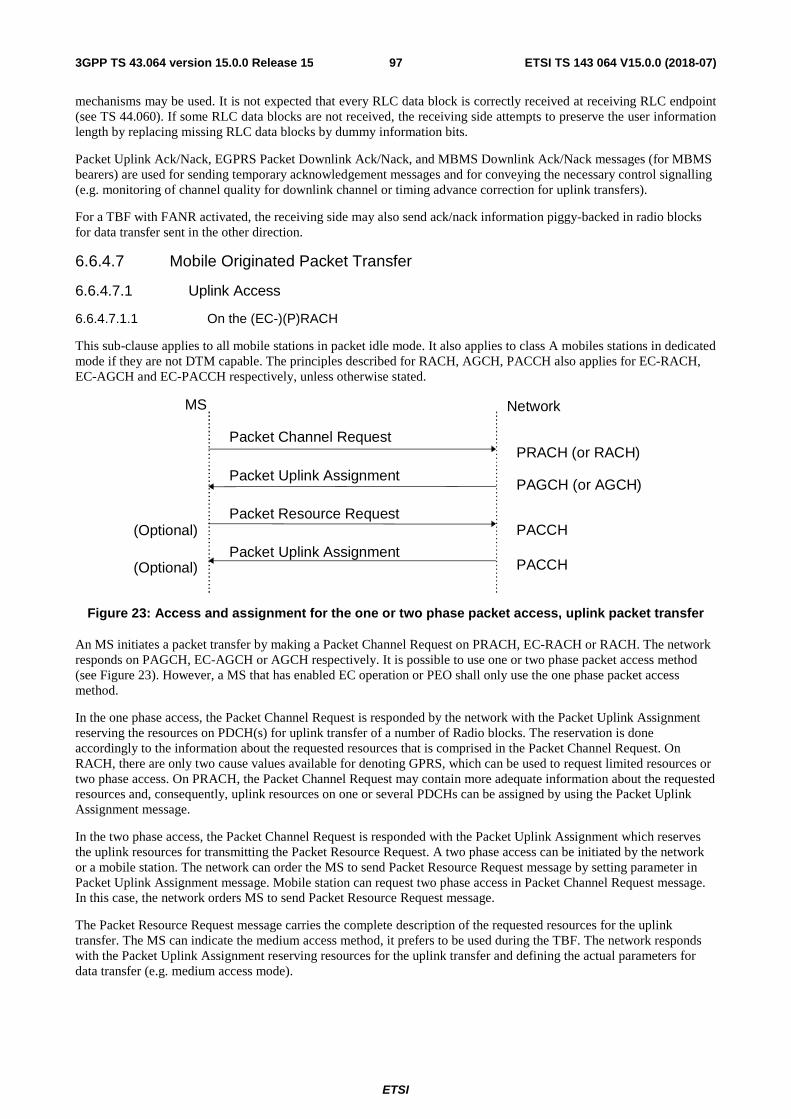
ETSI
ETSI TS 143 064 V15.0.0 (2018-07)973GPP TS 43.064 version 15.0.0 Release 15
mechanisms may be used. It is not expected that every RLC data block is correctly received at receiving RLC endpoint (see TS 44.060). If some RLC data blocks are not received, the receiving side attempts to preserve the user information length by replacing missing RLC data blocks by dummy information bits.
Packet Uplink Ack/Nack, EGPRS Packet Downlink Ack/Nack, and MBMS Downlink Ack/Nack messages (for MBMS bearers) are used for sending temporary acknowledgement messages and for conveying the necessary control signalling (e.g. monitoring of channel quality for downlink channel or timing advance correction for uplink transfers).
For a TBF with FANR activated, the receiving side may also send ack/nack information piggy-backed in radio blocks for data transfer sent in the other direction.
6.6.4.7 Mobile Originated Packet Transfer
6.6.4.7.1 Uplink Access
6.6.4.7.1.1 On the (EC-)(P)RACH
This sub-clause applies to all mobile stations in packet idle mode. It also applies to class A mobiles stations in dedicated mode if they are not DTM capable. The principles described for RACH, AGCH, PACCH also applies for EC-RACH, EC-AGCH and EC-PACCH respectively, unless otherwise stated.
Figure 23: Access and assignment for the one or two phase packet access, uplink packet transfer
An MS initiates a packet transfer by making a Packet Channel Request on PRACH, EC-RACH or RACH. The network responds on PAGCH, EC-AGCH or AGCH respectively. It is possible to use one or two phase packet access method (see Figure 23). However, a MS that has enabled EC operation or PEO shall only use the one phase packet access method.
In the one phase access, the Packet Channel Request is responded by the network with the Packet Uplink Assignment reserving the resources on PDCH(s) for uplink transfer of a number of Radio blocks. The reservation is done accordingly to the information about the requested resources that is comprised in the Packet Channel Request. On RACH, there are only two cause values available for denoting GPRS, which can be used to request limited resources or two phase access. On PRACH, the Packet Channel Request may contain more adequate information about the requested resources and, consequently, uplink resources on one or several PDCHs can be assigned by using the Packet Uplink Assignment message.
In the two phase access, the Packet Channel Request is responded with the Packet Uplink Assignment which reserves the uplink resources for transmitting the Packet Resource Request. A two phase access can be initiated by the network or a mobile station. The network can order the MS to send Packet Resource Request message by setting parameter in Packet Uplink Assignment message. Mobile station can request two phase access in Packet Channel Request message. In this case, the network orders MS to send Packet Resource Request message.
The Packet Resource Request message carries the complete description of the requested resources for the uplink transfer. The MS can indicate the medium access method, it prefers to be used during the TBF. The network responds with the Packet Uplink Assignment reserving resources for the uplink transfer and defining the actual parameters for data transfer (e.g. medium access mode).
MS Network
Packet Channel Request
Packet Uplink Assignment
Packet Resource Request
Packet Uplink Assignment
PRACH (or RACH)
PAGCH (or AGCH)
PACCH
PACCH
(Optional)
(Optional)
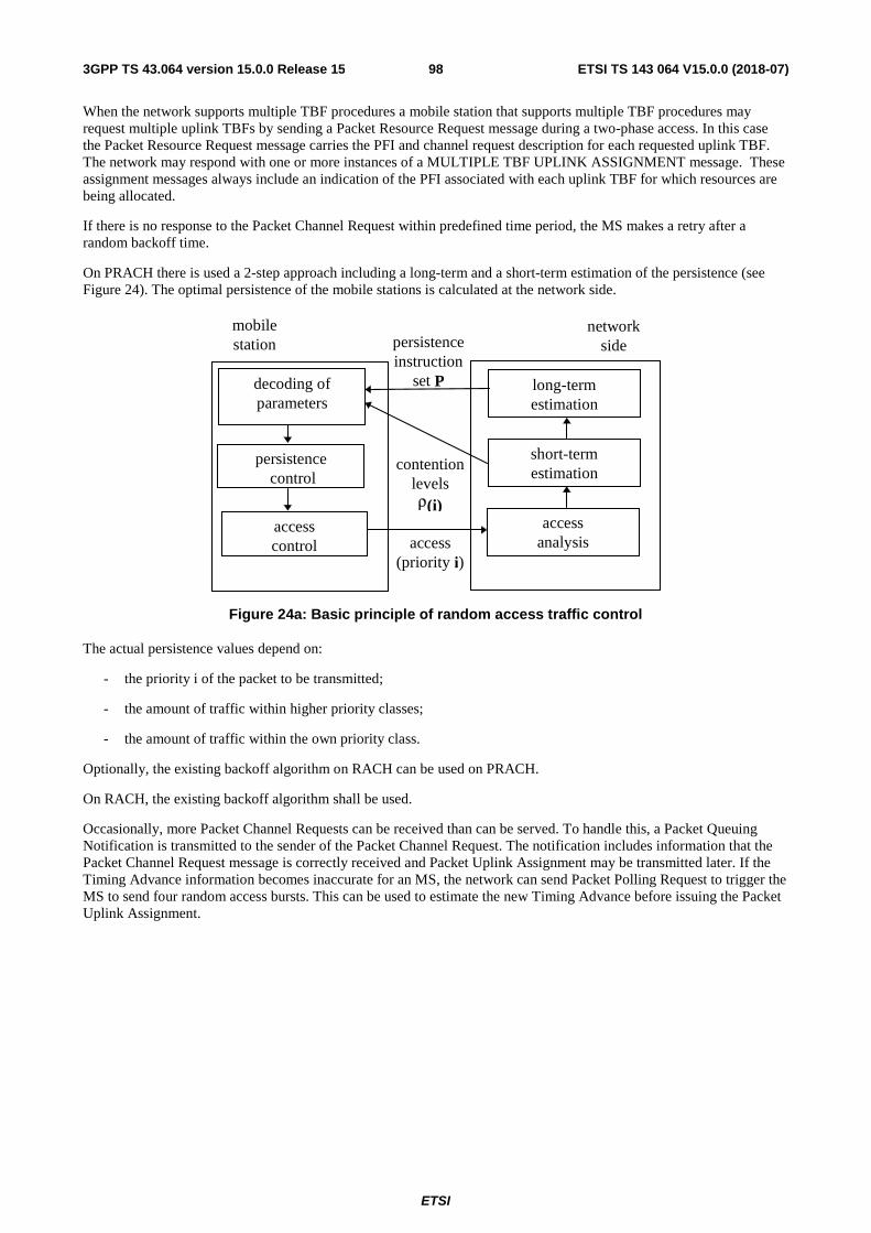
ETSI
ETSI TS 143 064 V15.0.0 (2018-07)983GPP TS 43.064 version 15.0.0 Release 15
When the network supports multiple TBF procedures a mobile station that supports multiple TBF procedures may request multiple uplink TBFs by sending a Packet Resource Request message during a two-phase access. In this case the Packet Resource Request message carries the PFI and channel request description for each requested uplink TBF. The network may respond with one or more instances of a MULTIPLE TBF UPLINK ASSIGNMENT message. These assignment messages always include an indication of the PFI associated with each uplink TBF for which resources are being allocated.
If there is no response to the Packet Channel Request within predefined time period, the MS makes a retry after a random backoff time.
On PRACH there is used a 2-step approach including a long-term and a short-term estimation of the persistence (see Figure 24). The optimal persistence of the mobile stations is calculated at the network side.
Figure 24a: Basic principle of random access traffic control
The actual persistence values depend on:
- the priority i of the packet to be transmitted;
- the amount of traffic within higher priority classes;
- the amount of traffic within the own priority class.
Optionally, the existing backoff algorithm on RACH can be used on PRACH.
On RACH, the existing backoff algorithm shall be used.
Occasionally, more Packet Channel Requests can be received than can be served. To handle this, a Packet Queuing Notification is transmitted to the sender of the Packet Channel Request. The notification includes information that the Packet Channel Request message is correctly received and Packet Uplink Assignment may be transmitted later. If the Timing Advance information becomes inaccurate for an MS, the network can send Packet Polling Request to trigger the MS to send four random access bursts. This can be used to estimate the new Timing Advance before issuing the Packet Uplink Assignment.
accesscontrol
decoding ofparameters
persistence control
short-termestimation
accessanalysis
long-termestimation
persistenceinstruction
set P
contentionlevelsρ(i)
access(priority i)
networkside
mobilestation
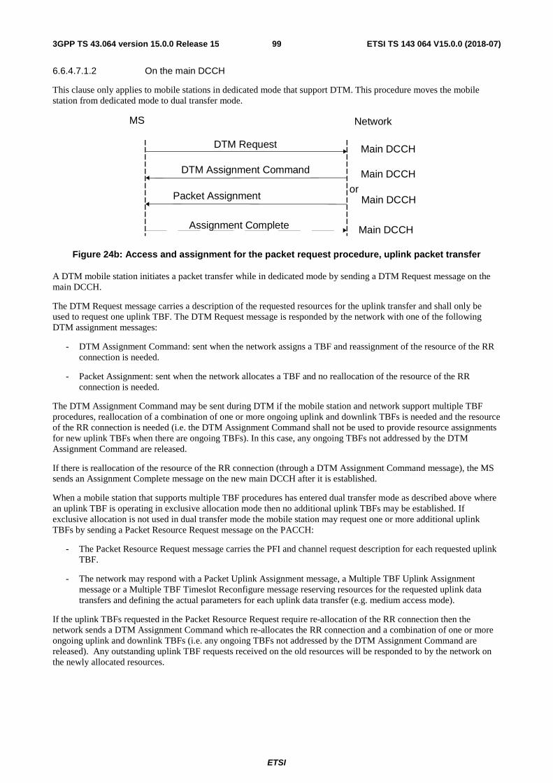
ETSI
ETSI TS 143 064 V15.0.0 (2018-07)993GPP TS 43.064 version 15.0.0 Release 15
6.6.4.7.1.2 On the main DCCH
This clause only applies to mobile stations in dedicated mode that support DTM. This procedure moves the mobile station from dedicated mode to dual transfer mode.
Figure 24b: Access and assignment for the packet request procedure, uplink packet transfer
A DTM mobile station initiates a packet transfer while in dedicated mode by sending a DTM Request message on the main DCCH.
The DTM Request message carries a description of the requested resources for the uplink transfer and shall only be used to request one uplink TBF. The DTM Request message is responded by the network with one of the following DTM assignment messages:
- DTM Assignment Command: sent when the network assigns a TBF and reassignment of the resource of the RR connection is needed.
- Packet Assignment: sent when the network allocates a TBF and no reallocation of the resource of the RR connection is needed.
The DTM Assignment Command may be sent during DTM if the mobile station and network support multiple TBF procedures, reallocation of a combination of one or more ongoing uplink and downlink TBFs is needed and the resource of the RR connection is needed (i.e. the DTM Assignment Command shall not be used to provide resource assignments for new uplink TBFs when there are ongoing TBFs). In this case, any ongoing TBFs not addressed by the DTM Assignment Command are released.
If there is reallocation of the resource of the RR connection (through a DTM Assignment Command message), the MS sends an Assignment Complete message on the new main DCCH after it is established.
When a mobile station that supports multiple TBF procedures has entered dual transfer mode as described above where an uplink TBF is operating in exclusive allocation mode then no additional uplink TBFs may be established. If exclusive allocation is not used in dual transfer mode the mobile station may request one or more additional uplink TBFs by sending a Packet Resource Request message on the PACCH:
- The Packet Resource Request message carries the PFI and channel request description for each requested uplink TBF.
- The network may respond with a Packet Uplink Assignment message, a Multiple TBF Uplink Assignment message or a Multiple TBF Timeslot Reconfigure message reserving resources for the requested uplink data transfers and defining the actual parameters for each uplink data transfer (e.g. medium access mode).
If the uplink TBFs requested in the Packet Resource Request require re-allocation of the RR connection then the network sends a DTM Assignment Command which re-allocates the RR connection and a combination of one or more ongoing uplink and downlink TBFs (i.e. any ongoing TBFs not addressed by the DTM Assignment Command are released). Any outstanding uplink TBF requests received on the old resources will be responded to by the network on the newly allocated resources.
MS Network
DTM Request Main DCCH
DTM Assignment Command
Packet Assignment
Main DCCH
Main DCCHor
Assignment Complete Main DCCH
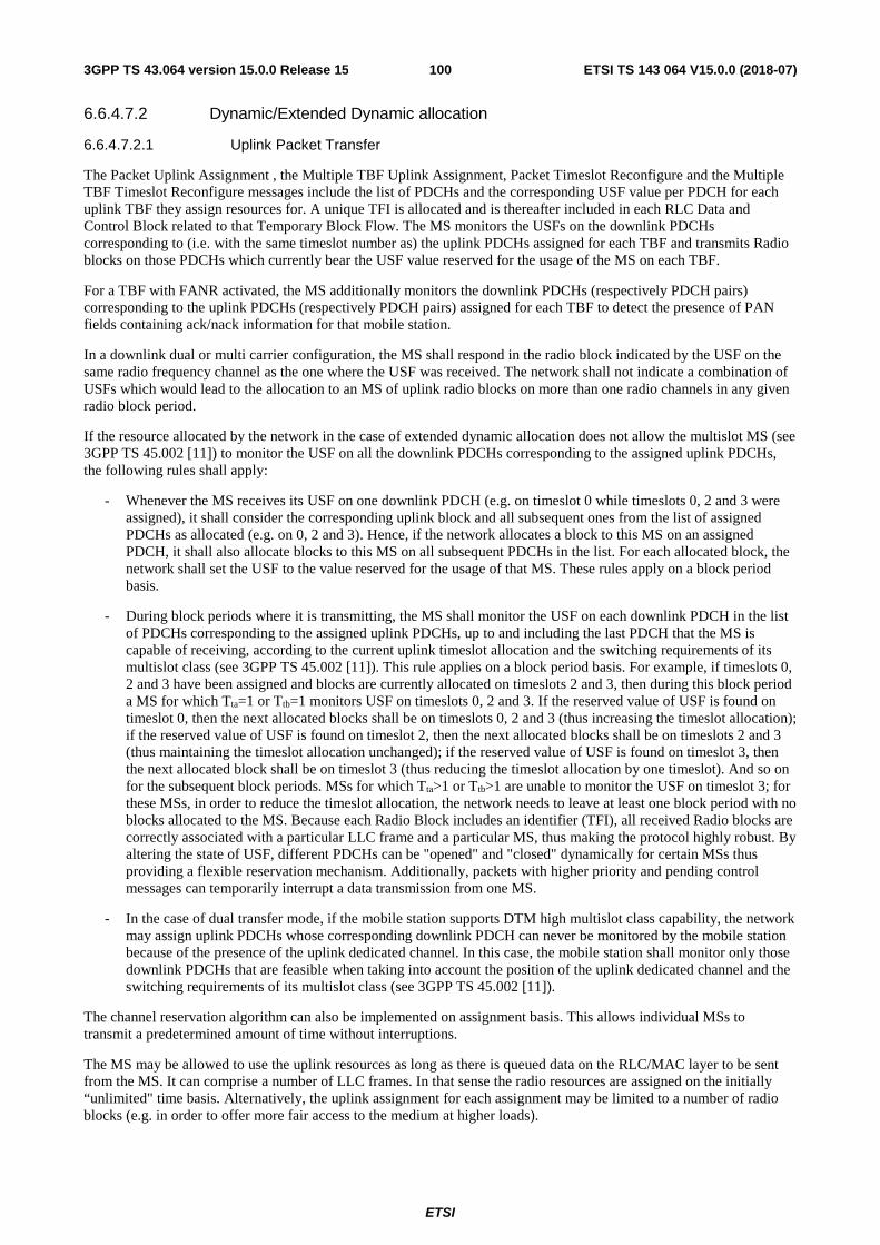
ETSI
ETSI TS 143 064 V15.0.0 (2018-07)1003GPP TS 43.064 version 15.0.0 Release 15
6.6.4.7.2 Dynamic/Extended Dynamic allocation
6.6.4.7.2.1 Uplink Packet Transfer
The Packet Uplink Assignment , the Multiple TBF Uplink Assignment, Packet Timeslot Reconfigure and the Multiple TBF Timeslot Reconfigure messages include the list of PDCHs and the corresponding USF value per PDCH for each uplink TBF they assign resources for. A unique TFI is allocated and is thereafter included in each RLC Data and Control Block related to that Temporary Block Flow. The MS monitors the USFs on the downlink PDCHs corresponding to (i.e. with the same timeslot number as) the uplink PDCHs assigned for each TBF and transmits Radio blocks on those PDCHs which currently bear the USF value reserved for the usage of the MS on each TBF.
For a TBF with FANR activated, the MS additionally monitors the downlink PDCHs (respectively PDCH pairs) corresponding to the uplink PDCHs (respectively PDCH pairs) assigned for each TBF to detect the presence of PAN fields containing ack/nack information for that mobile station.
In a downlink dual or multi carrier configuration, the MS shall respond in the radio block indicated by the USF on the same radio frequency channel as the one where the USF was received. The network shall not indicate a combination of USFs which would lead to the allocation to an MS of uplink radio blocks on more than one radio channels in any given radio block period.
If the resource allocated by the network in the case of extended dynamic allocation does not allow the multislot MS (see 3GPP TS 45.002 [11]) to monitor the USF on all the downlink PDCHs corresponding to the assigned uplink PDCHs, the following rules shall apply:
- Whenever the MS receives its USF on one downlink PDCH (e.g. on timeslot 0 while timeslots 0, 2 and 3 were assigned), it shall consider the corresponding uplink block and all subsequent ones from the list of assigned PDCHs as allocated (e.g. on 0, 2 and 3). Hence, if the network allocates a block to this MS on an assigned PDCH, it shall also allocate blocks to this MS on all subsequent PDCHs in the list. For each allocated block, the network shall set the USF to the value reserved for the usage of that MS. These rules apply on a block period basis.
- During block periods where it is transmitting, the MS shall monitor the USF on each downlink PDCH in the list of PDCHs corresponding to the assigned uplink PDCHs, up to and including the last PDCH that the MS is capable of receiving, according to the current uplink timeslot allocation and the switching requirements of its multislot class (see 3GPP TS 45.002 [11]). This rule applies on a block period basis. For example, if timeslots 0, 2 and 3 have been assigned and blocks are currently allocated on timeslots 2 and 3, then during this block period a MS for which Tta=1 or Ttb=1 monitors USF on timeslots 0, 2 and 3. If the reserved value of USF is found on timeslot 0, then the next allocated blocks shall be on timeslots 0, 2 and 3 (thus increasing the timeslot allocation); if the reserved value of USF is found on timeslot 2, then the next allocated blocks shall be on timeslots 2 and 3 (thus maintaining the timeslot allocation unchanged); if the reserved value of USF is found on timeslot 3, then the next allocated block shall be on timeslot 3 (thus reducing the timeslot allocation by one timeslot). And so on for the subsequent block periods. MSs for which Tta>1 or Ttb>1 are unable to monitor the USF on timeslot 3; for these MSs, in order to reduce the timeslot allocation, the network needs to leave at least one block period with no blocks allocated to the MS. Because each Radio Block includes an identifier (TFI), all received Radio blocks are correctly associated with a particular LLC frame and a particular MS, thus making the protocol highly robust. By altering the state of USF, different PDCHs can be "opened" and "closed" dynamically for certain MSs thus providing a flexible reservation mechanism. Additionally, packets with higher priority and pending control messages can temporarily interrupt a data transmission from one MS.
- In the case of dual transfer mode, if the mobile station supports DTM high multislot class capability, the network may assign uplink PDCHs whose corresponding downlink PDCH can never be monitored by the mobile station because of the presence of the uplink dedicated channel. In this case, the mobile station shall monitor only those downlink PDCHs that are feasible when taking into account the position of the uplink dedicated channel and the switching requirements of its multislot class (see 3GPP TS 45.002 [11]).
The channel reservation algorithm can also be implemented on assignment basis. This allows individual MSs to transmit a predetermined amount of time without interruptions.
The MS may be allowed to use the uplink resources as long as there is queued data on the RLC/MAC layer to be sent from the MS. It can comprise a number of LLC frames. In that sense the radio resources are assigned on the initially “unlimited" time basis. Alternatively, the uplink assignment for each assignment may be limited to a number of radio blocks (e.g. in order to offer more fair access to the medium at higher loads).
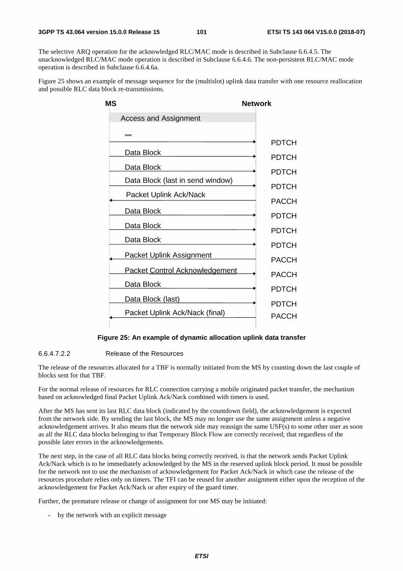
ETSI
ETSI TS 143 064 V15.0.0 (2018-07)1013GPP TS 43.064 version 15.0.0 Release 15
The selective ARQ operation for the acknowledged RLC/MAC mode is described in Subclause 6.6.4.5. The unacknowledged RLC/MAC mode operation is described in Subclause 6.6.4.6. The non-persistent RLC/MAC mode operation is described in Subclause 6.6.4.6a.
Figure 25 shows an example of message sequence for the (multislot) uplink data transfer with one resource reallocation and possible RLC data block re-transmissions.
Packet Uplink Ack/Nack
Data Block (last)
Access and Assignment
MS Network
PDTCH
PACCH
PDTCH
Packet Uplink Assignment
Packet Control AcknowledgementPACCH
PACCH
Data BlockPDTCH
Data BlockPDTCH
Data Block (last in send window)PDTCH
Data BlockPDTCH
Data BlockPDTCH
Data BlockPDTCH
Data BlockPDTCH
Packet Uplink Ack/Nack (final) PACCH
Figure 25: An example of dynamic allocation uplink data transfer
6.6.4.7.2.2 Release of the Resources
The release of the resources allocated for a TBF is normally initiated from the MS by counting down the last couple of blocks sent for that TBF.
For the normal release of resources for RLC connection carrying a mobile originated packet transfer, the mechanism based on acknowledged final Packet Uplink Ack/Nack combined with timers is used.
After the MS has sent its last RLC data block (indicated by the countdown field), the acknowledgement is expected from the network side. By sending the last block, the MS may no longer use the same assignment unless a negative acknowledgement arrives. It also means that the network side may reassign the same USF(s) to some other user as soon as all the RLC data blocks belonging to that Temporary Block Flow are correctly received; that regardless of the possible later errors in the acknowledgements.
The next step, in the case of all RLC data blocks being correctly received, is that the network sends Packet Uplink Ack/Nack which is to be immediately acknowledged by the MS in the reserved uplink block period. It must be possible for the network not to use the mechanism of acknowledgement for Packet Ack/Nack in which case the release of the resources procedure relies only on timers. The TFI can be reused for another assignment either upon the reception of the acknowledgement for Packet Ack/Nack or after expiry of the guard timer.
Further, the premature release or change of assignment for one MS may be initiated:
- by the network with an explicit message
ETSI
ETSI TS 143 064 V15.0.0 (2018-07)1023GPP TS 43.064 version 15.0.0 Release 15
- in dual transfer mode, by the release of the RR connection (i.e. handover, assignment and channel release procedures) or
- by the establishment of an RR connection.
In the case of release, the MS is ordered to interrupt the Temporary Block Flow for the TBF being released. The MS shall then reorganise the uplink buffer and issue a new Packet Channel Request to continue the uplink transfer with the RLC data blocks containing untransferred (i.e. on the RLC/MAC layer unacknowledged) LLC frames.
A change in assignment may also be initiated by the network, in which case the Packet Uplink Assignment, Packet Timeslot Reconfigure, Multiple TBF Uplink Assignment, Multiple TBF Timeslot Reconfigure, DTM Assignment Command or Packet Assignment message is issued.
6.6.4.7.3 Void
6.6.4.7.4 Exclusive Allocation
Exclusive allocation uses the Packet Uplink Assignment, Packet Timeslot Reconfigure, DTM Assignment Command or Packet Assignment messages to communicate a exclusive uplink resource allocation to the MS. The exclusive allocation consists of a start frame and a slot assignment. The MS waits until the start frame indicated and then starts transmitting the radio blocks. The exclusive allocation includes neither the USF nor the block assignment bitmap. The MS is free to transmit on the uplink without monitoring the downlink for the USF. Unused USF values may be used to prevent other mobiles from transmitting. A unique TFI is assigned and is thereafter included in each RLC data and downlink control block related to that Temporary Block Flow. Because each Radio Block includes an identifier (TFI or TLLI), all received Radio blocks are correctly associated with a particular LLC frame and a particular MS.
When a mobile station that supports multiple TBF procedures is in dual transfer mode where exclusive allocation is used, only one uplink TBF can be established. If exclusive allocation is not used in dual transfer mode then a mobile station that supports multiple TBF procedures may request the establishment of multiple uplink TBFs (i.e. in this case the mobile station must support a DTM multislot class that allows for more than one uplink timeslot). In this case the mobile station shall always indicate the PFI associated with each uplink TBF that it requests and all uplink TBFs shall operate using dynamic allocation or extended dynamic allocation.
The selective ARQ operation for the acknowledged RLC/MAC mode is described in Subclause 6.6.4.5. The unacknowledged RLC/MAC mode operation is described in Subclause 6.6.4.6. The non-persistent RLC/MAC mode operation is described in Subclause 6.6.4.6a.
Figure 25 shows an example of message sequence for the (multislot) uplink data transfer with one resource reallocation and possible RLC data block re-transmissions.
6.6.4.7.4a Fixed Uplink Allocation
Fixed Uplink Allocation (FUA) uses the EC IMMEDIATE ASSIGNMENT TYPE 1, EC IMMEDIATE ASSIGNMENT TYPE 2, EC PACKET UPLINK ASSIGNMENT or EC PACKET UPLINK ACK/NACK message to communicate the fixed uplink resource allocation to the MS. The FUA consists of a start indication, the resource allocation, the MS assigned MCS, and uplink and downlink Coverage Class. The MS waits until the first allocated resource block and starts transmitting the radio blocks, possibly using blind physical layer transmissions, if so required, according to its Coverage Class.
Since neither concurrent TBFs nor USF based uplink allocation are supported, the MS need not monitor the downlink during the uplink transfer.
After the last radio block in the fixed uplink allocation has been transmitted, the MS shall monitor the EC-PACCH for the EC PACKET UPLINK ACK/NACK message. When received, the MS shall act on the received block bitmap and the new fixed uplink allocation, if present.
If the EC-EGPRS PACKET UPLINK ACK/NACK message indicates all RLC data blocks have been received, the MS shall as indicated in the EC PACKET UPLINK ACK/NACK message continue monitoring the EC-PACCH or enter Packet Idle Mode and monitor the EC-AGCH to be reachable for possible downlink transmission.
Figure 6.6.4.7-1 shows an example of message sequence for the fixed uplink data transfer with one assignment transmitted on EC-AGCH (FUA 1) and a second fixed uplink assignment sent on EC-PACCH (FUA 2) with new fixed uplink assigned resources used for RLC data block transmission and possible RLC data block re-transmissions. The transfer is completed with a Final Ack Indicator (FAI) included in a EC-PUAN message, see 3GPP TS 44.060 [7], from the network on EC-PACCH.
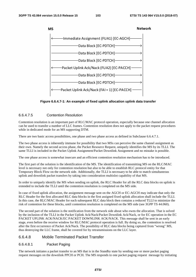
ETSI
ETSI TS 143 064 V15.0.0 (2018-07)1033GPP TS 43.064 version 15.0.0 Release 15
Immediate Assignment (FUA1) [EC-AGCH]
Data Block [EC-PDTCH]
Data Block [EC-PDTCH]
Data Block [EC-PDTCH]
Packet Uplink Ack/Nack (FUA2) [EC-PACCH]
Data Block [EC-PDTCH]
Data Block [EC-PDTCH]
Packet Uplink Ack/Nack (FAI = 1) [EC-PACCH]
MS Network
Figure 6.6.4.7-1: An example of fixed uplink allocation uplink data transfer
6.6.4.7.5 Contention Resolution
Contention resolution is an important part of RLC/MAC protocol operation, especially because one channel allocation can be used to transfer a number of LLC frames. Contention resolution does not apply to the packet request procedures while in dedicated mode for an MS supporting DTM.
There are two basic access possibilities, one phase and two phase access as defined in Subclause 6.6.4.7.1.
The two phase access is inherently immune for possibility that two MSs can perceive the same channel assignment as their own. Namely the second access phase, the Packet Resource Request, uniquely identifies the MS by its TLLI. The same TLLI is included in the Packet Uplink Assignment/Packet Downlink Assignment and no mistake is possible.
The one phase access is somewhat insecure and an efficient contention resolution mechanism has to be introduced.
The first part of the solution is the identification of the MS. The identification of transmitting MS on the RLC/MAC level is necessary not only for contention resolution but also to be able to establish RLC protocol entity for that Temporary Block Flow on the network side. Additionally, the TLLI is necessary to be able to match simultaneous uplink and downlink packet transfers by taking into consideration multislot capability of that MS.
In order to uniquely identify the MS when sending on uplink, the RLC Header for all the RLC data blocks on uplink is extended to include the TLLI until the contention resolution is completed on the MS side.
In case of fixed uplink allocation, the assignment message sent on the AGCH or EC-AGCH may indicate that only the RLC Header for the first allocated RLC data blocks in the first assigned fixed uplink allocation shall include the TLLI. In this case, the RLC/MAC Header for each subsequent RLC data block then contains a reduced TLLI to minimize the risk of contention for these blocks, until contention resolution is completed on the MS side (see 3GPP TS 44.060).
The second part of the solution is the notification from the network side about who owns the allocation. That is solved by the inclusion of the TLLI in the Packet Uplink Ack/Nack/Packet Downlink Ack/Nack, or for EC operation in the EC PACKET UPLINK ACK/NACK/EC PACKET DOWNLINK ACK/NACK. This message shall be sent in an early stage, even before the receive window for RLC/MAC protocol operation is full. By doing so, the contention is resolved after the first occurrence of Packet Ack/Nack. The possibility of RLC data blocks being captured from “wrong" MS, thus destroying the LLC frame, shall be covered for by retransmissions on the LLC layer.
6.6.4.8 Mobile Terminated Packet Transfer
6.6.4.8.1 Packet Paging
The network initiates a packet transfer to an MS that is in the Standby state by sending one or more packet paging request messages on the downlink PPCH or PCH. The MS responds to one packet paging request message by initiating
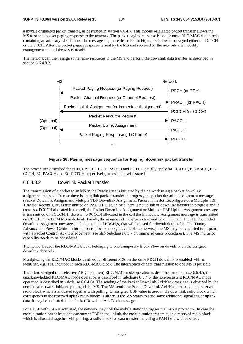
ETSI
ETSI TS 143 064 V15.0.0 (2018-07)1043GPP TS 43.064 version 15.0.0 Release 15
a mobile originated packet transfer, as described in section 6.6.4.7. This mobile originated packet transfer allows the MS to send a packet paging response to the network. The packet paging response is one or more RLC/MAC data blocks containing an arbitrary LLC frame. The message sequence described in Figure 26 below is conveyed either on PCCCH or on CCCH. After the packet paging response is sent by the MS and received by the network, the mobility management state of the MS is Ready.
The network can then assign some radio resources to the MS and perform the downlink data transfer as described in section 6.6.4.8.2.
Figure 26: Paging message sequence for Paging, downlink packet transfer
The procedures described for PCH, RACH, CCCH, PACCH and PDTCH equally apply for EC-PCH, EC-RACH, EC-CCCH, EC-PACCH and EC-PDTCH respectively, unless otherwise stated.
6.6.4.8.2 Downlink Packet Transfer
The transmission of a packet to an MS in the Ready state is initiated by the network using a packet downlink assignment message. In case there is an uplink packet transfer in progress, the packet downlink assignment message (Packet Downlink Assignment, Multiple TBF Downlink Assignment, Packet Timeslot Reconfigure or a Multiple TBF Timeslot Reconfigure) is transmitted on PACCH. Else, in case there is no uplink or downlink transfer in progress and if there is a PCCCH allocated in the cell, the Packet Downlink Assignment or Multiple TBF Uplink Assignment message is transmitted on PCCCH. If there is no PCCCH allocated in the cell the Immediate Assignment message is transmitted on CCCH. For a DTM MS in dedicated mode, the assignment message is transmitted on the main DCCH. The packet downlink assignment messages include the list of PDCH(s) that will be used for downlink transfer. The Timing Advance and Power Control information is also included, if available. Otherwise, the MS may be requested to respond with a Packet Control Acknowledgement (see also Subclause 6.5.7 on timing advance procedures). The MS multislot capability needs to be considered.
The network sends the RLC/MAC blocks belonging to one Temporary Block Flow on downlink on the assigned downlink channels.
Multiplexing the RLC/MAC blocks destined for different MSs on the same PDCH downlink is enabled with an identifier, e.g. TFI, included in each RLC/MAC block. The interruption of data transmission to one MS is possible.
The acknowledged (i.e. selective ARQ operation) RLC/MAC mode operation is described in subclause 6.6.4.5; the unacknowledged RLC/MAC mode operation is described in subclause 6.6.4.6; the non-persistent RLC/MAC mode operation is described in subclause 6.6.4.6a. The sending of the Packet Downlink Ack/Nack message is obtained by the occasional network initiated polling of the MS. The MS sends the Packet Downlink Ack/Nack message in a reserved radio block which is allocated together with polling. Unassigned USF value is used in the downlink radio block which corresponds to the reserved uplink radio blocks. Further, if the MS wants to send some additional signalling or uplink data, it may be indicated in the Packet Downlink Ack/Nack message.
For a TBF with FANR activated, the network may poll the mobile station to trigger the FANR procedure. In case the mobile station has at least one concurrent TBF in the uplink, the mobile station transmits, in a reserved radio block which is allocated together with polling, a radio block for data transfer including a PAN field with ack/nack
MS Network
Packet Paging Request (or Paging Request) PPCH (or PCH)
Packet Channel Request (or Channel Request)PRACH (or RACH)
Packet Uplink Assignment (or Immediate Assignment)PCCCH (or CCCH)
Packet Resource RequestPACCH(Optional)
Packet Uplink AssignmentPACCH(Optional)
Packet Paging Response (LLC frame)PDTCH
…
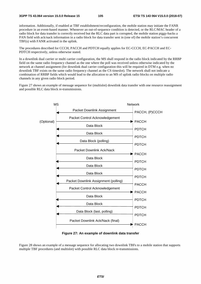
ETSI
ETSI TS 143 064 V15.0.0 (2018-07)1053GPP TS 43.064 version 15.0.0 Release 15
information. Additionally, if enabled at TBF establishment/reconfiguration, the mobile station may initiate the FANR procedure in an event-based manner. Whenever an out-of-sequence condition is detected, or the RLC/MAC header of a radio block for data transfer is correctly received but the RLC data part is corrupted, the mobile station piggy-backs a PAN field with ack/nack information in a radio block for data transfer sent in (one of) the mobile station’s concurrent TBF(s) with FANR activated in the uplink.
The procedures described for CCCH, PACCH and PDTCH equally applies for EC-CCCH, EC-PACCH and EC-PDTCH respectively, unless otherwise stated.
In a downlink dual carrier or multi carrier configuration, the MS shall respond in the radio block indicated by the RRBP field on the same radio frequency channel as the one where the poll was received unless otherwise indicated by the network at channel assignment (for downlink dual carrier configuration this will be required in DTM e.g. when no downlink TBF exists on the same radio frequency channel as the CS timeslot). The network shall not indicate a combination of RRBP fields which would lead to the allocation to an MS of uplink radio blocks on multiple radio channels in any given radio block period.
Figure 27 shows an example of message sequence for (multislot) downlink data transfer with one resource reassignment and possible RLC data block re-transmissions.
Figure 27: An example of downlink data transfer
Figure 28 shows an example of a message sequence for allocating two downlink TBFs to a mobile station that supports multiple TBF procedures (and multislot) with possible RLC data block re-transmissions.
MS Network
Packet Downlink Assignment PACCH, (P)CCCH
Packet Control AcknowledgementPACCH
Data BlockPDTCH
Packet Downlink Ack/NackPACCH
(Optional)
Data BlockPDTCH
Data Block (polling)PDTCH
Data BlockPDTCH
Packet Control AcknowledgementPACCH
Data BlockPDTCH
Data BlockPDTCH
Data BlockPDTCH
Packet Downlink Ack/Nack (final)PACCH
Data BlockPDTCH
Data Block (last, polling)PDTCH
Packet Downlink Assignment (polling)PACCH
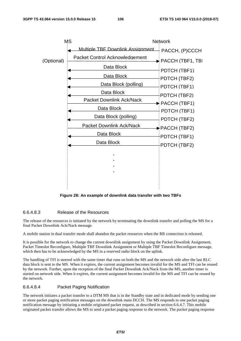
ETSI
ETSI TS 143 064 V15.0.0 (2018-07)1063GPP TS 43.064 version 15.0.0 Release 15
MS Network
Multiple TBF Downlink Assignment PACCH, (P)CCCH
Packet Control Acknowledgement PACCH (TBF1, TBF
Data Block PDTCH (TBF1)
Packet Downlink Ack/Nack PACCH (TBF1)
(Optional)
Data Block PDTCH (TBF2) Data Block (polling) PDTCH (TBF1) Data Block
PDTCH (TBF2)
Data Block PDTCH (TBF1) Data Block (polling) PDTCH (TBF2)
Data Block PDTCH (TBF1) Data Block PDTCH (TBF2)
Packet Downlink Ack/Nack PACCH (TBF2)
.
.
.
.
Figure 28: An example of downlink data transfer with two TBFs
6.6.4.8.3 Release of the Resources
The release of the resources is initiated by the network by terminating the downlink transfer and polling the MS for a final Packet Downlink Ack/Nack message.
A mobile station in dual transfer mode shall abandon the packet resources when the RR connection is released.
It is possible for the network to change the current downlink assignment by using the Packet Downlink Assignment, Packet Timeslot Reconfigure, Multiple TBF Downlink Assignment or Multiple TBF Timeslot Reconfigure message, which then has to be acknowledged by the MS in a reserved radio block on the uplink.
The handling of TFI is steered with the same timer that runs on both the MS and the network side after the last RLC data block is sent to the MS. When it expires, the current assignment becomes invalid for the MS and TFI can be reused by the network. Further, upon the reception of the final Packet Downlink Ack/Nack from the MS, another timer is started on network side. When it expires, the current assignment becomes invalid for the MS and TFI can be reused by the network.
6.6.4.8.4 Packet Paging Notification
The network initiates a packet transfer to a DTM MS that is in the Standby state and in dedicated mode by sending one or more packet paging notification messages on the downlink main DCCH. The MS responds to one packet paging notification message by initiating a mobile originated packet request, as described in section 6.6.4.7. This mobile originated packet transfer allows the MS to send a packet paging response to the network. The packet paging response
ETSI
ETSI TS 143 064 V15.0.0 (2018-07)1073GPP TS 43.064 version 15.0.0 Release 15
is one or more RLC/MAC data blocks containing an arbitrary LLC frame. After the packet paging response is sent by the MS and received by the network, the mobility management state of the MS is Ready.
The network can then assign some radio resources to the MS and perform the downlink data transfer as described in section 6.6.4.8.2.
6.6.4.9 Simultaneous Uplink and Downlink Packet Transfer
6.6.4.9.1 MS Does Not Support Multiple TBF Procedures
During the ongoing uplink Temporary Block Flow, the MS continuously monitors one downlink PDCH for possible occurrences of Packet Downlink Assignment or Packet Timeslot Reconfigure messages on PACCH (see Figure 25). The MS is therefore reachable for downlink packet transfers that can then be conveyed simultaneously on the PDCH(s) that respect the MS multislot capability. An EC-GSM-IoT MS transmitting radioblock in a Fixed Uplink Allocation need not simultaneously monitor the downlink for the occurrence of messages on the EC-PACCH.
If the MS wants to send packets to the network during the ongoing downlink Temporary Block Flow, it can be indicated in the acknowledgement that is sent from the MS. By doing so, no explicit Packet Channel Requests have to be sent to the network. Further, the network already has the knowledge of which PDCH(s) that particular MS is currently using so that the uplink resources can be assigned on the PDCH(s) that respect the MS multislot capability. This method may introduce an extra delay when initiating the uplink packet transfer but only for the first LLC frame in a sequence.
In a downlink dual carrier or multi carrier configuration, the network shall not indicate a combination of USF and/or RRBP fields which would lead to the allocation to an MS of uplink radio blocks on multiple radio channels in any given radio block period.
6.6.4.9.2 MS Supports Multiple TBF Procedures
Mobile station support of multiple TBF procedures is optional. A mobile station that supports multiple TBF procedures may operate multiple uplink and downlink TBFs concurrently. The maximum number of TBFs that a mobile station that supports multiple TBF procedures can support concurrently is not specified. Mobile station implementations are expected to ensure that the mobile station can support the number of TBFs sufficient to operate all the PDP contexts it has activated. As such, a mobile station may choose to release, modify or activate one or more PDP contexts when prioritizing the services it wants to operate concurrently. The network is not required to consider any potential complexity limitations regarding the number of concurrent TBFs when establishing an uplink or downlink TBF for a mobile station that supports multiple TBF procedures.
When any given PDP Context is activated, it is allocated a Packet Flow Context by the network and the payload associated with the corresponding PFI will be sent using one TBF (for a unidirectional service) or one uplink and one downlink TBF (for a bidirectional service). As such, each activated PDP Context has an implicit number of TBFs required to support it. However, the total number of TBFs required to support a given set of active PDP Contexts associated with a mobile station that supports multiple TBF procedures may be reduced as a result of TBF sharing as follows:
- Any given PDP Context that a mobile station attempts to activate for a unidirectional service may be aggregated by the SGSN so that the same PFI is associated with multiple PDP Contexts (see clause 12.6.3.5 of 3GPP TS 23.060). When this occurs a single TBF is used to deliver user plane payload associated with any of the aggregated PDP Contexts.
- Bandwidth from a TBF allocated to send user plane payload for an active PDP Context is stolen to send control plane messages (e.g. GMM or SM).
Network support of packet flow context (PFC) procedures is indicated by the PFC_FEATURE_MODE parameter that is broadcast on either the BCCH or PBCCH. If the PFC_FEATURE_MODE bit is not present then the network does not support PFC procedures or multiple TBF procedures. If the network supports PFC procedures then a mobile station may indicate a PFI value during uplink TBF establishment.
Network support of multiple TBF procedures is indicated using the MTBF_CAPABILITY parameter that is broadcast on either the BCCH and PBCCH. If the network indicates it supports multiple TBF procedures then it shall also indicate support for PFC procedures. When the network and the mobile station both support multiple TBF procedures then the mobile station shall indicate the PFI value associated with each uplink TBF it attempts to establish
During one or more ongoing TBFs, the mobile station continuously monitors its assigned downlink PDCHs for possible occurrences of downlink TBF allocations from the network. The network has knowledge of which uplink PDCH(s) the
ETSI
ETSI TS 143 064 V15.0.0 (2018-07)1083GPP TS 43.064 version 15.0.0 Release 15
mobile station is already using and can therefore assign downlink PDCH(s) that respect the multislot capability of the MS.
During one or more ongoing TBFs, a mobile station can request the establishment of one or more uplink TBFs by sending a Packet Downlink Ack/Nack or a Packet Resource Request message to the network. The network has knowledge of which downlink PDCH(s) the mobile station is already using and can therefore assign uplink PDCH(s) that respect the multislot capability of the MS. Using a Packet Downlink Ack/Nack to make an uplink TBF request may introduce an extra delay when initiating the corresponding uplink packet transfer(s) but only for the first LLC frame in a sequence.
In a downlink dual carrier configuration, the network shall not indicate a combination of USF and/or RRBP fields which would lead to the allocation to an MS of uplink radio blocks on both radio channels in any given radio block period.
Multiple TBF procedures are not supported by Mobile stations in downlink multi carrier configurations, or by MS in EC operation.
6.7 Abnormal cases in GPRS MS Ready State The RLC/MAC error causes and procedures to handle these can be found in 3GPP TS 44.018 [6] , 3GPP TS 44.060 [7] and 3GPP TS 45.008 [15].
6.8 Void
6.9 MBMS Data Transfer MBMS data, in the form of individual upper layer frames, is mapped into RLC/MAC-PTM_DATA primitive and distributed from SGSN to the BSS representing the cells that belong to the Service Area. In the case of A/Gb mode, upper layer frames are LLC frames.
The procedures for notification, user counting and addressing, channel assignment and data transfer are specified in 3GPP TS 43.246.
ETSI
ETSI TS 143 064 V15.0.0 (2018-07)1093GPP TS 43.064 version 15.0.0 Release 15
Annex A (informative): Bibliography
1) ITU-T I.130, Method for the Characterization of Telecommunication Services Supported by an ISDN
2) ITU-T Q.65, Stage 2 of the Method for Characterization of the Services Supported by an ISDN
3) DIS 8886, OSI Data Link Service Definition
4) DIS 10022, OSI Physical Service Definition
5) ISO 10039, Medium Access Control Service Definition
6) ISO 4335, HDLC Procedures
7) ISO 7478, Multilink Procedures
8) ISO 7498, OSI Basic Reference Model and Layer Service Conventions
ETSI
ETSI TS 143 064 V15.0.0 (2018-07)1103GPP TS 43.064 version 15.0.0 Release 15
Annex B (informative): Multiple TBF Feature
B.1 General The multiple TBF feature has been optionally introduced for mobile stations and networks operating in A/Gb mode, this feature is described in TS 43.064 and TS 44.060, and in TS 43.055 and TS 44.018 for DTM procedures.
A mobile station that supports multiple TBF procedures may operate multiple uplink and downlink TBFs concurrently. The maximum number of TBFs that a mobile station can support in either direction concurrently is not specified.
In order to support multiple TBFs, both the network and the mobile station must support:
i) Packet flow procedures. The PFI (packet flow identifier) is used in the equivalent manner to the RB Id (radio bearer identifier in Iu mode) in RLC/MAC control messages
ii) Multiple TBF assignment messages (i.e. MULTIPLE TBF UPLINK ASSIGNMENT, MULTIPLE TBF DOWNLINK ASSIGNMENT and MULTIPLE TBF TIMESLOT RECONFIGURE messages)
There are no minimum multislot class requirements defined in relation to the support of the multiple TBF feature.
Mobile station implementations are expected to ensure that the mobile station can support the number of TBFs sufficient to operate all the PDP contexts it has activated. As such, a mobile station may choose to release, modify or activate one or more PDP contexts when prioritising the services it wants to operate concurrently. The network is not required to consider any potential complexity limitations regarding the number of concurrent TBFs when establishing an uplink or downlink TBF for a mobile station that supports multiple TBF procedures.
B.2 Multiple TBF capability The mobile station indicates its support of multiple TBFs in the “Multiple TBF Capability” field in the MS Radio Access Capabilities 2 Information Element which is included in the first PACKET RESOURCE REQUEST message sent to the network (e.g. in a two-phase access if multiple TBFs are requested directly from packet idle mode, or as part of the first PACKET RESOURCE REQUEST message on the PACCH if the initial TBF has been established using a one-phase access). The MS Radio Access Capabilities 2 Information Element is also included in the GMM ATTACH REQUEST and ROUTING AREA UPDATE REQUEST message.
The network indicates whether it supports multiple TBFs in the “Multiple TBF Capability” field in the GPRS Cell Options IE contained in the system broadcast information (i.e. PSI1, PSI13 and SI13). The network also includes the GPRS Cell Options IE in the DTM ASSIGNMENT COMMAND message and the PACKET ASSIGNMENT message during DTM procedures.
A mobile station cannot request multiple uplink TBFs in a DTM REQUEST message, but it includes and sets a new bit called “Multiple TBF Capability” in the Channel Request Description 2 information element in that message. Once it has moved into dual transfer mode through the establishment of a CS channel and a single TBF on a PS channel it may request multiple TBFs using the PACKET RESOURCE REQUEST message on the PACCH of the PDTCH in the same way as for packet transfer mode.
The network may assign multiple downlink TBFs to a mobile station which is already in dual transfer mode using the MULTIPLE TBF DOWNLINK ASSIGNMENT or MULTIPLE TBF TIMESLOT RECONFIGURE message on the PACCH of an existing TBF. For the case where there are no ongoing TBFs for a given MS, the network determines the mobile station’s multiple TBF capabilities from the MS RAC IE which is provided by the SGSN with the downlink LLC PDUs.
The network may reconfigure the mobile station’s TBFs during a CS channel reconfiguration which does not involve a cell change. On CS handover, all PS resources are dropped and have to be re-established in the new cell.
ETSI
ETSI TS 143 064 V15.0.0 (2018-07)1113GPP TS 43.064 version 15.0.0 Release 15
B.3 Multiple TBF procedures
B.3.1 Data multiplexing options
B.3.1.1 Single TBF per upper layer flow
If the mobile station has user data to send for two or more PFCs, it requests one uplink TBF for each PFC. In the downlink, the network may assign a separate TBF to the mobile station for each PFC for which there is user data to send or it may decide to perform downlink (DL) TBF sharing, see B.3.1.2.
If a single TBF per upper layer flow is established, the network assigns one RLC instance and one TBF for user data from one PFC. The QoS parameter settings for the TBF relate directly to the QoS requirements for the PFC.
B.3.1.2 DL TBF sharing
In the downlink the network may decide to perform DL TBF sharing for PFCs with similar QoS requirements which do not have strict delay requirements (i.e. background and interactive services). Multiplexing of user data from these different PFCs onto a single TBF is done on an LLC PDU basis and the PFC to which the user data belongs is only identifiable at the LLC layer using SAPI (i.e. the SGSN indicates a PFI associated with one user data flow when sending an LLC PDU associated with another user data flow to the BSS on the Gb interface). As a single RLC instance is used for all LLC PDUs delivered on that TBF, the different PFCs must use the same RLC mode.
B.3.1.3 Explicit UL TBF switching
The network allocates the new PFC ownership of the ongoing uplink TBF on which the PACKET RESOURCE REQUEST message was sent using the PACKET UPLINK ASSIGNMENT message.
B.3.2 RLC/MAC Signalling
In the single TBF configuration, RLC/MAC control messages relating to a particular TBF are sent to the network on the PACCH of a timeslot on which the TFI of that TBF is valid. For example, the (EGPRS) PACKET DOWNLINK ACK/NACK message is sent on the PACCH/U of an uplink timeslot on which the downlink TFI is valid.
The network may choose not to assign to a mobile station with multiple active TBFs any resources on any of the uplink timeslots corresponding to the downlink timeslots on which the downlink TFI is valid (e.g. when an MS has been assigned more downlink timeslots than uplink timeslots). In this case the network must assign an “uplink control timeslot” to the mobile station for those downlink TBFs assigned one or more timeslots for which no corresponding uplink timeslot has been assigned. The mobile station then sends the RLC/MAC control message on the assigned uplink control timeslot (where the downlink TFI is not a unique identifier) and adds the downlink timeslot number into the message in order for the network to identify the relevant TBF.
If the mobile station receives more than one assignment message, then the mobile station uses the uplink control timeslot given in the most recently received assignment message. It is the responsibility of the network to assign resources to a mobile station without violating its multislot capabilities.
Note that a “downlink control timeslot” concept is not needed, as for the case where an MS has been assigned more uplink timeslots than downlink timeslots each uplink TBF will always have at least one uplink timeslot for which there is a corresponding downlink timeslot. This is possible through the use of extended dynamic allocation where MS permission to transmit on a given uplink timeslot may be provided on a downlink timeslot that does not directly correspond to that uplink timeslot.
B.3.3 TBF establishment
B.3.3.1 TFI allocation
A TBF is assigned one TFI value which is valid on all of the timeslots on which data for this TBF may be sent. In a DLMC configuration, a TBF may be assigned different TFI and eTFI values for different downlink carriers. The assigned TFI and eTFI values for a specific downlink carrier is then valid on all of the timeslots on which data for this TBF may be sent on that carrier.
The network assigns the TFI value and all the valid timeslots for the TBF in the assignment message. A multislot mobile may therefore have some TBFs with TFI values which are valid for fewer than all of the timeslots assigned to
ETSI
ETSI TS 143 064 V15.0.0 (2018-07)1123GPP TS 43.064 version 15.0.0 Release 15
the mobile station. These timeslot restrictions are specified by the network at the TBF assignment. Similarly the network will only assign a USF value to an uplink TBF for those timeslots on which data for this TBF may be sent.
The result of this is that although no TFI values are wasted, the uplink control timeslot concept is needed to allow RLC/MAC control messages relating to a downlink TBF to be sent on an uplink timeslot where this TFI is not valid, see B.3.2.
Data for one PFC is assigned a single TBF at the TBF establishment, thus creating a one-to-one relationship between PFI and TFI. In case of a DLMC capable MS in DLMC configuration, the relationship between PFI and TFI may be one-to- many since each downlink carrier may be assigned a specific TFI value.
B.3.3.2 Single TBF request / establishment
A mobile station in packet idle mode supporting multiple TBF procedures may request a single uplink TBF according to existing procedures, using either one-phase or two-phase access. The mobile station must include the PFI to be associated with each TBF. The network may respond with either a PACKET UPLINK ASSIGNMENT or a PACKET TIMESLOT RECONFIGURE message (see section 7 of TS 44.060).
The network may send a PACKET DOWNLINK ASSIGNMENT message to a mobile station in packet idle mode to assign a downlink TBF to the mobile station.
The network may send a PACKET UPLINK/DOWNLINK ASSIGNMENT or a PACKET TIMESLOT RECONFIGURE message to a mobile station in packet transfer mode. All ongoing uplink (respectively downlink) TBFs which are not included in the PACKET UPLINK ASSIGNMENT (respectively PACKET DOWNLINK ASSIGNMENT) message are released and the explicitly addressed TBFs are either reconfigured (if already active) or established (if not active beforehand).
When assigning a single uplink TBF and/or a single downlink TBF in a PACKET UPLINK ASSIGNMENT, PACKET DOWNLINK ASSIGNMENT or PACKET TIMESLOT RECONFIGURE message to a mobile station which supports multiple TBF procedures, the network must indicate a PFI to be associated with each TBF. This ensures that if the mobile station requests additional TBFs, the PFI can be used as a flow identifier in accordance with multiple TBF procedures.
B.3.3.3 Multiple TBF establishment / reconfiguration
B.3.3.3.1 Multiple uplink TBF request / establishment
The mobile station in packet idle mode may request multiple TBFs by performing a two-phase access according to existing procedures (on CCCH or PCCCH) and including the multiple TBF request information in the Extended Channel Request Description IE of the PACKET RESOURCE REQUEST message.
The mobile station may request multiple TBFs from packet transfer mode or dual transfer mode by including the multiple TBF request information in the Extended Channel Request Description IE of the PACKET RESOURCE REQUEST message.
In response to a PACKET RESOURCE REQUEST message requesting multiple uplink TBFs, the network may send one of the following messages:
• PACKET ACCESS REJECT message rejecting the whole request (the mobile station may retry after T3172 expires).
• PACKET UPLINK ASSIGNMENT message assigning an uplink TBF to the PFC in the multiple TBF request having the highest priority (See note 1). On reception of this message the mobile station shall release all ongoing uplink TBFs. The mobile station cannot have more than one uplink TBF ongoing as a result of receiving this message.
• PACKET UPLINK ASSIGNMENT message indicating the PFI of the PFC using an ongoing uplink TBF to indicate that the corresponding ongoing uplink TBF is being reconfigured. The mobile station interprets this as not being the response to the multiple TBF resource request (See note 2). However any other previously assigned uplink TBFs are implicitly released upon reception of the PUA message. The mobile station cannot have more than one uplink TBF ongoing as a result of receiving this message.
• PACKET TIMESLOT RECONFIGURE message to indicate that an ongoing uplink TBF is being reconfigured and that also an ongoing downlink TBF is being reconfigured. The mobile station interprets this as not being the
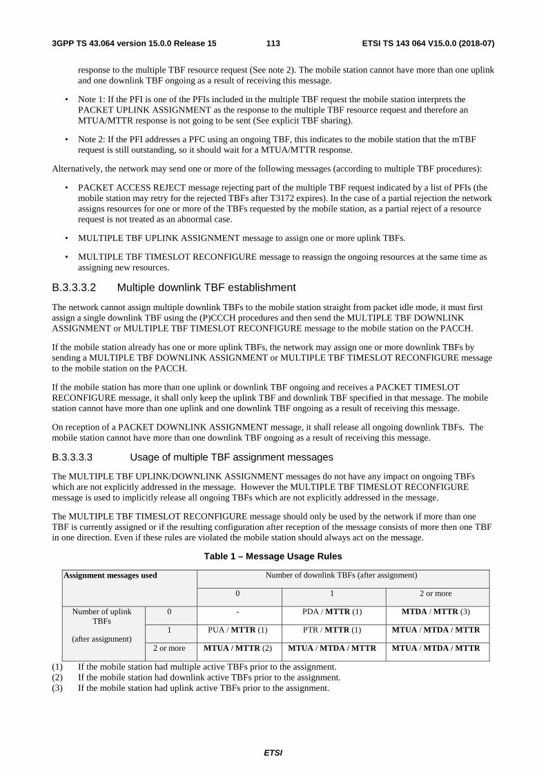
ETSI
ETSI TS 143 064 V15.0.0 (2018-07)1133GPP TS 43.064 version 15.0.0 Release 15
response to the multiple TBF resource request (See note 2). The mobile station cannot have more than one uplink and one downlink TBF ongoing as a result of receiving this message.
• Note 1: If the PFI is one of the PFIs included in the multiple TBF request the mobile station interprets the PACKET UPLINK ASSIGNMENT as the response to the multiple TBF resource request and therefore an MTUA/MTTR response is not going to be sent (See explicit TBF sharing).
• Note 2: If the PFI addresses a PFC using an ongoing TBF, this indicates to the mobile station that the mTBF request is still outstanding, so it should wait for a MTUA/MTTR response.
Alternatively, the network may send one or more of the following messages (according to multiple TBF procedures):
• PACKET ACCESS REJECT message rejecting part of the multiple TBF request indicated by a list of PFIs (the mobile station may retry for the rejected TBFs after T3172 expires). In the case of a partial rejection the network assigns resources for one or more of the TBFs requested by the mobile station, as a partial reject of a resource request is not treated as an abnormal case.
• MULTIPLE TBF UPLINK ASSIGNMENT message to assign one or more uplink TBFs.
• MULTIPLE TBF TIMESLOT RECONFIGURE message to reassign the ongoing resources at the same time as assigning new resources.
B.3.3.3.2 Multiple downlink TBF establishment
The network cannot assign multiple downlink TBFs to the mobile station straight from packet idle mode, it must first assign a single downlink TBF using the (P)CCCH procedures and then send the MULTIPLE TBF DOWNLINK ASSIGNMENT or MULTIPLE TBF TIMESLOT RECONFIGURE message to the mobile station on the PACCH.
If the mobile station already has one or more uplink TBFs, the network may assign one or more downlink TBFs by sending a MULTIPLE TBF DOWNLINK ASSIGNMENT or MULTIPLE TBF TIMESLOT RECONFIGURE message to the mobile station on the PACCH.
If the mobile station has more than one uplink or downlink TBF ongoing and receives a PACKET TIMESLOT RECONFIGURE message, it shall only keep the uplink TBF and downlink TBF specified in that message. The mobile station cannot have more than one uplink and one downlink TBF ongoing as a result of receiving this message.
On reception of a PACKET DOWNLINK ASSIGNMENT message, it shall release all ongoing downlink TBFs. The mobile station cannot have more than one downlink TBF ongoing as a result of receiving this message.
B.3.3.3.3 Usage of multiple TBF assignment messages
The MULTIPLE TBF UPLINK/DOWNLINK ASSIGNMENT messages do not have any impact on ongoing TBFs which are not explicitly addressed in the message. However the MULTIPLE TBF TIMESLOT RECONFIGURE message is used to implicitly release all ongoing TBFs which are not explicitly addressed in the message.
The MULTIPLE TBF TIMESLOT RECONFIGURE message should only be used by the network if more than one TBF is currently assigned or if the resulting configuration after reception of the message consists of more then one TBF in one direction. Even if these rules are violated the mobile station should always act on the message.
Table 1 – Message Usage Rules
Assignment messages used Number of downlink TBFs (after assignment)
0 1 2 or more
Number of uplink TBFs
(after assignment)
0 - PDA / MTTR (1) MTDA / MTTR (3)
1 PUA / MTTR (1) PTR / MTTR (1) MTUA / MTDA / MTTR
2 or more MTUA / MTTR (2) MTUA / MTDA / MTTR MTUA / MTDA / MTTR
(1) If the mobile station had multiple active TBFs prior to the assignment. (2) If the mobile station had downlink active TBFs prior to the assignment. (3) If the mobile station had uplink active TBFs prior to the assignment.
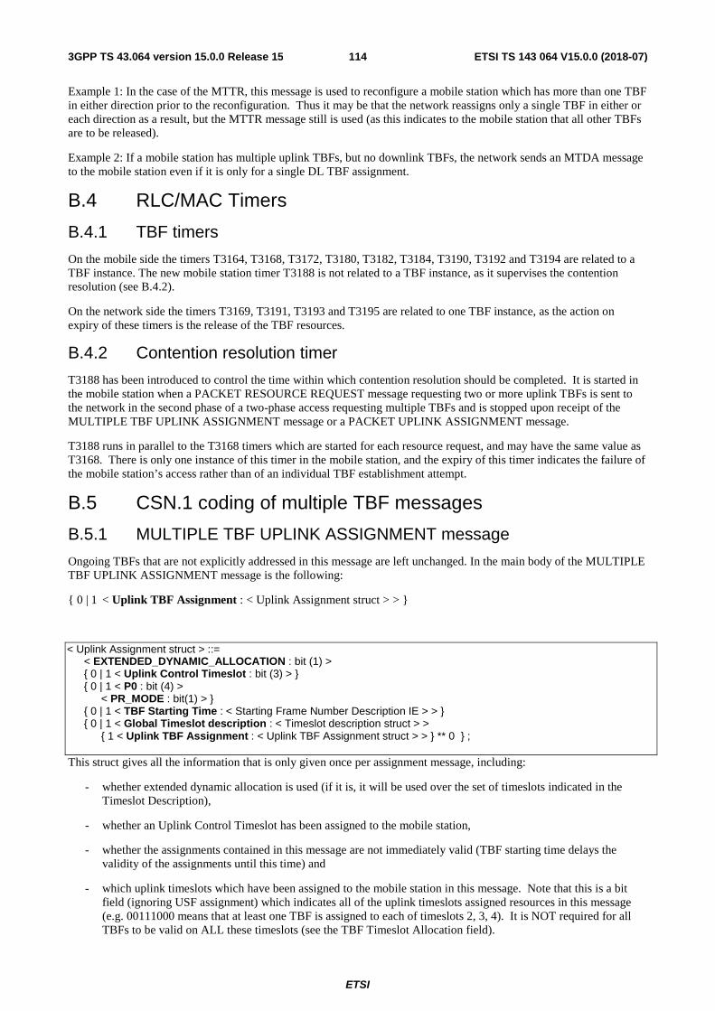
ETSI
ETSI TS 143 064 V15.0.0 (2018-07)1143GPP TS 43.064 version 15.0.0 Release 15
Example 1: In the case of the MTTR, this message is used to reconfigure a mobile station which has more than one TBF in either direction prior to the reconfiguration. Thus it may be that the network reassigns only a single TBF in either or each direction as a result, but the MTTR message still is used (as this indicates to the mobile station that all other TBFs are to be released).
Example 2: If a mobile station has multiple uplink TBFs, but no downlink TBFs, the network sends an MTDA message to the mobile station even if it is only for a single DL TBF assignment.
B.4 RLC/MAC Timers
B.4.1 TBF timers
On the mobile side the timers T3164, T3168, T3172, T3180, T3182, T3184, T3190, T3192 and T3194 are related to a TBF instance. The new mobile station timer T3188 is not related to a TBF instance, as it supervises the contention resolution (see B.4.2).
On the network side the timers T3169, T3191, T3193 and T3195 are related to one TBF instance, as the action on expiry of these timers is the release of the TBF resources.
B.4.2 Contention resolution timer
T3188 has been introduced to control the time within which contention resolution should be completed. It is started in the mobile station when a PACKET RESOURCE REQUEST message requesting two or more uplink TBFs is sent to the network in the second phase of a two-phase access requesting multiple TBFs and is stopped upon receipt of the MULTIPLE TBF UPLINK ASSIGNMENT message or a PACKET UPLINK ASSIGNMENT message.
T3188 runs in parallel to the T3168 timers which are started for each resource request, and may have the same value as T3168. There is only one instance of this timer in the mobile station, and the expiry of this timer indicates the failure of the mobile station’s access rather than of an individual TBF establishment attempt.
B.5 CSN.1 coding of multiple TBF messages
B.5.1 MULTIPLE TBF UPLINK ASSIGNMENT message
Ongoing TBFs that are not explicitly addressed in this message are left unchanged. In the main body of the MULTIPLE TBF UPLINK ASSIGNMENT message is the following:
{ 0 | 1 < Uplink TBF Assignment : < Uplink Assignment struct > > }
< Uplink Assignment struct > ::= < EXTENDED_DYNAMIC_ALLOCATION : bit (1) > { 0 | 1 < Uplink Control Timeslot : bit (3) > } { 0 | 1 < P0 : bit (4) > < PR_MODE : bit(1) > } { 0 | 1 < TBF Starting Time : < Starting Frame Number Description IE > > } { 0 | 1 < Global Timeslot description : < Timeslot description struct > > { 1 < Uplink TBF Assignment : < Uplink TBF Assignment struct > > } ** 0 } ; This struct gives all the information that is only given once per assignment message, including:
- whether extended dynamic allocation is used (if it is, it will be used over the set of timeslots indicated in the Timeslot Description),
- whether an Uplink Control Timeslot has been assigned to the mobile station,
- whether the assignments contained in this message are not immediately valid (TBF starting time delays the validity of the assignments until this time) and
- which uplink timeslots which have been assigned to the mobile station in this message. Note that this is a bit field (ignoring USF assignment) which indicates all of the uplink timeslots assigned resources in this message (e.g. 00111000 means that at least one TBF is assigned to each of timeslots 2, 3, 4). It is NOT required for all TBFs to be valid on ALL these timeslots (see the TBF Timeslot Allocation field).

ETSI
ETSI TS 143 064 V15.0.0 (2018-07)1153GPP TS 43.064 version 15.0.0 Release 15
< Uplink TBF Assignment struct > ::= -- Recursive for multiple TBFs { 0 < RB Id : bit (5) > | 1 < PFI : bit (7) > } < TFI Assignment : bit (5) > { 0 | 1 < CHANNEL_CODING_COMMAND : bit (2) > } { 0 | 1 < EGPRS Channel Coding Command : < EGPRS Modulation and Coding Scheme IE > > } { 0 | 1 < EGPRS Window Size : < EGPRS Window Size IE > > } { 0 -- The timeslots assigned to the TBF are all the timeslots assigned -- in the Global Timeslot description | 1 < TBF_TIMESLOT_ALLOCATION : bit (N) > } -- The timeslots assigned to the TBF are a subset of all the -- timeslots assigned in the Global Timeslot description. Where -- N is the amount of timeslots assigned to the MS in the Global -- Timeslot description { 0 < USF_ALLOCATION : bit (3) > -- The same USF is valid on all timeslots assigned to the TBF | 1 -- Different USF(s) assigned < USF_ALLOCATION : bit (3) > -- USF assignment on the lowest numbered timeslot -- assigned to the TBF { 0 | 1 < USF_ALLOCATION : bit (3) > } * (M-1) } ; -- USFs on subsequent timeslots assigned to the TBF: -- A ‘0’ (respectively a ‘1’ followed by a USF value) -- means same (respectively different) USF value as the -- USF on the next lower numbered timeslot assigned to -- the TBF. Where M is the amount of timeslots assigned -- to the TBF in the TBF_TIMESLOT_ALLOCATION if -- present, else in the Global Timeslot description The length of the TBF_TIMESLOT_ALLOCATION field is equal to the number of timeslots marked as being assigned to the mobile station in the Global Timeslot description struct in the Uplink Assignment struct. It allows multiple TBFs to have different timeslot allocations, if it is not included then all TBFs assigned in this message share the timeslot allocation as described in the Global Timeslot description.
This coding allows the network to assign different parameters (timeslots, USFs) for each TBF in the message but is optimized for the cases where:
a) The TBF is assigned on all timeslots in the Global Timeslot Description; or
b) The TBF is assigned on a subset of the timeslots indicated in the Global Timeslot Description;
and
c) the same USF is used on all timeslots of the TBF; or
d) there are different USFs for the TBF, but the same USF is used on consecutive timeslots of the TBF.
B.5.2 MULTIPLE TBF DOWNLINK ASSIGNMENT message
Ongoing TBFs that are not explicitly addressed in this message are left unchanged. In the main body of the MULTIPLE TBF DOWNLINK ASSIGNMENT message is the following:
{ 1 < Multiple Downlink TBF Assignment : < Multiple Downlink TBF Assignment struct > > } ** 0 which indicates that the following struct may be repeated.
< Multiple Downlink TBF Assignment struct > ::= < TIMESLOT_ALLOCATION : bit (8) > { 1 < Downlink TBF assignment : < Downlink TBF assignment struct > > } ** 0 ; This struct is repeated for each set of TBFs that share a common downlink timeslot allocation. For example, if the mobile station is assigned two downlink TBFs where each operates on timeslots 4 and 5, plus another downlink TBF that is only assigned on timeslot 5, this would require two instances of the Multiple Downlink TBF Assignment struct in this message.
This approach is used because it is more likely for different downlink TBFs to share a common timeslot allocation than it is for uplink TBFs. Hence this coding is optimised for the case where all downlink TBFs allocated to a given mobile station are valid on all timeslots (leaving the network to perform the scheduling as necessary).
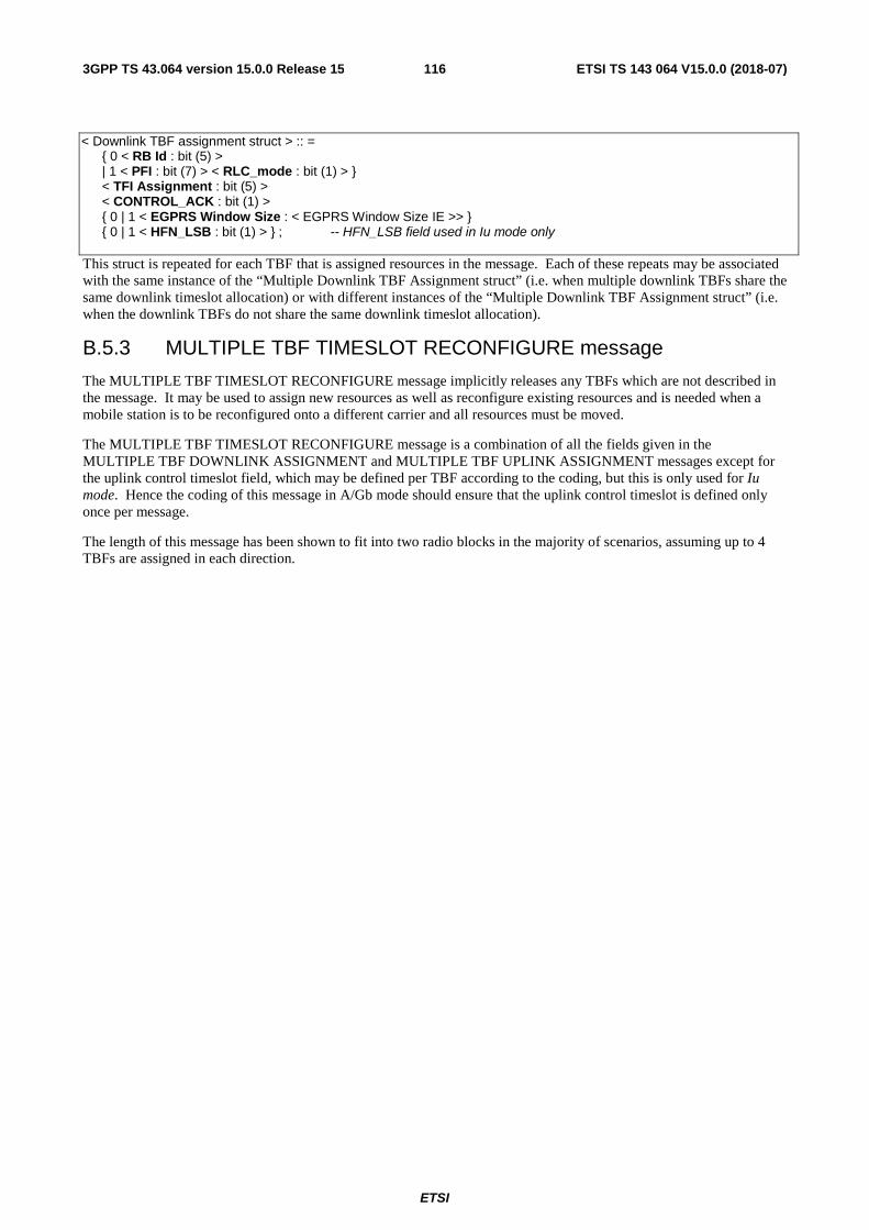
ETSI
ETSI TS 143 064 V15.0.0 (2018-07)1163GPP TS 43.064 version 15.0.0 Release 15
< Downlink TBF assignment struct > :: = { 0 < RB Id : bit (5) > | 1 < PFI : bit (7) > < RLC_mode : bit (1) > } < TFI Assignment : bit (5) > < CONTROL_ACK : bit (1) > { 0 | 1 < EGPRS Window Size : < EGPRS Window Size IE >> } { 0 | 1 < HFN_LSB : bit (1) > } ; -- HFN_LSB field used in Iu mode only This struct is repeated for each TBF that is assigned resources in the message. Each of these repeats may be associated with the same instance of the “Multiple Downlink TBF Assignment struct” (i.e. when multiple downlink TBFs share the same downlink timeslot allocation) or with different instances of the “Multiple Downlink TBF Assignment struct” (i.e. when the downlink TBFs do not share the same downlink timeslot allocation).
B.5.3 MULTIPLE TBF TIMESLOT RECONFIGURE message
The MULTIPLE TBF TIMESLOT RECONFIGURE message implicitly releases any TBFs which are not described in the message. It may be used to assign new resources as well as reconfigure existing resources and is needed when a mobile station is to be reconfigured onto a different carrier and all resources must be moved.
The MULTIPLE TBF TIMESLOT RECONFIGURE message is a combination of all the fields given in the MULTIPLE TBF DOWNLINK ASSIGNMENT and MULTIPLE TBF UPLINK ASSIGNMENT messages except for the uplink control timeslot field, which may be defined per TBF according to the coding, but this is only used for Iu mode. Hence the coding of this message in A/Gb mode should ensure that the uplink control timeslot is defined only once per message.
The length of this message has been shown to fit into two radio blocks in the majority of scenarios, assuming up to 4 TBFs are assigned in each direction.
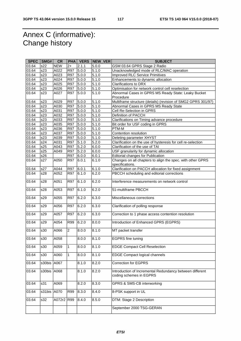
ETSI
ETSI TS 143 064 V15.0.0 (2018-07)1173GPP TS 43.064 version 15.0.0 Release 15
Annex C (informative): Change history
SPEC SMG# CR PHA VERS NEW_VER SUBJECT 03.64 s22 NEW 2+ 2.1.1 5.0.0 GSM 03.64 GPRS Stage 2 Radio 03.64 s23 A022 R97 5.0.0 5.1.0 Unacknowledged mode of RLC/MAC operation 03.64 s23 A023 R97 5.0.0 5.1.0 Improved RLC Service Primitives 03.64 s23 A024 R97 5.0.0 5.1.0 Enhancements to dynamic allocation 03.64 s23 A025 R97 5.0.0 5.1.0 Clarifications to DRX 03.64 s23 A026 R97 5.0.0 5.1.0 Optimisation for network control cell reselection 03.64 s23 A027 R97 5.0.0 5.1.0 Abnormal Cases in GPRS MS Ready State: Leaky Bucket
Procedure 03.64 s23 A029 R97 5.0.0 5.1.0 Multiframe structure (details) (revision of SMG2 GPRS 301/97) 03.64 s23 A030 R97 5.0.0 5.1.0 Abnormal Cases in GPRS MS Ready State 03.64 s23 A031 R97 5.0.0 5.1.0 Cell Re-Selection in GPRS 03.64 s23 A032 R97 5.0.0 5.1.0 Definition of PACCH 03.64 s23 A033 R97 5.0.0 5.1.0 Clarifications on Timing advance procedure 03.64 s23 A035 R97 5.0.0 5.1.0 Bit order for USF coding in GPRS 03.64 s23 A036 R97 5.0.0 5.1.0 PTM-M 03.64 s23 A037 R97 5.0.0 5.1.0 Contention resolution 03.64 s23 A039 R97 5.0.0 5.1.0 Deleting parameter XHYST 03.64 s24 A031 R97 5.1.0 5.2.0 Clarification on the use of hysteresis for cell re-selection 03.64 s25 A043 R97 5.2.0 6.0.0 Clarification of the use of TAI 03.64 s25 A049 R97 5.2.0 6.0.0 USF granularity for dynamic allocation 03.64 s26 R97 6.0.0 6.0.1 Editorial changes for Publication 03.64 s27 A050 R97 6.0.1 6.1.0 Changes on all chapters to align the spec. with other GPRS
specifications. 03.64 s27 A044 R97 6.0.1 6.1.0 Clarification on PACCH allocation for fixed assignment 03.64 s28 A052 R97 6.1.0 6.2.0 PBCCH scheduling and editorial corrections
03.64 s28 A051 R97 6.1.0 6.2.0 Interference measurements on network control
03.64 s28 A053 R97 6.1.0 6.2.0 51-multiframe PBCCH
03.64 s29 A055 R97 6.2.0 6.3.0 Miscellaneous corrections
03.64 s29 A056 R97 6.2.0 6.3.0 Clarification of polling response
03.64 s29 A057 R97 6.2.0 6.3.0 Correction to 1 phase access contention resolution
03.64 s29 A054 R99 6.2.0 8.0.0 Introduction of Enhanced GPRS (EGPRS)
03.64 s30 A066 2 8.0.0 8.1.0 MT packet transfer
03.64 s30 A058 8.0.0 8.1.0 EGPRS fine tuning
03.64 s30 A059 1 8.0.0 8.1.0 EDGE Compact Cell Reselection
03.64 s30 A060 1 8.0.0 8.1.0 EDGE Compact logical channels
03.64 s30bis A067 8.1.0 8.2.0 Correction for EGPRS
03.64 s30bis A068 8.1.0 8.2.0 Introduction of Incremental Redundancy between different coding schemes in EGPRS
03.64 s31 A069 8.2.0 8.3.0 GPRS & SMS-CB interworking
03.64 s31bis A070 R99 8.3.0 8.4.0 8-PSK support in UL
03.64 s32 A072r2 R99 8.4.0 8.5.0 DTM: Stage 2 Description
September 2000 TSG-GERAN
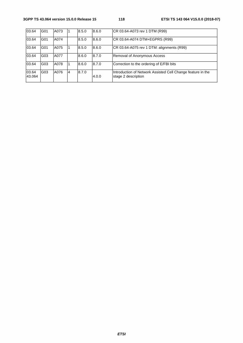
ETSI
ETSI TS 143 064 V15.0.0 (2018-07)1183GPP TS 43.064 version 15.0.0 Release 15
03.64 G01 A073 1 8.5.0 8.6.0 CR 03.64-A073 rev 1 DTM (R99)
03.64 G01 A074 8.5.0 8.6.0 CR 03.64-A074 DTM+EGPRS (R99)
03.64 G01 A075 1 8.5.0 8.6.0 CR 03.64-A075 rev 1 DTM: alignments (R99)
03.64 G03 A077 8.6.0 8.7.0 Removal of Anonymous Access
03.64 G03 A078 1 8.6.0 8.7.0 Correction to the ordering of E/FBI bits
03.64 43.064
G03 A076 4 8.7.0 4.0.0
Introduction of Network Assisted Cell Change feature in the stage 2 description

ETSI
ETSI TS 143 064 V15.0.0 (2018-07)1193GPP TS 43.064 version 15.0.0 Release 15
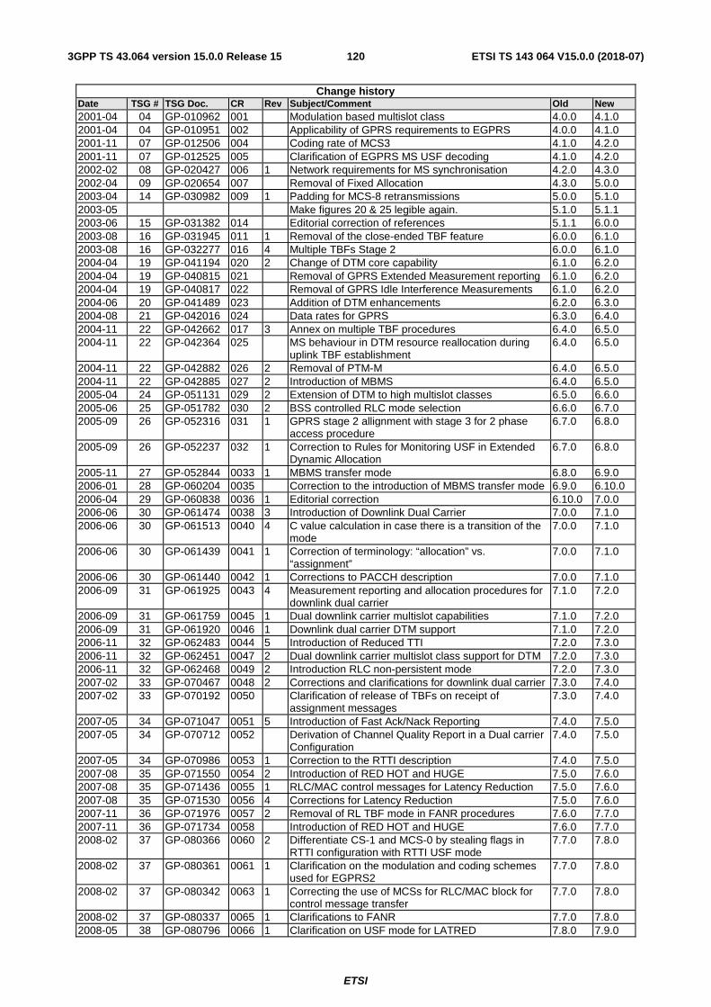
ETSI
ETSI TS 143 064 V15.0.0 (2018-07)1203GPP TS 43.064 version 15.0.0 Release 15
Change history Date TSG # TSG Doc. CR Rev Subject/Comment Old New 2001-04 04 GP-010962 001 Modulation based multislot class 4.0.0 4.1.0 2001-04 04 GP-010951 002 Applicability of GPRS requirements to EGPRS 4.0.0 4.1.0 2001-11 07 GP-012506 004 Coding rate of MCS3 4.1.0 4.2.0 2001-11 07 GP-012525 005 Clarification of EGPRS MS USF decoding 4.1.0 4.2.0 2002-02 08 GP-020427 006 1 Network requirements for MS synchronisation 4.2.0 4.3.0 2002-04 09 GP-020654 007 Removal of Fixed Allocation 4.3.0 5.0.0 2003-04 14 GP-030982 009 1 Padding for MCS-8 retransmissions 5.0.0 5.1.0 2003-05 Make figures 20 & 25 legible again. 5.1.0 5.1.1 2003-06 15 GP-031382 014 Editorial correction of references 5.1.1 6.0.0 2003-08 16 GP-031945 011 1 Removal of the close-ended TBF feature 6.0.0 6.1.0 2003-08 16 GP-032277 016 4 Multiple TBFs Stage 2 6.0.0 6.1.0 2004-04 19 GP-041194 020 2 Change of DTM core capability 6.1.0 6.2.0 2004-04 19 GP-040815 021 Removal of GPRS Extended Measurement reporting 6.1.0 6.2.0 2004-04 19 GP-040817 022 Removal of GPRS Idle Interference Measurements 6.1.0 6.2.0 2004-06 20 GP-041489 023 Addition of DTM enhancements 6.2.0 6.3.0 2004-08 21 GP-042016 024 Data rates for GPRS 6.3.0 6.4.0 2004-11 22 GP-042662 017 3 Annex on multiple TBF procedures 6.4.0 6.5.0 2004-11 22 GP-042364 025 MS behaviour in DTM resource reallocation during
uplink TBF establishment 6.4.0 6.5.0
2004-11 22 GP-042882 026 2 Removal of PTM-M 6.4.0 6.5.0 2004-11 22 GP-042885 027 2 Introduction of MBMS 6.4.0 6.5.0 2005-04 24 GP-051131 029 2 Extension of DTM to high multislot classes 6.5.0 6.6.0 2005-06 25 GP-051782 030 2 BSS controlled RLC mode selection 6.6.0 6.7.0 2005-09 26 GP-052316 031 1 GPRS stage 2 allignment with stage 3 for 2 phase
access procedure 6.7.0 6.8.0
2005-09 26 GP-052237 032 1 Correction to Rules for Monitoring USF in Extended Dynamic Allocation
6.7.0 6.8.0
2005-11 27 GP-052844 0033 1 MBMS transfer mode 6.8.0 6.9.0 2006-01 28 GP-060204 0035 Correction to the introduction of MBMS transfer mode 6.9.0 6.10.0 2006-04 29 GP-060838 0036 1 Editorial correction 6.10.0 7.0.0 2006-06 30 GP-061474 0038 3 Introduction of Downlink Dual Carrier 7.0.0 7.1.0 2006-06 30 GP-061513 0040 4 C value calculation in case there is a transition of the
mode 7.0.0 7.1.0
2006-06 30 GP-061439 0041 1 Correction of terminology: “allocation” vs. “assignment”
7.0.0 7.1.0
2006-06 30 GP-061440 0042 1 Corrections to PACCH description 7.0.0 7.1.0 2006-09 31 GP-061925 0043 4 Measurement reporting and allocation procedures for
downlink dual carrier 7.1.0 7.2.0
2006-09 31 GP-061759 0045 1 Dual downlink carrier multislot capabilities 7.1.0 7.2.0 2006-09 31 GP-061920 0046 1 Downlink dual carrier DTM support 7.1.0 7.2.0 2006-11 32 GP-062483 0044 5 Introduction of Reduced TTI 7.2.0 7.3.0 2006-11 32 GP-062451 0047 2 Dual downlink carrier multislot class support for DTM 7.2.0 7.3.0 2006-11 32 GP-062468 0049 2 Introduction RLC non-persistent mode 7.2.0 7.3.0 2007-02 33 GP-070467 0048 2 Corrections and clarifications for downlink dual carrier 7.3.0 7.4.0 2007-02 33 GP-070192 0050 Clarification of release of TBFs on receipt of
assignment messages 7.3.0 7.4.0
2007-05 34 GP-071047 0051 5 Introduction of Fast Ack/Nack Reporting 7.4.0 7.5.0 2007-05 34 GP-070712 0052 Derivation of Channel Quality Report in a Dual carrier
Configuration 7.4.0 7.5.0
2007-05 34 GP-070986 0053 1 Correction to the RTTI description 7.4.0 7.5.0 2007-08 35 GP-071550 0054 2 Introduction of RED HOT and HUGE 7.5.0 7.6.0 2007-08 35 GP-071436 0055 1 RLC/MAC control messages for Latency Reduction 7.5.0 7.6.0 2007-08 35 GP-071530 0056 4 Corrections for Latency Reduction 7.5.0 7.6.0 2007-11 36 GP-071976 0057 2 Removal of RL TBF mode in FANR procedures 7.6.0 7.7.0 2007-11 36 GP-071734 0058 Introduction of RED HOT and HUGE 7.6.0 7.7.0 2008-02 37 GP-080366 0060 2 Differentiate CS-1 and MCS-0 by stealing flags in
RTTI configuration with RTTI USF mode 7.7.0 7.8.0
2008-02 37 GP-080361 0061 1 Clarification on the modulation and coding schemes used for EGPRS2
7.7.0 7.8.0
2008-02 37 GP-080342 0063 1 Correcting the use of MCSs for RLC/MAC block for control message transfer
7.7.0 7.8.0
2008-02 37 GP-080337 0065 1 Clarifications to FANR 7.7.0 7.8.0 2008-05 38 GP-080796 0066 1 Clarification on USF mode for LATRED 7.8.0 7.9.0
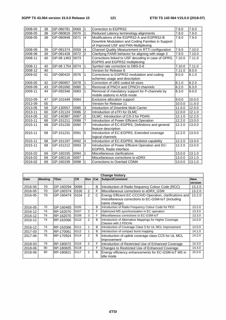
ETSI
ETSI TS 143 064 V15.0.0 (2018-07)1213GPP TS 43.064 version 15.0.0 Release 15
2008-05 38 GP-080781 0069 1 Correction to EGPRS2 7.8.0 7.9.0 2008-05 38 GP-080819 0070 1 Reduced Latency terminology alignments 7.8.0 7.9.0 2008-05 38 GP-080948 0071 4 Modifications of the EGPRS2-A and EGPRS2-B
Downlink Modulation and Coding Families in Support of Improved USF and PAN Multiplexing
7.8.0 7.9.0
2008-08 39 GP-081374 0059 4 Channel Quality Measurement in RTTI configuration 7.9.0 7.10.0 2008-08 39 GP-081428 0072 2 Clarifying FANR behavior for aligning with stage 3 7.9.0 7.10.0 2008-11 40 GP-08 1463 0073 Corrections linked to USF decoding in case of GPRS,
EGPRS and EGPRS2 multiplexing 7.10.0 7.11.0
2008-11 40 GP-08 1754 0074 1 Symbol rate correction to DBS-5-6 7.10.0 7.11.0 2008-12 40 Version for Release 8 7.11.0 8.0.0 2009-02 41 GP-090420 0076 1 Corrections to EGPRS2 modulation and coding
schemes usage and description 8.0.0 8.1.0
2009-05 42 GP-090957 0078 1 Correction of UBS coded bit sizes 8.1.0 8.2.0 2009-09 43 GP-091690 0080 1 Removal of PNCH and CPNCH channels 8.2.0 8.3.0 2009-11 44 GP-092346 0083 1 Removal of mandatory support for P-channels by
mobile stations in A/Gb mode 8.3.0 9.0.0
2010-09 47 GP-101449 0084 Exclusive allocation support 9.0.0 10.0.0 2012-09 55 Version for Release 11 10.0.0 11.0.0 2013-05 58 GP-130557 0085 3 Intoduction of Downlink Multi Carrier 11.0.0 12.0.0 2013-11 60 GP-131124 0086 2 Introduction of eTFI for DLMC 12.0.0 12.1.0 2014-05 62 GP-140387 0087 3 DLMC: Introduction of CS-3 for PDAN 12.1.0 12.2.0 2015-11 68 GP-151211 0088 7 Introduction of Power Efficient Operation 12.2.0 13.0.0 2015-11 68 GP-151230 0090 7 Introduction of EC-EGPRS, Definitions and general
feature description 12.2.0 13.0.0
2015-11 68 GP-151231 0091 5 Introduction of EC-EGPRS, Extended coverage logical channels
12.2.0 13.0.0
2015-11 68 GP-151197 0092 4 Introduction of EC-EGPRS, Multislot capability 12.2.0 13.0.0 2015-11 68 GP-151212 0093 2 Introduction of Power Efficient Operation and EC-
EGPRS, Radio interface 12.2.0 13.0.0
2016-02 69 GP-160155 0094 1 Miscellaneous clarifications 13.0.0 13.1.0 2016-02 69 GP-160116 0097 Miscellaneous corrections to eDRX 13.0.0 13.1.0 2016-02 69 GP-160199 0098 1 Corrections to Overlaid CDMA 13.0.0 13.1.0
Change history Date Meeting TDoc CR Rev Cat Subject/Comment New
version 2016-05 70 GP-160294 0099 - B Introduction of Radio frequency Colour Code (RCC) 13.2.0 2016-05 70 GP-160374 0100 2 F Miscellaneous corrections to eDRX_GSM 13.2.0 2016-05 70 GP-160474 0104 2 C Energy Efficient EC-CCCH/D Operation, clarifications and
miscellaneous corrections to EC-GSM-IoT (including name change)
13.2.0
2016-05 70 GP-160465 0105 - B Introduction of Radio Frequency Colour Code for PEO 13.2.0
2016-12 74 RP-162070 0107 2 F Optimized MS synchronization in EC operation 13.3.0
2016-12 74 RP-162070 0109 3 F Miscellaneous corrections to EC-GSM-IoT 13.3.0
2016-12 74 RP-162066 0110 2 B Introduction of Alternative Mappings for Higher Coverage Classes with 2 PDCHs
14.0.0
2016-12 74 RP-162066 0111 1 B Introduction of Coverage Class 5 for UL MCL Improvement 14.0.0
2017-03 75 RP-170061 0112 1 B Introduction of compact burst mapping 14.1.0
2017-06 76 RP-170924 0114 2 B Introduction of uplink coverage class CC5 for UL MCL improvement
14.2.0
2018-03 79 RP-180072 0116 2 F Introduction of Restricted Use of Enhanced Coverage 14.3.0
2018-06 80 RP-180825 0118 - F Changes to Restricted Use of Enhanced Coverage 14.4.0
2018-06 80 RP-180821 0117 2 B Energy efficiency enhancements for EC-GSM-IoT MS in idle mode
15.0.0

ETSI
ETSI TS 143 064 V15.0.0 (2018-07)1223GPP TS 43.064 version 15.0.0 Release 15
History
Document history
V15.0.0 July 2018 Publication