Embed Size (px)
Citation preview
ETSI TS 133 108 V5.6.0 (2003-12)
Technical Specification
Universal Mobile Telecommunications System (UMTS);3G security;
Handover interface for Lawful Interception (LI) (3GPP TS 33.108 version 5.6.0 Release 5)
ETSI
ETSI TS 133 108 V5.6.0 (2003-12) 1 3GPP TS 33.108 version 5.6.0 Release 5
Reference RTS/TSGS-0333108v560
Keywords UMTS
ETSI
650 Route des Lucioles F-06921 Sophia Antipolis Cedex - FRANCE
Tel.: +33 4 92 94 42 00 Fax: +33 4 93 65 47 16
Siret N° 348 623 562 00017 - NAF 742 C
Association à but non lucratif enregistrée à la Sous-Préfecture de Grasse (06) N° 7803/88
Important notice
Individual copies of the present document can be downloaded from: http://www.etsi.org
The present document may be made available in more than one electronic version or in print. In any case of existing or perceived difference in contents between such versions, the reference version is the Portable Document Format (PDF).
In case of dispute, the reference shall be the printing on ETSI printers of the PDF version kept on a specific network drive within ETSI Secretariat.
Users of the present document should be aware that the document may be subject to revision or change of status. Information on the current status of this and other ETSI documents is available at
http://portal.etsi.org/tb/status/status.asp
If you find errors in the present document, send your comment to: [email protected]
Copyright Notification
No part may be reproduced except as authorized by written permission. The copyright and the foregoing restriction extend to reproduction in all media.
© European Telecommunications Standards Institute 2003.
All rights reserved.
DECTTM, PLUGTESTSTM and UMTSTM are Trade Marks of ETSI registered for the benefit of its Members. TIPHONTM and the TIPHON logo are Trade Marks currently being registered by ETSI for the benefit of its Members. 3GPPTM is a Trade Mark of ETSI registered for the benefit of its Members and of the 3GPP Organizational Partners.
ETSI
ETSI TS 133 108 V5.6.0 (2003-12) 2 3GPP TS 33.108 version 5.6.0 Release 5
Intellectual Property Rights IPRs essential or potentially essential to the present document may have been declared to ETSI. The information pertaining to these essential IPRs, if any, is publicly available for ETSI members and non-members, and can be found in ETSI SR 000 314: "Intellectual Property Rights (IPRs); Essential, or potentially Essential, IPRs notified to ETSI in respect of ETSI standards", which is available from the ETSI Secretariat. Latest updates are available on the ETSI Web server (http://webapp.etsi.org/IPR/home.asp).
Pursuant to the ETSI IPR Policy, no investigation, including IPR searches, has been carried out by ETSI. No guarantee can be given as to the existence of other IPRs not referenced in ETSI SR 000 314 (or the updates on the ETSI Web server) which are, or may be, or may become, essential to the present document.
Foreword This Technical Specification (TS) has been produced by ETSI 3rd Generation Partnership Project (3GPP).
The present document may refer to technical specifications or reports using their 3GPP identities, UMTS identities or GSM identities. These should be interpreted as being references to the corresponding ETSI deliverables.
The cross reference between GSM, UMTS, 3GPP and ETSI identities can be found under http://webapp.etsi.org/key/queryform.asp .
ETSI
ETSI TS 133 108 V5.6.0 (2003-12) 3 3GPP TS 33.108 version 5.6.0 Release 5
Contents
Intellectual Property Rights ................................................................................................................................2
Foreword.............................................................................................................................................................2
Foreword.............................................................................................................................................................6
Introduction ........................................................................................................................................................6
1 Scope ........................................................................................................................................................7
2 References ................................................................................................................................................7
3 Definitions and abbreviations...................................................................................................................8 3.1 Definitions..........................................................................................................................................................8 3.2 Abbreviations ...................................................................................................................................................10
4 General ...................................................................................................................................................11 4.1 Basic principles for the handover interface ......................................................................................................11 4.2 Legal requirements ...........................................................................................................................................12 4.3 Functional requirements ...................................................................................................................................12 4.4 Overview of handover interface .......................................................................................................................12 4.4.1 Handover interface port 2 (HI2) .................................................................................................................13 4.4.2 Handover interface port 3 (HI3) .................................................................................................................14 4.5 HI2: Interface port for intercept related information ........................................................................................14 4.5.1 Data transmission protocols........................................................................................................................14 4.5.2 Application for IRI (HI2 information) ........................................................................................................14 4.5.3 Types of IRI records ...................................................................................................................................15
5 Circuit-switch domain ............................................................................................................................15
6 Packet data domain.................................................................................................................................15 6.1 Identifiers .........................................................................................................................................................15 6.1.1 Lawful interception identifier .....................................................................................................................16 6.1.2 Network identifier.......................................................................................................................................16 6.1.3 Correlation number .....................................................................................................................................16 6.2 Performance, reliability, and quality ................................................................................................................16 6.2.1 Timing ........................................................................................................................................................16 6.2.2 Quality ........................................................................................................................................................17 6.2.3 Reliability ...................................................................................................................................................17 6.3 Security aspects ................................................................................................................................................17 6.4 Quantitative aspects..........................................................................................................................................17 6.5 IRI for packet domain.......................................................................................................................................17 6.5.1 Events and information...............................................................................................................................20 6.5.1.1 REPORT record information ................................................................................................................20 6.5.1.2 BEGIN record information ...................................................................................................................23 6.5.1.3 CONTINUE record information ...........................................................................................................25 6.5.1.4 END record information .......................................................................................................................27 6.6 IRI reporting for packet domain at GGSN .......................................................................................................28 6.7 Content of communication interception for packet domain at GGSN..............................................................28
7 Multi-media domain...............................................................................................................................28 7.1 Identifiers .........................................................................................................................................................29 7.1.1 Lawful interception identifier .....................................................................................................................29 7.1.2 Network identifier.......................................................................................................................................30 7.1.3 Correlation number .....................................................................................................................................30 7.2 IRI for IMS.......................................................................................................................................................30 7.2.1 Events and information...............................................................................................................................31
Annex A (normative): HI2 delivery mechanisms and procedures...................................................32
A.1 ROSE......................................................................................................................................................32
ETSI
ETSI TS 133 108 V5.6.0 (2003-12) 4 3GPP TS 33.108 version 5.6.0 Release 5
A.1.1 Architecture......................................................................................................................................................32 A.1.2 ASE_HI procedures..........................................................................................................................................33 A.1.2.1 Sending part ................................................................................................................................................33 A.1.2.2 Receiving part .............................................................................................................................................33 A.1.2.3 Data link management ................................................................................................................................34 A.1.2.3.1 Data link establishment .........................................................................................................................34 A.1.2.3.2 Data link release....................................................................................................................................34 A.1.2.4 Handling of unrecognized fields and parameters........................................................................................35
A.2 FTP.........................................................................................................................................................35 A.2.1 Introduction ......................................................................................................................................................35 A.2.2 Usage of the FTP..............................................................................................................................................35 A.2.3 Profiles (informative)..................................................................................................................................36 A.2.4 File content .................................................................................................................................................38 A.2.5 Exceptional procedures...............................................................................................................................38 A.2.6 Other considerations ...................................................................................................................................38
Annex B (normative): Structure of data at the handover interface ................................................40
B.1 Syntax definitions...................................................................................................................................40
B.2 3GPP object tree.....................................................................................................................................41
B.3 Intercept related information (HI2) ........................................................................................................41 B.4 HI3 CC definition.............................................................................................................................................47
Annex C (normative): UMTS HI3 interface ......................................................................................48
C.1 UMTS LI correlation header ..................................................................................................................48 C.1.1 Introduction ......................................................................................................................................................48 C.1.2 Definition of ULIC header version 0................................................................................................................48 C.1.3 Definition of ULIC header version 1................................................................................................................49 C.1.4 Exceptional procedure......................................................................................................................................50 C.1.5 Other considerations.........................................................................................................................................50
C.2 FTP.........................................................................................................................................................50 C.2.1 Introduction ......................................................................................................................................................50 C.2.2 Usage of the FTP..............................................................................................................................................50 C.2.3 Exceptional procedures ....................................................................................................................................52 C.2.4 CC contents for FTP.........................................................................................................................................52 C.2.4.1 Fields ..........................................................................................................................................................52 C.2.4.2 Information element syntax ........................................................................................................................54 C.2.5 Other considerations.........................................................................................................................................56
Annex D (informative): LEMF requirements - handling of unrecognised fields and parameters......................................................................................................57
Annex E (informative): Bibliography...................................................................................................58
Annex F (informative): Void .................................................................................................................60
Annex G (informative): United States lawful interception .................................................................61
G.1 Delivery methods preferences ................................................................................................................61
G.2 HI2 delivery methods .............................................................................................................................61 G.2.1 TPKT/TCP/IP...................................................................................................................................................61 G.2.1.1 Introduction.................................................................................................................................................61 G.2.1.2 Normal Procedures .....................................................................................................................................61 G.2.1.2.1 Usage of TCP/IP when MF initiates TCP Connections ........................................................................61 G.2.1.2.2 Use of TPKT .........................................................................................................................................61 G.2.1.2.3 Sending of LI messages ........................................................................................................................62 G.2.1.3 ASN.1 for HI2 Mediation Function Messages............................................................................................62 G.2.1.4 Error Procedures .........................................................................................................................................62 G.2.1.5 Security Considerations ..............................................................................................................................62
ETSI
ETSI TS 133 108 V5.6.0 (2003-12) 5 3GPP TS 33.108 version 5.6.0 Release 5
G.3 HI3 delivery methods .............................................................................................................................63 G.3.1 Use of TCP/IP ..................................................................................................................................................63 G.3.1.1 Normal Procedures .....................................................................................................................................63 G.3.1.1.1 Usage of TCP/IP when MF initiates TCP Connections ........................................................................63 G.3.1.1.2 Use of TPKT .........................................................................................................................................63 G.3.1.1.3 Sending of Content of Communication Messages ................................................................................63 G.3.1.2 ASN.1 for HI3 Mediation Function Messages............................................................................................64 G.3.1.3 Error Procedures .........................................................................................................................................64 G.3.1.4 Security Considerations ..............................................................................................................................64
G.4 Cross reference of terms between J-STD-025-A and 3GPP...................................................................65
Annex H (normative): United States lawful interception .................................................................66
Annex J (informative): Change history ...............................................................................................67
History ..............................................................................................................................................................68
ETSI
ETSI TS 133 108 V5.6.0 (2003-12) 6 3GPP TS 33.108 version 5.6.0 Release 5
Foreword This Technical Specification has been produced by the 3rd Generation Partnership Project (3GPP).
The contents of the present document are subject to continuing work within the TSG and may change following formal TSG approval. Should the TSG modify the contents of the present document, it will be re-released by the TSG with an identifying change of release date and an increase in version number as follows:
Version x.y.z
where:
x the first digit:
1 presented to TSG for information;
2 presented to TSG for approval;
3 or greater indicates TSG approved document under change control.
y the second digit is incremented for all changes of substance, i.e. technical enhancements, corrections, updates, etc.
z the third digit is incremented when editorial only changes have been incorporated in the document.
Introduction This Technical Specification has been produced by 3GPP TSG SA to allow for the standardization in the area of lawful interception of telecommunications. This document addresses the handover interfaces for lawful interception of Packet-Data Services, Circuit Switched Services, and Multimedia Services within the Universal Mobile Telecommunication System (UMTS). The specification defines the handover interfaces for delivery of lawful interception Intercept Related Information (IRI) and Content of Communication (CC) to the Law Enforcement Monitoring Facility.
Laws of individual nations and regional institutions (e.g. European Union), and sometimes licensing and operating conditions define a need to intercept telecommunications traffic and related information in modern telecommunications systems. It has to be noted that lawful interception shall always be done in accordance with the applicable national or regional laws and technical regulations. Nothing in this specification, including the definitions, is intended to supplant national law.
This specification should be used in conjunction with 3GPP TS 33.106 and 33.107 in the same release. This specification may also be used with earlier releases of 33.106 and 33.107, as well as for earlier releases of UMTS and GPRS.
ETSI
ETSI TS 133 108 V5.6.0 (2003-12) 7 3GPP TS 33.108 version 5.6.0 Release 5
1 Scope This specification addresses the handover interfaces for lawful interception of Packet-Data Services, Circuit Switched Services, and Multimedia Services within the UMTS network. The handover interface in this context includes the delivery of Intercept Related Information (HI2) and Content of Communication (HI3) to the Law Enforcement Monitoring Facility.
2 References The following documents contain provisions which, through reference in this text, constitute provisions of the present document.
• References are either specific (identified by date of publication, edition number, version number, etc.) or non-specific.
• For a specific reference, subsequent revisions do not apply.
• For a non-specific reference, the latest version applies. In the case of a reference to a 3GPP document (including a GSM document), a non-specific reference implicitly refers to the latest version of that document in the same Release as the present document.
[1] TR 101 331: "Telecommunications security; Lawful Interception (LI); requirements of Law Enforcement Agencies".
[2] ES 201 158: "Telecommunications security; Lawful Interception (LI); Requirements for network functions".
[3] ETR 330: "Security Techniques Advisory Group (STAG); A guide to legislative and regulatory environment".
[4] GSM 09.02: "Digital cellular telecommunications system (Phase 2+); Mobile Application Part (MAP) specification".
[5] ITU-T Recommendation X.680: "Specification of Abstract Syntax Notation One (ASN.1)".
[6] ITU-T Recommendation X.690: "Specification of basic encoding rules for Abstract Syntax Notation One (ASN.1)".
[7] ITU-T Recommendation X.880: "Information technology - Remote Operations: Concepts, model and notation".
[8] ITU-T Recommendation X.882: "Information technology - Remote Operations: OSI realizations - Remote Operations Service Element (ROSE) protocol specification".
[9] EN 300 940, GSM 04.08: "Digital cellular communications system (Phase 2+); Mobile radio interface layer 3 specification".
[10] TS 101 509 "Digital cellular telecommunications system (Phase 2+); Lawful interception; Stage 2 (GSM 03.33).
[11] GSM 03.03: "Digital cellular telecommunications system (Phase 2+); Numbering, addressing and identification".
[12] GSM 09.60 (EN 301 347): "Digital cellular telecommunications system (Phase 2+); General Packet Radio Service (GPRS); GPRS tunelling protocol (GTP) across Gn and Gp Interface".
[13] STD 9 "File Transfer Protocol (FTP)", October 1985.
[14] GSM 12.15 "3rd Generation Partnership Project; Technical Specification Group Services and System Aspects; Telecommunication Management; Charging & Billing; GSM call and event data for the Packet Switched (PS) domain)".
ETSI
ETSI TS 133 108 V5.6.0 (2003-12) 8 3GPP TS 33.108 version 5.6.0 Release 5
[15] STD0005 "Internet Protocol".
[16] STD0007 "Transmission Control Protocol".
[17] 3GPP TS 29.060 "GPRS Tunnelling Protocol".
[18] 3GPP TS 33.106 "Lawful Interception Requirements".
[19] 3GPP TS 33.107 "Lawful Interception Architecture and Functions".
[20] 3GPP TS 23.107 "QoS Concepts and Architecture".
[21] 3GPP TS 24.008: "3GPP Technical Specification Group Core Network; Mobile radio interface layer 3 specification".
[22] ES 201 671 version 2.1.1: "Handover Interface for the lawful interception of telecommunications traffic".
[23] J-STD-25-A: "Lawfully Authorized Electronic Surveillance".
[24] ETSI TS 101 671 version 2.3.1: "Handover Interface for the lawful interception of telecommunications traffic".
[25] 3GPP TS 23.003 "3rd Generation Partnership Project; Technical Specification Group Core Network; Numbering, addressing, and identification".
[26] RFC 2543: "SIP: Session Initiation Protocol".
[27] RFC 1006: "ISO Transport Service on top of the TCP".
[28] RFC 2126: "ISO Transport Service on top of TCP (ITOT)".
[29] ITU-T Recommendation Q.763: "Formats and Codes of the ISDN User Part of Signalling System No. 7".
3 Definitions and abbreviations
3.1 Definitions For the purposes of the present document, the following terms and definitions apply.
access provider: access provider provides a user of some network with access from the user's terminal to that network.
NOTE 1: This definition applies specifically for the present document. In a particular case, the access provider and network operator may be a common commercial entity.
(to) buffer: temporary storing of information in case the necessary telecommunication connection to transport information to the LEMF is temporarily unavailable.
communication: Information transfer according to agreed conventions.
content of communication: information exchanged between two or more users of a telecommunications service, excluding intercept related information. This includes information which may, as part of some telecommunications service, be stored by one user for subsequent retrieval by another.
handover interface: physical and logical interface across which the interception measures are requested from network operator / access provider / service provider, and the results of interception are delivered from a network operator / access provider / service provider to a law enforcement monitoring facility.
identity: technical label which may represent the origin or destination of any telecommunications traffic, as a rule clearly identified by a physical telecommunications identity number (such as a telephone number) or the logical or virtual telecommunications identity number (such as a personal number) which the subscriber can assign to a physical access on a case-by-case basis.
ETSI
ETSI TS 133 108 V5.6.0 (2003-12) 9 3GPP TS 33.108 version 5.6.0 Release 5
interception: action (based on the law), performed by an network operator / access provider / service provider, of making available certain information and providing that information to a law enforcement monitoring facility.
NOTE 2: In the present document the term interception is not used to describe the action of observing communications by a law enforcement agency.
interception configuration information: information related to the configuration of interception.
interception interface: physical and logical locations within the network operator's / access provider's / service provider's telecommunications facilities where access to the content of communication and intercept related information is provided. The interception interface is not necessarily a single, fixed point.
interception measure: technical measure which facilitates the interception of telecommunications traffic pursuant to the relevant national laws and regulations.
intercept related information: collection of information or data associated with telecommunication services involving the target identity, specifically communication associated information or data (e.g. unsuccessful communication attempts), service associated information or data and location information.
interception subject: person or persons, specified in a lawful authorization, whose telecommunications are to be intercepted.
internal intercepting function: point within a network or network element at which the content of communication and the intercept related information are made available.
internal network interface: network's internal interface between the Internal Intercepting Function and a mediation device.
invocation and operation: describes the action and conditions under which the service is brought into operation; in the case of a lawful interception this may only be on a particular communication. It should be noted that when lawful interception is activated, it shall be invoked on all communications (Invocation takes place either subsequent to or simultaneously with activation.). Operation is the procedure which occurs once a service has been invoked.
NOTE 3: The definition is based on [8], but has been adapted for the special application of lawful interception, instead of supplementary services.
law enforcement agency: organization authorized by a lawful authorization based on a national law to request interception measures and to receive the results of telecommunications interceptions.
law enforcement monitoring facility: law enforcement facility designated as the transmission destination for the results of interception relating to a particular interception subject.
lawful authorization: permission granted to a LEA under certain conditions to intercept specified telecommunications and requiring co-operation from a network operator / access provider / service provider. Typically this refers to a warrant or order issued by a lawfully authorized body.
lawful interception: see interception.
lawful interception identifier: identifier for a particular interception.
location information: information relating to the geographic, physical or logical location of an identity relating to an interception subject.
mediation device: equipment, which realizes the mediation function.
mediation function: mechanism which passes information between a network operator, an access provider or service provider and a handover interface, and information between the internal network interface and the handover interface.
network element: component of the network structure, such as a local exchange, higher order switch or service control processor.
network element identifier: uniquely identifies the relevant network element carrying out the lawful interception.
network identifier: internationally unique identifier that includes a unique identification of the network operator, access provider, or service provider and, optionally, the network element identifier.
ETSI
ETSI TS 133 108 V5.6.0 (2003-12) 103GPP TS 33.108 version 5.6.0 Release 5
network operator: operator of a public telecommunications infrastructure which permits the conveyance of signals between defined network termination points by wire, by microwave, by optical means or by other electromagnetic means.
quality of service: quality specification of a telecommunications channel, system, virtual channel, computer-telecommunications session, etc. Quality of service may be measured, for example, in terms of signal-to-noise ratio, bit error rate, message throughput rate or call blocking probability.
reliability: probability that a system or service will perform in a satisfactory manner for a given period of time when used under specific operating conditions.
result of interception: information relating to a target service, including the content of communication and intercept related information, which is passed by a network operator, an access provider or a service provider to a law enforcement agency. Intercept related information shall be provided whether or not call activity is taking place.
service information: information used by the telecommunications infrastructure in the establishment and operation of a network related service or services. The information may be established by a network operator, an access provider, a service provider or a network user.
service provider: natural or legal person providing one or more public telecommunications services whose provision consists wholly or partly in the transmission and routing of signals on a telecommunications network. A service provider needs not necessarily run his own network.
SMS: Short Message Service gives the ability to send character messages to phones. SMS messages can be MO (mobile originate) or MT(mobile terminate).
target identity: technical identity (e.g. the interception's subject directory number), which uniquely identifies a target of interception. One target may have one or several target identities.
target service: telecommunications service associated with an interception subject and usually specified in a lawful authorization for interception.
NOTE 4: There may be more than one target service associated with a single interception subject.
telecommunications: any transfer of signs, signals, writing images, sounds, data or intelligence of any nature transmitted in whole or in part by a wire, radio, electromagnetic, photoelectronic or photo-optical system.
3.2 Abbreviations For the purposes of the present document, the following abbreviations apply:
AP Access Provider ASN.1 Abstract Syntax Notation, Version 1 ASE Application Service Element BER Basic Encoding Rules CC Content of Communication CSCF Call Session Control Function DF Delivery Function FTP File Transfer Protocol GGSN Gateway GPRS Support Node GLIC GPRS LI Correlation GPRS General Packet Radio Service GSM Global System for Mobile communications GSN GPRS Support Node (SGSN or GGSN) GTP GPRS Tunnelling Protocol HI Handover Interface HI1 Handover Interface Port 1 (for Administrative Information) HI2 Handover Interface Port 2 (for Intercept Related Information) HI3 Handover Interface Port 3 (for Content of Communication) HLC High Layer Compatibility IA Interception Area IA5 International Alphabet No. 5 IAP Interception Access Point
ETSI
ETSI TS 133 108 V5.6.0 (2003-12) 113GPP TS 33.108 version 5.6.0 Release 5
ICI Interception Configuration Information IE Information Element IIF Internal Interception Function IMEI International Mobile station Equipment Identity IMS IP Multimedia Core Network Subsystem IMSI International Mobile Subscriber Identity INI Internal network interface IP Internet Protocol IPS Internet Protocol Stack IRI Intercept Related Information LEA Law Enforcement Agency LEMF Law Enforcement Monitoring Facility LI Lawful Interception LIID Lawful Interception Identifier LLC Lower layer compatibility LSB Least significant bit MAP Mobile Application Part MF Mediation Function MS Mobile Station MSB Most significant bit MSISDN Mobile Subscriber ISDN Number MSN Multiple Subscriber Number NEID Network Element Identifier NID Network Identifier NWO Network Operator OA&M Operation, Administration & Maintenance P-CSCF Proxy Call Session Control Function PDP Packet Data Protocol PLMN Public land mobile network PSTN Public Switched Telephone Network ROSE Remote Operation Service Element Rx Receive direction S-CSCF Serving Call Session Control Function SGSN Serving GPRS Support Node SMAF Service Management Agent Function SMF Service Management Function SMS Short Message Service SvP Service Provider TCP Transmission Control Protocol TI Target identity TP Terminal Portability T-PDU tunneled PDU Tx Transmit direction UI User Interaction UMTS Universal Mobile Telecommunication System VPN Virtual Private Network
4 General The present document focuses on the handover interface related to the provision of information related to LI between a network operator, access provider and/or service provider and a Law Enforcement Agency (LEA).
4.1 Basic principles for the handover interface The network requirements mentioned in the present document are derived, in part, from the requirements defined in ES 201 158 [2].
Lawful interception may require functions to be provided in the switching or routing nodes of a telecommunications network.
ETSI
ETSI TS 133 108 V5.6.0 (2003-12) 123GPP TS 33.108 version 5.6.0 Release 5
The specification of the handover interface is subdivided into three logical ports each optimised to the different purposes and types of information being exchanged.
The interface is extensible. (i.e. the interface may be modified in the future as necessary).
4.2 Legal requirements It shall be possible to select elements from the handover interface specification to conform with:
- national requirements;
- national law;
- any law applicable to a specific LEA.
As a consequence, the present document shall define, in addition to mandatory requirements, which are always applicable, supplementary options, in order to take into account the various influences listed above. See also [1] and [3].
4.3 Functional requirements A lawful authorization shall describe the kind of information (Intercept Related Information (IRI) only, or IRI with Content of Communication (CC)) that is required by an LEA, the identifiers for the interception subject, the start and stop time of LI, and the addresses of the LEAs for delivery of CC and/or IRI and further information.
A single interception subject may be the subject of interception by different LEAs. It shall be possible strictly to separate these interception measures.
If two targets are communicating with each other, each target is dealt with separately.
4.4 Overview of handover interface The generic handover interface adopts a three port structure such that administrative information (HI1), intercept related information (HI2), and the content of communication (HI3) are logically separated.
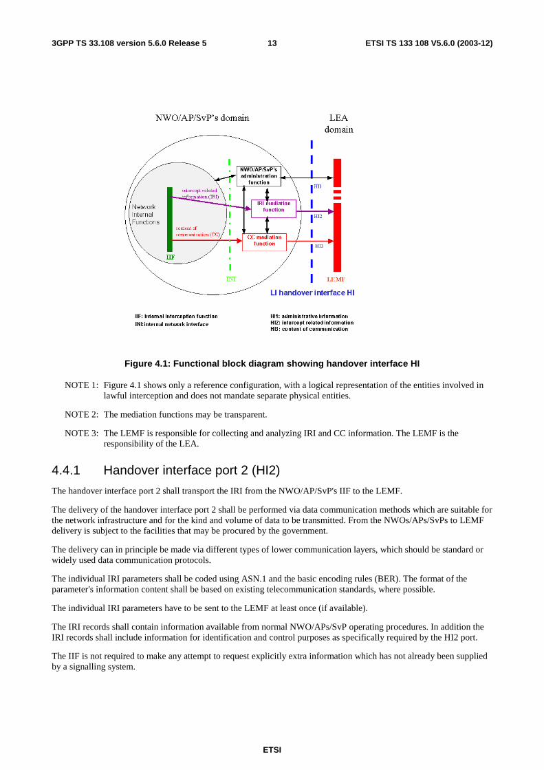
Figure 4.1 shows a block diagram with the relevant entities for Lawful Interception.
The outer circle represents the NWO/AP/SvP´s domain with respect to lawful interception. It contains the network internal functions, the internal network interface (INI), the administration function and the mediation functions for IRI and CC. The inner circle contains the internal functions of the network (e.g. switching, routing, handling of the communication process). Within the network internal function the results of interception (i.e., IRI and CC) are generated in the Internal Interception Function (IIF).
The IIF provides the Content of Communication (CC) and the Intercept Related Information (IRI), respectively, at the Internal Network Interface (INI). For both kinds of information, mediation functions may be used, which provide the final representation of the standardized handover interfaces at the NWO/AP/SvP's domain boundary.
ETSI
ETSI TS 133 108 V5.6.0 (2003-12) 133GPP TS 33.108 version 5.6.0 Release 5
Figure 4.1: Functional block diagram showing handover interface HI
NOTE 1: Figure 4.1 shows only a reference configuration, with a logical representation of the entities involved in lawful interception and does not mandate separate physical entities.
NOTE 2: The mediation functions may be transparent.
NOTE 3: The LEMF is responsible for collecting and analyzing IRI and CC information. The LEMF is the responsibility of the LEA.
4.4.1 Handover interface port 2 (HI2)
The handover interface port 2 shall transport the IRI from the NWO/AP/SvP's IIF to the LEMF.
The delivery of the handover interface port 2 shall be performed via data communication methods which are suitable for the network infrastructure and for the kind and volume of data to be transmitted. From the NWOs/APs/SvPs to LEMF delivery is subject to the facilities that may be procured by the government.
The delivery can in principle be made via different types of lower communication layers, which should be standard or widely used data communication protocols.
The individual IRI parameters shall be coded using ASN.1 and the basic encoding rules (BER). The format of the parameter's information content shall be based on existing telecommunication standards, where possible.
The individual IRI parameters have to be sent to the LEMF at least once (if available).
The IRI records shall contain information available from normal NWO/APs/SvP operating procedures. In addition the IRI records shall include information for identification and control purposes as specifically required by the HI2 port.
The IIF is not required to make any attempt to request explicitly extra information which has not already been supplied by a signalling system.
ETSI
ETSI TS 133 108 V5.6.0 (2003-12) 143GPP TS 33.108 version 5.6.0 Release 5
4.4.2 Handover interface port 3 (HI3)
The port HI3 shall transport the content of the communication (CC) of the intercepted telecommunication service to the LEMF. The content of communication shall be presented as a transparent en-clair copy of the information flow during an established, frequently bi-directional, communication of the interception subject.
As the appropriate form of HI3 depends upon the service being intercepted, HI3 is described in relevant annexes.
The HI2 and HI3 are logically different interfaces, even though in some installations the HI2 and HI3 packet streams might also be delivered via a common transmission path from a MF to a LEMF. It is possible to correlate HI2 and HI3 packet streams by having common (referencing) data fields embedded in the IRI and the CC packet streams.
4.5 HI2: Interface port for intercept related information The HI2 interface port shall be used to transport all intercept-related information (IRI), i.e. the information or data associated with the communication services of the target identity apparent to the network. It includes signalling information used to establish the telecommunication service and to control its progress, time stamps, and, if available, further information such as location information. Only information which is part of standard network signalling procedures shall be used within communication related IRI.
Sending of the intercept-related information (IRI) to the LEMF shall in general take place as soon as possible, after the relevant information is available.
In exceptional cases (e.g. data link failure), the intercept related information may be buffered for later transmission for a specified period of time.
Within this section only definitions are made which apply in general for all network technologies. Additional technology specific HI2 definitions are specified in related Annexes.
4.5.1 Data transmission protocols
The protocol used by the "LI application" for the encoding and the sending of data between the MF and the LEMF is based on already standardized data transmission protocols like ROSE or FTP.
The specified data communication methods provide a general means of data communication between the LEA and the NWO/AP/SvP's mediation function. They are used for the delivery of:
- HI2 type of information (IRI records);
- Certain types of content of communication (e.g., SMS).
The present document specifies the use of the two possible methods for delivery: ROSE or FTP on the application layer and the BER on the presentation layer. The lower layers for data communication may be chosen in agreement with the NWO/AP/SvP and the LEA.
The delivery to the LEMF should use the internet protocol stack.
4.5.2 Application for IRI (HI2 information)
The handover interface port 2 shall transport the intercept related information (IRI) from the NWO/AP/SvP's MF to the LEMF.
The individual IRI parameters shall be coded using ASN.1 and the basic encoding rules (BER). Where possible, the format of the information content shall be taken over from existing telecommunication standards, which are used for these parameters with the network already (e.g., IP). Within the ASN.1 coding for IRI, such standard parameters are typically defined as octet strings.
ETSI
ETSI TS 133 108 V5.6.0 (2003-12) 153GPP TS 33.108 version 5.6.0 Release 5
4.5.3 Types of IRI records
Intercept related information shall be conveyed to the LEMF in messages, or IRI data records, respectively. Four types of IRI records are defined:
1) IRI-BEGIN record at the first event of a communication attempt, opening the IRI transaction.
2) IRI-END record at the end of a communication attempt, closing the IRI transaction.
3) IRI-CONTINUE record at any time during a communication attempt within the IRI transaction.
4) IRI-REPORT record used in general for non-communication related events.
For information related to an existing communication case, the record types 1 to 3 shall be used. They form an IRI transaction for each communication case or communication attempt, which corresponds directly to the communication phase (set-up, active or release).
For packet oriented data services, the first event of a communication attempt shall be the PDP context activation or a similar event and an IRI-BEGIN record shall be issued. The end of the communication attempt shall be the PDP context deactivation or a similar event and an IRI-END record shall be issued. While a PDP context is active, IRI-CONTINUE records shall be used for CC relevant IRI data records, IRI-REPORT records otherwise.
Record type 4 is used for non-communication related subscriber action, like subscriber controlled input (SCI) for service activation. For simple cases, it can also be applicable for reporting unsuccessful communication attempts.
The record type is an explicit part of the record. The 4 record types are defined independently of target communication events. The actual indication of one or several communication events, which caused the generation of an IRI record, is part of further parameters within the record's, information content. Consequently, the record types of the IRI transactions are not related to specific messages of the signalling protocols of a communication case, and are therefore independent of future enhancements of the intercepted services, of network specific features, etc. Any transport level information (i.e. higher-level services) on the target communication-state or other target communication related information is contained within the information content of the IRI records.
For packet oriented data services, if LI is being activated during an already established PDP context or similar, an IRI-BEGIN record will mark the start of the interception. If LI is being deactivated during an established PDP context or similar, no IRI-END record will be transmitted. The end of interception can be communicated to the LEA by other means (e.g. HI1).
5 Circuit-switch domain Circuit-switch for UMTS is supported by ES 201 671[22] and J-STD-025[23].
6 Packet data domain
6.1 Identifiers Specific identifiers are necessary to identify a target for interception uniquely and to correlate between the data, which is conveyed over the different handover interfaces (HI2 and HI3). The identifiers are defined in the subsections below.
For the delivery of CC and IRI the SGSN or GGSN provide correlation numbers and target identities to the HI2 and HI3. The correlation number is unique per PDP context and is used to correlate CC with IRI and the different IRI's of one PDP context.
ETSI
ETSI TS 133 108 V5.6.0 (2003-12) 163GPP TS 33.108 version 5.6.0 Release 5
6.1.1 Lawful interception identifier
For each target identity related to an interception measure, the authorized NWO/AP/SvP operator shall assign a special Lawful Interception Identifier (LIID), which has been agreed between the LEA and the NWO/AP/SvP.
Using an indirect identification, pointing to a target identity makes it easier to keep the knowledge about a specific interception target limited within the authorized NWO/AP/SvP operators and the handling agents at the LEA.
The LIID is a component of the CC delivery procedure and of the IRI records. It shall be used within any information exchanged at the handover interfaces HI2 and HI3 for identification and correlation purposes.
The LIID format shall consist of alphanumeric characters. It might for example, among other information, contain a lawful authorization reference number, and the date, when the lawful authorization was issued.
The authorized NWO/AP/SvP shall either enter a unique LIID for each target identity of the interception subject or a single LIID for multiple target identities all pertaining to the same interception subject.
If more than one LEA intercepts the same target identity, there shall be unique LIIDs assigned relating to each LEA.
6.1.2 Network identifier
The network identifier (NID) is a mandatory parameter; it should be internationally unique. It consists of the following two identifiers.
1) NWO/AP/SvP- identifier (mandatory): Unique identification of network operator, access provider or service provider.
2) Network element identifier NEID (optional): The purpose of the network element identifier is to uniquely identify the relevant network element carrying out the LI operations, such as LI activation, IRI record sending, etc.
A network element identifier may be an IP address or other identifier. For GSM and UMTS systems deployed in the U.S., the network element identifier is required.
6.1.3 Correlation number
The Correlation Number is unique per PDP context and used for the following purposes:
- correlate CC with IRI,
- correlate different IRI records within one PDP context.
As an example, in the UMTS system, the Correlation Number may be the combination of GGSN address and charging ID.
6.2 Performance, reliability, and quality
6.2.1 Timing
As a general principle, within a telecommunication system, intercept related information (IRI), if buffered, should be buffered for as short a time as possible.
NOTE: If the transmission of intercept related information fails, it may be buffered or lost.
Subject to national requirements, the following timing requirements shall be supported:
- Each IRI data record shall be sent by the delivery function to the LEMF over the HI2 within seconds of the detection of the triggering event by the IAP at least 95% of the time.
- Each IRI data record shall contain a time-stamp, based on the intercepting nodes clock, that is generated following the detection of the IRI triggering event.
ETSI
ETSI TS 133 108 V5.6.0 (2003-12) 173GPP TS 33.108 version 5.6.0 Release 5
6.2.2 Quality
The quality of service associated with the result of interception should be (at least) equal to the quality of service of the original content of communication. This may be derived from the QoS class used for the original intercepted session [7]. The QoS used from the NWOs/APs/SvPs to the LEMF is determined by what NWOs/APs/SvPs and law enforcement agree upon.
6.2.3 Reliability
The reliability associated with the result of interception should be (at least) equal to the reliability of the original content of communication. This may be derived from the QoS class used for the original intercepted session [7].
Reliability from the NWOs/APs/SvPs to the LEMF is determined by what NWOs/APs/SvPs and law enforcement agree upon.
6.3 Security aspects Security is defined by national requirements.
6.4 Quantitative aspects The number of target interceptions supported is a national requirement.
The area of Quantitative Aspects addresses the ability to perform multiple, simultaneous interceptions within a provider's network and at each of the relevant intercept access points within the network. Specifics related to this topic include:
- The ability to access and monitor all simultaneous communications originated, received, or redirected by the interception subject;
- The ability for multiple LEAs (up to five) to monitor, simultaneously, the same interception subject while maintaining unobtrusiveness, including between agencies;
- The ability of the network to simultaneously support a number of separate (i.e., multiple interception subjects) legally authorized interceptions within its service area(s), including different levels of authorization for each interception, including between agencies (i.e., IRI only, or IRI and communication content).
6.5 IRI for packet domain Intercept related information will in principle be available in the following phases of a data transmission:
1. At connection attempt when the target identity becomes active, at which time packet transmission may or may not occur (set up of a data context, target may be the originating or terminating party);
2. At the end of a connection, when the target identity becomes inactive (removal of a data context);
3. At certain times when relevant information are available.
In addition, information on non-transmission related actions of a target constitute IRI and is sent via HI2, e.g. information on subscriber controlled input.
The intercept related information (IRI) may be subdivided into the following categories:
1. Control information for HI2 (e.g. correlation information);
2. Basic data context information, for standard data transmission between two parties.
The events defined in ref [11] are used to generate records for the delivery via HI2.
ETSI
ETSI TS 133 108 V5.6.0 (2003-12) 183GPP TS 33.108 version 5.6.0 Release 5
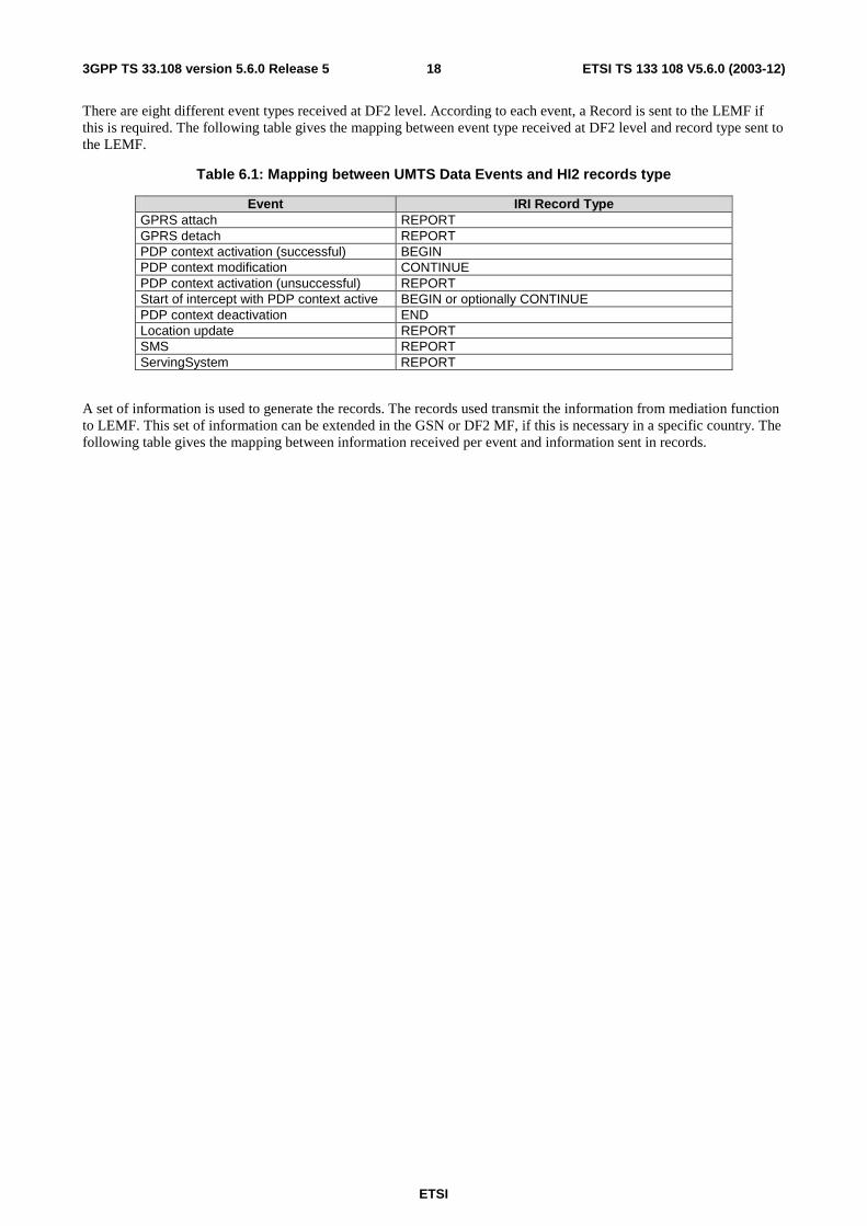
There are eight different event types received at DF2 level. According to each event, a Record is sent to the LEMF if this is required. The following table gives the mapping between event type received at DF2 level and record type sent to the LEMF.
Table 6.1: Mapping between UMTS Data Events and HI2 records type
Event IRI Record Type GPRS attach REPORT GPRS detach REPORT PDP context activation (successful) BEGIN PDP context modification CONTINUE PDP context activation (unsuccessful) REPORT Start of intercept with PDP context active BEGIN or optionally CONTINUE PDP context deactivation END Location update REPORT SMS REPORT ServingSystem REPORT
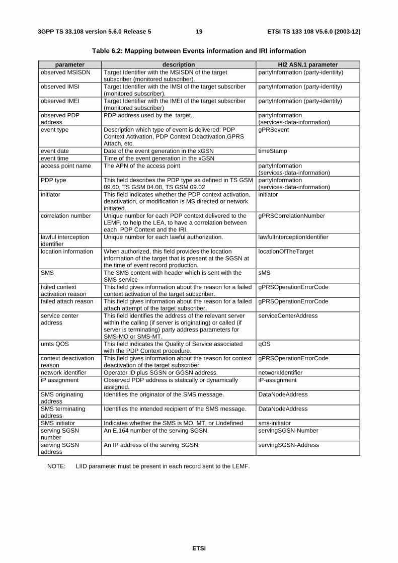
A set of information is used to generate the records. The records used transmit the information from mediation function to LEMF. This set of information can be extended in the GSN or DF2 MF, if this is necessary in a specific country. The following table gives the mapping between information received per event and information sent in records.
ETSI
ETSI TS 133 108 V5.6.0 (2003-12) 193GPP TS 33.108 version 5.6.0 Release 5
Table 6.2: Mapping between Events information and IRI information
parameter description HI2 ASN.1 parameter observed MSISDN Target Identifier with the MSISDN of the target
subscriber (monitored subscriber). partyInformation (party-identiity)
observed IMSI Target Identifier with the IMSI of the target subscriber (monitored subscriber).
partyInformation (party-identity)
observed IMEI Target Identifier with the IMEI of the target subscriber (monitored subscriber)
partyInformation (party-identity)
observed PDP address
PDP address used by the target.. partyInformation (services-data-information)
event type Description which type of event is delivered: PDP Context Activation, PDP Context Deactivation,GPRS Attach, etc.
gPRSevent
event date Date of the event generation in the xGSN timeStamp event time Time of the event generation in the xGSN access point name The APN of the access point partyInformation
(services-data-information) PDP type This field describes the PDP type as defined in TS GSM
09.60, TS GSM 04.08, TS GSM 09.02 partyInformation (services-data-information)
initiator This field indicates whether the PDP context activation, deactivation, or modification is MS directed or network initiated.
initiator
correlation number Unique number for each PDP context delivered to the LEMF, to help the LEA, to have a correlation between each PDP Context and the IRI.
gPRSCorrelationNumber
lawful interception identifier
Unique number for each lawful authorization. lawfulInterceptionIdentifier
location information When authorized, this field provides the location information of the target that is present at the SGSN at the time of event record production.
locationOfTheTarget
SMS The SMS content with header which is sent with the SMS-service
sMS
failed context activation reason
This field gives information about the reason for a failed context activation of the target subscriber.
gPRSOperationErrorCode
failed attach reason This field gives information about the reason for a failed attach attempt of the target subscriber.
gPRSOperationErrorCode
service center address
This field identifies the address of the relevant server within the calling (if server is originating) or called (if server is terminating) party address parameters for SMS-MO or SMS-MT.
serviceCenterAddress
umts QOS This field indicates the Quality of Service associated with the PDP Context procedure.
qOS
context deactivation reason
This field gives information about the reason for context deactivation of the target subscriber.
gPRSOperationErrorCode
network identifier Operator ID plus SGSN or GGSN address. networkIdentifier iP assignment Observed PDP address is statically or dynamically
assigned. iP-assignment
SMS originating address
Identifies the originator of the SMS message. DataNodeAddress
SMS terminating address
Identifies the intended recipient of the SMS message. DataNodeAddress
SMS initiator Indicates whether the SMS is MO, MT, or Undefined sms-initiator serving SGSN number
An E.164 number of the serving SGSN. servingSGSN-Number
serving SGSN address
An IP address of the serving SGSN. servingSGSN-Address
NOTE: LIID parameter must be present in each record sent to the LEMF.
ETSI
ETSI TS 133 108 V5.6.0 (2003-12) 203GPP TS 33.108 version 5.6.0 Release 5
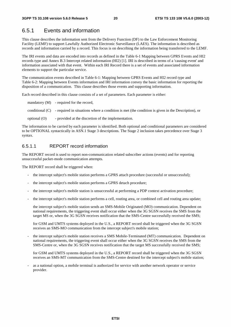
6.5.1 Events and information
This clause describes the information sent from the Delivery Function (DF) to the Law Enforcement Monitoring Facility (LEMF) to support Lawfully Authorized Electronic Surveillance (LAES). The information is described as records and information carried by a record. This focus is on describing the information being transferred to the LEMF.
The IRI events and data are encoded into records as defined in the Table 6-1 Mapping between GPRS Events and HI2 records type and Annex B.3 Intercept related information (HI2) [1]. IRI is described in terms of a 'causing event' and information associated with that event. Within each IRI Record there is a set of events and associated information elements to support the particular service.
The communication events described in Table 6-1: Mapping between GPRS Events and HI2 record type and Table 6-2: Mapping between Events information and IRI information convey the basic information for reporting the disposition of a communication. This clause describes those events and supporting information.
Each record described in this clause consists of a set of parameters. Each parameter is either:
mandatory (M) - required for the record,
conditional (C) - required in situations where a condition is met (the condition is given in the Description), or
optional (O) - provided at the discretion of the implementation.
The information to be carried by each parameter is identified. Both optional and conditional parameters are considered to be OPTIONAL syntactically in ASN.1 Stage 3 descriptions. The Stage 2 inclusion takes precedence over Stage 3 syntax.
6.5.1.1 REPORT record information
The REPORT record is used to report non-communication related subscriber actions (events) and for reporting unsuccessful packet-mode communication attempts.
The REPORT record shall be triggered when:
- the intercept subject's mobile station performs a GPRS attach procedure (successful or unsuccessful);
- the intercept subject's mobile station performs a GPRS detach procedure;
- the intercept subject's mobile station is unsuccessful at performing a PDP context activation procedure;
- the intercept subject's mobile station performs a cell, routing area, or combined cell and routing area update;
the intercept subject's mobile station sends an SMS-Mobile Originated (MO) communication. Dependent on national requirements, the triggering event shall occur either when the 3G SGSN receives the SMS from the target MS or, when the 3G SGSN receives notification that the SMS-Centre successfully received the SMS;
for GSM and UMTS systems deployed in the U.S., a REPORT record shall be triggered when the 3G SGSN receives an SMS-MO communication from the intercept subject's mobile station;
- the intercept subject's mobile station receives a SMS Mobile-Terminated (MT) communication. Dependent on national requirements, the triggering event shall occur either when the 3G SGSN receives the SMS from the SMS-Centre or, when the 3G SGSN receives notification that the target MS successfully received the SMS;
for GSM and UMTS systems deployed in the U.S., a REPORT record shall be triggered when the 3G SGSN receives an SMS-MT communication from the SMS-Centre destined for the intercept subject's mobile station;
- as a national option, a mobile terminal is authorized for service with another network operator or service provider.
ETSI
ETSI TS 133 108 V5.6.0 (2003-12) 213GPP TS 33.108 version 5.6.0 Release 5
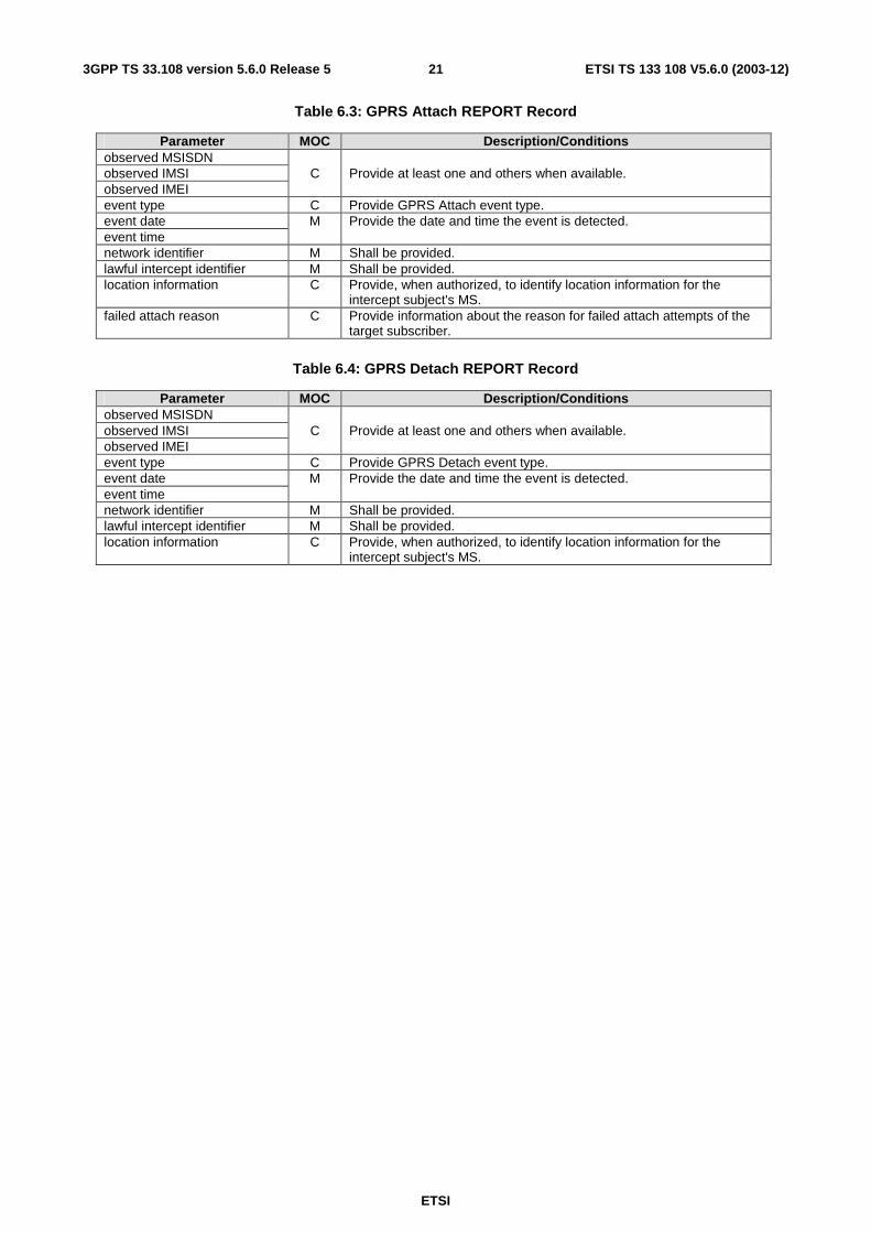
Table 6.3: GPRS Attach REPORT Record
Parameter MOC Description/Conditions observed MSISDN observed IMSI C Provide at least one and others when available. observed IMEI event type C Provide GPRS Attach event type. event date M Provide the date and time the event is detected. event time network identifier M Shall be provided. lawful intercept identifier M Shall be provided. location information C Provide, when authorized, to identify location information for the
intercept subject's MS. failed attach reason C Provide information about the reason for failed attach attempts of the
target subscriber.
Table 6.4: GPRS Detach REPORT Record
Parameter MOC Description/Conditions observed MSISDN observed IMSI C Provide at least one and others when available. observed IMEI event type C Provide GPRS Detach event type. event date M Provide the date and time the event is detected. event time network identifier M Shall be provided. lawful intercept identifier M Shall be provided. location information C Provide, when authorized, to identify location information for the
intercept subject's MS.
ETSI
ETSI TS 133 108 V5.6.0 (2003-12) 223GPP TS 33.108 version 5.6.0 Release 5
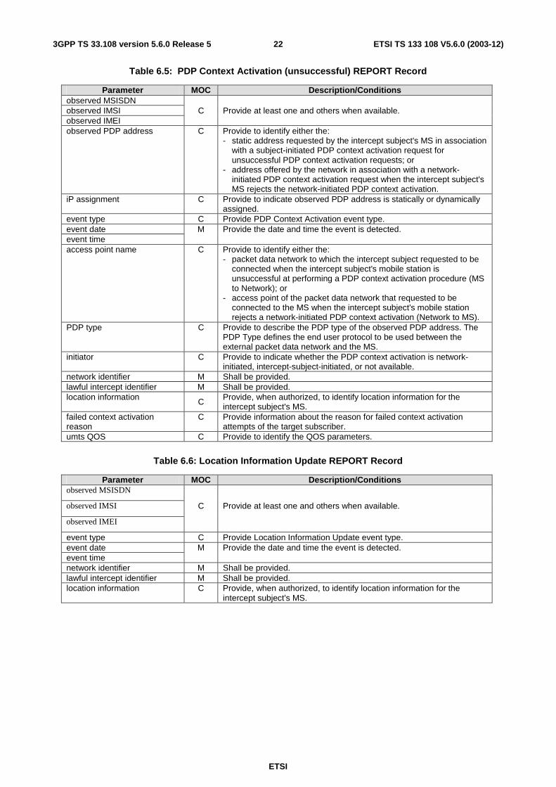
Table 6.5: PDP Context Activation (unsuccessful) REPORT Record
Parameter MOC Description/Conditions observed MSISDN observed IMSI C Provide at least one and others when available. observed IMEI observed PDP address C Provide to identify either the:
- static address requested by the intercept subject's MS in association with a subject-initiated PDP context activation request for unsuccessful PDP context activation requests; or
- address offered by the network in association with a network-initiated PDP context activation request when the intercept subject's MS rejects the network-initiated PDP context activation.
iP assignment C Provide to indicate observed PDP address is statically or dynamically assigned.
event type C Provide PDP Context Activation event type. event date M Provide the date and time the event is detected. event time access point name C Provide to identify either the:
- packet data network to which the intercept subject requested to be connected when the intercept subject's mobile station is unsuccessful at performing a PDP context activation procedure (MS to Network); or
- access point of the packet data network that requested to be connected to the MS when the intercept subject's mobile station rejects a network-initiated PDP context activation (Network to MS).
PDP type C Provide to describe the PDP type of the observed PDP address. The PDP Type defines the end user protocol to be used between the external packet data network and the MS.
initiator C Provide to indicate whether the PDP context activation is network-initiated, intercept-subject-initiated, or not available.
network identifier M Shall be provided. lawful intercept identifier M Shall be provided. location information C Provide, when authorized, to identify location information for the
intercept subject's MS. failed context activation reason
C Provide information about the reason for failed context activation attempts of the target subscriber.
umts QOS C Provide to identify the QOS parameters.
Table 6.6: Location Information Update REPORT Record
Parameter MOC Description/Conditions observed MSISDN
observed IMSI C Provide at least one and others when available.
observed IMEI
event type C Provide Location Information Update event type. event date M Provide the date and time the event is detected. event time network identifier M Shall be provided. lawful intercept identifier M Shall be provided. location information C Provide, when authorized, to identify location information for the
intercept subject's MS.
ETSI
ETSI TS 133 108 V5.6.0 (2003-12) 233GPP TS 33.108 version 5.6.0 Release 5
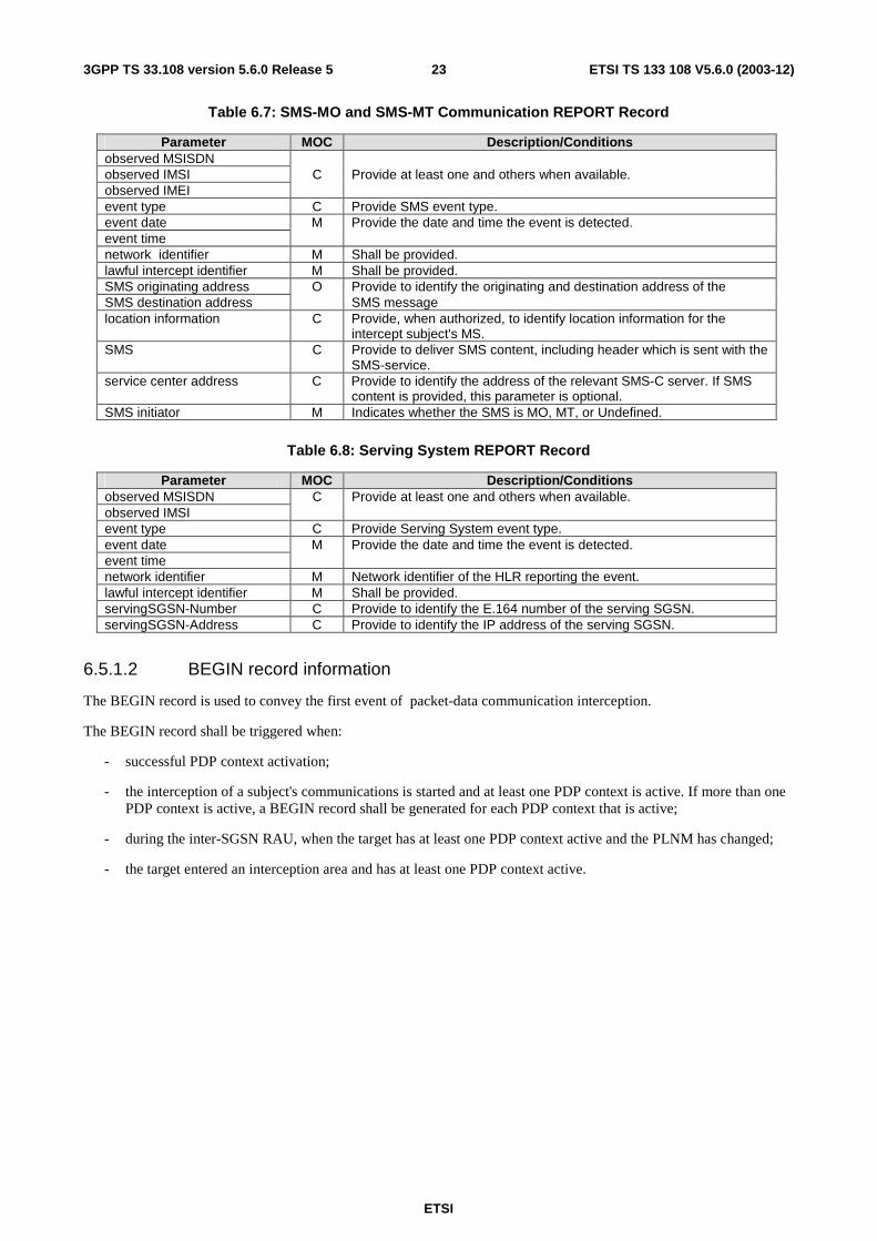
Table 6.7: SMS-MO and SMS-MT Communication REPORT Record
Parameter MOC Description/Conditions observed MSISDN observed IMSI C Provide at least one and others when available. observed IMEI event type C Provide SMS event type. event date M Provide the date and time the event is detected. event time network identifier M Shall be provided. lawful intercept identifier M Shall be provided. SMS originating address O Provide to identify the originating and destination address of the SMS destination address SMS message location information C Provide, when authorized, to identify location information for the
intercept subject's MS. SMS C Provide to deliver SMS content, including header which is sent with the
SMS-service. service center address C Provide to identify the address of the relevant SMS-C server. If SMS
content is provided, this parameter is optional. SMS initiator M Indicates whether the SMS is MO, MT, or Undefined.
Table 6.8: Serving System REPORT Record
Parameter MOC Description/Conditions observed MSISDN C Provide at least one and others when available. observed IMSI event type C Provide Serving System event type. event date M Provide the date and time the event is detected. event time network identifier M Network identifier of the HLR reporting the event. lawful intercept identifier M Shall be provided. servingSGSN-Number C Provide to identify the E.164 number of the serving SGSN. servingSGSN-Address C Provide to identify the IP address of the serving SGSN.
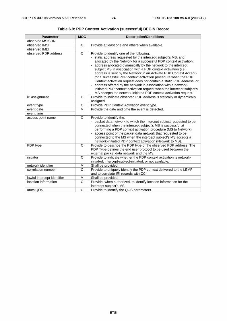
6.5.1.2 BEGIN record information
The BEGIN record is used to convey the first event of packet-data communication interception.
The BEGIN record shall be triggered when:
- successful PDP context activation;
- the interception of a subject's communications is started and at least one PDP context is active. If more than one PDP context is active, a BEGIN record shall be generated for each PDP context that is active;
- during the inter-SGSN RAU, when the target has at least one PDP context active and the PLNM has changed;
- the target entered an interception area and has at least one PDP context active.
ETSI
ETSI TS 133 108 V5.6.0 (2003-12) 243GPP TS 33.108 version 5.6.0 Release 5
Table 6.9: PDP Context Activation (successful) BEGIN Record
Parameter MOC Description/Conditions observed MSISDN observed IMSI C Provide at least one and others when available. observed IMEI observed PDP address C Provide to identify one of the following:
- static address requested by the intercept subject's MS, and allocated by the Network for a successful PDP context activation;
- address allocated dynamically by the network to the intercept subject MS in association with a PDP context activation (i.e., address is sent by the Network in an Activate PDP Context Accept) for a successful PDP context activation procedure when the PDP Context activation request does not contain a static PDP address; or
- address offered by the network in association with a network-initiated PDP context activation request when the intercept subject's MS accepts the network-initiated PDP context activation request.
iP assignment C Provide to indicate observed PDP address is statically or dynamically assigned.
event type C Provide PDP Context Activation event type. event date M Provide the date and time the event is detected. event time access point name C Provide to identify the:
- packet data network to which the intercept subject requested to be connected when the intercept subject's MS is successful at performing a PDP context activation procedure (MS to Network).
- access point of the packet data network that requested to be connected to the MS when the intercept subject's MS accepts a network-initiated PDP context activation (Network to MS).
PDP type C Provide to describe the PDP type of the observed PDP address. The PDP Type defines the end user protocol to be used between the external packet data network and the MS.
initiator C Provide to indicate whether the PDP context activation is network-initiated, intercept-subject-initiated, or not available.
network identifier M Shall be provided. correlation number C Provide to uniquely identify the PDP context delivered to the LEMF
and to correlate IRI records with CC. lawful intercept identifier M Shall be provided. location information C Provide, when authorized, to identify location information for the
intercept subject's MS. umts QOS C Provide to identify the QOS parameters.
ETSI
ETSI TS 133 108 V5.6.0 (2003-12) 253GPP TS 33.108 version 5.6.0 Release 5
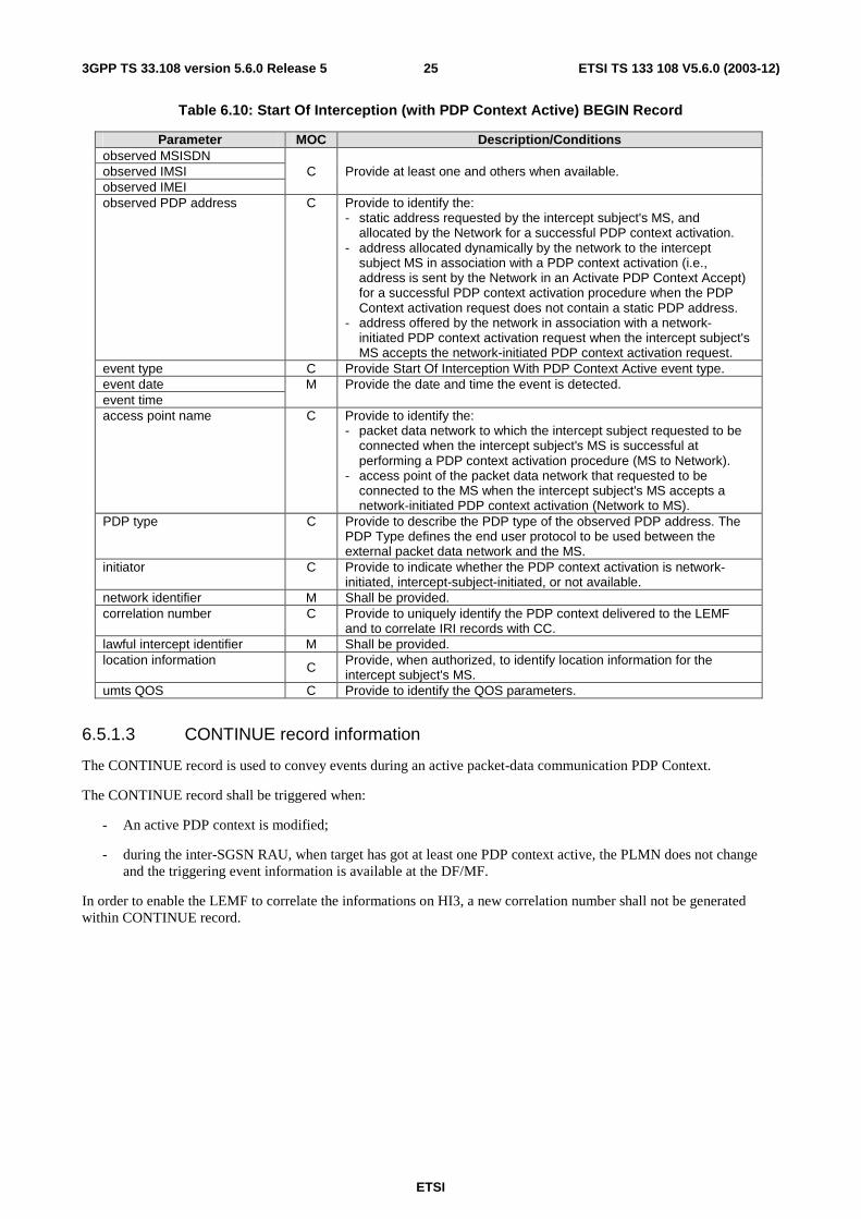
Table 6.10: Start Of Interception (with PDP Context Active) BEGIN Record
Parameter MOC Description/Conditions observed MSISDN observed IMSI C Provide at least one and others when available. observed IMEI observed PDP address C Provide to identify the:
- static address requested by the intercept subject's MS, and allocated by the Network for a successful PDP context activation.
- address allocated dynamically by the network to the intercept subject MS in association with a PDP context activation (i.e., address is sent by the Network in an Activate PDP Context Accept) for a successful PDP context activation procedure when the PDP Context activation request does not contain a static PDP address.
- address offered by the network in association with a network-initiated PDP context activation request when the intercept subject's MS accepts the network-initiated PDP context activation request.
event type C Provide Start Of Interception With PDP Context Active event type. event date M Provide the date and time the event is detected. event time access point name C Provide to identify the:
- packet data network to which the intercept subject requested to be connected when the intercept subject's MS is successful at performing a PDP context activation procedure (MS to Network).
- access point of the packet data network that requested to be connected to the MS when the intercept subject's MS accepts a network-initiated PDP context activation (Network to MS).
PDP type C Provide to describe the PDP type of the observed PDP address. The PDP Type defines the end user protocol to be used between the external packet data network and the MS.
initiator C Provide to indicate whether the PDP context activation is network-initiated, intercept-subject-initiated, or not available.
network identifier M Shall be provided. correlation number C Provide to uniquely identify the PDP context delivered to the LEMF
and to correlate IRI records with CC. lawful intercept identifier M Shall be provided. location information C Provide, when authorized, to identify location information for the
intercept subject's MS. umts QOS C Provide to identify the QOS parameters.
6.5.1.3 CONTINUE record information
The CONTINUE record is used to convey events during an active packet-data communication PDP Context.
The CONTINUE record shall be triggered when:
- An active PDP context is modified;
- during the inter-SGSN RAU, when target has got at least one PDP context active, the PLMN does not change and the triggering event information is available at the DF/MF.
In order to enable the LEMF to correlate the informations on HI3, a new correlation number shall not be generated within CONTINUE record.
ETSI
ETSI TS 133 108 V5.6.0 (2003-12) 263GPP TS 33.108 version 5.6.0 Release 5
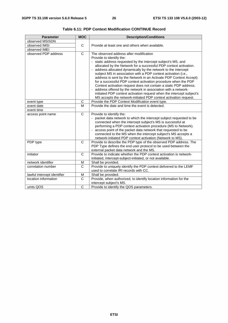
Table 6.11: PDP Context Modification CONTINUE Record
Parameter MOC Description/Conditions observed MSISDN observed IMSI C Provide at least one and others when available. observed IMEI observed PDP address C The observed address after modification
Provide to identify the: - static address requested by the intercept subject's MS, and
allocated by the Network for a successful PDP context activation. - address allocated dynamically by the network to the intercept
subject MS in association with a PDP context activation (i.e., address is sent by the Network in an Activate PDP Context Accept) for a successful PDP context activation procedure when the PDP Context activation request does not contain a static PDP address.
- address offered by the network in association with a network-initiated PDP context activation request when the intercept subject's MS accepts the network-initiated PDP context activation request.
event type C Provide the PDP Context Modification event type. event date M Provide the date and time the event is detected. event time access point name C Provide to identify the:
- packet data network to which the intercept subject requested to be connected when the intercept subject's MS is successful at performing a PDP context activation procedure (MS to Network).
- access point of the packet data network that requested to be connected to the MS when the intercept subject's MS accepts a network-initiated PDP context activation (Network to MS).
PDP type C Provide to describe the PDP type of the observed PDP address. The PDP Type defines the end user protocol to be used between the external packet data network and the MS.
initiator C Provide to indicate whether the PDP context activation is network-initiated, intercept-subject-initiated, or not available.
network identifier M Shall be provided. correlation number C Provide to uniquely identify the PDP context delivered to the LEMF
used to correlate IRI records with CC. lawful intercept identifier M Shall be provided. location information C Provide, when authorized, to identify location information for the
intercept subject's MS. umts QOS C Provide to identify the QOS parameters.
ETSI
ETSI TS 133 108 V5.6.0 (2003-12) 273GPP TS 33.108 version 5.6.0 Release 5
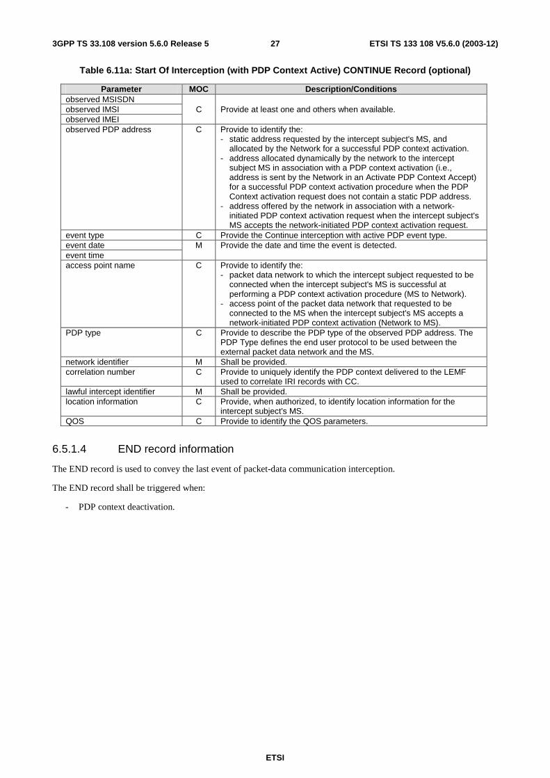
Table 6.11a: Start Of Interception (with PDP Context Active) CONTINUE Record (optional)
Parameter MOC Description/Conditions observed MSISDN observed IMSI C Provide at least one and others when available. observed IMEI observed PDP address C Provide to identify the:
- static address requested by the intercept subject's MS, and allocated by the Network for a successful PDP context activation.
- address allocated dynamically by the network to the intercept subject MS in association with a PDP context activation (i.e., address is sent by the Network in an Activate PDP Context Accept) for a successful PDP context activation procedure when the PDP Context activation request does not contain a static PDP address.
- address offered by the network in association with a network-initiated PDP context activation request when the intercept subject's MS accepts the network-initiated PDP context activation request.
event type C Provide the Continue interception with active PDP event type. event date M Provide the date and time the event is detected. event time access point name C Provide to identify the:
- packet data network to which the intercept subject requested to be connected when the intercept subject's MS is successful at performing a PDP context activation procedure (MS to Network).
- access point of the packet data network that requested to be connected to the MS when the intercept subject's MS accepts a network-initiated PDP context activation (Network to MS).
PDP type C Provide to describe the PDP type of the observed PDP address. The PDP Type defines the end user protocol to be used between the external packet data network and the MS.
network identifier M Shall be provided. correlation number C Provide to uniquely identify the PDP context delivered to the LEMF
used to correlate IRI records with CC. lawful intercept identifier M Shall be provided. location information C Provide, when authorized, to identify location information for the
intercept subject's MS. QOS C Provide to identify the QOS parameters.
6.5.1.4 END record information
The END record is used to convey the last event of packet-data communication interception.
The END record shall be triggered when:
- PDP context deactivation.
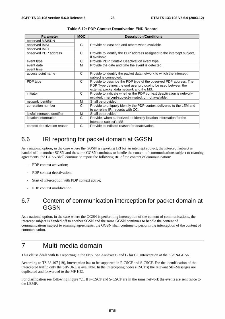
ETSI
ETSI TS 133 108 V5.6.0 (2003-12) 283GPP TS 33.108 version 5.6.0 Release 5
Table 6.12: PDP Context Deactivation END Record
Parameter MOC Description/Conditions observed MSISDN observed IMSI C Provide at least one and others when available. observed IMEI observed PDP address C Provide to identify the PDP address assigned to the intercept subject,
if available. event type C Provide PDP Context Deactivation event type. event date M Provide the date and time the event is detected. event time access point name C Provide to identify the packet data network to which the intercept
subject is connected. PDP type C Provide to describe the PDP type of the observed PDP address. The
PDP Type defines the end user protocol to be used between the external packet data network and the MS.
initiator C Provide to indicate whether the PDP context deactivation is network-initiated, intercept-subject-initiated, or not available.
network identifier M Shall be provided. correlation number C Provide to uniquely identify the PDP context delivered to the LEM and
to correlate IRI records with CC. lawful intercept identifier M Shall be provided. location information C Provide, when authorized, to identify location information for the
intercept subject's MS. context deactivation reason C Provide to indicate reason for deactivation.
6.6 IRI reporting for packet domain at GGSN As a national option, in the case where the GGSN is reporting IRI for an intercept subject, the intercept subject is handed off to another SGSN and the same GGSN continues to handle the content of communications subject to roaming agreements, the GGSN shall continue to report the following IRI of the content of communication:
- PDP context activation;
- PDP context deactivation;
- Start of interception with PDP context active;
- PDP context modification.
6.7 Content of communication interception for packet domain at GGSN
As a national option, in the case where the GGSN is performing interception of the content of communications, the intercept subject is handed off to another SGSN and the same GGSN continues to handle the content of communications subject to roaming agreements, the GGSN shall continue to perform the interception of the content of communication.
7 Multi-media domain This clause deals with IRI reporting in the IMS. See Annexes C and G for CC interception at the SGSN/GGSN.
According to TS 33.107 [19], interception has to be supported in P-CSCF and S-CSCF. For the identification of the intercepted traffic only the SIP-URL is available. In the intercepting nodes (CSCF's) the relevant SIP-Messages are duplicated and forwarded to the MF HI2.
For clarification see following Figure 7.1. If P-CSCF and S-CSCF are in the same network the events are sent twice to the LEMF.
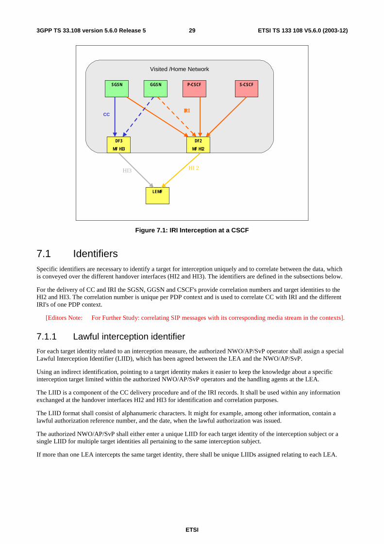
ETSI
ETSI TS 133 108 V5.6.0 (2003-12) 293GPP TS 33.108 version 5.6.0 Release 5
Visited /Home Network
S-CSCFP-CSCFGGSNSGSN
DF2
MF HI2
LEMF
CCIRI
DF3
MF HI3
HI 2HI3
Figure 7.1: IRI Interception at a CSCF
7.1 Identifiers Specific identifiers are necessary to identify a target for interception uniquely and to correlate between the data, which is conveyed over the different handover interfaces (HI2 and HI3). The identifiers are defined in the subsections below.
For the delivery of CC and IRI the SGSN, GGSN and CSCF's provide correlation numbers and target identities to the HI2 and HI3. The correlation number is unique per PDP context and is used to correlate CC with IRI and the different IRI's of one PDP context.
[Editors Note: For Further Study: correlating SIP messages with its corresponding media stream in the contexts].
7.1.1 Lawful interception identifier
For each target identity related to an interception measure, the authorized NWO/AP/SvP operator shall assign a special Lawful Interception Identifier (LIID), which has been agreed between the LEA and the NWO/AP/SvP.
Using an indirect identification, pointing to a target identity makes it easier to keep the knowledge about a specific interception target limited within the authorized NWO/AP/SvP operators and the handling agents at the LEA.
The LIID is a component of the CC delivery procedure and of the IRI records. It shall be used within any information exchanged at the handover interfaces HI2 and HI3 for identification and correlation purposes.
The LIID format shall consist of alphanumeric characters. It might for example, among other information, contain a lawful authorization reference number, and the date, when the lawful authorization was issued.
The authorized NWO/AP/SvP shall either enter a unique LIID for each target identity of the interception subject or a single LIID for multiple target identities all pertaining to the same interception subject.
If more than one LEA intercepts the same target identity, there shall be unique LIIDs assigned relating to each LEA.
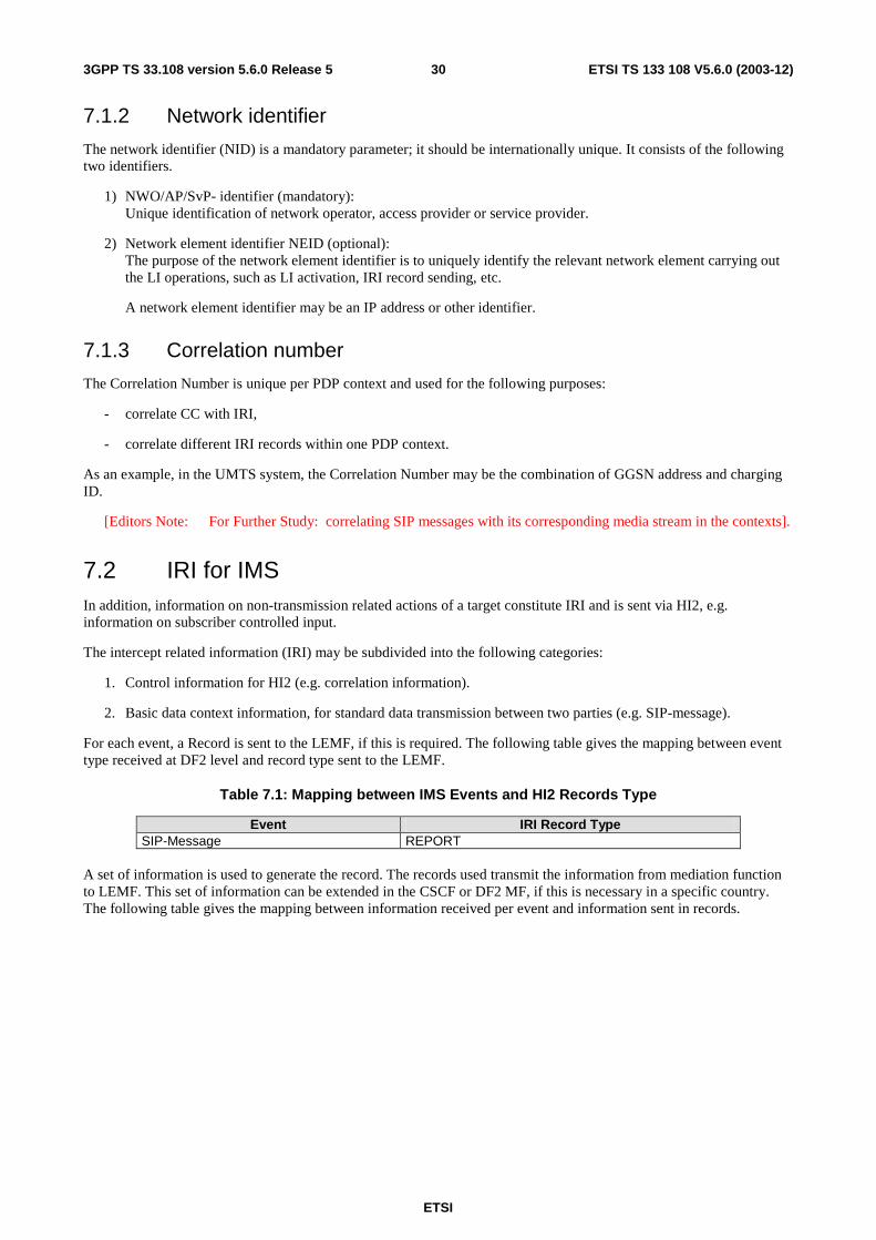
ETSI
ETSI TS 133 108 V5.6.0 (2003-12) 303GPP TS 33.108 version 5.6.0 Release 5
7.1.2 Network identifier
The network identifier (NID) is a mandatory parameter; it should be internationally unique. It consists of the following two identifiers.
1) NWO/AP/SvP- identifier (mandatory): Unique identification of network operator, access provider or service provider.
2) Network element identifier NEID (optional): The purpose of the network element identifier is to uniquely identify the relevant network element carrying out the LI operations, such as LI activation, IRI record sending, etc.
A network element identifier may be an IP address or other identifier.
7.1.3 Correlation number
The Correlation Number is unique per PDP context and used for the following purposes:
- correlate CC with IRI,
- correlate different IRI records within one PDP context.
As an example, in the UMTS system, the Correlation Number may be the combination of GGSN address and charging ID.
[Editors Note: For Further Study: correlating SIP messages with its corresponding media stream in the contexts].
7.2 IRI for IMS In addition, information on non-transmission related actions of a target constitute IRI and is sent via HI2, e.g. information on subscriber controlled input.
The intercept related information (IRI) may be subdivided into the following categories:
1. Control information for HI2 (e.g. correlation information).
2. Basic data context information, for standard data transmission between two parties (e.g. SIP-message).
For each event, a Record is sent to the LEMF, if this is required. The following table gives the mapping between event type received at DF2 level and record type sent to the LEMF.
Table 7.1: Mapping between IMS Events and HI2 Records Type
Event IRI Record Type SIP-Message REPORT
A set of information is used to generate the record. The records used transmit the information from mediation function to LEMF. This set of information can be extended in the CSCF or DF2 MF, if this is necessary in a specific country. The following table gives the mapping between information received per event and information sent in records.
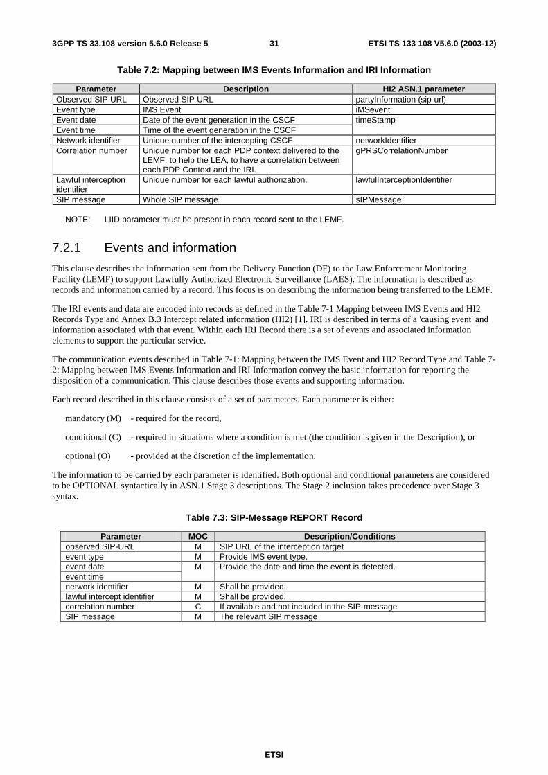
ETSI
ETSI TS 133 108 V5.6.0 (2003-12) 313GPP TS 33.108 version 5.6.0 Release 5
Table 7.2: Mapping between IMS Events Information and IRI Information
Parameter Description HI2 ASN.1 parameter Observed SIP URL Observed SIP URL partyInformation (sip-url) Event type IMS Event iMSevent Event date Date of the event generation in the CSCF timeStamp Event time Time of the event generation in the CSCF Network identifier Unique number of the intercepting CSCF networkIdentifier Correlation number Unique number for each PDP context delivered to the
LEMF, to help the LEA, to have a correlation between each PDP Context and the IRI.
gPRSCorrelationNumber
Lawful interception identifier
Unique number for each lawful authorization. lawfulInterceptionIdentifier
SIP message Whole SIP message sIPMessage NOTE: LIID parameter must be present in each record sent to the LEMF.
7.2.1 Events and information
This clause describes the information sent from the Delivery Function (DF) to the Law Enforcement Monitoring Facility (LEMF) to support Lawfully Authorized Electronic Surveillance (LAES). The information is described as records and information carried by a record. This focus is on describing the information being transferred to the LEMF.
The IRI events and data are encoded into records as defined in the Table 7-1 Mapping between IMS Events and HI2 Records Type and Annex B.3 Intercept related information (HI2) [1]. IRI is described in terms of a 'causing event' and information associated with that event. Within each IRI Record there is a set of events and associated information elements to support the particular service.
The communication events described in Table 7-1: Mapping between the IMS Event and HI2 Record Type and Table 7-2: Mapping between IMS Events Information and IRI Information convey the basic information for reporting the disposition of a communication. This clause describes those events and supporting information.
Each record described in this clause consists of a set of parameters. Each parameter is either:
mandatory (M) - required for the record,
conditional (C) - required in situations where a condition is met (the condition is given in the Description), or
optional (O) - provided at the discretion of the implementation.
The information to be carried by each parameter is identified. Both optional and conditional parameters are considered to be OPTIONAL syntactically in ASN.1 Stage 3 descriptions. The Stage 2 inclusion takes precedence over Stage 3 syntax.
Table 7.3: SIP-Message REPORT Record
Parameter MOC Description/Conditions observed SIP-URL M SIP URL of the interception target event type M Provide IMS event type. event date M Provide the date and time the event is detected. event time network identifier M Shall be provided. lawful intercept identifier M Shall be provided. correlation number C If available and not included in the SIP-message SIP message M The relevant SIP message
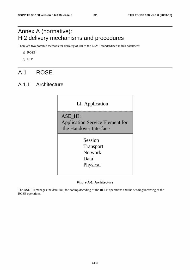
ETSI
ETSI TS 133 108 V5.6.0 (2003-12) 323GPP TS 33.108 version 5.6.0 Release 5
Annex A (normative): HI2 delivery mechanisms and procedures There are two possible methods for delivery of IRI to the LEMF standardized in this document:
a) ROSE
b) FTP
A.1 ROSE
A.1.1 Architecture
LI_Application
ASE_HI :Application Service Element forthe Handover Interface
SessionTransportNetworkDataPhysical
Figure A-1: Architecture
The ASE_HI manages the data link, the coding/decoding of the ROSE operations and the sending/receiving of the ROSE operations.
ETSI
ETSI TS 133 108 V5.6.0 (2003-12) 333GPP TS 33.108 version 5.6.0 Release 5
A.1.2 ASE_HI procedures
A.1.2.1 Sending part
To request the sending of data to a peer entity, the LI_Application provides the ASE_HI, the address of the peer entity, the nature of the data and the data.
On receiving a request of the LI_Application:
- If the data link toward the peer entity address is active, the ASE_HI, from the nature of the data provided, encapsulates this data in the relevant RO-Invoke operation.
- If the data link toward the peer entity address isn't active, the ASE_HI establishes this data link (see annex A.1.2.3). Then, depending on the nature of the data provided, the ASE_HI encapsulates this data in the relevant RO-Invoke operation.
Depending on the natures of the data provided by the LI_Application, the ASE_HI encapsulates this data within the relevant ROSE operation:
- IRI: in this case the data provided by the application are encoded within the class 2 RO-Invoke operation Umts_Sending_of_IRI.
- SMS: in this case the data provided by the application are encoded within the class 2 RO-Invoke operation Umts_Sending-of-IRI.
Depending on the class of the operation, the ASE-HI may have to wait for an answer. In this case a timer, depending on the operation, is started on the sending of the operation and stopped on the receipt of an answer (RO_Result, RO_Error, RO_Reject).
On timeout of the timer, the ASE_HI indicates to the LI_Application that no answer has been received. It is under the LI_Application responsibility to send again the data or to inform the administrator of the problem.
On receipt of an answer component (after verification that the component isn't erroneous), the ASE_HI stop the relevant timer and acts depending on the type of component:
- On receipt of a RO_Result, the ASE_HI provide the relevant LI_Application an indication that the data has been received by the peer LI-application and the possible parameters contained in the RO_Result.
- On receipt of a RO_Error, the ASE_HI provide the relevant LI_Application an indication that the data hasn't been received by the peer LI-application and the possible "Error cause". The error causes are defined for each operation in the relevant ASN1 script. It is under the LI_Application responsibility to generate or not an alarm message toward an operator or administrator.
- On receipt of a RO_Reject_U/P, the ASE_HI provide the relevant LI_Application an indication that the data hasn't been received by the peer LI-application and the "Problem cause". The "problem causes" are defined in [7] to [8]. It is under the LI_Application responsibility to send again the data or to inform the operator/administrator of the error.
On receipt of an erroneous component, the ASE_HI acts as described in ITU-T Recommendations [7] to [8].
A.1.2.2 Receiving part
On receipt of a ROSE operation from the lower layers:
- When receiving operations from the peer entity, the ASE_HI verifies the syntax of the component and transmits the parameters to the LI-Application. If no error/problem is detected, in accordance with the [7] to [8] standard result (only Class2 operation are defined), the ASE_HI sends back a RO_Result which coding is determined by the relevant operation ASN1 script. The different operations which can be received are:
- RO-Invoke operation "Sending-of-IRI" (HI2 interface);
- RO-Invoke operation "No-Circuit-Call-Related-Services" (HI3 interface).
ETSI
ETSI TS 133 108 V5.6.0 (2003-12) 343GPP TS 33.108 version 5.6.0 Release 5
In case of error, the ASE_HI acts depending on the reason of the error or problem:
- In accordance with the rules defined by [7] to [8], an RO_Error is sent in the case of an unsuccessful operation at the application level. The Error cause provided is one among those defined by the ASN1 script of the relevant operation;
- In accordance with the rules defined in [7] to [8], an RO_Reject_U/P is sent in the case of an erroneous component. On receipt of an erroneous component, the ASE_HI acts as described in [7] to [8].
A.1.2.3 Data link management
This function is used to establish or release a data link between two peer LI_Applications entities (MF and LEMF).
Depending on a per destination address configuration data, the data link establishment may be required either by the LEMF LI_Application or by the MF LI_Application.
A.1.2.3.1 Data link establishment
To request the establishment of a data link toward a peer entity, the LI_Application provides, among others, the destination address of the peer entity (implicitly, this address defined the protocol layers immediately under the ASE_HI: TCP/IP, X25, …). On receipt of this request, the ASE_HI request the establishment of the data link with respect of the rules of the under layers protocol.
As soon as the data link is established, the requesting LI_Application initiates an authentication procedure:
- the origin LI_Application requests the ASE_HI to send the class 2 RO-Invoke operation "Sending_of_Password" which includes the "origin password" provided by the LI_Application;
- the peer LI-Application, on receipt of the "origin password" and after acceptance, requests to its ASE_HI to send back a RO-Result. In addition, this destination application requests the ASE_HI to send the class 2 RO-Invoke operation "Sending-of-Password" which includes the "destination password" provided by the LI_Application;
- the origin LI-Application, on receipt of the "destination password" and after acceptance, requests to its ASE_HI to send back a RO-Result. This application is allowed to send data;
- after receipt of the RO_Result, this application is allowed to send data.
In case of erroneous password, the data link is immediately released and an "password error indication" is sent toward the operator.
Optionally a Data link test procedure may be used to verify periodically the data link:
- When no data have been exchanged during a network dependent period of time toward an address, (may vary from 1 to 30 minutes) the LI_Application requests the ASE_HI to send the class 2 RO-Invoke operation Data-Link-Test;
- The peer LI-Application, on receipt of this operation , requests to it's ASE_HI to send back a RO-Result;
- On receipt of the Result the test is considered valid by the LI_Application;
- If no Result is received or if a Reject/Error message is received, the LI_Aplication requests the ASE_LI to release the data link and send an error message toward the operator.
A.1.2.3.2 Data link release
- The End of the connection toward the peer LI_Application is under the responsibility of the LI_Application. E.g., the End of the connection may be requested in the following cases:
- When all the data (IRI, …) has been sent. To prevent unnecessary release, the datalink may be released only when no LI_Application data have been exchanged during a network dependent period of time;
- The data link is established when a call is intercepted and released when the intercepted call is released (and all the relevant data have been sent);
- For security purposes;
- For changing of password or address of the LEMF/IIF.
ETSI
ETSI TS 133 108 V5.6.0 (2003-12) 353GPP TS 33.108 version 5.6.0 Release 5
- To end the connection an LI_Application requests the ASE_HI to send the class 2 RO-Invoke operation "End-Of-Connection".
- The peer LI-Application, on receipt of this operation , requests to it's ASE_HI to send back a RO_Result.
- On receipt of the Result the LI_Application requests the ASE_LI to release the data link.
- If no Result is received after a network dependent period of time, or if a Reject/Error message is received, the LI_Application requests the ASE_LI to release the data link and to send an error message toward the operator/administrator.
A.1.2.4 Handling of unrecognized fields and parameters
See annex D.
A.2 FTP
A.2.1 Introduction At HI2 interface FTP is used over internet protocol stack for the delivery of the IRI. The FTP is defined in ref [13]. The IP is defined in ref [15]. The TCP is defined in ref [16].
FTP supports reliable delivery of data. The data may be temporarily buffered in the mediation function (MF) in case of link failure. FTP is independent of the payload data it carries.
A.2.2 Usage of the FTP The MF acts as the FTP client and the LEMF acts as the FTP server . The client pushes the data to the server.
The receiving node LEMF stores the received data as files. The MF may buffer files.
Several records may be gathered into bigger packages prior to sending, to increase bandwidth efficiency.
The following configurable intercept data collection (= transfer package closing / file change) threshold parameters should be supported:
- frequency of transfer, based on send timeout, e.g. X ms;
- frequency of transfer, based on volume trigger, e.g. X octets.
Every file shall contain only complete IRI records. The single IRI record shall not be divided into several files.
There are two possible ways as to how the interception data may be sent from the MF to the LEMF. One way is to produce files that contain interception data only for one observed target (ref: "File naming method A)"). The other way is to multiplex all the intercepted data that MF receives to the same sequence of general purpose interception files sent by the MF (ref: "File naming method B)").
File naming:
The names for the files transferred to a LEA are formed according to one of the 2 available formats, depending on the delivery file strategy chosen (e.g. due to national convention or operator preference).
Either each file contains data of only one observed target (as in method A) or several targets' data is put to files common to all observed target traffic through MF (as in method B).
The maximum set of allowed characters in interception file names are "a"…"z", "A"…"Z", "-", "_", ".", and decimals "0"…"9".
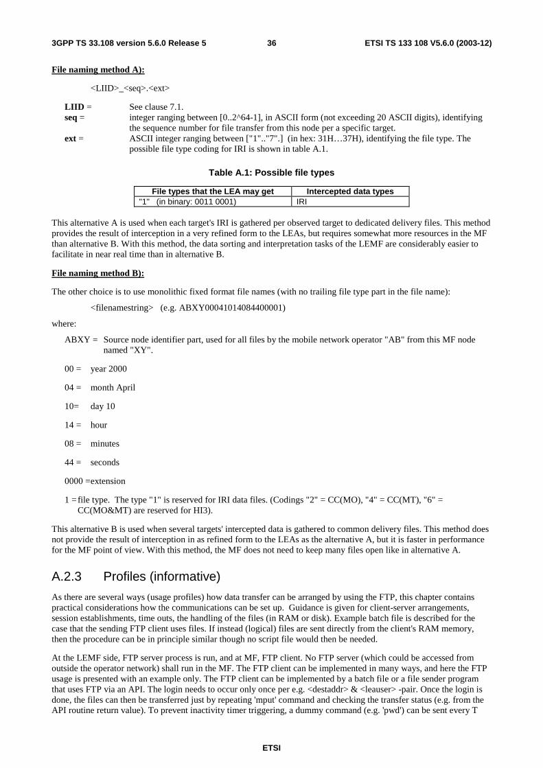
ETSI
ETSI TS 133 108 V5.6.0 (2003-12) 363GPP TS 33.108 version 5.6.0 Release 5
File naming method A):
<LIID>_<seq>.<ext>
LIID = See clause 7.1. seq = integer ranging between [0..2^64-1], in ASCII form (not exceeding 20 ASCII digits), identifying
the sequence number for file transfer from this node per a specific target. ext = ASCII integer ranging between ["1".."7".] (in hex: 31H…37H), identifying the file type. The
possible file type coding for IRI is shown in table A.1.
Table A.1: Possible file types
File types that the LEA may get Intercepted data types "1" (in binary: 0011 0001) IRI
This alternative A is used when each target's IRI is gathered per observed target to dedicated delivery files. This method provides the result of interception in a very refined form to the LEAs, but requires somewhat more resources in the MF than alternative B. With this method, the data sorting and interpretation tasks of the LEMF are considerably easier to facilitate in near real time than in alternative B.
File naming method B):
The other choice is to use monolithic fixed format file names (with no trailing file type part in the file name):
<filenamestring> (e.g. ABXY00041014084400001)
where:
ABXY = Source node identifier part, used for all files by the mobile network operator "AB" from this MF node named "XY".
00 = year 2000
04 = month April
10= day 10
14 = hour
08 = minutes
44 = seconds
0000 = extension
1 = file type. The type "1" is reserved for IRI data files. (Codings "2" = CC(MO), "4" = CC(MT), "6" = CC(MO&MT) are reserved for HI3).
This alternative B is used when several targets' intercepted data is gathered to common delivery files. This method does not provide the result of interception in as refined form to the LEAs as the alternative A, but it is faster in performance for the MF point of view. With this method, the MF does not need to keep many files open like in alternative A.
A.2.3 Profiles (informative)
As there are several ways (usage profiles) how data transfer can be arranged by using the FTP, this chapter contains practical considerations how the communications can be set up. Guidance is given for client-server arrangements, session establishments, time outs, the handling of the files (in RAM or disk). Example batch file is described for the case that the sending FTP client uses files. If instead (logical) files are sent directly from the client's RAM memory, then the procedure can be in principle similar though no script file would then be needed.
At the LEMF side, FTP server process is run, and at MF, FTP client. No FTP server (which could be accessed from outside the operator network) shall run in the MF. The FTP client can be implemented in many ways, and here the FTP usage is presented with an example only. The FTP client can be implemented by a batch file or a file sender program that uses FTP via an API. The login needs to occur only once per e.g. <destaddr> & <leauser> -pair. Once the login is done, the files can then be transferred just by repeating 'mput' command and checking the transfer status (e.g. from the API routine return value). To prevent inactivity timer triggering, a dummy command (e.g. 'pwd') can be sent every T
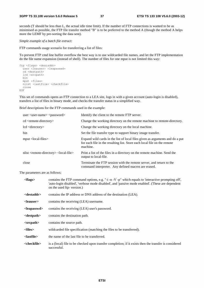
ETSI
ETSI TS 133 108 V5.6.0 (2003-12) 373GPP TS 33.108 version 5.6.0 Release 5
seconds (T should be less than L, the actual idle time limit). If the number of FTP connections is wanted to be as minimised as possible, the FTP file transfer method "B" is to be preferred to the method A (though the method A helps more the LEMF by pre-sorting the data sent).
Simple example of a batch file extract:
FTP commands usage scenario for transferring a list of files:
To prevent FTP cmd line buffer overflow the best way is to use wildcarded file names, and let the FTP implementation do the file name expansion (instead of shell). The number of files for one mput is not limited this way:
ftp <flags> <destaddr> user <leauser> <leapasswd> cd <destpath> lcd <srcpath> bin mput <files> nlist <lastfile> <checkfile> close EOF
This set of commands opens an FTP connection to a LEA site, logs in with a given account (auto-login is disabled), transfers a list of files in binary mode, and checks the transfer status in a simplified way.
Brief descriptions for the FTP commands used in the example:
user <user-name> <password> Identify the client to the remote FTP server.
cd <remote-directory> Change the working directory on the remote machine to remote-directory.
lcd <directory> Change the working directory on the local machine.
bin Set the file transfer type to support binary image transfer.
mput <local-files> Expand wild cards in the list of local files given as arguments and do a put for each file in the resulting list. Store each local file on the remote machine.
nlist <remote-directory> <local-file> Print a list of the files in a directory on the remote machine. Send the output to local-file.
close Terminate the FTP session with the remote server, and return to the command interpreter. Any defined macros are erased.
The parameters are as follows:
<flags> contains the FTP command options, e.g. "-i -n -V -p" which equals to 'interactive prompting off', 'auto-login disabled', 'verbose mode disabled', and 'passive mode enabled'. (These are dependent on the used ftp- version.)
<destaddr> contains the IP address or DNS address of the destination (LEA).
<leauser> contains the receiving (LEA) username.
<leapasswd> contains the receiving (LEA) user's password.
<destpath> contains the destination path.
<srcpath> contains the source path.
<files> wildcarded file specification (matching the files to be transferred).
<lastfile> the name of the last file to be transferred.
<checkfile> is a (local) file to be checked upon transfer completion; if it exists then the transfer is considered successful.
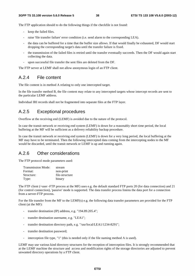
ETSI
ETSI TS 133 108 V5.6.0 (2003-12) 383GPP TS 33.108 version 5.6.0 Release 5
The FTP application should to do the following things if the checkfile is not found:
- keep the failed files.
- raise 'file transfer failure' error condition (i.e. send alarm to the corresponding LEA).
- the data can be buffered for a time that the buffer size allows. If that would finally be exhausted, DF would start dropping the corresponding target's data until the transfer failure is fixed.
- the transmission of the failed files is retried until the transfer eventually succeeds. Then the DF would again start collecting the data.
- upon successful file transfer the sent files are deleted from the DF.
The FTP server at LEMF shall not allow anonymous login of an FTP client.
A.2.4 File content
The file content is in method A relating to only one intercepted target.
In the file transfer method B, the file content may relate to any intercepted targets whose intercept records are sent to the particular LEMF address.
Individual IRI records shall not be fragmented into separate files at the FTP layer.
A.2.5 Exceptional procedures
Overflow at the receiving end (LEMF) is avoided due to the nature of the protocol.
In case the transit network or receiving end system (LEMF) is down for a reasonably short time period, the local buffering at the MF will be sufficient as a delivery reliability backup procedure.
In case the transit network or receiving end system (LEMF) is down for a very long period, the local buffering at the MF may have to be terminated. Then the following intercepted data coming from the intercepting nodes to the MF would be discarded, until the transit network or LEMF is up and running again.
A.2.6 Other considerations
The FTP protocol mode parameters used:
Transmission Mode: stream Format: non-print Structure: file-structure Type: binary
The FTP client (=user -FTP process at the MF) uses e.g. the default standard FTP ports 20 (for data connection) and 21 (for control connection), 'passive' mode is supported. The data transfer process listens the data port for a connection from a server-FTP process.
For the file transfer from the MF to the LEMF(s) e.g. the following data transfer parameters are provided for the FTP client (at the MF):
- transfer destination (IP) address, e.g. "194.89.205.4";
- transfer destination username, e.g. "LEA1";
- transfer destination directory path, e.g. "/usr/local/LEA1/1234-8291";
- transfer destination password;
- interception file type, "1" (this is needed only if the file naming method A is used).
LEMF may use various kind directory structures for the reception of interception files. It is strongly recommended that at the LEMF machine the structure and access and modification rights of the storage directories are adjusted to prevent unwanted directory operations by a FTP client.
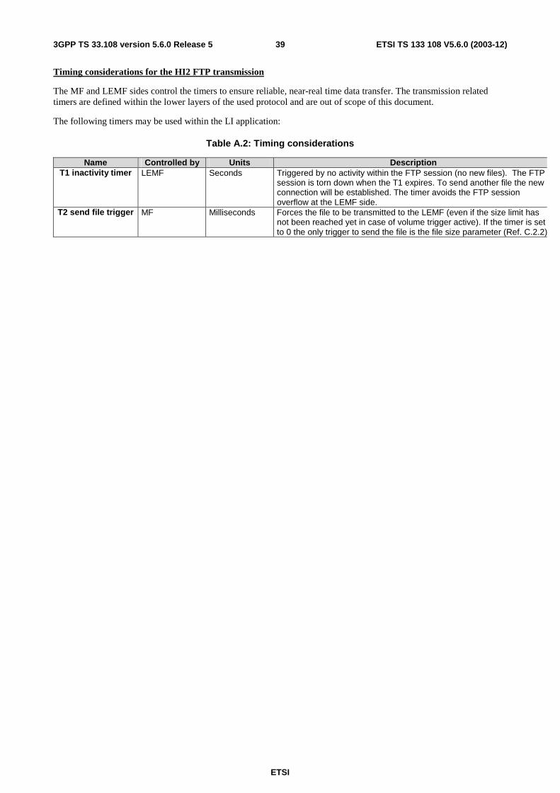
ETSI
ETSI TS 133 108 V5.6.0 (2003-12) 393GPP TS 33.108 version 5.6.0 Release 5
Timing considerations for the HI2 FTP transmission
The MF and LEMF sides control the timers to ensure reliable, near-real time data transfer. The transmission related timers are defined within the lower layers of the used protocol and are out of scope of this document.
The following timers may be used within the LI application:
Table A.2: Timing considerations
Name Controlled by Units Description T1 inactivity timer LEMF Seconds Triggered by no activity within the FTP session (no new files). The FTP
session is torn down when the T1 expires. To send another file the new connection will be established. The timer avoids the FTP session overflow at the LEMF side.
T2 send file trigger MF Milliseconds Forces the file to be transmitted to the LEMF (even if the size limit has not been reached yet in case of volume trigger active). If the timer is set to 0 the only trigger to send the file is the file size parameter (Ref. C.2.2)
ETSI
ETSI TS 133 108 V5.6.0 (2003-12) 403GPP TS 33.108 version 5.6.0 Release 5
Annex B (normative): Structure of data at the handover interface This annex specifies the coding details at the handover interface HI for all data, which may be sent from the NWO/AP/SvP's equipment to the LEMF, across HI.
At the HI2 and HI3 handover interface ports, the following data may be present:
- interface port HI2: Intercept related information (IRI);
- interface port HI3: records containing content of communication (CC).
The detailed coding specification for these types of information is contained in this annex, including sufficient details for a consistent implementation in the NWO/AP/SvP's equipment and the LEMF.
It must be noticed some data are ROSE specific and have no meaning when FTP is used. Those specificities are described at the beginning of each sub-annex.
B.1 Syntax definitions The transferred information and messages are encoded to be binary compatible with [5] (Abstract Syntax Notation One (ASN.1)) and [6] (Basic Encoding Rules (BER)).
These recommendations use precise definitions of the words type, class, value, and parameter. Those definitions are paraphrased below for clarity.
A type, in the context of the abstract syntax or transfer syntax, is a set of all possible values. For example, an INTEGER is a type for all negative and positive integers.
A class, in the context of the abstract syntax or transfer syntax, is a one of four possible domains for uniquely defining a type. The classes defined by ASN.1 and BER are: UNIVERSAL, APPLICATION, CONTEXT, and PRIVATE.
The UNIVERSAL class is reserved for international standards such as [5] and [6]. Most parameter type identifiers in the HI ROSE operations are encoded as CONTEXT specific class. Users of the protocol may extend the syntax with PRIVATE class parameters without conflict with the present document, but risk conflict with other users' extensions. APPLICATION class parameters are reserved for future extensions.
A value is a particular instance of a type. For example, five (5) is a possible value of the type INTEGER.
A parameter in the present document is a particular instance of the transfer syntax to transport a value consisting of a tag to identify the parameter type, a length to specify the number of octets in the value, and the value.
In the BER a tag (a particular type and class identifier) may either be a primitive or a constructor. A primitive is a pre-defined type (of class UNIVERSAL) and a constructor consists of other types (primitives or other constructors). A constructor type may either be IMPLICIT or EXPLICIT. An IMPLICIT type is encoded with the constructor identifier alone. Both ends of a communication must understand the underlying structure of the IMPLICIT types. EXPLICIT types are encoded with the identifiers of all the contained types. For example, an IMPLICIT Number of type INTEGER would be tagged only with the Number tag, where an EXPLICIT number of type INTEGER would have the INTEGER tag within the Number tag. The present document uses IMPLICIT tagging for more compact message encoding.
For the coding of the value part of each parameter the general rule is to use a widely use a standardized format when it exists (ISUP, DSS1, MAP, …).
As a large part of the information exchanged between the user's may be transmitted within ISUP/DSS1 signalling, the using of the coding defined for this signalling guarantee the integrity of the information provided to the LEMF and the evolution of the interface. For example if new values are used within existing ISUP parameters, this new values shall be transmitted transparently toward the LEMF.
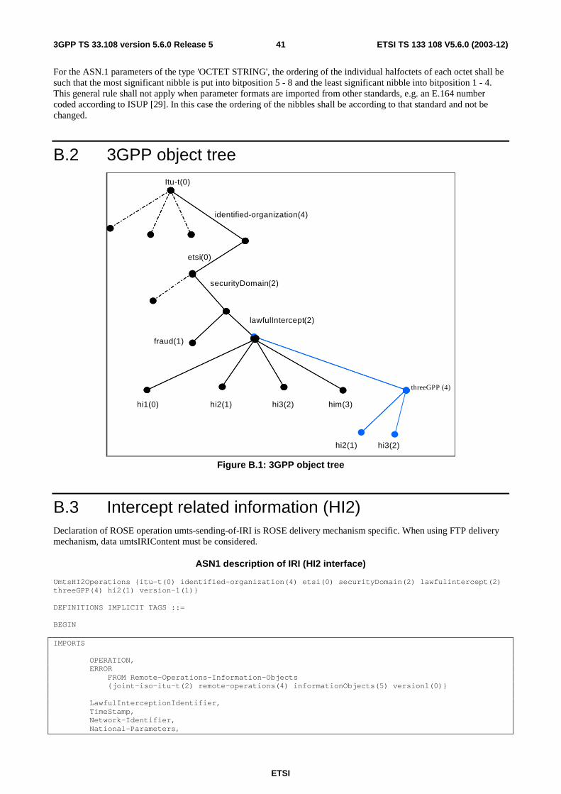
ETSI
ETSI TS 133 108 V5.6.0 (2003-12) 413GPP TS 33.108 version 5.6.0 Release 5
For the ASN.1 parameters of the type 'OCTET STRING', the ordering of the individual halfoctets of each octet shall be such that the most significant nibble is put into bitposition 5 - 8 and the least significant nibble into bitposition 1 - 4. This general rule shall not apply when parameter formats are imported from other standards, e.g. an E.164 number coded according to ISUP [29]. In this case the ordering of the nibbles shall be according to that standard and not be changed.
B.2 3GPP object tree
hi2(1) hi3(2)
Itu - t (0)
identified - organization(4)
etsi (0)
securityDomain (2)
fraud(1)
lawfulIntercept (2)
hi1(0) hi2(1) hi3(2) him(3)
threeGPP (4)
Figure B.1: 3GPP object tree
B.3 Intercept related information (HI2) Declaration of ROSE operation umts-sending-of-IRI is ROSE delivery mechanism specific. When using FTP delivery mechanism, data umtsIRIContent must be considered.
ASN1 description of IRI (HI2 interface)
UmtsHI2Operations {itu-t(0) identified-organization(4) etsi(0) securityDomain(2) lawfulintercept(2) threeGPP(4) hi2(1) version-1(1)} DEFINITIONS IMPLICIT TAGS ::= BEGIN IMPORTS OPERATION, ERROR FROM Remote-Operations-Information-Objects {joint-iso-itu-t(2) remote-operations(4) informationObjects(5) version1(0)} LawfulInterceptionIdentifier, TimeStamp, Network-Identifier, National-Parameters,
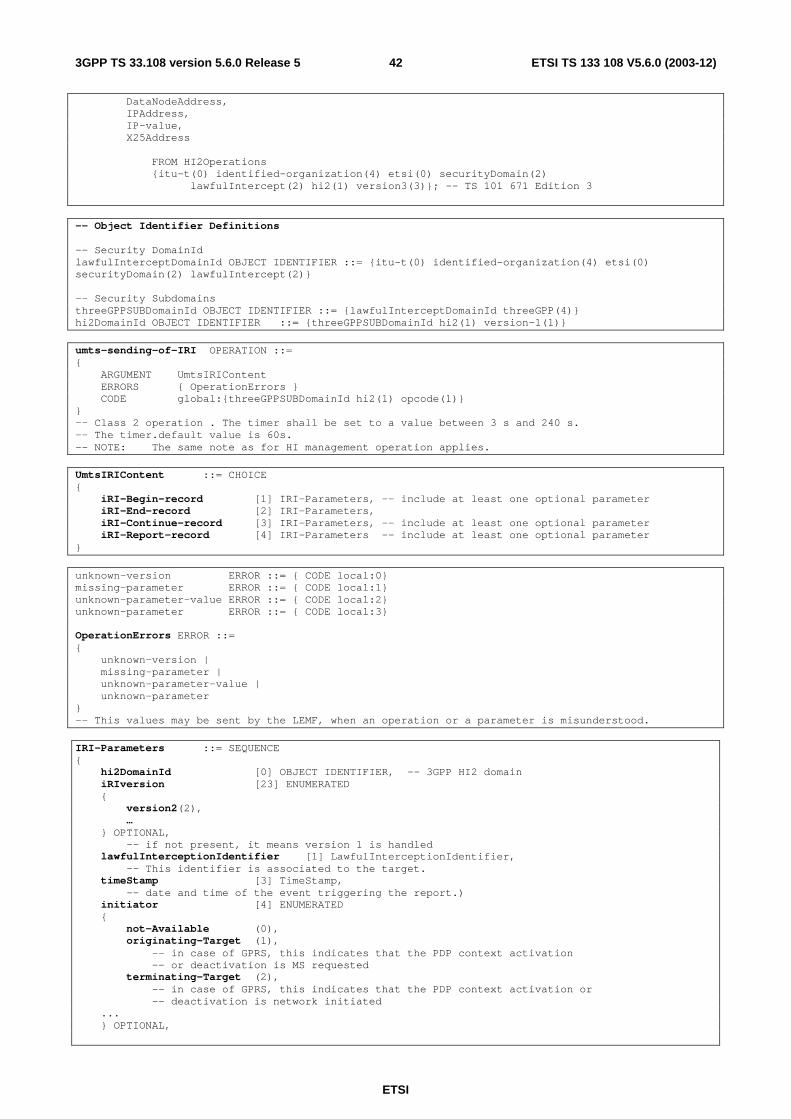
ETSI
ETSI TS 133 108 V5.6.0 (2003-12) 423GPP TS 33.108 version 5.6.0 Release 5
DataNodeAddress, IPAddress, IP-value, X25Address FROM HI2Operations {itu-t(0) identified-organization(4) etsi(0) securityDomain(2) lawfulIntercept(2) hi2(1) version3(3)}; -- TS 101 671 Edition 3 -- Object Identifier Definitions -- Security DomainId lawfulInterceptDomainId OBJECT IDENTIFIER ::= {itu-t(0) identified-organization(4) etsi(0) securityDomain(2) lawfulIntercept(2)} -- Security Subdomains threeGPPSUBDomainId OBJECT IDENTIFIER ::= {lawfulInterceptDomainId threeGPP(4)} hi2DomainId OBJECT IDENTIFIER ::= {threeGPPSUBDomainId hi2(1) version-1(1)} umts-sending-of-IRI OPERATION ::= { ARGUMENT UmtsIRIContent ERRORS { OperationErrors } CODE global:{threeGPPSUBDomainId hi2(1) opcode(1)} } -- Class 2 operation . The timer shall be set to a value between 3 s and 240 s. -- The timer.default value is 60s. -- NOTE: The same note as for HI management operation applies. UmtsIRIContent ::= CHOICE { iRI-Begin-record [1] IRI-Parameters, -- include at least one optional parameter iRI-End-record [2] IRI-Parameters, iRI-Continue-record [3] IRI-Parameters, -- include at least one optional parameter iRI-Report-record [4] IRI-Parameters -- include at least one optional parameter } unknown-version ERROR ::= { CODE local:0} missing-parameter ERROR ::= { CODE local:1} unknown-parameter-value ERROR ::= { CODE local:2} unknown-parameter ERROR ::= { CODE local:3} OperationErrors ERROR ::= { unknown-version | missing-parameter | unknown-parameter-value | unknown-parameter } -- This values may be sent by the LEMF, when an operation or a parameter is misunderstood. IRI-Parameters ::= SEQUENCE { hi2DomainId [0] OBJECT IDENTIFIER, -- 3GPP HI2 domain iRIversion [23] ENUMERATED { version2(2), … } OPTIONAL, -- if not present, it means version 1 is handled lawfulInterceptionIdentifier [1] LawfulInterceptionIdentifier, -- This identifier is associated to the target. timeStamp [3] TimeStamp, -- date and time of the event triggering the report.) initiator [4] ENUMERATED { not-Available (0), originating-Target (1), -- in case of GPRS, this indicates that the PDP context activation -- or deactivation is MS requested terminating-Target (2), -- in case of GPRS, this indicates that the PDP context activation or -- deactivation is network initiated ... } OPTIONAL,
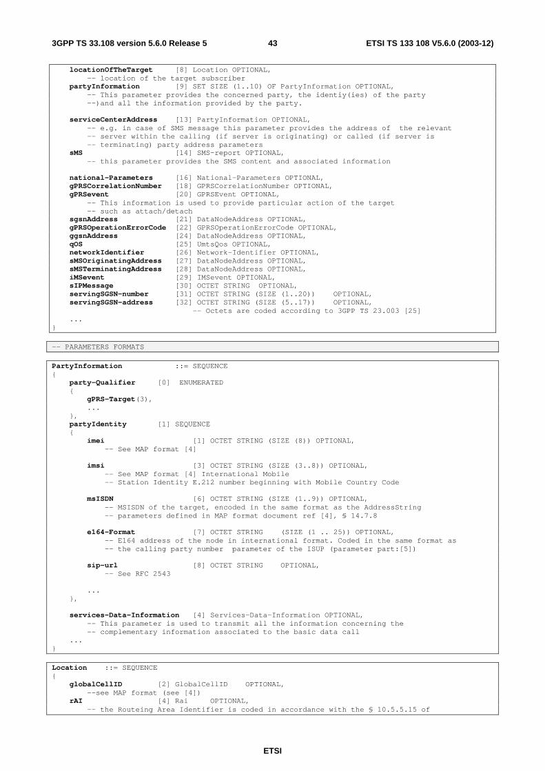
ETSI
ETSI TS 133 108 V5.6.0 (2003-12) 433GPP TS 33.108 version 5.6.0 Release 5
locationOfTheTarget [8] Location OPTIONAL, -- location of the target subscriber partyInformation [9] SET SIZE (1..10) OF PartyInformation OPTIONAL, -- This parameter provides the concerned party, the identiy(ies) of the party --)and all the information provided by the party. serviceCenterAddress [13] PartyInformation OPTIONAL, -- e.g. in case of SMS message this parameter provides the address of the relevant -- server within the calling (if server is originating) or called (if server is -- terminating) party address parameters sMS [14] SMS-report OPTIONAL, -- this parameter provides the SMS content and associated information national-Parameters [16] National-Parameters OPTIONAL, gPRSCorrelationNumber [18] GPRSCorrelationNumber OPTIONAL, gPRSevent [20] GPRSEvent OPTIONAL, -- This information is used to provide particular action of the target -- such as attach/detach sgsnAddress [21] DataNodeAddress OPTIONAL, gPRSOperationErrorCode [22] GPRSOperationErrorCode OPTIONAL, ggsnAddress [24] DataNodeAddress OPTIONAL, qOS [25] UmtsQos OPTIONAL, networkIdentifier [26] Network-Identifier OPTIONAL, sMSOriginatingAddress [27] DataNodeAddress OPTIONAL, sMSTerminatingAddress [28] DataNodeAddress OPTIONAL, iMSevent [29] IMSevent OPTIONAL, sIPMessage [30] OCTET STRING OPTIONAL, servingSGSN-number [31] OCTET STRING (SIZE (1..20)) OPTIONAL, servingSGSN-address [32] OCTET STRING (SIZE (5..17)) OPTIONAL, -- Octets are coded according to 3GPP TS 23.003 [25] ... }
-- PARAMETERS FORMATS PartyInformation ::= SEQUENCE { party-Qualifier [0] ENUMERATED { gPRS-Target(3), ... }, partyIdentity [1] SEQUENCE { imei [1] OCTET STRING (SIZE (8)) OPTIONAL, -- See MAP format [4] imsi [3] OCTET STRING (SIZE (3..8)) OPTIONAL, -- See MAP format [4] International Mobile -- Station Identity E.212 number beginning with Mobile Country Code msISDN [6] OCTET STRING (SIZE (1..9)) OPTIONAL, -- MSISDN of the target, encoded in the same format as the AddressString -- parameters defined in MAP format document ref [4], § 14.7.8 e164-Format [7] OCTET STRING (SIZE (1 .. 25)) OPTIONAL, -- E164 address of the node in international format. Coded in the same format as -- the calling party number parameter of the ISUP (parameter part:[5]) sip-url [8] OCTET STRING OPTIONAL, -- See RFC 2543 ... }, services-Data-Information [4] Services-Data-Information OPTIONAL, -- This parameter is used to transmit all the information concerning the -- complementary information associated to the basic data call ... } Location ::= SEQUENCE { globalCellID [2] GlobalCellID OPTIONAL, --see MAP format (see [4]) rAI [4] Rai OPTIONAL, -- the Routeing Area Identifier is coded in accordance with the § 10.5.5.15 of
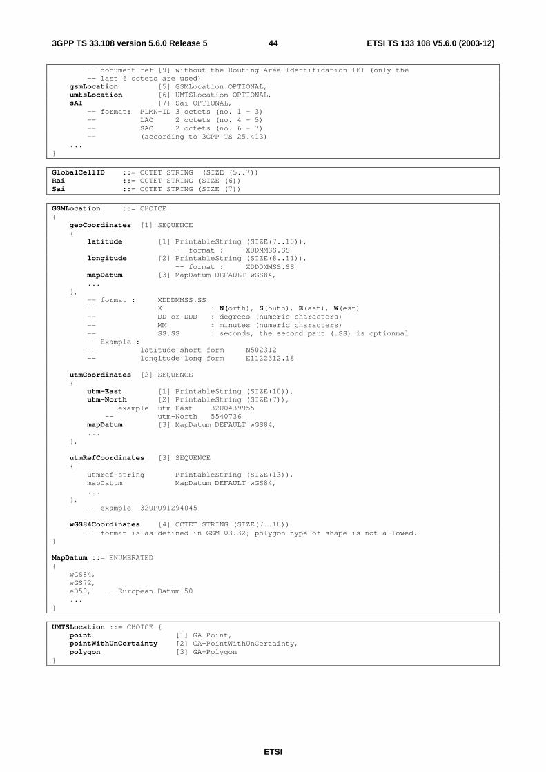
ETSI
ETSI TS 133 108 V5.6.0 (2003-12) 443GPP TS 33.108 version 5.6.0 Release 5
-- document ref [9] without the Routing Area Identification IEI (only the -- last 6 octets are used) gsmLocation [5] GSMLocation OPTIONAL, umtsLocation [6] UMTSLocation OPTIONAL, sAI [7] Sai OPTIONAL, -- format: PLMN-ID 3 octets (no. 1 – 3) -- LAC 2 octets (no. 4 – 5) -- SAC 2 octets (no. 6 – 7) -- (according to 3GPP TS 25.413) ... } GlobalCellID ::= OCTET STRING (SIZE (5..7)) Rai ::= OCTET STRING (SIZE (6)) Sai ::= OCTET STRING (SIZE (7))
GSMLocation ::= CHOICE { geoCoordinates [1] SEQUENCE { latitude [1] PrintableString (SIZE(7..10)), -- format : XDDMMSS.SS longitude [2] PrintableString (SIZE(8..11)), -- format : XDDDMMSS.SS mapDatum [3] MapDatum DEFAULT wGS84, ... }, -- format : XDDDMMSS.SS -- X : N(orth), S(outh), E(ast), W(est) -- DD or DDD : degrees (numeric characters) -- MM : minutes (numeric characters) -- SS.SS : seconds, the second part (.SS) is optionnal -- Example : -- latitude short form N502312 -- longitude long form E1122312.18 utmCoordinates [2] SEQUENCE { utm-East [1] PrintableString (SIZE(10)), utm-North [2] PrintableString (SIZE(7)), -- example utm-East 32U0439955 -- utm-North 5540736 mapDatum [3] MapDatum DEFAULT wGS84, ... }, utmRefCoordinates [3] SEQUENCE { utmref-string PrintableString (SIZE(13)), mapDatum MapDatum DEFAULT wGS84, ... }, -- example 32UPU91294045 wGS84Coordinates [4] OCTET STRING (SIZE(7..10)) -- format is as defined in GSM 03.32; polygon type of shape is not allowed. } MapDatum ::= ENUMERATED { wGS84, wGS72, eD50, -- European Datum 50 ... } UMTSLocation ::= CHOICE { point [1] GA-Point, pointWithUnCertainty [2] GA-PointWithUnCertainty, polygon [3] GA-Polygon }
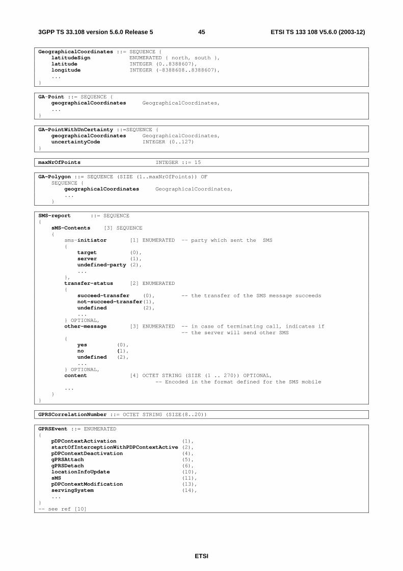
ETSI
ETSI TS 133 108 V5.6.0 (2003-12) 453GPP TS 33.108 version 5.6.0 Release 5
GeographicalCoordinates ::= SEQUENCE { latitudeSign ENUMERATED { north, south }, latitude INTEGER (0..8388607), longitude INTEGER (-8388608..8388607), ... } GA-Point ::= SEQUENCE { geographicalCoordinates GeographicalCoordinates, ... } GA-PointWithUnCertainty ::=SEQUENCE { geographicalCoordinates GeographicalCoordinates, uncertaintyCode INTEGER (0..127) } maxNrOfPoints INTEGER ::= 15
GA-Polygon ::= SEQUENCE (SIZE (1..maxNrOfPoints)) OF SEQUENCE { geographicalCoordinates GeographicalCoordinates, ... } SMS-report ::= SEQUENCE { sMS-Contents [3] SEQUENCE { sms-initiator [1] ENUMERATED -- party which sent the SMS { target (0), server (1), undefined-party (2), ... }, transfer-status [2] ENUMERATED { succeed-transfer (0), -- the transfer of the SMS message succeeds not-succeed-transfer(1), undefined (2), ... } OPTIONAL, other-message [3] ENUMERATED -- in case of terminating call, indicates if -- the server will send other SMS { yes (0), no (1), undefined (2), ... } OPTIONAL, content [4] OCTET STRING (SIZE (1 .. 270)) OPTIONAL, -- Encoded in the format defined for the SMS mobile ... } } GPRSCorrelationNumber ::= OCTET STRING (SIZE(8..20))
GPRSEvent ::= ENUMERATED { pDPContextActivation (1), startOfInterceptionWithPDPContextActive (2), pDPContextDeactivation (4), gPRSAttach (5), gPRSDetach (6), locationInfoUpdate (10), sMS (11), pDPContextModification (13), servingSystem (14), ... } -- see ref [10]
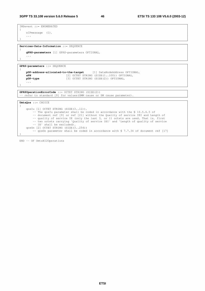
ETSI
ETSI TS 133 108 V5.6.0 (2003-12) 463GPP TS 33.108 version 5.6.0 Release 5
IMSevent ::= ENUMERATED { sIPmessage (1), ... } Services-Data-Information ::= SEQUENCE { gPRS-parameters [1] GPRS-parameters OPTIONAL, ... } GPRS-parameters ::= SEQUENCE { pDP-address-allocated-to-the-target [1] DataNodeAddress OPTIONAL, aPN [2] OCTET STRING (SIZE(1..100)) OPTIONAL, pDP-type [3] OCTET STRING (SIZE(2)) OPTIONAL, ... } GPRSOperationErrorCode ::= OCTET STRING (SIZE(2)) -- refer to standard [9] for values(GMM cause or SM cause parameter). UmtsQos ::= CHOICE { qosIu [1] OCTET STRING (SIZE(3..11)), -- The qosIu parameter shall be coded in accordance with the § 10.5.6.5 of -- document ref [9] or ref [21] without the Quality of service IEI and Length of -- quality of service IE (only the last 3, or 11 octets are used. That is, first -- two octets carrying 'Quality of service IEI' and 'Length of quality of service -- IE' shall be excluded). qosGn [2] OCTET STRING (SIZE(3..254)) -- qosGn parameter shall be coded in accordance with § 7.7.34 of document ref [17] } END -- OF UmtsHI2Operations
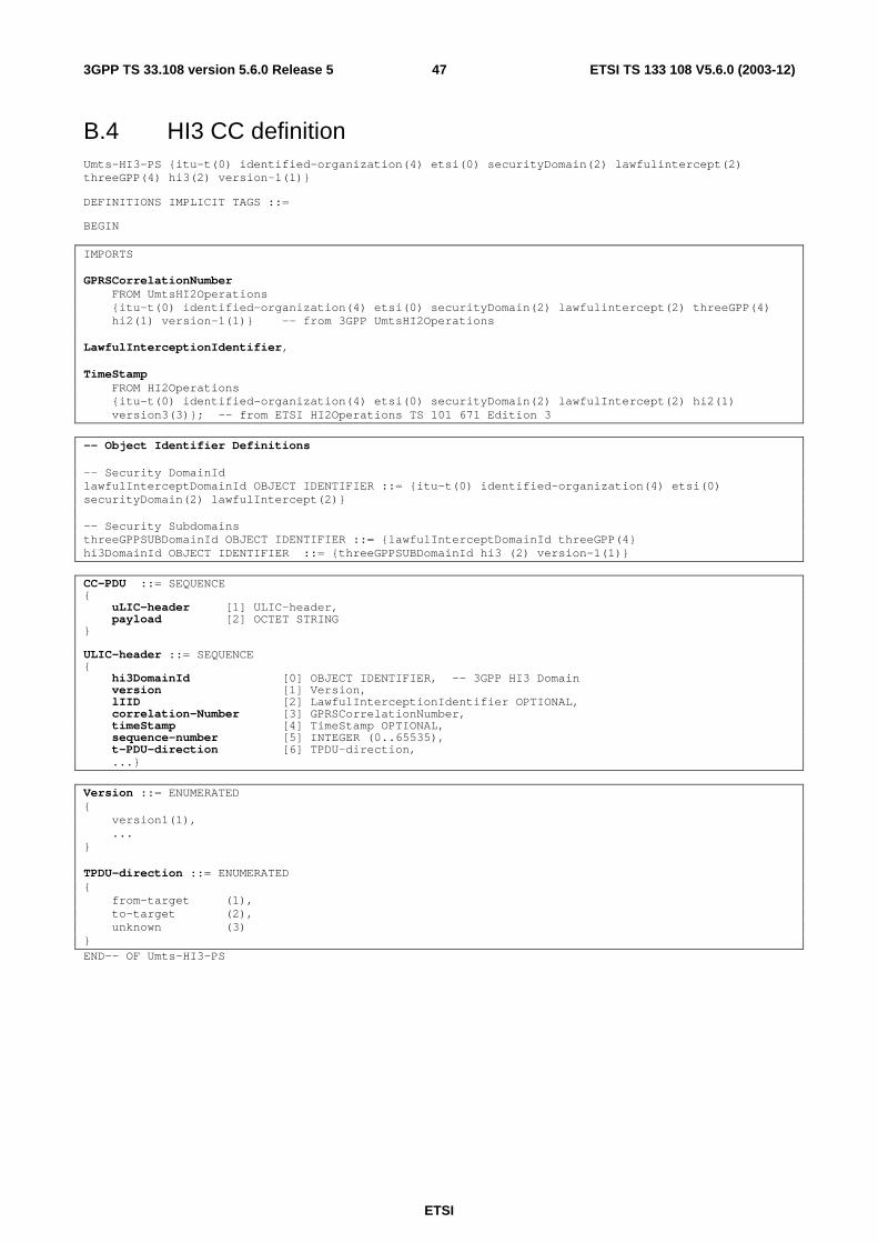
ETSI
ETSI TS 133 108 V5.6.0 (2003-12) 473GPP TS 33.108 version 5.6.0 Release 5
B.4 HI3 CC definition Umts-HI3-PS {itu-t(0) identified-organization(4) etsi(0) securityDomain(2) lawfulintercept(2) threeGPP(4) hi3(2) version-1(1)} DEFINITIONS IMPLICIT TAGS ::= BEGIN
IMPORTS GPRSCorrelationNumber FROM UmtsHI2Operations {itu-t(0) identified-organization(4) etsi(0) securityDomain(2) lawfulintercept(2) threeGPP(4) hi2(1) version-1(1)} -- from 3GPP UmtsHI2Operations LawfulInterceptionIdentifier, TimeStamp FROM HI2Operations {itu-t(0) identified-organization(4) etsi(0) securityDomain(2) lawfulIntercept(2) hi2(1) version3(3)}; -- from ETSI HI2Operations TS 101 671 Edition 3 -- Object Identifier Definitions -- Security DomainId lawfulInterceptDomainId OBJECT IDENTIFIER ::= {itu-t(0) identified-organization(4) etsi(0) securityDomain(2) lawfulIntercept(2)} -- Security Subdomains threeGPPSUBDomainId OBJECT IDENTIFIER ::= {lawfulInterceptDomainId threeGPP(4} hi3DomainId OBJECT IDENTIFIER ::= {threeGPPSUBDomainId hi3 (2) version-1(1)} CC-PDU ::= SEQUENCE { uLIC-header [1] ULIC-header, payload [2] OCTET STRING } ULIC-header ::= SEQUENCE { hi3DomainId [0] OBJECT IDENTIFIER, -- 3GPP HI3 Domain version [1] Version, lIID [2] LawfulInterceptionIdentifier OPTIONAL, correlation-Number [3] GPRSCorrelationNumber, timeStamp [4] TimeStamp OPTIONAL, sequence-number [5] INTEGER (0..65535), t-PDU-direction [6] TPDU-direction, ...} Version ::= ENUMERATED { version1(1), ... } TPDU-direction ::= ENUMERATED { from-target (1), to-target (2), unknown (3) } END-- OF Umts-HI3-PS
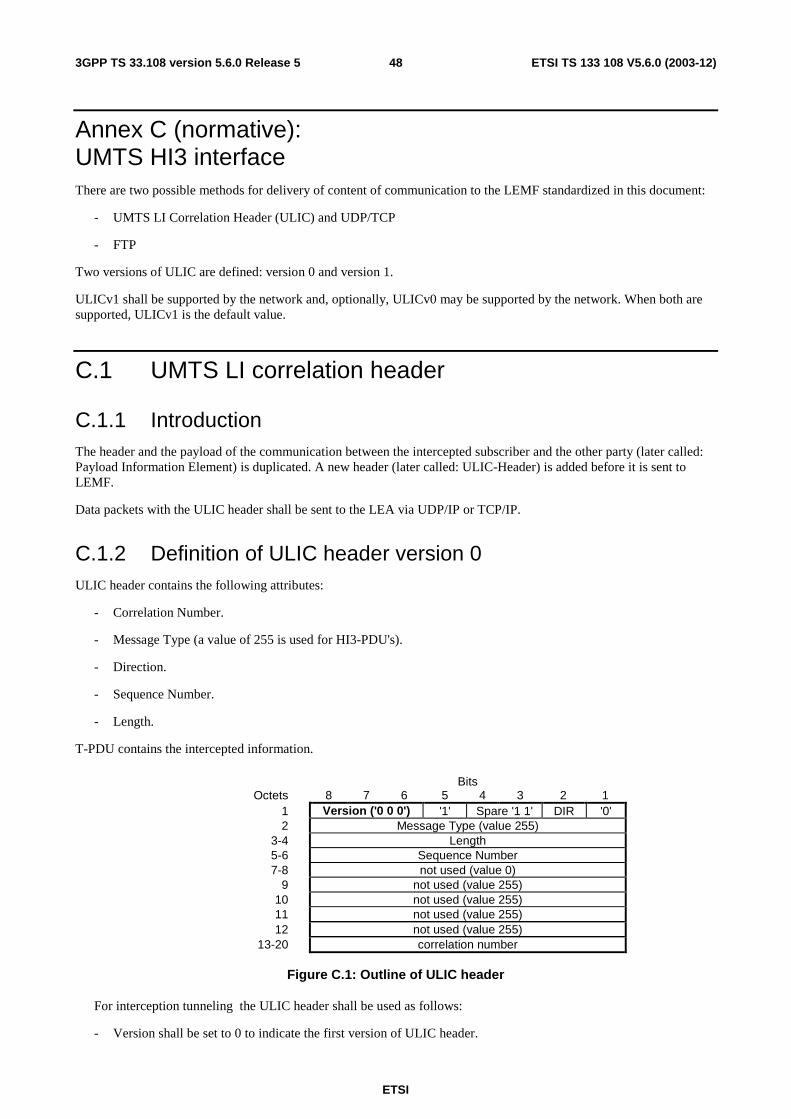
ETSI
ETSI TS 133 108 V5.6.0 (2003-12) 483GPP TS 33.108 version 5.6.0 Release 5
Annex C (normative): UMTS HI3 interface There are two possible methods for delivery of content of communication to the LEMF standardized in this document:
- UMTS LI Correlation Header (ULIC) and UDP/TCP
- FTP
Two versions of ULIC are defined: version 0 and version 1.
ULICv1 shall be supported by the network and, optionally, ULICv0 may be supported by the network. When both are supported, ULICv1 is the default value.
C.1 UMTS LI correlation header
C.1.1 Introduction The header and the payload of the communication between the intercepted subscriber and the other party (later called: Payload Information Element) is duplicated. A new header (later called: ULIC-Header) is added before it is sent to LEMF.
Data packets with the ULIC header shall be sent to the LEA via UDP/IP or TCP/IP.
C.1.2 Definition of ULIC header version 0 ULIC header contains the following attributes:
- Correlation Number.
- Message Type (a value of 255 is used for HI3-PDU's).
- Direction.
- Sequence Number.
- Length.
T-PDU contains the intercepted information.
Bits Octets 8 7 6 5 4 3 2 1
1 Version ('0 0 0') '1' Spare '1 1' DIR '0' 2 Message Type (value 255)
3-4 Length 5-6 Sequence Number 7-8 not used (value 0)
9 not used (value 255) 10 not used (value 255) 11 not used (value 255) 12 not used (value 255)
13-20 correlation number
Figure C.1: Outline of ULIC header
For interception tunneling the ULIC header shall be used as follows:
- Version shall be set to 0 to indicate the first version of ULIC header.
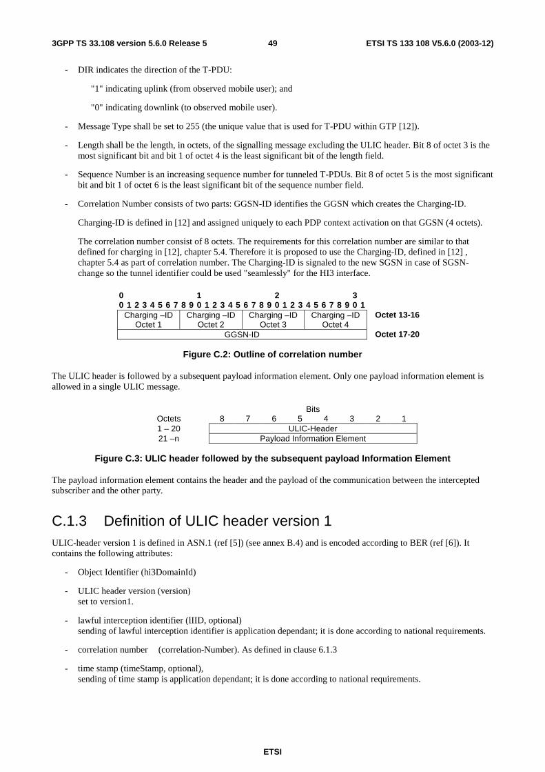
ETSI
ETSI TS 133 108 V5.6.0 (2003-12) 493GPP TS 33.108 version 5.6.0 Release 5
- DIR indicates the direction of the T-PDU:
"1" indicating uplink (from observed mobile user); and
"0" indicating downlink (to observed mobile user).
- Message Type shall be set to 255 (the unique value that is used for T-PDU within GTP [12]).
- Length shall be the length, in octets, of the signalling message excluding the ULIC header. Bit 8 of octet 3 is the most significant bit and bit 1 of octet 4 is the least significant bit of the length field.
- Sequence Number is an increasing sequence number for tunneled T-PDUs. Bit 8 of octet 5 is the most significant bit and bit 1 of octet 6 is the least significant bit of the sequence number field.
- Correlation Number consists of two parts: GGSN-ID identifies the GGSN which creates the Charging-ID.
Charging-ID is defined in [12] and assigned uniquely to each PDP context activation on that GGSN (4 octets).
The correlation number consist of 8 octets. The requirements for this correlation number are similar to that defined for charging in [12], chapter 5.4. Therefore it is proposed to use the Charging-ID, defined in [12] , chapter 5.4 as part of correlation number. The Charging-ID is signaled to the new SGSN in case of SGSN-change so the tunnel identifier could be used "seamlessly" for the HI3 interface.
0 1 2 3 0 1 2 3 4 5 6 7 8 9 0 1 2 3 4 5 6 7 8 9 0 1 2 3 4 5 6 7 8 9 0 1
Charging –ID Octet 1
Charging –ID Octet 2
Charging –ID Octet 3
Charging –ID Octet 4
Octet 13-16
GGSN-ID Octet 17-20
Figure C.2: Outline of correlation number
The ULIC header is followed by a subsequent payload information element. Only one payload information element is allowed in a single ULIC message.
Bits Octets 8 7 6 5 4 3 2 1 1 – 20 ULIC-Header 21 –n Payload Information Element
Figure C.3: ULIC header followed by the subsequent payload Information Element
The payload information element contains the header and the payload of the communication between the intercepted subscriber and the other party.
C.1.3 Definition of ULIC header version 1 ULIC-header version 1 is defined in ASN.1 (ref [5]) (see annex B.4) and is encoded according to BER (ref [6]). It contains the following attributes:
- Object Identifier (hi3DomainId)
- ULIC header version (version) set to version1.
- lawful interception identifier (lIID, optional) sending of lawful interception identifier is application dependant; it is done according to national requirements.
- correlation number (correlation-Number). As defined in clause 6.1.3
- time stamp (timeStamp, optional), sending of time stamp is application dependant; it is done according to national requirements.
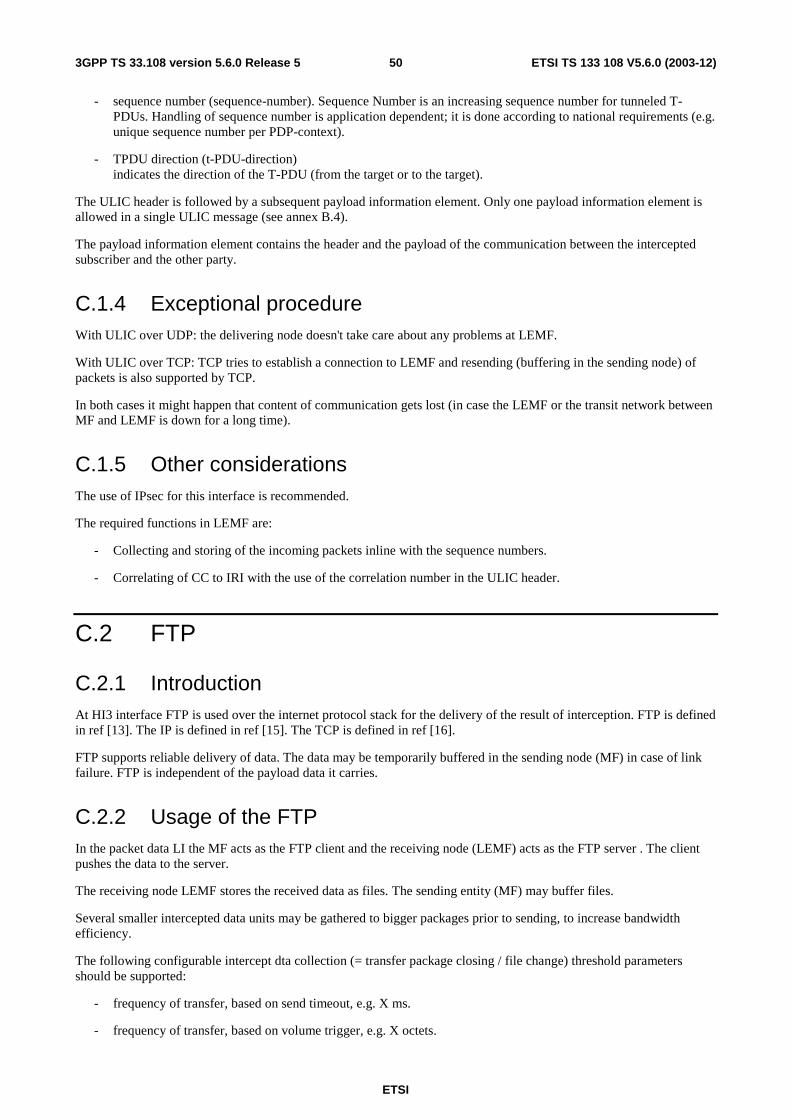
ETSI
ETSI TS 133 108 V5.6.0 (2003-12) 503GPP TS 33.108 version 5.6.0 Release 5
- sequence number (sequence-number). Sequence Number is an increasing sequence number for tunneled T-PDUs. Handling of sequence number is application dependent; it is done according to national requirements (e.g. unique sequence number per PDP-context).
- TPDU direction (t-PDU-direction) indicates the direction of the T-PDU (from the target or to the target).
The ULIC header is followed by a subsequent payload information element. Only one payload information element is allowed in a single ULIC message (see annex B.4).
The payload information element contains the header and the payload of the communication between the intercepted subscriber and the other party.
C.1.4 Exceptional procedure With ULIC over UDP: the delivering node doesn't take care about any problems at LEMF.
With ULIC over TCP: TCP tries to establish a connection to LEMF and resending (buffering in the sending node) of packets is also supported by TCP.
In both cases it might happen that content of communication gets lost (in case the LEMF or the transit network between MF and LEMF is down for a long time).
C.1.5 Other considerations The use of IPsec for this interface is recommended.
The required functions in LEMF are:
- Collecting and storing of the incoming packets inline with the sequence numbers.
- Correlating of CC to IRI with the use of the correlation number in the ULIC header.
C.2 FTP
C.2.1 Introduction At HI3 interface FTP is used over the internet protocol stack for the delivery of the result of interception. FTP is defined in ref [13]. The IP is defined in ref [15]. The TCP is defined in ref [16].
FTP supports reliable delivery of data. The data may be temporarily buffered in the sending node (MF) in case of link failure. FTP is independent of the payload data it carries.
C.2.2 Usage of the FTP In the packet data LI the MF acts as the FTP client and the receiving node (LEMF) acts as the FTP server . The client pushes the data to the server.
The receiving node LEMF stores the received data as files. The sending entity (MF) may buffer files.
Several smaller intercepted data units may be gathered to bigger packages prior to sending, to increase bandwidth efficiency.
The following configurable intercept dta collection (= transfer package closing / file change) threshold parameters should be supported:
- frequency of transfer, based on send timeout, e.g. X ms.
- frequency of transfer, based on volume trigger, e.g. X octets.
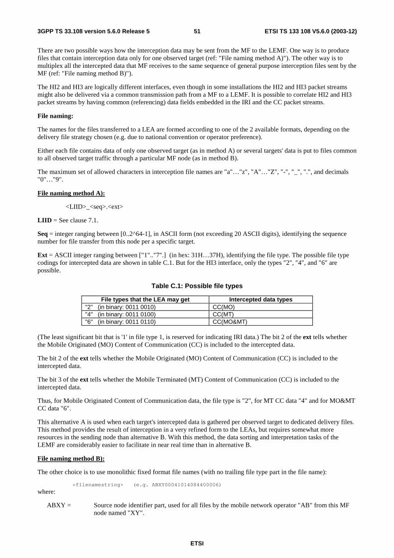
ETSI
ETSI TS 133 108 V5.6.0 (2003-12) 513GPP TS 33.108 version 5.6.0 Release 5
There are two possible ways how the interception data may be sent from the MF to the LEMF. One way is to produce files that contain interception data only for one observed target (ref: "File naming method A)"). The other way is to multiplex all the intercepted data that MF receives to the same sequence of general purpose interception files sent by the MF (ref: "File naming method B)").
The HI2 and HI3 are logically different interfaces, even though in some installations the HI2 and HI3 packet streams might also be delivered via a common transmission path from a MF to a LEMF. It is possible to correlate HI2 and HI3 packet streams by having common (referencing) data fields embedded in the IRI and the CC packet streams.
File naming:
The names for the files transferred to a LEA are formed according to one of the 2 available formats, depending on the delivery file strategy chosen (e.g. due to national convention or operator preference).
Either each file contains data of only one observed target (as in method A) or several targets' data is put to files common to all observed target traffic through a particular MF node (as in method B).
The maximum set of allowed characters in interception file names are "a"…"z", "A"…"Z", "-", "_", ".", and decimals "0"…"9".
File naming method A):
<LIID>_<seq>.<ext>
LIID = See clause 7.1.
Seq = integer ranging between [0..2^64-1], in ASCII form (not exceeding 20 ASCII digits), identifying the sequence number for file transfer from this node per a specific target.
Ext = ASCII integer ranging between ["1".."7".] (in hex: 31H…37H), identifying the file type. The possible file type codings for intercepted data are shown in table C.1. But for the HI3 interface, only the types "2", "4", and "6" are possible.
Table C.1: Possible file types
File types that the LEA may get Intercepted data types "2" (in binary: 0011 0010) CC(MO) "4" (in binary: 0011 0100) CC(MT) "6" (in binary: 0011 0110) CC(MO&MT)
(The least significant bit that is '1' in file type 1, is reserved for indicating IRI data.) The bit 2 of the ext tells whether the Mobile Originated (MO) Content of Communication (CC) is included to the intercepted data.
The bit 2 of the ext tells whether the Mobile Originated (MO) Content of Communication (CC) is included to the intercepted data.
The bit 3 of the ext tells whether the Mobile Terminated (MT) Content of Communication (CC) is included to the intercepted data.
Thus, for Mobile Originated Content of Communication data, the file type is "2", for MT CC data "4" and for MO&MT CC data "6".
This alternative A is used when each target's intercepted data is gathered per observed target to dedicated delivery files. This method provides the result of interception in a very refined form to the LEAs, but requires somewhat more resources in the sending node than alternative B. With this method, the data sorting and interpretation tasks of the LEMF are considerably easier to facilitate in near real time than in alternative B.
File naming method B):
The other choice is to use monolithic fixed format file names (with no trailing file type part in the file name):
<filenamestring> (e.g. ABXY00041014084400006)
where:
ABXY = Source node identifier part, used for all files by the mobile network operator "AB" from this MF node named "XY".
ETSI
ETSI TS 133 108 V5.6.0 (2003-12) 523GPP TS 33.108 version 5.6.0 Release 5
00 = year 2000 04= month April 10= day 10 14 = hour 08 = minutes 44= seconds 0000 = extension 6 = file type. Coding: "2" = CC(MO), "4" = CC(MT), "6" = CC(MO&MT). (The type "1" is reserved
for IRI data files)
This alternative B is used when several targets' intercepted data is gathered to common delivery files. This method does not provide the result of interception in as refined form to the LEAs as the alternative A, but it is faster in performance for the MF point of view. With this method, the MF does not need to keep many files open like in alternative A.
C.2.3 Exceptional procedures Overflow at the receiving end (LEMF) is avoided due to the nature of the protocol.
In case the transit network or receiving end system (LEMF) is down for a reasonably short time period, the local buffering at the MF will be sufficient as a delivery reliability backup procedure.
In case the transit network or receiving end system (LEMF) is down for a very long period, the local buffering at the MF may have to be terminated. Then the following intercepted data coming from the intercepting nodes towards the MF would be discarded, until the transit network or LEMF is up and running again.
C.2.4 CC contents for FTP
C.2.4.1 Fields
The logical contents of the CC-header is described here.
CC-header = (Version, HeaderLength, PayloadLength, PayloadType, PayloadTimeStamp, PayloadDirection, CCSeqNumber, CorrelationNumber, LIID, PrivateExtension).
The Information Element CorrelationNumber forms the means to correlate the IRI and CC of the communication session intercepted.
The first column indicates whether the Information Element referred is Mandatory, Conditional or Optional.
The second column is the Type in decimal.
The third column is the length of the Value in octets.
(Notation used in table C.2: M = Mandatory, O = Optional, C= Conditional).
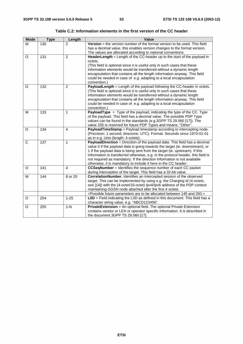
ETSI
ETSI TS 133 108 V5.6.0 (2003-12) 533GPP TS 33.108 version 5.6.0 Release 5
Table C.2: Information elements in the first version of the CC header
Mode Type Length Value M 130 2 Version = the version number of the format version to be used. This field
has a decimal value, this enables version changes to the format version. The values are allocated according to national conventions.
O 131 2 HeaderLength = Length of the CC-header up to the start of the payload in octets. (This field is optional since it is useful only in such cases that these information elements would be transferred without a dynamic length encapsulation that contains all the length information anyway. This field could be needed in case of e.g. adapting to a local encapsulation convention.)
O 132 2 PayloadLength = Length of the payload following the CC-header in octets. (This field is optional since it is useful only in such cases that these information elements would be transferred without a dynamic length encapsulation that contains all the length information anyway. This field could be needed in case of e.g. adapting to a local encapsulation convention.)
M 133 1 PayloadType = Type of the payload, indicating the type of the CC. Type of the payload. This field has a decimal value. The possible PDP Type values can be found in the standards (e.g.3GPP TS 29.060 [17]). The value 255 is reserved for future PDP Types and means: "Other".
O 134 4 PayloadTimeStamp = Payload timestamp according to intercepting node. (Precision: 1 second, timezone: UTC). Format: Seconds since 1970-01-01 as in e.g. Unix (length: 4 octets).
C 137 1 PayloadDirection = Direction of the payload data. This field has a decimal value 0 if the payload data is going towards the target (ie. downstream), or 1 if the payload data is being sent from the target (ie. upstream). If this information is transferred otherwise, e.g. in the protocol header, this field is not required as mandatory. If the direction information is not available otherwise, it is mandatory to include it here in the CC header.
O 141 4 CCSeqNumber = Identifies the sequence number of each CC packet during interception of the target. This field has a 32-bit value.
M 144 8 or 20 CorrelationNumber. Identifies an intercepted session of the observed target. This can be implemented by using e.g. the Charging Id (4 octets, see [14]) with the (4-octet/16-octet) Ipv4/Ipv6 address of the PDP context maintaining GGSN node attached after the first 4 octets.
<Possible future parameters are to be allocated between 145 and 250.> O 254 1-25 LIID = Field indicating the LIID as defined in this document. This field has a
character string value, e.g. "ABCD123456". O 255 1-N PrivateExtension = An optional field. The optional Private Extension
contains vendor or LEA or operator specific information. It is described in the document 3GPP TS 29.060 [17].
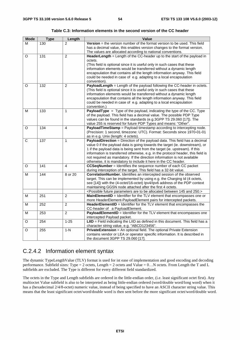
ETSI
ETSI TS 133 108 V5.6.0 (2003-12) 543GPP TS 33.108 version 5.6.0 Release 5
Table C.3: Information elements in the second version of the CC header
Mode Type Length Value M 130 2 Version = the version number of the format version to be used. This field
has a decimal value, this enables version changes to the format version. The values are allocated according to national conventions.
O 131 2 HeaderLength = Length of the CC-header up to the start of the payload in octets. (This field is optional since it is useful only in such cases that these information elements would be transferred without a dynamic length encapsulation that contains all the length information anyway. This field could be needed in case of e.g. adapting to a local encapsulation convention).
O 132 2 PayloadLength = Length of the payload following the CC-header in octets. (This field is optional since it is useful only in such cases that these information elements would be transferred without a dynamic length encapsulation that contains all the length information anyway. This field could be needed in case of e.g. adapting to a local encapsulation convention.)
M 133 1 PayloadType = Type of the payload, indicating the type of the CC. Type of the payload. This field has a decimal value. The possible PDP Type values can be found in the standards (e.g.3GPP TS 29.060 [17]). The value 255 is reserved for future PDP Types and means: "Other".
O 134 4 PayloadTimeStamp = Payload timestamp according to intercepting node. (Precision: 1 second, timezone: UTC). Format: Seconds since 1970-01-01 as in e.g. Unix (length: 4 octets).
C 137 1 PayloadDirection = Direction of the payload data. This field has a decimal value 0 if the payload data is going towards the target (ie. downstream), or 1 if the payload data is being sent from the target (ie. upstream). If this information is transferred otherwise, e.g. in the protocol header, this field is not required as mandatory. If the direction information is not available otherwise, it is mandatory to include it here in the CC header.
O 141 4 CCSeqNumber = Identifies the sequence number of each CC packet during interception of the target. This field has a 32-bit value.
M 144 8 or 20 CorrelationNumber. Identifies an intercepted session of the observed target. This can be implemented by using e.g. the Charging Id (4 octets, see [14]) with the (4-octet/16-octet) Ipv4/Ipv6 address of the PDP context maintaining GGSN node attached after the first 4 octets.
<Possible future parameters are to be allocated between 145 and 250.> M 251 2 MainElementID = Identifier for the TLV element that encompasses one or
more HeaderElement-PayloadElement pairs for intercepted packets. M 252 2 HeaderElementID = Identifier for the TLV element that encompasses the
CC-header of a PayloadElement. M 253 2 PayloadElementID = Identifier for the TLV element that encompasses one
intercepted Payload packet. O 254 1-25 LIID = Field indicating the LIID as defined in this document. This field has a
character string value, e.g. "ABCD123456". O 255 1-N PrivateExtension = An optional field. The optional Private Extension
contains vendor or LEA or operator specific information. It is described in the document 3GPP TS 29.060 [17].
C.2.4.2 Information element syntax
The dynamic TypeLengthValue (TLV) format is used for ist ease of implementation and good encoding and decoding performance. Subfield sizes: Type = 2 octets, Length = 2 octets and Value = 0…N octets. From Length the T and L subfields are excluded. The Type is different for every different field standardized.
The octets in the Type and Length subfields are ordered in the little-endian order, (i.e. least significant octet first). Any multioctet Value subfield is also to be interpreted as being little-endian ordered (word/double word/long word) when it has a (hexadecimal 2/4/8-octet) numeric value, instead of being specified to have an ASCII character string value. This means that the least significant octet/word/double word is then sent before the more significant octet/word/double word.
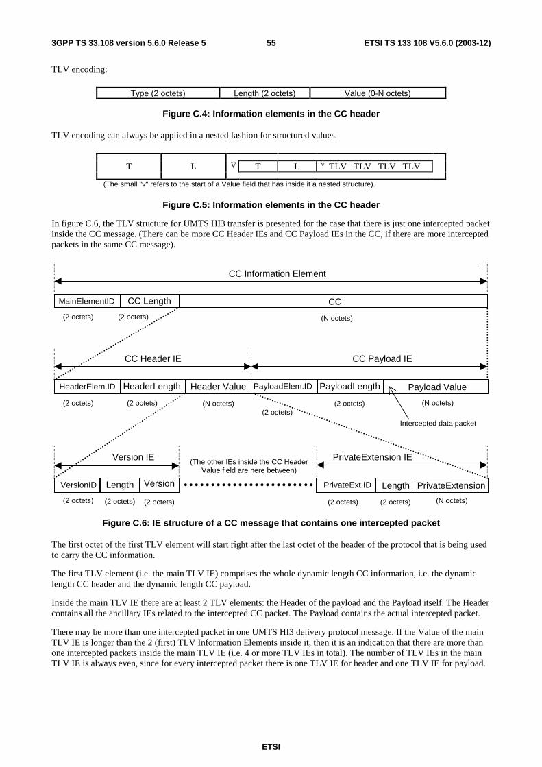
ETSI
ETSI TS 133 108 V5.6.0 (2003-12) 553GPP TS 33.108 version 5.6.0 Release 5
TLV encoding:
Type (2 octets) Length (2 octets) Value (0-N octets)
Figure C.4: Information elements in the CC header
TLV encoding can always be applied in a nested fashion for structured values.
T L V T L V TLV TLV TLV TLV
(The small "v" refers to the start of a Value field that has inside it a nested structure).
Figure C.5: Information elements in the CC header
In figure C.6, the TLV structure for UMTS HI3 transfer is presented for the case that there is just one intercepted packet inside the CC message. (There can be more CC Header IEs and CC Payload IEs in the CC, if there are more intercepted packets in the same CC message).
(2 octets)
MainElementID CC Length CC
(2 octets) (N octets)
(2 octets)
HeaderElem.ID HeaderLength Header Value
(2 octets) (N octets)(2 octets)
PayloadElem.ID PayloadLength Payload Value
(2 octets) (N octets)
CC Payload IECC Header IE
(2 octets)
VersionID Length Version
(2 octets) (2 octets) (2 octets)
PrivateExt.ID Length PrivateExtension
(2 octets) (N octets)
PrivateExtension IEVersion IE
Intercepted data packet
(The other IEs inside the CC HeaderValue field are here between)
CC Information Element
Figure C.6: IE structure of a CC message that contains one intercepted packet
The first octet of the first TLV element will start right after the last octet of the header of the protocol that is being used to carry the CC information.
The first TLV element (i.e. the main TLV IE) comprises the whole dynamic length CC information, i.e. the dynamic length CC header and the dynamic length CC payload.
Inside the main TLV IE there are at least 2 TLV elements: the Header of the payload and the Payload itself. The Header contains all the ancillary IEs related to the intercepted CC packet. The Payload contains the actual intercepted packet.
There may be more than one intercepted packet in one UMTS HI3 delivery protocol message. If the Value of the main TLV IE is longer than the 2 (first) TLV Information Elements inside it, then it is an indication that there are more than one intercepted packets inside the main TLV IE (i.e. 4 or more TLV IEs in total). The number of TLV IEs in the main TLV IE is always even, since for every intercepted packet there is one TLV IE for header and one TLV IE for payload.
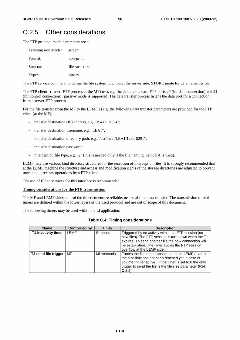
ETSI
ETSI TS 133 108 V5.6.0 (2003-12) 563GPP TS 33.108 version 5.6.0 Release 5
C.2.5 Other considerations The FTP protocol mode parameters used:
Transmission Mode: stream
Format: non-print
Structure: file-structure
Type: binary
The FTP service command to define the file system function at the server side: STORE mode for data transmission.
The FTP client– (=user -FTP process at the MF) uses e.g. the default standard FTP ports 20 (for data connection) and 21 (for control connection), 'passive' mode is supported. The data transfer process listens the data port for a connection from a server-FTP process.
For the file transfer from the MF to the LEMF(s) e.g. the following data transfer parameters are provided for the FTP client (at the MF):
- transfer destination (IP) address, e.g. "194.89.205.4";
- transfer destination username, e.g. "LEA1";
- transfer destination directory path, e.g. "/usr/local/LEA1/1234-8291";
- transfer destination password;
- interception file type, e.g. "2" (this is needed only if the file naming method A is used).
LEMF may use various kind directory structures for the reception of interception files. It is strongly recommended that at the LEMF machine the structure and access and modification rights of the storage directories are adjusted to prevent unwanted directory operations by a FTP client.
The use of IPSec services for this interface is recommended.
Timing considerations for the FTP transmission
The MF and LEMF sides control the timers to ensure reliable, near-real time data transfer. The transmission related timers are defined within the lower layers of the used protocol and are out of scope of this document.
The following timers may be used within the LI application:
Table C.4: Timing considerations
Name Controlled by Units Description T1 inactivity timer LEMF Seconds Triggered by no activity within the FTP session (no
new files). The FTP session is torn down when the T1 expires. To send another file the new connection will be established. The timer avoids the FTP session overflow at the LEMF side.
T2 send file trigger MF Milliseconds Forces the file to be transmitted to the LEMF (even if the size limit has not been reached yet in case of volume trigger active). If the timer is set to 0 the only trigger to send the file is the file size parameter (Ref. C.2.2).
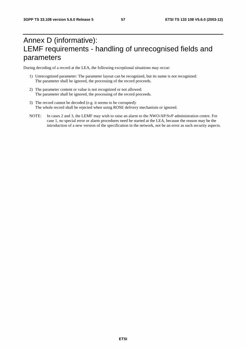
ETSI
ETSI TS 133 108 V5.6.0 (2003-12) 573GPP TS 33.108 version 5.6.0 Release 5
Annex D (informative): LEMF requirements - handling of unrecognised fields and parameters During decoding of a record at the LEA, the following exceptional situations may occur:
1) Unrecognized parameter: The parameter layout can be recognized, but its name is not recognized: The parameter shall be ignored, the processing of the record proceeds.
2) The parameter content or value is not recognized or not allowed: The parameter shall be ignored, the processing of the record proceeds.
3) The record cannot be decoded (e.g. it seems to be corrupted): The whole record shall be rejected when using ROSE delivery mechanism or ignored.
NOTE: In cases 2 and 3, the LEMF may wish to raise an alarm to the NWO/AP/SvP administration centre. For case 1, no special error or alarm procedures need be started at the LEA, because the reason may be the introduction of a new version of the specification in the network, not be an error as such security aspects.
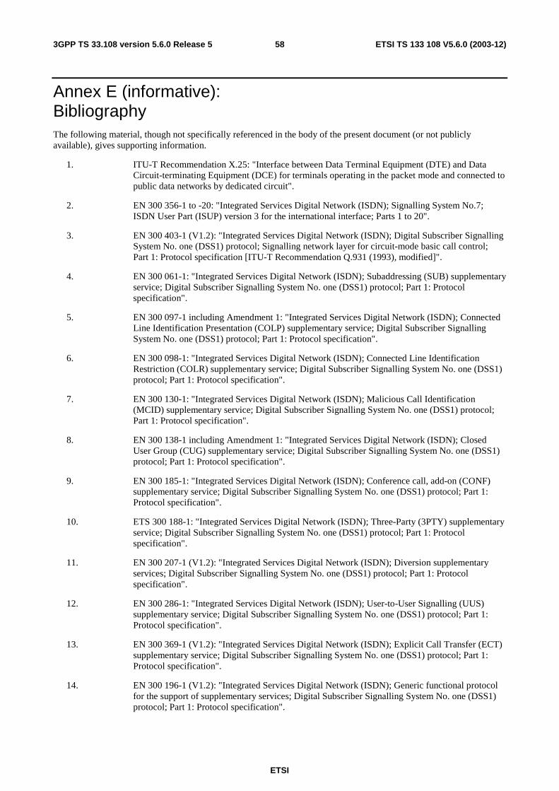
ETSI
ETSI TS 133 108 V5.6.0 (2003-12) 583GPP TS 33.108 version 5.6.0 Release 5
Annex E (informative): Bibliography The following material, though not specifically referenced in the body of the present document (or not publicly available), gives supporting information.
1. ITU-T Recommendation X.25: "Interface between Data Terminal Equipment (DTE) and Data Circuit-terminating Equipment (DCE) for terminals operating in the packet mode and connected to public data networks by dedicated circuit".
2. EN 300 356-1 to -20: "Integrated Services Digital Network (ISDN); Signalling System No.7; ISDN User Part (ISUP) version 3 for the international interface; Parts 1 to 20".
3. EN 300 403-1 (V1.2): "Integrated Services Digital Network (ISDN); Digital Subscriber Signalling System No. one (DSS1) protocol; Signalling network layer for circuit-mode basic call control; Part 1: Protocol specification [ITU-T Recommendation Q.931 (1993), modified]".
4. EN 300 061-1: "Integrated Services Digital Network (ISDN); Subaddressing (SUB) supplementary service; Digital Subscriber Signalling System No. one (DSS1) protocol; Part 1: Protocol specification".
5. EN 300 097-1 including Amendment 1: "Integrated Services Digital Network (ISDN); Connected Line Identification Presentation (COLP) supplementary service; Digital Subscriber Signalling System No. one (DSS1) protocol; Part 1: Protocol specification".
6. EN 300 098-1: "Integrated Services Digital Network (ISDN); Connected Line Identification Restriction (COLR) supplementary service; Digital Subscriber Signalling System No. one (DSS1) protocol; Part 1: Protocol specification".
7. EN 300 130-1: "Integrated Services Digital Network (ISDN); Malicious Call Identification (MCID) supplementary service; Digital Subscriber Signalling System No. one (DSS1) protocol; Part 1: Protocol specification".
8. EN 300 138-1 including Amendment 1: "Integrated Services Digital Network (ISDN); Closed User Group (CUG) supplementary service; Digital Subscriber Signalling System No. one (DSS1) protocol; Part 1: Protocol specification".
9. EN 300 185-1: "Integrated Services Digital Network (ISDN); Conference call, add-on (CONF) supplementary service; Digital Subscriber Signalling System No. one (DSS1) protocol; Part 1: Protocol specification".
10. ETS 300 188-1: "Integrated Services Digital Network (ISDN); Three-Party (3PTY) supplementary service; Digital Subscriber Signalling System No. one (DSS1) protocol; Part 1: Protocol specification".
11. EN 300 207-1 (V1.2): "Integrated Services Digital Network (ISDN); Diversion supplementary services; Digital Subscriber Signalling System No. one (DSS1) protocol; Part 1: Protocol specification".
12. EN 300 286-1: "Integrated Services Digital Network (ISDN); User-to-User Signalling (UUS) supplementary service; Digital Subscriber Signalling System No. one (DSS1) protocol; Part 1: Protocol specification".
13. EN 300 369-1 (V1.2): "Integrated Services Digital Network (ISDN); Explicit Call Transfer (ECT) supplementary service; Digital Subscriber Signalling System No. one (DSS1) protocol; Part 1: Protocol specification".
14. EN 300 196-1 (V1.2): "Integrated Services Digital Network (ISDN); Generic functional protocol for the support of supplementary services; Digital Subscriber Signalling System No. one (DSS1) protocol; Part 1: Protocol specification".
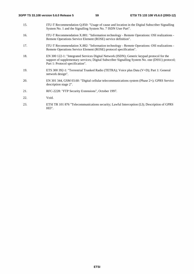
ETSI
ETSI TS 133 108 V5.6.0 (2003-12) 593GPP TS 33.108 version 5.6.0 Release 5
15. ITU-T Recommendation Q.850: "Usage of cause and location in the Digital Subscriber Signalling System No. 1 and the Signalling System No. 7 ISDN User Part".
16. ITU-T Recommendation X.881: "Information technology - Remote Operations: OSI realizations - Remote Operations Service Element (ROSE) service definition".
17. ITU-T Recommendation X.882: "Information technology - Remote Operations: OSI realizations - Remote Operations Service Element (ROSE) protocol specification".
18. EN 300 122-1: "Integrated Services Digital Network (ISDN); Generic keypad protocol for the support of supplementary services; Digital Subscriber Signalling System No. one (DSS1) protocol; Part 1: Protocol specification".
19. ETS 300 392-1: "Terrestrial Trunked Radio (TETRA); Voice plus Data (V+D); Part 1: General network design".
20. EN 301 344, GSM 03.60: "Digital cellular telecommunications system (Phase 2+); GPRS Service description stage 2".
21. RFC-2228: "FTP Security Extensions", October 1997.
22. Void.
23. ETSI TR 101 876 "Telecommunications security; Lawful Interception (LI); Description of GPRS HI3".

ETSI
ETSI TS 133 108 V5.6.0 (2003-12) 603GPP TS 33.108 version 5.6.0 Release 5
Annex F (informative): Void
ETSI
ETSI TS 133 108 V5.6.0 (2003-12) 613GPP TS 33.108 version 5.6.0 Release 5
Annex G (informative): United States lawful interception
G.1 Delivery methods preferences Law enforcement agencies want reliable delivery of intercepted communications to the LEMF:
- U.S. Law enforcement prefers that the capability to deliver IRI to the LEMF be provided over the HI2 directly over TCP (at the transport layer) and the Internet Protocol (IP) (at the network layer).
- U.S. Law enforcement prefers that the capability to deliver content of communication to the LEMF be provided using the GPRS LI Correlation Header over TCP/IP method for delivery.
G.2 HI2 delivery methods
G.2.1 TPKT/TCP/IP
G.2.1.1 Introduction
The protocol used by the "LI application" for the encoding of IRI data and the sending of IRI data between the MF and the LEMF is based on already standardized data transmission protocols. At the HI2 interface, the "LI application" protocol is used directly over the Transmission Control Protocol (TCP), which uses the Internet Protocol (IP) for the delivery of the IRI. IP is defined in ref [15]. TCP is defined in ref [16].
TCP/IP supports reliable delivery of data. TCP is independent of the payload data it carries.
G.2.1.2 Normal Procedures
Either the MF or LEMF may initiate the TCP connection. The case when the MF initiates the TCP connection is detailed in G.2.1.2.1.
G.2.1.2.1 Usage of TCP/IP when MF initiates TCP Connections
The MF shall initiate TCP connections to the LEMF for LI purposes. Once a TCP connection is established, the MF shall send the LI application messages defined in section G.2.1.3. The MF shall not receive TCP data.
The "LI application" messages may be sent over a single TCP connection per LEMF. A TCP/IP connection shall be capable of transporting "LI application" messages for multiple surveillance cases to a single LEA. The MF initiates the establishment of TCP connections to the LEMF equipment designated by the LEA. Optionally, the MF may use more than one TCP connection per LEMF for the purpose of delivering "LI application" messages to minimize the effects of congestion or facility failures. For example, if more than one TCP connection was used "LI application" messages may be uniformly distributed across the connections. If delays are detected on one TCP connection, the MF could begin to transmit more messages on the other TCP connections. The number of TCP connections supported to the LEMF shall be less than or equal to the provisioned maximum number of such connections.
G.2.1.2.2 Use of TPKT
The individual IRI parameters are coded using ASN.1 and the basic encoding rules (BER). The individual IRI parameters are conveyed to the LEMF in "LI application" messages or IRI data records.
TCP is a stream-based protocol and has no inherent message delineation capability.
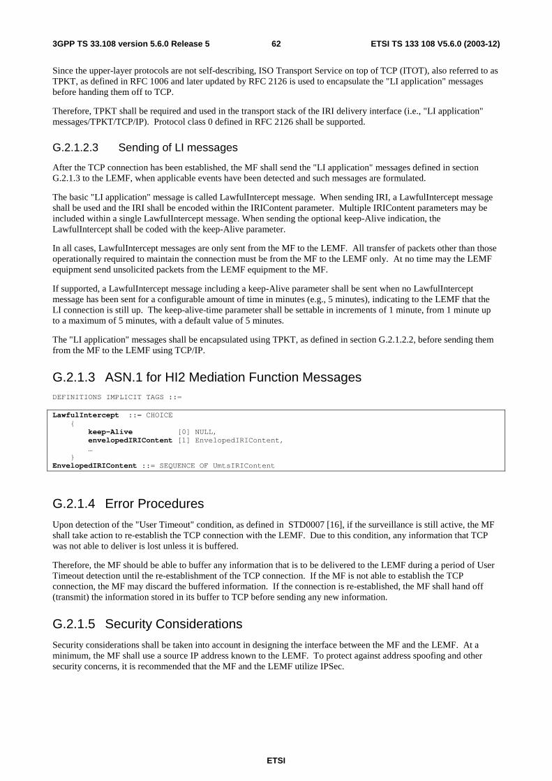
ETSI
ETSI TS 133 108 V5.6.0 (2003-12) 623GPP TS 33.108 version 5.6.0 Release 5
Since the upper-layer protocols are not self-describing, ISO Transport Service on top of TCP (ITOT), also referred to as TPKT, as defined in RFC 1006 and later updated by RFC 2126 is used to encapsulate the "LI application" messages before handing them off to TCP.
Therefore, TPKT shall be required and used in the transport stack of the IRI delivery interface (i.e., "LI application" messages/TPKT/TCP/IP). Protocol class 0 defined in RFC 2126 shall be supported.
G.2.1.2.3 Sending of LI messages
After the TCP connection has been established, the MF shall send the "LI application" messages defined in section G.2.1.3 to the LEMF, when applicable events have been detected and such messages are formulated.
The basic "LI application" message is called LawfulIntercept message. When sending IRI, a LawfulIntercept message shall be used and the IRI shall be encoded within the IRIContent parameter. Multiple IRIContent parameters may be included within a single LawfulIntercept message. When sending the optional keep-Alive indication, the LawfulIntercept shall be coded with the keep-Alive parameter.
In all cases, LawfulIntercept messages are only sent from the MF to the LEMF. All transfer of packets other than those operationally required to maintain the connection must be from the MF to the LEMF only. At no time may the LEMF equipment send unsolicited packets from the LEMF equipment to the MF.
If supported, a LawfulIntercept message including a keep-Alive parameter shall be sent when no LawfulIntercept message has been sent for a configurable amount of time in minutes (e.g., 5 minutes), indicating to the LEMF that the LI connection is still up. The keep-alive-time parameter shall be settable in increments of 1 minute, from 1 minute up to a maximum of 5 minutes, with a default value of 5 minutes.
The "LI application" messages shall be encapsulated using TPKT, as defined in section G.2.1.2.2, before sending them from the MF to the LEMF using TCP/IP.
G.2.1.3 ASN.1 for HI2 Mediation Function Messages DEFINITIONS IMPLICIT TAGS ::= LawfulIntercept ::= CHOICE { keep-Alive [0] NULL, envelopedIRIContent [1] EnvelopedIRIContent, … } EnvelopedIRIContent ::= SEQUENCE OF UmtsIRIContent
G.2.1.4 Error Procedures
Upon detection of the "User Timeout" condition, as defined in STD0007 [16], if the surveillance is still active, the MF shall take action to re-establish the TCP connection with the LEMF. Due to this condition, any information that TCP was not able to deliver is lost unless it is buffered.
Therefore, the MF should be able to buffer any information that is to be delivered to the LEMF during a period of User Timeout detection until the re-establishment of the TCP connection. If the MF is not able to establish the TCP connection, the MF may discard the buffered information. If the connection is re-established, the MF shall hand off (transmit) the information stored in its buffer to TCP before sending any new information.
G.2.1.5 Security Considerations
Security considerations shall be taken into account in designing the interface between the MF and the LEMF. At a minimum, the MF shall use a source IP address known to the LEMF. To protect against address spoofing and other security concerns, it is recommended that the MF and the LEMF utilize IPSec.
ETSI
ETSI TS 133 108 V5.6.0 (2003-12) 633GPP TS 33.108 version 5.6.0 Release 5
G.3 HI3 delivery methods
G.3.1 Use of TCP/IP At the HI3 interface, the user data packets with the GLIC header shall be sent to the LEMF over Transmission Control Protocol (TCP), which uses the Internet Protocol (IP).
TCP/IP supports reliable delivery of data. TCP is independent of the payload data it carries.
G.3.1.1 Normal Procedures
Either the MF or LEMF may initiate the TCP connection. The case when the MF initiates the TCP connection is detailed in G.3.1.1.1.
G.3.1.1.1 Usage of TCP/IP when MF initiates TCP Connections
The MF shall initiate TCP connections to the LEMF for the purpose of delivering CC. Once a TCP connection is established, the MF will send CC messages to the LEMF via TCP.
CC messages shall be sent over TCP connections established specifically to deliver CC. A minimum of one TCP connection shall be established per intercept subject per LEMF to deliver CC associated only with the intercept subject. The MF initiates the establishment of TCP connections to the LEMF equipment designated by the LEA. Optionally, the MF may use more than one TCP connection per intercept subject per LEMF for the purpose of delivering CC associated with the intercept subject to minimize the effects of congestion or facility failures. For example, if more than one TCP connection is used, CC messages may be uniformly distributed across the connections. If delays are detected on one TCP connection, the MF could begin to transmit more messages on the other TCP connections. The number of TCP connections supported to the LEMF per intercept subject shall be less than or equal to the provisioned maximum number of such connections.
After the TCP connection establishment procedure, the MF shall send the connectionStatus message including the lawfulInterceptionIdentifier parameter to the LEMF. The delivery of the lawful interception identifier to the LEMF after the TCP connection establishment procedure will assist the LEMF in correlating the TCP connection, established for delivering content of communication, with a particular surveillance and the intercept subject.
G.3.1.1.2 Use of TPKT
TCP is a stream-based protocol and has no inherent message delineation capability.
Since the upper-layer protocols are not self-describing, ITOT, also referred to as TPKT, as defined in RFC 1006 and later updated by RFC 2126 is used to encapsulate the CC and connectionStatus messages before handing them off to TCP.
Therefore, TPKT shall be required and used in the transport stack of the CC delivery interface (e.g., CC messages/TPKT/TCP/IP). Protocol class 0 defined in RFC 2126 shall be supported.
G.3.1.1.3 Sending of Content of Communication Messages
After the TCP connection has been established and the connectionStatus message has been sent, the MF shall send the CC messages (including the GLIC header) defined in Section C.1 using TPKT to the LEMF.
In all cases, CC messages are only sent from the MF to the LEMF. All transfer of packets other than those operationally required to maintain the connection must be from the MF to the LEMF only. At no time may the LEMF equipment send unsolicited packets from the LEMF equipment to the MF.
If supported, a connectionStatus message including the keep-Alive parameter shall be sent from the MF to the LEMF when no CC message has been sent for a configurable amount of time in minutes (e.g., 5 minutes), indicating to the LEMF that the TCP connection is still up. If a keep-alive capability is supported, a keep-Alive parameter shall be settable in increments of 1 minute, from 1 minute up to a maximum of 5 minutes, with a default value of 5 minutes.
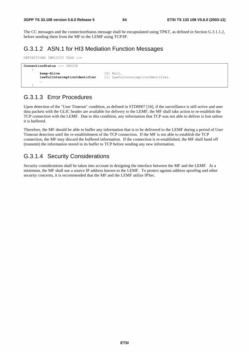
ETSI
ETSI TS 133 108 V5.6.0 (2003-12) 643GPP TS 33.108 version 5.6.0 Release 5
The CC messages and the connectionStatus message shall be encapsulated using TPKT, as defined in Section G.3.1.1.2, before sending them from the MF to the LEMF using TCP/IP.
G.3.1.2 ASN.1 for HI3 Mediation Function Messages DEFINITIONS IMPLICIT TAGS ::= ConnectionStatus ::= CHOICE { keep-Alive [0] Null, lawfulInterceptionIdentifier [1] LawfulInterceptionIdentifier, … }
G.3.1.3 Error Procedures
Upon detection of the "User Timeout" condition, as defined in STD0007 [16], if the surveillance is still active and user data packets with the GLIC header are available for delivery to the LEMF, the MF shall take action to re-establish the TCP connection with the LEMF. Due to this condition, any information that TCP was not able to deliver is lost unless it is buffered.
Therefore, the MF should be able to buffer any information that is to be delivered to the LEMF during a period of User Timeout detection until the re-establishment of the TCP connection. If the MF is not able to establish the TCP connection, the MF may discard the buffered information. If the connection is re-established, the MF shall hand off (transmit) the information stored in its buffer to TCP before sending any new information.
G.3.1.4 Security Considerations
Security considerations shall be taken into account in designing the interface between the MF and the LEMF. At a minimum, the MF shall use a source IP address known to the LEMF. To protect against address spoofing and other security concerns, it is recommended that the MF and the LEMF utilize IPSec.
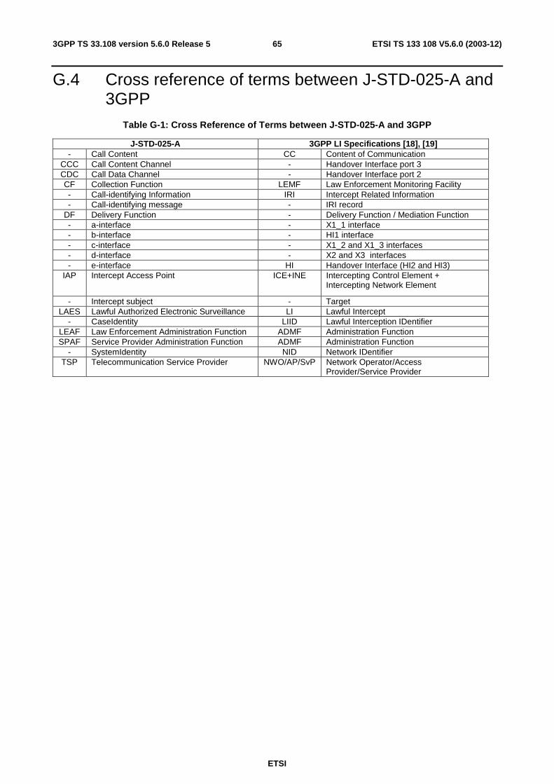
ETSI
ETSI TS 133 108 V5.6.0 (2003-12) 653GPP TS 33.108 version 5.6.0 Release 5
G.4 Cross reference of terms between J-STD-025-A and 3GPP
Table G-1: Cross Reference of Terms between J-STD-025-A and 3GPP
J-STD-025-A 3GPP LI Specifications [18], [19] - Call Content CC Content of Communication
CCC Call Content Channel - Handover Interface port 3 CDC Call Data Channel - Handover Interface port 2 CF Collection Function LEMF Law Enforcement Monitoring Facility - Call-identifying Information IRI Intercept Related Information - Call-identifying message - IRI record
DF Delivery Function - Delivery Function / Mediation Function - a-interface - X1_1 interface - b-interface - HI1 interface - c-interface - X1_2 and X1_3 interfaces - d-interface - X2 and X3 interfaces - e-interface HI Handover Interface (HI2 and HI3)
IAP Intercept Access Point ICE+INE Intercepting Control Element + Intercepting Network Element
- Intercept subject - Target LAES Lawful Authorized Electronic Surveillance LI Lawful Intercept
- CaseIdentity LIID Lawful Interception IDentifier LEAF Law Enforcement Administration Function ADMF Administration Function SPAF Service Provider Administration Function ADMF Administration Function
- SystemIdentity NID Network IDentifier TSP Telecommunication Service Provider NWO/AP/SvP Network Operator/Access
Provider/Service Provider
ETSI
ETSI TS 133 108 V5.6.0 (2003-12) 663GPP TS 33.108 version 5.6.0 Release 5
Annex H (normative): United States lawful interception With respect to the handover interfaces they must be capable of delivering intercepted communications and IRI information to the government in a format such that they may be transmitted by means of equipment, facilities, or services procured by the government to a location other than the premises of the carrier.
With respect to location information ‘when authorized’ means the ability to provide location information on a per-surveillance basis.
The delivery methods described in this document are optional methods and no specific method is required in the United States.
The specification of lawful intercept capabilities in this document does not imply that those services supported by these lawful intercept capabilities are covered by CALEA. Inclusion of a capability in this document does not imply that capability is required by CALEA. This document is intended to satisfy the requirements of section 107 (a) (2) of the Communications Assistance for Law Enforcement Act, Pub. L. 103-414 such that a telecommunications carrier, manufacturer, or support service provider that is in compliance with this document shall have "Safe Harbor".
In the United States surveillance on the GGSN is not required, but is an option that may be negotiated between the service provider and law enforcement.
A TSP shall not be responsible for decrypting or decompressing, or ensuring the government's ability to decrypt or decompress, any communication encrypted or compressed by a subscriber or customer, unless the encryption or compression was provided by the TSP and the TSP possesses the information necessary to decrypt or decompress the communication. A TSP that provides the government with information about how to decrypt or decompress a communication (e.g. identifying the type of compression software used to compress the communication, directing the government to the appropriate vendor that can provide decryption or decompression equipment, or providing the encryption key used to encrypt the communication) fully satisfies its obligation under the preceding sentence.
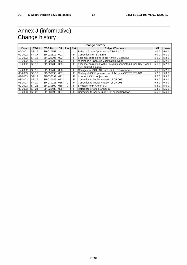
ETSI
ETSI TS 133 108 V5.6.0 (2003-12) 673GPP TS 33.108 version 5.6.0 Release 5
Annex J (informative): Change history
Change history Date TSG # TSG Doc. CR Rev Cat Subject/Comment Old New
06-2002 SP-16 SP-020357 - - - Release 5 draft Approved at TSG SA #16. 2.0.0 5.0.0 09-2002 SP-17 SP-020512 001 F Corrections to TS 33.108 5.0.0 5.1.0 12-2002 SP-18 SP-020705 002 F Essential corrections to the Annex C.1 (ULIC) 5.1.0 5.2.0 12-2002 SP-18 SP-020706 003 F Missing PDP Context Modification event 5.1.0 5.2.0 12-2002 SP-18 SP-020706 005 F Essential correction to the LI events generated during RAU, when
PDP context is active 5.1.0 5.2.0
12-2002 SP-18 SP-020706 006 F Changes to TS 33.108 for U.S. LI Requirements 5.1.0 5.2.0 03-2003 SP-19 SP-030096 007 F Coding of ASN.1 parameters of the type OCTET STRING 5.2.0 5.3.0 03-2003 SP-19 SP-030099 011 F Incorrect ASN.1 object tree 5.2.0 5.3.0 03-2003 SP-19 SP-030149 013 F Correction to implementation of CR 005 5.2.0 5.3.0 06-2003 SP-20 SP-030221 015 1 F Correction to implementation of CR 005 5.3.0 5.4.0 09-2003 SP-21 SP-030509 018 1 F Syntax error in Annex B.3 5.4.0 5.5.0 09-2003 SP-21 SP-030482 025 - F Reference errors in Annex G 5.4.0 5.5.0 12-2003 SP-22 SP-030592 027 - F Correction to Annex G on TCP based transport 5.5.0 5.6.0
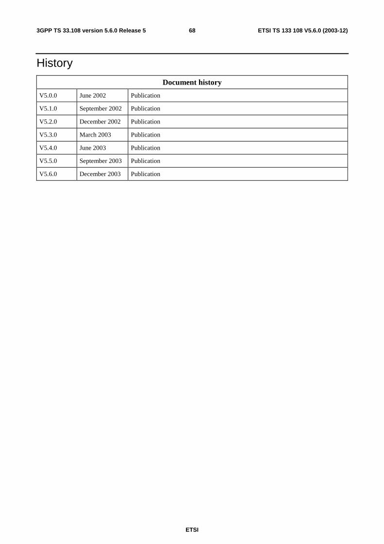
ETSI
ETSI TS 133 108 V5.6.0 (2003-12) 683GPP TS 33.108 version 5.6.0 Release 5
History
Document history
V5.0.0 June 2002 Publication
V5.1.0 September 2002 Publication
V5.2.0 December 2002 Publication
V5.3.0 March 2003 Publication
V5.4.0 June 2003 Publication
V5.5.0 September 2003 Publication
V5.6.0 December 2003 Publication