Embed Size (px)
Citation preview
ETSI TS 132 421 V10.5.0 (2012-07)
Digital cellular telecommunications system (Phase 2+); Universal Mobile Telecommunications System (UMTS);
LTE; Telecommunication management; Subscriber and equipment trace; Trace concepts and requirements
(3GPP TS 32.421 version 10.5.0 Release 10)
Technical Specification
ETSI
ETSI TS 132 421 V10.5.0 (2012-07)13GPP TS 32.421 version 10.5.0 Release 10
Reference RTS/TSGS-0532421va50
Keywords GSM,LTE,UMTS
ETSI
650 Route des Lucioles F-06921 Sophia Antipolis Cedex - FRANCE
Tel.: +33 4 92 94 42 00 Fax: +33 4 93 65 47 16
Siret N° 348 623 562 00017 - NAF 742 C
Association à but non lucratif enregistrée à la Sous-Préfecture de Grasse (06) N° 7803/88
Important notice
Individual copies of the present document can be downloaded from: http://www.etsi.org
The present document may be made available in more than one electronic version or in print. In any case of existing or perceived difference in contents between such versions, the reference version is the Portable Document Format (PDF).
In case of dispute, the reference shall be the printing on ETSI printers of the PDF version kept on a specific network drive within ETSI Secretariat.
Users of the present document should be aware that the document may be subject to revision or change of status. Information on the current status of this and other ETSI documents is available at
http://portal.etsi.org/tb/status/status.asp
If you find errors in the present document, please send your comment to one of the following services: http://portal.etsi.org/chaircor/ETSI_support.asp
Copyright Notification
No part may be reproduced except as authorized by written permission. The copyright and the foregoing restriction extend to reproduction in all media.
© European Telecommunications Standards Institute 2012.
All rights reserved.
DECTTM, PLUGTESTSTM, UMTSTM and the ETSI logo are Trade Marks of ETSI registered for the benefit of its Members. 3GPPTM and LTE™ are Trade Marks of ETSI registered for the benefit of its Members and
of the 3GPP Organizational Partners. GSM® and the GSM logo are Trade Marks registered and owned by the GSM Association.
ETSI
ETSI TS 132 421 V10.5.0 (2012-07)23GPP TS 32.421 version 10.5.0 Release 10
Intellectual Property Rights IPRs essential or potentially essential to the present document may have been declared to ETSI. The information pertaining to these essential IPRs, if any, is publicly available for ETSI members and non-members, and can be found in ETSI SR 000 314: "Intellectual Property Rights (IPRs); Essential, or potentially Essential, IPRs notified to ETSI in respect of ETSI standards", which is available from the ETSI Secretariat. Latest updates are available on the ETSI Web server (http://ipr.etsi.org).
Pursuant to the ETSI IPR Policy, no investigation, including IPR searches, has been carried out by ETSI. No guarantee can be given as to the existence of other IPRs not referenced in ETSI SR 000 314 (or the updates on the ETSI Web server) which are, or may be, or may become, essential to the present document.
Foreword This Technical Specification (TS) has been produced by ETSI 3rd Generation Partnership Project (3GPP).
The present document may refer to technical specifications or reports using their 3GPP identities, UMTS identities or GSM identities. These should be interpreted as being references to the corresponding ETSI deliverables.
The cross reference between GSM, UMTS, 3GPP and ETSI identities can be found under http://webapp.etsi.org/key/queryform.asp.
ETSI
ETSI TS 132 421 V10.5.0 (2012-07)33GPP TS 32.421 version 10.5.0 Release 10
Contents
Intellectual Property Rights ................................................................................................................................ 2
Foreword ............................................................................................................................................................. 2
Foreword ............................................................................................................................................................. 5
Introduction ........................................................................................................................................................ 6
1 Scope ........................................................................................................................................................ 7
2 References ................................................................................................................................................ 7
3 Definitions, symbols and abbreviations ................................................................................................... 8
3.1 Definitions .......................................................................................................................................................... 8
3.2 Abbreviations ................................................................................................................................................... 10
4 Trace concepts and high-level architecture ............................................................................................ 11
4.1 Trace concepts .................................................................................................................................................. 11
4.2 Trace high level Architecture ........................................................................................................................... 13
4.3 Service Level Tracing for IMS high level Architecture ................................................................................... 16
5 Trace requirements ................................................................................................................................. 18
5.1 General trace requirements ............................................................................................................................... 18
5.2 Requirements for Trace data ............................................................................................................................ 19
5.3 Requirements for Trace activation ................................................................................................................... 20
5.3.1 Requirements for Trace Session activation ................................................................................................. 20
5.3.2 Requirements for starting a Trace Recording Session ................................................................................ 22
5.4 Requirements for Trace deactivation ................................................................................................................ 23
5.4.1 Requirements for Trace Session deactivation ............................................................................................. 23
5.4.2 Requirements for stopping a Trace Recording Session .............................................................................. 24
5.5 Requirements for Trace Data reporting ............................................................................................................ 25
5.6 Requirements for Privacy and Security ............................................................................................................ 26
5.7 Requirements for Charging .............................................................................................................................. 26
5.8 Use cases for Trace........................................................................................................................................... 27
6 Requirements for managing MDT ......................................................................................................... 28
6.1 Business Level Requirements........................................................................................................................... 28
6.2 Specification level requirements ...................................................................................................................... 29
Annex A (informative): Trace use cases ............................................................................................... 30
A.1 Use case #1: multi-vendor UE validation ............................................................................................... 30
A.1.1 Description ....................................................................................................................................................... 30
A.1.2 Example of required data for this use case ....................................................................................................... 30
A.2 Use case #2: subscriber complaint ......................................................................................................... 30
A.2.1 Description ....................................................................................................................................................... 30
A.2.2 Example of required data for this use case ....................................................................................................... 31
A.3 Use case #3: malfunctioning UE ............................................................................................................ 32
A.3.1 Description ....................................................................................................................................................... 32
A.3.2 Example of required data for this use case ....................................................................................................... 32
A.4 Use case #4: checking radio coverage .................................................................................................... 32
A.4.1 Description ....................................................................................................................................................... 32
A.4.2 Example of required data to cover use case #4 ................................................................................................. 32
A.5 Use case #5: testing a new feature .......................................................................................................... 33
A.5.1 Description ....................................................................................................................................................... 33
A.5.2 Example of required data to cover use case #5 ................................................................................................. 33
A.6 Use case #6: fine-tuning and optimisation of algorithms/procedures .................................................... 33
A.6.1 Description ....................................................................................................................................................... 33
ETSI
ETSI TS 132 421 V10.5.0 (2012-07)43GPP TS 32.421 version 10.5.0 Release 10
A.6.2 Example of required data to cover use case #6 ................................................................................................. 34
A.7 Use case #7: Automated testing of Service Provider services ................................................................ 34
A.7.1 Description ....................................................................................................................................................... 34
A.8 Use case #8: Regression testing following a network fix ....................................................................... 34
A.8.1 Description ....................................................................................................................................................... 34
A.9 Use case #9: Service fault localization within a Service Provider network ........................................... 34
A.9.1 Description ....................................................................................................................................................... 34
A.10 Use case #10: Service fault localization when a service is hosted by a third party Service Provider .... 34
A.10.1 Description ....................................................................................................................................................... 34
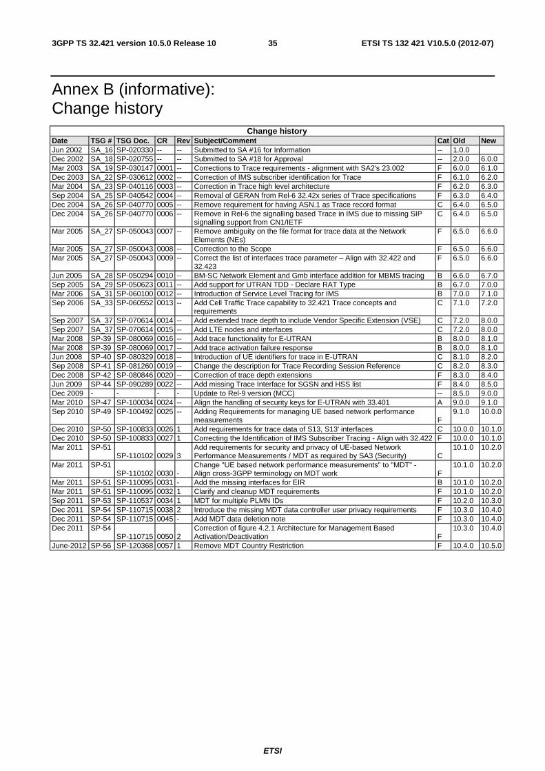
Annex B (informative): Change history ............................................................................................... 35
History .............................................................................................................................................................. 36
ETSI
ETSI TS 132 421 V10.5.0 (2012-07)53GPP TS 32.421 version 10.5.0 Release 10
Foreword This Technical Specification has been produced by the 3rd Generation Partnership Project (3GPP).
The contents of the present document are subject to continuing work within the TSG and may change following formal TSG approval. Should the TSG modify the contents of the present document, it will be re-released by the TSG with an identifying change of release date and an increase in version number as follows:
Version x.y.z
where:
x the first digit:
1 presented to TSG for information;
2 presented to TSG for approval;
3 or greater indicates TSG approved document under change control.
y the second digit is incremented for all changes of substance, i.e. technical enhancements, corrections, updates, etc.
z the third digit is incremented when editorial only changes have been incorporated in the document.
ETSI
ETSI TS 132 421 V10.5.0 (2012-07)63GPP TS 32.421 version 10.5.0 Release 10
Introduction The present document is part of a TS-family covering the 3rd Generation Partnership Project; Technical Specification Group Services and System Aspects; Telecommunication management, as identified below:
TS 32.421: "Subscriber and equipment trace: Trace concepts and requirements";
TS 32.422: "Subscriber and equipment trace: Trace control and configuration management";
TS 32.423: "Subscriber and equipment trace: Trace data definition and management";
Subscriber and equipment trace provide very detailed information at call level on one or more specific mobile(s). This data is an additional source of information to Performance Measurements and allows going further in monitoring and optimisation operations.
Contrary to Performance measurements, which are a permanent source of information, trace is activated on user demand for a limited period of time for specific analysis purposes.
Trace plays a major role in activities such as determination of the root cause of a malfunctioning mobile, advanced troubleshooting, optimisation of resource usage and quality, RF coverage control and capacity improvement, dropped call analysis, Core Network and UTRAN end-to-end UMTS procedure validation.
The capability to log data on any interface at call level for a specific user (e.g. IMSI) or mobile type (e.g. IMEI or IMEISV), or service initiated by a user allows getting information which cannot be deduced from Performance measurements such as perception of end-user QoS during his call (e.g. requested QoS vs. provided QoS), correlation between protocol messages and RF measurements, or interoperability with specific mobile vendors.
Moreover, performance measurements provide values aggregated on an observation period; Subscriber and UE Trace give instantaneous values for a specific event (e.g. call, location update, etc.).
If performance measurements are mandatory for daily operations, future network planning and primary trouble shooting; Subscriber and UE Trace is the easy way to go deeper into investigation and UMTS network optimisation.
In order to produce this data, Subscriber and UE Trace are carried out in the NEs, which comprise the network. The data can then be transferred to an external system (e.g. an Operations System (OS) in TMN terminology, for further evaluation).
ETSI
ETSI TS 132 421 V10.5.0 (2012-07)73GPP TS 32.421 version 10.5.0 Release 10
1 Scope The present document describes the requirements for the management of Trace and the reporting of Trace data (including FDD mode and TDD mode) across UMTS networks or EPS networks as it refers to subscriber tracing (tracing of IMSI or Public User Identity) and equipment tracing (tracing of IMEI or IMEISV). Trace also includes the ability to trace all active calls in a cell or multiple cells (Cell Traffic Trace). The present document also includes the description of Service Level Tracing (tracing of a specific service). It defines the administration of Trace Session activation/deactivation by the Element Manager (EM), the network or User Equipment (UE) itself via signalling, the generation of Trace results in the Network Elements (NEs) and UE and the transfer of these results to one or more Operations Systems, i.e. EM(s) and/or Network Manager(s) (NM(s)).
The present document is built upon the basic Subscriber and UE Trace concept described in clause 4. The high-level requirements for Trace data, Trace Session activation/deactivation and Trace reporting are defined in clause 5. Clause 5 also contains an overview of use cases for Trace (the use cases are described in Annex A). Trace control and configuration management are described in 3GPP TS 32.422 [2], and Trace data definition and management are described in 3GPP TS 32.423 [3].
The present document does not cover any Trace capability limitations within a NE (e.g. maximum number of simultaneous traced mobiles for a given NE) or any functionality related to these limitations (e.g. NE aborting a Trace Session due to resource limitations).
The objectives of the Trace specifications are:
a) to provide the descriptions for a standard set of Trace data;
b) to produce a common description of the management technique for Trace administration and result reporting;
c) to define a method for Trace results reporting across the management interfaces.
The following is beyond the scope of the present document, and therefore the present document does not describe:
- tracing non-Subscriber or non-UE related events within an NE;
- tracing of all possible parties in a multi-party call (although multiple calls related to the IMSI specified in the Trace control and configuration parameters are traceable).
The definition of Trace data is intended to result in comparability of Trace data produced in a multi-vendor wireless UMTS and/or EPS network(s), for those Trace control and configuration parameters that can be standardised across all vendors' implementations.
Vendor specific extensions to the Trace control and configuration parameters and Trace data are discussed in 3GPP TS 32.422 [2] and 3GPP TS 32.423 [3].
2 References The following documents contain provisions, which, through reference in this text, constitute provisions of the present document.
• References are either specific (identified by date of publication, edition number, version number, etc.) or non-specific.
• For a specific reference, subsequent revisions do not apply.
• For a non-specific reference, the latest version applies. In the case of a reference to a 3GPP document (including a GSM document), a non-specific reference implicitly refers to the latest version of that document in the same Release as the present document.
[1] 3GPP TS 32.101: "Telecommunication management; Principles and high level requirements".
[2] 3GPP TS 32.422: "Telecommunication management; Subscriber and equipment trace: Trace control and configuration management".
ETSI
ETSI TS 132 421 V10.5.0 (2012-07)83GPP TS 32.421 version 10.5.0 Release 10
[3] 3GPP TS 32.423: "Telecommunication management; Subscriber and equipment trace: Trace data definition and management".
[4] 3GPP TS 23.002: "Network architecture".
[6] 3GPP TS 29.207: "Policy control over Go interface".
[7] 3GPP TS 52.008: "Telecommunication management; GSM subscriber and equipment trace".
[8] 3GPP TR 21.905: "Vocabulary for 3GPP Specifications".
[9] OMA Service Provider Environment Requirements, OMA-RD-OSPE-V1_0-20050614-C, The Open Mobile Alliance™ (URL:http://www.openmobilealliance.org/)
[10] 3GPP TS 33.401: "System Architecture Evolution (SAE); Security architecture".
[11] 3GPP TS 37.320 : "Universal Terrestrial Radio Access (UTRA) and Evolved Universal Terrestrial Radio Access (E-UTRA); Radio measurement collection for Minimization of Drive Tests (MDT); Overall description, Stage 2".
NOTE: Overall management principles are defined in 3GPP TS 32.101 [1].
3 Definitions, symbols and abbreviations
3.1 Definitions For the purposes of the present document, the terms and definitions given in 21.905 [8] and the following apply:
Cell Traffic Trace: The ability to trace one or more active calls in one or more cells.
Collection Period: TBD
Editor"s note: This definition requires RAN2 input.
End user visible events: Refer to OMA Service Provider Requirements [9].
Immediate MDT: See 3GPP TS 37.320 [11].
Logged MDT: See 3GPP TS 37.320 [11].
management activation/deactivation: Trace Session is activated/deactivated in different NEs directly from the EM using the management interfaces of those NEs.
MDT Measurements: See 3GPP TS 37.320 [11].
Signalling Based Activation/Deactivation: Trace Session is activated/deactivated in different NEs using the signalling interfaces between those elements so that the NEs may forward the activation/deactivation originating from the EM
System Context: two different realisations of the telecommunication management architecture. System Context A has the Itf-N between a Network Manager and an Element Manger. System Context B has the Itf-N between a Network Manager and a Network Element that has an embedded Element Manager. See figure 1 in TS 32.101 [1].
Reporting Period: TBD
Editor"s note: This definition requires RAN2 input.
Trace: general term used for Subscriber, Equipment and Service Trace.
Trace record: in the NE a Trace record is a set of Traceable data collected as determined by the Trace control and configuration parameters.
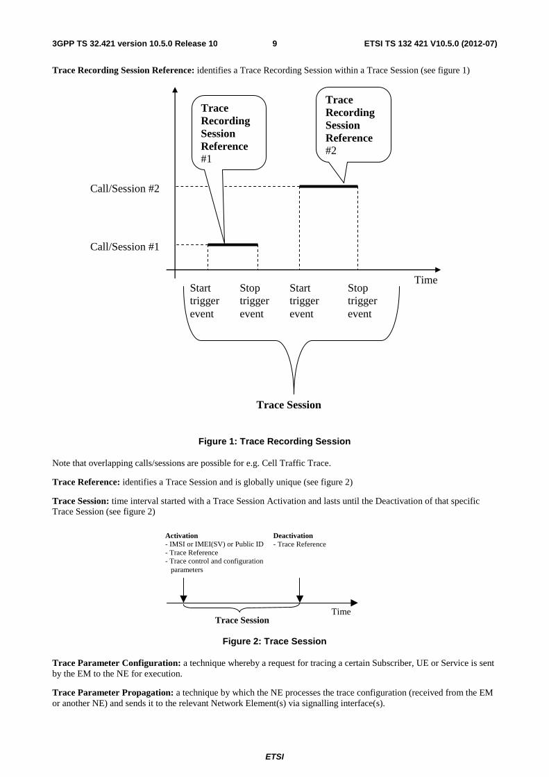
Trace Recording Session: time interval within a Trace Session while trace records are generated for the Subscriber, UE or Service being traced. The triggering events starting and stopping a Trace Recording Session are defined in 3GPP TS 32.422 [2] (see figure 1).
ETSI
ETSI TS 132 421 V10.5.0 (2012-07)93GPP TS 32.421 version 10.5.0 Release 10
Trace Recording Session Reference: identifies a Trace Recording Session within a Trace Session (see figure 1)
Call/Session #2
Call/Session #1
Start trigger event
Stop trigger event
Start trigger event
Stop trigger event
Trace Recording Session Reference #2
Trace Recording Session Reference #1
Trace Session
Time
Figure 1: Trace Recording Session
Note that overlapping calls/sessions are possible for e.g. Cell Traffic Trace.
Trace Reference: identifies a Trace Session and is globally unique (see figure 2)
Trace Session: time interval started with a Trace Session Activation and lasts until the Deactivation of that specific Trace Session (see figure 2)
Deactivation - Trace Reference
Activation - IMSI or IMEI(SV) or Public ID - Trace Reference - Trace control and configuration parameters
Trace Session Time
Figure 2: Trace Session
Trace Parameter Configuration: a technique whereby a request for tracing a certain Subscriber, UE or Service is sent by the EM to the NE for execution.
Trace Parameter Propagation: a technique by which the NE processes the trace configuration (received from the EM or another NE) and sends it to the relevant Network Element(s) via signalling interface(s).
ETSI
ETSI TS 132 421 V10.5.0 (2012-07)103GPP TS 32.421 version 10.5.0 Release 10
Service Level Tracing: Refer to OMA Service Provider Requirements [9].
3.2 Abbreviations For the purposes of the present document, the abbreviations given in 21.905 [8], 32.101 [1] and the following apply:
TCE Trace Collection Entity
ETSI
ETSI TS 132 421 V10.5.0 (2012-07)113GPP TS 32.421 version 10.5.0 Release 10
4 Trace concepts and high-level architecture
4.1 Trace concepts The diversity of Trace requirements makes it difficult to identify and anticipate all the operator's specific needs. Thus, the objective of this TS is not to list an exhaustive set of information to meet all the requirements. Rather, Trace data is defined without any limitation on the 2 following dimensions:
- Trace scope: NEs and signalling interfaces to Trace.
- Trace depth: level of details of Trace data.
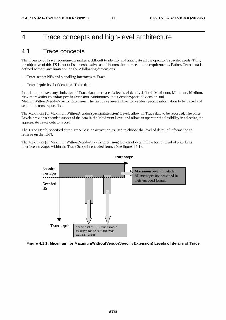
In order not to have any limitation of Trace data, there are six levels of details defined: Maximum, Minimum, Medium, MaximumWithoutVendorSpecificExtension, MinimumWithoutVendorSpecificExtension and MediumWithoutVendorSpecificExtension. The first three levels allow for vendor specific information to be traced and sent in the trace report file.
The Maximum (or MaximumWithoutVendorSpecificExtension) Levels allow all Trace data to be recorded. The other Levels provide a decoded subset of the data in the Maximum Level and allow an operator the flexibility in selecting the appropriate Trace data to record.
The Trace Depth, specified at the Trace Session activation, is used to choose the level of detail of information to retrieve on the Itf-N.
The Maximum (or MaximumWithoutVendorSpecificExtension) Levels of detail allow for retrieval of signalling interface messages within the Trace Scope in encoded format (see figure 4.1.1).
Encoded messages
Decoded IEs
Maximum level of details: All messages are provided in their encoded format.
Trace scope
Trace depth Specific set of IEs from encoded messages can be decoded by an external system.
Maximum level of details: All messages are provided in their encoded format.
Trace scope
Trace depth Specific set of IEs from encoded messages can be decoded by an external system.
Encoded messages
Decoded IEs
Figure 4.1.1: Maximum (or MaximumWithoutVendorSpecificExtension) Levels of details of Trace
ETSI
ETSI TS 132 421 V10.5.0 (2012-07)123GPP TS 32.421 version 10.5.0 Release 10
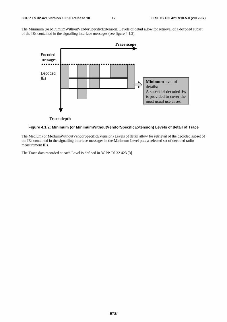
The Minimum (or MinimumWithoutVendorSpecificExtension) Levels of detail allow for retrieval of a decoded subset of the IEs contained in the signalling interface messages (see figure 4.1.2).
Minimum level of details: A subset of decoded IEs is provided to cover the most usual use cases.
Encoded messages
Decoded IEs
Trace depth
Trace scope
Minimum level of details: A subset of decoded IEs is provided to cover the most usual use cases.
Encoded messages
Decoded IEs
Trace depth
Trace scope
Figure 4.1.2: Minimum (or MinimumWithoutVendorSpecificExtension) Levels of detail of Trace
The Medium (or MediumWithoutVendorSpecificExtension) Levels of detail allow for retrieval of the decoded subset of the IEs contained in the signalling interface messages in the Minimum Level plus a selected set of decoded radio measurement IEs.
The Trace data recorded at each Level is defined in 3GPP TS 32.423 [3].
ETSI
ETSI TS 132 421 V10.5.0 (2012-07)133GPP TS 32.421 version 10.5.0 Release 10
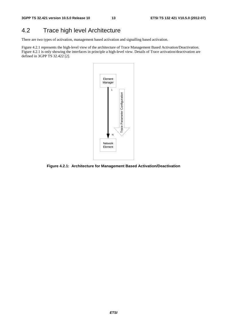
4.2 Trace high level Architecture There are two types of activation, management based activation and signalling based activation.
Figure 4.2.1 represents the high-level view of the architecture of Trace Management Based Activation/Deactivation. Figure 4.2.1 is only showing the interfaces in principle a high-level view. Details of Trace activation/deactivation are defined in 3GPP TS 32.422 [2].
Element Manager
Tra
ce P
aram
eter
Con
figur
atio
n
Network Element
1
N
Figure 4.2.1: Architecture for Management Based Activation/Deactivation
ETSI
ETSI TS 132 421 V10.5.0 (2012-07)143GPP TS 32.421 version 10.5.0 Release 10
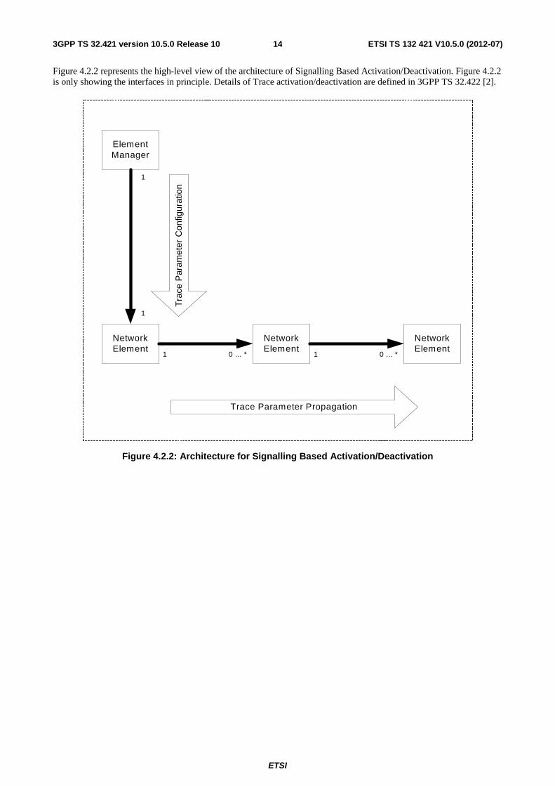
Figure 4.2.2 represents the high-level view of the architecture of Signalling Based Activation/Deactivation. Figure 4.2.2 is only showing the interfaces in principle. Details of Trace activation/deactivation are defined in 3GPP TS 32.422 [2].
ElementManager
Tra
ce P
aram
eter
Con
figur
atio
n
Trace Parameter Propagation
NetworkElement
NetworkElement
NetworkElement
0 ... *11 0 ... *
1
1
Figure 4.2.2: Architecture for Signalling Based Activation/Deactivation
ETSI
ETSI TS 132 421 V10.5.0 (2012-07)153GPP TS 32.421 version 10.5.0 Release 10
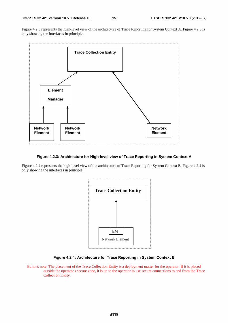
Figure 4.2.3 represents the high-level view of the architecture of Trace Reporting for System Context A. Figure 4.2.3 is only showing the interfaces in principle.
Figure 4.2.3: Architecture for High-level view of Trace Reporting in System Context A
Figure 4.2.4 represents the high-level view of the architecture of Trace Reporting for System Context B. Figure 4.2.4 is only showing the interfaces in principle.
Figure 4.2.4: Architecture for Trace Reporting in System Context B
Editor's note: The placement of the Trace Collection Entity is a deployment matter for the operator. If it is placed outside the operator's secure zone, it is up to the operator to use secure connections to and from the Trace Collection Entity.
Trace Collection Entity
EM
Network Element
Network Element
Network Element
Element
Manager
Network Element
Trace Collection Entity
ETSI
ETSI TS 132 421 V10.5.0 (2012-07)163GPP TS 32.421 version 10.5.0 Release 10
4.3 Service Level Tracing for IMS high level Architecture There are two ways in which to activate service level trace for IMS:
a) Trace activation at the UE, and
b) Trace activation at an IMS NE.
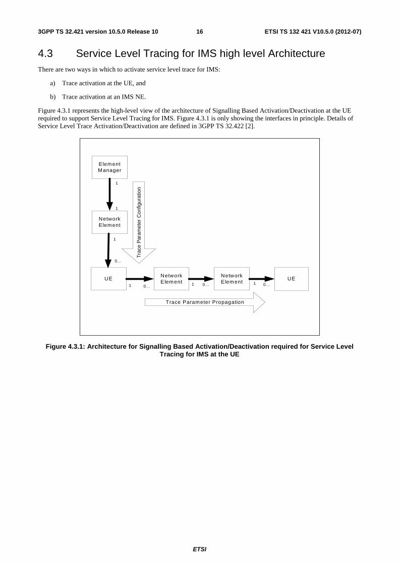
Figure 4.3.1 represents the high-level view of the architecture of Signalling Based Activation/Deactivation at the UE required to support Service Level Tracing for IMS. Figure 4.3.1 is only showing the interfaces in principle. Details of Service Level Trace Activation/Deactivation are defined in 3GPP TS 32.422 [2].
ElementManager
Tra
ce P
aram
eter
Con
figur
atio
n
NetworkElement
NetworkElement
UE1
1
1
NetworkElement
UE
Trace Parameter Propagation
0... 0... 0...1 1
1
0...
Figure 4.3.1: Architecture for Signalling Based Activation/Deactivation required for Service Level Tracing for IMS at the UE
ETSI
ETSI TS 132 421 V10.5.0 (2012-07)173GPP TS 32.421 version 10.5.0 Release 10
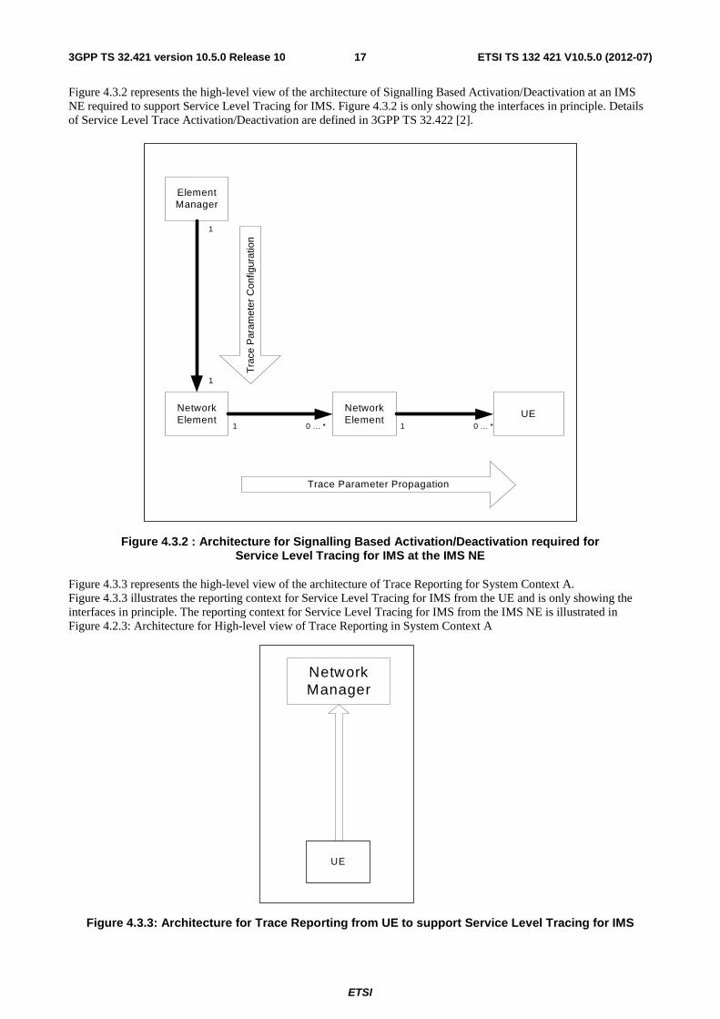
Figure 4.3.2 represents the high-level view of the architecture of Signalling Based Activation/Deactivation at an IMS NE required to support Service Level Tracing for IMS. Figure 4.3.2 is only showing the interfaces in principle. Details of Service Level Trace Activation/Deactivation are defined in 3GPP TS 32.422 [2].
ElementManager
Tra
ce P
aram
eter
Con
figur
atio
n
Trace Parameter Propagation
NetworkElement
UENetworkElement
0 ... *11 0 ... *
1
1
Figure 4.3.2 : Architecture for Signalling Based Activation/Deactivation required for Service Level Tracing for IMS at the IMS NE
Figure 4.3.3 represents the high-level view of the architecture of Trace Reporting for System Context A. Figure 4.3.3 illustrates the reporting context for Service Level Tracing for IMS from the UE and is only showing the interfaces in principle. The reporting context for Service Level Tracing for IMS from the IMS NE is illustrated in Figure 4.2.3: Architecture for High-level view of Trace Reporting in System Context A
NetworkManager
UE
Figure 4.3.3: Architecture for Trace Reporting from UE to support Service Level Tracing for IMS
ETSI
ETSI TS 132 421 V10.5.0 (2012-07)183GPP TS 32.421 version 10.5.0 Release 10
5 Trace requirements
5.1 General trace requirements The general high-level requirements for Trace, common to both Management activation/deactivation and Signalling Based Activation/Deactivation, are as follows:
- for the Maximum Level: Trace data encompassing all signalling messages on the different interfaces dedicated to the events of the traced subscriber or UE with their entire content (all IEs) shall be retrieved. The operator can then use an external system (e.g. an Operations System (OS) in TMN terminology) and decode specific information in line with operator requirements.
- for the Minimum Level: a selected subset of IEs shall be retrieved from the signalling interface messages. The Minimum Level provides support for the most common use cases (described in annex A).
- for the Medium Level: a selected Minimum Level subset of IEs from the signalling interface messages and a selected set of radio measurement IEs shall be retrieved.
- for the MaximumWithoutVendorSpecificExtension Level: it is the same as for Maximum level without vendor specific data.
- for the MediumWithoutVendorSpecificExtension Level: it is the same as for Medium level without vendor specific data.
- for the MinimumWithoutVendorSpecificExtension Level: it is the same as for Minimum level without vendor specific data.
The high-level requirements for Trace, specific for Service Level Tracing for IMS are as follows:
The following high-level OMA Service Level Tracing requirements apply. (refer to OMA Service Provider Environment Requirements [9]).
NOTE: Each referenced OMA requirement utilizes its OMA unique identifier within square brackets. Clarification provided to each requirement should be considered applicable to other OMA requirements using the same concepts.
- [SLT-HL-1] with the following clarification:
- The OMA term OMA Service Provider Environment (OSPE) shall be understood as PLMN.
- [SLT-HL-5] with the following clarification:
- In the context of Service Level Tracing for IMS a Minimum and Maximum level of detail of trace only applies. Trace data for Service Level Tracing at Minimum and Maximum level of detail shall include information associated to end user visible events
- [SLT-HL-6] with the following clarification:
- The OMA term service chain shall be understood as the relationship between appropriate IMS elements needed to support a service. The term service chain does not imply a strict sequence of events.
- The source of the logged trace information (e.g. IMS element including S-CSCF) shall be identifiable when the retrieved trace information is analyzed.
- [SLT-HL-10] with the following clarification:
- IMS elements that do not support Service Level Tracing shall not prohibit the propagation of the Trace Parameter Propagation.
- [SLT-OSR-1
- Multiple Service Level Trace instances shall be simultaneously supported by the PLMN and the UE (e.g. several services initiated from the same UE may each have a Trace Recording Session Reference)
ETSI
ETSI TS 132 421 V10.5.0 (2012-07)193GPP TS 32.421 version 10.5.0 Release 10
5.2 Requirements for Trace data The high level requirements for Trace data, common to both Management activation/deactivation and Signalling Based Activation/Deactivation, are as follows:
- The Trace records have to contain Information Elements or signalling messages from control signalling and/or the characteristics of the user data. The following list contains the Network Elements and the Traceable interfaces in the NEs where tracing is needed:
- MSC Server: A, Iu-CS, Mc and MAP (G, B, E, F, D, C) interfaces; CAP
- MGW: Mc, Nb-UP, Iu-UP
- HSS: MAP (C, D, Gc, Gr) Cx, S6a and S6d interfaces and location and subscription information
- EIR: MAP(F), S13, S13", MAP (Gf)
- SGSN: Gb, Iu-PS, Gn, MAP (Gr, Gd, Gf), CAP (Ge) Gs, S6d, S4, S3 and S13' interfaces
- GGSN: Gn, Gi and Gmb interfaces
- S-CSCF: Mw, Mg, Mr and Mi interfaces
- P-CSCF: Gm and Go interfaces
- RNC: Iu-CS, Iu-PS, Iur, Iub and Uu interfaces
- BM-SC: Gmb interface
- e-NodeB: S1-MME, X2, Uu
- MME: S1-MME, S3, S6a, S10, S11, S13
- Serving Gateway: S4, S5, S8, S11
- PDN Gateway: S2a, S2b, S2c, S5, S6b, Gx, S8, SGi
- A unique ID within a Trace Session shall be generated for each Trace Recording Session. This is called the Trace Recording Session Reference.
The high level requirements for Trace data applicable for Signalling Based Activation/Deactivation for Service Level Tracing for IMS, are as follows:
- In the context of Service Level Tracing for IMS Trace records have to contain Information Elements or signalling messages or end user visible event from control signalling and/or the characteristics of the user data. The following list contains the IMS NEs and the Traceable interfaces in the NEs where tracing is needed:
- HSS: Sh and Cx interfaces and location and subscription information;
- S-CSCF: ISC, Mw, Mg, Mr and Mi interfaces;
- P-CSCF: Gm and Go interfaces;
- I-CSCF: Mw and Cx interfaces;
- SIP AS: ISC interface;
- MRF: Mr interfaces;
- MGCF: Mg interfaces;
- BGCF: Mi interfaces;
- A unique ID within a Trace Session shall be generated for each Trace Recording Session. This is called the Trace Recording Session Reference. In the context of Service Level Tracing for IMS the Trace Recording Session shall be unique across all IMS NEs within a PLMN.
ETSI
ETSI TS 132 421 V10.5.0 (2012-07)203GPP TS 32.421 version 10.5.0 Release 10
Changes to existing NEs and interfaces above may be required. These changes would be dependent upon various 3GPP working groups and possibly other non-3GPP industry groups for completion of Trace Session Activation/Deactivation.
For a detailed description of NEs and interfaces above see 3GPP TS 23.002 [4].
5.3 Requirements for Trace activation
5.3.1 Requirements for Trace Session activation
The high level requirements for Trace Session activation, common to both Management activation and Signalling based activation), are as follows:
- In the case of a subscriber Trace, the Trace Session will be activated for a certain subscriber whose identification (IMSI in UTRAN/CS/PS) shall be known in the NEs where subscriber Trace is needed. In the case of E-UTRAN the IMSI shall not be included in the Trace Parameter Propagation data to the e-NodeB.
- In the case of a UE Trace, the Trace Session will be activated for a certain UE whose identification (IMEI or IMEISV) shall be known in the NEs where UE Trace is needed. In the case of E-UTRAN, neither the IMEI nor IMEISV shall be included in the Trace Parameter Propagation data to the e-NodeB - Trace Session activation shall be possible for both home subscribers and visiting subscribers.
- There are two methods for Trace Session activation: Management activation and Signalling activation.
- For an established call/session within a Network Element, it is optional for the Network Element to start a Trace Recording Session for the associated Subscriber or UE upon receipt of the Trace activation request from the EM.
- A globally unique ID shall be generated for each Trace Session to identify the Trace Session. This is called the Trace Reference. The method for achieving this is to divide the Trace reference into Country, Operator, and trace Id.
- Trace Session may be activated from the EM simultaneously to multiple NEs with the same Trace Reference (i.e. same Trace Session).
- The Trace Scope and Depth shall be specified within the control and configuration parameters during Trace Session activation.
- There can be cases in a NE when it receives multiple Trace Session activations for the same connection (e.g. simultaneous CS/PS connections). In these cases the starting time of the Trace Session Activation and the starting time of the first Trace Recording Session is the same using signalling based activation. For these cases there are two different cases for the Trace Session activation in a Network Element when it receives another Trace Session activation to the same subscriber or MS:
- If the Trace Reference is equal to an existing one, a new Trace Session shall not be started;
- If the Trace Reference is not equal to an existing one, a new Trace Session may be started.
- The EM shall always provide the trace control and configuration parameters to the appropriate NEs at the time of Trace Session activation.
- The Trace collection entity shall be notified, in case of theTrace Session activation has failed, by the response message with the specific cause (e.g. overload) from the NE on which the Trace Session activation failure happened.
The high-level requirements for Trace Session activation, specific to Signalling Based activation, are as follows:
- Signalling based activation shall be able to capture signalling messages as early in a session as possible, e.g. by means of a piggybacked trace invocation message in the case of a new connection or new bearer setup
For active users, it shall be possible to start trace recording when the trace order is received, by means of a distinct trace invocation message.
ETSI
ETSI TS 132 421 V10.5.0 (2012-07)213GPP TS 32.421 version 10.5.0 Release 10
The high-level requirements for Trace Session activation, specific to Management activation, are as follows:
- In the case of a subscriber Trace, the Trace Session will be activated for a certain subscriber whose identification (IMSI in UTRAN/CS/PS or Public User Identity in IMS) shall be known in the NEs where subscriber Trace is needed.
In the case of a Cell Traffic Trace, Trace Session activation should be possible for all calls active in a cell or multiple cells without knowledge of the UEs" identification (IMEI or IMEISV).
- In the case of a Cell Traffic Trace, Trace Sessions should be activated for all the NEs where Cell Traffic Trace is specified.
The high-level requirements for Trace Session activation specific for Service Level Tracing for IMS are as follows:
The following high-level OMA Service Level Tracing requirements apply [9]:
- [SLT-COM-2] with the following clarification:
- The OMA term component in the context of Service Level Tracing for IMS shall be understood as IMS NE and UE.
- [SLT-HL-2] with the following clarification:
- The OMA terms device and component shall be understood as UE and IMS NE, respectively;
- The IMS NEs HSS, P/I/S-CSCF, AS and UE, apply only.
- [SLT-AC-1] with the following clarification:
- The OMA term Authorised Actor shall be understood as NE, EM or NM;
- The OMA term trace indication shall be understood as Start Trigger Event.
- [SLT-AC-2] with the following clarification:
- The OMA term Service Provider shall be understood as Service Provider;
- The OMA term marking request shall be understood as the ability to send the Trace Parameter Configuration to either the UE or IMS NE.
- [SLT-AC-6]
- [SLT-AC-7] with the following clarification:
- The OMA term criteria shall be understood as Trace Configuration Parameters.
ETSI
ETSI TS 132 421 V10.5.0 (2012-07)223GPP TS 32.421 version 10.5.0 Release 10
5.3.2 Requirements for starting a Trace Recording Session
The high level requirements for starting a Trace Recording Session, common to both Management activation and Signalling based activation), are as follows:
- It is optional for the NE to start a Trace Recording Session if there are insufficient resources available within the NE.
- The Trace Recording Session Reference shall be unique within a Trace Session.
- The Trace Recording Session should be started after appropriate start trigger events are detected.
The high level requirements for starting a Trace Recording Session, specific to Management activation, are as follows:
- Each NE shall generate its own Trace Recording Session Reference (i.e., independent Trace Recording Sessions).
- Each NE shall start the Trace Recording Session based upon the Trace control and configuration parameters received by the NE in the Trace Session activation.
- In the case of a trace other than Cell Traffic Trace, the correlation of Trace data will be done with a Trace Reference and IMSI / IMEI / IMEISV / Public User Identity.
- The Trace Recording Session can start only when the IMSI (in the case of a subscriber trace), the IMEI / IMEISV (in case of UE trace) or Public User Identity (in the case of IMS) is made available in the NE. In order to trace the early phases of the call the IMSI (in case of subscriber trace), the IMEI / IMEISV (in case of UE trace) or Public User Identity (in case of IMS) shall be made available to the NE as soon as practically possible. E.g. the IMSI and IMEI / IMEISV shall be made available to both Serving RNC and Drift RNC.
- In the case of E-UTRAN the Core Network node that triggers a Trace Recording Session to E-UTRAN shall either:
• provide a trace log including Trace Reference, Trace Recording Session Reference and the identity of the UE (i.e. IMSI or IMEI(SV) to the Trace Collection Entity, or
• provide a notification including Trace Reference, Trace Recording Session Reference and the identity of the UE (i.e. IMSI or IMEI(SV)) to the Trace Collection Entity.
- In the case of a Cell Traffic Trace, the Trace Recording Session should start upon the Trace control and configuration parameters being received by the NEs in the Trace Session activation and the presence of call activity. Furthermore, the the Core Network node that handles the traced session should be requested to:
• provide a trace log including Trace Reference, Trace Recording Session Reference and the identity of the UE (i.e. IMSI or IMEI(SV) to the Trace Collection Entity, or
• provide a notification including Trace Reference, Trace Recording Session Reference and the identity of the UE (i.e. IMSI or IMEI(SV)) to the Trace Collection Entity.
The high-level requirements for starting a Trace Recording Session, specific for Service Level Tracing for IMS are as follows:
The following high-level OMA Service Level Tracing requirements apply [9]:
- [SLT-HL-3] with the following clarification:
- The OMA term marked shall be understood as UE or IMS NE that has previously received Trace Parameter Configuration information.
- The OMA term marking shall be understood as Trace Parameter Configuration.
- [SLT-COM-3] with the following clarification:
- The OMA term indication for SLT shall be understood as Start Trigger Event
- The OMA terms inbound and outbound protocols shall be understood as, for example, inbound SIP and outbound Diameter.
ETSI
ETSI TS 132 421 V10.5.0 (2012-07)233GPP TS 32.421 version 10.5.0 Release 10
5.4 Requirements for Trace deactivation
5.4.1 Requirements for Trace Session deactivation
The high level requirements for Trace Session deactivation, common to both Management deactivation and Signalling based deactivation, are as follows:
- The Trace Session shall be deactivated using the Trace Reference specified for the Trace Session activation.
- The Trace Session shall be deactivated in all those NEs where it was activated.
- The deactivation of a Trace Session during a Trace Recording Session within a NE may take place anytime after the NE receives the deactivation request until the end of the current Trace Recording Session related to the traced Subscriber or UE.
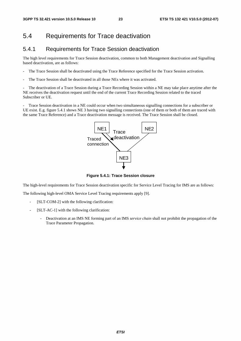
- Trace Session deactivation in a NE could occur when two simultaneous signalling connections for a subscriber or UE exist. E.g. figure 5.4.1 shows NE 3 having two signalling connections (one of them or both of them are traced with the same Trace Reference) and a Trace deactivation message is received. The Trace Session shall be closed.
NE1 NE 2
NE 3
Traced connection
Trace deactivation
Figure 5.4.1: Trace Session closure
The high-level requirements for Trace Session deactivation specific for Service Level Tracing for IMS are as follows:
The following high-level OMA Service Level Tracing requirements apply [9].
- [SLT-COM-2] with the following clarification:
- [SLT-AC-1] with the following clarification:
- Deactivation at an IMS NE forming part of an IMS service chain shall not prohibit the propagation of the Trace Parameter Propagation.
ETSI
ETSI TS 132 421 V10.5.0 (2012-07)243GPP TS 32.421 version 10.5.0 Release 10
5.4.2 Requirements for stopping a Trace Recording Session
The high level requirements for stopping a Trace Recording Session, common to both Management deactivation and Signalling based deactivation, are as follows:
- The Trace Recording Session should be stopped after appropriate stop trigger events are detected.
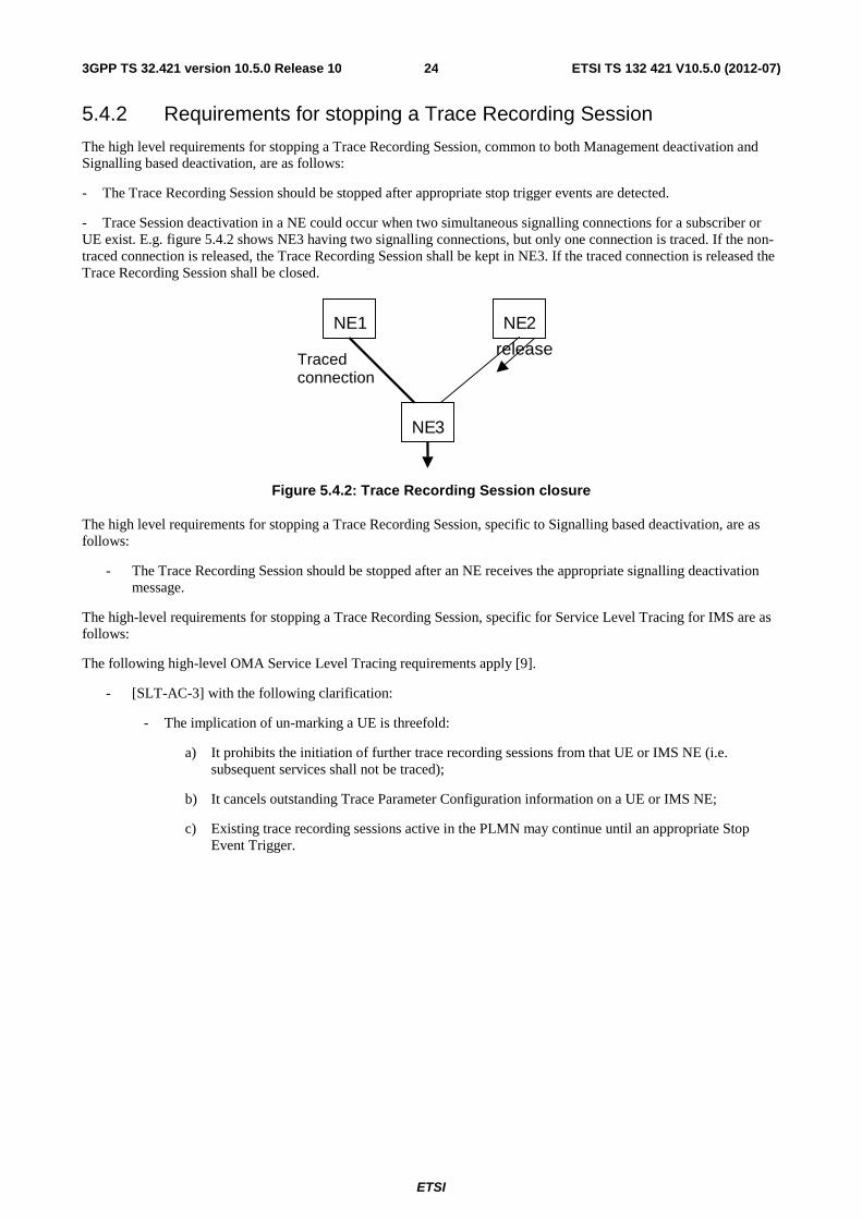
- Trace Session deactivation in a NE could occur when two simultaneous signalling connections for a subscriber or UE exist. E.g. figure 5.4.2 shows NE3 having two signalling connections, but only one connection is traced. If the non-traced connection is released, the Trace Recording Session shall be kept in NE3. If the traced connection is released the Trace Recording Session shall be closed.
NE1 NE 2
NE 3
release Traced
connection
Figure 5.4.2: Trace Recording Session closure
The high level requirements for stopping a Trace Recording Session, specific to Signalling based deactivation, are as follows:
- The Trace Recording Session should be stopped after an NE receives the appropriate signalling deactivation message.
The high-level requirements for stopping a Trace Recording Session, specific for Service Level Tracing for IMS are as follows:
The following high-level OMA Service Level Tracing requirements apply [9].
- [SLT-AC-3] with the following clarification:
- The implication of un-marking a UE is threefold:
a) It prohibits the initiation of further trace recording sessions from that UE or IMS NE (i.e. subsequent services shall not be traced);
b) It cancels outstanding Trace Parameter Configuration information on a UE or IMS NE;
c) Existing trace recording sessions active in the PLMN may continue until an appropriate Stop Event Trigger.
ETSI
ETSI TS 132 421 V10.5.0 (2012-07)253GPP TS 32.421 version 10.5.0 Release 10
5.5 Requirements for Trace Data reporting The high level requirements for Trace Data reporting, common to both Management activation/deactivation and Signalling Based Activation/Deactivation, are as follows (Trace record contents, file formats and file transfer mechanisms are defined in 3GPP TS 32.423 [3]):
- Trace records should be generated in each NE where a Trace Session has been activated and a Trace Recording Session has been started.
- Format of the Trace records sent over Itf-N shall be XML based on the Schema in TS 32.423 [3].
- Trace records should be transferred on the Itf-N to the Network Manager using one of two approaches: direct transfer from NE to NM or transfer from NE to NM via EM.
- Trace records may also be transferred to an external IP address (received in Trace Control and Configuration Parameters) in 3 ways:
1. Direct transfer from NE to IP address
2. Transfer from NE to IP address via EM
3. Transfer from NE to EM. The EM notifies the holder of the IP address that collects the files.
The high-level requirements for stopping a Trace Recording Session, specific for Service Level Tracing for IMS are as follows:
The following high-level OMA Service Level Tracing requirements apply [9].
- [SLT-HL-4] with the following clarification:
- Encoded trace information shall be Standard File Format. Standard File Format may not be applicable for encoded trace information at the UE.
- [SLT-HL-7] with the following clarification:
- An instance of a service level trace across a PLMN shall be uniquely identifiable using the Trace Recording Session Reference.
- [SLT-HL-8]
- [SLT-COM-1] with the following clarification:
- Time stamping alone to determine the sequence of IMS NEs performing trace within the service chain shall not be used;
- Statistical information shall not be included as part of IMS NE characteristics;
- Service Level Tracing shall apply only to the IMS session layer and not the underlying transport layers.
- [SLT-COM-4] with the following clarification:
- An IMS NE, in addition to providing trace information specific to a service that it has traced, may also make available other information, for example, timestamp and throughput information.
- [SLT-NI-1] with the following clarification:
- The UE shall expose a standardised interface for Trace Parameter Configuration and the retrieval of trace information. This interface may not be standardized by 3GPP.
- [SLT-NI-2] with the following clarification:
- An IMS NE shall transfer Trace records in Standard File Formats via Itf-N.
For transfer of Trace records via Itf-N, FTP or secure FTP shall be used.
The transfer of Trace record from the UE is For Further Study.
ETSI
ETSI TS 132 421 V10.5.0 (2012-07)263GPP TS 32.421 version 10.5.0 Release 10
5.6 Requirements for Privacy and Security The high-level requirements for privacy and security, specific for Service Level Tracing for IMS are as follows:
The following high-level OMA Service Level Tracing requirements apply [9].
- [SLT-PRV-1] with the following clarification:
- Privacy shall be applied across the appropriate Trace Itf-N.
- [SLT-SEC-1]
- [SLT-SEC-2]
- [SLT-SEC-3] with the following clarification:
- It may not be possible to retrieve Trace information from IMS NEs from outside the PLMN where the IMS NEs reside.
- [SLT-IOP-1] with the following clarification:
- The propagation of the Trace Parameter Configuration and the Start Trigger event shall be prohibited by the PLMN when e.g. the SIP AS is hosted outside a PLMN.
As the radio access nodes in E-UTRAN are outside an operator"s secure domain, the following requirement applies for E-UTRAN as described in 3GPP TS 33.401 [10]:
- [SET-SEC-1] Keys stored inside eNBs shall never leave a secure environment within the eNB. When security key(s) transported on control signalling messages are included in the trace file, the key value(s) shall be removed and replaced with the value 'Unavailable'.
5.7 Requirements for Charging The high-level requirements for charging, specific for Service Level Tracing for IMS are as follows:
The following high-level OMA Service Level Tracing requirements apply [9].
- [SLT-CRG-1]
ETSI
ETSI TS 132 421 V10.5.0 (2012-07)273GPP TS 32.421 version 10.5.0 Release 10
5.8 Use cases for Trace The operator can use Subscriber and UE Trace for numerous purposes. However, the use cases for Trace can be divided into two basic categories:
- Troubleshooting use cases cover situations where the operator is solving an existing problem in his network;
- Validation testing use cases cover situations where the operator is not solving a known problem but merely analysing, fine-tuning or optimising his network.
A more detailed description for the following use cases for Subscriber and UE Trace can be found in annex A:
- Interoperability checking between UE from different vendors;
- QoS profile checking for a subscriber after a subscriber complaint;
- Malfunctioning UE;
- Checking radio coverage in a certain area;
- Testing new features;
- Fine-tuning and optimisation of algorithms or procedures.
The operator can use Service Level Tracing for IMS for numerous purposes. However, the use cases for Trace can be divided into two basic categories:
- Troubleshooting use cases cover situations where the operator is solving existing problems with services offered to their subscribers.
- Validation testing use cases cover situations where the operator is not solving a known problem but performing service regression and automated service testing.
A more detailed description of the following use cases for Service Level Tracing can be found in annex A:
- Automated testing of service provider services;
- Regression testing following a network fix;
- Service fault localization within a Service Provider"s network;
- Service fault localization when a service is hosted by a third party Service Provider.
ETSI
ETSI TS 132 421 V10.5.0 (2012-07)283GPP TS 32.421 version 10.5.0 Release 10
6 Requirements for managing MDT
6.1 Business Level Requirements REQ-MDT-CON-1 The Operator shall be able to collect measurements for Network Performance Management purposes from UEs within their network.
REQ-MDT-CON-2 The collected measurements shall be made available in a centralised entity.
REQ-MDT-CON-3 Operator shall be able to select specific set of subscribers for the measurement collection based on IMSI.
REQ-MDT-CON-4 Operator shall be able to select specific set of devices for the measurement collection based on IMEI(SV).
REQ-MDT-CON-5 Operator shall be able to select specific set of devices for the measurement collection based on geographical area.
REQ-MDT-CON-6 Operator shall be able to select specific set of devices for the measurement collection based on device capabilities.
REQ-MDT-CON-7 Operator shall be able to select specific set of subscribers based on IMSI and a geographical areas for the measurement collection.
REQ-MDT-CON-8 Operator shall be able to select specific set of devices based on IMEI(SV) and a geographical area for the measurement collection.
REQ-MDT-CON-9 Operator shall be able to configure set of device capabilities and a geographical area for the measurement collection.
REQ-MDT-CON-10 Operator shall be able to select specific set of subscribers based on IMSI and a set of device capabilities and a geographical area for the measurement collection.
REQ-MDT-CON-11 Operator shall be able to select specific set of device IMEI(SV) and capabilities and a geographical area for the measurement collection.
REQ-MDT-CON-12 Operator shall be able to select set of subscribers based on IMSI and a set of device capabilities for the measurement collection
REQ-MDT-CON-13 Operator shall be able to select specific set of device IMEI(SV) and capabilities for the measurement collection.
REQ-MDT-CON-14 The operator shall be able to configure the duration of the measurement collection
REQ-MDT-CON-15 The operator shall be able to configure the UE measurement types and events for collection
REQ-MDT-CON-16 The operator shall be able to configure the type of UE measurement reporting and log formats i.e. raw measurement results or type of measurement aggregation (e.g. statistical aggregation of raw measurement results, sampling of raw measurement results, etc.)
REQ-MDT-CON-17 The management of MDT shall be independent from the management of SON functionalities
REQ-MDT-CON-18 The management of UE based network performance measurements shall allow the network operator to control whether or not it is possible to link a measurement result and related information (e.g. location information) to a real user ID such as an IMSI/IMEI.
REQ-MDT-CON-19 An operator that uses more than one PLMN shall be able to activate MDT in each of those PLMN.
NOTE: MDT data can be collected by a network operator operating with a set of PLMN_IDs in different countries, but under the same common user privacy agreement in different countries in the same legal privacy protection domain.
ETSI
ETSI TS 132 421 V10.5.0 (2012-07)293GPP TS 32.421 version 10.5.0 Release 10
REQ-MDT-CON-20 The TCE used to collect MDT data shall be controlled by the same operator, as the operator that the user has given his consent to.
6.2 Specification level requirements All requirements are valid for Logged MDT and Immediate MDT functionality if not mentioned otherwise:
REQ-MDT-FUN-01 It shall be possible to collect UE measurements based on one or more IMEI(SV) number.
REQ-MDT-FUN-02 It shall be possible to collect UE measurements based on one or more IMSI number.
REQ-MDT-FUN-03 It shall be possible to collect UE measurement logs preceding and following a particular event (e.g. radio link failure).
REQ-MDT-FUN-04 Each UE measurement result shall be linked to a time stamp. Accuracy of time information (absolute time, relative time) is FFS in RAN. (Editor"s Note: FFS in RAN)
REQ-MDT-FUN-05 The solutions for collecting UE measurements for the purpose of minimization of drive tests shall be able to work independently from SON support in the network.
REQ-MDT-FUN-06 It shall be possible to collect UE measurements in one or more cells or TA/RA/LA.
REQ-MDT-FUN-07 It shall be possible to collect UE measurements based on one or more IMSI in one or more cells or TA/RA/LA.
REQ-MDT-FUN-08 It shall be possible to collect UE measurements based on one or more IMEI(SV) in one or more cells or TA/RA/LA.
REQ-MDT-FUN-09 It shall be possible to configure UE measurement types, and triggering conditions under which UE measurements would be collected for MDT.
REQ-MDT-FUN-10 Void.
REQ-MDT-FUN-11 It shall be possible to configure the condition of MDT data collection based on certain device capability information in one or more cells or in TA/RA/LA.
REQ-MDT-FUN-12 It shall be possible to configure MDT data collection based on one or more IMSI in one or more cells or TA/RA/TA with a set of device capability information.
REQ-MDT-FUN-13 It shall be possible to configure MDT data collection based on one or more IMEI(SV) in one or more cells or TA/RA/TA with a set of device capability information.
REQ-MDT-FUN-14 It shall be possible to configure MDT data collection based on one or more IMEI(SV) with a set of device capability information.
REQ-MDT-FUN-15 It shall be possible to configure MDT data collection based on one or more IMSI with a set of device capability information.
REQ-MDT-FUN-16 It shall be possible to activate a Trace Session for MDT data collection (or UE measurement collection for MDT purpose) independently from other mobility related performance measurements and call trace collection.
REQ-MDT-FUN-17 It shall be possible to deactivate MDT data collection by using Trace Reference.
REQ-MDT-FUN-18 It shall be possible to create a combine Trace Session for UE measurement collection and for subscriber and equipment/cell trace.
REQ-MDT-FUN-19 Void.
REQ-MDT-FUN-20 MDT activation shall be supported for a UE belonging to any PLMN of the same Operator.
REQ-MDT-FUN-21 The PLMN where TCE collecting MDT data resides shall match the RPLMN of the UE providing the MDT data.
NOTE: There may be regulatory obligation to delete MDT data after processing.
ETSI
ETSI TS 132 421 V10.5.0 (2012-07)303GPP TS 32.421 version 10.5.0 Release 10
Annex A (informative): Trace use cases
A.1 Use case #1: multi-vendor UE validation
A.1.1 Description The aim of this use case is to check how different vendor's UEs are working (e.g. in field testing) in the mobile network or to get detailed information on the UE.
The study can be started by an initiative from operator for verification of UE from different vendors (e.g. testing how the UE fulfils the requirements set by the standards).
The operator can perform the test using test UEs or tracing subscribers' mobiles.
A.1.2 Example of required data for this use case The Trace parameters required to cover use case #1 are listed below:
- Tracing is needed in the Radio Network (RNC) or in the Core Network (MSS, SGSN);
- The identification of the Trace case shall be IMEI or IMEISV (and possibly IMSI);
- The level of details usually is to get the most important IEs from the signalling messages (Medium Level) or all messages with their encoded IEs (Maximum Level).
The traceable protocols are:
- In RNC: RRC, NBAP, RNSAP, RANAP.
- In MSS/SGSN: DTAP messages.
A.2 Use case #2: subscriber complaint
A.2.1 Description The aim of this use case is to check how the complaining subscriber's services are working, to get information on the services in order to find out the reason for the complaint.
The study can be started after a subscriber is complaining at his/her home or visited operator that some of the service to which he/she subscribed is not working. E.g. the subscriber:
- cannot make calls;
- cannot use some supplementary service;
- does not get the negotiated QoS level (e.g. Mobile subscriber activates video-streaming application to watch the latest sport events and every time the subscriber tries to connect to the service the system disconnects the subscriber's UMTS bearer).
As the Trace is activated for a subscriber, the signalling based Trace Session activation shall be used, as the location of the subscriber is not known.
ETSI
ETSI TS 132 421 V10.5.0 (2012-07)313GPP TS 32.421 version 10.5.0 Release 10
A.2.2 Example of required data for this use case The Trace parameters required to cover the use case #2 are listed below:
- The list of NEs where tracing may be needed depends on the service being complained about by the subscriber. For this use case, tracing should be possible in all network elements, such as: HSS, MSS, RNC, MGW, SGSN, GGSN.
- The identification of the subscriber in a Trace is IMSI in UTRAN/CS/PS. The identification of the UE in a Trace is IMEI or IMEISV.
- The data includes those Information Elements from the signalling messages, which are related to the service(s) being complained about by the subscriber (Medium Level).
Example cases, which can be the basis for subscriber complaint:
1. The subscriber's CS call is misrouted
This illustrates an instance where a subscriber complains that his calls are being cross-connected (or misrouted). Such a complaint involves setting up a Trace at all the 3GPP standardised interfaces being handled by the MSC. However, the Trace functionality shall not cover MSC internal or vendor proprietary interfaces. The Trace record shall need to have the dialled number and connected number.
2. The subscriber's call is dropped
Tracing data is required from the radio network (UTRAN) or from the core network (MSS, SGSN, GGSN). In the radio network the radio coverage shall be checked. See use case #4 (checking radio coverage). Beside the radio coverage, other information can be useful as well, like RLC parameter, power information (OLPC or RRC measurement report), error ratios (BLER / BER, SDU error ratio), etc. Tracing in the core network is needed also, if the problem is not in the radio network. E.g. in case of PS domain the call can be dropped by the application due to the long delays or congestions in TCP layer or due to bad QoS. Thus in SGSN the requested and negotiated QoS parameters should be included in the Trace record.
3. The received QoS level is less than the negotiated level.
To be able to solve the possible problem Tracing data is required from HSS, SGSN, GGSN, and UTRAN. Furthermore in case of problem in CS calls tracing in MGW shall be performed.
From HSS Trace data the operator can monitor whether the subscriber's authentication to the network is successful, and what kind of QoS parameters are allowed to the subscriber. From SGSN Trace data the operator can monitor PDP context creation request from mobile. Request seems to contain legal QoS profile (incl. Maximum bandwidth, guaranteed bandwidth etc) and the local resources in SGSN are available to provide the service as requested by the subscriber. From UTRAN Trace data the operator can monitor whether the maximum bandwidth and guaranteed bandwidth, requested by SGSN, acceptable for UTRAN. Thus to check whether UTRAN can provide and maintain the requested radio access bearer services. From GGSN Trace data the operator can monitor PDP context activation between SGSN and GGSN. If the problem is in the CS domain the MGW Trace can provide the QoS data.
ETSI
ETSI TS 132 421 V10.5.0 (2012-07)323GPP TS 32.421 version 10.5.0 Release 10
A.3 Use case #3: malfunctioning UE
A.3.1 Description The aim of this use case is to check a UE, which is not working correctly.
The study can be initiated by the operator when he/she suspects that a UE not working according to the specifications or he/she would like to get more information on a specific UE, which is on the grey or black EIR list.
A.3.2 Example of required data for this use case The Trace parameters required to cover the use case #3 are listed below:
- UE Tracing may be needed in the Radio Network (UTRAN) or in the Core Network (MSS, SGSN).
- The identification of the subscriber in a Trace is IMSI. The identification of the UE in a Trace is IMEI or IMEISV.
- The level of details depends on the operator needs (either Minimum Level or Medium Level).
The malfunction of UE in UTRAN can occur in different places. The problem can be in basic RRC and RANAP signalling, Radio Bearer procedures, Handover procedures, Power control etc.
Therefore, all RRC, RANAP, NBAP, RNSAP signalling procedures, transmission powers, error ratios (BLER / BER, SDU error ratio) and retransmission can be included in the Trace records.
A.4 Use case #4: checking radio coverage
A.4.1 Description This use case aims at checking the radio coverage on a particular network area.
This study can be started by an initiative from operator for testing radio coverage on a particular geographical area following network extension for instance (e.g. new site installation).
The operator can perform a drive test on the new site area, and check that radio coverage is correct, or may collect Cell Traffic Trace data on all of the cells active in the area of interest.
A.4.2 Example of required data to cover use case #4 The DL radio coverage can be checked using the values of CPICH Ec/No and RSCP measured by the mobile on the cells in the active set and the monitored set. These measurements are sent to the RNC trough the RRC message MEASUREMENT REPORT.
The UTRAN Trace record intra frequency measurement contains the required information.
The UTRAN Trace record inter frequency, and inter RAT measurements can also be used to check radio coverage with other frequencies or systems.
After a network extension, the operator can check that Ec/No and RSCP levels on the new site area are the expected ones, and there is no coverage hole.
The following Trace parameters are required to cover use case #4:
- The type of NE to Trace is RNC.
- The identification of the subscriber in a Trace is IMSI. The identification of the UE in a Trace is IMEI or IMEISV.
ETSI
ETSI TS 132 421 V10.5.0 (2012-07)333GPP TS 32.421 version 10.5.0 Release 10
- In the case of a Cell Traffic Trace, the identification of the cells where Trace data is to be collected.
- The Trace data to retrieve shall contain the messages with all IEs that are relevant for radio coverage.
A.5 Use case #5: testing a new feature
A.5.1 Description This use case aims at testing the implementation of a new feature in the network before its general deployment. The functionality can be either a standard feature or a vendor/operator specific feature.
This study is started by an initiative from the operator.
The operator can perform a drive test on the area where the feature is introduced, and check its good behaviour as well as its benefits, in term of quality or capacity. He can also rely on subscribers' Trace data when they use the feature to be tested.
A.5.2 Example of required data to cover use case #5 Depending on the feature, the list of NEs to Trace, as well as the level of details can be different.
For a feature concerning Core and UTRAN networks, for instance hard handover, SRNS relocation, or new UMTS bearer service, the operator needs to activate Trace on several NEs.
Then, the operator can be interested in:
- Only the protocol messages generated by the feature; or
- The impact of the new feature introduction on the network, for instance, the radio coverage, the capacity, the quality, or the behaviour of the existing algorithms.
In this last case, the operator needs more detailed data, for instance messages with all (Maximum Level) or part of the IEs (Minimum Level).
The following Trace parameters are required to cover use case #5:
- The types of NEs to Trace are NEs that can be traced related to the feature.
- The identification of the subscriber in a Trace is IMSI. The identification of the UE in a Trace is IMEI or IMEISV.
- The Trace data to retrieve can be either only the protocol messages (Maximum Level) or the messages with all or part of the IEs (Minimum Level).
A.6 Use case #6: fine-tuning and optimisation of algorithms/procedures
A.6.1 Description Subscriber and UE Trace is part of the optimisation process. Trace data are used to get feedback on the network quality and capacity after optimisation operations like parameter fine-tuning, or new network design. Each intervention to improve the network behaviour can be confirmed both by measurement data and Trace data.
This study is started following an initiative from the operator.
The operator can perform a drive test on the area and/or activate a Cell Traffic Trace where the optimisation has been performed, and check its good behaviour as well as its impact on the network. He can also rely on subscribers' Trace data when they use the network to be optimised.
ETSI
ETSI TS 132 421 V10.5.0 (2012-07)343GPP TS 32.421 version 10.5.0 Release 10
A.6.2 Example of required data to cover use case #6 Depending on the optimisation operation, the list of NEs to Trace, as well as the level of details can be different. But generally, fine-tuning activities like scrambling code plan, handover and relocation algorithms, or call admission algorithm optimisation concern a very specific part of the network.
To cover this use case, the operator is usually searching for the highest level of details, on specific NEs.
The following Trace parameters are required to cover use case #6:
- The types of NEs to Trace are any NE that can be traced related to the network to be optimised.
- The identification of the subscriber in a Trace is IMSI. The identification of the UE in a Trace is IMEI or IMEISV.
- In the case of a Cell Traffic Trace, the identification of the cells where Trace data is to be collected.
- The Trace data to retrieve are the messages in encoded format with all (Maximum Level) or part of the IEs (Minimum Level).
A.7 Use case #7: Automated testing of Service Provider services
A.7.1 Description For a detailed description of this use-case see OMA Service Provider Environment Requirements [9].
A.8 Use case #8: Regression testing following a network fix
A.8.1 Description For a detailed description of this use-case see OMA Service Provider Environment Requirements [9].
A.9 Use case #9: Service fault localization within a Service Provider network
A.9.1 Description For a detailed description of this use-case see OMA Service Provider Environment Requirements [9].
A.10 Use case #10: Service fault localization when a service is hosted by a third party Service Provider
A.10.1 Description For a detailed description of this use-case see OMA Service Provider Environment Requirements [9].
ETSI
ETSI TS 132 421 V10.5.0 (2012-07)353GPP TS 32.421 version 10.5.0 Release 10
Annex B (informative): Change history
Change history Date TSG # TSG Doc. CR Rev Subject/Comment Cat Old New Jun 2002 SA_16 SP-020330 -- -- Submitted to SA #16 for Information -- 1.0.0 Dec 2002 SA_18 SP-020755 -- -- Submitted to SA #18 for Approval -- 2.0.0 6.0.0 Mar 2003 SA_19 SP-030147 0001 -- Corrections to Trace requirements - alignment with SA2's 23.002 F 6.0.0 6.1.0 Dec 2003 SA_22 SP-030612 0002 -- Correction of IMS subscriber identification for Trace F 6.1.0 6.2.0 Mar 2004 SA_23 SP-040116 0003 -- Correction in Trace high level architecture F 6.2.0 6.3.0 Sep 2004 SA_25 SP-040542 0004 -- Removal of GERAN from Rel-6 32.42x series of Trace specifications F 6.3.0 6.4.0 Dec 2004 SA_26 SP-040770 0005 -- Remove requirement for having ASN.1 as Trace record format C 6.4.0 6.5.0 Dec 2004 SA_26 SP-040770 0006 -- Remove in Rel-6 the signalling based Trace in IMS due to missing SIP
signalling support from CN1/IETF C 6.4.0 6.5.0
Mar 2005 SA_27 SP-050043 0007 -- Remove ambiguity on the file format for trace data at the Network Elements (NEs)
F 6.5.0 6.6.0
Mar 2005 SA_27 SP-050043 0008 -- Correction to the Scope F 6.5.0 6.6.0 Mar 2005 SA_27 SP-050043 0009 -- Correct the list of interfaces trace parameter – Align with 32.422 and
32.423 F 6.5.0 6.6.0
Jun 2005 SA_28 SP-050294 0010 -- BM-SC Network Element and Gmb interface addition for MBMS tracing B 6.6.0 6.7.0 Sep 2005 SA_29 SP-050623 0011 -- Add support for UTRAN TDD - Declare RAT Type B 6.7.0 7.0.0 Mar 2006 SA_31 SP-060100 0012 -- Introduction of Service Level Tracing for IMS B 7.0.0 7.1.0 Sep 2006 SA_33 SP-060552 0013 -- Add Cell Traffic Trace capability to 32.421 Trace concepts and
requirements C 7.1.0 7.2.0
Sep 2007 SA_37 SP-070614 0014 -- Add extended trace depth to include Vendor Specific Extension (VSE) C 7.2.0 8.0.0 Sep 2007 SA_37 SP-070614 0015 -- Add LTE nodes and interfaces C 7.2.0 8.0.0 Mar 2008 SP-39 SP-080069 0016 -- Add trace functionality for E-UTRAN B 8.0.0 8.1.0 Mar 2008 SP-39 SP-080069 0017 -- Add trace activation failure response B 8.0.0 8.1.0 Jun 2008 SP-40 SP-080329 0018 -- Introduction of UE identifiers for trace in E-UTRAN C 8.1.0 8.2.0 Sep 2008 SP-41 SP-081260 0019 -- Change the description for Trace Recording Session Reference C 8.2.0 8.3.0 Dec 2008 SP-42 SP-080846 0020 -- Correction of trace depth extensions F 8.3.0 8.4.0 Jun 2009 SP-44 SP-090289 0022 -- Add missing Trace Interface for SGSN and HSS list F 8.4.0 8.5.0 Dec 2009 - - - - Update to Rel-9 version (MCC) -- 8.5.0 9.0.0 Mar 2010 SP-47 SP-100034 0024 -- Align the handling of security keys for E-UTRAN with 33.401 A 9.0.0 9.1.0 Sep 2010 SP-49 SP-100492 0025 -- Adding Requirements for managing UE based network performance
measurements F 9.1.0 10.0.0
Dec 2010 SP-50 SP-100833 0026 1 Add requirements for trace data of S13, S13' interfaces C 10.0.0 10.1.0 Dec 2010 SP-50 SP-100833 0027 1 Correcting the Identification of IMS Subscriber Tracing - Align with 32.422 F 10.0.0 10.1.0 Mar 2011 SP-51
SP-110102 0029 3 Add requirements for security and privacy of UE-based Network Performance Measurements / MDT as required by SA3 (Security) C
10.1.0 10.2.0
Mar 2011 SP-51 SP-110102 0030 -
Change "UE based network performance measurements" to "MDT" - Align cross-3GPP terminology on MDT work F
10.1.0 10.2.0
Mar 2011 SP-51 SP-110095 0031 - Add the missing interfaces for EIR B 10.1.0 10.2.0 Mar 2011 SP-51 SP-110095 0032 1 Clarify and cleanup MDT requirements F 10.1.0 10.2.0 Sep 2011 SP-53 SP-110537 0034 1 MDT for multiple PLMN IDs F 10.2.0 10.3.0 Dec 2011 SP-54 SP-110715 0038 2 Introduce the missing MDT data controller user privacy requirements F 10.3.0 10.4.0 Dec 2011 SP-54 SP-110715 0045 - Add MDT data deletion note F 10.3.0 10.4.0 Dec 2011 SP-54
SP-110715 0050 2 Correction of figure 4.2.1 Architecture for Management Based Activation/Deactivation F
10.3.0 10.4.0
June-2012 SP-56 SP-120368 0057 1 Remove MDT Country Restriction F 10.4.0 10.5.0
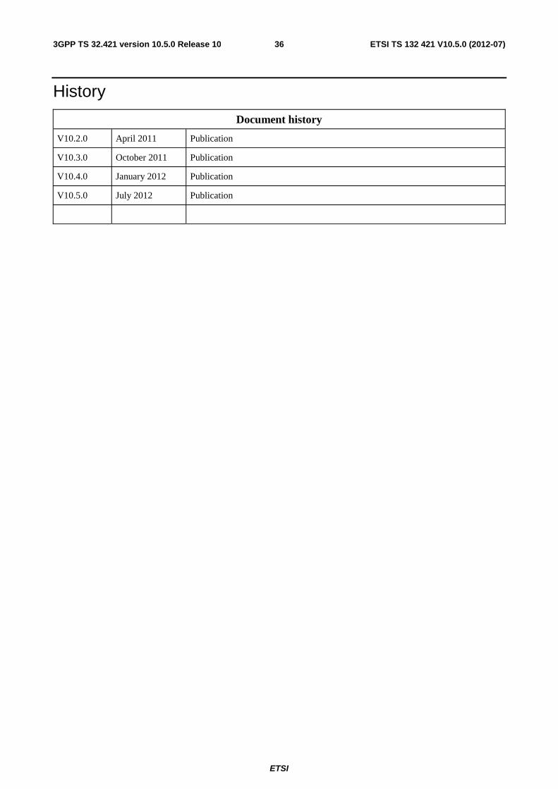
ETSI
ETSI TS 132 421 V10.5.0 (2012-07)363GPP TS 32.421 version 10.5.0 Release 10
History
Document history
V10.2.0 April 2011 Publication
V10.3.0 October 2011 Publication
V10.4.0 January 2012 Publication
V10.5.0 July 2012 Publication