Embed Size (px)
Citation preview
ETSI TS 129 527 V8.3.0 (2009-04)
Technical Specification
Digital cellular telecommunications system (Phase 2+);Universal Mobile Telecommunications System (UMTS);
TISPAN;Endorsement of the SIP-ISUP Interworking between the IP
Multimedia (IM) Core Network (CN) subsystem and Circuit Switched (CS) networks
[3GPP TS 29.163 (Release 7), modified] (3GPP TS 29.527 version 8.3.0 Release 8)
GLOBAL SYSTEM FOR MOBILE COMMUNICATIONS
R
ETSI
ETSI TS 129 527 V8.3.0 (2009-04) 1 3GPP TS 29.527 version 8.3.0 Release 8
Reference RTS/TSGC-0329527v830
Keywords GSM, UMTS
ETSI
650 Route des Lucioles F-06921 Sophia Antipolis Cedex - FRANCE
Tel.: +33 4 92 94 42 00 Fax: +33 4 93 65 47 16
Siret N° 348 623 562 00017 - NAF 742 C
Association à but non lucratif enregistrée à la Sous-Préfecture de Grasse (06) N° 7803/88
Important notice
Individual copies of the present document can be downloaded from: http://www.etsi.org
The present document may be made available in more than one electronic version or in print. In any case of existing or perceived difference in contents between such versions, the reference version is the Portable Document Format (PDF).
In case of dispute, the reference shall be the printing on ETSI printers of the PDF version kept on a specific network drive within ETSI Secretariat.
Users of the present document should be aware that the document may be subject to revision or change of status. Information on the current status of this and other ETSI documents is available at
http://portal.etsi.org/tb/status/status.asp
If you find errors in the present document, please send your comment to one of the following services: http://portal.etsi.org/chaircor/ETSI_support.asp
Copyright Notification
No part may be reproduced except as authorized by written permission. The copyright and the foregoing restriction extend to reproduction in all media.
© European Telecommunications Standards Institute 2009.
All rights reserved.
DECTTM, PLUGTESTSTM, UMTSTM, TIPHONTM, the TIPHON logo and the ETSI logo are Trade Marks of ETSI registered for the benefit of its Members.
3GPPTM is a Trade Mark of ETSI registered for the benefit of its Members and of the 3GPP Organizational Partners. LTE™ is a Trade Mark of ETSI currently being registered
for the benefit of its Members and of the 3GPP Organizational Partners. GSM® and the GSM logo are Trade Marks registered and owned by the GSM Association.
ETSI
ETSI TS 129 527 V8.3.0 (2009-04) 2 3GPP TS 29.527 version 8.3.0 Release 8
Intellectual Property Rights IPRs essential or potentially essential to the present document may have been declared to ETSI. The information pertaining to these essential IPRs, if any, is publicly available for ETSI members and non-members, and can be found in ETSI SR 000 314: "Intellectual Property Rights (IPRs); Essential, or potentially Essential, IPRs notified to ETSI in respect of ETSI standards", which is available from the ETSI Secretariat. Latest updates are available on the ETSI Web server (http://webapp.etsi.org/IPR/home.asp).
Pursuant to the ETSI IPR Policy, no investigation, including IPR searches, has been carried out by ETSI. No guarantee can be given as to the existence of other IPRs not referenced in ETSI SR 000 314 (or the updates on the ETSI Web server) which are, or may be, or may become, essential to the present document.
Foreword This Technical Specification (TS) has been produced by ETSI 3rd Generation Partnership Project (3GPP).
The present document may refer to technical specifications or reports using their 3GPP identities, UMTS identities or GSM identities. These should be interpreted as being references to the corresponding ETSI deliverables.
The cross reference between GSM, UMTS, 3GPP and ETSI identities can be found under http://webapp.etsi.org/key/queryform.asp.
ETSI
ETSI TS 129 527 V8.3.0 (2009-04) 3 3GPP TS 29.527 version 8.3.0 Release 8
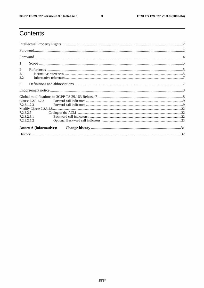
Contents
Intellectual Property Rights ................................................................................................................................2
Foreword.............................................................................................................................................................2
Foreword.............................................................................................................................................................4
1 Scope ........................................................................................................................................................5
2 References ................................................................................................................................................5 2.1 Normative references .........................................................................................................................................5 2.2 Informative references........................................................................................................................................7
3 Definitions and abbreviations...................................................................................................................7
Endorsement notice ............................................................................................................................................8
Global modifications to 3GPP TS 29.163 Release 7..........................................................................................8 Clause 7.2.3.1.2.3 Forward call indicators ................................................................................................................9 7.2.3.1.2.3 Forward call indicators ................................................................................................................9 Modify Clause 7.2.3.2.5 ....................................................................................................................................................22 7.2.3.2.5 Coding of the ACM .........................................................................................................................22 7.2.3.2.5.1 Backward call indicators............................................................................................................22 7.2.3.2.5.2 Optional Backward call indicators.............................................................................................23
Annex A (informative): Change history ...............................................................................................31
History ..............................................................................................................................................................32
ETSI
ETSI TS 129 527 V8.3.0 (2009-04) 4 3GPP TS 29.527 version 8.3.0 Release 8
Foreword This Technical Specification (TS) was been produced by ETSI Technical Committee Telecommunications and Internet converged Services and Protocols for Advanced Networking (TISPAN) and originally published as ETSI ES 283 027 [26]. It was transferred to the 3rd Generation Partnership Project (3GPP) in in January 2008.
The contents of the present document are subject to continuing work within the TSG and may change following formal TSG approval. Should the TSG modify the contents of the present document, it will be re-released by the TSG with an identifying change of release date and an increase in version number as follows:
Version x.y.z
where:
x the first digit:
1 presented to TSG for information;
2 presented to TSG for approval;
3 or greater indicates TSG approved document under change control.
y the second digit is incremented for all changes of substance, i.e. technical enhancements, corrections, updates, etc.
z the third digit is incremented when editorial only changes have been incorporated in the document.
ETSI
ETSI TS 129 527 V8.3.0 (2009-04) 5 3GPP TS 29.527 version 8.3.0 Release 8
1 Scope The present document provides the ETSI endorsement of the 3GPP TS 29.163 [1].
Clauses 7.2.3 and 7.4 of 3GPP TS 29.163 [1] specify the signalling interworking between ISDN User Part (ISUP) protocols and SIP in order to support services that can be commonly supported by ISUP and SIP-based network domains.
Clause 9.2.3.3.5 specifies how ringing tone is applied at the gateway when interworking ISUP and SIP.
The present document specifies the principles of interworking between the ETSI TISPAN IMS and ISUP based legacy CS networks, in order to support IM basic voice calls, therefore all the references to interworking between IMS and BICC are out of scope of the present document.
The present document is a protocol interworking specification; therefore all references to the user plane interworking are out of scope of the present document.
The present document specifies the interworking between ETSI SIP profile (as specified within ES 283 003 [3]) and ISUP, as specified in EN 300 356-1 [2] respectively.
2 References The following documents contain provisions which, through reference in this text, constitute provisions of the present document.
• References are either specific (identified by date of publication, edition number, version number, etc.) or non-specific.
• For a specific reference, subsequent revisions do not apply.
• For a non-specific reference, the latest version applies. In the case of a reference to a 3GPP document (including a GSM document), a non-specific reference implicitly refers to the latest version of that document in the same Release as the present document.
Referenced documents which are not found to be publicly available in the expected location might be found at http://docbox.etsi.org/Reference.
For online referenced documents, information sufficient to identify and locate the source shall be provided. Preferably, the primary source of the referenced document should be cited, in order to ensure traceability. Furthermore, the reference should, as far as possible, remain valid for the expected life of the document. The reference shall include the method of access to the referenced document and the full network address, with the same punctuation and use of upper case and lower case letters.
NOTE: While any hyperlinks included in this clause were valid at the time of publication ETSI cannot guarantee their long term validity.
2.1 Normative references The following referenced documents are indispensable for the application of the present document. For dated references, only the edition cited applies. For non-specific references, the latest edition of the referenced document (including any amendments) applies.
[1] 3GPP TS 29.163: "3rd Generation Partnership Project; Technical Specification Group Core Network and Terminals; Interworking between the IP Multimedia (IM) Core Network (CN) subsystem and Circuit Switched (CS) networks (Release 7)".
[2] ETSI EN 300 356-1 (V4.2.1): "Integrated Services Digital Network (ISDN); Signalling System No.7 (SS7); ISDN User Part (ISUP) version 4 for the international interface; Part 1: Basic services [ITU-T Recommendations Q.761 to Q.764 (1999) modified]".
ETSI
ETSI TS 129 527 V8.3.0 (2009-04) 6 3GPP TS 29.527 version 8.3.0 Release 8
[3] ETSI ES 283 003: "Telecommunications and Internet converged Services and Protocols for Advanced Networking (TISPAN); IP Multimedia Call Control Protocol based on Session Initiation Protocol (SIP) and Session Description Protocol (SDP) Stage 3 [3GPP TS 24.229 (Release 7), modified]".
[4] ETSI ES 282 007: "Telecommunications and Internet converged Services and Protocols for Advanced Networking (TISPAN); IP Multimedia Subsystem (IMS); Functional architecture".
[5] ETSI EN 300 356-3 (V4.2.1): "Integrated Services Digital Network (ISDN); Signalling System No.7 (SS7); ISDN User Part (ISUP) version 4 for the international interface; Part 3: Calling Line Identification Presentation (CLIP) supplementary service [ITU-T Recommendation Q.731, clause 3 (1993) modified]".
[6] ETSI EN 300 356-4 (V4.2.1): "Integrated Services Digital Network (ISDN); Signalling System No.7 (SS7); ISDN User Part (ISUP) version 4 for the international interface; Part 4: Calling Line Identification Restriction (CLIR) supplementary service [ITU-T Recommendation Q.731, clause 4 (1993) modified]".
[7] ETSI EN 300 356-5 (V4.1.2): "Integrated Services Digital Network (ISDN); Signalling System No.7 (SS7); ISDN User Part (ISUP) version 4 for the international interface; Part 5: Connected Line Identification Presentation (COLP) supplementary service [ITU-T Recommendation Q.731, clause 5 (1993) modified]".
[8] ETSI EN 300 356-6 (V4.1.2): "Integrated Services Digital Network (ISDN); Signalling System No.7 (SS7); ISDN User Part (ISUP) version 4 for the international interface; Part 6: Connected Line Identification Restriction (COLR) supplementary service [ITU-T Recommendation Q.731, clause 6 (1993) modified]".
[9] ETSI EN 300 356-7 (V4.1.2): "Integrated Services Digital Network (ISDN); Signalling System No.7 (SS7); ISDN User Part (ISUP) version 4 for the international interface; Part 7: Terminal Portability (TP) supplementary service [ITU-T Recommendation Q.733, clause 4 (1993) modified]".
[10] ETSI EN 300 356-8 (V4.1.2): "Integrated Services Digital Network (ISDN); Signalling System No.7 (SS7); ISDN User Part (ISUP) version 4 for the international interface; Part 8: User-to-User Signalling (UUS) supplementary service [ITU-T Recommendation Q.737, clause 1 (1997) modified]".
[11] ETSI EN 300 356-9 (V4.1.2): "Integrated Services Digital Network (ISDN); Signalling System No.7 (SS7); ISDN User Part (ISUP) version 4 for the international interface; Part 9: Closed User Group (CUG) supplementary service [ITU-T Recommendation Q.735, clause 1 (1993) modified]".
[12] ETSI EN 300 356-10 (V4.1.2): "Integrated Services Digital Network (ISDN); Signalling System No.7 (SS7); ISDN User Part (ISUP) version 4 for the international interface; Part 10: Subaddressing (SUB) supplementary service [ITU-T Recommendation Q.731, clause 8 (1992) modified]".
[13] ETSI EN 300 356-11 (V4.1.2): "Integrated Services Digital Network (ISDN); Signalling System No.7 (SS7); ISDN User Part (ISUP) version 4 for the international interface; Part 11: Malicious Call Identification (MCID) supplementary service [ITU-T Recommendation Q.731, clause 7 (1997) modified]".
[14] ETSI EN 300 356-12 (V4.2.1): "Integrated Services Digital Network (ISDN); Signalling System No.7 (SS7); ISDN User Part (ISUP) version 4 for the international interface; Part 12: Conference call, add-on (CONF) supplementary service [ITU-T Recommendation Q.734, clause 1 (1993) and implementors guide (1998) modified]".
[15] ETSI EN 300 356-14 (V4.2.1): "Integrated Services Digital Network (ISDN); Signalling System No.7 (SS7); ISDN User Part (ISUP) version 4 for the international interface; Part 14: Explicit Call Transfer (ECT) supplementary service [ITU-T Recommendation Q.732, clause 7 (1996) and implementors guide (1998) modified]".
ETSI
ETSI TS 129 527 V8.3.0 (2009-04) 7 3GPP TS 29.527 version 8.3.0 Release 8
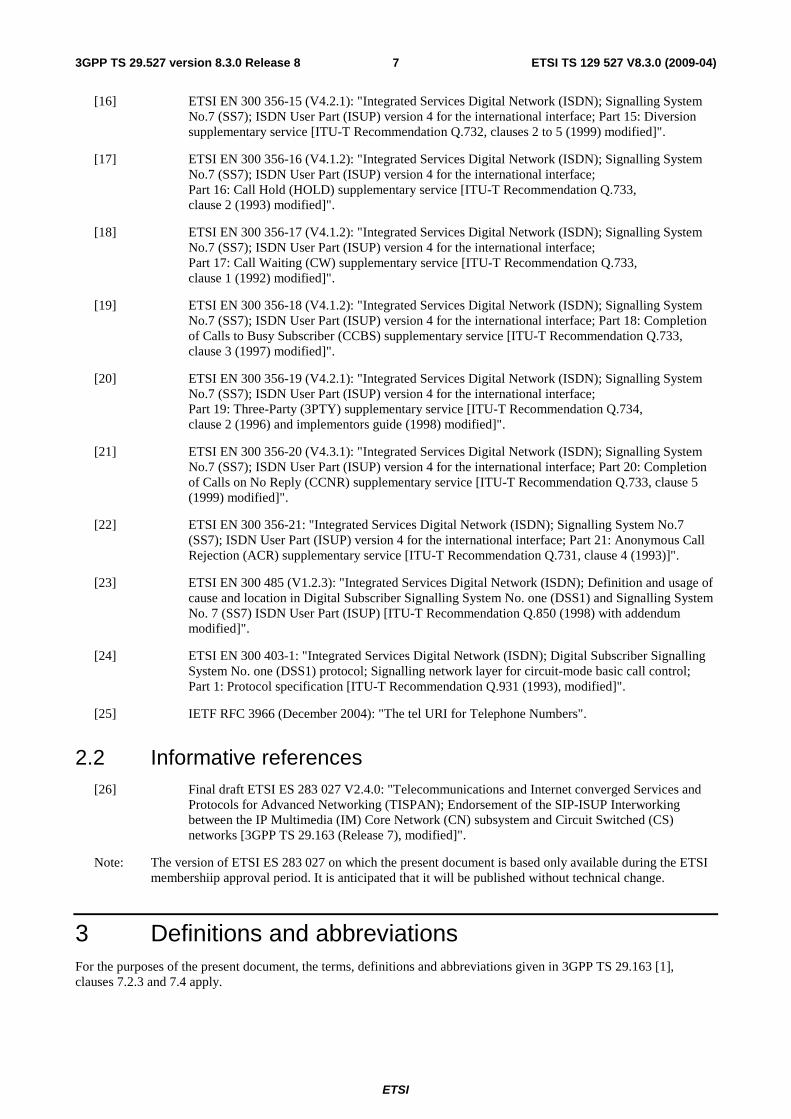
[16] ETSI EN 300 356-15 (V4.2.1): "Integrated Services Digital Network (ISDN); Signalling System No.7 (SS7); ISDN User Part (ISUP) version 4 for the international interface; Part 15: Diversion supplementary service [ITU-T Recommendation Q.732, clauses 2 to 5 (1999) modified]".
[17] ETSI EN 300 356-16 (V4.1.2): "Integrated Services Digital Network (ISDN); Signalling System No.7 (SS7); ISDN User Part (ISUP) version 4 for the international interface; Part 16: Call Hold (HOLD) supplementary service [ITU-T Recommendation Q.733, clause 2 (1993) modified]".
[18] ETSI EN 300 356-17 (V4.1.2): "Integrated Services Digital Network (ISDN); Signalling System No.7 (SS7); ISDN User Part (ISUP) version 4 for the international interface; Part 17: Call Waiting (CW) supplementary service [ITU-T Recommendation Q.733, clause 1 (1992) modified]".
[19] ETSI EN 300 356-18 (V4.1.2): "Integrated Services Digital Network (ISDN); Signalling System No.7 (SS7); ISDN User Part (ISUP) version 4 for the international interface; Part 18: Completion of Calls to Busy Subscriber (CCBS) supplementary service [ITU-T Recommendation Q.733, clause 3 (1997) modified]".
[20] ETSI EN 300 356-19 (V4.2.1): "Integrated Services Digital Network (ISDN); Signalling System No.7 (SS7); ISDN User Part (ISUP) version 4 for the international interface; Part 19: Three-Party (3PTY) supplementary service [ITU-T Recommendation Q.734, clause 2 (1996) and implementors guide (1998) modified]".
[21] ETSI EN 300 356-20 (V4.3.1): "Integrated Services Digital Network (ISDN); Signalling System No.7 (SS7); ISDN User Part (ISUP) version 4 for the international interface; Part 20: Completion of Calls on No Reply (CCNR) supplementary service [ITU-T Recommendation Q.733, clause 5 (1999) modified]".
[22] ETSI EN 300 356-21: "Integrated Services Digital Network (ISDN); Signalling System No.7 (SS7); ISDN User Part (ISUP) version 4 for the international interface; Part 21: Anonymous Call Rejection (ACR) supplementary service [ITU-T Recommendation Q.731, clause 4 (1993)]".
[23] ETSI EN 300 485 (V1.2.3): "Integrated Services Digital Network (ISDN); Definition and usage of cause and location in Digital Subscriber Signalling System No. one (DSS1) and Signalling System No. 7 (SS7) ISDN User Part (ISUP) [ITU-T Recommendation Q.850 (1998) with addendum modified]".
[24] ETSI EN 300 403-1: "Integrated Services Digital Network (ISDN); Digital Subscriber Signalling System No. one (DSS1) protocol; Signalling network layer for circuit-mode basic call control; Part 1: Protocol specification [ITU-T Recommendation Q.931 (1993), modified]".
[25] IETF RFC 3966 (December 2004): "The tel URI for Telephone Numbers".
2.2 Informative references [26] Final draft ETSI ES 283 027 V2.4.0: "Telecommunications and Internet converged Services and
Protocols for Advanced Networking (TISPAN); Endorsement of the SIP-ISUP Interworking between the IP Multimedia (IM) Core Network (CN) subsystem and Circuit Switched (CS) networks [3GPP TS 29.163 (Release 7), modified]".
Note: The version of ETSI ES 283 027 on which the present document is based only available during the ETSI membershiip approval period. It is anticipated that it will be published without technical change.
3 Definitions and abbreviations For the purposes of the present document, the terms, definitions and abbreviations given in 3GPP TS 29.163 [1], clauses 7.2.3 and 7.4 apply.
ETSI
ETSI TS 129 527 V8.3.0 (2009-04) 8 3GPP TS 29.527 version 8.3.0 Release 8
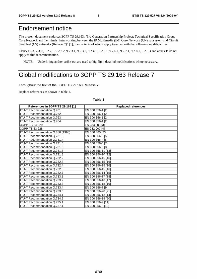
Endorsement notice The present document endorses 3GPP TS 29.163: "3rd Generation Partnership Project; Technical Specification Group Core Network and Terminals; Interworking between the IP Multimedia (IM) Core Network (CN) subsystem and Circuit Switched (CS) networks (Release 7)" [1], the contents of which apply together with the following modifications:
Clauses 6.3, 7.3, 8, 9.2.2.1, 9.2.2.2, 9.2.3.1, 9.2.3.2, 9.2.4.1, 9.2.5.1, 9.2.6.1, 9.2.7.1, 9.2.8.1, 9.2.8.3 and annex B do not apply to this recommendation.
NOTE: Underlining and/or strike-out are used to highlight detailed modifications where necessary.
Global modifications to 3GPP TS 29.163 Release 7
Throughout the text of the 3GPP TS 29.163 Release 7
Replace references as shown in table 1.
Table 1
References in 3GPP TS 29.163 [1] Replaced references ITU-T Recommendation Q.761 EN 300 356-1 [2] ITU-T Recommendation Q.762 EN 300 356-1 [2] ITU-T Recommendation Q.763 EN 300 356-1 [2] ITU-T Recommendation Q.764 EN 300 356-1 [2] 3GPP TS 24.229 ES 283 003 [3] 3GPP TS 23.228 ES 282 007 [4] ITU-T Recommendation Q.850 (1998) EN 300 485 [23] ITU-T Recommendation Q.731.3 EN 300 356-3 [5] ITU-T Recommendation Q.731.4 EN 300 356-4 [6] ITU-T Recommendation Q.731.5 EN 300 356-5 [7] ITU-T Recommendation Q.731.6 EN 300 356-6 [8] ITU-T Recommendation Q.731.7 EN 300 356-11 [13] ITU-T Recommendation Q.731.8 EN 300 356-10 [12] ITU-T Recommendation Q.732.2 EN 300 356-15 [16] ITU-T Recommendation Q.732.3 EN 300 356-15 [16] ITU-T Recommendation Q.732.4 EN 300 356-15 [16] ITU-T Recommendation Q.732.5 EN 300 356-15 [16] ITU-T Recommendation Q.732.7 EN 300 356-14 [15] ITU-T Recommendation Q.733.1 EN 300 356-17 [18] ITU-T Recommendation Q.733.2 EN 300 356-16 [17] ITU-T Recommendation Q.733.3 EN 300 356-18 [19] ITU-T Recommendation Q.733.4 EN 300 356-7 [9] ITU-T Recommendation Q.733.5 EN 300 356-20 [21] ITU-T Recommendation Q.734.1 EN 300 356-12 [14] ITU-T Recommendation Q.734.2 EN 300 356-19 [20] ITU-T Recommendation Q.735.1 EN 300 356-9 [11] ITU-T Recommendation Q.737.1 EN 300 356-8 [10]
ETSI
ETSI TS 129 527 V8.3.0 (2009-04) 9 3GPP TS 29.527 version 8.3.0 Release 8
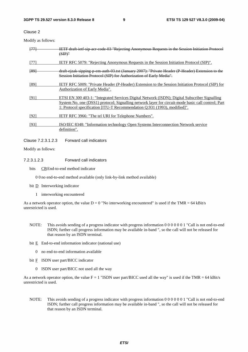
Clause 2
Modify as follows:
[77] IETF draft-ietf-sip-acr-code-03 "Rejecting Anonymous Requests in the Session Initiation Protocol (SIP)"
[77] IETF RFC 5079: "Rejecting Anonymous Requests in the Session Initiation Protocol (SIP)".
[89] draft-ejzak-sipping-p-em-auth-03.txt (January 2007): "Private Header (P-Header) Extension to the Session Initiation Protocol (SIP) for Authorization of Early Media".
[89] IETF RFC 5009: "Private Header (P-Header) Extension to the Session Initiation Protocol (SIP) for Authorization of Early Media".
[91] ETSI EN 300 403-1: "Integrated Services Digital Network (ISDN); Digital Subscriber Signalling System No. one (DSS1) protocol; Signalling network layer for circuit-mode basic call control; Part 1: Protocol specification [ITU-T Recommendation Q.931 (1993), modified]".
[92] IETF RFC 3966: "The tel URI for Telephone Numbers".
[93] ISO/IEC 8348: "Information technology Open Systems Interconnection Network service definition".
Clause 7.2.3.1.2.3 Forward call indicators
Modify as follows:
7.2.3.1.2.3 Forward call indicators
bits CB End-to-end method indicator
0 0 no end-to-end method available (only link-by-link method available)
bit D Interworking indicator
1 interworking encountered
As a network operator option, the value D = 0 "No interworking encountered" is used if the TMR = 64 kBit/s unrestricted is used.
NOTE: This avoids sending of a progress indicator with progress information 0 0 0 0 0 0 1 "Call is not end-to-end ISDN; further call progress information may be available in-band ", so the call will not be released for that reason by an ISDN terminal.
bit E End-to-end information indicator (national use)
0 no end-to-end information available
bit F ISDN user part/BICC indicator
0 ISDN user part/BICC not used all the way
As a network operator option, the value F = 1 "ISDN user part/BICC used all the way" is used if the TMR = 64 kBit/s unrestricted is used.
NOTE: This avoids sending of a progress indicator with progress information 0 0 0 0 0 0 1 "Call is not end-to-end ISDN; further call progress information may be available in-band ", so the call will not be released for that reason by an ISDN terminal.
ETSI
ETSI TS 129 527 V8.3.0 (2009-04) 103GPP TS 29.527 version 8.3.0 Release 8
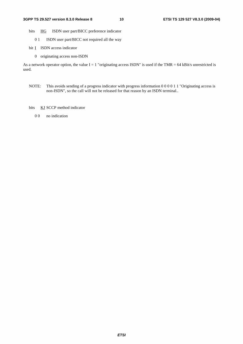
bits HG ISDN user part/BICC preference indicator
0 1 ISDN user part/BICC not required all the way
bit I ISDN access indicator
0 originating access non-ISDN
As a network operator option, the value I = 1 "originating access ISDN" is used if the TMR = 64 kBit/s unrestricted is used.
NOTE: This avoids sending of a progress indicator with progress information 0 0 0 0 1 1 "Originating access is non-ISDN", so the call will not be released for that reason by an ISDN terminal..
bits KJ SCCP method indicator
0 0 no indication
ETSI
ETSI TS 129 527 V8.3.0 (2009-04) 113GPP TS 29.527 version 8.3.0 Release 8
If the PSTN XML is supported as a network option, the Forward Call indicators derived as shown in Table 02a shall take precedence.
Table 02a: Mapping of PSTN XML elements to Forward call indicators parameter
INVITE → IAM→ PSTN XML Content
Forward call indicators parameter PSTN XML with Progress indicator No 6
(Meaning: originating access ISDN) Forward call indicators parameter ISDN User Part indicator 1 "ISDN User Part used all the way" ISDN access indicator 1 "originating access ISDN"
Clause 7.2.3.1.2.5 Transmission medium requirement
Modify first paragraph as follows:
The I-MGCF may either transcode the selected codec(s) to the codec on the PSTN side or it may attempt to interwork the media without transcoding. If the I-MGCF transcodes, it shall select the TMR parameter to "3,1 kHz audio". If the I-MGCF does not transcode, it should map the TMR, USI and Access Transport parameters from the selected codec according to table 2a. However, if the I-MGCF supports this PSTN XML body as a network option, and if a PSTN XML body is received in the INVITE request and the I-MGCF selects media encoded in any of the formats in Table 2a (G.711, Clearmode or t38) among the offered media, the I-MGCF shall derive these parameters from the XML body instead, as detailed in Table 2b. The support of any of the media listed in table 2a is optional. The SDP for the data transfer with 64 kbit/s clearmode shall be mapped to the TMR "64 kbit/s unrestricted".
Add table 2b as follows:
Table 2b: Mapping of PSTN XML elements with ISUP Parameters
INVITE � IAM � PSTN XML Value ISUP Parameter Content
ProgressIndicator Progress indicator HighLayerCompatibility High layer compatibility
(NOTE) LowLayerCompatibility
Access Transport Parameter
Low layer compatibility BearerCapability User Service Information HighLayerCompatibility User Tele Service High layer compatibility BearerInfomationElement (InformationTransferCabability)
Speech TMR Speech
3.1 kHz audio 3.1 kHz audio Unrestricted digital
information 64 kbit/s unrestricted
Unrestricted digital information with tones/announcements
64 kbit/s unrestricted
NOTE: If two high layer compatibility information elements are received, they shall be transferred in the same order as received in the PSTN XML body in the INVITE message.
Add clause 7.2.3.1.2.1.5a
7.2.3.1.2.5a Transmission medium requirement prime and USI prime (optional)
The Fallback mechanism described in the present Clause shall only apply if a two PSTN XML Bearer Capability element appears within the INVITE Request and the MGCF supports the PSTN XML body as a network option.
When the INVITE request includes multiple audio codecs with codec appearing in Table 2a then the I-MGCF shall:
- If the first stated codec in the INVITE is a codec appearing in Table 2a and is the equivalent as stated within the second Bearer Capability in the XML Bearer Capability element then the I-MGCF shall map the XML Bearer Capability element into the TMR and USI prime and shall set the TMR to “64 kBit/s unrestricted preferred”.
- If the second stated codec in the INVITE is a codec appearing in Table 2a and is the equivalent as stated within the first Bearer Capability in the XML Bearer Capability element then the I-MGCF shall map the XML Bearer
ETSI
ETSI TS 129 527 V8.3.0 (2009-04) 123GPP TS 29.527 version 8.3.0 Release 8
Capability element into the TMR prime and USI and shall map the TMR prime from the PSTN XML BearerInfomationElement (InformationTransferCabability).
- If the compared codec stated within the INVITE is not equivalent as stated within XML Bearer Capability element then the XML Bearer Capability element shall be discarded
If the Fallback mechanism is not supported by the succeeding network the procedures as described within clause 7.2.3.1.2.5 shall apply
In cases where the fallback appears within the terminating entity and sends back a codec to which is fallen back then the I-MGCF shall only apply the cut-though to the chosen codec.
In cases where the fallback appears within the terminating entity and sends back a SDP Answer that is equivalent with the TMR prime codec (fallback codec) then the I-MGCF shall only apply the cut-though to the fallback codec. In cases where preconditions are used the I-MGCF has to wait for the SDP answer where the preconditions are met and fallback codec is sent back.
Add clause 7.2.3.1.2.10
7.2.3.1.2.10 Access Transport Parameter and User Tele Service
When an INVITE was received containing a PSTN XML body as defined in ES 283 003 [3], an available "ProgressIndicator" element can be as a network option mapped into a Progress Indicator in the Access Transport Parameter of the sent IAM
Table 7a0.1: Mapping of PSTN XML elements with ISUP Parameters
INVITE � IAM � PSTN XML ISUP Parameter Content
ProgressIndicator Progress indicator HighLayerCompatibility High layer compatibility (Note) LowLayerCompatibility
Access Transport Parameter
Low layer compatibility BearerCapability User Service Information HighLayerCompatibility User Tele Service High layer compatibility (Note) NOTE: If two high layer compatibility information elements are received, they are transferred in the same order as
received in the INVITE message in the access transport parameter of the initial address message.
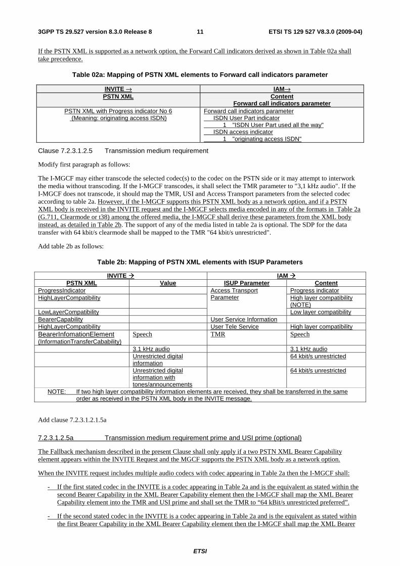
Clause 7.2.3.1.4 Sending of 180 ringing
Modify as follows:
The I-MGCF shall send the SIP 180 Ringing when receiving any of the following messages:
- ACM with Called party's status indicator set to subscriber free.
180 Ringing P-Early-Media (1)
ACM (Subscriber Free)
I-MGCF
Ring tone
NOTE: Including the P-Early-Media Header is a network option for a speech call.
Figure 6: The receipt of ACM
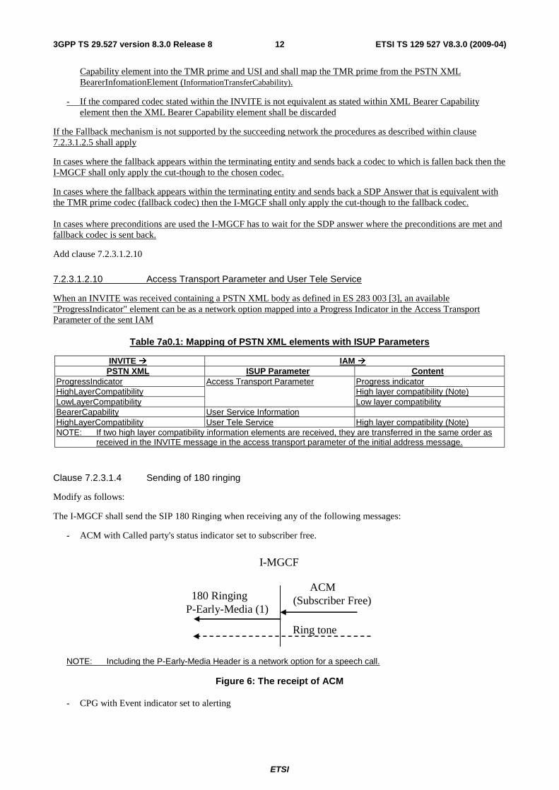
- CPG with Event indicator set to alerting
ETSI
ETSI TS 129 527 V8.3.0 (2009-04) 133GPP TS 29.527 version 8.3.0 Release 8
180 Ringing P-Early-Media (1)
CPG (Alerting)
I-MGCF
Ring tone
NOTE: Including the P-Early-Media Header is a network option for a speech call.
Figure 7: Receipt of CPG (Alerting)
For a speech call, if the I-MGCF supports the P-Early-Media header as a network option, and if the INVITE request includes the P-Early-Media header, the I-MGCF shall include in the SIP 180 ringing response a P-Early-Media header authorizing early media, except when:
- the I-MGCF has already sent a reliable provisional response including a P-Early-Media header, as defined in RFC5009 [89]; and
- the most recently sent P-Early-Media header authorized early media.
NOTE: If the I-MGCF signals the P-Early-Media header authorizing early media, then the IMS can expect tones or announcements to the calling party to flow from the CS network via an MGW controlled by the I-MGCF. In particular, once the I-MGCF sends the 180 Ringing response, ringback is expected in media from the CS network.
If the I-MGCF supports the PSTN XML body as a network option and the I-MGCF interworks media encoded in any of the formats in Table 2a (G.711, Clearmode or t38) without transcoding, the I-MGCF shall map the Access Transport Format received in the CPG or ACM into PSTN XML elements as shown in Table 7a.0.2 and include this XML body in the 180 Ringing.
Table 7a0.2: ISUP Parameters with Mapping of PSTN XML elements
�18x �CPG or ACM PSTN XML ISUP Parameter Content
ProgressIndicator Progress indicator HighLayerCompatibility High layer compatibility (NOTE 1) LowLayerCompatibility Low layer compatibility BearerCapability
Access Transport Parameter
Bearer Capability NOTE 1: If two high layer compatibility information elements are received, they are transferred in the same order as
received in the INVITE message in the access transport parameter of the initial address message. NOTE 2: see Clause 7.2.3.1.4.1 Transmission Medium Used parameter (TMU)
If the I-MGCF supports the PSTN XML body as a network option, an available Progress Indicator element in the ACM or CPG contained in the ATP parameter shall be mapped into the PSTN XML ProgressIndicator in the 180 Ringing as shown in table 7a0g.
ETSI
ETSI TS 129 527 V8.3.0 (2009-04) 143GPP TS 29.527 version 8.3.0 Release 8
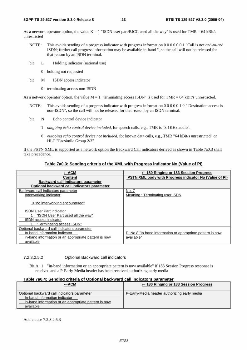
Table 7a0.3: Sending criteria of the XML with Progress indicator X
← 180 Ringing ←ACM PSTN XML body with Progress indicator X Content
Backward call indicators parameter Optional backward call indicators parameter
No. 1 (Call is not end-to-end ISDN: further progress information may be available in-band)
Backward call indicators parameter ISDN User Part indicator 0 ISDN User Part not used all the way
No. 2 (Destination address is non-ISDN)
Backward call indicators parameter ISDN User Part indicator 1 ISDN User Part used all the way ISDN access indicator 0 Terminating access non-ISDN
No. 7 meaning: Terminating access ISDN
Backward call indicators parameter ISDN User Part indicator 1 ISDN User Part used all the way ISDN access indicator 1 Terminating access ISDN
No.8 ”In-band information or appropriate pattern is now available”
Optional backward call indicators parameter In-band information indicator in-band information or an appropriate pattern is now available
Progress indicator
Progress indicator information elements possibly present in the access transport parameter of the Address Complete Message (ACM) are transferred into the PSTN XML body (as defined in ES 283 003 [3]) of the 180 Ringing sent to the calling user.
Add Clause 7.2.3.1.4.1
7.2.3.1.4.1 Transmission Medium Used parameter (TMU)
If the Transmission Medium Used parameter (TMU) is present and the BC is not available in the ATP in the Address Complete Message (ACM) or Call Progress Message (CPG), and if no BC is available in the ATP, and if no progress indicator No. 1 (call is not end-to-end ISDN) or No. 2 (destination address is non-ISDN) has been received in the CPG or ACM, the TMU value (Speech or 3.1 kHz audio) shall be included in the PSTN XML BearerCapability. If the Transmission Medium Used parameter (TMU) and the BC is available in the ATP in the Address Complete Message (ACM) or Call Progress Message (CPG), and if no progress indicator No. 1 (call is not end-to-end ISDN) or No. 2 (destination address is non-ISDN) has been received in the CPG or ACM, the BC value shall be included to the PSTN XML BearerCapability
Table 7a0.f – Sending of BC fallback indication
← 180 Ringing or 183 Session Progress ←ACM/CPG
PSTN XML BearerCapability = Speech TMU Speech ATP No BC
PSTN XML BearerCapability = 3.1 kHz audio TMU 3.1 kHz audio ATP No BC
PSTN XML BearerCapability received in the ATP (speech or 3.1 kHz audio)
TMU Speech or 3.1 kHz audio ATP BC (speech or 3.1 kHz audio)
Clause 7.2.3.1.4A Sending of 183 Session Progress for early media scenarios
Modify as follows:
If SIP preconditions are used, the first 183 Session Progress will be sent after the reception of the INVITE request, before any ISUP message has been received from the CS network. The I-MGCF shall not include the P-Early-Media header in any SIP message before it receives an ISUP ACM.
On receipt of an ACM with the options described in table 7a2 the I-MGCF can be sent, as a network option, a 183 Session Progress response with following options:
ETSI
ETSI TS 129 527 V8.3.0 (2009-04) 153GPP TS 29.527 version 8.3.0 Release 8
Table 7a2: Sending criteria of the XML with Progress indicator X
← 183 Session Progress ←ACM PSTN XML body with Progress indicator X Content
No. 1 (Call is not end-to-end ISDN: further progress information may be available in-band)
Backward call indicators parameter ISDN User Part indicator 0 ISDN User Part not used all the way
No. 2 (Destination address is non-ISDN)
Backward call indicators parameter ISDN User Part indicator 1 ISDN User Part used all the way ISDN access indicator 0 Terminating access non-ISDN
No. 7 meaning: Terminating access ISDN
Backward call indicators parameter ISDN User Part indicator 1 ISDN User Part used all the way ISDN access indicator 1 Terminating access ISDN
Progress indicator
Progress indicator information elements possibly present in the access transport parameter of the Address Complete Message (ACM) are transferred into the PSTN XML body (as defined in ES 283 003 [3]) of the 183 Session Progress sent to the calling user.
For a speech call upon receipt of one of the following messages, if the I-MGCF supports the P-Early-Media header as a network option, and if the I-MGCF has received the P-Early-Media header in the INVITE request, and has not already sent a provisional response including a P-Early-Media header with parameters indicating authorization of early media, then the I-MGCF shall send the 183 Session Progress response with a P-Early-Media header authorizing early media:
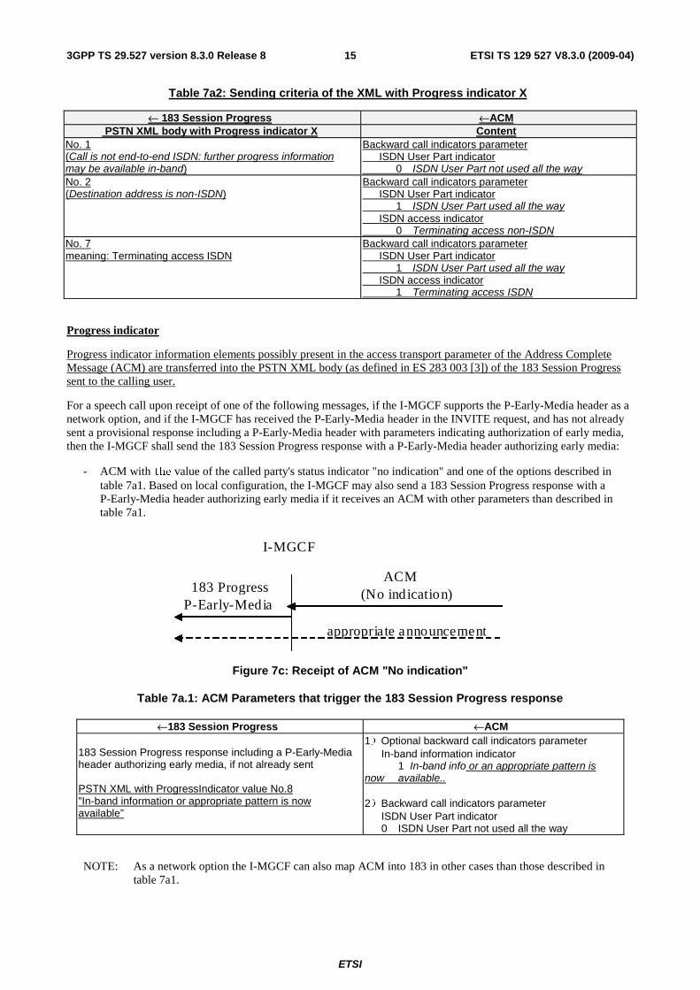
- ACM with the value of the called party's status indicator "no indication" and one of the options described in table 7a1. Based on local configuration, the I-MGCF may also send a 183 Session Progress response with a P-Early-Media header authorizing early media if it receives an ACM with other parameters than described in table 7a1.
183 Progress P-Early-Media
ACM (No indication)
I-MGCF
appropriate announcement
Figure 7c: Receipt of ACM "No indication"
Table 7a.1: ACM Parameters that trigger the 183 Session Progress response
←183 Session Progress ←ACM 183 Session Progress response including a P-Early-Media header authorizing early media, if not already sent PSTN XML with ProgressIndicator value No.8 ”In-band information or appropriate pattern is now available”
1)Optional backward call indicators parameter In-band information indicator 1 In-band info or an appropriate pattern is now available.. 2)Backward call indicators parameter ISDN User Part indicator 0 ISDN User Part not used all the way
NOTE: As a network option the I-MGCF can also map ACM into 183 in other cases than those described in table 7a1.
ETSI
ETSI TS 129 527 V8.3.0 (2009-04) 163GPP TS 29.527 version 8.3.0 Release 8
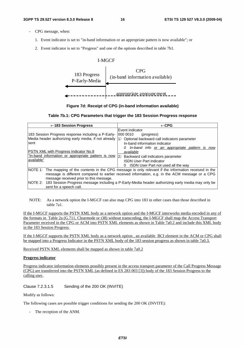
- CPG message, when:
1. Event indicator is set to "in-band information or an appropriate pattern is now available"; or
2. Event indicator is set to "Progress" and one of the options described in table 7b1.
CPG (in-band information available) 183 Progress
P-Early-Media
I-MGCF
appropriate announcment
Figure 7d: Receipt of CPG (in-band information available)
Table 7b.1: CPG Parameters that trigger the 183 Session Progress response
←183 Session Progress ←CPG 183 Session Progress response including a P-Early-Media header authorizing early media, if not already sent PSTN XML with Progress Indicator No.8 ”In-band information or appropriate pattern is now available”
Event indicator 000 0010 (progress) 1)Optional backward call indicators parameter In-band information indicator 0 In-band info or an appropriate pattern is now available 2)Backward call indicators parameter ISDN User Part indicator 0 ISDN User Part not used all the way
NOTE 1: The mapping of the contents in the CPG message is only relevant if the information received in the message is different compared to earlier received information, e.g. in the ACM message or a CPG message received prior to this message.
NOTE 2: 183 Session Progress message including a P-Early-Media header authorizing early media may only be sent for a speech call.
NOTE: As a network option the I-MGCF can also map CPG into 183 in other cases than those described in table 7a1.
If the I-MGCF supports the PSTN XML body as a network option and the I-MGCF interworks media encoded in any of the formats in Table 2a (G.711, Clearmode or t38) without transcoding, the I-MGCF shall map the Access Transport Parameter received in the CPG or ACM into PSTN XML elements as shown in Table 7a0.2 and include this XML body in the 183 Session Progress.
If the I-MGCF supports the PSTN XML body as a network option , an available BCI element in the ACM or CPG shall be mapped into a Progress Indicator in the PSTN XML body of the 183 session progress as shown in table 7a0.3.
Received PSTN XML elements shall be mapped as shown in table 7a0.2
Progress indicator
Progress indicator information elements possibly present in the access transport parameter of the Call Progress Message (CPG) are transferred into the PSTN XML (as defined in ES 283 003 [3]) body of the 183 Session Progress to the calling user.
Clause 7.2.3.1.5 Sending of the 200 OK (INVITE)
Modify as follows:
The following cases are possible trigger conditions for sending the 200 OK (INVITE):
- The reception of the ANM.
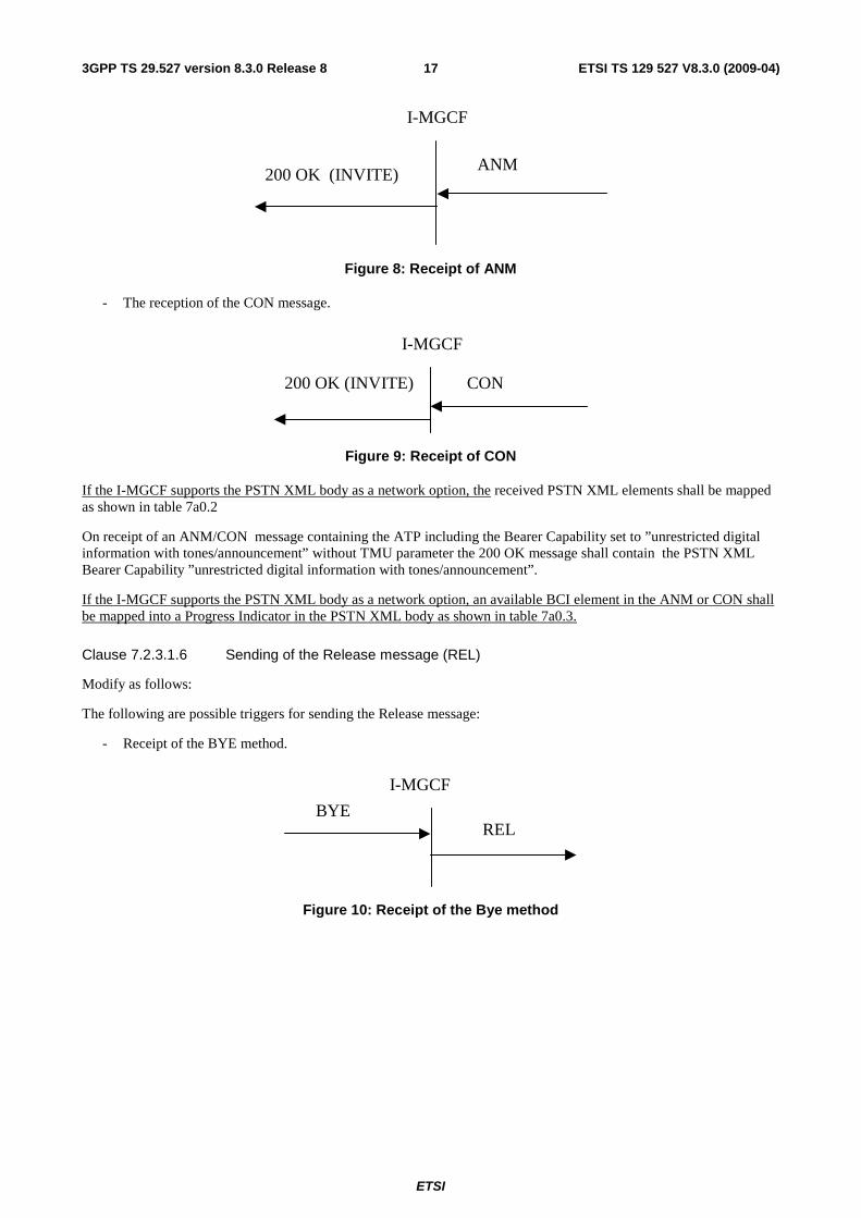
ETSI
ETSI TS 129 527 V8.3.0 (2009-04) 173GPP TS 29.527 version 8.3.0 Release 8
ANM 200 OK (INVITE)
I-MGCF
Figure 8: Receipt of ANM
- The reception of the CON message.
I-MGCF
CON 200 OK (INVITE)
Figure 9: Receipt of CON
If the I-MGCF supports the PSTN XML body as a network option, the received PSTN XML elements shall be mapped as shown in table 7a0.2
On receipt of an ANM/CON message containing the ATP including the Bearer Capability set to ”unrestricted digital information with tones/announcement” without TMU parameter the 200 OK message shall contain the PSTN XML Bearer Capability ”unrestricted digital information with tones/announcement”.
If the I-MGCF supports the PSTN XML body as a network option, an available BCI element in the ANM or CON shall be mapped into a Progress Indicator in the PSTN XML body as shown in table 7a0.3.
Clause 7.2.3.1.6 Sending of the Release message (REL)
Modify as follows:
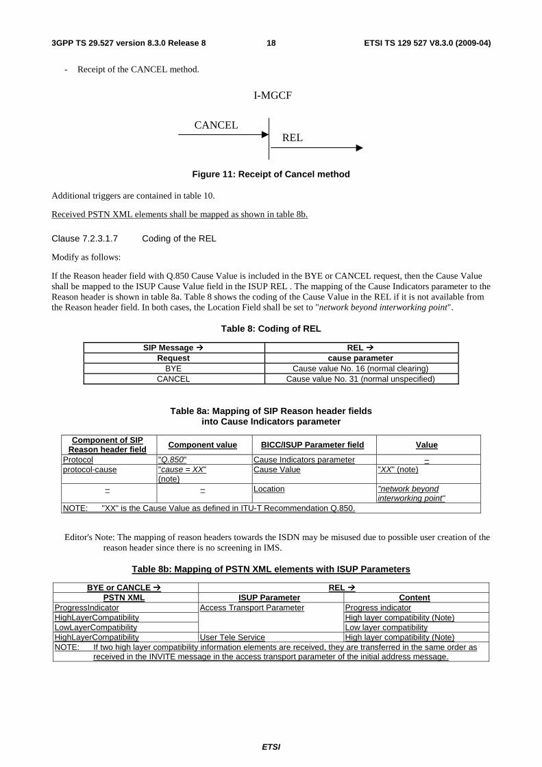
The following are possible triggers for sending the Release message:
- Receipt of the BYE method.
BYE REL
I-MGCF
Figure 10: Receipt of the Bye method
ETSI
ETSI TS 129 527 V8.3.0 (2009-04) 183GPP TS 29.527 version 8.3.0 Release 8
- Receipt of the CANCEL method.
I-MGCF
CANCEL REL
Figure 11: Receipt of Cancel method
Additional triggers are contained in table 10.
Received PSTN XML elements shall be mapped as shown in table 8b.
Clause 7.2.3.1.7 Coding of the REL
Modify as follows:
If the Reason header field with Q.850 Cause Value is included in the BYE or CANCEL request, then the Cause Value shall be mapped to the ISUP Cause Value field in the ISUP REL . The mapping of the Cause Indicators parameter to the Reason header is shown in table 8a. Table 8 shows the coding of the Cause Value in the REL if it is not available from the Reason header field. In both cases, the Location Field shall be set to "network beyond interworking point".
Table 8: Coding of REL
SIP Message � REL � Request cause parameter
BYE Cause value No. 16 (normal clearing) CANCEL Cause value No. 31 (normal unspecified)
Table 8a: Mapping of SIP Reason header fields into Cause Indicators parameter
Component of SIP Reason header field Component value BICC/ISUP Parameter field Value
Protocol "Q.850" Cause Indicators parameter – protocol-cause "cause = XX"
(note) Cause Value "XX" (note)
– – Location "network beyond interworking point"
NOTE: "XX" is the Cause Value as defined in ITU-T Recommendation Q.850.
Editor's Note: The mapping of reason headers towards the ISDN may be misused due to possible user creation of the reason header since there is no screening in IMS.
Table 8b: Mapping of PSTN XML elements with ISUP Parameters
BYE or CANCLE � REL � PSTN XML ISUP Parameter Content
ProgressIndicator Progress indicator HighLayerCompatibility High layer compatibility (Note) LowLayerCompatibility
Access Transport Parameter
Low layer compatibility HighLayerCompatibility User Tele Service High layer compatibility (Note) NOTE: If two high layer compatibility information elements are received, they are transferred in the same order as
received in the INVITE message in the access transport parameter of the initial address message.
ETSI
ETSI TS 129 527 V8.3.0 (2009-04) 193GPP TS 29.527 version 8.3.0 Release 8
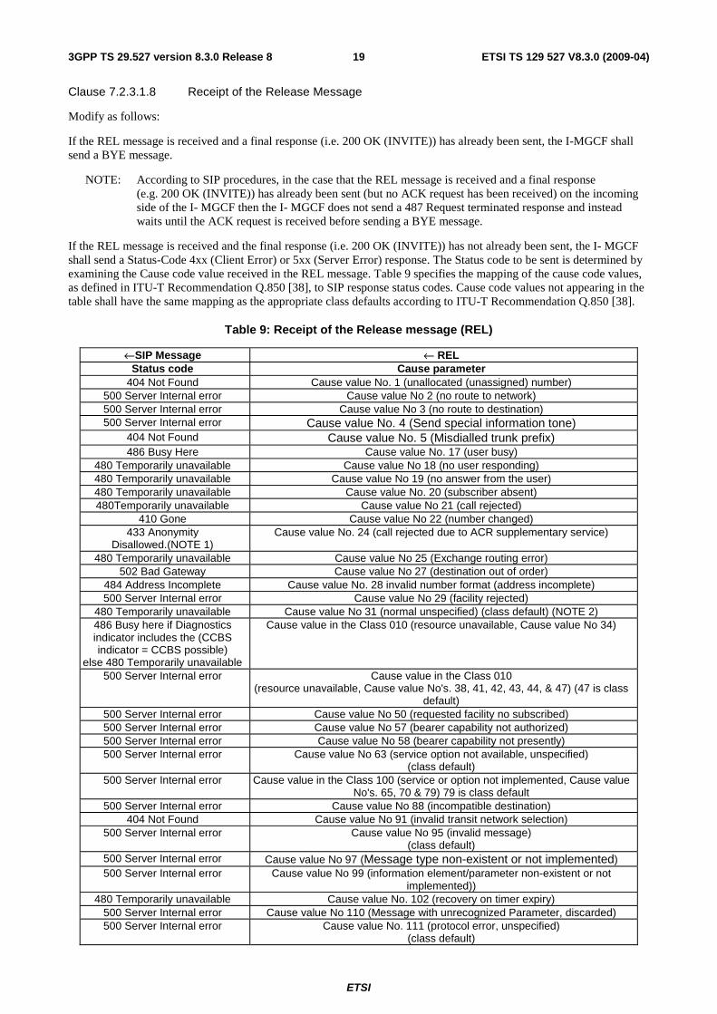
Clause 7.2.3.1.8 Receipt of the Release Message
Modify as follows:
If the REL message is received and a final response (i.e. 200 OK (INVITE)) has already been sent, the I-MGCF shall send a BYE message.
NOTE: According to SIP procedures, in the case that the REL message is received and a final response (e.g. 200 OK (INVITE)) has already been sent (but no ACK request has been received) on the incoming side of the I- MGCF then the I- MGCF does not send a 487 Request terminated response and instead waits until the ACK request is received before sending a BYE message.
If the REL message is received and the final response (i.e. 200 OK (INVITE)) has not already been sent, the I- MGCF shall send a Status-Code 4xx (Client Error) or 5xx (Server Error) response. The Status code to be sent is determined by examining the Cause code value received in the REL message. Table 9 specifies the mapping of the cause code values, as defined in ITU-T Recommendation Q.850 [38], to SIP response status codes. Cause code values not appearing in the table shall have the same mapping as the appropriate class defaults according to ITU-T Recommendation Q.850 [38].
Table 9: Receipt of the Release message (REL)
←SIP Message ← REL Status code Cause parameter
404 Not Found Cause value No. 1 (unallocated (unassigned) number) 500 Server Internal error Cause value No 2 (no route to network) 500 Server Internal error Cause value No 3 (no route to destination) 500 Server Internal error Cause value No. 4 (Send special information tone)
404 Not Found Cause value No. 5 (Misdialled trunk prefix) 486 Busy Here Cause value No. 17 (user busy)
480 Temporarily unavailable Cause value No 18 (no user responding) 480 Temporarily unavailable Cause value No 19 (no answer from the user) 480 Temporarily unavailable Cause value No. 20 (subscriber absent) 480Temporarily unavailable Cause value No 21 (call rejected)
410 Gone Cause value No 22 (number changed) 433 Anonymity
Disallowed.(NOTE 1) Cause value No. 24 (call rejected due to ACR supplementary service)
480 Temporarily unavailable Cause value No 25 (Exchange routing error) 502 Bad Gateway Cause value No 27 (destination out of order)
484 Address Incomplete Cause value No. 28 invalid number format (address incomplete) 500 Server Internal error Cause value No 29 (facility rejected)
480 Temporarily unavailable Cause value No 31 (normal unspecified) (class default) (NOTE 2) 486 Busy here if Diagnostics indicator includes the (CCBS indicator = CCBS possible)
else 480 Temporarily unavailable
Cause value in the Class 010 (resource unavailable, Cause value No 34)
500 Server Internal error Cause value in the Class 010 (resource unavailable, Cause value No's. 38, 41, 42, 43, 44, & 47) (47 is class
default) 500 Server Internal error Cause value No 50 (requested facility no subscribed) 500 Server Internal error Cause value No 57 (bearer capability not authorized) 500 Server Internal error Cause value No 58 (bearer capability not presently) 500 Server Internal error Cause value No 63 (service option not available, unspecified)
(class default) 500 Server Internal error Cause value in the Class 100 (service or option not implemented, Cause value
No's. 65, 70 & 79) 79 is class default 500 Server Internal error Cause value No 88 (incompatible destination)
404 Not Found Cause value No 91 (invalid transit network selection) 500 Server Internal error Cause value No 95 (invalid message)
(class default) 500 Server Internal error Cause value No 97 (Message type non-existent or not implemented) 500 Server Internal error Cause value No 99 (information element/parameter non-existent or not
implemented)) 480 Temporarily unavailable Cause value No. 102 (recovery on timer expiry)
500 Server Internal error Cause value No 110 (Message with unrecognized Parameter, discarded) 500 Server Internal error Cause value No. 111 (protocol error, unspecified)
(class default)
ETSI
ETSI TS 129 527 V8.3.0 (2009-04) 203GPP TS 29.527 version 8.3.0 Release 8
←SIP Message ← REL Status code Cause parameter
480 Temporarily unavailable Cause value No. 127 (interworking unspecified) (class default)
NOTE 1: Anonymity Disallowed, RFC5079 [77] refers NOTE 2: Class 1 and class 2 have the same default value.
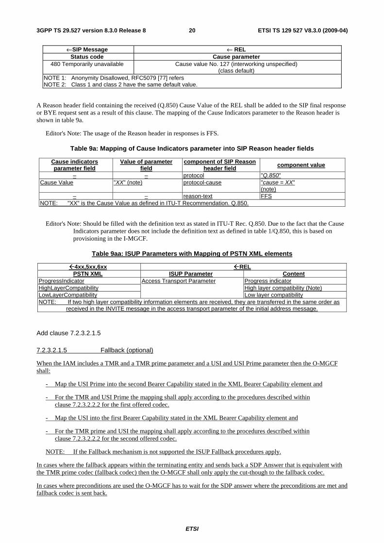
A Reason header field containing the received (Q.850) Cause Value of the REL shall be added to the SIP final response or BYE request sent as a result of this clause. The mapping of the Cause Indicators parameter to the Reason header is shown in table 9a.
Editor's Note: The usage of the Reason header in responses is FFS.
Table 9a: Mapping of Cause Indicators parameter into SIP Reason header fields
Cause indicators parameter field
Value of parameter field
component of SIP Reason header field component value
– – protocol "Q.850" Cause Value "XX" (note) protocol-cause "cause = XX"
(note) – – reason-text FFS
NOTE: "XX" is the Cause Value as defined in ITU-T Recommendation. Q.850.
Editor's Note: Should be filled with the definition text as stated in ITU-T Rec. Q.850. Due to the fact that the Cause Indicators parameter does not include the definition text as defined in table 1/Q.850, this is based on provisioning in the I-MGCF.
Table 9aa: ISUP Parameters with Mapping of PSTN XML elements
�4xx,5xx,6xx �REL PSTN XML ISUP Parameter Content
ProgressIndicator Progress indicator HighLayerCompatibility High layer compatibility (Note) LowLayerCompatibility
Access Transport Parameter
Low layer compatibility NOTE: If two high layer compatibility information elements are received, they are transferred in the same order as
received in the INVITE message in the access transport parameter of the initial address message.
Add clause 7.2.3.2.1.5
7.2.3.2.1.5 Fallback (optional)
When the IAM includes a TMR and a TMR prime parameter and a USI and USI Prime parameter then the O-MGCF shall:
- Map the USI Prime into the second Bearer Capability stated in the XML Bearer Capability element and
- For the TMR and USI Prime the mapping shall apply according to the procedures described within clause 7.2.3.2.2.2 for the first offered codec.
- Map the USI into the first Bearer Capability stated in the XML Bearer Capability element and
- For the TMR prime and USI the mapping shall apply according to the procedures described within clause 7.2.3.2.2.2 for the second offered codec.
NOTE: If the Fallback mechanism is not supported the ISUP Fallback procedures apply.
In cases where the fallback appears within the terminating entity and sends back a SDP Answer that is equivalent with the TMR prime codec (fallback codec) then the O-MGCF shall only apply the cut-though to the fallback codec.
In cases where preconditions are used the O-MGCF has to wait for the SDP answer where the preconditions are met and fallback codec is sent back.
ETSI
ETSI TS 129 527 V8.3.0 (2009-04) 213GPP TS 29.527 version 8.3.0 Release 8
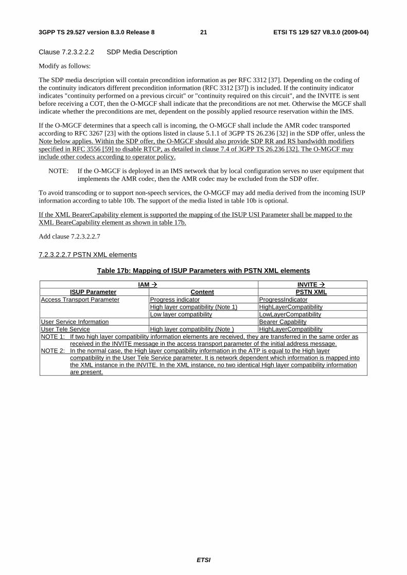
Clause 7.2.3.2.2.2 SDP Media Description
Modify as follows:
The SDP media description will contain precondition information as per RFC 3312 [37]. Depending on the coding of the continuity indicators different precondition information (RFC 3312 [37]) is included. If the continuity indicator indicates "continuity performed on a previous circuit" or "continuity required on this circuit", and the INVITE is sent before receiving a COT, then the O-MGCF shall indicate that the preconditions are not met. Otherwise the MGCF shall indicate whether the preconditions are met, dependent on the possibly applied resource reservation within the IMS.
If the O-MGCF determines that a speech call is incoming, the O-MGCF shall include the AMR codec transported according to RFC 3267 [23] with the options listed in clause 5.1.1 of 3GPP TS 26.236 [32] in the SDP offer, unless the Note below applies. Within the SDP offer, the O-MGCF should also provide SDP RR and RS bandwidth modifiers specified in RFC 3556 [59] to disable RTCP, as detailed in clause 7.4 of 3GPP TS 26.236 [32]. The O-MGCF may include other codecs according to operator policy.
NOTE: If the O-MGCF is deployed in an IMS network that by local configuration serves no user equipment that implements the AMR codec, then the AMR codec may be excluded from the SDP offer.
To avoid transcoding or to support non-speech services, the O-MGCF may add media derived from the incoming ISUP information according to table 10b. The support of the media listed in table 10b is optional.
If the XML BearerCapability element is supported the mapping of the ISUP USI Parameter shall be mapped to the XML BeareCapability element as shown in table 17b.
Add clause 7.2.3.2.2.7
7.2.3.2.2.7 PSTN XML elements
Table 17b: Mapping of ISUP Parameters with PSTN XML elements
IAM � INVITE � ISUP Parameter Content PSTN XML
Progress indicator ProgressIndicator High layer compatibility (Note 1) HighLayerCompatibility
Access Transport Parameter
Low layer compatibility LowLayerCompatibility User Service Information Bearer Capability User Tele Service High layer compatibility (Note ) HighLayerCompatibility NOTE 1: If two high layer compatibility information elements are received, they are transferred in the same order as
received in the INVITE message in the access transport parameter of the initial address message. NOTE 2: In the normal case, the High layer compatibility information in the ATP is equal to the High layer
compatibility in the User Tele Service parameter. It is network dependent which information is mapped into the XML instance in the INVITE. In the XML instance, no two identical High layer compatibility information are present.
ETSI
ETSI TS 129 527 V8.3.0 (2009-04) 223GPP TS 29.527 version 8.3.0 Release 8
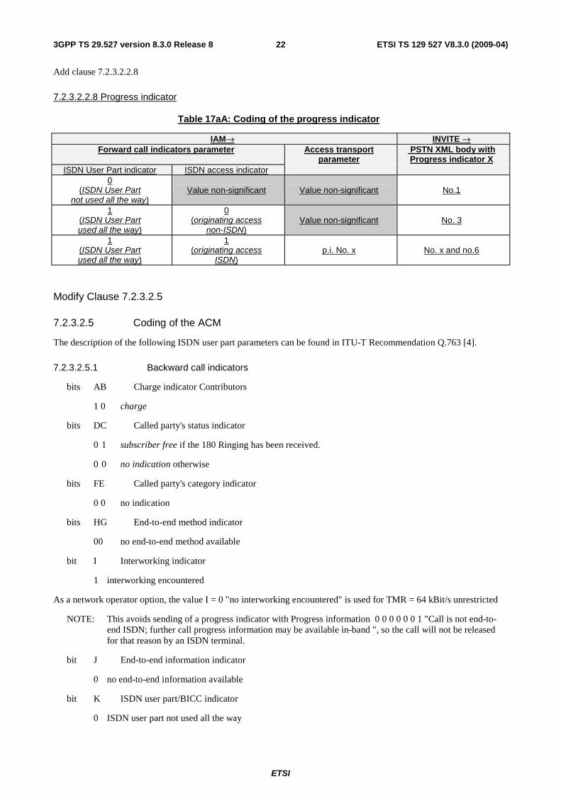
Add clause 7.2.3.2.2.8
7.2.3.2.2.8 Progress indicator
Table 17aA: Coding of the progress indicator
IAM→ INVITE → Forward call indicators parameter Access transport
parameter PSTN XML body with Progress indicator X
ISDN User Part indicator ISDN access indicator 0
(ISDN User Part not used all the way)
Value non-significant
Value non-significant
No.1
1 (ISDN User Part used all the way)
0 (originating access
non-ISDN)
Value non-significant
No. 3
1 (ISDN User Part used all the way)
1 (originating access
ISDN)
p.i. No. x
No. x and no.6
Modify Clause 7.2.3.2.5
7.2.3.2.5 Coding of the ACM
The description of the following ISDN user part parameters can be found in ITU-T Recommendation Q.763 [4].
7.2.3.2.5.1 Backward call indicators
bits AB Charge indicator Contributors
1 0 charge
bits DC Called party's status indicator
0 1 subscriber free if the 180 Ringing has been received.
0 0 no indication otherwise
bits FE Called party's category indicator
0 0 no indication
bits HG End-to-end method indicator
00 no end-to-end method available
bit I Interworking indicator
1 interworking encountered
As a network operator option, the value I = 0 "no interworking encountered" is used for TMR = 64 kBit/s unrestricted
NOTE: This avoids sending of a progress indicator with Progress information 0 0 0 0 0 0 1 "Call is not end-to-end ISDN; further call progress information may be available in-band ", so the call will not be released for that reason by an ISDN terminal.
bit J End-to-end information indicator
0 no end-to-end information available
bit K ISDN user part/BICC indicator
0 ISDN user part not used all the way
ETSI
ETSI TS 129 527 V8.3.0 (2009-04) 233GPP TS 29.527 version 8.3.0 Release 8
As a network operator option, the value K = 1 "ISDN user part/BICC used all the way" is used for TMR = 64 kBit/s unrestricted
NOTE: This avoids sending of a progress indicator with progress information 0 0 0 0 0 0 1 "Call is not end-to-end ISDN; further call progress information may be available in-band ", so the call will not be released for that reason by an ISDN terminal.
bit L Holding indicator (national use)
0 holding not requested
bit M ISDN access indicator
0 terminating access non-ISDN
As a network operator option, the value M = 1 "terminating access ISDN" is used for TMR = 64 kBit/s unrestricted.
NOTE: This avoids sending of a progress indicator with progress information 0 0 0 0 0 1 0 " Destination access is non-ISDN", so the call will not be released for that reason by an ISDN terminal.
bit N Echo control device indicator
1 outgoing echo control device included, for speech calls, e.g., TMR is "3.1KHz audio".
0 outgoing echo control device not included, for known data calls, e.g., TMR "64 kBit/s unrestricted" or HLC "Facsimile Group 2/3".
If the PSTN XML is supported as a network option the Backward Call indicators derived as shown in Table 7a0.3 shall take precedence.
Table 7a0.3: Sending criteria of the XML with Progress indicator No (Value of PI)
←ACM ← 180 Ringing or 183 Session Progress Content
Backward call indicators parameter Optional backward call indicators parameter
PSTN XML body with Progress indicator No (Value of PI)
Backward call indicators parameter Interworking indicator
0 "no interworking encountered"
ISDN User Part indicator 1 "ISDN User Part used all the way" ISDN access indicator 1 "Terminating access ISDN"
No. 7 Meaning : Terminating user ISDN
Optional backward call indicators parameter In-band information indicator in-band information or an appropriate pattern is now available
PI No.8 ”In-band information or appropriate pattern is now available”
7.2.3.2.5.2 Optional Backward call indicators
Bit A 1 "in-band information or an appropriate pattern is now available" if 183 Session Progress response is received and a P-Early-Media header has been received authorizing early media
Table 7a0.4: Sending criteria of Optional backward call indicators parameter ←ACM ← 180 Ringing or 183 Session Progress
Optional backward call indicators parameter In-band information indicator in-band information or an appropriate pattern is now available
P-Early-Media header authorizing early media
Add clause 7.2.3.2.5.3
ETSI
ETSI TS 129 527 V8.3.0 (2009-04) 243GPP TS 29.527 version 8.3.0 Release 8
7.2.3.2.5.3 Access Transport Parameter
Table 17c: Mapping of PSTN XML elements with ISUP Parameters
� ACM � 180, � 183 ISUP Parameter Content PSTN XML
Progress indicator ProgressIndicator High layer compatibility (Note) HighLayerCompatibility Low layer compatibility LowLayerCompatibility
Access Transport Parameter
Bearer Capability (speech or 3.1 kHz audio)
BearerCapability (NOTE 2)
User Tele Service High layer compatibility (Note) HighLayerCompatibility Transmission medium used parameter (speech or 3.1 kHz audio) (NOTE 3)
Bearer Capability BearerCapability (speech or 3.1 kHz audio) NOTE: 2
NOTE 1: If two high layer compatibility information elements are received, they are transferred in the same order as received in the INVITE message in the access transport parameter of the initial address message.
NOTE 2: Applicable if PSTN XML body with Progress indicator No.5 and No. 7 and no PSTN No. 1 or No. 2 has been received
NOTE 3: The sending of the Transmission medium used is only applicable if two PSTN XML Bearer Capability elements for the fallback connection type in the INVITE was received
Add clause 7.2.3.2.5.4
7.2.3.2.5.4 Progress indicator
Table7.2.3.2.5.4-1: Handling of the progress indicator
←ACM ←183 Access transport parameter PSTN XML body with Progress
indicator X p.i. No. x
Except: No 7 p.i. No. x
Table 7.2.3.2.5.4-2: Handling of the progress indicator
←ACM ←180 Access transport parameter PSTN XML body with Progress
indicator X p.i. No. x
Except: No 7 p.i. No. x
Add clause 7.2.3.2.6.1
7.2.3.2.6.1 Handling of the progress indicator
Table 7.2.3.2.5.6-1: Handling of the progress indicator
←CPG ←183 Access transport parameter PSTN XML body with Progress
indicator X p.i. No. x
Except: No.8, No.3, No.7 p.i. No. x
ETSI
ETSI TS 129 527 V8.3.0 (2009-04) 253GPP TS 29.527 version 8.3.0 Release 8
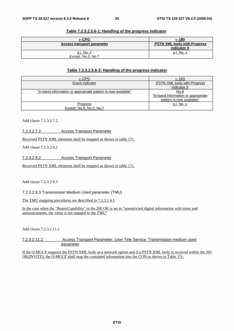
Table 7.2.3.2.5.6-1: Handling of the progress indicator
←CPG ←180 Access transport parameter PSTN XML body with Progress
indicator X p.i. No. x
Except: No.3, No.7 p.i. No. x
Table 7.2.3.2.5.6-3: Handling of the progress indicator
←CPG ←183 Event indicator PSTN XML body with Progress
indicator X ”In-band information or appropriate pattern is now available” No.8
”In-band information or appropriate pattern is now available”
Progress Except: No.8, No.3, No.7
p.i. No. x
Add clause 7.2.3.2.7.2
7.2.3.2.7.2 Access Transport Parameter
Received PSTN XML elements shall be mapped as shown in table 17c.
Add clause 7.2.3.2.9.2
7.2.3.2.9.2 Access Transport Parameter
Received PSTN XML elements shall be mapped as shown in table 17c.
Add clause 7.2.3.2.9.3
7.2.3.2.9.3 Transmission Medium Used parameter (TMU)
The TMU mapping procedures are described in 7.2.3.1.4.1
In the case when the "BearerCapability" in the 200 OK is set to "unrestricted digital information with tones and announcements, the value is not mapped to the TMU"
Add clause 7.2.3.2.11.2
7.2.3.2.11.2 Access Transport Parameter, User Tele Service, Transmission medium used parameter
If the O-MGCF supports the PSTN XML body as a network option and if a PSTN XML body is received within the 200 OK(INVITE), the O-MGCF shall map the contained information into the CON as shown in Table 17c.
ETSI
ETSI TS 129 527 V8.3.0 (2009-04) 263GPP TS 29.527 version 8.3.0 Release 8
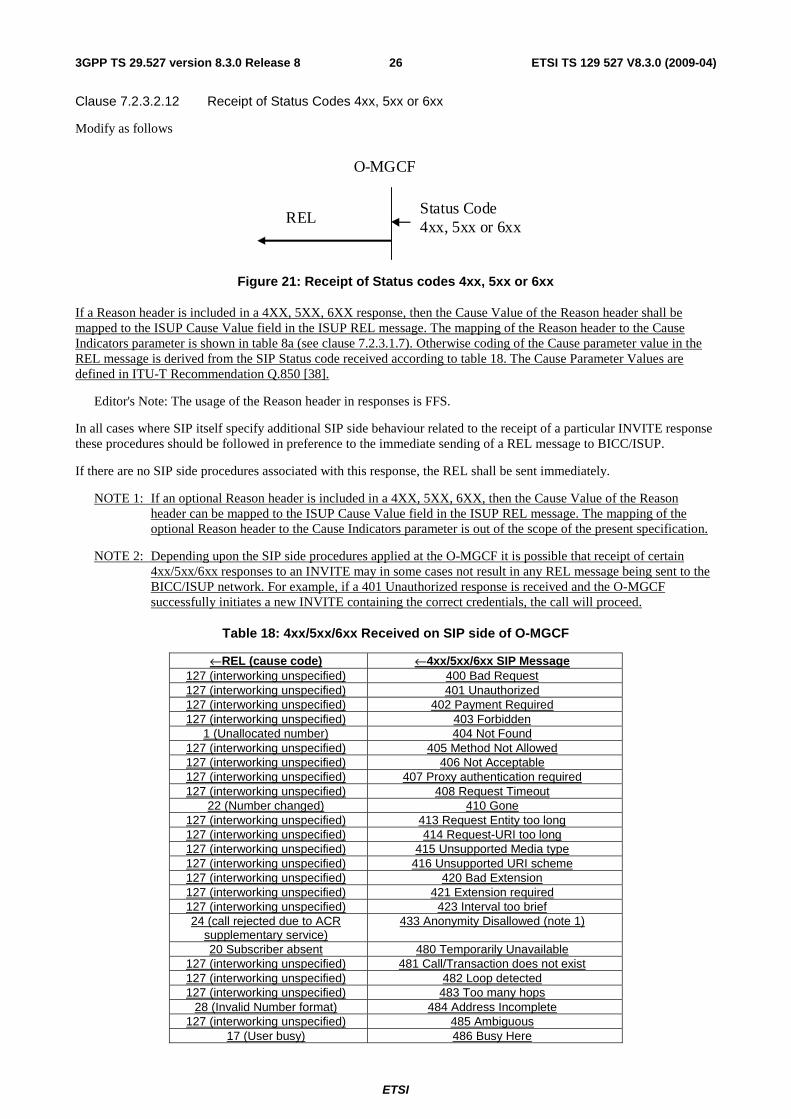
Clause 7.2.3.2.12 Receipt of Status Codes 4xx, 5xx or 6xx
Modify as follows
REL Status Code 4xx, 5xx or 6xx
O-MGCF
Figure 21: Receipt of Status codes 4xx, 5xx or 6xx
If a Reason header is included in a 4XX, 5XX, 6XX response, then the Cause Value of the Reason header shall be mapped to the ISUP Cause Value field in the ISUP REL message. The mapping of the Reason header to the Cause Indicators parameter is shown in table 8a (see clause 7.2.3.1.7). Otherwise coding of the Cause parameter value in the REL message is derived from the SIP Status code received according to table 18. The Cause Parameter Values are defined in ITU-T Recommendation Q.850 [38].
Editor's Note: The usage of the Reason header in responses is FFS.
In all cases where SIP itself specify additional SIP side behaviour related to the receipt of a particular INVITE response these procedures should be followed in preference to the immediate sending of a REL message to BICC/ISUP.
If there are no SIP side procedures associated with this response, the REL shall be sent immediately.
NOTE 1: If an optional Reason header is included in a 4XX, 5XX, 6XX, then the Cause Value of the Reason header can be mapped to the ISUP Cause Value field in the ISUP REL message. The mapping of the optional Reason header to the Cause Indicators parameter is out of the scope of the present specification.
NOTE 2: Depending upon the SIP side procedures applied at the O-MGCF it is possible that receipt of certain 4xx/5xx/6xx responses to an INVITE may in some cases not result in any REL message being sent to the BICC/ISUP network. For example, if a 401 Unauthorized response is received and the O-MGCF successfully initiates a new INVITE containing the correct credentials, the call will proceed.
Table 18: 4xx/5xx/6xx Received on SIP side of O-MGCF
←REL (cause code) ←4xx/5xx/6xx SIP Message 127 (interworking unspecified) 400 Bad Request 127 (interworking unspecified) 401 Unauthorized 127 (interworking unspecified) 402 Payment Required 127 (interworking unspecified) 403 Forbidden
1 (Unallocated number) 404 Not Found 127 (interworking unspecified) 405 Method Not Allowed 127 (interworking unspecified) 406 Not Acceptable 127 (interworking unspecified) 407 Proxy authentication required 127 (interworking unspecified) 408 Request Timeout
22 (Number changed) 410 Gone 127 (interworking unspecified) 413 Request Entity too long 127 (interworking unspecified) 414 Request-URI too long 127 (interworking unspecified) 415 Unsupported Media type 127 (interworking unspecified) 416 Unsupported URI scheme 127 (interworking unspecified) 420 Bad Extension 127 (interworking unspecified) 421 Extension required 127 (interworking unspecified) 423 Interval too brief 24 (call rejected due to ACR
supplementary service) 433 Anonymity Disallowed (note 1)
20 Subscriber absent 480 Temporarily Unavailable 127 (interworking unspecified) 481 Call/Transaction does not exist 127 (interworking unspecified) 482 Loop detected 127 (interworking unspecified) 483 Too many hops
28 (Invalid Number format) 484 Address Incomplete 127 (interworking unspecified) 485 Ambiguous
17 (User busy) 486 Busy Here
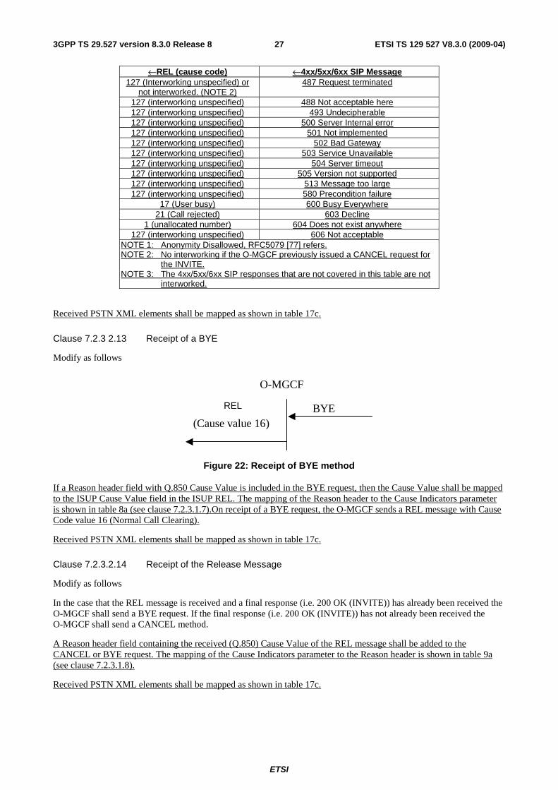
ETSI
ETSI TS 129 527 V8.3.0 (2009-04) 273GPP TS 29.527 version 8.3.0 Release 8
←REL (cause code) ←4xx/5xx/6xx SIP Message 127 (Interworking unspecified) or
not interworked. (NOTE 2) 487 Request terminated
127 (interworking unspecified) 488 Not acceptable here 127 (interworking unspecified) 493 Undecipherable 127 (interworking unspecified) 500 Server Internal error 127 (interworking unspecified) 501 Not implemented 127 (interworking unspecified) 502 Bad Gateway 127 (interworking unspecified) 503 Service Unavailable 127 (interworking unspecified) 504 Server timeout 127 (interworking unspecified) 505 Version not supported 127 (interworking unspecified) 513 Message too large 127 (interworking unspecified) 580 Precondition failure
17 (User busy) 600 Busy Everywhere 21 (Call rejected) 603 Decline
1 (unallocated number) 604 Does not exist anywhere 127 (interworking unspecified) 606 Not acceptable
NOTE 1: Anonymity Disallowed, RFC5079 [77] refers. NOTE 2: No interworking if the O-MGCF previously issued a CANCEL request for
the INVITE. NOTE 3: The 4xx/5xx/6xx SIP responses that are not covered in this table are not
interworked.
Received PSTN XML elements shall be mapped as shown in table 17c.
Clause 7.2.3 2.13 Receipt of a BYE
Modify as follows
REL
(Cause value 16)
O-MGCF
BYE
Figure 22: Receipt of BYE method
If a Reason header field with Q.850 Cause Value is included in the BYE request, then the Cause Value shall be mapped to the ISUP Cause Value field in the ISUP REL. The mapping of the Reason header to the Cause Indicators parameter is shown in table 8a (see clause 7.2.3.1.7).On receipt of a BYE request, the O-MGCF sends a REL message with Cause Code value 16 (Normal Call Clearing).
Received PSTN XML elements shall be mapped as shown in table 17c.
Clause 7.2.3.2.14 Receipt of the Release Message
Modify as follows
In the case that the REL message is received and a final response (i.e. 200 OK (INVITE)) has already been received the O-MGCF shall send a BYE request. If the final response (i.e. 200 OK (INVITE)) has not already been received the O-MGCF shall send a CANCEL method.
A Reason header field containing the received (Q.850) Cause Value of the REL message shall be added to the CANCEL or BYE request. The mapping of the Cause Indicators parameter to the Reason header is shown in table 9a (see clause 7.2.3.1.8).
Received PSTN XML elements shall be mapped as shown in table 17c.
ETSI
ETSI TS 129 527 V8.3.0 (2009-04) 283GPP TS 29.527 version 8.3.0 Release 8
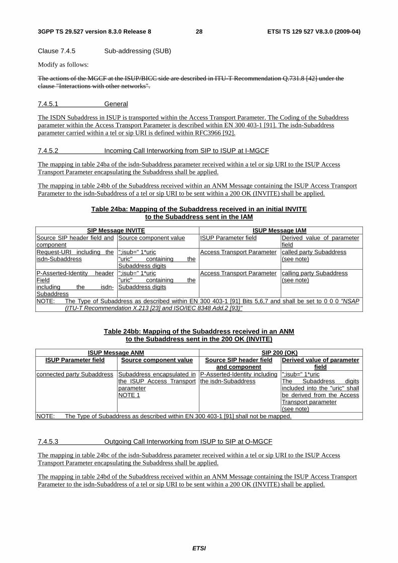
Clause 7.4.5 Sub-addressing (SUB)
Modify as follows:
The actions of the MGCF at the ISUP/BICC side are described in ITU-T Recommendation Q.731.8 [42] under the clause "Interactions with other networks".
7.4.5.1 General
The ISDN Subaddress in ISUP is transported within the Access Transport Parameter. The Coding of the Subaddress parameter within the Access Transport Parameter is described within EN 300 403-1 [91]. The isdn-Subaddress parameter carried within a tel or sip URI is defined within RFC3966 [92].
7.4.5.2 Incoming Call Interworking from SIP to ISUP at I-MGCF
The mapping in table 24ba of the isdn-Subaddress parameter received within a tel or sip URI to the ISUP Access Transport Parameter encapsulating the Subaddress shall be applied.
The mapping in table 24bb of the Subaddress received within an ANM Message containing the ISUP Access Transport Parameter to the isdn-Subaddress of a tel or sip URI to be sent within a 200 OK (INVITE) shall be applied.
Table 24ba: Mapping of the Subaddress received in an initial INVITE to the Subaddress sent in the IAM
SIP Message INVITE ISUP Message IAM Source SIP header field and component
Source component value ISUP Parameter field Derived value of parameter field
Request-URI including the isdn-Subaddress
";isub=" 1*uric "uric" containing the Subaddress digits
Access Transport Parameter
called party Subaddress (see note)
P-Asserted-Identity header Field including the isdn-Subaddress
";isub=" 1*uric "uric" containing the Subaddress digits
Access Transport Parameter
calling party Subaddress (see note)
NOTE: The Type of Subaddress as described within EN 300 403-1 [91] Bits 5,6,7 and shall be set to 0 0 0 "NSAP (ITU-T Recommendation X.213 [23] and ISO/IEC 8348 Add.2 [93)"
Table 24bb: Mapping of the Subaddress received in an ANM to the Subaddress sent in the 200 OK (INVITE)
ISUP Message ANM SIP 200 (OK) ISUP Parameter field Source component value Source SIP header field
and component Derived value of parameter
field connected party Subaddress Subaddress encapsulated in
the ISUP Access Transport parameter NOTE 1
P-Asserted-Identity including the isdn-Subaddress
";isub=" 1*uric The Subaddress digits included into the "uric" shall be derived from the Access Transport parameter (see note)
NOTE: The Type of Subaddress as described within EN 300 403-1 [91] shall not be mapped.
7.4.5.3 Outgoing Call Interworking from ISUP to SIP at O-MGCF
The mapping in table 24bc of the isdn-Subaddress parameter received within a tel or sip URI to the ISUP Access Transport Parameter encapsulating the Subaddress shall be applied.
The mapping in table 24bd of the Subaddress received within an ANM Message containing the ISUP Access Transport Parameter to the isdn-Subaddress of a tel or sip URI to be sent within a 200 OK (INVITE) shall be applied.
ETSI
ETSI TS 129 527 V8.3.0 (2009-04) 293GPP TS 29.527 version 8.3.0 Release 8
Table 24bc: Mapping of the Subaddress received in an IAM to the Subaddress sent in the INVITE
ISUP IAM Message SIP INVITE Message ISUP Parameter field Source component value Source SIP header field and
component Derived value of parameter
field called party Subaddress
Access Transport parameter Note 1
Request-URI and To header field including the isdn-Subaddress
";isub=" 1*uric The Subaddress digits included into the "uric" shall be derived from the Access Transport parameter (see note)
calling party Subaddress
Access Transport parameter Note 1
P-Asserted-Identity header field and From header field including the isdn-Subaddress
";isub=" 1*uric The Subaddress digits included into the "uric" shall be derived from the Access Transport parameter (see note)
NOTE: The "Type of Subaddress" as described within EN 300 403-1 [91] shall not be mapped
Table 24bd: Mapping of the Subaddress received in a 200OK to the Subaddress sent in the ANM
200OK ANM Source SIP header field and
component Source component value ISUP Parameter field Derived value of parameter
field P-Asserted-Identity including the
";isub=" 1*uric
connected party Subaddress Access Transport parameter (see note)
NOTE: The "Type of Subaddress as described" within EN 300 403-1 [91] Bits 5,6,7 and shall be set to 0 0 0 "NSAP (ITU-T Recommendation. X.213 [23] and ISO/IEC 8348 Add.2 [93])"
Clause 7.4.21 User-to-User Signalling (UUS)
Modify as follows:
7.4.21.1 User-to-User Signalling (UUS) service 1 (implicit)
The coding of the User-user information element is described within EN 300 356-8 [10]. The User-to-User header is defined within ES 283 003 [3].
NOTE 1: If the draft-johnston- sipping-cc-uui is agreed then the Reference to ES 283 003 [3] will be replaced by the agreed RFC.
NOTE 2: The IETF RFC needs more detail on encoding of the UUI as defined within ITU-T Recommendation Q.763 i.e. the protocol discriminator and the encoding syntax.
The content of the uuidata field of the User-to-User header shall start with the first octet being the protocol discriminator and followed by the user information octets.
The format of the uuidata field shall be the hexadecimal representation of binary data coded in ascii alphanumeric characters. For example, the 8- bit binary value 0011- 1111 is 3F in hexadecimal. To code this in ascii, one 8- bit byte containing the ascii code for the character '3' (0011- 0011 or 033H) and one 8- bit byte containing the ascii code for the character 'F' (0100- 0110 or 046H) are required. For each byte value, the high-order hexadecimal digit is always the first digit of the pair of hexadecimal digits. The ascii letters used for the hex digits shall always be capital form.
For example:
User-to-User: 00C81031313232333334343535363637373838FA08303900064630E9E0;encoding=hex
Interworking procedures between the user-user information element and User-to-User header for the User-to-user signalling service 1 are defined in the following clauses.
NOTE 1: For 3GPP Release 8 the encoding of data should be described in more detail.
NOTE 2: For 3GPP Release 8 the interworking of the encoded data should be described in more detail.
ETSI
ETSI TS 129 527 V8.3.0 (2009-04) 303GPP TS 29.527 version 8.3.0 Release 8
7.4.21.1.1 Incoming Call Interworking from SIP to ISUP at I-MGCF
On the receipt of the User-to-User Header if the encoding header field parameter of the User-to-User header set to hex the I-MGCF shall map the content of the uuidata header field to the protocol discriminator and user information parameters of the user-user information element. Mapping procedures for other encoding header field values are or further study.
The length of user-user contents parameter shall be set by the I-MGCF according to the normal procedures.
The I-MGCF maps the messages transporting the user-user information according to the normal interworking procedures.
Table 7.4.21.1.1: Mapping of the User-to-User header to the ISUP user-to-user information parameter
SIP parameter � � ISUP parameter
Source SIP header field and
component
Source component
value
ISUP Parameter field Derived value of parameter field
User-to-User uuidata User-to-User Protocol discriminator and User Information
7.4.21.1.2 Outgoing Call Interworking from ISUP to SIP at O-MGCF
On the receipt of the user-user information element the O-MGCF shall map the protocol discriminator and user information parameters to the uuidata header field of the User-to-User header.
The O-MGCF shall set the encoding header field parameter of the User-to-User header to the "hex" value
The O-MGCF maps the messages transporting the user-user information according to the normal interworking procedures.
Table 7.4.21.1.1: Mapping of the ISUP user-to-user information parameter to the User-to-User header
� ISUP parameter � SIP parameter
ISUP Parameter field
Source parameter field Source SIP header field
and component
Derived value of parameter field
User-to-User Protocol discriminator and User Information User-to-User uuidata
7.4.21.2 User-to-User Signalling (UUS) service 1 (explicit)
The actions of the MGCF at the ISUP/BICC side are described in ITU-T Recommendation Q.737.1[42] under the clause "Interactions with other networks".
7.4.21.3 User-to-User Signalling (UUS) service 2 (implicit & explicit)
The actions of the MGCF at the ISUP/BICC side are described in ITU-T Recommendation Q.737.1[42] under the clause "Interactions with other networks".
7.4.21.4 User-to-User Signalling (UUS) service 3 (implicit & explicit)
The actions of the MGCF at the ISUP/BICC side are described in ITU-T Recommendation Q.737.1[42] under the clause "Interactions with other networks".
Annex D (informative): Bibliography
draft-johnston-sipping-cc-uui-02 "Transporting User to User Information for Call Centres using SIP" 2007
ETSI
ETSI TS 129 527 V8.3.0 (2009-04) 313GPP TS 29.527 version 8.3.0 Release 8
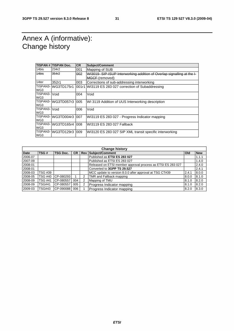
Annex A (informative): Change history
TISPAN # TISPAN Doc. CR Subject/Comment 14bis 234r2 001 Mapping of SUB 14bis 354r2 002 WI3019- SIP-ISUP Interworking addition of Overlap signalling at the I-
MGCF (removed) 14ter 352r1 003 Corrections of sub-addressing interworking TISPAN3-WG3
WG3TD175r1 001r1 WI3119 ES 283 027 correction of Subaddressing
TISPAN3-WG3
Void 004 Void
TISPAN3-WG3
WG3TD057r3 005 WI 3119 Addition of UUS Interworking description
TISPAN3-WG3
Void 006 Void
TISPAN3-WG3
WG3TD004r3 007 WI3119 ES 283 027 - Progress Indicator mapping
TISPAN3-WG3
WG3TD165r4 008 WI3119 ES 283 027 Fallback
TISPAN3-WG3
WG3TD129r3 009 WI3120 ES 283 027 SIP XML transit specific interworking
Change history Date TSG # TSG Doc. CR Rev Subject/Comment Old New 2006-07 Published as ETSI ES 283 027 1.1.1 2007-09 Published as ETSI ES 283 027 1.4.0 2008-01 Released on ETSI member approval process as ETSI ES 283 027 2.4.0 2008-01 Converted to 3GPP TS 29.527 2.4.1 2008-03 TSG #39 MCC update to version 8.0.0 after approval at TSG CT#39 2.4.1 8.0.0 2008-05 TSG #40 CP-080293 1 2 TMR and Fallback mapping 8.0.0 8.1.0 2008-09 TSG #41 CP-080557 004 2 Mapping of TMU 8.1.0 8.2.0 2008-09 TSG#41 CP-080557 005 2 Progress Indicator mapping 8.1.0 8.2.0 2009-03 TSG#43 CP-090088 006 1 Progress Indicator mapping 8.2.0 8.3.0

ETSI
ETSI TS 129 527 V8.3.0 (2009-04) 323GPP TS 29.527 version 8.3.0 Release 8
History
Document history
V8.0.0 April 2008 Publication
V8.1.0 July 2008 Publication
V8.2.0 October 2008 Publication
V8.3.0 April 2009 Publication


![°:² y ã=sþãdù3nÍ`M4 b ÉI ärÜ M ß ÓܺTv\Fù\ù \]\:'Ð Í ! n ... · ETSI TS 101 351 V8.3.0 (2000-03) Technical Specification Digital cellular telecommunications system](https://img.pdfslide.us/doc/110x75/5eb7467c530e821c81002fed/-y-sd3nm4-b-i-roe-m-oetvf-n-etsi.jpg)