Embed Size (px)
Citation preview

ETSI TS 129 212 V11.6.0 (2012-10)
Universal Mobile Telecommunications System (UMTS); LTE;
Policy and Charging Control (PCC) over Gx/Sd reference point (3GPP TS 29.212 version 11.6.0 Release 11)
Technical Specification

ETSI
ETSI TS 129 212 V11.6.0 (2012-10)13GPP TS 29.212 version 11.6.0 Release 11
Reference RTS/TSGC-0329212vb60
Keywords LTE,UMTS
ETSI
650 Route des Lucioles F-06921 Sophia Antipolis Cedex - FRANCE
Tel.: +33 4 92 94 42 00 Fax: +33 4 93 65 47 16
Siret N° 348 623 562 00017 - NAF 742 C
Association à but non lucratif enregistrée à la Sous-Préfecture de Grasse (06) N° 7803/88
Important notice
Individual copies of the present document can be downloaded from: http://www.etsi.org
The present document may be made available in more than one electronic version or in print. In any case of existing or perceived difference in contents between such versions, the reference version is the Portable Document Format (PDF).
In case of dispute, the reference shall be the printing on ETSI printers of the PDF version kept on a specific network drive within ETSI Secretariat.
Users of the present document should be aware that the document may be subject to revision or change of status. Information on the current status of this and other ETSI documents is available at
http://portal.etsi.org/tb/status/status.asp
If you find errors in the present document, please send your comment to one of the following services: http://portal.etsi.org/chaircor/ETSI_support.asp
Copyright Notification
No part may be reproduced except as authorized by written permission. The copyright and the foregoing restriction extend to reproduction in all media.
© European Telecommunications Standards Institute 2012.
All rights reserved.
DECTTM, PLUGTESTSTM, UMTSTM and the ETSI logo are Trade Marks of ETSI registered for the benefit of its Members. 3GPPTM and LTE™ are Trade Marks of ETSI registered for the benefit of its Members and
of the 3GPP Organizational Partners. GSM® and the GSM logo are Trade Marks registered and owned by the GSM Association.

ETSI
ETSI TS 129 212 V11.6.0 (2012-10)23GPP TS 29.212 version 11.6.0 Release 11
Intellectual Property Rights IPRs essential or potentially essential to the present document may have been declared to ETSI. The information pertaining to these essential IPRs, if any, is publicly available for ETSI members and non-members, and can be found in ETSI SR 000 314: "Intellectual Property Rights (IPRs); Essential, or potentially Essential, IPRs notified to ETSI in respect of ETSI standards", which is available from the ETSI Secretariat. Latest updates are available on the ETSI Web server (http://ipr.etsi.org).
Pursuant to the ETSI IPR Policy, no investigation, including IPR searches, has been carried out by ETSI. No guarantee can be given as to the existence of other IPRs not referenced in ETSI SR 000 314 (or the updates on the ETSI Web server) which are, or may be, or may become, essential to the present document.
Foreword This Technical Specification (TS) has been produced by ETSI 3rd Generation Partnership Project (3GPP).
The present document may refer to technical specifications or reports using their 3GPP identities, UMTS identities or GSM identities. These should be interpreted as being references to the corresponding ETSI deliverables.
The cross reference between GSM, UMTS, 3GPP and ETSI identities can be found under http://webapp.etsi.org/key/queryform.asp.

ETSI
ETSI TS 129 212 V11.6.0 (2012-10)33GPP TS 29.212 version 11.6.0 Release 11
Contents
Intellectual Property Rights ................................................................................................................................ 2
Foreword ............................................................................................................................................................. 2
Foreword ........................................................................................................................................................... 12
1 Scope ...................................................................................................................................................... 13
2 References .............................................................................................................................................. 13
3 Definitions and abbreviations ................................................................................................................. 15
3.1 Definitions ........................................................................................................................................................ 15
3.2 Abbreviations ................................................................................................................................................... 15
4 Gx reference point .................................................................................................................................. 16
4.1 Overview .......................................................................................................................................................... 16
4.2 Gx Reference model ......................................................................................................................................... 16
4.3 PCC Rules ........................................................................................................................................................ 17
4.3.1 PCC Rule Definition ................................................................................................................................... 17
4.3.2 Operations on PCC Rules ........................................................................................................................... 19
4.3a IP flow mobility routing rules .......................................................................................................................... 19
4.3a.1 Functional entities ....................................................................................................................................... 19
4.3a.2 IP flow mobility routing rule definition ...................................................................................................... 19
4.3a.3 Operations on Routing rules ....................................................................................................................... 20
4.3a.4 PCC procedures for IP flow mobility routing rule over Gx reference point ............................................... 20
4.3a.4.1 Provisioning of IP flow mobility routing rules...................................................................................... 20
4.3b Application Detection and Control Rules ......................................................................................................... 21
4.3b.1 Functional entities ....................................................................................................................................... 21
4.3b.2 Application Detection and Control Rule Definition ................................................................................... 21
4.3b.3 Operations on ADC Rules .......................................................................................................................... 22
4.4 Functional elements .......................................................................................................................................... 22
4.4.1 PCRF .......................................................................................................................................................... 22
4.4.2 PCEF ........................................................................................................................................................... 23
4.5 PCC procedures over Gx reference point ......................................................................................................... 24
4.5.1 Request for PCC rules................................................................................................................................. 24
4.5.2 Provisioning of PCC rules .......................................................................................................................... 26
4.5.2.0 Overview ............................................................................................................................................... 26
4.5.2.1 Selecting a PCC rule for Uplink IP packets .......................................................................................... 28
4.5.2.2 Selecting a PCC rule and IP CAN Bearer for Downlink IP packets ..................................................... 29
4.5.2.3 Gate function ......................................................................................................................................... 29
4.5.2.4 Policy enforcement for "Authorized QoS" per PCC Rule ..................................................................... 29
4.5.2.5 Usage Monitoring Control .................................................................................................................... 29
4.5.3 Provisioning of Event Triggers ................................................................................................................... 29
4.5.4 Provisioning of charging related information for the IP-CAN session ....................................................... 30
4.5.4.1 Provisioning of Charging Addresses ..................................................................................................... 30
4.5.4.2 Provisioning of Default Charging Method ............................................................................................ 30
4.5.4.3 Void....................................................................................................................................................... 30
4.5.4.4 Provisioning of Access Network Charging Identifier ........................................................................... 30
4.5.5 Provisioning and Policy Enforcement of Authorized QoS ......................................................................... 31
4.5.5.0 Overview ............................................................................................................................................... 31
4.5.5.0a Provisioning of authorized QoS per IP CAN bearer ............................................................................. 31
4.5.5.1 Policy enforcement for authorized QoS per IP CAN bearer ................................................................. 31
4.5.5.2 Policy provisioning for authorized QoS per service data flow .............................................................. 32
4.5.5.3 Policy enforcement for authorized QoS per service data flow .............................................................. 32
4.5.5.4 Coordination of authorized QoS scopes in mixed mode ....................................................................... 32
4.5.5.5 Provisioning of authorized QoS per QCI .............................................................................................. 32
4.5.5.6 Policy enforcement for authorized QoS per QCI .................................................................................. 32
4.5.5.7 Provisioning of authorized QoS per APN ............................................................................................. 33
4.5.5.8 Policy enforcement for authorized QoS per APN ................................................................................. 33

ETSI
ETSI TS 129 212 V11.6.0 (2012-10)43GPP TS 29.212 version 11.6.0 Release 11
4.5.5.9 Provisioning of authorized QoS for the Default EPS Bearer ................................................................ 33
4.5.5.10 Policy enforcement for authorized QoS of the Default EPS Bearer ...................................................... 33
4.5.6 Indication of IP-CAN Bearer Termination Implications............................................................................. 33
4.5.7 Indication of IP-CAN Session Termination ................................................................................................ 34
4.5.8 Request of IP-CAN Bearer Termination ..................................................................................................... 34
4.5.9 Request of IP-CAN Session Termination ................................................................................................... 35
4.5.10 Bearer Control Mode Selection .................................................................................................................. 35
4.5.11 Provisioning of Event Report Indication .................................................................................................... 36
4.5.12 PCC Rule Error Handling ........................................................................................................................... 36
4.5.13 Time of the day procedures......................................................................................................................... 37
4.5.14 Trace activation/deactivation ...................................................................................................................... 38
4.5.15 IMS Emergency Session Support ............................................................................................................... 38
4.5.15.1 Functional Entities ................................................................................................................................ 38
4.5.15.2 PCC procedures for Emergency services over Gx reference point ....................................................... 38
4.5.15.2.1 Request for PCC Rules for Emergency services ............................................................................. 38
4.5.15.2.2 Provisioning of PCC Rules for Emergency services ....................................................................... 38
4.5.15.2.2.1 Provisioning of PCC Rules at Gx session establishment ........................................................... 38
4.5.15.2.2.2 Provisioning of PCC Rules for Emergency Services ................................................................. 39
4.5.15.2.3 Removal of PCC Rules for Emergency Services ............................................................................. 39
4.5.15.2.4 Removal of PCC Rules at Gx session termination .......................................................................... 39
4.5.16 Requesting Usage Monitoring Control ....................................................................................................... 39
4.5.17 Reporting Accumulated Usage ................................................................................................................... 41
4.5.17.1 Usage Threshold Reached ..................................................................................................................... 41
4.5.17.2 PCC Rule Removal ............................................................................................................................... 42
4.5.17.3 Usage Monitoring Disabled .................................................................................................................. 42
4.5.17.4 IP-CAN Session Termination................................................................................................................ 42
4.5.17.5 PCRF Requested Usage Report............................................................................................................. 42
4.5.17.6 Report in case of Monitoring Time provided ........................................................................................ 42
4.5.18 IMS Restoration Support ............................................................................................................................ 43
4.5.19 Multimedia Priority Support ....................................................................................................................... 43
4.5.19.1 PCC Procedures for Multimedia Priority services over Gx reference point .......................................... 43
4.5.19.1.1 Provisioning of PCC Rules for Multimedia Priority Services ......................................................... 43
4.5.19.1.2 Invocation/Revocation of Priority EPS Bearer Services ................................................................. 44
4.5.19.1.3 Invocation/Revocation of IMS Multimedia Priority Services ......................................................... 44
4.5.20 Sponsored Data Connectivity ..................................................................................................................... 45
4.5.21 PCRF Failure and Restoration .................................................................................................................... 45
4.5.22 Reporting Access Network Information ..................................................................................................... 45
4.6 ADC procedures over Gx reference point ........................................................................................................ 45
4.6.1 Request for ADC rules ................................................................................................................................ 45
4.6.2 Provisioning of ADC rules ......................................................................................................................... 46
4.6.2.1 General .................................................................................................................................................. 46
4.6.2.2 Gate function ......................................................................................................................................... 46
4.6.2.3 Bandwidth limitation function .............................................................................................................. 47
4.6.2.4 Redirect function ................................................................................................................................... 47
4.6.2.5 Usage Monitoring Control .................................................................................................................... 47
4.6.3 ADC Rule Error Handling .......................................................................................................................... 47
4.6.4 Requesting Usage Monitoring Control for applications ............................................................................. 48
4.6.5 Reporting applications' Accumulated Usage .............................................................................................. 49
4.6.5.1 General .................................................................................................................................................. 49
4.6.5.2 Usage Threshold Reached ..................................................................................................................... 50
4.6.5.3 ADC Rule Removal .............................................................................................................................. 50
4.6.5.4 Usage Monitoring Disabled .................................................................................................................. 50
4.6.5.5 IP-CAN Session Termination................................................................................................................ 50
4.6.5.6 PCRF Requested Usage Report............................................................................................................. 50
4.6.5.7 Report in case of Monitoring Time provided ........................................................................................ 51
4.6.6 Application Detection Information ............................................................................................................. 51
4.6.7 Time of the day procedures for ADC Rules ............................................................................................... 51
4a Gxx reference points .............................................................................................................................. 52
4a.1 Overview .......................................................................................................................................................... 52
4a.2 Gxx Reference model ....................................................................................................................................... 53
4a.3 Quality of Service Control Rules ..................................................................................................................... 54

ETSI
ETSI TS 129 212 V11.6.0 (2012-10)53GPP TS 29.212 version 11.6.0 Release 11
4a.3.1 Quality of Service Control Rule Definition ................................................................................................ 54
4a.3.2 Operations on QoS Rules ............................................................................................................................ 55
4a.4 Functional elements .......................................................................................................................................... 56
4a.4.1 PCRF .......................................................................................................................................................... 56
4a.4.2 BBERF ........................................................................................................................................................ 56
4a.5 PCC procedures over Gxx reference points ..................................................................................................... 57
4a.5.1 Gateway control and QoS Rules Request ................................................................................................... 57
4a.5.2 Gateway control and QoS Rules Provision ................................................................................................. 58
4a.5.2.1 Overview ............................................................................................................................................... 58
4a.5.3 Gateway Control Session Termination ....................................................................................................... 59
4a.5.4 Request of Gateway Control Session Termination ..................................................................................... 59
4a.5.5 QoS Control Rule error handling ................................................................................................................ 60
4a.5.6 Gateway Control session to Gx session linking .......................................................................................... 60
4a.5.7 Multiple BBF support ................................................................................................................................. 61
4a.5.7.1 General .................................................................................................................................................. 61
4a.5.7.2 Handling of two BBFs associated with the same IP-CAN session during handover ............................ 61
4a.5.7.3 Handling of multiple BBFs with flow mobility within IP-CAN session ............................................... 62
4a.5.8 Provisioning of Event Triggers ................................................................................................................... 63
4a.5.9 Bearer Control Mode Selection .................................................................................................................. 64
4a.5.10 Provisioning and Policy Enforcement of Authorized QoS ......................................................................... 64
4a.5.10.1 Provisioning of authorized QoS for the Default EPS Bearer ................................................................ 64
4a.5.10.2 Policy enforcement for authorized QoS of the Default EPS Bearer ...................................................... 64
4a.5.10.3 Provisioning of authorized QoS per APN ............................................................................................. 64
4a.5.10.4 Policy provisioning for authorized QoS per service data flow .............................................................. 65
4a.5.10.5 Policy enforcement for authorized QoS per service data flow .............................................................. 65
4a.5.11 Trace activation/deactivation ...................................................................................................................... 65
4a.5.12 IMS Emergency Session Support ............................................................................................................... 65
4a.5.12.1 PCC procedures for Emergency services over Gxx reference point ..................................................... 65
4a.5.12.1.1 Gateway control and QoS Rules request for Emergency services ................................................... 65
4a.5.12.1.2 Provisioning of QoS Rules for Emergency services ........................................................................ 66
4a.5.12.1.2.1 Provisioning of QoS Rules at Gxx session establishment .......................................................... 66
4a.5.12.1.2.2 Provisioning of QoS Rules for Emergency services .................................................................. 66
4a.5.12.2 Gateway Control Session to Gx session linking.................................................................................... 66
4a.5.12.3 Removal of QoS Rules for Emergency Services ................................................................................... 66
4a.5.12.4 Termination of Gateway Control session for Emergency Services ....................................................... 67
4a.5.13 Time of the day procedures......................................................................................................................... 67
4a.5.14 Multimedia Priority Support ....................................................................................................................... 68
4a.5.14.1 PCC Procedures for Multimedia Priority services over Gxx reference point ........................................ 68
4a.5.14.1.1 Provisioning of QoS Rules for Multimedia Priority Services.......................................................... 68
4a.5.14.1.2 Invocation/Revocation of Priority EPS Bearer Services ................................................................. 68
4a.5.14.1.3 Invocation/Revocation of IMS Multimedia Priority Services ......................................................... 68
4a.5.15 PCRF Failure and Restoration .................................................................................................................... 68
4a.5.16 Reporting Access Network Information ..................................................................................................... 69
4b Sd reference point ................................................................................................................................... 69
4b.1 Overview .......................................................................................................................................................... 69
4b.2 Sd Reference model.......................................................................................................................................... 69
4b.3 Application Detection and Control Rules ......................................................................................................... 71
4b.3.1 Functional entities ....................................................................................................................................... 71
4b.3.2 Application Detection and Control Rule Definition ................................................................................... 71
4b.3.3 Operations on ADC Rules .......................................................................................................................... 71
4b.4 Functional elements .......................................................................................................................................... 72
4b.4.1 PCRF .......................................................................................................................................................... 72
4b.4.2 TDF ............................................................................................................................................................. 72
4b.5 ADC procedures over Sd reference point for solicited application reporting ................................................... 72
4b.5.1 Provisioning of ADC rules ......................................................................................................................... 72
4b.5.1.1 General .................................................................................................................................................. 72
4b.5.1.2 Gate function ......................................................................................................................................... 74
4b.5.1.3 Bandwidth limitation function .............................................................................................................. 74
4b.5.1.4 Redirect function ................................................................................................................................... 74
4b.5.1.5 Usage Monitoring Control .................................................................................................................... 74
4b.5.2 Request for ADC rules ................................................................................................................................ 74

ETSI
ETSI TS 129 212 V11.6.0 (2012-10)63GPP TS 29.212 version 11.6.0 Release 11
4b.5.3 Provisioning of Event Triggers ................................................................................................................... 75
4b.5.4 Request of TDF Session Termination ......................................................................................................... 75
4b.5.5 ADC Rule Error Handling .......................................................................................................................... 75
4b.5.6 Requesting Usage Monitoring Control ....................................................................................................... 76
4b.5.7 Reporting Accumulated Usage ................................................................................................................... 77
4b.5.7.1 General .................................................................................................................................................. 77
4b.5.7.2 Usage Threshold Reached ..................................................................................................................... 78
4b.5.7.3 ADC Rule Removal .............................................................................................................................. 78
4b.5.7.4 Usage Monitoring Disabled .................................................................................................................. 78
4b.5.7.5 TDF Session Termination ..................................................................................................................... 78
4b.5.7.6 PCRF Requested Usage Report............................................................................................................. 78
4b.5.7.7 Report in case of Monitoring Time provided ........................................................................................ 79
4b.5.8 Provisioning of Event Report Indication .................................................................................................... 79
4b.5.9 Application Detection Information ............................................................................................................. 79
4b.5.10 Time of the day procedures......................................................................................................................... 80
4b.5.11 PCRF Failure and Restoration .................................................................................................................... 81
4b.5a ADC procedures over Sd reference point for unsolicited application reporting ............................................... 81
4b.5a.1 Provisioning of ADC rules ......................................................................................................................... 81
4b.5a.1.1 General .................................................................................................................................................. 81
4b.5a.2 Application Detection Information ............................................................................................................. 81
4b.5a.3 Request of TDF Session Termination ......................................................................................................... 82
4b.5a.4 TDF session to Gx session linking .............................................................................................................. 82
5 Gx protocol ............................................................................................................................................. 82
5.1 Protocol support ............................................................................................................................................... 82
5.2 Initialization, maintenance and termination of connection and session............................................................ 83
5.3 Gx specific AVPs ............................................................................................................................................. 83
5.3.1 Bearer-Usage AVP (3GPP-GPRS and 3GPP-EPS access types) ................................................................ 86
5.3.2 Charging-Rule-Install AVP (All access types) ........................................................................................... 87
5.3.3 Charging-Rule-Remove AVP (All access types) ........................................................................................ 87
5.3.4 Charging-Rule-Definition AVP (All access types) ..................................................................................... 88
5.3.5 Charging-Rule-Base-Name AVP (All access types) ................................................................................... 88
5.3.6 Charging-Rule-Name AVP (All access types) ............................................................................................ 88
5.3.7 Event-Trigger AVP (All access types)........................................................................................................ 89
5.3.8 Metering-Method AVP (All access types) .................................................................................................. 95
5.3.9 Offline AVP (All access types)................................................................................................................... 95
5.3.10 Online AVP (All access types) ................................................................................................................... 95
5.3.11 Precedence AVP (All access types) ............................................................................................................ 96
5.3.12 Reporting-Level AVP (All access types) .................................................................................................... 96
5.3.13 TFT-Filter AVP (3GPP-GPRS access type only) ....................................................................................... 97
5.3.14 TFT-Packet-Filter-Information AVP (3GPP-GPRS access type only) ....................................................... 97
5.3.15 ToS-Traffic-Class AVP (All access types) ................................................................................................. 98
5.3.16 QoS-Information AVP (All access types) ................................................................................................... 98
5.3.17 QoS-Class-Identifier AVP (All access types) ............................................................................................. 99
5.3.18 Charging-Rule-Report AVP (All access types) ........................................................................................ 100
5.3.19 PCC-Rule-Status AVP (All access types) ................................................................................................. 100
5.3.20 Bearer-Identifier AVP (Applicable access type 3GPP-GPRS) ................................................................. 101
5.3.21 Bearer-Operation AVP (Applicable access type 3GPP-GPRS) ................................................................ 101
5.3.22 Access-Network-Charging-Identifier-Gx AVP (All access types) ........................................................... 101
5.3.23 Bearer-Control-Mode AVP ....................................................................................................................... 102
5.3.24 Network-Request-Support AVP ............................................................................................................... 102
5.3.25 Guaranteed-Bitrate-DL AVP .................................................................................................................... 102
5.3.26 Guaranteed-Bitrate-UL AVP .................................................................................................................... 102
5.3.27 IP-CAN-Type AVP (All access types) ..................................................................................................... 102
5.3.28 QoS-Negotiation AVP (3GPP-GPRS Access Type only)......................................................................... 103
5.3.29 QoS-Upgrade AVP (3GPP-GPRS Access Type only) .............................................................................. 103
5.3.30 Event-Report-Indication AVP (All access types) ..................................................................................... 104
5.3.31 RAT-Type AVP ........................................................................................................................................ 104
5.3.32 Allocation-Retention-Priority AVP (All access types) ............................................................................. 105
5.3.33 CoA-IP-Address AVP (All access types) ................................................................................................. 106
5.3.34 Tunnel-Header-Filter AVP (All access types) .......................................................................................... 106
5.3.35 Tunnel-Header-Length AVP (All access types) ....................................................................................... 106

ETSI
ETSI TS 129 212 V11.6.0 (2012-10)73GPP TS 29.212 version 11.6.0 Release 11
5.3.36 Tunnel-Information AVP (All access types) ............................................................................................ 106
5.3.37 CoA-Information AVP (All access types) ................................................................................................ 107
5.3.38 Rule-Failure-Code AVP (All access types) .............................................................................................. 107
5.3.39 APN-Aggregate-Max-Bitrate-DL AVP .................................................................................................... 108
5.3.40 APN-Aggregate-Max-Bitrate-UL AVP .................................................................................................... 109
5.3.41 Revalidation-Time (ALL Access Types) .................................................................................................. 109
5.3.42 Rule-Activation-Time (ALL Access Types) ............................................................................................. 109
5.3.43 Rule-Deactivation-Time (ALL Access Types) ......................................................................................... 109
5.3.44 Session-Release-Cause (All access types) ................................................................................................ 109
5.3.45 Priority-Level AVP (All access types)...................................................................................................... 109
5.3.46 Pre-emption-Capability AVP .................................................................................................................... 110
5.3.47 Pre-emption-Vulnerability AVP ............................................................................................................... 110
5.3.48 Default-EPS-Bearer-QoS AVP ................................................................................................................. 110
5.3.49 AN-GW-Address AVP (All access types) ................................................................................................ 111
5.3.50 Resource-Allocation-Notification AVP (All access types) ....................................................................... 111
5.3.51 Security-Parameter-Index AVP (All access types) ................................................................................... 111
5.3.52 Flow-Label AVP (All access types) ......................................................................................................... 111
5.3.53 Flow-Information AVP (All access types) ................................................................................................ 111
5.3.54 Packet-Filter-Content AVP ....................................................................................................................... 112
5.3.55 Packet-Filter-Identifier AVP ..................................................................................................................... 112
5.3.56 Packet-Filter-Information AVP ................................................................................................................ 112
5.3.57 Packet-Filter-Operation AVP.................................................................................................................... 113
5.3.58 PDN-Connection-ID AVP ........................................................................................................................ 113
5.3.59 Monitoring-Key AVP ............................................................................................................................... 113
5.3.60 Usage-Monitoring-Information AVP ........................................................................................................ 113
5.3.61 Usage-Monitoring-Level AVP.................................................................................................................. 114
5.3.62 Usage-Monitoring-Report AVP ................................................................................................................ 114
5.3.63 Usage-Monitoring-Support AVP .............................................................................................................. 114
5.3.64 CSG-Information-Reporting AVP ............................................................................................................ 115
5.3.65 Flow-Direction AVP ................................................................................................................................. 115
5.3.66 Packet-Filter-Usage AVP (All access types) ............................................................................................ 115
5.3.67 Charging-Correlation-Indicator AVP (All access types) .......................................................................... 116
5.3.68 Routing-Rule-Install AVP ........................................................................................................................ 116
5.3.69 Routing-Rule-Remove AVP ..................................................................................................................... 116
5.3.70 Routing-Rule-Definition AVP .................................................................................................................. 116
5.3.71 Routing-Rule-Identifier AVP.................................................................................................................... 117
5.3.72 Routing-Filter AVP................................................................................................................................... 117
5.3.73 Routing-IP-Address AVP ......................................................................................................................... 117
5.3.74 Void .......................................................................................................................................................... 117
5.3.75 Void .......................................................................................................................................................... 117
5.3.76 Void .......................................................................................................................................................... 117
5.3.77 TDF-Application-Identifier AVP .............................................................................................................. 117
5.3.78 TDF-Information AVP ............................................................................................................................. 117
5.3.79 TDF-Destination-Realm AVP .................................................................................................................. 118
5.3.80 TDF-Destination-Host AVP ..................................................................................................................... 118
5.3.81 TDF-IP-Address AVP............................................................................................................................... 118
5.3.82 Redirect-Information AVP ....................................................................................................................... 118
5.3.83 Redirect-Support AVP .............................................................................................................................. 118
5.3.84 PS-to-CS-Session-Continuity AVP (3GPP-EPS access type only) .......................................................... 119
5.3.85 ADC-Rule-Install AVP ............................................................................................................................. 119
5.3.86 ADC-Rule-Remove AVP ......................................................................................................................... 119
5.3.87 ADC-Rule-Definition AVP ...................................................................................................................... 119
5.3.88 ADC-Rule-Base-Name AVP .................................................................................................................... 120
5.3.89 ADC-Rule-Name AVP ............................................................................................................................. 120
5.3.90 ADC-Rule-Report AVP ............................................................................................................................ 120
5.3.91 Application-Detection-Information AVP ................................................................................................. 120
5.3.92 TDF-Application-Instance-Identifier AVP ............................................................................................... 121
5.3.93 ADC-Revalidation-Time (ALL Access Types) ........................................................................................ 121
5.3.94 HeNB-BBF-FQDN AVP (3GPP-EPS access type only) .......................................................................... 121
5.3.95 HeNB-Local-IP-Address AVP (3GPP-EPS access type only) ................................................................. 121
5.3.96 UE-Local-IP-Address AVP (Non-3GPP-EPS access type only) .............................................................. 121
5.3.97 UDP-Source-Port AVP (3GPP-EPS and Non-3GPP-EPS access types) .................................................. 121

ETSI
ETSI TS 129 212 V11.6.0 (2012-10)83GPP TS 29.212 version 11.6.0 Release 11
5.3.98 Mute-Notification AVP ............................................................................................................................ 121
5.3.99 Monitoring-Time AVP ............................................................................................................................. 122
5.4 Gx re-used AVPs ............................................................................................................................................ 122
5.4.1 Use of the Supported-Features AVP on the Gx reference point ............................................................... 126
5.4.2 Flow-Description AVP ............................................................................................................................. 127
5.5 Gx specific Experimental-Result-Code AVP values ...................................................................................... 128
5.5.1 General ...................................................................................................................................................... 128
5.5.2 Success ...................................................................................................................................................... 128
5.5.3 Permanent Failures ................................................................................................................................... 128
5.5.4 Transient Failures ..................................................................................................................................... 129
5.6 Gx Messages .................................................................................................................................................. 129
5.6.1 Gx Application .......................................................................................................................................... 129
5.6.2 CC-Request (CCR) Command .................................................................................................................. 130
5.6.3 CC-Answer (CCA) Command .................................................................................................................. 131
5.6.4 Re-Auth-Request (RAR) Command ......................................................................................................... 131
5.6.5 Re-Auth-Answer (RAA) Command ......................................................................................................... 132
5a Gxx protocols ....................................................................................................................................... 132
5a.1 Protocol support ............................................................................................................................................. 132
5a.2 Initialization, maintenance and termination of connection and session.......................................................... 133
5a.3 Gxx specific AVPs ......................................................................................................................................... 133
5a.3.1 QoS-Rule-Install AVP (All access types) ................................................................................................. 133
5a.3.2 QoS-Rule-Remove AVP (All access types) .............................................................................................. 134
5a.3.3 QoS-Rule-Definition AVP (All access types)........................................................................................... 134
5a.3.4 QoS-Rule-Name AVP (All access types) ................................................................................................. 135
5a.3.5 QoS-Rule-Report AVP (All access types) ................................................................................................ 135
5a.3.6 Session-Linking-Indicator AVP (All access types) .................................................................................. 135
5a.3.7 QoS-Rule-Base-Name AVP (All access types) ........................................................................................ 135
5a.4 Gxx re-used AVPs .......................................................................................................................................... 135
5a.4.1 Use of the Supported-Features AVP on the Gxx reference point ............................................................. 140
5a.5 Gxx specific Experimental-Result-Code AVP values .................................................................................... 141
5a.6 Gxx Messages ................................................................................................................................................ 142
5a.6.1 Gxx Application ........................................................................................................................................ 142
5a.6.2 CC-Request (CCR) Command .................................................................................................................. 142
5a.6.3 CC-Answer (CCA) Command .................................................................................................................. 143
5a.6.4 Re-Auth-Request (RAR) Command ......................................................................................................... 143
5a.6.5 Re-Auth-Answer (RAA) Command ......................................................................................................... 144
5b Sd protocol ........................................................................................................................................... 144
5b.1 Protocol support ............................................................................................................................................. 144
5b.2 Initialization, maintenance and termination of connection and session.......................................................... 144
5b.3 Sd specific AVPs ............................................................................................................................................ 144
5b.4 Sd re-used AVPs ............................................................................................................................................ 144
5b.4.1 Use of the Supported-Features AVP on the Sd reference point ................................................................ 149
5b.5 Sd specific Experimental-Result-Code AVP values ....................................................................................... 150
5b.5.1 General ...................................................................................................................................................... 150
5b.5.2 Success ...................................................................................................................................................... 150
5b.5.3 Permanent Failures ................................................................................................................................... 151
5b.5.4 Transient Failures ..................................................................................................................................... 151
5b.6 Sd Messages ................................................................................................................................................... 151
5b.6.1 Sd Application .......................................................................................................................................... 151
5b.6.2 TDF-Session-Request (TSR) Command ................................................................................................... 151
5b.6.3 TDF-Session-Answer (TSA) Command ................................................................................................... 152
5b.6.4 CC-Request (CCR) Command .................................................................................................................. 152
5b.6.5 CC-Answer (CCA) Command .................................................................................................................. 153
5b.6.6 Re-Auth-Request (RAR) Command ......................................................................................................... 153
5b.6.7 Re-Auth-Answer (RAA) Command ......................................................................................................... 154
Annex A (normative): Access specific aspects (GPRS) ................................................................... 155
A.1 Scope .................................................................................................................................................... 155
A.2 Reference Model .................................................................................................................................. 155

ETSI
ETSI TS 129 212 V11.6.0 (2012-10)93GPP TS 29.212 version 11.6.0 Release 11
A.2 Functional Elements ............................................................................................................................. 155
A.2.1 PCRF .............................................................................................................................................................. 155
A.3 PCC procedures .................................................................................................................................... 155
A.3.1 Request for PCC rules .................................................................................................................................... 155
A.3.2 Provisioning of PCC rules .............................................................................................................................. 156
A.3.2.1 PCC rule request for services not known to PCRF ................................................................................... 157
A.3.2.2 Selecting a PCC rule and IP CAN Bearer for Downlink IP packets ......................................................... 157
A.3.3 Provisioning and Policy Enforcement of Authorized QoS ............................................................................. 157
A.3.3.0 Overview .................................................................................................................................................. 157
A.3.3.1 Provisioning of authorized QoS per IP CAN bearer ................................................................................. 157
A.3.3.2 Policy enforcement for authorized QoS per IP CAN bearer ..................................................................... 159
A.3.3.2a Policy provisioning for authorized QoS per service data flow ................................................................. 159
A.3.3.3 Policy enforcement for authorized QoS per service data flow .................................................................. 159
A.3.3.3a Coordination of authorized QoS scopes in mixed mode ........................................................................... 159
A.3.3.3b Provisioning of authorized QoS per QCI .................................................................................................. 160
A.3.3.4 Policy enforcement for authorized QoS per QCI ...................................................................................... 160
A.3.3.5 Void .......................................................................................................................................................... 160
A.3.4 Indication of IP-CAN Bearer Termination Implications ................................................................................ 160
A.3.5 Indication of IP-CAN Session Termination ................................................................................................... 160
A.3.6 Request of IP-CAN Bearer Termination ........................................................................................................ 160
A.3.7 Request of IP-CAN Session Termination ....................................................................................................... 161
A.3.8 Bearer Control Mode Selection ...................................................................................................................... 161
A.3.9 Bearer Binding Mechanism ............................................................................................................................ 162
A.3.10 Void ................................................................................................................................................................ 162
A.3.11 PCC Rule Error Handling ............................................................................................................................... 162
A.3.12 IMS Emergency Session Support ................................................................................................................... 162
A.3.12.1 Request of PCC Rules for an Emergency services ................................................................................... 162
A.3.12.2 Provisioning of PCC Rules for an Emergency services ............................................................................ 162
A.3.13 Removal of PCC Rules for Emergency Services ........................................................................................... 163
A.3.14 Removal of PCC Rules at Gx session termination ......................................................................................... 163
A.3.15 IMS Restoration Support ................................................................................................................................ 163
A.3.16 Provisioning of CSG information reporting indication .................................................................................. 163
A.3.17 Packet-Filter-Usage AVP ............................................................................................................................... 163
A.3.18 Precedence handling ....................................................................................................................................... 163
A.4 QoS Mapping ....................................................................................................................................... 164
A.4.1 GPRS QCI to UMTS QoS parameter mapping .............................................................................................. 164
A.4.2 GPRS ARP to UMTS ARP parameter mapping............................................................................................. 164
Annex B (normative): Access specific aspects, 3GPP (GERAN/UTRAN/E-UTRAN) EPS ........ 165
B.1 Scope .................................................................................................................................................... 165
B.2 Functional Elements ............................................................................................................................. 165
B.2.1 PCRF .............................................................................................................................................................. 165
B.2.2 PCEF .............................................................................................................................................................. 165
B.2.3 BBERF ........................................................................................................................................................... 165
B.3 PCC procedures .................................................................................................................................... 165
B.3.1 Request for PCC and/or QoS rules ................................................................................................................. 165
B.3.2 Provisioning of PCC and/or QoS rules ........................................................................................................... 166
B.3.3 Provisioning and Policy Enforcement of Authorized QoS ............................................................................. 167
B.3.3.1 Provisioning of authorized QoS per APN ................................................................................................. 167
B.3.3.2 Policy enforcement for authorized QoS per APN ..................................................................................... 167
B.3.3.3 QoS handling for interoperation with Gn/Gp SGSN ................................................................................ 167
B.3.3.4 Void .......................................................................................................................................................... 170
B.3.3.5 Policy provisioning for authorized QoS per service data flow ................................................................. 170
B.3.4 Packet-Filter-Information AVP ...................................................................................................................... 170
B.3.5 Bearer Control Mode Selection ...................................................................................................................... 170
B.3.6 Trace activation/deactivation at P-GW ........................................................................................................... 170
B.3.7 IMS Restoration Support ................................................................................................................................ 170
B.3.8 Provisioning of CSG information reporting indication .................................................................................. 170
B.3.9 Packet-Filter-Usage AVP ............................................................................................................................... 171

ETSI
ETSI TS 129 212 V11.6.0 (2012-10)103GPP TS 29.212 version 11.6.0 Release 11
B.3.10 User CSG Information Reporting ................................................................................................................... 171
B.3.11 Request of IP-CAN Bearer Termination ........................................................................................................ 171
B.3.12 CS To PS handover ........................................................................................................................................ 171
B.3.13 Precedence handling ....................................................................................................................................... 171
Annex C (Informative): Mapping table for type of access networks ................................................ 173
Annex D (normative): Access specific aspects (EPC-based Non-3GPP) ....................................... 174
D.1 Scope .................................................................................................................................................... 174
D.2 EPC-based eHRPD Access .................................................................................................................. 174
D.2.1 General ........................................................................................................................................................... 174
D.2.2 Gxa procedures ............................................................................................................................................... 174
D.2.2.1 Request for QoS rules ............................................................................................................................... 174
D.2.2.2 Provisioning of QoS rules ......................................................................................................................... 174
D.2.2.2.1 QoS rule request for services not known to PCRF .............................................................................. 174
D.2.2.3 Provisioning and Policy Enforcement of Authorized QoS ....................................................................... 175
D.2.2.3.1 Provisioning of authorized QoS .......................................................................................................... 175
D.2.2.3.2 Policy enforcement for authorized QoS .............................................................................................. 175
D.2.3 Bearer Control Mode Selection ...................................................................................................................... 175
D.2.4 QoS Mapping ................................................................................................................................................. 176
D.2.4.1 QCI to eHRPD QoS parameter mapping .................................................................................................. 176
D.3 EPC-based Trusted WLAN Access with S2a ....................................................................................... 176
Annex E (normative): Access specific aspects, Fixed Broadband Access interworking with EPC ............................................................................................................... 177
E.1 Scope .................................................................................................................................................... 177
E.2 Definitions and abbreviations ............................................................................................................... 177
E.2.1 Definitions ................................................................................................................................................ 177
E.2.2 Abbreviations ............................................................................................................................................ 177
E.3 Reference points and Reference model ................................................................................................ 177
E.3.0 General ...................................................................................................................................................... 177
E.3.1 Gx Reference Point ................................................................................................................................... 177
E.3.2 Gxx Reference Point ................................................................................................................................. 178
E.3.3 S15 Reference Point.................................................................................................................................. 178
E.3.3a Sd Reference Point.................................................................................................................................... 178
E.3.4 Reference Model ....................................................................................................................................... 178
E.4 Functional Elements ............................................................................................................................. 181
E.4.1 PCRF .............................................................................................................................................................. 181
E.4.2 PCEF .............................................................................................................................................................. 182
E.4.3 BBERF ........................................................................................................................................................... 182
E.4.4 HNB GW ........................................................................................................................................................ 182
E.5 PCC procedures .................................................................................................................................... 182
E.5.1 PCC procedures over Gx reference point ....................................................................................................... 182
E.5.2 PCC procedures over Gxx reference point ..................................................................................................... 183
E.5.2.1 Gateway Control Session Establishment ............................................................................................................ 183
E.5.2.2 Gateway Control Session Modification .............................................................................................................. 183
E.5.2.3 Gateway Control Session Termination ............................................................................................................... 183
E.5.2.4 Request of Gateway Control Session Termination ............................................................................................. 183
E.5.3 S15 Procedures ............................................................................................................................................... 183
E.5.3.1 S15 Session Establishment .................................................................................................................. 183
E.5.3.2 S15 Session Modification ................................................................................................................... 184
E.5.3.3 S15 Session Termination ..................................................................................................................... 184
E.5.4 ADC procedures over Sd reference point for solicited application reporting ................................................. 184
E.5.4.1 TDF session establishment ................................................................................................................................. 184
E.5.5 ADC procedures over Sd reference point for unsolicited application reporting ............................................. 185
E.5.5.1 General 185
E.5.5.2 TDF session to S9a* session linking ................................................................................................................... 185
ETSI
ETSI TS 129 212 V11.6.0 (2012-10)113GPP TS 29.212 version 11.6.0 Release 11
E.6 S15 Protocol ................................................................................................................................................... 185
E.6.1 Protocol support ........................................................................................................................................ 185
E.6.2 Initialization, maintenance and termination of connection and session .................................................... 186
E.6.3 S15 specific AVPs .................................................................................................................................... 186
E.6.3.1 General ................................................................................................................................................ 186
E.6.3.2 CS-Service-QoS-Request-Identifier .................................................................................................... 186
E.6.3.3 CS-Service-QoS-Request-Operation ................................................................................................... 186
E.6.4 S15 re- used AVPs .................................................................................................................................... 187
E.6.4.1 General ................................................................................................................................................ 187
E.6.4.2 Use of the Supported-Features AVP on the S15 reference point ........................................................ 187
E.6.5 S15 specific Experimental-Result-Code AVP values ............................................................................... 188
E.6.5.1 General ................................................................................................................................................ 188
E.6.5.2 Success ................................................................................................................................................ 188
E.6.5.3 Permanent Failures .............................................................................................................................. 188
E.6.5.4 Transient Failures ................................................................................................................................ 188
E.6.6 S15 Messages............................................................................................................................................ 188
E.6.6.1 S15 Application ................................................................................................................................... 188
E.6.6.2 CC-Request (CCR) Command ............................................................................................................ 189
E.6.6.3 CC-Answer (CCA) Command ............................................................................................................ 189
Annex F (informative): Change history ............................................................................................. 190
History ............................................................................................................................................................ 197

ETSI
ETSI TS 129 212 V11.6.0 (2012-10)123GPP TS 29.212 version 11.6.0 Release 11
Foreword This Technical Specification has been produced by the 3rd Generation Partnership Project (3GPP).
The contents of the present document are subject to continuing work within the TSG and may change following formal TSG approval. Should the TSG modify the contents of the present document, it will be re-released by the TSG with an identifying change of release date and an increase in version number as follows:
Version x.y.z
where:
x the first digit:
1 presented to TSG for information;
2 presented to TSG for approval;
3 or greater indicates TSG approved document under change control.
y the second digit is incremented for all changes of substance, i.e. technical enhancements, corrections, updates, etc.
z the third digit is incremented when editorial only changes have been incorporated in the document.

ETSI
ETSI TS 129 212 V11.6.0 (2012-10)133GPP TS 29.212 version 11.6.0 Release 11
1 Scope The present document provides the stage 3 specification of the Gx, Gxx and Sd reference points for the present release. The functional requirements and the stage 2 specifications of the Gx, Gxx and Sd reference points are contained in 3GPP TS 23.203 [7]. The Gx reference point lies between the Policy and Charging Rule Function and the Policy and Charging Enforcement Function. The Gxx reference point lies between the Policy and Charging Rule Function and the Bearer Binding and Event Reporting Function. The Sd reference point lies between the Policy and Charging Rule Function and the Traffic Detection Function.
Whenever it is possible the present document specifies the requirements for the protocol by reference to specifications produced by the IETF within the scope of Diameter. Where this is not possible, extensions to Diameter are defined within the present document.
2 References The following documents contain provisions which, through reference in this text, constitute provisions of the present document.
• References are either specific (identified by date of publication and/or edition number or version number) or non-specific.
• For a specific reference, subsequent revisions do not apply.
• For a non-specific reference, the latest version applies. In the case of a reference to a 3GPP document (including a GSM document), a non-specific reference implicitly refers to the latest version of that document in the same Release as the present document.
[1] 3GPP TR 21.905: "Vocabulary for 3GPP Specifications".
[2] 3GPP TS 29.210: "Charging Rule Provisioning over Gx Interface".
[3] Void.
[4] Void.
[5] IETF RFC 3588: "Diameter Base Protocol".
[6] Void.
[7] 3GPP TS 23.203: "Policy Control and Charging architecture".
[8] 3GPP TS 29.213: "Policy and charging control signalling flows and Quality of Service (QoS) parameter mapping".
[9] IETF RFC 4006: "Diameter Credit Control Application".
[10] 3GPP TS 29.214: "Policy and Charging Control over Rx reference point".
[11] 3GPP TS 29.061: "Interworking between the Public Land Mobile Network (PLMN) supporting packet based services and Packet Data Networks (PDN)".
[12] IETF RFC 4005: "Diameter Network Access Server Application".
[13] 3GPP TS 24.008: "Mobile radio interface Layer 3 specification".
[14] 3GPP TS 29.229: "Cx and Dx interfaces based on Diameter protocol; Protocol details".
[15] IETF RFC 3162: "Radius and IPv6".
[16] 3GPP TS 32.295: "Telecommunication management; Charging management; Charging Data Record (CDR) transfer".

ETSI
ETSI TS 129 212 V11.6.0 (2012-10)143GPP TS 29.212 version 11.6.0 Release 11
[17] 3GPP TS 23.060: "General Packet Radio Service (GPRS); Service description; Stage 2".
[18] 3GPP TS 29.060: "General Packet Radio Service (GPRS); GPRS Tunnelling Protocol (GTP) across the Gn and Gp interface".
[19] 3GPP TS 32.299: "Telecommunication management; Charging management; Diameter charging applications ".
[20] 3GPP2 X.S0011-E v1.0: "cdma2000 Wireless IP Network Standard".
[21] 3GPP TS 32.240: "Telecommunication management; Charging management; Charging architecture and principles".
[22] 3GPP TS 29.274: "3GPP Evolved Packet System. Evolved GPRS Tunnelling Protocol for EPS (GTPv2)".
[23] 3GPP TS 23.402: "Architecture enhancements for non-3GPP accesses".
[24] 3GPP2 X.S0057-0 v2.0: "E-UTRAN – eHRPD Connectivity and Interworking: Core Network Aspects".
[25] 3GPP TS 23.003: "Numbering, addressing and identification".
[26] 3GPP TS 29.272: "3GPP Evolved Packet System. Mobility Management Entity (MME) and Serving GPRS Support Node (SGSN) related interfaces based on Diameter protocol".
[27] 3GPP TS 32.422: "Telecommunication management; Subscriber and equipment trace; Trace control and configuration management".
[28] 3GPP TS 29.275: "Proxy Mobile IPv6 (PMIPv6) based Mobility and Tunnelling Protocols; Stage 3".
[29] 3GPP TS 43.318: "Generic access to the A/Gb interface; Stage 2".
[30] 3GPP2 X.S0062-0 v1.0: "PCC for cdma2000 1x and HRPD Networks ".
[31] 3GPP TS 23.228: "IP multimedia subsystem; Stage 2".
[32] 3GPP TS 23.401: "General Packet Radio Service (GPRS) enhancements for Evolved Universal Terrestrial Radio Access Network (E-UTRAN) access.
[33] 3GPP TS 23.380: "IMS Restoration Procedures".
[34] Void.
[35] 3GPP TS 23.261: "IP flow mobility and seamless Wireless Local Area Network (WLAN) offload; Stage 2".
[36] IETF RFC 3046: "DHCP Relay Agent Information Option".
[37] ETSI TS 283 034 v2.2.0: "Telecommunications and Internet converged Services and Protocols for Advanced Networking (TISPAN); Network Attachment Sub-System (NASS); e4 interface based on the DIAMETER protocol".
[38] 3GPP TS 23.335: "User Data Convergence (UDC); Technical realization and information flows; Stage 2".
[39] 3GPP TS 29.335: "User Data Convergence (UDC); User Data Repository Access Protocol over the Ud interface; Stage 3".
[40] 3GPP TS 23.216: "Single Radio Voice Call Continuity (SRVCC); Stage 2".
[41] 3GPP TS 23.107: "Quality of Service (QoS) concept and architecture".
[42] 3GPP TS 24.301: "Non-Access-Stratum (NAS) protocol for Evolved Packet".

ETSI
ETSI TS 129 212 V11.6.0 (2012-10)153GPP TS 29.212 version 11.6.0 Release 11
3 Definitions and abbreviations
3.1 Definitions For the purposes of the present document, the terms and definitions given in 3GPP TR 21.905 [1] and the following apply:
IP-CAN bearer: IP transmission path of defined capacity, delay and bit error rate, etc. See 3GPP TS 21.905 [1] for the definition of bearer.
IP-CAN session: association between a UE and an IP network. The association is identified by one or more UE IPv4 addresses/ and/or IPv6 prefix together with a UE identity information, if available, and a PDN represented by a PDN ID (e.g. an APN). An IP-CAN session incorporates one or more IP-CAN bearers. Support for multiple IP-CAN bearers per IP-CAN session is IP-CAN specific. An IP-CAN session exists as long as the related UE IPv4 address and/or IPv6 prefix are assigned and announced to the IP network.
IP flow: unidirectional flow of IP packets with the same source IP address and port number and the same destination IP address and port number and the same transport protocol. Port numbers are only applicable if used by the transport protocol.
Gateway Control Session: An association between a BBERF and a PCRF (when GTP is not used in the EPC), used for transferring access specific parameters, BBERF events and QoS rules between the PCRF and BBERF. In the context of this specification this is implemented by use of the Gxx procedures.
Monitoring key: Identifies a usage monitoring control instance.
TDF session: An association between the TDF and the PCRF. The association is identified by one UE IPv4 address and/or IPv6 prefix together with optionally a PDN represented by a PDN ID and a set of ADC rules to be applied by the TDF.
Usage monitoring control instance: the monitoring and reporting of the usage threshold for input, output or total data volume for the IP-CAN session/TDF session or the service data flows/application’s traffic associated with the same monitoring key.
Service data flow: an aggregate set of packet flows that matches a service data flow template (from 3GPP TS 23.203 [7]).
Service data flow filter: a set of packet flow header parameter values/ranges used to identify one or more of the packet flows constituting a service data flow (from 3GPP TS 23.203 [7]).
3.2 Abbreviations For the purpose of the present document, the abbreviations given in 3GPP TR 21.905 [1] and the following apply:
ADC Application Detection and Control AF Application Function AMBR Aggregate Maximum Bit Rate BBERF Bearer Binding and Event Reporting Function CCA Credit-Control-Answer (CC-Answer) CCR Credit-Control-Request (CC-Request) CSG Closed Subscriber Group CSG-ID Closed Subscriber Group IDentity DCC Diameter Credit Control GBR Guaranteed Bit Rate MPS Multimedia Priority Service OCS Online charging system OFCS Offline charging system PCEF Policy and Charging Enforcement Function PCRF Policy and Charging Rule Function RAA Re-Auth-Answer (RA-Answer) RAR Re-Auth-Request (RA-Request)SUPL Secure User Plane for Location

ETSI
ETSI TS 129 212 V11.6.0 (2012-10)163GPP TS 29.212 version 11.6.0 Release 11
TDF Traffic Detection Function TDA TDF-Session-Answer TDR TDF-Session-Request UDC User Data Convergence UDR User Data Repository
4 Gx reference point
4.1 Overview The Gx reference point is located between the Policy and Charging Rules Function (PCRF) and the Policy and Charging Enforcement Function (PCEF). The Gx reference point is used for provisioning and removal of PCC rules from the PCRF to the PCEF and the transmission of traffic plane events from the PCEF to the PCRF. The Gx reference point can be used for charging control, policy control or both by applying AVPs relevant to the application. The Gx reference point can also be used for application’s traffic detection and control.
The stage 2 level requirements for the Gx reference point are defined in 3GPP TS 23.203 [7].
Signalling flows related to the both Rx and Gx interfaces are specified in 3GPP TS 29.213 [8].
The definition of case 1, case 2a and case 2b is specified in subclause 4.0 in 3GPP TS 29.213 [8].
4.2 Gx Reference model The Gx reference point is defined between the PCRF and the PCEF. The relationships between the different functional entities involved are depicted in figure 4.2.1 and 4.2.2
Gx
Application Function (AF)
Sy
Gy
Gz
Subscription Profile Repository
(SPR)
Rx
Sp
Offline Charging System (OFCS)
Online ChargingSystem (OCS)
Gxx Sd
Policy and Charging Rules Function (PCRF)
AN-Gateway
Bearer Binding and
Event Reporting Function
(BBERF) Gateway
Policy and Charging
Enforcement Function
(PCEF) Traffic Detection Function (TDF)

ETSI
ETSI TS 129 212 V11.6.0 (2012-10)173GPP TS 29.212 version 11.6.0 Release 11
Figure 4.2.1: Gx reference point at the Policy and Charging Control (PCC) architecture with SPR
NOTE 1: The PCEF may support Application Detection and Control feature.
With the UDC-based architecture, as defined in 3GPP TS 23.335 [38] and applied in 3GPP TS 23.203 [7], the UDR replaces SPR and the Ud reference point provides access to the subscription data in the UDR. The Ud interface as defined in 3GPP TS 29.335 [39] is the interface between the PCRF and the UDR The relationships between the different functional elements are depicted in figure 4.2. When UDC architecture is used, SPR and Sp, whenever mentioned in this document, is replaced by UDR and Ud.
Gx
Application Function (AF)
Gy
Sy
Online Charging System (OCS)
Gz
User Data Repository
(UDR)
Rx
Ud
Offline Charging System (OFCS)
Gxx Sd
Policy and Charging Rules Function (PCRF)
AN-Gateway
Bearer Binding and
Event Reporting Function
(BBERF) Gateway
Policy and Charging
Enforcement Function
(PCEF) Traffic Detection Function (TDF)
Figure 4.2.2: Gx reference point at the Policy and Charging Control (PCC) architecture with UDR
NOTE 2: The details associated with the Sp reference point are not specified in this Release. The SPR’s relation to existing subscriber databases is not specified in this Release.
NOTE 3: The UDC Application Informational Model related to the PCRF is not specified in this Release.
NOTE 4: The PCEF may support Application Detection and Control feature.
NOTE 5: PCEF is located in the Gateway node implementing the IP access to the PDN. Refer to Annexes of 3GPP TS 23.203[7] for application to specific IP-CAN types.
NOTE 6: Refer to Annexes A.5 and H.2 of 3GPP TS 23.203[7] for application of AN-Gateways.
4.3 PCC Rules
4.3.1 PCC Rule Definition
The purpose of the PCC rule is to:

ETSI
ETSI TS 129 212 V11.6.0 (2012-10)183GPP TS 29.212 version 11.6.0 Release 11
- Detect a packet belonging to a service data flow.
- The service data flow filters within the PCC rule are used for the selection of downlink IP CAN bearers.
- The service data flow filters within the PCC rule are used for the enforcement that uplink IP flows are transported in the correct IP CAN bearer.
- Identify the service the service data flow contributes to.
- Provide applicable charging parameters for a service data flow.
- Provide policy control for a service data flow.
The PCEF shall select a PCC rule for each received packet by evaluating received packets against service data flow filters of PCC rules in the order of the precedence of the PCC rules. When a packet matches a service data flow filter, the packet matching process for that packet is completed, and the PCC rule for that filter shall be applied.
There are two different types of PCC rules as defined in 3GPP TS 23.203 [7]:
- Dynamic PCC rules. Dynamically provisioned by the PCRF to the PCEF via the Gx interface. These PCC rules may be either predefined or dynamically generated in the PCRF. Dynamic PCC rules can be installed, modified and removed at any time.
- Predefined PCC rules. Preconfigured in the PCEF. Predefined PCC rules can be activated or deactivated by the PCRF at any time. Predefined PCC rules within the PCEF may be grouped allowing the PCRF to dynamically activate a set of PCC rules over the Gx reference point.
NOTE: The operator may define a predefined PCC rule, to be activated by the PCEF. Such a predefined rule is not explicitly known in the PCRF.
A PCC rule consists of:
- a rule name;
- service identifier;
- service data flow filter(s);
- precedence;
- gate status;
- QoS parameters;
- indication for PS to CS session continuity;
- charging key (i.e. rating group);
- other charging parameters;
- monitoring key;
- sponsor identity;
- application service provider identity;
- indication of access network information reporting.
The rule name shall be used to reference a PCC rule in the communication between the PCEF and the PCRF.
The service identifier shall be used to identify the service or the service component the service data flow relates to.
The service data flow filter(s) shall be used to select the traffic for which the rule applies. It shall be possible to define wildcarded service data flow filter(s), both for the dynamic and predefined PCC rules.
The gate status indicates whether the service data flow, detected by the service data flow filter(s), may pass (gate is open) or shall be discarded (gate is closed) in uplink and/or in downlink direction.

ETSI
ETSI TS 129 212 V11.6.0 (2012-10)193GPP TS 29.212 version 11.6.0 Release 11
The QoS information includes the QoS class identifier (authorized QoS class for the service data flow), the Allocation and Retention Priority (ARP) and authorized bitrates for uplink and downlink.
The PS to CS session continuity indicates that the service data flow may be handed over to the CS domain as defined in 3GPP TS 23.216 [40].
The charging parameters define whether online and offline charging interfaces are used, what is to be metered in offline charging, on what level the PCEF shall report the usage related to the rule, etc.
For different PCC rules with overlapping service data flow filter, the precedence of the rule determines which of these rules is applicable. When a dynamic PCC rule and a predefined PCC rule have the same precedence, the dynamic PCC rule takes precedence.
PCC rule also includes Application Function record information for enabling charging correlation between the application and bearer layer if the AF has provided this information via the Rx interface. For IMS this includes the IMS Charging Identifier (ICID) and flow identifiers.
The monitoring key for a PCC rule identifies a monitoring control instance that shall be used for usage monitoring control of the service data flows controlled by the predefined PCC rule or dynamic PCC rule.
If sponsored data connectivity is supported, the sponsor identity for a PCC rule identifies the 3rd party organization (the sponsor) willing to pay for the operator's charge for connectivity required to deliver a service to the end user.
If sponsored data connectivity is supported, the application service provider identity for a PCC rule identifies the 3rd party organization (the ASP) that is delivering the service to the end user.
If Access Network Information Reporting is supported, the value of Required-Access-Info AVP for a PCC rule identifies the Access Network Information parameters requested by the AF.
4.3.2 Operations on PCC Rules
For dynamic PCC rules, the following operations are available:
Installation: to provision a PCC rules that has not been already provisioned.
Modification: to modify a PCC rule already installed.
Removal: to remove a PCC rule already installed.
For predefined PCC rules, the following operations are available:
Activation: to allow the PCC rule being active.
Deactivation: to disallow the PCC rule.
The procedures to perform these operations are further described in subclause 4.5.2.0.
4.3a IP flow mobility routing rules
4.3a.1 Functional entities
The PCEF shall provide IP flow mobility routing rules and report IP flow mobility routing rules related events to the PCRF via the Gx reference point.
The PCRF shall select either the PCEF or any applicable BBERF as the bearer binding function for each service data flow based on the Routing Address included in the IP flow mobility routing rules received from the PCEF.
4.3a.2 IP flow mobility routing rule definition
The IP flow mobility routing rule is used by the PCRF to select the applicable BBF (BBERF or PCEF) for a service data flow in flow mobility scenarios and in turn provision QoS rules related to the service data flow to the selected BBERF.

ETSI
ETSI TS 129 212 V11.6.0 (2012-10)203GPP TS 29.212 version 11.6.0 Release 11
The PCRF shall evaluate the service data flow filters against the routing filter contained in the IP flow mobility routing rule in the order of the precedence of the IP flow mobility routing rules. When a routing filter matches the service data flow filter, the routing address contained in the matching IP flow mobility routing rule shall be applied to the service data flow.
An IP flow mobility routing rule consists of:
- a rule identifier;
- routing filter(s);
- precedence;
- routing address;
The rule identifier is assigned by the PCEF and shall be unique within an IP-CAN session. It is used to reference an IP flow mobility routing rule in the communication between the PCEF and the PCRF.
The IP flow mobility routing rule shall comprise one or more routing filters, containing information for matching service data flows. A default packet filter is specified by using wild card filters. The default packet filter is used to indicate the default route for service data flows without explicit route assignment. An IP flow mobility routing rule containing a default packet filter shall not contain any other packet filters.
The precedence defines in what order the IP flow mobility routing rules are used by the PCRF to determine where to route a service data flow. The precedence of the IP flow mobility routing rules not containing the default packet filter is derived from the priority assigned to the routing filters included in the Binding Update as specified in 3GPP TS 23.261 [35]. The PCEF shall assign the lowest evaluation precedence to the IP flow mobility routing rule containing the default packet filter.
The routing address identifies the IP address and thus the BBF to be used for all service data flows matching the routing filters contained in IP flow mobility routing rules. The routing address can be equal to a care-of address or to the home address of the UE. In case 1 and case 2b the routing address contains the home address and in case 2a the routing address contains the care-of address.
NOTE: IP flow mobility routing rules can be defined in case 1 only for 3GPP access where GTP-based S5/S8 are employed or case 2b only for PMIP-based 3GPP accesses.
4.3a.3 Operations on Routing rules
If IP flow mobility is supported as specified in 3GPP TS 23.261 [35], the PCEF shall derive IP flow mobility routing rules based on the IP flow mobility binding information provided by the UE. The rule contains information required by the PCRF to install the PCC/QoS rules for a service data flow at the correct BBF in flow mobility scenarios.
For IP flow mobility routing rules, the following operations are available:
- Installation: the PCEF provides a new IP flow mobility routing rule to the PCRF.
- Modification: the PCEF modifies an existing IP flow mobility routing rule already installed at the PCRF.
- Removal: the PCEF removes an IP flow mobility routing rule already installed at the PCRF.
The procedures to perform these operations are further described in clause 4.3a.4.
4.3a.4 PCC procedures for IP flow mobility routing rule over Gx reference point
4.3a.4.1 Provisioning of IP flow mobility routing rules
When provisioning IP flow mobility routing rules, the PCEF executes the same procedure as for a Request for PCC Rules as described in subclause 4.5.1.
The PCEF may install IP flow mobility routing rules at IP-CAN session establishment.

ETSI
ETSI TS 129 212 V11.6.0 (2012-10)213GPP TS 29.212 version 11.6.0 Release 11
NOTE: PCEF installs IP flow mobility routing rules at IP-CAN session establishment only in case 2a.
If the PCEF installs IP flow mobility routing rules at IP-CAN session establishment:
- In addition to the parameters defined in clause 4.5.1, the PCEF shall also include in the CC-Request, IP flow mobility routing rules within the Routing-Rule-Install AVP with one ore more Routing-Rule-Definition AVPs.
- the PCEF shall include a default route within the Routing-Rule-Definition AVP by including wildcarded filters within Routing-Filter AVP.
The PCEF may install, modify, and remove IP flow mobility routing rules at IP-CAN session modification.
- In such a case in addition to the parameters defined in clause 4.5.1, for IP flow mobility routing rule installation and modification, the PCEF shall include in the CC-Request the Routing-Rule-Install AVP with one or more Routing-Rule-Definition AVPs containing the new and updated IP flow mobility routing rules.
- For IP flow mobility routing rule removal, the PCEF shall include the Routing-Rule-Remove AVP with the Routing-Rule-Identifier of the rules to be removed.
- The PCEF shall also include the Event-Trigger AVP set to ROUTING_RULE_CHANGE
At IP-CAN session termination as described in 4.5.7, the PCRF removes instantly all IP flow mobility routing rules related to the terminated IP-CAN session.
To install a new or modify an already installed IP flow mobility routing rule, the Routing-Rule-Definition AVP shall be used. If an IP flow mobility routing rule with the same rule identifier, as supplied in the Routing-Rule-Identifier AVP within the Routing-Rule-Definition AVP, already exists at the PCRF, the new IP flow mobility routing rule shall update the currently installed rule. If the existing IP flow mobility routing rule already has attributes also included in the new IP flow mobility routing rule definition, the existing attributes shall be overwritten. Any attribute in the existing IP flow mobility routing rule not included in the new IP flow mobility routing rule definition shall remain valid.
4.3b Application Detection and Control Rules
4.3b.1 Functional entities
The PCRF may provide ADC Rules to the PCEF supporting Application Detection and Control feature by using Gx interface.
Once the start or stop of the application’s traffic, matching one of those ADC Rules, is detected, if PCRF has previously subscribed to the APPLICATION_START/APPLICATION_STOP Event-Triggers, unless a request to mute such a notification (Mute-Notification AVP ) is part of the corresponding ADC Rule, the PCEF shall report the information regarding the detected application’s traffic to the PCRF and apply the enforcement actions, if defined within the corresponding ADC Rule.
4.3b.2 Application Detection and Control Rule Definition
The purpose of the ADC rule is to apply the detection and enforcement actions for the specified application traffic.
The PCEF shall select an ADC rule for the traffic, matching the application definition. When a traffic matches an application definition, the matching process for that traffic is completed, and the ADC rule for that application shall be applied.
There are two different types of ADC rules as defined in [7]:
- Dynamic ADC rules. Dynamically provisioned by the PCRF to the PCEF. These ADC rules may be either predefined or dynamically generated in the PCRF. Dynamic ADC rules can be installed, modified and removed at any time. The dynamic ADC rules are applicable only in case of solicited application reporting.
- Predefined ADC rules. Preconfigured in the PCEF. In the case of solicited reporting, the Predefined ADC rules can be activated or deactivated by the PCRF at any time. Predefined ADC rules within the PCEF may be grouped allowing the PCRF to dynamically activate a set of ADC rules.
An ADC rule consists of:

ETSI
ETSI TS 129 212 V11.6.0 (2012-10)223GPP TS 29.212 version 11.6.0 Release 11
- a rule identifier;
- TDF application identifier;
- monitoring key;
- gate status;
- UL maximum bit rate;
- DL maximum bit rate;
- redirect;
The rule identifier shall be used to reference an ADC rule in the communication between the PCEF and the PCRF.
The TDF application identifier shall be used to reference the corresponding application, for which the rule applies.
The monitoring key for an ADC rule identifies a monitoring control instance that shall be used for usage monitoring control of a particular application or a group of applications (as identified by the ADC rule(s)) or all detected traffic belonging to a specific TDF session.
NOTE: TDF session level monitoring is applicable only for ADC rules used over Sd.
The gate status indicates whether the application, identified by the TDF application identifier, may pass (gate is open) or shall be blocked (gate is closed) in uplink and/or in downlink direction.
The UL maximum bitrate indicates the authorized maximum bitrate for the uplink component of the detected application traffic.
The DL maximum bitrate indicates the authorized maximum bitrate for the downlink component of the detected application traffic.
The Redirect indicates whether the detected application traffic should be redirected to another controlled address. The target redirect address may also be included.
4.3b.3 Operations on ADC Rules
For dynamic ADC rules, the following operations are available:
- Installation: to provision an ADC rules that has not been already provisioned.
- Modification: to modify an ADC rule already installed.
- Removal: to remove an ADC rule already installed.
For predefined ADC rules, the following operations are available:
- Activation: to allow the ADC rule being active.
- Deactivation: to disallow the ADC rule.
The procedures to perform these operations are further described in clause 4.6.
4.4 Functional elements
4.4.1 PCRF
The PCRF (Policy Control and Charging Rules Function) is a functional element that encompasses policy control decision and flow based charging control functionalities. These 2 functionalities are the heritage of the release 6 logical entities PDF and CRF respectively. The PCRF provides network control regarding the service data flow and application’s traffic detection, gating, QoS and flow based charging (except credit management) towards the PCEF. The PCRF receives session and media related information from the AF and informs AF of traffic plane events.

ETSI
ETSI TS 129 212 V11.6.0 (2012-10)233GPP TS 29.212 version 11.6.0 Release 11
The PCRF shall provision PCC Rules to the PCEF via the Gx reference point. In case of PCEF supporting Application Detection and Control feature, the PCRF may also provision ADC Rules to the PCEF via the Gx reference point Particularities for the Gxx reference point are specified in clause 4a.4.1. Particularities for the Sd reference point are specified in clause 4b.4.1.
If IP flow mobility applies, the PCRF shall, based on IP flow mobility routing rules received from the PCEF, provide the authorized PCC/QoS rules to the applicable BBF.
The PCRF PCC Rule decisions may be based on one or more of the following:
- Information obtained from the AF via the Rx reference point, e.g. the session, media and subscriber related information.
- Information obtained from the PCEF via the Gx reference point, e.g. IP-CAN bearer attributes, request type, subscriber related information, IP flow mobility routing rules (if IP flow mobility is supported) and detected application’s traffic information, if the PCEF supports Application Detection and Control feature.
- Information obtained from the SPR via the Sp reference point, e.g. subscriber and service related data.
- Information obtained from the TDF via the Sd reference point, e.g. report on application’s traffic detection start/stop.
NOTE: The details associated with the Sp reference point are not specified in this Release. The SPR’s relation to existing subscriber databases is not specified in this Release.
- Information obtained from the BBERF via the Gxx reference point.
- Own PCRF pre-configured information.
If the information from the PCEF contains traffic mapping information not matching any service data flow filter known to the PCRF, and the PCRF allows the UE to request enhanced QoS for services not known to the PCRF, the PCRF shall add this traffic mapping information as service data flow filters to the corresponding authorized PCC Rule. The PCRF may wildcard missing filter parameters, e.g. missing uplink TFT address and port information in case of GPRS.
The PCRF shall report events to the AF via the Rx reference point.
The PCRF shall inform the PCEF through the use of PCC rules on the treatment of each service data flow that is under PCC control, in accordance with the PCRF policy decisions.
The PCRF shall be able to select the bearer control mode that will apply for the IP-CAN session and provide it to the PCEF via the Gx reference point.
Upon subscription to loss of AF signalling bearer notifications by the AF, the PCRF shall request the PCEF to notify the PCRF of the loss of resources associated to the PCC Rules corresponding with AF Signalling IP Flows, if this has not been requested previously.
If permitted by the subscriber's profile configuration received from the SPR, the PCRF may invoke the application’s traffic detection and control at the PCEF supporting Application Detection and Control feature, by providing the corresponding ADC Rules.
4.4.2 PCEF
The PCEF (Policy and Charging Enforcement Function) is the functional element that encompasses policy enforcement and flow based charging functionalities. These 2 functionalities are the heritage of the release 6 logical entities PEP and TPF respectively. This functional entity is located at the Gateway (e.g. GGSN in the GPRS case, P-GW in the EPS case and PDG in the WLAN case). It provides control over the user plane traffic handling at the Gateway and its QoS, and provides service data flow detection and counting as well as online and offline charging interactions.
For a service data flow that is under policy control the PCEF shall allow the service data flow to pass through the Gateway if and only if the corresponding gate is open.
For a service data flow that is under charging control the PCEF shall allow the service data flow to pass through the Gateway if and only if there is a corresponding active PCC rule and, for online charging, the OCS has authorized the applicable credit with that Charging key. The PCEF may let a service data flow pass through the Gateway during the course of the credit re-authorization procedure.

ETSI
ETSI TS 129 212 V11.6.0 (2012-10)243GPP TS 29.212 version 11.6.0 Release 11
If requested by the PCRF, the PCEF shall report to the PCRF when the status of the related service data flow changes. This procedure can be used to monitor an IP-CAN bearer dedicated for AF signalling traffic.
In case the SDF is tunnelled at the BBERF, the PCEF shall inform the PCRF about the mobility protocol tunnelling header of the service data flows at IP-CAN session establishment or IP-CAN session modification when the tunnelling header information is changed.
If requested by PCRF, a PCEF, which supports Application Detection and Control feature, shall:
- Perform application’s traffic detection and control
- Report the detected application’s traffic start/stop events to the PCRF along with TDF application instance identifier and service data flow descriptions, if deducible.
For PCEF supporting Application Detection and Control feature, the ADC rules apply to all traffic belonging to a specific IP-CAN session. The PCEF shall first enforce the PCC rules and then the ADC rules in the uplink direction. In the downlink direction, the ADC rules shall be enforced on the traffic before the PCC rules are applied.
4.5 PCC procedures over Gx reference point
4.5.1 Request for PCC rules
The PCEF shall indicate, via the Gx reference point, a request for PCC rules in the following instances.
1) At IP-CAN session establishment:
- The PCEF shall send a CC-Request with CC-Request-Type AVP set to the value "INITIAL_REQUEST". The PCEF shall supply user identification within the Subscription-Id AVP and other attributes to allow the PCRF to identify the rules to be applied. The other attributes shall include the type of IP-CAN within the IP-CAN-Type AVP, the type of the radio access technology within the RAT-Type AVP, the PDN information, if available, within the Called-Station-Id AVP, the PDN connection identifier, if available, within the PDN-Connection-ID AVP, the UE IPv4 address within the Framed-IP-Address and/or the UE IPv6 prefix within the Framed-IPv6-Prefix AVP and the UE time zone information within 3GPP-MS-TimeZone AVP, if available. The PCEF may also include the Access-Network-Charging-Address and Access-Network-Charging-Identifier-Gx AVPs, the SGSN address within either 3GPP-SGSN-Address AVP or 3GPP-SGSN-IPv6-Address AVP, the user location information within 3GPP-User-Location-Info, the Routing Area Identity within RAI AVP, the PLMN id within the 3GPP-SGSN-MCC-MNC AVP, the information about the user equipment within User-Equipment-Info AVP in the CC-Request. Furthermore, if applicable for the IP-CAN type, the PCEF may indicate the support of network-initiated bearer request procedures by supplying the Network-Request-Support AVP. The PCEF shall also include the APN-AMBR if available using the APN-Aggregate-Max-Bitrate-DL/UL AVPs. If available, the PCEF shall also provide an indication if the default bearer is requested to be used for IMS signalling using the Bearer-Usage AVP. If UE provides information of IP flow mobility change, the PCEF includes IP flow mobility routing rules as defined in subclause 4.3a.4 . The PCEF may provide TDF-Information AVP, if available.
For IP-CAN types that support multiple IP-CAN bearers, the PCEF may provide the Default-EPS-Bearer-QoS AVP including the ARP and QCI values corresponding to the Default EPS Bearer QoS.
For 3GPP-EPS and 3GPP2 accesses, the PCEF shall provide the IP address(es) (IPv4 or IPv6, if available) of the SGW/AGW within the AN-GW-Address AVP.
For xDSL IP-CAN Type the PCEF may provide the Subscription-Id AVP and shall not provide the RAT Type AVP, The Logical-Access-ID AVP and the Physical-Access-ID AVP shall be provided.
2) At IP-CAN session modification:
- IP-CAN session modification with PCEF-requested rules can occur for various reasons, e.g. when:
- a request to establish or terminate an IP-CAN bearer occurs;
- a request for resource modification occurs;
- an Event trigger is met.

ETSI
ETSI TS 129 212 V11.6.0 (2012-10)253GPP TS 29.212 version 11.6.0 Release 11
The PCEF shall send a CC-Request with CC-Request-Type AVP set to the value "UPDATE_REQUEST". The PCEF may include the Access-Network-Charging-Address and Access-Network-Charging-Identifier-Gx AVPs in the CC-Request. For an IP-CAN Session modification where an existing IP-CAN Bearer is modified, the PCEF shall supply within the PCC rule request the specific event which caused the IP-CAN session modification (within the Event-Trigger AVP) and any related data affected by the IP-CAN session modification. Any change in PCC rule status shall be supplied to PCRF within the Charging-Rule-Report AVP. If UE provides information of IP flow mobility change, the PCEF includes IP flow mobility routing rules to the PCRF as specified in clause 4.3a.4.
In the case that the UE initiates a resource modification procedure, the PCEF shall include within the CC-Request the Event-Trigger AVP set to RESOURCE_MODIFICATION_REQUEST and shall include the Packet-Filter-Operation AVP set as follows, with the amendments as specified in Annex A and Annex B:
- When the UE requests to add filters without any link to existing bearer or existing packet filter, the PCEF shall set the Packet-Filter-Operation AVP to "ADDITION", and shall include:
- a Packet-Filter-Information AVP for each packet filter requested for addition;
- the QoS-Information AVP to indicate the requested QoS for the new packet filters.
- When the UE requests to add filters, including a link to an existing packet filter, the PCEF shall set the Packet-Filter-Operation AVP to "ADDITION", and shall include:
- a Packet-Filter-Information AVP for each packet filter requested for addition; and
- one Packet-Filter-Information AVP with only the Packet-Filter-Identifier AVP, set to the value for the linked existing filter; and
- the QoS-Information AVP to indicate the requested QoS for the new packet filters and the PCC rule containing the linked packet filter.
- When the UE requests to modify existing packet filterthe PCEF shall set the Packet-Filter-Operation AVP to "MODIFICATION", and shall include:
- a Packet-Filter-Information AVP, including its Packet-Filter-Identifier AVP value, for each modified packet filter; and
- if the UE request includes modified QoS information the PCEF shall also include the QoS-Information AVP to indicate the updated QoS for the affected PCC rule(s).
- When the UE requests to modify the QoS associated with existing packet filter(s), without modifying the filter(s), the PCEF shall set the Packet-Filter-Operation AVP to "MODIFICATION", and shall include:
- one Packet-Filter-Information AVP with only the Packet-Filter-Identifier AVP, set to the value for each of the affected packet filter(s); and
- the QoS-Information AVP to indicate the updated QoS for the affected PCC rule(s).
- When the UE requests to delete existing packet filter the PCEF shall set the Packet-Filter-Operation AVP to "DELETION", and shall include:
- a Packet-Filter-Information AVP for each packet filter deleted by the UE. Each Packet-Filter-Information AVP shall include a packet filter identifier as provided by the PCRF in the PCC rule within the Packet-Filter-Identifier AVP identifying the previously requested packet filter being deleted; and
- the QoS-Information AVP to indicate the updated QoS for the affected PCC rule(s)a
The PCEF shall calculate the requested GBR, for a GBR QCI, as the sum of the previously authorized GBR for the set of affected PCC rules, containing one or more affected packet filter, adjusted with the difference between the requested GBR for the bearer and previously negotiated GBR for the bearer. For the UE request to add filters, without providing any link to an existing filter, the GBR as requested by the UE for those filters shall be used.
If the request covers all the PCC rules with a bearer binding to the same bearer, then the PCEF may request a change to the QCI for existing packet filters.

ETSI
ETSI TS 129 212 V11.6.0 (2012-10)263GPP TS 29.212 version 11.6.0 Release 11
A PCC rule is affected if one or more previously assigned packet filter identifiers for filters within the rule are included with the Packet-Filter-Identifier AVP within the request.
For the purpose of adding or modifying a packet filter, the Packet-Filter-Information AVP shall include the packet filter precedence information within the Precedence AVP and the Packet-Filter-Content, ToS-Traffic-Class, Security-Parameter-Index, Flow-Label and Flow-Direction AVPs set to the value(s) describing the packet filter provided by the UE.
PCC rules can also be requested as a consequence of a failure in the PCC rule installation/activation or enforcement without requiring an Event-Trigger. See clause 4.5.12.
NOTE: The UE signalling with the network is governed by the applicable NAS signalling TS. The NAS TS for a specific access may restrict the UE possibilities to make requests compared to what is stated above.
If the PCRF is, due to incomplete, erroneous or missing information (e.g. QoS, SGSN address, RAT type, TFT, subscriber information) not able to provision a policy decision as response to the request for PCC rules by the PCEF, the PCRF may reject the request using a CC Answer with the Gx experimental result code DIAMETER_ERROR_INITIAL_PARAMETERS (5140). If the PCEF receives a CC Answer with this code, the PCEF shall reject the IP-CAN session establishment or modification that initiated the CC Request.
If the PCRF detects that the packet filters in the request for new PCC rules received from the PCEF is covered by the packet filters of outstanding PCC rules that the PCRF is provisioning to the PCEF, the PCRF may reject the request using a CC-Answer with the Gx experimental result code DIAMETER_ERROR_CONFLICTING_REQUEST (5147). If the PCEF receives a CC-Answer with this code, the PCEF shall reject the IP-CAN session modification that initiated the CC-Request.
If the PCRF does not accept one or more of the traffic mapping filters provided by the PCEF in a CC Request (e.g. because the PCRF does not allow the UE to request enhanced QoS for services not known to the PCRF), the PCRF shall reject the request using a CC Answer with the Gx experimental result code DIAMETER_ERROR_TRAFFIC_MAPPING_INFO_REJECTED (5144). If the PCEF receives a CC Answer with this code, the PCEF shall reject the IP-CAN session establishment or modification that initiated the CC Request.
The PCRF shall not combine a rejection with provisioning of PCC rule operations in the same CC Answer.
4.5.2 Provisioning of PCC rules
4.5.2.0 Overview
The PCRF shall indicate, via the Gx reference point, PCC rules to be applied at the PCEF. This may be using one of the following procedures:
- PULL procedure (Provisioning solicited by the PCEF): In response to a request for PCC rules being made by the PCEF, as described in the preceding section, the PCRF shall provision PCC rules in the CC-Answer; or
- PUSH procedure (Unsolicited provisioning): The PCRF may decide to provision PCC rules without obtaining a request from the PCEF, e.g. in response to information provided to the PCRF via the Rx reference point, or in response to an internal trigger within the PCRF. To provision PCC rules without a request from the PCEF, the PCRF shall include these PCC rules in an RA-Request message. No CCR/CCA messages are triggered by this RA-Request. The PCRF should NOT send a new RA-Request command to the PCEF until the previous RA-Request has been acknowledged for the same IP-CAN session.
For each request from the PCEF or upon the unsolicited provision the PCRF shall provision zero or more PCC rules. The PCRF may perform an operation on a single PCC rule by one of the following means:
- To activate or deactivate a PCC rule that is predefined at the PCEF, the PCRF shall provision a reference to this PCC rule within a Charging-Rule-Name AVP and indicate the required action by choosing either the Charging-Rule-Install AVP or the Charging-Rule-Remove AVP.
- To install or modify a PCRF-provisioned PCC rule, the PCRF shall provision a corresponding Charging-Rule-Definition AVP within a Charging-Rule-Install AVP.
- To remove a PCC rule which has previously been provisioned by the PCRF, the PCRF shall provision the name of this PCC rule as value of a Charging-Rule-Name AVP within a Charging-Rule-Remove AVP.

ETSI
ETSI TS 129 212 V11.6.0 (2012-10)273GPP TS 29.212 version 11.6.0 Release 11
- If, for certain accesses, the PCRF performs the bearer binding, the PCRF may move previously installed or activated PCC rules from one IP CAN bearer to another IP CAN bearer. See annex A for further details.
As an alternative to providing a single PCC rule, the PCRF may provide a Charging-Rule-Base-Name AVP within a Charging-Rule-Install AVP or the Charging-Rule-Remove AVP as a reference to a group of PCC rules predefined at the PCEF. With a Charging-Rule-Install AVP, a predefined group of PCC rules is activated. With a Charging-Rule-Remove AVP, a predefined group of PCC rules is deactivated.
The PCRF may combine multiple of the above PCC rule operations in a single command.
When the UE initiates a resource modification procedure, the PCRF shall provision PCC rule(s) that are only related to the UE’s resource modification in the corresponding CCA command.
To activate a predefined PCC rule at the PCEF, the rule name within a Charging-Rule-Name AVP shall be supplied within a Charging-Rule-Install AVP as a reference to the predefined rule. To activate a group of predefined PCC rules within the PCEF (e.g. gold users or gaming services) a Charging-Rule-Base-Name AVP shall be supplied within a Charging-Rule-Install AVP as a reference to the group of predefined PCC rules.
To install a new or modify an already installed PCRF defined PCC rule, the Charging-Rule-Definition AVP shall be used. If a PCC rule with the same rule name, as supplied in the Charging-Rule-Name AVP within the Charging-Rule-Definition AVP, already exists at the PCEF, the new PCC rule shall update the currently installed rule. If the existing PCC rule already has attributes also included in the new PCC rule definition, the existing attributes shall be overwritten. Any attribute in the existing PCC rule not included in the new PCC rule definition shall remain valid.
Upon installation or activation of a PCC rule, the PCEF shall then perform the bearer binding according to subclause 5.4 in 3GPP TS 29.213 [8] and use the select IP CAN bearer for the new PCC rule.
Upon the same modification of the QCI and/or ARP of all the PCC rules bound to the same bearer, the PCEF should modify the QCI and/or ARP for that bearer.
Provisioning of predefined PCC rules upon invocation/revocation of an MPS service shall be done according to subclause 5.3 in 3GPP TS 29.213[8].
Further details of the binding mechanism can be found in 3GPP TS 29.213 [8].
For deactivating single predefined or removing PCRF-provided PCC rules, the Charging-Rule-Name AVP shall be supplied within a Charging-Rule-Remove AVP. For deactivating a group of predefined PCC rules, the Charging-Rule-Base-Name AVP shall be supplied within a Charging-Rule-Remove AVP.
NOTE 1: When deactivating a predefined PCC rule that is activated in more than one IP-CAN bearers, the predefined PCC rule is deactivated simultaneously in all the IP-CAN bearers where it was previously activated.
The PCRF may request the PCEF to confirm that the resources associated to a PCC rule are successfully allocated. To do so the PCRF shall provide the Event-Trigger AVP with the value SUCCESSFUL_RESOURCE_ALLOCATION (22). In addition the PCRF shall install the rules that need resource allocation confirmation by including the Resource-Allocation-Notification AVP with the value ENABLE_NOTIFICATION (0) within the corresponding Charging-Rule-Install AVP. If a Charging-Rule-Install AVP does not include the Resource-Allocation-Notification AVP, the resource allocation shall not be notified by the PCEF even if this AVP was present in previous installations of the same rule.
NOTE 1A: The PCEF reporting the successful installation of PCC rules using RAA command means that the PCC rules are installed but the bearer binding or QoS resource reservation may not yet be completed, see 3GPP TS 29.213 [8].
If the provisioning of PCC rules fails, the PCEF informs the PCRF as described in subclause 4.5.12 PCC Rule Error Handling. Depending on the cause, the PCRF may decide if re-installation, modification, removal of PCC rules or any other action applies.
If the PCRF is unable to create a PCC rule for the response to the CC Request by the PCEF, the PCRF may reject the request as described in subclause 4.5.1.
If the PCRF receives a request for PCC rules for an IP-CAN session from the PCEF, or a request for QoS rules for a gateway control session from the BBERF, while no suitable authorized PCC rules are configured in the PCRF or can be derived from service information provisioned by an AF, the PCRF shall check the set of services the user is allowed to access.

ETSI
ETSI TS 129 212 V11.6.0 (2012-10)283GPP TS 29.212 version 11.6.0 Release 11
If the user is not allowed to access AF session based services, the PCRF shall check whether the user is allowed to request resources for services not known to the PCRF and whether the requested QoS and/or packet filters can be authorized. If this is the case, the PCRF shall provide a PCC rule to authorize the UE requested QoS and packet filters that were received as part of the request for PCC/QoS rules. The service data flow description shall be derived from the packet filter information. If the user is not allowed to request resources for services not known to the PCRF, the PCRF shall reject the request.
If the user is allowed to access AF session based services, the PCRF may, depending e.g. on the user’s subscription details or operator policy, authorise the requested QoS for a timer supervised grace period (the timer started by the PCRF either by the request from the PCEF or from the BBERF) to wait for AF service information. If an AF session bound to the same IP-CAN session is ongoing and only preliminary service information was received within this AF session, the PCRF shall base the authorization of the requested QoS on the preliminary service information.
NOTE 2: This scenario may for instance be encountered for a UE terminated IMS session establishment or modification with UE initiated resource reservation, refer to 3GPP TS 29.214 [10]. If the PCRF does not authorize a request for PCC/QoS rules in this scenario, the IMS session setup may fail.
NOTE 3: During the grace period, the QoS and packet filters requested by the UE need to be authorized even if the user is not allowed to request for resources for services not known to the PCRF or if the requested QCI is not allowed for services not known to the PCRF as it is not clear at this point in time whether the UE resource request belongs to an AF session or to a service not known to the PCRF.
If the preliminary service information is insufficient to construct appropriate PCC rules or no preliminary service information is available, the PCRF shall provide preliminary PCC rules to authorize the UE requested QoS and packet filters. Therefore, the preliminary PCC rules shall contain wildcarded flow description or flow description derived from possible packet filters received as part of the request for PCC/QoS rules. The PCRF may apply a dedicated charging key value to indicate to the charging subsystem that the charging key is preliminary and may be corrected later on.
NOTE 4: With the dedicated charging key, the PCRF instructs the charging subsystem to recalculate the applicable charge for the time when the dedicated charging key value was applied once the dedicated charging key value is replaced with some other value in a new provisioning of PCC rules. For example, if online charging applies, Session Charging with Unit Reservation (SCUR) can be used .When the charging key changes, the PCEF will return initially reserved credit units and the OCS then can recalculate the consumed credit units applying the rate derived from the new other charging key value and update the user’s credit accordingly.
NOTE 5: A preliminary PCC rule is a normal PCC rule containing preliminary information.
If the PCRF receives AF service information while the timer-supervised grace period is running, the PCRF shall stop the timer and may derive authorized PCC rules from this service information and update or replace the preliminary PCC rules that were previously provided for the UE requested QoS and packet filters, for instance by choosing service specific QoS parameters and charging keys.
NOTE 6: The dedicated preliminary charging key value that was previously provided by the PCRF instructs the charging subsystem to recalculate the applicable charge when the new service specific charging key is provided. The recalculation covers the time when the previous dedicated charging key value was active. The new service specific charging key is applied from that time onwards.
If the timer expires and the PCRF has not received any AF service information, the PCRF should apply the policy for services not known to the PCRF and may downgrade or revoke the authorization for the preliminary PCC/QoS rules (previously provided for the UE requested QoS and packet filters) in accordance with the policy for services not known to the PCRF. The PCRF should adjust the charging keys within the PCC rules and should downgrade the authorized QoS to the allowed value for the services not known to the PCRF, if required.
For the case where the BBERF requests QoS rules from the PCRF, the PCRF derives the QoS rules from the PCC rules and provisions the QoS rules to the BBERF according to subclause 4a.5.2.
If the IP flow mobility is supported and the tariff depends on what access network is in use for the sevice data flow, then the PCRF may set the charging key of the PCC rule in accordance with the access network in use.
4.5.2.1 Selecting a PCC rule for Uplink IP packets
If PCC is enabled, the PCEF shall select the applicable PCC rule for each received uplink IP packet within an IP CAN bearer by evaluating the packet against uplink service data flow filters of PCRF-provided or predefined active PCC

ETSI
ETSI TS 129 212 V11.6.0 (2012-10)293GPP TS 29.212 version 11.6.0 Release 11
rules of this IP CAN bearer in the order of the precedence of the PCC rules. When a PCRF-provided PCC rule and a predefined PCC rule have the same precedence, the uplink service data flow filters of the PCRF-provided PCC rule shall be applied first. When a packet matches a service data flow filter, the packet matching process for that packet is completed, and the PCC rule for that filter shall be applied. Uplink IP packets which do not match any PCC rule of the corresponding IP CAN bearer shall be silently discarded.
4.5.2.2 Selecting a PCC rule and IP CAN Bearer for Downlink IP packets
If PCC is enabled, the PCEF shall select a PCC rule for each received downlink IP packet within an IP CAN session by evaluating the packet against downlink service data flow filters of PCRF-provided or predefined active PCC rules of all IP CAN bearers of the IP CAN session in the order of the precedence of the PCC rules. When a PCRF-provided PCC rule and a predefined PCC rule have the same precedence, the downlink service data flow filters of the PCRF-provided PCC rule shall be applied first. When a packet matches a service data flow filter, the packet matching process for that packet is completed, and the PCC rule for that filter shall be applied. The Downlink IP Packet shall be transported within the IP CAN bearer where the selected PCC rule is mapped. Downlink IP packets which do not match any PCC rule of the IP CAN session shall be silently discarded.
4.5.2.3 Gate function
The Gate Function represents a user plane function enabling or disabling the forwarding of service data flow packets. A gate is described within a PCC rule. If the PCC rule contains Flow-Information AVP(s) applicable for uplink IP flows, it shall describe a gate for the corresponding uplink IP flows. If the PCC rule contains Flow-Information AVP(s) applicable for downlink IP flows, it shall describe a gate for the corresponding downlink IP flows. The Flow Status AVP of the PCC rule shall describe if the possible uplink and possible downlink gate is opened or closed.
The commands to open or close the gate shall lead to the enabling or disabling of the passage for corresponding IP packets. If the gate is closed all packets of the related IP flows shall be dropped. If the gate is opened the packets of the related IP flows are allowed to be forwarded.
4.5.2.4 Policy enforcement for "Authorized QoS" per PCC Rule
The PCRF can provide the authorized QoS for a PCC rule to the PCEF. The Provisioning of authorized QoS per PCC Rule shall be performed using the PCC rule provisioning procedure. For a PCRF-provided PCC rule, the "Authorized QoS" shall be encoded using a QoS-Information AVP within the Charging-Rule-Definition AVP of the PCC rule. If "Authorized QoS" is provided for a PCC rule, the PCEF shall enforce the corresponding policy.
See also Clause 4.5.5.
4.5.2.5 Usage Monitoring Control
Usage monitoring may be performed for service data flows associated with one or more PCC rules.
The provisioning of usage monitoring control per PCC rule shall be performed using the PCC rule provisioning procedure. For a PCRF-provided PCC rule, the monitoring key shall be set using the Monitoring-Key AVP within the Charging-Rule-Definition AVP of the PCC rule. For a predefined PCC rule, the monitoring key shall be included in the rule definition at the PCEF. Usage monitoring shall be activated both for service data flows associated with predefined PCC rules and dynamic PCC rules, including rules with deferred activation and/or deactivation times while those rules are active.
NOTE: It is recommended that the same traffic is not monitored by both PCC rules and ADC rules with active usage monitoring at the same time. This avoids double counting.
4.5.3 Provisioning of Event Triggers
The PCRF may provide one or several event triggers within one or several Event-Trigger AVP to the PCEF using the PCC rule provision procedure. Event triggers may be used to determine which IP-CAN session modification or specific event causes the PCEF to re-request PCC rules. Although event trigger reporting from PCEF to PCRF can apply for an IP CAN session or bearer depending on the particular event, provisioning of event triggers will be done at session level. The Event-Trigger AVP may be provided in combination with the initial or subsequent PCC rule provisioning.

ETSI
ETSI TS 129 212 V11.6.0 (2012-10)303GPP TS 29.212 version 11.6.0 Release 11
The PCRF may add new event triggers or remove the already provided ones at each request from the PCEF or upon the unsolicited provision from the PCRF. In order to do so, the PCRF shall provide the new complete list of applicable event triggers including the needed provisioned Event-Trigger AVPs in the CCA or RAR commands.
The PCRF may remove all previously provided event triggers by providing the Event-Trigger AVP set to the value NO_EVENT_TRIGGERS. When an Event-Trigger AVP is provided with this value, no other Event-Trigger AVP shall be provided in the CCA or RAR command. Upon reception of an Event-Trigger AVP with this value, the PCEF shall not inform PCRF of any event except for those events that are always reported and do not require provisioning from the PCRF.
If no Event-Trigger AVP is included in a CCA or RAR operation, any previously provisioned event trigger will be still applicable.
There are event triggers that are required to be unconditionally reported from the PCEF to the PCRF as specified in clause 5.3.7 even though the PCRF has not provisioned them to the PCEF.
4.5.4 Provisioning of charging related information for the IP-CAN session
4.5.4.1 Provisioning of Charging Addresses
In combination with the initial PCC rule provisioning only, the PCRF may provide OFCS and/or OCS addresses within a Charging-Information AVP to the PCEF defining the offline and online charging system addresses respectively. These shall overwrite any predefined addresses at the PCEF. Both primary and secondary addresses for OFCS and/or OCS shall be provided simultaneously. Provisioning OFCS or OCS addresses without PCC rules for offline or online charged service data flows, respectively, shall not be considered as an error since such PCC rules may be provided in later provisioning.
4.5.4.2 Provisioning of Default Charging Method
The default charging method indicates what charging method shall be used for every PCC rule where the charging method is omitted. The PCEF may have a pre-configured Default charging method.
Upon the initial interaction with the PCRF, the PCEF shall provide the pre-configured Default charging method if available within the Online AVP and/or Offline AVP embedded directly within the CCR command to the PCRF.
Upon the initial interaction with the PCEF, the PCRF may provide default charging method within the Online AVP or Offline AVP embedded directly within the CCA command to the PCEF. The default charging method provided by the PCRF shall overwrite any predefined default charging method at the PCEF.
4.5.4.3 Void
4.5.4.4 Provisioning of Access Network Charging Identifier
When the Access-Network-Charging-Identifier-Gx AVP is unknown to the PCRF, the PCRF may request the PCEF to provide the Access-Network-Charging-Identifier-Gx AVP associated to dynamic PCC rules. To do so, the PCRF shall provide the Event-Trigger AVP with the value CHARGING_CORRELATION_EXCHANGE (28) and the Charging-Correlation-Indicator AVP indicating CHARGING_IDENTIFIER_REQUIRED within the Charging-Rule-Install AVP.
If the Event-Trigger AVP with the value CHARGING_CORRELATION_EXCHANGE (28) has been provided to the PCEF, the PCEF shall include the access network charging identifier that the PCEF has assigned for the dynamic PCC Rules within the Access-Network-Charging-Identifier-Gx where the Charging-Correlation-Indicator AVP indicated CHARGING_IDENTIFIER_REQUIRED.
NOTE: The PCRF subscribes to this event trigger for the dynamic PCC rules related to the flows for which the AF has requested a notification about Access Network Charging Information, according to 3GPP TS 29.214 [10].

ETSI
ETSI TS 129 212 V11.6.0 (2012-10)313GPP TS 29.212 version 11.6.0 Release 11
4.5.5 Provisioning and Policy Enforcement of Authorized QoS
4.5.5.0 Overview
The PCRF may provide authorized QoS to the PCEF.
The authorized QoS shall be provisioned within a CCA or RAR Diameter message as QoS-Information AVP. The provisioning of the authorized QoS (which is composed of QCI, ARP and bitrates) is performed from the PCRF to the PCEF. The authorized QoS can refer to a PCC rule, to an IP CAN bearer, to a QCI or to an APN.
- When the authorized QoS applies to an IP CAN bearer, it shall be provisioned outside a Charging-Rule-Definition AVP and it shall also include the Bearer-Identifier AVP to indicate what bearer it applies to.
- When the authorized QoS applies to a PCC rule, it shall be provisioned within the corresponding PCC rule by including the QoS-Information AVP within the Charging-Rule-Definition AVP. The QoS-Information AVP shall not contain a Bearer-Identifier AVP.
- When the authorized QoS applies to QCI, authorised MBR per QCI is supplied. In such a case the authorized QoS shall be provisioned outside a Charging-Rule-Definition AVP at the command level. This case applies only for IP-CAN types that support non-GBR bearers that have a separate MBR (i.e. 3GPP-GPRS access). Its applicability is specified in annex A.
- When the authorized QoS applies to an APN, authorised APN-Aggregate-Max-Bitrate UL/DL is supplied. In such a case the authorized QoS shall be provisioned outside a Charging-Rule-Definition AVP at command level.
- When the authorized QoS applies to the default EPS bearer it shall be provisioned within the Default-EPS-Bearer-QoS AVP.
Authorized QoS at IP-CAN bearer level is access specific. See Annex A for further details.
The authorized QoS provides appropriate values for the resources to be enforced.
The authorized QoS for a PCC rule is a request for allocating the corresponding resources, and the authorized QoS for a QCI is a request for an upper limit for the MBR that the PCEF assigns to non-GBR bearers with that QCI.
The Provisioning of authorized QoS per PCC rule is a part of PCC rule provisioning procedure.
If the PCEF cannot allocate any of the resources as authorized by the PCRF, the PCEF informs the PCRF and acts as described in Clause 4.5.12 PCC Rule Error handling.
The PCEF is responsible for enforcing the policy based authorization.
QoS authorization information may be dynamically provisioned by the PCRF or it can be a pre-defined PCC rule in the PCEF.
The PCEF shall make sure that the total QoS information of the PCC rules for one IP-CAN bearer does not exceed the authorized QoS information, i.e. the information received from the PCRF.
If the PCRF is unable to make a decision for the response to the CC-Request by the PCEF, the PCRF may reject the request as described in subclause 4.5.1.
4.5.5.0a Provisioning of authorized QoS per IP CAN bearer
The authorized QoS per IP-CAN bearer is used if the bearer binding is performed by the PCRF (as defined in 3GPP TS 29.213 [8]). Provisioning of authorized QoS per IP-CAN bearer is access specific. See Annex A for further details.
4.5.5.1 Policy enforcement for authorized QoS per IP CAN bearer
The PCEF is responsible for enforcing the policy based authorization, i.e. to ensure that the requested QoS is in-line with the "Authorized QoS" per IP CAN Bearer. Policy enforcement of authorized QoS per IP-CAN bearer is access specific. See Annex A for further details.

ETSI
ETSI TS 129 212 V11.6.0 (2012-10)323GPP TS 29.212 version 11.6.0 Release 11
4.5.5.2 Policy provisioning for authorized QoS per service data flow
The Provisioning of authorized QoS per service data flow is a part of PCC rule provisioning procedure, as described in subclause 4.5.2.0.
The authorized QoS per service data flow shall be provisioned within the corresponding PCC rule by including the QoS-Information AVP within the Charging-Rule-Definition AVP in the CCA or RAR commands. This QoS-Information AVP shall not contain a Bearer-Identifier AVP.
4.5.5.3 Policy enforcement for authorized QoS per service data flow
If an authorized QoS is defined for a PCC rule, the PCEF shall limit the data rate of the service data flow corresponding to that PCC rule not to exceed the maximum authorized bandwidth for the PCC rule by discarding packets exceeding the limit.
The PCEF shall reserve the resources necessary for the guaranteed bitrate for the PCC rule upon receipt of a PCC rule provisioning including QoS information. For GBR bearers the PCEF should set the bearer’s GBR to the sum of the GBRs of all PCC rules that are active/installed and bound to that GBR bearer. For GBR bearers the PCEF should set the bearer’s MBR to the sum of the MBRs of all PCC rules that are active/installed and bound to that GBR bearer. For non-GBR bearers, when the IP-CAN type supports non-GBR bearers that have a separate MBR (i.e. 3GPP-GPRS), the PCEF may also set the bearer’s MBR to the sum of the MBRs of all PCC rules that are active and bound to that non-GBR bearer unless that sum exceeds a possibly provisioned authorized QoS per QCI for the bearer's QCI (see subclause 4.5.5.6). If an authorized QoS per QCI has been provisioned for the bearer's QCI, the PCEF should set the bearer’s MBR to the corresponding MBR. The access-specific BS Manager (as included in 3GPP TS 29.213 [8]) within the PCEF receives the authorised access-specific QoS information from the Translation/mapping function. Then the PCEF shall start the needed procedures to ensure that the provisioned resources are according to the authorized values. This may imply that the PCEF needs to request the establishment of new IP CAN bearer(s) or the modification of existing IP CAN bearer(s). If the enforcement is not successful, the PCEF shall inform the PCRF as described in subclause 4.5.5.0.
Upon deactivation or removal of a PCC rule, the PCEF shall free the resources reserved for that PCC rule.
4.5.5.4 Coordination of authorized QoS scopes in mixed mode
Coordination of authorized QoS scopes in mixed mode is access specific. See Annex A for further details.
4.5.5.5 Provisioning of authorized QoS per QCI
When the IP-CAN type supports non-GBR bearers that have a separate MBR (i.e. 3GPP-GPRS) the PCRF may provision an authorized QoS per QCI for non-GBR bearer QCI values. The PCRF shall not provision an authorized QoS per QCI for GBR bearer QCI values.
The authorized QoS per QCI shall be provisioned at RAR or CCA command level using the QoS-Information AVP with the QoS-Class-Identifier AVP and the Maximum-Requested-Bandwidth-UL AVP and/or the Maximum-Requested-Bandwidth-DL AVP. The Guaranteed Bitrate values shall not be filled up. Multiple QoS-Information AVPs can be used for assigning authorized QoS for several QCIs with one command. The authorized QoS per QCI may be provisioned before or in connection with the activation of the first PCC rule with a certain QCI. The PCRF may also provision a changed authorized QoS per QCI at any time.
4.5.5.6 Policy enforcement for authorized QoS per QCI
The PCEF can receive an authorized QoS per QCI for non GBR-bearer QCI values for those IP-CAN types that support non-GBR bearers that have a separate MBR (i.e. 3GPP-GPRS). It sets an upper limit for the MBR that the PCEF may assign to a non-GBR bearer with that QCI. If the PCEF receives an authorized QoS per QCI for a non-GBR bearer QCI value, it shall not set a higher MBR for that bearer than the provisioned MBR. The PCEF should assign the authorized MBR per QCI to a non-GBR bearer with that QCI to avoid frequent IP-CAN bearer modifications as PCC rules can be dynamically activated and deactivated.
If multiple IP-CAN bearers within the same IP-CAN session are assigned the same QCI, the authorized MBR per QCI applies independently to each of those IP-CAN bearers.
The access-specific BS Manager (as included in 3GPP TS 29.213 [8]) within the PCEF receives the authorized access-specific QoS information from the Translation/mapping function.

ETSI
ETSI TS 129 212 V11.6.0 (2012-10)333GPP TS 29.212 version 11.6.0 Release 11
4.5.5.7 Provisioning of authorized QoS per APN
The PCRF may provision the authorized QoS per APN as part of the IP-CAN session establishment procedure and may be modified at any time as long as there is an IP-CAN session active for that APN. The authorized QoS per APN may be modified as part of the IP-CAN session establishment or modification of any of the IP-CAN sessions active for a UE within that APN. The last provided value replaces the old value associated with a certain UE and APN aggregate regardless of which IP-CAN session is modified in case multiple IP-CAN sessions exist for the same APN.
The authorized QoS per APN shall be provisioned at RAR or CCA command level using the QoS-Information AVP including the APN-Aggregate-Max-Bitrate-UL AVP and/or the APN-Aggregate-Max-Bitrate- DL AVP. When APN-Aggregate-Max-Bitrate-UL AVP and/or the APN-Aggregate-Max-Bitrate- DL AVP are provided, the Max-Requested-Bandwidth values, and the Guaranteed Bitrate values shall not be included.
NOTE: The QoS per APN limits the aggregate bit rate of all Non-GBR bearers of the same APN, i.e. the GBR bearers are outside the scope of QoS per APN.
The PCRF may provision the authorized QoS per APN, based on information obtained from the SPR or internal policies.
If the modification of the QoS per APN fails, the PCEF shall retain the existing QoS per APN without any modification and send to the PCRF a new CCR command with the Event Trigger set to APN-AMBR _MODIFICATION_FAILURE providing the retained value within the APN-Aggregate-Max-Bitrate-UL AVP and/or APN-Aggregate-Max-Bitrate-DL AVP included in QoS-Information AVP.
NOTE: The access network can reject the modification of the bearer if the APN-AMBR does not comply with the roaming agreement. Refer to 3GPP TS 23.401 [32].
4.5.5.8 Policy enforcement for authorized QoS per APN
The PCEF shall be able to enforce the AMBR per APN.
The PCEF may receive an authorized QoS per APN at IP-CAN session establishment and also at IP-CAN session modification. It sets an upper limit for the bandwidth usage for all the non-GBR bearers for that APN. The PCEF shall limit to that value the aggregated traffic of all SDFs of the same APN that are associated with Non-GBR QCIs.
4.5.5.9 Provisioning of authorized QoS for the Default EPS Bearer
The PCRF may provision the authorized QoS for the default EPS bearer. The authorized QoS may be obtained upon interaction with the SPR.
The default EPS bearer QoS information shall be provisioned at RAR or CCA command level using the Default-EPS-Bearer-QoS AVP including the QoS-Class-Identifier AVP and the Allocation-Retention-Priority AVP. The provided QoS-Class-Identifier AVP shall include a non-GBR corresponding value.
If the modification of the default EPS bearer QoS information fails, the PCEF shall retain the existing default EPS bearer QoS without any modification and send the PCRF a new CCR command and include with Event Trigger set to DEFAULT-EPS-BEARER-QOS _MODIFICATION_FAILURE providing the retained values within the Allocation-Retention-PriorityAVP and QoS-Class-Identifier AVP included in Default-EPS-Bearer-QoS AVP.
NOTE: The access network can reject the modification of the default bearer if the default beaer QoS does not comply with the roaming agreement. Refer to 3GPP TS 23.401 [32].
4.5.5.10 Policy enforcement for authorized QoS of the Default EPS Bearer
The PCEF may receive the authorized QoS for the default bearer over Gx interface. The PCEF enforces it which may lead to the upgrade or downgrade of the subscribed default EPS Bearer QoS.
4.5.6 Indication of IP-CAN Bearer Termination Implications
This procedure applies to those IP-CAN networks that support multiple bearers. This procedure applies only to dedicated bearers. For 3GPP-GPRS IP-CAN network, see annex A.

ETSI
ETSI TS 129 212 V11.6.0 (2012-10)343GPP TS 29.212 version 11.6.0 Release 11
If the last IP CAN bearer within an IP CAN session is being terminated, the PCEF shall apply the procedures in clause 4.5.7 to indicate the IP CAN session termination.
When the PCEF detects that a dedicated IP-CAN bearer could not be activated or has been terminated it shall remove the affected PCC rules and send a CCR command to the PCRF with CC-Request-Type AVP set to the value "UPDATE_REQUEST", including the Charging-Rule-Report AVP specifying the affected PCC rules with the PCC-Rule-Status set to inactive and including the Rule-Failure-Code AVP assigned to the value RESOURCE_ALLOCATION_FAILURE (10).
This shall be done whenever one of these conditions applies:
- The PCEF is requested to initiate the deactivation of a bearer,
- PCC rule(s) are removed/deactivated (e.g. due to unsuccessful reservation of resources to satisfy the bearer binding).
NOTE: The PCEF will not initiate the deactivation of the bearer upon reception of the UE-initiated resource modification procedure indicating packet filter deletion. If all the PCC rules associated to a bearer have been deleted as a consequence of the PCRF interaction, the PCEF will initiate the bearer termination procedure towards the IP-CAN network.
The PCRF is not aware that it requests the termination of an IP CAN bearer by removing certain PCC rules. If upon removal of the PCC rules, there are no more PCC rules active in the PCEF for an IP-CAN bearer, the PCEF shall initiate the bearer termination procedure.
Signalling flows for the IP-CAN bearer termination and details of the binding mechanism are presented in 3GPP TS 29.213 [8].
4.5.7 Indication of IP-CAN Session Termination
The PCEF shall contact the PCRF when the IP-CAN session is being terminated. The PCEF shall send a CC-Request with CC-Request-Type AVP set to the value "TERMINATION_REQUEST".
If the PCEF needs to send an IP-CAN session termination request towards a PCRF which is known to have restarted since the IP-CAN session establishment, the PCEF should not send CC-Request to inform the PCRF.
NOTE: When a PCRF is known to have restarted, the PCC contexts and Diameter sessions affected by the failure are lost in the PCRF, the PCEF does not need to inform the PCRF for this case.
When the PCRF receives the CC-Request, it shall acknowledge this message by sending a CC-Answer to the PCEF.
NOTE: According to DCC procedures, the Diameter Credit Control session is being terminated with this message exchange.
Signalling flows for the IP-CAN session termination are presented in 3GPP TS 29.213 [8].
4.5.8 Request of IP-CAN Bearer Termination
This procedure applies to those IP-CAN networks that support multiple bearers. This procedure applies only to dedicated bearers. For 3GPP-GPRS IP-CAN network, see annex A.
As a consequence of the removal of PCC rules initiated by the PCRF, the PCEF may require the termination of an existing bearer. The PCRF may not be aware that it requests the termination of an IP-CAN bearer by removing certain PCC rules.
The PCRF may request the removal of the PCC rules by using the PCC rule provisioning procedures in subclause 4.5.2 to remove all PCRF-provisioned PCC rules and deactivate all PCC rules predefined within the PCEF. The PCRF may either completely remove these PCC rules from the IP CAN session or reinstall them (e.g. by changing the QoS or charging information) within the IP CAN session. When all the PCC rules applied to one bearer have been deleted and/or deactivated, the PCEF will instantly start the bearer termination procedure.
If the selected Bearer Control Mode (BCM) is UE-only, and the PCRF receives a trigger for the removal of all PCC rules from the AF, the following steps apply. In order to avoid race conditions, the PCRF should start a timer to wait for the UE-initiated resource release message. If a UE-initiated resource release is performed before timer expiry, the PCRF

ETSI
ETSI TS 129 212 V11.6.0 (2012-10)353GPP TS 29.212 version 11.6.0 Release 11
will receive an Indication of IP-CAN Bearer Termination Implications according to subclause 4.5.6 and shall then not perform the removal of the PCC rules. Otherwise, if the timer expires, the PCRF shall remove/deactivate the affected PCC rules that have been previously installed/activated.
If the selected BCM is UE-only, and the PCRF decides to remove one or more PCC rules due to an internal trigger or trigger from the SPR, the PCRF shall instantly remove/deactivate the affected PCC rules that have been previously installed/activated.
If the selected BCM is UE/NW, and the PCRF removes/deactivates at the PCEF, all PCC rules bound to an IP CAN bearer (due to any trigger), the PCEF shall instantly start the procedures to terminate the related IP-CAN bearer.
If no more PCC rules are applied to an IP CAN bearer, the PCEF shall apply IP CAN specific procedures to terminate the IP CAN bearer, if such procedures exist for this IP CAN type. Furthermore, the PCEF shall apply the indication of IP CAN Bearer Termination procedure in subclause 4.5.6.0.
4.5.9 Request of IP-CAN Session Termination
If the PCRF decides to terminate an IP CAN session due to an internal trigger or trigger from the SPR, the PCRF shall send an RAR command including the Session-Release-Cause AVP to the PCEF. The PCEF shall acknowledge the command by sending an RAA command to the PCRF and instantly remove/deactivate all the PCC rules that have been previously installed or activated on that IP-CAN session.
The PCEF shall apply IP CAN specific procedures to terminate the IP CAN session. Furthermore, the PCEF shall apply the indication of IP CAN Session Termination procedure in clause 4.5.7.
See Annex A for 3GPP-GPRS access type.
4.5.10 Bearer Control Mode Selection
The PCEF may indicate, via the Gx reference point, a request for Bearer Control Mode (BCM) selection at IP-CAN session establishment or IP-CAN session modification (e.g. as a consequence of an SGSN change). It will be done using the PCC rule request procedure.
NOTE 1: For the cases where Gxx is deployed in the network, the Bearer Control Mode selection may occur either in the Gxx reference point or Gx reference point, depending on the IP-CAN type. See access specific annexes.
When applicable for the IP-CAN type, if information about the support of network-initiated procedures is available, the PCEF shall supply at IP-CAN Session Establishment, the Network-Request-Support AVP in the CC-Request with a CC-Request-Type AVP set to the value "INITIAL_REQUEST". At IP-CAN Session Modification, the PCEF shall supply, if available, the Network-Request-Support AVP in the CC-Request with a CC-Request-Type AVP set to the value "UPDATE_REQUEST". The Network-Request-Support AVP indicates the access network support of the network requested bearer control.
The PCRF derives the selected Bearer-Control-Mode AVP based on the received Network-Request-Support AVP, access network information, subscriber information and operator policy. The PCRF selects the same Bearer Control Mode for all PDN connections with the same IP-CAN type from a UE to the same APN. If the selected bearer control mode is UE_NW, the PCRF shall decide what mode (UE or NW) shall apply for every PCC rule.
NOTE 2: For operator-controlled services, the UE and the PCRF may be provisioned with information indicating which mode is to be used.
When applicable for the IP-CAN type, the selected Bearer-Control-Mode AVP shall be provided to the PCEF using the PCC Rules provision procedure at IP-CAN session establishment. The selected value will be applicable for the whole IP-CAN session.
When the bearer binding function is changed from the BBERF to the PCEF, the PCEF may indicate, via the Gx reference point, a request for Bearer Control Mode (BCM) selection at IP-CAN session modification as described above.
NOTE 3: The bearer binding function can be changed from the BBERF to the PCEF when the UE moves from a case 2a) system or a case 2b) system to a case 1) system (see 3GPP TS 29.213 [8]).

ETSI
ETSI TS 129 212 V11.6.0 (2012-10)363GPP TS 29.212 version 11.6.0 Release 11
4.5.11 Provisioning of Event Report Indication
For the cases where Gxa and/or Gxc are deployed in the network, the PCEF may indicate the PCRF to be informed about specific changes occurred in the access network. In this case, the PCRF shall subscribe to the appropriate event triggers in the BBERF according to clause 4a.5.8. After receiving the reply of the event subscription from the BBERF, the PCRF shall send the event related information to the PCEF by using a RAR command. The Event Report concept is defined in 3GPP TS 23.203 [7] clause 3.1.
When PCRF is notified that an event is triggered in the BBERF, if the PCEF has previously requested to be informed of the specific event, the PCRF shall notify the PCEF about the event occurred together with additional related information. This notification will be done by using the Event-Report-Indication AVP. There may be neither PCC Rule provisioning nor Event Trigger provisioning together with event report indication in this message.
When multiple BBERFs exist as in flow mobility case, the PCEF may subscribe to different event triggers at different BBERFs. In this case, the PCEF shall include the Routing-IP-Address AVP within the Event-Report-Indication AVP to identify the BBERF for which the event triggers are to be installed. If the PCEF did not include Routing-IP-Address AVP within the Event-Report-Indication AVP, then the Event-Report-Indication AVP applies to all the BBERFs and the same event triggers will be installed on all of them.
4.5.12 PCC Rule Error Handling
If the installation/activation of one or more PCC rules fails, the PCEF shall include one or more Charging-Rule-Report AVP(s) in either a CCR or an RAA command as described below for the affected PCC rules. Within each Charging-Rule-Report AVP, the PCEF shall identify the failed PCC rule(s) by including the Charging-Rule-Name AVP(s) or Charging-Rule-Base-Name AVP(s), shall identify the failed reason code by including a Rule-Failure-Code AVP, and shall include the PCC-Rule-Status AVP as described below:
- If the installation/activation of one or more PCC rules fails using a PUSH mode (i.e., the PCRF installs/activates a rule using RAR command), the PCEF shall communicate the failure to the PCRF in the RAA response to the RAR if the validation of the PCC Rule was unsuccessful or in a CCR command if the resource allocation for the PCC Rule was unsuccessful.
- If the installation/activation of one or more PCC rules fails using a PULL mode (i.e., the PCRF installs/activates a rule using a CCA command) the PCEF shall send the PCRF a new CCR command and include the Rule-Failure-Code AVP.
If the installation/activation of one or more new PCC rules (i.e., rules which were not previously successfully installed) fails, the PCEF shall set the PCC-Rule-Status to INACTIVE for both the PUSH and the PULL modes.
If the modification of a currently active PCC rule using PUSH mode fails, the PCEF shall retain the existing PCC rule as active without any modification unless the reason for the failure has an impact also on the existing PCC rule. The PCEF shall report the modification failure to the PCRF using the RAA command when the validation of the PCC Rule installation was unsuccessful or using the CCR command when the resource allocation for the corresponding PCC Rule was unsuccessful.
If the modification of a currently active PCC rule using PULL mode fails, the PCEF shall retain the existing PCC rule as active without any modification unless the reason for the failure has an impact also on the existing PCC rule. The PCEF shall report the modification failure to the PCRF using the CCR command.
Depending on the value of the Rule-Failure-Code for PULL and PUSH mode, the PCRF may decide whether retaining of the old PCC rule, re-installation, modification, removal of the PCC rule or any other action applies.
If a PCC rule was successfully installed/activated, but can no longer be enforced by the PCEF, the PCEF shall send the PCRF a new CCR command and include a Charging-Rule-Report AVP. The PCEF shall include the Rule-Failure-Code AVP within the Charging-Rule-Report AVP and shall set the PCC-Rule-Status to INACTIVE.
NOTE: When the PCRF receives PCC-Rule-Status set to INACTIVE, the PCRF does not need request the PCEF to remove the inactive PCC rule.

ETSI
ETSI TS 129 212 V11.6.0 (2012-10)373GPP TS 29.212 version 11.6.0 Release 11
4.5.13 Time of the day procedures
PCEF shall be able to perform PCC rule request as instructed by the PCRF. Revalidation-Time when set by the PCRF, shall cause the PCEF to trigger a PCRF interaction to request PCC rules from the PCRF for an established IP CAN session. The PCEF shall stop the timer once the PCEF triggers an REVALIDATION_TIMEOUT event.
PCRF shall be able to provide a new value for the revalidation timeout by including Revalidation-Time in CCA or RAR
PCRF shall be able to stop the revalidation timer by disabling the REVALIDATION_TIMEOUT event trigger.
The PCRF may control at what time the status of a PCC rule changes.
1) If Rule-Activation-Time is specified only and has not yet occurred, then the PCEF shall set the PCC rule inactive and make it active at that time. If Rule-Activation-Time has passed, then the PCEF shall immediately set the PCC rule active.
2) If Rule-Deactivation-Time is specified only and has not yet occurred, then the PCEF shall set the PCC rule active and make it inactive at that time. If Rule-Deactivation-Time has passed, then the PCEF shall immediately set the PCC rule inactive.
3) If both Rule-Activation-Time and Rule-Deactivation-Time are specified, and the Rule-Activation-Time occurs before the Rule-Deactivation-Time, and also when the PCC rule is provided before or at the time specified in the Rule-Deactivation-Time, the PCEF shall handle the rule as defined in 1) and then as defined in 2).
4) If both Rule-Activation-Time and Rule-Deactivation-Time are specified, and the Rule-Deactivation-Time occurs before the Rule-Activation-Time, and also when the PCC rule is provided before or at the time specified in the Rule-Activation-Time, the PCEF shall handle the rule as defined in 2) and then as defined in 1).
5) If both Rule-Activation-Time and Rule-Deactivation-Time are specified but time has already occurred for both, and the Rule-Activation-Time occurs before the Rule-Deactivation-Time, then the PCEF shall immediately set the PCC rule inactive.
6) If both Rule-Activation-Time and Rule-Deactivation-Time are specified but time has passed for both, and the Rule-Deactivation-Time occurs before the Rule-Activation-Time, then the PCEF shall immediately set the PCC rule active.
PCC Rule Activation or Deactivation will not generate any CCR commands with Charging-Rule-Report since PCRF is already aware of the state of the rules.
If Rule-Activation-Time or Rule-Deactivation-Time is specified in the Charging-Rule-Install then it will replace the previously set values for the specified PCC rules. If Rule-Activation-Time AVP, Rule-Deactivation-Time AVP or both AVPs are omitted, then any previous value for the omitted AVP is no longer valid.
The 3GPP-MS-TimeZone AVP, if available, may be used by the PCRF to derive the Rule-Activation-Time and Rule-Deactivation-Time.
If the PCC rule(s) that include the Rule-Activation-Time AVP are bound to a bearer that will require traffic mapping information to be sent to the UE, the PCEF shall report the failure to the PCRF by including the Charging-Rule-Report AVP with the Rule-Failure-Code set the value "NO_BEARER_BOUND (15)" for the affected PCC rule(s) identified by the Charing-Rule-Name AVP in either a CCR or an RAA command.
NOTE 1: This limitation prevents dependencies on the signalling of changed traffic mapping information towards the UE.
The PCC rules including Rule-Activation-Time and Rule-Deactivation-Time shall not be applied for changes of the QoS or service data flow filter information.
The PCRF may modify a currently installed PCC rule, including setting, modifying or clearing its deferred activation and/or deactivation time. When modifying a dynamic PCC rule with a prior and/or new deferred activation and/or deactivation time, the PCRF shall provide all attributes of that rule in the Charging-Rule-Definition AVP, including attributes that have not changed.
NOTE 2: In this case, the PCRF omission of an attribute that has a prior value will erase that attribute from the PCC rule.

ETSI
ETSI TS 129 212 V11.6.0 (2012-10)383GPP TS 29.212 version 11.6.0 Release 11
4.5.14 Trace activation/deactivation
Trace activation/deactivation at the P-GW takes place via the PCRF and is 3GPP-EPS access specific. See Annex B for further information.
4.5.15 IMS Emergency Session Support
4.5.15.1 Functional Entities
The PCRF shall store a configurable list of Emergency APNs that are valid for the operator to which the PCRF belongs to.
For emergency APNs, the IMSI may not be present. The PCEF, BBERF and PCRF shall support request for PCC/QoS Rules that do not include an IMSI.
4.5.15.2 PCC procedures for Emergency services over Gx reference point
4.5.15.2.1 Request for PCC Rules for Emergency services
The PCEF executes the same procedure as for a Request for PCC Rules unrelated to Emergency Services described in subclause 4.5.1.
A PCEF that requests PCC Rules at IP-CAN Session Establishment shall send a CCR command with CC-Request-Type AVP set to value "INITIAL_REQUEST" and the Called-Station-Id AVP including the Emergency APN. The PCEF may include the IMSI within the Subscription-Id AVP and if the IMSI is not available the PCEF shall include the IMEI within the User-Equipment-Info AVP. The PCEF may include the rest of the attributes described in clause 4.5.1.
Any PCEF-initiated requests for PCC Rules for an IMS Emergency service that include the "RESOURCE_MODIFICATION_REQUEST" Event-Trigger AVP shall be rejected by the PCRF with the error DIAMETER_ERROR_TRAFFIC_MAPPING_INFO_REJECTED.
If the PCRF detects that the initial or subsequent CCR command shall be rejected, it shall execute the procedure for the type of Gx experimental result code described in subclause 4.5.1.
4.5.15.2.2 Provisioning of PCC Rules for Emergency services
4.5.15.2.2.1 Provisioning of PCC Rules at Gx session establishment
The PCRF shall detect that a Gx session is restricted to IMS Emergency services when a CCR command is received with a CC-Request-Type AVP set to value "INITIAL_REQUEST" and the Called-Station-Id AVP includes a PDN identifier that matches one of the Emergency APNs from the configurable list. The PCRF:
- shall provision PCC Rules restricting the access to Emergency Services (e.g. P-CSCF(s), DHCP(s) and DNS (s) and SUPL(s) addresses) as required by local operator policies in a CCA command according to the procedures described in subclause 4.5.2.
- may provision the authorized QoS that applies to the default EPS bearer within the Default-EPS-Bearer-QoS AVP in a CCA command according to the procedures described in subclause 4.5.5.10 except for obtaining the authorized QoS upon interaction with the SPR. The value for the Priority-Level AVP shall be assigned as required by local operator policies (e.g. if an IMS Emergency session is prioritized the Priority-Level AVP may contain a value that is reserved for an operator domain use of IMS Emergency sessions). If the IP-CAN-Type AVP is assigned to "3GPP-EPS" or "3GPP-GPRS" the values for Pre-emption-Capability AVP and the Pre-emption-Vulnerability AVP shall be assigned as required by local operator policies.
- may provision the authorized QoS that applies to an APN within the APN-Aggregate-Max-Bitrate UL/DL in a CCA command according to the procedures described in subclause 4.5.5.7.
- shall always assign NW mode to the PCC Rules that are bound to an IP-CAN session restricted to Emergency services.

ETSI
ETSI TS 129 212 V11.6.0 (2012-10)393GPP TS 29.212 version 11.6.0 Release 11
When the PCEF detects that the provisioning of PCC Rules failed, it shall execute the procedure for the type of Gx experimental result code described in subclause 4.5.2.
4.5.15.2.2.2 Provisioning of PCC Rules for Emergency Services
When the PCRF receives IMS service information from the AF for an Emergency service and derives authorized PCC Rules from the service information, the Priority-Level AVP in the QoS information within the PCC Rule shall be assigned a priority as required by local operator policies (e.g. if an IMS Emergency session is prioritized the Priority-Level AVP may contain a value that is reserved for an operator domain use of IMS Emergency session). If the IP-CAN Type AVP is assigned to "3GPP-EPS" or "3GPP-GPRS" and the Pre-emption-Capability AVP and Pre-emption-Vulnerability AVP were received within the Allocation-Retention-Priority AVP in the Default-EPS-Bearer-QoS AVP in the initial CCR command, the values of the Pre-emption-Capability AVP and Pre-emption-Vulnerability AVP shall also be assigned as required by local operator policies.
The PCRF shall immediately initiate a PUSH procedure as described in subclause 4.5.2.0 to provision PCC Rules and the procedures described in subclause 4.5.5.2 to provision the authorized QoS per service data flow.
The provisioning of PCC Rules at the PCEF that require the establishment of a dedicated bearer for emergency services shall cancel the inactivity timer in the PCEF, if running.
Any PCEF-initiated request for PCC Rules for an IMS Emergency service triggered by Event-Trigger AVP assigned to “RESOURCE_MODIFICATION_REQUEST” (i.e. UE-initiated resource reservation) shall be rejected by the PCRF with the error DIAMETER_ERROR_TRAFFIC_MAPPING_INFO_REJECTED. If the Bearer Control Mode is assigned to "UE_ONLY" and the PCRF receives a request for PCC Rules that are associated with an Emergency service, it shall provision PCC Rules as described in subclause 4.5.2 and the authorized QoS per service data flow as described in subclause 4.5.2.2.
The PCEF shall execute the procedures described in subclause 4.5.2.0 and subclause 4.5.5.3 to ensure that a new IP-CAN bearer is established for the Emergency service.
When the PCEF detects that the provisioning of PCC Rules failed, it shall execute the procedure for the type of Gx experimental result code described in subclause 4.5.12.
4.5.15.2.3 Removal of PCC Rules for Emergency Services
The reception of a request to terminate an AF session for an IMS Emergency service by the PCRF triggers the removal of PCC Rules assigned to the terminated IMS Emergency Service from the PCEF by using a RAR command with Charging-Rule-Remove AVP including the removed PCC Rules.
At reception of a RAR that removes one or several PCC Rules from an IP-CAN Session restricted to emergency services the PCEF shall:
- when all PCC Rules bound to an IP-CAN bearer are removed, initiate an IP-CAN bearer termination procedure as defined in subclause 4.5.8.
- when not all PCC Rule bound an IP-CAN bearer are removed, initiate an IP-CAN bearer modification procedure as defined in subclause 4.5.2 and subclause 4.5.5.1.
In addition, the PCEF shall initiate an inactivity timer if all PCC Rules with a QCI other than the default bearer QCI or the QCI used for IMS signalling were removed from the IP-CAN session restricted to Emergency Services. When the inactivity timer expires the PCEF shall initiate an IP-CAN session termination procedure as defined in subclause 4.5.7.
4.5.15.2.4 Removal of PCC Rules at Gx session termination
The reception of a request to terminate the IP-CAN session restricted to IMS Emergency session shall trigger the termination of the Gx session for IMS Emergency session as defined in subclause 4.5.7.
4.5.16 Requesting Usage Monitoring Control
The PCRF may indicate, via the Gx reference point, the need to apply monitoring control for the accumulated usage of network resources on an IP-CAN session basis. Usage is defined as volume of user plane traffic. The data collection for usage monitoring control shall be performed per monitoring key, which may apply for a single Service Data Flow, a set of Service Data Flows or for all the traffic in an IP-CAN session.

ETSI
ETSI TS 129 212 V11.6.0 (2012-10)403GPP TS 29.212 version 11.6.0 Release 11
If the PCRF requests usage monitoring control and if at this time, the PCRF is not subscribed to the "USAGE_REPORT" Event-Trigger, the PCRF shall include the Event-Trigger AVP, set to the value "USAGE_REPORT", in a CC-Answer or RA-Request. The PCRF shall not remove the "USAGE_REPORT" Event-Trigger AVP while usage monitoring is still active in the PCEF.
At IP-CAN session establishment and modification, the PCRF may provide the applicable thresholds for usage monitoring control to the PCEF, together with the respective monitoring keys. To provide the initial threshold for one or more monitoring key(s), the PCRF may include the threshold in either RA-Request or in the response of a CC-Request initiated by the PCEF.
During the IP-CAN session establishment, the PCRF may receive information about total allowed usage per PDN and/ or per UE from the SPR, i.e. the overall amount of allowed traffic volume that are to be monitored for the PDN connections of a user and/or total allowed usage for Monitoring key(s) per PDN and UE
NOTE: The details associated with the Sp reference point are not specified in this Release.
In order to provide the applicable threshold for usage monitoring control, the PCRF shall include a Usage-Monitoring-Information AVP per monitoring key. The threshold level shall be provided in its Granted-Service-Unit AVP. Threshold levels may be defined for:
- the total volume only; or
- the uplink volume only; or
- the downlink volume only; or
- the uplink and downlink volume.
The PCRF shall provide the applicable threshold(s) in the CC-Total-Octets, CC-Input-Octets or CC-Output-Octets AVPs of the Granted-Service-Unit AVP. The monitoring key shall be provided in the Monitoring-Key AVP. The PCRF may provide multiple usage monitoring control instances. The PCRF shall indicate if the usage monitoring instance applies to the IP-CAN session or to one or more PCC rules. For this purpose, the Usage-Monitoring-Level AVP may be provided with a value respectively set to SESSION_LEVEL or PCC_RULE_LEVEL. The PCRF may provide one usage monitoring control instance applicable at IP-CAN session level and one or more usage monitoring instances applicable at PCC Rule level.
The PCRF may provide a Monitoring-Time AVP to the PCEF for the monitoring keys(s) in order to receive reports for the accumulated usage before and after the monitoring time occurs within the report triggered by the events defined in 4.5.17.1-4.5.17.5. In such a case, there may be two instances of Granted-Service-Unit AVP within Usage-Monitoring-Information AVP per monitoring key. One of them indicates the threshold levels before the monitoring time occurs, and the other one, which includes Monitoring-Time AVP, indicates the subsequent threshold levels after the monitoring time occurs. The detailed functionality in such a case is defined by 4.5.17.6.
If the PCRF wishes to modify the threshold level for one or more monitoring keys, the PCRF shall provide the thresholds for all the different levels applicable to the corresponding monitoring key(s).
If the PCRF wishes to modify the monitoring key for the session level usage monitoring instance, it shall disable the existing session level monitoring usage instance following the procedures defined in 4.5.17.3 and shall provide a new session level usage monitoring instance following the procedures defined in this clause. The PCRF may enable the new session level usage monitoring instance and disable the existing session level usage monitoring instance in the same command.
When the accumulated usage is reported in a CCR command, the PCRF shall indicate to the PCEF if usage monitoring shall continue for that IP-CAN session, usage monitoring key, or both as follows:
- If monitoring shall continue for specific level(s), the PCRF shall provide the new thresholds for the level(s) in the CC-Answer using the same AVP as before (CC-Total-Octets, CC-Input-Octets or CC-Output-Octets AVP within the Granted-Service-Unit AVP); - otherwise, if the PCRF wishes to stop monitoring for specific level(s) the PCRF shall not include an updated usage threshold in the CCA command for the stopped level(s) i.e. the corresponding CC-Total-Octets, CC-Input-Octets or CC-Output-Octets AVPs shall not be included within Granted-Service-Units AVP.
When usage monitoring is enabled, the PCRF may request the PCEF to report accumulated usage for one or more enabled monitoring keys regardless if a usage threshold has been reached by sending to the PCEF within the Usage-Monitoring-Information AVP the Usage-Monitoring-Report AVP set to the value

ETSI
ETSI TS 129 212 V11.6.0 (2012-10)413GPP TS 29.212 version 11.6.0 Release 11
USAGE_MONITORING_REPORT_REQUIRED. The PCRF shall only require PCEF to report accumulated usage for one or more monitoring keys in a CC-Answer when the PCEF has not provided accumulated usage in the CC-Request for the same monitoring key(s).
To specify the usage monitoring key for which usage is requested the PCRF shall include the usage monitoring key within the Monitoring-Key AVP within the Usage-Monitoring-Information AVP. To request usage be reported for all enabled usage monitoring keys the PCRF shall omit the Monitoring-Key.
The PCRF shall process the usage reports and shall perform the actions as appropriate for each report.
4.5.17 Reporting Accumulated Usage
When usage monitoring is enabled, the PCEF shall measure the volume of the IP-CAN session or the volume of the applicable service data flows and report accumulated usage to the PCRF in the following conditions:
- when a usage threshold is reached;
- when all PCC rules for which usage monitoring is enabled for a particular usage monitoring key are removed or deactivated;
- when usage monitoring is explicitly disabled by the PCRF;
- when an IP-CAN session is terminated;
- when requested by the PCRF;
To report accumulated usage for a specific monitoring key the PCEF shall send a CC-Request with the Usage-Monitoring-Information AVP including the accumulated usage since the last report. For each of the enabled monitoring keys to be reported, the Usage-Monitoring-Information AVP shall include the monitoring key in the Monitoring-Key AVP and the accumulated volume usage in the Used-Service-Unit AVP. Accumulated volume reporting shall be done for the total volume, the uplink volume or the downlink volume as requested by the PCRF, and set in CC-Total-Octets, CC-Input-Octets or CC-Output-Octets AVPs of Used-Service-Unit AVP respectively. The PCEF shall continue to perform volume measurement after the report until instructed by the PCRF to stop the monitoring.
In case a Monitoring-Time AVP was provided by the PCRF within one instance of the Granted-Service-Unit AVP included within the Usage-Monitoring-Information AVP for the usage monitoring control request, the PCEF shall report as defined in 4.5.17.6.
For cases where the PCRF indicates in a CC-Answer command whether the usage monitoring shall continue as a response to the reporting of accumulated usage in a CCR command, the PCEF shall behave as follows
- if the PCRF provisions an updated usage threshold in the CCA command, the monitoring continues using the updated threshold value provisioned by the PCRF;
- otherwise, if the PCRF does not include an updated usage threshold in the CCA command, the PCEF shall not continue usage monitoring for that IP-CAN session, usage monitoring key, or both as applicable.
NOTE: When the PCRF indicates that usage monitoring shall not continue in the CCA, the PCEF does not report usage which has accumulated between sending the CCR and receiving the CCA.
Upon receiving the reported usage from the PCEF, the PCRF shall deduct the value of the usage report from the total allowed usage for that IP-CAN session, usage monitoring key, or both as applicable, and the PCRF may also derive the PCC rules based on the remaining allowed usage or reported usage and provision them to the PCEF.
Additional procedures for each of the scenarios above are described in the following subclauses of 4.5.17.
4.5.17.1 Usage Threshold Reached
When usage monitoring is enabled for a particular monitoring key, the PCEF shall measure the volume of all traffic for the IP-CAN session or the corresponding service data flows and notify the PCRF when a usage threshold for that monitoring key is reached and report the accumulated usage for that monitoring key and include the "USAGE_REPORT" Event-Trigger in a CCR command with CC-Request Type AVP set to the value "UPDATE_REQUEST" by following the procedures to report accumulated usage at the service data flow level defined in clause 4.5.17.

ETSI
ETSI TS 129 212 V11.6.0 (2012-10)423GPP TS 29.212 version 11.6.0 Release 11
4.5.17.2 PCC Rule Removal
When the PCRF removes or deactivates the last PCC rule associated with a usage monitoring key in an RAR or CCA command in response to a CCR command not related to reporting usage for the same monitoring key, the PCEF shall send a new CCR command with the CC-Request-Type set to the value "UPDATE_REQUEST" including the Event-Trigger set to "USAGE_REPORT" to report accumulated usage for the usage monitoring key within the Usage-Monitoring-Information AVP using the procedures to report accumulated usage at the service data flow level defined in clause 4.5.17.
When the PCEF reports that the last PCC rule associated with a usage monitoring key is inactive, the PCEF shall report the accumulated usage for that monitoring key within the same CCR command if the Charging-Rule-Report AVP was included in a CCR command; otherwise, if the Charging-Rule-Report AVP was included in an RAA command, the PCEF shall send a new CCR command to report accumulated usage for the usage monitoring key.
4.5.17.3 Usage Monitoring Disabled
Once enabled, the PCRF may explicitly disable usage monitoring as a result of receiving a CCR from the PCEF which is not related to reporting usage, other external triggers (e.g., receiving an AF request, subscriber profile update), or a PCRF internal trigger. When the PCRF disables usage monitoring, the PCEF shall report the accumulated usage which has occurred while usage monitoring was enabled.
To disable usage monitoring for a monitoring key, the PCRF shall send the Usage-Monitoring-Information AVP including only the applicable monitoring key within the Monitoring-Key AVP and the Usage-Monitoring-Support AVP set to USAGE_MONITORING_DISABLED.
When the PCRF disables usage monitoring in a RAR or CCA command, the PCEF shall send a new CCR command with CC-Request Type AVP set to the value "UPDATE_REQUEST" and the Event-Trigger AVP set to "USAGE_REPORT" to report accumulated usage for the disabled usage monitoring key(s).
4.5.17.4 IP-CAN Session Termination
At IP-CAN session termination the PCEF shall send the accumulated usage information for all monitoring keys for which usage monitoring is enabled in the CCR command with the CC-Request-Type AVP set to the value "TERMINATION_REQUEST" using the procedures to report accumulated usage defined in clause 4.5.17.
If all IP-CAN sessions of a user to the same APN are terminated, the PCRF may store the remaining allowed usage, i.e. the information about the remaining overall amount of resources, in the SPR.
4.5.17.5 PCRF Requested Usage Report
When the PCEF receives the Usage-Monitoring-Information AVP including the Usage-Monitoring-Report AVP set to the value USAGE_MONITORING_REPORT_REQUIRED, the PCEF shall send a new CCR command with CC-Request Type AVP set to the value "UPDATE_REQUEST" and the Event-Trigger AVP set to "USAGE_REPORT" to report accumulated usage for the monitoring key received in the Usage-Monitoring-Information AVP using the procedures to report accumulated usage defined in clause 4.5.17. If the Monitoring-Key AVP was omitted in the received Usage-Monitoring-Information AVP, the PCEF shall send the accumulated usage for all the monitoring keys that were enabled at the time the Usage-Monitoring-Information was received.
4.5.17.6 Report in case of Monitoring Time provided
If Monitoring-Time AVP was provided within one instance of the Granted-Service-Unit AVP included within the Usage-Monitoring-Information AVP by the PCRF, and if the PCEF needs to report the accumulated usage when one of the events defined insub clause 4.5.17.1-4.5.17.5 occurs before the monitoring time, the PCEF shall report the accumulated usage as defined subclause 4.5.17.1-4.5.17.5 and the PCEF shall not retain the monitoring time; otherwise,- If two instances of the Granted-Service-Unit AVP are provided by the PCRF, the PCEF shall reset the usage threshold to the value of the Granted-Service-Unit AVP with the Monitoring-Time AVP.- If only one instance of the Granted-Service-Unit AVP is provided by the PCRF, the PCEF shall reset the usage threshold to the remaining value of the Granted-Service-Unit AVP previously sent by the PCRF (i.e. excluding the accumulated volume usage).

ETSI
ETSI TS 129 212 V11.6.0 (2012-10)433GPP TS 29.212 version 11.6.0 Release 11
- For both cases, the usage report from the PCEF shall include two instances of the Used-Service-Unit AVP, one of them to indicate the usage before the monitoring time and the other one accompanied by the Monitoring-Time AVP under the same Used-Service-Unit AVP to indicate the usage after the monitoring time.
When the PCRF receives the accumulated usage report in a CCR command, the PCRF shall indicate to the PCEF if usage monitoring shall continue as defined in subclause 4.5.16. The PCRF may provide the Monitoring-Time AVP again within one instance of the Granted-Service-Unit AVP if reports for the accumulated usage before and after the provided monitoring time are required.
4.5.18 IMS Restoration Support
In order to support IMS Restoration procedures (refer to 3GPP TS 23.380 [33]), PCRF needs to convey the AF address to the PCEF. In order to do so, in case AF provisions information about the AF signalling flows between the UE and the AF, as defined in 3GPP TS 29.214 [10] Section 4.4.5a, the PCRF shall install the corresponding dynamic PCC rules (if not installed before) by triggering a RAR message. The PCRF shall provide the Charging-Rule-Install AVP including the Charging-Rule-Definition AVP(s). The Charging-Rule-Definition AVP shall include in the Flow-Information AVP the signalling flows between UE and the AF. The Charging-Rule-Definition AVP shall also include the AF-Signalling-Protocol AVP set to the value corresponding to the signalling protocol used between the UE and the AF.
The PCEF shall acknowledge the command by sending an RAA command to the PCRF and shall initiate the corresponding bearer procedure if required. The PCEF shall extract the AF address from the PCC rules and use it for the monitoring procedure as defined for the different access types. See Annex A & B.
NOTE: The PCEF will use the AF-Signalling-Protocol AVP to check if, for the applicable protocol, monitoring procedure has to be started for the AF address included in the PCC Rules.
In case AF de-provisions information about the AF signalling flows between the UE and the AF, as defined in 3GPP TS 29.214 [10] Section 4.4.5a, the PCRF shall remove the corresponding dynamic PCC rules by triggering a RAR message. The PCRF shall provide the Charging-Rule-Remove AVP including the corresponding Charging-Rule-Name AVP(s).
The PCEF shall acknowledge the command by sending a RAA command to the PCRF. The PCEF shall stop the monitoring procedure for the AF address included in the removed PCC rule.
4.5.19 Multimedia Priority Support
4.5.19.1 PCC Procedures for Multimedia Priority services over Gx reference point
4.5.19.1.1 Provisioning of PCC Rules for Multimedia Priority Services
The provision of PCC Rules corresponding to both MPS and non-MPS service shall be performed as described in subclause 4.5.2.0.
When the PCRF derives PCC Rules corresponding to MPS service, the ARP and QCI shall be set as appropriate for the prioritized service, e.g. an IMS Multimedia Priority Service.
When the PCRF derives PCC Rules corresponding to non-MPS service, the PCRF shall generate the PCC Rules as per normal procedures. At the time the Priority EPS Service is invoked (i.e.MPS EPS Priority and MPS Priority Level are set), the PCRF shall upgrade the ARP and/or QCI also for the PCC Rules corresponding to non-MPS service. The PCRF shall change the ARP and/or QCI modified for the Priority EPS Bearer service to an appropriate value according to PCRF decision.
When the PCRF receives a CCR command with CC-Request-Type AVP set to value "INITIAL_REQUEST", the PCRF shall check whether any of these parameters is stored in the SPR: MPS EPS Priority, MPS Priority Level and/or IMS Signalling Priority. The PCRF shall derive the applicable PCC rules and default bearer QoS based on that information. If the IMS Signalling Priority is set and the Called-Station-Id AVP corresponds to an APN dedicated for IMS, the PCRF shall assign an ARP corresponding to MPS for the default bearer and for the PCC Rules corresponding to the IMS signalling bearer. If the Called-Station-Id AVP does not correspond to an APN dedicated for IMS, the ARP shall be derived without considering IMS Signalling Priority.
NOTE: Subscription data for MPS is provided to PCRF through the Sp reference point.

ETSI
ETSI TS 129 212 V11.6.0 (2012-10)443GPP TS 29.212 version 11.6.0 Release 11
Once the PCRF receives a notification of a change in MPS EPS Priority, MPS Priority Level and/or IMS Signalling Priority from the SPR, the PCRF shall make the corresponding policy decisions (i.e. ARP and/or QCI change) and, if applicable, shall initiate a RAR command to provision the modified data.
NOTE 1: The details associated with the Sp reference point are not specified in this Release. The SPR’s relation to existing subscriber databases is not specified in this Release.
NOTE 2: The MPS Priority Level is one among other input data such as operator policy for the PCRF to set the ARP.
4.5.19.1.2 Invocation/Revocation of Priority EPS Bearer Services
When a Priority EPS Bearer Service is invoked, the PCRF shall
- Derive the corresponding PCC Rules with the ARP and QCI set as appropriate for a prioritized service.
- Set the ARP and QCI of the default bearer as appropriate for a Priority EPS Bearer Service.
- Set the ARP and QCI of PCC Rules installed before the activation of the Priority EPS Bearer Service to the ARP and QCI as appropriate for the Priority EPS Bearer Service.
When a Priority EPS Bearer Service is revoked, the PCRF shall
- Delete the PCC Rules corresponding to the Priority EPS Bearer Service if they were previously provided.
- Set the ARP and QCI of the default bearer to the normal ARP and QCI.
- Set the ARP and QCI of all active PCC Rules as appropriate for the PCRF.
NOTE: The activation/deactivation of a Priority EPS Bearer Service requires explicit invocation/revocation via SPR MPS user profile (MPS EPS Priority, MPS Priority Level). An AF for MPS Priority Service can also be used to provide Priority EPS Bearer Services using network-initiated resource allocation procedures (via interaction with PCC) for originating accesses.
The PCRF shall provision the PCEF with the applicable PCC Rules upon Priority EPS Bearer Service activation and deactivation as described in subclause 4.5.2.0. The provision of the QoS information applicable for the PCC Rules shall be performed as described in subclause 4.5.5.2. The provision of QoS information for the default bearer shall be performed as described in subclause 4.5.5.9.
4.5.19.1.3 Invocation/Revocation of IMS Multimedia Priority Services
If the PCRF receives service information including an MPS session indication and the service priority level from the P-CSCF or at reception of the indication that IMS Signalling Priority is active for the IP-CAN session, the PCRF shall:
- set the ARP of the default bearer as appropriate for the prioritized service;
- if required, set the ARP of all PCC rules assigned to the IMS signalling bearer as appropriate for IMS Multimedia Priority Services;
- derive the PCC Rules corresponding to the IMS Multimedia Priority Service and set the ARP of these PCC Rules based on the information received over Rx.
If the PCRF detects that the P-CSCF released all the MPS session and the IMS Signalling Priority has been deactivated for the IP-CAN session the PCRF shall
- delete the PCC Rules corresponding to the IMS Multimedia Priority Service;
- set the ARP of the default bearer as appropriate for the IMS Multimedia Priority set to inactive;
- replace the ARP of all PCC Rules assigned to the IMS signalling bearer as appropriate when the IMS Multimedia Priority is inactive.
The PCRF shall provision the PCEF with the applicable PCC Rules upon MPS session initiation and release as described in subclause 4.5.2.0. The provision of the QoS information applicable for the PCC Rules shall be performed

ETSI
ETSI TS 129 212 V11.6.0 (2012-10)453GPP TS 29.212 version 11.6.0 Release 11
as described in subclause 4.5.5.2. The provision of QoS information for the default bearer shall be performed as described in subclause 4.5.5.9.
4.5.20 Sponsored Data Connectivity
Sponsored data connectivity may be performed for service data flows associated with one or more PCC rules if the information about the sponsor, the application service provider and optionally the threshold values are provided by the AF.
The provisioning of sponsored data connectivity per PCC rule shall be performed using the PCC rule provisioning procedure. The sponsor identity shall be set using the Sponsor-Identity AVP within the Charging-Rule-Definition AVP of the PCC rule. The application service provider identity shall be set using the Application-Service-Provider-Identity AVP within the Charging-Rule-Definition AVP of the PCC rule. Sponsor-Identity AVP and Application-Service-Provider-Identity AVP shall be included if the Reporting-Level AVP is set to the value SPONSORED_CONNECTIVITY_LEVEL.
When receiving the flow based usage thresholds from the AF, the PCRF shall use the sponsor identity to generate a monitoring key. The PCRF may also request usage monitoring control following the procedure specified in clause 4.5.16, in this case, only the flow based usage is applied for the sponsored data connectivity. If requested, the PCEF may also report the usage to the PCRF following the procedure specified in clause 4.5.17.
4.5.21 PCRF Failure and Restoration
If the PCEF needs to send an IP-CAN session modification request towards a PCRF which is known to have restarted since the IP-CAN session establishment, the PCEF should not send the IP-CAN session modification request towards a PCRF and the PCEF may tear down the associated PDN connection based on operator policy, by initiating PDN connection deactivation procedure. Emergency and eMPS sessions should not be torn down.
NOTE 1: This mechanism enables the clean up of PDN connections affected by the PCRF failure and leads the UE to initiate a UE requested PDN connectivity procedure for the same APN.
NOTE 2: The method the PCEF uses to determine that a PCRF has restarted is not specified in this release.
4.5.22 Reporting Access Network Information
If the AF requests the PCRF to report the access network information, the PCRF shall provide the requested access network information indication (e.g. user location and/or user timezone information) to the PCEF within the Required-Access-Info AVP including within the Charging-Rule-Definition AVP; the PCRF shall also provide the ACCESS_NETWORK_INFO_REPORT event trigger within Event-Trigger AVP.
When the access network information is available, the PCEF shall provide the corresponding access network information to the PCRF within the 3GPP-User-Location-Info AVP and/or 3GPP-MS-TimeZone AVP as requested by the PCRF. The PCEF shall also provide the ACCESS_NETWORK_INFO_REPORT event trigger within Event-Trigger AVP.
If the PCRF requested user location as part of the Required-Access-Info AVP and it is not available in the PCEF, the PCEF shall provide the serving PLMN identifier within the 3GPP-SGSN-MCC-MNC AVP.
4.6 ADC procedures over Gx reference point NOTE: This section is applicable only to PCEF supporting Application Detection and Control feature.
4.6.1 Request for ADC rules
The PCEF supporting Application Detection and Control feature, shall indicate, via the Gx reference point, a request for ADC rules at IP-CAN session establishment, IP-CAN session modification and as a consequence of a failure in the ADC rule installation/activation or enforcement following the same procedures as defined by subclause 4.5.1 for the PCC Rules request. When both PCC and ADC rules are required, these shall be requested in the same message.

ETSI
ETSI TS 129 212 V11.6.0 (2012-10)463GPP TS 29.212 version 11.6.0 Release 11
4.6.2 Provisioning of ADC rules
4.6.2.1 General
In case PCRF decides, based on subscriber’s profile configuration, that the ADC Rules are to be applied at the PCEF, the PCRF shall provide them via the Gx reference point. This may be done by using one of the following procedures:
- PULL procedure (Provisioning solicited by the PCEF): In response to a request for ADC rules being made by the PCEF, as described in the preceding section, the PCRF shall provision ADC rules in the CC-Answer; or
- PUSH procedure (Unsolicited provisioning): The PCRF may decide to provision ADC rules without obtaining a request from the PCEF, e.g. in response to an internal trigger within the PCRF. To provision ADC rules without a request from the PCEF, the PCRF shall include these ADC rules in an RA-Request message. No CCR/CCA messages are triggered by this RA-Request. The PCRF should NOT send a new RA-Request command to the PCEF until the previous RA-Request has been acknowledged for the same IP-CAN session.
For each request from the PCEF or upon the unsolicited provision the PCRF shall provision zero or more ADC rules. The PCRF may perform an operation on a single ADC rule by one of the following means:
- To activate or deactivate an ADC rule that is predefined at the PCEF, the PCRF shall provision a reference to this ADC rule within an ADC-Rule-Name AVP and indicate the required action by choosing either the ADC-Rule-Install AVP or the ADC-Rule-Remove AVP.
- To install or modify a PCRF-provisioned ADC rule, the PCRF shall provision a corresponding ADC-Rule-Definition AVP within an ADC-Rule-Install AVP.
- To remove an ADC rule which has previously been provisioned by the PCRF, the PCRF shall provision the name of this ADC rule as value of an ADC-Rule-Name AVP within an ADC-Rule-Remove AVP.
As an alternative to providing a single ADC rule, the PCRF may provide an ADC-Rule-Base-Name AVP within an ADC-Rule-Install AVP or the ADC-Rule-Remove AVP as a reference to a group of ADC rules predefined at the PCEF. With an ADC-Rule-Install AVP, a predefined group of ADC rules is activated. With an ADC-Rule-Remove AVP, a predefined group of ADC rules is deactivated.
The PCRF may combine multiple of the above ADC rule operations in a single command.
To activate a predefined ADC rule at the PCEF, the rule name within an ADC-Rule-Name AVP shall be supplied within an ADC-Rule-Install AVP as a reference to the predefined rule. To activate a group of predefined ADC rules within the PCEF, an ADC-Rule-Base-Name AVP shall be supplied within an ADC-Rule-Install AVP as a reference to the group of predefined ADC rules.
To install a new or modify an already installed PCRF defined ADC rule, the ADC-Rule-Definition AVP shall be used. If an ADC rule with the same rule name, as supplied in the ADC-Rule-Name AVP within the ADC-Rule-Definition AVP, already exists at the PCEF, the new ADC rule shall update the currently installed rule. If the existing ADC rule already has attributes also included in the new ADC rule definition, the existing attributes shall be overwritten. Any attribute in the existing ADC rule not included in the new ADC rule definition shall remain valid.
For deactivating single predefined or removing PCRF-provided ADC rules, the ADC-Rule-Name AVP shall be supplied within an ADC-Rule-Remove AVP. For deactivating a group of predefined ADC rules, the ADC-Rule-Base-Name AVP shall be supplied within an ADC-Rule-Remove AVP.
If the provisioning of ADC rules fails, the PCEF informs the PCRF as described in Clause 4.6.3 ADC Rule Error Handling. Depending on the cause, the PCRF may decide if re-installation, modification, removal of ADC rules or any other action applies.
ADC rules and PCC rules may be provisioned within the same message. When both are to be provisioned at the same time, it is recommended that they be included in the same message.
4.6.2.2 Gate function
The Gate Function represents a user plane function enabling or disabling the forwarding of application’s traffic. A gate is applicable to the detected application’s traffic. The Flow-Status AVP of the ADC rule shall describe if the possible uplink and possible downlink gate for the detected application’s traffic is opened or closed.

ETSI
ETSI TS 129 212 V11.6.0 (2012-10)473GPP TS 29.212 version 11.6.0 Release 11
The commands to open or close the gate shall lead to the enabling or disabling of the passage for corresponding detected application’s traffic uplink/downlink. If the corresponding uplink and/or downlink gate is closed, all packets belonging to the detected application’s traffic uplink and/or downlink shall be dropped. If the corresponding uplink and/or downlink gate is opened, all packets belonging to the detected application’s traffic uplink and/or downlink are allowed to be forwarded.
4.6.2.3 Bandwidth limitation function
The PCRF can provide the maximum allowed bit rate (QoS) for an ADC rule to the PCEF. The Provisioning shall be performed using the ADC rule provisioning procedure. The allowed QoS shall be encoded using a QoS-Information AVP within the ADC-Rule-Definition AVP of the ADC rule. If QoS-Information is provided for an ADC rule, the PCEF shall enforce the corresponding policy for the detected application’s traffic. Only the Max-Requested-Bandwidth-UL AVP and the Max-Requested-Bandwidth-DL AVP shall be used.
4.6.2.4 Redirect function
The PCRF may provide the redirect instruction (e.g. redirect the detected application’s traffic to another controlled address) for an ADC rule to the PCEF. The Provisioning shall be performed using the ADC rule provisioning procedure. The redirect instruction shall be encoded using a Redirect-Information AVP within the ADC-Rule-Definition AVP of the ADC rule. If Redirect-Information AVP is provided for an ADC rule, the PCEF shall implement the redirection for the detected application’s uplink traffic. If the Redirect-Server-Address AVP is provided within the Redirect-Information AVP, the PCEF shall redirect the detected application’s uplink traffic to this address. In this case, the redirect address type (e.g. IPv4, IPv6 or URL) shall be defined by the Redirect-Address-Type AVP. If the Redirect-Server-Address AVP is not provided, the redirection address locally configured in the PCEF shall be used instead. The Redirect-Support AVP equal to REDIRECTION_DISABLED may also be included. It indicates to disable the redirection for a certain already installed or activated ADC rule. For a predefined ADC rule, the redirect information shall be included in the rule definition at the PCEF.
4.6.2.5 Usage Monitoring Control
Usage monitoring may be performed for application(s) associated with one or more ADC rules.
The provisioning of usage monitoring control per ADC rule shall be performed using the ADC rule provisioning procedure. For a dynamic ADC rule, the monitoring key shall be set using the Monitoring-Key AVP within the ADC-Rule-Definition AVP of the ADC rule. For a predefined ADC rule, the monitoring key shall be included in the rule definition at the PCEF.
4.6.3 ADC Rule Error Handling
If the installation/activation of one or more ADC rules fails, the PCEF shall include one or more ADC-Rule-Report AVP(s) in either a CCR or an RAA command as described below for the affected ADC rules. Within each ADC-Rule-Report AVP, the PCEF shall identify the failed ADC rule(s) by including the ADC-Rule-Name AVP(s) or ADC-Rule-Base-Name AVP(s), shall identify the failed reason code by including a Rule-Failure-Code AVP, and shall include the PCC-Rule-Status AVP as described below:
- If the installation/activation of one or more ADC rules fails using a PUSH mode (i.e., the PCRF installs/activates a rule using a RAR command), the PCEF shall communicate the failure to the PCRF in the corresponding RAA response.
- If the installation/activation of one or more ADC rules fails using a PULL mode (i.e., the PCRF installs/activates a rule using a CCA command), the PCEF shall send the PCRF a new CCR command and include the Rule-Failure-Code AVP.
If the installation/activation of one or more new ADC rules (i.e., rules which were not previously successfully installed) fails, the PCEF shall set the PCC-Rule-Status to INACTIVE for both the PUSH and the PULL modes.
If the modification of a currently active ADC rule using PUSH mode fails, the PCEF shall retain the existing ADC rule as active without any modification unless the reason for the failure has an impact also on the existing ADC rule. The PCEF shall report the modification failure to the PCRF using the RAA command.

ETSI
ETSI TS 129 212 V11.6.0 (2012-10)483GPP TS 29.212 version 11.6.0 Release 11
If the modification of a currently active ADC rule using PULL mode fails, the PCEF shall retain the existing ADC rule as active without any modification unless the reason for the failure has an impact also on the existing ADC rule. The PCEF shall report the modification failure to the PCRF using the CCR command.
Depending on the value of the Rule-Failure-Code for PULL and PUSH mode, the PCRF may decide whether retaining of the old ADC rule, re-installation, modification, removal of the ADC rule or any other action applies.
If an ADC rule was successfully installed/activated, but can no longer be enforced by the PCEF, the PCEF shall send the PCRF a new CCR command and include an ADC-Rule-Report AVP. The PCEF shall include the Rule-Failure-Code AVP within the ADC-Rule-Report AVP and shall set the PCC-Rule-Status to INACTIVE.
4.6.4 Requesting Usage Monitoring Control for applications
The PCRF may indicate, via the Gx reference point, the need to apply monitoring control for the accumulated usage of application(s). Usage is defined as volume of user plane traffic. The data collection for usage monitoring control shall be performed per monitoring key, which may apply to one application (i.e. the monitoring key is used by a single ADC rule), or to several applications (i.e., the monitoring key is used by many ADC rules).
NOTE: This is in addition to the service data flow/IP-CAN session level report request, defined by 4.5.16.
If the PCRF requests usage monitoring control and if at this time, the PCRF is not subscribed to the "USAGE_REPORT" Event-Trigger, the PCRF shall include the Event-Trigger AVP, set to the value "USAGE_REPORT", in a CC-Answer or RA-Request.
At IP-CAN session establishment and modification, the PCRF may provide the applicable thresholds for usage monitoring control to the PCEF, together with the respective monitoring keys. To provide the initial threshold for one or more monitoring key(s), the PCRF may include the threshold in either RAR or in the response of a CCR, initiated by the PCEF.
During the IP-CAN session establishment, the PCRF may receive information about total allowed usage per PDN and/ or per UE from the SPR, i.e. the overall amount of allowed traffic volume that are to be monitored for the PDN connections of a user and/or total allowed usage for Monitoring key(s) per PDN and UE and should use it when making a decisions about usage monitoring control.
In order to provide the applicable threshold for usage monitoring control, the PCRF shall include a Usage-Monitoring-Information AVP per monitoring key. The threshold level shall be provided in its Granted-Service-Unit AVP. Threshold levels may be defined for:
- the total volume only; or
- the uplink volume only; or
- the downlink volume only; or
- the uplink and downlink volume.
The PCRF shall provide the applicable threshold(s) in the CC-Total-Octets, CC-Input-Octets or CC-Output-Octets AVPs of the Granted-Service-Unit AVP. The monitoring key shall be provided in the Monitoring-Key AVP. The PCRF may provide multiple usage monitoring control instances. The PCRF shall indicate if the usage monitoring instance applies to one or more ADC rules. For this purpose, the Usage-Monitoring-Level AVP may be provided with a value respectively set to ADC_RULE_LEVEL. The PCRF may provide one or more usage monitoring instances applicable at ADC Rule level.
NOTE: The Usage-Monitoring-Level AVP value equal to SESSION_LEVEL is not used within ADC Rules for the case of PCEF supporting Application Detection and Control feature.
The PCRF may provide a Monitoring-Time AVP to the PCEF for the monitoring keys(s) in order to receive reports for the accumulated usage before and after the monitoring time occurs within the report triggered by the events defined in 4.6.5.2-4.6.5.6. In such a case, there may be two instances of Granted-Service-Unit AVP within Usage-Monitoring-Information AVP per monitoring key. One of them indicates the threshold levels before the monitoring time occurs, and the other one, which includes Monitoring-Time AVP, indicates the subsequent threshold levels after the monitoring time occurs.The detailed functionality in such a case is defined by 4.6.5.7.

ETSI
ETSI TS 129 212 V11.6.0 (2012-10)493GPP TS 29.212 version 11.6.0 Release 11
If the PCRF wishes to modify the threshold level for one or more monitoring keys, the PCRF shall provide the thresholds for all the different levels applicable to the corresponding monitoring key(s).
When the accumulated usage is reported in a CCR command, the PCRF shall indicate to the PCEF if usage monitoring shall continue for that usage monitoring key, as follows:
- If monitoring shall continue for specific level(s), the PCRF shall provide the new thresholds for the level(s) in the CC-Answer using the same AVP as before (CC-Total-Octets, CC-Input-Octets or CC-Output-Octets AVP within the Granted-Service-Unit AVP);
- otherwise, if the PCRF wishes to stop monitoring for specific level(s) the PCRF shall not include an updated usage threshold in the CCA command for the stopped level(s) i.e. the corresponding CC-Total-Octets, CC-Input-Octets or CC-Output-Octets AVPs shall not be included within Granted-Service-Units AVP.
When usage monitoring is enabled, the PCRF may request the PCEF to report accumulated usage for all enabled monitoring or selected monitoring keys regardless if a usage threshold has been reached by sending to the PCEF within the Usage-Monitoring-Information AVP the Usage-Monitoring-Report AVP set to the value USAGE_MONITORING_REPORT_REQUIRED. The PCRF shall only require PCEF to report accumulated usage for one or more monitoring keys in a CC-Answer when the PCEF has not provided accumulated usage in the CC-Request for the same monitoring key(s).
To specify the usage monitoring key for which usage is requested, the PCRF shall include the usage monitoring key within the Monitoring-Key AVP within the Usage-Monitoring-Information AVP. To request usage be reported for all enabled usage monitoring keys, the PCRF shall omit the Monitoring-Key.
The PCRF shall process the usage reports and shall perform the actions as appropriate for each report.
4.6.5 Reporting applications' Accumulated Usage
4.6.5.1 General
When usage monitoring is enabled, the PCEF shall measure the volume of the particular application (s), and report accumulated usage to the PCRF in the following conditions:
- when an usage threshold is reached;
- when all ADC rules for which usage monitoring is enabled for a particular usage monitoring key are removed or deactivated;
- when usage monitoring is explicitly disabled by the PCRF;
- when an IP-CAN session is terminated;
- when requested by the PCRF;
To report accumulated usage for a specific monitoring key, the PCEF shall send a CC-Request with the Usage-Monitoring-Information AVP including the accumulated usage since the last report. The Usage-Monitoring-Information AVP shall include the monitoring key in the Monitoring-Key AVP and the accumulated volume usage in the Used-Service-Unit AVP. Accumulated volume reporting shall be done for the total volume, the uplink volume or the downlink volume as requested by the PCRF, and set in CC-Total-Octets, CC-Input-Octets or CC-Output-Octets AVPs of Used-Service-Unit AVP respectively. The PCEF shall continue to perform volume measurement after the report until instructed by the PCRF to stop the monitoring.
In case a Monitoring-Time AVP was provided by the PCRF within one instance of the Granted-Service-Unit AVP included within the Usage-Monitoring-Information AVP for the usage monitoring control request, the PCEF shall report as defined in 4.6.5.7.
For cases, where the PCRF indicates in a CC-Answer command whether the usage monitoring shall continue as a response to the reporting of accumulated usage in a CCR command, the PCEF shall behave as follows:
- if the PCRF provisions an updated usage threshold in the CCA command, the monitoring continues using the updated threshold value provisioned by the PCRF;

ETSI
ETSI TS 129 212 V11.6.0 (2012-10)503GPP TS 29.212 version 11.6.0 Release 11
- otherwise, if the PCRF does not include an updated usage threshold in the CCA command, the PCEF shall not continue usage monitoring for that usage monitoring key.
NOTE: When the PCRF indicates that usage monitoring shall not continue in the CCA, the PCEF does not report usage which has accumulated between sending the CCR and receiving the CCA.
Upon receiving the reported usage from the PCEF, the PCRF shall deduct the value of the usage report from the total allowed usage for that usage monitoring key, and the PCRF may also derive the ADC rules based on the remaining allowed usage or reported usage and provision them to the PCEF.
Additional procedures for each of the scenarios above are described in the following subclauses of 4.6.5.
4.6.5.2 Usage Threshold Reached
When usage monitoring is enabled for a particular monitoring key, the PCEF shall measure the volume of the corresponding application (s) and notify the PCRF when a usage threshold for that monitoring key is reached and report the accumulated usage for that monitoring key and include the "USAGE_REPORT" Event-Trigger in a CCR command with CC-Request Type AVP set to the value "UPDATE_REQUEST" by following the procedures to report accumulated usage defined in clause 4.6.5.1.
4.6.5.3 ADC Rule Removal
When the PCRF removes or deactivates the last ADC rule associated with a usage monitoring key in an RAR or CCA command in response to a CCR command not related to reporting usage for the same monitoring key, the PCEF shall send a new CCR command with the CC-Request-Type set to the value "UPDATE_REQUEST" including the Event-Trigger set to "USAGE_REPORT" to report accumulated usage for the usage monitoring key within the Usage-Monitoring-Information AVP using the procedures to report accumulated usage defined in clause 4.6.5.1.
When the PCEF reports that the last ADC rule associated with a usage monitoring key is inactive, the PCEF shall report the accumulated usage for that monitoring key within the same CCR command if the ADC-Rule-Report AVP was included in a CCR command; otherwise, if the ADC-Rule-Report AVP was included in an RAA command, the PCEF shall send a new CCR command to report accumulated usage for the usage monitoring key.
4.6.5.4 Usage Monitoring Disabled
Once enabled, the PCRF may explicitly disable usage monitoring as a result of receiving a CCR from the PCEF which is not related to reporting usage, but related to other external triggers (e.g. subscriber profile update), or a PCRF internal trigger. When the PCRF disables usage monitoring, the PCEF shall report the accumulated usage which has occurred while usage monitoring was enabled since the last report.
To disable usage monitoring for a monitoring key, the PCRF shall send the Usage-Monitoring-Information AVP including only the applicable monitoring key within the Monitoring-Key AVP and the Usage-Monitoring-Support AVP set to USAGE_MONITORING_DISABLED.
When the PCRF disables usage monitoring in a RAR or CCA command, the PCEF shall send a new CCR command with CC-Request Type AVP set to the value "UPDATE_REQUEST" and the Event-Trigger AVP set to "USAGE_REPORT" to report accumulated usage for the disabled usage monitoring key(s).
4.6.5.5 IP-CAN Session Termination
At IP-CAN session termination, the PCEF shall send the accumulated usage information for all monitoring keys for which usage monitoring is enabled in the CCR command with the CC-Request-Type AVP set to the value "TERMINATION_REQUEST" using the procedures to report accumulated usage defined in clause 4b.5.7.1.
4.6.5.6 PCRF Requested Usage Report
When the PCEF receives the Usage-Monitoring-Information AVP including the Usage-Monitoring-Report AVP set to the value USAGE_MONITORING_REPORT_REQUIRED, the PCEF shall send a new CCR command with CC-Request Type AVP set to the value "UPDATE_REQUEST" and the Event-Trigger AVP set to "USAGE_REPORT" to report accumulated usage for the monitoring key received in the Usage-Monitoring-Information AVP using the procedures to report accumulated usage defined in clause 4.6.5.1. If the Monitoring-Key AVP was omitted in the
ETSI
ETSI TS 129 212 V11.6.0 (2012-10)513GPP TS 29.212 version 11.6.0 Release 11
received Usage-Monitoring-Information AVP, the PCEF shall send the accumulated usage for all the monitoring keys that were enabled at the time the Usage-Monitoring-Information was received.
4.6.5.7 Report in case of Monitoring Time provided
If Monitoring-Time AVP was provided within one instance of the Granted-Service-Unit AVP included within the Usage-Monitoring-Information AVP by the PCRF, and if the PCEF needs to report the accumulated usage when one of the events defined in subclause 4.6.5.2-4.6.5.6 occurs before the monitoring time, the PCEF shall report the accumulated usage as defined subclause 4.6.5.2-4.6.5.6 and the PCEF shall not retain the monitoring time; otherwise,
- If two instances of the Granted-Service-Unit AVP are provided by the PCRF, the PCEF shall reset the usage threshold to the value of the Granted-Service-Unit AVP with the Monitoring-Time AVP
- If only one instance of the Granted-Service-Unit AVP is provided by the PCRF, the PCEF shall reset the usage threshold to the remaining value of the Granted-Service-Unit AVP previously sent by the PCRF (i.e. excluding the accumulated volume usage).
- For both cases, the usage report from the PCEF shall include two instances of the Used-Service-Unit AVP, one of them to indicate the usage before the monitoring time and the other one accompanied by the Monitoring-Time AVP under the same Used-Service-Unit AVP to indicate the usage after the monitoring time.
When PCRF receives the accumulated usage report in a CCR command, the PCRF shall indicate to the PCEF if usage monitoring shall continue as defined in subclause 4.6.4. The PCRF may provide the Monitoring-Time AVP again within one instance of the Granted-Service-Unit AVP if reports for the accumulated usage before and after the provided monitoring time are required.
4.6.6 Application Detection Information
For the solicited application reporting, the PCRF may instruct the PCEF to detect application (s) by providing the ADC-Rule-Install AVP (s) with the corresponding parameters as follows: the application to be detected is identified by the TDF-Application-Identifier AVP, which is either provided under ADC-Rule-Definition AVP for dynamic ADC Rules or pre-provisioned for the corresponding predefined ADC Rule, and in such a case only ADC-Rule-Name/ADC-Rule-Base-Name is provided. If the PCRF requires to be reported about when the application start/stop is detected, it shall also subscribe to the APPLICATION_START and APPLICATION_STOP Event-Triggers. The PCRF may also mute such a notification about a specific detected application by providing Mute-Notification AVP within the ADC Rule.
When the start or stop of the application’s traffic, identified by TDF-Application-Identifier, is detected, if PCRF has previously subscribed to the APPLICATION_START/APPLICATION_STOP Event-Triggers, unless a request to mute such a notification (Mute-Notification AVP) is part of the corresponding ADC Rule, the PCEF shall report the information regarding the detected application’s traffic in the Application-Detection-Information AVP in the CCR command.
The corresponding TDF-Application-Identifier AVP shall be included under Application-Detection-Information AVP. When the Event trigger indicates APPLICATION_START, the Flow-Information AVP for the detected application may be included under Application-Detection-Information AVP, if deducible. The Flow-Information AVP, if present, shall contain the Flow-Description AVP and Flow-Direction AVP. The TDF-Application-Instance-Identifier, which is dynamically assigned by the PCEF in order to allow correlation of APPLICATION_START and APPLICATION_STOP Event-Triggers to the specific Flow-Information AVP, if service data flow descriptions are deducible, shall also be provided when the Flow-Information AVP is included. Also, the corresponding Event-Trigger (APPLICATION_START or APPLICATION_STOP) shall be provided to PCRF. When the TDF-Application-Instance-Identifier is provided along with the APPLICATION_START, it shall also be provided along with the corresponding APPLICATION_STOP. The PCRF then may make the policy decision based on the information received and send the updated PCC and ADC rules to the PCEF, and updated QoS rules to the BBERF, if applicable.
4.6.7 Time of the day procedures for ADC Rules
PCEF shall be able to perform ADC rule request as instructed by the PCRF. ADC-Revalidation-Time, when set by the PCRF, shall cause the PCEF to trigger a PCRF interaction to request ADC rules from the PCRF for an established IP CAN session. The PCEF shall stop the timer once the PCEF triggers an ADC_REVALIDATION_TIMEOUT event. When Revalidation-Time and ADC-Revalidation-Time are set for the same time, the PCRF interaction to request ADC and PCC rules should be done by using the same CCR message.
ETSI
ETSI TS 129 212 V11.6.0 (2012-10)523GPP TS 29.212 version 11.6.0 Release 11
PCRF shall be able to provide a new value for the revalidation timeout by including ADC-Revalidation-Time in CCA or RAR.
PCRF shall be able to stop the ADC revalidation timer by disabling the ADC_REVALIDATION_TIMEOUT event trigger.
The PCRF may control at what time the status of an ADC rule changes.
1) If Rule-Activation-Time is specified only and has not yet occurred, then the PCEF shall set the ADC rule inactive and make it active at that time. If Rule-Activation-Time has passed, then the PCEF shall immediately set the ADC rule active.
2) If Rule-Deactivation-Time is specified only and has not yet occurred, then the PCEF shall set the ADC rule active and make it inactive at that time. If Rule-Deactivation-Time has passed, then the PCEF shall immediately set the ADC rule inactive.
3) If both Rule-Activation-Time and Rule-Deactivation-Time are specified, and the Rule-Activation-Time occurs before the Rule-Deactivation-Time, and also when the ADC rule is provided before or at the time specified in the Rule-Deactivation-Time., the PCEF shall handle the rule as defined in 1) and then as defined in 2) .
4) If both Rule-Activation-Time and Rule-Deactivation-Time are specified, and the Rule-Deactivation-Time occurs before the Rule-Activation-Time, and also when the ADC rule is provided before or at the time specified in the Rule-Activation-Time., the PCEF shall handle the rule as defined in 2) and then as defined in 1),
5) If both Rule-Activation-Time and Rule-Deactivation-Time are specified but time has passed for both, and the Rule-Activation-Time occurs before the Rule-Deactivation-Time, then the PCEF shall immediately set the ADC rule inactive.
6) If both Rule-Activation-Time and Rule-Deactivation-Time are specified but time has passed for both, and the Rule-Deactivation-Time occurs before the Rule-Activation-Time, then the PCEF shall immediately set the ADC rule active.
ADC Rule Activation or Deactivation shall not generate any CCR commands with ADC-Rule-Report since PCRF is already aware of the state of the rules.
If Rule-Activation-Time or Rule-Deactivation-Time is specified in the ADC-Rule-Install, then it shall replace the previously set values for the specified ADC rules.
If Rule-Activation-Time AVP, Rule-Deactivation-Time AVP or both AVPs are omitted, then any previous value for the omitted AVP is no longer valid.
The 3GPP-MS-TimeZone AVP, if available, may be used by the PCRF to derive the Rule-Activation-Time and Rule-Deactivation-Time.
4a Gxx reference points
4a.1 Overview The Gxx reference point is located between the Policy and Charging Rules Function (PCRF) and the Bearer Binding and Event Reporting Function (BBERF). Gxc applies when the BBERF is located in the S-GW and Gxa applies when the BBERF is located in a trusted non-3GPP access. The Gxx reference point is used for:
- Provisioning, update and removal of QoS rules from the PCRF to the BBERF
- Transmission of traffic plane events from the BBERF to the PCRF.
The stage 2 level requirements for the Gxx reference point are defined in 3GPP TS 23.203 [7] and 3GPP TS 23.402 [23].
Signalling flows related to Rx, Gx and Gxx interfaces are specified in 3GPP TS 29.213 [8].
Gxx reference point does not apply for 3GPP-GPRS Access Type.

ETSI
ETSI TS 129 212 V11.6.0 (2012-10)533GPP TS 29.212 version 11.6.0 Release 11
The definition of case 1, case 2a and case 2b is specified in subclause 4.0 in 3GPP TS 29.213 [8].
4a.2 Gxx Reference model The Gxx reference point is defined between the PCRF and the BBERF. The BBERF is located in the AN-Gateway. The AN-Gateway is the S-GW when Gxc applies and it is the trusted non-3GPP access gateway when Gxa applies. The relationships between the different functional entities involved are depicted in figure 4a.2.1 and 4a.2.2.
Gx
Application Function (AF)
Sy
Gy
Gz
Subscription Profile Repository
(SPR)
Rx
Sp
Offline Charging System (OFCS)
Gxx Sd
Policy and Charging Rules Function (PCRF)
AN-Gateway
Bearer Binding and
Event Reporting Function
(BBERF) Gateway
Policy and Charging
Enforcement Function
(PCEF) Traffic Detection Function (TDF)
Online ChargingSystem (OCS)
Figure 4a.2.1: Gxx reference point at the Policy and Charging Control (PCC) architecture with SPR
NOTE 1: The PCEF may support Application Detection and Control feature.
With the UDC-based architecture, as defined in 3GPP TS 23.335 [38] and applied in 3GPP TS 23.203 [7], the UDR replaces SPR and the Ud reference point provides access to the subscription data in the UDR. The Ud interface as defined in 3GPP TS 29.335 [39] is the interface between the PCRF and the UDR. The relationships between the different functional elements are depicted in figure 4a.2.2. When UDC architecture is used, SPR and Sp, whenever mentioned in this document, is replaced by UDR and Ud.

ETSI
ETSI TS 129 212 V11.6.0 (2012-10)543GPP TS 29.212 version 11.6.0 Release 11
Gx
Application Function (AF)
Sy
Gy
User Data Repository
(UDR)
Gz
Rx
Ud
Offline Charging System (OFCS)
Gxx Sd
Policy and Charging Rules Function (PCRF)
AN-Gateway
Bearer Binding and
Event Reporting Function
(BBERF) Gateway
Policy and Charging
Enforcement Function
(PCEF)
Online ChargingSystem (OCS)
Traffic Detection Function (TDF)
Figure 4a.2.2: Gxx reference point at the Policy and Charging Control (PCC) architecture with UDR
NOTE 2: The details associated with the Sp reference point are not specified in this Release. The SPR’s relation to existing subscriber databases is not specified in this Release.
NOTE 3: The UDC Application Informational Model related to the PCRF is not specified in this Release.
NOTE 4: The PCEF may support Application Detection and Control feature.
NOTE 5: PCEF is located in the Gateway node implementing the IP access to the PDN. Refer to Annexes of 3GPP TS 23.203[7] for application to specific IP-CAN types.
NOTE 6: Refer to Annexes A.5 and H.2 of 3GPP TS 23.203[7] for application of AN-Gateways.
4a.3 Quality of Service Control Rules
4a.3.1 Quality of Service Control Rule Definition
The purpose of the Quality of Service Control rule (QoS rule) for the BBERF is to:
- Detect a packet belonging to a service data flow.
- The service data flow filters within the QoS rule are used for the selection of downlink IP CAN bearers.
- The service data flow filters within the QoS rule are used for the enforcement that uplink IP flows are transported in the correct IP CAN bearer.
- Identify the service the service data flow contributes to.
For an IP-CAN session, the QoS rules are derived from the PCC rules. The QoS rule shall contain the same service data flow template, precedence and QoS information as the corresponding PCC rule. For case 2a (as defined in 3GPP TS 29.213 [8]), the QoS rules that are derived from a PCC rule shall contain the applicable tunnelling header information.

ETSI
ETSI TS 129 212 V11.6.0 (2012-10)553GPP TS 29.212 version 11.6.0 Release 11
NOTE 1: During the course of a BBERF relocation procedure, the QoS rules in the non-primary BBERF might not be consistent with the PCC rules in the PCEF.
For case 2a (as defined in 3GPP TS 29.213 [8]) there can be also QoS rules that do not apply to the IP-CAN session and that are local to the access system, thus not having any corresponding PCC rule. These QoS rules shall not have any associated tunnelling header information.
The BBERF shall select a QoS rule for each received packet by evaluating received packets against in this order:
- if present, the tunnelling header information
- the service data flow filters of QoS rules, associated with the matching tunnelling header information, in their order of the precedence.
- service data flow filters of QoS rules not associated with any tunnelling header info.
When a packet matches a service data flow filter, the packet matching process for that packet is completed, and the QoS rule for that filter shall be applied.
There are two different types of QoS rules as defined in 3GPP TS 23.203 [7]:
- Dynamic Qos rules. Dynamically provisioned by the PCRF to the BBERF via the Gxx interface. These QoS rules are dynamically generated in the PCRF according to the corresponding PCC rules.
- Predefined QoS rules. Preconfigured in the BBERF. Predefined QoS rules can be activated or deactivated by the PCRF along with the corresponding predefined PCC rules. Predefined QoS rules within the BBERF may be grouped allowing the PCRF to dynamically activate a set of QoS rules over the Gxx reference point.
NOTE 2: The mechanism for configuring pre-defined QoS rules at the BBERF and PCRF and corresponding pre-defined PCC rules at the PCEF and PCRF are outside the scope of this specification.
A QoS rule consists of:
- a rule name;
- service data flow filter(s);
- precedence;
- QoS parameters;
The rule name shall be used to reference a QoS rule in the communication between the BBERF and the PCRF.
The service data flow filter(s) shall be used to select the traffic for which the rule applies.
The QoS information includes the QoS class identifier (authorized QoS class for the service data flow), the ARP and authorized bitrates for uplink and downlink.
For different QoS rules with overlapping service data flow filter, the precedence of the rule determines which of these rules is applicable. When a dynamic QoS rule and a predefined QoS rule have the same precedence, the dynamic QoS rule takes precedence.
4a.3.2 Operations on QoS Rules
For dynamic QoS rules, the following operations are available:
- Installation: to provision a QoS rule that has not been already provisioned.
- Modification: to modify a QoS rule already installed.
- Removal: to remove a QoS rule already installed.
For predefined QoS rules, the following operations are available:
- Activation: to allow the QoS rule being active.
- Deactivation: to disallow the QoS rule.

ETSI
ETSI TS 129 212 V11.6.0 (2012-10)563GPP TS 29.212 version 11.6.0 Release 11
The procedures to perform these operations are further described in clause 4a.5.2.
4a.4 Functional elements
4a.4.1 PCRF
The PCRF has been already specified in clause 4.4.1. Particularities for the Gxx reference point are specified in this clause.
The PCRF shall provision QoS Rules to the BBERF via the Gxx reference point.
The PCRF shall provide QoS rules with identical service data flow templates as provided to the PCEF in the PCC rules. If the service data flow is tunnelled at the BBERF, the PCRF shall provide the BBERF with mobility protocol tunnelling header information received from the PCEF to enable the service data flow detection in the mobility tunnel at the BBERF.
If IP flow mobility applies, the PCRF shall, based on IP flow mobility routing rules received from the PCEF, provide the authorized QoS rules to the applicable BBERF.
The PCRF QoS Rule decisions may be based on one or more of the following:
- Information obtained from the AF via the Rx reference point, e.g. the session, media and subscriber related information.
- Information obtained from the PCEF via the Gx reference point, e.g. IP-CAN bearer attributes, request type, subscriber related information and IP flow mobility routing rules (if IP flow mobility is supported).
- Information obtained from the SPR via the Sp reference point, e.g. subscriber and service related data.
- Information obtained from the BBERF via the Gxx reference point.
The PCRF shall inform the BBERF through the use of QoS rules on the treatment of each service data flow that is under PCC control, in accordance with the PCRF policy decision(s).
Upon subscription to loss of AF signalling bearer notifications by the AF, the PCRF shall request to BBERF to be notified of the loss of resources associated to the QoS Rules corresponding with AF Signalling IP Flows, if this has not been requested previously to the BBERF. In this case, PCRF will not subscribe to this event in the PCEF.
The PCRF shall, based on information reported from BBERF and PCEF, determine the Gx session(s) that shall be linked with a Gateway Control session.
4a.4.2 BBERF
The BBERF (Bearer Binding and Event Reporting Function) is a functional element located in the S-GW when Gxc applies and in a trusted non-3GPP access when Gxa applies. It provides control over the user plane traffic handling and encompasses the following functionalities:
- Bearer binding: For a service data flow that is under QoS control, the Bearer Binding Function (BBF) within BBERF shall ensure that the service data flow is carried over the bearer with the appropriate QoS class. The ARP, GBR, MBR and QCI are used by the BBERF in the same way as in the PCEF for resource reservation.
- Uplink bearer binding verification.
- Event reporting: The BBERF shall report events to the PCRF based on the event triggers installed by the PCRF.
- Service data flow detection for tunnelled and untunnelled SDFs: The BBERF uses service data flow filters received from the PCRF for service data flow detection.
- Service data flow detection for tunnelled SDFs: For the selection of the service data flow filters to apply the BBERF shall use a match with the tunnelling associated tunnelling header information received from the PCRF as a prerequisite.
If requested by the PCRF, the BBERF shall report to the PCRF when the status of the related service data flow changes.

ETSI
ETSI TS 129 212 V11.6.0 (2012-10)573GPP TS 29.212 version 11.6.0 Release 11
4a.5 PCC procedures over Gxx reference points
4a.5.1 Gateway control and QoS Rules Request
The BBERF shall indicate, via the Gxx reference point, a request for QoS rules in the following instances:
1) At Gateway Control Session Establishment:
The BBERF shall send a CCR command with the CC-Request-Type AVP set to the value "INITIAL_REQUEST". The CCR command shall include the IMSI within the Subscription-Id AVP and the access network gateway address within the AN-GW-Address AVP. If available and applicable, the BBERF shall supply one or more of the following additional parameters to allow the PCRF to identify the rules to be applied : the type of IP-CAN within the IP-CAN-Type AVP, the type of the radio access technology within the RAT-Type AVP, the PDN information within the Called-Station-Id AVP, the PDN connection identifier within the PDN-Connection-ID AVP, if multiple PDN connections for the same APN are supported, the PLMN id within the 3GPP-SGSN-MCC-MNC AVP, the UE IPv4 address within the Framed-IP-Address AVP and/or the UE IPv6 prefix within the Framed-IPv6-Prefix AVP, information about the user equipment within User-Equipment-Info AVP, QoS information within QoS-Information-AVP, user location information within the 3GPP-User-Location-Info AVP or 3GPP2-BSID AVP, the access network gateway address, and the UE time zone information within 3GPP-MS-TimeZone AVP. Furthermore, if applicable for the IP-CAN type, the BBERF may indicate the support of network-initiated bearer request procedures by supplying the Network-Request-Support AVP. The BBERF shall also send the APN-AMBR if available using the APN-Aggregate-Max-Bitrate-DL/UL AVPs.
For case 2b, the BBERF may provide the Session-Linking-Indicator AVP to indicate whether the PCRF shall perform the linking of the new Gateway Control Session with an existing Gx session immediately or not.
For IP-CAN types that support multiple IP-CAN bearers, the BBERF may provide the Default-EPS-Bearer-QoS AVP including the ARP and QCI values corresponding to the Default EPS Bearer QoS.
2) At Gateway Control Session Modification:
The BBERF shall send a CC-Request with CC-Request-Type AVP set to the value "UPDATE_REQUEST". For a Gateway Control and QoS Rules request where an existing IP-CAN resource is modified, the BBERF shall supply within the QoS rule request the specific event which caused such request (within the Event-Trigger AVP) and any previously provisioned QoS rule(s) affected by the gateway control and QoS Rules request. The affected QoS Rules and their status shall be supplied to the PCRF within the QoS-Rule-Report AVP.
In the case that the UE initiates a resource modification procedure, the BBERF shall include within the CC-Request the Event-Trigger AVP set to “RESOURCE_MODIFICATION_REQUEST” and shall include the Packet-Filter-Operation AVP set as follows:
- When the UE requests to allocate new resources the BBERF shall set the Packet-Filter-Operation AVP to "ADDITION", and shall include within the CC-Request a Packet-Filter-Information AVP for each packet filter requested by the UE and the QoS-Information AVP to indicate the requested QoS for the affected packet filters. Each Packet-Filter-Information AVP shall include the packet filter precedence information within the Precedence AVP and the Packet-Filter-Content AVP set to the value of the packet filter provided by the UE. If the UE has specified a reference to an existing packet filter, the BBERF shall include an additional Packet-Filter-Information AVP with only the Packet-Filter-Identifier AVP, set to the value for the referred existing filter. If the QoS rule is generated for a GBR QCI, the PCRF shall update the existing QoS rule by adding the new packet filter(s).
- When the UE requests to modify existing resources the BBERF shall set the Packet-Filter-Operation AVP to "MODIFICATION", and shall include within the CC-Request a Packet-Filter-Information AVP for each affected packet filter. A packet filter is affected by the modification if QoS associated with it is modified or if its filter value or precedence is modified. If the UE request includes modified QoS information the BBERF shall also include the QoS-Information AVP within the CC-Request to indicate the updated QoS for the affected packet filters. Each Packet-Filter-Information AVP shall include a packet filter identifier as provided by the PCRF in the QoS rule within the Packet-Filter-Identifier AVP identifying the previously requested packet filter being modified and, if the precedence value is changed, shall include packet filter precedence information within the Precedence AVP. For each packet filter that the UE has requested to modify the filter value (if any), the BBERF shall provide the Packet-Filter-Content AVP set to the value of the updated packet filter provided by the UE.

ETSI
ETSI TS 129 212 V11.6.0 (2012-10)583GPP TS 29.212 version 11.6.0 Release 11
- When the UE requests to delete resources the BBERF shall set the Packet-Filter-Operation AVP to "DELETION", and shall include within the CC-Request a Packet-Filter-Information AVP for each packet filter deleted by the UE. Each Packet-Filter-Information AVP shall include a packet filter identifier as provided by the PCRF within the QoS rule within the Packet-Filter-Identifier AVP identifying the previously requested packet filter being deleted. If the deletion of the packet filters changes the QoS associated with the resource, the BBERF shall include the QoS-Information AVP to indicate the QoS associated with the deleted packet filters to allow the PCRF to modify the QoS accordingly.
QoS rules can also be requested as a consequence of a failure in the QoS rule installation or enforcement without requiring an Event-Trigger. See subclause 4a.5.4.
If the PCRF is, due to incomplete, erroneous or missing information (e.g. subscription related information not available or authorized QoS exceeding the subscribed bandwidth) not able to provision a policy decision as response to the request for QoS Rules by the BBERF, the PCRF may reject the request using a CC Answer with the Gx experimental result code DIAMETER_ERROR_INITIAL_PARAMETERS (5140). If the BBERF receives a CC Answer with this code, the BBERF shall reject the access network specific request that has resulted in this gateway control and QoS Rules request.
If the PCRF detects that the packet filters in the request for new QoS rules by the BBERF is covered by the packet filters of outstanding PCC/QoS rules that the PCRF is provisioning to the PCEF/BBERF, the PCRF may reject the request using a CC-Answer with the Gx experimental result code DIAMETER_ERROR_CONFLICTING_REQUEST (5147). If the BBERF receives a CC-Answer with this code, the BBERF shall reject the modification that initiated the CC-Request.
4a.5.2 Gateway control and QoS Rules Provision
4a.5.2.1 Overview
The PCRF may decide to operate on QoS Rules without obtaining a request from the BBERF, e.g. in response to information provided to the PCRF via the Rx reference point, or in response to an internal trigger within the PCRF, or from a trigger by the SPR. To operate on QoS Rules without a request from the BBERF, the PCRF shall include these QoS Rules in an RA-Request message within either the QoS-Rule-Install AVP or the QoS-Rule-Remove AVP.
The BBERF shall reply with an RA-Answer. If the corresponding IP-CAN resource cannot be established or modified to satisfy the bearer binding, then the BBERF shall reject the activation of a QoS rule using the Gxx experimental result code DIAMETER_BEARER_EVENT (4142) and a proper Event-Trigger value. Depending on the cause, the PCRF can decide if re-installation, modification, removal of QoS Rules or any other action apply.
The PCRF shall indicate, via the Gxx reference point, QoS rules to be applied at the BBERF. This may be using one of the following procedures:
- PULL procedure (Provisioning solicited by the BBERF): In response to a request for QoS rules being made by the BBERF, as described in the preceding section, the PCRF shall provision QoS rules in the CC-Answer; or
- PUSH procedure (Unsolicited provisioning): The PCRF may decide to provision QoS rules without obtaining a request from the BBERF, e.g. in response to information provided to the PCRF via the Rx reference point, or in response to an internal trigger within the PCRF, or from a trigger by the SPR. To provision QoS rules without a request from the BBERF, the PCRF shall include these QoS rules in an RA-Request message. The PCRF should NOT send a new RA-Request command to the PCEF until the previous RA-Request has been acknowledged for the same IP-CAN session.
For each request from the BBERF or upon the unsolicited provision the PCRF shall provision zero or more QoS rules. The PCRF may perform an operation on a single QoS rule by one of the following means:
- To activate or deactivate a QoS rule that is predefined at the BBERF, the PCRF shall provision a reference to this QoS rule within a QoS-Rule-Name AVP and indicate the required action by choosing either the QoS-Rule-Install AVP or the QoS-Rule-Remove AVP.
- To install or modify a PCRF-provisioned QoS rule, the PCRF shall provision a corresponding QoS-Rule-Definition AVP within a QoS-Rule-Install AVP.
- To remove a QoS rule which has previously been provisioned by the PCRF, the PCRF shall provision the name of this rule as value of a QoS-Rule-Name AVP within a QoS-Rule-Remove AVP.

ETSI
ETSI TS 129 212 V11.6.0 (2012-10)593GPP TS 29.212 version 11.6.0 Release 11
As an alternative to providing a single QoS rule, the PCRF may provide a QoS-Rule-Base-Name AVP within a QoS-Rule-Install AVP or the QoS-Rule-Remove AVP as a reference to a group of QoS rules predefined at the BBERF. With a QoS-Rule-Install AVP, a predefined group of QoS rules is activated or moved. With a QoS-Rule-Remove AVP, a predefined group of QoS rules is deactivated.
The PCRF may combine multiple of the above QoS rule operations in a single CC-Answer command or RA-Request command.
To install a new or modify an already installed PCRF defined QoS rule, the QoS-Rule-Definition AVP shall be used. If a QoS rule with the same rule name, as supplied in the QoS-Rule-Name AVP within the QoS-Rule-Definition AVP, already exists at the BBERF, the new QoS rule shall update the currently installed rule. If the existing QoS rule already has attributes also included in the new QoS rule definition, the existing attributes shall be overwritten. Any attribute in the existing QoS rule not included in the new QoS rule definition shall remain valid.
Upon the same modification of the QCI and/or ARP of all the QoS rules bound to the same bearer, the BBERF should modify the QCI and/or ARP for that bearer.
Provisioning of predefined QoS rules upon invocation/revocation of an MPS service shall be done according to subclause 5.3 in 3GPP TS 29.213[8].
In case 2a, if the PCRF has received the access network charging identifier information within Access-Network-Charging-Identifier-Gx AVP from the PCEF, the PCRF shall include the Access-Network-Charging-Identifier-Value AVP within the QoS-Rule-Install AVP to inform the BBERF about the charging identifier information for the related QoS rules. The charging identifier information is used by the BBERF for charging correlation.
The PCRF may request the BBERF to confirm that the resources associated to a QoS rule are successfully allocated. To do so the PCRF shall provide the Event-Trigger AVP with the value SUCCESSFUL_RESOURCE_ALLOCATION (22). In addition the PCRF shall install the rules that need resource allocation confirmation by including the Resource-Allocation-Notification AVP with the value ENABLE_NOTIFICATION (0)within the corresponding Charging-Rule-Install AVP. If a Charging-Rule-Install AVP does not include the Resource-Allocation-Notification AVP, the resource allocation shall not be notified by the BBERF even if this AVP was present in previous installations of the same rule.
NOTE: The BBERF reporting the successful installation of QoS rules using RAA command means that the QoS rules are installed but the bearer binding or QoS resource reservation may not yet be completed, see 3GPP TS 29.213 [8]. The BBERF informs the PCRF about the successful resource reservation only if the PCRF has provided the Event-Trigger AVP indicating SUCCESSFUL_RESOURCE_ALLOCATION (22).
If the provisioning of QoS rules fails or provisioning of QoS rules succeed and then QoS resource reservation failed, the BBERF informs the PCRF as described in subclause 4a.5.4 QoS Rule Error Handling. Depending on the cause, PCRF can decide if re-installation, modification, removal of QoS rules or any other action apply.
If the PCRF is unable to create a QoS rule for the response to the CC Request by the PCEF, the PCRF may reject the request as described in subclause 4a5.1.
4a.5.3 Gateway Control Session Termination
The BBERF shall contact the PCRF when the gateway control session is being terminated (e.g. detach). The BBERF shall send a CC-Request with CC-Request-Type AVP set to the value "TERMINATION_REQUEST".
If the BBERF needs to send a Gateway Control Session termination request towards a PCRF which is known to have restarted since the Gateway Control Session establishment, the BBERF should not send CC-Request to inform the PCRF.
When the PCRF receives the CC-Request, it shall acknowledge this message by sending a CC-Answer to the BBERF.
4a.5.4 Request of Gateway Control Session Termination
The PCRF may request the termination of a gateway control session.
If the PCRF decides to terminate a gateway control session due to an internal trigger or trigger from the SPR, the PCRF shall send an RAR command including the Session-Release-Cause AVP to the BBERF. When the BBERF receives the RAR Command, it shall acknowledge the command by sending an RAA command to the PCRF and instantly

ETSI
ETSI TS 129 212 V11.6.0 (2012-10)603GPP TS 29.212 version 11.6.0 Release 11
remove/deactivate all the QoS rules that have been previously installed or activated on that gateway control session. And then the BBERF shall apply the gateway control session termination procedure in Clause 4a.5.3.
4a.5.5 QoS Control Rule error handling
The same error handling behaviour as defined in clause 4.5.12 shall apply for QoS control rules. However, QoS-Rule-Report AVP shall be used to report the affected QoS rules instead of Charging-Rule-Report AVP.
4a.5.6 Gateway Control session to Gx session linking
For the cases where Gxx is deployed in the network, the PCRF shall determine at IP-CAN session establishment, which open Gateway Control session applies to the new established IP-CAN session.
If the already established Gateway Control session for that subscriber is not related with a PDN identifier (i.e. the Called-Station-Id AVP was not received at Gateway Control Session Establishment), the PCRF shall determine that the IP-CAN session being established corresponds to that Gateway Control Session if the following conditions are fulfilled:
- The CoA-IP-Address AVP received in the IP-CAN session establishment matches the Framed-IP-Address or Framed-IPv6-Prefix received during the Gateway Control Session Establishment and
- Optionally, the Subscription-Id AVP received in the IP-CAN session establishment matches the Subscription-Id AVP received during the Gateway Control Session Establishment
In this case, the PCRF may have more than one IP-CAN Gx session linked to the Gateway Control session.
If the already established Gateway Control session for that subscriber is related with a PDN identifier (i.e. the Called-Station-Id AVP was received during the Gateway Control Session Establishment), the PCRF shall determine that the IP-CAN session being established corresponds to that Gateway Control Session if the following conditions are fulfilled:
- The Called-Station-Id AVP received in the IP-CAN session establishment matches the Called-Station-Id AVP received during the Gateway Control Session Establishment and
- The Subscription-Id AVP received in the IP-CAN session establishment matches the Subscription-Id AVP received during the Gateway Control Session Establishment and
- If received, the PDN-Connection-ID AVP received in the IP-CAN session establishment matches the PDN-Connection-ID AVP received during the Gateway Control Session Establishment.
In this case, the PCRF shall have only one IP-CAN Gx session linked to the Gateway Control session.
Upon reception of a Gateway Control Session Establishment where there are already active Gx sessions for that UE in the PCRF (i.e. BBERF relocation, BBERF pre-registration and flow mobility), the PCRF may be able to determine the Gx session(s) that apply to the new established Gateway Control session as follows:
- If the new Gateway Control session for that subscriber is not related with a PDN identifier (i.e. the Called-Station-Id AVP was not received at Gateway Control Session Establishment), the PCRF shall determine the Gx session(s) that correspond to that Gateway Control Session upon reception of IP-CAN session modification. In this case, the same conditions as for the IP-CAN session establishment must be fulfilled.
- If the new Gateway Control session for that subscriber is related with a PDN identifier (i.e. the Called-Station-Id AVP is received) the PCRF shall check the Session-Linking-Indicator AVP. If it is not received, or it indicates SESSION_LINKING_IMMEDIATE the PCRF shall determine the Gx session that corresponds to the Gateway Control Session as follows:
If multiple PDN connections for the same APN are not supported:
- The Called-Station-Id AVP is received in the Gateway Control Session Establishment and it matches the APN of the Gx session and
- The Subscription-Id AVP received in the Gateway Control Session Establishment matches the Subscription-Id for the IP-CAN session(s) and
- If received, the Framed-IP-Address AVP and/or Framed-IPv6-Prefix AVP included in the Gateway Control Session Establishment matches the Framed-IP-Address AVP and/or Framed-IPv6-Prefix AVP, of the Gx

ETSI
ETSI TS 129 212 V11.6.0 (2012-10)613GPP TS 29.212 version 11.6.0 Release 11
session. If both Framed-IP-Address AVP and Framed-IPv6-Prefix AVP are present in the Gateway Control Session Establishment, both of them must also be present in the Gx session.
NOTE: The Subscription-Id AVP used for the session linking may be in the form IMSI or IMSI based NAI as defined in 3GPP TS 23.003 [25].
If multiple PDN connections for the same APN are supported:
- If the Framed-IP-Address AVP and/or Framed-IPv6-Prefix AVP are received during the Gateway Control Session Establishment, the PCRF links the Gateway Control Session to the existing Gx session where Framed-IP-Address AVP and/or Framed-IPv6-Prefix AVP are equal and the PDN ID are matched.
- If the Framed-IP-Address AVP and/or Framed-IPv6-Prefix AVP are not received during the Gateway Control Session Establishment, the PCRF has to defer the linking with existing Gx session until an IP-CAN Session modification is received with matching UE Identity, PDN Connection ID, and PDN ID.
In this case, the PCRF shall link the Gateway Control Session to the Gx session.
When the Session-Linking-Indicator AVP is received and indicates SESSION_LINKING_DEFERRED, the PCRF shall keep the new Gateway Control Session pending and shall defer linking until an IP-CAN Session Establishment or Modification is received including the Subscription-Id AVP, Called-Station-Id AVP and IP-CAN-Type AVP with the same values as those received during the Gateway Control Session establishment.
4a.5.7 Multiple BBF support
4a.5.7.1 General
After the PCRF has linked the new established Gateway Control session with the active Gx session as specified in subclause 4a.5.6, if the PCRF receives the indication of IP flow mobility applying (e.g. ROUTING_RULE_CHANGE (37) event trigger) from the active Gx session, then the subclause 4a.5.7.3 will apply, otherwise the subclause 4a.5.7.2 will apply.
4a.5.7.2 Handling of two BBFs associated with the same IP-CAN session during handover
This procedure takes place during the handover situations where one or more BBF can be part of a pre-registration procedure. The two BBFs can be located in two separate BBERFs, or one BBF is located in the PCEF and the other one in a BBERF.
The PCRF, based on IP-CAN type information received from the BBERF and PCEF, shall identify the BBERF as primary or non-primary.
Upon receiving a Gateway Control Session Establishment request from a new BBERF and if the PCRF identifies multiple Gateway Control sessions involved for a particular IP-CAN session (i.e. multiple BBERF connections during handovers) the PCRF shall carry out the following procedures:
- The PCRF shall identify the Gateway Control session that reported the same IP-CAN type as reported by PCEF and classify the BBERF that initiated that Gateway Control session as "primary".
- In the case where more that one Gateway Control sessions reported the same IP-CAN type as reported by PCEF the PCRF shall classify the BBERF that initiated the last Gateway Control session as "primary".
- The remaining BBERF connections shall be classified by the PCRF as "non-primary".
Additionally, the PCRF may update the PCC rules, derive corresponding QoS rules and provide the updated QoS rules to the new BBERF to accommodate the capabilities of the target access network (e.g. based on RAT and IP-CAN types).
During the Gateway Control and QoS Rule Request, the PCRF shall act as follows with regards to the Gxx reference point:
- In the response to a CCR command with the CC-Request-Type AVP set to the value "INITIAL_REQUEST", if the BCM selected by the PCRF for that BBERF (primary/non-primary) indicates UE_NW, the PCRF shall

ETSI
ETSI TS 129 212 V11.6.0 (2012-10)623GPP TS 29.212 version 11.6.0 Release 11
provision the applicable active QoS rules for the linked IP-CAN session in the QoS-Rule-Install AVP in the CC-Answer command. In the case of non-primary BBERF, only those that do not require any modification for the active PCC rules will be provided.
- In the response of a CCR command with the CC-Request-Type set to the value "INITIAL_REQUEST", if the BCM selected by the PCRF for that BBERF (primary/non-primary) that initiated the Gateway Control session indicates UE_ONLY, the PCRF shall only include QoS rules applicable to the default bearer in the CC-Answer command.
- In the response to a CCR command with the CC-Request-Type set to the value "UPDATE_REQUEST" initiated by a BBERF that the PCRF has classified as non-primary, indicating UE-initiated resource modification request as described in subclause 4a.5.1, the PCRF shall create the QoS rules based on the traffic mapping information received in the request and check whether there are aligned PCC rules installed in the PCEF. If the aligned PCC rules active in the PCEF require no modification, the PCRF shall provision the QoS rules within the QoS-Rule-Install AVP to the non-primary BBERF that created the request. Otherwise, the PCRF shall reject the request using the Gxx experimental result code DIAMETER_ERROR_TRAFFIC_MAPPING_INFO_REJECTED (5144).
- In the response to a CCR command with the CC-Request-Type set to the value "UPDATE_REQUEST" initiated by a BBERF including any other event trigger within the Event-Trigger AVP, the PCRF shall provision/modify/remove the applicable QoS rules in the CC-Answer command when the BBERF is selected as primary. Otherwise, only QoS rules with aligned active PCC rules will be provided.
NOTE: The PCRF operates on the PCC rules towards the PCEF when the CCR command was received from a primary BBERF.
When the PCRF receives a CCR command with the CC-Request-Type set to the value "TERMINATION_REQUEST" initiated by a BBERF, the PCRF shall apply the procedure described in subclause 4a.5.3.
For unsolicited provisioning of QoS rules, the PCRF shall provision the applicable QoS rules (those that are Nw-init) to those BBERFs where the Bearer Control Mode is UE_NW.
For the case where the primary BBERF rejects the installation of one or more QoS rule(s) in a RA-Answer command, the PCRF shall remove the impacted QoS rules from all the non-primary BBERFs in a RAR message including the removed QoS rules in the QoS-Rule-Remove AVP. If a non-primary BBERF rejects the installation of one or more QoS rules the PCRF shall not take any action towards the PCEF and BBERFs regarding the rejected rules.
If a primary BBERF reported the failure in a new CC-Request command, the PCRF shall remove the impacted QoS rules in the CC-Answer command and shall initiate a RA-Request command towards all the non-primary BBERFs including the removed QoS rules in the QoS-Rule-Remove AVP. If the BBERF that reported the failure is a non-primary BBERF, the PCRF shall acknowledge the Diameter CCR with a CCA command and shall not take further action towards the PCEF and BBERFs regarding the failed rules.
Upon reception of a CCR command over the Gx interface indicating "UPDATE_REQUEST" with Event-Trigger AVP value indicating IP-CAN_CHANGE and AN_GW_CHANGE, the PCRF shall reclassify the BBERFs based on the classification procedures described above. After re-classification of the BBERFs, the PCRF shall perform necessary update to the QoS rules in the new primary BBERF based on the status of the PCC rules and the Bearer Control Mode supported.
When the PCEF subscribes to events by using the Event-Report-Indication AVP, the PCRF shall provision those events only in the primary BBERF.
4a.5.7.3 Handling of multiple BBFs with flow mobility within IP-CAN session
This procedure takes place during flow mobility situations where more than one BBF exist within the same IP-CAN session. The multiple BBFs can be located in separate BBERFs, or one BBF is located in the PCEF and the other one in separate BBERFs.
For flow mobility within IP-CAN session, the PCRF does not differentiate between primary and non-primary BBFs. Based on the IP flow mobility routing rule information received from the PCEF, the PCRF may associate the default route with one of the BBFs. The default route is identified by the IP flow mobility routing rule containing a wild card routing filter.

ETSI
ETSI TS 129 212 V11.6.0 (2012-10)633GPP TS 29.212 version 11.6.0 Release 11
Upon an IP-CAN Session Establishment or IP-CAN Session Modification that includes one or more Routing-Rule- Definition AVP(s), the PCRF shall store the IP flow mobility routing rule information.
Upon an IP-CAN Session Modification that includes one or more Routing-Rule-Definition AVP(s), the PCRF shall check whether there are service data flow(s) for active PCC Rules that can be associated with one BBF based on the routing information by comparing the Flow-Information AVP of the PCC Rules with the Routing-Filter AVP of the Routing-Rule-Definition AVP. If they match, the PCRF determines that the bearer binding for a service data flow is located in a BBF comparing the Routing-IP-address AVP contained in the IP flow mobility routing rule against the Framed-IP-Address/Framed-IPv6-Prefix and CoA-IP-Address received during the IP-CAN session establishment/modification. The matching IP address will identify the BBF to be used for the related service data flows. When the BBF corresponds to a BBERF, the PCRF shall, if required, create the QoS rules, and provide the QoS rules to the identified BBERF.
If the PCRF creates new PCC Rules or modifies the Flow-Information AVP of an existing one (e.g. as a consequence of an AF interaction, or Bearer Resource Modification Request), the PCRF shall check if the new service data flow information matches any of the IP flow mobility routing rule information. If they match, the PCRF determines that the bearer binding for a service data flow is located in a BBF comparing the Routing-IP-address AVP contained in the IP flow mobility routing rule against the Framed-IP-Address/Framed-IPv6-Prefix and CoA-IP-Address received during the IP-CAN session establishment/modification. The matching IP address will identify the BBF to be used for the related service data flows. If the PCRF determines that the bearer binding for a service data flow is located in the BBERF, the PCRF shall, if required, create the QoS rules, and provide the QoS rules to the identified BBERF.
NOTE: For IP flow mobility, the address/prefix contained in the CoA-IP-Address AVP identifies the BBERF set up for case 2a; the address/prefix contained in the Framed-IP-Address or Framed-IPv6-Prefix AVP identifies the BBF located in the PCEF or in the BBERF of the 3GPP access.
The PCRF may select different bearer control mode for different BBFs based on the procedures described in clause 4.5.10 for PCEF and clause 4a.5.9 for BBERF. Provision of PCC/QoS rules to a specific BBF follows the rule provision procedures based on the bearer control mode selected for that BBF.
When the route of a service data flow changes from one source BBF to another target BBF, the PCRF shall:
- if the source BBF is located in a BBERF, remove the QoS rules related to the service data flow from the source BBERF following the Gateway control and QoS rules provision procedures described in clause 4a.5.2;
- if the target BBF is located in a BBERF, and the BCM is NW_UE, provision the QoS rules related to the service data flow to the target BBERF following the Gateway control and QoS rules provision procedures described in clause 4a.5.2
The PCRF supporting IFOM that has received an IP-CAN type associated to an established IP-CAN session, upon reception of an IP-CAN type AVP from a PCEF as part of an IP-CAN session modification procedure, if the IP-CAN type is different from the one stored for that IP-CAN session and the IP-CAN session modification contains the ROUTING_RULE_CHANGE event trigger, shall associate the new received IP CAN type to the IP-CAN session (i.e. multiple IP-CAN types are associated to the IP-CAN session).
4a.5.8 Provisioning of Event Triggers
The PCRF may provide one or several event triggers within one or several Event-Trigger AVP to the BBERF using the Gateway Control and QoS rule provision procedure. Event triggers may be used to determine which specific event causes the BBERF to re-request QoS rules. Provisioning of event triggers will be done at Gateway Control session level. The Event-Trigger AVP may be provided either in combination with the initial or subsequent QoS rule provisioning.
The PCEF may request the PCRF to be informed about specific changes occurred in the access network as indicated in clause 4.5.11. In this case, the PCRF shall additionally subscribe to the corresponding event triggers at the BBERF.
The PCRF may add new event triggers or remove the already provided ones at each request from the BBERF or upon the unsolicited provision from the PCRF. In order to do so, the PCRF shall provide the new complete list of applicable event triggers related to the Gateway Control session including the needed provisioned Event-Trigger AVPs in the CCA or RAR commands.
The BBERF shall include the initial information related to the event trigger that has been provisioned in the Event-Trigger AVP in the response to the Gateway Control and QoS rule provisioning procedure. The initial information related to the event trigger is included within a RAA command.

ETSI
ETSI TS 129 212 V11.6.0 (2012-10)643GPP TS 29.212 version 11.6.0 Release 11
The PCRF may remove all previously provided event triggers by providing the Event-Trigger AVP set to the value NO_EVENT_TRIGGERS. When an Event-Trigger AVP is provided with this value, no other Event-Trigger AVP shall be provided in the CCA or RAR command. Upon reception of an Event-Trigger AVP with this value, the BBERF shall not inform PCRF of any event that requires to be provisioned from the PCRF except for those events that are always reported and do not require provisioning from the PCRF.
If no Event-Trigger AVP is included in a CCA or RAR operation, any previously provisioned event trigger will be still applicable.
4a.5.9 Bearer Control Mode Selection
When bearer binding is performed at the BBERF, the BBERF may indicate, via the Gxx reference point, a request for Bearer Control Mode (BCM) selection at Gateway Control session establishment. It will be done using the Gateway Control and QoS rule request procedure.
When applicable for the IP-CAN type, the BBERF shall supply at Gateway Control Session Establishment, if information about the support of network initiated procedures is available, the Network-Request-Support AVP in the CC-Request with a CC-Request-Type AVP set to the value "INITIAL_REQUEST". The Network-Request-Support AVP indicates the access network support of the network requested bearer control.
The PCRF derives the selected Bearer-Control-Mode AVP based on the received Network-Request-Support AVP, access network information, subscriber information and operator policy. The PCRF selects the same Bearer Control Mode for all PDN connections with the same IP-CAN type from a UE to the same APN. If the selected bearer control mode is UE_NW, the PCRF shall decide what mode (UE or NW) shall apply for every QoS rule.
NOTE: For operator-controlled services, the UE and the PCRF may be provisioned with information indicating which mode is to be used.
The selected Bearer-Control-Mode AVP shall be provided to the BBERF using the Gateway Control and QoS Rules provision procedure at Gateway Control session establishment. The selected value will be applicable for the whole Gateway Control session.
When the bearer binding function is changed from the PCEF to the BBERF, the BBERF may indicate, via the Gxx reference point, a request for Bearer Control Mode (BCM) selection at Gateway Control Session Establishment as described above.
In multiple BBERFs case, each BBERF may indicate a request for Bearer Control Mode selection independently and the BCM selected for each BBERF may be different.
4a.5.10 Provisioning and Policy Enforcement of Authorized QoS
4a.5.10.1 Provisioning of authorized QoS for the Default EPS Bearer
The PCRF may provision the authorized QoS for the default EPS bearer. The authorized QoS may be obtained upon interaction with the SPR.
The default EPS bearer QoS information shall be provisioned at RAR or CCA command level using the Default-EPS-Bearer-QoS AVP including the QoS-Class-Identifier AVP and the Allocation-Retention-Priority AVP. The provided QoS-Class-Identifier AVP shall include a non-GBR corresponding value.
4a.5.10.2 Policy enforcement for authorized QoS of the Default EPS Bearer
The BBERF may receive the authorized QoS for the default bearer over Gxx interface. The BBERF enforces it which may lead to the upgrade or downgrade of the subscribed default EPS Bearer QoS.
4a.5.10.3 Provisioning of authorized QoS per APN
The PCRF may provision the authorized QoS per APN as part of the Gateway Control and QoS rules provision procedure.
The authorized QoS per APN may be modified at Gateway Control session establishment and also at Gateway Control session modification. The last provided value replaces the old value associated with a certain UE and APN.

ETSI
ETSI TS 129 212 V11.6.0 (2012-10)653GPP TS 29.212 version 11.6.0 Release 11
The authorized QoS per APN shall be provisioned at RAR or CCA command level using the QoS-Information AVP including the APN-Aggregate-Max-Bitrate-UL AVP and/or the APN-Aggregate-Max-Bitrate- DL AVP. When APN-Aggregate-Max-Bitrate-UL AVP and/or the APN-Aggregate-Max-Bitrate- DL AVP are provided, the Max-Requested-Bandwidth values, and the Guaranteed Bitrate values shall not be included.
NOTE: The QoS per APN limits the aggregate bit rate of all Non-GBR bearers of the same APN, i.e. the GBR bearers are outside the scope of QoS per APN.
Upon receiving the subscribed AMBR per APN from the BBERF, the PCRF shall be able to provision the AMBR per APN to the PCEF for enforcement using the provisioning of authorized QoS per APN procedure specified in clause 4.5.5.7.
4a.5.10.4 Policy provisioning for authorized QoS per service data flow
The Provisioning of authorized QoS per service data flow is a part of QoS rule provisioning procedure, as described in Clause 4a.5.2.
The authorized QoS per service data flow shall be provisioned within the corresponding QoS rule by including the QoS-Information AVP within the QoS-Rule-Definition AVP in the CCA or RAR commands. This QoS-Information AVP shall not contain a Bearer-Identifier AVP.
4a.5.10.5 Policy enforcement for authorized QoS per service data flow
The BBERF shall reserve the resources necessary for the guaranteed bitrate for the QoS rule upon receipt of a QoS rule provisioning including QoS information. The BBERF shall start the needed procedures to ensure that the provisioned resources are according to the authorized values. This may imply that the BBERF needs to request the establishment of new IP CAN bearer(s) or the modification of existing IP CAN bearer(s). If the enforcement is not successful, the BBERF shall inform the PCRF as described in subclause 4a.5.5.
Upon deactivation or removal of a QoS rule, the BBERF shall free the resources reserved for that QoS rule.
4a.5.11 Trace activation/deactivation
Trace activation/deactivation at the P-GW takes place via the PCRF and is 3GPP-EPS access specific. See Annex B for further information.
4a.5.12 IMS Emergency Session Support
4a.5.12.1 PCC procedures for Emergency services over Gxx reference point
4a.5.12.1.1 Gateway control and QoS Rules request for Emergency services
The BBERF executes the same procedure as for a Gateway control and QoS Rules request unrelated to Emergency Services described in subclause 4a.5.1.
A BBERF that requests QoS Rules at Gateway Control Session Establishment shall send a CCR command with CC-Request-Type AVP set to value "INITIAL_REQUEST". For case 2b the BBERF shall send the Called-Station-Id AVP including the Emergency APN. The BBERF may include the IMSI within the Subscription-Id AVP and if the IMSI is not available the BBERF shall include the IMEI within the User-Equipment-Info AVP. The BBERF may include the rest of the attributes described in subclause 4a.5.1.
If the PCRF detects that the initial or subsequent CCR command shall be rejected, it shall execute the procedure for the type of Gx experimental result code described in subclause 4a.5.1.

ETSI
ETSI TS 129 212 V11.6.0 (2012-10)663GPP TS 29.212 version 11.6.0 Release 11
4a.5.12.1.2 Provisioning of QoS Rules for Emergency services
4a.5.12.1.2.1 Provisioning of QoS Rules at Gxx session establishment
The PCRF shall detect that a Gxx session is restricted to IMS Emergency services when a CCR command is received with a CC-Request-Type AVP set to value "INITIAL_REQUEST" and the Called-Station-Id AVP includes a PDN identifier that matches one of the Emergency APNs from the configurable list. The PCRF:
- shall provision QoS Rules restricting the access to Emergency Services (e.g. P-CSCF(s), DHCP(s) and DNS (s) and SUPL(s) addresses) as required by local operator policies in a CCA command according to the procedures described in clause 4a.5.2.
- may provision the authorized QoS that applies to the default EPS bearer within the Default-EPS-Bearer-QoS AVP in a CCA command according to the procedures described in clause 4a.5.10.1 except for obtaining the authorized QoS upon interaction with the SPR. The value for the Priority-Level AVP shall be assigned as required by local operator policies (e.g. if an IMS Emergency session is prioritized the Priority-Level AVP may contain a value that is reserved for an operator domain use of IMSEmergency sessions). If the IP-CAN Type AVP is assigned to "3GPP-EPS" the values for Pre-emption-Capability AVP and Pre-emption-Vulnerability AVP shall be assigned as required by local operator policies.
- may provision the authorized QoS that applies to an APN within the APN-Aggregate-Max-Bitrate UL/DL in a CCA command according to the procedures described in subclause 4a.5.10.3.
When the PCEF detects that the provisioning of QoS Rules failed, it shall execute the procedure for the type of Gx experimental result code described in subclause 4a.5.5.
4a.5.12.1.2.2 Provisioning of QoS Rules for Emergency services
When the PCRF receives IMS service information from the AF for an Emergency service and derives authorized QoS Rules from the service information, the priority in the Priority-Level AVP in the QoS information within the QoS Rule shall be assigned a value as required by local operator policies (e.g. if an IMS Emergency session is prioritized the Priority-Level AVP may contain a value that is reserved for an operator domain use of IMSEmergency sessions). If the IP-CAN Type AVP is assigned to "3GPP-EPS" the values for the Pre-emption-Capability AVP and Pre-emption-Vulnerability AVP shall also be assigned as required by local operator policies.
The PCRF shall derive authorized QoS Rules from the PCC Rules that are bound to an IP-CAN session restricted to Emergency services and immediately initiate a PUSH procedure as described in subclause 4a.5.2.1 to provision QoS Rules and the procedures described in subclause 4.5.5.2 to provision the authorized QoS per service data flow.
Any BBERF-initiated request for QoS Rules for an IMS Emergency service triggered by Event-Trigger AVP assigned to “RESOURCE_MODIFICATION_REQUEST” (i.e. UE-initiated resource reservation) shall be rejected by the PCRF, with the error DIAMETER_ERROR_TRAFFIC_MAPPING_INFO_REJECTED.
The BBERF shall execute the procedures described in subclause 4a.5.2.1 and subclause 4.5.5.3 to ensure that a new IP-CAN bearer is established for the Emergency service.
When the BBERF detects that the provisioning of QoS Rules failed, it shall execute the procedure for the type of Gx experimental result code described in subclause 4a.5.5.
4a.5.12.2 Gateway Control Session to Gx session linking
If the Subscription-Id AVP was not received, the PCRF shall perform Gateway Control Session to Gx session linking by using the User-Equipment-Info AVP.
4a.5.12.3 Removal of QoS Rules for Emergency Services
The reception of a request to terminate an AF session for an IMS Emergency service by the PCRF triggers the removal of QoS Rules assigned to the terminated IMS Emergency Service from the BBERF by using the subclause 4a.5.2.1 to provision QoS Rules.
At reception of a RAR that removes one or several QoS Rules from an IP-CAN Session restricted to emergency services the BBERF shall:

ETSI
ETSI TS 129 212 V11.6.0 (2012-10)673GPP TS 29.212 version 11.6.0 Release 11
- when all QoS Rules bound to an IP-CAN bearer are removed, initiate an IP-CAN bearer termination procedure.
- when not all QoS Rules bound an IP-CAN bearer are removed, initiate an IP-CAN bearer modification procedure.
4a.5.12.4 Termination of Gateway Control session for Emergency Services
The procedure to terminate a Gateway Control Session defined for case 2b) in 4a.5.3 and for case 2a) in 4a.5.4 applies.
4a.5.13 Time of the day procedures
If the PCRF includes the activation time in Rule-Activation-Time and/or the deactivation time in Rule-Deactivation-Time when the PCRF provision the PCC rules to the PCEF, the PCRF shall set the same activation time in Rule-Activation-Time and/or the deactivation time in Rule-Deactivation-Time when the PCRF provision the corresponding QoS rules to the BBERF.
The PCRF may control at what time the status of a QoS rule changes.
1) If Rule-Activation-Time is specified only and has not yet occurred, then the BBERF shall set the QoS rule inactive and make it active at that time. If Rule-Activation-Time has passed, then the BBERF shall immediately set the QoS rule active.
2) If Rule-Deactivation-Time is specified only and has not yet occurred, then the BBERF shall set the QoS rule active and make it inactive at that time. If Rule-Deactivation-Time has passed, then the BBERF shall immediately set the QoS rule inactive.
3) If both Rule-Activation-Time and Rule-Deactivation-Time are specified, and the Rule-Activation-Time occurs before the Rule-Deactivation-Time, and also when the QoS rule is provided before or at the time specified in the Rule-Deactivation-Time, the BBERF shall handle the rule as defined in 1) and then as defined in 2).
4) If both Rule-Activation-Time and Rule-Deactivation-Time are specified, and the Rule-Deactivation-Time occurs before the Rule-Activation-Time, and also when the QoS rule is provided before or at the time specified in the Rule-Activation-Time, the BBERF shall handle the rule as defined in 2) and then as defined in 1).
5) If both Rule-Activation-Time and Rule-Deactivation-Time are specified but time has already occurred for both, and the Rule-Activation-Time occurs before the Rule-Deactivation-Time, then the BBERF shall immediately set the QoS rule inactive.
6) If both Rule-Activation-Time and Rule-Deactivation-Time are specified but time has passed for both, and the Rule-Deactivation-Time occurs before the Rule-Activation-Time, then the BBERF shall immediately set the QoS rule active.
If Rule-Activation-Time or Rule-Deactivation-Time is specified in the QoS-Rule-Install then it will replace the previously set values for the specified QoS rules. If Rule-Activation-Time AVP, Rule-Deactivation-Time AVP or both AVPs are omitted, then any previous value for the omitted AVP is no longer valid.
The 3GPP-MS-TimeZone AVP, if available, may be used by the PCRF to derive the Rule-Activation-Time and Rule-Deactivation-Time.
If the QoS rule(s) that include the Rule-Activation-Time AVP are bound to a bearer that will require traffic mapping information to be sent to the UE, the BBERF shall report the failure to the PCRF by including the QoS-Rule-Report AVP with the Rule-Failure-Code set the value "NO_BEARER_BOUND (15)" for the affected QoS rule(s) identified by the QoS-Rule-Name AVP in either a CCR or an RAA command.
NOTE 1: This limitation prevents dependencies on the signalling of changed traffic mapping information towards the UE.
The QoS rules including Rule-Activation-Time and Rule-Deactivation-Time shall not be applied for changes of the QoS or service data flow filter information.

ETSI
ETSI TS 129 212 V11.6.0 (2012-10)683GPP TS 29.212 version 11.6.0 Release 11
4a.5.14 Multimedia Priority Support
4a.5.14.1 PCC Procedures for Multimedia Priority services over Gxx reference point
4a.5.14.1.1 Provisioning of QoS Rules for Multimedia Priority Services
The provision of QoS Rules corresponding to both MPS and non-MPS services shall be performed as described in clause 4a.5.2.
The QoS Rules applicable for MPS and non-MPS services shall be derived from the PCC Rules generated as described in clause 4.5.191.2.
When the PCRF receives a CCR command with CC-Request-Type AVP set to value "INITIAL_REQUEST", the PCRF shall check whether any of these parameters are stored in the SPR: MPS EPS Priority, MPS Priority Level and/or IMS Signalling Priority. The PCRF shall derive the QoS Rules from the generated PCC Rules and default bearer QoS based on that information. If the IMS Signalling Priority is set and the Called-Station-Id AVP is received and corresponds to an APN dedicated for IMS, the PCRF shall assign an ARP corresponding to MPS for the default bearer and for the PCC/QoS Rules corresponding to the IMS signalling bearer. If the Called-Station-Id AVP does not correspond to an APN dedicated for IMS, the ARP shall be derived without considering IMS Signalling Priority.
NOTE 0: Subscription data for MPS is provided to PCRF through the Sp reference point.
Once the PCRF receives a notification of a change in MPS EPS Priority, MPS Priority Level and/or IMS Signalling Priority from the SPR, the PCRF shall make the corresponding policy decisions (i.e. ARP and/or QCI change) and, if applicable, shall initiate a RAR command to provision the modified data.
NOTE 1: The details associated with the Sp reference point are not specified in this Release. The SPR’s relation to existing subscriber databases is not specified in this Release.
NOTE 2: The MPS Priority Level is one among other input data such as operator policy for the PCRF to set the ARP.
4a.5.14.1.2 Invocation/Revocation of Priority EPS Bearer Services
When a Priority EPS Bearer Service is invoked or revoked, the PCRF shall behave as described in clause 4.5.19.1.2. The PCRF shall derive the QoS Rules from the applicable PCC Rules.
The PCRF shall provision the BBERF with the applicable QoS Rules upon Priority EPS Bearer Service activation and deactivation as described in clause 4a.5.2. The provision of the QoS information applicable for the QoS Rules shall be performed as described in clause 4a.5.10.4. The provision of QoS information for the default bearer shall be performed as described in clause 4a.5.10.1.
4a.5.14.1.3 Invocation/Revocation of IMS Multimedia Priority Services
If the PCRF receives service information including an MPS session indication and the service priority level from the P-CSCF or detects that the P-CSCF released all the MPS Session, the PCRF shall behave as described in clause 4.5.19.1.3. The PCRF shall derive the QoS Rules from the applicable PCC Rules.
The PCRF shall provision the BBERF with the applicable QoS Rules upon MPS session initiation and release as described in clause 4a.5.2. The provision of the QoS information applicable for the QoS Rules shall be performed as described in clause 4a.5.10.4. The provision of QoS information for the default bearer shall be performed as described in clause 4a.5.10.1.
4a.5.15 PCRF Failure and Restoration
If the BBERF needs to send a Gateway Control Session modification request towards a PCRF which is known to have restarted since the Gateway Control Session establishment, the BBERF should not send the Gateway Control Session modification request towards a PCRF and the BBERF may tear down the associated PDN connection based on operator policy, by initiating PDN connection deactivation procedure. Emergency and eMPS sessions should not be torn down.
NOTE 1: This mechanism enables the clean up of PDN connections affected by the PCRF failure and leads the UE to initiate a UE requested PDN connectivity procedure for the same APN.

ETSI
ETSI TS 129 212 V11.6.0 (2012-10)693GPP TS 29.212 version 11.6.0 Release 11
NOTE 2: The method the BBERF uses to determine that a PCRF has restarted is not specified in this release.
4a.5.16 Reporting Access Network Information
If the AF requests the PCRF to report the access network information, the PCRF shall provide the requested access network information indication (e.g. user location and/or user timezone information) to the BBERF within the Required-Access-Info AVP including within the QoS-Rule-Definition AVP; the PCRF shall also provide the ACCESS_NETWORK_INFO_REPORT event trigger within Event-Trigger AVP.
When the access network information is available, the BBERF shall provide the corresponding access network information to the PCRF within the3GPP-User-Location-Info AVP and/or 3GPP-MS-TimeZone AVP as requested by the PCRF. The BBERF shall also provide the ACCESS_NETWORK_INFO_REPORT event trigger within Event-Trigger AVP.
If the PCRF requested user location as part of the Required-Access-Info AVP and it is not available in the BBERF, the BBERF shall provide the serving PLMN identifier within the 3GPP-SGSN-MCC-MNC AVP.
4b Sd reference point
4b.1 Overview The Sd reference point is located between the Policy and Charging Rules Function (PCRF) and the Traffic Detection Function (TDF). For the solicited application reporting, the Sd reference point is used for establishment and termination of TDF session between PCRF and TDF, provisioning of Application Detection and Control rules from the PCRF for the purpose of traffic detection and enforcement at the TDF, usage monitoring control of TDF session and of detected applications and reporting of the start and the stop of a detected applications’s traffic and transfer of service data flow descriptions for detected applications, ifdeducible, from the TDF to the PCRF. For the unsolicited reporting, the Sd reference point is used for establishment and termination of TDF session between PCRF and TDF, reporting of the start and the stop of a detected application’s traffic and transfer of service data flow descriptions for detected applications, if deducible, and transfer of Application instance identifier, if service data flow descriptions are deducible, from the TDF to the PCRF.
The stage 2 level requirements for the Sd reference point are defined in 3GPP TS 23.203 [7].
Signalling flows related to the Sd, Rx, Gxx and Gx interfaces are specified in 3GPP TS 29.213 [8].
4b.2 Sd Reference model The Sd reference point is defined between the PCRF and the TDF. The relationships between the different functional entities involved are depicted in figure 4b.2.1 and 4b.2.2.
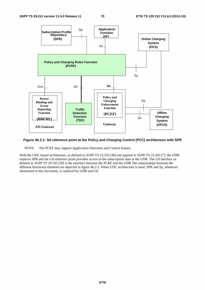
ETSI
ETSI TS 129 212 V11.6.0 (2012-10)703GPP TS 29.212 version 11.6.0 Release 11
Gx
Application Function (AF)
Gy
Gz
Subscription Profile Repository
(SPR)
Rx
Sp
Offline Charging System (OFCS)
Gxx Sd
Traffic Detection Function (TDF)
Policy and Charging Rules Function (PCRF)
AN-Gateway
Bearer Binding and
Event Reporting Function
(BBERF) Gateway
Policy and Charging
Enforcement Function
(PCEF)
Online ChargingSystem (OCS)
Sy
Figure 4b.2.1: Sd reference point at the Policy and Charging Control (PCC) architecture with SPR
NOTE: The PCEF may support Application Detection and Control feature.
With the UDC-based architecture, as defined in 3GPP TS 23.335 [38] and applied in 3GPP TS 23.203 [7], the UDR replaces SPR and the Ud reference point provides access to the subscription data in the UDR. The Ud interface as defined in 3GPP TS 29.335 [39] is the interface between the PCRF and the UDR The relationships between the different functional elements are depicted in figure 4b.2.2. When UDC architecture is used, SPR and Sp, whenever mentioned in this document, is replaced by UDR and Ud.

ETSI
ETSI TS 129 212 V11.6.0 (2012-10)713GPP TS 29.212 version 11.6.0 Release 11
Gx
Application Function (AF)
Gy
Gz
User Data Repository
(UDR)
Rx
Ud
Offline Charging System (OFCS)
Gxx Sd
Traffic Detection Function (TDF)
Policy and Charging Rules Function (PCRF)
AN-Gateway
Bearer Binding and
Event Reporting Function
(BBERF) Gateway
Policy and Charging
Enforcement Function
(PCEF)
Online ChargingSystem (OCS)
Sy
Figure 4b.2.2: Sd reference point at the Policy and Charging Control (PCC) architecture with UDR
NOTE 1: The details associated with the Sp reference point are not specified in this Release. The SPR’s relation to existing subscriber databases is not specified in this Release.
NOTE 2: The UDC Application Informational Model related to the PCRF is not specified in this Release.
NOTE 3: The PCEF may support Application Detection and Control feature.
4b.3 Application Detection and Control Rules
4b.3.1 Functional entities
The PCRF may provide ADC Rules to the TDF by using Sd interface.
Once the start or stop of the application’s traffic, matching one of those ADC Rules, is detected, if PCRF has previously subscribed to the APPLICATION_START/APPLICATION_STOP Event-Triggers, unless a request to mute such a notification (Mute-Notification AVP) is part of the corresponding ADC Rule, the TDF shall report the information regarding the detected application’s traffic to the PCRF and apply the enforcement actions, if defined within the corresponding ADC Rule.
4b.3.2 Application Detection and Control Rule Definition
The ADC Rule definition is the same as provided by 4.3b.2. TDF is used instead of PCEF.
4b.3.3 Operations on ADC Rules
The Operations on ADC Rules are the same as defined by 4.3b.3.
The procedures to perform these operations are further described in clause 4b.5.

ETSI
ETSI TS 129 212 V11.6.0 (2012-10)723GPP TS 29.212 version 11.6.0 Release 11
4b.4 Functional elements
4b.4.1 PCRF
The PCRF (Policy Control and Charging Rules Function) is a functional element that encompasses policy control decision. The PCRF provides network control regarding the application detection, gating, bandwidth limitation and redirection towards the TDF.
The PCRF may provision ADC Rules to the TDF via the Sd reference point.
The PCRF ADC Rule decisions may be based on one or more of the following:
- Information obtained from the PCEF via the Gx reference point, e.g. request type, subscriber/device related information, location information.
- Information obtained from the SPR via the Sp reference point, e.g. subscriber related data. The subscription information may include user profile configuration indicating whether application detection and control should be enabled.
NOTE: The details associated with the Sp reference point are not specified in this Release. The SPR’s relation to existing subscriber databases is not specified in this Release.
- Information obtained from the TDF via the Sd reference point, e.g. detected application, usage monitoring report.
- Information obtained from the BBERF via the Gxx reference point.
- Own PCRF pre-configured information.
The PCRF shall inform the TDF through the use of ADC rules, if applicable, on the treatment of applications, in accordance with the PCRF policy decisions.
It is PCRF's responsibility to coordinate the PCC rules and QoS rules, if applicable, with ADC rules in order to ensure consistent service delivery.
4b.4.2 TDF
The TDF (Traffic Detection Function) is a functional entity that performs application's traffic detection and reporting of the detected application by using TDF application identifier and its TDF application instance identifier and its service data flow descriptions, if deducible, to the PCRF.
For the solicited application reporting, the TDF shall perform the following enforcement actions to the detected application traffic, if requested by PCRF:
- Gating;
- Redirection;
- Bandwidth limitation.
For the solicited application reporting, the TDF shall support usage monitoring as specified in clauses 4b.5.6 and 4b.5.7.
4b.5 ADC procedures over Sd reference point for solicited application reporting
4b.5.1 Provisioning of ADC rules
4b.5.1.1 General
If PCRF decides, based on subscriber’s profile configuration, that the TDF session should be established with the TDF per corresponding IP-CAN session, during the IP-CAN session establishment or at any point of time when the PCRF
ETSI
ETSI TS 129 212 V11.6.0 (2012-10)733GPP TS 29.212 version 11.6.0 Release 11
decides that the session with TDF is to be established (e.g. subscriber profile changes), the PCRF shall indicate via the Sd reference point, the ADC rules to be applied at the TDF. The TDF-Information AVP shall be either received over Gx within initial CC-Request received from PCEF or pre-provisioned at PCRF. Each ADC rule shall include TDF-Application-Identifier AVP which references the corresponding application for which the rule applies.
When establishing the session with the TDF, the PCRF shall send a TS-Request with the PDN information, if available, within the Called-Station-Id AVP, the UE IPv4 address within the Framed-IP-Address and/or the UE IPv6 prefix within the Framed-IPv6-Prefix AVP. These parameters shall uniquely identify the session between the PCRF and the TDF. Additionally, if available (i.e. received from the PCEF or the BBERF), the PCRF may include the following information: the user identification within the Subscription-Id AVP, the type of IP-CAN within the IP-CAN-Type AVP, the type of the radio access technology within the RAT-Type AVP if applicable, the device information within User-Equipment-Info AVP, the SGSN address within either 3GPP-SGSN-Address AVP or 3GPP-SGSN-IPv6-Address AVP, the user location information within 3GPP-User-Location-Info or within 3GPP2-BSID, the Routing Area Identity within RAI AVP, the IPv4 and/ or IPv6 address(es) of the access node gateway (SGW for 3GPP and AGW for non-3GPP networks) in the AN-GW-Address AVPs, the MCC and the MNC of the SGSN/S-GW in the 3GPP-SGSN-MCC-MNC AVP, and the UE time zone information within 3GPP-MS-TimeZone AVP. For xDSL IP-CAN Type, the Logical-Access-ID AVP and the Physical-Access-ID AVP may be provided.
The ADC rules may be transferred to the TDF by using one of the following procedures:
- PUSH procedure (Unsolicited provisioning): The PCRF may decide to provision ADC rules at TDF session establishment within TS-Request or at any point of time within active TDF session by using RA-Request. To provision ADC rules, the PCRF shall include those ADC rules in either TS-Request or RA-Request message; or
- PULL procedure (Provisioning solicited by the TDF): In response to a request for ADC rules being made by the TDF, as described in the section 4b.5.2, the PCRF shall provision ADC rules in the CC-Answer.
For each request from the TDF or upon the unsolicited provision, the PCRF shall provision zero or more ADC rules. The PCRF may perform an operation on a single ADC rule by one of the following means:
- To activate or deactivate an ADC rule that is predefined at the TDF, the PCRF shall provision a reference to this ADC rule within an ADC-Rule-Name AVP and indicate the required action by choosing either the ADC-Rule-Install AVP or the ADC-Rule-Remove AVP.
- To install or modify a PCRF-provisioned ADC rule, the PCRF shall provision a corresponding ADC-Rule-Definition AVP within an ADC-Rule-Install AVP.
- To remove an ADC rule which has previously been provisioned by the PCRF, the PCRF shall provision the name of this ADC rule as value of an ADC-Rule-Name AVP within an ADC-Rule-Remove AVP.
As an alternative to providing a single ADC rule, the PCRF may provide an ADC-Rule-Base-Name AVP within an ADC-Rule-Install AVP or the ADC-Rule-Remove AVP as a reference to a group of ADC rules predefined at the TDF. With an ADC-Rule-Install AVP, a predefined group of ADC rules is activated. With an ADC-Rule-Remove AVP, a predefined group of ADC rules is deactivated.
The PCRF may combine multiple of the above ADC rule operations in a single command.
To activate a predefined ADC rule at the TDF, the rule name within an ADC-Rule-Name AVP shall be supplied within an ADC-Rule-Install AVP as a reference to the predefined rule. To activate a group of predefined ADC rules within the TDF, an ADC-Rule-Base-Name AVP shall be supplied within an ADC-Rule-Install AVP as a reference to the group of predefined ADC rules.
To install a new or modify an already installed PCRF defined ADC rule, the ADC-Rule-Definition AVP shall be used. If an ADC rule with the same rule name, as supplied in the ADC-Rule-Name AVP within the ADC-Rule-Definition AVP, already exists at the TDF, the new ADC rule shall update the currently installed rule. If the existing ADC rule already has attributes also included in the new ADC rule definition, the existing attributes shall be overwritten. Any attribute in the existing ADC rule not included in the new ADC rule definition shall remain valid.
For deactivating single predefined or removing PCRF-provided ADC rules, the ADC-Rule-Name AVP shall be supplied within an ADC-Rule-Remove AVP. For deactivating a group of predefined ADC rules, the ADC-Rule-Base-Name AVP shall be supplied within an ADC-Rule-Remove AVP.
The TDF shall apply the ADC rules to the user plane traffic with the IP address(es) matching the UE IPv4 address within the Framed-IP-Address and/or the UE IPv6 prefix within the Framed-IPv6-Prefix AVP received over Sd interface and report the detected applcation information via the corresponding TDF session.

ETSI
ETSI TS 129 212 V11.6.0 (2012-10)743GPP TS 29.212 version 11.6.0 Release 11
If the provisioning of ADC rules fails, the TDF informs the PCRF as described in Clause 4b.5.5 ADC Rule Error Handling. Depending on the cause, the PCRF may decide if re-installation, modification, removal of ADC rules or any other action applies.
4b.5.1.2 Gate function
The Gate Function represents a user plane function enabling or disabling the forwarding of application’s traffic. A gate is applicable to the detected application’s traffic. The Flow-Status AVP of the ADC rule shall describe if the possible uplink and possible downlink gate for the detected application’s traffic is opened or closed.
The commands to open or close the gate shall lead to the enabling or disabling of the passage for corresponding detected application’s traffic uplink/downlink. If the corresponding uplink and/or downlink gate is closed, all packets belonging to the detected application’s traffic uplink and/or downlink shall be dropped. If the corresponding uplink and/or downlink gate is opened, all packets belonging to the detected application’s traffic uplink and/or downlink are allowed to be forwarded.
4b.5.1.3 Bandwidth limitation function
The PCRF can provide the maximum allowed bit rate (QoS) for an ADC rule to the TDF. The Provisioning shall be performed using the ADC rule provisioning procedure. The allowed QoS shall be encoded using a QoS-Information AVP within the ADC-Rule-Definition AVP of the ADC rule. If QoS-Information is provided for an ADC rule, the TDF shall enforce the corresponding policy for the detected application’s traffic. Only the Max-Requested-Bandwidth-UL AVP and the Max-Requested-Bandwidth-DL AVP shall be used.
4b.5.1.4 Redirect function
The PCRF may provide the redirect instruction (e.g. redirect the detected application’s traffic to another controlled address) for an ADC rule to the TDF. The Provisioning shall be performed using the ADC rule provisioning procedure. The redirect instruction shall be encoded using a Redirect-Information AVP within the ADC-Rule-Definition AVP of the ADC rule. If Redirect-Information AVP is provided for an ADC rule, the TDF shall implement the redirection for the detected application’s uplink traffic. If the Redirect-Server-Address AVP is provided within.the Redirect-Information AVP, the TDF shall redirect the detected application’s uplink traffic to this address. In this case, the redirect address type (e.g. IPv4, IPv6, URL) shall be defined by the Redirect-Address-Type AVP. If the Redirect-Server-Address AVP is not provided, the redirection address locally configured in the TDF shall be used instead.
The Redirect-Support AVP may also be included. Redirect-Support AVP equal to REDIRECTION_DISABLED indicates to disable the redirection for a certain already installed or activated ADC rule. For a predefined ADC rule, the redirect information shall be included in the rule definition at the TDF.
4b.5.1.5 Usage Monitoring Control
Usage monitoring may be performed for application (s) associated with one or more ADC rules.
The provisioning of usage monitoring control per ADC rule shall be performed using the ADC rule provisioning procedure. For a dynamic ADC rule, the monitoring key shall be set using the Monitoring-Key AVP within the ADC-Rule-Definition AVP of the ADC rule. For a predefined ADC rule, the monitoring key shall be included in the rule definition at the TDF.
4b.5.2 Request for ADC rules
The TDF shall indicate, via the Sd reference point, a request for ADC rules during the active TDF session established with PCRF, when a provisioned Event trigger is met. The TDF shall send a CC-Request with CC-Request-Type AVP set to the value "UPDATE_REQUEST". Additionally, the TDF shall supply the specific event which caused the request (within the Event-Trigger AVP) and any previously provisioned affected ADC rule(s) The ADC rules and their status shall be supplied to PCRF within the ADC-Rule-Report AVP.
ADC rules can also be requested as a consequence of a failure in the ADC rule installation/activation or enforcement without requiring an Event-Trigger. For the additional information see clause 4b.5.5.

ETSI
ETSI TS 129 212 V11.6.0 (2012-10)753GPP TS 29.212 version 11.6.0 Release 11
4b.5.3 Provisioning of Event Triggers
The PCRF may provide one or several event triggers within one or several Event-Trigger AVP to the TDF using the ADC rule provision procedure. Event triggers may be used to determine which event causes the TDF to inform PCRF once occur. Provisioning of event triggers from the PCRF to the TDF shall be done at TDF session level. The Event-Trigger AVP may be provided in combination with the initial or subsequent ADC rule provisioning in TSR, RAR or CCA message.
The PCRF may add new event triggers or remove the already provided ones. In order to do so, the PCRF shall provide the new complete list of applicable event triggers including the needed provisioned Event-Trigger AVPs in the CCA or RARcommands.
The PCRF may remove all previously provided event triggers by providing the Event-Trigger AVP set to the value NO_EVENT_TRIGGERS. When an Event-Trigger AVP is provided with this value, no other Event-Trigger AVP shall be provided in the CCA or RAR command. Upon reception of an Event-Trigger AVP with this value, the TDF shall not inform PCRF of any event.
If no Event-Trigger AVP is included in a CCA or RAR operation, any previously provisioned event trigger shall still be applicable.
4b.5.4 Request of TDF Session Termination
When the corresponding IP-CAN session is terminated or at any point of time when the PCRF decides that the session with TDF is to be terminated (e.g. subscriber profile changes), the PCRF shall send a RAR command including the Session-Release-Cause AVP to the TDF. The TDF shall acknowledge the command by sending a RAA command to the PCRF and instantly remove/deactivate all the ADC rules that have been previously installed or activated on that TDF session.
The TDF shall send a CC-Request with CC-Request-Type AVP set to the value "TERMINATION_REQUEST" to PCRF to terminate the TDF session.
When the PCRF receives the CC-Request, it shall acknowledge this message by sending a CC-Answer to the TDF.
NOTE 1: According to DCC procedures, the Diameter Credit Control session is being terminated with this message exchange, as specified in IETF RFC 4006 [9].
Signalling flows for the TDF session termination are presented in 3GPP TS 29.213 [8].
4b.5.5 ADC Rule Error Handling
If the installation/activation of one or more ADC rules fails, the TDF shall include one or more ADC-Rule-Report AVP(s) in either a TSA, a CCR or an RAA command as described below for the affected ADC rules. Within each ADC-Rule-Report AVP, the TDF shall identify the failed ADC rule(s) by including the ADC-Rule-Name AVP(s) or ADC-Rule-Base-Name AVP(s), shall identify the failed reason code by including a Rule-Failure-Code AVP, and shall include the PCC-Rule-Status AVP as described below:
- If the installation/activation of one or more ADC rules fails using a PUSH mode (i.e., the PCRF installs/activates a rule using TSR or RAR command), the TDF shall communicate the failure to the PCRF in the corresponding TSA/RAA response.
- If the installation/activation of one or more ADC rules fails using a PULL mode (i.e., the PCRF installs/activates a rule using a CCA command), the TDF shall send the PCRF a new CCR command and include the Rule-Failure-Code AVP.
If the installation/activation of one or more new ADC rules (i.e., rules which were not previously successfully installed) fails, the TDF shall set the PCC-Rule-Status to INACTIVE for both the PUSH and the PULL modes.
If the modification of a currently active ADC rule using PUSH mode fails, the TDF shall retain the existing ADC rule as active without any modification unless the reason for the failure has an impact also on the existing ADC rule. The TDF shall report the modification failure to the PCRF using the TSA/RAA command.

ETSI
ETSI TS 129 212 V11.6.0 (2012-10)763GPP TS 29.212 version 11.6.0 Release 11
If the modification of a currently active ADC rule using PULL mode fails, the TDF shall retain the existing ADC rule as active without any modification unless the reason for the failure has an impact also on the existing ADC rule. The TDF shall report the modification failure to the PCRF using the CCR command.
Depending on the value of the Rule-Failure-Code for PULL and PUSH mode, the PCRF may decide whether retaining of the old ADC rule, re-installation, modification, removal of the ADC rule or any other action applies.
If an ADC rule was successfully installed/activated, but can no longer be enforced by the TDF, the TDF shall send the PCRF a new CCR command and include an ADC-Rule-Report AVP. The TDF shall include the Rule-Failure-Code AVP within the ADC-Rule-Report AVP and shall set the PCC-Rule-Status to INACTIVE.
4b.5.6 Requesting Usage Monitoring Control
The PCRF may indicate, via the Sd reference point, the need to apply monitoring control for the accumulated usage of network resources on a per TDF session basis. Usage is defined as volume of user plane traffic. The data collection for usage monitoring control shall be performed per monitoring key, which may apply to one application (i.e. the monitoring key is used by a single ADC rule), or to several applications (i.e., the monitoring key is used by many ADC rules), or all detected traffic belonging to a specific TDF session.
If the PCRF requests usage monitoring control and if at this time, the PCRF is not subscribed to the "USAGE_REPORT" Event-Trigger, the PCRF shall include the Event-Trigger AVP, set to the value "USAGE_REPORT", in a TS-Request, CC-Answer or RA-Request.
At TDF session establishment and modification, the PCRF may provide the applicable thresholds for usage monitoring control to the TDF, together with the respective monitoring keys. To provide the initial threshold for one or more monitoring key(s), the PCRF may include the threshold in either TSR, RAR or in the response of a CCR, initiated by the TDF.
During the IP-CAN session establishment, the PCRF may receive information about total allowed usage per PDN and/ or per UE from the SPR, i.e. the overall amount of allowed traffic volume that are to be monitored for the PDN connections of a user and/or total allowed usage for Monitoring key(s) per PDN and UE and should use it when making a decisions about usage monitoring control.
In order to provide the applicable threshold for usage monitoring control, the PCRF shall include a Usage-Monitoring-Information AVP per monitoring key. The threshold level shall be provided in its Granted-Service-Unit AVP. Threshold levels may be defined for:
- the total volume only; or
- the uplink volume only; or
- the downlink volume only; or
- the uplink and downlink volume.
The PCRF shall provide the applicable threshold(s) in the CC-Total-Octets, CC-Input-Octets or CC-Output-Octets AVPs of the Granted-Service-Unit AVP. The monitoring key shall be provided in the Monitoring-Key AVP. The PCRF may provide multiple usage monitoring control instances. The PCRF shall indicate if the usage monitoring instance applies to the TDF session or to one or more ADC rules. For this purpose, the Usage-Monitoring-Level AVP may be provided with a value respectively set to SESSION_LEVEL or ADC_RULE_LEVEL. The PCRF may provide one usage monitoring control instance applicable at TDF session level and one or more usage monitoring instances applicable at ADC Rule level.
The PCRF may provide a Monitoring-Time AVP to the TDF for the monitoring keys(s) in order to receive reports for the accumulated usage before and after the monitoring time occurs within the report triggered by the events defined in 4b.5.7.2-4b.5.7.6. In such a case, there may be two instances of Granted-Service-Unit AVP within Usage-Monitoring-Information AVP per monitoring key. One of them indicates the threshold levels before the monitoring time occurs, and the other one, which includes Monitoring-Time AVP, indicates the subsequent threshold levels after the monitoring time occurs.The detailed functionality in such a case is defined by 4b.5.7.7.
If the PCRF wishes to modify the threshold level for one or more monitoring keys, the PCRF shall provide the thresholds for all the different levels applicable to the corresponding monitoring key(s).

ETSI
ETSI TS 129 212 V11.6.0 (2012-10)773GPP TS 29.212 version 11.6.0 Release 11
If the PCRF wishes to modify the monitoring key for the TDF session level usage monitoring instance, it shall disable the existing session level monitoring usage instance following the procedures defined in 4b.5.7.4 and shall provide a new TDF session level usage monitoring instance following the procedures defined in this clause. The PCRF may enable the new TDF session level usage monitoring instance and disable the existing TDF session level usage monitoring instance in the same command.
When the accumulated usage is reported in a CCR command, the PCRF shall indicate to the TDF if usage monitoring shall continue for that TDF session, usage monitoring key, or both as follows:
- If monitoring shall continue for specific level(s), the PCRF shall provide the new thresholds for the level(s) in the CC-Answer using the same AVP as before (CC-Total-Octets, CC-Input-Octets or CC-Output-Octets AVP within the Granted-Service-Unit AVP);
- otherwise, if the PCRF wishes to stop monitoring for specific level(s) the PCRF shall not include an updated usage threshold in the CCA command for the stopped level(s) i.e. the corresponding CC-Total-Octets, CC-Input-Octets or CC-Output-Octets AVPs shall not be included within Granted-Service-Units AVP.
When usage monitoring is enabled, the PCRF may request the TDF to report accumulated usage for all enabled monitoring or selected monitoring keys regardless if a usage threshold has been reached by sending to the TDF within the Usage-Monitoring-Information AVP the Usage-Monitoring-Report AVP set to the value USAGE_MONITORING_REPORT_REQUIRED. The PCRF shall only require TDF to report accumulated usage for one or more monitoring keys in a CC-Answer when the TDF has not provided accumulated usage in the CC-Request for the same monitoring key(s).
To specify the usage monitoring key for which usage is requested, the PCRF shall include the usage monitoring key within the Monitoring-Key AVP within the Usage-Monitoring-Information AVP. To request usage be reported for all enabled usage monitoring keys, the PCRF shall omit the Monitoring-Key.
The PCRF shall process the usage reports and shall perform the actions as appropriate for each report.
4b.5.7 Reporting Accumulated Usage
4b.5.7.1 General
When usage monitoring is enabled, the TDF shall measure the volume of the TDF session or the volume of the particular application (s), and report accumulated usage to the PCRF in the following conditions:
- when a usage threshold is reached;
- when all ADC rules for which usage monitoring is enabled for a particular usage monitoring key are removed or deactivated;
- when usage monitoring is explicitly disabled by the PCRF;
- when a TDF session is terminated;
- when requested by the PCRF;
To report accumulated usage for a specific monitoring key, the TDF shall send a CC-Request with the Usage-Monitoring-Information AVP including the accumulated usage since the last report. The Usage-Monitoring-Information AVP shall include the monitoring key in the Monitoring-Key AVP and the accumulated volume usage in the Used-Service-Unit AVP. Accumulated volume reporting shall be done for the total volume, the uplink volume or the downlink volume as requested by the PCRF, and set in CC-Total-Octets, CC-Input-Octets or CC-Output-Octets AVPs of Used-Service-Unit AVP respectively. The TDF shall continue to perform volume measurement after the report until instructed by the PCRF to stop the monitoring.
In case a Monitoring-Time AVP was provided by the PCRF within one instance of the Granted-Service-Unit AVP included within the Usage-Monitoring-Information AVP for the usage monitoring control request, the PCEF shall report as defined in 4b.5.7.7.
For cases, where the PCRF indicates in a CC-Answer command whether the usage monitoring shall continue as a response to the reporting of accumulated usage in a CCR command, the TDF shall behave as follows:

ETSI
ETSI TS 129 212 V11.6.0 (2012-10)783GPP TS 29.212 version 11.6.0 Release 11
- if the PCRF provisions an updated usage threshold in the CCA command, the monitoring continues using the updated threshold value provisioned by the PCRF;
- otherwise, if the PCRF does not include an updated usage threshold in the CCA command, the TDF shall not continue usage monitoring for that TDF session, usage monitoring key, or both as applicable.
NOTE: When the PCRF indicates that usage monitoring shall not continue in the CCA, the TDF does not report usage which has accumulated between sending the CCR and receiving the CCA.
Upon receiving the reported usage from the TDF, the PCRF shall deduct the value of the usage report from the total allowed usage for that IP-CAN session, usage monitoring key, or both as applicable, and the PCRF may also derive the ADC rules based on the remaining allowed usage or reported usage and provision them to the TDF.
Additional procedures for each of the scenarios above are described in the following subclauses of 4b.5.7.
4b.5.7.2 Usage Threshold Reached
When usage monitoring is enabled for a particular monitoring key, the TDF shall measure the volume of all traffic for the TDF session or the corresponding application (s) and notify the PCRF when a usage threshold for that monitoring key is reached and report the accumulated usage for that monitoring key and include the "USAGE_REPORT" Event-Trigger in a CCR command with CC-Request Type AVP set to the value "UPDATE_REQUEST" by following the procedures to report accumulated usage defined in clause 4b.5.7.1.
4b.5.7.3 ADC Rule Removal
When the PCRF removes or deactivates the last ADC rule associated with a usage monitoring key in an RAR or CCA command in response to a CCR command not related to reporting usage for the same monitoring key, the TDF shall send a new CCR command with the CC-Request-Type set to the value "UPDATE_REQUEST" including the Event-Trigger set to "USAGE_REPORT" to report accumulated usage for the usage monitoring key within the Usage-Monitoring-Information AVP using the procedures to report accumulated usage defined in clause 4b.5.7.1.
When the TDF reports that the last ADC rule associated with a usage monitoring key is inactive, the TDF shall report the accumulated usage for that monitoring key within the same CCR command if the ADC-Rule-Report AVP was included in a CCR command; otherwise, if the ADC-Rule-Report AVP was included in an RAA command, the TDF shall send a new CCR command to report accumulated usage for the usage monitoring key.
4b.5.7.4 Usage Monitoring Disabled
Once enabled, the PCRF may explicitly disable usage monitoring as a result of receiving a CCR from the TDF which is not related to reporting usage, but related to other external triggers (e.g. subscriber profile update), or a PCRF internal trigger. When the PCRF disables usage monitoring, the TDF shall report the accumulated usage which has occurred while usage monitoring was enabled since the last report.
To disable usage monitoring for a monitoring key, the PCRF shall send the Usage-Monitoring-Information AVP including only the applicable monitoring key within the Monitoring-Key AVP and the Usage-Monitoring-Support AVP set to USAGE_MONITORING_DISABLED.
When the PCRF disables usage monitoring in a RAR or CCA command, the TDF shall send a new CCR command with CC-Request Type AVP set to the value "UPDATE_REQUEST" and the Event-Trigger AVP set to "USAGE_REPORT" to report accumulated usage for the disabled usage monitoring key(s).
4b.5.7.5 TDF Session Termination
At TDF session termination, the TDF shall send the accumulated usage information for all monitoring keys for which usage monitoring is enabled in the CCR command with the CC-Request-Type AVP set to the value "TERMINATION_REQUEST" using the procedures to report accumulated usage defined in clause 4b.5.7.1.
4b.5.7.6 PCRF Requested Usage Report
When the TDF receives the Usage-Monitoring-Information AVP including the Usage-Monitoring-Report AVP set to the value USAGE_MONITORING_REPORT_REQUIRED, the TDF shall send a new CCR command with CC-Request Type AVP set to the value "UPDATE_REQUEST" and the Event-Trigger AVP set to "USAGE_REPORT" to

ETSI
ETSI TS 129 212 V11.6.0 (2012-10)793GPP TS 29.212 version 11.6.0 Release 11
report accumulated usage for the monitoring key received in the Usage-Monitoring-Information AVP using the procedures to report accumulated usage defined in clause 4b.5.7. If the Monitoring-Key AVP was omitted in the received Usage-Monitoring-Information AVP, the TDF shall send the accumulated usage for all the monitoring keys that were enabled at the time the Usage-Monitoring-Information was received.
4b.5.7.7 Report in case of Monitoring Time provided
If Monitoring-Time AVP was provided within one instance of the Granted-Service-Unit AVP included within the Usage-Monitoring-Information AVP by the PCRF, and if the TDF needs to report the accumulated usage when one of the events defined in subclause 4b.5.7.2-4b.5.7.6 occurs before the monitoring time, the PCEF shall report the accumulated usage as defined subclause 4b.5.7.2-4b.5.7.6 and the TDF shall not retain the monitoring time; otherwise,
- If two instances of the Granted-Service-Unit AVP are provided by the PCRF, the TDF shall reset the usage threshold to the value of the Granted-Service-Unit AVP with the Monitoring-Time AVP.
- If only one instance of the Granted-Service-Unit AVP is provided by the PCRF, the TDF shall reset the usage threshold to the remaining value of the Granted-Service-Unit AVP previously sent by the PCRF (i.e. excluding the accumulated volume usage)i
- For both cases, the usage report from the TDF shall include two instances of the Used-Service-Unit AVP, one of them to indicate the usage before the monitoring time and the other one accompanied by the Monitoring-Time AVP under the same Used-Service-Unit AVP to indicate the usage after the monitoring time.
When PCRF receives the accumulated usage report in a CCR command, the PCRF shall indicate to the TDF if usage monitoring shall continue as defined in subclause 4b.5.6. The PCRF may provide the Monitoring-Time AVP again within one instance of the Granted-Service-Unit AVP if reports for the accumulated usage before and after the provided monitoring time are required.
4b.5.8 Provisioning of Event Report Indication
The TDF may request from the PCRF to be informed about specific changes occurred in the location information/access network information in either a TSA, a CCR or an RAA command. In this case, the PCRF shall subscribe to the appropriate event triggers in the PCEF according to clause 4.5.3 or in the BBERF according to clause 4a.5.8.
NOTE 1: In case the IP flow mobility feature is enabled, the TDF doesn't have accurate information about the location and the type of RAT the user is attached to.
After receiving the reply of the event subscription from the PCEF, the PCRF shall send the event related information to the TDF by using a RAR command.
When PCRF is notified that an event is triggered in the PCEF or the BBERF, if the TDF has previously requested to be informed of the specific event, the PCRF shall notify the TDF about the event occurred together with additional related information (i.e. the parameter value). This notification shall be done by using the Event-Report-Indication AVP. There may be neither ADC Rule provisioning nor Event Trigger provisioning together with event report indication in this message.
When PCRF is notified by PCEF that either an UE_IP_ADDRESS_ALLOCATE or an UE_IP_ADDRESS_RELEASE event of the IP-CAN session occurs in the PCEF, the PCRF shall notify the TDF about the event for the corresponding TDF session. The Framed-IP-Address AVP shall also be provided. This notification shall also be done by using the Event-Report-Indication AVP within a RAR command. There may be neither ADC Rules nor Event Triggers in this message. If the PCRF notifies of the new IPv4 address to the TDF, the TDF shall additional ly apply the ADC rules to the user plane traffic with the IP address matching the new IPv4 address and report the detected applcation information via the corresponding TDF session. If the PCRF notifies to the TDF that the IPv4 address has been released, the TDF shall stop applying the ADC rule to the user plane traffic with IP address matching the released IPv4 address.
NOTE 2: The TDF does not need to subscribe the notification of the UE_IP_ADDRESS_ALLOCATE and UE_IP_ADDRESS_RELEASE.
4b.5.9 Application Detection Information
For the solicited application reporting, the PCRF may instruct the TDF to detect application (s) by providing the ADC-Rule-Install AVP (s) with the corresponding parameters as follows: the application to be detected is identified by the

ETSI
ETSI TS 129 212 V11.6.0 (2012-10)803GPP TS 29.212 version 11.6.0 Release 11
TDF-Application-Identifier AVP, which is either provided under ADC-Rule-Definition AVP for dynamic ADC Rules or pre-provisioned for the corresponding predefined ADC Rule, and in such a case only ADC-Rule-Name/ADC-Rule-Base-Name is provided . If the PCRF requires to be reported about when the application start/stop is detected, it shall also subscribe to the APPLICATION_START and APPLICATION_STOP Event-Triggers. The PCRF may also mute such a notification about a specific detected application by providing Mute-Notification within the corresponding ADC-Rule-Definition AVP.
When the start or stop of the application’s traffic, identified by TDF-Application-Identifier, is detected, if PCRF has previously subscribed to the APPLICATION_START/APPLICATION_STOP Event-Triggers, unless a request to mute such a notification (Mute-Notification AVP ) is part of the corresponding ADC-Rule-Definition AVP, the TDF shall report the information regarding the detected application’s traffic in the Application-Detection-Information AVP in the CCR command.
The corresponding TDF-Application-Identifier AVP shall be included under Application-Detection-Information AVP. When the Event trigger indicates APPLICATION_START, the Flow-Information AVP for the detected application may be included under Application-Detection-Information AVP, if deducible. The Flow-Information AVP, if present, shall contain the Flow-Description AVP and Flow-Direction AVP. The TDF-Application-Instance-Identifier, which is dynamically assigned by the TDF in order to allow correlation of APPLICATION_START and APPLICATION_STOP Event-Triggers to the specific Flow-Information AVP, if service data flow descriptions are deducible, shall also be provided. Also, the corresponding Event-Trigger (APPLICATION_START or APPLICATION_STOP) shall be provided to PCRF. When the TDF-Application-Instance-Identifier is provided along with the APPLICATION_START, it shall also be provided along with the corresponding APPLICATION_STOP. The PCRF then may make the policy decision based on the information received and send the updated PCC rules to the PCEF, updated QoS rules to the BBERF, if applicable, and the updated ADC rules to the TDF.
4b.5.10 Time of the day procedures
TDF shall be able to perform ADC rule request as instructed by the PCRF in a TSR, CCA or a RAR commands. ADC-Revalidation-Time, when set by the PCRF, shall cause the TDF to trigger a PCRF interaction to request ADC rules from the PCRF for an established TDF session. The TDF shall stop the timer once the TDF triggers an ADC_REVALIDATION_TIMEOUT event.
PCRF shall be able to provide a new value for the revalidation timeout by including ADC-Revalidation-Time in CCA or RAR.
PCRF shall be able to stop the ADC revalidation timer by disabling the ADC_REVALIDATION_TIMEOUT event trigger.
The PCRF may control at what time the status of an ADC rule changes.
1) If Rule-Activation-Time is specified only and has not yet occurred, then the TDF shall set the ADC rule inactive and make it active at that time. If Rule-Activation-Time has passed, then the TDF shall immediately set the ADC rule active.
2) If Rule-Deactivation-Time is specified only and has not yet occurred, then the TDF shall set the ADC rule active and make it inactive at that time. If Rule-Deactivation-Time has passed, then the TDF shall immediately set the ADC rule inactive.
3) If both Rule-Activation-Time and Rule-Deactivation-Time are specified, and the Rule-Activation-Time occurs before the Rule-Deactivation-Time, and also when the ADC rule is provided before or at the time specified in the Rule-Deactivation-Time, the TDF shall handle the rule as defined in 1) and then as defined in 2),
4) If both Rule-Activation-Time and Rule-Deactivation-Time are specified, and the Rule-Deactivation-Time occurs before the Rule-Activation-Time, and also when the ADC rule is provided before or at the time specified in the Rule-Activation-Time., the TDF shall handle the rule as defined in 2) and then as defined in 1),
5) If both Rule-Activation-Time and Rule-Deactivation-Time are specified but time has passed for both, and the Rule-Activation-Time occurs before the Rule-Deactivation-Time, then the TDF shall immediately set the ADC rule inactive.
6) If both Rule-Activation-Time and Rule-Deactivation-Time are specified but time has passed for both, and the Rule-Deactivation-Time occurs before the Rule-Activation-Time, then the PCEF shall immediately set the ADC rule active.

ETSI
ETSI TS 129 212 V11.6.0 (2012-10)813GPP TS 29.212 version 11.6.0 Release 11
ADC Rule Activation or Deactivation shall not generate any CCR commands with ADC-Rule-Report since PCRF is already aware of the state of the rules.
If Rule-Activation-Time or Rule-Deactivation-Time is specified in the ADC-Rule-Install, then it shall replace the previously set values for the specified ADC rules.
If Rule-Activation-Time AVP, Rule-Deactivation-Time AVP or both AVPs are omitted, then any previous value for the omitted AVP is no longer valid.
The 3GPP-MS-TimeZone AVP, if available, may be used by the PCRF and by the TDF to derive the Rule-Activation-Time and Rule-Deactivation-Time.
4b.5.11 PCRF Failure and Restoration
If the TDF needs to send a TDF Session update request (e.g. following usage threshold reached) towards a PCRF which is known to have restarted since the TDF Session establishment, the TDF should not send the TDF Session update request towards a PCRF, and the TDF may clean up the TDF session related information.
NOTE 1: This mechanism in the TDF removes all application traffic control on the PDN connection and has no effect on the state of the PDN connection. It is expected that the PCEF will perform the same detection and clean up of PDN connections affected by the PCRF failure and restoration
NOTE 2: The method the TDF uses to determine that a PCRF has restarted is not specified in this release.
4b.5a ADC procedures over Sd reference point for unsolicited application reporting
4b.5a.1 Provisioning of ADC rules
4b.5a.1.1 General
If a TDF is configured for unsolicited reporting, the TDF is pre-configured with ADC rules which specify which applications to detect and report. These rules are always active and are not controlled by the PCRF.
4b.5a.2 Application Detection Information
When the start or stop of the application’s traffic, identified by TDF-Application-Identifier, is detected, the TDF shall report the information regarding the detected application’s traffic in the Application-Detection-Information AVP in the CCR command.
1) When the TDF detects an application for an IPv4 address or IPv6 address for which a TDF session does not exist, the TDF shall send CC-Request with CC-Request-Type set to value “INITIAL-REQUEST”. The TDF provides the full UE IP address using either Framed-IP-Address AVP or Framed-IPv6-Prefix AVP and, if available, the PDN identifier. The corresponding CCA may contain the IPv6 prefix within the Framed-IPv6-Prefix AVPs if the established TDF session is IPv6 address related.
2) When an application is detected for an IPv4 address or IPv6 Prefix for which a TDF session already exists, the TDF shall send CC-Request with CC-Request-Type set to value “UPDATE_REQUEST”.
NOTE: It is considered that a TDF session exists for a detected application related to an IPv6 address if the IPv6 address belongs to the IPv6 prefix provided by the PCRF for that TDF session,.
The corresponding TDF-Application-Identifier AVP shall be included under Application-Detection-Information AVP. Also, the corresponding Event-Trigger (APPLICATION_START or APPLICATION_STOP) shall be provided to PCRF. When the Event trigger indicates APPLICATION_START, if deducible, the Flow-Information AVP for the detected application shall be included under Application-Detection-Information AVP. The Flow-Information AVP, if present, shall contain the Flow-Description AVP and Flow-Direction AVP. The TDF-Application-Instance-Identifier, which is dynamically assigned by the TDF in order to allow correlation of APPLICATION_START and APPLICATION_STOP Event-Triggers to the specific Flow-Information AVP, if service data flow descriptions are deducible, shall also be provided.

ETSI
ETSI TS 129 212 V11.6.0 (2012-10)823GPP TS 29.212 version 11.6.0 Release 11
4b.5a.3 Request of TDF Session Termination
In the unsolicited reporting case the session termination procedure as defined in subclause 4b.5.4 is initiated in the following cases.
- the corresponding IP-CAN session is terminated;
- the IPv4 address of a dual stack IP-CAN session is released and there is an active IPv4 address related TDF session for that IP-CAN session;
- at any point of time when the PCRF decides that the session with TDF is to be terminated (e.g. subscriber profile changes).
4b.5a.4 TDF session to Gx session linking
When the PCRF receives the CCR command with the CC-Request-Type set to the value "INITIAL_REQUEST", the PCRF links the TDF session to a Gx session, if the IPv4 address or IPv6 address of the TDF session matches the IPv4 address or IPv6 prefix of the Gx session. The PDN information if available in the Called-Station-Id AVP may also be used for this session linking.
The TDF should handle each IPv4 address and IPv6 prefix, assuming the max prefix length used in the access network, within a separate TDF session. The PCRF shall link the separate IPv4 address related TDF session and IPv6 address related TDF session to the same IP-CAN session and correlate the TDF sessions.
NOTE 1: In the scenario where the TDF performs initial Application Detection on mutiple simultaneous traffic flows for the same IPv6 prefix (i.e. two or more traffic flows from IPv6 addresses of the same IP-CAN session) the TDF could not be aware that those flows belong to the same IP-CAN session until a response is received from the PCRF, containing the IPv6 prefix. This leads to using separate TDF sessions for the IPv6 addresses for the same IP-CAN session. The TDF reports new application detection information related to that IPv6 prefix via any of the TDF sessions at a later stage.
5 Gx protocol
5.1 Protocol support The Gx protocol in the present release is based on Gx protocol defined for Release 6 as specified in 3GPP TS 29.210 [2]. However, due to a new paradigm (DCC session for an IP-CAN session) between Release 6 and the present release, the Gx application in the present release has an own vendor specific Diameter application.
The Gx application is defined as a vendor specific Diameter application, where the vendor is 3GPP and the Application-ID for the Gx Application in the present release is 16777238. The vendor identifier assigned by IANA to 3GPP (http://www.iana.org/assignments/enterprise-numbers) is 10415.
NOTE: A route entry can have a different destination based on the application identification AVP of the message. Therefore, Diameter agents (relay, proxy, redirection, translation agents) must be configured appropriately to identify the 3GPP Gx application within the Auth-Application-Id AVP in order to create suitable routeing tables.
Due to the definition of the commands used in Gx protocol, there is no possibility to skip the Auth-Application-Id AVP and use the Vendor-Specific-Application-Id AVP instead. Therefore the Gx application identification shall be included in the Auth-Application-Id AVP.
With regard to the Diameter protocol defined over the Gx interface, the PCRF acts as a Diameter server, in the sense that it is the network element that handles PCC Rule requests for a particular realm. The PCEF acts as the Diameter client, in the sense that is the network element requesting PCC rules in the transport plane network resources.

ETSI
ETSI TS 129 212 V11.6.0 (2012-10)833GPP TS 29.212 version 11.6.0 Release 11
5.2 Initialization, maintenance and termination of connection and session
The initialization and maintenance of the connection between each PCRF and PCEF pair is defined by the underlying protocol. Establishment and maintenance of connections between Diameter nodes is described in RFC 3588 [5].
After establishing the transport connection, the PCRF and the PCEF shall advertise the support of the Gx specific Application by including the value of the application identifier in the Auth-Application-Id AVP and the value of the 3GPP (10415) in the Vendor-Id AVP of the Vendor-Specific-Application-Id AVP contained in the Capabilities-Exchange-Request and Capabilities-Exchange-Answer commands. The Capabilities-Exchange-Request and Capabilities-Exchange-Answer commands are specified in the Diameter Base Protocol (RFC 3588 [5]).
The termination of the Diameter session on Gx can be initiated either by the PCEF or PCRF, as specified in subclauses 4.5.7 and 4.5.9, respectively.
5.3 Gx specific AVPs Table 5.3.1 describes the Diameter AVPs defined for the Gx reference point, their AVP Code values, types, possible flag values, whether or not the AVP may be encrypted, what access types (e.g. 3GPP-GPRS, etc.) the AVP is applicable to, the applicability of the AVPs to charging control, policy control or both, and which supported features the AVP is applicable to. The Vendor-Id header of all AVPs defined in the present document shall be set to 3GPP (10415).

ETSI
ETSI TS 129 212 V11.6.0 (2012-10)843GPP TS 29.212 version 11.6.0 Release 11
Table 5.3.1: Gx specific Diameter AVPs
AVP Flag rules (NOTE 1)
Attribute Name AVP Code
Clause defined
Value Type (NOTE 2)
Must May Should not
Must not
May Encr.
Acc. type Applicability (notes 3, 9)
ADC-Revalidation-Time 2801 5.3.93 Time V P M Y All ADC ADC-Rule-Install 1092 5.3.85 Grouped V P M Y All ADC ADC-Rule-Remove 1093 5.3.86 Grouped V P M Y All ADC ADC-Rule-Definition 1094 5.3.87 Grouped V P M Y All ADC ADC-Rule-Base-Name 1095 5.3.88 UTF8String V P M Y All ADC ADC-Rule-Name 1096 5.3.89 OctetString V P M Y All ADC ADC-Rule-Report 1097 5.3.90 Grouped V P M Y All ADC Application-Detection-Information
1098 5.3.91 Grouped V P M Y All ADC
Access-Network-Charging-Identifier-Gx
1022 5.3.22 Grouped M,V P Y All CC
Allocation-Retention-Priority 1034 5.3.32 Grouped V P M Y All Both Rel8
AN-GW-Address 1050 5.3.49 Address V P M Y All Both Rel8
APN-Aggregate-Max-Bitrate-DL 1040 5.3.39 Unsigned32 V P M Y All
PC Rel8
APN-Aggregate-Max-Bitrate-UL 1041 5.3.40 Unsigned32 V P M Y All
PC Rel8
Bearer-Control-Mode 1023 5.3.23 Enumerated M,V P Y 3GPP-GPRS 3GPP-EPS 3GPP2 Non-3GPP-EPS (NOTE 6)
PC
Bearer-Identifier 1020 5.3.20 OctetString M,V P Y 3GPP-GPRS Both Bearer-Operation 1021 5.3.21 Enumerated M,V P Y 3GPP-GPRS Both Bearer-Usage 1000 5.3.1 Enumerated M,V P Y 3GPP-GPRS
3GPP-EPS Both
Charging-Rule-Install 1001 5.3.2 Grouped M,V P Y All Both Charging-Rule-Remove 1002 5.3.3 Grouped M,V P Y All Both Charging-Rule-Definition 1003 5.3.4 Grouped M,V P Y All Both Charging-Rule-Base-Name 1004 5.3.5 UTF8String M,V P Y All Both Charging-Rule-Name 1005 5.3.6 OctetString M,V P Y All Both Charging-Rule-Report 1018 5.3.18 Grouped M,V P Y All Both Charging-Correlation-Indicator 1073 5.3.67 Enumerated V P M Y All CC
Rel8 CoA-IP-Address 1035 5.3.33 Address V P M Y All
(NOTE 8) Both Rel8
CoA-Information 1039 5.3.37 Grouped V P M Y All (NOTE 8)
Both Rel8
CSG-Information-Reporting 1071 5.3.64 Enumerated V P M Y 3GPP-GPRS 3GPP-EPS
CC Rel9
Default-EPS-Bearer-QoS 1049 5.3.48 Grouped V P M Y All (NOTE 5)
PC Rel8
Event-Report-Indication 1033 5.3.30 Grouped V P M Y All Both Rel8
Event-Trigger 1006 5.3.7 Enumerated M,V P Y All Both Flow-Direction 1080 5.3.65 Enumerated V P M Y All Both
Rel9 Flow-Information 1058 5.3.53 Grouped V P M Y All Both Flow-Label 1057 5.3.52 OctetString V P M Y All Both IP-CAN-Type 1027 5.3.27 Enumerated M,V P Y All Both Guaranteed-Bitrate-DL 1025 5.3.25 Unsigned32 M,V P Y All PC Guaranteed-Bitrate-UL 1026 5.3.26 Unsigned32 M,V P Y All PC HeNB-BBF-FQDN 2803 5.3.94 UTF8String V P M Y 3GPP-EPS PC
EPC-routed

ETSI
ETSI TS 129 212 V11.6.0 (2012-10)853GPP TS 29.212 version 11.6.0 Release 11
HeNB-Local-IP-Address 2804 5.3.95 Address V P M Y 3GPP-EPS PC EPC-routed
Metering-Method 1007 5.3.8 Enumerated M,V P Y All CC Monitoring-Key 1066 5.3.59 OctetString V P M Y All Both
Rel9 Mute-Notification 2809 5.3.98 Enumerated V P M Y All ADC Monitoring-Time 2810 5.3.99 Time V P M Y All Both
UMCH Network-Request-Support 1024 5.3.24 Enumerated M,V P Y 3GPP-GPRS
3GPP-EPS 3GPP2 Non-3GPP-EPS (NOTE 6)
PC
Offline 1008 5.3.9 Enumerated M,V P Y All CC Online 1009 5.3.10 Enumerated M,V P Y All CC Packet-Filter-Content 1059 5.3.54 IPFilterRule V P M Y All
(NOTE 5) Both Rel8
Packet-Filter-Identifier 1060 5.3.55 OctetString V P M Y All (NOTE 5)
Both Rel8
Packet-Filter-Information 1061 5.3.56 Grouped V P M Y All (NOTE 5)
Both Rel8
Packet-Filter-Operation 1062 5.3.57 Enumerated V P M Y All (NOTE 5)
Both Rel8
Packet-Filter-Usage 1072 5.3.66 Enumerated V P M Y All Both Rel9
PDN-Connection-ID 1065 5.3.58 OctetString V P Y All (NOTE 7)
Both Rel9
Precedence 1010 5.3.11 Unsigned32 M,V P Y All Both Pre-emption-Capability 1047 5.3.46 Enumerated V P M Y 3GPP- EPS,
3GPP-GPRS Both Rel8
Pre-emption-Vulnerability 1048 5.3.47 Enumerated V P M Y 3GPP- EPS, 3GPP-GPRS
Both Rel8
Priority-Level 1046 5.3.45 Unsigned32 V P M Y All Both Rel8
Redirect-Information 1085 5.3.82 Grouped V P M Y All ADC Redirect- Support 1086 5.3.83 Enumerated V P M Y All ADC Reporting-Level 1011 5.3.12 Enumerated M,V P Y All CC Routing-Filter 1078 5.3.72 Grouped V P M Y 3GPP-EPS ,
Non-3GPP-EPS
Both IFOM
Routing-IP-Address 1079 5.3.73 Address V P M Y 3GPP-EPS ,Non-3GPP-EPS
Both IFOM
Routing-Rule-Definition 1076 5.3.70 Grouped V P M Y 3GPP-EPS, Non-3GPP-EPS
Both IFOM
Routing-Rule-Identifier 1077 5.3.71 OctetString V P M Y 3GPP-EPS , Non-3GPP-EPS
Both IFOM
Routing-Rule-Install 1081 5.3.68 Grouped V P M Y 3GPP-EPS ,Non-3GPP-EPS
Both IFOM
Routing-Rule-Remove 1075 5.3.69 Grouped V P M Y 3GPP-EPS , Non-3GPP-EPS
Both IFOM
PCC-Rule-Status 1019 5.3.19 Enumerated M,V P Y All Both Session-Release-Cause 1045 5.3.44 Enumerated M,V P Y All Both TDF-Information 1087 5.3.78 Grouped V P M Y All
PC
TDF-Application-Identifier 1088 5.3.77 OctetString V P M Y All
PC ADC
TDF-Application-Instance-Identifier
2802 5.3.92 OctetString V P M Y All
ADC
TDF-Destination-Host 1089 5.3.80 DiameterIdentity
V P M Y All
PC

ETSI
ETSI TS 129 212 V11.6.0 (2012-10)863GPP TS 29.212 version 11.6.0 Release 11
TDF-Destination-Realm 1090 5.3.79 DiameterIdentity
V P M Y All
PC
TDF-IP-address 1091 5.3.81 Address V P M Y All
PC
QoS-Class-Identifier 1028 5.3.17 Enumerated M,V P Y All Both QoS-Information 1016 5.3.16 Grouped M.V P Y All Both QoS-Negotiation 1029 5.3.28 Enumerated M,V P Y 3GPP-GPRS
PC
Qos-Upgrade 1030 5.3.29 Enumerated M.V P Y 3GPP-GPRS PC PS-to-CS-Session-Continuity 1099 5.3.84 Enumerated V P Y 3GPP-EPS Both
vSRVCC
Resource-Allocation-Notification
1063 5.3.50 Enumerated V P M Y All Both Rel8
Rule-Failure-Code 1031 5.3.38 Enumerated M.V P Y All Both Security-Parameter-Index 1056 5.3.51 OctetString V P M Y All Both TFT-Filter 1012 5.3.13 IPFilterRule M,V P Y 3GPP-GPRS Both TFT-Packet-Filter-Information 1013 5.3.14 Grouped M,V P Y 3GPP-GPRS Both ToS-Traffic-Class 1014 5.3.15 OctetString M,V P Y All Both Tunnel-Header-Filter 1036 5.3.34 IPFilterRule V P M Y All
(NOTE 8) Both Rel8
Tunnel-Header-Length 1037 5.3.35 Unsigned32 V P M Y All (NOTE 8)
Both Rel8
Tunnel-Information 1038 5.3.36 Grouped V P M Y All (NOTE 8)
Both Rel8
RAT-Type 1032 5.3.31 Enumerated V P M Y All (NOTE 4)
Both Rel8
Revalidation-Time 1042 5.3.41 Time M,V P Y All Both Rule-Activation-Time 1043 5.3.42 Time M,V P Y All Both UDP-Source-Port 2806 5.3.97 Unsigned32 V P M Y 3GPP-EPS
Non-3GPP-EPS
PC EPC-routed
UE-Local-IP-Address 2805 5.3.96 Address V P M Y Non-3GPP-EPS
PC BBAI
Usage-Monitoring-Information 1067 5.3.60 Grouped V P M Y All Both Rel9
Rule-DeActivation-Time 1044 5.3.43 Time M,V P Y All Both Usage-Monitoring-Level 1068 5.3.61 Enumarated V P M Y All Both
Rel9 Usage-Monitoring-Report 1069 5.3.62 Enumerated V P M Y All Both
Rel9 Usage-Monitoring-Support 1070 5.3.63 Enumerated V P M Y All Both
Rel9 NOTE 1: The AVP header bit denoted as 'M', indicates whether support of the AVP is required. The AVP header bit
denoted as 'V', indicates whether the optional Vendor-ID field is present in the AVP header. For further details, see RFC 3588 [5].
NOTE 2: The value types are defined in RFC 3588 [5]. NOTE 3: AVPs marked with “CC” are applicable to charging control, AVPs marked with “PC” are applicable to policy
control and AVPs marked with “Both” are applicable to both charging control and policy control. AVPs marked with “ADC” are applicable to application detection and control.
NOTE 4: RAT-Type AVP applies to 3GPP, Non-3GPP-EPS, and 3GPP2 access types. NOTE 5: This AVP does not apply to 3GPP-GPRS access type. NOTE 6: The 3GPP2 usage is defined in 3GPP2 X.S0062 [30]. Non-3GPP-EPS usage applies to GTP based S2b, NOTE 7: This AVP only applies to case 2b as defined in 3GPP TS 29.213 [8]. NOTE 8: This AVP only applies to case 2a as defined in 3GPP TS 29.213 [8]. NOTE 9: AVPs marked with "Rel8", "Rel9" or "IFOM" are applicable as described in subclause 5.4.1.
5.3.1 Bearer-Usage AVP (3GPP-GPRS and 3GPP-EPS access types)
The Bearer-Usage AVP (AVP code 1000) is of type Enumerated, and it shall indicate how the bearer is being used. If the Bearer-Usage AVP has not been previously provided, its absence shall indicate that no specific information is available. If the Bearer-Usage AVP has been provided, its value shall remain valid until it is provided the next time. The following values are defined:
GENERAL (0)

ETSI
ETSI TS 129 212 V11.6.0 (2012-10)873GPP TS 29.212 version 11.6.0 Release 11
This value shall indicate no specific bearer usage information is available.
IMS_SIGNALLING (1)
This value shall indicate that the bearer is used for IMS signalling only.
Editor's Note: It is for further study whether this AVP applies to I-WLAN or not.
5.3.2 Charging-Rule-Install AVP (All access types)
The Charging-Rule-Install AVP (AVP code 1001) is of type Grouped, and it is used to activate, install or modify PCC rules as instructed from the PCRF to the PCEF.
For installing a new PCC rule or modifying a PCC rule already installed, Charging-Rule-Definition AVP shall be used.
For activating a specific PCC rule predefined at the PCEF, Charging-Rule-Name AVP shall be used as a reference for that PCC rule. The Charging-Rule-Base-Name AVP is a reference that may be used for activating a group of PCC rules predefined at the PCEF.
For GPRS scenarios where the bearer binding is performed by the PCRF, the Bearer Identifier AVP shall be included as part of Charging-Rule-Install AVP.
If present within Charging-Rule-Install AVP, the Bearer-Identifier AVP indicates that the PCC rules within this Charging-Rule-Install AVP shall be installed or activated within the IP CAN bearer identified by the Bearer-Identifier AVP.
If no Bearer-Identifier AVP is included within the Charging-Rule-Install AVP, the PCEF shall select an IP CAN bearer for each of the PCC rules within this Charging-Rule-Install AVP, were the PCC rule is installed or activated.
If Rule-Activation-Time or Rule-Deactivation-Time is specified then it applies to all the PCC rules within the Charging-Rule-Install AVP.
If Resource-Allocation-Notification AVP is included then it applies to all the rules within the Charging-Rule-Install AVP. If a Charging-Rule-Install AVP does not include the Resource-Allocation-Notification AVP, the resource allocation shall not be notified by the PCEF even if this AVP was present in previous installations of the same rule.
If the Charging-Correlation-Indicator AVP is included within the Charging-Rule-Install AVP, it indicates that the PCEF shall provide the assigned access network charging identifier for the dynamic PCC Rules that are provided in the Charging-Rule-Definition AVP(s) within the Access-Network-Charging-Identifier-Gx AVP.
AVP Format:
Charging-Rule-Install ::= < AVP Header: 1001 > *[ Charging-Rule-Definition ] *[ Charging-Rule-Name ] *[ Charging-Rule-Base-Name ] [ Bearer-Identifier ] [ Rule-Activation-Time ] [ Rule-Deactivation-Time ] [ Resource-Allocation-Notification ] [ Charging-Correlation-Indicator ] *[ AVP ]
5.3.3 Charging-Rule-Remove AVP (All access types)
The Charging-Rule-Remove AVP (AVP code 1002) is of type Grouped, and it is used to deactivate or remove PCC rules from an IP CAN session.
Charging-Rule-Name AVP is a reference for a specific PCC rule at the PCEF to be removed or for a specific PCC rule predefined at the PCEF to be deactivated. The Charging-Rule-Base-Name AVP is a reference for a group of PCC rules predefined at the PCEF to be deactivated.
AVP Format:
Charging-Rule-Remove ::= < AVP Header: 1002 > *[ Charging-Rule-Name ] *[ Charging-Rule-Base-Name ]

ETSI
ETSI TS 129 212 V11.6.0 (2012-10)883GPP TS 29.212 version 11.6.0 Release 11
*[ AVP ]
5.3.4 Charging-Rule-Definition AVP (All access types)
The Charging-Rule-Definition AVP (AVP code 1003) is of type Grouped, and it defines the PCC rule for a service data flow sent by the PCRF to the PCEF. The Charging-Rule-Name AVP uniquely identifies the PCC rule and it is used to reference to a PCC rule in communication between the PCEF and the PCRF within one IP CAN session. The Flow-Information AVP(s) determines the traffic that belongs to the service data flow.
If optional AVP(s) within a Charging-Rule-Definition AVP are omitted, but corresponding information has been provided in previous Gx messages, the previous information remains valid. If Flow-Information AVP(s) are supplied, they replace all previous Flow-Information AVP(s). If Flows AVP(s) are supplied, they replace all previous Flows AVP(s).
The PS-to-CS-Session-Continuity AVP indicates if a service data flow is a candidate for PS to CS session continuity.
Flows AVP may appear if and only if AF-Charging-Identifier AVP is also present.
AF-Signalling-Protocol AVP may appear if the PCC Rule applies for IMS signalling.
Monitoring-Key AVP contains the monitoring key that may apply to the PCC rule.
Sponsor-Identity AVP and Application-Service-Provider-Identity AVP shall be included if the Reporting-Level AVP is set to the value SPONSORED_CONNECTIVITY_LEVEL for the service data flow.
Required-Access-Info AVP may appear if the AF requests PCRF to report user access network information.
AVP Format:
Charging-Rule-Definition ::= < AVP Header: 1003 > { Charging-Rule-Name } [ Service-Identifier ] [ Rating-Group ] * [ Flow-Information ] [ Flow-Status ] [ QoS-Information ] [ PS-to-CS-Session-Continuity ] [ Reporting-Level ] [ Online ] [ Offline ] [ Metering-Method ] [ Precedence ] [ AF-Charging-Identifier ] * [ Flows ] [ Monitoring-Key] [ AF-Signalling-Protocol ] [ Sponsor-Identity ] [ Application-Service-Provider-Identity ]
*[ Required-Access-Info ] * [ AVP ]
5.3.5 Charging-Rule-Base-Name AVP (All access types)
The Charging-Rule-Base-Name AVP (AVP code 1004) is of type UTF8String, and it indicates the name of a pre-defined group of PCC rules residing at the PCEF.
5.3.6 Charging-Rule-Name AVP (All access types)
The Charging-Rule-Name AVP (AVP code 1005) is of type OctetString, and it defines a name for PCC rule. For PCC rules provided by the PCRF it uniquely identifies a PCC rule within one IP CAN session. For PCC rules pre-defined at the PCEF it uniquely identifies a PCC rule within the PCEF.

ETSI
ETSI TS 129 212 V11.6.0 (2012-10)893GPP TS 29.212 version 11.6.0 Release 11
5.3.7 Event-Trigger AVP (All access types)
The Event-Trigger AVP (AVP code 1006) is of type Enumerated. When sent from the PCRF to the PCEF the Event-Trigger AVP indicates an event that shall cause a re-request of PCC rules. When sent from the PCEF to the PCRF the Event-Trigger AVP indicates that the corresponding event has occurred at the gateway.
NOTE 1: An exception to the above is the Event Trigger AVP set to NO_EVENT_TRIGGERS that indicates that PCEF shall not notify PCRF of any event that requires to be provisioned.
NOTE 2: There are events that do not require to be provisioned by the PCRF, according to the value definition included in this clause. These events will always be reported by the PCEF even though the PCRF has not provisioned them in a RAR or CCA command.
Whenever the PCRF subscribes to one or more event triggers by using the RAR command, the PCEF shall send the corresponding currently applicable values (e.g. 3GPP-SGSN-Address AVP or 3GPP-SGSN-IPv6-Address AVP, RAT-Type, 3GPP-User-Location-Info, etc.) to the PCRF in the RAA if available, and in this case, the Event-Trigger AVPs shall not be included.
Whenever one of these events occurs, the PCEF shall send the related AVP that has changed together with the event trigger indication.
Unless stated for a specific value, the Event-Trigger AVP applies to all access types.
The values 8, 9, 10 and 38 are obsolete and shall not be used.
The following values are defined:
SGSN_CHANGE (0)
This value shall be used in CCA and RAR commands by the PCRF to indicate that upon the change of the serving SGSN PCC rules shall be requested. When used in a CCR command, this value indicates that the PCEF generated the request because the serving SGSN changed. The new value of the serving SGSN shall be indicated in either 3GPP-SGSN-Address AVP or 3GPP-SGSN-IPv6-Address AVP. Applicable only to 3GPP-GPRS access types and 3GPP-EPS access types with access to the P-GW using Gn/Gp.
QOS_CHANGE (1)
This value shall be used in CCA and RAR commands by the PCRF to indicate that upon any QoS change (even within the limits of the current authorization) at bearer or APN level PCC rules shall be requested. When used in a CCR command, this value indicates that the PCEF generated the request because there has been a change in the requested QoS for a specific bearer (e.g. the previously maximum authorized QoS has been exceeded) or APN. When applicable to 3GPP-GPRS and if the PCRF performs bearer binding, the Bearer-Identifier AVP shall be provided to indicate the affected bearer. QoS-Information AVP is required to be provided in the same request with the new value. When applicable at APN level, this event trigger shall be reported when the corresponding event occurs, even if the event trigger is not provisioned by the PCRF.
RAT_CHANGE (2)
This value shall be used in CCA and RAR commands by the PCRF to indicate that upon a RAT change PCC rules shall be requested. When used in a CCR command, this value indicates that the PCEF generated the request because of a RAT change. The new RAT type shall be provided in the RAT-Type AVP.
TFT_CHANGE (3)
This value shall be used in CCA and RAR commands by the PCRF to indicate that upon a TFT change at bearer level PCC rules shall be requested. When used in a CCR command, this value indicates that the PCEF generated the request because of a change in the TFT. The Bearer-Identifier AVP shall be provided to indicate the affected bearer. All the TFT filter definitions for this bearer, including the requested changes, but excluding the TFT filters created with NW-initiated procedures, shall be provided in TFT-Packet-Filter-Information AVP. This event trigger shall be provisioned by the PCRF at the PCEF. Applicable only to 3GPP-GPRS.
PLMN_CHANGE (4)
This value shall be used in CCA and RAR commands by the PCRF to indicate that upon a PLMN change PCC rules shall be requested. When used in a CCR command, this value indicates that the PCEF generated the request

ETSI
ETSI TS 129 212 V11.6.0 (2012-10)903GPP TS 29.212 version 11.6.0 Release 11
because there was a change of PLMN. 3GPP-SGSN-MCC-MNC AVP shall be provided in the same request with the new value.
LOSS_OF_BEARER (5)
This value shall be used in CCA and RAR commands by the PCRF to indicate that upon loss of bearer, GW should inform PCRF. When used in a CCR command, this value indicates that the PCEF generated the request because the bearer associated with the PCC rules indicated by the corresponding Charging-Rule-Report AVP was lost. The PCC-Rule-Status AVP within the Charging-Rule-Report AVP shall indicate that these PCC rules are temporarily inactive. Applicable to those access-types that handle multiple bearers within one single IP-CAN session (e.g. GPRS). The mechanism of indicating loss of bearer to the GW is IP-CAN access type specific. For GPRS, this is indicated by a PDP context modification request with Maximum Bit Rate (MBR) in QoS profile changed to 0 kbps. When the PCRF performs the bearer binding, the PCEF shall provide the Bearer-Identifier AVP to indicate the bearer that has been lost.
RECOVERY_OF_BEARER (6)
This value shall be in CCA and RAR commands by the PCRF used to indicate that upon recovery of bearer, GW should inform PCRF. When used in a CCR command, this value indicates that the PCEF generated the request because the bearer associated with the PCC rules indicated by the corresponding Charging-Rule-Report AVP was recovered. The PCC-Rule-Status AVP within the Charging-Rule-Report AVP shall indicate that these rules are active again. Applicable to those access-types that handle multiple bearers within one single IP-CAN session (e.g. GPRS). The mechanism for indicating recovery of bearer to the GW is IP-CAN access type specific. For GPRS, this is indicated by a PDP context modification request with Maximum Bit Rate (MBR) in QoS profile changed from 0 kbps to a valid value. When the PCRF performs the bearer binding, the PCEF shall provide the Bearer-Identifier AVP to indicate the bearer that has been recovered.
IP-CAN_CHANGE (7)
This value shall be used in CCA and RAR commands by the PCRF to indicate that upon a change in the IP-CAN type PCC rules shall be requested. When used in a CCR command, this value indicates that the PCEF generated the request because there was a change of IP-CAN type. IP-CAN-Type AVP shall be provided in the same request with the new value. The RAT-Type AVP shall also be provided when applicable to the specific IP-CAN Type (e.g. 3GPP IP-CAN Type).
QOS_CHANGE_EXCEEDING_AUTHORIZATION (11)
This value shall be used in CCA and RAR commands by the PCRF to indicate that only upon a requested QoS change beyond the current authorized value(s) at bearer level PCC rules shall be requested. When used in a CCR command, this value indicates that the PCEF generated the request because there has been a change in the requested QoS beyond the authorized value(s) for a specific bearer. The Bearer-Identifier AVP shall be provided to indicate the affected bearer. QoS-Information AVP is required to be provided in the same request with the new value. Applicable only to 3GPP-GPRS.
RAI_CHANGE (12)
This value shall be used in CCA and RAR commands by the PCRF to indicate that upon a change in the RAI, PCEF shall inform the PCRF. When used in a CCR command, this value indicates that the PCEF generated the request because there has been a change in the RAI. The new RAI value shall be provided in the RAI AVP. If the user location has been changed but the PCEF can not get the detail location information (e.g. handover from 3G to 2G network), the PCEF shall send the RAI AVP to the PCRF by setting the LAC of the RAI to value 0x0000. Applicable only to 3GPP-GPRS and 3GPP-EPS access types.
USER_LOCATION_CHANGE (13)
This value shall be used in CCA and RAR commands by the PCRF to indicate that upon a change in the user location (i.e. i.e. applicable for CGI/SAI/RAI/TAI/ECGI), PCEF shall inform the PCRF. When used in a CCR command, this value indicates that the PCEF generated the request because there has been a change in the user location. The new location value shall be provided in the 3GPP-User-Location-Info AVP. If the user location has been changed but the PCEF can not get the detail location information (e.g. handover from 3G to 2G network),
ETSI
ETSI TS 129 212 V11.6.0 (2012-10)913GPP TS 29.212 version 11.6.0 Release 11
the PCEF shall send the 3GPP-User-Location-Info AVP to the PCRF by setting the LAC of the CGI/SAI to value 0x0000, LAC of the RAI to value 0x0000 for GPRS access, and setting the TAC of the TAI to value 0x0000, setting the ECI of the ECGI to value 0x0000 for the EPS access. Applicable only to 3GPP-GPRS and 3GPP-EPS access types.
NO_EVENT_TRIGGERS (14)
This value shall be used in CCA and RAR commands by the PCRF to indicate that PCRF does not require any Event Trigger notification except for those events that do not require subscription and are always provisioned.
OUT_OF_CREDIT (15)
This value shall be used in CCA and RAR commands by the PCRF to indicate that the PCEF shall inform the PCRF about the PCC rules for which credit is no longer available, together with the applied termination action. When used in a CCR command, this value indicates that the PCEF generated the request because the PCC rules indicated by the corresponding Charging-Rule-Report AVP have run out of credit, and that the termination action indicated by the corresponding Final-Unit-Indication AVP applies (3GPP TS 32.240 [21] and 3GPP TS 32.299 [19]).
REALLOCATION_OF_CREDIT (16)
This value shall be used in CCA and RAR commands by the PCRF to indicate that the PCEF shall inform the PCRF about the PCC rules for which credit has been reallocated after the former out of credit indication. When used in a CCR command, this value indicates that the PCEF generated the request because the PCC rules indicated by the corresponding Charging-Rule-Report AVP have been reallocated credit after the former out of credit indication (3GPP TS 32.240 [21] and 3GPP TS 32.299 [19]).
REVALIDATION_TIMEOUT (17)
This value shall be used in CCA and RAR commands by the PCRF to indicate that upon revalidation timeout, the PCEF shall inform the PCRF. When used in a CCR command, this value indicates that the PCEF generated the request because there has been a PCC revalidation timeout.
UE_IP_ADDRESS_ALLOCATE (18)
When used in a CCR command, this value indicates that the PCEF generated the request because a UE IPv4 address is allocated. The Framed-IP-Address AVP shall be provided in the same request. This event trigger does not require to be provisioned by the PCRF. This event trigger shall be reported when the corresponding event occurs, even if the event trigger is not provisioned by the PCRF. Applicable to functionality introduced with the Rel8 feature as described in clause 5.4.1.
UE_IP_ADDRESS_RELEASE (19)
When used in a CCR command, this value indicates that the PCEF generated the request because a UE IPv4 address is released. The Framed-IP-Address AVP shall be provided in the same request. This event trigger does not require to be provisioned by the PCRF. This event trigger shall be reported when the corresponding event occurs, even if the event trigger is not provisioned by the PCRF. Applicable to functionality introduced with the Rel8 feature as described in clause 5.4.1.
DEFAULT_EPS_BEARER_QOS_CHANGE (20)
This value shall be used in CCA and RAR commands by the PCRF to indicate that upon a change in the default EPS Bearer QoS, PCEF shall inform the PCRF. When used in a CCR command, this value indicates that the PCEF generated the request because there has been a change in the default EPS Bearer QoS. The new value shall be provided in the Default-EPS-Bearer-QoS AVP. This event trigger shall be reported when the corresponding event occurs, even if the event trigger is not provisioned by the PCRF. Not applicable in 3GPP-GPRS access type. Applicable to functionality introduced with the Rel8 feature as described in clause 5.4.1.
AN_GW_CHANGE (21)
This value shall be used in CCA and RAR commands by the PCRF to indicate that upon the change of the serving Access Node Gateway, PCC rules shall be requested. When used in a CCR command, this value indicates that the PCEF generated the request because the serving Access Node gateway changed. The new value of the serving Access Node gateway shall be indicated in the AN-GW-Address AVP. Applicable to functionality introduced with the Rel8 feature as described in clause 5.4.1.

ETSI
ETSI TS 129 212 V11.6.0 (2012-10)923GPP TS 29.212 version 11.6.0 Release 11
SUCCESSFUL_RESOURCE_ALLOCATION (22)
This value shall be used in CCA and RAR commands by the PCRF to indicate that the PCEF can inform the PCRF of successful resource allocation for those rules that requires so.
When used in a CCR command, this value indicates that the PCEF informs the PCRF that the resources for a rule have been successfully allocated. The affected rules are indicated within the Charging-Rule-Report AVP with the PCC-Rule-Status AVP set to the value ACTIVE (0). Applicable to functionality introduced with the Rel8 feature as described in clause 5.4.1.
RESOURCE_MODIFICATION_REQUEST (23)
This value shall be used in a CCR command to indicate that PCC rules are requested for a resource modification request initiated by the UE. The Packet-Filter-Operation and Packet-Filter-Information AVPs shall be provided in the same request. This event trigger does not require to be provisioned by the PCRF. It shall be reported by the PCEF when the corresponding event occurs even if the event trigger is not provisioned by the PCRF. Applicable to functionality introduced with the Rel8 feature as described in clause 5.4.1.
PGW_TRACE_CONTROL (24)
This value indicates that the command contains a trace activation or deactivation request for the P-GW. Trace activation is indicated with the presence of the Trace-Data AVP with the relevant trace parameters. Trace deactivation is indicated with the presence of the Trace-Reference AVP. This event trigger needs no subscription. Applicable to functionality introduced with the Rel8 feature as described in clause 5.4.1.
UE_TIME_ZONE_CHANGE (25)
This value shall be used in CCA and RAR commands by the PCRF to indicate that upon a change to the time zone the UE is currently located in, PCC rules shall be requested. When used in a CCR command, this value indicates that the PCEF generated the request because the time zone the UE is currently located in has changed. The new value of the UE’s time zone shall be indicated in the 3GPP-MS-TimeZone AVP.
TAI_CHANGE (26)
This value shall be used in CCA and RAR commands by the PCRF to indicate that upon a change in the TAI, PCEF shall inform the PCRF. When used in a CCR command, this value indicates that the PCEF generated the request because there has been a change in the TAI. The new TAI value shall be provided in the 3GPP-User-Location-Info AVP. If the user tracking area location has been changed but the PCEF can not get the detail location information, the PCEF shall send the 3GPP-User-Location-Info AVP to the PCRF by setting the TAC of the TAI to value 0x0000. Applicable only to 3GPP-EPS access type and to functionality introduced with the Rel8 feature as described in clause 5.4.1.
ECGI_CHANGE (27)
This value shall be used in CCA and RAR commands by the PCRF to indicate that upon a change in the ECGI, PCEF shall inform the PCRF. When used in a CCR command, this value indicates that the PCEF generated the request because there has been a change in the ECGI. The new ECGI value shall be provided in the 3GPP-User-Location-Info AVP. If the ECGI has been changed but the PCEF can not get the detail location information, the PCEF shall send the 3GPP-User-Location-Info AVP to the PCRF by setting the ECI of the ECGI to value 0x0000. Applicable only to 3GPP-EPS access type and to functionality introduced with the Rel8 feature as described in clause 5.4.1.
CHARGING_CORRELATION_EXCHANGE (28)
The PCRF shall use this value in CCA and RAR commands to indicate that the PCEF shall report the access network charging identifier associated to one or more dynamic PCC Rules within the Access-Network-Charging-Identifier-Gx AVP. The Charging-Correlation-Indicator AVP with value CHARGING_IDENTIFIER_REQUIRED shall be provided.
When used in a CCR command, this value indicates that an access network charging identifier has been assigned. The actual value shall be reported with the Access-Network-Charging-Identifier-Gx AVP. Applicable to functionality introduced with the Rel8 feature as described in clause 5.4.1.
APN-AMBR_MODIFICATION_FAILURE (29)

ETSI
ETSI TS 129 212 V11.6.0 (2012-10)933GPP TS 29.212 version 11.6.0 Release 11
The PCEF shall use this value to indicate to the PCRF that APN-AMBR modifications have failed. The PCEF shall use this value in a new CCR command that indicates the failure of either a PUSH initiated modification or a PULL initiated modification. This event trigger needs no subscription. Applicable to functionality introduced with the Rel8 feature as described in clause 5.4.1.
USER_CSG_INFORMATION_CHANGE (30)
The PCRF shall use this value to indicate a request of reporting the event that the user enters/leaves a CSG cell.
When the user enters a CSG cell, the User-CSG-Information AVP shall also be provided with the event report in the CCR command. Applicable to functionality introduced with the Rel9 feature as described in clause 5.4.1.
USAGE_REPORT (33)
This value shall be used in a CCA and RAR commands by the PCRF when requesting usage monitoring at the PCEF. The PCRF shall also provide in the CCA or RAR command the Usage-Monitoring-Information AVP(s) including the Monitoring-Key AVP and the Granted-Service-Unit AVP.
When used in a CCR command, this value indicates that the PCEF generated the request to report the accumulated usage for one or more monitoring keys. The PCEF shall also provide the accumulated usage volume using the Usage-Monitoring-Information AVP(s) including the Monitoring-Key AVP and the Used-Service-Unit AVP. Applicable to functionality introduced with the Rel9 feature and, additionally, with the ADC feature, as described in clause 5.4.1.
DEFAULT-EPS-BEARER-QOS_MODIFICATION_FAILURE (34)
The PCEF shall use this value to indicate to the PCRF that Default EPS Bearer QoS modifications have failed. The PCEF shall use this value in a new CCR command that indicates the failure of either a PUSH initiated modification or a PULL initiated modification. This event trigger needs no subscription. Applicable to functionality introduced with the Rel8 feature as described in clause 5.4.1.
USER_CSG_HYBRID_SUBSCRIBED_INFORMATION_CHANGE (35)
The PCRF shall use this value to indicate a request of reporting the event that the user enters/leaves a hybrid cell that the user subscribes to.
When the user enters a hybrid cell where the user is a member, the User-CSG-Information AVP shall also be provided with the event report in the CCR command. Applicable to functionality introduced with the Rel9 feature as described in clause 5.4.1.
USER_CSG_ HYBRID_UNSUBSCRIBED_INFORMATION_CHANGE (36)
The PCRF shall use this value to indicate a request of reporting the event that the user enters/leaves a hybrid cell that the user does not subscribe to.
When the user enters a hybrid cell where the user is not a member, the User-CSG-Information AVP shall be provided with the event report in the CCR command. Applicable to functionality introduced with the Rel9 feature as described in clause 5.4.1.
ROUTING_RULE_CHANGE (37)
When used in a CCR command, this value indicates that the PCEF generated the request because there has been a change in the IP flow mobility routing rules for flow mobility (installation/modification/removal of the IP flow mobility routing rule). The new IP flow mobility routing rule information shall be provided in the Routing-Rule-Definition AVP within the same CCR command. This event trigger needs no subscription. Applicable only to IPFlowMobility functionality feature (IFOM) as described in clause 5.4.1.
APPLICATION_START (39)
This value shall be used in CCA and RAR commands by the PCRF to indicate that the PCEF shall inform the PCRF when the start of the application’s traffic for the application, required for detection, has been identified, unless a request to mute such a notification (Mute-Notification AVP) is part of the corresponding ADC-Rule-Definition AVP.
When used in a CCR command, this value indicates that the PCEF identified the start of the corresponding application’s traffic for an applicationidentified by a TDF-Application-Identifier AVP.The detected

ETSI
ETSI TS 129 212 V11.6.0 (2012-10)943GPP TS 29.212 version 11.6.0 Release 11
application(s) shall be identified by the Application-Detection-Information AVP(s). Applicable to functionality introduced with the ADC feature as described in clause 5.4.1.
For unsolicited application reporting, APPLICATION_START Event Trigger does not need to be subscribed by the PCRF.
NOTE: APPLICATION_START is always provided together with APPLICATION_STOP, when used by the PCRF in CCA and RAR commands sent to the PCEF.
APPLICATION_STOP (40)
This value shall be used in a CCA and RAR commands by the PCRF to indicate that the PCEF shall inform the PCRF when the stop of the application’s traffic for the application, required for detection, has been identified, unless a request to mute such a notification (Mute-Notification AVP) is part of the corresponding ADC-Rule-Definition AVP.
When used in a CCR command, this value indicates that the PCEF identified the stop of the corresponding application’s traffic for an applicationidentified by a TDF-Application-Identifier AVP . The detected application(s) shall be identified by the Application-Detection-Information AVP(s). Applicable to functionality introduced with the ADC feature as described in clause 5.4.1.
For unsolicited application reporting, APPLICATION_STOP Event Trigger does not need to be subscribed by the PCRF.
ADC_REVALIDATION_TIMEOUT (41)
This value shall be used in CCA and RAR commands by the PCRF to indicate that upon ADC revalidation timeout, the PCEF shall inform the PCRF. When used in a CCR command, this value indicates that the PCEF generated the request because there has been an ADC revalidation timeout.
CS_TO_PS_HANDOVER (42)
This value shall be used in CCA and RAR command by the PCRF to indicate that upon a CS to PS Handover, the PCEF shall inform the PCRF. When used in a CCR command, this value indicates that the PCEF generated the request because there is a CS to PS handover. Applicable only to CS to PS SRVCC functionality feature (rSRVCC) as described in clause 5.4.1.
UE_LOCAL_IP_ADDRESS_CHANGE (43)
When used in a CCR command, this value indicates that the PCEF generated the request because the UE Local IP Address or the UDP source port number or both assigned by the Fixed Broadband Access have changed. The UE-Local-IP-Address AVP and/or the UDP-Source-Port AVP shall be provided in the same request. This event trigger does not require to be provisioned by the PCRF. Applicable to functionality introduced with the EPC-routed feature as described in clause 5.4.1.
H(E)NB_LOCAL_IP_ADDRESS_CHANGE (44)
When used in a CCR command, this value indicates that the PCEF generated the request because the H(e)NB Local IP Address or the UDP source port number or both assigned by the Fixed Broadband Access have changed. The HeNB-Local-IP-Address AVP and/or the UDP-Source-Port AVP shall be provided in the same request. Applicable to functionality introduced with the EPC-routed feature as described in clause 5.4.1.
ACCESS_NETWORK_INFO_REPORT (45)
This value shall be used in CCA and RAR commands by the PCRF to indicate that upon completion of an IP-CAN bearer establishment, modification or termination procedure, or upon termination of the IP-CAN session, and if the AF requests the PCRF to report the access network information, the PCEF shall report the corresponding user location (or PLMN identifier if the user location is not available) and/or UE Timezone to the PCRF accordingly. When used in a CCR command, this value indicates that the PCEF generated the request because the PCEF reports the corresponding access network information to the PCRF as requested.
ETSI
ETSI TS 129 212 V11.6.0 (2012-10)953GPP TS 29.212 version 11.6.0 Release 11
5.3.8 Metering-Method AVP (All access types)
The Metering-Method AVP (AVP code 1007) is of type Enumerated, and it defines what parameters shall be metered for offline charging. The PCEF may use the AVP for online charging in case of decentralized unit determination, refer to 3GPP TS 32.299 [19].
The following values are defined:
DURATION (0)
This value shall be used to indicate that the duration of the service data flow shall be metered.
VOLUME (1)
This value shall be used to indicate that volume of the service data flow traffic shall be metered.
DURATION_VOLUME (2)
This value shall be used to indicate that the duration and the volume of the service data flow traffic shall be metered.
If the Metering-Method AVP is omitted but has been supplied previously, the previous information remains valid. If the Metering-Method AVP is omitted and has not been supplied previously, the metering method pre-configured at the PCEF is applicable as default metering method.
5.3.9 Offline AVP (All access types)
The Offline AVP (AVP code 1008) is of type Enumerated.
If the Offline AVP is embedded within a Charging-Rule-definition AVP it defines whether the offline charging interface from the PCEF for the associated PCC rule shall be enabled. The absence of this AVP within the first provisioning of the Charging-Rule-definition AVP of a new PCC rule indicates that the default charging method for offline shall be used.
If the Offline AVP is embedded within the initial CCR on command level, it indicates the default charging method for offline pre-configured at the PCEF is applicable as default charging method for offline. The absence of this AVP within the initial CCR indicates that the charging method for offline pre-configured at the PCEF is not available.
If the Offline AVP is embedded within the initial CCA on command level, it indicates the default charging method for offline. The absence of this AVP within the initial CCA indicates that the charging method for offline pre-configured at the PCEF is applicable as default charging method for offline.
The default charging method provided by the PCRF shall take precedence over any pre-configured default charging method at the PCEF.
The following values are defined:
DISABLE_OFFLINE (0)
This value shall be used to indicate that the offline charging interface for the associated PCC rule shall be disabled.
ENABLE_OFFLINE (1)
This value shall be used to indicate that the offline charging interface for the associated PCC rule shall be enabled.
5.3.10 Online AVP (All access types)
The Online AVP (AVP code 1009) is of type Enumerated.
If the Online AVP is embedded within a Charging-Rule-definition AVP, it defines whether the online charging interface from the PCEF for the associated PCC rule shall be enabled. The absence of this AVP within the first provisioning of

ETSI
ETSI TS 129 212 V11.6.0 (2012-10)963GPP TS 29.212 version 11.6.0 Release 11
the Charging-Rule-Definition AVP of a new PCC rule indicates that the default charging method for online shall be used.
If the Online AVP is embedded within the initial CCR on command level, it indicates the default charging method for online pre-configured at the PCEF is applicable as default charging method for online. The absence of this AVP within the initial CCR indicates that the charging method for online pre-configured at the PCEF is not available.
If the Online AVP is embedded within the initial CCA on command level, it indicates the default charging method for online. The absence of this AVP within the initial CCA indicates that the charging method for online pre-configured at the PCEF is applicable as default charging method for online.
The default charging method provided by the PCRF shall take precedence over any pre-configured default charging method at the PCEF.
The following values are defined:
DISABLE_ONLINE (0)
This value shall be used to indicate that the online charging interface for the associated PCC rule shall be disabled.
ENABLE_ONLINE (1)
This value shall be used to indicate that the online charging interface for the associated PCC rule shall be enabled.
5.3.11 Precedence AVP (All access types)
The Precedence AVP (AVP code 1010) is of type Unsigned32.
Within the Charging Rule Definition AVP, the Precedence AVP determines the order, in which the service data flow templates are applied at service data flow detection at the PCEF. A PCC rule with the Precedence AVP with lower value shall be applied before a PCC rule with the Precedence AVP with higher value.
NOTE 1: For PCRF-initiated IP-CAN session modification cases where the PCEF creates new service data flow filters (e.g. mapping into new TFT-UL filters), the PCEF need to make an appropriate mapping between the value of the Precedence AVP from the PCC rule and the precedence information of the traffic mapping information filter. The PCEF have to maintain the order of the precedence information provided by the PCRF for the PCC rules with the precedence information of the new traffic mapping information filters. For UE-initiated IP-CAN session modification cases, according to 3GPP TS 23.060 [17], the precedence of the traffic mapping information filter provided by the UE is not modified by the PCEF. Also see access specific annexes for mapping of Precedence AVP from the PCC rule and the precedence information of the traffic mapping information filter.
NOTE 2: The precedence value range defined within the PCC rule is operator configurable and can be set based on the IP-CAN type.
The Precedence AVP is also used within the TFT-Packet-Filter-Information AVP to indicate the evaluation precedence of the Traffic Mapping Information filters (for GPRS the TFT packet filters) as received from the UE. The PCEF shall assign a lower value in the corresponding Precedence AVP to a Traffic Mapping Information filter with a higher evaluation precedence than to a Traffic Mapping Information filter with a lower evaluation precedence.
The Precedence AVP is also used within the Routing-Rule-Defintion AVP to indicate the evaluation precedence of the routing filters contained as within the IP flow mobility routing rules. A lower value in the Precedence AVP indicates higher evaluation precedence. The PCEF shall assign the lowest evaluation precedence to a Routing filter containg the wild card filter.
5.3.12 Reporting-Level AVP (All access types)
The Reporting-Level AVP (AVP code 1011) is of type Enumerated, and it defines on what level the PCEF reports the usage for the related PCC rule. The following values are defined:
SERVICE_IDENTIFIER_LEVEL (0)

ETSI
ETSI TS 129 212 V11.6.0 (2012-10)973GPP TS 29.212 version 11.6.0 Release 11
This value shall be used to indicate that the usage shall be reported on service id and rating group combination level, and is applicable when the Service-Identifier and Rating-Group have been provisioned within the Charging-Rule-Definition AVP.
RATING_GROUP_LEVEL (1)
This value shall be used to indicate that the usage shall be reported on rating group level, and is applicable when the Rating-Group has been provisioned within the Charging-Rule-Definition AVP.
SPONSORED_CONNECTIVITY_LEVEL (2)
This value shall be used to indicate that the usage shall be reported on sponsor identity and rating group combination level, and is applicable when the Sponsor-IdentityAVP, Application-Service-Provider-Identity AVP and Rating-Group AVP have been provisioned within the Charging-Rule-Definition AVP. Applicable for offline charging.
If the Reporting-Level AVP is omitted but has been supplied previously, the previous information remains valid. If the Reporting-Level AVP is omitted and has not been supplied previously, the reporting level pre-configured at the PCEF is applicable as default reporting level.
5.3.13 TFT-Filter AVP (3GPP-GPRS access type only)
The TFT-Filter AVP (AVP code 1012) is of type IPFilterRule, and it contains the flow filter for one TFT packet filter. The TFT-Filter AVP is derived from the Traffic Flow Template (TFT) defined in 3GPP TS 24.008 [13]. The following information shall be sent:
- Action shall be set to "permit".
- Direction shall be set to "out".
- Protocol shall be set to the value provided within the TFT packet filter parameter "Protocol Identifier/Next Header Type". If the TFT packet filter parameter "Protocol Identifier/Next Header Type" is not provided within the TFT packet filter, Protocol shall be set to "ip".
- Source IP address (possibly masked). The source IP address shall be derived from TFT packet filter parameters "Remote address" and "Subnet Mask". The source IP address shall be set to "any", if no such information is provided in the TFT packet filter.
- Source and/or destination port (single value, list or ranges). The information shall be derived from the corresponding TFT packet filter remote and/or local port parameters. Source and/or destination port(s) shall be omitted if the corresponding information is not provided in the TFT packet filter.
- Destination IP address (possibly masked). The Destination IP address shall be derived from TFT packet filter parameters "Local address" and "Subnet Mask". If no such information is provided in the TFT packet filter, the Destination IP address shall be set to "assigned".
The IPFilterRule type shall be used with the following restrictions:
- No options shall be used.
- The invert modifier "!" for addresses shall not be used.
The direction "out" indicates that the IPFilterRule "source" parameters correspond to the TFT filter "remote" parameters in the packet filter and the IPFilterRule "destination" correspond to the TFT filter "local" (UE end) parameters. The TFT-Filter AVP applies in the direction(s) as specified in the accompanying Flow-Direction AVP.
Destination IP address including the value provided by the UE may be provided within the TFT-Filter AVP when the ExtendedFilter feature is supported as described in subclause 5.4.1.
5.3.14 TFT-Packet-Filter-Information AVP (3GPP-GPRS access type only)
The TFT-Packet-Filter-Information AVP (AVP code 1013) is of type Grouped, and it contains the information from a single TFT packet filter including the evaluation precedence, the filter and the Type-of-Service/Traffic Class sent from the PCEF to the PCRF. The PCEF shall include one TFT-Packet-Filter-Information AVP for each TFT packet filter

ETSI
ETSI TS 129 212 V11.6.0 (2012-10)983GPP TS 29.212 version 11.6.0 Release 11
applicable at a PDP context within each PCC rule request corresponding to that PDP context. TFT-Packet-Filter-Information AVPs are derived from the Traffic Flow Template (TFT) defined in 3GPP TS 24.008 [13].
AVP Format:
TFT-Packet-Filter-Information ::= < AVP Header: 1013 > [ Precedence ] [ TFT-Filter ] [ ToS-Traffic-Class ] [ Security-Parameter-Index ] [ Flow-Label ] [ Flow-Direction ] *[ AVP ]
5.3.15 ToS-Traffic-Class AVP (All access types)
The ToS-Traffic-Class AVP (AVP code 1014) is of type OctetString, and is encoded on two octets. The first octet contains the IPv4 Type-of-Service or the IPv6 Traffic-Class field and the second octet contains the ToS/Traffic Class mask field. One example is that of a TFT packet filter as defined in 3GPP TS 24.008 [13].
5.3.16 QoS-Information AVP (All access types)
The QoS-Information AVP (AVP code 1016) is of type Grouped, and it defines the QoS information for resources requested by the UE, an IP-CAN bearer, PCC rule, QCI or APN. When this AVP is sent from the PCEF to the PCRF, it indicates the requested QoS information associated with resources requested by the UE, an IP CAN bearer or the subscribed QoS information at APN level. When this AVP is sent from the PCRF to the PCEF, it indicates the authorized QoS for:
- an IP CAN bearer (when appearing at CCA or RAR command level or
- a service data flow (when included within the PCC rule) or
- a QCI (when appearing at CCA or RAR command level with the QoS-Class-Identifier AVP and the Maximum-Requested-Bandwidth-UL AVP and/or the Maximum-Requested-Bandwidth-DL AVP) or
- an APN (when appearing at CCA or RAR command level with APN-Aggregate-Max-Bitrate-DL and APN-Aggregate-Max-Bitrate-DL).
The QoS class identifier identifies a set of IP-CAN specific QoS parameters that define QoS, excluding the applicable bitrates and ARP. It is applicable both for uplink and downlink direction.
The Max-Requested-Bandwidth-UL defines the maximum bit rate allowed for the uplink direction.
The Max-Requested-Bandwidth-DL defines the maximum bit rate allowed for the downlink direction.
The Guaranteed-Bitrate-UL defines the guaranteed bit rate allowed for the uplink direction.
The Guaranteed-Bitrate-DL defines the guaranteed bit rate allowed for the downlink direction.
The APN-Aggregate-Max-Bitrate-UL defines the total bandwidth usage for the uplink direction of non-GBR QCIs at the APN.
The APN-Aggregate-Max-Bitrate-DL defines the total bandwidth usage for the downlink direction of non-GBR QCIs at the APN.
The Bearer Identifier AVP shall be included as part of the QoS-Information AVP if the QoS information refers to an IP CAN bearer initiated by the UE and the PCRF performs the bearer binding. The Bearer Identifier AVP identifies this bearer. Several QoS-Information AVPs for different Bearer Identifiers may be provided per command.
When the QoS-Information AVP is provided within the CCR command along with the RESOURCE_MODIFICATION_REQUEST event trigger, the QoS-information AVP includes only the QoS-Class-Identifier AVP and Guaranteed-Bitrate-UL and/or Guaranteed-Bitrate-DL AVPs.
The Allocation-Retention-Priority AVP is an indicator of the priority of allocation and retention for the Service Data Flow.
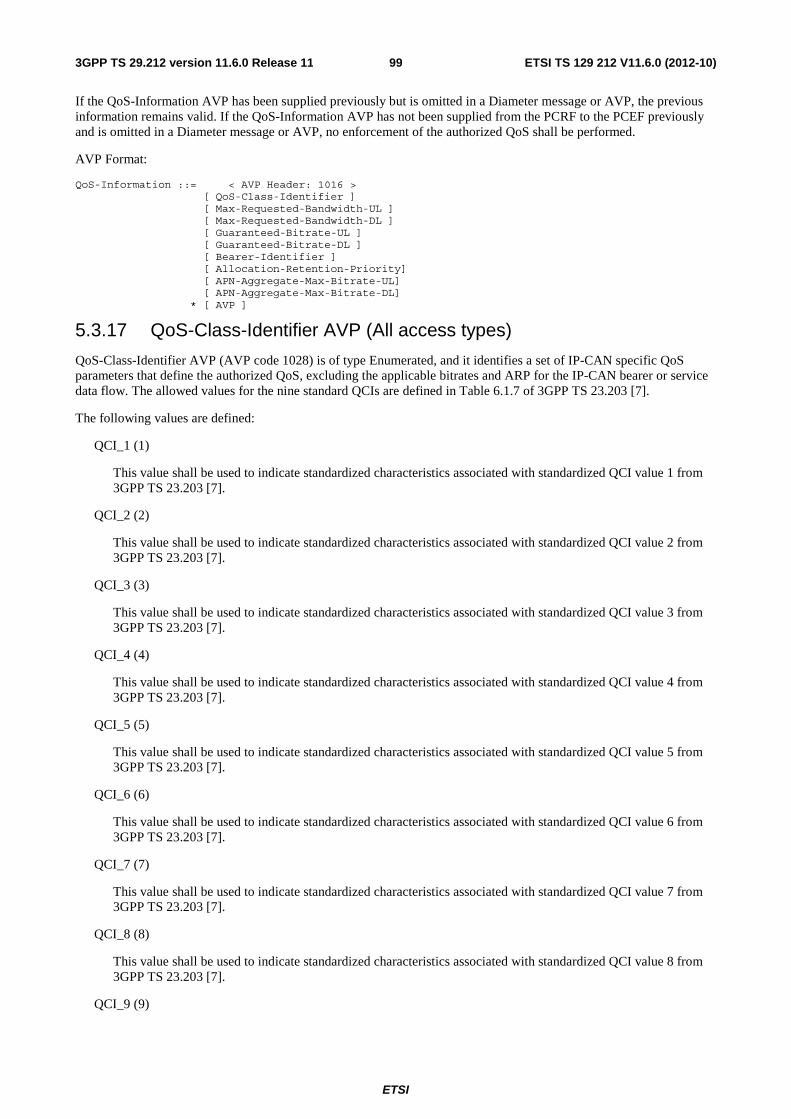
ETSI
ETSI TS 129 212 V11.6.0 (2012-10)993GPP TS 29.212 version 11.6.0 Release 11
If the QoS-Information AVP has been supplied previously but is omitted in a Diameter message or AVP, the previous information remains valid. If the QoS-Information AVP has not been supplied from the PCRF to the PCEF previously and is omitted in a Diameter message or AVP, no enforcement of the authorized QoS shall be performed.
AVP Format:
QoS-Information ::= < AVP Header: 1016 > [ QoS-Class-Identifier ] [ Max-Requested-Bandwidth-UL ] [ Max-Requested-Bandwidth-DL ] [ Guaranteed-Bitrate-UL ] [ Guaranteed-Bitrate-DL ] [ Bearer-Identifier ] [ Allocation-Retention-Priority] [ APN-Aggregate-Max-Bitrate-UL] [ APN-Aggregate-Max-Bitrate-DL] * [ AVP ]
5.3.17 QoS-Class-Identifier AVP (All access types)
QoS-Class-Identifier AVP (AVP code 1028) is of type Enumerated, and it identifies a set of IP-CAN specific QoS parameters that define the authorized QoS, excluding the applicable bitrates and ARP for the IP-CAN bearer or service data flow. The allowed values for the nine standard QCIs are defined in Table 6.1.7 of 3GPP TS 23.203 [7].
The following values are defined:
QCI_1 (1)
This value shall be used to indicate standardized characteristics associated with standardized QCI value 1 from 3GPP TS 23.203 [7].
QCI_2 (2)
This value shall be used to indicate standardized characteristics associated with standardized QCI value 2 from 3GPP TS 23.203 [7].
QCI_3 (3)
This value shall be used to indicate standardized characteristics associated with standardized QCI value 3 from 3GPP TS 23.203 [7].
QCI_4 (4)
This value shall be used to indicate standardized characteristics associated with standardized QCI value 4 from 3GPP TS 23.203 [7].
QCI_5 (5)
This value shall be used to indicate standardized characteristics associated with standardized QCI value 5 from 3GPP TS 23.203 [7].
QCI_6 (6)
This value shall be used to indicate standardized characteristics associated with standardized QCI value 6 from 3GPP TS 23.203 [7].
QCI_7 (7)
This value shall be used to indicate standardized characteristics associated with standardized QCI value 7 from 3GPP TS 23.203 [7].
QCI_8 (8)
This value shall be used to indicate standardized characteristics associated with standardized QCI value 8 from 3GPP TS 23.203 [7].
QCI_9 (9)

ETSI
ETSI TS 129 212 V11.6.0 (2012-10)1003GPP TS 29.212 version 11.6.0 Release 11
This value shall be used to indicate standardized characteristics associated with standardized QCI value 9 from 3GPP TS 23.203 [7].
The QCI values 0, 10 – 255 are divided for usage as follows:
0: Reserved
10-127: Reserved
128-254: Operator specific
255: Reserved
Table 5.3.17.1: Void
5.3.18 Charging-Rule-Report AVP (All access types)
The Charging-Rule-Report AVP (AVP code 1018) is of type Grouped, and it is used to report the status of PCC rules.
Charging-Rule-Name AVP is a reference for a specific PCC rule at the PCEF that has been successfully installed, modified or removed (for dynamic PCC rules), or activated or deactivated (for predefined PCC rules) because of trigger from the MS. Charging-Rule-Base-Name AVP is a reference for a group of PCC rules predefined at the PCEF that has been successfully activated or deactivated because of trigger from the MS.
The Charging-Rule-Report AVP can also be used to report the status of the PCC rules which cannot be installed/activated or enforced at the PCEF. In this condition, the Charging-Rule-Name AVP is used to indicate a specific PCC rule which cannot be installed/activated or enforced, and the Charging-Rule-Base-Name AVP is used to indicate a group of PCC rules which cannot be activated. The Rule-Failure-Code indicates the reason that the PCC rules cannot be successfully installed/activated or enforced.
The Charging-Rule-Report AVP can also be used to report the status of the PCC rules for which credit is no longer available or credit has been reallocated after the former out of credit indication. When reporting an out of credit condition, the Final-Unit-Indication AVP indicates the termination action the PCEF applies to the PCC rules as instructed by the OCS.
For GPRS scenarios where the bearer binding is performed by the PCRF, the Bearer-Identifier AVP may be included within the Charging-Rule-Report AVP.
AVP Format:
Charging-Rule-Report ::= < AVP Header: 1018 > *[ Charging-Rule-Name ] *[ Charging-Rule-Base-Name ] [ Bearer-Identifier ] [ PCC-Rule-Status ] [ Rule-Failure-Code ] [ Final-Unit-Indication ] *[ AVP ]
Multiple instances of Charging-Rule-Report AVPs shall be used in the case it is required to report different PCC-Rule-Status or Rule-Failure-Code values for different groups of rules within the same Diameter command.
5.3.19 PCC-Rule-Status AVP (All access types)
The PCC-Rule-Status AVP (AVP code 1019) is of type Enumerated, and describes the status of one or a group of PCC Rules.
The following values are defined:
ACTIVE (0)
This value is used to indicate that the PCC rule(s) are successfully installed (for those provisioned from PCRF) or activated (for those pre-provisioned in PCEF)
INACTIVE (1)

ETSI
ETSI TS 129 212 V11.6.0 (2012-10)1013GPP TS 29.212 version 11.6.0 Release 11
This value is used to indicate that the PCC rule(s) are removed (for those provisioned from PCRF) or inactive (for those pre-provisioned in PCEF)
TEMPORARILY INACTIVE (2)
This value is used to indicate that, for some reason (e.g. loss of bearer), already installed or activated PCC rules are temporarily disabled.
5.3.20 Bearer-Identifier AVP (Applicable access type 3GPP-GPRS)
The Bearer-Identifier AVP (AVP code 1020) is of type OctetString, and it indicates the bearer to which specific information refers.
When present within a CC-Request Diameter command, subsequent AVPs within the CC-Request refer to the specific bearer identified by this AVP.
The bearer identifier of an IP CAN bearer shall be unique within the corresponding IP CAN session. The bearer identifier shall be selected by the PCEF.
5.3.21 Bearer-Operation AVP (Applicable access type 3GPP-GPRS)
The Bearer-Operation AVP (AVP code 1021) is of type of Enumerated, and it indicates the bearer event that causes a request for PCC rules. This AVP shall be supplied if the bearer event relates to an IP CAN bearer initiated by the UE.
The following values are defined:
TERMINATION (0)
This value is used to indicate that a bearer is being terminated.
ESTABLISHMENT (1)
This value is used to indicate that a new bearer is being established.
MODIFICATION (2)
This value is used to indicate that an existing bearer is being modified.
5.3.22 Access-Network-Charging-Identifier-Gx AVP (All access types)
The Access-Network-Charging-Identifier-Gx AVP (AVP code 1022) is of type Grouped. It contains a charging identifier (e.g. GCID) within the Access-Network-Charging-Identifier-Value AVP and the related PCC rule name(s) within the Charging-Rule-Name AVP(s) and/or within the Charging-Rule-Base-Name AVP(s). If the charging identifier applies to the entire IP CAN session, no Charging-Rule-Name AVPs or Charging-Rule-Base-Name AVPs need to be provided. Otherwise, all the Charging-Rule-Name AVPs or Charging-Rule-Base-Name AVPs corresponding to PCC rules associated to the provided Access-Network-Charging-Identifier-Value shall be included.
NOTE: For Case 1 and GPRS, the charging identifier for an IP-CAN bearer is provided together with all the Charging-Rule-Name AVPs or Charging-Rule-Base-Name AVPs corresponding to PCC rules activated or installed within the IP-CAN bearer.
The Access-Network-Charging-Identifier-Gx AVP can be sent from the PCEF to the PCRF. The PCRF may use this information for charging correlation towards the AF.
AVP Format:
Access-Network-Charging-Identifier-Gx ::= < AVP Header: 1022 > { Access-Network-Charging-Identifier-Value} *[ Charging-Rule-Base-Name ] *[ Charging-Rule-Name ]
ETSI
ETSI TS 129 212 V11.6.0 (2012-10)1023GPP TS 29.212 version 11.6.0 Release 11
5.3.23 Bearer-Control-Mode AVP
The Bearer-Control-Mode AVP (AVP code 1023) is of type of Enumerated. It is sent from PCRF to PCEF and indicates the PCRF selected bearer control mode.
The following values are defined:
UE_ONLY (0)
This value is used to indicate that the UE shall request any resource establishment, modification or termination.
RESERVED (1)
This value is not used in this Release.
UE_NW (2)
This value is used to indicate that both the UE and PCEF may request any resource establishment, modification or termination by adding, modifying or removing traffic flow information.
See Annex A.3.8 for particularities in 3GPP-GPRS access.
5.3.24 Network-Request-Support AVP
The Network-Request-Support AVP (AVP code 1024) is of type of Enumerated and indicates the UE and network support of the network initiated procedures.
If the Network Request Support AVP has not been previously provided, its absence shall indicate the value NETWORK_REQUEST NOT SUPPORTED. If the Network Request Support AVP has been provided, its value shall remain valid until it is provided the next time.
The following values are defined:
NETWORK_REQUEST NOT SUPPORTED (0)
This value is used to indicate that the UE and the access network do not support the network initiated bearer establishment request procedure.
NETWORK_REQUEST SUPPORTED (1)
This value is used to indicate that the UE and the access network support the network initiated bearer establishment request procedure.
5.3.25 Guaranteed-Bitrate-DL AVP
The Guaranteed-Bitrate-DL AVP (AVP code 1025) is of type Unsigned32, and it indicates the guaranteed bitrate in bits per second for a downlink service data flow. The bandwidth contains all the overhead coming from the IP-layer and the layers above, e.g. IP, UDP, RTP and RTP payload.
5.3.26 Guaranteed-Bitrate-UL AVP
The Guaranteed –Bitrate-UL AVP (AVP code 1026) is of type Unsigned32, and it indicates the guaranteed bitrate in bits per second for an uplink service data flow. The bandwidth contains all the overhead coming from the IP-layer and the layers above, e.g. IP, UDP, RTP and RTP payload.
5.3.27 IP-CAN-Type AVP (All access types)
The IP-CAN-Type AVP (AVP code 1027) is of type Enumerated, and it shall indicate the type of Connectivity Access Network in which the user is connected.
The IP-CAN-Type AVP shall always be present during the IP-CAN session establishment. During an IP-CAN session modification, this AVP shall be present when there has been a change in the IP-CAN type and the PCRF requested to be

ETSI
ETSI TS 129 212 V11.6.0 (2012-10)1033GPP TS 29.212 version 11.6.0 Release 11
informed of this event. The Event-Trigger AVP with value IP-CAN-CHANGE shall be provided together with the IP-CAN-Type AVP.
NOTE: The informative Annex C presents a mapping between the code values for different access network types.
The following values are defined:
3GPP-GPRS (0)
This value shall be used to indicate that the IP-CAN is associated with a 3GPP GPRS access that is connected to the GGSN based on the Gn/Gp interfaces and is further detailed by the RAT-Type AVP. RAT-Type AVP will include applicable 3GPP values, except EUTRAN.
DOCSIS (1)
This value shall be used to indicate that the IP-CAN is associated with a DOCSIS access.
xDSL (2)
This value shall be used to indicate that the IP-CAN is associated with an xDSL access.
WiMAX (3)
This value shall be used to indicate that the IP-CAN is associated with a WiMAX access (IEEE 802.16).
3GPP2 (4)
This value shall be used to indicate that the IP-CAN is associated with a 3GPP2 access connected to the 3GPP2 packet core as specified in 3GPP2 X.S0011 [20] and is further detailed by the RAT-Type AVP.
3GPP-EPS (5)
This value shall be used to indicate that the IP-CAN associated with a 3GPP EPS access and is further detailed by the RAT-Type AVP.
Non-3GPP-EPS (6)
This value shall be used to indicate that the IP-CAN associated with an EPC based non-3GPP access and is further detailed by the RAT-Type AVP.
5.3.28 QoS-Negotiation AVP (3GPP-GPRS Access Type only)
The QoS-Negotiation AVP (AVP code 1029) is of type Enumerated. The value of the AVP indicates for a single PCC rule request if the PCRF is allowed to negotiate the QoS by supplying in the answer to this request an authorized QoS different from the requested QoS.
The following values are defined:
NO_QoS_NEGOTIATION (0)
This value indicates that a QoS negotiation is not allowed for the corresponding PCC rule request.
QoS_NEGOTIATION_SUPPORTED (1)
This value indicates that a QoS negotiation is allowed for the corresponding PCC rule request. This is the default value applicable if this AVP is not supplied
5.3.29 QoS-Upgrade AVP (3GPP-GPRS Access Type only)
The QoS-Upgrade AVP (AVP code 1030) is of type Enumerated. The value of the AVP indicates whether the SGSN supports that the GGSN upgrades the QoS in a Create PDP context response or Update PDP context response. If the SGSN does not support a QoS upgrade, the PCRF shall not provision an authorized QoS which is higher than the requested QoS for this IP CAN bearer in the response of the IP-CAN session establishment or modification. The setting is applicable to the bearer indicated in the request within the Bearer-Identifier AVP.

ETSI
ETSI TS 129 212 V11.6.0 (2012-10)1043GPP TS 29.212 version 11.6.0 Release 11
If no QoS-Upgrade AVP has been supplied for an IP CAN bearer, the default value QoS_UPGRADE_NOT_SUPPORTED is applicable. If the QoS-Upgrade AVP has previously been supplied for an IP CAN bearer but is not supplied in a new PCC rule request, the previously supplied value remains applicable.
The following values are defined:
QoS_UPGRADE_NOT_SUPPORTED (0)
This value indicates that the IP-CAN bearer does not support the upgrading of the requested QoS. This is the default value applicable if no QoS-Upgrade AVP has been supplied for an IP CAN bearer.
QoS_UPGRADE_SUPPORTED (1)
This value indicates that the IP-CAN bearer supports the upgrading of the requested QoS.
5.3.30 Event-Report-Indication AVP (All access types)
The Event-Report-Indication AVP (AVP code 1033) is of type Grouped. When sent from the PCRF to the PCEF, it is used to report an event coming from the Access Network GW (BBERF) and relevant info to the PCEF. When sent from the PCEF to the PCRF, it is used to provide the information about the required event triggers to the PCRF. Only Event-Trigger AVP will be supplied in this case.
The PCEF may require adding new event triggers or removing the already provided ones. In order to do so, the PCEF shall provide the new complete list of applicable event triggers within the Event-Trigger AVP included in the Event-Report-Indication AVP to the PCRF.
The PCEF may require removing all previously provided event triggers by providing the Event-Trigger AVP set to the value NO_EVENT_TRIGGERS included in the Event-Report-Indication AVP to the PCRF.
If the event triggers required by the PCEF are associated with certain parameter values, the PCRF shall provide those values to the PCEF.
The PCEF may subscribe to different or common set of event triggers at different BBERFs by including the Routing-IP-Address AVP in the Event-Report-Indication AVP to the PCRF.
The PCEF may provide the following Event-Trigger values to the PCRF: QOS_CHANGE, RAI_CHANGE, RAT_CHANGE, USER_LOCATION_CHANGE, UE_TIME_ZONE_CHANGE, USER_CSG_INFORMATION_CHANGE, USER_CSG_HYBRID_SUBSCRIBED_INFORMATION_CHANGE, USER_CSG_ HYBRID_UNSUBSCRIBED_INFORMATION_CHANGE, TAI_CHANGE and ECGI_CHANGE.
Event-Trigger value QOS_CHANGE shall be used to report a change in APN-Aggregate-Max-Bitrate-DL AVP and/or APN-Aggregate-Max-Bitrate-UL AVP included within the QoS-Information AVP.
Applicability of the Event-Triggers to the different accesses is defined in clause 5.3.7.
AVP Format:
Event-Report-Indication ::= < AVP Header: 1033 > *[ Event-Trigger ] [ User-CSG-Information ] [ RAT-Type ] [ QoS-Information ] [ RAI ] [ 3GPP-User-Location-Info ] [ Trace-Data ] [ Trace-Reference ] [ 3GPP2-BSID ] [ 3GPP-MS-TimeZone ] [ Routing-IP-Address ] *[ AVP ]
5.3.31 RAT-Type AVP
The RAT-Type AVP (AVP code 1032) is of type Enumerated and is used to identify the radio access technology that is serving the UE.

ETSI
ETSI TS 129 212 V11.6.0 (2012-10)1053GPP TS 29.212 version 11.6.0 Release 11
NOTE 1: Values 0-999 are used for generic radio access technologies that can apply to different IP-CAN types and are not IP-CAN specific.
NOTE 2: Values 1000-1999 are used for 3GPP specific radio access technology types.
NOTE 3: Values 2000-2999 are used for 3GPP2 specific radio access technology types.
NOTE 4: The informative Annex C presents a mapping between the code values for different access network types.
The following values are defined:
WLAN (0)
This value shall be used to indicate that the RAT is WLAN.
VIRTUAL (1)
This value shall be used to indicate that the RAT is unknown. For further details refer to 3GPP TS 29.274 [22].
UTRAN (1000)
This value shall be used to indicate that the RAT is UTRAN. For further details refer to 3GPP TS 29.060 [18].
GERAN (1001)
This value shall be used to indicate that the RAT is GERAN. For further details refer to 3GPP TS 29.060 [18].
GAN (1002)
This value shall be used to indicate that the RAT is GAN. For further details refer to 3GPP TS 29.060 [18] and 3GPP TS 43.318 [29].
HSPA_EVOLUTION (1003)
This value shall be used to indicate that the RAT is HSPA Evolution. For further details refer to 3GPP TS 29.060 [18].
EUTRAN (1004)
This value shall be used to indicate that the RAT is EUTRAN. For further details refer to 3GPP TS 29.274 [22]
CDMA2000_1X (2000)
This value shall be used to indicate that the RAT is CDMA2000 1X. For further details refer to 3GPP2 X.S0011 [20].
HRPD (2001)
This value shall be used to indicate that the RAT is HRPD. For further details refer to 3GPP2 X.S0011 [20].
UMB (2002)
This value shall be used to indicate that the RAT is UMB. For further details refer to 3GPP2 X.S0011 [20].
EHRPD (2003)
This value shall be used to indicate that the RAT is eHRPD. For further details refer to 3GPP2 X.S0057 [24].
5.3.32 Allocation-Retention-Priority AVP (All access types)
The Allocation-Retention-Priority AVP (AVP code 1034) is of type Grouped, and it is used to indicate the priority of allocation and retention, the pre-emption capability and pre-emption vulnerability for the SDF if provided within the QoS-Information-AVP or for the EPS default bearer if provided within the Default-EPS-Bearer-QoS AVP.
The Priority-Level AVP of the default bearer should be set to a sufficiently high level of priority and the ARP pre-emption vulnerability of the default bearer should be set appropriately to minimize the risk for unexpected PDN disconnection or UE detach from the network according to operator specific policies.

ETSI
ETSI TS 129 212 V11.6.0 (2012-10)1063GPP TS 29.212 version 11.6.0 Release 11
AVP Format:
Allocation-Retention-Priority ::= < AVP Header: 1034 > { Priority-Level } [ Pre-emption-Capability ] [ Pre-emption-Vulnerability ]
5.3.33 CoA-IP-Address AVP (All access types)
The CoA-IP-Address AVP (AVP Code 1035) is of type Address and contains the mobile node’s care-of-address. The care-of-address type may be IPv4 or IPv6.
5.3.34 Tunnel-Header-Filter AVP (All access types)
The Tunnel-Header-Filter AVP (AVP code 1036) is of type IPFilterRule, and it defines the tunnel (outer) header filter information of a MIP tunnel where the associated QoS rules apply for the tunnel payload.
The Tunnel-Header-Filter AVP shall include the following information:
- Action shall be set to "permit";
- Direction (in or out);
- Protocol;
- Source IP address;
- Source port (single value) for UDP tunneling;
- Destination IP address;
- Destination port (single value) for UDP tunneling.
The IPFilterRule type shall be used with the following restrictions:
- Options shall not be used.
- The invert modifier "!" for addresses shall not be used.
The direction "out" refers to downlink direction.
The direction "in" refers to uplink direction.
5.3.35 Tunnel-Header-Length AVP (All access types)
The Tunnel-Header-Length AVP (AVP code 1037) is of type Unsigned32. This AVP indicates the length of the tunnel header in octets.
5.3.36 Tunnel-Information AVP (All access types)
The Tunnel-Information AVP (AVP code 1038) is of type Grouped, and it contains the tunnel (outer) header information from a single IP flow. The Tunnel-Information AVP is sent from the PCEF to the PCRF and from the PCRF to the BBERF.
The Tunnel-Information AVP may include only the Tunnel-Header-Length AVP, only the Tunnel-Header-Filter AVP, or both.
The Tunnel-Header-Length AVP provides the length of the tunnel header and identifies the offset where the tunnelled payload starts. The BBERF uses the length value provided in Tunnel-Header-Length AVP to locate the inner IP header and perform service data flow detection and related QoS control.
The Tunnel-Header-Filter AVP identifies the tunnel (outer) header information in the downlink and uplink directions.
AVP Format:
Tunnel-Information ::= < AVP Header: 1038 >

ETSI
ETSI TS 129 212 V11.6.0 (2012-10)1073GPP TS 29.212 version 11.6.0 Release 11
[ Tunnel-Header-Length ] 2[ Tunnel-Header-Filter ] *[ AVP ]
5.3.37 CoA-Information AVP (All access types)
The CoA-Information AVP (AVP code 1039) is of type Grouped, and it contains care-of-address and the tunnel information related to the care of address. The CoA-Information AVP is sent from the PCEF to the PCRF.
When used, the CoA-Information AVP shall include a CoA-IP-Address AVP. The CoA-Information AVP shall also include a Tunnel-Information AVP, which provides the tunnel header length and tunnel header filter information related to the specific care-of-address.
AVP Format:
CoA-Information ::= < AVP Header: 1039> { Tunnel-Information } { CoA-IP-Address } *[ AVP ]
5.3.38 Rule-Failure-Code AVP (All access types)
The Rule-Failure-Code AVP (AVP code 1031) is of type Enumerated. It is sent by the PCEF to the PCRF within a Charging-Rule-Report AVP to identify the reason a PCC Rule is being reported.
The following values are defined:
UNKNOWN_RULE_NAME (1)
This value is used to indicate that the pre-provisioned PCC rule could not be successfully activated because the Charging-Rule-Name or Charging-Rule-Base-Name is unknown to the PCEF.
RATING_GROUP_ERROR (2)
This value is used to indicate that the PCC rule could not be successfully installed or enforced because the Rating-Group specified within the Charging-Rule-Definition AVP by the PCRF is unknown or, invalid.
SERVICE_IDENTIFIER_ERROR (3)
This value is used to indicate that the PCC rule could not be successfully installed or enforced because the Service-Identifier specified within the Charging-Rule-Definition AVP by the PCRF is invalid, unknown, or not applicable to the service being charged.
GW/PCEF_MALFUNCTION (4)
This value is used to indicate that the PCC rule could not be successfully installed (for those provisioned from the PCRF) or activated (for those pre-provisioned in PCEF) or enforced (for those already successfully installed) due to GW/PCEF malfunction.
RESOURCES_LIMITATION (5)
This value is used to indicate that the PCC rule could not be successfully installed (for those provisioned from PCRF) or activated (for those pre-provisioned in PCEF) or enforced (for those already successfully installed) due to a limitation of resources at the PCEF.
MAX_NR_BEARERS_REACHED (6)
This value is used to indicate that the PCC rule could not be successfully installed (for those provisioned from PCRF) or activated (for those pre-provisioned in PCEF) or enforced (for those already successfully installed) due to the fact that the maximum number of bearers has been reached for the IP-CAN session.
UNKNOWN_BEARER_ID (7)
This value is used to indicate that the PCC rule could not be successfully installed or enforced at the PCEF because the Bearer-Id specified within the Charging-Rule-Install AVP by the PCRF is unknown or invalid. Applicable only for GPRS in the case the PCRF performs the bearer binding.
MISSING_BEARER_ID (8)

ETSI
ETSI TS 129 212 V11.6.0 (2012-10)1083GPP TS 29.212 version 11.6.0 Release 11
This value is used to indicate that the PCC rule could not be successfully installed or enforced at the PCEF because the Bearer-Id is not specified within the Charging-Rule-Install AVP by the PCRF. Applicable only for GPRS in the case the PCRF performs the bearer binding.
MISSING_FLOW_INFORMATION (9)
This value is used to indicate that the PCC rule could not be successfully installed or enforced because the Flow-Information AVP is not specified within the Charging-Rule-Definition AVP by the PCRF during the first install request of the PCC rule.
RESOURCE_ALLOCATION_FAILURE (10)
This value is used to indicate that the PCC rule could not be successfully installed or maintained since the bearer establishment/modification failed, or the bearer was released.
UNSUCCESSFUL_QOS_VALIDATION (11)
This value is used to:
indicate that the QoS validation has failed or,
- Indicate when Guaranteed Bandwidth > Max-Requested-Bandwidth.
INCORRECT_FLOW_INFORMATION (12)
This value is used to indicate that the PCC rule could not be successfully installed or modified at the PCEF because the provided flow information is not supported by the network (e.g. the provided IP address(es) or IPv6 prefix(es) do not correspond to an IP version applicable for the IP-CAN session).
PS_TO_CS_HANDOVER (13)
This value is used to indicate that the PCC rule could not be maintained because of PS to CS handover. This value is only applicable for 3GPP-GPRS and 3GPP-EPS. Applicable to functionality introduced with the Rel9 feature as described in clause 5.4.1.
TDF_APPLICATION_IDENTIFIER_ERROR (14)
This value is used to indicate that the rule could not be successfully installed or enforced because the TDF-Application-Identifier is invalid, unknown, or not applicable to the application required for detection.
NO_BEARER_BOUND (15)
This value is used to indicate that there is no IP-CAN bearer without traffic mapping information which the PCEF can bind the PCC rule(s) including Rule-Activation-Time AVP to.
FILTER_RESTRICTIONS (15)
This value is used to indicate that the Flow-Description AVP(s) cannot be handled by the PCEF because one of the following restrictions was not met.
- Only the Action "permit" shall be used.
- No "options" shall be used.
- The invert modifier "!" for addresses shall not be used.
- The keyword "assigned" shall not be used.
5.3.39 APN-Aggregate-Max-Bitrate-DL AVP
The APN-Aggregate-Max-Bitrate-DL AVP (AVP code 1040) is of type Unsigned32, and it indicates the maximum aggregate bit rate in bits per seconds for the downlink direction across all non-GBR bearers related with the same APN.
When provided in a CC-Request, it indicates the subscribed maximum bitrate and/or the maximum bitrate retained in the PCEF. When provided in a CC-Answer, it indicates the maximum bandwidth authorized by PCRF.

ETSI
ETSI TS 129 212 V11.6.0 (2012-10)1093GPP TS 29.212 version 11.6.0 Release 11
5.3.40 APN-Aggregate-Max-Bitrate-UL AVP
The APN-Aggregate-Max-Bitrate-UL AVP (AVP code 1041) is of type Unsigned32, and it indicates the maximum aggregate bit rate in bits per seconds for the uplink direction across all non-GBR bearers related with the same APN.
When provided in a CC-Request, it indicates the subscribed maximum bandwidth and/or the maximum bitrate retained in the PCEF. When provided in a CC-Answer, it indicates the maximum bandwidth authorized by PCRF.
5.3.41 Revalidation-Time (ALL Access Types)
The Revalidation-Time AVP (AVP code 1042) is of type Time. This value indicates the NTP time before which the PCEF will have to re-request PCC rules. This value shall be provided with the event trigger when REVALIDATION_TIMEOUT is provisioned via CCA or RAR.
5.3.42 Rule-Activation-Time (ALL Access Types)
The Rule-Activation-Time AVP (AVP code 1043) is of type Time. This value indicates the NTP time at which the PCC rule has to be enforced. The AVP is included in Charging-Rule-Install AVP and is applicable for all the PCC rules included within the Charging-Rule-Install AVP.
5.3.43 Rule-Deactivation-Time (ALL Access Types)
The Rule-Deactivation-Time AVP (AVP code 1044) is of type Time. This value indicates the NTP time at which the PCEF has to stop enforcing the PCC rule. The AVP is included in Charging-Rule-Install AVP and is applicable for all the PCC rules included within the Charging-Rule-Install AVP.
5.3.44 Session-Release-Cause (All access types)
Session-Release-Cause AVP (AVP code 1045) is of type Enumerated, and determines the cause of release the IP-CAN session by the PCRF. The following values are defined:
UNSPECIFIED_REASON (0)
This value is used for unspecified reasons.
UE_SUBSCRIPTION_REASON (1)
This value is used to indicate that the subscription of UE has changed (e.g. removed) and the session needs to be terminated.
INSUFFICIENT_SERVER_RESOURCES (2)
This value is used to indicate that the server is overloaded and needs to abort the session.
IP_CAN_SESSION_TERMINATION (3)
This value is used to indicate that the corresponding IP-CAN session is terminated. The IP_CAN_SESSION_TERMINATION value is introduced in order to be used by Sd only, when PCRF initiates the TDF session termination within IP-CAN session termination.
UE_IP_ADDRESS_RELEASE (4)
This value is used to indicate that the IPv4 address of a dual stack IP-CAN session is released. The UE_IP_ADDRESS_RELEASE value is introduced in order to be used by Sd only, when PCRF initiates the TDF session termination if the IPv4 address of a dual stack IP-CAN session is released and if there is an active IPv4 address related TDF session for that IP-CAN session.
5.3.45 Priority-Level AVP (All access types)
The Priority-Level AVP (AVP code 1046) is of type Unsigned 32. The AVP is used for deciding whether a bearer establishment or modification request can be accepted or needs to be rejected in case of resource limitations (typically

ETSI
ETSI TS 129 212 V11.6.0 (2012-10)1103GPP TS 29.212 version 11.6.0 Release 11
used for admission control of GBR traffic). The AVP can also be used to decide which existing bearers to pre-empt during resource limitations. The priority level defines the relative importance of a resource request.
Values 1 to 15 are defined, with value 1 as the highest level of priority.
Values 1 to 8 should only be assigned for services that are authorized to receive prioritized treatment within an operator domain. Values 9 to 15 may be assigned to resources that are authorized by the home network and thus applicable when a UE is roaming.
5.3.46 Pre-emption-Capability AVP
The Pre-emption-Capability AVP (AVP code 1047) is of type Enumerated. If it is provided within the QoS-Information AVP, the AVP defines whether a service data flow can get resources that were already assigned to another service data flow with a lower priority level. If it is provided within the Default-EPS-Bearer-QoS AVP, the AVP defines whether the default bearer can get resources that were already assigned to another bearer with a lower priority level.
The following values are defined:
PRE-EMPTION_CAPABILITY_ENABLED (0)
This value indicates that the service data flow or bearer is allowed to get resources that were already assigned to another service data flow or bearer with a lower priority level.
PRE-EMPTION_CAPABILITY_DISABLED (1)
This value indicates that the service data flow or bearer is not allowed to get resources that were already assigned to another service data flow or bearer with a lower priority level. This is the default value applicable if this AVP is not supplied.
5.3.47 Pre-emption-Vulnerability AVP
The Pre-emption Vulnerability AVP (AVP code 1048) is of type Enumerated. If it is provided within the QoS-Information AVP, the AVP defines whether a service data flow can lose the resources assigned to it in order to admit a service data flow with higher priority level. If it is provided within the Default-EPS-Bearer-QoS AVP, the AVP defines whether the default bearer can lose the resources assigned to it in order to admit a pre-emption capable bearer with a higher priority level.
The following values are defined:
PRE-EMPTION_VULNERABILITY_ENABLED (0)
This value indicates that the resources assigned to the service data flow or bearer can be pre-empted and allocated to a service data flow or bearer with a higher priority level. This is the default value applicable if this AVP is not supplied.
PRE-EMPTION_VULNERABILITY_DISABLED (1)
This value indicates that the resources assigned to the service data flow or bearer shall not be pre-empted and allocated to a service data flow or bearer with a higher priority level.
5.3.48 Default-EPS-Bearer-QoS AVP
The Default-EPS-Bearer-QoS AVP (AVP code 1049) is of type Grouped, and it defines the QoS information for the EPS default bearer. When this AVP is sent from the PCEF to the PCRF, it indicates the subscribed QoS for the default EPS bearer and/or the retained QoS for the default EPS bearer in the PCEF. When this AVP is sent from the PCRF to the PCEF, it indicates the authorized QoS for the default EPS bearer.
The QoS class identifier identifies a set of IP-CAN specific QoS parameters that define QoS, excluding the applicable bitrates and ARP. When included in the Default-EPS-Bearer-QoS AVP, it shall include only non-GBR values.
The Allocation-Retention-Priority AVP is an indicator of the priority of allocation and retention for the default bearer.
AVP Format:
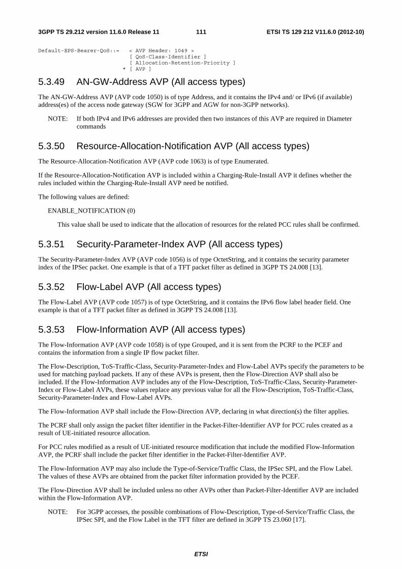
ETSI
ETSI TS 129 212 V11.6.0 (2012-10)1113GPP TS 29.212 version 11.6.0 Release 11
Default-EPS-Bearer-QoS::= < AVP Header: 1049 > [ QoS-Class-Identifier ] [ Allocation-Retention-Priority ] * [ AVP ]
5.3.49 AN-GW-Address AVP (All access types)
The AN-GW-Address AVP (AVP code 1050) is of type Address, and it contains the IPv4 and/ or IPv6 (if available) address(es) of the access node gateway (SGW for 3GPP and AGW for non-3GPP networks).
NOTE: If both IPv4 and IPv6 addresses are provided then two instances of this AVP are required in Diameter commands
5.3.50 Resource-Allocation-Notification AVP (All access types)
The Resource-Allocation-Notification AVP (AVP code 1063) is of type Enumerated.
If the Resource-Allocation-Notification AVP is included within a Charging-Rule-Install AVP it defines whether the rules included within the Charging-Rule-Install AVP need be notified.
The following values are defined:
ENABLE_NOTIFICATION (0)
This value shall be used to indicate that the allocation of resources for the related PCC rules shall be confirmed.
5.3.51 Security-Parameter-Index AVP (All access types)
The Security-Parameter-Index AVP (AVP code 1056) is of type OctetString, and it contains the security parameter index of the IPSec packet. One example is that of a TFT packet filter as defined in 3GPP TS 24.008 [13].
5.3.52 Flow-Label AVP (All access types)
The Flow-Label AVP (AVP code 1057) is of type OctetString, and it contains the IPv6 flow label header field. One example is that of a TFT packet filter as defined in 3GPP TS 24.008 [13].
5.3.53 Flow-Information AVP (All access types)
The Flow-Information AVP (AVP code 1058) is of type Grouped, and it is sent from the PCRF to the PCEF and contains the information from a single IP flow packet filter.
The Flow-Description, ToS-Traffic-Class, Security-Parameter-Index and Flow-Label AVPs specify the parameters to be used for matching payload packets. If any of these AVPs is present, then the Flow-Direction AVP shall also be included. If the Flow-Information AVP includes any of the Flow-Description, ToS-Traffic-Class, Security-Parameter-Index or Flow-Label AVPs, these values replace any previous value for all the Flow-Description, ToS-Traffic-Class, Security-Parameter-Index and Flow-Label AVPs.
The Flow-Information AVP shall include the Flow-Direction AVP, declaring in what direction(s) the filter applies.
The PCRF shall only assign the packet filter identifier in the Packet-Filter-Identifier AVP for PCC rules created as a result of UE-initiated resource allocation.
For PCC rules modified as a result of UE-initiated resource modification that include the modified Flow-Information AVP, the PCRF shall include the packet filter identifier in the Packet-Filter-Identifier AVP.
The Flow-Information AVP may also include the Type-of-Service/Traffic Class, the IPSec SPI, and the Flow Label. The values of these AVPs are obtained from the packet filter information provided by the PCEF.
The Flow-Direction AVP shall be included unless no other AVPs other than Packet-Filter-Identifier AVP are included within the Flow-Information AVP.
NOTE: For 3GPP accesses, the possible combinations of Flow-Description, Type-of-Service/Traffic Class, the IPSec SPI, and the Flow Label in the TFT filter are defined in 3GPP TS 23.060 [17].

ETSI
ETSI TS 129 212 V11.6.0 (2012-10)1123GPP TS 29.212 version 11.6.0 Release 11
AVP Format:
Flow-Information ::= < AVP Header: 1058 > [ Flow-Description ] [ Packet-Filter-Identifier ] [ Packet-Filter-Usage ] [ ToS-Traffic-Class ] [ Security-Parameter-Index ] [ Flow-Label ] [ Flow-Direction ] *[ AVP ]
5.3.54 Packet-Filter-Content AVP
The Packet-Filter-Content AVP (AVP code 1059) is of type IPFilterRule, and it contains the content of the packet filter as requested by the UE and required by the PCRF to create the PCC rules. The following information shall be sent:
- Action shall be set to "permit".
- Direction shall be set to "out".
- Protocol shall be set to the value provided within the packet filter provided by the UE. If not provided, Protocol shall be set to "ip".
- Source IP address (possibly masked). The Source IP address shall be derived from the packet filter parameters, for the remote end, sent by the UE. If the Source IP address is not provided by the UE, this field shall be set to "any".
- Source and/or destination port (single value, list or ranges). The information shall be derived from the remote and/or local port packet filter parameters. Source and/or destination port(s) shall be omitted if the corresponding information is not provided in the packet filter.
- Destination IP address (possibly masked). The Destination IP address shall be derived from the packet filter parameters sent by the UE. The Destination shall be set to the value provided by the UE. If no Destination IP address is provided in the packet filter the Destination shall be set to "assigned", which refers to the IPv4 address and/or IPv6 prefix of the UE as indicated by the Framed-IP-Address and/or Framed-IPv6-Prefix AVPs.
The IPFilterRule type shall be used with the following restrictions:
- No options shall be used.
- The invert modifier "!" for addresses shall not be used.
The direction "out" indicates that the IPFilterRule "source" parameters correspond to the "remote" parameters in the packet filter and the IPFilterRule "destination" parameters correspond to the "local" (UE end) parameters. The Packet-Filter-Content AVP applies in the direction(s) as specified in the accompanying Flow-Direction AVP.
Destination IP address including the value provided by the UE may be provided within the Packet-Filter-Content AVP when the ExtendedFilter feature is supported as described in clause 5.4.1.
5.3.55 Packet-Filter-Identifier AVP
The Packet-Filter-Identifier AVP (AVP code 1060) is of type OctetString, and it indicates the identity of the packet filter. For PCC rules created as a result of UE-initiated resource allocation, the packet filter identifier is assigned by the PCRF and within the scope of the PCRF is unique per UE.
5.3.56 Packet-Filter-Information AVP
The Packet-Filter-Information AVP (AVP code 1061) is of type Grouped, and it contains the information from a single packet filter sent from the PCEF to the PCRF. Depending on the Packet-Filter-Operation included within the CCR command it may include the packet filter identifier, evaluation precedence, filter value, filter direction, Type-of-Service/Traffic Class, the IPSec SPI, and the Flow Label.
When the Packet-Filter-Operation AVP included within the CCR command indicates DELETION, only the Packet-Filter-Identifier AVP shall be provided.

ETSI
ETSI TS 129 212 V11.6.0 (2012-10)1133GPP TS 29.212 version 11.6.0 Release 11
The Flow-Direction AVP shall be included unless no other AVPs other than Packet-Filter-Identifier AVP are included within the Packet-Filter-Information AVP.
When the Packet-Filter-Operation AVP included within the CCR command indicates ADDITION and is linked to an existing packet filter, only the Packet-Filter-Identifier AVP shall be provided for the existing packet filter.
See annex B.3.4 for E-UTRAN specific details.
AVP Format:
Packet-Filter-Information ::= < AVP Header: 1061 > [ Packet-Filter-Identifier ] [ Precedence ] [ Packet-Filter-Content ] [ ToS-Traffic-Class ] [ Security-Parameter-Index ] [ Flow-Label ] [ Flow-Direction ] *[ AVP ]
5.3.57 Packet-Filter-Operation AVP
The Packet-Filter-Operation AVP (AVP code 1062) is of type of Enumerated, and it indicates a UE initiated resource operation that causes a request for PCC rules.
The following values are defined:
DELETION (0)
This value is used to indicate that the resources reserved for the provided packet filter identifiers are to be deleted and are no longer used by the UE.
ADDITION (1)
This value is used to indicate that the UE requests resources allocated for the provided packet filters.
MODIFICATION (2)
This value is used to indicate that the reserved QoS, the filter, the precedence, or any of the fields for the provided packet filter identifiers are being modified.
5.3.58 PDN-Connection-ID AVP
The PDN-Connection-ID AVP (AVP code 1065) is of type OctetString, and it indicates the PDN connection to which specific information refers.
5.3.59 Monitoring-Key AVP
The Monitoring-Key AVP (AVP code 1066) is of type OctetString and is used for usage monitoring control purposes as an identifier to a usage monitoring control instance.
5.3.60 Usage-Monitoring-Information AVP
The Usage-Monitoring-Information AVP (AVP code 1067) is of type Grouped, and it contains the usage monitoring control information.
The Monitoring-Key AVP identifies the usage monitoring control instance.
The Granted-Service-Unit AVP shall be used by the PCRF to provide the threshold level to the PCEF. The CC-Total-Octets AVP shall be used for providing threshold level for the total volume, or the CC-Input-Octets and/or CC-Output-Octets AVPs shall be used for providing threshold level for the uplink volume and/or the downlink volume. Monitoring-Time AVP shall be used for providing the time at which the PCEF shall reapply the threshold value provided by the PCRF.

ETSI
ETSI TS 129 212 V11.6.0 (2012-10)1143GPP TS 29.212 version 11.6.0 Release 11
The Used-Service-Unit AVP shall be used by the PCEF to provide the measured usage to the PCRF. Reporting shall be done, as requested by the PCRF, in CC-Total-Octets, CC-Input-Octets or CC-Output-Octets AVPs of Used-Service-Unit AVP. Monitoring-Time AVP shall be used to indicate the time at which the PCEF shall reapply the threshold value provided by the PCRF.
The Usage-Monitoring-Level AVP determines the scope of the usage monitoring instance.
The Usage-Monitoring-Report AVP determines if accumulated usage shall be reported for the usage monitoring key included in Monitoring-Key AVP.
The Usage-Monitoring-Support AVP determines if a usage monitoring instance is disabled.
AVP Format:
Usage-Monitoring-Information::= < AVP Header: 1067 > [ Monitoring-Key ] 0,2[ Granted-Service-Unit ] 0,2[ Used-Service-Unit ] [ Usage-Monitoring-Level ] [ Usage-Monitoring-Report ] [ Usage-Monitoring-Support ] *[ AVP ]
5.3.61 Usage-Monitoring-Level AVP
The Usage-Monitoring-Level AVP (AVP code 1068) is of type Enumerated and is used by the PCRF to indicate whether the usage monitoring instance applies to the IP-CAN session or to one or more PCC rules or to one or more ADC rules.
If Usage-Monitoring-Level AVP is not provided, its absence shall indicate the value PCC_RULE_LEVEL (1).
The following values are defined:
SESSION_LEVEL (0)
This value, if provided within an RAR or CCA command by the PCRF, indicates that the usage monitoring instance applies to the entire IP-CAN session.
PCC_RULE_LEVEL (1)
This value, if provided within an RAR or CCA command by the PCRF indicates that the usage monitoring instance applies to one or more PCC rules.
ADC_RULE_LEVEL (2)
This value, if provided within an RAR or CCA command by the PCRF, indicates that the usage monitoring instance applies to one or more ADC rules.
5.3.62 Usage-Monitoring-Report AVP
The Usage-Monitoring-Report AVP (AVP code 1069) is of type Enumerated and is used by the PCRF to indicate that accumulated usage is to be reported by the PCEF regardless of whether a usage threshold is reached.
The following values are defined:
USAGE_MONITORING_REPORT_REQUIRED (0)
This value, if provided within an RAR or CCA command by the PCRF indicates that accumulated usage shall be reported by the PCEF.
5.3.63 Usage-Monitoring-Support AVP
The Usage-Monitoring-Support AVP (AVP code 1070) is of type Enumerated and is used by the PCRF to indicate whether usage monitoring shall be disabled for certain Monitoring Key.
The following values are defined:

ETSI
ETSI TS 129 212 V11.6.0 (2012-10)1153GPP TS 29.212 version 11.6.0 Release 11
USAGE_MONITORING_DISABLED (0)
This value indicates that usage monitoring is disabled for a monitoring key.
5.3.64 CSG-Information-Reporting AVP
The CSG-Information-Reporting AVP (AVP code 1071) is of type Enumerated, it is sent from the PCRF to the PCEF to request the PCEF to report the user CSG information change to the charging domain. The following values are defined:
CHANGE_CSG_CELL (0)
This value indicates that the PCEF reports the user CSG information change to the charging domain when the UE enters/leaves/accesses via a CSG cell.
CHANGE_CSG_SUBSCRIBED_HYBRID_CELL (1)
This value indicates that the PCEF reports the user CSG information change to the charging domain when the UE enters/leaves/accesses via a hybrid cell in which the subscriber is a CSG member.
CHANGE_CSG_UNSUBSCRIBED_HYBRID_CELL (2)
This value indicates that the PCEF reports the user CSG information change to the charging domain when the UE enters/leaves/accesses via a hybrid cell in which the subscriber is not a CSG member.
NOTE: Due to the increased signalling load, it is recommended that such reporting applied for a limited number of subscribers only.
5.3.65 Flow-Direction AVP
The Flow-Direction AVP (AVP code 1080) is of type Enumerated. It indicates the direction/directions that a filter is applicable, downlink only, uplink only or both down- and uplink (bidirectional).
UNSPECIFIED (0)
The corresponding filter applies for traffic to the UE (downlink), but has no specific direction declared. The service data flow detection shall apply the filter for uplink traffic as if the filter was bidirectional. The PCRF shall not use the value UNSPECIFIED in filters created by the network in NW-initiated procedures. The PCRF shall only include the value UNSPECIFIED in filters in UE-initiated procedures if the same value is received from in the CCR request from the PCEF.
DOWNLINK (1)
The corresponding filter applies for traffic to the UE.
UPLINK (2)
The corresponding filter applies for traffic from the UE.
BIDIRECTIONAL (3)
The corresponding filter applies for traffic both to and from the UE.
NOTE: The corresponding filter data is unidirectional. The filter for the opposite direction has the same parameters, but having the source and destination address/port parameters swapped.
5.3.66 Packet-Filter-Usage AVP (All access types)
The Packet-Filter-Usage AVP (AVP code 1072) is of type of Enumerated, and it indicates whether the UE shall be provisioned with the related traffic mapping information, i.e. the packet filter. Traffic mapping information may be sent to the UE as per the relevant IP-CAN specifications even if not instructed to do so with the Packet-Filter-Usage AVP.
The following values are defined:
SEND_TO_UE (1)

ETSI
ETSI TS 129 212 V11.6.0 (2012-10)1163GPP TS 29.212 version 11.6.0 Release 11
This value is used to indicate that the related traffic mapping information, i.e. the packet filter, shall be sent to the UE, if applicable to the IP-CAN type as per relevant IP-CAN specifications.
NOTE: The maximum number of packet filters sent to UE is limited by the IP-CAN type. See access specific annexes.
5.3.67 Charging-Correlation-Indicator AVP (All access types)
The Charging-Correlation-Indicator AVP (AVP code 1073) is of type Enumerated.
If the Charging-Correlation-Indicator AVP is included within a Charging-Rule-Install AVP it indicates that the Access-Network-Charging-Identifier-Gx AVP assigned to the dynamic PCC rules need to be provided.
The following values are defined:
CHARGING_IDENTIFIER_REQUIRED (0)
This value shall be used to indicate that the Access-Network-Charging-Identifier-Gx AVP for the dynamic PCC rule(s) shall be reported to the PCRF by the PCEF.
5.3.68 Routing-Rule-Install AVP
The Routing-Rule-Install AVP (AVP code 1081 ) is of type Grouped, and it is used to install or modify IP flow mobility routing rules as instructed from the PCEF to the PCRF.
For installing a new IP flow mobility routing rule or modifying a IP flow mobility routing rule already installed, Routing-Rule-Definition AVP shall be used.
AVP Format:
Routing-Rule-Install ::= < AVP Header: 1081 > *[ Routing-Rule-Definition ] *[ AVP ]
5.3.69 Routing-Rule-Remove AVP
The Routing-Rule-Remove AVP (AVP code 1075) is of type Grouped, and it is used to remove IP flow mobility routing rules for an IP CAN session from the PCRF.
Routing-Rule-Identifier AVP is a reference for a specific IP flow mobility routing rule at the PCRF to be removed.
AVP Format:
Routing-Rule-Remove ::= < AVP Header: 1075 > *[ Routing-Rule-Identifier ] *[ AVP ]
5.3.70 Routing-Rule-Definition AVP
The Routing-Rule-Definition AVP (AVP code 1076) is of type Grouped, and it defines the IP flow mobility routing rule sent by the PCEF to the PCRF.
The Routing-Rule-Identifier AVP uniquely identifies the IP flow mobility routing rule and it is used to reference to a IP flow mobility routing rule in communication between the PCEF and the PCRF within one IP CAN session.
The Routing-IP-Address AVP identifies the IP address to be used for transporting for service data flows matching the IP flow mobility routing rule. The IP address may be a care-of-address or the home address.
The Routing-Filter AVP(s) contains detailed description of routing filter(s) for determining the service data flows that belong to the IP flow mobility routing rule.
AVP Format:
Routing-Rule-Definition ::= < AVP Header: 1076 > { Routing-Rule-Identifier }

ETSI
ETSI TS 129 212 V11.6.0 (2012-10)1173GPP TS 29.212 version 11.6.0 Release 11
*[ Routing-Filter ] [ Precedence ] [ Routing-IP-Address ] *[ AVP ]
5.3.71 Routing-Rule-Identifier AVP
The Routing-Rule-Identifier AVP (AVP code 1077) is of type OctetString, and it defines a unique identifier for IP flow mobility routing rule. For IP flow mobility routing rules provided by the PCEF it uniquely identifies a IP flow mobility routing rule within one IP CAN session. The identifier value is assigned by the PCEF when instructing the PCRF to install the IP flow mobility routing rule.
5.3.72 Routing-Filter AVP
The Routing-Filter AVP (AVP code 1078) is of type Grouped and is sent from the PCEF to the PCRF. This AVP contains the information for a single routing filter .
The Routing-Filter AVP shall include the Flow-Direction AVP with value set to "BIDIRECTIONAL". The direction information contained in the Flow-Description AVP shall be "out".
The routing filter may be wild carded by omitting ToS-Traffice-Class AVP, Security-Parameter-Index AVP, and Flow-Label AVP, setting Flow-Direction AVP to the value "BIDIRECTIONAL", setting Flow-Description AVP to the value "permit out ip from any to any".
The Routing-Filter AVP may also include the Type-of-Service/Traffic Class, the IPSec SPI, and the Flow Label. The values of these AVPs are obtained from the routing information provided to the PCEF.
AVP Format:
Routing-Filter ::= < AVP Header: 1078 > { Flow-Description } { Flow-Direction } [ ToS-Traffic-Class ] [ Security-Parameter-Index ] [ Flow-Label ] *[ AVP ]
5.3.73 Routing-IP-Address AVP
The Routing-IP-Address AVP (AVP Code 1079) is of type Address and contains the mobile node’s home address or care-of-address. The address type may be IPv4 or IPv6.
5.3.74 Void
5.3.75 Void
5.3.76 Void
5.3.77 TDF-Application-Identifier AVP
The TDF-Application-Identifier AVP (AVP Code 1088) is of type OctetString. It references the application (e.g. its value may represent an application such as a list of URLs, etc.) for which the Application Detection and Control (ADC) rule applies.
5.3.78 TDF-Information AVP
The TDF-Information AVP (AVP code 1087) is of type Grouped and may be sent from the PCEF to the PCRF in a Gx CCR with CC-Request-Type set to INITIAL-REQUEST. This AVP contains the information about the TDF that shall handle the application detection and reporting for that IP-CAN Session. The PCRF shall create the TDF session with that TDF.

ETSI
ETSI TS 129 212 V11.6.0 (2012-10)1183GPP TS 29.212 version 11.6.0 Release 11
The TDF-Information AVP shall include either the TDF-Destination-Realm and TDF-Destination-Host AVP, or the TDF-IP-Address AVP.
NOTE: The TDF-Information AVP may also be pre-provisioned in the PCRF. In case the TDF-Information AVP pre-provisioned at the PCRF and not received from the PCEF, it is being handled e.g. by configuration that PCEF routes the traffic to the same TDF. In case the TDF-Information is pre-provisioned in the PCRF and also the value is received in CC-Request from the PCEF, the value received in CC-Request takes precedence over pre-provisioned value.
AVP Format:
TDF-Information::= < AVP Header: 1087 > [ TDF-Destination-Realm ] [ TDF-Destination-Host ] [ TDF-IP-Address ]
5.3.79 TDF-Destination-Realm AVP
The TDF-Destination-Realm AVP (AVP code 1090) is of type DiameterIdentity and contains the Destination-Realm of the TDF.
5.3.80 TDF-Destination-Host AVP
The TDF-Destination-Host AVP (AVP code 1089) is of type DiameterIdentity and contains the Destination-Host of the TDF.
5.3.81 TDF-IP-Address AVP
The TDF-IP-Address AVP (AVP Code 1091) is of type Address and contains the address of the corresponding TDF node.
The address type may be IPv4 or IPv6.
5.3.82 Redirect-Information AVP
The Redirect-Information AVP (AVP code 1085) is of type Grouped. It indicates whether the detected application traffic should be redirected to another controlled address. The Redirect-Information AVP is sent from the PCRF as a part of ADC-Rule-Definition AVP..
If the Redirect-Information AVP includes the Redirect-Server-Address AVP, the Redirect-Address-Type AVP shall also be provided indicating the type of address given in the Redirect-Server-Address AVP.
AVP Format:
Redirect-Information ::= < AVP Header: 1085 > [ Redirect-Support ] [ Redirect-Address-Type ] [ Redirect-Server-Address ] *[ AVP ]
5.3.83 Redirect-Support AVP
The Redirect-Support AVP (AVP Code 1086) is of type Enumerated.
The following value is defined:
REDIRECTION_DISABLED (0)
This value indicates that redirection is disabled for a detected application’s traffic.
REDIRECTION_ENABLED (1)

ETSI
ETSI TS 129 212 V11.6.0 (2012-10)1193GPP TS 29.212 version 11.6.0 Release 11
This value indicates that redirection is enabled for a detected application’s traffic. This is the default value applicable if this AVP is not supplied.
5.3.84 PS-to-CS-Session-Continuity AVP (3GPP-EPS access type only)
The PS-to-CS-Session-Continuity AVP (AVP code 1099) is of type Enumerated, and indicates whether the service data flow is a candidate for PS to CS session continuity as specified in 3GPP TS 23.216 [40].
The following values are defined:
VIDEO_PS2CS_CONT_CANDIDATE (0)
This value is used to indicate that the service data flow carries video and is a candidate for PS to CS session continuity.
5.3.85 ADC-Rule-Install AVP
The ADC-Rule-Install AVP (AVP code 1092) is of type Grouped, and it is used to activate, install or modify ADC rules as instructed from the PCRF.
For installing a new ADC rule or modifying an ADC rule already installed, ADC-Rule-Definition AVP shall be used.
For activating a specific predefined ADC rule, ADC-Rule-Name AVP shall be used as a reference for that ADC rule. The ADC-Rule-Base-Name AVP is a reference that may be used for activating a group of predefined ADC rules.
If Rule-Activation-Time or Rule-Deactivation-Time is specified then it applies to all the ADC rules within the ADC-Rule-Install.
AVP Format:
ADC-Rule-Install ::= < AVP Header: 1092 > *[ ADC-Rule-Definition ] *[ ADC-Rule-Name ] *[ ADC-Rule-Base-Name ] [ Rule-Activation-Time ] [ Rule-Deactivation-Time ] *[ AVP ]
5.3.86 ADC-Rule-Remove AVP
The ADC-Rule-Remove AVP (AVP code 1093) is of type Grouped, and it is used to deactivate or remove ADC rules as instructed from the PCRF.
ADC-Rule-Name AVP is a reference for a specific dynamic ADC rule to be removed or for a specific predefined ADC rule to be deactivated. The ADC-Rule-Base-Name AVP is a reference for a group of predefined ADC rules to be deactivated.
AVP Format:
ADC-Rule-Remove ::= < AVP Header: 1093 > *[ ADC-Rule-Name ] *[ ADC-Rule-Base-Name ] *[ AVP ]
5.3.87 ADC-Rule-Definition AVP
The ADC-Rule-Definition AVP (AVP code 1094) is of type Grouped, and it defines the ADC rule sent by the PCRF. The ADC-Rule-Name AVP uniquely identifies the ADC rule and it is used to reference to an ADC rule in communication between the PCRF and the PCEF within one IP-CAN session. The TDF Application Identifier AVP(s) determines the traffic that belongs to the application.
If optional AVP(s) within an ADC-Rule-Definition AVP are omitted, but corresponding information has been provided in previous Sd messages, the previous information remains valid.
Monitoring-Key AVP contains the monitoring key that may apply to the ADC rule.

ETSI
ETSI TS 129 212 V11.6.0 (2012-10)1203GPP TS 29.212 version 11.6.0 Release 11
Mute-Notification AVP value shall not be changed during an active IP-CAN session.
AVP Format:
ADC-Rule-Definition ::= < AVP Header: 1094 > { ADC-Rule-Name } [ TDF-Application-Identifier ] [ Flow-Status ] [ QoS-Information ] [ Monitoring-Key ] [ Redirect-Information ] [ Mute-Notification ] * [ AVP ]
5.3.88 ADC-Rule-Base-Name AVP
The ADC-Rule-Base-Name AVP (AVP code 1095) is of type UTF8String, and it indicates the name of a predefined group of ADC rules.
5.3.89 ADC-Rule-Name AVP
The ADC-Rule-Name AVP (AVP code 1096) is of type OctetString, and it defines a name for ADC rule. For ADC rules provided by the PCRF it uniquely identifies an ADC rule within one IP-CAN session. For predefined ADC rules, it uniquely identifies an ADC rule within the PCEF.
5.3.90 ADC-Rule-Report AVP
The ADC-Rule-Report AVP (AVP code 1097) is of type Grouped, and it is used to report the status of ADC rules.
The ADC-Rule-Report AVP is used to report the status of the ADC rules which cannot be installed/activated or enforced at the PCEF. In this condition, the ADC-Rule-Name AVP is used to indicate a specific ADC rule which cannot be installed/activated or enforced, and the ADC-Rule-Base-Name AVP is used to indicate a group of ADC rules which cannot be activated. The PCC-Rule-Status AVP is set to INACTIVE. The Rule-Failure-Code indicates the reason that the ADC rules cannot be successfully installed/activated or enforced.
AVP Format:
ADC-Rule-Report ::= < AVP Header: 1097 > *[ ADC-Rule-Name ] *[ ADC-Rule-Base-Name ] [ PCC-Rule-Status ] [ Rule-Failure-Code ] *[ AVP ]
Multiple instances of ADC-Rule-Report AVPs shall be used in the case it is required to report different PCC-Rule-Status or Rule-Failure-Code values for different groups of rules within the same Diameter command.
5.3.91 Application-Detection-Information AVP
The Application-Detection-Information AVP (AVP code 1098) is of type Grouped, and it is used to report once the start/stop of the application traffic, defined by TDF-Application-Identifier, has been detected, in case PCRF has subscribed for APPLICATION_START/APPLICATION_STOP Event-Triggers, unless a request to mute such a notification (Mute-Notification AVP) is part of the corresponding ADC-Rule-Definition AVP.
The corresponding TDF-Application-Identifier AVP shall be included under Application-Detection-Information AVP. When the Event trigger indicates APPLICATION_START, the Flow-Information AVP for the detected application, if deducible, shall be included under Application-Detection-Information AVP. When the Flow-Information AVP is included, the TDF-Application-Instance-Identifier AVP shall also be included. The Flow-Information AVP, if present, shall contain the Flow-Description AVP and Flow-Direction AVP. Also, the corresponding Event-Trigger (APPLICATION_START or APPLICATION_STOP) shall be provided to PCRF. When the TDF-Application-Instance-Identifier AVP is included with an APPLICATION_START event, it shall also be included when the corresponding APPLICATION_STOP event is notified.
AVP Format:

ETSI
ETSI TS 129 212 V11.6.0 (2012-10)1213GPP TS 29.212 version 11.6.0 Release 11
Application-Detection-Information ::= < AVP Header: 1098 > { TDF-Application-Identifier } [ TDF-Application-Instance-Identifier ] *[ Flow-Information ] *[ AVP ]
5.3.92 TDF-Application-Instance-Identifier AVP
The TDF-Application-Instance-Identifier AVP (AVP Code 2802) is of type OctetString. It shall be dynamically assigned by the PCEF supporting ADC feature in order to allow correlation of application Start and Stop events to the specific service data flow description, if service data flow descriptions are deducible and shall be reported from the PCEF to the PCRF when the flow description is deducible along with the corresponding Event Trigger.
5.3.93 ADC-Revalidation-Time (ALL Access Types)
The ADC-Revalidation-Time AVP (AVP code 2801) is of type Time. This value indicates the NTP time before which the PCEF shall have to re-request ADC rules. This value shall be provided with the event trigger when ADC_REVALIDATION_TIMEOUT is provisioned via CCA or RAR.
5.3.94 HeNB-BBF-FQDN AVP (3GPP-EPS access type only)
The HeNB-BBF-FQDN AVP (AVP code 2803) is of type UTF8String and contains the domain name of the fixed broadband acess network where the H(e)NB connects to.
5.3.95 HeNB-Local-IP-Address AVP (3GPP-EPS access type only)
The HeNB-Local-IP-Address AVP (AVP code 2804) is of type Address and contains the H(e)NB local IP address as defined in Annex E.2.1. The H(e)NB local IP address type may be IPv4 or IPv6.
5.3.96 UE-Local-IP-Address AVP (Non-3GPP-EPS access type only)
The UE-Local-IP-Address AVP (AVP code 2805) is of type Address and contains the UE local IP address as defined in Annex E.2.1. The UE local IP address type may be IPv4 or IPv6.
5.3.97 UDP-Source-Port AVP (3GPP-EPS and Non-3GPP-EPS access types)
The UDP-Source-Port AVP (AVP Code 2806) is of type Unsigned32 and contains the UDP source port number in the case that NA(P)T is detected for supporting interworking with fixed broadband access network as defined in Annex E.
5.3.98 Mute-Notification AVP
The Mute-Notification AVP (AVP code 2809) is of type Enumerated, and it is used to mute the notification to the PCRF of the detected application's start/stop for the specific ADC Rule,
The following values are defined:
MUTE_REQUIRED (0)
This value is used to indicate that the PCEF shall not inform the PCRF when the application’s start/stop for the specific ADC rule(s) is detected.
Mute-Notification AVP shall be used for solicited application reporting only.
Absence of this AVP means that application start/stop notifications shall be sent for the detected application.

ETSI
ETSI TS 129 212 V11.6.0 (2012-10)1223GPP TS 29.212 version 11.6.0 Release 11
5.3.99 Monitoring-Time AVP
The Monitoring-Time AVP (AVP Code 2810) is of type Time and it defines the time at which the PCEF shall reapply the threshold value provided by the PCRF.
5.4 Gx re-used AVPs Table 5.4 lists the Diameter AVPs re-used by the Gx reference point from existing Diameter Applications, reference to their respective specifications, short description of their usage within the Gx reference point, the applicability of the AVPs to charging control, policy control or both, and which supported features the AVP is applicable to. Other AVPs from existing Diameter Applications, except for the AVPs from Diameter base protocol, do not need to be supported. The AVPs from Diameter base protocol are not included in table 5.4, but they are re-used for the Gx reference point. Unless otherwise stated, re-used AVPs shall maintain their 'M', 'P' and 'V' flag settings. Where 3GPP Radius VSAs are re-used, unless otherwise stated, they shall be translated to Diameter AVPs as described in RFC 4005 [12] with the exception that the 'M' flag shall be set and the 'P' flag may be set.

ETSI
ETSI TS 129 212 V11.6.0 (2012-10)1233GPP TS 29.212 version 11.6.0 Release 11
Table 5.4: Gx re-used Diameter AVPs
Attribute Name Reference Description Acc. type Applicability (notes 1, 4)
3GPP-GGSN-Address 3GPP TS 29.061 [11]
The IPv4 address of the P-GW. Non-3GPP-EPS
Both EPC-routed
3GPP-GGSN-IPv6-Address
3GPP TS 29.061 [11]
The IPv6 address of the P-GW. Non-3GPP-EPS
Both EPC-routed
3GPP-RAT-Type (NOTE 3)
3GPP TS 29.061 [11]
Indicate which Radio Access Technology is currently serving the UE.
3GPP-GPRS Both
3GPP-SGSN-Address 3GPP TS 29.061 [11]
The IPv4 address of the SGSN 3GPP-GPRS, 3GPP-EPS
Both
3GPP-SGSN-IPv6-Address
3GPP TS 29.061 [11]
The IPv6 address of the SGSN 3GPP-GPRS. 3GPP-EPS
Both
3GPP-SGSN-MCC-MNC
3GPP TS 29.061 [11]
For GPRS the MCC and the MNC of the SGSN. For 3GPP/non-3GPP accesses the MCC and the MNC provided by the serving gateway (SGW or AGW). Not applicable for WLAN accesses
All Both
3GPP-User-Location-Info
3GPP TS 29.061 [11]
Indicates details of where the UE is currently located (e.g. SAI or CGI)
3GPP-GPRS. 3GPP-EPS
Both
3GPP2-BSID 3GPP2 X.S0057-0 [24]
For 3GPP2 indicates the BSID of where the UE is currently located (e.g. Cell-Id, SID, NID). The Vendor-Id shall be set to 3GPP2 (5535) [24]. The support of this AVP shall be advertised in the capabilities exchange mechanisms (CER/CEA) by including the value 5535, identifying 3GPP2, in a Supported-Vendor-Id AVP. This AVP shall have the ‘M’ bit cleared.
3GPP2 Both Rel8
Access-Network-Charging-Address
3GPP TS 29.214 [10]
Indicates the IP Address of the network entity within the access network performing charging (e.g. the GGSN IP address).
All CC
Access-Network-Charging-Identifier-Value
3GPP TS 29.214 [10]
Contains a charging identifier (e.g. GCID). All CC
Required-Access-Info 3GPP TS 29.214 [10]
Indicates the access network information for which the AF entity requests the PCRF reporting.
3GPP-GPRS. 3GPP-EPS
CC NetLoc
AF-Charging-Identifier 3GPP TS 29.214 [10]
The AF charging identifier that may be used in charging correlation. For IMS the ICID. This AVP may only be included in a Charging-Rule-definition AVP if the SERVICE_IDENTIFIER_LEVEL reporting is being selected with the Reporting-Level AVP.
All CC
Application-Service-Provider-Identity
3GPP TS 29.214 [10]
For sponsored connectivity, the identity of the application service provider that is delivering a service to a end user.
All Both Sponsored-Connectivity
Called-Station-Id IETF RFC 4005 [12]
The address the user is connected to. For GPRS the APN.
All Both
CC-Request-Number IETF RFC 4006 [9]
The number of the request for mapping requests and answers
All Both
CC-Request-Type IETF RFC 4006 [9]
The type of the request (initial, update, termination)
All Both
Charging-Information 3GPP TS 29.229 [14]
The Charging-Information AVP is of type Grouped, and contains the addresses of the charging functions in the following AVPs:
- Primary-Event-Charging-Function-Name is of type DiameterURI and defines the address of the primary online charging system. The protocol definition in the DiameterURI shall be either omitted or supplied with value "Diameter".
- Secondary-Event-Charging-Function-Name is of type DiameterURI and defines the
All CC

ETSI
ETSI TS 129 212 V11.6.0 (2012-10)1243GPP TS 29.212 version 11.6.0 Release 11
Attribute Name Reference Description Acc. type Applicability (notes 1, 4)
address of the secondary online charging system for the bearer. The protocol definition in the DiameterURI shall be either omitted or supplied with value "Diameter".
- Primary-Charging-Collection-Function-Name is of type DiameterURI and defines the address of the primary offline charging system for the bearer. If the GTP' protocol is applied on the Gz interface as specified in 3GPP TS 32.295 [16], the protocol definition in the DiameterURI shall be omitted. If Diameter is applied on the Gz interface, the protocol definition in DiameterURI shall be either omitted or supplied with value "Diameter". The choice of the applied protocol on the Gz interface depends upon configuration in the PCEF.
- Secondary-Charging-Collection-Function-Name is of type DiameterURI and defines the address of the secondary offline charging system for the bearer. If the GTP' protocol is applied on the Gz interface as specified in 3GPP TS 32.295 [16], the protocol definition in the DiameterURI shall be omitted. If Diameter is applied on the Gz interface, the protocol definition in DiameterURI shall be either omitted or supplied with value "Diameter". The choice of the applied protocol on the Gz interface depends upon configuration in the PCEF.
User-CSG-Information 3GPP TS 32.299 [19]
Indicates the user “Closed Subscriber Group” Information associated to CSG cell access: it comprises the CSG-Id, CSG-Access-Mode and CSG-Membership-Indication AVPs.
3GPP-EPS CC Rel9
Final-Unit-Indication IETF RFC 4006 [9]
The action applied by the PCEF, and the related filter parameters and redirect address parameters (if available), when the user's account cannot cover the service cost.
All CC
Flow-Description 3GPP TS 29.214 [10], 5.4.2
- Defines the service data flow filter parameters for a PCC rule or routing filter parameters for an IP flow mobility routing rule. The rules for usage on Gx are defined insub clause 5.4.2.
All Both
Flows 3GPP TS 29.214 [10]
The flow identifiers of the IP flows related to a PCC rule as provided by the AF. May be only used in charging correlation together with AF-Charging-Identifier AVP.
All CC
Flow-Status 3GPP TS 29.214 [10]
Defines whether the service data flow is enabled or disabled. The value "REMOVED" is not applicable to Gx.
All Both
Framed-IP-Address IETF RFC 4005 [12]
The IPv4 address allocated for the user. All Both
Framed-IPv6-Prefix IETF RFC 4005 [12]
The IPv6 prefix allocated for the user. The encoding of the value within this Octet String type AVP shall be as defined in IETF RFC 3162 [15], Clause 2.3. The "Reserved", "Prefix-Length" and "Prefix" fields shall be included in this order.
All Both
Granted-Service-Unit (NOTE 5)
IETF RFC 4006 [9]
The volume threshold for usage monitoring control purposes. Only the CC-Total-Octets or one of the CC-Input-Octets and CC-Output-Octets AVPs are re-used. Monitoring-Time AVP as defined in 5.3. 99 may be optionally added to the grouped AVP if UMCH feature is supported. This AVP shall have the 'M' bit cleared.
All Both Rel9
Logical-Access-ID ETSI TS Contains a Circuit-ID (as defined in RFC 3046 xDSL Both

ETSI
ETSI TS 129 212 V11.6.0 (2012-10)1253GPP TS 29.212 version 11.6.0 Release 11
Attribute Name Reference Description Acc. type Applicability (notes 1, 4)
283 034 [37]
[36]). The Logical Access ID may explicitly contain the identity of the Virtual Path and Virtual Channel carrying the traffic. The vendor-id shall be set to ETSI (13019) [37]. The support of this AVP shall be advertised in the capabilities exchange mechanisms (CER/CEA) by including the ETSI parameter in the Supported-Vendor-Id AVP. This AVP shall have the ‘M’ bit cleared.
Rel10
Max-Requested-Bandwidth-UL (NOTE 2)
3GPP TS 29.214 [10]
Defines the maximum authorized bandwidth for uplink.
All PC
Max-Requested-Bandwidth-DL (NOTE 2)
3GPP TS 29.214 [10]
Defines the maximum authorized bandwidth for downlink.
All PC
Physical-Access-ID ETSI TS 283 034 [37]
Identifies the physical access to which the user equipment is connected. Includes a port identifier and the identity of the access node where the port resides. The vendor-id shall be set to ETSI (13019) [37]. The support of this AVP shall be advertised in the capabilities exchange mechanisms (CER/CEA) by including the ETSI parameter in the Supported-Vendor-Id AVP. This AVP shall have the ‘M’ bit cleared.
xDSL Both Rel10
RAI 3GPP TS 29.061 [11]
Contains the Routing Area Identity of the SGSN where the UE is registered
3GPP-GPRS. 3GPP-EPS
Both
Rating-Group IETF RFC 4006 [9]
The charging key for the PCC rule used for rating purposes
All CC
Service-Identifier IETF RFC 4006 [9]
The identity of the service or service component the service data flow in a PCC rule relates to.
All CC
Sponsor-Identity 3GPP TS 29.214 [10]
For sponsored data connectivity, it Identifies the sponsor willing to pay for the operator's charge for connectivity.
All CC Sponsored-Connectivity
Subscription-Id IETF RFC 4006 [9]
The identification of the subscription (IMSI, MSISDN, etc)
All Both
Supported-Features 3GPP TS 29.229 [14]
If present, this AVP informs the destination host about the features that the origin host requires to successfully complete this command exchange.
All Both Rel8
Used-Service-Unit (NOTE 5)
IETF RFC 4006 [9]
The measured volume for usage monitoring control purposes. The volume threshold for usage monitoring control purposes. Only the CC-Total-Octets or one of the CC-Input-Octets and CC-Output-Octets AVPs are re-used. This AVP shall have the 'M' bit cleared.
All Both Rel9
Trace-Data (NOTE 5)
3GPP TS 29.272 [26]
Contains trace control and configuration parameters, specified in 3GPP TS 32.422 [27]. This AVP shall have the 'M' bit cleared.
3GPP-EPS Both Rel8
Trace-Reference 3GPP TS 29.272 [26]
Contains the trace reference parameter, specified in 3GPP TS 32.422 [27]. This AVP shall have the 'M' bit cleared.
3GPP-EPS Both Rel8
User-Equipment-Info IETF RFC 4006 [9]
The identification and capabilities of the terminal (IMEISV, etc.) When the User-Equipment-Info-Type is set to IMEISV(0), the value within the User-Equipment-Info-Value shall be a UTF-8 encoded decimal.
All Both
3GPP-MS-TimeZone 3GPP TS 29.061 [11]
Indicate the offset between universal time and local time in steps of 15 minutes of where the MS currently resides.
All Both
AF-Signalling-Protocol 3GPP TS 29.214 [10]
Indicates the protocol used for signalling between the UE and the AF.
All Both ProvAF-signalFlow
Redirect-Address-Type IETF RFC Defines the address type of the address given in All PC

ETSI
ETSI TS 129 212 V11.6.0 (2012-10)1263GPP TS 29.212 version 11.6.0 Release 11
Attribute Name Reference Description Acc. type Applicability (notes 1, 4)
4006 [9] the Redirect-Server-Address AVP. ADC Redirect-Server-Address
IETF RFC 4006 [9]
Indicates the target for redirected application traffic.
All PC ADC
NOTE 1: AVPs marked with "CC" are applicable to charging control, AVPs marked with "PC" are applicable to policy control and AVPs marked with "Both" are applicable to both charging control and policy control.
NOTE 2: When sending from the PCRF to the PCEF, the Max-Requested-Bandwidth-UL/DL AVP indicate the maximum allowed bit rate for the uplink/downlink direction; when sending from the PCEF to the PCRF, the Max-Requested-Bandwidth-UL/DL AVP indicate the maximum requested bit rate for the uplink/downlink direction.
NOTE 3: This AVP is included for backward compatibility purposes when the PCEF only supports features that are not required for the successful operation of the session.
NOTE 4: AVPs marked with "Rel8", "Rel9", "ProvAFsignalFlow" or "SponsoredConnectivity" or "ADC" are applicable as described in clause 5.4.1.
NOTE 5: AVPs included within this grouped AVP shall have the ‘M’ bit cleared.
5.4.1 Use of the Supported-Features AVP on the Gx reference point
The Supported-Features AVP is used during session establishment to inform the destination host about the required and optional features that the origin host supports. The client shall, in the first request in a Diameter session indicate the set of features required for the successul processing of the session. If there are features supported by the client that are not advertised as part of the required set of features, the client shall provide in the same request this set of optional features that are optional for the successful processing of the session. The server shall, in the first answer within the Diameter session indicate the set of features that it has in common with the client and that the server shall support within the same Diameter session. Any further command messages shall always be compliant with the list of supported features indicated in the Supported-Features AVPs during session establishment. Features that are not advertised as supported shall not be used to construct the command messages for that Diameter session. Unless otherwise stated, the use of the Supported-Features AVP on the Gx reference point shall be compliant with the requirements for dynamic discovery of supported features and associated error handling on the Cx reference point as defined in clause 7.2.1 of 3GPP TS 29.229 [14].
The base functionality for the Gx reference point is the 3GPP Rel-7 standard and a feature is an extension to that functionality. If the origin host does not support any features beyond the base functionality, the Supported-Features AVP may be absent from the Gx commands. As defined in clause 7.1.1 of 3GPP TS 29.229 [14], when extending the application by adding new AVPs for a feature, the new AVPs shall have the M bit cleared and the AVP shall not be defined mandatory in the command ABNF.
As defined in 3GPP TS 29.229 [14], the Supported-Features AVP is of type grouped and contains the Vendor-Id, Feature-List-ID and Feature-List AVPs. On the Gx reference point, the Supported-Features AVP is used to identify features that have been defined by 3GPP and hence, for features defined in this document, the Vendor-Id AVP shall contain the vendor ID of 3GPP (10415). If there are multiple feature lists defined for the Gx reference point, the Feature-List-ID AVP shall differentiate those lists from one another.
On receiving an initial request application message, the destination host shall act as defined in clause 7.2.1 of 3GPP TS 29.229 [14]. The following exceptions apply to the initial CCR/CCA command pair:
- If the PCEF supports features that are required for the successful operation of the session, the CCR shall include these required features within Supported-Features AVP(s) with the 'M' bit set.
- If the PCEF supports features that are not required for the successful operation of the session, the CCR shall include these optional features within Supported-Features AVP(s) with the 'M' bit cleared.
- If the CCR command does not contain any Supported-Features AVP(s) and the PCRF supports Rel-7 Gx functionality, the CCA command shall not include the Supported-Features AVP. In this case, both PCEF and PCRF shall behave as specified in the Rel-7 version of this document.
- If the CCR command contains the Supported-Features AVP and the PCRF supports all the features advertised in the CCR command within Supported-Features AVP(s) with the ‘M’ bit set, the CCA from the PCRF shall include the Supported-Features AVP, with the 'M' bit cleared, indicating only the features that both the PCRF and PCEF support.

ETSI
ETSI TS 129 212 V11.6.0 (2012-10)1273GPP TS 29.212 version 11.6.0 Release 11
Once the PCRF and PCEF have negotiated the set of supported features during session establishment, the set of common features shall be used during the lifetime of the Diameter session.
The table below defines the features applicable to the Gx interfaces for the feature list with a Feature-List-ID of 1.
Table 5.4.1.1: Features of Feature-List-ID 1 used in Gx
Feature bit
Feature M/O Description
0 Rel8 M This feature indicates the support of base 3GPP Rel-8 Gx functionality, including the AVPs and corresponding procedures supported by the base 3GPP Rel-7 Gx standard, but excluding those features represented by separate feature bits. AVPs introduced with this feature are marked with "Rel8" in table 5.3.1.
1 Rel9 M This feature indicates the support of base 3GPP Rel-9 Gx functionality, including the AVPs and corresponding procedures supported by the Rel8 feature bit, but excluding those features represented by separate feature bits. AVPs introduced with this feature are marked with "Rel9" in table 5.3.1.
2 ProvAFsignalFlow O This feature indicates support for the feature of IMS Restoration as described in subclause 4.5.18. If PCEF supports this feature the PCRF may provision AF signalling IP flow information.
3 Rel10 M This feature indicates the support of base 3GPP Rel-10 Gx functionality, including the AVPs and corresponding procedures supported by the Rel8 and Rel9 feature bit, but excluding those features represented by separate feature bits. AVPs introduced with this feature are marked with "Rel10" in table 5.3.1.
4 SponsoredConnectivity O This feature indicates support for sponsored data connectivity feature. If the PCEF supports this feature, the PCRF may authorize sponsored data connectivity to the subscriber.
5 IFOM O This feature indicates support for IP flow mobility feature. If the PCEF supports this feature, the PCRF shall behave as described in subclause 4a.5.7.3.
6 ADC O This feature indicates support for the Application Detection and Control feature.
7 vSRVCC O This feature indicates support for the vSRVCC feature (see 3GPP TS 23.216 [40]).
8 EPC-routed O This feature indicates support for interworking with Fixed Broad band Access networks when the traffic is routed via the EPC network as defined in Annex E.
9 rSRVCC O This feature indicates support for the CS to PS SRVCC feature (see 3GPP TS 23.216 [40]).
10 NetLoc O This feature indicates the support of the Access Network Information Reporting. If the PCEF supports this feature, the PCRF shall behave as described in subclause 4.5.22
11 UMCH O This feature indicates support for Usage Monitoring Congestion Handling. If the PCEF supports this feature, the benaviour shall be as specified in subclauses 4.5.17.6 and 4.6.5.7.
12 ExtendedFilter O This feature indicates the support for the local (i.e. UE) address and mask being present in filters signalled between network and UE.
Feature bit:The order number of the bit within the Feature-List AVP where the least significant bit is assigned number "0".
Feature: A short name that can be used to refer to the bit and to the feature, e.g. "EPS". M/O: Defines if the implementation of the feature is mandatory ("M") or optional ("O") in this 3GPP Release. Description: A clear textual description of the feature.
5.4.2 Flow-Description AVP
The Flow-Description AVP (AVP code is defined in 3GPP TS 29.214 [10]) is of type IPFilterRule, and defines a packet filter for an IP flow with the following information:
- Action shall be keyword permit"
- Direction shall be keyword "out".
ETSI
ETSI TS 129 212 V11.6.0 (2012-10)1283GPP TS 29.212 version 11.6.0 Release 11
- Protocol shall be the decimal protocol number or, to indicate that the value is not used for matching packets, the keyword "ip".
- Source IP address (possibly masked) or, to indicate that the value is not used for matching packets, the keyword "any".
- Source port is optional and, if present, shall be the decimal port number or port range.
- Destination IP address (possibly masked) or, to indicate that the value is not used for matching packets, the keyword "assigned".
- Destination port is optional and, if present, shall be the decimal port number or port range.
The IPFilterRule type shall be used with the following restrictions:
- The parameter encoding shall comply with IETF RFC 3588 [5].
- No "options" shall be used.
- The invert modifier "!" for addresses shall not be used.
The direction "out" indicates that the IPFilterRule "source" parameters correspond to the "remote" parameters in the packet filter and the IPFilterRule "destination" parameters correspond to the "local" (UE end) parameters. The Flow-Description AVP applies in the direction(s) as specified in the accompanying Flow-Direction AVP.
5.5 Gx specific Experimental-Result-Code AVP values
5.5.1 General
RFC 3588 [5] specifies the Experimental-Result AVP containing Vendor-ID AVP and Experimental-Result-Code AVP. The Experimental-Result-Code AVP (AVP Code 298) is of type Unsigned32 and contains a vendor-assigned value representing the result of processing a request. The Vendor-ID AVP shall be set to 3GPP (10415).
5.5.2 Success
Result Codes that fall within the Success category are used to inform a peer that a request has been successfully completed.
The Result-Code AVP values defined in Diameter BASE RFC 3588 [5] shall be applied.
5.5.3 Permanent Failures
Errors that fall within the Permanent Failures category shall be used to inform the peer that the request failed, and should not be attempted again.
The Result-Code AVP values defined in Diameter BASE RFC 3588 [5] are applicable. Also the following specific Gx Experimental-Result-Codes values are defined:
DIAMETER_ERROR_INITIAL_PARAMETERS (5140)
This error shall be used when the set of bearer or session or subscriber information needed by the PCRF for rule selection is incomplete or erroneous or not available for the decision to be made. (E.g. QoS, SGSN address, RAT type, TFT, subscriber information)
DIAMETER_ERROR_TRIGGER_EVENT (5141)
This error shall be used when the set of bearer/session information sent in a CCR originated due to a trigger event been met is incoherent with the previous set of bearer/session information for the same bearer/session. (E.g. event trigger met was RAT changed, and the RAT notified is the same as before)
DIAMETER_PCC_RULE_EVENT (5142)

ETSI
ETSI TS 129 212 V11.6.0 (2012-10)1293GPP TS 29.212 version 11.6.0 Release 11
This error shall be used when the PCC rules cannot be installed/activated. Affected PCC-Rules will be provided in the Charging-Rule-Report AVP including the reason and status as described in Clause 4.5.12. Absence of the Charging-Rule-Report means that all provided PCC rules for that specific bearer/session are affected.
DIAMETER_ERROR_BEARER_NOT_AUTHORIZED (5143)
This error shall be used when the PCRF cannot authorize an IP-CAN bearer (e.g. the authorized QoS would exceed the subscribed QoS) upon the reception of an IP-CAN bearer authorization request coming from the PCEF. The affected IP-CAN bearer is the one that triggered the corresponding CCR. The PCEF shall reject the attempt to initiate or modify the bearer indicated in the related CCR command.
DIAMETER_ERROR_TRAFFIC_MAPPING_INFO_REJECTED (5144)
This error shall be used when the PCRF does not accept one or more of the traffic mapping filters (e.g. TFT filters for GPRS) provided by the PCEF in a CC Request.
DIAMETER_ERROR_CONFLICTING_REQUEST (5147)
This error shall be used when the PCRF cannot accept the UE-initiated resource request as a network-initiated resource allocation is already in progress that has packet filters that cover the packet filters in the received UE-initiated resource request. The PCEF shall reject the attempt for UE-initiated resource request.
DIAMETER_ADC_RULE_EVENT (5148)
This error shall be used when the ADC rules cannot be installed/activated. Affected ADC Rules shall be provided in the ADC-Rule-Report AVP including the reason and status as described in Clause 5b.3.6. Absence of the ADC-Rule-Report means that all provided ADC rules for that IP-CAN session are affected.
5.5.4 Transient Failures
Errors that fall within the transient failures category are used to inform a peer that the request could not be satisfied at the time it was received, but may be able to satisfy the request in the future.
The Result-Code AVP values defined in Diameter Base RFC 3588 [5] are applicable. Also the following specific Gx Experimental-Result-Code value is defined for transient failures:
DIAMETER_PCC_BEARER_EVENT (4141)
This error shall be used when for some reason a PCC rule cannot be enforced or modified successfully in a network initiated procedure. Affected PCC-Rules will be provided in the Charging-Rule-Report AVP including the reason and status as described in Clause 4.5.12.
5.6 Gx Messages
5.6.1 Gx Application
Gx Messages are carried within the Diameter Application(s) described in clause 5.1.
Existing Diameter command codes from the Diameter base protocol RFC 3588 [5] and the Diameter Credit Control Application RFC 4006 [9] are used with the Gx specific AVPs specified in clause 5.3. The Diameter Credit Control Application AVPs and AVPs from other Diameter applications that are re-used are defined in clause 5.4. Due to the definition of these commands there is no possibility to skip the Auth-Application-Id AVP and use the Vendor-Specific-Application-Id AVP instead. Therefore the Gx application identifier shall be included in the Auth-Application-Id AVP.
In order to support both PULL and PUSH procedures, a diameter session needs to be established for each IP-CAN session. For IP-CAN types that support multiple IP-CAN bearers (as in the case of GPRS), the diameter session is established when the very first IP-CAN bearer for the IP-CAN session is established.
NOTE: Some of the AVPs included in the messages formats below are in bold to highlight that these AVPs are used by this specific protocol and do not belong to the original message definition in the DCC Application RFC 4006 [9] or Diameter Base Protocol RFC 3588 [5].

ETSI
ETSI TS 129 212 V11.6.0 (2012-10)1303GPP TS 29.212 version 11.6.0 Release 11
5.6.2 CC-Request (CCR) Command
The CCR command, indicated by the Command-Code field set to 272 and the 'R' bit set in the Command Flags field, is sent by the PCEF to the PCRF in order to request PCC rules for a bearer and provision IP flow mobility routing rules. The CCR command is also sent by the PCEF to the PCRF in order to indicate bearer, PCC rule or IP flow mobility routing rule related events or the termination of the IP CAN bearer and/or session.
Message Format:
<CC-Request> ::= < Diameter Header: 272, REQ, PXY > < Session-Id > { Auth-Application-Id } { Origin-Host } { Origin-Realm } { Destination-Realm } { CC-Request-Type } { CC-Request-Number } [ Destination-Host ] [ Origin-State-Id ] *[ Subscription-Id ] *[ Supported-Features ] [ TDF-Information ] [ Network-Request-Support ] *[ Packet-Filter-Information ] [ Packet-Filter-Operation ] [ Bearer-Identifier ] [ Bearer-Operation ] [ Framed-IP-Address ] [ Framed-IPv6-Prefix ] [ IP-CAN-Type ] [ 3GPP-RAT-Type ] [ RAT-Type ] [ Termination-Cause ] [ User-Equipment-Info ] [ QoS-Information ] [ QoS-Negotiation ] [ QoS-Upgrade ] [ Default-EPS-Bearer-QoS ] 0*2[ AN-GW-Address ] [ 3GPP-SGSN-MCC-MNC ] [ 3GPP-SGSN-Address ] [ 3GPP-SGSN-IPv6-Address ] [ 3GPP-GGSN-Address ] [ 3GPP-GGSN-IPv6-Address ] [ RAI ] [ 3GPP-User-Location-Info] [ 3GPP-MS-TimeZone ] [ Called-Station-Id ] [ PDN-Connection-ID ] [ Bearer-Usage ] [ Online ] [ Offline ] *[ TFT-Packet-Filter-Information ] *[ Charging-Rule-Report] *[ ADC-Rule-Report ] *[ Application-Detection-Information ] *[ Event-Trigger] [ Event-Report-Indication] [ Access-Network-Charging-Address ] *[ Access-Network-Charging-Identifier-Gx ] *[ CoA-Information ] *[ Usage-Monitoring-Information ] [ Routing-Rule-Install ] [ Routing-Rule-Remove ] [ Logical-Access-ID ] [ Physical-Access-ID ] *[ Proxy-Info ] *[ Route-Record ] *[ AVP ]
NOTE: Multiple instances of the Subscription-Id AVP in the CCR command correspond to multiple types of identifier for the same subscriber, for example IMSI and MSISDN.
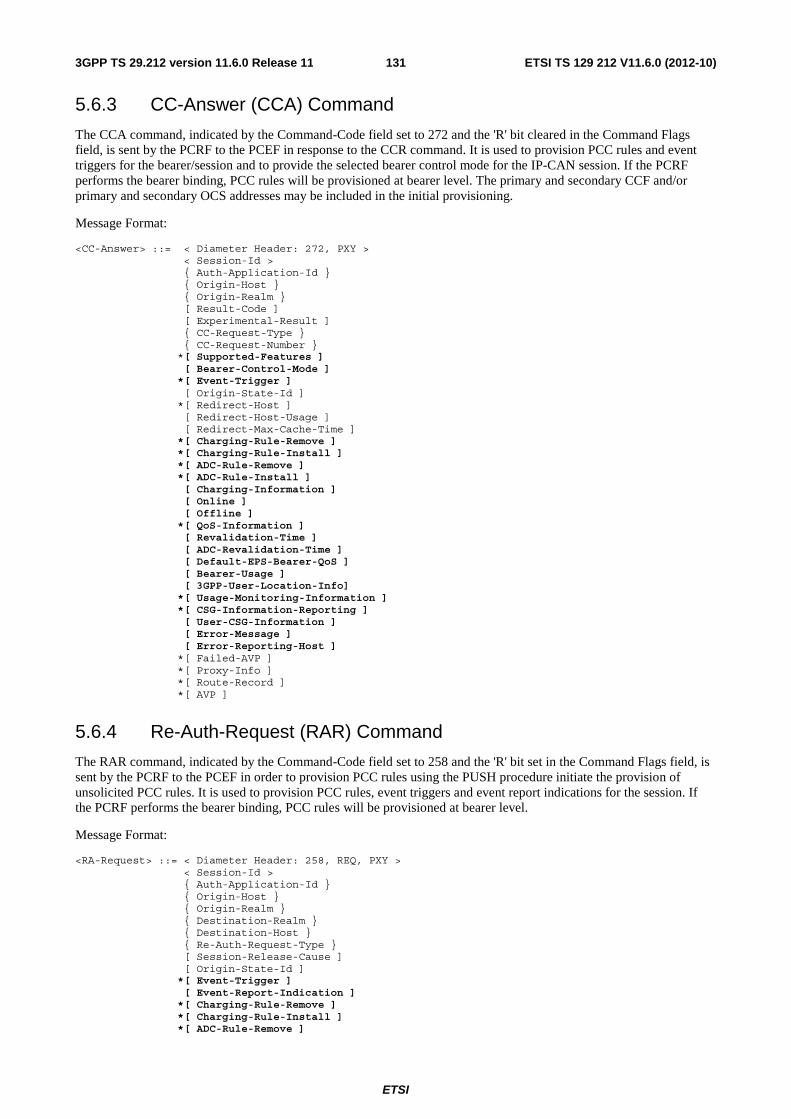
ETSI
ETSI TS 129 212 V11.6.0 (2012-10)1313GPP TS 29.212 version 11.6.0 Release 11
5.6.3 CC-Answer (CCA) Command
The CCA command, indicated by the Command-Code field set to 272 and the 'R' bit cleared in the Command Flags field, is sent by the PCRF to the PCEF in response to the CCR command. It is used to provision PCC rules and event triggers for the bearer/session and to provide the selected bearer control mode for the IP-CAN session. If the PCRF performs the bearer binding, PCC rules will be provisioned at bearer level. The primary and secondary CCF and/or primary and secondary OCS addresses may be included in the initial provisioning.
Message Format:
<CC-Answer> ::= < Diameter Header: 272, PXY > < Session-Id > { Auth-Application-Id } { Origin-Host } { Origin-Realm } [ Result-Code ] [ Experimental-Result ] { CC-Request-Type } { CC-Request-Number } *[ Supported-Features ] [ Bearer-Control-Mode ] *[ Event-Trigger ] [ Origin-State-Id ] *[ Redirect-Host ] [ Redirect-Host-Usage ] [ Redirect-Max-Cache-Time ] *[ Charging-Rule-Remove ] *[ Charging-Rule-Install ] *[ ADC-Rule-Remove ] *[ ADC-Rule-Install ] [ Charging-Information ] [ Online ] [ Offline ] *[ QoS-Information ] [ Revalidation-Time ] [ ADC-Revalidation-Time ] [ Default-EPS-Bearer-QoS ] [ Bearer-Usage ] [ 3GPP-User-Location-Info] *[ Usage-Monitoring-Information ] *[ CSG-Information-Reporting ] [ User-CSG-Information ] [ Error-Message ] [ Error-Reporting-Host ] *[ Failed-AVP ] *[ Proxy-Info ] *[ Route-Record ] *[ AVP ]
5.6.4 Re-Auth-Request (RAR) Command
The RAR command, indicated by the Command-Code field set to 258 and the 'R' bit set in the Command Flags field, is sent by the PCRF to the PCEF in order to provision PCC rules using the PUSH procedure initiate the provision of unsolicited PCC rules. It is used to provision PCC rules, event triggers and event report indications for the session. If the PCRF performs the bearer binding, PCC rules will be provisioned at bearer level.
Message Format:
<RA-Request> ::= < Diameter Header: 258, REQ, PXY > < Session-Id > { Auth-Application-Id } { Origin-Host } { Origin-Realm } { Destination-Realm } { Destination-Host } { Re-Auth-Request-Type } [ Session-Release-Cause ] [ Origin-State-Id ] *[ Event-Trigger ] [ Event-Report-Indication ] *[ Charging-Rule-Remove ] *[ Charging-Rule-Install ] *[ ADC-Rule-Remove ]

ETSI
ETSI TS 129 212 V11.6.0 (2012-10)1323GPP TS 29.212 version 11.6.0 Release 11
*[ ADC-Rule-Install ] [ Default-EPS-Bearer-QoS ] *[ QoS-Information ] [ Revalidation-Time ] [ ADC-Revalidation-Time ] *[ Usage-Monitoring-Information ] *[ Proxy-Info ] *[ Route-Record ] *[ AVP]
5.6.5 Re-Auth-Answer (RAA) Command
The RAA command, indicated by the Command-Code field set to 258 and the 'R' bit cleared in the Command Flags field, is sent by the PCEF to the PCRF in response to the RAR command.
Message Format:
<RA-Answer> ::= < Diameter Header: 258, PXY > < Session-Id > { Origin-Host } { Origin-Realm } [ Result-Code ] [ Experimental-Result ] [ Origin-State-Id ] [ IP-CAN-Type ] [ RAT-Type ] 0*2 [ AN-GW-Address ] [ 3GPP-SGSN-MCC-MNC ] [ 3GPP-SGSN-Address ] [ 3GPP-SGSN-IPv6-Address ] [ RAI ] [ 3GPP-User-Location-Info ] [ 3GPP-MS-TimeZone ] * [ Charging-Rule-Report] *[ ADC-Rule-Report ] [ Error-Message ] [ Error-Reporting-Host ] * [ Failed-AVP ] * [ Proxy-Info ] * [ AVP ]
5a Gxx protocols
5a.1 Protocol support The Gxx application is defined as a vendor specific Diameter application, where the vendor is 3GPP and the Application-ID for the Gxx Application in the present release is 16777266. The vendor identifier assigned by IANA to 3GPP (http://www.iana.org/assignments/enterprise-numbers) is 10415.
NOTE: A route entry can have a different destination based on the application identification AVP of the message. Therefore, Diameter agents (relay, proxy, redirection, translation agents) must be configured appropriately to identify the 3GPP Gxx application within the Auth-Application-Id AVP in order to create suitable routeing tables.
Due to the definition of the commands used in Gxx protocol, there is no possibility to skip the Auth-Application-Id AVP and use the Vendor-Specific-Application-Id AVP instead. Therefore the Gxx application identification shall be included in the Auth-Application-Id AVP.
With regard to the Diameter protocol defined over the Gxx interface, the PCRF acts as a Diameter server, in the sense that it is the network element that handles QoS Rule requests for a particular realm. The BBERF acts as the Diameter client, in the sense that it is the network element requesting QoS rules in the transport plane network resources.

ETSI
ETSI TS 129 212 V11.6.0 (2012-10)1333GPP TS 29.212 version 11.6.0 Release 11
5a.2 Initialization, maintenance and termination of connection and session
The initialization and maintenance of the connection between the BBERF and PCRF (visited or home) are defined by the underlying protocol. Establishment and maintenance of connections between Diameter nodes are described in IETF RFC 3588 [5].
After establishing the transport connection, the PCRF and the BBERF shall advertise the support of the Gxx specific Application by including the value of the application identifier in the Auth-Application-Id AVP and the value of the 3GPP (10415) in the Vendor-Id AVP of the Vendor-Specific-Application-Id AVP contained in the Capabilities-Exchange-Request and Capabilities-Exchange-Answer commands. The Capabilities-Exchange-Request and Capabilities-Exchange-Answer commands are specified in the Diameter Base Protocol (RFC 3588 [5]).
The termination of the Diameter session on Gxx can be initiated either by the BBERF or PCRF, as specified in subclauses 4a.5.3 and 4a.5.4, respectively.
5a.3 Gxx specific AVPs Table 5a.3.1 describes the Diameter AVPs defined for the Gxx reference point, their AVP Code values, types, possible flag values, whether or not the AVP may be encrypted and what access types (e.g. 3GPP-EPS, etc.) the AVP is applicable to. The Vendor-Id header of all AVPs defined in the present document shall be set to 3GPP (10415).
Table 5a.3.1: Gxx specific Diameter AVPs
AVP Flag rules (NOTE 1) Attribute Name AVP
Code Clause defined
Value Type (NOTE 2)
Must May Should not
Must not
May Encr.
Acc. type
Applicability (NOTE 5)
QoS-Rule-Install 1051 5a.3.1 Grouped M,V P Y All QoS-Rule-Remove 1052 5a.3.2 Grouped M,V P Y All QoS-Rule-Definition 1053 5a.3.3 Grouped M,V P Y All QoS-Rule-Name 1054 5a.3.4 OctetString M,V P Y All QoS-Rule-Base-Name 1074 5a.3.7 UTF8String V P M Y All Rel9 QoS-Rule-Report 1055 5a.3.5 Grouped M,V P Y All Session-Linking-Indicator 1064 5a.3.6 Enumerated M,V P Y All
(NOTE4)
NOTE 1: The AVP header bit denoted as 'M', indicates whether support of the AVP is required. The AVP header bit denoted as 'V', indicates whether the optional Vendor-ID field is present in the AVP header. For further details, see RFC 3588 [5].
NOTE 2: The value types are defined in RFC 3588 [5]. NOTE 3: The Gxx specific AVPs do not apply to 3GPP-GPRS Access Type. NOTE 4: This AVP only applies to case 2b as defined in 3GPP TS 29.213 [8] NOTE 5: AVPs marked with "Rel9" are applicable as described in subclause 5a.4.1.
5a.3.1 QoS-Rule-Install AVP (All access types)
The QoS-Rule-Install AVP (AVP code 1051) is of type Grouped, and it is used to activate, install or modify QoS rules as instructed from the PCRF to the BBERF.
For installing a new QoS rule or modifying a QoS rule already installed, QoS-Rule-Definition AVP shall be used.
For activating a specific QoS rule predefined at the BBERF, QoS-Rule-Name AVP shall be used as a reference for that QoS rule. The QoS-Rule-Base-Name AVP is a reference that may be used for activating a group of QoS rules predefined at the BBERF.
When Tunnel-Information AVP is provided it applies to all the QoS rules included within the QoS-Rule-Install AVP. When QoS rules are being modified, the newly provided Tunnel-Information AVP replaces previously provided Tunnel-Information AVP for the modified QoS rules. If Resource-Allocation-Notification AVP is included then it applies to all the rules within the QoS-Rule-Install AVP. If a QoS-Rule-Install AVP does not include the Resource-Allocation-Notification AVP, the resource allocation shall not be notified by the BBERF even if this AVP was present in previous installations of the same rule.

ETSI
ETSI TS 129 212 V11.6.0 (2012-10)1343GPP TS 29.212 version 11.6.0 Release 11
In case 2a, the QoS-Rule-Install AVP may also contain a charging identifier within the Access-Network-Charging-Identifier-Value AVP. The charging identifier information is used by the BBERF for charging correlation. When the Access-Network-Charging-Identifier-Value AVP is included, the identifier applies to all the QoS rules included within the QoS-Rule-Install AVP. The charging identifier value for a QoS rule shall be the same as that for the corresponding PCC rule. When a QoS rule is being modified and no new charging identifier is provided, then the previously provided charging identifier shall apply for the modified QoS rules.
If Rule-Activation-Time or Rule-Deactivation-Time is specified then it applies to all the QoS rules within the QoS-Rule-Install AVP.
The 3GPP-GGSN-Address AVP, 3GPP-GGSN-IPv6-Address AVP, AN-GW-Address AVP and UDP-Source-Port AVP are only applicable for S9a interface when provided. UDP-Source-Port AVP provided within QoS-Rule-Install AVP is only applicable for the trusted S2c case and shall take precedence over the one provided at the S9a command level.
AVP Format:
QoS-Rule-Install ::= < AVP Header: 1051> *[ QoS-Rule-Definition ] *[ QoS-Rule-Name ] *[ QoS-Rule-Base-Name ] [ Tunnel-Information ] [ Access-Network-Charging-Identifier-Value ] [ Resource-Allocation-Notification ] [ Rule-Activation-Time ] [ Rule-Deactivation-Time ] [ 3GPP-GGSN-Address ] [ 3GPP-GGSN-IPv6-Address ] 0*2[ AN-GW-Address ] [ UDP-Source-Port ] *[ AVP ]
5a.3.2 QoS-Rule-Remove AVP (All access types)
The QoS-Rule-Remove AVP (AVP code 1052) is of type Grouped, and it is used to deactivate or remove QoS rules from an Gateway Control session.
QoS-Rule-Name AVP is a reference for a specific QoS rule at the BBERF to be removed or for a specific QoS rule predefined at the BBERF to be deactivated. The QoS-Rule-Base-Name AVP is a reference for a group of QoS rules predefined at the BBERF to be deactivated.
AVP Format:
QoS-Rule-Remove ::= < AVP Header: 1052> *[ QoS-Rule-Name ] *[ QoS-Rule-Base-Name ] *[ AVP ]
5a.3.3 QoS-Rule-Definition AVP (All access types)
The QoS-Rule-Definition AVP (AVP code 1053) is of type Grouped, and it defines the QoS rule for a service data flow sent by the PCRF to the BBERF. The QoS-Rule-Name AVP uniquely identifies the QoS rule and it is used to reference to a QoS rule in communication between the BBERF and the PCRF within one Gateway Control session. The Flow-Information AVP(s) determines the traffic that belongs to the service data flow.
If optional AVP(s) within a QoS-Rule-Definition AVP are omitted, but corresponding information has been provided in previous Gxx messages, the previous information remains valid. If Flow-Information AVP(s) are supplied, they replace all previous Flow-Information AVP(s).
Required-Access-Info AVP may appear if the AF requests PCRF to report user access network information.
AVP Format:
QoS-Rule-Definition ::= < AVP Header: 1053> { QoS-Rule-Name } *[ Flow-Information ] [ QoS-Information ] [ Precedence ]
*[ Required-Access-Info ] *[ AVP ]

ETSI
ETSI TS 129 212 V11.6.0 (2012-10)1353GPP TS 29.212 version 11.6.0 Release 11
5a.3.4 QoS-Rule-Name AVP (All access types)
The QoS-Rule-Name AVP (AVP code 1054) is of type OctetString, and it defines a name for QoS rule. For QoS rules provided by the PCRF it uniquely identifies a QoS rule within one Gateway Control session. For QoS pre-defined at the BBERF it uniquely identifies a QoS rule within the BBERF.
5a.3.5 QoS-Rule-Report AVP (All access types)
The QoS-Rule-Report AVP (AVP code 1055) is of type Grouped, and it is used to report the status of QoS rules.
QoS-Rule-Name AVP is a reference for a specific QoS rule at the BBERF that has been successfully installed, modified or removed (for dynamic QoS rules), or activated or deactivated (for predefined QoS rules). QoS-Rule-Base-Name AVP is a reference for a group of QoS rules predefined at the BBERF that has been successfully activated or deactivated.
The QoS-Rule-Report AVP can also be used to report the status of the QoS rules which cannot be installed/activated or enforced at the BBERF. In this condition, the QoS-Rule-Name AVP is used to indicate a specific QoS rule which cannot be installed/activated or enforced and the QoS-Rule-Base-Name AVP is used to indicate a group of QoS rules which cannot be activated. The Rule-Failure-Code AVP indicates the reason that the QoS rules cannot be successfully installed/activated or enforced.
AVP Format:
QoS-Rule-Report ::= < AVP Header: 1055> *[ QoS-Rule-Name ] *[ QoS-Rule-Base-Name ] [ PCC-Rule-Status ] [ Rule-Failure-Code ] *[ AVP ]
Multiple instances of QoS-Rule-Report AVPs shall be used in the case it is required to report different PCC-Rule-Status or Rule-Failure-Code values for different rules within the same Diameter command.
5a.3.6 Session-Linking-Indicator AVP (All access types)
The Session-Linking-Indicator AVP (AVP code 1064) is of type Enumerated and indicates whether the session linking between the Gateway Control Session and the Gx session must be deferred. The absence of this AVP in case 2b as defined in 3GPP TS 29.213 [8] shall indicate the value SESSION_LINKING_IMMEDIATE.
The following values are defined:
SESSION_LINKING_IMMEDIATE (0)
This value shall be used to indicate that the PCRF shall perform the linking between the new Gateway Control Session with an existing Gx session immediately.
SESSION_LINKING_DEFERRED (1)
This value shall be used to indicate that the PCRF shall not attempt linking the new Gateway Control Session with an existing Gx session immediately.
5a.3.7 QoS-Rule-Base-Name AVP (All access types)
The QoS-Rule-Base-Name AVP (AVP code 1074) is of type UTF8String, and it indicates the name of a pre-defined group of QoS rules residing at the BBERF.
5a.4 Gxx re-used AVPs Table 5a.4.1 lists the Diameter AVPs re-used by the Gxx reference point from Gx reference point and other existing Diameter Applications, reference to their respective specifications, short description of their usage within the Gxx reference point, the applicability of the AVPs to a specific access, and which supported features the AVP is applicable to. When reused from Gx reference point, the specific clause in the present specification is referred. Other AVPs from

ETSI
ETSI TS 129 212 V11.6.0 (2012-10)1363GPP TS 29.212 version 11.6.0 Release 11
existing Diameter Applications, except for the AVPs from Diameter base protocol, do not need to be supported. The AVPs from Diameter base protocol are not included in table 5a.4, but they are re-used for the Gxx reference point. Unless otherwise stated, re-used AVPs shall maintain their 'M', 'P' and 'V' flag settings. Where RADIUS VSAs are re-used, unless otherwise stated, they shall be translated to Diameter AVPs as described in RFC 4005 [12] with the exception that the ‘M’ flag shall be set and the ‘P’ flag may be set.

ETSI
ETSI TS 129 212 V11.6.0 (2012-10)1373GPP TS 29.212 version 11.6.0 Release 11
Table 5a.4.1: Gxx re-used Diameter AVPs
Attribute Name Reference Description Acc. type
Applicability (note 5)
3GPP-MS-TimeZone
3GPP TS 29.061 [11]
Indicate the offset between universal time and local time in steps of 15 minutes of where the MS currently resides.
All
AN-GW-Address 5.3.49 Carries the address of the AN-GW (S-GW/AGW/ ePDG)
All EPC-routed (See NOTE 8)
3GPP-SGSN-MCC-MNC
3GPP TS 29.061 [11]
Carries the MCC/MNC information of the AN-GW All
3GPP-User-Location-Info
3GPP TS 29.061 [11]
Indicates details of where the UE is currently located (e.g. SAI or CGI)
3GPP-EPS
3GPP2-BSID
3GPP2 X.S0057 [24]
For 3GPP2 indicates the BSID of where the UE is currently located (e.g. Cell-Id, SID, NID). The Vendor-Id shall be set to 3GPP2 (5535) [24]. The support of this AVP shall be advertised in the capabilities exchange mechanisms (CER/CEA) by including the value 5535, identifying 3GPP2, in a Supported-Vendor-Id AVP.
3GPP2, Non-3GPP-EPS
Access-Network-Charging-Identifier-Value
3GPP TS 29.214 [10]
Contains a charging identifier. All (See NOTE 6)
Allocation- Retention-Priority
5.3.32 Indicates a priority for accepting or rejecting a bearer establishment or modification request and dropping a bearer in case of resource limitations.
All
APN-Aggregate-Max-Bitrate-DL
5.3.39 Indicates the aggregate maximum bitrate for the downlink direction for all non-GBR bearers of the APN.
All
APN-Aggregate-Max-Bitrate-UL
5.3.40 Indicates the aggregate maximum bitrate for the uplink direction for all non-GBR bearers of the APN.
All
PS-to-CS-Session-Continuity
5.3.84 Indicates whether the service data flow is a candidate for PS to CS session continuity.
3GPP- EPS
vSRVCC
Bearer-Control-Mode
5.3.23 Indicates the PCRF selected bearer control mode. All (See NOTE 3)
Called-Station-Id IETF RFC 4005 [12]
The address the user is connected to (i.e. the PDN identifier).
All
PDN-Connection-ID
5.3.58 The identification of PDN connection to the same APN.
All (See NOTE 4)
Rel9
CC-Request-Number
IETF RFC 4006 [9]
The number of the request for mapping requests and answers
All
CC-Request-Type IETF RFC 4006 [9]
The type of the request (initial, update, termination) All
User-CSG-Information (note 7)
3GPP TS 32.299 [19]
Indicates the user "Closed Subscriber Group" Information associated to CSG or hybrid cell access: it comprises the CSG-Id, CSG-Access-Mode and CSG-Membership-Indication AVPs. This AVP shall have the ‘M’ bit cleared.
3GPP-EPS
Rel9

ETSI
ETSI TS 129 212 V11.6.0 (2012-10)1383GPP TS 29.212 version 11.6.0 Release 11
Attribute Name Reference Description Acc. type
Applicability (note 5)
Event-Trigger 5.3.7 Reports the event that occurred on the BBERF. For Event-Trigger LOSS_OF_BEARER, BBERF will include the impacted QoS rules within the QoS-Rule-Report. For Event-Trigger RECOVERY_OF_BEARER BBERF will include the impacted QoS rules within the QoS-Rule-Report. For 3GPP2 access USER_LOCATION_CHANGE is used to report and request changes to the 3GPP2-BSID. For the Event-Trigger UE_TIME_ZONE_CHANGE, the BBERF includes the new value of the UE time zone within the 3GPP-MS-TimeZone AVP. The following values are not applicable: SGSN_CHANGE (0), PLMN_CHANGE (4), IP-CAN_CHANGE (7), QOS_CHANGE_EXCEEDING_AUTHORIZATION (11), OUT_OF_CREDIT (15), REALLOCATION_OF_CREDIT (16), UE_IP_ADDRESS_ALLOCATE (18), UE_ IP_ADDRESS_RELEASE (19) , AN_GW_CHANGE (21) and USAGE_REPORT (33),ROUTING_RULE_CHANGE (37), APPLICATION_START (39), APPLICATION_STOP (40) and ADC_REVALIDATION_TIMEOUT (41).
All
Flow-Description 3GPP TS 29.214 [10], 5.4.2
Defines the service data flow filter parameters for a QoS rule. The same rules as for Gx, Table 5.4, apply. The rules for usage on Gxx are defined in subclause 5.4.2
All
Flow-Information 5.3.53 Defines the service data flow filter parameters for a QoS rule and may include flow description, packet filter identifier, ToS/Traffic Class, SPI and Flow Label information. May also include an instruction as to whether signalling the information to the UE is to occur.
All
Flow-Label 5.3.52 Defines the IPv6 flow label Framed-IP-Address
IETF RFC 4005 [12]
The IPv4 address allocated for the user. All
Framed-IPv6-Prefix
IETF RFC 4005 [12]
The IPv6 prefix allocated for the user. The encoding of the value within this Octet String type AVP shall be as defined in IETF RFC 3162 [15], Clause 2.3. The "Reserved", "Prefix-Length" and "Prefix" fields shall be included in this order.
All
Guaranteed-Bitrate-DL (NOTE 1)
5.3.25 Defines the guaranteed bitrate for downlink. All
Guaranteed-Bitrate-UL (NOTE 1)
5.3.26 Defines the guaranteed bitrate for uplink. All
HeNB-BBF-FQDN 5.3.94 Contains the domain name of the fixed broadband acess network where the H(e)NB connects to
3GPP-EPS
EPC-routed
HeNB-Local-IP-Address
5.3.95 Contains the H(e)NB local IP address as defined in Annex E.2.1.
3GPP-EPS
EPC-routed
IP-CAN-Type 5.3.27 Indicates the type of Connectivity Access Network that the user is connected to.
All
Max-Requested-Bandwidth-UL (note 2)
3GPP TS 29.214 [10]
Defines the maximum authorized bandwidth for uplink.
All
Max-Requested-Bandwidth-DL (note 2)
3GPP TS 29.214 [10]
Defines the maximum authorized bandwidth for downlink.
All
Packet-Filter-Content
5.3.54 Indicates the content of the packet filter. Destination IP address including the value provided by the UE may be provided when the ExtendedFilter feature is supported as described in clause 5a.4.1.
All

ETSI
ETSI TS 129 212 V11.6.0 (2012-10)1393GPP TS 29.212 version 11.6.0 Release 11
Attribute Name Reference Description Acc. type
Applicability (note 5)
Packet-Filter-Identifier
5.3.55 The identity of the packet filter. All
Packet-Filter-Information
5.3.56 Information related to the packet filters that the BBERF provides to the PCRF.
All
Packet-Filter-Operation
5.3.57 Indicates the operation that the terminal is requesting over the packet filters provided by the Packet-Filter-Information AVPs.
All
Packet-Filter-Usage
5.3.66 Indicates whether the UE shall be provisioned with the related traffic mapping information.
All Rel9
Network-Request-Support
5.3.24 Indicates whether the UE and access network supports the network requested bearer control mode or not.
All (See NOTE 3)
Precedence 5.3.11 Indicates the precedence of QoS rules or packet filters.
All
PCC-Rule-Status 5.3.19 Describes the status of one or a group of QoS rules. All QoS-Class-Identifier
5.3.17 Identifies a set of IP-CAN specific QoS parameters All
QoS-Information 5.3.16 Defines the QoS information for a resource or QoS rule.
All
Default-EPS-Bearer-QoS
5.3.48 Defines the QoS information of the default bearer All
RAI 3GPP TS 29.061 [11]
Contains the Routing Area Identity of the SGSN where the UE is registered
3GPP-EPS
RAT-Type 5.3.31 Identifies the radio access technology that is serving the UE.
All
Resource-Allocation- Notification
5.3.50 Indicates whether successful resource allocation notification for rules is needed or not.
All
Rule-Activation-Time
5.3.41 Indicates the NTP time at which the QoS rules has to be enforced.
All
Rule-Deactivation-Time
5.2.42 Indicates the NTP time at which the BBERF has to stop enforcing the QoS rules.
All
Rule-Failure-Code 5.3.38 Identifies the reason a QoS rule is being reported. All Security-Parameter-Index
5.3.51 Defines the IPSec SPI All
Session-Release-Cause
5.3.44 Indicate the reason of termination initiated by the PCRF. Only the reason code UNSPECIFIED_REASON is applicable for the PCRF-initiated Gxx session termination.
All
Subscription-Id IETF RFC 4006 [9]
The identification of the subscription (i.e. IMSI) All
Supported-Features
3GPP TS 29.229 [14]
If present, this AVP informs the destination host about the features that the origin host requires to successfully complete this command exchange
All
ToS-Traffic-Class 5.3.15 Defines the IPv4 ToS or IPv6 Traffic Class All Trace-Data 3GPP TS 29.272
[26] Contains trace control and configuration parameters, specified in 3GPP TS 32.422 [27].
3GPP-EPS
Trace-Reference 3GPP TS 29.272 [26]
Contains the trace reference parameter, specified in 3GPP TS 32.422 [27].
3GPP-EPS
Tunnel-Header-Filter
5.3.34 Defines the tunnel (outer) header filter information of a tunnelled IP flow.
All (see NOTE 3 and NOTE 6)
Tunnel-Header-Length
5.3.35 Indicates the length of the tunnel (outer) header. All (see NOTE 3 and NOTE 6)
Tunnel-Information
5.3.36 Defines the tunnel (outer) header information for an IP flow.
All (see NOTE 3 and NOTE 6)

ETSI
ETSI TS 129 212 V11.6.0 (2012-10)1403GPP TS 29.212 version 11.6.0 Release 11
Attribute Name Reference Description Acc. type
Applicability (note 5)
UDP-Source-Port 5.3.97 Contains the UDP source port number in the case that NA(P)T is detected for supporting interworking with Fixed Broadband access network as defined in Annex E.
3GPP-EPS Non-3GPP-EPS
EPC-routed
UE-Local-IP-Address
5.3.96 Contains the UE local IP address as defined in Annex E.2.1.
Non-3GPP-EPS
BBAI
User-Equipment-Info
IETF RFC 4006 [9]
The identification and capabilities of the terminal (IMEISV, etc.) When the User-Equipment-Info-Type is set to IMEISV(0), the value within the User-Equipment-Info-Value shall be a UTF-8 encoded decimal.
All
Required-Access-Info
3GPP TS 29.214 [10]
Indicates the access network information for which the AF entity requestes the PCRF reporting.
3GPP-GPRS. 3GPP-EPS
CC NetLoc
NOTE 1: When sending from the PCRF to the BBERF, the Guaranteed-Bitrate-UL/DL AVP indicate the allowed guaranteed bit rate for the uplink/downlink direction; when sending from the BBERF to the PCRF, the Guaranteed-Bitrate-UL/DL AVP indicate the requested guaranteed bit rate for the uplink/downlink direction.
NOTE 2: When sending from the PCRF to the BBERF, the Max-Requested-Bandwidth-UL/DL AVP indicate the maximum allowed bit rate for the uplink/downlink direction; when sending from the BBERF to the PCRF, the Max-Requested-Bandwidth-UL/DL AVP indicate the maximum requested bit rate for the uplink/downlink direction.
NOTE 3: This AVP does not apply to 3GPP-EPS Access Types. NOTE 4: This AVP only applies to case 2b as defined in 3GPP TS 29.213 [8]. NOTE 5: AVPs marked with "Rel9" are applicable as described in clause 5a.4.1. NOTE 6: This AVP only applies to case 2a as defined in 3GPP TS 29.213 [8]. NOTE 7: AVPs included within this grouped AVP shall have the ‘M’ bit cleared. NOTE 8: AN-GW-Address AVP carries the address of the ePDG is only applicable for “EPC-routed”.
5a.4.1 Use of the Supported-Features AVP on the Gxx reference point
The Supported-Features AVP is used during session establishment to inform the destination host about the required and optional features that the origin host supports. The client shall, in the first request of a Diameter session indicate the set of features required for the successul processing of the session. If there are additional features supported by the client that are not advertised as part of the required set of features, the client shall also provide this additional set of features that are optional for the successful processing of the session. The server shall, in the first answer within the Diameter session indicate the set of features that it has in common with the client and that the server shall support within the same Diameter session. Any further command messages shall always be compliant with the list of supported features indicated in the Supported-Features AVPs during session establishment. Features that are not advertised as supported shall not be used to construct the command messages for that Diameter session. Unless otherwise stated, the use of the Supported-Features AVP on the Gxx reference point shall be compliant with the requirements for dynamic discovery of supported features on the Cx reference point as defined in clause 7.2.1 of 3GPP TS 29.229 [14].
The base functionality for the Gxx reference point is the 3GPP Rel-8 standard and a feature is an extension to that functionality. If the origin host does not support any features beyond the base functionality, the Supported-Features AVP may be absent from the Gxx commands. As defined in clause 7.1.1 of 3GPP TS 29.229 [14], when extending the application by adding new AVPs for a feature, the new AVPs shall have the M bit cleared and the AVP shall not be defined mandatory in the command ABNF.
As defined in 3GPP TS 29.229 [14], the Supported-Features AVP is of type grouped and contains the Vendor-Id, Feature-List-ID and Feature-List AVPs. On the Gxx reference point, the Supported-Features AVP is used to identify features that have been defined by 3GPP and hence, for features defined in this document, the Vendor-Id AVP shall contain the vendor ID of 3GPP (10415). If there are multiple feature lists defined for the Gxx reference point, the Feature-List-ID AVP shall differentiate those lists from one another.
On receiving an initial request application message, the destination host shall act as defined in section 7.2.1 of 3GPP TS 29.229 [14]. The following exceptions apply to the initial CCR/CCA command pair:

ETSI
ETSI TS 129 212 V11.6.0 (2012-10)1413GPP TS 29.212 version 11.6.0 Release 11
- If the BBERF supports features that are required for the successful operation of the session, the CCR shall include these required features within Supported-Features AVP(s) with the 'M' bit set.
- If the BBERF supports features that are not required for the successful operation of the session, the CCR shall include these optional features within Supported-Features AVP(s) with the 'M' bit cleared.
- If the CCR command does not contain any Supported-Features AVP(s) and the PCRF supports Rel-8 Gxx functionality, the CCA command shall not include the Supported-Features AVP. In this case, both BBERF and PCRF shall behave as specified in the Rel-8 version of this document.
- If the CCR command contains the Supported-Features AVP(s) and the PCRF supports all the features advertised in the CCR command within Supported-Features AVP(s) with the 'M' bit set, the CCA from the PCRF shall include the Supported-Features AVP(s), with the 'M' bit cleared, indicating only the features that both the PCRF and BBERF support.
Once the PCRF and BBERF have negotiated the set of supported features during session establishment, the set of common features shall be used during the lifetime of the Diameter session.
The table below defines the features applicable to the Gxx interfaces for the feature list with a Feature-List-ID of 1.
Table 5a.4.1.1: Features of Feature-List-ID 1 used in Gxx
Feature bit
Feature M/O Description
0 Rel9 M This feature indicates the support of base 3GPP Rel-9 Gxx functionality, including the AVPs and corresponding procedures supported by the base 3GPP Rel-8 Gxx standard, but excluding those features represented by separate feature bits. AVPs introduced with this feature are marked with "Rel9" in Table 5a.3.1 and Table 5a.4.1.
1 vSRVCC O This feature indicates support for the vSRVCC feature (see 3GPP TS 23.216 [40]). 2 EPC-routed O This feature indicates support for interworking with Fixed Broad band Access
networks when the traffic is routed via the EPC network as defined in Annex E. 3 NetLoc O This feature indicates the support of the Access Network Information Reporting. If
the BBERF supports this feature, the PCRF shall behave as described in subclause 4a.5.16
4 ExtendedFilter O This feature indicates the support for the local UE address being present in filters signalled between network and UE.
Feature bit: The order number of the bit within the Feature-List AVP where the least significant bit is assigned number "0".
Feature: A short name that can be used to refer to the bit and to the feature, e.g. "EPS". M/O: Defines if the implementation of the feature is mandatory ("M") or optional ("O") in this 3GPP Release. Description: A clear textual description of the feature.
5a.5 Gxx specific Experimental-Result-Code AVP values The same codes specified in clause 5.5 apply here with the following exceptions:
The following permanent Experimental-Result-Code shall be used instead of DIAMETER_PCC_RULE_EVENT (5142):
DIAMETER_QOS_RULE_EVENT (5145)
This error shall be used when the QoS rules cannot be installed/activated. Affected QoS-Rules will be provided in the QoS-Rule-Report AVP including the reason and status as described in Clause 4a.5.5.
The following transient Experimental-Result-Code shall be used instead of DIAMETER_PCC_BEARER_EVENT (4141):
DIAMETER_BEARER_EVENT (4142)
This error shall be used when for some reason a QoS rule cannot be enforced or modified successfully in a network initiated procedure. Affected QoS Rules will be provided in the QoS-Rule-Report AVP including the reason and status as described in Clause 4a.5.5.

ETSI
ETSI TS 129 212 V11.6.0 (2012-10)1423GPP TS 29.212 version 11.6.0 Release 11
5a.6 Gxx Messages
5a.6.1 Gxx Application
Gxx Messages are carried within the Diameter Application(s) described in clause 5a.1.
Existing Diameter command codes from the Diameter base protocol RFC 3588 [5] and the Diameter Credit Control Application RFC 4006 [9] are used with the Gxx specific AVPs specified in clause 5a.3. The Diameter Credit Control Application AVPs and AVPs from other Diameter applications that are re-used are defined in clause 5a.4. Due to the definition of these commands there is no possibility to skip the Auth-Application-Id AVP and use the Vendor-Specific-Application-Id AVP instead. Therefore the Gxx application identifier shall be included in the Auth-Application-Id AVP. A diameter session needs to be established for each Gateway Control session.
NOTE: Some of the AVPs included in the messages formats below are in bold to highlight that these AVPs are used by this specific protocol and do not belong to the original message definition in the DCC Application RFC 4006 [9] or Diameter Base Protocol RFC 3588 [5].
5a.6.2 CC-Request (CCR) Command
The CCR command, indicated by the Command-Code field set to 272 and the 'R' bit set in the Command Flags field, is sent by the BBERF to the PCRF in order to request QoS rules. The CCR command is also sent by the BBERF to the PCRF in order to indicate QoS rule related events or the termination of the Gateway Control session.
Message Format:
<CC-Request> ::= < Diameter Header: 272, REQ, PXY > < Session-Id > { Auth-Application-Id } { Origin-Host } { Origin-Realm } { Destination-Realm } { CC-Request-Type } { CC-Request-Number } [ Destination-Host ] [ Origin-State-Id ] *[ Supported-Features ] *[ Subscription-Id ] [ Network-Request-Support ] *[ Packet-Filter-Information ] [ Packet-Filter-Operation ] [ Framed-IP-Address ] [ Framed-IPv6-Prefix ] [ IP-CAN-Type ] [ RAT-Type ] [ Termination-Cause ] [ User-Equipment-Info ] [ QoS-Information ] [ Default-EPS-Bearer-QoS ] 0*2[ AN-GW-Address ] [ 3GPP-SGSN-MCC-MNC ] [ RAI ] [ 3GPP-User-Location-Info] [ 3GPP-MS-TimeZone ] [ 3GPP2-BSID ] [ User-CSG-Information ] [ Called-Station-Id ] [ PDN-Connection-ID ] *[ QoS-Rule-Report] *[ Event-Trigger] [ Session-Linking-Indicator ] [ Trace-Data ] [ Trace-Reference ] *[ Proxy-Info ] *[ Route-Record ] *[ AVP ]

ETSI
ETSI TS 129 212 V11.6.0 (2012-10)1433GPP TS 29.212 version 11.6.0 Release 11
5a.6.3 CC-Answer (CCA) Command
The CCA command, indicated by the Command-Code field set to 272 and the 'R' bit cleared in the Command Flags field, is sent by the PCRF to the BBERF in response to the CCR command. It is used to provision QoS rules and event triggers for the bearer/session and to provide the selected bearer control mode for the Gateway Control session.
Message Format:
<CC-Answer> ::= < Diameter Header: 272, PXY > < Session-Id > { Auth-Application-Id } { Origin-Host } { Origin-Realm } [ Result-Code ] [ Experimental-Result ] { CC-Request-Type } { CC-Request-Number } *[ Supported-Features ] [ Bearer-Control-Mode ] *[ Event-Trigger ] [ Origin-State-Id ] *[ Redirect-Host ] [ Redirect-Host-Usage ] [ Redirect-Max-Cache-Time ] *[ QoS-Rule-Remove ] *[ QoS-Rule-Install ] [ QoS-Information ] [ Default-EPS-Bearer-QoS ] [ Error-Message ] [ Error-Reporting-Host ] *[ Failed-AVP ] *[ Proxy-Info ] *[ Route-Record ] *[ AVP ]
5a.6.4 Re-Auth-Request (RAR) Command
The RAR command, indicated by the Command-Code field set to 258 and the 'R' bit set in the Command Flags field, is sent by the PCRF to the BBERF in order to provision QoS rules using the PUSH procedure initiate the provision of unsolicited QoS rules. It is used to provision QoS rules, event triggers and event report indications for the session.
Message Format:
<RA-Request> ::= < Diameter Header: 258, REQ, PXY > < Session-Id > { Auth-Application-Id } { Origin-Host } { Origin-Realm } { Destination-Realm } { Destination-Host } { Re-Auth-Request-Type } [ Session-Release-Cause ] [ Origin-State-Id ] *[ Event-Trigger ] *[ QoS-Rule-Remove ] *[ QoS-Rule-Install ] [ QoS-Information ] [ Default-EPS-Bearer-QoS ] *[ Proxy-Info ] *[ Route-Record ] *[ AVP]

ETSI
ETSI TS 129 212 V11.6.0 (2012-10)1443GPP TS 29.212 version 11.6.0 Release 11
5a.6.5 Re-Auth-Answer (RAA) Command
The RAA command, indicated by the Command-Code field set to 258 and the 'R' bit cleared in the Command Flags field, is sent by the BBERF to the PCRF in response to the RAR command.
Message Format:
<RA-Answer> ::= < Diameter Header: 258, PXY > < Session-Id > { Origin-Host } { Origin-Realm } [ Result-Code ] [ Experimental-Result ] [ Origin-State-Id ] [ RAT-Type ] [ 3GPP-SGSN-MCC-MNC ] [ RAI ] [ 3GPP-User-Location-Info ] [ User-CSG-Information ] [ 3GPP-MS-TimeZone ] [ 3GPP2-BSID ] * [ QoS-Rule-Report] [ Error-Message ] [ Error-Reporting-Host ] * [ Failed-AVP ] * [ Proxy-Info ] * [ AVP ]
5b Sd protocol
5b.1 Protocol support The Sd application is defined as a vendor specific Diameter application, where the vendor is 3GPP. The vendor identifier assigned by IANA to 3GPP (http://www.iana.org/assignments/enterprise-numbers) is 10415. The Application-ID for the Sd Application is 16777303 and this value shall be used in the Diameter command header as well as any Application-ID AVPs (Auth-Application-Id/Vendor-Specific-Application-Id) in the command body.
5b.2 Initialization, maintenance and termination of connection and session
The initialization and maintenance of the connection between each PCRF and TDF pair is defined by the underlying protocol. Establishment and maintenance of connections between Diameter nodes is described in RFC 3588 [5].
After establishing the transport connection, the PCRF and the TDF shall advertise the support of the Sd specific Application by including the value of the application identifier in the Auth-Application-Id AVP and the value of the 3GPP (10415) in the Vendor-Id AVP of the Vendor-Specific-Application-Id AVP contained in the Capabilities-Exchange-Request and Capabilities-Exchange-Answer commands. The Capabilities-Exchange-Request and Capabilities-Exchange-Answer commands are specified in the Diameter Base Protocol (RFC 3588 [5]).
The Diameter session on Sd is established either at the request of the PCRF in case of solicited application reporting or at the request of the TDF in case of unsolicited application reporting. Session modifications may be initiated by either TDF or PCRF. Session termination is initiated at the request of the PCRF as specified in subclause 4b.5.4.
5b.3 Sd specific AVPs There are no Sd specific AVPs defined in this release.
5b.4 Sd re-used AVPs Table 5b.4 lists the Diameter AVPs re-used by the Sd reference point from existing Diameter Applications, reference to their respective specifications, short description of their usage within the Sd reference pointand which supported

ETSI
ETSI TS 129 212 V11.6.0 (2012-10)1453GPP TS 29.212 version 11.6.0 Release 11
features the AVP is applicable to. Other AVPs from existing Diameter Applications, except for the AVPs from Diameter base protocol, do not need to be supported. The AVPs from Diameter base protocol are not included in table 5b.4, but they are re-used for the Sd reference point. Unless otherwise stated, re-used AVPs shall maintain their 'M', 'P' and 'V' flag settings. Where 3GPP Radius VSAs are re-used, unless otherwise stated, they shall be translated to Diameter AVPs as described in IETF RFC 4005 [12] with the exception that the 'M' flag shall be set and the 'P' flag may be set.

ETSI
ETSI TS 129 212 V11.6.0 (2012-10)1463GPP TS 29.212 version 11.6.0 Release 11
Table 5b.4: Sd re-used Diameter AVPs
Attribute Name Reference Description ADC-Revalidation-Time 5.3.93 Causing the TDF to trigger a PCRF interaction to request ADC
rules from the PCRF for an established TDF session. ADC-Rule-Install 5.3.85 Used to activate, install or modify ADC rules as instructed from
the PCRF to the TDF. ADC-Rule-Remove 5.3.86 Used to deactivate or remove ADC rules from a TDF session. ADC-Rule-Definition 5.3.87 Defines the ADC rule sent by the PCRF to the TDF. ADC-Rule-Base-Name 5.3.88 Indicates the name of a pre-defined group of ADC rules residing
at the TDF. ADC-Rule-Name 5.3.89 Defines the ADC rule name sent by the PCRF to the TDF. ADC-Rule-Report 5.3.90 Used to report the status of ADC rules from the TDF to the
PCRF. AN-GW-Address 5.3.49 Contains the IPv4 and/ or IPv6 (if available) address(es) of the
access node gateway (SGW for 3GPP and AGW for non-3GPP networks).
Application-Detection-Information
5.3.91 Used to report from the TDF to the PCRF once the start/stop of the application traffic, defined by TDF-Application-Identifier, has been detected.
Called-Station-Id IETF RFC 4005 [12] The address the user is connected to (i.e. the PDN identifier). CC-Request-Number IETF RFC 4006 [9] The number of the request for mapping requests and answers. CC-Request-Type IETF RFC 4006 [9] The type of the CC-Request. For the Solicited application
reporting, only update and termination values are applicable. Event-Report-Indication 5.3.30 When sent from the PCRF to the TDF, it is used to report an
event coming from the PCEF or BPCF if NSWO is supported and the relevant info to the TDF. When sent from the TDF to the PCRF, it is used to provide the information about the required event triggers to the PCRF. Only Event-Trigger AVP will be supplied in this case. For 3GPP2 access, USER_LOCATION_CHANGE is used to report and request changes to the 3GPP2-BSID. The following values for the included Event-Trigger are applicable: SGSN_CHANGE (0), RAT_CHANGE (2), PLMN_CHANGE (4), IP-CAN_CHANGE (7), RAI_CHANGE (12), USER_LOCATION_CHANGE (13), NO_EVENT_TRIGGERS (14), UE_IP_ADDRESS_ALLOCATE (18), UE_IP_ADDRESS_RELEASE (19) , AN_GW_CHANGE (21), UE_TIME_ZONE_CHANGE (25). TAI_CHANGE (26), ECGI_CHANGE (27).
Event-Trigger 5.3.7 When sent from the PCRF to the TDF, indicates an event that shall cause a re-request of ADC rules. When sent from the TDF to the PCRF, indicates that the corresponding event has occurred at the TDF. The following values are applicable: NO_EVENT_TRIGGERS (14); USAGE_REPORT (26); APPLICATION_START (39); APPLICATION_STOP (40); ADC_REVALIDATION_TIMEOUT (41).
Flow-Description 3GPP TS 29.214 [10]
Defines the service data flow filter parameters for a detected application, if deducible.
Flow-Direction 5.3.65 It indicates the direction/directions that a filter for a detected application is applicable, downlink only, uplink only or both down- and uplink (bidirectional).
Flow-Information 5.3.53 This parameter may be sent from the TDF to the PCRF within Application-Detection-Information AVP and contains the information from a single IP flow packet filter of an application, once detected, if deducible at TDF. Only Flow-Description AVP and Flow-Direction AVPs are used. See NOTE 1.
Flow-Status 3GPP TS 29.214 [10]
This parameter may be sent from the PCRF to the TDF within ADC-Rule-Definition AVP and describe if the possible uplink and/or possible downlink gate for the detected application shall be opened or closed.
Framed-IP-Address IETF RFC 4005 [12] The IPv4 address allocated for the user. If NSWO is supported, the AVP contains the Local IPv4 address assigned by Fixed Broadband Access network.

ETSI
ETSI TS 129 212 V11.6.0 (2012-10)1473GPP TS 29.212 version 11.6.0 Release 11
Attribute Name Reference Description ADC-Revalidation-Time 5.3.93 Causing the TDF to trigger a PCRF interaction to request ADC
rules from the PCRF for an established TDF session. ADC-Rule-Install 5.3.85 Used to activate, install or modify ADC rules as instructed from
the PCRF to the TDF. ADC-Rule-Remove 5.3.86 Used to deactivate or remove ADC rules from a TDF session. ADC-Rule-Definition 5.3.87 Defines the ADC rule sent by the PCRF to the TDF. ADC-Rule-Base-Name 5.3.88 Indicates the name of a pre-defined group of ADC rules residing
at the TDF. ADC-Rule-Name 5.3.89 Defines the ADC rule name sent by the PCRF to the TDF. ADC-Rule-Report 5.3.90 Used to report the status of ADC rules from the TDF to the
PCRF. AN-GW-Address 5.3.49 Contains the IPv4 and/ or IPv6 (if available) address(es) of the
access node gateway (SGW for 3GPP and AGW for non-3GPP networks).
Application-Detection-Information
5.3.91 Used to report from the TDF to the PCRF once the start/stop of the application traffic, defined by TDF-Application-Identifier, has been detected.
Framed-IPv6-Prefix IETF RFC 4005 [12] The IPv6 prefix allocated for the user. If NSWO is supported, the AVP contains the Local IPv6 prefix or address assigned by Fixed Broadband Access network. The encoding of the value within this Octet String type AVP shall be as defined in IETF RFC 3162 [15], Clause 2.3. The "Reserved", "Prefix-Length" and "Prefix" fields shall be included in this order. For the unsolicited case, the TDF may include the valid full IPv6 address that is applicable to an IP flow or IP flows. The TDF shall set the “Prefix Length” to 128 and encode the IPv6 address of the UE within the “Prefix” field.
Granted-Service-Unit (NOTE 2)
IETF RFC 4006 [9] The volume threshold for usage monitoring control purposes. Only the CC-Total-Octets or one of the CC-Input-Octets and CC-Output-Octets AVPs are re-used. Monitoring-Time AVP as defined in 5.3.99 may be optionally added to the grouped AVP if UMCH feature is supported. This AVP shall have the 'M' bit cleared.
IP-CAN-Type 5.3.27 Indicate the type of Connectivity Access Network in which the user is connected.
Logical-Access-ID ETSI TS 283 034 [37]
Contains a Circuit-ID (as defined in RFC 3046 [36]). The Logical Access ID may explicitly contain the identity of the Virtual Path and Virtual Channel carrying the traffic. The vendor-id shall be set to ETSI (13019) [37]. The support of this AVP shall be advertised in the capabilities exchange mechanisms (CER/CEA) by including the ETSI parameter in the Supported-Vendor-Id AVP. This AVP shall have the ‘M’ bit cleared.
Max-Requested-Bandwidth-UL
3GPP TS 29.214 [10]
Defines the maximum authorized bandwidth for uplink.
Max-Requested-Bandwidth-DL
3GPP TS 29.214 [10]
Defines the maximum authorized bandwidth for downlink.
Monitoring-key 5.3.59 An identifier to a usage monitoring control instance. Mute-Notification 5.3.98 An indication whether application start/stop notification is to be
muted for ADC Rule by the TDF, Mute-Notification AVP value shall not be changed during an active TDF session.
Monitoring-Time 5.3.99 Defines the time at which the TDF re-applies the volume threshold, provided by the PCRF. Applicable if UMCH is supported as described in the subclause 5b.4.1.
PCC-Rule-Status 5.3.19 Describes the status of one or a group of ADC rules. Physical-Access-ID ETSI TS 283 034
[37] Identifies the physical access to which the user equipment is connected. Includes a port identifier and the identity of the access node where the port resides. The vendor-id shall be set to ETSI (13019) [37]. The support of this AVP shall be advertised in the capabilities exchange mechanisms (CER/CEA) by including the ETSI parameter in the Supported-Vendor-Id AVP. This AVP shall have the ‘M’ bit cleared.

ETSI
ETSI TS 129 212 V11.6.0 (2012-10)1483GPP TS 29.212 version 11.6.0 Release 11
Attribute Name Reference Description ADC-Revalidation-Time 5.3.93 Causing the TDF to trigger a PCRF interaction to request ADC
rules from the PCRF for an established TDF session. ADC-Rule-Install 5.3.85 Used to activate, install or modify ADC rules as instructed from
the PCRF to the TDF. ADC-Rule-Remove 5.3.86 Used to deactivate or remove ADC rules from a TDF session. ADC-Rule-Definition 5.3.87 Defines the ADC rule sent by the PCRF to the TDF. ADC-Rule-Base-Name 5.3.88 Indicates the name of a pre-defined group of ADC rules residing
at the TDF. ADC-Rule-Name 5.3.89 Defines the ADC rule name sent by the PCRF to the TDF. ADC-Rule-Report 5.3.90 Used to report the status of ADC rules from the TDF to the
PCRF. AN-GW-Address 5.3.49 Contains the IPv4 and/ or IPv6 (if available) address(es) of the
access node gateway (SGW for 3GPP and AGW for non-3GPP networks).
Application-Detection-Information
5.3.91 Used to report from the TDF to the PCRF once the start/stop of the application traffic, defined by TDF-Application-Identifier, has been detected.
QoS-Information 5.3.16 Defines the QoS information (bandwidth limitation) for the applications, detected by the TDF and sent from the PCRF to the TDF. Only the Max-Requested-Bandwidth-UL and the Max-Requested-Bandwidth-DL are used.
RAI 3GPP TS 29.061 [11]
Contains the Routing Area Identity of the SGSN where the UE is registered.
RAT-Type 5.3.31 Identifies the radio access technology that is serving the UE. Redirect- Address-Type IETF RFC 4006 [9] Defines the address type of the address given in the Redirect-
Server-Address AVP. Redirect-Information 5.3.82 Contains the address information of the redirect server (e.g.,
captive portal) with which the end user is to be connected. Redirect-Server-Address
IETF RFC 4006 [9] Defines the address of the redirect server with which the end user is to be connected.
Redirect- Support 5.3.83 Disable the redirection support for certain already established ADC rule.
Rule-Failure-Code 5.3.38 Identifies the reason an ADC rule is being reported. Rule-Activation-Time 5.3.42 Indicates the time when rule is to be activated. Rule-Deactivation-Time 5.3.43 Indicates the time when rule is to be deactivated. Session-Release-Cause
5.3.44 Indicate the reason of termination initiated by the PCRF.
Subscription-Id IETF RFC 4006 [9] The identification of the subscription (IMSI, MSISDN, etc). Supported-Features 3GPP TS 29.229
[14] If present, this AVP informs the destination host about the features that the origin host requires to successfully complete this command exchange.
TDF-Application-Identifier
5.3.77 References the application, for which the Application Detection and Control (ADC) rule applies.
TDF-Application-Instance-Identifier
5.3.92 Shall be assigned and reported by the TDF to the PCRF in order to allow correlation of application Start and Stop Event-Triggers to the specific service data flow descriptions, if service data flow descriptions are deducible.
Usage-Monitoring-Information
5.3.60 Contains the usage monitoring control information.
Usage-Monitoring-Level 5.3.61 Indicates whether the usage monitoring instance applies to the TDF session or to one or more ADC rules.
Usage-Monitoring-Support
5.3.62 Indicates whether usage monitoring shall be disabled for certain Monitoring Key.
Usage-Monitoring-Report
5.3.63 Indicates that accumulated usage is to be reported by the TDF regardless of whether a usage threshold is reached for certain usage monitoring key (within a Usage-Monitoring-Information AVP) .
Used-Service-Unit (NOTE 2)
IETF RFC 4006 [9] The measured volume for usage monitoring control purposes. The volume threshold for usage monitoring control purposes. Only the CC-Total-Octets or one of the CC-Input-Octets and CC-Output-Octets AVPs are re-used. Monitoring-Time AVP as defined in 5.3.99 may be optionally added to the grouped AVP if UMCH feature is supported. This AVP shall have the 'M' bit cleared.

ETSI
ETSI TS 129 212 V11.6.0 (2012-10)1493GPP TS 29.212 version 11.6.0 Release 11
Attribute Name Reference Description ADC-Revalidation-Time 5.3.93 Causing the TDF to trigger a PCRF interaction to request ADC
rules from the PCRF for an established TDF session. ADC-Rule-Install 5.3.85 Used to activate, install or modify ADC rules as instructed from
the PCRF to the TDF. ADC-Rule-Remove 5.3.86 Used to deactivate or remove ADC rules from a TDF session. ADC-Rule-Definition 5.3.87 Defines the ADC rule sent by the PCRF to the TDF. ADC-Rule-Base-Name 5.3.88 Indicates the name of a pre-defined group of ADC rules residing
at the TDF. ADC-Rule-Name 5.3.89 Defines the ADC rule name sent by the PCRF to the TDF. ADC-Rule-Report 5.3.90 Used to report the status of ADC rules from the TDF to the
PCRF. AN-GW-Address 5.3.49 Contains the IPv4 and/ or IPv6 (if available) address(es) of the
access node gateway (SGW for 3GPP and AGW for non-3GPP networks).
Application-Detection-Information
5.3.91 Used to report from the TDF to the PCRF once the start/stop of the application traffic, defined by TDF-Application-Identifier, has been detected.
User-Equipment-Info IETF RFC 4006 [9] The identification and capabilities of the terminal (IMEISV, etc.) When the User-Equipment-Info-Type is set to IMEISV(0), the value within the User-Equipment-Info-Value shall be a UTF-8 encoded decimal.
3GPP-MS-TimeZone 3GPP TS 29.061 [11]
Indicate the offset between universal time and local time in steps of 15 minutes of where the MS currently resides.
3GPP-SGSN-Address 3GPP TS 29.061 [11]
The IPv4 address of the SGSN
3GPP-SGSN-IPv6-Address
3GPP TS 29.061 [11]
The IPv6 address of the SGSN
3GPP-SGSN-MCC-MNC
3GPP TS 29.061 [11]
For GPRS the MCC and the MNC of the SGSN. For 3GPP/non-3GPP accesses the MCC and the MNC provided by the serving gateway (SGW or AGW). Not applicable for WLAN accesses.
3GPP-User-Location-Info
3GPP TS 29.061 [11]
Indicates details of where the UE is currently located (e.g. SAI or CGI)
3GPP2-BSID 3GPP2 X.S0057-0 [24]
For 3GPP2 indicates the BSID of where the UE is currently located (e.g. Cell-Id, SID, NID). The Vendor-Id shall be set to 3GPP2 (5535) [24]. The support of this AVP shall be advertised in the capabilities exchange mechanisms (CER/CEA) by including the value 5535, identifying 3GPP2, in a Supported-Vendor-Id AVP. This AVP shall have the ‘M’ bit cleared.
NOTE 1: This parameter can apply only to some of the detected applications. For other applications (e.g. P2P), this parameter may not be possible to provide.
NOTE 2: AVPs included within this grouped AVP shall have the ‘M’ bit cleared.
5b.4.1 Use of the Supported-Features AVP on the Sd reference point
The Supported-Features AVP is used during session establishment to inform the destination host about the required and optional features that the origin host supports. The client shall, in the first request in a Diameter session indicate the set of features required for the successul processing of the session. If there are features supported by the client that are not advertised as part of the required set of features, the client shall provide in the same request this set of optional features that are optional for the successful processing of the session. The server shall, in the first answer within the Diameter session indicate the set of features that it has in common with the client and that the server shall support within the same Diameter session. Any further command messages shall always be compliant with the list of supported features indicated in the Supported-Features AVPs during session establishment. Features that are not advertised as supported shall not be used to construct the command messages for that Diameter session. Unless otherwise stated, the use of the Supported-Features AVP on the Sd reference point shall be compliant with the requirements for dynamic discovery of supported features and associated error handling on the Sd reference point as defined in subclause 7.2.1 of 3GPP TS 29.229 [14].
The base functionality for the Sd reference point is the 3GPP Rel-11 standard and a feature is an extension to that functionality. If the origin host does not support any features beyond the base functionality, the Supported-Features AVP may be absent from the Sd commands. As defined in subclause 7.1.1 of 3GPP TS 29.229 [14], when extending the

ETSI
ETSI TS 129 212 V11.6.0 (2012-10)1503GPP TS 29.212 version 11.6.0 Release 11
application by adding new AVPs for a feature, the new AVPs shall have the M bit cleared and the AVP shall not be defined mandatory in the command ABNF.
As defined in 3GPP TS 29.229 [14], the Supported-Features AVP is of type grouped and contains the Vendor-Id, Feature-List-ID and Feature-List AVPs. On the Sd reference point, the Supported-Features AVP is used to identify features that have been defined by 3GPP and hence, for features defined in this document, the Vendor-Id AVP shall contain the vendor ID of 3GPP (10415). If there are multiple feature lists defined for the Sd reference point, the Feature-List-ID AVP shall differentiate those lists from one another.
On receiving an initial request application message, the destination host shall act as defined in subclause 7.2.1 of 3GPP TS 29.229 [14]. The following exceptions apply to the initial TSR/TSA command pair:
- If the PCRF supports features that are required for the successful operation of the session, the TSR shall include these required features within Supported-Features AVP(s) with the 'M' bit set.
- If the TDF supports features that are not required for the successful operation of the session, the TSA shall include these optional features within Supported-Features AVP(s) with the 'M' bit cleared.
- If the TSR command does not contain any Supported-Features AVP(s), the TSA command shall not include the Supported-Features AVP. In this case, both TDF and PCRF shall behave as specified in the Rel-11 version of this document without UMCH feature.
- If the TSR command contains the Supported-Features AVP and the TDF supports all the features advertised in the TSR command within Supported-Features AVP(s) with the ‘M’ bit set, the TSA from the TDF shall include the Supported-Features AVP, with the 'M' bit cleared, indicating only the features that both the PCRF and TDF support.
Once the PCRF and TDF have negotiated the set of supported features during session establishment, the set of common features shall be used during the lifetime of the Diameter session.
The table below defines the features applicable to the Gx interfaces for the feature list with a Feature-List-ID of 1.
Table 5b.4.1.1: Features of Feature-List-ID 1 used in Sd
Feature bit
Feature M/O Description
0 UMCH O This feature indicates support for Usage Monitoring Congestion Handling. If the TDF supports this feature, the benaviour shall be as specified in subclauses 4b.5.7.7
Feature bit:The order number of the bit within the Feature-List AVP where the least significant bit is assigned number "0".
Feature: A short name that can be used to refer to the bit and to the feature, e.g. "EPS". M/O: Defines if the implementation of the feature is mandatory ("M") or optional ("O") in this 3GPP Release. Description: A clear textual description of the feature.
5b.5 Sd specific Experimental-Result-Code AVP values
5b.5.1 General
RFC 3588 [5] specifies the Experimental-Result AVP containing Vendor-ID AVP and Experimental-Result-Code AVP. The Experimental-Result-Code AVP (AVP Code 298) is of type Unsigned32 and contains a vendor-assigned value representing the result of processing a request. The Vendor-ID AVP shall be set to 3GPP (10415).
5b.5.2 Success
Result Codes that fall within the Success category are used to inform a peer that a request has been successfully completed.
The Result-Code AVP values defined in Diameter BASE RFC 3588 [5] shall be applied.

ETSI
ETSI TS 129 212 V11.6.0 (2012-10)1513GPP TS 29.212 version 11.6.0 Release 11
5b.5.3 Permanent Failures
Errors that fall within the Permanent Failures category shall be used to inform the peer that the request failed, and should not be attempted again.
The Result-Code AVP values defined in Diameter BASE RFC 3588 [5] are applicable. Also the following specific Gx Experimental-Result-Codes value is reused for TDF session: DIAMETER_ADC_RULE_EVENT (see 5.5.3).:
5b.5.4 Transient Failures
Errors that fall within the transient failures category are used to inform a peer that the request could not be satisfied at the time it was received, but may be able to satisfy the request in the future.
The Result-Code AVP values defined in Diameter Base RFC 3588 [5] are applicable.
5b.6 Sd Messages
5b.6.1 Sd Application
Sd Messages are carried within the Diameter Application(s) described in clause 5b.1.
In addition to the TDF-Session-Request/Answer commands used to establish the TDF session, existing Diameter command codes from the Diameter base protocol RFC 3588 [5] and the Diameter Credit Control Application RFC 4006 [9] are used with the Sd specific AVPs specified in clause 5b.3. The Diameter Credit Control Application AVPs and AVPs from other Diameter applications that are re-used are defined in clause 5b.4. Due to the definition of these reused commands there is no possibility to skip the Auth-Application-Id AVP and use the Vendor-Specific-Application-Id AVP instead. Therefore the Sd application identifier shall be included in the Auth-Application-Id AVP for the reused commands. The Sd application identifier shall be included in the Auth-Application-Id AVP within the Vendor-Specific-Application-Id grouped AVP contained in the TDF-Session-Request/Answer commands.
In order to support both PULL and PUSH procedures, a Diameter session needs to be established for each TDF session, if there is a decision made by PCRF to establish TDF session.
NOTE: Some of the AVPs included in the messages formats below are in bold to highlight that these AVPs are used by this specific protocol and do not belong to the original message definition in the DCC Application RFC 4006 [9] or Diameter Base Protocol RFC 3588 [5].
5b.6.2 TDF-Session-Request (TSR) Command
The TSR command, indicated by the Command-Code field set to 8388637 and the 'R' bit set in the Command Flags field, is sent by the PCRF to the TDF in order to establish the TDF session and to provision the ADC rules. It may also include the requested event triggers.
Message Format:
<TS-Request> ::= < Diameter Header: 8388637, REQ, PXY > < Session-Id > { Vendor-Specific-Application-Id } { Origin-Host } { Origin-Realm } { Destination-Realm } [ Destination-Host ] [ Origin-State-Id ] *[ Subscription-Id ] *[ Supported-Features ] [ Framed-IP-Address ] [ Framed-IPv6-Prefix ] [ IP-CAN-Type ] [ RAT-Type ] [ User-Equipment-Info ] 0*2[ AN-GW-Address ] [ 3GPP-SGSN-Address ] [ 3GPP-SGSN-IPv6-Address ] [ 3GPP-SGSN-MCC-MNC ] [ RAI ]

ETSI
ETSI TS 129 212 V11.6.0 (2012-10)1523GPP TS 29.212 version 11.6.0 Release 11
[ 3GPP-User-Location-Info ] [ 3GPP-MS-TimeZone ] [ Called-Station-Id ] *[ ADC-Rule-Install ] [ ADC-Revalidation-Time ] *[ Usage-Monitoring-Information ] *[ Event-Trigger] [ Logical-Access-ID ] [ Physical-Access-ID ] [ 3GPP2-BSID ] *[ Proxy-Info ] *[ Route-Record ] *[ AVP ]
5b.6.3 TDF-Session-Answer (TSA) Command
The TSA command, indicated by the Command-Code field set to 8388637and the 'R' bit cleared in the Command Flags field, is sent by the TDF to the PCRF in response to the TS-Request command.
Message Format:
<TS-Answer> ::= < Diameter Header: 8388637, PXY > < Session-Id > { Vendor-Specific-Application-Id } { Origin-Host } { Origin-Realm } [ Result-Code ] [ Experimental-Result ] [ Origin-State-Id ] *[ Supported-Features ] *[ ADC-Rule-Report ] [ Event-Report-Indication ] [ Error-Message ] [ Error-Reporting-Host ] *[ Failed-AVP ] *[ Proxy-Info ] *[ Route-Record ] *[ AVP ]
5b.6.4 CC-Request (CCR) Command
The CCR command, indicated by the Command-Code field set to 272 and the 'R' bit set in the Command Flags field, is sent by the TDF to the PCRF in order to request ADC rules or to inform PCRF about the application detection. It is also sent to the PCRF in case of TDF session termination, following receipt of the corresponding RAR command from the PCRF.
Message Format:
<CC-Request> ::= < Diameter Header: 272, REQ, PXY > < Session-Id > { Auth-Application-Id } { Origin-Host } { Origin-Realm } { Destination-Realm } { CC-Request-Type } { CC-Request-Number } [ Destination-Host ] [ Origin-State-Id ] [ Framed-IP-Address ] [ Framed-IPv6-Prefix ] *[ ADC-Rule-Report] *[ Application-Detection-Information ] *[ Event-Trigger] [ Event-Report-Indication ] *[ Usage-Monitoring-Information ] *[ Proxy-Info ] *[ Route-Record ] *[ Supported-Features ] *[ AVP ]
NOTE 1: For the Solicited application reporting, only CC-Request-Type equal to UPDATE_REQUEST and TERMINATION_REQUEST are used.

ETSI
ETSI TS 129 212 V11.6.0 (2012-10)1533GPP TS 29.212 version 11.6.0 Release 11
5b.6.5 CC-Answer (CCA) Command
The CCA command, indicated by the Command-Code field set to 272 and the 'R' bit cleared in the Command Flags field, is sent by the PCRF to the TDF in response to the CCR command. It is used to provision ADC rules and event triggers for the TDF session and to acknowledge the report of the application’s traffic start/stop.
Message Format:
<CC-Answer> ::= < Diameter Header: 272, PXY > < Session-Id > { Auth-Application-Id } { Origin-Host } { Origin-Realm } [ Result-Code ] [ Experimental-Result ] { CC-Request-Type } { CC-Request-Number } [ Framed-IP-Address ] [ Framed-IPv6-Prefix ] *[ Event-Trigger ] [ Origin-State-Id ] *[ Redirect-Host ] [ Redirect-Host-Usage ] [ Redirect-Max-Cache-Time ] *[ ADC-Rule-Remove ] *[ ADC-Rule-Install ] [ ADC-Revalidation-Time ] [ IP-CAN-Type ] [ RAT-Type ] 0*2[ AN-GW-Address ] [ 3GPP-SGSN-Address ] [ 3GPP-SGSN-IPv6-Address ] [ 3GPP-SGSN-MCC-MNC ] [ RAI ] [ 3GPP-User-Location-Info ] [ 3GPP-MS-TimeZone ] *[ Usage-Monitoring-Information ] [ Error-Message ] [ Error-Reporting-Host ] *[ Failed-AVP ] *[ Proxy-Info ] *[ Route-Record ] *[ Supported-Features ] *[ AVP ]
NOTE 1: For the Solicited application reporting, only CC-Request-Type equal to UPDATE_REQUEST and TERMINATION_REQUEST are used.
NOTE 2: Framed-IP-address and Framed-IPv6-Prefix AVPs are applicable only for the Unsolicited Application Reporting.
5b.6.6 Re-Auth-Request (RAR) Command
The RAR command, indicated by the Command-Code field set to 258 and the 'R' bit set in the Command Flags field, is sent by the PCRF to the TDF in order to provision ADC rules using the PUSH procedure for solicited application reporting. It is also used to provision event triggers and to report event report indications for the TDF session for solicited application reporting and to request the TDF session termination for both solicited and unsolicited application reporting.
Message Format:
<RA-Request> ::= < Diameter Header: 258, REQ, PXY > < Session-Id > { Auth-Application-Id } { Origin-Host } { Origin-Realm } { Destination-Realm } { Destination-Host } { Re-Auth-Request-Type } [ Session-Release-Cause ] [ Origin-State-Id ] *[ Event-Trigger ]

ETSI
ETSI TS 129 212 V11.6.0 (2012-10)1543GPP TS 29.212 version 11.6.0 Release 11
[ Event-Report-Indication ] *[ ADC-Rule-Remove ] *[ ADC-Rule-Install ] [ ADC-Revalidation-Time ] [ IP-CAN-Type ] [ RAT-Type ] 0*2[ AN-GW-Address ] [ 3GPP-SGSN-Address ] [ 3GPP-SGSN-IPv6-Address ] [ 3GPP-SGSN-MCC-MNC ] [ RAI ] [ 3GPP-User-Location-Info ] [ 3GPP-MS-TimeZone ] *[ Usage-Monitoring-Information ] *[ Proxy-Info ] *[ Route-Record ] *[ AVP]
5b.6.7 Re-Auth-Answer (RAA) Command
The RAA command, indicated by the Command-Code field set to 258 and the 'R' bit cleared in the Command Flags field, is sent by the TDF to the PCRF in response to the RAR command.
Message Format:
<RA-Answer> ::= < Diameter Header: 258, PXY > < Session-Id > { Origin-Host } { Origin-Realm } [ Result-Code ] [ Experimental-Result ] [ Origin-State-Id ] * [ ADC-Rule-Report ] [ Event-Report-Indication ] [ Error-Message ] [ Error-Reporting-Host ] * [ Failed-AVP ] * [ Proxy-Info ] * [ AVP ]

ETSI
ETSI TS 129 212 V11.6.0 (2012-10)1553GPP TS 29.212 version 11.6.0 Release 11
Annex A (normative): Access specific aspects (GPRS)
A.1 Scope This annex defines access specific aspects procedures for use of Gx/Gxx between PCRF and a GPRS IP-CAN.
A.2 Reference Model In GPRS IP-CAN, the BBERF does not apply. The Gxx reference point is not applicable.
A.2 Functional Elements
A.2.1 PCRF For GPRS it shall be possible to support policy control, i.e. access control and QoS control, on a per-PDP context basis for the UE initiated bearer control case.
A.3 PCC procedures
A.3.1 Request for PCC rules At IP-CAN session establishment as described in clause 4.5.1, information about the user equipment (e.g. IMEISV), QoS negotiated and further QoS related information as detailed in Clause A.3.3.1, user location information (e.g. RAI, CGI/SAI) SGSN Address, SGSN country and network codes, APN and indication if the bearer is used as IMS signalling PDP context shall be provided. The PCEF shall provide the Bearer-Identifier AVP at the IP-CAN session establishment. In this case, the PCEF shall also include the Bearer-Operation AVP set to the value "Establishment". If information about the support of network-initiated bearer procedures is available, the Network-Request-Support AVP shall be provided.
NOTE 1: 3GPP TS 29.060 [18] appears to define the RAT type as optional over Gn/Gp interface. In fact the optionality is introduced solely for maintaining backwards compatibility at the protocol level between different versions of the protocol. It is mandatory for the RAT Type IE to be sent from the SGSN to the GGSN, as this is only for compatibility and it is also mandatory to be sent by the SGSN to the GGSN for Flow Based Charging as defined in 3GPP TS 23.060 [17]. For these reasons RAT Type is also mandatory to be included in the initial CC-Request as described in clause 4.5.1 of the current specification.
IP-CAN session modification with PCEF-requested rules, as described in clause 4.5.1, can occur in the following cases:
- When a new PDP Context is being established by the UE in an already existing IP-CAN Session.
- When a PDP context is being modified and an Event trigger is met.
- When a PDP context is being terminated.
The request for PCC rules is formed in the same way, regardless the bearer control mode. The IP-CAN session may have no resources initiated by the network, e.g. for an IP-CAN session that operates in BCM UE_ONLY, and in that case there are no NW-initiated resources to take into account.
The following replaces, for packet filter information and QoS handling, what is specified in clause 4.5.1:

ETSI
ETSI TS 129 212 V11.6.0 (2012-10)1563GPP TS 29.212 version 11.6.0 Release 11
- If a new IP-CAN bearer is being established, the PCEF shall assign a new bearer identifier to this IP-CAN bearer, include this identifier within the Bearer-Identifier AVP, and include the Bearer-Operation AVP set to the value "ESTABLISHMENT", the UE-provided TFT filters and the requested QoS of the new IP-CAN bearer.
- If an existing IP-CAN bearer is being modified:
- If the PCEF has not yet notified the PCRF about this IP CAN bearer and the UE adds one or more packet filters to the Traffic Flow template, the PCEF shall assign a new bearer identifier to this IP-CAN bearer, include the Bearer-Identifier AVP, the Bearer-Operation AVP set to the value "ESTABLISHMENT", the UE-provided TFT filters and the requested QoS as detailed in Clause A.3.3.3a.
- If the PCEF has already notified the PCRF about this IP CAN bearer, the PCEF shall include the Bearer-Identifier AVP, the Bearer-Operation AVP set to the value "MODIFICATION" all the TFT filter definitions for this bearer, including the requested changes but excluding the TFT filters created with NW-initiated procedures, and QoS related information as detailed in Clause A.3.3.3a.
- If an existing IP-CAN bearer is being terminated, the PCEF shall include the Bearer-Identifier AVP, the Bearer-Operation AVP set to the value "TERMINATION" and the Charging-Rule-Report AVP indicating the removal of any PCC rules created with NW-initiated procedures having the bearer binding with the same bearer.
- If the Event trigger that caused the IP-CAN bearer modification applies at session level (i.e. it is common to all the bearers belonging to that IP-CAN session), PCEF shall send a single CC-Request for all the affected bearers. In this case, the Bearer-Identifier AVP shall not be included to indicate that it applies to all the IP-CAN bearers in the IP-CAN session. If the Event trigger that caused the IP CAN bearer modification applies at bearer level, the Charging-Rule-Report AVP shall include all the affected PCC rules.
If the PCRF does not accept one or more of the TFT filters provided by the PCEF in a CC Request (e.g. because the PCRF does not allow the UE to request enhanced QoS for services not known to the PCRF), the PCRF shall reject the request using a CC Answer with the Gx experimental result code TRAFFIC_MAPPING_INFO_REJECTED (5144). If the PCEF receives a CC Answer with this code, the PCEF shall reject the IP-CAN session establishment or modification that initiated the CC Request by applying a proper cause code and other parameters as per 3GPP TS 29.060 [18].
A.3.2 Provisioning of PCC rules If the PCRF performs the bearer binding and installs or activates a new PCC rule, the PCRF shall indicate the IP CAN bearer where the new rule shall be installed or activated using a Bearer-Identifier AVP within the Charging-Rule-Install AVP. If the PCRF modifies an already installed PCC rule, the PCRF does not need to indicate the bearer. If the PCEF obtains an updated definition of a PCC rule within a Charging-Rule-Install AVP without a Bearer-Identifier AVP, the PCEF shall continue to apply the PCC rule to the IP CAN bearer that has previously been indicated.
If the PCRF does not perform the bearer binding and installs or activates a new PCC rule, the PCRF does not indicate the bearer within the Charging-Rule-Install AVP. The PCEF shall then perform the bearer binding and select the IP CAN bearer where the provisioned new PCC rule is applied.
If the PCRF performs the bearer binding, the PCRF may move previously installed or activated PCC rule(s) from one IP CAN bearer to another IP CAN bearer. To move such PCC rule(s), the PCRF shall indicate the new bearer using the Bearer-Identifier AVP within a Charging-Rule-Install AVP and shall indicate the charging rules(s) to be moved using Charging-Rule name AVP(s), and/or a Charging-Rule-Base-Name AVP(s), and/or Charging-Rule-Definition AVP(s) (for PCC rule(s) that are modified at the same time). The PCEF shall then apply these PCC rules at the new indicated IP CAN bearer and shall remove them from the IP CAN bearer where the rules previously had been applied.
The PCRF may request the establishment of a bearer dedicated to IMS signalling by providing the applicable PCC rules to the PCEF.
When the PCEF includes the Bearer-Usage AVP required for the bearer within the CCR command during the IP-CAN session establishment procedure, the PCRF shall provide the Bearer-Usage AVP back in the response with the authorized usage. If the PCEF includes IMS_SIGNALLING within the Bearer-Usage AVP and the PCRF accepts that default bearer is dedicated to IMS signalling, the PCRF shall include the IMS_SIGNALLING within the Bearer-Usage AVP. In this case, the PCRF shall restrict the bearer to only be used for IMS signalling as specified in 3GPP TS 23.228 [31] by applying the applicable QCI for IMS signalling.

ETSI
ETSI TS 129 212 V11.6.0 (2012-10)1573GPP TS 29.212 version 11.6.0 Release 11
If the PCEF include the IMS_SIGNALLING within the Bearer-Usage AVP in the CCR command, but the PCRF does not include the IMS_SIGNALLING within the Bearer-Usage AVP in the CCA command, the PCC Rules provided by the PCRF shall have a QCI value different from the QCI value for the IMS signalling.
When the PCRF performs the bearer binding and the UE initiates a Secondary PDP Context Activation, if the PCEF includes the Bearer-Usage AVP indicating IMS_SIGNALLING and the PCRF accepts that a bearer dedicated to IMS signalling shall be used, the PCRF shall return the IMS_SIGNALLING within the Bearer-Usage AVP. The provided PCC rules shall have the QCI applicable for IMS signalling.
A.3.2.1 PCC rule request for services not known to PCRF
When the PCRF receives a request for PCC rules while no suitable authorized PCC rules are configured in the PCRF, and if the user is not allowed to access AF session based services but is allowed to request resources for services not known to the PCRF, refer to subclause 4.5.2.0, the PCRF may downgrade the bitrate parameters and the QCI according to PCC internal policies when authorizing the request.
A.3.2.2 Selecting a PCC rule and IP CAN Bearer for Downlink IP packets
TFT filters shall not be applied to assign downlink IP packets to PDP contexts if PCC is enabled for an APN.
A.3.3 Provisioning and Policy Enforcement of Authorized QoS For 3GPP-GPRS, default EPS bearer QoS provisioning and enforcement is not applicable.
A.3.3.0 Overview
The PCRF may provide the authorized QoS that applies to a bearer to the PCEF. When the authorized QoS applies to an IP CAN bearer, it shall be provisioned outside a Charging-Rule-Definition AVP and it shall also include the Bearer-Identifier AVP to indicate what bearer it applies to.
If the PCRF performs the bearer binding, the authorized QoS per IP CAN bearer presents the QoS for this IP CAN bearer. Authorized QoS per QCI is not applicable. If the PCEF performs the bearer binding, the authorized QoS per IP CAN bearer is not applicable.
The Provisioning of authorized QoS per IP CAN bearer may be performed separate or in combination with the PCC rule provisioning procedure in subclause 4.5.2.0.
In case the PCRF provides PCC rules dynamically, authorised QoS information for the IP-CAN bearer (combined QoS) may be provided. For a predefined PCC rule within the PCEF the authorized QoS information shall take affect when the PCC rule is activated.
The PCEF shall make sure that the total QoS information of the PCC rules for one IP-CAN bearer does not exceed the authorized QoS information, i.e. the information received from the PCRF.
A.3.3.1 Provisioning of authorized QoS per IP CAN bearer
The authorized QoS per IP-CAN bearer is used if the bearer binding is performed by the PCRF (as defined in 3GPP TS 29.213 [8]).
The PCEF will request the authorization of an IP CAN bearer establishment or modification by the PCRF using the "Request for PCC rules" procedure if the related conditions outlined in subclause 4.5.1 apply. While executing this procedure, the PCEF shall apply the following QoS related procedures:
- When the UE request the establishment of a new IP-CAN bearer, the PCEF shall derive the requested QoS information. The PCEF shall use Table A.4.1.1 to map the requested QoS within the IP CAN bearer establishment request to the QoS-Information AVP. If the PCEF receives the "upgrade QoS Supported" flag set to "1" in the Common Flag Information element within the corresponding Create PDP context request (3GPP TS 29.060[18]), the PCEF shall supply the QoS-Upgrade AVP with value QoS_UPGRADE_SUPPORTED. The PCEF shall request a new PCC decisions using a CCR command including the requested QoS information within the QoS-Information AVP, in the CCR command to be sent to the PCRF.

ETSI
ETSI TS 129 212 V11.6.0 (2012-10)1583GPP TS 29.212 version 11.6.0 Release 11
The PCEF shall then wait for the corresponding CCA before replying to the IP-CAN bearer establishment request.
- If at any point of time the PCEF receives a request for a modification of an already existing IP-CAN bearer that matches event triggers supplied by the PCRF for the IP CAN session, the PCEF shall also request a new PCC decisions using a CCR command including the corresponding event triggers in the Event-Trigger AVP. If a QoS change for the existing IP-CAN bearer is requested the PCEF shall include the requested QoS information within the QoS-Information AVP in the CCR. If the PCEF receives within the corresponding Update PDP context request the "upgrade QoS Supported" flag in the Common Flag Information element (3GPP TS 29.060[18]) set to a different value than previously communicated to the PCRF, the PCEF shall supply the QoS-Upgrade AVP indicating the new value. If the PCEF receives within the Update PDP context request the "No QoS negotiation" flag set to "1" in the Common Flag Information element (3GPP TS 29.060[18]), the PCEF shall supply the QoS-Negotiation AVP with the value NO_QoS_NEGOTIATION. The PCEF shall wait for the corresponding CCA before replying to the IP-CAN bearer modification request.
When receiving a CCR with a QoS-Information AVP, the PCRF shall decide upon the requested QoS information within the CCR command.
- The PCRF may compare the authorized QoS derived according to subclause 6.3 of 3GPP TS 29.213 with the requested QoS. If the requested QoS is less than the authorised QoS, the PCRF may either request to upgrade the IP CAN QoS by supplying that authorised QoS in the QoS-Information AVP to the PCEF (e.g. if the PCRF has exact knowledge of the required QoS for the corresponding service), or the PCRF may only authorise the requested QoS by supplying the requested QoS in the QoS-Information AVP to the PCEF (e.g. if the PCRF only derives upper limits for the authorized QoS for the corresponding service). If the requested QoS is higher than the authorised QoS, the PCRF shall downgrade the IP CAN QoS by supplying the authorised QoS in the QoS-Information AVP to the PCEF.
The following restrictions apply to the PCRF QoS authorization process:
- If the QoS-Negotiation AVP is received by the PCRF indicating that QoS negotiation is not allowed, the PCRF shall provision the requested QoS as authorized QoS.
- If the QoS-Upgrade AVP has been received by the PCRF indicating that QoS upgrade is not supported, the PCRF shall not provision an authorized QoS that is higher than the requested QoS
If for any reason the PCRF cannot authorize the requested QoS (e.g. authorized QoS would exceed the subscribed QoS), the PCRF shall indicate to the PCEF that the request is rejected by answering with a CCA command including the Experimental-Result-Code AVP set to the value DIAMETER_ERROR_BEARER_NOT_AUTHORIZED (5143) together with the bearer-identifier AVP. Otherwise, the PCRF shall provide a response for the CCR to the PCEF by issuing a CCA command without this experimental result code. The PCRF may use this CCA at the same time for the solicited PCC rule provisioning procedure in subclause 4.5.2. The CCA command shall include a QoS-Information AVP at command level including the Bearer-Identifier AVP used in the corresponding CCR and the authorized QCI and bitrates. If PCRF decides to move rules between bearers, the CCA command shall also include the QoS-Information AVP(s) for the impacted bearers.
The PCRF may also decide to modify the authorized QoS per IP CAN bearer if it receives a CCR with other event triggers, for instance if the PCRF moves PCC rules from one IP-CAN bearer to another (e.g. in GPRS due to a TFT change). The PCRF shall then provision the updated authorized QoS per IP CAN bearer in the CCA within a QoS-Information AVP at command level including the corresponding Bearer-Identifier AVP.
The PCRF may decide to modify the authorized QoS per IP CAN bearer at any time. To modify the authorized QoS per IP CAN bearer, The PCRF shall send an unsolicited authorization to the PCEF. The unsolicited authorization shall be performed by sending a RAR command to the PCEF and including the QoS-Information AVP(s) with the new authorized values per IP CAN bearer. The PCRF may use this RAR at the same time for the unsolicited PCC rule provisioning procedure in subclause 4.5.2.0. If the trigger to modify the authorized QoS comes from the AF, before starting an unsolicited provisioning, the PCRF may start a timer to wait for a UE requested corresponding PDP context modification. At the expiry of the timer, if no PCC rule request has previously been received by the PCRF, the PCRF should go on with the unsolicited authorization as explained above.
In addition to a provisioning of the "Authorized QoS" per IP CAN Bearer, the PCRF may also provide an authorized QoS per PCC rule.

ETSI
ETSI TS 129 212 V11.6.0 (2012-10)1593GPP TS 29.212 version 11.6.0 Release 11
A.3.3.2 Policy enforcement for authorized QoS per IP CAN bearer
The PCEF is responsible for enforcing the policy based authorization, i.e., to ensure that the requested QoS is in-line with the "Authorized QoS" per IP-CAN bearer, as described in Clause 4.5.5.1.
Upon reception of an authorized QoS per IP-CAN bearer within a CCA or RAR command, the PCEF shall perform the mapping from that "Authorised QoS" information for the IP-CAN bearer into authorised UMTS QoS information according to Table A.4.1.1. The authorised UMTS QoS information is further processed by the UMTS BS Manager within the GGSN.
If the PCEF receives a solicited authorization decision from the PCRF (i.e. a decision within a CCA) and the requested QoS received within the IP-CAN bearer establishment or modification request that triggered the corresponding request for the authorization decision does not match the authorised QoS, the PCEF shall adjust the requested QoS information to the authorised QoS information within the IP-CAN bearer establishment or modification response.
The PCEF may store the authorized QoS of an active IP-CAN bearer in order to be able to make local decisions, when the UE requests for an IP-CAN bearer modification.
When the PCEF receives an unsolicited authorisation decision from the PCRF (i.e. a decision within a RAR) with updated QoS information for an IP-CAN bearer, the PCEF shall update the stored authorised QoS. If the existing QoS of the IP-CAN bearer does not match the updated authorised QoS the PCEF shall perform a network initiated IP-CAN bearer modification to adjust the QoS to the authorised level.
If the PCEF provide authorized QoS for both, the IP-CAN bearer and PCC rule(s), the enforcement of authorized QoS of the individual PCC rules shall take place first.
A.3.3.2a Policy provisioning for authorized QoS per service data flow
If the PCRF performs the bearer binding for a service data flow, the PCRF may optionally provision an authorized QoS for that service data flow.
For the authorization of a PCC rule with a GBR QCI the PCRF shall assign a GBR value within the limit supported by the serving network (i.e. GERAN/UTRAN). The PCRF shall subscribe the RAT_CHANGE event to get the RAT type information for PCC rule authorization.
NOTE: For the authorization of PCC Rules with the same QCI the PCRF may also check that aggregated GBR is within the limits supported by the serving network to minimize the risk of rejection of the bearer by the serving network.
A.3.3.3 Policy enforcement for authorized QoS per service data flow
If the PCRF provides authorized QoS for both, the IP-CAN bearer and PCC rule(s), the enforcement of authorized QoS of the individual PCC rules shall take place first.
The mapping from the authorized QoS parameters to the UMTS QoS parameters shall be performed according to Table A.4.1.1.
A.3.3.3a Coordination of authorized QoS scopes in mixed mode
The PCEF will request the authorization of an IP CAN bearer establishment or modification by the PCRF using the "Request for PCC rules" procedure if the related conditions outlined in Clause 4.5.1 and A.3.1 apply. The PCEF shall exclude any guaranteed bitrate for the NW-created PCC rule(s) it has bound to that IP CAN bearer from the requested QoS of that IP CAN bearer and request the authorization of the QoS for the affected PCC rules and, if any, new filters from the PCRF within the within the QoS-Information AVP.
The PCRF shall authorize the bandwidth for an IP CAN bearer which is required for the PCC rules it has bound to this IP CAN bearer. The PCEF shall add to the PCRF-provisioned authorized bandwidth of an IP CAN bearer the required bandwidth of all PCC rules it has bound to that IP CAN bearer unless the derived MBR value exceeds a possibly provisioned authorized QoS per QCI for the bearerer´s QCI (see Clause 4.5.5.6).

ETSI
ETSI TS 129 212 V11.6.0 (2012-10)1603GPP TS 29.212 version 11.6.0 Release 11
A.3.3.3b Provisioning of authorized QoS per QCI
If the PCRF performs the bearer binding the PCRF shall not provision an authorized QoS per QCI.
Policy provisioning for authorized QoS per QCI may apply when the IP-CAN type is 3GPP-GPRS. It shall be performed according to clause 4.5.5.5.
A.3.3.4 Policy enforcement for authorized QoS per QCI
Policy enforcement for authorized QoS per QCI may apply when the IP-CAN type is 3GPP-GPRS. It shall be performed according to clause 4.5.5.6.
The mapping from the authorized QoS parameters to the UMTS QoS parameters shall be performed according to Table A.4.1.1.
A.3.3.5 Void
A.3.4 Indication of IP-CAN Bearer Termination Implications When a PDP context is terminated, , the PCEF shall apply the "Indication of IP CAN Bearer Termination Implications" procedure to inform the PCRF about implications of this bearer termination if any of the following conditions apply while the IP-CAN Session remains active:
- A PDP Context is terminated, which has been initiated by the UE.
- A PDP Context is terminated, which has been initiated by the network (e.g. SGSN).
Editor’s Note: It is ffs if the indication of bearer termination is also applicable if the provisioned total QoS is reduced compared to what has been provisioned in the Authorized-QoS AVP on session level.
The following exceptions to subclause 4.5.6 shall apply in 3GPP-GPRS.
When the PCRF performs bearer binding, the PCEF shall also supply the Bearer-Identifier and Bearer-Operation AVPs to indicate "Termination" of a specific bearer in a CC-Request with CC-Request-Type AVP set to the value "UPDATE_REQUEST".
When the PCRF receives the CC-Request indicating the implications of a bearer termination, it shall acknowledge the message by sending a CC-Answer to the PCEF. The PCRF has the option to make a new PCC decision for the affected PCC Rules. Within the CC-answer, the PCRF may provision PCC rules as detailed in subclause 4.5.2.0. When the PCRF performs the bearer binding, the PCRF may provision PCC rules e.g. to move PCC rules previously applied to the terminated IP CAN bearer to any of the remaining IP CAN bearer(s). The Bearer-Identifier of the selected bearer(s) will be provided. The PCEF shall remove all PCC rules previously applied to the terminated IP CAN bearer, which have not been moved.
The PCEF shall remove all PCC rules previously applied to the terminated IP CAN bearer, which have not been moved.
If the last PDP context within an IP CAN session is being terminated, the PCEF shall apply the procedures in subclause A.3.5 to indicate the IP CAN session termination
A.3.5 Indication of IP-CAN Session Termination For GPRS, an IP-CAN session is terminated when the last PDP Context within the IP-CAN session is being terminated. The procedure described in clause 4.5.7 applies here.
A.3.6 Request of IP-CAN Bearer Termination If no more PCC rules are applied to an IP CAN bearer, the PCEF shall send a PDP context deactivation request.
If the termination of the last IP CAN bearer within an IP CAN session is requested, the PCRF and PCEF shall apply the procedures in subclause A.3.7.

ETSI
ETSI TS 129 212 V11.6.0 (2012-10)1613GPP TS 29.212 version 11.6.0 Release 11
If the selected Bearer Control Mode is UE-only, the PCRF may request the termination of an existing IP CAN bearer within an IP CAN session by using the PCC rule provisioning procedures in subclause 4.5.2.0 to remove all PCRF-provisioned PCC rules and deactivate all PCC rules predefined within the PCEF, which have been applied to this IP CAN bearer. The PCRF may either completely remove these PCC rules from the IP CAN session or move them to another IP CAN bearer within the IP CAN session.
If the PCEF performs the IP CAN bearer binding, the PCRF is not aware that it requests the termination of an IP CAN bearer by removing certain PCC rules. If upon removal of the PCC rules, there are no more PCC rules active in the PCEF for an IP-CAN bearer, the PCEF shall initiate the bearer termination procedure. Further details of the binding mechanism can be found in 3GPP TS 29.213 [8].
If the selected Bearer Control Mode (BCM) is UE-only, and the PCRF receives a trigger for the removal of all PCC rules bound to an IP CAN bearer from the AF, the following steps apply. In order to avoid race conditions, the PCRF should start a timer to wait for the UE-initiated termination message. If a UE-initiated termination of an IP CAN bearer is performed before timer expiry, the PCRF will receive an Indication of IP-CAN Bearer Termination Implications according to subclause 4.5.6 and shall then not perform the network-initiated termination of that IP CAN bearer. Otherwise, if the timer expires, the PCRF shall remove/deactivate all the PCC rules that have been previously installed/activated for that IP-CAN bearer.
If the IP-CAN bearer termination is caused by the PS to CS handover, the PCEF may report related PCC rules for this IP-CAN bearer by including the Rule-Failure-Code AVP set to the value PS_TO_CS_HANDOVER.
If the PCRF decides to remove all PCC rules bound to an IP CAN bearer due to an internal trigger or trigger from the SPR, the PCRF shall instantly remove/deactivate all the PCC rules that have been previously installed/activated on that IP-CAN bearer.
If no more PCC rules are applied to an IP CAN bearer, the PCEF shall terminate the IP CAN bearer.
A.3.7 Request of IP-CAN Session Termination The procedure described in clause 4.5.9 applies with the following changes:
If no more PCC rules are applied to an IP CAN session, the PCEF shall send a PDP context deactivation request with the teardown indicator set to indicate that the termination of the entire IP-CAN session is requested.
If the selected Bearer Control Mode (BCM) is UE-only, and the PCRF receives a trigger for the removal of all PCC rules bound to an IP CAN session from the AF, the following steps apply. In order to avoid race conditions, the PCRF should start a timer to wait for the UE-initiated bearer termination message. If a UE-initiated bearer termination of an IP CAN session is performed before timer expiry, the PCRF will receive an Indication of IP-CAN Session Termination according to Clause A.3.5 and shall then not perform the network-initiated termination of that IP CAN session. Otherwise, if the timer expires, the PCRF shall remove/deactivate all the PCC rules that have been previously installed or activated for that IP-CAN session.
A.3.8 Bearer Control Mode Selection The GGSN shall only include the Network-Request-Support AVP if it supports this procedure and both the UE and the SGSN have previously indicated to the GGSN (refer to 3GPP TS 23.060 [17] and 29.060 [18]) that they also support it. The Network-Request-Support AVP shall be included if the GGSN received it from the SGSN.
The PCRF derives the Selected Bearer-Control-Mode AVP based on the received Network-Request-Support AVP, access network information, subscriber information and operator policy. The Selected Bearer-Control-Mode AVP shall be provided to the GGSN using the PCC Rules provision procedure at IP-CAN session establishment. The GGSN should forward it to the UE. The selected value is applicable to all PDP Contexts within the activated PDP Address/APN pair.
The BCM selection procedure can also be triggered as a consequence of a change of SGSN.
The values defined in 5.3.23 for the Bearer-Control-Mode AVP apply with the following meaning:
UE_ONLY (0)
This value is used to indicate that the UE shall request any additional PDP Context establishment.

ETSI
ETSI TS 129 212 V11.6.0 (2012-10)1623GPP TS 29.212 version 11.6.0 Release 11
RESERVED (1)
This value is not used in this Release.
UE_NW (2)
This value is used to indicate that both the UE and PCEF may request any additional PDP Context establishment and add own traffic mapping information to a PDP Context.
A.3.9 Bearer Binding Mechanism There are no access specific procedures defined for bearer binding.
A.3.10 Void
A.3.11 PCC Rule Error Handling In addition to the procedures described in clause 4.5.12 the following procedures apply:
If the PCRF performs the bearer binding, for predefined PCC rules that contain only uplink service data flow filters which are known to the PCRF, the PCEF may include the Bearer-Identifier AVP within the Charging-Rule-Report AVP to indicate the affected IP-CAN bearer from a failed PCC rule activation. If no Bearer-Identifier is provided then the PCRF shall assume that PCC rule failed to activate to all assigned IP-CAN bearers
NOTE: In such a case the same PCC rule can be activated to multiple IP-CAN bearers of the same IP-CAN session.
A.3.12 IMS Emergency Session Support
A.3.12.1 Request of PCC Rules for an Emergency services
The PCEF shall execute the procedures described in subclause A.3.1 to Request PCC Rules for Emergency.
A PCEF that requests PCC Rules at IP-CAN Session Establishment shall send a CCR command with CC-Request-Type AVP set to value "INITIAL_REQUEST" and the Called-Station-Id AVP including the Emergency APN. The PCEF may include the IMSI within the Subscription-Id AVP and if the IMSI is not available the PCEF shall include the IMEI within the User-Equipment-Info AVP. The PCEF may include the rest of the attributes described in clause A.3.1.
If the PCRF detects that the initial or subsequent CCR command shall be rejected, it shall execute the procedure for the type of Gx experimental result code described in subclause A.3.1.
Any PCEF-initiated requests for PCC Rules for an IMS Emergency service that include the "TFT_CHANGE" Event-Trigger AVP shall be rejected by the PCRF with the error DIAMETER_ERROR_TRAFFIC_MAPPING_INFO_REJECTED.
A.3.12.2 Provisioning of PCC Rules for an Emergency services
The PCRF shall execute the procedures described in subclause A.3.2 to provision PCC Rules.
The PCRF shall detect that a Gx session is restricted to IMS Emergency services when a CCR command is received with a CC-Request-Type AVP set to value "INITIAL_REQUEST" and the Called-Station-Id AVP includes a PDN identifier that matches one of the Emergency APNs from the configurable list. The PCRF:
- shall provision PCC Rules restricting the access to Emergency Services (e.g. P-CSCF(s), DHCP(s) and DNS (s) and SUPL(s) addresses) required by local operator policies in a CCA command according to the procedures described in clause A.3.2.
- may provision the authorized QoS within the QoS-Information AVP in a CCA command according to the procedures described in clause A.3.3.1 except for obtaining the authorized QoS upon interaction with the SPR.

ETSI
ETSI TS 129 212 V11.6.0 (2012-10)1633GPP TS 29.212 version 11.6.0 Release 11
- shall assign NW mode to the PCC Rules that are bound to an IP-CAN session restricted to Emergency services.
NOTE 1: The PCRF does not provision the authorized QoS per QCI for Gx sessions established for the Emergency purposes.
When the PCRF receives IMS service information for an Emergency service and derives authorized PCC Rules from the service information, the Priority-Level AVP, the Pre-emption-Capability AVP and the Pre-emption-Vulnerability AVP in the QoS information within the PCC Rule shall be assigned values as required by local operator policies.
If the Bearer Control Mode is assigned to "UE_NW" the PCRF shall assign NW mode to the PCC Rules that are bound to an IP-CAN session restricted to Emergency services and immediately initiate a PUSH procedure as described in subclause A.3.2 to provision PCC Rules and the procedures described in subclause A.3.3.2a to provision the authorized QoS per service data flow, except for the QoS Information within the PCC Rules that shall be assigned a priority within the Priority-Level AVP as required by local operator policies.
Any PCEF-initiated request for PCC Rules for an IMS Emergency service triggered by Event-Trigger AVP assigned to "TFT-change" shall be rejected by the PCRF with the error DIAMETER_ERROR_TRAFFIC_MAPPING_INFO_REJECTED.
A.3.13 Removal of PCC Rules for Emergency Services The reception of a request to terminate an AF session for an IMS Emergency service by the PCRF follows the same procedure defined in subclause 4.5.15.2.3.
A.3.14 Removal of PCC Rules at Gx session termination The reception of a request to terminate the IP-CAN session restricted to IMS Emergency session shall follow the same procedure defined in subclause 4.5.15.2.4.
A.3.15 IMS Restoration Support The procedure described in clause 4.5.18 applies and the monitoring procedure is defined in 3GPP TS 29.061 [11] Section 13a.2.2.1.
A.3.16 Provisioning of CSG information reporting indication The PCRF may provide one or more CSG-Information-Reporting AVPs during IP-CAN session establishment, to request the PCEF to report the user CSG information change applicable for an IP-CAN session to the charging domain.
NOTE: The SPR can provide the Subscriber’s User CSG Information reporting rules to the PCRF, the SPR’s relation to existing subscriber databases is not specified in this Release.
A.3.17 Packet-Filter-Usage AVP NOTE: The maximum number of packet filters sent to UE is limited as specified in 3GPP TS 24.008 [13].
A.3.18 Precedence handling PCRF provides only one precedence value per PCC rule. For network initiated IP-CAN session modification, since one PCC rule may result in more than one TFT filters, the PCEF shall ensure that each TFT filter is assigned unique precedence value across all TFT filters of the corresponding PDN connection (as specified in 3GPP TS 24.008 [13]). When two PCC rules result in two sets of TFT filters, the PCEF shall also ensure that the relative precedence of the each set of TFT filters is same as the relative precedence of the corresponding PCC rule. E.g. if PCC rule R1 has higher precedence than PCC rule R2, all the TFT filters corresponding to R1 shall have higher precedence than all the TFT filters corresponding to R2.
NOTE: The maximum value of precedence of the TFT filter is limited as specified in 3GPP TS 24.008 [13].

ETSI
ETSI TS 129 212 V11.6.0 (2012-10)1643GPP TS 29.212 version 11.6.0 Release 11
A.4 QoS Mapping
A.4.1 GPRS QCI to UMTS QoS parameter mapping The mapping of GPRS QCI to UMTS QoS parameters is shown in the following table (coming from TS 23.203 [7] Annex A table A.3):
Table A.4.1.1: Mapping for GPRS QoS Class Identifier to/from R99 UMTS QoS parameters
GPRS QoS-Class-Identifier AVP
Value
R99 UMTS QoS parameters Traffic Class THP Signalling
Indication Source
Statistics Descriptor
1 Conversational n/a n/a speech (NOTE)
2 Conversational n/a n/a unknown 3 Streaming n/a n/a speech
(NOTE) 4 Streaming n/a n/a unknown 5 Interactive 1 Yes n/a 6 Interactive 1 No n/a 7 Interactive 2 No n/a 8 Interactive 3 No n/a 9 Background n/a n/a n/a
NOTE: The QCI values that map to "speech" should be selected for service data flows consisting of speech (and the associated RTCP) only.
NOTE: This table defines the mapping for GPRS QCI to/from UMTS QoS parameters for pre-release 8 GPRS. The characteristics of GPRS QCIs are independent from the standardized QCI characteristics for EPS.
The PCEF determines R97/98 attributes from R99 attributes according to 3GPP TS 23.107 [41].
A.4.2 GPRS ARP to UMTS ARP parameter mapping The mapping of the Allocation-Retention-Priority AVP to the UMTS ARP parameter(s) is specified in clause B.3.3.3.

ETSI
ETSI TS 129 212 V11.6.0 (2012-10)1653GPP TS 29.212 version 11.6.0 Release 11
Annex B (normative): Access specific aspects, 3GPP (GERAN/UTRAN/E-UTRAN) EPS
B.1 Scope This annex defines access specific aspects procedures for use of Gx/Gxx between PCRF and a 3GPP EPC IP-CAN.
B.2 Functional Elements
B.2.1 PCRF There are no access specific procedures defined.
B.2.2 PCEF There are no access specific procedures defined.
B.2.3 BBERF There are no access specific procedures defined.
B.3 PCC procedures
B.3.1 Request for PCC and/or QoS rules This procedure is defined in clauses 4.5.1 and 4a.5.1 the following specifics.
Information about the support of network-initiated bearer procedures for the IP-CAN session shall be provided via the Gx reference point.
For GERAN and UTRAN accesses:
- When the UE requests to modify the bearer QoS without specifying any TFT filter the PCEF shall set the Packet-Filter-Operation AVP to "MODIFICATION", and shall include within the CC-Request:
- one Packet-Filter-Information AVP with only the Packet-Filter-Identifier AVP, set to the value for each of the packet filter(s) created by the UE. If BCM is MS-only, the PCEF shall include all the packet filter identifier(s) previously assigned on Gx for this EPS bearer within the Packet-Filter-Identifier AVP. If BCM is MS/NW, the PCEF shall also include the SDF filter identifier(s) that correspond to the packet filter identifier(s) in the parameter list of the TFT within the Packet-Filter-Identifier AVP; and
- the QoS-Information AVP to indicate the requested QoS for the affected packet filters; and
- if there is no packet filter set by the network on the same bearer, the QoS-Information AVP may indicate an updated QCI.
- When the UE requests to add filters to an existing TFT, the PCEF shall set the Packet-Filter-Operation AVP to "MODIFICATION", and shall include within the CC-Request the request:

ETSI
ETSI TS 129 212 V11.6.0 (2012-10)1663GPP TS 29.212 version 11.6.0 Release 11
- one Packet-Filter-Information AVP for each for each packet filter requested for addition without any Packet-Filter-Identifier AVP; and
- one Packet-Filter-Information AVP for each of the existing filter(s), created by the UE, with the Packet-Filter-Identifier AVP and without any filter attributes used for matching; and
- the QoS-Information AVP to indicate the requested QoS for the affected PCC rules.
For GERAN and UTRAN access, the relationship between the TFT operation requested by MS and the Gx operation provided by PCEF to PCRF is as follows:
- If the TFT operation is "Replace packet filters in existing TFT", the PCEF shall set the Packet-Filter-Operation AVP to "MODIFICATION".
- If the TFT operation is "Delete packet filters from existing TFT", the PCEF shall set the Packet-Filter-Operation AVP to "DELETION".
- If the TFT operation is " Add packet filters to existing TFT", the PCEF shall set the Packet-Filter-Operation AVP to "MODIFICATION".
- If the TFT operation is "Create new TFT", the PCEF shall set the Packet-Filter-Operation AVP to " ADDITION".
- If the TFT operation is " Delete existing TFT", the PCEF shall set the Packet-Filter-Operation AVP to " DELETION".
- If the TFT operation is "No TFT operation" or the TFT is missing (allowed in BCM MS-only only, the PCEF shall set the Packet-Filter-Operation AVP to "MODIFICATION"
For GERAN and UTRAN accesses, the PCRF shall provide packet filters in the PCC rule as received in the Packet-Filter-Information AVP for each packet filter requested by the UE.
For GERAN and UTRAN accesses, if the PCRF receives a request for addition of service data flow(s) with a reference to existing packet filter identifiers (and by that to existing PCC rule(s)), the PCRF shall update the existing PCC rule for the new service data flow(s) without changing the QCI and ARP.
NOTE: The reference to an existing packet filter identifiers informs the PCRF that the request is confined to an existing bearer, having bearer bindings with PCC rules that have the same QCI/ARP combination. Assigning a different QCI or ARP to the new service data flows would cause the procedure to fail, since the PCEF cannot map the new service data flows to another bearer.
For E-UTRAN accesses with UE initiated resource modification procedure, the PCRF shall either authorize the same QoS as requested QoS within the QoS-Information AVP or reject the request if the requested QoS can not be authorized. The PCRF may reject the request using a CC-Answer with the Gx experimental result code DIAMETER_ERROR_INITIAL_PARAMETERS (5140). If the PCEF receives a CC-Answer with this code, the PCEF shall reject the IP-CAN session modification that initiated the CC-Request.
B.3.2 Provisioning of PCC and/or QoS rules For GTP-based 3GPP accesses, the PCRF may request the establishment of a bearer dedicated to IMS signalling by providing the applicable PCC rules to the PCEF.
For PMIP-based 3GPP accesses, the PCRF may request the establishment of a bearer dedicated to IMS signalling by providing the applicable QoS rules to the BBERF.
When the PCEF includes the Bearer-Usage AVP required for the default bearer within the CCR command during the IP-CAN session establishment procedure, the PCRF shall provide the Bearer-Usage AVP back in the response with the authorized usage.
If during IP-CAN session establishment procedure, the PCEF includes IMS_SIGNALLING within the Bearer-Usage AVP and the PCRF accepts that default bearer is dedicated to IMS signalling, the PCRF shall include the IMS_SIGNALLING within the Bearer-Usage AVP. In this case, the PCRF shall restrict the bearer to only be used for IMS signalling as specified in 3GPP TS 23.228 [31] by applying the applicable QCI for IMS signalling.

ETSI
ETSI TS 129 212 V11.6.0 (2012-10)1673GPP TS 29.212 version 11.6.0 Release 11
If the PCEF include the IMS_SIGNALLING within the Bearer-Usage AVP in the CCR command, but the PCRF does not include the IMS_SIGNALLING within the Bearer-Usage AVP in the CCA command, the PCC Rules provided by the PCRF shall have a QCI value different from the QCI value for the IMS signalling.
When UE initiates a resource modification request, if the PCEF includes the Bearer-Usage AVP indicating IMS_SIGNALLING and the PCRF accepts that a bearer dedicated to IMS signalling shall be used, the PCRF shall return the IMS_SIGNALLING within the Bearer-Usage AVP. The provided PCC rules shall have the QCI applicable for IMS signalling.
B.3.3 Provisioning and Policy Enforcement of Authorized QoS
B.3.3.1 Provisioning of authorized QoS per APN
There are no access specific procedures defined.
B.3.3.2 Policy enforcement for authorized QoS per APN
There are no access specific procedures defined.
B.3.3.3 QoS handling for interoperation with Gn/Gp SGSN
When the PCEF receives the establishment or modification of an IP-CAN bearer from a Gn/Gp SGSN, the PCEF shall derive the requested QoS information in the CC-Request command following the mapping rules included in 3GPP TS 23.401 [32] Annex E as follows:
- Guaranteed-Bitrate-UL AVP and Guaranteed-Bitrate-DL AVP shall be obtained from the bearer parameter GBR received within the PDP-Context.
- If APN-AMBR is not received within the initial PDP-Context for the IP-CAN session, the APN-Aggregate-Max-Bitrate-UL AVP and APN-Aggregate-Max-Bitrate-DL AVP shall be mapped from the bearer parameter MBR received within the PDP-Context. If APN-AMBR is received as a part of the initial PDP Context for the IP-CAN session, it shall be included within the APN-Aggregate-Max-Bitrate-UL AVP and APN-Aggregate-Max-Bitrate DL AVP. When the PCEF receives a request for modification of the MBR for the initial PDP context or any non-GBR PDP context, the PCEF shall accept any MBR value that is less or equal to the corresponding APN-AMBR value or otherwise reject the request without interacting with the PCRF.
NOTE 1: For the modification of non-GBR PDP-Context procedures, the PDN-GW will do the mediation between bearer MBR and APN-AMBR without interacting with the PCRF.
- Default-EPS-Bearer-QoS AVP shall be derived based on the QoS bearer parameters included in the initial PDP-Context received for the IP-CAN session. When the PCEF receives a request for modification of the initial PDP context that modifies either the QoS-Class-Identifier AVP or Allocation-Retention-Priority AVP, the modified values shall be provided as part of the Default-EPS-Bearer-QoS AVP.
- Allocation-Retention-Priority AVP shall be mapped one-to-one from the Evolved ARP if this parameter is included within the PDP Context. Otherwise, it will be derived as follows:
○ The Pre-emption-Capability AVP and Pre-emption-Vulnerability AVP shall be set based on operator policies.
○ The Priority-Level AVP is derived as described in table B.3.3.3.1:
Table B.3.3.3.1: Mapping of ARP to Priority-Level AVP
ARP Value Priority-Level AVP 1 1 2 H+1 3 M+1
NOTE 2: The values of H (high priority) and M (medium priority) can be set according to operator requirements to ensure proper treatment of users with higher priority level information. The minimum value of H is 1. The minimum value of M is H+1.

ETSI
ETSI TS 129 212 V11.6.0 (2012-10)1683GPP TS 29.212 version 11.6.0 Release 11
- QoS-Class-Identifier AVP may be derived based on table B.3.3.3.2:
Table B.3.3.3.2: Mapping between standardized QCIs and R99 UMTS QoS parameter values
QoS-Class-
Identifier AVP value
R99 UMTS QoS parameters
Traffic Class
Traffic Handling Priority
Signalling Indication
Source Statistics
Descriptor
1 Conversational N/A N/A Speech
2 Conversational N/A N/A Unknown (NOTE 1)
3 Conversational N/A N/A Unknown (NOTE 2)
4 Streaming N/A N/A Unknown (NOTE 3)
5 Interactive 1 Yes N/A 6 Interactive 1 No N/A 7 Interactive 2 No N/A 8 Interactive 3 No N/A 9 Background N/A N/A N/A
NOTE 1: When QCI 2 is mapped to UMTS QoS parameter values, the Transfer Delay parameter is set to 150 ms. When UMTS QoS parameter values are mapped to a QCI, QCI 2 is used for conversational/unknown if the Transfer Delay parameter is greater or equal to 150 ms.
NOTE 2: When QCI 3 is mapped to UMTS QoS parameter values, the Transfer Delay parameter is set to 80 ms as the lowest possible value. When UMTS QoS parameter values are mapped to a QCI, QCI 3 is used for conversational/unknown if the Transfer Delay parameter is lower than 150 ms.
NOTE 3: When QCI 4 is mapped to UMTS QoS parameter values, it is mapped to Streaming/Unknown. When UMTS QoS parameter values are mapped to a QCI, Streaming/Unknown and Streaming/Speech are both mapped to QCI 4.
The PCEF determines R97/98 attributes from R99 attributes according to 3GPP TS 23.107 [41].
The PCRF shall provide the authorized QoS information according to clause 4.5.5.2 (when the authorized QoS applies to the service data flow), clause 4.5.5.8 (when the authorized QoS applies at APN level) or 4.5.5.9 (when the authorized QoS applies to the default bearer).
When the PCEF receives the authorized QoS information applicable for the service data flow, the PCEF shall act according to clause 4.5.5.3. The PCEF shall then derive the QoS information of the PDP context from the calculated authorized QoS as follows:
- For non-GBR bearers, if APN-AMBR parameter was not received in the initial PDP context for the IP-CAN session, the bearer parameter MBR shall be set to the value of the authorized APN-Aggregate-Max-Bitrate-UL and APN-Aggregate-Max-Bitrate-DL AVPs. For GBR-bearers the MBR and GBR of the PDP-Context shall be mapped one-to-one from the MBR and GBR values calculated for that bearer according to clause 4.5.5.3.
- The Allocation-Retention-Priority AVP received as part of the PCC Rule shall be used to bind the PCC rules to the corresponding bearer. If the SGSN supports the Evolved ARP parameter (i.e. it was received as part of the PDP contexts) the Evolved ARP for the PDP context shall be mapped one-to-one from the Allocation-Retention-Priority AVP assigned to the corresponding bearer. If the SGSN does not support Evolved ARP parameter, the the P-GW shall ignore the Pre-emption-Capability AVP and Pre-emption-Vulnerability AVP when deriving the ARP of the PDP Context.
The ARP parameter is derived as described in table B.3.3.3.2:

ETSI
ETSI TS 129 212 V11.6.0 (2012-10)1693GPP TS 29.212 version 11.6.0 Release 11
Table B.3.3.3.2: Mapping of Priority-Level AVP to ARP
Priority-Level AVP ARP value 1 to H 1
H+1 to M 2 M+1 to 15 3
NOTE 3: The values of H (high priority) and M (medium priority) can be set according to operator requirements to ensure proper treatment of users with higher priority level information. The minimum value of H is 1. The minimum value of M is H+1.
The P-GW shall bind only PCC rules with the same ARP setting (Priority-Level AVP, Pre-emption-Capability AVP and Pre-emption-Vulnerability AVP) to the same PDP context to enable modification of the bearer ARP without impacting the assignment of services to bearers after a handover to E-UTRAN.
NOTE 4: When Evolved ARP parameter is not received as part of the PDP-Context, any change of the bearer ARP parameter may get overwritten by the SGSN due to subscription enforcement.
- The PCEF may derive the Traffic Class, Traffic Handling Priority, Signalling Indication and Source Statistics Descriptor from the QoS-Class-Identifier AVP based on the table B.3.3.3.2. The standardized QCI characteristics may be derived from the QoS-Class-Identifier AVP according to table 6.1.7 in 3GPP TS 23.203[7]. The derivation of other values received as part of the QoS-Class-Identifier AVP shall be performed as defined in 3GPP TS 23.401 [32], Annex E.
Common flags “Upgrade QoS Supported” and “No QoS negotiation” shall be handled as follows.
- If “Upgrade QoS Supported” flag is set to “1” and the “No QoS negotiation” flag is set to “0” or is absent in the Common Flag Information Element within the Common Flag IE (3GPP TS 29.060[18]), then normal procedures apply.
- When the PCEF receives within the Create PDP context request the "Upgrade QoS Supported" flag set to "0" or if it is absent, the PCEF shall contact the PCRF including the requested QoS information derived following the mapping rules described in this clause.When the PCEF derives the authorized UMTS QoS information received from the PCRF according to the mapping procedures described in this clause, it shall check
o Whether the authorized GBR, MBR or APN-AMBR is higher than the GBR, MBR or APN-AMBR requested from the GnGp SGSN. If it is so, the PCEF shall accept the requested values. Otherwise it shall behave according to normal procedures.
o Whether the authorized ARP and/or QCI are different from the requested values. If it is so, the PCEF shall reject the procedure. Otherwise it shall behave according to normal procedures.
- When the PCEF receives an Update PDP context request it shall check whether the "No QoS negotiation" flag and the "Upgrade QoS Supported" flags are present. The following procedures shall apply.
o If the "No QoS negotiation" flag is set to "1" and/or the "Upgrade QoS Supported" flag set to "0" in the Common Flag Information Element (3GPP TS 29.060[18]), the PCEF shall derive the QoS information according to the mapping procedures described in this clause. If the derived QCI and/or ARP is different from the QCI and/or ARP authorized for that bearer, the PCEF shall reject the procedure. Otherwise, the next procedure shall apply.
o If the "No QoS negotiation" flag is set to "1", if the derived MBR or APN-AMBR is higher than the requested MBR or APN-AMBR, the PCEF shall accept the requested QoS values without interacting with the PCRF. If the derived MBR or APN-AMBR is less than the requestedMBR or APN-AMBR, the PCEF shall reject the requested QoS change. If the GBR is different from the authorized GBR, the PCEF shall reject the requested QoS change.
o If the "Upgrade QoS Supported" flag set to "0" in the Common Flag Information Element or if the corresponding bit within the Common Flag IE is absent (3GPP TS 29.060[18]), and the “No QoS negotiation” flag is set to “0” or is absent, the PCEF shall behave in the same way as when the “Upgrade QoS supported” flag set to “0” is received in the Create PDP Context request procedure.
When the PCEF receives the authorized QoS information applicable for the default bearer as part of the Default-EPS-Bearer-QoS AVP, the PCEF shall then derive the QoS information corresponding to the initial PDP Context from the QoS-Class-Identifier AVP and Allocation-Retention-Priority AVP, following the same derivation rules as when the QoS information is received as part of the PCC Rule.
ETSI
ETSI TS 129 212 V11.6.0 (2012-10)1703GPP TS 29.212 version 11.6.0 Release 11
When the PCEF receives the authorized QoS information applicable for the APN, the PCEF shall act according to clause 4.5.5.8. The PCEF shall modify the MBR for the PDP contexts with Traffic Class ‘Interactive’ and ‘Background’.
When the PCEF receives the Secondary PDP Context Activation command, the PCEF shall derive the QoS information and packet filter information, and interact with PCRF by applying the UE initiated resource modification procedure as specified in clause 4.5.1.
B.3.3.4 Void
B.3.3.5 Policy provisioning for authorized QoS per service data flow
For the authorization of a PCC rule with a GBR QCI the PCRF shall assign a GBR value within the limit supported by the serving network (i.e. GERAN/UTRAN). The PCRF shall subscribe the RAT_CHANGE event to get the RAT type information for PCC rule authorization.
NOTE: For the authorization of PCC Rules with the same QCI the PCRF may also check that aggregated GBR is within the limits supported by the serving network to minimize the risk of rejection of the bearer by the serving network.
B.3.4 Packet-Filter-Information AVP In addition to the definition of the Packet-Filter-Information AVP in clause 5.3.55, for E-UTRAN the Packet-Filter-Information AVPs shall be derived from the information defined in 3GPP TS 24.008 [13].
B.3.5 Bearer Control Mode Selection Bearer Control Mode Selection shall take place via the Gx reference point according to clause 4.5.10.
B.3.6 Trace activation/deactivation at P-GW In case of a PMIP-based 3GPP access the S-GW sends the trace activation and deactivation to the P-GW via the PCRF. To activate the trace, the S-GW sends the Trace Information to the PCRF in a CCR message within a Trace-Data AVP and with an Event-Trigger AVP containing the value PGW_TRACE_CONTROL. The PCRF sends the Trace-Data and Event-Trigger AVPs within an Event-Report-Indication AVP further to the P-GW in a CCA message (upon IP-CAN session establishment) or RAR message. To deactivate the trace, the S-GW sends the Trace Reference to the PCRF in a CCR message within a Trace-Reference AVP and with an Event-Trigger AVP containing the value PGW_TRACE_CONTROL. The PCRF sends the Trace-Reference and Event-Trigger AVPs within an Event-Report-Indication AVP further to the P-GW in a RAR message.
B.3.7 IMS Restoration Support The procedure described in clause 4.5.18 applies and the monitoring procedure is defined in 3GPP TS 29.061 [11] Section 13a.2.2.1.
B.3.8 Provisioning of CSG information reporting indication The PCRF may provide one or more CSG-Information-Reporting AVPs during IP-CAN session establishment, to request the PCEF to report the user CSG information change applicable for an IP-CAN session to the charging domain.
NOTE: The SPR can provide the Subscriber's User CSG Information reporting rules to the PCRF, the SPR’s relation to existing subscriber databases is not specified in this Release.

ETSI
ETSI TS 129 212 V11.6.0 (2012-10)1713GPP TS 29.212 version 11.6.0 Release 11
B.3.9 Packet-Filter-Usage AVP NOTE: The maximum number of packet filters sent to UE is limited as specified in 3GPP TS 24.008 [13].
B.3.10 User CSG Information Reporting In case of a PMIP-based 3GPP access the S-GW may send user CSG information to the P-GW via the PCRF. During the IP-CAN Session Establishment, the S-GW may send the user CSG information to the PCRF in a CC-Request command within a User-CSG-Information AVP and the PCRF sends User-CSG-Information AVP in a CC-Answer command to the P-GW.
For the PMIP-based 3GPP access, the P-GW shall, for the purpose of reporting to the charging domain, select and subscribe to the applicable event triggers USER_CSG_INFORMATION_CHANGE, USER_CSG_HYBRID_SUBSCRIBED_INFORMATION_CHANGE and/or USER_CSG_ HYBRID_UNSUBSCRIBED_INFORMATION_CHANGE within an Event-Report-Indication AVP for reporting from the BBERF via the PCRF. The PCRF shall subscribe to the same set of event triggers in the S-GW as requested by the PCEF.
NOTE: The P-GW subscribes to the event triggers to the S-GW via PCRF aggregating the information received from both PCRF and OCS.
The S-GW reports that user CSG information has changed with the applicable values provided in the related Event-Trigger AVPs and, when applicable, the new user CSG information within the User-CSG-Information AVP.
The PCRF shall send the Event-Trigger AVPs and when applicable, the User-CSG-Information AVP within an Event-Report-Indication AVP to the P-GW in a RA-Request command.
B.3.11 Request of IP-CAN Bearer Termination For PMIP-based 3GPP accesses, if the IP-CAN bearer termination is caused by the PS to CS handover, the BBERF reports related QoS rules for this IP-CAN bearer by including the Rule-Failure-Code AVP set to the value PS_TO_CS_HANDOVER as part of the Gateway Control Session Modification procedure.
For GTP-based 3GPP accesses, if the IP-CAN bearer termination is caused by the PS to CS handover, the PCEF reports related PCC rules for this IP-CAN bearer by including the Rule-Failure-Code AVP set to the value PS_TO_CS_HANDOVER as part of the IP-CAN session modification procedure.
B.3.12 CS To PS handover In order to support CS to PS handover according to 3GPP TS 23.216 [40], the PCRF shall ensure that voice media may use the default bearer until the appropriate bearer has been established. If the operator policy requires a policy decision to be made in order to allow voice media on the default bearer, the PCRF shall subscribe to the CS_TO_PS_HANDOVER event trigger. Upon detection of CS to PS handover, the PCEF shall generate a CS_TO_PS_HANDOVER event. In response to the event the PCRF shall make policy decisions, for example provisioning or modifying the appropriate PCC rules, to allow voice media on the default bearer. NOTE: If the PCRF provides dynamic PCC rules to be installed in the default bearer, the QoS-Class-
Identifier AVP and Allocation-Retention-Priority AVP in the PCC rule(s) shall be respectively set to the same value as the ones of the default EPS bearer QoS information of the IP-CAN session.
Editor’s Note: It is FFS how the PCRF is aware that the setup of the dedicated bearer for voice corresponding the session transfer procedure related to the CS to PS handover.
B.3.13 Precedence handling PCRF provides only one precedence value per PCC rule. For network initiated IP-CAN session modification, since one PCC rule may result in more than one TFT filters, the PCEF/BBERF has to ensure that each TFT filter is assigned unique precedence value across all TFT filters of the corresponding PDN connection (as specified in 3GPP TS 24.008

ETSI
ETSI TS 129 212 V11.6.0 (2012-10)1723GPP TS 29.212 version 11.6.0 Release 11
[13] and TS 24.301[42]). When two PCC rules result in two sets of TFT filters, the PCEF/BBERF shall also ensure that the relative precedence of the each set of TFT filters is same as the relative precedence of the corresponding PCC rule. E.g. if PCC rule R1 has higher precedence than PCC rule R2, all the TFT filters corresponding to R1 shall have higher precedence than all the TFT filters corresponding to R2.
NOTE: The maximum value of precedence of the TFT filter is limited as specified in 3GPP TS 24.008 [13].

ETSI
ETSI TS 129 212 V11.6.0 (2012-10)1733GPP TS 29.212 version 11.6.0 Release 11
Annex C (Informative): Mapping table for type of access networks P-GW can receive information about the access networks that are used by the UE to connect to EPS over several reference points. Table C-1 maps the values of the IANA registered Access Technology Types used for PMIP in 3GPP TS 29.275 [28] with the values of the RAT types specified for GTPv2 in 3GPP TS 29.274 [22] and with the values of the RAT types and IP-CAN types specified in this specification.
Table C-1: Mapping table for type of access network code values
Access Technology Type registered with IANA, see
3GPP TS 29.275 [28]
PCC related RAT-Type, see subclause 5.3.31
RAT-Type specified for GTPv2, see 3GPP TS
29.274 [22]
IP-CAN-Type, see subclause 5.3.27
(NOTE) Value Description Value Description Value Description Value Description
0 Reserved 0 <reserved> 1 Virtual 1 VIRTUAL 7 Virtual 6 Non-3GPP-EPS 2 PPP 3 IEEE 802.3 4 IEEE 802.11a/b/g 0 WLAN 3 WLAN 5 IEEE 802.16e 6
3 Non-3GPP-EPS WiMAX
6 3GPP GERAN 1001 GERAN 2 GERAN 0 3GPP-GPRS 5 3GPP-EPS
7 3GPP UTRAN 1000 UTRAN 1 UTRAN 0 3GPP-GPRS 5 3GPP-EPS
8 3GPP E-UTRAN 1004 EUTRAN 6 EUTRAN 5 3GPP-EPS 9 3GPP2 eHRPD 2003 EHRPD 6
4 Non-3GPP-EPS 3GPP2
10 3GPP2 HRPD 2001 HRPD 6 4
Non-3GPP-EPS 3GPP2
11 3GPP2 1xRTT 2000 CDMA2000_1X 6 4
Non-3GPP-EPS 3GPP2
12 3GPP2 UMB 2002 UMB 6 4
Non-3GPP-EPS 3GPP2
13-255 Unassigned 1002 GAN 4 GAN 0 3GPP-GPRS
5 3GPP-EPS 1003 HSPA_EVOLUTION 5 HSPA Evolution 0 3GPP-GPRS
5 3GPP-EPS 1 DOCSIS 2 xDSL
NOTE: The mapping of RAT-Type and Access Technology Type parameters to IP-CAN-Type depends on the packet core the radio access network is connected to. Possible mappings are listed in the IP-CAN-Type column.
ETSI
ETSI TS 129 212 V11.6.0 (2012-10)1743GPP TS 29.212 version 11.6.0 Release 11
Annex D (normative): Access specific aspects (EPC-based Non-3GPP)
D.1 Scope This annex defines access specific procedures for use of Gxx between PCRF and a Non-3GPP access connected to EPC. Gx interface applies between the PCRF and the PCEF and shall follow the procedures within the main body of this specification.
If an EPC-based non-3GPP access (3GPP TS 23.402 [23]) requires Gxx for dynamic QoS control then it shall include the BBERF. The allocation of a BBERF to a node within the non-3GPP IP-CAN is out of 3GPP scope, unless otherwise specified in this Annex.
D.2 EPC-based eHRPD Access
D.2.1 General In case of EPC-based eHRPD access the BBERF is located in the HRPD Serving Gateway (HSGW) as defined in 3GPP2 X.S0057 [24].
The HSGW of an EPC-based eHRPD access that supports a Gxa interface shall support all the Gxa procedures defined in this specification.
During the pre-registration phase in case of optimised EUTRAN-to-HRPD handovers, the Serving GW and the HSGW are associated with the IP-CAN session(s) of the UE in the PCRF. The HSGW is the non-primary BBERF.
D.2.2 Gxa procedures
D.2.2.1 Request for QoS rules
The procedures specified in clause 4a.5.1 apply with the following additions.
At gateway control session establishment as described in clause 4a.5.1, the information about the radio access technology shall be provided. The BBERF includes also the BSID if available. If information about the support of network-initiated QoS procedures is available, the Network-Request-Support AVP shall be provided.
When UE requests the establishment or modification of resources, the BBERF shall map the requested QoS information to the QoS-Information AVP following the guideline described in clause D.2.4.
D.2.2.2 Provisioning of QoS rules
D.2.2.2.1 QoS rule request for services not known to PCRF
When the PCRF receives a request for QoS rules while no suitable authorized PCC/QoS rules are configured in the PCRF, and if the user is not allowed to access AF session based services but is allowed to request resources for services not known to the PCRF, to the procedures specified in subclause 4.5.2.0 apply. In addition, the PCRF may downgrade the bitrate parameters and the QCI according to operator policies when authorizing the request.
ETSI
ETSI TS 129 212 V11.6.0 (2012-10)1753GPP TS 29.212 version 11.6.0 Release 11
D.2.2.3 Provisioning and Policy Enforcement of Authorized QoS
D.2.2.3.1 Provisioning of authorized QoS
When receiving a CCR with a QoS-Information AVP, the PCRF shall decide upon the requested QoS information within the CCR command.
- The PCRF may compare the authorized QoS derived according to Clause 6.3 of 3GPP TS 29.213 [8] with the requested QoS for the service data flow. If the requested QoS is less than the authorised QoS, the PCRF may either request to upgrade the IP CAN QoS by supplying that authorised QoS in the QoS-Information AVP within the QoS-Rule-Definition AVP to the BBERF (e.g. if the PCRF has exact knowledge of the required QoS for the corresponding service), or the PCRF may only authorise the requested QoS by supplying the requested QoS in the QoS-Information AVP within the QoS-Rule-Definition AVP to the BBERF (e.g. if the PCRF only derives upper limits for the authorized QoS for the corresponding service data flow). If the requested QoS is higher than the authorised QoS, the PCRF shall downgrade the IP CAN QoS by supplying the authorised QoS in the QoS-Information AVP within the QoS-Rule-Definition AVP to the BBERF.
The PCRF may decide to modify the authorized QoS at any time. The PCRF shall send an unsolicited authorization to the BBERF as described in 4a.5.2. If the trigger to modify the authorized QoS comes from the AF, before starting an unsolicited provisioning, the PCRF may start a timer to wait for a UE requested corresponding QoS modification. At the expiry of the timer, if no QoS rule request has previously been received by the PCRF, the PCRF should go on with the unsolicited authorization as explained above.
D.2.2.3.2 Policy enforcement for authorized QoS
The procedures as described in 4a.5.10 apply with the following additions.
Upon reception of an authorized QoS within a CCA or RAR command, the BBERF shall perform the mapping from that "Authorised QoS" information into authorised access specific QoS information according to guidelines described in Clause D.2.4.
When the BBERF receives an unsolicited authorisation decision from the PCRF (i.e. a decision within a RAR) with updated QoS information, the BBERF shall update the stored authorised QoS. If the existing QoS of the IP-CAN bearer does not match the updated authorised QoS the BBERF shall perform a network initiated QoS modification to adjust the QoS to the authorised level.
D.2.3 Bearer Control Mode Selection Bearer Control Mode selection shall take place via Gxa reference point to the HSGW.
The HSGW shall only include the Network-Request-Support AVP if it supports this the network-initiated bearer setup procedure and the UE has previously indicated to the HSGW that the UE also support it.
The PCRF derives the selected Bearer-Control-Mode AVP based on the received Network-Request-Support AVP, access network information, subscriber information and operator policy. The PCRF selects the same Bearer Control Mode for all PDN connections from a UE to the same APN. The selected Bearer-Control-Mode AVP shall be provided to the HSGW using the QoS rule provision procedures at Gateway control session establishment.
The BCM selection procedure may also be triggered as a consequence of a change of HSGW.
The values defined in 5.3.23 for the Bearer-Control-Mode AVP apply with the following meaning:
UE_ONLY (0)
This value is used to indicate that the UE shall request any additional resource establishment.
RESERVED (1)
This value is not used in this Release.
UE_NW (2)

ETSI
ETSI TS 129 212 V11.6.0 (2012-10)1763GPP TS 29.212 version 11.6.0 Release 11
This value is used to indicate that both the UE and the BBERF may request any additional bearer establishment and add additional traffic mapping information to an existing bearer.
D.2.4 QoS Mapping
D.2.4.1 QCI to eHRPD QoS parameter mapping
The mapping of QCI to eHRPD QoS parameters follows the guidelines described 3GPP2 X.S0057 [24].
D.3 EPC-based Trusted WLAN Access with S2a For EPC-based trusted WLAN Access with S2a, the PCEF is located in the P-GW and the BBERF does not apply.
NOTE: Gxa interface is not used for S2a-PMIP in Trusted WLAN within this release of the specification.

ETSI
ETSI TS 129 212 V11.6.0 (2012-10)1773GPP TS 29.212 version 11.6.0 Release 11
Annex E (normative): Access specific aspects, Fixed Broadband Access interworking with EPC
E.1 Scope This annex defines access specific aspects procedures for use of Gx, Gxx and S15 between PCRF and PCEF, BBERF(ePDG/S-GW) and HNB GW respectively.
E.2 Definitions and abbreviations
E.2.1 Definitions
UE local IP address is defined as: either the public IPv4 address and/or IPv6 address assigned to the UE by the BBF domain in the no-NAT case, or the public IPv4 address assigned by the BBF domain to the NATed RG that is used for this UE.
H(e)NB local IP address is defined as: either the public IP IPv4 address and/or IPv6 address assigned to the H(e)NB by the BBF domain in the no-NAT case, or the public IPv4 address assigned by the BBF domain to the NATed RG that is used for this H(e)NB.
Non-seamless WLAN offload (NSWO) is defined as: a capability of routing specific IP flows over the WLAN access without traversing the EPC as defined in subclause 4.1.5 of 3GPP TS 23.402 [23].
Non-seamless WLAN offload APN (NSWO-APN) is defined as: an APN allowing the BPCF to indicate to PCRF that for subscribers of a certain HPLMN the IP-CAN session is related to NSWO traffic.
EPC-routed traffic is defined as: User plane traffic that is routed via a PDN GW in EPC as part of a PDN Connection. EPC-routed traffic applies to non-roaming, roaming with home routed and roaming with visited aceess cases.
E.2.2 Abbreviations
The following abbreviations are relevant for this annex only:
BBF Broadband Forum BPCF Broadband Policy Control Function NA(P)T Network Address (Port) Translation NSWO Non-Seamless WLAN offload NSWO-APN Non-Seamless WLAN offload APN RG Residential Gateway
E.3 Reference points and Reference model
E.3.0 General
For Fixed Broadband Access network interworking, the applied scenarios of case 1, case 2a and case 2b are defined in subclause E.4.1 in 3GPP TS 29.213 [8].
E.3.1 Gx Reference Point
In addition to the specification of the Gx reference point defined in clause 4, this reference point is also used to transport, for case 1:

ETSI
ETSI TS 129 212 V11.6.0 (2012-10)1783GPP TS 29.212 version 11.6.0 Release 11
- The UE local IP address, the UDP source port number of IPSec tunnel if the NA(P)T is detected and ePDG IP address when GTP-based S2b is used in the WLAN scenario.
- The UE local IP address, the UDP source port number of DSMIPv6 binding update signalling (user plane traffic is not encapsulated by IPsec), UDP source port number of IPSec tunnel (user plane traffic is encapsulated by IPsec) if the NA(P)T is detected and P-GW IP address when trusted S2c is used in the WLAN scenario.
- The H(e)NB local IP address, the UDP source port number of IPSec tunnel if the NA(P)T is detected, and the FQDN of the Fixed Broadband access network at which the H(e)NB is connected to if available for GTP-based S5/S8 is used in the H(e)NB scenario.
E.3.2 Gxx Reference Point
This reference point is defined between the PCRF and the BBERF which is located at the ePDG or S-GW for PMIP-based S5/S8. It is used to transport:
- The UE local IP address, the UDP source port number of IPSec tunnel if the NA(P)T is detected, and ePDG IP address when PMIP based S2b (case 2b) or untrusted S2c (case 2a) is used in the WLAN scenario (BBERF located at the ePDG) .
- The H(e)NB local IP address, the UDP source port number of IPSec tunnel if the NA(P)T is detected, and the FQDN of the Fixed Broadband access network at which the H(e)NB is connected to if available for PMIP based S5/S8 (case 2b) in the H(e)NB scenario (BBERF located at the S-GW).
When the BBERF is located at the ePDG, no QoS Rules should be sent over the Gxx reference point.
E.3.3 S15 Reference Point
The S15 reference point is located between the HNB GW and the PCRF and between the HNB GW and the V-PCRF. It enables provisioning and removal of dynamic QoS rules from the (V-) PCRF to the BPCF for the purpose of allocation and release of QoS resources in the Fixed Broadband Access Network for HNB CS calls.
E.3.3a Sd Reference Point
This reference point is an intra-operator interface between the TDF and the (V-)PCRF for the NSWO traffic. Scenarios where NSWO traffic is routed via the TDF are therefore limited to the case where the Fixed Broadband Access Network and the PLMN are owned by the same operator.
E.3.4 Reference Model
The relationships between the different functional entities involved for EPC-routed traffic are depicted in figure E.3.4.1 and E.3.4.2

ETSI
ETSI TS 129 212 V11.6.0 (2012-10)1793GPP TS 29.212 version 11.6.0 Release 11
Gx
Application Function (AF)
Sy
Gy
SdGxx
HNB-GW
S15
BPCF
S9a
ePDG/S-GW
Bearer Binding
and Event Reporting Function
(BBERF) Gz
Subscription Profile Repository
(SPR)
Rx
Sp
Offline Charging System (OFCS)
Online ChargingSystem (OCS)
Policy and Charging Rules Function (PCRF)
PDN Gateway
Policy and Charging
Enforcement Function
(PCEF) Traffic Detection Function (TDF)
Figure E.3.4.1: Gx, Gxx and S15 reference point at the Policy and Charging Control (PCC) architecture with SPR

ETSI
ETSI TS 129 212 V11.6.0 (2012-10)1803GPP TS 29.212 version 11.6.0 Release 11
Gx
Application Function (AF)
Sy
Gy
SdGxx
HNB-GW
S15
BPCF
S9a
User Data Repository
Application Function (AF)
Bearer Binding
and Event Reporting Function
(BBERF) Gz
Rx
Ud
Offline Charging System (OFCS)
Online ChargingSystem (OCS)
Policy and Charging Rules Function (PCRF)
ePDG/S-GW
PDN Gateway
Policy and Charging
Enforcement Function
(PCEF) Traffic Detection Function (TDF)
User Data Repository
(UDR)
Figure E.3.4.2: Gx, Gxx and S15 reference point at the Policy and Charging Control (PCC) architecture with UDR
The relationships between the different functional entities involved for NSWO traffic are depicted in figure E.3.4.3 and E.3.4.4
Figure E.3.4.3: Sd reference point at the Policy and Charging Control (PCC) architecture with SPR

ETSI
ETSI TS 129 212 V11.6.0 (2012-10)1813GPP TS 29.212 version 11.6.0 Release 11
Figure E.3.4.4: Sd reference point at the Policy and Charging Control (PCC) architecture with UDR
NOTE 1: The TDF in this architecture is used with traffic that is non-seamless WLAN offloaded in the Fixed Broadband Access Network.
NOTE 2: Sd is an intra-operator interface. Scenarios where non-seamless WLAN offloaded traffic is routed via the TDF are therefore limited to the case where the Fixed Broadband Access Network and the PLMN are owned by the same operator.
E.4 Functional Elements
E.4.1 PCRF The PCRF functionality defined in subclause 4.4.1, subclause 4a.4.1 and subclause 4b.4.1 shall apply. In addition, to support interworking with Fixed Broadband Access networks for EPC-routed traffic, the PCRF shall:
- Be able to receive from the PCEF the H(e)NB Local IP address, if available UDP source port number, and if available, the FQDN of the Fixed Broadband access network at which the H(e)NB is connected for the H(e)NB scenario when GTP-based S5/S8 is used (case 1).
- Be able to receive from the BBERF(S-GW) the H(e)NB Local IP address, if available UDP source port number, and if available, the FQDN of the Fixed Broadband access network at which the H(e)NB is connected for the H(e)NB scenario when PMIP-based S5/S8 is used (case 2b).
- Be able to receive the UE local IP address, if available, UDP source port number from the BBERF (ePDG) (case 2a and case 2b) and PCEF (case 1) and ePDG IP address or P-GW IP address for the WLAN scenario.
- Be able to receive the HNB local IP address, if available, UDP source port number, and if available, the FQDN of the Fixed Broadband access network at which the HNB is connected from HNB GW (case 1) for the HNB CS scenario.
In addition, to support interworking with Fixed Broadband Access networks for NSWO traffic, the PCRF shall:

ETSI
ETSI TS 129 212 V11.6.0 (2012-10)1823GPP TS 29.212 version 11.6.0 Release 11
- Establish an Sd session with the TDF for an S9a* session with the UE local IP address. The TDF address may be received over S9a reference point or can be preprovisioned in the PCRF.
NOTE: Scenarios where non-seamless WLAN offloaded traffic is routed via the TDF are limited to the case where the Fixed Broadband Access Network and the PLMN are owned by the same operator.
- Make the ADC decisions based on information obtained from the BPCF via the S9a reference point.
E.4.2 PCEF The PCEF functionality defined in clause 4.4.2 shall apply. In addition, to support interworking with Fixed Broadband Access networks, the PCEF shall:
- Support the reporting of the H(e)NB Local IP address, if available UDP source port number, and if available the FQDN of the Fixed Broadband access network at which the H(e)NB is connected over Gx reference point for the H(e)NB scenario when GTP-based S5/S8 is used (case 1).
- Support the reporting of the UE local IP address, if available UDP source port number (case 1) and P-GW IP address over Gx reference point for the WLAN scenario when GTP-based S2b or trusted S2c is used (case 1).
E.4.3 BBERF For case 2a and case 2b of WLAN scenario, the BBERF(ePDG) shall support the reporting of the UE's Local IP address, UDP source port number if the NA(P)T is detected and ePDG IP address to the PCRF over Gxx reference point corresponding to Gxb* Bearer Binding, uplink bearer binding verification functions are not supported.
For case 2b of H(e)NB scenario, Gxx reference point corresponds to Gxc and the BBERF(S-GW) functionality defined in clause 4a.4.2 shall apply. In addition, to support interworking with Fixed Broadband Access networks, the BBERF shall support reporting the H(e)NB local IP address, the UDP source port number of IPSec tunnel if the NA(P)T is detected, and the FQDN of the Fixed Broadband access network at which the H(e)NB is connected to if available.
E.4.4 HNB GW To support interworking with Fixed Broadband Access networks, the HNB GW shall:
- Support S15 session establishment, modification and termination between the HNB GW and PCRF for the CS sessions.
- Support the reporting of the QoS information of CS session to the PCRF so as to trigger the PCRF to request allocation of resources in the Fixed Broadband access network.
- Support the reporting of the HNB local IP address, if available UDP source port number and if available the FQDN of Fixed Broadband network where the HNB is connected to.
E.5 PCC procedures
E.5.1 PCC procedures over Gx reference point The PCC procedures over Gx reference point defined in clause 4.5 shall apply. In addition, to support interworking with Fixed Broadband Access networks, during the IP-CAN session establishment or modification, the PCEF may include
- In WLAN scenario, when GTP-based S2b and trusted S2c is used, the UE Local IP Address within the UE-Local-IP-Address AVP, and the UDP source port number of IPSec tunnel or the UDP souce port number of DSMIPv6 binding update signalling within the UDP-Source-Port AVP if available for case 1 and the PDN-GW address within the 3GPP-GGSN-Address (IPv4 address) or 3GPP-GGSN-IPv6-Address (IPv6 address) for trusted S2c access or the ePDG IP address within the AN-GW-Address for GTP-based S2b.

ETSI
ETSI TS 129 212 V11.6.0 (2012-10)1833GPP TS 29.212 version 11.6.0 Release 11
- In H(e)NB scenario, when GTP-based S5/S8 is used), the H(e)NB local IP Address within the HeNB-Local-IP-Address, UDP source port number of IPSec tunnel within UDP-Source-Port AVP if available and the FQDN of Fixed Broadband network where the H(e)NB is connected to for case 1 in H(e)NB scenario when GTP-base S5/S8 is used. For the WLAN scenario, the IP-CAN-Type is set to the value "Non-3GPP-EPS".
E.5.2 PCC procedures over Gxx reference point
E.5.2.1 Gateway Control Session Establishment
For the case 2a and case 2b of WLAN scenario, the BBERF (ePDG) may initiate a Gateway Control Session Establishment with the PCRF if it is aware that a 3GPP UE has attached via the BBF access and also learns the IMSI of the subscriber.
The BBERF(ePDG) shall send a CCR command with the CC-Request-Type AVP set to the value "INITIAL_REQUEST", the CCR command shall include the IMSI within the Subscription-Id AVP, the type of IP-CAN within the IP-CAN-Type AVP set to the value "Non-3GPP-EPS", the PDN information within the Called-Station-ID AVP if available, the UE Local IP Address within the UE-Local-IP-Address AVP, the UDP source port number of IPSec tunnel within the UDP- Source- Port AVP if available and the ePDG IP address within the AN-GW-Address AVP.
For the case 2b of H(e)NB scenario, the procedure defined in clause 4a.5.1 applies. In addition, to support interworking with Fixed Broadband Access networks, during the Gateway Control session establishment, the BBERF(S-GW) may include the H(e)NB local IP Address within the HeNB-Local-IP-Address, UDP source port number of IPSec tunnel within UDP-Source-Port AVP if available and the FQDN of Fixed Broadband network where the H(e)NB is connected to if available.
E.5.2.2 Gateway Control Session Modification
For the case 2a and case 2b of WLAN scenario, the BBERF(ePDG) may initiate a Gateway Control session modification with the PCRF if the Local UE IP address and/or the UDP source port number if available are changed.
The BBERF(ePDG) shall send a CCR command with the CC-Request-Type AVP set to the value "UPDATE_REQUEST", the CCR command shall include the UE Local IP Address within the UE-Local-IP-Address AVP and/or the UDP source port number of IPsec tunnel within the UDP-Source-Port AVP.
For the case 2b of H(e)NB scenario, the procedure defined in clause 4a.5.1 applies. In addition, to support interworking with Fixed Broadband Access networks, during the Gateway Control session modification, the BBERF(S-GW) may include the H(e)NB local IP Address within the HeNB-Local-IP-Address, UDP source port number of IPSec tunnel within UDP-Source-Port AVP if available and the FQDN of Fixed Broadband network where the HNB is connected to if available.
E.5.2.3 Gateway Control Session Termination
Procedure defined in clause 4a.5.3 shall apply.
E.5.2.4 Request of Gateway Control Session Termination
Procedure defined in clause 4a.5.4 shall apply.
NOTE: BBERF(ePDG) does not need to remove/deactivate the QoS rule because the QoS rule are not applicable to the BBERF(ePDG).
E.5.3 S15 Procedures
E.5.3.1 S15 Session Establishment
The HNB GW initiates an S15 Session Establishment with the PCRF if the HNB registers to the HNB GW.

ETSI
ETSI TS 129 212 V11.6.0 (2012-10)1843GPP TS 29.212 version 11.6.0 Release 11
The HNB GW shall send a CC-Request with the CC-Request-Type AVP set to the value "INITIAL_REQUEST", The CCR command shall include the HNB Local IP address within the HeNB-Local-IP-Address AVP, the UDP source port number of IPSec tunnel within the UDP-Source-Port AVP if available and the FQDN of Fixed Broadband network where the HNB is connected to within the HeNB-BBF-FQDN AVP if available.
When the PCRF receives the CC-Request, it shall acknowledge this message by sending a CC-Answer to the HNB GW.
E.5.3.2 S15 Session Modification
The HNB GW initiates an S15 session modification with the PCRF if the HNB GW receives the RAB assignment message to request, modify and cancel the resource for the CS service.
The HNB GW shall send a CCR command with the CC-Request-Type AVP set to the value "UPDATE_REQUEST".
When the RAB assignment requests to allocate new resources, the HNB GW shall include the requested QoS information which is derived from the RAB message within the QoS-Information AVP, and the QoS request identifier assigned by the HNB GW within CS-Service-QoS-Request-Identifier AVP in the CCR command.
When the RAB assignment requests to modify existing resources, the HNB GW shall set the CS-Service-QoS-Request-Operation AVP to "MODIFICATION", the HNB GW shall also include the requested QoS information which is derived from the RAB message within the QoS-Information AVP and the QoS request identifier assigned by the HNB GW within CS-Service-QoS-Request-Identifier AVP in the CCR command.
When the RAB assignment requests to delete resources the HNB GW shall set the CS-Service-QoS-Request-Operation AVP to "DELETION", and shall also include the QoS request identifier assigned by the HNB GW within CS-Service-QoS-Request-Identifier AVP in the CCR command.
E.5.3.3 S15 Session Termination
The HNB GW initiates the S15 session termination with the PCRF if the HNB GW initiates deregistration for the HNB or receives the deregistration request from the HNB.
The HNB GW shall send a CC-Request with CC-Request-Type AVP set to the value "TERMINATION_REQUEST".
If the HNB GW needs to send an S15 Session termination request towards a PCRF which is known to have restarted since the S15 Session establishment, the HNB GW should not send CC-Request to inform the PCRF.
When the PCRF receives the CC-Request, it shall acknowledge this message by sending a CC-Answer to the HNB GW.
E.5.4 ADC procedures over Sd reference point for solicited application reporting
E.5.4.1 TDF session establishment
If PCRF decides, based on subscriber’s profile configuration, that the TDF session should be established with the TDF per corresponding IP-CAN session, during the IP-CAN session establishment or at any point of time when the PCRF decides that the session with TDF is to be established (e.g. subscriber profile changes), the PCRF shall indicate via the Sd reference point, the ADC rules to be applied at the TDF. The TDF-Information AVP shall be either received over S9a within initial CC-Request received from BPCF or pre-provisioned at PCRF.
NOTE: In case the TDF-Information is pre-provisioned in the PCRF and also the value is received in CC-Request from the BPCF, the value received in CC-Request takes precedence over the pre-provisioned value.
When establishing the session with the TDF, the PCRF shall send a TS-Request with the PDN information (NSWO-APN), if available, within the Called-Station-Id AVP, the UE Local IP address within the Framed-IP-Address AVP and/or the Framed-IPv6-Prefix AVP.

ETSI
ETSI TS 129 212 V11.6.0 (2012-10)1853GPP TS 29.212 version 11.6.0 Release 11
E.5.5 ADC procedures over Sd reference point for unsolicited application reporting
E.5.5.1 General
For provisioning of ADC Rules and Application Detection Information reporting the procedures described in subclauses 4b.5a.1 and 4b.5a.2 apply respectively.
For the request of TDF Session Termination, the procedure described in subclause 4b.5a.3 applies, with the exemption that the release of IPv4 address in a dual stack scenario is notified with the S9a* Session Termination for that IPv4 address.
E.5.5.2 TDF session to S9a* session linking
When the PCRF receives the CCR command with the CC-Request-Type set to the value "INITIAL_REQUEST" over Sd reference point, the PCRF links the TDF session to an S9a* session, if the IPv4 address or IPv6 address of the TDF session matches the UE local IP address of the S9a* session. The PDN information (i.e NSWO-APN) if available in the Called-Station-Id AVP may also be used for this session linking.
The TDF should handle each IPv4 address and IPv6 prefix, assuming the max prefix length used in the access network, within a separate TDF session.
NOTE 1: In a dual-stack scenario where a 3GPP UE in the Broadband Fixed Access Network is allocated an IPv6 address/prefix and an IPv4 address, this would result in two S9a* sessions. The PCRF would link the IPv4 address related TDF session and IPv6 address related TDF session for the same UE to the different S9a* sessions.
NOTE 2: In the scenario where the TDF performs initial Application Detection on mutiple simultaneous traffic flows for the same IPv6 prefix (i.e. two or more traffic flows from IPv6 addresses of the same IP-CAN session) the TDF could not be aware that those flows belong to the same IP-CAN session until a response is received from the PCRF, containing the IPv6 prefix. This leads to using separate TDF sessions for the IPv6 addresses for the same IP-CAN session. The TDF reports new application detection information related to that IPv6 prefix via any of the TDF sessions at a later stage.
E.6 S15 Protocol
E.6.1 Protocol support
The S15 application is defined as a vendor specific Diameter application, where the vendor is 3GPP and the Application-ID for the S15 Application in the present release is xxxxxxxx. The vendor identifier assigned by IANA to 3GPP (http://www.iana.org/assignments/enterprise-numbers) is 10415.
NOTE: A route entry can have a different destination based on the application identification AVP of the message. Therefore, Diameter agents (relay, proxy, redirection, translation agents) must be configured appropriately to identify the 3GPP S15 application within the Auth-Application-Id AVP in order to create suitable routeing tables.
Due to the definition of the commands used in S15 protocol, there is no possibility to skip the Auth-Application-Id AVP and use the Vendor-Specific-Application-Id AVP instead. Therefore the S15 application identification shall be included in the Auth-Application-Id AVP.
With regard to the Diameter protocol defined over the S15 interface, the PCRF acts as a Diameter server, the HNB GW acts as the Diameter client.

ETSI
ETSI TS 129 212 V11.6.0 (2012-10)1863GPP TS 29.212 version 11.6.0 Release 11
E.6.2 Initialization, maintenance and termination of connection and session
The initialization and maintenance of the connection between each PCRF and HNB GW pair is defined by the underlying protocol. Establishment and maintenance of connections between Diameter nodes is described in IETF RFC 3588 [5].
After establishing the transport connection, the PCRF and the HNB GW shall advertise the support of the S15 specific Application by including the value of the application identifier in the Auth-Application-Id AVP and the value of the 3GPP (10415) in the Vendor-Id AVP of the Vendor-Specific-Application-Id AVP contained in the Capabilities-Exchange-Request and Capabilities-Exchange-Answer commands. The Capabilities-Exchange-Request and Capabilities-Exchange-Answer commands are specified in the Diameter base protocol (IETF RFC 3588 [5]).
The termination of the Diameter user session is specified in IETF RFC 3588 [5] in clauses 8.4 and 8.5. The description of how to use of these termination procedures in the normal cases is embedded in the procedures description.
E.6.3 S15 specific AVPs
E.6.3.1 General
Table E.6.3.1.1 describes the Diameter AVPs defined for the S15 reference point, their AVP Code values, types, possible flag values, whether or not the AVP may be encrypted, what access types (e.g. 3GPP-EPS, etc.) the AVP is applicable to, the applicability of the AVPs to charging control, policy control or both, and which supported features the AVP is applicable to. The Vendor-Id header of all AVPs defined in the present document shall be set to 3GPP (10415).
Table E.6.3.1.1: S15 specific Diameter AVPs
AVP Flag rules (NOTE 1) Attribute Name AVP
Code Clause defined
Value Type (NOTE 2)
Must May Should not
Must not
May Encr.
Acc. type
Applicability
(NOTE3) CS-Service-Qos-Request-Identifier
2807 E.6.3.2 OctetString M, V P Y 3GPP-EPS
PC
CS-Service-QoS-Request-Operation
2808 E.6.3.3 Enumerated M.V P Y 3GPP-EPS
PC
NOTE 1: The AVP header bit denoted as 'M', indicates whether support of the AVP is required. The AVP header bit denoted as 'V', indicates whether the optional Vendor-ID field is present in the AVP header. For further details, see IETF RFC 3588 [5].
NOTE 2: The value types are defined in IETF RFC 3588 [5]. NOTE 3: AVPs marked “PC” are applicable to policy control.
E.6.3.2 CS-Service-QoS-Request-Identifier
The CS-Service-QoS-Requset-Identifier (AVP code 2807) is of type OctetString, and it identifies the QoS request instance request by the HNB GW for the CS-Service. QoS request identifier is assigned by the HNB GW and within the scope of the HNB GW is unique per PCRF.
E.6.3.3 CS-Service-QoS-Request-Operation
CS-Service-QoS-Request-Operation AVP (AVP code 2808) is type of Enumerated, and it indicates a resource operation of the CS service.
The following values are defined:
DELETION (0)
This value is used to indicate that the resources reserved for the provided QoS request identifiers are to be deleted and no longer used by CS service.
MODIFICATION (1)

ETSI
ETSI TS 129 212 V11.6.0 (2012-10)1873GPP TS 29.212 version 11.6.0 Release 11
This value is used to indicate that the reserved resources for the provided QoS request identifiers are being modified.
E.6.4 S15 re- used AVPs
E.6.4.1 General
Table E.6.4.1.1 lists the Diameter AVPs re-used by the S15 reference point from Gx reference point and other existing Diameter Applications, reference to their respective specifications, short description of their usage within the S15 reference point and the applicability of the AVPs to a specific access. When reused from Gx reference point, the specific clause in the present specification is referred. Other AVPs from existing Diameter Applications, except for the AVPs from Diameter base protocol, do not need to be supported. The AVPs from Diameter base protocol are not included in table E.6.4.1.1, but they are re-used for the S15 reference point. Unless otherwise stated, re-used AVPs shall maintain their 'M', 'P' and 'V' flag settings. Where RADIUS VSAs are re-used, unless otherwise stated, they shall be translated to Diameter AVPs as described in IETF RFC 4005 [12] with the exception that the ‘M’ flag shall be set and the ‘P’ flag may be set.
Table E.6.4.1.1: S15 re-used Diameter AVPs
Attribute Name Reference Description Acc. type HeNB-BBF-FQDN 5.3.94 Contains the domain name of the fixed broadband
acess network where the HNB is connected to 3GPP-EPS
HeNB-Local-IP-Address
5.3.95 Contains the HNB local IP address as defined in Annex E.2.1.
3GPP-EPS
QoS-Information 5.3.16 Contains the QoS information for a resource of the CS service
3GPP-EPS
UDP-Source-Port 5.3.97 Contains the UDP source port number in the case that NA(P)T is detected for supporting interworking with Fixed Broadband access network as defined in Annex E.
3GPP-EPS
E.6.4.2 Use of the Supported-Features AVP on the S15 reference point
The Supported-Features AVP is used during session establishment to inform the destination host about the required and optional features that the origin host supports. The client shall, in the first request of a Diameter session indicate the set of features required for the successul processing of the session. If there are additional features supported by the client that are not advertised as part of the required set of features, the client shall also provide this additional set of features that are optional for the successful processing of the session. The server shall, in the first answer within the Diameter session indicate the set of features that it has in common with the client and that the server shall support within the same Diameter session. Any further command messages shall always be compliant with the list of supported features indicated in the Supported-Features AVPs during session establishment. Features that are not advertised as supported shall not be used to construct the command messages for that Diameter session. Unless otherwise stated, the use of the Supported-Features AVP on the S15 reference point shall be compliant with the requirements for dynamic discovery of supported features on the Cx reference point as defined in clause 7.2.1 of 3GPP TS 29.229 [14].
The base functionality for the S15 reference point is the 3GPP Rel-11 standard and a feature is an extension to that functionality. If the origin host does not support any features beyond the base functionality, the Supported-Features AVP may be absent from the S15 commands. As defined in clause 7.1.1 of 3GPP TS 29.229 [14], when extending the application by adding new AVPs for a feature, the new AVPs shall have the M bit cleared and the AVP shall not be defined mandatory in the command ABNF.
As defined in 3GPP TS 29.229 [14], the Supported-Features AVP is of type grouped and contains the Vendor-Id, Feature-List-ID and Feature-List AVPs. On the S15 reference point, the Supported-Features AVP is used to identify features that have been defined by 3GPP and hence, for features defined in this document, the Vendor-Id AVP shall contain the vendor ID of 3GPP (10415). If there are multiple feature lists defined for the S15 reference point, the Feature-List-ID AVP shall differentiate those lists from one another.
On receiving an initial request application message, the destination host shall act as defined in section 7.2.1 of 3GPP TS 29.229 [14]. The following exceptions apply to the initial CCR/CCA command pair:
- If the HNB GW supports features that are required for the successful operation of the session, the CCR shall include these required features within Supported-Features AVP(s) with the 'M' bit set.

ETSI
ETSI TS 129 212 V11.6.0 (2012-10)1883GPP TS 29.212 version 11.6.0 Release 11
- If the HNB GW supports features that are not required for the successful operation of the session, the CCR shall include these optional features within Supported-Features AVP(s) with the 'M' bit cleared.
- If the CCR command does not contain any Supported-Features AVP(s) and the PCRF supports Rel-11 S15 functionality, the CCA command shall not include the Supported-Features AVP. In this case, both HNB GW and PCRF shall behave as specified in the Rel-11 version of this document.
- If the CCR command contains the Supported-Features AVP(s) and the PCRF supports all the features advertised in the CCR command within Supported-Features AVP(s) with the 'M' bit set, the CCA from the PCRF shall include the Supported-Features AVP(s), with the 'M' bit cleared, indicating only the features that both the PCRF and HNB GW support.
Once the HNB GW and PCRF have negotiated the set of supported features during session establishment, the set of common features shall be used during the lifetime of the Diameter session.
E.6.5 S15 specific Experimental-Result-Code AVP values
E.6.5.1 General
IETF RFC 3588 [5] specifies the Experimental-Result AVP containing Vendor-ID AVP and Experimental-Result-Code AVP. The Experimental-Result-Code AVP (AVP Code 298) is of type Unsigned32 and contains a vendor-assigned value representing the result of processing a request. The Vendor-ID AVP shall be set to 3GPP (10415).
E.6.5.2 Success
Result Codes that fall within the Success category are used to inform a peer that a request has been successfully completed.
The Result-Code AVP values defined in Diameter base protocol, IETF RFC 3588 [5], shall be applied.
E.6.5.3 Permanent Failures
Errors that fall within the Permanent Failures category shall be used to inform the peer that the request failed, and should not be attempted again.
The Result-Code AVP values defined in Diameter base protocol, IETF RFC 3588 [5], are applicable.
E.6.5.4 Transient Failures
Errors that fall within the transient failures category are used to inform a peer that the request could not be satisfied at the time it was received, but may be able to satisfy the request in the future.
The Result-Code AVP values defined in Diameter base protocol, IETF RFC 3588 [5], are applicable.
E.6.6 S15 Messages
E.6.6.1 S15 Application
S15 Messages are carried within the Diameter Application(s) described in clause E.6.1.
Existing Diameter command codes from the Diameter base protocol, IETF RFC 3588 [5], and the Diameter Credit Control Application, IETF RFC 4006 [9], are used with the S15 specific AVPs specified in clause E.6.3. The Diameter Credit Control Application AVPs and AVPs from other Diameter applications that are re-used are defined in clause E.6.4. Due to the definition of these commands there is no possibility to skip the Auth-Application-Id AVP and use the Vendor-Specific-Application-Id AVP instead. Therefore the S15 application identifier shall be included in the Auth-Application-Id AVP. A diameter session needs to be established for each S15 session.
NOTE: Some of the AVPs included in the messages formats below are in bold to highlight that these AVPs are used by this specific protocol and do not belong to the original message definition in the DCC Application, IETF RFC 4006 [9], or Diameter base protocol, IETF RFC 3588 [5].

ETSI
ETSI TS 129 212 V11.6.0 (2012-10)1893GPP TS 29.212 version 11.6.0 Release 11
E.6.6.2 CC-Request (CCR) Command
The CCR command, indicated by the Command-Code field set to 272 and the 'R' bit set in the Command Flags field, is sent by the HNB GW to the PCRF in order to initiate an S15 session establishment or request resource for the CS service. The CCR command is also sent by the HNB GW to the PCRF in order to indicate the termination of the S15 session.
Message Format:
<CC-Request> ::= < Diameter Header: 272, REQ, PXY > < Session-Id > { Auth-Application-Id } { Origin-Host } { Origin-Realm } { Destination-Realm } { CC-Request-Type } { CC-Request-Number } [ CS-Service-QoS-Request-Identifier ] [ CS-Service-QoS-Request-Operation ] [ Destination-Host ] [ HeNB-Local-IP-Address ] [ HeNB-BBF-FQDN ] [ Origin-State-Id ] [ QoS-Information ] [ UDP-Source-Port ] *[ Proxy-Info ] *[ Route-Record ] *[ AVP ]
E.6.6.3 CC-Answer (CCA) Command
The CCA command, indicated by the Command-Code field set to 272 and the 'R' bit cleared in the Command Flags field, is sent by the PCRF to the HNB GW in response to the CCR command. It is used to provision the admission control result in the fixed broadband access network.
Message Format:
<CC-Answer> ::= < Diameter Header: 272, PXY > < Session-Id > { Auth-Application-Id } { Origin-Host } { Origin-Realm } [ Result-Code ] [ Experimental-Result ] { CC-Request-Type } { CC-Request-Number } [ Origin-State-Id ] *[ Redirect-Host ] [ Redirect-Host-Usage ] [ Redirect-Max-Cache-Time ] [ Error-Message ] [ Error-Reporting-Host ] *[ Failed-AVP ] *[ Proxy-Info ] *[ Route-Record ] *[ AVP ]

ETSI
ETSI TS 129 212 V11.6.0 (2012-10)1903GPP TS 29.212 version 11.6.0 Release 11
Annex F (informative): Change history
Date TSG # TSG Doc. CR Rev Subject/Comment Old New 11/11/2005 Includes the following TDOCs agreed at CT3#38:
C3-050692, C3-050834, C3-050835, C3-050843, C3-050846 0.0.0 0.1.0
17/02/2006 Includes the following TDOCs agreed at CT3#39: C3-060130, C3-060131, C3-060132, C3-060140
0.1.0 0.2.0
12/05/2006 Includes the following TDOCs agreed at CT3#40: C3-060199, C3-060200, C3-060255, C3-060259, C3-060260
0.2.0 0.3.0
13/09/2006 Includes the following TDOCs agreed at CT3#41: C3-060378, C3-060379, C3-060382, C3-060434, C3-060438, C3-060439, C3-060441, C3-060443, C3-060445, C3-060536, C3-060551
0.3.0 0.4.0
09/11/2006 Includes the following TDOCs agreed at CT3#42: C3-060786, C3-060854, C3-060750, C3-060595, C3-060848, C3-060753, C3-060630, C3-060755, C3-060849, C3-060829, C3-060866, C3-060756, C3-060700, C3-060851
0.4.0 0.5.0
01/12/2006 TSG#33 CP-060636 Editorial update by MCC for presentation to TSG CT for information 0.3.0 1.0.0 22/02/2007 Includes the following TDOCs agreed at CT3#43:
C3-070050, C3-070084, C3-070137, C3-070166, C3-070175, C3-070212, C3-070239, C3-070244, C3-070245, C3-070246, C3-070268
1.0.0 1.1.0
28/02/2007 TSG#35 CP-060097 Editorial update by MCC for presentation to TSG CT for approval 1.1.0 2.0.0 03-2007 MCC update to version 7.0.0 after approval at TSG CT#35 2.0.0 7.0.0 06-2007 TSG#36 CP-070419 001 1 IP-CAN session specific charging 7.0.0 7.1.0 06-2007 TSG#36 CP-070420 004 11 Handling of Authorized QoS 7.0.0 7.1.0 06-2007 TSG#36 CP-070419 005 2 Subscription to notification of Loss of AF signalling 7.0.0 7.1.0 06-2007 TSG#36 CP-070419 006 1 Routeing of Diameter commands – Gx 7.0.0 7.1.0 06-2007 TSG#36 CP-070420 007 5 QoS change event 7.0.0 7.1.0 06-2007 TSG#36 CP-070419 008 PCC rule without Flow-Description AVP 7.0.0 7.1.0 06-2007 TSG#36 CP-070419 009 1 Addition and removal of event triggers 7.0.0 7.1.0 06-2007 TSG#36 CP-070419 010 2 Metering-Method AVP 7.0.0 7.1.0 06-2007 TSG#36 CP-070419 011 2 Reporting-Level AVP 7.0.0 7.1.0 06-2007 TSG#36 CP-070419 012 1 PCC-Rule-Status AVP 7.0.0 7.1.0 06-2007 TSG#36 CP-070419 013 Charging-Information AVP 7.0.0 7.1.0 06-2007 TSG#36 CP-070419 014 1 PCC-Rule-Event AVP 7.0.0 7.1.0 06-2007 TSG#36 CP-070419 015 Corrections to Reused AVPs 7.0.0 7.1.0 06-2007 TSG#36 CP-070419 016 4 Precedence AVP 7.0.0 7.1.0 06-2007 TSG#36 CP-070419 017 6 Mixed Mode 7.0.0 7.1.0 06-2007 TSG#36 CP-070419 018 2 Correction to where binding should be 7.0.0 7.1.0 06-2007 TSG#36 CP-070420 024 1 Alignment of the QoS information 7.0.0 7.1.0 09-2007 TSG#37 CP-070555 025 Usage of Event-Trigger AVP in RAA 7.1.0 7.2.0 09-2007 TSG#37 CP-070555 027 Correct inconsistent name of re-used AVPs 7.1.0 7.2.0 09-2007 TSG#37 CP-070555 031 2 Combine different sets of authorized QoS information 7.1.0 7.2.0 09-2007 TSG#37 CP-070555 033 1 Precedence of the PCC rule 7.1.0 7.2.0 09-2007 TSG#37 CP-070555 034 3 Experimental-Result-Code for the IP-CAN session rejection 7.1.0 7.2.0 09-2007 TSG#37 CP-070555 036 1 Several bearer QoS-Authorization AVP(s) in the same command 7.1.0 7.2.0 09-2007 TSG#37 CP-070555 037 2 Bearer Identifier handling in Event Trigger reporting 7.1.0 7.2.0 09-2007 TSG#37 CP-070555 039 2 Removal of Editor’s Notes 7.1.0 7.2.0 09-2007 TSG#37 CP-070555 041 2 Location based PCC decisions and Event Triggers 7.1.0 7.2.0 09-2007 TSG#37 CP-070555 042 IP-CAN Type AVP missing in commands 7.1.0 7.2.0 09-2007 TSG#37 CP-070555 043 1 BCM change due to handover 7.1.0 7.2.0 09-2007 TSG#37 CP-070555 048 Support of Authorisation Token in Gx 7.1.0 7.2.0 09-2007 TSG#37 CP-070556 049 3 Extension of IP-CAN-Type AVP to specify non-3GPP IP-CANs 7.1.0 7.2.0 09-2007 TSG#37 CP-070555 051 1 Authorized QoS per QCI 7.1.0 7.2.0 09-2007 TSG#37 CP-070555 052 Applicability to charging or policy control 7.1.0 7.2.0 09-2007 TSG#37 CP-070555 053 2 IP-CAN bearer operation failure 7.1.0 7.2.0 09-2007 TSG#37 CP-070555 054 Gx Application Id 7.1.0 7.2.0 12-2007 TSG#38 CP-070726 056 Add Bearer-Identifier AVP in RAA message 7.2.0 7.3.0 12-2007 TSG#38 CP-070726 057 Alignment for the Indication of IP-CAN Bearer Termination
Implications 7.2.0 7.3.0
12-2007 TSG#38 CP-070726 058 5 Correction of default charging method over Gx interface 7.2.0 7.3.0 12-2007 TSG#38 CP-070726 061 2 Clarify the ambiguous name of Max-Requested-Bandwidth-UL/DL
AVPs 7.2.0 7.3.0
12-2007 TSG#38 CP-070726 062 2 Authorized QoS per QCI provisioned in CCA 7.2.0 7.3.0 12-2007 TSG#38 CP-070726 064 3 Modify the description of Charging-Rule-Report AVP 7.2.0 7.3.0

ETSI
ETSI TS 129 212 V11.6.0 (2012-10)1913GPP TS 29.212 version 11.6.0 Release 11
12-2007 TSG#38 CP-070726 067 2 Adding 3GPP-User-Location-Info AVP in CCR message 7.2.0 7.3.0 12-2007 TSG#38 CP-070726 068 1 Removing unnecessary and ambiguous text from the Charging-
Rule-Install section 7.2.0 7.3.0
12-2007 TSG#38 CP-070726 069 AVP applicability to charging or policy control 7.2.0 7.3.0 03-2008 TSG#39 CP-080040 071 Adding clarification around the encoding of the IMEISV 7.3.0 7.4.0 03-2008 TSG#39 CP-080040 072 1 Reporting the current event related value by the event trigger 7.3.0 7.4.0 03-2008 TSG#39 CP-080040 073 1 PDP Session 7.3.0 7.4.0 03-2008 TSG#39 CP-080040 074 Metering method for online charging 7.3.0 7.4.0 03-2008 TSG#39 CP-080040 077 4 Support of access capabilities for QoS control in PCC 7.3.0 7.4.0 05-2008 TSG#40 CP-080292 100 2 Binding of PCC rules having no AF session 7.4.0 7.5.0 05-2008 TSG#40 CP-080292 101 2 Rejection of traffic mapping information 7.4.0 7.5.0 05-2008 TSG#40 CP-080292 102 1 Downgrading of QoS request 7.4.0 7.5.0 05-2008 TSG#40 CP-080299 78 1 Supporting tunneled and untunneled PCC rules 7.5.0 8.0.0 05-2008 TSG#40 CP-080299 81 IP CAN session definition update 7.5.0 8.0.0 05-2008 TSG#40 CP-080299 82 3 Event Report handling in Gx 7.5.0 8.0.0 05-2008 TSG#40 CP-080299 86 Introduction of Gxx reference points 7.5.0 8.0.0 05-2008 TSG#40 CP-080299 89 3 Gxx reference points overview 7.5.0 8.0.0 05-2008 TSG#40 CP-080299 90 2 Gxx reference model 7.5.0 8.0.0 05-2008 TSG#40 CP-080299 91 2 Quality of Service Control rule definition and operations 7.5.0 8.0.0 05-2008 TSG#40 CP-080299 92 2 PCRF functional element for Gxx 7.5.0 8.0.0 05-2008 TSG#40 CP-080299 93 1 BBERF functional element for Gxx 7.5.0 8.0.0 05-2008 TSG#40 CP-080299 97 2 RAT type AVP 7.5.0 8.0.0 05-2008 TSG#40 CP-080299 98 1 IP-CAN session termination procedures at Gxx 7.5.0 8.0.0 05-2008 TSG#40 CP-080299 99 1 IP-CAN session modification procedures at Gxx 7.5.0 8.0.0 09-2008 TSG#41 CP-080651 079 9 PCC Error Handling Procedures 8.0.0 8.1.0 09-2008 TSG#41 CP-080650 103 3 Update Gxx interface for Gateway relocation scenarios 8.0.0 8.1.0 09-2008 TSG#41 CP-080553 106 1 Removal of BCM=Nw-Init 8.0.0 8.1.0 09-2008 TSG#41 CP-080634 107 1 ARP Handling in Gx 8.0.0 8.1.0 09-2008 TSG#41 CP-080634 110 3 Completion of QoS rules request procedure in Gxx 8.0.0 8.1.0 09-2008 TSG#41 CP-080634 114 Error code misalignments 8.0.0 8.1.0 09-2008 TSG#41 CP-080634 117 3 Add CoA and tunnel related AVPs 8.0.0 8.1.0 09-2008 TSG#41 CP-080634 118 1 Separation of GPRS specific procedures 8.0.0 8.1.0 09-2008 TSG#41 CP-080649 119 4 Use 3GPP-SGSN-MCC-MNC AVP for all accesses 8.0.0 8.1.0 09-2008 TSG#41 CP-080648 120 4 Gxx Application Id 8.0.0 8.1.0 09-2008 TSG#41 CP-080634 124 1 Removing the unnecessary subclause 8.0.0 8.1.0 09-2008 TSG#41 CP-080634 125 1 PCRF initiated gateway control session termination 8.0.0 8.1.0 09-2008 TSG#41 CP-080553 135 1 Missing AVP codes 8.0.0 8.1.0 09-2008 TSG#41 CP-080634 136 Updates on Gxx reference point 8.0.0 8.1.0 09-2008 TSG#41 CP-080652 137 3 Gxx reused/specific AVPs 8.0.0 8.1.0 09-2008 TSG#41 CP-080634 138 2 Gxx commands 8.0.0 8.1.0 09-2008 TSG#41 CP-080634 139 1 Add tunnel related AVPs 8.0.0 8.1.0 09-2008 TSG#41 CP-080553 145 2 Setting of Precedence in PCRF-initiated IP-CAN session
modifcation 8.0.0 8.1.0
09-2008 TSG#41 CP-080553 149 1 Correction of RAA command 8.0.0 8.1.0 09-2008 TSG#41 CP-080553 151 4 Out of credit indication 8.0.0 8.1.0 12-2008 TSG#42 CP-080920 154 4 Gx and Gxx linking session 8.1.0 8.2.0 12-2008 TSG#42 CP-080920 155 2 APN-AMBR in Gx and Gxx 8.1.0 8.2.0 12-2008 TSG#42 CP-080920 157 1 New IP-CAN Type 3GPP-EPS and new RAT Type for E-UTRAN. 8.1.0 8.2.0 12-2008 TSG#42 CP-080920 158 4 QoS-Rule AVP correction 8.1.0 8.2.0 12-2008 TSG#42 CP-080920 159 2 Including QoS-Rules related AVPs in the procedures 8.1.0 8.2.0 12-2008 TSG#42 CP-080960 161 8 Time zone for Time Of Day 8.1.0 8.2.0 12-2008 TSG#42 CP-080920 165 5 IP-CAN session termination initiated by PCRF 8.1.0 8.2.0 12-2008 TSG#42 CP-080768 166 1 Use 3GPP-SGSN-MCC-MNC AVP for all accesses 8.1.0 8.2.0 12-2008 TSG#42 CP-080920 169 1 Tunnel information Handling over Gxx 8.1.0 8.2.0 12-2008 TSG#42 CP-080920 170 RAA command over Gxx 8.1.0 8.2.0 12-2008 TSG#42 CP-080920 173 1 Support for 3GPP2 BSID in Gx and Gxx 8.1.0 8.2.0 12-2008 TSG#42 CP-080920 175 4 Event Triggers handling in Gxx 8.1.0 8.2.0 12-2008 TSG#42 CP-080920 185 4 Change the format of ARP AVP 8.1.0 8.2.0 12-2008 TSG#42 CP-080920 187 2 PCRF-initiated Gxx session termination (29.212) 8.1.0 8.2.0 12-2008 TSG#42 CP-080920 190 2 Default QoS handling 8.1.0 8.2.0 12-2008 TSG#42 CP-080920 192 2 BCM Selection in Gx and Gxx reference points 8.1.0 8.2.0 12-2008 TSG#42 CP-080920 193 Clean-up of QoS handling procedures 8.1.0 8.2.0 12-2008 TSG#42 CP-080920 194 2 Gxx tunnelling information description and use 8.1.0 8.2.0 12-2008 TSG#42 CP-080751 197 1 Additional failure codes in Rule-Failure-Code AVP 8.1.0 8.2.0 12-2008 TSG#42 CP-080920 198 1 New AVP to convey SGW/AGW IP addresses over Gx/Gxx
protocols 8.1.0 8.2.0
12-2008 TSG#42 CP-080920 199 1 Additional Event Trigger 8.1.0 8.2.0 12-2008 TSG#42 CP-080920 205 Clean-up of IP-CAN bearer and session termination procedures 8.1.0 8.2.0 12-2008 TSG#42 CP-080920 206 2 ARP Setting for Default Bearers 8.1.0 8.2.0 03-2009 TSG#43 CP-090084 209 1 Clarification for provisioning of Event Report Indication 8.2.0 8.3.0 03-2009 TSG#43 CP-090084 214 Inconsistent AVP code of CoA-Information AVP 8.2.0 8.3.0

ETSI
ETSI TS 129 212 V11.6.0 (2012-10)1923GPP TS 29.212 version 11.6.0 Release 11
03-2009 TSG#43 CP-090074 216 2 Correction of Policy enforcement for authorized QoS per service data flow
8.2.0 8.3.0
03-2009 TSG#43 CP-090084 217 3 Clarification on QoS control at the BBERF 8.2.0 8.3.0 03-2009 TSG#43 CP-090084 219 Termination-Cause on Gxx 8.2.0 8.3.0 03-2009 TSG#43 CP-090082 220 3 Adding Supported-Features AVP to Gx commands 8.2.0 8.3.0 03-2009 TSG#43 CP-090082 221 2 Adding Supported-Features AVP to Gxx commands 8.2.0 8.3.0 03-2009 TSG#43 CP-090084 222 2 Event Reporting procedures 8.2.0 8.3.0 03-2009 TSG#43 CP-090084 223 MBR per QCI 8.2.0 8.3.0 03-2009 TSG#43 CP-090084 225 6 Derivation of QoS rules from PCC rules 8.2.0 8.3.0 03-2009 TSG#43 CP-090084 226 Cleanup of PCC rules request and provisioning procedures 8.2.0 8.3.0 03-2009 TSG#43 CP-090084 227 2 Session linking for S2c case 8.2.0 8.3.0 03-2009 TSG#43 CP-090084 228 1 Removal of GPRS access type from Gxx 8.2.0 8.3.0 03-2009 TSG#43 CP-090084 229 7 Success Notification for Rule Installation 8.2.0 8.3.0 03-2009 TSG#43 CP-090084 230 QoS handling in GPRS 8.2.0 8.3.0 03-2009 TSG#43 CP-090084 232 4 AN-GW-Address AVP Over Gxx 8.2.0 8.3.0 03-2009 TSG#43 CP-090084 233 2 Sending APN-AMBR and Default QoS parameters to the PCRF 8.2.0 8.3.0 03-2009 TSG#43 CP-090074 235 3 Correction on Charging-Rule-Report AVP 8.2.0 8.3.0 03-2009 TSG#43 CP-090084 236 3 Clarification to AVP usage within CCR 8.2.0 8.3.0 03-2009 TSG#43 CP-090084 237 1 Clarification on bearer control mode selection 8.2.0 8.3.0 03-2009 TSG#43 CP-090074 238 1 Indication of IP-CAN bearer termination 8.2.0 8.3.0 03-2009 TSG#43 CP-090084 239 1 Error response for conflicting resource request 8.2.0 8.3.0 03-2009 TSG#43 CP-090084 240 4 Clarifications on event triggers 8.2.0 8.3.0 03-2009 TSG#43 CP-090083 241 1 Clarification on multiple BBERF handling 8.2.0 8.3.0 03-2009 TSG#43 CP-090074 244 TFT at initial CC Request 8.2.0 8.3.0 03-2009 TSG#43 CP-090096 245 2 IMS session setup with UE initiated resource reservation 8.2.0 8.3.0 03-2009 TSG#43 CP-090084 246 2 Gateway Control session 8.2.0 8.3.0 03-2009 TSG#43 CP-090084 247 1 Default bearer QoS provisioning 8.2.0 8.3.0 03-2009 TSG#43 CP-090084 249 1 Renaming ARP-Value AVP to Priority-Level 8.2.0 8.3.0 03-2009 TSG#43 CP-090268 253 Clarification for TFT operations 8.2.0 8.3.0 05-2009 TSG#44 CP-090337 254 2 Priority level for the default bearer 8.3.0 8.4.0 05-2009 TSG#44 CP-090337 255 QoS negotiation in 3GPP-EPS 8.3.0 8.4.0 05-2009 TSG#44 CP-090337 256 1 IMS signalling bearer handling for network initiated bearers 8.3.0 8.4.0 05-2009 TSG#44 CP-090337 257 3 Reporting event trigger value to the PCEF when Gxx is used 8.3.0 8.4.0 05-2009 TSG#44 CP-090337 258 1 Extend Rule-Failure-Code AVP with UNSUCCESSFUL-QoS-
VALIDATION value 8.3.0 8.4.0
05-2009 TSG#44 CP-090337 260 QoS per QCI 8.3.0 8.4.0 05-2009 TSG#44 CP-090337 261 3 QoS per APN, etc. 8.3.0 8.4.0 05-2009 TSG#44 CP-090337 262 3 Handling Multiple BBERF – BBERF Reclassification 8.3.0 8.4.0 05-2009 TSG#44 CP-090337 266 1 Correction to feature bit definition 8.3.0 8.4.0 05-2009 TSG#44 CP-090337 267 1 Additional filter parameters 8.3.0 8.4.0 05-2009 TSG#44 CP-090337 268 1 Charging ID for S2c 8.3.0 8.4.0 05-2009 TSG#44 CP-090334 270 2 Precedence based on IP-CAN type 8.3.0 8.4.0 05-2009 TSG#44 CP-090337 271 1 Corrections in multiple BBF procedures 8.3.0 8.4.0 05-2009 TSG#44 CP-090337 272 Correction of Gx CCR Message Format 8.3.0 8.4.0 05-2009 TSG#44 CP-090337 273 Correction to Gxx Experimental-Result-code
DIAMETER_BEARER_EVENT 8.3.0 8.4.0
05-2009 TSG#44 CP-090337 274 2 UE-init Bearer Resource Modification Request 8.3.0 8.4.0 05-2009 TSG#44 CP-090337 275 2 3GPP2 access specific annex including AMBR per APN 8.3.0 8.4.0 05-2009 TSG#44 CP-090334 278 4 Clarification of Precedence relation for UE-initiated IP-CAN session
modification(R8 29.212) 8.3.0 8.4.0
05-2009 TSG#44 CP-090337 281 2 Clarification on QoS rules provided during inter-BBERF handovers 8.3.0 8.4.0 05-2009 TSG#44 CP-090334 284 Correction to the operation on dynamic PCC rules 8.3.0 8.4.0 05-2009 TSG#44 CP-090334 285 2 IP Packets matching procedures handling 8.3.0 8.4.0 05-2009 TSG#44 CP-090337 288 Gxx Application ID 8.3.0 8.4.0 09-2009 TSG#45 CP-090571 289 1 Deferred leg linking indicator in Gxx 8.4.0 8.5.0 09-2009 TSG#45 CP-090572 290 3 Supported features handling in Gx 8.4.0 8.5.0 09-2009 TSG#45 CP-090572 291 2 Indication of QoS reservation result over Gx and Gxx 8.4.0 8.5.0 09-2009 TSG#45 CP-090572 292 1 Dual IP address allocation 8.4.0 8.5.0 09-2009 TSG#45 CP-090571 293 2 ARP priority level values in intra-operator domain 8.4.0 8.5.0 09-2009 TSG#45 CP-090572 295 1 BCM in Gxx for 3gpp accesses 8.4.0 8.5.0 09-2009 TSG#45 CP-090572 296 1 AVP code 1051 Reassignment 8.4.0 8.5.0 09-2009 TSG#45 CP-090572 298 Correction for 3GPP2 AVP BSID 8.4.0 8.5.0 09-2009 TSG#45 CP-090580 299 Fix the redirect procedure over the Gx interface 8.4.0 8.5.0 09-2009 TSG#45 CP-090569 303 1 Alignment of TFT and PCC packet filters 8.4.0 8.5.0 09-2009 TSG#45 CP-090569 305 1 Adding the missed AVP in the RAA 8.4.0 8.5.0 09-2009 TSG#45 CP-090585 313 3 Clarification for the Gxx Gx linking 8.4.0 8.5.0 09-2009 TSG#45 CP-090572 318 3 Trace (de)activation at P-GW 8.4.0 8.5.0 09-2009 TSG#45 CP-090569 321 1 Error handling in authorized QoS enforcement 8.4.0 8.5.0 09-2009 TSG#45 CP-090572 323 1 Correction to the table of Gxx re-used AVPs 8.4.0 8.5.0 09-2009 TSG#45 CP-090571 324 1 Handling of multiple BBERF 8.4.0 8.5.0 09-2009 TSG#45 CP-090572 325 1 Report the UE time zone information to the PCRF 8.4.0 8.5.0 09-2009 TSG#45 CP-090572 330 2 3GPP2-BSID over Gx 8.4.0 8.5.0

ETSI
ETSI TS 129 212 V11.6.0 (2012-10)1933GPP TS 29.212 version 11.6.0 Release 11
09-2009 TSG#45 CP-090585 297 3 IMS Emergency Services 8.5.0 9.0.0 09-2009 TSG#45 CP-090586 301 2 Supporting multiple PDN connection to same APN 8.5.0 9.0.0 12-2009 TSG#46 CP-090836 333 Adding time zone event related AVP in the RAA 9.0.0 9.1.0 12-2009 TSG#46 CP-090836 336 2 RAT type in the initial CCR 9.0.0 9.1.0 12-2009 TSG#46 CP-090840 338 1 Mapping for GRPS QoS Class Identifier to from UMTS QoS
parameters 9.0.0 9.1.0
12-2009 TSG#46 CP-090857 346 2 Usage Reporting in Gx 9.0.0 9.1.0 12-2009 TSG#46 CP-090856 347 4 Completion of Gx procedures for IMS Emergency calls 9.0.0 9.1.0 12-2009 TSG#46 CP-090840 352 5 Mapping of access network codes 9.0.0 9.1.0 12-2009 TSG#46 CP-090840 353 3 Addition of allowed values for QCI AVP 9.0.0 9.1.0 12-2009 TSG#46 CP-090840 356 2 Corrections on setting of IP-CAN Type value 9.0.0 9.1.0 12-2009 TSG#46 CP-090840 360 1 Corrections to applicability of some AVPs 9.0.0 9.1.0 12-2009 TSG#46 CP-090836 364 1 Corrections to PCC rule provisioning 9.0.0 9.1.0 12-2009 TSG#46 CP-090840 366 2 Clarification of the Event-Report-Indication AVP 9.0.0 9.1.0 12-2009 TSG#46 CP-090836 369 1 Clarification and correction of Ipv6 procedures over Gx 9.0.0 9.1.0 12-2009 TSG#46 CP-090857 371 4 Supported Features for Rel-9 Gx and Gxx 9.0.0 9.1.0 12-2009 TSG#46 CP-090857 374 2 PCC Support for CSG 9.0.0 9.1.0 12-2009 TSG#46 CP-090836 377 1 Correction for the missing Charging-Rule-Base-Name 9.0.0 9.1.0 12-2009 TSG#46 CP-090840 379 1 QCI change during an MS-Initiated EPS Bearer Modification
Procedure 9.0.0 9.1.0
12-2009 TSG#46 CP-090840 381 1 Cleaning of the Editor’s Notes 9.0.0 9.1.0 12-2009 TSG#46 CP-090840 383 1 3GPP-RAT-Type support for backward compatibility 9.0.0 9.1.0 12-2009 TSG#46 CP-090840 387 3 EPC-based non-3GPP Annex 9.0.0 9.1.0 12-2009 TSG#46 CP-090840 389 1 Resolve editors note on MCC/MNC AVP 9.0.0 9.1.0 12-2009 TSG#46 CP-090857 392 2 Correction to applicability of the PDN-Connection-ID AVP 9.0.0 9.1.0 12-2009 TSG#46 CP-090840 395 1 PCC/QoS rule modification failure handling 9.0.0 9.1.0 03-2010 TSG#47 CP-100070 401 1 Usage reporting 9.1.0 9.2.0 03-2010 TSG#47 CP-100074 406 1 PCC supporting IMS signalling bearer 9.1.0 9.2.0 03-2010 TSG#47 CP-100074 408 1 Reporting the successful installation of PCC rules (R9 29.212) 9.1.0 9.2.0 03-2010 TSG#47 CP-100074 412 2 PCC rule for the UE-initiated resource modification 9.1.0 9.2.0 03-2010 TSG#47 CP-100074 414 1 TAI and ECGI location change event triggers 9.1.0 9.2.0 03-2010 TSG#47 CP-100090 415 Providing monitoring key for IP-CAN session 9.1.0 9.2.0 03-2010 TSG#47 CP-100090 416 2 Usage Monitoring Control 9.1.0 9.2.0 03-2010 TSG#47 CP-100074 418 1 AVPs applicability for case 2a 9.1.0 9.2.0 03-2010 TSG#47 CP-100076 420 2 QoS handling for 3GPP EPS with Gn/Gp SGSN 9.1.0 9.2.0 03-2010 TSG#47 CP-100090 422 2 Bidirectional Service Data Flow filters 9.1.0 9.2.0 03-2010 TSG#47 CP-100086 424 3 IMS Restoration procedure over Gx 9.1.0 9.2.0 03-2010 TSG#47 CP-100080 426 1 BBERF interaction for time of the day procedures 9.1.0 9.2.0 03-2010 TSG#47 CP-100074 428 Correcting the Gxx interface function 9.1.0 9.2.0 03-2010 TSG#47 CP-100074 430 1 Reporting the mobility protocol tunnelling header 9.1.0 9.2.0 03-2010 TSG#47 CP-100090 433 2 Correction to the Gateway control session to Gx session linking for
MUPSAP 9.1.0 9.2.0
03-2010 TSG#47 CP-100090 434 2 Limitation of usage of predefined PCC rules 9.1.0 9.2.0 03-2010 TSG#47 CP-100090 437 2 Control of traffic mapping information generation 9.1.0 9.2.0 03-2010 TSG#47 CP-100074 439 1 Removal of Editor’s Note on IP-CAN type for Gn/Gp SGSN
connected to PGW in 29.212 R9 9.1.0 9.2.0
03-2010 TSG#47 CP-100074 441 2 RAT-type value for eHRPD 29.212 R9 9.1.0 9.2.0 03-2010 TSG#47 CP-100090 442 1 Clarification on CSG clauses for PMIP Architecture in 29.212 R9 9.1.0 9.2.0 03-2010 TSG#47 CP-100076 444 2 Supported-Feature feature bit definitions 9.1.0 9.2.0 03-2010 TSG#47 CP-100076 446 Removing Supported-Features in RAR and RAA 9.1.0 9.2.0 03-2010 TSG#47 CP-100074 448 Correcting Allocation-Retention-Priority AVP M bit setting 9.1.0 9.2.0 06-2010 TSG#48 CP-100321 452 1 Missing code values 9.2.0 9.3.0 06-2010 TSG#48 CP-100321 453 1 Reporting accumulated usage for a terminated IP-CAN session 9.2.0 9.3.0 06-2010 TSG#48 CP-100309 455 2 Access Network Charging Identifier handling in Gx 9.2.0 9.3.0 06-2010 TSG#48 CP-100309 457 1 M-bit correction in some AVPs 9.2.0 9.3.0 06-2010 TSG#48 CP-100309 459 1 Flow-Description AVP to be syntactically optional 9.2.0 9.3.0 06-2010 TSG#48 CP-100309 461 1 AVPs applicability for case 2a 9.2.0 9.3.0 06-2010 TSG#48 CP-100321 462 2 Completion of Usage Reporting procedures. 9.2.0 9.3.0 06-2010 TSG#48 CP-100321 463 2 Filter direction handling 9.2.0 9.3.0 06-2010 TSG#48 CP-100321 464 Packet-Filter-Usage AVP in Gxx 9.2.0 9.3.0 06-2010 TSG#48 CP-100321 465 Evolved ARP in GPRS 9.2.0 9.3.0 06-2010 TSG#48 CP-100309 469 1 QoS negotiation for 3GPP EPS access with GnGp SGSN 9.2.0 9.3.0 06-2010 TSG#48 CP-100400 473 3 Expandable QCI value 9.2.0 9.3.0 06-2010 TSG#48 CP-100321 477 2 Number of packet filter send to UE 9.2.0 9.3.0 06-2010 TSG#48 CP-100309 479 1 Corrections to PCC procedures over Gx reference point 9.2.0 9.3.0 06-2010 TSG#48 CP-100309 481 2 Add SDF filter to an existing PCC rule 9.2.0 9.3.0 06-2010 TSG#48 CP-100309 485 1 AVPs applicability for case 2b 9.2.0 9.3.0 06-2010 TSG#48 CP-100321 487 1 Clarification of CSG Information Reporting 9.2.0 9.3.0 06-2010 TSG#48 CP-100321 488 Clarification of Reporting Accumulated Usage 9.2.0 9.3.0 06-2010 TSG#48 CP-100321 489 Usage monitoring control for both session level and PCC rule level 9.2.0 9.3.0 09-2010 TSG#49 CP-100558 491 1 APN-AMBR support in GPRS 9.3.0 9.4.0 09-2010 TSG#49 CP-100548 492 2 Correcting unspecific external reference 9.3.0 9.4.0

ETSI
ETSI TS 129 212 V11.6.0 (2012-10)1943GPP TS 29.212 version 11.6.0 Release 11
09-2010 TSG#49 CP-100544 494 1 Informing bearer termination to the PCRF 9.3.0 9.4.0 09-2010 TSG#49 CP-100554 495 1 ARP for prioritization of IMS Emergency calls 9.3.0 9.4.0 09-2010 TSG#49 CP-100554 496 2 Usage for policy decisions 9.3.0 9.4.0 09-2010 TSG#49 CP-100544 506 Including two event triggers in Event-Report-Indication AVP 9.3.0 9.4.0 09-2010 TSG#49 CP-100544 510 HSS Initiated Subscribed QoS Modification 9.3.0 9.4.0 09-2010 TSG#49 CP-100561 497 3 Routing rules definition and usage in Gx interface 9.4.0 10.0.0 09-2010 TSG#49 CP-100561 498 2 Routing rules procedure over Gx interface 9.4.0 10.0.0 09-2010 TSG#49 CP-100561 499 3 Multiple BBF support in case of flow mobility 9.4.0 10.0.0 09-2010 TSG#49 CP-100561 501 1 IFOM impacts on PCEF & PCRF 9.4.0 10.0.0 12-2010 TSG#50 CP-100791 511 3 Additions to support sponsored connectivity 10.0.0 10.1.0 12-2010 TSG#50 CP-100792 518 1 Packet Filter Attribute Combinations 10.0.0 10.1.0 12-2010 TSG#50 CP-100793 525 1 Addition of AVPs to support xDSL line identification on the Gx
interface 10.0.0 10.1.0
12-2010 TSG#50 CP-100791 526 4 UDR and Ud in PCC Architecture 10.0.0 10.1.0 12-2010 TSG#50 CP-100793 528 Support of EARP in GPRS 10.0.0 10.1.0 12-2010 TSG#50 CP-100792 531 1 IP version support in PCC Rules 10.0.0 10.1.0 12-2010 TSG#50 CP-100783 533 1 Incorrect AVP code 10.0.0 10.1.0 12-2010 TSG#50 CP-100789 534 2 MPS support over Gx 10.0.0 10.1.0 12-2010 TSG#50 CP-100773 543 2 Error in PCRF Modification of APN-AMBR and default bearer QoS 10.0.0 10.1.0 12-2010 TSG#50 CP-100786 547 Multiple BBERF handling for IFOM 10.0.0 10.1.0 12-2010 TSG#50 CP-100788 548 1 Update for GTP-based S2b in 29.212 10.0.0 10.1.0 03-2011 TSG#51 CP-110121 551 Bearer priority handling for EMPS. 10.1.0 10.2.0 03-2011 TSG#51 CP-110114 553 3 Completion of CSG information reporting 10.1.0 10.2.0 03-2011 TSG#51 CP-110210 555 1 Correction of the Event-Trigger AVP enumeration 10.1.0 10.2.0 03-2011 TSG#51 CP-110114 557 1 Bearer binding function in PCEF 10.1.0 10.2.0 03-2011 TSG#51 CP-110106 559 2 Access type for QOS_CHANGE and
QOS_CHANGE_EXCEEDING_AUTHORIZATION 10.1.0 10.2.0
03-2011 TSG#51 CP-110118 560 1 Event triggers for multiple BBERFs in IP flow mobility case 10.1.0 10.2.0 03-2011 TSG#51 CP-110125 561 2 Reporting for sponsored connectivity 10.1.0 10.2.0 03-2011 TSG#51 CP-110125 562 6 Requesting Usage Monitoring Control for sponsored connectivity 10.1.0 10.2.0 03-2011 TSG#51 CP-110132 563 2 Gx request handling 10.1.0 10.2.0 03-2011 TSG#51 CP-110120 564 2 S2b GTP addition to Annex D.1 10.1.0 10.2.0 03-2011 TSG#51 CP-110120 565 1 S2b RAT Type 10.1.0 10.2.0 03-2011 TSG#51 CP-110106 568 1 Modification failure of APN-AMBR and Default EPS Bearer QoS 10.1.0 10.2.0 03-2011 TSG#51 CP-110118 569 2 RAT based charging for IFOM 10.1.0 10.2.0 03-2011 TSG#51 CP-110106 571 2 M-bit cleared for AVPs related to a supported feature 10.1.0 10.2.0 03-2011 TSG#51 CP-110125 572 2 Correction to Sponsor-Identity AVP and Application-Service-
Provider-Identity AVP 10.1.0 10.2.0
03-2011 TSG#51 CP-110123 573 1 Correction to the AVPs to support xDSL line identification on the Gx 10.1.0 10.2.0 03-2011 TSG#51 CP-110118 574 3 Identification of BBF against IP flow mobility routing rule 10.1.0 10.2.0 03-2011 TSG#51 CP-110223 576 2 Bearer control mode for multiple PDN connections 10.1.0 10.2.0 03-2011 TSG#51 CP-110106 579 1 Reference to 3GPP2 updated 10.1.0 10.2.0 03-2011 TSG#51 CP-110118 580 2 Overlapping AVP code values 10.1.0 10.2.0 03-2011 TSG#51 CP-110106 584 1 Mapping between EPS and Rel-99 QoS parameters 10.1.0 10.2.0 03-2011 TSG#51 CP-110118 588 3 IFOM feature in Release 10 10.1.0 10.2.0 03-2011 TSG#51 CP-110118 589 3 Access type for IFOM 10.1.0 10.2.0 03-2011 TSG#51 CP-110118 590 2 Multiple BBERFregistration for IFOM 10.1.0 10.2.0 03-2011 TSG#51 CP-110106 593 TFT-Packet-Filter-Information AVP over Gxx 10.1.0 10.2.0 03-2011 TSG#51 CP-110114 595 1 PS-to-CS HO indicator impacts to PCC 10.1.0 10.2.0 03-2011 TSG#51 CP-110131 597 2 PCRF Failure and Restoration 10.1.0 10.2.0 03-2011 TSG#51 CP-110114 599 1 Correction to the Usage-Monitoring-Report AVP. 10.1.0 10.2.0 03-2011 TSG#51 CP-110133 587 1 Sd reference point in PCC Architecture 10.2.0 11.0.0 03-2011 TSG#51 CP-110133 598 Introduction of new clauses to support service awareness and
privacy policies 10.2.0 11.0.0
03-2011 TSG#51 Correction of Event-Trigger AVP made by MCC 11.0.0 11.0.1 06-2011 TSG#52 CP-110422 607 1 Pre-emption value for Default Bearer 11.0.1 11.1.0 06-2011 TSG#52 CP-110396 608 1 Pre-emption AVP for Bearer 11.0.1 11.1.0 06-2011 TSG#52 CP-110405 613 Correction to applicablitity of QoS-Base-Rule-Name 11.0.1 11.1.0 06-2011 TSG#52 CP-110413 615 2 Remove the editors note in clause 4.5.16 11.0.1 11.1.0 06-2011 TSG#52 CP-110405 621 1 Accumulated usage reporting for all the enabled monitoring keys 11.0.1 11.1.0 06-2011 TSG#52 CP-110405 624 1 Event Trigger not used in Gxx (29.212) 11.0.1 11.1.0 06-2011 TSG#52 CP-110420 626 1 QoS setting for Pre-R7 UE 11.0.1 11.1.0 06-2011 TSG#52 CP-110425 627 1 Subscriber Spending Limits based on Sy reference point (R11
29.212) 11.0.1 11.1.0
06-2011 TSG#52 CP-110423 630 1 29.212 general modifications of title, scope and definitions related to the introduction of TDF
11.0.1 11.1.0
06-2011 TSG#52 CP-110423 631 1 29.212 modifications related to the introduction of TDF enhancements into PCEF
11.0.1 11.1.0
06-2011 TSG#52 CP-110423 632 3 29.212: introduction of new AVPs into Gx related to TDF functionality
11.0.1 11.1.0
06-2011 TSG#52 CP-110423 633 2 29.212 modifications related to the introduction of Sd: Section 4b general and functional elements definitions.
11.0.1 11.1.0

ETSI
ETSI TS 129 212 V11.6.0 (2012-10)1953GPP TS 29.212 version 11.6.0 Release 11
06-2011 TSG#52 CP-110423 634 2 29.212 modifications related to the introduction of Sd: Section 4b – ADC Procedures definitions
11.0.1 11.1.0
06-2011 TSG#52 CP-110423 635 2 29.212 modifications related to the introduction of Sd: Section 5b - Sd protocol AVPs
11.0.1 11.1.0
06-2011 TSG#52 CP-110423 636 2 29.212 modifications related to the introduction of Sd: Section 5b - Sd messages
11.0.1 11.1.0
06-2011 TSG#52 CP-110405 642 2 Bearer Control Mode for multiple PDN connections for 3GPP2 accesses
11.0.1 11.1.0
09-2011 TSG#53 CP-110608 654 Gn/Gp PGW internal bearer MBR mediation in relation to APN-AMBR
11.1.0 11.2.0
09-2011 TSG#53 CP-110608 658 1 QoS Modification failure handling 11.1.0 11.2.0 09-2011 TSG#53 CP-110624 660 2 Adding PS to CS session continuity indication for vSRVCC 11.1.0 11.2.0 09-2011 TSG#53 CP-110627 661 2 Correcting terminology on service flow 11.1.0 11.2.0 09-2011 TSG#53 CP-110627 662 1 Editorial cleanup in TS 29.212 11.1.0 11.2.0 09-2011 TSG#53 CP-110623 664 2 Modifications for Gx procedures related to ADC Rules support 11.1.0 11.2.0 09-2011 TSG#53 CP-110623 665 Gxx text correction with regard to Application Detection and Control
feature 11.1.0 11.2.0
09-2011 TSG#53 CP-110623 666 2 Sd procedures add/modifications 11.1.0 11.2.0 09-2011 TSG#53 CP-110623 667 1 Gx AVPs and messages adds/modifications related to Application
Detection and Control feature 11.1.0 11.2.0
09-2011 TSG#53 CP-110623 668 2 Sd AVPs and messages adds/modifications 11.1.0 11.2.0 09-2011 TSG#53 CP-110623 669 ADC event triggers not used over Gxx 11.1.0 11.2.0 09-2011 TSG#53 CP-110623 671 1 Scope of application start and stop event 11.1.0 11.2.0 09-2011 TSG#53 CP-110614 676 Correcting the value of CHARGING_CORRELATION_EXCHANGE 11.1.0 11.2.0 09-2011 TSG#53 CP-110701 684 1 PCC rule error handling procedure 11.1.0 11.2.0 09-2011 TSG#53 CP-110608 697 Correction to the architecture figure(Rel-11) 11.1.0 11.2.0 09-2011 TSG#53 CP-110608 701 1 Usage limitation of the deferred PCC&QoS rule 11.1.0 11.2.0 09-2011 TSG#53 CP-110614 704 Reintroduce provisioning of CSG information reporting indication 11.1.0 11.2.0 12-2011 TSG#54 CP-110935 707 Alignment of PCC reference architecture with Stage 2 specification 11.2.0 11.3.0 12-2011 TSG#54 CP-110838 708 4 Addition of Unsolicited Application Reporting from TDF 11.2.0 11.3.0 12-2011 TSG#54 CP-110838 709 2 Use of APPLICATION START and APPLICATION STOP event
triggers for unsolicited application reporting 11.2.0 11.3.0
12-2011 TSG#54 CP-110827 714 1 Corrections in AVP and Command definitions 11.2.0 11.3.0 12-2011 TSG#54 CP-110845 715 Corrections in AVPnames 11.2.0 11.3.0 12-2011 TSG#54 CP-110838 716 1 Additional parameters/event triggers support for location
information transferred to TDF and Editor's notes removals 11.2.0 11.3.0
12-2011 TSG#54 CP-110827 720 1 QoS-Negotiation and QoS-Upgrade on the Gx for 3GPP-EPS access type
11.2.0 11.3.0
12-2011 TSG#54 CP-110832 725 1 Providing the Packet-Filter-Identifier AVP to the PCEF 11.2.0 11.3.0 12-2011 TSG#54 CP-110838 727 Modify Diameter AVP code values for Gx Protocol 11.2.0 11.3.0 12-2011 TSG#54 CP-110838 728 2 URL categories for ADC rule 11.2.0 11.3.0 12-2011 TSG#54 CP-110838 729 2 Solicited application reporting (R11 29.212) 11.2.0 11.3.0 12-2011 TSG#54 CP-110843 730 1 BBF Access Interworking Reference Architecture and Points (R11
29.212) 11.2.0 11.3.0
12-2011 TSG#54 CP-110843 731 2 PCC Procedures over S9a reference point 11.2.0 11.3.0 12-2011 TSG#54 CP-110827 736 1 ToD PCC Rules and QoS Rules handling 11.2.0 11.3.0 12-2011 TSG#54 CP-110845 737 1 Correction on supported features handling in Gx 11.2.0 11.3.0 12-2011 TSG#54 CP-110838 739 1 Redirection Address Handling 11.2.0 11.3.0 12-2011 TSG#54 CP-110838 740 1 ToD ADC Rules handling 11.2.0 11.3.0 12-2011 TSG#54 CP-110843 741 2 New annex to define fixed broadband access interworking with
EPC 11.2.0 11.3.0
12-2011 TSG#54 CP-110843 742 1 Definition of functional entities 11.2.0 11.3.0 12-2011 TSG#54 CP-110827 746 1 Correction to the usage of Even-Report-Indication 11.2.0 11.3.0 12-2011 TSG#54 CP-110838 755 Clarification of application detection by using ADC rule 11.2.0 11.3.0 12-2011 TSG#54 CP-110838 756 1 Several corrections for SAPP 11.2.0 11.3.0 12-2011 TSG#54 CP-110840 757 1 Bearer binding for vSRVCC(29.212) 11.2.0 11.3.0 12-2011 TSG#54 CP-110843 758 1 Definition and abbreviations for BBAI annex 11.2.0 11.3.0 03-2012 TSG#55 CP-120078 763 1 Access-Network-Charging-Identifier-Gx AVP for pre-defined PCC
rule 11.3.0 11.4.0
03-2012 TSG#55 CP-120200 767 3 TFT operation when GnGp SGSN accesses to PGW (R11 29.212) 11.3.0 11.4.0 03-2012 TSG#55 CP-120070 770 2 Application detecting and reporting (R11 29.212) 11.3.0 11.4.0 03-2012 TSG#55 CP-120077 771 2 The Scope of the Monitoring Key (R11 29.212) 11.3.0 11.4.0 03-2012 TSG#55 CP-120077 772 1 Multiple instances of the Subscription Id (R11 29.212) 11.3.0 11.4.0 03-2012 TSG#55 CP-120201 773 IPv6 address for BBAI (R11 29.212) 11.3.0 11.4.0 03-2012 TSG#55 CP-120070 774 1 Optional support of xDSL and 3GPP2 parameters over Sd 11.3.0 11.4.0 03-2012 TSG#55 CP-120070 775 1 Support of Framed-IPv6-Prefix AVP for the Unsolicited mode 11.3.0 11.4.0 03-2012 TSG#55 CP-120056 780 1 Correction to deferred rules 11.3.0 11.4.0 03-2012 TSG#55 CP-120200 784 2 QoS mapping 11.3.0 11.4.0 03-2012 TSG#55 CP-120063 787 1 Correction to usage monitoring control 11.3.0 11.4.0 03-2012 TSG#55 CP-120068 789 1 Clarification of SGSN change reporting 11.3.0 11.4.0 03-2012 TSG#55 CP-120201 790 2 Gx and Gxx protocol enhancement for BBAI 11.3.0 11.4.0 03-2012 TSG#55 CP-120201 791 1 Functional Elements updated of BBAI 11.3.0 11.4.0

ETSI
ETSI TS 129 212 V11.6.0 (2012-10)1963GPP TS 29.212 version 11.6.0 Release 11
03-2012 TSG#55 CP-120201 792 2 PCC procedure over Gx and Gxb for BBAI 11.3.0 11.4.0 03-2012 TSG#55 CP-120201 793 2 S15 procedure 11.3.0 11.4.0 03-2012 TSG#55 CP-120201 794 4 S15 protocol 11.3.0 11.4.0 03-2012 TSG#55 CP-120070 795 1 Alignment of 29.212 Section 5b.4 to the agreed specification 11.3.0 11.4.0 06-2012 TSG#56 CP-120352 800 1 Support of rSRVCC in Gx 11.4.0 11.5.0 06-2012 TSG#56 CP-120346 801 1 ToD ADC Rules handling 11.4.0 11.5.0 06-2012 TSG#56 CP-120350 803 4 Impacts in Gx and Gxx to complete WLAN scenario 11.4.0 11.5.0 06-2012 TSG#56 CP-120335 807 1 Adapting GERAN/UTRAN procedures with S4-SGSN 11.4.0 11.5.0 06-2012 TSG#56 CP-120358 809 1 PCRF behavior and applicability of QoS-Upgrade AVP 11.4.0 11.5.0 06-2012 TSG#56 CP-120358 810 3 New Rule-Failure Codes 11.4.0 11.5.0 06-2012 TSG#56 CP-120335 811 1 Diameter session termination 11.4.0 11.5.0 06-2012 TSG#56 CP-120350 818 3 Update the architecture and reference point for S5/S8 PMIP case 11.4.0 11.5.0 06-2012 TSG#56 CP-120351 819 2 Update the definition and abbreviation(29.212) 11.4.0 11.5.0 06-2012 TSG#56 CP-120351 820 3 Sd impact to support NSWO 11.4.0 11.5.0 06-2012 TSG#56 CP-120351 821 1 Architecture of NSWO(29.212) 11.4.0 11.5.0 06-2012 TSG#56 CP-120345 825 Include support of other media for IMS Emergency Session 11.4.0 11.5.0 06-2012 TSG#56 CP-120335 829 1 QoS Validation for UE initiated resource modification 11.4.0 11.5.0 06-2012 TSG#56 CP-120346 839 Command Code for TSR &TSA (R11 29.212) 11.4.0 11.5.0 06-2012 TSG#56 CP-120353 840 1 Support trusted WLAN over S2a (R11 29.212) 11.4.0 11.5.0 06-2012 TSG#56 CP-120354 842 2 Support network location reporting for IMS functionality over GxGxx
interfaces (R11 29212) 11.4.0 11.5.0
06-2012 TSG#56 CP-120335 847 Add Event-Trigger AVP in the RAA command 11.4.0 11.5.0 06-2012 TSG#56 CP-120346 851 2 Missing clarification on unsolicited application reporting session
establishment 11.4.0 11.5.0
06-2012 TSG#56 CP-120346 852 2 Mute for application detection notification requirements 11.4.0 11.5.0 06-2012 TSG#56 CP-120345 853 2 Usage Monitoring Congestion Handling 11.4.0 11.5.0 06-2012 TSG#56 CP-120335 857 1 Mapping of the Precedence AVP from PCC rule to precedence
information of the service data flow filter for 3GPP accesses 11.4.0 11.5.0
06-2012 TSG#56 CP-120345 858 1 Supported-Feature support for Extended filter handling over Gx/Gxx
11.4.0 11.5.0
06-2012 TSG#56 CP-120330 863 3 Complete PCC rule in deferred rule procedures 11.4.0 11.5.0 06-2012 TSG#56 CP-120350 865 2 Transport of ePDG or PGW IP address (TS29.212) 11.4.0 11.5.0 06-2012 TSG#56 CP-120350 866 2 Resolve the FFS of CS-Service-Request-Operation AVP 11.4.0 11.5.0 06-2012 TSG#56 CP-120346 867 1 Clarification of Sd reference point overview 11.4.0 11.5.0 06-2012 TSG#56 CP-120346 868 2 TDF session Linking in case of unsolicited application 11.4.0 11.5.0 09-2012 TSG#57 CP-120528 872 BBAI related Event Triggers completion 11.5.0 11.6.0 09-2012 TSG#57 CP-120528 873 1 Inclusion of ePDG/PGW IP Address in Gx/Gxx procedures 11.5.0 11.6.0 09-2012 TSG#57 CP-120529 874 1 Completion of Sd procedures for BBAI II 11.5.0 11.6.0 09-2012 TSG#57 CP-120646 875 1 Addition of PLMN ID for NETLOC in TS 29.212 11.5.0 11.6.0 09-2012 TSG#57 CP-120520 885 1 Removal of Maximum MBR APN-AMBR 11.5.0 11.6.0 09-2012 TSG#57 CP-120536 888 2 Serving network limitation for PCC Rule Authorization 11.5.0 11.6.0 09-2012 TSG#57 CP-120536 889 1 Supported feature for R11 (R11 29.212) 11.5.0 11.6.0 09-2012 TSG#57 CP-120528 893 1 Definition of case 1, case 2a and case 2b 11.5.0 11.6.0 09-2012 TSG#57 CP-120523 899 1 Clarification of the redirection function 11.5.0 11.6.0 09-2012 TSG#57 CP-120528 901 Correction to the scope of BBAI annex 11.5.0 11.6.0 09-2012 TSG#57 CP-120528 902 1 Including the ePDG address and P-GW address on Gx and Gxx 11.5.0 11.6.0 09-2012 TSG#57 CP-120528 903 Including the UDP-Source-Port in the Qos-Rule-Install 11.5.0 11.6.0 09-2012 TSG#57 CP-120528 904 Unsolicited application reporting for BBAI 11.5.0 11.6.0 09-2012 TSG#57 CP-120528 905 2 Removal of RAT-Type BBF-WLAN from the Gx/Gxx protocol 11.5.0 11.6.0 09-2012 TSG#57 CP-120529 906 Remove the editors note regarding the supported feature for
NSWO 11.5.0 11.6.0
09-2012 TSG#57 CP-120522 908 2 Clarification of the usage monitoring congestion handling 11.5.0 11.6.0 09-2012 TSG#57 CP-120655 911 1 Title correction 11.5.0 11.6.0

ETSI
ETSI TS 129 212 V11.6.0 (2012-10)1973GPP TS 29.212 version 11.6.0 Release 11
History
Document history
V11.6.0 October 2012 Publication


![TS 129 280 - V11.6.0 - Universal Mobile Telecommunications … · 2014-07-03 · MSC server enhanced for vSRVCC as defined in 3GPP TS 23.216 [2]. 2 References The following documents](https://img.pdfslide.us/doc/110x75/5e94f0c5d35420041c56413d/ts-129-280-v1160-universal-mobile-telecommunications-2014-07-03-msc-server.jpg)