Embed Size (px)
Citation preview
ETSI TS 125 101 V6.19.0 (2009-03)
Technical Specification
Universal Mobile Telecommunications System (UMTS);User Equipment (UE) radio transmission and reception (FDD)
(3GPP TS 25.101 version 6.19.0 Release 6)
ETSI
ETSI TS 125 101 V6.19.0 (2009-03) 1 3GPP TS 25.101 version 6.19.0 Release 6
Reference RTS/TSGR-0425101v6j0
Keywords UMTS
ETSI
650 Route des Lucioles F-06921 Sophia Antipolis Cedex - FRANCE
Tel.: +33 4 92 94 42 00 Fax: +33 4 93 65 47 16
Siret N° 348 623 562 00017 - NAF 742 C
Association à but non lucratif enregistrée à la Sous-Préfecture de Grasse (06) N° 7803/88
Important notice
Individual copies of the present document can be downloaded from: http://www.etsi.org
The present document may be made available in more than one electronic version or in print. In any case of existing or perceived difference in contents between such versions, the reference version is the Portable Document Format (PDF).
In case of dispute, the reference shall be the printing on ETSI printers of the PDF version kept on a specific network drive within ETSI Secretariat.
Users of the present document should be aware that the document may be subject to revision or change of status. Information on the current status of this and other ETSI documents is available at
http://portal.etsi.org/tb/status/status.asp
If you find errors in the present document, please send your comment to one of the following services: http://portal.etsi.org/chaircor/ETSI_support.asp
Copyright Notification
No part may be reproduced except as authorized by written permission. The copyright and the foregoing restriction extend to reproduction in all media.
© European Telecommunications Standards Institute 2009.
All rights reserved.
DECTTM, PLUGTESTSTM, UMTSTM, TIPHONTM, the TIPHON logo and the ETSI logo are Trade Marks of ETSI registered for the benefit of its Members.
3GPPTM is a Trade Mark of ETSI registered for the benefit of its Members and of the 3GPP Organizational Partners. LTE™ is a Trade Mark of ETSI currently being registered
for the benefit of its Members and of the 3GPP Organizational Partners. GSM® and the GSM logo are Trade Marks registered and owned by the GSM Association.
ETSI
ETSI TS 125 101 V6.19.0 (2009-03) 2 3GPP TS 25.101 version 6.19.0 Release 6
Intellectual Property Rights IPRs essential or potentially essential to the present document may have been declared to ETSI. The information pertaining to these essential IPRs, if any, is publicly available for ETSI members and non-members, and can be found in ETSI SR 000 314: "Intellectual Property Rights (IPRs); Essential, or potentially Essential, IPRs notified to ETSI in respect of ETSI standards", which is available from the ETSI Secretariat. Latest updates are available on the ETSI Web server (http://webapp.etsi.org/IPR/home.asp).
Pursuant to the ETSI IPR Policy, no investigation, including IPR searches, has been carried out by ETSI. No guarantee can be given as to the existence of other IPRs not referenced in ETSI SR 000 314 (or the updates on the ETSI Web server) which are, or may be, or may become, essential to the present document.
Foreword This Technical Specification (TS) has been produced by ETSI 3rd Generation Partnership Project (3GPP).
The present document may refer to technical specifications or reports using their 3GPP identities, UMTS identities or GSM identities. These should be interpreted as being references to the corresponding ETSI deliverables.
The cross reference between GSM, UMTS, 3GPP and ETSI identities can be found under http://webapp.etsi.org/key/queryform.asp.
ETSI
ETSI TS 125 101 V6.19.0 (2009-03) 3 3GPP TS 25.101 version 6.19.0 Release 6
Contents
Intellectual Property Rights ................................................................................................................................2
Foreword.............................................................................................................................................................2
Foreword.............................................................................................................................................................8
1 Scope ........................................................................................................................................................9
2 References ................................................................................................................................................9
3 Definitions, symbols and abbreviations ...................................................................................................9 3.1 Definitions..........................................................................................................................................................9 3.2 Abbreviations ...................................................................................................................................................10
4 General ...................................................................................................................................................12 4.1 Relationship between Minimum Requirements and Test Requirements ..........................................................12 4.2 Power Classes...................................................................................................................................................12 4.3 Control and monitoring functions ....................................................................................................................12 4.3.1 Minimum requirement ................................................................................................................................12 4.4 RF requirements in later releases .....................................................................................................................12
5 Frequency bands and channel arrangement............................................................................................12 5.1 General .............................................................................................................................................................12 5.2 Frequency bands...............................................................................................................................................13 5.3 TX-RX frequency separation ...........................................................................................................................13 5.4 Channel arrangement........................................................................................................................................13 5.4.1 Channel spacing..........................................................................................................................................13 5.4.2 Channel raster .............................................................................................................................................13 5.4.3 Channel number..........................................................................................................................................13 5.4.4 UARFCN ....................................................................................................................................................15
6 Transmitter characteristics .....................................................................................................................15 6.1 General .............................................................................................................................................................15 6.2 Transmit power ................................................................................................................................................15 6.2.1 UE maximum output power........................................................................................................................15 6.2.2 UE maximum output power with HS-DPCCH and E-DCH .......................................................................16 6.2.3 UE Relative code domain power accuracy .................................................................................................16 6.3 Frequency Error................................................................................................................................................17 6.4 Output power dynamics....................................................................................................................................17 6.4.1 Open loop power control ............................................................................................................................17 6.4.1.1 Minimum requirement ..........................................................................................................................17 6.4.2 Inner loop power control in the uplink........................................................................................................17 6.4.2.1 Power control steps ...............................................................................................................................17 6.4.2.1.1 Minimum requirement.....................................................................................................................17 6.4.3 Minimum output power ..............................................................................................................................18 6.4.3.1 Minimum requirement ..........................................................................................................................18 6.4.4 Out-of-synchronization handling of output power......................................................................................18 6.4.4.1 Minimum requirement ..........................................................................................................................19 6.4.4.2 Test case................................................................................................................................................19 6.5 Transmit ON/OFF power .................................................................................................................................20 6.5.1 Transmit OFF power...................................................................................................................................20 6.5.1.1 Minimum requirement ..........................................................................................................................20 6.5.2 Transmit ON/OFF Time mask ....................................................................................................................20 6.5.2.1 Minimum requirement ..........................................................................................................................21 6.5.3 Change of TFC ...........................................................................................................................................22 6.5.3.1 Minimum requirement ..........................................................................................................................22 6.5.4 Power setting in uplink compressed mode..................................................................................................23 6.5.4.1 Minimum requirement ..........................................................................................................................24 6.5.5 HS-DPCCH.................................................................................................................................................25 6.5.5.1 Minimum requirement ..........................................................................................................................25
ETSI
ETSI TS 125 101 V6.19.0 (2009-03) 4 3GPP TS 25.101 version 6.19.0 Release 6
6.6 Output RF spectrum emissions.........................................................................................................................26 6.6.1 Occupied bandwidth ...................................................................................................................................26 6.6.2 Out of band emission ..................................................................................................................................26 6.6.2.1 Spectrum emission mask.......................................................................................................................27 6.6.2.1.1 Minimum requirement.....................................................................................................................27 6.6.2.2 Adjacent Channel Leakage power Ratio (ACLR).................................................................................27 6.6.2.2.1 Minimum requirement.....................................................................................................................27 6.6.3 Spurious emissions .....................................................................................................................................28 6.6.3.1 Minimum requirement ..........................................................................................................................28 6.7 Transmit intermodulation .................................................................................................................................29 6.7.1 Minimum requirement ................................................................................................................................29 6.8 Transmit modulation ........................................................................................................................................30 6.8.1 Transmit pulse shape filter..........................................................................................................................30 6.8.2 Error Vector Magnitude..............................................................................................................................30 6.8.2.1 Minimum requirement ..........................................................................................................................30 6.8.3 Peak code domain error ..............................................................................................................................31 6.8.3.1 Minimum requirement ..........................................................................................................................31 6.8.3a Relative code domain error.........................................................................................................................31 6.8.3a.1 Relative Code Domain Error.................................................................................................................31 6.8.3a.1.1 Minimum requirement ..........................................................................................................................31 6.8.4 Phase discontinuity for uplink DPCH.........................................................................................................32 6.8.4.1 Minimum requirement ..........................................................................................................................32 6.8.5 Phase discontinuity for HS-DPCCH...........................................................................................................32 6.8.5.1 Minimum requirement ..........................................................................................................................32
7 Receiver characteristics..........................................................................................................................33 7.1 General .............................................................................................................................................................33 7.2 Diversity characteristics ...................................................................................................................................33 7.3 Reference sensitivity level................................................................................................................................33 7.3.1 Minimum requirement ................................................................................................................................33 7.4 Maximum input level .......................................................................................................................................34 7.4.1 Minimum requirement for DPCH reception ...............................................................................................34 7.4.2 Minimum requirement for HS-PDSCH reception.......................................................................................34 7.4.2.1 Minimum requirement for 16QAM.......................................................................................................34 7.5 Adjacent Channel Selectivity (ACS)................................................................................................................35 7.5.1 Minimum requirement ................................................................................................................................35 7.6 Blocking characteristics ...................................................................................................................................36 7.6.1 Minimum requirement (In-band blocking) .................................................................................................36 7.6.2 Minimum requirement (Out of-band blocking) ..........................................................................................36 7.6.3 Minimum requirement (Narrow band blocking) ..............................................................................................37 7.7 Spurious response.............................................................................................................................................38 7.7.1 Minimum requirement ................................................................................................................................38 7.8 Intermodulation characteristics ........................................................................................................................38 7.8.1 Minimum requirement ................................................................................................................................38 7.8.2 Minimum requirement (Narrow band)........................................................................................................38 7.9 Spurious emissions ...........................................................................................................................................39 7.9.1 Minimum requirement ................................................................................................................................39
8 Performance requirement .......................................................................................................................40 8.1 General .............................................................................................................................................................40 8.2 Demodulation in static propagation conditions ................................................................................................41 8.2.1 (void) ..........................................................................................................................................................41 8.2.2 Demodulation of Forward Access Channel (FACH) ..................................................................................41 8.2.3 Demodulation of Dedicated Channel (DCH)..............................................................................................41 8.2.3.1 Minimum requirement ..........................................................................................................................41 8.3 Demodulation of DCH in multi-path fading propagation conditions ...............................................................41 8.3.1 Single Link Performance ............................................................................................................................41 8.3.1.1 Minimum requirement ..........................................................................................................................42 8.4 Demodulation of DCH in moving propagation conditions...............................................................................44 8.4.1 Single link performance..............................................................................................................................44 8.4.1.1 Minimum requirement ..........................................................................................................................44 8.5 Demodulation of DCH in birth-death propagation conditions .........................................................................45
ETSI
ETSI TS 125 101 V6.19.0 (2009-03) 5 3GPP TS 25.101 version 6.19.0 Release 6
8.5.1 Single link performance..............................................................................................................................45 8.5.1.1 Minimum requirement ..........................................................................................................................45 8.6 Demodulation of DCH in downlink Transmit diversity modes........................................................................45 8.6.1 Demodulation of DCH in open-loop transmit diversity mode....................................................................45 8.6.1.1 Minimum requirement ..........................................................................................................................45 8.6.2 Demodulation of DCH in closed loop transmit diversity mode..................................................................46 8.6.2.1 Minimum requirement ..........................................................................................................................46 8.6.3 (void) ..........................................................................................................................................................46 8.7 Demodulation in Handover conditions.............................................................................................................46 8.7.1 Demodulation of DCH in Inter-Cell Soft Handover ...................................................................................46 8.7.1.1 Minimum requirement ..........................................................................................................................47 8.7.2 Combining of TPC commands from radio links of different radio link sets...............................................47 8.7.2.1 Minimum requirement ..........................................................................................................................47 8.7.3 Combining of reliable TPC commands from radio links of different radio link sets ..................................48 8.7.3.1 Minimum requirement ..........................................................................................................................48 8.8 Power control in downlink ...............................................................................................................................49 8.8.1 Power control in the downlink, constant BLER target ...............................................................................49 8.8.1.1 Minimum requirements .........................................................................................................................49 8.8.2 Power control in the downlink, initial convergence....................................................................................50 8.8.2.1 Minimum requirements .........................................................................................................................50 8.8.3 Power control in downlink, wind up effects ...............................................................................................51 8.8.3.1 Minimum requirements .........................................................................................................................51 8.8.4 Power control in the downlink, different transport formats ........................................................................51 8.8.4.1 Minimum requirements .........................................................................................................................51 8.8.5 Power control in the downlink for F-DPCH ...............................................................................................52 8.8.5.1 Minimum requirements .........................................................................................................................52 8.9 Downlink compressed mode ............................................................................................................................53 8.9.1 Single link performance..............................................................................................................................53 8.9.1.1 Minimum requirements .........................................................................................................................53 8.10 Blind transport format detection.......................................................................................................................54 8.10.1 Minimum requirement ................................................................................................................................54 8.11 Detection of Broadcast channel (BCH) ............................................................................................................55 8.11.1 Minimum requirement without transmit diversity ......................................................................................55 8.11.2 Minimum requirement with open loop transmit diversity ..........................................................................55 8.12 Demodulation of Paging Channel (PCH) .........................................................................................................56 8.12.1 Minimum requirement ................................................................................................................................56 8.13 Detection of Acquisition Indicator (AI) ...........................................................................................................56 8.13.1 Minimum requirement ................................................................................................................................57 8.14 (void) ................................................................................................................................................................57 8.15 (void) ................................................................................................................................................................57 8.16 (void) ................................................................................................................................................................57
9 Performance requirement (HSDPA) ......................................................................................................57 9.1 (void) ................................................................................................................................................................58 9.2 Demodulation of HS-DSCH (Fixed Reference Channel).................................................................................58 9.2.1 Single Link performance ............................................................................................................................60 9.2.1.1 Requirement QPSK, Fixed Reference Channel (FRC) H-Set 1/2/3 ......................................................60 9.2.1.2 Requirement 16QAM, Fixed Reference Channel (FRC) H-Set 1/2/3 ...................................................61 9.2.1.3 Minimum requirement QPSK, Fixed Reference Channel (FRC) H-Set 4/5..........................................62 9.2.1.4 Requirement QPSK, Fixed Reference Channel (FRC) H-Set 6 ............................................................63 9.2.1.5 Requirement 16QAM, Fixed Reference Channel (FRC) H-Set 6 .........................................................64 9.2.2 Open Loop Diversity performance .............................................................................................................65 9.2.2.1 Requirement QPSK, Fixed Reference Channel (FRC) H-Set 1/2/3 ......................................................65 9.2.2.2 Requirement 16QAM, Fixed Reference Channel (FRC) H-Set 1/2/3 ...................................................66 9.2.2.3 Minimum requirement QPSK, Fixed Reference Channel (FRC) H-Set 4/5..........................................67 9.2.3 Closed Loop Diversity Performance...........................................................................................................68 9.2.3.1 Requirement QPSK, Fixed Reference Channel (FRC) H-Set 1/2/3 ......................................................68 9.2.3.2 Requirement 16QAM, Fixed Reference Channel (FRC) H-Set 1/2/3 ...................................................70 9.2.3.3 Minimum requirement QPSK, Fixed Reference Channel (FRC) H-Set 4/5..........................................71 9.2.3.4 Requirement QPSK, Fixed Reference Channel (FRC) H-Set 6 ............................................................72 9.2.3.5 Requirement 16QAM, Fixed Reference Channel (FRC) H-Set 6 .........................................................72 9.3 Reporting of Channel Quality Indicator ...........................................................................................................73
ETSI
ETSI TS 125 101 V6.19.0 (2009-03) 6 3GPP TS 25.101 version 6.19.0 Release 6
9.3.1 Single Link Performance ............................................................................................................................73 9.3.1.1 AWGN propagation conditions .............................................................................................................73 9.3.1.1.1 Minimum Requirement – All UE capability categories...................................................................73 9.3.1.2 Fading propagation conditions ..............................................................................................................74 9.3.1.2.1 Minimum Requirement – All UE capability categories...................................................................74 9.3.2 Open Loop Diversity Performance .............................................................................................................75 9.3.2.1 AWGN propagation conditions .............................................................................................................75 9.3.2.1.1 Minimum Requirement – All UE capability categories...................................................................75 9.3.2.2 Fading propagation conditions ..............................................................................................................76 9.3.2.2.1 Minimum Requirement – All UE capability categories...................................................................76 9.3.3 Closed Loop Diversity Performance...........................................................................................................77 9.3.3.1 AWGN propagation conditions .............................................................................................................77 9.3.3.1.1 Minimum Requirement - All UE capability categories ...................................................................77 9.3.3.2 Fading propagation conditions ..............................................................................................................78 9.3.3.2.1 Minimum Requirement – All UE capability categories...................................................................78 9.4 HS-SCCH Detection Performance ...................................................................................................................79 9.4.1 Single Link Performance ............................................................................................................................79 9.4.2 Open Loop Diversity Performance .............................................................................................................80
10 Performance requirement (E-DCH) .......................................................................................................81 10.1 General .............................................................................................................................................................81 10.2 Detection of E-DCH HARQ ACK Indicator Channel (E-HICH).....................................................................82 10.2.1 Single link performance..............................................................................................................................82 10.2.1.1 Minimum requirement ..........................................................................................................................82 10.2.2 Detection in Inter-Cell Handover conditions ..............................................................................................83 10.2.2.1 Minimum requirement for RLS not containing the Serving E-DCH cell..............................................83 10.2.2.2 Minimum requirement for RLS containing the serving E-DCH cell ....................................................84 10.3 Detection of E-DCH Relative Grant Channel (E-RGCH) ................................................................................85 10.3.1 Single link performance ...................................................................................................................................85 10.3.1.1 Minimum requirement ..........................................................................................................................85 10.3.2 Detection in Inter-Cell Handover conditions ..............................................................................................86 10.3.2.1 Minimum requirement for Non-serving E-DCH RL.............................................................................86 10.4 Demodulation of E-DCH Absolute Grant Channel (E-AGCH) .......................................................................87 10.4.1 Single link performance ...................................................................................................................................87 10.4.1.1 Minimum requirement ..........................................................................................................................87
11 Performance requirement (MBMS)........................................................................................................87 11.1 Demodulation of MCCH ..................................................................................................................................87 11.1.1 Minimum requirement ..........................................................................................................................87 11.2 Demodulation of MTCH ..................................................................................................................................88 11.2.1 Minimum requirement ..........................................................................................................................88 11.3 Demodulation of MTCH and cell identification...............................................................................................88 11.3.1 Minimum requirement ................................................................................................................................89
Annex A (normative): Measurement channels ..................................................................................90
A.1 General ...................................................................................................................................................90
A.2 UL reference measurement channel .......................................................................................................90 A.2.1 UL reference measurement channel (12.2 kbps) ..............................................................................................90 A.2.2 UL reference measurement channel (64 kbps) .................................................................................................91 A.2.3 UL reference measurement channel (144 kbps) ...............................................................................................92 A.2.4 UL reference measurement channel (384 kbps) ...............................................................................................93 A.2.5 UL reference measurement channel (768 kbps) ...............................................................................................94
A.3 DL reference measurement channel .......................................................................................................95 A.3.0 DL reference measurement channel (0 kbps) ...................................................................................................95 A.3.1 DL reference measurement channel (12.2 kbps) ..............................................................................................96 A.3.2 DL reference measurement channel (64 kbps) .................................................................................................97 A.3.3 DL reference measurement channel (144 kbps) ...............................................................................................98 A.3.4 DL reference measurement channel (384 kbps) ...............................................................................................99 A.3.5 DL reference measurement channel 2 (64 kbps) ............................................................................................100
A.4 DL reference measurement channel for BTFD performance requirements .........................................101
ETSI
ETSI TS 125 101 V6.19.0 (2009-03) 7 3GPP TS 25.101 version 6.19.0 Release 6
A.4A (void) ....................................................................................................................................................103
A.5 DL reference compressed mode parameters.........................................................................................103
A.6 DL reference parameters for PCH tests................................................................................................104
A.7 DL reference channel parameters for HSDPA tests .............................................................................105 A.7.1 Fixed Reference Channel (FRC) ....................................................................................................................105 A.7.1.1 Fixed Reference Channel Definition H-Set 1 ...........................................................................................105 A.7.1.2 Fixed Reference Channel Definition H-Set 2 ...........................................................................................106 A.7.1.3 Fixed Reference Channel Definition H-Set 3 ...........................................................................................107 A.7.1.4 Fixed Reference Channel Definition H-Set 4 ...........................................................................................108 A.7.1.5 Fixed Reference Channel Definition H-Set 5 ...........................................................................................109 A.7.1.6 Fixed Reference Channel Definition H-Set 6 ...........................................................................................109
A.8 DL reference parameters for MBMS tests............................................................................................110 A.8.1 MCCH ............................................................................................................................................................110 A.8.1 MTCH ............................................................................................................................................................111
A.9 DL reference parameters for combined MTCH demodulation and cell identification.........................111
Annex B (normative): Propagation conditions................................................................................113
B.1 (void) ....................................................................................................................................................113
B.2 Propagation Conditions ........................................................................................................................113 B.2.1 Static propagation condition...........................................................................................................................113 B.2.2 Multi-path fading propagation conditions ......................................................................................................113 B.2.3 Moving propagation conditions......................................................................................................................115 B.2.4 Birth-Death propagation conditions ...............................................................................................................115
Annex C (normative): Downlink Physical Channels.......................................................................117
C.1 General .................................................................................................................................................117
C.2 Connection Set-up ................................................................................................................................117
C.3 During connection ................................................................................................................................117 C.3.1 Measurement of Rx Characteristics................................................................................................................117 C.3.2 Measurement of Performance requirements...................................................................................................118 C.3.3 Connection with open-loop transmit diversity mode......................................................................................119 C.3.4 Connection with closed loop transmit diversity mode....................................................................................119 C.3.5 (void) ..............................................................................................................................................................121
C.4 W-CDMA Modulated Interferer ..........................................................................................................121
C.5 HSDPA DL Physical channels .............................................................................................................121 C.5.1 Downlink Physical Channels connection set-up.............................................................................................121 C.5.2 OCNS Definition............................................................................................................................................126
C.6 MBMS DL Physical channels ..............................................................................................................127 C.6.1 Downlink Physical Channels connection set-up.............................................................................................127
Annex D (normative): Environmental conditions ...........................................................................128
D.1 General .................................................................................................................................................128
D.2 Environmental requirements ................................................................................................................128 D.2.1 Temperature ...................................................................................................................................................128 D.2.2 Voltage ...........................................................................................................................................................128 D.2.3 Vibration.........................................................................................................................................................129
Annex E (informative): Change history .............................................................................................130
History ............................................................................................................................................................133
ETSI
ETSI TS 125 101 V6.19.0 (2009-03) 8 3GPP TS 25.101 version 6.19.0 Release 6
Foreword This Technical Specification (TS) has been produced by the 3rd Generation Partnership Project (3GPP).
The contents of the present document are subject to continuing work within the TSG and may change following formal TSG approval. Should the TSG modify the contents of the present document, it will be re-released by the TSG with an identifying change of release date and an increase in version number as follows:
Version x.y.z
where:
x the first digit:
1 presented to TSG for information;
2 presented to TSG for approval;
3 or greater indicates TSG approved document under change control.
y the second digit is incremented for all changes of substance, i.e. technical enhancements, corrections, updates, etc.
z the third digit is incremented when editorial only changes have been incorporated in the document.
ETSI
ETSI TS 125 101 V6.19.0 (2009-03) 9 3GPP TS 25.101 version 6.19.0 Release 6
1 Scope The present document establishes the minimum RF characteristics of the FDD mode of UTRA for the User Equipment (UE).
2 References The following documents contain provisions which, through reference in this text, constitute provisions of the present document.
• References are either specific (identified by date of publication, edition number, version number, etc.) or non-specific.
• For a specific reference, subsequent revisions do not apply.
• For a non-specific reference, the latest version applies. In the case of a reference to a 3GPP document (including a GSM document), a non-specific reference implicitly refers to the latest version of that document in the same Release as the present document.
[1] (void)
[2] ITU-R Recommendation SM.329: "Unwanted emissions in the spurious domain".
[3] (void)
[4] 3GPP TS 25.433: "UTRAN Iub Interface NBAP Signalling".
[5] ETSI ETR 273: "Electromagnetic compatibility and Radio spectrum Matters (ERM); Improvement of radiated methods of measurement (using test sites) and evaluation of the corresponding measurement uncertainties; Part 1: Uncertainties in the measurement of mobile radio equipment characteristics; Sub-part 2: Examples and annexes".
[6] 3GPP TS 45.004: "Modulation".
[7] 3GPP TS 25.331: "Radio Resource Control (RRC); Protocol Specification".
[8] 3GPP TS 25.214: "Physical layer procedures (FDD)".
[9] 3GPP TS 25.307: "Requirements on User Equipments (UEs) supporting a release-independent frequency band".
3 Definitions, symbols and abbreviations
3.1 Definitions For the purposes of the present document, the following definitions apply:
Enhanced performance requirements type 1: This defines performance requirements which are optional for the UE. The requirements are based on UEs which utilise receiver diversity.
Enhanced performance requirements type 2: This defines performance requirements which are optional for the UE. The requirements are based on UEs which utilise a chip equaliser receiver structure.
Power Spectral Density: The units of Power Spectral Density (PSD) are extensively used in this document. PSD is a function of power versus frequency and when integrated across a given bandwidth, the function represents the mean power in such a bandwidth. When the mean power is normalised to (divided by) the chip-rate it represents the mean energy per chip. Some signals are directly defined in terms of energy per chip, (DPCH_Ec, Ec, OCNS_Ec and S-CCPCH_Ec) and others defined in terms of PSD (Io, Ioc, Ior and Îor). There also exist quantities that are a ratio of
ETSI
ETSI TS 125 101 V6.19.0 (2009-03) 103GPP TS 25.101 version 6.19.0 Release 6
energy per chip to PSD (DPCH_Ec/Ior, Ec/Ior etc.). This is the common practice of relating energy magnitudes in communication systems. It can be seen that if both energy magnitudes in the ratio are divided by time, the ratio is converted from an energy ratio to a power ratio, which is more useful from a measurement point of view. It follows that an energy per chip of X dBm/3.84 MHz can be expressed as a mean power per chip of X dBm. Similarly, a signal PSD of Y dBm/3.84 MHz can be expressed as a signal power of Y dBm.
Maximum Output Power: This s a measure of the maximum power the UE can transmit (i.e. the actual power as would be measured assuming no measurement error) in a bandwidth of at least (1+ α) times the chip rate of the radio access mode. The period of measurement shall be at least one timeslot.
Mean power: When applied to a W-CDMA modulated signal this is the power (transmitted or received) in a bandwidth of at least (1+ α) times the chip rate of the radio access mode. The period of measurement shall be at least one timeslot unless otherwise stated.
Nominal Maximum Output Power: This is the nominal power defined by the UE power class.
RRC filtered mean power: The mean power as measured through a root raised cosine filter with roll-off factor α and a bandwidth equal to the chip rate of the radio access mode.
NOTE 1: The RRC filtered mean power of a perfectly modulated W-CDMA signal is 0.246 dB lower than the mean power of the same signal.
NOTE 2: The roll-off factor α is defined in section 6.8.1.
Throughput: Number of information bits per second excluding CRC bits successfully received on HS-DSCH by a HSDPA capable UE.
3.2 Abbreviations For the purposes of the present document, the following abbreviations apply:
ACLR Adjacent Channel Leakage power Ratio ACS Adjacent Channel Selectivity AICH Acquisition Indication Channel BER Bit Error Ratio BLER Block Error Ratio CQI Channel Quality Indicator CW Continuous Wave (un-modulated signal) DCH Dedicated Channel, which is mapped into Dedicated Physical Channel. DL Down Link (forward link) DTX Discontinuous Transmission DPCCH Dedicated Physical Control Channel DPCH Dedicated Physical Channel
cE_DPCH Average energy per PN chip for DPCH.
or
c
I
E_DPCH The ratio of the transmit energy per PN chip of the DPCH to the total transmit power spectral
density at the Node B antenna connector. DPDCH Dedicated Physical Data Channel E-DCH Enhanced Dedicated Channel E-AGCH E-DCH Absolute Grant Channel E-HICH E-DCH HARQ ACK Indicator Channel E-RGCH E-DCH Relative Grant Channel EIRP Effective Isotropic Radiated Power
cE Average energy per PN chip.
or
c
I
E The ratio of the average transmit energy per PN chip for different fields or physical channels to the
total transmit power spectral density. FACH Forward Access Channel FDD Frequency Division Duplex
ETSI
ETSI TS 125 101 V6.19.0 (2009-03) 113GPP TS 25.101 version 6.19.0 Release 6
FDR False transmit format Detection Ratio. A false Transport Format detection occurs when the receiver detects a different TF to that which was transmitted, and the decoded transport block(s) for this incorrect TF passes the CRC check(s).
Fuw Frequency of unwanted signal. This is specified in bracket in terms of an absolute frequency(s) or a frequency offset from the assigned channel frequency.
HARQ Hybrid Automatic Repeat Request HSDPA High Speed Downlink Packet Access HS-DSCH High Speed Downlink Shared Channel HS-PDSCH High Speed Physical Downlink Shared Channel HS-SCCH High Speed Shared Control Channel Information Data Rate
Rate of the user information, which must be transmitted over the Air Interface. For example, output rate of the voice codec.
oI The total received power spectral density, including signal and interference, as measured at the UE
antenna connector.
ocI The power spectral density (integrated in a noise bandwidth equal to the chip rate and normalized
to the chip rate) of a band limited white noise source (simulating interference from cells, which are not defined in a test procedure) as measured at the UE antenna connector.
orI The total transmit power spectral density (integrated in a bandwidth of (1+α) times the chip rate
and normalized to the chip rate)of the downlink signal at the Node B antenna connector.
orI The received power spectral density (integrated in a bandwidth of (1+α) times the chip rate and
normalized to the chip rate) of the downlink signal as measured at the UE antenna connector. MER Message Error Ratio Node B A logical node responsible for radio transmission / reception in one or more cells to/from the User
Equipment. Terminates the Iub interface towards the RNC OCNS Orthogonal Channel Noise Simulator, a mechanism used to simulate the users or control signals on
the other orthogonal channels of a downlink link.
cE_OCNS Average energy per PN chip for the OCNS.
or
c
I
E_OCNS The ratio of the average transmit energy per PN chip for the OCNS to the total transmit power
spectral density. P-CCPCH Primary Common Control Physical Channel PCH Paging Channel
o
c
I
ECCPCHP − The ratio of the received P-CCPCH energy per chip to the total received power spectral density at
the UE antenna connector.
or
c
I
ECCPCHP _− The ratio of the average transmit energy per PN chip for the P-CCPCH to the total transmit power
spectral density. P-CPICH Primary Common Pilot Channel PICH Paging Indicator Channel PPM Parts Per Million R Number of information bits per second excluding CRC bits successfully received on HS-DSCH by
a HSDPA capable UE. <REFSENS> Reference sensitivity
<REF orI > Reference orI
RACH Random Access Channel SCH Synchronization Channel consisting of Primary and Secondary synchronization channels
CCPCHS − Secondary Common Control Physical Channel.
cECCPCHS _− Average energy per PN chip for S-CCPCH.
SG Serving Grant SIR Signal to Interference ratio SML Soft Metric Location (Soft channel bit) STTD Space Time Transmit Diversity TDD Time Division Duplexing TFC Transport Format Combination TFCI Transport Format Combination Indicator
ETSI
ETSI TS 125 101 V6.19.0 (2009-03) 123GPP TS 25.101 version 6.19.0 Release 6
TPC Transmit Power Control TSTD Time Switched Transmit Diversity UE User Equipment UL Up Link (reverse link) UTRA UMTS Terrestrial Radio Access
4 General
4.1 Relationship between Minimum Requirements and Test Requirements
The Minimum Requirements given in this specification make no allowance for measurement uncertainty. The test specification 34.121 Annex F defines Test Tolerances. These Test Tolerances are individually calculated for each test. The Test Tolerances are used to relax the Minimum Requirements in this specification to create Test Requirements.
The measurement results returned by the test system are compared - without any modification - against the Test Requirements as defined by the shared risk principle.
The Shared Risk principle is defined in ETR 273 Part 1 sub-part 2 section 6.5.
4.2 Power Classes For UE power classes 1 and 2, a number of RF parameter are not specified. It is intended that these are part of a later release.
4.3 Control and monitoring functions This requirement verifies that the control and monitoring functions of the UE prevent it from transmitting if no acceptable cell can be found by the UE.
4.3.1 Minimum requirement
The power of the UE, as measured with a thermal detector, shall not exceed -30dBm if no acceptable cell can be found by the UE.
4.4 RF requirements in later releases The standardisation of new frequency bands may be independent of a release. However, in order to implement a UE that conforms to a particular release but supports a band of operation that is specified in a later release, it is necessary to specify some extra requirements. TS 25.307 [9] specifies requirements on UEs supporting a frequency band that is independent of release.
NOTE: For terminals conforming to the 3GPP release of the present document, some RF requirements in later releases may be mandatory independent of whether the UE supports the bands specified in later releases or not. The set of requirements from later releases that is also mandatory for UEs conforming to the 3GPP release of the present document is determined by regional regulation.
5 Frequency bands and channel arrangement
5.1 General The information presented in this subclause is based on a chip rate of 3.84 Mcps.
ETSI
ETSI TS 125 101 V6.19.0 (2009-03) 133GPP TS 25.101 version 6.19.0 Release 6
NOTE: Other chip rates may be considered in future releases.
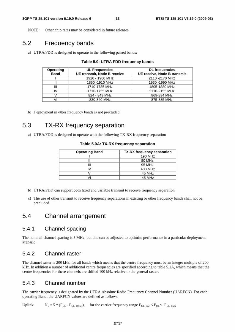
5.2 Frequency bands a) UTRA/FDD is designed to operate in the following paired bands:
Table 5.0: UTRA FDD frequency bands
Operating Band
UL Frequencies UE transmit, Node B receive
DL frequencies UE receive, Node B transmit
I 1920 - 1980 MHz 2110 -2170 MHz II 1850 -1910 MHz 1930 -1990 MHz III 1710-1785 MHz 1805-1880 MHz IV 1710-1755 MHz 2110-2155 MHz V 824 - 849 MHz 869-894 MHz VI 830-840 MHz 875-885 MHz
b) Deployment in other frequency bands is not precluded
5.3 TX-RX frequency separation a) UTRA/FDD is designed to operate with the following TX-RX frequency separation
Table 5.0A: TX-RX frequency separation
Operating Band TX-RX frequency separation I 190 MHz II 80 MHz. III 95 MHz. IV 400 MHz V 45 MHz VI 45 MHz
b) UTRA/FDD can support both fixed and variable transmit to receive frequency separation.
c) The use of other transmit to receive frequency separations in existing or other frequency bands shall not be precluded.
5.4 Channel arrangement
5.4.1 Channel spacing
The nominal channel spacing is 5 MHz, but this can be adjusted to optimise performance in a particular deployment scenario.
5.4.2 Channel raster
The channel raster is 200 kHz, for all bands which means that the centre frequency must be an integer multiple of 200 kHz. In addition a number of additional centre frequencies are specified according to table 5.1A, which means that the centre frequencies for these channels are shifted 100 kHz relative to the general raster.
5.4.3 Channel number
The carrier frequency is designated by the UTRA Absolute Radio Frequency Channel Number (UARFCN). For each operating Band, the UARFCN values are defined as follows:
Uplink: NU = 5 * (FUL - FUL_Offset), for the carrier frequency range FUL_low ≤ FUL ≤ FUL_high
ETSI
ETSI TS 125 101 V6.19.0 (2009-03) 143GPP TS 25.101 version 6.19.0 Release 6
Downlink: ND = 5 * (FDL - FDL_Offset), for the carrier frequency range FDL_low ≤ FDL ≤ FDL_high
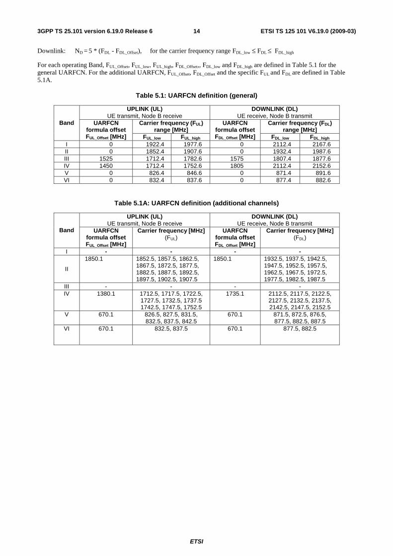
For each operating Band, FUL_Offset, FUL_low, FUL_high, FDL_Offset,, FDL_low and FDL_high are defined in Table 5.1 for the general UARFCN. For the additional UARFCN, FUL_Offset, FDL_Offset and the specific FUL and FDL are defined in Table 5.1A.
Table 5.1: UARFCN definition (general)
UPLINK (UL) UE transmit, Node B receive
DOWNLINK (DL) UE receive, Node B transmit
Carrier frequency (FUL) range [MHz]
Carrier frequency (FDL) range [MHz]
Band UARFCN formula offset FUL_Offset [MHz] FUL_low FUL_high
UARFCN formula offset FDL_Offset [MHz] FDL_low FDL_high
I 0 1922.4 1977.6 0 2112.4 2167.6 II 0 1852.4 1907.6 0 1932.4 1987.6 III 1525 1712.4 1782.6 1575 1807.4 1877.6 IV 1450 1712.4 1752.6 1805 2112.4 2152.6 V 0 826.4 846.6 0 871.4 891.6 VI 0 832.4 837.6 0 877.4 882.6
Table 5.1A: UARFCN definition (additional channels)
UPLINK (UL) UE transmit, Node B receive
DOWNLINK (DL) UE receive, Node B transmit
Band UARFCN formula offset FUL_Offset [MHz]
Carrier frequency [MHz] (FUL)
UARFCN formula offset FDL_Offset [MHz]
Carrier frequency [MHz] (FDL)
I - - - -
II
1850.1 1852.5, 1857.5, 1862.5, 1867.5, 1872.5, 1877.5, 1882.5, 1887.5, 1892.5, 1897.5, 1902.5, 1907.5
1850.1 1932.5, 1937.5, 1942.5, 1947.5, 1952.5, 1957.5, 1962.5, 1967.5, 1972.5, 1977.5, 1982.5, 1987.5
III - - - - IV 1380.1
1712.5, 1717.5, 1722.5, 1727.5, 1732.5, 1737.5 1742.5, 1747.5, 1752.5
1735.1
2112.5, 2117.5, 2122.5, 2127.5, 2132.5, 2137.5, 2142.5, 2147.5, 2152.5
V 670.1
826.5, 827.5, 831.5, 832.5, 837.5, 842.5
670.1
871.5, 872.5, 876.5, 877.5, 882.5, 887.5
VI 670.1
832.5, 837.5 670.1
877.5, 882.5
ETSI
ETSI TS 125 101 V6.19.0 (2009-03) 153GPP TS 25.101 version 6.19.0 Release 6
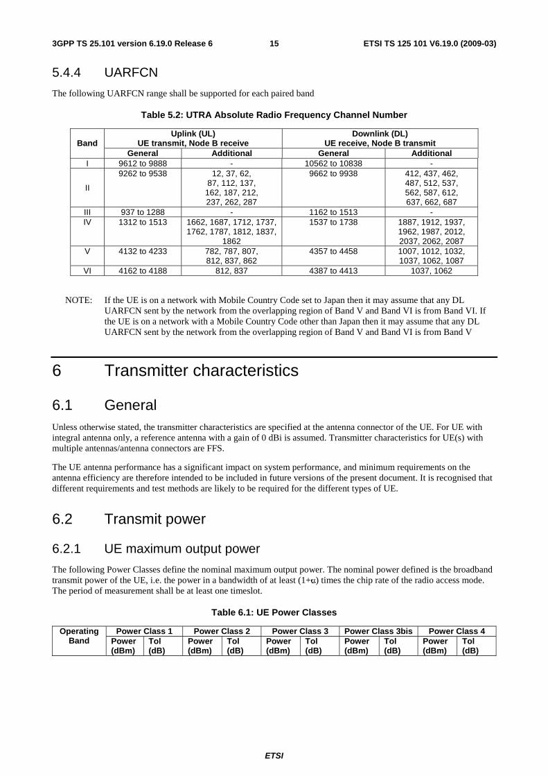
5.4.4 UARFCN
The following UARFCN range shall be supported for each paired band
Table 5.2: UTRA Absolute Radio Frequency Channel Number
Uplink (UL) UE transmit, Node B receive
Downlink (DL) UE receive, Node B transmit Band
General Additional General Additional I 9612 to 9888 - 10562 to 10838 -
II
9262 to 9538 12, 37, 62, 87, 112, 137,
162, 187, 212, 237, 262, 287
9662 to 9938 412, 437, 462, 487, 512, 537, 562, 587, 612, 637, 662, 687
III 937 to 1288 - 1162 to 1513 - IV 1312 to 1513 1662, 1687, 1712, 1737,
1762, 1787, 1812, 1837, 1862
1537 to 1738 1887, 1912, 1937, 1962, 1987, 2012, 2037, 2062, 2087
V 4132 to 4233 782, 787, 807, 812, 837, 862
4357 to 4458 1007, 1012, 1032, 1037, 1062, 1087
VI 4162 to 4188 812, 837 4387 to 4413 1037, 1062
NOTE: If the UE is on a network with Mobile Country Code set to Japan then it may assume that any DL UARFCN sent by the network from the overlapping region of Band V and Band VI is from Band VI. If the UE is on a network with a Mobile Country Code other than Japan then it may assume that any DL UARFCN sent by the network from the overlapping region of Band V and Band VI is from Band V
6 Transmitter characteristics
6.1 General Unless otherwise stated, the transmitter characteristics are specified at the antenna connector of the UE. For UE with integral antenna only, a reference antenna with a gain of 0 dBi is assumed. Transmitter characteristics for UE(s) with multiple antennas/antenna connectors are FFS.
The UE antenna performance has a significant impact on system performance, and minimum requirements on the antenna efficiency are therefore intended to be included in future versions of the present document. It is recognised that different requirements and test methods are likely to be required for the different types of UE.
6.2 Transmit power
6.2.1 UE maximum output power
The following Power Classes define the nominal maximum output power. The nominal power defined is the broadband transmit power of the UE, i.e. the power in a bandwidth of at least (1+α) times the chip rate of the radio access mode. The period of measurement shall be at least one timeslot.
Table 6.1: UE Power Classes
Power Class 1 Power Class 2 Power Class 3 Power Class 3bis Power Class 4 Operating Band Power
(dBm) Tol (dB)
Power (dBm)
Tol (dB)
Power (dBm)
Tol (dB)
Power (dBm)
Tol (dB)
Power (dBm)
Tol (dB)
ETSI
ETSI TS 125 101 V6.19.0 (2009-03) 163GPP TS 25.101 version 6.19.0 Release 6
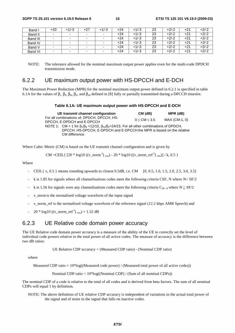
Band I +33 +1/-3 +27 +1/-3 +24 +1/-3 23 +2/-2 +21 +2/-2 Band II - - - - +24 +1/-3 23 +2/-2 +21 +2/-2 Band III - - - - +24 +1/-3 23 +2/-2 +21 +2/-2 Band IV - - - - +24 +1/-3 23 +2/-2 +21 +2/-2 Band V - - - - +24 +1/-3 23 +2/-2 +21 +2/-2 Band VI - - - - +24 +1/-3 23 +2/-2 +21 +2/-2
NOTE: The tolerance allowed for the nominal maximum output power applies even for the multi-code DPDCH transmission mode.
6.2.2 UE maximum output power with HS-DPCCH and E-DCH
The Maximum Power Reduction (MPR) for the nominal maximum output power defined in 6.2.1 is specified in table 6.1A for the values of βc, βd, βhs, βec and βed
defined in [8] fully or partially transmitted during a DPCCH timeslot.
Table 6.1A: UE maximum output power with HS-DPCCH and E-DCH
UE transmit channel configuration CM (dB) MPR (dB) For all combinations of; DPDCH, DPCCH, HS-DPCCH, E-DPDCH and E-DPCCH 0 ≤ CM ≤ 3.5 MAX (CM-1, 0)
NOTE 1: CM = 1 for βc/βd =12/15, βhs/βc=24/15. For all other combinations of DPDCH, DPCCH, HS-DPCCH, E-DPDCH and E-DPCCH the MPR is based on the relative CM difference.
Where Cubic Metric (CM) is based on the UE transmit channel configuration and is given by
CM =CEIL{ [20 * log10 ((v_norm 3) rms) - 20 * log10 ((v_norm_ref 3) rms)] / k, 0.5 }
Where
- CEIL{ x, 0.5 } means rounding upwards to closest 0.5dB, i.e. CM � [0, 0.5, 1.0, 1.5, 2.0, 2.5, 3.0, 3.5]
- k is 1.85 for signals where all channelisations codes meet the following criteria CSF, N where N< SF/2
- k is 1.56 for signals were any channelisations codes meet the following criteria CSF, N where N ≥ SF/2
- v_norm is the normalized voltage waveform of the input signal
- v_norm_ref is the normalized voltage waveform of the reference signal (12.2 kbps AMR Speech) and
- 20 * log10 ((v_norm_ref 3) rms) = 1.52 dB
6.2.3 UE Relative code domain power accuracy
The UE Relative code domain power accuracy is a measure of the ability of the UE to correctly set the level of individual code powers relative to the total power of all active codes. The measure of accuracy is the difference between two dB ratios:
UE Relative CDP accuracy = (Measured CDP ratio) - (Nominal CDP ratio)
where
Measured CDP ratio = 10*log((Measured code power) / (Measured total power of all active codes))
Nominal CDP ratio = 10*log((Nominal CDP) / (Sum of all nominal CDPs))
The nominal CDP of a code is relative to the total of all codes and is derived from beta factors. The sum of all nominal CDPs will equal 1 by definition.
NOTE: The above definition of UE relative CDP accuracy is independent of variations in the actual total power of the signal and of noise in the signal that falls on inactive codes.
ETSI
ETSI TS 125 101 V6.19.0 (2009-03) 173GPP TS 25.101 version 6.19.0 Release 6
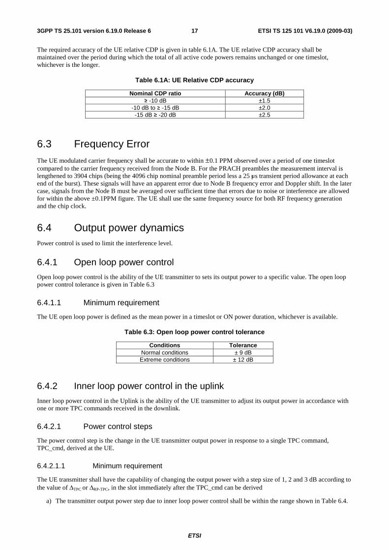
The required accuracy of the UE relative CDP is given in table 6.1A. The UE relative CDP accuracy shall be maintained over the period during which the total of all active code powers remains unchanged or one timeslot, whichever is the longer.
Table 6.1A: UE Relative CDP accuracy
Nominal CDP ratio Accuracy (dB) ≥ -10 dB ±1.5
-10 dB to ≥ -15 dB ±2.0 -15 dB ≥ -20 dB ±2.5
6.3 Frequency Error
The UE modulated carrier frequency shall be accurate to within ±0.1 PPM observed over a period of one timeslot compared to the carrier frequency received from the Node B. For the PRACH preambles the measurement interval is lengthened to 3904 chips (being the 4096 chip nominal preamble period less a 25 μs transient period allowance at each end of the burst). These signals will have an apparent error due to Node B frequency error and Doppler shift. In the later case, signals from the Node B must be averaged over sufficient time that errors due to noise or interference are allowed for within the above ±0.1PPM figure. The UE shall use the same frequency source for both RF frequency generation and the chip clock.
6.4 Output power dynamics Power control is used to limit the interference level.
6.4.1 Open loop power control
Open loop power control is the ability of the UE transmitter to sets its output power to a specific value. The open loop power control tolerance is given in Table 6.3
6.4.1.1 Minimum requirement
The UE open loop power is defined as the mean power in a timeslot or ON power duration, whichever is available.
Table 6.3: Open loop power control tolerance
Conditions Tolerance Normal conditions ± 9 dB Extreme conditions ± 12 dB
6.4.2 Inner loop power control in the uplink
Inner loop power control in the Uplink is the ability of the UE transmitter to adjust its output power in accordance with one or more TPC commands received in the downlink.
6.4.2.1 Power control steps
The power control step is the change in the UE transmitter output power in response to a single TPC command, TPC_cmd, derived at the UE.
6.4.2.1.1 Minimum requirement
The UE transmitter shall have the capability of changing the output power with a step size of 1, 2 and 3 dB according to the value of ΔTPC or ΔRP-TPC, in the slot immediately after the TPC_cmd can be derived
a) The transmitter output power step due to inner loop power control shall be within the range shown in Table 6.4.
ETSI
ETSI TS 125 101 V6.19.0 (2009-03) 183GPP TS 25.101 version 6.19.0 Release 6
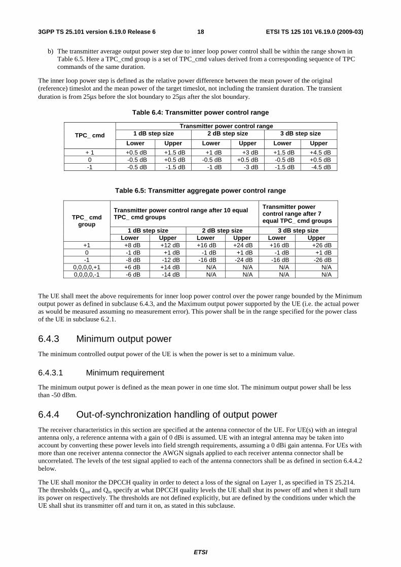
b) The transmitter average output power step due to inner loop power control shall be within the range shown in Table 6.5. Here a TPC_cmd group is a set of TPC_cmd values derived from a corresponding sequence of TPC commands of the same duration.
The inner loop power step is defined as the relative power difference between the mean power of the original (reference) timeslot and the mean power of the target timeslot, not including the transient duration. The transient duration is from 25μs before the slot boundary to 25μs after the slot boundary.
Table 6.4: Transmitter power control range
Transmitter power control range 1 dB step size 2 dB step size 3 dB step size TPC_ cmd
Lower Upper Lower Upper Lower Upper
+ 1 +0.5 dB +1.5 dB +1 dB +3 dB +1.5 dB +4.5 dB 0 -0.5 dB +0.5 dB -0.5 dB +0.5 dB -0.5 dB +0.5 dB -1 -0.5 dB -1.5 dB -1 dB -3 dB -1.5 dB -4.5 dB
Table 6.5: Transmitter aggregate power control range
Transmitter power control range after 10 equal TPC_ cmd groups
Transmitter power control range after 7 equal TPC_ cmd groups
1 dB step size 2 dB step size 3 dB step size
TPC_ cmd group
Lower Upper Lower Upper Lower Upper +1 +8 dB +12 dB +16 dB +24 dB +16 dB +26 dB 0 -1 dB +1 dB -1 dB +1 dB -1 dB +1 dB -1 -8 dB -12 dB -16 dB -24 dB -16 dB -26 dB
0,0,0,0,+1 +6 dB +14 dB N/A N/A N/A N/A 0,0,0,0,-1 -6 dB -14 dB N/A N/A N/A N/A
The UE shall meet the above requirements for inner loop power control over the power range bounded by the Minimum output power as defined in subclause 6.4.3, and the Maximum output power supported by the UE (i.e. the actual power as would be measured assuming no measurement error). This power shall be in the range specified for the power class of the UE in subclause 6.2.1.
6.4.3 Minimum output power
The minimum controlled output power of the UE is when the power is set to a minimum value.
6.4.3.1 Minimum requirement
The minimum output power is defined as the mean power in one time slot. The minimum output power shall be less than -50 dBm.
6.4.4 Out-of-synchronization handling of output power
The receiver characteristics in this section are specified at the antenna connector of the UE. For UE(s) with an integral antenna only, a reference antenna with a gain of 0 dBi is assumed. UE with an integral antenna may be taken into account by converting these power levels into field strength requirements, assuming a 0 dBi gain antenna. For UEs with more than one receiver antenna connector the AWGN signals applied to each receiver antenna connector shall be uncorrelated. The levels of the test signal applied to each of the antenna connectors shall be as defined in section 6.4.4.2 below.
The UE shall monitor the DPCCH quality in order to detect a loss of the signal on Layer 1, as specified in TS 25.214. The thresholds Qout and Qin specify at what DPCCH quality levels the UE shall shut its power off and when it shall turn its power on respectively. The thresholds are not defined explicitly, but are defined by the conditions under which the UE shall shut its transmitter off and turn it on, as stated in this subclause.
ETSI
ETSI TS 125 101 V6.19.0 (2009-03) 193GPP TS 25.101 version 6.19.0 Release 6
The DPCCH quality shall be monitored in the UE and compared to the thresholds Qout and Qin for the purpose of monitoring synchronization. The threshold Qout should correspond to a level of DPCCH quality where no reliable detection of the TPC commands transmitted on the downlink DPCCH can be made. This can be at a TPC command error ratio level of e.g. 30%. The threshold Qin should correspond to a level of DPCCH quality where detection of the TPC commands transmitted on the downlink DPCCH is significantly more reliable than at Qout. This can be at a TPC command error ratio level of e.g. 20%.
6.4.4.1 Minimum requirement
When the UE estimates the DPCCH quality over the last 160 ms period to be worse than a threshold Qout, the UE shall shut its transmitter off within 40 ms. The UE shall not turn its transmitter on again until the DPCCH quality exceeds an acceptable level Qin. When the UE estimates the DPCCH quality over the last 160 ms period to be better than a threshold Qin, the UE shall again turn its transmitter on within 40 ms.
The UE transmitter shall be considered "off" if the transmitted power is below the level defined in subclause 6.5.1 (Transmit off power). Otherwise the transmitter shall be considered as "on".
6.4.4.2 Test case
This subclause specifies a test case, which provides additional information for how the minimum requirement should be interpreted for the purpose of conformance testing.
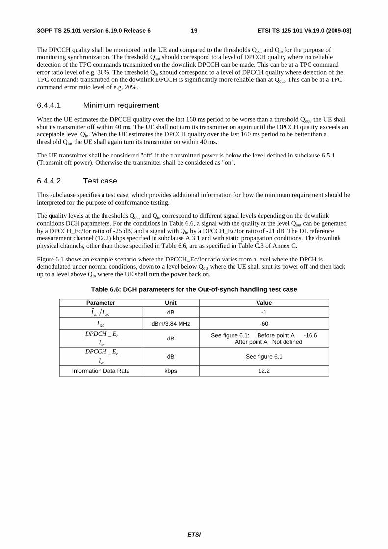
The quality levels at the thresholds Qout and Qin correspond to different signal levels depending on the downlink conditions DCH parameters. For the conditions in Table 6.6, a signal with the quality at the level Qout can be generated by a DPCCH_Ec/Ior ratio of -25 dB, and a signal with Qin by a DPCCH_Ec/Ior ratio of -21 dB. The DL reference measurement channel (12.2) kbps specified in subclause A.3.1 and with static propagation conditions. The downlink physical channels, other than those specified in Table 6.6, are as specified in Table C.3 of Annex C.
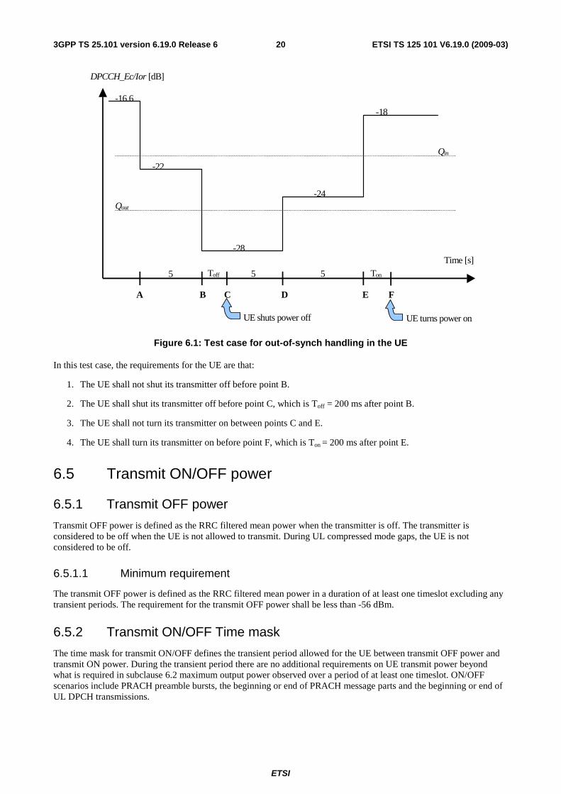
Figure 6.1 shows an example scenario where the DPCCH_Ec/Ior ratio varies from a level where the DPCH is demodulated under normal conditions, down to a level below Qout where the UE shall shut its power off and then back up to a level above Qin where the UE shall turn the power back on.
Table 6.6: DCH parameters for the Out-of-synch handling test case
Parameter Unit Value
ocor II dB -1
ocI dBm/3.84 MHz -60
or
c
I
EDPDCH _ dB See figure 6.1: Before point A -16.6 After point A Not defined
or
c
I
EDPCCH _ dB See figure 6.1
Information Data Rate kbps 12.2
ETSI
ETSI TS 125 101 V6.19.0 (2009-03) 203GPP TS 25.101 version 6.19.0 Release 6
DPCCH_Ec/Ior [dB]
A B C D E F
Time [s]
-16.6
-22
-28
-24
-18
UE shuts power off UE turns power on
5 Toff 5
Qout
Qin
5 Ton
Figure 6.1: Test case for out-of-synch handling in the UE
In this test case, the requirements for the UE are that:
1. The UE shall not shut its transmitter off before point B.
2. The UE shall shut its transmitter off before point C, which is Toff = 200 ms after point B.
3. The UE shall not turn its transmitter on between points C and E.
4. The UE shall turn its transmitter on before point F, which is Ton = 200 ms after point E.
6.5 Transmit ON/OFF power
6.5.1 Transmit OFF power
Transmit OFF power is defined as the RRC filtered mean power when the transmitter is off. The transmitter is considered to be off when the UE is not allowed to transmit. During UL compressed mode gaps, the UE is not considered to be off.
6.5.1.1 Minimum requirement
The transmit OFF power is defined as the RRC filtered mean power in a duration of at least one timeslot excluding any transient periods. The requirement for the transmit OFF power shall be less than -56 dBm.
6.5.2 Transmit ON/OFF Time mask
The time mask for transmit ON/OFF defines the transient period allowed for the UE between transmit OFF power and transmit ON power. During the transient period there are no additional requirements on UE transmit power beyond what is required in subclause 6.2 maximum output power observed over a period of at least one timeslot. ON/OFF scenarios include PRACH preamble bursts, the beginning or end of PRACH message parts and the beginning or end of UL DPCH transmissions.
ETSI
ETSI TS 125 101 V6.19.0 (2009-03) 213GPP TS 25.101 version 6.19.0 Release 6
6.5.2.1 Minimum requirement
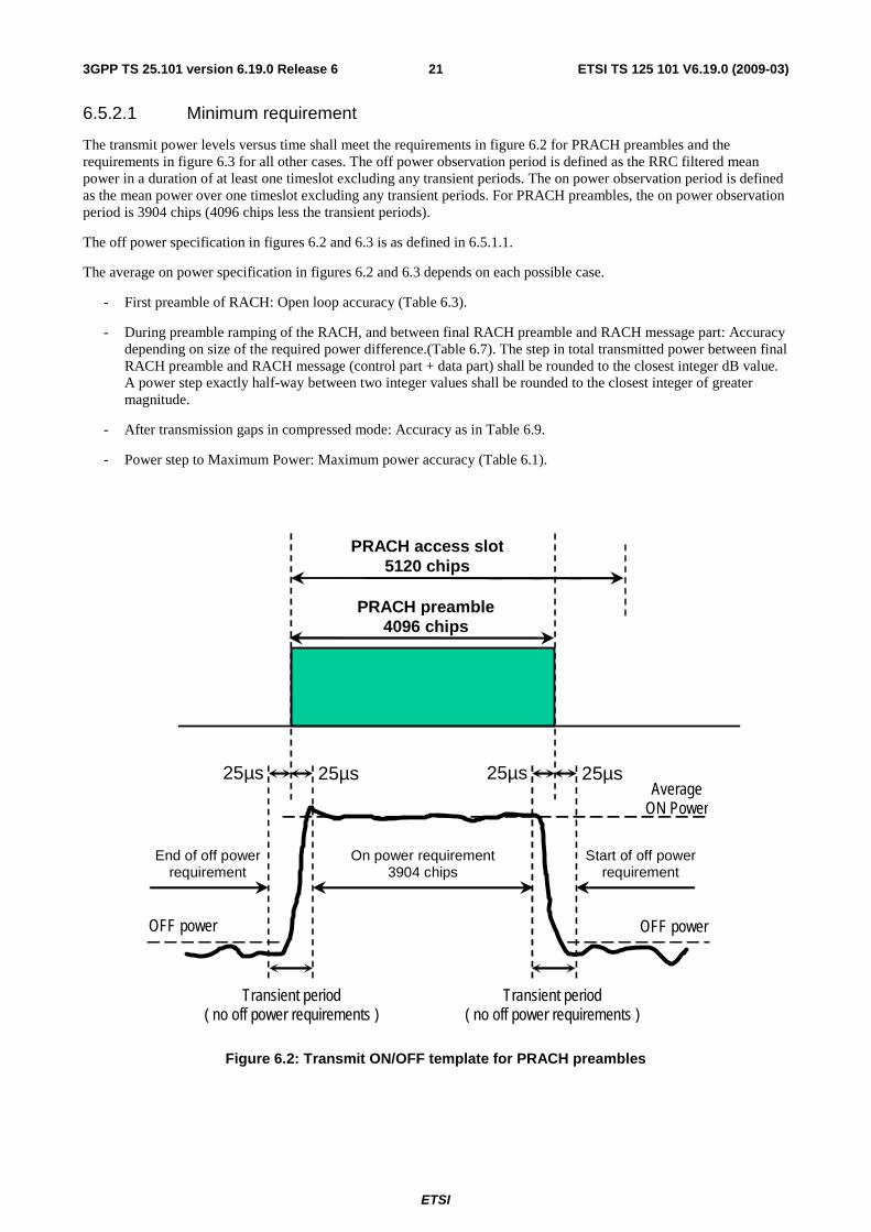
The transmit power levels versus time shall meet the requirements in figure 6.2 for PRACH preambles and the requirements in figure 6.3 for all other cases. The off power observation period is defined as the RRC filtered mean power in a duration of at least one timeslot excluding any transient periods. The on power observation period is defined as the mean power over one timeslot excluding any transient periods. For PRACH preambles, the on power observation period is 3904 chips (4096 chips less the transient periods).
The off power specification in figures 6.2 and 6.3 is as defined in 6.5.1.1.
The average on power specification in figures 6.2 and 6.3 depends on each possible case.
- First preamble of RACH: Open loop accuracy (Table 6.3).
- During preamble ramping of the RACH, and between final RACH preamble and RACH message part: Accuracy depending on size of the required power difference.(Table 6.7). The step in total transmitted power between final RACH preamble and RACH message (control part + data part) shall be rounded to the closest integer dB value. A power step exactly half-way between two integer values shall be rounded to the closest integer of greater magnitude.
- After transmission gaps in compressed mode: Accuracy as in Table 6.9.
- Power step to Maximum Power: Maximum power accuracy (Table 6.1).
PRACH preamble 4096 chips
PRACH access slot 5120 chips
On power requirement 3904 chips
Average ON Power
Start of off power requirement
25µs
25µs
Transient period ( no off power requirements )
End of off power requirement
25µs
25µs
Transient period ( no off power requirements )
OFF power OFF power
Figure 6.2: Transmit ON/OFF template for PRACH preambles
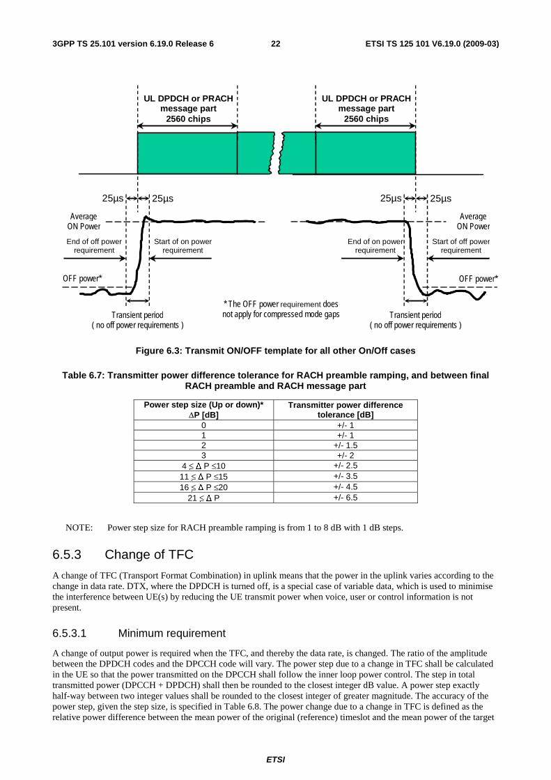
ETSI
ETSI TS 125 101 V6.19.0 (2009-03) 223GPP TS 25.101 version 6.19.0 Release 6
UL DPDCH or PRACH message part
2560 chips
End of off power requirement
25µs
25µs
Transient period ( no off power requirements )
OFF power*
Start of on power requirement
Average ON Power
Start of off power requirement
25µs
25µs
Transient period ( no off power requirements )
OFF power*
End of on power requirement
UL DPDCH or PRACH message part
2560 chips
Average ON Power
* The OFF power requirement does not apply for compressed mode gaps
Figure 6.3: Transmit ON/OFF template for all other On/Off cases
Table 6.7: Transmitter power difference tolerance for RACH preamble ramping, and between final RACH preamble and RACH message part
Power step size (Up or down)* ΔP [dB]
Transmitter power difference tolerance [dB]
0 +/- 1 1 +/- 1 2 +/- 1.5 3 +/- 2
4 ≤ Δ P ≤10 +/- 2.5 11 ≤ Δ P ≤15 +/- 3.5 16 ≤ Δ P ≤20 +/- 4.5
21 ≤ Δ P +/- 6.5
NOTE: Power step size for RACH preamble ramping is from 1 to 8 dB with 1 dB steps.
6.5.3 Change of TFC
A change of TFC (Transport Format Combination) in uplink means that the power in the uplink varies according to the change in data rate. DTX, where the DPDCH is turned off, is a special case of variable data, which is used to minimise the interference between UE(s) by reducing the UE transmit power when voice, user or control information is not present.
6.5.3.1 Minimum requirement
A change of output power is required when the TFC, and thereby the data rate, is changed. The ratio of the amplitude between the DPDCH codes and the DPCCH code will vary. The power step due to a change in TFC shall be calculated in the UE so that the power transmitted on the DPCCH shall follow the inner loop power control. The step in total transmitted power (DPCCH + DPDCH) shall then be rounded to the closest integer dB value. A power step exactly half-way between two integer values shall be rounded to the closest integer of greater magnitude. The accuracy of the power step, given the step size, is specified in Table 6.8. The power change due to a change in TFC is defined as the relative power difference between the mean power of the original (reference) timeslot and the mean power of the target
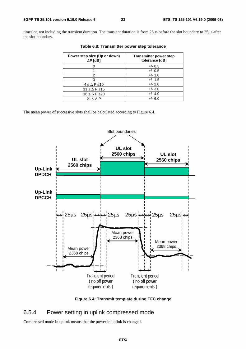
ETSI
ETSI TS 125 101 V6.19.0 (2009-03) 233GPP TS 25.101 version 6.19.0 Release 6
timeslot, not including the transient duration. The transient duration is from 25μs before the slot boundary to 25μs after the slot boundary.
Table 6.8: Transmitter power step tolerance
Power step size (Up or down) ΔP [dB]
Transmitter power step tolerance [dB]
0 +/- 0.5 1 +/- 0.5 2 +/- 1.0 3 +/- 1.5
4 ≤ Δ P ≤10 +/- 2.0 11 ≤ Δ P ≤15 +/- 3.0 16 ≤ Δ P ≤20 +/- 4.0
21 ≤ Δ P +/- 6.0
The mean power of successive slots shall be calculated according to Figure 6.4.
Slot boundaries
Up-Link DPDCH
25µs
25µs
Transient period ( no off power requirements )
25µs
25µs
Mean power 2368 chips
25µs 25µs
Up-Link DPCCH
Mean power 2368 chips
Mean power 2368 chips
Transient period ( no off power requirements )
UL slot 2560 chips
UL slot 2560 chips
UL slot 2560 chips
Figure 6.4: Transmit template during TFC change
6.5.4 Power setting in uplink compressed mode
Compressed mode in uplink means that the power in uplink is changed.
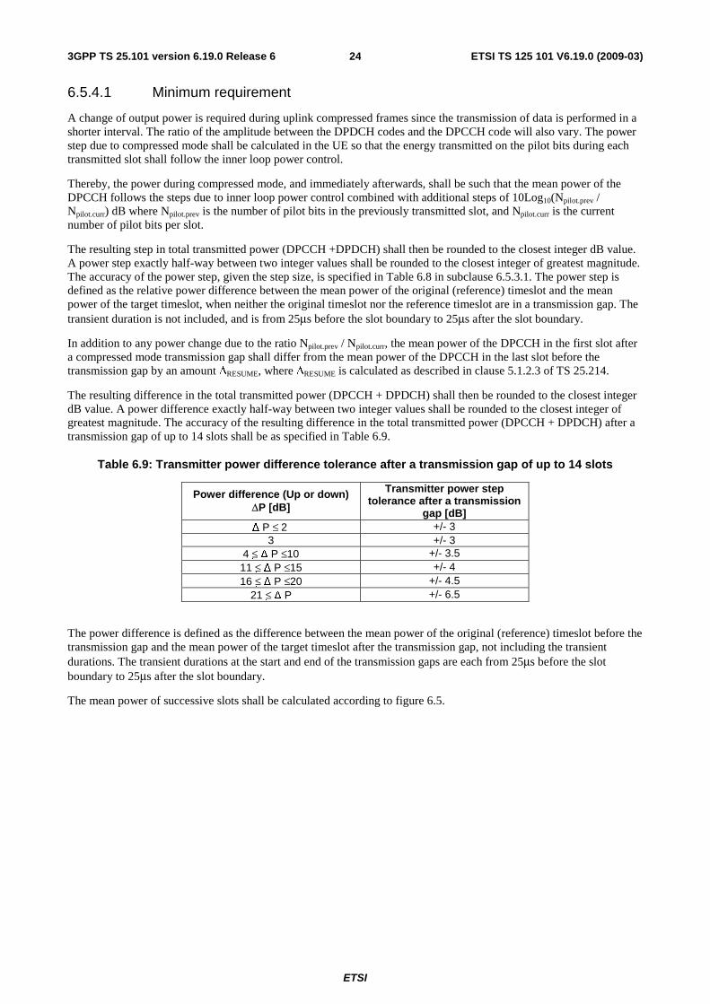
ETSI
ETSI TS 125 101 V6.19.0 (2009-03) 243GPP TS 25.101 version 6.19.0 Release 6
6.5.4.1 Minimum requirement
A change of output power is required during uplink compressed frames since the transmission of data is performed in a shorter interval. The ratio of the amplitude between the DPDCH codes and the DPCCH code will also vary. The power step due to compressed mode shall be calculated in the UE so that the energy transmitted on the pilot bits during each transmitted slot shall follow the inner loop power control.
Thereby, the power during compressed mode, and immediately afterwards, shall be such that the mean power of the DPCCH follows the steps due to inner loop power control combined with additional steps of 10Log10(Npilot.prev / Npilot.curr) dB where Npilot.prev is the number of pilot bits in the previously transmitted slot, and Npilot.curr is the current number of pilot bits per slot.
The resulting step in total transmitted power (DPCCH +DPDCH) shall then be rounded to the closest integer dB value. A power step exactly half-way between two integer values shall be rounded to the closest integer of greatest magnitude. The accuracy of the power step, given the step size, is specified in Table 6.8 in subclause 6.5.3.1. The power step is defined as the relative power difference between the mean power of the original (reference) timeslot and the mean power of the target timeslot, when neither the original timeslot nor the reference timeslot are in a transmission gap. The transient duration is not included, and is from 25μs before the slot boundary to 25μs after the slot boundary.
In addition to any power change due to the ratio Npilot.prev / Npilot.curr, the mean power of the DPCCH in the first slot after a compressed mode transmission gap shall differ from the mean power of the DPCCH in the last slot before the transmission gap by an amount ΔRESUME, where ΔRESUME is calculated as described in clause 5.1.2.3 of TS 25.214.
The resulting difference in the total transmitted power (DPCCH + DPDCH) shall then be rounded to the closest integer dB value. A power difference exactly half-way between two integer values shall be rounded to the closest integer of greatest magnitude. The accuracy of the resulting difference in the total transmitted power (DPCCH + DPDCH) after a transmission gap of up to 14 slots shall be as specified in Table 6.9.
Table 6.9: Transmitter power difference tolerance after a transmission gap of up to 14 slots
Power difference (Up or down) ΔP [dB]
Transmitter power step tolerance after a transmission
gap [dB] Δ P ≤ 2 +/- 3
3 +/- 3 4 ≤ Δ P ≤10 +/- 3.5 11 ≤ Δ P ≤15 +/- 4 16 ≤ Δ P ≤20 +/- 4.5
21 ≤ Δ P +/- 6.5
The power difference is defined as the difference between the mean power of the original (reference) timeslot before the transmission gap and the mean power of the target timeslot after the transmission gap, not including the transient durations. The transient durations at the start and end of the transmission gaps are each from 25μs before the slot boundary to 25μs after the slot boundary.
The mean power of successive slots shall be calculated according to figure 6.5.
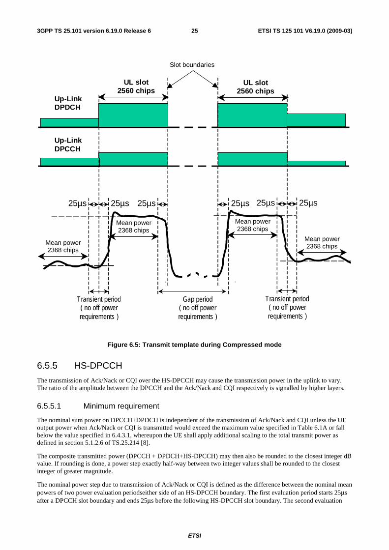
ETSI
ETSI TS 125 101 V6.19.0 (2009-03) 253GPP TS 25.101 version 6.19.0 Release 6
Slot boundaries
Up-Link DPDCH
Mean power 2368 chips
25µs
Up-Link DPCCH
Mean power 2368 chips
Mean power 2368 chips
25µs
25µs
Transient period ( no off power requirements )
UL slot 2560 chips
UL slot 2560 chips
25µs
Gap period ( no off power requirements )
25µs
25µs
Transient period ( no off power requirements )
Mean power 2368 chips
Figure 6.5: Transmit template during Compressed mode
6.5.5 HS-DPCCH
The transmission of Ack/Nack or CQI over the HS-DPCCH may cause the transmission power in the uplink to vary. The ratio of the amplitude between the DPCCH and the Ack/Nack and CQI respectively is signalled by higher layers.
6.5.5.1 Minimum requirement
The nominal sum power on DPCCH+DPDCH is independent of the transmission of Ack/Nack and CQI unless the UE output power when Ack/Nack or CQI is transmitted would exceed the maximum value specified in Table 6.1A or fall below the value specified in 6.4.3.1, whereupon the UE shall apply additional scaling to the total transmit power as defined in section 5.1.2.6 of TS.25.214 [8].
The composite transmitted power (DPCCH + DPDCH+HS-DPCCH) may then also be rounded to the closest integer dB value. If rounding is done, a power step exactly half-way between two integer values shall be rounded to the closest integer of greater magnitude.
The nominal power step due to transmission of Ack/Nack or CQI is defined as the difference between the nominal mean powers of two power evaluation periodseither side of an HS-DPCCH boundary. The first evaluation period starts 25μs after a DPCCH slot boundary and ends 25μs before the following HS-DPCCH slot boundary. The second evaluation
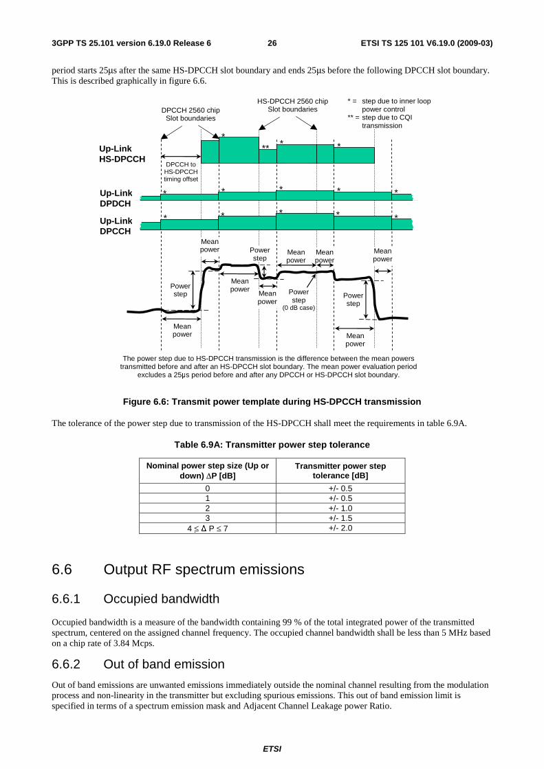
ETSI
ETSI TS 125 101 V6.19.0 (2009-03) 263GPP TS 25.101 version 6.19.0 Release 6
period starts 25μs after the same HS-DPCCH slot boundary and ends 25μs before the following DPCCH slot boundary. This is described graphically in figure 6.6.
The power step due to HS-DPCCH transmission is the difference between the mean powers transmitted before and after an HS-DPCCH slot boundary. The mean power evaluation period
excludes a 25μs period before and after any DPCCH or HS-DPCCH slot boundary.
Power step
** *
* *
* * * * *
* * * * *
Up-Link DPDCH
Up-Link DPCCH
DPCCH 2560 chip Slot boundaries
Up-Link HS-DPCCH
HS-DPCCH 2560 chip Slot boundaries
DPCCH to HS-DPCCH timing offset
* = step due to inner loop power control ** = step due to CQI transmission
Mean power
Mean power
Power step
Mean power
Mean power
Power step
Mean power
Mean power
Mean power
Mean power
Power step
(0 dB case)
Figure 6.6: Transmit power template during HS-DPCCH transmission
The tolerance of the power step due to transmission of the HS-DPCCH shall meet the requirements in table 6.9A.
Table 6.9A: Transmitter power step tolerance
Nominal power step size (Up or down) ΔP [dB]
Transmitter power step tolerance [dB]
0 +/- 0.5 1 +/- 0.5 2 +/- 1.0 3 +/- 1.5
4 ≤ Δ P ≤ 7 +/- 2.0
6.6 Output RF spectrum emissions
6.6.1 Occupied bandwidth
Occupied bandwidth is a measure of the bandwidth containing 99 % of the total integrated power of the transmitted spectrum, centered on the assigned channel frequency. The occupied channel bandwidth shall be less than 5 MHz based on a chip rate of 3.84 Mcps.
6.6.2 Out of band emission
Out of band emissions are unwanted emissions immediately outside the nominal channel resulting from the modulation process and non-linearity in the transmitter but excluding spurious emissions. This out of band emission limit is specified in terms of a spectrum emission mask and Adjacent Channel Leakage power Ratio.
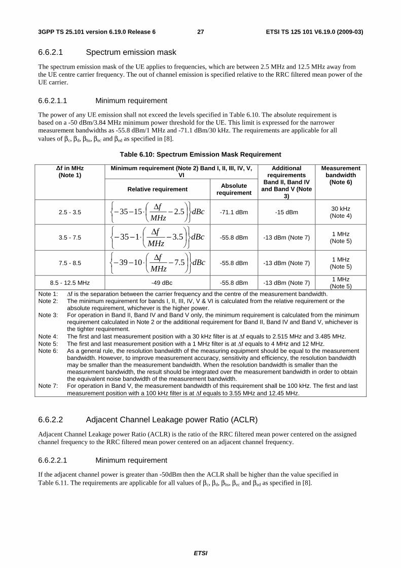
ETSI
ETSI TS 125 101 V6.19.0 (2009-03) 273GPP TS 25.101 version 6.19.0 Release 6
6.6.2.1 Spectrum emission mask
The spectrum emission mask of the UE applies to frequencies, which are between 2.5 MHz and 12.5 MHz away from the UE centre carrier frequency. The out of channel emission is specified relative to the RRC filtered mean power of the UE carrier.
6.6.2.1.1 Minimum requirement
The power of any UE emission shall not exceed the levels specified in Table 6.10. The absolute requirement is based on a -50 dBm/3.84 MHz minimum power threshold for the UE. This limit is expressed for the narrower measurement bandwidths as -55.8 dBm/1 MHz and -71.1 dBm/30 kHz. The requirements are applicable for all values of βc, βd, βhs, βec and βed as specified in [8].
Table 6.10: Spectrum Emission Mask Requirement
Minimum requirement (Note 2) Band I, II, III, IV, V, VI
Δf in MHz (Note 1)
Relative requirement Absolute requirement
Additional requirements
Band II, Band IV and Band V (Note
3)
Measurement bandwidth
(Note 6)
2.5 - 3.5 dBcMHz
f
⎭⎬⎫
⎩⎨⎧
⎟⎠
⎞⎜⎝
⎛ −Δ⋅−− 5.21535
-71.1 dBm -15 dBm 30 kHz (Note 4)
3.5 - 7.5 dBcMHz
f
⎭⎬⎫
⎩⎨⎧
⎟⎠
⎞⎜⎝
⎛ −Δ⋅−− 5.3135
-55.8 dBm -13 dBm (Note 7) 1 MHz (Note 5)
7.5 - 8.5 dBcMHz
f
⎭⎬⎫
⎩⎨⎧
⎟⎠
⎞⎜⎝
⎛ −Δ⋅−− 5.71039
-55.8 dBm -13 dBm (Note 7) 1 MHz (Note 5)
8.5 - 12.5 MHz -49 dBc -55.8 dBm -13 dBm (Note 7) 1 MHz (Note 5)
Note 1: Δf is the separation between the carrier frequency and the centre of the measurement bandwidth. Note 2: The minimum requirement for bands I, II, III, IV, V & VI is calculated from the relative requirement or the
absolute requirement, whichever is the higher power. Note 3: For operation in Band II, Band IV and Band V only, the minimum requirement is calculated from the minimum
requirement calculated in Note 2 or the additional requirement for Band II, Band IV and Band V, whichever is the tighter requirement.
Note 4: The first and last measurement position with a 30 kHz filter is at Δf equals to 2.515 MHz and 3.485 MHz. Note 5: The first and last measurement position with a 1 MHz filter is at Δf equals to 4 MHz and 12 MHz. Note 6: As a general rule, the resolution bandwidth of the measuring equipment should be equal to the measurement
bandwidth. However, to improve measurement accuracy, sensitivity and efficiency, the resolution bandwidth may be smaller than the measurement bandwidth. When the resolution bandwidth is smaller than the measurement bandwidth, the result should be integrated over the measurement bandwidth in order to obtain the equivalent noise bandwidth of the measurement bandwidth.
Note 7: For operation in Band V, the measurement bandwidth of this requirement shall be 100 kHz. The first and last measurement position with a 100 kHz filter is at Δf equals to 3.55 MHz and 12.45 MHz.
6.6.2.2 Adjacent Channel Leakage power Ratio (ACLR)
Adjacent Channel Leakage power Ratio (ACLR) is the ratio of the RRC filtered mean power centered on the assigned channel frequency to the RRC filtered mean power centered on an adjacent channel frequency.
6.6.2.2.1 Minimum requirement
If the adjacent channel power is greater than -50dBm then the ACLR shall be higher than the value specified in Table 6.11. The requirements are applicable for all values of βc, βd, βhs, βec and βed
as specified in [8].
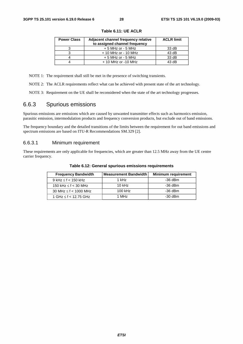
ETSI
ETSI TS 125 101 V6.19.0 (2009-03) 283GPP TS 25.101 version 6.19.0 Release 6
Table 6.11: UE ACLR
Power Class Adjacent channel frequency relative to assigned channel frequency
ACLR limit
3 + 5 MHz or - 5 MHz 33 dB 3 + 10 MHz or - 10 MHz 43 dB 4 + 5 MHz or - 5 MHz 33 dB 4 + 10 MHz or -10 MHz 43 dB
NOTE 1: The requirement shall still be met in the presence of switching transients.
NOTE 2: The ACLR requirements reflect what can be achieved with present state of the art technology.
NOTE 3: Requirement on the UE shall be reconsidered when the state of the art technology progresses.
6.6.3 Spurious emissions
Spurious emissions are emissions which are caused by unwanted transmitter effects such as harmonics emission, parasitic emission, intermodulation products and frequency conversion products, but exclude out of band emissions.
The frequency boundary and the detailed transitions of the limits between the requirement for out band emissions and spectrum emissions are based on ITU-R Recommendations SM.329 [2].
6.6.3.1 Minimum requirement
These requirements are only applicable for frequencies, which are greater than 12.5 MHz away from the UE centre carrier frequency.
Table 6.12: General spurious emissions requirements
Frequency Bandwidth Measurement Bandwidth Minimum requirement
9 kHz ≤ f < 150 kHz 1 kHz -36 dBm
150 kHz ≤ f < 30 MHz 10 kHz -36 dBm
30 MHz ≤ f < 1000 MHz 100 kHz -36 dBm
1 GHz ≤ f < 12.75 GHz 1 MHz -30 dBm
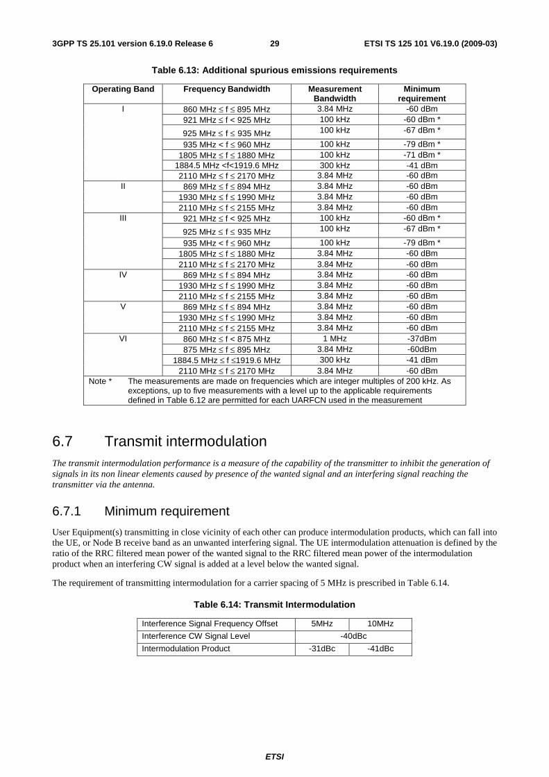
ETSI
ETSI TS 125 101 V6.19.0 (2009-03) 293GPP TS 25.101 version 6.19.0 Release 6
Table 6.13: Additional spurious emissions requirements
Operating Band Frequency Bandwidth Measurement Bandwidth
Minimum requirement
860 MHz ≤ f ≤ 895 MHz 3.84 MHz -60 dBm 921 MHz ≤ f < 925 MHz 100 kHz -60 dBm *
925 MHz ≤ f ≤ 935 MHz 100 kHz -67 dBm *
935 MHz < f ≤ 960 MHz 100 kHz -79 dBm * 1805 MHz ≤ f ≤ 1880 MHz 100 kHz -71 dBm *
1884.5 MHz <f<1919.6 MHz 300 kHz -41 dBm
I
2110 MHz ≤ f ≤ 2170 MHz 3.84 MHz -60 dBm 869 MHz ≤ f ≤ 894 MHz 3.84 MHz -60 dBm
1930 MHz ≤ f ≤ 1990 MHz 3.84 MHz -60 dBm II
2110 MHz ≤ f ≤ 2155 MHz 3.84 MHz -60 dBm 921 MHz ≤ f < 925 MHz 100 kHz -60 dBm *
925 MHz ≤ f ≤ 935 MHz 100 kHz -67 dBm *
935 MHz < f ≤ 960 MHz 100 kHz -79 dBm * 1805 MHz ≤ f ≤ 1880 MHz 3.84 MHz -60 dBm
III
2110 MHz ≤ f ≤ 2170 MHz 3.84 MHz -60 dBm 869 MHz ≤ f ≤ 894 MHz 3.84 MHz -60 dBm
1930 MHz ≤ f ≤ 1990 MHz 3.84 MHz -60 dBm IV
2110 MHz ≤ f ≤ 2155 MHz 3.84 MHz -60 dBm 869 MHz ≤ f ≤ 894 MHz 3.84 MHz -60 dBm
1930 MHz ≤ f ≤ 1990 MHz 3.84 MHz -60 dBm V
2110 MHz ≤ f ≤ 2155 MHz 3.84 MHz -60 dBm 860 MHz ≤ f < 875 MHz 1 MHz -37dBm 875 MHz ≤ f ≤ 895 MHz 3.84 MHz -60dBm
1884.5 MHz ≤ f ≤1919.6 MHz 300 kHz -41 dBm
VI
2110 MHz ≤ f ≤ 2170 MHz 3.84 MHz -60 dBm Note * The measurements are made on frequencies which are integer multiples of 200 kHz. As
exceptions, up to five measurements with a level up to the applicable requirements defined in Table 6.12 are permitted for each UARFCN used in the measurement
6.7 Transmit intermodulation The transmit intermodulation performance is a measure of the capability of the transmitter to inhibit the generation of signals in its non linear elements caused by presence of the wanted signal and an interfering signal reaching the transmitter via the antenna.
6.7.1 Minimum requirement
User Equipment(s) transmitting in close vicinity of each other can produce intermodulation products, which can fall into the UE, or Node B receive band as an unwanted interfering signal. The UE intermodulation attenuation is defined by the ratio of the RRC filtered mean power of the wanted signal to the RRC filtered mean power of the intermodulation product when an interfering CW signal is added at a level below the wanted signal.
The requirement of transmitting intermodulation for a carrier spacing of 5 MHz is prescribed in Table 6.14.
Table 6.14: Transmit Intermodulation
Interference Signal Frequency Offset 5MHz 10MHz
Interference CW Signal Level -40dBc
Intermodulation Product -31dBc -41dBc
ETSI
ETSI TS 125 101 V6.19.0 (2009-03) 303GPP TS 25.101 version 6.19.0 Release 6
6.8 Transmit modulation Transmit modulation defines the modulation quality for expected in-channel RF transmissions from the UE. The requirements apply to all transmissions including the PRACH pre-amble and message parts and all other expected transmissions. In cases where the mean power of the RF signal is allowed to change versus time e.g. PRACH, DPCH in compressed mode, change of TFC, inner loop power control and for HSDPA transmissions with non-constant HS-DPCCH code power, the the EVM, Peak Code Domain Error and E-DCH Code Domain Error requirements do not apply during the 25 us period before and after the nominal time when the mean power is expected to change.
6.8.1 Transmit pulse shape filter
The transmit pulse shaping filter is a root-raised cosine (RRC) with roll-off α =0.22 in the frequency domain. The impulse response of the chip impulse filter RC0(t) is:
( )( ) ( )
⎟⎟
⎠
⎞
⎜⎜
⎝
⎛
⎟⎟⎠
⎞⎜⎜⎝
⎛−
⎟⎟⎠
⎞⎜⎜⎝
⎛++⎟⎟
⎠
⎞⎜⎜⎝
⎛−
=20
41
1cos41sin
CC
CCC
T
t
T
t
T
t
T
t
T
t
tRC
απ
απααπ
Where the roll-off factor α =0.22 and the chip duration is
schiprate
T μ26042.01 ≈=
6.8.2 Error Vector Magnitude
The Error Vector Magnitude is a measure of the difference between the reference waveform and the measured waveform. This difference is called the error vector. Both waveforms pass through a matched Root Raised Cosine filter with bandwidth 3,84 MHz and roll-off α=0,22. Both waveforms are then further modified by selecting the frequency, absolute phase, absolute amplitude and chip clock timing so as to minimise the error vector. The EVM result is defined as the square root of the ratio of the mean error vector power to the mean reference power expressed as a %. The measurement interval is one timeslot except when the mean power between slots is expected to change whereupon the measurement interval is reduced by 25 μs at each end of the slot. For the PRACH preamble the measurement interval is 4096 chips less 25 μs at each end of the burst (3904 chips).
For signals containing more than one spreading code where the slot alignment of the codes is not the same and the code power is varying, the period over which the nominal mean power remains constant can be less than one timeslot. For such time-varying signals it is not possible to define EVM across one timeslot since this interval contains an expected change in mean power, and the exact timing and trajectory of the power change is not defined. For these signals, the EVM minimum requirements apply only for intervals of at least one half timeslot (less any 25μs transient periods) during which the nominal code power of each individual code is constant.
NOTE: The reason for setting a lower limit for the EVM measurement interval is that for any given impaired signal, the EVM would be expected to improve for measurement intervals less than one timeslot while the frequency error would be expected to degrade.
6.8.2.1 Minimum requirement
The Error Vector Magnitude shall not exceed 17.5 % for the parameters specified in Table 6.15. The requirements are applicable for all values of βc, βd, βhs, βec and βed as specified in [8].
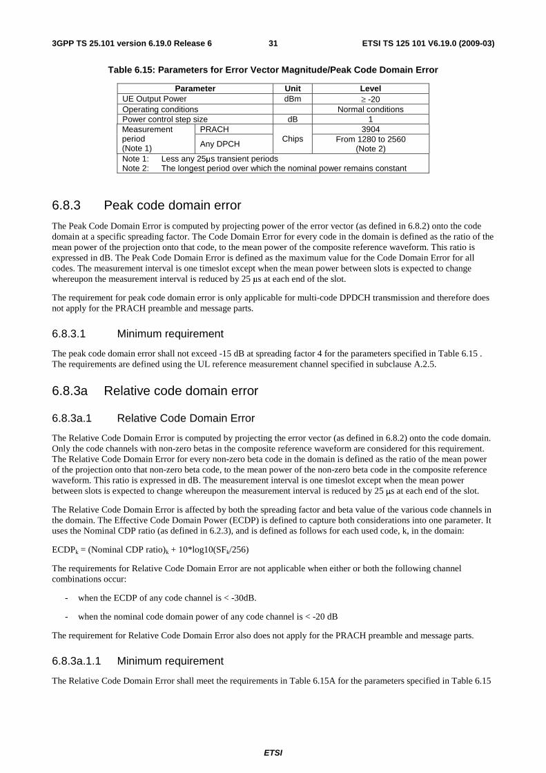
ETSI
ETSI TS 125 101 V6.19.0 (2009-03) 313GPP TS 25.101 version 6.19.0 Release 6
Table 6.15: Parameters for Error Vector Magnitude/Peak Code Domain Error
Parameter Unit Level UE Output Power dBm ≥ -20 Operating conditions Normal conditions Power control step size dB 1
PRACH 3904 Measurement period (Note 1) Any DPCH
Chips From 1280 to 2560 (Note 2)
Note 1: Less any 25μs transient periods Note 2: The longest period over which the nominal power remains constant
6.8.3 Peak code domain error
The Peak Code Domain Error is computed by projecting power of the error vector (as defined in 6.8.2) onto the code domain at a specific spreading factor. The Code Domain Error for every code in the domain is defined as the ratio of the mean power of the projection onto that code, to the mean power of the composite reference waveform. This ratio is expressed in dB. The Peak Code Domain Error is defined as the maximum value for the Code Domain Error for all codes. The measurement interval is one timeslot except when the mean power between slots is expected to change whereupon the measurement interval is reduced by 25 μs at each end of the slot.
The requirement for peak code domain error is only applicable for multi-code DPDCH transmission and therefore does not apply for the PRACH preamble and message parts.
6.8.3.1 Minimum requirement
The peak code domain error shall not exceed -15 dB at spreading factor 4 for the parameters specified in Table 6.15 . The requirements are defined using the UL reference measurement channel specified in subclause A.2.5.
6.8.3a Relative code domain error
6.8.3a.1 Relative Code Domain Error
The Relative Code Domain Error is computed by projecting the error vector (as defined in 6.8.2) onto the code domain. Only the code channels with non-zero betas in the composite reference waveform are considered for this requirement. The Relative Code Domain Error for every non-zero beta code in the domain is defined as the ratio of the mean power of the projection onto that non-zero beta code, to the mean power of the non-zero beta code in the composite reference waveform. This ratio is expressed in dB. The measurement interval is one timeslot except when the mean power between slots is expected to change whereupon the measurement interval is reduced by 25 μs at each end of the slot.
The Relative Code Domain Error is affected by both the spreading factor and beta value of the various code channels in the domain. The Effective Code Domain Power (ECDP) is defined to capture both considerations into one parameter. It uses the Nominal CDP ratio (as defined in 6.2.3), and is defined as follows for each used code, k, in the domain:
ECDPk = (Nominal CDP ratio)k + 10*log10(SFk/256)
The requirements for Relative Code Domain Error are not applicable when either or both the following channel combinations occur:
- when the ECDP of any code channel is < -30dB.
- when the nominal code domain power of any code channel is < -20 dB
The requirement for Relative Code Domain Error also does not apply for the PRACH preamble and message parts.
6.8.3a.1.1 Minimum requirement
The Relative Code Domain Error shall meet the requirements in Table 6.15A for the parameters specified in Table 6.15
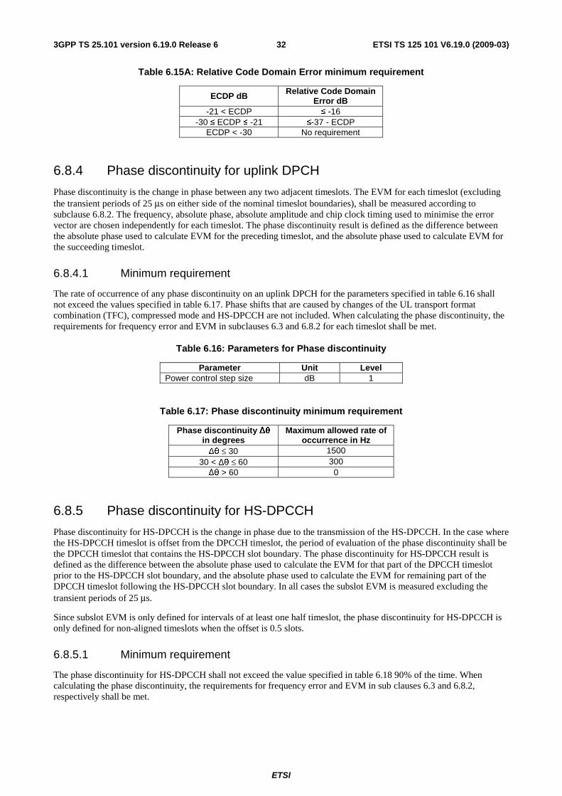
ETSI
ETSI TS 125 101 V6.19.0 (2009-03) 323GPP TS 25.101 version 6.19.0 Release 6
Table 6.15A: Relative Code Domain Error minimum requirement
ECDP dB Relative Code Domain Error dB
-21 < ECDP ≤ -16 -30 ≤ ECDP ≤ -21 ≤-37 - ECDP
ECDP < -30 No requirement
6.8.4 Phase discontinuity for uplink DPCH
Phase discontinuity is the change in phase between any two adjacent timeslots. The EVM for each timeslot (excluding the transient periods of 25 μs on either side of the nominal timeslot boundaries), shall be measured according to subclause 6.8.2. The frequency, absolute phase, absolute amplitude and chip clock timing used to minimise the error vector are chosen independently for each timeslot. The phase discontinuity result is defined as the difference between the absolute phase used to calculate EVM for the preceding timeslot, and the absolute phase used to calculate EVM for the succeeding timeslot.
6.8.4.1 Minimum requirement
The rate of occurrence of any phase discontinuity on an uplink DPCH for the parameters specified in table 6.16 shall not exceed the values specified in table 6.17. Phase shifts that are caused by changes of the UL transport format combination (TFC), compressed mode and HS-DPCCH are not included. When calculating the phase discontinuity, the requirements for frequency error and EVM in subclauses 6.3 and 6.8.2 for each timeslot shall be met.
Table 6.16: Parameters for Phase discontinuity
Parameter Unit Level Power control step size dB 1
Table 6.17: Phase discontinuity minimum requirement
Phase discontinuity Δθ in degrees
Maximum allowed rate of occurrence in Hz
Δθ ≤ 30 1500 30 < Δθ ≤ 60 300 Δθ > 60 0
6.8.5 Phase discontinuity for HS-DPCCH
Phase discontinuity for HS-DPCCH is the change in phase due to the transmission of the HS-DPCCH. In the case where the HS-DPCCH timeslot is offset from the DPCCH timeslot, the period of evaluation of the phase discontinuity shall be the DPCCH timeslot that contains the HS-DPCCH slot boundary. The phase discontinuity for HS-DPCCH result is defined as the difference between the absolute phase used to calculate the EVM for that part of the DPCCH timeslot prior to the HS-DPCCH slot boundary, and the absolute phase used to calculate the EVM for remaining part of the DPCCH timeslot following the HS-DPCCH slot boundary. In all cases the subslot EVM is measured excluding the transient periods of 25 μs.
Since subslot EVM is only defined for intervals of at least one half timeslot, the phase discontinuity for HS-DPCCH is only defined for non-aligned timeslots when the offset is 0.5 slots.
6.8.5.1 Minimum requirement
The phase discontinuity for HS-DPCCH shall not exceed the value specified in table 6.18 90% of the time. When calculating the phase discontinuity, the requirements for frequency error and EVM in sub clauses 6.3 and 6.8.2, respectively shall be met.
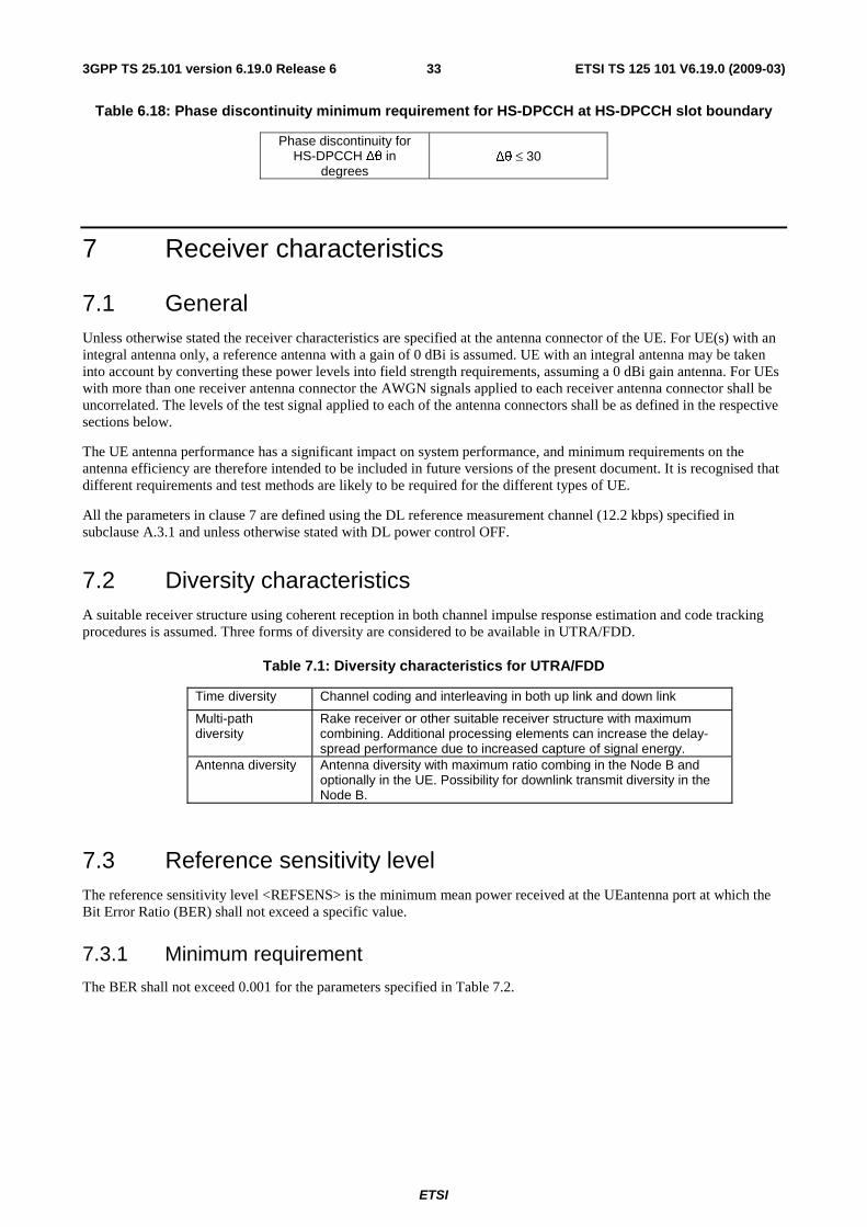
ETSI
ETSI TS 125 101 V6.19.0 (2009-03) 333GPP TS 25.101 version 6.19.0 Release 6
Table 6.18: Phase discontinuity minimum requirement for HS-DPCCH at HS-DPCCH slot boundary
Phase discontinuity for HS-DPCCH Δθ in
degrees Δθ ≤ 30
7 Receiver characteristics
7.1 General Unless otherwise stated the receiver characteristics are specified at the antenna connector of the UE. For UE(s) with an integral antenna only, a reference antenna with a gain of 0 dBi is assumed. UE with an integral antenna may be taken into account by converting these power levels into field strength requirements, assuming a 0 dBi gain antenna. For UEs with more than one receiver antenna connector the AWGN signals applied to each receiver antenna connector shall be uncorrelated. The levels of the test signal applied to each of the antenna connectors shall be as defined in the respective sections below.
The UE antenna performance has a significant impact on system performance, and minimum requirements on the antenna efficiency are therefore intended to be included in future versions of the present document. It is recognised that different requirements and test methods are likely to be required for the different types of UE.
All the parameters in clause 7 are defined using the DL reference measurement channel (12.2 kbps) specified in subclause A.3.1 and unless otherwise stated with DL power control OFF.
7.2 Diversity characteristics A suitable receiver structure using coherent reception in both channel impulse response estimation and code tracking procedures is assumed. Three forms of diversity are considered to be available in UTRA/FDD.
Table 7.1: Diversity characteristics for UTRA/FDD
Time diversity Channel coding and interleaving in both up link and down link
Multi-path diversity
Rake receiver or other suitable receiver structure with maximum combining. Additional processing elements can increase the delay-spread performance due to increased capture of signal energy.
Antenna diversity Antenna diversity with maximum ratio combing in the Node B and optionally in the UE. Possibility for downlink transmit diversity in the Node B.
7.3 Reference sensitivity level The reference sensitivity level <REFSENS> is the minimum mean power received at the UEantenna port at which the Bit Error Ratio (BER) shall not exceed a specific value.
7.3.1 Minimum requirement
The BER shall not exceed 0.001 for the parameters specified in Table 7.2.
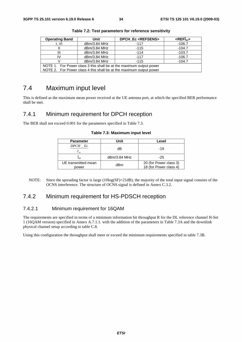
ETSI
ETSI TS 125 101 V6.19.0 (2009-03) 343GPP TS 25.101 version 6.19.0 Release 6
Table 7.2: Test parameters for reference sensitivity
Operating Band Unit DPCH_Ec <REFSENS> <REFÎor> I, VI dBm/3.84 MHz -117 -106.7
II dBm/3.84 MHz -115 -104.7 III dBm/3.84 MHz -114 -103.7 IV dBm/3.84 MHz -117 -106.7 V dBm/3.84 MHz -115 -104.7
NOTE 1. For Power class 3 this shall be at the maximum output power NOTE 2. For Power class 4 this shall be at the maximum output power
7.4 Maximum input level This is defined as the maximum mean power received at the UE antenna port, at which the specified BER performance shall be met.
7.4.1 Minimum requirement for DPCH reception
The BER shall not exceed 0.001 for the parameters specified in Table 7.3.
Table 7.3: Maximum input level
Parameter Unit Level
orI
EcDPCH _ dB -19
Îor dBm/3.84 MHz -25
UE transmitted mean power dBm 20 (for Power class 3)
18 (for Power class 4)
NOTE: Since the spreading factor is large (10log(SF)=21dB), the majority of the total input signal consists of the OCNS interference. The structure of OCNS signal is defined in Annex C.3.2.
7.4.2 Minimum requirement for HS-PDSCH reception
7.4.2.1 Minimum requirement for 16QAM
The requirements are specified in terms of a minimum information bit throughput R for the DL reference channel H-Set 1 (16QAM version) specified in Annex A.7.1.1. with the addition of the parameters in Table 7.3A and the downlink physical channel setup according to table C.8.
Using this configuration the throughput shall meet or exceed the minimum requirements specified in table 7.3B.
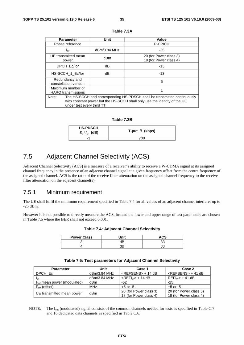
ETSI
ETSI TS 125 101 V6.19.0 (2009-03) 353GPP TS 25.101 version 6.19.0 Release 6
Table 7.3A
Parameter Unit Value Phase reference P-CPICH
Îor dBm/3.84 MHz -25
UE transmitted mean power dBm 20 (for Power class 3)
18 (for Power class 4)
DPCH_Ec/Ior dB -13
HS-SCCH_1_Ec/Ior dB -13
Redundancy and constellation version 6
Maximum number of HARQ transmissions 1
Note: The HS-SCCH and corresponding HS-PDSCH shall be transmitted continuously with constant power but the HS-SCCH shall only use the identity of the UE under test every third TTI
Table 7.3B
HS-PDSCH /c orE I (dB) T-put R (kbps)
-3 700
7.5 Adjacent Channel Selectivity (ACS) Adjacent Channel Selectivity (ACS) is a measure of a receiver"s ability to receive a W-CDMA signal at its assigned channel frequency in the presence of an adjacent channel signal at a given frequency offset from the centre frequency of the assigned channel. ACS is the ratio of the receive filter attenuation on the assigned channel frequency to the receive filter attenuation on the adjacent channel(s).
7.5.1 Minimum requirement
The UE shall fulfil the minimum requirement specified in Table 7.4 for all values of an adjacent channel interferer up to -25 dBm.
However it is not possible to directly measure the ACS, instead the lower and upper range of test parameters are chosen in Table 7.5 where the BER shall not exceed 0.001.
Table 7.4: Adjacent Channel Selectivity
Power Class Unit ACS 3 dB 33 4 dB 33
Table 7.5: Test parameters for Adjacent Channel Selectivity
Parameter Unit Case 1 Case 2 DPCH_Ec dBm/3.84 MHz <REFSENS> + 14 dB <REFSENS> + 41 dB Îor dBm/3.84 MHz <REFÎor> + 14 dB REFÎor> + 41 dB Ioac mean power (modulated) dBm -52 -25 Fuw (offset) MHz +5 or -5 +5 or -5
UE transmitted mean power dBm 20 (for Power class 3) 18 (for Power class 4)
20 (for Power class 3) 18 (for Power class 4)
NOTE: The Ioac (modulated) signal consists of the common channels needed for tests as specified in Table C.7 and 16 dedicated data channels as specified in Table C.6.
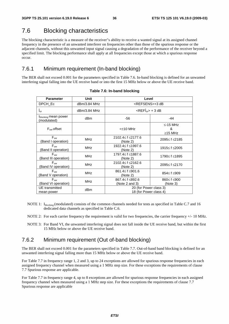
ETSI
ETSI TS 125 101 V6.19.0 (2009-03) 363GPP TS 25.101 version 6.19.0 Release 6
7.6 Blocking characteristics The blocking characteristic is a measure of the receiver"s ability to receive a wanted signal at its assigned channel frequency in the presence of an unwanted interferer on frequencies other than those of the spurious response or the adjacent channels, without this unwanted input signal causing a degradation of the performance of the receiver beyond a specified limit. The blocking performance shall apply at all frequencies except those at which a spurious response occur.
7.6.1 Minimum requirement (In-band blocking)
The BER shall not exceed 0.001 for the parameters specified in Table 7.6. In-band blocking is defined for an unwanted interfering signal falling into the UE receive band or into the first 15 MHz below or above the UE receive band.
Table 7.6: In-band blocking
Parameter Unit Level
DPCH_Ec dBm/3.84 MHz <REFSENS>+3 dB
Îor dBm/3.84 MHz <REFÎor> + 3 dB
Iblocking mean power (modulated) dBm -56 -44
Fuw offset =±10 MHz ≤-15 MHz
& ≥15 MHz
Fuw
(Band I operation) MHz 2102.4≤ f ≤2177.6 (Note 2)
2095≤ f ≤2185
Fuw
(Band II operation) MHz 1922.4≤ f ≤1997.6 (Note 2)
1915≤ f ≤2005
Fuw (Band III operation)
MHz 1797.4≤ f ≤1887.6 (Note 2)
1790≤ f ≤1895
Fuw (Band IV operation) MHz 2102.4≤ f ≤2162.6
(Note 2) 2095≤ f ≤2170
Fuw (Band V operation) MHz 861.4≤ f ≤901.6
(Note 2) 854≤ f ≤909
Fuw (Band VI operation) MHz 867.4≤ f ≤892.6
(Note 2 and 3) 860≤ f ≤900
(Note 3) UE transmitted mean power
dBm 20 (for Power class 3) 18 (for Power class 4)
NOTE 1: Iblocking (modulated) consists of the common channels needed for tests as specified in Table C.7 and 16 dedicated data channels as specified in Table C.6.
NOTE 2: For each carrier frequency the requirement is valid for two frequencies, the carrier frequency +/- 10 MHz.
NOTE 3: For Band VI, the unwanted interfering signal does not fall inside the UE receive band, but within the first 15 MHz below or above the UE receive band.
7.6.2 Minimum requirement (Out of-band blocking)
The BER shall not exceed 0.001 for the parameters specified in Table 7.7. Out-of-band band blocking is defined for an unwanted interfering signal falling more than 15 MHz below or above the UE receive band.
For Table 7.7 in frequency range 1, 2 and 3, up to 24 exceptions are allowed for spurious response frequencies in each assigned frequency channel when measured using a 1 MHz step size. For these exceptions the requirements of clause 7.7 Spurious response are applicable.
For Table 7.7 in frequency range 4, up to 8 exceptions are allowed for spurious response frequencies in each assigned frequency channel when measured using a 1 MHz step size. For these exceptions the requirements of clause 7.7 Spurious response are applicable
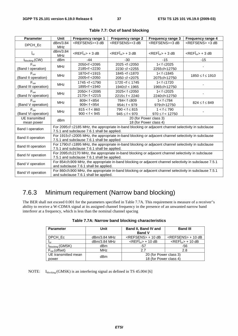
ETSI
ETSI TS 125 101 V6.19.0 (2009-03) 373GPP TS 25.101 version 6.19.0 Release 6
Table 7.7: Out of band blocking
Parameter Unit Frequency range 1 Frequency range 2 Frequency range 3 Frequency range 4
DPCH_Ec dBm/3.84 MHz
<REFSENS>+3 dB <REFSENS>+3 dB <REFSENS>+3 dB <REFSENS> +3 dB
Îor dBm/3.84
MHz <REFÎor> + 3 dB <REFÎor> + 3 dB <REFÎor> + 3 dB <REFÎor> + 3 dB
Iblocking (CW) dBm -44 -30 -15 -15 Fuw
(Band I operation) MHz 2050<f <2095
2185<f <2230 2025 <f ≤2050 2230 ≤f <2255
1< f ≤2025 2255≤f<12750
-
Fuw
(Band II operation) MHz 1870<f <1915
2005<f <2050 1845 <f ≤1870 2050 ≤f <2075
1< f ≤1845 2075≤f<12750
1850 ≤ f ≤ 1910
Fuw (Band III operation) MHz 1745 <f <1790
1895<f <1940 1720 <f ≤ 1745 1940≤f < 1965
1< f ≤1720 1965≤f<12750
-
Fuw (Band IV operation) MHz 2050< f <2095
2170< f <2215 2025< f ≤2050 2215≤ f < 2240
1< f ≤2025 2240≤f<12750
-
Fuw (Band V operation) MHz 809< f <854
909< f <954 784< f ≤809 954≤ f < 979
1< f ≤784 979≤f<12750
824 ≤ f ≤ 849
Fuw (Band VI operation) MHz 815 < f < 860
900 < f < 945 790 < f ≤ 815 945 ≤ f < 970
1 < f ≤ 790 970 ≤ f < 12750
-
UE transmitted mean power dBm 20 (for Power class 3)
18 (for Power class 4)
Band I operation For 2095≤f ≤2185 MHz, the appropriate in-band blocking or adjacent channel selectivity in subclause 7.5.1 and subclause 7.6.1 shall be applied.
Band II operation For 1915≤f ≤2005 MHz, the appropriate in-band blocking or adjacent channel selectivity in subclause 7.5.1 and subclause 7.6.1 shall be applied
Band III operation For 1790≤f ≤1895 MHz, the appropriate in-band blocking or adjacent channel selectivity in subclause 7.5.1 and subclause 7.6.1 shall be applied.
Band IV operation For 2095≤f≤2170 MHz, the appropriate in-band blocking or adjacent channel selectivity in subclause 7.5.1 and subclause 7.6.1 shall be applied.
Band V operation For 854≤f≤909 MHz, the appropriate in-band blocking or adjacent channel selectivity in subclause 7.5.1 and subclause 7.6.1 shall be applied.
Band VI operation For 860≤f≤900 MHz, the appropriate in-band blocking or adjacent channel selectivity in subclause 7.5.1 and subclause 7.6.1 shall be applied.
7.6.3 Minimum requirement (Narrow band blocking) The BER shall not exceed 0.001 for the parameters specified in Table 7.7A. This requirement is measure of a receiver"s ability to receive a W-CDMA signal at its assigned channel frequency in the presence of an unwanted narrow band interferer at a frequency, which is less than the nominal channel spacing
Table 7.7A: Narrow band blocking characteristics
Parameter Unit Band II, Band IV and Band V
Band III
DPCH_Ec dBm/3.84 MHz <REFSENS> + 10 dB <REFSENS> + 10 dB Îor dBm/3.84 MHz <REFÎor> + 10 dB <REFÎor> + 10 dB Iblocking (GMSK) dBm -57 -56 Fuw (offset) MHz 2.7 2.8 UE transmitted mean power
dBm 20 (for Power class 3) 18 (for Power class 4)
NOTE: Iblocking (GMSK) is an interfering signal as defined in TS 45.004 [6]
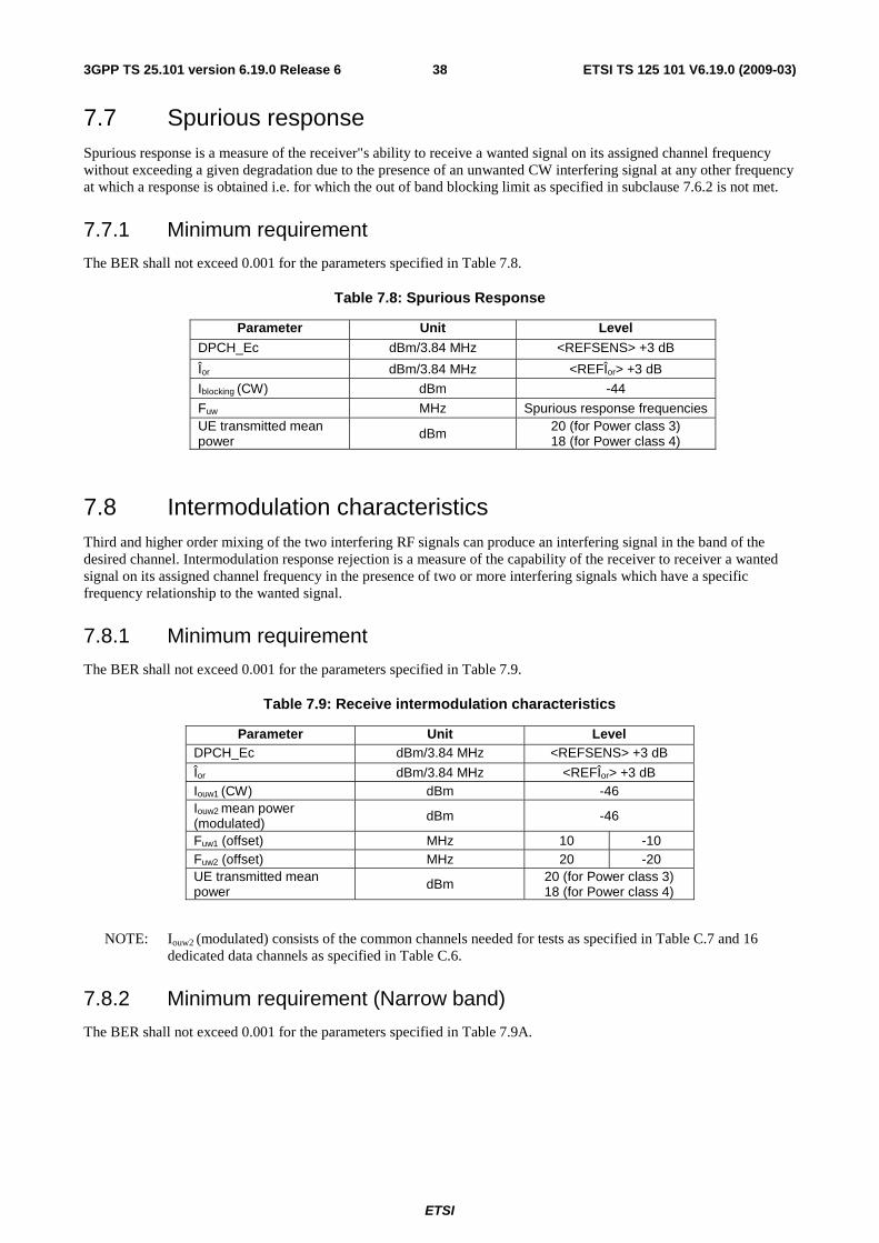
ETSI
ETSI TS 125 101 V6.19.0 (2009-03) 383GPP TS 25.101 version 6.19.0 Release 6
7.7 Spurious response Spurious response is a measure of the receiver"s ability to receive a wanted signal on its assigned channel frequency without exceeding a given degradation due to the presence of an unwanted CW interfering signal at any other frequency at which a response is obtained i.e. for which the out of band blocking limit as specified in subclause 7.6.2 is not met.
7.7.1 Minimum requirement
The BER shall not exceed 0.001 for the parameters specified in Table 7.8.
Table 7.8: Spurious Response
Parameter Unit Level
DPCH_Ec dBm/3.84 MHz <REFSENS> +3 dB
Îor dBm/3.84 MHz <REFÎor> +3 dB
Iblocking (CW) dBm -44
Fuw MHz Spurious response frequencies UE transmitted mean power dBm 20 (for Power class 3)
18 (for Power class 4)
7.8 Intermodulation characteristics Third and higher order mixing of the two interfering RF signals can produce an interfering signal in the band of the desired channel. Intermodulation response rejection is a measure of the capability of the receiver to receiver a wanted signal on its assigned channel frequency in the presence of two or more interfering signals which have a specific frequency relationship to the wanted signal.
7.8.1 Minimum requirement
The BER shall not exceed 0.001 for the parameters specified in Table 7.9.
Table 7.9: Receive intermodulation characteristics
Parameter Unit Level DPCH_Ec dBm/3.84 MHz <REFSENS> +3 dB
Îor dBm/3.84 MHz <REFÎor> +3 dB Iouw1 (CW) dBm -46 Iouw2 mean power (modulated) dBm -46
Fuw1 (offset) MHz 10 -10 Fuw2 (offset) MHz 20 -20 UE transmitted mean power dBm 20 (for Power class 3)
18 (for Power class 4)
NOTE: Iouw2 (modulated) consists of the common channels needed for tests as specified in Table C.7 and 16 dedicated data channels as specified in Table C.6.
7.8.2 Minimum requirement (Narrow band)
The BER shall not exceed 0.001 for the parameters specified in Table 7.9A.
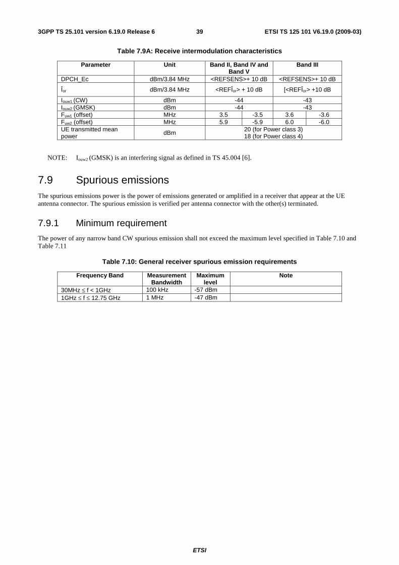
ETSI
ETSI TS 125 101 V6.19.0 (2009-03) 393GPP TS 25.101 version 6.19.0 Release 6
Table 7.9A: Receive intermodulation characteristics
Parameter Unit Band II, Band IV and Band V
Band III
DPCH_Ec dBm/3.84 MHz <REFSENS>+ 10 dB <REFSENS>+ 10 dB
Îor dBm/3.84 MHz <REFÎor> + 10 dB [<REFÎor> +10 dB
Iouw1 (CW) dBm -44 -43 Iouw2 (GMSK) dBm -44 -43 Fuw1 (offset) MHz 3.5 -3.5 3.6 -3.6 Fuw2 (offset) MHz 5.9 -5.9 6.0 -6.0 UE transmitted mean power dBm 20 (for Power class 3)
18 (for Power class 4)
NOTE: Iouw2 (GMSK) is an interfering signal as defined in TS 45.004 [6].
7.9 Spurious emissions The spurious emissions power is the power of emissions generated or amplified in a receiver that appear at the UE antenna connector. The spurious emission is verified per antenna connector with the other(s) terminated.
7.9.1 Minimum requirement
The power of any narrow band CW spurious emission shall not exceed the maximum level specified in Table 7.10 and Table 7.11
Table 7.10: General receiver spurious emission requirements
Frequency Band Measurement Bandwidth
Maximum level
Note
30MHz ≤ f < 1GHz 100 kHz -57 dBm 1GHz ≤ f ≤ 12.75 GHz 1 MHz -47 dBm
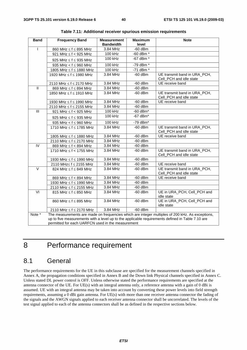
ETSI
ETSI TS 125 101 V6.19.0 (2009-03) 403GPP TS 25.101 version 6.19.0 Release 6
Table 7.11: Additional receiver spurious emission requirements
Band Frequency Band MeasurementBandwidth
Maximum level
Note
860 MHz ≤ f ≤ 895 MHz 3.84 MHz -60 dBm 921 MHz ≤ f < 925 MHz 100 kHz -60 dBm *
925 MHz ≤ f ≤ 935 MHz 100 kHz -67 dBm *
935 MHz < f ≤ 960 MHz 100 kHz -79 dBm * 1805 MHz ≤ f ≤ 1880 MHz 100 kHz -71 dBm *
1920 MHz ≤ f ≤ 1980 MHz 3.84 MHz -60 dBm UE transmit band in URA_PCH, Cell_PCH and idle state
I
2110 MHz ≤ f ≤ 2170 MHz 3.84 MHz -60 dBm UE receive band 869 MHz ≤ f ≤ 894 MHz 3.84 MHz -60 dBm
1850 MHz ≤ f ≤ 1910 MHz 3.84 MHz -60 dBm UE transmit band in URA_PCH, Cell_PCH and idle state
1930 MHz ≤ f ≤ 1990 MHz 3.84 MHz -60 dBm UE receive band
II
2110 MHz ≤ f ≤ 2155 MHz 3.84 MHz -60 dBm 921 MHz ≤ f < 925 MHz 100 kHz -60 dBm*
925 MHz ≤ f ≤ 935 MHz 100 kHz -67 dBm*
935 MHz < f ≤ 960 MHz 100 kHz -79 dBm* 1710 MHz ≤ f ≤ 1785 MHz 3.84 MHz -60 dBm UE transmit band in URA_PCH,
Cell_PCH and idle state 1805 MHz ≤ f ≤ 1880 MHz 3.84 MHz -60 dBm UE receive band
III
2110 MHz ≤ f ≤ 2170 MHz 3.84 MHz -60 dBm 869 MHz ≤ f < 894 MHz 3.84 MHz -60 dBm
1710 MHz ≤ f < 1755 MHz 3.84 MHz -60 dBm UE transmit band in URA_PCH, Cell_PCH and idle state
1930 MHz ≤ f ≤ 1990 MHz 3.84 MHz -60 dBm
IV
2110 MHz≤ f ≤ 2155 MHz 3.84 MHz -60 dBm UE receive band 824 MHz ≤ f ≤ 849 MHz 3.84 MHz -60 dBm UE transmit band in URA_PCH,
Cell_PCH and idle state 869 MHz ≤ f < 894 MHz 3.84 MHz -60 dBm UE receive band
1930 MHz ≤ f ≤ 1990 MHz 3.84 MHz -60 dBm
V
2110 MHz ≤ f ≤ 2155 MHz 3.84 MHz -60 dBm 815 MHz ≤ f ≤ 850 MHz 3.84 MHz -60 dBm UE in URA_PCH, Cell_PCH and
idle state 860 MHz ≤ f ≤ 895 MHz 3.84 MHz -60 dBm UE in URA_PCH, Cell_PCH and
idle state
VI
2110 MHz ≤ f ≤ 2170 MHz 3.84 MHz -60 dBm Note * The measurements are made on frequencies which are integer multiples of 200 kHz. As exceptions,
up to five measurements with a level up to the applicable requirements defined in Table 7.10 are permitted for each UARFCN used in the measurement
8 Performance requirement
8.1 General The performance requirements for the UE in this subclause are specified for the measurement channels specified in Annex A, the propagation conditions specified in Annex B and the Down link Physical channels specified in Annex C. Unless stated DL power control is OFF. Unless otherwise stated the performance requirements are specified at the antenna connector of the UE. For UE(s) with an integral antenna only, a reference antenna with a gain of 0 dBi is assumed. UE with an integral antenna may be taken into account by converting these power levels into field strength requirements, assuming a 0 dBi gain antenna. For UE(s) with more than one receiver antenna connector the fading of the signals and the AWGN signals applied to each receiver antenna connector shall be uncorrelated. The levels of the test signal applied to each of the antenna connectors shall be as defined in the respective sections below.
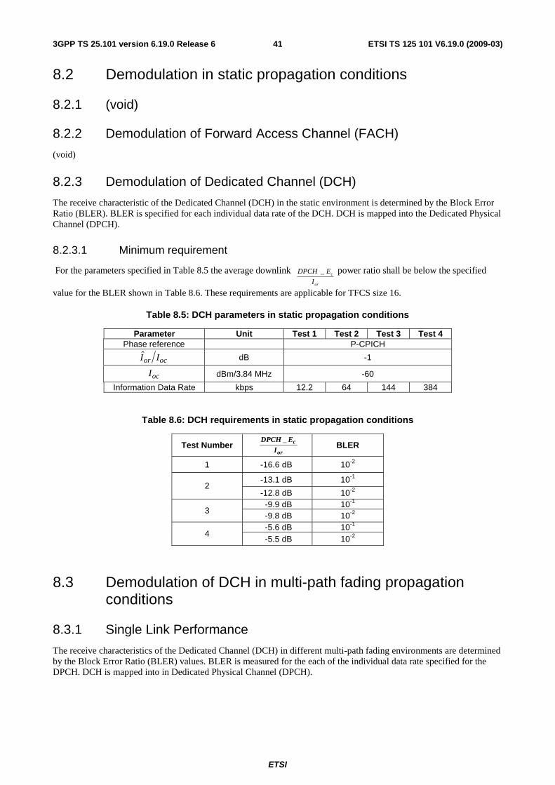
ETSI
ETSI TS 125 101 V6.19.0 (2009-03) 413GPP TS 25.101 version 6.19.0 Release 6
8.2 Demodulation in static propagation conditions
8.2.1 (void)
8.2.2 Demodulation of Forward Access Channel (FACH)
(void)
8.2.3 Demodulation of Dedicated Channel (DCH)
The receive characteristic of the Dedicated Channel (DCH) in the static environment is determined by the Block Error Ratio (BLER). BLER is specified for each individual data rate of the DCH. DCH is mapped into the Dedicated Physical Channel (DPCH).
8.2.3.1 Minimum requirement
For the parameters specified in Table 8.5 the average downlink or
c
I
EDPCH _ power ratio shall be below the specified
value for the BLER shown in Table 8.6. These requirements are applicable for TFCS size 16.
Table 8.5: DCH parameters in static propagation conditions
Parameter Unit Test 1 Test 2 Test 3 Test 4 Phase reference P-CPICH
ocor II dB -1
ocI dBm/3.84 MHz -60
Information Data Rate kbps 12.2 64 144 384
Table 8.6: DCH requirements in static propagation conditions
Test Number or
c
I
EDPCH _ BLER
1 -16.6 dB 10-2
-13.1 dB 10-1 2
-12.8 dB 10-2 -9.9 dB 10-1
3 -9.8 dB 10-2 -5.6 dB 10-1
4 -5.5 dB 10-2
8.3 Demodulation of DCH in multi-path fading propagation conditions
8.3.1 Single Link Performance
The receive characteristics of the Dedicated Channel (DCH) in different multi-path fading environments are determined by the Block Error Ratio (BLER) values. BLER is measured for the each of the individual data rate specified for the DPCH. DCH is mapped into in Dedicated Physical Channel (DPCH).
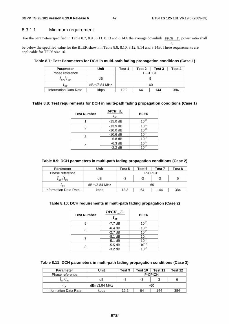
ETSI
ETSI TS 125 101 V6.19.0 (2009-03) 423GPP TS 25.101 version 6.19.0 Release 6
8.3.1.1 Minimum requirement
For the parameters specified in Table 8.7, 8.9 , 8.11, 8.13 and 8.14A the average downlink or
c
I
EDPCH _ power ratio shall
be below the specified value for the BLER shown in Table 8.8, 8.10, 8.12, 8.14 and 8.14B. These requirements are applicable for TFCS size 16.
Table 8.7: Test Parameters for DCH in multi-path fading propagation conditions (Case 1)
Parameter Unit Test 1 Test 2 Test 3 Test 4 Phase reference P-CPICH
ocor II dB 9
ocI dBm/3.84 MHz -60
Information Data Rate kbps 12.2 64 144 384
Table 8.8: Test requirements for DCH in multi-path fading propagation conditions (Case 1)
Test Number or
c
I
EDPCH _ BLER
1 -15.0 dB 10-2 -13.9 dB 10-1 2 -10.0 dB 10-2 -10.6 dB 10-1
3 -6.8 dB 10-2 -6.3 dB 10-1 4 -2.2 dB 10-2
Table 8.9: DCH parameters in multi-path fading propagation conditions (Case 2)
Parameter Unit Test 5 Test 6 Test 7 Test 8 Phase reference P-CPICH
ocor II dB -3 -3 3 6
ocI dBm/3.84 MHz -60
Information Data Rate kbps 12.2 64 144 384
Table 8.10: DCH requirements in multi-path fading propagation (Case 2)
Test Number or
c
I
EDPCH _ BLER
5 -7.7 dB 10-2 -6.4 dB 10-1 6 -2.7 dB 10-2 -8.1 dB 10-1 7 -5.1 dB 10-2 -5.5 dB 10- 1 8 -3.2 dB 10-2
Table 8.11: DCH parameters in multi-path fading propagation conditions (Case 3)
Parameter Unit Test 9 Test 10 Test 11 Test 12 Phase reference P-CPICH
ocor II dB -3 -3 3 6
ocI dBm/3.84 MHz -60
Information Data Rate kbps 12.2 64 144 384
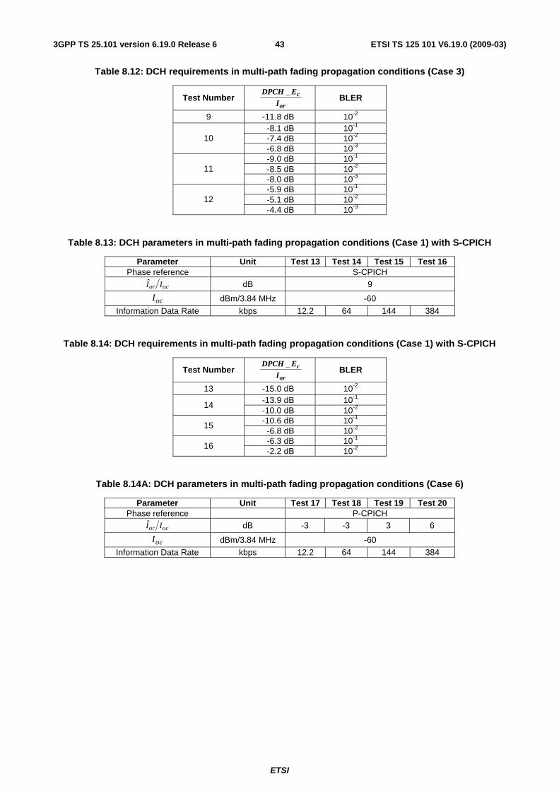
ETSI
ETSI TS 125 101 V6.19.0 (2009-03) 433GPP TS 25.101 version 6.19.0 Release 6
Table 8.12: DCH requirements in multi-path fading propagation conditions (Case 3)
Test Number or
c
I
EDPCH _ BLER
9 -11.8 dB 10-2 -8.1 dB 10-1 -7.4 dB 10-2 10 -6.8 dB 10-3 -9.0 dB 10-1 -8.5 dB 10-2 11 -8.0 dB 10-3 -5.9 dB 10-1 -5.1 dB 10-2 12 -4.4 dB 10-3
Table 8.13: DCH parameters in multi-path fading propagation conditions (Case 1) with S-CPICH
Parameter Unit Test 13 Test 14 Test 15 Test 16 Phase reference S-CPICH
ocor II dB 9
ocI dBm/3.84 MHz -60
Information Data Rate kbps 12.2 64 144 384
Table 8.14: DCH requirements in multi-path fading propagation conditions (Case 1) with S-CPICH
Test Number or
c
I
EDPCH _ BLER
13 -15.0 dB 10-2 -13.9 dB 10-1 14 -10.0 dB 10-2 -10.6 dB 10-1 15
-6.8 dB 10-2 -6.3 dB 10-1 16 -2.2 dB 10-2
Table 8.14A: DCH parameters in multi-path fading propagation conditions (Case 6)
Parameter Unit Test 17 Test 18 Test 19 Test 20 Phase reference P-CPICH
ocor II dB -3 -3 3 6
ocI dBm/3.84 MHz -60
Information Data Rate kbps 12.2 64 144 384
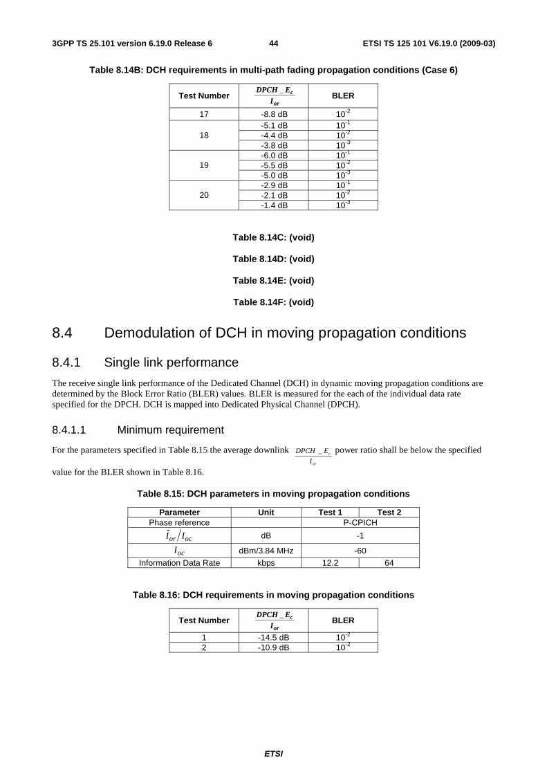
ETSI
ETSI TS 125 101 V6.19.0 (2009-03) 443GPP TS 25.101 version 6.19.0 Release 6
Table 8.14B: DCH requirements in multi-path fading propagation conditions (Case 6)
Test Number or
c
I
EDPCH _ BLER
17 -8.8 dB 10-2 -5.1 dB 10-1 -4.4 dB 10-2 18 -3.8 dB 10-3 -6.0 dB 10-1 -5.5 dB 10-2 19 -5.0 dB 10-3 -2.9 dB 10-1 -2.1 dB 10-2 20 -1.4 dB 10-3
Table 8.14C: (void)
Table 8.14D: (void)
Table 8.14E: (void)
Table 8.14F: (void)
8.4 Demodulation of DCH in moving propagation conditions
8.4.1 Single link performance
The receive single link performance of the Dedicated Channel (DCH) in dynamic moving propagation conditions are determined by the Block Error Ratio (BLER) values. BLER is measured for the each of the individual data rate specified for the DPCH. DCH is mapped into Dedicated Physical Channel (DPCH).
8.4.1.1 Minimum requirement
For the parameters specified in Table 8.15 the average downlink or
c
I
EDPCH _ power ratio shall be below the specified
value for the BLER shown in Table 8.16.
Table 8.15: DCH parameters in moving propagation conditions
Parameter Unit Test 1 Test 2 Phase reference P-CPICH
ocor II dB -1
ocI dBm/3.84 MHz -60
Information Data Rate kbps 12.2 64
Table 8.16: DCH requirements in moving propagation conditions
Test Number or
c
IEDPCH _ BLER
1 -14.5 dB 10-2 2 -10.9 dB 10-2
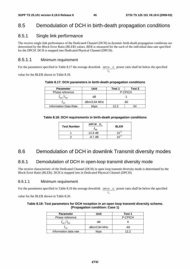
ETSI
ETSI TS 125 101 V6.19.0 (2009-03) 453GPP TS 25.101 version 6.19.0 Release 6
8.5 Demodulation of DCH in birth-death propagation conditions
8.5.1 Single link performance
The receive single link performance of the Dedicated Channel (DCH) in dynamic birth-death propagation conditions are determined by the Block Error Ratio (BLER) values. BER is measured for the each of the individual data rate specified for the DPCH. DCH is mapped into Dedicated Physical Channel (DPCH).
8.5.1.1 Minimum requirement
For the parameters specified in Table 8.17 the average downlink or
c
I
EDPCH _ power ratio shall be below the specified
value for the BLER shown in Table 8.18.
Table 8.17: DCH parameters in birth-death propagation conditions
Parameter Unit Test 1 Test 2 Phase reference P-CPICH
ocor II dB -1
ocI dBm/3.84 MHz -60
Information Data Rate kbps 12.2 64
Table 8.18: DCH requirements in birth-death propagation conditions
Test Number or
c
I
EDPCH _ BLER
1 -12.6 dB 10-2 2 -8.7 dB 10-2
8.6 Demodulation of DCH in downlink Transmit diversity modes
8.6.1 Demodulation of DCH in open-loop transmit diversity mode
The receive characteristic of the Dedicated Channel (DCH) in open loop transmit diversity mode is determined by the Block Error Ratio (BLER). DCH is mapped into in Dedicated Physical Channel (DPCH).
8.6.1.1 Minimum requirement
For the parameters specified in Table 8.19 the average downlink or
c
I
EDPCH _ power ratio shall be below the specified
value for the BLER shown in Table 8.20.
Table 8.19: Test parameters for DCH reception in an open loop transmit diversity scheme. (Propagation condition: Case 1)
Parameter Unit Test 1 Phase reference P-CPICH
ocor II dB 9
ocI dBm/3.84 MHz -60
Information data rate kbps 12.2
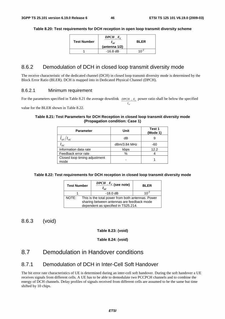
ETSI
ETSI TS 125 101 V6.19.0 (2009-03) 463GPP TS 25.101 version 6.19.0 Release 6
Table 8.20: Test requirements for DCH reception in open loop transmit diversity scheme
Test Number or
c
I
EDPCH _
(antenna 1/2)
BLER
1 -16.8 dB 10-2
8.6.2 Demodulation of DCH in closed loop transmit diversity mode
The receive characteristic of the dedicated channel (DCH) in closed loop transmit diversity mode is determined by the Block Error Ratio (BLER). DCH is mapped into in Dedicated Physical Channel (DPCH).
8.6.2.1 Minimum requirement
For the parameters specified in Table 8.21 the average downlink or
c
I
EDPCH _ power ratio shall be below the specified
value for the BLER shown in Table 8.22.
Table 8.21: Test Parameters for DCH Reception in closed loop transmit diversity mode (Propagation condition: Case 1)
Parameter Unit Test 1 (Mode 1)
ocor II dB 9
ocI dBm/3.84 MHz -60
Information data rate kbps 12.2 Feedback error rate % 4 Closed loop timing adjustment mode - 1
Table 8.22: Test requirements for DCH reception in closed loop transmit diversity mode
Test Number or
c
I
EDPCH _ (see note) BLER
1 -18.0 dB 10-2 NOTE: This is the total power from both antennas. Power
sharing between antennas are feedback mode dependent as specified in TS25.214.
8.6.3 (void)
Table 8.23: (void)
Table 8.24: (void)
8.7 Demodulation in Handover conditions
8.7.1 Demodulation of DCH in Inter-Cell Soft Handover
The bit error rate characteristics of UE is determined during an inter-cell soft handover. During the soft handover a UE receives signals from different cells. A UE has to be able to demodulate two PCCPCH channels and to combine the energy of DCH channels. Delay profiles of signals received from different cells are assumed to be the same but time shifted by 10 chips.
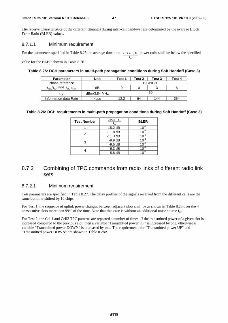
ETSI
ETSI TS 125 101 V6.19.0 (2009-03) 473GPP TS 25.101 version 6.19.0 Release 6
The receive characteristics of the different channels during inter-cell handover are determined by the average Block Error Ratio (BLER) values.
8.7.1.1 Minimum requirement
For the parameters specified in Table 8.25 the average downlink or
c
I
EDPCH _ power ratio shall be below the specified
value for the BLER shown in Table 8.26.
Table 8.25: DCH parameters in multi-path propagation conditions during Soft Handoff (Case 3)
Parameter Unit Test 1 Test 2 Test 3 Test 4 Phase reference P-CPICH
ocor II 1ˆ and ocor II 2
ˆ dB 0 0 3 6
ocI dBm/3.84 MHz -60
Information data Rate kbps 12.2 64 144 384
Table 8.26: DCH requirements in multi-path propagation conditions during Soft Handoff (Case 3)
Test Number or
c
IEDPCH _
BLER
1 -15.2 dB 10-2 -11.8 dB 10-1 2 -11.3 dB 10-2
-9.9 dB 10-1 3 -9.5 dB 10-2 -6.3 dB 10-1 4 -5.8 dB 10-2
8.7.2 Combining of TPC commands from radio links of different radio link sets
8.7.2.1 Minimum requirement
Test parameters are specified in Table 8.27. The delay profiles of the signals received from the different cells are the same but time-shifted by 10 chips.
For Test 1, the sequence of uplink power changes between adjacent slots shall be as shown in Table 8.28 over the 4 consecutive slots more than 99% of the time. Note that this case is without an additional noise source Ioc.
For Test 2, the Cell1 and Cell2 TPC patterns are repeated a number of times. If the transmitted power of a given slot is increased compared to the previous slot, then a variable "Transmitted power UP" is increased by one, otherwise a variable "Transmitted power DOWN" is increased by one. The requirements for "Transmitted power UP" and "Transmitted power DOWN" are shown in Table 8.28A.
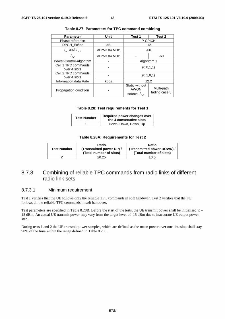
ETSI
ETSI TS 125 101 V6.19.0 (2009-03) 483GPP TS 25.101 version 6.19.0 Release 6
Table 8.27: Parameters for TPC command combining
Parameter Unit Test 1 Test 2 Phase reference - P-CPICH
DPCH_Ec/Ior dB -12
1orI and 2orI dBm/3.84 MHz -60
ocI dBm/3.84 MHz - -60
Power-Control-Algorithm - Algorithm 1 Cell 1 TPC commands
over 4 slots - {0,0,1,1}
Cell 2 TPC commands over 4 slots - {0,1,0,1}
Information data Rate kbps 12.2
Propagation condition - Static without
AWGN source ocI
Multi-path fading case 3
Table 8.28: Test requirements for Test 1
Test Number Required power changes over the 4 consecutive slots
1 Down, Down, Down, Up
Table 8.28A: Requirements for Test 2
Test Number Ratio
(Transmitted power UP) / (Total number of slots)
Ratio (Transmitted power DOWN) /
(Total number of slots) 2 ≥0.25 ≥0.5
8.7.3 Combining of reliable TPC commands from radio links of different radio link sets
8.7.3.1 Minimum requirement
Test 1 verifies that the UE follows only the reliable TPC commands in soft handover. Test 2 verifies that the UE follows all the reliable TPC commands in soft handover.
Test parameters are specified in Table 8.28B. Before the start of the tests, the UE transmit power shall be initialised to -15 dBm. An actual UE transmit power may vary from the target level of -15 dBm due to inaccurate UE output power step.
During tests 1 and 2 the UE transmit power samples, which are defined as the mean power over one timeslot, shall stay 90% of the time within the range defined in Table 8.28C.
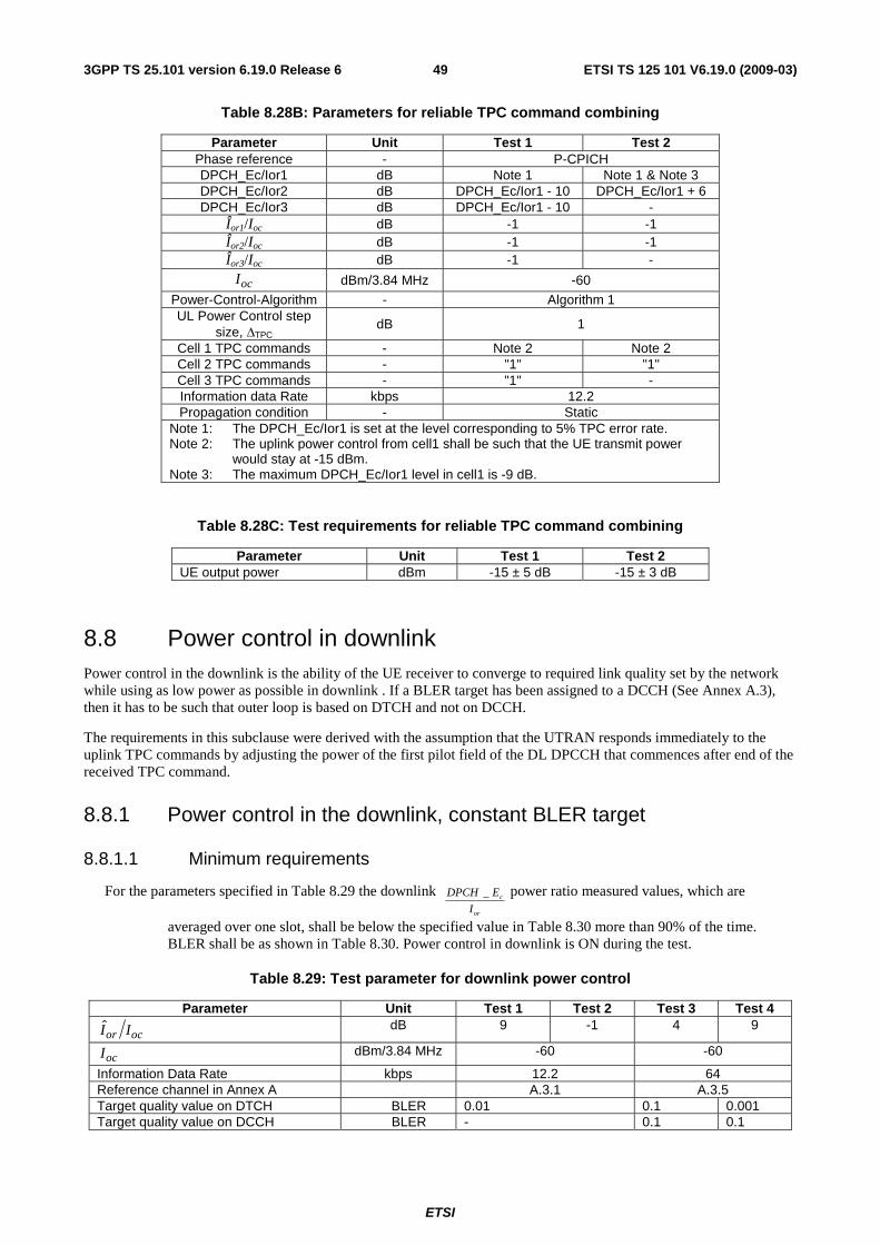
ETSI
ETSI TS 125 101 V6.19.0 (2009-03) 493GPP TS 25.101 version 6.19.0 Release 6
Table 8.28B: Parameters for reliable TPC command combining
Parameter Unit Test 1 Test 2 Phase reference - P-CPICH DPCH_Ec/Ior1 dB Note 1 Note 1 & Note 3 DPCH_Ec/Ior2 dB DPCH_Ec/Ior1 - 10 DPCH_Ec/Ior1 + 6 DPCH_Ec/Ior3 dB DPCH_Ec/Ior1 - 10 -
Îor1/Ioc dB -1 -1 Îor2/Ioc
dB -1 -1 Îor3/Ioc dB -1 -
ocI dBm/3.84 MHz -60
Power-Control-Algorithm - Algorithm 1 UL Power Control step
size, ΔTPC dB 1
Cell 1 TPC commands - Note 2 Note 2 Cell 2 TPC commands - "1" "1" Cell 3 TPC commands - "1" - Information data Rate kbps 12.2 Propagation condition - Static
Note 1: The DPCH_Ec/Ior1 is set at the level corresponding to 5% TPC error rate. Note 2: The uplink power control from cell1 shall be such that the UE transmit power
would stay at -15 dBm. Note 3: The maximum DPCH_Ec/Ior1 level in cell1 is -9 dB.
Table 8.28C: Test requirements for reliable TPC command combining
Parameter Unit Test 1 Test 2 UE output power dBm -15 ± 5 dB -15 ± 3 dB
8.8 Power control in downlink Power control in the downlink is the ability of the UE receiver to converge to required link quality set by the network while using as low power as possible in downlink . If a BLER target has been assigned to a DCCH (See Annex A.3), then it has to be such that outer loop is based on DTCH and not on DCCH.
The requirements in this subclause were derived with the assumption that the UTRAN responds immediately to the uplink TPC commands by adjusting the power of the first pilot field of the DL DPCCH that commences after end of the received TPC command.
8.8.1 Power control in the downlink, constant BLER target
8.8.1.1 Minimum requirements
For the parameters specified in Table 8.29 the downlink or
c
I
EDPCH _ power ratio measured values, which are
averaged over one slot, shall be below the specified value in Table 8.30 more than 90% of the time. BLER shall be as shown in Table 8.30. Power control in downlink is ON during the test.
Table 8.29: Test parameter for downlink power control
Parameter Unit Test 1 Test 2 Test 3 Test 4
ocor II dB 9 -1 4 9
ocI dBm/3.84 MHz -60 -60
Information Data Rate kbps 12.2 64 Reference channel in Annex A A.3.1 A.3.5 Target quality value on DTCH BLER 0.01 0.1 0.001 Target quality value on DCCH BLER - 0.1 0.1
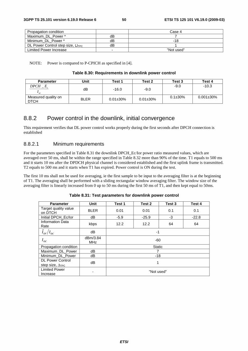
ETSI
ETSI TS 125 101 V6.19.0 (2009-03) 503GPP TS 25.101 version 6.19.0 Release 6
Propagation condition Case 4 Maximum_DL_Power * dB 7 Minimum_DL_Power * dB -18 DL Power Control step size, �TPC dB 1 Limited Power Increase - "Not used"
NOTE: Power is compared to P-CPICH as specified in [4].
Table 8.30: Requirements in downlink power control
Parameter Unit Test 1 Test 2 Test 3 Test 4
or
c
I
EDPCH _ dB -16.0 -9.0
-9.0 -10.3
Measured quality on DTCH BLER 0.01±30% 0.01±30% 0.1±30% 0.001±30%
8.8.2 Power control in the downlink, initial convergence
This requirement verifies that DL power control works properly during the first seconds after DPCH connection is established
8.8.2.1 Minimum requirements
For the parameters specified in Table 8.31 the downlink DPCH_Ec/Ior power ratio measured values, which are averaged over 50 ms, shall be within the range specified in Table 8.32 more than 90% of the time. T1 equals to 500 ms and it starts 10 ms after the DPDCH physical channel is considered established and the first uplink frame is transmitted. T2 equals to 500 ms and it starts when T1 has expired. Power control is ON during the test.
The first 10 ms shall not be used for averaging, ie the first sample to be input to the averaging filter is at the beginning of T1. The averaging shall be performed with a sliding rectangular window averaging filter. The window size of the averaging filter is linearly increased from 0 up to 50 ms during the first 50 ms of T1, and then kept equal to 50ms.
Table 8.31: Test parameters for downlink power control
Parameter Unit Test 1 Test 2 Test 3 Test 4 Target quality value on DTCH BLER 0.01 0.01 0.1 0.1
Initial DPCH_Ec/Ior dB -5.9 -25.9 -3 -22.8 Information Data Rate kbps 12.2 12.2 64 64
ocor II dB -1
ocI dBm/3.84 MHz -60
Propagation condition Static Maximum_DL_Power dB 7 Minimum_DL_Power dB -18 DL Power Control step size, ΔTPC
dB 1
Limited Power Increase - "Not used"
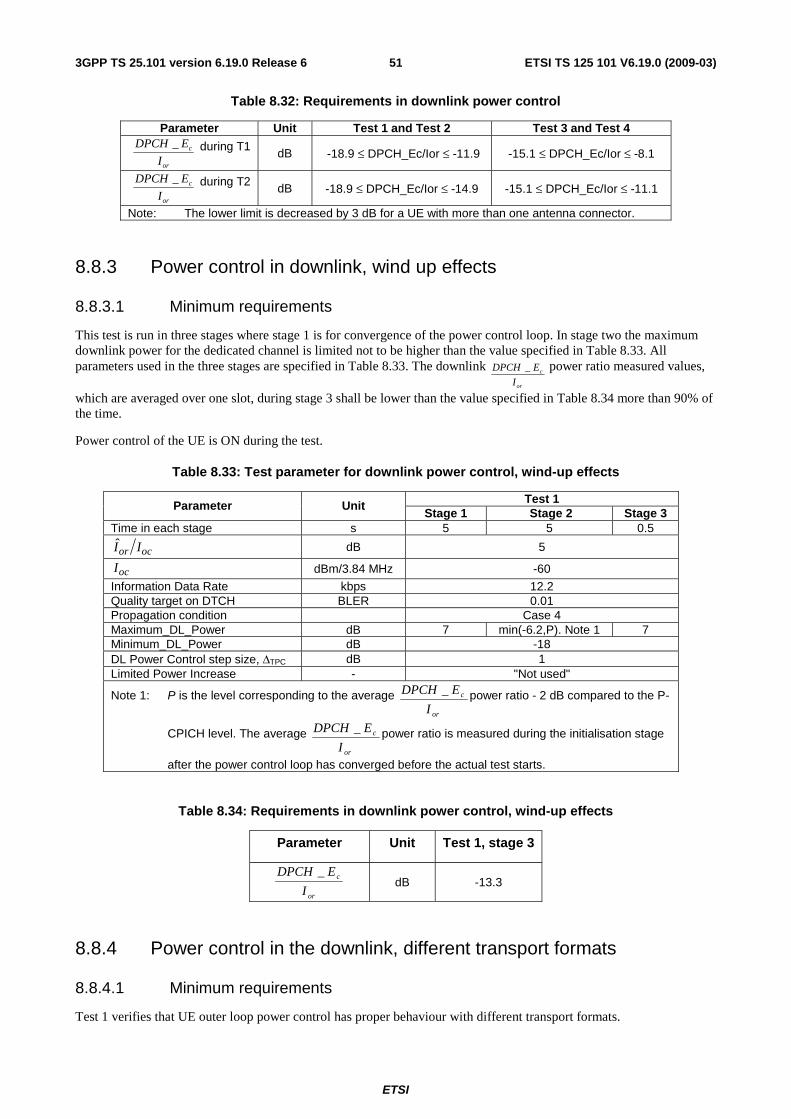
ETSI
ETSI TS 125 101 V6.19.0 (2009-03) 513GPP TS 25.101 version 6.19.0 Release 6
Table 8.32: Requirements in downlink power control
Parameter Unit Test 1 and Test 2 Test 3 and Test 4
or
c
I
EDPCH _ during T1 dB -18.9 ≤ DPCH_Ec/Ior ≤ -11.9 -15.1 ≤ DPCH_Ec/Ior ≤ -8.1
or
c
I
EDPCH _ during T2 dB -18.9 ≤ DPCH_Ec/Ior ≤ -14.9 -15.1 ≤ DPCH_Ec/Ior ≤ -11.1
Note: The lower limit is decreased by 3 dB for a UE with more than one antenna connector.
8.8.3 Power control in downlink, wind up effects
8.8.3.1 Minimum requirements
This test is run in three stages where stage 1 is for convergence of the power control loop. In stage two the maximum downlink power for the dedicated channel is limited not to be higher than the value specified in Table 8.33. All parameters used in the three stages are specified in Table 8.33. The downlink
or
c
I
EDPCH _ power ratio measured values,
which are averaged over one slot, during stage 3 shall be lower than the value specified in Table 8.34 more than 90% of the time.
Power control of the UE is ON during the test.
Table 8.33: Test parameter for downlink power control, wind-up effects
Test 1 Parameter Unit Stage 1 Stage 2 Stage 3
Time in each stage s 5 5 0.5
ocor II dB 5
ocI dBm/3.84 MHz -60
Information Data Rate kbps 12.2 Quality target on DTCH BLER 0.01 Propagation condition Case 4 Maximum_DL_Power dB 7 min(-6.2,P). Note 1 7 Minimum_DL_Power dB -18 DL Power Control step size, ΔTPC dB 1 Limited Power Increase - "Not used"
Note 1: P is the level corresponding to the average or
c
I
EDPCH _ power ratio - 2 dB compared to the P-
CPICH level. The average or
c
I
EDPCH _ power ratio is measured during the initialisation stage
after the power control loop has converged before the actual test starts.
Table 8.34: Requirements in downlink power control, wind-up effects
Parameter Unit Test 1, stage 3
or
c
I
EDPCH _ dB -13.3
8.8.4 Power control in the downlink, different transport formats
8.8.4.1 Minimum requirements
Test 1 verifies that UE outer loop power control has proper behaviour with different transport formats.
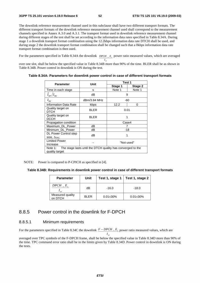
ETSI
ETSI TS 125 101 V6.19.0 (2009-03) 523GPP TS 25.101 version 6.19.0 Release 6
The downlink reference measurement channel used in this subclause shall have two different transport formats. The different transport formats of the downlink reference measurement channel used shall correspond to the measurement channels specified in Annex A.3.0 and A.3.1. The transport format used in downlink reference measurement channel during different stages of the test shall be set according to the information data rates specified in Table 8.34A. During stage 1 a downlink transport format combination using the 12.2kbps information data rate DTCH shall be used, and during stage 2 the downlink transport format combination shall be changed such that a 0kbps information data rate transport format combination is then used.
For the parameters specified in Table 8.34A the downlink or
c
I
EDPCH _ power ratio measured values, which are averaged
over one slot, shall be below the specified value in Table 8.34B more than 90% of the time. BLER shall be as shown in Table 8.34B. Power control in downlink is ON during the test.
Table 8.34A: Parameters for downlink power control in case of different transport formats
Test 1 Parameter Unit Stage 1 Stage 2
Time in each stage s Note 1 Note 1
ocor II dB 9
ocI dBm/3.84 MHz -60
Information Data Rate kbps 12.2 0 Quality target on DTCH BLER 0.01
Quality target on DCCH BLER 1
Propagation condition Case4 Maximum_DL_Power dB 7 Minimum_DL_Power dB -18 DL Power Control step size, ΔTPC
dB 1
Limited Power Increase - "Not used"
Note 1: The stage lasts until the DTCH quality has converged to the quality target
NOTE: Power is compared to P-CPICH as specified in [4].
Table 8.34B: Requirements in downlink power control in case of different transport formats
Parameter Unit Test 1, stage 1 Test 1, stage 2
or
c
I
EDPCH _ dB -16.0 -18.0
Measured quality on DTCH
BLER 0.01±30% 0.01±30%
8.8.5 Power control in the downlink for F-DPCH
8.8.5.1 Minimum requirements
For the parameters specified in Table 8.34C the downlink or
c
I
EDPCHF _− power ratio measured values, which are
averaged over TPC symbols of the F-DPCH frame, shall be below the specified value in Table 8.34D more than 90% of the time. TPC command error ratio shall be in the limits given by Table 8.34D. Power control in downlink is ON during the tests.
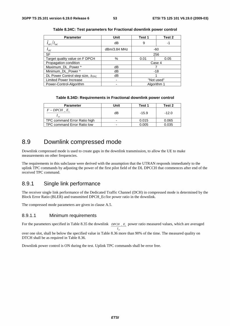
ETSI
ETSI TS 125 101 V6.19.0 (2009-03) 533GPP TS 25.101 version 6.19.0 Release 6
Table 8.34C: Test parameters for Fractional downlink power control
Parameter Unit Test 1 Test 2
ocor II dB 9 -1
ocI dBm/3.84 MHz -60
SF 256 Target quality value on F DPCH % 0.01 0.05 Propagation condition Case 4 Maximum_DL_Power * dB 7 Minimum_DL_Power * dB -18 DL Power Control step size, ΔTPC dB 1 Limited Power Increase - "Not used" Power-Control-Algorithm - Algorithm 1
Table 8.34D: Requirements in Fractional downlink power control
Parameter Unit Test 1 Test 2
or
c
I
EDPCHF _− dB -15.9 -12.0
TPC command Error Ratio high - 0.015 0.065 TPC command Error Ratio low - 0.005 0.035
8.9 Downlink compressed mode Downlink compressed mode is used to create gaps in the downlink transmission, to allow the UE to make measurements on other frequencies.
The requirements in this subclause were derived with the assumption that the UTRAN responds immediately to the uplink TPC commands by adjusting the power of the first pilot field of the DL DPCCH that commences after end of the received TPC command.
8.9.1 Single link performance
The receiver single link performance of the Dedicated Traffic Channel (DCH) in compressed mode is determined by the Block Error Ratio (BLER) and transmitted DPCH_Ec/Ior power ratio in the downlink.
The compressed mode parameters are given in clause A.5.
8.9.1.1 Minimum requirements
For the parameters specified in Table 8.35 the downlink or
c
I
EDPCH _ power ratio measured values, which are averaged
over one slot, shall be below the specified value in Table 8.36 more than 90% of the time. The measured quality on DTCH shall be as required in Table 8.36.
Downlink power control is ON during the test. Uplink TPC commands shall be error free.
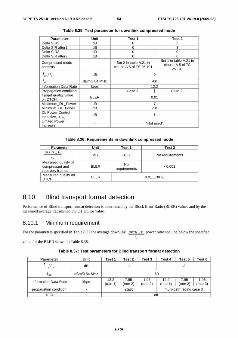
ETSI
ETSI TS 125 101 V6.19.0 (2009-03) 543GPP TS 25.101 version 6.19.0 Release 6
Table 8.35: Test parameter for downlink compressed mode
Parameter Unit Test 1 Test 2 Delta SIR1 dB 0 3 Delta SIR after1 dB 0 3 Delta SIR2 dB 0 0 Delta SIR after2 dB 0 0
Compressed mode patterns
- Set 2 in table A.21 in clause A.5 of TS 25.101
Set 1 in table A.21 in clause A.5 of TS
25.101
ocor II dB 9
ocI dBm/3.84 MHz -60
Information Data Rate kbps 12.2 Propagation condition Case 3 Case 2 Target quality value on DTCH BLER 0.01
Maximum_DL_Power dB 7 Minimum_DL_Power dB -18 DL Power Control step size, ΔTPC
dB 1
Limited Power Increase - "Not used"
Table 8.36: Requirements in downlink compressed mode
Parameter Unit Test 1 Test 2
or
c
I
EDPCH _ dB -13.7 No requirements
Measured quality of compressed and recovery frames
BLER No requirements
<0.001
Measured quality on DTCH
BLER 0.01 ± 30 %
8.10 Blind transport format detection Performance of Blind transport format detection is determined by the Block Error Ratio (BLER) values and by the measured average transmitted DPCH_Ec/Ior value.
8.10.1 Minimum requirement
For the parameters specified in Table 8.37 the average downlink or
c
I
EDPCH _ power ratio shall be below the specified
value for the BLER shown in Table 8.38.
Table 8.37: Test parameters for Blind transport format detection
Parameter Unit Test 1 Test 2 Test 3 Test 4 Test 5 Test 6
ocor II dB -1 -3
ocI dBm/3.84 MHz -60
Information Data Rate kbps 12.2 (rate 1)
7.95 (rate 2)
1.95 (rate 3)
12.2 (rate 1)
7.95 (rate 2)
1.95 (rate 3)
propagation condition - static multi-path fading case 3
TFCI - off
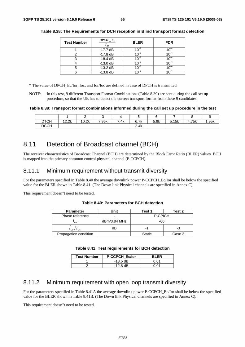
ETSI
ETSI TS 125 101 V6.19.0 (2009-03) 553GPP TS 25.101 version 6.19.0 Release 6
Table 8.38: The Requirements for DCH reception in Blind transport format detection
Test Number or
c
IEDPCH _ BLER FDR
1 -17.7 dB 10-2 10-4 2 -17.8 dB 10-2 10-4 3 -18.4 dB 10-2 10-4 4 -13.0 dB 10-2 10-4 5 -13.2 dB 10-2 10-4 6 -13.8 dB 10-2 10-4
* The value of DPCH_Ec/Ior, Ioc, and Ior/Ioc are defined in case of DPCH is transmitted
NOTE: In this test, 9 different Transport Format Combinations (Table 8.39) are sent during the call set up procedure, so that the UE has to detect the correct transport format from these 9 candidates.
Table 8.39: Transport format combinations informed during the call set up procedure in the test
1 2 3 4 5 6 7 8 9 DTCH 12.2k 10.2k 7.95k 7.4k 6.7k 5.9k 5.15k 4.75k 1.95k DCCH 2.4k
8.11 Detection of Broadcast channel (BCH) The receiver characteristics of Broadcast Channel (BCH) are determined by the Block Error Ratio (BLER) values. BCH is mapped into the primary common control physical channel (P-CCPCH).
8.11.1 Minimum requirement without transmit diversity
For the parameters specified in Table 8.40 the average downlink power P-CCPCH_Ec/Ior shall be below the specified value for the BLER shown in Table 8.41. (The Down link Physical channels are specified in Annex C).
This requirement doesn"t need to be tested.
Table 8.40: Parameters for BCH detection
Parameter Unit Test 1 Test 2 Phase reference - P-CPICH
ocI dBm/3.84 MHz -60
ocor II dB -1 -3
Propagation condition Static Case 3
Table 8.41: Test requirements for BCH detection
Test Number P-CCPCH_Ec/Ior BLER 1 -18.5 dB 0.01 2 -12.8 dB 0.01
8.11.2 Minimum requirement with open loop transmit diversity
For the parameters specified in Table 8.41A the average downlink power P-CCPCH_Ec/Ior shall be below the specified value for the BLER shown in Table 8.41B. (The Down link Physical channels are specified in Annex C).
This requirement doesn"t need to be tested.
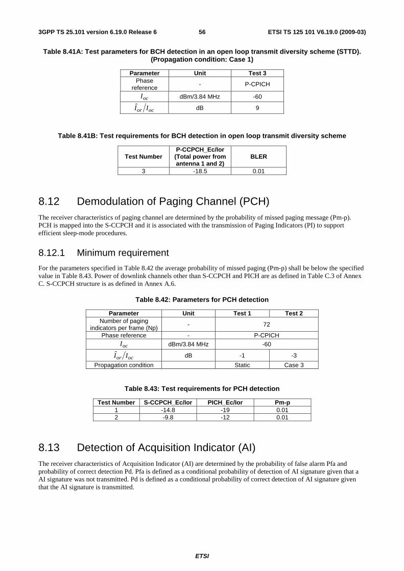
ETSI
ETSI TS 125 101 V6.19.0 (2009-03) 563GPP TS 25.101 version 6.19.0 Release 6
Table 8.41A: Test parameters for BCH detection in an open loop transmit diversity scheme (STTD). (Propagation condition: Case 1)
Parameter Unit Test 3 Phase
reference - P-CPICH
ocI dBm/3.84 MHz -60
ocor II dB 9
Table 8.41B: Test requirements for BCH detection in open loop transmit diversity scheme
Test Number P-CCPCH_Ec/Ior
(Total power from antenna 1 and 2)
BLER
3 -18.5 0.01
8.12 Demodulation of Paging Channel (PCH) The receiver characteristics of paging channel are determined by the probability of missed paging message (Pm-p). PCH is mapped into the S-CCPCH and it is associated with the transmission of Paging Indicators (PI) to support efficient sleep-mode procedures.
8.12.1 Minimum requirement
For the parameters specified in Table 8.42 the average probability of missed paging (Pm-p) shall be below the specified value in Table 8.43. Power of downlink channels other than S-CCPCH and PICH are as defined in Table C.3 of Annex C. S-CCPCH structure is as defined in Annex A.6.
Table 8.42: Parameters for PCH detection
Parameter Unit Test 1 Test 2 Number of paging
indicators per frame (Np) - 72
Phase reference - P-CPICH
ocI dBm/3.84 MHz -60
ocor II dB -1 -3
Propagation condition Static Case 3
Table 8.43: Test requirements for PCH detection
Test Number S-CCPCH_Ec/Ior PICH_Ec/Ior Pm-p 1 -14.8 -19 0.01 2 -9.8 -12 0.01
8.13 Detection of Acquisition Indicator (AI) The receiver characteristics of Acquisition Indicator (AI) are determined by the probability of false alarm Pfa and probability of correct detection Pd. Pfa is defined as a conditional probability of detection of AI signature given that a AI signature was not transmitted. Pd is defined as a conditional probability of correct detection of AI signature given that the AI signature is transmitted.
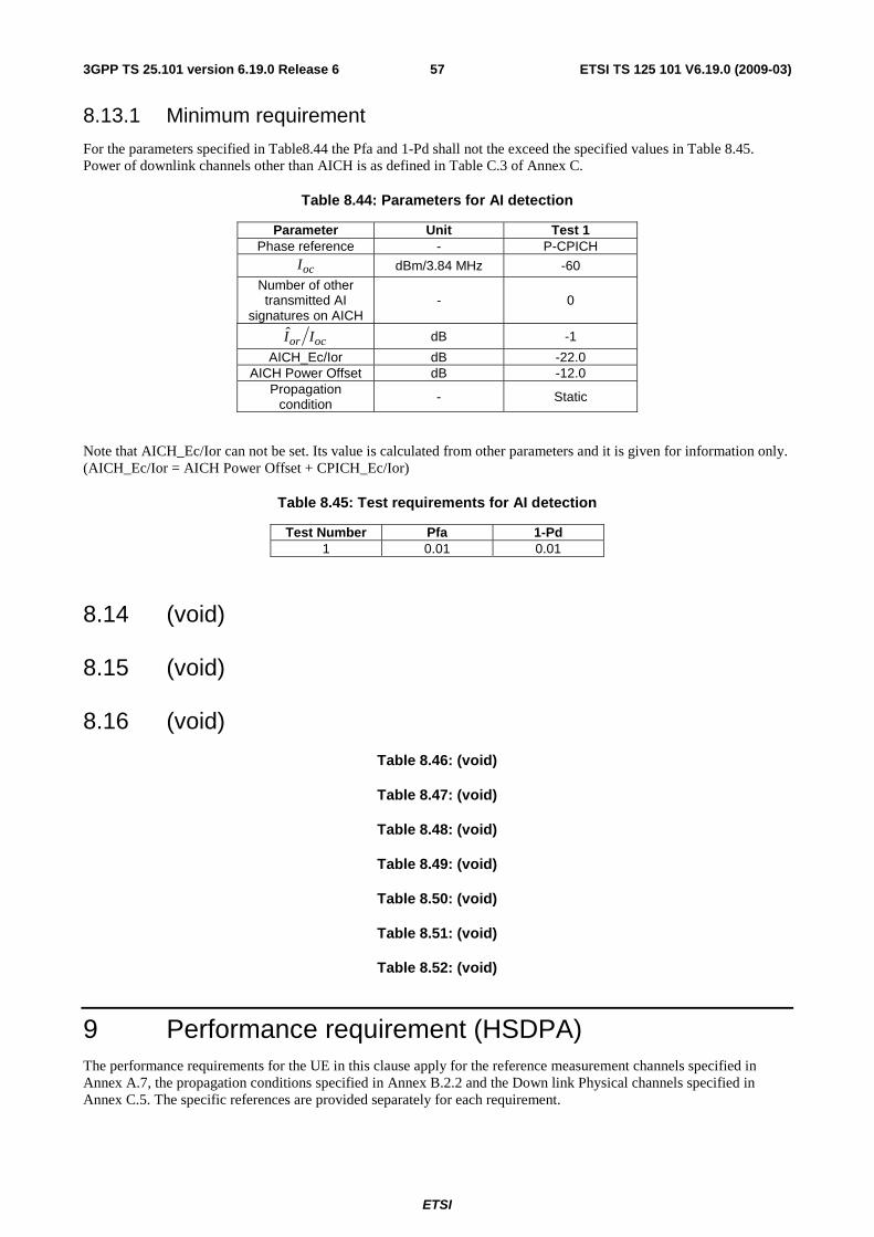
ETSI
ETSI TS 125 101 V6.19.0 (2009-03) 573GPP TS 25.101 version 6.19.0 Release 6
8.13.1 Minimum requirement
For the parameters specified in Table8.44 the Pfa and 1-Pd shall not the exceed the specified values in Table 8.45. Power of downlink channels other than AICH is as defined in Table C.3 of Annex C.
Table 8.44: Parameters for AI detection
Parameter Unit Test 1 Phase reference - P-CPICH
ocI dBm/3.84 MHz -60
Number of other transmitted AI
signatures on AICH - 0
ocor II dB -1
AICH_Ec/Ior dB -22.0 AICH Power Offset dB -12.0
Propagation condition - Static
Note that AICH_Ec/Ior can not be set. Its value is calculated from other parameters and it is given for information only. (AICH_Ec/Ior = AICH Power Offset + CPICH_Ec/Ior)
Table 8.45: Test requirements for AI detection
Test Number Pfa 1-Pd 1 0.01 0.01
8.14 (void)
8.15 (void)
8.16 (void)
Table 8.46: (void)
Table 8.47: (void)
Table 8.48: (void)
Table 8.49: (void)
Table 8.50: (void)
Table 8.51: (void)
Table 8.52: (void)
9 Performance requirement (HSDPA) The performance requirements for the UE in this clause apply for the reference measurement channels specified in Annex A.7, the propagation conditions specified in Annex B.2.2 and the Down link Physical channels specified in Annex C.5. The specific references are provided separately for each requirement.
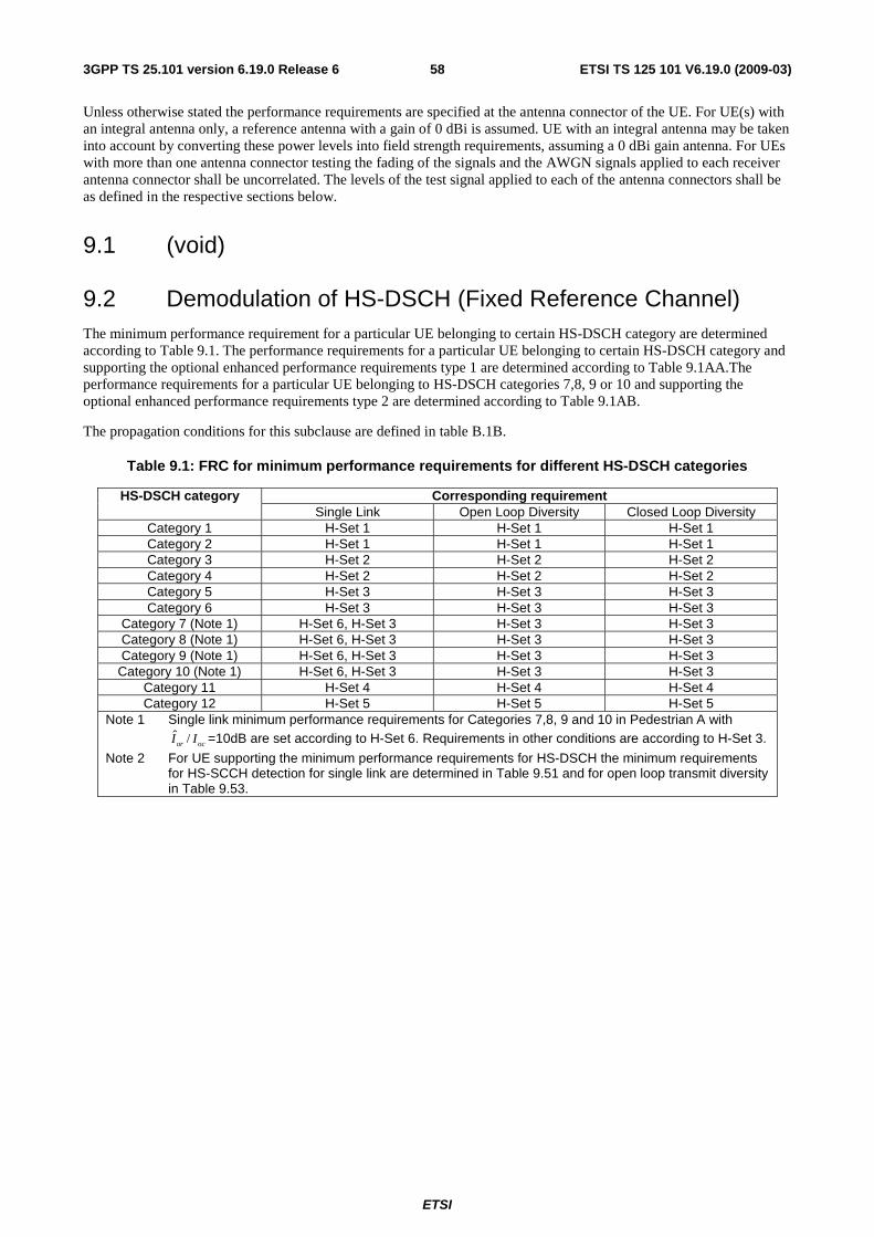
ETSI
ETSI TS 125 101 V6.19.0 (2009-03) 583GPP TS 25.101 version 6.19.0 Release 6
Unless otherwise stated the performance requirements are specified at the antenna connector of the UE. For UE(s) with an integral antenna only, a reference antenna with a gain of 0 dBi is assumed. UE with an integral antenna may be taken into account by converting these power levels into field strength requirements, assuming a 0 dBi gain antenna. For UEs with more than one antenna connector testing the fading of the signals and the AWGN signals applied to each receiver antenna connector shall be uncorrelated. The levels of the test signal applied to each of the antenna connectors shall be as defined in the respective sections below.
9.1 (void)
9.2 Demodulation of HS-DSCH (Fixed Reference Channel) The minimum performance requirement for a particular UE belonging to certain HS-DSCH category are determined according to Table 9.1. The performance requirements for a particular UE belonging to certain HS-DSCH category and supporting the optional enhanced performance requirements type 1 are determined according to Table 9.1AA.The performance requirements for a particular UE belonging to HS-DSCH categories 7,8, 9 or 10 and supporting the optional enhanced performance requirements type 2 are determined according to Table 9.1AB.
The propagation conditions for this subclause are defined in table B.1B.
Table 9.1: FRC for minimum performance requirements for different HS-DSCH categories
Corresponding requirement HS-DSCH category Single Link Open Loop Diversity Closed Loop Diversity
Category 1 H-Set 1 H-Set 1 H-Set 1 Category 2 H-Set 1 H-Set 1 H-Set 1 Category 3 H-Set 2 H-Set 2 H-Set 2 Category 4 H-Set 2 H-Set 2 H-Set 2 Category 5 H-Set 3 H-Set 3 H-Set 3 Category 6 H-Set 3 H-Set 3 H-Set 3
Category 7 (Note 1) H-Set 6, H-Set 3 H-Set 3 H-Set 3 Category 8 (Note 1) H-Set 6, H-Set 3 H-Set 3 H-Set 3 Category 9 (Note 1) H-Set 6, H-Set 3 H-Set 3 H-Set 3
Category 10 (Note 1) H-Set 6, H-Set 3 H-Set 3 H-Set 3 Category 11 H-Set 4 H-Set 4 H-Set 4 Category 12 H-Set 5 H-Set 5 H-Set 5
Note 1 Single link minimum performance requirements for Categories 7,8, 9 and 10 in Pedestrian A with ˆ /or ocI I =10dB are set according to H-Set 6. Requirements in other conditions are according to H-Set 3.
Note 2 For UE supporting the minimum performance requirements for HS-DSCH the minimum requirements for HS-SCCH detection for single link are determined in Table 9.51 and for open loop transmit diversity in Table 9.53.
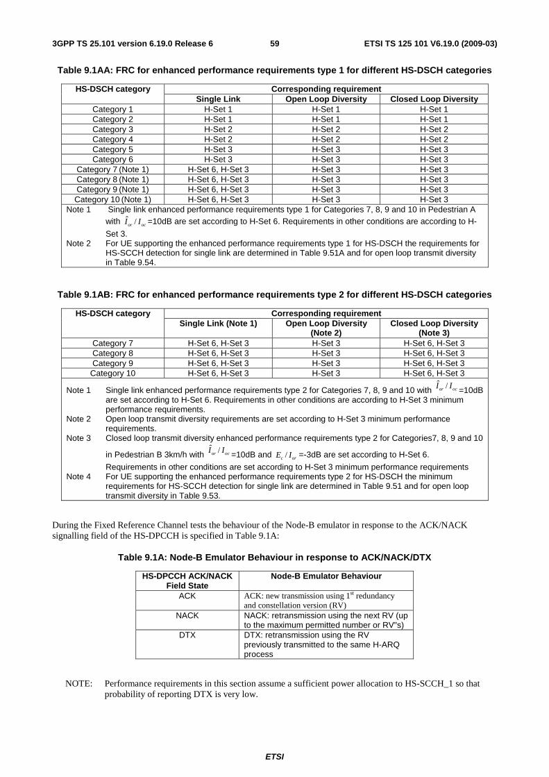
ETSI
ETSI TS 125 101 V6.19.0 (2009-03) 593GPP TS 25.101 version 6.19.0 Release 6
Table 9.1AA: FRC for enhanced performance requirements type 1 for different HS-DSCH categories
Corresponding requirement HS-DSCH category Single Link Open Loop Diversity Closed Loop Diversity
Category 1 H-Set 1 H-Set 1 H-Set 1 Category 2 H-Set 1 H-Set 1 H-Set 1 Category 3 H-Set 2 H-Set 2 H-Set 2 Category 4 H-Set 2 H-Set 2 H-Set 2 Category 5 H-Set 3 H-Set 3 H-Set 3 Category 6 H-Set 3 H-Set 3 H-Set 3
Category 7 (Note 1) H-Set 6, H-Set 3 H-Set 3 H-Set 3 Category 8 (Note 1) H-Set 6, H-Set 3 H-Set 3 H-Set 3 Category 9 (Note 1) H-Set 6, H-Set 3 H-Set 3 H-Set 3 Category 10 (Note 1) H-Set 6, H-Set 3 H-Set 3 H-Set 3
Note 1 Single link enhanced performance requirements type 1 for Categories 7, 8, 9 and 10 in Pedestrian A with ˆ /or ocI I =10dB are set according to H-Set 6. Requirements in other conditions are according to H-
Set 3. Note 2 For UE supporting the enhanced performance requirements type 1 for HS-DSCH the requirements for
HS-SCCH detection for single link are determined in Table 9.51A and for open loop transmit diversity in Table 9.54.
Table 9.1AB: FRC for enhanced performance requirements type 2 for different HS-DSCH categories
Corresponding requirement HS-DSCH category Single Link (Note 1) Open Loop Diversity
(Note 2) Closed Loop Diversity
(Note 3) Category 7 H-Set 6, H-Set 3 H-Set 3 H-Set 6, H-Set 3 Category 8 H-Set 6, H-Set 3 H-Set 3 H-Set 6, H-Set 3 Category 9 H-Set 6, H-Set 3 H-Set 3 H-Set 6, H-Set 3
Category 10 H-Set 6, H-Set 3 H-Set 3 H-Set 6, H-Set 3
Note 1 Single link enhanced performance requirements type 2 for Categories 7, 8, 9 and 10 with ˆ /or ocI I =10dB
are set according to H-Set 6. Requirements in other conditions are according to H-Set 3 minimum performance requirements.
Note 2 Open loop transmit diversity requirements are set according to H-Set 3 minimum performance requirements.
Note 3 Closed loop transmit diversity enhanced performance requirements type 2 for Categories7, 8, 9 and 10
in Pedestrian B 3km/h with ˆ /or ocI I =10dB and /c orE I =-3dB are set according to H-Set 6.
Requirements in other conditions are set according to H-Set 3 minimum performance requirements Note 4 For UE supporting the enhanced performance requirements type 2 for HS-DSCH the minimum
requirements for HS-SCCH detection for single link are determined in Table 9.51 and for open loop transmit diversity in Table 9.53.
During the Fixed Reference Channel tests the behaviour of the Node-B emulator in response to the ACK/NACK signalling field of the HS-DPCCH is specified in Table 9.1A:
Table 9.1A: Node-B Emulator Behaviour in response to ACK/NACK/DTX
HS-DPCCH ACK/NACK Field State
Node-B Emulator Behaviour
ACK ACK: new transmission using 1st redundancy and constellation version (RV)
NACK NACK: retransmission using the next RV (up to the maximum permitted number or RV"s)
DTX DTX: retransmission using the RV previously transmitted to the same H-ARQ process
NOTE: Performance requirements in this section assume a sufficient power allocation to HS-SCCH_1 so that probability of reporting DTX is very low.
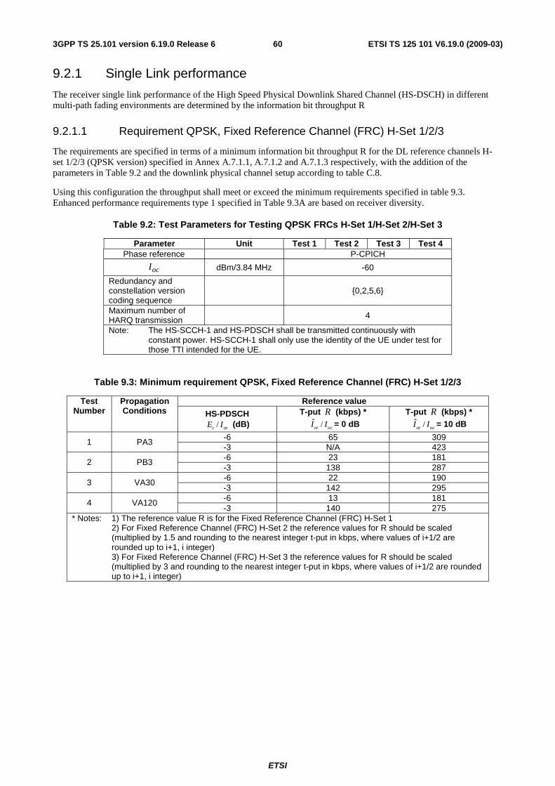
ETSI
ETSI TS 125 101 V6.19.0 (2009-03) 603GPP TS 25.101 version 6.19.0 Release 6
9.2.1 Single Link performance
The receiver single link performance of the High Speed Physical Downlink Shared Channel (HS-DSCH) in different multi-path fading environments are determined by the information bit throughput R
9.2.1.1 Requirement QPSK, Fixed Reference Channel (FRC) H-Set 1/2/3
The requirements are specified in terms of a minimum information bit throughput R for the DL reference channels H-set 1/2/3 (QPSK version) specified in Annex A.7.1.1, A.7.1.2 and A.7.1.3 respectively, with the addition of the parameters in Table 9.2 and the downlink physical channel setup according to table C.8.
Using this configuration the throughput shall meet or exceed the minimum requirements specified in table 9.3. Enhanced performance requirements type 1 specified in Table 9.3A are based on receiver diversity.
Table 9.2: Test Parameters for Testing QPSK FRCs H-Set 1/H-Set 2/H-Set 3
Parameter Unit Test 1 Test 2 Test 3 Test 4 Phase reference P-CPICH
ocI dBm/3.84 MHz -60
Redundancy and constellation version coding sequence
{0,2,5,6}
Maximum number of HARQ transmission 4
Note: The HS-SCCH-1 and HS-PDSCH shall be transmitted continuously with constant power. HS-SCCH-1 shall only use the identity of the UE under test for those TTI intended for the UE.
Table 9.3: Minimum requirement QPSK, Fixed Reference Channel (FRC) H-Set 1/2/3
Reference value Test Number
Propagation Conditions HS-PDSCH
/c orE I (dB) T-put R (kbps) *
ˆ /or ocI I = 0 dB T-put R (kbps) *
ˆ /or ocI I = 10 dB
-6 65 309 1 PA3 -3 N/A 423 -6 23 181 2 PB3 -3 138 287 -6 22 190 3 VA30 -3 142 295 -6 13 181 4 VA120 -3 140 275
* Notes: 1) The reference value R is for the Fixed Reference Channel (FRC) H-Set 1 2) For Fixed Reference Channel (FRC) H-Set 2 the reference values for R should be scaled
(multiplied by 1.5 and rounding to the nearest integer t-put in kbps, where values of i+1/2 are rounded up to i+1, i integer)
3) For Fixed Reference Channel (FRC) H-Set 3 the reference values for R should be scaled (multiplied by 3 and rounding to the nearest integer t-put in kbps, where values of i+1/2 are rounded up to i+1, i integer)
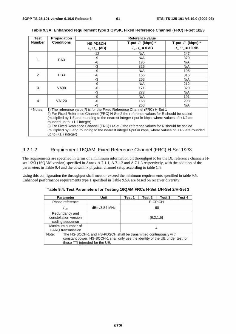
ETSI
ETSI TS 125 101 V6.19.0 (2009-03) 613GPP TS 25.101 version 6.19.0 Release 6
Table 9.3A: Enhanced requirement type 1 QPSK, Fixed Reference Channel (FRC) H-Set 1/2/3
Reference value Test Number
Propagation Conditions HS-PDSCH
/c orE I (dB) T-put R (kbps) *
ˆ /or ocI I = 0 dB T-put R (kbps) *
ˆ /or ocI I = 10 dB
-12 N/A 247 -9 N/A 379 -6 195 N/A
1 PA3
-3 329 N/A -9 N/A 195 -6 156 316 2 PB3 -3 263 N/A -9 N/A 212 -6 171 329 3 VA30 -3 273 N/A -9 N/A 191 -6 168 293 4 VA120 -3 263 N/A
* Notes: 1) The reference value R is for the Fixed Reference Channel (FRC) H-Set 1 2) For Fixed Reference Channel (FRC) H-Set 2 the reference values for R should be scaled
(multiplied by 1.5 and rounding to the nearest integer t-put in kbps, where values of i+1/2 are rounded up to i+1, i integer)
3) For Fixed Reference Channel (FRC) H-Set 3 the reference values for R should be scaled (multiplied by 3 and rounding to the nearest integer t-put in kbps, where values of i+1/2 are rounded up to i+1, i integer)
9.2.1.2 Requirement 16QAM, Fixed Reference Channel (FRC) H-Set 1/2/3
The requirements are specified in terms of a minimum information bit throughput R for the DL reference channels H-set 1/2/3 (16QAM version) specified in Annex A.7.1.1, A.7.1.2 and A.7.1.3 respectively, with the addition of the parameters in Table 9.4 and the downlink physical channel setup according to table C.8.
Using this configuration the throughput shall meet or exceed the minimum requirements specified in table 9.5. Enhanced performance requirements type 1 specified in Table 9.5A are based on receiver diversity.
Table 9.4: Test Parameters for Testing 16QAM FRCs H-Set 1/H-Set 2/H-Set 3
Parameter Unit Test 1 Test 2 Test 3 Test 4 Phase reference P-CPICH
ocI dBm/3.84 MHz -60
Redundancy and constellation version
coding sequence {6,2,1,5}
Maximum number of HARQ transmission
4
Note: The HS-SCCH-1 and HS-PDSCH shall be transmitted continuously with constant power. HS-SCCH-1 shall only use the identity of the UE under test for those TTI intended for the UE.
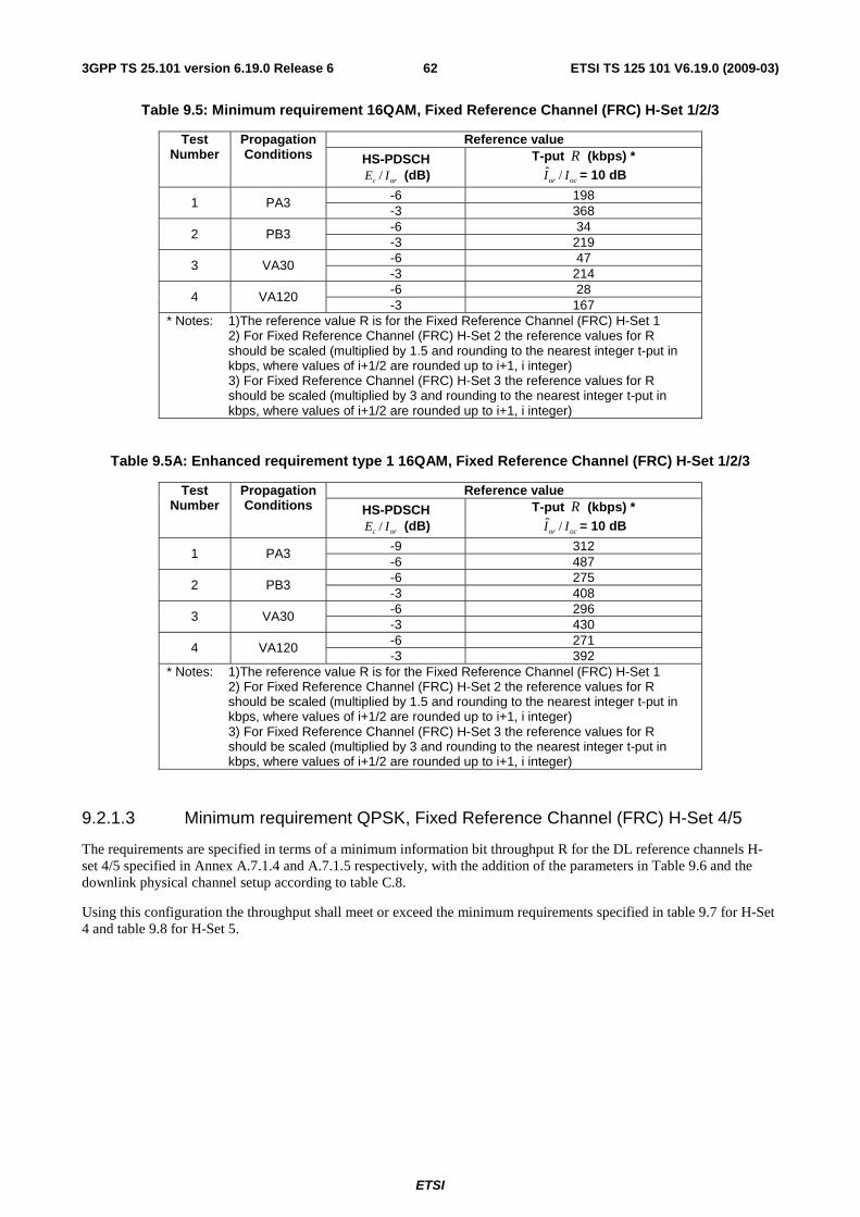
ETSI
ETSI TS 125 101 V6.19.0 (2009-03) 623GPP TS 25.101 version 6.19.0 Release 6
Table 9.5: Minimum requirement 16QAM, Fixed Reference Channel (FRC) H-Set 1/2/3
Reference value Test Number
Propagation Conditions HS-PDSCH
/c orE I (dB) T-put R (kbps) *
ˆ /or ocI I = 10 dB
-6 198 1 PA3 -3 368 -6 34 2 PB3 -3 219 -6 47 3 VA30 -3 214 -6 28 4 VA120 -3 167
* Notes: 1)The reference value R is for the Fixed Reference Channel (FRC) H-Set 1 2) For Fixed Reference Channel (FRC) H-Set 2 the reference values for R
should be scaled (multiplied by 1.5 and rounding to the nearest integer t-put in kbps, where values of i+1/2 are rounded up to i+1, i integer)
3) For Fixed Reference Channel (FRC) H-Set 3 the reference values for R should be scaled (multiplied by 3 and rounding to the nearest integer t-put in kbps, where values of i+1/2 are rounded up to i+1, i integer)
Table 9.5A: Enhanced requirement type 1 16QAM, Fixed Reference Channel (FRC) H-Set 1/2/3
Reference value Test Number
Propagation Conditions HS-PDSCH
/c orE I (dB) T-put R (kbps) *
ˆ /or ocI I = 10 dB
-9 312 1 PA3 -6 487 -6 275 2 PB3 -3 408 -6 296 3 VA30 -3 430 -6 271 4 VA120 -3 392
* Notes: 1)The reference value R is for the Fixed Reference Channel (FRC) H-Set 1 2) For Fixed Reference Channel (FRC) H-Set 2 the reference values for R
should be scaled (multiplied by 1.5 and rounding to the nearest integer t-put in kbps, where values of i+1/2 are rounded up to i+1, i integer)
3) For Fixed Reference Channel (FRC) H-Set 3 the reference values for R should be scaled (multiplied by 3 and rounding to the nearest integer t-put in kbps, where values of i+1/2 are rounded up to i+1, i integer)
9.2.1.3 Minimum requirement QPSK, Fixed Reference Channel (FRC) H-Set 4/5
The requirements are specified in terms of a minimum information bit throughput R for the DL reference channels H-set 4/5 specified in Annex A.7.1.4 and A.7.1.5 respectively, with the addition of the parameters in Table 9.6 and the downlink physical channel setup according to table C.8.
Using this configuration the throughput shall meet or exceed the minimum requirements specified in table 9.7 for H-Set 4 and table 9.8 for H-Set 5.
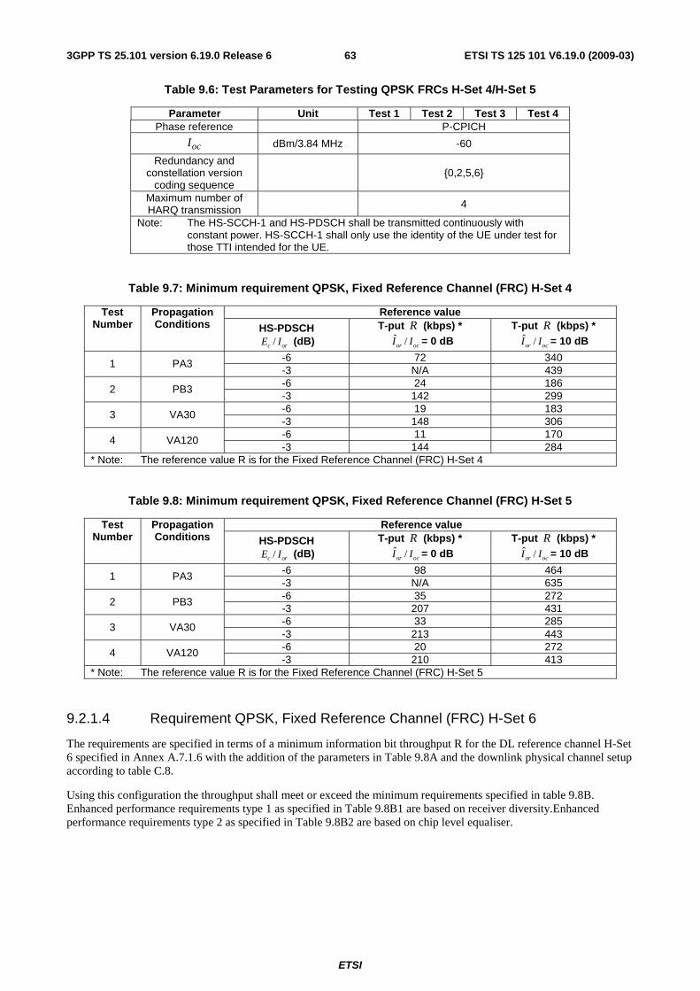
ETSI
ETSI TS 125 101 V6.19.0 (2009-03) 633GPP TS 25.101 version 6.19.0 Release 6
Table 9.6: Test Parameters for Testing QPSK FRCs H-Set 4/H-Set 5
Parameter Unit Test 1 Test 2 Test 3 Test 4 Phase reference P-CPICH
ocI dBm/3.84 MHz -60
Redundancy and constellation version
coding sequence {0,2,5,6}
Maximum number of HARQ transmission 4
Note: The HS-SCCH-1 and HS-PDSCH shall be transmitted continuously with constant power. HS-SCCH-1 shall only use the identity of the UE under test for those TTI intended for the UE.
Table 9.7: Minimum requirement QPSK, Fixed Reference Channel (FRC) H-Set 4
Reference value Test Number
Propagation Conditions HS-PDSCH
/c orE I (dB) T-put R (kbps) *
ˆ /or ocI I = 0 dB T-put R (kbps) *
ˆ /or ocI I = 10 dB
-6 72 340 1 PA3 -3 N/A 439 -6 24 186 2 PB3 -3 142 299 -6 19 183 3 VA30 -3 148 306 -6 11 170 4 VA120 -3 144 284
* Note: The reference value R is for the Fixed Reference Channel (FRC) H-Set 4
Table 9.8: Minimum requirement QPSK, Fixed Reference Channel (FRC) H-Set 5
Reference value Test Number
Propagation Conditions HS-PDSCH
/c orE I (dB) T-put R (kbps) *
ˆ /or ocI I = 0 dB T-put R (kbps) *
ˆ /or ocI I = 10 dB
-6 98 464 1 PA3 -3 N/A 635 -6 35 272 2 PB3 -3 207 431 -6 33 285 3 VA30 -3 213 443 -6 20 272 4 VA120 -3 210 413
* Note: The reference value R is for the Fixed Reference Channel (FRC) H-Set 5
9.2.1.4 Requirement QPSK, Fixed Reference Channel (FRC) H-Set 6
The requirements are specified in terms of a minimum information bit throughput R for the DL reference channel H-Set 6 specified in Annex A.7.1.6 with the addition of the parameters in Table 9.8A and the downlink physical channel setup according to table C.8.
Using this configuration the throughput shall meet or exceed the minimum requirements specified in table 9.8B. Enhanced performance requirements type 1 as specified in Table 9.8B1 are based on receiver diversity.Enhanced performance requirements type 2 as specified in Table 9.8B2 are based on chip level equaliser.
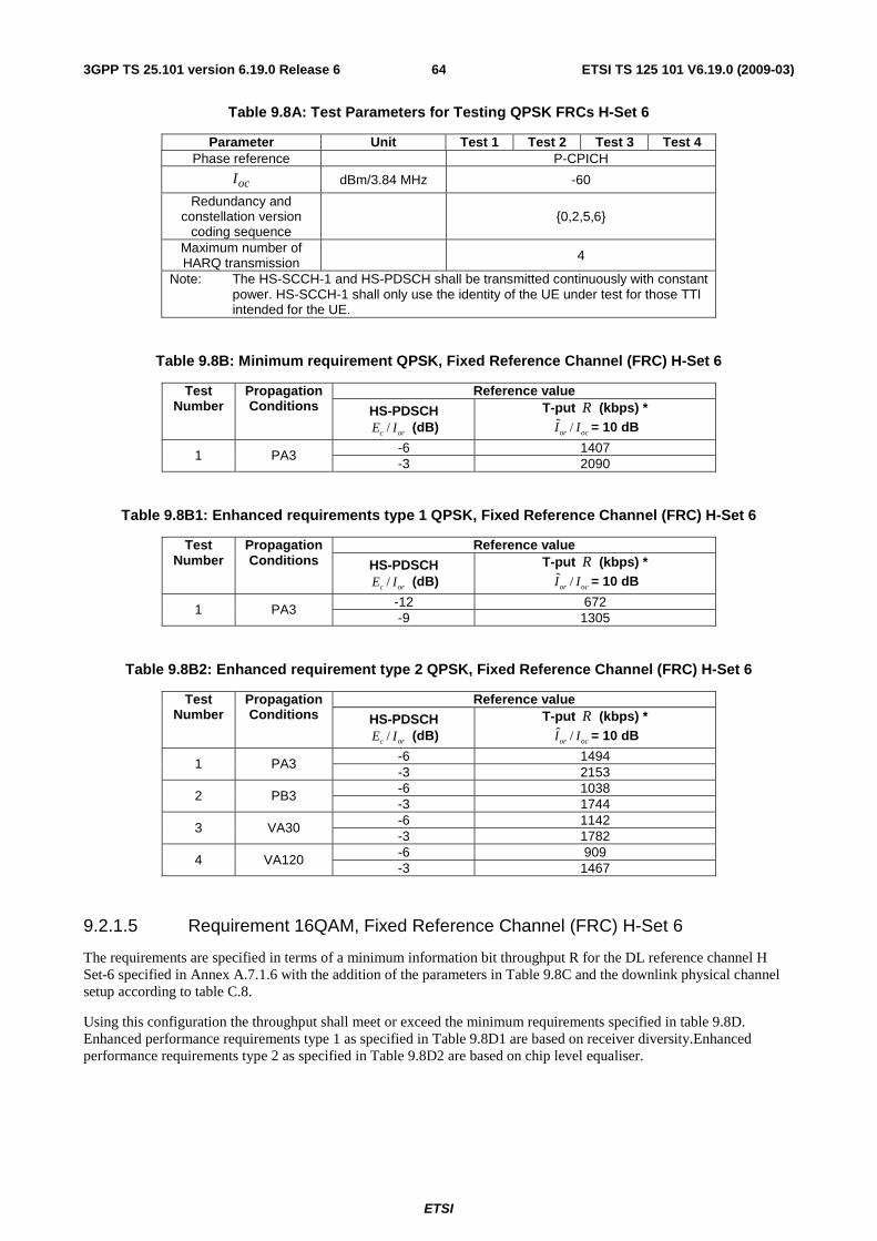
ETSI
ETSI TS 125 101 V6.19.0 (2009-03) 643GPP TS 25.101 version 6.19.0 Release 6
Table 9.8A: Test Parameters for Testing QPSK FRCs H-Set 6
Parameter Unit Test 1 Test 2 Test 3 Test 4 Phase reference P-CPICH
ocI dBm/3.84 MHz -60
Redundancy and constellation version
coding sequence {0,2,5,6}
Maximum number of HARQ transmission 4
Note: The HS-SCCH-1 and HS-PDSCH shall be transmitted continuously with constant power. HS-SCCH-1 shall only use the identity of the UE under test for those TTI intended for the UE.
Table 9.8B: Minimum requirement QPSK, Fixed Reference Channel (FRC) H-Set 6
Reference value Test Number
Propagation Conditions HS-PDSCH
/c orE I (dB) T-put R (kbps) *
ˆ /or ocI I = 10 dB
-6 1407 1 PA3 -3 2090
Table 9.8B1: Enhanced requirements type 1 QPSK, Fixed Reference Channel (FRC) H-Set 6
Reference value Test Number
Propagation Conditions HS-PDSCH
/c orE I (dB) T-put R (kbps) *
ˆ /or ocI I = 10 dB
-12 672 1 PA3 -9 1305
Table 9.8B2: Enhanced requirement type 2 QPSK, Fixed Reference Channel (FRC) H-Set 6
Reference value Test Number
Propagation Conditions HS-PDSCH
/c orE I (dB) T-put R (kbps) *
ˆ /or ocI I = 10 dB
-6 1494 1 PA3 -3 2153 -6 1038 2 PB3 -3 1744 -6 1142 3 VA30 -3 1782 -6 909 4 VA120 -3 1467
9.2.1.5 Requirement 16QAM, Fixed Reference Channel (FRC) H-Set 6
The requirements are specified in terms of a minimum information bit throughput R for the DL reference channel H Set-6 specified in Annex A.7.1.6 with the addition of the parameters in Table 9.8C and the downlink physical channel setup according to table C.8.
Using this configuration the throughput shall meet or exceed the minimum requirements specified in table 9.8D. Enhanced performance requirements type 1 as specified in Table 9.8D1 are based on receiver diversity.Enhanced performance requirements type 2 as specified in Table 9.8D2 are based on chip level equaliser.
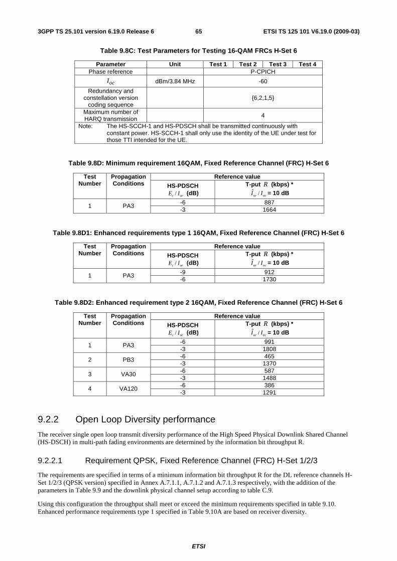
ETSI
ETSI TS 125 101 V6.19.0 (2009-03) 653GPP TS 25.101 version 6.19.0 Release 6
Table 9.8C: Test Parameters for Testing 16-QAM FRCs H-Set 6
Parameter Unit Test 1 Test 2 Test 3 Test 4 Phase reference P-CPICH
ocI dBm/3.84 MHz -60
Redundancy and constellation version
coding sequence {6,2,1,5}
Maximum number of HARQ transmission 4
Note: The HS-SCCH-1 and HS-PDSCH shall be transmitted continuously with constant power. HS-SCCH-1 shall only use the identity of the UE under test for those TTI intended for the UE.
Table 9.8D: Minimum requirement 16QAM, Fixed Reference Channel (FRC) H-Set 6
Reference value Test Number
Propagation Conditions HS-PDSCH
/c orE I (dB) T-put R (kbps) *
ˆ /or ocI I = 10 dB
-6 887 1 PA3 -3 1664
Table 9.8D1: Enhanced requirements type 1 16QAM, Fixed Reference Channel (FRC) H-Set 6
Reference value Test Number
Propagation Conditions HS-PDSCH
/c orE I (dB) T-put R (kbps) *
ˆ /or ocI I = 10 dB
-9 912 1 PA3 -6 1730
Table 9.8D2: Enhanced requirement type 2 16QAM, Fixed Reference Channel (FRC) H-Set 6
Reference value Test Number
Propagation Conditions HS-PDSCH
/c orE I (dB) T-put R (kbps) *
ˆ /or ocI I = 10 dB
-6 991 1 PA3 -3 1808 -6 465 2 PB3 -3 1370 -6 587 3 VA30 -3 1488 -6 386 4 VA120 -3 1291
9.2.2 Open Loop Diversity performance
The receiver single open loop transmit diversity performance of the High Speed Physical Downlink Shared Channel (HS-DSCH) in multi-path fading environments are determined by the information bit throughput R.
9.2.2.1 Requirement QPSK, Fixed Reference Channel (FRC) H-Set 1/2/3
The requirements are specified in terms of a minimum information bit throughput R for the DL reference channels H-Set 1/2/3 (QPSK version) specified in Annex A.7.1.1, A.7.1.2 and A.7.1.3 respectively, with the addition of the parameters in Table 9.9 and the downlink physical channel setup according to table C.9.
Using this configuration the throughput shall meet or exceed the minimum requirements specified in table 9.10. Enhanced performance requirements type 1 specified in Table 9.10A are based on receiver diversity.
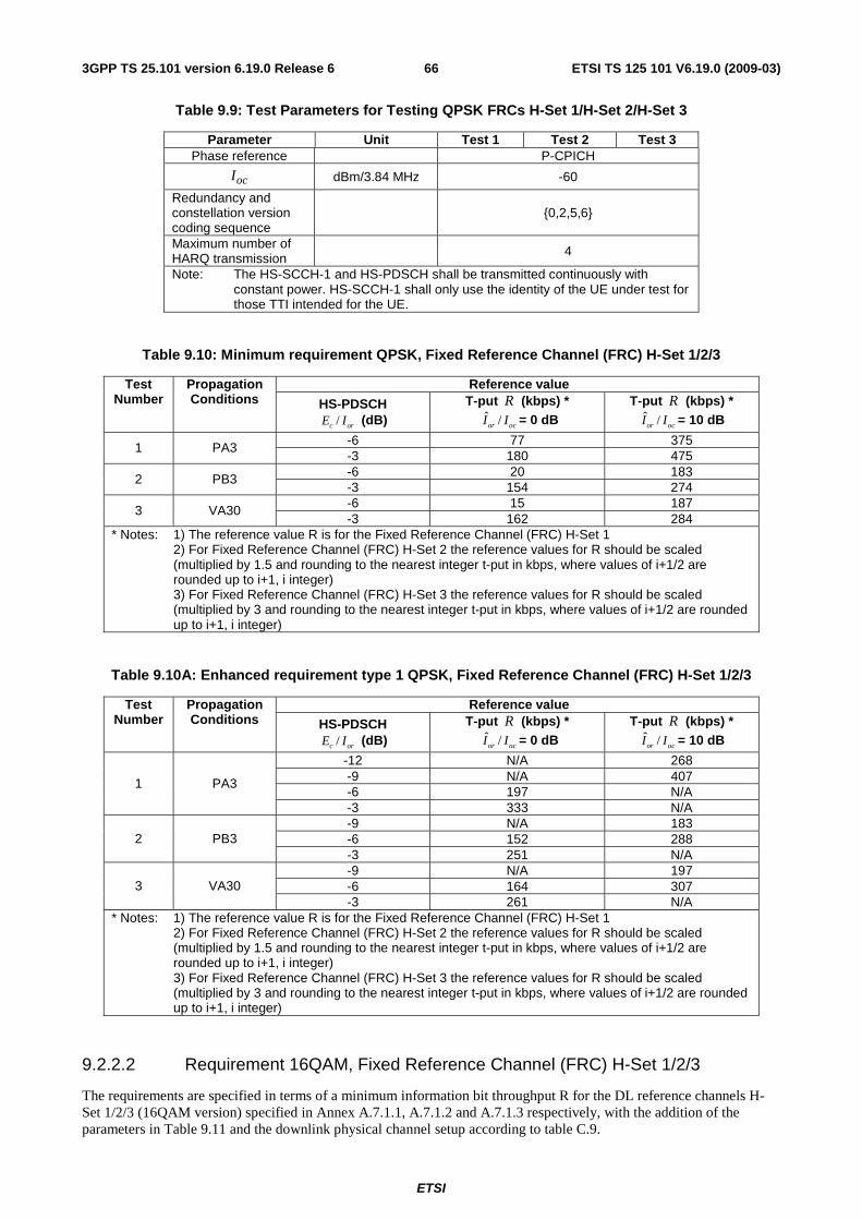
ETSI
ETSI TS 125 101 V6.19.0 (2009-03) 663GPP TS 25.101 version 6.19.0 Release 6
Table 9.9: Test Parameters for Testing QPSK FRCs H-Set 1/H-Set 2/H-Set 3
Parameter Unit Test 1 Test 2 Test 3 Phase reference P-CPICH
ocI dBm/3.84 MHz -60
Redundancy and constellation version coding sequence
{0,2,5,6}
Maximum number of HARQ transmission
4
Note: The HS-SCCH-1 and HS-PDSCH shall be transmitted continuously with constant power. HS-SCCH-1 shall only use the identity of the UE under test for those TTI intended for the UE.
Table 9.10: Minimum requirement QPSK, Fixed Reference Channel (FRC) H-Set 1/2/3
Reference value Test Number
Propagation Conditions HS-PDSCH
/c orE I (dB) T-put R (kbps) *
ˆ /or ocI I = 0 dB T-put R (kbps) *
ˆ /or ocI I = 10 dB
-6 77 375 1 PA3 -3 180 475 -6 20 183 2 PB3 -3 154 274 -6 15 187 3 VA30 -3 162 284
* Notes: 1) The reference value R is for the Fixed Reference Channel (FRC) H-Set 1 2) For Fixed Reference Channel (FRC) H-Set 2 the reference values for R should be scaled
(multiplied by 1.5 and rounding to the nearest integer t-put in kbps, where values of i+1/2 are rounded up to i+1, i integer)
3) For Fixed Reference Channel (FRC) H-Set 3 the reference values for R should be scaled (multiplied by 3 and rounding to the nearest integer t-put in kbps, where values of i+1/2 are rounded up to i+1, i integer)
Table 9.10A: Enhanced requirement type 1 QPSK, Fixed Reference Channel (FRC) H-Set 1/2/3
Reference value Test Number
Propagation Conditions HS-PDSCH
/c orE I (dB) T-put R (kbps) *
ˆ /or ocI I = 0 dB T-put R (kbps) *
ˆ /or ocI I = 10 dB
-12 N/A 268 -9 N/A 407 -6 197 N/A
1 PA3
-3 333 N/A -9 N/A 183 -6 152 288 2 PB3 -3 251 N/A -9 N/A 197 -6 164 307 3 VA30 -3 261 N/A
* Notes: 1) The reference value R is for the Fixed Reference Channel (FRC) H-Set 1 2) For Fixed Reference Channel (FRC) H-Set 2 the reference values for R should be scaled
(multiplied by 1.5 and rounding to the nearest integer t-put in kbps, where values of i+1/2 are rounded up to i+1, i integer)
3) For Fixed Reference Channel (FRC) H-Set 3 the reference values for R should be scaled (multiplied by 3 and rounding to the nearest integer t-put in kbps, where values of i+1/2 are rounded up to i+1, i integer)
9.2.2.2 Requirement 16QAM, Fixed Reference Channel (FRC) H-Set 1/2/3
The requirements are specified in terms of a minimum information bit throughput R for the DL reference channels H-Set 1/2/3 (16QAM version) specified in Annex A.7.1.1, A.7.1.2 and A.7.1.3 respectively, with the addition of the parameters in Table 9.11 and the downlink physical channel setup according to table C.9.
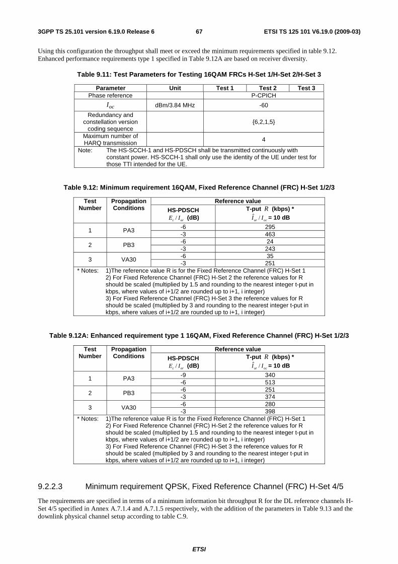
ETSI
ETSI TS 125 101 V6.19.0 (2009-03) 673GPP TS 25.101 version 6.19.0 Release 6
Using this configuration the throughput shall meet or exceed the minimum requirements specified in table 9.12. Enhanced performance requirements type 1 specified in Table 9.12A are based on receiver diversity.
Table 9.11: Test Parameters for Testing 16QAM FRCs H-Set 1/H-Set 2/H-Set 3
Parameter Unit Test 1 Test 2 Test 3 Phase reference P-CPICH
ocI dBm/3.84 MHz -60
Redundancy and constellation version
coding sequence
{6,2,1,5}
Maximum number of HARQ transmission
4
Note: The HS-SCCH-1 and HS-PDSCH shall be transmitted continuously with constant power. HS-SCCH-1 shall only use the identity of the UE under test for those TTI intended for the UE.
Table 9.12: Minimum requirement 16QAM, Fixed Reference Channel (FRC) H-Set 1/2/3
Reference value Test Number
Propagation Conditions HS-PDSCH
/c orE I (dB) T-put R (kbps) *
ˆ /or ocI I = 10 dB
-6 295 1 PA3 -3 463 -6 24 2 PB3 -3 243 -6 35 3 VA30 -3 251
* Notes: 1)The reference value R is for the Fixed Reference Channel (FRC) H-Set 1 2) For Fixed Reference Channel (FRC) H-Set 2 the reference values for R
should be scaled (multiplied by 1.5 and rounding to the nearest integer t-put in kbps, where values of i+1/2 are rounded up to i+1, i integer)
3) For Fixed Reference Channel (FRC) H-Set 3 the reference values for R should be scaled (multiplied by 3 and rounding to the nearest integer t-put in kbps, where values of i+1/2 are rounded up to i+1, i integer)
Table 9.12A: Enhanced requirement type 1 16QAM, Fixed Reference Channel (FRC) H-Set 1/2/3
Reference value Test Number
Propagation Conditions HS-PDSCH
/c orE I (dB) T-put R (kbps) *
ˆ /or ocI I = 10 dB
-9 340 1 PA3 -6 513 -6 251 2 PB3 -3 374 -6 280 3 VA30 -3 398
* Notes: 1)The reference value R is for the Fixed Reference Channel (FRC) H-Set 1 2) For Fixed Reference Channel (FRC) H-Set 2 the reference values for R
should be scaled (multiplied by 1.5 and rounding to the nearest integer t-put in kbps, where values of i+1/2 are rounded up to i+1, i integer)
3) For Fixed Reference Channel (FRC) H-Set 3 the reference values for R should be scaled (multiplied by 3 and rounding to the nearest integer t-put in kbps, where values of i+1/2 are rounded up to i+1, i integer)
9.2.2.3 Minimum requirement QPSK, Fixed Reference Channel (FRC) H-Set 4/5
The requirements are specified in terms of a minimum information bit throughput R for the DL reference channels H-Set 4/5 specified in Annex A.7.1.4 and A.7.1.5 respectively, with the addition of the parameters in Table 9.13 and the downlink physical channel setup according to table C.9.
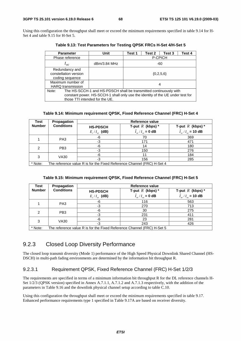
ETSI
ETSI TS 125 101 V6.19.0 (2009-03) 683GPP TS 25.101 version 6.19.0 Release 6
Using this configuration the throughput shall meet or exceed the minimum requirements specified in table 9.14 for H-Set 4 and table 9.15 for H-Set 5.
Table 9.13: Test Parameters for Testing QPSK FRCs H-Set 4/H-Set 5
Parameter Unit Test 1 Test 2 Test 3 Test 4 Phase reference P-CPICH
ocI dBm/3.84 MHz -60
Redundancy and constellation version
coding sequence {0,2,5,6}
Maximum number of HARQ transmission
4
Note: The HS-SCCH-1 and HS-PDSCH shall be transmitted continuously with constant power. HS-SCCH-1 shall only use the identity of the UE under test for those TTI intended for the UE.
Table 9.14: Minimum requirement QPSK, Fixed Reference Channel (FRC) H-Set 4
Reference value Test Number
Propagation Conditions HS-PDSCH
/c orE I (dB) T-put R (kbps) *
ˆ /or ocI I = 0 dB T-put R (kbps) *
ˆ /or ocI I = 10 dB
-6 70 369 1 PA3 -3 171 471 -6 14 180 2 PB3 -3 150 276 -6 11 184 3 VA30 -3 156 285
* Note: The reference value R is for the Fixed Reference Channel (FRC) H-Set 4
Table 9.15: Minimum requirement QPSK, Fixed Reference Channel (FRC) H-Set 5
Reference value Test Number
Propagation Conditions HS-PDSCH
/c orE I (dB) T-put R (kbps) *
ˆ /or ocI I = 0 dB T-put R (kbps) *
ˆ /or ocI I = 10 dB
-6 116 563 1 PA3 -3 270 713 -6 30 275 2 PB3 -3 231 411 -6 23 281 3 VA30 -3 243 426
* Note: The reference value R is for the Fixed Reference Channel (FRC) H-Set 5
9.2.3 Closed Loop Diversity Performance
The closed loop transmit diversity (Mode 1) performance of the High Speed Physical Downlink Shared Channel (HS-DSCH) in multi-path fading environments are determined by the information bit throughput R.
9.2.3.1 Requirement QPSK, Fixed Reference Channel (FRC) H-Set 1/2/3
The requirements are specified in terms of a minimum information bit throughput R for the DL reference channels H-Set 1/2/3 (QPSK version) specified in Annex A.7.1.1, A.7.1.2 and A.7.1.3 respectively, with the addition of the parameters in Table 9.16 and the downlink physical channel setup according to table C.10.
Using this configuration the throughput shall meet or exceed the minimum requirements specified in table 9.17. Enhanced performance requirements type 1 specified in Table 9.17A are based on receiver diversity.
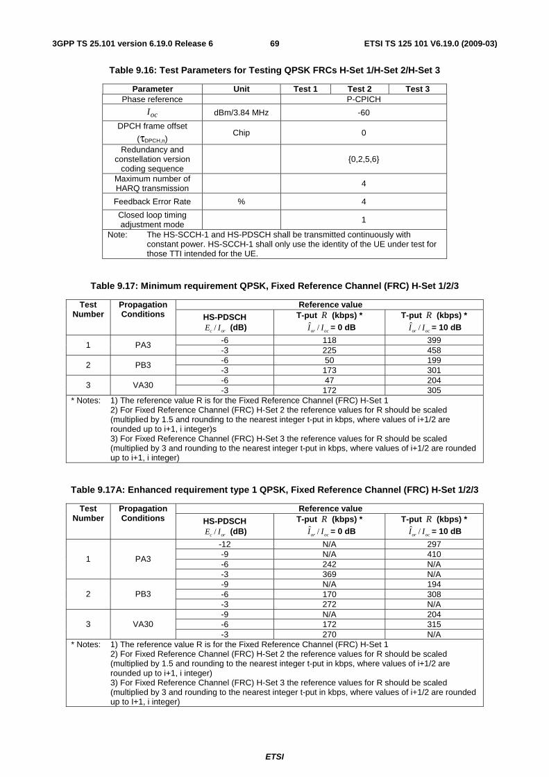
ETSI
ETSI TS 125 101 V6.19.0 (2009-03) 693GPP TS 25.101 version 6.19.0 Release 6
Table 9.16: Test Parameters for Testing QPSK FRCs H-Set 1/H-Set 2/H-Set 3
Parameter Unit Test 1 Test 2 Test 3 Phase reference P-CPICH
ocI dBm/3.84 MHz -60
DPCH frame offset
(τDPCH,n) Chip 0
Redundancy and constellation version
coding sequence
{0,2,5,6}
Maximum number of HARQ transmission
4
Feedback Error Rate % 4
Closed loop timing adjustment mode 1
Note: The HS-SCCH-1 and HS-PDSCH shall be transmitted continuously with constant power. HS-SCCH-1 shall only use the identity of the UE under test for those TTI intended for the UE.
Table 9.17: Minimum requirement QPSK, Fixed Reference Channel (FRC) H-Set 1/2/3
Reference value Test Number
Propagation Conditions HS-PDSCH
/c orE I (dB) T-put R (kbps) *
ˆ /or ocI I = 0 dB T-put R (kbps) *
ˆ /or ocI I = 10 dB
-6 118 399 1 PA3 -3 225 458 -6 50 199 2 PB3 -3 173 301 -6 47 204 3 VA30 -3 172 305
* Notes: 1) The reference value R is for the Fixed Reference Channel (FRC) H-Set 1 2) For Fixed Reference Channel (FRC) H-Set 2 the reference values for R should be scaled
(multiplied by 1.5 and rounding to the nearest integer t-put in kbps, where values of i+1/2 are rounded up to i+1, i integer)s
3) For Fixed Reference Channel (FRC) H-Set 3 the reference values for R should be scaled (multiplied by 3 and rounding to the nearest integer t-put in kbps, where values of i+1/2 are rounded up to i+1, i integer)
Table 9.17A: Enhanced requirement type 1 QPSK, Fixed Reference Channel (FRC) H-Set 1/2/3
Reference value Test Number
Propagation Conditions HS-PDSCH
/c orE I (dB) T-put R (kbps) *
ˆ /or ocI I = 0 dB T-put R (kbps) *
ˆ /or ocI I = 10 dB
-12 N/A 297 -9 N/A 410 -6 242 N/A
1 PA3
-3 369 N/A -9 N/A 194 -6 170 308 2 PB3 -3 272 N/A -9 N/A 204 -6 172 315 3 VA30 -3 270 N/A
* Notes: 1) The reference value R is for the Fixed Reference Channel (FRC) H-Set 1 2) For Fixed Reference Channel (FRC) H-Set 2 the reference values for R should be scaled
(multiplied by 1.5 and rounding to the nearest integer t-put in kbps, where values of i+1/2 are rounded up to i+1, i integer)
3) For Fixed Reference Channel (FRC) H-Set 3 the reference values for R should be scaled (multiplied by 3 and rounding to the nearest integer t-put in kbps, where values of i+1/2 are rounded up to I+1, i integer)
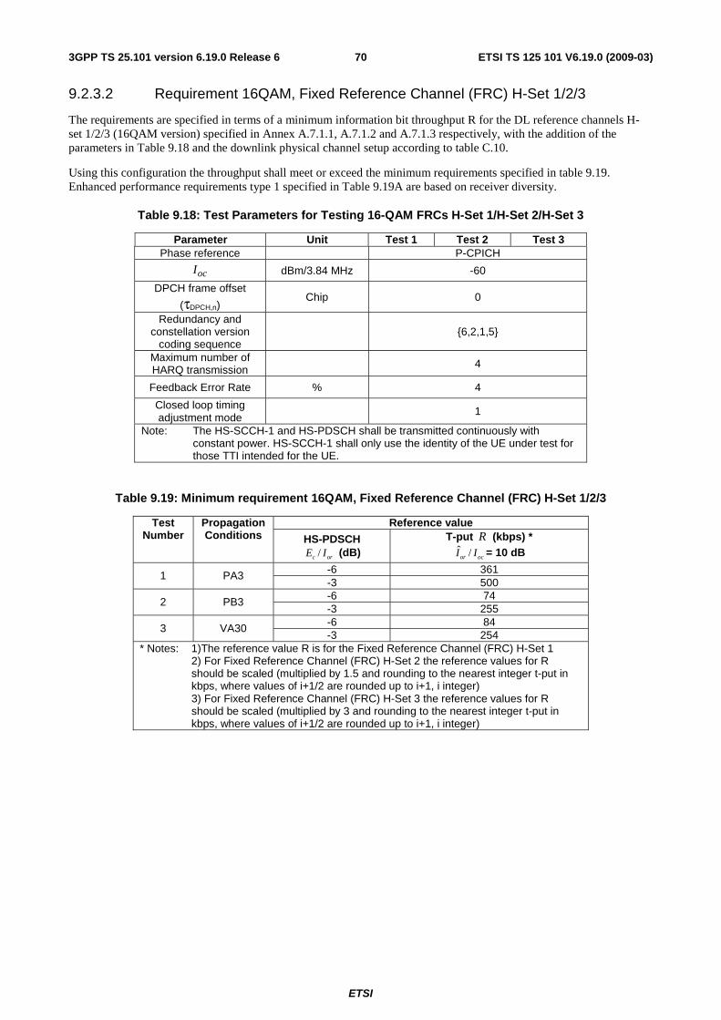
ETSI
ETSI TS 125 101 V6.19.0 (2009-03) 703GPP TS 25.101 version 6.19.0 Release 6
9.2.3.2 Requirement 16QAM, Fixed Reference Channel (FRC) H-Set 1/2/3
The requirements are specified in terms of a minimum information bit throughput R for the DL reference channels H-set 1/2/3 (16QAM version) specified in Annex A.7.1.1, A.7.1.2 and A.7.1.3 respectively, with the addition of the parameters in Table 9.18 and the downlink physical channel setup according to table C.10.
Using this configuration the throughput shall meet or exceed the minimum requirements specified in table 9.19. Enhanced performance requirements type 1 specified in Table 9.19A are based on receiver diversity.
Table 9.18: Test Parameters for Testing 16-QAM FRCs H-Set 1/H-Set 2/H-Set 3
Parameter Unit Test 1 Test 2 Test 3 Phase reference P-CPICH
ocI dBm/3.84 MHz -60
DPCH frame offset
(τDPCH,n) Chip 0
Redundancy and constellation version
coding sequence
{6,2,1,5}
Maximum number of HARQ transmission
4
Feedback Error Rate % 4
Closed loop timing adjustment mode
1
Note: The HS-SCCH-1 and HS-PDSCH shall be transmitted continuously with constant power. HS-SCCH-1 shall only use the identity of the UE under test for those TTI intended for the UE.
Table 9.19: Minimum requirement 16QAM, Fixed Reference Channel (FRC) H-Set 1/2/3
Reference value Test Number
Propagation Conditions HS-PDSCH
/c orE I (dB) T-put R (kbps) *
ˆ /or ocI I = 10 dB
-6 361 1 PA3 -3 500 -6 74 2 PB3 -3 255 -6 84 3 VA30 -3 254
* Notes: 1)The reference value R is for the Fixed Reference Channel (FRC) H-Set 1 2) For Fixed Reference Channel (FRC) H-Set 2 the reference values for R
should be scaled (multiplied by 1.5 and rounding to the nearest integer t-put in kbps, where values of i+1/2 are rounded up to i+1, i integer)
3) For Fixed Reference Channel (FRC) H-Set 3 the reference values for R should be scaled (multiplied by 3 and rounding to the nearest integer t-put in kbps, where values of i+1/2 are rounded up to i+1, i integer)
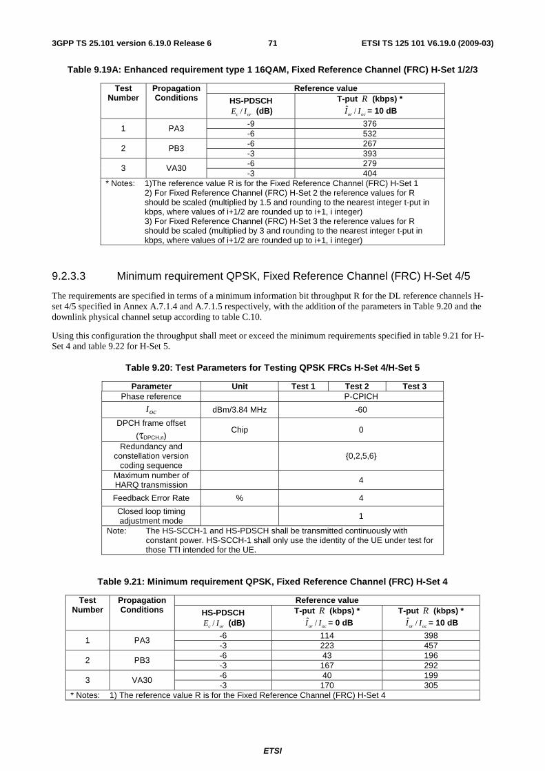
ETSI
ETSI TS 125 101 V6.19.0 (2009-03) 713GPP TS 25.101 version 6.19.0 Release 6
Table 9.19A: Enhanced requirement type 1 16QAM, Fixed Reference Channel (FRC) H-Set 1/2/3
Reference value Test Number
Propagation Conditions HS-PDSCH
/c orE I (dB) T-put R (kbps) *
ˆ /or ocI I = 10 dB
-9 376 1 PA3 -6 532 -6 267 2 PB3 -3 393 -6 279 3 VA30 -3 404
* Notes: 1)The reference value R is for the Fixed Reference Channel (FRC) H-Set 1 2) For Fixed Reference Channel (FRC) H-Set 2 the reference values for R
should be scaled (multiplied by 1.5 and rounding to the nearest integer t-put in kbps, where values of i+1/2 are rounded up to i+1, i integer)
3) For Fixed Reference Channel (FRC) H-Set 3 the reference values for R should be scaled (multiplied by 3 and rounding to the nearest integer t-put in kbps, where values of i+1/2 are rounded up to i+1, i integer)
9.2.3.3 Minimum requirement QPSK, Fixed Reference Channel (FRC) H-Set 4/5
The requirements are specified in terms of a minimum information bit throughput R for the DL reference channels H-set 4/5 specified in Annex A.7.1.4 and A.7.1.5 respectively, with the addition of the parameters in Table 9.20 and the downlink physical channel setup according to table C.10.
Using this configuration the throughput shall meet or exceed the minimum requirements specified in table 9.21 for H-Set 4 and table 9.22 for H-Set 5.
Table 9.20: Test Parameters for Testing QPSK FRCs H-Set 4/H-Set 5
Parameter Unit Test 1 Test 2 Test 3 Phase reference P-CPICH
ocI dBm/3.84 MHz -60
DPCH frame offset
(τDPCH,n) Chip 0
Redundancy and constellation version
coding sequence {0,2,5,6}
Maximum number of HARQ transmission 4
Feedback Error Rate % 4
Closed loop timing adjustment mode 1
Note: The HS-SCCH-1 and HS-PDSCH shall be transmitted continuously with constant power. HS-SCCH-1 shall only use the identity of the UE under test for those TTI intended for the UE.
Table 9.21: Minimum requirement QPSK, Fixed Reference Channel (FRC) H-Set 4
Reference value Test Number
Propagation Conditions HS-PDSCH
/c orE I (dB) T-put R (kbps) *
ˆ /or ocI I = 0 dB T-put R (kbps) *
ˆ /or ocI I = 10 dB
-6 114 398 1 PA3 -3 223 457 -6 43 196 2 PB3 -3 167 292 -6 40 199 3 VA30 -3 170 305
* Notes: 1) The reference value R is for the Fixed Reference Channel (FRC) H-Set 4
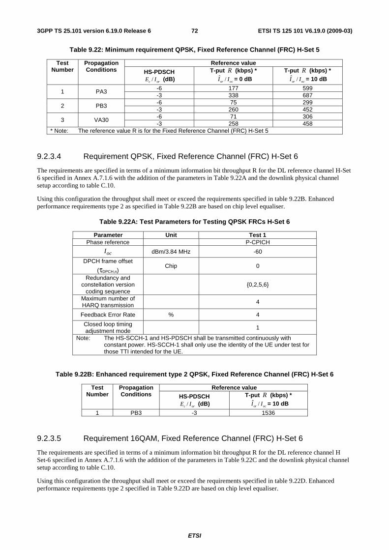
ETSI
ETSI TS 125 101 V6.19.0 (2009-03) 723GPP TS 25.101 version 6.19.0 Release 6
Table 9.22: Minimum requirement QPSK, Fixed Reference Channel (FRC) H-Set 5
Reference value Test Number
Propagation Conditions HS-PDSCH
/c orE I (dB) T-put R (kbps) *
ˆ /or ocI I = 0 dB T-put R (kbps) *
ˆ /or ocI I = 10 dB
-6 177 599 1 PA3 -3 338 687 -6 75 299 2 PB3 -3 260 452 -6 71 306 3 VA30 -3 258 458
* Note: The reference value R is for the Fixed Reference Channel (FRC) H-Set 5
9.2.3.4 Requirement QPSK, Fixed Reference Channel (FRC) H-Set 6
The requirements are specified in terms of a minimum information bit throughput R for the DL reference channel H-Set 6 specified in Annex A.7.1.6 with the addition of the parameters in Table 9.22A and the downlink physical channel setup according to table C.10.
Using this configuration the throughput shall meet or exceed the requirements specified in table 9.22B. Enhanced performance requirements type 2 as specified in Table 9.22B are based on chip level equaliser.
Table 9.22A: Test Parameters for Testing QPSK FRCs H-Set 6
Parameter Unit Test 1 Phase reference P-CPICH
ocI dBm/3.84 MHz -60
DPCH frame offset
(τDPCH,n) Chip 0
Redundancy and constellation version
coding sequence
{0,2,5,6}
Maximum number of HARQ transmission
4
Feedback Error Rate % 4
Closed loop timing adjustment mode 1
Note: The HS-SCCH-1 and HS-PDSCH shall be transmitted continuously with constant power. HS-SCCH-1 shall only use the identity of the UE under test for those TTI intended for the UE.
Table 9.22B: Enhanced requirement type 2 QPSK, Fixed Reference Channel (FRC) H-Set 6
Reference value Test Number
Propagation Conditions HS-PDSCH
/c orE I (dB) T-put R (kbps) * ˆ /or ocI I = 10 dB
1 PB3 -3 1536
9.2.3.5 Requirement 16QAM, Fixed Reference Channel (FRC) H-Set 6
The requirements are specified in terms of a minimum information bit throughput R for the DL reference channel H Set-6 specified in Annex A.7.1.6 with the addition of the parameters in Table 9.22C and the downlink physical channel setup according to table C.10.
Using this configuration the throughput shall meet or exceed the requirements specified in table 9.22D. Enhanced performance requirements type 2 specified in Table 9.22D are based on chip level equaliser.
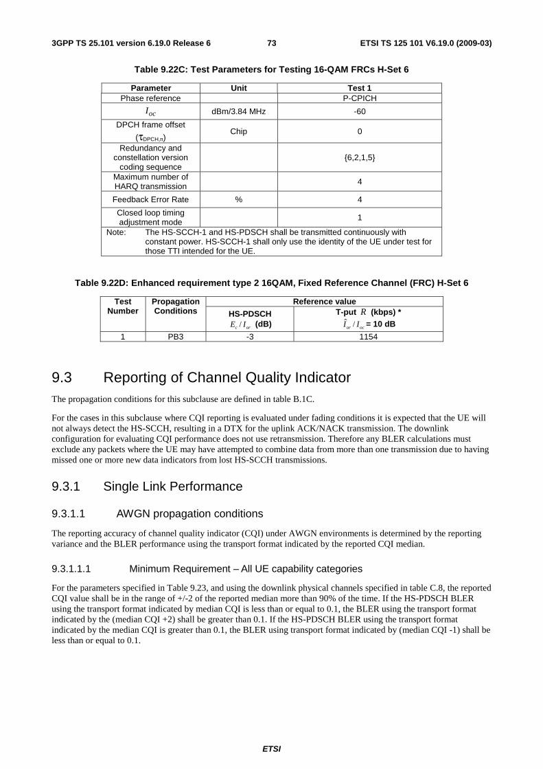
ETSI
ETSI TS 125 101 V6.19.0 (2009-03) 733GPP TS 25.101 version 6.19.0 Release 6
Table 9.22C: Test Parameters for Testing 16-QAM FRCs H-Set 6
Parameter Unit Test 1 Phase reference P-CPICH
ocI dBm/3.84 MHz -60
DPCH frame offset
(τDPCH,n) Chip 0
Redundancy and constellation version
coding sequence
{6,2,1,5}
Maximum number of HARQ transmission
4
Feedback Error Rate % 4
Closed loop timing adjustment mode 1
Note: The HS-SCCH-1 and HS-PDSCH shall be transmitted continuously with constant power. HS-SCCH-1 shall only use the identity of the UE under test for those TTI intended for the UE.
Table 9.22D: Enhanced requirement type 2 16QAM, Fixed Reference Channel (FRC) H-Set 6
Reference value Test Number
Propagation Conditions HS-PDSCH
/c orE I (dB) T-put R (kbps) *
ˆ /or ocI I = 10 dB
1 PB3 -3 1154
9.3 Reporting of Channel Quality Indicator The propagation conditions for this subclause are defined in table B.1C.
For the cases in this subclause where CQI reporting is evaluated under fading conditions it is expected that the UE will not always detect the HS-SCCH, resulting in a DTX for the uplink ACK/NACK transmission. The downlink configuration for evaluating CQI performance does not use retransmission. Therefore any BLER calculations must exclude any packets where the UE may have attempted to combine data from more than one transmission due to having missed one or more new data indicators from lost HS-SCCH transmissions.
9.3.1 Single Link Performance
9.3.1.1 AWGN propagation conditions
The reporting accuracy of channel quality indicator (CQI) under AWGN environments is determined by the reporting variance and the BLER performance using the transport format indicated by the reported CQI median.
9.3.1.1.1 Minimum Requirement – All UE capability categories
For the parameters specified in Table 9.23, and using the downlink physical channels specified in table C.8, the reported CQI value shall be in the range of +/-2 of the reported median more than 90% of the time. If the HS-PDSCH BLER using the transport format indicated by median CQI is less than or equal to 0.1, the BLER using the transport format indicated by the (median CQI +2) shall be greater than 0.1. If the HS-PDSCH BLER using the transport format indicated by the median CQI is greater than 0.1, the BLER using transport format indicated by (median CQI -1) shall be less than or equal to 0.1.

ETSI
ETSI TS 125 101 V6.19.0 (2009-03) 743GPP TS 25.101 version 6.19.0 Release 6
Table 9.23: Test Parameter for CQI test in AWGN - single link
Parameter Unit Test 1 Test 2 Test 3
ˆ /or ocI I dB 0 5 10
ocI dBm/3.84 MHz -60
Phase reference - P-CPICH
HS-PDSCH /c orE I dB -3
HS-SCCH_1 /c orE I dB -10
DPCH /c orE I dB -10
Maximum number of H-ARQ transmission - 1
Number of HS-SCCH set to be monitored - 1
CQI feedback cycle ms 2
CQI repetition factor - 1
HS-SCCH-1 signalling pattern -
To incorporate inter-TTI=3 the six sub-frame HS-SCCH-1 signalling pattern shall be "…XOOXOO…", where "X" indicates TTI in which the HS-SCCH-1 uses the identity of the UE under test, and "O" indicates TTI in which the HS-SCCH-1 uses a different UE identity.
Note1: Measurement power offset "Γ" is configured by RRC accordingly and as defined in [7]
Note2: TF for HS-PDSCH is configured according to the reported CQI statistics. TF based on median CQI, median CQI -1, median CQI+2 are used. Other physical channel parameters are configured according to the CQI mapping table described in TS25.214
Note3: HS-PDSCH Ec/Ior is decreased according to reference power adjustment Δ described in TS 25.214
Note 4: For any given transport format the power of the HS-SCCH and HS-PDSCH shall be transmitted continuously with constant power.
9.3.1.2 Fading propagation conditions
The reporting accuracy of the channel quality indicator (CQI) under fading environments is determined by the BLER performance using the transport format indicated by the reported CQI median.
The specified requirements may be subject to further simulations to verify assumptions.
9.3.1.2.1 Minimum Requirement – All UE capability categories
For the parameters specified in Table 9.26, and using the downlink physical channels specified in table C.8, the requirements are specified in terms of maximum BLERs at particular reported CQIs when transmitting a fixed transport format given by the CQI median as shown in Table 9.27. The BLER at a particular reported CQI is obtained by associating a particular CQI reference measurement period with the HS-PDSCH subframe overlapping with the end of this CQI reference measurement period and calculating the fraction of erroneous HS-PDSCH subframes.
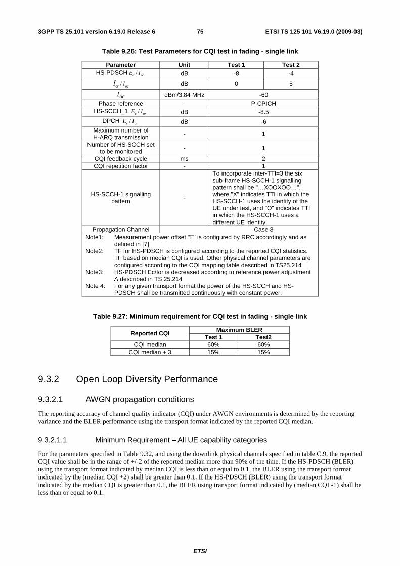
ETSI
ETSI TS 125 101 V6.19.0 (2009-03) 753GPP TS 25.101 version 6.19.0 Release 6
Table 9.26: Test Parameters for CQI test in fading - single link
Parameter Unit Test 1 Test 2 HS-PDSCH /c orE I dB -8 -4
ˆ /or ocI I dB 0 5
ocI dBm/3.84 MHz -60
Phase reference - P-CPICH HS-SCCH_1 /c orE I dB -8.5
DPCH /c orE I dB -6 Maximum number of H-ARQ transmission - 1
Number of HS-SCCH set to be monitored - 1
CQI feedback cycle ms 2 CQI repetition factor - 1
HS-SCCH-1 signalling pattern -
To incorporate inter-TTI=3 the six sub-frame HS-SCCH-1 signalling pattern shall be "…XOOXOO…", where "X" indicates TTI in which the HS-SCCH-1 uses the identity of the UE under test, and "O" indicates TTI in which the HS-SCCH-1 uses a different UE identity.
Propagation Channel Case 8 Note1: Measurement power offset "Γ" is configured by RRC accordingly and as
defined in [7] Note2: TF for HS-PDSCH is configured according to the reported CQI statistics.
TF based on median CQI is used. Other physical channel parameters are configured according to the CQI mapping table described in TS25.214
Note3: HS-PDSCH Ec/Ior is decreased according to reference power adjustment Δ described in TS 25.214
Note 4: For any given transport format the power of the HS-SCCH and HS-PDSCH shall be transmitted continuously with constant power.
Table 9.27: Minimum requirement for CQI test in fading - single link
Maximum BLER Reported CQI Test 1 Test2
CQI median 60% 60% CQI median + 3 15% 15%
9.3.2 Open Loop Diversity Performance
9.3.2.1 AWGN propagation conditions
The reporting accuracy of channel quality indicator (CQI) under AWGN environments is determined by the reporting variance and the BLER performance using the transport format indicated by the reported CQI median.
9.3.2.1.1 Minimum Requirement – All UE capability categories
For the parameters specified in Table 9.32, and using the downlink physical channels specified in table C.9, the reported CQI value shall be in the range of +/-2 of the reported median more than 90% of the time. If the HS-PDSCH (BLER) using the transport format indicated by median CQI is less than or equal to 0.1, the BLER using the transport format indicated by the (median CQI +2) shall be greater than 0.1. If the HS-PDSCH (BLER) using the transport format indicated by the median CQI is greater than 0.1, the BLER using transport format indicated by (median CQI -1) shall be less than or equal to 0.1.
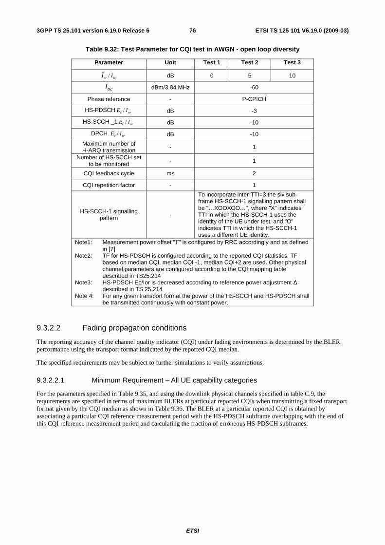
ETSI
ETSI TS 125 101 V6.19.0 (2009-03) 763GPP TS 25.101 version 6.19.0 Release 6
Table 9.32: Test Parameter for CQI test in AWGN - open loop diversity
Parameter Unit Test 1 Test 2 Test 3
ˆ /or ocI I dB 0 5 10
ocI dBm/3.84 MHz -60
Phase reference - P-CPICH
HS-PDSCH /c orE I dB -3
HS-SCCH _1 /c orE I dB -10
DPCH /c orE I dB -10
Maximum number of H-ARQ transmission - 1
Number of HS-SCCH set to be monitored - 1
CQI feedback cycle ms 2
CQI repetition factor - 1
HS-SCCH-1 signalling pattern -
To incorporate inter-TTI=3 the six sub-frame HS-SCCH-1 signalling pattern shall be "…XOOXOO…", where "X" indicates TTI in which the HS-SCCH-1 uses the identity of the UE under test, and "O" indicates TTI in which the HS-SCCH-1 uses a different UE identity.
Note1: Measurement power offset "Γ" is configured by RRC accordingly and as defined in [7]
Note2: TF for HS-PDSCH is configured according to the reported CQI statistics. TF based on median CQI, median CQI -1, median CQI+2 are used. Other physical channel parameters are configured according to the CQI mapping table described in TS25.214
Note3: HS-PDSCH Ec/Ior is decreased according to reference power adjustment Δ described in TS 25.214
Note 4: For any given transport format the power of the HS-SCCH and HS-PDSCH shall be transmitted continuously with constant power.
9.3.2.2 Fading propagation conditions
The reporting accuracy of the channel quality indicator (CQI) under fading environments is determined by the BLER performance using the transport format indicated by the reported CQI median.
The specified requirements may be subject to further simulations to verify assumptions.
9.3.2.2.1 Minimum Requirement – All UE capability categories
For the parameters specified in Table 9.35, and using the downlink physical channels specified in table C.9, the requirements are specified in terms of maximum BLERs at particular reported CQIs when transmitting a fixed transport format given by the CQI median as shown in Table 9.36. The BLER at a particular reported CQI is obtained by associating a particular CQI reference measurement period with the HS-PDSCH subframe overlapping with the end of this CQI reference measurement period and calculating the fraction of erroneous HS-PDSCH subframes.
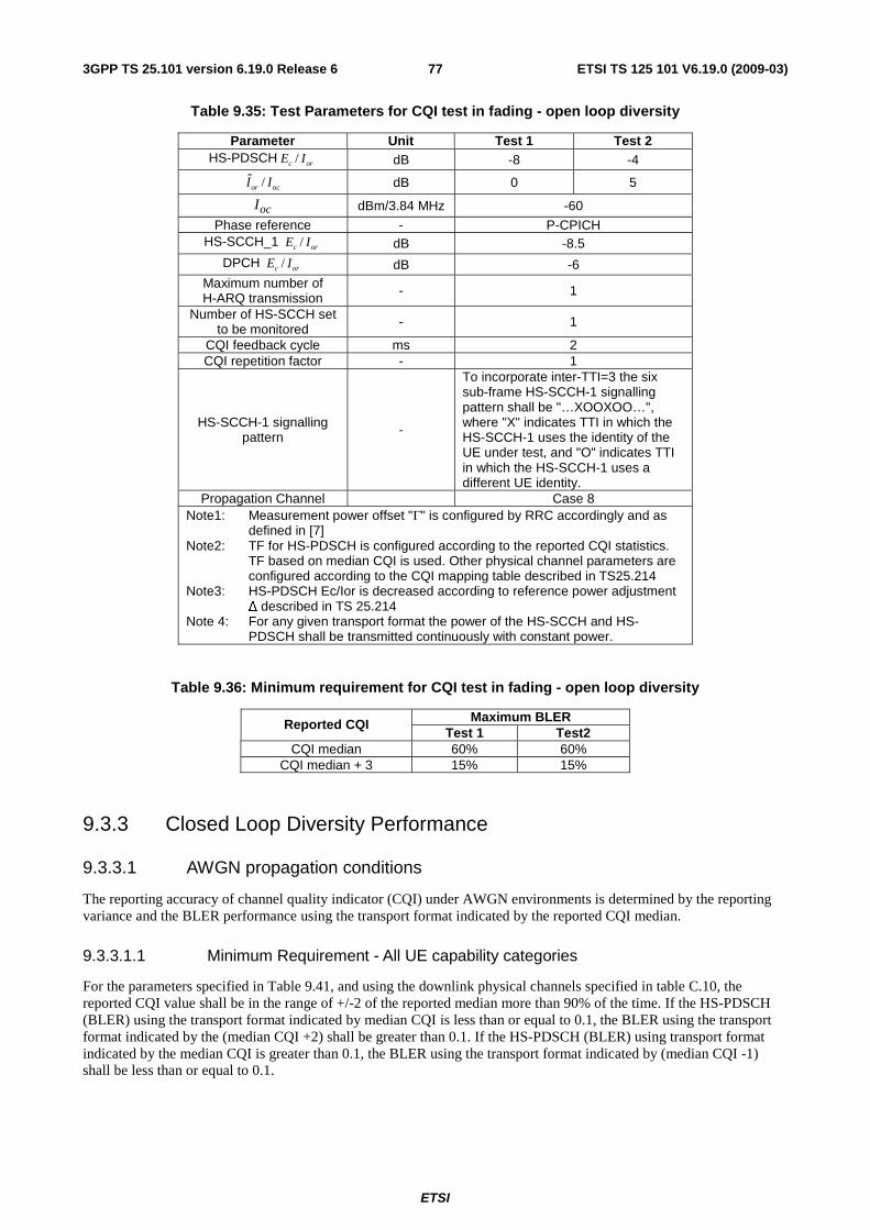
ETSI
ETSI TS 125 101 V6.19.0 (2009-03) 773GPP TS 25.101 version 6.19.0 Release 6
Table 9.35: Test Parameters for CQI test in fading - open loop diversity
Parameter Unit Test 1 Test 2 HS-PDSCH /c orE I dB -8 -4
ˆ /or ocI I dB 0 5
ocI dBm/3.84 MHz -60
Phase reference - P-CPICH HS-SCCH_1 /c orE I dB -8.5
DPCH /c orE I dB -6 Maximum number of H-ARQ transmission - 1
Number of HS-SCCH set to be monitored - 1
CQI feedback cycle ms 2 CQI repetition factor - 1
HS-SCCH-1 signalling pattern -
To incorporate inter-TTI=3 the six sub-frame HS-SCCH-1 signalling pattern shall be "…XOOXOO…", where "X" indicates TTI in which the HS-SCCH-1 uses the identity of the UE under test, and "O" indicates TTI in which the HS-SCCH-1 uses a different UE identity.
Propagation Channel Case 8 Note1: Measurement power offset "Γ" is configured by RRC accordingly and as
defined in [7] Note2: TF for HS-PDSCH is configured according to the reported CQI statistics.
TF based on median CQI is used. Other physical channel parameters are configured according to the CQI mapping table described in TS25.214
Note3: HS-PDSCH Ec/Ior is decreased according to reference power adjustment Δ described in TS 25.214
Note 4: For any given transport format the power of the HS-SCCH and HS-PDSCH shall be transmitted continuously with constant power.
Table 9.36: Minimum requirement for CQI test in fading - open loop diversity
Maximum BLER Reported CQI Test 1 Test2
CQI median 60% 60% CQI median + 3 15% 15%
9.3.3 Closed Loop Diversity Performance
9.3.3.1 AWGN propagation conditions
The reporting accuracy of channel quality indicator (CQI) under AWGN environments is determined by the reporting variance and the BLER performance using the transport format indicated by the reported CQI median.
9.3.3.1.1 Minimum Requirement - All UE capability categories
For the parameters specified in Table 9.41, and using the downlink physical channels specified in table C.10, the reported CQI value shall be in the range of +/-2 of the reported median more than 90% of the time. If the HS-PDSCH (BLER) using the transport format indicated by median CQI is less than or equal to 0.1, the BLER using the transport format indicated by the (median CQI +2) shall be greater than 0.1. If the HS-PDSCH (BLER) using transport format indicated by the median CQI is greater than 0.1, the BLER using the transport format indicated by (median CQI -1) shall be less than or equal to 0.1.
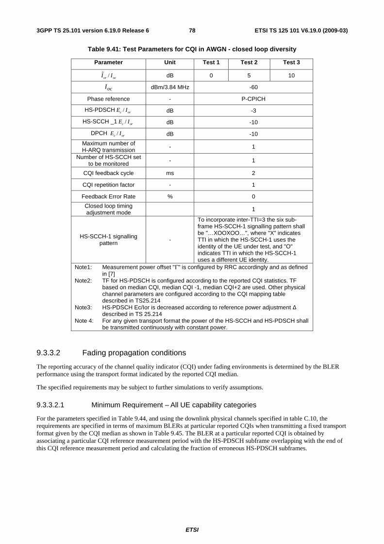
ETSI
ETSI TS 125 101 V6.19.0 (2009-03) 783GPP TS 25.101 version 6.19.0 Release 6
Table 9.41: Test Parameters for CQI in AWGN - closed loop diversity
Parameter Unit Test 1 Test 2 Test 3
ˆ /or ocI I dB 0 5 10
ocI dBm/3.84 MHz -60
Phase reference - P-CPICH
HS-PDSCH /c orE I dB -3
HS-SCCH _1 /c orE I dB -10
DPCH /c orE I dB -10
Maximum number of H-ARQ transmission - 1
Number of HS-SCCH set to be monitored - 1
CQI feedback cycle ms 2
CQI repetition factor - 1
Feedback Error Rate % 0
Closed loop timing adjustment mode 1
HS-SCCH-1 signalling pattern -
To incorporate inter-TTI=3 the six sub-frame HS-SCCH-1 signalling pattern shall be "…XOOXOO…", where "X" indicates TTI in which the HS-SCCH-1 uses the identity of the UE under test, and "O" indicates TTI in which the HS-SCCH-1 uses a different UE identity.
Note1: Measurement power offset "Γ" is configured by RRC accordingly and as defined in [7]
Note2: TF for HS-PDSCH is configured according to the reported CQI statistics. TF based on median CQI, median CQI -1, median CQI+2 are used. Other physical channel parameters are configured according to the CQI mapping table described in TS25.214
Note3: HS-PDSCH Ec/Ior is decreased according to reference power adjustment Δ described in TS 25.214
Note 4: For any given transport format the power of the HS-SCCH and HS-PDSCH shall be transmitted continuously with constant power.
9.3.3.2 Fading propagation conditions
The reporting accuracy of the channel quality indicator (CQI) under fading environments is determined by the BLER performance using the transport format indicated by the reported CQI median.
The specified requirements may be subject to further simulations to verify assumptions.
9.3.3.2.1 Minimum Requirement – All UE capability categories
For the parameters specified in Table 9.44, and using the downlink physical channels specified in table C.10, the requirements are specified in terms of maximum BLERs at particular reported CQIs when transmitting a fixed transport format given by the CQI median as shown in Table 9.45. The BLER at a particular reported CQI is obtained by associating a particular CQI reference measurement period with the HS-PDSCH subframe overlapping with the end of this CQI reference measurement period and calculating the fraction of erroneous HS-PDSCH subframes.
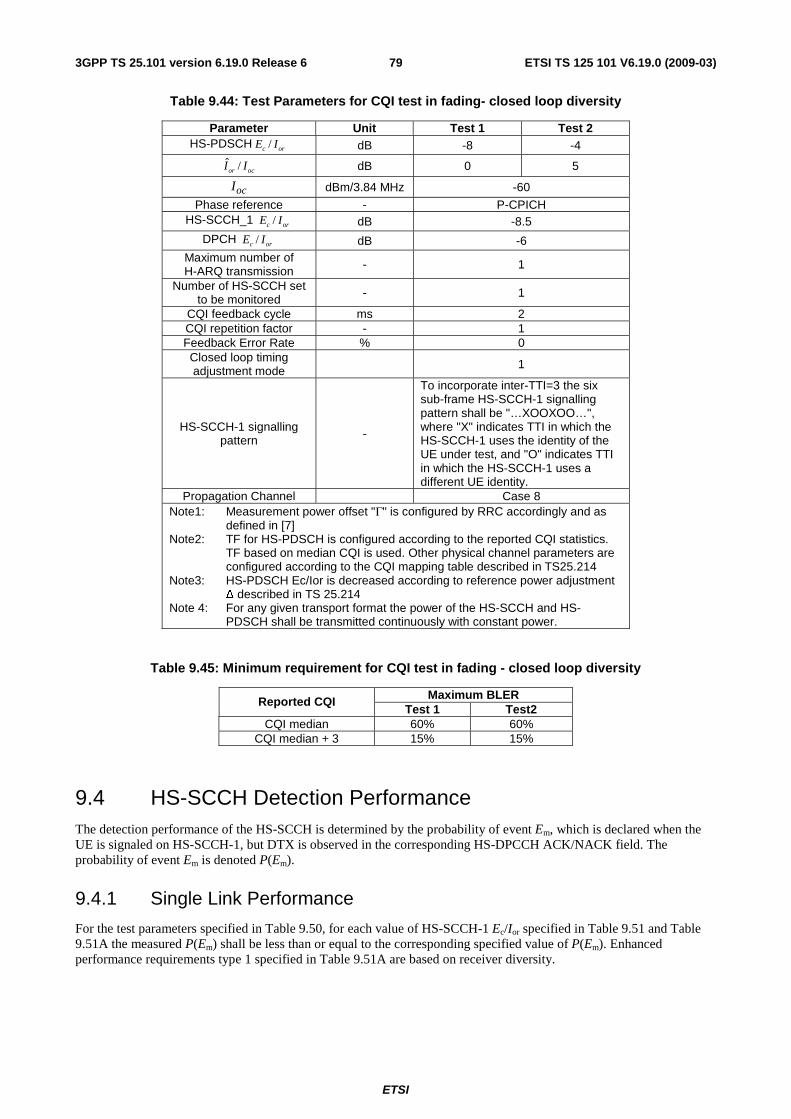
ETSI
ETSI TS 125 101 V6.19.0 (2009-03) 793GPP TS 25.101 version 6.19.0 Release 6
Table 9.44: Test Parameters for CQI test in fading- closed loop diversity
Parameter Unit Test 1 Test 2 HS-PDSCH /c orE I dB -8 -4
ˆ /or ocI I dB 0 5
ocI dBm/3.84 MHz -60
Phase reference - P-CPICH HS-SCCH_1 /c orE I dB -8.5
DPCH /c orE I dB -6 Maximum number of H-ARQ transmission - 1
Number of HS-SCCH set to be monitored - 1
CQI feedback cycle ms 2 CQI repetition factor - 1 Feedback Error Rate % 0 Closed loop timing adjustment mode 1
HS-SCCH-1 signalling pattern -
To incorporate inter-TTI=3 the six sub-frame HS-SCCH-1 signalling pattern shall be "…XOOXOO…", where "X" indicates TTI in which the HS-SCCH-1 uses the identity of the UE under test, and "O" indicates TTI in which the HS-SCCH-1 uses a different UE identity.
Propagation Channel Case 8 Note1: Measurement power offset "Γ" is configured by RRC accordingly and as
defined in [7] Note2: TF for HS-PDSCH is configured according to the reported CQI statistics.
TF based on median CQI is used. Other physical channel parameters are configured according to the CQI mapping table described in TS25.214
Note3: HS-PDSCH Ec/Ior is decreased according to reference power adjustment Δ described in TS 25.214
Note 4: For any given transport format the power of the HS-SCCH and HS-PDSCH shall be transmitted continuously with constant power.
Table 9.45: Minimum requirement for CQI test in fading - closed loop diversity
Maximum BLER Reported CQI Test 1 Test2
CQI median 60% 60% CQI median + 3 15% 15%
9.4 HS-SCCH Detection Performance The detection performance of the HS-SCCH is determined by the probability of event Em, which is declared when the UE is signaled on HS-SCCH-1, but DTX is observed in the corresponding HS-DPCCH ACK/NACK field. The probability of event Em is denoted P(Em).
9.4.1 Single Link Performance
For the test parameters specified in Table 9.50, for each value of HS-SCCH-1 Ec/Ior specified in Table 9.51 and Table 9.51A the measured P(Em) shall be less than or equal to the corresponding specified value of P(Em). Enhanced performance requirements type 1 specified in Table 9.51A are based on receiver diversity.
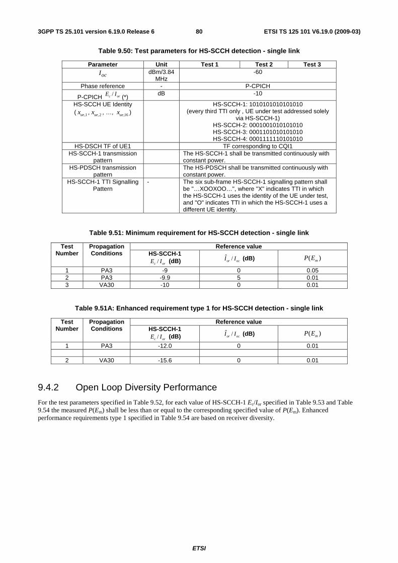
ETSI
ETSI TS 125 101 V6.19.0 (2009-03) 803GPP TS 25.101 version 6.19.0 Release 6
Table 9.50: Test parameters for HS-SCCH detection - single link
Parameter Unit Test 1 Test 2 Test 3
ocI dBm/3.84
MHz -60
Phase reference - P-CPICH
P-CPICH /c orE I (*) dB -10
HS-SCCH UE Identity ( ,1uex , ,2uex , …, ,16uex )
HS-SCCH-1: 1010101010101010 (every third TTI only , UE under test addressed solely
via HS-SCCH-1) HS-SCCH-2: 0001001010101010 HS-SCCH-3: 0001101010101010 HS-SCCH-4: 0001111110101010
HS-DSCH TF of UE1 TF corresponding to CQI1 HS-SCCH-1 transmission
pattern The HS-SCCH-1 shall be transmitted continuously with
constant power. HS-PDSCH transmission
pattern The HS-PDSCH shall be transmitted continuously with
constant power. HS-SCCH-1 TTI Signalling
Pattern - The six sub-frame HS-SCCH-1 signalling pattern shall
be "…XOOXOO…", where "X" indicates TTI in which the HS-SCCH-1 uses the identity of the UE under test, and "O" indicates TTI in which the HS-SCCH-1 uses a different UE identity.
Table 9.51: Minimum requirement for HS-SCCH detection - single link
Reference value Test Number
Propagation Conditions HS-SCCH-1
/c orE I (dB) ˆ /or ocI I (dB) ( )mP E
1 PA3 -9 0 0.05 2 PA3 -9.9 5 0.01 3 VA30 -10 0 0.01
Table 9.51A: Enhanced requirement type 1 for HS-SCCH detection - single link
Reference value Test Number
Propagation Conditions HS-SCCH-1
/c orE I (dB) ˆ /or ocI I (dB) ( )mP E
1 PA3 -12.0 0 0.01
2 VA30 -15.6 0 0.01
9.4.2 Open Loop Diversity Performance
For the test parameters specified in Table 9.52, for each value of HS-SCCH-1 Ec/Ior specified in Table 9.53 and Table 9.54 the measured P(Em) shall be less than or equal to the corresponding specified value of P(Em). Enhanced performance requirements type 1 specified in Table 9.54 are based on receiver diversity.
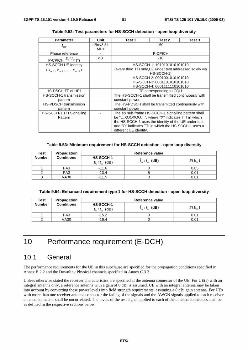
ETSI
ETSI TS 125 101 V6.19.0 (2009-03) 813GPP TS 25.101 version 6.19.0 Release 6
Table 9.52: Test parameters for HS-SCCH detection - open loop diversity
Parameter Unit Test 1 Test 2 Test 3
ocI dBm/3.84
MHz -60
Phase reference - P-CPICH
P-CPICH /c orE I (*) dB -10
HS-SCCH UE Identity ( ,1uex , ,2uex , …, ,16uex )
HS-SCCH-1: 1010101010101010 (every third TTI only,UE under test addressed solely via
HS-SCCH-1) HS-SCCH-2: 0001001010101010 HS-SCCH-3: 0001101010101010 HS-SCCH-4: 0001111110101010
HS-DSCH TF of UE1 TF corresponding to CQI1 HS-SCCH-1 transmission
pattern The HS-SCCH-1 shall be transmitted continuously with
constant power. HS-PDSCH transmission
pattern The HS-PDSCH shall be transmitted continuously with
constant power. HS-SCCH-1 TTI Signalling
Pattern - The six sub-frame HS-SCCH-1 signalling pattern shall
be "…XOOXOO…", where "X" indicates TTI in which the HS-SCCH-1 uses the identity of the UE under test, and "O" indicates TTI in which the HS-SCCH-1 uses a different UE identity.
Table 9.53: Minimum requirement for HS-SCCH detection - open loop diversity
Reference value Test Number
Propagation Conditions HS-SCCH-1
/c orE I (dB) ˆ /or ocI I (dB) ( )mP E
1 PA3 -11.6 0 0.05 2 PA3 -13.4 5 0.01 3 VA30 -11.5 0 0.01
Table 9.54: Enhanced requirement type 1 for HS-SCCH detection - open loop diversity
Reference value Test Number
Propagation Conditions HS-SCCH-1
/c orE I (dB) ˆ /or ocI I (dB) ( )mP E
1 PA3 -15.2 0 0.01 2 VA30 -16.4 0 0.01
10 Performance requirement (E-DCH)
10.1 General The performance requirements for the UE in this subclause are specified for the propagation conditions specified in Annex B.2.2 and the Downlink Physical channels specified in Annex C.3.2.
Unless otherwise stated the receiver characteristics are specified at the antenna connector of the UE. For UE(s) with an integral antenna only, a reference antenna with a gain of 0 dBi is assumed. UE with an integral antenna may be taken into account by converting these power levels into field strength requirements, assuming a 0 dBi gain antenna. For UEs with more than one receiver antenna connector the fading of the signals and the AWGN signals applied to each receiver antenna connector shall be uncorrelated. The levels of the test signal applied to each of the antenna connectors shall be as defined in the respective sections below.
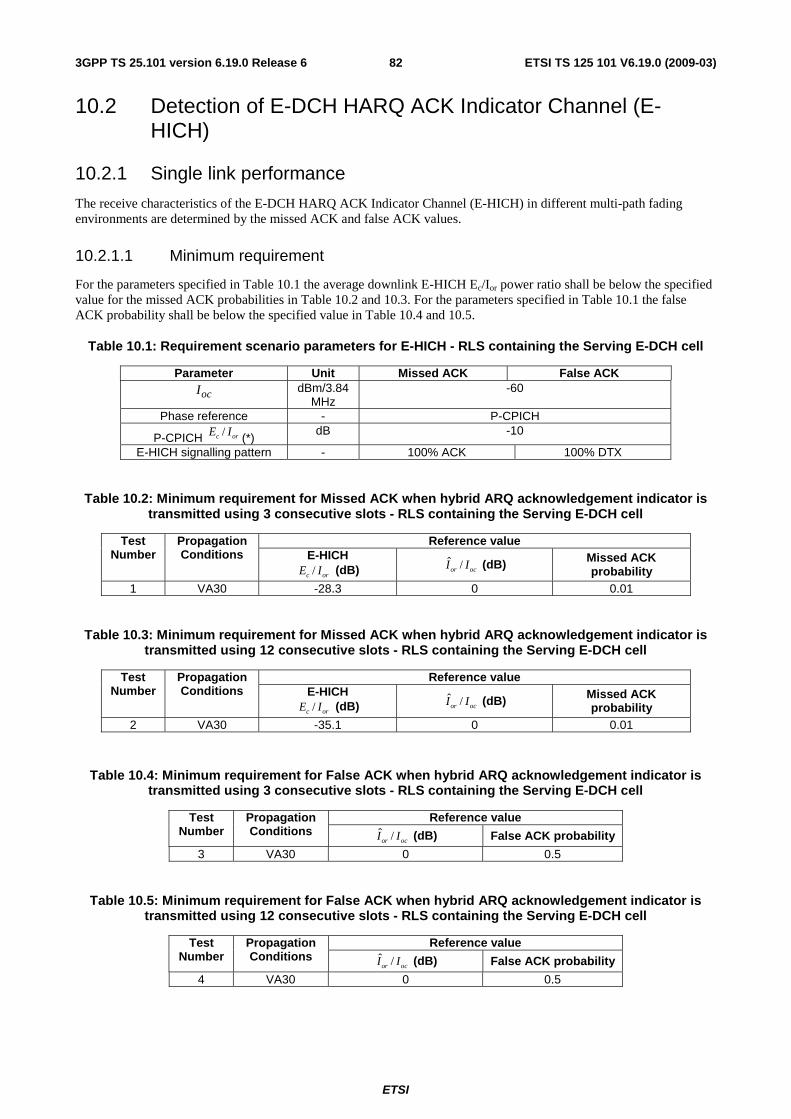
ETSI
ETSI TS 125 101 V6.19.0 (2009-03) 823GPP TS 25.101 version 6.19.0 Release 6
10.2 Detection of E-DCH HARQ ACK Indicator Channel (E-HICH)
10.2.1 Single link performance
The receive characteristics of the E-DCH HARQ ACK Indicator Channel (E-HICH) in different multi-path fading environments are determined by the missed ACK and false ACK values.
10.2.1.1 Minimum requirement
For the parameters specified in Table 10.1 the average downlink E-HICH Ec/Ior power ratio shall be below the specified value for the missed ACK probabilities in Table 10.2 and 10.3. For the parameters specified in Table 10.1 the false ACK probability shall be below the specified value in Table 10.4 and 10.5.
Table 10.1: Requirement scenario parameters for E-HICH - RLS containing the Serving E-DCH cell
Parameter Unit Missed ACK False ACK
ocI dBm/3.84
MHz -60
Phase reference - P-CPICH
P-CPICH /c orE I (*) dB -10
E-HICH signalling pattern - 100% ACK 100% DTX
Table 10.2: Minimum requirement for Missed ACK when hybrid ARQ acknowledgement indicator is transmitted using 3 consecutive slots - RLS containing the Serving E-DCH cell
Reference value Test Number
Propagation Conditions E-HICH
/c orE I (dB) ˆ /or ocI I (dB) Missed ACK
probability 1 VA30 -28.3 0 0.01
Table 10.3: Minimum requirement for Missed ACK when hybrid ARQ acknowledgement indicator is transmitted using 12 consecutive slots - RLS containing the Serving E-DCH cell
Reference value Test Number
Propagation Conditions E-HICH
/c orE I (dB) ˆ /or ocI I (dB) Missed ACK
probability 2 VA30 -35.1 0 0.01
Table 10.4: Minimum requirement for False ACK when hybrid ARQ acknowledgement indicator is transmitted using 3 consecutive slots - RLS containing the Serving E-DCH cell
Reference value Test Number
Propagation Conditions ˆ /or ocI I (dB) False ACK probability
3 VA30 0 0.5
Table 10.5: Minimum requirement for False ACK when hybrid ARQ acknowledgement indicator is transmitted using 12 consecutive slots - RLS containing the Serving E-DCH cell
Reference value Test Number
Propagation Conditions ˆ /or ocI I (dB) False ACK probability
4 VA30 0 0.5
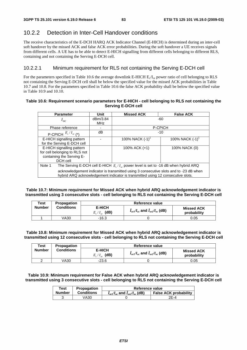
ETSI
ETSI TS 125 101 V6.19.0 (2009-03) 833GPP TS 25.101 version 6.19.0 Release 6
10.2.2 Detection in Inter-Cell Handover conditions
The receive characteristics of the E-DCH HARQ ACK Indicator Channel (E-HICH) is determined during an inter-cell soft handover by the missed ACK and false ACK error probabilities. During the soft handover a UE receives signals from different cells. A UE has to be able to detect E-HICH signalling from different cells belonging to different RLS, containing and not containing the Serving E-DCH cell.
10.2.2.1 Minimum requirement for RLS not containing the Serving E-DCH cell
For the parameters specified in Table 10.6 the average downlink E-HICH Ec/Ior power ratio of cell belonging to RLS not containing the Serving E-DCH cell shall be below the specified value for the missed ACK probabilities in Table 10.7 and 10.8. For the parameters specified in Table 10.6 the false ACK probability shall be below the specified value in Table 10.9 and 10.10.
Table 10.6: Requirement scenario parameters for E-HICH - cell belonging to RLS not containing the Serving E-DCH cell
Parameter Unit Missed ACK False ACK
ocI dBm/3.84
MHz -60
Phase reference - P-CPICH
P-CPICH /c orE I (*) dB -10
E-HICH signalling pattern for the Serving E-DCH cell
- 100% NACK (-1)1 100% NACK (-1)1
E-HICH signalling pattern for cell belonging to RLS not
containing the Serving E-DCH cell
100% ACK (+1) 100% NACK (0)
Note 1 The Serving E-DCH cell E-HICH /c orE I power level is set to -16 dB when hybrid ARQ
acknowledgement indicator is transmitted using 3 consecutive slots and to -23 dB when hybrid ARQ acknowledgement indicator is transmitted using 12 consecutive slots.
Table 10.7: Minimum requirement for Missed ACK when hybrid ARQ acknowledgement indicator is transmitted using 3 consecutive slots - cell belonging to RLS not containing the Serving E-DCH cell
Reference value Test Number
Propagation Conditions E-HICH
/c orE I (dB) Îor1/Ioc and Îor2/Ioc (dB) Missed ACK probability
1 VA30 -16.3 0 0.05
Table 10.8: Minimum requirement for Missed ACK when hybrid ARQ acknowledgement indicator is transmitted using 12 consecutive slots - cell belonging to RLS not containing the Serving E-DCH cell
Reference value Test Number
Propagation Conditions E-HICH
/c orE I (dB) Îor1/Ioc and Îor2/Ioc (dB) Missed ACK probability
2 VA30 -23.6 0 0.05
Table 10.9: Minimum requirement for False ACK when hybrid ARQ acknowledgement indicator is transmitted using 3 consecutive slots - cell belonging to RLS not containing the Serving E-DCH cell
Reference value Test Number
Propagation Conditions Îor1/Ioc and Îor2/Ioc (dB) False ACK probability
3 VA30 0 2E-4
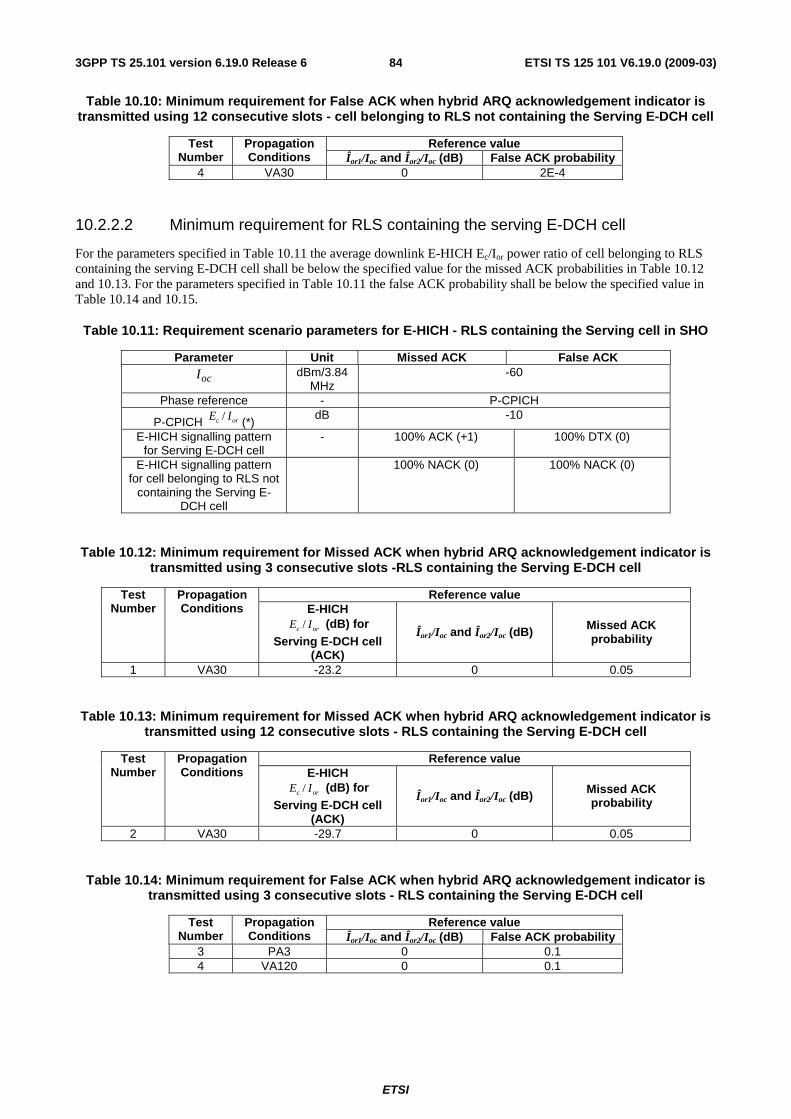
ETSI
ETSI TS 125 101 V6.19.0 (2009-03) 843GPP TS 25.101 version 6.19.0 Release 6
Table 10.10: Minimum requirement for False ACK when hybrid ARQ acknowledgement indicator is transmitted using 12 consecutive slots - cell belonging to RLS not containing the Serving E-DCH cell
Reference value Test Number
Propagation Conditions Îor1/Ioc and Îor2/Ioc (dB) False ACK probability
4 VA30 0 2E-4
10.2.2.2 Minimum requirement for RLS containing the serving E-DCH cell
For the parameters specified in Table 10.11 the average downlink E-HICH Ec/Ior power ratio of cell belonging to RLS containing the serving E-DCH cell shall be below the specified value for the missed ACK probabilities in Table 10.12 and 10.13. For the parameters specified in Table 10.11 the false ACK probability shall be below the specified value in Table 10.14 and 10.15.
Table 10.11: Requirement scenario parameters for E-HICH - RLS containing the Serving cell in SHO
Parameter Unit Missed ACK False ACK
ocI dBm/3.84
MHz -60
Phase reference - P-CPICH
P-CPICH /c orE I (*) dB -10
E-HICH signalling pattern for Serving E-DCH cell
- 100% ACK (+1) 100% DTX (0)
E-HICH signalling pattern for cell belonging to RLS not
containing the Serving E-DCH cell
100% NACK (0) 100% NACK (0)
Table 10.12: Minimum requirement for Missed ACK when hybrid ARQ acknowledgement indicator is transmitted using 3 consecutive slots -RLS containing the Serving E-DCH cell
Reference value Test Number
Propagation Conditions E-HICH
/c orE I (dB) for Serving E-DCH cell
(ACK)
Îor1/Ioc and Îor2/Ioc (dB) Missed ACK probability
1 VA30 -23.2 0 0.05
Table 10.13: Minimum requirement for Missed ACK when hybrid ARQ acknowledgement indicator is transmitted using 12 consecutive slots - RLS containing the Serving E-DCH cell
Reference value Test Number
Propagation Conditions E-HICH
/c orE I (dB) for Serving E-DCH cell
(ACK)
Îor1/Ioc and Îor2/Ioc (dB) Missed ACK probability
2 VA30 -29.7 0 0.05
Table 10.14: Minimum requirement for False ACK when hybrid ARQ acknowledgement indicator is transmitted using 3 consecutive slots - RLS containing the Serving E-DCH cell
Reference value Test Number
Propagation Conditions Îor1/Ioc and Îor2/Ioc (dB) False ACK probability
3 PA3 0 0.1 4 VA120 0 0.1
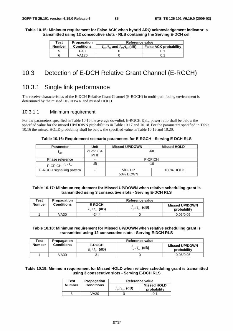
ETSI
ETSI TS 125 101 V6.19.0 (2009-03) 853GPP TS 25.101 version 6.19.0 Release 6
Table 10.15: Minimum requirement for False ACK when hybrid ARQ acknowledgement indicator is transmitted using 12 consecutive slots - RLS containing the Serving E-DCH cell
Reference value Test Number
Propagation Conditions Îor1/Ioc and Îor2/Ioc (dB) False ACK probability
5 PA3 0 0.1 6 VA120 0 0.1
10.3 Detection of E-DCH Relative Grant Channel (E-RGCH)
10.3.1 Single link performance The receive characteristics of the E-DCH Relative Grant Channel (E-RGCH) in multi-path fading environment is determined by the missed UP/DOWN and missed HOLD.
10.3.1.1 Minimum requirement
For the parameters specified in Table 10.16 the average downlink E-RGCH Ec/Ior power ratio shall be below the specified value for the missed UP/DOWN probabilities in Table 10.17 and 10.18. For the parameters specified in Table 10.16 the missed HOLD probability shall be below the specified value in Table 10.19 and 10.20.
Table 10.16: Requirement scenario parameters for E-RGCH - Serving E-DCH RLS
Parameter Unit Missed UP/DOWN Missed HOLD
ocI dBm/3.84
MHz -60
Phase reference - P-CPICH
P-CPICH /c orE I dB -10
E-RGCH signalling pattern - 50% UP 50% DOWN
100% HOLD
Table 10.17: Minimum requirement for Missed UP/DOWN when relative scheduling grant is transmitted using 3 consecutive slots - Serving E-DCH RLS
Reference value Test Number
Propagation Conditions E-RGCH
/c orE I (dB) ˆ /or ocI I (dB) Missed UP/DOWN
probability 1 VA30 -24.4 0 0.05/0.05
Table 10.18: Minimum requirement for Missed UP/DOWN when relative scheduling grant is transmitted using 12 consecutive slots - Serving E-DCH RLS
Reference value Test Number
Propagation Conditions E-RGCH
/c orE I (dB) ˆ /or ocI I (dB) Missed UP/DOWN
probability 1 VA30 -31 0 0.05/0.05
Table 10.19: Minimum requirement for Missed HOLD when relative scheduling grant is transmitted using 3 consecutive slots - Serving E-DCH RLS
Reference value Test Number
Propagation Conditions
ˆ /or ocI I (dB) Missed HOLD
probability 3 VA30 0 0.1
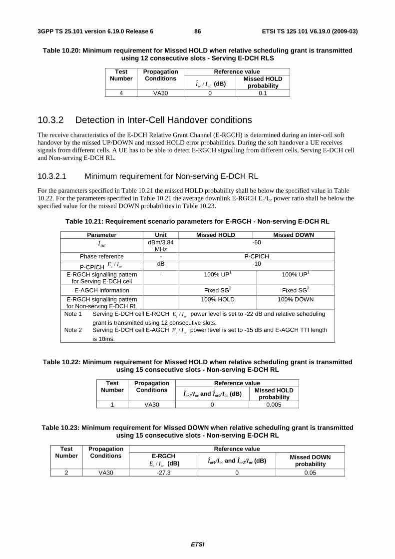
ETSI
ETSI TS 125 101 V6.19.0 (2009-03) 863GPP TS 25.101 version 6.19.0 Release 6
Table 10.20: Minimum requirement for Missed HOLD when relative scheduling grant is transmitted using 12 consecutive slots - Serving E-DCH RLS
Reference value Test Number
Propagation Conditions
ˆ /or ocI I (dB) Missed HOLD
probability 4 VA30 0 0.1
10.3.2 Detection in Inter-Cell Handover conditions
The receive characteristics of the E-DCH Relative Grant Channel (E-RGCH) is determined during an inter-cell soft handover by the missed UP/DOWN and missed HOLD error probabilities. During the soft handover a UE receives signals from different cells. A UE has to be able to detect E-RGCH signalling from different cells, Serving E-DCH cell and Non-serving E-DCH RL.
10.3.2.1 Minimum requirement for Non-serving E-DCH RL
For the parameters specified in Table 10.21 the missed HOLD probability shall be below the specified value in Table 10.22. For the parameters specified in Table 10.21 the average downlink E-RGCH Ec/Ior power ratio shall be below the specified value for the missed DOWN probabilities in Table 10.23.
Table 10.21: Requirement scenario parameters for E-RGCH - Non-serving E-DCH RL
Parameter Unit Missed HOLD Missed DOWN
ocI dBm/3.84
MHz -60
Phase reference - P-CPICH
P-CPICH /c orE I dB -10
E-RGCH signalling pattern for Serving E-DCH cell
- 100% UP1 100% UP1
E-AGCH information Fixed SG2 Fixed SG2
E-RGCH signalling pattern for Non-serving E-DCH RL
100% HOLD 100% DOWN
Note 1 Serving E-DCH cell E-RGCH /c orE I power level is set to -22 dB and relative scheduling
grant is transmitted using 12 consecutive slots. Note 2 Serving E-DCH cell E-AGCH /c orE I power level is set to -15 dB and E-AGCH TTI length
is 10ms.
Table 10.22: Minimum requirement for Missed HOLD when relative scheduling grant is transmitted using 15 consecutive slots - Non-serving E-DCH RL
Reference value Test Number
Propagation Conditions
Îor1/Ioc and Îor2/Ioc (dB) Missed HOLD probability
1 VA30 0 0.005
Table 10.23: Minimum requirement for Missed DOWN when relative scheduling grant is transmitted using 15 consecutive slots - Non-serving E-DCH RL
Reference value Test Number
Propagation Conditions E-RGCH
/c orE I (dB) Îor1/Ioc and Îor2/Ioc (dB) Missed DOWN probability
2 VA30 -27.3 0 0.05
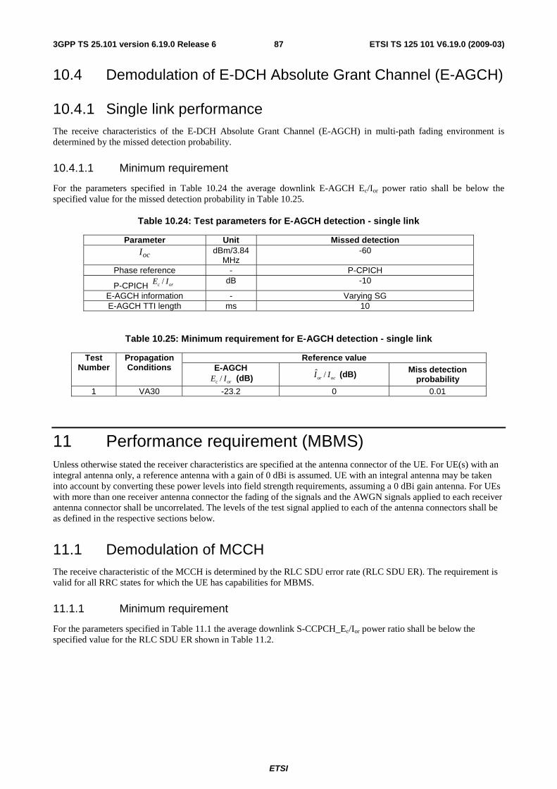
ETSI
ETSI TS 125 101 V6.19.0 (2009-03) 873GPP TS 25.101 version 6.19.0 Release 6
10.4 Demodulation of E-DCH Absolute Grant Channel (E-AGCH)
10.4.1 Single link performance The receive characteristics of the E-DCH Absolute Grant Channel (E-AGCH) in multi-path fading environment is determined by the missed detection probability.
10.4.1.1 Minimum requirement
For the parameters specified in Table 10.24 the average downlink E-AGCH Ec/Ior power ratio shall be below the specified value for the missed detection probability in Table 10.25.
Table 10.24: Test parameters for E-AGCH detection - single link
Parameter Unit Missed detection
ocI dBm/3.84
MHz -60
Phase reference - P-CPICH
P-CPICH /c orE I dB -10
E-AGCH information - Varying SG E-AGCH TTI length ms 10
Table 10.25: Minimum requirement for E-AGCH detection - single link
Reference value Test Number
Propagation Conditions E-AGCH
/c orE I (dB) ˆ /or ocI I (dB) Miss detection
probability 1 VA30 -23.2 0 0.01
11 Performance requirement (MBMS) Unless otherwise stated the receiver characteristics are specified at the antenna connector of the UE. For UE(s) with an integral antenna only, a reference antenna with a gain of 0 dBi is assumed. UE with an integral antenna may be taken into account by converting these power levels into field strength requirements, assuming a 0 dBi gain antenna. For UEs with more than one receiver antenna connector the fading of the signals and the AWGN signals applied to each receiver antenna connector shall be uncorrelated. The levels of the test signal applied to each of the antenna connectors shall be as defined in the respective sections below.
11.1 Demodulation of MCCH The receive characteristic of the MCCH is determined by the RLC SDU error rate (RLC SDU ER). The requirement is valid for all RRC states for which the UE has capabilities for MBMS.
11.1.1 Minimum requirement
For the parameters specified in Table 11.1 the average downlink S-CCPCH_Ec/Ior power ratio shall be below the specified value for the RLC SDU ER shown in Table 11.2.
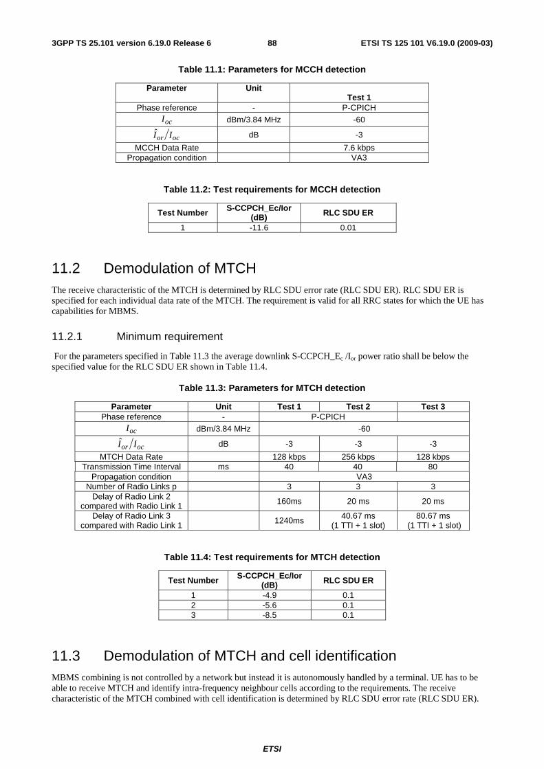
ETSI
ETSI TS 125 101 V6.19.0 (2009-03) 883GPP TS 25.101 version 6.19.0 Release 6
Table 11.1: Parameters for MCCH detection
Parameter Unit Test 1
Phase reference - P-CPICH
ocI dBm/3.84 MHz -60
ocor II dB -3
MCCH Data Rate 7.6 kbps Propagation condition VA3
Table 11.2: Test requirements for MCCH detection
Test Number S-CCPCH_Ec/Ior (dB) RLC SDU ER
1 -11.6 0.01
11.2 Demodulation of MTCH The receive characteristic of the MTCH is determined by RLC SDU error rate (RLC SDU ER). RLC SDU ER is specified for each individual data rate of the MTCH. The requirement is valid for all RRC states for which the UE has capabilities for MBMS.
11.2.1 Minimum requirement
For the parameters specified in Table 11.3 the average downlink S-CCPCH_Ec /Ior power ratio shall be below the specified value for the RLC SDU ER shown in Table 11.4.
Table 11.3: Parameters for MTCH detection
Parameter Unit Test 1 Test 2 Test 3 Phase reference - P-CPICH
ocI dBm/3.84 MHz -60
ocor II dB -3 -3 -3
MTCH Data Rate 128 kbps 256 kbps 128 kbps Transmission Time Interval ms 40 40 80
Propagation condition VA3 Number of Radio Links p 3 3 3
Delay of Radio Link 2 compared with Radio Link 1 160ms 20 ms 20 ms
Delay of Radio Link 3 compared with Radio Link 1
1240ms 40.67 ms (1 TTI + 1 slot)
80.67 ms (1 TTI + 1 slot)
Table 11.4: Test requirements for MTCH detection
Test Number S-CCPCH_Ec/Ior (dB) RLC SDU ER
1 -4.9 0.1 2 -5.6 0.1 3 -8.5 0.1
11.3 Demodulation of MTCH and cell identification MBMS combining is not controlled by a network but instead it is autonomously handled by a terminal. UE has to be able to receive MTCH and identify intra-frequency neighbour cells according to the requirements. The receive characteristic of the MTCH combined with cell identification is determined by RLC SDU error rate (RLC SDU ER).
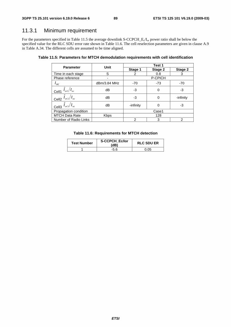
ETSI
ETSI TS 125 101 V6.19.0 (2009-03) 893GPP TS 25.101 version 6.19.0 Release 6
11.3.1 Minimum requirement
For the parameters specified in Table 11.5 the average downlink S-CCPCH_Ec/Ior power ratio shall be below the specified value for the RLC SDU error rate shown in Table 11.6. The cell reselection parameters are given in clause A.9 in Table A.34. The different cells are assumed to be time aligned.
Table 11.5: Parameters for MTCH demodulation requirements with cell identification
Test 1 Parameter Unit Stage 1 Stage 2 Stage 2
Time in each stage S 2 0.8 3 Phase reference - P-CPICH
ocI dBm/3.84 MHz -70 -73 -70
Cell1 ocor II 1ˆ
dB -3 0 -3
Cell2 ocor II 2ˆ
dB -3 0 -infinity
Cell3 ocor II 3ˆ
dB -infinity 0 -3
Propagation condition Case1 MTCH Data Rate Kbps 128 Number of Radio Links 2 3 2
Table 11.6: Requirements for MTCH detection
Test Number S-CCPCH_Ec/Ior (dB) RLC SDU ER
1 -5.6 0.05
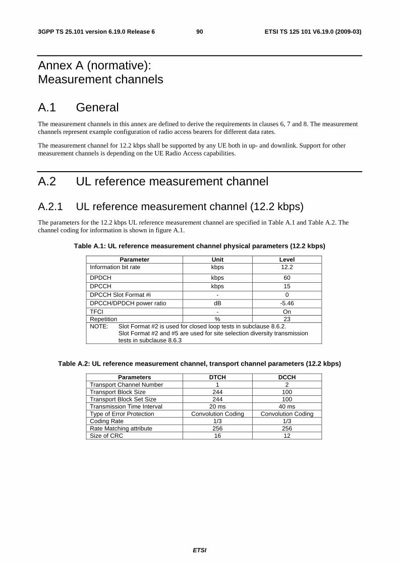
ETSI
ETSI TS 125 101 V6.19.0 (2009-03) 903GPP TS 25.101 version 6.19.0 Release 6
Annex A (normative): Measurement channels
A.1 General The measurement channels in this annex are defined to derive the requirements in clauses 6, 7 and 8. The measurement channels represent example configuration of radio access bearers for different data rates.
The measurement channel for 12.2 kbps shall be supported by any UE both in up- and downlink. Support for other measurement channels is depending on the UE Radio Access capabilities.
A.2 UL reference measurement channel
A.2.1 UL reference measurement channel (12.2 kbps) The parameters for the 12.2 kbps UL reference measurement channel are specified in Table A.1 and Table A.2. The channel coding for information is shown in figure A.1.
Table A.1: UL reference measurement channel physical parameters (12.2 kbps)
Parameter Unit Level Information bit rate kbps 12.2
DPDCH kbps 60 DPCCH kbps 15 DPCCH Slot Format #i - 0 DPCCH/DPDCH power ratio dB -5.46 TFCI - On Repetition % 23 NOTE: Slot Format #2 is used for closed loop tests in subclause 8.6.2. Slot Format #2 and #5 are used for site selection diversity transmission
tests in subclause 8.6.3
Table A.2: UL reference measurement channel, transport channel parameters (12.2 kbps)
Parameters DTCH DCCH Transport Channel Number 1 2 Transport Block Size 244 100 Transport Block Set Size 244 100 Transmission Time Interval 20 ms 40 ms Type of Error Protection Convolution Coding Convolution Coding Coding Rate 1/3 1/3 Rate Matching attribute 256 256 Size of CRC 16 12
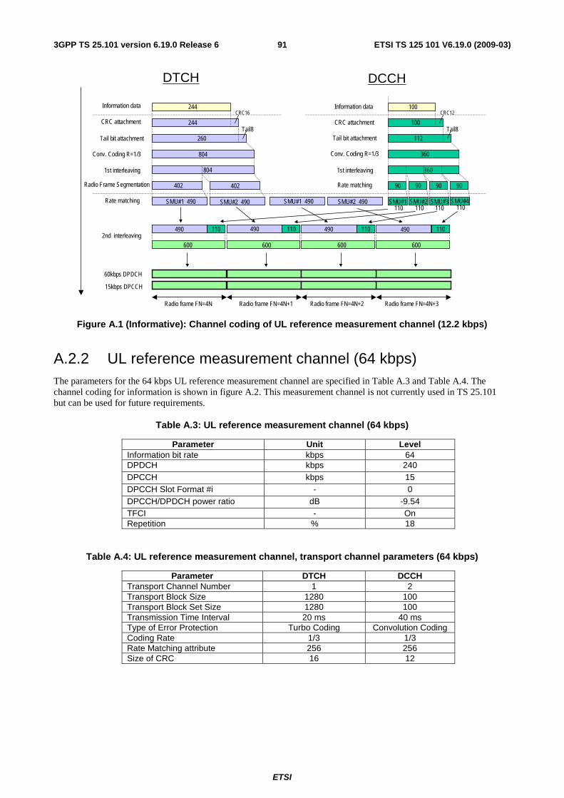
ETSI
ETSI TS 125 101 V6.19.0 (2009-03) 913GPP TS 25.101 version 6.19.0 Release 6
60kbps DPDCH
Conv. Coding R=1/3
Radio frame FN=4N+1 Radio frame FN=4N+2 Radio frame FN=4N+3Radio frame FN=4N
Information data
CRC attachment
Tail bit attachment
Rate matching
2nd interleaving600
490 110 490 110 490 110 490
SMU#1 490 SMU#2 490 SMU#1 110
SMU#2 110
SMU#3110
SMU#4 110
600 600 600
402
804
260Tail8
CRC16
244
244
110
360
360
112Tail8
100
CRC12
1st interleaving
Radio Frame Segmentation
CRC attachment
Information data
Tail bit attachment
Conv. Coding R=1/3
Rate matching
1st interleaving
DTCH DCCH
804
402
SMU#1 490 SMU#2 490
90 90 90 90
15kbps DPCCH
100
Figure A.1 (Informative): Channel coding of UL reference measurement channel (12.2 kbps)
A.2.2 UL reference measurement channel (64 kbps) The parameters for the 64 kbps UL reference measurement channel are specified in Table A.3 and Table A.4. The channel coding for information is shown in figure A.2. This measurement channel is not currently used in TS 25.101 but can be used for future requirements.
Table A.3: UL reference measurement channel (64 kbps)
Parameter Unit Level Information bit rate kbps 64 DPDCH kbps 240 DPCCH kbps 15 DPCCH Slot Format #i - 0 DPCCH/DPDCH power ratio dB -9.54 TFCI - On Repetition % 18
Table A.4: UL reference measurement channel, transport channel parameters (64 kbps)
Parameter DTCH DCCH Transport Channel Number 1 2 Transport Block Size 1280 100 Transport Block Set Size 1280 100 Transmission Time Interval 20 ms 40 ms Type of Error Protection Turbo Coding Convolution Coding Coding Rate 1/3 1/3 Rate Matching attribute 256 256 Size of CRC 16 12
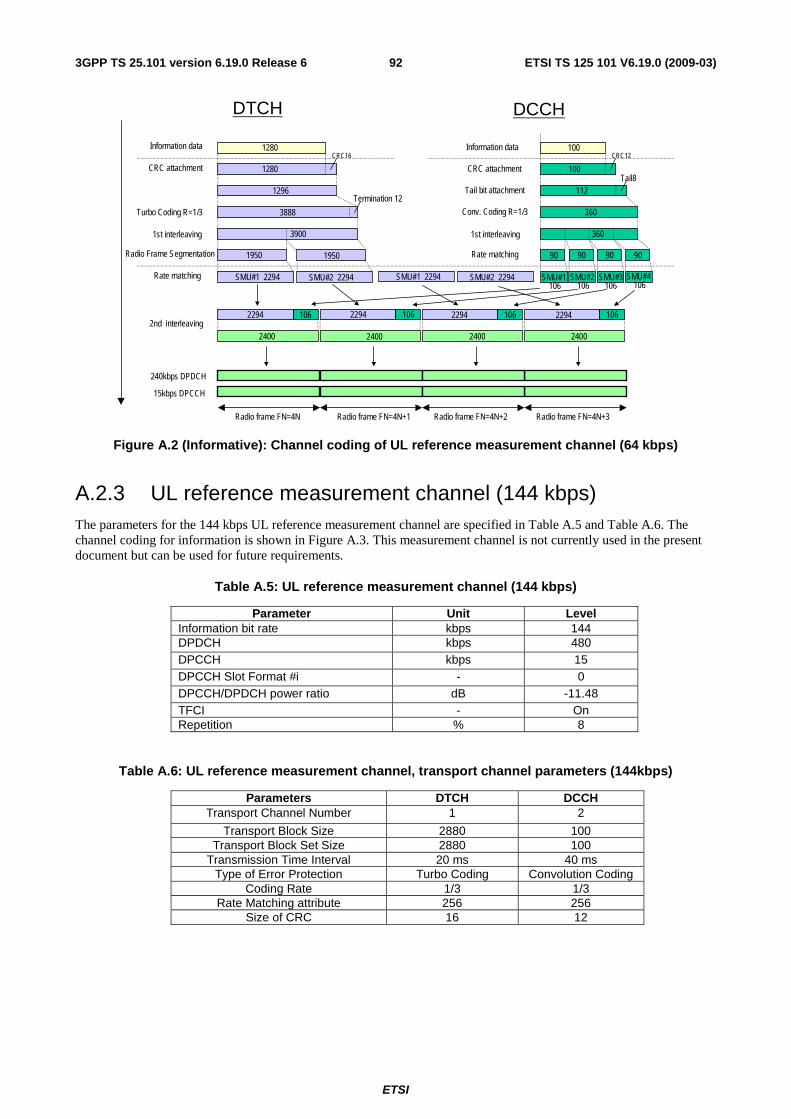
ETSI
ETSI TS 125 101 V6.19.0 (2009-03) 923GPP TS 25.101 version 6.19.0 Release 6
240kbps DPDCH
Turbo Coding R=1/3
Radio frame FN=4N+1 Radio frame FN=4N+2 Radio frame FN=4N+3Radio frame FN=4N
Information data
CRC attachment
2nd interleaving2400
2294 106 2294 106 2294 106 2294
SMU#1 2294 SMU#2 2294 SMU#1 106
SMU#2 106
SMU#3106
SMU#4 106
2400 2400 2400
1950
3888
1296Termination 12
CRC16
1280
1280
106
360
360
112Tail8
100
1st interleaving
CRC attachment
Information data
Tail bit attachment
Conv. Coding R=1/3
Rate matching
1st interleaving
DTCH DCCH
3900
1950
SMU#1 2294 SMU#2 2294
90 90 90 90
15kbps DPCCH
Rate matching
Radio Frame Segmentation
100CRC12
Figure A.2 (Informative): Channel coding of UL reference measurement channel (64 kbps)
A.2.3 UL reference measurement channel (144 kbps) The parameters for the 144 kbps UL reference measurement channel are specified in Table A.5 and Table A.6. The channel coding for information is shown in Figure A.3. This measurement channel is not currently used in the present document but can be used for future requirements.
Table A.5: UL reference measurement channel (144 kbps)
Parameter Unit Level Information bit rate kbps 144 DPDCH kbps 480 DPCCH kbps 15 DPCCH Slot Format #i - 0 DPCCH/DPDCH power ratio dB -11.48 TFCI - On Repetition % 8
Table A.6: UL reference measurement channel, transport channel parameters (144kbps)
Parameters DTCH DCCH Transport Channel Number 1 2
Transport Block Size 2880 100 Transport Block Set Size 2880 100
Transmission Time Interval 20 ms 40 ms Type of Error Protection Turbo Coding Convolution Coding
Coding Rate 1/3 1/3 Rate Matching attribute 256 256
Size of CRC 16 12
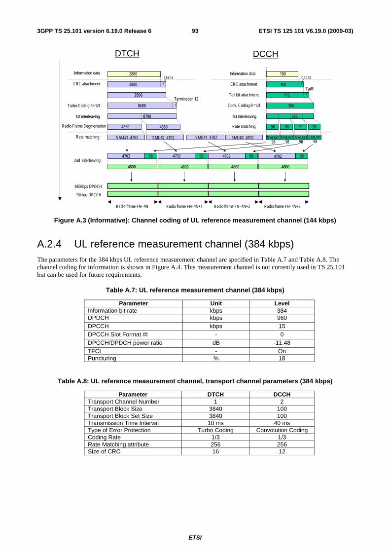
ETSI
ETSI TS 125 101 V6.19.0 (2009-03) 933GPP TS 25.101 version 6.19.0 Release 6
480kbps DPDCH
Turbo Coding R=1/3
Radio frame FN=4N+1 Radio frame FN=4N+2 Radio frame FN=4N+3Radio frame FN=4N
Information data
CRC attachment
2nd interleaving4800
4702 98 4702 98 4702 98 4702
SMU#1 4702 SMU#2 4702 SMU#1 98
SMU#2 98
SMU#398
SMU#4 98
4800 4800 4800
4350
8688
2896Termination 12
2880
2880
98
360
360
112Tail8
100
1st interleaving
CRC attachment
Information data
Tail bit attachment
Conv. Coding R=1/3
Rate matching
1st interleaving
DTCH DCCH
8700
4350
SMU#1 4702 SMU#2 4702
90 90 90 90
15kbps DPCCH
Rate matching
Radio Frame Segmentation
100CRC16 CRC12
Figure A.3 (Informative): Channel coding of UL reference measurement channel (144 kbps)
A.2.4 UL reference measurement channel (384 kbps) The parameters for the 384 kbps UL reference measurement channel are specified in Table A.7 and Table A.8. The channel coding for information is shown in Figure A.4. This measurement channel is not currently used in TS 25.101 but can be used for future requirements.
Table A.7: UL reference measurement channel (384 kbps)
Parameter Unit Level Information bit rate kbps 384 DPDCH kbps 960 DPCCH kbps 15 DPCCH Slot Format #I - 0 DPCCH/DPDCH power ratio dB -11.48 TFCI - On Puncturing % 18
Table A.8: UL reference measurement channel, transport channel parameters (384 kbps)
Parameter DTCH DCCH Transport Channel Number 1 2 Transport Block Size 3840 100 Transport Block Set Size 3840 100 Transmission Time Interval 10 ms 40 ms Type of Error Protection Turbo Coding Convolution Coding Coding Rate 1/3 1/3 Rate Matching attribute 256 256 Size of CRC 16 12
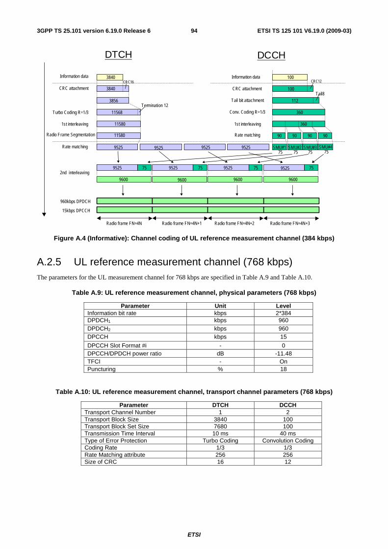
ETSI
ETSI TS 125 101 V6.19.0 (2009-03) 943GPP TS 25.101 version 6.19.0 Release 6
960kbps DPDCH
Turbo Coding R=1/3
Radio frame FN=4N+1 Radio frame FN=4N+2 Radio frame FN=4N+3Radio frame FN=4N
Information data
CRC attachment
2nd interleaving
9600
9525 75 9525 75 9525 75 9525
9525 9525 SMU#1 75
SMU#2 75
SMU#375
SMU#4 75
9600 9600 9600
11580
11568
3856
75
360
360
112
Tail8100
1st interleaving
CRC attachment
Information data
Tail bit attachment
Conv. Coding R=1/3
Rate matching
1st interleaving
DTCH DCCH
11580
9525 9525
90 90 90 90
15kbps DPCCH
Rate matching
Radio Frame Segmentation
1003840
3840
CRC16
Termination 12
CRC12
Figure A.4 (Informative): Channel coding of UL reference measurement channel (384 kbps)
A.2.5 UL reference measurement channel (768 kbps) The parameters for the UL measurement channel for 768 kbps are specified in Table A.9 and Table A.10.
Table A.9: UL reference measurement channel, physical parameters (768 kbps)
Parameter Unit Level Information bit rate kbps 2*384 DPDCH1 kbps 960 DPDCH2 kbps 960 DPCCH kbps 15
DPCCH Slot Format #i - 0 DPCCH/DPDCH power ratio dB -11.48 TFCI - On Puncturing % 18
Table A.10: UL reference measurement channel, transport channel parameters (768 kbps)
Parameter DTCH DCCH Transport Channel Number 1 2 Transport Block Size 3840 100 Transport Block Set Size 7680 100 Transmission Time Interval 10 ms 40 ms Type of Error Protection Turbo Coding Convolution Coding Coding Rate 1/3 1/3 Rate Matching attribute 256 256 Size of CRC 16 12
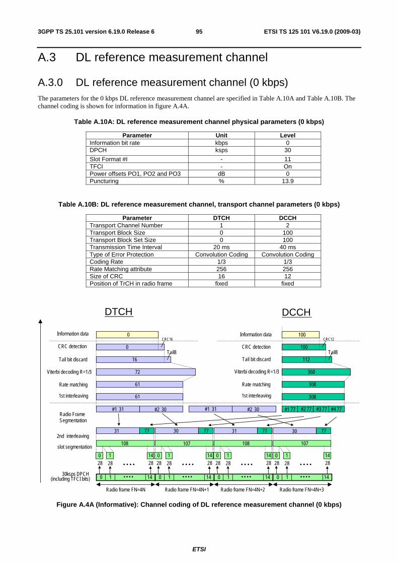
ETSI
ETSI TS 125 101 V6.19.0 (2009-03) 953GPP TS 25.101 version 6.19.0 Release 6
A.3 DL reference measurement channel
A.3.0 DL reference measurement channel (0 kbps) The parameters for the 0 kbps DL reference measurement channel are specified in Table A.10A and Table A.10B. The channel coding is shown for information in figure A.4A.
Table A.10A: DL reference measurement channel physical parameters (0 kbps)
Parameter Unit Level Information bit rate kbps 0 DPCH ksps 30
Slot Format #I - 11 TFCI - On Power offsets PO1, PO2 and PO3 dB 0 Puncturing % 13.9
Table A.10B: DL reference measurement channel, transport channel parameters (0 kbps)
Parameter DTCH DCCH Transport Channel Number 1 2 Transport Block Size 0 100 Transport Block Set Size 0 100 Transmission Time Interval 20 ms 40 ms Type of Error Protection Convolution Coding Convolution Coding Coding Rate 1/3 1/3 Rate Matching attribute 256 256 Size of CRC 16 12 Position of TrCH in radio frame fixed fixed
Viterbi decoding R=1/3
Radio frame FN=4N+1 Radio frame FN=4N+2 Radio frame FN=4N+3 Radio frame FN=4N
Information data
CRC detection
Tail bit discard
2 nd interleaving 108
31 77 30 77 31 77 30
#1 31 #2 30 #1 77 #2 77 #3 77 #4 77
107 108 107
61
72
16 Tail8
CRC16 0
0
77
308
360
112 Tail8
100 CRC12
Rate matching
1 st interleaving
CRC detection
Information data
Tail bit discard
Viterbi decoding R=1/3
DTCH DCCH
61
#1 31 #2 30
308
100
Radio Frame Segmentation
slot segmentation
30 ksps DPCH (including TFCI bits)
Rate matching
1 st interleaving
0 1 14 • • • •
28 28 0 1
28 • • • • 14
0 1 14 • • • •
28 28 0 1
28 • • • • 14
0 1 14 • • • •
28 28 0 1
28 • • • • 14
0 1 14 • • • •
28 28 0 1
28 • • • • 14
Figure A.4A (Informative): Channel coding of DL reference measurement channel (0 kbps)
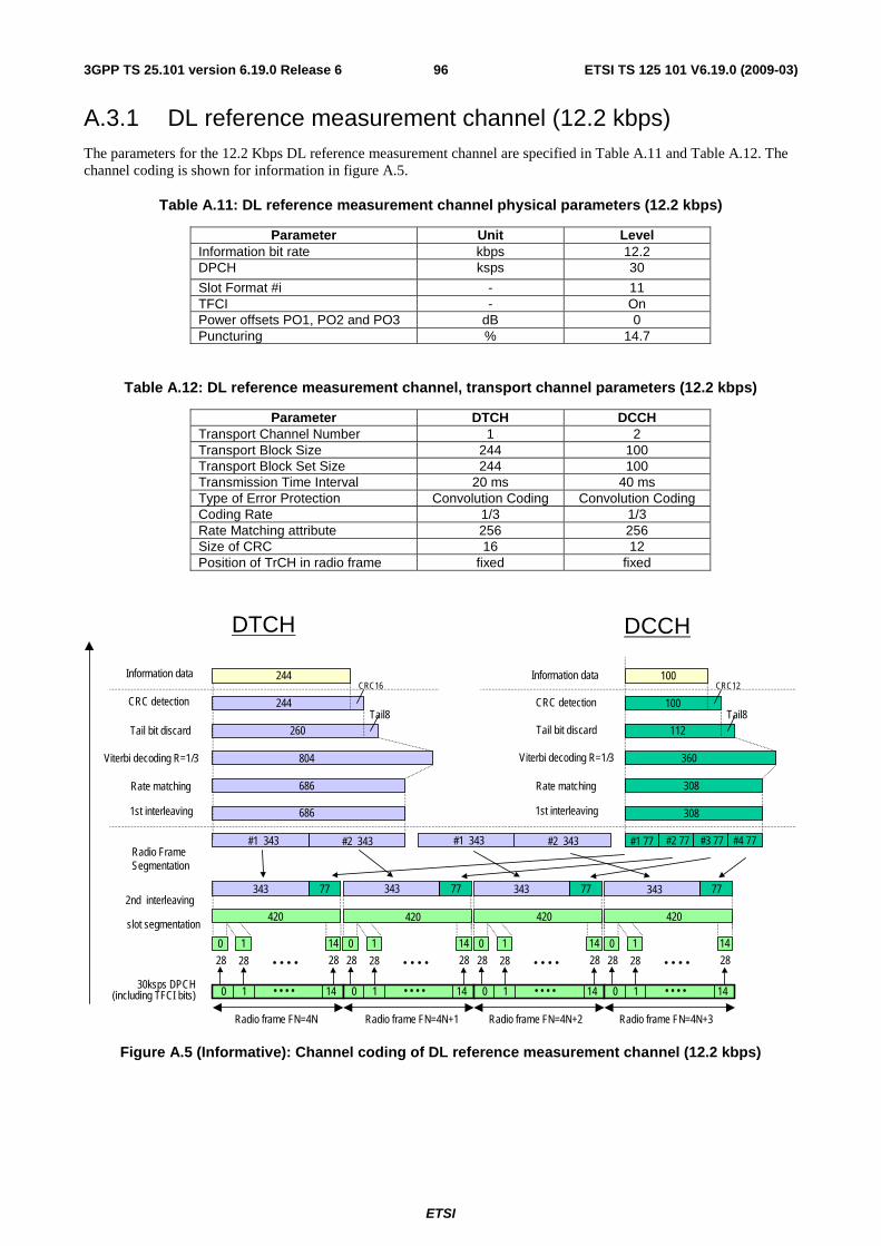
ETSI
ETSI TS 125 101 V6.19.0 (2009-03) 963GPP TS 25.101 version 6.19.0 Release 6
A.3.1 DL reference measurement channel (12.2 kbps) The parameters for the 12.2 Kbps DL reference measurement channel are specified in Table A.11 and Table A.12. The channel coding is shown for information in figure A.5.
Table A.11: DL reference measurement channel physical parameters (12.2 kbps)
Parameter Unit Level Information bit rate kbps 12.2 DPCH ksps 30
Slot Format #i - 11 TFCI - On Power offsets PO1, PO2 and PO3 dB 0 Puncturing % 14.7
Table A.12: DL reference measurement channel, transport channel parameters (12.2 kbps)
Parameter DTCH DCCH Transport Channel Number 1 2 Transport Block Size 244 100 Transport Block Set Size 244 100 Transmission Time Interval 20 ms 40 ms Type of Error Protection Convolution Coding Convolution Coding Coding Rate 1/3 1/3 Rate Matching attribute 256 256 Size of CRC 16 12 Position of TrCH in radio frame fixed fixed
Viterbi decoding R=1/3
Radio frame FN=4N+1 Radio frame FN=4N+2 Radio frame FN=4N+3Radio frame FN=4N
Information data
CRC detection
Tail bit discard
2nd interleaving420
343 77 343 77 343 77 343
#1 343 #2 343 #1 77 #2 77 #3 77 #4 77
420 420 420
686
804
260Tail8
CRC16
244
244
77
308
360
112Tail8
100
CRC12
Rate matching
1st interleaving
CRC detection
Information data
Tail bit discard
Viterbi decoding R=1/3
DTCH DCCH
686
#1 343 #2 343
308
100
Radio Frame Segmentation
slot segmentation
30ksps DPCH (including TFCI bits)
Rate matching
1st interleaving
0 1 14• • • •
28 28
0 1
28• • • •
14
0 1 14• • • •
28 28
0 1
28• • • •
14
0 1 14• • • •
28 28
0 1
28• • • •
14
0 1 14• • • •
28 28
0 1
28• • • •
14
Figure A.5 (Informative): Channel coding of DL reference measurement channel (12.2 kbps)
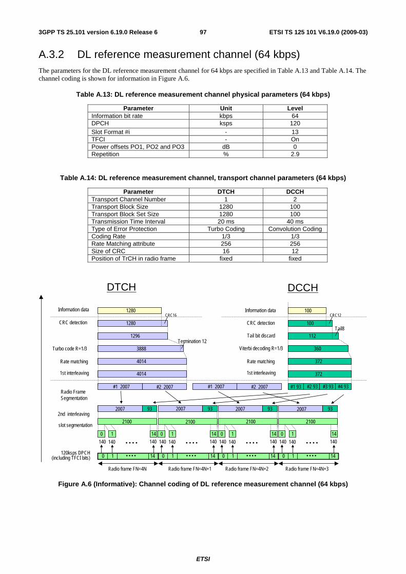
ETSI
ETSI TS 125 101 V6.19.0 (2009-03) 973GPP TS 25.101 version 6.19.0 Release 6
A.3.2 DL reference measurement channel (64 kbps) The parameters for the DL reference measurement channel for 64 kbps are specified in Table A.13 and Table A.14. The channel coding is shown for information in Figure A.6.
Table A.13: DL reference measurement channel physical parameters (64 kbps)
Parameter Unit Level Information bit rate kbps 64 DPCH ksps 120 Slot Format #i - 13 TFCI - On Power offsets PO1, PO2 and PO3 dB 0 Repetition % 2.9
Table A.14: DL reference measurement channel, transport channel parameters (64 kbps)
Parameter DTCH DCCH Transport Channel Number 1 2 Transport Block Size 1280 100 Transport Block Set Size 1280 100 Transmission Time Interval 20 ms 40 ms Type of Error Protection Turbo Coding Convolution Coding Coding Rate 1/3 1/3 Rate Matching attribute 256 256 Size of CRC 16 12 Position of TrCH in radio frame fixed fixed
Turbo code R=1/3
Radio frame FN=4N+1 Radio frame FN=4N+2 Radio frame FN=4N+3Radio frame FN=4N
Information data
CRC detection
2nd interleaving2100
2007 93 2007 93 2007 93 2007
#1 2007 #2 2007 #1 93 #2 93 #3 93 #4 93
2100 2100 2100
4014
3888
1296
CRC16
1280
1280
93
372
360
100
CRC12
Rate matching
1st interleaving
CRC detection
Information data
DTCH DCCH
4014
#1 2007 #2 2007
372
100
Radio Frame Segmentation
slot segmentation
120ksps DPCH (including TFCI bits)
Rate matching
1st interleaving
0 1 14• • • •
140 140
0 1
140• • • •
14
0 1 14• • • •
140 140
0 1
140• • • •
14
0 1 14• • • •
140 140
0 1
140• • • •
14
0 1 14• • • •
140 140
0 1
140• • • •
14
Termination 12112
Tail8Tail bit discard
Viterbi decoding R=1/3
Figure A.6 (Informative): Channel coding of DL reference measurement channel (64 kbps)

ETSI
ETSI TS 125 101 V6.19.0 (2009-03) 983GPP TS 25.101 version 6.19.0 Release 6
A.3.3 DL reference measurement channel (144 kbps) The parameters for the DL measurement channel for 144 kbps are specified in Table A.15 and Table A.16. The channel coding is shown for information in Figure A.7.
Table A.15: DL reference measurement channel physical parameters (144 kbps)
Parameter Unit Level Information bit rate kbps 144 DPCH ksps 240 Slot Format #i - 14 TFCI - On Power offsets PO1, PO2 and PO3 dB 0 Puncturing % 2.7
Table A.16: DL reference measurement channel, transport channel parameters (144 kbps)
Parameter DTCH DCCH Transport Channel Number 1 2 Transport Block Size 2880 100 Transport Block Set Size 2880 100 Transmission Time Interval 20 ms 40 ms Type of Error Protection Turbo Coding Convolution Coding Coding Rate 1/3 1/3 Rate Matching attribute 256 256 Size of CRC 16 12 Position of TrCH in radio frame fixed fixed
Turbo code R=1/3
Radio frame FN=4N+1 Radio frame FN=4N+2 Radio frame FN=4N+3Radio frame FN=4N
Information data
CRC detection
2nd interleaving4320
4232 88 4232 88 4232 88 4232
#1 4232 #2 4232 #1 88 #2 88 #3 88 #4 88
4320 4320 4320
8464
8688
2896
CRC16
2880
2880
88
352
360
100
CRC12
Rate matching
1st interleaving
CRC detection
Information data
DTCH DCCH
8464
#1 4232 #2 4232
352
100
Radio Frame Segmentation
slot segmentation
240ksps DPCH (including TFCI bits)
Rate matching
1st interleaving
0 1 14• • • •
288 288
0 1
288• • • •
14
0 1 14• • • •
288 288
0 1
288• • • •
14
0 1 14• • • •
288 288
0 1
288• • • •
14
0 1 14• • • •
288 288
0 1
288• • • •
14
Termination 12112
Tail8Tail bit discard
Viterbi decoding R=1/3
Figure A.7 (Informative): Channel coding of DL reference measurement channel (144 kbps)
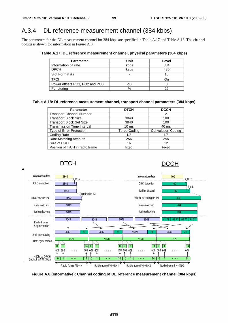
ETSI
ETSI TS 125 101 V6.19.0 (2009-03) 993GPP TS 25.101 version 6.19.0 Release 6
A.3.4 DL reference measurement channel (384 kbps) The parameters for the DL measurement channel for 384 kbps are specified in Table A.17 and Table A.18. The channel coding is shown for information in Figure A.8
Table A.17: DL reference measurement channel, physical parameters (384 kbps)
Parameter Unit Level Information bit rate kbps 384 DPCH ksps 480 Slot Format # i - 15
TFCI On Power offsets PO1, PO2 and PO3 dB 0 Puncturing % 22
Table A.18: DL reference measurement channel, transport channel parameters (384 kbps)
Parameter DTCH DCCH Transport Channel Number 1 2 Transport Block Size 3840 100 Transport Block Set Size 3840 100 Transmission Time Interval 10 ms 40 ms Type of Error Protection Turbo Coding Convolution Coding Coding Rate 1/3 1/3 Rate Matching attribute 256 256 Size of CRC 16 12 Position of TrCH in radio frame fixed Fixed
Turbo code R=1/3
Radio frame FN=4N+1 Radio frame FN=4N+2 Radio frame FN=4N+3Radio frame FN=4N
Information data
CRC detection
2nd interleaving9120
9049 71 9049 71 9049 71 9049
9049 9049 #1 71 #2 71 #3 71 #4 71
9120 9120 9120
9049
11568
3856
CRC16
3840
3840
71
284
360
100
CRC12
Rate matching
1st interleaving
CRC detection
Information data
DTCH DCCH
9049
9049 9049
284
100
Radio Frame Segmentation
slot segmentation
480ksps DPCH (including TFCI bits)
Rate matching
1st interleaving
0 1 14• • • •
608 608
0 1
608• • • •
14
0 1 14• • • •
608 608
0 1
608• • • •
14
0 1 14• • • •
608 608
0 1
608• • • •
14
0 1 14• • • •
608 608
0 1
608• • • •
14
Termination 12112
Tail8Tail bit discard
Viterbi decoding R=1/3
Figure A.8 (Informative): Channel coding of DL reference measurement channel (384 kbps)
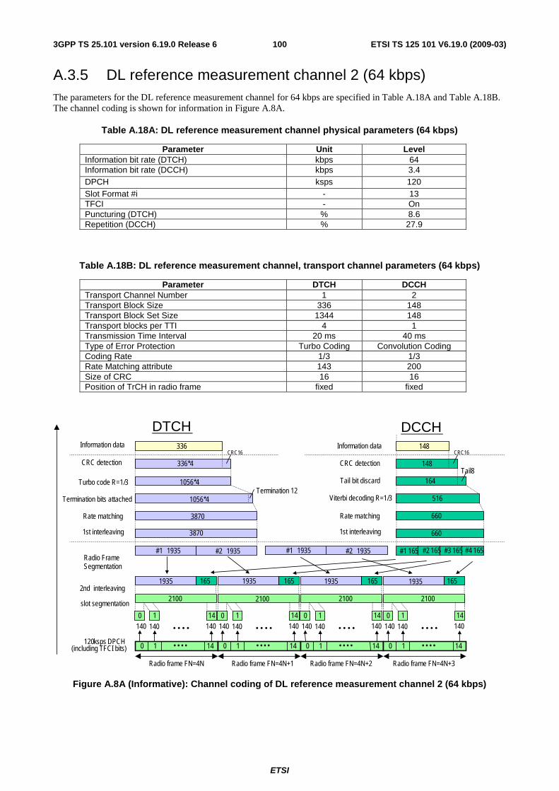
ETSI
ETSI TS 125 101 V6.19.0 (2009-03) 1003GPP TS 25.101 version 6.19.0 Release 6
A.3.5 DL reference measurement channel 2 (64 kbps) The parameters for the DL reference measurement channel for 64 kbps are specified in Table A.18A and Table A.18B. The channel coding is shown for information in Figure A.8A.
Table A.18A: DL reference measurement channel physical parameters (64 kbps)
Parameter Unit Level Information bit rate (DTCH) kbps 64 Information bit rate (DCCH) kbps 3.4 DPCH ksps 120 Slot Format #i - 13 TFCI - On Puncturing (DTCH) % 8.6 Repetition (DCCH) % 27.9
Table A.18B: DL reference measurement channel, transport channel parameters (64 kbps)
Parameter DTCH DCCH Transport Channel Number 1 2 Transport Block Size 336 148 Transport Block Set Size 1344 148 Transport blocks per TTI 4 1 Transmission Time Interval 20 ms 40 ms Type of Error Protection Turbo Coding Convolution Coding Coding Rate 1/3 1/3 Rate Matching attribute 143 200 Size of CRC 16 16 Position of TrCH in radio frame fixed fixed
Turbo code R=1/3
Radio frame FN=4N+1 Radio frame FN=4N+2 Radio frame FN=4N+3 Radio frame FN=4N
Information data
CRC detection
2 nd interleaving 2100
1935 165 1935 165 1935 165 1935
#1 1935 #2 1935 #1 165 #2 165 #3 165 #4 165
2100 2100 2100
3870
1056*4
1056*4
CRC16 336*4
336
165
660
516
148 CRC16
Rate matching 1 st interleaving
CRC detection
Information data
DTCH DCCH
3870
#1 1935 #2 1935
660
148
Radio Frame Segmentation
slot segmentation
120 ksps DPCH (including TFCI bits)
Rate matching 1 st interleaving
0 1 14 • • • •
140 140 0 1
140 • • • • 14
0 1 14 • • • •
140 140 0 1
140 • • • • 14
0 1 14 • • • •
140 140 0 1
140 • • • • 14
0 1 14 • • • •
140 140 0 1
140 • • • • 14
Termination 12 164
Tail8 Tail bit discard
Viterbi decoding R=1/3 Termination bits attached
Figure A.8A (Informative): Channel coding of DL reference measurement channel 2 (64 kbps)
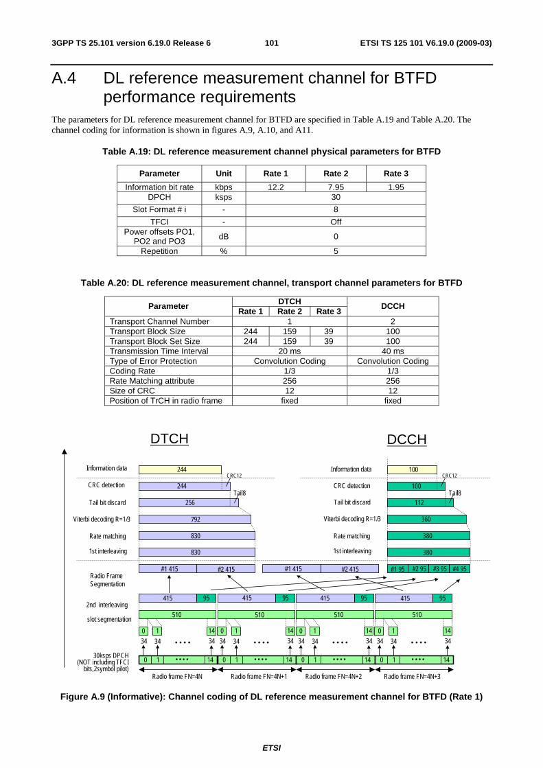
ETSI
ETSI TS 125 101 V6.19.0 (2009-03) 1013GPP TS 25.101 version 6.19.0 Release 6
A.4 DL reference measurement channel for BTFD performance requirements
The parameters for DL reference measurement channel for BTFD are specified in Table A.19 and Table A.20. The channel coding for information is shown in figures A.9, A.10, and A11.
Table A.19: DL reference measurement channel physical parameters for BTFD
Parameter Unit Rate 1 Rate 2 Rate 3
Information bit rate kbps 12.2 7.95 1.95 DPCH ksps 30
Slot Format # i - 8
TFCI - Off Power offsets PO1,
PO2 and PO3 dB 0
Repetition % 5
Table A.20: DL reference measurement channel, transport channel parameters for BTFD
DTCH Parameter Rate 1 Rate 2 Rate 3
DCCH
Transport Channel Number 1 2 Transport Block Size 244 159 39 100 Transport Block Set Size 244 159 39 100 Transmission Time Interval 20 ms 40 ms Type of Error Protection Convolution Coding Convolution Coding Coding Rate 1/3 1/3 Rate Matching attribute 256 256 Size of CRC 12 12 Position of TrCH in radio frame fixed fixed
Viterbi decoding R=1/3
Radio frame FN=4N+1 Radio frame FN=4N+2 Radio frame FN=4N+3Radio frame FN=4N
Information data
CRC detection
Tail bit discard
2nd interleaving510
415 95 415 95 415 95 415
#1 415 #2 415 #1 95 #2 95 #3 95 #4 95
510 510 510
830
792
256Tail8
CRC12
244
244
95
380
360
112Tail8
100
CRC12
Rate matching
1st interleaving
CRC detection
Information data
Tail bit discard
Viterbi decoding R=1/3
DTCH DCCH
830
#1 415 #2 415
380
100
Radio Frame Segmentation
slot segmentation
30ksps DPCH (NOT including TFCI
bits,2symbol pilot)
Rate matching
1st interleaving
0 1 14• • • •
34 34
0 1
34• • • •
14
0 1 14• • • •
34 34
0 1
34• • • •
14
0 1 14• • • •
34 34
0 1
34• • • •
14
0 1 14• • • •
34 34
0 1
34• • • •
14
Figure A.9 (Informative): Channel coding of DL reference measurement channel for BTFD (Rate 1)
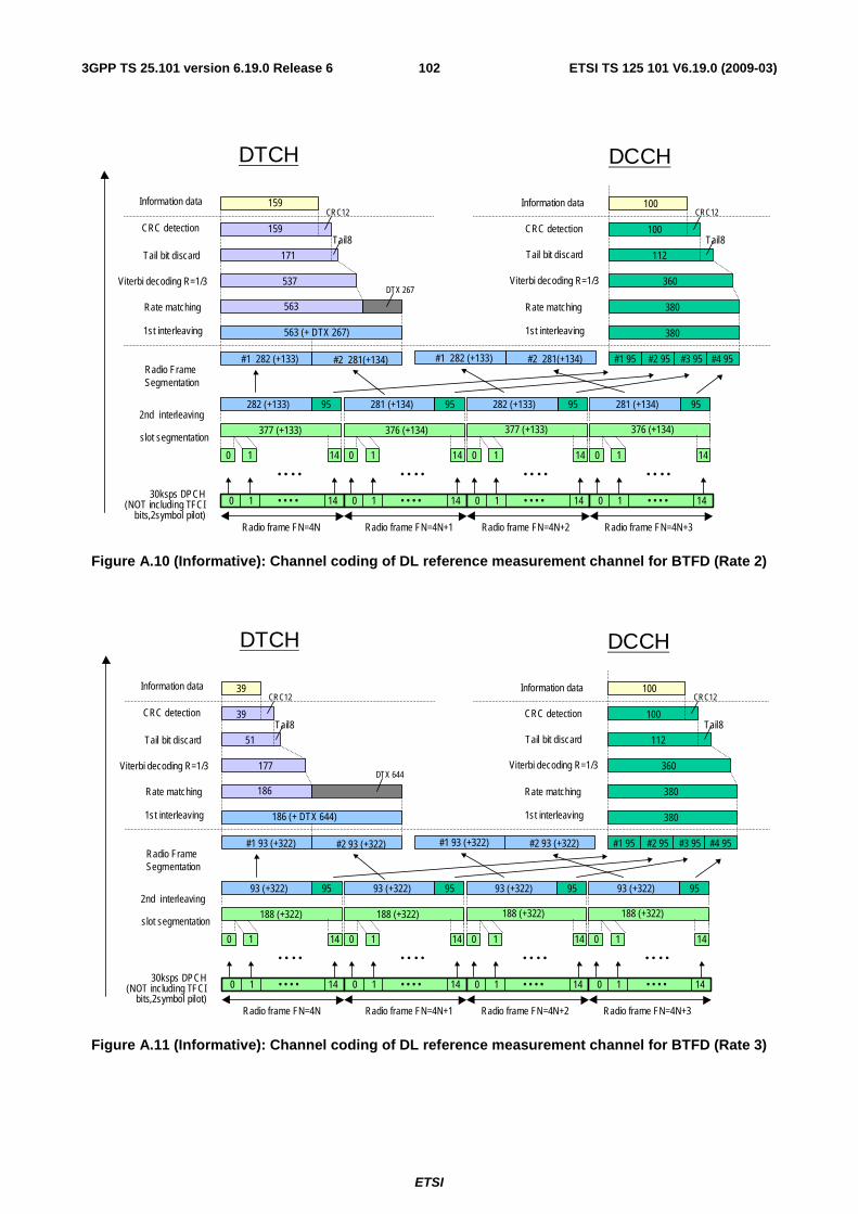
ETSI
ETSI TS 125 101 V6.19.0 (2009-03) 1023GPP TS 25.101 version 6.19.0 Release 6
Viterbi decoding R=1/3
Radio frame FN=4N+1 Radio frame FN=4N+2 Radio frame FN=4N+3Radio frame FN=4N
Information data
CRC detection
Tail bit discard
2nd interleaving282 (+133) 95 281 (+134) 95 95
#1 282 (+133) #2 281(+134) #1 95 #2 95 #3 95 #4 95
563 (+ DTX 267)
537
171
Tail8
CRC12
159
159
95
380
360
112
Tail8100
CRC12
Rate matching
1st interleaving
CRC detection
Information data
Tail bit discard
Viterbi decoding R=1/3
DTCH DCCH
563
380
100
Radio Frame Segmentation
slot segmentation
30ksps DPCH (NOT including TFCI
bits,2symbol pilot)
Rate matching
1st interleaving
0 1 14• • • •
0 1
• • • •
14
0 1 14• • • •
0 1
• • • •
14
0 1 14• • • •
0 1
• • • •
14
0 1 14• • • •
0 1
• • • •
14
282 (+133) 281 (+134)
DTX 267
#1 282 (+133) #2 281(+134)
377 (+133) 376 (+134) 377 (+133) 376 (+134)
Figure A.10 (Informative): Channel coding of DL reference measurement channel for BTFD (Rate 2)
Viterbi decoding R=1/3
Radio frame FN=4N+1 Radio frame FN=4N+2 Radio frame FN=4N+3Radio frame FN=4N
Information data
CRC detection
Tail bit discard
2nd interleaving95 95 95
#1 95 #2 95 #3 95 #4 95
177
51
Tail8
CRC12
39
39
95
380
360
112
Tail8100
CRC12
Rate matching
1st interleaving
CRC detection
Information data
Tail bit discard
Viterbi decoding R=1/3
DTCH DCCH
186
380
100
Radio Frame Segmentation
slot segmentation
30ksps DPCH (NOT including TFCI
bits,2symbol pilot)
Rate matching
1st interleaving
0 1 14• • • •
0 1
• • • •
14
0 1 14• • • •
0 1
• • • •
14
0 1 14• • • •
0 1
• • • •
14
0 1 14• • • •
0 1
• • • •
14
DTX 644
186 (+ DTX 644)
#1 93 (+322) #2 93 (+322) #1 93 (+322) #2 93 (+322)
93 (+322) 93 (+322) 93 (+322) 93 (+322)
188 (+322) 188 (+322) 188 (+322) 188 (+322)
Figure A.11 (Informative): Channel coding of DL reference measurement channel for BTFD (Rate 3)
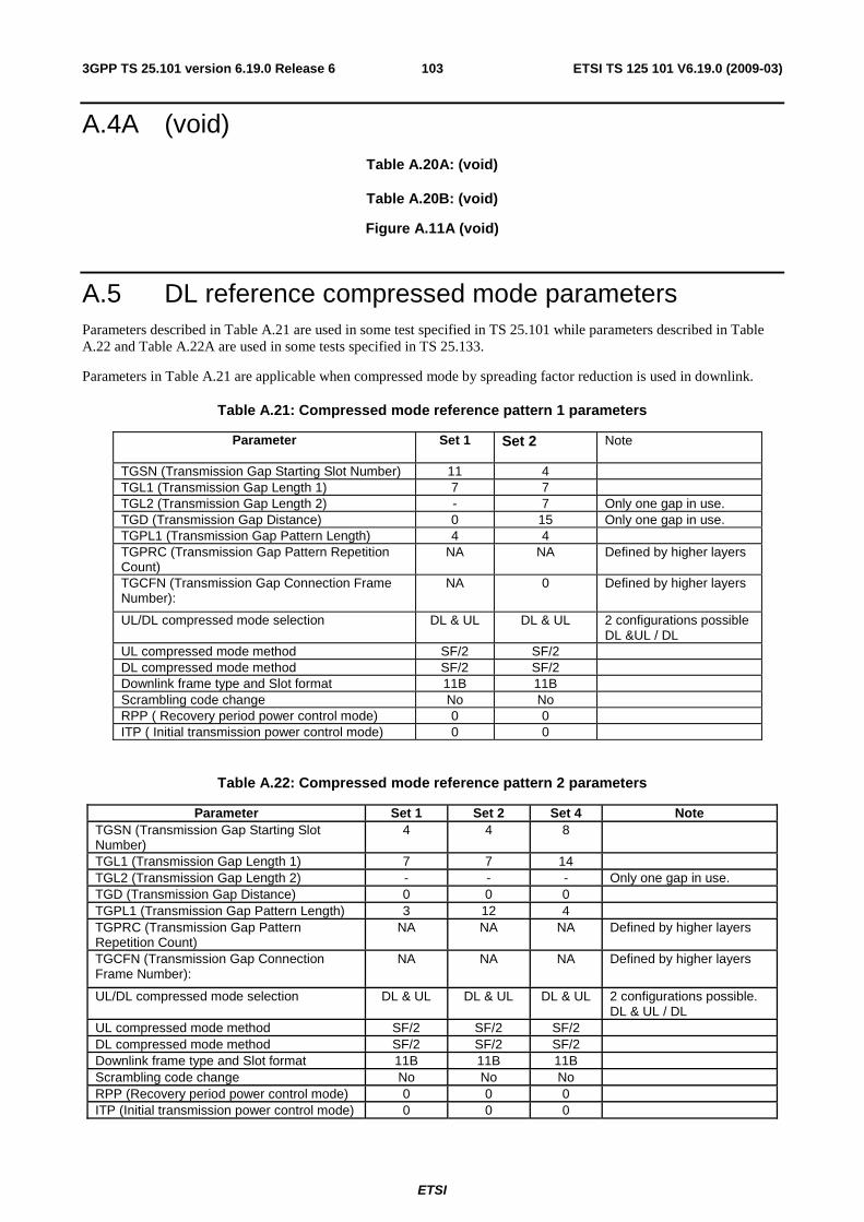
ETSI
ETSI TS 125 101 V6.19.0 (2009-03) 1033GPP TS 25.101 version 6.19.0 Release 6
A.4A (void) Table A.20A: (void)
Table A.20B: (void)
Figure A.11A (void)
A.5 DL reference compressed mode parameters Parameters described in Table A.21 are used in some test specified in TS 25.101 while parameters described in Table A.22 and Table A.22A are used in some tests specified in TS 25.133.
Parameters in Table A.21 are applicable when compressed mode by spreading factor reduction is used in downlink.
Table A.21: Compressed mode reference pattern 1 parameters
Parameter Set 1 Set 2 Note
TGSN (Transmission Gap Starting Slot Number) 11 4 TGL1 (Transmission Gap Length 1) 7 7 TGL2 (Transmission Gap Length 2) - 7 Only one gap in use. TGD (Transmission Gap Distance) 0 15 Only one gap in use. TGPL1 (Transmission Gap Pattern Length) 4 4 TGPRC (Transmission Gap Pattern Repetition Count)
NA NA Defined by higher layers
TGCFN (Transmission Gap Connection Frame Number):
NA 0 Defined by higher layers
UL/DL compressed mode selection DL & UL DL & UL 2 configurations possible DL &UL / DL
UL compressed mode method SF/2 SF/2 DL compressed mode method SF/2 SF/2 Downlink frame type and Slot format 11B 11B Scrambling code change No No RPP ( Recovery period power control mode) 0 0 ITP ( Initial transmission power control mode) 0 0
Table A.22: Compressed mode reference pattern 2 parameters
Parameter Set 1 Set 2 Set 4 Note TGSN (Transmission Gap Starting Slot Number)
4 4 8
TGL1 (Transmission Gap Length 1) 7 7 14 TGL2 (Transmission Gap Length 2) - - - Only one gap in use. TGD (Transmission Gap Distance) 0 0 0 TGPL1 (Transmission Gap Pattern Length) 3 12 4 TGPRC (Transmission Gap Pattern Repetition Count)
NA NA NA Defined by higher layers
TGCFN (Transmission Gap Connection Frame Number):
NA NA NA Defined by higher layers
UL/DL compressed mode selection DL & UL DL & UL DL & UL 2 configurations possible. DL & UL / DL
UL compressed mode method SF/2 SF/2 SF/2 DL compressed mode method SF/2 SF/2 SF/2 Downlink frame type and Slot format 11B 11B 11B Scrambling code change No No No RPP (Recovery period power control mode) 0 0 0 ITP (Initial transmission power control mode) 0 0 0
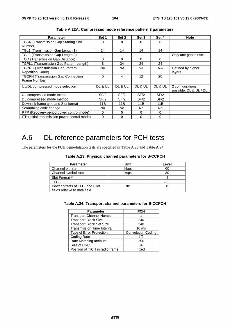
ETSI
ETSI TS 125 101 V6.19.0 (2009-03) 1043GPP TS 25.101 version 6.19.0 Release 6
Table A.22A: Compressed mode reference pattern 3 parameters
Parameter Set 1 Set 2 Set 3 Set 4 Note TGSN (Transmission Gap Starting Slot Number)
8 8 8 8
TGL1 (Transmission Gap Length 1) 14 14 14 14 TGL2 (Transmission Gap Length 2) - - - - Only one gap in use. TGD (Transmission Gap Distance) 0 0 0 0 TGPL1 (Transmission Gap Pattern Length) 8 24 24 24 TGPRC (Transmission Gap Pattern Repetition Count)
NA NA NA NA Defined by higher layers
TGCFN (Transmission Gap Connection Frame Number):
0 4 12 20
UL/DL compressed mode selection DL & UL DL & UL DL & UL DL & UL 2 configurations possible. DL & UL / DL
UL compressed mode method SF/2 SF/2 SF/2 SF/2 DL compressed mode method SF/2 SF/2 SF/2 SF/2 Downlink frame type and Slot format 11B 11B 11B 11B Scrambling code change No No No No RPP (Recovery period power control mode) 0 0 0 0 ITP (Initial transmission power control mode) 0 0 0 0
A.6 DL reference parameters for PCH tests The parameters for the PCH demodulation tests are specified in Table A.23 and Table A.24.
Table A.23: Physical channel parameters for S-CCPCH
Parameter Unit Level Channel bit rate kbps 60 Channel symbol rate ksps 30 Slot Format #i - 4 TFCI - OFF Power offsets of TFCI and Pilot fields relative to data field
dB 0
Table A.24: Transport channel parameters for S-CCPCH
Parameter PCH Transport Channel Number 1 Transport Block Size 240 Transport Block Set Size 240 Transmission Time Interval 10 ms Type of Error Protection Convolution Coding Coding Rate 1/2 Rate Matching attribute 256 Size of CRC 16 Position of TrCH in radio frame fixed
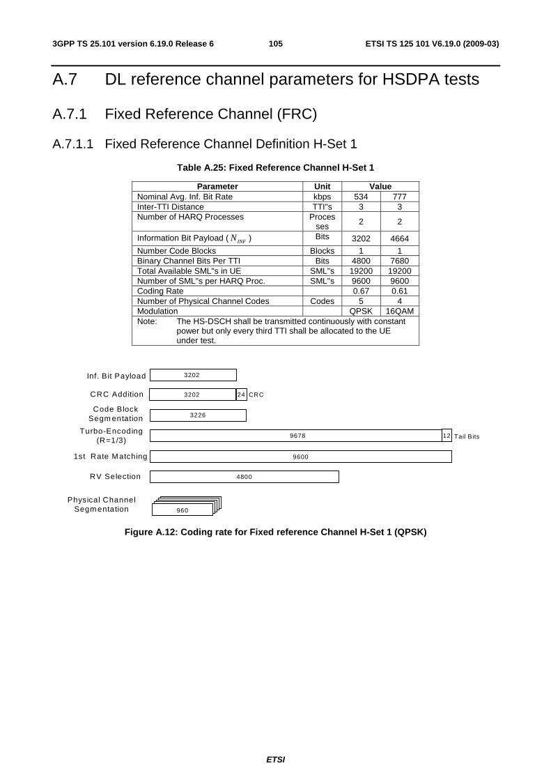
ETSI
ETSI TS 125 101 V6.19.0 (2009-03) 1053GPP TS 25.101 version 6.19.0 Release 6
A.7 DL reference channel parameters for HSDPA tests
A.7.1 Fixed Reference Channel (FRC)
A.7.1.1 Fixed Reference Channel Definition H-Set 1
Table A.25: Fixed Reference Channel H-Set 1
Parameter Unit Value Nominal Avg. Inf. Bit Rate kbps 534 777 Inter-TTI Distance TTI"s 3 3 Number of HARQ Processes Proces
ses 2 2
Information Bit Payload ( INFN ) Bits 3202 4664
Number Code Blocks Blocks 1 1 Binary Channel Bits Per TTI Bits 4800 7680 Total Available SML"s in UE SML"s 19200 19200 Number of SML"s per HARQ Proc. SML"s 9600 9600 Coding Rate 0.67 0.61 Number of Physical Channel Codes Codes 5 4 Modulation QPSK 16QAM Note: The HS-DSCH shall be transmitted continuously with constant
power but only every third TTI shall be allocated to the UE under test.
Inf. Bit Payload
CRC Addition
Turbo-Encoding(R=1/3)
3202
Code BlockSegm entation
1st Rate Matching 9600
Tail B its129678
3226
CRC243202
RV Selection 4800
Physical ChannelSegm entation 960
Figure A.12: Coding rate for Fixed reference Channel H-Set 1 (QPSK)
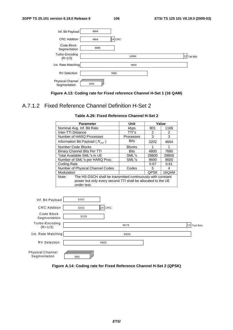
ETSI
ETSI TS 125 101 V6.19.0 (2009-03) 1063GPP TS 25.101 version 6.19.0 Release 6
Inf. Bit Payload
CRC Addition
Turbo-Encoding(R=1/3)
4664
Code BlockSegmentation
1st Rate Matching 9600
Tail Bits1214064
4688
CRC244664
RV Selection 7680
1920Physical Channel
Segmentation
Figure A.13: Coding rate for Fixed reference Channel H-Set 1 (16 QAM)
A.7.1.2 Fixed Reference Channel Definition H-Set 2
Table A.26: Fixed Reference Channel H-Set 2
Parameter Unit Value Nominal Avg. Inf. Bit Rate kbps 801 1166 Inter-TTI Distance TTI"s 2 2 Number of HARQ Processes Processes 3 3 Information Bit Payload ( INFN ) Bits 3202 4664
Number Code Blocks Blocks 1 1 Binary Channel Bits Per TTI Bits 4800 7680 Total Available SML"s in UE SML"s 28800 28800 Number of SML"s per HARQ Proc. SML"s 9600 9600 Coding Rate 0.67 0.61 Number of Physical Channel Codes Codes 5 4 Modulation QPSK 16QAM Note: The HS-DSCH shall be transmitted continuously with constant
power but only every second TTI shall be allocated to the UE under test.
Inf. Bit Payload
CRC Addition
Turbo-Encoding(R=1/3)
3202
Code BlockSegm entation
1st Rate Matching 9600
Tail B its129678
3226
CRC243202
RV Selection 4800
Physical ChannelSegm entation 960
Figure A.14: Coding rate for Fixed Reference Channel H-Set 2 (QPSK)
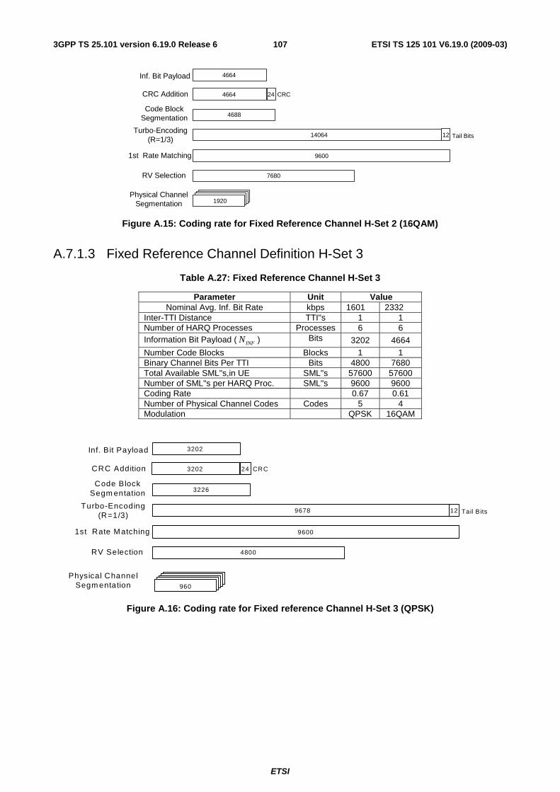
ETSI
ETSI TS 125 101 V6.19.0 (2009-03) 1073GPP TS 25.101 version 6.19.0 Release 6
Inf. Bit Payload
CRC Addition
Turbo-Encoding(R=1/3)
4664
Code BlockSegmentation
1st Rate Matching 9600
Tail Bits1214064
4688
CRC244664
RV Selection 7680
1920Physical Channel
Segmentation
Figure A.15: Coding rate for Fixed Reference Channel H-Set 2 (16QAM)
A.7.1.3 Fixed Reference Channel Definition H-Set 3
Table A.27: Fixed Reference Channel H-Set 3
Parameter Unit Value Nominal Avg. Inf. Bit Rate kbps 1601 2332
Inter-TTI Distance TTI"s 1 1 Number of HARQ Processes Processes 6 6 Information Bit Payload ( INFN ) Bits 3202 4664
Number Code Blocks Blocks 1 1 Binary Channel Bits Per TTI Bits 4800 7680 Total Available SML"s,in UE SML"s 57600 57600 Number of SML"s per HARQ Proc. SML"s 9600 9600 Coding Rate 0.67 0.61 Number of Physical Channel Codes Codes 5 4 Modulation QPSK 16QAM
Inf. Bit Payload
CRC Addition
Turbo-Encoding(R=1/3)
3202
Code BlockSegm entation
1st Rate Matching 9600
Tail B its129678
3226
CRC243202
RV Selection 4800
Physical ChannelSegm entation 960
Figure A.16: Coding rate for Fixed reference Channel H-Set 3 (QPSK)
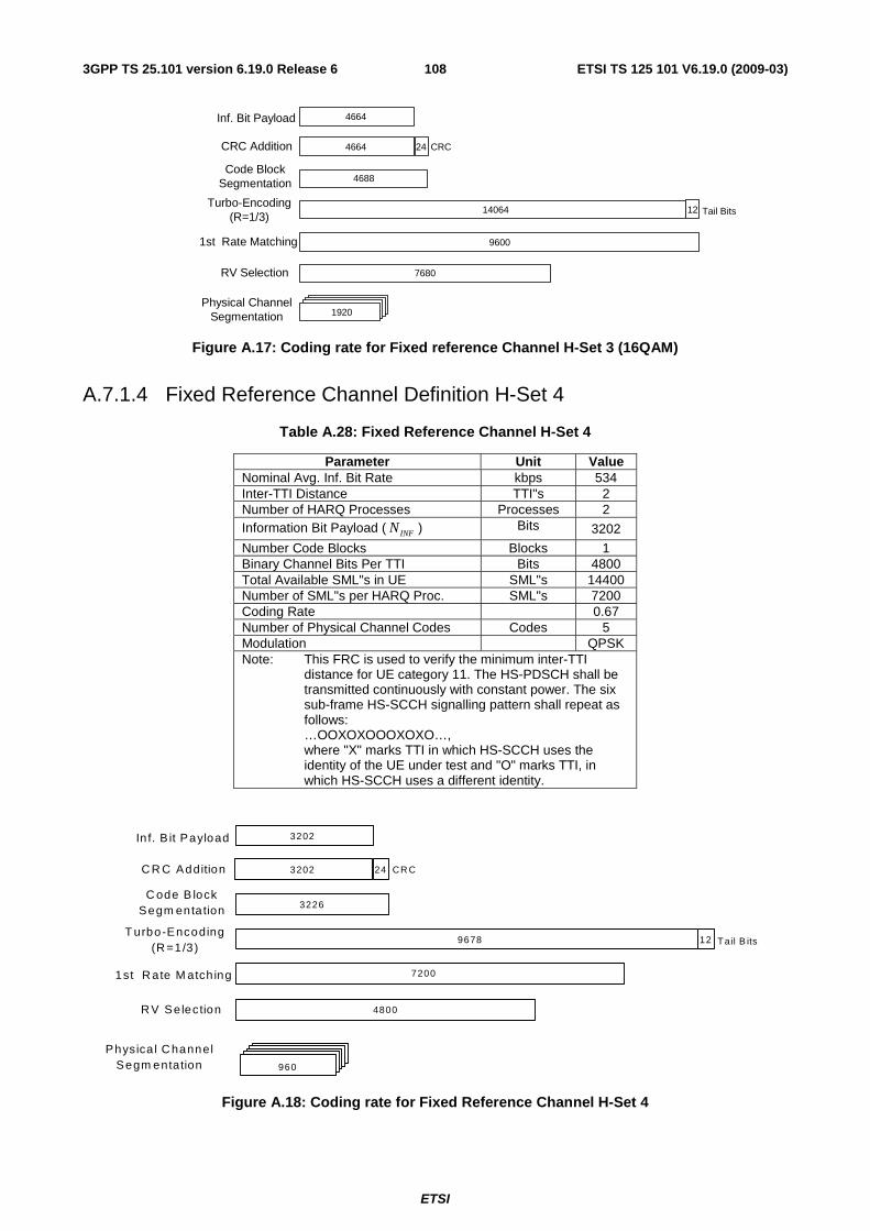
ETSI
ETSI TS 125 101 V6.19.0 (2009-03) 1083GPP TS 25.101 version 6.19.0 Release 6
Inf. Bit Payload
CRC Addition
Turbo-Encoding(R=1/3)
4664
Code BlockSegmentation
1st Rate Matching 9600
Tail Bits1214064
4688
CRC244664
RV Selection 7680
1920Physical Channel
Segmentation
Figure A.17: Coding rate for Fixed reference Channel H-Set 3 (16QAM)
A.7.1.4 Fixed Reference Channel Definition H-Set 4
Table A.28: Fixed Reference Channel H-Set 4
Parameter Unit Value Nominal Avg. Inf. Bit Rate kbps 534 Inter-TTI Distance TTI"s 2 Number of HARQ Processes Processes 2 Information Bit Payload ( INFN ) Bits 3202
Number Code Blocks Blocks 1 Binary Channel Bits Per TTI Bits 4800 Total Available SML"s in UE SML"s 14400 Number of SML"s per HARQ Proc. SML"s 7200 Coding Rate 0.67 Number of Physical Channel Codes Codes 5 Modulation QPSK Note: This FRC is used to verify the minimum inter-TTI
distance for UE category 11. The HS-PDSCH shall be transmitted continuously with constant power. The six sub-frame HS-SCCH signalling pattern shall repeat as follows: …OOXOXOOOXOXO…, where "X" marks TTI in which HS-SCCH uses the identity of the UE under test and "O" marks TTI, in which HS-SCCH uses a different identity.
In f. B it Payload
C R C Addition
T urbo-Encoding(R =1/3)
3202
C ode B lockSegm enta tion
1st R ate M atch ing
Tail B its129678
3226
CR C243202
R V Se lection 4800
Physica l C hannelSegm entation 960
7200
Figure A.18: Coding rate for Fixed Reference Channel H-Set 4
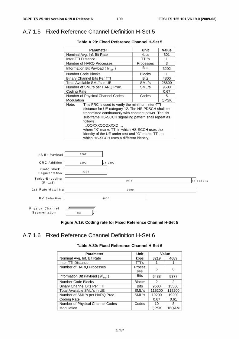
ETSI
ETSI TS 125 101 V6.19.0 (2009-03) 1093GPP TS 25.101 version 6.19.0 Release 6
A.7.1.5 Fixed Reference Channel Definition H-Set 5
Table A.29: Fixed Reference Channel H-Set 5
Parameter Unit Value Nominal Avg. Inf. Bit Rate kbps 801 Inter-TTI Distance TTI"s 1 Number of HARQ Processes Processes 3 Information Bit Payload ( INFN ) Bits 3202
Number Code Blocks Blocks 1 Binary Channel Bits Per TTI Bits 4800 Total Available SML"s in UE SML"s 28800 Number of SML"s per HARQ Proc. SML"s 9600 Coding Rate 0.67 Number of Physical Channel Codes Codes 5 Modulation QPSK Note: This FRC is used to verify the minimum inter-TTI
distance for UE category 12. The HS-PDSCH shall be transmitted continuously with constant power. The six sub-frame HS-SCCH signalling pattern shall repeat as follows: …OOXXXOOOXXXO…, where "X" marks TTI in which HS-SCCH uses the identity of the UE under test and "O" marks TTI, in which HS-SCCH uses a different identity.
In f . B it P a y lo a d
C R C A d d itio n
T u rb o -E n c o d in g(R = 1 /3 )
3 2 0 2
C o d e B lo c kS e g m e n ta tio n
1 s t R a te M a tc h in g 9 6 0 0
T a il B its1 29 6 7 8
3 2 2 6
C R C2 43 2 0 2
R V S e le c tio n 4 8 0 0
P h ys ic a l C h a n n e lS e g m e n ta tio n 9 6 0
Figure A.19: Coding rate for Fixed Reference Channel H-Set 5
A.7.1.6 Fixed Reference Channel Definition H-Set 6
Table A.30: Fixed Reference Channel H-Set 6
Parameter Unit Value Nominal Avg. Inf. Bit Rate kbps 3219 4689 Inter-TTI Distance TTI"s 1 1 Number of HARQ Processes Proces
ses 6 6
Information Bit Payload ( INFN ) Bits 6438 9377
Number Code Blocks Blocks 2 2 Binary Channel Bits Per TTI Bits 9600 15360 Total Available SML"s in UE SML"s 115200 115200 Number of SML"s per HARQ Proc. SML"s 19200 19200 Coding Rate 0.67 0.61 Number of Physical Channel Codes Codes 10 8 Modulation QPSK 16QAM
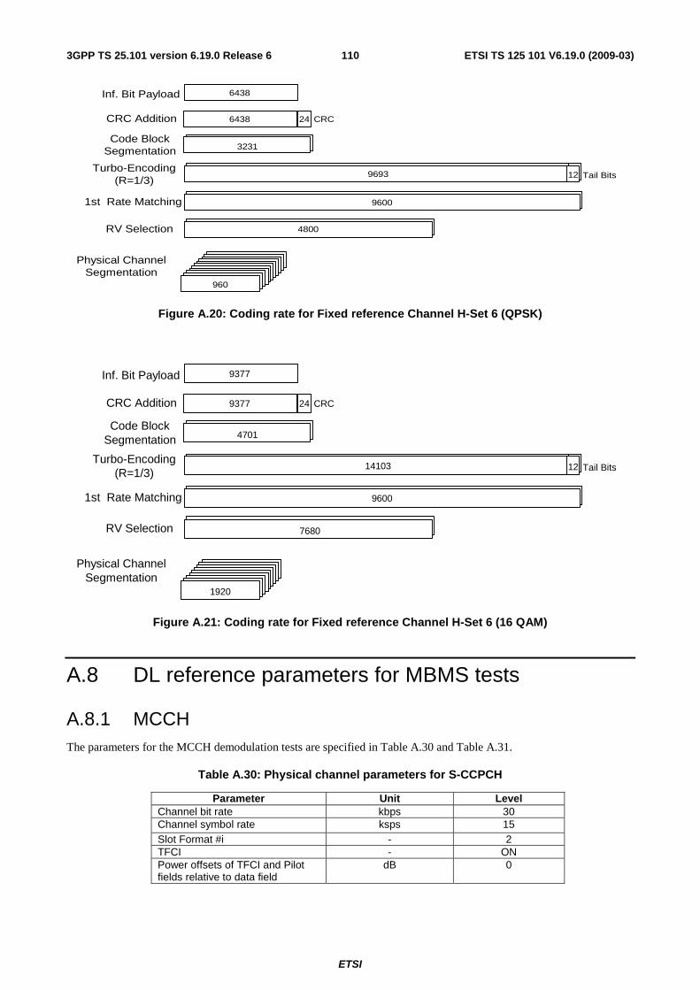
ETSI
ETSI TS 125 101 V6.19.0 (2009-03) 1103GPP TS 25.101 version 6.19.0 Release 6
4800
9600
129693
Inf. Bit Payload
CRC Addition
Turbo-Encoding(R=1/3)
6438
Code BlockSegmentation
1st Rate Matching 9600
Tail Bits129693
3231
CRC246438
RV Selection 4800
Physical ChannelSegmentation
960
Figure A.20: Coding rate for Fixed reference Channel H-Set 6 (QPSK)
4800
9600
129693
Inf. Bit Payload
CRC Addition
Turbo-Encoding(R=1/3)
9377
Code BlockSegmentation
1st Rate Matching 9600
Tail Bits1214103
4701
CRC249377
RV Selection 7680
Physical ChannelSegmentation
1920
Figure A.21: Coding rate for Fixed reference Channel H-Set 6 (16 QAM)
A.8 DL reference parameters for MBMS tests
A.8.1 MCCH The parameters for the MCCH demodulation tests are specified in Table A.30 and Table A.31.
Table A.30: Physical channel parameters for S-CCPCH
Parameter Unit Level Channel bit rate kbps 30 Channel symbol rate ksps 15 Slot Format #i - 2 TFCI - ON Power offsets of TFCI and Pilot fields relative to data field
dB 0
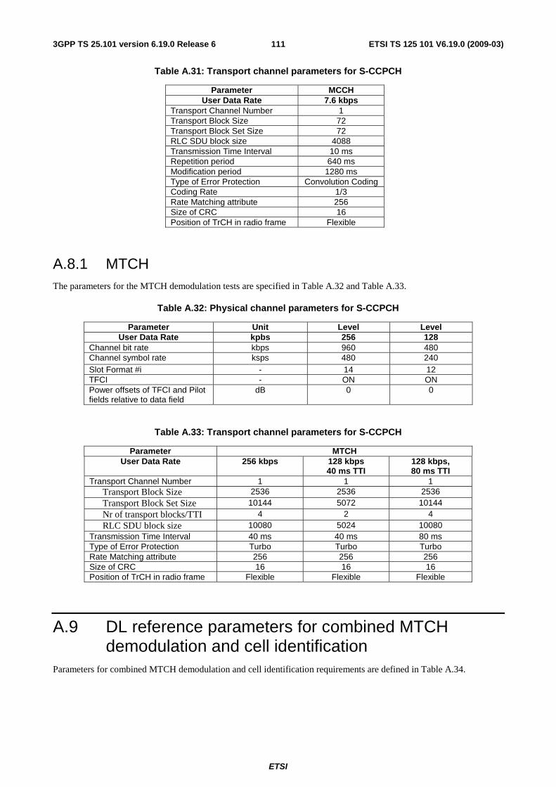
ETSI
ETSI TS 125 101 V6.19.0 (2009-03) 1113GPP TS 25.101 version 6.19.0 Release 6
Table A.31: Transport channel parameters for S-CCPCH
Parameter MCCH User Data Rate 7.6 kbps
Transport Channel Number 1 Transport Block Size 72 Transport Block Set Size 72 RLC SDU block size 4088 Transmission Time Interval 10 ms Repetition period 640 ms Modification period 1280 ms Type of Error Protection Convolution Coding Coding Rate 1/3 Rate Matching attribute 256 Size of CRC 16 Position of TrCH in radio frame Flexible
A.8.1 MTCH The parameters for the MTCH demodulation tests are specified in Table A.32 and Table A.33.
Table A.32: Physical channel parameters for S-CCPCH
Parameter Unit Level Level User Data Rate kpbs 256 128
Channel bit rate kbps 960 480 Channel symbol rate ksps 480 240 Slot Format #i - 14 12 TFCI - ON ON Power offsets of TFCI and Pilot fields relative to data field
dB 0 0
Table A.33: Transport channel parameters for S-CCPCH
Parameter MTCH User Data Rate 256 kbps 128 kbps
40 ms TTI 128 kbps, 80 ms TTI
Transport Channel Number 1 1 1 Transport Block Size 2536 2536 2536 Transport Block Set Size 10144 5072 10144 Nr of transport blocks/TTI 4 2 4 RLC SDU block size 10080 5024 10080
Transmission Time Interval 40 ms 40 ms 80 ms Type of Error Protection Turbo Turbo Turbo Rate Matching attribute 256 256 256 Size of CRC 16 16 16 Position of TrCH in radio frame Flexible Flexible Flexible
A.9 DL reference parameters for combined MTCH demodulation and cell identification
Parameters for combined MTCH demodulation and cell identification requirements are defined in Table A.34.
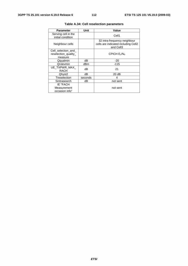
ETSI
ETSI TS 125 101 V6.19.0 (2009-03) 1123GPP TS 25.101 version 6.19.0 Release 6
Table A.34: Cell reselection parameters
Parameter Unit Value Serving cell in the
initial condition Cell1
Neighbour cells 32 intra-frequency neighbour
cells are indicated including Cell2 and Cell3
Cell_selection_and_reselection_quality_
measure CPICH Ec/N0
Qqualmin dB -20 Qrxlevmin dBm -115
UE_TXPWR_MAX_ RACH dB 21
Qhyst2 dB 20 dB Treselection seconds 4 Sintrasearch dB not sent
IE "FACH Measurement occasion info"
not sent
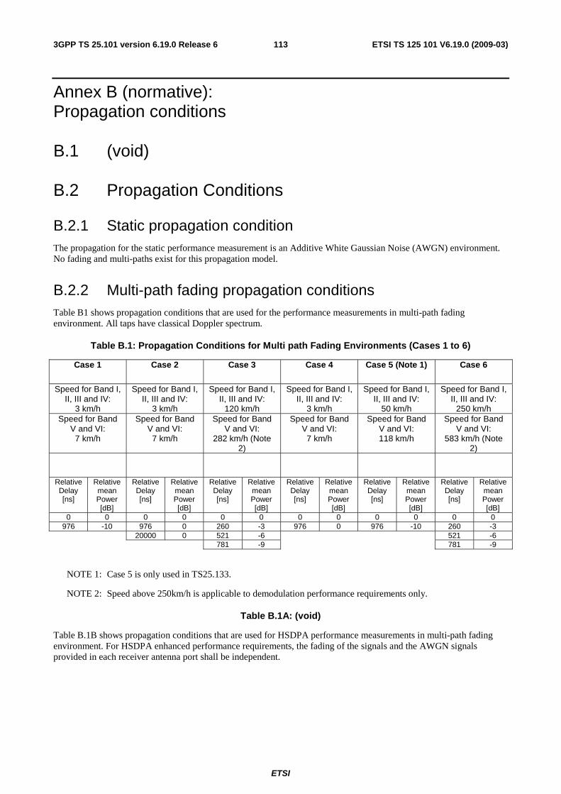
ETSI
ETSI TS 125 101 V6.19.0 (2009-03) 1133GPP TS 25.101 version 6.19.0 Release 6
Annex B (normative): Propagation conditions
B.1 (void)
B.2 Propagation Conditions
B.2.1 Static propagation condition The propagation for the static performance measurement is an Additive White Gaussian Noise (AWGN) environment. No fading and multi-paths exist for this propagation model.
B.2.2 Multi-path fading propagation conditions Table B1 shows propagation conditions that are used for the performance measurements in multi-path fading environment. All taps have classical Doppler spectrum.
Table B.1: Propagation Conditions for Multi path Fading Environments (Cases 1 to 6)
Case 1 Case 2 Case 3 Case 4 Case 5 (Note 1) Case 6
Speed for Band I, II, III and IV:
3 km/h
Speed for Band I, II, III and IV:
3 km/h
Speed for Band I, II, III and IV:
120 km/h
Speed for Band I, II, III and IV:
3 km/h
Speed for Band I, II, III and IV:
50 km/h
Speed for Band I, II, III and IV:
250 km/h Speed for Band
V and VI: 7 km/h
Speed for Band V and VI:
7 km/h
Speed for Band V and VI:
282 km/h (Note 2)
Speed for Band V and VI:
7 km/h
Speed for Band V and VI: 118 km/h
Speed for Band V and VI:
583 km/h (Note 2)
Relative Delay [ns]
Relative mean Power [dB]
Relative Delay [ns]
Relative mean Power [dB]
Relative Delay [ns]
Relative mean Power [dB]
Relative Delay [ns]
Relative mean Power [dB]
Relative Delay [ns]
Relative mean Power [dB]
Relative Delay [ns]
Relative mean Power [dB]
0 0 0 0 0 0 0 0 0 0 0 0 976 -10 976 0 260 -3 976 0 976 -10 260 -3
20000 0 521 -6 521 -6 781 -9 781 -9
NOTE 1: Case 5 is only used in TS25.133.
NOTE 2: Speed above 250km/h is applicable to demodulation performance requirements only.
Table B.1A: (void)
Table B.1B shows propagation conditions that are used for HSDPA performance measurements in multi-path fading environment. For HSDPA enhanced performance requirements, the fading of the signals and the AWGN signals provided in each receiver antenna port shall be independent.
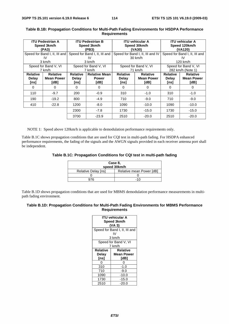
ETSI
ETSI TS 125 101 V6.19.0 (2009-03) 1143GPP TS 25.101 version 6.19.0 Release 6
Table B.1B: Propagation Conditions for Multi-Path Fading Environments for HSDPA Performance Requirements
ITU Pedestrian A Speed 3km/h
(PA3)
ITU Pedestrian B Speed 3km/h
(PB3)
ITU vehicular A Speed 30km/h
(VA30)
ITU vehicular A Speed 120km/h
(VA120) Speed for Band I, II, III and
IV 3 km/h
Speed for Band I, II, III and IV
3 km/h
Speed for Band I, II, III and IV 30 km/h
Speed for Band I, II, III and IV
120 km/h Speed for Band V, VI
7 km/h Speed for Band V, VI
7 km/h Speed for Band V, VI
71 km/h Speed for Band V, VI
282 km/h (Note 1) Relative
Delay [ns]
Relative Mean Power
[dB]
Relative Delay [ns]
Relative Mean Power [dB]
Relative Delay [ns]
Relative Mean Power
[dB]
Relative Delay [ns]
Relative Mean Power
[dB] 0 0 0 0 0 0 0 0
110 -9.7 200 -0.9 310 -1.0 310 -1.0
190 -19.2 800 -4.9 710 -9.0 710 -9.0
410 -22.8 1200 -8.0 1090 -10.0 1090 -10.0
2300 -7.8 1730 -15.0 1730 -15.0
3700 -23.9 2510 -20.0 2510 -20.0
NOTE 1: Speed above 120km/h is applicable to demodulation performance requirements only.
Table B.1C shows propagation conditions that are used for CQI test in multi-path fading. For HSDPA enhanced performance requirements, the fading of the signals and the AWGN signals provided in each receiver antenna port shall be independent.
Table B.1C: Propagation Conditions for CQI test in multi-path fading
Case 8, speed 30km/h
Relative Delay [ns] Relative mean Power [dB] 0 0
976 -10
Table B.1D shows propagation conditions that are used for MBMS demodulation performance measurements in multi-path fading environment.
Table B.1D: Propagation Conditions for Multi-Path Fading Environments for MBMS Performance Requirements
ITU vehicular A Speed 3km/h
(VA 3) Speed for Band I, II, III and
IV 3 km/h
Speed for Band V, VI 7 km/h
Relative Delay [ns]
Relative Mean Power
[dB] 0 0
310 -1.0 710 -9.0
1090 -10.0 1730 -15.0 2510 -20.0
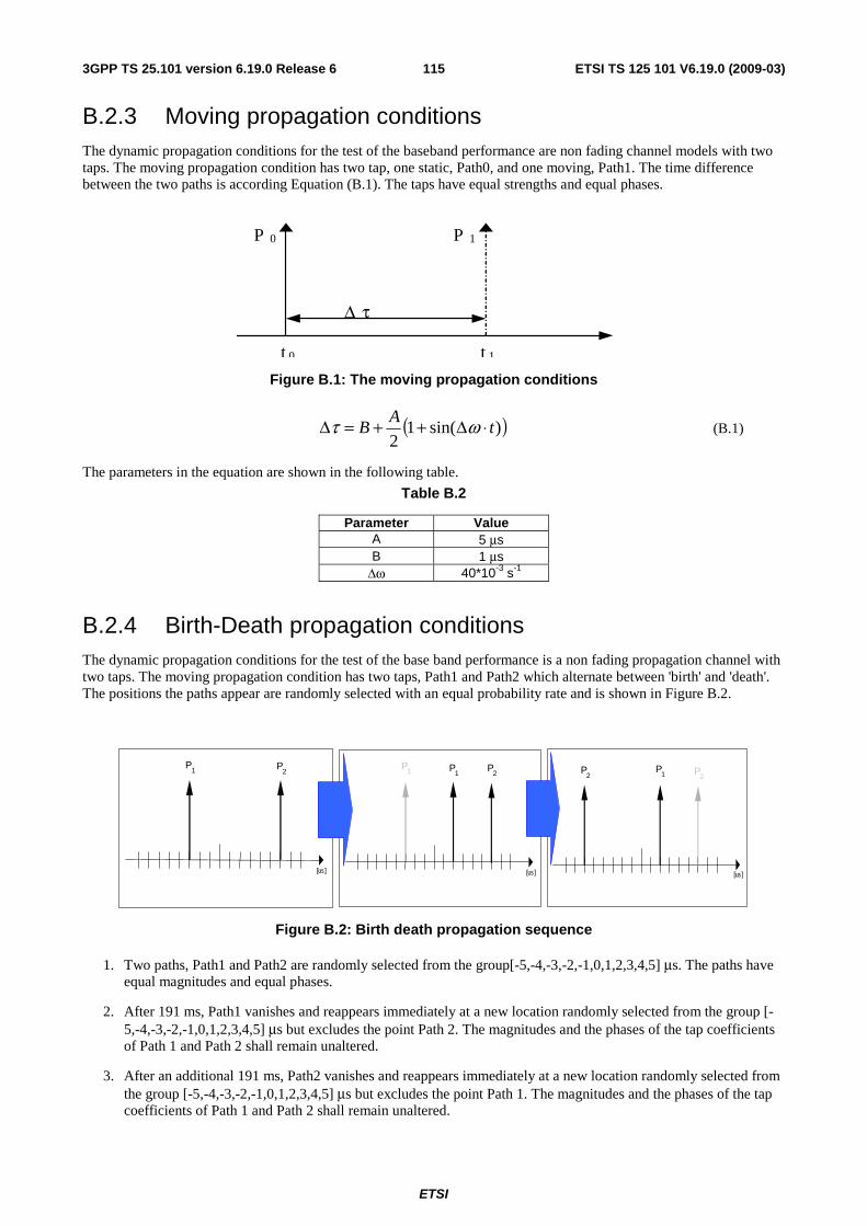
ETSI
ETSI TS 125 101 V6.19.0 (2009-03) 1153GPP TS 25.101 version 6.19.0 Release 6
B.2.3 Moving propagation conditions The dynamic propagation conditions for the test of the baseband performance are non fading channel models with two taps. The moving propagation condition has two tap, one static, Path0, and one moving, Path1. The time difference between the two paths is according Equation (B.1). The taps have equal strengths and equal phases.
t 1
P 1
Δ τ
P 0
t 0
Figure B.1: The moving propagation conditions
( ))sin(12
tA
B ⋅Δ++=Δ ωτ (B.1)
The parameters in the equation are shown in the following table.
Table B.2
Parameter Value A 5 μs B 1 μs
Δω 40*10-3 s-1
B.2.4 Birth-Death propagation conditions The dynamic propagation conditions for the test of the base band performance is a non fading propagation channel with two taps. The moving propagation condition has two taps, Path1 and Path2 which alternate between 'birth' and 'death'. The positions the paths appear are randomly selected with an equal probability rate and is shown in Figure B.2.
P 1 P
2 P 1
[ us]
P 1 P
2
[ us]
P 2 P
1
[ us]
P 2
Figure B.2: Birth death propagation sequence
1. Two paths, Path1 and Path2 are randomly selected from the group[-5,-4,-3,-2,-1,0,1,2,3,4,5] μs. The paths have equal magnitudes and equal phases.
2. After 191 ms, Path1 vanishes and reappears immediately at a new location randomly selected from the group [-5,-4,-3,-2,-1,0,1,2,3,4,5] μs but excludes the point Path 2. The magnitudes and the phases of the tap coefficients of Path 1 and Path 2 shall remain unaltered.
3. After an additional 191 ms, Path2 vanishes and reappears immediately at a new location randomly selected from the group [-5,-4,-3,-2,-1,0,1,2,3,4,5] μs but excludes the point Path 1. The magnitudes and the phases of the tap coefficients of Path 1 and Path 2 shall remain unaltered.

ETSI
ETSI TS 125 101 V6.19.0 (2009-03) 1163GPP TS 25.101 version 6.19.0 Release 6
The sequence in 2) and 3) is repeated.
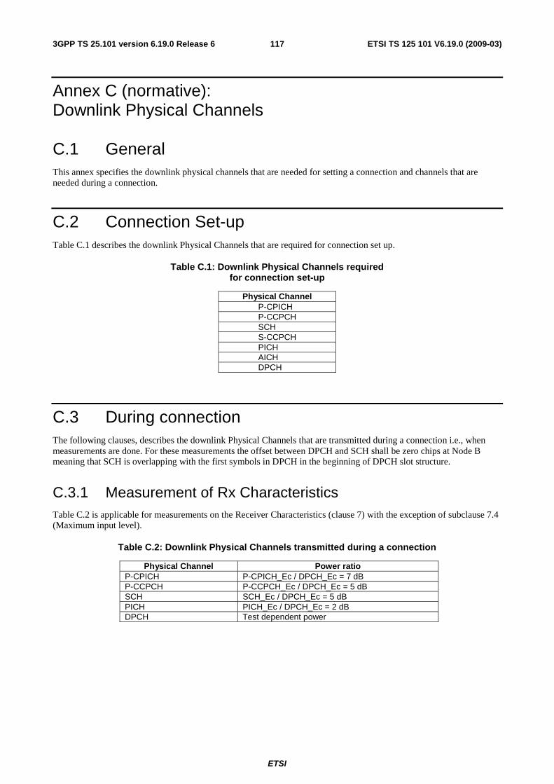
ETSI
ETSI TS 125 101 V6.19.0 (2009-03) 1173GPP TS 25.101 version 6.19.0 Release 6
Annex C (normative): Downlink Physical Channels
C.1 General This annex specifies the downlink physical channels that are needed for setting a connection and channels that are needed during a connection.
C.2 Connection Set-up Table C.1 describes the downlink Physical Channels that are required for connection set up.
Table C.1: Downlink Physical Channels required for connection set-up
Physical Channel P-CPICH P-CCPCH SCH S-CCPCH PICH AICH DPCH
C.3 During connection The following clauses, describes the downlink Physical Channels that are transmitted during a connection i.e., when measurements are done. For these measurements the offset between DPCH and SCH shall be zero chips at Node B meaning that SCH is overlapping with the first symbols in DPCH in the beginning of DPCH slot structure.
C.3.1 Measurement of Rx Characteristics Table C.2 is applicable for measurements on the Receiver Characteristics (clause 7) with the exception of subclause 7.4 (Maximum input level).
Table C.2: Downlink Physical Channels transmitted during a connection
Physical Channel Power ratio P-CPICH P-CPICH_Ec / DPCH_Ec = 7 dB P-CCPCH P-CCPCH_Ec / DPCH_Ec = 5 dB SCH SCH_Ec / DPCH_Ec = 5 dB PICH PICH_Ec / DPCH_Ec = 2 dB DPCH Test dependent power
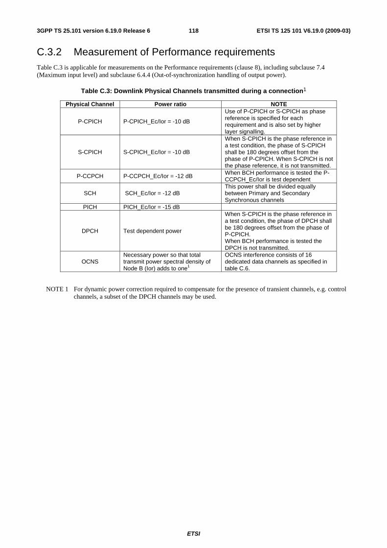
ETSI
ETSI TS 125 101 V6.19.0 (2009-03) 1183GPP TS 25.101 version 6.19.0 Release 6
C.3.2 Measurement of Performance requirements Table C.3 is applicable for measurements on the Performance requirements (clause 8), including subclause 7.4 (Maximum input level) and subclause 6.4.4 (Out-of-synchronization handling of output power).
Table C.3: Downlink Physical Channels transmitted during a connection1
Physical Channel Power ratio NOTE
P-CPICH P-CPICH_Ec/Ior = -10 dB
Use of P-CPICH or S-CPICH as phase reference is specified for each requirement and is also set by higher layer signalling.
S-CPICH S-CPICH_Ec/Ior = -10 dB
When S-CPICH is the phase reference in a test condition, the phase of S-CPICH shall be 180 degrees offset from the phase of P-CPICH. When S-CPICH is not the phase reference, it is not transmitted.
P-CCPCH P-CCPCH_Ec/Ior = -12 dB When BCH performance is tested the P-CCPCH_Ec/Ior is test dependent
SCH SCH_Ec/Ior = -12 dB This power shall be divided equally between Primary and Secondary Synchronous channels
PICH PICH_Ec/Ior = -15 dB
DPCH Test dependent power
When S-CPICH is the phase reference in a test condition, the phase of DPCH shall be 180 degrees offset from the phase of P-CPICH. When BCH performance is tested the DPCH is not transmitted.
OCNS Necessary power so that total transmit power spectral density of Node B (Ior) adds to one1
OCNS interference consists of 16 dedicated data channels as specified in table C.6.
NOTE 1 For dynamic power correction required to compensate for the presence of transient channels, e.g. control channels, a subset of the DPCH channels may be used.
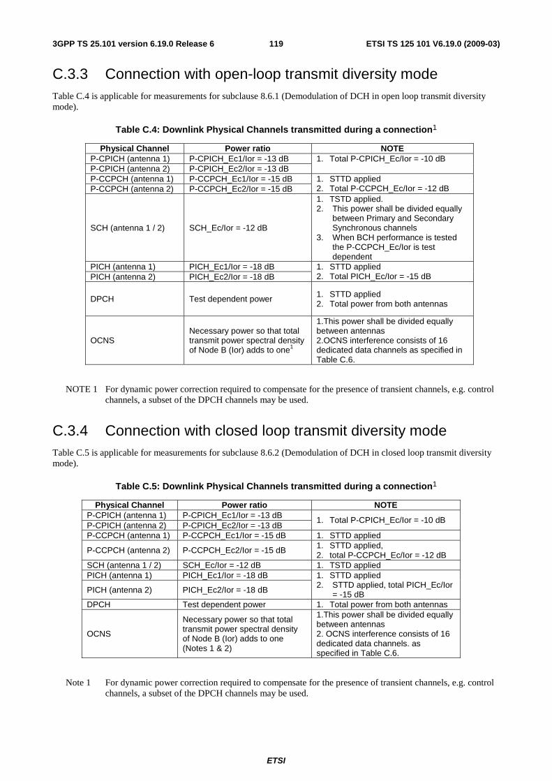
ETSI
ETSI TS 125 101 V6.19.0 (2009-03) 1193GPP TS 25.101 version 6.19.0 Release 6
C.3.3 Connection with open-loop transmit diversity mode Table C.4 is applicable for measurements for subclause 8.6.1 (Demodulation of DCH in open loop transmit diversity mode).
Table C.4: Downlink Physical Channels transmitted during a connection1
Physical Channel Power ratio NOTE P-CPICH (antenna 1) P-CPICH_Ec1/Ior = -13 dB P-CPICH (antenna 2) P-CPICH_Ec2/Ior = -13 dB
1. Total P-CPICH_Ec/Ior = -10 dB
P-CCPCH (antenna 1) P-CCPCH_Ec1/Ior = -15 dB P-CCPCH (antenna 2) P-CCPCH_Ec2/Ior = -15 dB
1. STTD applied 2. Total P-CCPCH_Ec/Ior = -12 dB
SCH (antenna 1 / 2) SCH_Ec/Ior = -12 dB
1. TSTD applied. 2. This power shall be divided equally
between Primary and Secondary Synchronous channels
3. When BCH performance is tested the P-CCPCH_Ec/Ior is test dependent
PICH (antenna 1) PICH_Ec1/Ior = -18 dB PICH (antenna 2) PICH_Ec2/Ior = -18 dB
1. STTD applied 2. Total PICH_Ec/Ior = -15 dB
DPCH Test dependent power 1. STTD applied 2. Total power from both antennas
OCNS Necessary power so that total transmit power spectral density of Node B (Ior) adds to one1
1.This power shall be divided equally between antennas 2.OCNS interference consists of 16 dedicated data channels as specified in Table C.6.
NOTE 1 For dynamic power correction required to compensate for the presence of transient channels, e.g. control channels, a subset of the DPCH channels may be used.
C.3.4 Connection with closed loop transmit diversity mode Table C.5 is applicable for measurements for subclause 8.6.2 (Demodulation of DCH in closed loop transmit diversity mode).
Table C.5: Downlink Physical Channels transmitted during a connection1
Physical Channel Power ratio NOTE P-CPICH (antenna 1) P-CPICH_Ec1/Ior = -13 dB P-CPICH (antenna 2) P-CPICH_Ec2/Ior = -13 dB
1. Total P-CPICH_Ec/Ior = -10 dB
P-CCPCH (antenna 1) P-CCPCH_Ec1/Ior = -15 dB 1. STTD applied
P-CCPCH (antenna 2) P-CCPCH_Ec2/Ior = -15 dB 1. STTD applied, 2. total P-CCPCH_Ec/Ior = -12 dB
SCH (antenna 1 / 2) SCH_Ec/Ior = -12 dB 1. TSTD applied PICH (antenna 1) PICH_Ec1/Ior = -18 dB
PICH (antenna 2) PICH_Ec2/Ior = -18 dB
1. STTD applied 2. STTD applied, total PICH_Ec/Ior
= -15 dB DPCH Test dependent power 1. Total power from both antennas
OCNS
Necessary power so that total transmit power spectral density of Node B (Ior) adds to one (Notes 1 & 2)
1.This power shall be divided equally between antennas 2. OCNS interference consists of 16 dedicated data channels. as specified in Table C.6.
Note 1 For dynamic power correction required to compensate for the presence of transient channels, e.g. control channels, a subset of the DPCH channels may be used.
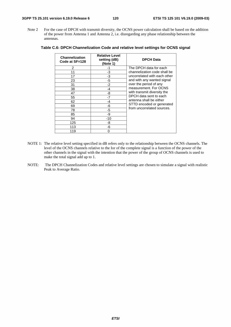
ETSI
ETSI TS 125 101 V6.19.0 (2009-03) 1203GPP TS 25.101 version 6.19.0 Release 6
Note 2 For the case of DPCH with transmit diversity, the OCNS power calculation shall be based on the addition of the power from Antenna 1 and Antenna 2, i.e. disregarding any phase relationship between the antennas.
Table C.6: DPCH Channelization Code and relative level settings for OCNS signal
Channelization Code at SF=128
Relative Level setting (dB)
(Note 1) DPCH Data
2 -1 11 -3 17 -3 23 -5 31 -2 38 -4 47 -8 55 -7 62 -4 69 -6 78 -5 85 -9 94 -10
125 -8 113 -6 119 0
The DPCH data for each channelization code shall be uncorrelated with each other and with any wanted signal over the period of any measurement. For OCNS with transmit diversity the DPCH data sent to each antenna shall be either STTD encoded or generated from uncorrelated sources.
NOTE 1: The relative level setting specified in dB refers only to the relationship between the OCNS channels. The level of the OCNS channels relative to the Ior of the complete signal is a function of the power of the other channels in the signal with the intention that the power of the group of OCNS channels is used to make the total signal add up to 1.
NOTE: The DPCH Channelization Codes and relative level settings are chosen to simulate a signal with realistic Peak to Average Ratio.
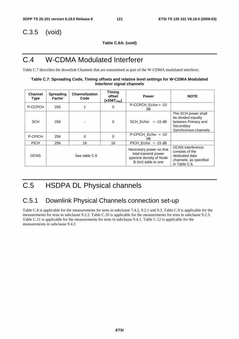
ETSI
ETSI TS 125 101 V6.19.0 (2009-03) 1213GPP TS 25.101 version 6.19.0 Release 6
C.3.5 (void)
Table C.6A: (void)
C.4 W-CDMA Modulated Interferer Table C.7 describes the downlink Channels that are transmitted as part of the W-CDMA modulated interferer.
Table C.7: Spreading Code, Timing offsets and relative level settings for W-CDMA Modulated Interferer signal channels
Channel Type
Spreading Factor
Channelization Code
Timing offset
(x256Tchip) Power NOTE
P-CCPCH 256 1 0 P-CCPCH_Ec/Ior = -10 dB
SCH 256 - 0 SCH_Ec/Ior = -10 dB
The SCH power shall be divided equally between Primary and Secondary Synchronous channels
P-CPICH 256 0 0 P-CPICH_Ec/Ior = -10 dB
PICH 256 16 16 PICH_Ec/Ior = -15 dB
OCNS See table C.6
Necessary power so that total transmit power
spectral density of Node B (Ior) adds to one
OCNS interference consists of the dedicated data channels. as specified in Table C.6.
C.5 HSDPA DL Physical channels
C.5.1 Downlink Physical Channels connection set-up Table C.8 is applicable for the measurements for tests in subclause 7.4.2, 9.2.1 and 9.3. Table C.9 is applicable for the measurements for tests in subclause 9.2.2. Table C.10 is applicable for the measurements for tests in subclause 9.2.3. Table C.11 is applicable for the measurements for tests in subclause 9.4.1. Table C.12 is applicable for the measurements in subclause 9.4.2
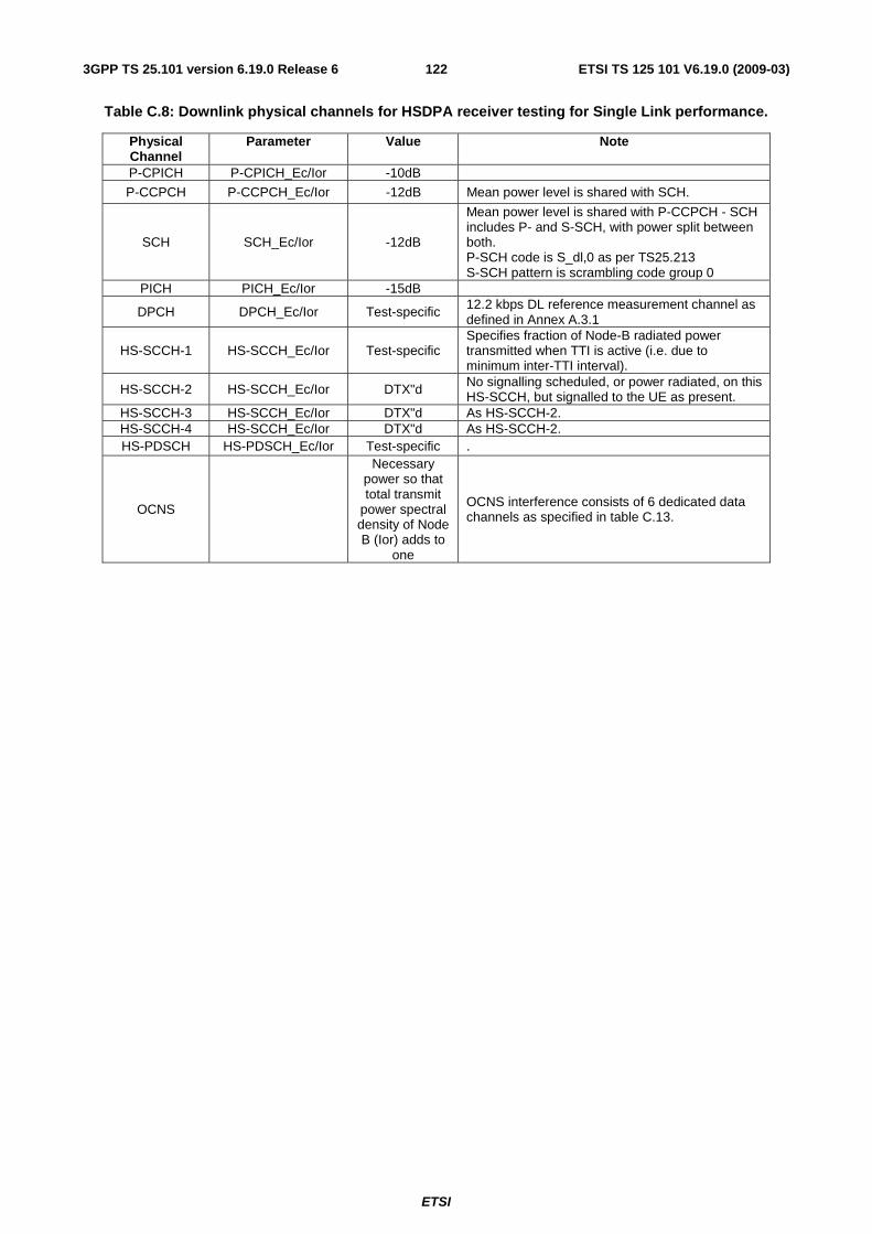
ETSI
ETSI TS 125 101 V6.19.0 (2009-03) 1223GPP TS 25.101 version 6.19.0 Release 6
Table C.8: Downlink physical channels for HSDPA receiver testing for Single Link performance.
Physical Channel
Parameter Value Note
P-CPICH P-CPICH_Ec/Ior -10dB
P-CCPCH P-CCPCH_Ec/Ior -12dB Mean power level is shared with SCH.
SCH SCH_Ec/Ior -12dB
Mean power level is shared with P-CCPCH - SCH includes P- and S-SCH, with power split between both. P-SCH code is S_dl,0 as per TS25.213 S-SCH pattern is scrambling code group 0
PICH PICH_Ec/Ior -15dB
DPCH DPCH_Ec/Ior Test-specific 12.2 kbps DL reference measurement channel as defined in Annex A.3.1
HS-SCCH-1 HS-SCCH_Ec/Ior Test-specific Specifies fraction of Node-B radiated power transmitted when TTI is active (i.e. due to minimum inter-TTI interval).
HS-SCCH-2 HS-SCCH_Ec/Ior DTX"d No signalling scheduled, or power radiated, on this HS-SCCH, but signalled to the UE as present.
HS-SCCH-3 HS-SCCH_Ec/Ior DTX"d As HS-SCCH-2. HS-SCCH-4 HS-SCCH_Ec/Ior DTX"d As HS-SCCH-2. HS-PDSCH HS-PDSCH_Ec/Ior Test-specific .
OCNS
Necessary power so that total transmit
power spectral density of Node B (Ior) adds to
one
OCNS interference consists of 6 dedicated data channels as specified in table C.13.

ETSI
ETSI TS 125 101 V6.19.0 (2009-03) 1233GPP TS 25.101 version 6.19.0 Release 6
Table C.9: Downlink physical channels for HSDPA receiver testing for Open Loop Transmit Diversity performance.
Physical Channel Parameter Value Note P-CPICH (antenna 1) P-CPICH_Ec1/Ior -13dB P-CPICH (antenna 2) P-CPICH_Ec2/Ior -13dB
1. Total P-CPICH_Ec/Ior = -10dB
P-CCPCH (antenna 1) P-CCPCH_Ec1/Ior -15dB
P-CCPCH (antenna 2) P-CCPCH_Ec2/Ior -15dB
1. STTD applied. 2. Total P-CCPCH Ec/Ior is -12dB.
SCH (antenna 1/2) SCH_Ec/Ior -12dB 1. TSTD applied. 2. Power divided equally between primary and secondary SCH.
PICH (antenna 1) PICH_Ec1/Ior -18dB PICH (antenna 2) PICH_Ec2/Ior -18dB
1. STTD applied. 2. Total PICH Ec/Ior is -15dB.
DPCH DPCH_Ec/Ior Test-specific 1. STTD applied. HS-SCCH-1 HS-SCCH_Ec/Ior Test-specific 1. STTD applied.
2. Specifies fraction of Node-B radiated power transmitted when TTI is active (i.e. due to minimum inter-TTI interval).
HS-SCCH-2 HS-SCCH_Ec/Ior DTX"d 1. UE assumes STTD applied. 2. No signalling scheduled, or power radiated, on this HS-SCCH, but signalled to the UE as present.
HS-SCCH-3 HS-SCCH_Ec/Ior DTX"d 1. As HS-SCCH-2. HS-SCCH-4 HS-SCCH_Ec/Ior DTX"d 2. As HS-SCCH-2. HS-PDSCH HS-PDSCH_Ec/Ior Test-specific 1. STTD applied.
OCNS Necessary power so that total transmit power
spectral density of
Node B (Ior) adds to one
(Note 1)
1. Balance of power orI of the Node-B is
assigned to OCNS. 2. Power divided equally between antennas. 3. OCNS interference consists of 6 dedicated data channels as specified in table C.13.
Note 1 For the case of DPCH with transmit diversity, the OCNS power calculation shall be based on the addition of the power from Antenna 1 and Antenna 2, i.e. disregarding any phase relationship between the antennas.
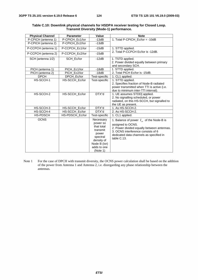
ETSI
ETSI TS 125 101 V6.19.0 (2009-03) 1243GPP TS 25.101 version 6.19.0 Release 6
Table C.10: Downlink physical channels for HSDPA receiver testing for Closed Loop. Transmit Diversity (Mode-1) performance.
Physical Channel Parameter Value Note P-CPICH (antenna 1) P-CPICH_Ec1/Ior -13dB P-CPICH (antenna 2) P-CPICH_Ec2/Ior -13dB
1. Total P-CPICH_Ec/Ior = -10dB
P-CCPCH (antenna 1) P-CCPCH_Ec1/Ior -15dB
P-CCPCH (antenna 2) P-CCPCH_Ec2/Ior -15dB
1. STTD applied. 2. Total P-CCPCH Ec/Ior is -12dB.
SCH (antenna 1/2) SCH_Ec/Ior -12dB 1. TSTD applied. 2. Power divided equally between primary and secondary SCH.
PICH (antenna 1) PICH_Ec1/Ior -18dB PICH (antenna 2) PICH_Ec2/Ior -18dB
1. STTD applied. 2. Total PICH Ec/Ior is -15dB.
DPCH DPCH_Ec/Ior Test-specific 1. CL1 applied. HS-SCCH-1 HS-SCCH_Ec/Ior Test-specific 1. STTD applied.
2. Specifies fraction of Node-B radiated power transmitted when TTI is active (i.e. due to minimum inter-TTI interval).
HS-SCCH-2 HS-SCCH_Ec/Ior DTX"d 1. UE assumes STDD] applied. 2. No signalling scheduled, or power radiated, on this HS-SCCH, but signalled to the UE as present.
HS-SCCH-3 HS-SCCH_Ec/Ior DTX"d 1. As HS-SCCH-2. HS-SCCH-4 HS-SCCH_Ec/Ior DTX"d 2. As HS-SCCH-2. HS-PDSCH HS-PDSCH_Ec/Ior Test-specific 1. CL1 applied.
OCNS Necessary power so that total transmit power
spectral density of
Node B (Ior) adds to one
(Note 1)
1. Balance of power orI of the Node-B is
assigned to OCNS. 2. Power divided equally between antennas. 3. OCNS interference consists of 6 dedicated data channels as specified in table C.13.
Note 1 For the case of DPCH with transmit diversity, the OCNS power calculation shall be based on the addition of the power from Antenna 1 and Antenna 2, i.e. disregarding any phase relationship between the antennas.
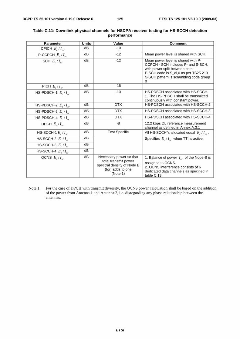
ETSI
ETSI TS 125 101 V6.19.0 (2009-03) 1253GPP TS 25.101 version 6.19.0 Release 6
Table C.11: Downlink physical channels for HSDPA receiver testing for HS-SCCH detection performance
Parameter Units Value Comment CPICH /c orE I dB -10
P-CCPCH /c orE I dB -12 Mean power level is shared with SCH.
SCH /c orE I dB -12 Mean power level is shared with P-CCPCH - SCH includes P- and S-SCH, with power split between both. P-SCH code is S_dl,0 as per TS25.213 S-SCH pattern is scrambling code group 0
PICH /c orE I dB -15
HS-PDSCH-1 /c orE I dB -10 HS-PDSCH associated with HS-SCCH-1. The HS-PDSCH shall be transmitted continuously with constant power.
HS-PDSCH-2 /c orE I dB DTX HS-PDSCH associated with HS-SCCH-2
HS-PDSCH-3 /c orE I dB DTX HS-PDSCH associated with HS-SCCH-3
HS-PDSCH-4 /c orE I dB DTX HS-PDSCH associated with HS-SCCH-4
DPCH /c orE I dB -8 12.2 kbps DL reference measurement channel as defined in Annex A.3.1
HS-SCCH-1 /c orE I dB
HS-SCCH-2 /c orE I dB
HS-SCCH-3 /c orE I dB
HS-SCCH-4 /c orE I dB
Test Specific All HS-SCCH"s allocated equal /c orE I .
Specifies /c orE I when TTI is active.
OCNS /c orE I dB Necessary power so that total transmit power
spectral density of Node B (Ior) adds to one
(Note 1)
1. Balance of power orI of the Node-B is
assigned to OCNS. 2. OCNS interference consists of 6 dedicated data channels as specified in table C.13.
Note 1 For the case of DPCH with transmit diversity, the OCNS power calculation shall be based on the addition of the power from Antenna 1 and Antenna 2, i.e. disregarding any phase relationship between the antennas.
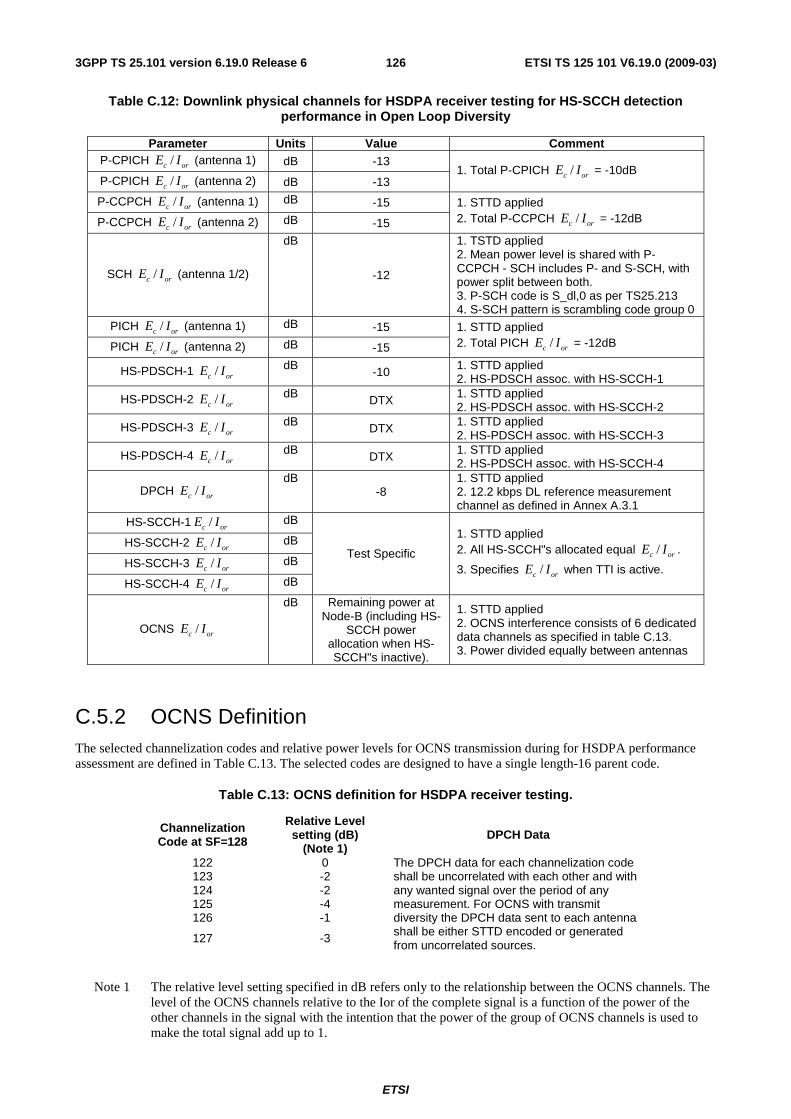
ETSI
ETSI TS 125 101 V6.19.0 (2009-03) 1263GPP TS 25.101 version 6.19.0 Release 6
Table C.12: Downlink physical channels for HSDPA receiver testing for HS-SCCH detection performance in Open Loop Diversity
Parameter Units Value Comment P-CPICH /c orE I (antenna 1) dB -13
P-CPICH /c orE I (antenna 2) dB -13 1. Total P-CPICH /c orE I = -10dB
P-CCPCH /c orE I (antenna 1) dB -15
P-CCPCH /c orE I (antenna 2) dB -15
1. STTD applied 2. Total P-CCPCH /c orE I = -12dB
SCH /c orE I (antenna 1/2)
dB
-12
1. TSTD applied 2. Mean power level is shared with P-CCPCH - SCH includes P- and S-SCH, with power split between both. 3. P-SCH code is S_dl,0 as per TS25.213 4. S-SCH pattern is scrambling code group 0
PICH /c orE I (antenna 1) dB -15
PICH /c orE I (antenna 2) dB -15
1. STTD applied 2. Total PICH /c orE I = -12dB
HS-PDSCH-1 /c orE I dB -10 1. STTD applied 2. HS-PDSCH assoc. with HS-SCCH-1
HS-PDSCH-2 /c orE I dB DTX 1. STTD applied 2. HS-PDSCH assoc. with HS-SCCH-2
HS-PDSCH-3 /c orE I dB DTX 1. STTD applied 2. HS-PDSCH assoc. with HS-SCCH-3
HS-PDSCH-4 /c orE I dB DTX 1. STTD applied 2. HS-PDSCH assoc. with HS-SCCH-4
DPCH /c orE I dB
-8 1. STTD applied 2. 12.2 kbps DL reference measurement channel as defined in Annex A.3.1
HS-SCCH-1 /c orE I dB
HS-SCCH-2 /c orE I dB
HS-SCCH-3 /c orE I dB
HS-SCCH-4 /c orE I dB
Test Specific
1. STTD applied 2. All HS-SCCH"s allocated equal /c orE I .
3. Specifies /c orE I when TTI is active.
OCNS /c orE I
dB Remaining power at Node-B (including HS-
SCCH power allocation when HS-SCCH"s inactive).
1. STTD applied 2. OCNS interference consists of 6 dedicated data channels as specified in table C.13. 3. Power divided equally between antennas
C.5.2 OCNS Definition The selected channelization codes and relative power levels for OCNS transmission during for HSDPA performance assessment are defined in Table C.13. The selected codes are designed to have a single length-16 parent code.
Table C.13: OCNS definition for HSDPA receiver testing.
Channelization Code at SF=128
Relative Level setting (dB)
(Note 1) DPCH Data
122 0 123 -2 124 -2 125 -4 126 -1
127 -3
The DPCH data for each channelization code shall be uncorrelated with each other and with any wanted signal over the period of any measurement. For OCNS with transmit diversity the DPCH data sent to each antenna shall be either STTD encoded or generated from uncorrelated sources.
Note 1 The relative level setting specified in dB refers only to the relationship between the OCNS channels. The level of the OCNS channels relative to the Ior of the complete signal is a function of the power of the other channels in the signal with the intention that the power of the group of OCNS channels is used to make the total signal add up to 1.
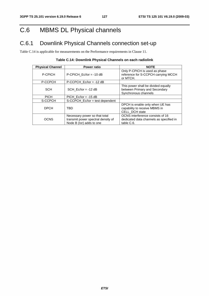
ETSI
ETSI TS 125 101 V6.19.0 (2009-03) 1273GPP TS 25.101 version 6.19.0 Release 6
C.6 MBMS DL Physical channels
C.6.1 Downlink Physical Channels connection set-up Table C.14 is applicable for measurements on the Performance requirements in Clause 11.
Table C.14: Downlink Physical Channels on each radiolink
Physical Channel Power ratio NOTE
P-CPICH P-CPICH_Ec/Ior = -10 dB Only P-CPICH is used as phase reference for S-CCPCH carrying MCCH or MTCH.
P-CCPCH P-CCPCH_Ec/Ior = -12 dB
SCH SCH_Ec/Ior = -12 dB This power shall be divided equally between Primary and Secondary Synchronous channels
PICH PICH_Ec/Ior = -15 dB S-CCPCH S-CCPCH_Ec/Ior = test dependent
DPCH TBD DPCH is enable only when UE has capability to receive MBMS in CELL_DCH state
OCNS Necessary power so that total transmit power spectral density of Node B (Ior) adds to one
OCNS interference consists of 16 dedicated data channels as specified in table C.6.
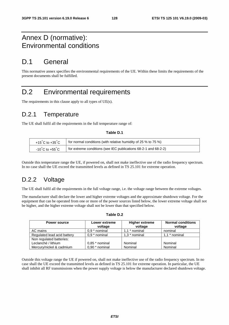
ETSI
ETSI TS 125 101 V6.19.0 (2009-03) 1283GPP TS 25.101 version 6.19.0 Release 6
Annex D (normative): Environmental conditions
D.1 General This normative annex specifies the environmental requirements of the UE. Within these limits the requirements of the present documents shall be fulfilled.
D.2 Environmental requirements The requirements in this clause apply to all types of UE(s).
D.2.1 Temperature The UE shall fulfil all the requirements in the full temperature range of:
Table D.1
+15°C to +35°C for normal conditions (with relative humidity of 25 % to 75 %)
-10°C to +55°C for extreme conditions (see IEC publications 68-2-1 and 68-2-2)
Outside this temperature range the UE, if powered on, shall not make ineffective use of the radio frequency spectrum. In no case shall the UE exceed the transmitted levels as defined in TS 25.101 for extreme operation.
D.2.2 Voltage The UE shall fulfil all the requirements in the full voltage range, i.e. the voltage range between the extreme voltages.
The manufacturer shall declare the lower and higher extreme voltages and the approximate shutdown voltage. For the equipment that can be operated from one or more of the power sources listed below, the lower extreme voltage shall not be higher, and the higher extreme voltage shall not be lower than that specified below.
Table D.2
Power source Lower extreme voltage
Higher extreme voltage
Normal conditions voltage
AC mains 0,9 * nominal 1,1 * nominal nominal Regulated lead acid battery 0,9 * nominal 1,3 * nominal 1,1 * nominal Non regulated batteries: Leclanché / lithium Mercury/nickel & cadmium
0,85 * nominal 0,90 * nominal
Nominal Nominal
Nominal Nominal
Outside this voltage range the UE if powered on, shall not make ineffective use of the radio frequency spectrum. In no case shall the UE exceed the transmitted levels as defined in TS 25.101 for extreme operation. In particular, the UE shall inhibit all RF transmissions when the power supply voltage is below the manufacturer declared shutdown voltage.

ETSI
ETSI TS 125 101 V6.19.0 (2009-03) 1293GPP TS 25.101 version 6.19.0 Release 6
D.2.3 Vibration The UE shall fulfil all the requirements when vibrated at the following frequency/amplitudes.
Table D.3
Frequency ASD (Acceleration Spectral Density) random vibration
5 Hz to 20 Hz 0,96 m2/s3
20 Hz to 500 Hz 0,96 m2/s3 at 20 Hz, thereafter -3 dB/Octave
Outside the specified frequency range the UE, if powered on, shall not make ineffective use of the radio frequency spectrum. In no case shall the UE exceed the transmitted levels as defined in TS 25.101 for extreme operation
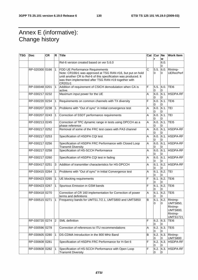
ETSI
ETSI TS 125 101 V6.19.0 (2009-03) 1303GPP TS 25.101 version 6.19.0 Release 6
Annex E (informative): Change history
TSG Doc CR R Title Cat Curr
New
Work Item
Rel-6 version created based on ver 5.6.0 6.0.0
RP-020300 0166 1 FDD UE Performance Requirements Note: CR166r1 was approved at TSG RAN #16, but put on hold until another CR to Rel-6 of this specification was produced. It was then implemented after TSG RAN #19 together with CR201r1
C 5.5.0
6.0.0
RInImp-UERecPerf
RP-030048 0201 1 Addition of requirement of CSICH demodulation when CA is active.
F 5.5.0
6.0.0
TEI6
RP-030217 0232 Maximum input power for the UE A 6.0.0
6.1.0
HSDPA-RF
RP-030220 0234 1 Requirements on common channels with TX diversity F 6.0.0
6.1.0
TEI6
RP-030207 0238 1 Problems with "Out of sync" in Initial convergence test A 6.0.0
6.1.0
TEI
RP-030207 0243 1 Correction of SSDT performance requirements A 6.0.0
6.1.0
TEI
RP-030213 0245 Correction of TPC dynamic range in tests using DPCCH as a phase reference
A 6.0.0
6.1.0
TEI5
RP-030217 0252 Removal of some of the FRC test cases with PA3 channel A 6.0.0
6.1.0
HSDPA-RF
RP-030217 0253 Specification of HSDPA CQI test A 6.0.0
6.1.0
HSDPA-RF
RP-030217 0256 Specification of HSDPA FRC Performance with Closed Loop Transmit Diversity
A 6.0.0
6.1.0
HSDPA-RF
RP-030217 0258 Specification of HS-SCCH Performance A 6.0.0
6.1.0
HSDPA-RF
RP-030217 0260 Specification of HSDPA CQI test in fading A 6.0.0
6.1.0
HSDPA-RF
RP-030417 0251 3 Addition of transmitter characteristics for HS-DPCCH A 6.1.0
6.2.0
HSDPA-RF
RP-030415 0264 1 Problems with "Out of sync" in Initial Convergence test A 6.1.0
6.2.0
TEI
RP-030423 0265 1 UE blocking requirements F 6.1.0
6.2.0
TEI6
RP-030423 0267 1 Spurious Emission in GSM bands F 6.1.0
6.2.0
TEI6
RP-030418 0270 Correction of CR 160 implementation for Correction of power terms and definitions
A 6.1.0
6.2.0
TEI5
RP-030515 0271 1 Frequency bands for UMTS1.7/2.1, UMTS800 and UMTS850 B 6.1.0
6.2.0
RInImp-UMTS850, RInImp-UMTS800, RInImp-UMTS1721
RP-030720 0274 2 SML definition F 6.2.0
6.3.0
TEI6
RP-030596 0278 Correction of references to ITU recommendations A 6.2.0
6.3.0
TEI5
RP-030605 0280 1 DS-CDMA Introduction in the 800 MHz Band B 6.2.0
6.3.0
RInImp-UMTS800
RP-030608 0281 Specification of HSDPA FRC Performance for H-Set 6 F 6.2.0
6.3.0
HSDPA-RF
RP-030608 0282 1 Specification of HS-SCCH Performance with Open Loop Transmit Diversity
F 6.2.0
6.3.0
HSDPA-RF
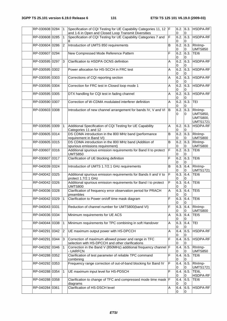
ETSI
ETSI TS 125 101 V6.19.0 (2009-03) 1313GPP TS 25.101 version 6.19.0 Release 6
RP-030608 0284 1 Specification of CQI Testing for UE Capability Categories 11, 12 and 1-6 in Open and Closed Loop Transmit Diversities
F 6.2.0
6.3.0
HSDPA-RF
RP-030608 0285 1 Specification of CQI Testing for UE Capability Categories 7 and 8
F 6.2.0
6.3.0
HSDPA-RF
RP-030604 0286 2 Introduction of UMTS 850 requirements B 6.2.0
6.3.0
RInImp-UMTS850
RP-030607 0294 New Compressed Mode Reference Pattern F 6.2.0
6.3.0
TEI6
RP-030595 0297 3 Clarification to HSDPA OCNS definition A 6.2.0
6.3.0
HSDPA-RF
RP-030595 0302 Power allocation for HS-SCCH in FRC test A 6.2.0
6.3.0
HSDPA-RF
RP-030595 0303 Corrections of CQI reporting section A 6.2.0
6.3.0
HSDPA-RF
RP-030595 0304 Correction for FRC test in Closed loop mode 1 A 6.2.0
6.3.0
HSDPA-RF
RP-030595 0305 DTX handling for CQI test in fading channel A 6.2.0
6.3.0
HSDPA-RF
RP-030590 0307 Correction of W-CDMA modulated interferer definition A 6.2.0
6.3.0
TEI
RP-030603 0308 Introduction of new channel arrangement for bands IV, V and VI B 6.2.0
6.3.0
RInImp-UMTS850, UMTS800,UMTS1721
RP-030595 0309 1 Additional Specification of CQI Testing for UE Capability Categories 11 and 12
A 6.2.0
6.3.0
HSDPA-RF
RP-030605 0314 DS CDMA introduction in the 800 MHz band (performance requirement in Band VI)
B 6.2.0
6.3.0
RInImp-UMTS800
RP-030605 0315 DS CDMA introduction in the 800 MHz band (Addition of spurious emissions requirement)
B 6.2.0
6.3.0
RInImp-UMTS800
RP-030607 0316 Additional spurious emission requirements for Band II to protect UMTS850
F 6.2.0
6.3.0
TEI6
RP-030607 0317 Clarification of UE blocking definition F 6.2.0
6.3.0
TEI6
RP-040039 0324 Introduction of UMTS 1.7/2.1 GHz requirements B 6.3.0
6.4.0
RInImp-UMTS1721
RP-040042 0325 Additional spurious emission requirements for Bands II and V to protect 1.7/2.1 GHz
F 6.3.0
6.4.0
TEI6
RP-040042 0326 Additional spurious emission requirements for Band I to protect UMTS800
F 6.3.0
6.4.0
TEI6
RP-040036 0328 Clarification of frequency error observation period for PRACH preambles
A 6.3.0
6.4.0
TEI5
RP-040042 0329 1 Clarification to Power on/off time mask diagram F 6.3.0
6.4.0
TEI6
RP-040043 0331 Reduction of channel number for UMTS800(band VI) F 6.3.0
6.4.0
RInImp-UMTS800
RP-040036 0334 Minimum requirements for UE ACS A 6.3.0
6.4.0
TEI5
RP-040044 0338 1 Minimum requirements for TPC combining in soft Handover A 6.3.0
6.4.0
TEI
RP-040291 0342 2 UE maximum output power with HS-DPCCH A 6.4.0
6.5.0
HSDPA-RF
RP-040291 0344 3 Correction of maximum allowed power and range in TFC selection with HS-DPCCH and other clarifications
F 6.4.0
6.5.0
HSDPA-RF
RP-040292 0346 1 Correction in the Band V (850MHz) additional frequency channel - UARFCN
F 6.4.0
6.5.0
RInImp-UMTS850
RP-040288 0352 Clarification of test parameter of reliable TPC command combining
F 6.4.0
6.5.0
TEI6
RP-040292 0353 Frequency range correction of out-of-band blocking for Band IV F 6.4.0
6.5.0
RInImp-UMTS1721
RP-040288 0354 1 UE maximum input level for HS-PDSCH F 6.4.0
6.5.0
TEI6, HSDPA-RF
RP-040288 0358 Clarification to change of TFC and compressed mode time mask diagrams
F 6.4.0
6.5.0
TEI6
RP-040284 0361 Clarification of HS-DSCH level A 6.4.0
6.5.0
HSDPA-RF
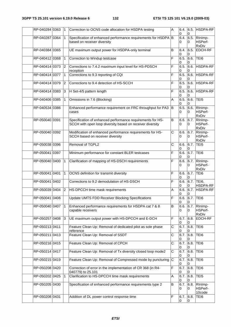
ETSI
ETSI TS 125 101 V6.19.0 (2009-03) 1323GPP TS 25.101 version 6.19.0 Release 6
RP-040284 0363 1 Correction to OCNS code allocation for HSDPA testing A 6.4.0
6.5.0
HSDPA-RF
RP-040287 0364 1 Specification of enhanced performance requirements for HSDPA based on receiver diversity
B 6.4.0
6.5.0
RInImp-HSPerf-RxDiv
RP-040384 0365 UE maximum output power for HSDPA-only terminal B 6.4.0
6.5.0
EDCH-RF
RP-040412 0368 1 Correction to Windup testcase F 6.5.0
6.6.0
TEI6
RP-040414 0373 2 Corrections to 7.4.2 maximum input level for HS-PDSCH reception
F 6.5.0
6.6.0
HSDPA-RF
RP-040414 0377 1 Corrections to 9.3 reporting of CQI F 6.5.0
6.6.0
HSDPA-RF
RP-040414 0379 2 Corrections to 9.4 detection of HS-SCCH F 6.5.0
6.6.0
HSDPA-RF
RP-040414 0383 3 H Set-4/5 pattern length F 6.5.0
6.6.0
HSDPA-RF
RP-040406 0385 1 Omissions in 7.6 (Blocking) A 6.5.0
6.6.0
TEI5
RP-040534 0386 Enhanced performance requirement on FRC throughput for PA3 cases
B 6.5.0
6.6.0
RInImp-HSPerf-RxDiv
RP-050040 0391 Specification of enhanced performance requirements for HS-SCCH with open loop diversity based on receiver diversity
B 6.6.0
6.7.0
RInImp-HSPerf-RxDiv
RP-050040 0392 Modification of enhanced performance requirements for HS-SCCH based on receiver diversity
C 6.6.0
6.7.0
RInImp-HSPerf-RxDiv
RP-050038 0396 Removal of TGPL2 C 6.6.0
6.7.0
TEI5
RP-050041 0397 Minimum performance for constant BLER testcases F 6.6.0
6.7.0
TEI6
RP-050040 0400 1 Clarification of mapping of HS-DSCH requirements F 6.6.0
6.7.0
RInImp-HSPerf-RxDiv
RP-050041 0401 1 OCNS definition for transmit diversity F 6.6.0
6.7.0
TEI6
RP-050041 0402 Corrections to 9.2 demodulation of HS-DSCH F 6.6.0
6.7.0
TEI6, HSDPA-RF
RP-050039 0404 2 HS-DPCCH time mask requirements A 6.6.0
6.7.0
HSDPA-RF
RP-050041 0406 Update UMTS FDD Receiver Blocking Specifications F 6.6.0
6.7.0
TEI6
RP-050040 0407 1 Enhanced performance requirements for HSDPA cat 7 & 8 capable receivers
B 6.6.0
6.7.0
RInImp-HSPerf-RxDiv
RP-050257 0408 3 UE maximum output power with HS-DPCCH and E-DCH F 6.7.0
6.8.0
EDCH-RF
RP-050213 0411 Feature Clean Up: Removal of dedicated pilot as sole phase reference
C 6.7.0
6.8.0
TEI6
RP-050211 0413 Feature Clean Up: Removal of SSDT C 6.7.0
6.8.0
TEI6
RP-050216 0415 Feature Clean Up: Removal of CPCH C 6.7.0
6.8.0
TEI6
RP-050214 0417 Feature Clean Up: Removal of Tx diversity closed loop mode2 C 6.7.0
6.8.0
TEI6
RP-050215 0419 Feature Clean Up: Removal of Compressed mode by puncturing C 6.7.0
6.8.0
TEI6
RP-050208 0420 Correction of error in the implementation of CR 368 (in R4-040779) to 25.101
F 6.7.0
6.8.0
TEI6
RP-050202 0425 1 Clarification to HS-DPCCH time mask requirements A 6.7.0
6.8.0
TEI5
RP-050205 0430 Specification of enhanced performance requirements type 2 B 6.7.0
6.8.0
RInImp-HSPerf-10code
RP-050208 0431 Addition of DL power control response time F 6.7.0
6.8.0
TEI6
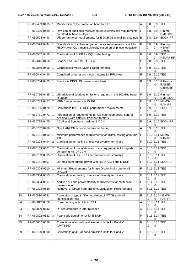
ETSI
ETSI TS 125 101 V6.19.0 (2009-03) 1333GPP TS 25.101 version 6.19.0 Release 6
RP-050489 0435 1 Modification of the protection band for PHS A 6.8.0
6.9.0
TEI
RP-050496 0439 1 Revision of additional receiver spurious emissions requirements on 800MHz band in Japan
F 6.8.0
6.9.0
RInImp-UMTS800
RP-050504 0443 UE performance requirements for E-DCH DL signalling channels B 6.8.0
6.9.0
EDCH-RF
RP-050598 0444 1 Specification of enhanced performance requirements type 2 for HSDPA with CL transmit diversity based on chip level equaliser
F 6.8.0
6.9.0
RInImp-HSPerf-10code
RP-050507 0450 1 Clarification of BLER for CQI under fading F 6.8.0
6.9.0
TEI6, HSDPA-RF
RP-050615 0456 Band V and Band VI UARFCN F 6.8.0
6.9.0
TEI6
RP-050840 0458 1 Compressed Mode Layer 1 Requirements F 6.9.0
6.10.0
TEI6
RP-050840 0460 Combined compressed mode patterns for RRM test F 6.9.0
6.10.0
TEI6
RP-050734 0463 1 Fractional DPCH DL power control test B 6.9.0
6.10.0
RANimp-RABSE-CodeOptFDD
RP-050736 0465 1 UE additional spurious emissions required in the 800MHz band in Japan
F 6.9.0
6.10.0
RInImp-UMTS800
RP-050743 0467 2 MBMS requirements in 25.101 F 6.9.0
6.10.0
MBMS-RAN-RF
RP-050735 0470 1 Corrections to UE E-DCH performance requirements F 6.9.0
6.10.0
EDCH-RF
RP-050731 0473 1 Introduction of requirements for UE outer loop power control behaviour with different transport formats
A 6.9.0
6.10.0
TEI5
RP-050735 0475 ACLR and Spectrum mask for E-DCH F 6.9.0
6.10.0
EDCH-RF
RP-050732 0486 1 New UARFCN scheme and re-numbering A 6.9.0
6.10.0
TEI5
RP-060101 0492 1 Minimum performance requirements for MBMS testing of 80 ms TTI
F 6.10.0
6.11.0
MBMS-RAN-RF
RP-060103 0494 2 Clarification for testing of receiver diversity terminals F 6.10.0
6.11.0
TEI6
RP-060103 0501 2 Clarification of modulation accuracy requirements for signals containing HS-DPCCH
A 6.10.0
6.11.0
TEI5
RP-060103 0505 1 Clarification of HS-SCCH performance requirements F 6.10.0
6.11.0
TEI6
RP-060181 0507 UE maximum output, power with HS-DPCCH and E-DCH F 6.10.0
6.11.0
EDCH-RF
RP-060304 0510 1 Minimum Requirements for Phase Discontinuity due to HS-DPCCH
F 6.11.0
6.12.0
TEI6
RP-060304 0515 Clarification for testing of receiver diversity terminals F 6.11.0
6.12.0
TEI6
RP-060304 0517 1 Addition of code power stability requirements for multi-code transmission
F 6.11.0
6.12.0
TEI6
RP-060303 0520 Removal of CPCH from Transmit Modulation Requirements A 6.11.0
6.12.0
TEI5
34 RP-060810 0531 Correction of typo in "Demodulation of MTCH and cell identification" test
F 6.13.0
6.14.0
MBMS-RAN-RF
34 RP-060812 0526 Power setting with HS-DPCCH A 6.13.0
6.14.0
TEI5
34 RP-060809 0542 RF requirements in later releases A 6.13.0
6.14.0
TEI
34 RP-060802 0522 3 Peak code domain error for E-DCH F 6.13.0
6.14.0
TEI6
35 RP-070652 0558 Corrections of out-of-band emission limits for Band V (UMTS850)
F 6.14.0
6.15.0
TEI6
39 RP-080120 0590 Corrections of out-of-band emission limits for Band V F 6.15.0
6.16.0
TEI6
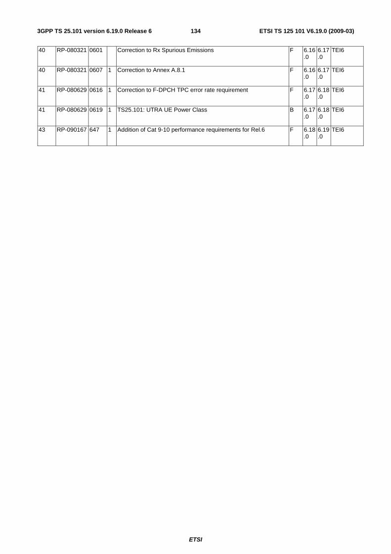
ETSI
ETSI TS 125 101 V6.19.0 (2009-03) 1343GPP TS 25.101 version 6.19.0 Release 6
40 RP-080321 0601 Correction to Rx Spurious Emissions F 6.16.0
6.17.0
TEI6
40 RP-080321 0607 1 Correction to Annex A.8.1 F 6.16.0
6.17.0
TEI6
41 RP-080629 0616 1 Correction to F-DPCH TPC error rate requirement F 6.17.0
6.18.0
TEI6
41 RP-080629 0619 1 TS25.101: UTRA UE Power Class B 6.17.0
6.18.0
TEI6
43 RP-090167 647 1 Addition of Cat 9-10 performance requirements for Rel.6 F 6.18.0
6.19.0
TEI6
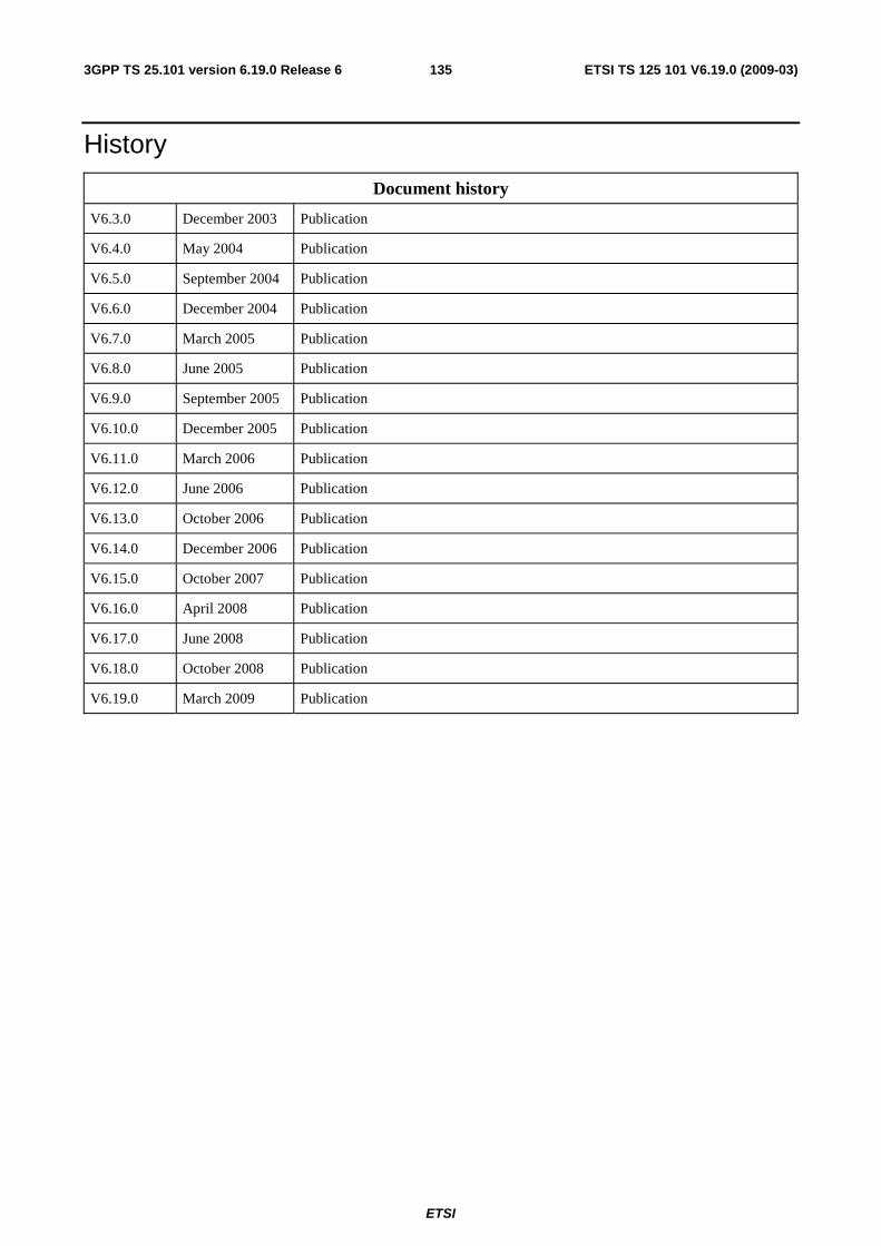
ETSI
ETSI TS 125 101 V6.19.0 (2009-03) 1353GPP TS 25.101 version 6.19.0 Release 6
History
Document history
V6.3.0 December 2003 Publication
V6.4.0 May 2004 Publication
V6.5.0 September 2004 Publication
V6.6.0 December 2004 Publication
V6.7.0 March 2005 Publication
V6.8.0 June 2005 Publication
V6.9.0 September 2005 Publication
V6.10.0 December 2005 Publication
V6.11.0 March 2006 Publication
V6.12.0 June 2006 Publication
V6.13.0 October 2006 Publication
V6.14.0 December 2006 Publication
V6.15.0 October 2007 Publication
V6.16.0 April 2008 Publication
V6.17.0 June 2008 Publication
V6.18.0 October 2008 Publication
V6.19.0 March 2009 Publication