Embed Size (px)
Citation preview

ETSI TS 103 327 V1.1.1 (2019-04)
Smart Body Area Networks (SmartBAN); Service and application standardized enablers and interfaces,
APIs and infrastructure for interoperability management
TECHNICAL SPECIFICATION
ETSI
ETSI TS 103 327 V1.1.1 (2019-04)2
Reference DTS/SmartBAN-004
Keywords application layer, control, health, information
model, interface, interoperability, interworking, IoT, network, ontology, privacy, protocol, security,
service
ETSI
650 Route des Lucioles F-06921 Sophia Antipolis Cedex - FRANCE
Tel.: +33 4 92 94 42 00 Fax: +33 4 93 65 47 16
Siret N° 348 623 562 00017 - NAF 742 C
Association à but non lucratif enregistrée à la Sous-Préfecture de Grasse (06) N° 7803/88
Important notice
The present document can be downloaded from: http://www.etsi.org/standards-search
The present document may be made available in electronic versions and/or in print. The content of any electronic and/or print versions of the present document shall not be modified without the prior written authorization of ETSI. In case of any
existing or perceived difference in contents between such versions and/or in print, the prevailing version of an ETSI deliverable is the one made publicly available in PDF format at www.etsi.org/deliver.
Users of the present document should be aware that the document may be subject to revision or change of status. Information on the current status of this and other ETSI documents is available at
https://portal.etsi.org/TB/ETSIDeliverableStatus.aspx
If you find errors in the present document, please send your comment to one of the following services: https://portal.etsi.org/People/CommiteeSupportStaff.aspx
Copyright Notification
No part may be reproduced or utilized in any form or by any means, electronic or mechanical, including photocopying and microfilm except as authorized by written permission of ETSI.
The content of the PDF version shall not be modified without the written authorization of ETSI. The copyright and the foregoing restriction extend to reproduction in all media.
© ETSI 2019.
All rights reserved.
DECTTM, PLUGTESTSTM, UMTSTM and the ETSI logo are trademarks of ETSI registered for the benefit of its Members. 3GPPTM and LTETM are trademarks of ETSI registered for the benefit of its Members and
of the 3GPP Organizational Partners. oneM2M™ logo is a trademark of ETSI registered for the benefit of its Members and
of the oneM2M Partners. GSM® and the GSM logo are trademarks registered and owned by the GSM Association.
ETSI
ETSI TS 103 327 V1.1.1 (2019-04)3
Contents Intellectual Property Rights ................................................................................................................................ 5
Foreword ............................................................................................................................................................. 5
Modal verbs terminology .................................................................................................................................... 5
Introduction ........................................................................................................................................................ 5
1 Scope ........................................................................................................................................................ 6
2 References ................................................................................................................................................ 6
2.1 Normative references ......................................................................................................................................... 6
2.2 Informative references ........................................................................................................................................ 6
3 Definition of terms, symbols and abbreviations ....................................................................................... 9
3.1 Terms .................................................................................................................................................................. 9
3.2 Symbols .............................................................................................................................................................. 9
3.3 Abbreviations ................................................................................................................................................... 10
4 Ambit and induced constraints ............................................................................................................... 12
5 High Level Architecture of SmartBAN heterogeneity management architecture .................................. 14
5.0 Introduction ...................................................................................................................................................... 14
5.1 SmartBAN reference model and architecture ................................................................................................... 15
5.1.0 Introduction................................................................................................................................................. 15
5.1.1 SmartBAN reference model High Level Architecture (HLA) .................................................................... 15
5.1.2 ETSI SmartBAN and AIOTI [i.5] IoT High Level Architecture (HLA) mapping ..................................... 16
5.1.3 ETSI SmartBAN and oneM2M[i.3] High Level Architecture (HLA) mapping ......................................... 17
5.1.4 ETSI SmartBAN and HL7 Fast Healthcare Interoperability Resources Specification (FHIR [i.6]) interactions .................................................................................................................................................. 19
5.1.5 SmartBAN reference architecture: agents definitions ................................................................................. 24
5.1.6 SmartBAN reference architecture: Process and data flows ........................................................................ 26
5.1.6.0 Introduction ........................................................................................................................................... 26
5.1.6.1 Set up phase .......................................................................................................................................... 26
5.1.6.2 Node Discovery Phase .......................................................................................................................... 27
5.1.6.3 Measurement Collection Phase ............................................................................................................. 27
5.1.6.4 Service Discovery Phase ....................................................................................................................... 28
5.1.6.5 Service Processing Phase ...................................................................................................................... 29
5.1.6.6 Network Management ........................................................................................................................... 29
5.1.7 Summary ..................................................................................................................................................... 30
5.2 SmartBAN IoT compliant layering reference architecture validation .............................................................. 30
5.2.1 Validation use case: elderly at home monitoring ........................................................................................ 30
5.2.2 Tests and results .......................................................................................................................................... 34
Annex A (informative): Background and SoA ..................................................................................... 37
A.0 Introduction ............................................................................................................................................ 37
A.1 Existing data sharing/transfer formats, protocols and interoperability frameworks for (or applicable for) sensors/actuators and BANs........................................................................................... 37
A.1.1 Sensor Web Enablement (SWE [i.16]) ............................................................................................................. 37
A.1.2 WSN's data communication protocols .............................................................................................................. 39
A.1.2.0 Introduction................................................................................................................................................. 39
A.1.2.1 JSON and JSON-LD protocols ([i.11], [i.17]) ............................................................................................ 39
A.1.2.2 Constrained Application Protocol (CoAP [i.12]) ........................................................................................ 39
A.2 e-health related architectures .................................................................................................................. 41
A.2.0 Introduction ...................................................................................................................................................... 41
A.2.1 ContoExam ([i.21]) .......................................................................................................................................... 41
A.2.2 Personal Connected Health Alliance global healthcare architecture ................................................................ 43
A.2.3 ASTM Healthcare Informatics architecture ([i.26]) ......................................................................................... 44
A.2.4 MedCom ([i.32]) .............................................................................................................................................. 45
A.2.5 The pan-Canadian EHR ([i.34]) ....................................................................................................................... 45

ETSI
ETSI TS 103 327 V1.1.1 (2019-04)4
A.3 Existing Semantic Web Service Architectures ....................................................................................... 48
A.3.1 OWL-S [i.35] ................................................................................................................................................... 48
A.3.2 Service Profile .................................................................................................................................................. 48
A.3.3 Service Model .................................................................................................................................................. 49
A.3.4 Service Grounding ............................................................................................................................................ 49
A.4 Existing generic service layers and enablers for in particular WSNs and WBANs ............................... 50
A.4.1 Service Oriented Architecture for WSN ........................................................................................................... 50
A.4.2 Semantic SOA for WSN ................................................................................................................................... 53
A.4.3 Open Sensor Web Architecture (OSWA [i.43]) ............................................................................................... 55
History .............................................................................................................................................................. 56

ETSI
ETSI TS 103 327 V1.1.1 (2019-04)5
Intellectual Property Rights
Essential patents
IPRs essential or potentially essential to normative deliverables may have been declared to ETSI. The information pertaining to these essential IPRs, if any, is publicly available for ETSI members and non-members, and can be found in ETSI SR 000 314: "Intellectual Property Rights (IPRs); Essential, or potentially Essential, IPRs notified to ETSI in respect of ETSI standards", which is available from the ETSI Secretariat. Latest updates are available on the ETSI Web server (https://ipr.etsi.org/).
Pursuant to the ETSI IPR Policy, no investigation, including IPR searches, has been carried out by ETSI. No guarantee can be given as to the existence of other IPRs not referenced in ETSI SR 000 314 (or the updates on the ETSI Web server) which are, or may be, or may become, essential to the present document.
Trademarks
The present document may include trademarks and/or tradenames which are asserted and/or registered by their owners. ETSI claims no ownership of these except for any which are indicated as being the property of ETSI, and conveys no right to use or reproduce any trademark and/or tradename. Mention of those trademarks in the present document does not constitute an endorsement by ETSI of products, services or organizations associated with those trademarks.
Foreword This Technical Specification (TS) has been produced by ETSI Technical Committee Smart Body Area Network (SmartBAN).
Modal verbs terminology In the present document "shall", "shall not", "should", "should not", "may", "need not", "will", "will not", "can" and "cannot" are to be interpreted as described in clause 3.2 of the ETSI Drafting Rules (Verbal forms for the expression of provisions).
"must" and "must not" are NOT allowed in ETSI deliverables except when used in direct citation.
Introduction The present document gives the high level description of infrastructure and mechanisms providing solutions for interoperability management in SmartBAN. The scope mainly covers the networking level up to the service and application level. The expected solutions will mainly concern the description and the specification of a standardized infrastructure for SmartBAN entities (e.g. sensors, actuators) interactions, data access and monitoring, irrespective of whatever lower layers and radio technologies are used underneath. On the service and application side, standardized APIs, in particular, for secure interaction and access to SmartBAN data/entities (data transfer and sharing mechanisms included) will be addressed.
ETSI
ETSI TS 103 327 V1.1.1 (2019-04)6
1 Scope The present document describes and specifies the high level infrastructure, its building blocks and associated APIs providing interoperability management solutions for SmartBAN. The architecture described in the present document also enables generic interaction and access to BAN data and entities, and thus paves the way to interoperability (networks and syntactic interoperability). Since the SmartBAN reference architecture specified and formatized in the present document fully relies on SmartBAN open semantic data model and corresponding ontologies as already standardized in [1], it therefore also addresses data and semantic interoperability.
The present document is applicable to a BAN and/or a SmartBAN comprising wearable sensors/actuators devices, a relay/coordinator device and a Hub. The relay/Coordinator and the Hub functionalities may be handled by a single device or by two distinct devices.
The present document is also addressing syntactic interoperability by defining unified data transfer and message formats.
2 References
2.1 Normative references References are either specific (identified by date of publication and/or edition number or version number) or non-specific. For specific references, only the cited version applies. For non-specific references, the latest version of the referenced document (including any amendments) applies.
Referenced documents which are not found to be publicly available in the expected location might be found at https://docbox.etsi.org/Reference/.
NOTE: While any hyperlinks included in this clause were valid at the time of publication, ETSI cannot guarantee their long term validity.
The following referenced documents are necessary for the application of the present document.
[1] ETSI TS 103 378 (V1.1.1) (12-2015): "Smart Body Area Networks (SmartBAN) Unified data representation formats, semantic and open data model".
2.2 Informative references References are either specific (identified by date of publication and/or edition number or version number) or non-specific. For specific references, only the cited version applies. For non-specific references, the latest version of the referenced document (including any amendments) applies.
NOTE: While any hyperlinks included in this clause were valid at the time of publication, ETSI cannot guarantee their long term validity.
The following referenced documents are not necessary for the application of the present document but they assist the user with regard to a particular subject area.
[i.1] S. Movassaghi, M. Abolhasan, J. Lipman, D. Smith and A. Jamalipour: "Wireless Body Area Networks: A Survey", in IEEE Communications Surveys & Tutorials, issue 99, pp. 1-29, January 2014.
[i.2] J. Y. Khan and M. R. Yuce: "Wireless Body Area Network (WBAN) for Medical Applications", New Developments in Biomedical Engineering, Domenico Campolo (Ed.), 2010, ISBN: 978-953-7619-57-2.
[i.3] oneM2M TS-0001-V2.10.0 (08-2016): "Functional Architecture".
NOTE: Available at http://www.onem2m.org/images/files/deliverables/Release2/TS-0001-%20Functional_Architecture-V2_10_0.pdf.

ETSI
ETSI TS 103 327 V1.1.1 (2019-04)7
[i.4] Alliance for Internet of Things Innovation (AIOTI) WG03 - IoT Standardization: "IoT High Level Architecture (HLA) Release 3.0".
NOTE: Available at https://aioti.eu/wp-content/uploads/2017/06/AIOTI-HLA-R3-June-2017.pdf.
[i.5] Alliance for Internet of Things Innovation (AIOTI) WG03 - IoT Standardization: "High Level Architecture (HLA) Release 4.0".
NOTE: Available at https://aioti.eu/wp-content/uploads/2018/06/AIOTI-HLA-R4.0.7.1-Final.pdf.
[i.6] HL7 FHIR® Specification 3 document.
NOTE 1: Available at http://hl7.org/fhir/index.html.
NOTE 2: FHIR® is an example of an existing eHealth standard. This information is given for the convenience of users of the present document and does not constitute an endorsement by ETSI of this standard.
[i.7] IETF RFC 2616 (04-2014): "Hypertext Transfer Protocol -- HTTP/1.1".
NOTE: Available at https://tools.ietf.org/html/rfc2616.
[i.8] ZigBee® Specification document.
NOTE: Available at http://www.zigbee.org/download/standard-zigbee-pro-specification-2/#.
[i.9] OASIS MQTT Version 3.1.1 (04-2014).
NOTE: Available at http://docs.oasis-open.org/mqtt/mqtt/v3.1.1/csprd02/mqtt-v3.1.1-csprd02.pdf.
[i.10] Bluetooth® Core Specification 4.2 document.
NOTE 1: Available at https://www.bluetooth.org/DocMan/handlers/DownloadDoc.ashx?doc_id=286439.
NOTE 2: Bluetooth® is an example of a suitable product available commercially. This information is given for the convenience of users of the present document and does not constitute an endorsement by ETSI of this product.
[i.11] ECMA-404 (12-2017): "The JSON Data Interchange Format".
NOTE: Available at http://www.ecma-international.org/publications/files/ECMA-ST/ECMA-404.pdf.
[i.12] IETF RFC 7552 (06-2014): "The Constrained Application Protocol (CoAP)".
NOTE: Available at https://tools.ietf.org/html/rfc7252.
[i.13] Roy T. Fielding: "Architectural styles and the design of network-based software architectures". PhD Thesis, University of California, Irvine, 2000.
NOTE: Available at http://www.ics.uci.edu/~fielding/pubs/dissertation/top.htm.
[i.14] W3C SPARQL 1.1 Query Language (03-2013).
NOTE: Available at https://www.w3.org/TR/sparql11-query/.
[i.15] W3C SWRL (05-2004): "A Semantic Web Rule Language Combining OWL and RuleML".
NOTE: Available at https://www.w3.org/Submission/SWRL.
[i.16] Open Geosatial Consortium (OGC) Sensor Web Enablement tutorial.
NOTE: Available at http://www.opengeospatial.org/domain/swe.
[i.17] M. LANTHALER, C. GÜTL: "On using JSON-LD to create evolvable RESTful services", in Proceedings of the Third International Workshop on RESTful Design, pp. 25-32, Lyon, France, April 2012.
ETSI
ETSI TS 103 327 V1.1.1 (2019-04)8
[i.18] IETF RFC 0793 (09-1981): "Transmission Control Protocol".
NOTE: Available at https://www.ietf.org/rfc/rfc793.txt.
[i.19] IETF Constrained RESTful Environments (core) working group.
NOTE: Available at https://datatracker.ietf.org/wg/core/charter/.
[i.20] IETF RFC 0768 (08-1980): "User Datagram Protocol".
NOTE: Available at https://tools.ietf.org/html/rfc768.
[i.21] P. Brandt, T., Basten, S. Stuijk: "ContoExam: an ontology on context-aware examinations", in Proceedings of FOIS2014, pp. 303-316, Brazil, September 2014.
[i.22] SNOMED CT® starter guide.
NOTE 1: Available at https://confluence.ihtsdotools.org/display/DOCSTART/SNOMED+CT+Starter+Guide.
NOTE 2: SNOMED CT® is an example of an existing eHealth reference terminology. This information is given for the convenience of users of the present document and does not constitute an endorsement by ETSI of this reference terminology.
[i.23] NISO spring 2015 ISQ issue.
NOTE: Available at https://groups.niso.org/publications/isq/2015/.
[i.24] Personal Connected Health Alliance.
NOTE: Available at http://www.pchalliance.org/.
[i.25] ISO/IEEETM 11073 standards: "Health informatics -- Personal health device communication".
NOTE: Available at https://www.iso.org/search.html?q=11073.
[i.26] ASTM International Technical Committee E31 description.
NOTE: Available at https://www.astm.org/COMMIT/E31_FactsheetHI.pdf.
[i.27] ASTM E1238-97: "Standard Specification for Transferring Clinical Observations Between Independent Computer Systems" (Withdrawn 2002).
NOTE: Available at https://www.astm.org/DATABASE.CART/WITHDRAWN/E1238.htm.
[i.28] ASTM E1394-97: "Standard Specification for Transferring Information Between Clinical Instruments and Computer Systems" (Withdrawn 2002).
NOTE: Available at https://www.astm.org/DATABASE.CART/WITHDRAWN/E1394.htm.
[i.29] ASTM E1467-94: "Standard related to the transfer of digital neurophysiological data between independent computer systems" (Withdrawn 2004).
NOTE: Available at https://www.astm.org/Standards/E1467.htm.
[i.30] ASTM E2369-12: "Standard Specification for Continuity of Care Record (CCR)".
NOTE: Available at https://www.astm.org/Standards/E2369.htm.
[i.31] ASTM E1384-07 (2013): "Standard Practice for Content and Structure of the Electronic Health Record (EHR)" (Withdrawn 2017).
NOTE: Available at https://www.astm.org/Standards/E1384.htm.
[i.32] J. H. Bjerregaard, P. C. Duedal. MedCom: "Danish health care network. Studies in health technology and informatics", 2003. Vol. 100, p. 59-65.

ETSI
ETSI TS 103 327 V1.1.1 (2019-04)9
[i.33] W3C SOAP Version 1.2 specification (04-2007).
NOTE: Available at https://www.w3.org/TR/soap/.
[i.34] Dennis Giokas Chief Technology Officer Solution Architecture Group Canada Health Infoway Inc. 1: "SOA in the pan-Canadian EHR".
NOTE: Available at http://www.omg.org/news/meetings/workshops/HC-Australia/Giokas.pdf.
[i.35] W3C OWL-S (11-2004): "Semantic Markup for Web Services".
NOTE: Available at https://www.w3.org/Submission/OWL-S/.
[i.36] Lan, M. Qilong, J. Du: "Architecture of wireless sensor networks for environmental monitoring. In Education Technology and Training", in Proceedings of IEEE IITA-GRS 2008, Shanghai, China, December 2008.
[i.37] E. Avilés-López, J. García-Macías, J. Antonio: "TinySOA: a service-oriented architecture for wireless sensor networks", Service Oriented Computing and Applications. 2009. Vol. 3, n 2, pp. 99-108.
[i.38] F. C. Dedicato, P. F. Pires, L. Pirmez, T. Batista: "Wireless Sensor Networks as a service", In Proceedings of IEEE ECBS2010, pp. 410-417, UK, March 2010.
[i.39] A. Ghobakhlou, A. Kmoch, P. Sallis: "Integration of Wireless Sensor Network and Web Services", in Proceedings of the 20th International Congress on Modelling and Simulation, pp. 1-6, Adelaide, Australia, 2013.
[i.40] K. K. Khedo, R. K. Subramanian: "A service-oriented component-based middleware architecture for wireless sensor networks", International Journal of Computer Science and Network Security, 2009. Vol. 9, n 3, pp. 174-182.
[i.41] A. P. Singh, O. P. Vyas, S. Varma: "Flexible Service Oriented Network Architecture for Wireless Sensor Networks", International Journal of Computers Communications & Control. 2014. Vol. 9, n 5, pp. 610-622.
[i.42] F. Amato, V. Casola, A., Gaglione, A. Mazzeo: "A semantic enriched data model for sensor network interoperability", Simulation Modelling Practice and Theory. 2011. Vol. 19, n 8, pp. 1745-1757.
[i.43] CHU, Xingchen: "Open sensor web architecture: core services", The University of Melbourne, Australia, 2005.
3 Definition of terms, symbols and abbreviations
3.1 Terms Void.
3.2 Symbols For the purposes of the present document, the following symbols apply:
bpm beats per minute bps bit per second s second
ETSI
ETSI TS 103 327 V1.1.1 (2019-04)10
3.3 Abbreviations For the purposes of the present document, the following abbreviations apply:
ACK Acknowledgement (e.g. ACK message) AE Application Entity AIOTI Alliance for Internet of Things Innovation API Application Programming Interface ASTM American Standards for Testing and Materials AT ATtention (e.g. AT Command) BAN Body Area Network BANID Body Area Network IDentifier BLE Bluetooth Low Energy BLES Bluetooth LE Scanner agent CCR Continuity of Care Record CCU Central Control Unit CEN Comité Européen de Normalisation (European Committee for Standardization) CoAP Constrained Application Protocol CON Confirmable (e.g. CON message) Core Constrained RESTful Environments CPU Central Processing Unit CSE Core Service Entity DIM Domain Information Model DS Data Scanner agents DTLS Datagram Transport Layer Security E2E End-to-End ECG Electrocardiogram EDI Electronic Document Interchanged EEG Electroencephalogram EHR Electronic Health Record EHRS Electronic Health Record Solution EU European Union FHIR Fast Healthcare Interoperability Resources GATT Generic Attribute Profile GCM Google Cloud Messaging GUI Graphical User Interface GW Gateway HDF HL7 Development Framework HDP Health Device Profile HIAL Health Information Access Layer HL7 Health Level Seven International HLA High Level Architecture HMI Human-Machine Interface HR Heart Rate HTTP Hypertext Transfer Protocol ICT Information and Communication Technology IEEE Institute of Electrical and Electronics Engineers IHE Integrating the Healthcare Enterprise IoT Internet of Things IP Internet Protocol ISM Industrial, Scientific and Medical ISQ Information Standards Quarterly IT Information Technology JS JSON Scanner JSON JavaScript Object Notation JSON-LD JavaScript Object Notation Linked Data JW JSON Writer LAN Local Area Network LAN-IF Local Area Network Interface LD Linked Data LE Low Energy

ETSI
ETSI TS 103 327 V1.1.1 (2019-04)11
LRS Longitude Record Services M2M Machine to Machine MAC Medium Access Control MAS Management Abstraction and Semantics MBAN Medical Body Area Network MQTT Message Queue Telemetry Transport MVTU Ministry of Science Technology and Innovation MW Measurement Wrapper NICTA National ICT Australia NISO National Information Standards Organization NON Non-confirmable (e.g. NON message) NSE Network Service Entity NW Node semantic Wrappers OGC Open Geospatial Consortium OMA Open Mobile Alliance OSWA Open Sensor Web Architecture OWL Web Ontology Language OWL-S Web Ontology Language for Services PAN Personal Area Network PAN-IF Peripheral Area Network Interface PDA Personal Digital Assistant PER Packet Error Rate PHY Physical PoS Point of Services PW Process semantic Wrappers QoI Quality of Information QoS Quality of Service RAM Random Access Memory RDF Resource Description Framework REST REpresentational State Transfer RFID Radio Frequency Identification RSSI Received Signal Strength Indication RST Reset (e.g. RST message) RTLS Real Time Location Services SAS Sensor Alert Service SCS Sensor Collection Service SDO Standards Development Organizations SensorML Sensor Model Language SIG Special Interest Group SMS Short Message Service SOA Service Oriented Architecture SOAP Simple Object Access Protocol SOS Sensor Observation Service SPARQL Simple Protocol and RDF Query Language SPS Sensor Planning Service SW Semantic Wrapper SWE Sensor Web Enablement SWRL Semantic Web Rule Language TAN Touchable Area Network TAN-IF Touchable Area Network Interface TBD To Be Defined TC Technical Committee TCP Transmission Control Protocol TML TransducerML TransducerML Transducer Model Language TS Technical Specification UDDI Universal Description, Discovery and Integration UDI Universal Device Identifier UDP User Datagram Protocol UI User Interface UML Unified Model Language URI Uniform Resource Identifier

ETSI
ETSI TS 103 327 V1.1.1 (2019-04)12
URL Uniform Resource Locator US United States UUID Universally Unique IDentifier W3C World Wide Web Consortium WAN Wide Area Network WAN-IF Wide Area Network Interface WBAN Wireless Body Area Network WNS Web Notification Service WoT Web of Things WRS Web Registry Service WSDL Web Services Description Language WSN Wireless Sensor Network WW WSN Writer XaaS Everything as a Service xHRN-IF Electronic/Personal Health Records Network Interface XML eXtensible Markup Language
4 Ambit and induced constraints The scope of the present clause is to briefly investigate the initial TC SmartBAN use case requirements in order to point out their impact on High level specifications and designs of the present document. The initial additional requirements induced by scenario addressed within the present document are also listed.
Wireless Body Area Networks (WBANs) are made of a collection of low-power embedded devices, mainly sensors or actuators that are used for monitoring vital data of a human and its environment (but not limited to human). Those embedded devices are located in the vicinity or on or inside the body, and are mainly provided with short range communication technologies. BANs are short distance networks of maximum 6 m3 that contain maximum 6 networks per m2 and maximum 256 nodes per network [i.1]. These nodes may be mobile and the network topology may change frequently. The data rate of sensed data can actually vary from 75,9 kbps to 15,6 Mbps [i.1]. WBANs are not expected to be operated in licensed frequency bands. Hence, the frequency spectrum of operation will be in the unregulated frequency bands for industrial, scientific and medical (ISM) applications. If ISM and MBAN bands (US and European) with frequency between 2,3 GHz and 2,5 GHz are initially considered within TC SmartBAN, higher frequency bands (from 3,2 to 10,2 GHz) will also be considered for allowing the support of Real Time Location Services (RTLS). Finally, WBANs are characterized by strong constraints in terms of low power, low latency, low Packet Error Rate (PER), reliability, QoS, coexistence and security. The initial technical requirements retained by TC SmartBAN for WBAN parameters are listed in table 1.
Table 1: Initial technical requirements retained by TC SmartBAN for WBAN parameters
Parameter SmartBAN Requirements
Coexistence/robustness Good (low interference to other systems, high tolerance to interference)
Data rates (Sensor) Nominally < 100 kbps/node (vital sign monitoring) Transmission rate (PHY) Up to 1 Mbps Network topology Star network Power consumption (node) TBD
QoS control Priority based control and cross layer optimization. Emergency signal transmission supported.
Reliability Robust to shadowing and multipath interference Max. node capacity up to 16 nodes (typically 8) Range < 1,5 m Latency < 125 ms (high sampling applications e.g. ECG, EEG.) Security / privacy TBD
ETSI
ETSI TS 103 327 V1.1.1 (2019-04)13
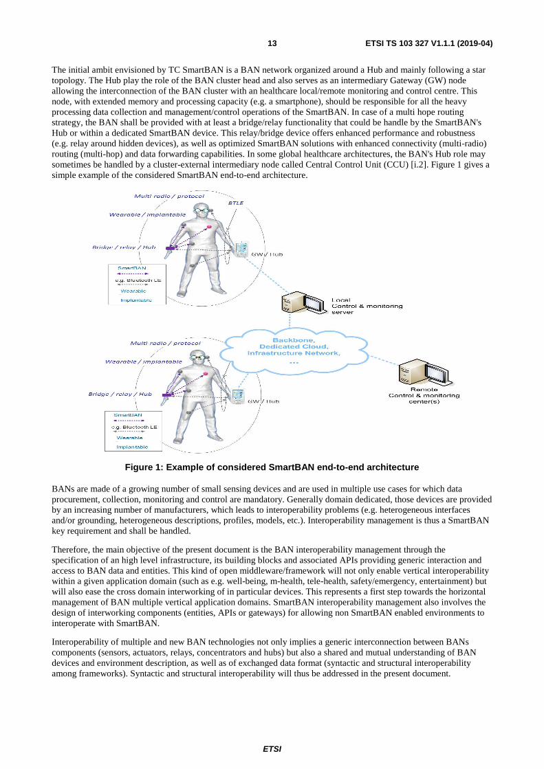
The initial ambit envisioned by TC SmartBAN is a BAN network organized around a Hub and mainly following a star topology. The Hub play the role of the BAN cluster head and also serves as an intermediary Gateway (GW) node allowing the interconnection of the BAN cluster with an healthcare local/remote monitoring and control centre. This node, with extended memory and processing capacity (e.g. a smartphone), should be responsible for all the heavy processing data collection and management/control operations of the SmartBAN. In case of a multi hope routing strategy, the BAN shall be provided with at least a bridge/relay functionality that could be handle by the SmartBAN's Hub or within a dedicated SmartBAN device. This relay/bridge device offers enhanced performance and robustness (e.g. relay around hidden devices), as well as optimized SmartBAN solutions with enhanced connectivity (multi-radio) routing (multi-hop) and data forwarding capabilities. In some global healthcare architectures, the BAN's Hub role may sometimes be handled by a cluster-external intermediary node called Central Control Unit (CCU) [i.2]. Figure 1 gives a simple example of the considered SmartBAN end-to-end architecture.
Figure 1: Example of considered SmartBAN end-to-end architecture
BANs are made of a growing number of small sensing devices and are used in multiple use cases for which data procurement, collection, monitoring and control are mandatory. Generally domain dedicated, those devices are provided by an increasing number of manufacturers, which leads to interoperability problems (e.g. heterogeneous interfaces and/or grounding, heterogeneous descriptions, profiles, models, etc.). Interoperability management is thus a SmartBAN key requirement and shall be handled.
Therefore, the main objective of the present document is the BAN interoperability management through the specification of an high level infrastructure, its building blocks and associated APIs providing generic interaction and access to BAN data and entities. This kind of open middleware/framework will not only enable vertical interoperability within a given application domain (such as e.g. well-being, m-health, tele-health, safety/emergency, entertainment) but will also ease the cross domain interworking of in particular devices. This represents a first step towards the horizontal management of BAN multiple vertical application domains. SmartBAN interoperability management also involves the design of interworking components (entities, APIs or gateways) for allowing non SmartBAN enabled environments to interoperate with SmartBAN.
Interoperability of multiple and new BAN technologies not only implies a generic interconnection between BANs components (sensors, actuators, relays, concentrators and hubs) but also a shared and mutual understanding of BAN devices and environment description, as well as of exchanged data format (syntactic and structural interoperability among frameworks). Syntactic and structural interoperability will thus be addressed in the present document.
ETSI
ETSI TS 103 327 V1.1.1 (2019-04)14
Finally, the following reminder has to be made: BAN interoperability and heterogeneity management have to be handled by taking into account other strong constraints like in particular low complexity, ultra-low power and dynamicity (e.g. node mobility, topology changes). That is why the SmartBAN dedicated interoperability framework that is specified in the present document shall be designed as modular/distributable and extensible. Therefore, existing distributed and Multi-Agents based architectures like, e.g. oneM2M [i.3] and IoT [i.4] are, in particular, considered in the present document.
All the aforementioned issues are addressed in the present document.
5 High Level Architecture of SmartBAN heterogeneity management architecture
5.0 Introduction Actually, almost all SmartBAN services are presented as close solutions where the users adopts a low-level sensor network configuration, and use a specific application coupled with this implemented network configuration. This application prohibits the possibility to benefit from collected data among different solutions and service providers. For this reason, a general architecture should be designed to achieve interoperability, not only between SmartBAN's components, but also between different solutions and applications. In SmartBAN, body sensors should communicate with the body getaway or hub, which in turn will send data to a local server and/or remote and distributed monitoring servers and services distributed among medical specialists, caregivers, relatives and even home managers. This transfer of data within a SmartBAN should be described in a general architecture to facilitate the interconnection between different nodes.
Beside interoperability within the SmartBAN, linking patients to their history records as well as patient identification should be required for improving patient care, safety and decrease health care cost. For illustration, consider a patient who is accessing the emergency part of a hospital, it will be very useful if the hospital staff identifies the patient and retrieves all historical data (allergies, surgeries, medical consultations, etc.) for intelligent and accurate intervention. However, relating patients to their records is still tedious because actually data warehouse systems are siloed and proprietary systems where interoperability is still the big challenge. Thus, standardizing the approaches to patient identification among different health-care systems is required. For this reason, SmartBAN reference architecture shall emphasize the cooperation between different SmartBANs and should also lead to new cross domain applications in order to integrate the SmartBANs in the Web of Things (WoT). In addition, this architecture shall:
• provide sensor/actuators/device interoperability, as well as network interoperability, i.e. be multi-platform enabled. For network interoperability management purposes, the SmartBAN reference model should follow the oneM2M specifications;
• provide ontology-based intelligence with semantic interoperability and data reusability functionalities;
• enhance the nodes registration process toward zero configuration and automatic BAN nodes/services discovery;
• handle urgent cases and notifications;
• provide dynamic reconfiguration of the network when necessary to extend the lifetime of the network;
• provide faults' management;
• address security, privacy and confidentiality;
• ensure the freshness of the data and services; and
• especially enable the automatic patient identification, device/data/service discovery and description.
ETSI
ETSI TS 103 327 V1.1.1 (2019-04)15
To achieve this goal, XaaS (Everything as a Service) and WoT (Web of Things) approaches should be envisioned. A semantic representation of the information and semantic interoperability strategies are also the key issues to manage the interoperability between different vendors and applications. Furthermore, to provide a smart and context aware environment where computers will accomplish tasks instead of people, the multi-agent architecture is the most promising technique. This architecture is dynamic, where agents are invoked when needed and can communicate to invoke other agents. These agents will work autonomously and cooperatively. In addition, the multi-agent architecture provides a good level of granularity and redundancy where agents can be implemented on different devices; thus enabling a distributed computing architecture.
5.1 SmartBAN reference model and architecture
5.1.0 Introduction
To improve the maintainability and the flexibility, the proposed SmartBAN reference model and architecture is designed as a multi-agent IoT architecture. The SmartBAN reference model shall also fully rely on BAN semantic data, service model, corresponding ontologies (as already standardized in [1]), and shall also address semantic interoperability. It is specified for both: allowing a generic and secure interaction/access to any BAN data/entities, providing a unified reference platform for BAN distributed monitoring and control operations.
5.1.1 SmartBAN reference model High Level Architecture (HLA)
The SmartBAN reference architecture follows a multi-layer model where all layers:
• are communicating to each other;
• can be implemented independently in a device depending on the device capabilities and the needs, thus allowing for constraint devices to include just the required functionality.
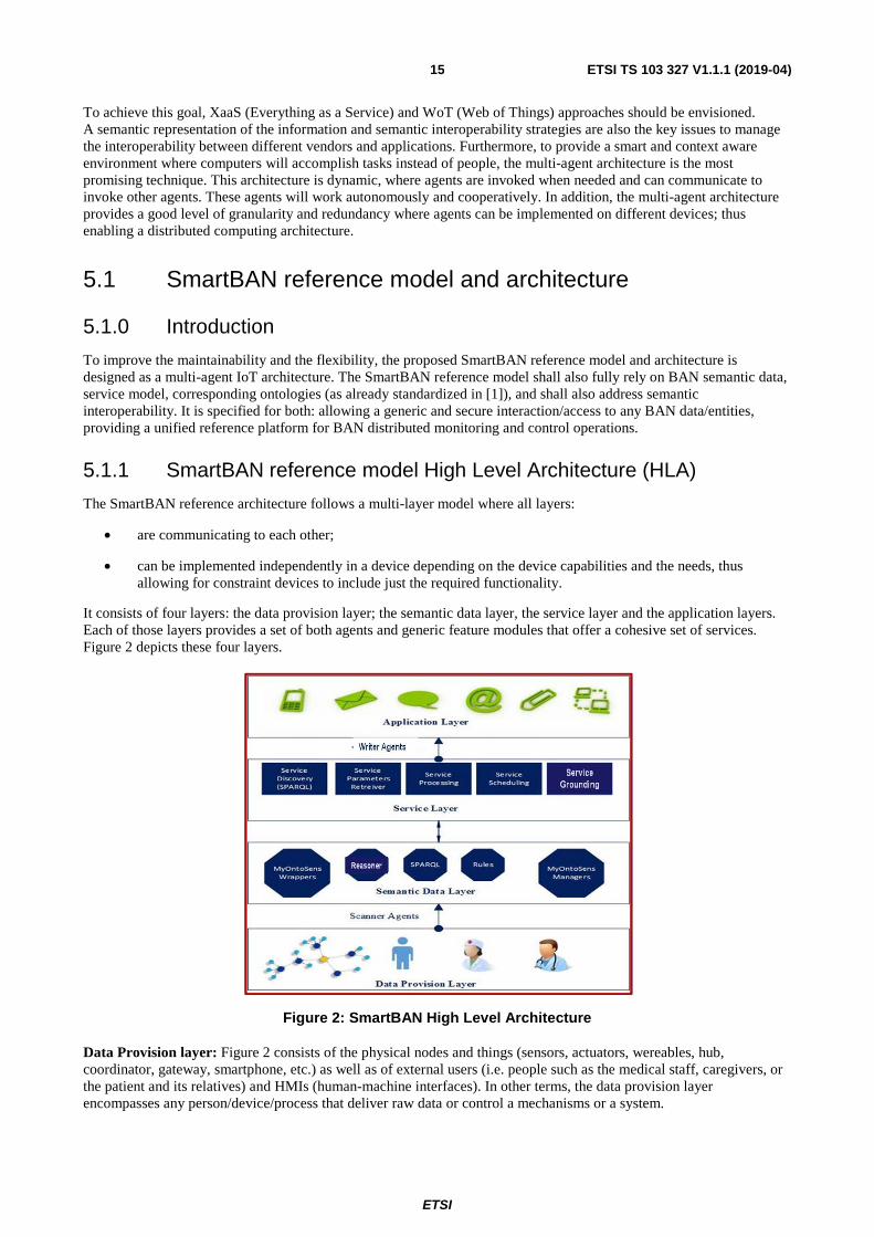
It consists of four layers: the data provision layer; the semantic data layer, the service layer and the application layers. Each of those layers provides a set of both agents and generic feature modules that offer a cohesive set of services. Figure 2 depicts these four layers.
Figure 2: SmartBAN High Level Architecture
Data Provision layer: Figure 2 consists of the physical nodes and things (sensors, actuators, wereables, hub, coordinator, gateway, smartphone, etc.) as well as of external users (i.e. people such as the medical staff, caregivers, or the patient and its relatives) and HMIs (human-machine interfaces). In other terms, the data provision layer encompasses any person/device/process that deliver raw data or control a mechanisms or a system.

ETSI
ETSI TS 103 327 V1.1.1 (2019-04)16
Semantic Data layer: is composed of entities mainly providing SmartBAN semantic and ontologies management functionalities (like e.g. reasoning, semantic search/annotation/eventing, etc.). This layer also extends standard BAN systems with additional embedded intelligence related functionalities through some rules management entities. Due to the integration of a set of agents and generic feature modules that offer semantic rules management and rezoning functionalities, this layer also permits to correlate different collected data for advanced decision making. The semantic data can be retrieved by using Semantic Query Language (SPARQL).
Service layer: mainly provides generic entities related to service management functionalities like e.g. service creation, discovery and execution. The services shall be semantically described using SmartBAN service ontology specified and formalized in [1]. This ontology permits the automatic service discovery in terms of QoS, QoI, I/O parameters, effects, etc. This also helps service developer/user to interact with the SmartBAN regardless the underneath layers.
SmartBAN Service and Semantic Data layers link the application layer to the data provision layer. They shall fully rely on SmartBAN data model and ontologies as already specified and formalized in [1]. Service and Semantic Data layers provide a set of agents and generic feature modules that offer a cohesive set of services. Those agents and modules can exchange data or command with each other and this is done through dedicated data templates and a specific interface (see Figure 2).
Application layer: is composed of several Application Entities, each one implementing a given SmartBAN application logic (e.g. data monitoring, patient evaluation result, patient notification, etc.). SmartBAN Application Entities can exchange data or command with each other and this is done through dedicated data templates and a specific interface (see Figure 2).
5.1.2 ETSI SmartBAN and AIOTI [i.5] IoT High Level Architecture (HLA) mapping
The Alliance for Internet of Things Innovation (AIOTI) has been initiated as a result of the European and global IoT technology and market developments. AIOTI is a non-profit association under the Belgium law which goal is to create and master sustainable innovative European IoT ecosystems. AIOTI aims to address all the challenges of IoT technology and applications deployment in order to accelerate sustainable economic development and growth in the new emerging European and global digital markets. Those challenges includes in particular standardization, interoperability management, security and policy issues. Therefore, AIOTI is actually the EU key alliance for unifying IoT over Europe and in particular its common high level reference architectures, requirements & guidelines should be taken into consideration. Among AIOTI Working Groups, WG3 is addressing IoT standardization aspects. One of its sub-group has defined a reference IoT High Level Architecture. It is thus strongly recommended to position and map the SmartBAN reference model previously introduced in clause 5.1.1 of the present document to the AIOTI IoT HLA architecture presented in [i.5]. Figure 3 provides the corresponding high level mapping.

ETSI
ETSI TS 103 327 V1.1.1 (2019-04)17
Figure 3: ETSI SmartBAN and AIOTI HLA reference models mapping
Figure 3 shows that ETSI SmartBAN application layer is composed of several Application Entities, each one implementing a given SmartBAN application logic. Consequently, there is a direct mapping between ETSI SmartBAN and AIOTI application layers.
Figure 3 also shows that ETSI SmartBAN Service and Semantic Data layers link the application layer to the data provision layer. They both provide a set of agents and generic feature modules that offer a cohesive set of services (likewise for AIOTI HLA). Those agents and modules can exchange data or command with each other and this is done through dedicated data templates and a specific interface (see Figure 3). Therefore, each aforementioned entity of ETSI SmartBAN Service and Semantic Data layers can fully be considered as an IoT entity and be thus all forgathered in the AIOTI IoT Layer.
Finally, Figure 3 shows that ETSI SmartBAN Data Provision Layer and IoT Network Layer have exactly the same role (direct mapping).
5.1.3 ETSI SmartBAN and oneM2M[i.3] High Level Architecture (HLA) mapping
oneM2M is a global organization composed of over 200 member organizations, among them: 8 ICT related SDOs including ETSI, 6 standard bodies including OMA (Open Mobile Alliance). Its objectives are, in particular, the design, the standardization and the specification (technical specifications included) of a reference network/communication level intermediation framework for enabling the generic and efficient interconnection and deployment of both devices and M2M applications. oneM2M is, in particular, capitalizing on ETSI M2M and OMA LWM2M. Finally, it has to be said that oneM2M is intended to be an "horizontal" framework, therefore, addressing any application domain (eHealth and smart appliances/homes included).
Figure 4 presents oneM2M High Level Architecture model.
SmartBAN
SmartBAN
SmartBAN
SmartBAN
ETSI
ETSI TS 103 327 V1.1.1 (2019-04)18
Figure 4: oneM2M High Level Architecture Model
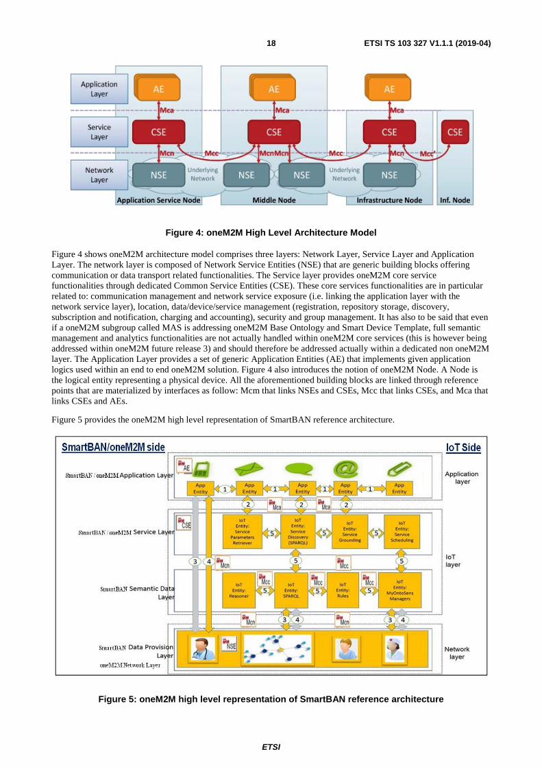
Figure 4 shows oneM2M architecture model comprises three layers: Network Layer, Service Layer and Application Layer. The network layer is composed of Network Service Entities (NSE) that are generic building blocks offering communication or data transport related functionalities. The Service layer provides oneM2M core service functionalities through dedicated Common Service Entities (CSE). These core services functionalities are in particular related to: communication management and network service exposure (i.e. linking the application layer with the network service layer), location, data/device/service management (registration, repository storage, discovery, subscription and notification, charging and accounting), security and group management. It has also to be said that even if a oneM2M subgroup called MAS is addressing oneM2M Base Ontology and Smart Device Template, full semantic management and analytics functionalities are not actually handled within oneM2M core services (this is however being addressed within oneM2M future release 3) and should therefore be addressed actually within a dedicated non oneM2M layer. The Application Layer provides a set of generic Application Entities (AE) that implements given application logics used within an end to end oneM2M solution. Figure 4 also introduces the notion of oneM2M Node. A Node is the logical entity representing a physical device. All the aforementioned building blocks are linked through reference points that are materialized by interfaces as follow: Mcm that links NSEs and CSEs, Mcc that links CSEs, and Mca that links CSEs and AEs.
Figure 5 provides the oneM2M high level representation of SmartBAN reference architecture.
Figure 5: oneM2M high level representation of SmartBAN reference architecture
ETSI
ETSI TS 103 327 V1.1.1 (2019-04)19
Figure 5 shows that:
• There is a direct mapping between oneM2M Network Layer and SmartBAN Data Provision Layer and its generic Agents (equivalent to oneM2M NSEs).
• There is a direct mapping between oneM2M Service Layer and SmartBAN Service Layer and its generic Agents (equivalent to oneM2M CSEs).
• There is a direct mapping between oneM2M application layer and SmartBAN Application Layer and its application agents (equivalent to oneM2M AE).
The Semantic Data Layer of SmartBAN reference model (see Figure 2) is not mapped yet to any oneM2M layer in Figure 5 since, as already aforementioned, oneM2M is not actually addressing full semantic management and analytics functionalities within its current release core services (this will only be fully addressed within oneM2M future release 4). This SmartBAN Semantic Data Layer and its generic semantic management related agents are therefore actually integrated within an IoT Layer dedicated sub-layer. These agents may, however, use:
• The Mcn interface to communicate with SmartBAN CSE agents or with SmartBAN NSE agents.
• The Mcc interface to communicate with each other.
• The Mca interface to be linked to SmartBAN Application Entities agents.
It has also to be said that, when oneM2M release 4 will be available, the mapping between oneM2M Service Layer and SmartBAN Semantic Layer will be direct and thus all the SmartBAN generic semantic management related agents should be equivalent to oneM2M CSEs.
5.1.4 ETSI SmartBAN and HL7 Fast Healthcare Interoperability Resources Specification (FHIR [i.6]) interactions
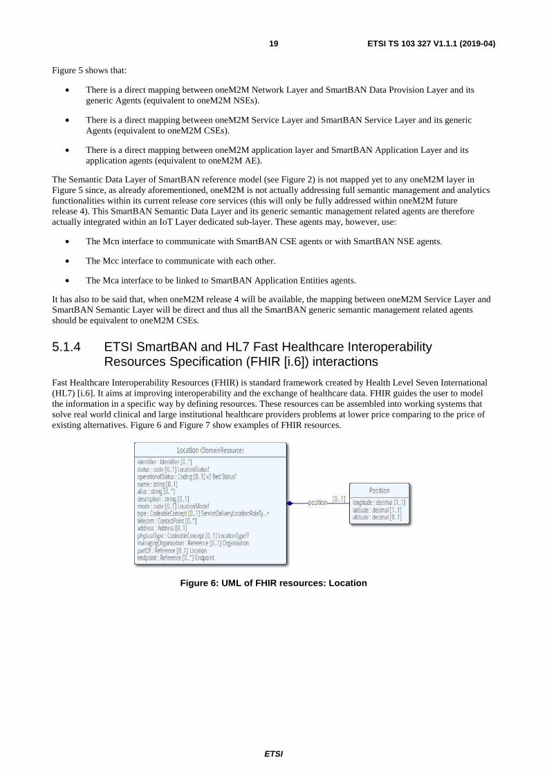
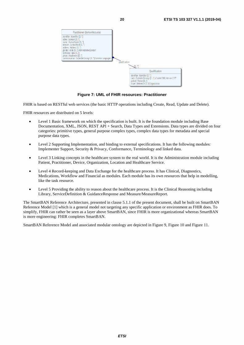
Fast Healthcare Interoperability Resources (FHIR) is standard framework created by Health Level Seven International (HL7) [i.6]. It aims at improving interoperability and the exchange of healthcare data. FHIR guides the user to model the information in a specific way by defining resources. These resources can be assembled into working systems that solve real world clinical and large institutional healthcare providers problems at lower price comparing to the price of existing alternatives. Figure 6 and Figure 7 show examples of FHIR resources.
Figure 6: UML of FHIR resources: Location
ETSI
ETSI TS 103 327 V1.1.1 (2019-04)20
Figure 7: UML of FHIR resources: Practitioner
FHIR is based on RESTful web services (the basic HTTP operations including Create, Read, Update and Delete).
FHIR resources are distributed on 5 levels:
• Level 1 Basic framework on which the specification is built. It is the foundation module including Base Documentation, XML, JSON, REST API + Search, Data Types and Extensions. Data types are divided on four categories: primitive types, general purpose complex types, complex data types for metadata and special purpose data types.
• Level 2 Supporting Implementation, and binding to external specifications. It has the following modules: Implementer Support, Security & Privacy, Conformance, Terminology and linked data.
• Level 3 Linking concepts in the healthcare system to the real world. It is the Administration module including Patient, Practitioner, Device, Organization, Location and Healthcare Service.
• Level 4 Record-keeping and Data Exchange for the healthcare process. It has Clinical, Diagnostics, Medications, Workflow and Financial as modules. Each module has its own resources that help in modelling, like the task resource.
• Level 5 Providing the ability to reason about the healthcare process. It is the Clinical Reasoning including Library, ServiceDefinition & GuidanceResponse and Measure/MeasureReport.
The SmartBAN Reference Architecture, presented in clause 5.1.1 of the present document, shall be built on SmartBAN Reference Model [1] which is a general model not targeting any specific application or environment as FHIR does. To simplify, FHIR can rather be seen as a layer above SmartBAN, since FHIR is more organizational whereas SmartBAN is more engineering: FHIR completes SmartBAN.
SmartBAN Reference Model and associated modular ontology are depicted in Figure 9, Figure 10 and Figure 11.

ETSI
ETSI TS 103 327 V1.1.1 (2019-04)21
Figure 8: FHIR patient resources
Figure 9: SmartBAN WBAN model
In level 3, FHIR has specified the patient resource as depicted in Figure 8. It has an independent patient class connected to 4 other classes: contact, link, animal and communication. Whereas in the SmartBAN WBAN model (see Figure 9), the main class is the WBAN class (the wireless Body Area network) that has a contact class connected to a person class, and the patient class is inherited from the person class. The attributes are larger in FHIR than in SmartBAN.

ETSI
ETSI TS 103 327 V1.1.1 (2019-04)22
Figure 10: SmartBAN Node model
Node
Hub
Actuator
Process
ProcessID
calibration
drift
latency
precision
resolution
responseorder
uom
Data
QOS
DataTransmission
Action
Do
is usedFor
hasData
Measurement
value
TimeStamp
TTL
hasMeasurements
measures
Validity Compression
CompAlgorithmAlgoVersion
<<Enumeration>>
Constraints
SensorML:Legal
DocumentRight
OperatingSensorML:Security
SecAlgorithm
KeyLength
KeyMinValue
MaxValue
hasConstraints
SampleTime
FormathasFormat
I/O
ProcessID
calibration
drift
latency
precision
resolution
responseorder
uom
SampleTime
hasInput
hasOutput
AlgoVersion
Figure 11: SmartBAN Process & Measurements model
ETSI
ETSI TS 103 327 V1.1.1 (2019-04)23
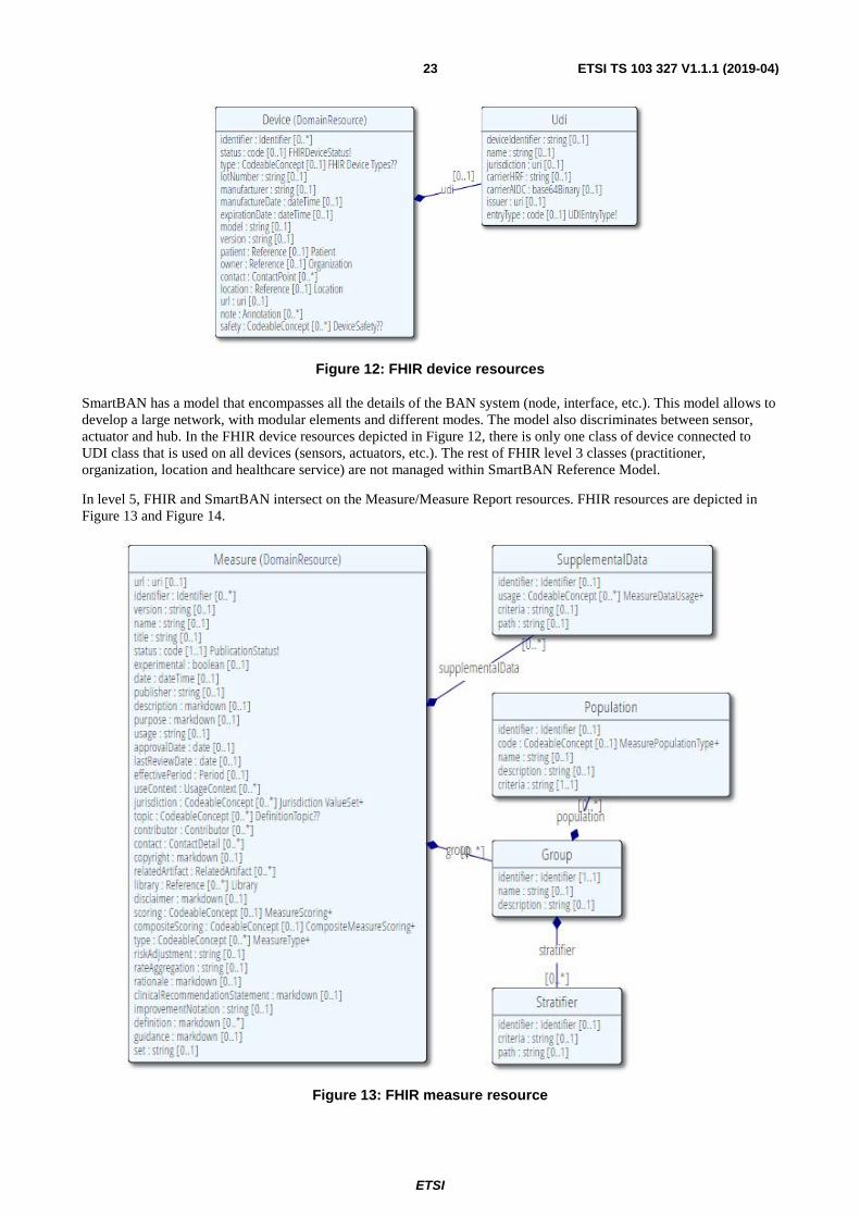
Figure 12: FHIR device resources
SmartBAN has a model that encompasses all the details of the BAN system (node, interface, etc.). This model allows to develop a large network, with modular elements and different modes. The model also discriminates between sensor, actuator and hub. In the FHIR device resources depicted in Figure 12, there is only one class of device connected to UDI class that is used on all devices (sensors, actuators, etc.). The rest of FHIR level 3 classes (practitioner, organization, location and healthcare service) are not managed within SmartBAN Reference Model.
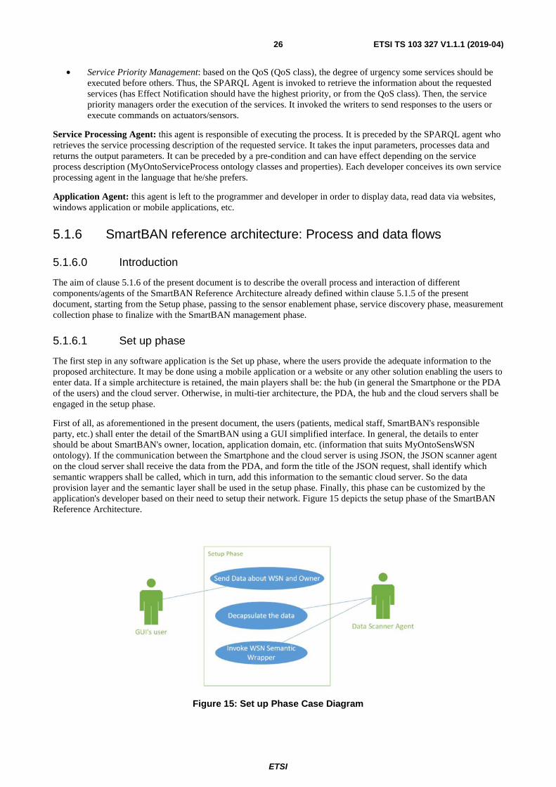
In level 5, FHIR and SmartBAN intersect on the Measure/Measure Report resources. FHIR resources are depicted in Figure 13 and Figure 14.
Figure 13: FHIR measure resource

ETSI
ETSI TS 103 327 V1.1.1 (2019-04)24
Figure 14: FHIR MeasureReport resource
The measurement in SmartBAN Reference Model is distributed on several classes and connected to a process class. This distribution allows to change easily the pre-process data, like compression, encryption, etc, from a device to another or from a network to another (see Figure 11). FHIR's "measure resource" focuses on the data itself as a measurement for the patient. The measure class is also connected to a group and a population that are used as reference to evaluate the measurement. The measure is the main class in FHIR while the node is the main class in SmartBAN.
In conclusion, the SmartBAN Reference Architecture specified in clause 5.1.1 of the present document, as well as the SmartBAN reference Model it shall be relying on (as already standardized in [1]), are complementary and not conflicting. FHIR is mainly addressing working systems for solving clinical and administrative problems. Its data model is complementary to the SmartBAN Reference Model and can be easily handled within the SmartBAN Reference Architecture specified in the present document.
5.1.5 SmartBAN reference architecture: agents definitions
The architecture is built of various software agents in order to provide granularity, flexibility and the ability to adapt to pervasive environment such as BANs.
An software agent is a piece of software that functions as an agent for a user or another program, and working autonomy and continuously in a particular environment. They are invoked by a task, reside in wait status, do not require user interaction and can have a starting condition. In the SmartBAN Reference Architecture depicted in the present document, an agent may invoke another agent and one agent may be used for many functionalities.
Scanner Agents: the Scanner Agent are responsible for data retrieval from the physical nodes/users or applications/software. They are also responsible for passing this data out to the semantic wrappers. In fact, two types of scanners exist: Data Scanners and Service Scanners:
• Data Scanners are in listening mode waiting to receive data from the Data Provision Layer. For each communication protocol, a data scanner agent shall be implemented. The data scanners link the Data Provision Layer to the Semantic Layer. For example, if a Smartphone is receiving data from Bluetooth LE device and at the same time, and if it is communicating with a server via HTTP [i.7], two scanner agents shall be set on the mobile: the Bluetooth LE Data Scanner and the HTTP Data Scanner. Because the widely used communication protocols in BANs are ZigBee/dotdot [i.8], MQTT [i.9], Bluetooth LE [i.10], the SmartBAN Reference Architecture shall enclosed at least a ZigBee data scanner, a Bluetooth LE Data Scanner and, for the wide area wireless communication, an HTTP Data Scanner.

ETSI
ETSI TS 103 327 V1.1.1 (2019-04)25
• Service Scanners are in listening mode waiting to receive data from application users. They play the role of the bridge between the application layer and the service layer. Regarding the service scanners and because the widely used IoT/oneM2M protocols are JSON [i.11] and CoAP [i.12], the SmartBAN Reference Architecture shall enclosed at least a CoAP Service Scanner and a JSON Service Scanner agents. Those agents have been actually carried out in the SmartBAN Reference Architecture depicted in the present document because it is preferred to use the Restful architecture to provide the WBAN services to external users. This choice is motivated by the lightness, easy implementation, flexibility of Restful architectures, and their loosely coupled client/server communication mode [i.13]. This is essential in heterogeneous network dealing with users who ignore the underneath techniques used in WSN (like the non-parametric users cited in MiSense Architecture).
In summary, the Scanner agent decapsulates the message sent form SmartBAN's nodes or outside users and invokes the adequate Semantic wrappers in case of Data Scanner or the suitable Service Agent in case of Service Scanner.
Writer Agents: the Writer agents are used to provide data from the external users or to manage the WSNs. Their main functionality is to encapsulate messages, respecting the communication protocol used. As for Scanners, each communication protocol has its own Writer Agent. But because the writers do not have to invoke other agents, the service writer and the data writer are not separated.
Semantic wrapper (SW) Agents: it gives semantic meaning to the information based on MyOntoSens and MyOntoService ontologies. It can be seen as a function that maps the raw data extracted from nodes/users/applications (via the scanners) to set of well-formed form of the proposed ontologies. It reads data from the scanner agent and adds the semantic information in the Semantic Layer. These agents are always invoked by the Scanners.
SPARQL Agent: the SPARQL agent should execute SPARQL query [i.14] on the overall ontology and enables semantic queries. It is invoked each time a data should be extracted from the ontology (e.g. node discovery, service discovery, retrieval of measurements, retrieval of the characteristics of a node, etc.).
Authentication Agent: its role is to authenticate the users and to verify the permission and accessibility of the users (Authentication and access control handling). Many techniques may be used: data base technique, access rules technique and external cloud solutions. The developer may use the information stored in the ontology like username, email, and password in the Person Class to authenticate the user. In addition, it can benefit from the relations isRelative and hasContact predefined in the SmartBAN modular ontology (see [1]) to determine the user's permission. In these cases, the Authentication Agent will invoke the SPARQL Agent to retrieve the semantic information from the ontology.
Rule Agent: the role of this agent is to add new Semantic Web Rule Language (SWRL) [i.15] rules to the SmartBAN modular ontology. It is very beneficent for domain experts' users like the medical staff to interact with this architecture and add specific domain constraints. An SWRL translator is used to transform the constraints set up by the experts to a SWRL rule (e.g. via a Web Interface). The Rule agent shall call the Inference Engine to ensure that this rule does not cause any inconsistency. In case the new ontology is well classified, a confirmation message will be sent to the expert. Otherwise the expert shall be asked to modify the constraints. This agent is still under development and is therefore not fully specified and validated in the present document. This will be done in the next revision of the present document.
Trigger Agent: the role of the trigger agent is to listen on a certain event and to invoke the notification agent or wrapper agents based on the implemented scenario. Semantic trigger agents that listen on a specific part of the ontology and generate a trigger on change are used in the present document. But, any type of triggering systems may be used without affecting the overall functionality of the SmartBAN Reference Architecture depicted in the present document.
Notification Agent: the role of the notification agent is to send urgent notification or reminder to subscribed users. A MQTT agent, or GCM notification agent, may be used. The service developer may always implement its own notification agent via email, SMS calls, etc.
Security Agent: its role is to encrypt/decrypt the data based on an external system or on the information stored in the ontology (Security Constraint Class). If the data is secured, this agent is invoked by the scanners to decrypt the messages and the writer to encrypt the messages.
Traffic Management Agent: the role of this agent is to prioritize the services requested by a user and decide how and to whom the response should be sent. The management is done into two levels:
• Routing management: if the WSN have different routes to attempt the users, the traffic management should select the best path. To do so, it will invoke the SPARQL Agent to retrieve information about, for example, the state of the link (LinkState Class), the reaming battery of the gateways or the sinks (MemoEnergy class), the current mode of a node (in CurrentMode object property), etc.
ETSI
ETSI TS 103 327 V1.1.1 (2019-04)26
• Service Priority Management: based on the QoS (QoS class), the degree of urgency some services should be executed before others. Thus, the SPARQL Agent is invoked to retrieve the information about the requested services (has Effect Notification should have the highest priority, or from the QoS class). Then, the service priority managers order the execution of the services. It invoked the writers to send responses to the users or execute commands on actuators/sensors.
Service Processing Agent: this agent is responsible of executing the process. It is preceded by the SPARQL agent who retrieves the service processing description of the requested service. It takes the input parameters, processes data and returns the output parameters. It can be preceded by a pre-condition and can have effect depending on the service process description (MyOntoServiceProcess ontology classes and properties). Each developer conceives its own service processing agent in the language that he/she prefers.
Application Agent: this agent is left to the programmer and developer in order to display data, read data via websites, windows application or mobile applications, etc.
5.1.6 SmartBAN reference architecture: Process and data flows
5.1.6.0 Introduction
The aim of clause 5.1.6 of the present document is to describe the overall process and interaction of different components/agents of the SmartBAN Reference Architecture already defined within clause 5.1.5 of the present document, starting from the Setup phase, passing to the sensor enablement phase, service discovery phase, measurement collection phase to finalize with the SmartBAN management phase.
5.1.6.1 Set up phase
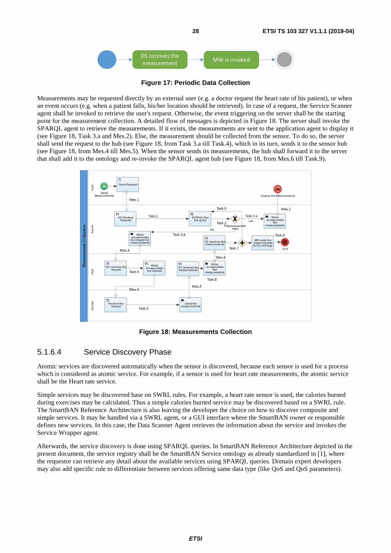
The first step in any software application is the Set up phase, where the users provide the adequate information to the proposed architecture. It may be done using a mobile application or a website or any other solution enabling the users to enter data. If a simple architecture is retained, the main players shall be: the hub (in general the Smartphone or the PDA of the users) and the cloud server. Otherwise, in multi-tier architecture, the PDA, the hub and the cloud servers shall be engaged in the setup phase.
First of all, as aforementioned in the present document, the users (patients, medical staff, SmartBAN's responsible party, etc.) shall enter the detail of the SmartBAN using a GUI simplified interface. In general, the details to enter should be about SmartBAN's owner, location, application domain, etc. (information that suits MyOntoSensWSN ontology). If the communication between the Smartphone and the cloud server is using JSON, the JSON scanner agent on the cloud server shall receive the data from the PDA, and form the title of the JSON request, shall identify which semantic wrappers shall be called, which in turn, add this information to the semantic cloud server. So the data provision layer and the semantic layer shall be used in the setup phase. Finally, this phase can be customized by the application's developer based on their need to setup their network. Figure 15 depicts the setup phase of the SmartBAN Reference Architecture.
Figure 15: Set up Phase Case Diagram

ETSI
ETSI TS 103 327 V1.1.1 (2019-04)27
5.1.6.2 Node Discovery Phase
One of the most complex issues for the integration of SmartBAN in the WoT is the automatic node discovery, which includes the node discovery, service discovery and the effect of the node on the overall SmartBAN network. This step shall be conceived with minimum user's interactions. Figure 16 depicts the node discovery process.
Figure 16: Node Discovery Process
First of all, the Data Scanners agents receive the data from nodes/users. For example, if a ZigBee WBAN is used, the ZigBee Data Scanner agent, which should be implemented in a coordinator, shall read the data received by a node, and identify the AT command used in order to call the adequate wrapper agent. If a new ZigBee node joined the network, the ZigBee Data Scanner agent will retrieve the node's information (MAC address, channel, Firm version, etc.) and will call the Node Wrapper agent. The Node wrapper Agent adds this information to MyOntoSensNode ontology and adds the object properties "BelongToCluster" and "BelongToWBAN" to the previously created WBAN individual for linking these sensors. In that way, once the SPARQL query dedicated for nodes' discovery is executed, the nodes will be discovered without any user interaction. All the aforementioned mechanisms are still valid if Bluetooth LE is used. Indeed, the Bluetooth LE data scanner will be implemented on the server. Based on the UUID, this Data Scanner may determine the wrapper agent that should be invoked.
Moreover, each sensor is used to monitor a certain process. Thus, the scanner should identify this information and invoke the Process Semantic Wrapper to assign the process (used For object property) for each sensor. For example, in Bluetooth LE, the UUID indicates if the sensor is used for heart rate monitoring, blood pressure and other. Till this step, the answers to the two first issues are provided: the discovery of the node and the atomic service offered by it.
More complicated issue is how the discovery of a node is affecting the overall network. In general, this question is essential in a large sensor network where more than one sensor is used to provide the same data. In this case, the actual status of the sensor (current mode, available battery lifetime, routing level and others) may play an effective role in the data fusion mechanism, as well as in the management of the WBAN. If it is the case (mostly used in ZigBee networks), the MemoEnergy and LinkState wrappers are invoked. Furthermore and if necessary, the ZigBee writer may be called to put a sensor in sleep mode or to change the coordinator in the network, due to its limited battery lifetime. The ZigBeeWriter will encapsulate the message in the adequate AT command.
The node discovery step enables the automatic node discovery encompassing the node's physical characteristics, node's atomic service, nodes' energy characteristics, etc. This information not only permits the discovery of the nodes, but also gives the opportunity to effectively and remotely manage the SmartBAN.
5.1.6.3 Measurement Collection Phase
The measurement collection phase consists of collecting raw sensed values in order to add it to the Measurement class in the MyOntoSensProcess ontology. The collection can be periodic, on event triggering or on request. If it is periodic, the DS (Data Scanner agents) shall periodically retrieve the value by invoking the MW (Measurement Wrapper) agent. Figure 17 depicts the activity diagram for a periodic data collection.
Note that this flow of activities may be done on the server or on the hub depending on the deployed architecture. For example, in a WBAN application, the Smartphone may be the data collector, thus, it will execute this flow of activities.
ETSI
ETSI TS 103 327 V1.1.1 (2019-04)28
Figure 17: Periodic Data Collection
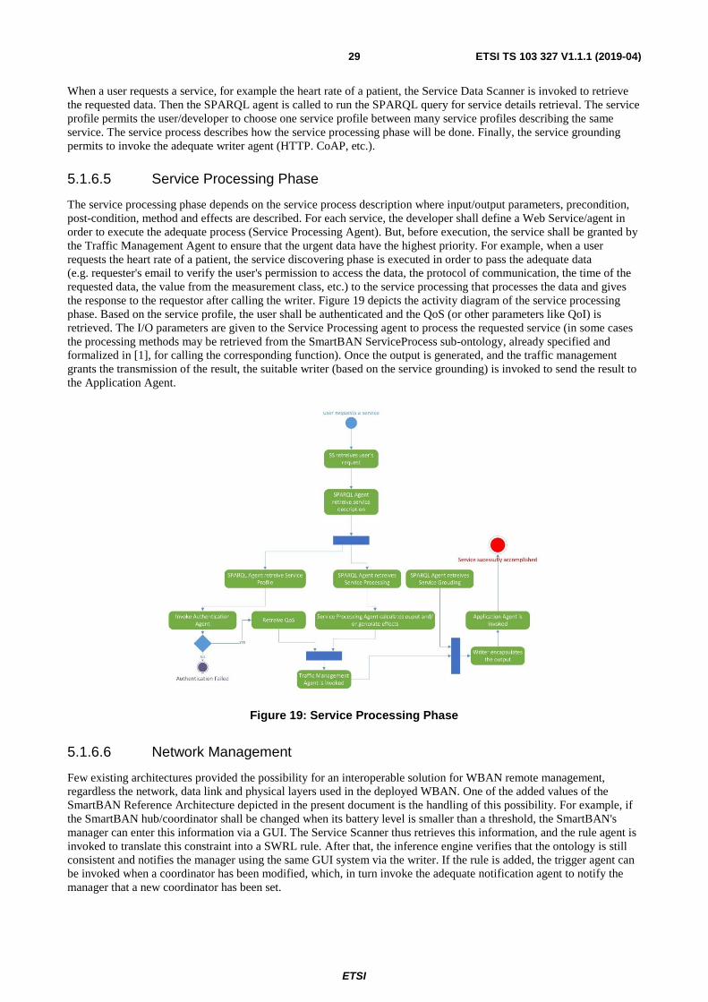
Measurements may be requested directly by an external user (e.g. a doctor request the heart rate of his patient), or when an event occurs (e.g. when a patient falls, his/her location should be retrieved). In case of a request, the Service Scanner agent shall be invoked to retrieve the user's request. Otherwise, the event triggering on the server shall be the starting point for the measurement collection. A detailed flow of messages is depicted in Figure 18. The server shall invoke the SPARQL agent to retrieve the measurements. If it exists, the measurements are sent to the application agent to display it (see Figure 18, Task 3.a and Mes.2). Else, the measurement should be collected from the sensor. To do so, the server shall send the request to the hub (see Figure 18, from Task 3.a till Task.4), which in its turn, sends it to the sensor hub (see Figure 18, from Mes.4 till Mes.5). When the sensor sends its measurements, the hub shall forward it to the server that shall add it to the ontology and re-invoke the SPARQL agent hub (see Figure 18, from Mes.6 till Task.9).
Figure 18: Measurements Collection
5.1.6.4 Service Discovery Phase
Atomic services are discovered automatically when the sensor is discovered, because each sensor is used for a process which is considered as atomic service. For example, if a sensor is used for heart rate measurements, the atomic service shall be the Heart rate service.
Simple services may be discovered base on SWRL rules. For example, a heart rate sensor is used, the calories burned during exercises may be calculated. Thus a simple calories burned service may be discovered based on a SWRL rule. The SmartBAN Reference Architecture is also leaving the developer the choice on how to discover composite and simple services. It may be handled via a SWRL agent, or a GUI interface where the SmartBAN owner or responsible defines new services. In this case, the Data Scanner Agent retrieves the information about the service and invokes the Service Wrapper agent.
Afterwards, the service discovery is done using SPARQL queries. In SmartBAN Reference Architecture depicted in the present document, the service registry shall be the SmartBAN Service ontology as already standardized in [1], where the requestor can retrieve any detail about the available services using SPARQL queries. Domain expert developers may also add specific rule to differentiate between services offering same data type (like QoS and QoS parameters).
ETSI
ETSI TS 103 327 V1.1.1 (2019-04)29
When a user requests a service, for example the heart rate of a patient, the Service Data Scanner is invoked to retrieve the requested data. Then the SPARQL agent is called to run the SPARQL query for service details retrieval. The service profile permits the user/developer to choose one service profile between many service profiles describing the same service. The service process describes how the service processing phase will be done. Finally, the service grounding permits to invoke the adequate writer agent (HTTP. CoAP, etc.).
5.1.6.5 Service Processing Phase
The service processing phase depends on the service process description where input/output parameters, precondition, post-condition, method and effects are described. For each service, the developer shall define a Web Service/agent in order to execute the adequate process (Service Processing Agent). But, before execution, the service shall be granted by the Traffic Management Agent to ensure that the urgent data have the highest priority. For example, when a user requests the heart rate of a patient, the service discovering phase is executed in order to pass the adequate data (e.g. requester's email to verify the user's permission to access the data, the protocol of communication, the time of the requested data, the value from the measurement class, etc.) to the service processing that processes the data and gives the response to the requestor after calling the writer. Figure 19 depicts the activity diagram of the service processing phase. Based on the service profile, the user shall be authenticated and the QoS (or other parameters like QoI) is retrieved. The I/O parameters are given to the Service Processing agent to process the requested service (in some cases the processing methods may be retrieved from the SmartBAN ServiceProcess sub-ontology, already specified and formalized in [1], for calling the corresponding function). Once the output is generated, and the traffic management grants the transmission of the result, the suitable writer (based on the service grounding) is invoked to send the result to the Application Agent.
Figure 19: Service Processing Phase
5.1.6.6 Network Management
Few existing architectures provided the possibility for an interoperable solution for WBAN remote management, regardless the network, data link and physical layers used in the deployed WBAN. One of the added values of the SmartBAN Reference Architecture depicted in the present document is the handling of this possibility. For example, if the SmartBAN hub/coordinator shall be changed when its battery level is smaller than a threshold, the SmartBAN's manager can enter this information via a GUI. The Service Scanner thus retrieves this information, and the rule agent is invoked to translate this constraint into a SWRL rule. After that, the inference engine verifies that the ontology is still consistent and notifies the manager using the same GUI system via the writer. If the rule is added, the trigger agent can be invoked when a coordinator has been modified, which, in turn invoke the adequate notification agent to notify the manager that a new coordinator has been set.

ETSI
ETSI TS 103 327 V1.1.1 (2019-04)30
Many more scenarios may be envisioned. It is up to the developer to choose what he/she needs, starting from just monitoring the SmartBAN's characteristics (SPARQL queries), passing through modifying the characteristics of certain nodes (e.g. the current mode from active to sleep), till the automatic change in the SmartBAN based on domain experts requirements (SWRL rule).
5.1.7 Summary
In summary, the SmartBAN Reference Architecture depicted in the present document permits the automatic nodes discovery, services discovery, services matching, remote monitoring, and automatic notification, with the minimum user and developer interaction. It masks the heterogeneity between different nodes and communication protocol due to the use of scanner agents and writer agents. In addition, this SmartBAN Reference Architecture enables the re-use and sharing of the information between different application/service providers due to the use of SPARQL queries and service scanners. Furthermore, it opens the door to new creative solution for domain expert developers in order to enhance data fusion and decision making using SWRL agents.
SmartBAN Reference Architecture described in the present document may be used for small flat SmartBAN to large scale SmartBAN where the management of nodes and the data fusion are mandatory in such fields. To validate SmartBAN Reference Architecture, as well as to clarify its functionality, a detailed implementation of the smart home for elderly fall monitoring is provided in the next clause of the present document.
5.2 SmartBAN IoT compliant layering reference architecture validation
5.2.1 Validation use case: elderly at home monitoring
Smart home for elderly fall monitoring system has been the use case that has been selected for the validation of the SmartBAN Reference Architecture depicted in the present document. The system consists of:
1) BAN, the body area network containing:
- The HR sensor (in our use case the H7Polar Sensor); Note that more biomedical sensors can be used without the need to reconfigure the application like temperature sensor, SPO2, etc.
- The smartphone or PDA which plays the role of accelerometer sensor, ambient light intensity sensor, ambient temperature, ambient humidity and home location sensor. Furthermore, the smartphone can process, reason and display data. It can be used for alarm generation, remainder and alerts.
2) Home Cluster: the Home Cluster consisting of:
- The BAN; It can contain more than one BAN if more than one patient is monitored in the same home.
- The Bluetooth Location sensors placed at different rooms in the home to identify the indoor location of the patient.
- The local semantic server where the heavy treatment of data is done.
3) The medical, clinical, emergency, authentication or any external required server connected to the Home Cluster via the Internet.
4) The relatives' terminals who are allowed to monitor the patient's system as well as interacting with it.
On the local server, the following agents should be implemented and used:
• JSON scanner and writer agents (to receive/send data from/to the patient's Smartphone).
• Node semantic Wrappers (NW), Process semantic Wrappers (PW), service semantic wrappers (SW, to translate raw data to semantic information).
• Pellet reasoner agent (to infer semantic data).
• SPARQL agent (to retrieve semantic information).

ETSI
ETSI TS 103 327 V1.1.1 (2019-04)31
On the remote monitoring server (hospital/caregivers side), the following agents should be installed:
• JSON scanner and writer agents (to receive/send data from/to the local server, as well as for sending data to remote medical servers if needed).
• WSN semantic wrappers (WW), Node semantic wrappers (NW), Process semantic wrappers (PW), Service semantic wrappers (SW, to translate raw data to semantic information).
• Pellet reasoner agent (to infer semantic data).
• SPARQL agent (to retrieve semantic information residing on the cloud monitoring server or on the local server).
• CoAP server agent to create resources (patient's information) and to respond to GET request from patient's relative and medical staff users.
• Authentication agent to authenticate users' Smartphone (the choice has actually been limited to a Google API authentication server for implementation simplicity purposes and because an AndroidTM mobile application was firstly developed. Security is out of the scope of our testing case and more advanced authentication servers can always be implemented latter on).
• Notification agent to notify medical staff and patient's relatives if the patient has fallen or if his heart rate exceeds the maximum normal value (a goggle GCM authentication server was used due to its easy integration but any other notification servers like e.g. MQTT can be used).
• Traffic Management agent to prioritize notification data flow.
After the mobile application has been installed on the patient's smartphone and his local server is equipped with all required agents (more scanner/writer agents can be added if other types of communication protocols are used like ZigBee, RFID, etc.), the patient is ready to use the system. Figure 20 summarizes the use case selected for the SmartBAN Reference Architecture validation.
Figure 20: Use case selected for the SmartBAN Reference Architecture validation: elderly at home monitoring/control
SmartBAN Reference Architecture phases:
First, the user has to accomplish the setup phase, then the application will be in data collection phase, where measurements are collected and sent to the local server. The server, then, sends the required information to the cloud monitoring server. The cloud monitoring server will: authenticate external users, provide requested data, and send notifications when necessary.

ETSI
ETSI TS 103 327 V1.1.1 (2019-04)32
The setup phase consists of:
1) SmartBAN and Patient initialization: where the creation of the WBAN, Cluster, and Contact individuals should be setup in an new instance of SmartBAN modular ontologies (as already standardized in [1]).
2) Node discovery: where the system detects the presence of the sensor/node, discovers its characteristics and adds these information to instances of SmartBAN Reference Architecture Node and SensProcess ontologies (as already standardized in [1]).
3) Node management: if additional management are needed. In our case, the Indoor Localization demands a calibration phase to determine the patient's location.
Initialization Phase: When the patient uses for the first time the application, he/she can either choose to join an existing BAN, or to create a new BAN. If a new BAN should be created, JSON Writer (JW) agent sends the mobile IP to the local server. Then, the local server encapsulates the JSON message, generates a new BANID and sends it to the patient's mobile, and finally invokes the WW (WSN Writer) to create the new BAN individual. Else, the user should enter the BANID. In both cases, the server responds with the new created PatientID that is displayed on the home screen. Figure 21 depicts the flow of messages during the initialization phase.
This semantic information is first created on the local server (Figure 21, message 3.b), and then created on the cloud server using Insert SPARQL query.
Note that in message 1, as well as in message 2.b of Figure 21, more information can be retrieved from the Smartphone and the server respectively, such as the manufacturer ID, the operation system, the RAM capability, etc. In other terms, the properties described in "NodeType" and "Node" classes of SmartBAN Reference Architecture Node ontology (see [1]) can be retrieved from the Smartphone.
Figure 21: Flow of Messages in Smart Home Initialization Phase
Log in Phase: When this phase loads, the user is directly connected to the Google server via his/her Gmail account. The application may transparently retrieve some information directly from his/her account, without any interaction, like his/her mail, first name, last name and gender. In addition, the application displays a user Interface for the patient in order to fill other required fields for describing the Patient class within SmartBAN Reference Model and associated modular ontology [1] (in our application: weight, height, gender, location, email, mobile phone). The JSON Writer (JW) on the smartphone sends this information to the local server. The JSON Scanner (JS) reads this information and invokes the Patient Wrapper (PaW) for semantic annotation.
After the login phase, the BAN number, the patient number, and the patient's personal information of the Login activity should be stored on the Smartphone.

ETSI
ETSI TS 103 327 V1.1.1 (2019-04)33
Sensor Discovery Phase: Two types of sensors exist in the use case selected for clause 5.2.1 of the present document, the Bluetooth LE sensors and the built-in mobile sensors. In this case, the Bluetooth LE Scanner agent (BLES) on the mobile side will detect the sensors and, based on the UUID; it can discover the sensor characteristics. The service type, device MAC address, firmware version, hardware version, model number, software revision, and battery level are firstly detected in order to discover the sensor characteristics. The BLES invokes the JSON Writer (JW) to send this information to the local server. The JSON Scanner (JS) on the server side reads this information and invokes the Node semantic Wrappers (NW) and the Process semantic Wrappers (PW) to add the semantic annotation. This flow of messages is depicted in Figure 22.This is what exactly happens with HR sensor. Nevertheless, the Rad Beacon used for Indoor localization needs additional set up phase to be discovered properly, because the UUID does not reflect the intend service (Indoor Localization).The patient in a certain zone or room needs to be located. For that purpose, once the Rad Beacons are discovered, they are displayed on the patient's mobile screen in order to be selected by the Patient. To enhance the selection process, the developer can assign, in addition to the UUID, Major and Minor parameters describing the main functionality of the beacon (e.g. the location). After submitting his/her choice, the JW sends the beacons' MAC address to the remote server. The NW adds these nodes to SmartBAN Reference Model Node ontology (see [1]). Then, the user specifies the number of rooms in the house. For each room, he/she enters its name and an initiation phase is launched for 20 s to read values from all registered beacons. After 20 s, the minimum and maximum RSSI values read from each beacon are registered for this room in order to locate the patient. The JW sends to the local server the rooms' name. Then, the PW add these names as data for the Indoor Localization process. So, the flow of messages, shown in Figure 21, will start after the initial localization phase.
The following paragraph describes the built in sensors. The JW on the mobile side sends JSON message having as title "Sensor" and containing the sensor's description (Process: acceleration, data rate: 50 samples per second). Note that in the specific use case retained for clause 5.2.1 of the present document, after drawing the fall detection graph on data rate variation, 50 samples per second are taken. Hence, the sensors are discovered and the local server sends an insert SPARQL query to cloud server to add these semantic information. Figure 13 depicts the flow of messages for automatic HR BLE sensor discovery. This flow of messages remain the same for all BLE sensors that do not need any additional setup phase (e.g. if a BLE body temperature sensor is used). Note that the same messages shown in Figure 22 will be retained for Built-in sensors, but the JS will detect their presence instead of the BLES.
Figure 22: Sensor Discovery in Smart Home Scenario Measurements Collection Phase

ETSI
ETSI TS 103 327 V1.1.1 (2019-04)34
After the initialization phases, the home page activity starts and becomes the User Interface (UI) page of this app. Each time this activity is loaded, on one hand, the BLES identifies the connected BLE devices and sent it to the servers. The local server runs a SPARQL query to verify if these nodes already exist, otherwise they will be added as shown in Figure 22. In this way, the SmartBAN system is always updated transparently, without the need of any intervention form the user. This feature provides a plug and play mechanism for sensors enablement. On the other hand, because the main aim is to detect the fall of a patient, the Smartphone verifies if the beacons are powered (the Indoor Localization is mandatory in elderly fall detection). Otherwise, a notification shall be displayed telling the patient to power on the beacons. If the patient did not power those beacons after 20 minutes, a message is automatically sent to the system's support to assist the elderly (maybe he/she is not able to do so). Moreover, if the mobile battery level is smaller than a threshold, a notification is displayed to charge the mobile phone. These precautions are done to be sure that there is enough power resources to detect the fall of the elderly. This activates the data collection phase. The measurements are retrieved form the sensors, sent to the local server, which in turns adds it to the ontology. The local server will send these measurements to the CoAP cloud server in order to update the resources value. The JW on the server side sends a JSON message to the Cloud server having as title "Measurement", and containing the "WSNID", "PatientID" and the process (HR, Humidity, Ambient Temperature, Actual Location, Lightness, and the three axes linear acceleration) with the value (e.g. "HR": 117). The Cloud server sends a POST CoAP message to update the measured value. Notification Phase: Periodically, the local server sends the SPARQL Query to retrieve the status of the patient. If the status is Falling, or DangerHR, the notification agent is invoked.
5.2.2 Tests and results
The applications were tested on Android smartPhones (Android 4.4.2 KITKAT-API 19 and Android 5.0.1-API 21 Lollipop after upgrade and Android 4.1.2 Jelly Bean- API 16). One patient per WSN is first considered. The application is installed on two different patients' mobile. For each patient, one relative was added. Then, the scenario where two patients are sharing the same Home Cluster was considered, i.e. sharing the same Rad Beacons for the indoor localization. The distance between rooms were about 20 m and three Rad beacons were implemented in three different zones at the patient's home. Only one patient's screen shuts where he/she is adding a new BAN will be depicted in clause 5.2.2 of the present document. For testing only, the remote server and the local server were on the same machine, but working on different port numbers. It took about 20 seconds to load the full ontology. It uses 425 692 Kbits of RAM and 76 % of the CPU as maximum values. Table 2 presents the number of kbits used for creating the semantic data in different stages (onload, WSN creation, etc.)
After verifying that the servers has classified the ontology, the implemented mobile applications was tested.
When opening the patient's application for the first time, Figure 23 appears and the patient chooses to create a new WSN. Then, the server assigns new numbers for the created WSN and Patient. Therefore, the server created the corresponding individuals (see Figure 23).
After creating a new Home Cluster or adding the patient to an existing home Cluster, the user should click the "setup WSN" button in order to begin the setup process, starting with the login activity using Google + API. When the login activity is loaded, the user is directly connected to the Google server via his Gmail. The application can then retrieve some information directly from his account (without his interaction) like, e.g. his mail, first name, last name and gender. The application also provides the patient an interface, to fill other required field for the SmartBAN Ontology.
After a successful signing in, the patient is prompt to the indoor localization setup phase, where he/she should precise the number of rooms and do the calibration.
After finishing the calibration phase for all the rooms, the heart rate sensor will be detected. The user should confirm its usage. When all the sensors are successfully discovered, the patient is driven to the home page depicted in Figure 23. This page is the same for the patient and the relatives. It is the page where all the data are get from the CoAP server and displayed on the screen. At this point, all individuals have been created and well classified on the local server, as well as the cloud server.
Note that the user may add a new beacon for the indoor localization at any time. For that purpose, the setup IndoorLocalization option was provided, a new beacon was added, calibrated and successfully discovered. Moreover, the HR sensor was removed, thus, the server received from the JSON Writer (JW) that has the HR sensor off. So, when running the node discovery query, the HR sensor is obviously not discovered anymore.
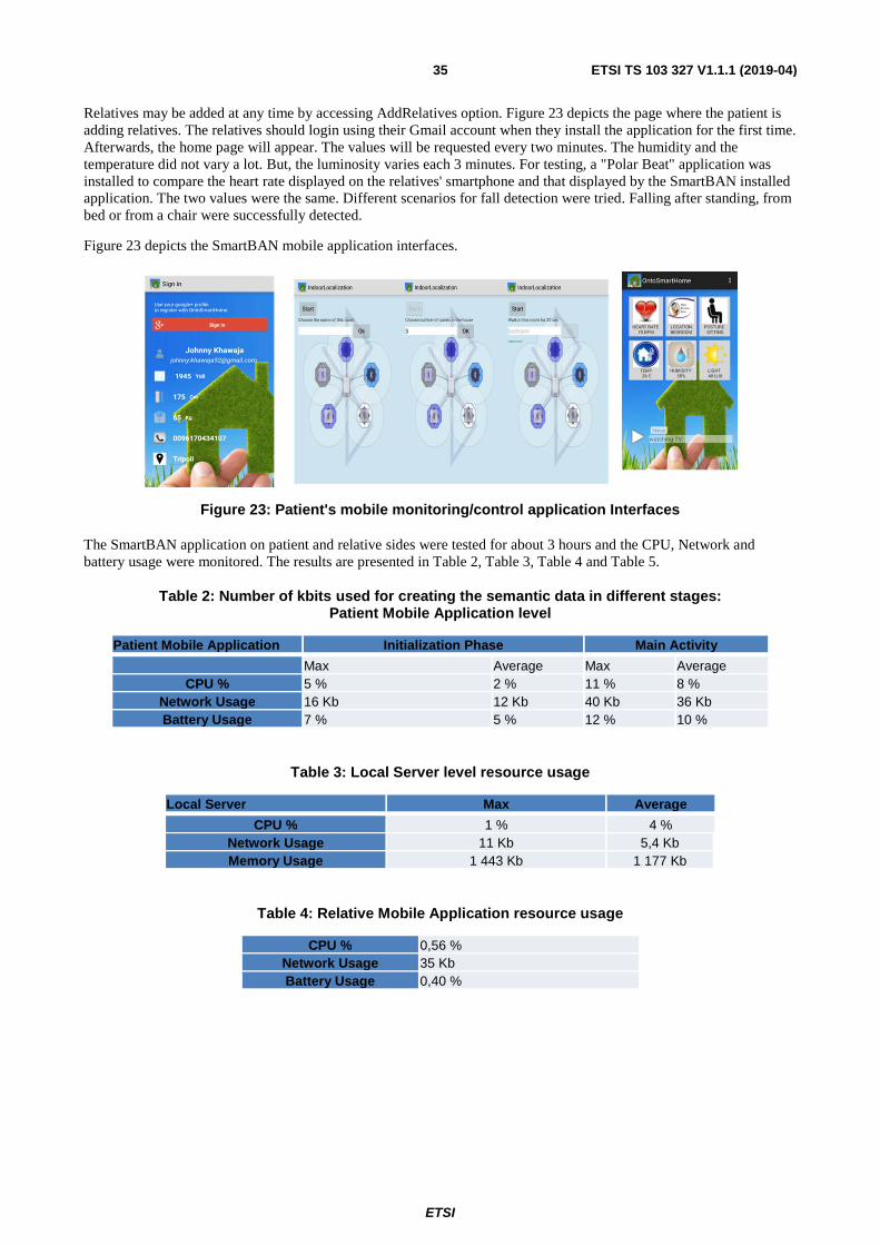
ETSI
ETSI TS 103 327 V1.1.1 (2019-04)35
Relatives may be added at any time by accessing AddRelatives option. Figure 23 depicts the page where the patient is adding relatives. The relatives should login using their Gmail account when they install the application for the first time. Afterwards, the home page will appear. The values will be requested every two minutes. The humidity and the temperature did not vary a lot. But, the luminosity varies each 3 minutes. For testing, a "Polar Beat" application was installed to compare the heart rate displayed on the relatives' smartphone and that displayed by the SmartBAN installed application. The two values were the same. Different scenarios for fall detection were tried. Falling after standing, from bed or from a chair were successfully detected.
Figure 23 depicts the SmartBAN mobile application interfaces.
Figure 23: Patient's mobile monitoring/control application Interfaces
The SmartBAN application on patient and relative sides were tested for about 3 hours and the CPU, Network and battery usage were monitored. The results are presented in Table 2, Table 3, Table 4 and Table 5.
Table 2: Number of kbits used for creating the semantic data in different stages: Patient Mobile Application level
Patient Mobile Application Initialization Phase Main Activity
Max Average Max Average CPU % 5 % 2 % 11 % 8 %
Network Usage 16 Kb 12 Kb 40 Kb 36 Kb Battery Usage 7 % 5 % 12 % 10 %
Table 3: Local Server level resource usage
Local Server Max Average
CPU % 1 % 4 % Network Usage 11 Kb 5,4 Kb Memory Usage 1 443 Kb 1 177 Kb
Table 4: Relative Mobile Application resource usage
CPU % 0,56 % Network Usage 35 Kb Battery Usage 0,40 %
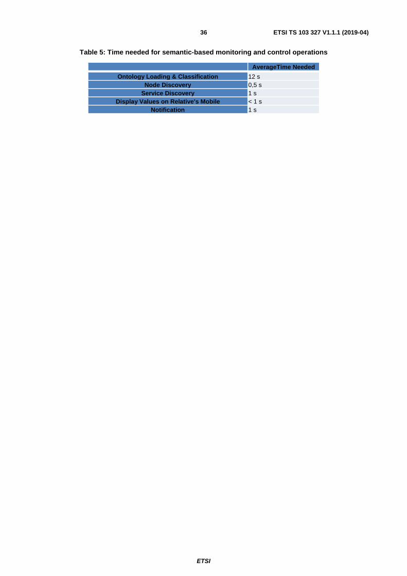
ETSI
ETSI TS 103 327 V1.1.1 (2019-04)36
Table 5: Time needed for semantic-based monitoring and control operations
AverageTime Needed
Ontology Loading & Classification 12 s Node Discovery 0,5 s
Service Discovery 1 s Display Values on Relative's Mobile < 1 s
Notification 1 s
ETSI
ETSI TS 103 327 V1.1.1 (2019-04)37
Annex A (informative): Background and SoA
A.0 Introduction Annex A of the present document presents the SoA, i.e. all existing documents, works and architectures that have to be investigated for identifying:
• specifications that could be reused and directly standardized;
• closely related frameworks that could be of interest for the present document;
• missing parts that will have to be fully specified in the present document;
for coming up with the reference specifications of the SmartBAN's interoperability management global architecture.
Existing Multi-Agents architectures, as well as SOAs (Service Oriented Architectures), M2M/oneM2M (Machine to Machine) and IoT (Internet of Things) compliant architectures are some of the existing global frameworks that should be investigated. Other existing standards should also probably be investigated, like in particular:
• CEN TC 251 about Health Informatics;
• IEEE reference models for medical device communications;
• Continua Alliance works on an healthcare global architecture;
• Integrating the Healthcare Enterprise (IHE) organization works;
• Health Level Seven International (HL7);
• etc.;
even if they are mainly related to BANs interoperability (some of their models and architectural principles may be of interest for the present document).
In terms of protocols, JSON, JSON LD and CoAP data communication protocols should also be investigated in Annex A of the present document.
A.1 Existing data sharing/transfer formats, protocols and interoperability frameworks for (or applicable for) sensors/actuators and BANs
A.1.1 Sensor Web Enablement (SWE [i.16]) Sensor Web Enablement initiative, was launched by the Open Geospatial Consortium (OGC) in 1999. The objective of this initiative is to produce the specification of all the protocols and interfaces allowing any sensors to be accessible and manageable over the Web. The common language used in SWE standard is XML.
SWE defines a Common Data Model which sustains the functionalities required by all SWE standards. It is used to describe static data (files), dynamically generated datasets (on the fly processing), data subsets, process and web service inputs and outputs and real time streaming data. Moreover, SWE defines a Service Data Model used as reference for the development of SWE services. The Service Data Model specifies data types and interfaces common to Sensor Web services. It includes 8 packages: Content, Notifications, Common, Common Code, DescribeSensor, UpdateSensorDescription, InsertSensor and DeleteSensor.
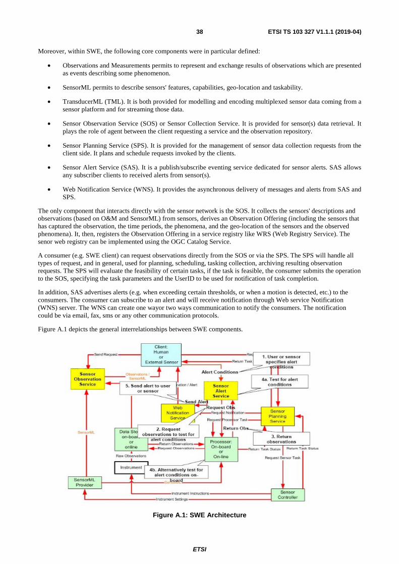
ETSI
ETSI TS 103 327 V1.1.1 (2019-04)38
Moreover, within SWE, the following core components were in particular defined:
• Observations and Measurements permits to represent and exchange results of observations which are presented as events describing some phenomenon.
• SensorML permits to describe sensors' features, capabilities, geo-location and taskability.
• TransducerML (TML). It is both provided for modelling and encoding multiplexed sensor data coming from a sensor platform and for streaming those data.
• Sensor Observation Service (SOS) or Sensor Collection Service. It is provided for sensor(s) data retrieval. It plays the role of agent between the client requesting a service and the observation repository.
• Sensor Planning Service (SPS). It is provided for the management of sensor data collection requests from the client side. It plans and schedule requests invoked by the clients.
• Sensor Alert Service (SAS). It is a publish/subscribe eventing service dedicated for sensor alerts. SAS allows any subscriber clients to received alerts from sensor(s).
• Web Notification Service (WNS). It provides the asynchronous delivery of messages and alerts from SAS and SPS.
The only component that interacts directly with the sensor network is the SOS. It collects the sensors' descriptions and observations (based on O&M and SensorML) from sensors, derives an Observation Offering (including the sensors that has captured the observation, the time periods, the phenomena, and the geo-location of the sensors and the observed phenomena). It, then, registers the Observation Offering in a service registry like WRS (Web Registry Service). The senor web registry can be implemented using the OGC Catalog Service.
A consumer (e.g. SWE client) can request observations directly from the SOS or via the SPS. The SPS will handle all types of request, and in general, used for planning, scheduling, tasking collection, archiving resulting observation requests. The SPS will evaluate the feasibility of certain tasks, if the task is feasible, the consumer submits the operation to the SOS, specifying the task parameters and the UserID to be used for notification of task completion.
In addition, SAS advertises alerts (e.g. when exceeding certain thresholds, or when a motion is detected, etc.) to the consumers. The consumer can subscribe to an alert and will receive notification through Web service Notification (WNS) server. The WNS can create one wayor two ways communication to notify the consumers. The notification could be via email, fax, sms or any other communication protocols.
Figure A.1 depicts the general interrelationships between SWE components.
Figure A.1: SWE Architecture
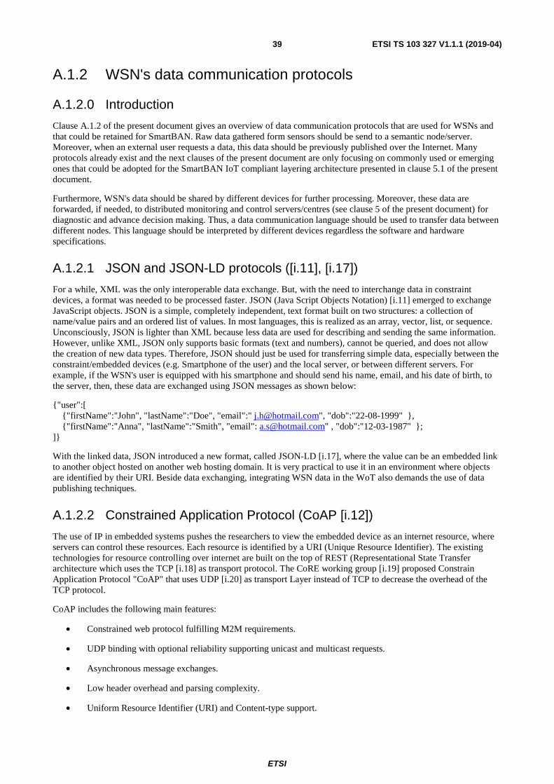
ETSI
ETSI TS 103 327 V1.1.1 (2019-04)39
A.1.2 WSN's data communication protocols
A.1.2.0 Introduction
Clause A.1.2 of the present document gives an overview of data communication protocols that are used for WSNs and that could be retained for SmartBAN. Raw data gathered form sensors should be send to a semantic node/server. Moreover, when an external user requests a data, this data should be previously published over the Internet. Many protocols already exist and the next clauses of the present document are only focusing on commonly used or emerging ones that could be adopted for the SmartBAN IoT compliant layering architecture presented in clause 5.1 of the present document.
Furthermore, WSN's data should be shared by different devices for further processing. Moreover, these data are forwarded, if needed, to distributed monitoring and control servers/centres (see clause 5 of the present document) for diagnostic and advance decision making. Thus, a data communication language should be used to transfer data between different nodes. This language should be interpreted by different devices regardless the software and hardware specifications.
A.1.2.1 JSON and JSON-LD protocols ([i.11], [i.17])
For a while, XML was the only interoperable data exchange. But, with the need to interchange data in constraint devices, a format was needed to be processed faster. JSON (Java Script Objects Notation) [i.11] emerged to exchange JavaScript objects. JSON is a simple, completely independent, text format built on two structures: a collection of name/value pairs and an ordered list of values. In most languages, this is realized as an array, vector, list, or sequence. Unconsciously, JSON is lighter than XML because less data are used for describing and sending the same information. However, unlike XML, JSON only supports basic formats (text and numbers), cannot be queried, and does not allow the creation of new data types. Therefore, JSON should just be used for transferring simple data, especially between the constraint/embedded devices (e.g. Smartphone of the user) and the local server, or between different servers. For example, if the WSN's user is equipped with his smartphone and should send his name, email, and his date of birth, to the server, then, these data are exchanged using JSON messages as shown below:
{"user":[ {"firstName":"John", "lastName":"Doe", "email":" [email protected]", "dob":"22-08-1999" }, {"firstName":"Anna", "lastName":"Smith", "email": [email protected]" , "dob":"12-03-1987" }; ]}
With the linked data, JSON introduced a new format, called JSON-LD [i.17], where the value can be an embedded link to another object hosted on another web hosting domain. It is very practical to use it in an environment where objects are identified by their URI. Beside data exchanging, integrating WSN data in the WoT also demands the use of data publishing techniques.
A.1.2.2 Constrained Application Protocol (CoAP [i.12])
The use of IP in embedded systems pushes the researchers to view the embedded device as an internet resource, where servers can control these resources. Each resource is identified by a URI (Unique Resource Identifier). The existing technologies for resource controlling over internet are built on the top of REST (Representational State Transfer architecture which uses the TCP [i.18] as transport protocol. The CoRE working group [i.19] proposed Constrain Application Protocol "CoAP" that uses UDP [i.20] as transport Layer instead of TCP to decrease the overhead of the TCP protocol.
CoAP includes the following main features:
• Constrained web protocol fulfilling M2M requirements.
• UDP binding with optional reliability supporting unicast and multicast requests.
• Asynchronous message exchanges.
• Low header overhead and parsing complexity.
• Uniform Resource Identifier (URI) and Content-type support.
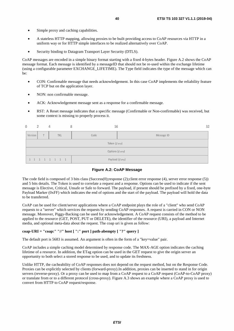
ETSI
ETSI TS 103 327 V1.1.1 (2019-04)40
• Simple proxy and caching capabilities.
• A stateless HTTP mapping, allowing proxies to be built providing access to CoAP resources via HTTP in a uniform way or for HTTP simple interfaces to be realized alternatively over CoAP.
• Security binding to Datagram Transport Layer Security (DTLS).
CoAP messages are encoded in a simple binary format starting with a fixed 4-bytes header. Figure A.2 shows the CoAP message format. Each message is identified by a messageID that should not be re-used within the exchange lifetime (using a configurable parameter EXCHANGE_LIFETIME). The Type field indicates the type of the message which can be:
• CON: Confirmable message that needs acknowledgement. In this case CoAP implements the reliability feature of TCP but on the application layer.
• NON: non confirmable message.
• ACK: Acknowledgement message sent as a response for a confirmable message.
• RST: A Reset message indicates that a specific message (Confirmable or Non-confirmable) was received, but some context is missing to properly process it.
Figure A.2: CoAP Message
The code field is composed of 3 bits class (Success(0);response (2);client error response (4), server error response (5)) and 5 bits details. The Token is used to correlate a request and a response. Options can be used to indicate if the sent message is Elective, Critical, Unsafe or Safe to forward. The payload, if present should be prefixed by a fixed, one-byte Payload Marker (0xFF) which indicates the end of options and the start of the payload. The payload will hold the data to be transferred.
CoAP can be used for client/server applications where a CoAP endpoint plays the role of a "client" who send CoAP requests to a "server" which services the requests by sending CoAP responses. A request is carried in CON or NON message. Moreover, Piggy-Backing can be used for acknowledgement. A CoAP request consists of the method to be applied to the resource (GET, POST, PUT or DELETE), the identifier of the resource (URI), a payload and Internet media, and optional meta-data about the request. The coap uri is given as follow:
coap-URI = "coap:" "//" host [ ":" port ] path-abempty [ "?" query ]
The default port is 5683 is assumed. An argument is often in the form of a "key=value" pair.
CoAP includes a simple caching model determined by response code. The MAX-AGE option indicates the caching lifetime of a resource. In addition, the ETag option can be used in the GET request to give the origin server an opportunity to both select a stored response to be used, and to update its freshness.
Unlike HTTP, the cacheability of CoAP responses does not depend on the request method, but on the Response Code. Proxies can be explicitly selected by clients (forward-proxy).In addition, proxies can be inserted to stand in for origin servers (reverse-proxy). Or a proxy can be used to map from a CoAP request to a CoAP request (CoAP-to-CoAP proxy) or translate from or to a different protocol (cross-proxy). Figure A.3 shows an example where a CoAP proxy is used to convert from HTTP to CoAP request/response.

ETSI
ETSI TS 103 327 V1.1.1 (2019-04)41
Figure A.3: Implementation of CoAP proxy
CoAP implements 4 security's types:
1) NoSec: There is no protocol level security.
2) PreSharedKey: DTLS (Datagram Transport Layer Security) is enabled. A list of pre-shared keys is defined and each key includes a list of which nodes it can be used to communicate with.
3) RawPublicKey: DTLS is enabled and the device has an asymmetric key pair without a certificate (a raw public key) that is validated using an out-of-band mechanism. The device also has an identity calculated from the public key and a list of identities of the nodes it can communicate with.
Certificate: DTLS is enabled and the device has an asymmetric key pair with an X.509 certificate that binds it to its Authority Name and is signed by some common trust root.
A.2 e-health related architectures
A.2.0 Introduction Clauses A.2.1 to A.2.5 of the present document investigate other e-health related architectures like in particular MedCom Web-based architecture, Danish National e-Health Authority framework specification and metadata, eHealth dedicated cloud like solutions, etc.
A.2.1 ContoExam ([i.21]) A general architecture for examinations (ContoExam ontology) has been proposed in [i.21]. It relates examinations to controlled domain vocabularies in e-health (e.g. SNOMED-CT [i.22]), adds context information about the examinations, and relates domain properties, such as used in epilepsy, to other system of properties such as NISO ISQ (Information Standards Quarterly [i.23]). Figure A.4 depicts the classes' hierarchy of the ContoExam ontology. Figure A.5 shows how semantic interoperability can be split into 5 layers. The lowest layer, the repository schemata, represents semantics concerning the technological details about data accessing: how to read sensor data; syntactical details of how data are addressed; specifics data about how to store a patient observation according to e-health standards assessments. The syntactic interoperability is assured by driving the management, monitoring and control of all the data handling of the previous layer. The domain-variant ontology layer represents the semantics for communication outside the local system by representing the domain's specific properties. The domain-invariant ontology layer enables the sharing of those concepts. For example, for examination concept, ContoExam ontology represents the domain abstract ontology.
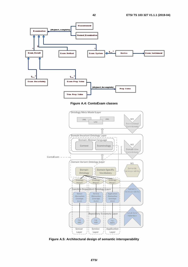
ETSI
ETSI TS 103 327 V1.1.1 (2019-04)42
Figure A.4: ContoExam classes
Figure A.5: Architectural design of semantic interoperability

ETSI
ETSI TS 103 327 V1.1.1 (2019-04)43
A.2.2 Personal Connected Health Alliance global healthcare architecture
The Personal Connected Health Alliance [i.24] (formerly known as Continua Alliance) is a non-profit industry organization containing about 200 members across the world aiming to develop and publish design guidelines that combine and apply existing technology standards to achieve end-to-end, plug-and-play interoperability in personal connected health. Figure A.6 shows the Personal Connected Health Alliance global healthcare architecture.
Figure A.6: The Personal Connected Health Alliance global healthcare architecture
The IEEE 11073 standards [i.25] are based on an object-oriented Domain Information Model (DIM) that contains 8 packages dedicated for medical, patients and device interoperability. Its primary goal is to standardize how data move from a sensing device (source) to a receiving device (sink), and what format is used. These standards thus provide interoperable terminology for the data (each medical term is represented by a code formed of 32 bits). For each device type, a device specialization that utilizes the common framework to model the specific data from device type is created. The service model defines how the information model should be accessed by the receiving device based on event reports. Moreover, the communication model defines the way of interaction between the service model and the underlying transport layer. The optimized exchange protocol is designed in an optimized way due to the following factors:
• The configuration parameters are exchanged only at the beginning of the communication.
• The sender/receiver can reuse a previously agreed configuration.
• The sender/receiver can use a predefined standard configuration.
• The sender/receiver can choose between multiple events' reports.
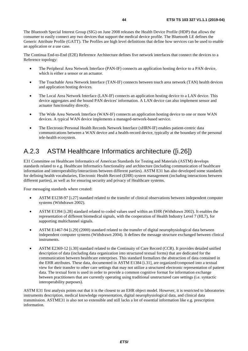
ETSI
ETSI TS 103 327 V1.1.1 (2019-04)44
The Bluetooth Special Interest Group (SIG) on June 2008 releases the Health Device Profile (HDP) that allows the consumer to easily connect any two devices that support the medical device profile. The Bluetooth LE defines the Generic Attribute Profile (GATT). The Profiles are high level definitions that define how services can be used to enable an application or a use case.
The Continua End-to-End (E2E) Reference Architecture defines five network interfaces that connect the devices to a Reference topology:
• The Peripheral Area Network Interface (PAN-IF) connects an application hosting device to a PAN device, which is either a sensor or an actuator.
• The Touchable Area Network Interface (TAN-IF) connects between touch area network (TAN) health devices and application hosting devices.
• The Local Area Network Interface (LAN-IF) connects an application hosting device to a LAN device. This device aggregates and the bound PAN devices' information. A LAN device can also implement sensor and actuator functionality directly.
• The Wide Area Network Interface (WAN-IF) connects an application hosting device to one or more WAN devices. A typical WAN device implements a managed-network-based service.
• The Electronic/Personal Health Records Network Interface (xHRN-IF) enables patient-centric data communications between a WAN device and a health-record device, typically at the boundary of the personal tele-health ecosystem.
A.2.3 ASTM Healthcare Informatics architecture ([i.26]) E31 Committee on Healthcare Informatics of American Standards for Testing and Materials (ASTM) develops standards related to e.g. Healthcare Informatics functionality and architecture (including communication of healthcare information and interoperability/interactions between different parties). ASTM E31 has also developed some standards for defining health vocabularies, Electronic Health Record (EHR) system management (including interactions between different parties), as well as for ensuring security and privacy of Healthcare systems.
Four messaging standards where created:
• ASTM E1238-97 [i.27] standard related to the transfer of clinical observations between independent computer systems (Withdrawn 2002).
• ASTM E1394 [i.28] standard related to coded values used within an EHR (Withdrawn 2002). It enables the representation of different biomedical signals, with the cooperation of Health Industry Level 7 (HL7), for supporting multichannel signals.
• ASTM E1467-94 [i.29] (2000) standard related to the transfer of digital neurophysiological data between independent computer systems (Withdrawn 2004). It defines the message structure exchanged between clinical instruments.
• ASTM E2369-12 [i.30] standard related to the Continuity of Care Record (CCR). It provides detailed unified description of data (including data organization into structured textual forms) that are dedicated for the communication between healthcare enterprises. This standard formalizes the abstraction of data contained in the EHR attributes. These data, documented in ASTM E1384 [i.31], are organized/composed into a textual view for their transfer to other care settings that may not utilize a structured electronic representation of patient data. The textual form is used in order to provide a common cognitive format for information exchange between practitioners that are currently operating using traditional unstructured care settings (i.e. syntactic interoperability purposes).
ASTM E31 first analysis points out that it is the closest to an EHR object model. However, it is restricted to laboratories instruments description, medical knowledge representation, digital neurophysiological data, and clinical data transmission. ASTME31 is also not so extensible and still lacks a lot of essential information like e.g. prescription information.

ETSI
ETSI TS 103 327 V1.1.1 (2019-04)45
A.2.4 MedCom ([i.32]) The Danish healthcare data network MedCom was developed in 1994. Starting with its first project, MedCom1 focused on developing communication standards for the interaction between medical practices, hospitals and pharmacies, based on Electronic Document Interchanged (EDI). The implementation and consolidation of the project began with Medcom2 in 1997-1999. In 2000-2001, MedCom3 focused on the quality of services and diffusion. With the evolution of the Internet, MedCom 4 adopted Internet and web based technologies in 2002-2005. MedCom 4 periods involved the development of XML standards for EHR data exchanges. In cooperation with the Ministry of Science Technology and Innovation (MVTU) and suppliers of IT systems to the healthcare sector (among others), MedCom drew up a proposal (MedCom 5) in 2006-2007 for the "Good Web Service" for general application in the healthcare sector based on the developed XML standards. The proposal was based on a service oriented IT architecture, and the recommendation was for this architecture to be common to the public sector. All clients' requests are converted to XML SOAP [i.33] messages and sent to a SOAP server for treatments.
A.2.5 The pan-Canadian EHR ([i.34]) Canada health infoway developed an information and interoperability framework: The Electronic Health Record Solution (EHRS) Blueprint in order to develop solutions to share and access clinical data so that the necessary health information is available for patient care regardless the providers' location. While the EHR provides the electronic records of the patient's health history, the EHRS Blueprint describes the conceptual architecture to share, use and access health information taking in consideration:
• The privacy protection.
• Data's discovery and availability.
• Heterogeneous technology environments.
• Costs inherent to integration.
Figure A.7 depicts the pan-Canadian EHR integrated view.
Figure A.7: Pan-Canadian EHR integrated view
EHRS Blueprint has considered four possible methods to share information across systems:
1) All Point of Services (PoS) access one single database and all users can only pull data from this database.
2) Data broadcast to PoS, or a logical subset of systems. Direct connection would occur between each PoS and all other participating systems.

ETSI
ETSI TS 103 327 V1.1.1 (2019-04)46
3) A single index/locator service that maintains the links to all PoS applications.
4) Use of a shared reference information source that is populated with clinically relevant data by the various PoS system. This reference source remains external to the operation of each PoS. This method formed the basis of EHRS.
The jurisdictional infostructure of the EHRS is detailed in Figure A.8. The PoS can only access the health information access layer (HIAL) that enables the applications to the see the EHR in a consistent way across EHR implementations. The HIAL is formed of the communication bus and the common services. The PoS interacts with the EHRS using the messaging and protocols defined in the communication bus layer. The messaging is responsible of describing the routing, transformation, encryption/decryption, encoding/decoding, parsing and serialization services. Examples of used messaging protocols are HL7 HDF [i.6], IHE and others. The protocol deals with the network, transport and application protocols.
The common services can be divided into four main groups:
• Interop, integration and context group. This group is responsible of service registration, caching, discovery, interoperability, mapping and queuing.
• Privacy and security.
• Subscription to events and notifications.
• Management and Configuration services.
More details on the common service layer are given in Figure A.9.
When the PoS requests information for a given patient, the data should be gathered from different registries. This is the role of the single Longitude Record Services (LRS) which has the necessary knowledge about the location of the EHR data to provide it adequately to the PoS request. The LRS can be divided into two groups of services: Data and Business services. The details of these services are given in Figure A.10. At the heart of LRS is the EHR index service which holds metadata information about every document or record published in the EHR.
The LRS communicate with the:
• Registries Data & Services which includes client, provider, location and terminology registries. The LRS uses these registries to verify the clients attributes and ensure that the right clinician or user accesses and provides the right information on the right person in relation to the right location.
• EHR Data & Services that holds the shared health records, the drug information, the diagnostic imaging, and laboratory records. Note that the PoS can add information to these records as well as directly retrieve information from these records.
• Ancillary Data & Services which includes outbreak management and reporting.
• Any other health information, in other term, the Data Warehouse.

ETSI
ETSI TS 103 327 V1.1.1 (2019-04)47
Figure A.8: Pan-Canadian EHR high level global architecture
Figure A.9: Pan-Canadian EHR Common service Layer

ETSI
ETSI TS 103 327 V1.1.1 (2019-04)48
Figure A.10: Pan-Canadian EHR LRS services
A.3 Existing Semantic Web Service Architectures
A.3.1 OWL-S [i.35] OWL-S, the semantic markup for web services, developed by DARPA DAML program using OWL languages aims to describe semantic web services. It permits the automatic web service: discovery, invocation, composition, interoperation, and execution monitoring. The OWL-S ontology includes mainly three sub-ontologies as shown in Figure A.11 and are the following: the service profile ontology that describes what the service does; the process model ontology that describes how the service is used; and the grounding ontology that describes how to interact with the service.
Figure A.11: Top Level of the Service ontology
A.3.2 Service Profile The main aim of the service profile is to provide the automatic service discovery. On one hand, when a producer wants to publish a server, it should describe the service based on the service profile ontology. On the other hand, the requester will discover the capabilities of available servers based on the service Profile.
The service profile includes three different aspects:
• Functional aspect that determines the functionality of a service. The "hasProcess" object property, connects a "Profile" to a "Process" that has inputs, outputs, preconditions and effects produced during the execution of a service.

ETSI
ETSI TS 103 327 V1.1.1 (2019-04)49
• Classification aspect that describes the type of service. It may precise the service's type based on a predefined Service Category.
• Non-functional aspect that makes the difference between services offering same service but in different manners. The non-functional parameters can be the QoS, privacy, security, etc.
A.3.3 Service Model The service model contains a sub-class, "Process", that indicates to the consumer what he should do to invoke a service. The process could be atomic, composite (composed of atomic processes), or simple (used to provide abstracted views of atomic or composite processes).
While an atomic process has a single interaction between consumer and producer, a composite process has a set of processes linked together by a control flow (sequence, parallelism, etc.) and a data flow that describes how the data is interchanged between the processes.
Each process has:
• Participants: the client requesting the process and the server performing the process.
• Parameters: the input, output and local parameters.
• Pre-condition: a condition that the client should satisfy in order to invoke the service. This condition could be an expression, a SWRL rule or others.
• Result: obtained after the execution of the process. The result has a type and a value.
A.3.4 Service Grounding The service grounding defines how abstract information can be realized by concrete information exchanges. It details the used transport protocol, port number and the message format. Actually, the service grounding class contains only the WSDL sub-class used to exchange SOAP messages.
Figure A.12 depicts a typical OWL-S interaction Model. A service provider advertises a service described by a service model and a service profile. A requester queries for a service. The OWL-S matchmaker verifies if there is an available service that matches the query, if yes, it provides the requestor by the URI of the available services. The requestor, then, choses an adequate server and retrieves the service model in order to invoke the service.
More researches can be investigated for the OWL-S matchmaker and matching algorithm.
Figure A.12: Typical OWL-S Semantic Web Service interaction model
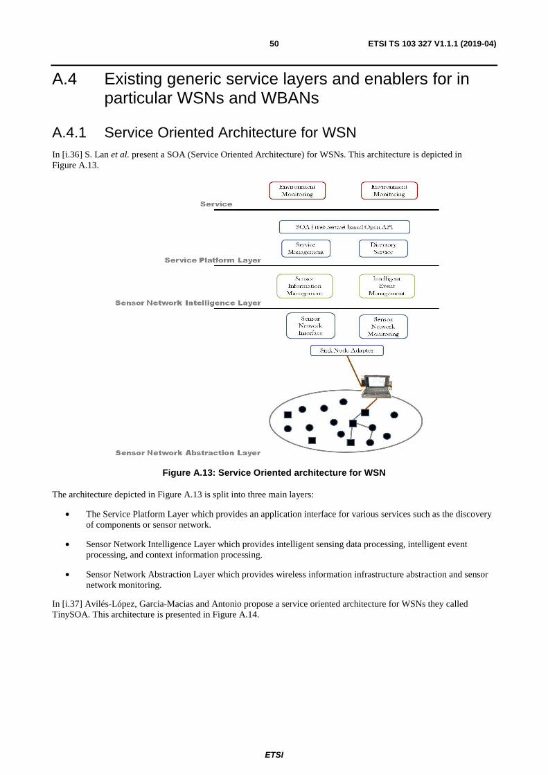
ETSI
ETSI TS 103 327 V1.1.1 (2019-04)50
A.4 Existing generic service layers and enablers for in particular WSNs and WBANs
A.4.1 Service Oriented Architecture for WSN In [i.36] S. Lan et al. present a SOA (Service Oriented Architecture) for WSNs. This architecture is depicted in Figure A.13.
Figure A.13: Service Oriented architecture for WSN
The architecture depicted in Figure A.13 is split into three main layers:
• The Service Platform Layer which provides an application interface for various services such as the discovery of components or sensor network.
• Sensor Network Intelligence Layer which provides intelligent sensing data processing, intelligent event processing, and context information processing.
• Sensor Network Abstraction Layer which provides wireless information infrastructure abstraction and sensor network monitoring.
In [i.37] Avilés-López, Garcia-Macias and Antonio propose a service oriented architecture for WSNs they called TinySOA. This architecture is presented in Figure A.14.

ETSI
ETSI TS 103 327 V1.1.1 (2019-04)51
Figure A.14: TinySOA architecture
As depicted in Figure A.14, the Node encompasses all the functionality of sensing nodes and networks. The gateway receives, at startup, the registration messages with the single capabilities of each node. This gateway, then, aggregates the received node capabilities and deduces the services that can be provided by the full sensor network. All information about the infrastructure is stored in a registry. The server acts as a Web Services' provider, abstracting each available WSN as a separate web service. This provides an common interface for consulting services offered by each of the networks, for checking the registry and for registering/consulting events and maintenance tasks. Additionally, an information web service, in which clients can retrieve how many different network web services are available and how to access them, is set up.
TinyVisor was also implemented in [i.37] for testing purposes. At start up TinyVisor asks for the URL (Unique Resource Locator) of a TinySOA server. This server URLis provided for locating information and network web services. Once connected to the server, TyniVisor proceeds to open the information web service and sends a request for retrieving the number of currently available network web services. An interactive dialog box is, then, displayed. This dialog box shows the information related to the available WSNs including the name, description, and web service URL. It is, then, possible to select the network that is going to be used for monitoring and visualization. Once this network is selected, the information regarding its nodes and the corresponding sensed data can be visualized. This visualization is doable either in data mode graph mode, or topology mode. Figure A.15 presents the callable functions, from any program, through the web services interface to access WSNs.
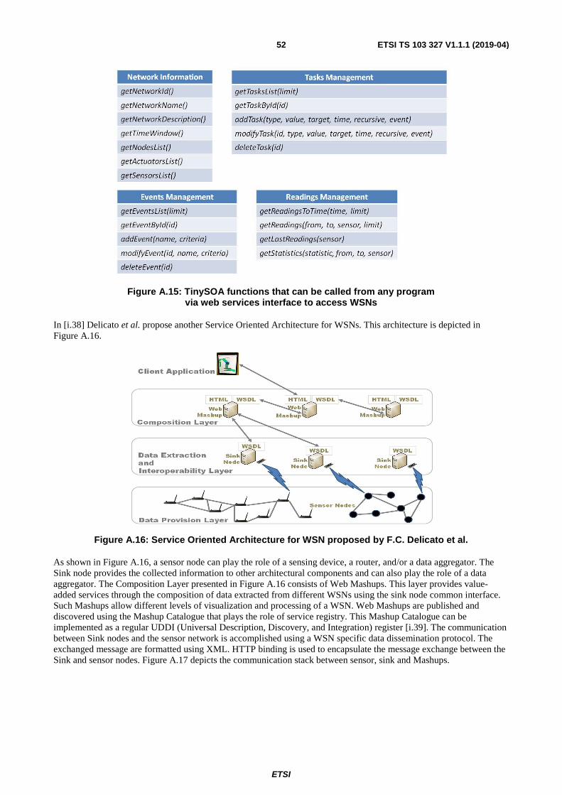
ETSI
ETSI TS 103 327 V1.1.1 (2019-04)52
Figure A.15: TinySOA functions that can be called from any program via web services interface to access WSNs
In [i.38] Delicato et al. propose another Service Oriented Architecture for WSNs. This architecture is depicted in Figure A.16.
Figure A.16: Service Oriented Architecture for WSN proposed by F.C. Delicato et al.
As shown in Figure A.16, a sensor node can play the role of a sensing device, a router, and/or a data aggregator. The Sink node provides the collected information to other architectural components and can also play the role of a data aggregator. The Composition Layer presented in Figure A.16 consists of Web Mashups. This layer provides value-added services through the composition of data extracted from different WSNs using the sink node common interface. Such Mashups allow different levels of visualization and processing of a WSN. Web Mashups are published and discovered using the Mashup Catalogue that plays the role of service registry. This Mashup Catalogue can be implemented as a regular UDDI (Universal Description, Discovery, and Integration) register [i.39]. The communication between Sink nodes and the sensor network is accomplished using a WSN specific data dissemination protocol. The exchanged message are formatted using XML. HTTP binding is used to encapsulate the message exchange between the Sink and sensor nodes. Figure A.17 depicts the communication stack between sensor, sink and Mashups.
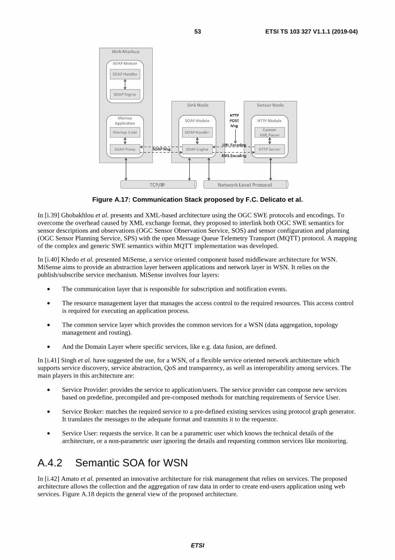
ETSI
ETSI TS 103 327 V1.1.1 (2019-04)53
Figure A.17: Communication Stack proposed by F.C. Delicato et al.
In [i.39] Ghobakhlou et al. presents and XML-based architecture using the OGC SWE protocols and encodings. To overcome the overhead caused by XML exchange format, they proposed to interlink both OGC SWE semantics for sensor descriptions and observations (OGC Sensor Observation Service, SOS) and sensor configuration and planning (OGC Sensor Planning Service, SPS) with the open Message Queue Telemetry Transport (MQTT) protocol. A mapping of the complex and generic SWE semantics within MQTT implementation was developed.
In [i.40] Khedo et al. presented MiSense, a service oriented component based middleware architecture for WSN. MiSense aims to provide an abstraction layer between applications and network layer in WSN. It relies on the publish/subscribe service mechanism. MiSense involves four layers:
• The communication layer that is responsible for subscription and notification events.
• The resource management layer that manages the access control to the required resources. This access control is required for executing an application process.
• The common service layer which provides the common services for a WSN (data aggregation, topology management and routing).
• And the Domain Layer where specific services, like e.g. data fusion, are defined.
In [i.41] Singh et al. have suggested the use, for a WSN, of a flexible service oriented network architecture which supports service discovery, service abstraction, QoS and transparency, as well as interoperability among services. The main players in this architecture are:
• Service Provider: provides the service to application/users. The service provider can compose new services based on predefine, precompiled and pre-composed methods for matching requirements of Service User.
• Service Broker: matches the required service to a pre-defined existing services using protocol graph generator. It translates the messages to the adequate format and transmits it to the requestor.
• Service User: requests the service. It can be a parametric user which knows the technical details of the architecture, or a non-parametric user ignoring the details and requesting common services like monitoring.
A.4.2 Semantic SOA for WSN In [i.42] Amato et al. presented an innovative architecture for risk management that relies on services. The proposed architecture allows the collection and the aggregation of raw data in order to create end-users application using web services. Figure A.18 depicts the general view of the proposed architecture.

ETSI
ETSI TS 103 327 V1.1.1 (2019-04)54
Figure A.18: Semantic SOA Overview Architecture proposed by F. Amato et al.
As shown in Figure A.18, the Data Collection Service Layer interacts directly with the WSN for collecting the raw data. The Data Collection Service Layer then enriches these raw data with ontological modelling techniques. This layer thus offers the service of converting data into XML/RDF data model. The Integration Service Layer aggregates and clusterizes data according to a defined data model. Then, this Integration Service layer delivers it to the Application Service Layer. Finally, the application service layer invokes the service which is accessible through WSDL standard.
Each service has its own security policy and it is published in a public registry. To integrate data from heterogeneous source, the wrapper-mediator paradigm has been used. Each wrapper explores and monitors the local sensor network and sends to the mediator an appropriate description of the related information according to a common data model. Figure A.19 summarizes the wrapper-mediator functionality within the Collection and Integration Services.
Figure A.19: Collection and Integration Services

ETSI
ETSI TS 103 327 V1.1.1 (2019-04)55
For the discovery and the registration of a specific wrapper, the getConnection function is used. It then activates the service provided by the wrapper module. The getNetworks gives as output the list of all networks connected to the system, their topology, and basic information such as network identifiers, number of sensors and maximum depth for each network. The getNetworkFeatures takes as input parameter the network identifier and returns: the type of system, the middleware, the number of sensors, the maximum depth, the IP address, the registration time, the communication ports, as well as information about the base station (frequency, communication link). The getParameters returns the sensor parameters, like the IDs (i.e. network, cluster and sensor identifiers), the free memory, the voltage and the channel quality. The getPredicates gives all the physical variable measured by a sensor (identified by its sensor identifier). Finally, the monitoring task queries a sensor, or a sensor network, invokes both the requestProcessing and the getResults services for getting the results related to a specific query.
In conclusion, to add semantic meanings to the sensed data, the sensors add-on (data aggregator) retrieves samples from sensor systems and converts them into an XML format, according to defined translation rules. The XML-RDF Wrapper translates the file into an RDF document, according to a set of sensor domain ontologies. Finally, the O&M Data modeler retrieves an RDF document and converts it in an O&M standard XML document.
A.4.3 Open Sensor Web Architecture (OSWA [i.43]) OSWA is an extension of SWE proposed by NICTA (National ICT Australia Ltd) University of Melbourne. Its main aim is to combine SOA with SWE. OSWA defines four different layers as shown in Figure A.20.
Figure A.20: OSWA layers
As shown in Figure A.20, the OSWA service layer reuses the services described in SWE and specifies how these services can be implemented in real scenarios. It uses WSDL and UDDI for service discovery. SCS provides interface to both streaming data and query based sensor applications that are built on top of TinyOS and TinyDB respectively. Only two features of SPS were implemented: getFeasibility and submitRequest. The WNS offered two features: registerUser and doNotification. For user registration a JDBC-based UserAccountManager has been implemented. Moreover, the email protocol is used to notify clients. Sensor Repository Service is deployed as a web service that can be accessed via SOAP messages.

ETSI
ETSI TS 103 327 V1.1.1 (2019-04)56
History
Document history
V1.1.1 April 2019 Publication