Embed Size (px)
Citation preview
ETSI TS 102 693 V1.1.2 (2009-11)
Technical Specification
Digital Audio Broadcasting (DAB);Encapsulation of DAB Interfaces (EDI)
European Broadcasting Union Union Européenne de Radio-Télévision
EBU·UER
ETSI
ETSI TS 102 693 V1.1.2 (2009-11)2
Reference RTS/JTC-DAB-63
Keywords broadcasting, DAB, digital, MUX, radio
ETSI
650 Route des Lucioles F-06921 Sophia Antipolis Cedex - FRANCE
Tel.: +33 4 92 94 42 00 Fax: +33 4 93 65 47 16
Siret N° 348 623 562 00017 - NAF 742 C
Association à but non lucratif enregistrée à la Sous-Préfecture de Grasse (06) N° 7803/88
Important notice
Individual copies of the present document can be downloaded from: http://www.etsi.org
The present document may be made available in more than one electronic version or in print. In any case of existing or perceived difference in contents between such versions, the reference version is the Portable Document Format (PDF).
In case of dispute, the reference shall be the printing on ETSI printers of the PDF version kept on a specific network drive within ETSI Secretariat.
Users of the present document should be aware that the document may be subject to revision or change of status. Information on the current status of this and other ETSI documents is available at
http://portal.etsi.org/tb/status/status.asp
If you find errors in the present document, please send your comment to one of the following services: http://portal.etsi.org/chaircor/ETSI_support.asp
Copyright Notification
No part may be reproduced except as authorized by written permission. The copyright and the foregoing restriction extend to reproduction in all media.
© European Telecommunications Standards Institute 2009.
© European Broadcasting Union 2009. All rights reserved.
DECTTM, PLUGTESTSTM, UMTSTM, TIPHONTM, the TIPHON logo and the ETSI logo are Trade Marks of ETSI registered
for the benefit of its Members. 3GPPTM is a Trade Mark of ETSI registered for the benefit of its Members and of the 3GPP Organizational Partners.
LTE™ is a Trade Mark of ETSI currently being registered for the benefit of its Members and of the 3GPP Organizational Partners.
GSM® and the GSM logo are Trade Marks registered and owned by the GSM Association.
ETSI
ETSI TS 102 693 V1.1.2 (2009-11)3
Contents
Intellectual Property Rights ................................................................................................................................ 6
Foreword ............................................................................................................................................................. 6
Introduction ........................................................................................................................................................ 6
1 Scope ........................................................................................................................................................ 8
2 References ................................................................................................................................................ 8
2.1 Normative references ......................................................................................................................................... 8
2.2 Informative references ........................................................................................................................................ 9
3 Definitions, symbols, abbreviations and conventions .............................................................................. 9
3.1 Definitions .......................................................................................................................................................... 9
3.2 Symbols ............................................................................................................................................................ 10
3.3 Abbreviations ................................................................................................................................................... 10
3.4 Conventions ...................................................................................................................................................... 12
4 General description................................................................................................................................. 12
4.1 System overview .............................................................................................................................................. 12
4.2 System architecture .......................................................................................................................................... 13
4.2.1 TAG Items and TAG Packets (informative) ............................................................................................... 14
4.3 EDI Packets ...................................................................................................................................................... 14
4.3.1 STI-D(LI) .................................................................................................................................................... 15
4.3.2 ETI(LI) ........................................................................................................................................................ 16
4.3.3 Other LI (Informative) ................................................................................................................................ 16
5 TAG Items .............................................................................................................................................. 16
5.1 Mandatory TAG Items ..................................................................................................................................... 16
5.1.1 Protocol type and revision (*ptr) ................................................................................................................ 16
5.1.2 DAB STI-D(LI) Management (dsti) ........................................................................................................... 17
5.1.3 DAB ETI(LI) Management (deti) ............................................................................................................... 18
5.1.4 STI-D Payload Stream <m> (ss<m>) ......................................................................................................... 20
5.1.5 ETI Sub-Channel Stream <n> (est<n>) ...................................................................................................... 21
5.2 Optional TAG Items ......................................................................................................................................... 22
5.2.1 Information (info) ....................................................................................................................................... 22
5.2.2 Network Adapted Signalling Channel (nasc) .............................................................................................. 23
5.2.3 Frame Padding User Data (frpd) ................................................................................................................. 23
5.3 Revision history ................................................................................................................................................ 23
Annex A (normative): Regenerating LI Frame from EDI Packets ................................................. 25
A.1 Regenerating an STI-D(LI) Frame from an EDI Packets ....................................................................... 25
A.1.1 FC - rfa (3 bits) ................................................................................................................................................. 25
A.1.2 FC - DL (13 bits) .............................................................................................................................................. 25
A.1.3 FC - rfa (8 bits) ................................................................................................................................................. 26
A.1.4 FC - NST (11 bits) ............................................................................................................................................ 26
A.1.5 STC - STLm (13 bits) ....................................................................................................................................... 26
A.1.6 EOH - rfa (16 bits)............................................................................................................................................ 26
A.1.7 EOH - CRCH (16 bits) ..................................................................................................................................... 26
A.1.8 MST - CRCSTm (16 bits) ................................................................................................................................ 26
A.1.9 EOF - rfa (32 bits) ............................................................................................................................................ 26
A.2 Regenerating an ETI(LI) Frame from an EDI Packet ............................................................................ 28
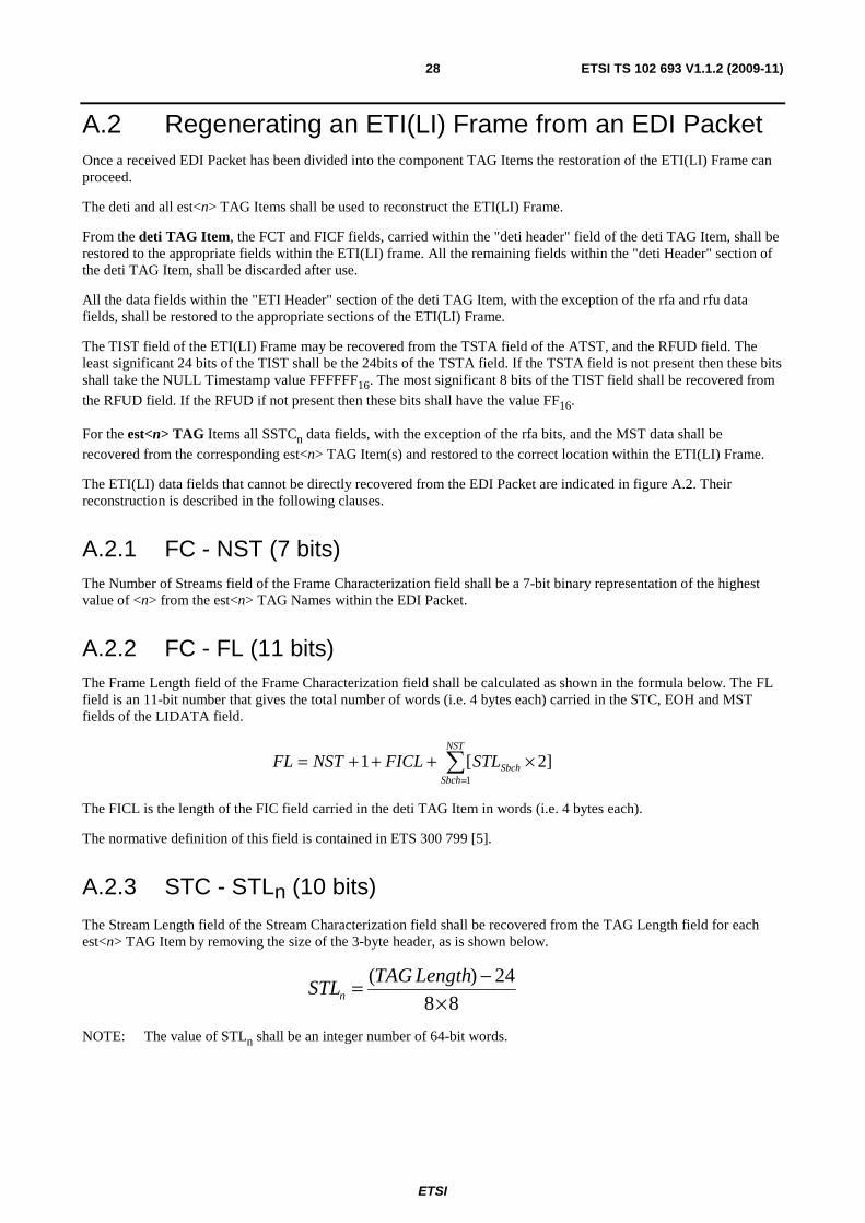
A.2.1 FC - NST (7 bits) .............................................................................................................................................. 28
A.2.2 FC - FL (11 bits) ............................................................................................................................................... 28
A.2.3 STC - STLn (10 bits) ........................................................................................................................................ 28
A.2.4 EOH - CRCh (16 bits) ...................................................................................................................................... 29
A.2.5 EOF - CRC (16 bits) ......................................................................................................................................... 29
ETSI
ETSI TS 102 693 V1.1.2 (2009-11)4
A.2.6 EOF - Rfu (16 bits) ........................................................................................................................................... 29
Annex B (normative): Conversion and Backwards Compatibility .................................................. 31
B.1 STI-D Special Considerations ................................................................................................................ 31
B.1.1 Control Frame Size field (CFS) ........................................................................................................................ 31
B.1.2 Control Frame field (CF) .................................................................................................................................. 31
B.1.3 Frame Padding field (FRPD) ............................................................................................................................ 31
B.1.4 Timestamps ...................................................................................................................................................... 32
B.1.4.1 Converting to EDI ....................................................................................................................................... 32
B.1.4.2 Converting from EDI .................................................................................................................................. 32
B.2 ETI Special Considerations .................................................................................................................... 32
B.2.1 Frame Padding Field (FRPD) ........................................................................................................................... 32
B.2.2 Timestamps ...................................................................................................................................................... 33
B.2.2.1 Converting to EDI ....................................................................................................................................... 33
B.2.2.2 Converting from EDI .................................................................................................................................. 33
B.2.3 Network Adapted Signalling Channel (NASC) ................................................................................................ 33
B.2.3.1 Converting to EDI ....................................................................................................................................... 33
B.2.3.2 Converting from EDI .................................................................................................................................. 33
B.3 ETI Network Deployment and Timing................................................................................................... 34
B.3.1 Legacy-LI Network .......................................................................................................................................... 34
B.3.2 EDI Network .................................................................................................................................................... 34
B.3.3 Mixed EDI and Legacy-LI Network ................................................................................................................ 35
B.3.4 EDI/Legacy-LI Converters ............................................................................................................................... 35
B.3.4.1 EDI to Legacy-LI Converter ....................................................................................................................... 35
B.3.4.2 Legacy-LI to EDI Converter ....................................................................................................................... 36
B.3.5 Full Network Example (including Converters) ................................................................................................ 36
B.4 Network Deployment Considerations .............................................................................................................. 37
Annex C (informative): DAB Modulator - Continuity of Transmission ........................................... 38
C.1 Overview ................................................................................................................................................ 38
C.2 Recreating Essential Fields .................................................................................................................... 39
C.2.1 DLFC (Frame Count High (FCTH) and Frame Count (FCT)) ......................................................................... 39
C.2.2 Frame Phase (FP) ............................................................................................................................................. 39
C.2.3 Timestamp (ATST) .......................................................................................................................................... 39
C.2.4 Error Field (STAT) ........................................................................................................................................... 39
C.2.5 FIC Data ........................................................................................................................................................... 40
C.2.6 ETI sub-channel streams .................................................................................................................................. 40
C.4 Required Configuration Options ............................................................................................................ 40
C.5 Notification ............................................................................................................................................. 40
C.6 Use in SFN Application ......................................................................................................................... 40
Annex D (normative): Physical presentation ..................................................................................... 41
D.1 Ethernet (IP over Ethernet) ..................................................................................................................... 41
D.1.1 Transport Layer ................................................................................................................................................ 41
D.1.2 Network Layer .................................................................................................................................................. 41
D.1.3 Link Layer ........................................................................................................................................................ 42
Annex E (normative): EDI Packet Resend Functionality................................................................. 43
E.1 Theory of Operation ............................................................................................................................... 43
E.2 Parameters .............................................................................................................................................. 44
E.2.1 Parameters for the EDI Decoder ....................................................................................................................... 44
E.2.2 Parameters for the EDI Encoder ....................................................................................................................... 45
E.3 Requesting an EDI Packet Resend (EDI Decoder) ................................................................................ 46
E.4 Resending EDI Packets (EDI Encoder) .................................................................................................. 46

ETSI
ETSI TS 102 693 V1.1.2 (2009-11)5
Annex F (informative): EDI Timestamps ............................................................................................ 48
F.1 Relationships .......................................................................................................................................... 48
F.2 Rationale ................................................................................................................................................. 48
History .............................................................................................................................................................. 49
ETSI
ETSI TS 102 693 V1.1.2 (2009-11)6
Intellectual Property Rights IPRs essential or potentially essential to the present document may have been declared to ETSI. The information pertaining to these essential IPRs, if any, is publicly available for ETSI members and non-members, and can be found in ETSI SR 000 314: "Intellectual Property Rights (IPRs); Essential, or potentially Essential, IPRs notified to ETSI in respect of ETSI standards", which is available from the ETSI Secretariat. Latest updates are available on the ETSI Web server (http://webapp.etsi.org/IPR/home.asp).
Pursuant to the ETSI IPR Policy, no investigation, including IPR searches, has been carried out by ETSI. No guarantee can be given as to the existence of other IPRs not referenced in ETSI SR 000 314 (or the updates on the ETSI Web server) which are, or may be, or may become, essential to the present document.
Foreword This Technical Specification (TS) has been produced by Joint Technical Committee (JTC) Broadcast of the European Broadcasting Union (EBU), Comité Européen de Normalisation ELECtrotechnique (CENELEC) and the European Telecommunications Standards Institute (ETSI).
NOTE: The EBU/ETSI JTC Broadcast was established in 1990 to co-ordinate the drafting of standards in the specific field of broadcasting and related fields. Since 1995 the JTC Broadcast became a tripartite body by including in the Memorandum of Understanding also CENELEC, which is responsible for the standardization of radio and television receivers. The EBU is a professional association of broadcasting organizations whose work includes the co-ordination of its members' activities in the technical, legal, programme-making and programme-exchange domains. The EBU has active members in about 60 countries in the European broadcasting area; its headquarters is in Geneva.
European Broadcasting Union CH-1218 GRAND SACONNEX (Geneva) Switzerland Tel: +41 22 717 21 11 Fax: +41 22 717 24 81
The Eureka Project 147 was established in 1987, with funding from the European Commission, to develop a system for the broadcasting of audio and data to fixed, portable or mobile receivers. Their work resulted in the publication of European Standard, EN 300 401 [1], for DAB (see note) which now has worldwide acceptance. The members of the Eureka Project 147 are drawn from broadcasting organizations and telecommunication providers together with companies from the professional and consumer electronics industry.
NOTE: DAB is a registered trademark owned by one of the Eureka Project 147 partners.
Introduction The present document provides a mechanism for the encapsulation of STI-D (see EN 300 797 [4]) and ETI (see ETS 300 799 [5]) compliant data streams for distribution over IP networks. EDI is based on the existing Distribution and Communications Protocol (DCP - TS 102 821 [2]), and therefore a layered approach relevant to unique IP network designs can be implemented. An EDI Packet represents a single STI-D or ETI 24 ms logical frame. In order to maximize efficiency across the IP network, unnecessary LI data (i.e. data formatted according to the STI-D or ETI "logical interface"), which can be reliably reproduced at the receiver is removed. The TAG Items are grouped to form a single EDI Packet, and passed onto DCP for Application Framing (AF).
EDI is designed to distribute STI-D and ETI over varying conditions of IP networks, and ensure the robust delivery of STI-D and ETI compliant data over networks affected by congestion, jitter and limited packet loss. EDI can be configured to operate a re-send function, or re-construct missed packets at the receiver in times of packet loss. Once the EDI Packet has been passed to the DCP stage, Protection, Fragmentation and Transport (PFT) can add a further layer of Reed Solomon block coding and fragmentation if required; this is especially attractive for uni-directional or low Quality of Service (QoS) networks.

ETSI
ETSI TS 102 693 V1.1.2 (2009-11)7
EDI utilizes open internet standards, and can be configured for operation over uni-directional unicast and multicast UDP/IP, and connection based TCP/IP, including MTU adaptations.
An EDI Decoder may be designed to re-create a compliant STI-D(LI) or ETI(LI) single 24 ms logical frame, which can be used in legacy networks, as all specific framing requirements may be passed through the transparent EDI encapsulation stage. As such, EDI can be configured to operate in a mixed legacy network (including maintaining existing timing constraints), in which a combination of EDI and traditional (non-IP based) delivery solutions are employed, or as an EDI delivered network only.
ETSI
ETSI TS 102 693 V1.1.2 (2009-11)8
1 Scope The present document gives the specification for the delivery of STI-D(LI) and ETI(LI) over IP networks. An example for STI-D would be from a DAB Service Multiplexer to a DAB Ensemble Multiplexer. An example for ETI would be between DAB Ensemble Multiplexers and DAB Modulators (COFDM).
2 References References are either specific (identified by date of publication and/or edition number or version number) or non-specific.
• For a specific reference, subsequent revisions do not apply.
• Non-specific reference may be made only to a complete document or a part thereof and only in the following cases:
- if it is accepted that it will be possible to use all future changes of the referenced document for the purposes of the referring document;
- for informative references.
Referenced documents which are not found to be publicly available in the expected location might be found at http://docbox.etsi.org/Reference.
NOTE: While any hyperlinks included in this clause were valid at the time of publication ETSI cannot guarantee their long term validity.
2.1 Normative references The following referenced documents are indispensable for the application of the present document. For dated references, only the edition cited applies. For non-specific references, the latest edition of the referenced document (including any amendments) applies.
[1] ETSI EN 300 401: "Radio Broadcasting Systems; Digital Audio Broadcasting (DAB) to mobile, portable and fixed receivers".
[2] ETSI TS 102 821: "Digital Radio Mondiale (DRM); Distribution and Communications Protocol (DCP)".
[3] ISO/IEC 10646: "Information technology - Universal Multiple-Octet Coded Character Set (UCS)".
[4] ETSI EN 300 797: "Digital Audio Broadcasting (DAB); Distribution interfaces; Service Transport Interface (STI)".
[5] ETSI ETS 300 799: "Digital Audio Broadcasting (DAB); Distribution interfaces; Ensemble Transport Interface (ETI)".
[6] IEEE 802.3-2002: " Information technology - Telecommunications and information exchange between systems - Local and metropolitan area networks specific requirements - Part 3: Carrier Sense Multiple Access with Collision Detection (CSMA/CD) Access Method and Physical Layer Specifications".
[7] TIA/EIA-568-B (series): "Commercial Building Telecommunications Cabling Standard - Part 1: General Requirements".
[8] ITU-T Recommendation G.703 (1972): "Physical/Electrical characteristics of hierarchical digital interfaces: Section 6. Interface at 2 048 kbit/s".
[9] ITU-T Recommendation G.704 (1988): "Synchronous frame structures used at primary and secondary hierarchical levels: Section 2.3 Basic frame structure at 2 048 kbit/s".
ETSI
ETSI TS 102 693 V1.1.2 (2009-11)9
2.2 Informative references The following referenced documents are not essential to the use of the present document but they assist the user with regard to a particular subject area. For non-specific references, the latest version of the referenced document (including any amendments) applies.
Not applicable.
3 Definitions, symbols, abbreviations and conventions
3.1 Definitions For the purposes of the present document, the following terms and definitions apply:
Application Framing (AF): layer of the DCP providing a logical grouping of a number of TAG Items
byte: collection of 8-bits
Distribution and Communications Protocol (DCP): transport layer communications protocol providing fragmentation, addressing and/or reliable data transmission over errored channels using a Reed Solomon code to provide Forward Error Correction (FEC)
EDI Encoder: application or device that generates an EDI conforming output stream and sends this stream through one of DCP's basic transmission layers
EDI Decoder: application or device that receives and processes an EDI conforming EDI input stream through one of DCP's basics transmission layers
EDI Packet: TAG Packet containing those TAG Items transporting ETI(LI) or STI-D(LI) information
Fast Information Block (FIB): data burst of 256 bits
NOTE: The sequence of FIBs is carried by the Fast Information Channel. The structure of the FIB is common to all transmission modes.
Fast Information Channel (FIC): part of the transmission frame, comprising the Fast Information Blocks, which contain the multiplex configuration information together with optional service Information and data service components
Greenwich Mean Time (GMT): historically standard time for all international applications, now superseded by UTC
Global Position System (GPS): constellation of satellites providing accurate time and position information to receivers
GPS Time: time signal broadcast by the GPS satellites using an epoch of January 6th 1980 with no leap seconds and a "week number" (actually a modulo-604 800 seconds number) that wraps every 1 024 weeks (approximately 19,7 years)
LI Data: part of the LI which carries the data describing the signal
LI Frame: carries data representing a 24 ms period of the LI Data
logical frame: contains data for a time interval of 24 ms
Main Service Channel (MSC): channel of the multiplex data stream which occupies the major part of the transmission frame and which carries all the digital audio services, together with possible supporting and additional data services
Modified Julian Date (MJD): date format based on the number of days since midnight GMT on 17th November 1858 AD
NOTE: Time can be represented as a fraction of a day, however as MJD is subject to leap seconds, the fractional part corresponding to an SI second is of variable size and hence complex to implement in a fixed width bit-field.
Single Frequency Network (SFN): network of transmitters sharing the same radio frequency to cover a large area
ETSI
ETSI TS 102 693 V1.1.2 (2009-11)10
TAG Item: DCP elemental type combining in a single logical data the name, length and value of the data
TAG Name: name field within an individual TAG Item used to identify an individual piece of information
TAG Packet: collection of TAG Items with a header carrying a cohesive and self-contained block of data
TAG Value: the payload of a TAG Item
TAI (International Atomic Time, literally Temps Atomique International): time format counting in standard SI seconds
NOTE: TAI and GPS Time have a constant offset of 19 s.
Transmission Frame: actual transmitted frame, specific to the four DAB transmission modes, conveying the Synchronization Channel, the Fast Information Channel and the Main Service Channel
UTC (Coordinated Universal Time, literally Universel Temps Coordonné): time format counting in standard SI seconds with periodic adjustments made by the addition (or removal) of leap seconds to keep the difference between UTC and Astronomical Time less than ±0,9 s
NOTE: TAI and UTC were defined as having an initial offset of 10 s on January 1st 1972 (TAI prior to this date had a variable fractional offset to UTC as the two times did not use the same definition of the second). As at 28th August 2008 there have been 23 leap seconds, all positive, making TAI=UTC+33.
3.2 Symbols For the purposes of the present document, the following symbols apply:
Nx The value "N" is expressed in radix "x". The radix of "x" shall be decimal, thus 2A16 is the
hexadecimal representation of the decimal number 42.
3.3 Abbreviations For the purposes of the present document, the following abbreviations apply:
AF Application Framing AR Application framing protocol Revision ASS frame ASynchronous Signalling ATST Absolute Time STamp ATSTF ATST Flag BOOTP BOOT Protocol CF CRC flag CFS Control Frame Size CIF Common Interleaved Frame COFDM Coded Orthogonal Frequency Division Multiplexing CRC Cyclic Redundancy Check CRCH Header Cyclic Redundancy Checksum CRCST STream Cyclic Redundancy Checksum CRCSTF STream Cyclic Redundancy Checksum Flag CU Capacity Units DAB Digital Audio Broadcasting DCP Distribution and Communication Protocol DFCTH Data Frame CounT Higher DFCTL Data Frame CounT Lower DHCP Dynamic Host Configuration Protocol DL Data Length DLFC EDI Logical Frame Count D-LIDATA Data part Logical Interface DATA DRM Digital Radio Mondiale EDI Encapsulation for DAB Distribution Interfaces EOF End of Frame
ETSI
ETSI TS 102 693 V1.1.2 (2009-11)11
EOH End of Header ERR ERRor status ETI Ensemble Transport Interface FC Frame Characterization FCT Frame CounT FCTH Frame CounT Higher FEC Forward Error Correction FIB Fast Information Block FIC Fast Information Channel FICF FIC Flag FICL FIC Length FRPD FRame Padding user Data FSS Frame Synchronous Signalling GMT Greenwich Mean Time GPS Global Positioning System ID IDentifier IERS International Earth Rotation and reference Systems service IGMP Internet Group Management Protocol IP Internet Protocol IPSEC Internet Protocol SECurity ISO International Organization for Standardization ISTC Individual STream Characterization ISTD Individual STream Data LAN Local Area Network LI Logical Interface LIDATA Logical Interface DATA field LSb Least Significant bit LSB Least Significant Byte MAC Media Access Control MDI Medium Dependent Interface MFN Multiple Frequency Network MJD Modified Julian Date MNSC Multiplex Network Signalling Channel MSb Most Significant bit MSB Most Significant Byte MSC Main Service Channel MST Main Stream Data MTU Maximum Transfer Unit NA Network Adaption NASC Network Adapted Signalling Channel NI Network Independent NST Number of STreams PFT Protection, Fragmentation and Transportation PPS Pulse Per Second QoS Quality of Service RF Radio Frequency rfa reserved for future application RFAD Reserved for Future Additions Data field RFADF RFAD Flag rfu reserved for future use RFUD Reserved for Future Use Data field RFUDF RFUD Flag SAD Sub-channel Start Address SCID Sub-Channel ID SFN Single Frequency Network SI Système International d'unités (International System of units) SSTC Sub-channel STream Characterization STAT STATus Field STC STream Characterization STI Service Transport Interface STI-D Service Transport Interface - Data STID STream ID
ETSI
ETSI TS 102 693 V1.1.2 (2009-11)12
STIHF STI Header Flag STL STream Length TAG Tag, Length, Value TAI International Atomic Time (Temps Atomique International) TCP Transmission Control Protocol TID Type IDentifier TII Transmitter Identification Information TIST TIme STamp TPL Type and Protection Level TSTA Time STAmp UDP User Datagram Protocol UTC Co-ordinated Universal Time (Temps Universel Coordonné) UTCO Universal Time Coordinated Offset UTF 8-bit Unicode Transformation Format
3.4 Conventions The order of bits and bytes within each description shall use the following notation unless otherwise stated:
• in figures, the bit or byte shown in the left hand position is considered to be first;
• in tables, the bit or byte shown in the left hand position is considered to be first;
• in byte fields, the Most Significant bit (MSb) is considered to be first and denoted by the higher number. For example, the MSb of a single byte is denoted "b7" and the Least Significant bit (LSb) is denoted "b0";
• all multi-byte numeric values shall be coded with the Most Significant Byte (MSB) first (network byte order);
• in vectors (mathematical expressions), the bit with the lowest index is considered to be first.
4 General description
4.1 System overview The "Encapsulation of DAB Interfaces" protocol (EDI) carries the information required to reconstruct a complete STI-D(LI) or ETI(LI) logical frame.
STI-D(LI) is primarily employed to carry data for single or multiple sub-channels to a DAB Service Multiplexer or a DAB Ensemble Multiplexer. STI-D sources are generally located in one of two types of site: at the Multiplex Centre where they are locally connected to the Multiplexer equipment, or at a studio centre, from where they require a data link of some form to deliver their output to the DAB Service Multiplexer or the DAB Ensemble Multiplexer.
An ETI(LI) logical frame contains all data required to construct all elements of the Main Service Channel (MSC) and Fast Information Channel (FIC) and ancillary data (such as MNSC) of a DAB Multiplex signal. The DAB Modulator (COFDM) encodes the data carried by ETI to construct a full DAB transmission frame, with the local addition of the null symbol and synchronization symbol. Typically the DAB Ensemble Multiplexer will be sited at a Multiplex Centre, which may be co-located with one of the transmitters. DAB Modulators will be located at the transmitter site as a part of the transmitter system.
The distribution method for both STI-D(LI) and ETI(LI) may be one, or more, of several different forms, including terrestrial leased line, RF link and satellite.
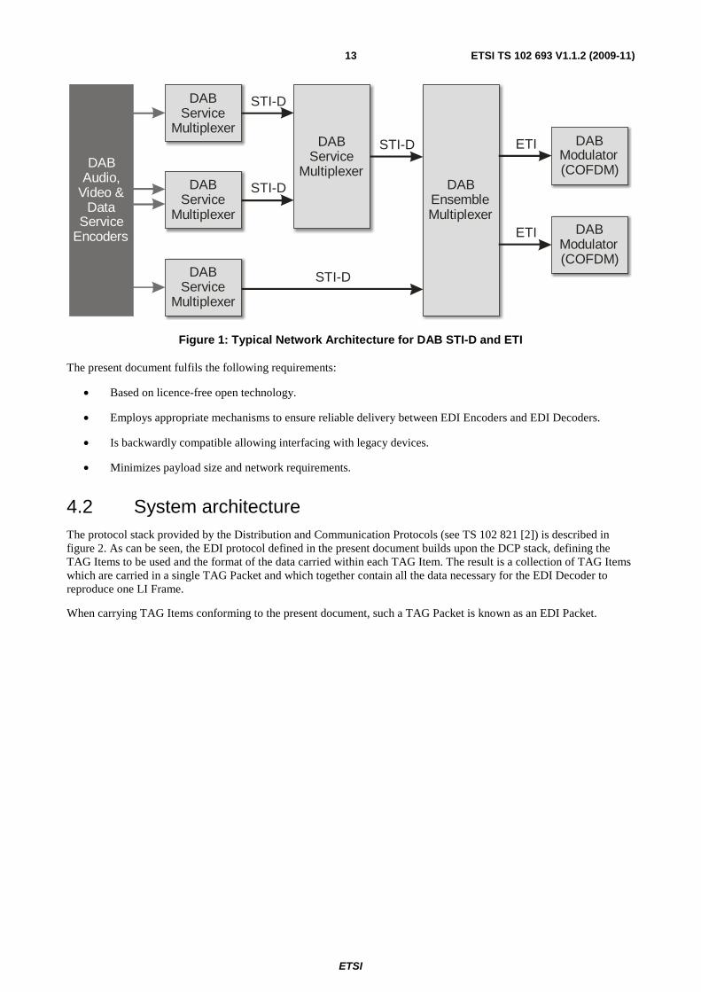
A typical DAB distribution network may follow the architecture as outlined in figure 1.
ETSI
ETSI TS 102 693 V1.1.2 (2009-11)13
DABService
MultiplexerDAB
EnsembleMultiplexer
DABService
Multiplexer
DABService
Multiplexer
DABService
Multiplexer
DABModulator(COFDM)
DABModulator(COFDM)
DABAudio,
Video &Data
ServiceEncoders
STI-D
STI-D
STI-D
STI-D ETI
ETI
Figure 1: Typical Network Architecture for DAB STI-D and ETI
The present document fulfils the following requirements:
• Based on licence-free open technology.
• Employs appropriate mechanisms to ensure reliable delivery between EDI Encoders and EDI Decoders.
• Is backwardly compatible allowing interfacing with legacy devices.
• Minimizes payload size and network requirements.
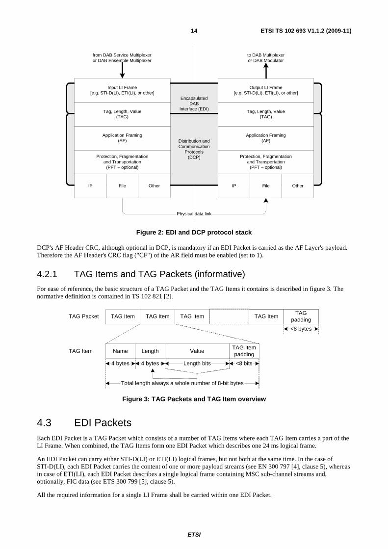
4.2 System architecture The protocol stack provided by the Distribution and Communication Protocols (see TS 102 821 [2]) is described in figure 2. As can be seen, the EDI protocol defined in the present document builds upon the DCP stack, defining the TAG Items to be used and the format of the data carried within each TAG Item. The result is a collection of TAG Items which are carried in a single TAG Packet and which together contain all the data necessary for the EDI Decoder to reproduce one LI Frame.
When carrying TAG Items conforming to the present document, such a TAG Packet is known as an EDI Packet.
ETSI
ETSI TS 102 693 V1.1.2 (2009-11)14
EncapsulatedDAB
Interface (EDI)
Distribution andCommunication
Protocols(DCP)
Input LI Frame[e.g. STI-D(LI), ETI(LI), or other]
Output LI Frame[e.g. STI-D(LI), ETI(LI), or other]
Application Framing(AF)
Protection, Fragmentationand Transportation
(PFT – optional)
IP File Other
Physical data link
Tag, Length, Value(TAG)
from DAB Service Multiplexeror DAB Ensemble Multiplexer
to DAB Multiplexeror DAB Modulator
Application Framing(AF)
Protection, Fragmentationand Transportation
(PFT – optional)
IP File Other
Tag, Length, Value(TAG)
Figure 2: EDI and DCP protocol stack
DCP's AF Header CRC, although optional in DCP, is mandatory if an EDI Packet is carried as the AF Layer's payload. Therefore the AF Header's CRC flag ("CF") of the AR field must be enabled (set to 1).
4.2.1 TAG Items and TAG Packets (informative)
For ease of reference, the basic structure of a TAG Packet and the TAG Items it contains is described in figure 3. The normative definition is contained in TS 102 821 [2].
Name Length Value
TAG Item TAG Item
TAG Itempadding
TAGpadding
TAG ItemTAG Item
TAG Item
TAG Packet
<8 bytes
<8 bits4 bytes Length bits4 bytes
Total length always a whole number of 8-bit bytes
Figure 3: TAG Packets and TAG Item overview
4.3 EDI Packets Each EDI Packet is a TAG Packet which consists of a number of TAG Items where each TAG Item carries a part of the LI Frame. When combined, the TAG Items form one EDI Packet which describes one 24 ms logical frame.
An EDI Packet can carry either STI-D(LI) or ETI(LI) logical frames, but not both at the same time. In the case of STI-D(LI), each EDI Packet carries the content of one or more payload streams (see EN 300 797 [4], clause 5), whereas in case of ETI(LI), each EDI Packet describes a single logical frame containing MSC sub-channel streams and, optionally, FIC data (see ETS 300 799 [5], clause 5).
All the required information for a single LI Frame shall be carried within one EDI Packet.
ETSI
ETSI TS 102 693 V1.1.2 (2009-11)15
Within a single EDI Packet, each TAG Name shall be unique. No TAG Name may occur multiple times within an EDI Packet. An EDI Decoder shall not require TAG Items to be carried in a specific order within the EDI Packet.
Upon reception of one EDI Packet one complete LI Frame can be recovered. The actual composition of the EDI Packet is dependent upon the application and the type of LI Frame being transported.
In the present version of the present document there are several possible combinations of mandatory TAG Items that can be combined to form an EDI Packet.
The EDI specification also defines additional TAG Items which may be supported by some implementations - these are known as optional TAG Items and extend the basic EDI implementation. These TAG Items shall be ignored without error by equipment not supporting the appropriate feature(s).
Additional proprietary TAG Items may be supported by individual implementations but do not form part of the EDI specification and shall be ignored without error by equipment not recognizing the TAG Name. EDI conformant equipment shall not require any additional information other than as described in the present document.
NOTE: It is possible to receive multiple EDI Packets with identical content. Duplicate EDI Packets will be ignored by the EDI Decoder without error. An EDI Packet can be assumed to be a duplicate if its DLFC value (EDI Logical Frame Count) is identical to that of an EDI Packet already received within the same DLFC period, i.e. the time taken for the DLFC to cycle through the full range of possible values.
4.3.1 STI-D(LI)
The following mandatory TAG Items must be supported by every EDI implementation for the transport of STI-D(LI) information.
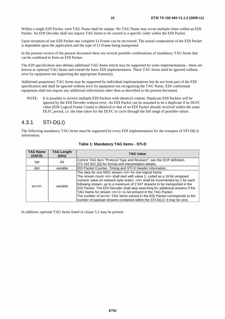
Table 1: Mandatory TAG Items - STI-D
TAG Name (ASCII)
TAG Length (bits) TAG Value
*ptr 64 Control TAG Item "Protocol Type and Revision"; see the DCP definition (TS 102 821 [2]) for format and interpretation details.
dsti variable EDI Packet Counter, Timing and STI-D Header information.
ss<m> variable
The data for one MSC stream <m> for one logical frame. The stream count <m> shall start with value 1, coded as a 16 bit unsigned numeric value (in network byte order). <m> shall be incremented by 1 for each following stream, up to a maximum of 2 047 streams to be transported in the EDI Packet. The EDI Decoder shall stop searching for additional streams if the TAG Name for stream <m+1> is not present in the TAG Packet. The number of ss<m> TAG Items carried in the EDI Packet corresponds to the number of payload streams contained within the STI-D(LI); it may be zero.
In addition, optional TAG Items listed in clause 5.2 may be present.
ETSI
ETSI TS 102 693 V1.1.2 (2009-11)16
4.3.2 ETI(LI)
The following mandatory TAG Items must be supported by every EDI implementation for the transport of ETI(LI) information.
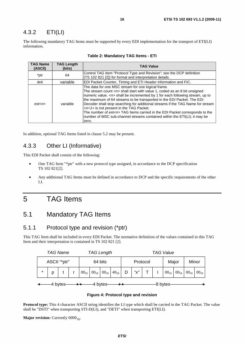
Table 2: Mandatory TAG Items - ETI
TAG Name (ASCII)
TAG Length (bits) TAG Value
*ptr 64 Control TAG Item "Protocol Type and Revision"; see the DCP definition (TS 102 821 [2]) for format and interpretation details.
deti variable EDI Packet Counter, Timing and ETI Header information and FIC.
est<n> variable
The data for one MSC stream for one logical frame. The stream count <n> shall start with value 1, coded as an 8 bit unsigned numeric value. <n> shall be incremented by 1 for each following stream, up to the maximum of 64 streams to be transported in the EDI Packet. The EDI Decoder shall stop searching for additional streams if the TAG Name for stream <n+1> is not present in the TAG Packet. The number of est<n> TAG Items carried in the EDI Packet corresponds to the number of MSC sub-channel streams contained within the ETI(LI); it may be zero.
In addition, optional TAG Items listed in clause 5.2 may be present.
4.3.3 Other LI (Informative)
This EDI Packet shall consist of the following:
• One TAG Item "*ptr" with a new protocol type assigned, in accordance to the DCP specification TS 102 821[2].
• Any additional TAG Items must be defined in accordance to DCP and the specific requirements of the other LI.
5 TAG Items
5.1 Mandatory TAG Items
5.1.1 Protocol type and revision (*ptr)
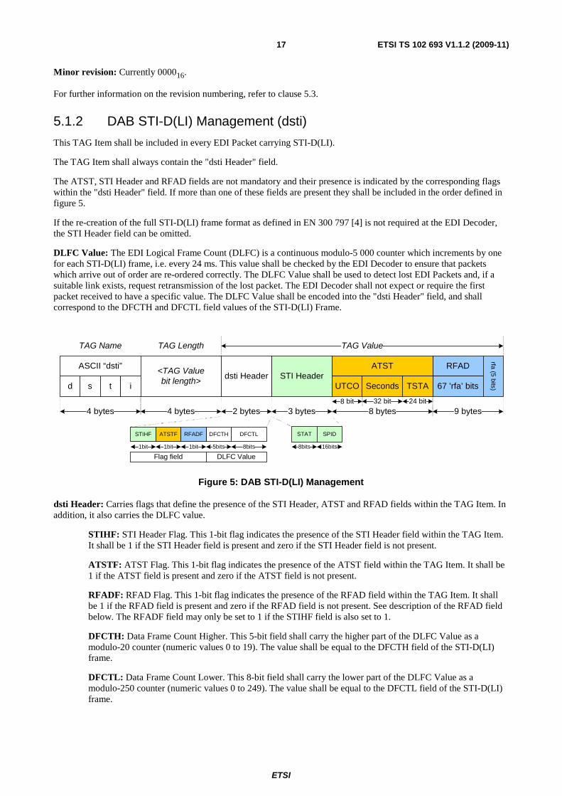
This TAG Item shall be included in every EDI Packet. The normative definition of the values contained in this TAG Item and their interpretation is contained in TS 102 821 [2].
TAG ValueTAG LengthTAG Name
Protocol MinorMajor
D “x” T I* p rt 0016 001600160016001600160016 4016
ASCII “*ptr” 64 bits
4 bytes 4 bytes 8 bytes
Figure 4: Protocol type and revision
Protocol type: This 4 character ASCII string identifies the LI type which shall be carried in the TAG Packet. The value shall be "DSTI" when transporting STI-D(LI), and "DETI" when transporting ETI(LI).
Major revision: Currently 000016.
ETSI
ETSI TS 102 693 V1.1.2 (2009-11)17
Minor revision: Currently 000016.
For further information on the revision numbering, refer to clause 5.3.
5.1.2 DAB STI-D(LI) Management (dsti)
This TAG Item shall be included in every EDI Packet carrying STI-D(LI).
The TAG Item shall always contain the "dsti Header" field.
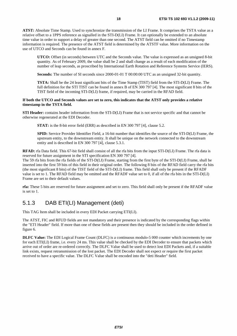
The ATST, STI Header and RFAD fields are not mandatory and their presence is indicated by the corresponding flags within the "dsti Header" field. If more than one of these fields are present they shall be included in the order defined in figure 5.
If the re-creation of the full STI-D(LI) frame format as defined in EN 300 797 [4] is not required at the EDI Decoder, the STI Header field can be omitted.
DLFC Value: The EDI Logical Frame Count (DLFC) is a continuous modulo-5 000 counter which increments by one for each STI-D(LI) frame, i.e. every 24 ms. This value shall be checked by the EDI Decoder to ensure that packets which arrive out of order are re-ordered correctly. The DLFC Value shall be used to detect lost EDI Packets and, if a suitable link exists, request retransmission of the lost packet. The EDI Decoder shall not expect or require the first packet received to have a specific value. The DLFC Value shall be encoded into the "dsti Header" field, and shall correspond to the DFCTH and DFCTL field values of the STI-D(LI) Frame.
TAG LengthTAG Name
STI Headerd s t i
ASCII “dsti”<TAG Valuebit length>
4 bytes 4 bytes 3 bytes
STAT
8bits
SPID
16bits
RFAD
67 ’rfa’ bits
rfa (5 bits)
9 bytes2 bytes
ATST
UTCO
8 bytes
TSTA
32 bit 24 bit8 bit
dsti HeaderSeconds
DFCTH
5bits
DFCTL
8bits
ATSTF
1bit
STIHF RFADF
1bit1bit
Flag field DLFC Value
TAG Value
Figure 5: DAB STI-D(LI) Management
dsti Header: Carries flags that define the presence of the STI Header, ATST and RFAD fields within the TAG Item. In addition, it also carries the DLFC value.
STIHF: STI Header Flag. This 1-bit flag indicates the presence of the STI Header field within the TAG Item. It shall be 1 if the STI Header field is present and zero if the STI Header field is not present.
ATSTF: ATST Flag. This 1-bit flag indicates the presence of the ATST field within the TAG Item. It shall be 1 if the ATST field is present and zero if the ATST field is not present.
RFADF: RFAD Flag. This 1-bit flag indicates the presence of the RFAD field within the TAG Item. It shall be 1 if the RFAD field is present and zero if the RFAD field is not present. See description of the RFAD field below. The RFADF field may only be set to 1 if the STIHF field is also set to 1.
DFCTH: Data Frame Count Higher. This 5-bit field shall carry the higher part of the DLFC Value as a modulo-20 counter (numeric values 0 to 19). The value shall be equal to the DFCTH field of the STI-D(LI) frame.
DFCTL: Data Frame Count Lower. This 8-bit field shall carry the lower part of the DLFC Value as a modulo-250 counter (numeric values 0 to 249). The value shall be equal to the DFCTL field of the STI-D(LI) frame.
ETSI
ETSI TS 102 693 V1.1.2 (2009-11)18
ATST: Absolute Time Stamp. Used to synchronize the transmission of the LI Frame. It comprises the TSTA value as a relative offset to a 1PPS reference as signalled in the STI-D(LI) Frame. It can optionally be extended to an absolute time value in order to support a delay of greater than one second. The ATST field can be omitted if no Timestamp information is required. The presence of the ATST field is determined by the ATSTF value. More information on the use of UTCO and Seconds can be found in annex F.
UTCO: Offset (in seconds) between UTC and the Seconds value. The value is expressed as an unsigned 8-bit quantity. As of February 2009, the value shall be 2 and shall change as a result of each modification of the number of leap seconds, as proscribed by International Earth Rotation and Reference Systems Service (IERS).
Seconds: The number of SI seconds since 2000-01-01 T 00:00:00 UTC as an unsigned 32-bit quantity.
TSTA: Shall be the 24 least significant bits of the Time Stamp (TIST) field from the STI-D(LI) Frame. The full definition for the STI TIST can be found in annex B of EN 300 797 [4]. The most significant 8 bits of the TIST field of the incoming STI-D(LI) frame, if required, may be carried in the RFAD field.
If both the UTCO and Seconds values are set to zero, this indicates that the ATST only provides a relative timestamp in the TSTA field.
STI Header: contains header information from the STI-D(LI) Frame that is not service specific and that cannot be otherwise regenerated at the EDI Decoder.
STAT: is the 8-bit error field (ERR) as described in EN 300 797 [4], clause 5.2.
SPID: Service Provider Identifier Field, a 16-bit number that identifies the source of the STI-D(LI) Frame, the upstream entity, to the downstream entity. It shall be unique on the network connected to the downstream entity and is described in EN 300 797 [4], clause 5.3.1.
RFAD: rfa Data field. This 67-bit field shall consist of all the rfa bits from the input STI-D(LI) Frame. The rfa data is reserved for future assignment in the STI specification EN 300 797 [4]. The 59 rfa bits from the rfa fields of the STI-D(LI) Frame, starting from the first byte of the STI-D(LI) Frame, shall be inserted into the first 59 bits of this field in their original order. The following 8 bits of the RFAD field carry the rfa bits (the most significant 8 bits) of the TIST field of the STI-D(LI) frame. This field shall only be present if the RFADF value is set to 1. The RFAD field may be omitted and the RFADF value set to 0, if all of the rfa bits in the STI-D(LI) Frame are set to their default values.
rfa: These 5 bits are reserved for future assignment and set to zero. This field shall only be present if the RFADF value is set to 1.
5.1.3 DAB ETI(LI) Management (deti)
This TAG Item shall be included in every EDI Packet carrying ETI(LI).
The ATST, FIC and RFUD fields are not mandatory and their presence is indicated by the corresponding flags within the "ETI Header" field. If more than one of these fields are present then they should be included in the order defined in figure 6.
DLFC Value: The EDI Logical Frame Count (DLFC) is a continuous modulo-5 000 counter which increments by one for each ETI(LI) frame, i.e. every 24 ms. This value shall be checked by the EDI Decoder to ensure that packets which arrive out of order are re-ordered correctly. The DLFC Value shall be used to detect lost EDI Packets and, if a suitable link exists, request retransmission of the lost packet. The EDI Decoder shall not expect or require the first packet received to have a specific value. The DLFC Value shall be encoded into the "deti Header" field.
ETSI
ETSI TS 102 693 V1.1.2 (2009-11)19
TAG LengthTAG Name
d e t i
ASCII “deti”<TAG Valuebit length>
4 bytes 4 bytes
FIC RFUD
24
’rfu’ bits
3 bytes96 or 128 bytes2 bytes
deti Header
FCTH
5bits
FCT
8bits
FICF
1bit 1bit
RFUDF
ATST
UTCO
8 bytes
TSTA
32 bit 24 bit8 bit
SecondsETI Header
4 bytes
STAT
8bits
MID
2bits
FP
3bits
rfa
2bits
Flag field DLFC Value
MNSC
16bits
rfu
1bit1bit
ATSTF
TAG Value
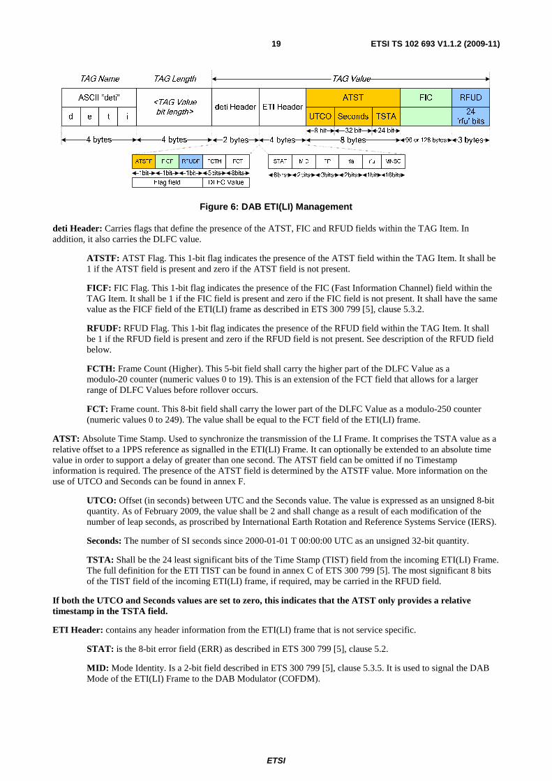
Figure 6: DAB ETI(LI) Management
deti Header: Carries flags that define the presence of the ATST, FIC and RFUD fields within the TAG Item. In addition, it also carries the DLFC value.
ATSTF: ATST Flag. This 1-bit flag indicates the presence of the ATST field within the TAG Item. It shall be 1 if the ATST field is present and zero if the ATST field is not present.
FICF: FIC Flag. This 1-bit flag indicates the presence of the FIC (Fast Information Channel) field within the TAG Item. It shall be 1 if the FIC field is present and zero if the FIC field is not present. It shall have the same value as the FICF field of the ETI(LI) frame as described in ETS 300 799 [5], clause 5.3.2.
RFUDF: RFUD Flag. This 1-bit flag indicates the presence of the RFUD field within the TAG Item. It shall be 1 if the RFUD field is present and zero if the RFUD field is not present. See description of the RFUD field below.
FCTH: Frame Count (Higher). This 5-bit field shall carry the higher part of the DLFC Value as a modulo-20 counter (numeric values 0 to 19). This is an extension of the FCT field that allows for a larger range of DLFC Values before rollover occurs.
FCT: Frame count. This 8-bit field shall carry the lower part of the DLFC Value as a modulo-250 counter (numeric values 0 to 249). The value shall be equal to the FCT field of the ETI(LI) frame.
ATST: Absolute Time Stamp. Used to synchronize the transmission of the LI Frame. It comprises the TSTA value as a relative offset to a 1PPS reference as signalled in the ETI(LI) Frame. It can optionally be extended to an absolute time value in order to support a delay of greater than one second. The ATST field can be omitted if no Timestamp information is required. The presence of the ATST field is determined by the ATSTF value. More information on the use of UTCO and Seconds can be found in annex F.
UTCO: Offset (in seconds) between UTC and the Seconds value. The value is expressed as an unsigned 8-bit quantity. As of February 2009, the value shall be 2 and shall change as a result of each modification of the number of leap seconds, as proscribed by International Earth Rotation and Reference Systems Service (IERS).
Seconds: The number of SI seconds since 2000-01-01 T 00:00:00 UTC as an unsigned 32-bit quantity.
TSTA: Shall be the 24 least significant bits of the Time Stamp (TIST) field from the incoming ETI(LI) Frame. The full definition for the ETI TIST can be found in annex C of ETS 300 799 [5]. The most significant 8 bits of the TIST field of the incoming ETI(LI) frame, if required, may be carried in the RFUD field.
If both the UTCO and Seconds values are set to zero, this indicates that the ATST only provides a relative timestamp in the TSTA field.
ETI Header: contains any header information from the ETI(LI) frame that is not service specific.
STAT: is the 8-bit error field (ERR) as described in ETS 300 799 [5], clause 5.2.
MID: Mode Identity. Is a 2-bit field described in ETS 300 799 [5], clause 5.3.5. It is used to signal the DAB Mode of the ETI(LI) Frame to the DAB Modulator (COFDM).
ETSI
ETSI TS 102 693 V1.1.2 (2009-11)20
The value of the MID field implicitly defines the length of the FIC field, if present:
• 96 bytes for Mode I, II and IV.
• 128 bytes for Mode III.
FP: Frame Phase, a 3-bit field as described in ETS 300 799 [5], clause 5.3.4. Used to signal to the DAB Modulator (COFDM) when to insert Transmitter Identification Information (TII) into the null symbol of the DAB signal.
rfa: These 2 bits are reserved for future assignment and set to zero.
rfu: This shall be a 1-bit field. If it is set to zero then the following 16 bits of the ETI Header field carry the MNSC as described below. If it is set to 1 then the following 16 bits are currently undefined.
MNSC: Multiplex Network Signalling Channel. A 16-bit field which can be used for Frame Synchronous Signalling (FSS) or Frame Asynchronous Signalling (ASS) as described in ETS 300 799 [5], clause 5.5.1.
FIC: Fast Information Channel. This 768 or 1024-bit field shall only be present if the FICF value is set to 1. The content of the FIC field is described in ETS 300 799 [5], clause 5.6.
RFUD: Rfu Data field. This 24-bit field shall consist of all the rfu bits from the input ETI(LI) Frame. The rfu data is reserved for future use in the ETI specification ETS 300 799 [5]. The 16 rfu bits from the rfu fields of the ETI(LI) Frame, starting from the first byte of the ETI(LI) Frame, shall be inserted into the first 16 bits of this field in their original order. The following 8 bits of the RFUD field carry the rfa bits (the most significant 8 bits) of the TIST field of the ETI(LI) frame. This field shall only be present if the RFUDF value is set to 1. The RFUD field may be omitted and the RFUDF value set to 0, if all of the rfu bits in the ETI(LI) Frame are set to their default values.
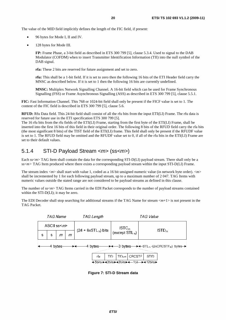
5.1.4 STI-D Payload Stream <m> (ss<m>)
Each ss<m> TAG Item shall contain the data for the corresponding STI-D(LI) payload stream. There shall only be a ss<m> TAG Item produced where there exists a corresponding payload stream within the input STI-D(LI) Frame.
The stream index <m> shall start with value 1, coded as a 16 bit unsigned numeric value (in network byte order). <m> shall be incremented by 1 for each following payload stream, up to a maximum number of 2 047. TAG Items with numeric values outside the stated range are not considered to be payload streams as defined in this clause.
The number of ss<m> TAG Items carried in the EDI Packet corresponds to the number of payload streams contained within the STI-D(LI); it may be zero.
The EDI Decoder shall stop searching for additional streams if the TAG Name for stream <m+1> is not present in the TAG Packet.
TAG Name TAG Length TAG Value
(24 + 8xSTLm) bitsISTCm
(except STLm)
ASCII ss<m>
s s m m
4 bytes 4 bytes 3 bytes
ISTDm
STLm -(2xCRCSTFm) bytes
TID TIDext CRCSTF STID
3bits 3bits 1bit 12bits
rfa
5bits
Figure 7: STI-D Stream data
ETSI
ETSI TS 102 693 V1.1.2 (2009-11)21
ISTCm: Individual Stream Characterization Field for payload stream m as described in EN 300 797 [4], clause 5.4.1.
All sections of the ISTCm information carried in the STI-D(LI) Frame for payload stream m, with the exception of STL
(Stream Length) which can be regenerated from the TAG Length field of the "ss<m>" TAG Item at the EDI Decoder, shall be taken from the STI-D(LI) Frame and inserted into the "ss<m>" TAG Item.
rfa: 5 bits of padding information shall be added to the start of the ISTCm field. These bits are not currently
defined and shall be set to zero.
TID: Type Identifier Field. A 3-bit field which identifies the type of information carried in the STI-D(LI) MST field, and by extension the corresponding "ss<m>" TAG Item. TID is described in EN 300 797 [4], clause 5.4.1.1.
TIDext: Type Identifier Extension Field. A 3-bit field which gives additional information relevant to the type of data carried. The interpretation of the information provided by this field is dependent upon the value carried in the TID field. TIDext is described in EN 300 797 [4], clause 5.4.1.3.
CRCSTF: Stream Cyclic Redundancy Checksum Flag. A 1-bit field that indicates the presence of a CRCST field directly after the stream data in the MST field of the original STI(LI) Frame. CRCSTF is described in EN 300 797 [4], clause 5.4.1.4. The CRCST field itself is not carried.
STID: Stream ID uniquely identifies a specific payload stream. This 12-bit field shall be taken from the STI-D(LI) Frame. STID is described in EN 300 797 [4], clause 5.4.1.5.
ISTDm: The Individual Stream Data field is the complete STI-D payload stream field for a single service but excluding
the Stream Cyclic Redundancy Checksum (CRCSTm). ISTD is described in EN 300 797 [4], clause 5.6.1.
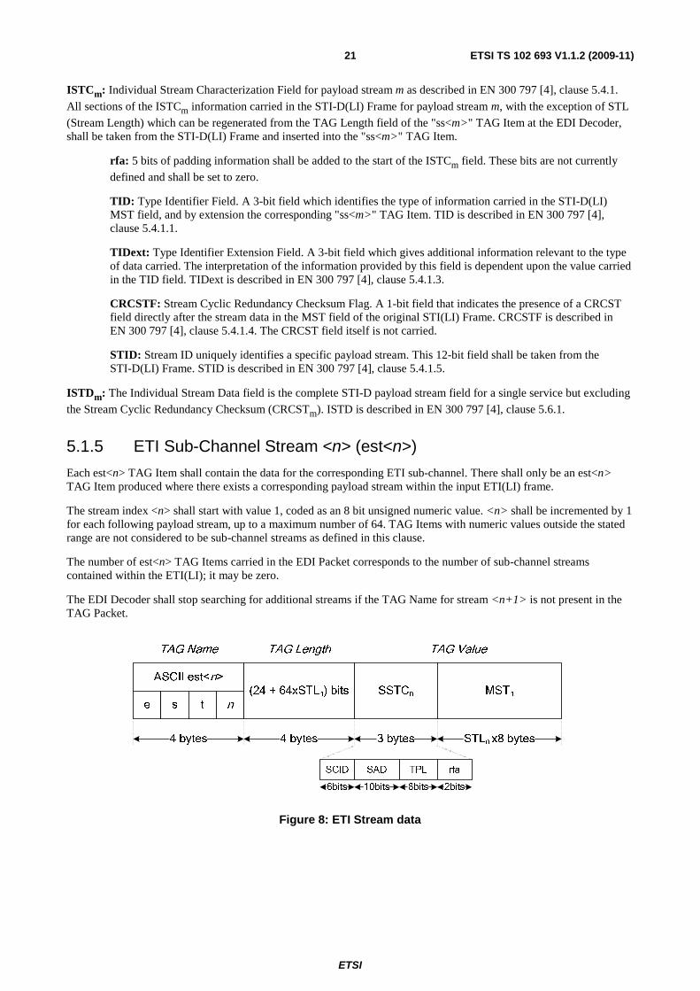
5.1.5 ETI Sub-Channel Stream <n> (est<n>)
Each est<n> TAG Item shall contain the data for the corresponding ETI sub-channel. There shall only be an est<n> TAG Item produced where there exists a corresponding payload stream within the input ETI(LI) frame.
The stream index <n> shall start with value 1, coded as an 8 bit unsigned numeric value. <n> shall be incremented by 1 for each following payload stream, up to a maximum number of 64. TAG Items with numeric values outside the stated range are not considered to be sub-channel streams as defined in this clause.
The number of est<n> TAG Items carried in the EDI Packet corresponds to the number of sub-channel streams contained within the ETI(LI); it may be zero.
The EDI Decoder shall stop searching for additional streams if the TAG Name for stream <n+1> is not present in the TAG Packet.
TAG Name TAG Length TAG Value
(24 + 64xSTLn) bits SSTCn
ASCII est<n>
e s t n
4 bytes 4 bytes 3 bytes
MSTn
STLn x8 bytes
SCID SAD TPL rfa
6bits 10bits 6bits 2bits
Figure 8: ETI Stream data
ETSI
ETSI TS 102 693 V1.1.2 (2009-11)22
SSTCn: Sub-channel Stream Characterization Field for sub-channel stream n as described in ETS 300 799 [5],
clause 5.4.1. All sections of the SSTCn information carried in the ETI(LI) Frame for sub-channel stream n, with the
exception of STL (Stream Length) which can be regenerated from the TAG Length field of the "est<n>" TAG Item at the EDI Decoder, shall be taken from the ETI(LI) Frame and inserted into the "est<n>" TAG Item.
SCID: sub-channel ID uniquely identifying a specific sub-channel. This 6-bit field shall be taken from the ETI(LI) Frame. SCID is described in ETS 300 799 [5].
SAD: 10-bit field giving information regarding the Sub-channel Start Address within the DAB frame (start CU index). This is a number with values between 0 and 863 inclusive and gives the start address in Capacity Units (CU) of the position in which the service shall be placed in the DAB Frame. SAD is described in ETS 300 799 [5], clause 5.4.1.2.
TPL: Sub-channel Type and Protection Level, 6-bit field that describes the type and level of error protection to be applied to the sub-channel. TPL is described in ETS 300 799 [5], clause 5.4.1.3.
rfa: 2 bits of padding information shall be added to the end of the SSTCn field. These bits are not currently
defined and shall be set to zero.
MSTn: Main Stream Data field is the complete sub-channel data from the ETI(LI), which is the Sub-Channel Stream described in ETS 300 799 [5], clause 5.4.1.4.
5.2 Optional TAG Items Every EDI implementation may choose to support the following optional TAG Items. Where one or more of the optional TAG Items are supported, they shall behave as described below. When not supported by an implementation, the presence of these TAG Items shall be ignored.
Table 3: Optional TAG Items
TAG Name (ASCII)
TAG Length (bits) TAG Value
info variable Free-form textual information. nasc variable Network Adapted Signalling Channel frpd variable Frame Padding User Data
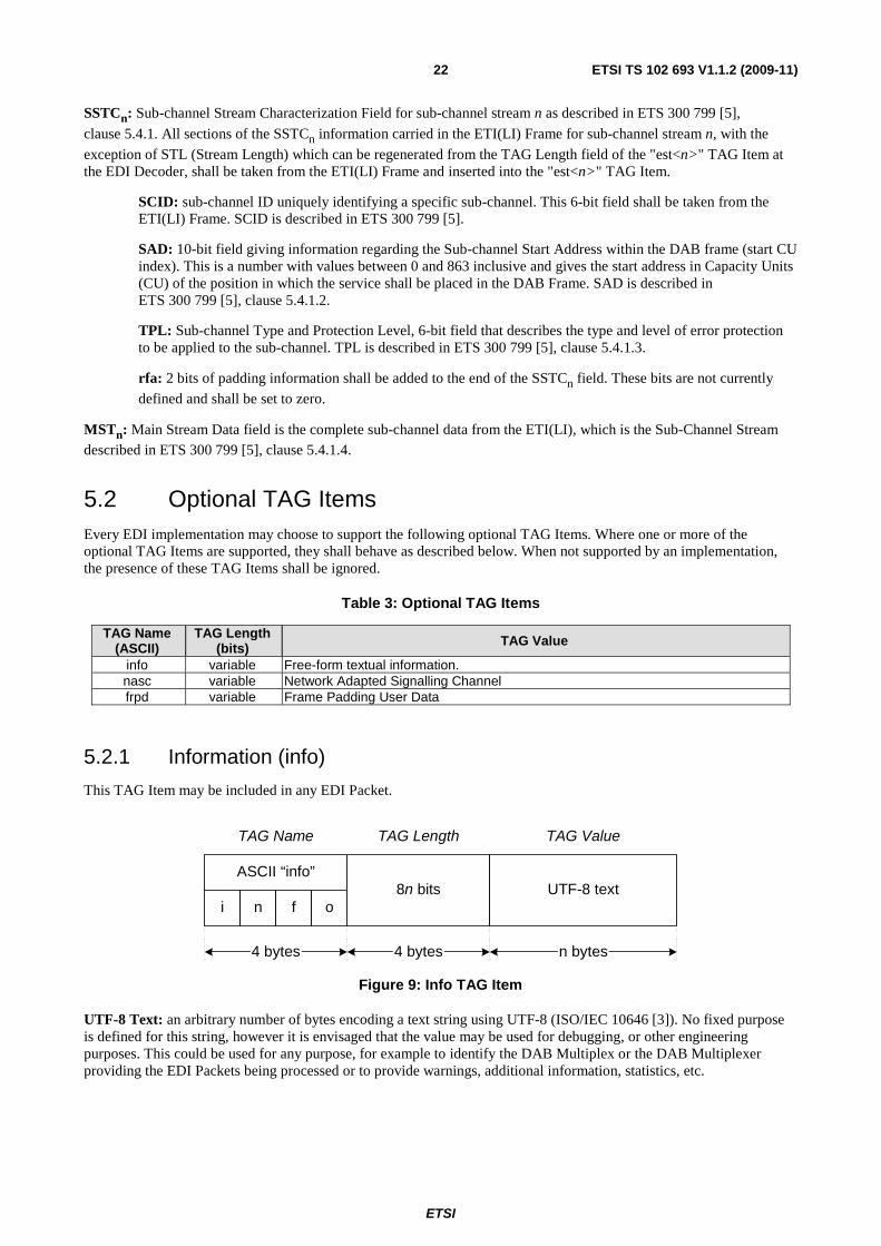
5.2.1 Information (info)
This TAG Item may be included in any EDI Packet.
TAG Name TAG ValueTAG Length
8n bitsASCII “info”
i n f oUTF-8 text
4 bytes 4 bytes n bytes
Figure 9: Info TAG Item
UTF-8 Text: an arbitrary number of bytes encoding a text string using UTF-8 (ISO/IEC 10646 [3]). No fixed purpose is defined for this string, however it is envisaged that the value may be used for debugging, or other engineering purposes. This could be used for any purpose, for example to identify the DAB Multiplex or the DAB Multiplexer providing the EDI Packets being processed or to provide warnings, additional information, statistics, etc.
ETSI
ETSI TS 102 693 V1.1.2 (2009-11)23
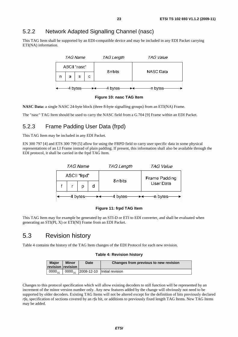
5.2.2 Network Adapted Signalling Channel (nasc)
This TAG Item shall be supported by an EDI-compatible device and may be included in any EDI Packet carrying ETI(NA) information.
TAG Name TAG ValueTAG Length
8n bitsASCII “nasc”
n a s cNASC Data
4 bytes 4 bytes n bytes
Figure 10: nasc TAG Item
NASC Data: a single NASC 24-byte block (three 8-byte signalling groups) from an ETI(NA) Frame.
The "nasc" TAG Item should be used to carry the NASC field from a G.704 [9] Frame within an EDI Packet.
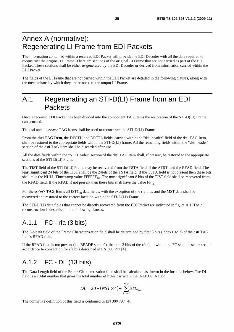
5.2.3 Frame Padding User Data (frpd)
This TAG Item may be included in any EDI Packet.
EN 300 797 [4] and ETS 300 799 [5] allow for using the FRPD field to carry user specific data in some physical representations of an LI Frame instead of plain padding. If present, this information shall also be available through the EDI protocol, it shall be carried in the frpd TAG Item.
TAG ValueTAG LengthTAG Name
f r dp
8n bits
ASCII “frpd”
4 bytes 4 bytes
Frame Padding
User Data
n bytes
Figure 11: frpd TAG Item
This TAG Item may for example be generated by an STI-D or ETI to EDI converter, and shall be evaluated when generating an STI(PI, X) or ETI(NI) Frame from an EDI Packet.
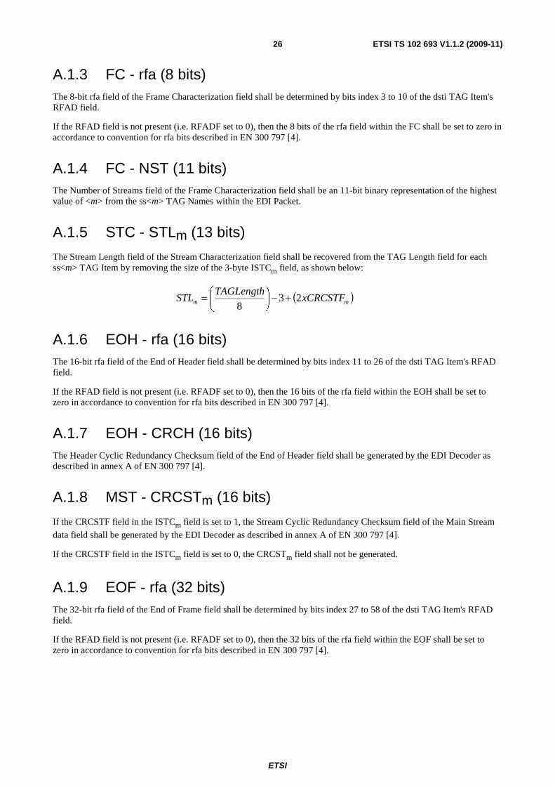
5.3 Revision history Table 4 contains the history of the TAG Item changes of the EDI Protocol for each new revision.
Table 4: Revision history
Major revision
Minor revision
Date Changes from previous to new revision
000016 000016 2008-12-10 Initial revision
Changes to this protocol specification which will allow existing decoders to still function will be represented by an increment of the minor version number only. Any new features added by the change will obviously not need to be supported by older decoders. Existing TAG Items will not be altered except for the definition of bits previously declared rfa, specification of sections covered by an rfu bit, or additions to previously fixed length TAG Items. New TAG Items may be added.

ETSI
ETSI TS 102 693 V1.1.2 (2009-11)24
Changes to this protocol specification which will render previous implementations unable to correctly process the new format will be represented by an increment of the major version number. Older implementations should not attempt to decode such EDI Packets. Changes may include modification to or removal of existing TAG Item definitions.
The information given in this clause and describing the changes introduced with the change of a version number shall be sufficient to correctly implement any previous version of this protocol specification even if access to previous versions of the present document is not possible.
ETSI
ETSI TS 102 693 V1.1.2 (2009-11)25
Annex A (normative): Regenerating LI Frame from EDI Packets The information contained within a received EDI Packet will provide the EDI Decoder with all the data required to reconstruct the original LI Frame. There are sections of the original LI Frame that are not carried as part of the EDI Packet. These sections shall be either re-generated by the EDI Decoder or derived from information carried within the EDI Packet.
The fields of the LI Frame that are not carried within the EDI Packet are detailed in the following clauses, along with the mechanisms by which they are restored to the output LI Frame.
A.1 Regenerating an STI-D(LI) Frame from an EDI Packets
Once a received EDI Packet has been divided into the component TAG Items the restoration of the STI-D(LI) Frame can proceed.
The dsti and all ss<m> TAG Items shall be used to reconstruct the STI-D(LI) Frame.
From the dsti TAG Item, the DFCTH and DFCTL fields, carried within the "dsti header" field of the dsti TAG Item, shall be restored to the appropriate fields within the STI-D(LI) frame. All the remaining fields within the "dsti header" section of the dsti TAG Item shall be discarded after use.
All the data fields within the "STI Header" section of the dsti TAG Item shall, if present, be restored to the appropriate sections of the STI-D(LI) Frame.
The TIST field of the STI-D(LI) Frame may be recovered from the TSTA field of the ATST, and the RFAD field. The least significant 24 bits of the TIST shall be the 24bits of the TSTA field. If the TSTA field is not present then these bits shall take the NULL Timestamp value FFFFFF16. The most significant 8 bits of the TIST field shall be recovered from
the RFAD field. If the RFAD if not present then these bits shall have the value FF16.
For the ss<m> TAG Items all ISTCm data fields, with the exception of the rfa bits, and the MST data shall be
recovered and restored to the correct location within the STI-D(LI) Frame.
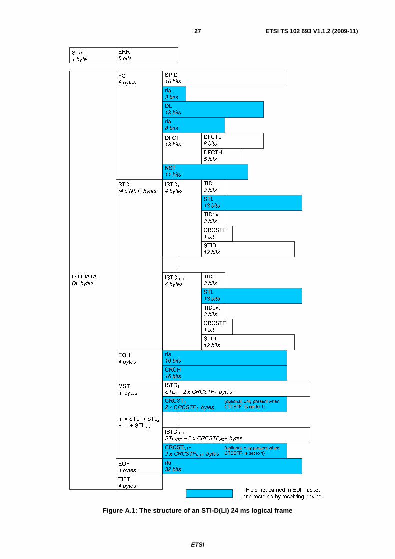
The STI-D(LI) data fields that cannot be directly recovered from the EDI Packet are indicated in figure A.1. Their reconstruction is described in the following clauses.
A.1.1 FC - rfa (3 bits) The 3-bit rfa field of the Frame Characterization field shall be determined by first 3 bits (index 0 to 2) of the dsti TAG Item's RFAD field.
If the RFAD field is not present (i.e. RFADF set to 0), then the 3 bits of the rfa field within the FC shall be set to zero in accordance to convention for rfa bits described in EN 300 797 [4].
A.1.2 FC - DL (13 bits) The Data Length field of the Frame Characterization field shall be calculated as shown in the formula below. The DL field is a 13-bit number that gives the total number of bytes carried in the D-LIDATA field.
( ) ∑=
+×+=NST
StrmStrmSTLNSTDL
1
420
The normative definition of this field is contained in EN 300 797 [4].
ETSI
ETSI TS 102 693 V1.1.2 (2009-11)26
A.1.3 FC - rfa (8 bits) The 8-bit rfa field of the Frame Characterization field shall be determined by bits index 3 to 10 of the dsti TAG Item's RFAD field.
If the RFAD field is not present (i.e. RFADF set to 0), then the 8 bits of the rfa field within the FC shall be set to zero in accordance to convention for rfa bits described in EN 300 797 [4].
A.1.4 FC - NST (11 bits) The Number of Streams field of the Frame Characterization field shall be an 11-bit binary representation of the highest value of <m> from the ss<m> TAG Names within the EDI Packet.
A.1.5 STC - STLm (13 bits)
The Stream Length field of the Stream Characterization field shall be recovered from the TAG Length field for each ss<m> TAG Item by removing the size of the 3-byte ISTCm field, as shown below:
( )mm xCRCSTFTAGLength
STL 238
+−⎟⎠
⎞⎜⎝
⎛=
A.1.6 EOH - rfa (16 bits) The 16-bit rfa field of the End of Header field shall be determined by bits index 11 to 26 of the dsti TAG Item's RFAD field.
If the RFAD field is not present (i.e. RFADF set to 0), then the 16 bits of the rfa field within the EOH shall be set to zero in accordance to convention for rfa bits described in EN 300 797 [4].
A.1.7 EOH - CRCH (16 bits) The Header Cyclic Redundancy Checksum field of the End of Header field shall be generated by the EDI Decoder as described in annex A of EN 300 797 [4].
A.1.8 MST - CRCSTm (16 bits)
If the CRCSTF field in the ISTCm field is set to 1, the Stream Cyclic Redundancy Checksum field of the Main Stream
data field shall be generated by the EDI Decoder as described in annex A of EN 300 797 [4].
If the CRCSTF field in the ISTCm field is set to 0, the CRCSTm field shall not be generated.
A.1.9 EOF - rfa (32 bits) The 32-bit rfa field of the End of Frame field shall be determined by bits index 27 to 58 of the dsti TAG Item's RFAD field.
If the RFAD field is not present (i.e. RFADF set to 0), then the 32 bits of the rfa field within the EOF shall be set to zero in accordance to convention for rfa bits described in EN 300 797 [4].
ETSI
ETSI TS 102 693 V1.1.2 (2009-11)27
SPID16 bits
rfa
3 bits
DL13 bits
rfa8 bits
DFCTL
8 bits
DFCTH5 bits
DFCT13 bits
FC
8 bytes
NST11 bits
D-LIDATADL bytes
STC(4 x NST) bytes
ISTC1
4 bytes
TID
3 bits
STL13 bits
TIDext
3 bits
STID12 bits
CRCSTF1 bit
ISTCNST
4 bytes
TID3 bits
STL13 bits
TIDext3 bits
STID
12 bits
CRCSTF1 bit
.
.
.
rfa16 bits
EOH4 bytes
CRCH16 bits
MSTm bytes
m = STL1 + STL2+ … + STLNST
ISTD1
STL1 – 2 x CRCSTF1 bytes
CRCST1
2 x CRCSTF1 bytes(optional, only present when
CTCSTF1 is set to 1)
ISTDNST
STLNST – 2 x CRCSTFNST bytes
CRCSTNST
2 x CRCSTFNST bytes(optional, only present when
CTCSTF1 is set to 1)
.
.
.
EOF4 bytes
TIST
4 bytes
rfa
32 bits
ERR
8 bitsSTAT1 byte
Field not carried in EDI Packet
and restored by receiving device.
Figure A.1: The structure of an STI-D(LI) 24 ms logical frame
ETSI
ETSI TS 102 693 V1.1.2 (2009-11)28
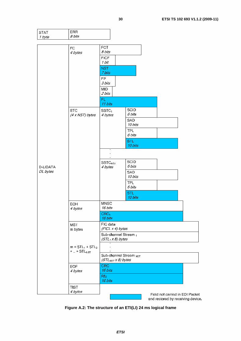
A.2 Regenerating an ETI(LI) Frame from an EDI Packet Once a received EDI Packet has been divided into the component TAG Items the restoration of the ETI(LI) Frame can proceed.
The deti and all est<n> TAG Items shall be used to reconstruct the ETI(LI) Frame.
From the deti TAG Item, the FCT and FICF fields, carried within the "deti header" field of the deti TAG Item, shall be restored to the appropriate fields within the ETI(LI) frame. All the remaining fields within the "deti Header" section of the deti TAG Item, shall be discarded after use.
All the data fields within the "ETI Header" section of the deti TAG Item, with the exception of the rfa and rfu data fields, shall be restored to the appropriate sections of the ETI(LI) Frame.
The TIST field of the ETI(LI) Frame may be recovered from the TSTA field of the ATST, and the RFUD field. The least significant 24 bits of the TIST shall be the 24bits of the TSTA field. If the TSTA field is not present then these bits shall take the NULL Timestamp value FFFFFF16. The most significant 8 bits of the TIST field shall be recovered from
the RFUD field. If the RFUD if not present then these bits shall have the value FF16.
For the est<n> TAG Items all SSTCn data fields, with the exception of the rfa bits, and the MST data shall be
recovered from the corresponding est<n> TAG Item(s) and restored to the correct location within the ETI(LI) Frame.
The ETI(LI) data fields that cannot be directly recovered from the EDI Packet are indicated in figure A.2. Their reconstruction is described in the following clauses.
A.2.1 FC - NST (7 bits) The Number of Streams field of the Frame Characterization field shall be a 7-bit binary representation of the highest value of <n> from the est<n> TAG Names within the EDI Packet.
A.2.2 FC - FL (11 bits) The Frame Length field of the Frame Characterization field shall be calculated as shown in the formula below. The FL field is an 11-bit number that gives the total number of words (i.e. 4 bytes each) carried in the STC, EOH and MST fields of the LIDATA field.
∑=
×+++=NST
SbchSbchSTLFICLNSTFL
1
]2[1
The FICL is the length of the FIC field carried in the deti TAG Item in words (i.e. 4 bytes each).
The normative definition of this field is contained in ETS 300 799 [5].
A.2.3 STC - STLn (10 bits)
The Stream Length field of the Stream Characterization field shall be recovered from the TAG Length field for each est<n> TAG Item by removing the size of the 3-byte header, as is shown below.
88
24)(
×−= LengthTAG
STLn
NOTE: The value of STLn shall be an integer number of 64-bit words.

ETSI
ETSI TS 102 693 V1.1.2 (2009-11)29
A.2.4 EOH - CRCh (16 bits)
The Header Cyclic Redundancy Checksum field of the End of Header field shall be generated by the EDI Decoder as described in annex D of ETS 300 799 [5].
A.2.5 EOF - CRC (16 bits) The Cyclic Redundancy Checksum field of the End of Frame field shall be generated by the EDI Decoder as described in annex D of ETS 300 799 [5].
A.2.6 EOF - Rfu (16 bits) This 16-bit rfu field of the End of Frame field shall be determined by the first 16 bits (index 0 to 15) of the deti TAG Item's RFUD field.
If the RFUD field is not present (i.e. RFUDF set to 0), then the 16 bits of the rfu field within the EOF shall be set to zero in accordance to convention for rfa bits described in ETS 300 799 [5].
ETSI
ETSI TS 102 693 V1.1.2 (2009-11)30
FCT
FICF
NST
FP
MID
FL
FC
D-LIDATA
STC SSTC1SCID
SAD
TPL
STL
SSTCNST
MNSCEOH
CRCh
MST
m bytes
m = STL1 + STL2+ … + STLNST
Sub-channel Stream 1
EOF
TIST
CRC
ERRSTAT
SCID
SAD
TPL
STL
FIC data
Sub-channel Stream NST
Rfu
Field not carried in EDI Packet
and restored by receiving device.
Figure A.2: The structure of an ETI(LI) 24 ms logical frame
ETSI
ETSI TS 102 693 V1.1.2 (2009-11)31
Annex B (normative): Conversion and Backwards Compatibility The EDI Specification is designed to maintain compatibility with equipment which employs the legacy physical manifestations of both STI-D and ETI. This will allow, with the aid of a suitable device, EDI to be utilized in a DAB network without the need to replace the existing source and destination equipment, for example, DAB Multiplexers or DAB Modulators (COFDMs).
In both STI-D and ETI (EN 300 797 [4] and ETS 300 799 [5]) the physical presentations are generated from the LI Frame. The physical presentations are also converted to the LI Frame at the opposite end of the process. For details of how to perform standard LI to physical presentation, and vice versa, see EN 300 797 [4] and ETS 300 799 [5].
There are some fields that are present in the framing required by the physical presentations, which are not present in the LI Frame; these fields are discussed in this annex.
The terms "EDI Encoder" and "EDI Decoder" in the context of this Annex shall refer to "EDI / Legacy-LI Converter" applications or devices, i.e. functional units creating an EDI stream from legacy STI-D or ETI streams, or creating legacy STI-D/ETI streams from an incoming EDI stream, respectively.
B.1 STI-D Special Considerations This clause provides details on how to manage the non-LI sections of the STI(PI, X) generic transport frame structure, which is then finally adapted to the final physical presentation, when converting between legacy physical implementations and EDI.
B.1.1 Control Frame Size field (CFS) This field shall indicate the length of the CF field. The CFS field shall be a 16-bit number which shall give the total number of bytes carried in the CF field.
When converting to EDI this field shall only be used to identify the start of the Frame Padding (FRPD) field. The CFS field shall be discarded and not carried within EDI.
When converting from EDI this field, when generated, shall be zero.
B.1.2 Control Frame field (CF) In STI(PI, X) this field carries and STI-C data that is required. It shall not be carried within EDI.
When converting to EDI this field shall be discarded and not carried with EDI.
When converting from EDI this field shall not be present in the STI(PI, X) Frame due to the CFS field being set to zero.
B.1.3 Frame Padding field (FRPD) Padding of value 5516 shall be inserted at the end of an STI(PI, X) Frame to bring the frame to the required size for the
physical circuit.
When converting to EDI the FRPD field within the STI(PI, X) shall be checked for its content. If the content is padding of value 5516 then the FRPD field shall be discarded and not carried by EDI. If the FRPD contents are not 5516 then the
contents of the FRPD field shall be extracted from the STI(PI, X) Frame and inserted as the payload of an frpd TAG Item that shall be carried in the EDI Packet.
ETSI
ETSI TS 102 693 V1.1.2 (2009-11)32
When converting from EDI then incoming EDI Packets shall be examined to identify if an "frpd" TAG Item is present. If an "frpd" TAG Item is found then the payload of the TAG Item shall be inserted as the FRPD in the output STI(PI, X) Frame. If an "frpd" TAG Item is not found then the frame shall be filled with padding bytes of value 5516.
B.1.4 Timestamps A timestamp field (TIST) is carried in every presentation of STI(PI, X) courtesy of the STI-D(LI) Frame. In addition to this, each STI(PI, G.704/1) carries an additional timestamp within the G.704 [9] framing structure. When converting between EDI and the legacy physical presentations of STI, an EDI Encoder shall determine the status of all applicable timestamps.
B.1.4.1 Converting to EDI
When converting to EDI the EDI Encoder shall give preference to the TIST field from the STI-D(LI) Frame over that of the G.704 [9] Frame. If the TIST field of the STI-D(LI) is a non-NULL timestamp value, then the EDI Encoder shall insert the TIST field from the STI-D(LI) Frame into the TSTA field of the ATST field of the dsti TAG Item.
Only if the G.704 [9] timestamp is a non-NULL timestamp while the TIST field from the STI-D(LI) is a NULL timestamp value, then the EDI Encoder shall insert the G.704 [9] timestamp into the TSTA field of the ATST field within the dsti TAG Item.
The EDI Encoder may indicate to the user which timestamp is available to the EDI Encoder and which is being inserted into the TAG Item.
B.1.4.2 Converting from EDI
When converting to a legacy physical presentation of STI-D(LI) from EDI it should be possible for the operator to specify whether the EDI TSTA field within the dsti TAG Item is inserted into the TIST field of the STI-D(LI) Frame or the G.704 [9] timestamp field. The location not defined as carrying the timestamp shall have its value set to NULL (FF16).
If no specific location is defined by the operator then the TSTA field from the ATST field within the dsti TAG Item shall be inserted into the LI and the G.704 [9] timestamp fields.
B.2 ETI Special Considerations This clause provides details on how to manage the non-LI sections of the ETI(NI) and ETI(NA) generic transport frame structure, which is then finally adapted to the final physical presentation, when converting between legacy physical implementations and EDI.
B.2.1 Frame Padding Field (FRPD) The ETI standard, ETS 300 799 [5] allows for using the FRPD field to carry user specific data. Padding of value 5516
shall be inserted at the end of an ETI(NI) Frame to bring the frame to the required size for the physical circuit. Frame Padding is specified in all of the physical presentations of ETI and the specific size of the FRPD field can be found in the appropriate clause of ETS 300 799 [5].
When converting to EDI the FRPD field within the incoming ETI(NI) Frame shall be checked for its content. If the content is padding of value 5516 then the FRPD field shall be discarded and not carried by EDI. If the FRPD contents
are not 5516 then the contents of the FRPD field shall be extracted from the ETI(NI) Frame and inserted as the payload
of an frpd TAG Item that shall be carried in the EDI Packet.
When converting from EDI then incoming EDI Packets shall be examined to identify if a "frpd" TAG Item is present. If an "frpd" TAG Item is found then the payload of the TAG Item shall be inserted as the FRPD in the output ETI(NI) Frame. If an "frpd" TAG Item is not found then the frame shall be filled with padding bytes of value 5516.
ETSI
ETSI TS 102 693 V1.1.2 (2009-11)33
B.2.2 Timestamps
A timestamp field (TIST) is carried in every presentation of ETI(NI) and ETI(NA) courtesy of the ETI(LI) Frame. In addition to this, each ETI(NA, G.704 [9]) Frame carries an additional timestamp within the G.704 [9] framing structure. When converting between EDI and the legacy physical presentations of ETI, an EDI Encoder shall determine the status of all applicable timestamps.
B.2.2.1 Converting to EDI
When converting to EDI the EDI Encoder shall give preference to the TIST field from the ETI(LI) Frame over that of the NA Frame. If the TIST field of the ETI(LI) is a non-NULL timestamp value, then the EDI Encoder shall insert the TIST field from the ETI(LI) Frame into the TSTA field of the ATST field of the deti TAG Item.
Only if the NA timestamp is a non-NULL timestamp while the TIST field from the ETI (LI) is a NULL timestamp value, then the EDI Encoder shall insert the NA timestamp into the TSTA field of the ATST field within the deti TAG Item.
The EDI Encoder may indicate to the user which timestamp is available to the EDI Encoder and which is being inserted into the TAG Item.
B.2.2.2 Converting from EDI
When converting to a legacy physical presentation of ETI(LI) from EDI it should be possible for the operator to specify whether the EDI TSTA field within the deti TAG Item is inserted into the TIST field of the ETI(LI) Frame or the G.704 [9] timestamp field. The location not defined as carrying the timestamp shall have its value set to NULL (FF16).
If no specific location is defined by the operator then the TSTA field from the ATST field within the deti TAG Item shall be inserted into the LI and the G.704 [9] timestamp fields.
B.2.3 Network Adapted Signalling Channel (NASC) The ETI specification ETS 300 799 [5] provides for a signalling channel within an ETI(NA, G.704 [9]) Frame that is encoded in a similar manner to the MNSC of the ETI(LI) Frame. An EDI Encoder should allow for the carriage of NASC groups within an "nasc" TAG Item. The payload of a nasc TAG Item shall be the entire 24-byte block.
NOTE: If NASC is transported in EDI then a "nasc" TAG Item may not be present in every EDI Packet.
B.2.3.1 Converting to EDI
An EDI Encoder shall be capable of managing NASC data. The entire NASC 24-byte block from an ETI(NA) Frame will be inserted into a "nasc" TAG Item which shall be included in an EDI Packet.
NASC messages shall be transferred as the entire 24-byte block from the ETI(NA) Frame which is comprised of three 8-byte signalling groups.
B.2.3.2 Converting from EDI
An EDI Decoder shall be capable of managing NASC data. Should an EDI Packet contain an "nasc" TAG Item then the contents (TAG Value) of this TAG Item shall be extracted and inserted into the ETI(NA) Frame as described in ETS 300 799 [5]. If a "nasc" TAG Item is not present in an EDI Packet then the NASC field locations of the G.704 [9] Frame shall be formatted in the same manner as when the NASC does not carry any useful information.
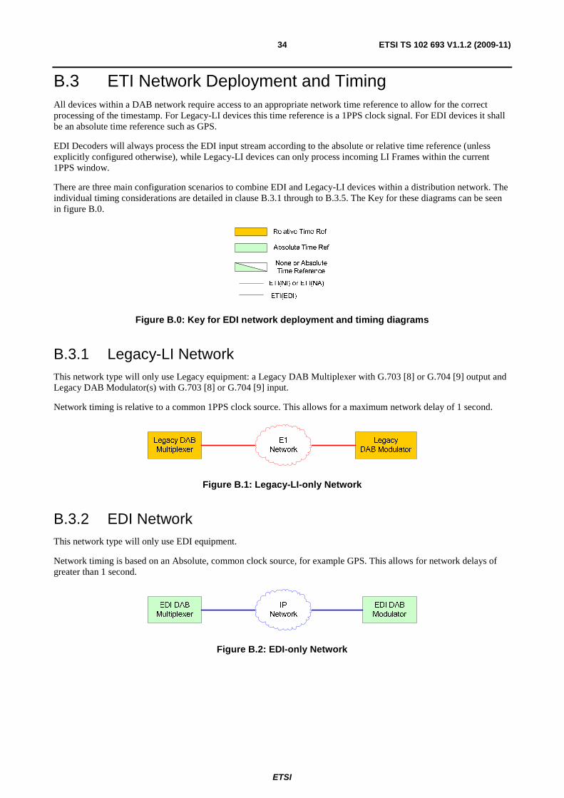
ETSI
ETSI TS 102 693 V1.1.2 (2009-11)34
B.3 ETI Network Deployment and Timing All devices within a DAB network require access to an appropriate network time reference to allow for the correct processing of the timestamp. For Legacy-LI devices this time reference is a 1PPS clock signal. For EDI devices it shall be an absolute time reference such as GPS.
EDI Decoders will always process the EDI input stream according to the absolute or relative time reference (unless explicitly configured otherwise), while Legacy-LI devices can only process incoming LI Frames within the current 1PPS window.
There are three main configuration scenarios to combine EDI and Legacy-LI devices within a distribution network. The individual timing considerations are detailed in clause B.3.1 through to B.3.5. The Key for these diagrams can be seen in figure B.0.
Figure B.0: Key for EDI network deployment and timing diagrams
B.3.1 Legacy-LI Network This network type will only use Legacy equipment: a Legacy DAB Multiplexer with G.703 [8] or G.704 [9] output and Legacy DAB Modulator(s) with G.703 [8] or G.704 [9] input.
Network timing is relative to a common 1PPS clock source. This allows for a maximum network delay of 1 second.
Figure B.1: Legacy-LI-only Network
B.3.2 EDI Network This network type will only use EDI equipment.
Network timing is based on an Absolute, common clock source, for example GPS. This allows for network delays of greater than 1 second.
Figure B.2: EDI-only Network
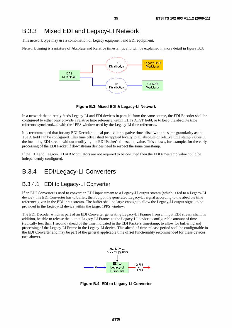
ETSI
ETSI TS 102 693 V1.1.2 (2009-11)35
B.3.3 Mixed EDI and Legacy-LI Network This network type may use a combination of Legacy equipment and EDI equipment.
Network timing is a mixture of Absolute and Relative timestamps and will be explained in more detail in figure B.3.
Figure B.3: Mixed EDI & Legacy-LI Network
In a network that directly feeds Legacy-LI and EDI devices in parallel from the same source, the EDI Encoder shall be configured to either only provide a relative time reference within EDI's ATST field, or to keep the absolute time reference synchronized with the 1PPS window used by the Legacy-LI time references.
It is recommended that for any EDI Decoder a local positive or negative time offset with the same granularity as the TSTA field can be configured. This time offset shall be applied locally to all absolute or relative time stamp values in the incoming EDI stream without modifying the EDI Packet's timestamp value. This allows, for example, for the early processing of the EDI Packet if downstream devices need to respect the same timestamp.
If the EDI and Legacy-LI DAB Modulators are not required to be co-timed then the EDI timestamp value could be independently configured.
B.3.4 EDI/Legacy-LI Converters
B.3.4.1 EDI to Legacy-LI Converter
If an EDI Converter is used to convert an EDI input stream to a Legacy-LI output stream (which is fed to a Legacy-LI device), this EDI Converter has to buffer, then output the generated Legacy-LI signal according to the absolute time reference given in the EDI input stream. The buffer shall be large enough to allow the Legacy-LI output signal to be provided to the Legacy-LI device within the target 1PPS window.
The EDI Decoder which is part of an EDI Converter generating Legacy-LI Frames from an input EDI stream shall, in addition, be able to release the output Legacy-LI Frames to the Legacy-LI device a configurable amount of time (typically less than 1 second) ahead of the time indicated in the EDI Packet's timestamp, to allow for buffering and processing of the Legacy-LI Frame in the Legacy-LI device. This ahead-of-time-release period shall be configurable in the EDI Converter and may be part of the general applicable time offset functionality recommended for these devices (see above).
IP
EDI to
Legacy-LI
Converter
G.703
or
G.704
Absolute Time Reference (eg GPS)
Figure B.4: EDI to Legacy-LI Converter
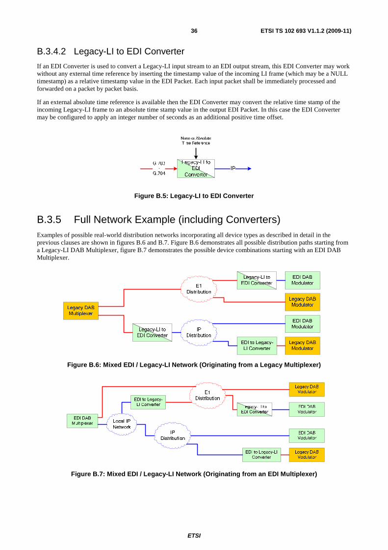
ETSI
ETSI TS 102 693 V1.1.2 (2009-11)36
B.3.4.2 Legacy-LI to EDI Converter
If an EDI Converter is used to convert a Legacy-LI input stream to an EDI output stream, this EDI Converter may work without any external time reference by inserting the timestamp value of the incoming LI frame (which may be a NULL timestamp) as a relative timestamp value in the EDI Packet. Each input packet shall be immediately processed and forwarded on a packet by packet basis.
If an external absolute time reference is available then the EDI Converter may convert the relative time stamp of the incoming Legacy-LI frame to an absolute time stamp value in the output EDI Packet. In this case the EDI Converter may be configured to apply an integer number of seconds as an additional positive time offset.
G.703
or
G.704
IP
None or Absolute
Time Reference
Legacy-LI to
EDI
Converter
Figure B.5: Legacy-LI to EDI Converter
B.3.5 Full Network Example (including Converters) Examples of possible real-world distribution networks incorporating all device types as described in detail in the previous clauses are shown in figures B.6 and B.7. Figure B.6 demonstrates all possible distribution paths starting from a Legacy-LI DAB Multiplexer, figure B.7 demonstrates the possible device combinations starting with an EDI DAB Multiplexer.
Figure B.6: Mixed EDI / Legacy-LI Network (Originating from a Legacy Multiplexer)
Figure B.7: Mixed EDI / Legacy-LI Network (Originating from an EDI Multiplexer)
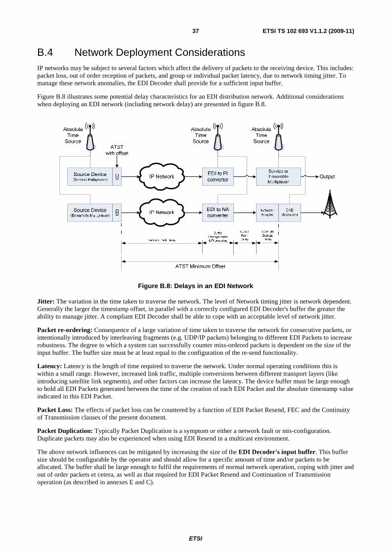
ETSI
ETSI TS 102 693 V1.1.2 (2009-11)37
B.4 Network Deployment Considerations IP networks may be subject to several factors which affect the delivery of packets to the receiving device. This includes: packet loss, out of order reception of packets, and group or individual packet latency, due to network timing jitter. To manage these network anomalies, the EDI Decoder shall provide for a sufficient input buffer.
Figure B.8 illustrates some potential delay characteristics for an EDI distribution network. Additional considerations when deploying an EDI network (including network delay) are presented in figure B.8.
EDI
EDI
Figure B.8: Delays in an EDI Network
Jitter: The variation in the time taken to traverse the network. The level of Network timing jitter is network dependent. Generally the larger the timestamp offset, in parallel with a correctly configured EDI Decoder's buffer the greater the ability to manage jitter. A compliant EDI Decoder shall be able to cope with an acceptable level of network jitter.
Packet re-ordering: Consequence of a large variation of time taken to traverse the network for consecutive packets, or intentionally introduced by interleaving fragments (e.g. UDP/IP packets) belonging to different EDI Packets to increase robustness. The degree to which a system can successfully counter miss-ordered packets is dependent on the size of the input buffer. The buffer size must be at least equal to the configuration of the re-send functionality.
Latency: Latency is the length of time required to traverse the network. Under normal operating conditions this is within a small range. However, increased link traffic, multiple conversions between different transport layers (like introducing satellite link segments), and other factors can increase the latency. The device buffer must be large enough to hold all EDI Packets generated between the time of the creation of each EDI Packet and the absolute timestamp value indicated in this EDI Packet.
Packet Loss: The effects of packet loss can be countered by a function of EDI Packet Resend, FEC and the Continuity of Transmission clauses of the present document.
Packet Duplication: Typically Packet Duplication is a symptom or either a network fault or mis-configuration. Duplicate packets may also be experienced when using EDI Resend in a multicast environment.
The above network influences can be mitigated by increasing the size of the EDI Decoder's input buffer. This buffer size should be configurable by the operator and should allow for a specific amount of time and/or packets to be allocated. The buffer shall be large enough to fulfil the requirements of normal network operation, coping with jitter and out of order packets et cetera, as well as that required for EDI Packet Resend and Continuation of Transmission operation (as described in annexes E and C).
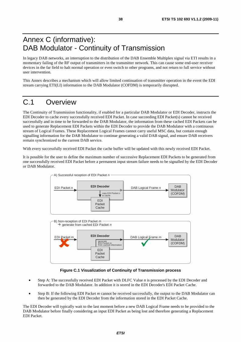
ETSI
ETSI TS 102 693 V1.1.2 (2009-11)38
Annex C (informative): DAB Modulator - Continuity of Transmission In legacy DAB networks, an interruption to the distribution of the DAB Ensemble Multiplex signal via ETI results in a momentary failing of the RF output of transmitters in the transmitter network. This can cause some end-user receiver devices in the far field to halt normal operation or even switch to other programs, and not return to full service without user intervention.
This Annex describes a mechanism which will allow limited continuation of transmitter operation in the event the EDI stream carrying ETI(LI) information to the DAB Modulator (COFDM) is temporarily disrupted.
C.1 Overview The Continuity of Transmission functionality, if enabled for a particular DAB Modulator or EDI Decoder, instructs the EDI Decoder to cache every successfully received EDI Packet. In case succeeding EDI Packet(s) cannot be received successfully and in time to be forwarded to the DAB Modulator, the information from these cached EDI Packets can be used to generate Replacement EDI Packets within the EDI Decoder to provide the DAB Modulator with a continuous stream of Logical Frames. These Replacement Logical Frames cannot carry useful MSC data, but contain enough signalling information for the DAB Modulator to continue generating a valid DAB signal, and ensure DAB receivers remain synchronized to the current DAB service.
With every successfully received EDI Packet the cache buffer will be updated with this newly received EDI Packet.
It is possible for the user to define the maximum number of successive Replacement EDI Packets to be generated from one successfully received EDI Packet before a permanent input stream failure needs to be signalled by the EDI Decoder or DAB Modulator.
EDI Decoder DAB Logical Frame nEDI Packet n
EDIPacket Cache
copy EDI Packet to cache
n
A) Successful reception of EDI Packet n
EDI Decoder DAB Logical Frame mEDI Packet m
EDIPacket Cache
generateEDI Packet from cached information
m
B) Non-reception of EDI Packet generate from cached EDI Packet
mn�
DABModulator(COFDM)
DABModulator(COFDM)
Figure C.1 Visualization of Continuity of Transmission process
• Step A: The successfully received EDI Packet with DLFC Value n is processed by the EDI Decoder and forwarded to the DAB Modulator. In addition it is stored in the EDI Decoder's EDI Packet Cache.
• Step B: If the following EDI Packet m cannot be received successfully, the output to the DAB Modulator can then be generated by the EDI Decoder from the information stored in the EDI Packet Cache.
The EDI Decoder will typically wait to the last moment before a new DAB Logical Frame needs to be provided to the DAB Modulator before finally considering an input EDI Packet as being lost and therefore generating a Replacement EDI Packet.
ETSI
ETSI TS 102 693 V1.1.2 (2009-11)39
In the process of generating Replacement DAB Logical Frames, several of the fields within the EDI Packet require modification in order to correctly prepare the information to be used as a replacement for the subsequent packet. These are discussed in clause C.2.
C.2 Recreating Essential Fields This clause describes the process to generate a Replacement EDI Packet m from a cached EDI Packet n, which can then be normally processed by the EDI Decoder to output a new DAB Logical Frame.
In order to generate the Replacement EDI Packet m the whole EDI Packet n with all of its TAG Items from the EDI Packet Cache is copied. This copied EDI Packet m is then modified as described below.
There are several fields within the information carried in the "deti" TAG Item of the new EDI Packet m which are specific to each EDI Packet. These fields are: EDI Logical Frame Count (DLFC Value, stored in the fields Frame Count High (FCTH) and Frame Count (FCT)), Frame Phase (FP), Timestamp (ATST) and Error Field (ERR). These fields require manipulation, as described in clauses C.2.1 to C.2.4.
The information carried in the FIC field of the "deti" TAG Item requires special consideration as described in clause C.2.5.
The information carried in each ETI sub-channel stream TAG Item requires special considerations as described in clause C.2.6.
After generating and modifying the Replacement EDI Packet m, it replaces the previous EDI Packet n in the EDI Packet Cache to serve as the basis for any Replacement EDI Packets required subsequently (up to the maximum number of generated Replacement EDI Packets as defined by the operator).
C.2.1 DLFC (Frame Count High (FCTH) and Frame Count (FCT)) The DLFC Value is derived from the cached EDI Packet n, incrementing its DLFC Value by 1 (modulo 5000), and thereby guaranteeing a continuously increasing DLFC Value for all EDI Packets leaving the EDI Decoder. The new DLFC Value is stored in the FCTH and FCT fields of the generated Replacement EDI Packet m.
C.2.2 Frame Phase (FP) The FP field is derived from the cached EDI Packet n and incremented by 1 modulo 8. The FP has a fixed relationship with the CIF Count (Frame Count (FCT)). Therefore the FP is set to 0 when CIF Count = 0. Table 4 of ETS 300 799 [5] gives the sequence and relationship between FP and CIF Count.
C.2.3 Timestamp (ATST) The timestamp field ATST is derived from the cached EDI Packet n, incrementing its ATST value by 24 ms, and thereby guaranteeing a continuously increasing ATST timestamp value in steps of 24 ms for all EDI Packets leaving the EDI Decoder. The new timestamp value is stored in the ATST fields of the Replacement EDI Packet m.
The addition of 24 ms will affect the TSTA member field of the ATST. If an absolute time value is provided in the ATST field of the cached EDI Packet (i.e. the Seconds member field of the ATST field is non-zero), it may also require an increment of the value in the Seconds field.
C.2.4 Error Field (STAT) The 8-bit STAT Field from the ETI Header section of the "deti" TAG Item is modified in the Replacement EDI Packet.
The STAT Field is set to the value 0F16 (Error Level 2) for Replacement EDI Packets generated by this process, in
order to allow a DAB Modulator to select an alternate feed should one be available.
ETSI
ETSI TS 102 693 V1.1.2 (2009-11)40
C.2.5 FIC Data If the FICF field in the cached EDI Packet n is set to 0 then the FIC field is not present and is not added to the Replacement EDI Packet m.
If the FICF field in the cached EDI Packet n is set to 1 then the FIC field is formatted to signal no useful FIC data. This is achieved by beginning each FIB with an End Marker byte, FF16 followed by 29-bytes of Padding, 0016 and ending in
a valid 2-bytes of CRC. The value of the CRC will be A8A816.
C.2.6 ETI sub-channel streams Each ETI sub-channel stream is described by one est<n> TAG Item, carrying both descriptive information in the SSTCn
field, as well as the MSC payload data for the particular stream in the MSTn field.
The Sub-channel Stream Characterization Field (SSTCn) is kept unmodified in the Replacement EDI Packet.
The MSC payload data does not follow a predictable pattern and is different in each 24 ms Logical Frame. As a result it is not possible to recover the information for a missing packet using information from a previous one. Therefore the Main Stream Data field (MSTk) carrying the MSC payload data has all of its content bytes set to FF16 in the
Replacement EDI Packet.
C.4 Required Configuration Options It is not mandatory for an EDI Decoder processing EDI Packets carrying ETI(LI) information to support the Continuity of Transmission feature described in this annex. However, if supported by an EDI Decoder it will be possible for the operator to enable or disable this feature as required.
In addition the number of Replacement EDI Packets successively generated from the last successfully received and cached EDI Packet is limited to no more than 8 by default. It should be possible for the operator of the EDI Decoder to change this number manually to higher or lower values as required.
C.5 Notification Whenever a Replacement EDI Packet is created due to a missing input EDI Packet, the operator should be notified accordingly.
When the first additional Replacement EDI Packet fails to be created because the maximum number of Replacement EDI Packets generated from a single successfully received EDI Packet has been reached, the operator should be informed accordingly.
C.6 Use in SFN Application An important purpose of the Continuity of Transmission feature is to keep DAB receivers synchronized, particularly when isolated DAB transmitters are operating in MFN mode (Multiple Frequency Network).
However, if running in an Single Frequency Network (SFN) scenario, the creation and broadcast of Replacement EDI Packets for one DAB transmitter may disturb the reception of other DAB transmitters in the same SFN, which have experienced no disruption to their input feed. In this scenario the network operator is advised to turn the Continuity of Transmission feature off, or only enable it for particularly important DAB transmitters within the SFN. The maximum number of Replacement EDI Packets which is allowed to be generated from a single successfully received EDI Packet should not exceed the default value of 8. This represents half of the Time Interleaver depth.
Should the number of Replacement EDI Packets generated from a single successfully received EDI Packet be allowed to exceed the default value of 8 then the STAT field should be changed to FF16 (Error Level 3) for those Replacement
EDI Packets exceeding 8 until valid EDI Packets are received and normal operation is restored.
ETSI
ETSI TS 102 693 V1.1.2 (2009-11)41
Annex D (normative): Physical presentation The Distribution & Communication Protocol DCP (see TS 102 821 [2]), serving as the basic transport protocol for EDI, allows almost any physical interface to be used.
To ensure local physical interoperability, all EDI implementations shall provide, as a minimum, a UDP/IP interface using twisted-pair Ethernet (10Base-T). The parameters for the IP stack shall be manually configurable. Automatic configuration using DHCP, BOOTP or similar may also be provided.
Further optional interfaces may be provided by an implementation.
The parameter for additional interfaces may be specified in more detail in future revisions of the present document.
D.1 Ethernet (IP over Ethernet) The Ethernet network connection shall be used to transport IP packets (Internet Protocol over Ethernet). This connection may be used for local and long-distance connection end-points. The following minimum requirements are designed to allow point-to-point or point-to-multipoint unidirectional transmission of a DCP stream in any of the applications of EDI.
NOTE: The DCP does not provide any security mechanisms. Security can be implemented in a number of layers. Minimally compliant implementations need not implement application or transport layer security and is compatible with network layer security implemented in external equipment, for example IPSEC or other tunnelling mechanisms.
For DCP-based transmission protocols referencing the IP over Ethernet protocol (to transport UDP datagrams) as their recommended/mandatory hardware interface, the following settings and restrictions shall apply.
D.1.1 Transport Layer • The mapping of DCP packets to IP is specified in annex B of TS 102 821 [2] which mandates a 1 to 1
encapsulation of PFT or AF packets in UDP datagrams.
• All equipment shall support direct encapsulation of the UDP transport stream in IPv4 datagrams.
• All equipment sending DCP streams shall be configurable to set the destination UDP port number and to specify or identify the source UDP port.
• All equipment receiving DCP streams shall be configurable to set the listening UDP port number (destination UDP port). The source UDP port number (carried in received UDP packets) may be configurable as an additional filtering parameter or the equipment may receive from any source port.
• All equipment receiving DCP streams shall, at least, support the use of UDP Checksum.
D.1.2 Network Layer • All equipment implementing an IP interface shall be capable of operating as an IPv4 host with configurable
interface IP address, subnet mask and default gateway.
• All equipment sending DCP streams shall be configurable to set the destination IP address, which can be a unicast or a multicast IP address.
• Equipment receiving DCP streams may be configurable to set the source IP address as an additional filtering parameter or the equipment may receive from any source address.
ETSI
ETSI TS 102 693 V1.1.2 (2009-11)42
• All equipment receiving DCP streams shall be configurable to listen on the IP address assigned to the network interface.
• All equipment receiving DCP streams shall be configurable to listen on a configurable IPv4 multicast IP address, in which case the equipment shall maintain membership of the specified multicast group, or groups, using IGMP.
D.1.3 Link Layer For DCP-based transmission protocols referencing the Ethernet protocol as their recommended/mandatory hardware interface, the following settings and restrictions shall apply:
• The interface shall be compatible with IEEE 802.3 [6] 10Base-T LANs using half-duplex multi-port repeaters (hubs).
• The interface shall be compatible with IEEE 802.3 [6] 100Base-TX LANs using half-duplex and/or full-duplex switches.
• The interface presentation shall be RJ-45 socket MDI (Medium Dependent Interface) wired to TIA/EIA-568-B [7].
Network adapters shall have a globally unique MAC address.
ETSI
ETSI TS 102 693 V1.1.2 (2009-11)43
Annex E (normative): EDI Packet Resend Functionality The FEC (forward error correction) mechanism defined in the DCP specification (see TS 102 821 [2]) increases the transmission robustness by enabling the reconstruction of a configurable number of lost UDP/IP packets in the EDI Decoder. It can be enabled both on uni- as well as bi-directional connections.
As an additional mechanism to recover from lost UDP/IP Packets, this EDI specification defines the EDI Packet Resend functionality. This feature enables an EDI Decoder to actively request the re-transmission of missing EDI Packets from the EDI Encoder.
This feature can only be used on bi-directional connections. In addition, the network latency to deliver DCP Packets must be low enough and the timestamp value carried in the EDI Packet must allow sufficient time for the EDI Decoder to detect a missing EDI Packet, request its re-transmission from the EDI Encoder, and then receive and process the retransmitted EDI Packet.
It should be clearly stated by the manufacturer whether the EDI Packet Resend functionality is supported by an EDI Encoder or EDI Decoder implementation.
E.1 Theory of Operation This clause describes how the EDI Packet Resend functionality shall be implemented in EDI Encoders and EDI Decoders.
The EDI Encoder is the unit sending out EDI Packets, listening for resend-requests from EDI Decoders, and upon reception of such requests, resends the previously cached EDI Packets to the EDI Decoders.
The EDI Decoder is the unit listening for incoming EDI Packets. It shall check the DLFC Value, and upon loss of EDI Packets, request the resend of the missing packet from the EDI Encoder.
The resend mechanism is illustrated in figure E.1:
After successful reception of EDI Packet #0 (t1), the EDI Decoder would normally expect reception of EDI Packet #1
exactly 24 ms later at t3 (on average, ignoring network jitter and delays). If EDI Packet #1 is not received at t3, the EDI
Decoder shall wait for a period beyond the normal receive time of the EDI Packet #1 before requesting a resend (t4);
this timeout period, toinitial, shall be either user defined or determined by the EDI Decoder from other parameters. The
timeout period toinitial shall begin 24 ms after (scheduled) reception of the previous EDI Packet.
Following the transmission of a resend request (t4), the EDI Decoder should receive that resent EDI Packet #1 after a
maximum timeout period of torepeat, covering the transmission of the request from EDI Decoder to EDI Encoder (t5), the
transmission of the resent EDI Packet from EDI Encoder to EDI Decoder (t6), and some extra delay to deal with
network jitter (t7).
In case the requested and resent EDI Packet #1 was still not received after a timeout period of torepeat (starting after the
initial resend request has been sent), then another resend request may be sent (t7), repeating the process described above
(t4 to t7). This process may be repeated until one of the following conditions has been met:
• the EDI Packet is successfully received;
• the maximum number of resend requests is reached;
• or the EDI Packet would need to be forwarded and processed according to its timestamp information and therefore has to be considered permanently lost.
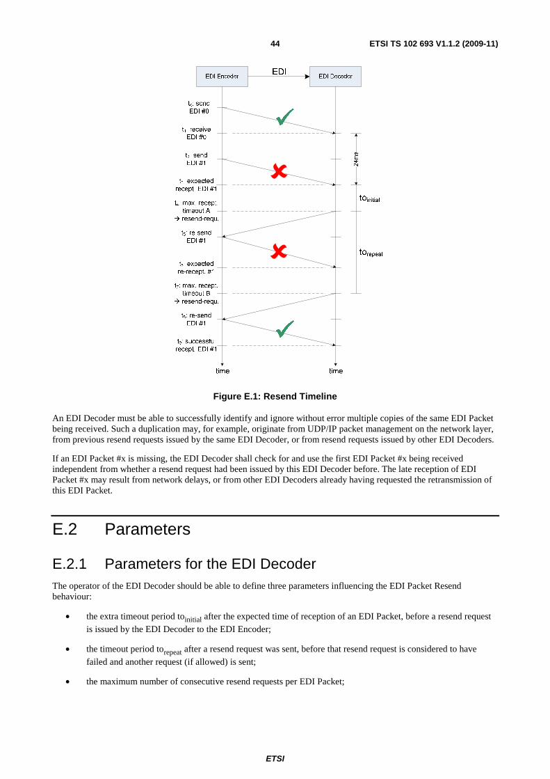
ETSI
ETSI TS 102 693 V1.1.2 (2009-11)44
Figure E.1: Resend Timeline
An EDI Decoder must be able to successfully identify and ignore without error multiple copies of the same EDI Packet being received. Such a duplication may, for example, originate from UDP/IP packet management on the network layer, from previous resend requests issued by the same EDI Decoder, or from resend requests issued by other EDI Decoders.
If an EDI Packet #x is missing, the EDI Decoder shall check for and use the first EDI Packet #x being received independent from whether a resend request had been issued by this EDI Decoder before. The late reception of EDI Packet #x may result from network delays, or from other EDI Decoders already having requested the retransmission of this EDI Packet.
E.2 Parameters
E.2.1 Parameters for the EDI Decoder The operator of the EDI Decoder should be able to define three parameters influencing the EDI Packet Resend behaviour:
• the extra timeout period toinitial after the expected time of reception of an EDI Packet, before a resend request
is issued by the EDI Decoder to the EDI Encoder;
• the timeout period torepeat after a resend request was sent, before that resend request is considered to have
failed and another request (if allowed) is sent;
• the maximum number of consecutive resend requests per EDI Packet;
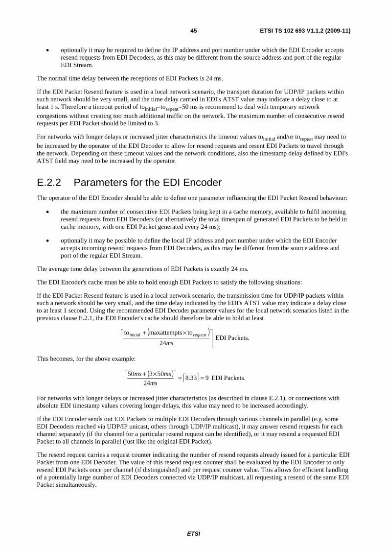
ETSI
ETSI TS 102 693 V1.1.2 (2009-11)45
• optionally it may be required to define the IP address and port number under which the EDI Encoder accepts resend requests from EDI Decoders, as this may be different from the source address and port of the regular EDI Stream.
The normal time delay between the receptions of EDI Packets is 24 ms.
If the EDI Packet Resend feature is used in a local network scenario, the transport duration for UDP/IP packets within such network should be very small, and the time delay carried in EDI's ATST value may indicate a delay close to at least 1 s. Therefore a timeout period of toinitial=torepeat=50 ms is recommend to deal with temporary network
congestions without creating too much additional traffic on the network. The maximum number of consecutive resend requests per EDI Packet should be limited to 3.
For networks with longer delays or increased jitter characteristics the timeout values toinitial and/or torepeat may need to
be increased by the operator of the EDI Decoder to allow for resend requests and resent EDI Packets to travel through the network. Depending on these timeout values and the network conditions, also the timestamp delay defined by EDI's ATST field may need to be increased by the operator.
E.2.2 Parameters for the EDI Encoder The operator of the EDI Encoder should be able to define one parameter influencing the EDI Packet Resend behaviour:
• the maximum number of consecutive EDI Packets being kept in a cache memory, available to fulfil incoming resend requests from EDI Decoders (or alternatively the total timespan of generated EDI Packets to be held in cache memory, with one EDI Packet generated every 24 ms);
• optionally it may be possible to define the local IP address and port number under which the EDI Encoder accepts incoming resend requests from EDI Decoders, as this may be different from the source address and port of the regular EDI Stream.
The average time delay between the generations of EDI Packets is exactly 24 ms.
The EDI Encoder's cache must be able to hold enough EDI Packets to satisfy the following situations:
If the EDI Packet Resend feature is used in a local network scenario, the transmission time for UDP/IP packets within such a network should be very small, and the time delay indicated by the EDI's ATST value may indicate a delay close to at least 1 second. Using the recommended EDI Decoder parameter values for the local network scenarios listed in the previous clause E.2.1, the EDI Encoder's cache should therefore be able to hold at least
( )
⎥⎥
⎤⎢⎢
⎡ ×+ms
requestinitial
24
tosmaxattemptto EDI Packets.
This becomes, for the above example:
( )
⎡ ⎤ 933.824
50350 ==⎥⎥
⎤⎢⎢
⎡ ×+ms
msms EDI Packets.
For networks with longer delays or increased jitter characteristics (as described in clause E.2.1), or connections with absolute EDI timestamp values covering longer delays, this value may need to be increased accordingly.
If the EDI Encoder sends out EDI Packets to multiple EDI Decoders through various channels in parallel (e.g. some EDI Decoders reached via UDP/IP unicast, others through UDP/IP multicast), it may answer resend requests for each channel separately (if the channel for a particular resend request can be identified), or it may resend a requested EDI Packet to all channels in parallel (just like the original EDI Packet).
The resend request carries a request counter indicating the number of resend requests already issued for a particular EDI Packet from one EDI Decoder. The value of this resend request counter shall be evaluated by the EDI Encoder to only resend EDI Packets once per channel (if distinguished) and per request counter value. This allows for efficient handling of a potentially large number of EDI Decoders connected via UDP/IP multicast, all requesting a resend of the same EDI Packet simultaneously.
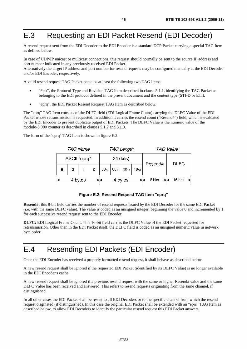
ETSI
ETSI TS 102 693 V1.1.2 (2009-11)46
E.3 Requesting an EDI Packet Resend (EDI Decoder) A resend request sent from the EDI Decoder to the EDI Encoder is a standard DCP Packet carrying a special TAG Item as defined below.
In case of UDP/IP unicast or multicast connections, this request should normally be sent to the source IP address and port number indicated in any previously received EDI Packet. Alternatively the target IP address and port number for resend requests may be configured manually at the EDI Decoder and/or EDI Encoder, respectively.
A valid resend request TAG Packet contains at least the following two TAG Items:
• "*ptr", the Protocol Type and Revision TAG Item described in clause 5.1.1, identifying the TAG Packet as belonging to the EDI protocol defined in the present document and the content type (STI-D or ETI).
• "eprq", the EDI Packet Resend Request TAG Item as described below.
The "eprq" TAG Item consists of the DLFC field (EDI Logical Frame Count) carrying the DLFC Value of the EDI Packet whose retransmission is requested. In addition it carries the resend count ("Resend#") field, which is evaluated by the EDI Encoder to prevent duplicate output of EDI Packets. The DLFC Value is the numeric value of the modulo-5 000 counter as described in clauses 5.1.2 and 5.1.3.
The form of the "eprq" TAG Item is shown in figure E.2.
TAG ValueTAG LengthTAG Name
e p qr 0016 00160016 1816
ASCII “eprq” 24 (bits)
4 bytes 4 bytes
Resend#
8 bits 16 bits
DLFC
Figure E.2: Resend Request TAG Item "eprq"
Resend#: this 8-bit field carries the number of resend requests issued by the EDI Decoder for the same EDI Packet (i.e. with the same DLFC value). The value is coded as an unsigned integer, beginning the value 0 and incremented by 1 for each successive resend request sent to the EDI Encoder.
DLFC: EDI Logical Frame Count. This 16-bit field carries the DLFC Value of the EDI Packet requested for retransmission. Other than in the EDI Packet itself, the DLFC field is coded as an unsigned numeric value in network byte order.
E.4 Resending EDI Packets (EDI Encoder) Once the EDI Encoder has received a properly formatted resend request, it shall behave as described below.
A new resend request shall be ignored if the requested EDI Packet (identified by its DLFC Value) is no longer available in the EDI Encoder's cache.
A new resend request shall be ignored if a previous resend request with the same or higher Resend# value and the same DLFC Value has been received and answered. This refers to resend requests originating from the same channel, if distinguished.
In all other cases the EDI Packet shall be resent to all EDI Decoders or to the specific channel from which the resend request originated (if distinguished). In this case the original EDI Packet shall be extended with an "eprs" TAG Item as described below, to allow EDI Decoders to identify the particular resend request this EDI Packet answers.
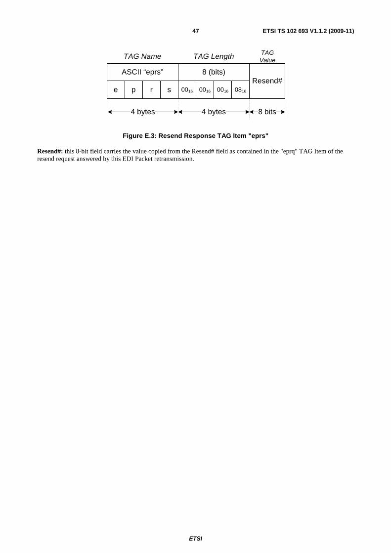
ETSI
ETSI TS 102 693 V1.1.2 (2009-11)47
TAG ValueTAG LengthTAG Name
e p sr 0016 00160016 0816
ASCII “eprs” 8 (bits)
4 bytes 4 bytes
Resend#
8 bits
Figure E.3: Resend Response TAG Item "eprs"
Resend#: this 8-bit field carries the value copied from the Resend# field as contained in the "eprq" TAG Item of the resend request answered by this EDI Packet retransmission.
ETSI
ETSI TS 102 693 V1.1.2 (2009-11)48
Annex F (informative): EDI Timestamps
F.1 Relationships The relationships between UTC, TAI, GPS Time and EDI Time ("EDI", as represented by the ATST field) are, as at the time of writing (February 2009), as follows:
• GPS = TAI - 19 s (constant).
• UTC = TAI - 34 s (variable due to leap seconds).
• UTC = GPS - 15 s (variable due to leap seconds).
• UTC = EDI - UTCO (constant due to varying value of UTCO).
• EDI = TAI - 32 s (constant).
• EDI = GPS - 13 s (constant).
• EDI = UTC + UTCO (constant due to varying value of UTCO).
F.2 Rationale Several other standard time/date encodings are in common use, including MJD, UTC, GPS and TAI. It was agreed that none of these adequately addressed the needs of the EDI specification and that it was desirable to define a time format specifically for the EDI Time (as represented by the ATST field). The following reasons were given for rejecting other common timebases:
• MJD is subject to leap seconds making the fractional portion very hard to represent in a fixed-point format.
• UTC is subject to leap seconds making the number of seconds in a day variable (86 399/86 400/86 401).
• GPS Time was subject to "week number wrapping" approximately every 19,7 years.
• UTC, TAI, MJD and GPS Time all have epochs (start dates) partway through the 400-year leap-year cycle.
The EDI Time is not subject to leap seconds, but contains sufficient extra information (in the UTCO field) to trivially convert the value to UTC which does include leap-seconds. Conversion to GPS Time and/or TAI is also trivial, simply involving the subtraction of a constant value. The epoch for EDI Time is synchronized with the start of a 400-year leap-year cycle, making leap year calculations simpler and less error prone.

ETSI
ETSI TS 102 693 V1.1.2 (2009-11)49
History
Document history
V1.1.1 September 2009 Publication
V1.1.2 November 2009 Publication


![TS 103 129 - V1.1.2 - Digital Video Broadcasting (DVB); Framing … · 2014-03-21 · ETSI 7 ETSI TS 103 129 V1.1.2 (2014-03) [i.2] National Marine Electronic Association, NMEA 0183](https://img.pdfslide.us/doc/110x75/5eaa10ac059444467b0bd471/ts-103-129-v112-digital-video-broadcasting-dvb-framing-2014-03-21-etsi.jpg)