Embed Size (px)
Citation preview
ETSI TS 100 812-2 V2.2.1 (2002-04)Technical Specification
Terrestrial Trunked Radio (TETRA);Subscriber Identity Module to
Mobile Equipment (SIM-ME) interface;Part 2: Characteristics of the TSIM application
ETSI
ETSI TS 100 812-2 V2.2.1 (2002-04)2
ReferenceDTS/TETRA-07071-2
Keywordscard, security, SIM, TETRA
ETSI
650 Route des LuciolesF-06921 Sophia Antipolis Cedex - FRANCE
Tel.: +33 4 92 94 42 00 Fax: +33 4 93 65 47 16
Siret N° 348 623 562 00017 - NAF 742 CAssociation à but non lucratif enregistrée à laSous-Préfecture de Grasse (06) N° 7803/88
Important notice
Individual copies of the present document can be downloaded from:http://www.etsi.org
The present document may be made available in more than one electronic version or in print. In any case of existing orperceived difference in contents between such versions, the reference version is the Portable Document Format (PDF).
In case of dispute, the reference shall be the printing on ETSI printers of the PDF version kept on a specific network drivewithin ETSI Secretariat.
Users of the present document should be aware that the document may be subject to revision or change of status.Information on the current status of this and other ETSI documents is available at
http://portal.etsi.org/tb/status/status.asp
If you find errors in the present document, send your comment to:[email protected]
Copyright Notification
No part may be reproduced except as authorized by written permission.The copyright and the foregoing restriction extend to reproduction in all media.
© European Telecommunications Standards Institute 2002.All rights reserved.
DECTTM, PLUGTESTSTM and UMTSTM are Trade Marks of ETSI registered for the benefit of its Members.TIPHONTM and the TIPHON logo are Trade Marks currently being registered by ETSI for the benefit of its Members.3GPPTM is a Trade Mark of ETSI registered for the benefit of its Members and of the 3GPP Organizational Partners.
ETSI
ETSI TS 100 812-2 V2.2.1 (2002-04)3
ContentIntellectual Property Rights ................................................................................................................................7
Foreword.............................................................................................................................................................7
Introduction ........................................................................................................................................................7
1 Scope ........................................................................................................................................................8
2 References ................................................................................................................................................8
3 Definitions, symbols and abbreviations ...................................................................................................93.1 Definitions..........................................................................................................................................................93.2 Symbols............................................................................................................................................................103.3 Abbreviations ...................................................................................................................................................10
4 Void........................................................................................................................................................11
5 Void........................................................................................................................................................11
6 Void........................................................................................................................................................11
7 Security features.....................................................................................................................................127.1 General on security...........................................................................................................................................127.2 Authentication and cipher key generation procedure .......................................................................................127.3 Support of Over The Air Re-keying (OTAR) distribution of cipher keys........................................................127.4 Support of SIM-ME enhanced security ............................................................................................................137.5 Storage of DCK................................................................................................................................................137.6 User verification and file access conditions .....................................................................................................13
8 Void........................................................................................................................................................14
9 TETRA Commands................................................................................................................................149.1 AUTHENTICATE ...........................................................................................................................................149.1.1 Command description .................................................................................................................................149.1.1.1 TETRA TA11/TA12 ALGORITHM ....................................................................................................149.1.1.2 TETRA TA21/TA22 ALGORITHM ....................................................................................................159.1.1.3 TB4/TE ALGORITHM.........................................................................................................................159.1.1.4 TA32 ALGORITHM ............................................................................................................................159.1.1.5 TA41/TA82 ALGORITHM ..................................................................................................................159.1.1.6 TA41/TA52 ALGORITHM ..................................................................................................................169.1.1.7 TA71 ALGORITHM ............................................................................................................................169.2 Coding of the commands..................................................................................................................................169.2.1 AUTHENTICATE......................................................................................................................................169.3 Definitions and coding .....................................................................................................................................189.4 Status conditions returned by the card..............................................................................................................209.4.1 Security management..................................................................................................................................209.4.2 Commands versus possible status responses ..............................................................................................20
10 Contents of the EFs ................................................................................................................................2110.1 General on EFs .................................................................................................................................................2110.2 Contents of the EFs at the MF level .................................................................................................................2110.3 Contents of the EFs at the TETRA application level .......................................................................................2110.3.1 EFSST (SIM Service Table) .........................................................................................................................2110.3.2 EFITSI (Individual Tetra Subscriber Identity) ..............................................................................................2510.3.3 EFITSIDIS (ITSI Disabled).............................................................................................................................2710.3.4 EFUNAME (Username) ..................................................................................................................................2710.3.5 EFSCT (Subscriber Class Table)...................................................................................................................2810.3.6 EFPHASE (Phase identification) ....................................................................................................................2910.3.7 EFCCK (Common Cipher Key) ....................................................................................................................2910.3.8 EFCCKLOC (CCK location areas) ..................................................................................................................3110.3.9 EFSCK (Static Cipher Keys) .........................................................................................................................3210.3.10 EFGSSIS (Static GSSIs).................................................................................................................................34
ETSI
ETSI TS 100 812-2 V2.2.1 (2002-04)4
10.3.11 EFGRDS (Group related data for static GSSIs) .............................................................................................3610.3.12 EFGSSID (Dynamic GSSIs)...........................................................................................................................3710.3.13 EFGRDD (Group related data for dynamic GSSIs)........................................................................................3710.3.14 EFGCK (Group Cipher Keys) .......................................................................................................................3810.3.15 EFMGCK (Modified Group Cipher Keys) .....................................................................................................3910.3.16 EFGINFO (User's group information) ............................................................................................................4010.3.17 EFSEC (Security settings).............................................................................................................................4310.3.18 EFFORBID (Forbidden networks)...................................................................................................................4310.3.19 EFPREF (Preferred networks) .......................................................................................................................4510.3.20 EFSPN (Service Provider Name) ..................................................................................................................4610.3.21 Void ............................................................................................................................................................4710.3.22 EFDNWRK (Broadcast network information).................................................................................................4710.3.23 EFNWT (Network table) ...............................................................................................................................4910.3.24 EFGWT (Gateway table) ...............................................................................................................................5110.3.25 EFCMT (Call Modifier Table).......................................................................................................................5310.3.26 EFADNGWT (Abbreviated Dialling Number with Gateways) ........................................................................5510.3.27 EFGWTEXT1 (Gateway Extension1)...............................................................................................................5710.3.28 EFADNTETRA (Abbreviated dialling numbers for TETRA network) .............................................................5710.3.29 EFEXTA (Extension A) .................................................................................................................................5910.3.30 EFFDNGWT (Fixed dialling numbers with Gateways) ...................................................................................6010.3.31 EFGWTEXT2 (Gateway Extension2)...............................................................................................................6010.3.32 EFFDNTETRA (Fixed dialling numbers for TETRA network) ........................................................................6110.3.33 EFEXTB (Extension B)..................................................................................................................................6110.3.34 EFLNDGWT (Last number dialled with Gateways) ........................................................................................6210.3.35 EFLNDTETRA (Last numbers dialled for TETRA network)............................................................................6210.3.36 EFSDNGWT (Service Dialling Numbers with gateway) .................................................................................6310.3.37 EFGWTEXT3 (Gateway Extension3)...............................................................................................................6310.3.38 EFSDNTETRA (Service Dialling Numbers for TETRA network)....................................................................6410.3.39 EFSTXT (Status message texts).....................................................................................................................6410.3.40 EFMSGTXT (SDS-1 message texts)................................................................................................................6510.3.41 EFSDS123 (Status and SDS type 1, 2 and 3 message storage) .......................................................................6710.3.42 EFSDS4 (SDS type 4 message storage) .........................................................................................................6910.3.43 EFMSGEXT (Message Extension)...................................................................................................................7610.3.44 EFEADDR (Emergency addresses).................................................................................................................7710.3.45 EFEINFO (Emergency call information)........................................................................................................7910.3.46 EFDMOCh (DMO radio channel information) ...............................................................................................8010.3.47 EFMSCh (MS allocation of DMO channels) .................................................................................................8110.3.48 EFKH (List of Key Holders).........................................................................................................................8210.3.49 EFREPGATE (DMO repeater and gateway list) ..............................................................................................8310.3.50 EFAD (Administrative data).........................................................................................................................8410.3.51 EFPREF_LA (Preferred location areas) ...........................................................................................................8410.3.52 EFLNDComp (Composite LND file)................................................................................................................8510.3.53 EFDFLTSTSGT (Status Default Target)............................................................................................................8610.3.54 EFSDSMEM_STATUS (SDS Memory Status) .....................................................................................................8910.3.55 EFWELCOME (Welcome Message).................................................................................................................9010.3.56 EFSDSR (SDS delivery report)......................................................................................................................9110.3.57 EFSDSP (SDS parameters) ............................................................................................................................9210.3.58 EFDIALSC (Dialling schemes for TETRA network)......................................................................................9310.3.59 EFAPN (APN table) ......................................................................................................................................9410.3.60 EFARR (Access Rule Reference)..................................................................................................................9510.3.61 EFPNI (Private Number Information)...........................................................................................................9510.3.62 EFscan (Scan list files) ..................................................................................................................................9610.3.63 EFSCAND (Scan list data) ..............................................................................................................................9710.3.64 EFDMO_GSSIS (DMO pre-programmed group numbers)................................................................................9810.3.65 EFDMO_GRDS (Group related data for DMO static GSSIs)............................................................................9810.3.66 EFGTMO_GDMO (TMO - DMO selected group association) .........................................................................10010.3.67 EFGDMO_GTMO (DMO - TMO selected group association) .........................................................................10010.3.68 EFDMO_DEP (Default encryption parameters) .............................................................................................10110.4 Contents of the EFs at the Telecom level .......................................................................................................10210.4.1 EFADN (Abbreviated dialling numbers) .....................................................................................................10210.4.2 EFFDN (Fixed dialling numbers) ................................................................................................................10210.4.3 EFMSISDN (MSISDN) .................................................................................................................................102
ETSI
ETSI TS 100 812-2 V2.2.1 (2002-04)5
10.4.4 EFLND (Last number dialled).....................................................................................................................10210.4.5 EFSDN (Service Dialling Numbers) ...........................................................................................................10310.4.6 EFEXT1 (Extension1)..................................................................................................................................10310.4.7 EFEXT2 (Extension2)..................................................................................................................................10310.4.8 EFEXT3 (Extension3)..................................................................................................................................10310.5 Files of TETRA..............................................................................................................................................103
11 Application protocol.............................................................................................................................10511.1 General procedures.........................................................................................................................................10611.1.1 Reading an EF...........................................................................................................................................10611.1.2 Updating an EF .........................................................................................................................................10711.1.3 Invalidating an EF.....................................................................................................................................10711.2 SIM management procedures .........................................................................................................................10711.2.1 SIM initialization ......................................................................................................................................10711.2.2 TETRA session initialization....................................................................................................................10711.2.3 TETRA session termination......................................................................................................................10811.2.4 Language preference request ....................................................................................................................10811.2.5 Administrative information request ..........................................................................................................10811.2.6 SIM service table request..........................................................................................................................10811.2.7 SIM phase request.....................................................................................................................................10811.2.8 SIM presence detection.............................................................................................................................10811.2.9 SIM card number request..........................................................................................................................10811.2.10 Common Cipher Key request....................................................................................................................10911.3 PIN related procedures ...................................................................................................................................10911.3.1 PIN verification ........................................................................................................................................10911.3.2 PIN value substitution...............................................................................................................................10911.3.3 PIN disabling ............................................................................................................................................11011.3.4 PIN enabling .............................................................................................................................................11011.3.5 PIN unblocking.........................................................................................................................................11011.4 TETRA security related procedures ...............................................................................................................11011.4.1 Authentication procedures and generation of DCK ..................................................................................11111.4.1.1 Mutual authentication requirement request .........................................................................................11111.4.1.2 SIM authentication ..............................................................................................................................11111.4.1.3 SwMI authentication ...........................................................................................................................11111.4.2 TETRA OTAR key computation (CCK, GCK, SCK) ..............................................................................11111.4.2.1 CCK distribution .................................................................................................................................11111.4.2.2 CCK changeover .................................................................................................................................11111.4.2.3 GCK distribution.................................................................................................................................11111.4.2.4 SCK distribution .................................................................................................................................11211.4.3 ITSI request ..............................................................................................................................................11211.4.4 ITSI disabling/re-enabling ........................................................................................................................11211.5 Subscription related procedures .....................................................................................................................11211.5.1 Username request......................................................................................................................................11211.5.2 ITSI temporarily disabled enquiry ............................................................................................................11311.5.3 Subscriber class request ............................................................................................................................11311.5.4 Void ..........................................................................................................................................................11311.5.5 Group identity information .......................................................................................................................11311.5.5.1 Static Group identity information .......................................................................................................11311.5.5.2 Dynamic Group identity information ..................................................................................................11311.5.6 Group related data.....................................................................................................................................11311.5.7 User's group information ..........................................................................................................................11411.5.8 Call modifiers ...........................................................................................................................................11411.5.9 Service Provider Name .............................................................................................................................11411.5.10 DMO channel procedures .........................................................................................................................11411.5.11 Emergency addresses................................................................................................................................11411.5.12 Interrupted emergency call request ...........................................................................................................11411.6 Network related procedures............................................................................................................................11511.6.1 Forbidden networks ..................................................................................................................................11511.6.2 Preferred networks....................................................................................................................................11511.7 Dialling number related procedures ...............................................................................................................11511.7.1 Dialling numbers under DFTETRA ............................................................................................................115
11.7.2 Dialling numbers under DFTELECOM .......................................................................................................117
ETSI
ETSI TS 100 812-2 V2.2.1 (2002-04)6
11.7.3 FDNGWT specific procedures .................................................................................................................11811.7.3.1 FDNGWT capability request ..............................................................................................................11811.7.3.2 FDNGWT disabling ............................................................................................................................11811.7.3.3 FDNGWT enabling.............................................................................................................................11811.8 Status and short data message procedures......................................................................................................11911.8.1 Display of status message texts.................................................................................................................11911.8.2 Display of SDS1 message texts ................................................................................................................11911.8.3 Storage of status and SDS messages types 1, 2 and 3...............................................................................11911.8.4 Storage of SDS messages type 4...............................................................................................................11911.8.5 SDS delivery report ..................................................................................................................................12011.8.6 Default Status Target ................................................................................................................................120
Annex A: Void ......................................................................................................................................121
Annex B (informative): FDN Procedures...........................................................................................122
Annex C (informative): Suggested contents of EFs at pre-personalization.....................................123
C.1 Contents of the EFs at the MF level .....................................................................................................123
C.2 Contents of the EFs at the TETRA application level ...........................................................................123
C.3 Contents of the EFs at the Telecom Level............................................................................................125
Annex D (normative): Database structure for group IDs and phone books.................................126
Annex E (informative): Emergency call facilities and procedures ..................................................128
Annex F (informative): Composite List of Last Dialled Numbers...................................................130
Annex G (informative): Bibliography.................................................................................................132
History ............................................................................................................................................................133
ETSI
ETSI TS 100 812-2 V2.2.1 (2002-04)7
Intellectual Property RightsIPRs essential or potentially essential to the present document may have been declared to ETSI. The informationpertaining to these essential IPRs, if any, is publicly available for ETSI members and non-members, and can be foundin ETSI SR 000 314: "Intellectual Property Rights (IPRs); Essential, or potentially Essential, IPRs notified to ETSI inrespect of ETSI standards", which is available from the ETSI Secretariat. Latest updates are available on the ETSI Webserver (http://webapp.etsi.org/IPR/home.asp).
Pursuant to the ETSI IPR Policy, no investigation, including IPR searches, has been carried out by ETSI. No guaranteecan be given as to the existence of other IPRs not referenced in ETSI SR 000 314 (or the updates on the ETSI Webserver) which are, or may be, or may become, essential to the present document.
ForewordThis Technical Specification (TS) has been produced by ETSI Project Terrestrial Trunked Radio (TETRA).
The present document is part 2 of a multi-part deliverable covering the Subscriber Identity Module to MobileEquipment (SIM-ME) interface, as identified below:
Part 1: "Physical and logical characteristics";
Part 2: "Characteristics of the TSIM application".
IntroductionThe present document defines TETRA SIM application to be used with the generic Terminal/Integrated Circuit Card(ICC) interface.
ETSI
ETSI TS 100 812-2 V2.2.1 (2002-04)8
1 ScopeThe present document defines the TETRA SIM ('TSIM') application for TETRA mobile radio network operation.
The present document specifies:
- specific command parameters;
- file structures;
- contents of EFs (Elementary Files);
- security functions;
- application protocol to be used on the interface between UICC and ME.
This is to ensure interoperability between a TSIM/UICC combination and an ME in accordance with the requirementslaid down in ETR 295 [1].
Common files and commands are specified in TS 102 221 [14] to which reference should be made.
The present document does not define any aspects related to the administrative management phase of the TSIM. Anyinternal technical realization of either the TSIM or the ME is only specified where this is reflected over the ME-TSIMinterface.
2 ReferencesThe following documents contain provisions which, through reference in this text, constitute provisions of the presentdocument.
• References are either specific (identified by date of publication and/or edition number or version number) ornon-specific.
• For a specific reference, subsequent revisions do not apply.
• For a non-specific reference, the latest version applies.
[1] ETSI ETR 295: "Terrestrial Trunked Radio (TETRA); User requirements for Subscriber IdentityModule (SIM)".
[2] ETSI ETS 300 392-1: "Terrestrial Trunked Radio (TETRA); Voice plus Data (V+D);Part 1: General Network Design".
[3] ETSI EN 300 392-2: "Terrestrial Trunked Radio (TETRA); Voice plus Data (V+D); Part 2: AirInterface (AI)".
[4] ETSI EN 300 392-7: "Terrestrial Trunked Radio (TETRA); Voice plus Data (V+D);Part 7: Security".
[5] ETSI TS 100 977: "Digital cellular telecommunications system (Phase 2+); Specification of theSubscriber Identity Module - Mobile Equipment (SIM - ME) interface (3GPP TS 11.11 version8.5.0 Release 1999)".
[6] ITU-T Recommendation T.50: "International Reference Alphabet (IRA) (Formerly InternationalAlphabet No. 5 or IA5) - Information technology - 7-bit coded character set for informationinterchange".
[7] ETSI ETS 300 396-6: "Terrestrial Trunked Radio (TETRA); Direct Mode Operation (DMO);Part 6: Security".
ETSI
ETSI TS 100 812-2 V2.2.1 (2002-04)9
[8] ETSI ETS 300 392-12-22: "Terrestrial Trunked Radio (TETRA); Voice plus Data (V+D);Part 12: Supplementary services stage 3; Sub-part 22: Dynamic Group Number Assignment(DGNA)".
[9] ISO/IEC 8859-1: "Information technology - 8-bit single-byte coded graphic charactersets - Part 1: Latin alphabet No. 1".
[10] ETSI ETS 300 394-2 (Edition 1) (all parts): "Terrestrial Trunked Radio (TETRA); Conformancetesting specification; Part 2: Protocol testing specification for Voice plus Data (V+D)".
[11] ETSI TS 100 940: "Digital cellular telecommunications system (Phase 2+); Mobile radio interface;Layer 3 specification (3GPP TS 04.08 version 7.9.1 Release 1998)".
[12] ETSI TS 100 927: "Digital cellular telecommunications system (Phase 2+); Numbering,Addressing and Identification (3GPP TS 03.03 version 7.6.0 Release 1998)".
[13] ISO/IEC 7816-9: "Identification cards - Integrated circuit(s) cards withcontacts - Part 9: Additional interindustry commands and security attributes".
[14] ETSI TS 102 221: "Smart cards; UICC-Terminal interface; Physical and logical characteristics".
3 Definitions, symbols and abbreviations
3.1 DefinitionsFor the purposes of the present document, the terms and definitions given in TS 102 221 [14], ETS 300 392-1 [2] andthe following apply:
access conditions: set of security attributes associated with access to an Elementary File (EF)
NOTE: ADM (administrative):
indicates an access condition defined by the card issuer. Before issue of the card ADM serves as aplaceholder for an access condition to be defined by the card issuer. Any access condition may beassigned. The assigned access condition is used during the usage phase of the SIM;
PINn (personal identification number):
defines the access condition to an EF which requires verification of the user identity (n = 1 or n = 2).
NEV (never):
access to the EF is never allowed across the SIM-ME interface.
administrative phase: part of the card life between the manufacturing phase and the usage phase
card holder verification: authentication of the user to the SIM card
key generator: secure system entity authorized to generate Static Cipher Keys (SCKs) for Direct Mode Operation(DMO)
key holder: secure system entity authorized to distribute SCKs for DMO
key user: standard Direct Mode (DM) terminal which uses SCKs provided by an authorized key holder
Mobile Equipment (ME): part of the MS which interfaces to the SIM card
Mobile Station (MS): entirety of the equipment needed to communicate with the infrastructure (in trunked mode ofoperation) or direct with another MS (in direct mode of operation)
personalization: addition of subscriber and end user data to the appropriate EFs in the SIM during the administrativephase of a card's life cycle
pre-personalization: assignment of EF values at the manufacturing phase of a card's life cycle
ETSI
ETSI TS 100 812-2 V2.2.1 (2002-04)10
TETRA application: set of security mechanisms, files, data and protocols required by TETRA
TETRA session: part of the card session dedicated to the TETRA operation
TETRA SIM: subscriber identity module used in a TETRA MS
TSIM: TETRA SIM application supported by the UICC
usage phase: part of the card life, after the administrative phase, when the card is being used for operational purposes
3.2 SymbolsFor the purposes of the present document, the following symbols apply:
'0' to '9' and 'A' to 'F' The sixteen hexadecimal digits
3.3 AbbreviationsFor the purposes of the present document, the following abbreviations apply:
ADF Application Dedicated FileADM ADMinistrative (see definitions)ADN Abbreviated Dialling NumberALW ALWaysAPN Access Point NameBCD Binary Coded DecimalCCK Common Cipher KeyCCK-id CCK identifierCLA CLAssDCK Derived Cipher KeyDCK1 Part 1 of the DCKDCK2 Part 2 of the DCKDF Dedicated FileDGNA Dynamic Group Number AssignmentDMO Direct Mode OperationEF Elementary FileFCP File Control ParametersFDN Fixed Dialling NumberFSSN Fleet Specific Short NumberGCK Group Cipher KeyGCK-VN GCK Version NumberGGSN Gateway GPRS Support NodeGPRS General Packet Radio ServiceGSSI Group Short Subscriber IdentityGTSI Group Tetra Subscriber IdentityIC Integrated CircuitID IDentifierIP Internet ProtocolISSI Individual Short Subscriber IdentityITSI Individual TETRA Subscriber IdentityK individual subscriber authentication KeyKE Enhanced security KeyLND Last Number DialledLSB Least Significant BitMCC Mobile Country CodeME Mobile EquipmentMF Master FileMGCK Modified Group Cipher KeyMMI Man Machine InterfaceMNC Mobile Network CodeMS Mobile Station
ETSI
ETSI TS 100 812-2 V2.2.1 (2002-04)11
MSB Most Significant BitNET NETworkNEV NEVer (see definitions)OTAR Over The Air Re-keyingPABX Private Automatic Branch ExchangePIN Personal Identification NumberPS_DO PIN Status Data ObjectPSTN Public Switched Telephone NetworkRAND1 RANDom challenge 1RAND2 RANDom challenge 2RES1 RESponse 1RES2 RESponse 2RFU Reserved for Future UseRS Random SeedRSO Random Seed for OTARSCCK Sealed CCKSCK Static Cipher KeySCKN SCK numberSCK-VN SCK version numberSDN Service Dialling NumberSDS Short Data ServiceSEID Security Environment IDSGCK Sealed GCKSIM Subscriber Identity ModuleSSC Supplementary Service Control stringSSCK Sealed SCKSSI Short Subscriber IdentitySwMI Switching and Management InfrastructureTE TETRA algorithm for enhanced security on SIM-ME interfaceTLV Tag, Length, ValueTON Type Of NumberTP Transfer layer ProtocolUICC Universal Integrated Circuit CardXRES2 EXpected RESponse 2
4 Void
5 Void
6 Void
ETSI
ETSI TS 100 812-2 V2.2.1 (2002-04)12
7 Security features
7.1 General on securityThe security aspects of TETRA are described in EN 300 392-7 [4] and ETS 300 396-6 [7]. This clause givesinformation related to security features supported by the SIM to enable the following:
- authentication of the subscriber identity to the network;
- data confidentiality over the air interface;
- confidentiality of air interface keys when passed over the SIM-ME interface;
- file access conditions.
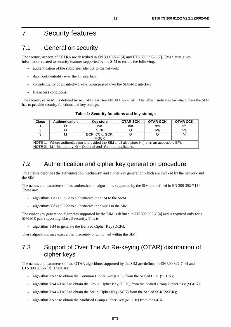
The security of an MS is defined by security class (see EN 300 392-7 [4]). The table 1 indicates for which class the SIMhas to provide security functions and key storage.
Table 1: Security functions and key storage
Class Authentication Key store OTAR SCK OTAR GCK OTAR CCK1 O n/a n/a n/a n/a2 O SCK O n/a n/a3 M DCK, CCK, GCK,
MGCKO O M
NOTE 1: Where authentication is provided the SIM shall also store K (not in an accessible EF).NOTE 2: M = Mandatory, O = Optional and n/a = not applicable.
7.2 Authentication and cipher key generation procedureThis clause describes the authentication mechanism and cipher key generation which are invoked by the network andthe SIM.
The names and parameters of the authentication algorithms supported by the SIM are defined in EN 300 392-7 [4].These are:
- algorithms TA11/TA12 to authenticate the SIM to the SwMI;
- algorithms TA21/TA22 to authenticate the SwMI to the SIM.
The cipher key generation algorithm supported by the SIM is defined in EN 300 392-7 [4] and is required only for aSIM-ME pair supporting Class 3 security. This is:
- algorithm TB4 to generate the Derived Cipher Key (DCK).
These algorithms may exist either discretely or combined within the SIM.
7.3 Support of Over The Air Re-keying (OTAR) distribution ofcipher keys
The names and parameters of the OTAR algorithms supported by the SIM are defined in EN 300 392-7 [4] andETS 300 396-6 [7]. These are:
- algorithm TA32 to obtain the Common Cipher Key (CCK) from the Sealed CCK (SCCK);
- algorithm TA41/TA82 to obtain the Group Cipher Key (GCK) from the Sealed Group Cipher Key (SGCK);
- algorithm TA41/TA52 to obtain the Static Cipher Key (SCK) from the Sealed SCK (SSCK);
- algorithm TA71 to obtain the Modified Group Cipher Key (MGCK) from the GCK.
ETSI
ETSI TS 100 812-2 V2.2.1 (2002-04)13
These algorithms may exist either discretely or combined within the SIM.
7.4 Support of SIM-ME enhanced securityEnhanced security for DCK, CCK, SCK and MGCK on the SIM-ME interface in SIM-ME pairs supporting securityClass 2 and 3 is supported by use of the TETRA algorithm for enhanced security on SIM-ME interface (TE) algorithm.When enhanced SIM-ME security is required (SIM Service 20 set):
- algorithm immediately following TB4 algorithm;
- CCK, SCK and MGCK are sealed by the TE algorithm as part of the "Read EF" command.
7.5 Storage of DCKAfter successful authentication DCK shall be stored on the SIM for further use to unseal cipher keys but only for theduration of the TETRA session.
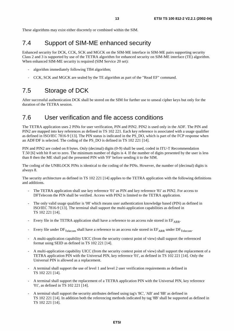
7.6 User verification and file access conditionsThe TETRA application uses 2 PINs for user verification, PIN and PIN2. PIN2 is used only in the ADF. The PIN andPIN2 are mapped into key references as defined in TS 102 221. Each key reference is associated with a usage qualifieras defined in ISO/IEC 7816-9 [13]. The PIN status is indicated in the PS_DO, which is part of the FCP response whenan ADF/DF is selected. The coding of the PS_DO is defined in TS 102 221 [14].
PIN and PIN2 are coded on 8 bytes. Only (decimal) digits (0-9) shall be used, coded in ITU-T RecommendationT.50 [6] with bit 8 set to zero. The minimum number of digits is 4. If the number of digits presented by the user is lessthan 8 then the ME shall pad the presented PIN with 'FF' before sending it to the SIM.
The coding of the UNBLOCK PINs is identical to the coding of the PINs. However, the number of (decimal) digits isalways 8.
The security architecture as defined in TS 102 221 [14] applies to the TETRA application with the following definitionsand additions.
- The TETRA application shall use key reference '01' as PIN and key reference '81' as PIN2. For access toDFTelecom the PIN shall be verified. Access with PIN2 is limited to the TETRA application.
- The only valid usage qualifier is '08' which means user authentication knowledge based (PIN) as defined inISO/IEC 7816-9 [13]. The terminal shall support the multi-application capabilities as defined inTS 102 221 [14].
- Every file in the TETRA application shall have a reference to an access rule stored in EFARR.
- Every file under DFTelecom shall have a reference to an access rule stored in EFARR under DFTelecom.
- A multi-application capability UICC (from the security context point of view) shall support the referencedformat using SEID as defined in TS 102 221 [14].
- A multi-application capability UICC (from the security context point of view) shall support the replacement of aTETRA application PIN with the Universal PIN, key reference '01', as defined in TS 102 221 [14]. Only theUniversal PIN is allowed as a replacement.
- A terminal shall support the use of level 1 and level 2 user verification requirements as defined inTS 102 221 [14].
- A terminal shall support the replacement of a TETRA application PIN with the Universal PIN, key reference'01', as defined in TS 102 221 [14].
- A terminal shall support the security attributes defined using tag's '8C', 'AB' and '8B' as defined inTS 102 221 [14]. In addition both the referencing methods indicated by tag '8B' shall be supported as defined inTS 102 221 [14].
ETSI
ETSI TS 100 812-2 V2.2.1 (2002-04)14
The access rule is referenced in the FCP using tag '8B'. The TLV object contains the file ID (the file ID of EFARR) and
record number, or file ID (the file ID of EFARR), SEID and record number, pointer to the record in EFARR where the
access rule is stored. Each SEID refers to a record number in EFARR. EFs having the same access rule use the same
record reference in EFARR. For an example EFARR, see TS 102 221 [14].
8 Void
9 TETRA Commands
9.1 AUTHENTICATE
9.1.1 Command description
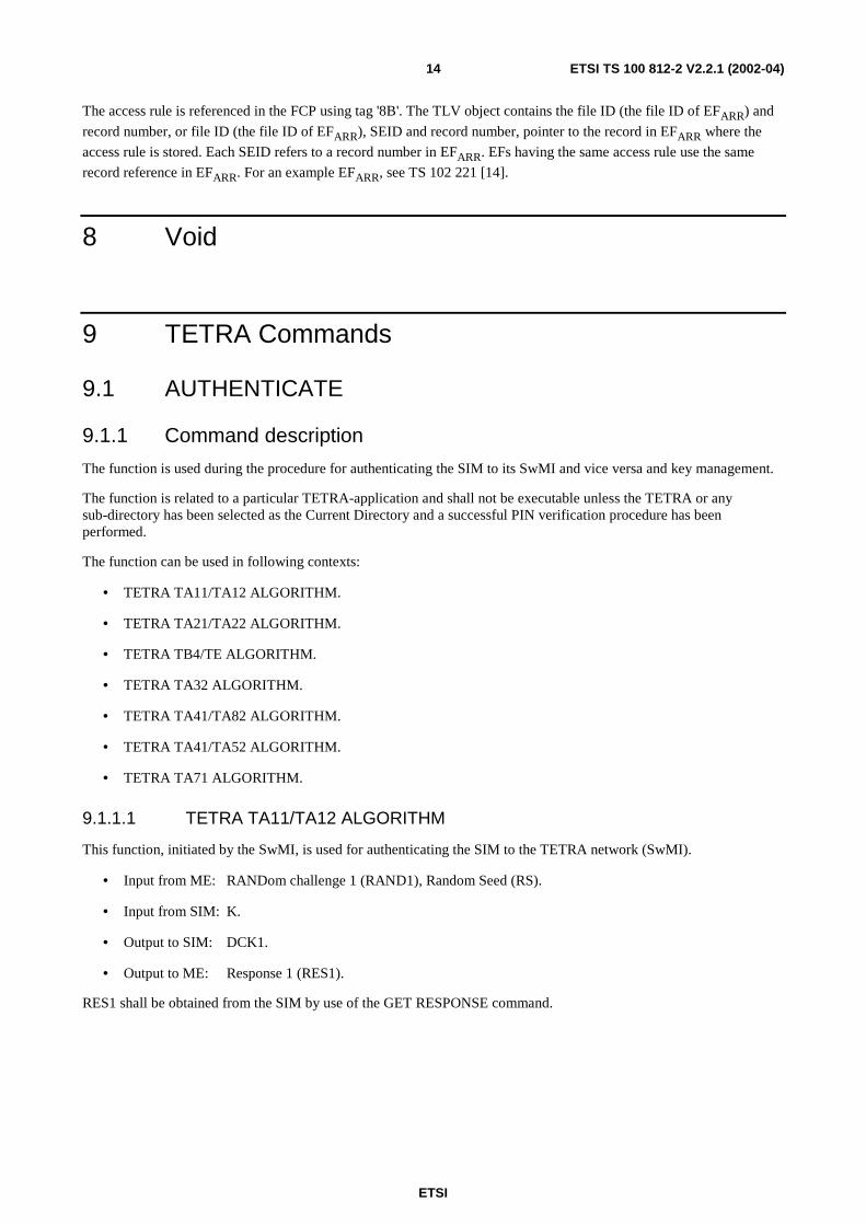
The function is used during the procedure for authenticating the SIM to its SwMI and vice versa and key management.
The function is related to a particular TETRA-application and shall not be executable unless the TETRA or anysub-directory has been selected as the Current Directory and a successful PIN verification procedure has beenperformed.
The function can be used in following contexts:
• TETRA TA11/TA12 ALGORITHM.
• TETRA TA21/TA22 ALGORITHM.
• TETRA TB4/TE ALGORITHM.
• TETRA TA32 ALGORITHM.
• TETRA TA41/TA82 ALGORITHM.
• TETRA TA41/TA52 ALGORITHM.
• TETRA TA71 ALGORITHM.
9.1.1.1 TETRA TA11/TA12 ALGORITHM
This function, initiated by the SwMI, is used for authenticating the SIM to the TETRA network (SwMI).
• Input from ME: RANDom challenge 1 (RAND1), Random Seed (RS).
• Input from SIM: K.
• Output to SIM: DCK1.
• Output to ME: Response 1 (RES1).
RES1 shall be obtained from the SIM by use of the GET RESPONSE command.
ETSI
ETSI TS 100 812-2 V2.2.1 (2002-04)15
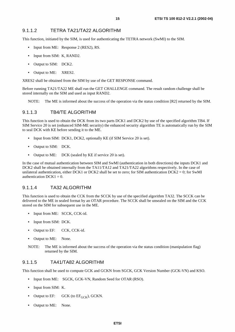
9.1.1.2 TETRA TA21/TA22 ALGORITHM
This function, initiated by the SIM, is used for authenticating the TETRA network (SwMI) to the SIM.
• Input from ME: Response 2 (RES2), RS.
• Input from SIM: K, RAND2.
• Output to SIM: DCK2.
• Output to ME: XRES2.
XRES2 shall be obtained from the SIM by use of the GET RESPONSE command.
Before running TA21/TA22 ME shall run the GET CHALLENGE command. The result random challenge shall bestored internally on the SIM and used as input RAND2.
NOTE: The ME is informed about the success of the operation via the status condition [R2] returned by the SIM.
9.1.1.3 TB4/TE ALGORITHM
This function is used to obtain the DCK from its two parts DCK1 and DCK2 by use of the specified algorithm TB4. IfSIM Service 20 is set (enhanced SIM-ME security) the enhanced security algorithm TE is automatically run by the SIMto seal DCK with KE before sending it to the ME.
• Input from SIM: DCK1, DCK2, optionally KE (if SIM Service 20 is set).
• Output to SIM: DCK.
• Output to ME: DCK (sealed by KE if service 20 is set).
In the case of mutual authentication between SIM and SwMI (authentication in both directions) the inputs DCK1 andDCK2 shall be obtained internally from the TA11/TA12 and TA21/TA22 algorithms respectively. In the case ofunilateral authentication, either DCK1 or DCK2 shall be set to zero; for SIM authentication DCK2 = 0; for SwMIauthentication DCK1 = 0.
9.1.1.4 TA32 ALGORITHM
This function is used to obtain the CCK from the SCCK by use of the specified algorithm TA32. The SCCK can bedelivered to the ME in sealed format by an OTAR procedure. The SCCK shall be unsealed on the SIM and the CCKstored on the SIM for subsequent use in the ME.
• Input from ME: SCCK, CCK-id.
• Input from SIM: DCK.
• Output to EF: CCK, CCK-id.
• Output to ME: None.
NOTE: The ME is informed about the success of the operation via the status condition (manipulation flag)returned by the SIM.
9.1.1.5 TA41/TA82 ALGORITHM
This function shall be used to compute GCK and GCKN from SGCK, GCK Version Number (GCK-VN) and KSO.
• Input from ME: SGCK, GCK-VN, Random Seed for OTAR (RSO).
• Input from SIM: K.
• Output to EF: GCK (to EFGCK), GCKN.
• Output to ME: None.
ETSI
ETSI TS 100 812-2 V2.2.1 (2002-04)16
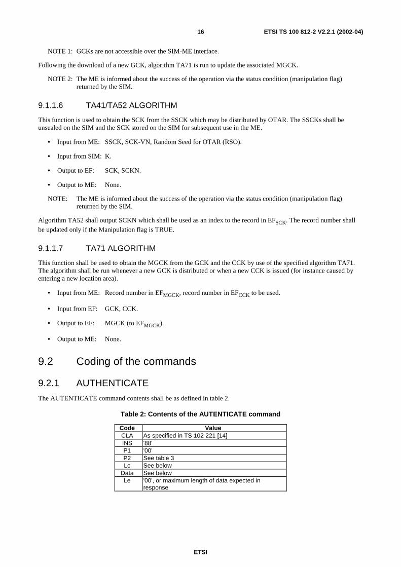
NOTE 1: GCKs are not accessible over the SIM-ME interface.
Following the download of a new GCK, algorithm TA71 is run to update the associated MGCK.
NOTE 2: The ME is informed about the success of the operation via the status condition (manipulation flag)returned by the SIM.
9.1.1.6 TA41/TA52 ALGORITHM
This function is used to obtain the SCK from the SSCK which may be distributed by OTAR. The SSCKs shall beunsealed on the SIM and the SCK stored on the SIM for subsequent use in the ME.
• Input from ME: SSCK, SCK-VN, Random Seed for OTAR (RSO).
• Input from SIM: K.
• Output to EF: SCK, SCKN.
• Output to ME: None.
NOTE: The ME is informed about the success of the operation via the status condition (manipulation flag)returned by the SIM.
Algorithm TA52 shall output SCKN which shall be used as an index to the record in EFSCK. The record number shall
be updated only if the Manipulation flag is TRUE.
9.1.1.7 TA71 ALGORITHM
This function shall be used to obtain the MGCK from the GCK and the CCK by use of the specified algorithm TA71.The algorithm shall be run whenever a new GCK is distributed or when a new CCK is issued (for instance caused byentering a new location area).
• Input from ME: Record number in EFMGCK, record number in EFCCK to be used.
• Input from EF: GCK, CCK.
• Output to EF: MGCK (to EFMGCK).
• Output to ME: None.
9.2 Coding of the commands
9.2.1 AUTHENTICATE
The AUTENTICATE command contents shall be as defined in table 2.
Table 2: Contents of the AUTENTICATE command
Code ValueCLA As specified in TS 102 221 [14]INS '88'P1 '00'P2 See table 3Lc See below
Data See belowLe '00', or maximum length of data expected in
response
ETSI
ETSI TS 100 812-2 V2.2.1 (2002-04)17
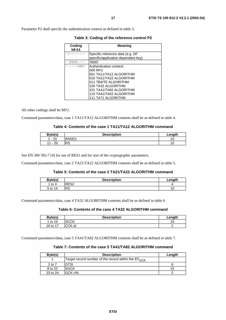
Parameter P2 shall specify the authentication context as defined in table 3.
Table 3: Coding of the reference control P2
Codingb8-b1
Meaning
'1-------' Specific reference data (e.g. DFspecific/application dependant key)
'-XXXX---' '0000''-----XXX' Authentication context:
000 RFU001 TA11/TA12 ALGORITHM010 TA21/TA22 ALGORITHM011 TB4/TE ALGORITHM100 TA32 ALGORITHM101 TA41/TA82 ALGORITHM110 TA41/TA52 ALGORITHM111 TA71 ALGORITHM
All other codings shall be RFU.
Command parameters/data, case 1 TA11/TA12 ALGORITHM contents shall be as defined in table 4.
Table 4: Contents of the case 1 TA11/TA12 ALGORITHM command
Byte(s) Description Length1 - 10 RAND1 10
11 - 20 RS 10
See EN 300 392-7 [4] for use of RES1 and for size of the cryptographic parameters.
Command parameters/data, case 2 TA21/TA22 ALGORITHM contents shall be as defined in table 5.
Table 5: Contents of the case 2 TA21/TA22 ALGORITHM command
Byte(s) Description Length1 to 4 RES2 45 to 14 RS 10
Command parameters/data, case 4 TA32 ALGORITHM contents shall be as defined in table 6
Table 6: Contents of the case 4 TA32 ALGORITHM command
Byte(s) Description Length1 to 15 SCCK 15
16 to 17 CCK-id 2
Command parameters/data, case 5 TA41/TA82 ALGORITHM contents shall be as defined in table 7.
Table 7: Contents of the case 5 TA41/TA82 ALGORITHM command
Byte(s) Description Length1 Target record number of the record within the EFGCK
2 to 7 GTSI 68 to 22 SGCK 15
23 to 24 GCK-VN 2
ETSI
ETSI TS 100 812-2 V2.2.1 (2002-04)18
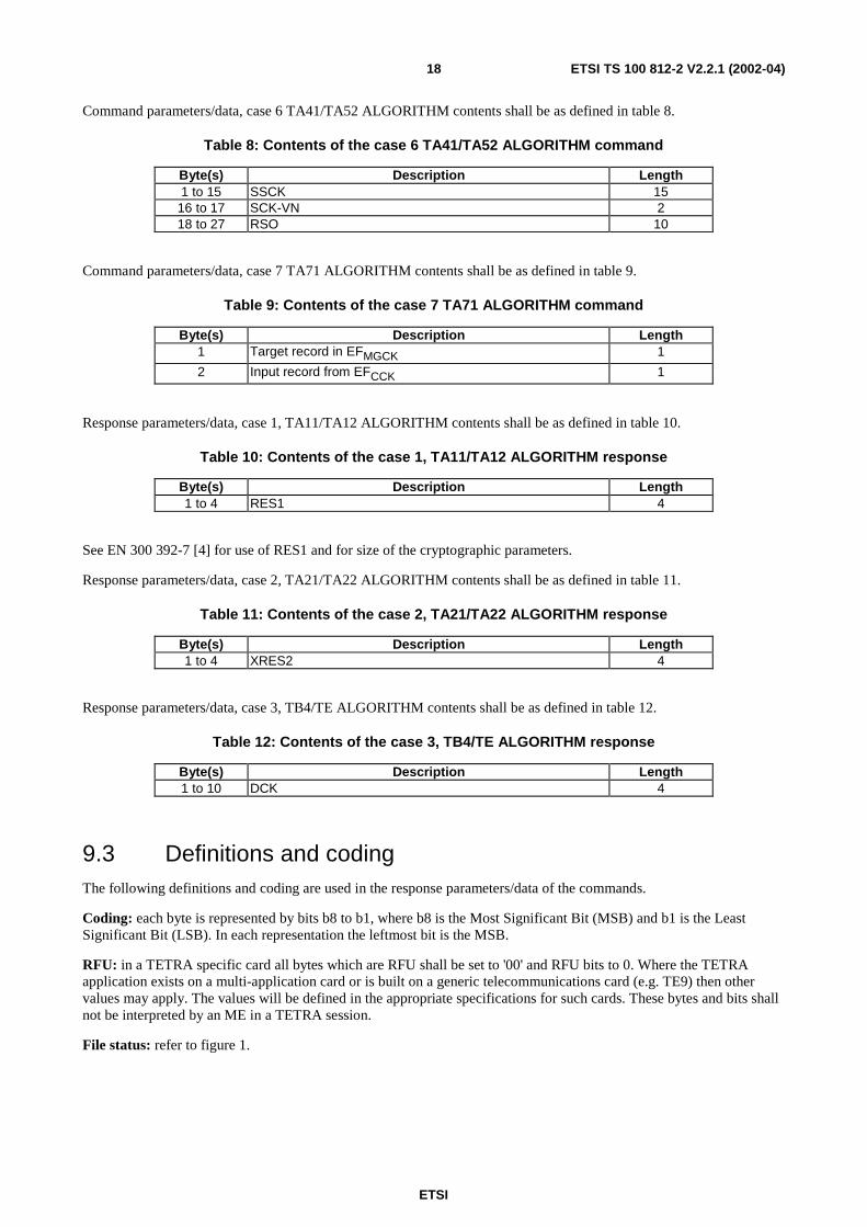
Command parameters/data, case 6 TA41/TA52 ALGORITHM contents shall be as defined in table 8.
Table 8: Contents of the case 6 TA41/TA52 ALGORITHM command
Byte(s) Description Length1 to 15 SSCK 15
16 to 17 SCK-VN 218 to 27 RSO 10
Command parameters/data, case 7 TA71 ALGORITHM contents shall be as defined in table 9.
Table 9: Contents of the case 7 TA71 ALGORITHM command
Byte(s) Description Length1 Target record in EFMGCK 1
2 Input record from EFCCK 1
Response parameters/data, case 1, TA11/TA12 ALGORITHM contents shall be as defined in table 10.
Table 10: Contents of the case 1, TA11/TA12 ALGORITHM response
Byte(s) Description Length1 to 4 RES1 4
See EN 300 392-7 [4] for use of RES1 and for size of the cryptographic parameters.
Response parameters/data, case 2, TA21/TA22 ALGORITHM contents shall be as defined in table 11.
Table 11: Contents of the case 2, TA21/TA22 ALGORITHM response
Byte(s) Description Length1 to 4 XRES2 4
Response parameters/data, case 3, TB4/TE ALGORITHM contents shall be as defined in table 12.
Table 12: Contents of the case 3, TB4/TE ALGORITHM response
Byte(s) Description Length1 to 10 DCK 4
9.3 Definitions and codingThe following definitions and coding are used in the response parameters/data of the commands.
Coding: each byte is represented by bits b8 to b1, where b8 is the Most Significant Bit (MSB) and b1 is the LeastSignificant Bit (LSB). In each representation the leftmost bit is the MSB.
RFU: in a TETRA specific card all bytes which are RFU shall be set to '00' and RFU bits to 0. Where the TETRAapplication exists on a multi-application card or is built on a generic telecommunications card (e.g. TE9) then othervalues may apply. The values will be defined in the appropriate specifications for such cards. These bytes and bits shallnot be interpreted by an ME in a TETRA session.
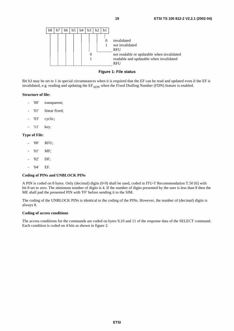
File status: refer to figure 1.
ETSI
ETSI TS 100 812-2 V2.2.1 (2002-04)19
b8 b7 b6 b5 b4 b3 b2 b1
0 invalidated1 not invalidated
RFU0 not readable or updatable when invalidated1 readable and updatable when invalidated
RFU
Figure 1: File status
Bit b3 may be set to 1 in special circumstances when it is required that the EF can be read and updated even if the EF isinvalidated, e.g. reading and updating the EFADN when the Fixed Dialling Number (FDN) feature is enabled.
Structure of file:
- '00' transparent;
- '01' linear fixed;
- '03' cyclic;
- '11' key.
Type of File:
- '00' RFU;
- '01' MF;
- '02' DF;
- '04' EF.
Coding of PINs and UNBLOCK PINs
A PIN is coded on 8 bytes. Only (decimal) digits (0-9) shall be used, coded in ITU-T Recommendation T.50 [6] withbit 8 set to zero. The minimum number of digits is 4. If the number of digits presented by the user is less than 8 then theME shall pad the presented PIN with 'FF' before sending it to the SIM.
The coding of the UNBLOCK PINs is identical to the coding of the PINs. However, the number of (decimal) digits isalways 8.
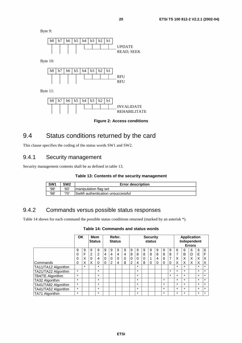
Coding of access conditions
The access conditions for the commands are coded on bytes 9,10 and 11 of the response data of the SELECT command.Each condition is coded on 4 bits as shown in figure 2.
ETSI
ETSI TS 100 812-2 V2.2.1 (2002-04)20
Byte 9:
b8 b7 b6 b5 b4 b3 b2 b1
UPDATEREAD; SEEK
Byte 10:
b8 b7 b6 b5 b4 b3 b2 b1
RFURFU
Byte 11:
b8 b7 b6 b5 b4 b3 b2 b1
INVALIDATEREHABILITATE
Figure 2: Access conditions
9.4 Status conditions returned by the cardThis clause specifies the coding of the status words SW1 and SW2.
9.4.1 Security management
Security management contents shall be as defined in table 13.
Table 13: Contents of the security management
SW1 SW2 Error description'98' '60' manipulation flag set'98' '70' SwMI authentication unsuccessful
9.4.2 Commands versus possible status responses
Table 14 shows for each command the possible status conditions returned (marked by an asterisk *).
Table 14: Commands and status words
OK MemStatus
Refer.Status
Securitystatus
ApplicationIndependent
Errors
Commands
9000
9FXX
920X
9240
9400
9402
9404
9408
9802
9804
9808
9810
9840
9860
9870
67XX
6BXX
6DXX
6EXX
6FXX
TA11/TA12 Algorithm * * * * * * *TA21/TA22 Algorithm * * * * * * * *TB4/TE Algorithm * * * * * * * *TA32 Algorithm * * * * * * * *TA41/TA82 Algorithm * * * * * * * *TA41/TA52 Algorithm * * * * * * * *TA71 Algorithm * * * * * * * *
ETSI
ETSI TS 100 812-2 V2.2.1 (2002-04)21
10 Contents of the EFs
10.1 General on EFsThis clause specifies the EFs for the TETRA session defining access conditions, data items and coding. A data item is apart of an EF which represents a complete logical entity, e.g. the alpha tag in an EFADN record.
EFs or data items having an unassigned value, or, which during the TETRA session, are cleared by the ME, shall havetheir bytes set to 'FF'. After the administrative phase all data items shall have a defined value or have their bytes set to'FF'. If a data item is "deleted" during a TETRA session by the allocation of a value specified in another TETRA TS,then this value shall be used, and the data item is not unassigned.
EFs are mandatory (M) or optional (O). The file size of an optional EF may be zero. All implemented EFs with a filesize greater than zero shall contain all mandatory data items. Optional data items may either be filled with 'F', or, iflocated at the end of an EF, need not exist.
Using the command GET RESPONSE the ME can determine the length of variable length records (e.g. 1 to X).
NOTE: The field "Update activity" has only meaning to the card manufacturer to help choosing proper memorymanagement for EFs. If an EF is updated very seldom, e.g. once during the administrative phase, it is setto "low". If an EF is updated or may be updated in every TETRA session it is set to "high". The actualupdate activity of certain EFs also depends on the system. Therefore the update activity of an EF is set tohigh if it may be updated frequently in some systems. For example, high security systems may want toupdate cipher keys frequently, but less secure systems may update keys only when a particular reason todo it arises.
10.2 Contents of the EFs at the MF levelContents of application independent files at the MF level shall be as specified in TS 102 221 [14].
10.3 Contents of the EFs at the TETRA application level
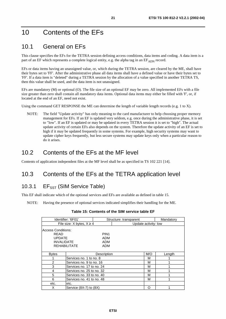
10.3.1 EFSST (SIM Service Table)
This EF shall indicate which of the optional services and EFs are available as defined in table 15.
NOTE: Having the presence of optional services indicated simplifies their handling for the ME.
Table 15: Contents of the SIM service table EF
Identifier: '6F01' Structure: transparent MandatoryFile size: X bytes, X ≥ 4 Update activity: low
Access Conditions:READ PIN1UPDATE ADMINVALIDATE ADMREHABILITATE ADM
Bytes Description M/O Length1 Services no. 1 to no. 8 M 12 Services no. 9 to no. 16 M 13 Services no. 17 to no. 24 M 14 Services no. 25 to no. 32 M 15 Services no. 33 to no. 40 M 16 Services no. 41 to no. 48 M 1
etc. etc.X Service (8X-7) to (8X) O 1
ETSI
ETSI TS 100 812-2 V2.2.1 (2002-04)22
- Services:
Contents:
Service no.1: PIN1 disable function
Service no.2: ADNTETRA (Internal TETRA Phone Book) and Extension A
Service no.3: ADNGWT (External phones), Gateway Extension1 and Gateway table
Service no.4: FDNTETRA and Extension B
Service no.5: FDNGWT, Gateway Extension2 and Gateway table
Service no.6: SDNTETRA
Service no.7: SDNGWT, Gateway Extension3 and Gateway table
Service no.8: LNDTETRA and Extension A
Service no.9: LNDGWT, Gateway Extension1 and Gateway table
Service no.10: RFU
Service no.11: CCK and CCK location areas
Service no.12: SCK
Service no.13: GCK and MGCK
Service no.14: Service Provider Name
Service no.15: Preferred Networks
Service no. 16: Username
Service no. 17: Authentication
Service no. 18: OTAR
Service no. 19: RFU
Service no.20: Enhanced SIM-ME security
Service no.21: RFU
Service no.22: Status message texts
Service no.23: SDS1 message texts
Service no.24: SDS 123 Storage
Service no.25: SDS 4 Storage (including the SDS 4 message storage status)
Service no.26: Call Modifiers
Service no.27: DMO channel information, MS allocation of DMO channels, DMO groups,DMO-TMO associations
Service no.28: List of key holders
Service no.29: DMO repeater and gateway list
Service no.30: SDS Parameters
Service no.31: Default Status Target
Service no.32: SDS Delivery Report
ETSI
ETSI TS 100 812-2 V2.2.1 (2002-04)23
Service no.33: RFU Service no.34: Preferred Location Area
Service no.35: Welcome Message
Service no.36: ADN (External phones), Extension1 and Gateway table
Service no.37: FDN, Extension2 and Gateway table
Service no. 38: SDN, Extension3 and Gateway table
Service no. 39: LND, Extension1 and Gateway table
Service no. 40: LNDComp
Service no. 41: Private Number information
Service no. 42: APN table
Service no. 43: Multi-Group feature
NOTE: Other services are possible in the future and will be coded on further bytes in the EF.
The coding falls under the responsibility of ETSI.
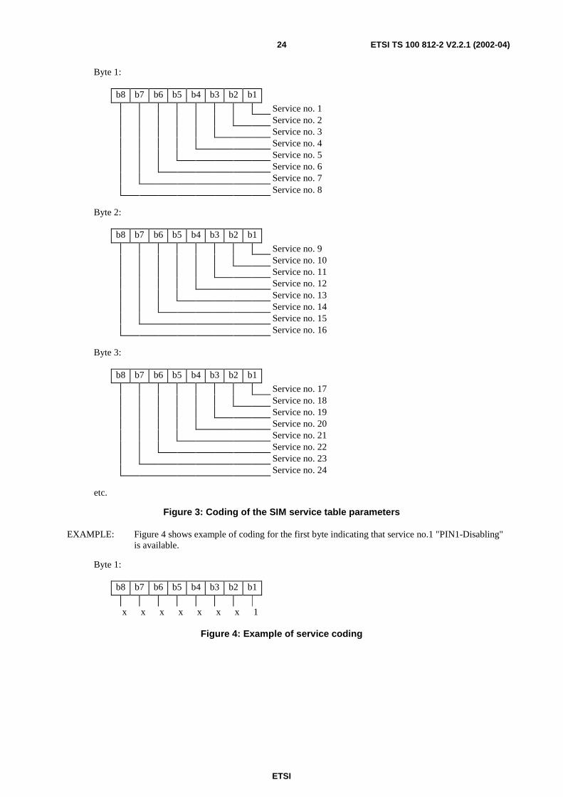
Coding shall be as defined in figure 3.
1 bit is used to code each service:
bit = 1: service available
bit = 0: service not available
ETSI
ETSI TS 100 812-2 V2.2.1 (2002-04)24
Byte 1:
b8 b7 b6 b5 b4 b3 b2 b1
Service no. 1Service no. 2Service no. 3Service no. 4Service no. 5Service no. 6Service no. 7Service no. 8
Byte 2:
b8 b7 b6 b5 b4 b3 b2 b1
Service no. 9Service no. 10Service no. 11Service no. 12Service no. 13Service no. 14Service no. 15Service no. 16
Byte 3:
b8 b7 b6 b5 b4 b3 b2 b1
Service no. 17Service no. 18Service no. 19Service no. 20Service no. 21Service no. 22Service no. 23Service no. 24
etc.
Figure 3: Coding of the SIM service table parameters
EXAMPLE: Figure 4 shows example of coding for the first byte indicating that service no.1 "PIN1-Disabling"is available.
Byte 1:
b8 b7 b6 b5 b4 b3 b2 b1
x x x x x x x 1
Figure 4: Example of service coding
ETSI
ETSI TS 100 812-2 V2.2.1 (2002-04)25
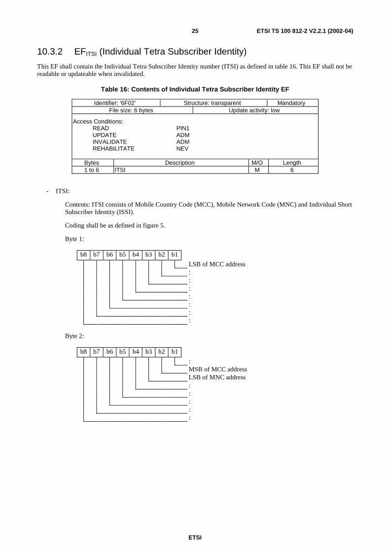
10.3.2 EFITSI (Individual Tetra Subscriber Identity)
This EF shall contain the Individual Tetra Subscriber Identity number (ITSI) as defined in table 16. This EF shall not bereadable or updateable when invalidated.
Table 16: Contents of Individual Tetra Subscriber Identity EF
Identifier: '6F02' Structure: transparent MandatoryFile size: 6 bytes Update activity: low
Access Conditions:READ PIN1UPDATE ADMINVALIDATE ADMREHABILITATE NEV
Bytes Description M/O Length1 to 6 ITSI M 6
- ITSI:
Contents: ITSI consists of Mobile Country Code (MCC), Mobile Network Code (MNC) and Individual ShortSubscriber Identity (ISSI).
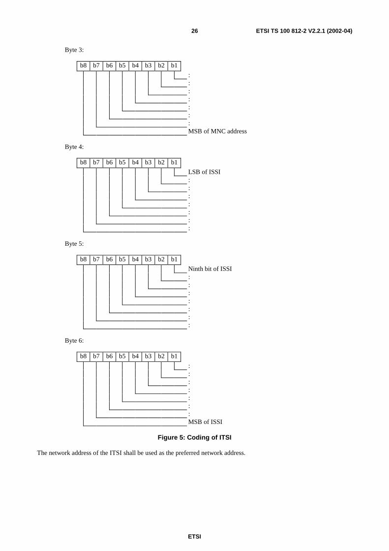
Coding shall be as defined in figure 5.
Byte 1:
b8 b7 b6 b5 b4 b3 b2 b1
LSB of MCC address:::::::
Byte 2:
b8 b7 b6 b5 b4 b3 b2 b1
:MSB of MCC addressLSB of MNC address:::::
ETSI
ETSI TS 100 812-2 V2.2.1 (2002-04)26
Byte 3:
b8 b7 b6 b5 b4 b3 b2 b1
:::::::MSB of MNC address
Byte 4:
b8 b7 b6 b5 b4 b3 b2 b1
LSB of ISSI:::::::
Byte 5:
b8 b7 b6 b5 b4 b3 b2 b1
Ninth bit of ISSI:::::::
Byte 6:
b8 b7 b6 b5 b4 b3 b2 b1
:::::::MSB of ISSI
Figure 5: Coding of ITSI
The network address of the ITSI shall be used as the preferred network address.
ETSI
ETSI TS 100 812-2 V2.2.1 (2002-04)27
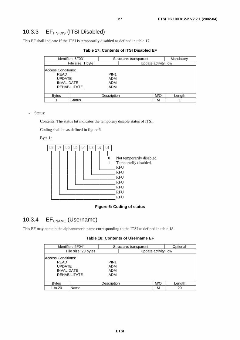
10.3.3 EFITSIDIS (ITSI Disabled)
This EF shall indicate if the ITSI is temporarily disabled as defined in table 17.
Table 17: Contents of ITSI Disabled EF
Identifier: '6F03' Structure: transparent MandatoryFile size: 1 byte Update activity: low
Access Conditions:READ PIN1UPDATE ADMINVALIDATE ADMREHABILITATE ADM
Bytes Description M/O Length1 Status M 1
- Status:
Contents: The status bit indicates the temporary disable status of ITSI.
Coding shall be as defined in figure 6.
Byte 1:
b8 b7 b6 b5 b4 b3 b2 b1
0 Not temporarily disabled1 Temporarily disabled.
RFURFURFURFURFURFURFU
Figure 6: Coding of status
10.3.4 EFUNAME (Username)
This EF may contain the alphanumeric name corresponding to the ITSI as defined in table 18.
Table 18: Contents of Username EF
Identifier: '6F04' Structure: transparent OptionalFile size: 20 bytes Update activity: low
Access Conditions:READ PIN1UPDATE ADMINVALIDATE ADMREHABILITATE ADM
Bytes Description M/O Length1 to 20 Name M 20
ETSI
ETSI TS 100 812-2 V2.2.1 (2002-04)28
- Name:
Contents: The common name of the card holder to be displayed.
Coding: According to the default 8-bit alphabet ISO/IEC 8859-1 [9]. Unused bytes shall be set as 'FF'.
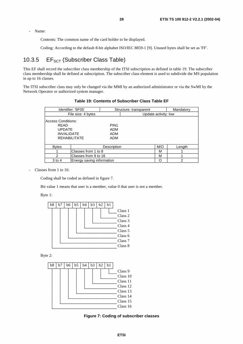
10.3.5 EFSCT (Subscriber Class Table)
This EF shall record the subscriber class membership of the ITSI subscription as defined in table 19. The subscriberclass membership shall be defined at subscription. The subscriber class element is used to subdivide the MS populationin up to 16 classes.
The ITSI subscriber class may only be changed via the MMI by an authorized administrator or via the SwMI by theNetwork Operator or authorized system manager.
Table 19: Contents of Subscriber Class Table EF
Identifier: '6F05' Structure: transparent MandatoryFile size: 4 bytes Update activity: low
Access Conditions:READ PIN1UPDATE ADMINVALIDATE ADMREHABILITATE ADM
Bytes Description M/O Length1 Classes from 1 to 8 M 12 Classes from 9 to 16 M 1
3 to 4 Energy saving information O 2
- Classes from 1 to 16:
Coding shall be coded as defined in figure 7.
Bit value 1 means that user is a member, value 0 that user is not a member.
Byte 1:
b8 b7 b6 b5 b4 b3 b2 b1
Class 1Class 2Class 3Class 4Class 5Class 6Class 7Class 8
Byte 2:
b8 b7 b6 b5 b4 b3 b2 b1
Class 9Class 10Class 11Class 12Class 13Class 14Class 15Class 16
Figure 7: Coding of subscriber classes
ETSI
ETSI TS 100 812-2 V2.2.1 (2002-04)29
- Energy Saving Information:
Contents: Indicates which energy saving scheme (if any) is in operation and the starting point of the energyeconomy mode.
Coding: As per EN 300 392-2 [3] (14 bits) with b8 and b7 of first byte RFU.
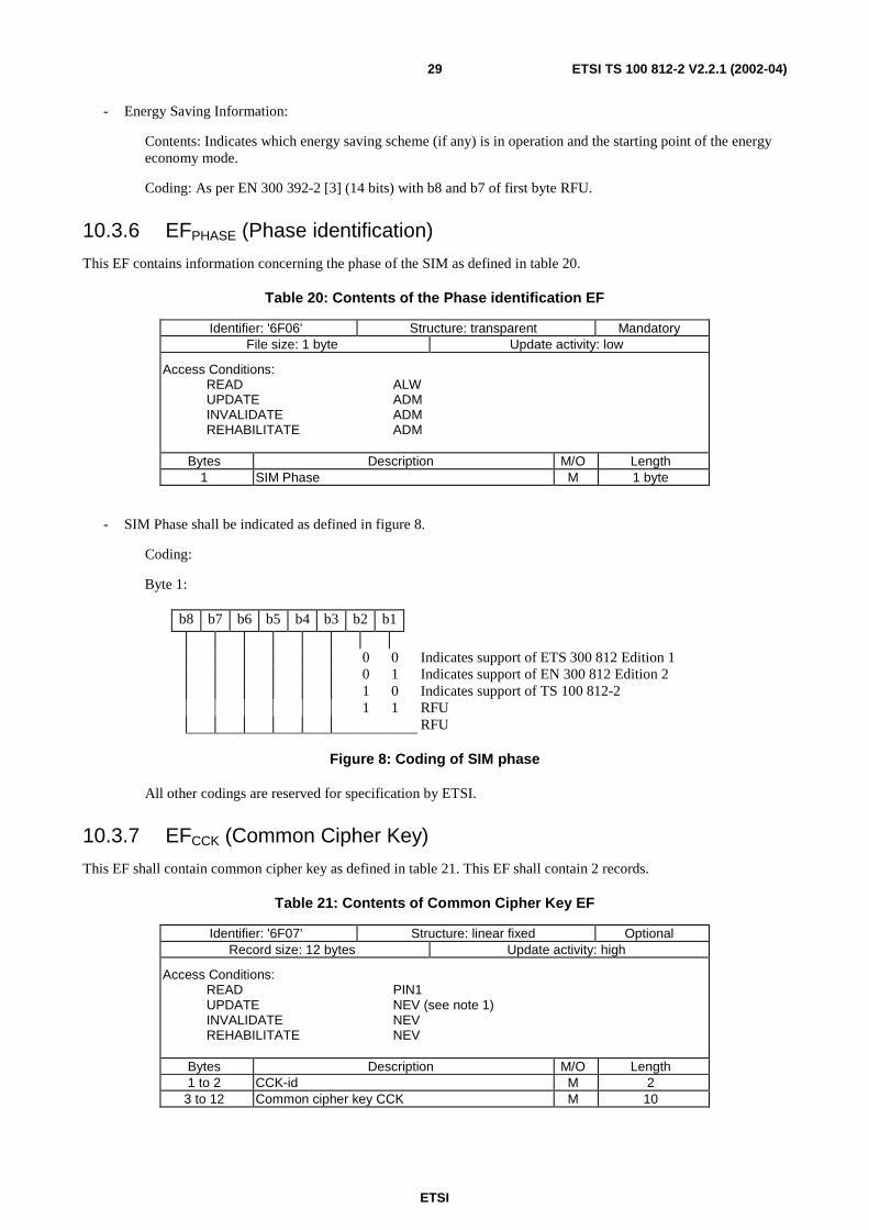
10.3.6 EFPHASE (Phase identification)
This EF contains information concerning the phase of the SIM as defined in table 20.
Table 20: Contents of the Phase identification EF
Identifier: '6F06' Structure: transparent MandatoryFile size: 1 byte Update activity: low
Access Conditions:READ ALWUPDATE ADMINVALIDATE ADMREHABILITATE ADM
Bytes Description M/O Length1 SIM Phase M 1 byte
- SIM Phase shall be indicated as defined in figure 8.
Coding:
Byte 1:
b8 b7 b6 b5 b4 b3 b2 b1
0 0 Indicates support of ETS 300 812 Edition 10 1 Indicates support of EN 300 812 Edition 21 0 Indicates support of TS 100 812-21 1 RFU
RFU
Figure 8: Coding of SIM phase
All other codings are reserved for specification by ETSI.
10.3.7 EFCCK (Common Cipher Key)
This EF shall contain common cipher key as defined in table 21. This EF shall contain 2 records.
Table 21: Contents of Common Cipher Key EF
Identifier: '6F07' Structure: linear fixed OptionalRecord size: 12 bytes Update activity: high
Access Conditions:READ PIN1UPDATE NEV (see note 1)INVALIDATE NEVREHABILITATE NEV
Bytes Description M/O Length1 to 2 CCK-id M 2
3 to 12 Common cipher key CCK M 10
ETSI
ETSI TS 100 812-2 V2.2.1 (2002-04)30
NOTE: This EF is updated using the TA32 algorithm on the SIM.
If SIM Service 20 is set (Enhanced SIM-ME security) the enhanced security algorithm TE shall be automatically run bythe SIM to seal the record with Enhanced Security Key (KE) before sending it to the ME.
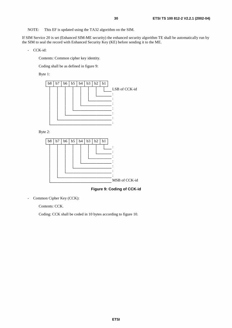
- CCK-id:
Contents: Common cipher key identity.
Coding shall be as defined in figure 9:
Byte 1:
b8 b7 b6 b5 b4 b3 b2 b1
LSB of CCK-id:::::::
Byte 2:
b8 b7 b6 b5 b4 b3 b2 b1
:::::::MSB of CCK-id
Figure 9: Coding of CCK-id
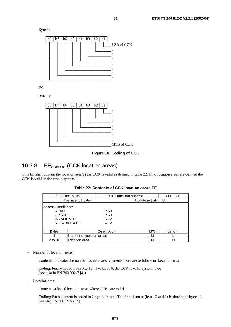
- Common Cipher Key (CCK):
Contents: CCK.
Coding: CCK shall be coded in 10 bytes according to figure 10.
ETSI
ETSI TS 100 812-2 V2.2.1 (2002-04)31
Byte 3:
b8 b7 b6 b5 b4 b3 b2 b1
LSB of CCK:::::::
etc.
Byte 12:
b8 b7 b6 b5 b4 b3 b2 b1
:::::::MSB of CCK
Figure 10: Coding of CCK
10.3.8 EFCCKLOC (CCK location areas)
This EF shall contain the location area(s) the CCK is valid as defined in table 22. If no location areas are defined theCCK is valid in the whole system.
Table 22: Contents of CCK location areas EF
Identifier: '6F08' Structure: transparent OptionalFile size: 31 bytes Update activity: high
Access Conditions:READ PIN1UPDATE PIN1INVALIDATE ADMREHABILITATE ADM
Bytes Description M/O Length1 Number of location areas M 1
2 to 31 Location area O 30
- Number of location areas:
Contents: indicates the number location area elements there are to follow in 'Location area'.
Coding: binary coded from 0 to 15. If value is 0, the CCK is valid system wide(see also in EN 300 392-7 [4]).
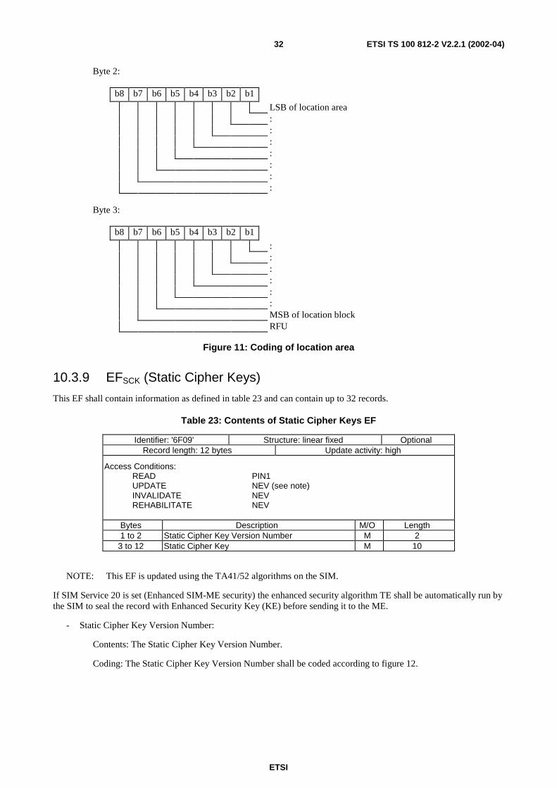
- Location area:
Contents: a list of location areas where CCKs are valid.
Coding: Each element is coded in 2 bytes, 14 bits. The first element (bytes 2 and 3) is shown in figure 11.See also EN 300 392-7 [4].
ETSI
ETSI TS 100 812-2 V2.2.1 (2002-04)32
Byte 2:
b8 b7 b6 b5 b4 b3 b2 b1
LSB of location area:::::::
Byte 3:
b8 b7 b6 b5 b4 b3 b2 b1
::::::MSB of location blockRFU
Figure 11: Coding of location area
10.3.9 EFSCK (Static Cipher Keys)
This EF shall contain information as defined in table 23 and can contain up to 32 records.
Table 23: Contents of Static Cipher Keys EF
Identifier: '6F09' Structure: linear fixed OptionalRecord length: 12 bytes Update activity: high
Access Conditions:READ PIN1UPDATE NEV (see note)INVALIDATE NEVREHABILITATE NEV
Bytes Description M/O Length1 to 2 Static Cipher Key Version Number M 2
3 to 12 Static Cipher Key M 10
NOTE: This EF is updated using the TA41/52 algorithms on the SIM.
If SIM Service 20 is set (Enhanced SIM-ME security) the enhanced security algorithm TE shall be automatically run bythe SIM to seal the record with Enhanced Security Key (KE) before sending it to the ME.
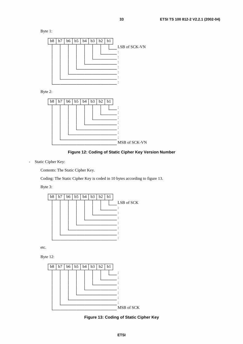
- Static Cipher Key Version Number:
Contents: The Static Cipher Key Version Number.
Coding: The Static Cipher Key Version Number shall be coded according to figure 12.
ETSI
ETSI TS 100 812-2 V2.2.1 (2002-04)33
Byte 1:
b8 b7 b6 b5 b4 b3 b2 b1
LSB of SCK-VN:::::::
Byte 2:
b8 b7 b6 b5 b4 b3 b2 b1
:::::::MSB of SCK-VN
Figure 12: Coding of Static Cipher Key Version Number
- Static Cipher Key:
Contents: The Static Cipher Key.
Coding: The Static Cipher Key is coded in 10 bytes according to figure 13.
Byte 3:
b8 b7 b6 b5 b4 b3 b2 b1
LSB of SCK:::::::
etc.
Byte 12:
b8 b7 b6 b5 b4 b3 b2 b1
:::::::MSB of SCK
Figure 13: Coding of Static Cipher Key
ETSI
ETSI TS 100 812-2 V2.2.1 (2002-04)34
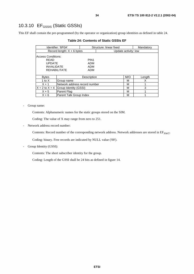
10.3.10 EFGSSIS (Static GSSIs)
This EF shall contain the pre-programmed (by the operator or organization) group identities as defined in table 24.
Table 24: Contents of Static GSSIs EF
Identifier: '6F0A' Structure: linear fixed MandatoryRecord length: X + 6 bytes Update activity: low
Access Conditions:READ PIN1UPDATE ADMINVALIDATE ADMREHABILITATE ADM
Bytes Description M/O Length1 to X Group name M XX + 1 Network address record number M 1
X + 2 to X + 4 Group Identity (GSSI) M 3X + 5 Parent Flag M 1X + 6 Parent Talk Group Index M 1
- Group name:
Contents: Alphanumeric names for the static groups stored on the SIM.
Coding: The value of X may range from zero to 251.
- Network address record number:
Contents: Record number of the corresponding network address. Network addresses are stored in EFNWT.
Coding: binary. Free records are indicated by NULL value ('00').
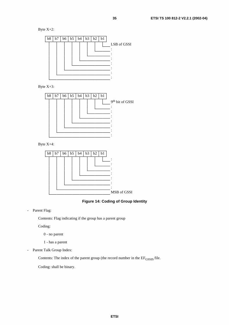
- Group Identity (GSSI):
Contents: The short subscriber identity for the group.
Coding: Length of the GSSI shall be 24 bits as defined in figure 14.
ETSI
ETSI TS 100 812-2 V2.2.1 (2002-04)35
Byte X+2:
b8 b7 b6 b5 b4 b3 b2 b1
LSB of GSSI:::::::
Byte X+3:
b8 b7 b6 b5 b4 b3 b2 b1
9th bit of GSSI:::::::
Byte X+4:
b8 b7 b6 b5 b4 b3 b2 b1
:::::::MSB of GSSI
Figure 14: Coding of Group Identity
- Parent Flag:
Contents: Flag indicating if the group has a parent group
Coding:
0 - no parent
1 - has a parent
- Parent Talk Group Index:
Contents: The index of the parent group (the record number in the EFGSSIS file.
Coding: shall be binary.
ETSI
ETSI TS 100 812-2 V2.2.1 (2002-04)36
10.3.11 EFGRDS (Group related data for static GSSIs)
This EF shall contain information related to each static GSSI as defined in table 25. There shall be a 1:1 relationshipbetween each record in EFGRDS and the corresponding record in EFGSSIS.
Table 25: Contents of Group related data for static GSSIs EF
Identifier: '6F0B' Structure: linear fixed MandatoryRecord size: 2 bytes Update activity: low
Access Conditions:READ PIN1UPDATE PIN1INVALIDATE ADMREHABILITATE ADM
Bytes Description M/O Length1 Key record number M 12 Group related data M 1
- Key record number:
Contents: Class 2 systems record number of the corresponding SCK in the EFSCK-file.
Contents: Class 3 systems record number of the corresponding GCK in the EFGCK-file.
Coding: binary. In class 2 systems if there is no SCK defined for this group, key record number shall beNULL value ('00').
Coding: binary. In class 3 systems if there is no GCK defined for this group, key record number shall beNULL value ('00').
- Group related data:
Contents:
Group Identity lifetime (2 bits): Shall indicate the attachment lifetime of the group identity as defined intable 26 copied from EN 300 392-2 [3], clause 16.10.16.
Class of usage (3 bits). Shall indicate the importance of the group for the user and define the participationrules for the groups defined with Class of usage. (EN 300 392-2 [3] and ETS 300 392-12-22 [8]).
Permanent Detachment Flag (1 bit). Shall indicate that whether a group identity was permanent detached bythe SwMI.
MS user is allowed to request an attachment (1 bit): Shall indicate whether MS user is allowed to request anattachment.
Table 26: Group identity attachment lifetime
Information element Length Value RemarkGroup Identity Lifetime 2 00 attachment not needed
01 attachment for next ITSI attach required10 attachment not allowed for next ITSI attach11 attachment for next location update required
Coding: shall be as defined in figure 56.
ETSI
ETSI TS 100 812-2 V2.2.1 (2002-04)37
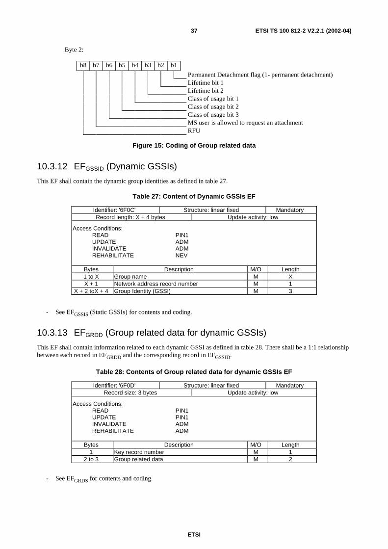
Byte 2:
b8 b7 b6 b5 b4 b3 b2 b1
Permanent Detachment flag (1- permanent detachment)Lifetime bit 1Lifetime bit 2Class of usage bit 1Class of usage bit 2Class of usage bit 3MS user is allowed to request an attachmentRFU
Figure 15: Coding of Group related data
10.3.12 EFGSSID (Dynamic GSSIs)
This EF shall contain the dynamic group identities as defined in table 27.
Table 27: Content of Dynamic GSSIs EF
Identifier: '6F0C' Structure: linear fixed MandatoryRecord length: X + 4 bytes Update activity: low
Access Conditions:READ PIN1UPDATE ADMINVALIDATE ADMREHABILITATE NEV
Bytes Description M/O Length1 to X Group name M XX + 1 Network address record number M 1
X + 2 toX + 4 Group Identity (GSSI) M 3
- See EFGSSIS (Static GSSIs) for contents and coding.
10.3.13 EFGRDD (Group related data for dynamic GSSIs)
This EF shall contain information related to each dynamic GSSI as defined in table 28. There shall be a 1:1 relationshipbetween each record in EFGRDD and the corresponding record in EFGSSID.
Table 28: Contents of Group related data for dynamic GSSIs EF
Identifier: '6F0D' Structure: linear fixed MandatoryRecord size: 3 bytes Update activity: low
Access Conditions:READ PIN1UPDATE PIN1INVALIDATE ADMREHABILITATE ADM
Bytes Description M/O Length1 Key record number M 1
2 to 3 Group related data M 2
- See EFGRDS for contents and coding.
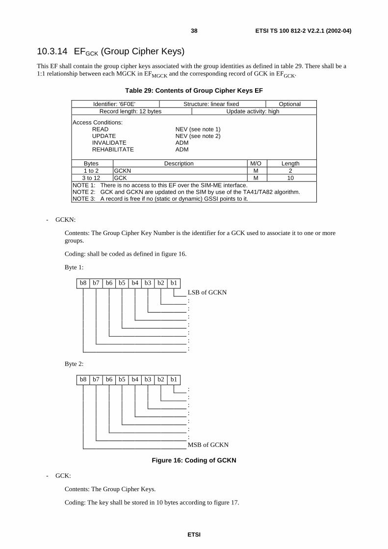
ETSI
ETSI TS 100 812-2 V2.2.1 (2002-04)38
10.3.14 EFGCK (Group Cipher Keys)
This EF shall contain the group cipher keys associated with the group identities as defined in table 29. There shall be a1:1 relationship between each MGCK in EFMGCK and the corresponding record of GCK in EFGCK.
Table 29: Contents of Group Cipher Keys EF
Identifier: '6F0E' Structure: linear fixed OptionalRecord length: 12 bytes Update activity: high
Access Conditions:READ NEV (see note 1)UPDATE NEV (see note 2)INVALIDATE ADMREHABILITATE ADM
Bytes Description M/O Length1 to 2 GCKN M 2
3 to 12 GCK M 10NOTE 1: There is no access to this EF over the SIM-ME interface.NOTE 2: GCK and GCKN are updated on the SIM by use of the TA41/TA82 algorithm.NOTE 3: A record is free if no (static or dynamic) GSSI points to it.
- GCKN:
Contents: The Group Cipher Key Number is the identifier for a GCK used to associate it to one or moregroups.
Coding: shall be coded as defined in figure 16.
Byte 1:
b8 b7 b6 b5 b4 b3 b2 b1
LSB of GCKN:::::::
Byte 2:
b8 b7 b6 b5 b4 b3 b2 b1
:::::::MSB of GCKN
Figure 16: Coding of GCKN
- GCK:
Contents: The Group Cipher Keys.
Coding: The key shall be stored in 10 bytes according to figure 17.
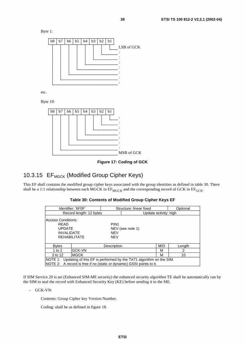
ETSI
ETSI TS 100 812-2 V2.2.1 (2002-04)39
Byte 1:
b8 b7 b6 b5 b4 b3 b2 b1
LSB of GCK:::::::
etc.
Byte 10:
b8 b7 b6 b5 b4 b3 b2 b1
:::::::MSB of GCK
Figure 17: Coding of GCK
10.3.15 EFMGCK (Modified Group Cipher Keys)
This EF shall contains the modified group cipher keys associated with the group identities as defined in table 30. Thereshall be a 1:1 relationship between each MGCK in EFMGCK and the corresponding record of GCK in EFGCK.
Table 30: Contents of Modified Group Cipher Keys EF
Identifier: '6F0F' Structure: linear fixed OptionalRecord length: 12 bytes Update activity: high
Access Conditions:READ PIN1UPDATE NEV (see note 1)INVALIDATE NEVREHABILITATE NEV
Bytes Description M/O Length1 to 2 GCK-VN M 2
3 to 12 MGCK M 10NOTE 1: Updating of this EF is performed by the TA71 algorithm on the SIM.NOTE 2: A record is free if no (static or dynamic) GSSI points to it.
If SIM Service 20 is set (Enhanced SIM-ME security) the enhanced security algorithm TE shall be automatically run bythe SIM to seal the record with Enhanced Security Key (KE) before sending it to the ME.
- GCK-VN:
Contents: Group Cipher key Version Number.
Coding: shall be as defined in figure 18.
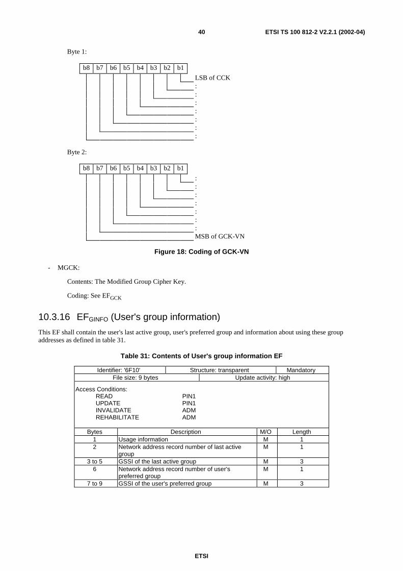
ETSI
ETSI TS 100 812-2 V2.2.1 (2002-04)40
Byte 1:
b8 b7 b6 b5 b4 b3 b2 b1
LSB of CCK:::::::
Byte 2:
b8 b7 b6 b5 b4 b3 b2 b1
:::::::MSB of GCK-VN
Figure 18: Coding of GCK-VN
- MGCK:
Contents: The Modified Group Cipher Key.
Coding: See EFGCK
10.3.16 EFGINFO (User's group information)
This EF shall contain the user's last active group, user's preferred group and information about using these groupaddresses as defined in table 31.
Table 31: Contents of User's group information EF
Identifier: '6F10' Structure: transparent MandatoryFile size: 9 bytes Update activity: high
Access Conditions:READ PIN1UPDATE PIN1INVALIDATE ADMREHABILITATE ADM
Bytes Description M/O Length1 Usage information M 12 Network address record number of last active
groupM 1
3 to 5 GSSI of the last active group M 36 Network address record number of user's
preferred groupM 1
7 to 9 GSSI of the user's preferred group M 3
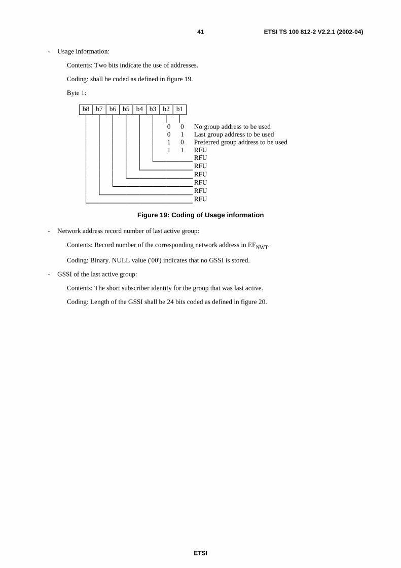
ETSI
ETSI TS 100 812-2 V2.2.1 (2002-04)41
- Usage information:
Contents: Two bits indicate the use of addresses.
Coding: shall be coded as defined in figure 19.
Byte 1:
b8 b7 b6 b5 b4 b3 b2 b1
0 0 No group address to be used0 1 Last group address to be used1 0 Preferred group address to be used1 1 RFU
RFURFURFURFURFURFU
Figure 19: Coding of Usage information
- Network address record number of last active group:
Contents: Record number of the corresponding network address in EFNWT.
Coding: Binary. NULL value ('00') indicates that no GSSI is stored.
- GSSI of the last active group:
Contents: The short subscriber identity for the group that was last active.
Coding: Length of the GSSI shall be 24 bits coded as defined in figure 20.
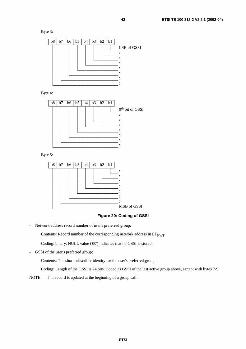
ETSI
ETSI TS 100 812-2 V2.2.1 (2002-04)42
Byte 3:
b8 b7 b6 b5 b4 b3 b2 b1
LSB of GSSI:::::::
Byte 4:
b8 b7 b6 b5 b4 b3 b2 b1
9th bit of GSSI:::::::
Byte 5:
b8 b7 b6 b5 b4 b3 b2 b1
:::::::MSB of GSSI
Figure 20: Coding of GSSI
- Network address record number of user's preferred group:
Contents: Record number of the corresponding network address in EFNWT.
Coding: binary. NULL value ('00') indicates that no GSSI is stored.
- GSSI of the user's preferred group:
Contents: The short subscriber identity for the user's preferred group.
Coding: Length of the GSSI is 24 bits. Coded as GSSI of the last active group above, except with bytes 7-9.
NOTE: This record is updated at the beginning of a group call.
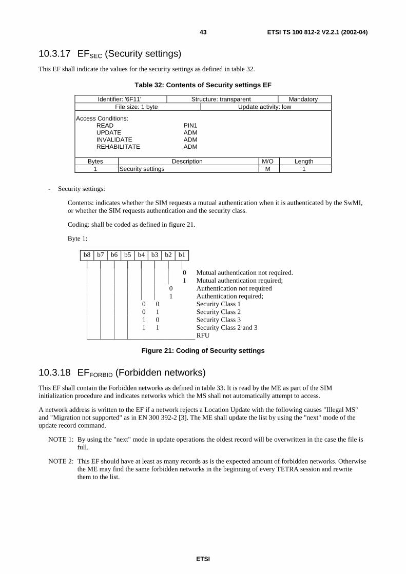
ETSI
ETSI TS 100 812-2 V2.2.1 (2002-04)43
10.3.17 EFSEC (Security settings)
This EF shall indicate the values for the security settings as defined in table 32.
Table 32: Contents of Security settings EF
Identifier: '6F11' Structure: transparent MandatoryFile size: 1 byte Update activity: low
Access Conditions:READ PIN1UPDATE ADMINVALIDATE ADMREHABILITATE ADM
Bytes Description M/O Length1 Security settings M 1
- Security settings:
Contents: indicates whether the SIM requests a mutual authentication when it is authenticated by the SwMI,or whether the SIM requests authentication and the security class.
Coding: shall be coded as defined in figure 21.
Byte 1:
b8 b7 b6 b5 b4 b3 b2 b1
0 Mutual authentication not required.1 Mutual authentication required;
0 Authentication not required1 Authentication required;
0 0 Security Class 10 1 Security Class 21 0 Security Class 31 1 Security Class 2 and 3
RFU
Figure 21: Coding of Security settings
10.3.18 EFFORBID (Forbidden networks)
This EF shall contain the Forbidden networks as defined in table 33. It is read by the ME as part of the SIMinitialization procedure and indicates networks which the MS shall not automatically attempt to access.
A network address is written to the EF if a network rejects a Location Update with the following causes "Illegal MS"and "Migration not supported" as in EN 300 392-2 [3]. The ME shall update the list by using the "next" mode of theupdate record command.
NOTE 1: By using the "next" mode in update operations the oldest record will be overwritten in the case the file isfull.
NOTE 2: This EF should have at least as many records as is the expected amount of forbidden networks. Otherwisethe ME may find the same forbidden networks in the beginning of every TETRA session and rewritethem to the list.
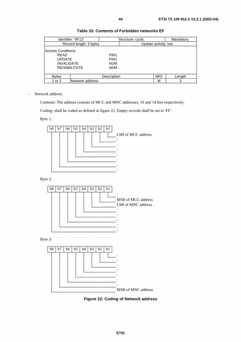
ETSI
ETSI TS 100 812-2 V2.2.1 (2002-04)44
Table 33: Contents of Forbidden networks EF
Identifier: '6F12' Structure: cyclic MandatoryRecord length: 3 bytes Update activity: low
Access Conditions:READ PIN1UPDATE PIN1INVALIDATE ADMREHABILITATE ADM
Bytes Description M/O Length1 to 3 Network address M 3
- Network address:
Contents: The address consists of MCC and MNC addresses, 10 and 14 bits respectively.
Coding: shall be coded as defined in figure 22. Empty records shall be set to 'FF'.
Byte 1:
b8 b7 b6 b5 b4 b3 b2 b1
LSB of MCC address:::::::
Byte 2:
b8 b7 b6 b5 b4 b3 b2 b1
:MSB of MCC addressLSB of MNC address:::::
Byte 3:
b8 b7 b6 b5 b4 b3 b2 b1
:::::::MSB of MNC address
Figure 22: Coding of Network address
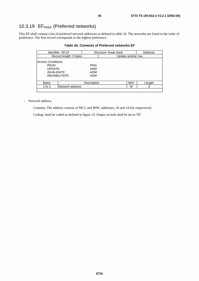
ETSI
ETSI TS 100 812-2 V2.2.1 (2002-04)45
10.3.19 EFPREF (Preferred networks)
This EF shall contain a list of preferred network addresses as defined in table 34. The networks are listed in the order ofpreference. The first record corresponds to the highest preference.
Table 34: Contents of Preferred networks EF
Identifier: '6F13' Structure: linear fixed OptionalRecord length: 3 bytes Update activity: low
Access Conditions:READ PIN1UPDATE ADMINVALIDATE ADMREHABILITATE ADM
Bytes Description M/O Length1 to 3 Network address M 3
- Network address:
Contents: The address consists of MCC and MNC addresses, 10 and 14 bits respectively.
Coding: shall be coded as defined in figure 23. Empty records shall be set to 'FF'.
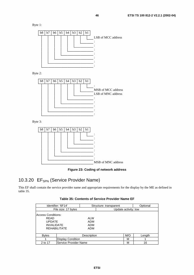
ETSI
ETSI TS 100 812-2 V2.2.1 (2002-04)46
Byte 1:
b8 b7 b6 b5 b4 b3 b2 b1
LSB of MCC address:::::::
Byte 2:
b8 b7 b6 b5 b4 b3 b2 b1
:MSB of MCC addressLSB of MNC address:::::
Byte 3:
b8 b7 b6 b5 b4 b3 b2 b1
:::::::MSB of MNC address
Figure 23: Coding of network address
10.3.20 EFSPN (Service Provider Name)
This EF shall contain the service provider name and appropriate requirements for the display by the ME as defined intable 35.
Table 35: Contents of Service Provider Name EF
Identifier: '6F14' Structure: transparent OptionalFile size: 17 bytes Update activity: low
Access Conditions:READ ALWUPDATE ADMINVALIDATE ADMREHABILITATE ADM
Bytes Description M/O Length1 Display Condition M 1
2 to 17 Service Provider Name M 16
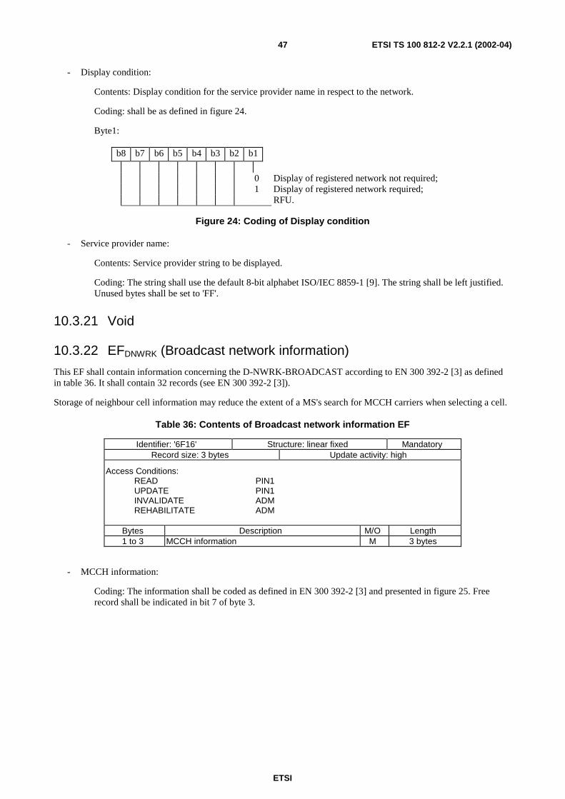
ETSI
ETSI TS 100 812-2 V2.2.1 (2002-04)47
- Display condition:
Contents: Display condition for the service provider name in respect to the network.
Coding: shall be as defined in figure 24.
Byte1:
b8 b7 b6 b5 b4 b3 b2 b1
0 Display of registered network not required;1 Display of registered network required;
RFU.
Figure 24: Coding of Display condition
- Service provider name:
Contents: Service provider string to be displayed.
Coding: The string shall use the default 8-bit alphabet ISO/IEC 8859-1 [9]. The string shall be left justified.Unused bytes shall be set to 'FF'.
10.3.21 Void
10.3.22 EFDNWRK (Broadcast network information)
This EF shall contain information concerning the D-NWRK-BROADCAST according to EN 300 392-2 [3] as definedin table 36. It shall contain 32 records (see EN 300 392-2 [3]).
Storage of neighbour cell information may reduce the extent of a MS's search for MCCH carriers when selecting a cell.
Table 36: Contents of Broadcast network information EF
Identifier: '6F16' Structure: linear fixed MandatoryRecord size: 3 bytes Update activity: high
Access Conditions:READ PIN1UPDATE PIN1INVALIDATE ADMREHABILITATE ADM
Bytes Description M/O Length1 to 3 MCCH information M 3 bytes
- MCCH information:
Coding: The information shall be coded as defined in EN 300 392-2 [3] and presented in figure 25. Freerecord shall be indicated in bit 7 of byte 3.
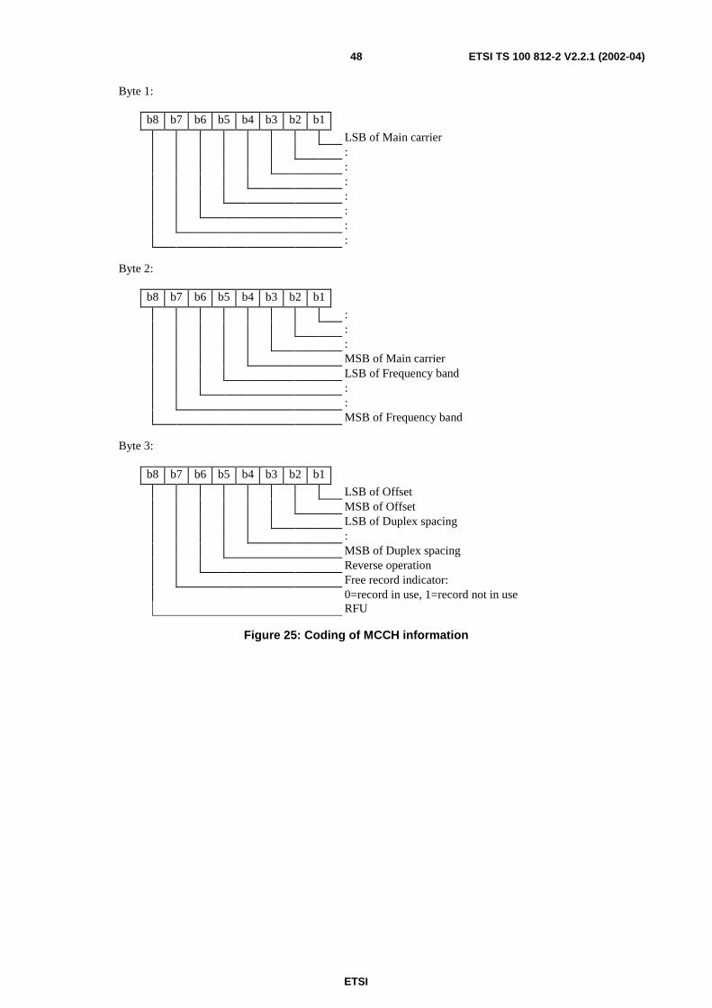
ETSI
ETSI TS 100 812-2 V2.2.1 (2002-04)48
Byte 1:
b8 b7 b6 b5 b4 b3 b2 b1
LSB of Main carrier:::::::
Byte 2:
b8 b7 b6 b5 b4 b3 b2 b1
:::MSB of Main carrierLSB of Frequency band::MSB of Frequency band
Byte 3:
b8 b7 b6 b5 b4 b3 b2 b1
LSB of OffsetMSB of OffsetLSB of Duplex spacing:MSB of Duplex spacingReverse operationFree record indicator:0=record in use, 1=record not in useRFU
Figure 25: Coding of MCCH information
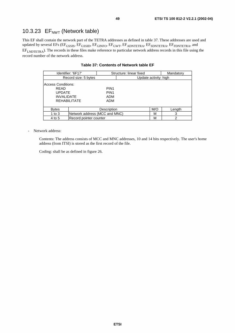
ETSI
ETSI TS 100 812-2 V2.2.1 (2002-04)49
10.3.23 EFNWT (Network table)
This EF shall contain the network part of the TETRA addresses as defined in table 37. These addresses are used andupdated by several EFs (EFGSSIS, EFGSSID, EFGINFO, EFGWT, EFADNTETRA, EFSDNTETRA, EFFDNTETRA, and
EFLNDTETRA). The records in these files make reference to particular network address records in this file using the
record number of the network address.
Table 37: Contents of Network table EF
Identifier: '6F17' Structure: linear fixed MandatoryRecord size: 5 bytes Update activity: high
Access Conditions:READ PIN1UPDATE PIN1INVALIDATE ADMREHABILITATE ADM
Bytes Description M/O Length1 to 3 Network address (MCC and MNC) M 34 to 5 Record pointer counter M 2
- Network address:
Contents: The address consists of MCC and MNC addresses, 10 and 14 bits respectively. The user's homeaddress (from ITSI) is stored as the first record of the file.
Coding: shall be as defined in figure 26.
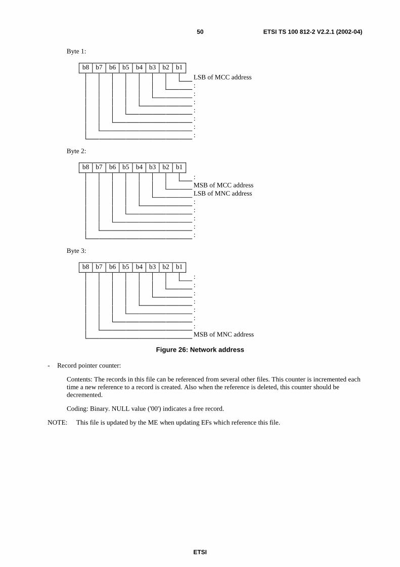
ETSI
ETSI TS 100 812-2 V2.2.1 (2002-04)50
Byte 1:
b8 b7 b6 b5 b4 b3 b2 b1
LSB of MCC address:::::::
Byte 2:
b8 b7 b6 b5 b4 b3 b2 b1
:MSB of MCC addressLSB of MNC address:::::
Byte 3:
b8 b7 b6 b5 b4 b3 b2 b1
:::::::MSB of MNC address
Figure 26: Network address
- Record pointer counter:
Contents: The records in this file can be referenced from several other files. This counter is incremented eachtime a new reference to a record is created. Also when the reference is deleted, this counter should bedecremented.
Coding: Binary. NULL value ('00') indicates a free record.
NOTE: This file is updated by the ME when updating EFs which reference this file.
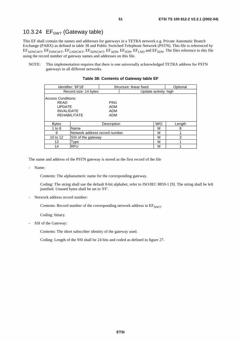
ETSI
ETSI TS 100 812-2 V2.2.1 (2002-04)51
10.3.24 EFGWT (Gateway table)
This EF shall contain the names and addresses for gateways in a TETRA network e.g. Private Automatic BranchExchange (PABX) as defined in table 38 and Public Switched Telephone Network (PSTN). This file is referenced byEFADNGWT, EFFDNGWT, EFLNDGWT, EFSDNGWT, EFADN, EFFDN, EFLND and EFSDN. The files reference to this file
using the record number of gateway names and addresses on this file.
NOTE: This implementation requires that there is one universally acknowledged TETRA address for PSTNgateways in all different networks.
Table 38: Contents of Gateway table EF
Identifier: '6F18' Structure: linear fixed OptionalRecord size: 14 bytes Update activity: high
Access Conditions:READ PIN1UPDATE ADMINVALIDATE ADMREHABILITATE ADM
Bytes Description M/O Length1 to 8 Name M 8
9 Network address record number M 110 to 12 SSI of the gateway M 3
13 Type M 114 RFU M 1
The name and address of the PSTN gateway is stored as the first record of the file
- Name:
Contents: The alphanumeric name for the corresponding gateway.
Coding: The string shall use the default 8-bit alphabet, refer to ISO/IEC 8859-1 [9]. The string shall be leftjustified. Unused bytes shall be set to 'FF'.
- Network address record number:
Contents: Record number of the corresponding network address in EFNWT.
Coding: binary.
- SSI of the Gateway:
Contents: The short subscriber identity of the gateway used.
Coding: Length of the SSI shall be 24 bits and coded as defined in figure 27.
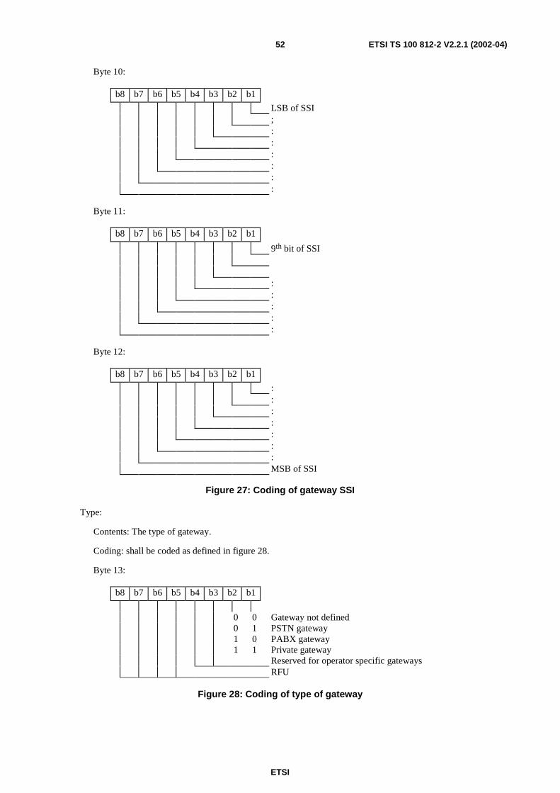
ETSI
ETSI TS 100 812-2 V2.2.1 (2002-04)52
Byte 10:
b8 b7 b6 b5 b4 b3 b2 b1
LSB of SSI;::::::
Byte 11:
b8 b7 b6 b5 b4 b3 b2 b1
9th bit of SSI
:::::
Byte 12:
b8 b7 b6 b5 b4 b3 b2 b1
:::::::MSB of SSI
Figure 27: Coding of gateway SSI
Type:
Contents: The type of gateway.
Coding: shall be coded as defined in figure 28.
Byte 13:
b8 b7 b6 b5 b4 b3 b2 b1
0 0 Gateway not defined0 1 PSTN gateway1 0 PABX gateway1 1 Private gateway
Reserved for operator specific gatewaysRFU
Figure 28: Coding of type of gateway
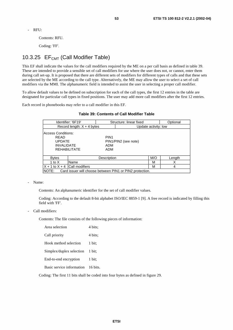
ETSI
ETSI TS 100 812-2 V2.2.1 (2002-04)53
- RFU:
Contents: RFU.
Coding: 'FF'.
10.3.25 EFCMT (Call Modifier Table)
This EF shall indicate the values for the call modifiers required by the ME on a per call basis as defined in table 39.These are intended to provide a sensible set of call modifiers for use where the user does not, or cannot, enter themduring call set-up. It is proposed that there are different sets of modifiers for different types of calls and that these setsare selected by the ME according to the call type. Alternatively, the ME may allow the user to select a set of callmodifiers via the MMI. The alphanumeric field is intended to assist the user in selecting a proper call modifier.
To allow default values to be defined on subscription for each of the call types, the first 12 entries in the table aredesignated for particular call types in fixed positions. The user may add more call modifiers after the first 12 entries.
Each record in phonebooks may refer to a call modifier in this EF.
Table 39: Contents of Call Modifier Table
Identifier: '6F19' Structure: linear fixed OptionalRecord length: X + 4 bytes Update activity: low
Access Conditions:READ PIN1UPDATE PIN1/PIN2 (see note)INVALIDATE ADMREHABILITATE ADM
Bytes Description M/O Length1 to X Name M X
X + 1 to X + 4 Call modifiers M 4NOTE: Card issuer will choose between PIN1 or PIN2 protection.
- Name:
Contents: An alphanumeric identifier for the set of call modifier values.
Coding: According to the default 8-bit alphabet ISO/IEC 8859-1 [9]. A free record is indicated by filling thisfield with 'FF'.
- Call modifiers:
Contents: The file consists of the following pieces of information:
Area selection 4 bits;
Call priority 4 bits;
Hook method selection 1 bit;
Simplex/duplex selection 1 bit;
End-to-end encryption 1 bit;
Basic service information 16 bits.
Coding: The first 11 bits shall be coded into four bytes as defined in figure 29.
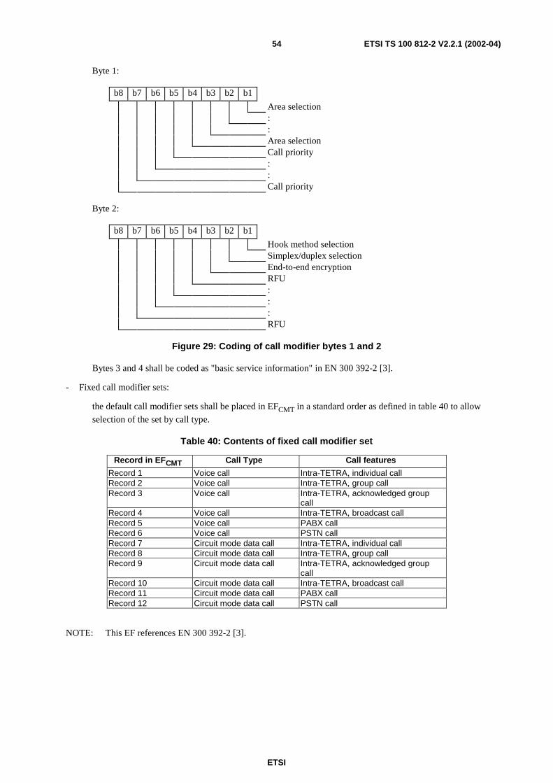
ETSI
ETSI TS 100 812-2 V2.2.1 (2002-04)54
Byte 1:
b8 b7 b6 b5 b4 b3 b2 b1
Area selection::Area selectionCall priority::Call priority
Byte 2:
b8 b7 b6 b5 b4 b3 b2 b1
Hook method selectionSimplex/duplex selectionEnd-to-end encryptionRFU:::RFU
Figure 29: Coding of call modifier bytes 1 and 2
Bytes 3 and 4 shall be coded as "basic service information" in EN 300 392-2 [3].
- Fixed call modifier sets:
the default call modifier sets shall be placed in EFCMT in a standard order as defined in table 40 to allow
selection of the set by call type.
Table 40: Contents of fixed call modifier set
Record in EFCMT Call Type Call features
Record 1 Voice call Intra-TETRA, individual callRecord 2 Voice call Intra-TETRA, group callRecord 3 Voice call Intra-TETRA, acknowledged group
callRecord 4 Voice call Intra-TETRA, broadcast callRecord 5 Voice call PABX callRecord 6 Voice call PSTN callRecord 7 Circuit mode data call Intra-TETRA, individual callRecord 8 Circuit mode data call Intra-TETRA, group callRecord 9 Circuit mode data call Intra-TETRA, acknowledged group
callRecord 10 Circuit mode data call Intra-TETRA, broadcast callRecord 11 Circuit mode data call PABX callRecord 12 Circuit mode data call PSTN call
NOTE: This EF references EN 300 392-2 [3].
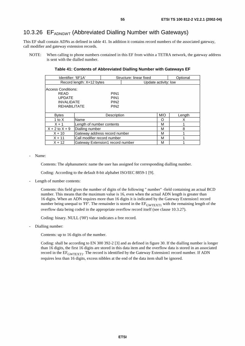
ETSI
ETSI TS 100 812-2 V2.2.1 (2002-04)55
10.3.26 EFADNGWT (Abbreviated Dialling Number with Gateways)
This EF shall contain ADNs as defined in table 41. In addition it contains record numbers of the associated gateway,call modifier and gateway extension records.
NOTE: When calling to phone numbers contained in this EF from within a TETRA network, the gateway addressis sent with the dialled number.
Table 41: Contents of Abbreviated Dialling Number with Gateways EF
Identifier: '6F1A' Structure: linear fixed OptionalRecord length: X+12 bytes Update activity: low
Access Conditions:READ PIN1UPDATE PIN1INVALIDATE PIN2REHABILITATE PIN2
Bytes Description M/O Length1 to X Name O XX + 1 Length of number contents M 1
X + 2 to X + 9 Dialling number M 8X + 10 Gateway address record number M 1X + 11 Call modifier record number M 1X + 12 Gateway Extension1 record number M 1
- Name:
Contents: The alphanumeric name the user has assigned for corresponding dialling number.
Coding: According to the default 8-bit alphabet ISO/IEC 8859-1 [9].
- Length of number contents:
Contents: this field gives the number of digits of the following " number" -field containing an actual BCDnumber. This means that the maximum value is 16, even when the actual ADN length is greater than16 digits. When an ADN requires more than 16 digits it is indicated by the Gateway Extension1 recordnumber being unequal to 'FF'. The remainder is stored in the EFGWTEXT1 with the remaining length of the
overflow data being coded in the appropriate overflow record itself (see clause 10.3.27).
Coding: binary. NULL ('00') value indicates a free record.
- Dialling number:
Contents: up to 16 digits of the number.
Coding: shall be according to EN 300 392-2 [3] and as defined in figure 30. If the dialling number is longerthan 16 digits, the first 16 digits are stored in this data item and the overflow data is stored in an associatedrecord in the EFGWTEXT1. The record is identified by the Gateway Extension1 record number. If ADN
requires less than 16 digits, excess nibbles at the end of the data item shall be ignored.
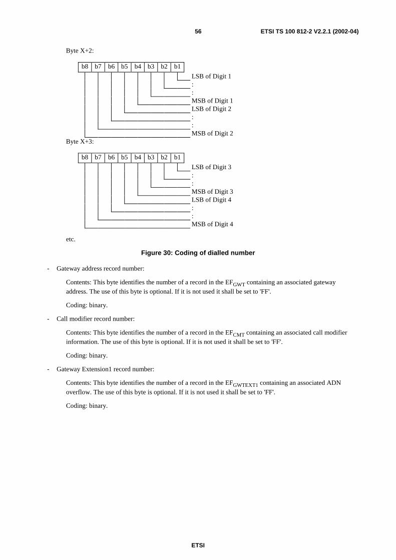
ETSI
ETSI TS 100 812-2 V2.2.1 (2002-04)56
Byte X+2:
b8 b7 b6 b5 b4 b3 b2 b1
LSB of Digit 1::MSB of Digit 1LSB of Digit 2::MSB of Digit 2
Byte X+3:
b8 b7 b6 b5 b4 b3 b2 b1
LSB of Digit 3::MSB of Digit 3LSB of Digit 4::MSB of Digit 4
etc.
Figure 30: Coding of dialled number
- Gateway address record number:
Contents: This byte identifies the number of a record in the EFGWT containing an associated gateway
address. The use of this byte is optional. If it is not used it shall be set to 'FF'.
Coding: binary.
- Call modifier record number:
Contents: This byte identifies the number of a record in the EFCMT containing an associated call modifier
information. The use of this byte is optional. If it is not used it shall be set to 'FF'.
Coding: binary.
- Gateway Extension1 record number:
Contents: This byte identifies the number of a record in the EFGWTEXT1 containing an associated ADN
overflow. The use of this byte is optional. If it is not used it shall be set to 'FF'.
Coding: binary.
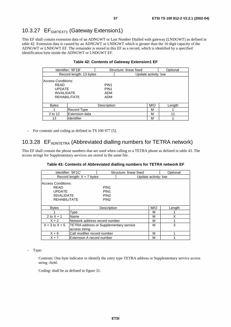
ETSI
ETSI TS 100 812-2 V2.2.1 (2002-04)57
10.3.27 EFGWTEXT1 (Gateway Extension1)
This EF shall contain extension data of an ADNGWT or Last Number Dialled with gateway (LNDGWT) as defined intable 42. Extension data is caused by an ADNGWT or LNDGWT which is greater than the 16 digit capacity of theADNGWT or LNDGWT EF. The remainder is stored in this EF as a record, which is identified by a specifiedidentification byte inside the ADNGWT or LNDGWT EF.
Table 42: Contents of Gateway Extension1 EF
Identifier: '6F1B' Structure: linear fixed OptionalRecord length: 13 bytes Update activity: low
Access Conditions:READ PIN1UPDATE PIN1INVALIDATE ADMREHABILITATE ADM
Bytes Description M/O Length1 Record Type M 1
2 to 12 Extension data M 1113 Identifier M 1
- For contents and coding as defined in TS 100 977 [5].
10.3.28 EFADNTETRA (Abbreviated dialling numbers for TETRA network)
This EF shall contain the phone numbers that are used when calling to a TETRA phone as defined in table 43. Theaccess strings for Supplementary services are stored in the same file.
Table 43: Contents of Abbreviated dialling numbers for TETRA network EF
Identifier: '6F1C' Structure: linear fixed OptionalRecord length: X + 7 bytes Update activity: low
Access Conditions:READ PIN1UPDATE PIN1INVALIDATE PIN2REHABILITATE PIN2
Bytes Description M/O Length1 Type M 1
2 to X + 1 Name M XX + 2 Network address record number M 1
X + 3 to X + 5 TETRA address or Supplementary serviceaccess string
M 3
X + 6 Call modifier record number M 1X + 7 Extension A record number M 1
- Type:
Contents: One byte indicator to identify the entry type TETRA address or Supplementary service accessstring -field.
Coding: shall be as defined in figure 31.
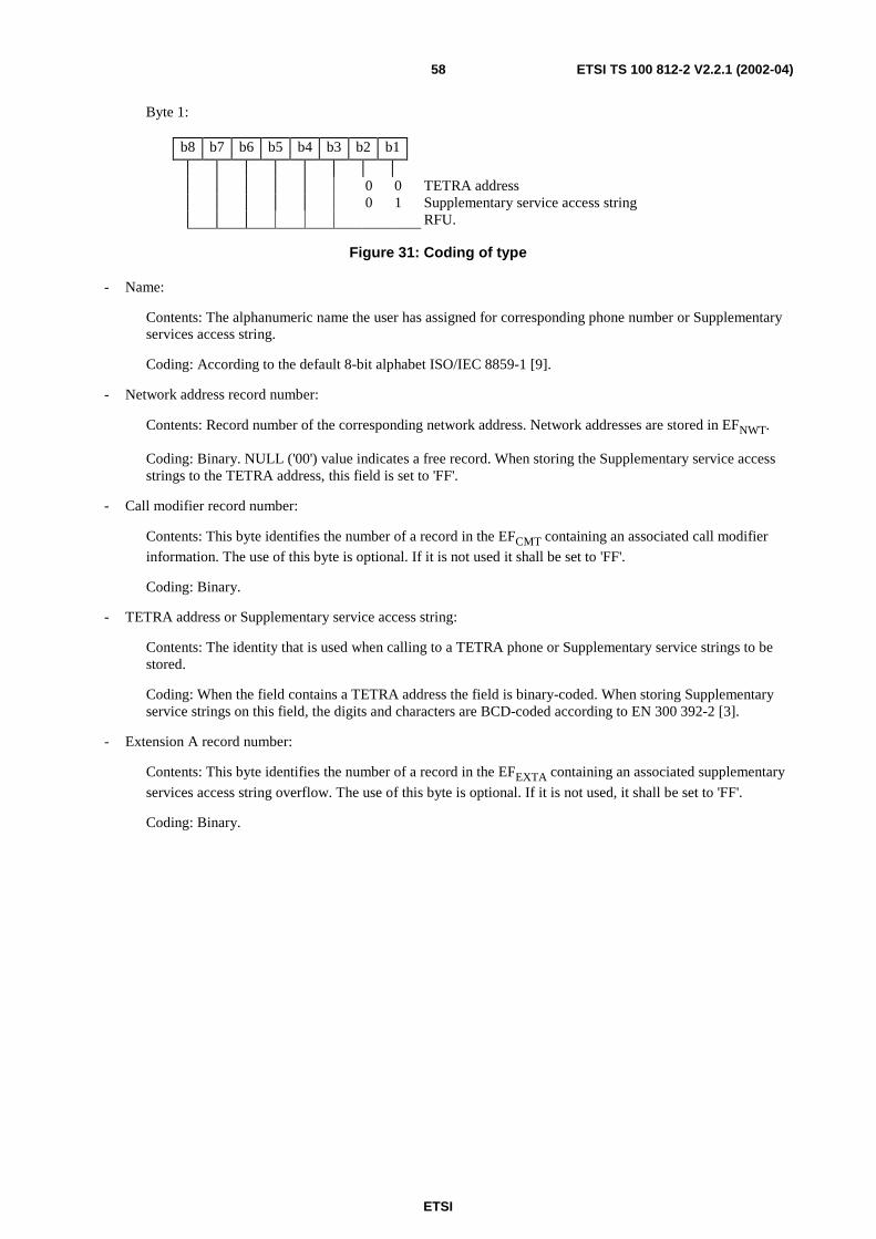
ETSI
ETSI TS 100 812-2 V2.2.1 (2002-04)58
Byte 1:
b8 b7 b6 b5 b4 b3 b2 b1
0 0 TETRA address0 1 Supplementary service access string
RFU.
Figure 31: Coding of type
- Name:
Contents: The alphanumeric name the user has assigned for corresponding phone number or Supplementaryservices access string.
Coding: According to the default 8-bit alphabet ISO/IEC 8859-1 [9].
- Network address record number:
Contents: Record number of the corresponding network address. Network addresses are stored in EFNWT.
Coding: Binary. NULL ('00') value indicates a free record. When storing the Supplementary service accessstrings to the TETRA address, this field is set to 'FF'.
- Call modifier record number:
Contents: This byte identifies the number of a record in the EFCMT containing an associated call modifier
information. The use of this byte is optional. If it is not used it shall be set to 'FF'.
Coding: Binary.
- TETRA address or Supplementary service access string:
Contents: The identity that is used when calling to a TETRA phone or Supplementary service strings to bestored.
Coding: When the field contains a TETRA address the field is binary-coded. When storing Supplementaryservice strings on this field, the digits and characters are BCD-coded according to EN 300 392-2 [3].
- Extension A record number:
Contents: This byte identifies the number of a record in the EFEXTA containing an associated supplementary
services access string overflow. The use of this byte is optional. If it is not used, it shall be set to 'FF'.
Coding: Binary.
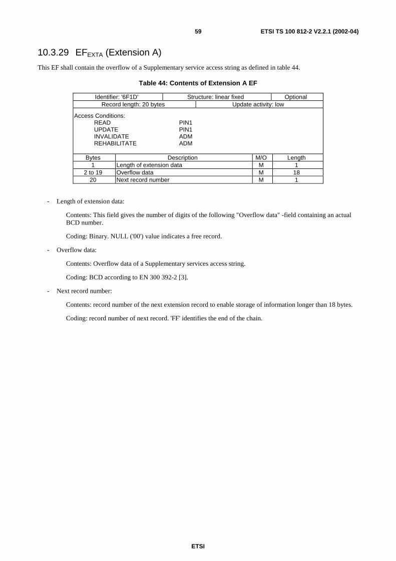
ETSI
ETSI TS 100 812-2 V2.2.1 (2002-04)59
10.3.29 EFEXTA (Extension A)
This EF shall contain the overflow of a Supplementary service access string as defined in table 44.
Table 44: Contents of Extension A EF
Identifier: '6F1D' Structure: linear fixed OptionalRecord length: 20 bytes Update activity: low
Access Conditions:READ PIN1UPDATE PIN1INVALIDATE ADMREHABILITATE ADM
Bytes Description M/O Length1 Length of extension data M 1
2 to 19 Overflow data M 1820 Next record number M 1
- Length of extension data:
Contents: This field gives the number of digits of the following "Overflow data" -field containing an actualBCD number.
Coding: Binary. NULL ('00') value indicates a free record.
- Overflow data:
Contents: Overflow data of a Supplementary services access string.
Coding: BCD according to EN 300 392-2 [3].
- Next record number:
Contents: record number of the next extension record to enable storage of information longer than 18 bytes.
Coding: record number of next record. 'FF' identifies the end of the chain.
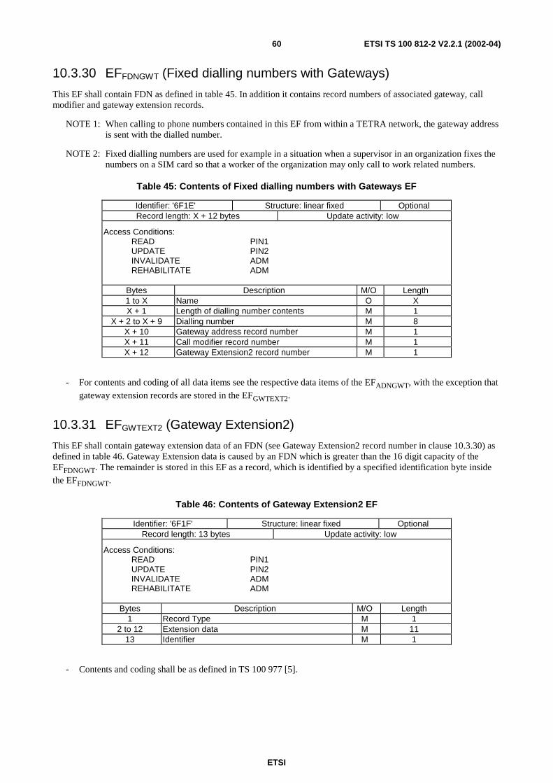
ETSI
ETSI TS 100 812-2 V2.2.1 (2002-04)60
10.3.30 EFFDNGWT (Fixed dialling numbers with Gateways)
This EF shall contain FDN as defined in table 45. In addition it contains record numbers of associated gateway, callmodifier and gateway extension records.
NOTE 1: When calling to phone numbers contained in this EF from within a TETRA network, the gateway addressis sent with the dialled number.
NOTE 2: Fixed dialling numbers are used for example in a situation when a supervisor in an organization fixes thenumbers on a SIM card so that a worker of the organization may only call to work related numbers.
Table 45: Contents of Fixed dialling numbers with Gateways EF
Identifier: '6F1E' Structure: linear fixed OptionalRecord length: X + 12 bytes Update activity: low
Access Conditions:READ PIN1UPDATE PIN2INVALIDATE ADMREHABILITATE ADM
Bytes Description M/O Length1 to X Name O XX + 1 Length of dialling number contents M 1
X + 2 to X + 9 Dialling number M 8X + 10 Gateway address record number M 1X + 11 Call modifier record number M 1X + 12 Gateway Extension2 record number M 1
- For contents and coding of all data items see the respective data items of the EFADNGWT, with the exception that
gateway extension records are stored in the EFGWTEXT2.
10.3.31 EFGWTEXT2 (Gateway Extension2)
This EF shall contain gateway extension data of an FDN (see Gateway Extension2 record number in clause 10.3.30) asdefined in table 46. Gateway Extension data is caused by an FDN which is greater than the 16 digit capacity of theEFFDNGWT. The remainder is stored in this EF as a record, which is identified by a specified identification byte inside
the EFFDNGWT.
Table 46: Contents of Gateway Extension2 EF
Identifier: '6F1F' Structure: linear fixed OptionalRecord length: 13 bytes Update activity: low
Access Conditions:READ PIN1UPDATE PIN2INVALIDATE ADMREHABILITATE ADM
Bytes Description M/O Length1 Record Type M 1
2 to 12 Extension data M 1113 Identifier M 1
- Contents and coding shall be as defined in TS 100 977 [5].
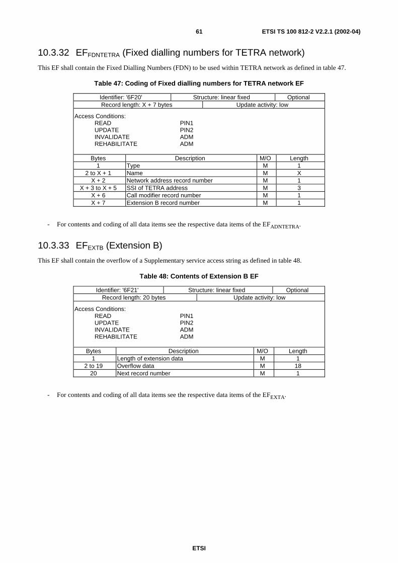
ETSI
ETSI TS 100 812-2 V2.2.1 (2002-04)61
10.3.32 EFFDNTETRA (Fixed dialling numbers for TETRA network)
This EF shall contain the Fixed Dialling Numbers (FDN) to be used within TETRA network as defined in table 47.
Table 47: Coding of Fixed dialling numbers for TETRA network EF
Identifier: '6F20' Structure: linear fixed OptionalRecord length: X + 7 bytes Update activity: low
Access Conditions:READ PIN1UPDATE PIN2INVALIDATE ADMREHABILITATE ADM
Bytes Description M/O Length1 Type M 1
2 to X + 1 Name M XX + 2 Network address record number M 1
X + 3 to X + 5 SSI of TETRA address M 3X + 6 Call modifier record number M 1X + 7 Extension B record number M 1
- For contents and coding of all data items see the respective data items of the EFADNTETRA.
10.3.33 EFEXTB (Extension B)
This EF shall contain the overflow of a Supplementary service access string as defined in table 48.
Table 48: Contents of Extension B EF
Identifier: '6F21' Structure: linear fixed OptionalRecord length: 20 bytes Update activity: low
Access Conditions:READ PIN1UPDATE PIN2INVALIDATE ADMREHABILITATE ADM
Bytes Description M/O Length1 Length of extension data M 1
2 to 19 Overflow data M 1820 Next record number M 1
- For contents and coding of all data items see the respective data items of the EFEXTA.
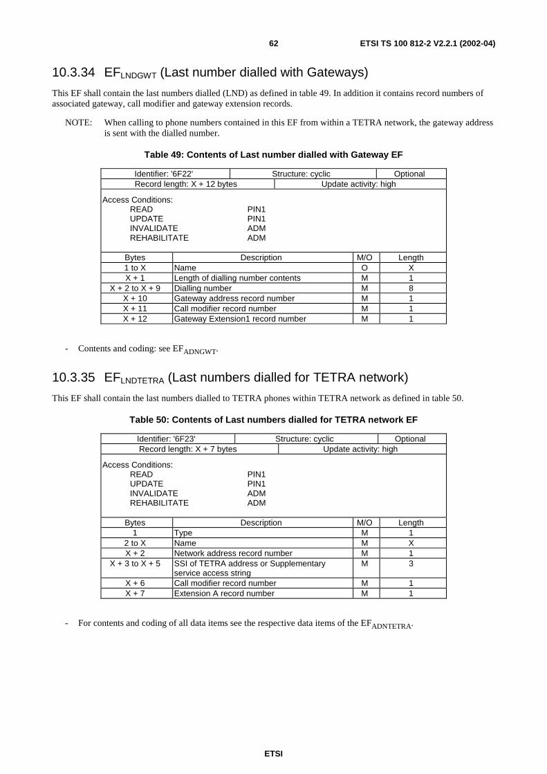
ETSI
ETSI TS 100 812-2 V2.2.1 (2002-04)62
10.3.34 EFLNDGWT (Last number dialled with Gateways)
This EF shall contain the last numbers dialled (LND) as defined in table 49. In addition it contains record numbers ofassociated gateway, call modifier and gateway extension records.
NOTE: When calling to phone numbers contained in this EF from within a TETRA network, the gateway addressis sent with the dialled number.
Table 49: Contents of Last number dialled with Gateway EF
Identifier: '6F22' Structure: cyclic OptionalRecord length: X + 12 bytes Update activity: high
Access Conditions:READ PIN1UPDATE PIN1INVALIDATE ADMREHABILITATE ADM
Bytes Description M/O Length1 to X Name O XX + 1 Length of dialling number contents M 1
X + 2 to X + 9 Dialling number M 8X + 10 Gateway address record number M 1X + 11 Call modifier record number M 1X + 12 Gateway Extension1 record number M 1
- Contents and coding: see EFADNGWT.
10.3.35 EFLNDTETRA (Last numbers dialled for TETRA network)
This EF shall contain the last numbers dialled to TETRA phones within TETRA network as defined in table 50.
Table 50: Contents of Last numbers dialled for TETRA network EF
Identifier: '6F23' Structure: cyclic OptionalRecord length: X + 7 bytes Update activity: high
Access Conditions:READ PIN1UPDATE PIN1INVALIDATE ADMREHABILITATE ADM
Bytes Description M/O Length1 Type M 1
2 to X Name M XX + 2 Network address record number M 1
X + 3 to X + 5 SSI of TETRA address or Supplementaryservice access string
M 3
X + 6 Call modifier record number M 1X + 7 Extension A record number M 1
- For contents and coding of all data items see the respective data items of the EFADNTETRA.
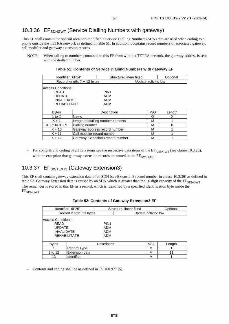
ETSI
ETSI TS 100 812-2 V2.2.1 (2002-04)63
10.3.36 EFSDNGWT (Service Dialling Numbers with gateway)
This EF shall contain the special user-non-modifiable Service Dialling Numbers (SDN) that are used when calling to aphone outside the TETRA network as defined in table 51. In addition it contains record numbers of associated gateway,call modifier and gateway extension records.
NOTE: When calling to numbers contained in this EF from within a TETRA network, the gateway address is sentwith the dialled number.
Table 51: Contents of Service Dialling Numbers with gateway EF
Identifier: '6F24' Structure: linear fixed OptionalRecord length: X + 12 bytes Update activity: low
Access Conditions:READ PIN1UPDATE ADMINVALIDATE ADMREHABILITATE ADM
Bytes Description M/O Length1 to X Name O XX + 1 Length of dialling number contents M 1
X + 2 to X + 9 Dialling number M 8X + 10 Gateway address record number M 1X + 11 Call modifier record number M 1X + 12 Gateway Extension3 record number M 1
- For contents and coding of all data items see the respective data items of the EFADNGWT (see clause 10.3.25),
with the exception that gateway extension records are stored in the EFGWTEXT3.
10.3.37 EFGWTEXT3 (Gateway Extension3)
This EF shall contain gateway extension data of an SDN (see Extension3 record number in clause 10.3.36) as defined intable 52. Gateway Extension data is caused by an SDN which is greater than the 16 digit capacity of the EFSDNGWT.
The remainder is stored in this EF as a record, which is identified by a specified identification byte inside theEFSDNGWT.
Table 52: Contents of Gateway Extension3 EF
Identifier: '6F25' Structure: linear fixed OptionalRecord length: 13 bytes Update activity: low
Access Conditions:READ PIN1UPDATE ADMINVALIDATE ADMREHABILITATE ADM
Bytes Description M/O Length1 Record Type M 1
2 to 12 Extension data M 1113 Identifier M 1
- Contents and coding shall be as defined in TS 100 977 [5].
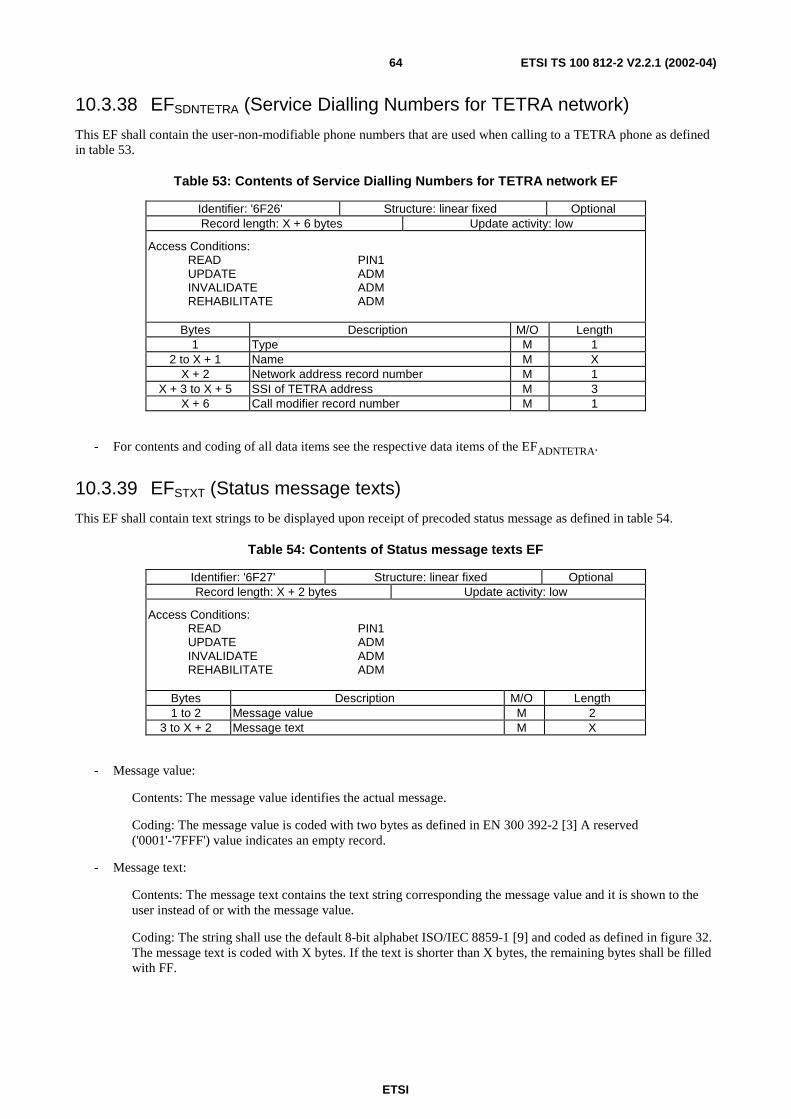
ETSI
ETSI TS 100 812-2 V2.2.1 (2002-04)64
10.3.38 EFSDNTETRA (Service Dialling Numbers for TETRA network)
This EF shall contain the user-non-modifiable phone numbers that are used when calling to a TETRA phone as definedin table 53.
Table 53: Contents of Service Dialling Numbers for TETRA network EF
Identifier: '6F26' Structure: linear fixed OptionalRecord length: X + 6 bytes Update activity: low
Access Conditions:READ PIN1UPDATE ADMINVALIDATE ADMREHABILITATE ADM
Bytes Description M/O Length1 Type M 1
2 to X + 1 Name M XX + 2 Network address record number M 1
X + 3 to X + 5 SSI of TETRA address M 3X + 6 Call modifier record number M 1
- For contents and coding of all data items see the respective data items of the EFADNTETRA.
10.3.39 EFSTXT (Status message texts)
This EF shall contain text strings to be displayed upon receipt of precoded status message as defined in table 54.
Table 54: Contents of Status message texts EF
Identifier: '6F27' Structure: linear fixed OptionalRecord length: X + 2 bytes Update activity: low
Access Conditions:READ PIN1UPDATE ADMINVALIDATE ADMREHABILITATE ADM
Bytes Description M/O Length1 to 2 Message value M 2
3 to X + 2 Message text M X
- Message value:
Contents: The message value identifies the actual message.
Coding: The message value is coded with two bytes as defined in EN 300 392-2 [3] A reserved('0001'-'7FFF') value indicates an empty record.
- Message text:
Contents: The message text contains the text string corresponding the message value and it is shown to theuser instead of or with the message value.
Coding: The string shall use the default 8-bit alphabet ISO/IEC 8859-1 [9] and coded as defined in figure 32.The message text is coded with X bytes. If the text is shorter than X bytes, the remaining bytes shall be filledwith FF.
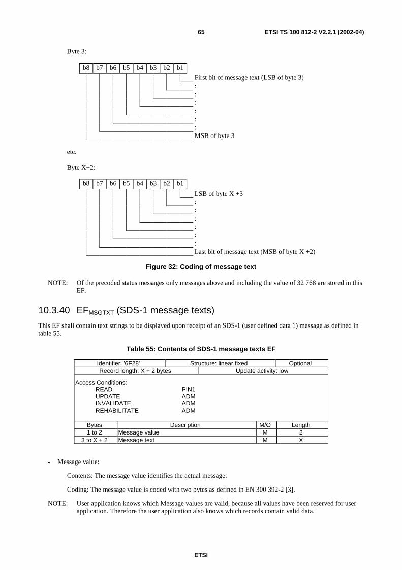
ETSI
ETSI TS 100 812-2 V2.2.1 (2002-04)65
Byte 3:
b8 b7 b6 b5 b4 b3 b2 b1
First bit of message text (LSB of byte 3)::::::MSB of byte 3
etc.
Byte X+2:
b8 b7 b6 b5 b4 b3 b2 b1
LSB of byte X +3::::::Last bit of message text (MSB of byte X +2)
Figure 32: Coding of message text
NOTE: Of the precoded status messages only messages above and including the value of 32 768 are stored in thisEF.
10.3.40 EFMSGTXT (SDS-1 message texts)
This EF shall contain text strings to be displayed upon receipt of an SDS-1 (user defined data 1) message as defined intable 55.
Table 55: Contents of SDS-1 message texts EF
Identifier: '6F28' Structure: linear fixed OptionalRecord length: X + 2 bytes Update activity: low
Access Conditions:READ PIN1UPDATE ADMINVALIDATE ADMREHABILITATE ADM
Bytes Description M/O Length1 to 2 Message value M 2
3 to X + 2 Message text M X
- Message value:
Contents: The message value identifies the actual message.
Coding: The message value is coded with two bytes as defined in EN 300 392-2 [3].
NOTE: User application knows which Message values are valid, because all values have been reserved for userapplication. Therefore the user application also knows which records contain valid data.
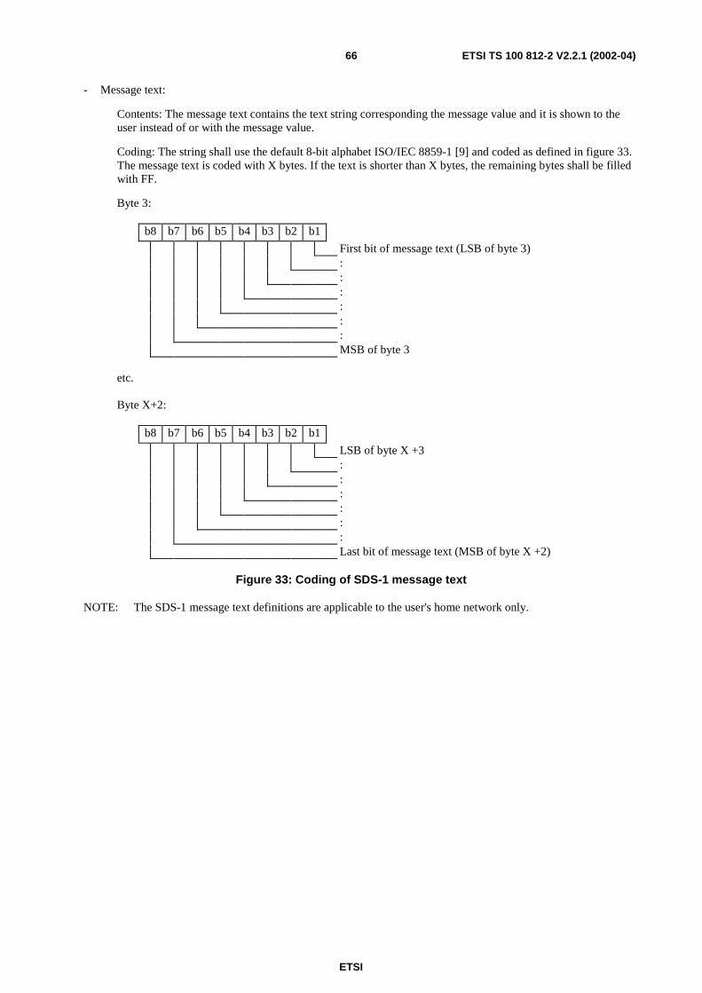
ETSI
ETSI TS 100 812-2 V2.2.1 (2002-04)66
- Message text:
Contents: The message text contains the text string corresponding the message value and it is shown to theuser instead of or with the message value.
Coding: The string shall use the default 8-bit alphabet ISO/IEC 8859-1 [9] and coded as defined in figure 33.The message text is coded with X bytes. If the text is shorter than X bytes, the remaining bytes shall be filledwith FF.
Byte 3:
b8 b7 b6 b5 b4 b3 b2 b1
First bit of message text (LSB of byte 3)::::::MSB of byte 3
etc.
Byte X+2:
b8 b7 b6 b5 b4 b3 b2 b1
LSB of byte X +3::::::Last bit of message text (MSB of byte X +2)
Figure 33: Coding of SDS-1 message text
NOTE: The SDS-1 message text definitions are applicable to the user's home network only.
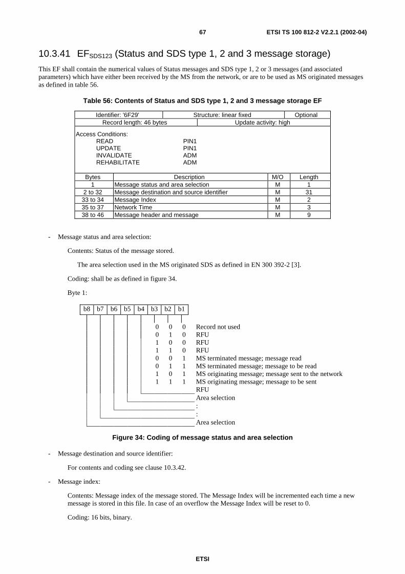
ETSI
ETSI TS 100 812-2 V2.2.1 (2002-04)67
10.3.41 EFSDS123 (Status and SDS type 1, 2 and 3 message storage)
This EF shall contain the numerical values of Status messages and SDS type 1, 2 or 3 messages (and associatedparameters) which have either been received by the MS from the network, or are to be used as MS originated messagesas defined in table 56.
Table 56: Contents of Status and SDS type 1, 2 and 3 message storage EF
Identifier: '6F29' Structure: linear fixed OptionalRecord length: 46 bytes Update activity: high
Access Conditions:READ PIN1UPDATE PIN1INVALIDATE ADMREHABILITATE ADM
Bytes Description M/O Length1 Message status and area selection M 1
2 to 32 Message destination and source identifier M 3133 to 34 Message Index M 235 to 37 Network Time M 338 to 46 Message header and message M 9
- Message status and area selection:
Contents: Status of the message stored.
The area selection used in the MS originated SDS as defined in EN 300 392-2 [3].
Coding: shall be as defined in figure 34.
Byte 1:
b8 b7 b6 b5 b4 b3 b2 b1
0 0 0 Record not used0 1 0 RFU1 0 0 RFU1 1 0 RFU0 0 1 MS terminated message; message read0 1 1 MS terminated message; message to be read1 0 1 MS originating message; message sent to the network1 1 1 MS originating message; message to be sent
RFUArea selection::Area selection
Figure 34: Coding of message status and area selection
- Message destination and source identifier:
For contents and coding see clause 10.3.42.
- Message index:
Contents: Message index of the message stored. The Message Index will be incremented each time a newmessage is stored in this file. In case of an overflow the Message Index will be reset to 0.
Coding: 16 bits, binary.
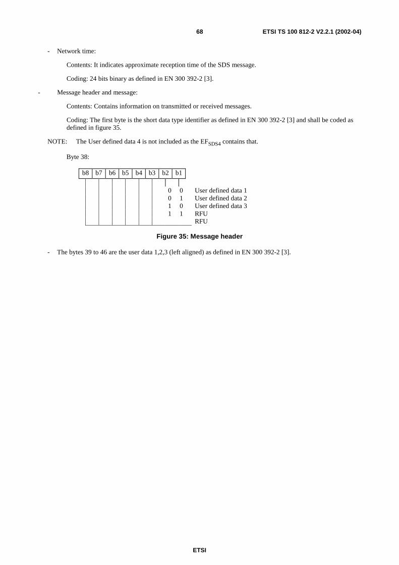
ETSI
ETSI TS 100 812-2 V2.2.1 (2002-04)68
- Network time:
Contents: It indicates approximate reception time of the SDS message.
Coding: 24 bits binary as defined in EN 300 392-2 [3].
- Message header and message:
Contents: Contains information on transmitted or received messages.
Coding: The first byte is the short data type identifier as defined in EN 300 392-2 [3] and shall be coded asdefined in figure 35.
NOTE: The User defined data 4 is not included as the EFSDS4 contains that.
Byte 38:
b8 b7 b6 b5 b4 b3 b2 b1
0 0 User defined data 10 1 User defined data 21 0 User defined data 31 1 RFU
RFU
Figure 35: Message header
- The bytes 39 to 46 are the user data 1,2,3 (left aligned) as defined in EN 300 392-2 [3].
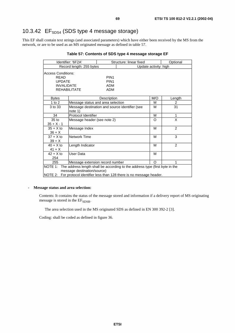
ETSI
ETSI TS 100 812-2 V2.2.1 (2002-04)69
10.3.42 EFSDS4 (SDS type 4 message storage)
This EF shall contain text strings (and associated parameters) which have either been received by the MS from thenetwork, or are to be used as an MS originated message as defined in table 57.
Table 57: Contents of SDS type 4 message storage EF
Identifier: '6F2A' Structure: linear fixed OptionalRecord length: 255 bytes Update activity: high
Access Conditions:READ PIN1UPDATE PIN1INVALIDATE ADMREHABILITATE ADM
Bytes Description M/O Length1 to 2 Message status and area selection M 2
3 to 33 Message destination and source identifier (seenote 1)
M 31
34 Protocol Identifier M 135 to
35 + X - 1Message header (see note 2) O X
35 + X to36 + X
Message Index M 2
37 + X to39 + X
Network Time M 3
40 + X to41 + X
Length Indicator M 2
42 + X to254
User Data M
255 Message extension record number O 1NOTE 1: The address length shall be according to the address type (first byte in the
message destination/source)NOTE 2: For protocol identifier less than 128 there is no message header.
- Message status and area selection:
Contents: It contains the status of the message stored and information if a delivery report of MS originatingmessage is stored in the EFSDSR.
The area selection used in the MS originated SDS as defined in EN 300 392-2 [3].
Coding: shall be coded as defined in figure 36.
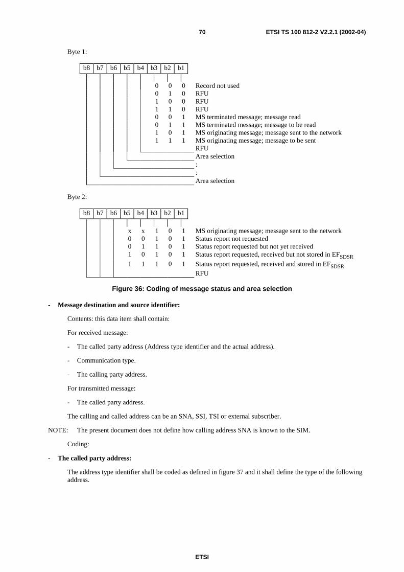
ETSI
ETSI TS 100 812-2 V2.2.1 (2002-04)70
Byte 1:
b8 b7 b6 b5 b4 b3 b2 b1
0 0 0 Record not used0 1 0 RFU1 0 0 RFU1 1 0 RFU0 0 1 MS terminated message; message read0 1 1 MS terminated message; message to be read1 0 1 MS originating message; message sent to the network1 1 1 MS originating message; message to be sent
RFUArea selection::Area selection
Byte 2:
b8 b7 b6 b5 b4 b3 b2 b1
x x 1 0 1 MS originating message; message sent to the network0 0 1 0 1 Status report not requested0 1 1 0 1 Status report requested but not yet received1 0 1 0 1 Status report requested, received but not stored in EFSDSR1 1 1 0 1 Status report requested, received and stored in EFSDSR
RFU
Figure 36: Coding of message status and area selection
- Message destination and source identifier:
Contents: this data item shall contain:
For received message:
- The called party address (Address type identifier and the actual address).
- Communication type.
- The calling party address.
For transmitted message:
- The called party address.
The calling and called address can be an SNA, SSI, TSI or external subscriber.
NOTE: The present document does not define how calling address SNA is known to the SIM.
Coding:
- The called party address:
The address type identifier shall be coded as defined in figure 37 and it shall define the type of the followingaddress.
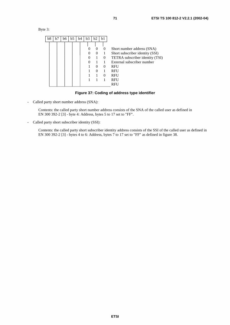
ETSI
ETSI TS 100 812-2 V2.2.1 (2002-04)71
Byte 3:
b8 b7 b6 b5 b4 b3 b2 b1
0 0 0 Short number address (SNA)0 0 1 Short subscriber identity (SSI)0 1 0 TETRA subscriber identity (TSI)0 1 1 External subscriber number1 0 0 RFU1 0 1 RFU1 1 0 RFU1 1 1 RFU
RFU
Figure 37: Coding of address type identifier
- Called party short number address (SNA):
Contents: the called party short number address consists of the SNA of the called user as defined inEN 300 392-2 [3] - byte 4: Address, bytes 5 to 17 set to "FF".
- Called party short subscriber identity (SSI):
Contents: the called party short subscriber identity address consists of the SSI of the called user as defined inEN 300 392-2 [3] - bytes 4 to 6: Address, bytes 7 to 17 set to "FF" as defined in figure 38.
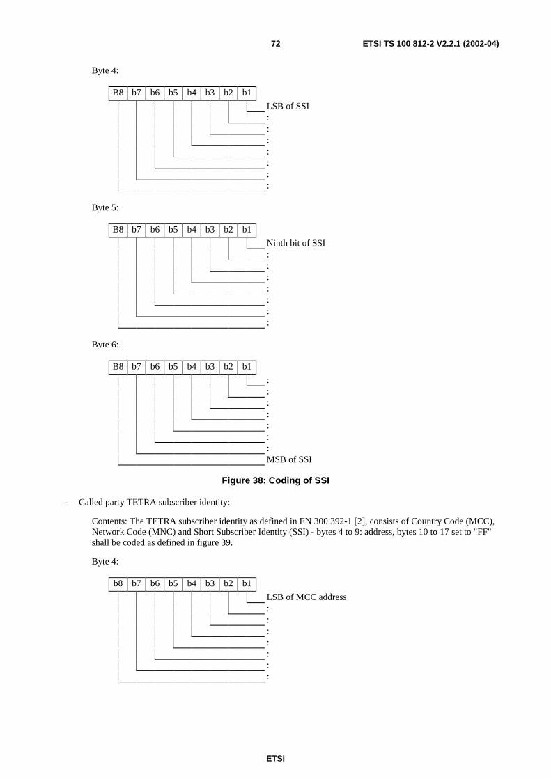
ETSI
ETSI TS 100 812-2 V2.2.1 (2002-04)72
Byte 4:
B8 b7 b6 b5 b4 b3 b2 b1
LSB of SSI:::::::
Byte 5:
B8 b7 b6 b5 b4 b3 b2 b1
Ninth bit of SSI:::::::
Byte 6:
B8 b7 b6 b5 b4 b3 b2 b1
:::::::MSB of SSI
Figure 38: Coding of SSI
- Called party TETRA subscriber identity:
Contents: The TETRA subscriber identity as defined in EN 300 392-1 [2], consists of Country Code (MCC),Network Code (MNC) and Short Subscriber Identity (SSI) - bytes 4 to 9: address, bytes 10 to 17 set to "FF"shall be coded as defined in figure 39.
Byte 4:
b8 b7 b6 b5 b4 b3 b2 b1
LSB of MCC address:::::::

ETSI
ETSI TS 100 812-2 V2.2.1 (2002-04)73
Byte 5:
b8 b7 b6 b5 b4 b3 b2 b1
:MSB of MCC addressLSB of MNC address:::::
Byte 6:
b8 b7 b6 b5 b4 b3 b2 b1
:::::::MSB of MNC address
Byte 7:
b8 b7 b6 b5 b4 b3 b2 b1
LSB of SSI:::::::
Byte 8:
b8 b7 b6 b5 b4 b3 b2 b1
Ninth bit of SSI:::::::
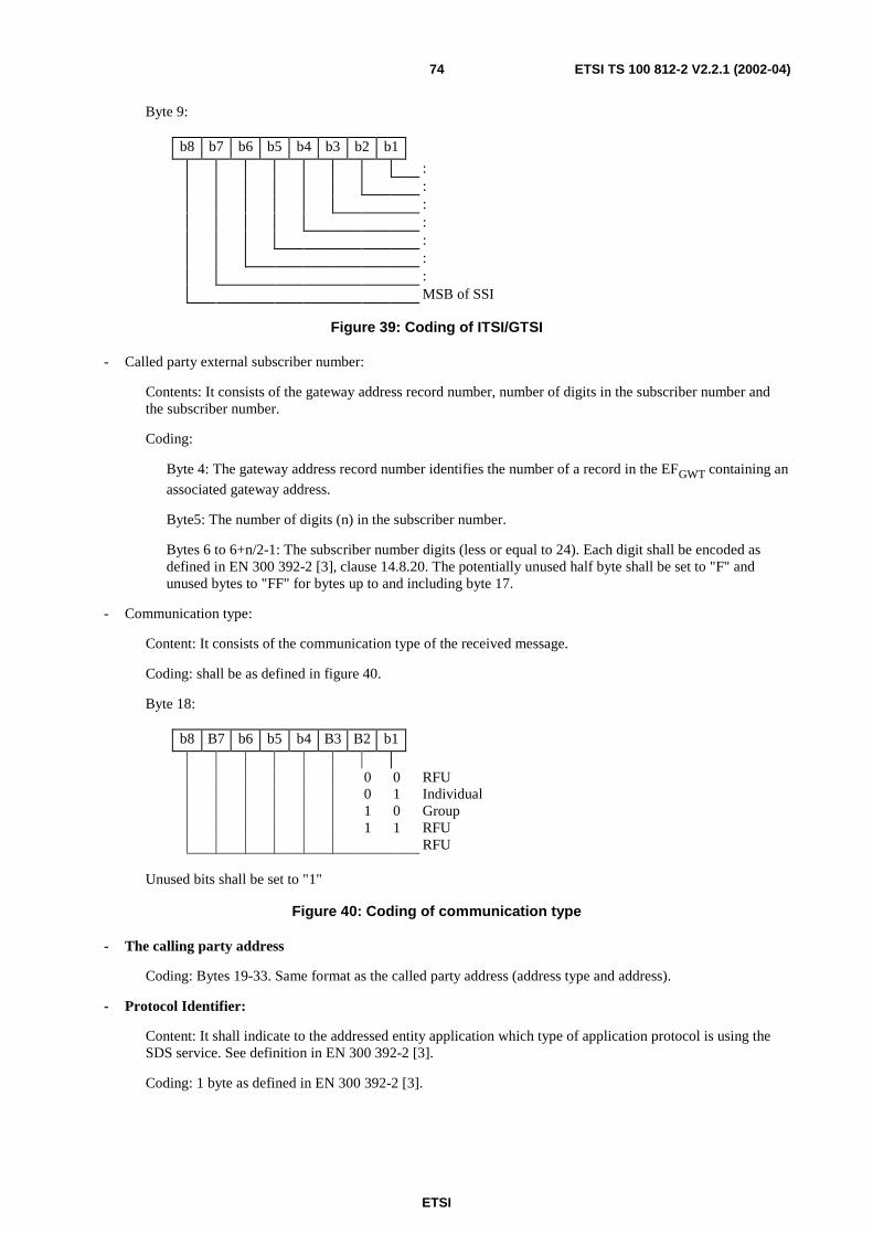
ETSI
ETSI TS 100 812-2 V2.2.1 (2002-04)74
Byte 9:
b8 b7 b6 b5 b4 b3 b2 b1
:::::::MSB of SSI
Figure 39: Coding of ITSI/GTSI
- Called party external subscriber number:
Contents: It consists of the gateway address record number, number of digits in the subscriber number andthe subscriber number.
Coding:
Byte 4: The gateway address record number identifies the number of a record in the EFGWT containing an
associated gateway address.
Byte5: The number of digits (n) in the subscriber number.
Bytes 6 to 6+n/2-1: The subscriber number digits (less or equal to 24). Each digit shall be encoded asdefined in EN 300 392-2 [3], clause 14.8.20. The potentially unused half byte shall be set to "F" andunused bytes to "FF" for bytes up to and including byte 17.
- Communication type:
Content: It consists of the communication type of the received message.
Coding: shall be as defined in figure 40.
Byte 18:
b8 B7 b6 b5 b4 B3 B2 b1
0 0 RFU0 1 Individual1 0 Group1 1 RFU
RFU
Unused bits shall be set to "1"
Figure 40: Coding of communication type
- The calling party address
Coding: Bytes 19-33. Same format as the called party address (address type and address).
- Protocol Identifier:
Content: It shall indicate to the addressed entity application which type of application protocol is using theSDS service. See definition in EN 300 392-2 [3].
Coding: 1 byte as defined in EN 300 392-2 [3].
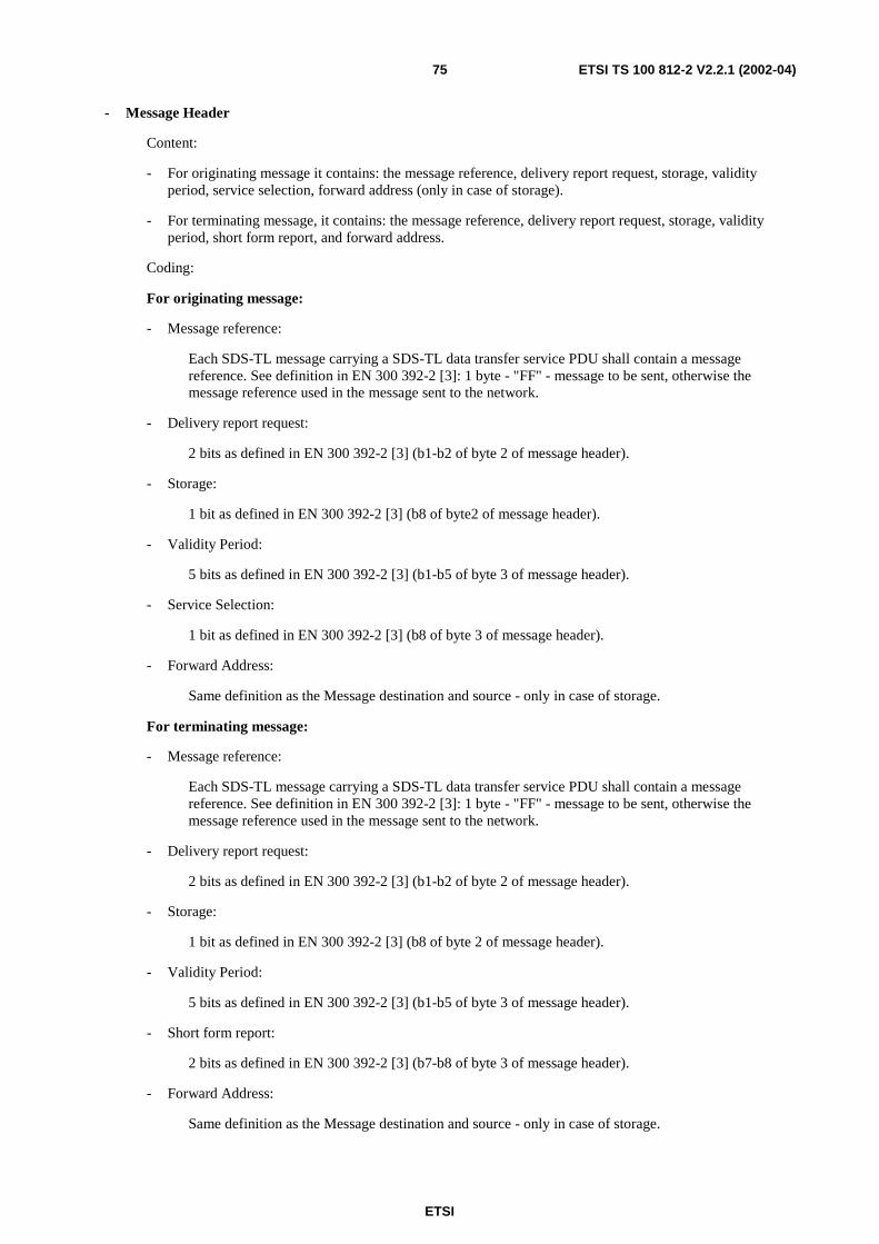
ETSI
ETSI TS 100 812-2 V2.2.1 (2002-04)75
- Message Header
Content:
- For originating message it contains: the message reference, delivery report request, storage, validityperiod, service selection, forward address (only in case of storage).
- For terminating message, it contains: the message reference, delivery report request, storage, validityperiod, short form report, and forward address.
Coding:
For originating message:
- Message reference:
Each SDS-TL message carrying a SDS-TL data transfer service PDU shall contain a messagereference. See definition in EN 300 392-2 [3]: 1 byte - "FF" - message to be sent, otherwise themessage reference used in the message sent to the network.
- Delivery report request:
2 bits as defined in EN 300 392-2 [3] (b1-b2 of byte 2 of message header).
- Storage:
1 bit as defined in EN 300 392-2 [3] (b8 of byte2 of message header).
- Validity Period:
5 bits as defined in EN 300 392-2 [3] (b1-b5 of byte 3 of message header).
- Service Selection:
1 bit as defined in EN 300 392-2 [3] (b8 of byte 3 of message header).
- Forward Address:
Same definition as the Message destination and source - only in case of storage.
For terminating message:
- Message reference:
Each SDS-TL message carrying a SDS-TL data transfer service PDU shall contain a messagereference. See definition in EN 300 392-2 [3]: 1 byte - "FF" - message to be sent, otherwise themessage reference used in the message sent to the network.
- Delivery report request:
2 bits as defined in EN 300 392-2 [3] (b1-b2 of byte 2 of message header).
- Storage:
1 bit as defined in EN 300 392-2 [3] (b8 of byte 2 of message header).
- Validity Period:
5 bits as defined in EN 300 392-2 [3] (b1-b5 of byte 3 of message header).
- Short form report:
2 bits as defined in EN 300 392-2 [3] (b7-b8 of byte 3 of message header).
- Forward Address:
Same definition as the Message destination and source - only in case of storage.
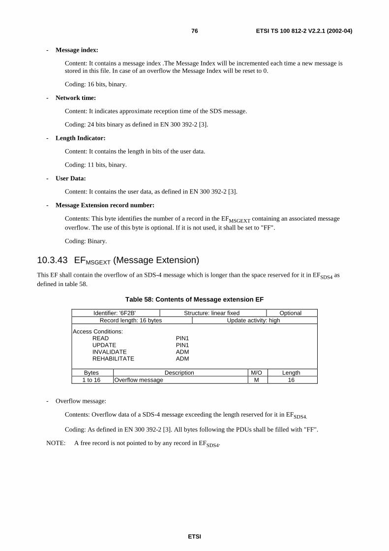
ETSI
ETSI TS 100 812-2 V2.2.1 (2002-04)76
- Message index:
Content: It contains a message index .The Message Index will be incremented each time a new message isstored in this file. In case of an overflow the Message Index will be reset to 0.
Coding: 16 bits, binary.
- Network time:
Content: It indicates approximate reception time of the SDS message.
Coding: 24 bits binary as defined in EN 300 392-2 [3].
- Length Indicator:
Content: It contains the length in bits of the user data.
Coding: 11 bits, binary.
- User Data:
Content: It contains the user data, as defined in EN 300 392-2 [3].
- Message Extension record number:
Contents: This byte identifies the number of a record in the EFMSGEXT containing an associated message
overflow. The use of this byte is optional. If it is not used, it shall be set to "FF".
Coding: Binary.
10.3.43 EFMSGEXT (Message Extension)
This EF shall contain the overflow of an SDS-4 message which is longer than the space reserved for it in EFSDS4 as
defined in table 58.
Table 58: Contents of Message extension EF
Identifier: '6F2B' Structure: linear fixed OptionalRecord length: 16 bytes Update activity: high
Access Conditions:READ PIN1UPDATE PIN1INVALIDATE ADMREHABILITATE ADM
Bytes Description M/O Length1 to 16 Overflow message M 16
- Overflow message:
Contents: Overflow data of a SDS-4 message exceeding the length reserved for it in EFSDS4.
Coding: As defined in EN 300 392-2 [3]. All bytes following the PDUs shall be filled with "FF".
NOTE: A free record is not pointed to by any record in EFSDS4.
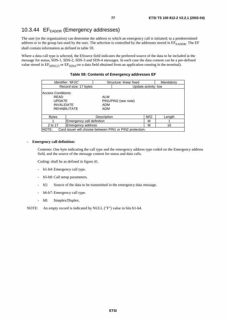
ETSI
ETSI TS 100 812-2 V2.2.1 (2002-04)77
10.3.44 EFEADDR (Emergency addresses)
The user (or the organization) can determine the address to which an emergency call is initiated; to a predeterminedaddress or to the group last used by the user. The selection is controlled by the addresses stored in EFEADDR. The EF
shall contain information as defined in table 59.
Where a data call type is selected, the ESource field indicates the preferred source of the data to be included in themessage for status, SDS-1, SDS-2, SDS-3 and SDS-4 messages. In each case the data content can be a pre-definedvalue stored in EFSDS123 or EFSDS4 (or a data field obtained from an application running in the terminal).
Table 59: Contents of Emergency addresses EF
Identifier: '6F2C' Structure: linear fixed MandatoryRecord size: 17 bytes Update activity: low
Access Conditions:READ ALWUPDATE PIN1/PIN2 (see note)INVALIDATE ADMREHABILITATE ADM
Bytes Description M/O Length1 Emergency call definition M 1
2 to 17 Emergency address M 16NOTE: Card issuer will choose between PIN1 or PIN2 protection.
- Emergency call definition:
Contents: One byte indicating the call type and the emergency address type coded on the Emergency addressfield, and the source of the message content for status and data calls.
Coding: shall be as defined in figure 41.
- b1-b4: Emergency call type.
- b5-b8: Call setup parameters.
- b5: Source of the data to be transmitted in the emergency data message.
- b6-b7: Emergency call type.
- b8: Simplex/Duplex.
NOTE: An empty record is indicated by NULL ("F") value in bits b1-b4.
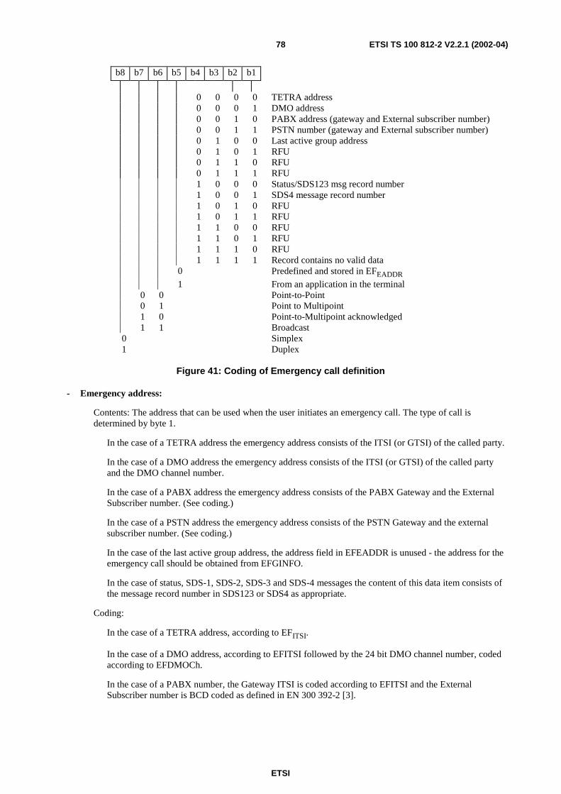
ETSI
ETSI TS 100 812-2 V2.2.1 (2002-04)78
b8 b7 b6 b5 b4 b3 b2 b1
0 0 0 0 TETRA address0 0 0 1 DMO address0 0 1 0 PABX address (gateway and External subscriber number)0 0 1 1 PSTN number (gateway and External subscriber number)0 1 0 0 Last active group address0 1 0 1 RFU0 1 1 0 RFU0 1 1 1 RFU1 0 0 0 Status/SDS123 msg record number1 0 0 1 SDS4 message record number1 0 1 0 RFU1 0 1 1 RFU1 1 0 0 RFU1 1 0 1 RFU1 1 1 0 RFU1 1 1 1 Record contains no valid data
0 Predefined and stored in EFEADDR1 From an application in the terminal
0 0 Point-to-Point0 1 Point to Multipoint1 0 Point-to-Multipoint acknowledged1 1 Broadcast
0 Simplex1 Duplex
Figure 41: Coding of Emergency call definition
- Emergency address:
Contents: The address that can be used when the user initiates an emergency call. The type of call isdetermined by byte 1.
In the case of a TETRA address the emergency address consists of the ITSI (or GTSI) of the called party.
In the case of a DMO address the emergency address consists of the ITSI (or GTSI) of the called partyand the DMO channel number.
In the case of a PABX address the emergency address consists of the PABX Gateway and the ExternalSubscriber number. (See coding.)
In the case of a PSTN address the emergency address consists of the PSTN Gateway and the externalsubscriber number. (See coding.)
In the case of the last active group address, the address field in EFEADDR is unused - the address for theemergency call should be obtained from EFGINFO.
In the case of status, SDS-1, SDS-2, SDS-3 and SDS-4 messages the content of this data item consists ofthe message record number in SDS123 or SDS4 as appropriate.
Coding:
In the case of a TETRA address, according to EFITSI.
In the case of a DMO address, according to EFITSI followed by the 24 bit DMO channel number, codedaccording to EFDMOCh.
In the case of a PABX number, the Gateway ITSI is coded according to EFITSI and the ExternalSubscriber number is BCD coded as defined in EN 300 392-2 [3].
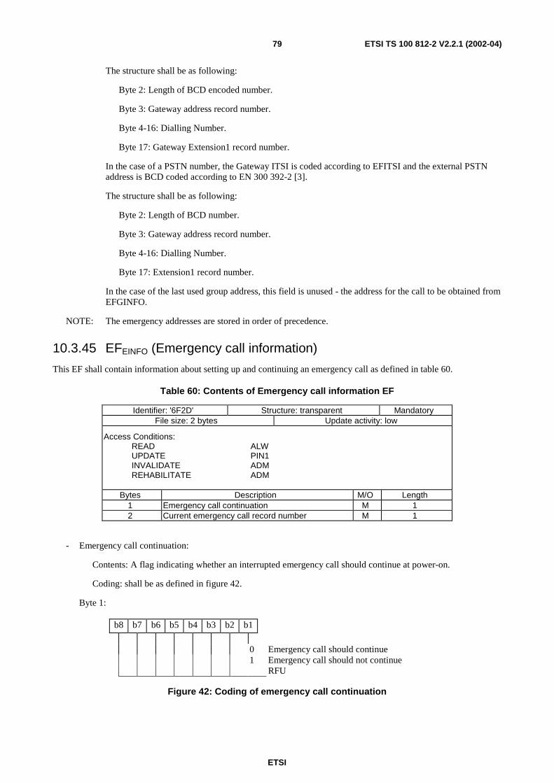
ETSI
ETSI TS 100 812-2 V2.2.1 (2002-04)79
The structure shall be as following:
Byte 2: Length of BCD encoded number.
Byte 3: Gateway address record number.
Byte 4-16: Dialling Number.
Byte 17: Gateway Extension1 record number.
In the case of a PSTN number, the Gateway ITSI is coded according to EFITSI and the external PSTNaddress is BCD coded according to EN 300 392-2 [3].
The structure shall be as following:
Byte 2: Length of BCD number.
Byte 3: Gateway address record number.
Byte 4-16: Dialling Number.
Byte 17: Extension1 record number.
In the case of the last used group address, this field is unused - the address for the call to be obtained fromEFGINFO.
NOTE: The emergency addresses are stored in order of precedence.
10.3.45 EFEINFO (Emergency call information)
This EF shall contain information about setting up and continuing an emergency call as defined in table 60.
Table 60: Contents of Emergency call information EF
Identifier: '6F2D' Structure: transparent MandatoryFile size: 2 bytes Update activity: low
Access Conditions:READ ALWUPDATE PIN1INVALIDATE ADMREHABILITATE ADM
Bytes Description M/O Length1 Emergency call continuation M 12 Current emergency call record number M 1
- Emergency call continuation:
Contents: A flag indicating whether an interrupted emergency call should continue at power-on.
Coding: shall be as defined in figure 42.
Byte 1:
b8 b7 b6 b5 b4 b3 b2 b1
0 Emergency call should continue1 Emergency call should not continue
RFU
Figure 42: Coding of emergency call continuation
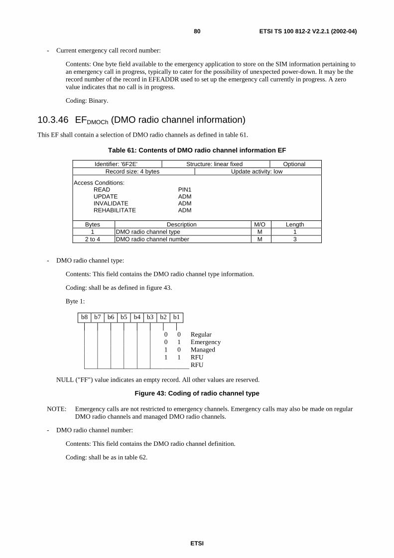
ETSI
ETSI TS 100 812-2 V2.2.1 (2002-04)80
- Current emergency call record number:
Contents: One byte field available to the emergency application to store on the SIM information pertaining toan emergency call in progress, typically to cater for the possibility of unexpected power-down. It may be therecord number of the record in EFEADDR used to set up the emergency call currently in progress. A zerovalue indicates that no call is in progress.
Coding: Binary.
10.3.46 EFDMOCh (DMO radio channel information)
This EF shall contain a selection of DMO radio channels as defined in table 61.
Table 61: Contents of DMO radio channel information EF
Identifier: '6F2E' Structure: linear fixed OptionalRecord size: 4 bytes Update activity: low
Access Conditions:READ PIN1UPDATE ADMINVALIDATE ADMREHABILITATE ADM
Bytes Description M/O Length1 DMO radio channel type M 1
2 to 4 DMO radio channel number M 3
- DMO radio channel type:
Contents: This field contains the DMO radio channel type information.
Coding: shall be as defined in figure 43.
Byte 1:
b8 b7 b6 b5 b4 b3 b2 b1
0 0 Regular0 1 Emergency1 0 Managed1 1 RFU
RFU
NULL ("FF") value indicates an empty record. All other values are reserved.
Figure 43: Coding of radio channel type
NOTE: Emergency calls are not restricted to emergency channels. Emergency calls may also be made on regularDMO radio channels and managed DMO radio channels.
- DMO radio channel number:
Contents: This field contains the DMO radio channel definition.
Coding: shall be as in table 62.
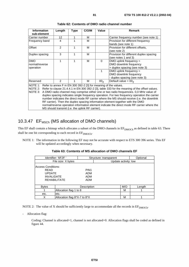
ETSI
ETSI TS 100 812-2 V2.2.1 (2002-04)81
Table 62: Contents of DMO radio channel number
Informationsub-element
Length Type C/O/M Value Remark
Carrier number 12 1 M Carrier frequency number (see note 1)Frequency band 4 1 M Provision for different frequency
bands (see note 1)Offset 2 1 M Provision for different offsets,
(see note 2)Duplex spacing 3 1 M Provision for different duplex spacing
(see notes 1 and 3)0 DMO uplink frequency =
DMO downlink frequency+ duplex spacing (see note 3)
DMOnormal/reverseoperation
1 1 M
1 DMO uplink frequency =DMO downlink frequency- duplex spacing (see note 3)
Reserved 2 1 M 002 Default value = 002NOTE 1: Refer to annex F in EN 300 392-2 [3] for meaning of the values.NOTE 2: Refer to clause 21.4.4.1 in EN 300 392-2 [3], table 333 for the meaning of the offset values.NOTE 3: A DMO radio channel may comprise either one or two radio frequencies. 0,0 MHz value of
duplex spacing indicates single frequency operation. For two frequency operation the carriernumber indicates the direct mode RF carrier where the MS should receive (i.e. the downlinkRF carrier). Then the duplex spacing information element together with the DMOnormal/reverse operation information element indicate the direct mode RF carrier where theMS should transmit (i.e. the uplink RF carrier).
10.3.47 EFMSCh (MS allocation of DMO channels)
This EF shall contain a bitmap which allocates a subset of the DMO channels in EFDMOCh as defined in table 63. There
shall be one bit corresponding to each record in EFDMOCh.
NOTE 1: The information in the following EF may not be accurate with respect to ETS 300 396 series. This EFwill be updated accordingly when necessary.
Table 63: Contents of MS allocation of DMO channels EF
Identifier: '6F2F ' Structure: transparent OptionalFile size: X bytes Update activity: low
Access Conditions:READ PIN1UPDATE ADMINVALIDATE ADMREHABILITATE ADM
Bytes Description M/O Length1 Allocation flag 1 to 8 M 1
etc. etc.X Allocation flag 8*X-7 to 8*X M 1
NOTE 2: The value of X should be sufficiently large to accommodate all the records in EFDMOCh.
- Allocation flag:
Coding: Channel is allocated=1, channel is not allocated=0. Allocation flags shall be coded as defined infigure 44.
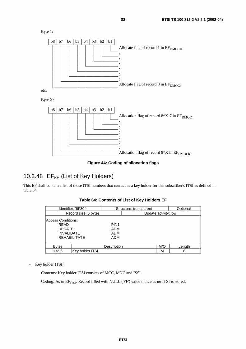
ETSI
ETSI TS 100 812-2 V2.2.1 (2002-04)82
Byte 1:
b8 b7 b6 b5 b4 b3 b2 b1
Allocate flag of record 1 in EFDMOCH
::::::Allocate flag of record 8 in EFDMOCh
etc.
Byte X:
b8 b7 b6 b5 b4 b3 b2 b1
Allocation flag of record 8*X-7 in EFDMOCh
::::::Allocation flag of record 8*X in EFDMOCh
Figure 44: Coding of allocation flags
10.3.48 EFKH (List of Key Holders)
This EF shall contain a list of those ITSI numbers that can act as a key holder for this subscriber's ITSI as defined intable 64.
Table 64: Contents of List of Key Holders EF
Identifier: '6F30 ' Structure: transparent OptionalRecord size: 6 bytes Update activity: low
Access Conditions:READ PIN1UPDATE ADMINVALIDATE ADMREHABILITATE ADM
Bytes Description M/O Length1 to 6 Key holder ITSI M 6
- Key holder ITSI;
Contents: Key holder ITSI consists of MCC, MNC and ISSI.
Coding: As in EFITSI. Record filled with NULL ('FF') value indicates no ITSI is stored.
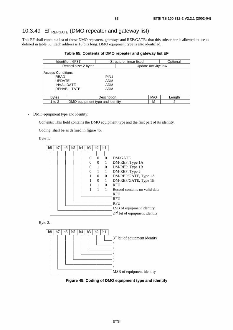
ETSI
ETSI TS 100 812-2 V2.2.1 (2002-04)83
10.3.49 EFREPGATE (DMO repeater and gateway list)
This EF shall contain a list of those DMO repeaters, gateways and REP/GATEs that this subscriber is allowed to use asdefined in table 65. Each address is 10 bits long. DMO equipment type is also identified.
Table 65: Contents of DMO repeater and gateway list EF
Identifier: '6F31' Structure: linear fixed OptionalRecord size: 2 bytes Update activity: low
Access Conditions:READ PIN1UPDATE ADMINVALIDATE ADMREHABILITATE ADM
Bytes Description M/O Length1 to 2 DMO equipment type and identity M 2
- DMO equipment type and identity:
Contents: This field contains the DMO equipment type and the first part of its identity.
Coding: shall be as defined in figure 45.
Byte 1:
b8 b7 b6 b5 b4 b3 b2 b1
0 0 0 DM-GATE0 0 1 DM-REP, Type 1A0 1 0 DM-REP, Type 1B0 1 1 DM-REP, Type 21 0 0 DM-REP/GATE, Type 1A1 0 1 DM-REP/GATE, Type 1B1 1 0 RFU1 1 1 Record contains no valid data
RFURFURFULSB of equipment identity2nd bit of equipment identity
Byte 2:
b8 b7 b6 b5 b4 b3 b2 b1
3rd bit of equipment identity::::::MSB of equipment identity
Figure 45: Coding of DMO equipment type and identity
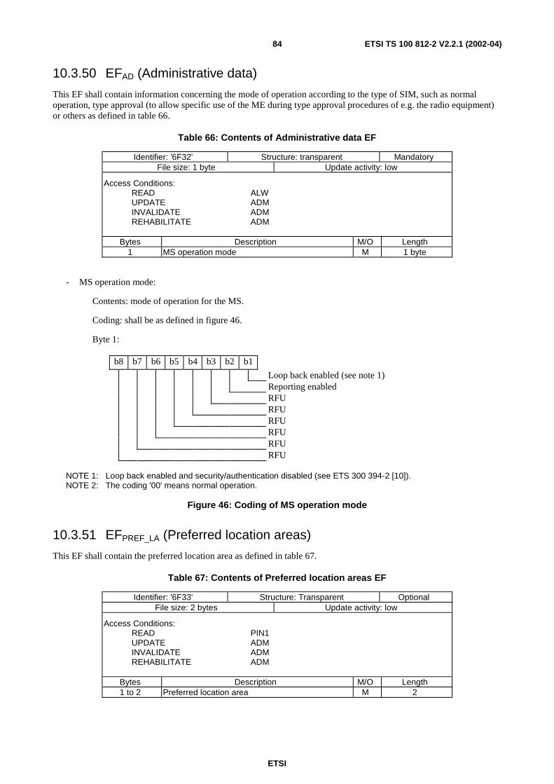
ETSI
ETSI TS 100 812-2 V2.2.1 (2002-04)84
10.3.50 EFAD (Administrative data)
This EF shall contain information concerning the mode of operation according to the type of SIM, such as normaloperation, type approval (to allow specific use of the ME during type approval procedures of e.g. the radio equipment)or others as defined in table 66.
Table 66: Contents of Administrative data EF
Identifier: '6F32' Structure: transparent MandatoryFile size: 1 byte Update activity: low
Access Conditions:READ ALWUPDATE ADMINVALIDATE ADMREHABILITATE ADM
Bytes Description M/O Length1 MS operation mode M 1 byte
- MS operation mode:
Contents: mode of operation for the MS.
Coding: shall be as defined in figure 46.
Byte 1:
b8 b7 b6 b5 b4 b3 b2 b1
Loop back enabled (see note 1)Reporting enabledRFURFURFURFURFURFU
NOTE 1: Loop back enabled and security/authentication disabled (see ETS 300 394-2 [10]).NOTE 2: The coding '00' means normal operation.
Figure 46: Coding of MS operation mode
10.3.51 EFPREF_LA (Preferred location areas)
This EF shall contain the preferred location area as defined in table 67.
Table 67: Contents of Preferred location areas EF
Identifier: '6F33' Structure: Transparent OptionalFile size: 2 bytes Update activity: low
Access Conditions:READ PIN1UPDATE ADMINVALIDATE ADMREHABILITATE ADM
Bytes Description M/O Length1 to 2 Preferred location area M 2
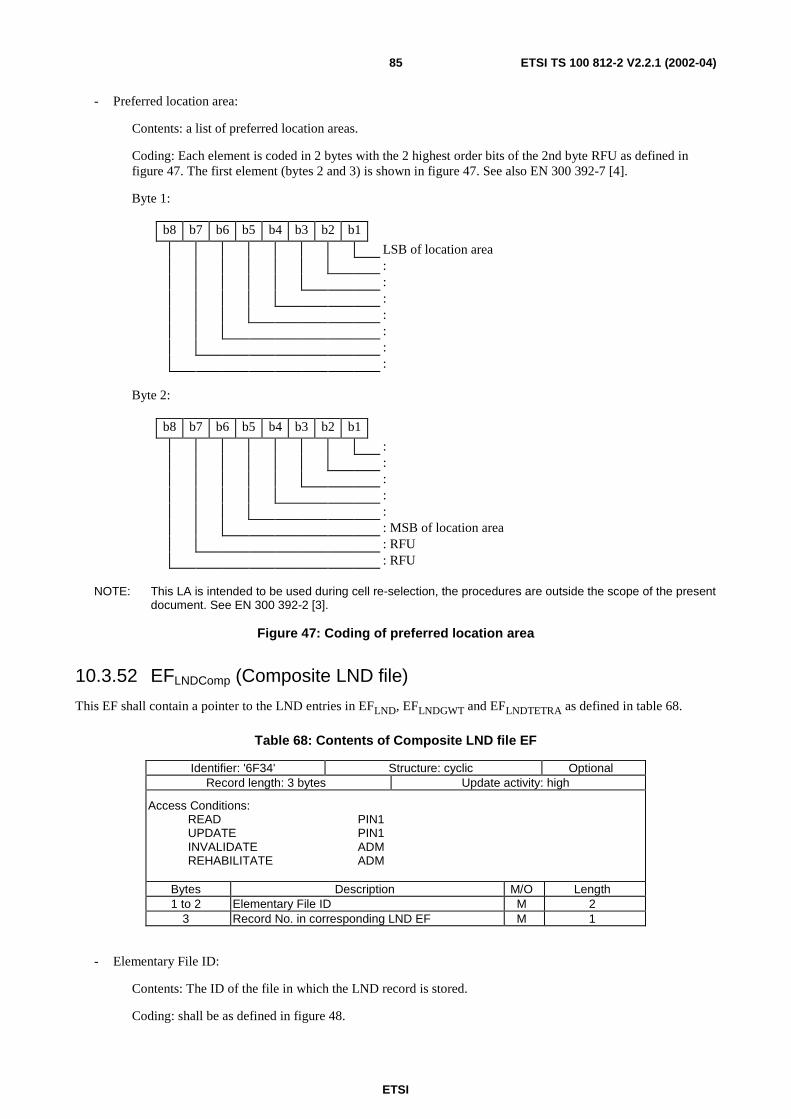
ETSI
ETSI TS 100 812-2 V2.2.1 (2002-04)85
- Preferred location area:
Contents: a list of preferred location areas.
Coding: Each element is coded in 2 bytes with the 2 highest order bits of the 2nd byte RFU as defined infigure 47. The first element (bytes 2 and 3) is shown in figure 47. See also EN 300 392-7 [4].
Byte 1:
b8 b7 b6 b5 b4 b3 b2 b1
LSB of location area:::::::
Byte 2:
b8 b7 b6 b5 b4 b3 b2 b1
:::::: MSB of location area: RFU: RFU
NOTE: This LA is intended to be used during cell re-selection, the procedures are outside the scope of the presentdocument. See EN 300 392-2 [3].
Figure 47: Coding of preferred location area
10.3.52 EFLNDComp (Composite LND file)
This EF shall contain a pointer to the LND entries in EFLND, EFLNDGWT and EFLNDTETRA as defined in table 68.
Table 68: Contents of Composite LND file EF
Identifier: '6F34' Structure: cyclic OptionalRecord length: 3 bytes Update activity: high
Access Conditions:READ PIN1UPDATE PIN1INVALIDATE ADMREHABILITATE ADM
Bytes Description M/O Length1 to 2 Elementary File ID M 2
3 Record No. in corresponding LND EF M 1
- Elementary File ID:
Contents: The ID of the file in which the LND record is stored.
Coding: shall be as defined in figure 48.
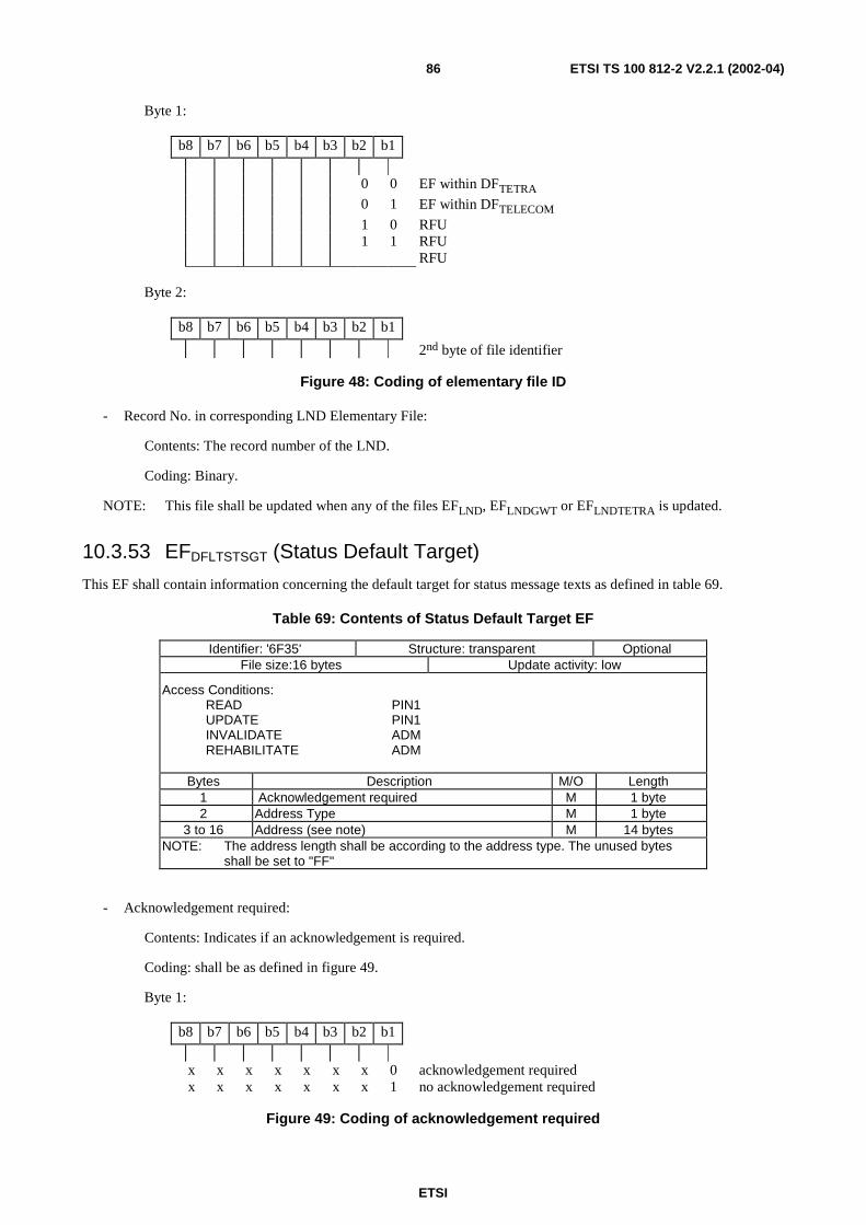
ETSI
ETSI TS 100 812-2 V2.2.1 (2002-04)86
Byte 1:
b8 b7 b6 b5 b4 b3 b2 b1
0 0 EF within DFTETRA0 1 EF within DFTELECOM1 0 RFU1 1 RFU
RFU
Byte 2:
b8 b7 b6 b5 b4 b3 b2 b1
2nd byte of file identifier
Figure 48: Coding of elementary file ID
- Record No. in corresponding LND Elementary File:
Contents: The record number of the LND.
Coding: Binary.
NOTE: This file shall be updated when any of the files EFLND, EFLNDGWT or EFLNDTETRA is updated.
10.3.53 EFDFLTSTSGT (Status Default Target)
This EF shall contain information concerning the default target for status message texts as defined in table 69.
Table 69: Contents of Status Default Target EF
Identifier: '6F35' Structure: transparent OptionalFile size:16 bytes Update activity: low
Access Conditions:READ PIN1UPDATE PIN1INVALIDATE ADMREHABILITATE ADM
Bytes Description M/O Length1 Acknowledgement required M 1 byte2 Address Type M 1 byte
3 to 16 Address (see note) M 14 bytesNOTE: The address length shall be according to the address type. The unused bytes
shall be set to "FF"
- Acknowledgement required:
Contents: Indicates if an acknowledgement is required.
Coding: shall be as defined in figure 49.
Byte 1:
b8 b7 b6 b5 b4 b3 b2 b1
x x x x x x x 0 acknowledgement requiredx x x x x x x 1 no acknowledgement required
Figure 49: Coding of acknowledgement required
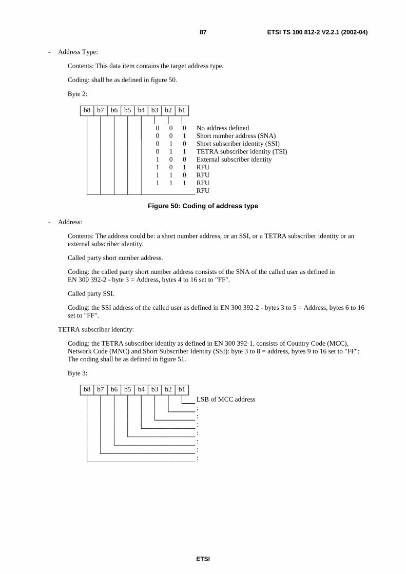
ETSI
ETSI TS 100 812-2 V2.2.1 (2002-04)87
- Address Type:
Contents: This data item contains the target address type.
Coding: shall be as defined in figure 50.
Byte 2:
b8 b7 b6 b5 b4 b3 b2 b1
0 0 0 No address defined0 0 1 Short number address (SNA)0 1 0 Short subscriber identity (SSI)0 1 1 TETRA subscriber identity (TSI)1 0 0 External subscriber identity1 0 1 RFU1 1 0 RFU1 1 1 RFU
RFU
Figure 50: Coding of address type
- Address:
Contents: The address could be: a short number address, or an SSI, or a TETRA subscriber identity or anexternal subscriber identity.
Called party short number address.
Coding: the called party short number address consists of the SNA of the called user as defined inEN 300 392-2 - byte 3 = Address, bytes 4 to 16 set to "FF".
Called party SSI.
Coding: the SSI address of the called user as defined in EN 300 392-2 - bytes 3 to 5 = Address, bytes 6 to 16set to "FF".
TETRA subscriber identity:
Coding: the TETRA subscriber identity as defined in EN 300 392-1, consists of Country Code (MCC),Network Code (MNC) and Short Subscriber Identity (SSI): byte 3 to 8 = address, bytes 9 to 16 set to "FF":The coding shall be as defined in figure 51.
Byte 3:
b8 b7 b6 b5 b4 b3 b2 b1
LSB of MCC address:::::::
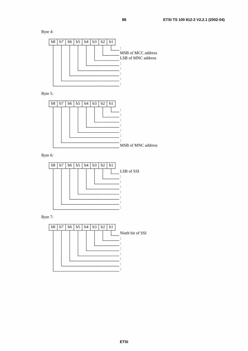
ETSI
ETSI TS 100 812-2 V2.2.1 (2002-04)88
Byte 4:
b8 b7 b6 b5 b4 b3 b2 b1
:MSB of MCC addressLSB of MNC address:::::
Byte 5:
b8 b7 b6 b5 b4 b3 b2 b1
:::::::MSB of MNC address
Byte 6:
b8 b7 b6 b5 b4 b3 b2 b1
LSB of SSI:::::::
Byte 7:
b8 b7 b6 b5 b4 b3 b2 b1
Ninth bit of SSI:::::::
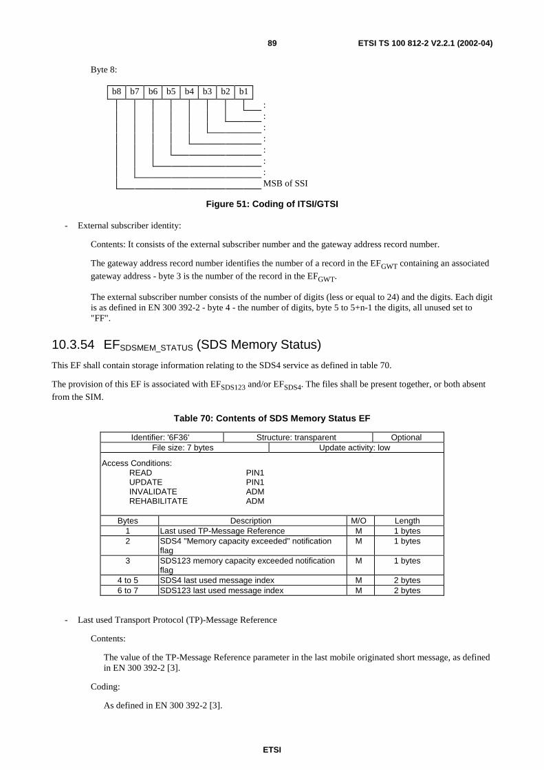
ETSI
ETSI TS 100 812-2 V2.2.1 (2002-04)89
Byte 8:
b8 b7 b6 b5 b4 b3 b2 b1
:::::::MSB of SSI
Figure 51: Coding of ITSI/GTSI
- External subscriber identity:
Contents: It consists of the external subscriber number and the gateway address record number.
The gateway address record number identifies the number of a record in the EFGWT containing an associated
gateway address - byte 3 is the number of the record in the EFGWT.
The external subscriber number consists of the number of digits (less or equal to 24) and the digits. Each digitis as defined in EN 300 392-2 - byte 4 - the number of digits, byte 5 to 5+n-1 the digits, all unused set to"FF".
10.3.54 EFSDSMEM_STATUS (SDS Memory Status)
This EF shall contain storage information relating to the SDS4 service as defined in table 70.
The provision of this EF is associated with EFSDS123 and/or EFSDS4. The files shall be present together, or both absent
from the SIM.
Table 70: Contents of SDS Memory Status EF
Identifier: '6F36' Structure: transparent OptionalFile size: 7 bytes Update activity: low
Access Conditions:READ PIN1UPDATE PIN1INVALIDATE ADMREHABILITATE ADM
Bytes Description M/O Length1 Last used TP-Message Reference M 1 bytes2 SDS4 "Memory capacity exceeded" notification
flagM 1 bytes
3 SDS123 memory capacity exceeded notificationflag
M 1 bytes
4 to 5 SDS4 last used message index M 2 bytes6 to 7 SDS123 last used message index M 2 bytes
- Last used Transport Protocol (TP)-Message Reference
Contents:
The value of the TP-Message Reference parameter in the last mobile originated short message, as definedin EN 300 392-2 [3].
Coding:
As defined in EN 300 392-2 [3].
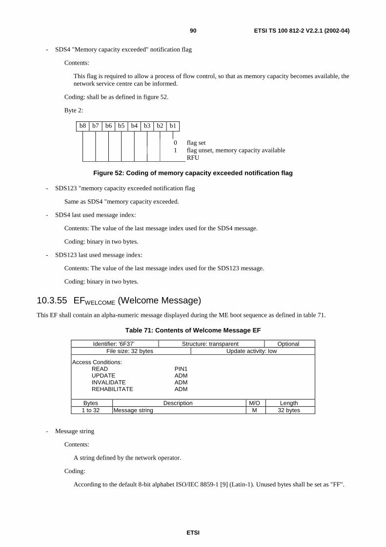
ETSI
ETSI TS 100 812-2 V2.2.1 (2002-04)90
- SDS4 "Memory capacity exceeded" notification flag
Contents:
This flag is required to allow a process of flow control, so that as memory capacity becomes available, thenetwork service centre can be informed.
Coding: shall be as defined in figure 52.
Byte 2:
b8 b7 b6 b5 b4 b3 b2 b1
0 flag set1 flag unset, memory capacity available
RFU
Figure 52: Coding of memory capacity exceeded notification flag
- SDS123 "memory capacity exceeded notification flag
Same as SDS4 "memory capacity exceeded.
- SDS4 last used message index:
Contents: The value of the last message index used for the SDS4 message.
Coding: binary in two bytes.
- SDS123 last used message index:
Contents: The value of the last message index used for the SDS123 message.
Coding: binary in two bytes.
10.3.55 EFWELCOME (Welcome Message)
This EF shall contain an alpha-numeric message displayed during the ME boot sequence as defined in table 71.
Table 71: Contents of Welcome Message EF
Identifier: '6F37' Structure: transparent OptionalFile size: 32 bytes Update activity: low
Access Conditions:READ PIN1UPDATE ADMINVALIDATE ADMREHABILITATE ADM
Bytes Description M/O Length1 to 32 Message string M 32 bytes
- Message string
Contents:
A string defined by the network operator.
Coding:
According to the default 8-bit alphabet ISO/IEC 8859-1 [9] (Latin-1). Unused bytes shall be set as "FF".
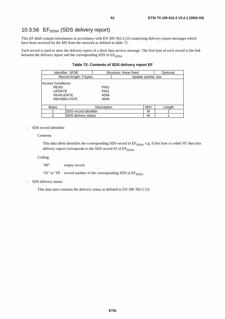
ETSI
ETSI TS 100 812-2 V2.2.1 (2002-04)91
10.3.56 EFSDSR (SDS delivery report)
This EF shall contain information in accordance with EN 300 392-2 [3] comprising delivery report messages whichhave been received by the MS from the network as defined in table 72.
Each record is used to store the delivery report of a short data service message. The first byte of each record is the linkbetween the delivery report and the corresponding SDS in EFSDS4.
Table 72: Contents of SDS delivery report EF
Identifier: '6F38' Structure: linear fixed OptionalRecord length: 2 bytes Update activity: low
Access Conditions:READ PIN1UPDATE PIN1INVALIDATE ADMREHABILITATE ADM
Bytes Description M/O Length1 SDS record identifier M 12 SDS delivery status M 1
- SDS record identifier
Contents:
This data idem identifies the corresponding SDS record in EFSDS4, e.g. if this byte is coded '05' then this
delivery report corresponds to the SDS record #5 of EFSDS4.
Coding:
"00" empty record.
"01" to "FF record number of the corresponding SDS in EFSDS4
- SDS delivery status:
This data item contains the delivery status as defined in EN 300 392-2 [3].
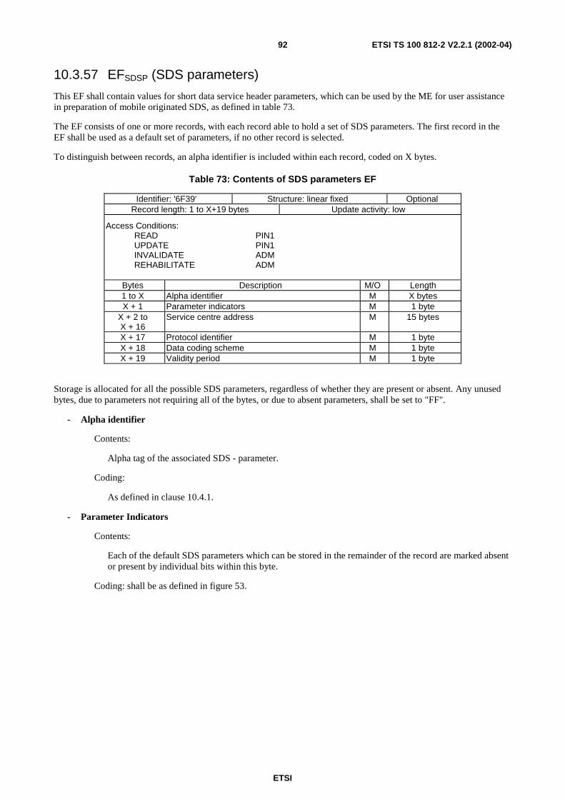
ETSI
ETSI TS 100 812-2 V2.2.1 (2002-04)92
10.3.57 EFSDSP (SDS parameters)
This EF shall contain values for short data service header parameters, which can be used by the ME for user assistancein preparation of mobile originated SDS, as defined in table 73.
The EF consists of one or more records, with each record able to hold a set of SDS parameters. The first record in theEF shall be used as a default set of parameters, if no other record is selected.
To distinguish between records, an alpha identifier is included within each record, coded on X bytes.
Table 73: Contents of SDS parameters EF
Identifier: '6F39' Structure: linear fixed OptionalRecord length: 1 to X+19 bytes Update activity: low
Access Conditions:READ PIN1UPDATE PIN1INVALIDATE ADMREHABILITATE ADM
Bytes Description M/O Length1 to X Alpha identifier M X bytesX + 1 Parameter indicators M 1 byte
X + 2 toX + 16
Service centre address M 15 bytes
X + 17 Protocol identifier M 1 byteX + 18 Data coding scheme M 1 byteX + 19 Validity period M 1 byte
Storage is allocated for all the possible SDS parameters, regardless of whether they are present or absent. Any unusedbytes, due to parameters not requiring all of the bytes, or due to absent parameters, shall be set to "FF".
- Alpha identifier
Contents:
Alpha tag of the associated SDS - parameter.
Coding:
As defined in clause 10.4.1.
- Parameter Indicators
Contents:
Each of the default SDS parameters which can be stored in the remainder of the record are marked absentor present by individual bits within this byte.
Coding: shall be as defined in figure 53.
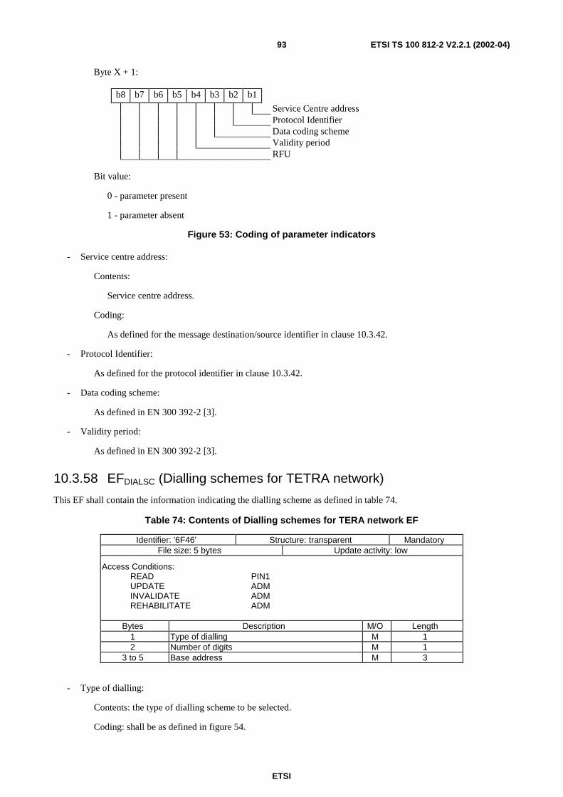
ETSI
ETSI TS 100 812-2 V2.2.1 (2002-04)93
Byte X + 1:
b8 b7 b6 b5 b4 b3 b2 b1
Service Centre addressProtocol IdentifierData coding schemeValidity periodRFU
Bit value:
0 - parameter present
1 - parameter absent
Figure 53: Coding of parameter indicators
- Service centre address:
Contents:
Service centre address.
Coding:
As defined for the message destination/source identifier in clause 10.3.42.
- Protocol Identifier:
As defined for the protocol identifier in clause 10.3.42.
- Data coding scheme:
As defined in EN 300 392-2 [3].
- Validity period:
As defined in EN 300 392-2 [3].
10.3.58 EFDIALSC (Dialling schemes for TETRA network)
This EF shall contain the information indicating the dialling scheme as defined in table 74.
Table 74: Contents of Dialling schemes for TERA network EF
Identifier: '6F46' Structure: transparent MandatoryFile size: 5 bytes Update activity: low
Access Conditions:READ PIN1UPDATE ADMINVALIDATE ADMREHABILITATE ADM
Bytes Description M/O Length1 Type of dialling M 12 Number of digits M 1
3 to 5 Base address M 3
- Type of dialling:
Contents: the type of dialling scheme to be selected.
Coding: shall be as defined in figure 54.
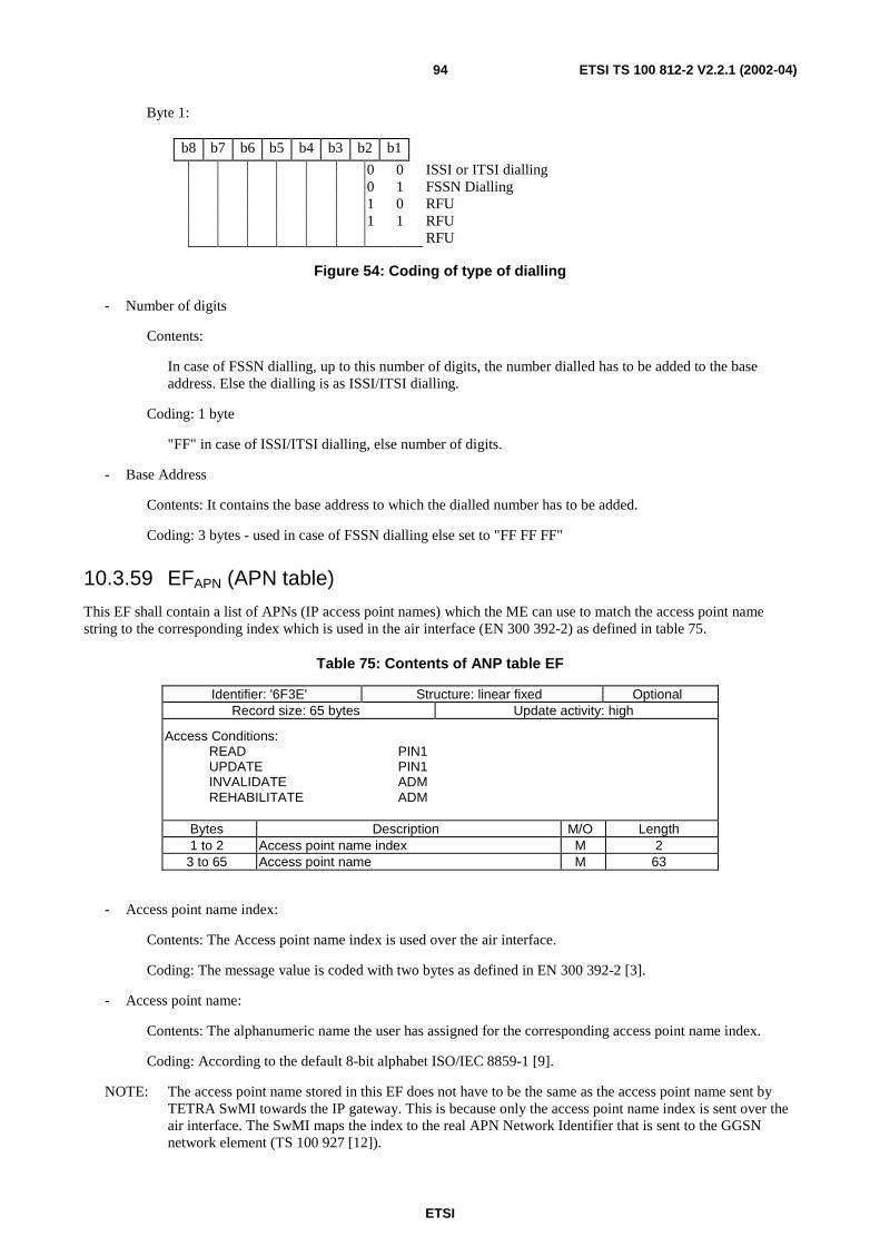
ETSI
ETSI TS 100 812-2 V2.2.1 (2002-04)94
Byte 1:
b8 b7 b6 b5 b4 b3 b2 b1
0 0 ISSI or ITSI dialling0 1 FSSN Dialling1 0 RFU1 1 RFU
RFU
Figure 54: Coding of type of dialling
- Number of digits
Contents:
In case of FSSN dialling, up to this number of digits, the number dialled has to be added to the baseaddress. Else the dialling is as ISSI/ITSI dialling.
Coding: 1 byte
"FF" in case of ISSI/ITSI dialling, else number of digits.
- Base Address
Contents: It contains the base address to which the dialled number has to be added.
Coding: 3 bytes - used in case of FSSN dialling else set to "FF FF FF"
10.3.59 EFAPN (APN table)
This EF shall contain a list of APNs (IP access point names) which the ME can use to match the access point namestring to the corresponding index which is used in the air interface (EN 300 392-2) as defined in table 75.
Table 75: Contents of ANP table EF
Identifier: '6F3E' Structure: linear fixed OptionalRecord size: 65 bytes Update activity: high
Access Conditions:READ PIN1UPDATE PIN1INVALIDATE ADMREHABILITATE ADM
Bytes Description M/O Length1 to 2 Access point name index M 2
3 to 65 Access point name M 63
- Access point name index:
Contents: The Access point name index is used over the air interface.
Coding: The message value is coded with two bytes as defined in EN 300 392-2 [3].
- Access point name:
Contents: The alphanumeric name the user has assigned for the corresponding access point name index.
Coding: According to the default 8-bit alphabet ISO/IEC 8859-1 [9].
NOTE: The access point name stored in this EF does not have to be the same as the access point name sent byTETRA SwMI towards the IP gateway. This is because only the access point name index is sent over theair interface. The SwMI maps the index to the real APN Network Identifier that is sent to the GGSNnetwork element (TS 100 927 [12]).
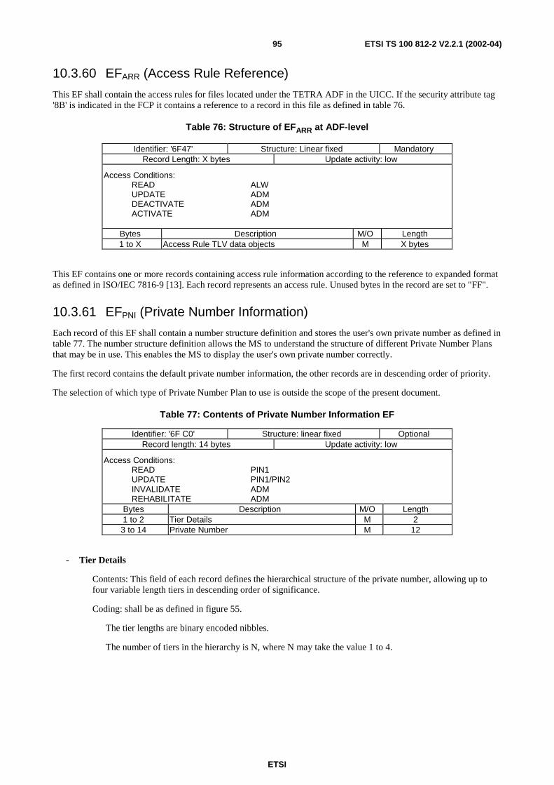
ETSI
ETSI TS 100 812-2 V2.2.1 (2002-04)95
10.3.60 EFARR (Access Rule Reference)
This EF shall contain the access rules for files located under the TETRA ADF in the UICC. If the security attribute tag'8B' is indicated in the FCP it contains a reference to a record in this file as defined in table 76.
Table 76: Structure of EFARR at ADF-level
Identifier: '6F47' Structure: Linear fixed MandatoryRecord Length: X bytes Update activity: low
Access Conditions:READ ALWUPDATE ADMDEACTIVATE ADMACTIVATE ADM
Bytes Description M/O Length1 to X Access Rule TLV data objects M X bytes
This EF contains one or more records containing access rule information according to the reference to expanded formatas defined in ISO/IEC 7816-9 [13]. Each record represents an access rule. Unused bytes in the record are set to "FF".
10.3.61 EFPNI (Private Number Information)
Each record of this EF shall contain a number structure definition and stores the user's own private number as defined intable 77. The number structure definition allows the MS to understand the structure of different Private Number Plansthat may be in use. This enables the MS to display the user's own private number correctly.
The first record contains the default private number information, the other records are in descending order of priority.
The selection of which type of Private Number Plan to use is outside the scope of the present document.
Table 77: Contents of Private Number Information EF
Identifier: '6F C0' Structure: linear fixed OptionalRecord length: 14 bytes Update activity: low
Access Conditions:READ PIN1UPDATE PIN1/PIN2INVALIDATE ADMREHABILITATE ADM
Bytes Description M/O Length1 to 2 Tier Details M 23 to 14 Private Number M 12
- Tier Details
Contents: This field of each record defines the hierarchical structure of the private number, allowing up tofour variable length tiers in descending order of significance.
Coding: shall be as defined in figure 55.
The tier lengths are binary encoded nibbles.
The number of tiers in the hierarchy is N, where N may take the value 1 to 4.
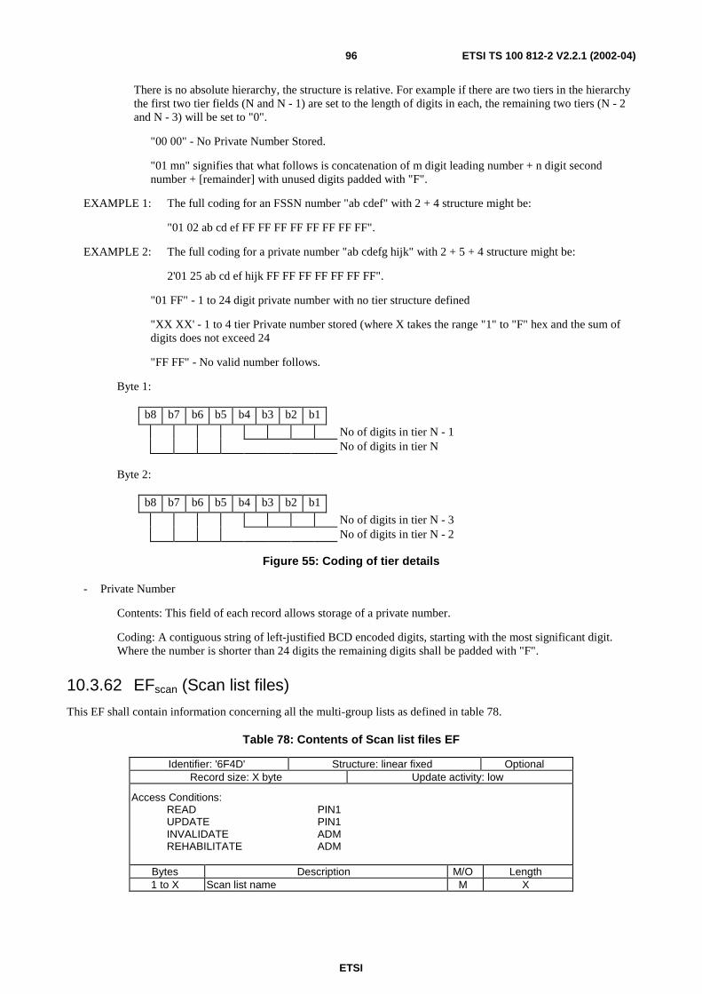
ETSI
ETSI TS 100 812-2 V2.2.1 (2002-04)96
There is no absolute hierarchy, the structure is relative. For example if there are two tiers in the hierarchythe first two tier fields (N and N - 1) are set to the length of digits in each, the remaining two tiers (N - 2and N - 3) will be set to "0".
"00 00" - No Private Number Stored.
"01 mn" signifies that what follows is concatenation of m digit leading number + n digit secondnumber + [remainder] with unused digits padded with "F".
EXAMPLE 1: The full coding for an FSSN number "ab cdef" with 2 + 4 structure might be:
"01 02 ab cd ef FF FF FF FF FF FF FF FF".
EXAMPLE 2: The full coding for a private number "ab cdefg hijk" with 2 + 5 + 4 structure might be:
2'01 25 ab cd ef hijk FF FF FF FF FF FF FF".
"01 FF" - 1 to 24 digit private number with no tier structure defined
"XX XX' - 1 to 4 tier Private number stored (where X takes the range "1" to "F" hex and the sum ofdigits does not exceed 24
"FF FF" - No valid number follows.
Byte 1:
b8 b7 b6 b5 b4 b3 b2 b1
No of digits in tier N - 1No of digits in tier N
Byte 2:
b8 b7 b6 b5 b4 b3 b2 b1
No of digits in tier N - 3No of digits in tier N - 2
Figure 55: Coding of tier details
- Private Number
Contents: This field of each record allows storage of a private number.
Coding: A contiguous string of left-justified BCD encoded digits, starting with the most significant digit.Where the number is shorter than 24 digits the remaining digits shall be padded with "F".
10.3.62 EFscan (Scan list files)
This EF shall contain information concerning all the multi-group lists as defined in table 78.
Table 78: Contents of Scan list files EF
Identifier: '6F4D' Structure: linear fixed OptionalRecord size: X byte Update activity: low
Access Conditions:READ PIN1UPDATE PIN1INVALIDATE ADMREHABILITATE ADM
Bytes Description M/O Length1 to X Scan list name M X
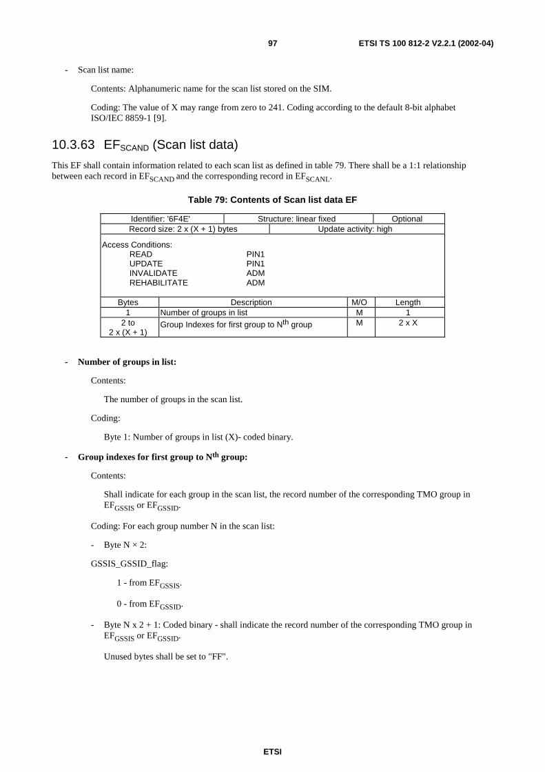
ETSI
ETSI TS 100 812-2 V2.2.1 (2002-04)97
- Scan list name:
Contents: Alphanumeric name for the scan list stored on the SIM.
Coding: The value of X may range from zero to 241. Coding according to the default 8-bit alphabetISO/IEC 8859-1 [9].
10.3.63 EFSCAND (Scan list data)
This EF shall contain information related to each scan list as defined in table 79. There shall be a 1:1 relationshipbetween each record in EFSCAND and the corresponding record in EFSCANL.
Table 79: Contents of Scan list data EF
Identifier: '6F4E' Structure: linear fixed OptionalRecord size: 2 x (X + 1) bytes Update activity: high
Access Conditions:READ PIN1UPDATE PIN1INVALIDATE ADMREHABILITATE ADM
Bytes Description M/O Length1 Number of groups in list M 1
2 to2 x (X + 1)
Group Indexes for first group to Nth group M 2 x X
- Number of groups in list:
Contents:
The number of groups in the scan list.
Coding:
Byte 1: Number of groups in list (X)- coded binary.
- Group indexes for first group to Nth group:
Contents:
Shall indicate for each group in the scan list, the record number of the corresponding TMO group inEFGSSIS or EFGSSID.
Coding: For each group number N in the scan list:
- Byte N × 2:
GSSIS_GSSID_flag:
1 - from EFGSSIS.
0 - from EFGSSID.
- Byte N x 2 + 1: Coded binary - shall indicate the record number of the corresponding TMO group inEFGSSIS or EFGSSID.
Unused bytes shall be set to "FF".
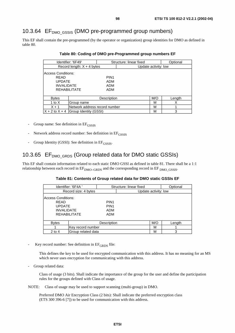
ETSI
ETSI TS 100 812-2 V2.2.1 (2002-04)98
10.3.64 EFDMO_GSSIS (DMO pre-programmed group numbers)
This EF shall contain the pre-programmed (by the operator or organization) group identities for DMO as defined intable 80.
Table 80: Coding of DMO pre-Programmed group numbers EF
Identifier: '6F49' Structure: linear fixed OptionalRecord length: X + 4 bytes Update activity: low
Access Conditions:READ PIN1UPDATE ADMINVALIDATE ADMREHABILITATE ADM
Bytes Description M/O Length1 to X Group name M XX + 1 Network address record number M 1
X + 2 to X + 4 Group Identity (GSSI) M 3
- Group name: See definition in EFGSSIS
- Network address record number: See definition in EFGSSIS
- Group Identity (GSSI): See definition in EFGSSIS.
10.3.65 EFDMO_GRDS (Group related data for DMO static GSSIs)
This EF shall contain information related to each static DMO GSSI as defined in table 81. There shall be a 1:1relationship between each record in EFDMO_GRDS and the corresponding record in EF DMO_GSSIS.
Table 81: Contents of Group related data for DMO static GSSIs EF
Identifier: '6F4A ' Structure: linear fixed OptionalRecord size: 4 bytes Update activity: low
Access Conditions:READ PIN1UPDATE PIN1INVALIDATE ADMREHABILITATE ADM
Bytes Description M/O Length1 Key record number M 1
2 to 4 Group related data M 3
- Key record number: See definition in EFGRDS file:
This defines the key to be used for encrypted communication with this address. It has no meaning for an MSwhich never uses encryption for communicating with this address.
- Group related data:
Class of usage (3 bits). Shall indicate the importance of the group for the user and define the participationrules for the groups defined with Class of usage.
NOTE: Class of usage may be used to support scanning (multi-group) in DMO.
Preferred DMO Air Encryption Class (2 bits): Shall indicate the preferred encryption class(ETS 300 396-6 [7]) to be used for communication with this address.
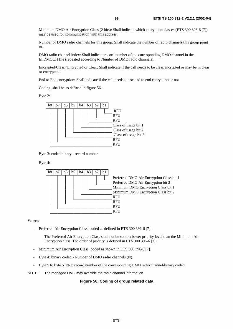
ETSI
ETSI TS 100 812-2 V2.2.1 (2002-04)99
Minimum DMO Air Encryption Class (2 bits): Shall indicate which encryption classes (ETS 300 396-6 [7])may be used for communication with this address.
Number of DMO radio channels for this group: Shall indicate the number of radio channels this group pointto.
DMO radio channel index: Shall indicate record number of the corresponding DMO channel in theEFDMOCH file (repeated according to Number of DMO radio channels).
Encrypted/Clear/"Encrypted or Clear: Shall indicate if the call needs to be clear/encrypted or may be in clearor encrypted.
End to End encryption: Shall indicate if the call needs to use end to end encryption or not
Coding: shall be as defined in figure 56.
Byte 2:
b8 b7 b6 b5 b4 b3 b2 b1
RFURFURFUClass of usage bit 1Class of usage bit 2Class of usage bit 3
RFURFU
Byte 3: coded binary - record number
Byte 4:
b8 b7 b6 b5 b4 b3 b2 b1
Preferred DMO Air Encryption Class bit 1Preferred DMO Air Encryption bit 2Minimum DMO Encryption Class bit 1Minimum DMO Encryption Class bit 2RFURFURFURFU
Where:
- Preferred Air Encryption Class: coded as defined in ETS 300 396-6 [7].
The Preferred Air Encryption Class shall not be set to a lower priority level than the Minimum AirEncryption class. The order of priority is defined in ETS 300 396-6 [7].
- Minimum Air Encryption Class: coded as shown in ETS 300 396-6 [7].
- Byte 4: binary coded - Number of DMO radio channels (N).
- Byte 5 to byte 5+N-1: record number of the corresponding DMO radio channel-binary coded.
NOTE: The managed DMO may override the radio channel information.
Figure 56: Coding of group related data
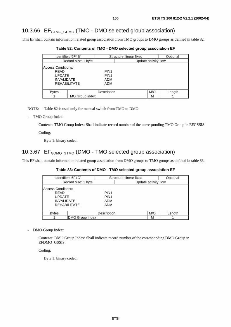
ETSI
ETSI TS 100 812-2 V2.2.1 (2002-04)100
10.3.66 EFGTMO_GDMO (TMO - DMO selected group association)
This EF shall contain information related group association from TMO groups to DMO groups as defined in table 82.
Table 82: Contents of TMO - DMO selected group association EF
Identifier: '6F4B' Structure: linear fixed OptionalRecord size: 1 byte Update activity: low
Access Conditions:READ PIN1UPDATE PIN1INVALIDATE ADMREHABILITATE ADM
Bytes Description M/O Length1 TMO Group index M 1
NOTE: Table 82 is used only for manual switch from TMO to DMO.
- TMO Group Index:
Contents: TMO Group Index: Shall indicate record number of the corresponding TMO Group in EFGSSIS.
Coding:
Byte 1: binary coded.
10.3.67 EFGDMO_GTMO (DMO - TMO selected group association)
This EF shall contain information related group association from DMO groups to TMO groups as defined in table 83.
Table 83: Contents of DMO - TMO selected group association EF
Identifier: '6F4C' Structure: linear fixed OptionalRecord size: 1 byte Update activity: low
Access Conditions:READ PIN1UPDATE PIN1INVALIDATE ADMREHABILITATE ADM
Bytes Description M/O Length1 DMO Group index M 1
- DMO Group Index:
Contents: DMO Group Index: Shall indicate record number of the corresponding DMO Group inEFDMO_GSSIS.
Coding:
Byte 1: binary coded.
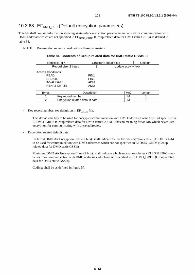
ETSI
ETSI TS 100 812-2 V2.2.1 (2002-04)101
10.3.68 EFDMO_DEP (Default encryption parameters)
This EF shall contain information showing air-interface encryption parameters to be used for communication withDMO addresses which are not specified in EFDMO_GRDS (Group related data for DMO static GSSIs) as defined in
table 84.
NOTE: Pre-emption requests need not use these parameters.
Table 84: Contents of Group related data for DMO static GSSIs EF
Identifier: '6F4F' Structure: linear fixed OptionalRecord size: 2 bytes Update activity: low
Access Conditions:READ PIN1UPDATE PIN1INVALIDATE ADMREHABILITATE ADM
Bytes Description M/O Length1 Key record number M 12 Encryption related default data M 1
- Key record number: see definition in EFGRDS file.
This defines the key to be used for encrypted communication with DMO addresses which are not specified inEFDMO_GRDS (Group related data for DMO static GSSIs). It has no meaning for an MS which never usesencryption for communicating with these addresses.
- Encryption related default data:
Preferred DMO Air Encryption Class (2 bits): shall indicate the preferred encryption class (ETS 300 396-6)to be used for communication with DMO addresses which are not specified in EFDMO_GRDS (Grouprelated data for DMO static GSSIs).
Minimum DMO Air Encryption Class (2 bits): shall indicate which encryption classes (ETS 300 396-6) maybe used for communication with DMO addresses which are not specified in EFDMO_GRDS (Group relateddata for DMO static GSSIs).
Coding: shall be as defined in figure 57.
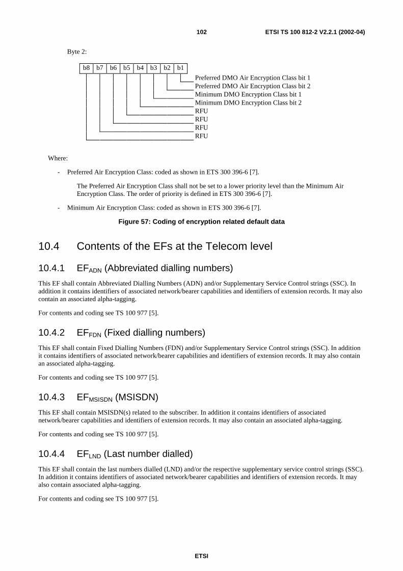
ETSI
ETSI TS 100 812-2 V2.2.1 (2002-04)102
Byte 2:
b8 b7 b6 b5 b4 b3 b2 b1
Preferred DMO Air Encryption Class bit 1Preferred DMO Air Encryption Class bit 2Minimum DMO Encryption Class bit 1Minimum DMO Encryption Class bit 2RFURFURFURFU
Where:
- Preferred Air Encryption Class: coded as shown in ETS 300 396-6 [7].
The Preferred Air Encryption Class shall not be set to a lower priority level than the Minimum AirEncryption Class. The order of priority is defined in ETS 300 396-6 [7].
- Minimum Air Encryption Class: coded as shown in ETS 300 396-6 [7].
Figure 57: Coding of encryption related default data
10.4 Contents of the EFs at the Telecom level
10.4.1 EFADN (Abbreviated dialling numbers)
This EF shall contain Abbreviated Dialling Numbers (ADN) and/or Supplementary Service Control strings (SSC). Inaddition it contains identifiers of associated network/bearer capabilities and identifiers of extension records. It may alsocontain an associated alpha-tagging.
For contents and coding see TS 100 977 [5].
10.4.2 EFFDN (Fixed dialling numbers)
This EF shall contain Fixed Dialling Numbers (FDN) and/or Supplementary Service Control strings (SSC). In additionit contains identifiers of associated network/bearer capabilities and identifiers of extension records. It may also containan associated alpha-tagging.
For contents and coding see TS 100 977 [5].
10.4.3 EFMSISDN (MSISDN)
This EF shall contain MSISDN(s) related to the subscriber. In addition it contains identifiers of associatednetwork/bearer capabilities and identifiers of extension records. It may also contain an associated alpha-tagging.
For contents and coding see TS 100 977 [5].
10.4.4 EFLND (Last number dialled)
This EF shall contain the last numbers dialled (LND) and/or the respective supplementary service control strings (SSC).In addition it contains identifiers of associated network/bearer capabilities and identifiers of extension records. It mayalso contain associated alpha-tagging.
For contents and coding see TS 100 977 [5].
ETSI
ETSI TS 100 812-2 V2.2.1 (2002-04)103
10.4.5 EFSDN (Service Dialling Numbers)
This EF shall contain special service numbers (SDN) and/or the respective supplementary service control strings (SSC).In addition it contains identifiers of associated network/bearer capabilities and identifiers of extension records. It mayalso contain associated alpha-tagging.
For contents and coding see TS 100 977 [5].
10.4.6 EFEXT1 (Extension1)
This EF shall contain extension data of an ADN/SSC, an MSISDN, or an LND. Extension data is caused by:
- an ADN/SSC (MSISDN, LND) which is greater than the 20 digit capacity of the ADN/SSC (MSISDN, LND)Elementary File or where common digits are required to follow an ADN/SSC string of less than 20 digits. Theremainder is stored in this EF as a record, which is identified by a specified identification byte inside theADN/SSC (MSISDN, LND) Elementary File. The EXT1 record in this case is specified as additional data;
- an associated called party subaddress. The EXT1 record in this case is specified as subaddress data.
For contents and coding see TS 100 977 [5].
10.4.7 EFEXT2 (Extension2)
This EF shall contain extension data of an FDN/SSC (see EXT2 in clause 10.4.2).
For contents and coding see TS 100 977 [5].
10.4.8 EFEXT3 (Extension3)
This EF shall contain extension data of an SDN (see EXT3 in clause 10.4.5).
For contents and coding see TS 100 977 [5].
10.5 Files of TETRAThis clause contains a figure depicting the file structure of the SIM. DFTETRA shall be selected by using the identifier
'7F90'.
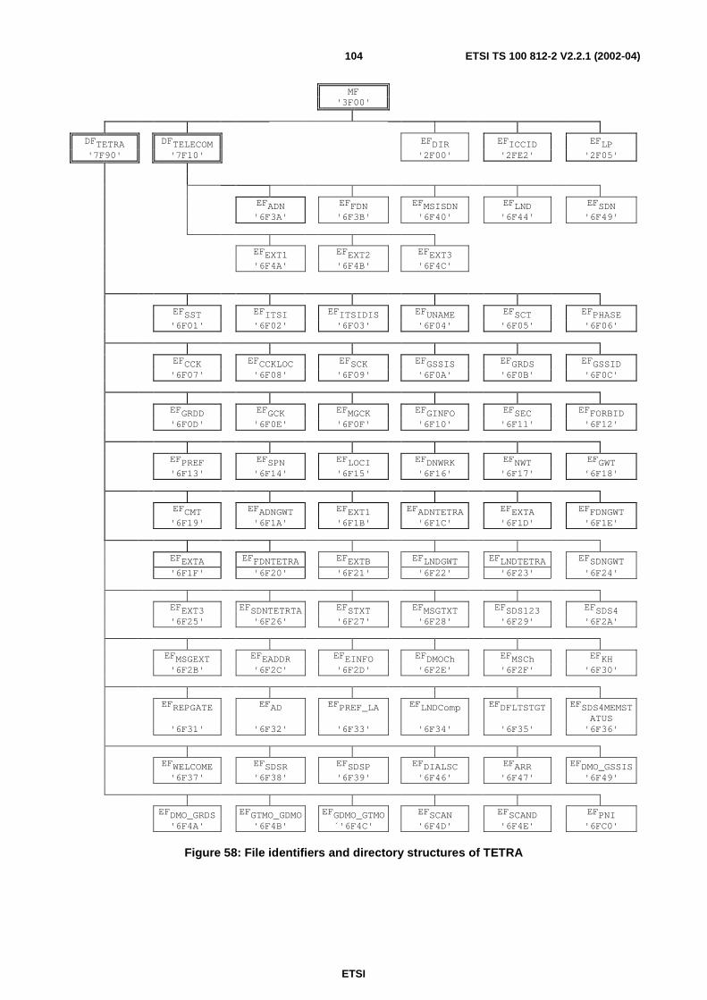
ETSI
ETSI TS 100 812-2 V2.2.1 (2002-04)104
MF'3F00'
DFTETRA DFTELECOM EFDIR EFICCID EFLP'7F90' '7F10' '2F00' '2FE2' '2F05'
EFADN EFFDN EFMSISDN EFLND EFSDN'6F3A' '6F3B' '6F40' '6F44' '6F49'
EFEXT1 EFEXT2 EFEXT3'6F4A' '6F4B' '6F4C'
EFSST EFITSI EFITSIDIS EFUNAME EFSCT EFPHASE'6F01' '6F02' '6F03' '6F04' '6F05' '6F06'
EFCCK EFCCKLOC EFSCK EFGSSIS EFGRDS EFGSSID'6F07' '6F08' '6F09' '6F0A' '6F0B' '6F0C'
EFGRDD EFGCK EFMGCK EFGINFO EFSEC EFFORBID'6F0D' '6F0E' '6F0F' '6F10' '6F11' '6F12'
EFPREF EFSPN EFLOCI EFDNWRK EFNWT EFGWT'6F13' '6F14' '6F15' '6F16' '6F17' '6F18'
EFCMT EFADNGWT EFEXT1 EFADNTETRA EFEXTA EFFDNGWT'6F19' '6F1A' '6F1B' '6F1C' '6F1D' '6F1E'
EFEXTA EFFDNTETRA EFEXTB EFLNDGWT EFLNDTETRA EFSDNGWT'6F1F' '6F20' '6F21' '6F22' '6F23' '6F24'
EFEXT3 EFSDNTETRTA EFSTXT EFMSGTXT EFSDS123 EFSDS4'6F25' '6F26' '6F27' '6F28' '6F29' '6F2A'
EFMSGEXT EFEADDR EFEINFO EFDMOCh EFMSCh EFKH'6F2B' '6F2C' '6F2D' '6F2E' '6F2F' '6F30'
EFREPGATE EFAD EFPREF_LA EFLNDComp EFDFLTSTGT EFSDS4MEMSTATUS
'6F31' '6F32' '6F33' '6F34' '6F35' '6F36'
EFWELCOME EFSDSR EFSDSP EFDIALSC EFARR EFDMO_GSSIS'6F37' '6F38' '6F39' '6F46' '6F47' '6F49'
EFDMO_GRDS EFGTMO_GDMO EFGDMO_GTMO EFSCAN EFSCAND EFPNI'6F4A' '6F4B' ´'6F4C' '6F4D' '6F4E' '6FC0'
Figure 58: File identifiers and directory structures of TETRA
ETSI
ETSI TS 100 812-2 V2.2.1 (2002-04)105
11 Application protocolThe SIM interfaces with appropriate terminal equipment (ME) when in TETRA administrative mode. These operationsare outside the scope of the present document.
During TETRA network operations the SIM exchanges messages with the ME via the SIM/ME interface. A messagecan be a command or a response as follows:
- a TETRA command/response pair is a sequence consisting of a command and the associated response;
- a TETRA procedure consists of one or more TETRA command/response pairs which are used to perform all orpart of an application-oriented task. A procedure shall be considered as a whole, that is to say that thecorresponding task is achieved if and only if the procedure is completed. The ME shall ensure that, whenoperated according to the manufacturer's manual, any unspecified interruption of the sequence ofcommand/response pairs which realize the procedure, leads to the abortion of the procedure itself;
- a TETRA session of the SIM in the TETRA application is the interval of time starting at the completion of theSIM initialization procedure and ending either with the start of the TETRA session termination procedure, or atthe first instant the link between the SIM and the ME is interrupted.
During the TETRA network operation phase, the ME plays the role of the master and the SIM plays the role of theslave.
The list of procedures at the SIM/ME interface in TETRA network operation are listed in the following table:
The ME automatically initiates some procedures. They are marked "ME".
NOTE 1: Some procedures at the SIM/ME interface require MMI interactions. The following descriptions do notintend to infer any specific implementation of the corresponding MMI. When MMI interaction isrequired, it is marked "MMI".
NOTE 2: Some procedures are not clearly user dependent. They are directly caused by the interaction of the MSand the network. Such procedures are marked NETwork "(NET)".
General Procedures:
- Reading an EF ME;
- Updating an EF ME.
SIM management procedures:
- SIM initialization ME;
- TETRA session initialization ME;
- TETRA session termination ME;
- Language preference request ME;
- Administrative information request ME;
- SIM service table request ME;
- SIM phase request ME;
- SIM presence detection ME.
ETSI
ETSI TS 100 812-2 V2.2.1 (2002-04)106
PIN related procedures:
- PIN verification MMI;
- PIN value substitution MMI;
- PIN disabling MMI;
- PIN enabling MMI;
- PIN unblocking MMI.
TETRA security related procedures:
- TETRA algorithms computation NET;
- TETRA key computation (SCK, DCK, MGCK, GCK) NET;
ITSI request NET;
- ITSI disabling NET;
- Location Information NET;
- Broadcast network information NET;
- Forbidden networks information NET.
Subscription related procedures:
- Username MMI;
- Subscriber class request ME;
- Group information MMI/NET;
- User's group information ME/NET;
- Call modifiers NET/ME;
- Network information ME;
- Dialling Numbers (ADN, ADNTETRA, ADNGWT, FDN, FDNTETRA, FDNGWT, LND, LNDTETRA,LNDGWT, SDN, SDNTETRA, SDNGWT LNDComp) MMI/ME;
- SDS messages (Message texts, SDS123 and SDS4) MMI;
- Preferred networks MMI;
- Service Provider Name (SPN) ME;
- ICCID ME;
- Emergency addresses ME/MMI.
11.1 General procedures
11.1.1 Reading an EF
The ME selects the EF and sends a READ command. This contains the location of the data to be read. If the accesscondition for READ is fulfilled, the SIM sends the requested data contained in the EF to the ME. If the access conditionis not fulfilled, no data will be sent and an error code will be returned.
ETSI
ETSI TS 100 812-2 V2.2.1 (2002-04)107
11.1.2 Updating an EF
The ME selects the EF and sends an UPDATE command. This contains the location of the data to be updated and thenew data to be stored. If the access condition for UPDATE is fulfilled, the SIM updates the selected EF by replacing theexisting data in the EF with that contained in the command. If the access condition is not fulfilled, the data existing inthe EF will be unchanged, the new data will not be stored, and an error code will be returned.
In some cases, files are updated by running an algorithm resident on the SIM.
11.1.3 Invalidating an EF
The ME selects the EF and sends an INVALIDATE command. If the access conditions of INVALIDATE are fulfilledthe EF is invalidated.
11.2 SIM management proceduresThe procedures listed in this clause are required for execution of the procedures in clause 11.3, 11.4 and 11.5.
11.2.1 SIM initialization
The ME runs the language request procedure. If none of the indicated languages are available, the ME selects a defaultlanguage (e.g. English). The ME checks the presence of an EFCHV1 at master file level. If the read access condition is
PIN, the ME runs the PIN verification procedure for PIN1 as defined in clause 11.3.1.
11.2.2 TETRA session initialization
Following the SIM initialization, the ME selects DFTETRA by using the identifier or by the path given in EFDIR. The
ME then selects EFITSI to obtain its INVALIDATION status. If the ITSI is invalidated the ME informs the user and the
TETRA session initialization fails.
The ME runs the PIN verification procedure for PIN1 as defined in clause 11.3.1. If the PIN verification isunsuccessful, the TETRA session initialization fails.
NOTE: If there is no EFCHV1 present at the application level, there has to be one at the master file level. For
convenience of the user, implementations having both an EFCHV at application and at master file level
should be avoided.
If the PIN verification procedure is performed successfully, the ME then runs the following procedures:
- Administrative information request;
- SIM Phase request;
- SIM Service Table request;
- ITSI request;
- ITSI temporarily disabled enquiry;
- Subscriber class request;
- Preferred networks request;
- Location Information request;
- Mutual authentication requirement request;
- Forbidden networks request;
- Interrupted emergency call request.
ETSI
ETSI TS 100 812-2 V2.2.1 (2002-04)108
After the SIM initialization has been completed successfully, the MS is ready for a TETRA session.
NOTE: If the ITSI is "Temporary disabled by SwMI", the ME enters a TETRA session with a restricted mode ofoperation. The restricted TETRA session usually consists of the MS simply listening to the SwMI toeventually detect a re-enabling of the ITSI by the network (see EN 300 392-7 [4]).
11.2.3 TETRA session termination
The ME terminates the TETRA session as follows:
The ME runs all the procedures that are necessary to transfer the following subscriber related information to the SIM:
As soon as the SIM indicates that these procedures are completed, the ME/SIM link may be deactivated.
Finally, the ME deletes all these subscriber related information elements from its memory.
NOTE 1: This procedure is not to be confused with the deactivation procedure.
NOTE 2: If the ME has already updated any of the subscriber related information during the TETRA Session, andthe value has not changed until TETRA session termination, the ME may omit the respective updateprocedure.
11.2.4 Language preference request
Request: The ME performs the reading procedure with EFLP.
Update: The ME performs the updating procedure with EFLP.
11.2.5 Administrative information request
Request: The ME performs the reading procedure with EFAD.
Update: The ME performs the updating procedure with EFAD.
11.2.6 SIM service table request
The ME performs the reading procedure with EFSST.
11.2.7 SIM phase request
The ME performs the reading procedure with EFPHASE
11.2.8 SIM presence detection
As an additional mechanism, to ensure that the SIM has not been removed during a card session, the ME sends, atfrequent intervals, a STATUS command during each call. A STATUS command shall be issued within all 30 secondperiods of inactivity on the SIM-ME interface during a call. Inactivity in this case is defined as starting at the end of thelast communication or the last issued STATUS command. If no response data is received to this STATUS command,then the call shall be terminated as soon as possible but at least within 5 seconds after the STATUS command has beensent. If the DF indicated in response to a STATUS command is not the same as that which was indicated in the previousresponse, or accessed by the previous command, then the call shall be terminated as soon as possible but at least within5 seconds after the response data has been received. This procedure shall be used in addition to a mechanical or otherdevice used to detect the removal of a SIM.
11.2.9 SIM card number request
The ME performs the reading procedure with EFICCID.
ETSI
ETSI TS 100 812-2 V2.2.1 (2002-04)109
11.2.10 Common Cipher Key request
The ME performs the read procedure with EFCCK to obtain the current record in this EF.
11.3 PIN related proceduresThe procedures listed in this clause are mandatory.
A successful completion of one of the following procedures grants the access right of the corresponding PIN for theTETRA session. This right is valid for all files within the application(s) protected by this PIN.
After a third consecutive presentation of a wrong PIN to the SIM, not necessarily in the same TETRA session, the PINstatus becomes "blocked" and the access right previously granted by this PIN is lost immediately.
An access right is not granted if any of the following procedures are unsuccessfully completed or aborted.
11.3.1 PIN verification
The ME checks the PIN status.
In the case of PIN1 the following procedures applies:
- If the PIN1 status is "blocked", and PIN1 is "enabled" the procedure ends and is finished unsuccessfully.
- If the PIN1 status is "blocked" but PIN1 is "disabled", the procedure ends and is finished successfully. The MEshall, however, accept SIMs which do not grant access rights when PIN1 is "blocked" and "disabled". In thatcase ME shall consider those SIMs as "blocked";
- If the PIN status is not "blocked", but PIN1 is "disabled", the procedure is finished successfully.
- If the PIN1 status is not "blocked" and PIN1 is "enabled", the ME uses the VERIFY PIN1 function. If the PIN1presented by the ME is equal to the corresponding PIN1 stored in the SIM, the procedure is finishedsuccessfully. If the PIN1 presented by the ME is not equal to the corresponding PIN1 stored in the SIM, theprocedure ends and is finished unsuccessfully.
In the case of PIN2 the following procedure applies:
- if the PIN2 status is "blocked", the procedure ends and is finished unsuccessfully;
- if the PIN2 status is not "blocked", the ME uses the VERIFY PIN function. If the PIN2 presented by the ME isequal to the corresponding PIN2 stored in the SIM, the procedure is finished successfully. If the PIN2 presentedby the ME is not equal to the corresponding PIN2 stored in the SIM, the procedure ends and is finishedunsuccessfully.
11.3.2 PIN value substitution
The ME checks the PIN status. If the PIN status is "blocked" or "disabled", the procedure ends and is finishedunsuccessfully.
If the PIN status is not "blocked" and the enabled/disabled indicator is set "enabled", the ME uses the CHANGE PINfunction. If the old PIN presented by the ME is equal to the corresponding PIN stored in the SIM, the new PINpresented by the ME is stored in the SIM and the procedure is finished successfully.
If the old PIN and the PIN in memory are not identical, the procedure ends and is finished unsuccessfully.
ETSI
ETSI TS 100 812-2 V2.2.1 (2002-04)110
11.3.3 PIN disabling
Requirement: Service no.1 "available".
The ME checks the PIN1 status. If the PIN1 status is "blocked", the procedure ends and is finished unsuccessfully.
If the PIN1 status is not "blocked", the ME reads the PIN1 enabled/disabled indicator. If this is set "disabled", theprocedure ends and is finished unsuccessfully.
If the PIN1 status is not "blocked" and the enabled/disabled indicator is set "enabled", the ME uses the DISABLE PINfunction. If the PIN1 presented by the ME is equal to the PIN1 stored in the SIM, the status of PIN1 is set "disabled"and the procedure is finished successfully. If the PIN1 presented by the ME is not equal to the PIN1 stored in the SIM,the procedure ends and is finished unsuccessfully.
This requirement applies to the PIN1 at the TETRA application level. For the PIN1 at the master file level, it onlyapplies in the case of a TETRA only card.
11.3.4 PIN enabling
The ME checks the PIN1 status. If the PIN1 status is "blocked", the procedure ends and is finished unsuccessfully.
If the PIN1 status is not "blocked", the ME reads the PIN1 enabled/disabled indicator. If this is set "enabled", theprocedure ends and is finished unsuccessfully.
If the PIN1 status is not "blocked" and the enabled/disabled indicator is set "disabled", the ME uses the ENABLE PINfunction. If the PIN1 presented by the ME is equal to the PIN1 stored in the SIM, the status of PIN1 is set "enabled" andthe procedure is finished successfully. If the PIN presented by the ME is not equal to the PIN1 stored in the SIM, theprocedure ends and is finished unsuccessfully.
11.3.5 PIN unblocking
The execution of the PIN unblocking procedure is independent of the corresponding PIN status, i.e. being blocked ornot.
The ME checks the UNBLOCK PIN status. If the UNBLOCK PIN status is "blocked", the procedure ends and isfinished unsuccessfully.
If the UNBLOCK PIN status is not "blocked", the ME uses the UNBLOCK PIN function. If the UNBLOCK PINpresented by the ME is equal to the corresponding UNBLOCK PIN stored in the SIM, the relevant PIN status becomes"unblocked" and the procedure is finished successfully. If the UNBLOCK PIN presented by the ME is not equal to thecorresponding UNBLOCK PIN stored in the SIM, the procedure ends and is finished unsuccessfully.
11.4 TETRA security related proceduresThe procedures listed in this clause are only executable if the associated services, which are optional, are provided inthe SIM. However, if the procedures are implemented, they shall be in accordance with the requirement stated in thisclause. If a procedure is related to a specific service indicated in the SIM service table, it shall only be executed if thecorresponding bit denoting this service as "available" (see EFSST). In all other cases this procedure shall not start.
The SIM security procedures are associated with the air interface message exchange protocol procedures forauthenticating the SIM to a TETRA network and the TETRA network to the SIM. During these SIM securityprocedures the card runs the specified algorithms TA11/12 and TA21/22 to calculate respectively the expected responsefrom the SIM, (X)RES1 with its associated derived cipher key DCK1 and the expected response from the SwMI,(X)RES2 with its associated derived cipher key DCK2.
On successful authentication the derived cipher key DCK, used for encrypting air interface signalling and trafficchannels, shall be derived from its two parts DCK1 and DCK2 by running the TB4 algorithm.
All the algorithms shall not be executable unless DFTETRA has been selected as the Current Directory and a successful
PIN verification procedure has been performed (see clause 11.3.1).
ETSI
ETSI TS 100 812-2 V2.2.1 (2002-04)111
The procedures are either initiated by the ME (internal applications or MMI) or interfaced from the SwMI via the ME.In the latter case the ME provides only a delivery service with no other functionality than to interpret the PDUs ifnecessary.
11.4.1 Authentication procedures and generation of DCK
11.4.1.1 Mutual authentication requirement request
The SIM performs the read procedure with EFSEC to determine whether a mutual authentication is requested by the SIM
in case of a SIM authentication request from the SwMI.
11.4.1.2 SIM authentication
The ME runs the TA11/12 ALGORITHM, followed by a GET RESPONSE to obtain the RES1. If and only if the SIMrequests a mutual authentication (see clause 11.4.1.1), the ME runs then the GET CHALLENGE, followed by theTA21/22 ALGORITHM. If the authentication was successful, it finally runs the TB4 ALGORITHM to obtain DCK.
11.4.1.3 SwMI authentication
The ME runs the GET CHALLENGE function, followed by the TA21/22 ALGORITHM. If and only if the SwMIrequests a mutual authentication, the ME runs the TA11/12 ALGORITHM, followed by a GET RESPONSE to obtainthe RES1. If the authentication was successful, it finally runs the TB4 ALGORITHM to obtain DCK.
11.4.2 TETRA OTAR key computation (CCK, GCK, SCK)
The CCK, GCK and SCK cipher keys can be updated by OTAR. They are sent over the air interface in sealed formatand need to be unsealed on receipt by algorithms on the SIM.
SCK and CCK are accessible from the SIM-ME interface but GCK is accessible only in modified format (MGCK).
11.4.2.1 CCK distribution
On receipt of a new SCCK from the SwMI, the ME checks the validity of the CCK-ID then runs the TA32ALGORITHM to update EFCCK. The record to be updated in EFCCK is identified as follows: The ME checks whether
the CCK-ID being broadcast by the SwMI is identical to the CCK-ID stored in record 1 of EFCCK. If not identical,
record 1 is updated; otherwise, record 2 is updated.
11.4.2.2 CCK changeover
When the ME detects a new CCK-ID in use it determines the record number in EFCCK which contains the new
CCK-ID. After verifying that the new CCK-ID is valid, the ME runs the TA71 ALGORITHM to update all records inEFMGCK using the CCK record in EFCCK identified by the CCK-ID.
11.4.2.3 GCK distribution
The ME analyses EFGSSIS and EFGSSID to locate the required GTSI. If the GTSI is not already present, the ME
allocates a free record number in the EFGSSID and there places the new GTSI.
The ME checks whether there is a GCK (and MGCK) associated with the GTSI by accessing the appropriate GCKrecord number data element in EFGRDS or EFGRDD. If there is no such associated GCK, then a free record in EFGCK is
allocated (see note below), and the corresponding target record number in EFGRDS or EFGRDD is updated accordingly.
In the case where there was already a GCK (and MGCK) present, the ME identifies whether the new GCK-VN is validby comparing it to the GCK-VN being stored currently in the appropriate record of EFMGCK. If it is not valid the
procedure is aborted.
ETSI
ETSI TS 100 812-2 V2.2.1 (2002-04)112
The ME then runs the TA82 ALGORITHM to update the respective GCK. After this, the ME runs the TA71ALGORITHM on this particular GCK to obtain the corresponding MGCK. For this operation, the current CCK (the onebeing indicated on the broadcast channel) is used.
NOTE: To allocate a free record in EFGCK the ME reads EFGRDS and EFGRDD and works out if there is a record
in EFGCK which is not presently pointed to by any GCK record pointer.
11.4.2.4 SCK distribution
On receipt of a new SSCK from the SwMI, the ME identifies whether the new SCK-VN is valid by comparing it to theone being stored currently. If it is not valid the procedure is aborted. Then the ME runs the TA41/52 ALGORITHM inorder to unseal the SCK and store it in that record of EFSCK, which is indicated by the SCKN.
11.4.3 ITSI request
The ME performs the reading procedure with EFITSI.
11.4.4 ITSI disabling/re-enabling
See also EN 300 392-7 [4].
Permanent disabling:
On receiving the ITSI permanent disable command the ME selects EFITSI and shall thenimmediately run the SwMI authentication procedure defined in clause 11.4.1.3. If the SwMI issuccessfully authenticated then the invalidate procedure is performed on EFITSI. The TETRAsession is immediately terminated (see note).
Temporary disabling:
On receiving the ITSI temporary disable command the ME selects EFITSIDIS and shall thenimmediately run the SwMI authentication procedure defined in clause 11.4.1.3. If the SwMI issuccessfully authenticated then the ME performs the update procedure with EFITSIDIS to set theflag to "temporarily disabled" (see note).
Re-enabling:
On receiving the ITSI enable command the ME selects EFITSIDIS and shall then immediately runthe SwMI authentication procedure defined in clause 11.4.1.3. If the SwMI is successfullyauthenticated then the updating procedure is performed on EFITSIDIS to set the flag to "notdisabled".
NOTE: It is an implementation issue for the SIM to deny access to further sensitive EFs (such as group identitiesand air interface encryption keys) if the ITSI is temporarily or permanently disabled.
11.5 Subscription related proceduresThe procedures listed in this clause are only executable if the associated services, which are optional, are provided inthe SIM. However, if the procedures are implemented, it shall be in accordance with the requirement stated in thisclause. If a procedure is related to a specific service indicated in the SIM service table, it shall only be executed if thecorresponding bit denoting this service as "available" (see EFSST). In all other cases this procedure shall not start.
11.5.1 Username request
Requirement: Service no.16 "available".
Request: The ME performs the reading procedure with EFUNAME.
Update: The ME performs the updating procedure with EFUNAME.
ETSI
ETSI TS 100 812-2 V2.2.1 (2002-04)113
11.5.2 ITSI temporarily disabled enquiry
Request: The ME performs the reading procedure with EFITSIDIS.
Update: The ME performs the updating procedure with EFITSIDIS.
11.5.3 Subscriber class request
Request: The ME performs the reading procedure with EFSCT.
Update: The ME performs the updating procedure with EFSCT.
11.5.4 Void
11.5.5 Group identity information
The following procedures apply to both static (EFGSSIS) and dynamic (EFGSSID) groups with the exceptions mentioned
in the following clauses.
11.5.5.1 Static Group identity information
Request: The ME performs the reading procedure with EFGSSIS.
11.5.5.2 Dynamic Group identity information
Request: The ME performs the reading procedure with EFGSSID.
Erasure: The ME identifies the record in EFGSSID containing the GSSID to be erased and marks it as free.
Update/invalidate:
The ME selects EFGSSID and shall then immediately run the SwMI authentication procedure
defined in clause 11.4.1.3. If the SwMI is successfully authenticated then the update or invalidateprocedure is performed on EFGSSID.
The update and erasure of EFGSSID requires the updating of the network table. The handling procedures of the network
table (EFNWT) are defined under clause 11.6.
11.5.6 Group related data
The following procedures apply to both static and dynamic group related data (EFGRDS and EFGRDD).
Request: The ME performs the reading procedure with EFGRDS or EFGRDD.
Update: The ME performs the updating procedure with EFGRDS or EFGRDD.
NOTE: A record in EFGRDS or EFGRDD is free when the associated record in EFGSSIS or EFGSSID is marked free.
ETSI
ETSI TS 100 812-2 V2.2.1 (2002-04)114
11.5.7 User's group information
Request: The ME performs the reading procedure with EFGINFO.
Update: The ME performs the updating procedure with EFGINFO.
The update of the file is performed in the beginning of a group call.
The update of this file requires the updating of the network table. The handling procedures of thenetwork table (EFNWT) are defined under clause 11.6.
11.5.8 Call modifiers
Requirement: Service no.26 "available".
Request: The ME performs the reading procedure with EFCMT.
Update: The ME performs the updating procedure with EFCMT.
11.5.9 Service Provider Name
Requirement: Service no.14 "available".
Request: The ME performs the reading procedure with EFSPN.
11.5.10 DMO channel procedures
Requirement: Service no.27 "available".
Request: The ME performs the reading procedure with EFDMOCh.
Update: The ME performs the updating procedure with EFDMOCh.
Erasure: The ME erases the contents of the record in EFDMOCh by filling the record with 'FF'.
11.5.11 Emergency addresses
Request: The ME performs the reading procedure with EFEADDR.
Update: The ME performs the updating procedure with EFEADDR.
Erasure: The ME erases the contents of the record in EFEADDR by filling the b1 to b4 in the record with 1.
11.5.12 Interrupted emergency call request
Request: The ME performs the reading procedure with EFEINFO.
Update: The ME performs the update procedure with EFEINFO.
NOTE: If an emergency call was in progress when the ME was powered down the current emergency call recordnumber, if non-zero, indicates that an emergency call procedure was in progress when the ME waspowered down. The ME should recognize the non-zero value as an indication to take action as necessaryto restart the emergency call after authentication.
ETSI
ETSI TS 100 812-2 V2.2.1 (2002-04)115
11.6 Network related proceduresRequest: The ME performs the reading procedure with EFNWT.
Update: The ME checks whether the network address to be stored is already present.If so, the record pointer counter of the found network address record is increased by one.
If the address is not found on the network table, a new record is added to the network table and thecorresponding record pointer counter is set to one.
Erasure: The record on the network table is deleted (indicated as free by filling it with 'FF's).
11.6.1 Forbidden networks
Request: The ME performs the reading procedure with EFFORBID.
Update: The ME performs the updating procedure with EFFORBID.
Erasure: The ME can erase the whole contents of the Forbidden networks. The action can either be initiatedby the ME or the MMI. In case of erasure, the whole table of Forbidden addresses will be erasedi.e. marked free by filling them with 'FF's.
11.6.2 Preferred networks
Requirement: Service no.15 "available".
Request: The ME performs the reading procedure with EFPREF.
Update: The ME performs the updating procedure with EFPREF.
11.7 Dialling number related proceduresThe procedures listed in this clause are only executable if the associated services, which are optional, are provided inthe SIM. However, if the procedures are implemented, it shall be in accordance with the requirement stated in thisclause. If a procedure is related to a specific service indicated in the SIM service table, it shall only be executed if thecorresponding bit denoting this service as "available" (see EFSST). In all other cases this procedure shall not start.
11.7.1 Dialling numbers under DFTETRA
The following procedures may be applied to EFADNGWT and its associated extension file EFGWTEXT1 as described in
the procedures below. The procedures also refer to EFFDNGWT, EFLNDGWT, EFSDNGWT, EFADNTETRA, EFFDNTETRA,
EFLNDTETRA and EFSDNTETRA and their associated extension files. If these files are not available, as denoted in the
SIM service table, the current procedure shall be aborted and the appropriate EFs shall remain unchanged.
As an example, the following procedures are described as applied to ADNGWT.
Requirement: Service no.3 "available".
Request: The ME sends the identification of the information to be read. The ME shall analyse the data ofEFADNGWT (see clause 10.3.26) to ascertain whether additional data is associated inEFGWTEXT1. If necessary, the ME performs the reading procedure on EFGWTEXT1 andEFGWT to assemble the complete ADNGWT.
Update: The ME analyses and assembles the information to be stored as follows:
i) the ME identifies the record containing the Name to be updated;
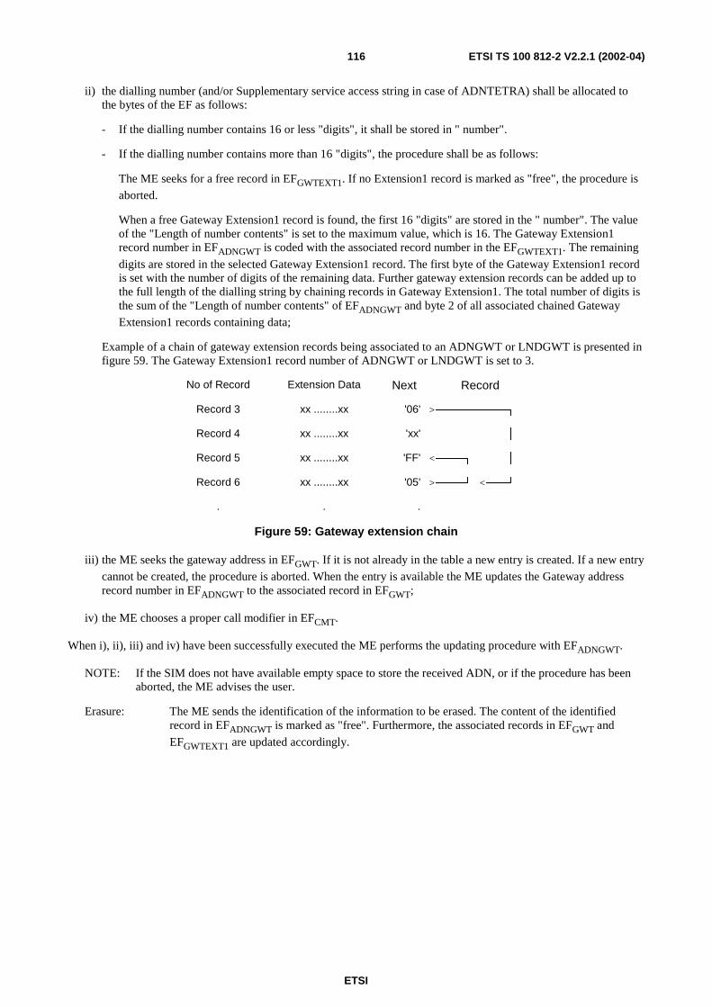
ETSI
ETSI TS 100 812-2 V2.2.1 (2002-04)116
ii) the dialling number (and/or Supplementary service access string in case of ADNTETRA) shall be allocated tothe bytes of the EF as follows:
- If the dialling number contains 16 or less "digits", it shall be stored in " number".
- If the dialling number contains more than 16 "digits", the procedure shall be as follows:
The ME seeks for a free record in EFGWTEXT1. If no Extension1 record is marked as "free", the procedure is
aborted.
When a free Gateway Extension1 record is found, the first 16 "digits" are stored in the " number". The valueof the "Length of number contents" is set to the maximum value, which is 16. The Gateway Extension1record number in EFADNGWT is coded with the associated record number in the EFGWTEXT1. The remaining
digits are stored in the selected Gateway Extension1 record. The first byte of the Gateway Extension1 recordis set with the number of digits of the remaining data. Further gateway extension records can be added up tothe full length of the dialling string by chaining records in Gateway Extension1. The total number of digits isthe sum of the "Length of number contents" of EFADNGWT and byte 2 of all associated chained Gateway
Extension1 records containing data;
Example of a chain of gateway extension records being associated to an ADNGWT or LNDGWT is presented infigure 59. The Gateway Extension1 record number of ADNGWT or LNDGWT is set to 3.
No of Record Extension Data Next Record
Record 3 xx ........xx '06' >──────────┐
Record 4 xx ........xx 'xx' │
Record 5 xx ........xx 'FF' <────┐ │
Record 6 xx ........xx '05' >────┘ <───┘
. . .
Figure 59: Gateway extension chain
iii) the ME seeks the gateway address in EFGWT. If it is not already in the table a new entry is created. If a new entry
cannot be created, the procedure is aborted. When the entry is available the ME updates the Gateway addressrecord number in EFADNGWT to the associated record in EFGWT;
iv) the ME chooses a proper call modifier in EFCMT.
When i), ii), iii) and iv) have been successfully executed the ME performs the updating procedure with EFADNGWT.
NOTE: If the SIM does not have available empty space to store the received ADN, or if the procedure has beenaborted, the ME advises the user.
Erasure: The ME sends the identification of the information to be erased. The content of the identifiedrecord in EFADNGWT is marked as "free". Furthermore, the associated records in EFGWT and
EFGWTEXT1 are updated accordingly.
ETSI
ETSI TS 100 812-2 V2.2.1 (2002-04)117
11.7.2 Dialling numbers under DFTELECOM
The following procedures may be applied to EFADN and its associated extension file EFEXT1 as described in the
procedures below, and also to EFFDN, EFLND, EFSDN and their associated extension files. If these files are not
available, as denoted in the SIM service table, the current procedure shall be aborted and the appropriate EFs shallremain unchanged.
As an example, the following procedures are described as applied to ADN.
Requirement: Service no. 36 "available".
Request: The ME sends the identification of the information to be read. The ME shall analyse the data ofEFADN (see clause 10.4.1) to ascertain whether additional data is associated in EFEXT1. Ifnecessary, the ME performs the reading procedure on EFEXT1 and reading of default gateway SSIfrom EFGWT to assemble the complete ADN.
Update: The ME analyses and assembles the information to be stored as follows (subscriber has chosen tostore ADN to the general EFADN under DFTELECOM):
i) the ME identifies the record containing the Name to be updated;
ii) the dialling number shall be allocated to the bytes of the EF as follows:
- if a "+" is found, the TON identifier is set to "International";
- if the dialling number contains 20 or less "digits", it shall be stored in " Dialling Number/SSC String ";
- if the dialling number contains more than 20 "digits", the procedure shall be as follows:
The ME seeks for a free record in EFEXT1. If no Extension1 record is marked as "free", the procedure is
aborted.
When a free Extension1 record is found, the first 20 "digits" are stored in the Dialling Number/SSC String.The value of the " Length of BCD number/SSC contents " is set to the maximum value, which is 11. TheExtension1 record number in EFADN is coded with the associated record number in the EFEXT1. The
remaining digits are stored in the selected Extension1 record. The first byte of the extension data in EFEXT1(second byte of Extension1 record) is set with the number of digits of the remaining data. Further extensionrecords can be added up to the full length of the dialling string by chaining records in Extension1. The totalnumber of digits is the sum of the " Length of BCD number/SSC contents " of EFADN and byte 2 of all
associated chained extension data records containing data;
iii) If a called party subaddress is associated to the ADN/SSC the procedure shall proceed as follows:
If the length of the called party subaddress is less than or equal to 11 bytes (see TS 100 940 [11] for coding):
- the ME seeks for a free record in EF EXT1. If an Extension1 record is not marked as "free", the ME runs thePurge procedure. If an Extension1 record is still unavailable, the procedure is aborted;
- the ME stores the called party subaddress in the Extension1 record, and sets the Extension1 record type to"called party subaddress".
If the length of the called party subaddress is greater than 11 bytes (see TS 100 940 [11] for coding):
- the ME seeks for two free records in EFEXT1. If no such two records are found, the ME runs the Purgeprocedure. If two Extension1 records are still unavailable, the procedure is aborted;
- the ME stores the called party subaddress in the two Extension1 records. The identifier field in theExtension1 record containing the first part of the subaddress data is coded with the associated EFEXT1 recordnumber containing the second part of the subaddress data. Both Extension1 record types are set to "calledparty subaddress".
Once i), ii), and iii) have been considered the ME performs the updating procedure with EFADN. If the SIM has noavailable empty space to store the received ADN/SSC, or if the procedure has been aborted, the ME advises the user.
ETSI
ETSI TS 100 812-2 V2.2.1 (2002-04)118
Erasure: The ME sends the identification of the information to be erased. The content of the identifiedrecord in EFADN is marked as "free". Furthermore, the associated records in EFEXT1 are updatedaccordingly.
Purge: The ME shall access each EF which references EFEXT1 (EFEXT2) for storage and shall identifyrecords in these files using extension data (additional data or called party subaddress). Note thatexisting chains have to be followed to the end. All referred Extension1 (Extension2) records arenoted by the ME. All Extension1 (Extension2) records not noted are then marked by the ME as"free".
11.7.3 FDNGWT specific procedures
Requirement: Service no. 5 "available"
If FDN is enabled (i.e. EFADNGWT is invalidated or not present) the ME shall operate in a restricted mode where only
those phone numbers contained in EFFDN and EFFDNGWTare used.
If FDNTETRA is enabled (i.e. EFADNTETRA is invalidated or not present) the ME shall operate in a restricted mode
where only those phone numbers contained in EFFDNTETRA are used.
Both modes FDN and FDNTETRA can be enabled independently of each other.
ADNGWT and FDNGWT are mutually exclusive of each other and independent of the state of ADNTETRA andFDNTETRA. Likewise, ADNTETRA and FDNTETRA are mutually exclusive of each other and independent of thestate of ADNGWT and FDNGWT. This means that there may be restricted ADNGWT phonebook operation orrestricted TETRA phonebook operation and these are independent of each other.
The following three procedures are only applicable to service no.4 (FDNTETRA) no.5 (FDNGWT). As an example, thefollowing procedures are described as applied to FDNGWT.
11.7.3.1 FDNGWT capability request
To ascertain the state of FDNGWT, the ME checks in EFSST whether or not ADNGWT is activated. If ADNGWT is
not activated, service no.5 is enabled. If ADNGWT is activated, the ME checks the response data EFADNGWT. If
EFADNGWT are invalidated, service no.5 is enabled. In all other cases service no.5 is disabled.
11.7.3.2 FDNGWT disabling
The FDNGWT disabling procedure requires that PIN2 verification procedure has been performed successfully and thatADNGWT is activated. If not, FDNGWT disabling procedure will not be executed successfully. To disable FDNGWTcapability, the ME rehabilitates EFADNGWT. The invalidate/rehabilitate flag of EFADNGWT, which are set by the
REHABILITATE command, is at the same time the indicator for the state of the service no.5. If ADNGWT is notactivated, disabling of FDNGWT is not possible and thus service no.5 is always enabled (see FDNGWT capabilityrequest).
11.7.3.3 FDNGWT enabling
The FDNGWT enabling procedure requires that PIN2 verification procedure has been performed successfully. If not,FDNGWT enabling procedure will not be executed successfully. To enable FDNGWT capability, the ME invalidatesEFADNGWT. The invalidate/rehabilitate flag of EFADNGWT, which is set by the INVALIDATE command, is at the same
time the indicator for the state of the service no.5 (see FDNGWT capability request). If ADNGWT is not activated,service no.5 is always enabled.
Invalidated ADNGWTs may optionally still be readable and updatable depending on the file status (see clause 9.4).
ETSI
ETSI TS 100 812-2 V2.2.1 (2002-04)119
11.8 Status and short data message proceduresThe procedures listed in this clause are only executable if the associated services, which are optional, are provided inthe SIM. However, if the procedures are implemented, it shall be in accordance with the requirement stated in thisclause. If a procedure is related to a specific service indicated in the SIM service table, it shall only be executed if thecorresponding bit denoting this service as "available" (see EFSST). In all other cases this procedure shall not start.
11.8.1 Display of status message texts
Requirement: Service no.22 "available".
Request: The SIM selects EFSTXT and searches for the identified status message value. If the message value
is found it performs the reading procedure with EFSTXT.
11.8.2 Display of SDS1 message texts
Requirement: Service no.23 "available".
Request: The SIM selects EFMSGTXT and searches for the identified status message value. If the message
value is found it performs the reading procedure with EFMSGTXT.
11.8.3 Storage of status and SDS messages types 1, 2 and 3
Requirement: Service no.24 "available".
Request: The SIM selects EFSDS123 and searches for the identified status or SDS message. If this message is
found, the ME performs the reading procedure with EFSDS123.
Update: The ME looks for the next available area to store the status or SDS message in EFSDS123. If such
an area is available, it performs the updating procedure with EFSDS1123.
If there is no available empty space in the SIM to store the received short message, the ME advisesthe user.
Erasure: The ME selects EFSDS123 and identifies the records to be erased. Then it performs the update
procedure to mark them as free.
NOTE: Depending on the ME, the message may be read before the record is marked as "free". After performingthe updating procedure with EFSDS123, the memory allocated to this short message in the SIM is made
available for a new incoming message. The memory of the SIM may still contain the old message until anew message is stored in that area.
11.8.4 Storage of SDS messages type 4
Requirement: Service no.25 "available".
Request: The SIM selects EFSDS4 and searches for the identified short message. If this message is found,
the ME performs the reading procedure.
Update: The ME looks for the next available area to store the short message in EFSDS4. If such an area is
available, it performs the updating procedure with EFSDS4.
If there is no available empty space in the SIM to store the received short message, the ME advisesthe user.
Erasure: The ME selects EFSDS4 and identifies the records to be erased. Then it performs the update
procedure to mark them as free.
ETSI
ETSI TS 100 812-2 V2.2.1 (2002-04)120
NOTE: Depending on the ME, the message may be read before the record is marked as "free". After performingthe updating procedure with EFSDS123, the memory allocated to this short message in the SIM is made
available for a new incoming message. The memory of the SIM may still contain the old message until anew message is stored in that area.
11.8.5 SDS delivery report
Requirement: Service number 32 "available".
Request: If the status of a stored short message indicates that there is a corresponding status report, the MEperforms the seek function with EFSDSR to identify the record containing the appropriate status
report. The ME performs the reading procedure with EFSDSR.
Update: If the status report is received, the ME first seeks within the SDS record identifiers of EFSDSR for
the same record number it used for the short message in EFSDS4. If such a record identifier is
found in EFSDSR, it is used for storage. If such a record identifier is not found, then the ME seeks
for a free entry in EFSDSR for storage. If no free entry is found, the ME runs the Purge procedure
with EFSDSR. If there is still no free entry, the status report is not stored.
If the ME found an appropriate record in EFSDSR for storage, it updates the record with the status
report setting the record identifier in EFSDSR to the appropriate record number of the short
message in EFSDS4.
The status in EFSDS4 is updated accordingly (see clause 10.3.42) by performing update procedure
with EFSDS4.
Erasure: The ME runs the update procedure with EFSDSR by storing '00' in the first byte of the record.
Purge: The ME shall read the SDS record identifier (byte 1) of each record of EFSDSR. With each record
the ME checks the corresponding SDS message in EFSDS4. If the status of the corresponding SDS
is not equal to 'status report requested, received and stored in EFSDSR' the ME shall perform the
erasure procedure with the appropriate record in EFSDSR.
11.8.6 Default Status Target
Requirement: Service number 31 "available".
Request: The ME checks whether a destination address has been specified if not then the ME performs theread procedure with EFDFLTSTSTGT.
Update: The ME runs the update procedure with EFDFLTSTSTGT.

ETSI
ETSI TS 100 812-2 V2.2.1 (2002-04)121
Annex A:Void
ETSI
ETSI TS 100 812-2 V2.2.1 (2002-04)122
Annex B (informative):FDN ProceduresThe FDN facility allows operation of the TETRA terminal in a restricted state whereby it can only initiate calls to apre-determined destination or list of destinations.
A TETRA SIM may be personalized so that the terminal can be operated in only the restricted state, only theunrestricted state or to allow the operation mode to be switched between states through the MMI.
FDN services
Two FDN services are provided for the TETRA SIM. Service number 4 allows fixed dialling to other TETRA addresseswhile service number 5 allows fixed dialling to destinations on a PABX or the PSTN. These services may beindividually or jointly enabled as indicated in the SIM service table.
The SIM service table provides an enable/disable indicator for each of the two FDN services to indicate to the ME thecapabilities of the SIM. Where the SIM service table indicates that the SIM is capable of both ADN and FDN services,the operating state can be switched as described below.
FDN operation
When the ME is operating in the restricted FDN state, the user may only call destinations listed in the FDN directoriesEFFDN (service no 5) and/or EFFDNTETRA (service no 4). Attempts to call other destinations shall be rejected by the
ME, other than those initiated by activation of the emergency call procedures.
FDN initialization
When a TETRA session is initialized, the ME should check the SIM service table for the state of the FDN services. Ifneither service is enabled, the ME should enter the unrestricted operation state, offering facilities as otherwise indicatedin the SIM service table.
If either of the FDN services are enabled in the SIM service table, the ME should further check the entries for ADN(service no 2) and ADNTETRA (service no. 3). If neither ADN service is enabled the ME should enter the restrictedFDN operation state.
If both ADN and FDN services are enabled in the SIM service table, the operation mode may be determined by thevalidity of EFADN. If EFADN is invalidated, the ME should enter the restricted FDN operation state. If EFADN is not
invalidated, the ME should enter the unrestricted state.
Change of FDN operation mode.
Where the SIM Service Table indicates that a SIM supports both FDN and unrestricted modes of operation, the validityof the file EFADN provides the indicator as to the current operating state as described above.
The ME may provide an MMI operation to allow toggling of the operation state by performing invalidation orrehabilitation of EFADN. This procedure can only be performed after successful completion of the PIN2 verification
procedure to satisfy the access rights for EFADN.
Change of FDN access details
The ME may provide a method on the MMI to change entries in the FDN directories, thereby changing the list of calldestination when the ME is operating in the restricted state. This procedure can only be performed after successfulcompletion of the PIN2 verification procedure to satisfy the access rights for update to EFFDN.
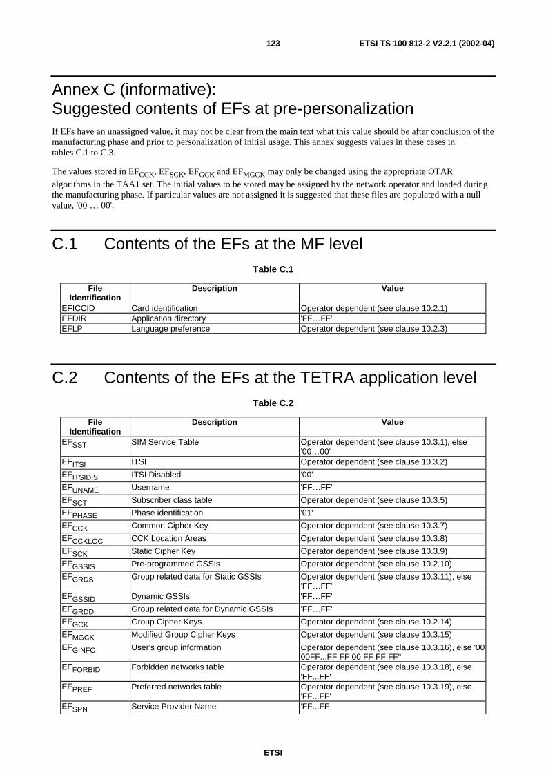
ETSI
ETSI TS 100 812-2 V2.2.1 (2002-04)123
Annex C (informative):Suggested contents of EFs at pre-personalizationIf EFs have an unassigned value, it may not be clear from the main text what this value should be after conclusion of themanufacturing phase and prior to personalization of initial usage. This annex suggests values in these cases intables C.1 to C.3.
The values stored in EFCCK, EFSCK, EFGCK and EFMGCK may only be changed using the appropriate OTAR
algorithms in the TAA1 set. The initial values to be stored may be assigned by the network operator and loaded duringthe manufacturing phase. If particular values are not assigned it is suggested that these files are populated with a nullvalue, '00 … 00'.
C.1 Contents of the EFs at the MF levelTable C.1
FileIdentification
Description Value
EFICCID Card identification Operator dependent (see clause 10.2.1)EFDIR Application directory 'FF…FF'EFLP Language preference Operator dependent (see clause 10.2.3)
C.2 Contents of the EFs at the TETRA application levelTable C.2
FileIdentification
Description Value
EFSST SIM Service Table Operator dependent (see clause 10.3.1), else'00…00'
EFITSI ITSI Operator dependent (see clause 10.3.2)
EFITSIDIS ITSI Disabled '00'
EFUNAME Username 'FF…FF'
EFSCT Subscriber class table Operator dependent (see clause 10.3.5)
EFPHASE Phase identification '01'
EFCCK Common Cipher Key Operator dependent (see clause 10.3.7)
EFCCKLOC CCK Location Areas Operator dependent (see clause 10.3.8)
EFSCK Static Cipher Key Operator dependent (see clause 10.3.9)
EFGSSIS Pre-programmed GSSIs Operator dependent (see clause 10.2.10)
EFGRDS Group related data for Static GSSIs Operator dependent (see clause 10.3.11), else'FF…FF'
EFGSSID Dynamic GSSIs 'FF…FF'
EFGRDD Group related data for Dynamic GSSIs 'FF…FF'
EFGCK Group Cipher Keys Operator dependent (see clause 10.2.14)
EFMGCK Modified Group Cipher Keys Operator dependent (see clause 10.3.15)
EFGINFO User's group information Operator dependent (see clause 10.3.16), else '0000FF...FF FF 00 FF FF FF''
EFFORBID Forbidden networks table Operator dependent (see clause 10.3.18), else'FF...FF'
EFPREF Preferred networks table Operator dependent (see clause 10.3.19), else'FF...FF'
EFSPN Service Provider Name 'FF...FF
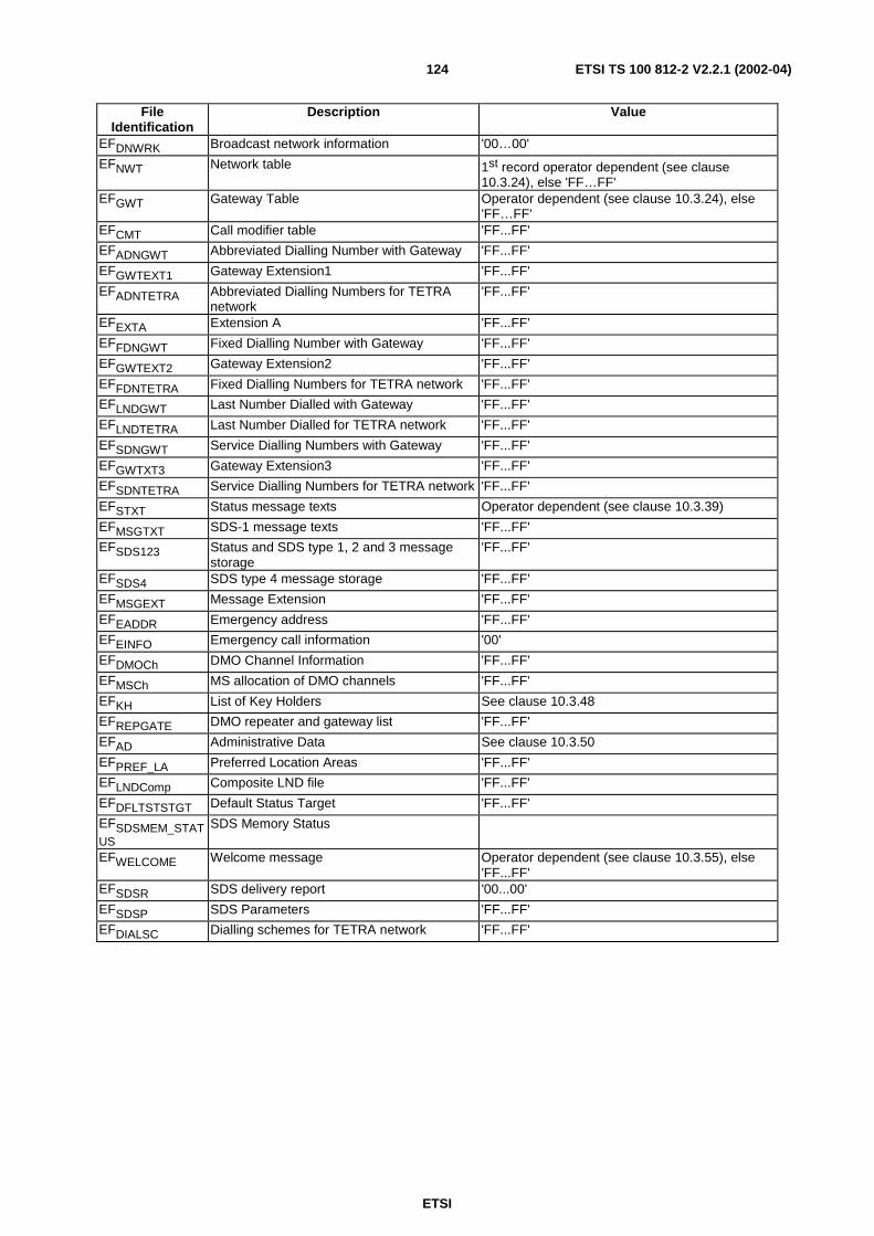
ETSI
ETSI TS 100 812-2 V2.2.1 (2002-04)124
FileIdentification
Description Value
EFDNWRK Broadcast network information '00…00'
EFNWT Network table 1st record operator dependent (see clause10.3.24), else 'FF…FF'
EFGWT Gateway Table Operator dependent (see clause 10.3.24), else'FF…FF'
EFCMT Call modifier table 'FF...FF'
EFADNGWT Abbreviated Dialling Number with Gateway 'FF...FF'
EFGWTEXT1 Gateway Extension1 'FF...FF'
EFADNTETRA Abbreviated Dialling Numbers for TETRAnetwork
'FF...FF'
EFEXTA Extension A 'FF...FF'
EFFDNGWT Fixed Dialling Number with Gateway 'FF...FF'
EFGWTEXT2 Gateway Extension2 'FF...FF'
EFFDNTETRA Fixed Dialling Numbers for TETRA network 'FF...FF'
EFLNDGWT Last Number Dialled with Gateway 'FF...FF'
EFLNDTETRA Last Number Dialled for TETRA network 'FF...FF'
EFSDNGWT Service Dialling Numbers with Gateway 'FF...FF'
EFGWTXT3 Gateway Extension3 'FF...FF'
EFSDNTETRA Service Dialling Numbers for TETRA network 'FF...FF'
EFSTXT Status message texts Operator dependent (see clause 10.3.39)
EFMSGTXT SDS-1 message texts 'FF...FF'
EFSDS123 Status and SDS type 1, 2 and 3 messagestorage
'FF...FF'
EFSDS4 SDS type 4 message storage 'FF...FF'
EFMSGEXT Message Extension 'FF...FF'
EFEADDR Emergency address 'FF...FF'
EFEINFO Emergency call information '00'
EFDMOCh DMO Channel Information 'FF...FF'
EFMSCh MS allocation of DMO channels 'FF...FF'
EFKH List of Key Holders See clause 10.3.48
EFREPGATE DMO repeater and gateway list 'FF...FF'
EFAD Administrative Data See clause 10.3.50
EFPREF_LA Preferred Location Areas 'FF...FF'
EFLNDComp Composite LND file 'FF...FF'
EFDFLTSTSTGT Default Status Target 'FF...FF'
EFSDSMEM_STATUS
SDS Memory Status
EFWELCOME Welcome message Operator dependent (see clause 10.3.55), else'FF...FF'
EFSDSR SDS delivery report '00...00'
EFSDSP SDS Parameters 'FF...FF'
EFDIALSC Dialling schemes for TETRA network 'FF...FF'
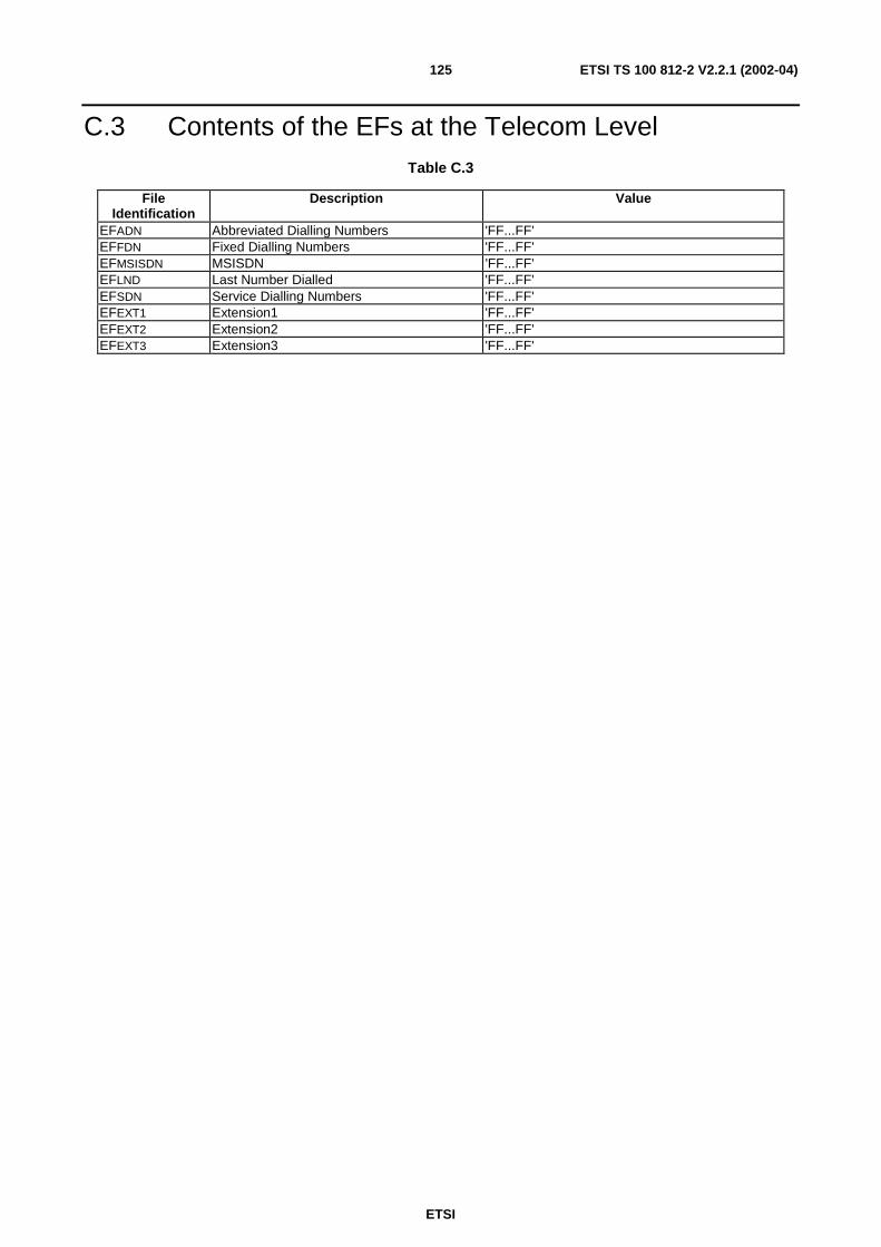
ETSI
ETSI TS 100 812-2 V2.2.1 (2002-04)125
C.3 Contents of the EFs at the Telecom LevelTable C.3
FileIdentification
Description Value
EFADN Abbreviated Dialling Numbers 'FF...FF'EFFDN Fixed Dialling Numbers 'FF...FF'EFMSISDN MSISDN 'FF...FF'EFLND Last Number Dialled 'FF...FF'EFSDN Service Dialling Numbers 'FF...FF'EFEXT1 Extension1 'FF...FF'EFEXT2 Extension2 'FF...FF'EFEXT3 Extension3 'FF...FF'

ETSI
ETSI TS 100 812-2 V2.2.1 (2002-04)126
Annex D (normative):Database structure for group IDs and phone booksUse of the network table
Relational database mechanisms are used to save a significant amount of memory. Several EFs (e.g. EFGSSIS and
EFGSSID) refer to the Network table for network address instead of saving it with each group short subscriber identity.
However, since a network address can be referenced from more than one place, a record pointer counter is needed tokeep track of how many times a network address is referenced. When the record pointer counter of a network address isone, it is referenced from only one place. When that address is removed, the corresponding network address can beremoved also, since it was the only one using it. This housekeeping method is used to remove unnecessary networkaddresses from the network table. Refer to figure D.1.
The network table is thus handled using the following procedures:
When a network address needs to be stored with a record, the network table (EFNWT see clause 10.3.23) needs to
be read. If the address (MCC and MNC) is already found on the network table, the Record pointer counter of thefound network address record needs to be increased by one. Only the record number of the network address onthe network table is stored with the record that needs the network address.
If the address is not found on the network table, a new record needs to be added to the network table. On thenetwork table the new network address (MCC and MNC) is stored along with a record pointer counter, which isset to one. Only the record number of the network address on the network table is stored with the record thatneeds the network address.
If the desired network address is not found in the network table, and it cannot be added because of the file beingfull, the new network address cannot be stored on the SIM.
If a record that uses a network address in the network table needs to be deleted, the network table also needs tobe updated. The record that needs to be updated can be found using the record number. The record number isstored with the record that is to be deleted. When the record in the network table is found, the record pointercounter is read. If the value of the counter is 2 or higher, the counter is decreased by one and the record thatreferenced it can be deleted.
If the record pointer counter is 1, the whole record on the network table can be deleted (indicated as free byfilling it with 'FF's) along with the record that pointed to that record.
EFMGCK EFGCKEFGSSIS EFGRDS
Record 1 Record 1
1:1
MGCKrecordnumber
Record 2 1:1 Record 2GSSIS
Grouprelateddata
Record 3 Record 3EFGSSID EFGRDD
…. ….1:1
MGCKrecordnumber
Record n Record n
GSSIDGrouprelateddata
Figure D.1: Graphical presentation of group data related EF structures
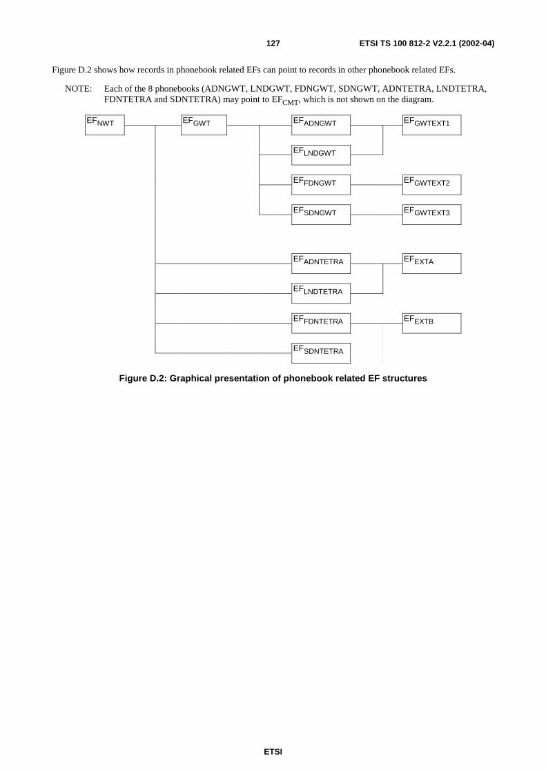
ETSI
ETSI TS 100 812-2 V2.2.1 (2002-04)127
Figure D.2 shows how records in phonebook related EFs can point to records in other phonebook related EFs.
NOTE: Each of the 8 phonebooks (ADNGWT, LNDGWT, FDNGWT, SDNGWT, ADNTETRA, LNDTETRA,FDNTETRA and SDNTETRA) may point to EFCMT, which is not shown on the diagram.
EFNWT EFGWT EFADNGWT EFGWTEXT1
EFLNDGWT
EFFDNGWT EFGWTEXT2
EFSDNGWT EFGWTEXT3
EFADNTETRA EFEXTA
EFLNDTETRA
EFFDNTETRA EFEXTB
EFSDNTETRA
Figure D.2: Graphical presentation of phonebook related EF structures
ETSI
ETSI TS 100 812-2 V2.2.1 (2002-04)128
Annex E (informative):Emergency call facilities and proceduresThe TETRA standards provide a wide variety of call types and facilities which may be used in an emergency situation.The activation of an emergency facility is implementation-specific and so the file content defined for the TETRA SIMcard is intended to offer flexibility in handling emergency situations. This annex offers further explanation of theinformation available to the ME in handling an emergency situation.
Emergency call control
The EFEINFO contains a control flag to indicate to the whether or not emergency calls are enabled for this particular
card.
Emergency call addresses
The EFEADDR contains a list of call destinations for use in an emergency call. Entries in the file can require that the call
be placed to either the last group in which the ME took part or to a pre-defined destination. When the file contains morethan one address, it is suggested that the order of the records in the file should indicate the order of preference for thecall, starting with the highest preference.
Each record in EFEADDR also contains a number of flags providing an indication as to the type of the call address,
allowing a mix of call types to be indicated. The call type can be one of a selection of 10 variants, including all of thecommon speech calls and short data transactions. For circuit mode calls, a data field indicates the nature of the requiredcall i.e. individual, group, acknowledged group or broadcast.
When the emergency call type is a status or short data transaction, an additional option is selected by a flag which maybe used to indicate a preference as to the source of the data to be transferred in an emergency message. When the pre-defined value stored in the card is selected, a record number pointer indicates EFSDS123 or EFSDS4 which contain both
the destination and message content. When the "application" source is selected, it is suggested that the contents of thedata field would be obtained by an application running in the ME.
Protection for interrupted emergency calls
The EF EFEINFO contains a flag indicating the action to be taken on power-on after an interrupted emergency call - to
optionally resume the emergency call without further operator intervention.
Where EFEINFO indicates that an interrupted emergency call should be continued next time the ME is powered up, the
ME should maintain the current emergency call index in EFEINFO during any emergency call procedure. In particular,
the index should be set by the ME to a value to be understood by the restarting ME as the call is initiated and zeroed onnormal termination. The index allows the restarting ME to establish that an emergency transaction was in progress and,from the index, which of the available call options to restart. The coding of the index is implementation-dependant butis dimensioned so that it can be used as a pointer to a record number in EFEADDR if required.
Successful connection of an emergency call
It is suggested above that the ME should attempt to set up the emergency call to each of the destinations prescribed inEFEADDR until a successful connection is achieved.
It should, however, be noted that not all call types provide a definite indication of success. An unacknowledged groupcall, for example, may succeed in establishing a 'call' but it is possible that no other member of the group could beavailable and so the result would be no exchange of useful information. For PABX or PSTN voice calls, call routingbeyond the TETRA infrastructure may not be able to return a definite indication of a successful exchange to theoriginating terminal and so a call to an unanswered or engaged number could result. The implementation of theemergency facility may take account of this possibility in controlling the emergency call.

ETSI
ETSI TS 100 812-2 V2.2.1 (2002-04)129
Emergency calls in Direct Mode.
When an emergency call record in EFEADDR requires the use of direct mode, the implementation may handle the
possibility of the required party being on one of a multiplicity of DMO channels. The record in EFEADDR includes a
field to indicate a channel number explicitly. It is suggested that a zero channel number could cause the ME to use theflags provided in EFDMOCh which designate a channel for emergency use in attempting to set up the call.
Emergency calls when the SIM card is not fitted
Where the ME is not equipped with a SIM interface, or the SIM is absent, it must still be possible, for someapplications, to make an emergency call.
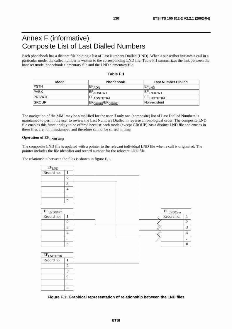
ETSI
ETSI TS 100 812-2 V2.2.1 (2002-04)130
Annex F (informative):Composite List of Last Dialled NumbersEach phonebook has a distinct file holding a list of Last Numbers Dialled (LND). When a subscriber initiates a call in aparticular mode, the called number is written to the corresponding LND file. Table F.1 summarizes the link between thehandset mode, phonebook elementary file and the LND elementary file.
Table F.1
Mode Phonebook Last Number DialledPSTN EFADN EFLNDPABX EFADNGWT EFLNDGWTPRIVATE EFADNTETRA EFLNDTETRAGROUP EFGSSIS/EFGSSID Non-existent
The navigation of the MMI may be simplified for the user if only one (composite) list of Last Dialled Numbers ismaintained to permit the user to review the Last Numbers Dialled in reverse chronological order. The composite LNDfile enables this functionality to be offered because each mode (except GROUP) has a distinct LND file and entries inthese files are not timestamped and therefore cannot be sorted in time.
Operation of EFLNDComp
The composite LND file is updated with a pointer to the relevant individual LND file when a call is originated. Thepointer includes the file identifier and record number for the relevant LND file.
The relationship between the files is shown in figure F.1.
EFLNDRecord no. 1
2
3
4
.
n
EFLNDGWT EFLNDComRecord no. 1 Record no. 1
2 2
3 3
4 4
. .
n n
EFLNDTETRRecord no. 1
2
3
4
.
n
Figure F.1: Graphical representation of relationship between the LND files

ETSI
ETSI TS 100 812-2 V2.2.1 (2002-04)131
It is recommended that a maximum file length equal to the length of one of the individual LND files is used. Thereasoning is that if EFLNDComp is longer than one of the individual LND files it will be quicker to find the original
dialling number in the phone books.

ETSI
ETSI TS 100 812-2 V2.2.1 (2002-04)132
Annex G (informative):BibliographyENV 726-3: "Terminal Equipment (TE); Requirements for IC cards and terminals for telecommunicationuse - Part 3: Application independent card requirements".
ENV 726-4: "Terminal Equipment (TE); Requirements for IC cards and terminals for telecommunicationuse - Part 4: Application independent card related terminal requirements".

ETSI
ETSI TS 100 812-2 V2.2.1 (2002-04)133
History
Document history
Edition 1 November 1998 Publication as ETS 300 812
V2.1.1 December 2001 Publication as EN 300 812
V2.2.1 April 2002 Publication


![TS 101 756 - V2.2.1 - Digital Audio Broadcasting (DAB ... · ETSI 7 ETSI TS 101 756 V2.2.1 (2017-08) [14] IEC 62106: "Specification of the Radio Data System (RDS) for VHF/FM sound](https://img.pdfslide.us/doc/110x75/5f0e9ef67e708231d4401e7a/ts-101-756-v221-digital-audio-broadcasting-dab-etsi-7-etsi-ts-101-756.jpg)


![TS 102 726-3 - V2.2.1 - Electromagnetic compatibility and ... 102 726-1 [i.2] which describes the applicable functions of the equipment being evaluated. ... the methodology defined](https://img.pdfslide.us/doc/110x75/5b09c7a27f8b9a51508dd7f5/ts-102-726-3-v221-electromagnetic-compatibility-and-102-726-1-i2-which.jpg)