Embed Size (px)
Citation preview

hydraulics & pneumatics
Competitive edge - always
www.achievehydraulics.com
Trusted for reliability & service
Hydraulic : Cylinders, Power Packs, Presses, SPMs
Contents
Introduction
Ø From CEO’s desk ...............
Ø About us ...........................................................................................
Ø Symbols ............................................................................................
Ø Hydraulic Cylinders - Constructional Details .....................................
Ø Cylinder Selection .............................................................................
AHP STD Series up to 160 bar
Tie Rod Type Cylinders .........................................................................
Ø Types of mountings ............................................................................
Ø Double Acting Hydraulic Cylinders .....................................................
Ø Flange and Side Lugs Mountings .......................................................
Ø Standard Trunnion Mountings ............................................................
Ø Extended Tie Rod Mountings ..............................................................
Ø Pivot Mountings .................................................................................
Ø Head Rectangular & Cap Rectangular Flange Mountings .....................
AHP STD Series up to 160 bar
Double-Ended Hydraulic Cylinders-003 ...............................................
AHP STD Series up to 250 bar
Heavy Duty Cylinders-004 ..................................................................
Ø Round Type Hydraulic Cylinder ............................................................
Ø Clevis Type Hydraulic Cylinder ............................................................
AHP Series MD up to 350 bar
Mill Duty Type Cylinders-004 ...............................................................
Ø Cylinders designed for extreme conditions ..........................................
Ø Front Circular Flange Mounting - Style MF3 ........................................
Ø Rear Circular Flange Mounting - Style MF4 .........................................
Ø Rear Pivot Mounted Hydraulic Cylinders with
Spherical Bearing - Style MP6 ............................................................
Ø Side Lugs Mounting - Style MS2 .........................................................
Ø Intermediate Trunnion Mounting - Style MT4 .......................................
Ø Rod End Accessories ..........................................................................
AHP Series WC up to 160 bar
Welded Type Cylinders-004 ................................................................
Ø Front Rectangular Flange Mounting - Style ME5 .................................
Ø Rear Female Clevis Mounting - Style MP1 ...........................................
Ø Rear Male Clevis Mounting - Style MP3 ..............................................
Ø Rear Clevis with Spherical Bearing Mounting - Style MP5 ....................
Ø Side Lugs Mounting - Style MS2 .........................................................
Ø Intermediate Trunnion Mounting - Style MT4 ......................................
Ø Rod End Eye .......................................................................................
Ø AHP STD Adaptor details .....................................................................
Ø Theoretical Push & Pull Force Chart .....................................................
AHP STD Series
AHP 005/006/007 ..................................................................................
Ø Block Cylinder .....................................................................................
Ø Compact Cylinder ..............................................................................
Ø Threaded Body Cylinder .....................................................................
AHP STD Series-007
Hydraulic Telescopic Cylinders
Single Acting/Double Acting 2, 3, 4 Stages .........................................
Ø Hydraulic Telescopic Cylinders ............................................................
Ø Piston Rod Sizes and Stop Tube ..........................................................
Ø Optional Features ..............................................................................
Hydraulic Cylinders - How to order ...................................................
AHP Series
Power Pack Units & Systems ...............................................................
............................................................... 03
04-09
10
11
12
13
14
15
16
17
18
19
20
21-22
23
24
24
25
26
27
28
29
30
31
32
33
34
35
36
37
38
39
40
41
42
43
44
45
46
47
48-49
50
51
52
53-58
02
Welcome to the world of high-quality and most reliable
hydraulic and pneumatic products at Achieve. We laid
its foundation in 2004 with the sole purpose of
manufacturing and providing the products which would
prove to be the best solutions to our customers' varied
and exacting requirements in this particular field. Living
up to our commitment, Achieve has been crossing
milestones, one after the other.
We have always kept our product range expanding
through research and development. As a result, we are
able to cater to the changing demands of various
customers and industries. You will find different models
of Achieve hydraulic cylinders and power packs
performing different applications and adding to your
productivity.
Recently, we introduced a range of Achieve Hydraulic
Power Pack Units which has received heartening
response and appreciation from our customers, as the
range is unmistakably characterized by the 'Achieve
Quality and Reliability'. We have already begun to
focus on developing hydraulic presses and SPMs in
response to your demand. A few machines already
commissioned will bring out our intent.
Achieve is dedicated to strive for highest customer
satisfaction through product excellence and
'no-complaint' after-sales service in the years to come.
Sincerely yours,
R. P. Sonawane, CEO
hydraulics & pneumatics
Competitive edge - always
From CEO’s desk
03www.achievehydraulics.com
About us
The year 2004 marked the moderate
beginning of a big dream. R. P. Sonawane,
a mechanical engineer, after gaining rich
experience of about 12 years in the field,
founded Achieve Hydraulics and
Pneumatics. The objective well defined - To
provide clients with highly reliable
hydraulic and pneumatic cylinders and
power packs at a competitive price and in
the fastest possible time. Very soon,
Achieve products started featuring as
standard fitments in equipments of several
reputed OEMs. Achieve specializes in
providing customized solutions for
hydraulic or pneumatic cylinders and
power packs. This development is
undertaken at no additional cost for our
clients. With our experience of over several
years and a variety of application
requirements, the time required for
developments is very short. To ensure
higher product quality and reliability, we
employ latest machines, manufacturing
techniques and quality systems. Every
Achieve product undergoes a stringent
performance test before it reaches you.
By being with us, you can achieve assured
competitive edge - always.
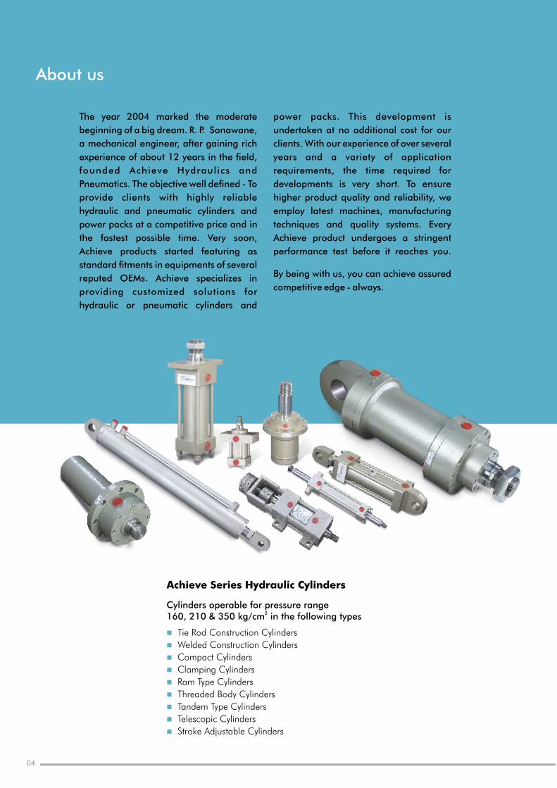
Cylinders operable for pressure range2160, 210 & 350 kg/cm in the following types
Tie Rod Construction Cylinders
Welded Cylinders
Compact Cylinders
Clamping Cylinders
Ram Type Cylinders
Threaded Body Cylinders
Tandem Type Cylinders
Telescopic Cylinders
l
n
n
n
n
n
n
n
n
n
Construction
Stroke Adjustable Cylinders
04
Achieve Series CylindersHydraulic
hydraulics & pneumatics
Competitive edge - always
05www.achievehydraulics.com
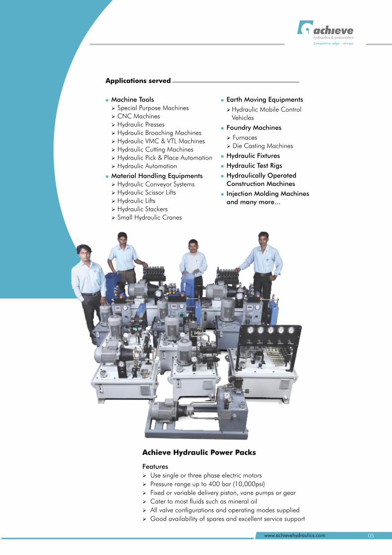
Features
Use single or three phase electric motors
Pressure range up to 400 bar (10,000psi)
Fixed or variable delivery piston, vane pumps or gear
Cater to most fluids such as mineral oil
All valve configurations and operating modes supplied
Good availability of spares and excellent service support
Ø
Ø
Ø
Ø
Ø
Ø
Machine Tools
Ø Special Purpose Machines
Ø CNC Machines
Ø Hydraulic Presses
Ø Hydraulic Broaching Machines
Ø Hydraulic VMC & VTL Machines
Ø Hydraulic Cutting Machines
Ø Hydraulic Pick & Place Automation
Ø Hydraulic Automation
Material Handling Equipments
Ø Hydraulic Conveyor Systems
Ø Hydraulic Scissor Lifts
Ø Hydraulic Lifts
Ø Hydraulic Stackers
Ø Small Hydraulic Cranes
n
n
n
n
n
n
n
n
Earth Moving Equipments
Ø Hydraulic Mobile Control
Vehicles
Foundry Machines
Ø Furnaces
Ø Die Casting Machines
Hydraulic Fixtures
Hydraulic Test Rigs
Hydraulically Operated
Construction Machines
Injection Molding Machines
and many more...
Applications served
Achieve Hydraulic Power Packs
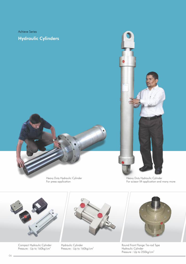
Hydraulic Cylinders
Achieve Series
Heavy Duty Hydraulic CylinderFor press application
Heavy Duty Hydraulic CylinderFor scissor lift application and many more
06
Compact Hydraulic Cylinder2Pressure : Up to 160kg/cm
Round Front Flange Tie-rod Type Hydraulic Cylinder
2Pressure : Up to 250kg/cm
Hydraulic Cylinder 2Pressure : Up to 160kg/cm
hydraulics & pneumatics
Competitive edge - always
07www.achievehydraulics.com
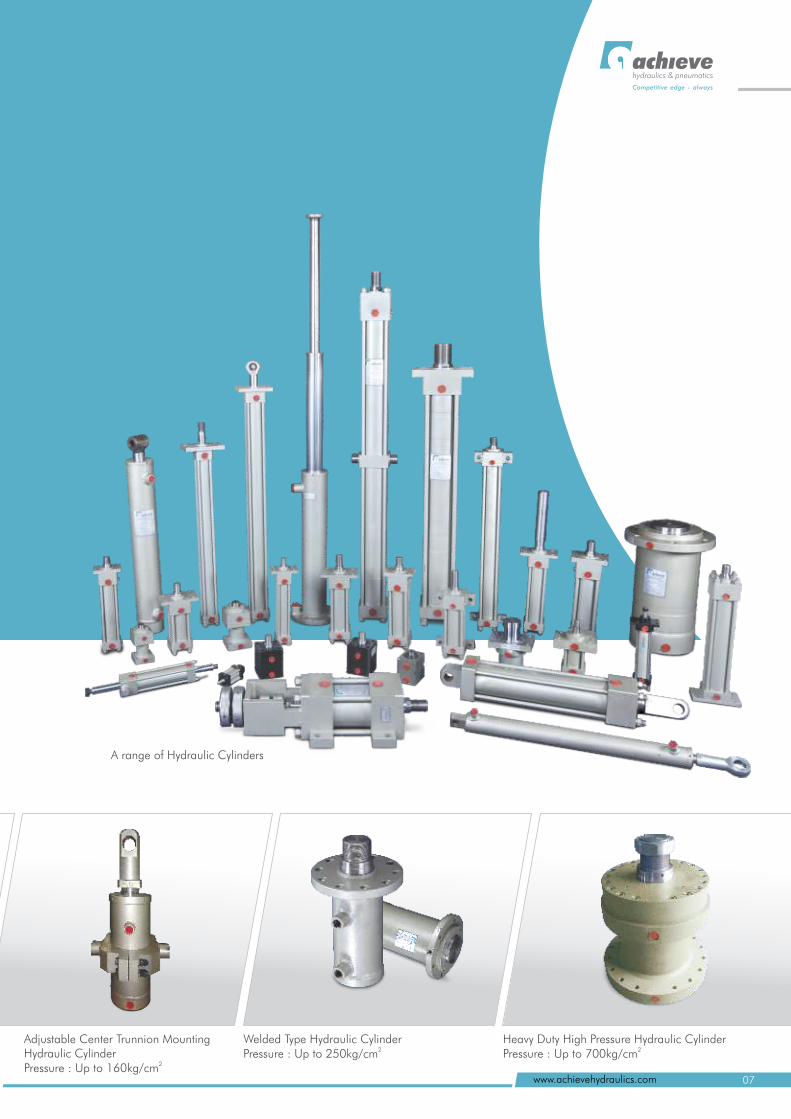
A range of Hydraulic Cylinders
Heavy Duty High Pressure Hydraulic Cylinder2Pressure : Up to 700kg/cm
Adjustable Center Trunnion Mounting Hydraulic Cylinder
2Pressure : Up to 160kg/cm
Welded Type Hydraulic Cylinder2Pressure : Up to 250kg/cm
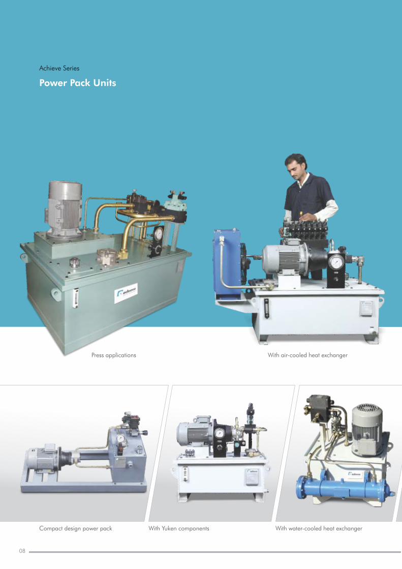
Power Pack Units
Press applications With air-cooled heat exchanger
Achieve Series
08
Compact design power pack With water-cooled heat exchangerWith Yuken components
hydraulics & pneumatics
Competitive edge - always
09www.achievehydraulics.com
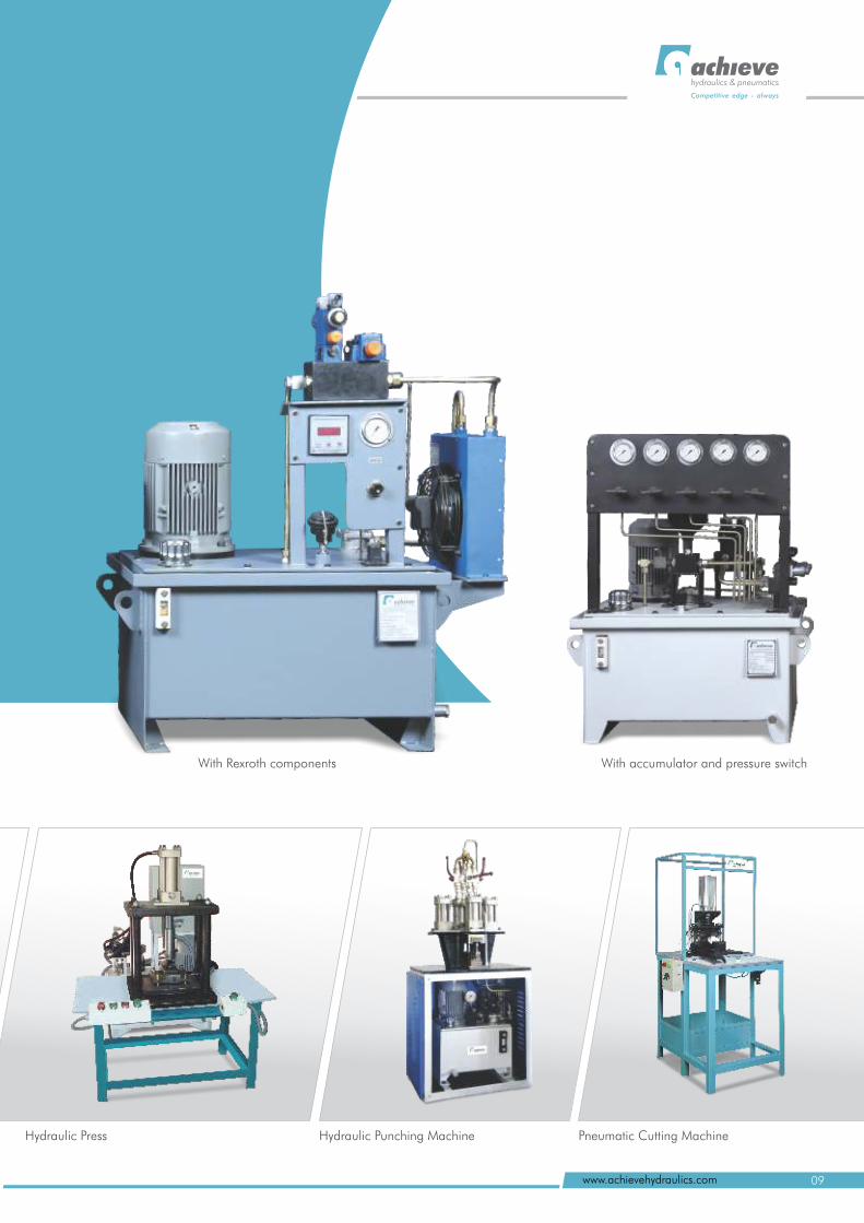
With Rexroth components With accumulator and pressure switch
Hydraulic Punching Machine Pneumatic Cutting MachineHydraulic Press
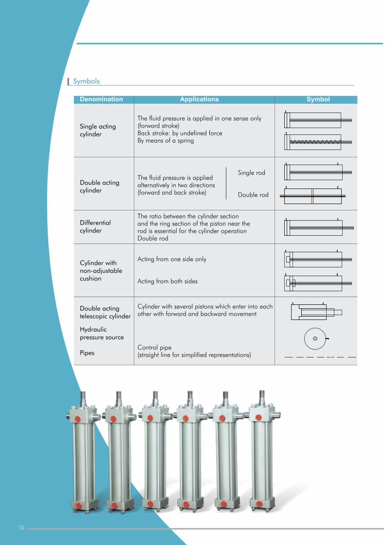
Single acting cylinder
Double acting cylinder
Differential cylinder
Cylinder with non-adjustable cushion
Double acting telescopic cylinder
Hydraulic pressure source
Pipes
The fluid pressure is applied in one sense only (forward stroke)Back stroke: by undefined forceBy means of a spring
The fluid pressure is applied alternatively in two directions (forward and back stroke)
The ratio between the cylinder section and the ring section of the piston near the rod is essential for the cylinder operationDouble rod
Acting from one side only
Acting from both sides
Cylinder with several pistons which enter into each other with forward and backward movement
Control pipe (straight line for simplified representations)
Denomination Applications Symbol
Single rod
Double rod
Symbols
10
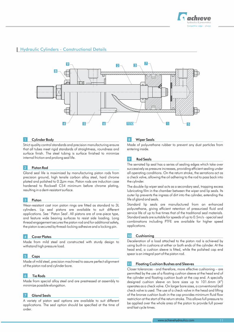
Hydraulic Cylinders - Constructional Details
Wiper Seals
Made of polyurethane rubber to prevent any dust particles from entering inside.
Rod Seals
The serrated lip seal has a series of sealing edges which take over successively as pressure increases, providing efficient sealing under all operating conditions. On the return stroke, the serrations act as a check valve, allowing the oil adhering to the rod to pass back into the cylinder.
The double-lip wiper seal acts as a secondary seal, trapping excess lubricating film in the chamber between the wiper and lip seals. Its outer lip prevents the ingress of dirt into the cylinder, extending the life of gland and seals.
Standard lip seals are manufactured from an enhanced polyurethane, giving efficient retention of pressurized fluid and service life of up to five times that of the traditional seal materials. Standard seals are suitable for speeds of up to 0.5m/s - special seal combinations including PTFE are available for higher speed applications.
Cushioning
Deceleration of a load attached to the piston rod is achieved by using built-in cushions at either or both ends of the cylinder. At the head end, a cushion sleeve is fitted, while the polished cap end spear is an integral part of the piston rod.
Floating Cushion Bushes and Sleeves
Closer tolerances - and therefore, more effective cushioning – are permitted by the use of a floating cushion sleeve at the head end of the cylinder and floating cushion bush at the cap end. A specially designed cushion sleeve on bore sizes up to 101.6mm (4”) operates as a check valve. On larger bore sizes, a conventional ball check valve is used. The use of a check valve in the head and lifting of the bronze cushion bush in the cap provides minimum fluid flow restriction at the start of the return stroke. This allows full pressure to be applied over the whole area of the piston to provide full power and fast cycle times.
8
9
10
11
2 37
15 6
9
8
4 51110
hydraulics & pneumatics
Competitive edge - always
11www.achievehydraulics.com
Cylinder Body
Strict quality control standards and precision manufacturing ensure that all tubes meet rigid standards of straightness, roundness and surface finish. The steel tubing is surface finished to minimize internal friction and prolong seal life.
Piston Rod
Gland seal life is maximized by manufacturing piston rods from precision ground, high tensile carbon alloy steel, hard chrome plated and polished to 0.2µm max. Piston rods are induction case hardened to Rockwell C54 minimum before chrome plating, resulting in a dent-resistant surface.
Piston
Wear-resistant cast iron piston rings are fitted as standard to 3L cylinders. Lip seal pistons are available to suit different applications. See ' Piston Seal'. All pistons are of one-piece type, and feature wide bearing surfaces to resist side loading. Long thread engagement secures the piston rod and for additional safety, the piston is secured by thread-locking adhesive and a locking pin.
Cover Plates
Made from mild steel and constructed with sturdy design to withstand high pressure load.
Caps
Made of mild steel, precision machined to assure perfect alignment of the piston rod and cylinder bore.
Tie Rods
Made from special alloy steel and are prestressed at assembly to minimize possible elongation.
Gland Seals
A variety of piston seal options are available to suit different applications. The seal option should be specified at the time of order.
1
2
3
4
5
6
7
Check List
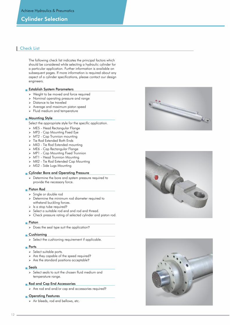
The following check list indicates the principal factors which should be considered while selecting a hydraulic cylinder for a particular application. Further information is available on subsequent pages. If more information is required about any aspect of a cylinder specifications, please contact our design engineers.
12
Cylinder Selection
Achieve Hydraulics & Pneumatics
Establish System Parameters
Ø Weight to be moved and force requiredØ Nominal operating pressure and rangeØ Distance to be traveledØ Average and maximum piston speedØ Fluid medium and temperature
Mounting Style
Select the appropriate style for the specific application.
Ø ME5 - Head Rectangular Flange Ø MP3 - Cap Mounting Fixed EyeØ MT2 - Cap Trunnion mounting Ø Tie Rod Extended Both EndsØ MX3 - Tie Rod Extended mounting Ø ME6 - Cap Rectangular FlangeØ MP1 - Cap Mounting Fixed TrunnionØ MT1 - Head Trunnion MountingØ MX2 - Tie Rod Extended Cap MountingØ MS2 - Side Lugs Mounting
Cylinder Bore and Operating Pressure
Ø Determine the bore and system pressure required to provide the necessary force.
Piston Rod
Ø Single or double rodØ Determine the minimum rod diameter required to
withstand buckling forces.Ø Is a stop tube requiredØ Select a suitable rod end and rod end thread.Ø Check pressure rating of selected cylinder and piston rod.
Piston
Ø Does the seal type suit the application
Cushioning
Ø Select the cushioning requirement if applicable.
Ports
Ø Select suitable ports. Ø Are they capable of the speed requiredØ Are the standard positions acceptable?
Seals
Ø Select seals to suit the chosen fluid medium and temperature range.
Rod and Cap End Accessories
Ø Are rod end and/or cap end accessories required
Operating Features
Ø Air bleeds, rod end bellows, etc.
l
l
l
l
l
l
l
l
l
?
?
?
?
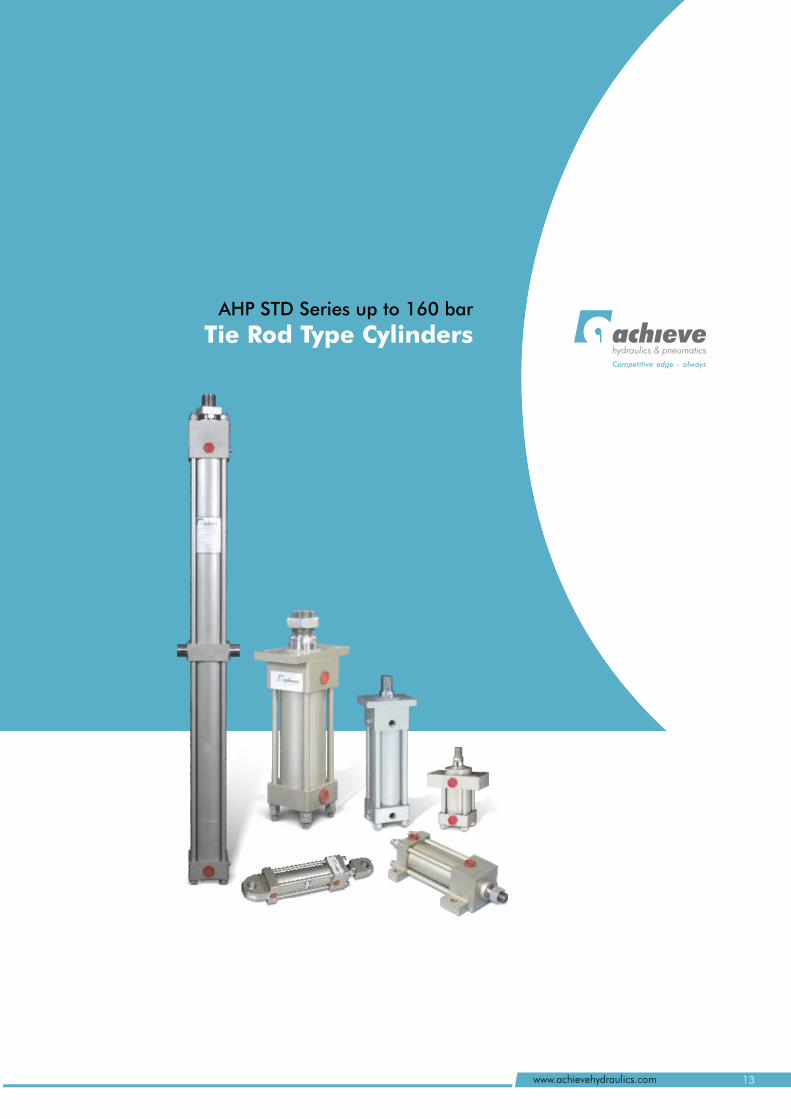
AHP STD Series up to 160 bar
Tie Rod Type Cylindershydraulics & pneumatics
Competitive edge - always
13www.achievehydraulics.com
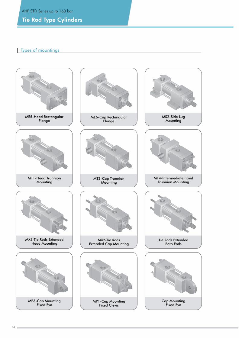
Cap Mounting Fixed Eye
MP1-Cap MountingFixed Clevis
MP3-Cap MountingFixed Eye
MS2-Side Lug Mounting
ME6-Cap RectangularFlange
ME5-Head RectangularFlange
AHP STD Series up to 160 bar
Tie Rod Type Cylinders
Types of mountings
MT1-Head TrunnionMounting
MT2-Cap Trunnion Mounting
MT4-Intermediate FixedTrunnion Mounting
14
Tie Rods Extended Both Ends
MX2-Tie Rods Extended Cap Mounting
MX3-Tie Rods ExtendedHead Mounting
Specifications
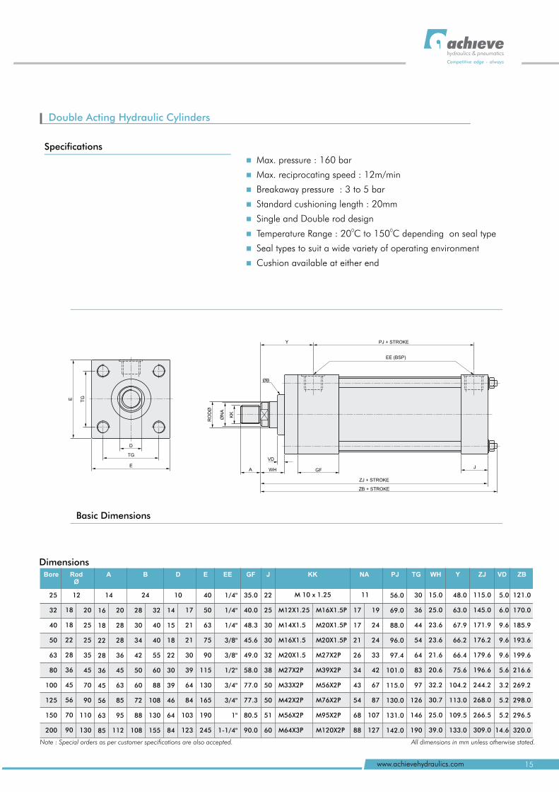
Double Acting Hydraulic Cylinders
D
TG
E
TGE
VD
A
KK
ØN
A
RO
DØ
ØB
Y
WH GFJ
PJ + STROKE
EE (BSP)
ZJ + STROKE
ZB + STROKE
Dimensions
12 14 24 10 M 10 x 1.25 11
RodØ
A B D E EE GF J KK NA PJ TG WH Y ZJ
5.0
6.0
9.6
9.6
9.6
5.6
3.2
5.2
5.2
14.6
Note : Special orders as per customer specifications are also accepted. All dimensions in mm unless otherwise stated.
ZBBore VD
40
50
63
75
90
115
130
165
190
245
1/4"
1/4"
1/4"
3/8"
3/8"
1/2"
3/4"
3/4"
1"
1-1/4"
35.0
40.0
48.3
45.6
49.0
58.0
77.0
77.3
80.5
90.0
22
25
30
30
32
38
50
50
51
60
25
32
40
50
63
80
100
125
150
200
18
18
22
28
36
45
56
70
90
20
25
25
35
45
70
90
110
130
16
18
22
28
36
45
56
63
85
20
28
28
36
45
63
85
95
112
28
30
34
42
50
60
72
88
108
32
40
40
55
60
88
108
130
155
14
15
18
22
30
39
46
64
84
17
21
21
30
39
64
84
103
123
M12X1.25
M14X1.5
M16X1.5
M20X1.5
M27X2P
M33X2P
M42X2P
M56X2P
M64X3P
M16X1.5P
M20X1.5P
M20X1.5P
M27X2P
M39X2P
M56X2P
M76X2P
M95X2P
M120X2P
17
17
21
26
34
43
54
68
88
19
24
24
33
42
67
87
107
127
56
69
88
96
97.4
101
115
130
131
142
.0
.0
.0
.0
.0
.0
.0
.0
.0
30
36
44
54
64
83
97
126
146
190
15
25
23.6
23.6
21.6
20.6
32.2
30.7
25
39
.0
.0
.0
.0
48
63
67.9
66.2
66.4
75.6
104.2
113
109.5
133
.0
.0
.0
.0
115
145
171.9
176.2
179.6
196.6
244.2
268
266.5
309
.0
.0
.0
.0
121.0
170.0
185.9
193.6
199.6
216.6
269.2
298.0
296.5
320.0
15www.achievehydraulics.com
hydraulics & pneumatics
Competitive edge - always
n
n
n
n
n
n
n
n
Max. pressure : 160 bar
Max. reciprocating speed : 12m/min
Breakaway pressure : 3 to 5 bar
Standard cushioning length : 20mm
Single and Double rod design0 0
Temperature Range : 20 C to 150 C depending on seal type
Seal types to suit a wide variety of operating environment
Cushion available at either end
Basic Dimensions
AHP STD Series up to 160 bar
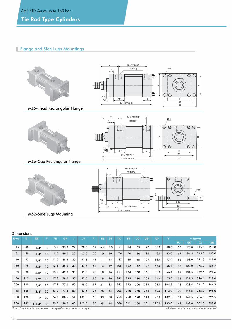
Tie Rod Type Cylinders
Flange and Side Lugs Mountings
ME6-Cap Rectangular Flange
ME5-Head Rectangular Flange
MS2-Side Lugs Mounting
Dimensions
Note : Special orders as per customer specifications are also accepted. All dimensions in mm unless otherwise stated.
E EE F FB GF J LH R SB ST TO TS UO US XS Y + Stroke
PJ SS ZJ
25
32
40
50
63
80
100
125
150
200
ZE
Bore
40
50
63
75
90
115
130
165
190
245
1/4"
1/4"
1/4"
3/8"
3/8"
1/2"
3/4"
3/4"
1"
1-1/4"
8
10
10
12
12
15
20
30
30
30
5.5
9.0
11
13.5
13.5
17.5
17.5
22.0
26.0
33.0
.0
35
40
48.5
45.6
49.0
58.0
77.0
77.3
80.5
90.0
.0
.0
22
25
30
30
35
35
50
50
51
60
20
25
31.5
37.5
45
57.5
65
82.5
102.5
122.5
.0
.0
.0
.0
27
30
41
52
65
83
97
126
155
190
6.6
10
11
14
18
18
21
26
33
39
8.5
10
13
19
26
26
32
32
38
44
51
70
87
105
117
149
162
208
253
300
54
70
85
102
124
149
172
210
260
311
65
90
115
142
160
190
220
260
320
380
72
90
105
127
161
186
216
254
318
381
33
48
56
56
58
64.6
91
89
96
116
.0
.0
.0
.0
.0
.0
.0
.0
.0
48
63
67.9
66.2
66.4
75.6
104.2
113
109.5
133
.0
.0
.0
.0
56
69
88
96
97
101
115
130
131
142
73
84.5
98
100
104.5
111.5
128.5
148.5
147.5
167
.0
.0
.0
.0
123.0
155.0
181.9
188.7
191.6
211.6
264.2
298.0
296.5
339.0
115
145
171.9
176.2
179.6
196.6
244.2
268
266.5
309
.0
.0
.0
.0
PJ + STROKE
EE(BSP)F
VD
WH
SS + STROKE
Y
ØSB
ST
TS
US
E-Sq
LH
ZJ + STROKE
XS
GF J
TO
E
UOE R
ØFBPJ + STROKE
EE(BSP)F
VD
WH GF
ZJ + STROKE
J
Y
ZE + STROKE
UO
TO
E
E R
ØFB
PJ + STROKE
F
VD
WH GF J
Y
ZJ + STROKE
EE(BSP)
16
06
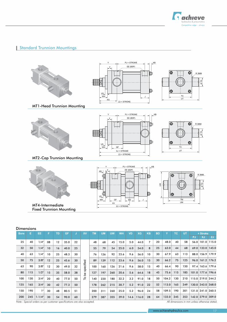
Standard Trunnion Mountings
MT4-Intermediate Fixed Trunnion Mounting
MT2-Cap Trunnion Mounting
MT1-Head Trunnion Mounting
PJ + STROKEY
EE (BSP)
VD
J
ZJ + STROKE
F
KB
WH
XG
TC
UT
R 3MM
Ø T
D
EE (BSP)
PJ + STROKEY KB
F
VD
WH GF
XJ + STROKE
ZJ + STROKE
TC
UT
R 3MM
Ø T
D
EE (BSP)
PJ + STROKEY KB
F
VD
WH GF
XV
ZJ + STROKE
KB
BD JØ
TD
TM
UM
UW
R 3MM
DimensionsE EE F TD GF J TM UM UW WH VD XG KB BD Y TC UTXV + Stroke
PJ XJ ZJ
Bore
25
32
40
50
63
80
100
125
150
200
40
50
63
75
90
115
130
165
190
245
1/4"
1/4"
1/4"
3/8"
3/8"
1/2"
3/4"
3/4"
1"
1-1/4"
08
10
10
12
12
15
20
30
30
30
12
16
25
25
30
35
40
42
48
54
35
40
48.3
45.6
49.0
58.0
77.0
77.3
80.5
90.0
.0
.0
22
25
30
30
32
38
50
50
51
60
To b
e s
peci
fied
48
55
76
89
100
127
140
178
200
279
68
79
126
139
160
197
220
262
311
387
45
54
92
112
126
260
180
215
260
355
15
25
23.6
23.6
21.6
20.6
32.2
30.7
25
39
.0
.0
.0
.0
5
6
9.6
9.6
9.6
5.6
3.2
5.2
5.2
14.6
.0
.0
44
54
56
56
58
64.6
91
91
96
116
.0
.0
.0
.0
.0
.0
.0
.0
.0
7
8
10
15
15
18
18
22
24
28
20
25
30
30
40
45
50
52
58
64
48
63
67.9
66.2
66.4
75.6
104.2
113
109.5
133
.0
.0
.0
.0
40
44
63
75
90
115
130
165
190
245
58
68
113
125
150
185
210
249
301
353
56
69
88
96
97.4
101
115
130
131
142
.0
.0
.0
.0
.0
.0
.0
.0
.0
101
133
156.9
161.2
163.6
177.6
219
243
241
279
.0
.0
.0
.0
.0
.0
115
145
179.9
176.2
179.6
196.6
244.2
268
260.5
309
.0
.0
.0
.0
Note : Special orders as per customer specifications are also accepted. All dimensions in mm unless otherwise stated.
17www.achievehydraulics.com
hydraulics & pneumatics
Competitive edge - always
AHP STD Series up to 160 bar
Tie Rod Type Cylinders
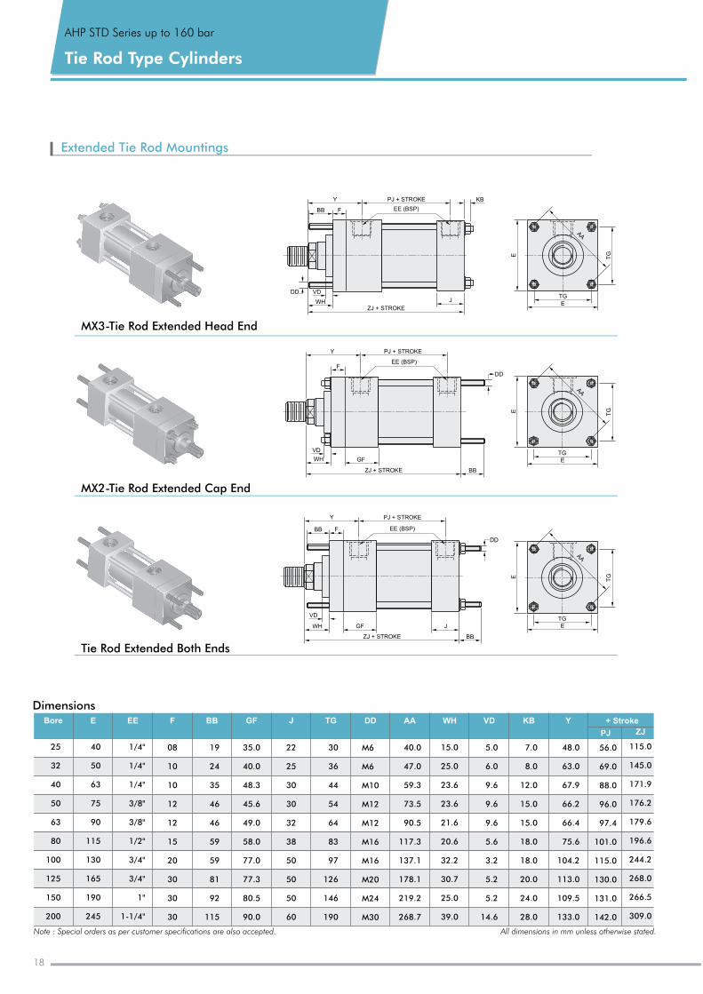
Extended Tie Rod Mountings
MX3-Tie Rod Extended Head End
MX2-Tie Rod Extended Cap End
Tie Rod Extended Both Ends
+ Stroke
ZJPJ
Bore E EE F BB GF J TG DD AA WH VD KB Y
25
32
40
50
63
80
100
125
150
200
40
50
63
75
90
115
130
165
190
245
1/4"
1/4"
1/4"
3/8"
3/8"
1/2"
3/4"
3/4"
1"
1-1/4"
08
10
10
12
12
15
20
30
30
30
19
24
35
46
46
59
59
81
92
115
35
40
48.3
45.6
49.0
58.0
77.0
77.3
80.5
90.0
.0
.0
22
25
30
30
32
38
50
50
50
60
30
36
44
54
64
83
97
126
146
190
M6
M6
M10
M12
M12
M16
M16
M20
M24
M30
40
47
59.3
73.5
90.5
117.3
137.1
178.1
219.2
268.7
.0
.0
15
25
23.6
23.6
21.6
20.6
32.2
30.7
25.0
39.0
.0
.0
5.0
6.0
9.6
9.6
9.6
5.6
3.2
5.2
5.2
14.6
7.0
8.0
12
15
15
18
18
20
24
28
.0
.0
.0
.0
.0
.0
.0
.0
48
63
67.9
66.2
66.4
75.6
104.2
113
109.5
133
.0
.0
.0
.0
56
69
88
96
97.4
101
115
130
131
142
.0
.0
.0
.0
.0
.0
.0
.0
.0
115
145
171.9
176.2
179.6
196.6
244.2
268
266.5
309
.0
.0
.0
.0
Dimensions
Note : Special orders as per customer specifications are also accepted. All dimensions in mm unless otherwise stated.
KB
EE (BSP)
PJ + STROKEY
BB F
J
ZJ + STROKE
VD
WH
DD
Y PJ + STROKE
EE (BSP)F
VD
WH GF
BB
DD
ZJ + STROKE
TG
TG
E
E
AA
Y PJ + STROKE
EE (BSP)BB
VD
WH GF
BB
DD
ZJ + STROKE
J
F
TG
TG
E
E
AA
TG
TG
E
E
AA
18
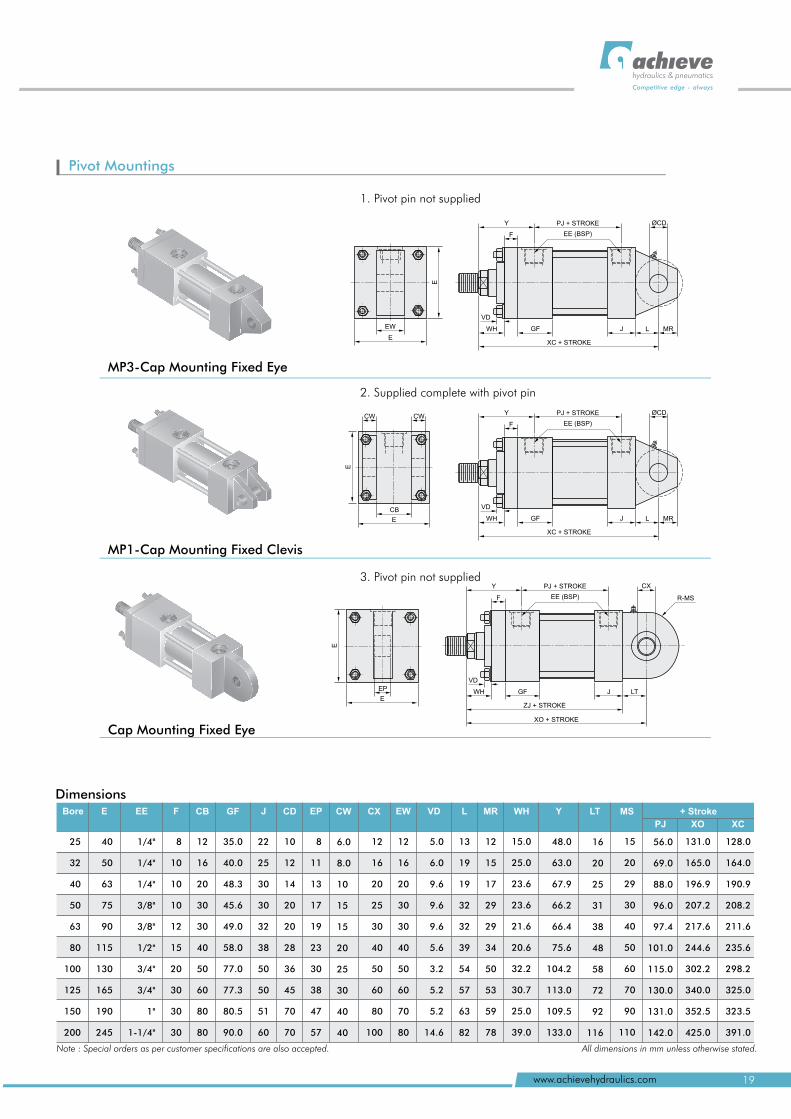
Pivot Mountings
3. Pivot pin not supplied
2. Supplied complete with pivot pin
1. Pivot pin not supplied
+ Stroke
PJ XO
Bore E EE F CB GF J CD EP CW CX EW VD L MR WH Y LT MS
XC
25
32
40
50
63
80
100
125
150
200
40
50
63
75
90
115
130
165
190
245
1/4"
1/4"
1/4"
3/8"
3/8"
1/2"
3/4"
3/4"
1"
1-1/4"
8
10
10
10
12
15
20
30
30
30
12
16
20
30
30
40
50
60
80
80
35
40
48.3
45.6
49.0
58.0
77.0
77.3
80.5
90.0
.0
.0
22
25
30
30
32
38
50
50
51
60
10
12
14
20
20
28
36
45
70
70
8
11
13
17
19
23
30
38
47
57
6.0
8.0
10
15
15
20
25
30
40
40
12
16
20
25
30
40
50
60
80
100
12
16
20
30
30
40
50
60
70
80
5.0
6.0
9.6
9.6
9.6
5.6
3.2
5.2
5.2
14.6
13
19
19
32
32
39
54
57
63
82
12
15
17
29
29
34
50
53
59
78
15
25
23.6
23.6
21.6
20.6
32.2
30.7
25.0
39.0
.0
.0
48
63
67.9
66.2
66.4
75.6
104.2
113
109.5
133
.0
.0
.0
.0
16
20
25
31
38
48
58
72
92
116
15
20
29
30
40
50
60
70
90
110
56
69
88
96
97.4
101
115
130
131
142
.0
.0
.0
.0
.0
.0
.0
.0
.0
131
165
196.9
207.2
217.6
244.6
302.2
340
352.5
425
.0
.0
.0
.0
128
164
190.9
208.2
211.6
235.6
298.2
325
323.5
391
.0
.0
.0
.0
Dimensions
Note : Special orders as per customer specifications are also accepted. All dimensions in mm unless otherwise stated.
MP3-Cap Mounting Fixed Eye
MP1-Cap Mounting Fixed Clevis
Cap Mounting Fixed Eye
CW CW
E
CB
E
PJ + STROKE
F
Y
EE (BSP)
GF J L MR
ØCD
XC + STROKE
VD
WH
EW
E
E
PJ + STROKE
F
Y
EE (BSP)
GF J L MR
ØCD
XC + STROKE
VD
WHE
E
EP
R-MS
PJ + STROKE
F
Y
EE (BSP)
GF J LT
CX
ZJ + STROKE
VD
WH
XO + STROKE
19www.achievehydraulics.com
hydraulics & pneumatics
Competitive edge - always
AHP STD Series up to 160 bar
Tie Rod Type Cylinders
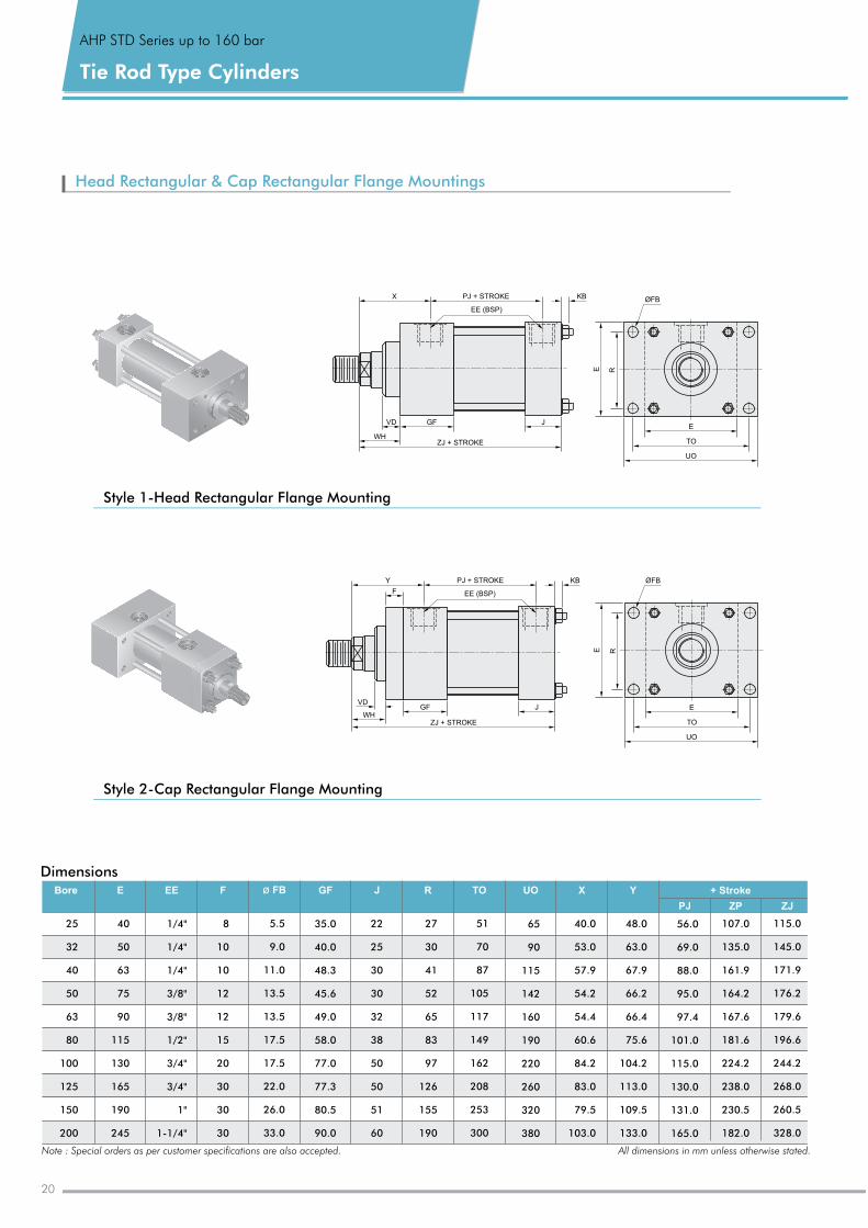
Head Rectangular & Cap Rectangular Flange Mountings
Style 1-Head Rectangular Flange Mounting
Style 2-Cap Rectangular Flange Mounting
PJ + STROKEX
EE (BSP)
VD
WHZJ + STROKE
GF J
KB ØFB
UO
TO
E
RE
PJ + STROKEY
EE (BSP)
VD
WHZJ + STROKE
GF J
KB
F
ØFB
UO
TO
E
RE
DimensionsEE F ø FB GF J R TO UO X Y + Stroke
PJ ZP ZJ
EBore
25
32
40
50
63
80
100
125
150
200
40
50
63
75
90
115
130
165
190
245
1/4"
1/4"
1/4"
3/8"
3/8"
1/2"
3/4"
3/4"
1"
1-1/4"
8
10
10
12
12
15
20
30
30
30
5.5
9.0
11
13.5
13.5
17.5
17.5
22.0
26.0
33.0
.0
35
40
48.3
45.6
49.0
58.0
77.0
77.3
80.5
90.0
.0
.0
22
25
30
30
32
38
50
50
51
60
27
30
41
52
65
83
97
126
155
190
51
70
87
105
117
149
162
208
253
300
65
90
115
142
160
190
220
260
320
380
40
53
57.9
54.2
54.4
60.6
84.2
83
79.5
103
.0
.0
.0
.0
48
63
67.9
66.2
66.4
75.6
104.2
113
109.5
133
.0
.0
.0
.0
56
69
88
95
97.4
101
115
130
131
165
.0
.0
.0
.0
.0
.0
.0
.0
.0
107
135
161.9
164.2
167.6
181.6
224.2
238
230.5
182.0
.0
.0
.0
115
145
171.9
176.2
179.6
196.6
244.2
268
260.5
328
.0
.0
.0
.0
Note : Special orders as per customer specifications are also accepted. All dimensions in mm unless otherwise stated.
20
21www.achievehydraulics.com
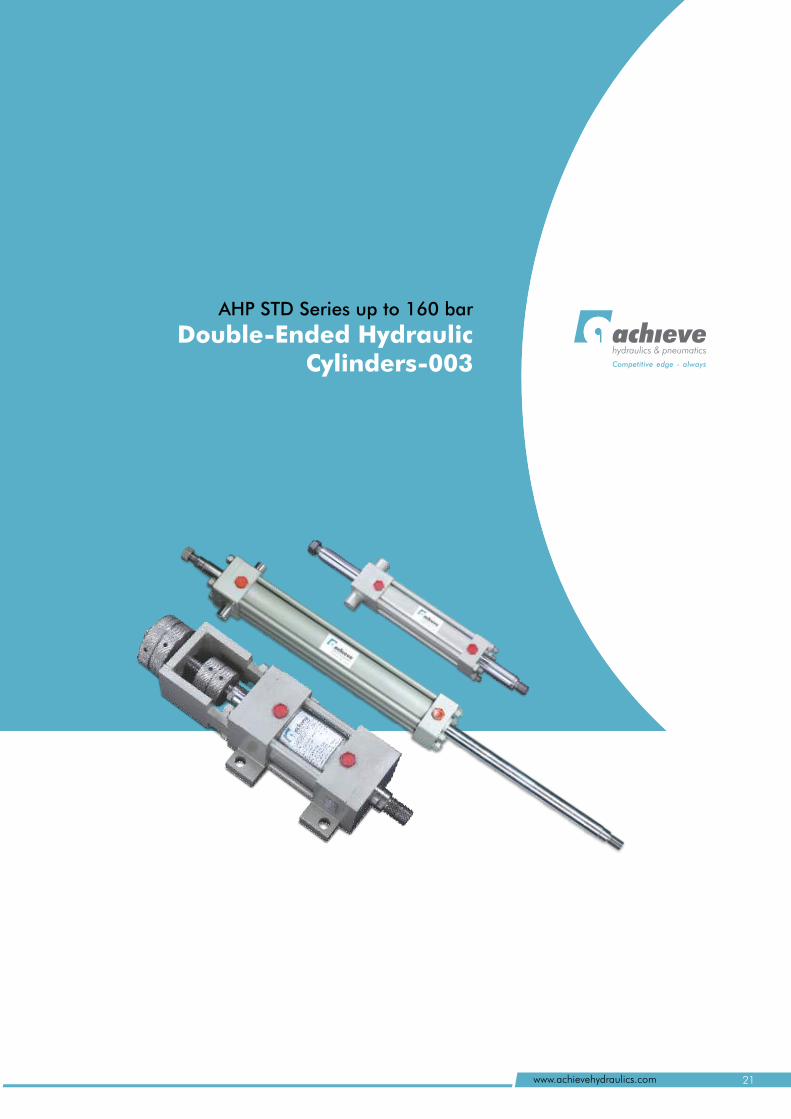
AHP STD Series up to 160 bar
Double-Ended Hydraulic Cylinders-003
hydraulics & pneumatics
Competitive edge - always
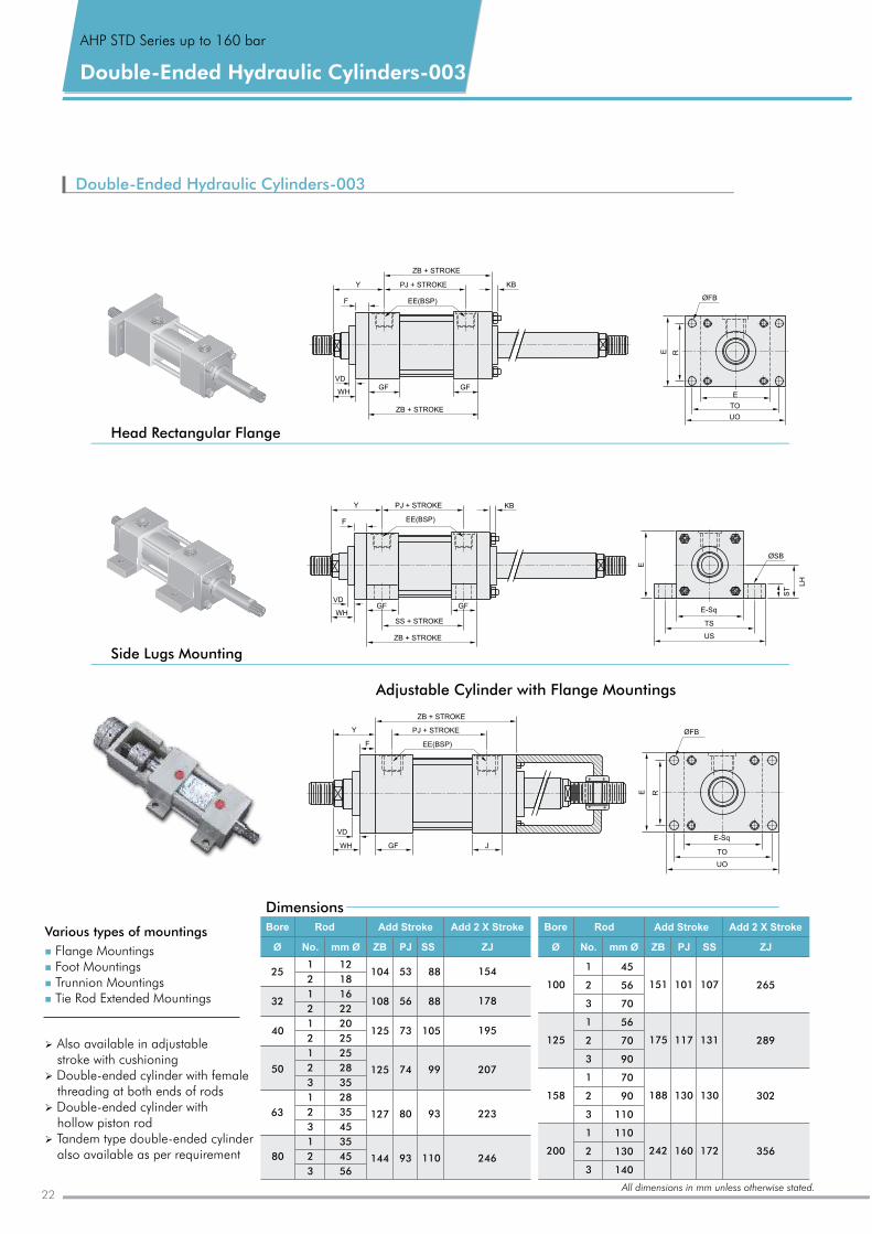
Ø
stroke with cushioningØ Double-ended cylinder with female
threading at both ends of rodsØ Double-ended cylinder with
hollow piston rodØ Tandem type double-ended cylinder
also available as per requirement
Also available in adjustable
Various types of mountings
n
n
n
n
Flange MountingsFoot MountingsTrunnion MountingsTie Rod Extended Mountings
06
Double-Ended Hydraulic Cylinders-003
Adjustable Cylinder with Flange Mountings
Side Lugs Mounting
Head Rectangular Flange
DimensionsBore Rod Add Stroke
Ø No. mm Ø ZB PJ SS
1
2
1
2
1
2
1
2
3
1
2
3
1
2
3
12
18
16
22
20
25
25
28
35
28
35
45
35
45
56
104
108
125
125
127
144
53
56
73
74
80
93
88
88
105
99
93
110
ZJ
Add 2 X Stroke
154
178
195
207
223
246
50
63
80
25
32
40
Bore Rod Add Stroke
Ø No. mm Ø ZB PJ SS
1
2
3
1
2
3
1
2
3
1
2
3
45
56
70
56
70
90
70
90
110
110
130
140
151
175
188
242
101
117
130
160
107
131
130
172
ZJ
Add 2 X Stroke
265
289
302
356
100
125
158
200
AHP STD Series up to 160 bar
Double-Ended Hydraulic Cylinders-003
F
VD
WH
Y
ZB + STROKE
PJ + STROKE
EE(BSP)
GF J
ØFB
UO
TO
E-Sq
RE
KB
GF GF
F
VD
WH
Y PJ + STROKE
EE(BSP)
ZB + STROKE
ZB + STROKE
ØFB
UO
TO
E
RE
KB
GF GF
F
VD
WH
Y PJ + STROKE
EE(BSP)
SS + STROKE
ZB + STROKE
ST
ØSB
E
E-Sq
TS
US
LH
22All dimensions in mm unless otherwise stated.
AHP STD Series up to 200 bar
Heavy Duty Cylinders-004 hydraulics & pneumatics
Competitive edge - always
23www.achievehydraulics.com
n n
nn n
n
n
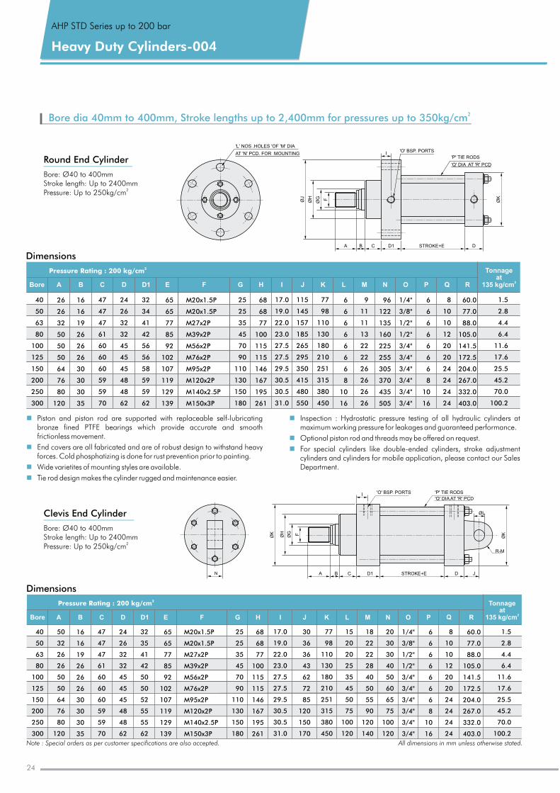
Piston and piston rod are supported with replaceable self-lubricating bronze fined PTFE bearings which provide accurate and smooth frictionless movement.
Inspection : Hydrostatic pressure testing of all hydraulic cylinders at maximum working pressure for leakages and guaranteed performance.
Optional piston rod and threads may be offered on request.End covers are all fabricated and are of robust design to withstand heavy For special cylinders like double-ended cylinders, stroke adjustment forces. Cold phosphatizing is done for rust prevention prior to painting. cylinders and cylinders for mobile application, please contact our Sales Wide varietites of mounting styles are available. Department.
Tie rod design makes the cylinder rugged and maintenance easier.
Dimensions
Dimensions
Bore A D D1 E F G H I J K L M N O P Q R
Tonnageat
2135 kg/cmB C
2Pressure Rating : 200 kg/cm
65
65
77
85
92
102
107
119
129
139
8
10
10
12
20
20
24
24
24
24
16
16
19
26
26
26
30
30
30
35
1/4"
3/8"
1/2"
1/2"
3/4"
3/4"
3/4"
3/4"
3/4"
3/4"
M20x1.5P
M20x1.5P
M27x2P
M39x2P
M56x2P
M76x2P
M95x2P
M120x2P
M140x2.5P
M150x3P
47
47
47
61
60
60
60
59
59
70
32
35
41
42
50
50
52
55
55
62
68
68
77
100
115
115
146
167
195
261
77
98
110
130
180
210
251
315
380
450
17
19.0
22.0
23
27.5
27.5
29.5
30.5
30.5
31.0
.0
.0
24
26
32
32
45
45
45
48
48
62
1.5
2.8
4.4
6.4
11.6
17.6
25.5
45.2
70.0
100.2
30
36
36
43
62
72
85
120
150
170
15
20
20
25
35
45
50
75
100
120
18
22
22
28
40
50
55
90
120
140
20
30
30
40
50
60
65
75
100
120
6
6
6
6
6
6
6
8
10
16
60.0
77.0
88.0
105.0
141.5
172.5
204.0
267
332.0
403.0
.0
40
50
63
80
100
125
150
200
250
300
50
32
26
26
50
50
64
76
80
120
25
25
35
45
70
90
110
130
150
180
Tonnageat
2135 kg/cm
Pressure Rating : 200 kg/cm2
Bore A D D1 E F G H I J K L M N O P Q RB C
40
50
63
80
100
125
150
200
250
300
26
26
32
50
50
50
64
76
80
120
16
16
19
26
26
26
30
30
30
35
47
47
47
61
60
60
60
59
59
70
24
26
32
32
45
45
45
48
48
62
32
34
41
42
56
56
58
59
59
62
65
65
77
85
92
102
107
119
129
139
M20x1.5P
M20 1.5P
M27 2P
M39 2P
M56 2P
M76 2P
M95x2P
M120x2P
M140x2.5P
M150x3P
x
x
x
x
x
25
25
35
45
70
90
110
130
150
180
68
68
77
100
115
115
146
167
195
261
17
19.0
22.0
23
27.5
27.5
29.5
30.5
30.5
31.0
.0
.0
115
145
157
185
265
295
350
415
480
550
77
98
110
130
180
210
251
315
380
450
6
6
6
6
6
6
6
8
10
16
9
11
11
13
22
22
26
26
26
26
96
122
135
160
225
255
305
370
435
505
1/4"
3/8"
1/2"
1/2"
3/4"
3/4"
3/4"
3/4"
3/4"
3/4"
6
6
6
6
6
6
6
8
10
16
8
10
10
12
20
20
24
24
24
24
60.0
77.0
88.0
105.0
141.5
172.5
204.0
267
332.0
403.0
.0
1.5
2.8
4.4
6.4
11.6
17.6
25.5
45.2
70.0
100.2
Round End Cylinder
Clevis End Cylinder
Note : Special orders as per customer specifications are also accepted. All dimensions in mm unless otherwise stated.
ØK
ØH
ØG F
N A B C D1 STROKE+E D
R-M
J
'P' TIE RODS
'Q' DIA AT 'R' PCD
'O' BSP. PORTS
ØL
ØK
I
I
A B C D1 STROKE+E D
'L' NOS .HOLES 'OF 'M' DIA
AT 'N' PCD. FOR MOUNTING'O' BSP. PORTS
' 'P TIE RODS
'Q' DIA AT 'R' PCD
ØJ
ØG
ØH F ØK
2Bore dia 40mm to 400mm, Stroke lengths up to 2,400mm for pressures up to 350kg/cm
AHP STD Series up to 200 bar
Heavy Duty Cylinders-004
Bore: Ø40 to 400mmStroke length: Up to 2400mm
2Pressure: Up to 250kg/cm
Bore: Ø40 to 400mmStroke length: Up to 2400mm
2Pressure: Up to 250kg/cm
24
AHP Series MD up to 350 bar
Mill Duty Type Cylinders-004hydraulics & pneumatics
Competitive edge - always
25www.achievehydraulics.com
Mill Type Cylinders-004Duty
Cylinders designed for extreme conditions
Note : Special orders as per customer specifications are also accepted.For detailed information of cylinder or to order, contact our Sales Department.
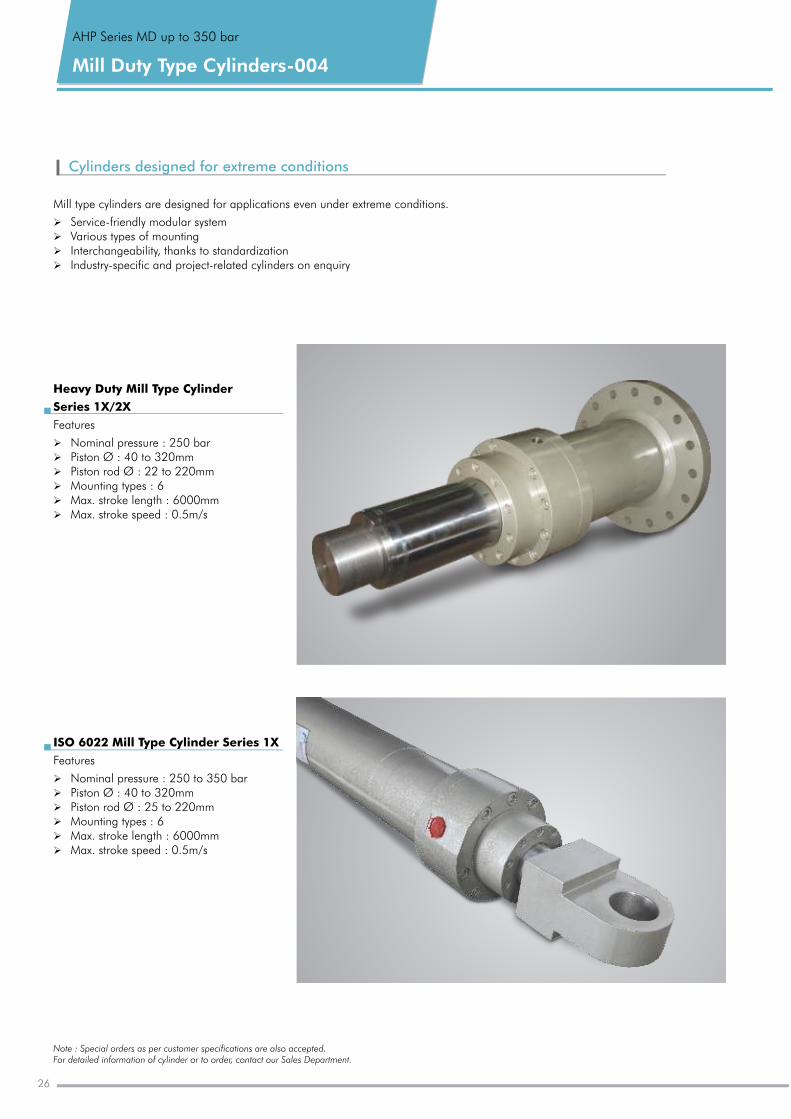
Mill type cylinders are designed for applications even under extreme conditions.
Ø Service-friendly modular systemØ Various types of mountingØ Interchangeability, thanks to standardizationØ Industry-specific and project-related cylinders on enquiry
Heavy Duty Mill Type Cylinder
Series 1X/2X
Features
Ø Nominal pressure : 250 barØ Piston : 40 to 320mmØ Piston rod Ø : 22 to 220mmØ Mounting types : 6Ø Max. stroke length : 6000mmØ Max. stroke speed : 0.5m/s
Ø
ISO 6022 Mill Type Cylinder Series 1X
Features
Ø Nominal pressure : 250 to 350 barØ Piston : 40 to 320mmØ Piston rod Ø : 25 to 220mmØ Mounting types : 6 Ø Max. stroke length : 6000mmØ Max. stroke speed : 0.5m/s
Ø
AHP Series MD up to 350 bar
26
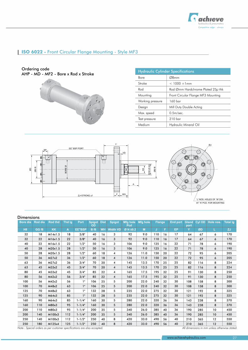
ISO 6022 - Front Circular Flange Mounting - Style MF3
Ordering codeAHP - MD - MF2 - Bore x Rod x Stroke
Hydraulic Cylinder Specifications
Bore
Stroke
Rod
Mounting
Working pressure
Design
Max. speed
Test pressure
Medium
ØBmm
< 1000 ±1mm
Rod Ømm Hardchrome Plated 25µ thk
Front Circular Flange MF3 Mounting
160 bar
Mill Duty Double Acting
0.5m/sec.
210 bar
Hydraulic Mineral Oil
Dimensions
H8 GG f8 KK A EE"BSP B f8 WH M YEP ZJØDWidth VD
18
22
22
28
28
36
36
45
45
56
56
70
70
90
90
110
110
140
140
180
18
22
22
28
28
36
36
45
45
56
56
63
63
85
85
95
95
112
112
125
M14x1.5
M16x1.5
M16x1.5
M20x1.5
M20x1.5
M27x2
M27x2
M33x2
M33x2
M42x2
M42x2
M48x2
M48x2
M64x3
M64x3
M80x3
M80x3
M100x3
M100x3
M125x4
3/8"
3/8"
1/2"
1/2"
1/2"
1/2"
3/4"
3/4"
3/4"
3/4"
1"
1"
1"
1"
1-1/4"
1-1/4"
1-1/4"
1-1/4"
1-1/2"
1-1/2"
40
40
50
50
60
60
70
70
85
85
106
106
132
132
160
160
200
200
250
250
16
16
16
16
18
18
20
20
22
22
25
25
28
28
30
30
35
35
40
40
3
3
3
3
4
4
4
4
4
4
5
5
5
5
5
5
5
5
8
8
9
9
9
9
11
11
13.5
13.5
17.5
17.5
22
22
22
22
22
22
26
26
33
33
.0
.0
.0
.0
.0
.0
.0
.0
.0
.0
.0
.0
.0
.0
.0
.0
110
110
125
125
150
150
170
170
195
195
240
240
275
275
320
320
385
385
490
490
17
17
22
22
22
22
25
25
25
25
30
30
30
30
36
36
36
36
40
40
16
16
16
16
20
20
25
25
32
32
32
32
32
32
36
36
40
40
56
56
64
64
71
71
72
72
82
82
91
91
108
108
121
121
143
143
190
190
210
210
67
67
78
78
95
95
116
116
130
130
158
158
192
192
238
238
285
285
365
365
170
170
190
190
205
205
224
224
250
250
300
300
325
325
370
370
450
450
550
550
32
32
40
40
50
50
63
63
80
80
100
100
125
125
160
160
200
200
250
250
Bore dia Rod dia Rod thd Thd lg Port Spigot OD
Dist Spigot End port Gland port
Cyl OD Total lg Hole nos. Mfg hole Pcd
Mfg hole Flange
Ø N ±0.2 J F L
92
92
106
106
126
126
145
145
165
165
200
200
235
235
280
280
340
340
420
420
6
6
6
6
6
6
8
8
8
8
8
8
8
8
8
8
10
10
12
12
Note : Special orders as per customer specifications are also accepted. All dimensions in mm unless otherwise stated.
ØD
ØB
f8
EPEE" BSP PORT
Y
VD
WHZJ+STROKE ±1
ØB
f8
KK
RO
D Ø
GG
A
F
ØJ
`L' NOS. HOLES OF `M' DIA
AT `N' PCD. FOR MOUNTING
BO
RE
Ø
27www.achievehydraulics.com
hydraulics & pneumatics
Competitive edge - always
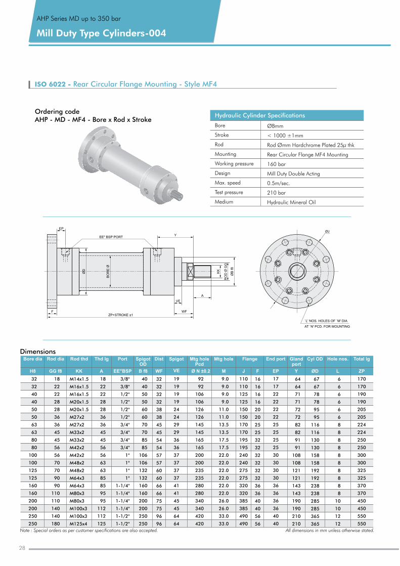
ISO 6022 - Rear Circular Flange Mounting - Style MF4
Hydraulic Cylinder Specifications
Bore
Stroke
Rod
Mounting
Working pressure
Design
Max. speed
Test pressure
Medium
ØBmm
< 1000 ±1mm
Rod Ømm Hardchrome Plated 25µ thk
Rear Circular Flange MF4 Mounting
160 bar
Mill Duty Double Acting
0.5m/sec.
210 bar
Hydraulic Mineral Oil
ZP+STROKE ±1F
ØB
f8
KK
RO
D Ø
GG
ØJ
`L' NOS. HOLES OF `M' DIA
AT `N' PCD. FOR MOUNTING
Y
WF
A
VE
ØD
EP
BO
RE
Ø
EE" BSP PORT
Ordering codeAHP - MD - MF4 - Bore x Rod x Stroke
Dimensions
H8 GG f8 KK A EE"BSP B f8 WF M YEP ZPØDVE
18
22
22
28
28
36
36
45
45
56
56
70
70
90
90
110
110
140
140
180
18
22
22
28
28
36
36
45
45
56
56
63
63
85
85
95
95
112
112
125
M14x1.5
M16x1.5
M16x1.5
M20x1.5
M20x1.5
M27x2
M27x2
M33x2
M33x2
M42x2
M42x2
M48x2
M48x2
M64x3
M64x3
M80x3
M80x3
M100x3
M100x3
M125x4
3/8"
3/8"
1/2"
1/2"
1/2"
1/2"
3/4"
3/4"
3/4"
3/4"
1"
1"
1"
1"
1-1/4"
1-1/4"
1-1/4"
1-1/4"
1-1/2"
1-1/2"
40
40
50
50
60
60
70
70
85
85
106
106
132
132
160
160
200
200
250
250
32
32
32
32
38
38
45
45
54
54
57
57
60
60
66
66
75
75
96
96
19
19
19
19
24
24
29
29
36
36
37
37
37
37
41
41
45
45
64
64
9
9
9
9
11
11
13.5
13.5
17.5
17.5
22
22
22
22
22
22
26
26
33
33
.0
.0
.0
.0
.0
.0
.0
.0
.0
.0
.0
.0
.0
.0
.0
.0
110
110
125
125
150
150
170
170
195
195
240
240
275
275
320
320
385
385
490
490
17
17
22
22
22
22
25
25
25
25
30
30
30
30
36
36
36
36
40
40
16
16
16
16
20
20
25
25
32
32
32
32
32
32
36
36
40
40
56
56
64
64
71
71
72
72
82
82
91
91
108
108
121
121
143
143
190
190
210
210
67
67
78
78
95
95
116
116
130
130
158
158
192
192
238
238
285
285
365
365
170
170
190
190
205
205
224
224
250
250
300
300
325
325
370
370
450
450
550
550
32
32
40
40
50
50
63
63
80
80
100
100
125
125
160
160
200
200
250
250
Bore dia Rod dia Rod thd Thd lg Port Spigot OD
Dist Spigot End port Gland port
Cyl OD Total lg Hole nos. Mtg hole Pcd
Mtg hole Flange
Ø N ±0.2 J F L
92
92
106
106
126
126
145
145
165
165
200
200
235
235
280
280
340
340
420
420
6
6
6
6
6
6
8
8
8
8
8
8
8
8
8
8
10
10
12
12
Note : Special orders as per customer specifications are also accepted. All dimensions in mm unless otherwise stated.
Mill Type Cylinders-004Duty
AHP Series MD up to 350 bar
28
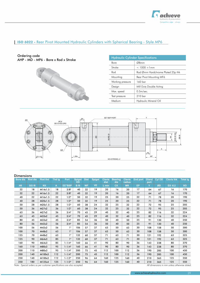
ISO 6022 - Rear Pivot Mounted Hydraulic Cylinders with Spherical Bearing - Style MP6
Ordering codeAHP - MD - MP6 - Bore x Rod x Stroke
Hydraulic Cylinder Specifications
Bore
Stroke
Rod
Mounting
Working pressure
Design
Max. speed
Test pressure
Medium
ØBmm
< 1000 ±1mm
Rod Ømm Hardchrome Plated 25µ thk
Rear Pivot Mounting MF6
160 bar
Mill Duty Double Acting
0.5m/sec.
210 bar
Hydraulic Mineral Oil
H8 XO
170
170
190
190
205
205
224
224
250
250
300
300
325
325
370
370
450
450
550
550
32
32
40
40
50
50
63
63
80
80
100
100
125
125
160
160
200
200
250
250
Bore dia Total lg Rod dia Rod thd Thd lg Port SpigotOD
Dist Spigot End port Gland port
Cyl OD Clevis thkClevis dist
Bearing dia
Clevis radius
GG f8 KK A EE"BSP B f8 WF CX YEP ØDVE
18
22
22
28
28
36
36
45
45
56
56
70
70
90
90
110
110
140
140
180
18
22
22
28
28
36
36
45
45
56
56
63
63
85
85
95
95
112
112
125
M14x1.5
M16x1.5
M16x1.5
M20x1.5
M20x1.5
M27x2
M27x2
M33x2
M33x2
M42x2
M42x2
M48x2
M48x2
M64x3
M64x3
M80x3
M80x3
M100x3
M100x3
M125x4
3/8"
3/8"
1/2"
1/2"
1/2"
1/2"
3/4"
3/4"
3/4"
3/4"
1"
1"
1"
1"
1-1/2"
1-1/4"
1-1/4"
1-1/4"
1-1/4"
1-1/2"
40
40
50
50
60
60
70
70
85
85
106
106
132
132
160
160
200
200
250
250
32
32
32
32
38
38
45
45
54
54
57
57
60
60
66
66
75
75
96
96
19
19
19
19
24
24
29
29
36
36
37
37
37
37
41
41
45
45
64
64
16
16
20
20
25
25
32
32
40
40
50
50
63
63
80
80
100
100
125
125
16
16
20
20
25
25
32
32
40
40
50
50
63
63
80
80
100
100
125
125
17
17
22
22
22
22
25
25
25
25
30
30
30
30
36
36
36
36
40
40
20
20
25
25
32
32
40
40
50
50
63
63
71
71
90
90
112
112
160
160
64
64
71
71
72
72
82
82
91
91
108
108
121
121
143
143
190
190
210
210
67
67
78
78
95
95
116
116
130
130
158
158
192
192
238
238
285
285
365
365
L min MR EX -0.2
20
20
25
25
32
32
40
40
50
50
63
63
71
71
90
90
112
112
160
160
Dimensions
Note : Special orders as per customer specifications are also accepted. All dimensions in mm unless otherwise stated.
EP
BO
RE
Ø
EE" BSP PORT
WF
XO+STROKE ±1
ØB
f8
KK
RO
D Ø
GG
A
ØD
VE
Y
L Min
MR
ØCXGE-CX-ES-2RS
EX -0.2
ØD
29www.achievehydraulics.com
hydraulics & pneumatics
Competitive edge - always
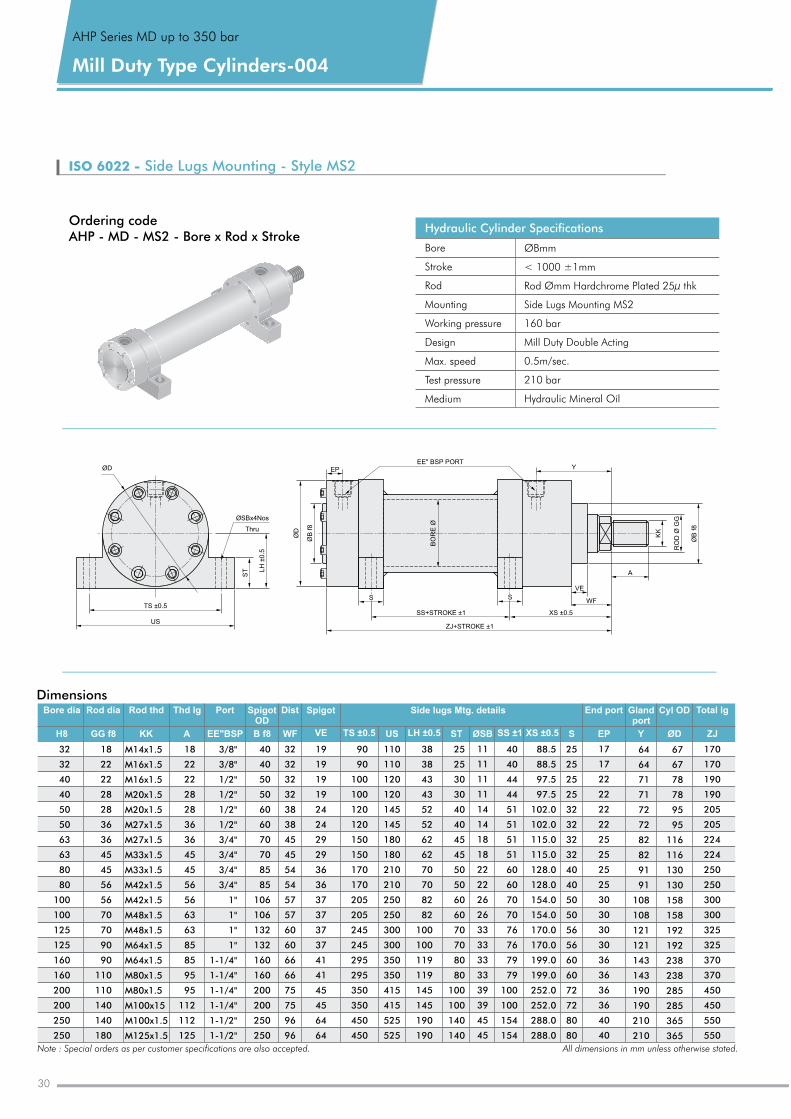
ISO 6022 - Side Lugs Mounting - Style MS2
Hydraulic Cylinder Specifications
Bore
Stroke
Rod
Mounting
Working pressure
Design
Max. speed
Test pressure
Medium
ØBmm
< 1000 ±1mm
Rod Ømm Hardchrome Plated 25µ thk
Side Lugs Mounting MS2
160 bar
Mill Duty Double Acting
0.5m/sec.
210 bar
Hydraulic Mineral Oil
Ordering codeAHP - MD - MS2 - Bore x Rod x Stroke
XS ±0.5
BO
RE
Ø
S
ØD
ØSBx4Nos
Thru
LH
±0.5
TS ±0.5
US
ØD
ØB
f8
EPEE" BSP PORT
Y
S
VE
WF
A
SS+ 1STROKE ±
ZJ+STROKE ±1
KK
RO
D Ø
GG
ØB
f8
ST
Dimensions
H8 GG f8 KK A EE"BSP B f8 WF US S YEP ZJØDVE LH ±0.5 XS ±0.5SS ±1
18
22
22
28
28
36
36
45
45
56
56
70
70
90
90
110
110
140
140
180
18
22
22
28
28
36
36
45
45
56
56
63
63
85
85
95
95
112
112
125
M14x1.5
M16x1.5
M16x1.5
M20x1.5
M20x1.5
M27x1.5
M27x1.5
M33x1.5
M33x1.5
M42x1.5
M42x1.5
M48x1.5
M48x1.5
M64x1.5
M64x1.5
M80x1.5
M80x1.5
M100x15
M100x1.5
M125x1.5
3/8"
3/8"
1/2"
1/2"
1/2"
1/2"
3/4"
3/4"
3/4"
3/4"
1"
1"
1"
1"
1-1/4"
1-1/4"
1-1/4"
1-1/4"
1-1/2"
1-1/2"
40
40
50
50
60
60
70
70
85
85
106
106
132
132
160
160
200
200
250
250
32
32
32
32
38
38
45
45
54
54
57
57
60
60
66
66
75
75
96
96
19
19
19
19
24
24
29
29
36
36
37
37
37
37
41
41
45
45
64
64
90
90
100
100
120
120
150
150
170
170
205
205
245
245
295
295
350
350
450
450
110
110
120
120
145
145
180
180
210
210
250
250
300
300
350
350
415
415
525
525
38
38
43
43
52
52
62
62
70
70
82
82
100
100
119
119
145
145
190
190
ST
25
25
30
30
40
40
45
45
50
50
60
60
70
70
80
80
100
100
140
140
ØSB
11
11
11
11
14
14
18
18
22
22
26
26
33
33
33
33
39
39
45
45
40
40
44
44
51
51
51
51
60
60
70
70
76
76
79
79
100
100
154
154
88.5
88.5
97.5
97.5
102
102
115
115
128
128
154
154
170
170
199
199
252
252
288
288
.0
.0
.0
.0
.0
.0
.0
.0
.0
.0
.0
.0
.0
.0
.0
.0
25
25
25
25
32
32
32
32
40
40
50
50
56
56
60
60
72
72
80
80
17
17
22
22
22
22
25
25
25
25
30
30
30
30
36
36
36
36
40
40
64
64
71
71
72
72
82
82
91
91
108
108
121
121
143
143
190
190
210
210
67
67
78
78
95
95
116
116
130
130
158
158
192
192
238
238
285
285
365
365
170
170
190
190
205
205
224
224
250
250
300
300
325
325
370
370
450
450
550
550
Rod dia Rod thd Thd lg Port Spigot OD
Dist Spigot Side lugs Mtg. details End port Gland port
Cyl OD Total lg Bore dia
32
32
40
40
50
50
63
63
80
80
100
100
125
125
160
160
200
200
250
250
TS ±0.5
Note : Special orders as per customer specifications are also accepted. All dimensions in mm unless otherwise stated.
Mill Type Cylinders-004Duty
AHP Series MD up to 350 bar
30
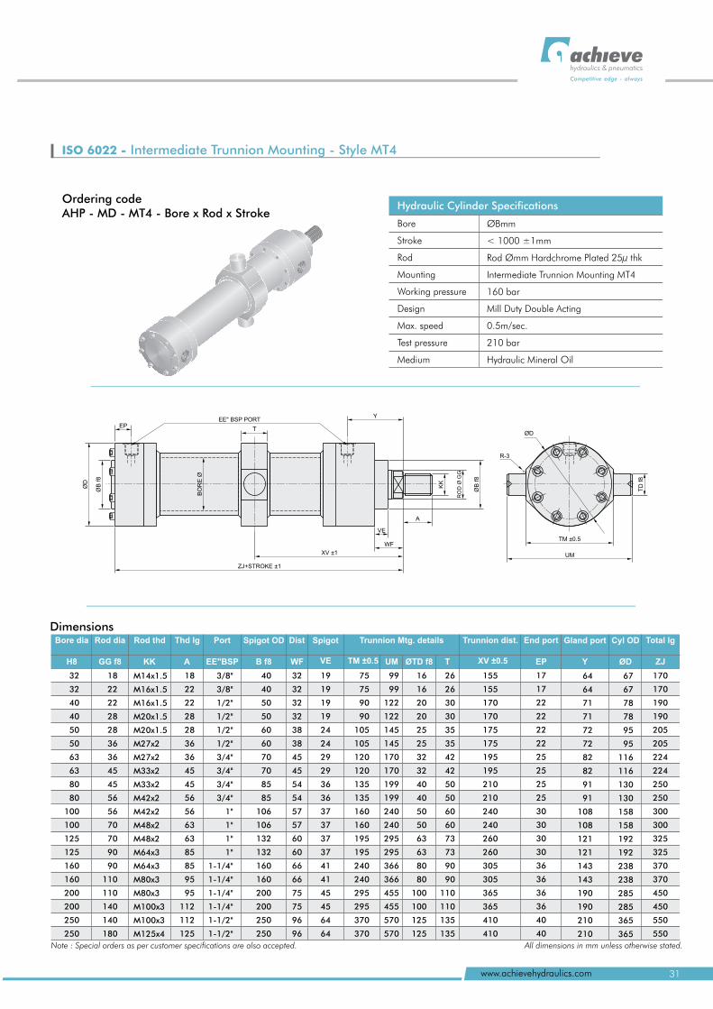
Hydraulic Cylinder Specifications
Bore
Stroke
Rod
Mounting
Working pressure
Design
Max. speed
Test pressure
Medium
ØBmm
< 1000 ±1mm
Rod Ømm Hardchrome Plated 25µ thk
Intermediate Trunnion Mounting MT4
160 bar
Mill Duty Double Acting
0.5m/sec.
210 bar
Hydraulic Mineral Oil
ISO 6022 - Intermediate Trunnion Mounting - Style MT4
Ordering codeAHP - MD - MT4 - Bore x Rod x Stroke
hydraulics & pneumatics
Competitive edge - always
31www.achievehydraulics.com
T
A
ØD
ØD
ØB
f8
EP
BO
RE
Ø
EE" BSP PORTY
VE
WF
XV ±1
ZJ+STROKE ±1
KK
RO
D Ø
GG
ØB
f8
R-3
TM ±0.5
UM
TD
f8
Dimensions
H8 GG f8 KK A B f8 WF UM YEP ZJØDVE
18
22
22
28
28
36
36
45
45
56
56
70
70
90
90
110
110
140
140
180
18
22
22
28
28
36
36
45
45
56
56
63
63
85
85
95
95
112
112
125
3/8"
3/8"
1/2"
1/2"
1/2"
1/2"
3/4"
3/4"
3/4"
3/4"
1"
1"
1"
1"
1-1/4"
1-1/4"
1-1/4"
1-1/4"
1-1/2"
1-1/2"
40
40
50
50
60
60
70
70
85
85
106
106
132
132
160
160
200
200
250
250
32
32
32
32
38
38
45
45
54
54
57
57
60
60
66
66
75
75
96
96
19
19
19
19
24
24
29
29
36
36
37
37
37
37
41
41
45
45
64
64
75
75
90
90
105
105
120
120
135
135
160
160
195
195
240
240
295
295
370
370
16
16
20
20
25
25
32
32
40
40
50
50
63
63
80
80
100
100
125
125
T
26
26
30
30
35
35
42
42
50
50
60
60
73
73
90
90
110
110
135
135
17
17
22
22
22
22
25
25
25
25
30
30
30
30
36
36
36
36
40
40
64
64
71
71
72
72
82
82
91
91
108
108
121
121
143
143
190
190
210
210
67
67
78
78
95
95
116
116
130
130
158
158
192
192
238
238
285
285
365
365
170
170
190
190
205
205
224
224
250
250
300
300
325
325
370
370
450
450
550
550
EE"BSP TM ±0.5 ØTD f8
M14x1.5
M16x1.5
M16x1.5
M20x1.5
M20x1.5
M27x2
M27x2
M33x2
M33x2
M42x2
M42x2
M48x2
M48x2
M64x3
M64x3
M80x3
M80x3
M100x3
M100x3
M125x4
99
99
122
122
145
145
170
170
199
199
240
240
295
295
366
366
455
455
570
570
32
32
40
40
50
50
63
63
80
80
100
100
125
125
160
160
200
200
250
250
Rod thd Port Trunnion Mtg. details End port Gland port Cyl OD Total lg Rod dia Thd lg Spigot OD Dist SpigotBore dia Trunnion dist.
155
155
170
170
175
175
195
195
210
210
240
240
260
260
305
305
365
365
410
410
XV ±0.5
Note : Special orders as per customer specifications are also accepted. All dimensions in mm unless otherwise stated.
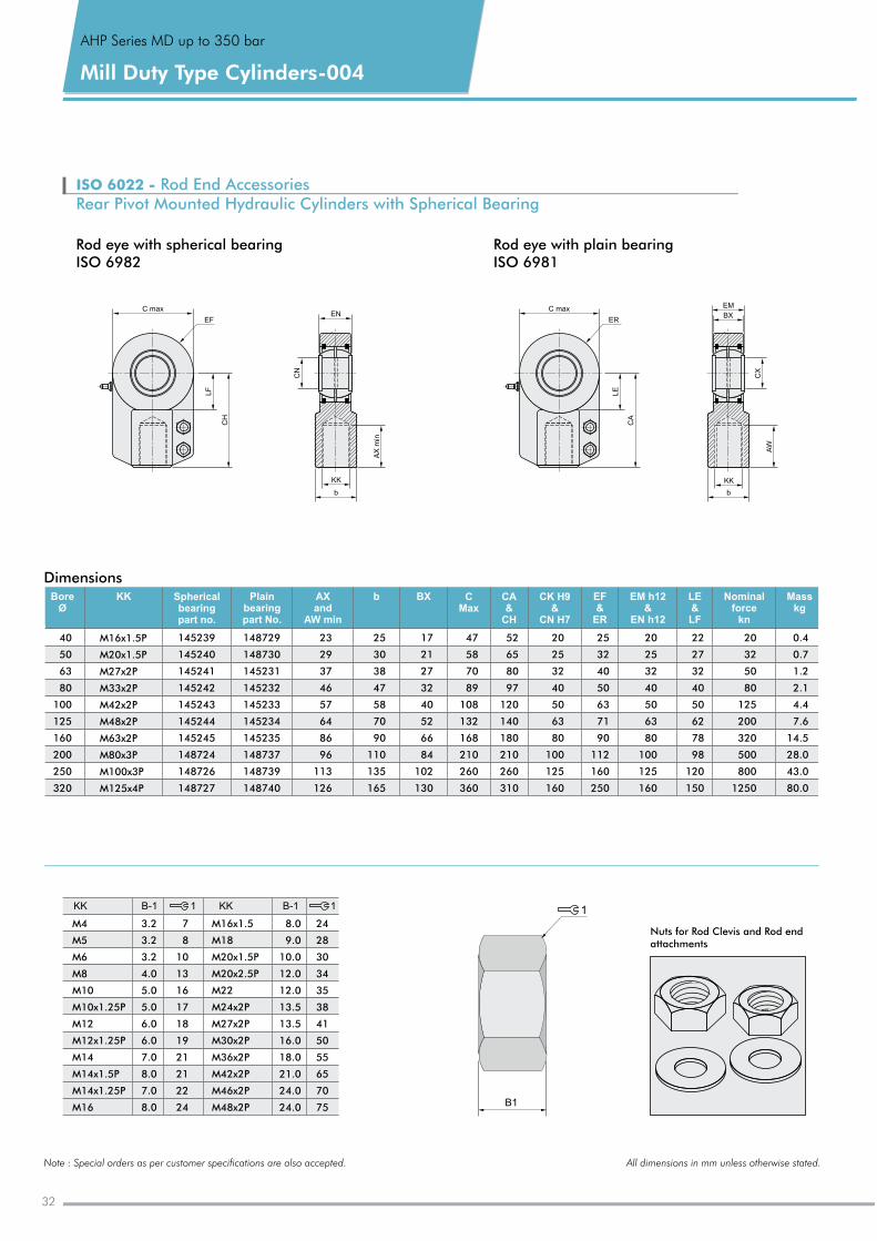
ISO 6022 - Rod End AccessoriesRear Pivot Mounted Hydraulic Cylinders with Spherical Bearing
C max C max
EF
LF
CH
ER
LE
CA
CN
EN
KK
b
AX
min
EM
BX
CX
KK
b
AW
1
B1
Nuts for Rod Clevis and Rod end attachments
Rod eye with spherical bearingISO 6982
Rod eye with plain bearingISO 6981
M4
M5
M6
M8
M10
M10x1.25P
M12
M12x1.25P
M14
M14x1.5P
M14x1.25P
M16
3.2
3.2
3.2
4.0
5
5
6
6
7
8
7
8
.0
.0
.0
.0
.0
.0
.0
.0
M16x1.5
M18
M20x1.5P
M20x2.5P
M22
M24x2P
M27x2P
M30x2P
M36x2P
M42x2P
M46x2P
M48x2P
8
9
10
12
12
13.5
13.5
16
18
21
24
24
.0
.0
.0
.0
.0
.0
.0
.0
.0
.0
7
8
10
13
16
17
18
19
21
21
22
24
24
28
30
34
35
38
41
50
55
65
70
75
KK 1B-1 KK B-1 1
Note : Special orders as per customer specifications are also accepted. All dimensions in mm unless otherwise stated.
145239
145240
145241
145242
145243
145244
145245
148724
148726
148727
17
21
27
32
40
52
66
84
102
130
47
58
70
89
108
132
168
210
260
360
52
65
80
97
120
140
180
210
260
310
40
50
63
80
100
125
160
200
250
320
M16x1.5P
M20x1.5P
M27x2P
M33x2P
M42x2P
M48x2P
M63x2P
M80x3P
M100x3P
M125x4P
BoreØ
KK Spherical bearingpart no.
Plainbearingpart No.
AXand
AW min
b BX CMax
CA&
CH
CK H9&
CN H7
EF&
ER
EM h12&
EN h12
LE&LF
Nominalforce
kn
Masskg
148729
148730
145231
145232
145233
145234
145235
148737
148739
148740
23
29
37
46
57
64
86
96
113
126
25
30
38
47
58
70
90
110
135
165
20
25
32
40
50
63
80
100
125
160
25
32
40
50
63
71
90
112
160
250
20
25
32
40
50
63
80
100
125
160
22
27
32
40
50
62
78
98
120
150
20
32
50
80
125
200
320
500
800
1250
0.4
0.7
1.2
2.1
4.4
7.6
14.5
28
43
80
.0
.0
.0
Dimensions
Mill Type Cylinders-004Duty
AHP Series MD up to 350 bar
32
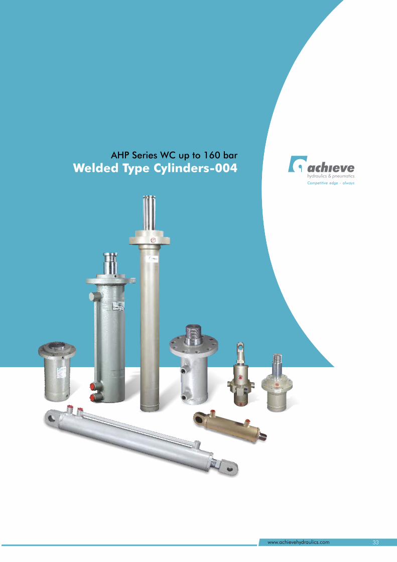
AHP Series WC up to 160 bar
Welded Type Cylinders-004hydraulics & pneumatics
Competitive edge - always
33www.achievehydraulics.com
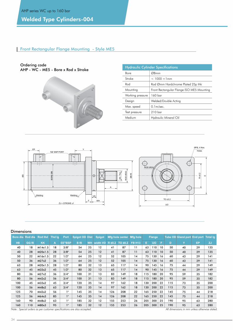
Front Rectangular Flange Mounting - Style ME5
Ordering codeAHP - WC - ME5 - Bore x Rod x Stroke
A
EP
ØD
'EE' BSP PORT
Y
VD
WH
KK
- T
hd
RO
D Ø
GG
ØB
f8
ZJ + STROKE ±1
F
WeldingWelding
R ±
0.2
E
TO ±0.2
UO
ØFB, 4 Nos.
Holes
BO
RE
ØB
ROD ØGG
Dimensions
18
28
22
36
28
45
36
56
45
56
70
56
90
110
18
28
22
36
28
45
36
56
45
63
56
85
63
95
3/8"
3/8"
1/2"
1/2"
1/2"
1/2"
3/4"
3/4"
3/4"
3/4"
1"
1"
1"
1"
54
54
64
64
80
80
100
100
120
120
145
145
185
185
25
25
25
25
32
32
31
31
35
35
35
35
32
32
12
12
12
12
13
13
13
13
14
14
14
14
12
12
41
41
52
52
65
65
83
83
97
97
126
126
155
155
87
87
105
105
117
117
149
149
162
162
208
208
253
253
11
11
14
14
14
14
18
18
18
18
22
22
26
26
50
50
60
60
75
75
95
95
115
115
145
145
190
190
40
40
43
43
44
44
59
59
73
73
75
75
95
95
29
29
29
29
29
29
35
35
35
35
44
44
63
63
135
135
141
141
149
149
182
182
200
200
218
218
280
280
40
40
50
50
63
63
80
80
100
100
125
125
160
160
110
110
130
130
145
145
180
180
200
200
250
250
300
300
10
10
16
16
16
16
20
20
22
22
22
22
25
25
63
63
75
75
90
90
115
115
130
130
165
165
205
205
M14x1.5
M20x1.5
M16x1.5
M27x2
M20x1.5
M33x2
M27x2
M42x2
M33x2
M48x2
M42x2
M64x3
M48x2
M80x3
Rod thd Mfg hole center Flange Tube OD Gland port End port Total lg Port SpigotRod dia Thd lg Spigot OD DistBore dia Mfg hole
KK UOE F D Y EP ZJEE"BSP width VD R ±0.2 TO ±0.2GG f8 A B f8 WHH8 FB H13
Note : Special orders as per customer specifications are also accepted. All dimensions in mm unless otherwise stated.
AHP series WC up to 160 bar
Welded Type Cylinders-004
Hydraulic Cylinder Specifications
Bore
Stroke
Rod
Mounting
Working pressure
Design
Max. speed
Test pressure
Medium
ØBmm
< 1000 ±1mm
Rod Ømm Hardchrome Plated 25µ thk
Front Rectangular Flange ISO ME5 Mounting
160 bar
Welded/Double Acting
0.1m/sec.
210 bar
Hydraulic Mineral Oil
34
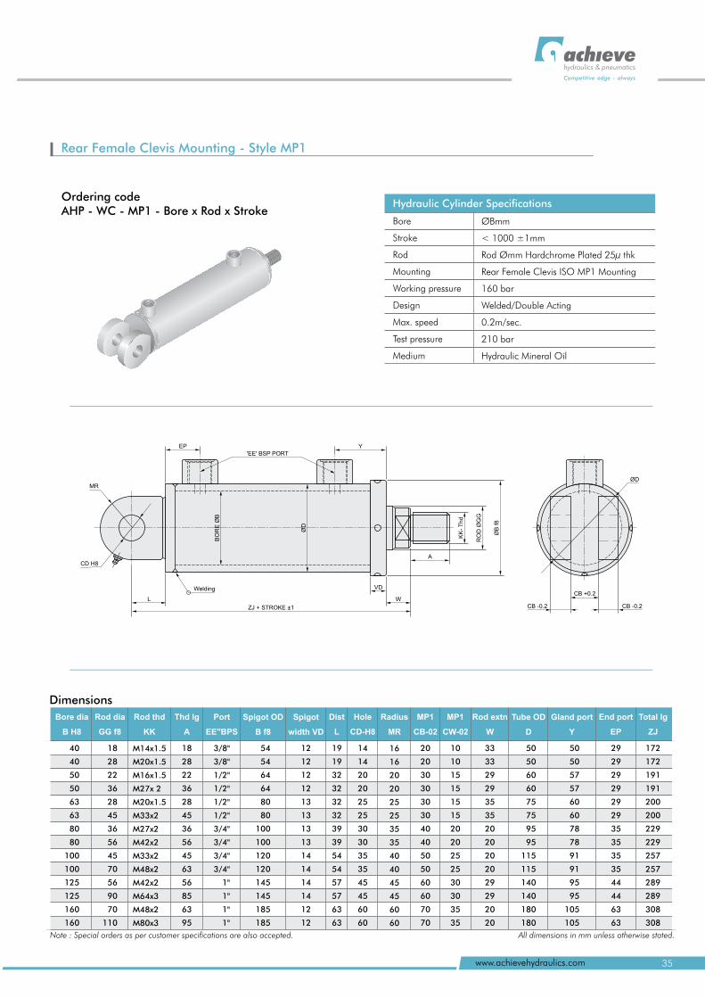
Rear Female Clevis Mounting - Style MP1
Ordering codeAHP - WC - MP1 - Bore x Rod x Stroke
Hydraulic Cylinder Specifications
Bore
Stroke
Rod
Mounting
Working pressure
Design
Max. speed
Test pressure
Medium
ØBmm
< 1000 ±1mm
Rod Ømm Hardchrome Plated 25µ thk
Rear Female Clevis ISO MP1 Mounting
160 bar
Welded/Double Acting
0.2m/sec.
210 bar
Hydraulic Mineral Oil
Dimensions
40
40
50
50
63
63
80
80
100
100
125
125
160
160
19
19
32
32
32
32
39
39
54
54
57
57
63
63
14
14
20
20
25
25
30
30
35
35
45
45
60
60
18
28
22
36
28
45
36
56
45
63
56
85
63
95
3/8"
3/8"
1/2"
1/2"
1/2"
1/2"
3/4"
3/4"
3/4"
3/4"
1"
1"
1"
1"
54
54
64
64
80
80
100
100
120
120
145
145
185
185
12
12
12
12
13
13
13
13
14
14
14
14
12
12
16
16
20
20
25
25
35
35
40
40
45
45
60
60
20
20
30
30
30
30
40
40
50
50
60
60
70
70
10
10
15
15
15
15
20
20
25
25
30
30
35
35
33
33
29
29
35
35
20
20
20
20
29
29
20
20
50
50
60
60
75
75
95
95
115
115
140
140
180
180
50
50
57
57
60
60
78
78
91
91
95
95
105
105
29
29
29
29
29
29
35
35
35
35
44
44
63
63
172
172
191
191
200
200
229
229
257
257
289
289
308
308
18
28
22
36
28
45
36
56
45
70
56
90
70
110
M14x1.5
M20x1.5
M16x1.5
M27x 2
M20x1.5
M33x2
M27x2
M42x2
M33x2
M48x2
M42x2
M64x3
M48x2
M80x3
Total lg
ZJ
Rod thd
KK
Tube OD
D
Gland port
Y
End port
EP
Bore dia
B H8
Rod dia
GG f8
Thd lg
A
Port
EE"BPS
Spigot OD
B f8
Dist
L
Hole
CD-H8
Radius
MR
MP1
CB-02
MP1
CW-02
Rod extn
W
Spigot
width VD
Note : Special orders as per customer specifications are also accepted. All dimensions in mm unless otherwise stated.
'EE' BSP PORTY
BO
RE
ØB
ØD
ZJ + STROKE ±1
L
VD
W
A
MR
CD H8
EP
Welding
RO
D Ø
GG
ØB
f8
KK
- T
hd
CB +0.2
CB -0.2CB -0.2
ØD
35www.achievehydraulics.com
hydraulics & pneumatics
Competitive edge - always
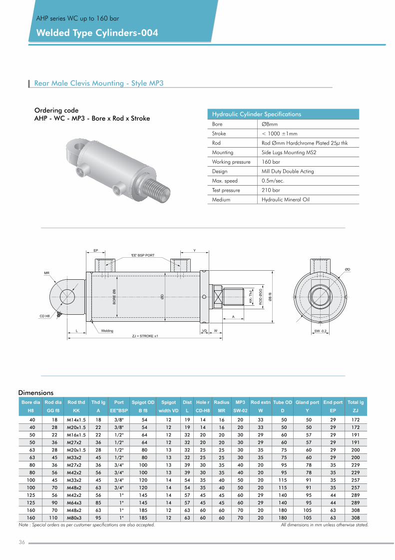
Rear Male Clevis Mounting - Style MP3
Hydraulic Cylinder Specifications
Bore
Stroke
Rod
Mounting
Working pressure
Design
Max. speed
Test pressure
Medium
ØBmm
< 1000 ±1mm
Rod Ømm Hardchrome Plated 25µ thk
Side Lugs Mounting MS2
160 bar
Mill Duty Double Acting
0.5m/sec.
210 bar
Hydraulic Mineral Oil
Ordering codeAHP - WC - MP3 - Bore x Rod x Stroke
Dimensions
40
40
50
50
63
63
80
80
100
100
125
125
160
160
18
28
22
36
28
45
36
56
45
70
56
90
70
110
18
22
22
36
28
45
36
56
45
63
56
85
63
95
M14x1.5
M20x1.5
M16x1.5
M27x2
M20x1.5
M33x2
M27x2
M42x2
M33x2
M48x2
M42x2
M64x3
M48x2
M80x3
3/8"
3/8"
1/2"
1/2"
1/2"
1/2"
3/4"
3/4"
3/4"
3/4"
1"
1"
1"
1"
54
54
64
64
80
80
100
100
120
120
145
145
185
185
12
12
12
12
13
13
13
13
14
14
14
14
12
12
172
172
191
191
200
200
229
229
257
257
289
289
308
308
19
19
32
32
32
32
39
39
54
54
57
57
63
63
14
14
20
20
25
25
30
30
35
35
45
45
60
60
16
16
20
20
25
25
35
35
40
40
45
45
60
60
20
20
30
30
30
30
40
40
50
50
60
60
70
70
33
33
29
29
35
35
20
20
20
20
29
29
20
20
50
50
57
57
60
60
78
78
91
91
95
95
105
105
50
50
60
60
75
75
95
95
115
115
140
140
180
180
29
29
29
29
29
29
35
35
35
35
44
44
63
63
Bore dia
H8
Rod dia
GG f8
Rod thd
KK
Thd lg
A
Port
EE"BSP
Spigot OD
B f8
Dist
L
Spigot
width VD
End port
EP
Gland port
Y
Total lg
ZJ
Hole r
CD-H8
Radius
MR
MP3
SW-02
Rod extn
W
Tube OD
D
Note : Special orders as per customer specifications are also accepted. All dimensions in mm unless otherwise stated.
ØD
SW -0.2
AHP series WC up to bar160
Welded Type Cylinders-004
MR
CD H8
L Welding
EP
'EE' BSP PORT
Y
VD W
A
KK
- T
hd
RO
D Ø
GG
ØB
f8
_ZJ + STROKE +1
BO
RE
ØB
ØD
36
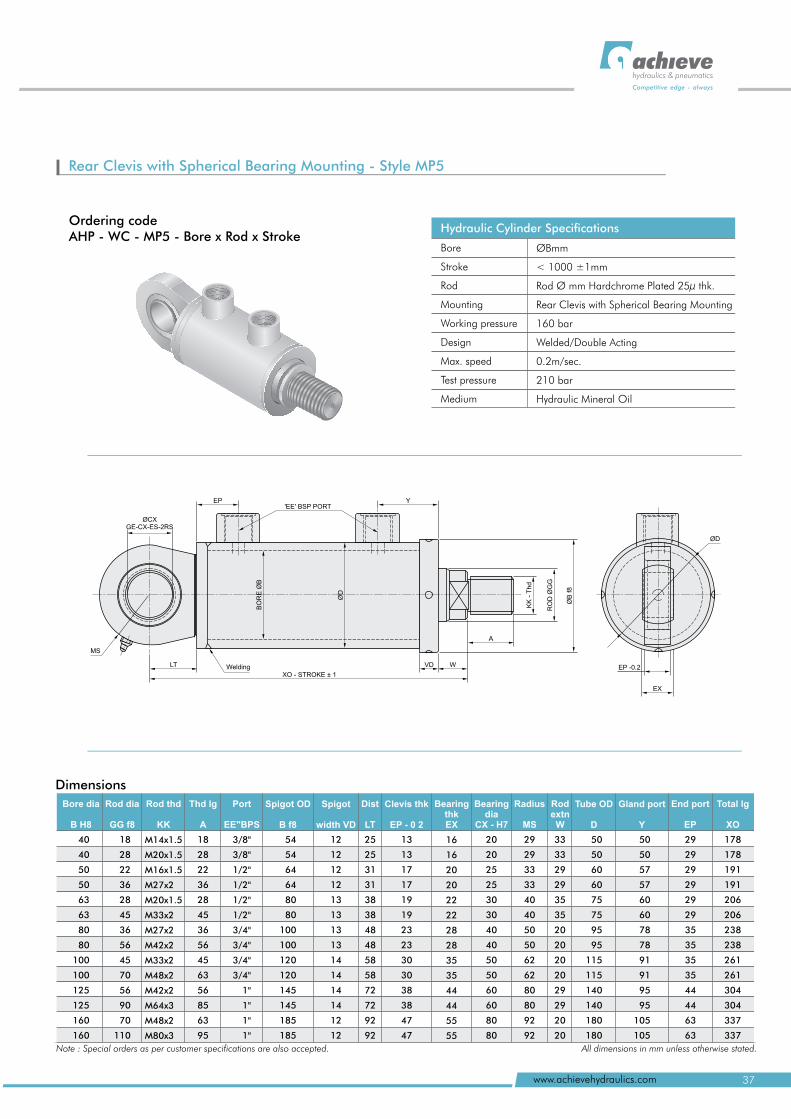
Ordering codeAHP - WC - MP5 - Bore x Rod x Stroke
Rear Clevis with Spherical Bearing MP5Mounting - Style
Hydraulic Cylinder Specifications
Bore
Stroke
Rod
Mounting
Working pressure
Design
Max. speed
Test pressure
Medium
ØBmm
< 1000 ±1mm
Rod Ø mm Hardchrome Plated 25µ thk.
Rear Clevis with Spherical Bearing Mounting
160 bar
Welded/Double Acting
0.2m/sec.
210 bar
Hydraulic Mineral Oil
40
40
50
50
63
63
80
80
100
100
125
125
160
160
18
28
22
36
28
45
36
56
45
70
56
90
70
110
M14x1.5
M20x1.5
M16x1.5
M27x2
M20x1.5
M33x2
M27x2
M42x2
M33x2
M48x2
M42x2
M64x3
M48x2
M80x3
18
28
22
36
28
45
36
56
45
63
56
85
63
95
3/8"
3/8"
1/2"
1/2"
1/2"
1/2"
3/4"
3/4"
3/4"
3/4"
1"
1"
1"
1"
54
54
64
64
80
80
100
100
120
120
145
145
185
185
12
12
12
12
13
13
13
13
14
14
14
14
12
12
25
25
31
31
38
38
48
48
58
58
72
72
92
92
13
13
17
17
19
19
23
23
30
30
38
38
47
47
16
16
20
20
22
22
28
28
35
35
44
44
55
55
20
20
25
25
30
30
40
40
50
50
60
60
80
80
29
29
33
33
40
40
50
50
62
62
80
80
92
92
33
33
29
29
35
35
20
20
20
20
29
29
20
20
50
50
60
60
75
75
95
95
115
115
140
140
180
180
50
50
57
57
60
60
78
78
91
91
95
95
105
105
29
29
29
29
29
29
35
35
35
35
44
44
63
63
178
178
191
191
206
206
238
238
261
261
304
304
337
337
Bore dia
B H8
Rod dia
GG f8
Rod thd
KK
Thd lg
A
Port
EE"BPS
Spigot OD
B f8
Dist
LT
Clevis thk
EP - 0 2
BearingthkEX
Bearingdia
CX - H7
Radius
MS
Spigot
width VD
Total lg
XO
Rod extn
W
Tube OD
D
Gland port
Y
End port
EP
Note : Special orders as per customer specifications are also accepted. All dimensions in mm unless otherwise stated.
ØCXGE-CX-ES-2RS
EP'EE' BSP PORT
Y
ØD
BO
RE
ØB
MS
LT WeldingXO - STROKE ± 1
VD W
A
KK
- T
hd
RO
D
GG
Ø
ØB
f8
EX
EP -0.2
ØD
37www.achievehydraulics.com
hydraulics & pneumatics
Competitive edge - always
Dimensions
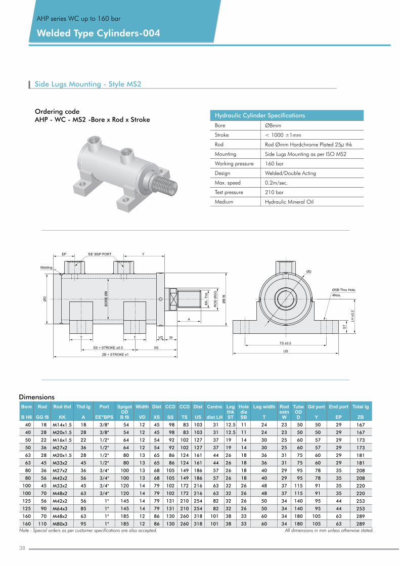
Side Lugs Mounting - Style MS2
Hydraulic Cylinder Specifications
Bore
Stroke
Rod
Mounting
Working pressure
Design
Max. speed
Test pressure
Medium
ØBmm
< 1000 ±1mm
Rod Ømm Hardchrome Plated 25µ thk
Side Lugs Mounting as per ISO MS2
160 bar
Welded/Double Acting
0.2m/sec.
210 bar
Hydraulic Mineral Oil
Ordering codeAHP - WC - MS2 -Bore x Rod x Stroke
Dimensions
Bore
B H8
Total lg
ZB
Rod
GG f8
Rod thd
KK
Thd lg
A
Port
EE"BPS
Spigot ODB f8
Dist
XS
Leg thkST
Hole diaSB
Leg width
T
Rod extn
W
Tube ODD
Gd port
Y
End port
EP
Width
VD
CCD
SS
CCD
TS
Dist
US
Centre
dist LH
40
40
50
50
63
63
80
80
100
100
125
125
160
160
18
28
22
36
28
45
36
56
45
70
56
90
70
110
M14x1.5
M20x1.5
M16x1.5
M27x2
M20x1.5
M33x2
M27x2
M42x2
M33x2
M48x2
M42x2
M64x3
M48x2
M80x3
18
28
22
36
28
45
36
56
45
63
56
85
63
95
3/8"
3/8"
1/2"
1/2"
1/2"
1/2"
3/4"
3/4"
3/4"
3/4"
1"
1"
1"
1"
54
54
64
64
80
80
100
100
120
120
145
145
185
185
12
12
12
12
13
13
13
13
14
14
14
14
12
12
45
45
54
54
65
65
68
68
79
79
79
79
86
86
98
98
92
92
86
86
105
105
102
102
131
131
130
130
31
31
37
37
44
44
57
57
63
63
82
82
101
101
83
83
102
102
124
124
149
149
172
172
210
210
260
260
12.5
12.5
19
19
26
26
26
26
32
32
32
32
38
38
103
103
127
127
161
161
186
186
216
216
254
254
318
318
24
24
30
30
36
36
40
40
48
48
50
50
60
60
11
11
14
14
18
18
18
18
26
26
26
26
33
33
23
23
25
25
31
31
29
29
37
37
34
34
34
34
50
50
60
60
75
75
95
95
115
115
140
140
180
180
29
29
29
29
29
29
35
35
35
35
44
44
63
63
50
50
57
57
60
60
78
78
91
91
95
95
105
105
167
167
173
173
181
181
208
208
220
220
253
253
289
289
Note : Special orders as per customer specifications are also accepted. All dimensions in mm unless otherwise stated.
EP ‘EE’ BSP PORT Y
SS + STROKE ±0.5
Welding
ØD
T T
ZB + STROKE ±1
XS
VD W
A
BO
RE
ØB
KK
- T
hd
RO
D Ø
GG
ØB
f8
TS ±0.5
US
ST
LH
±0
.2
ØSB Thru Hole,
4Nos.
ØD
AHP series WC up to bar160
Welded Type Cylinders-004
38
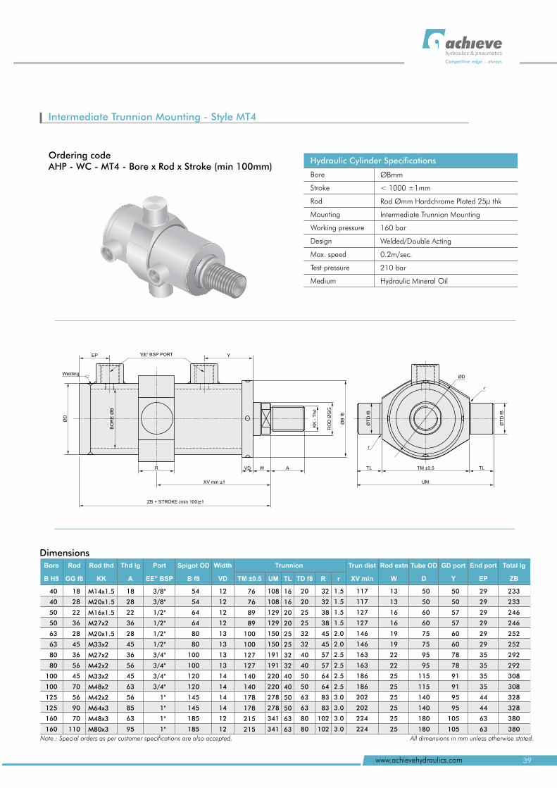
Hydraulic Cylinder Specifications
Bore
Stroke
Rod
Mounting
Working pressure
Design
Max. speed
Test pressure
Medium
ØBmm
< 1000 ±1mm
Rod Ømm Hardchrome Plated 25µ thk
Intermediate Trunnion Mounting
160 bar
Welded/Double Acting
0.2m/sec.
210 bar
Hydraulic Mineral Oil
Ordering codeAHP - WC - MT4 - Bore x Rod x Stroke (min 100mm)
Intermediate Trunnion Mounting - Style MT4
'EE' BSP PORTEP Y
Welding
ØD
BO
RE
ØB
R VD W A
XV min ±1
ZB + STROKE (min 100)±1
RO
D
GG
Ø
ØB
f8
KK
- T
hd
r
TL TM ±0.5
UM
r
TL
ØT
D f
8
ØT
D f
8
ØD
Dimensions
40
40
50
50
63
63
80
80
100
100
125
125
160
160
18
28
22
36
28
45
36
56
45
70
56
90
70
110
54
54
64
64
80
80
100
100
120
120
145
145
185
185
18
28
22
36
28
45
36
56
45
63
56
85
63
95
3/8"
3/8"
1/2"
1/2"
1/2"
1/2"
3/4"
3/4"
3/4"
3/4"
1"
1"
1"
1"
12
12
12
12
13
13
13
13
14
14
14
14
12
12
76
76
89
89
100
100
127
127
140
140
178
178
215
215
108
108
129
129
150
150
191
191
220
220
278
278
341
341
50
50
60
60
75
75
95
95
115
115
140
140
180
180
16
16
20
20
25
25
32
32
40
40
50
50
63
63
20
20
25
25
32
32
40
40
50
50
63
63
80
80
32
32
38
38
45
45
57
57
64
64
83
83
102
102
1.5
1.5
1.5
1.5
2
2
2.5
2.5
2.5
2.5
3
3
3
3
.0
.0
.0
.0
.0
.0
117
117
127
127
146
146
163
163
186
186
202
202
224
224
13
13
16
16
19
19
22
22
25
25
25
25
25
25
29
29
29
29
29
29
35
35
35
35
44
44
63
63
50
50
57
57
60
60
78
78
91
91
95
95
105
105
233
233
246
246
252
252
292
292
308
308
328
328
380
380
Rod thd
KK
M14x1.5
M20x1.5
M16x1.5
M27x2
M20x1.5
M33x2
M27x2
M42x2
M33x2
M48x2
M42x2
M64x3
M48x3
M80x3
Rod extn
W
Tube OD
D
GD port
Y
End port
EP
Total lg
ZB
Bore
B H8
Rod
GG f8
Thd lg
A
Port
EE” BSP
Spigot OD
B f8
Trun dist
XV min
Width
VD
Trunnion
R rTM ±0.5 UM TL TD f8
Note : Special orders as per customer specifications are also accepted. All dimensions in mm unless otherwise stated.
39www.achievehydraulics.com
hydraulics & pneumatics
Competitive edge - always
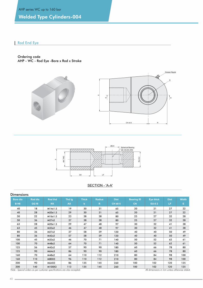
Rod End Eye
Dimensions
Bore dia
B H8
Rod thd
KK
Rod dia
GG f8
Thd lg
AX
Thick
b
Radius
R
Dist
CH ±0 5
Bearing ID
CN
Eye thick
EU-0 2
Dist
LF
Width
E
40
40
50
50
63
63
80
80
100
100
125
125
160
160
200
200
65
65
80
80
97
97
120
120
140
140
180
180
210
210
260
260
18
28
22
36
28
45
36
36
45
70
56
90
70
110
90
140
M14x1.5
M20x1.5
M16x1.5
M27x2
M20x1.5
M33x2
M27x2
M42x2
M33x2
M48x2
M42x2
M64x3
M48x2
M80X3
M64X3
M100X3
19
29
23
37
29
46
37
57
46
64
57
86
64
96
86
113
30
30
38
38
47
47
58
58
70
70
90
90
110
110
135
135
31
31
38
38
48
48
59
59
71
71
90
90
112
112
145
145
21
21
27
27
32
32
40
40
52
52
66
66
84
84
102
102
20
20
25
25
30
30
40
40
50
50
60
60
80
80
100
100
27
27
32
32
41
41
50
50
62
62
78
78
98
98
120
120
22
22
28
28
38
38
49
49
61
61
80
80
100
100
125
125
CH ±0.5
Grease Nipple
R
'A'E
R
'A'
Ordering codeAHP - WC - Rod Eye -Bore x Rod x Stroke
SECTION - 'A-A'
ØCHSpherical Bearing
GE-CN-ES-2RS
LF
EU
-0.2
AX
b
KK
TH
D
Note : Special orders as per customer specifications are also accepted. All dimensions in mm unless otherwise stated.
AHP series WC up to bar160
Welded Type Cylinders-004
40
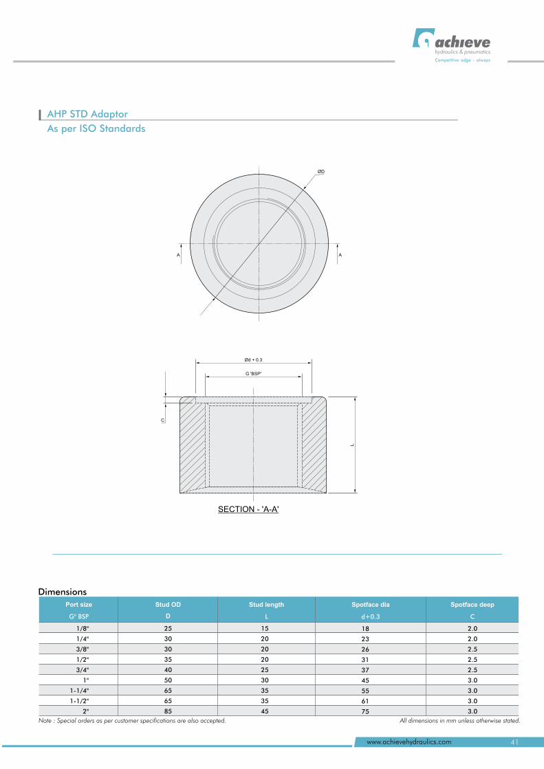
AH STD Adaptor
As per ISO Standards
P
ØD
AA
SECTION - 'A-A'
Ød + 0.3
G 'BSP'
C
L
Dimensions
Port size
G" BSP
Stud OD
D
1/8"
1/4"
3/8"
1/2"
3/4"
1"
1-1/4"
1-1/2"
2"
25
30
30
35
40
50
65
65
85
Stud length
L
15
20
20
20
25
30
35
35
45
Spotface dia
d+0.3
18
23
26
31
37
45
55
61
75
2
2
2.5
2.5
2.5
3
3
3
3
.0
.0
.0
.0
.0
.0
Spotface deep
C
Note : Special orders as per customer specifications are also accepted. All dimensions in mm unless otherwise stated.
41www.achievehydraulics.com
hydraulics & pneumatics
Competitive edge - always
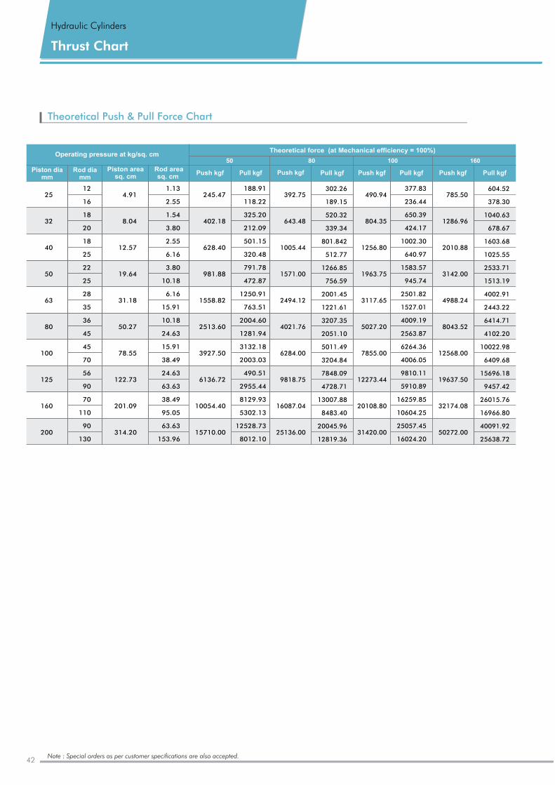
Theoretical Push & Pull Force Chart
Note : Special orders as per customer specifications are also accepted.
Operating pressure at kg/sq. cmTheoretical force (at Mechanical efficiency = 100%)
50 80 100 160
25
32
40
50
63
80
100
125
160
200
Piston dia mm
Rod dia mm
Piston area sq. cm
Pull kgf Push kgf Pull kgf Push kgf Push kgf Pull kgf Pull kgf
12
16
18
20
18
25
22
25
28
35
36
45
45
70
56
90
70
110
90
130
4.91
8.04
12.57
19.64
31.18
50.27
78.55
122.73
201.09
314.20
1.13
2.55
1.54
3.80
2.55
6.16
3.80
10.18
6.16
15.91
10.18
24.63
15.91
38.49
24.63
63.63
38.49
95.05
63.63
153.96
Rod area sq. cm
245.47
402.18
628.40
981.88
1558.82
2513.60
3927.50
6136.72
10054.40
15710.00
Push kgf
188.91
118.22
325.20
212.09
501.15
320.48
791.78
472.87
1250.91
763.51
2004.60
1281.94
3132.18
2003.03
490.51
2955.44
8129.93
5302.13
12528.73
8012.10
302.26
189.15
520.32
339.34
801.842
512.77
1266.85
756.59
2001.45
1221.61
3207.35
2051.10
5011.49
3204.84
7848.09
4728.71
13007.88
8483.40
20045.96
12819.36
392.75
643.48
1005.44
1571.00
2494.12
4021.76
6284.00
9818.75
16087.04
25136.00
490.94
804.35
1256.80
1963.75
3117.65
5027.20
7855.00
12273.44
20108.80
31420.00
377.83
236.44
650.39
424.17
1002.30
640.97
1583.57
945.74
2501.82
1527.01
4009.19
2563.87
6264.36
4006.05
9810.11
5910.89
16259.85
10604.25
25057.45
16024.20
604.52
378.30
1040.63
678.67
1603.68
1025.55
2533.71
1513.19
4002.91
2443.22
6414.71
4102.20
10022.98
6409.68
15696.18
9457.42
26015.76
16966.80
40091.92
25638.72
785.50
1286.96
2010.88
3142.00
4988.24
8043.52
12568.00
19637.50
32174.08
50272.00
Hydraulic Cylinders
Thrust Chart
42
AHP STD Series
AHP-005/006/007hydraulics & pneumatics
Competitive edge - always
43www.achievehydraulics.com
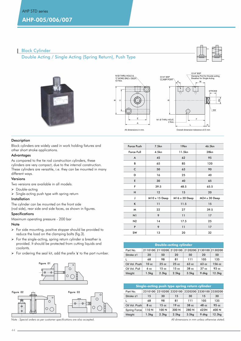
Description
Block cylinders are widely used in work holding fixtures and other short stroke applications.
Advantages
As compared to the tie rod construction cylinders, these cylinders are very compact, due to the internal construction.These cylinders are versatile, i.e. they can be mounted in many different ways.
Versions
Two versions are available in all models.
Ø Double-actingØ Single-acting push type with spring return
Installation
The cylinder can be mounted on the front side (rod side), rear side and side faces, as shown in figures.
Specifications
Maximum operating pressure - 200 bar
Note
Ø For side mounting, positive stopper should be provided to reduce the load on the clamping bolts (fig.3).
Ø For the single-acting, spring return cylinder a breather is provided. It should be protected from cutting liquids and coolants.
Ø For ordering the seal kit, add the prefix 's' to the part number.
Block Cylinder
Double Acting / Single Acting (Spring Return), Push Type
Double-acting cylinder
Part No.
Stroke ±1
L
Oil Vol. Push
Oil Vol. Pull
Weight
2110100
20
68
10 cc
6 cc
1.5kg
2110200
50
98
25 cc
15 cc
2.3kg
2120100
20
81
25 cc
15 cc
2.5kg
2120200
50
111
63 cc
38 cc
3.5kg
2130100
20
105
63 cc
37 cc
9.6kg
2130200
50
135
156 cc
93 cc
12.3kg
Force Push
Force Full
A
B
C
D
E
F
H
J
K
M
N1
N2
P
SW
7.5kn
4.5kn
45
65
50
16
30
39.5
12
M10 x 15 Deep
11
22
9
14
9
13
19
11.5kn
62
85
63
25
40
48.5
15
M16 x 30 Deep
11.5
27
11
17.5
11
20
kn 46.5
28kn
95
120
90
40
65
65.5
20
M24 x 30 Deep
15
39.5
17
25
17
32
kn
Figure 03
Figure 01
Figure 02
N1Ø THRU HOLE &
'C' BORE N2 x DEEP,02 Nos.
Ø
B CE
A
All dimensions in mm. Overall dimension tolerance ±0.5 mm
HL
B
G1/4" BSP
CLAMP PORT
N1 Ø THRU ,2 Nos.HOLE
G1/4" BSP
Declamp Port for Double acting,Breather for Single Acting
STROKE
SW
F
Ød
K M
Single-acting push type spring return cylinder
Part No.
Stroke ±1
L
Oil Vol. Push
Spring Force
Weight
2310100
15
68
8 cc
110 N
1.5kg
2310200
30
98
15 cc
100 N
2.3kg
2320100
15
81
19 cc
300 N
2.5kg
2320200
30
111
38 cc
280 N
3.5kg
2330100
15
105
48 cc
425N
9.6kg
2330200
30
135
95 cc
400 N
12.3kg
Note : Special orders as per customer specifications are also accepted. All dimensions in mm unless otherwise stated.
AHP-005/006/007
AHP STD series
44
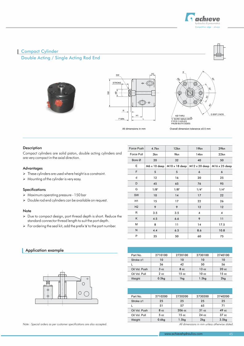
Application example
Description
Compact cylinders are solid piston, double acting cylinders and are very compact in the axial direction.
Advantages
Ø These cylinders are used where height is a constraint.
Ø Mounting of the cylinder is very easy.
Specifications
Ø Maximum operating pressure - 150 bar
Ø Double rod end cylinders can be available on request.
Note
Ø Due to compact design, port thread depth is short. Reduce the standard connector thread length to suit the port depth.
Ø For ordering the seal kit, add the prefix 's' to the part number.
SWH2
STROKE
R
H1
F MIN. L
All dimensions in mm
dØ
DØ
Part No.
Stroke ±1
L
Oil Vol. Push
Oil Vol. Pull
Weight
2710100
10
36
3 cc
2 cc
0.5kg
2720100
10
42
8 cc
15 cc
1kg
2730100
10
50
13 cc
10 cc
1.5kg
2740100
10
56
20 cc
15 cc
2kg
Force Push
Force Pull
Bore Ø
E
F
d
D
G
SW
H1
H2
R
K
M
N
P
4.7kn
3kn
20
M6 x 10 deep
5
12
45
1/8"
10
15
9
3.5
4.5
8
4.4
35
12
9kn
32
M10 x 18 deep
5
16
65
1/8"
14
17
9
3.5
6.6
11
6.5
50
kn 19
14kn
40
M12 x 20 deep
6
20
76
1/4"
17
22
12
4
9
14
8.6
60
kn 29
22kn
50
M16 x 25 deep
6
25
95
1/4"
22
26
12
4
11
17.5
10.8
75
kn
Part No.
Stroke ±1
L
Oil Vol. Push
Oil Vol. Pull
Weight
2710200
25
51
8 cc
5 cc
0.6kg
2720200
25
57
206 cc
15 cc
1.5kg
2730200
25
65
31 cc
24 cc
2kg
2740200
25
71
49 cc
37 cc
3.5kg
E
o
60
o60
KØ THRU
'C' BORE MØxN DEEPP PCD 3 HOLESFROM BOTH SIDES
G BSP 2 NOS.
Overall dimension tolerance ±0.5 mm
o
30
o30
ØD
Compact Cylinder
Double Acting / Single Acting Rod End
Note : Special orders as per customer specifications are also accepted. All dimensions in mm unless otherwise stated.
45www.achievehydraulics.com
hydraulics & pneumatics
Competitive edge - always
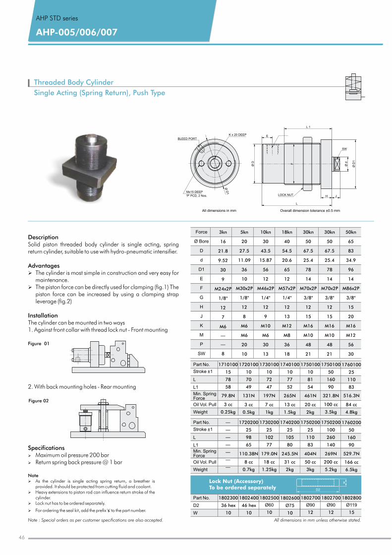
Threaded Body Cylinder
Single Acting (Spring Return), Push Type
Description Solid piston threaded body is single acting, spring return cylinder, suitable to use with hydro-pneumatic intensifier.
Advantages Ø The cylinder is most simple in construction and very easy for
maintenance. Ø The piston force can be directly used for clamping (fig.1) The
piston force can be increased by using a clamping strap leverage (fig.2)
InstallationThe cylinder can be mounted in two ways1. Against front collar with thread lock nut - Front mounting
2. With back mounting holes - Rear mounting
cylinder
Figure 01
Figure 02
BLEED PORT
K x 20 DEEP
Mx15 DEEP
'P' PCD, 2 Nos.
Ø D
1
All dimensions in mm Overall dimension tolerance ±0.5 mm
Ø D
1
Ø D F
Ø d
SW
L 1
L
LOCK NUT H J
E
Specifications Ø Maximum oil pressure 200 barØ Return spring back pressure @ 1 bar
Note Ø As the cylinder is single acting spring return, a breather is
provided. It should be protected from cutting fluid and coolant.Ø Heavy extensions to piston rod can influence return stroke of the
cylinder.Ø Lock nut has to be ordered separately.
Ø For ordering the seal kit, add the prefix 's' to the part number.
Note : Special orders as per customer specifications are also accepted. All dimensions in mm unless otherwise stated.
Force
Ø
D
d
D1
E
F
G
H
J
K
M
P
SW
Bore
3
16
21.8
9.52
30
9
M24x2P
1/8''
12
7
M6
—
—
8
kn 5
20
27.5
11.09
36
10
M30x2P
1/8''
12
8
M6
M6
20
10
kn 10
30
43.5
15.87
56
12
M46x2P
1/4''
12
9
M10
M6
30
13
kn 18
40
54.5
20.6
65
12
M57x2P
1/4''
12
13
M12
M8
36
18
kn 30
50
67.5
25.4
78
14
M70x2P
3/8''
12
15
M16
M10
48
21
kn 30
50
67.5
25.4
78
14
M70x2P
3/8''
12
15
M16
M10
48
21
kn 50
65
83
34.9
96
14
M86x2P
3/8''
15
20
M16
M12
56
30
kn
1802 00
46 hex
4
10
1802300
36 hex
10
1802 00
5
10
6
Ø7
1802 00
12
7
Ø90
1802 00
12
7
Ø90
1802 00
15
8
Ø119
Part No.
D2
W
1802 00
10
5
Ø60
Lock Nut (Accessory) To be ordered separately D2
w
AHP STD series
AHP-005/006/007
1710100
15
78
58
79.8N
3 cc
0.25kg
1720100
10
70
49
131N
3 cc
0.5kg
1730100
10
72
47
197N
7 cc
1kg
1740100
10
77
52
265N
13 cc
1.5kg
1750100
10
81
54
461N
20 cc
2kg
1750100
50
160
90
321.8N
100 cc
3.5kg
1760100
25
110
83
516.3N
84 cc
4.8kg
Part No.
Stroke ±1
L
L1
Min. SpringForce
Oil Vol. Pull
Weight
Part No.
Stroke ±1
L
L1
Min. SpringForce
Oil Vol. Pull
Weight
—
—
—
—
—
—
—
1720200
25
98
65
110.38N
8 cc
0.7kg
1730200
25
102
77
179.0N
18 cc
1.25kg
1740200
25
105
80
245.5N
31 cc
2kg
1750200
25
110
83
404N
50 cc
3kg
1750200
100
260
140
269N
200 cc
5.2kg
1760200
50
160
90
529.7N
166 cc
6.5kg
46
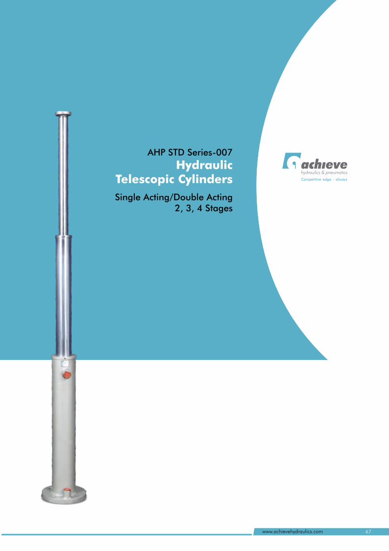
47www.achievehydraulics.com
hydraulics & pneumatics
Competitive edge - always
AHP STD Series-007
Hydraulic Telescopic Cylinders
l
Single Acting/Double Acting 2, 3, 4 Stages
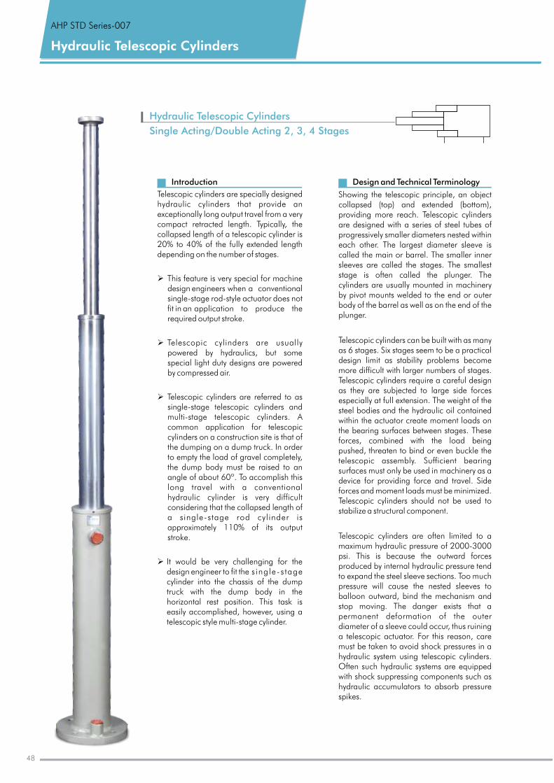
Hydraulic Telescopic Cylinders
Hydraulic
Single Acting/Double Acting 2, 3, 4 Stages
Telescopic Cylinders
Design and Technical Terminology
Showing the telescopic principle, an object collapsed (top) and extended (bottom), providing more reach. Telescopic cylinders are designed with a series of steel tubes of progressively smaller diameters nested within each other. The largest diameter sleeve is called the main or barrel. The smaller inner sleeves are called the stages. The smallest stage is often called the plunger. The cylinders are usually mounted in machinery by pivot mounts welded to the end or outer body of the barrel as well as on the end of the plunger.
Telescopic cylinders can be built with as many as 6 stages. Six stages seem to be a practical design limit as stability problems become more difficult with larger numbers of stages. Telescopic cylinders require a careful design as they are subjected to large side forces especially at full extension. The weight of the steel bodies and the hydraulic oil contained within the actuator create moment loads on the bearing surfaces between stages. These forces, combined with the load being pushed, threaten to bind or even buckle the telescopic assembly. Sufficient bearing surfaces must only be used in machinery as a device for providing force and travel. Side forces and moment loads must be minimized. Telescopic cylinders should not be used to stabilize a structural component.
Telescopic cylinders are often limited to a maximum hydraulic pressure of 2000-3000 psi. This is because the outward forces produced by internal hydraulic pressure tend to expand the steel sleeve sections. Too much pressure will cause the nested sleeves to balloon outward, bind the mechanism and stop moving. The danger exists that a permanent deformation of the outer diameter of a sleeve could occur, thus ruining a telescopic actuator. For this reason, care must be taken to avoid shock pressures in a hydraulic system using telescopic cylinders. Often such hydraulic systems are equipped with shock suppressing components such as hydraulic accumulators to absorb pressure spikes.
Introduction
Telescopic cylinders are specially designed hydraulic cylinders that provide an exceptionally long output travel from a very compact retracted length. Typically, the collapsed length of a telescopic cylinder is 20% to 40% of the fully extended length depending on the number of stages.
Ø This feature is very special for machine design engineers when a conventional single-stage rod-style actuator does not fit in an application to produce the required output stroke.
Ø Telescopic cylinders are usually powered by hydraulics, but some special light duty designs are powered by compressed air.
Ø Telescopic cylinders are referred to as single-stage telescopic cylinders and multi-stage telescopic cylinders. A common application for telescopic cylinders on a construction site is that of the dumping on a dump truck. In order to empty the load of gravel completely, the dump body must be raised to an angle of about 60º. To accomplish this long travel with a conventional hydraulic cylinder is very difficult considering that the collapsed length of a single-stage rod cylinder is approximately 110% of its output stroke.
Ø It would be very challenging for the design engineer to fit the s ingle - s tage cylinder into the chassis of the dump truck with the dump body in the horizontal rest position. This task is easily accomplished, however, using a telescopic style multi-stage cylinder.
AHP STD Series-007
48
hydraulics & pneumatics
Competitive edge - always
49www.achievehydraulics.com
Hydraulic Telescopic Cylinders
Single Acting/Double Acting 2, 3, 4 Stages
Telescopic cylinders can usually be classified into two basic designs: Single acting and double acting. A number of other special designs also exist including a hybrid single / double acting design and a constant speed, constant thrust design.
• Single Acting
Single acting telescopic cylinders are the simplest and most common design. As with a single acting rod style cylinder the single acting telescopic cylinder is extended using hydraulic pressure, but retracts using external forces when the hydraulic pressure is removed and relieved to the reservoir. This external retraction force is usually gravity acting on the weight of the load. This external weight must obviously be sufficient to overcome the friction and mechanical losses within the machine design even after the work portion of the machine cycle has been accomplished. In the example above of the dump truck, the weight of the dump body now raised at an angle of 60º, but empty of the load, must be enough to force the un-pressurized hydraulic fluid out of the cylinder and cause it to retract to the fully collapsed position.
• Double Acting
A double acting cylinder is extended and retracted using hydraulic pressure in both directions. Double acting telescopic cylinders are thus much more complex in design than the single acting type. This additional complexity is due to the requirement of adding retracting piston faces to all of the cylinder stages and the difficulty in supplying pressurized fluid to the retraction pistons of the intermediate stages.
To accomplish the double acting feature, additional hydraulic seals are added to internally seal off the individual stages. In addition, internal oil passageways are machined, so that as each stage completes retracting, an oil passage is opened to supply the next stage with pressurized fluid to retract. Thus, a double acting telescopic actuator usually retracts starting from the smallest diameter stage to finish with the largest stage retracting lastly. Because the seals used to accomplish this must pass over these internally machined fluid transfer holes, the seals are usually made from hard materials to resist wear and abrasion. They are often iron rings or glass reinforced nylon seals.
The extension and retraction fluid supply ports on double acting telescopic cylinders are usually located at the opposite ends of the cylinder's assembly. The extension port is mounted at the base of the outer barrel and the retraction port is mounted in the end of the plunger section. This can, in some applications, prove to be very difficult to connect with hydraulic hoses due to the distance between these ports at full extension. In such a circumstance, both ports can be located in the barrel. An internal passageway must be fitted however, so that the retracting fluid is supplied to the plunger
Basic Design - Types of Telescopic Cylinders
section at full extension. This special passageway is in itself a telescopic assembly that extends with the cylinder and is outfitted with seals on the various stages.
This additional complexity makes double acting telescopic cylinders very expensive. They are usually custom-designed for each application. Typical applications of double acting telescopic cylinders include the packer-ejector cylinders in garbage trucks and transfer trailers, horizontal compactors, telescopic excavator shovels and roll-on/roll-off trucks. In all of these applications, the cylinder operates near horizontally and thus is usually not available to retract the actuator. A double acting design is, therefore, required to both push and pull the telescoping mechanism.
Care must be taken when controlling most double acting telescopic cylinders. The effective retraction area is often much less than the extension area. Thus, if the hydraulic fluid return line is blocked during extension, a pressure-intensifying effect can occur, causing seal failure or even causing the metal sleeve to balloon outward. The cylinder could thus be rendered unable to retract because of failed seals or jam in position due to binding.
Another problem can occur if a double acting telescopic cylinder encounters a load that pulls on the actuator during extension such as when a tilting load goes over center and opens the cylinder beyond the internal volume of the hydraulic oil. When the piston face catches up again and strikes the oil column a pressure spike occurs which can damage the actuator.
In some unique applications, a single acting telescopic cylinder is adequate to accomplish the work except for one stage that is required to be double acting.
An example of this is erecting the most of a large mobile drilling rig. The mast is erected to the vertical position using a telescopic cylinder. However, to lower the mast gravity is not available for the initial tilt back from the vertical position. Thus, the plunger stage only of the telescopic actuator is equipped as a double acting cylinder to provide the initial force to pull the mast back from vertical. Once the tilt back has been initiated, then gravity takes over and supplies the force to complete the full cylinder retraction. The remaining stages, therefore, are single acting. This special combination is much less complex and much less costly than using an entirely double acting design.
Constant Thrust Constant Speed
In some applications, a telescopic cylinder is required to extend with a constant force or constant speed. To accomplish this, the cylinder is designed so that all the stages extend at the same time. This can also be accomplished in a double acting design by matching the extension and retraction areas of the pistons on all the stages.
Single/Double Acting Combination
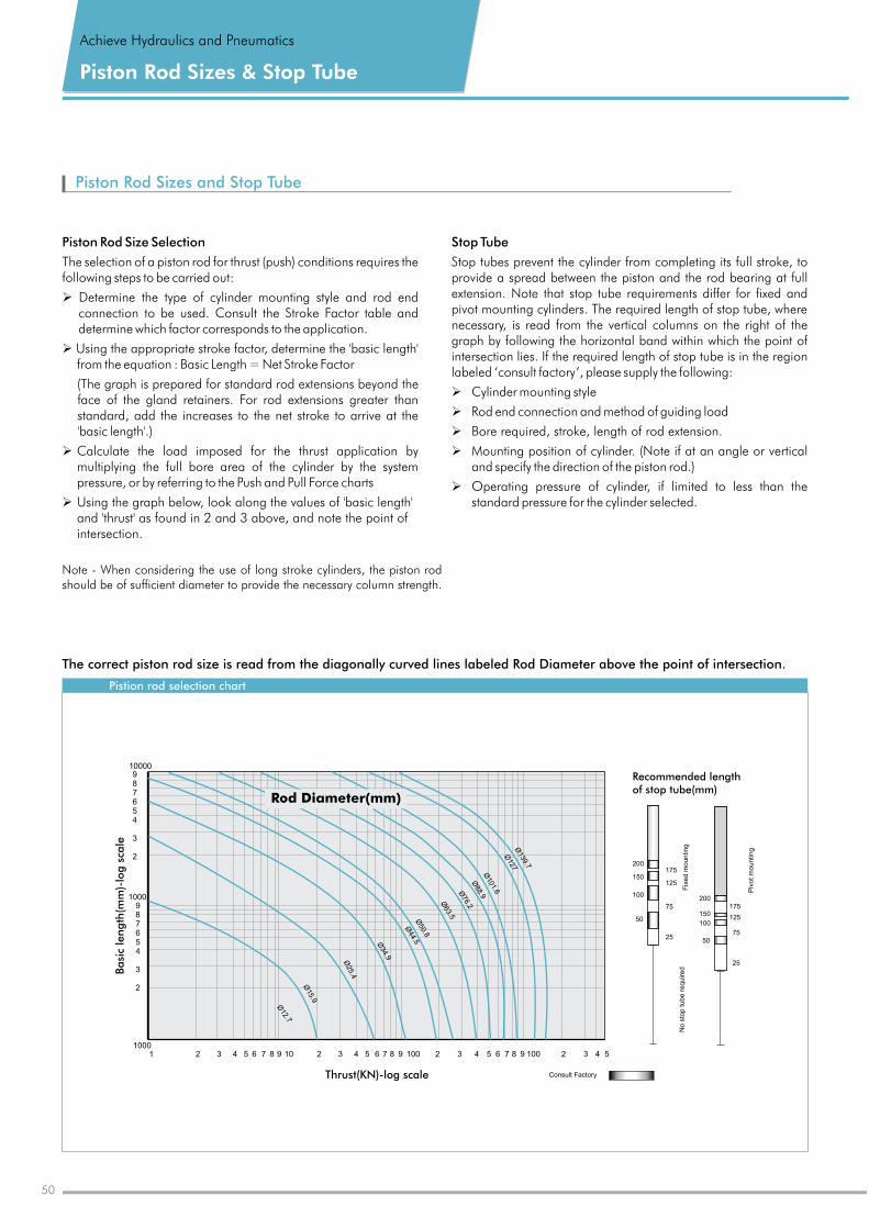
Piston Rod Sizes and Stop Tube
Piston Rod Size Selection
The selection of a piston rod for thrust (push) conditions requires the following steps to be carried out:
Ø Determine the type of cylinder mounting style and rod end connection to be used. Consult the Stroke Factor table and determine which factor corresponds to the application.
Ø Using the appropriate stroke factor, determine the 'basic length' from the equation : Basic Length = Net Stroke Factor
(The graph is prepared for standard rod extensions beyond the face of the gland retainers. For rod extensions greater than standard, add the increases to the net stroke to arrive at the 'basic length'.)
Ø Calculate the load imposed for the thrust application by multiplying the full bore area of the cylinder by the system pressure, or by referring to the Push and Pull Force charts
Ø Using the graph below, look along the values of 'basic length' and thrust' as found in 2 and 3 above, and note the point of intersection.
'
Stop Tube
Stop tubes prevent the cylinder from completing its full stroke, to provide a spread between the piston and the rod bearing at full extension. Note that stop tube requirements differ for fixed and pivot mounting cylinders. The required length of stop tube, where necessary, is read from the vertical columns on the right of the graph by following the horizontal band within which the point of intersection lies. If the required length of stop tube is in the region labeled ‘consult factory’, please supply the following:
Cylinder mounting style
Rod end connection and method of guiding load
Ø Bore required, stroke, length of rod extension.
Ø Mounting position of cylinder. (Note if at an angle or vertical and specify the direction of the piston rod.)
Ø Operating pressure of cylinder, if limited to less than the standard pressure for the cylinder selected.
Ø
Ø
Achieve Hydraulics and Pneumatics
Piston Rod Sizes & Stop Tube
Note - When considering the use of long stroke cylinders, the piston rod should be of sufficient diameter to provide the necessary column strength.
No
sto
p t
ub
e r
eq
uire
dF
ixe
d m
ou
ntin
g
Piv
ot
mo
un
ting
Recommended lengthof stop tube(mm)
200
150
100
50
175
125
75
25
175
125
75
25
200
150
100
50
Consult Factory
Basi
c le
ngth
(mm
)-lo
g s
cale
10001 2 3 4 5 6 7 8 9 10 2 3 4 5 6 7 8 9 100 2 3 4 5 6 7 8 9 100 2 3 4 5
Ø12.7
Ø15.9
Ø25.4
Ø34.9
Ø44.5
Ø50.8
Ø63.5
Ø76.2
Ø88.9
Ø101.6
Ø127
Ø139.7
Thrust(KN)-log scale
Rod Diameter(mm)
10000987654
3
2
987654
3
2
1000
Pistion rod selection chart
The correct piston rod size is read from the diagonally curved lines labeled Rod Diameter above the point of intersection.
50
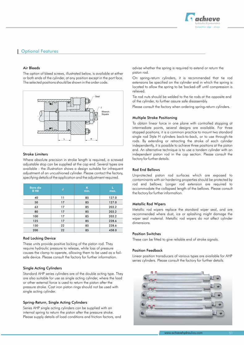
hydraulics & pneumatics
Competitive edge - always
51www.achievehydraulics.com
Optional Features
KL
J
WrenchSquare
Seal
Air Bleeds
The option of bleed screws, illustrated below, is available at either or both ends of the cylinder, at any position except in the port face. The selected positions should be shown in the order code.
Stroke Limiters
Where absolute precision in stroke length is required, a screwed adjustable stop can be supplied at the cap end. Several types are available - the illustration shows a design suitable for infrequent adjustment of an uncushioned cylinder. Please contact the factory, specifying details of the application and the adjustment required.
Rod Locking Device
These units provide positive locking of the piston rod. They require hydraulic pressure to release, while loss of pressure causes the clamp to operate, allowing them to be used as a fail-safe device. Please consult the factory for further information.
Single Acting Cylinders
Standard AHP series cylinders are of the double acting type. They are also suitable for use as single acting cylinder, where the load or other external force is used to return the piston after the pressure stroke. Cast iron piston rings should not be used with single acting cylinder.
Spring-Return, Single Acting Cylinders
Series AHP single acting cylinders can be supplied with an internal spring to return the piston after the pressure stroke. Please supply details of load conditions and friction factors, and
advise whether the spring is required to extend or return the piston rod.
On spring-return cylinders, it is recommended that tie rod extensions be specified on the cylinder end in which the spring is located to allow the spring to be 'backed-off' until compression is relieved.
Tie rod nuts should be welded to the tie rods at the opposite end of the cylinder, to further assure safe disassembly.
Please consult the factory when ordering spring-return cylinders.
Multiple Stroke Positioning
To obtain linear force in one plane with controlled stopping at intermediate points, several designs are available. For three stopped positions, it is a common practice to mount two standard single rod Style H cylinders back-to-back, or to use through-tie rods. By extending or retracting the stroke of each cylinder independently, it is possible to achieve three positions at the piston end. An alternative technique is to use a tandem cylinder with an independent piston rod in the cap section. Please consult the factory for further details.
Rod End Bellows
Unprotected piston rod surfaces which are exposed to contaminants with air hardening properties should be protected by rod end bellows. Longer rod extension are required to accommodate the collapsed length of the bellows. Please consult the factory for further information.
Metallic Rod Wipers
Metallic rod wipers replace the standard wiper seal, and are recommended where dust, ice or splashing might damage the wiper seal material. Metallic rod wipers do not affect cylinder dimensions.
Position Switches
These can be fitted to give reliable end of stroke signals.
Position Feedback
Linear position transducers of various types are available for AHP series cylinders. Please consult the factory for further details.
Bore dia B H8
Kmin.
JL
max.
40
50
63
80
100
125
150
200
11
17
17
17
17
17
22
22
85
85
85
85
85
85
85
85
127.0
127
203.2
203.2
203.2
228.6
228.6
458
.0
.0
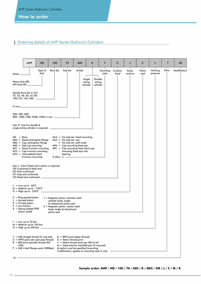
AHP Series Hydraulic Cylinders
How to order
52
Ordering details of AHP Series Hydraulic Cylinders
Heavy duty-HDMill duty-MD
Specify bore dia in mm25, 32, 40, 50, 63, 80100,125, 160, 200
200, 400, 600, 800, 1000,1500, 2000, 2500 in mm
Use ‘K’ only if a double & single acting cylinder is required.
Use ‘c’ only if head and cushion is requiredCB-Cushioned at both endNC-Non-cushionedCC-Cap end cushionedCH-Head end cushioned
L = - M = H =
Low up to 60°CMedium up to - 120°CHigh up to - 220°C
C = Ring packed pistonL = Lip seal pistonK = Hi load pistonF = Low frictionS = Spring loaded PTFE
piston seals6
L = M = H =
Low up to 70 bar Medium up to 160 bar High up to 350 bar
1X
00
Series
In mm
F C L T C L
Singleacting
cylinder
Doubleacting
cylinder
AHP HD 100 70 400 K
Bore dia Rod dia Stroke Mountingstyle
Cushionhead
Temp-erature
Pistonseal
Workingpressure
Ports ModificationType of duty
ME = BasicME5 = Head rectangular flangeME6 = Cap rectangular flangeMS2 = Side lug mountingMT1 = Head trunnion mountingMT2 = Cap trunnion mountingMT4 = Intermediate fixed
trunnion mounting
T = SAE straight thread O-ring (std)U = NPTE ports (dry seal pipe thread)R = BSP ports (parallel thread ISO
228)P = SAE 4-bolt flange ports (3000psi)
Mx3 = Tie rods ext. head mountingMx2 = Tie rods ext. cap
= Tie rods ext. both endsMP3 = Cap mounting fixed eyeMP1 = Cap mounting fixed clevis cap
mounting fixed eye with bearing
X other =
1 = Magnetic piston, stainless steel cylinder body, single bi-directional piston seal
2 = Magnetic piston, carbon steel body, single bi-directional piston seal
B = BPST ports (taper thread)G = Metric thread portsY = Metric thread ports per ISO 6149M = Used only for manifold port O-ring seal. M option must be specified (mounting modification), applies to mounting style C only.
Sample order: AHP / HD / 100 / 70 / 600 / K / ME5 / GB / L / C / M / R
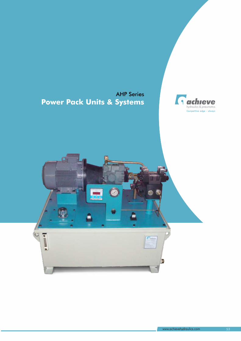
hydraulics & pneumatics
Competitive edge - always
AHP Series
Power Pack Units & Systems
53www.achievehydraulics.com
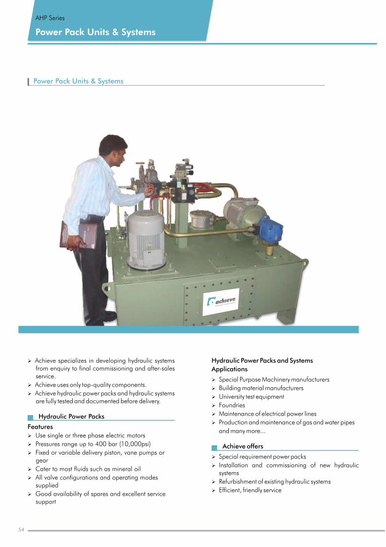
Power Pack Units & Systems
Hydraulic Power Packs and Systems
Applications
Special Purpose Machinery manufacturers
Building material manufacturers
University test equipment
Foundries
Maintenance of electrical power lines
Production and maintenance of gas and water pipes
and many more...
Achieve offers Special requirement power packs
Installation and commissioning of new hydraulic systems
Refurbishment of existing hydraulic systems
Efficient, friendly service
0
0
0
Ø
Ø
Ø
Ø
Ø
Ø
Ø
Ø
Ø
Ø
Power Pack Units & Systems
AHP Series
54
Ø
Ø
Ø
Ø
Ø
Ø
Ø
Ø
Ø
Achieve specializes in developing hydraulic systems from enquiry to final commissioning and after-sales service.
Achieve uses only top-quality components.
Achieve hydraulic power packs and hydraulic systems are fully tested and documented before delivery.
Hydraulic Power Packs
Features
Use single or three phase electric motors
Pressures range up to 400 bar (10,000psi)
Fixed or variable delivery piston, vane pumps or gear
Cater to most fluids such as mineral oil
All valve configurations and operating modes supplied
Good availability of spares and excellent service support
0
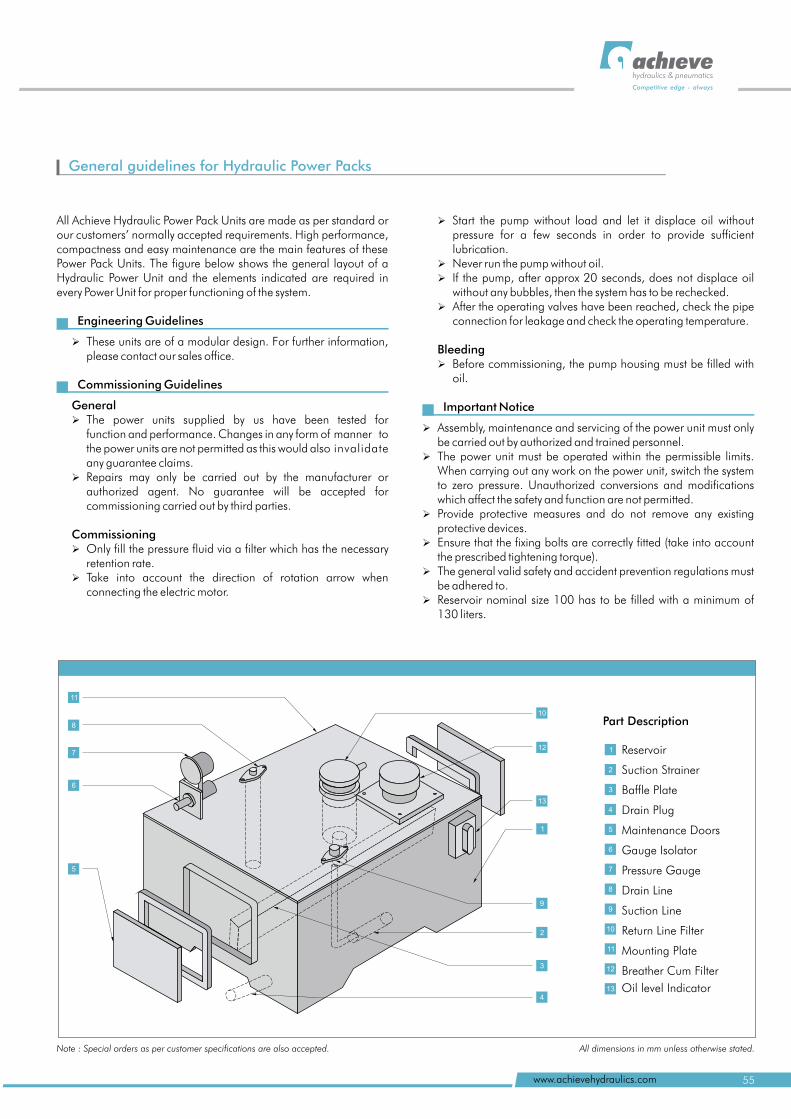
1
10
12
9
2
3
4
13
5
6
7
8
General guidelines for Hydraulic Power Packs
hydraulics & pneumatics
Competitive edge - always
55www.achievehydraulics.com
All Achieve Hydraulic Power Pack Units are made as per standard or our customers’ normally accepted requirements. High performance, compactness and easy maintenance are the main features of these Power Pack Units. The figure below shows the general layout of a Hydraulic Power Unit and the elements indicated are required in every Power Unit for proper functioning of the system.
Engineering Guidelines
Ø These units are of a modular design. For further information, please contact our sales office.
Commissioning Guidelines
General Ø The power units supplied by us have been tested for
function and performance. Changes in any form of manner to the power units are not permitted as this would also invalidate any guarantee claims.
Ø Repairs may only be carried out by the manufacturer or authorized agent. No guarantee will be accepted for commissioning carried out by third parties.
Commissioning Ø Only fill the pressure fluid via a filter which has the necessary
retention rate.Ø Take into account the direction of rotation arrow when
connecting the electric motor.
0
0
Ø
pressure for a few seconds in order to provide sufficient lubrication.
Ø Never run the pump without oil.Ø If the pump, after approx 20 seconds, does not displace oil
without any bubbles, then the system has to be rechecked.Ø After the operating valves have been reached, check the pipe
connection for leakage and check the operating temperature.
Bleeding Ø Before commissioning, the pump housing must be filled with
oil.
Important Notice
Ø Assembly, maintenance and servicing of the power unit must only be carried out by authorized and trained personnel.
Ø The power unit must be operated within the permissible limits.When carrying out any work on the power unit, switch the system to zero pressure. Unauthorized conversions and modifications which affect the safety and function are not permitted.
Ø Provide protective measures and do not remove any existing protective devices.
Ø Ensure that the fixing bolts are correctly fitted (take into account the prescribed tightening torque).
Ø The general valid safety and accident prevention regulations must be adhered to.
Ø Reservoir nominal size 100 has to be filled with a minimum of 130 liters.
Start the pump without load and let it displace oil without
0
Part Description
Reservoir
Suction Strainer
Baffle Plate
Drain Plug
Maintenance Doors
Gauge Isolator
Pressure Gauge
Drain Line
Suction Line
Return Line Filter
Mounting Plate
Breather Cum Filter
Oil level Indicator
0
11
1
11
8
6
5
7
10
12
9
2
3
4
13
Note : Special orders as per customer specifications are also accepted. All dimensions in mm unless otherwise stated.
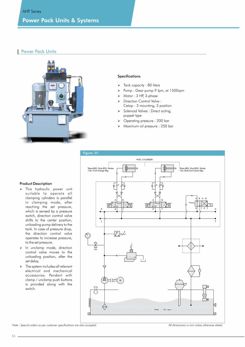
Power Pack Units & Systems
AHP Series
Power Pack Units
Specifications
Ø
Ø Pump : Gear pump 9 lpm, at 1500rpm
Ø Motor : 3 HP, 3-phase
Ø Direction Control Valve : Cetop - 3 mounting, 3 position
Ø Operating pressure : 200 bar
Ø Maximum oil pressure : 250 bar
0
Tank : 80 liters capacity
Ø Solenoid Valves : Direct acting, puppet type
Note : Special orders as per customer specifications are also accepted. All dimensions in mm unless otherwise stated.
Figure -01
*HYD. CYLINDER
*Bore-Ø63, Rod-Ø35, Stroke-140, Front Flange Mtg.
*Bore-Ø63, Rod-Ø35, Stroke-120, Both End Clevis Mtg.
A B
TPP
T
A B
TP
A B A B
TP TP P
T
M
TANK 80 Liters
Product Description
Ø This hydraulic power unit sui table to operate al l clamping cylinders is parallel in clamping mode, after reaching the set pressure, which is sensed by a pressure switch, direction control valve shifts to the center position, unloading pump delivery to the tank. In case of pressure drop, the direction control valve operates to increase pressure, to the set pressure.
Ø In unclamp mode, direction control valve moves to the unloading position, after the set delay.
Ø The system includes all relevant electrical and mechanical accessories. Pendent with clamp / unclamp push buttons is provided along with the switch.
56
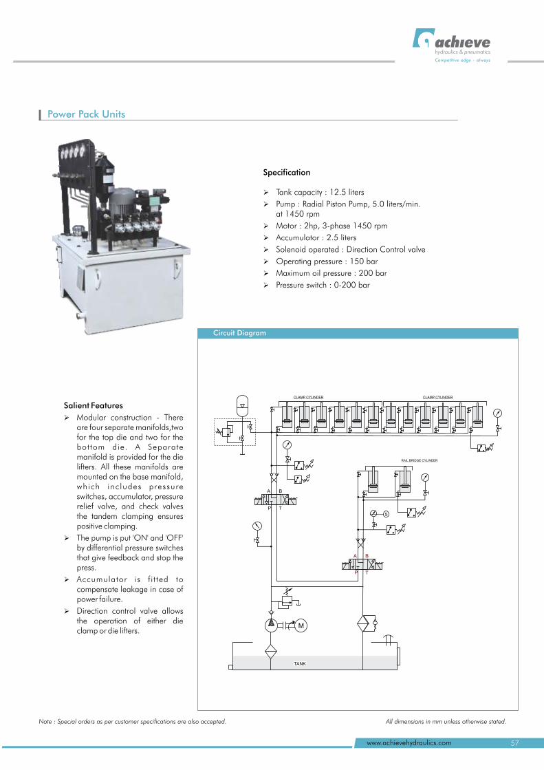
Power Pack Units
hydraulics & pneumatics
Competitive edge - always
57www.achievehydraulics.com
Note : Special orders as per customer specifications are also accepted. All dimensions in mm unless otherwise stated.
Specification
Ø Tank 12.5 liters
Ø Pump : Radial Piston Pump, 5.0 liters/min. at 1450 rpm
Ø Motor : 2hp, 3-phase 1450 rpm
Ø Accumulator : 2.5 liters
Ø Solenoid operated : Direction Control valve
Ø Operating pressure : 150 bar
Ø Maximum oil pressure : 200 bar
Ø Pressure switch : 0-200 bar
0
capacity :
Circuit Diagram
A B
P T
A B
P T
M
CLAMP CYLINDER CLAMP CYLINDER
RAIL BRIDGE CYLINDER
5
TANK
Salient Features
Ø Modular construction - There are four separate manifolds,two for the top die and two for the bottom die. A Separate manifold is provided for the die lifters. All these manifolds are mounted on the base manifold, which inc ludes pressure switches, accumulator, pressure relief valve, and check valves the tandem clamping ensures positive clamping.
Ø The pump is put 'ON' and 'OFF' by differential pressure switches that give feedback and stop the press.
Ø Accumulator is f i t ted to compensate leakage in case of power failure.
Ø Direction control valve allows the operation of either die clamp or die lifters.
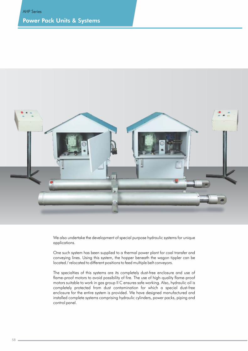
Power Pack Units & Systems
AHP Series
We also undertake the development of special purpose hydraulic systems for unique applications.
One such system has been supplied to a thermal power plant for coal transfer and conveying lines. Using this system, the hopper beneath the wagon tippler can be located / relocated to different positions to feed multiple belt conveyors.
The specialties of this systems are its completely dust-free enclosure and use of flame-proof motors to avoid possibility of fire. The use of high-quality flame-proof motors suitable to work in ensures safe working. Also, hydraulic oil is completely protected from dust contamination for which a special dust-free enclosure for the entire system is provided. We have designed manufactured and installed complete systems comprising hydraulic cylinders, power packs, piping and control panel.
gas group II C
58
hydraulics & pneumatics
Competitive edge - always
59www.achievehydraulics.com
Notes
All logos and monograms used in this catalogue are trademarks of respective companies.In keeping with our constant endeavour to meet ever-changing market needs, we reserve the right to alter or change the specifications mentioned without prior notice.
hydraulics & pneumatics
Competitive edge - always
Achieve Hydraulics & PneumaticsGat No. 1567, Chikhali-Talawade Road,
Shelar Wasti, Chikhali, Pune 412 114 INDIA
Mobile : +91-992244 3405, 992244 9243
Tel. : +91-20-6534 4771, 6613 9004/5
Fax : +91-20-6613 9003
E-mail : [email protected]
www.achievehydraulics.com
Technical changes reserved
Authorised Dealer
© copyright 2012 .Achieve Hydraulics & Pneumatics
Ach
ieve
-01/
0612
/2k
An ISO 9001:2008 Certified Company