Embed Size (px)
Citation preview


© MULTINAIL 1
TRUSS FACTS BOOK
CONTENTS
WHAT IS A TRUSS? 2THE EVOLUTION OF TRUSSES 3THE UNIVERSAL TRUSS PLATE 5TRUSS TERMS 6TRUSS NUMBERING SYSTEM 8TRUSS SHAPES 9TRUSS SYSTEMS 12 GABLE END 12 HIP 12 DUTCH HIP 14 GIRDER AND SADDLE 15 SPECIAL TRUSS SYSTEMS 16 CANTILEVER 17TRUSS DESIGN 18 TRUSS ANALYSIS 18 TRUSS LOADING COMBINATION & LOAD DURATION 18 LOAD DURATION 18 DESIGN OF TRUSS MEMBERS 18 WEBS 18 CHORDS 19 MODIFICATION FACTORS USED IN DESIGN 19 STANDARD & COMPLEX DESIGN 19BASIC TRUSS MECHANICS 20 TENSION 20 COMPRESSION 20 BENDING 20 DEFLECTION 21 TRUSS ACTION 21 DESIGN LOADS 22 LIVE LOADS 22 WIND LOAD 23 TERRAIN CATEGORIES 24 SEISMIC LOADS 24TRUSS HANDLING AND ERECTION 25MULTINAIL CONNECTOR PLATES 26 MULTI GRIPS 26 TRIPLE GRIPS 26 EASY FIX GIRDER BRACKETS 26 INTERNAL WALL BRACKETS 26 TRUSS BOOTS 26 ANTI TWIST TRUSS BOOTS 26 PURLIN STRAPS 27 CYCLONE TIES 27 JOIST HANGERS 27 STUD TIES 27 STRAP NAILS 27 FLAT TENSION BRACING 27 STEELWOOD JOISTS 28 MULTISTRUT JOISTS 29

2 © MULTINAIL
TRUSS FACTS BOOK
WHAT IS A TRUSS?
A ‘truss’ is formed when structural members are joined together in triangular configurations.
The truss is one of the basic types of structural frames formed from structural members. A truss consists of a group of ties and struts designed and connected to form a structure which acts as a large span beam.
The members usually form one or more triangles in a single plane and are arranged so that the external loads are applied at the joints and theoretically cause only axial tension or axial compression in the members. The members are assumed to be connected at their joints with frictionless hinges or pins, which allow the ends of the members freedom to rotate slightly.
Because the members in a truss are assumed to be connected to frictionless pins, the triangle formed is the only stable shape. Study of the truss shows that it is impossible for the triangle to change shape under load unless one or more of the sides is bent or broken.
Shapes of 4 or more sides are not stable and may collapse under load, as can be seen in the following images;
These structures may be deformed without a change in length of any of their members.

© MULTINAIL 3
TRUSS FACTS BOOK
THE EVOLUTION OF TRUSSES
In only a few decades, timber trusses have almost completely replaced traditional methods of roof construction.
Their advantage in allowing greater freedom of design and in speeding up construction, while reducing the impact of external influences such as weather
and building site theft, have been major factors in their success.For almost 25 years, Multinail has pioneered the development of the
engineering technology which has made these changes possible and has ensured that Multinail Fabricators continue to provide the highest quality
products at competitive cost. Multinail also makes virtually all the specialised hardware necessary for the
manufacture of building components such as roof trusses, wall frames and floor trusses, and a large range of high production machines and equipment
used in their fabrication.
LETS GO BACK IN TIME…
Before the 1940’s, most trusses were constructed of heavy steel, with the use of wood as members mainly limited to timbers with bolted connections in large buildings and bridges. This all changed with the start of World War II, where demand for speedy construction of military housing required less labour intensive practices and the reduction of jobsite time for framing roofs. To comply with the new requirements, timber members were utilised and connected together with glued and nailed plywood gussets, or simply nailed to joints, forming ‘wood trusses’.
This practice evolved after the war, with the boom of single family housing. To further reduce the labour intensive practice of, firstly, cutting the plywood
gussets, and then glue/nailing them to the timber, a light gauge metal plate was created, with predrilled holes to allow nails to be hammered through.
Seeing that the predrilled metal plates were inadequate and still labour intensive, Arthur Carol Sanford sought to devise an alternative. His invention of the truss plate was the first to utilise stamping in order to create triangular teeth which were then imbedded at the panel points of the truss to transfer the structural loads across the joints.
In 1979, ‘Automation in Housing & Systems Building News’, one of America’s leading building industry magazines, honoured Arthur Carol Sanford for what they describe as ‘his singular invention of the toothed metal connector plate in 1952’.
Sanford made other contributions to the growing truss industry, among them he contributed to the development of the rolling press, a method in which fabricators achieve the extremely high pressures needed to imbed nailplates into timber during truss manufacture. The strength of the joints constructed using this method generates trusses with predictable engineering properties. These pre-fabricated timber trusses are no longer a collection of individual timber members but complete building components, used to build entire roofs or floors.

4 © MULTINAIL
TRUSS FACTS BOOK
THE EVOLUTION OF TRUSSES
TODAY…The earliest truss plates still needed some hand applied nails. The modern truss plate system requires no nails - part of the natural progression which was made over the next decade.
With the progression of the nailplate, the Multinail Truss Plate was developed.
Multinail nailplates are manufactured from G300 steel and have a galvanised coating of 275 grams per square metre. Stainless steel nailplates are also available and, if required, arrangements can be made to have the nailplates powdercoated or for additional galvanising to be applied.
Multinail nailplates embody many refinements, particularly in the tooth shape which has been designed to grip the timber more securely. The bending and twisting of teeth during manufacture has been carefully designed to aid the transfer of forces across the finished joint. In addition, they greatly increase the joint’s resistance to damage during handling, when forces may be applied from virtually any direction.
This reliability of Multinail trusses is the result of several factors.
Among them the:
Truss plate itself, made from high grade steel to exacting tolerances to maintain the reliability and performance essential to safe truss construction.
Quality of engineering design, itself a function of Multinail’s talent and experience.
Methods used to cut and assemble the timber members of the truss as the use of automated saws and computer aided controls ensure an accurate fit of members and joints.
Care taken by Multinail fabricators to ensure that trusses are made in strict accordance with designs and handled with the care they deserve.
Over time, the ‘wood truss’ has become a highly engineered, prefabricated structural product making the most use of two very reliable resources:
- wood, which is energy efficient and renewable
- and steel, which, as a recyclable resource, is environmentally friendly.
The predicted life of nailplates is dependent on the protection of the nailplates from the weather, wind and other corrosive elements such as salt spray and chemicals.

© MULTINAIL 5
TRUSS FACTS BOOK
THE UNIVERSAL TRUSS PLATE
FEATURES
Long teeth.
Low plate cost per truss.
Penetrates high density hardwoods.
Eliminates tooth bending and wood splitting.
High force transfer per unit area.
High holding power in hardwoods & softwoods.
Prime quality galvanised steel.
ENGINEERED DESIGNProduction of an engineered truss product requires accurate cutting, jigging and pressing. The last thing that a fabricator wants is to be let down by timber splitting and truss plate teeth bending over when being pressed into timber, which may result in production delays, calls to site and increased costs of repairs and rebuilding.
However, timber splitting, teeth bending and associated problems, can now be eliminated with the use of Multinail’s Universal Truss Plates.
Designed to give truss fabricators the very best in holding power at a low cost per truss - and with eight teeth per square inch - the Universal Truss Plate is the ideal choice. In fact, Multinail was the first to introduce to South East Asia the principle of eight teeth per square inch in nailplates.
At Multinail, we didn’t just stop there. If you look carefully at the Universal Truss Plate, you will notice a uniquely designed tooth shape which gives the nailplate the full penetration and holding power that others have tried to copy but have not been able to reproduce.
PROVENExtensive tests in Australia and Asia have proven the versatility of the Universal Truss Plate.
It is suitable in such high density woods as Ironbark and Karri from Australia, Kapur and Selangur Batu from Malaysia, other high and low density hardwood timbers and in low density woods such as Radiata Pine and Oregon.
HOW IT WORKSThe Universal Truss Plate provides high density tooth concentration which ensures high strength transfer. This, together with the universal tooth shape, virtually eliminates any chance of the teeth bending or the wood splitting.
In addition, as the Universal Truss Plate produces tight fitting joints, they assist in resisting any rough handling a truss may receive during delivery or on site.

6 © MULTINAIL
TRUSS FACTS BOOK
TRUSS TERMS
TRUSSA prefabricated, engineered building component which functions as a structural support member.
MEMBERAny element (chord or web) of a truss.
APEXThe point on a truss at which the top chords meet.
AXIAL FORCE A force (either compression or tension) that acts along the length of a truss member. Measured in newtons (N) or kilo newtons (kN)
AXIAL STRESSA measure of the intensity of an axial force at a point along a member, calculated by dividing the axial force at that point by the cross-sectional area of the member. Measured in mega pascals (MPa).
BATTENSStructural members which are fixed perpendicular to the top chords of a truss to support tiles or to the bottom chords to support ceiling material and to restrain truss from buckling.
BENDING MOMENTA measure of the intensity of the combined forces acting on a member; ie, the reaction of a member to forces applied perpendicular to it (including the perpendicular components of applied forces). The maximum bending moment is generally towards the centre of a simple beam member.
BENDING STRESSA measure of the intensity of the combined bending forces acting on a member, calculated by dividing the bending moment by the section modulus of the member. Measured in mega pascals (MPa).
BOTTOM CHORDThe member which defines the bottom edge of the truss. Usually horizontal, this member carries a combined tension and bending stress under normal gravity loads.
BUTT JOINTA joint perpendicular to the length of two members joined at their ends.
CAMBERAn upward vertical displacement which is built into a truss to compensate for the anticipated deflection due to applied loads. All trusses spanning relatively large distances are cambered.
CANTILEVERThe parts of a truss which are outside the supports when the truss is supported inside rather than at the ends of its span.
COMBINED STRESSThe combined axial and bending stresses which act on a member simultaneously; ie, the combination of compression and bending stresses in a top chord or tension and bending stresses in a bottom chord which typically occur under normal gravity loads.
CONCENTRATED OR POINT LOADA load applied at a specific point; ie, a load arising from a man standing on the truss.
CUT-OFFThe term used to describe a truss which is based on a standard shape but cut short of the full span.
DEAD LOADThe weight of all the permanent loads applied to member of a truss; ie, the weight of the member itself, purlins, roofing ceilings, etc.
Pitching Point
Canitlever Web
Ceiling
Top ChordNailplate
Roofing
Bottom ChordBottom Chord TieCeiling
Batten
CanitleverTruss Overhang
Truss Span
Overall Length
Truss Overhang
Fascia
Pitching Point
Web Tie (Web Bracing)
Battens
Pitch
Web
Panel Point

© MULTINAIL 7
TRUSS FACTS BOOK
TRUSS TERMS
DEFLECTIONThe linear movement of a point on a member as a result of the application of a load or combination of loads. A measure of the deformation of a beam under load.
EAVES OVERHANGThe extension of the top chord of a truss beyond the bottom chord (at heel) to form the eaves of a roofing structure.
HEELA point on a truss where the top and bottom chords join.
HIP JOINTThe joint between the sloping and horizontal top chords of a truncated truss.
INTERPANEL SPLICEA splice in a member (at a specified distance from a panel point).
LAMINATED BEAM OR TRUSSTwo or more members or trusses mechanically fastened to act as a composite unit. Lamination allows the achievement of increased strength without the use of solid, larger section timber.
LATERAL OR LONGITUDINAL TIEA member connected at right angles to a chord or web member of a truss to restrain the member.
LIVE LOADThe combined load which arises from the use of a truss or member. It may include distributed, concentrated, impact and inertial loads, but excludes wind and earthquake loads.
LOAD DURATION COEFFICIENTThe percentage increase in the stress allowed in a member based upon the length of time that the load causing the stress is on the member. (The shorter the duration of the load, the higher the Load Duration Coefficient).
MANUFACTURING DETAILSDrawings which contain the data for truss fabrication and approval by local building authorities. (Produced automatically by the software used by Multinail Fabricators.)
MITRE CUTA cut in one or more members made at 45° to the plane of the truss; ie, the top or bottom chords of a creeper truss are mitre cut at the end of the truss where it meets the hip truss.
OVERALL LENGTHThe plan length of the truss (excluding overhangs). On standard trusses, the overall length equals the span.
OVERHANGThe clear extension of a chord beyond the main structure of a truss.
PANELThe chord segment of a truss, usually top or bottom chord, between two panel points.
PANEL POINTThe connection point between a chord and web.
PANEL POINT SPLICEA splice joint in a chord which coincides with a panel point.
PITCH The angular slope of a roof or ceiling. Also the angular slope of the top or bottom chords of a truss which form and/or follow the line of a roof or ceiling.
PLUMB CUTA vertical cut. A plumb cut is perpendicular to a horizontal member. All splices are plumb cut.
PURLINA structural member fixed perpendicular to the top chord of a truss to support sheet roofing.
SPANThe distance between the outer edges of the load-bearing walls supporting the trusses.
SPLICE JOINTThe point at which top and bottom chords are joined (at or between panel points) to form a single truss member.
SUPPORT REACTIONSThose forces (usually resolved into horizontal and vertical components) which are provided by the truss supports and are equal and opposite to the sum of the applied forces.
TOP CHORDSThe generally sloping members of a truss which define its top edge. Under normal gravity loads, these members usually carry a combined compression and bending stress.
TRUNCATED GIRDER STATIONThe position of a truncated girder. Defined in terms of its distance from the end wall.
WEBSMembers which join the top and bottom chords, and together with them, form a truss by which structural loads are transferred to the truss support.
WIND LOADSWinds loads are the forces applied to roof trusses by virtue of wind blowing on the structure, typically (but not always) upwards; ie, opposite to dead loads.

8 © MULTINAIL
TRUSS FACTS BOOK
TRUSS NUMBERING SYSTEM
Multinail uses a simple, flexible and very versatile system of member and joint numbers to identify all members and connectors.
LH Left heel
RH Right heel
TO Always allocated to the apex
BSO Always allocated to the joint immediately below the apex joint
T1R Joint immediately to the right of TO joint
T2R Joint immediately to the right of T1R joint
T1L Joint immediately to the left of TO joint
T2L Joint immediately to the left of T1L joint
TCR Top chord on the right hand side of TO joint
TCL Top chord on the left hand side of TO joint
A variation to this Numbering System occurs when the Top Chord contains a splice. The Top Chord is then allocated two denotations:
TCR1 The upper Top Chord on the right hand side of the TO joint
TCR2 The lower Top Chord on the right hand side of the TO joint and on the right hand side of the splice
If the Top Chord contains three members, than the next Top Chord would be marked TCR3, etc.
BOTTOM CHORDSFor the bottom chord, the numbers and markings are similar. If the truss does not have a BO joint, then the joints are marked as B1R, etc. and B1L from an imaginary line from the TO connector. Hence, the more joints, the more numbers to each side of this imaginary line.
With standard trusses, there is normally only one splice joint per bottom chord and the size and stress grade of each member is the same, thus the bottom chords are numbered BC1 and BC2 as it is not critical to which side of the truss it is positioned.
For trusses with multiple bottom chords such as Cathedral trusses in which there may be up to five bottom chords (and each may be a different size), the members are numbered from the left hand side of the truss and are marked as BC1, BC2…BC5. This numbering reflects the manner in which the truss drawing is developed.
SPLICESWhen a chord is spliced between panel points, it is marked as LTS1 (being the first splice in the top chord on the left hand side of the TO position). Similarly to RTS1.
When the chord is spliced at a panel point, the joint is marked as LTS2 or LBS3 relevant to the joint number in the top or bottom chord.
WEBSWebs (the internal truss members) are marked according to their position in relation to the apex joint TO and the vertical web under this joint, or the imaginary line from the TO position.
Thus, webs to the left of TO are marked W1L, W2L, etc. and webs to the right of this line are marked W1R, W2R, etc.
Note that it is possible that there may be more webs on one side than the other of the TO position.
TO
BSOLH RH
T1L T1R
TCL TCR
BC1 BC2
WO
LW1 RW1
TO
LH RH
T1L T1RTC1L TC1R
BC1 BC2
LW1 RW
1
T2RT2L
TC2L TCR2
RBS1(splice)
B2RB1LB2L
RTS1 (splice)LTS1 (splice)
© MULTINAIL 9
TRUSS FACTS BOOK
TRUSS SHAPES
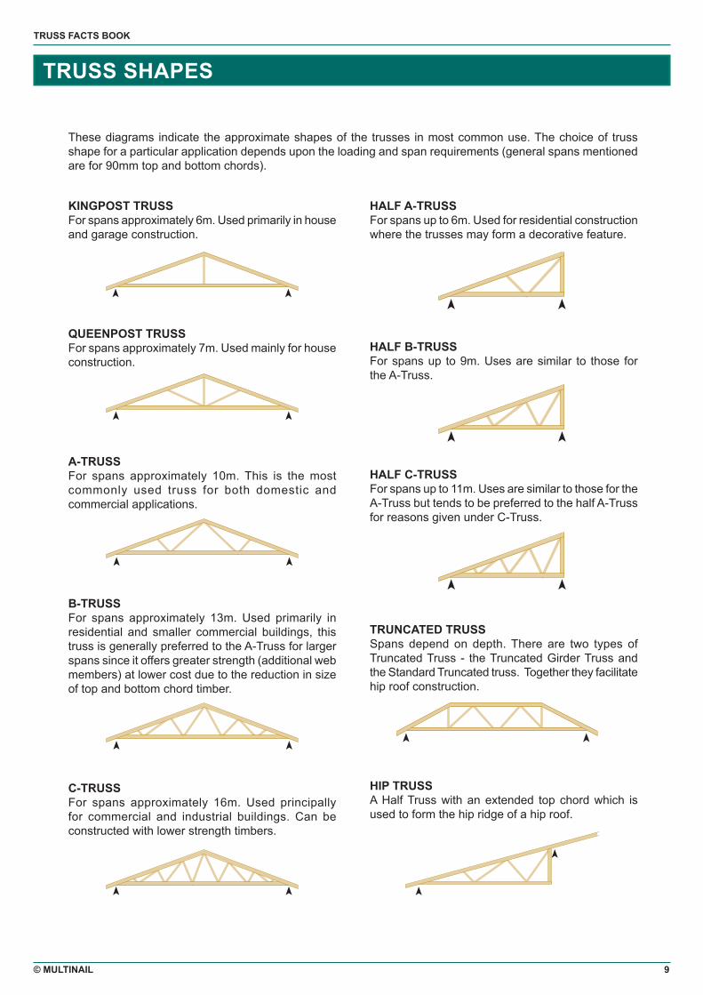
KINGPOST TRUSSFor spans approximately 6m. Used primarily in house and garage construction.
QUEENPOST TRUSSFor spans approximately 7m. Used mainly for house construction.
A-TRUSSFor spans approximately 10m. This is the most commonly used truss for both domestic and commercial applications.
B-TRUSSFor spans approximately 13m. Used primarily in residential and smaller commercial buildings, this truss is generally preferred to the A-Truss for larger spans since it offers greater strength (additional web members) at lower cost due to the reduction in size of top and bottom chord timber.
C-TRUSSFor spans approximately 16m. Used principally for commercial and industrial buildings. Can be constructed with lower strength timbers.
These diagrams indicate the approximate shapes of the trusses in most common use. The choice of truss shape for a particular application depends upon the loading and span requirements (general spans mentioned are for 90mm top and bottom chords).
HALF A-TRUSSFor spans up to 6m. Used for residential construction where the trusses may form a decorative feature.
HALF B-TRUSSFor spans up to 9m. Uses are similar to those for the A-Truss.
HALF C-TRUSSFor spans up to 11m. Uses are similar to those for the A-Truss but tends to be preferred to the half A-Truss for reasons given under C-Truss.
TRUNCATED TRUSSSpans depend on depth. There are two types of Truncated Truss - the Truncated Girder Truss and the Standard Truncated truss. Together they facilitate hip roof construction.
HIP TRUSSA Half Truss with an extended top chord which is used to form the hip ridge of a hip roof.

10 © MULTINAIL
TRUSS FACTS BOOK
TRUSS SHAPES
JACK TRUSSSimilar to the Half A-Truss but with an extended top chord which overlies a Truncated Truss to meet the extended top chord of a Hip Truss.
CREEPER TRUSSSimilar to a Jack Truss but mitre cut to intersect the Hip Truss between the outer wall and the Truncated Girder.
GIRDER TRUSSFor spans up to 15m. Special truss of any standard truss shape used to support other trusses which meet it at right angles. (The standard shape is maintained but Girder Truss members are generally larger in both size and stress grade.)
SCISSOR TRUSSFor spans up to 20m. Not a standard truss design but often used to achieve special vaulted ceiling effects, sometimes with relatively wide spans.
HALF SCISSOR TRUSSFor spans up to 10m. As its name implies, one-half of the standard Scissor Truss used for industrial, commercial and residential buildings.
PITCHED WARRENFor spans up to 30m. Generally used for industrial or commercial buildings to achieve low pitch with high strength over large spans.
DUAL PITCH TRUSSFor spans up to 15m. Non-standard truss used to achieve special architectural effects.
CUT-OFF TRUSSAny truss, the shape of which forms part of a standard truss. As the name implies, the Cut-Off Truss has a shorter span than that of the standard truss on which it is based; it is terminated by a vertical member along the line of the ‘cut-off’.
BOWSTRING TRUSSFor spans up to 30m. Used for large span industrial and commercial buildings including aircraft hangars.
HOWE TRUSSFor spans up to 12m. Used mainly for applications which involve high loading of the bottom chord (in preference to the A-Truss).

© MULTINAIL 11
TRUSS FACTS BOOK
TRUSS SHAPES
PRATT TRUSSFor spans up to 12m. May be used in preference to Howe Truss for circumstances of high bottom chord loading.
FAN FINK TRUSSFor spans up to 12m. Used mainly for applications which involve high loading of the top chord (eg, where the truss is exposed and the ceiling load is carried on the top chord).
DOUBLE HOWE TRUSSFor spans up to 20m. Used for the same reasons as the Howe Truss (in preference to the B-Truss).
PARALLEL CHORDEDFor spans up to 20m (depending on depth). As its name implies, the top and bottom chord are parallel. Used for both floor and roof applications.
ATTIC TRUSSFor spans up to 10m. Special purpose truss to simplify attic construction.
PORTAL FRAMEFor spans up to 35m. A standard commercial and industrial design for wide spans.
INVERTED CANTILEVERFor spans up to 20m. Used to achieve special architectural effects in churches, restaurants, motels, etc.
CATHEDRAL TRUSS For spans up to 15m. A non-standard truss used mainly in residential buildings to achieve a vaulted ceiling effect.
BELL TRUSS For spans up to 15m. A standard truss used to achieve a bell-shaped roofline.

12 © MULTINAIL
TRUSS FACTS BOOK
TRUSS SYSTEMS
GABLE ENDThe Gable is one of the simplest and most common types of roof. Gable ends may be either flush or may overhang the end wall of the building. Overhangs may be ‘open’ or ‘boxed’.
Gable ends may be formed with a Cutdown Truss - a truss of reduced height which is sometimes supported along its length by the end wall. This truss may in turn support either verge rafters (for a flush Gable) or an outrigger superstructure where an open Gable is to overhang the end wall.
There are several possible forms of superstructure. For example, as shown in the diagrams, the outrigger purlins may be supported by the top chords of the Cutdown Truss extending inwards to intersect the top chords of the next truss and extending outwards to end in verge rafters.
Alternatively (and again as shown in the diagrams), under-purlins may be employed, attached to the lower edges of the top chords of the last two or three trusses.
A boxed Gable may be constructed using a Standard as the end truss fixed to cantilevered beams which are supported by the building’s side walls. These cantilevered beams should extend back at least 2.5 times the cantilever distance and must be specifically designed for the expected load.
The position of the Gable Truss on the end wall is determined not only by structural demands but also by the requirements for convenient fixing of purlins and roofing material, ceiling material, Gable End battens and cladding.
Standard Truss
Gable Blocks
Outriggers
Gable Verge Rafter
Batten
Cutdown Truss
Outrigger PurlinsStandard
Truss
Batten
Prop
Under PurlinsStandard
Truss
Cantilevered Beam
Standard Truss
Cutdown Truss
Under Purlins

© MULTINAIL 13
TRUSS FACTS BOOK
TRUSS SYSTEMS
HIP
The Hip Roof Truss system is built around a Truncated Girder which transfers the weight of the hipped roof sections to the side walls. The system design specifies a Girder Station - the distance at which the Truncated Girder is located relative to the end wall.
The trusses which form the hips of the roof - the Hip Trusses - are supported at their outer ends by the corners of the end or side walls and at their inner ends by the Truncated Girder. Their top chords, which form the hips, are extended to meet the ridge line.
On the end wall side of the Truncated Girder, the roof structure is formed by Jack Trusses (between the end wall and the Truncated Girder) and Creeper Trusses (between the side walls and each of the Hip Trusses).
On the internal side of the Truncated Girder, the roof structure is formed by Truncated Trusses of increasing height towards the end of the ridge. The top chords of the Jack Trusses extend over the Truncated Girder and Truncated Standard Trusses.
The Hip Roof Truss sytem allows the construction of this traditional roof design without the need to locate load-bearing walls so as to support the hipped sections of roof.
A number of variations are possible; they are usually derived by an intersection of the first hip system with another or different type of truss system.
Truncated Girder
Truncated Standard
Standard Truss
Truncated Standard
Truncated Girder
Jack Truss
Standard Trusses
Creeper Truss
Hip Truss
Jack Truss

14 © MULTINAIL
TRUSS FACTS BOOK
TRUSS SYSTEMS
DUTCH HIP
The Dutch Hip Truss system is built around a special Girder Truss which has a waling plate fixed to one side.
As with the other Girder Trusses, it is placed at the specified Girder Station. The roof structure is similar to that used for the Hip Truss system except that there is no need for Truncated Trusses and the top chords of the Jack Trusses, instead of continuing over the Girder Truss, sit on the waling plate.
The result is a roof structure which combines some of the features of the hip roof with those of the gable.
Girder Truss
Girder Truss
Standard Truss
Waling PlateJack Truss

© MULTINAIL 15
TRUSS FACTS BOOK
TRUSS SYSTEMS
GIRDER AND SADDLE
The Girder and Saddle Truss eliminates the need for a load-bearing wall at the intersection of two gables in the roof structure.
Instead, a Girder Truss, placed parallel to the trusses in the second roof, is used at the intersection to support the ends of the trusses forming the first roof. Truss Boots are usually fixed to the Girder Truss in order to transfer the load from the trusses to the Girder and through it to the side walls.
The secondary roof line is continued past the Girder Truss by Saddle Trusses which diminish in size.
Laminated Girder Truss
Saddle Trusses
Laminated Girder Truss
Standard Truss

16 © MULTINAIL
TRUSS FACTS BOOK
TRUSS SYSTEMS
SPECIAL TRUSS SYSTEMS
CHIMNEYSTypical treatment of the roof structure around chimneys is shown in the diagrams. Standard Trusses are used to either side of the chimney. The intervening Cut-Off Trusses are supported by beams fixed to the side wall/s of the chimney.
CUT OFFSWhen the truss must be stopped short of its normal span (to allow for a chimney, for example), a Cut-Off Truss is created. This is supported at one end by the heel in the normal manner and at the other by the bottom chord immediately below the end member. It is possible for the Standard Truss Design to be modified at both ends to form a Double Cut-Off Truss.
HOT WATER SYSTEMSSpecial provision must be made in the design and fabrication of trusses required to carry additional loads such as those imposed by Hot Water Systems.
SOLAR HOT WATER SYSTEMSSpecial provision should be made in the design and fabrication of a roof truss system to carry the additional load imposed by a Solar Hot Water System.
Where this load is to be carried by an existing roof not specially designed for the purpose, a Solar Hot Water Heater with a capacity of up to 300 litres may generally be installed on the roof system provided the trusses within a roof length of approximately 3600mm are suitably modified. Details of these modifications (which take the form of strengthening both the chords and joints of each truss) may be obtained from any Multinail Fabricator.
Chimney
Chimney
Chimney
Chimney
Parallel Chorded Girder TrussesBeam
Cut-Off Trusses supported by beam
Cut-Off Trusses
Beam or Parallel Chorded Girder Trusses
Cut-Off Trusses
Solar Hot Water System

© MULTINAIL 17
TRUSS FACTS BOOK
TRUSS SYSTEMS
CANTILEVERA cantilever exists where a truss is supported inside its span rather than at the end of its bottom chord (ie, at the heel). A truss may be cantilevered on one side only, or on both.
There are three main types of cantilever (see diagrams). These are:
A) Where the bearing of the truss falls wholly within the solid length of the heel joint, no alteration is necessary to the Standard Truss.
B) Where the bearing of the truss is relatively close to the heel but outside of the solid length of the heel joint, a supplementary top chord is required to convert a Standard into a Cantilever Truss.
C) Where the distance between the heel joint and the bearing of the truss is relatively large, additional members must be used (see diagram).
The maximum length of cantilever which can be handled using standard design information is limited; eg, trusses with cantilever distances up to 1/5 nominal span for Type A Trusses, 1/6 nominal span for Type B Trusses and a combined distance of 1/4 the nominal span for any truss. Larger cantilevers demand special design.
Cantilever
Cantilever
Cantilever

18 © MULTINAIL
TRUSS FACTS BOOK
TRUSS DESIGN
INTRODUCTIONThis brief introduction to truss design is not intended as a comprehensive guide to the subject but as an overview of the techniques employed.
The design of the truss members can begin immediately once the anticipated loadings (Dead Load, Live Load and Wind Load) have been determined.
TRUSS ANALYSISFor truss shapes, where members and joints form a fully triangulated system (ie, statically determine trusses), truss analysis is carried out on the following assumptions;
i) That the chords are continuous members for bending moment, shear and deflection calculations. Negative moments at joint (nodes) areas evaluated using Clapyron’s Theorem of Three Moments and these moments are used to calculate the shear and deflection values at any point along the chord, for distributed and concentrated loads.
ii) That member forces may be calculated using a ‘pure’ truss (ie, all members pin-jointed) and calculated by either Maxwell Diagram or equilibrium of forces at joints.
iii) That the total truss deflection used to evaluate truss camber and to limit overall deflections can be calculated using the system of virtual work. Again, the members are considered as pin-ended and a dummy unit load is placed at the required point of deflection.
TRUSS LOADING COMBINATION AND LOAD DURATIONThe following combinations of loads are used to design all trusses:
a) SW + DL: permanent duration
b) SW + DL + SLL: short term live load combination
c) SW + DL + MLL: medium term live load combination
d) SW + DL + WL: duration of 5 seconds or less
Where, SW = Self Weight (timber trusses) DL = Dead Loads (tiles, plaster) SLL, MLL = Live Loads (people, snow) WL = Wind Loads
Each member in the truss is checked for strength under all three combinations of loadings. Dead loads plus live loads and dead loads plus wind loads may constitute several separate combinations in order to have checked the worst possible combination.
LOAD DURATIONThe limit state stress in a timber member is dependant upon this load duration factor (K1). For a combination of loads, the load duration factor to be chosen is the factor corresponding to the shortest duration load in the combination.
For trusses designed in accordance with AS1720.1-1997, the duration of a load considered to act on a truss is of major importance for dead loads only; the load is considered permanent and thus factor K1 at 0.57 is used. For dead and wind load combinations, the wind load duration is considered as gusts of maximum 5 second duration and K1 of 1.0 (for timber) is used. For dead and live load combinations several load cases may have to be checked due to differing load durations. In general, roof live loads are taken as applicable for up to 5 days with K1 of 0.94 (for joint). Ceiling live loads are taken as a maximum of 6 hours giving a K1 of 0.97 (for timber). This dead load plus roof live load plus ceiling live load is checked separately with K1 = 10.97 (for timber). Either may be critical.
DESIGN OF TRUSS MEMBERSTruss webs are designed for axial forces and chords, for axial forces plus bending moments and checked for shear and deflection between web junctions.
WEBSTension webs are checked for slenderness and the nett cross-sectional area is used to evaluate the tension stress. The cross-sectional area is taken as the product of the actual member depth and the thickness - less 6mm to allow for timber fibre damage by the Multinail Connector Plate.
Compression webs are also checked for slenderness. Effective length is used for buckling of the web in the plane of the truss and out of the truss plane.

© MULTINAIL 19
TRUSS FACTS BOOK
TRUSS DESIGN
CHORDSTension chords are designed for strength and stiffness. Tension chords must withstand combined tension and bending. The slenderness of the member is checked as for tension webs and also as a beam. The shear of the member is also checked but is usually critical only on heavily loaded members (eg, Girder Trusses).
The stiffness criteria is to limit the deflection of a chord between the panel points. The long term deflection is calculated for dead loads only, as the instantaneous deflection under this load multiplied by duration factor (from AS1720) is determined by the moisture condition of the timber. The limit on this deflection is (panel length) ÷300.
Live load and wind load deflections are calculated separately without consideration of the dead load deflection. Deflection is limited for live and wind loads to overcome damage to cladding materials and to reduce unsightly bows in the roof or ceiling.
Compression chords are also designed for strength and stiffness. The strength of compression chords is largely dependent on the lateral restraint conditions of the chords. The combined compression and bending stresses in the members are checked using the index equation in AS1720. Shear stress is also checked as for tension chords.
Deflections are checked as for tension chords and designed for similar allowable values.
MODIFICATION FACTORS USED IN DESIGNThe following shows a typical calculation for bending strength. The capacity in bending (ФM) of unnotched beams, for strength limit state, shall satisfy -
(ФM) ≥ M*
where,
(ФM) = Фk[f’bZ]
and,
M* = design action effect in bending
Ф = capacity factor
k = k1 x k4 …. x k12 and is the cumulative effective of the appropriate modification factors
f’b = characteristic strength in bending
Z = section modulus of beam about the axis of bending (bd2/6)
STANDARD AND COMPLEX DESIGNBoth standard truss designs and complex truss designs may be generated by either Multinail Fabricators or by Multinail Engineers. When a complex design is generated by the Fabricator for a quotation job, it is standard practice for a copy of the input and output to be checked by an engineer - either an independent consultant or a Multinail Engineer - prior to the truss being manufactured. For large projects such as hospitals, schools, offices, etc., the entire project is initially analysed and an overall truss and bracing layout completed.Each truss is then individually analysed, designed, drawn to scale, costed and presented with full cutting and jig layout dimensions to ensure accurate and uniform manufacture. Normally, trusses are analysed and designed for dead, live and wind loads but the analysis and design may be extended to include concentrated point loads as required. Trusses can also be analysed and designed for snow load, impact loads, moving loads and, if necessary, seismic loads. If the drawing specifies the purpose of the structure and the anticipated loads, then all of these loads will be taken into account in the analysis and design of the trusses and clearly itemised on the drawing. Computations can also be supplied if required.

20 © MULTINAIL
TRUSS FACTS BOOK
BASIC TRUSS MECHANICS
BENDINGA beam is subject to bending stress (eg, scaffold plank, diving board). The actual bending stress fb = Bending/Section Modulus.
INTRODUCTIONThe Australian Standard AS1720.1 Timber Structures Code outlines the design properties of timbers for bending, tension, shear and compression.
Multinail software checks that the stresses in the truss members do not exceed the allowable values and, if required, larger members or higher strength timber, are considered in order to keep the stresses below the allowable value.
Stress levels within nailplates are checked against the allowable tooth pickup and steel strength values which Multinail has determined over the years with different timbers.
TENSIONA member in tension is subject to tensile stress (eg, tow rope or chain).
Tension Stress (in a member)
= P/A in MPa
Where: P = Load in Newtons A = Area in Square mm
COMPRESSION A member in compression is tending to buckle or crush. Long compression members buckle and are weaker than short ones which crush. The allowable compression stress for a particular timber depends on the ‘slenderness ratio’ which is the greater of length/width or length/depth.
The Section Modulus (Z) is the resistance of a beam section to bending stress. This property depends upon size and cross sectional shape and for a uniformly rectangular shaped beam:
Z = bd2
6
Where: b = width in mm d = depth in mm
NOTE:‘Z’ depends on the square of ‘d’, so doubling the depth increases the strength of the beam four times.
For Example:Increasing 125 x 38 to 150 x 38 gives a sectional modulus of 1425003 which is stronger than a 125 x 50 which has a section modulus of 130208 mm3.
Simply, the depth is more important than the width. Note, however, that deep beams require more careful lateral restraint.
The Bending Moment depends on the load and the length of the beam.
For Example:Consider a simply supported beam carrying a Point Load ‘P’ at midspan.
So by doubling the length (L) or Load (P) you in fact double the Bending Moment.
Pull Pull
Push
D B
L
Push
Foc
Allo
wab
le S
tres
s
10 20 30 40 50
Slenderness Ratio L or L D B
P
P2
L2
L2
P2
The Maximum Bending Moment = P x L = PL 2 2 4

© MULTINAIL 21
TRUSS FACTS BOOK
BASIC TRUSS MECHANICS
TRUSS ACTIONA truss is like a large beam with each member in tension or compression, the chords acting as beams between the panel points as well as carrying axial load.
At any joint, the sum of the forces acting must be zero (otherwise motion would occur) and this, in fact, enables the forces to be determined.
For Example:
By measuring (or scaling) or by using simple trig. The forces are found to be 37.3 kN tension in the bottom chord and 38.6 kN compression in the top chord.
The following diagrams show typical Tension (T) Compression (C) forces in the modulus of a truss under uniformly distributed gravity loads.
DEFLECTIONDuring the analysis process when designing a truss, there are a number of deflection calculations made to determine the following:
A) Chord Inter-Panel DeflectionThe actual deflection of the timber chord between panel points is calculated and compared to the allowable deflection by the Australian Standard or stricter limits that may be applied.
B) Joint DeflectionEach joint within the truss is checked for vertical and horizontal deflection. In a flat (horizontal) bottom chord truss, there is no horizontal deflection in the bottom chord panel points and only some small horizonatl deflection in that top chord panels. The
deflection calculated in the bottom chord panel points is used to calculate camber built into the truss during manufacture.
NOTE:For trusses that do not have horizontal bottom chords, the horizontal deflection is most important as it may cause the supporting structure to deflect outwards. Care must be taken in application of the truss loads, fixing of the truss to the bearing point and maybe even design of the supporting structure, to resist these loads.
P1 - Top Chord
P2 - Bottom Chord
Reaction 10.0 KN
15°
P1 = 38.6 kN Compression
P2 = 37.3kN Tension
10kN
O C C O
T T T
OC T C C T
OC
C C C
O T O
C T C O C T C
C
C
C
C
T T
C
T T
C
T
T T
C
C
C
C
C C
T
T T T
T
Joint Inter-Panel Deflection

22 © MULTINAIL
TRUSS FACTS BOOK
BASIC TRUSS MECHANICS
DESIGN LOADSThe following details contain the basic dead, live and wind loads used for all truss design. The loads are used in as many combinations as required to achieve the most adverse loads on a particular truss.
Dead Loads are those loads considered to be applied to a truss system for the duration of the life of the structure. They include the weight of roof sheeting and purlins, ceiling material and battens, wind bracing, insulation, self-weight of the truss, hot water tanks, walls, etc…
These loads are considered in two major combinations:
a) The maximum dead load value which is used for calculations involving all dead and live load combinations and for wind load (acting down on the truss) which is an additional gravity load.
b) The minimum dead load value which is used in combination with wind load causing maximum possible uplift on the structure, thus achieving the largest stress reversal in the truss members.
The Tables opposite are examples of loads used for truss details.
NOTE:The information provided here is subject to changes according to Code requirements.
Tiles = Approximately 55kg/m2
Sheet Roof = Approximately 12kg/m2
Plaster = Approximately 10kg/m2
LIVE LOADS (FROM AS1170 PART 1)TOP CHORD LIVE LOADSFor non-trafficable roofs (from AS1170 – Part 1 Section 4.8).
Where the area supported by the truss exceeds 14m3, a value of 0.28Pa live load is applied over the plan area of the roof.
If the supported area is less than 14m3, the value of live load is taken as:
= 1.8 + 0.12KPa
(Supported Area)
The supported area is usually the product of the truss span and spacing.
BOTTOM CHORD LIVE LOADS(From AS1170 – Part 1 Section 3.7.3)
The load is assumed as that of a man standing in the centre of a particular panel of the truss bottom chord. The value is taken as 1.4kN where the internal height of the truss exceeds 1200mm and 0.9kN for height less than 1200mm.
For exposed trusses (section 4.8.3.2), the bottom chord load is taken as 1.3kN applied at each end panel point in turn and centrally in a panel where the internal height exceeds 1200mm.
For exposed Industrial and Commercial Buildings (Section 4.8.3.1) the bottom chord load is taken as 4.5kN applied at each bottom chord panel point, taken one at a time.

© MULTINAIL 23
TRUSS FACTS BOOK
BASIC TRUSS MECHANICS
WIND LOAD1. BASIC WIND VELOCITY VPBasic wind velocity Vp is determined from Table 3.2.3 for capital cities in AS1170 Part 2. For other areas, the following basic wind velocities can be used in Timber Structures:
Region A - 41m/sec;Region B - 49m/sec;Region C - 57m/sec;Region D - 69m/sec
2. DESIGN WIND VELOCITY VZVz = V x M(z, cat) x Ms x Mt x Mi
Where: M(Z, cat) = Terrain-Height Multiplier (Table 3.2.5.1 and Table 3.2.5.2)
Ms = Shielding Multiplier (Table 3.2.7)
Mt = Topographic Multiplier (Table 3.2.8)
Mi = Structure Importance Multiplier (Table 3.2.9 in AS1170 Part 2)
3. WIND PRESSURE (P)Wind Pressure (P) = 0.0006 x Vz2 (KPa)
4. EXAMPLESAssuming a house with an eaves height of less than 5 metres and in a Category 2 Region C area.
The Wind Load is calculated as follows:
Basic Wind Velocity = 57.0 (m/sec)M(z, cat) = 0.91Ms = 1.0Mt = 1.0Design Wind Velocity = 57 x 0.91 x 1 x 1 = 52(m/sec)Wind Pressure (P) = 522 x 0.0006 P = 1.6224 (KPa)
OTHER DESIGN CRITERIARoof Span - 10 metresRoofing - SheetingCeiling - PlasterboardRoof Pitch - 15°Truss Spacing - 900mmTimber - Green HardwoodWeb Configuration - A Type
The Wind Uplift force of each truss at support is calculated as follows:
Wind Uplift = (P-DL) x Spacing x (Int. + Ext.) x Span/2 Where: Dead Load = DL, including roofing and ceiling material and self weight of truss.
NOTE:This information is provided for your guidance only.
Changes occur almost continuously in the practice of calculating wind loading and it is therefore necessary to carefully consult the relevant Codes and other sources before undertaking this task.
Multinail’s TrusSource (Truss Design Software) performs these calculations automatically, based on the latest Code refinements and ‘best practice’ design criteria.
The results are summarised in the following table:
Case Int. + Ext. TC Size Web1 Size Uplift (KN)
1 0.8 100*38-F11 75*38-F11 3.662
2 1.2 125*38-F11 100*38-F11 6.340
3 1.3 100*38-F11 125*38-F11 6.972
4 1.7 125*38-F11 175*38-F11 9.631

24 © MULTINAIL
TRUSS FACTS BOOK
BASIC TRUSS MECHANICS
TERRAIN CATEGORIESThe surrounding terrain affects the wind forces acting on a structure. The Design Wind Velocity depends upon whether the structure is exposed, is on an open or hilly terrain with or without scattered obstructions of varying heights, or is in a well wooded or heavily built up area such as suburbs, industrial areas, cities, etc. All these, and many other factors, can affect the wind forces on the structure.
To assist in the selection of the Terrain Category, the following sketch and notes have been produced. Also refer to AS1170 – Part 2 for more detailed explanations.
Note: When a structure is located in an area where there is a gradual change in the terrain; ie, from a low category number to a high category number, or conversely a high category number to a lower category number, then the structure is subject to either a reduction or increase in the Design Wind Velocity. This relationship is called Fetch/Height. For details refer to AS1170 – Part 2.
CATEGORY 1Exposed open terrain with few or no obstructions. Average height of obstructions surrounding structure less than 1.5m. Includes open seacoast and flat treeless plains.
CATEGORY 2Open terrain with well scattered obstructions having heights generally 1.5m to 10m. Includes airfields, open parklands and undeveloped, sparsely built-up outskirts of towns and suburbs.
CATEGORY 3Terrain with numerous obstructions the size of domestic houses. Includes well wooded areas, suburbs, towns and industrial areas fully or partially developed.
SEISMIC LOADSThe Australian Standard for Earthquakes AS1170.4 considers houses as ductile structures. In order to determine whether seismic loading affects the structure, a number of factors must be known; the acceleration coefficient, which is dependent on the georgraphic location of the structure; and the site factor, which is dependant on the soil profile.
In the consideration of seismic loading, the connection of the wall supporting members to the roof trusses must be capable of resisting horizontal forces generated by the seismic activity.
According to Australian Loading Code, AS1170.4-1993, only ductile structures in the highest earthquake design category - H3 - require the design of the connection to resist a horizontal force at the top plate equal to approximately 5% of the dead load reaction. All other earthquake design categories for domestic structures require no specific earthquake design requirements.
In general, if a structure needs to withstand seismic loads, a Multinail engineer should be consulted.
CATEGORY 3
CATEGORY 2
CATEGORY 1
CATEGORY 2
CATEGORY 1

© MULTINAIL 25
TRUSS FACTS BOOK
TRUSS HANDLING AND ERECTION
All trusses are to be erected in accordance with the Australian Standard AS4440, ‘The Installation of Nailplated Timber Trusses’.
Before trusses are erected they must be checked to ensure that:• They comply with the requirements of the job;
ie, roofing and ceiling material, additional unit loads such as hot water tanks, solar heaters, air conditioners, etc.
• All relevant documents received with the trusses comply with the intended use of the trusses.
• The quality of all trusses are scrutinised; ie, checked for damage during transport, broken members, missing plates, etc. Any damage or poor quality in truss manufacture should be reported back to the fabricator immediately.
DO NOT attach any fall arrests or guardrail system to the trusses unless explicit written approval from the truss fabricator is received.Wall frames (see Framing Code AS1684) must also be checked to ensure they will be able to adequately support and hold down the trusses and their associated roof, ceiling or floor loads. The building must be stable horizontally before, during and after construction.
INSPECTION & STORAGETrusses should be inspected on arrival at site. Any damaged trusses should be reported immediately and not site repaired without the approval of the truss fabricator.Trusses may be transported either vertically or horizontally provided that in either case they are fully supported. Bundles (or individual trusses) should be stored flat and kept dry. Gluts or packers should be placed at 3000mm maximum spacing to support the trusses off the ground.
TEMPORARY BRACINGAll trusses are required to be braced (temporary and/or permanently) and stabilised throughout the installation of the roof truss system. As with any construction site, a risk assessment must be undertaken as truss installation invariably involves working at heights. All relevant workplace safety practices must be followed.
PERMANENT BRACINGBefore loading, the roof trusses must be permanently braced back to a rigid building structure, usually the supporting walls, to prevent rotation or buckling of the trusses. Permanent bracing relies upon the roof bracing along with the roof battens to effectively restrain the loads in the trusses and the wind loads.
BATTENSBattens to be attached to every lamination of every truss and not joined at girders.
INSTALLATION TOLERANCESTrusses must be installed straight and vertical and in their correct position. The best method for ensuring the correct truss positioning is to mark the locations on the top plate in accordance with the truss layout prior to truss erection.
ALTERATIONSA timber truss is an engineered structural component, designed and manufactured for specific conditions. Timber trusses must not be sawn, drilled or cut unless explicit written approval from the truss manufacturer is received. Unauthorised alterations may seriously impair the truss strength and could lead to failure of the structure.
WEATHERTrusses should be kept dry while they are waiting to be erected. Exposure to weather conditions can cause damage to trusses which can result in gaps between the timber and nailplate.
BOWINGTrusses must be erected with minimal bow in the truss or in chord members. The bow must not exceed “the length of bowed section/200” or 50mm, whichever is the minimum.
LEANINGTrusses must be erected so that no part of the truss is out of plumb with a tolerance not exceeding the lesser of “height/50” or 50mm.
LIFTINGWhen lifting, special care must be taken to avoid damage to truss joints. If it is necessary to handle a truss on its side, precautions must be taken to avoid damage due to sagging. Spreader bars (with attachment to panel points) must be used where the span exceeds 9000mm.
Crane
Crane
<60°
1/3 to 1/2 span
1/3 to 1/2 span
Chain for brace on lateral movement of truss
Vertical chain or sling

26 © MULTINAIL
TRUSS FACTS BOOK
MULTINAIL CONNECTOR PLATES
MULTI GRIPSP u n c h e d f r o m 1.0mm galvanised steel, Multi Grips are most commonly used for tying down trusses where the structure is located in an area of relatively low wind loading (ie, non-cyclonic) and, in cyclonic areas, for securing small
trusses such as jacks, hips or saddles. They are also suitable for a wide range of other applications such as connecting studs to wallplates, timber braces to roof trusses or for face-fixing beams. Bending legs facilitate several different configurations.
TRIPLE GRIPSTriple Grips offer an alternative to nai l ing or other methods where it is necessary to join two pieces of timber. They may be used to secure roof trusses to wall top plates in order to satisfy the requirements for the structures
built to withstand cyclonic wind loads. Available in 6 profiles, Triple Grips are made from 1.2mm galvanised steel.
EASY FIX GIRDER BRACKETSSteel girder brackets for easy fixing of timber roof trusses or rafters to the side of timber girder truss chords or timber beams - without the need for bolts, nuts or washers.
Avai lable in two sizes - 40mm to suit
35 or 38mm timber thickness, and 50mm to suit 45mm timber thickness.
INTERNAL WALL BRACKETSI n t e r n a l W a l l brackets are used to anchor wall top plates to the bottom chords of the trusses above them. The upper leg, which is attached to the truss, is slotted so as to allow movement of the bottom chord as the roof and ceilings
are added to the structure. Internal Wall Brackets are punched from 1.2mm galvanised steel.
TRUSS BOOTSM a d e f r o m galvanised steel, Truss Boots are used to connect T r u n c a t e d o r Standard Trusses to Girder Trusses or Beams.
ANTI TWIST TRUSS BOOTSAnti Twist Truss Boots are specifically designed to resist the turning moment which may be applied to the Truss Boot in some structures - High Load and N o r m a l L o a d configurations.
They set the standard for uniformity and reliability, with their unique tooth shape ensuring maximum performance in all timber species.
Multinail Connector Plates are made from 1.0mm, 1.5mm and 2.0mm galvanised steel and are available in a wide range of sizes.

© MULTINAIL 27
TRUSS FACTS BOOK
MULTINAIL CONNECTOR PLATES
PURLIN STRAPSAvailable in two p ro f i l es , Pu r l i n Straps are used to f ix pur l ins or battens to rafters or top chords so as to resist wind uplift.
CYCLONE TIESThese pre-punched a n d f o r m e d galvanised steel timber connectors a r e u s e d f o r secur ing t imber purlins to rafters and for securing trusses to timber top plates, in order to withstand cyclonic force winds.
JOIST HANGERSJoist Hangers are designed to provide a s i m p l e a n d versatile method of connecting floor joists or roof trusses to a supporting beam. They provide a more secure support than alternatives such as end nailing.
STUD TIESMade in two sizes, Stud Ties are used t o s e c u r e w a l l studs to top and bottom plates so as to provide a high resistance to wind uplift.
STRAP NAILSStrap Nails provide a versa t i le and convenient method of joining timber, p a r t i c u l a r l y i n situations where c o n v e n t i o n a l joining techniques a r e d i f f i c u l t o r impossible.
FLAT TENSION BRACINGThe Flat Tension Brace has been designed to resist raking forces in wall and roof structures and is available in both angle and flat sections.
by visiting www.multinail.com where the most up-to-date product information can be found and downloaded in pdf format.
Further information on any of these metal connector plates can be obtained either direct from Multinail, from your nearest Multinail Fabricator or simply

28 © MULTINAIL
TRUSS FACTS BOOK
MULTINAIL CONNECTOR PLATES
STEELWOOD JOISTS - FLOOR AND ROOF JOIST SYSTEM
DESCRIPTIONSteelWood Trusses are prefabricated top or bottom chord bearing trusses with parallel timber top and bottom chords, timber vertical compression members and diagonal steel tension web members. The overall depth is constant and itemised on each design and the truss panel length is 600mm.
Where single diagonal webs are used, they are alternated on the near and far sides of the SteelWood Truss unless design states otherwise. Two diagonal webs are required at the end bearing for spans 4000mm and above.
The Steelwood Web consists of a galvanised steel channel “dry welded” (pressed) onto the Multinail galvanised steel connector (MS-38x150 unless otherwise specified) and the SL clip.
These webs are punched from 1mm galvanised steel and have 0.0124 teeth per square mm (8 teeth psi) of (minimum) 10mm length.
DESIGNAxial forces in the top chord, bottom chord and web members are determined by standard truss design procedures assuming pin connectors at all joints and moment distribution by the method of central differences (Clapyron’s Theorem). Diagonal steel web members are required along the entire length of the truss except that one open panel may be located near the point of minimum shear. The open panel is limited to a 600mm maximum length.
Truss deflection is determined by the virtual work method utilising equivalent wood areas for all steel components based on the relative values of the modulus of elasticity of steel and wood.
Trusses are cambered to a minimum dead load deflection plus 3mm. Channel plate web assemblies have flattened ends containing pre-punched holes spaced to receive the teeth of the Multinail connector plates.
Bearings are designed in accordance with the code except that a minimum length of 70mm is provided. Chord splices utilise Multinail connectors of the type, gauge, number and length of teeth as specified on each design. Calculations using standard engineering
principles limit stresses in the steel plates to the values in the Timber Engineering Code and the manufacturer’s recommendations.
SteelWood Webs are installed in pairs on opposite faces of the chord members connected and are not installed at locations where knots occur.
MATERIAL SPECIFICATIONSTop and bottom chords and vertical timber members utilise stress graded material (visual or machine) of the size and stress grade nominated on each design with a maximum moisture content at time of fabrication of 15% for seasoned timbers and 40% for green timbers.
All steel is hot-dipped galvanised with a minimum of 300g/m2 of zinc and with a minimum yield stress of 250MPa.
For use in localities or exposed areas with a relatively high corrosion hazard, the connector plates may require a heavier zinc coating or painting afterwards with a zinc paint at regular intervals. Other types of corrosion resistant coating have been investigated and results are available on request.
ALLOWABLE VALUESTimber stress must not exceed the allowable values set out in Table 2.2.1 of the Timber Engineering Code AS1720.1975. Design values may be increased for the duration of load in accordance with Table 2.4.1.1 and 2.4.1.2. The duration of the load increases may not be applied to Table 1.
IDENTIFICATIONAll hardware is identified by name and gauge stamped into the web material.
TESTINGTests on joints, panels and full size SteelWood Trusses have been conducted, where applicable, in accordance with AS1649.1974; AS1720.1975; AS1538.1974.
NOTE: For further information on SteelWood Trusses please contact Multinail.
© MULTINAIL 29
TRUSS FACTS BOOK
MULTINAIL CONNECTOR PLATES
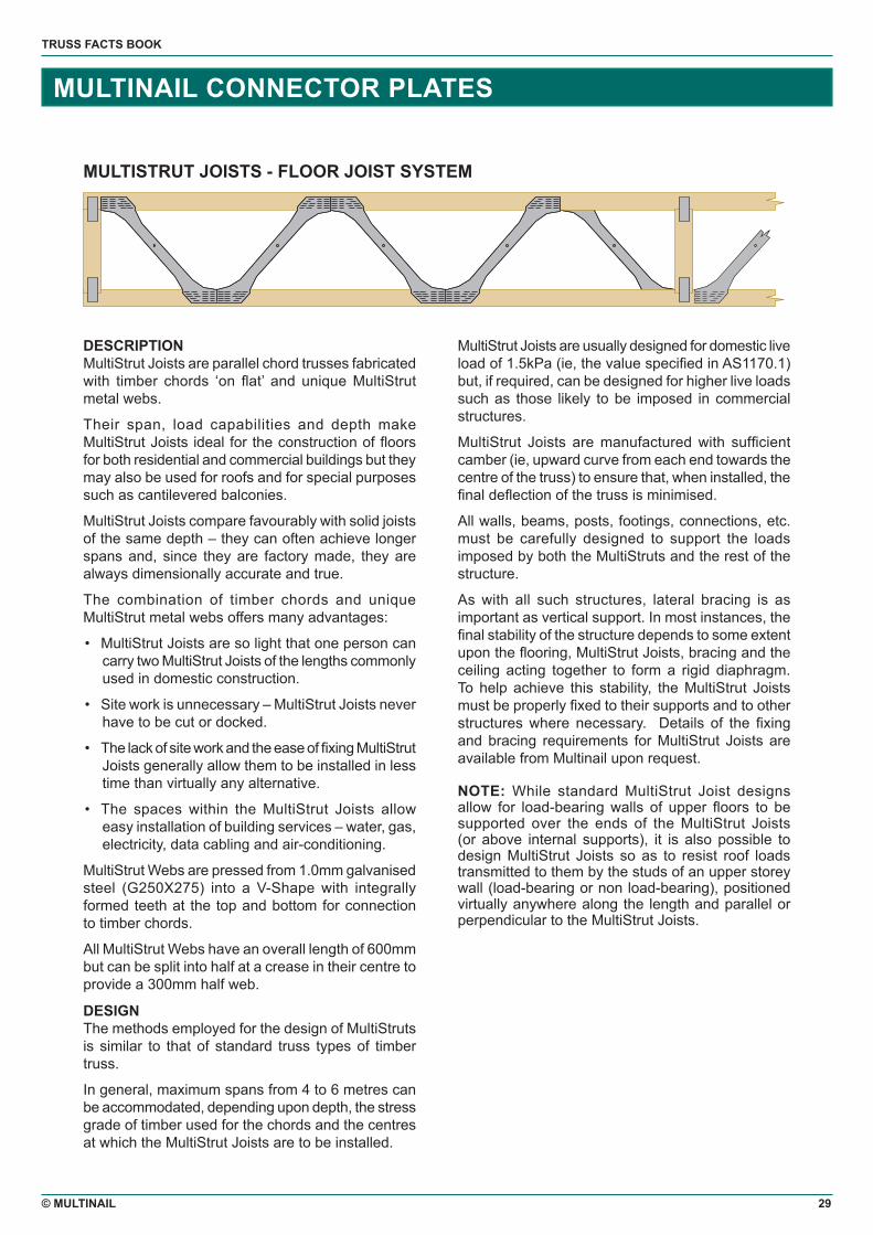
MULTISTRUT JOISTS - FLOOR JOIST SYSTEM
DESCRIPTIONMultiStrut Joists are parallel chord trusses fabricated with timber chords ‘on flat’ and unique MultiStrut metal webs.
Their span, load capabilities and depth make MultiStrut Joists ideal for the construction of floors for both residential and commercial buildings but they may also be used for roofs and for special purposes such as cantilevered balconies.
MultiStrut Joists compare favourably with solid joists of the same depth – they can often achieve longer spans and, since they are factory made, they are always dimensionally accurate and true.
The combination of timber chords and unique MultiStrut metal webs offers many advantages:
• MultiStrut Joists are so light that one person can carry two MultiStrut Joists of the lengths commonly used in domestic construction.
• Site work is unnecessary – MultiStrut Joists never have to be cut or docked.
• The lack of site work and the ease of fixing MultiStrut Joists generally allow them to be installed in less time than virtually any alternative.
• The spaces within the MultiStrut Joists allow easy installation of building services – water, gas, electricity, data cabling and air-conditioning.
MultiStrut Webs are pressed from 1.0mm galvanised steel (G250X275) into a V-Shape with integrally formed teeth at the top and bottom for connection to timber chords.
All MultiStrut Webs have an overall length of 600mm but can be split into half at a crease in their centre to provide a 300mm half web.
DESIGNThe methods employed for the design of MultiStruts is similar to that of standard truss types of timber truss.
In general, maximum spans from 4 to 6 metres can be accommodated, depending upon depth, the stress grade of timber used for the chords and the centres at which the MultiStrut Joists are to be installed.
MultiStrut Joists are usually designed for domestic live load of 1.5kPa (ie, the value specified in AS1170.1) but, if required, can be designed for higher live loads such as those likely to be imposed in commercial structures.
MultiStrut Joists are manufactured with sufficient camber (ie, upward curve from each end towards the centre of the truss) to ensure that, when installed, the final deflection of the truss is minimised.
All walls, beams, posts, footings, connections, etc. must be carefully designed to support the loads imposed by both the MultiStruts and the rest of the structure.
As with all such structures, lateral bracing is as important as vertical support. In most instances, the final stability of the structure depends to some extent upon the flooring, MultiStrut Joists, bracing and the ceiling acting together to form a rigid diaphragm. To help achieve this stability, the MultiStrut Joists must be properly fixed to their supports and to other structures where necessary. Details of the fixing and bracing requirements for MultiStrut Joists are available from Multinail upon request.
NOTE: While standard MultiStrut Joist designs allow for load-bearing walls of upper floors to be supported over the ends of the MultiStrut Joists (or above internal supports), it is also possible to design MultiStrut Joists so as to resist roof loads transmitted to them by the studs of an upper storey wall (load-bearing or non load-bearing), positioned virtually anywhere along the length and parallel or perpendicular to the MultiStrut Joists.

MULTINAIL AUSTRALIA PTY. LTD.ABN 79 003 999 586
HEAD OFFICE100 Cameron StreetWauchope NSW 2446 AustraliaT. + 61 (0)2 6585 3400F. + 61 (0)2 6585 3697E. [email protected]. www.multinail.com
BRISBANE OFFICE15 Mary StreetKingston QLD 4114 AustraliaT. + 61 (0)7 3808 3220F. + 61 (0)7 3208 2841
CAIRNS OFFICE23 Karwin StreetBayview Heights QLD 4868 AustraliaT. + 61 (0)7 4054 2062F. + 61 (0)7 4054 7741
SYDNEY OFFICE15/10 Victoria AvenueCastle Hill NSW 2154 AustraliaT. + 61 (0)2 9865 7011F. + 61 (0)2 9865 7010
MELBOURNE OFFICE6/16 Melverton DriveHallam VIC 3803 AustraliaT. + 61 (0)3 9796 3127F. + 61 (0)3 9796 3374
MULTINAIL MACHINERY PTY. LTD.ABN 52 060 402 860
NEW SOUTH WALES100 Cameron StreetWauchope NSW 2446 AustraliaT. + 61 (0)2 6585 3400F. + 61 (0)2 6586 1268
QUEENSLAND51-61 Musgrave RoadCoopers Plains QLD 4108 AustraliaT. + 61 (0)7 3336 1777F. + 61 (0)7 3275 3419
MULTINAIL ASIA SDN. BHD.KUALA LUMPUR OFFICENo. 1, Jalan TPP6/13Pinwang Industrial Park47100 PuchongSelangor MalaysiaT. + 60 (0)3 8061 6800F. + 61 (0)3 8061 6801E. [email protected]
Multinail’s Head Office and Manufacturing Facility at Wauchope is certified as complying with Australian Standard ISO9001 for the production of Nailplate, Bracing and Ancillary Components.
MNAP056