Embed Size (px)
Citation preview
MADE IN USA
Seri
alNr
:LNS America, Inc.
USA
4621 East Tech Drive
Cincinnati, Ohio 45245
Phone# 513.528.5674
http://www.LNSAmerica.com
Main fax# 513.528.5733
Service fax# 513.528.8320
332332332Hydrobar Express
Hydrobar Express
Hydrobar Express
TROUBLESHOOTING
AND SPARE PARTS
MANUALTROUBLESHOOTING
AND SPARE PARTS
MANUALTROUBLESHOOTING
AND SPARE PARTS
MANUAL

5
Table of Contents Chapter 1: ..........................................................................
Alarms .......................................................................................ALARM HISTORY ..............................................................................................Emergency Stop Line Open .............................................................................Lathe Emergency Stop Line Open...................................................................Bar Feeder Emergency Stop ............................................................................Oil Pressure Failure ..........................................................................................Air Pressure Failure..........................................................................................Main Access Cover Open.................................................................................Bar Feeder Retracted........................................................................................Front Measuring Stop Signal SQ1 Missing.....................................................Front Stopper Cannot Move Up .......................................................................Signal SQ1 For Front Stopper Defective.........................................................Guiding Channel Malfunction During Closing SQ3 .......................................Default Prior to Opening the Guiding Channel...............................................Guiding Channel Malfunction During Opening SQ3 ......................................Guiding Channel Malfunction During Closing SQ4 .......................................Guiding Channel Malfunction During Opening SQ4 ......................................Default Prior to Closing the Guiding Channel ................................................Front Rest Error ................................................................................................Servo Motor Positioning Error.........................................................................Vise Positioning Error ......................................................................................Home Position Proximity Switch SQ7 Missing...............................................Pusher Lost the Bar Stock During its Return to Home Position...................Bar Stock Not Extracted from the Collet.........................................................Vise Coupling Device Malfunction ..................................................................Switch SQ4 Signal Missing ..............................................................................Bar Stock Loading Error...................................................................................Bar Loading Error .............................................................................................Bar Remnant Too Long ....................................................................................Bar Stock Moving Backwards during Headstock Reverse with Collet OpenBar Stock Moving Forward during Headstock Reverse with Collet Open ...Headstock Travel is Shorter Than Programmed Length ...............................Servo Amp/PLC Comm. Fault ..........................................................................Bar Magazine Indexing Motor Faulty...............................................................Bar Stock Insertion Malfunction ......................................................................Servo Drive Alarm.............................................................................................Servo Motor Not Ready ....................................................................................Chuck Closed Prior to Feed Out Complete.....................................................A2 Interrupted During Loading ........................................................................Safety Time for Part Feed Out..........................................................................Software Sequence...........................................................................................Mitsubishi Servo Amplifier Alarm List ............................................................
Chapter 2: ..........................................................................
Common Issues.........................................................................Low Voltage / PLC Shutdown ..........................................................................Cannot Change Application Setup Parameters..............................................Multiple Bars have been Loaded into the Channel ........................................Front Rest Issues..............................................................................................Vibration Issues ................................................................................................
Chapter 3: ..........................................................................
HYDROBAR E
E109.09.200
.............1-1
..................1-1
............................1-3
............................1-4
............................1-5
............................1-6
............................1-7
............................1-8
............................1-9
..........................1-10
..........................1-11
..........................1-12
..........................1-13
..........................1-14
..........................1-15
..........................1-16
..........................1-17
..........................1-18
..........................1-19
..........................1-20
..........................1-21
..........................1-22
..........................1-23
..........................1-24
..........................1-25
..........................1-26
..........................1-28
..........................1-29
..........................1-30
..........................1-31 .........................1-32
..........................1-33
..........................1-34
..........................1-35
..........................1-36
..........................1-37
..........................1-38
..........................1-39
..........................1-40
..........................1-41
..........................1-42
..........................1-43
..........................1-45
.............2-1
..................2-1
............................2-2
............................2-3
............................2-3
............................2-4
............................2-5
.............3-1
XPRESS 332
Procedures ..................................................................................................3-1 Alignment Procedure for Front Rest ...........................................................................................3-2 Alignment Procedure for Mobile Vise .......................................................................................3-13 Alignment Procedure for Pusher Support Guiding Channel...................................................3-18 Calibration Procedure for Front Rest ........................................................................................3-30 Front Rest Override ....................................................................................................................3-33 Modified Upper Limiter Bracket Installation .............................................................................3-35 Pump Motor Splash Guard Assembly .......................................................................................3-41 Reference Procedure ..................................................................................................................3-43 Replacement of the Front Rest Diameter Adjustment Motor and Installation of the Modified Spacer Bracket ............................................................................................................................3-45 Adjustment Procedure for End of Bar.......................................................................................3-51 Replacement of the Loading Finger Diameter Motor ...............................................................3-53 Top Cut Positioning ....................................................................................................................3-55 Chain Tension Adjustment.........................................................................................................3-60 Pusher Changeover ....................................................................................................................3-64
Chapter 4: ....................................................................................... 4-1
Software Update/Restore ...........................................................................4-1 PLC Fault .......................................................................................................................................4-3 Restore PLC Program From Memory Card to PLC – v1.17a......................................................4-3 PLC Fault .......................................................................................................................................4-6 Restore Bar Feeder Parameters from MMI to PLC – v1.17a ......................................................4-6 Software Update............................................................................................................................4-9 Restore Bar Feeder Parameters From MMI to PLC – v1.17a .....................................................4-9 Software Update..........................................................................................................................4-12 Restore Display Data from Memory Card to MMI – v1.17a ......................................................4-12 Software Update..........................................................................................................................4-16 Restore PLC Program from Memory Card to PLC – v1.17a.....................................................4-16 PLC Fault – v2.08 ........................................................................................................................4-20 Software Update – v2.08.............................................................................................................4-23
Chapter 5: ....................................................................................... 5-1
Preventative Maintenance..........................................................................5-1 Daily Maintenance.........................................................................................................................5-2 Weekly Maintenance .....................................................................................................................5-2 Monthly Maintenance....................................................................................................................5-2 Annual Maintenance .....................................................................................................................5-3
Chapter 6: ....................................................................................... 6-1
Spare Parts..................................................................................................6-1 Recommended Spare Parts List ..................................................................................................6-2 Collet Reference Chart .................................................................................................................6-3 Guiding Channel Reference Chart...............................................................................................6-4 Parts Order Form ..........................................................................................................................6-6 Electrical Box Components .........................................................................................................6-7 Front Rest Air Blast Assembly.....................................................................................................6-8 Magazine Adjustment Decoder Disc Assembly..........................................................................6-9 Main Access Cover Switch Assembly.......................................................................................6-10 Hydraulics Assembly..................................................................................................................6-11 Material Presence Cylinder ........................................................................................................6-12 Pusher Locking Device – L/F Load............................................................................................6-13 Pusher Locking Device – R/F Load ...........................................................................................6-14 Front Rest Assembly – L/F Load ...............................................................................................6-15 Front Rest Assembly – R/F Load ...............................................................................................6-16 Measuring Bracket – L/F Load ...................................................................................................6-17 Measuring Bracket – R/F Load...................................................................................................6-18 Vise Assembly – L/F Load..........................................................................................................6-19 Vise Assembly – R/F Load .........................................................................................................6-20 Vise Assembly – Extraction Jaws..............................................................................................6-21 Chain Drive – Sub-assembly......................................................................................................6-22 Chain Drive – Servo Motor .........................................................................................................6-23 Chain Drive – Sprocket...............................................................................................................6-24
HYDROBAR EXPRESS 332
Chapter 1: Alarms
1-1
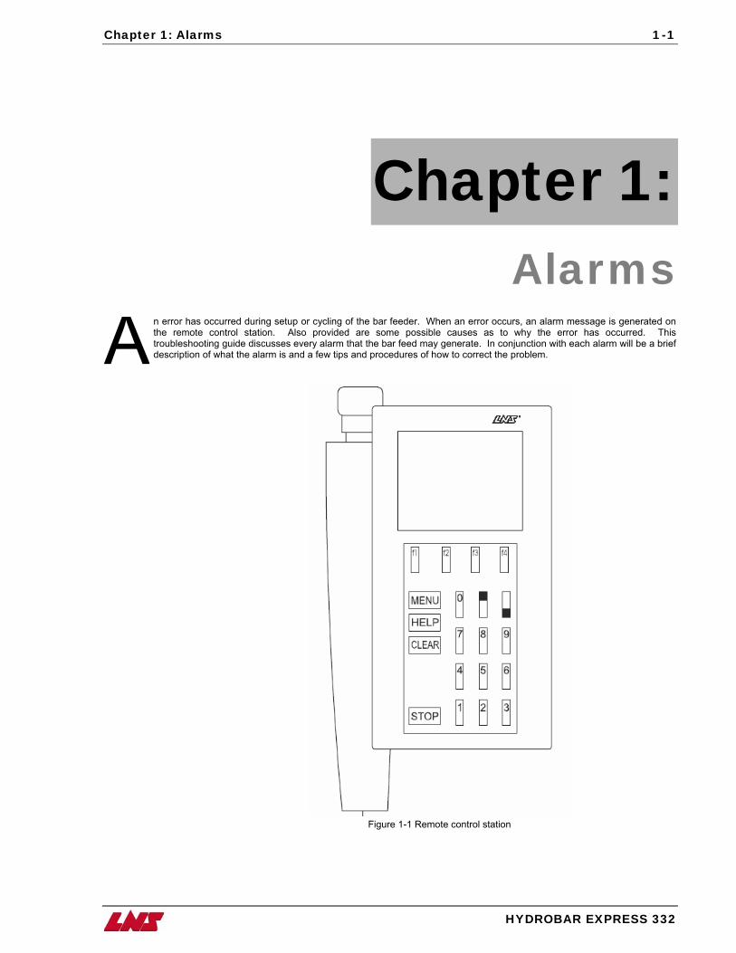
Chapter 1: Alarms
n error has occurred during setup or cycling of the bar feeder. When an error occurs, an alarm message is generated on the remote control station. Also provided are some possible causes as to why the error has occurred. This troubleshooting guide discusses every alarm that the bar feed may generate. In conjunction with each alarm will be a brief description of what the alarm is and a few tips and procedures of how to correct the problem. A
n
Figure 1-1 Remote control statioHYDROBAR EXPRESS 332
1-2 Chapter 1: Alarms
HYDROBAR EXPRESS 332
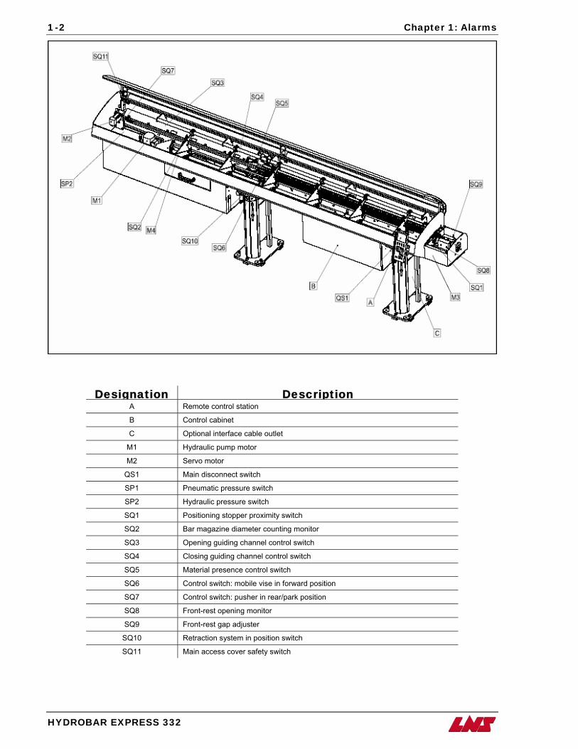
Designation Description A Remote control station
B Control cabinet
C Optional interface cable outlet
M1 Hydraulic pump motor
M2 Servo motor
QS1 Main disconnect switch
SP1 Pneumatic pressure switch
SP2 Hydraulic pressure switch
SQ1 Positioning stopper proximity switch
SQ2 Bar magazine diameter counting monitor
SQ3 Opening guiding channel control switch
SQ4 Closing guiding channel control switch
SQ5 Material presence control switch
SQ6 Control switch: mobile vise in forward position
SQ7 Control switch: pusher in rear/park position
SQ8 Front-rest opening monitor
SQ9 Front-rest gap adjuster
SQ10 Retraction system in position switch
SQ11 Main access cover safety switch
Chapter 1: Alarms
HYDROBAR EXPRESS 332
1-3
MOST RECENT
ALARMS
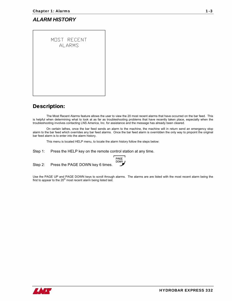
ALARM HISTORY
Description:
The Most Recent Alarms feature allows the user to view the 20 most recent alarms that have occurred on the bar feed. This is helpful when determining what to look at as far as troubleshooting problems that have recently taken place, especially when the troubleshooting involves contacting LNS America, Inc. for assistance and the message has already been cleared.
On certain lathes, once the bar feed sends an alarm to the machine, the machine will in return send an emergency stop alarm to the bar feed which overrides any bar feed alarms. Once the bar feed alarm is overridden the only way to pinpoint the original bar feed alarm is to enter into the alarm history.
This menu is located HELP menu, to locate the alarm history follow the steps below:
Step 1: Press the HELP key on the remote control station at any time.
Step 2: Press the PAGE DOWN key 6 times.
Use the PAGE UP and PAGE DOWN keys to scroll through alarms. The alarms are are listed with the most recent alarm being the first to appear to the 20th most recent alarm being listed last.
1-4 Chapter 1: Alarms
HYDROBAR EXPRESS 332
EMERGENCY STOP
LINE OPEN
********************
POSSIBLE CAUSES:
CONNECTION OR WIRING
PROBLEM IN CIRCUITRY
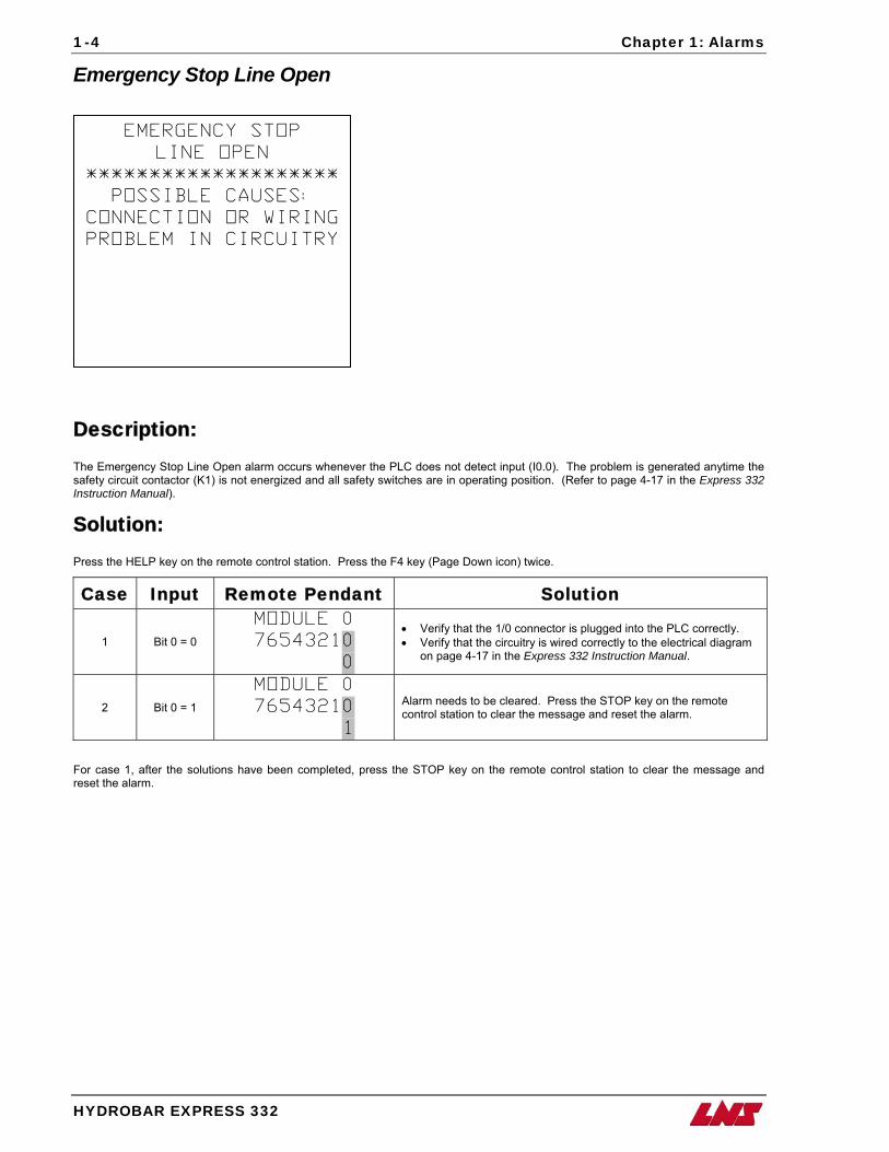
Emergency Stop Line Open
Description: The Emergency Stop Line Open alarm occurs whenever the PLC does not detect input (I0.0). The problem is generated anytime the safety circuit contactor (K1) is not energized and all safety switches are in operating position. (Refer to page 4-17 in the Express 332 Instruction Manual).
Solution: Press the HELP key on the remote control station. Press the F4 key (Page Down icon) twice.
Case Input Remote Pendant Solution
1 Bit 0 = 0
MODULE 0
76543210
0
• Verify that the 1/0 connector is plugged into the PLC correctly. • Verify that the circuitry is wired correctly to the electrical diagram
on page 4-17 in the Express 332 Instruction Manual.
2 Bit 0 = 1
MODULE 0
76543210
1
Alarm needs to be cleared. Press the STOP key on the remote control station to clear the message and reset the alarm.
For case 1, after the solutions have been completed, press the STOP key on the remote control station to clear the message and reset the alarm.
Chapter 1: Alarms
HYDROBAR EXPRESS 332
1-5
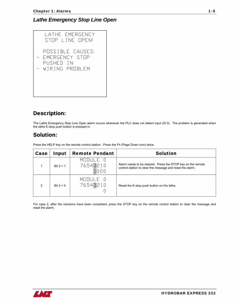
Lathe Emergency Stop Line Open
LATHE EMERGENCY
STOP LINE OPEN!
POSSIBLE CAUSES:
- EMERGENCY STOP
PUSHED IN
- WIRING PROBLEM
Description: The Lathe Emergency Stop Line Open alarm occurs whenever the PLC does not detect input (I0.3). The problem is generated when the lathe E-stop push button is pressed in.
Solution: Press the HELP key on the remote control station. Press the F4 (Page Down icon) twice.
Case Input Remote Pendant Solution
1 Bit 3 = 1
MODULE 0
76543210
1000
Alarm needs to be cleared. Press the STOP key on the remote control station to clear the message and reset the alarm.
2 Bit 3 = 0
MODULE 0
76543210
0
Reset the E-stop push button on the lathe.
For case 2, after the solutions have been completed, press the STOP key on the remote control station to clear the message and reset the alarm.
1-6 Chapter 1: Alarms
HYDROBAR EXPRESS 332
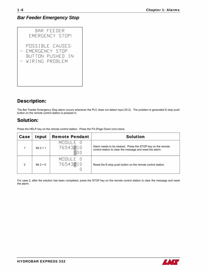
Bar Feeder Emergency Stop
BAR FEEDER
EMERGENCY STOP!
POSSIBLE CAUSES:
- EMERGENCY STOP
BUTTON PUSHED IN
- WIRING PROBLEM
Description: The Bar Feeder Emergency Stop alarm occurs whenever the PLC does not detect input (I0.2). The problem is generated E-stop push button on the remote control station is pressed in.
Solution: Press the HELP key on the remote control station. Press the F4 (Page Down icon) twice.
Case Input Remote Pendant Solution
1 Bit 2 = 1
MODULE 0
76543210
100
Alarm needs to be cleared. Press the STOP key on the remote control station to clear the message and reset the alarm.
2 Bit 2 = 0
MODULE 0
76543210
0
Reset the E-stop push button on the remote control station.
For case 2, after the solution has been completed, press the STOP key on the remote control station to clear the message and reset the alarm.
Chapter 1: Alarms
HYDROBAR EXPRESS 332
1-7
Oil Pressure Failure
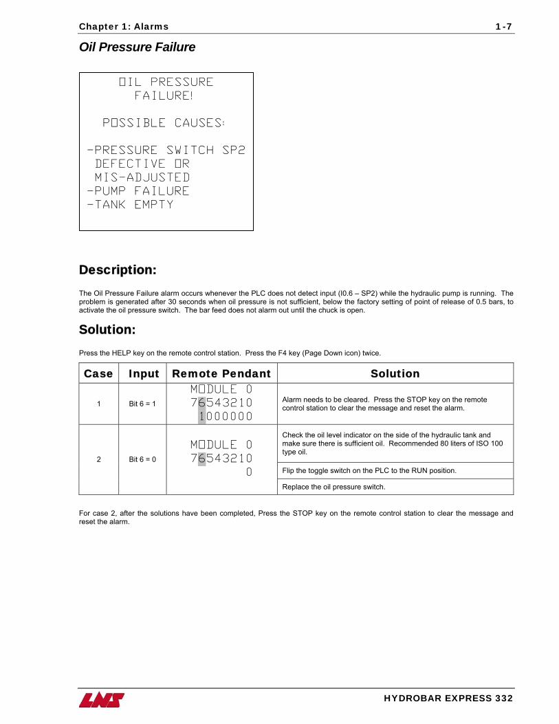
OIL PRESSURE
FAILURE!
POSSIBLE CAUSES:
-PRESSURE SWITCH SP2
DEFECTIVE OR
MIS-ADJUSTED
-PUMP FAILURE
-TANK EMPTY
Description: The Oil Pressure Failure alarm occurs whenever the PLC does not detect input (I0.6 – SP2) while the hydraulic pump is running. The problem is generated after 30 seconds when oil pressure is not sufficient, below the factory setting of point of release of 0.5 bars, to activate the oil pressure switch. The bar feed does not alarm out until the chuck is open.
Solution: Press the HELP key on the remote control station. Press the F4 key (Page Down icon) twice.
Case Input Remote Pendant Solution
1 Bit 6 = 1
MODULE 0
76543210
1000000
Alarm needs to be cleared. Press the STOP key on the remote control station to clear the message and reset the alarm.
Check the oil level indicator on the side of the hydraulic tank and make sure there is sufficient oil. Recommended 80 liters of ISO 100 type oil.
Flip the toggle switch on the PLC to the RUN position. 2 Bit 6 = 0
MODULE 0
76543210
0
Replace the oil pressure switch.
For case 2, after the solutions have been completed, Press the STOP key on the remote control station to clear the message and reset the alarm.
1-8 Chapter 1: Alarms
HYDROBAR EXPRESS 332
Air Pressure Failure
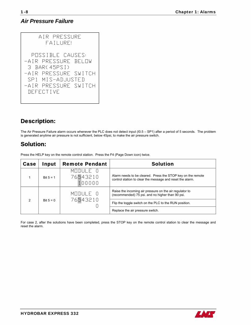
AIR PRESSURE
FAILURE!
POSSIBLE CAUSES:
-AIR PRESSURE BELOW
3 BAR(45PSI)
-AIR PRESSURE SWITCH
SP1 MIS-ADJUSTED
-AIR PRESSURE SWITCH
DEFECTIVE
Description: The Air Pressure Failure alarm occurs whenever the PLC does not detect input (I0.5 – SP1) after a period of 5 seconds. The problem is generated anytime air pressure is not sufficient, below 45psi, to make the air pressure switch.
Solution: Press the HELP key on the remote control station. Press the F4 (Page Down icon) twice.
Case Input Remote Pendant Solution
1 Bit 5 = 1
MODULE 0
76543210
100000
Alarm needs to be cleared. Press the STOP key on the remote control station to clear the message and reset the alarm.
Raise the incoming air pressure on the air regulator to (recommended) 75 psi. and no higher than 90 psi.
Flip the toggle switch on the PLC to the RUN position. 2 Bit 5 = 0
MODULE 0
76543210
0 Replace the air pressure switch.
For case 2, after the solutions have been completed, press the STOP key on the remote control station to clear the message and reset the alarm.
Chapter 1: Alarms
HYDROBAR EXPRESS 332
1-9
Main Access Cover Open
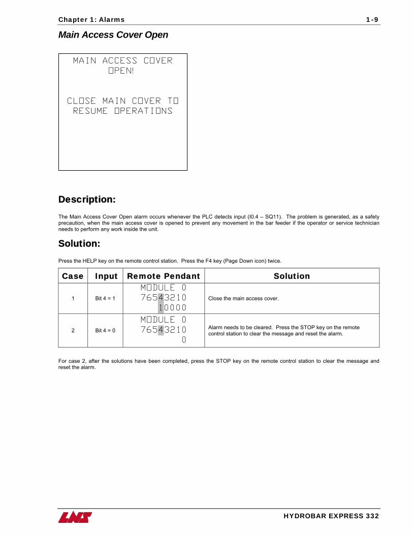
MAIN ACCESS COVER
OPEN!
CLOSE MAIN COVER TO
RESUME OPERATIONS
Description: The Main Access Cover Open alarm occurs whenever the PLC detects input (I0.4 – SQ11). The problem is generated, as a safety precaution, when the main access cover is opened to prevent any movement in the bar feeder if the operator or service technician needs to perform any work inside the unit.
Solution: Press the HELP key on the remote control station. Press the F4 key (Page Down icon) twice.
Case Input Remote Pendant Solution
1 Bit 4 = 1
MODULE 0
76543210
10000
Close the main access cover.
2 Bit 4 = 0
MODULE 0
76543210
0
Alarm needs to be cleared. Press the STOP key on the remote control station to clear the message and reset the alarm.
For case 2, after the solutions have been completed, press the STOP key on the remote control station to clear the message and reset the alarm.
1-10 Chapter 1: Alarms
HYDROBAR EXPRESS 332
Bar Feeder Retracted
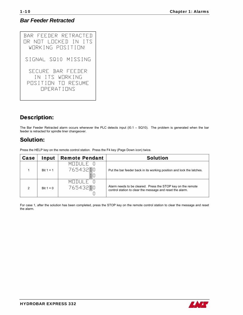
BAR FEEDER RETRACTED
OR NOT LOCKED IN ITS
WORKING POSITION!
SIGNAL SQ10 MISSING
SECURE BAR FEEDER
IN ITS WORKING
POSITION TO RESUME
OPERATIONS
Description: The Bar Feeder Retracted alarm occurs whenever the PLC detects input (I0.1 – SQ10). The problem is generated when the bar feeder is retracted for spindle liner changeover.
Solution: Press the HELP key on the remote control station. Press the F4 key (Page Down icon) twice.
Case Input Remote Pendant Solution
1 Bit 1 = 1
MODULE 0
76543210
10
Put the bar feeder back in its working position and lock the latches.
2 Bit 1 = 0
MODULE 0
76543210
0
Alarm needs to be cleared. Press the STOP key on the remote control station to clear the message and reset the alarm.
For case 1, after the solution has been completed, press the STOP key on the remote control station to clear the message and reset the alarm.
Chapter 1: Alarms
HYDROBAR EXPRESS 332
1-11
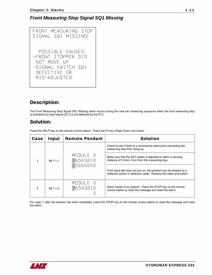
Front Measuring Stop Signal SQ1 Missing
FRONT MEASURING STOP
SIGNAL SQ1 MISSING!
POSSIBLE CAUSES:
-FRONT STOPPER DID
NOT MOVE UP
-SIGNAL SWITCH SQ1
DEFECTIVE OR
MIS-ADJUSTED
Description: The Front Measuring Stop Signal SQ1 Missing alarm occurs during the new bar measuring sequence when the front measuring stop is activated but input signal (I0.7) is not detected by the PLC.
Solution: Press the HELP key on the remote control station. Press the F4 key (Page Down icon) twice.
Case Input Remote Pendant Solution Check to see if there is a mechanical obstruction preventing the measuring stop from rising up.
Make sure that the SQ1 switch is adjusted to within a sensing distance of 0.5mm-1mm from the measuring stop. 1 Bit 7 = 1
MODULE 0
76543210
10000000 If the input still does not turn on, the problem can be isolated to a defective switch or defective cable. Replace the cable and switch.
2 Bit 7 = 0
MODULE 0
76543210
0
Alarm needs to be cleared. Press the STOP key on the remote control station to clear the message and reset the alarm.
For case 1, after the solution has been completed, press the STOP key on the remote control station to clear the message and reset the alarm.
1-12 Chapter 1: Alarms
H
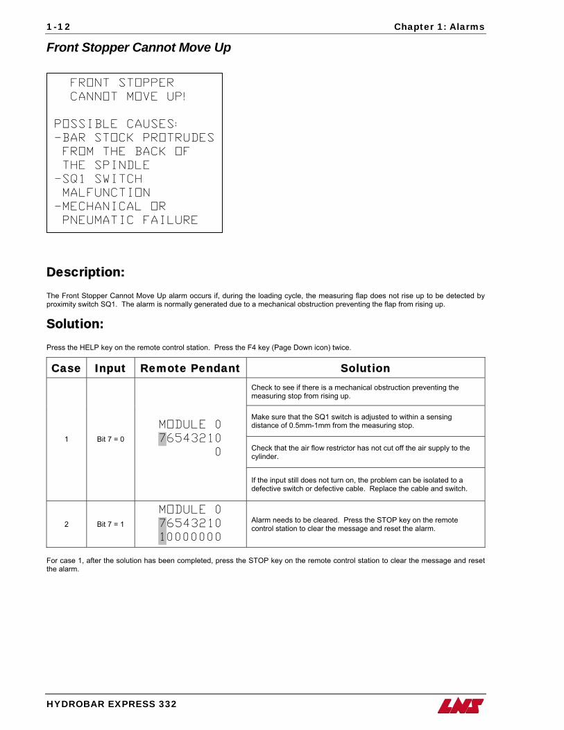
Front Stopper Cannot Move Up
DTp
SP
Ft
FRONT STOPPER
CANNOT MOVE UP!
POSSIBLE CAUSES:
-BAR STOCK PROTRUDES
FROM THE BACK OF
THE SPINDLE
-SQ1 SWITCH
MALFUNCTION
-MECHANICAL OR
PNEUMATIC FAILURE
YDROBAR EXPRESS 332
escription: he Front Stopper Cannot Move Up alarm occurs if, during the loading cycle, the measuring flap does not rise up to be detected by roximity switch SQ1. The alarm is normally generated due to a mechanical obstruction preventing the flap from rising up.
olution: ress the HELP key on the remote control station. Press the F4 key (Page Down icon) twice.
Case Input Remote Pendant Solution Check to see if there is a mechanical obstruction preventing the measuring stop from rising up.
Make sure that the SQ1 switch is adjusted to within a sensing distance of 0.5mm-1mm from the measuring stop.
Check that the air flow restrictor has not cut off the air supply to the cylinder.
1 Bit 7 = 0
MODULE 0
76543210
0
If the input still does not turn on, the problem can be isolated to a defective switch or defective cable. Replace the cable and switch.
2 Bit 7 = 1
MODULE 0
76543210
10000000
Alarm needs to be cleared. Press the STOP key on the remote control station to clear the message and reset the alarm.
or case 1, after the solution has been completed, press the STOP key on the remote control station to clear the message and reset he alarm.
Chapter 1: Alarms
HYDROBAR EXPRESS 332
1-13
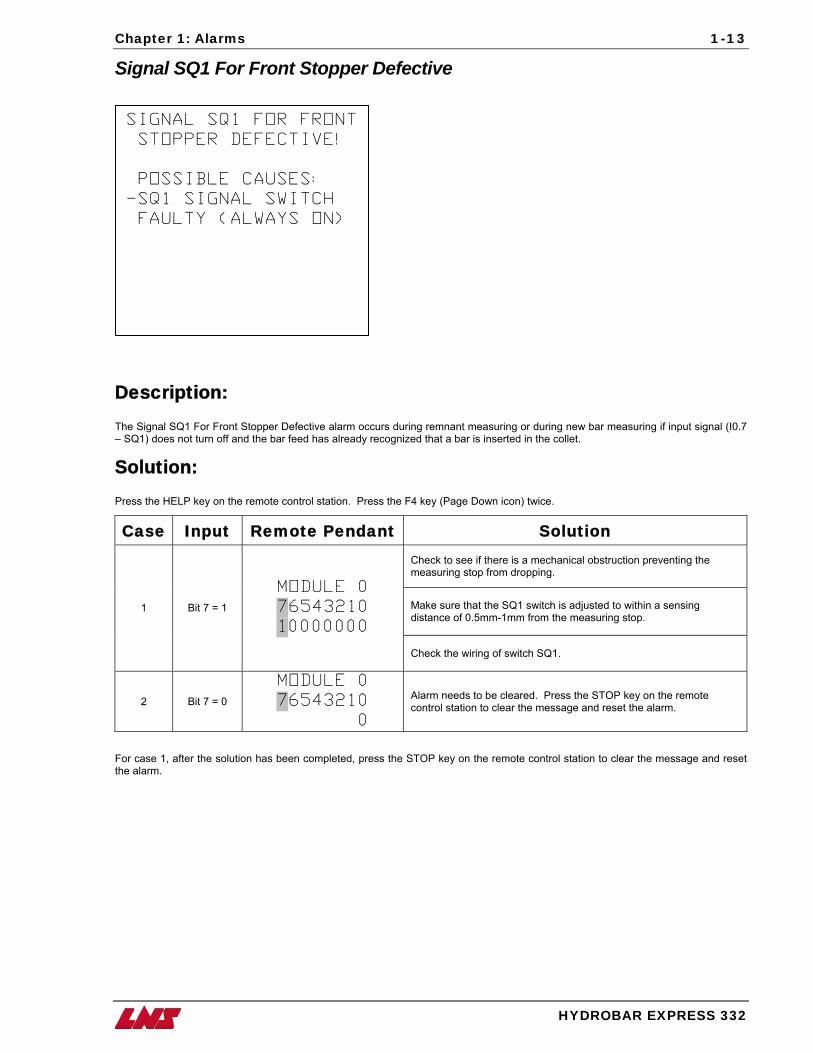
Signal SQ1 For Front Stopper Defective
SIGNAL SQ1 FOR FRONT
STOPPER DEFECTIVE!
POSSIBLE CAUSES:
-SQ1 SIGNAL SWITCH
FAULTY (ALWAYS ON)
Description: The Signal SQ1 For Front Stopper Defective alarm occurs during remnant measuring or during new bar measuring if input signal (I0.7 – SQ1) does not turn off and the bar feed has already recognized that a bar is inserted in the collet.
Solution: Press the HELP key on the remote control station. Press the F4 key (Page Down icon) twice.
Case Input Remote Pendant Solution Check to see if there is a mechanical obstruction preventing the measuring stop from dropping.
Make sure that the SQ1 switch is adjusted to within a sensing distance of 0.5mm-1mm from the measuring stop.
1 Bit 7 = 1
MODULE 0
76543210
10000000
Check the wiring of switch SQ1.
2 Bit 7 = 0
MODULE 0
76543210
0
Alarm needs to be cleared. Press the STOP key on the remote control station to clear the message and reset the alarm.
For case 1, after the solution has been completed, press the STOP key on the remote control station to clear the message and reset the alarm.
1-14 Chapter 1: Alarms
HYDROBAR EXPRESS 332
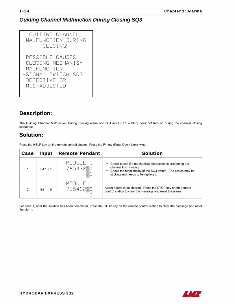
Guiding Channel Malfunction During Closing SQ3
GUIDING CHANNEL
MALFUNCTION DURING
CLOSING!
POSSIBLE CAUSES:
-CLOSING MECHANISM
MALFUNCTION
-SIGNAL SWITCH SQ3
DEFECTIVE OR
MIS-ADJUSTED
Description: The Guiding Channel Malfunction During Closing alarm occurs if input (I1.1 – SQ3) does not turn off during the channel closing sequence.
Solution: Press the HELP key on the remote control station. Press the F4 key (Page Down icon) twice.
Case Input Remote Pendant Solution
1 Bit 1 = 1
MODULE 1
76543210
10
Check to see if a mechanical obstruction is preventing the channel from closing.
Check the functionality of the SQ3 switch. The switch may be sticking and needs to be replaced.
2 Bit 1 = 0
MODULE 1
76543210
0
Alarm needs to be cleared. Press the STOP key on the remote control station to clear the message and reset the alarm.
For case 1, after the solution has been completed, press the STOP key on the remote control station to clear the message and reset the alarm.
Chapter 1: Alarms
HYDROBAR EXPRESS 332
1-15
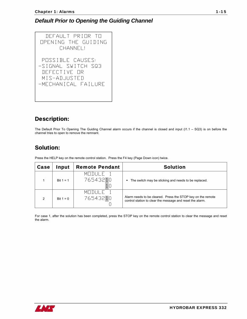
Default Prior to Opening the Guiding Channel
DEFAULT PRIOR TO
OPENING THE GUIDING
CHANNEL!
POSSIBLE CAUSES:
-SIGNAL SWITCH SQ3
DEFECTIVE OR
MIS-ADJUSTED
-MECHANICAL FAILURE
Description: The Default Prior To Opening The Guiding Channel alarm occurs if the channel is closed and input (I1.1 – SQ3) is on before the channel tries to open to remove the remnant.
Solution: Press the HELP key on the remote control station. Press the F4 key (Page Down icon) twice.
Case Input Remote Pendant Solution
1 Bit 1 = 1
MODULE 1
76543210
10
The switch may be sticking and needs to be replaced.
2 Bit 1 = 0
MODULE 1
76543210
0
Alarm needs to be cleared. Press the STOP key on the remote control station to clear the message and reset the alarm.
For case 1, after the solution has been completed, press the STOP key on the remote control station to clear the message and reset the alarm.
1-16 Chapter 1: Alarms
HYDROBAR EXPRESS 332
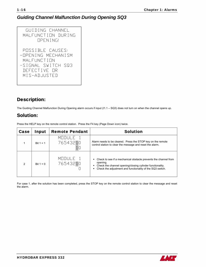
Guiding Channel Malfunction During Opening SQ3
GUIDING CHANNEL
MALFUNCTION DURING
OPENING!
POSSIBLE CAUSES:
-OPENING MECHANISM
MALFUNCTION
-SIGNAL SWITCH SQ3
DEFECTIVE OR
MIS-ADJUSTED
Description: The Guiding Channel Malfunction During Opening alarm occurs if input (I1.1 – SQ3) does not turn on when the channel opens up.
Solution: Press the HELP key on the remote control station. Press the F4 key (Page Down icon) twice.
Case Input Remote Pendant Solution
1 Bit 1 = 1
MODULE 1
76543210
10
Alarm needs to be cleared. Press the STOP key on the remote control station to clear the message and reset the alarm.
2 Bit 1 = 0
MODULE 1
76543210
0
Check to see if a mechanical obstacle prevents the channel from opening.
Check the channel opening/closing cylinder functionality. Check the adjustment and functionality of the SQ3 switch.
For case 1, after the solution has been completed, press the STOP key on the remote control station to clear the message and reset the alarm.
Chapter 1: Alarms
HYDROBAR EXPRESS 332
1-17
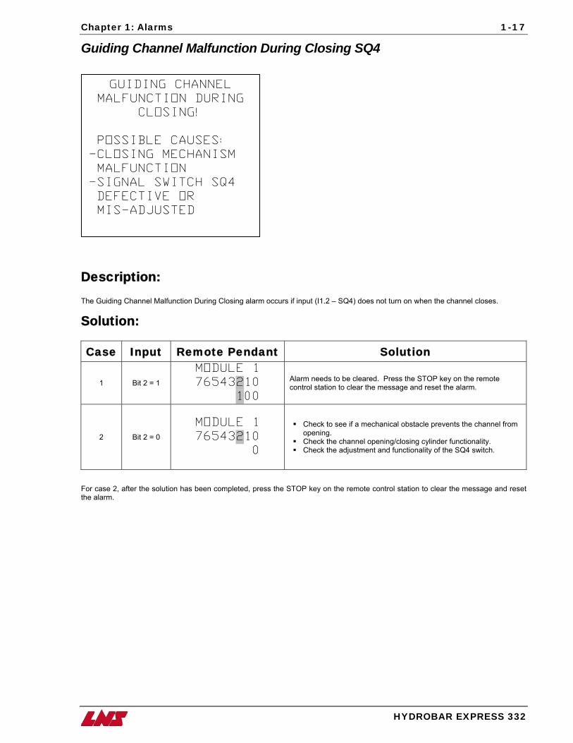
Guiding Channel Malfunction During Closing SQ4
GUIDING CHANNEL
MALFUNCTION DURING
CLOSING!
POSSIBLE CAUSES:
-CLOSING MECHANISM
MALFUNCTION
-SIGNAL SWITCH SQ4
DEFECTIVE OR
MIS-ADJUSTED
Description: The Guiding Channel Malfunction During Closing alarm occurs if input (I1.2 – SQ4) does not turn on when the channel closes.
Solution:
Case Input Remote Pendant Solution
1 Bit 2 = 1
MODULE 1
76543210
100
Alarm needs to be cleared. Press the STOP key on the remote control station to clear the message and reset the alarm.
2 Bit 2 = 0
MODULE 1
76543210
0
Check to see if a mechanical obstacle prevents the channel from opening.
Check the channel opening/closing cylinder functionality. Check the adjustment and functionality of the SQ4 switch.
For case 2, after the solution has been completed, press the STOP key on the remote control station to clear the message and reset the alarm.
1-18 Chapter 1: Alarms
HYDROBAR EXPRESS 332
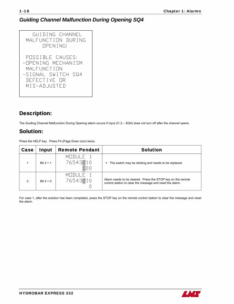
Guiding Channel Malfunction During Opening SQ4
GUIDING CHANNEL
MALFUNCTION DURING
OPENING!
POSSIBLE CAUSES:
-OPENING MECHANISM
MALFUNCTION
-SIGNAL SWITCH SQ4
DEFECTIVE OR
MIS-ADJUSTED
Description: The Guiding Channel Malfunction During Opening alarm occurs if input (I1.2 – SQ4) does not turn off after the channel opens.
Solution: Press the HELP key. Press F4 (Page Down icon) twice.
Case Input Remote Pendant Solution
1 Bit 2 = 1
MODULE 1
76543210
100
The switch may be sticking and needs to be replaced.
2 Bit 2 = 0
MODULE 1
76543210
0
Alarm needs to be cleared. Press the STOP key on the remote control station to clear the message and reset the alarm.
For case 1, after the solution has been completed, press the STOP key on the remote control station to clear the message and reset the alarm.
Chapter 1: Alarms
HYDROBAR EXPRESS 332
1-19
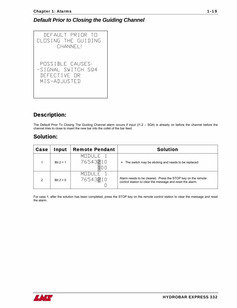
Default Prior to Closing the Guiding Channel
DEFAULT PRIOR TO
CLOSING THE GUIDING
CHANNEL!
POSSIBLE CAUSES:
-SIGNAL SWITCH SQ4
DEFECTIVE OR
MIS-ADJUSTED
Description: The Default Prior To Closing The Guiding Channel alarm occurs if input (I1.2 – SQ4) is already on before the channel before the channel tries to close to insert the new bar into the collet of the bar feed.
Solution:
Case Input Remote Pendant Solution
1 Bit 2 = 1
MODULE 1
76543210
100
The switch may be sticking and needs to be replaced.
2 Bit 2 = 0
MODULE 1
76543210
0
Alarm needs to be cleared. Press the STOP key on the remote control station to clear the message and reset the alarm.
For case 1, after the solution has been completed, press the STOP key on the remote control station to clear the message and reset the alarm.
1-20 Chapter 1: Alarms
HYDROBAR EXPRESS 332
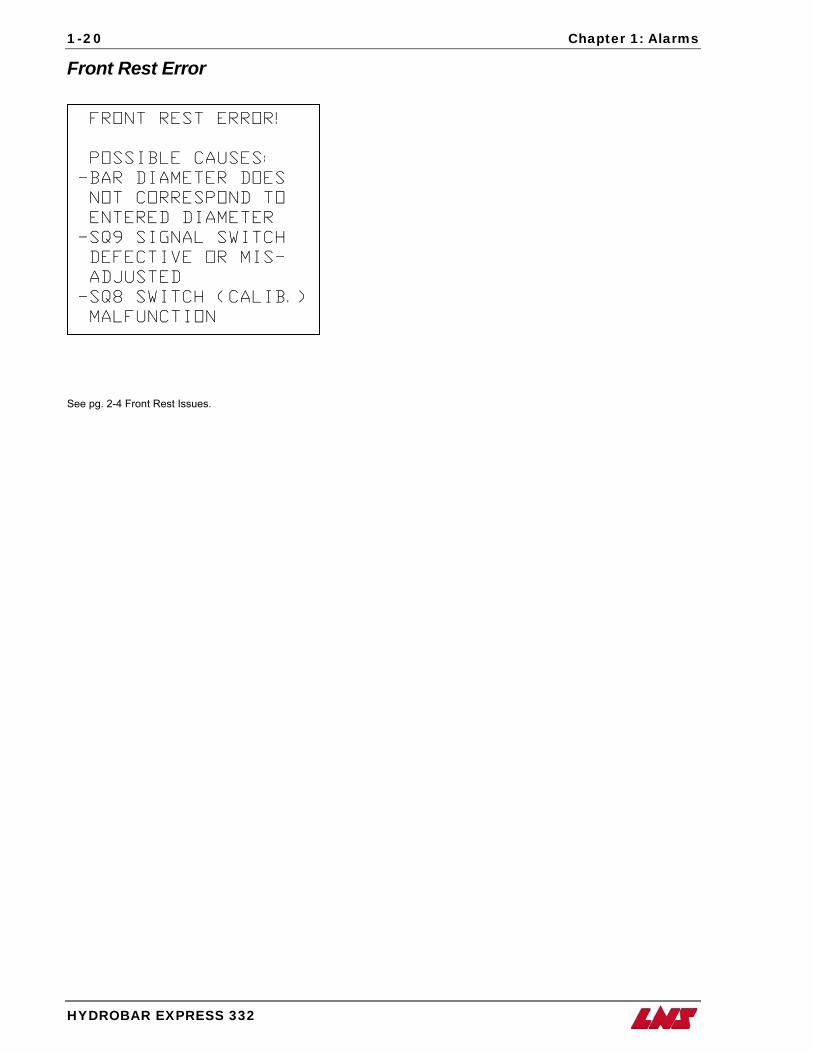
Front Rest Error
FRONT REST ERROR!
POSSIBLE CAUSES:
-BAR DIAMETER DOES
NOT CORRESPOND TO
ENTERED DIAMETER
-SQ9 SIGNAL SWITCH
DEFECTIVE OR MIS-
ADJUSTED
-SQ8 SWITCH (CALIB.)
MALFUNCTION
See pg. 2-4 Front Rest Issues.
Chapter 1: Alarms
HYDROBAR EXPRESS 332
1-21
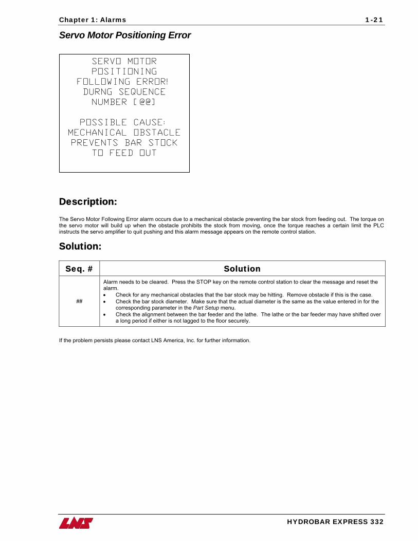
Servo Motor Positioning Error
SERVO MOTOR
POSITIONING
FOLLOWING ERROR!
DURNG SEQUENCE
NUMBER [@@]
POSSIBLE CAUSE:
MECHANICAL OBSTACLE
PREVENTS BAR STOCK
TO FEED OUT
Description: The Servo Motor Following Error alarm occurs due to a mechanical obstacle preventing the bar stock from feeding out. The torque on the servo motor will build up when the obstacle prohibits the stock from moving, once the torque reaches a certain limit the PLC instructs the servo amplifier to quit pushing and this alarm message appears on the remote control station.
Solution:
Seq. # Solution
##
Alarm needs to be cleared. Press the STOP key on the remote control station to clear the message and reset the alarm. • Check for any mechanical obstacles that the bar stock may be hitting. Remove obstacle if this is the case. • Check the bar stock diameter. Make sure that the actual diameter is the same as the value entered in for the
corresponding parameter in the Part Setup menu. • Check the alignment between the bar feeder and the lathe. The lathe or the bar feeder may have shifted over
a long period if either is not lagged to the floor securely.
If the problem persists please contact LNS America, Inc. for further information.
1-22 Chapter 1: Alarms
HYDROBAR EXPRESS 332
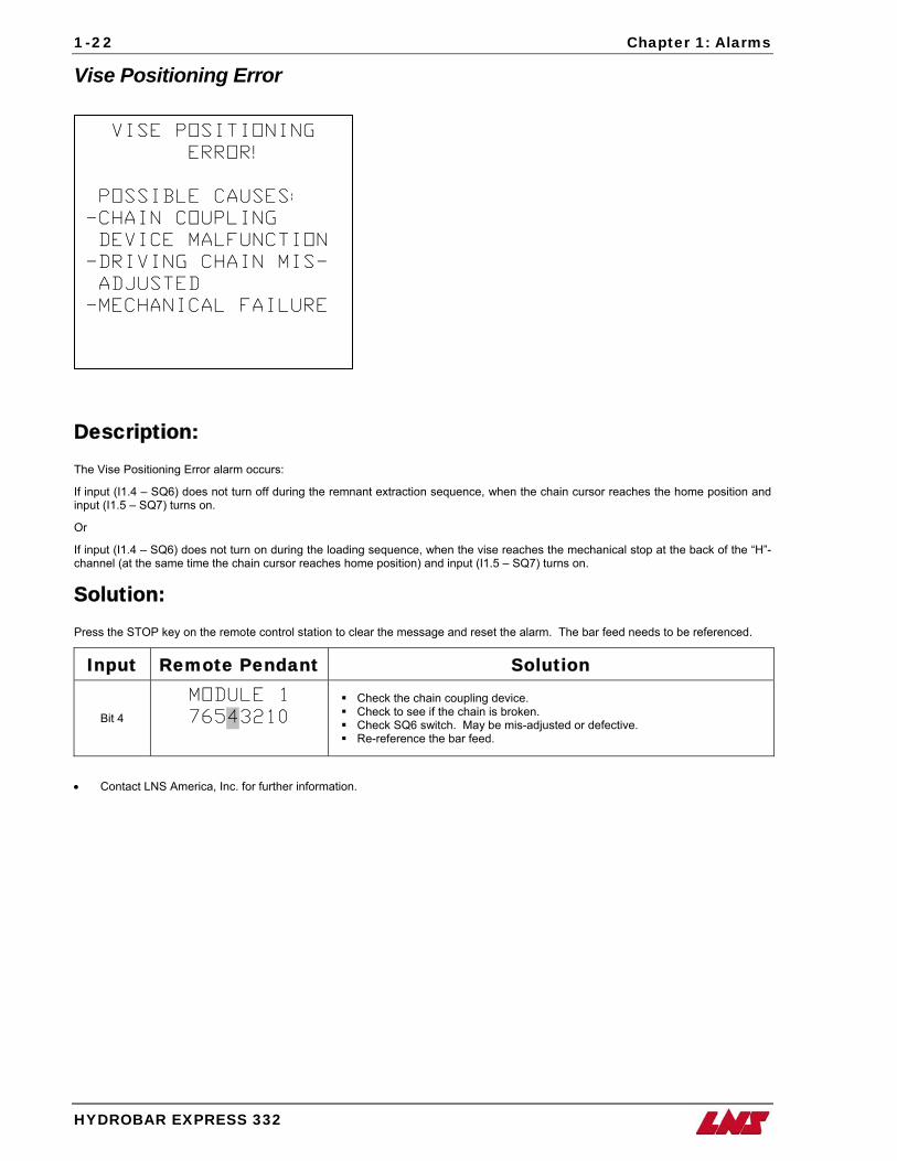
Vise Positioning Error
VISE POSITIONING
ERROR!
POSSIBLE CAUSES:
-CHAIN COUPLING
DEVICE MALFUNCTION
-DRIVING CHAIN MIS-
ADJUSTED
-MECHANICAL FAILURE
Description: The Vise Positioning Error alarm occurs:
If input (I1.4 – SQ6) does not turn off during the remnant extraction sequence, when the chain cursor reaches the home position and input (I1.5 – SQ7) turns on.
Or
If input (I1.4 – SQ6) does not turn on during the loading sequence, when the vise reaches the mechanical stop at the back of the “H”-channel (at the same time the chain cursor reaches home position) and input (I1.5 – SQ7) turns on.
Solution: Press the STOP key on the remote control station to clear the message and reset the alarm. The bar feed needs to be referenced.
Input Remote Pendant Solution
Bit 4
MODULE 1
76543210
Check the chain coupling device. Check to see if the chain is broken. Check SQ6 switch. May be mis-adjusted or defective. Re-reference the bar feed.
• Contact LNS America, Inc. for further information.
Chapter 1: Alarms
HYDROBAR EXPRESS 332
1-23
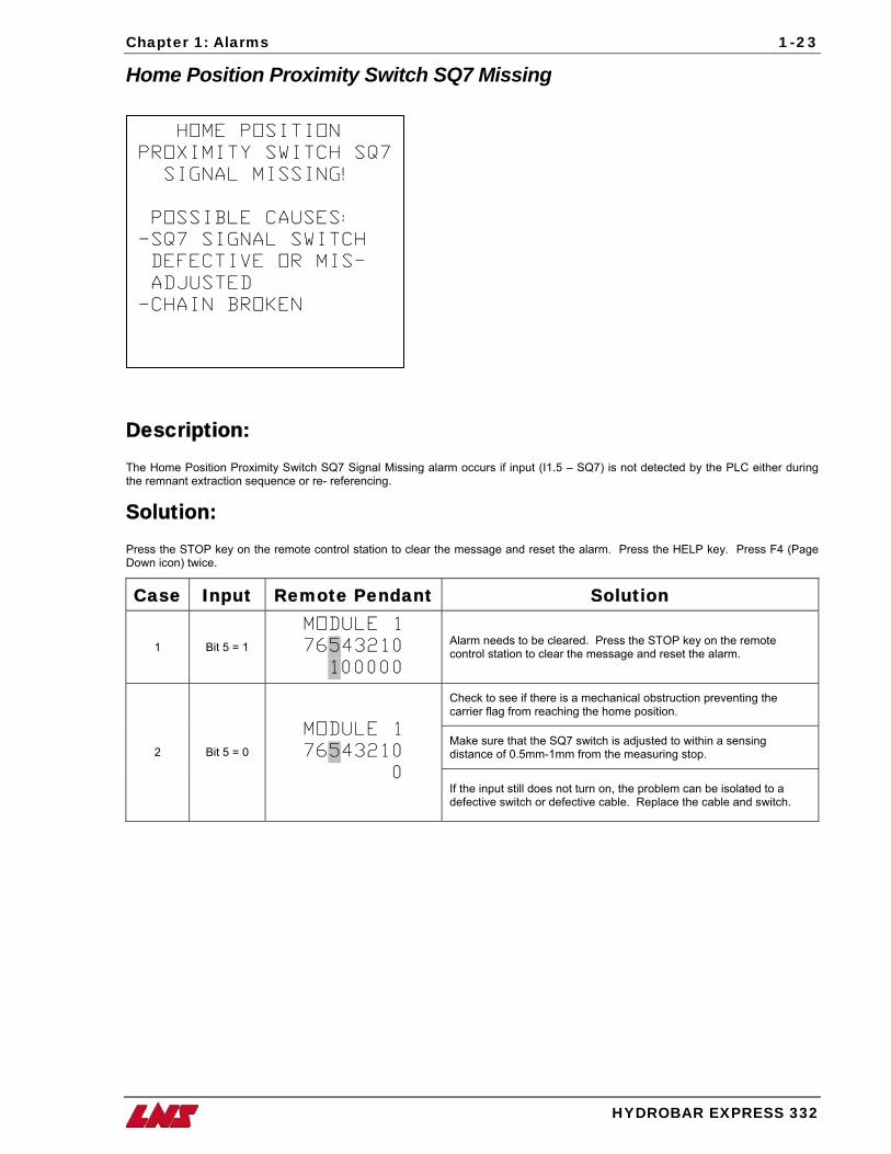
Home Position Proximity Switch SQ7 Missing
Description: The Home Position Proximity Switch SQ7 Signal Missing alarm occurs if input (I1.5 – SQ7) is not detected by the PLC either during the remnant extraction sequence or re- referencing.
Solution: Press the STOP key on the remote control station to clear the message and reset the alarm. Press the HELP key. Press F4 (Page Down icon) twice.
Case Input Remote Pendant Solution
1 Bit 5 = 1
MODULE 1
76543210
100000
Alarm needs to be cleared. Press the STOP key on the remote control station to clear the message and reset the alarm.
Check to see if there is a mechanical obstruction preventing the carrier flag from reaching the home position.
Make sure that the SQ7 switch is adjusted to within a sensing distance of 0.5mm-1mm from the measuring stop. 2 Bit 5 = 0
MODULE 1
76543210
0 If the input still does not turn on, the problem can be isolated to a defective switch or defective cable. Replace the cable and switch.
HOME POSITION
PROXIMITY SWITCH SQ7
SIGNAL MISSING!
POSSIBLE CAUSES:
-SQ7 SIGNAL SWITCH
DEFECTIVE OR MIS-
ADJUSTED
-CHAIN BROKEN
1-24 Chapter 1: Alarms
HYDROBAR EXPRESS 332
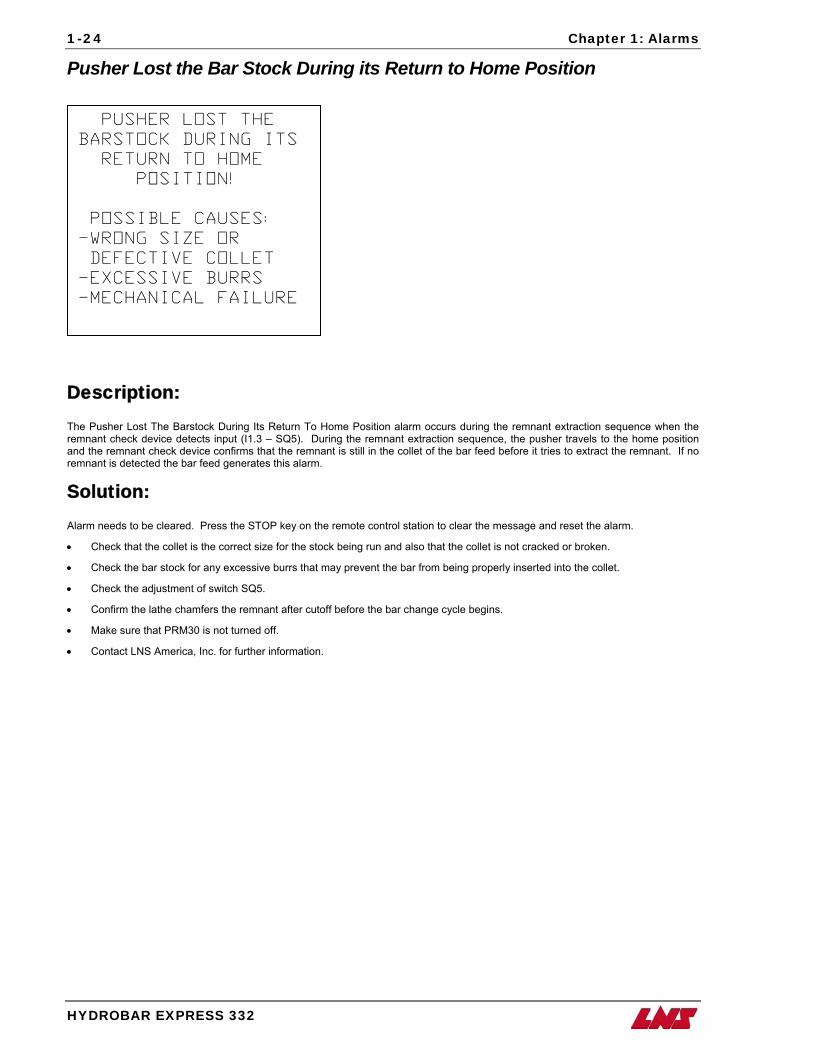
Pusher Lost the Bar Stock During its Return to Home Position
PUSHER LOST THE
BARSTOCK DURING ITS
RETURN TO HOME
POSITION!
POSSIBLE CAUSES:
-WRONG SIZE OR
DEFECTIVE COLLET
-EXCESSIVE BURRS
-MECHANICAL FAILURE
Description: The Pusher Lost The Barstock During Its Return To Home Position alarm occurs during the remnant extraction sequence when the remnant check device detects input (I1.3 – SQ5). During the remnant extraction sequence, the pusher travels to the home position and the remnant check device confirms that the remnant is still in the collet of the bar feed before it tries to extract the remnant. If no remnant is detected the bar feed generates this alarm.
Solution: Alarm needs to be cleared. Press the STOP key on the remote control station to clear the message and reset the alarm.
• Check that the collet is the correct size for the stock being run and also that the collet is not cracked or broken.
• Check the bar stock for any excessive burrs that may prevent the bar from being properly inserted into the collet.
• Check the adjustment of switch SQ5.
• Confirm the lathe chamfers the remnant after cutoff before the bar change cycle begins.
• Make sure that PRM30 is not turned off.
• Contact LNS America, Inc. for further information.
Chapter 1: Alarms
HYDROBAR EXPRESS 332
1-25
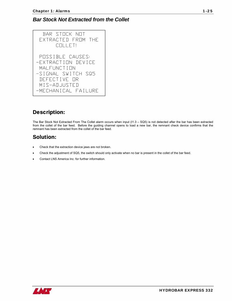
Bar Stock Not Extracted from the Collet
BAR STOCK NOT
EXTRACTED FROM THE
COLLET!
POSSIBLE CAUSES:
-EXTRACTION DEVICE
MALFUNCTION
-SIGNAL SWITCH SQ5
DEFECTIVE OR
MIS-ADJUSTED
-MECHANICAL FAILURE
Description: The Bar Stock Not Extracted From The Collet alarm occurs when input (I1.3 – SQ5) is not detected after the bar has been extracted from the collet of the bar feed. Before the guiding channel opens to load a new bar, the remnant check device confirms that the remnant has been extracted from the collet of the bar feed.
Solution: • Check that the extraction device jaws are not broken.
• Check the adjustment of SQ5, the switch should only activate when no bar is present in the collet of the bar feed.
• Contact LNS America Inc. for further information.
1-26 Chapter 1: Alarms
HYDROBAR EXPRESS 332
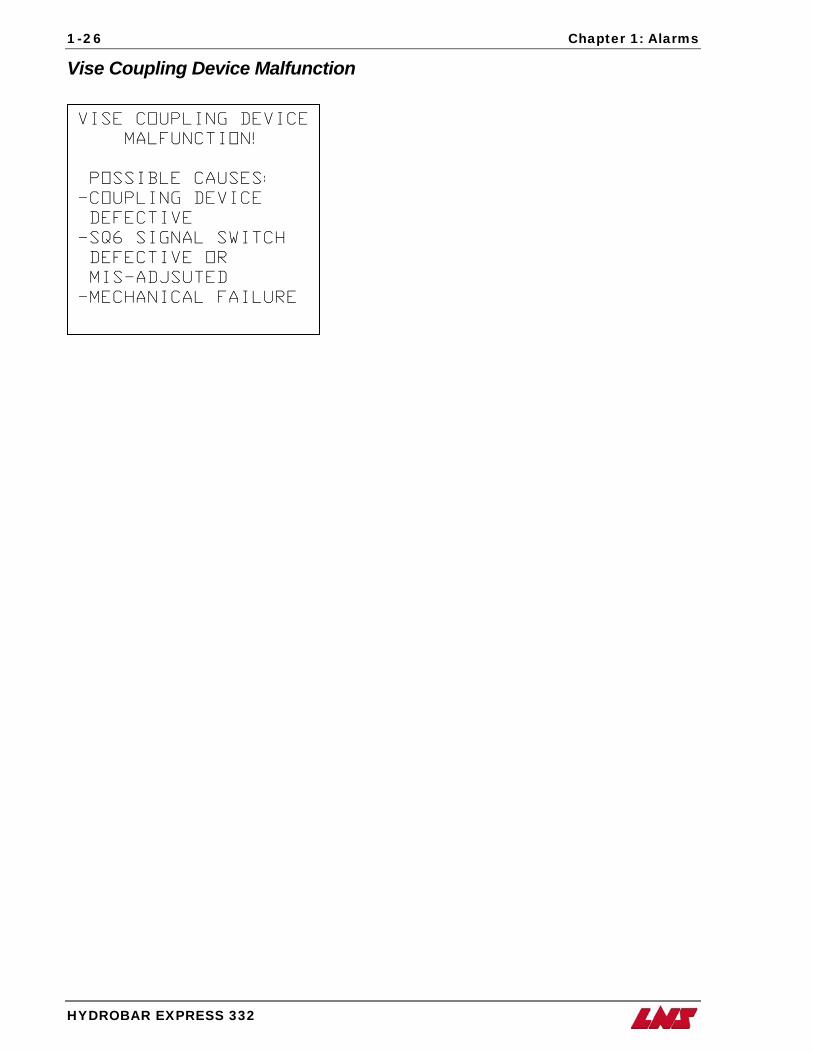
Vise Coupling Device Malfunction
VISE COUPLING DEVICE
MALFUNCTION!
POSSIBLE CAUSES:
-COUPLING DEVICE
DEFECTIVE
-SQ6 SIGNAL SWITCH
DEFECTIVE OR
MIS-ADJSUTED
-MECHANICAL FAILURE
Chapter 1: Alarms
HYDROBAR EXPRESS 332
1-27
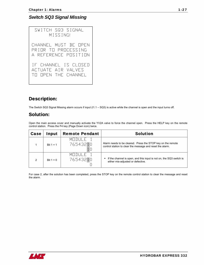
Switch SQ3 Signal Missing
SWITCH SQ3 SIGNAL
MISSING!
CHANNEL MUST BE OPEN
PRIOR TO PROCESSING
A REFERENCE POSITION
IF CHANNEL IS CLOSED
ACTUATE AIR VALVES
TO OPEN THE CHANNEL
Description: The Switch SQ3 Signal Missing alarm occurs if input (I1.1 – SQ3) is active while the channel is open and the input turns off.
Solution: Open the main access cover and manually activate the YV2A valve to force the channel open. Press the HELP key on the remote control station. Press the F4 key (Page Down icon) twice.
Case Input Remote Pendant Solution
1 Bit 1 = 1
MODULE 1
76543210
10
Alarm needs to be cleared. Press the STOP key on the remote control station to clear the message and reset the alarm.
2 Bit 1 = 0
MODULE 1
76543210
0
If the channel is open, and this input is not on, the SQ3 switch is either mis-adjusted or defective.
For case 2, after the solution has been completed, press the STOP key on the remote control station to clear the message and reset the alarm.
1-28 Chapter 1: Alarms
HYDROBAR EXPRESS 332
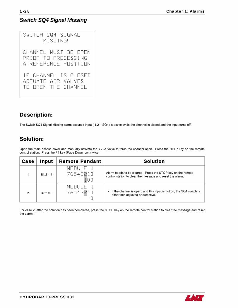
Switch SQ4 Signal Missing
SWITCH SQ4 SIGNAL
MISSING!
CHANNEL MUST BE OPEN
PRIOR TO PROCESSING
A REFERENCE POSITION
IF CHANNEL IS CLOSED
ACTUATE AIR VALVES
TO OPEN THE CHANNEL
Description: The Switch SQ4 Signal Missing alarm occurs if input (I1.2 – SQ4) is active while the channel is closed and the input turns off.
Solution: Open the main access cover and manually activate the YV2A valve to force the channel open. Press the HELP key on the remote control station. Press the F4 key (Page Down icon) twice.
Case Input Remote Pendant Solution
1 Bit 2 = 1
MODULE 1
76543210
100
Alarm needs to be cleared. Press the STOP key on the remote control station to clear the message and reset the alarm.
2 Bit 2 = 0
MODULE 1
76543210
0
If the channel is open, and this input is not on, the SQ4 switch is either mis-adjusted or defective.
For case 2, after the solution has been completed, press the STOP key on the remote control station to clear the message and reset the alarm.
Chapter 1: Alarms
HYDROBAR EXPRESS 332
1-29
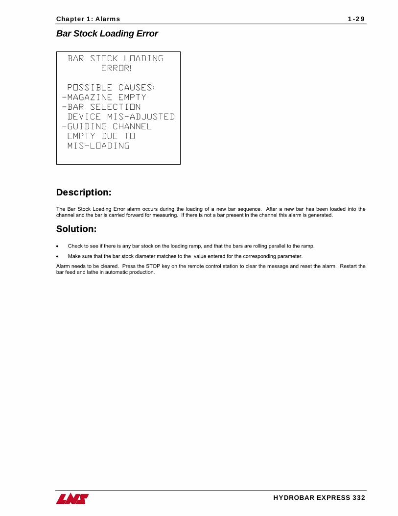
Bar Stock Loading Error
BAR STOCK LOADING
ERROR!
POSSIBLE CAUSES:
-MAGAZINE EMPTY
-BAR SELECTION
DEVICE MIS-ADJUSTED
-GUIDING CHANNEL
EMPTY DUE TO
MIS-LOADING
Description: The Bar Stock Loading Error alarm occurs during the loading of a new bar sequence. After a new bar has been loaded into the channel and the bar is carried forward for measuring. If there is not a bar present in the channel this alarm is generated.
Solution: • Check to see if there is any bar stock on the loading ramp, and that the bars are rolling parallel to the ramp.
• Make sure that the bar stock diameter matches to the value entered for the corresponding parameter.
Alarm needs to be cleared. Press the STOP key on the remote control station to clear the message and reset the alarm. Restart the bar feed and lathe in automatic production.
1-30 Chapter 1: Alarms
HYDROBAR EXPRESS 332
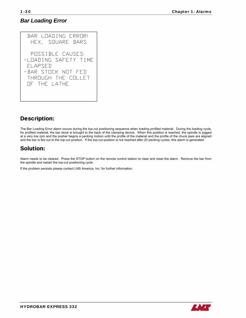
Bar Loading Error
BAR LOADING ERROR!
HEX, SQUARE BARS
POSSIBLE CAUSES:
-LOADING SAFETY TIME
ELAPSED
-BAR STOCK NOT FED
THROUGH THE COLLET
OF THE LATHE
Description: The Bar Loading Error alarm occurs during the top-cut positioning sequence when loading profiled material. During the loading cycle, for profiled material, the bar stock is brought to the back of the clamping device. When this position is reached, the spindle is jogged at a very low rpm and the pusher begins a pecking motion until the profile of the material and the profile of the chuck jaws are aligned and the bar is fed out to the top-cut position. If the top-cut position is not reached after 20 pecking cycles, this alarm is generated.
Solution: Alarm needs to be cleared. Press the STOP button on the remote control station to clear and reset the alarm. Remove the bar from the spindle and restart the top-cut positioning cycle.
If the problem persists please contact LNS America, Inc. for further information.
Chapter 1: Alarms
HYDROBAR EXPRESS 332
1-31
Bar Remnant Too Long
BAR REMNANT
TOO LONG!
POSSIBLE CAUSES:
-END OF BAR POSITION
IMPROPERLY ADJUSTED
-MACHINING VERY LONG
PARTS WITHOUT
OPTIMIZING BAR
LENGTH FOR MINIMUM
REMNANT LENGTH
Description: The maximum remnant that the bar feed can remove is 500mm (19.685”). The Bar Remnant Too Long alarm occurs during the remnant extraction sequence. After machining the last part and the clamping device opens, the pusher reverses to a determined position, the front measuring stop is activated, if signal switch SQ1 is not detected the bar feed continues with the extraction and will stop when it comes time to drop a new bar into the guiding channel, at which point this alarm is generated.
Solution: 1. Alarm needs to be cleared. Press the STOP key on the remote control station to clear the message and reset the alarm.
2. Press the F1 key on the remote control station for manual mode.
3. Press the F1 key on the remote control station and remove the long remnant from the channel.
4. After removing the remnant from the channel, press the F1 key (√) to verify that the bar has been manually removed from the channel.
• Check the End of Bar setting in the Parameters Related to Positioning menu.
• If the part length is fairly long, it will be necessary to cut the bar stock to achieve a minimum remnant length.
• If the problem persists please contact LNS America, Inc. for further information.
1-32 Chapter 1: Alarms
HYDROBAR EXPRESS 332
Bar Stock Moving Backwards during Headstock Reverse with Collet Open
BAR STOCK
IS MOVING BACKWARDS
DURING
HEADSTOCK REVERSE
WITH COLLET OPEN!
POSSIBLE CAUSES:
-STICKY COLLET
(NOT FULLY OPEN)
-TORQUE MIS-ADJUSTED
Description: The Bar Stock Moving Backwards alarm occurs when the bar feed detects any backward movement of the feeding pusher while the collet of the lathe is open and the headstock reverses for regrip.
Solution: • Check that the collet of the lathe is opening to its maximum allowance.
• Check the pushing torque value in the menu Parameters Related to Servo Drive (Torques) on the bar feed. The value can be increased if necessary.
Chapter 1: Alarms
HYDROBAR EXPRESS 332
1-33
Bar Stock Moving Forward during Headstock Reverse with Collet Open
BAR STOCK IS MOVING
FORWARD DURING
HEADSTOCK REVERSE
WITH COLLET OPEN !
POSSIBLE CAUSES : -CUT-OFF TOOL BROKEN
OR NOT IN POSITION
-EXCESSIVE PUSHING
TORQUE
Description: The Bar Stock Moving Forward alarm is generated when the bar feed detects any forward movement by the feeding pusher while the collet of the lathe is open and the headstock reverses for regrip.
Solution: Alarm needs to be cleared. Press the STOP key on the remote control station to clear the message and reset the alarm.
• Check that the cut-off tool is still intact. If it is broken, it will need to be replaced before putting the bar feed back in automatic production. If this alarm occurs often due to cut-off tools breaking, reduce the pushing torque in the menu Parameters Related to Servo Drive (Torques).
If the problem persists please contact LNS America, Inc. for further information.
1-34 Chapter 1: Alarms
HYDROBAR EXPRESS 332
Headstock Travel is Shorter Than Programmed Length
HEADSTOCK TRAVEL
IS SHORTER THAN THE
PROGRAMMED LENGTH
OR
THE PUSHER LOST THE
BAR STOCK ! VERIFY COLLET SIZE
Description: The overall part length parameter value is too short or the pusher did not travel the distance that was programmed in for the overall part length.
Solution: • Check that the Input Overall Part Length parameter is equal to the travel of the headstock and not the finished part length.
• Check the collet on the pusher. May be broken or worn or the incorrect size.
• Check to see if the pusher got jammed in the channel. Make sure the front guiding channels are seated correctly in the channel (maybe chips fell underneath the guiding channels).
If the problem persists please contact LNS America, Inc. for further information.
Chapter 1: Alarms
HYDROBAR EXPRESS 332
1-35
Servo Amp/PLC Comm. Fault
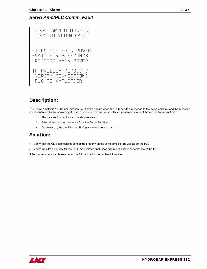
SERVO AMPLIFIER/PLC
COMMUNICATION FAULT
-TURN OFF MAIN POWER
-WAIT FOR 2 SECONDS
-RESTORE MAIN POWER
IF PROBLEM PERSISTS
VERIFY CONNECTIONS
PLC TO AMPLIFIER
Description: The Servo Amplifier/PLC Communication Fault alarm occurs when the PLC sends a message to the servo amplifier and the message is not confirmed by the servo amplifier via a checksum or vice versa. This is generated if one of three conditions is not met:
1. The data sent did not match the data received.
2. After 10 seconds, no response from the Servo Amplifier.
3. On power up, the amplifier and PLC parameters do not match.
Solution: • Verify that the CN3 connector is connected properly on the servo amplifier as well as on the PLC.
• Verify the 24VDC supply for the PLC. Any voltage fluctuation can result in poor performance of the PLC.
If the problem persists please contact LNS America, Inc. for further information.
1-36 Chapter 1: Alarms
HYDROBAR EXPRESS 332
Bar Magazine Indexing Motor Faulty
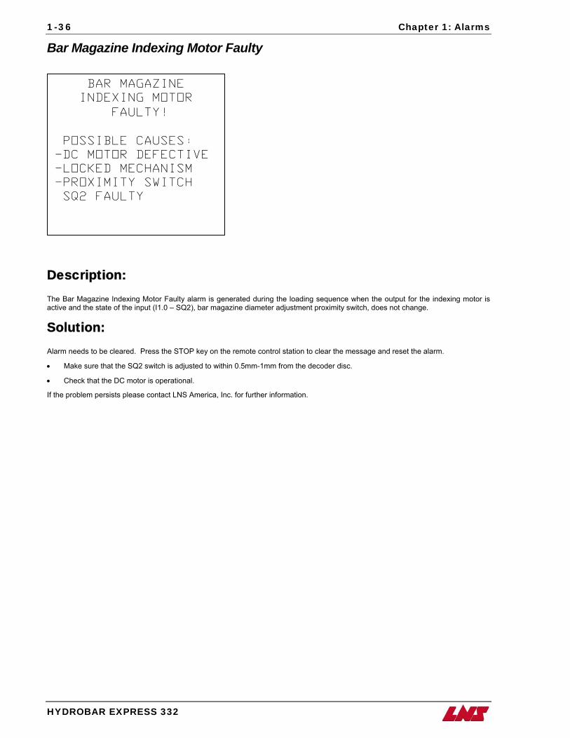
BAR MAGAZINE
INDEXING MOTOR
FAULTY !
POSSIBLE CAUSES : -DC MOTOR DEFECTIVE
-LOCKED MECHANISM
-PROXIMITY SWITCH
SQ2 FAULTY
Description: The Bar Magazine Indexing Motor Faulty alarm is generated during the loading sequence when the output for the indexing motor is active and the state of the input (I1.0 – SQ2), bar magazine diameter adjustment proximity switch, does not change.
Solution: Alarm needs to be cleared. Press the STOP key on the remote control station to clear the message and reset the alarm.
• Make sure that the SQ2 switch is adjusted to within 0.5mm-1mm from the decoder disc.
• Check that the DC motor is operational.
If the problem persists please contact LNS America, Inc. for further information.
Chapter 1: Alarms
HYDROBAR EXPRESS 332
1-37
Bar Stock Insertion Malfunction
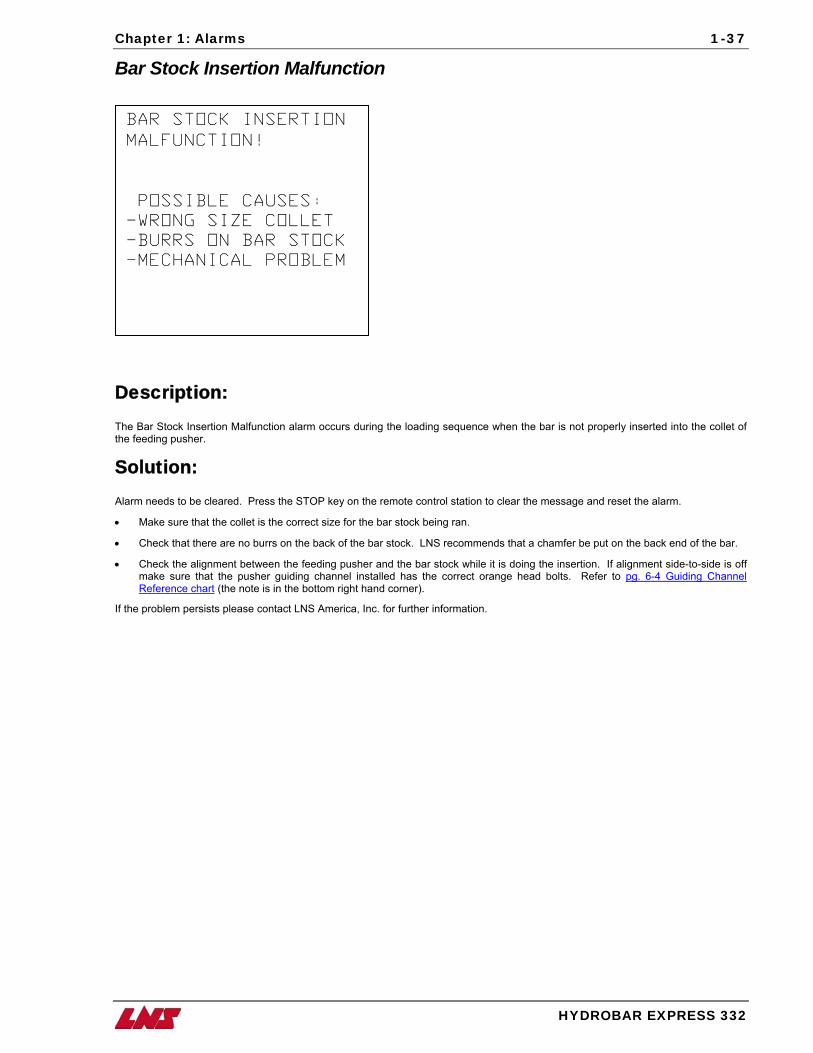
BAR STOCK INSERTION
MALFUNCTION !
POSSIBLE CAUSES : -WRONG SIZE COLLET
-BURRS ON BAR STOCK
-MECHANICAL PROBLEM
Description: The Bar Stock Insertion Malfunction alarm occurs during the loading sequence when the bar is not properly inserted into the collet of the feeding pusher.
Solution: Alarm needs to be cleared. Press the STOP key on the remote control station to clear the message and reset the alarm.
• Make sure that the collet is the correct size for the bar stock being ran.
• Check that there are no burrs on the back of the bar stock. LNS recommends that a chamfer be put on the back end of the bar.
• Check the alignment between the feeding pusher and the bar stock while it is doing the insertion. If alignment side-to-side is off make sure that the pusher guiding channel installed has the correct orange head bolts. Refer to pg. 6-4 Guiding Channel Reference chart (the note is in the bottom right hand corner).
If the problem persists please contact LNS America, Inc. for further information.
1-38 Chapter 1: Alarms
HYDROBAR EXPRESS 332
Servo Drive Alarm
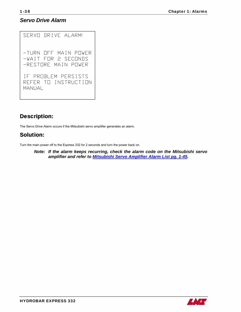
SERVO DRIVE ALARM!
-TURN OFF MAIN POWER
-WAIT FOR 2 SECONDS
-RESTORE MAIN POWER
IF PROBLEM PERSISTS
REFER TO INSTRUCTION
MANUAL
Description: The Servo Drive Alarm occurs if the Mitsubishi servo amplifier generates an alarm.
Solution: Turn the main power off to the Express 332 for 2 seconds and turn the power back on.
Note: If the alarm keeps recurring, check the alarm code on the Mitsubishi servo amplifier and refer to Mitsubishi Servo Amplifier Alarm List pg. 1-45.
Chapter 1: Alarms
HYDROBAR EXPRESS 332
1-39
Servo Motor Not Ready
SERVO MOTOR
NOT READY!
-VERIFY CN1B
CONNECTOR
-CHECK PLC OUTPUT
Q 4.4 (MUST BE ON)
Description: The PLC outputs a signal (Q4.4) to servo amplifier, which engages the servo motor and puts the servo motor in a “servo lock” condition. If the servo amplifier does not recognize the signal after 3 seconds, this alarm is generated.
Solution: • Verify that the CN1B connector is seated properly in the allotted socket on the servo amplifier.
• Verify that the PLC output (Q4.4) is turning on when the manual or automatic cycle is started.
• Verify that the K1 contactor is activated; input (I0.0) should be on.
If the problem persists please contact LNS America, Inc. for further information.
1-40 Chapter 1: Alarms
HYDROBAR EXPRESS 332
Chuck Closed Prior to Feed Out Complete
CLAMPING DEVICE HAS
CLOSED PRIOR TO
COMPLETING THE
FEED OUT
POSSIBLE CAUSES:
-LATHE PROGRAMMING
ERROR
-CLAMPING SIGNAL
FAULTY (PLC INPUT
A1)
Description: The Clamping Device Has Closed Prior To Completing The Feed Out alarm occurs if the input for the clamping device closed is detected before the value of the Input Part Length parameter is reached.
Solution: Verify that the clamping device is closing properly and that the Clamping Signal Active interface parameter is set in conjunction with how the interface signal is being sent.
Verify that the correct part length has been entered in the PARAMETERS RELATED TO APPLICATIONS menu.
Chapter 1: Alarms
HYDROBAR EXPRESS 332
1-41
A2 Interrupted During Loading
SIGNAL A2 (LATHE IN
AUTOMATIC MODE)
INTERRUPTED DURING
LOADING CYCLE!
RESUME AUTOMATIC
CYCLE OF THE LATHE
AND THE BAR FEEDER.
Description: The Signal A2 Interrupted During Loading Cycle alarm occurs whenever PLC input (I3.1) drops out during the loading cycle.
Solution: Alarm needs to be cleared. Press the STOP key on the remote control station to clear the message and reset the alarm. Remove the bar stock from the loading channel and reset the bar feeder and the lathe in automatic cycle.
1-42 Chapter 1: Alarms
HYDROBAR EXPRESS 332
Safety Time for Part Feed Out
SAFETY TIME
FOR PART FEED OUT
ELAPSED!
POSSIBLE CAUSES:
-PROGRAMMING ERROR
-MECH. INTERFERENCE
-INTERFACE PROBLEM
Description: The Safety Time For Part Feed Out Elapsed alarm occurs if the value set in OVERALL PART LENGTH is not reached within 1 minute after the bar feed is commanded to feed out.
Solution: Alarm needs to be cleared. Press the STOP key on the remote control station to clear the message and reset the alarm.
• Make sure that value for the OVERALL PART LENGTH is correct.
• Check for any mechanical obstruction that will not allow the bar feed to reach the feed out distance.
Contact LNS America, Inc. for further information.
Chapter 1: Alarms
HYDROBAR EXPRESS 332
1-43
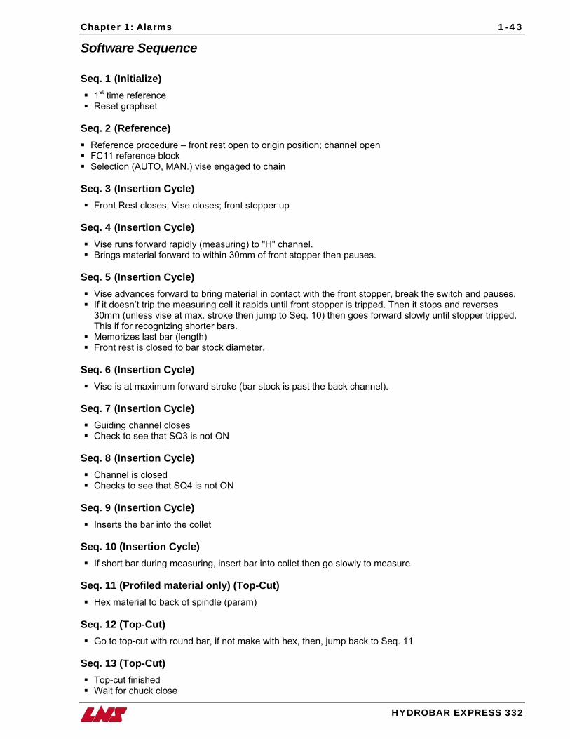
Software Sequence Seq. 1 (Initialize)
1st time reference Reset graphset
Seq. 2 (Reference) Reference procedure – front rest open to origin position; channel open FC11 reference block Selection (AUTO, MAN.) vise engaged to chain
Seq. 3 (Insertion Cycle)
Front Rest closes; Vise closes; front stopper up Seq. 4 (Insertion Cycle)
Vise runs forward rapidly (measuring) to "H" channel. Brings material forward to within 30mm of front stopper then pauses.
Seq. 5 (Insertion Cycle)
Vise advances forward to bring material in contact with the front stopper, break the switch and pauses. If it doesn’t trip the measuring cell it rapids until front stopper is tripped. Then it stops and reverses
30mm (unless vise at max. stroke then jump to Seq. 10) then goes forward slowly until stopper tripped. This if for recognizing shorter bars.
Memorizes last bar (length) Front rest is closed to bar stock diameter.
Seq. 6 (Insertion Cycle)
Vise is at maximum forward stroke (bar stock is past the back channel). Seq. 7 (Insertion Cycle)
Guiding channel closes Check to see that SQ3 is not ON
Seq. 8 (Insertion Cycle)
Channel is closed Checks to see that SQ4 is not ON
Seq. 9 (Insertion Cycle)
Inserts the bar into the collet Seq. 10 (Insertion Cycle)
If short bar during measuring, insert bar into collet then go slowly to measure Seq. 11 (Profiled material only) (Top-Cut)
Hex material to back of spindle (param) Seq. 12 (Top-Cut)
Go to top-cut with round bar, if not make with hex, then, jump back to Seq. 11 Seq. 13 (Top-Cut)
Top-cut finished Wait for chuck close
1-44 Chapter 1: Alarms
HYDROBAR EXPRESS 332
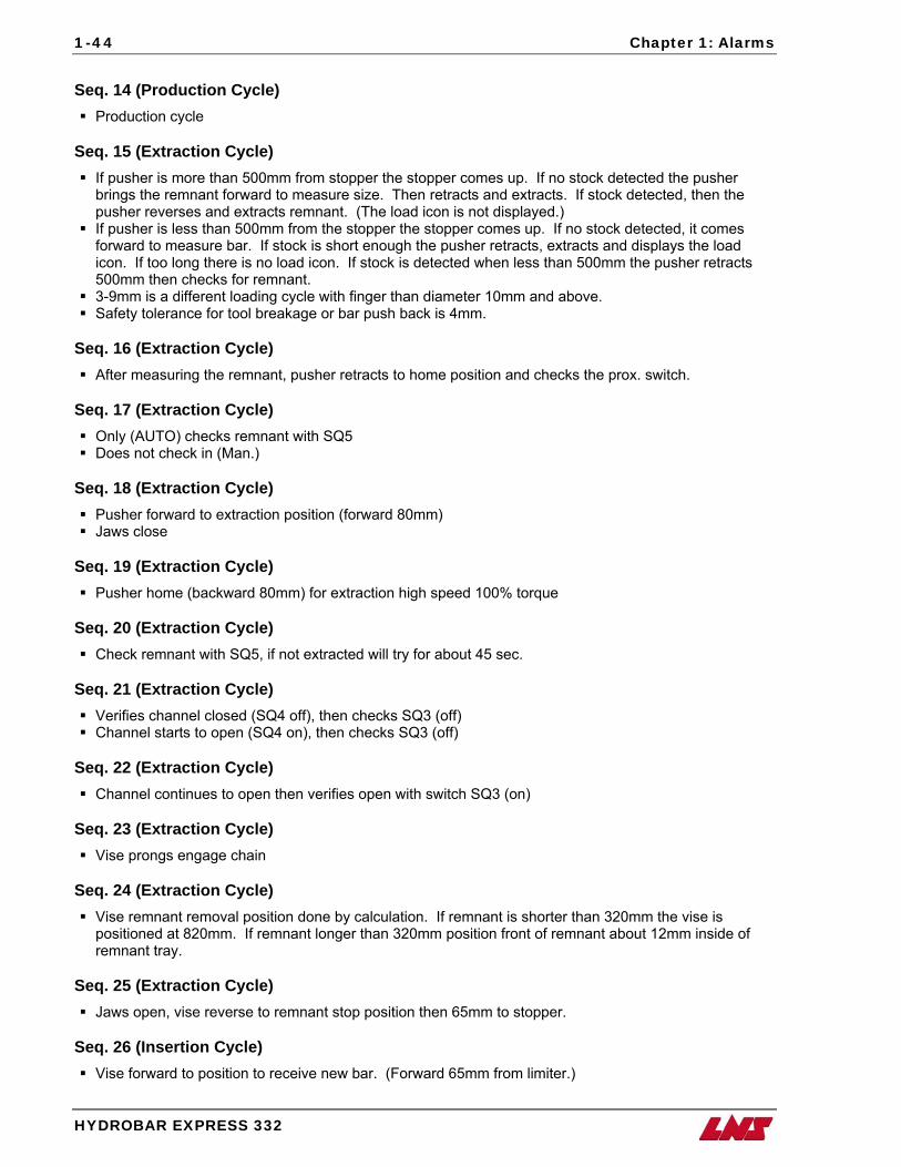
Seq. 14 (Production Cycle)
Production cycle Seq. 15 (Extraction Cycle)
If pusher is more than 500mm from stopper the stopper comes up. If no stock detected the pusher brings the remnant forward to measure size. Then retracts and extracts. If stock detected, then the pusher reverses and extracts remnant. (The load icon is not displayed.)
If pusher is less than 500mm from the stopper the stopper comes up. If no stock detected, it comes forward to measure bar. If stock is short enough the pusher retracts, extracts and displays the load icon. If too long there is no load icon. If stock is detected when less than 500mm the pusher retracts 500mm then checks for remnant.
3-9mm is a different loading cycle with finger than diameter 10mm and above. Safety tolerance for tool breakage or bar push back is 4mm.
Seq. 16 (Extraction Cycle)
After measuring the remnant, pusher retracts to home position and checks the prox. switch. Seq. 17 (Extraction Cycle)
Only (AUTO) checks remnant with SQ5 Does not check in (Man.)
Seq. 18 (Extraction Cycle)
Pusher forward to extraction position (forward 80mm) Jaws close
Seq. 19 (Extraction Cycle)
Pusher home (backward 80mm) for extraction high speed 100% torque Seq. 20 (Extraction Cycle)
Check remnant with SQ5, if not extracted will try for about 45 sec. Seq. 21 (Extraction Cycle)
Verifies channel closed (SQ4 off), then checks SQ3 (off) Channel starts to open (SQ4 on), then checks SQ3 (off)
Seq. 22 (Extraction Cycle)
Channel continues to open then verifies open with switch SQ3 (on) Seq. 23 (Extraction Cycle)
Vise prongs engage chain Seq. 24 (Extraction Cycle)
Vise remnant removal position done by calculation. If remnant is shorter than 320mm the vise is positioned at 820mm. If remnant longer than 320mm position front of remnant about 12mm inside of remnant tray.
Seq. 25 (Extraction Cycle)
Jaws open, vise reverse to remnant stop position then 65mm to stopper. Seq. 26 (Insertion Cycle)
Vise forward to position to receive new bar. (Forward 65mm from limiter.)
Chapter 1: Alarms
HYDROBAR EXPRESS 332
1-45
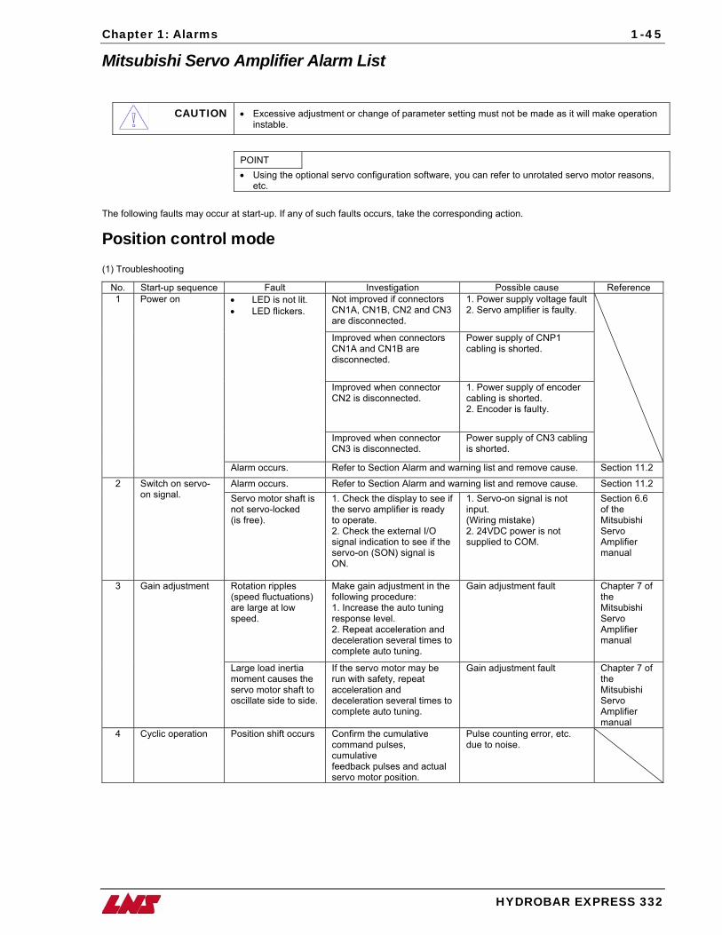
Mitsubishi Servo Amplifier Alarm List
CAUTION • Excessive adjustment or change of parameter setting must not be made as it will make operation instable.
POINT • Using the optional servo configuration software, you can refer to unrotated servo motor reasons,
etc.
The following faults may occur at start-up. If any of such faults occurs, take the corresponding action.
Position control mode (1) Troubleshooting
No. Start-up sequence Fault Investigation Possible cause Reference Not improved if connectors CN1A, CN1B, CN and CN3 2are disconnected.
1. Power supply voltage fault 2. Servo amplifier is faulty.
Improved when connectors CN1A and CN1B are disconnected.
Power supply of CNP1 cabling is shorted.
Improved when connector CN2 is disconnected.
1. Power supply of encoder cabling is shorted. 2. Encoder is faulty.
• LED is not lit. • LED flickers.
Improved when connector CN3 is disconnected.
Power supply of CN3 cabling is shorted.
1 Power on
Alarm occurs. Refer to Section Alarm and warning list and remove cause. Section 11.2
Alarm occurs. Refer to Section Alarm and warning list and remove cause. Section 11.2 2 Switch on servo-on signal. Servo motor shaft is
not servo-locked (is free).
1. Check the display to see if the servo amplifier is ready to operate. 2. Check the external I/O signal indication to see if the servo-on (SON) signal is ON.
1. Servo-on signal is not input. (Wiring mistake) 2. 24VDC power is not supplied to COM.
Section 6.6 of the Mitsubishi Servo Amplifier manual
Rotation ripples (speed fluctuations) are large at low speed.
Make gain adjustment in the following procedure: 1. Increase the auto tuning response level. 2. Repeat acceleration and deceleration several times to complete auto tuning.
Gain adjustment fault Chapter 7 of the Mitsubishi Servo Amplifier manual
3 Gain adjustment
Large load inertia moment causes the servo motor shaft to oscillate side to side.
If the servo motor may be run with safety, repeat acceleration and deceleration several times to complete auto tuning.
Gain adjustment fault Chapter 7 of the Mitsubishi Servo Amplifier manual
4 Cyclic operation Position shift occurs Confirm the cumulative command pulses, cumulative feedback pulses and actual servo motor position.
Pulse counting error, etc. due to noise.
1-46 Chapter 1: Alarms
HYDROBAR EXPRESS 332
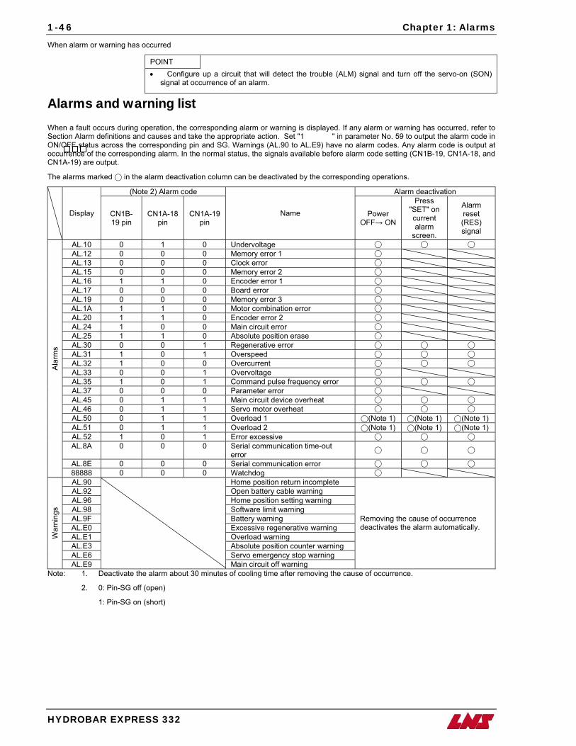
When alarm or warning has occurred
POINT • Configure up a circuit that will detect the trouble (ALM) signal and turn off the servo-on (SON)
signal at occurrence of an alarm.
Alarms and warning list When a fault occurs during operation, the corresponding alarm or warning is displayed. If any alarm or warning has occurred, refer to Section Alarm definitions and causes and take the appropriate action. Set "1 " in parameter No. 59 to output the alarm code in ON/OFF status across the corresponding pin and SG. Warnings (AL.90 to AL.E9) have no alarm codes. Any alarm code is output at occurrence of the corresponding alarm. In the normal status, the signals available before alarm code setting (CN1B-19, CN1A-18, and CN1A-19) are output.
The alarms marked in the alarm deactivation column can be deactivated by the corresponding operations.
(Note 2) Alarm code Alarm deactivation
Display CN1B-19 pin
CN1A-18 pin
CN1A-19 pin
Name Power OFF→ ON
Press "SET" on current alarm
screen.
Alarm reset (RES) signal
AL.10 0 1 0 Undervoltage AL.12 0 0 0 Memory error 1 AL.13 0 0 0 Clock error AL.15 0 0 0 Memory error 2 AL.16 1 1 0 Encoder error 1 AL.17 0 0 0 Board error AL.19 0 0 0 Memory error 3 AL.1A 1 1 0 Motor combination error AL.20 1 1 0 Encoder error 2 AL.24 1 0 0 Main circuit error AL.25 1 1 0 Absolute position erase AL.30 0 0 1 Regenerative error AL.31 1 0 1 Overspeed AL.32 1 0 0 Overcurrent AL.33 0 0 1 Overvoltage AL.35 1 0 1 Command pulse frequency error AL.37 0 0 0 Parameter error AL.45 0 1 1 Main circuit device overheat AL.46 0 1 1 Servo motor overheat AL.50 0 1 1 Overload 1 (Note 1) (Note 1) (Note 1) AL.51 0 1 1 Overload 2 (Note 1) (Note 1) (Note 1) AL.52 1 0 1 Error excessive AL.8A 0 0 0 Serial communication time-out
error
AL.8E 0 0 0 Serial communication error
Ala
rms
88888 0 0 0 Watchdog AL.90 Home position return incomplete AL.92 Open battery cable warning AL.96 Home position setting warning AL.98 Software limit warning AL.9F Battery warning AL.E0 Excessive regenerative warning AL.E1 Overload warning AL.E3 Absolute position counter warning AL.E6 Servo emergency stop warning
War
ning
s
AL.E9
Main circuit off warning
Removing the cause of occurrence deactivates the alarm automatically.
Note: 1. Deactivate the alarm about 30 minutes of cooling time after removing the cause of occurrence.
2. 0: Pin-SG off (open)
1: Pin-SG on (short)
Chapter 1: Alarms
HYDROBAR EXPRESS 332
1-47
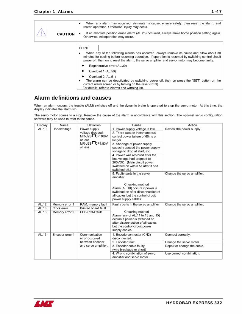
CAUTION
• When any alarm has occurred, eliminate its cause, ensure safety, then reset the alarm, and restart operation. Otherwise, injury may occur.
• If an absolute position erase alarm (AL.25) occurred, always make home position setting again. Otherwise, misoperation may occur.
POINT • When any of the following alarms has occurred, always remove its cause and allow about 30
minutes for cooling before resuming operation. If operation is resumed by switching control circuit power off, then on to reset the alarm, the servo amplifier and servo motor may become faulty.
• Regenerative error (AL.30)
• Overload 1 (AL.50)
• Overload 2 (AL.51) • The alarm can be deactivated by switching power off, then on press the "SET" button on the
current alarm screen or by turning on the reset (RES). For details, refer to Alarms and warning list.
Alarm definitions and causes When an alarm occurs, the trouble (ALM) switches off and the dynamic brake is operated to stop the servo motor. At this time, the display indicates the alarm No.
The servo motor comes to a stop. Remove the cause of the alarm in accordance with this section. The optional servo configuration software may be used to refer to the cause.
Display Name Definition Cause Action 1. Power supply voltage is low. 2. There was an instantaneous control power failure of 60ms or longer. 3. Shortage of power supply capacity caused the power supply voltage to drop at start, etc. 4. Power was restored after the bus voltage had dropped to 200VDC. (Main circuit power switched on within 5s after it had switched off.)
Review the power supply. AL.10 Undervoltage Power supply voltage dropped. MR-J2S- CP:160V or less MR-J2S- CP1:83V or less
5. Faulty parts in the servo amplifier
Checking method Alarm (AL.10) occurs if power is switched on after disconnection of all cables but the control circuit power supply cables.
Change the servo amplifier.
AL.12 Memory error 1 RAM, memory fault AL.13 Clock error Printed board fault AL.15 Memory error 2 EEP-ROM fault
Faulty parts in the servo amplifier
Checking method Alarm (any of AL.11 to 13 and 15) occurs if power is switched on after disconnection of all cables but the control circuit power supply cables.
Change the servo amplifier.
1. Encode connector (CN2) disconnected.
Connect correctly.
2. Encoder fault Change the servo motor. 3. Encoder cable faulty (wire breakage or short)
Repair or change the cable.
AL.16 Encoder error 1 Communication error occurred between encoder and servo amplifier.
4. Wrong combination of servo amplifier and servo motor
Use correct combination.
1-48 Chapter 1: Alarms
HYDROBAR EXPRESS 332
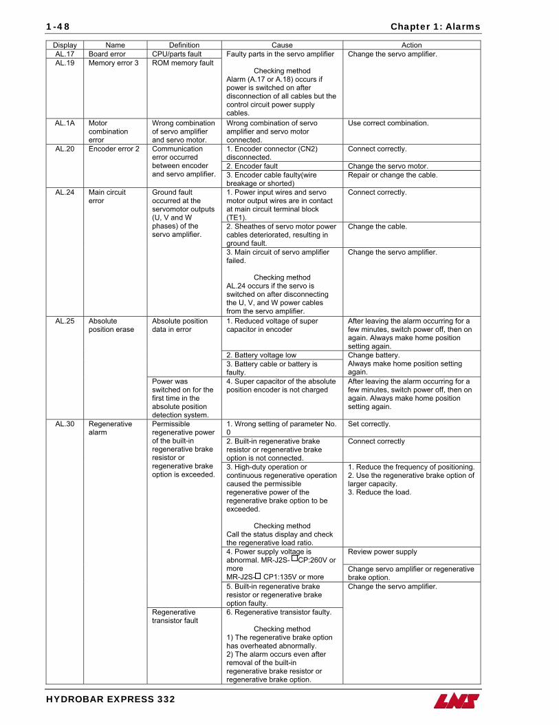
Display Name Definition Cause Action AL.17 Board error CPU/parts fault AL.19 Memory error 3 ROM memory fault
Faulty parts in the servo amplifier
Checking method Alarm (A.17 or A.18) occurs if power is switched on after disconnection of all cables but the control circuit power supply cables.
Change the servo amplifier.
AL.1A Motor combination error
Wrong combination of servo amplifier and servo motor.
Wrong combination of servo amplifier and servo motor connected.
Use correct combination.
1. Encoder connector (CN2) disconnected.
Connect correctly.
2. Encoder fault Change the servo motor.
AL.20 Encoder error 2 Communication error occurred between encoder and servo amplifier. 3. Encoder cable faulty(wire
breakage or shorted) Repair or change the cable.
1. Power input wires and servo motor output wires are in contact at main circuit terminal block (TE1).
Connect correctly.
2. Sheathes of servo motor power cables deteriorated, resulting in ground fault.
Change the cable.
AL.24 Main circuit error
Ground fault occurred at the servomotor outputs (U, V and W phases) of the servo amplifier.
3. Main circuit of servo amplifier failed.
Checking method AL.24 occurs if the servo is switched on after disconnecting the U, V, and W power cables from the servo amplifier.
Change the servo amplifier.
1. Reduced voltage of super capacitor in encoder
After leaving the alarm occurring for a few minutes, switch power off, then on again. Always make home position setting again.
2. Battery voltage low
Absolute position data in error
3. Battery cable or battery is faulty.
Change battery. Always make home position setting again.
AL.25 Absolute position erase
Power was switched on for the first time in the absolute position detection system.
4. Super capacitor of the absolute position encoder is not charged
After leaving the alarm occurring for a few minutes, switch power off, then on again. Always make home position setting again.
1. Wrong setting of parameter No. 0
Set correctly.
2. Built-in regenerative brake resistor or regenerative brake option is not connected.
Connect correctly
3. High-duty operation or continuous regenerative operation caused the permissible regenerative power of the regenerative brake option to be exceeded.
Checking method Call the status display and check the regenerative load ratio.
1. Reduce the frequency of positioning. 2. Use the regenerative brake option of larger capacity. 3. Reduce the load.
Review power supply 4. Power supply voltage is abnormal. MR-J2S- CP:260V or more MR-J2S- CP1:135V or more
Change servo amplifier or regenerative brake option.
Permissible regenerative power of the built-in regenerative brake resistor or regenerative brake option is exceeded.
5. Built-in regenerative brake resistor or regenerative brake option faulty.
AL.30 Regenerative alarm
Regenerative transistor fault
6. Regenerative transistor faulty.
Checking method 1) The regenerative brake option has overheated abnormally. 2) The alarm occurs even after removal of the built-in regenerative brake resistor or regenerative brake option.
Change the servo amplifier.
Chapter 1: Alarms
HYDROBAR EXPRESS 332
1-49
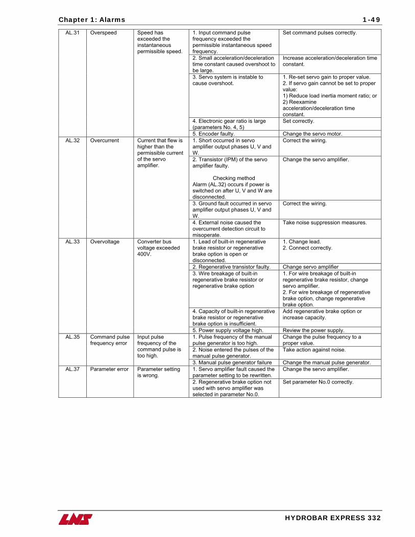
1. Input command pulse frequency exceeded the permissible instantaneous speed frequency.
Set command pulses correctly.
2. Small acceleration/deceleration time constant caused overshoot to be large.
Increase acceleration/deceleration time constant.
3. Servo system is instable to cause overshoot.
1. Re-set servo gain to proper value. 2. If servo gain cannot be set to proper value: 1) Reduce load inertia moment ratio; or 2) Reexamine acceleration/deceleration time constant.
4. Electronic gear ratio is large (parameters No. 4, 5)
Set correctly.
AL.31 Overspeed Speed has exceeded the instantaneous permissible speed.
5. Encoder faulty. Change the servo motor. 1. Short occurred in servo amplifier output phases U, V and W.
Correct the wiring.
2. Transistor (IPM) of the servo amplifier faulty.
Checking method Alarm (AL.32) occurs if power is switched on after U, V and W are disconnected.
Change the servo amplifier.
3. Ground fault occurred in servo amplifier output phases U, V and W.
Correct the wiring.
AL.32 Overcurrent Current that flew is higher than the permissible current of the servo amplifier.
4. External noise caused the overcurrent detection circuit to misoperate.
Take noise suppression measures.
1. Lead of built-in regenerative brake resistor or regenerative brake option is open or disconnected.
1. Change lead. 2. Connect correctly.
2. Regenerative transistor faulty. Change servo amplifier 3. Wire breakage of built-in regenerative brake resistor or regenerative brake option
1. For wire breakage of built-in regenerative brake resistor, change servo amplifier. 2. For wire breakage of regenerative brake option, change regenerative brake option.
4. Capacity of built-in regenerative brake resistor or regenerative brake option is insufficient.
Add regenerative brake option or increase capacity.
AL.33 Overvoltage Converter bus voltage exceeded 400V.
5. Power supply voltage high. Review the power supply. 1. Pulse frequency of the manual pulse generator is too high.
Change the pulse frequency to a proper value.
2. Noise entered the pulses of the manual pulse generator.
Take action against noise.
AL.35 Command pulse frequency error
Input pulse frequency of the command pulse is too high.
3. Manual pulse generator failure Change the manual pulse generator. 1. Servo amplifier fault caused the parameter setting to be rewritten.
Change the servo amplifier. AL.37 Parameter error Parameter setting is wrong.
2. Regenerative brake option not used with servo amplifier was selected in parameter No.0.
Set parameter No.0 correctly.
1-50 Chapter 1: Alarms
HYDROBAR EXPRESS 332
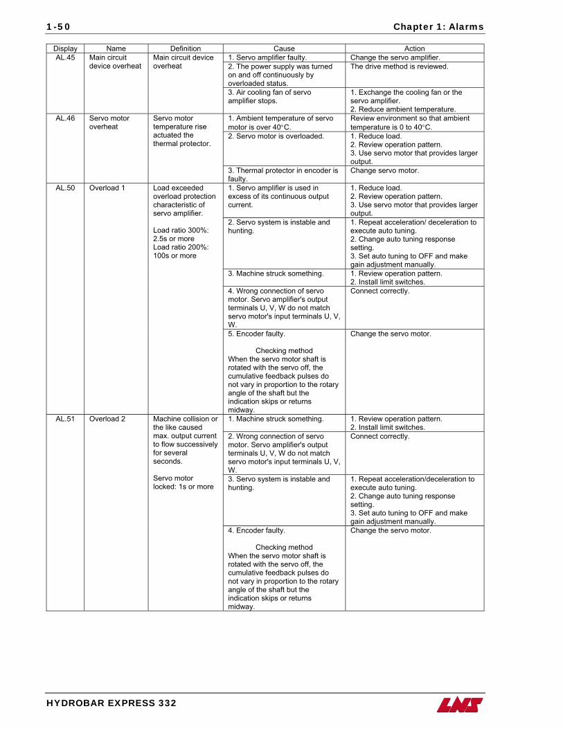
Display Name Definition Cause Action 1. Servo amplifier faulty. Change the servo amplifier. 2. The power supply was turned on and off continuously by overloaded status.
The drive method is reviewed. AL.45 Main circuit
device overheat Main circuit device overheat
3. Air cooling fan of servo amplifier stops.
1. Exchange the cooling fan or the servo amplifier. 2. Reduce ambient temperature.
1. Ambient temperature of servo motor is over 40°C.
Review environment so that ambient temperature is 0 to 40°C.
2. Servo motor is overloaded. 1. Reduce load. 2. Review operation pattern. 3. Use servo motor that provides larger output.
AL.46 Servo motor overheat
Servo motor temperature rise actuated the thermal protector.
3. Thermal protector in encoder is faulty.
Change servo motor.
1. Servo amplifier is used in excess of its continuous output current.
1. Reduce load. 2. Review operation pattern. 3. Use servo motor that provides larger output.
2. Servo system is instable and hunting.
1. Repeat acceleration/ deceleration to execute auto tuning. 2. Change auto tuning response setting. 3. Set auto tuning to OFF and make gain adjustment manually.
3. Machine struck something. 1. Review operation pattern. 2. Install limit switches.
4. Wrong connection of servo motor. Servo amplifier's output terminals U, V, W do not match servo motor's input terminals U, V, W.
Connect correctly.
AL.50 Overload 1 Load exceeded overload protection characteristic of servo amplifier. Load ratio 300%: 2.5s or more Load ratio 200%: 100s or more
5. Encoder faulty.
Checking method When the servo motor shaft is rotated with the servo off, the cumulative feedback pulses do not vary in proportion to the rotary angle of the shaft but the indication skips or returns midway.
Change the servo motor.
1. Machine struck something. 1. Review operation pattern. 2. Install limit switches.
2. Wrong connection of servo motor. Servo amplifier's output terminals U, V, W do not match servo motor's input terminals U, V, W.
Connect correctly.
3. Servo system is instable and hunting.
1. Repeat acceleration/deceleration to execute auto tuning. 2. Change auto tuning response setting. 3. Set auto tuning to OFF and make gain adjustment manually.
AL.51 Overload 2 Machine collision or the like caused max. output current to flow successively for several seconds. Servo motor locked: 1s or more
4. Encoder faulty.
Checking method When the servo motor shaft is rotated with the servo off, the cumulative feedback pulses do not vary in proportion to the rotary angle of the shaft but the indication skips or returns midway.
Change the servo motor.
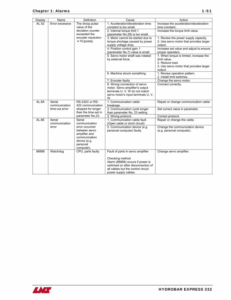
Chapter 1: Alarms
HYDROBAR EXPRESS 332
1-51
Display Name Definition Cause Action 1. Acceleration/deceleration time constant is too small.
Increase the acceleration/deceleration time constant.
2. Internal torque limit 1 (parameter No.28) is too small.
Increase the torque limit value.
3. Motor cannot be started due to torque shortage caused by power supply voltage drop.
1. Review the power supply capacity. 2. Use servo motor that provides larger output.
4. Position control gain 1 (parameter No.7) value is small.
Increase set value and adjust to ensure proper operation.
5. Servo motor shaft was rotated by external force.
1. When torque is limited, increase the limit value. 2. Reduce load. 3. Use servo motor that provides larger output.
6. Machine struck something. 1. Review operation pattern. 2. Install limit switches.
7. Encoder faulty Change the servo motor.
AL.52 Error excessive The droop pulse value of the deviation counter exceeded the encoder resolution
10 [pulse].
8. Wrong connection of servo motor. Servo amplifier's output terminals U, V, W do not match servo motor's input terminals U, V, W.
Connect correctly.
1. Communication cable breakage.
Repair or change communication cable
2. Communication cycle longer than parameter No. 23 setting.
Set correct value in parameter.
AL.8A Serial communication time-out error
RS-232C or RS-422 communication stopped for longer than the time set in parameter No.23. 3. Wrong protocol. Correct protocol.
1. Communication cable fault (Open cable or short circuit)
Repair or change the cable. AL.8E Serial communication error
Serial communication error occurred between servo amplifier and communication device (e.g. personal computer).
2. Communication device (e.g. personal computer) faulty
Change the communication device (e.g. personal computer).
88888 Watchdog CPU, parts faulty Fault of parts in servo amplifier Checking method Alarm (88888) occurs if power is switched on after disconnection of all cables but the control circuit power supply cables.
Change servo amplifier.
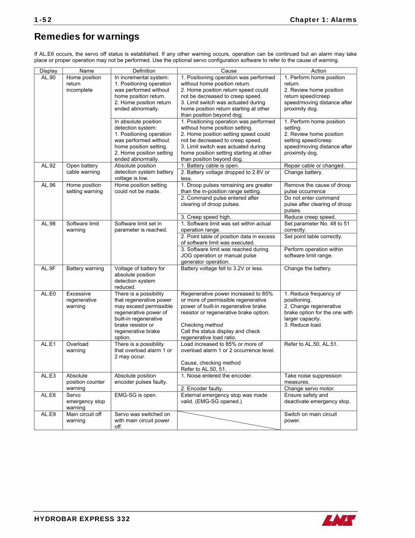
1-52 Chapter 1: Alarms
HYDROBAR EXPRESS 332
Remedies for warnings If AL.E6 occurs, the servo off status is established. If any other warning occurs, operation can be continued but an alarm may take place or proper operation may not be performed. Use the optional servo configuration software to refer to the cause of warning.
Display Name Definition Cause Action In incremental system: 1. Positioning operation was performed without home position return. 2. Home position return ended abnormally.
1. Positioning operation was performed without home position return. 2. Home position return speed could not be decreased to creep speed. 3. Limit switch was actuated during home position return starting at other than position beyond dog.
1. Perform home position return. 2. Review home position return speed/creep speed/moving distance after proximity dog.
AL.90 Home position return incomplete
In absolute position detection system: 1. Positioning operation was performed without home position setting. 2. Home position setting ended abnormally.
1. Positioning operation was performed without home position setting. 2. Home position setting speed could not be decreased to creep speed. 3. Limit switch was actuated during home position setting starting at other than position beyond dog.
1. Perform home position setting. 2. Review home position setting speed/creep speed/moving distance after proximity dog.
1. Battery cable is open. Repair cable or changed. AL.92 Open battery cable warning
Absolute position detection system battery voltage is low.
2. Battery voltage dropped to 2.8V or less.
Change battery.
1. Droop pulses remaining are greater than the in-position range setting.
Remove the cause of droop pulse occurrence
2. Command pulse entered after clearing of droop pulses.
Do not enter command pulse after clearing of droop pulses.
AL.96 Home position setting warning
Home position setting could not be made.
3. Creep speed high. Reduce creep speed. 1. Software limit was set within actual operation range.
Set parameter No. 48 to 51 correctly.
2. Point table of position data in excess of software limit was executed.
Set point table correctly.
AL.98 Software limit warning
Software limit set in parameter is reached.
3. Software limit was reached during JOG operation or manual pulse generator operation.
Perform operation within software limit range.
AL.9F Battery warning Voltage of battery for absolute position detection system reduced.
Battery voltage fell to 3.2V or less. Change the battery.
AL.E0 Excessive regenerative warning
There is a possibility that regenerative power may exceed permissible regenerative power of built-in regenerative brake resistor or regenerative brake option.
Regenerative power increased to 85% or more of permissible regenerative power of built-in regenerative brake resistor or regenerative brake option. Checking method Call the status display and check regenerative load ratio.
1. Reduce frequency of positioning. 2. Change regenerative brake option for the one with larger capacity. 3. Reduce load.
AL.E1 Overload warning
There is a possibility that overload alarm 1 or 2 may occur.
Load increased to 85% or more of overload alarm 1 or 2 occurrence level. Cause, checking method Refer to AL.50, 51.
Refer to AL.50, AL.51.
1. Noise entered the encoder. Take noise suppression measures.
AL.E3 Absolute position counter warning
Absolute position encoder pulses faulty.
2. Encoder faulty. Change servo motor. AL.E6 Servo
emergency stop warning
EMG-SG is open. External emergency stop was made valid. (EMG-SG opened.)
Ensure safety and deactivate emergency stop.
AL.E9 Main circuit off warning
Servo was switched on with main circuit power off.
Switch on main circuit power.
Chapter 2: Common Issues
HYDROBAR EXPRESS 332
2-1
Chapter 2:
Common Issues
he Hydrobar Express 332 is designed to be a user-friendly, simple, and reliable bar feeder, covering a range of diameters 0.125” to 1.250” (1.250”-1.375” with bar end preparation). Although easy to use, including extremely quick changeovers and the capability for unmanned operation this unit is not flawless. A list of common issues that have been documented by service technicians and problems relayed back from customers has been compiled in this manual. This chapter discusses the most common problems that have been observed. Along with each problem, a brief description is given as well as
quick reference charts of symptoms/solutions, sequences, and procedures for adjustments, changeovers and alignment.
T
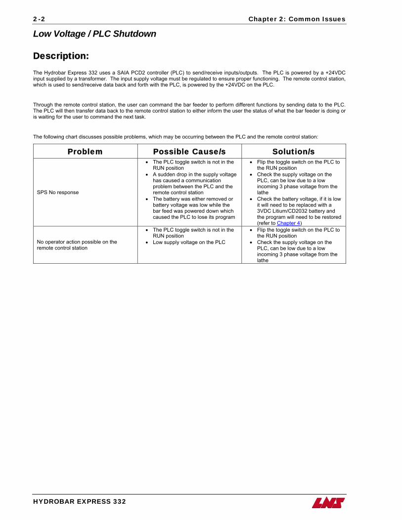
2-2 Chapter 2: Common Issues
HYDROBAR EXPRESS 332
Low Voltage / PLC Shutdown
Description: The Hydrobar Express 332 uses a SAIA PCD2 controller (PLC) to send/receive inputs/outputs. The PLC is powered by a +24VDC input supplied by a transformer. The input supply voltage must be regulated to ensure proper functioning. The remote control station, which is used to send/receive data back and forth with the PLC, is powered by the +24VDC on the PLC.
Through the remote control station, the user can command the bar feeder to perform different functions by sending data to the PLC. The PLC will then transfer data back to the remote control station to either inform the user the status of what the bar feeder is doing or is waiting for the user to command the next task.
The following chart discusses possible problems, which may be occurring between the PLC and the remote control station:
Problem Possible Cause/s Solution/s
SPS No response
• The PLC toggle switch is not in the RUN position
• A sudden drop in the supply voltage has caused a communication problem between the PLC and the remote control station
• The battery was either removed or battery voltage was low while the bar feed was powered down which caused the PLC to lose its program
• Flip the toggle switch on the PLC to the RUN position
• Check the supply voltage on the PLC, can be low due to a low incoming 3 phase voltage from the lathe
• Check the battery voltage, if it is low it will need to be replaced with a 3VDC Litium/CD2032 battery and the program will need to be restored (refer to Chapter 4)
No operator action possible on the remote control station
• The PLC toggle switch is not in the RUN position
• Low supply voltage on the PLC
• Flip the toggle switch on the PLC to the RUN position
• Check the supply voltage on the PLC, can be low due to a low incoming 3 phase voltage from the lathe
Chapter 2: Common Issues
HYDROBAR EXPRESS 332
2-3
Cannot Change Application Setup Parameters In order to change the values of any parameters in the bar feed, it must be in “STOP” mode. To determine whether the bar feed is in “STOP” mode, look at the “STOP” key on the remote control station. When the “STOP” key is pressed, two red LED’s will illuminate on either side of the remote.
In certain cases, as a precaution, the bar feed will not allow the parameters in the PARAMETERS RELATED TO APPLICATION menu to be changed unless a few conditions are met. The following conditions are required to change these parameters:
Guiding channels must be open.
Bar stock (if any) must be removed.
When removing the bar stock, the bar feed must recognize that the bar has been removed. In order for the bar feed to recognize that the bar has been removed follow the steps below:
Step 1: Press the manual mode icon.
Step 2: Press the remove bar stock icon. Note: If the remove bar stock icon is not present, skip the next step and go to Step 4.
tep 3: After pressing the remove bar stock icon, it will ask you to verify if the bar has been removed. Remove the bar from the
channel and pres and hold the confirmation icon.
S
Step 4: Press the “STOP” key on the remote control station and proceed with changing the parameters.
Multiple Bars have been Loaded into the Channel T e
wo bars loaded at a tim
Cause Solution Incorrect bar stock diameter. o the correct
size. Change the bar stock diameter parameter t
Top limiters are not set correctly and bars are bunching up The top limiters should bon the loading ramp.
e set so that the bars can roll freely without the possibility of bars overlapping.
A
Solution
bar was already in the channel and another
Cause
was loaded on top
A remnant too long to be dumped into the remnant pan has been confirmed that it was removed without physically removed. Perhaps during a shift change.
Remove the two bars from the channel and restart the loading process.
2-4 Chapter 2: Common Issues
HYDROBAR EXPRESS 332
Front Rest Issues How the front rest works? The front rest is used as a guide source for the bar stock to transfer from the bar feed through the headstock. The rest also acts as an extended support for the back of the bar while the spindle is rotating. It operates using an electric motor which drives the “jaws” open and closed. There are three operating positions at which the rest will open/close:
“Home” reference position - this is a constant position at which the rest will open up completely to a zero-position which calibrates the rest. This position is determined by a mechanical setting which is detected by a fixed proximity switch (SQ8).
Bar stock diameter position - this is a variable position at which the rest will close down to approximately (.020”) over the bar stock diameter. This position is automatically calculated when the bar stock diameter parameter is entered in.
Guiding channel position - this is a variable position at which the rest will open up to the I.D. of the guiding channel inserts. The rest opens to this position in order for the pusher (since the pusher O.D. is greater than the bar stock O.D.) to be able to travel through the rest. This position is automatically calculated when the guiding channel parameter is entered in.
Front Rest Opening/Closing Timing Chart
During Loading Sequence During Production Sequence Sequence Rest position
Remnant is being
measured
Remnant is being
extracted
Remnant is dropped into remnant pan
New bar is loaded/ being
measured
Bar has been measured/
passed through front
rest
Feeding part to part (pusher not at front rest open
position)
Feeding part to part (pusher at front rest open
position)
“Home” reference position
Bar stock diameter position
Guiding channel position
Symptoms of front rest mal-functioning Description Cause Solution
Front rest is locked in the “home” ref. position
The front rest has been manually locked open.
Mechanical obstruction has caused a front rest error.
Must be manually closed. Refer to pg. 3-33 Front Rest Override procedure.
Remove any debris which may have caused a mechanical obstruction.
Front rest is closing too tight on bar stock / pusher.
Bar stock diameter / guiding channel size has not been set correctly in the parameters.
SQ9 switch is mis-adjusted or defective.
Front rest is mis-calibrated (SQ8).
Check the bar stock diameter and guiding channel size parameters.
Check the functionality of the SQ9 switch.
Re-calibrate the front rest. Refer to pg. 3-30 Calibration Procedure for Front Rest.
Front rest is not closing enough on the bar stock
Bar stock diameter / guiding channel size has not been set correctly in the parameters.
SQ8 switch is mis-adjusted or defective.
Front rest is mis-calibrated.
Check the bar stock diameter and guiding channel size parameters.
Check the functionality of the SQ9 switch.
Re-calibrate the front rest. Refer to pg. 3-30 Calibration Procedure for Front Rest.
Chapter 2: Common Issues
HYDROBAR EXPRESS 332
2-5
Vibration Issues
The term “vibration” is being used regarding the Hydrobar Express 332, to indicate that the RPM performance of the lathe is physically deteriorated, to the point of creating an unbalanced rotational oscillation of the bar stock that is detrimental to the machining process.
Various items can cause the bar stock to vibrate, requiring the reduction of the spindle rpm to bring the anomaly back to a normal controlled rotation. These items can be related (but not limited to) the material, the lathe, the spindle reduction tubes, or the bar feed.
Material The material must be reasonably straight. LNS has a specification of .5mm / meter (non-accumulative).
If the material is a hot roll type it will not meet our specifications.
If the material has been “cropped” to length the last 6”-12” of the end of the bar may be unusable due to being bent severely in the process.
Note: Also, there is a possibility to have a severe angle on the end of the bar, which has been cropped. This might cause the mis-loading of a new bar into the collet of the bar feed.
When running profiled material (hex, square, etc.), vibration is more likely to occur due to the physical properties of the material, especially with extremely odd shaped material, in which case a lower rpm is recommended.
The composition of the material also has an effect on the guiding of bar stock. Steel and aluminum bars are relatively easy to guide, but because of the flexibility and specific weight of brass it is generally going to be more difficult to guide at high speeds.
Lathe The lathe should be level and on a solid foundation. LNS recommends that the lathe be bolted to the floor.
Spindle Reduction Tube Ensure that the properly sized spindle liner has been installed (matches guiding channel size).
Ensure that the spindle liner is straight (check total run out).
Ensure that the liner is securely fastened.
Bar Feed The bar feed must be within proper alignment to the spindle of the lathe.
The proper guiding elements should be used to provide minimal gap between the I.D. of the elements and the O.D. of the bar stock diameter. Should not exceed 10mm overall gap (5mm per side). Refer to pg. 6-4 Guiding Channel Reference chart for the recommended guiding elements and ordering numbers.
LNS recommends running ISO 100 hydraulic oil in the bar feed. In certain cases, a thicker oil (ISO 150) may produce better results when guiding profiled material.

Chapter 3: Procedures
HYDROBAR EXPRESS 332
3-1
Chapter 3: Procedures
he following chapter includes simple step-by-step procedures for mechanical adjustments, replacing damaged or faulty components and to resolve other issues related to the bar feeder. Along with some of these procedures are video clips which show the actual procedure being performed in case the written procedure is too difficult to follow. The video clips can be viewed on a PC with a compatible video card from the CD-ROM version of this manual.
T
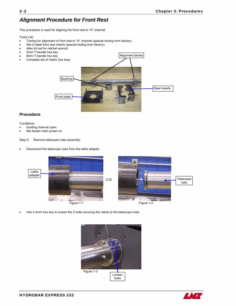
3-2 Chapter 3: Procedures
HYDROBAR EXPRESS 332
Alignment Procedure for Front Rest This procedure is used for aligning the front rest to “H” channel. Tools List: • Tooling for alignment of front rest to “H” channel (special tooling from factory) • Set of steel front rest inserts (special tooling from factory) • Allen bit set for ratchet wrench • 5mm T-handle hex key • 8mm T-handle hex key • Complete set of metric hex keys
Alignment blocks
Bushing
Steel inserts
Front plate
Procedure Conditions: • Guiding channel open. • Bar feeder main power on. Step 5: Remove telescopic tube assembly. • Disconnect the telescopic tube from the lathe adapter.
Figure 1-1 Figure 1-2
• Use a 4mm hex key to loosen the 2 bolts securing the clamp to the telescopic tube.
Figure 1-3
Loosen bolts
Lathe adapter
Telescopic tube
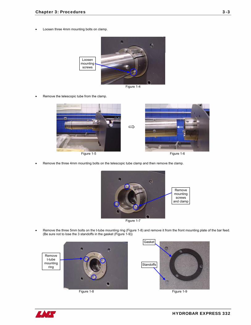
Chapter 3: Procedures
HYDROBAR EXPRESS 332
3-3
• Loosen three 4mm mounting bolts on clamp.
Loosen mounting screws
Figure 1-4
• Remove the telescopic tube from the clamp.
Figure 1-5 Figure 1-6
• Remove the three 4mm mounting bolts on the telescopic tube clamp and then remove the clamp.
Remove mounting screws
and clamp
Figure 1-7
• Remove the three 5mm bolts on the t-tube mounting ring (Figure 1-8) and remove it from the front mounting plate of the bar feed. (Be sure not to lose the 3 standoffs in the gasket (Figure 1-9))
Gasket
Remove t-tube
mounting ring
Standoffs
Figure 1-8 Figure 1-9
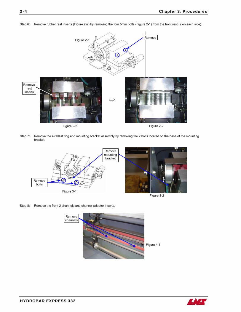
3-4 Chapter 3: Procedures
HYDROBAR EXPRESS 332
Step 6: Remove rubber rest inserts (Figure 2-2) by removing the four 5mm bolts (Figure 2-1) from the front rest (2 on each side).
RemoveFigure 2-1
Step 7: Remove the air blast ring and mounting bracket assembly by removing the 2 bolts located on the base of the mounting
bracket.
Step 8: Remove the front 2 channels and channel adapter inserts.
Remove rest
inserts
Figure 2-2Figure 2-2
Remove bolts
Remove mounting bracket
Remove channels
Figure 3-1 Figure 3-2
Figure 4-1
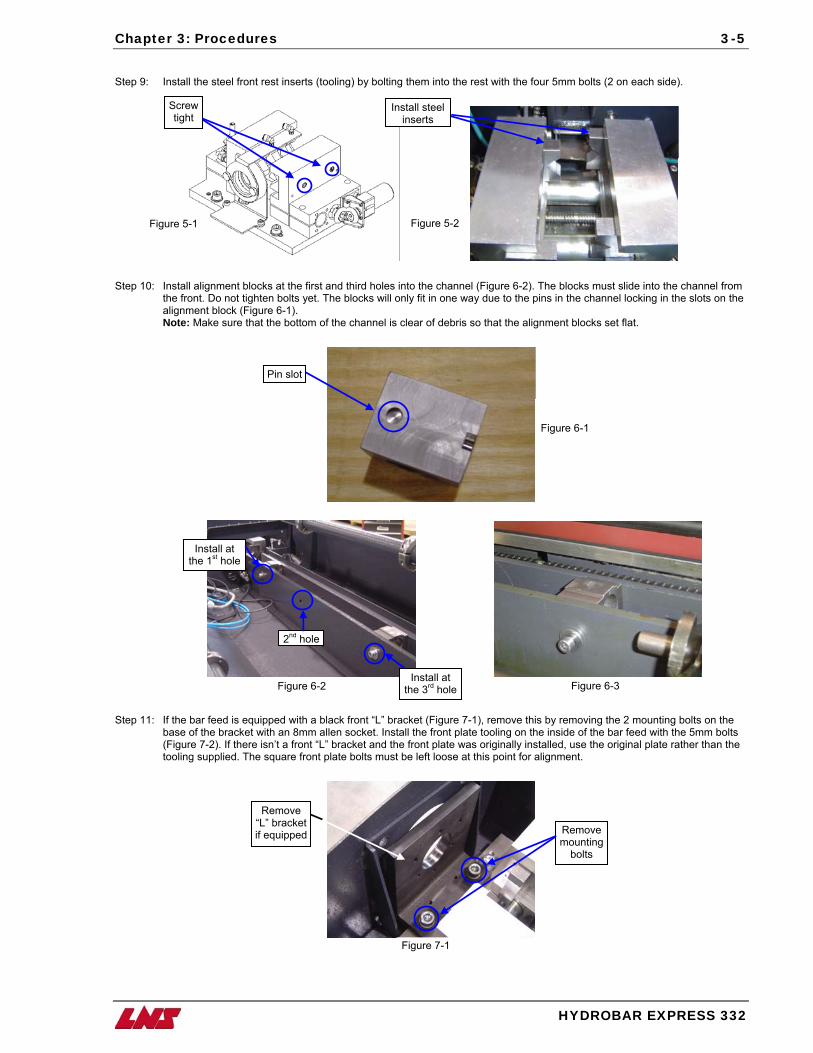
Chapter 3: Procedures
3-5
Step 9: Install the steel front rest inserts (tooling) by bolting them into the rest with the four 5mm bolts (2 on each side).
Screw tight
Install steel inserts
Step 10: Install alignment blocks at the first and third holes into the channel (Figure 6-2). The blocks must slide into the channel from
the front. Do not tighten bolts yet. The blocks will only fit in one way due to the pins in the channel locking in the slots on the alignment block (Figure 6-1). Note: Make sure that the bottom of the channel is clear of debris so that the alignment blocks set flat.
Step 11: If the bar feed is equip
base of the bracket wit(Figure 7-2). If there istooling supplied. The s
Install at the 1st hole
R“L”if e
P
Figure 5-1 Figure 5-2
in slot
HYDROBAR EXPRESS 332
ped with a black front “L” bracket (Figure 7-1), remove this by removing the 2 mounting bolts on the h an 8mm allen socket. Install the front plate tooling on the inside of the bar feed with the 5mm bolts n’t a front “L” bracket and the front plate was originally installed, use the original plate rather than the quare front plate bolts must be left loose at this point for alignment.
Install at the 3rd hole
2nd hole
emove bracket quipped Remove
mounting bolts
Figure 6-1
Figure 6-2 Figure 6-3
Figure 7-1
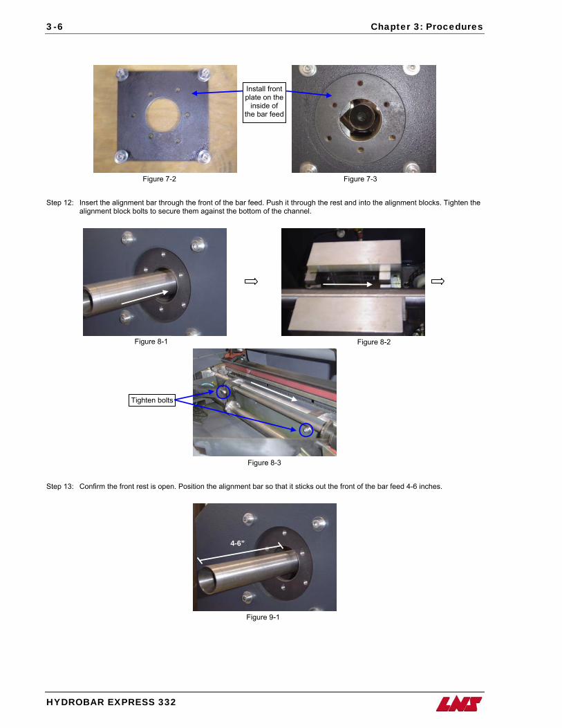
3-6 Chapter 3: Procedures
HYDROBAR EXPRESS 332
inside of the bar feed
Install front plate on the
Step 12: Insert the alignment bar through the front of the bar feed. Push it through the rest and into the alignment blocks. Tighten the
alignment block bolts to secure them against the bottom of the channel.
Step 13: Confirm the front rest is open. Position the alignment bar so that it sticks out the front of the bar feed 4-6 inches.
4-6”
Tighten bolts
Figure 7-2 Figure 7-3
Figure 8-1 Figure 8-2
Figure 8-3
Figure 9-1
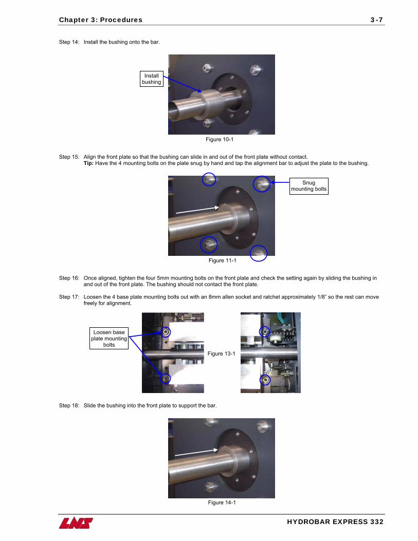
Chapter 3: Procedures
HYDROBAR EXPRESS 332
3-7
Step 14: Install the bushing onto the bar.
Install bushing
Step 15: Align the front plate so that the bushing can slide in and out of the front plate without contact.
Tip: Have the 4 mounting bolts on the plate snug by hand and tap the alignment bar to adjust the plate to the bushing.
Step 16: Once aligned, tighten the four 5mm mounting bolts on the front plate and check the setting again by sliding the bushing in
and out of the front plate. The bushing should not contact the front plate. Step 17: Loosen the 4 base plate mounting bolts out with an 8mm allen socket and ratchet approximately 1/8” so the rest can move
freely for alignment.
Step 18: Slide the bushing into the front plate to support the bar.
Snug mounting bolts
Figure 10-1
Figure 11-1
Figure 13-1
Figure 14-1
Loosen base plate mounting
bolts
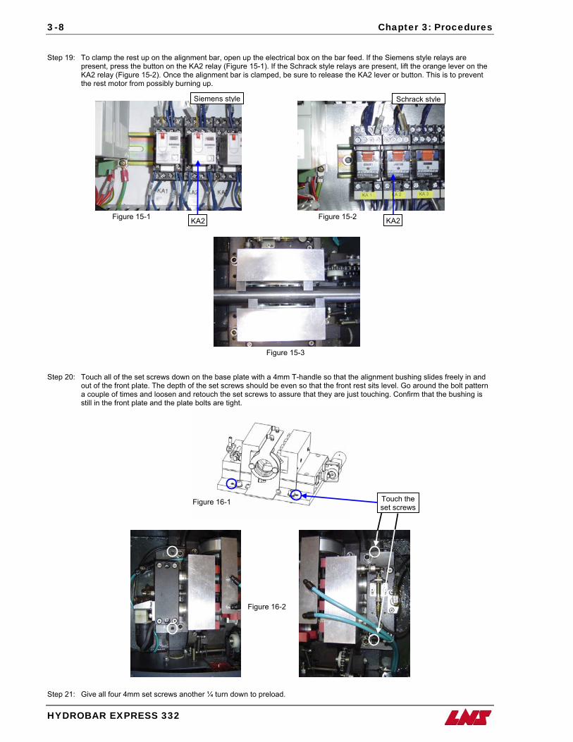
3-8 Chapter 3: Procedures
HYDROBAR EXPRESS 332
Step 19: To clamp the rest up on the alignment bar, open up the electrical box on the bar feed. If the Siemens style relays are
present, press the button on the KA2 relay (Figure 15-1). If the Schrack style relays are present, lift the orange lever on the KA2 relay (Figure 15-2). Once the alignment bar is clamped, be sure to release the KA2 lever or button. This is to prevent the rest motor from possibly burning up.
Step 20: Touch all of the set screws down on the base plate with a 4mm T-handle so that the alignment bushing slides freely in and
out of the front plate. The depth of the set screws should be even so that the front rest sits level. Go around the bolt pattern a couple of times and loosen and retouch the set screws to assure that they are just touching. Confirm that the bushing is still in the front plate and the plate bolts are tight.
Siemens style Schrack style
KA2 KA2
Touch the set screws
Figure 15-1 Figure 15-2
Figure 15-3
Figure 16-1
Figure 16-2
Step 21: Give all four 4mm set screws another ¼ turn down to preload.
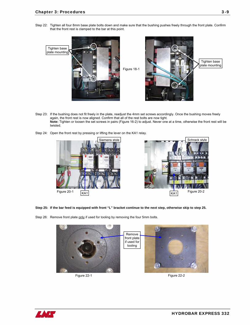
Chapter 3: Procedures
HYDROBAR E
3-9
Step 22: Tighten all four 8mm base plate bolts down and make sure that the bushing pushes freely through the front plate. Confirm
that the front rest is clamped to the bar at this point.
Step 23: If the bushing does not fit freely in the plate, readjust the 4mm set screws accordingly. Once the bushing
again, the front rest is now aligned. Confirm that all of the rest bolts are now tight. Note: Tighten or loosen the set screws in pairs (Figure 16-2) to adjust. Never one at a time, otherwise thtwisted.
Step 24: Open the front rest by pressing or lifting the lever on the KA1 relay.
Step 25: If the bar feed is equipped with front “L” bracket continue to the next step, otherwise skip to step Step 26: Remove front plate only if used for tooling by removing the four 5mm bolts.
Tighten base plate mounting
Siemens style Schrack
KA1 KA1
Remove front plateif used for
tooling
pFigure 18-1
Figure 20-1 Figure 20
Figure 22-1 Figure 22-2
Tighten base late mounting
XPRESS 332
moves freely
e front rest will be
25.
style
-2
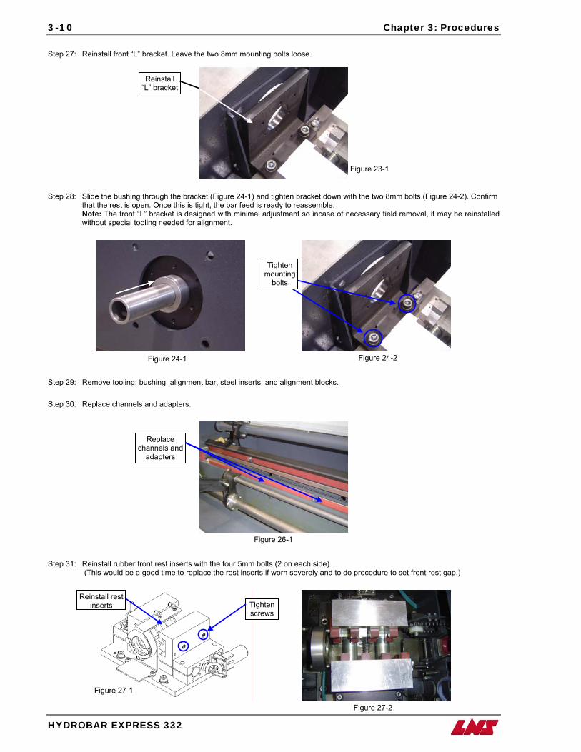
3-10 Chapter 3: Procedures
HYDROBAR EXPRESS 332
Step 27: Reinstall front “L” bracket. Leave the two 8mm mounting bolts loose.
Step 28: Slide the bushing through the bracket (Figure 24-1) and tighten bracket down with the two 8mm bolts (Figure 24-2). Confirm that the rest is open. Once this is tight, the bar feed is ready to reassemble. Note: The front “L” bracket is designed with minimal adjustment so incase of necessary field removal, it may be reinstalled without special tooling needed for alignment.
Step 29: Remove tooling; bushing, alignment bar, steel inserts, a Step 30: Replace channels and adapters.
Step 31: Reinstall rubber front rest inserts with the four 5mm bolt
(This would be a good time to replace the rest inserts if
Replace channels and
adapters
Reinstall rest inserts Tighte
screw
m
Figure 23-1
Figure 24-1
Figu
Figure 27-1
Reinstall “L” bracket
Tighten ounting bolts
nd alignment blocks.
s (2 on each side). worn severely and to do procedure to set front rest gap.)
n s
Figure 24-2
re 26-1
Figure 27-2
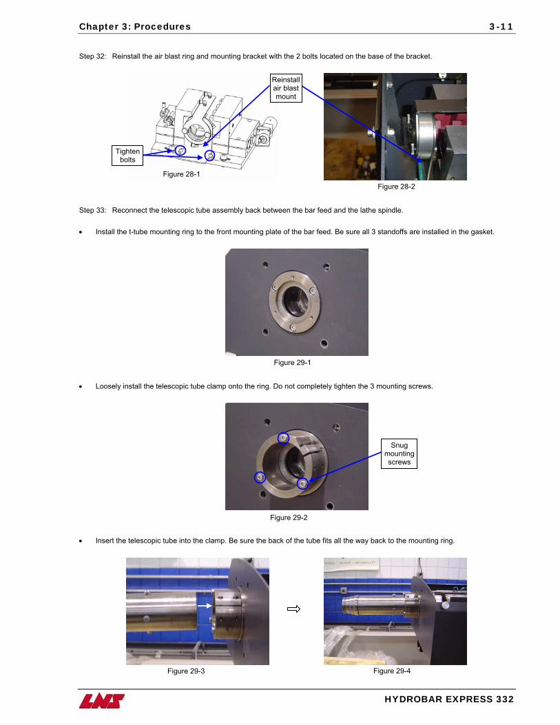
Chapter 3: Procedures
3-11
Step 32: Reinstall the air blast ring and mounting bracket with the 2 bolts located on the base of the bracket.
Tighten bolts
Reinstall air blast mount
Step 33: Reconnect the t • Install the t-tube mou
• Loosely install the tel
• Insert the telescopic
Figure 28-1
elescopic tube assembly back between the bar feed and the lathe
nting ring to the front mounting plate of the bar feed. Be sure all 3
escopic tube clamp onto the ring. Do not completely tighten the 3 m
tube into the clamp. Be sure the back of the tube fits all the way ba
Figure 28-2
spindle.
standoffs are installed in the gasket.
Figure 29-1
ounting screws.
Snug mounting screws
Figure 29-2
ck to the mounting ring.
Figure 29-3 Figure 29-4HYDROBAR EXPRESS 332
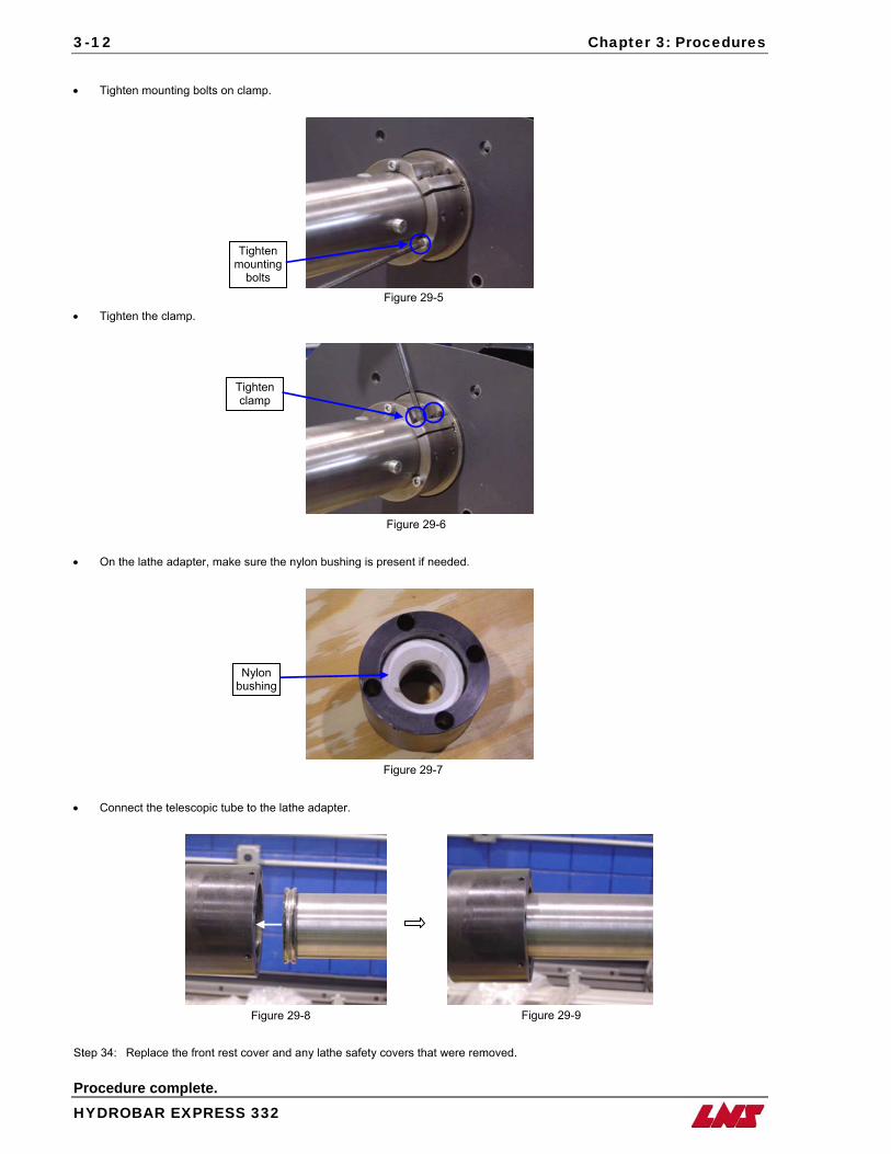
3-12 Chapter 3: Procedures
HYDROBAR EXPRESS 332
• Tighten mounting bolts on clamp.
• Tighten the clamp.
• On the lathe adapter, make sure the nylon bushing is pr
• Connect the telescopic tube to the lathe adapter.
Tighten mounting
bolts
Tighten clamp
Nylon bushing
Step 34: Replace the front rest cover and any lathe safety c Procedure complete.
Figure 29-5
o
Figure 29-6
esent if needed.
Figure 29-7 Figure 29-8vers that were removed.
Figure 29-9
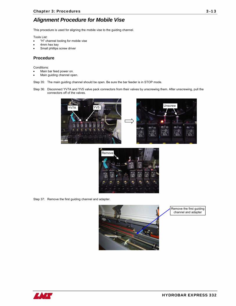
Chapter 3: Procedures
HYDROBAR EXPRESS 332
3-13
Alignment Procedure for Mobile Vise This procedure is used for aligning the mobile vise to the guiding channel. Tools List: • “H” channel tooling for mobile vise • 4mm hex key • Small phillips screw driver Procedure Conditions: • Main bar feed power on. • Main guiding channel open. Step 35: The main guiding channel should be open. Be sure the bar feeder is in STOP mode. Step 36: Disconnect YV7A and YV5 valve pack connectors from their valves by unscrewing them. After unscrewing, pull the
connectors off of the valves.
Unscrew YV7A YV5
Remove
Step 37: Remove the first guiding channel and adapter.
Remove the first guiding channel and adapter
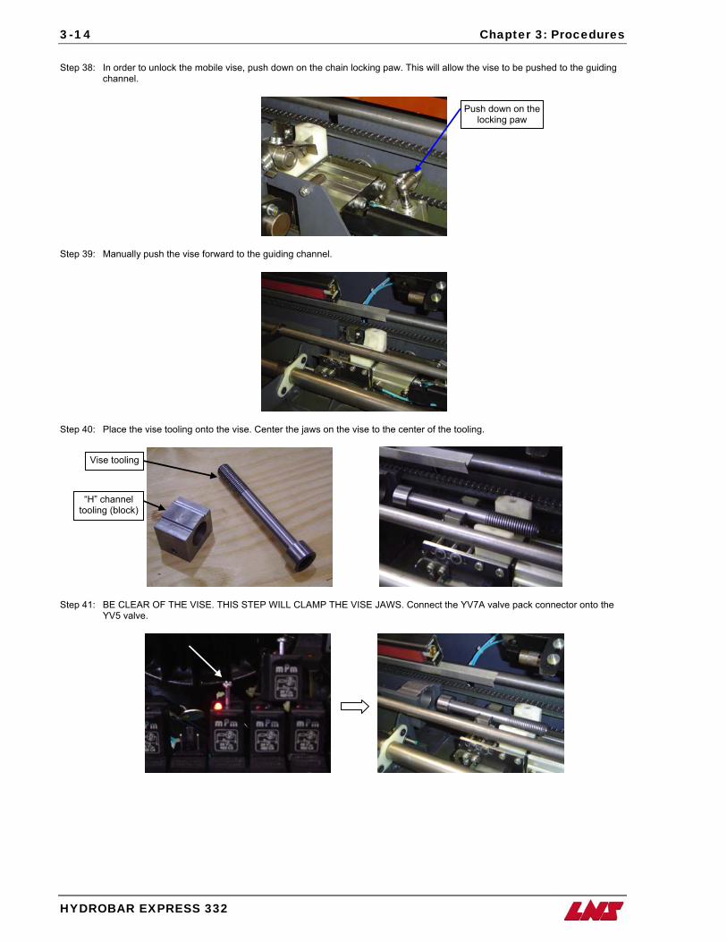
3-14 Chapter 3: Procedures
HYDROBAR EXPRESS 332
Step 38: In order to unlock the mobile vise, push down on the chain locking paw. This will allow the vise to be pushed to the guiding
channel.
Step 39: Manually push the vise forward to the guiding channel.
Step 40: Place the vise tooling onto the vise. Center the jaws on the vise to the center of the tooling.
Vise tooling
Push down on the locking paw
Step 41: BE CLEAR OF THE VISE. THIS STEP WILL CLAMP THE VISE JAWS. Connect the YV7A valve pack connector onto the YV5 valve.
“H” channel tooling (block)
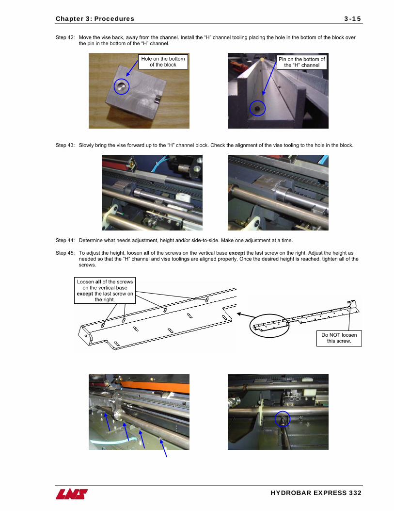
Chapter 3: Procedures
3-15
Step 42: Move the vise back, away from the channel. Install the “H” channel tooling placing the hole in the bottom of the block over
the pin in the bottom of the “H” channel.
Step 43: Slowly bring the vise forward up to the “H” channel block. Check the alignment of the vise tooling to the hole in the block.
Step 44: Determine what needs adjustment, height and/or side-to-side. Make one adjustment at a time.
Step 45: To adjust the height, loosen all of the screws on the vertical base except the last screw on the right. Adjust the height as needed so that the “H” channel and vise toolings are aligned properly. Once the desired height is reached, tighten all of the screws.
Pin on the bottom of the “H” channel
Hole on the bottom of the block
Loosen all of the screwson the vertical base
except the last screw onthe right.
HYDROBAR EXPRESS 332
Do NOT loosen this screw.
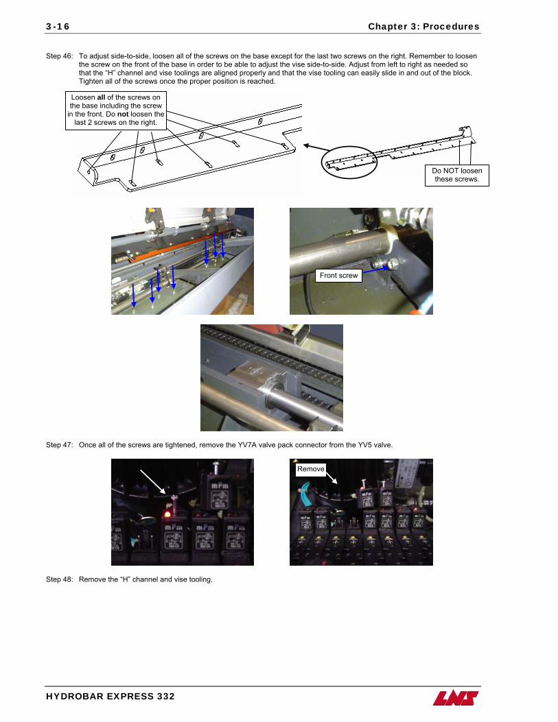
3-16 Chapter 3: Procedures
HYDROBAR EXPRESS 332
Step 46: To adjust side-to-side, loosen all of the screws on the base except for the last two screws on the right. Remember to loosen
the screw on the front of the base in order to be able to adjust the vise side-to-side. Adjust from left to right as needed so that the “H” channel and vise toolings are aligned properly and that the vise tooling can easily slide in and out of the block. Tighten all of the screws once the proper position is reached.
Loosen all of the screws on the base including the screw
in the front. Do not loosen the last 2 screws on the right.
Do NOT loosen these screws.
Step 47: Once all of the screws are tightened, remove the YV7A valve pack connector from the YV5 valve.
Remove
Front screw
Step 48: Remove the “H” channel and vise tooling.
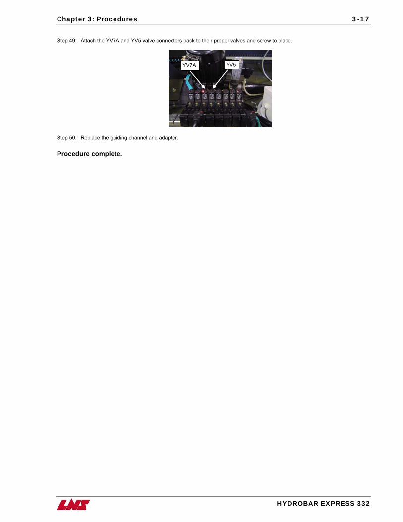
Chapter 3: Procedures
HYDROBAR EXPRESS 332
3-17
Step 49: Attach the YV7A and YV5 valve connectors back to their proper valves and screw to place.
YV7A YV5
Step 50: Replace the guiding channel and adapter. Procedure complete.
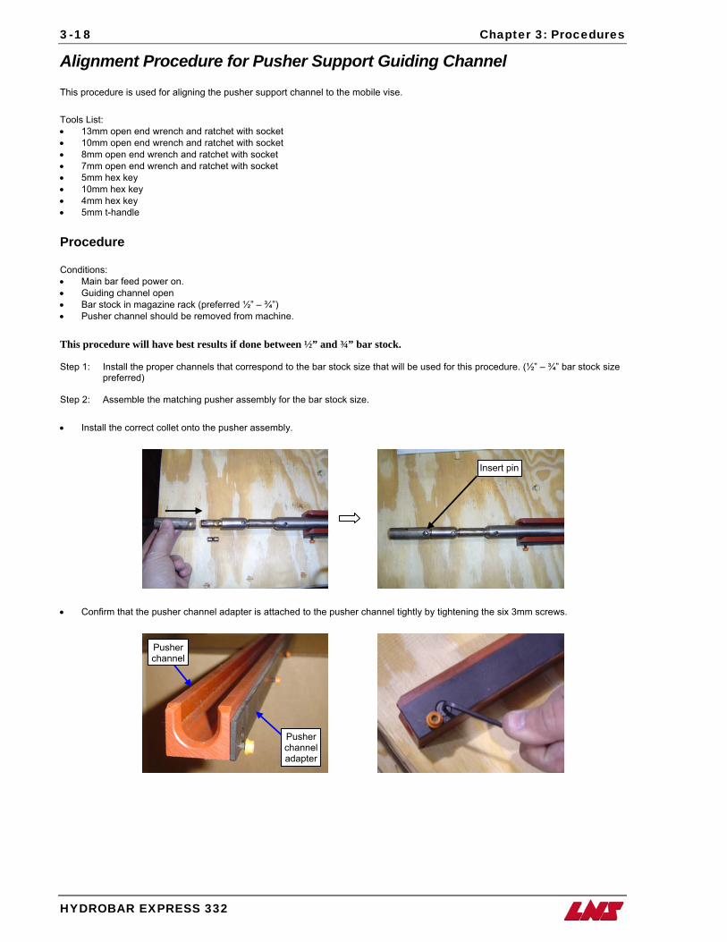
3-18 Chapter 3: Procedures
HYDROBAR EX
Alignment Procedure for Pusher Support Guiding Channel This procedure is used for aligning the pusher support channel to the mobile vise. Tools List: • 13mm open end wrench and ratchet with socket • 10mm open end wrench and ratchet with socket • 8mm open end wrench and ratchet with socket • 7mm open end wrench and ratchet with socket • 5mm hex key • 10mm hex key • 4mm hex key • 5mm t-handle Procedure Conditions: • Main bar feed power on. • Guiding channel open • Bar stock in magazine rack (preferred ½” – ¾”) • Pusher channel should be removed from machine. This procedure will have best results if done between ½” and ¾” bar stock. Step 1: Install the proper channels that correspond to the bar stock size that will be used for this procedure. (½” – ¾” bar stock size
preferred) Step 2: Assemble the matching pusher assembly for the bar stock size. • Install the correct collet onto the pusher assembly.
Insert pin
• Confirm that the pusher channel adapter is attached to the pusher channel tightly by tightening the six 3mm screws.
Pusher channelPRESS 332
Pusher channel adapter
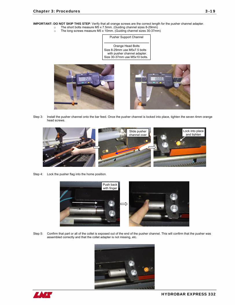
Chapter 3: Procedures
HYDROBA
3-19
IMPORTANT: DO NOT SKIP THIS STEP: Verify that all orange screws are the correct length for the pusher channel adapter.
o The short bolts measure M5 x 7.5mm. (Guiding channel sizes 8-29mm) o The long screws measure M5 x 10mm. (Guiding channel sizes 30-37mm)
Siz Siz
Step 3: Install the pusher channel onto the bar feed. Once the pusher channel is locked into place, tighten the seven 4mm orange
head screws.
Step 4: Lock the pusher flag into the home position.
Step 5: Confirm that part or all of the collet is exposed out of the end of the pusher channel. This will confirm
assembled correctly and that the collet adapter is not missing, etc.
Lock into place and tighten
Slide pusher channel over
Push backwith finger
Pusher Support Channel
Orange Head Bolts
e 8-29mm use M5x7.5 bolts with pusher channel adapter. e 30-37mm use M5x10 bolts.
R EXPRESS 332
that the pusher was
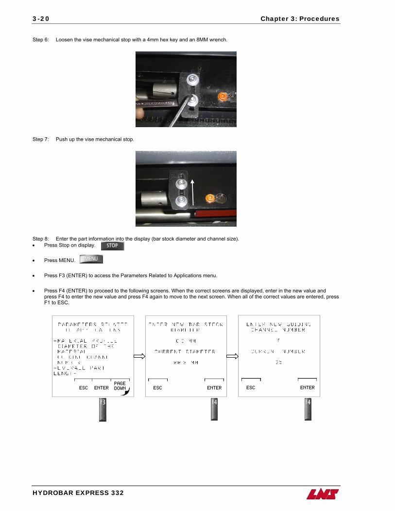
3-20 Chapter 3: Procedures
HYDROBAR EXPRESS 332
Step 6: Loosen the vise mechanical stop with a 4mm hex key and an 8MM wrench.
Step 7: Push up the vise mechanical stop.
Step 8: Enter the part information into the display (bar stock diameter and channel size). • Press Stop on display. • Press MENU.
• Press F3 (ENTER) to access the Parameters Related to Applications menu.
• Press F4 (ENTER) to proceed to the following screens. When the correct screens are displayed, enter in the new value and
press F4 to enter the new value and press F4 again to move to the next screen. When all of the correct values are entered, press F1 to ESC.
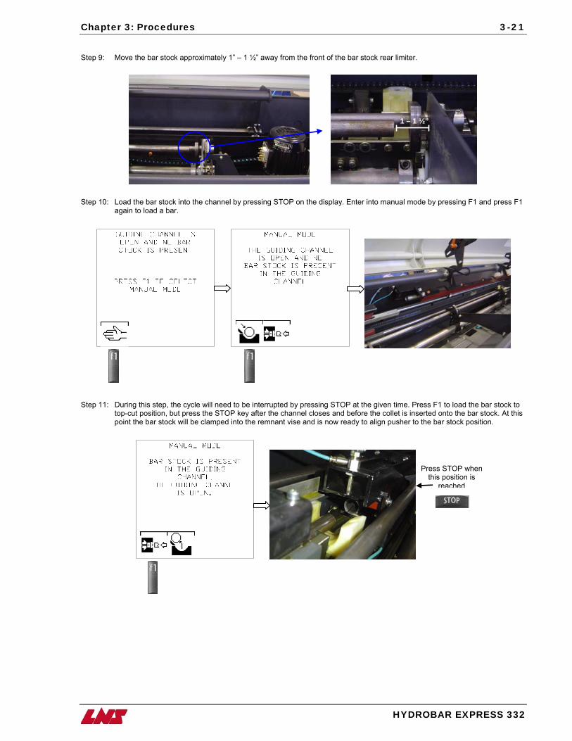
Chapter 3: Procedures
HYDR
3-21
Step 9: Move the bar stock approximately 1” – 1 ½” away from the front of the bar stock rear limiter.
1 – 1 ½”
Step 10: Load the bar stock into the channel by pressing STOP on the display. Enter into manual mode by pressing F1 and press F1
again to load a bar.
Step 11: During this step, the cycle will need to be interrupted by pressing STOP at the given time. Press F1 to load the bar stock to top-cut position, but press the STOP key after the channel closes and before the collet is inserted onto the bar stock. At this point the bar stock will be clamped into the remnant vise and is now ready to align pusher to the bar stock position.
Press STOP when this position is
reached
OBAR EXPRESS 332
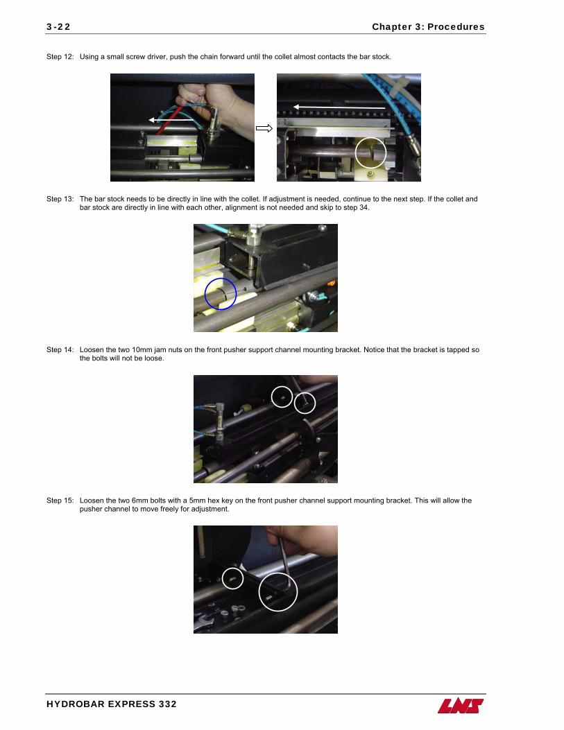
3-22 Chapter 3: Procedures
HYDROBAR EXPRESS 332
Step 12: Using a small screw driver, push the chain forward until the collet almost contacts the bar stock.
Step 13: The bar stock needs to be directly in line with the collet. If adjustment is needed, continue to the next step. If the collet and
bar stock are directly in line with each other, alignment is not needed and skip to step 34.
Step 14: Loosen the two 10mm jam nuts on the front pusher support channel mounting bracket. Notice that the bracket is tapped so
the bolts will not be loose.
Step 15: Loosen the two 6mm bolts with a 5mm hex key on the front pusher channel support mounting bracket. This will allow the pusher channel to move freely for adjustment.
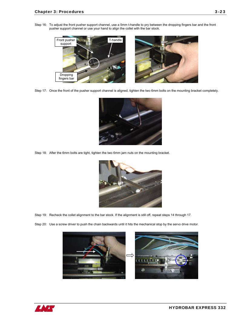
Chapter 3: Procedures
HYDROBAR EXPRESS 332
3-23
Step 16: To adjust the front pusher support channel, use a 5mm t-handle to pry between the dropping fingers bar and the front
pusher support channel or use your hand to align the collet with the bar stock.
Front pusher support
Dropping fingers bar
T-handle
Step 17: Once the front of the pusher support channel is aligned, tighten the two 6mm bolts on the mounting bracket completely.
Step 18: After the 6mm bolts are tight, tighten the two 6mm jam nuts on the mounting bracket.
Step 19: Recheck the collet alignment to the bar stock. If the alignment is still off, repeat steps 14 through 17. Step 20: Use a screw driver to push the chain backwards until it hits the mechanical stop by the servo drive motor.
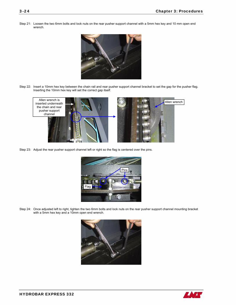
3-24 Chapter 3: Procedures
HYDROBAR EXPRESS 332
Step 21: Loosen the two 6mm bolts and lock nuts on the rear pusher support channel with a 5mm hex key and 10 mm open end
wrench.
Step 22: Insert a 10mm hex key between the chain rail and rear pusher support channel bracket to set the gap for the pusher flag. Inserting the 10mm hex key will set the correct gap itself.
Step 23: Adjust the rear pusher support channel left or right so the flag is centered over the pins.
Pins
Allen wrench
Flag
Allen wrench is inserted underneath the chain and rear
pusher support channel
Step 24: Once adjusted left to right, tighten the two 6mm bolts and lock nuts on the rear pusher support channel mounting bracket
with a 5mm hex key and a 10mm open end wrench.
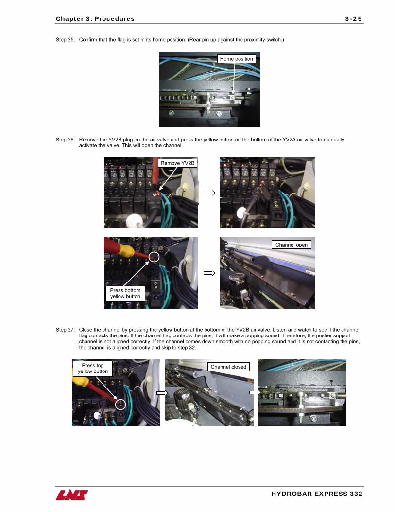
Chapter 3: Procedures
HYDROBAR EXPRESS 332
3-25
Step 25: Confirm that the flag is set in its home position. (Rear pin up against the proximity switch.)
Home position
Step 26: Remove the YV2B plug on the air valve and press the yellow button on the bottom of the YV2A air valve to manually
activate the valve. This will open the channel.
Remove YV2B
Channel open
Press bottom yellow button
Step 27: Close the channel by pressing the yellow button at the bottom of the YV2B air valve. Listen and watch to see if the channel
flag contacts the pins. If the channel flag contacts the pins, it will make a popping sound. Therefore, the pusher support channel is not aligned correctly. If the channel comes down smooth with no popping sound and it is not contacting the pins, the channel is aligned correctly and skip to step 32.
Press top yellow button
Channel closed
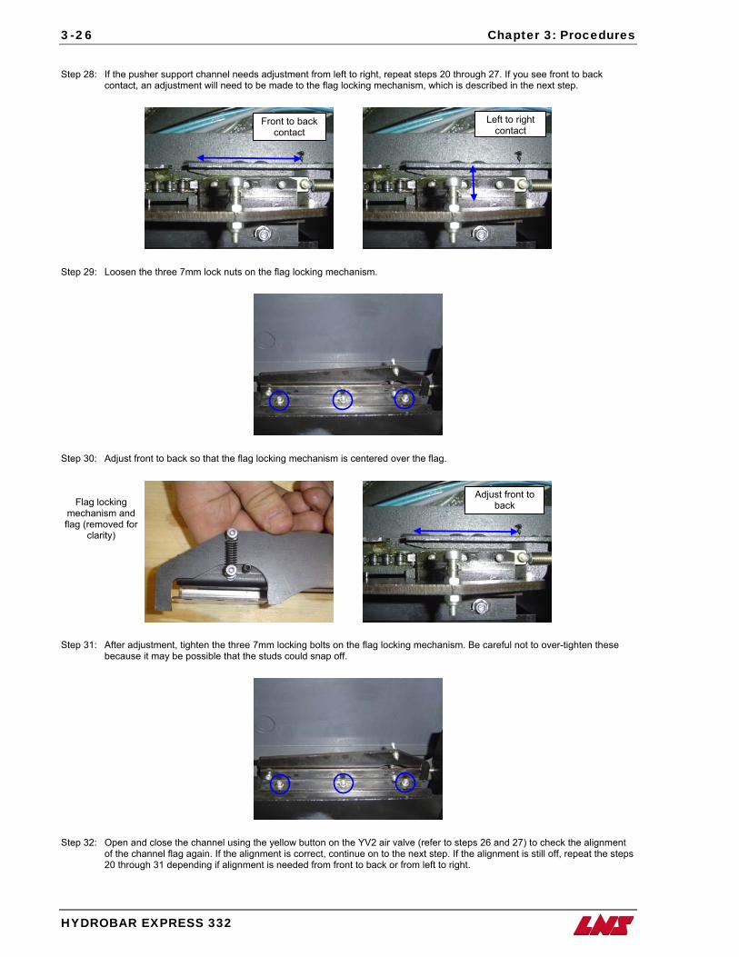
3-26 Chapter 3: Procedures
HYDROBAR EXPRESS 332
Step 28: If the pusher support channel needs adjustment from left to right, repeat steps 20 through 27. If you see front to back
contact, an adjustment will need to be made to the flag locking mechanism, which is described in the next step.
Left to right contact
Front to back contact
Step 29: Loosen the three 7mm lock nuts on the flag locking mechanism.
Step 30: Adjust front to back so that the flag locking mechanism is centered over the flag.
Step 31: After adjustment, tighten the three 7mm locking bolts on the flag locking mechanism. Be careful not to over-tighten these because it may be possible that the studs could snap off.
Flag locking mechanism and flag (removed for
clarity)
Adjust front to back
Step 32: Open and close the channel using the yellow button on the YV2 air valve (refer to steps 26 and 27) to check the alignment
of the channel flag again. If the alignment is correct, continue on to the next step. If the alignment is still off, repeat the steps 20 through 31 depending if alignment is needed from front to back or from left to right.
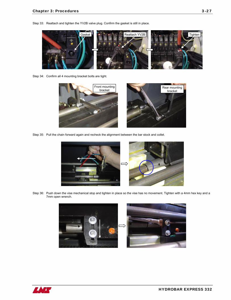
Chapter 3: Procedures
HYDROBAR EXPRESS 332
3-27
Step 33: Reattach and tighten the YV2B valve plug. Confirm the gasket is still in place.
Step 34: Confirm all 4 mounting bracket bolts are tight.
Front mounting bracket
Reattach YV2BGasket Tighten
Rear mounting bracket
Step 35: Pull the chain forward again and recheck the alignment between the bar stock and collet.
Step 36: Push down the vise mechanical stop and tighten in place so the vise has no movement. Tighten with a 4mm hex key and a 7mm open wrench.
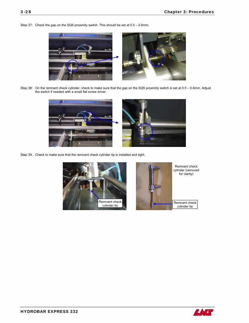
3-28 Chapter 3: Procedures
HYDROBAR EXPRESS 332
Step 37: Check the gap on the SQ6 proximity switch. This should be set at 0.5 – 0.6mm.
Step 38: On the remnant check cylinder, check to make sure that the gap on the SQ5 proximity switch is set at 0.5 – 0.6mm. Adjust the switch if needed with a small flat screw driver.
Step 39: Check to make sure that the remnant check cylinder tip is installed and tight.
Remnant check
cylinder tipRemnant check
cylinder tip
Remnant check cylinder (removed
for clarity)
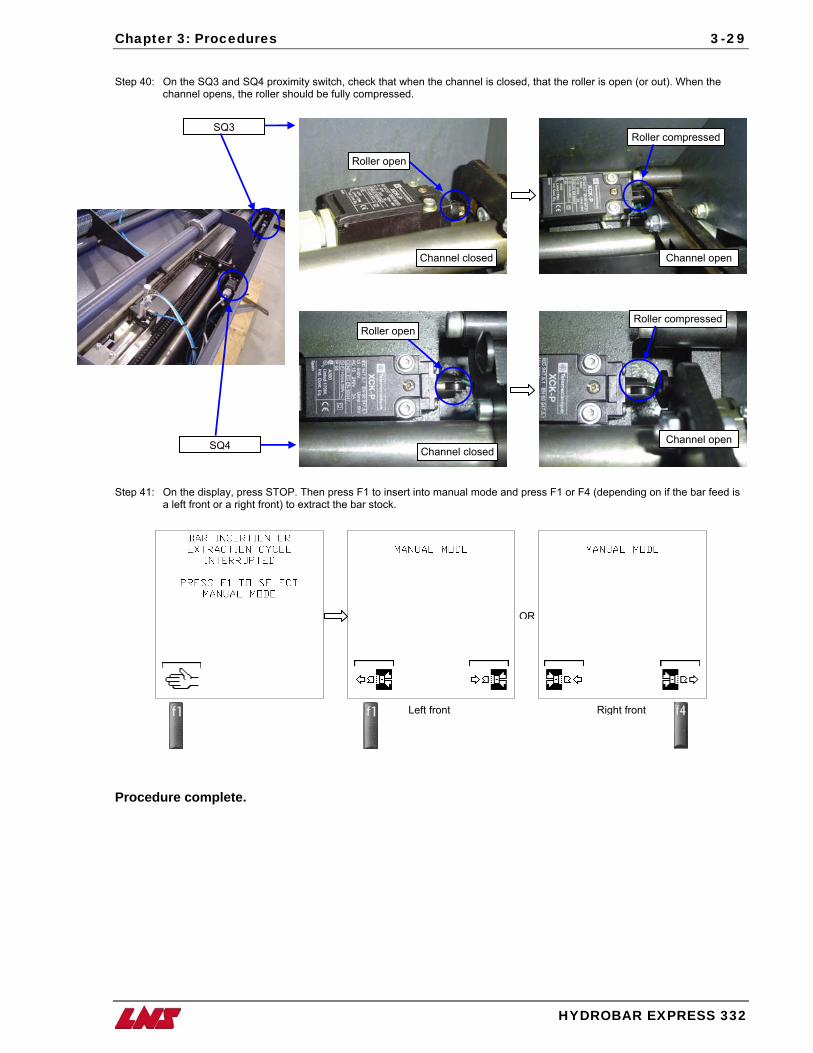
Chapter 3: Procedures
HYDROBAR EXPRESS 332
3-29
Step 40: On the SQ3 and SQ4 proximity switch, check that when the channel is closed, that the roller is open (or out). When the
channel opens, the roller should be fully compressed.
SQ3
SQ4
Roller open
Channel closed
Roller open
Channel closed
Roller compressed
Channel open
Roller compressed
Channel open
Step 41: On the display, press STOP. Then press F1 to insert into manual mode and press F1 or F4 (depending on if the bar feed is
a left front or a right front) to extract the bar stock.
OR
Left front Right front
Procedure complete.
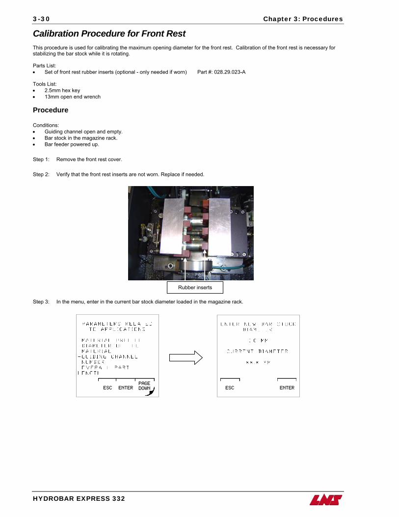
3-30 Chapter 3: Procedures
HYDROBAR EXPRESS 332
Calibration Procedure for Front Rest This procedure is used for calibrating the maximum opening diameter for the front rest. Calibration of the front rest is necessary for stabilizing the bar stock while it is rotating. Parts List: • Set of front rest rubber inserts (optional - only needed if worn) Part #: 028.29.023-A Tools List: • 2.5mm hex key • 13mm open end wrench Procedure Conditions: • Guiding channel open and empty. • Bar stock in the magazine rack. • Bar feeder powered up.
Step 1: Remove the front rest cover. Step 2: Verify that the front rest inserts are not worn. Replace if needed.
Rubber inserts
Step 3: In the menu, enter in the current bar stock diameter loaded in the magazine rack.
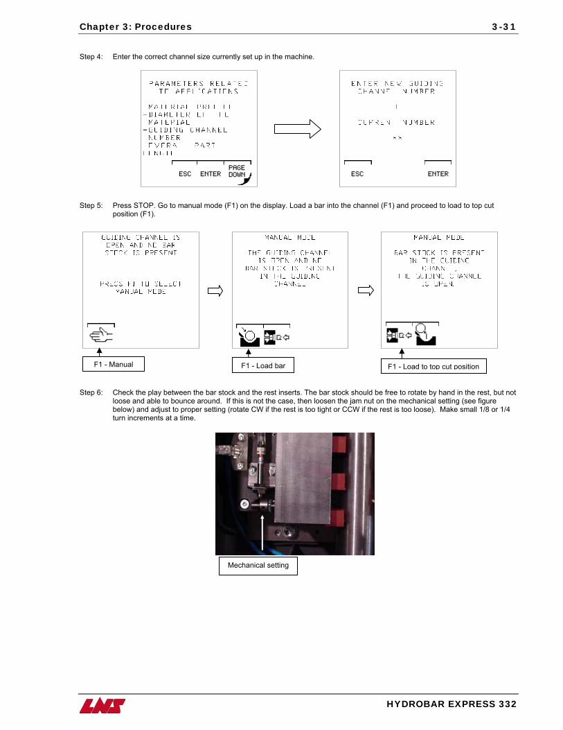
Chapter 3: Procedures
HYDROBAR EXPRESS 332
3-31
Step 4: Enter the correct channel size currently set up in the machine.
Step 5: Press STOP. Go to manual mode (F1) on the display. Load a bar into the channel (F1) and proceed to load to top cut
position (F1).
F1 - Load to top cut position F1 - Manual F1 - Load bar
Step 6: Check the play between the bar stock and the rest inserts. The bar stock should be free to rotate by hand in the rest, but not
loose and able to bounce around. If this is not the case, then loosen the jam nut on the mechanical setting (see figure below) and adjust to proper setting (rotate CW if the rest is too tight or CCW if the rest is too loose). Make small 1/8 or 1/4 turn increments at a time.
Mechanical setting
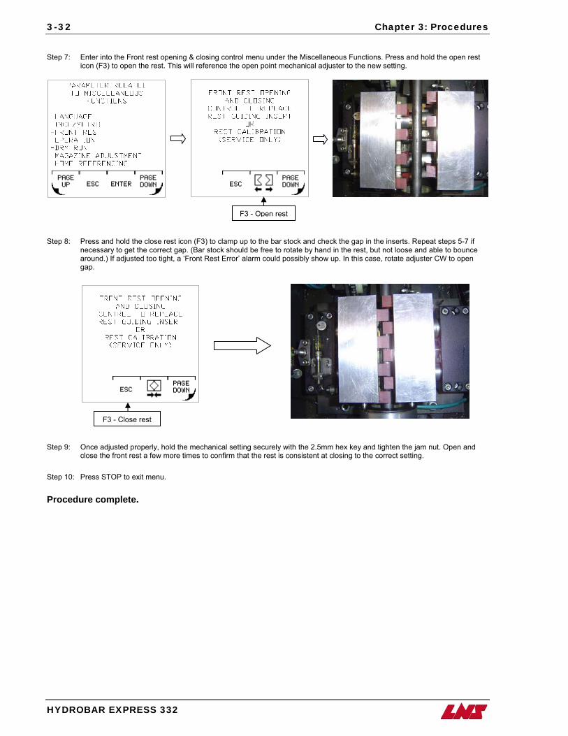
3-32 Chapter 3: Procedures
HYDROBAR EXPRESS 332
Step 7: Enter into the Front rest opening & closing control menu under the Miscellaneous Functions. Press and hold the open rest
icon (F3) to open the rest. This will reference the open point mechanical adjuster to the new setting.
F3 - Open rest
Step 8: Press and hold the close rest icon (F3) to clamp up to the bar stock and check the gap in the inserts. Repeat steps 5-7 if necessary to get the correct gap. (Bar stock should be free to rotate by hand in the rest, but not loose and able to bounce around.) If adjusted too tight, a ‘Front Rest Error’ alarm could possibly show up. In this case, rotate adjuster CW to open gap.
F3 - Close rest
Step 9: Once adjusted properly, hold the mechanical setting securely with the 2.5mm hex key and tighten the jam nut. Open and close the front rest a few more times to confirm that the rest is consistent at closing to the correct setting.
Step 10: Press STOP to exit menu. Procedure complete.
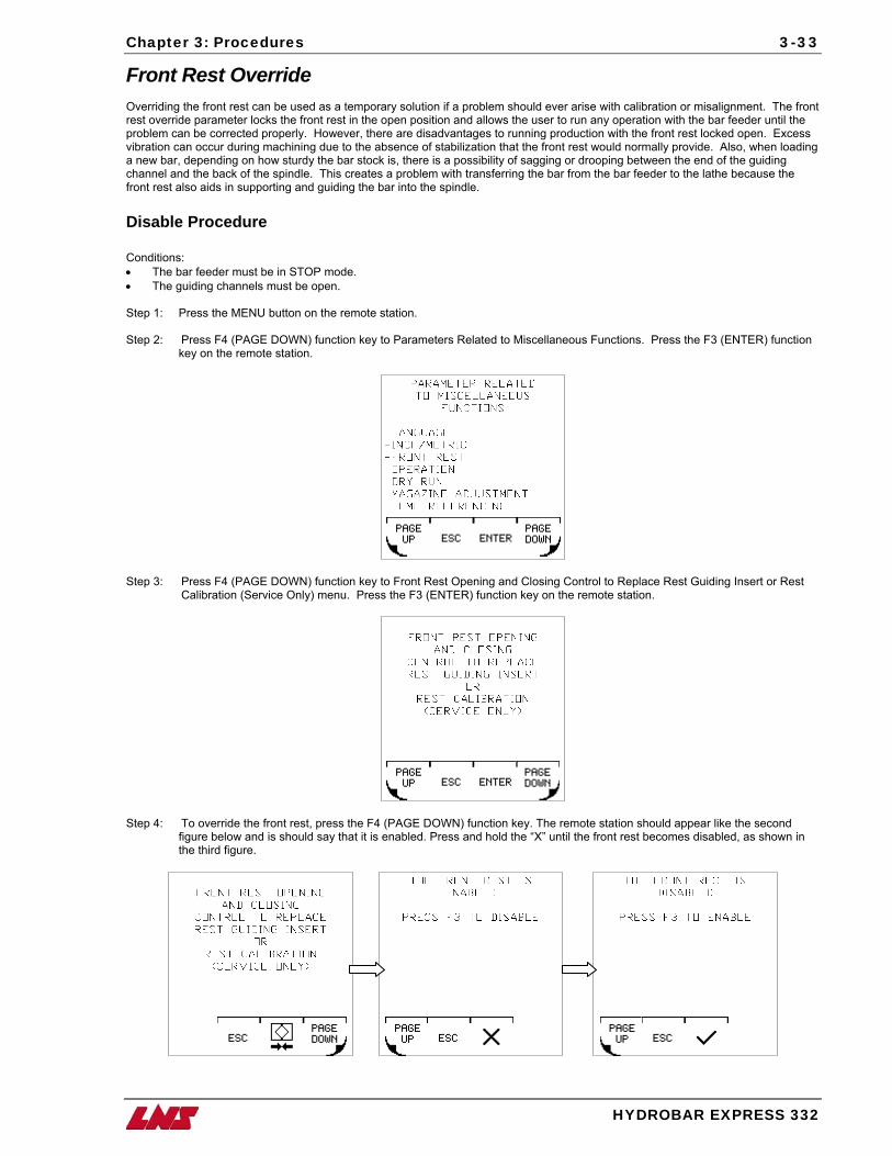
Chapter 3: Procedures
HYDROBAR EXPRESS 332
3-33
Front Rest Override Overriding the front rest can be used as a temporary solution if a problem should ever arise with calibration or misalignment. The front rest override parameter locks the front rest in the open position and allows the user to run any operation with the bar feeder until the problem can be corrected properly. However, there are disadvantages to running production with the front rest locked open. Excess vibration can occur during machining due to the absence of stabilization that the front rest would normally provide. Also, when loading a new bar, depending on how sturdy the bar stock is, there is a possibility of sagging or drooping between the end of the guiding channel and the back of the spindle. This creates a problem with transferring the bar from the bar feeder to the lathe because the front rest also aids in supporting and guiding the bar into the spindle. Disable Procedure Conditions: • The bar feeder must be in STOP mode. • The guiding channels must be open. Step 1: Press the MENU button on the remote station. Step 2: Press F4 (PAGE DOWN) function key to Parameters Related to Miscellaneous Functions. Press the F3 (ENTER) function
key on the remote station.
Step 3: Press F4 (PAGE DOWN) function key to Front Rest Opening and Closing Control to Replace Rest Guiding Insert or Rest
Calibration (Service Only) menu. Press the F3 (ENTER) function key on the remote station.
Step 4: To override the front rest, press the F4 (PAGE DOWN) function key. The remote station should appear like the second
figure below and is should say that it is enabled. Press and hold the “X” until the front rest becomes disabled, as shown in the third figure.
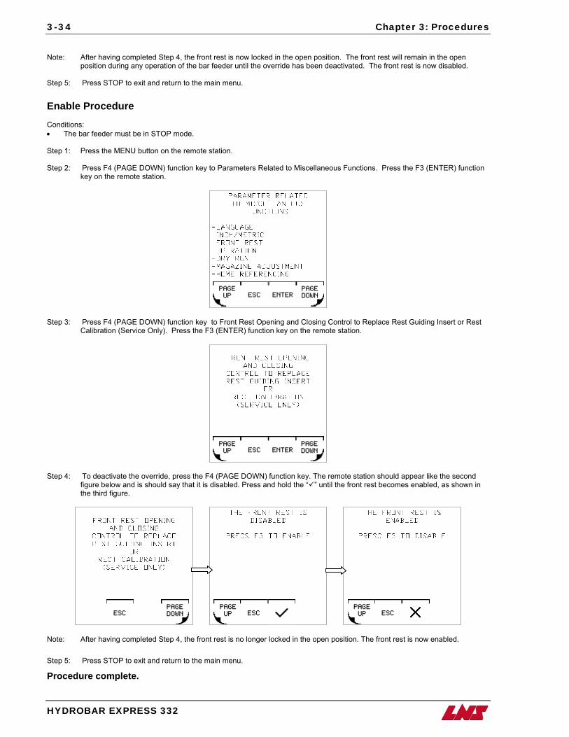
3-34 Chapter 3: Procedures
HYDROBAR EXPRESS 332
Note: After having completed Step 4, the front rest is now locked in the open position. The front rest will remain in the open position during any operation of the bar feeder until the override has been deactivated. The front rest is now disabled. Step 5: Press STOP to exit and return to the main menu. Enable Procedure Conditions: • The bar feeder must be in STOP mode. Step 1: Press the MENU button on the remote station. Step 2: Press F4 (PAGE DOWN) function key to Parameters Related to Miscellaneous Functions. Press the F3 (ENTER) function
key on the remote station.
Step 3: Press F4 (PAGE DOWN) function key to Front Rest Opening and Closing Control to Replace Rest Guiding Insert or Rest
Calibration (Service Only). Press the F3 (ENTER) function key on the remote station.
Step 4: To deactivate the override, press the F4 (PAGE DOWN) function key. The remote station should appear like the second
figure below and is should say that it is disabled. Press and hold the “ ” until the front rest becomes enabled, as shown in the third figure.
Note: After having completed Step 4, the front rest is no longer locked in the open position. The front rest is now enabled. Step 5: Press STOP to exit and return to the main menu.
Procedure complete.
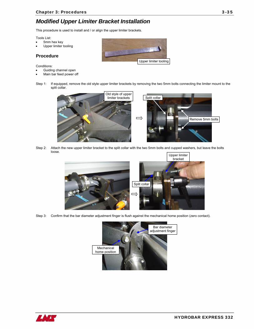
Chapter 3: Procedures
HYDROBAR EXPRESS 332
3-35
Modified Upper Limiter Bracket Installation This procedure is used to install and / or align the upper limiter brackets. Tools List:
Upper limiter tooling
• 5mm hex key • Upper limiter tooling Procedure Conditions: • Guiding channel open • Main bar feed power off Step 1: If equipped, remove the old style upper limiter brackets by removing the two 5mm bolts connecting the limiter mount to the
split collar.
Step 2: Attach the new upper limiter bracket to the split collar with the two 5mm bolts and cupped washers, but leave the bolts loose.
Old style of upper limiter brackets Split collar
Remove 5mm bolts
Upper limiter bracket
Split collar
Step 3: Confirm that the bar diameter adjustment finger is flush against the mechanical home position (zero contact).
Bar diameter adjustment finger
Mechanical home position
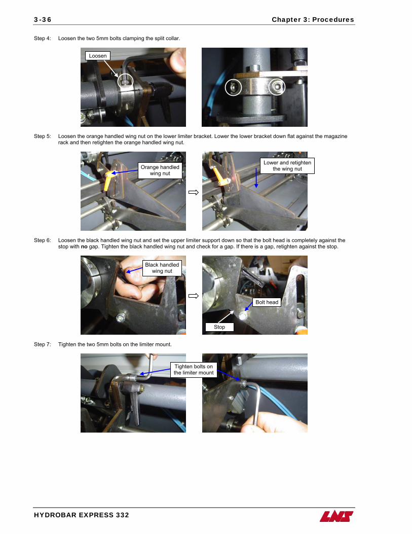
3-36 Chapter 3: Procedures
HYDROBAR EXPRESS 332
Step 4: Loosen the two 5mm bolts clamping the split collar.
Step 5: Loosen the orange handled wing nut on the lower limiter bracket. Lower the lower bracket down flat against the magazine
rack and then retighten the orange handled wing nut.
Lower and retighten the wing nut Orange handled
wing nut
Loosen
Step 6: Loosen the black handled wing nut and set the upper limiter support down so that the bolt head is completely against the
stop with no gap. Tighten the black handled wing nut and check for a gap. If there is a gap, retighten against the stop.
Black handled wing nut
Bolt head
Stop
Step 7: Tighten the two 5mm bolts on the limiter mount.
Tighten bolts on the limiter mount
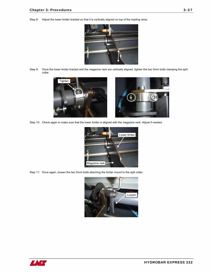
Chapter 3: Procedures
HYDROBAR EXPRESS 332
3-37
Step 8: Adjust the lower limiter bracket so that it is vertically aligned on top of the loading ramp.
Step 9: Once the lower limiter bracket and the magazine rack are vertically aligned, tighten the two 5mm bolts clamping the split
collar.
Tighten
Step 10: Check again to make sure that the lower limiter is aligned with the magazine rack. Adjust if needed.
Lower limiter
Magazine rack
Step 11: Once again, loosen the two 5mm bolts attaching the limiter mount to the split collar.
Loosen
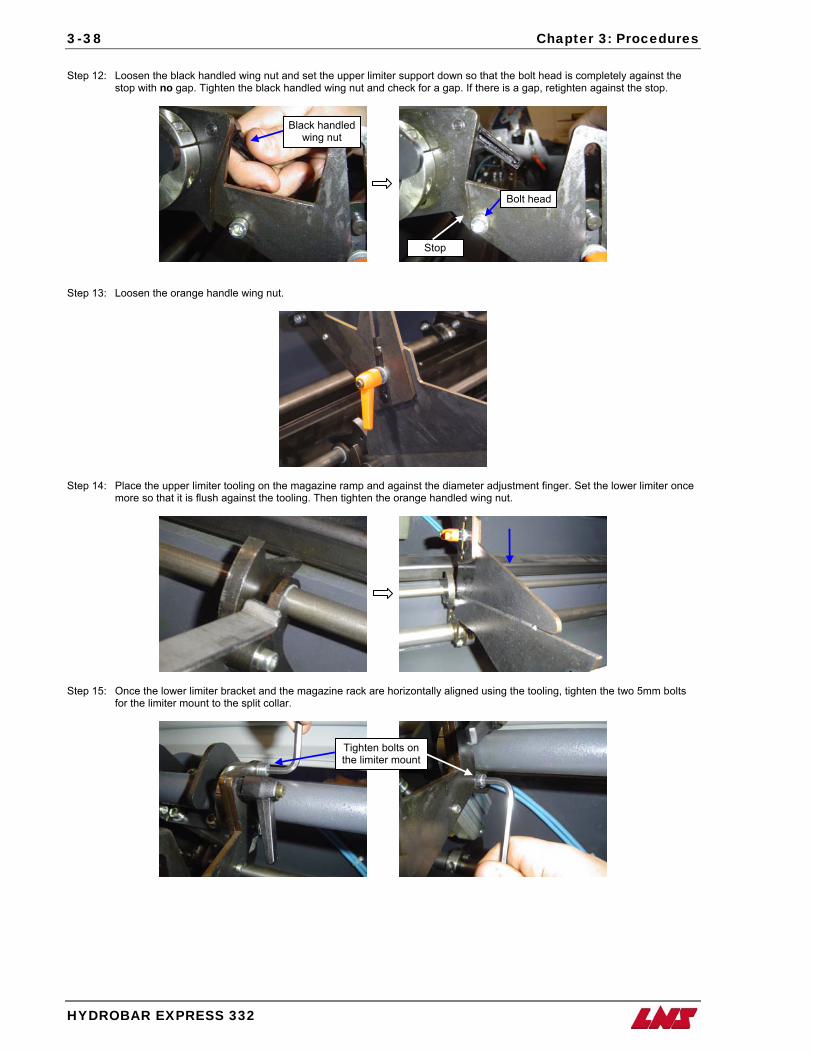
3-38 Chapter 3: Procedures
HYDROBAR EXPRESS 332
Step 12: Loosen the black handled wing nut and set the upper limiter support down so that the bolt head is completely against the
stop with no gap. Tighten the black handled wing nut and check for a gap. If there is a gap, retighten against the stop.
Black handled wing nut
Step 13: Loosen the orange handle wing nut.
Step 14: Place the upper limiter tooling on the magazine ramp and against the diameter adjustment finger. Set the lower limiter once
more so that it is flush against the tooling. Then tighten the orange handled wing nut.
Bolt head
Stop
Step 15: Once the lower limiter bracket and the magazine rack are horizontally aligned using the tooling, tighten the two 5mm bolts
for the limiter mount to the split collar.
Tighten bolts on the limiter mount
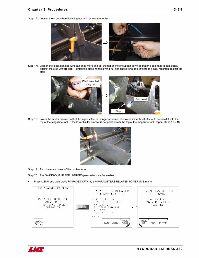
Chapter 3: Procedures
HYDROBAR EXPRESS 332
3-39
Step 16: Loosen the orange handled wing nut and remove the tooling.
Step 17: Loosen the black handled wing nut once more and set the upper limiter support down so that the bolt head is completely
against the stop with no gap. Tighten the black handled wing nut and check for a gap. If there is a gap, retighten against the stop.
Black handled wing nut
Bolt head
Stop
Step 18: Lower the limiter bracket so that it is against the bar magazine ramp. The lower limiter bracket should be parallel with the
top of the magazine rack. If the lower limiter bracket is not parallel with the top of the magazine rack, repeat steps 11 – 18.
Step 19: Turn the main power of the bar feeder on. Step 20: The SWING-OUT UPPER LIMITERS parameter must be enabled. • Press MENU and then press F4 (PAGE DOWN) to the PARAMETERS RELATED TO SERVICE menu.
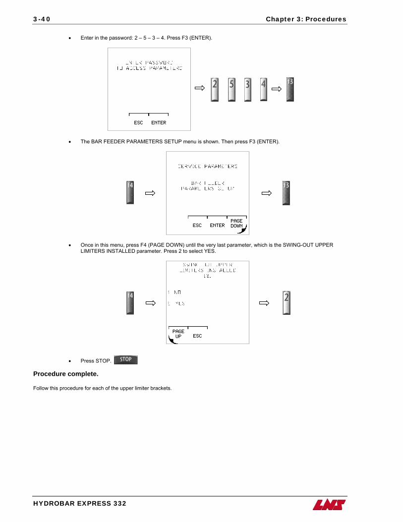
3-40 Chapter 3: Procedures
HYDROBAR EXPRESS 332
• Enter in the password: 2 – 5 – 3 – 4. Press F3 (ENTER).
• The BAR FEEDER PARAMETERS SETUP menu is shown. Then press F3 (ENTER).
• Once in this menu, press F4 (PAGE DOWN) until the very last parameter, which is the SWING-OUT UPPER LIMITERS INSTALLED parameter. Press 2 to select YES.
• Press STOP.
Procedure complete. Follow this procedure for each of the upper limiter brackets.
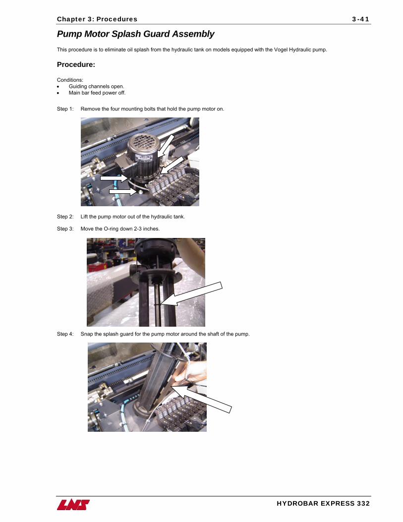
Chapter 3: Procedures
HYDROBAR EXPRESS 332
3-41
Pump Motor Splash Guard Assembly This procedure is to eliminate oil splash from the hydraulic tank on models equipped with the Vogel Hydraulic pump. Procedure: Conditions: • Guiding channels open. • Main bar feed power off.
Step 1: Remove the four mounting bolts that hold the pump motor on.
Step 2: Lift the pump motor out of the hydraulic tank. Step 3: Move the O-ring down 2-3 inches.
Step 4: Snap the splash guard for the pump motor around the shaft of the pump.
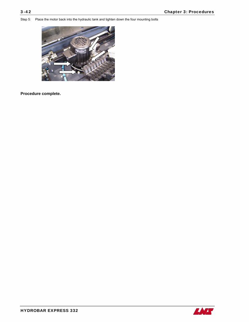
3-42 Chapter 3: Procedures
HYDROBAR EXPRESS 332
Step 5: Place the motor back into the hydraulic tank and tighten down the four mounting bolts
Procedure complete.
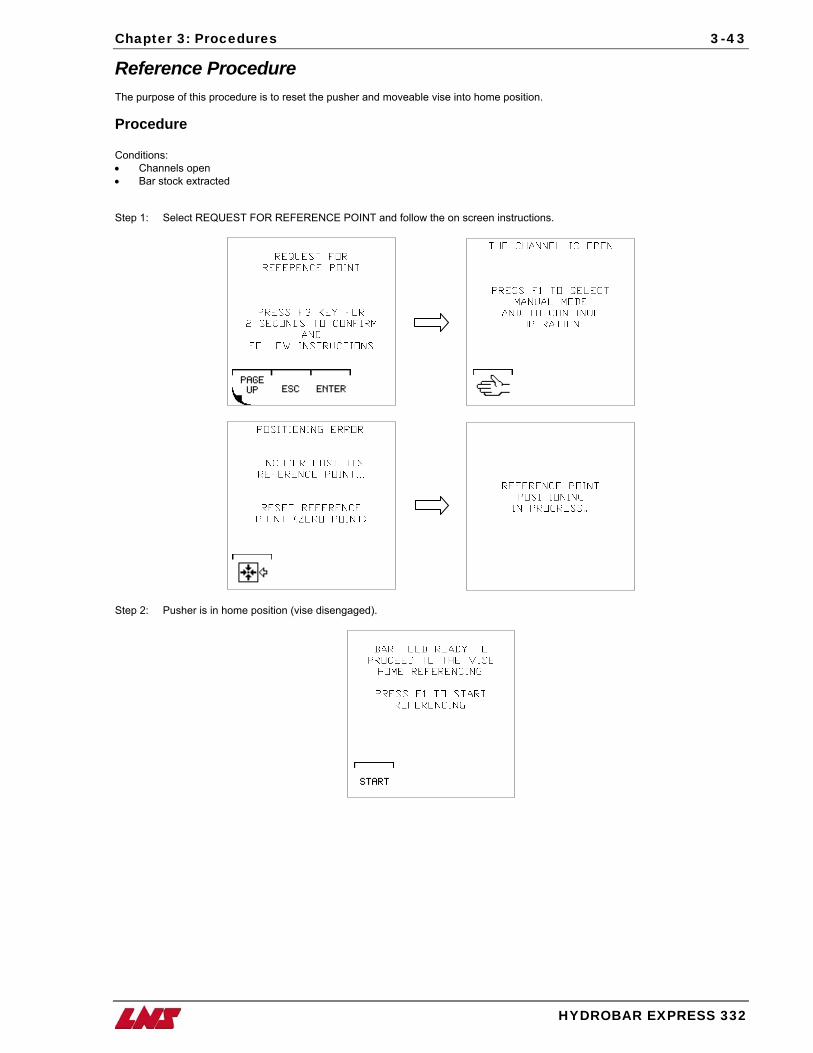
Chapter 3: Procedures
HYDROBAR EXPRESS 332
3-43
Reference Procedure The purpose of this procedure is to reset the pusher and moveable vise into home position. Procedure Conditions: • Channels open • Bar stock extracted Step 1: Select REQUEST FOR REFERENCE POINT and follow the on screen instructions.
Step 2: Pusher is in home position (vise disengaged).
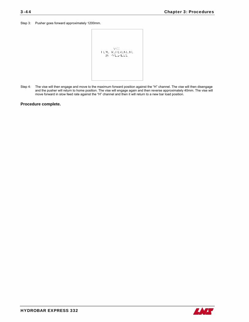
3-44 Chapter 3: Procedures
HYDROBAR EXPRESS 332
Step 3: Pusher goes forward approximately 1200mm.
Step 4: The vise will then engage and move to the maximum forward position against the “H” channel. The vise will then disengage and the pusher will return to home position. The vise will engage again and then reverse approximately 40mm. The vise will move forward in slow feed rate against the “H” channel and then it will return to a new bar load position.
Procedure complete.

Chapter 3: Procedures
HYDROBAR EXPRESS 332
3-45
Replacement of the Front Rest Diameter Adjustment Motor and Installation of the Modified Spacer Bracket This procedure is used to replace the motor on the front rest and install the modified spacer bracket. The modified spacer bracket is designed to keep the oil out of the rest motor. Parts List: • Front Rest Motor Assembly – Part # 4.307 • Modified Spacer Bracket – 034.09.094 Tools List: • 2.5m hex key • 4m hex key • 5m hex key Procedure Conditions: • Guiding channel open. Step 1: Remove the front rest cover. Step 2: Enter into the Front Rest Opening & Closing Control menu under the Miscellaneous Functions. Press and hold the close
rest icon (F3) to close the rest. DO NOT PRESS STOP ON DISPLAY AFTER CLOSING REST.
Close rest
Step 3: Turn off the main power on the bar feed. Step 4: Remove the 4 screws on the small front junction box, and remove the cover.
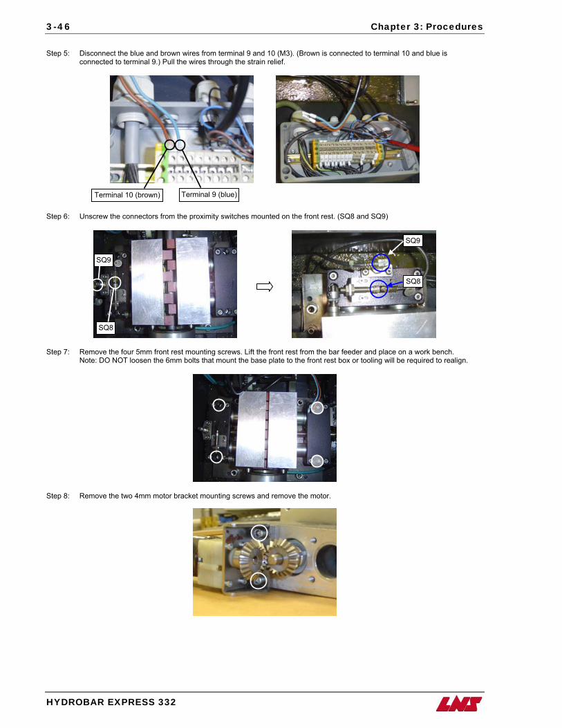
3-46 Chapter 3: Procedures
HYDROBAR EXPRESS 332
Step 5: Disconnect the blue and brown wires from terminal 9 and 10 (M3). (Brown is connected to terminal 10 and blue is
connected to terminal 9.) Pull the wires through the strain relief.
Terminal 9 (blue)Terminal 10 (brown)
Step 6: Unscrew the connectors from the proximity switches mounted on the front rest. (SQ8 and SQ9)
SQ9
SQ8
SQ9
SQ8
Step 7: Remove the four 5mm front rest mounting screws. Lift the front rest from the bar feeder and place on a work bench. Note: DO NOT loosen the 6mm bolts that mount the base plate to the front rest box or tooling will be required to realign.
Step 8: Remove the two 4mm motor bracket mounting screws and remove the motor.
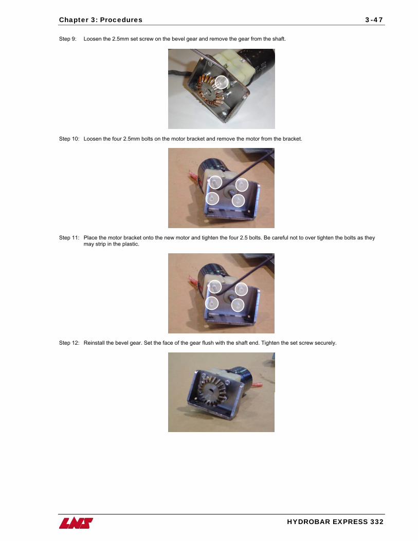
Chapter 3: Procedures
HYDROBAR EXPRESS 332
3-47
Step 9: Loosen the 2.5mm set screw on the bevel gear and remove the gear from the shaft.
Step 10: Loosen the four 2.5mm bolts on the motor bracket and remove the motor from the bracket.
Step 11: Place the motor bracket onto the new motor and tighten the four 2.5 bolts. Be careful not to over tighten the bolts as they
may strip in the plastic.
Step 12: Reinstall the bevel gear. Set the face of the gear flush with the shaft end. Tighten the set screw securely.
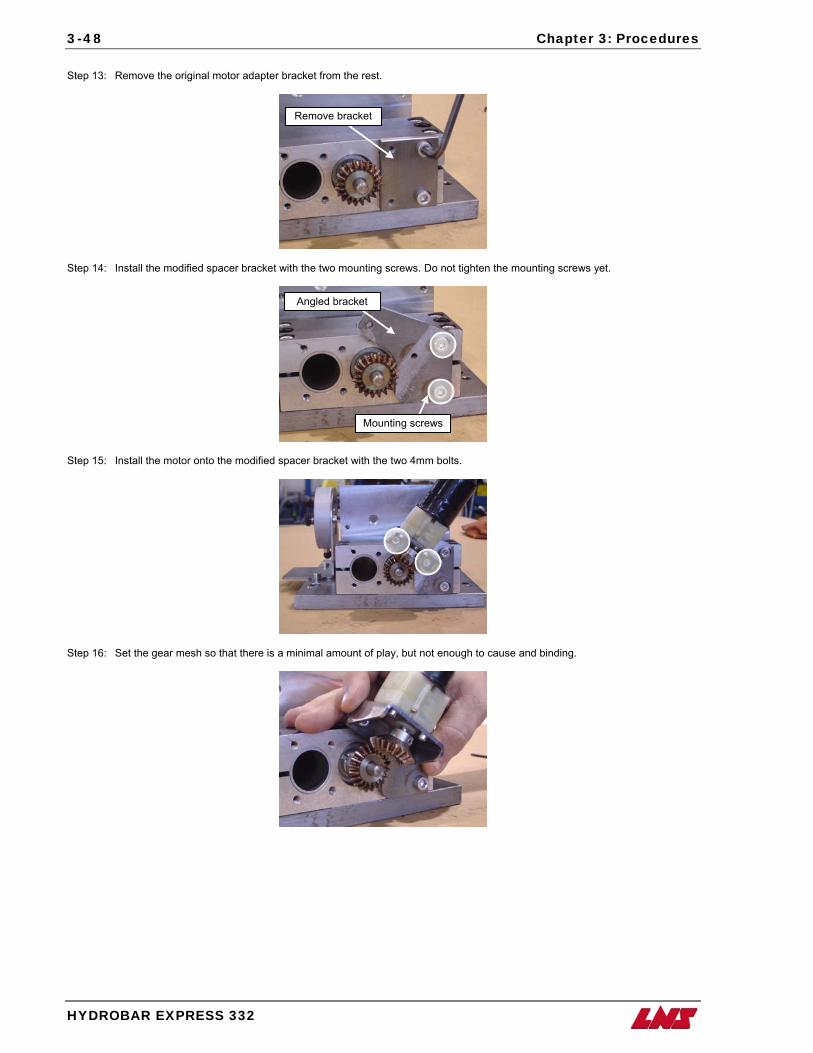
3-48 Chapter 3: Procedures
HYDROBAR EXPRESS 332
Step 13: Remove the original motor adapter bracket from the rest.
Remove bracket
Step 14: Install the modified spacer bracket with the two mounting screws. Do not tighten the mounting screws yet.
Angled bracket
Step 15: Install the motor onto the modified spacer bracket with the two 4mm bolts.
Mounting screws
Step 16: Set the gear mesh so that there is a minimal amount of play, but not enough to cause and binding.
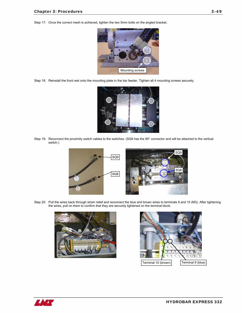
Chapter 3: Procedures
HYDROBAR EXPRESS 332
3-49
Step 17: Once the correct mesh is achieved, tighten the two 5mm bolts on the angled bracket.
Mounting screws
Step 18: Reinstall the front rest onto the mounting plate in the bar feeder. Tighten all 4 mounting screws securely.
Step 19: Reconnect the proximity switch cables to the switches. (SQ9 has the 90° connector and will be attached to the vertical switch.)
SQ8
SQ9SQ9
SQ8
Step 20: Pull the wires back through strain relief and reconnect the blue and brown wires to terminals 9 and 10 (M3). After tightening
the wires, pull on them to confirm that they are securely tightened on the terminal block.
Terminal 9 (blue)Terminal 10 (brown)
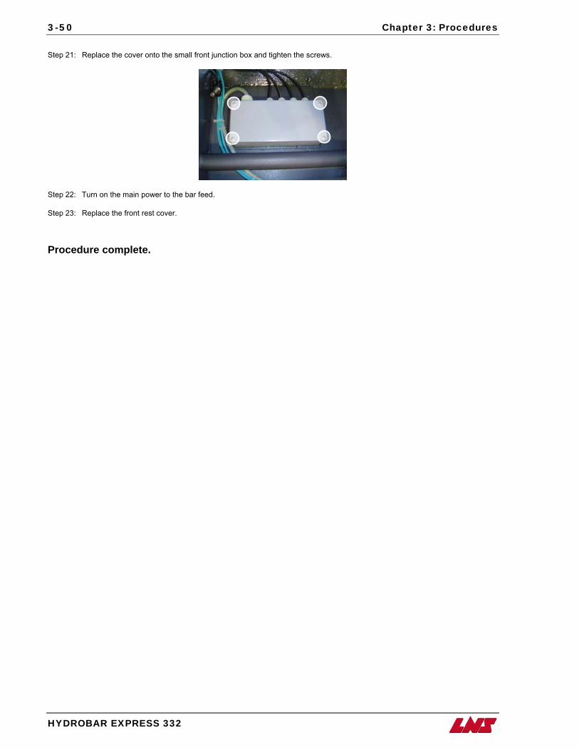
3-50 Chapter 3: Procedures
HYDROBAR EXPRESS 332
Step 21: Replace the cover onto the small front junction box and tighten the screws.
Step 22: Turn on the main power to the bar feed. Step 23: Replace the front rest cover. Procedure complete.
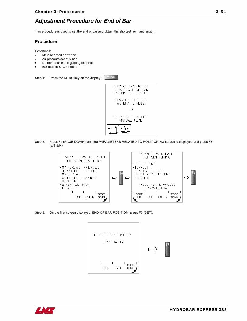
Chapter 3: Procedures
HYDROBAR EXPRESS 332
3-51
Adjustment Procedure for End of Bar This procedure is used to set the end of bar and obtain the shortest remnant length. Procedure Conditions: • Main bar feed power on • Air pressure set at 6 bar • No bar stock in the guiding channel • Bar feed in STOP mode Step 1: Press the MENU key on the display.
Step 2: Press F4 (PAGE DOWN) until the PARAMETERS RELATED TO POSITIONING screen is displayed and press F3 (ENTER).
Step 3: On the first screen displayed, END OF BAR POSITION, press F3 (SET).
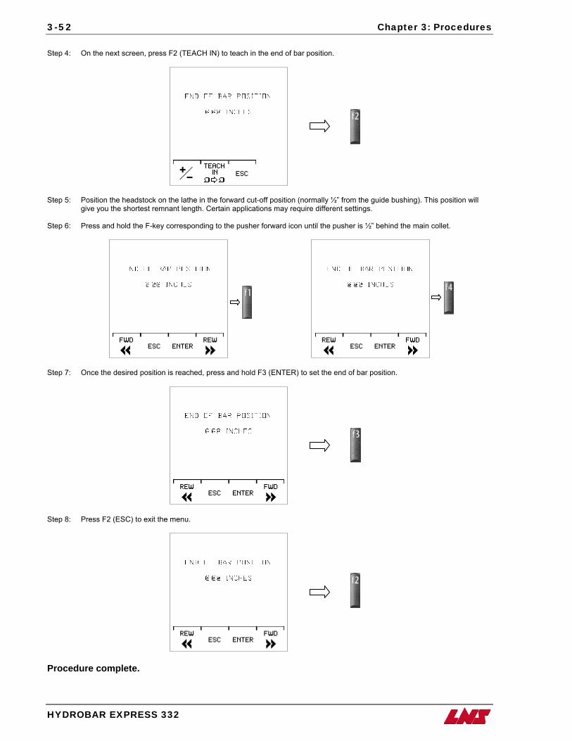
3-52 Chapter 3: Procedures
HYDROBAR EXPRESS 332
Step 4: On the next screen, press F2 (TEACH IN) to teach in the end of bar position.
Step 5: Position the headstock on the lathe in the forward cut-off position (normally ½” from the guide bushing). This position will
give you the shortest remnant length. Certain applications may require different settings. Step 6: Press and hold the F-key corresponding to the pusher forward icon until the pusher is ½” behind the main collet.
Step 7: Once the desired position is reached, press and hold F3 (ENTER) to set the end of bar position.
Step 8: Press F2 (ESC) to exit the menu.
Procedure complete.
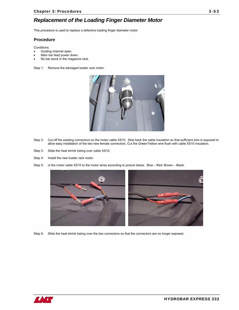
Chapter 3: Procedures
HYDROBAR EXPRESS 332
3-53
Replacement of the Loading Finger Diameter Motor This procedure is used to replace a defective loading finger diameter motor. Procedure Conditions: • Guiding channel open. • Main bar feed power down. • No bar stock in the magazine rack. Step 1: Remove the damaged loader rack motor. Step 2: Cut off the existing connectors on the motor cable XS10. Strip back the cable insulation so that sufficient wire is exposed to
allow easy installation of the two new female connectors. Cut the Green/Yellow wire flush with cable XS10 insulation. Step 3: Slide the heat shrink tubing over cable XS10. Step 4: Install the new loader rack motor. Step 5: ct the motor cable XS10 to the motor wires according to picture below. Blue – Red; Brown – Black.
Step 6: Slide the heat shrink tubing over the two connectors so that the connectors are no longer exposed.
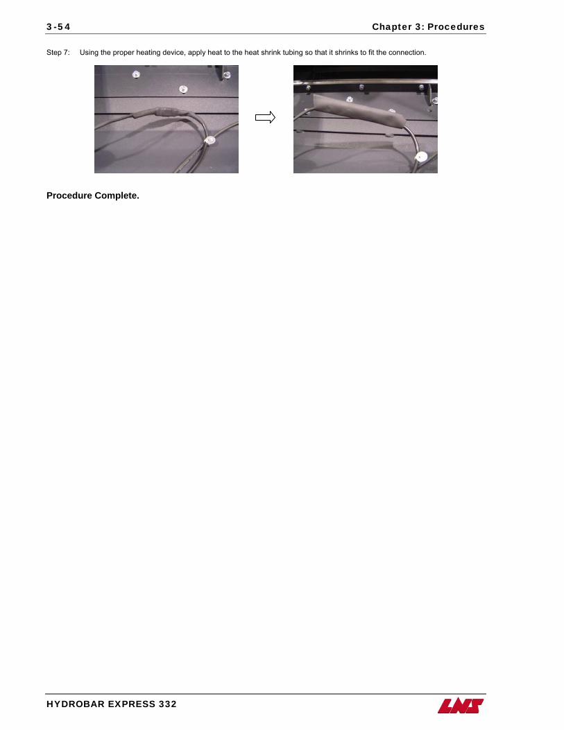
3-54 Chapter 3: Procedures
HYDROBAR EXPRESS 332
Step 7: Using the proper heating device, apply heat to the heat shrink tubing so that it shrinks to fit the connection.
Procedure Complete.
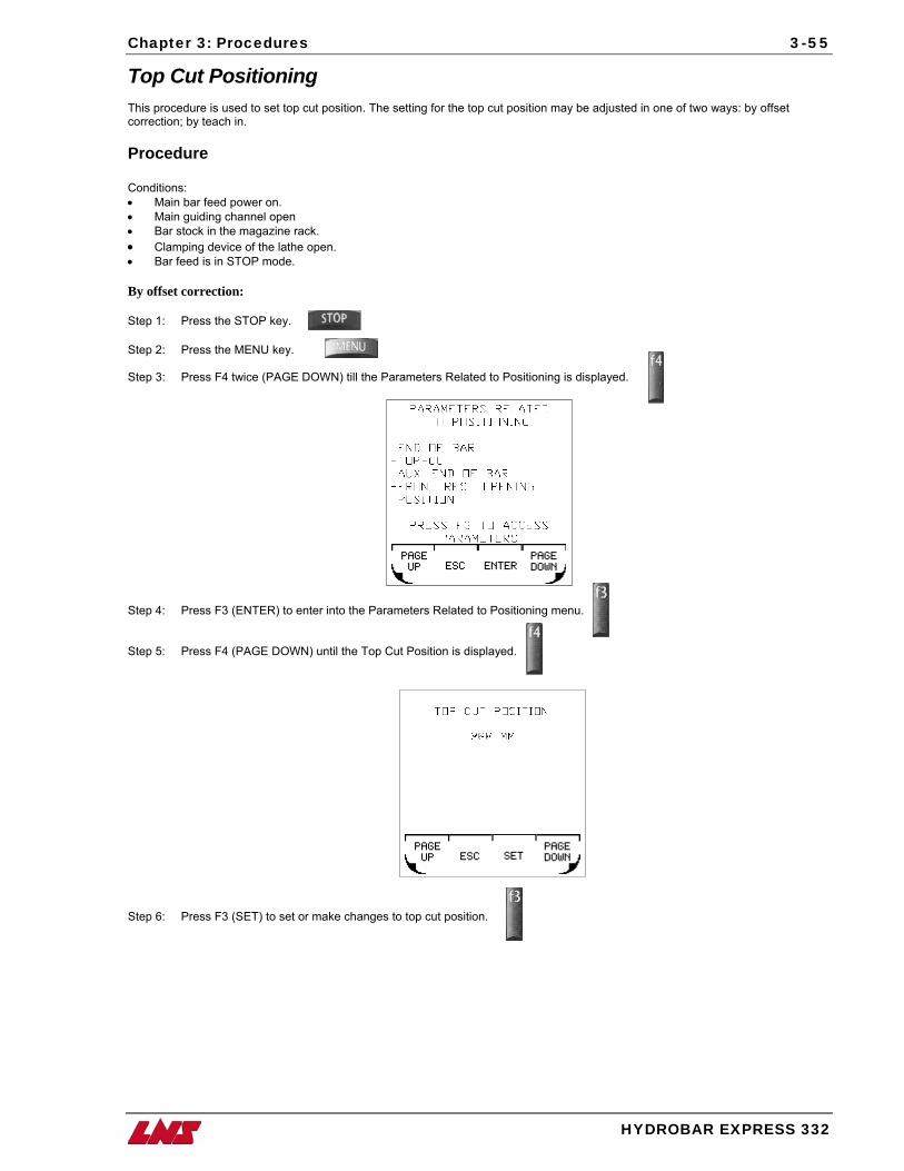
Chapter 3: Procedures
HYDROBAR EXPRESS 332
3-55
Top Cut Positioning This procedure is used to set top cut position. The setting for the top cut position may be adjusted in one of two ways: by offset correction; by teach in. Procedure Conditions: • Main bar feed power on. • Main guiding channel open • Bar stock in the magazine rack. • Clamping device of the lathe open. • Bar feed is in STOP mode. By offset correction: Step 1: Press the STOP key.
Step 2: Press the MENU key. Step 3: Press F4 twice (PAGE DOWN) till the Parameters Related to Positioning is displayed.
Step 4: Press F3 (ENTER) to enter into the Parameters Related to Positioning menu. Step 5: Press F4 (PAGE DOWN) until the Top Cut Position is displayed.
Step 6: Press F3 (SET) to set or make changes to top cut position.
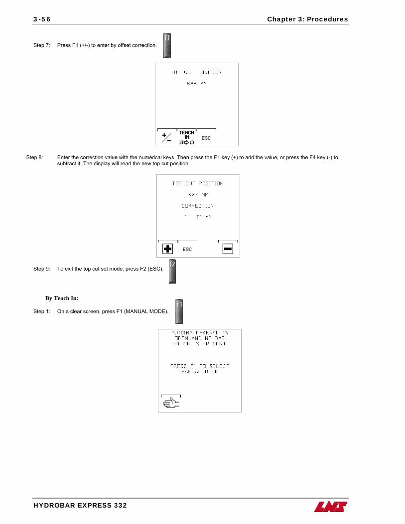
3-56 Chapter 3: Procedures
HYDROBAR EXPRESS 332
Step 7: Press F1 (+/-) to enter by offset correction.
Step 8: Enter the correction value with the numerical keys. Then press the F1 key (+) to add the value, or press the F4 key (-) to subtract it. The display will read the new top cut position.
Step 9: To exit the top cut set mode, press F2 (ESC).
By Teach In:
Step 1: On a clear screen, press F1 (MANUAL MODE).
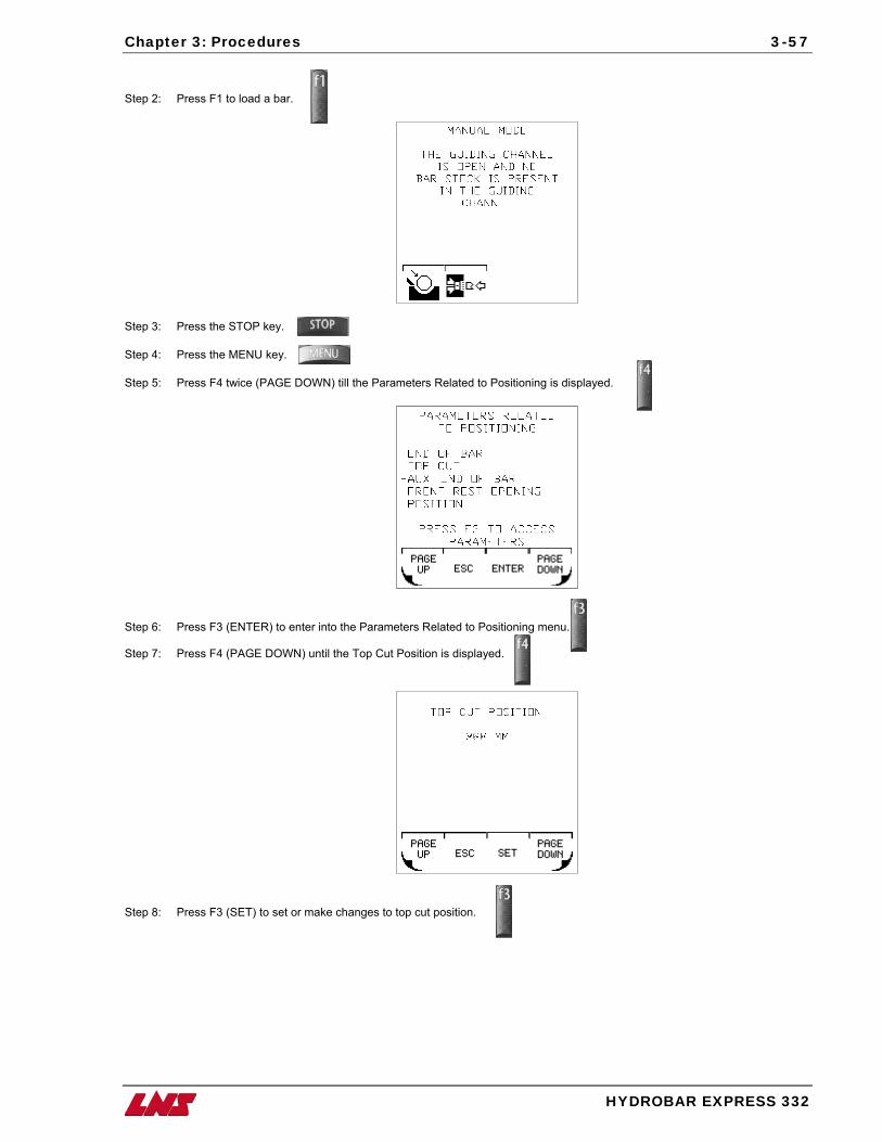
Chapter 3: Procedures
HYDROBAR EXPRESS 332
3-57
Step 2: Press F1 to load a bar.
Step 3: Press the STOP key.
Step 4: Press the MENU key. Step 5: Press F4 twice (PAGE DOWN) till the Parameters Related to Positioning is displayed.
Step 6: Press F3 (ENTER) to enter into the Parameters Related to Positioning menu. Step 7: Press F4 (PAGE DOWN) until the Top Cut Position is displayed.
Step 8: Press F3 (SET) to set or make changes to top cut position.
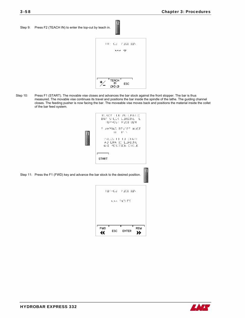
3-58 Chapter 3: Procedures
HYDROBAR EXPRESS 332
Step 9: Press F2 (TEACH IN) to enter the top-cut by teach in.
Step 10: Press F1 (START). The movable vise closes and advances the bar stock against the front stopper. The bar is thus measured. The movable vise continues its travel and positions the bar inside the spindle of the lathe. The guiding channel closes. The feeding pusher is now facing the bar. The moveable vise moves back and positions the material inside the collet of the bar feed system.
Step 11: Press the F1 (FWD) key and advance the bar stock to the desired position.
Chapter 3: Procedures
HYDROBAR EXPRESS 332
3-59
Step 12: To validate the new top cut position, keep F3 (ENTER) pressed until the ENTER icon disappears.
Step 13: To exit the set mode, press the STOP key. Procedure complete.
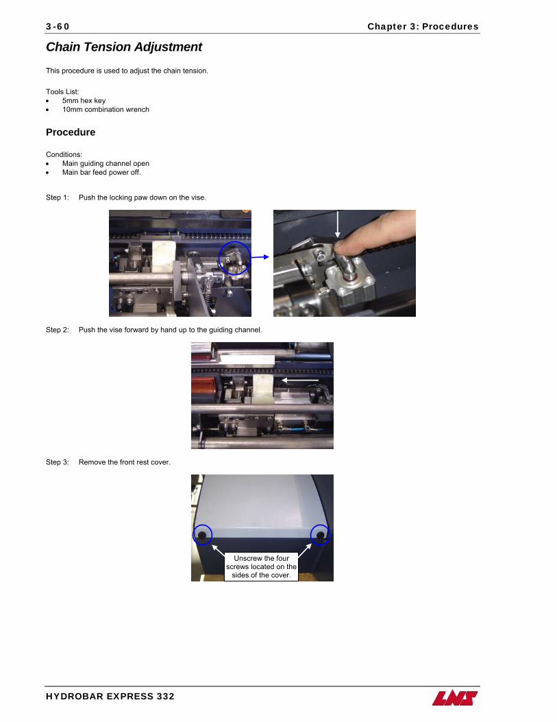
3-60 Chapter 3: Procedures
HYDROBAR EXPRESS 332
Chain Tension Adjustment This procedure is used to adjust the chain tension. Tools List: • 5mm hex key • 10mm combination wrench Procedure Conditions: • Main guiding channel open • Main bar feed power off. Step 1: Push the locking paw down on the vise.
Step 2: Push the vise forward by hand up to the guiding channel.
Step 3: Remove the front rest cover.
Unscrew the four screws located on the
sides of the cover.
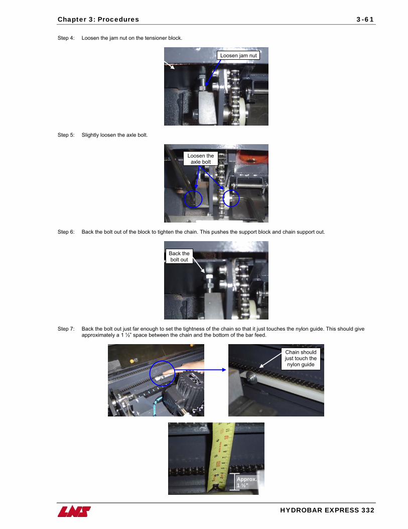
Chapter 3: Procedures
3-61
Step 4: Loosen the jam nut on the tensioner block.
Step 5: Slightly loosen the axle bolt.
Step 6: Back the bolt out of the block to tighten the chain. This push
Step 7: Back the bolt out just far enough to set the tightness of the approximately a 1 ½” space between the chain and the bott
Loosen jam nut
Loosen the axle bolt
es the support block and chain support out.
Back thebolt out
chain so that it just touches the nylon guide. This should give om of the bar feed.
Chain should just touch the nylon guide
Approx.1 ½”
HYDROBAR EXPRESS 332
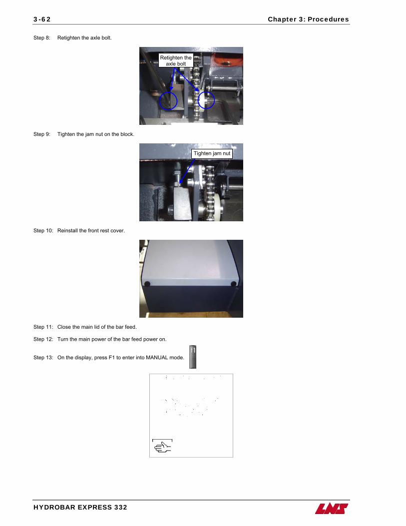
3-62 Chapter 3: Procedures
HYDROBAR EXPRESS 332
Step 8: Retighten the axle bolt.
Step 9: Tighten the jam nut on the block.
Step 10: Reinstall the front rest cover.
Step 11: Close the main lid of the bar feed. Step 12: Turn the main power of the bar feed power Step 13: On the display, press F1 to enter into MANU
Retighten theaxle bolt
Tighten jam nut
on.
AL mode.
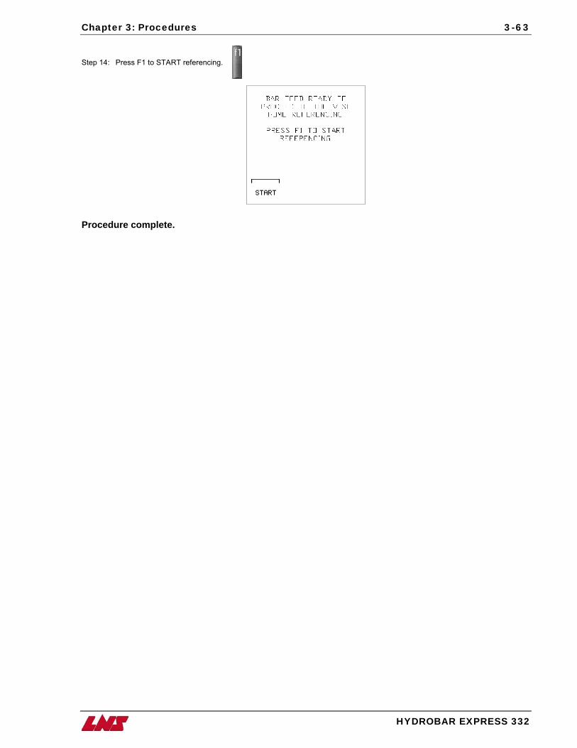
Chapter 3: Procedures
HYDROBAR EXPRESS 332
3-63
Step 14: Press F1 to START referencing.
Procedure complete.
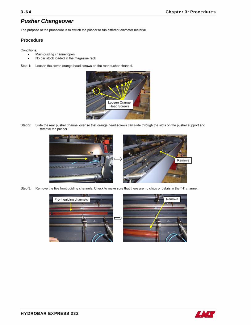
3-64 Chapter 3: Procedures
HYDROBAR EXPRESS 332
Pusher Changeover The purpose of the procedure is to switch the pusher to run different diameter material. Procedure Conditions:
• Main guiding channel open • No bar stock loaded in the magazine rack
Step 1: Loosen the seven orange head screws on the rear pusher channel.
Loosen Orange Head Screws
Step 2: Slide the rear pusher channel over so that orange head screws can slide through the slots on the pusher support and remove the pusher.
Remove
Step 3: Remove the five front guiding channels. Check to make sure that there are no chips or debris in the “H” channel.
Remove Front guiding channels
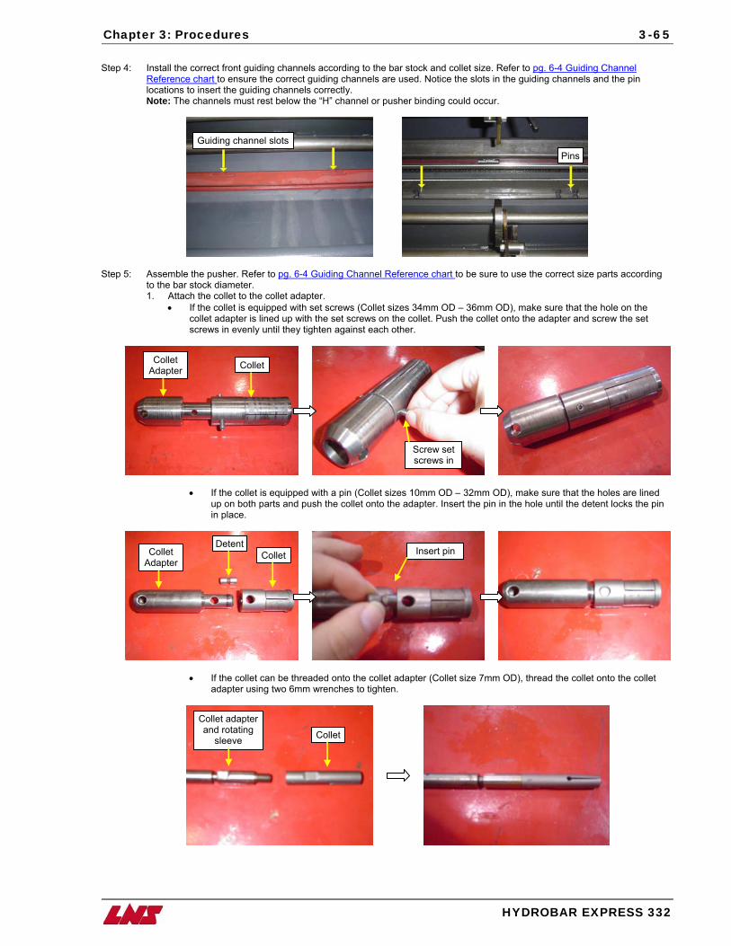
Chapter 3: Procedures
HYDROBA
3-65
Step 4: Install the correct front guiding channels according to the bar stock and collet size. Refer to pg. 6-4 Guiding Channel
Reference chart to ensure the correct guiding channels are used. Notice the slots in the guiding channels and the pin locations to insert the guiding channels correctly.
Note: The channels must rest below the “H” channel or pusher binding could occur.
Step 5: Assemble the pusher. Refer to pg. 6-4 Guiding Channel Reference chart to be sure to use the corrto the bar stock diameter. 1. Attach the collet to the collet adapter.
• If the collet is equipped with set screws (Collet sizes 34mm OD – 36mm OD), make surecollet adapter is lined up with the set screws on the collet. Push the collet onto the adaptscrews in evenly until they tighten against each other.
• If the collet is equipped with a pin (Collet sizes 10mm OD – 32mm OD), make sureup on both parts and push the collet onto the adapter. Insert the pin in the hole untiin place.
• If the collet can be threaded onto the collet adapter (Collet size 7mm OD), thread thadapter using two 6mm wrenches to tighten.
Guiding channel slots
Screw set screws in
Detent
Collet
Collet
Collet adapter and rotating
sleeve
Insert pin
Collet Adapter Collet
s
Collet Adapter
Pin
R EXPRESS 332
ect size parts according
that the hole on the er and screw the set
that the holes are lined l the detent locks the pin
e collet onto the collet
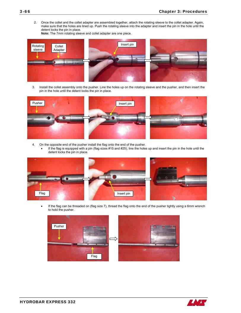
3-66 Chapter 3: Procedures
HYDROBAR EXPRESS 332
2. Once the collet and the collet adapter are assembled together, attach the rotating sleeve to the collet adapter. Again,
make sure that the holes are lined up. Push the rotating sleeve into the adapter and insert the pin in the hole until the detent locks the pin in place. Note: The 7mm rotating sleeve and collet adapter are one piece.
3. Install the collet assembly onto the pusher. Line the holes up on the rotating sleeve and the pusher, and then insert the pin in the hole until the detent locks the pin in place.
4. On the opposite end of the pusher install the flag onto the end of the pusher. • If the flag is equipped with a pin (flag sizes #15 and #25), line the holes up and insert the pin in the hole until the
detent locks the pin in place.
• If the flag can be threaded on (flag size 7), thread the flag onto the end of the pusher tightly using a 6mm wrench to hold the pusher.
Rotating sleeve
Collet Adapter
Pusher Insert pin
Flag Insert pin
Pusher
Flag
Insert pin
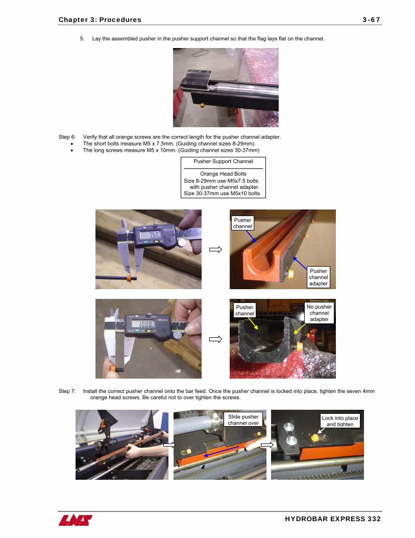
Chapter 3: Procedures
3-67
5. Lay the assembled pusher in the pusher support channel so that the flag lays flat on the channel.
Step 6: Verify that all orange screws are the correct length for the pusher channel adapter.
• The short bolts measure M5 x 7.5mm. (Guiding channel sizes 8-29mm) • The long screws measure M5 x 10mm. (Guiding channel sizes 30-37mm)
Siz Siz
Step 7: Install the correct pusher channel onto the ba
orange head screws. Be careful not to ove
Pusher Support Channel
Orange Head Bolts
e 8-29mm use M5x7.5 bolts with pusher channel adapter. e 30-37mm use M5x10 bolts.
HYDROBAR EXPRESS 332
Pusher channel
Pusher channel adapter
No pusher channel adapter
Pusher channel
r feed. Once the pusher channel is locked into place, tighten the seven 4mm r tighten the screws.
Lock into place and tighten
Slide pusher channel over
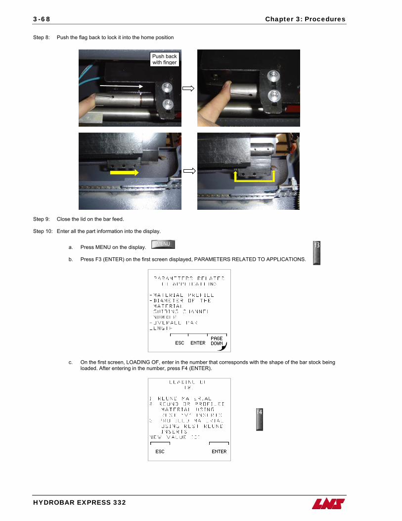
3-68 Chapter 3: Procedures
HYDROBAR EXPRESS 332
Step 8: Push the flag back to lock it into the home position
Step 9: Close the lid on the bar feed. Step 10: Enter all the part information into the disp
a. Press MENU on the display. b. Press F3 (ENTER) on the first
c. On the first screen, LOADING loaded. After entering in the nu
Push back with finger
lay.
screen displayed, PARAMETERS RELATED TO APPLICATIONS.
OF, enter in the number that corresponds with the shape of the bar stock being mber, press F4 (ENTER).
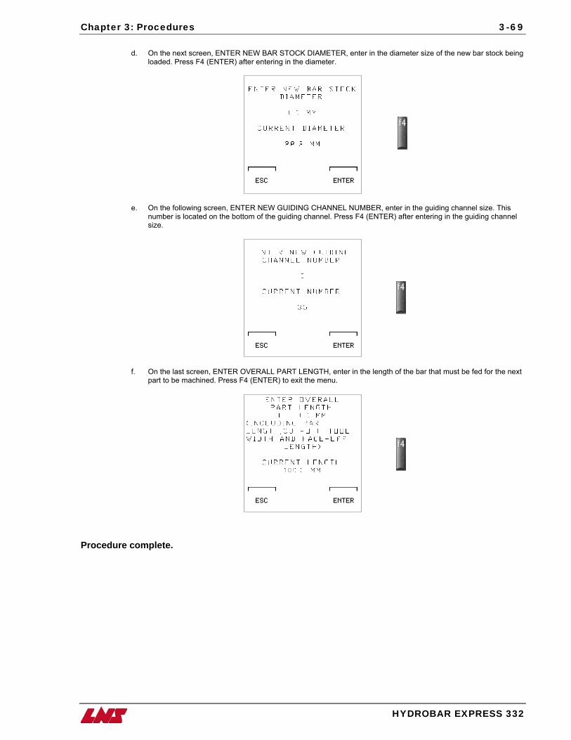
Chapter 3: Procedures
3-69
d. On the next screen, ENTER NEW BAR STOCK DIAMETER, enter in the diameter size of the new bar stock being
loaded. Press F4 (ENTER) after entering in the diameter.
e. On the following screen, ENTER NEW GUIDING CHANNEL NUMBER, enter in the guiding channel size. This number is located on the bottom of the guiding channel. Press F4 (ENTER) after entering in the guiding channel size.
f. On the last screen, ENTER OVERALL PART LENGTH, enter in the length of the bar that must be fed for the next part to be machined. Press F4 (ENTER) to exit the menu.
Procedure complete.
HYDROBAR EXPRESS 332

Chapter 4: Software Update/Restore 4-1
Software
Update/Restore
ith tthe useat abac
a few systematic pr
he help of the latest technological innovations, it is possible to update new software and restore lost data through use of Smart Media. Smart Media, which is mainly used in photography, has been integrated for use with the r-friendly remote control station. The Smart Media Card holds a backup program for the Hydrobar Express 332 if nytime there has been a power failure or any error has occurred in the user program. In addition, it automatically ks up any application/interface parameters that have been set for the most recent application being ran. Following ocedures is all it takes to be up and running with the most up to date software or restoring lost PLC programs
and/or parameters.
Chapter 4:
W
HYDROBAR EXPRESS 332
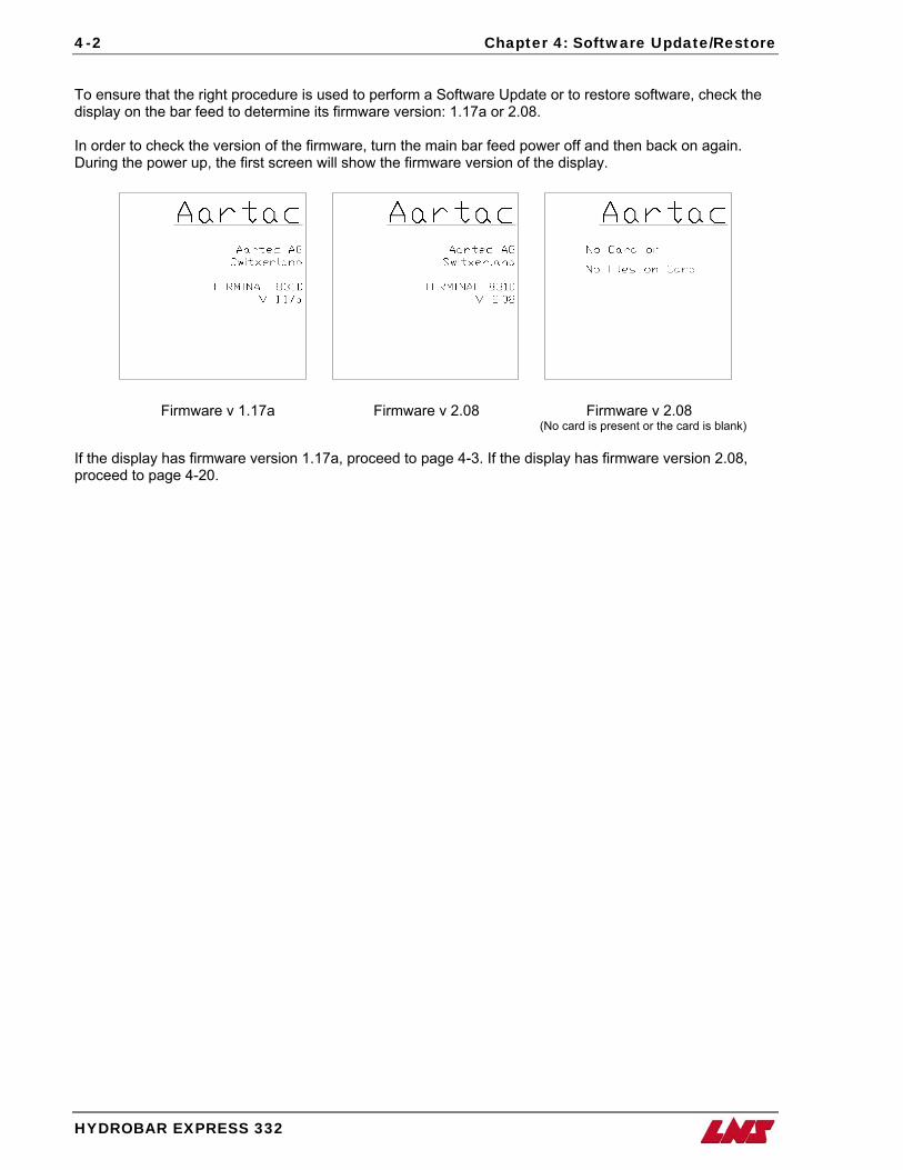
4-2 Chapter 4: Software Update/Restore
To ensure that the right procedure is used to perform a Software Update or to restore software, check the display on the bar feed to determine its firmware version: 1.17a or 2.08. In order to check the version of the firmware, turn the main bar feed power off and then back on again. During the power up, the first screen will show the firmware version of the display.
Firmware v 1.17a Firmware v 2.08 Firmware v 2.08 (No card is present or the card is blank) If the display has firmware version 1.17a, proceed to page 4-3. If the display has firmware version 2.08, proceed to page 4-20.
HYDROBAR EXPRESS 332
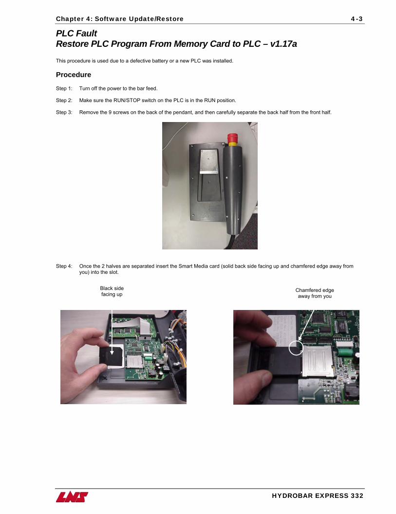
Chapter 4: Software Update/Restore 4-3
PLC Fault Restore PLC Program From Memory Card to PLC – v1.17a This procedure is used due to a defective battery or a new PLC was installed. Procedure Step 1: Turn off the power to the bar feed. Step 2: Make sure the RUN/STOP switch on the PLC is in the RUN position. Step 3: Remove the 9 screws on the back of the pendant, and then carefully separate the back half from the front half.
Step 4: Once the 2 halves are separated insert the Smart Media card (solid back side facing up and chamfered edge away from
you) into the slot.
Black side facing up
Chamfered edge away from you
HYDROBAR EXPRESS 332
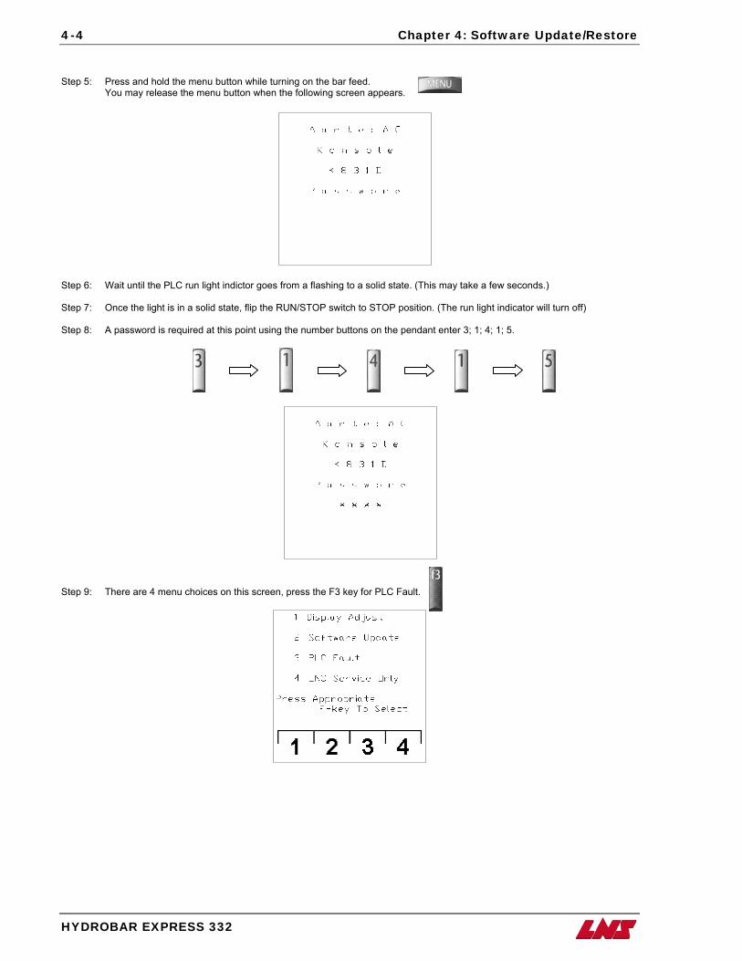
4-4 Chapter 4: Software Update/Restore
Step 5: Press and hold the menu button while turning on the bar feed. You may release the menu button when the following screen appears.
Step 6: Wait until the PLC run light indictor goes from a flashing to a solid state. (This may take a few seconds.) Step 7: Once the light is in a solid state, flip the RUN/STOP switch to STOP position. (The run light indicator will turn off) Step 8: A password is required at this point using the number buttons on the pendant enter 3; 1; 4; 1; 5.
Step 9: There are 4 menu choices on this screen, press the F3 key for PLC Fault.
HYDROBAR EXPRESS 332
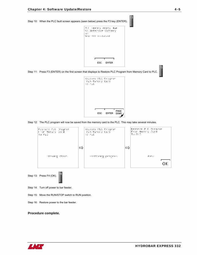
Chapter 4: Software Update/Restore 4-5
Step 10: When the PLC fault screen appears (seen below) press the F3 key (ENTER).
Step 11: Press F3 (ENTER) on the first screen that displays to Restore PLC Program from Memory Card to PLC.
Step 12: The PLC program will now be saved from the memory card to the PLC. This may take several minutes.
Step 13: Press F4 (OK).
Step 14: Turn off power to bar feeder. Step 15: Move the RUN/STOP switch to RUN position. Step 16: Restore power to the bar feeder. Procedure complete.
HYDROBAR EXPRESS 332
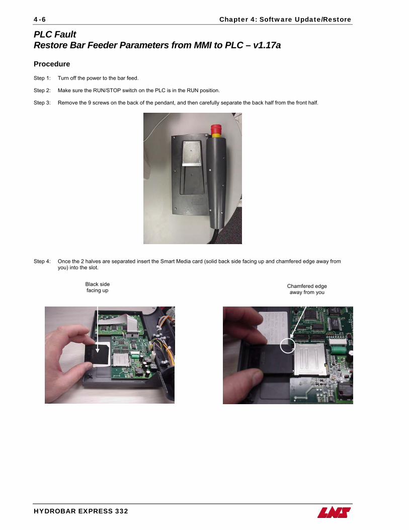
4-6 Chapter 4: Software Update/Restore
PLC Fault Restore Bar Feeder Parameters from MMI to PLC – v1.17a Procedure Step 1: Turn off the power to the bar feed. Step 2: Make sure the RUN/STOP switch on the PLC is in the RUN position. Step 3: Remove the 9 screws on the back of the pendant, and then carefully separate the back half from the front half.
Step 4: Once the 2 halves are separated insert the Smart Media card (solid back side facing up and chamfered edge away from
you) into the slot.
Black side facing up
Chamfered edge away from you
HYDROBAR EXPRESS 332
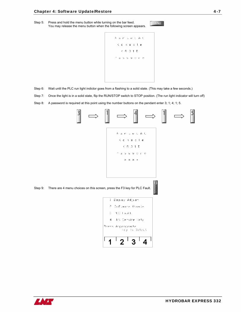
Chapter 4: Software Update/Restore 4-7
Step 5: Press and hold the menu button while turning on the bar feed. You may release the menu button when the following screen appears.
Step 6: Wait until the PLC run light indictor goes from a flashing to a solid state. (This may take a few seconds.) Step 7: Once the light is in a solid state, flip the RUN/STOP switch to STOP position. (The run light indicator will turn off) Step 8: A password is required at this point using the number buttons on the pendant enter 3; 1; 4; 1; 5.
Step 9: There are 4 menu choices on this screen, press the F3 key for PLC Fault.
HYDROBAR EXPRESS 332
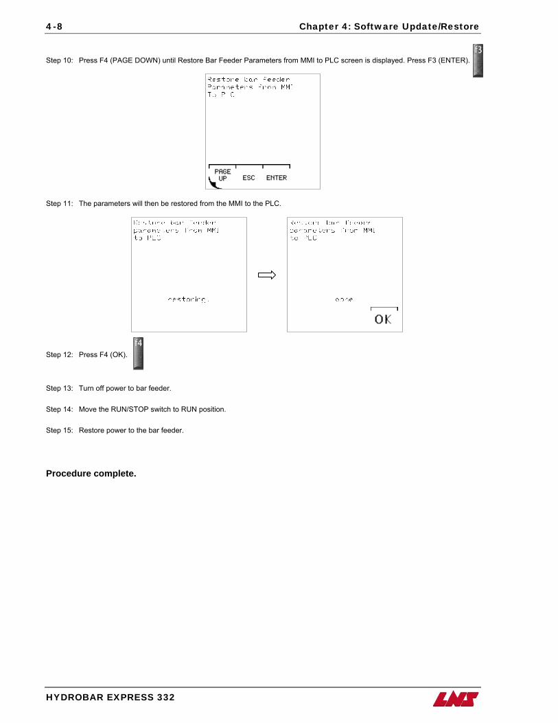
4-8 Chapter 4: Software Update/Restore
Step 10: Press F4 (PAGE DOWN) until Restore Bar Feeder Parameters from MMI to PLC screen is displayed. Press F3 (ENTER).
Step 11: The parameters will then be restored from the MMI to the PLC.
Step 12: Press F4 (OK).
Step 13: Turn off power to bar feeder. Step 14: Move the RUN/STOP switch to RUN position. Step 15: Restore power to the bar feeder.
Procedure complete.
HYDROBAR EXPRESS 332
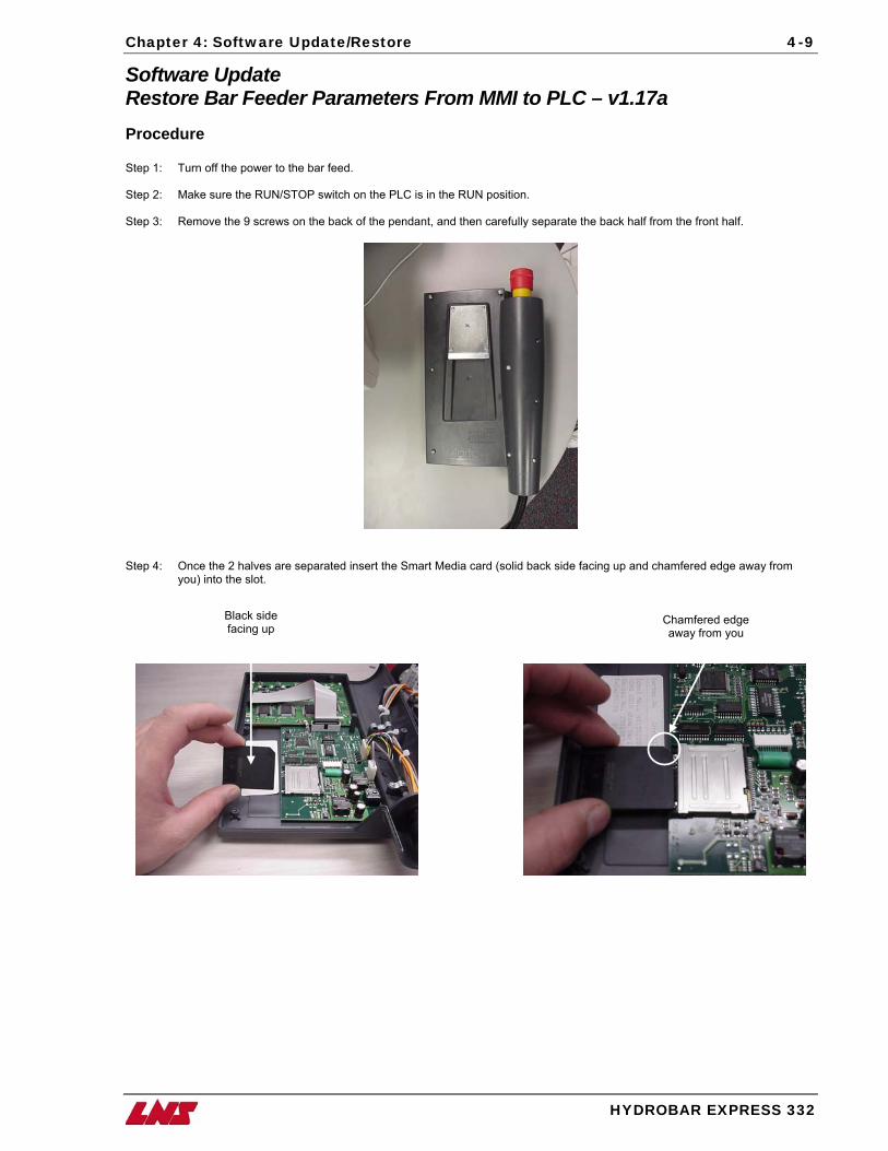
Chapter 4: Software Update/Restore 4-9
Software Update Restore Bar Feeder Parameters From MMI to PLC – v1.17a Procedure Step 1: Turn off the power to the bar feed. Step 2: Make sure the RUN/STOP switch on the PLC is in the RUN position. Step 3: Remove the 9 screws on the back of the pendant, and then carefully separate the back half from the front half.
Step 4: Once the 2 halves are separated insert the Smart Media card (solid back side facing up and chamfered edge away from
you) into the slot. Black side
facing up Chamfered edge away from you
HYDROBAR EXPRESS 332
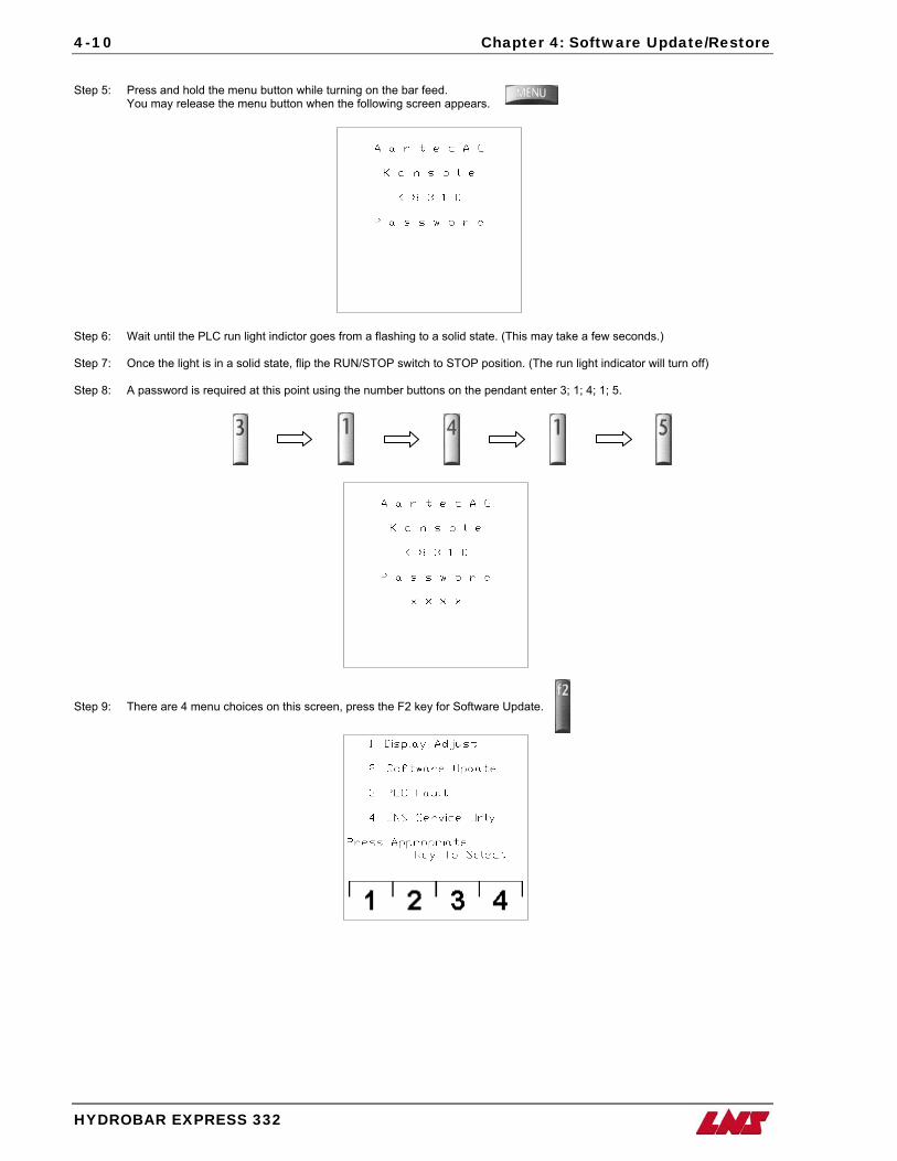
4-10 Chapter 4: Software Update/Restore
Step 5: Press and hold the menu button while turning on the bar feed. You may release the menu button when the following screen appears.
Step 6: Wait until the PLC run light indictor goes from a flashing to a solid state. (This may take a few seconds.) Step 7: Once the light is in a solid state, flip the RUN/STOP switch to STOP position. (The run light indicator will turn off) Step 8: A password is required at this point using the number buttons on the pendant enter 3; 1; 4; 1; 5.
Step 9: There are 4 menu choices on this screen, press the F2 key for Software Update.
HYDROBAR EXPRESS 332
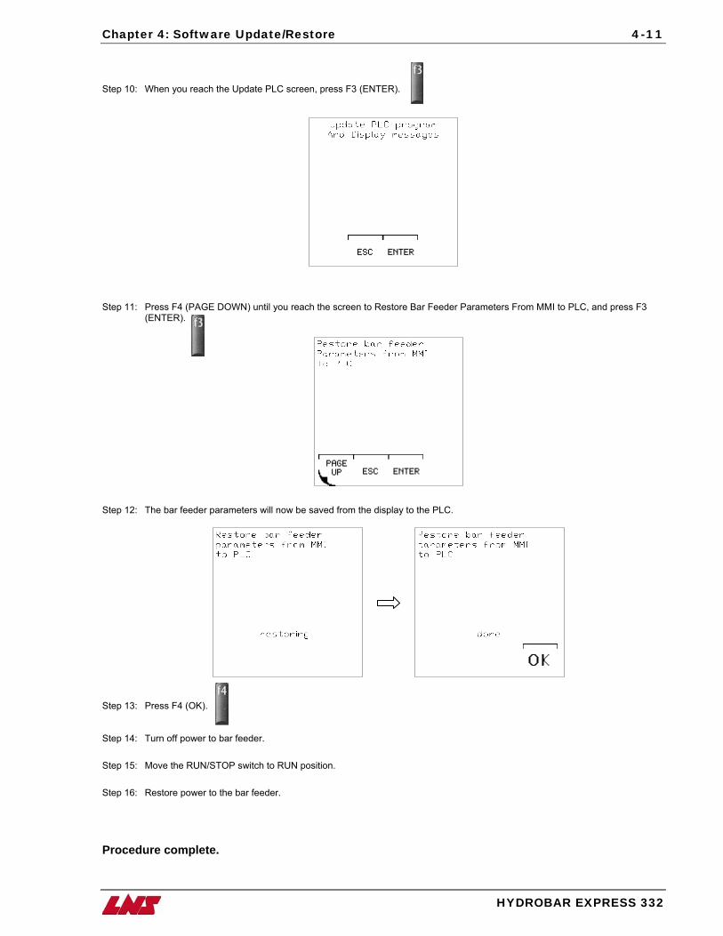
Chapter 4: Software Update/Restore 4-11
Step 10: When you reach the Update PLC screen, press F3 (ENTER).
Step 11: Press F4 (PAGE DOWN) until you reach the screen to Restore Bar Feeder Parameters From MMI to PLC, and press F3 (ENTER).
Step 12: The bar feeder parameters will now be saved from the display to the PLC.
Step 13: Press F4 (OK).
Step 14: Turn off power to bar feeder. Step 15: Move the RUN/STOP switch to RUN position. Step 16: Restore power to the bar feeder.
Procedure complete.
HYDROBAR EXPRESS 332
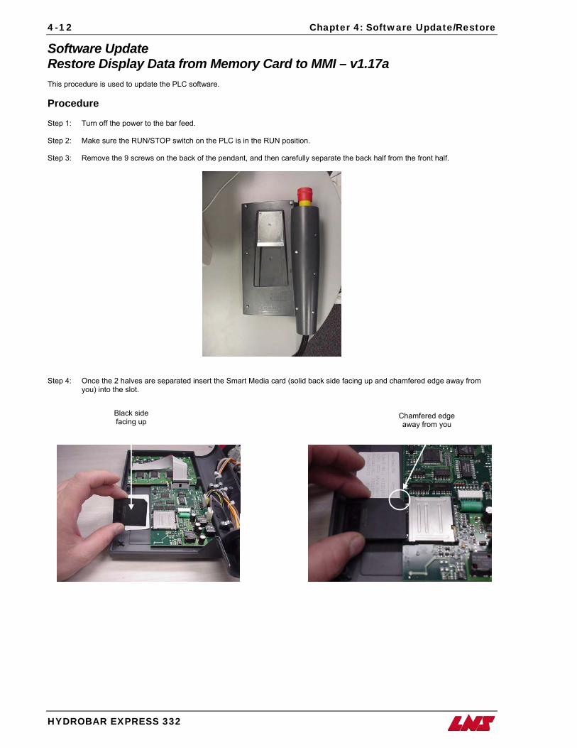
4-12 Chapter 4: Software Update/Restore
Software Update Restore Display Data from Memory Card to MMI – v1.17a This procedure is used to update the PLC software. Procedure Step 1: Turn off the power to the bar feed. Step 2: Make sure the RUN/STOP switch on the PLC is in the RUN position. Step 3: Remove the 9 screws on the back of the pendant, and then carefully separate the back half from the front half.
Step 4: Once the 2 halves are separated insert the Smart Media card (solid back side facing up and chamfered edge away from
you) into the slot.
Black side facing up
Chamfered edge away from you
HYDROBAR EXPRESS 332
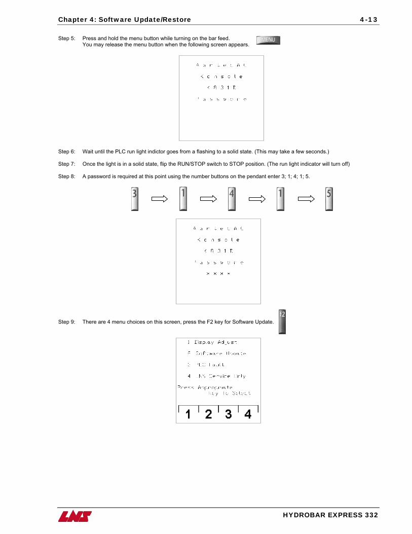
Chapter 4: Software Update/Restore 4-13
Step 5: Press and hold the menu button while turning on the bar feed. You may release the menu button when the following screen appears.
Step 6: Wait until the PLC run light indictor goes from a flashing to a solid state. (This may take a few seconds.) Step 7: Once the light is in a solid state, flip the RUN/STOP switch to STOP position. (The run light indicator will turn off) Step 8: A password is required at this point using the number buttons on the pendant enter 3; 1; 4; 1; 5.
Step 9: There are 4 menu choices on this screen, press the F2 key for Software Update.
HYDROBAR EXPRESS 332
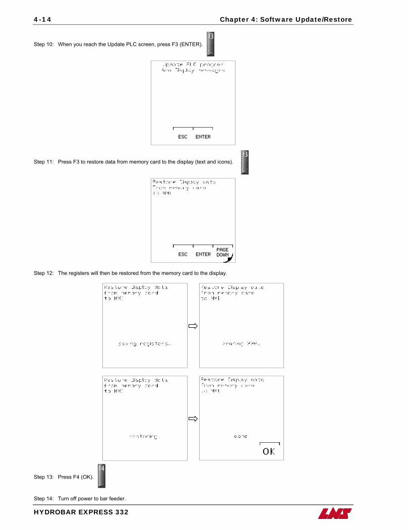
4-14 Chapter 4: Software Update/Restore
Step 10: When you reach the Update PLC screen, press F3 (ENTER).
Step 11: Press F3 to restore data from memory card to the display (text and icons).
Step 12: The registers will then be restored from the memory card to the display.
Step 13: Press F4 (OK).
Step 14: Turn off power to bar feeder.
HYDROBAR EXPRESS 332
Chapter 4: Software Update/Restore 4-15
Step 15: Move the RUN/STOP switch to RUN position. Step 16: Restore power to the bar feeder. Procedure complete.
HYDROBAR EXPRESS 332
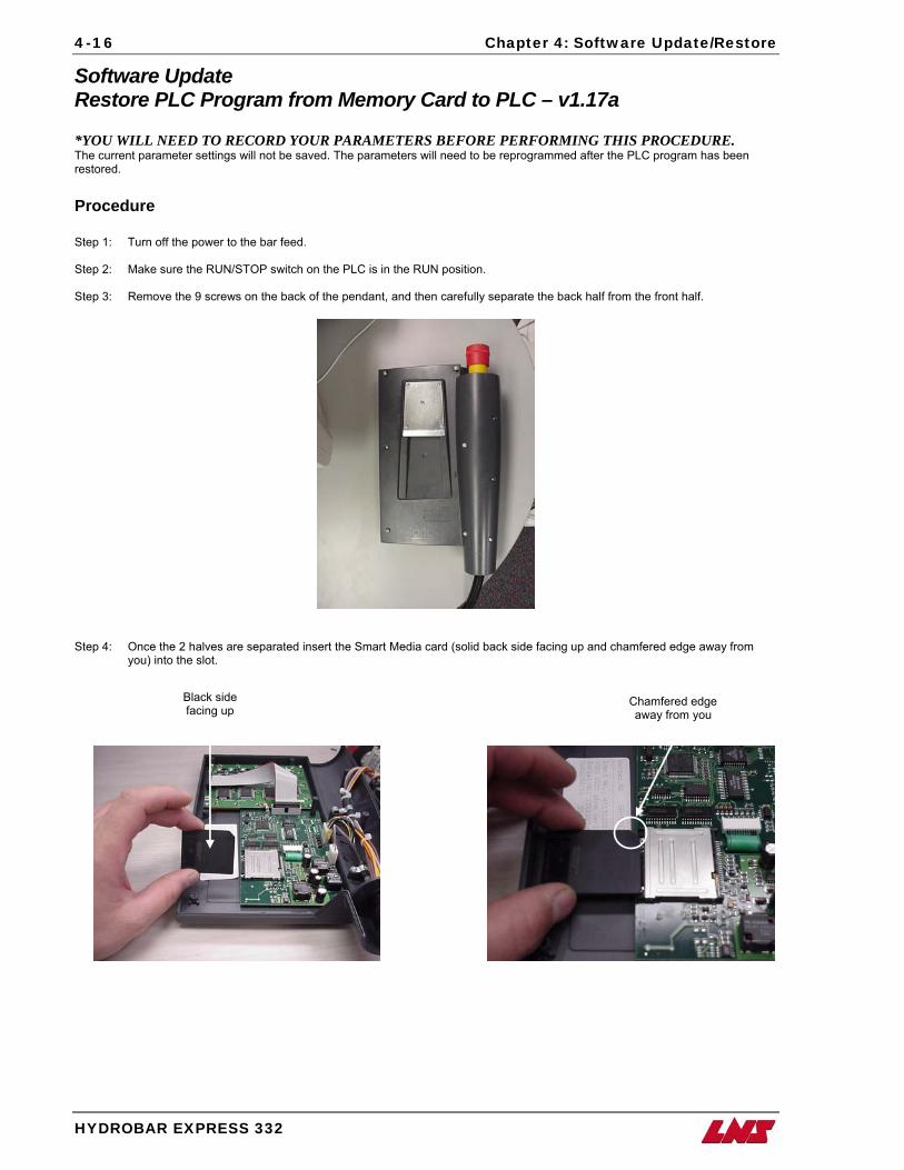
4-16 Chapter 4: Software Update/Restore
Software Update Restore PLC Program from Memory Card to PLC – v1.17a *YOU WILL NEED TO RECORD YOUR PARAMETERS BEFORE PERFORMING THIS PROCEDURE. The current parameter settings will not be saved. The parameters will need to be reprogrammed after the PLC program has been restored. Procedure Step 1: Turn off the power to the bar feed. Step 2: Make sure the RUN/STOP switch on the PLC is in the RUN position. Step 3: Remove the 9 screws on the back of the pendant, and then carefully separate the back half from the front half.
Step 4: Once the 2 halves are separated insert the Smart Media card (solid back side facing up and chamfered edge away from
you) into the slot. Black side
facing up Chamfered edge away from you
HYDROBAR EXPRESS 332

Chapter 4: Software Update/Restore 4-17
Step 5: Press and hold the menu button while turning on the bar feed. You may release the menu button when the following screen appears.
Step 6: Wait until the PLC run light indictor goes from a flashing to a solid state. (This may take a few seconds.) Step 7: Once the light is in a solid state, flip the RUN/STOP switch to STOP position. (The run light indicator will turn off) Step 8: A password is required at this point using the number buttons on the pendant enter 3; 1; 4; 1; 5.
Step 9: There are 4 menu choices on this screen, press the F2 key for Software Update.
HYDROBAR EXPRESS 332
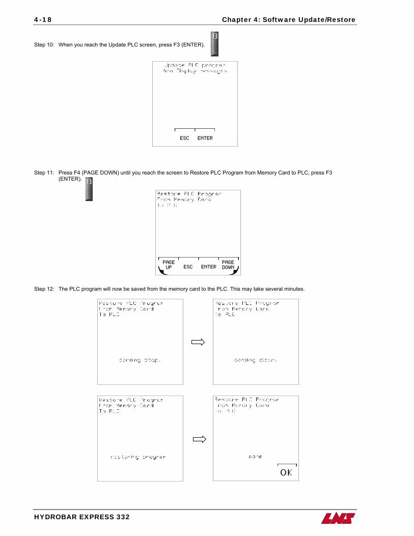
4-18 Chapter 4: Software Update/Restore
Step 10: When you reach the Update PLC screen, press F3 (ENTER).
Step 11: Press F4 (PAGE DOWN) until you reach the screen to Restore PLC Program from Memory Card to PLC, press F3
(ENTER).
Step 12: The PLC program will now be saved from the memory card to the PLC. This may take several minutes.
HYDROBAR EXPRESS 332
Chapter 4: Software Update/Restore 4-19
Step 13: Press F4 (OK).
Step 14: Turn off power to bar feeder. Step 15: Move the RUN/STOP switch to RUN position. Step 16: Restore power to the bar feeder. Procedure complete.
HYDROBAR EXPRESS 332
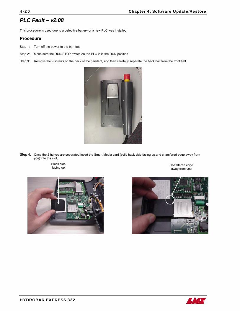
4-20 Chapter 4: Software Update/Restore
PLC Fault – v2.08 This procedure is used due to a defective battery or a new PLC was installed. Procedure Step 1: Turn off the power to the bar feed. Step 2: Make sure the RUN/STOP switch on the PLC is in the RUN position. Step 3: Remove the 9 screws on the back of the pendant, and then carefully separate the back half from the front half.
Step 4: Once the 2 halves are separated insert the Smart Media card (solid back side facing up and chamfered edge away from
you) into the slot. Black side
facing up Chamfered edge away from you
HYDROBAR EXPRESS 332
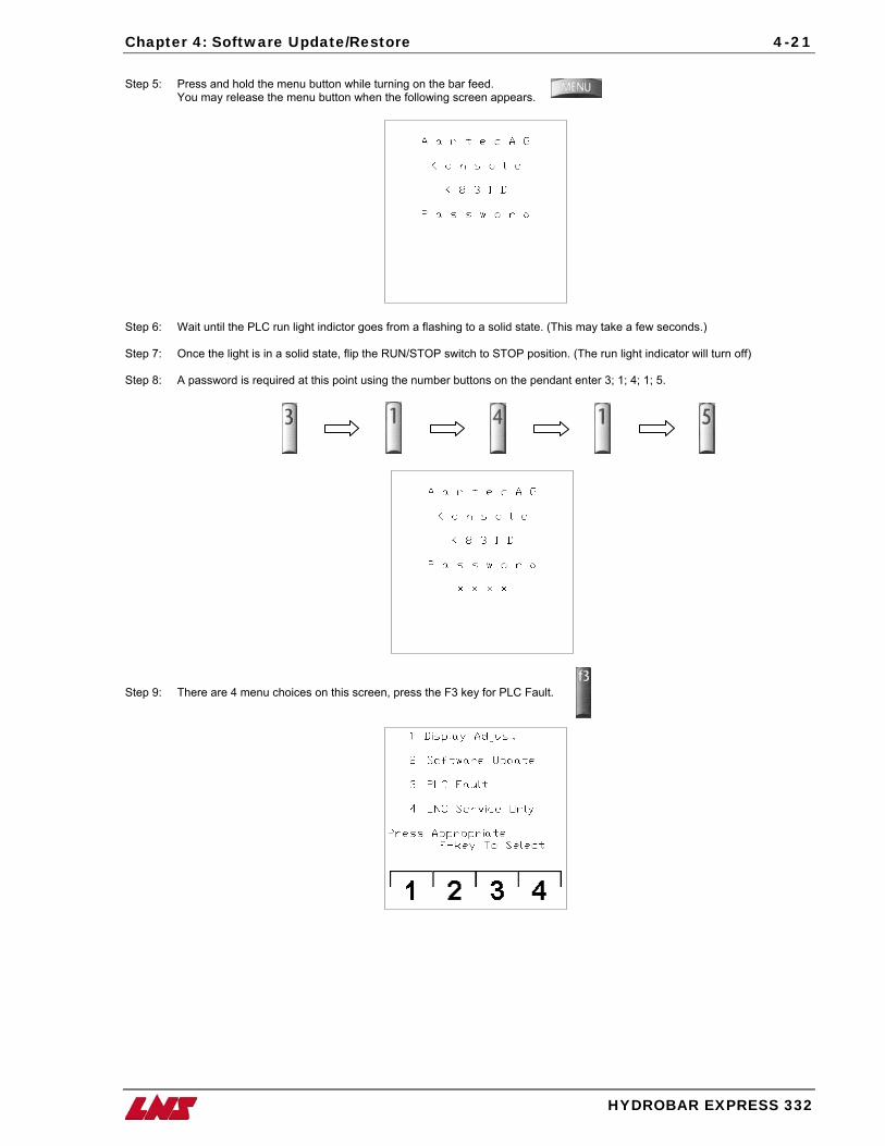
Chapter 4: Software Update/Restore 4-21
Step 5: Press and hold the menu button while turning on the bar feed.
You may release the menu button when the following screen appears.
Step 6: Wait until the PLC run light indictor goes from a flashing to a solid state. (This may take a few seconds.) Step 7: Once the light is in a solid state, flip the RUN/STOP switch to STOP position. (The run light indicator will turn off) Step 8: A password is required at this point using the number buttons on the pendant enter 3; 1; 4; 1; 5.
Step 9: There are 4 menu choices on this screen, press the F3 key for PLC Fault.
HYDROBAR EXPRESS 332
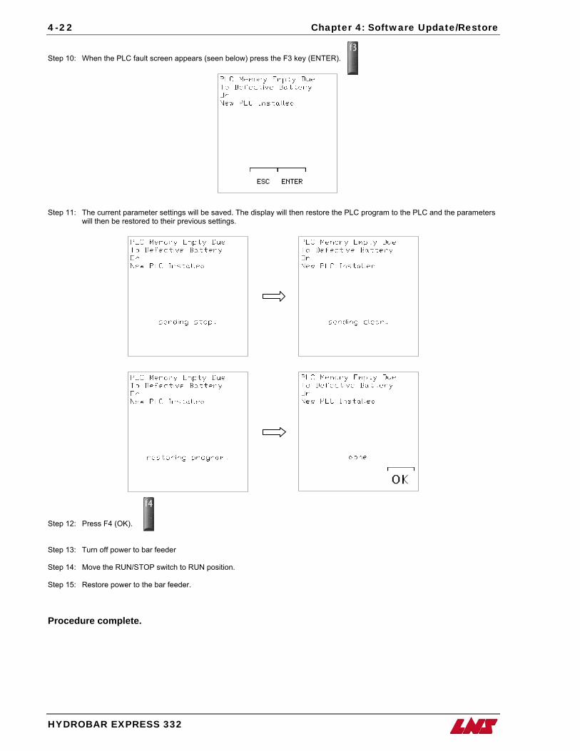
4-22 Chapter 4: Software Update/Restore
Step 10: When the PLC fault screen appears (seen below) press the F3 key (ENTER).
Step 11: The current parameter settings will be saved. The display will then restore the PLC program to the PLC and the parameters will then be restored to their previous settings.
Step 12: Press F4 (OK). Step 13: Turn off power to bar feeder Step 14: Move the RUN/STOP switch to RUN position. Step 15: Restore power to the bar feeder. Procedure complete.
HYDROBAR EXPRESS 332
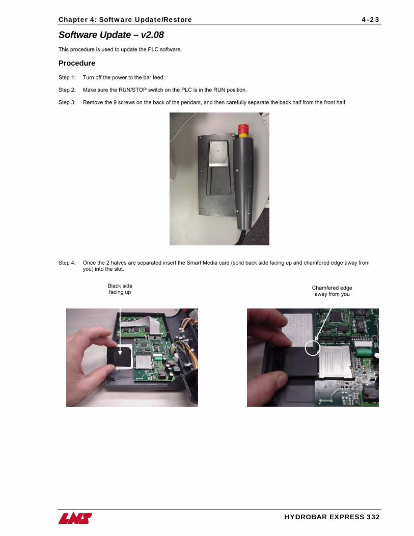
Chapter 4: Software Update/Restore 4-23
Software Update – v2.08 This procedure is used to update the PLC software. Procedure Step 1: Turn off the power to the bar feed. Step 2: Make sure the RUN/STOP switch on the PLC is in the RUN position. Step 3: Remove the 9 screws on the back of the pendant, and then carefully separate the back half from the front half.
Step 4: Once the 2 halves are separated insert the Smart Media card (solid back side facing up and chamfered edge away from
you) into the slot. Black side
facing up Chamfered edge away from you
HYDROBAR EXPRESS 332
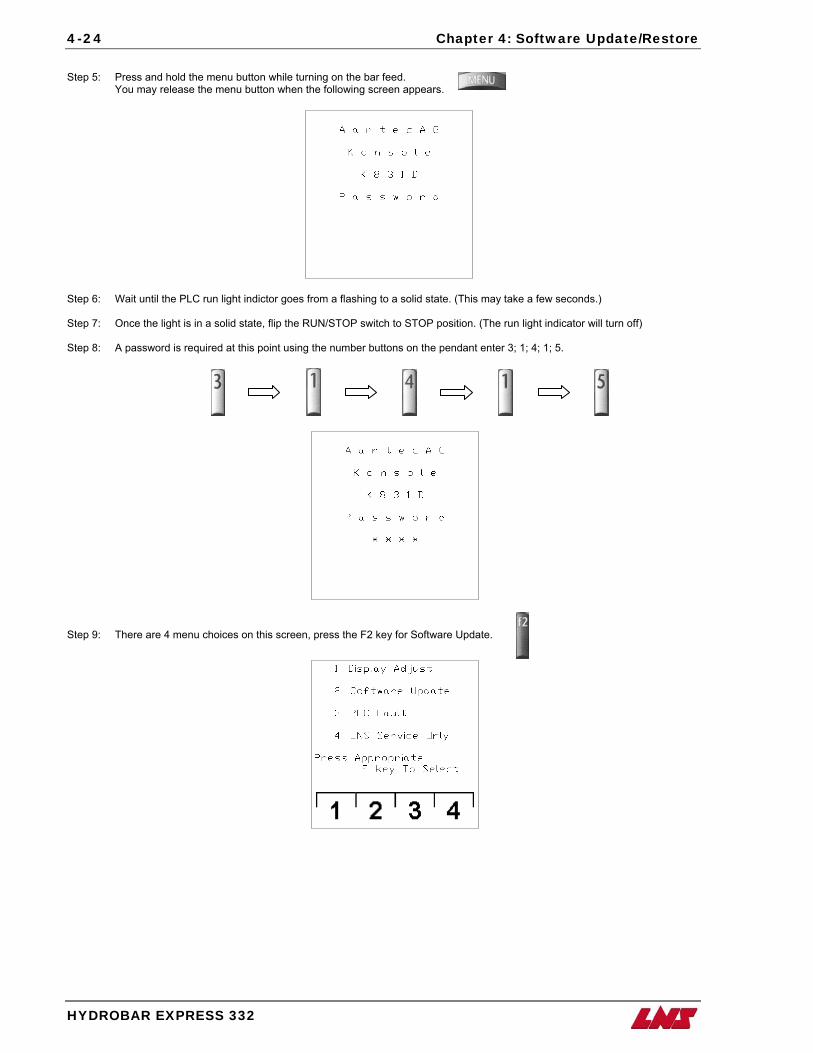
4-24 Chapter 4: Software Update/Restore
Step 5: Press and hold the menu button while turning on the bar feed.
You may release the menu button when the following screen appears.
Step 6: Wait until the PLC run light indictor goes from a flashing to a solid state. (This may take a few seconds.) Step 7: Once the light is in a solid state, flip the RUN/STOP switch to STOP position. (The run light indicator will turn off) Step 8: A password is required at this point using the number buttons on the pendant enter 3; 1; 4; 1; 5.
Step 9: There are 4 menu choices on this screen, press the F2 key for Software Update.
HYDROBAR EXPRESS 332
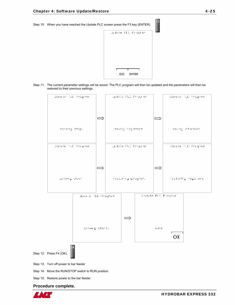
Chapter 4: Software Update/Restore 4-25
Step 10: When you have reached the Update PLC screen press the F3 key (ENTER).
Step 11: The current parameter settings will be saved. The PLC program will then be updated and the parameters will then be
restored to their previous settings.
Step 12: Press F4 (OK). Step 13: Turn off power to bar feeder Step 14: Move the RUN/STOP switch to RUN position. Step 15: Restore power to the bar feeder. Procedure complete.
HYDROBAR EXPRESS 332

Chapter 5: Preventative Maintenance 5-1
HYDROBAR EXPRESS 332
Chapter 5: Preventative Maintenance
erioits umaishoequi
dic maintenance of the Hydrobar Express 332 bar feeding system can only serve to improve the operation and prolong seful life. Following a few simple steps can be extremely helpful and takes relatively no time at all. The list of
ntenance procedures has been broken down into four groups determined by the frequency with which each procedure uld be followed, however, some items should be checked more often depending on the operating environment that the pment is exposed. P
5-2 Chapter 5: Preventative Maintenance
HYDROBAR EXPRESS 332
Daily Maintenance Verify the Air Pressure The recommended setting for operation with optimum performance should be at a minimum pressure of 5 bar (75 psi.) and a maximum pressure of 6 bar (90 psi.).
Weekly Maintenance Verify that the Air Decanter is Empty The air-filtering device is equipped with and automatic drainage valve, but depending on how much water is in the pneumatic circuit of the building, the water that is recuperated can build up faster than it can be drained. Excess water in the air lines can cause pneumatic cylinders to become defective. The water causes the o-rings inside the cylinder to swell up and no longer function correctly.
Hydraulic Oil Level When checking the level of the hydraulic oil, allow the bar feed to set idle for at least one hour so that the oil inside the coffin has time to drain back into the tank. If the oil is not allowed this time to drain back into the tank, the tank may look low, and if the oil is added it may cause an overflow.
Monthly Maintenance
Cleaning of the bar feeder Wipe down the outside of the bar feeder with a cloth and any regular detergent, for cleaning the inside of the bar feed use a cloth or brush. However, do not use the detergents on any of the guiding channels or any other parts made of synthetic materials. The use of compressed air for cleaning is not advisable, because chips and other particles can become lodged in sensitive areas and can impede the proper operation of the bar feeder.
Hydraulics Check the cleanliness of the hydraulic oil. It is important to wipe down the bars (even briefly) before loading them on the magazine rack. The bar feed recirculates the oil; excessive dirt and metal chips can form a deposit at the base of the coffin which can slow the oil return. The metal chips can also become lodged in the hydraulic pump causing the pump to lock up and/or the pump motor to overheat.
Rotating sleeves In order to guarantee the correct operation of the bar feeder, the rotating sleeve must function perfectly. Although the construction of the sleeve is very sturdy and reliable, it is recommended to verify periodically that it rotates without friction. If a defect should be present, please contact your local agent. This is a wear item and it is recommended to keep spares on hand, refer to Recommended Spare Parts List pg. 6-2.
Drive chain Over time, it is possible that the tension of the drive chain may loosen up. To tighten the chain, refer to Chain Tension Adjustment pg. 3-58.
Chapter 5: Preventative Maintenance 5-3
HYDROBAR EXPRESS 332
Annual Maintenance Check the PLC battery The PLC backup battery saves the PLC program in case of any power failure. The battery used in the SAIA PCD1 is a non-rechargeable 3VDC Lithium/ CD2032 battery. Over time, the battery will slowly discharge and an alarm message will appear on the remote control station (Low PLC Battery pg. 1-22). The following chart shows the average life expectancy of the battery:
Use of Automation Avg Life
Expectancy: 25°C
Avg Life Expectancy:
55°C 100% off 0% on 3 years 6 months
0% off 100% on 5 years 4 years
30% off 70% on 4 years 1 year
Verify the alignment of the bar feeder Check alignment of bar feeder to lathe spindle to make sure neither have shifted. In case the bar feeder or lathe has shifted.
After certain periods of time, the drive chain may need to be tightened, refer to Chain Tension Adjustment pg. 3-58.

Chapter 6: Spare Parts 6-1
HYDROBAR EXPRESS 332
Chapter 6: Spare Parts
Note: When ordering parts the following information will be needed to ensure better customer support:
• Bar feeder type
• Bar feeder Serial Number (found on the hydraulic tank next to the air regulator)
• Bar stock diameter
• Lathe type (make and model)
6-2 Chapter 6: Spare Parts
HYDROBAR EXPRESS 332
Recommended Spare Parts List
As an extended courtesy, a list of recommended spare parts has been compiled for the end user. The list consists of mechanical and electrical parts that over time may become faulty due to everyday wear on the item. For machines that are running production during multiple shifts or even 24/7, keeping an inventory of these spare parts can vastly minimize downtime. Keeping an inventory can also be very cost effective since shipping costs can escalate immensely, especially in cases where rush delivery is necessary.
Qty. Order # Part # Drawing # Description MECHANICAL
1 6E40-007 7mm rotating sleeve
1 6E40-010 10mm rotating sleeve
1 6E40-015 15mm rotating sleeve
1 6E40-025
Refer to pg. 6-4 Guiding Channel Reference chart
25mm rotating sleeve
2 028.29.023-A 028.29.023-A Inserts for front rest
4 032.05.074 032.05.074 Jaws for extracting device
ELECTRICAL 1 6S05-009.A 2 amp fuse
1 6S05-009.B 5 amp fuse
1 4.391 4.391 Proximity switch When ordering parts, to ensure better customer support, please specify the following information; Type of bar feeder, bar feeder serial number, bar stock diameter, and lathe type (refer to Parts Order Form pg. 6-6)
Spindle Liners Ensure that the properly sized spindle liner has been installed (matches guiding channel size).
Ensure that the spindle liner is straight (check total run out).
Ensure that the liner is securely fastened.
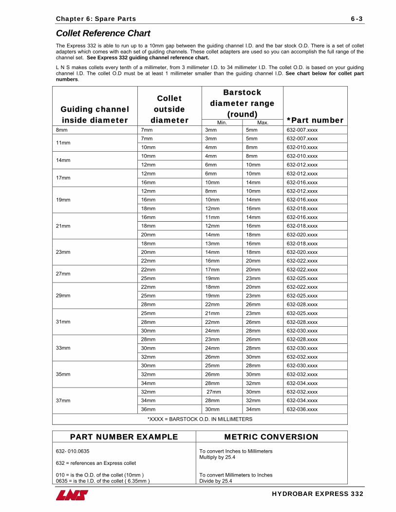
Chapter 6: Spare Parts 6-3
HYDROBAR EXPRESS 332
Collet Reference Chart The Express 332 is able to run up to a 10mm gap between the guiding channel I.D. and the bar stock O.D. There is a set of collet adapters which comes with each set of guiding channels. These collet adapters are used so you can accomplish the full range of the channel set. See Express 332 guiding channel reference chart.
L N S makes collets every tenth of a millimeter, from 3 millimeter I.D. to 34 millimeter I.D. The collet O.D. is based on your guiding channel I.D. The collet O.D must be at least 1 millimeter smaller than the guiding channel I.D. See chart below for collet part numbers.
Barstock diameter range
(round) Guiding channel inside diameter
Collet outside
diameter Min. Max. *Part number 8mm 7mm 3mm 5mm 632-007.xxxx
7mm 3mm 5mm 632-007.xxxx 11mm
10mm 4mm 8mm 632-010.xxxx
10mm 4mm 8mm 632-010.xxxx 14mm
12mm 6mm 10mm 632-012.xxxx
12mm 6mm 10mm 632-012.xxxx 17mm
16mm 10mm 14mm 632-016.xxxx 12mm 8mm 10mm 632-012.xxxx
16mm 10mm 14mm 632-016.xxxx 19mm
18mm 12mm 16mm 632-018.xxxx
16mm 11mm 14mm 632-016.xxxx
18mm 12mm 16mm 632-018.xxxx 21mm
20mm 14mm 18mm 632-020.xxxx
18mm 13mm 16mm 632-018.xxxx 20mm 14mm 18mm 632-020.xxxx 23mm
22mm 16mm 20mm 632-022.xxxx
22mm 17mm 20mm 632-022.xxxx 27mm
25mm 19mm 23mm 632-025.xxxx
22mm 18mm 20mm 632-022.xxxx
25mm 19mm 23mm 632-025.xxxx 29mm
28mm 22mm 26mm 632-028.xxxx
25mm 21mm 23mm 632-025.xxxx
28mm 22mm 26mm 632-028.xxxx 31mm
30mm 24mm 28mm 632-030.xxxx
28mm 23mm 26mm 632-028.xxxx
30mm 24mm 28mm 632-030.xxxx 33mm
32mm 26mm 30mm 632-032.xxxx
30mm 25mm 28mm 632-030.xxxx
32mm 26mm 30mm 632-032.xxxx 35mm
34mm 28mm 32mm 632-034.xxxx 32mm 27mm 30mm 632-032.xxxx
34mm 28mm 32mm 632-034.xxxx 37mm
36mm 30mm 34mm 632-036.xxxx
*XXXX = BARSTOCK O.D. IN MILLIMETERS
PART NUMBER EXAMPLE METRIC CONVERSION 632- 010.0635 632 = references an Express collet 010 = is the O.D. of the collet (10mm ) 0635 = is the I.D. of the collet ( 6.35mm )
To convert Inches to Millimeters Multiply by 25.4 To convert Millimeters to Inches Divide by 25.4
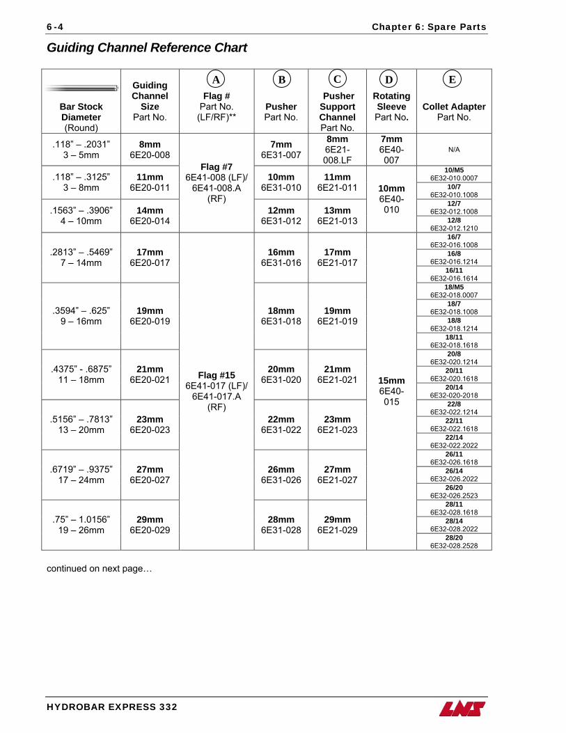
6-4 Chapter 6: Spare Parts
HYDROBAR EXPRESS 332
Guiding Channel Reference Chart
A C
Bar Stock Diameter (Round)
Guiding Channel
Size Part No.
Flag # Part No.
(LF/RF)**
Pusher Part No.
Pusher Support Channel Part No.
Rotating Sleeve Part No.
Collet Adapter Part No.
.118” – .2031” 3 – 5mm
8mm 6E20-008
7mm 6E31-007
8mm 6E21-008.LF
7mm 6E40-007
N/A
10/M5 6E32-010.0007 .118” – .3125”
3 – 8mm 11mm
6E20-011 10mm
6E31-010 11mm
6E21-011 10/7 6E32-010.1008
12/7 6E32-012.1008 .1563” – .3906”
4 – 10mm 14mm
6E20-014
Flag #7 6E41-008 (LF)/
6E41-008.A (RF)
12mm 6E31-012
13mm 6E21-013
10mm 6E40-010
12/8 6E32-012.1210
16/7 6E32-016.1008
16/8 6E32-016.1214
.2813” – .5469” 7 – 14mm
17mm 6E20-017
16mm 6E31-016
17mm 6E21-017
16/11 6E32-016.1614
18/M5 6E32-018.0007
18/7 6E32-018.1008
18/8 6E32-018.1214
.3594” – .625” 9 – 16mm
19mm 6E20-019
18mm 6E31-018
19mm 6E21-019
18/11 6E32-018.1618
20/8 6E32-020.1214
20/11 6E32-020.1618
.4375” - .6875” 11 – 18mm
21mm 6E20-021
20mm 6E31-020
21mm 6E21-021
20/14 6E32-020-2018
22/8 6E32-022.1214
22/11 6E32-022.1618
.5156” – .7813” 13 – 20mm
23mm 6E20-023
22mm 6E31-022
23mm 6E21-023
22/14 6E32-022.2022
26/11 6E32-026.1618
26/14 6E32-026.2022
.6719” – .9375” 17 – 24mm
27mm 6E20-027
26mm 6E31-026
27mm 6E21-027
26/20 6E32-026.2523
28/11 6E32-028.1618
28/14 6E32-028.2022
.75” – 1.0156” 19 – 26mm
29mm 6E20-029
Flag #15 6E41-017 (LF)/
6E41-017.A (RF)
28mm 6E31-028
29mm 6E21-029
15mm 6E40-015
28/20 6E32-028.2528
B D E
continued on next page…
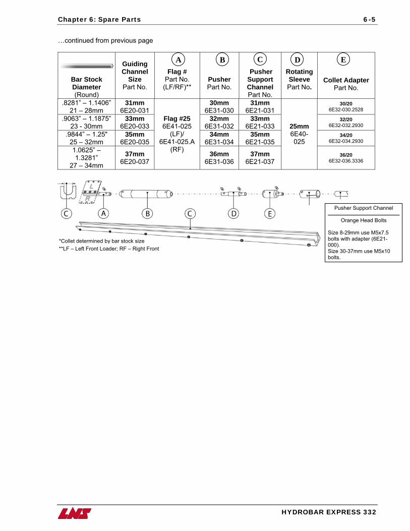
Chapter 6: Spare Parts 6-5
…continued from previous page
A C
Bar Stock Diameter (Round)
Guiding Channel
Size Part No.
Flag # Part No. (LF/RF)**
Pusher Part No.
Pusher Support Channel Part No.
Rotating Sleeve Part No.
Collet Adapter Part No.
.8281” – 1.1406” 21 – 28mm
31mm 6E20-031
30mm 6E31-030
31mm 6E21-031
30/20 6E32-030.2528
.9063” – 1.1875” 23 - 30mm
33mm 6E20-033
32mm 6E31-032
33mm 6E21-033
32/20 6E32-032.2930
.9844” – 1.25" 25 – 32mm
35mm 6E20-035
34mm 6E31-034
35mm 6E21-035
34/20 6E32-034.2930
1.0625” – 1.3281”
27 – 34mm
37mm 6E20-037
Flag #25 6E41-025
(LF)/ 6E41-025.A
(RF) 36mm 6E31-036
37mm 6E21-037
25mm 6E40-025
36/20
6E32-036.3336
B D E
Sbo
*Collet determined by bar stock size00S
ront Loader; RF – Right Front**LF – Left FHYDROBAR EX
bo
Pusher Support Channel
Orange Head Bolts
ize 8-29mm use M5x7.5 lts with adapter (6E21-0).
ize 30-37mm use M5x10 lts.
PRESS 332
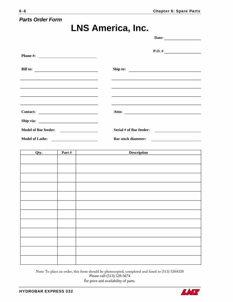
6-6 Chapter 6: Spare Parts
HYDROBAR EXPRESS 332
Parts Order Form
LNS America, Inc. Date:
P.O. # Phone #:
Bill to: Ship to:
Contact: Attn:
Ship via:
Model of Bar feeder: Serial # of Bar feeder:
Model of Lathe: Bar stock diameter:
Qty. Part # Description
Note: To place an order, this form should be photocopied, completed and faxed to (513) 528-8320
Please call (513) 528-5674 for price and availability of parts.
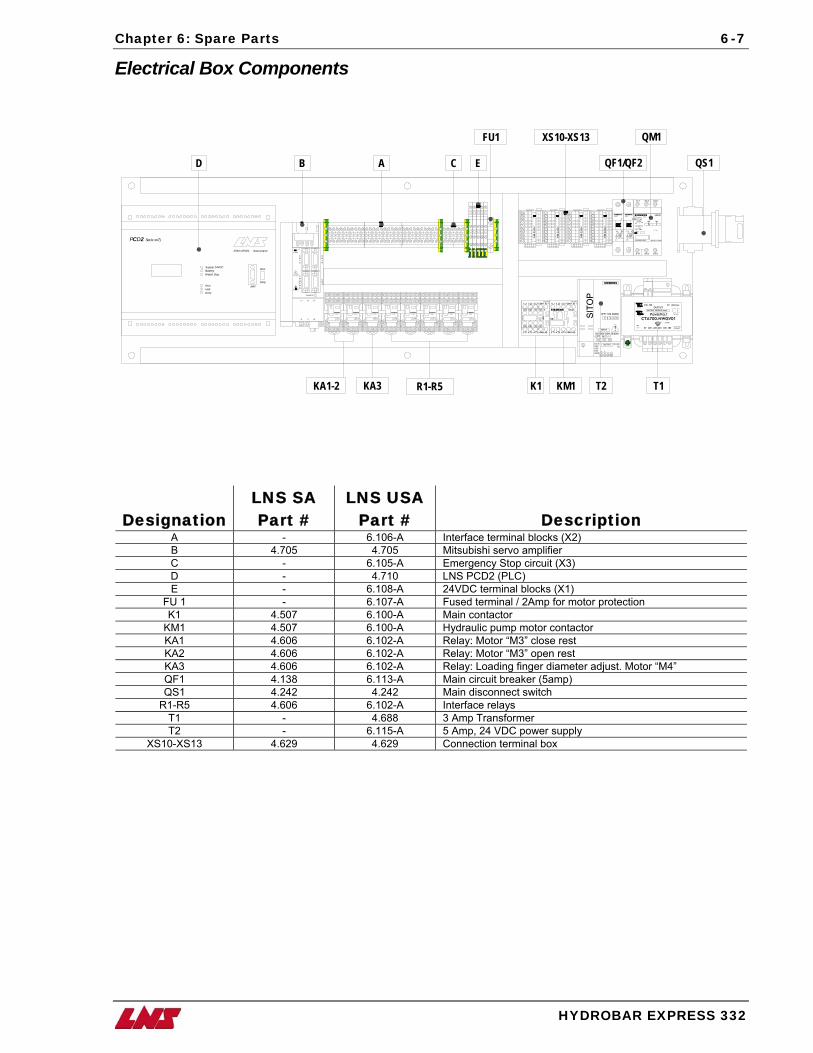
Chapter 6: Spare Parts 6-7
HYDROBAR EXPRESS 332
Electrical Box Components
WK
B 2
,5/B
/U
1
2
3
4
5
6
7
8
9
10
WK
B 2
,5/B
/U
1
2
3
4
5
6
7
8
9
10
WK
B 2
,5/B
/U
1
2
3
4
5
6
7
8
9
10
WK
B 2
,5/B
/U
1
2
3
4
5
6
7
8
9
10
SIEMENS5SX21
I
OC2~ 230/400V
60003
Uj~ 250/440
EDV
SIEMENS5SX21
I
OC2~ 230/400V
60003
Uj~ 250/440
EDV
SIEMENS SIRIUS
1 L1 3 L2 5 L3
2 T1 4 T2 6 T3
L1A
O I
4Amax
3,42,8
CLASS 10
52A
TEST
/ >>
OFF ON
3RV1011-1EA10G/031030 E05* *
230 230 0V @3Amps
OUTPUT FUSED 5 Amps
OUTPUT
INPUT
POWERVOLT
CTA700-NWGV0150/60Hz
0V 200 220 240 400 480
PV212004
ECC515B-1610-0421
C950
A60101
C
GRD
DC 24V1 L1 3 L2 5 L3 13NO A1+
2 T1 4 T2 6 T3 14NO A2-
S SIEMENS
DC 24V1 L1 3 L2 5 L3 13NO A1+
2 T1 4 T2 6 T3 14NO A2-
12
10E
SIRIUS
6EP1 333-3BA00
1 2 3 4 5
120/230V-500V 50/60HzPE N(L2) L1
24V OKOVERLOADSHUTDOWN
+ + - -
DC 24V5A
SITOP
SIEMENS
INPUT
OUTPUT
!
SIEMENS3TX71
SIEMENS3TX71
SIEMENS3TX71
SIEMENS3TX71
SIEMENS3TX71
SIEMENS3TX71
SIEMENS3TX71
SIEMENS3TX71
2534 ORVIN - Switzerland
Supply 24VDCBatteryWatch Dog
RunHaltError
MPIStop
Run
PCD2 Serie xx7j
OPEN
CHARGE
CN1A
CN2ENC
CN3
CN1B
CAUTIO N
WARNING
MO DE UP DOWN SET
L1 L2 L3
U V W
53NO 63NO 73NO 83NO
E05*
*
L003
1218
40
54NO 64NO 74NO 84NO
D B A C
XS10-XS13
E
FU1
QF1/QF2
QM1
QS1
KA1-2 KA3 R1-R5 K1 KM1 T2 T1
Designation LNS SA Part #
LNS USA Part # Description
A - 6.106-A Interface terminal blocks (X2) B 4.705 4.705 Mitsubishi servo amplifier C - 6.105-A Emergency Stop circuit (X3) D - 4.710 LNS PCD2 (PLC) E - 6.108-A 24VDC terminal blocks (X1)
FU 1 - 6.107-A Fused terminal / 2Amp for motor protection K1 4.507 6.100-A Main contactor
KM1 4.507 6.100-A Hydraulic pump motor contactor KA1 4.606 6.102-A Relay: Motor “M3” close rest KA2 4.606 6.102-A Relay: Motor “M3” open rest KA3 4.606 6.102-A Relay: Loading finger diameter adjust. Motor “M4” QF1 4.138 6.113-A Main circuit breaker (5amp) QS1 4.242 4.242 Main disconnect switch
R1-R5 4.606 6.102-A Interface relays T1 - 4.688 3 Amp Transformer T2 - 6.115-A 5 Amp, 24 VDC power supply
XS10-XS13 4.629 4.629 Connection terminal box
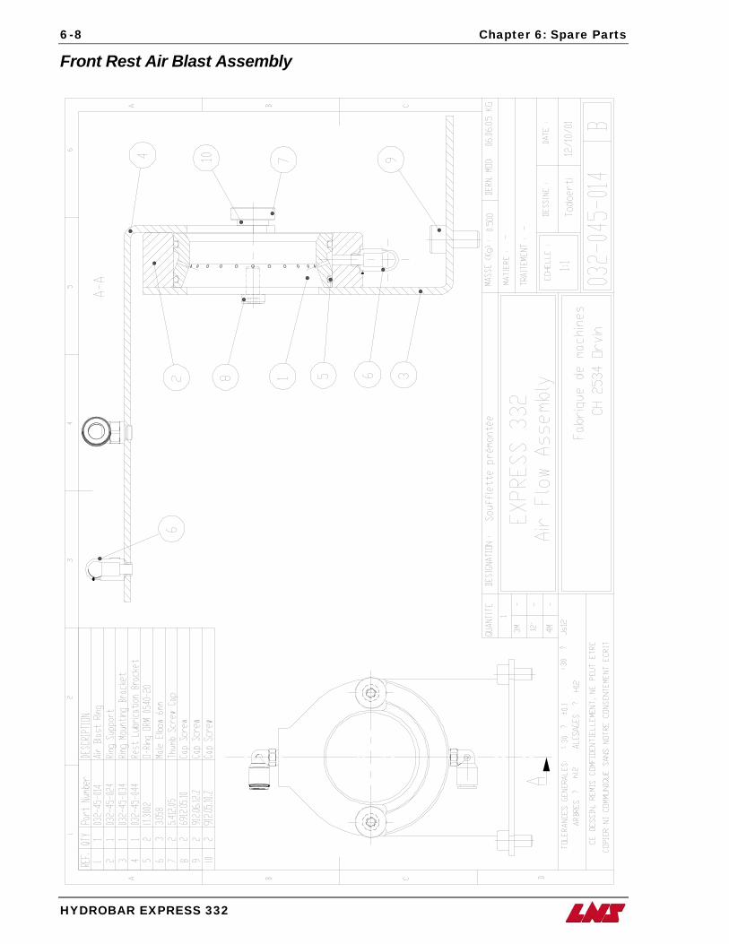
6-8 Chapter 6: Spare Parts
HYDROBAR EXPRESS 332
Front Rest Air Blast Assembly
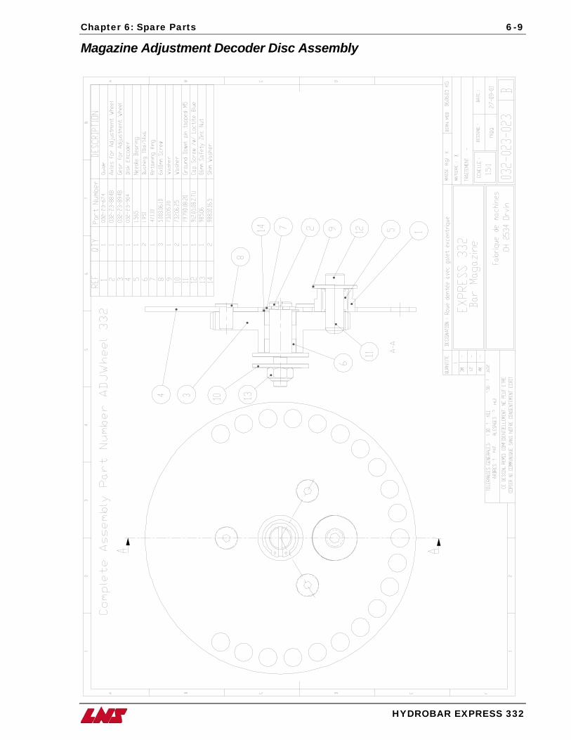
Chapter 6: Spare Parts 6-9
HYDROBAR EXPRESS 332
Magazine Adjustment Decoder Disc Assembly
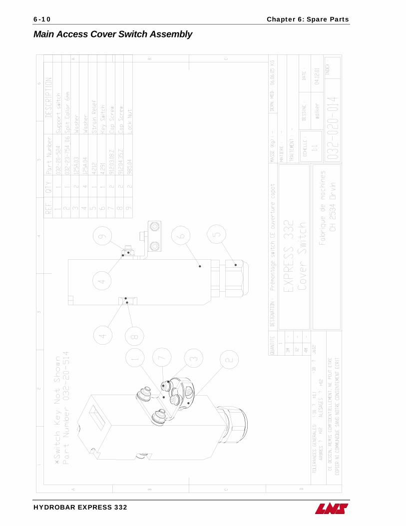
6-10 Chapter 6: Spare Parts
HYDROBAR EXPRESS 332
Main Access Cover Switch Assembly
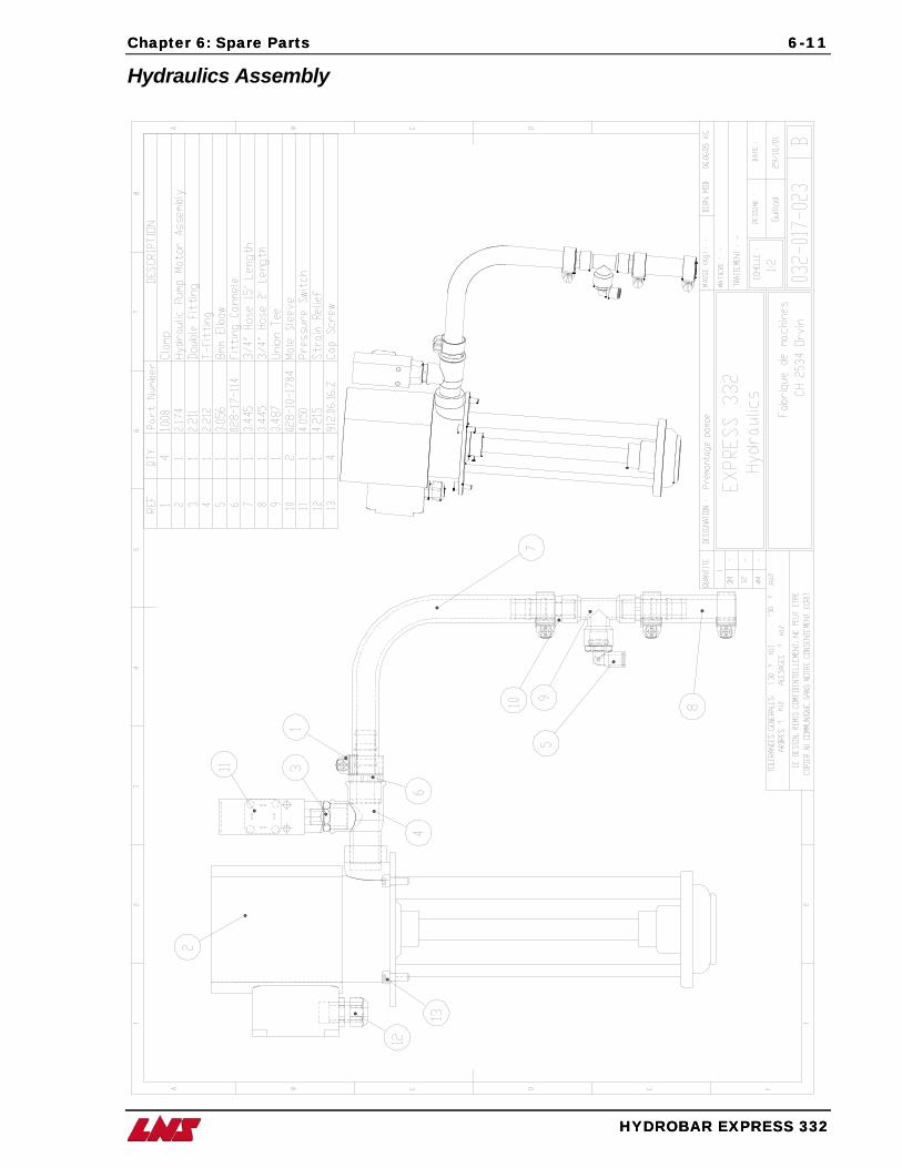
Chapter 6: Spare Parts Spare Parts 6-11
HYDROBAR EXPRESS 332
Chapter 6: 6-11
HYDROBAR EXPRESS 332
Hydraulics Assembly
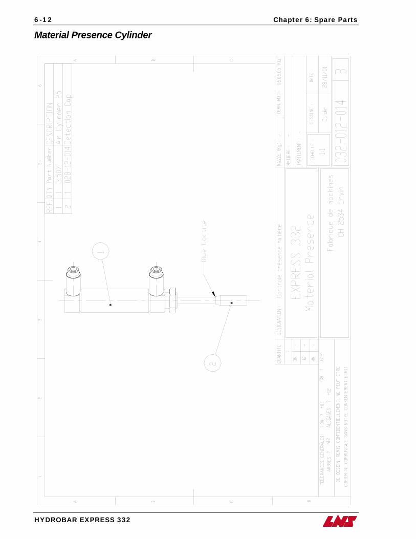
6-12 Chapter 6: Spare Parts
HYDROBAR EXPRESS 332
Material Presence Cylinder
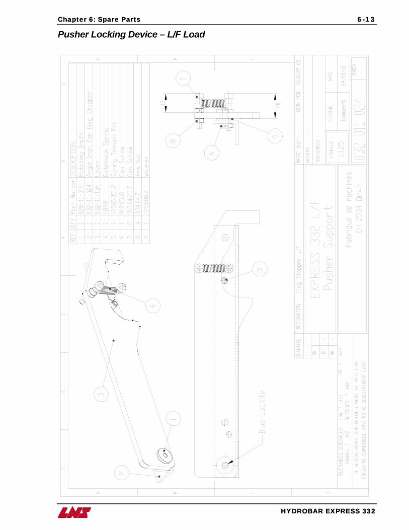
Chapter 6: Spare Parts Spare Parts 6-13
HYDROBAR EXPRESS 332
Chapter 6: 6-13
HYDROBAR EXPRESS 332
Pusher Locking Device – L/F Load
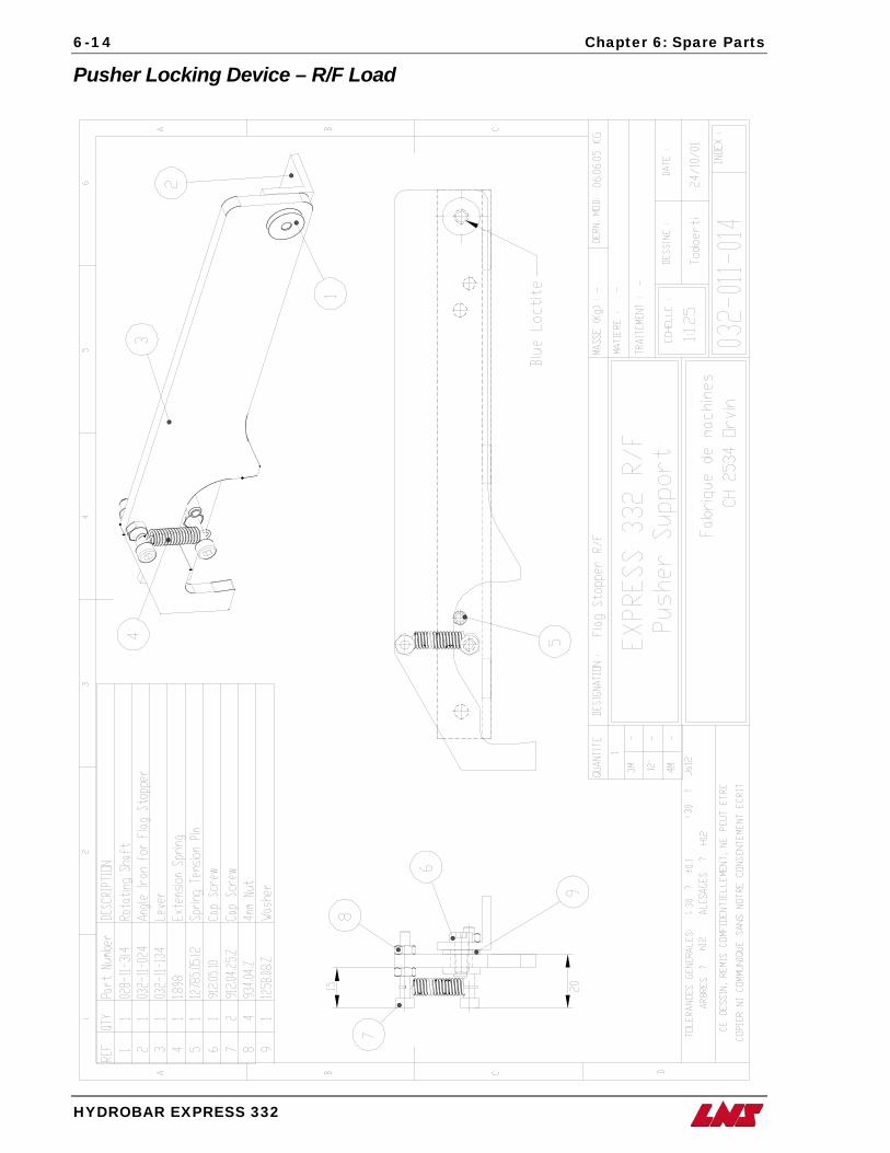
6-14 Chapter 6: Spare Parts
HYDROBAR EXPRESS 332
Pusher Locking Device – R/F Load
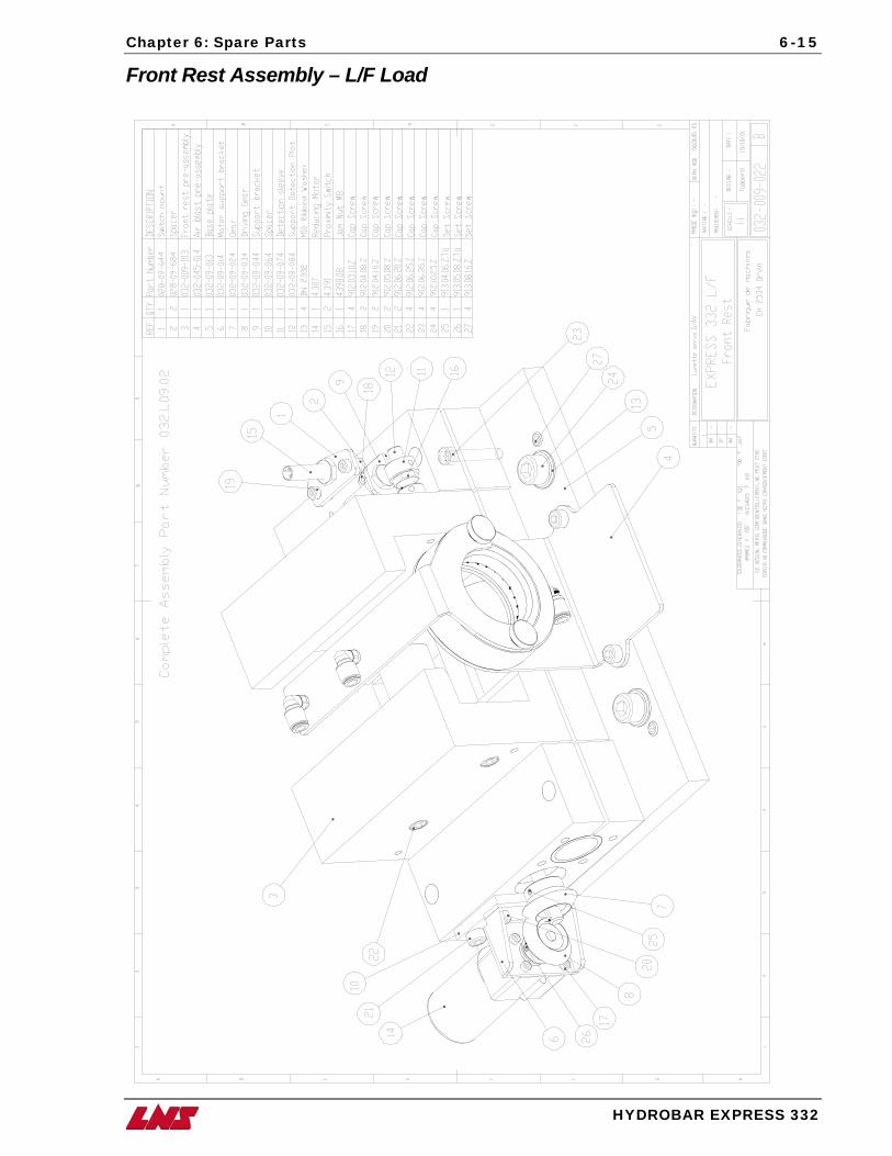
Chapter 6: Spare Parts 6-15
HYDROBAR EXPRESS 332
Front Rest Assembly – L/F Load
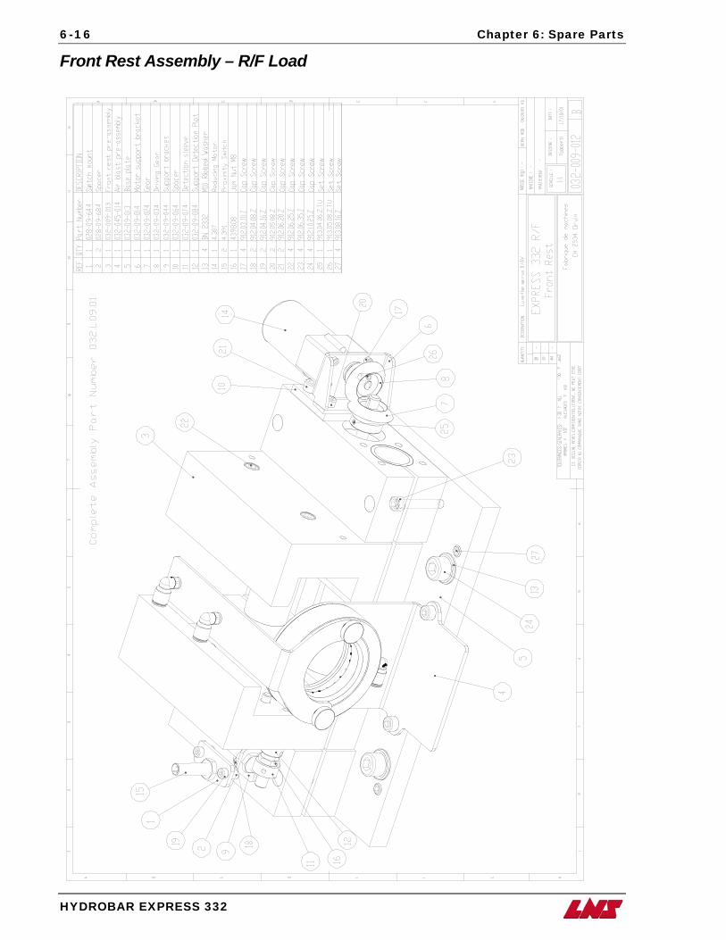
6-16 Chapter 6: Spare Parts
HYDROBAR EXPRESS 332
Front Rest Assembly – R/F Load
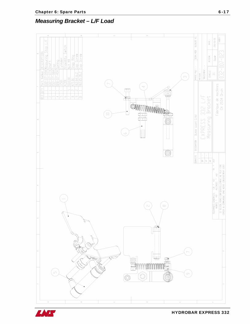
Chapter 6: Spare Parts 6-17
HYDROBAR EXPRESS 332
Measuring Bracket – L/F Load
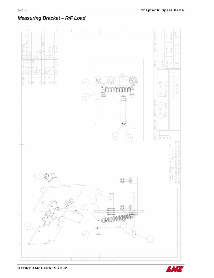
6-18 Chapter 6: Spare Parts
HYDROBAR EXPRESS 332
Measuring Bracket – R/F Load
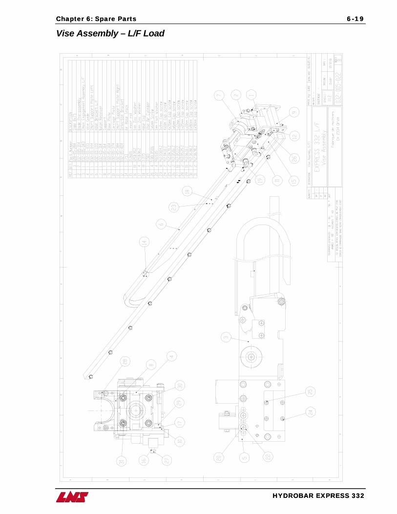
Chapter 6: Spare Parts Spare Parts 6-19
HYDROBAR EXPRESS 332
Chapter 6: 6-19
HYDROBAR EXPRESS 332
Vise Assembly – L/F Load
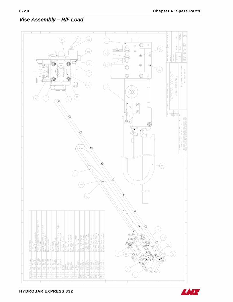
6-20 Chapter 6: Spare Parts
HYDROBAR EXPRESS 332
Vise Assembly – R/F Load
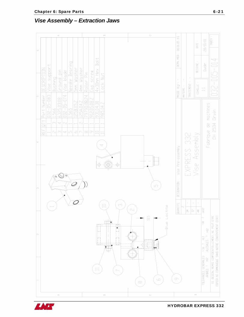
Chapter 6: Spare Parts 6-21
HYDROBAR EXPRESS 332
Vise Assembly – Extraction Jaws
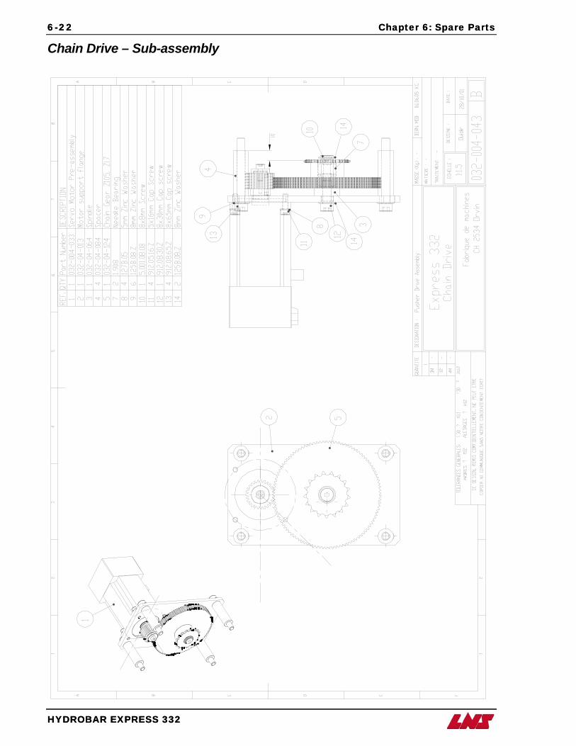
6-22 Chapter 6: Spare Parts Spare Parts
HYDROBAR EXPRESS 332
6-22 Chapter 6:
HYDROBAR EXPRESS 332
Chain Drive – Sub-assembly
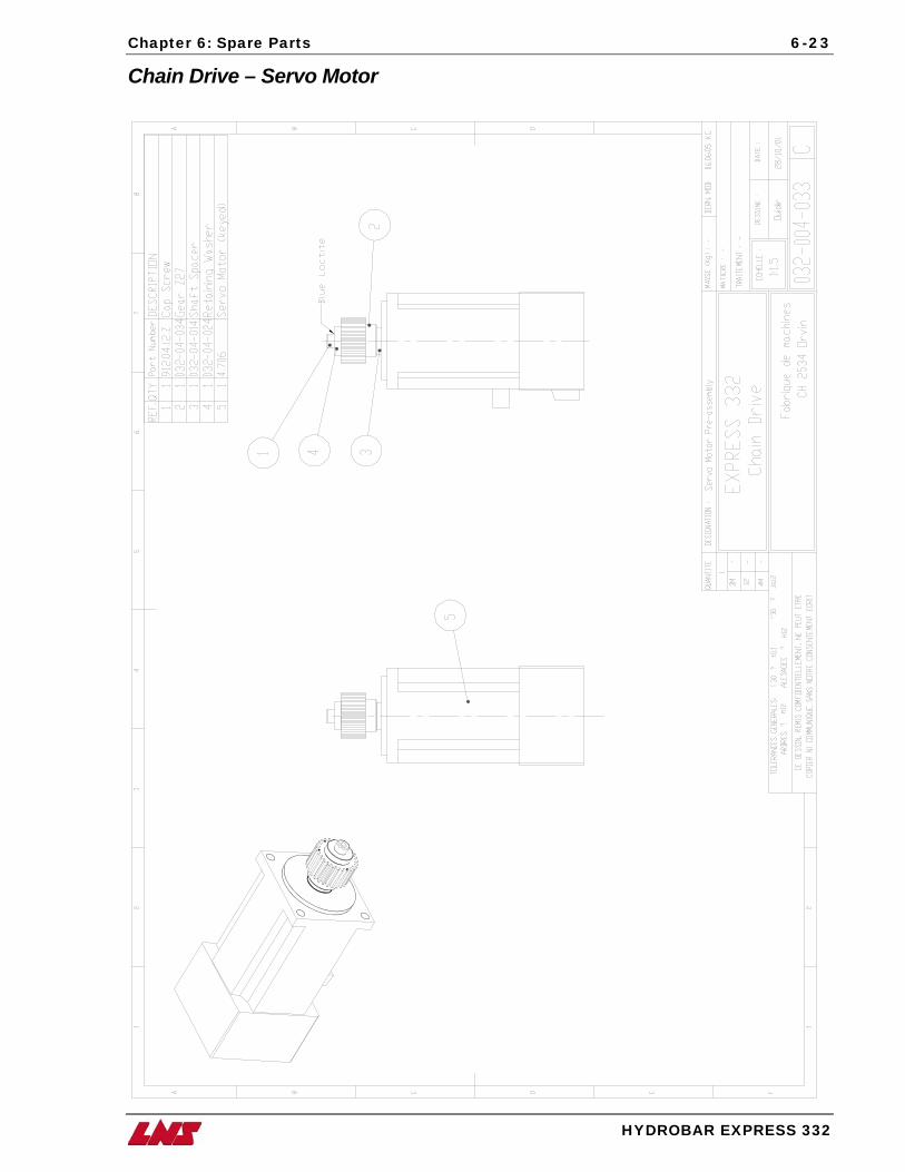
Chapter 6: Spare Parts 6-23
HYDROBAR EXPRESS 332
Chain Drive – Servo Motor
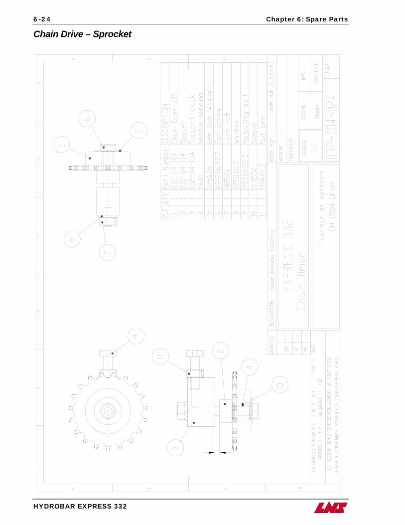
6-24 Chapter 6: Spare Parts
HYDROBAR EXPRESS 332
Chain Drive – Sprocket