Embed Size (px)
Citation preview
S&C IntelliCap® Plus Automatic Capacitor Control
Instruction Sheet 1023-550© S&C Electric Company 2003-2017, all rights reservedOctober 30, 2017
Troubleshooting
Table of Contents
Section Page Section Page
IntroductionQualified Persons . . . . . . . . . . . . . . . . . . . . . . . . . . . 2Read this Instruction Sheet . . . . . . . . . . . . . . . . . . . 2Retain this Instruction Sheet . . . . . . . . . . . . . . . . . . . 2Proper Application . . . . . . . . . . . . . . . . . . . . . . . . . . . 2Special Warranty Provisions . . . . . . . . . . . . . . . . . . . 2
Safety InformationUnderstanding Safety-Alert Messages . . . . . . . . . . . . . . 4Following Safety Instructions . . . . . . . . . . . . . . . . . . . . . 4Replacement Instructions and Labels . . . . . . . . . . . . . . 4
Safety Precautions . . . . . . . . . . . . . . . . . . . . . . . . . . . 5
Troubleshooting OverviewApplicable Software . . . . . . . . . . . . . . . . . . . . . . . . . . . . 6LCD Screen . . . . . . . . . . . . . . . . . . . . . . . . . . . . . . . . . . 6IntelliLink® Setup Software . . . . . . . . . . . . . . . . . . . . . . . 6Electrical Diagrams . . . . . . . . . . . . . . . . . . . . . . . . . . . . . 6Test Points . . . . . . . . . . . . . . . . . . . . . . . . . . . . . . . . . . . 7Tools Required . . . . . . . . . . . . . . . . . . . . . . . . . . . . . . . . 7Basic Troubleshooting . . . . . . . . . . . . . . . . . . . . . . . . . . . 7
Power ProblemsLoad Fuse is Blown . . . . . . . . . . . . . . . . . . . . . . . . . . 8
LED Display and LCD Screen ProblemsLED Display Problems . . . . . . . . . . . . . . . . . . . . . . . . . . 9LCD Screen Problems . . . . . . . . . . . . . . . . . . . . . . . . . . 9
Software TroubleshootingError Messages . . . . . . . . . . . . . . . . . . . . . . . . . . . . . . 11Incorrect Real-Time Data . . . . . . . . . . . . . . . . . . . . . . . 12
Miscellaneous Problems . . . . . . . . . . . . . . . . . . . . . 13
Using IntelliLink Setup Software to Locate Problems
Operation Screen . . . . . . . . . . . . . . . . . . . . . . . . . . . . . 15Alarm Status Screen . . . . . . . . . . . . . . . . . . . . . . . . . . . 18Trouble Conditions . . . . . . . . . . . . . . . . . . . . . . . . . . . . 18Error Conditions . . . . . . . . . . . . . . . . . . . . . . . . . . . . . . 19Metering Screen . . . . . . . . . . . . . . . . . . . . . . . . . . . . . . 20Product Information Screen . . . . . . . . . . . . . . . . . . . . . 23Chronological Log . . . . . . . . . . . . . . . . . . . . . . . . . . . . . 24
2 S&C Instruction Sheet 1023-550
Introduction
WARNINGThe equipment covered by this publication must be installed, operated, and main-tained by qualified persons who are knowledgeable in the installation, operation, and maintenance of overhead electric power distribution equipment along with the associ-ated hazards .
A qualified person is one who is trained and competent in:
• The skills and techniques necessary to distinguish exposed live parts from nonlive parts of electrical equipment
• The skills and techniques necessary to determine the proper approach distances corresponding to the voltages to which the qualified person will be exposed
• The proper use of the special precautionary techniques, personal protective equipment, insulating and shielding materials, and insulated tools for working on or near exposed energized parts of electrical equipment
These instructions are intended only for such qualified persons . They are not intended to be a substitute for adequate training and experience in safety procedures for this type of equipment .
NOTICERead this instruction sheet thoroughly and carefully before installing or operating your S&C IntelliCap Plus Automatic Capacitor Control . Familiarize yourself with the Safety Information on page 4 and Safety Precautions on page 5 . The latest version of this publi-cation is available online in PDF format at sandc.com/en/support/product-literature/ .
This instruction sheet is a permanent part of your S&C IntelliCap Plus Automatic Capacitor Control. Designate a location where you can easily retrieve and refer to this publication.
WARNINGThe equipment in this publication must be selected for a specific application . The application must be within the ratings furnished for the selected equipment .
The standard warranty contained in S&C’s standard conditions of sale, as set forth in Price Sheets 150 and 181, applies to the S&C IntelliCap Plus Automatic Capacitor Control, except that the first paragraph of the said warranty is replaced by the following:
(1) General: The seller warrants to the immediate purchaser or end user for a period of 10 years from the date of shipment that the equipment delivered will be of the kind and quality specified in the contract description and will be free of defects of workmanship and material. Should any failure to conform to this warranty appear under proper and normal use within 10 years after the date of shipment, the seller agrees, upon prompt notification thereof and confirmation that the equipment has been stored, installed, operated, inspected, and maintained in accordance with the recommendations of the seller and standard industry practice, to correct the nonconformity either by repairing any damaged or defective parts of the equipment or (at the seller’s option) by shipment of necessary replacement parts. The seller’s warranty does not apply to any equipment that has been disassembled, repaired, or altered by anyone other than the seller. This limited warranty is granted only to the immedi-ate purchaser or, if the equipment is purchased by a third party for installation in third-party equipment, the end user of the equipment. The seller’s duty to perform under any warranty may be delayed, at the seller’s sole option, until the seller has been paid in full for all goods purchased by the immediate purchaser. No such delay shall extend the warranty period.
Replacement parts provided by the seller or repairs performed by the seller under the warranty for the original equipment will be covered by the above special warranty provi-sion for its duration. Replacement parts purchased separately will be covered by the above special warranty provision.
Qualified Persons
Read this Instruction Sheet
Retain this Instruction Sheet
Proper Application
Special Warranty Provisions

S&C Instruction Sheet 1023-550 3
Introduction
Warranty of the S&C IntelliCap Plus Automatic Capacitor Control is contingent upon the installation, configuration, and use of the control or software in accordance with S&C’s applicable instruction sheets.
This warranty does not apply to major components not of S&C manufacture, such as communication devices. However, S&C will assign to the immediate purchaser or end user all manufacturer’s warranties that apply to such major components.
Warranty of equipment/services packages is contingent upon receipt of adequate informa-tion on the user’s distribution system, sufficiently detailed to prepare a technical analysis. The seller is not liable if an act of nature or parties beyond S&C’s control negatively impact performance of equipment/services packages; for example, new construction that impedes radio communication, or changes to the distribution system that impact protection systems, available fault currents, or system-loading characteristics.
4 S&C Instruction Sheet 1023-550
Safety Information
Understanding Safety-Alert Messages
Following Safety Instructions
Replacement Instructions and Labels
Several types of safety-alert messages may appear throughout this instruction sheet and on labels attached to the S&C IntelliCap Plus Automatic Capacitor Control. Familiarize yourself with these types of messages and the importance of these various signal words:
DANGER“DANGER” identifies the most serious and immediate hazards that will likely result in serious personal injury or death if instructions, including recommended precautions, are not followed .
WARNING“WARNING” identifies hazards or unsafe practices that can result in serious personal injury or death if instructions, including recommended precautions, are not followed .
CAUTION“CAUTION” identifies hazards or unsafe practices that can result in minor personal injury if instructions, including recommended precautions, are not followed .
NOTICE“NOTICE” identifies important procedures or requirements that can result in product or property damage if instructions are not followed .
If you do not understand any portion of this instruction sheet and need assistance, contact your nearest S&C Sales Office or S&C Authorized Distributor. Their tele- phone numbers are listed on S&C’s website sandc.com Or call S&C Headquarters at (773) 338-1000; in Canada, call S&C Electric Canada Ltd. at (416) 249-9171.
NOTICE
Read this instruction sheet thoroughly and carefully before installing or operating your S&C IntelliCap Plus Automatic Capacitor Control .
If you need additional copies of this instruction sheet, contact your nearest S&C Sales Office, S&C Authorized Distributor, S&C Headquarters, or S&C Electric Canada Ltd.
It is important that any missing, damaged, or faded labels on the equipment be replaced immediately. Replacement labels are available by contacting your nearest S&C Sales Office, S&C Authorized Distributor, S&C Headquarters, or S&C Electric Canada Ltd.
S&C Instruction Sheet 1023-550 5
Safety Precautions
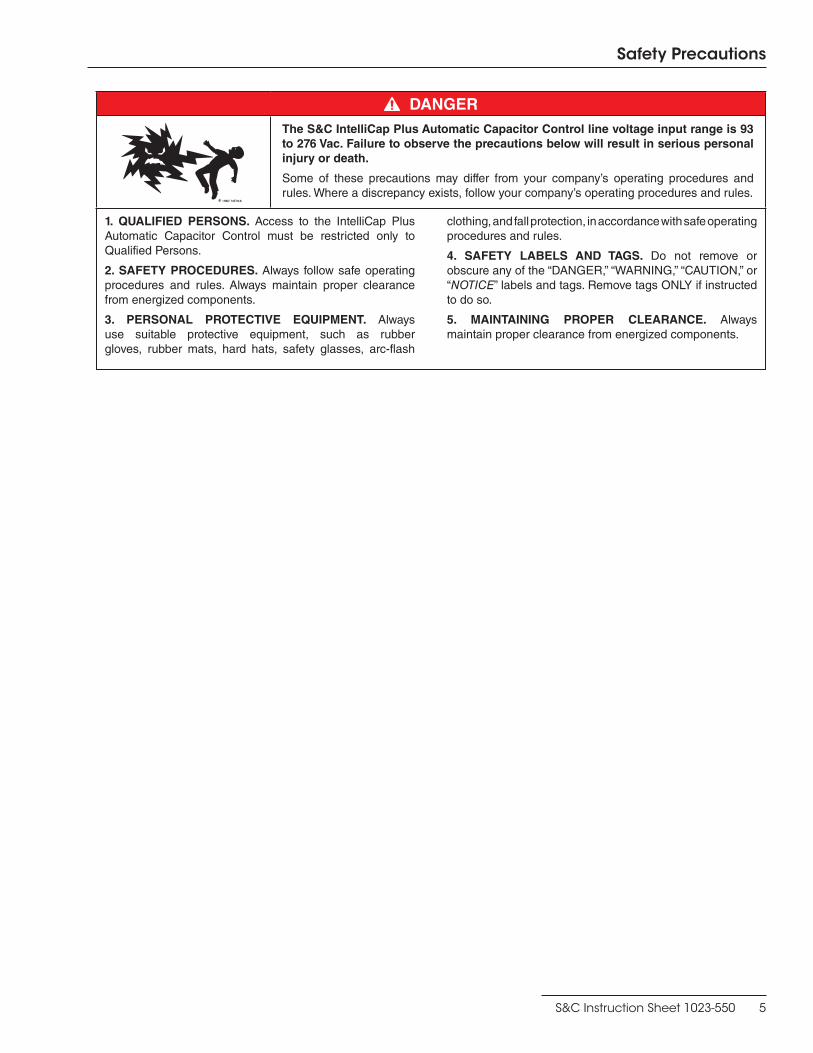
DANGERThe S&C IntelliCap Plus Automatic Capacitor Control line voltage input range is 93 to 276 Vac. Failure to observe the precautions below will result in serious personal injury or death.
Some of these precautions may differ from your company’s operating procedures and rules . Where a discrepancy exists, follow your company’s operating procedures and rules .
1. QUALIFIED PERSONS. Access to the IntelliCap Plus Automatic Capacitor Control must be restricted only to Qualified Persons .
2. SAFETY PROCEDURES. Always follow safe operating procedures and rules . Always maintain proper clearance from energized components .
3. PERSONAL PROTECTIVE EQUIPMENT. Always use suitable protective equipment, such as rubber gloves, rubber mats, hard hats, safety glasses, arc-flash
clothing, and fall protection, in accordance with safe operating procedures and rules .
4. SAFETY LABELS AND TAGS. Do not remove or obscure any of the “DANGER,” “WARNING,” “CAUTION,” or “NOTICE” labels and tags . Remove tags ONLY if instructed to do so .
5. MAINTAINING PROPER CLEARANCE. Always maintain proper clearance from energized components .
6 S&C Instruction Sheet 1023-550
Troubleshooting Overview
This instruction sheet was prepared for use with IntelliCap Plus software:PCSD126S and PCVD126S.
You can find software identification on the IntelliLink® Software Product Information screen. For questions regarding the applicability of information in this instruction sheet to future product releases, please contact S&C Electric Company.
WARNINGThe information in this instruction sheet is meant only for qualified people who are properly trained for work with this type of equipment, and who understand the hazards that may be involved . The information is this instruction sheet is not meant to be a substitute for training and experience in the safety procedures that are required for this type of equipment .
WARNINGThese instructions do NOT replace the need for utility operation standards . Any conflict between the information in this document and utility practices should be reviewed by appropriate utility personnel and a decision made as to the correct procedures to follow .
The S&C IntelliCap Automatic Capacitor Control is connected to switchgear operating at primary voltage levels . High voltage may be present in the wiring to the switch control or the switch control itself during certain failures of the switchgear wiring or grounding system, or because of a failure of the switch itself . For this reason, access to the switch control should be treated with the same safety precautions that would be applied when accessing other high-voltage lines and equipment . Follow all locally approved safety procedures when working on or around this switch control .
Before attempting to access an existing switch installation, check carefully for visible or audible signs of electrical or physical malfunction (do this before touching or operating the switch control or any other part of the installation) . These warning signs include such things as smoke, fire, open fuses, crackling noises, loud buzzing, etc . If a malfunc-tion is suspected, treat all components of the installation, including the switch control and associated mounting hardware, as if they were elevated to primary (high) voltage .
Applicable Software
LCD Screen
The following tools and features are used to diagnose and correct IntelliCap Plus control problems:
The LCD screen on the faceplate provides information about the present state of the control. For an explanation of the faceplate and LCD display, see “The Faceplate” section in Instruction Sheet 1023-540, “S&C IntelliCap® Plus Automatic Capacitor Control: Operation.”
Intell iLink Setup Software Operation , Alarm Status, Metering, and Product Information screens display information about the IntelliCap Plus control, IntelliCap Plus operations, and sensor data. For an explanation of these screens, see the “Using IntelliLink Software to Locate Problems” section in this instruction sheet.
To view these screens, use a portable PC computer, Windows 7, Microsoft Internet Explorer 5.0 or higher, a serial cable, and the IntelliLink Setup Software for the IntelliCap Plus control. For more information about the required equipment and how to use the IntelliLink Setup Software, see Instruction Sheet 1023-530, “S&C IntelliCap® Plus Automatic Capacitor Control: Setup.”
The electrical interconnect diagrams at the back of Instruction Sheet 1023-530, “S&C IntelliCap® Plus Automatic Capacitor Control: Setup” show the IntelliCap Plus wiring layout.
IntelliLink® Setup Software
Electrical Diagrams
S&C Instruction Sheet 1023-550 7
Troubleshooting Overview
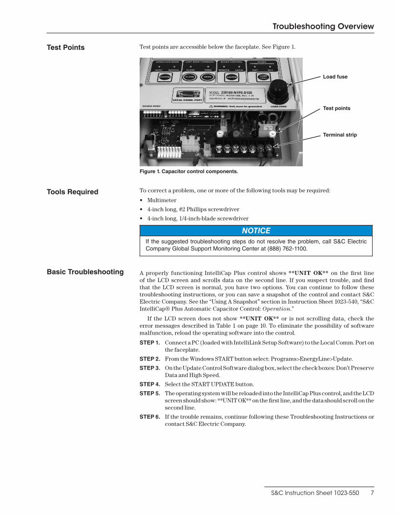
Figure 1. Capacitor control components.
Test points are accessible below the faceplate. See Figure 1.Test Points
Load fuse
Terminal strip
Test points
Tools Required
A properly functioning IntelliCap Plus control shows **UNIT OK** on the first line of the LCD screen and scrolls data on the second line. If you suspect trouble, and find that the LCD screen is normal, you have two options. You can continue to follow these troubleshooting instructions, or you can save a snapshot of the control and contact S&C Electric Company. See the “Using A Snapshot” section in Instruction Sheet 1023-540, “S&C IntelliCap® Plus Automatic Capacitor Control: Operation.”
If the LCD screen does not show **UNIT OK** or is not scrolling data, check the error messages described in Table 1 on page 10. To eliminate the possibility of software malfunction, reload the operating software into the control.
STEP 1. Connect a PC (loaded with IntelliLink Setup Software) to the Local Comm. Port on the faceplate.
STEP 2. From the Windows START button select: Programs>EnergyLine>Update.
STEP 3. On the Update Control Software dialog box, select the check boxes: Don’t Preserve Data and High Speed.
STEP 4. Select the START UPDATE button.
STEP 5. The operating system will be reloaded into the IntelliCap Plus control, and the LCD screen should show: **UNIT OK** on the first line, and the data should scroll on the second line.
STEP 6. If the trouble remains, continue following these Troubleshooting Instructions or contact S&C Electric Company.
Basic Troubleshooting
To correct a problem, one or more of the following tools may be required:
• Multimeter
• 4-inch long, #2 Phillips screwdriver
• 4-inch long, 1/4-inch-blade screwdriver
NOTICEIf the suggested troubleshooting steps do not resolve the problem, call S&C Electric Company Global Support Monitoring Center at (888) 762-1100 .
8 S&C Instruction Sheet 1023-550
Power Problems
When the load fuse blows, the voltage magnitude the control displays will be approximately zero.
NOTICEBefore changing a blown load fuse, set the operation mode to fthe Manual setting . This will prevent any automatic operation .
Follow these steps to check a blown load fuse:
STEP 1. With the faceplate buttons, change the operation mode to the Manual state.
STEP 2. Remove the fuse holder from the faceplate and replace the fuse. See Figure 1 on page 7.
STEP 3. Switch the bank in and out. If the new fuse blows, check the wiring, peripheral equipment, and line switches.
Load Fuse Is Blown
S&C Instruction Sheet 1023-550 9
LED Display and LCD Screen Problems
LED Display Problems Follow these steps when the Close and Open LED displays (on the faceplate) are off:
STEP 1. Check the LCD screen. If it is not operating normally, see the “LCD Screen Problems” section on page 9.
STEP 2. Do a lamp test. Press the faceplate LAMP TEST button. If the CLOSE or OPEN LED display does not turn on, but the other LED displays do, the LED display is probably bad. If none of the LED displays turn on, see the “LCD Screen Problems” section on page 9.
STEP 3. Switch the bank in or out manually. Press the faceplate OPERATION MODE CHANGE button so the MANUAL LED display is on. Following utility-approved work procedures and safety practices, switch the bank with the faceplate CLOSE or OPEN button. If you are powering-up the capacitor control for the first time, or if the control software has been reloaded (not updated), the LED displays do not indicate the bank state until a switching operation is performed.
LCD Screen Problems Follow these steps when the LCD screen is blank:
STEP 1. Check for ac power to the control. Check for ac voltage between test points 2 (Ac Line) and 3 (Neutral Return) below the faceplate. If there is no voltage:
(a) For controls with a meter base, make sure the Ac Line and Ac Neutral wires are connected to the proper terminals in the meter base socket.
(b) For controls with a bracket mount, make sure the cable wiring is correct. All IntelliCap Plus controls have a label inside the enclosure that shows the correct configuration.
(c) Following utility-approved work procedures and safety practices, verify that there is 120 Vac in the line which provides ac power to the control.
STEP 2. Replace the LCD screen. There may be a problem with the PC board, the LCD screen, or the operating system. Call S&C Electric Company.
Follow these steps when the LCD screen does not display **UNIT OK** or the data line is not scrolling:
STEP 1. Check the LCD screen error messages. Table 1 on page 10 shows possible messages.
STEP 2. Check for IntelliLink software troubleshooting messages. Connect your computer to the capacitor control, and start the IntelliLink software. Check for active messages on the Alarm Status screen. Follow the troubleshooting suggestions for those messages. See Table 1 on page 10.
10 S&C Instruction Sheet 1023-550
LED Display and LCD Screen Problems
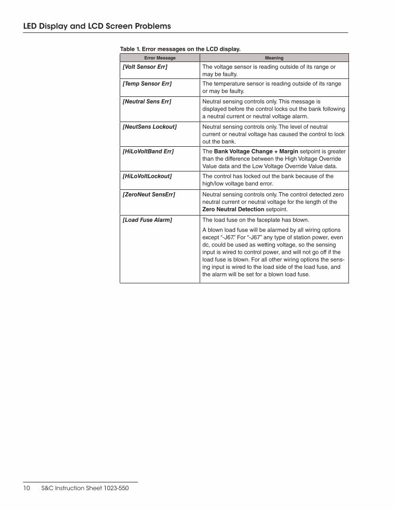
Table 1. Error messages on the LCD display.Error Message Meaning
[Volt Sensor Err] The voltage sensor is reading outside of its range or may be faulty .
[Temp Sensor Err] The temperature sensor is reading outside of its range or may be faulty .
[Neutral Sens Err] Neutral sensing controls only . This message is displayed before the control locks out the bank following a neutral current or neutral voltage alarm .
[NeutSens Lockout] Neutral sensing controls only . The level of neutral current or neutral voltage has caused the control to lock out the bank .
[HiLoVoltBand Err] The Bank Voltage Change + Margin setpoint is greater than the difference between the High Voltage Override Value data and the Low Voltage Override Value data .
[HiLoVoltLockout] The control has locked out the bank because of the high/low voltage band error .
[ZeroNeut SensErr] Neutral sensing controls only . The control detected zero neutral current or neutral voltage for the length of the Zero Neutral Detection setpoint .
[Load Fuse Alarm] The load fuse on the faceplate has blown .
A blown load fuse will be alarmed by all wiring options except “-J67 .” For “-J67” any type of station power, even dc, could be used as wetting voltage, so the sensing input is wired to control power, and will not go off if the load fuse is blown . For all other wiring options the sens-ing input is wired to the load side of the load fuse, and the alarm will be set for a blown load fuse .
S&C Instruction Sheet 1023-550 11
Software Troubleshooting
Error Messages Incompatible IdentThe IntelliLink software uses a different screenset (WMN file) for each type of control and normally selects the screenset for you. This message appears when you have a screenset selected (displayed) and try to connect to a snapshot (VM file) that requires a different screenset.
Follow these steps to select the correct screenset:
STEP 1. Close the open screenset. In the File menu select the Close Screenset option.
STEP 2. In the File menu select the Open Snapshot option.
STEP 3. In the Open Controller Data File dialog box, select the snapshot you want to view.
STEP 4. Click on the OK button to open both the snapshot and the correct screenset.
IntelliLink setup incorrect or incompleteReinstall the IntelliLink software on your computer.—There may be a problem with one of the files. See the “To Install the IntelliLink Software” section in Instruction Sheet 1023-530, “IntelliCap® Plus Automatic Capacitor Control: Setup,” for more information.
Opening port COM1....Trying 9600 BAUD....Connection FailedThese messages appear in the Connect dialog box when IntelliLink software cannot establish communication with the software in the capacitor control. Follow these steps to correct the problem:
STEP 1. Check that the capacitor control has power. If the LCD screen is blank, the control has no power and cannot communicate with your portable computer. See the LCD Display Problems section on page 9.
STEP 2. Check the cable connections between the computer and the control. Check that the serial cable is plugged into the LOCAL port on the faceplate – or the optical coupler is attached to the port on the side of the enclosure. Check that the cable is plugged into the correct port on the computer (usually COM1 on portable computers).
STEP 3. Check the optical coupler power source. If using an optical coupler, check that it has ac or battery power.
STEP 4. Try another communications port. The COM1 port on the computer may be broken or assigned to a different device. Connect the cable to another comm port on the computer. In the Connect dialog box, click the Change Setup button. From the pull-down list, select the name of the port where the cable is connected. Click on the Connect button.
STEP 5. Use a different serial cable. If using the faceplate LOCAL COMM port, the serial cable between the computer and the capacitor control may have a broken wire or pin. The cable may be wired for use with a different kind of computer, or it may be a nullmodem cable.
STEP 6. Check the serial port on the computer. If a 2-wire, ungrounded extension cord is used to power the computer or the capacitor control during lab testing, it may have damaged the serial port on the computer. Test the serial port by trying to communicate with a modem or other serial device.
Program in the control: XXXX... not configured for this programReinstall the IntelliLink software on the computer. Make sure to install the software for this type of capacitor control. See the “To Install the IntelliLink Software” section in Instruction Sheet 1023-530, “IntelliCap® Plus Automatic Capacitor Control: Setup,” for more information.
Software in control incompatible with open screenset. Connection cannot be establishedThe IntelliLink software uses a different screenset (WMN file) for each type of control and normally selects the screenset for you. This message appears when a screenset is selected (displayed) and there is an attempt to try to connect to a capacitor control that requires a different screenset.
12 S&C Instruction Sheet 1023-550
Software Troubleshooting
Incorrect Real-Time Data
Use the correct screenset. To close the open screenset, in the File menu select the Close Screenset option. Then in the File menu, select the Open Screenset option and choose the correct screenset for the capacitor control. When the screenset opens (the Operation screen is displayed), in the Connection menu, select the Connect to Device option.
Software in control is XXXX... IntelliLink is not properly configured for this productReinstall the IntelliLink software on the computer. There may be a problem with one of the files. See the “To Install the IntelliLink Software” section in Instruction Sheet 1023-530, “IntelliCap® Plus Automatic Capacitor Control: Setup,” for more information.
Sensed current is zero on the Operation screenCheck that the sensor cable is securely connected to the sensors and to the capacitor control. Check that the cable is not damaged. See Instruction Sheet 1023-510, “S&C IntelliCap® Plus Automatic Capacitor Control: Installation,” for more information.
Following utility-approved work procedures and safety practices, verify that current is flowing through the sensor and that the sensor is installed properly.
Line Voltage display does not match measured ac voltageIntelliCap Plus controls calculate True RMS voltage from frequent samples. Digital voltmeters calculate RMS voltage for a pure sine wave. Voltage harmonics encountered in power distribution alter the pure sine wave. RMS voltmeters do not account for this, so their readings are often inaccurate.
True RMS is a repeatable voltage result, independent of waveform harmonic content. Therefore, voltage override setpoint values can be accurately determined using voltages displayed and data logged by the IntelliCap Plus control. The Fluke Model 189 True RMS meter (or equivalent) is the reference voltmeter used to confirm voltage indications on an IntelliCap Plus control.
Real-time kvar values are wrongFollow these steps to correct kvar values:
STEP 1. Check the Voltage Transformer Wiring and Voltage Transformer Ratio setpoints on the Setup>Site-Related screen. The Voltage Transformer Wiring setpoint should reflect how the transformer powering the capacitor control is wired (phase to ground or phase to phase). The Voltage Transformer Ratio setpoint should be the ratio of the transformer’s primary rated voltage to 120 volts. For example, a 12000/120-240 volt transformer has a ratio of 12000/120, or 100:1.
STEP 2. Check the current level. Because of sensor accuracy limitations at low current levels, phase angle detection and display require a minimum current of 0.5% of full scale values. Below this threshold, the measured power factor reads “1.000” and the kvar values read “0.” Current magnitudes continue to be detected and displayed below the 0.5% threshold.
For example: For a capacitor control with a 600-amp Lindsey sensor, phase angle detection shuts down at approximately 3 amps. Below 3 amps, the power factor displayed is 1.000 and the kvars displayed is 0.
STEP 3. Check the Installation Phase Offset setpoint on the Setup>Site- Related screen.
S&C Instruction Sheet 1023-550 13
Miscellaneous Problems
SCADA commands are ignored by the capacitor controlFollow these steps to check SCADA command performance:
STEP 1. Check the SCADA CONTROL LED display. To operate the bank remotely, the faceplate REMOTE LED display must be lit. If it is not, press the SCADA CONTROL CHANGE button.
STEP 2. Check for control power. See the “LCD Display Problems” section on page 9.
STEP 3. Check the RTU address. On Page 1 of the Communications Setup screen, check which communications RTU address is used by this control. Make sure the SCADA master station is sending commands for this control to the correct address.
STEP 4. Check the baud rate. On Page 2 of the Communications Setup screen, make sure the baud rate is correct for your communications equipment. For modems, the baud rate should match the baud rate used by the SCADA master station.
STEP 5. Check your communications hardware. See the appropriate communication instructions for more information.
Capacitor bank switch does not operateFollow these steps to check bank switch operation:
STEP 1. Make sure the faceplate LOCAL and MANUAL LED displays are both lit. If the LOCAL LED display is off, press the SCADA CONTROL CHANGE button. If the MANUAL LED display is off, press the OPERATION MODE CHANGE button, then press the CLOSE or OPEN button.
STEP 2. Check the faceplate CLOSE/OPEN LED displays. If the OPEN LED display is blinking slowly, the Reclose Block delay is operating. Wait until it stops blinking, then try switching the bank again. If both LED displays are off, see the “Incompatible Ident” section on page 11.
STEP 3. Check the line voltage level. Make sure the line voltage is not below the minimum required to switch the capacitor bank.
STEP 4. Check the Capacitor Bank Switch Control Pulse Time. Connect the computer to the control and start the IntelliLink software. Check that the Capacitor Bank Switch Control Pulse Time setpoint (on Page 2 of the Setup>General screen) is long enough. See Instruction Sheet 1023-530, “S&C IntelliCap® Plus Automatic Capacitor Control: Setup,” for more information.
STEP 5. Check the wiring. The wiring between the capacitor control and a bank switch may be damaged or defective.
STEP 6. Check the capacitor bank primary switch(es). The capacitor bank switch(es) may be malfunctioning.
Some (but not all) capacitor bank switches do not operateSTEP 1. Check the line-voltage level. Make sure the line voltage is not below the minimum
required to switch the capacitor bank.
STEP 2. Check the Capacitor Bank Switch Control Pulse Time. Connect the computer to the capacitor control and start the IntelliLink software. Check that the Capacitor Bank Switch Control Pulse Time setpoint (on Page 2 of the Setup>General screen) is long enough. See Instruction Sheet 1023-530, “S&C IntelliCap® Plus Automatic Capacitor Control: Setup,” for more information.
STEP 3. Check the wiring. The wiring between the capacitor control and a bank switch may be damaged or defective.
STEP 4. Check the capacitor bank primary switch(es). The capacitor bank switch(es) may be malfunctioning.
14 S&C Instruction Sheet 1023-550
Miscellaneous Problems
Capacitor control is not switching the bank automaticallyFollow these steps to trouble troubleshoot automatic switching:
STEP 1. Make sure the faceplate AUTO LED display is lit. If the AUTO LED display is off, press the OPERATION MODE CHANGE button.
Note: If the capacitor control was in Manual mode and is returned to Automatic mode, it waits 60 seconds before switching the bank.
STEP 2. Check the Reclose Block field. If a number appears in this field on the Operation screen, the Reclose Block feature is operating. After the timer runs out, automatic switching should resume.
STEP 3. Check for a Voltage-Override condition. On the Operation screen, check for a voltage-override message. If a Voltage-Override condition is in effect, make sure the Voltage-Override setpoints are appropriate for this capacitor bank installation.
STEP 4. Check for a potential Voltage-Override condition. Check the present line voltage (on the Operation screen), the Voltage-Override setpoints presently in effect, and the Bank Voltage Rise + Margin setpoint (on Page 1 of the Setup>General screen). The capacitor control does not switch the bank if doing so would cause a Voltage-Override condition. See Instruction Sheet 1023-530, “S&C IntelliCap® Plus Automatic Capacitor Control: Setup,” for more information.
STEP 5. Check the number of automatic switching cycles. On the Operation Counters screen, look at the number of automatic switching cycles (switch in and switch out) for the day. If the number is equal to (or greater than) the Maximum Automatic Control Cycles Per Day setpoint, further switching is inhibited in Automatic mode until the next calendar day.
STEP 6. Check whether the bank is scheduled to be active. On Page 4 of the Setup>General screen, check whether today is a holiday. If the capacitor control is in Timeclock mode, Time-Biased Voltage mode, or Time-Biased Temperature mode, check the schedules.
STEP 7. Check for troubleshooting messages. Check for active messages on the Troubleshooting Event screens. Follow the troubleshooting suggestions for those messages.
STEP 8. Check manual bank operation. Put the control in Manual mode (the faceplate MANUAL LED display is lit). Following your company’s procedures, use the faceplate CLOSE or OPEN button to operate the capacitor bank. If the bank does not switch, see the “Capacitor bank switch does not operate” section on page 13.
S&C Instruction Sheet 1023-550 15
Using IntelliLink Software to Locate Problems
The IntelliLink software Operation, Alarm Status, Metering, and Product Information screens helps check the status of the capacitor control and locate the causes of several problem types.
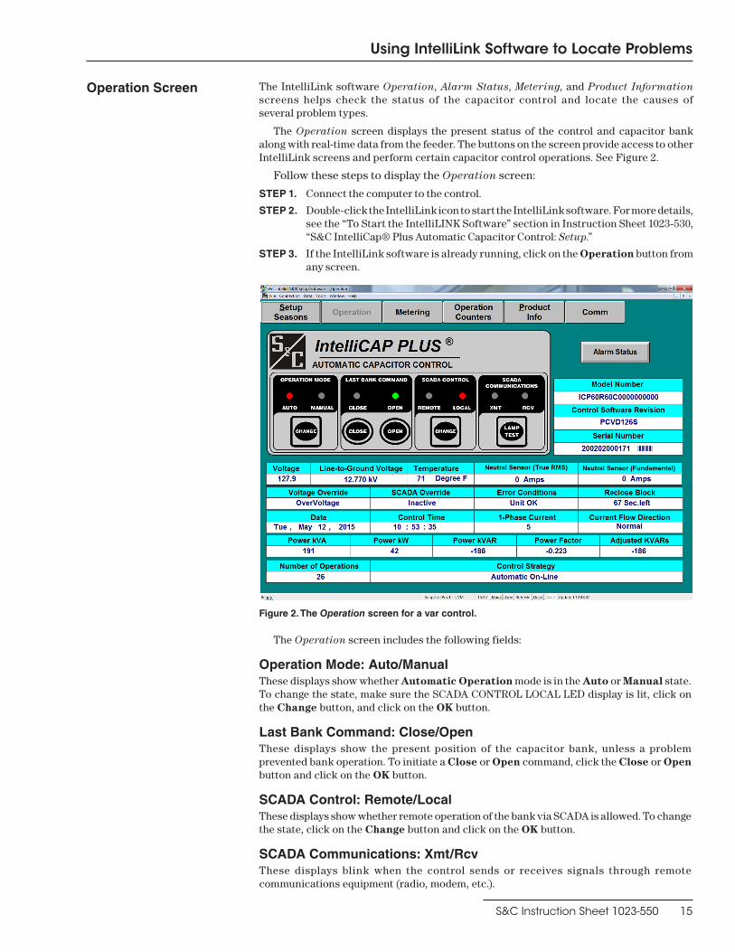
The Operation screen displays the present status of the control and capacitor bank along with real-time data from the feeder. The buttons on the screen provide access to other IntelliLink screens and perform certain capacitor control operations. See Figure 2.
Follow these steps to display the Operation screen:
STEP 1. Connect the computer to the control.
STEP 2. Double-click the IntelliLink icon to start the IntelliLink software. For more details, see the “To Start the IntelliLINK Software” section in Instruction Sheet 1023-530, “S&C IntelliCap® Plus Automatic Capacitor Control: Setup.”
STEP 3. If the IntelliLink software is already running, click on the Operation button from any screen.
Operation Screen
Figure 2. The Operation screen for a var control.
The Operation screen includes the following fields:
Operation Mode: Auto/ManualThese displays show whether Automatic Operation mode is in the Auto or Manual state. To change the state, make sure the SCADA CONTROL LOCAL LED display is lit, click on the Change button, and click on the OK button.
Last Bank Command: Close/OpenThese displays show the present position of the capacitor bank, unless a problem prevented bank operation. To initiate a Close or Open command, click the Close or Open button and click on the OK button.
SCADA Control: Remote/LocalThese displays show whether remote operation of the bank via SCADA is allowed. To change the state, click on the Change button and click on the OK button.
SCADA Communications: Xmt/RcvThese displays blink when the control sends or receives signals through remote communications equipment (radio, modem, etc.).
16 S&C Instruction Sheet 1023-550
Using IntelliLink Software to Locate Problems
Model NumberThis field shows the model number of this control.
Control Software RevisionThis field shows the S&C name of the control software version present in this control, for example PCSD100S.
Serial NumberThis field shows the serial number of the capacitor control.
Alarm Status buttonThis button takes you to the Alarm Status screen. When any alarms are presently active, the text on the button flashes.
Present ConditionsExcept for the Temperature value, these fields are the true RMS amplitude measurements for the three phases on the feeder. The capacitor control takes a measurement every 0.3 seconds. It then averages four measurements and displays the 1.2-second averaged value. For a more detailed explanation of these fields, see Instruction Sheet 1023- 530, “S&C IntelliCap® Plus Automatic Capacitor Control: Setup.”
The Temperature value is the present air temperature. The temperature sensor is located on the bottom of the control enclosure.
Neutral Sensor (Total RMS)This field displays the total RMS value for neutral sensing, when installed. Neutral sensing alarming uses the Total RMS value when the Neutral Sensing Alarming (Current or Voltage) setpoint on the IntelliLink Setup>Neutral Sensing screen, is set to Total RMS mode. When the control does not have neutral sensing installed, this field displays “n/a.”
Neutral Sensor (Fundamental)This field displays the fundamental (60-Hz) component of the neutral sensing value, when installed. Neutral sensing alarming uses the fundamental value when the Neutral Sensing Alarming (Current or Voltage) setpoint on the IntelliLink Setup>Neutral Sensing screen is set to Fundamental mode. When the control does not have neutral sensing installed this field displays “n/a.”
Voltage OverrideThis field shows whether a voltage-override condition is presently active.
SCADA OverrideThis field shows whether the SCADA Override feature is in the Enabled state via SCADA command.
Error ConditionsWhen the control detects an alarm or an error condition, this field displays the message “See Alarm Status.” When this message is present, see the Alarm Status screen for more information.
Current Flow Direction, Power kvars, and Power Factor (var controls only)The control measures the phase angle between the voltage and current waveforms. If the phase angle is between ±90 degrees, the Current Flow Direction field shows “Normal.” The control calculates and displays the measured power factor and measured 3-phase kvars. For controls with single-phase sensing, the displayed power kvars value is the calculated single-phase kvars value times three.
When the phase angle is between -90 degrees (the same as +270 degrees) and 0 degrees, the power factor and kvars are given a negative sign, which indicates that the current wave-form is leading the voltage waveform.
S&C Instruction Sheet 1023-550 17
Using IntelliLink Software to Locate Problems
When the phase angle is between 90 degrees and 270 degrees, 180 degrees is subtracted. The power factor and kvars are then calculated and displayed. Under these conditions, the Current Flow Direction field shows “Reverse.”
A properly configured control indicates “Reverse” only when the line current has reversed direction due to abnormal switching.
Reclose BlockAfter opening, the capacitor bank does not reclose for 5 minutes. This allows the capacitors to discharge. When the reclose block is in effect, this field shows the time remaining before the bank can be switched in.
DateThis field shows the present date in the control.
Control TimeThis field shows the present time in the control.
1-Phase Current (var controls only)This is the current (in amps), measured by the current sensor and scaled using the Single-Phase Full-Scale Current setpoint.
Current Flow Direction (var controls only)When the control is properly configured and power is flowing through the circuit in the normal direction, this field displays “Normal.” If unusual circuit switching conditions cause the direction of power flow to reverse, the value changes to “Reverse.” When the phase angle is outside the +/- 90 degree range, the control displays a “Reverse” message in the Current Flow Direction field and subtracts 180 degrees from the phase angle.
Power kVA (var controls only)This is the present kVA level measured at the location of the current sensor.
Power kW (var controls only)This is the present kW level measured at the location of the current sensor.
Power kvar (var controls only)This is the total kvar level measured at the location of the current sensor, calculated as 3 times the single-phase kvars. This assumes a balanced 3-phase system.
Power Factor (var controls only)This is the power factor calculated as the cosine of the value in the Corrected Phase Angle field on the Metering screen. Lagging phase angles are represented as values between 0 and 90 degrees. Leading phase angles are represented as values between 0 and -90 degrees.
Adjusted 3-Phase kvars (var controls only)This is the kvar level that is used by the control when operating in var mode. This value is different from the Measured 3-Phase kvars value if the bank is switched in and one of the following is true:
• The current sensor is on the source side of the bank and current flow is reversed.
• The current sensor is on the load side of the bank and current flow is normal.
Number of OperationsThis field shows the total number of switching cycles completed since installation of the control. The counter updates when the bank switch is opened. This counter is reset to zero when control software is reloaded (not updated).
Control StrategyThis field shows the control strategy for the present season.
18 S&C Instruction Sheet 1023-550
Using IntelliLink Software to Locate Problems
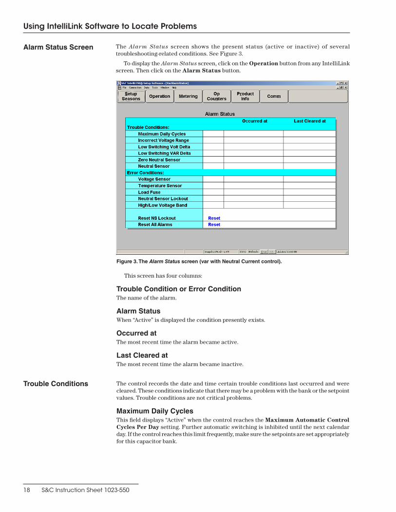
The Alarm Status screen shows the present status (active or inactive) of several troubleshooting-related conditions. See Figure 3.
To display the Alarm Status screen, click on the Operation button from any IntelliLink screen. Then click on the Alarm Status button.
Alarm Status Screen
Figure 3. The Alarm Status screen (var with Neutral Current control).
This screen has four columns:
Trouble Condition or Error ConditionThe name of the alarm.
Alarm StatusWhen “Active” is displayed the condition presently exists.
Occurred atThe most recent time the alarm became active.
Last Cleared atThe most recent time the alarm became inactive.
The control records the date and time certain trouble conditions last occurred and were cleared. These conditions indicate that there may be a problem with the bank or the setpoint values. Trouble conditions are not critical problems.
Maximum Daily CyclesThis field displays “Active” when the control reaches the Maximum Automatic Control Cycles Per Day setting. Further automatic switching is inhibited until the next calendar day. If the control reaches this limit frequently, make sure the setpoints are set appropriately for this capacitor bank.
Trouble Conditions
S&C Instruction Sheet 1023-550 19
Using IntelliLink Software to Locate Problems
Incorrect Voltage RangeThis field displays “Active” when the voltage is not within ±15% of the nominal voltage. Make sure the Nominal Operating Voltage setpoint (on Page 3 of the Setup>General screen) is set correctly.
Low Switching Volt DeltaThis f ield displays “Active” when the actual change in voltage levels dur ing switching is below the minimum percentage of the expected change. The Minimum Percentage of Average Delta Voltage setpoint is on Page 2 of the Setup>General screen. See Instruction Sheet 1023-530, “S&C IntelliCap® Plus Automatic Capacitor Control: Setup,” for more information.
Low Switching Var Delta (var controls only)This field displays “Active” when the actual change in kvar levels during switching is below the minimum percentage of the expected change. The Minimum Percentage of Average Delta kvars setpoint is on Page 2 of the Setup>General screen. See Instruction Sheet 1023-530, “S&C IntelliCap® Plus Automatic Capacitor Control: Setup,” for more information.
Zero Neutral Sensor (neutral current/neutral voltage controls only)For controls with neutral current sensing, this field displays “Active” when the control detects zero neutral current for the duration of the Zero Neutral-Current Detection setpoint.
For controls with neutral voltage sensing, this field displays “Active” when the control detects zero neutral voltage for the duration of the Zero Neutral-Voltage Detection setpoint.
Neutral Sensor (neutral current/neutral voltage controls only)For controls with neutral-current /neutral-voltage sensing, this f ield displays “Active” when the neutral current/neutral voltage is above the alarm level for the duration of the applicable Neutral Change-Time Threshold setpoint.
The Neutral Sensor alarm clears automatically if the problem is corrected before a retry is performed, after a successful retry, or by placing the control into Manual mode. The Neutral Sensor trouble condition is active during a Retry-Time Delay period.
The control records the date and time switch and sensor malfunctions last occurred and were cleared. An error condition requires prompt attention.
Voltage SensorThis field displays “Active” when there is a problem with the voltage sensor or when the sensor readings are outside the valid operating range (± 20% of the nominal voltage).
Temperature SensorThis field displays “Active” when there is a problem with the temperature sensor or when the sensor readings are outside the valid operating range (-40°F to approximately 150°F, or -40°C to 66°C).
Note: A bad temperature sensor does not prevent the control from operating. When the control is in Temperature or Time-Biased Temperature strategy, it reverts to Temperature Sensor Error, Voltage Only strategy, and will switch the bank if a voltage-override condition becomes active.
Load FuseThis f ield displays “Active” when the fuse mounted on the faceplate is blown. This indicates a problem with the wiring to the capacitor switches or with the capacitor switches themselves.
Neutral Sensor LockoutThis field displays “Active” when there is a neutral current or neutral voltage alarm that the control could not clear. The bank remains locked out until the alarm is reset.
Error Conditions
20 S&C Instruction Sheet 1023-550
Using IntelliLink Software to Locate Problems
High/Low Voltage BandThis field displays “Active” when the Bank Voltage Change + Margin average value is greater than the difference between the High-Voltage Override Value setpoint and the Low-Voltage Override Value setpoint for the present season. See Page 1 of the Setup>General screen for more information.
Reset NS LockoutIf the control is locked out because of a neutral sensor error, this field lets you clear the lockout. If the condition persists, the alarm reappears. The Neutral-Sensor Lockout condition will also be reset, and the associated neutral alarms cleared, whenever the control changes operating modes, either from Manual to Automatic mode or from Automatic to Manual mode. When the neutral condition is still present: in Manual mode the control will lockout again and in Automatic mode it will attempt Corrective Action and Retry, if these features are enabled.
Reset Alarms RequestThe Reset All Alarms request attempts to clear all trouble and error conditions. When the condition persists, the alarm will reappear.
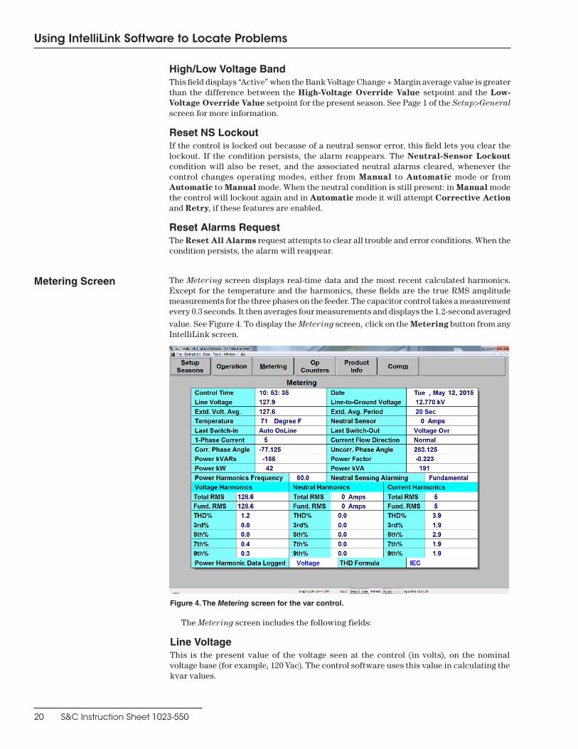
The Metering screen displays real-time data and the most recent calculated harmonics. Except for the temperature and the harmonics, these fields are the true RMS amplitude measurements for the three phases on the feeder. The capacitor control takes a measurement every 0.3 seconds. It then averages four measurements and displays the 1.2-second averaged
value. See Figure 4. To display the Metering screen, click on the Metering button from any IntelliLink screen.
Metering Screen
Figure 4. The Metering screen for the var control.
The Metering screen includes the following fields:
Line VoltageThis is the present value of the voltage seen at the control (in volts), on the nominal voltage base (for example, 120 Vac). The control software uses this value in calculating the kvar values.
S&C Instruction Sheet 1023-550 21
Using IntelliLink Software to Locate Problems
Line-to-Ground Voltage (var controls only)This is the present value of the distribution line voltage (in kV), calculated based on the Voltage Transformer Ratio setpoint and Voltage Transformer Wiring setpoint, on the Setup>Site-Related screen.
TemperatureThis is the present ambient air temperature. The temperature sensor is located on the bottom of the control enclosure.
Neutral SensorFor controls with neutral sensing, this is the present level of neutral current (in amps) or neutral voltage (in volts) measured by the neutral sensor.
Control TimeThis is the present time in the control.
DateThis is the present date in the control.
Last Switch-In or Last Switch-OutThese fields show the reasons for the last switch-in and switch-out event, for example “Timeclock” or “Hardware Manual.”
1-Phase Current (var controls only)This is the current (in amps), measured by the current sensor and scaled using the Current Sensor Ratio setpoint.
Current Flow Direction (var controls only)When the control is properly configured and power is flowing through the circuit in the normal direction, this field displays “Normal.” If unusual circuit switching conditions cause the direction of power flow to reverse, the field displays “Reverse.”
Corr. Phase Angle (var controls only)This is the corrected phase angle, the offset of the current waveform referenced to the voltage after setup correction factors are applied. When the control is properly configured, the corrected phase angles will all be 0 ± 89.9 degrees.
Lagging phase angles are represented as values between 0 and 90 degrees. Leading phase angles are represented as values between 0 and -90 degrees.
Uncorr. Phase Angle (var controls only)This is the phase angle, the offset of the current waveform referenced to the voltage, before setup correction factors are applied.
Power kvars (var controls only)This is the total kvar level measured at the location of the current sensor, calculated as 3 times the single-phase kvar value. This assumes a balanced 3-phase system.
Power Factor (var controls only)This is the power factor calculated as the cosine of the value in the Corrected Phase Angle field. Leading power factors are represented by negative numbers.
Power kW (var controls only)This is the present kW level measured at the location of the current sensor.
Power kVA (var controls only)This is the present kVA level measured at the location of the current sensor.
22 S&C Instruction Sheet 1023-550
Using IntelliLink Software to Locate Problems
Power HarmonicsThe capacitor control calculates the 1st (fundamental), 3rd, 5th, 7th, and 9th harmonics, as well as the total harmonic distortion (THD), every 15 minutes. The Total RMS value is a 24-hour total of all RMS harmonics. When the log is full, each new value overwrites the oldest value in the log.
Harmonics are expressed as a percentage of the fundamental. Total harmonic distor-tion is calculated as the ratio of the total RMS harmonic content to the RMS level of the fundamental.
FrequencyThis is the nominal operating frequency in use. For more information, see Page 3 of the Setup>General screen.
Neutral Sensor AlarmingThis is the component or components of the neutral current used to trigger the Neutral Sensing alarm.
Voltage HarmonicsThis column shows the most recently calculated harmonics for the single-phase voltage powering the control.
Neutral HarmonicsThis column shows the most recently calculated harmonics for the neutral current or neutral voltage where the neutral sensor is installed.
Current Harmonics (var controls only)This column shows the most recently calculated harmonics for the single-phase current where the current sensor is installed.
Power Harmonics Data LoggedThis setpoint selects the type of harmonic data the control records in the Selected Sensor Harmonics Analysis log: voltage, current, or neutral voltage/neutral current, as applicable.
THD FormulaThis setpoint selects the harmonics calculation method for data the control records. The options are IEC (the default) or IEEE.
S&C Instruction Sheet 1023-550 23
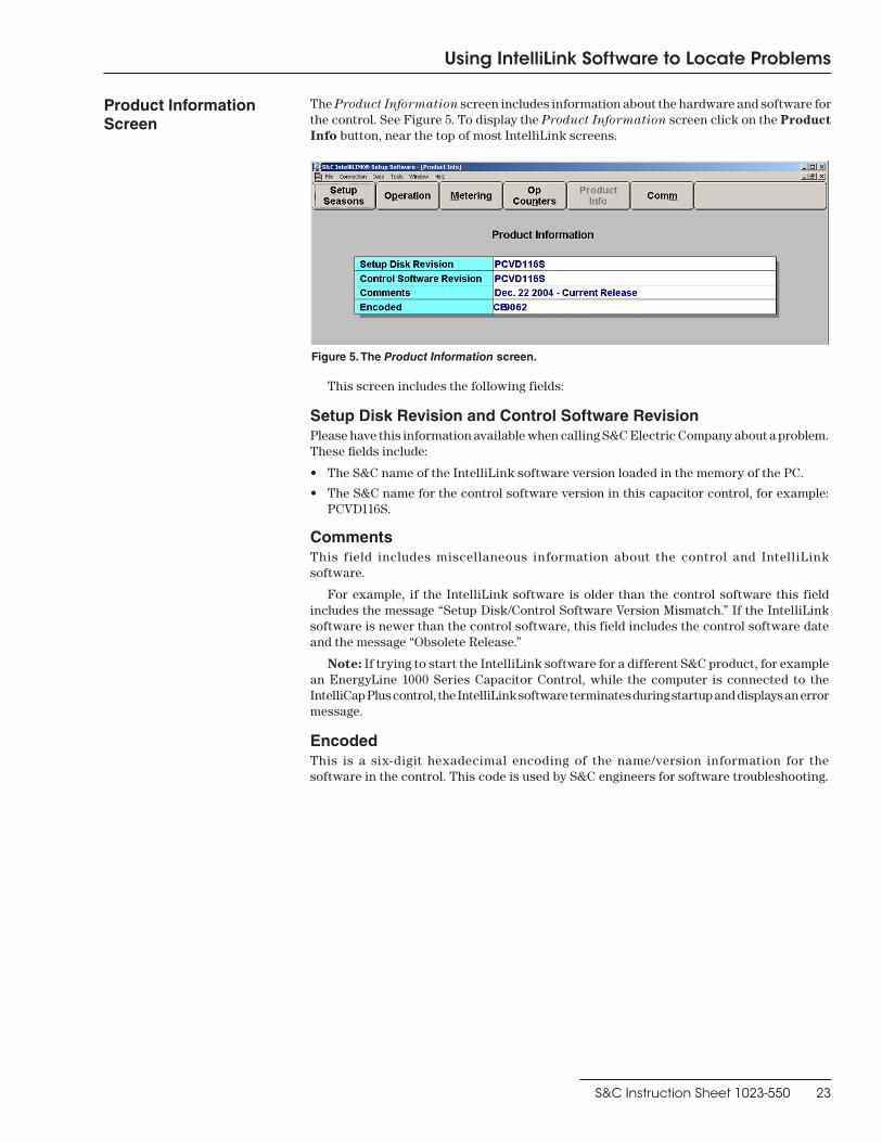
The Product Information screen includes information about the hardware and software for the control. See Figure 5. To display the Product Information screen click on the Product Info button, near the top of most IntelliLink screens.
Product Information Screen
Figure 5. The Product Information screen.
This screen includes the following fields:
Setup Disk Revision and Control Software RevisionPlease have this information available when calling S&C Electric Company about a problem. These fields include:
• The S&C name of the IntelliLink software version loaded in the memory of the PC.
• The S&C name for the control software version in this capacitor control, for example: PCVD116S.
CommentsThis field includes miscellaneous information about the control and IntelliLink software.
For example, if the IntelliLink software is older than the control software this field includes the message “Setup Disk/Control Software Version Mismatch.” If the IntelliLink software is newer than the control software, this field includes the control software date and the message “Obsolete Release.”
Note: If trying to start the IntelliLink software for a different S&C product, for example an EnergyLine 1000 Series Capacitor Control, while the computer is connected to the IntelliCap Plus control, the IntelliLink software terminates during startup and displays an error message.
EncodedThis is a six-digit hexadecimal encoding of the name/version information for the software in the control. This code is used by S&C engineers for software troubleshooting.
Using IntelliLink Software to Locate Problems
24 S&C Instruction Sheet 1023-550
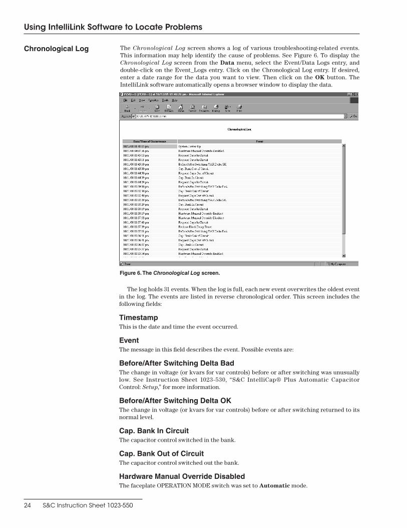
The Chronological Log screen shows a log of various troubleshooting-related events. This information may help identify the cause of problems. See Figure 6. To display the Chronological Log screen from the Data menu, select the Event/Data Logs entry, and double-click on the Event_Logs entry. Click on the Chronological Log entry. If desired, enter a date range for the data you want to view. Then click on the OK button. The IntelliLink software automatically opens a browser window to display the data.
Chronological Log
Figure 6. The Chronological Log screen.
The log holds 31 events. When the log is full, each new event overwrites the oldest event in the log. The events are listed in reverse chronological order. This screen includes the following fields:
TimestampThis is the date and time the event occurred.
EventThe message in this field describes the event. Possible events are:
Before/After Switching Delta BadThe change in voltage (or kvars for var controls) before or after switching was unusually low. See Instruction Sheet 1023-530, “S&C IntelliCap® Plus Automatic Capacitor Control: Setup,” for more information.
Before/After Switching Delta OKThe change in voltage (or kvars for var controls) before or after switching returned to its normal level.
Cap. Bank In CircuitThe capacitor control switched in the bank.
Cap. Bank Out of CircuitThe capacitor control switched out the bank.
Hardware Manual Override DisabledThe faceplate OPERATION MODE switch was set to Automatic mode.
Using IntelliLink Software to Locate Problems
S&C Instruction Sheet 1023-550 25
Hardware Manual Override EnabledThe faceplate OPERATION MODE switch was set to Manual mode.
Hardware Remote SCADA DisabledThe faceplate SCADA CONTROL switch was set to Local mode.
Hardware Remote SCADA EnabledThe faceplate SCADA CONTROL switch was set to Remote mode.
High-/Low-Voltage Band ActiveThe Bank Voltage Rise + Margin value is greater than the difference between the High-Voltage Override Value setpoint and the Low-Voltage Override Value setpoint.
High-/Low-Voltage Band ClearedThe Bank Voltage Change + Margin value, the High-Voltage Override Value setpoint, and the Low-Voltage Override Value setpoint are compatible.
High-/Low-Voltage Band LockoutThe control has blocked further automatic operation of the bank due to a Bank Voltage Change + Margin Value error.
IntelliLink Manual CloseThe user sent a command from the Operation screen to switch the bank in.
IntelliLink Manual OpenThe user sent a command from the Operation screen to switch the bank out.
Line Voltage Outside Operating RangeThe line voltage is outside the range for the Nominal Operating Voltage setpoint noted on Page 3 of the Setup>General screen.
Line Voltage Within Operating RangeThe line voltage is within the range for the Nominal Operating Voltage setpoint noted on Page 3 of the Setup>General screen.
Max Daily Auto Cycles ClearedThe Max Daily Auto Cycles Reached condition has cleared. The condition is cleared at the beginning of each calendar day, when all cycle counters are reset on the Operation Counters screen, and when the control tries to take corrective action after a Neutral Current/Neutral Voltage alarm.
Max Daily Auto Cycles ReachedThe number of automatic switching cycles has reached the Maximum Automatic Control Cycles Per Day setpoint noted on Page 2 of the Setup>General screen.
Request Caps. In Ckt.The capacitor control sent a command to switch in the capacitor bank.
Request Caps. Out of Ckt.The capacitor control sent a command to switch out the capacitor bank.
System Power-UpPower was restored to the capacitor control.
Temperature Sensor BadThe temperature sensor is reading outside of its range or may be faulty.
Using IntelliLink Software to Locate Problems
26 S&C Instruction Sheet 1023-550
Temperature Sensor O.K.A problem with the temperature sensor has cleared.
Voltage Override ActiveA high-voltage or low-voltage condition is present. See Instruction Sheet 1023-530, “S&C IntelliCap® Plus Automatic Capacitor Control: Setup,” for more information.
Voltage Override ClearedA high-voltage or low-voltage condition has cleared.
Voltage Sensor BadThe voltage sensor is reading outside of its range or may be faulty. If the sensor reading is out-of-range on the high end while the control is in Automatic mode, the control switches the capacitor bank open.
Voltage Sensor O.K.A problem with the voltage sensor has cleared.
For controls with var sensing, there are two additional event messages:
Reverse Current DetectedThe capacitor control has detected a reverse-current condition.
Reverse Current ClearedA reverse-current condition has cleared.
For controls with neutral sensing the additional event messages are:
Neutral Sensor Alarm ActiveThe level of neutral current or neutral voltage has caused the Neutral Sensor alarm to trigger. See Instruction Sheet 1023-530, “S&C IntelliCap® Plus Automatic Capacitor Control: Setup,” and Instruction Sheet 1023-540, “S&C IntelliCap® Plus Automatic Capacitor Control: Operation,” for more information.
Neutral Sensor Alarm ClearedThe Neutral Sensor alarm has cleared.
Neutral Sensor Alarm Retry ClearedThe Neutral Sensor alarm retry has cleared.
Neutral Sensor Alarm Retry PendingThe Neutral Sensor alarm retry is pending.
Neutral Sensor Alarm Subsequent Retry CompletedThe Neutral Sensor alarm subsequent retry has completed.
Neutral Sensor Alarm Subsequent Retry PendingThe Neutral Sensor alarm subsequent retry is pending.
Neutral Sensor LockoutNeutral current has caused lockout.
Reset Neutral Sensor LockoutThe neutral sensor lockout has been reset.
Using IntelliLink Software to Locate Problems