Embed Size (px)
Citation preview

Cisco uBR10012 Universal Broadband Router Hardware TOL-24078-01
C H A P T E R 3
Troubleshooting PRE ModulesThis chapter describes how to troubleshoot Performance Routing Engine (PRE) modules. It provides information on troubleshooting PRE fault states, the management Ethernet port, and the serial port.
• Information Required for Troubleshooting PRE Modules, page 3-1
• Upgrading the Primary PRE1 to PRE2 or PRE4 Modules, page 3-2
• PRE Module Status Screen, page 3-2
• Booting Up with Redundant PRE Modules, page 3-4
• PRE Module Faults, page 3-4
• Ethernet Connection Problems, page 3-5
• Console Port Serial Connection Problems, page 3-6
• Troubleshooting Common System Problems, page 3-7
Information Required for Troubleshooting PRE ModulesThe PRE2 module is the primary processor for the Cisco uBR10012 router running the Cisco IOS Release 12.2(33)SC train, and any problems with the PRE2 module affect all operations. However starting from Cisco IOS Release 12.2(33)SCB, PRE4 is widely used in the Cisco uBR10012 routers.
Note Cisco uBR3GX60V cable interface line card is not compatible with PRE2. You must use PRE4 with the Cisco uBR3GX60V cable interface line card.
If you suspect a problem with the PRE2 or PRE4 module, please collect the following information before proceeding further, to aid in troubleshooting the problem:
Step 1 Capture all console logs and system messages.
Step 2 Capture the output of the show tech-support command. Registered users on Cisco.com can decode the output of this command by using the Output Interpreter tool, which is at the following URL:
https://www.cisco.com/cgi-bin/Support/OutputInterpreter/home.pl
Step 3 Capture the complete bootup sequence, especially if the router is reporting errors at bootup.
3-1roubleshooting Guide for Cisco IOS Release 12.2SC

Chapter 3 Troubleshooting PRE ModulesUpgrading the Primary PRE1 to PRE2 or PRE4 Modules
Step 4 If the router is unresponsive, or if it refuses to boot to the Cisco IOS prompt, reboot the router to the ROMMON prompt and capture a stack trace, using the stack ROMMON command. For more information on this procedure, see the Obtaining a Stack Trace from ROM Monitor section in the Troubleshooting Router Hangs document, at the following URL:
http://www.cisco.com/en/US/products/hw/routers/ps359/products_tech_note09186a0080106fd7.shtml
Upgrading the Primary PRE1 to PRE2 or PRE4 ModulesThe Cisco uBR10012 routers running Cisco IOS Release 12.2SC supports only the PRE2 module in Cisco IOS Release 12.2(33)SCA, and later releases and PRE4 module in Cisco IOS Release 12.2(33)SCB, and later releases.
Upgrading a system that currently uses a PRE1 (or earlier processor) requires a hardware upgrade to a PRE2 to run Cisco IOS Release 12.2(33)SCA or later releases. For hardware installation instructions, see the Cisco Performance Routing Engine (ESR-PRE2) Upgrade Installation document at the following URL:
http://www.cisco.com/en/US/docs/interfaces_modules/cable/performance_routing_engine/quick/start/pre2_qsg.html
PRE Module Status ScreenLEDs on the front panel of the PRE provide a visual indication showing the status of PRE operation. The LEDs are separated into three categories:
• Alarms
• Status
• Failure
Figure 3-1 Cisco PRE2 Faceplate
Figure 3-2 Cisco PRE4 Faceplate
7699
5
PERFORMANCE ROUTING ENGINE ESR-PRE2
ALA
RM
S
CIS
CO
1000
0
FAIL
STAT
US
ACO
CR
ITIC
AL
MIN
OR
MAJ
OR
ETH
ERN
ETLI
NK
ACTI
VITY
CO
NSO
LE
AUX
SLOT
1
021
1327
PERFORMANCE ROUTING ENGINE
ALA
RM
S
CIS
CO
1000
0
ACTIVIT
Y
LINK
CRITIC
ALM
AJOR
MIN
OR
ACO
SLOT 0
STATUS
FAIL
BITSETHERNET
AUX
CONSOLE
P/N ESR-PRE4
1 3 7 8 92 106 121154
3-2Cisco uBR10012 Universal Broadband Router Hardware Troubleshooting Guide for Cisco IOS Release 12.2SC
OL-24078-01

Chapter 3 Troubleshooting PRE ModulesPRE Module Status Screen
Alarm relay contacts on the Cisco uBR10012 router connect the router to a site alarm maintenance system. This allows critical, major, and minor alarms generated by the Cisco uBR10012 router to be displayed on both the PRE front panel and to external visual or audible alarms connected to the system. For more information, refer to the Cisco uBR10012 Universal Broadband Router Hardware Installation Guide at the following URL:
http://www.cisco.com/en/US/docs/cable/cmts/ubr10012/installation/guide/hig.html
Pressing the ACO button on the (primary) PRE during an alarm condition shuts off the external alarm, but does not deactivate the alarm LEDs on the PRE front panel. Alarm LEDs on the front panel are deactivated only after the condition that caused the alarm is corrected.
PRE2 and PRE4 Module Status ScreenThe alphanumeric display on the PRE front panel provides information on the state of the PRE. The display consists of two 4-character LED panels. Table 3-1 describes the most common messages. If you report a problem to Cisco, it is helpful to include the message on the PRE alphanumeric display in your problem report.
1 Ejector levers 7 ACO (Alarm Cut-Off button)
2 Console and Auxiliary ports 8 CompactFlash Disk slot
3 Network Management Ethernet (NME) port 9 Slot 0 (disk0) LED
4 NME Activity and Link LEDs 10 STATUS, FAIL LEDs
5Reset button
11Building Internal Timing Source (BITS) LED
6Alarms: CRITICAL, MAJOR, MINOR LEDs 12
Alphanumeric display
Table 3-1 Messages on PRE Alphanumeric Display
Message Status
1111, 2222, 3333, 4444, 5555, 6666, 7777
The PRE4 has just been powered on and is running its power-on self-test.
ROM DONE The PRE4 has loaded the ROM monitor. This message appears briefly if the system is configured to boot a Cisco IOS software image. If the system is not configured to boot Cisco IOS, this message remains on the display and the rommon> prompt appears on the terminal window.
AUTO BOOT The ROM monitor is preparing to boot a Cisco IOS image.
BOOT IMGE A Cisco IOS image is starting to boot.
AUTO BOOT The ROM monitor is preparing to boot a Cisco IOS image.
BOOT IMGE A Cisco IOS image is starting to boot.
3-3Cisco uBR10012 Universal Broadband Router Hardware Troubleshooting Guide for Cisco IOS Release 12.2SC
OL-24078-01

Chapter 3 Troubleshooting PRE ModulesBooting Up with Redundant PRE Modules
Booting Up with Redundant PRE ModulesWhen two PRE modules are installed in the Cisco uBR10012 router, the active PRE module is the one that first loads the Cisco IOS software and asserts control over the shared bus. The other PRE module automatically boots the Cisco IOS software and enters the standby mode.
Typically, the PRE module in slot A (the left-most PRE module slot as you face the chassis) boots the Cisco IOS software more quickly than the PRE module in slot B (the PRE slot on the right). This is because the PRE module in slot B adds a slight delay in its bootup sequence, so as to allow the module in slot A to boot first.
However, the selection of the active PRE module does not affect the operations of the Cisco uBR10012 router. The router can operate normally with either the slot A or the slot B PRE module acting as the active PRE module.
If you notice that the slot B PRE module is always becoming the active PRE module, and you would like the slot A PRE module to become the active PRE module, check for the following:
• Check if the flask disks on active and standby are the same type. If the active disk is an older type, then the standby card can boot faster than the active type.
• If using an ATA-style Flash Disk is not possible, consider booting the Cisco IOS software image from the PRE module’s bootflash memory device.
• Verify that both PRE modules are booting the same version of Cisco IOS software. Slight variations in the loading of different images could allow the slot B PRE module to boot first.
PRE Module FaultsThe following sections describe the module faults or alarms that are generated or displayed on the PRE2 and the PRE4 modules.
IOS STRT, IOS EXC, IOS FPGA, IOS FPOK, IOS FILE, IOS STBY, IOS INTF, IOS MEM, IOS DRVR, IOS LIB, IOS MGMT, IOS PROT, IOS CONF
These messages appear in quick succession during the boot process.
IOS RUN [On the primary PRE4] The PRE4 has finished booting and is running Cisco IOS. This is the normal operating status for the primary PRE.
IOS STBY [On the secondary PRE4] The PRE4 is in standby mode and ready to take over if the primary PRE4 fails. This is the normal operating status for the secondary PRE4.
Table 3-1 Messages on PRE Alphanumeric Display
Message Status
3-4Cisco uBR10012 Universal Broadband Router Hardware Troubleshooting Guide for Cisco IOS Release 12.2SC
OL-24078-01
Chapter 3 Troubleshooting PRE ModulesEthernet Connection Problems
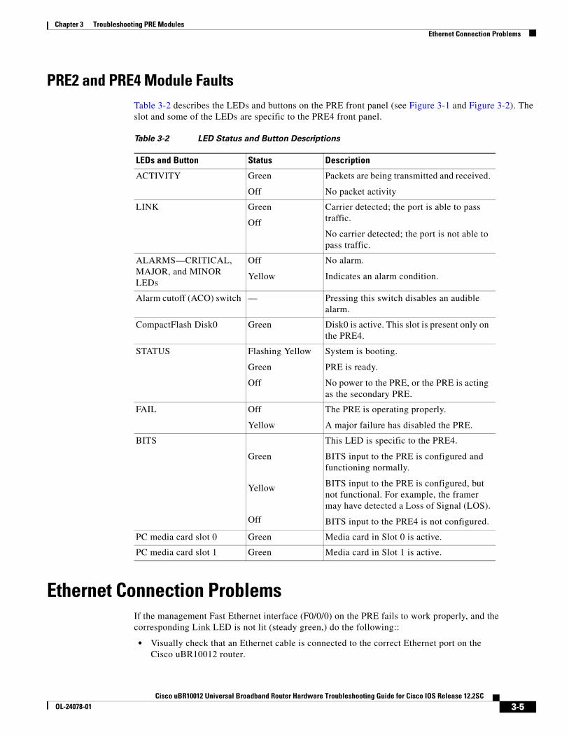
PRE2 and PRE4 Module FaultsTable 3-2 describes the LEDs and buttons on the PRE front panel (see Figure 3-1 and Figure 3-2). The slot and some of the LEDs are specific to the PRE4 front panel.
Ethernet Connection ProblemsIf the management Fast Ethernet interface (F0/0/0) on the PRE fails to work properly, and the corresponding Link LED is not lit (steady green,) do the following::
• Visually check that an Ethernet cable is connected to the correct Ethernet port on the Cisco uBR10012 router.
Table 3-2 LED Status and Button Descriptions
LEDs and Button Status Description
ACTIVITY Green
Off
Packets are being transmitted and received.
No packet activity
LINK Green
Off
Carrier detected; the port is able to pass traffic.
No carrier detected; the port is not able to pass traffic.
ALARMS—CRITICAL, MAJOR, and MINOR LEDs
Off
Yellow
No alarm.
Indicates an alarm condition.
Alarm cutoff (ACO) switch — Pressing this switch disables an audible alarm.
CompactFlash Disk0 Green Disk0 is active. This slot is present only on the PRE4.
STATUS Flashing Yellow
Green
Off
System is booting.
PRE is ready.
No power to the PRE, or the PRE is acting as the secondary PRE.
FAIL Off
Yellow
The PRE is operating properly.
A major failure has disabled the PRE.
BITS
Green
Yellow
Off
This LED is specific to the PRE4.
BITS input to the PRE is configured and functioning normally.
BITS input to the PRE is configured, but not functional. For example, the framer may have detected a Loss of Signal (LOS).
BITS input to the PRE4 is not configured.
PC media card slot 0 Green Media card in Slot 0 is active.
PC media card slot 1 Green Media card in Slot 1 is active.
3-5Cisco uBR10012 Universal Broadband Router Hardware Troubleshooting Guide for Cisco IOS Release 12.2SC
OL-24078-01

Chapter 3 Troubleshooting PRE ModulesConsole Port Serial Connection Problems
• Verify that you are using the correct type of cable for a 100BaseT Ethernet.
• Check to see if the cable is bad or broken.
• Make sure the primary PRE module booted up properly by checking the Status LED on its faceplate. This LED on the primary PRE module should be steady green. If a redundant PRE module is installed, its STATUS LED should be flashing green. If this is not the case with either PRE module, remove and reinsert the module and boot it up again.
Note The show interface command also shows that there is an Ethernet interface (E0/0/0) on the PRE module, but this is an internal interface that the router uses to communicate between PRE modules and line cards. This Ethernet interface is not configurable and can be used only by the router’s internal subsystems.
If the Link LED is lit (steady green), but the Ethernet port is not working properly, make sure that the port in question is configured properly and is not administratively shut down. If you have a working console connection, perform the following steps:
Step 1 At the switch prompt, enter show interface fastethernet0/0/0. If the port is administratively down, enter these commands to enable it:
c10000# configure terminalEnter configuration commands, one per line. End with CNTL/Z.c10000(config)#interface fastethernet0/0/0c10000(config-if)# no shutc10000(config-if)# exitc10000(config)# exitc10000#
Step 2 Check that the Ethernet port in question is assigned a valid IP address.
For more information about configuring Ethernet ports, refer to the Cisco uBR10012 Universal Broadband Router Software Configuration Guide.
If the cable, connections, power, and configuration all check out, and you still cannot connect to the Ethernet port on the module, replace the module in question. If the problem persists, contact the Cisco TAC for further assistance.
Console Port Serial Connection ProblemsIf the console screen connected to a Cisco uBR10012 console port appears frozen or fails to work properly, check the following steps:
Step 1 Refer to the “Cisco uBR10012 System Startup Sequence” section on page 1-4. If the display stops responding during this process, there is no console output.
Step 2 Check the console cable and make sure it is properly connected to the console port on the active PRE module at one end and to your terminal equipment or terminal server at the other end.
Note You cannot connect to the console port on the standby PRE module. You must connect to the console port on the currently active PRE module. If a switchover occurs, you must switch the serial cable to the new active PRE module to maintain the console connection.
3-6Cisco uBR10012 Universal Broadband Router Hardware Troubleshooting Guide for Cisco IOS Release 12.2SC
OL-24078-01

Chapter 3 Troubleshooting PRE ModulesTroubleshooting Common System Problems
Step 3 Verify that you are using the right type of cable and adapter. For information about pin-out connections and installation instructions, refer to the Cisco uBR10012 Universal Broadband Router Hardware Installation Guide.
Step 4 Make sure the cable is not defective or broken. Replace the cable with another high quality cable if possible, and check to see if the console port starts working.
Step 5 Check that the terminal equipment is configured with the correct settings for the console port. The default console port settings are:
• 9600 baud
• 8 data bits
• 1 stop bit
• No parity
• No flow control
Step 6 Check the LEDs on the PRE faceplate to make sure it has powered up properly. If necessary, remove and reinsert both PRE modules to power them up again. Also, make sure the terminal equipment is working properly.
Step 7 The console can appear frozen if the PRE processor is busy performing other tasks, such as parsing a large configuration file or passing a large burst of traffic. These periods are usually only temporary, and normal reaction resumes after a few moments.
Step 8 The console can be frozen if the PRE process is generating a large volume of debug messages. If this is the case, hit the return key a couple of times and type no debug all to attempt to turn off the debug messages. This will not work if the router is in global configuration mode, but try typing do no debug all to execute this EXEC mode command in global configuration mode.
If the cable, connections, power, and terminal settings all check out and you still cannot connect to the console port on the module, replace the module in question. If the problem persists, contact the Cisco TAC for further assistance.
Troubleshooting Common System ProblemsThis section describes how to troubleshoot the following common system problems on the Cisco uBR10012 router:
• Troubleshooting System Crashes, page 3-7
• High CPU Utilization Problems, page 3-8
• Bus Errors, page 3-13
• Memory Problems, page 3-14
Troubleshooting System CrashesSystem crashes occur when the router experiences an unexpected situation from which it cannot recover. In response, the router stops all processes and reloads. Crashes can result from either hardware or software problems.
3-7Cisco uBR10012 Universal Broadband Router Hardware Troubleshooting Guide for Cisco IOS Release 12.2SC
OL-24078-01
Chapter 3 Troubleshooting PRE ModulesTroubleshooting Common System Problems
When the router crashes, it is extremely important to gather as much information as possible about the crash before doing a manual reload or power-cycling the router. All information about the crash, except that which has been stored in the crashinfo file, is lost after a manual reload or power-cycle.
In particular, use the following commands to gather more information about the crash:
• All console, system, and message logs.
• Crashinfo file, if one was generated at the time of the crash.
• All output from the following commands:
– show version
– show context
– show stacks
– show tech-support
Note Registered Cisco.com users can decode the output of these show commands by using the Output Interpreter tool, which is at the following URL:
https://www.cisco.com/cgi-bin/Support/OutputInterpreter/home.pl
For additional information on troubleshooting system crashes, see the following URL:
• Troubleshooting Router Crashes, at the following URL:
http://www.cisco.com/en/US/products/hw/iad/ps397/products_tech_note09186a00800b4447.shtml
High CPU Utilization ProblemsThe PRE module can experience high CPU utilization, where the CPU processor approaches 100% usage for extended periods of time, for several reasons. See the following sections for possible causes and solutions.
• ARP Traffic, page 3-9
• CPUHOG Errors, page 3-10
• Debug and System Messages, page 3-10
• Exec and Virtual Exec Processes, page 3-11
• Interrupts are Consuming a Large Amount of Resources, page 3-11
• Invalid Scheduler Allocate Configuration, page 3-12
• IP Input Processing, page 3-12
• One or More Processes is Consuming an Excessive Amount of Resources, page 3-12
• Problems with Access Lists, page 3-12
• SNMP Traffic, page 3-13
Also see the Troubleshooting High CPU Utilization on Cisco Routers document, which is at the following URL:
http://www.cisco.com/en/US/products/hw/routers/ps133/products_tech_note09186a00800a70f2.shtml
3-8Cisco uBR10012 Universal Broadband Router Hardware Troubleshooting Guide for Cisco IOS Release 12.2SC
OL-24078-01

Chapter 3 Troubleshooting PRE ModulesTroubleshooting Common System Problems
ARP Traffic
High volumes of Address Resolution Protocol (ARP) requests and responses can occupy a significant portion of the CPU time, because the router cannot use fast-switching to process ARP packets, but must instead forward them to the route processor (RP). Because of this, processing a large volume of ARP traffic can also prevent the router from handling normal traffic.
Theft-of-service and denial-of-service (DoS) attacks also often generate a large number of ARP packets on the network. Many viruses also use ARP requests to discover computers that might be vulnerable to attack, and if these computers become infected, they are used to propagate the virus, generating even more ARP traffic on the network.
ARP requests are broadcast packets, so they are broadcast to all devices on that particular network segment. In some cases, a router can also forward ARP broadcasts to an ARP proxy for further processing. Some low-end routers commonly used by subscribers for home networks can also incorrectly respond to all ARP requests, which generates even more traffic.
In addition, the Cisco CMTS router automatically monitors ARP traffic and enters the IP addresses found in ARP requests into its own ARP table, in the expectation that a device will eventually be found with that IP address. Unacknowledged IP addresses remain in the router’s ARP table for 60 seconds, which means that a large volume of ARP traffic can fill the router’s ARP table.
If ARP traffic is excessive, you can try the following ways to limit this traffic:
Step 1 Disable the forwarding of ARP requests on a cable interface by using the no cable arp command in interface configuration mode.
Step 2 Disable the use of proxy-ARP on a cable interface by using the no cable proxy-arp command in interface configuration mode.
Note Using the no cable arp and no cable proxy-arp commands shifts all responsibility for the management of the IP addresses used by CMs and CPE devices to the DHCP server and provisioning system.
Another approach would be to identify the cable modems and customer premises equipment (CPE) that are generating the ARP traffic. A simple way of doing this is by using an access list to log requests for an unassigned IP address in the subnet being used on a cable interface.
Step 1 Reserve at least one IP address on each cable interface’s subnet and ensure that it is not being assigned to any cable modems or CPE devices. For example, if a cable interface is using the subnet 192.168.100.0/24, you could choose to reserve IP address 192.168.100.253 for this purpose. Ensure that the IP addresses you have chosen are not assigned to devices by your provisioning system.
Step 2 If you currently have an access list applied to the cable interface, add a line that logs requests for this particular IP address. If you are not currently using an access list on the cable interface, create one for this purpose. In both cases, the relevant line would be:
Router(config)# access-list number permit ip any host 192.168.100.253 log
where number is the number for the access-list. Change the IP address to whatever address you have selected to be reserved for this cable interface.
3-9Cisco uBR10012 Universal Broadband Router Hardware Troubleshooting Guide for Cisco IOS Release 12.2SC
OL-24078-01

Chapter 3 Troubleshooting PRE ModulesTroubleshooting Common System Problems
Note If you are creating a new access list, ensure that the last line of the list is access-list number permit ip any any. Otherwise, all other traffic will be blocked on the interface.
Step 3 Apply the access list to the cable interface using the ip access-group command:
Router(config-if)# ip access-group number in
Step 4 After applying the access list, regularly examine the message log to find the devices that are attempting to access the reserved IP address. If a cable modem or CPE device is repeatedly sending ARP requests or replies for this IP address, it could be part of a virus or theft-of-service attack, or it could indicate a cable modem with defective software.
Step 5 After identifying these devices, you can further investigate the matter, and if necessary, block these devices from further network access.
Note Besides using the access list to suppress ARP traffic, we have a separate "arp-filter" feature to filter and perform rate-limit for the congested ARP traffic. See Cable ARP Filtering feature guide for more information at: http://www.cisco.com/en/US/docs/ios/cable/configuration/guide/cmts_cbl_arp_fltr.html
CPUHOG Errors
The router displays a %SYS-3-CPUHOG error message when a process is using an excessive amount of processor cycles. For example, using the logging buffered command to allocate a significant amount of memory (for example, 200 MB) for log buffers could generate a %SYS-3-CPUHOG message, because allocating such an amount of memory requires a large amount of processor time.
For more information on what could cause this problem and how to resolve it, see the document What Causes %SYS-3-CPUHOG Messages, at the following URL:
http://www.cisco.com/en/US/products/hw/iad/ps397/products_tech_note09186a00800a6ac4.shtml
Debug and System Messages
A large volume of debugging messages or system messages can take a significant amount of processor time, because the PRE module must spend a significant amount of time displaying these messages on the console port. In particular, this can happen when using the verbose or detail mode of a debug command, or if the debug command is dumping the contents of packets or packet buffers.
Use the following techniques to reduce the number of these messages:
1. Turn off the debugging messages by entering the no debug all command in privileged EXEC mode:
Router# no debug all All possible debugging has been turned off
Router#
2. Disable console messages by using the no logging console command in global configuration mode:
Router# configure terminal Router(config)# no logging console Router(config)#
3-10Cisco uBR10012 Universal Broadband Router Hardware Troubleshooting Guide for Cisco IOS Release 12.2SC
OL-24078-01

Chapter 3 Troubleshooting PRE ModulesTroubleshooting Common System Problems
To keep the logging of console messages, but to limit the number of messages that can be displayed, use the logging rate-limit command. You can rate-limit all messages (including debug messages), or just the console messages, using one of the following commands:
Router(config)# logging rate-limit console number-of-messages-per-second
Router(config)# logging rate-limit all number-of-messages-per-second
3. If you have logged into the router using a Telnet connection, you can disable debug messages using the terminal default monitor command in privileged EXEC mode:
Router# terminal default monitor Router#
You can also filter the log messages that will be dumped to console using the logging console command in the global configuration mode.
Router(config)#logg console ?0-7 Logging severity levelalerts Immediate action needed (severity=1)critical Critical conditions (severity=2)debugging Debugging messages (severity=7)discriminator Establish MD-Console associationemergencies System is unusable (severity=0)errors Error conditions (severity=3)guaranteed Guarantee console messagesinformational Informational messages (severity=6)notifications Normal but significant conditions (severity=5)warnings Warning conditions (severity=4)xml Enable logging in XML
Exec and Virtual Exec Processes
The Exec process is the Cisco IOS process that handles the TTY serial lines (console, auxiliary, asynchronous), and the Virtual Exec process handles the Virtual TTY (VTY) Telnet sessions. These processes run as mid-level processes, so if either one is exceptionally busy, it could generate a high CPU usage level.
For information on resolving problems with high CPU usage caused by the Exec and Virtual EXEC processes, see the High CPU Utilization in Exec and Virtual Exec Processes document, at the following URL:
http://www.cisco.com/en/US/products/hw/routers/ps359/products_tech_note09186a00801c2ae4.shtml
Interrupts are Consuming a Large Amount of Resources
Interrupts allow software processes to request resources when needed, as opposed to waiting for time to be allocated to the process. If a process requests too many interrupts, however, it could impact CPU usage, resulting in less time available to other processes.
For more information, see the Troubleshooting High CPU Utilization Due to Interrupts document, at the following URL:
http://www.cisco.com/en/US/products/hw/routers/ps359/products_tech_note09186a00801c2af0.shtml
3-11Cisco uBR10012 Universal Broadband Router Hardware Troubleshooting Guide for Cisco IOS Release 12.2SC
OL-24078-01

Chapter 3 Troubleshooting PRE ModulesTroubleshooting Common System Problems
Invalid Scheduler Allocate Configuration
The scheduler allocate command guarantees the minimum amount of time that can be allocated for fast-switching during each network interrupt context, and the minimum amount of time that can be allocated for non-interrupt-driven processes. An incorrect configuration for the scheduler allocate command can cause high CPU usage, especially when too much time is allocated for non-interrupt processes. This could result in messages such as %IPCGRP-6-NOKEEP: Too long since a keepalive was received from the PRE.
We recommend using the default configuration, which can be restored by giving the default scheduler allocate command in global configuration mode:
Router(config)# default scheduler allocate Router(config)#
IP Input Processing
The Cisco IOS software uses a process named IP input to process IP packets that cannot be processed using the fast-switching process. If the router is process-switching a lot of IP traffic, it could result in excessively high CPU usage.
The most common reasons for excessive IP Input processing are that fast-switching has been disabled on one or more interfaces, and that the router is receiving a large volume of traffic that must be process-switched. For more information on resolving problems with the IP Input process, see the Troubleshooting High CPU Utilization in IP Input Process document at the following URL:
http://www.cisco.com/en/US/products/hw/routers/ps359/products_tech_note09186a00801c2af3.shtml
One or More Processes is Consuming an Excessive Amount of Resources
High CPU usage could occur if one or more processes is consuming an excessive amount of resources. For example, the router might have an excessive number of TCP connections open, or the TTY background process is busy displaying logging or debugging messages.
For more information, see the Troubleshooting High CPU Utilization Due to Processes document, at the following URL:
http://www.cisco.com/en/US/products/hw/routers/ps359/products_tech_note09186a00801c2af6.shtml
Problems with Access Lists
The PRE module could experience high CPU usage if the router has been configured with an access list (ACL) that is too complex or inefficiently written. Access lists are processed for top-down, starting with the first entry in the list and continuing through each entry until a match is found. The router can easily reach high CPU usage if it has to process dozens or hundreds of ACL entries for each packet it receives or transmits.
To resolve the problem, reorganize the list so that the most frequently matched entries are listed first. Also examine the list to see if multiple statements can be consolidated into a single entry. For example, instead of listing multiple addresses on the same subnet, use one entry with a wildcard mask that matches all of the individual addresses.
Consider using the Turbo ACL feature, which compiles the access lists so that they can be searched more efficiently. Enable the use of Turbo ACLs by giving the access-list compiled command in global configuration mode.
3-12Cisco uBR10012 Universal Broadband Router Hardware Troubleshooting Guide for Cisco IOS Release 12.2SC
OL-24078-01
Chapter 3 Troubleshooting PRE ModulesTroubleshooting Common System Problems
For more information on access lists, see the Configuring IP Services chapter in the IP Addressing and Services section of the Cisco IOS IP Configuration Guide, Release 12.2, at the following URL:
http://www.cisco.com/en/US/docs/ios/12_2/ip/configuration/guide/1cfip.html
Tip If you are using Ciscoworks to manage your network, consider using the Ciscoworks Access Control List Manager to manage access lists.
SNMP Traffic
High volumes of Simple Network Management Protocol (SNMP) traffic can occupy a significant portion of the CPU time, as the processor receives SNMP requests and sets the appropriate attributes on the router, or sends the appropriate information back to the SNMP manager. For information on controlling SNMP traffic, see the Application Note, IP Simple Network Management Protocol (SNMP) Causes High CPU Utilization, at the following URL:
http://www.cisco.com/en/US/tech/tk648/tk362/technologies_tech_note09186a00800948e6.shtml
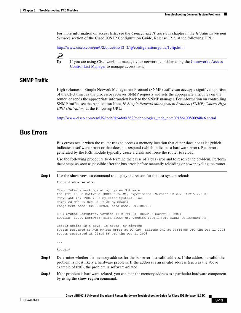
Bus ErrorsBus errors occur when the router tries to access a memory location that either does not exist (which indicates a software error) or that does not respond (which indicates a hardware error). Bus errors generated by the PRE module typically cause a crash and force the router to reload.
Use the following procedure to determine the cause of a bus error and to resolve the problem. Perform these steps as soon as possible after the bus error, before manually reloading or power cycling the router.
Step 1 Use the show version command to display the reason for the last system reload:
Router# show version
Cisco Internetwork Operating System Software IOS (tm) 10000 Software (UBR10K-P6-M), Experimental Version 12.2(20031215:22350]Copyright (c) 1986-2003 by cisco Systems, Inc.Compiled Mon 15-Dec-03 17:28 by mnagaiImage text-base: 0x60008968, data-base: 0x61B80000
ROM: System Bootstrap, Version 12.0(9r)SL2, RELEASE SOFTWARE (fc1)BOOTLDR: 10000 Software (C10K-EBOOT-M), Version 12.0(17)ST, EARLY DEPLOYMENT RE)
ubr10k uptime is 6 days, 18 hours, 59 minutesSystem returned to ROM by bus error at PC 0x0, address 0x0 at 04:15:55 UTC Thu Dec 11 2003 System restarted at 04:18:56 UTC Thu Dec 11 2003
...
Router#
Step 2 Determine whether the memory address for the bus error is a valid address. If the address is valid, the problem is most likely a hardware problem. If the address is an invalid address (such as the above example of 0x0), the problem is software-related.
Step 3 If the problem is hardware-related, you can map the memory address to a particular hardware component by using the show region command.
3-13Cisco uBR10012 Universal Broadband Router Hardware Troubleshooting Guide for Cisco IOS Release 12.2SC
OL-24078-01

Chapter 3 Troubleshooting PRE ModulesTroubleshooting Common System Problems
Router# show region
Region Manager:
Start End Size(b) Class Media Name 0x0A000000 0x0FFFFFFF 100663296 Iomem R/W iomem 0x2A000000 0x2FFFFFFF 100663296 Iomem R/W iomem:(iomem_cwt) 0x60000000 0x69FFFFFF 167772160 Local R/W main 0x60008968 0x61B7FFFF 28800664 IText R/O main:text 0x61B80000 0x61CC1ADF 1317600 IData R/W main:data 0x61CC1AE0 0x627663BF 11159776 IBss R/W main:bss 0x627663C0 0x69FFFFFF 126458944 Local R/W main:heap 0x70000000 0x7FFFFFFB 268435452 Local R/W heap2 0x80000000 0x89FFFFFF 167772160 Local R/W main:(main_k0) 0xA0000000 0xA9FFFFFF 167772160 Local R/W main:(main_k1)
Router#
Step 4 When you have identified the hardware that is generating the bus error, try removing and reinserting the hardware into the chassis. If this does not correct the problem, replace the DRAM chips on the hardware. If the problem persists, replace the hardware.
Step 5 If the problem is software-related, verify that you are running a released version of software, and that this release of software supports all of the hardware that is installed in the router. If necessary, upgrade the router to the latest version of software.
Step 6 To further troubleshoot the problem, registered users on Cisco.com can also decode the output of multiple show commands by using the Output Interpreter tool, which is at the following URL:
https://www.cisco.com/cgi-bin/Support/OutputInterpreter/home.pl
Tip The most effective way of using the Output Interpreter tool is to capture the output of the show stacks and show tech-support commands and upload the output into the tool. If the problem appears related to a line card, you can also try decoding the show context command.
For more information on troubleshooting bus errors, see the Troubleshooting Bus Error Crashes document, at the following URL:
http://www.cisco.com/en/US/products/sw/iosswrel/ps1831/products_tech_note09186a00800cdd51.shtml
Memory ProblemsThis section describes the following types of memory problems:
• Alignment Errors, page 3-15
• Low Memory Errors, page 3-15
• Memory Parity Errors, page 3-16
• Particle Pool Fallbacks, page 3-17
• Spurious Interrupts, page 3-18
• Spurious Memory Accesses, page 3-18
3-14Cisco uBR10012 Universal Broadband Router Hardware Troubleshooting Guide for Cisco IOS Release 12.2SC
OL-24078-01

Chapter 3 Troubleshooting PRE ModulesTroubleshooting Common System Problems
Alignment Errors
Alignment errors occur when the software attempts to read or write data using a data size that is not aligned with the memory address being used. For example, an alignment error occurs when attempting to read two bytes from a memory address that is not an even multiple of two bytes.
Alignment errors are always caused by a software bug, and can be either correctable or fatal. See the following sections for more information. Also see the document Troubleshooting Spurious Accesses, Alignment Errors, and Spurious Interrupts, at the following URL:
http://www.cisco.com/en/US/products/sw/iosswrel/ps1828/products_tech_note09186a00800a65d1.shtml
Correctable Alignment Errors
The Cisco IOS software can automatically correct most alignment errors. When it does so, the router generates a system error message similar to the following:
%ALIGN-3-CORRECT: Alignment correction made at 0x60262478 reading/writing 0x60A9FF5C
Occasional alignment errors do not necessarily require operator intervention, because the Cisco IOS software can correct these errors and continue with normal operations. However, correcting alignment errors consumes processor resources and could impact performance if the errors continuously repeat.
Fatal Alignment Errors
If the alignment error was a fatal error, it displays a message similar to the following:
%ALIGN-1-FATAL: Corrupted program counter error. ERROR: Slot 0, NPE300/IOFE2/VXR, CACHE, External Data Cache Memory Test:
*** Data Expected= 0x99999999 ***
Fatal alignment errors are most likely a hardware fault on the processor card. The card itself could be faulty, or the memory on the card could be faulty. Try replacing the processor card and rebooting the router. If a replacement card is not available, try replacing the memory on the processor card, making sure that the new memory meets the specifications that are required by the card.
Low Memory Errors
The router can experience low memory errors for a number of reasons, including the following possible causes:
• The router is handling an excessively large volume of traffic. In particular, the router could be experiencing a large volume of traffic that requires special handling, such as ARP requests.
• Abnormal processes are using excessive amounts of memory.
• Large amounts of memory are still allocated to dead processes.
• Software errors could have resulted in memory leaks.
• Hardware problems with the memory on the processor card or line card.
• Hardware problems on the processor card or line card.
Low memory problems are usually indicated by one or more system messages (for example, SYS-2-MALLOCFAIL). For troubleshooting steps to resolve problems with low memory, see the Tech Note titled Troubleshooting Memory Problems, at the following URL:
3-15Cisco uBR10012 Universal Broadband Router Hardware Troubleshooting Guide for Cisco IOS Release 12.2SC
OL-24078-01

Chapter 3 Troubleshooting PRE ModulesTroubleshooting Common System Problems
http://www.cisco.com/en/US/products/sw/iosswrel/ps1831/products_tech_note09186a00800a6f3a.shtml
Memory Parity Errors
A memory parity error means that one or more bits at a memory location were unexpectedly changed after they were originally written. This error could indicate a potential problem with the Dynamic Random Access Memory (DRAM) that is onboard the PRE module.
Parity errors are not expected during normal operations and might force the router to reload. If the router did reload because of a parity error, the show version command displays a message such as “System restarted by processor memory parity error” or “System restarted by shared memory parity error.” For example:
Router# show version
Cisco Internetwork Operating System Software IOS (tm) 10000 Software (UBR10K-P6-M), Experimental Version 12.2(20031215:22350]Copyright (c) 1986-2003 by cisco Systems, Inc.Compiled Mon 15-Dec-03 17:28 by mnagaiImage text-base: 0x60008968, data-base: 0x61B80000
ROM: System Bootstrap, Version 12.0(9r)SL2, RELEASE SOFTWARE (fc1)BOOTLDR: 10000 Software (C10K-EBOOT-M), Version 12.0(17)ST, EARLY DEPLOYMENT RE)
ubr10k uptime is 6 days, 18 hours, 59 minutesSystem returned to ROM by processor memory parity error at PC 0x60301298, address 0x0 at 17:19:47 PDT Mon Dec 15 2003System restarted at 17:19:47 PDT Mon Dec 15 2003
...
Router#
Parity errors can be categorized in two different ways:
• Soft parity errors occur when an energy level within the DRAM memory changes a bit from a one to a zero, or a zero to a one. Soft errors are rare and are most often the result of normal background radiation. When the CPU detects a soft parity error, it attempts to recover by restarting the affected subsystem, if possible. If the error is in a portion of memory that is not recoverable, it could cause the system to crash. Although soft parity errors can cause a system crash, you do not need to swap the board or any of the components, because the problem is not defective hardware.
• Hard parity errors occur when a hardware defect in the DRAM or processor board causes data to be repeatedly corrupted at the same address. In general, a hard parity error occurs when more than one parity error in a particular memory region occurs in a relatively short period of time (several weeks to months).
When parity occurs, take the following steps to resolve the problem:
Step 1 Determine whether this is a soft parity error or a hard parity error. Soft parity errors are 10 to 100 times more frequent than hard parity errors. Therefore, wait for a second parity error before taking any action. Monitor the router for several weeks after the first incident, and if the problem reoccurs, assume that the problem is a hard parity error and proceed to the next step.
Step 2 When a hard parity error occurs (two or more parity errors at the same memory location), try removing and reinserting the PRE module, making sure to fully insert the card and to securely tighten the restraining screws on the front panel.
3-16Cisco uBR10012 Universal Broadband Router Hardware Troubleshooting Guide for Cisco IOS Release 12.2SC
OL-24078-01

Chapter 3 Troubleshooting PRE ModulesTroubleshooting Common System Problems
Step 3 If this does not resolve the problem, remove and reseat the DRAM chips. If the problem continues, replace the DRAM chips.
Step 4 If parity errors occur, the problem is either with the PRE module or the router chassis. Replace the PRE module.
Step 5 If the problems continue, contact Cisco TAC for further instructions.
For more information about parity errors, see the Processor Memory Parity Errors document, at the following URL:
http://www.cisco.com/en/US/products/hw/routers/ps341/products_tech_note09186a0080094793.shtml
Particle Pool Fallbacks
Private particle pools are buffers in I/O memory that store packets while they are being processed. The Cisco IOS software allocates a fixed number of private particle pools during system initialization, and these buffers are reserved for packet use, so as to minimize system contention for memory resources.
The system uses buffer control structures called “rings” to manage the entries in the particle pools. Each ring is a circular linked-list of pointers to each packet in the particle pool. The system creates a pair of rings for each interface, with one ring for packets waiting to be transmitted and another ring for packets that are being received.
The system also allocates public pools in a number of different sizes for more general use. If a packet requires special handling, or if a packet cannot be completely processed at interrupt time, the system copies the packet into a portion of contiguous memory in the public pool, so it can be processed switched.
Tip Use the show buffers command to display the current status of the router’s particle pools.
Fallbacks with particle pools occur when bursts of traffic produce more packets than would fit in the available buffer space. When an interface runs out of space in the private particle pools, it falls back to using the normal public memory. Fallbacks are expected during periods of bursty traffic, and the router should be considered to be operating normally in these situations.
If fallbacks occur more frequently, however, it could indicate a problem. In particular, if the private particle pools are consistently producing fallbacks, it could result in the router using excessive amounts of public memory for packet processing, reducing the resources that are available to the other router processes. If this is the case, look for the following possible causes.
• Extremely fast interfaces are handling large volumes of traffic with a high rate of throughput that is approaching the maximum rate on the interface.
• The Fast Ethernet interfaces on the processor card could be heavily loaded.
• The Cisco IOS software has a memory leak that is not releasing the memory in the private particle pool after the interface has finished processing a packet.
For more information on resolving problems with particle pool buffers, see the document Buffer Tuning, at the following URL:
http://www.cisco.com/en/US/products/hw/routers/ps133/products_tech_note09186a00800a7b80.shtml
3-17Cisco uBR10012 Universal Broadband Router Hardware Troubleshooting Guide for Cisco IOS Release 12.2SC
OL-24078-01

Chapter 3 Troubleshooting PRE ModulesTroubleshooting Common System Problems
Also see the document Troubleshooting Buffer Leaks, at the following URL:
http://www.cisco.com/en/US/products/hw/iad/ps397/products_tech_note09186a00800a7b85.shtml
Spurious Interrupts
A spurious interrupt occurs when the Cisco IOS software generates an unnecessary interrupt for packet that has been processed already. This is a software error that is usually caused by an improper initialization of interrupt handling routines, or by a race condition where two processes compete to handle the same process.
Spurious interrupts can occasionally be expected during normal operations, and the occasional spurious interrupt has no discernible impact on the router’s performance. However, action might be needed if the number of spurious interrupts is high or increasing, and performance is being degraded, with packets being dropped.
For information on resolving the problem with spurious interrupts, see the document Troubleshooting Spurious Accesses, Alignment Errors, and Spurious Interrupts, at the following URL:
http://www.cisco.com/en/US/products/sw/iosswrel/ps1828/products_tech_note09186a00800a65d1.shtml
Spurious Memory Accesses
A spurious memory access occurs when a Cisco IOS software process attempts to access memory in the lowest 16 KB region of memory, which is a restricted location. Typically, such errors display a system error message similar to the following:
%ALIGN-3-SPURIOUS: Spurious memory access made at 0x60968C44 reading 0x0%ALIGN-3-TRACE: -Traceback= 60968C44 60269808 602389D8 00000000 00000000 00000000 00000000 00000000
Where possible, the Cisco IOS software handles spurious memory accesses by returning a value of zero to the calling routine, and then displaying the above error message. If this is not possible, the router crashes with a Segment Violation (SegV) error. In either case, the cause of the error is almost always a bug in the Cisco IOS software.
If possible, upgrade to the latest release of the Cisco IOS software. If the bug still exists on the router, see the section Spurious Accesses in the document Troubleshooting Spurious Accesses, Alignment Errors, and Spurious Interrupts, at the following URL:
http://www.cisco.com/en/US/products/sw/iosswrel/ps1828/products_tech_note09186a00800a65d1.shtml
3-18Cisco uBR10012 Universal Broadband Router Hardware Troubleshooting Guide for Cisco IOS Release 12.2SC
OL-24078-01