Embed Size (px)
Citation preview
www.alliancelaundry.com
Trou
blesh
ooting
Part No. 70422201R1April 2013
Tumble Dryers120 Pound Capacity170 Pound Capacity200 Pound Capacity
Models Starting Serial No. 0907003062Refer to Page 6 for Model Numbers
TMB1268C

© Copyright 2013, Alliance Laundry Systems LLC
All rights reserved. No part of the contents of this book may be reproduced or transmitted in any form or by any means without the expressed written consent of the publisher.
70422101R1 1© Copyright, Alliance Laundry Systems LLC – DO NOT COPY or TRANSMIT
Table of Contents
Section 1 – Safety Information .......................................................... 3Locating an Authorized Service Person ............................................... 5Safety Warnings and Decals ................................................................. 5Safety Precautions for Servicing Tumblers .......................................... 5
Section 2 – Introduction ..................................................................... 6Model Identification ............................................................................. 6Customer Service.................................................................................. 8Serial Plate Location............................................................................. 8How a Tumble Dryer Works ................................................................ 9Fire Suppression System Theory of Operation..................................... 10Temperature Sensor .............................................................................. 11
Section 3 – Troubleshooting............................................................... 131. Motor Does Not Start............................................................... 142. Motor Overload Protector Cycles Repeatedly ......................... 153. Motor Runs But Cylinder Does Not Turn................................ 164. Motor Does Not Stop ............................................................... 175. No Heat Condition (Non-CE and Non-Australian Models)..... 186. No Heat Condition ................................................................... 197. Gas Burner Does Not Ignite..................................................... 208. Burner Ignites and Goes Out Repeatedly................................. 219. Burner Shuts off Prematurely .................................................. 22
10. Burner Repeatedly Cycles Off On High Limit Thermostat ..... 2311. Steam Valve or Burner Does Not Shut-off .............................. 2412. Clothes Do Not Dry ................................................................. 2513. Tumble Dryer Overheating ...................................................... 2614. Burners Not Burning Properly - Gas Models........................... 2715. Loading Door Opens During Operation................................... 2816. Tumble Dryer Runs But No Steam To Coils –
Steam Models........................................................................... 2917. Water In Steam Line – Steam Models ..................................... 3018. Tumble Dryer Will Not Start, Time On Drying Timer, Door
Closed....................................................................................... 3119. Motor Runs But Will Not Heat ................................................ 3420. Cylinder Turns, But Will Not Heat.......................................... 3521. Cylinder Is “Stained” ............................................................... 37
Section 4 – Fire Supression System Troubleshooting...................... 3822. Tumble Dryer Does Not Operate and Light Is On................... 3923. Water Discharge, but No Fire .................................................. 4024. Tumble Dryer Does Not Operate and Light Is Off .................. 4125. Tumble Dryer Operates, but Water Does Not Discharge
and Light Is On ........................................................................ 42
Section 5 – Adjustments ..................................................................... 4426. Main Gas Burner Air Inlet Shutters (All Gas Models) ............ 4427. Airflow Switch......................................................................... 45

2 70422101R1© Copyright, Alliance Laundry Systems LLC – DO NOT COPY or TRANSMIT
28. Loading Door Catch (120 and 170 Pound Models) ................. 4529. Loading Door Strike (200 Pound Models)............................... 4630. Belt Drive................................................................................. 4631. Cylinder Clearance................................................................... 4732. Drive Belt Tension ................................................................... 4933. Fan Belt Tension ...................................................................... 50
Section 6 – Hybrid Timer Control Troubleshooting ....................... 5134. Control Has No Display........................................................... 5235. Display Flashes “dr” With Door Closed .................................. 5436. Motor Will Not Start/Run ........................................................ 5637. Unit Will Not Heat – Gas......................................................... 5838. Error Codes .............................................................................. 61
Section 7 – On Premise Micro Control (RM) Troubleshooting .................................................................................. 62
39. Control Has No Display........................................................... 6340. Door Open Indicator ................................................................ 6541. Motor Will Not Start/Run ........................................................ 6842. Unit Will Not Heat – Gas/Steam ............................................. 7043. Error Codes .............................................................................. 73
Section 8 – LED OPL and UniLinc Troubleshooting...................... 7444. No Fan Motor Rotation ............................................................ 7545. No Drive Motor Rotation......................................................... 7846. Stove and Cabinet Limit Errors ............................................... 8147. No Display ............................................................................... 8348. Airflow Errors .......................................................................... 8549. Fan Motor Centrifugal Switch Error........................................ 8750. Close Door Indication .............................................................. 8951. Moisture Sensor Error.............................................................. 91
Troubleshooting the Moisture Sensor Circuit....................................... 9352. Troubleshooting at the Control ................................................ 9353. Troubleshooting From Control to Slip Ring Assembly ........... 9554. Troubleshooting At Slip Ring Assembly ................................. 9755. Troubleshooting From Slip Ring Assembly to Moisture
Sensing Baffle and Basket ....................................................... 9756. Troubleshooting from Basket Shaft to Moisture Sensing
Baffle with Machine Basket Removed .................................... 9757. Troubleshooting at the Moisture Sensing Baffles with
Machine Basket Removed ....................................................... 9858. Fan Motor Contactor Error ...................................................... 9959. Rotation Sensor Error............................................................... 10160. Shorted or Open Thermistor .................................................... 10361. Fuses and Transformer Configuration Jumper......................... 10562. Dip Switch/Harness Index Mismatch ...................................... 10663. Electronic Control Testing ....................................................... 10764. Diagnostic Testing ................................................................... 115
70422201R1 3© Copyright, Alliance Laundry Systems LLC – DO NOT COPY or TRANSMIT
Section 1Safety Information
Throughout this manual and on machine decals, you will find precautionary statements (“CAUTION”, “WARNING”, and “DANGER”) followed by specific instructions. These precautions are intended for the personal safety of the operator, user, servicer, and those maintaining the machine.
Additional precautionary statements (“IMPORTANT” and “NOTE”) are followed by specific instructions.
IMPORTANT: The word “IMPORTANT” is used to inform the reader of specific procedures where minor machine damage will occur if the procedure is not followed.
NOTE: The word “NOTE” is used to communicate installation, operation, maintenance or servicing information that is important but not hazard related.
In the interest of safety, some general precautions relating to the operation of this machine follow.
Danger indicates an imminently hazardous situation that, if not avoided, will cause severe personal injury or death.
DANGER
Warning indicates a hazardous situation that, if not avoided, could cause severe personal injury or death.
WARNING
Caution indicates a hazardous situation that, if not avoided, may cause minor or moderate personal injury or property damage.
CAUTION
• Failure to install, maintain and/or operate this product according to the manufacturer’s instructions may result in conditions which can produce serious injury, death and/or property damage.
• Do not repair or replace any part of the product or attempt any servicing unless specifically recommended or published in this Service Manual and unless you understand and have the skills to carry out the servicing.
• Whenever ground wires are removed during servicing, these ground wires must be reconnected to ensure that the product is properly grounded and to reduce the risk of fire, electric shock, serious injury or death.
W006R2
•
WARNING

4 70422201R1© Copyright, Alliance Laundry Systems LLC – DO NOT COPY or TRANSMIT
Safety Information
IMPORTANT INFORMATION: During the lifetime of a tumbler, it may require service. The information contained in this manual was written and is intended for use by qualified service technicians who are familiar with the safety procedures required in the repair of a tumbler, and who are equipped with the proper tools and testing equipment.
NOTE: The WARNING and IMPORTANT instructions appearing in this manual are not meant to cover all possible conditions and situations that may occur. It must be understood that common sense, caution and carefulness are factors which CANNOT be built into this tumbler. These factors MUST BE supplied by the person(s) installing, maintaining or operating the tumbler.
Always contact your dealer, distributor, service agent or the manufacturer on any problems or conditions you do not understand.
To reduce the risk of electric shock, fire, explosion, serious injury or death:• Disconnect electric power to the tumble
dryer before servicing.• Never start the tumble dryer with any
guards/panels removed.• Whenever ground wires are removed
during servicing, these ground wires must be reconnected to ensure that the tumble dryer is properly grounded.
W240R1
WARNING
Repairs that are made to your products by unqualified persons can result in hazards due to improper assembly or adjustments subjecting you, or the inexperienced person making such repairs, to the risk of serious injury, electrical shock, or death.
W007
WARNING
If you or an unqualified person perform service on your product, you must assume the responsibility for any personal injury or property damage which may result. The manufacturer will not be responsible for any injury or property damage arising from improper service and/or service procedures.
W008
CAUTION
70422201R1 5© Copyright, Alliance Laundry Systems LLC – DO NOT COPY or TRANSMIT
Safety Information
Locating an Authorized Service PersonAlliance Laundry Systems is not responsible for personal injury or property damage resulting from improper service. Review all service information before beginning repairs.
Warranty service must be performed by an authorized technician, using authorized factory parts. If service is required after the warranty expires, Alliance Laundry Systems also recommends contacting an authorized technician and using authorized factory parts.
Safety Warnings and DecalsSAFETY WARNINGS and decals have been provided in key locations to remind you of important precautions for the safe operation and maintenance of your tumbler. Please take the time to review these warnings before proceeding with service work.
All decals have been designed and applied to withstand washing and cleaning. Decals should be checked periodically to be sure they have not been damaged, removed, or painted. Refer to the Parts Manual for ordering replacement decals.
Safety Precautions for Servicing Tumblers
Disconnect electrical service.
Shut off supply gas valve before servicing gas components.
Access panel MUST be reinstalled after inspection or servicing of tumble dryer is completed.
Use a non-corrosive leak detecting compound to check all pipe connections for gas leaks. DO NOT USE AN OPEN FLAME TO CHECK FOR GAS LEAKS!
Belt guard MUST be reinstalled after inspection or servicing of tumble dryer is completed.
Contactor box cover MUST be reinstalled after inspection or servicing of electric and/or reversing tumble dryer is completed.
Loading door switch MUST be operational before putting tumble dryer into service.
Junction box cover MUST be reinstalled after inspection or servicing of tumble dryer is completed.
6 70422201R1© Copyright, Alliance Laundry Systems LLC – DO NOT COPY or TRANSMIT
Section 2Introduction
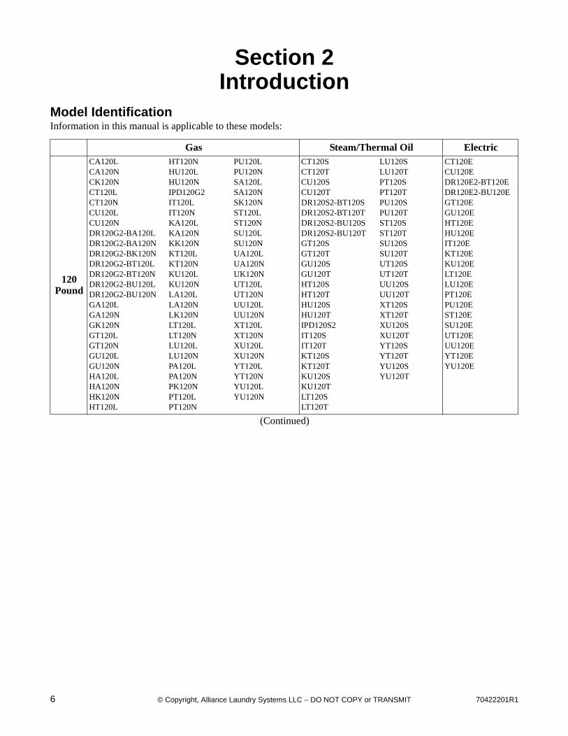
Model IdentificationInformation in this manual is applicable to these models:
Gas Steam/Thermal Oil Electric
120Pound
CA120LCA120NCK120NCT120LCT120NCU120LCU120NDR120G2-BA120LDR120G2-BA120NDR120G2-BK120NDR120G2-BT120LDR120G2-BT120NDR120G2-BU120LDR120G2-BU120NGA120LGA120NGK120NGT120LGT120NGU120LGU120NHA120LHA120NHK120NHT120L
HT120NHU120LHU120NIPD120G2IT120LIT120NKA120LKA120NKK120NKT120LKT120NKU120LKU120NLA120LLA120NLK120NLT120LLT120NLU120LLU120NPA120LPA120NPK120NPT120LPT120N
PU120LPU120NSA120LSA120NSK120NST120LST120NSU120LSU120NUA120LUA120NUK120NUT120LUT120NUU120LUU120NXT120LXT120NXU120LXU120NYT120LYT120NYU120LYU120N
CT120SCT120TCU120SCU120TDR120S2-BT120SDR120S2-BT120TDR120S2-BU120SDR120S2-BU120TGT120SGT120TGU120SGU120THT120SHT120THU120SHU120TIPD120S2IT120SIT120TKT120SKT120TKU120SKU120TLT120SLT120T
LU120SLU120TPT120SPT120TPU120SPU120TST120SST120TSU120SSU120TUT120SUT120TUU120SUU120TXT120SXT120TXU120SXU120TYT120SYT120TYU120SYU120T
CT120ECU120EDR120E2-BT120EDR120E2-BU120EGT120EGU120EHT120EHU120EIT120EKT120EKU120ELT120ELU120EPT120EPU120EST120ESU120EUT120EUU120EYT120EYU120E
(Continued)
70422201R1 7© Copyright, Alliance Laundry Systems LLC – DO NOT COPY or TRANSMIT
Introduction
Includes models with the following control suffixes:
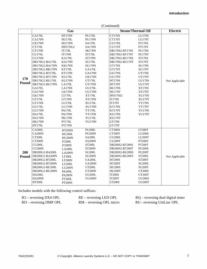
(Continued) Gas Steam/Thermal Oil Electric
170 Pound
CA170LCA170NCK170NCT170LCT170NCU170LCU170NDR170G2-BA170LDR170G2-BA170NDR170G2-BK170NDR170G2-BT170LDR170G2-BT170NDR170G2-BU170LDR170G2-BU170NGA170LGA170NGK170NGT170LGT170NGU170LGU170NHA170LHA170NHK170NHT170L
HT170NHU170LHU170NIPD170G2IT170LIT170NKA170LKA170NKK170NKT170LKT170NKU170LKU170NLA170LLA170NLK170NLT170LLT170NLU170LLU170NPA170LPA170NPK170NPT170LPT170N
PU170LPU170NSA170LSA170NSK170NST170LST170NSU170LSU170NUA170LUA170NUK170NUT170LUT170NUU170LUU170NXT170LXT170NXU170LXU170NYT170LYT170NYU170LYU170N
CT170SCT170TCU170SCU170TDR170S2-BT170SDR170S2-BT170TDR170S2-BU170SDR170S2-BU170TGT170SGT170TGU170SGU170THT170SHT170THU170SHU170TIPD170S2IT170SIT170TKT170SKT170TKU170SKU170TLT170SLT170T
LU170SLU170TPT170SPT170TPU170SPU170TST170SST170TSU170SSU170TUT170SUT170TUU170SUU170TXT170SXT170TXU170SXU170TYT170SYT170TYU170SYU170T
Not Applicable
200 Pound
CA200LCA200NCT200LCT200NCU200LCU200NDR200G2-BA200LDR200G2-BA200NDR200G2-BT200LDR200G2-BT200NDR200G2-BU200LDR200G2-BU200NHA200LHA200NHT200L
HT200NHU200LHU200NIT200LIT200NLA200LLA200NLT200LLT200NLU200LLU200NPA200LPA200NPT200LPT200N
PU200LPU200NSA200LSA200NST200LST200NSU200LSU200NUA200LUA200NUT200LUT200NUU200LUU200N
CT200SCT200TCU200SCU200TDR200S2-BT200SDR200S2-BT200TDR200S2-BU200SDR200S2-BU200THT200SHT200THU200SHU200TIT200SIT200TLT200S
LT200TLU200SLU200TPT200SPT200TPU200SPU200TST200SST200TSU200SSU200TUT200SUT200TUU200SUU200T
Not Applicable
R3 – reversing DX4 OPL RE – reversing LED OPL RQ – reversing dual digital timerRD – reversing DMP OPL RM – reversing OPL micro RU– reversing UniLinc OPL

8 70422201R1© Copyright, Alliance Laundry Systems LLC – DO NOT COPY or TRANSMIT
Introduction
Customer Service
If literature or replacement parts are required, contact the source from whom the machine was purchased or contact Alliance Laundry Systems at (920) 748-3950 for the name and address of the nearest authorized parts distributor.
For technical assistance, call (920) 748-3121.
Serial Plate Location
When calling or writing about your product, be sure to mention model and serial numbers. Model and serial numbers are located on serial plate as shown.
TMB2288N
120 Pound
Junction Box
Cover
Serial Plate
Serial Plate
Junction Box
Cover
170 Pound
70422201R1 9© Copyright, Alliance Laundry Systems LLC – DO NOT COPY or TRANSMIT
Introduction
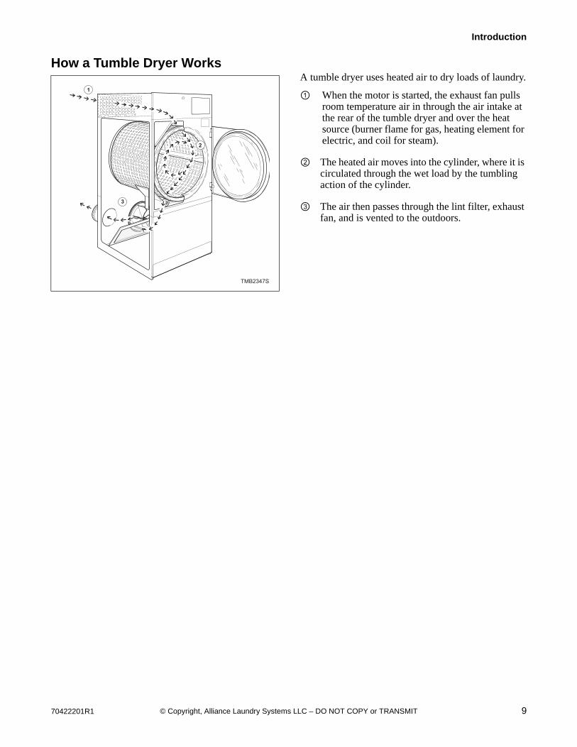
How a Tumble Dryer WorksA tumble dryer uses heated air to dry loads of laundry.
① When the motor is started, the exhaust fan pulls room temperature air in through the air intake at the rear of the tumble dryer and over the heat source (burner flame for gas, heating element for electric, and coil for steam).
② The heated air moves into the cylinder, where it is circulated through the wet load by the tumbling action of the cylinder.
③ The air then passes through the lint filter, exhaust fan, and is vented to the outdoors.
TMB2347S
1
3
2
10 70422201R1© Copyright, Alliance Laundry Systems LLC – DO NOT COPY or TRANSMIT
Introduction
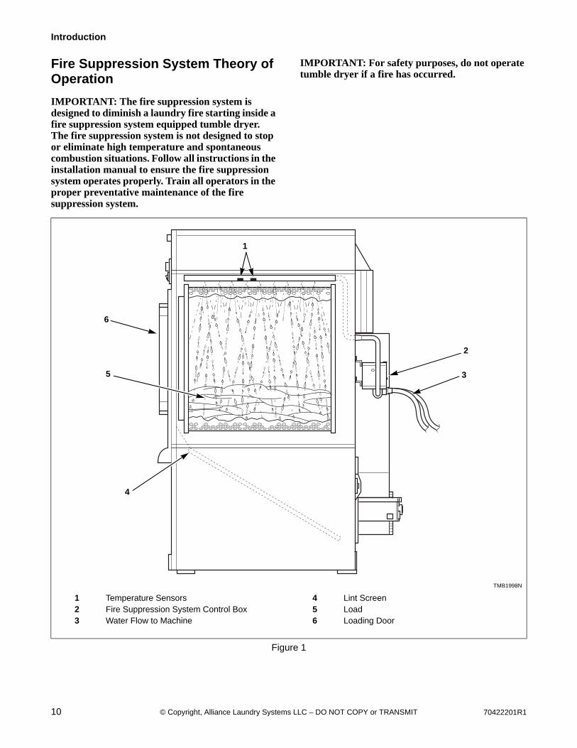
Fire Suppression System Theory of Operation
IMPORTANT: The fire suppression system is designed to diminish a laundry fire starting inside a fire suppression system equipped tumble dryer. The fire suppression system is not designed to stop or eliminate high temperature and spontaneous combustion situations. Follow all instructions in the installation manual to ensure the fire suppression system operates properly. Train all operators in the proper preventative maintenance of the fire suppression system.
IMPORTANT: For safety purposes, do not operate tumble dryer if a fire has occurred.
TMB1998N
1 Temperature Sensors 4 Lint Screen2 Fire Suppression System Control Box 5 Load3 Water Flow to Machine 6 Loading Door
Figure 1
1
6
3
2
5
4

70422201R1 11© Copyright, Alliance Laundry Systems LLC – DO NOT COPY or TRANSMIT
Introduction
Temperature Sensor
Two temperature sensors are located in the cylinder area of the tumble dryer to provide temperature readings. Refer to Figure 1 and Figure 2. These temperature sensors will trigger a mode change based on a pre-set temperature trip-point.
TMB1999N
1 Opening for Auxiliary Alarm Cable 5 Light2 Fuse 6 Reset Button3 Auxiliary Alarm Fast-On Connection 7 Auxiliary Alarm Fast-On Connection4 Test Button
Figure 2
TMB1999N
3
45
6
7
1 2

12 70422201R1© Copyright, Alliance Laundry Systems LLC – DO NOT COPY or TRANSMIT
Introduction
Modes of Operation
Power-Up ModeSends power to control, begins a status check of the system. Can send control into Idle Mode
or Lockout Mode.
Idle ModeMachine is operable while it monitors
temperature sensor readings. Control will enter Power Disconnect Mode if temperature
trip-point is exceeded.
Power Disconnect ModeMachine is disabled and controls on front will not
operate, will enter Power Disconnect Mode for one second, then Water On Mode.
Water On ModeMachine is disabled and controls on front will not operate. Remain in this mode for 90 seconds, then enter Lockout Mode. Can enter Lockout Error Mode if both temperature sensors become open, which occurs when temperature is below 40° F (4° C). Will enter Idle Mode if reset button is pressed. Refer to Figure 2.
Lockout ModeMachine is disabled and controls on front will not
operate. Control monitors temperature readings. Enters Water On Mode if temperature trip-point is exceeded.
Will enter Idle Mode if reset button is pressed.
Lockout Error ModeMachine is disabled and controls on front will not
operate. Water dispenses for four minutes. When the reset button is pressed, the control enters Idle
Mode.
If temperature trip-point exceeded
If both temperaturesensors become open When reset
button is pressed
If reset buttonis pressed

70422201R1 13© Copyright, Alliance Laundry Systems LLC – DO NOT COPY or TRANSMIT
Section 3Troubleshooting
IMPORTANT: Refer to appropriate wiring diagram for aid in testing tumble dryer components.
To reduce the risk of electric shock, fire, explosion, serious injury or death:• Disconnect electric power to the tumbler before servicing.• Close gas shut-off valve to gas tumbler before servicing.• Close steam valve to steam tumbler before servicing.• Never start the tumbler with any guards/panels removed.• Whenever ground wires are removed during servicing, these ground wires must be
reconnected to ensure that the tumbler is properly grounded.W002
WARNING
14 70422201R1© Copyright, Alliance Laundry Systems LLC – DO NOT COPY or TRANSMIT
Troubleshooting
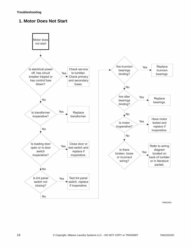
1. Motor Does Not Start
TMB2360S
Motor does
not start
Is electrical power
off, has circuit
breaker tripped or
has control fuse
blown?
Check service
to tumbler.
Check primary
and secondary
fuses.
Is transformer
inoperative?
Replace
transformer.
Is loading door
open or is door
switch
inoperative?
Close door or
test switch and
replace if
inoperative.
Is lint panel
switch not
closing?
Test lint panel
switch, replace
if inoperative.
Are trunnion
bearings
binding?
Replace
trunnion
bearings.
Is there
broken, loose
or incorrect
wiring?
Refer to wiring
diagram
located on
back of tumbler
or in literature
packet.
Yes
No
Yes
No
Yes
No
Yes
Yes
No
Yes
Are idler
bearings
binding?
Replace
bearings.
Is motor
inoperative?
Have motor
tested and
replace if
inoperative.
Yes
No
No
Yes
No
TMB2360S
70422201R1 15© Copyright, Alliance Laundry Systems LLC – DO NOT COPY or TRANSMIT
Troubleshooting
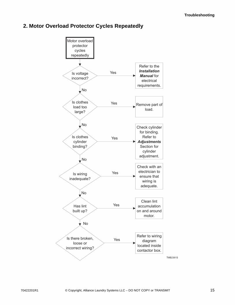
2. Motor Overload Protector Cycles Repeatedly
Motor overload
protector
cycles
repeatedly
Is voltage
incorrect?
Refer to the
Installation
Manual for
electrical
requirements.
Is clothes
load too
large?
Remove part of
load.
Is clothes
cylinder
binding?
Check cylinder
for binding.
Refer to
Adjustments
Section for
cylinder
adjustment.
Is wiring
inadequate?
Check with an
electrician to
ensure that
wiring is
adequate.
Has lint
built up?
Clean lint
accumulation
on and around
motor.
Is there broken,
loose or
incorrect wiring?
Refer to wiring
diagram
located inside
contactor box.
TMB2361S
Yes
No
Yes
No
Yes
No
Yes
No
Yes
No
Yes

16 70422201R1© Copyright, Alliance Laundry Systems LLC – DO NOT COPY or TRANSMIT
Troubleshooting
3. Motor Runs But Cylinder Does Not Turn
Motor runs but cylinder does
not turn
Is motor drive pulley
loose?
Tighten drive pulley bushing
screws.
Are cylinder belts broken
or loose?
Replace or adjust belts.
Is cylinder binding?
Check cylinder for binding. Refer to
Adjustments Section for proper cylinder
adjustment.
TMB1919S
Yes
Yes
Yes
No
Replace or adjust belt.
Is drive belt broken or
loose?
No
Yes
No
70422201R1 17© Copyright, Alliance Laundry Systems LLC – DO NOT COPY or TRANSMIT
Troubleshooting
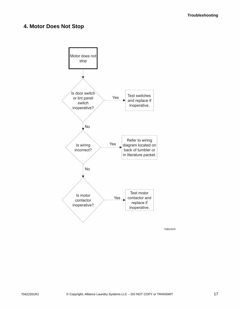
4. Motor Does Not Stop
Motor does not
stop
Is door switch
or lint panel
switch
inoperative?
Test switches
and replace if
inoperative.
Is motor
contactor
inoperative?
Test motor
contactor and
replace if
inoperative.
TMB2362S
Yes
No
Yes
Is wiring
incorrect?
Refer to wiring
diagram located on
back of tumbler or
in literature packet.
Yes
No
18 70422201R1© Copyright, Alliance Laundry Systems LLC – DO NOT COPY or TRANSMIT
Troubleshooting
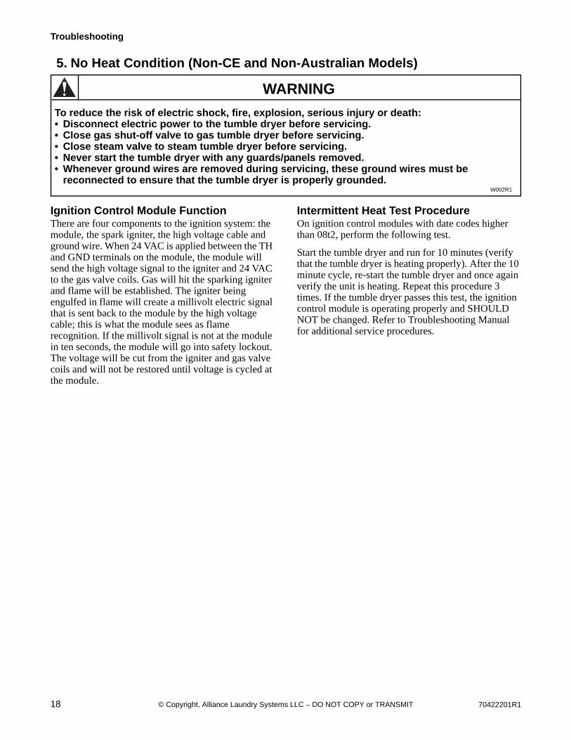
5. No Heat Condition (Non-CE and Non-Australian Models)
Ignition Control Module FunctionThere are four components to the ignition system: the module, the spark igniter, the high voltage cable and ground wire. When 24 VAC is applied between the TH and GND terminals on the module, the module will send the high voltage signal to the igniter and 24 VAC to the gas valve coils. Gas will hit the sparking igniter and flame will be established. The igniter being engulfed in flame will create a millivolt electric signal that is sent back to the module by the high voltage cable; this is what the module sees as flame recognition. If the millivolt signal is not at the module in ten seconds, the module will go into safety lockout. The voltage will be cut from the igniter and gas valve coils and will not be restored until voltage is cycled at the module.
Intermittent Heat Test ProcedureOn ignition control modules with date codes higher than 08t2, perform the following test.
Start the tumble dryer and run for 10 minutes (verify that the tumble dryer is heating properly). After the 10 minute cycle, re-start the tumble dryer and once again verify the unit is heating. Repeat this procedure 3 times. If the tumble dryer passes this test, the ignition control module is operating properly and SHOULD NOT be changed. Refer to Troubleshooting Manual for additional service procedures.
To reduce the risk of electric shock, fire, explosion, serious injury or death:• Disconnect electric power to the tumble dryer before servicing.• Close gas shut-off valve to gas tumble dryer before servicing.• Close steam valve to steam tumble dryer before servicing.• Never start the tumble dryer with any guards/panels removed.• Whenever ground wires are removed during servicing, these ground wires must be
reconnected to ensure that the tumble dryer is properly grounded.W002R1
WARNING

70422201R1 19© Copyright, Alliance Laundry Systems LLC – DO NOT COPY or TRANSMIT
Troubleshooting
6. No Heat Condition
Is the Ignition Control
Module’s red light on?
No
No
Yes
Yes
Refer to
Paragraph 7.
Replace igniter and high
voltage lead. Retest unit. If
unit still does not spark,
replace module.
No Refer to Paragraph 7
for heat circuit
troubleshooting.
Is there
24 volts AC between
the TH and GND terminals
on the module?
Yes
No Check wiring between
gas valve and module.
If wiring is good,
replace module.
Yes
Yes Is there continuity
between GND terminal on
module and machine?
No No
Does the igniter
spark but no
flame is produced?
No
Yes
Is there
24 volts AC at the gas
valve coils when igniter
is sparking?
Is the igniter
positioned properly
in the flame, and does the
flame look good?
Does the igniter
spark?
Verify that gas is supplied
to the machine. If gas and
voltage are present,
replace gas valve or coils.
Does the flame turn
off after igniter
stops sparking?
No
Yes
Replace module. Adjust position of
igniter and retest.
Yes
Verify machine is
properly grounded.
Replace igniter and
high voltage lead.
Retest unit. If it still
does not sense flame,
replace module.
TMB2395S
20 70422201R1© Copyright, Alliance Laundry Systems LLC – DO NOT COPY or TRANSMIT
Troubleshooting
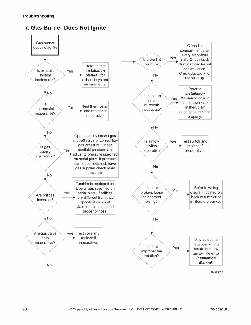
7. Gas Burner Does Not Ignite
Gas burner
does not ignite
Is exhaust
system
inadequate?
Refer to the
Installation
Manual for
exhaust system
requirements.
Is
thermostat
inoperative?
Test thermostat
and replace if
inoperative.
Is gas
supply
insufficient?
Open partially closed gas
shut-off valve or correct low
gas pressure. Check
manifold pressure and
adjust to pressure specified
on serial plate. If pressure
cannot be obtained, have
gas supplier check main
pressure.
Are orifices
incorrect?
Tumbler is equipped for
type of gas specified on
serial plate. If orifices
are different from that
specified on serial
plate, obtain and install
proper orifices.
TMB2363S
Are gas valve
coils
inoperative?
Test coils and
replace if
inoperative.
Is make-up
air or
ductwork
inadequate?
Refer to
Installation
Manual to ensure
that ductwork and
make-up air
openings are sized
properly.
Is airflow
switch
inoperative?
Test switch and
replace if
inoperative.
Yes
No
Yes
No
Yes
No
Yes
No
Yes
No
Yes
No
Yes
No
Is there
broken, loose
or incorrect
wiring?
Refer to wiring
diagram located on
back of tumbler or
in literature packet.
Is there
improper fan
rotation?
May be due to
improper wiring
resulting in low
airflow. Refer to
Installation
Manual.
Yes
No
Yes
Is there lint
buildup?
Clean lint
compartment after
every eight-hour
shift. Check back
draft damper for lint
accumulation.
Check ductwork for
lint build-up.
Yes
No
TMB2363S

70422201R1 21© Copyright, Alliance Laundry Systems LLC – DO NOT COPY or TRANSMIT
Troubleshooting
8. Burner Ignites and Goes Out Repeatedly
Burner ignites
and goes out
repeatedly
Is gas pressure
insufficient?
Check gas supply
and pressure. Low
flame will not
maintain sensor
conductivity.
Are burner ports
plugged?
Check burner tubes
for build-up.
Is exhaust system or
make-up air
inadequate?
Refer to
Installation
Manual for
exhaust and
make-up air
requirements.
Is high limit or cabinet
limit thermostat
inoperative?
Test thermostat
and replace if
inoperative.
TMB1922S
Are orifices
improper?
Tumbler is equipped for type of
gas specified on serial plate. If
orifices are different from that
specified on serial plate, obtain
and install proper orifices.
Is flame recognition
circuit improper?
Replace high voltage lead.
Replace igniter.
Replace ignition control
module.
Yes
No
Yes
No
Yes
No
Yes
No
Yes
No
Yes
22 70422201R1© Copyright, Alliance Laundry Systems LLC – DO NOT COPY or TRANSMIT
Troubleshooting
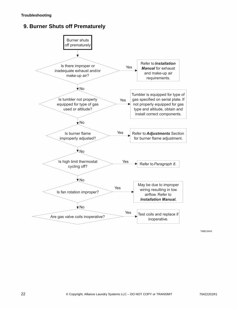
9. Burner Shuts off Prematurely
Burner shuts
off prematurely
Is there improper or
inadequate exhaust and/or
make-up air?
Refer to Installation
Manual for exhaust
and make-up air
requirements.
Is tumbler not properly
equipped for type of gas
used or altitude?
Tumbler is equipped for type of
gas specified on serial plate. If
not properly equipped for gas
type and altitude, obtain and
install correct components.
Is burner flame
improperly adjusted?
Refer to Adjustments Section
for burner flame adjustment.
Is high limit thermostat
cycling off?Refer to Paragraph 8.
Yes
No
Yes
No
Yes
No
Yes
No
TMB2364S
Is fan rotation improper?
May be due to improper
wiring resulting in low
airflow. Refer to
Installation Manual..
Are gas valve coils inoperative?Test coils and replace if
inoperative.
Yes
No
Yes
70422201R1 23© Copyright, Alliance Laundry Systems LLC – DO NOT COPY or TRANSMIT
Troubleshooting
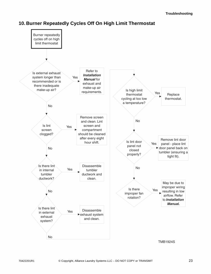
10. Burner Repeatedly Cycles Off On High Limit Thermostat
Burner repeatedly cycles off on high limit thermostat
Is external exhaust system longer than recommended or is there inadequate
make-up air?
Refer to Installation Manual for
exhaust and make-up air
requirements.
Is lint screen
clogged?
Remove screen and clean. Lint
screen and compartment
should be cleaned after every eight
hour shift.
Is there lint in internal tumbler
ductwork?
Disassemble tumbler
ductwork and clean.
Is there lint in external exhaust system?
Disassemble exhaust system
and clean.
Is high limit thermostat
cycling at too low a temperature?
Replace thermostat.
Is lint door panel not
closed properly?
Remove lint door panel - place lint
door panel back on tumbler (ensuring a
tight fit).
Is there improper fan
rotation?
May be due to improper wiring resulting in low airflow. Refer to Installation
Manual..
TMB1924S
Yes
No
Yes
No
Yes
No
Yes
No
Yes
No
Yes
No
Yes
24 70422201R1© Copyright, Alliance Laundry Systems LLC – DO NOT COPY or TRANSMIT
Troubleshooting
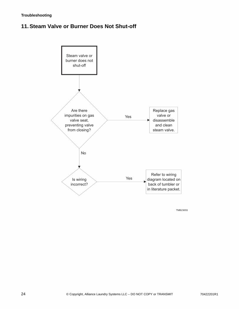
11. Steam Valve or Burner Does Not Shut-off
Steam valve or
burner does not
shut-off
Are there
impurities on gas
valve seat,
preventing valve
from closing?
Replace gas
valve or
disassemble
and clean
steam valve.
Is wiring
incorrect?
Refer to wiring
diagram located on
back of tumbler or
in literature packet.
Yes
No
Yes
TMB2365S
70422201R1 25© Copyright, Alliance Laundry Systems LLC – DO NOT COPY or TRANSMIT
Troubleshooting
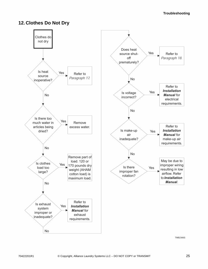
12. Clothes Do Not Dry
Clothes do
not dry
Is heat
source
inoperative?
Refer to
Paragraph 17.
Is there too
much water in
articles being
dried?
Remove
excess water.
Is clothes
load too
large?
Remove part of
load. 120 or
170 pounds dry
weight (AHAM
cotton load) is
maximum load.
Is exhaust
system
improper or
inadequate?
Refer to
Installation
Manual for
exhaust
requirements.
Does heat
source shut-
off
prematurely?
Refer to
Paragraph 18.
Is voltage
incorrect?
Refer to
Installation
Manual for
electrical
requirements.
TMB2366S
Is make-up
air
inadequate?
Refer to
Installation
Manual for
make-up air
requirements.
Yes
No
Yes
No
Yes
No
Yes
No
Yes
No
Yes
No
Yes
Is there
improper fan
rotation?
May be due to
improper wiring
resulting in low
airflow. Refer
to Installation
Manual.
No
Yes
26 70422201R1© Copyright, Alliance Laundry Systems LLC – DO NOT COPY or TRANSMIT
Troubleshooting
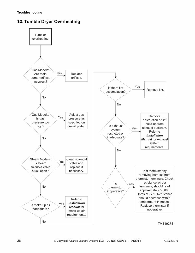
13. Tumble Dryer Overheating
Tumbler
overheating
Gas Models:
Are main
burner orifices
incorrect?
Replace
orifices.
Gas Models:
Is gas
pressure too
high?
Adjust gas
pressure as
specified on
serial plate.
Is make-up air
inadequate?
Refer to
Installation
Manual for
make-up air
requirements.
Is there lint
accumulation?Remove lint.
Is exhaust
system
restricted or
inadequate?
Remove
obstruction or lint
build-up from
exhaust ductwork.
Refer to
Installation
Manual for exhaust
system
requirements.
Is
thermistor
inoperative?
Test thermistor by
removing harness from
thermistor terminals. Check
resistance across
terminals, should read
approximately 50,000
Ohms at 77°F. Resistance
should decrease with a
temperature increase.
Replace thermistor if
inoperative.
TMB1927S
Yes
No
Yes
Yes
No
Yes
No
Yes
No
Yes
Steam Models:
Is steam
solenoid valve
stuck open?
Clean solenoid
valve and
replace if
necessary.
No
Yes
No
70422201R1 27© Copyright, Alliance Laundry Systems LLC – DO NOT COPY or TRANSMIT
Troubleshooting
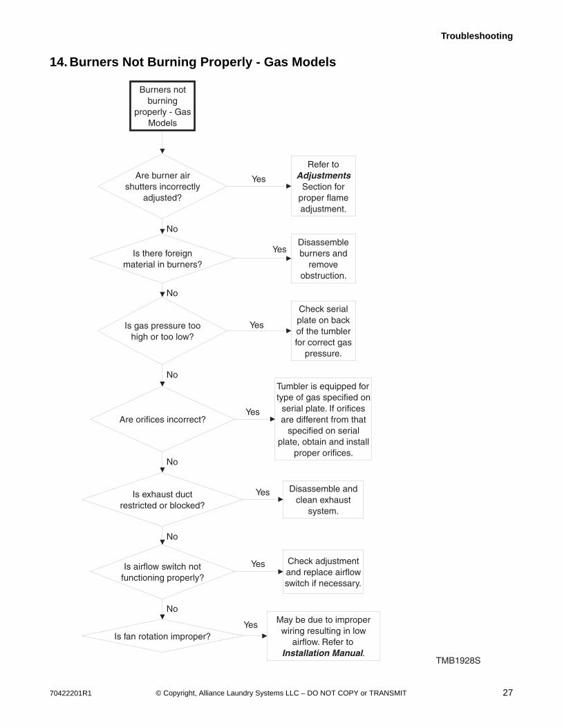
14. Burners Not Burning Properly - Gas Models
Burners not burning
properly - Gas Models
Are burner air shutters incorrectly
adjusted?
Refer to Adjustments
Section for proper flame adjustment.
Is there foreign material in burners?
Disassemble burners and
remove obstruction.
Is gas pressure too high or too low?
Check serial plate on back of the tumbler for correct gas
pressure.
Are orifices incorrect?
Tumbler is equipped for type of gas specified on
serial plate. If orifices are different from that
specified on serial plate, obtain and install
proper orifices.
Is exhaust duct restricted or blocked?
Disassemble and clean exhaust
system.
TMB1928S
Yes
No
Yes
No
Yes
No
Yes
Yes
No
Is airflow switch not functioning properly?
Check adjustment and replace airflow switch if necessary.
Is fan rotation improper?
May be due to improper wiring resulting in low
airflow. Refer to Installation Manual.
No
Yes
No
Yes

28 70422201R1© Copyright, Alliance Laundry Systems LLC – DO NOT COPY or TRANSMIT
Troubleshooting
15. Loading Door Opens During Operation
Loading door
opens during
operation
Is door strike
improperly
adjusted?
Refer to
Adjustments
Section for
door strike
adjustment.
Is tumbler
improperly
leveled?
Refer to
Installation
Manual for
leveling leg
adjustment.
TMB1885S
No
Yes
Yes
70422201R1 29© Copyright, Alliance Laundry Systems LLC – DO NOT COPY or TRANSMIT
Troubleshooting
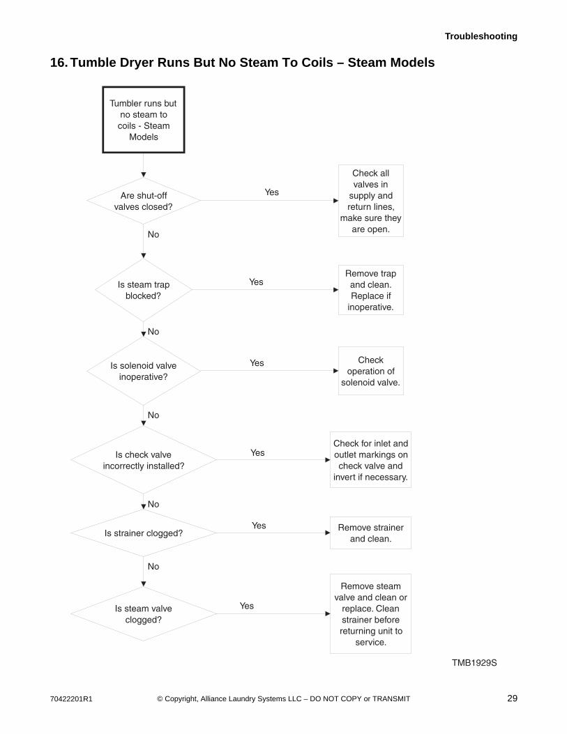
16. Tumble Dryer Runs But No Steam To Coils – Steam Models
Tumbler runs but no steam to coils - Steam
Models
Are shut-off valves closed?
Check all valves in
supply and return lines,
make sure they are open.
Is steam trap blocked?
Remove trap and clean. Replace if
inoperative.
Is solenoid valve inoperative?
Check operation of
solenoid valve.
Is check valve incorrectly installed?
Check for inlet and outlet markings on check valve and
invert if necessary.
Is strainer clogged?Remove strainer
and clean.
Is steam valve clogged?
Remove steam valve and clean or
replace. Clean strainer before returning unit to
service.
TMB1929S
Yes
No
Yes
No
Yes
No
Yes
No
Yes
No
Yes
30 70422201R1© Copyright, Alliance Laundry Systems LLC – DO NOT COPY or TRANSMIT
Troubleshooting
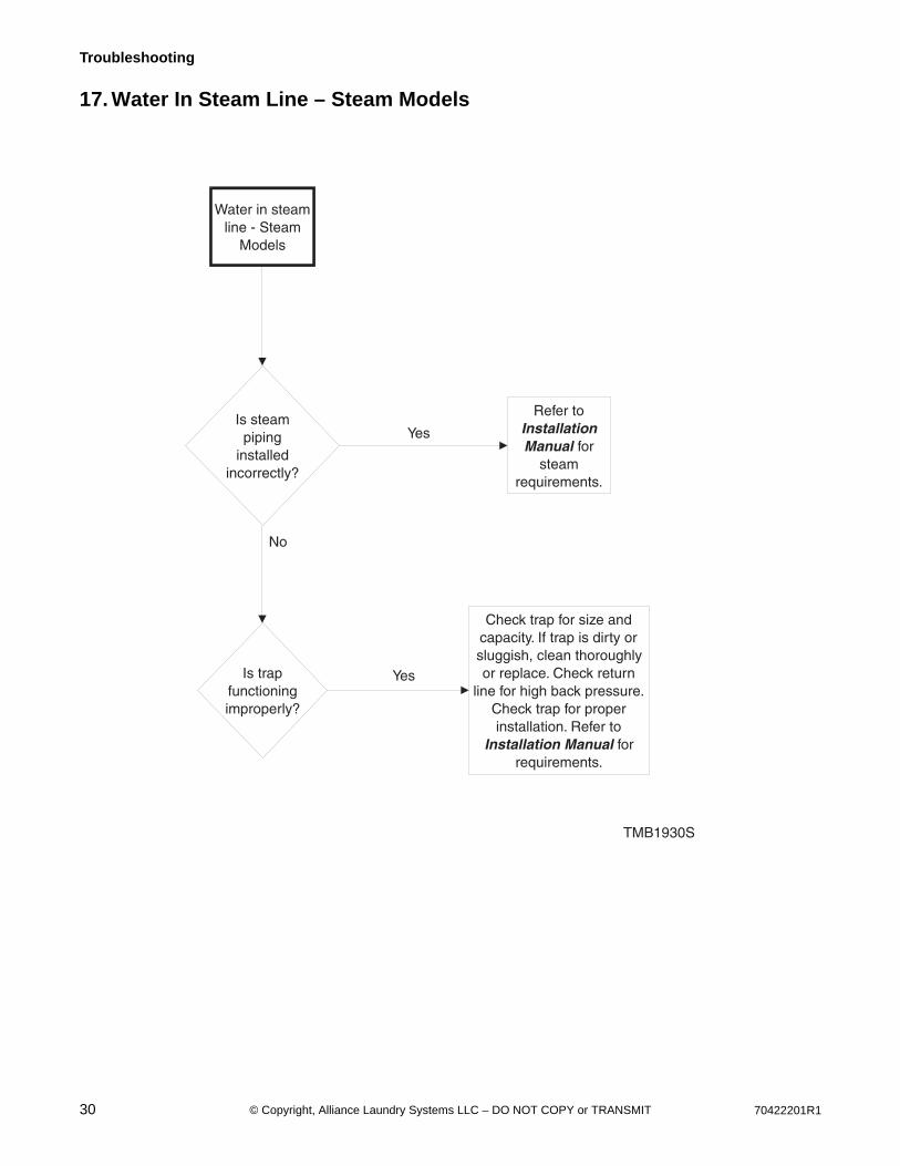
17. Water In Steam Line – Steam Models
Water in steam line - Steam
Models
Is steam piping
installed incorrectly?
Refer to Installation Manual for
steam requirements.
Is trap functioning improperly?
Check trap for size and capacity. If trap is dirty or sluggish, clean thoroughly or replace. Check return
line for high back pressure. Check trap for proper installation. Refer to
Installation Manual for requirements.
TMB1930S
Yes
No
Yes
70422201R1 31© Copyright, Alliance Laundry Systems LLC – DO NOT COPY or TRANSMIT
Troubleshooting
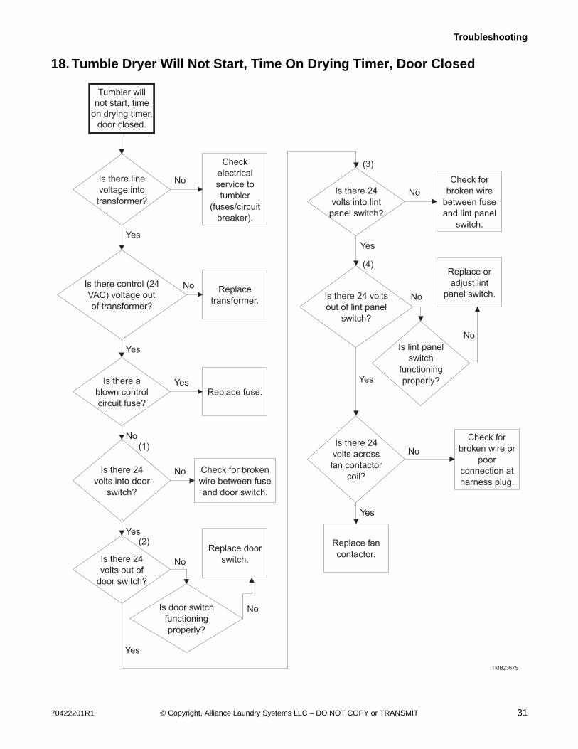
18. Tumble Dryer Will Not Start, Time On Drying Timer, Door Closed
TMB2367S
Tumbler willnot start, time
on drying timer,door closed.
Is there line voltage into transformer?
Check electrical service to tumbler
(fuses/circuit breaker).
Is there control (24 VAC) voltage out of transformer?
Replace transformer.
Is there a blown control circuit fuse?
Replace fuse.
Is there 24 volts into door
switch?
Check for broken wire between fuse and door switch.
Is there 24 volts out of
door switch?
Is door switch functioning properly?
Replace door switch.
Is there 24 volts into lint
panel switch?
Check for broken wire
between fuse and lint panel
switch.
Is there 24 volts out of lint panel
switch?
Is lint panel switch
functioning properly?
Replace or adjust lint
panel switch.
No
Yes
(1)
(3)
(4)
(2)
No
Yes
Yes
No
No
Yes
No
No
Yes
No
Yes
No
Yes
No
Is there 24 volts across fan contactor
coil?
Check for broken wire or
poor connection at harness plug.
Replace fan contactor.
No
Yes

32 70422201R1© Copyright, Alliance Laundry Systems LLC – DO NOT COPY or TRANSMIT
Troubleshooting
Tumble Dryer Will Not Start, Time On Drying Timer, Door Closed RQ Control
TMB2357S
1 2
34
70422201R1 33© Copyright, Alliance Laundry Systems LLC – DO NOT COPY or TRANSMIT
Troubleshooting
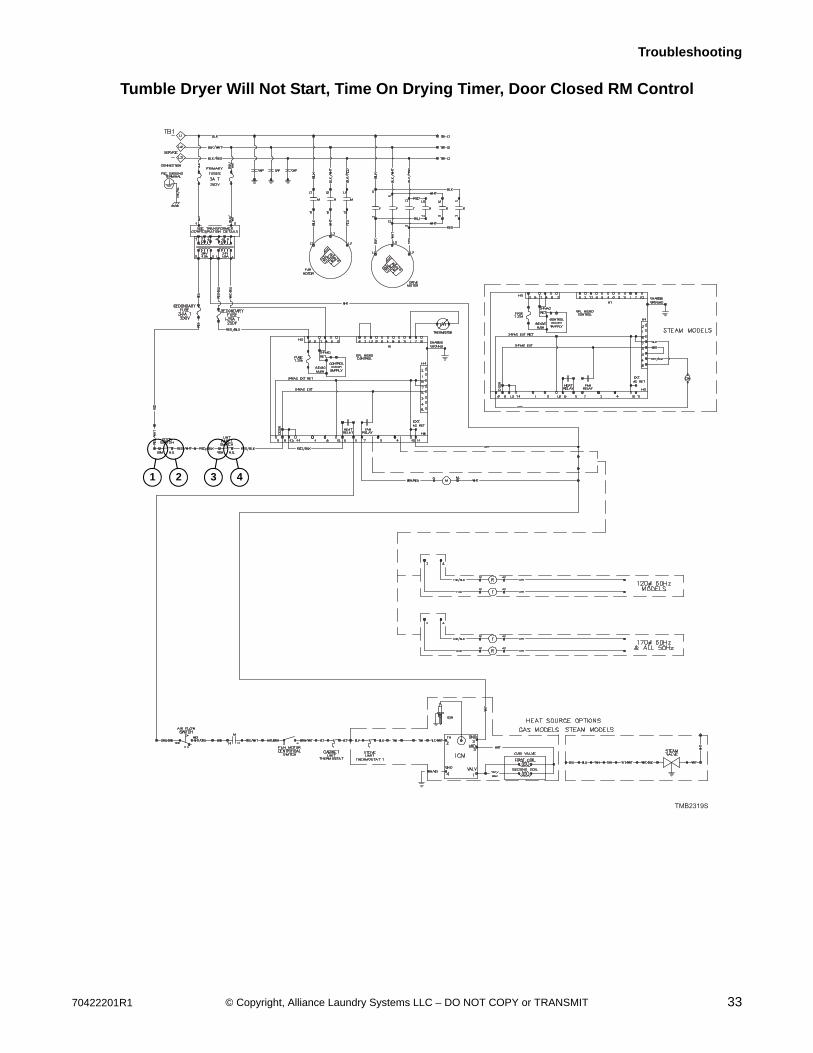
Tumble Dryer Will Not Start, Time On Drying Timer, Door Closed RM Control
TMB2319S
1 2 3 4
34 70422201R1© Copyright, Alliance Laundry Systems LLC – DO NOT COPY or TRANSMIT
Troubleshooting
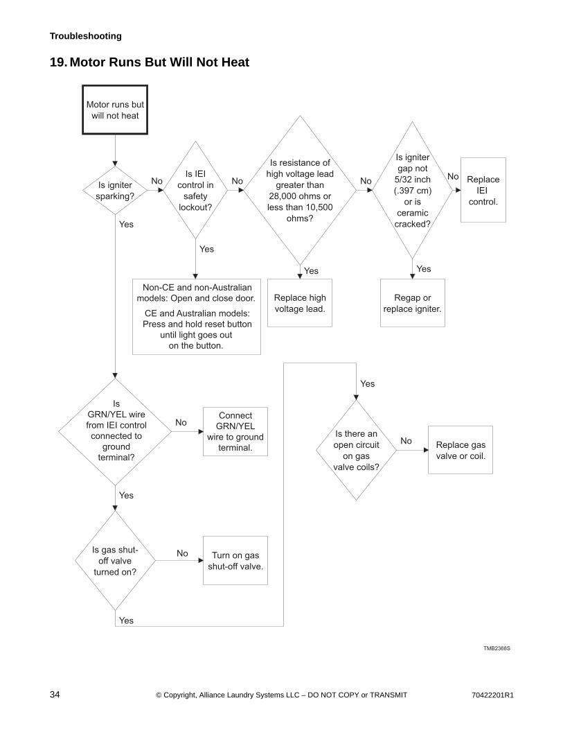
19. Motor Runs But Will Not Heat
Motor runs but
will not heat
Is igniter
sparking?
Is IEI
control in
safety
lockout?
Non-CE and non-Australian
models: Open and close door.
CE and Australian models:
Press and hold reset button
until light goes out
on the button.
Is resistance of
high voltage lead
greater than
28,000 ohms or
less than 10,500
ohms?
Replace high
voltage lead.
Is igniter
gap not
5/32 inch
(.397 cm)
or is
ceramic
cracked?
Regap or
replace igniter.
Replace
IEI
control.
Is
GRN/YEL wire
from IEI control
connected to
ground
terminal?
Connect
GRN/YEL
wire to ground
terminal.
Is gas shut-
off valve
turned on?
Turn on gas
shut-off valve.
TMB2368S
Is there an
open circuit
on gas
valve coils?
Replace gas
valve or coil.
No No NoNo
Yes
Yes Yes
Yes
No
Yes
No
Yes
Yes
No

70422201R1 35© Copyright, Alliance Laundry Systems LLC – DO NOT COPY or TRANSMIT
Troubleshooting
20. Cylinder Turns, But Will Not Heat
TMB2369S-a
Cylinder turns,
but will not heat
Does airflow
switch stay
open?
Is fan turning
counterclockwise
as viewed from
the front?
Reverse any
two of the
electrical
service leads at
the fan motor
contactor.
Refer to
Installation
Manual for
makeup air and
exhaust duct
requirements.
Is gas
shut-off
valve
open?
Open gas shut-
off valve.
Yes
No
Yes
No
No
Yes
Is there 24 volts
present at output
terminal of stove
high limit
thermostat?
Check for
broken or loose
wire to relay.
Is there 24 volts
present at input
terminal of stove
high limit
thermostat?
Replace stove
high limit
thermostat.
Is there 24 volts
present at output
terminal of airflow
switch?
Check for
broken or loose
wire to stove
high limit
thermostat.
Yes
No
Yes
No
Yes
No
Continued on
next page.

36 70422201R1© Copyright, Alliance Laundry Systems LLC – DO NOT COPY or TRANSMIT
Troubleshooting
20. Cylinder Turns, But Will Not Heat (continued)
TMB2369S-b
Continued from
previous page.
Is there 24 volts
present at input
terminal of airflow
switch?
Replace airflow
switch.
Is
there 24 volts
present at output
terminal of exhaust
high limit
thermostat?
Check for
broken or loose
wire to airflow
switch.
Is there 24 volts
present at input
terminal of
cabinet limit
thermostat?
Replace
cabinet limit
thermostat.
Is there 24
volts present
on org/wht
wire of fan
motor?
Check for
broken or loose
wire to cabinet
limit
thermostat.
No
No
Yes
No
Yes
No
Yes
No
Yes
70422201R1 37© Copyright, Alliance Laundry Systems LLC – DO NOT COPY or TRANSMIT
Troubleshooting
21. Cylinder Is “Stained”Over time, the cylinder and cylinder backs of tumble dryers can become “stained” from various melted fabrics. These discolored areas can be removed by scrubbing the inside of the cylinder with cleaner and a cleaning pad, such as Scotch- Brite®.
IMPORTANT: Do not use a steel wool pad to clean the cylinder. Steel wool can damage your machine.
Galvanized CylindersFor galvanized cylinders, use an all-purpose cleaner (such as 409®) and a cleaning pad (such as Scotch- Brite®) to clean the inside of the cylinder.
1. Spray the cleaner on the discolored areas and let soak for a few minutes.
2. Using the pad, scrub the areas until the discoloration is removed.
3. Repeat steps 1-2 as necessary. 4. Thoroughly wipe the entire cylinder after
cleaning to insure the cleaner has been removed.
Stainless Steel CylindersFor stainless steel cylinders, use a heavy duty powder cleanser (such as Zud®) and a cleaning pad (such as Scotch- Brite®) to clean the inside of the cylinder.
1. Using a water spray bottle, wet the cylinder and cylinder back.
2. Sprinkle cleanser onto the pad and scrub the discolored areas.
3. Repeat steps 1-2 as necessary.4. Thoroughly wipe the entire cylinder after
cleaning to insure the cleanser has been removed.

38 70422201R1© Copyright, Alliance Laundry Systems LLC – DO NOT COPY or TRANSMIT
Section 4Fire Supression System Troubleshooting
A water discharge or system fault is indicated when the fire suppression system control box light is on.
IMPORTANT: When handling electronic controls, use a ground wrist strap. Due to the sensitivity of electronic controls, careful handling is required. Wrist strap, cord and alligator clip are designed to carry away any electrostatic charge from your body and to direct charge to an available ground. By using this static protection device, potential electrostatic discharge problems associated with handling of electronic control will be minimized. Always handle electronic control by its metal edges.
To reduce the risk of electric shock, fire, explosion, serious injury or death:• Disconnect electric power to the tumble dryer before servicing.• Close gas shut-off valve to gas tumble dryer before servicing.• Close steam valve to steam tumble dryer before servicing.• Never start the tumble dryer with any guards/panels removed.• Whenever ground wires are removed during servicing, these ground wires must be
reconnected to ensure that the tumble dryer is properly grounded.W002R1
WARNING
70422201R1 39© Copyright, Alliance Laundry Systems LLC – DO NOT COPY or TRANSMIT
Fire Supression System Troubleshooting
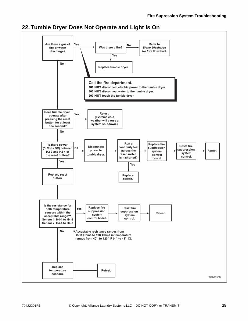
22. Tumble Dryer Does Not Operate and Light Is On
Are there signs offire or waterdischarge?
Was there a fire?
Replace tumble dryer.
Call the fire department.DO NOT disconnect electric power to the tumble dryer.DO NOT disconnect water to the tumble dryer.DO NOT touch the tumble dryer.
Does tumble dryeroperate after
pressing the resetbutton for at least
one second?
Is there power(5 Volts DC) between
H2-3 and H2-4 ofthe reset button?
Disconnectpower to
tumble dryer.
Run acontinuity test
across thereset switch.Is it shorted?
Replace fire suppression
system controlboard.
Replace resetbutton.
Is the resistance forboth temperature
sensors within theacceptable range?*
Sensor 1 H4-1 to H4-2Sensor 2 H4-4 to H4-3
Replace fire suppression
systemcontrol board.
Yes
No
Retest.(Extreme cold
weather will cause asystem shutdown.)
Refer toWater Discharge
No Fire flowchart.
Yes
No
Acceptable resistance ranges from150K Ohms to 19K Ohms in temperatureranges from 40° to 120° F (4° to 48° C).
Reset fire suppression
systemcontrol.
Retest.
Replacetemperature
sensors.
No
Retest.
Replaceswitch.
Reset fire suppression
systemcontrol.
Retest.No
Yes
Yes
No
Yes
TMB2196N
*
Yes
TMB2196N

40 70422201R1© Copyright, Alliance Laundry Systems LLC – DO NOT COPY or TRANSMIT
Fire Supression System Troubleshooting
23. Water Discharge, but No Fire
IMPORTANT: Electric Models: If water has discharged into machine, you MUST perform this diagnostic test with NO HEAT to the machine.
TMB2258N
Is the resistance forboth temperaturesensors within theacceptable range?*
Sensor 1 H4-1 to H4-2Sensor 2 H4-4 to H4-3
Replace fire suppression
systemcontrol board.
Yes
Acceptable resistance ranges from150K Ohms to 19K Ohms in temperatureranges from 40˚ to 120˚ F (4˚ to 48˚ C).
Reset fire suppression
systemcontrol.
Retest.
Replacetemperature
sensors.
No
Retest.
*
Is the unita reversing
model?
No
No
Yes
Setcontrol
tononreversing.
Electric Models:Set to no heat.
Start unit.Is the
cylinderturning
clockwise?
Is the ventblocked orrestricted?
Clear vent/easerestrictions.
Refer toInstallationManual for
proper venting.
Retestsystem.
Retestsystem.
Correct inputwiring to
change phase.(Fan is
spinningbackward.)
Yes
Yes No
No
TMB2258N
70422201R1 41© Copyright, Alliance Laundry Systems LLC – DO NOT COPY or TRANSMIT
Fire Supression System Troubleshooting
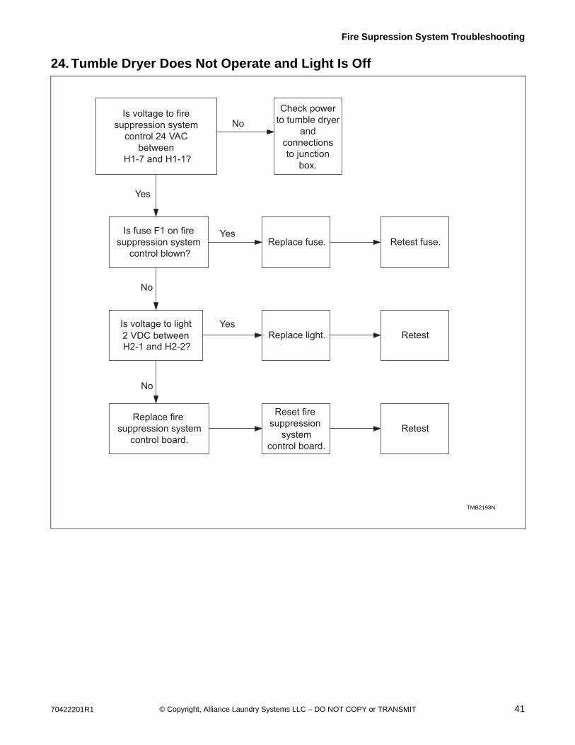
24. Tumble Dryer Does Not Operate and Light Is Off
TMB2198N
Is voltage to fire suppression system
control 24 VAC between
H1-7 and H1-1?
Is fuse F1 on fire suppression system
control blown?
Is voltage to light 2 VDC between H2-1 and H2-2?
Replace light.Yes
Replace fire suppression system
control board.
No
Reset fire suppression
systemcontrol board.
Retest
Check powerto tumble dryer
andconnectionsto junction
box.
No
Yes
Replace fuse. Retest fuse.Yes
No
Retest
TMB2198N

42 70422201R1© Copyright, Alliance Laundry Systems LLC – DO NOT COPY or TRANSMIT
Fire Supression System Troubleshooting
25. Tumble Dryer Operates, but Water Does Not Discharge and Light Is On
TMB2199N
Verify water is supplied to valve at the proper pressure and flow rate. Refer
to Installation section.
Make corrections to meet water
requirements of system.
NoRetest
Turn off tumble dryer.Are water inlet
screens clogged?
Yes
Clean inlet screens, then turn on water.
RetestYes
Are water hoses or the manifold nozzle clogged?
Clear any debris.
Reset fire suppression system
control.
Retest
Using an AC voltmeter, within 90 seconds, is there
voltage to the water manifold valve?
Reset fire suppression
system control.
Retest
Is wiring betweenvalve and fire
suppression systemcontrol good?
Replace fire suppression system
control.
Retest
Correct wiring. Refer to wiring diagram on the following page.
Disconnect hose from water valve
outlet.
RetestDoes water come out of
valve?
Replace water valve.
No
Yes
No
No
Yes
Yes
No
Reset fire suppression
systemcontrol.
Reset fire suppression
systemcontrol.
TMB2199N

70422201R1 43© Copyright, Alliance Laundry Systems LLC – DO NOT COPY or TRANSMIT
Fire Supression System Troubleshooting
FIRESUPPRESSION
SYSTEMCONTROL
BOARD
TMB2200N
70422201R1 44© Copyright, Alliance Laundry Systems LLC – DO NOT COPY or TRANSMIT
Section 5Adjustments
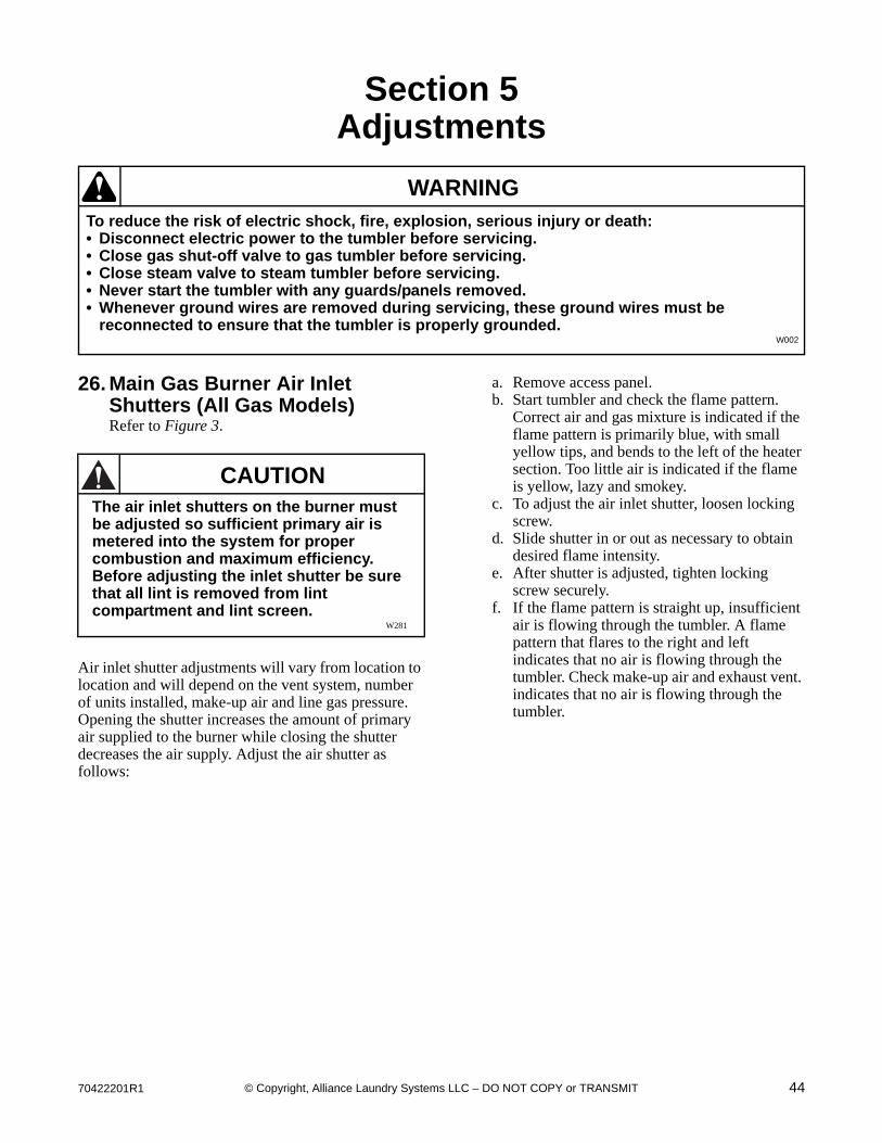
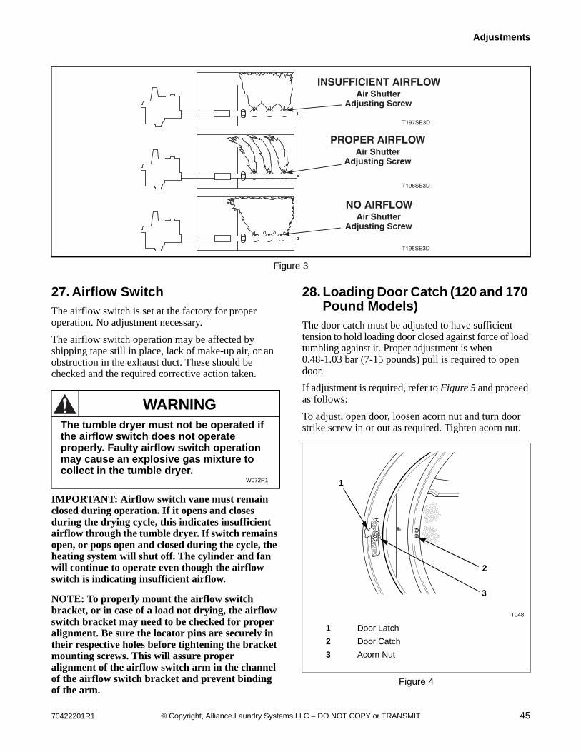
26. Main Gas Burner Air Inlet Shutters (All Gas Models)Refer to Figure 3.
Air inlet shutter adjustments will vary from location to location and will depend on the vent system, number of units installed, make-up air and line gas pressure. Opening the shutter increases the amount of primary air supplied to the burner while closing the shutter decreases the air supply. Adjust the air shutter as follows:
a. Remove access panel.b. Start tumbler and check the flame pattern.
Correct air and gas mixture is indicated if the flame pattern is primarily blue, with small yellow tips, and bends to the left of the heater section. Too little air is indicated if the flame is yellow, lazy and smokey.
c. To adjust the air inlet shutter, loosen locking screw.
d. Slide shutter in or out as necessary to obtain desired flame intensity.
e. After shutter is adjusted, tighten locking screw securely.
f. If the flame pattern is straight up, insufficient air is flowing through the tumbler. A flame pattern that flares to the right and left indicates that no air is flowing through the tumbler. Check make-up air and exhaust vent. indicates that no air is flowing through the tumbler.
To reduce the risk of electric shock, fire, explosion, serious injury or death:• Disconnect electric power to the tumbler before servicing.• Close gas shut-off valve to gas tumbler before servicing.• Close steam valve to steam tumbler before servicing.• Never start the tumbler with any guards/panels removed.• Whenever ground wires are removed during servicing, these ground wires must be
reconnected to ensure that the tumbler is properly grounded.W002
WARNING
CAUTIONThe air inlet shutters on the burner must be adjusted so sufficient primary air is metered into the system for proper combustion and maximum efficiency. Before adjusting the inlet shutter be sure that all lint is removed from lint compartment and lint screen.
W281
70422201R1 45© Copyright, Alliance Laundry Systems LLC – DO NOT COPY or TRANSMIT
Adjustments
27. Airflow SwitchThe airflow switch is set at the factory for proper operation. No adjustment necessary.
The airflow switch operation may be affected by shipping tape still in place, lack of make-up air, or an obstruction in the exhaust duct. These should be checked and the required corrective action taken.
IMPORTANT: Airflow switch vane must remain closed during operation. If it opens and closes during the drying cycle, this indicates insufficient airflow through the tumble dryer. If switch remains open, or pops open and closed during the cycle, the heating system will shut off. The cylinder and fan will continue to operate even though the airflow switch is indicating insufficient airflow.
NOTE: To properly mount the airflow switch bracket, or in case of a load not drying, the airflow switch bracket may need to be checked for proper alignment. Be sure the locator pins are securely in their respective holes before tightening the bracket mounting screws. This will assure proper alignment of the airflow switch arm in the channel of the airflow switch bracket and prevent binding of the arm.
28. Loading Door Catch (120 and 170 Pound Models)
The door catch must be adjusted to have sufficient tension to hold loading door closed against force of load tumbling against it. Proper adjustment is when 0.48-1.03 bar (7-15 pounds) pull is required to open door.
If adjustment is required, refer to Figure 5 and proceed as follows:
To adjust, open door, loosen acorn nut and turn door strike screw in or out as required. Tighten acorn nut.
Figure 3
T197SE3D
Air ShutterAdjusting Screw
INSUFFICIENT AIRFLOW
PROPER AIRFLOW
T196SE3D
Air ShutterAdjusting Screw
T195SE3D
Air ShutterAdjusting Screw
NO AIRFLOW
WARNINGThe tumble dryer must not be operated if the airflow switch does not operate properly. Faulty airflow switch operation may cause an explosive gas mixture to collect in the tumble dryer.
W072R1
T048I
1 Door Latch
2 Door Catch
3 Acorn Nut
Figure 4
2
3
1

46 70422201R1© Copyright, Alliance Laundry Systems LLC – DO NOT COPY or TRANSMIT
Adjustments
29. Loading Door Strike (200 Pound Models)
The loading door strike must be adjusted to have sufficient tension to hold loading door closed against force of load tumbling against it. Proper adjustment is when 8-15 pounds (35.6-66.7 N) pull is required to open door.
If adjustment is required, refer to Figure 5 and proceed as follows:
To adjust, open door, loosen adjustment screws and position strike for desired magnet engagement. Retighten screws.
Figure 5
30. Belt DriveThe drive assemblies consist of motors, belts, eyebolts and a step pulley.
The pulley diameters are sized to produce a cylinder speed of 37-39 RPM for 120 pound models or 29-31 RPM for 170 and 200 pound models.
The step pulley assembly is used for speed reduction as well as a means of adjusting belt tension. The pulley mounting plate is attached to the cabinet. The frame mounting plate has vertically slotted holes allowing up and down movement of the step pulley mounting plate for belt adjustment.
Adjust the belt tension as follows:
1. Disconnect electrical power to the tumble dryer before attempting any adjustments to the drive assembly.
2. Loosen pulley mounting plate bolts.
3. Loosen the upper nut on the final drive eyebolt.
4. Rotate the lower nut of the final drive eyebolt clockwise until proper belt tension is achieved.
5. Rotate upper nut clockwise against the lower nut in order to lock it into place.
6. Tighten pulley mounting plate bolts. Recheck belt tension.
7. If necessary, adjust the drive motor belt tension eyebolt using a similar procedure.
8. Adjust blower belt tension on 120 pound 50 Hertz tumble dryers and all 170 pound tumble dryers using a similar procedure.
NOTE: Proper tensions for new belts are measured with a Belt Tension Gauge:
Using a Belt Tension Gauge, the motor belt deflection should be 0.31 inch at five pounds pressure, and final drive belt deflection should be 0.25 inch at five pounds pressure.
Belts should not slip or make any noise when starting up under normal load.
TMB2359N
1 Door Strike
2 Adjustment Screws
1
2
Drive Motor Final Drive Blower
InitialAfter
Run-in InitialAfter
Run-in InitialAfter
Run-in
120 60-70 45-55 70-80 55-65 60-70 50-55
170 60-70 45-55 70-80 55-65 75-80 60-65
200 60-70 45-55 70-80 55-65 65-70 55-60
Table 1
70422201R1 47© Copyright, Alliance Laundry Systems LLC – DO NOT COPY or TRANSMIT
Adjustments
31. Cylinder ClearanceThe clearance between the cylinder rim and front panel must be adjusted so the cylinder is centered within the front panel opening when the cylinder is fully loaded and is turning. However, the adjustment should be made when the cylinder is empty.
NOTE: If the cylinder is not properly adjusted, the cylinder rim will rub against the front panel.
a. Open loading door.b. Check the gap between the center of the front
panel top flange and the cylinder rim. Proper adjustment is when the gap is 8/32 inch ± 3/32 inch. Refer to Figure 6. Perform steps d through i to adjust the cylinder rim/front panel flange clearance.
c. Check the cylinder fore/aft clearance between the inside front of the cylinder and the edge of the front panel flange. Proper adjustment is when the gap is 9/32 inch ± 1/32 inch. Refer to Figure 6. Perform steps j through n to adjust the cylinder fore/aft clearance.
Cylinder Rim/Front Panel FlangeClearance Adjustmenta. Support corner drive guard and remove
screws holding corner guard to rear of tumbler.
b. Support drive guard cover and remove screws holding guard to rear of tumbler.
c. Loosen rear bearing mounting screws. Refer to Figure 7.
d. Loosen the locknuts on rear adjustment screws. Refer to Figure 7.
e. Turn the adjusting screws in or out as necessary to obtain proper clearance between cylinder rim and front panel.
NOTE: Turning the adjusting screws clockwise will raise the cylinder and turning them counter-clockwise will lower the cylinder. Turn both screws evenly to adjust top and bottom clearance. Turn one or the other adjusting screw in or out to adjust side clearance.
f. After the cylinder is properly adjusted, tighten the adjusting screw locknuts and the rear bearing mounting screws.
g. Install drive guard cover.
NOTE: If adjusting the trunnion housing fails to correct the clearance, the problem is probably due to a worn trunnion shaft or defective bearings.
Cylinder Fore/Aft Clearance Adjustmenth. Support corner drive guard and remove
screws holding corner guard to rear of tumbler.
i. Support drive guard cover and remove screws holding guard to rear of tumbler.
j. Loosen setscrews in the front bearing assembly collar and rear bearing assembly collar. Refer to Figure 7.
k. Move cylinder assembly in or out as necessary to obtain proper clearance between the cylinder and the front panel.
l. After the cylinder is properly adjusted, tighten setscrews in the front and rear bearing assembly collars.
m. Install drive guard cover.

48 70422201R1© Copyright, Alliance Laundry Systems LLC – DO NOT COPY or TRANSMIT
Adjustments
Figure 6
TMB1786S
Inside Frontof Cylinder
CylinderRim
Front PanelFlange
(Top Shown)
Fore / AftClearance
Cylinder Rim /Front Panel Flange
Clearance
8/32" ± 3/32"
9/32" ± 1/32"
70422201R1 49© Copyright, Alliance Laundry Systems LLC – DO NOT COPY or TRANSMIT
Adjustments
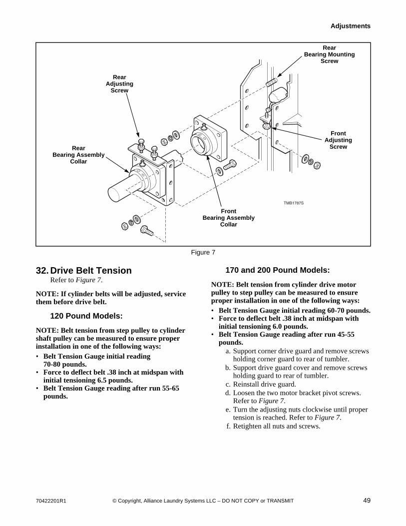
32. Drive Belt TensionRefer to Figure 7.
NOTE: If cylinder belts will be adjusted, service them before drive belt.
120 Pound Models:
NOTE: Belt tension from step pulley to cylinder shaft pulley can be measured to ensure proper installation in one of the following ways:• Belt Tension Gauge initial reading
70-80 pounds.• Force to deflect belt .38 inch at midspan with
initial tensioning 6.5 pounds.• Belt Tension Gauge reading after run 55-65
pounds.
170 and 200 Pound Models:
NOTE: Belt tension from cylinder drive motor pulley to step pulley can be measured to ensure proper installation in one of the following ways:• Belt Tension Gauge initial reading 60-70 pounds.• Force to deflect belt .38 inch at midspan with
initial tensioning 6.0 pounds.• Belt Tension Gauge reading after run 45-55
pounds.a. Support corner drive guard and remove screws
holding corner guard to rear of tumbler.b. Support drive guard cover and remove screws
holding guard to rear of tumbler.c. Reinstall drive guard.d. Loosen the two motor bracket pivot screws.
Refer to Figure 7.e. Turn the adjusting nuts clockwise until proper
tension is reached. Refer to Figure 7.f. Retighten all nuts and screws.
Figure 7
TMB1787S
RearBearing Mounting
Screw
RearBearing Assembly
Collar
FrontBearing Assembly
Collar
FrontAdjusting
Screw
RearAdjusting
Screw
50 70422201R1© Copyright, Alliance Laundry Systems LLC – DO NOT COPY or TRANSMIT
Adjustments
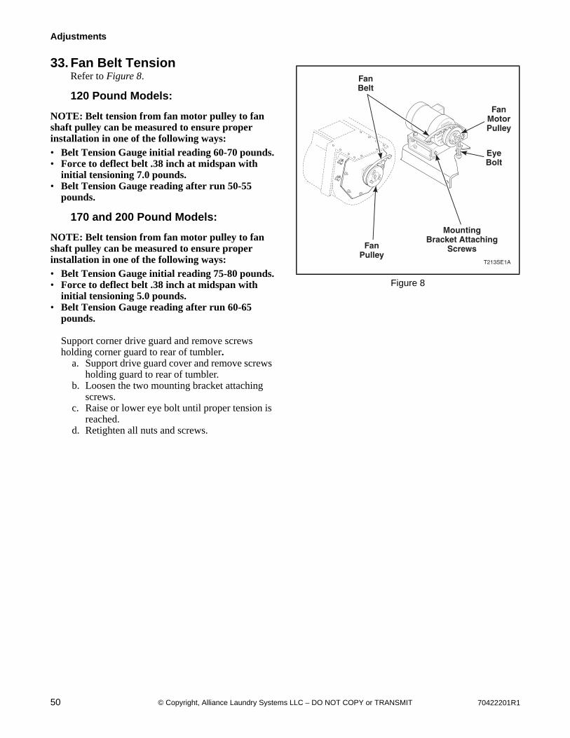
33. Fan Belt TensionRefer to Figure 8.
120 Pound Models:
NOTE: Belt tension from fan motor pulley to fan shaft pulley can be measured to ensure proper installation in one of the following ways:• Belt Tension Gauge initial reading 60-70 pounds.• Force to deflect belt .38 inch at midspan with
initial tensioning 7.0 pounds.• Belt Tension Gauge reading after run 50-55
pounds.
170 and 200 Pound Models:
NOTE: Belt tension from fan motor pulley to fan shaft pulley can be measured to ensure proper installation in one of the following ways:• Belt Tension Gauge initial reading 75-80 pounds.• Force to deflect belt .38 inch at midspan with
initial tensioning 5.0 pounds.• Belt Tension Gauge reading after run 60-65
pounds.
Support corner drive guard and remove screws holding corner guard to rear of tumbler.
a. Support drive guard cover and remove screws holding guard to rear of tumbler.
b. Loosen the two mounting bracket attaching screws.
c. Raise or lower eye bolt until proper tension is reached.
d. Retighten all nuts and screws.
Figure 8
T213SE1A
FanBelt
FanPulley
MountingBracket Attaching
Screws
EyeBolt
FanMotorPulley
70422201R1 51© Copyright, Alliance Laundry Systems LLC – DO NOT COPY or TRANSMIT
Section 6Hybrid Timer Control Troubleshooting
To reduce the risk of electric shock, fire, explosion, serious injury or death:• Disconnect electric power to the tumbler before servicing.• Close gas shut-off valve to gas tumbler before servicing.• Close steam valve to steam tumbler before servicing.• Never start the tumbler with any guards/panels removed.• Whenever ground wires are removed during servicing, these ground wires must be
reconnected to ensure that the tumbler is properly grounded.W002
WARNING
52 70422201R1© Copyright, Alliance Laundry Systems LLC – DO NOT COPY or TRANSMIT
Hybrid Timer Control Troubleshooting
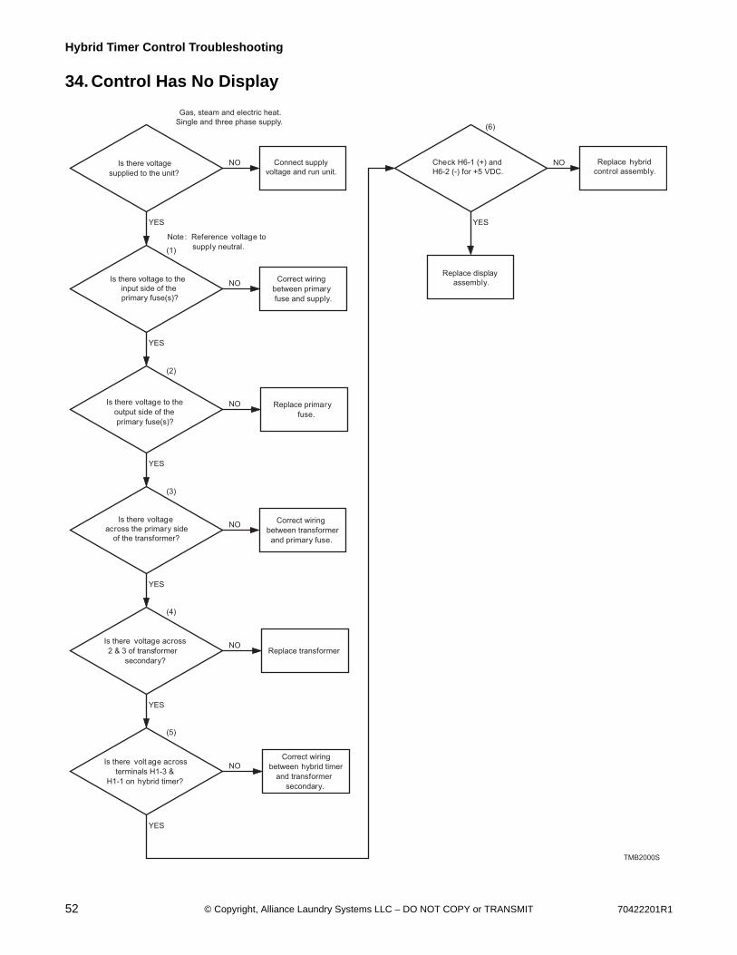
34. Control Has No Display
Is there voltage
supplied to the unit?
Is there voltage to the
input side of the
primary fuse(s)?
Is there voltage to the
output side of the
primary fuse(s)?
Is there voltage
across the primary side
of the transformer?
Is there voltage across
2 & 3 of transformer
secondary?
Is there volt age across
terminals H1-3 &
H1-1 on hybrid timer?
Check H6-1 (+) and
H6-2 (-) for +5 VDC.
Connect supply
voltage and run unit.
Correct wiring
between primary
fuse and supply.
Replace primary
fuse.
Correct wiring
between transformer
and primary fuse.
Replace transformer
Correct wiring
between hybrid timer
and transformer
secondary.
Replace hybrid
control assembly.
YES
(1)
(6)
(2)
(3)
(4)
(5)
NO
NO
NO
NO
NO
NO
NO
YES
YES
YES
YES
YES
YES
Replace display
assembly.
Gas, steam and electric heat.
Single and three phase supply.
Note: Reference voltage to
supply neutral.
TMB2000S
70422201R1 53© Copyright, Alliance Laundry Systems LLC – DO NOT COPY or TRANSMIT
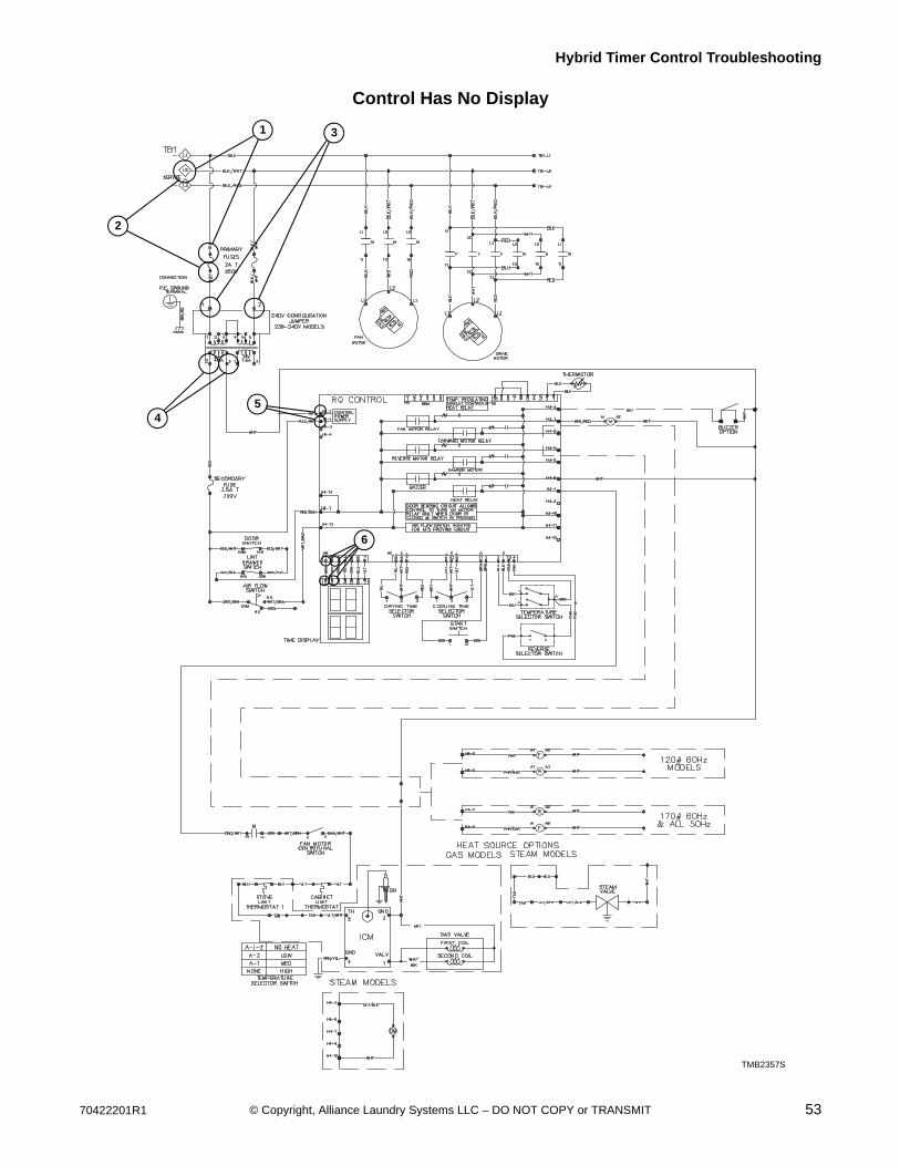
Hybrid Timer Control Troubleshooting
Control Has No Display
TMB2357S
5
1
2
3
4
6
TMB2357S

54 70422201R1© Copyright, Alliance Laundry Systems LLC – DO NOT COPY or TRANSMIT
Hybrid Timer Control Troubleshooting
35. Display Flashes “dr” With Door Closed
Is there voltage betweenH1-3 & H4-7 on
the control?
Replace hybridcontrol.
Is there power supplied to the unit?
NO
Is there voltage at input of primary fuses?
Is there voltage at output side of the primary fuses?
Is there voltageacross the
transformer primary?
Plug unit in and run it.
Correct wiring between primary fuse and power
supply.
Replace primary fuse(s).
Correct wiring between primary
fuse and transformer.
Is there voltage across terminals 2 &
3 of transformer secondary?
Replace transformer.
Is there voltage at the input of the
secondary fuse?
Is there voltage at output side of
secondary fuse?
Correct wiring between secondary
fuse and transformer.
Replace secondary fuse.
Correct wiring between lint panel switch
and hybrid control.
YES
NO
NO
NO
NO
NO
NO
NOYES
YES
YES
YES
YES
YES
YES
(1)
(2)
(3)
(4)
(5)
(6)
(7)
Is there voltage at COM of door switch?
Connect wiring between COM and
output of secondary fuse.
YES
NO
(8)
With door closed,is there voltage to NO of door
switch?
Replacedoor switch.
YES
NO
(9)
(10)
(11)
With lint panel closed, is there
power at NO connection?
Replacelint panel switch.
YES
NO
Is there voltage at COM of the
lint panel switch?
Connect wiring between door switch
and COM of lint panel switch.
YES
NO
TMB2052S
Gas, steam and electric heat.Single and three phase power supply.

70422201R1 55© Copyright, Alliance Laundry Systems LLC – DO NOT COPY or TRANSMIT
Hybrid Timer Control Troubleshooting
Display Flashes “dr” With Door Closed
TMB2357S
TMB2357S
2
3
4
5
6711
8
910
1
56 70422201R1© Copyright, Alliance Laundry Systems LLC – DO NOT COPY or TRANSMIT
Hybrid Timer Control Troubleshooting
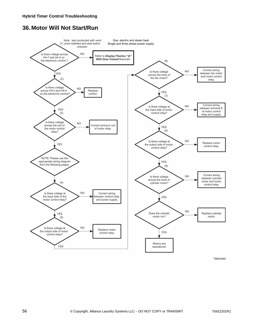
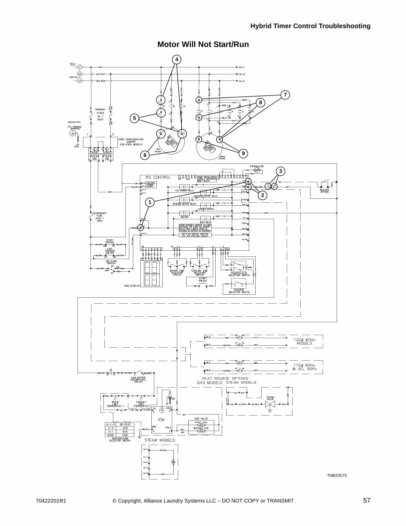
36. Motor Will Not Start/Run
Is there voltage across the lines of
cylinder motor?
Does the cylinder motor run?
Correct wiring between cylinder motor and motor
control relay.
Replace cylinder motor.
NO
NO
YES
YES
Motors are operational.
(9)
Is there voltage across H4-7 and H4-4 on
the electronic control ?
YES
Is there voltage across H4-3 and H4-4 on the electronic control?
Is there voltage at the input side of the motor control relay?
Is there voltage at the output side of motor
control relay?
Is there voltageacross the lines of
the fan motor?
Is there voltage at the input side of motor
control relay?
Is there voltage at the output side of motor
control relay?
Replace control.
Correct wiring between control relay
and power supply.
Replace motor control relay.
Correct wiring between fan motor and motor control
relay.
Correct wiring between terminal 6
of motor control relay and supply.
Replace motor control relay.
NO
YES
YES
YES
YESNO
NO
NO
NO
YES
NO
Note: test conducted with vend price satisfied and start button
pressed.
YES
NO
(1)
Is there voltage across the coil of the motor control
relay?
Correct wiring to coil of motor relay .
(2)
YES
NO
(3)
(4)
(5)
(6)
(7)
(8)
TMB2409S
Gas, electric and steam heat.Single and three phase power supply.
NOTE: Please use theappropriate wiring diagramfrom the following pages.
Refer to Display Flashes “dr”With Door Closed flowchart.
TMB2409S
70422201R1 57© Copyright, Alliance Laundry Systems LLC – DO NOT COPY or TRANSMIT
Hybrid Timer Control Troubleshooting
Motor Will Not Start/Run
TMB2357S
TMB2357S
12
3
4
5
6
7
8
9
58 70422201R1© Copyright, Alliance Laundry Systems LLC – DO NOT COPY or TRANSMIT
Hybrid Timer Control Troubleshooting
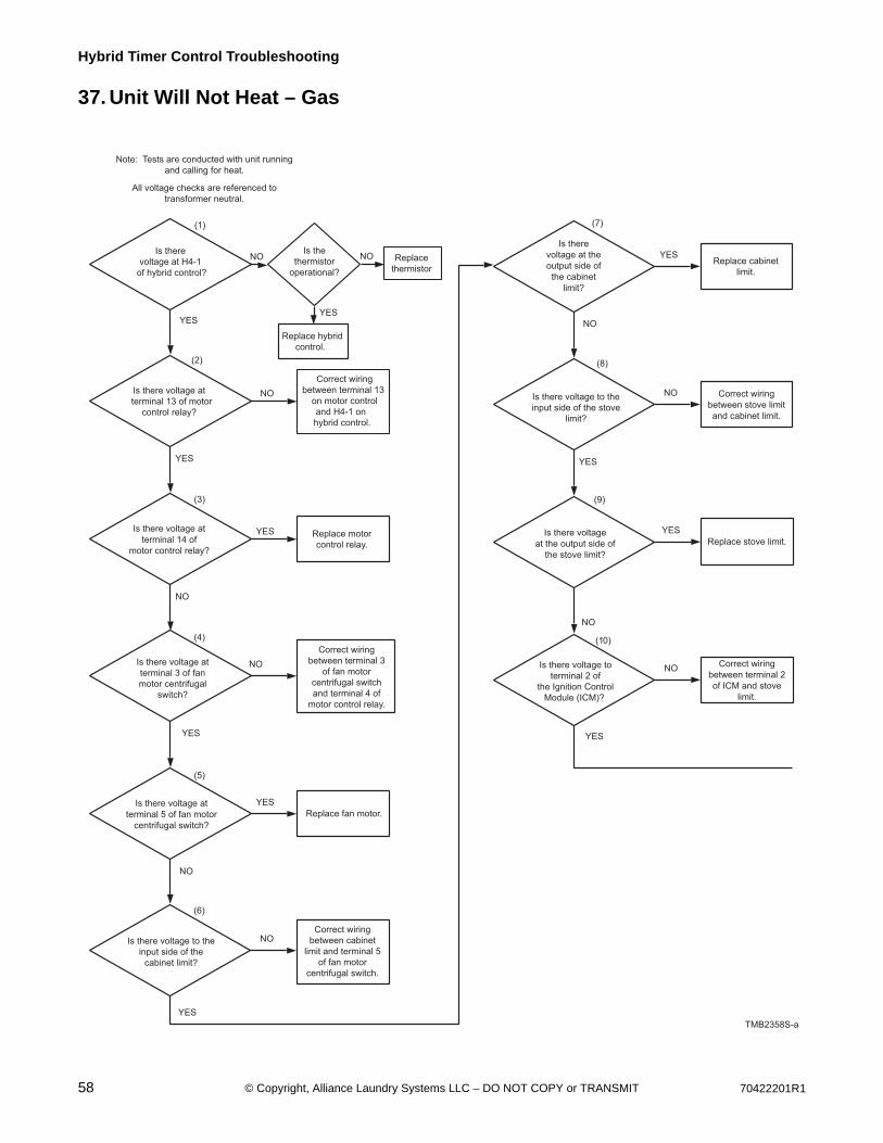
37. Unit Will Not Heat – Gas
Note: Tests are conducted with unit running
and calling for heat.
All voltage checks are referenced to
transformer neutral.
Correct wiring
between terminal 13
on motor control
and H4-1 on
hybrid control.
Is there voltage at
terminal 13 of motor
control relay?
Replace motor
control relay.
Is there voltage at
terminal 14 of
motor control relay?
Correct wiring
between terminal 3
of fan motor
centrifugal switch
and terminal 4 of
motor control relay.
Is there voltage at
terminal 3 of fan
motor centrifugal
switch?
Replace fan motor.Is there voltage at
terminal 5 of fan motor
centrifugal switch?
Correct wiring
between cabinet
limit and terminal 5
of fan motor
centrifugal switch.
Is there voltage to the
input side of the
cabinet limit?
Replace cabinet
limit.
Is there
voltage at the
output side of
the cabinet
limit?
Correct wiring
between stove limit
and cabinet limit.
Is there voltage to the
input side of the stove
limit?
Is the
thermistor
operational?
Replace hybrid
control.
Replace
thermistor
NONO
YESYES
NO
YES
NO
YES
YES
YES
NO
YES
YES
NO
NO
YES
NO
NO
YES
(1)
(2)
(3)
(4)
(5)
(6)
(7)
(8)
(9)
Replace stove limit.
NO
YESIs there voltage
at the output side of
the stove limit?
Correct wiring
between terminal 2
of ICM and stove
limit.
Is there voltage to
terminal 2 of
the Ignition Control
Module (ICM)?
NO
(10)
Is there
voltage at H4-1
of hybrid control?
TMB2358S-a
70422201R1 59© Copyright, Alliance Laundry Systems LLC – DO NOT COPY or TRANSMIT
Hybrid Timer Control Troubleshooting
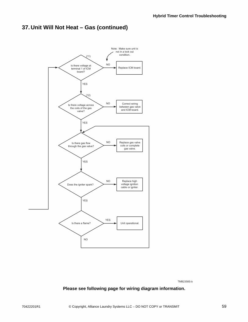
37. Unit Will Not Heat – Gas (continued)
Please see following page for wiring diagram information.
TMB2006S
TMB2358S-b
Replace ICM board.Is there voltage at
terminal 1 of ICM
board?
Correct wiring
between gas valve
and ICM board.
Is there voltage across
the coils of the gas
valve?
NO
YES
YES
NO
(11)
(12)
Note: Make sure unit is
not in a lock out
condition.
Replace gas valve
coils or complete
gas valve.
Is there gas flow
through the gas valve?
Replace high
voltage ignition
cable or igniter.Does the igniter spark?
NO
YES
NO
YES
Unit operational.Is there a flame?
YES
NO
60 70422201R1© Copyright, Alliance Laundry Systems LLC – DO NOT COPY or TRANSMIT
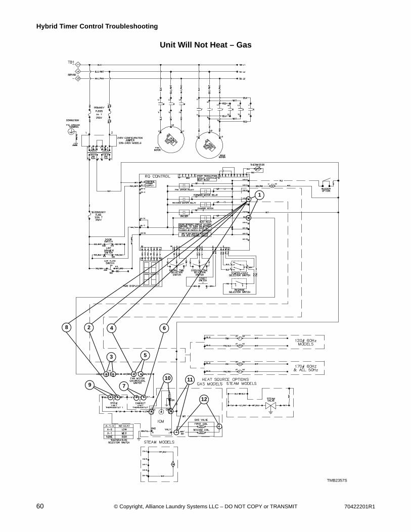
Hybrid Timer Control Troubleshooting
Unit Will Not Heat – Gas
TMB2357STMB2357S
1
2
3
4
5
6
7
8
910 11
12

70422201R1 61© Copyright, Alliance Laundry Systems LLC – DO NOT COPY or TRANSMIT
Hybrid Timer Control Troubleshooting
38. Error Codes
Display Definition Corrective Action
OP Open thermistor error. • Check thermistor. Replace if inoperative.• Check wiring between control and
thermistor. Refer to wiring diagram for proper wiring.
• Check control. Replace if inoperative.
SH Shorted thermistor error. • Check thermistor. Replace if inoperative.• Check wiring between control and
thermistor. Refer to wiring diagram for proper wiring.
• Check control. Replace if inoperative.
AF-1 Airflow switch closed when cycle started. • Check airflow switch. Replace if inoperative.
AF-2 Airflow switch failed to closed after cycle started.
• Check airflow switch. Replace if inoperative.
AF (flashing) Airflow switch opened/closed 5 or more times in a running cycle.
• Check airflow switch. Replace if inoperative.
To reduce the risk of electric shock, fire, explosion, serious injury or death:• Disconnect electric power to the tumbler before servicing.• Close gas shut-off valve to gas tumbler before servicing.• Close steam valve to steam tumbler before servicing.• Never start the tumbler with any guards/panels removed.• Whenever ground wires are removed during servicing, these ground wires must be
reconnected to ensure that the tumbler is properly grounded.W002
WARNING
62 70422201R1© Copyright, Alliance Laundry Systems LLC – DO NOT COPY or TRANSMIT
Section 7On Premise Micro Control (RM)
Troubleshooting
To reduce the risk of electric shock, fire, explosion, serious injury or death:• Disconnect electric power to the tumbler before servicing.• Close gas shut-off valve to gas tumbler before servicing.• Close steam valve to steam tumbler before servicing.• Never start the tumbler with any guards/panels removed.• Whenever ground wires are removed during servicing, these ground wires must be
reconnected to ensure that the tumbler is properly grounded.W002
WARNING
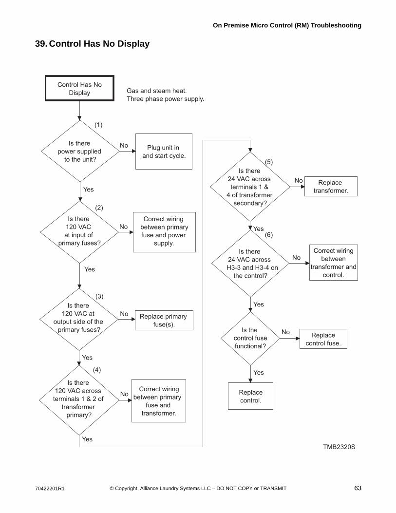
70422201R1 63© Copyright, Alliance Laundry Systems LLC – DO NOT COPY or TRANSMIT
On Premise Micro Control (RM) Troubleshooting
39. Control Has No Display
Control Has No
Display
Is there
power supplied
to the unit?
Is there
120 VAC
at input of
primary fuses?
Yes
Plug unit in
and start cycle.
No
Correct wiring
between primary
fuse and power
supply.
No
Is there
120 VAC across
terminals 1 & 2 of
transformer
primary?
NoCorrect wiring
between primary
fuse and
transformer.
Is there
24 VAC across
terminals 1 &
4 of transformer
secondary?
No Replace
transformer.
TMB2320S
Yes
NoCorrect wiring
between
transformer and
control.
Is there
24 VAC across
H3-3 and H3-4 on
the control?
Yes
Is there
120 VAC at
output side of the
primary fuses?
No Replace primary
fuse(s).
Yes
Gas and steam heat.
Three phase power supply.
(1)
(2)
(3)
Is the
control fuse
functional?
Replace
control fuse.
Replace
control.
Yes
No
(4)
(5)
(6)
Yes
Yes
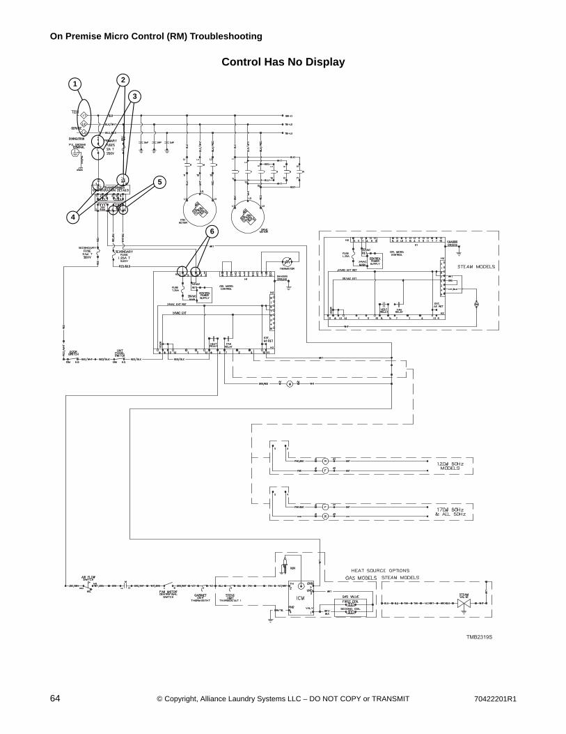
64 70422201R1© Copyright, Alliance Laundry Systems LLC – DO NOT COPY or TRANSMIT
On Premise Micro Control (RM) Troubleshooting
Control Has No Display
TMB2319S
4
2
3
5
1
6
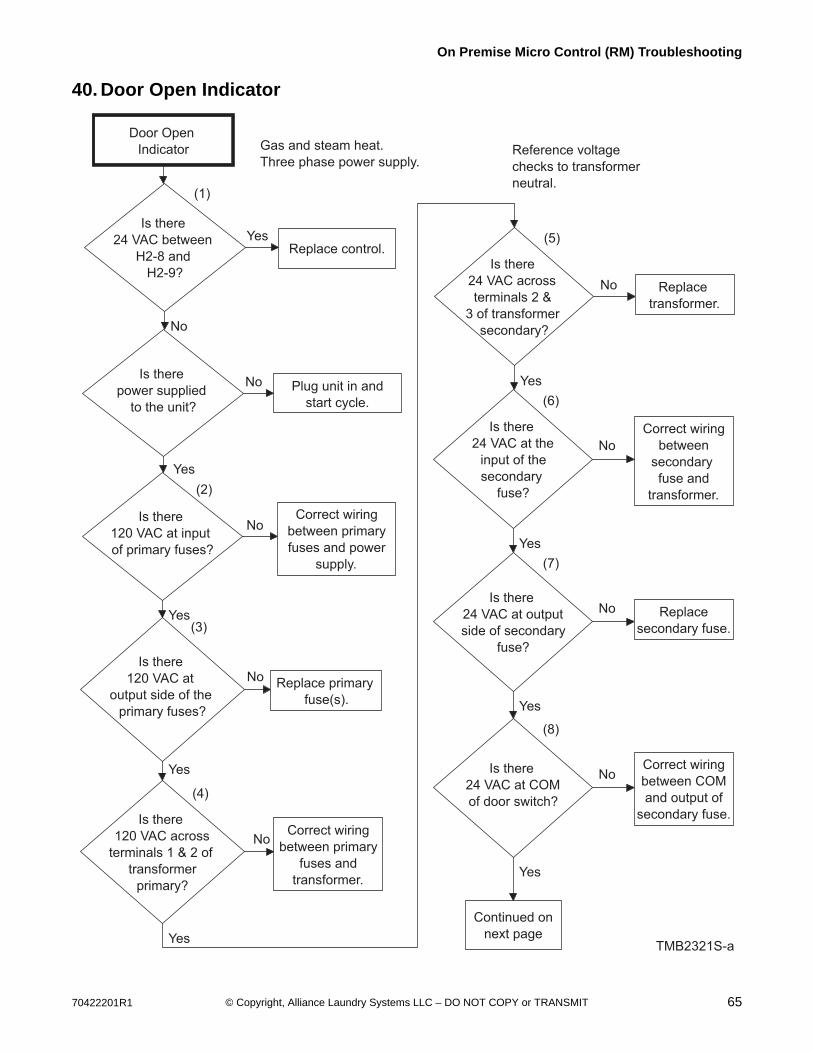
70422201R1 65© Copyright, Alliance Laundry Systems LLC – DO NOT COPY or TRANSMIT
On Premise Micro Control (RM) Troubleshooting
40. Door Open Indicator
Is there
24 VAC at the
input of the
secondary
fuse?
Door Open
Indicator
Is there
24 VAC between
H2-8 and
H2-9?
Is there
power supplied
to the unit?
No
Replace control.Yes
Plug unit in and
start cycle.
No
Is there
120 VAC at
output side of the
primary fuses?
NoReplace primary
fuse(s).
Is there
120 VAC across
terminals 1 & 2 of
transformer
primary?
NoCorrect wiring
between primary
fuses and
transformer.
TMB2321S-a
Yes
No Replace
transformer.
Is there
24 VAC across
terminals 2 &
3 of transformer
secondary?
Yes
Is there
120 VAC at input
of primary fuses?
NoCorrect wiring
between primary
fuses and power
supply.
Yes
Gas and steam heat.
Three phase power supply.
(1)
(2)
(3)
(4)
(5)
Yes
Reference voltage
checks to transformer
neutral.
(6)
Correct wiring
between
secondary
fuse and
transformer.
Yes
No
Is there
24 VAC at output
side of secondary
fuse?
(7)
No Replace
secondary fuse.
Is there
24 VAC at COM
of door switch?
(8)
NoCorrect wiring
between COM
and output of
secondary fuse.
Yes
Yes
Continued on
next page
Yes
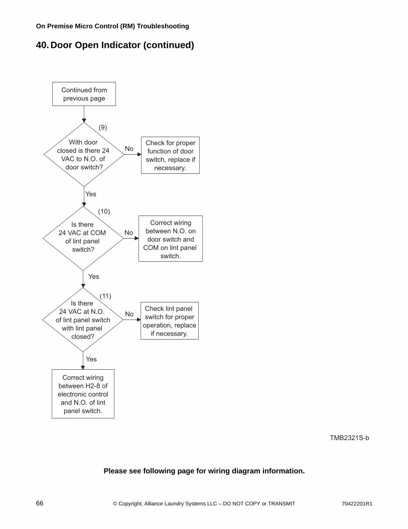
66 70422201R1© Copyright, Alliance Laundry Systems LLC – DO NOT COPY or TRANSMIT
On Premise Micro Control (RM) Troubleshooting
40. Door Open Indicator (continued)
Please see following page for wiring diagram information.
With door
closed is there 24
VAC to N.O. of
door switch?
Is there
24 VAC at COM
of lint panel
switch?
Yes
Check for proper
function of door
switch, replace if
necessary.
No
Correct wiring
between N.O. on
door switch and
COM on lint panel
switch.
No
TMB2321S-b
Is there
24 VAC at N.O.
of lint panel switch
with lint panel
closed?
NoCheck lint panel
switch for proper
operation, replace
if necessary.
Yes
(9)
(11)
Correct wiring
between H2-8 of
electronic control
and N.O. of lint
panel switch.
Continued from
previous page
(10)
Yes
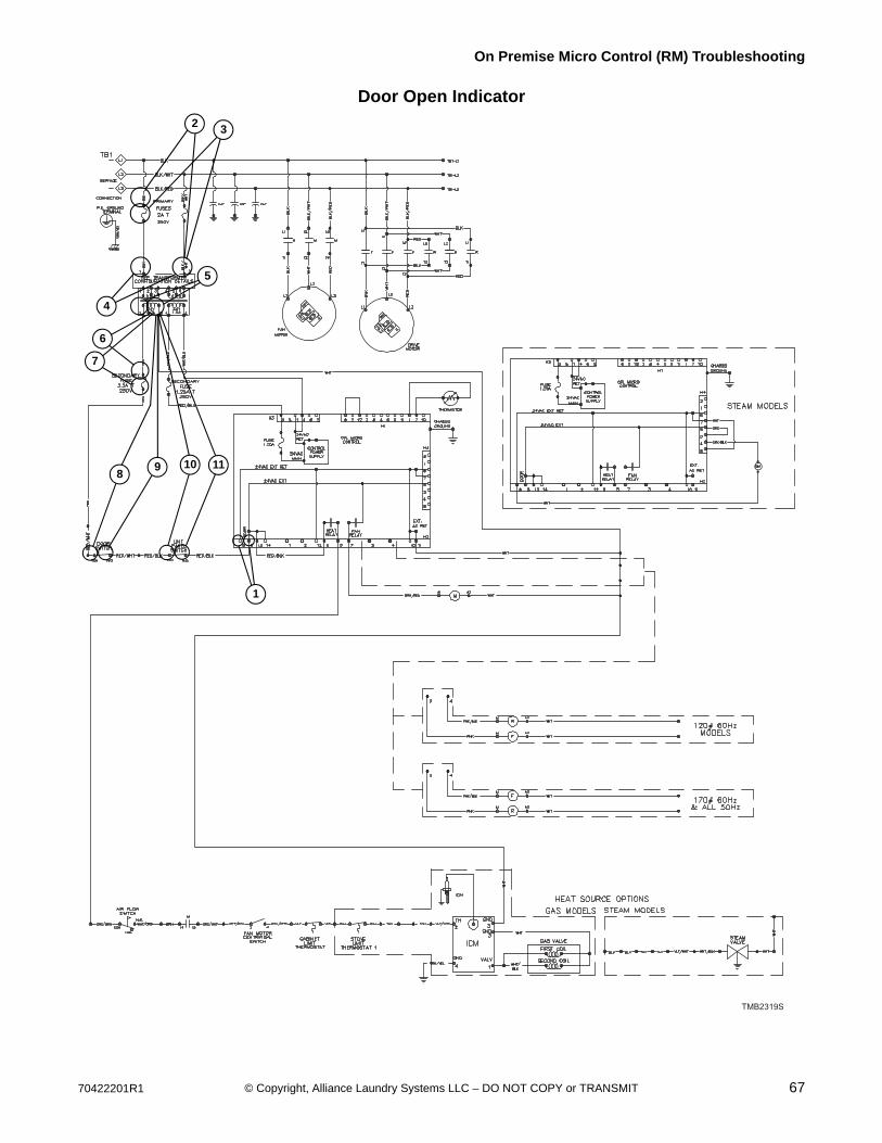
70422201R1 67© Copyright, Alliance Laundry Systems LLC – DO NOT COPY or TRANSMIT
On Premise Micro Control (RM) Troubleshooting
Door Open Indicator
TMB2319S
4
2 3
5
6
7
1
89 1110

68 70422201R1© Copyright, Alliance Laundry Systems LLC – DO NOT COPY or TRANSMIT
On Premise Micro Control (RM) Troubleshooting
41. Motor Will Not Start/Run
Motor Will Not
Start/Run
Is there
voltage between
H2-7 and H3-4?
Is there
24 VAC across
the coil of the motor
control relay?
Yes
Replace
control.
No
Correct wiring
to coil of
motor relay .
No
TMB2370S
Yes
Gas and steam heat.
Three phase power supply.
(1)
(2)
Note: For high voltage three
phase supply (200 volts or
higher), the motor is
supplied by L1, L2,
L3 through the motor
contactor terminals T1,
T2, T3. Make the appropriate
adjustments when doing
voltage checks.
Is there
supply voltage
between L1-L2, L2-L3
and L1-L3
of motor?
Replace
motor.
Correct wiring
between motor
and motor
contactor.
No
No
Yes
(5)
Is there
supply voltage
at L1-L2, L2-L3 and
L1-L3 at the motor
contactor?
(3)
Correct wiring
between L1, L2,
L3 and power
supply.
Is there
supply voltage
across T1-T2, T2-T3
and T1-T3 on the
motor contactor?
No
Yes
Replace motor
control relay.
(4)
Yes
Note: Test conducted with vend
price satisfied and start button
pressed.
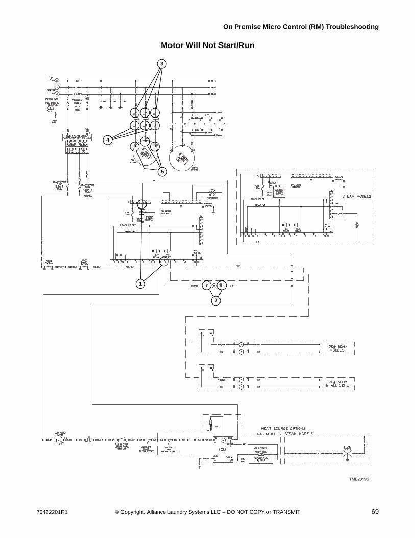
70422201R1 69© Copyright, Alliance Laundry Systems LLC – DO NOT COPY or TRANSMIT
On Premise Micro Control (RM) Troubleshooting
Motor Will Not Start/Run
TMB2319S
2
4
5
1
3
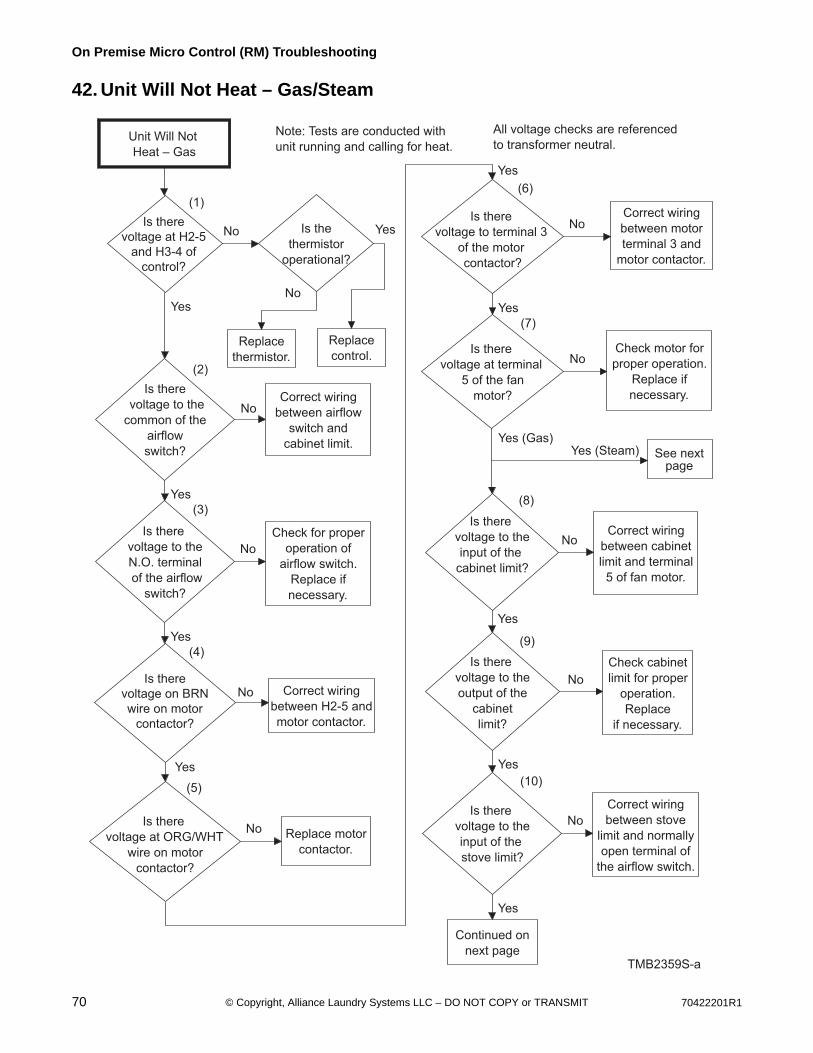
70 70422201R1© Copyright, Alliance Laundry Systems LLC – DO NOT COPY or TRANSMIT
On Premise Micro Control (RM) Troubleshooting
42. Unit Will Not Heat – Gas/Steam
Is there
voltage to the
N.O. terminal
of the airflow
switch?
Unit Will Not
Heat – Gas
Is there
voltage at H2-5
and H3-4 of
control?
Is there
voltage on BRN
wire on motor
contactor?
Yes
Replace
thermistor.
Correct wiring
between H2-5 and
motor contactor.
No
Is there
voltage to the
input of the
cabinet limit?
NoCorrect wiring
between cabinet
limit and terminal
5 of fan motor.
Is there
voltage to the
output of the
cabinet
limit?
No
Check cabinet
limit for proper
operation.
Replace
if necessary.
TMB2359S-a
Yes
NoCorrect wiring
between airflow
switch and
cabinet limit.
Is there
voltage to the
common of the
airflow
switch?
Yes
Is there
voltage at ORG/WHT
wire on motor
contactor?
Yes
All voltage checks are referenced
to transformer neutral.
(1)
(4)
(8)
(9)
(2)
Note: Tests are conducted with
unit running and calling for heat.
Is the
thermistor
operational?
No
Replace
control.
(5)
Replace motor
contactor.
No
Yes
No
(3)
Check for proper
operation of
airflow switch.
Replace if
necessary.
Yes
No
Is there
voltage to the
input of the
stove limit?
Correct wiring
between stove
limit and normally
open terminal of
the airflow switch.
(10)
Yes
No
Continued on
next page
Yes
Is there
voltage to terminal 3
of the motor
contactor?
(6)
Correct wiring
between motor
terminal 3 and
motor contactor.
Is there
voltage at terminal
5 of the fan
motor?
No
Yes
Yes (Gas)Yes (Steam)
Check motor for
proper operation.
Replace if
necessary.
No
(7)
Yes
See nextpage

70422201R1 71© Copyright, Alliance Laundry Systems LLC – DO NOT COPY or TRANSMIT
On Premise Micro Control (RM) Troubleshooting
42. Unit Will Not Heat – Gas/Steam (continued)
Please see following page for wiring diagram information.
TMB2359S-b
Is there
voltage to the
output side of the
stove limit?
Is there
voltage to
terminal 2 of the
Ignition Control
Module (ICM)?
Yes
Check operation
of stove limit.
Replace if
necessary.
No
Correct wiring
between terminal 2
of ICM and stove
limit.
No
Is there
voltage at
terminal 1 of
ICM board?
No Replace
ICM board.
Yes
(11)
(13)
Continued from
previous page
(12)
Note: Make sure unit is
not in a lockout condition.
Is there
voltage across
the coils of the
gas valve?
NoCorrect wiring
between gas
valve and
ICM board.
(14)
Yes
Is there gas flow
through the gas
valve?
Replace gas
valve coils or
complete
gas valve.
Yes
No
Does the igniter
spark?
Replace high
voltage ignition
cable, igniter or
ICM board.
Is there a
flame?
Unit
operational.
Yes
No
Yes
Yes
No
Yes (Gas)
Yes (Steam)
Continued fromprevious page
Is there
24 VAC across
the coil of the
steam valve?
NoCorrect wiring
between steam
valve coil and
motor.
Does the
steam valve
coil have
continuity?
No Replace the
steam valve
coil.
Yes
No Connect the
steam supply.
Is the steam
supply
functional?
Yes
Replace or
rebuild the
steam valve.
Yes
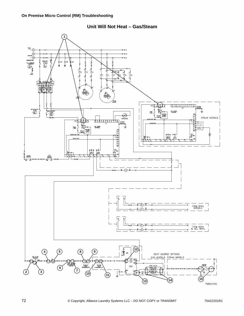
72 70422201R1© Copyright, Alliance Laundry Systems LLC – DO NOT COPY or TRANSMIT
On Premise Micro Control (RM) Troubleshooting
Unit Will Not Heat – Gas/Steam
TMB2319S
2 3
13 14
4 5
67
8 9
10 11
12
15
1

70422201R1 73© Copyright, Alliance Laundry Systems LLC – DO NOT COPY or TRANSMIT
On Premise Micro Control (RM) Troubleshooting
43. Error CodesOP - Indicates physical “open” in the thermistor circuit. Possible causes are: 1) thermistor, 2) wiring between con-trol and thermistor, 3) control.SH - Indicates a “short” in the thermistor circuit. Possible causes are: 1) shorted thermistor, 2) a short in the wiring between control and thermistor, 3) control.
To reduce the risk of electric shock, fire, explosion, serious injury or death:• Disconnect electric power to the dryer(s) before servicing.• Close gas shut-off valve to gas dryer(s) before servicing.• Never start the dryer(s) with any guards/panels removed.• Whenever ground wires are removed during servicing, these ground wires must be
reconnected to ensure that the dryer is properly grounded.W001R1
WARNING
Display Definition Corrective Action
OP Indicates an open circuit in the thermistor. • Check thermistor. Replace if inoperative.• Check wiring between control and
thermistor. Refer to wiring diagram for proper wiring.
• Check control. Replace if inoperative.
SH Indicates a short circuit in the thermistor. • Check thermistor. Replace if inoperative.• Check wiring between control and
thermistor. Refer to wiring diagram for proper wiring.
• Check control. Replace if inoperative.
74 70422201R1© Copyright, Alliance Laundry Systems LLC – DO NOT COPY or TRANSMIT
Section 8LED OPL and UniLinc Troubleshooting
Models with RE and RU Control Suffixes
NOTE: The UniLinc’s Inputs and Outputs Menu can be used to check the current status of inputs as well as control the state of any output.
Both UniLinc and LED OPL Controls contain a comprehensive test cycle that can be used to verify machine configuration and functionality.
Diagnostic LEDsBefore troubleshooting the following errors, verify that the front-end control is trying to turn the output on by checking for the corresponding red diagnostic LED on the Input/Output (I/O) Board. Diagnostic LEDs can be found for the following outputs:
• Forward Motor
• Reverse Motor
• Fan Motor
• Damper Motor
• External Alarm
• Heater
In addition, the I/O Board has a LED labeled “+5VDC” that indicates whether the I/O Board is powered. When lit, the I/O Board and front-end control should both be powered. If the LED does not light and both are powered, verify that the loading door and lint door are closed, and, if checking heater-related errors, that the heat interlock chain is closed (AirFlow Switch, Fan Contactor, Fan Centrifugal Switch, Cabinet Limit and Stove Limit). If the LED still does not light, check the connection between the front-end control and the I/O Board. If they are connected properly and voltage is present at the pin corresponding to the error with the ground pin on the same connector, the I/O Board must be replaced. If voltage is not present, the front-end control must be replaced.
To reduce the risk of electric shock, fire, explosion, serious injury or death:• Disconnect electric power to the tumble dryer before servicing.• Close gas shut-off valve to gas tumble dryer before servicing.• Close steam valve to steam tumble dryer before servicing.• Never start the tumble dryer with any guards/panels removed.• Whenever ground wires are removed during servicing, these ground wires must be
reconnected to ensure that the tumble dryer is properly grounded.W002R1
WARNING

70422201R1 75© Copyright, Alliance Laundry Systems LLC – DO NOT COPY or TRANSMIT
LED OPL and UniLinc Troubleshooting
44. No Fan Motor Rotation
Is there 24 volts AC at
H6-1 to H6-9?
Is there 24 volts AC st
H6-5 to H6-11?
Check Transformer
and Fuse F3.
Replace or
repair harness.
No
Yes
YesYes
Yes
Yes
Yes
No No
TMB2374S
NOTE: All mechanical checks should be performed prior to starting the electrical checks. Ensure the belt(s), basket, idler
and pulleys are rotating freely.
Is there 24 volts AC at
contactor A1 to A2
(or Brown/Red to White)?
Is there 5 volts
DC at H3-1 to H3-11 with
contactor commanded to close
and 0 volts DC with
contactor not
commanded?
Check control harness
H3 and front-end control (AP2.)
Replace as required.
Check control harness
H3 and I/O board (API).
Replace or repair
as required.
NOTE: The following checks are DC voltage checks.
CAUTION: Always power down the machine PRIOR to
disconnecting or connecting the H3 harness. Once
harness is disconnected, you can power up the machine
for troubleshooting. Failure to do so may damage
the front-end control.
NOTE: The H3 harness will need to remain
connected during this test.
No
Replace contactor.Is there line voltage
on the motor side
of the contactor?
No
Replace contactor.
No
Check incoming
power and wiring.
Replace or repair
as required.
No
Is contactor
energizing?
NOTE: The following checks are AC voltage
checks and should be equal to the line voltage
of the machine. Refer to the serial plate of the
machine for correct line voltage. The machine’s
motor(s) may be single or three phase.
Is there line voltage
on the line side of the
contactor?
Yes
Replace contactor.
Repair or replace
wiring harness.
No
Yes
Is there line voltage
at the motor?
(1)
(2)
(4)
(3)
(5)
(6)
(7)
NOTE: If the voltage is present but
lower than 24volts AC, ensure the
correct transformer configuration
jumper is installed.
TMB2374S
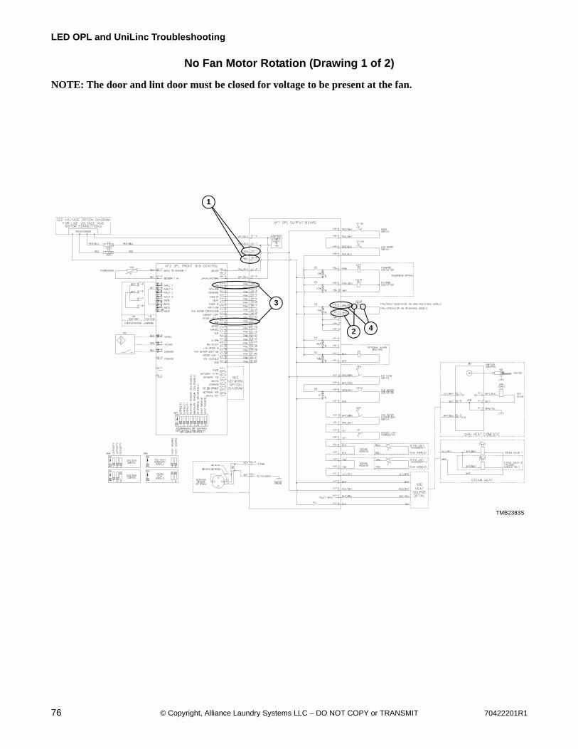
76 70422201R1© Copyright, Alliance Laundry Systems LLC – DO NOT COPY or TRANSMIT
LED OPL and UniLinc Troubleshooting
No Fan Motor Rotation (Drawing 1 of 2)
NOTE: The door and lint door must be closed for voltage to be present at the fan.
TMB2383S
1
3
2 4
TMB2383S
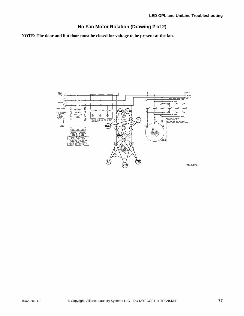
70422201R1 77© Copyright, Alliance Laundry Systems LLC – DO NOT COPY or TRANSMIT
LED OPL and UniLinc Troubleshooting
No Fan Motor Rotation (Drawing 2 of 2)
NOTE: The door and lint door must be closed for voltage to be present at the fan.
TMB2387S
6A
TMB2387S7A 7B
7C
6B
5B5A
6C
5C
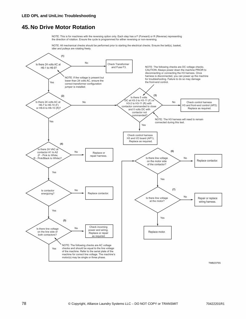
78 70422201R1© Copyright, Alliance Laundry Systems LLC – DO NOT COPY or TRANSMIT
LED OPL and UniLinc Troubleshooting
45. No Drive Motor Rotation
Is there 24 volts AC at
H6-1 to H6-9?
Is there 24 volts AC at
H6-7 to H6-10 (F)
or H6-6 to H6-10 (R)?
Check Transformer
and Fuse F3.
Replace or
repair harness.
No
Yes
Yes
Yes
Yes
Yes
Yes
No No
TMB2375S
NOTE: This is for machines with the reversing option only. Each step has a F (Forward) or R (Reverse) representing
the direction of rotation. Ensure the cycle is programmed for either reversing or non-reversing.
NOTE: All mechanical checks should be performed prior to starting the electrical checks. Ensure the belt(s), basket,
idler and pulleys are rotating freely.
Is there 24 VAC at
contactor A1 to A2
(F - Pink to White;
R - Pink/Black to White)?
Is there 5 volts
DC at H3-3 to H3-11 (F) or
H3-2 to H3-11 (R) with
contactor commanded to close
and 0 volts DC with
contactor not
commanded?
Check control harness
H3 and front-end control (AP2).
Replace as required.
Check control harness
H3 and I/O board (AP1).
Replace as required.
NOTE: The following checks are DC voltage checks.
CAUTION: Always power down the machine PRIOR to
disconnecting or connecting the H3 harness. Once
harness is disconnected, you can power up the machine
for troubleshooting. Failure to do so may damage
the front-end control.
NOTE: The H3 harness will need to remain
connected during this test.
No
Replace contactor.Is there line voltage
on the motor side
of the contactor?
No
Replace contactor.
No
Check incoming
power and wiring.
Replace or repair
as required.
No
Is contactor
energizing?
NOTE: The following checks are AC voltage
checks and should be equal to the line voltage
of the machine. Refer to the serial plate of the
machine for correct line voltage. The machine’s
motor(s) may be single or three phase.
Is there line voltage
on the line side of
both contactors?
Yes
Repair or replace
wiring harness.
Replace motor.
No
Yes
Is there line voltage
at the motor?
(1)
(2)
(4)
(3)
(5)
(6)
(7)
NOTE: If the voltage is present but
lower than 24 volts AC, ensure the
correct transformer configuration
jumper is installed.
TMB2375S
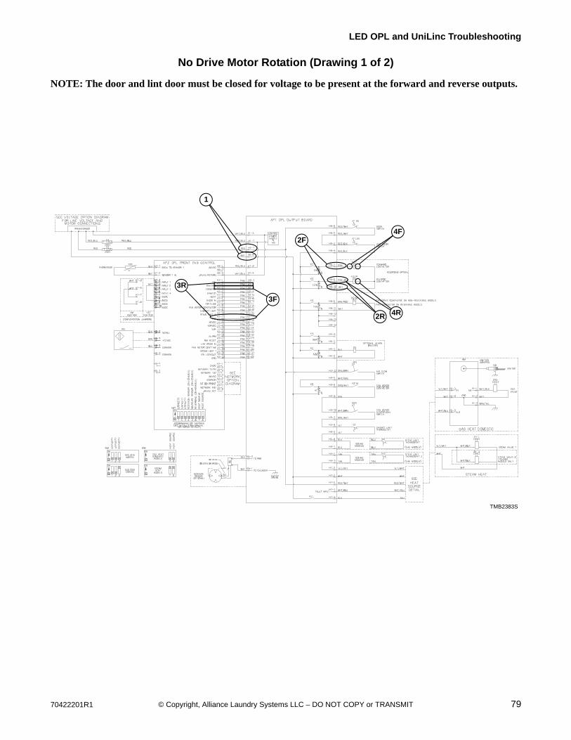
70422201R1 79© Copyright, Alliance Laundry Systems LLC – DO NOT COPY or TRANSMIT
LED OPL and UniLinc Troubleshooting
No Drive Motor Rotation (Drawing 1 of 2)
NOTE: The door and lint door must be closed for voltage to be present at the forward and reverse outputs.
TMB2383S
1
3F
2R 4R
TMB2383S
3R
4F2F
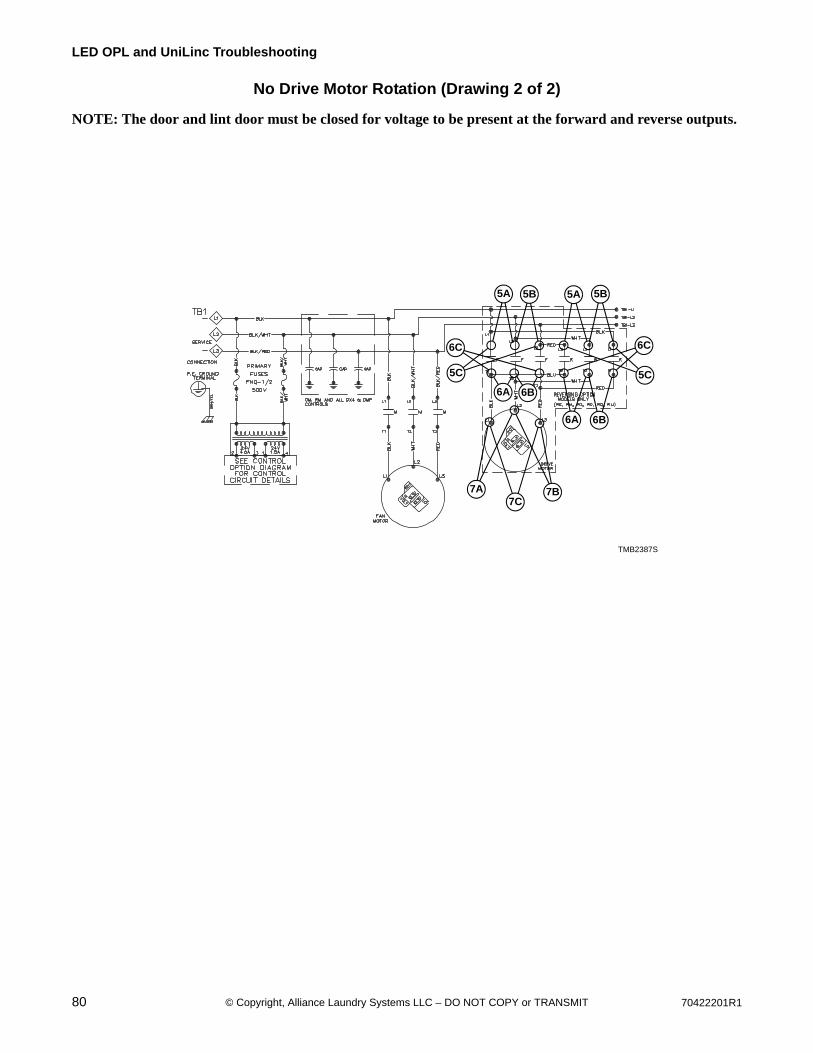
80 70422201R1© Copyright, Alliance Laundry Systems LLC – DO NOT COPY or TRANSMIT
LED OPL and UniLinc Troubleshooting
No Drive Motor Rotation (Drawing 2 of 2)
NOTE: The door and lint door must be closed for voltage to be present at the forward and reverse outputs.
TMB2387S
6A
TMB2387S
7A7C
6B
5B5A
5C
6C
7B
5B5A
6B6A
5C
6C
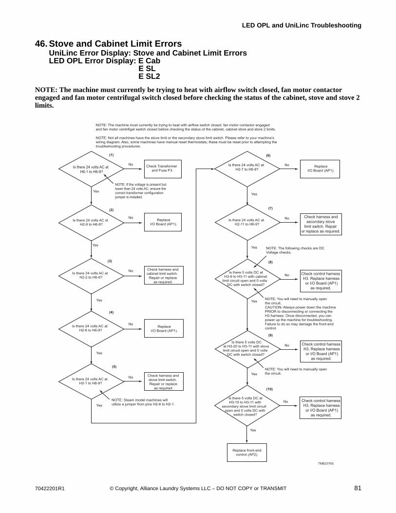
70422201R1 81© Copyright, Alliance Laundry Systems LLC – DO NOT COPY or TRANSMIT
LED OPL and UniLinc Troubleshooting
46. Stove and Cabinet Limit ErrorsUniLinc Error Display: Stove and Cabinet Limit ErrorsLED OPL Error Display: E Cab
E SL E SL2
NOTE: The machine must currently be trying to heat with airflow switch closed, fan motor contactor engaged and fan motor centrifugal switch closed before checking the status of the cabinet, stove and stove 2 limits.
Is there 24 volts AC atH6-1 to H6-9?
Is there 24 volts AC stH2-9 to H6-9?
Check Transformerand Fuse F3.
ReplaceI/O Board (AP1).
ReplaceI/O Board (AP1).
ReplaceI/O Board (AP1).
Check harness andcabinet limit switch.
Repair or replaceas required.
No
Yes
Yes
Yes
Yes
Yes
No
TMB2376S
NOTE: Not all machines have the stove limit or the secondary stove limit switch. Please refer to your machine’swiring diagram. Also, some machines have manual reset thermostats; these must be reset prior to attempting the troubleshooting procedures.
Is there 24 volts AC atH2-2 to H6-9?
No
Is there 24 volts AC atH2-7 to H6-9?
No
No
Check harness andstove limit switch.Repair or replace
as required.
No
Is there 24 volts AC atH2-8 to H6-9?
Is there 24 volts AC atH2-1 to H6-9?
Yes
Check harness andsecondary stove
limit switch. Repairor replace as required.
No
Yes
Yes
Check control harnessH3. Replace harness
or I/O Board (AP1)as required.
Check control harnessH3. Replace harness
or I/O Board (AP1)as required.
Check control harnessH3. Replace harness
or I/O Board (AP1)as required.
No
Yes
Is there 24 volts AC atH2-11 to H6-9?
(1)
(2)
(3)
(5)
(6)
(7)
Is there 5 volts DC at H3-9 to H3-11 with cabinet
limit circuit open and 0 volts DC with switch closed?
NoIs there 5 volts DC
at H3-20 to H3-11 with stovelimit circuit open and 0 volts
DC with switch closed?
(8)
(4)
NOTE: Steam model machines willutilize a jumper from pins H2-8 to H2-1.
NOTE: You will need to manually openthe circuit.CAUTION: Always power down the machinePRIOR to disconnecting or connecting the H3 harness. Once disconnected, you can power up the machine for troubleshooting.Failure to do so may damage the front-endcontrol.
NOTE: The following checks are DCVoltage checks.
NOTE: You will need to manually openthe circuit.
(9)
Is there 5 volts DC atH3-10 to H3-11 with
secondary stove limit circuitopen and 0 volts DC with
switch closed?
Yes
No
Replace front-endcontrol (AP2).
(10)
NOTE: The machine must currently be trying to heat with airflow switch closed, fan motor contactor engagedand fan motor centrifigal switch closed before checking the status of the cabinet, cabinet store and store 2 limits.
NOTE: If the voltage is present butlower than 24 volts AC, ensure thecorrect transformer configurationjumper is installed.
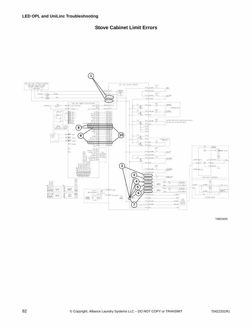
82 70422201R1© Copyright, Alliance Laundry Systems LLC – DO NOT COPY or TRANSMIT
LED OPL and UniLinc Troubleshooting
Stove Cabinet Limit Errors
TMB2383S
1
10
4
3
TMB2383S
5
6
8
9
7
2
H6-9
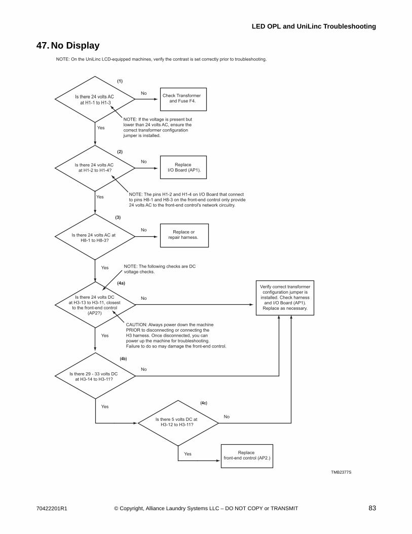
70422201R1 83© Copyright, Alliance Laundry Systems LLC – DO NOT COPY or TRANSMIT
LED OPL and UniLinc Troubleshooting
47. No Display
Is there 24 volts ACat H1-1 to H1-3
Is there 24 volts ACat H1-2 to H1-4?
Check Transformerand Fuse F4.
ReplaceI/O Board (AP1).
Replace orrepair harness.
No
Yes
Yes
Yes
Yes
No
TMB2377S
NOTE: On the UniLinc LCD-equipped machines, verify the contrast is set correctly prior to troubleshooting.
Is there 24 volts AC atH8-1 to H8-3?
No
NoIs there 24 volts DCat H3-13 to H3-11, closest
to the front-end control(AP2?)
(1)
(2)
(3)
(4a)
CAUTION: Always power down the machinePRIOR to disconnecting or connecting the H3 harness. Once disconnected, you can power up the machine for troubleshooting.Failure to do so may damage the front-end control.
NOTE: The following checks are DC voltage checks.
NOTE: The pins H1-2 and H1-4 on I/O Board that connectto pins H8-1 and H8-3 on the front-end control only provide24 volts AC to the front-end control's network circuitry.
Yes
NoIs there 29 - 33 volts DC
at H3-14 to H3-11?
Yes
NoIs there 5 volts DC atH3-12 to H3-11?
(4b)
Replacefront-end control (AP2.)
(4c)
NOTE: If the voltage is present butlower than 24 volts AC, ensure thecorrect transformer configurationjumper is installed.
Verify correct transformerconfiguration jumper is
installed. Check harnessand I/O Board (AP1).
Replace as necessary.
TMB2377S
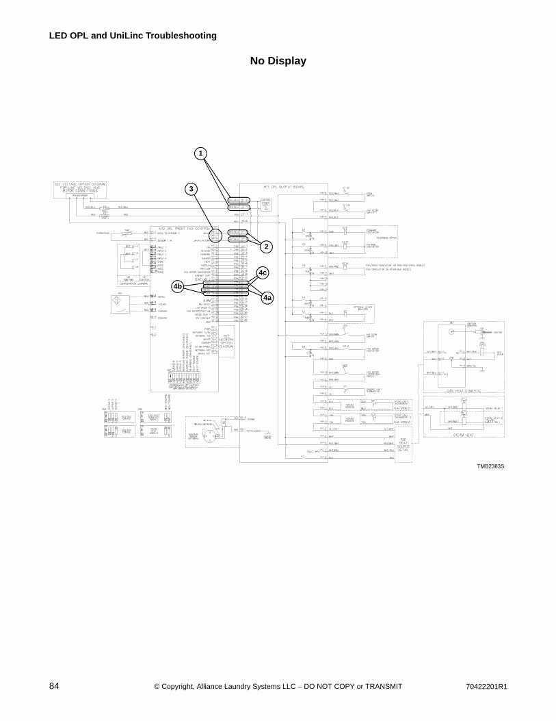
84 70422201R1© Copyright, Alliance Laundry Systems LLC – DO NOT COPY or TRANSMIT
LED OPL and UniLinc Troubleshooting
No Display
TMB2383S
1
4a
3
TMB2383S
4c
4b
2
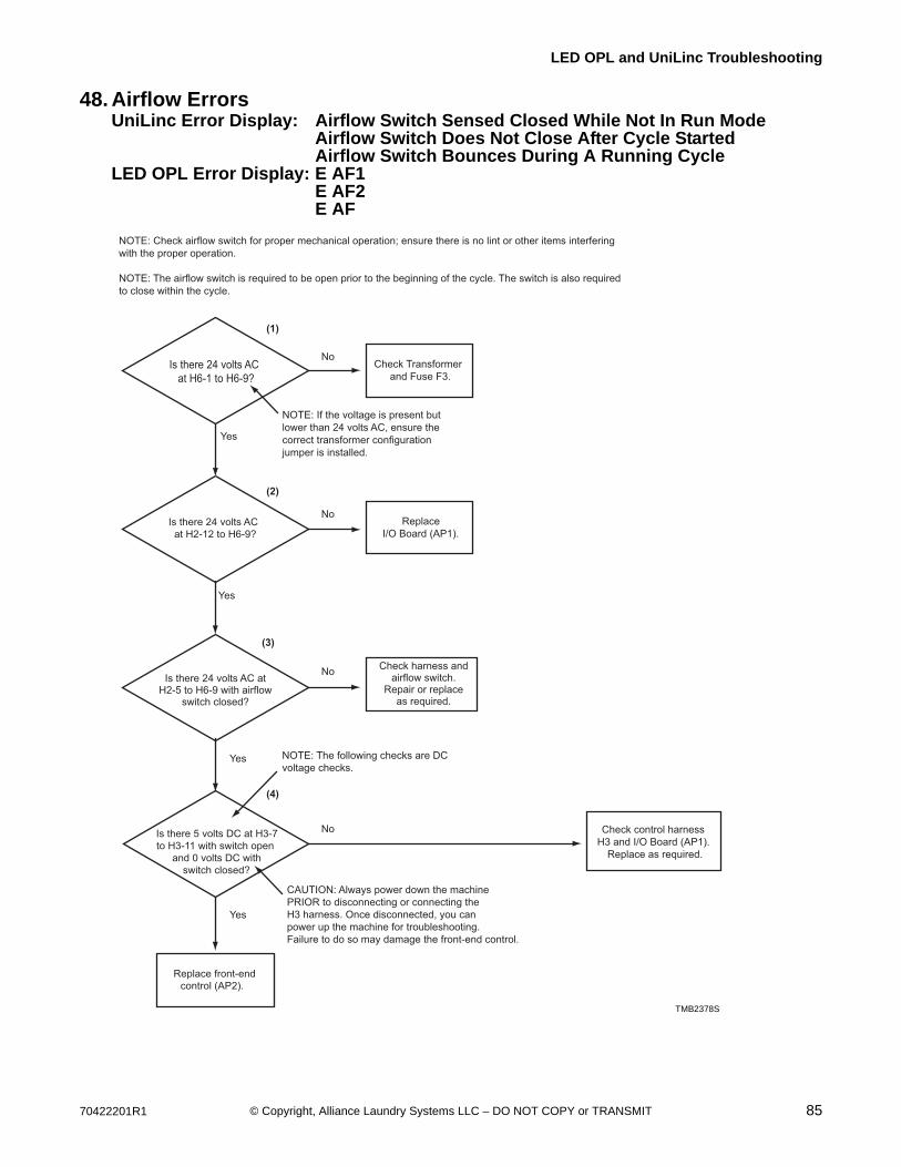
70422201R1 85© Copyright, Alliance Laundry Systems LLC – DO NOT COPY or TRANSMIT
LED OPL and UniLinc Troubleshooting
48. Airflow ErrorsUniLinc Error Display: Airflow Switch Sensed Closed While Not In Run Mode
Airflow Switch Does Not Close After Cycle StartedAirflow Switch Bounces During A Running Cycle
LED OPL Error Display: E AF1E AF2E AF
Is there 24 volts AC
at H6-1 to H6-9?
Is there 24 volts AC
at H2-12 to H6-9?
Check Transformer
and Fuse F3.
Replace
I/O Board (AP1).
No
Yes
Yes
Yes
Yes
No
No
Check control harness
H3 and I/O Board (AP1).
Replace as required.
NoIs there 5 volts DC at H3-7
to H3-11 with switch open
and 0 volts DC with
switch closed?
(1)
(2)
(3)
(4)
CAUTION: Always power down the machine
PRIOR to disconnecting or connecting the
H3 harness. Once disconnected, you can
power up the machine for troubleshooting.
Failure to do so may damage the front-end control.
NOTE: The following checks are DC
voltage checks.
Replace front-end
control (AP2).
NOTE: Check airflow switch for proper mechanical operation; ensure there is no lint or other items interfering
with the proper operation.
NOTE: The airflow switch is required to be open prior to the beginning of the cycle. The switch is also required
to close within the cycle.
NOTE: If the voltage is present but
lower than 24 volts AC, ensure the
correct transformer configuration
jumper is installed.
Check harness andairflow switch.
Repair or replaceas required.
Is there 24 volts AC atH2-5 to H6-9 with airflow
switch closed?
TMB2378S

86 70422201R1© Copyright, Alliance Laundry Systems LLC – DO NOT COPY or TRANSMIT
LED OPL and UniLinc Troubleshooting
Airflow Errors
TMB2383S
1
3
TMB2383S
4
2
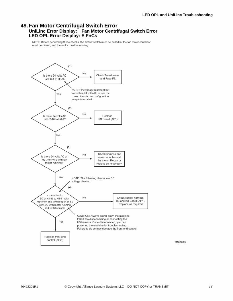
70422201R1 87© Copyright, Alliance Laundry Systems LLC – DO NOT COPY or TRANSMIT
LED OPL and UniLinc Troubleshooting
49. Fan Motor Centrifugal Switch ErrorUniLinc Error Display: Fan Motor Centrifugal Switch ErrorLED OPL Error Display: E FnCs
Is there 24 volts AC
at H6-1 to H6-9?
Is there 24 volts AC
at H2-10 to H6-9?
Check Transformer
and Fuse F3.
Replace
I/O Board (AP1).
Check harness and
wire connections at
the motor. Repair or
replace as necessary.
No
Yes
Yes
Yes
Yes
No
Is there 24 volts AC at
H2-3 to H6-9 with fan
motor running?
No
Check control harness
H3 and I/O Board (AP1).
Replace as required.
No
(1)
(2)
(3)
(4)
CAUTION: Always power down the machine
PRIOR to disconnecting or connecting the
H3 harness. Once disconnected, you can
power up the machine for troubleshooting.
Failure to do so may damage the front-end control.
NOTE: The following checks are DC
voltage checks.
Replace front-end
control (AP2.)
NOTE: Before performing these checks, the airflow switch must be pulled in, the fan motor contactor
must be closed, and the motor must be running.
TMB2379S
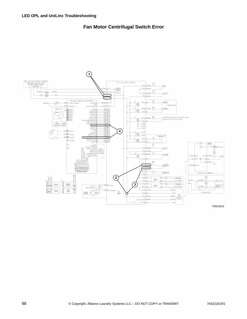
88 70422201R1© Copyright, Alliance Laundry Systems LLC – DO NOT COPY or TRANSMIT
LED OPL and UniLinc Troubleshooting
Fan Motor Centrifugal Switch Error
TMB2383S
1
2
TMB2383S
4
3
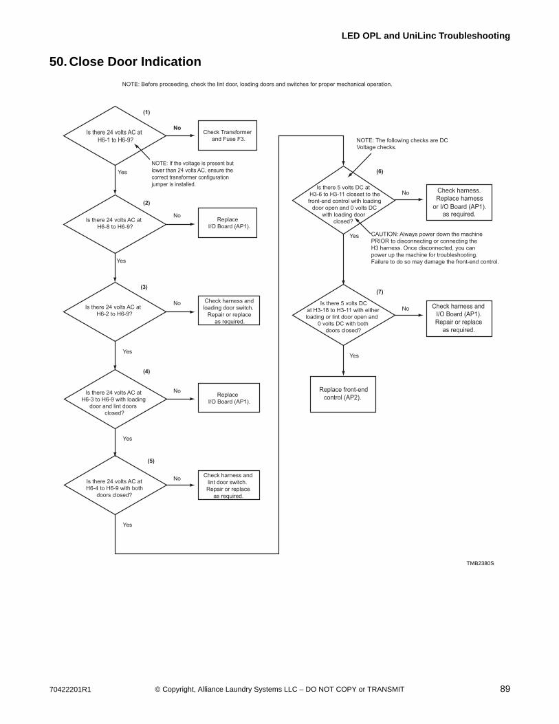
70422201R1 89© Copyright, Alliance Laundry Systems LLC – DO NOT COPY or TRANSMIT
LED OPL and UniLinc Troubleshooting
50. Close Door Indication
Is there 24 volts AC at
H6-1 to H6-9?
Is there 24 volts AC at
H6-8 to H6-9?
Check Transformer
and Fuse F3.
Replace
I/O Board (AP1).
Replace
I/O Board (AP1).
Check harness and
loading door switch.
Repair or replace
as required.
No
Yes
Yes
Yes
Yes
Yes
No
TMB2380S
NOTE: Before proceeding, check the lint door, loading doors and switches for proper mechanical operation.
Is there 24 volts AC at
H6-2 to H6-9?
No
No
Check harness and
lint door switch.
Repair or replace
as required.
No
Is there 24 volts AC at
H6-3 to H6-9 with loading
door and lint doors
closed?
Is there 24 volts AC at
H6-4 to H6-9 with both
doors closed?
Yes
Check harness.
Replace harness
or I/O Board (AP1).as required.
No
Yes
(1)
(2)
(3)
(5)
Is there 5 volts DC at
H3-6 to H3-11 closest to the
front-end control with loading
door open and 0 volts DC
with loading door
closed?
Check harness and
I/O Board (AP1).
Repair or replace
as required.
NoIs there 5 volts DC
at H3-18 to H3-11 with either
loading or lint door open and
0 volts DC with both
doors closed?
(6)
(4)
CAUTION: Always power down the machine
PRIOR to disconnecting or connecting the
H3 harness. Once disconnected, you can
power up the machine for troubleshooting.
Failure to do so may damage the front-end control.
NOTE: The following checks are DC
Voltage checks.
(7)
Replace front-end
control (AP2).
NOTE: If the voltage is present but
lower than 24 volts AC, ensure the
correct transformer configuration
jumper is installed.
TMB2380S

90 70422201R1© Copyright, Alliance Laundry Systems LLC – DO NOT COPY or TRANSMIT
LED OPL and UniLinc Troubleshooting
Close Door Indication
TMB2383S
1 2
TMB2383S
6
5
7
34
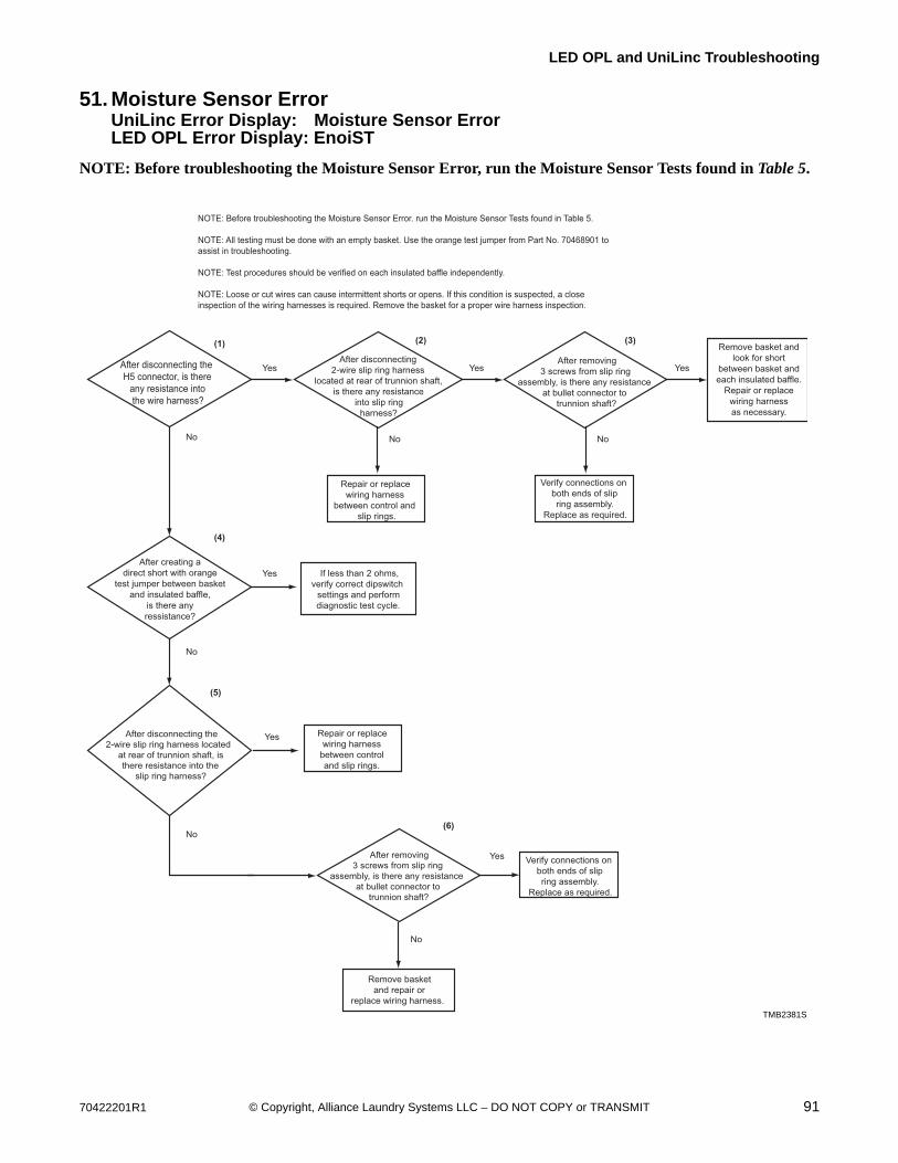
70422201R1 91© Copyright, Alliance Laundry Systems LLC – DO NOT COPY or TRANSMIT
LED OPL and UniLinc Troubleshooting
51. Moisture Sensor ErrorUniLinc Error Display: Moisture Sensor ErrorLED OPL Error Display: EnoiST
NOTE: Before troubleshooting the Moisture Sensor Error, run the Moisture Sensor Tests found in Table 5.
After disconnecting the
H5 connector, is there
any resistance into
the wire harness?
After disconnecting
2-wire slip ring harness
located at rear of trunnion shaft,
is there any resistance
into slip ring
harness?
If less than 2 ohms,
verify correct dipswitch
settings and perform
diagnostic test cycle.
Repair or replace
wiring harness
between control
and slip rings.
Repair or replace
wiring harness
between control and
slip rings.
Yes Yes Yes
No No
Verify connections on
both ends of slip
ring assembly.
Replace as required.
No
No
No
Yes
TMB2381S
After disconnecting the
2-wire slip ring harness located
at rear of trunnion shaft, is
there resistance into the
slip ring harness?
Yes
After removing
3 screws from slip ring
assembly, is there any resistance
at bullet connector to
trunnion shaft?
(1)(2)
(5)
(6)
(3)
After removing
3 screws from slip ring
assembly, is there any resistance
at bullet connector to
trunnion shaft?
Yes Verify connections on
both ends of slip
ring assembly.
Replace as required.
Remove basket
and repair or
replace wiring harness.
(4)
No
NOTE: Before troubleshooting the Moisture Sensor Error. run the Moisture Sensor Tests found in Table 5.
NOTE: All testing must be done with an empty basket. Use the orange test jumper from Part No. 70468901 to
assist in troubleshooting.
NOTE: Test procedures should be verified on each insulated baffle independently.
NOTE: Loose or cut wires can cause intermittent shorts or opens. If this condition is suspected, a close
inspection of the wiring harnesses is required. Remove the basket for a proper wire harness inspection.
After creating a
direct short with orange
test jumper between basket
and insulated baffle,
is there any
ressistance?
Remove basket and
look for short
between basket and
each insulated baffle.
Repair or replace
wiring harness
as necessary.
TMB2381S
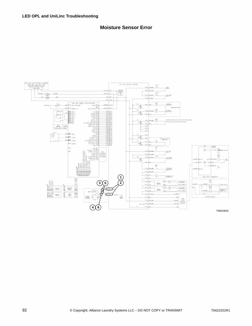
92 70422201R1© Copyright, Alliance Laundry Systems LLC – DO NOT COPY or TRANSMIT
LED OPL and UniLinc Troubleshooting
Moisture Sensor Error
TMB2383S
TMB2383S
1
23
64
5
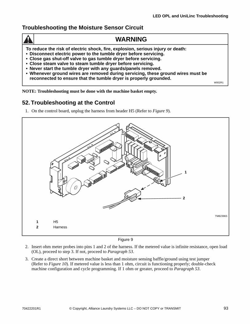
70422201R1 93© Copyright, Alliance Laundry Systems LLC – DO NOT COPY or TRANSMIT
LED OPL and UniLinc Troubleshooting
Troubleshooting the Moisture Sensor Circuit
NOTE: Troubleshooting must be done with the machine basket empty.
52. Troubleshooting at the Control1. On the control board, unplug the harness from header H5 (Refer to Figure 9).
2. Insert ohm meter probes into pins 1 and 2 of the harness. If the metered value is infinite resistance, open load (OL), proceed to step 3. If not, proceed to Paragraph 53.
3. Create a direct short between machine basket and moisture sensing baffle/ground using test jumper(Refer to Figure 10). If metered value is less than 1 ohm, circuit is functioning properly; double-check machine configuration and cycle programming. If 1 ohm or greater, proceed to Paragraph 53.
TMB2396S
1 H5
2 Harness
Figure 9
To reduce the risk of electric shock, fire, explosion, serious injury or death:• Disconnect electric power to the tumble dryer before servicing.• Close gas shut-off valve to gas tumble dryer before servicing.• Close steam valve to steam tumble dryer before servicing.• Never start the tumble dryer with any guards/panels removed.• Whenever ground wires are removed during servicing, these ground wires must be
reconnected to ensure that the tumble dryer is properly grounded.W002R1
WARNING
1
2
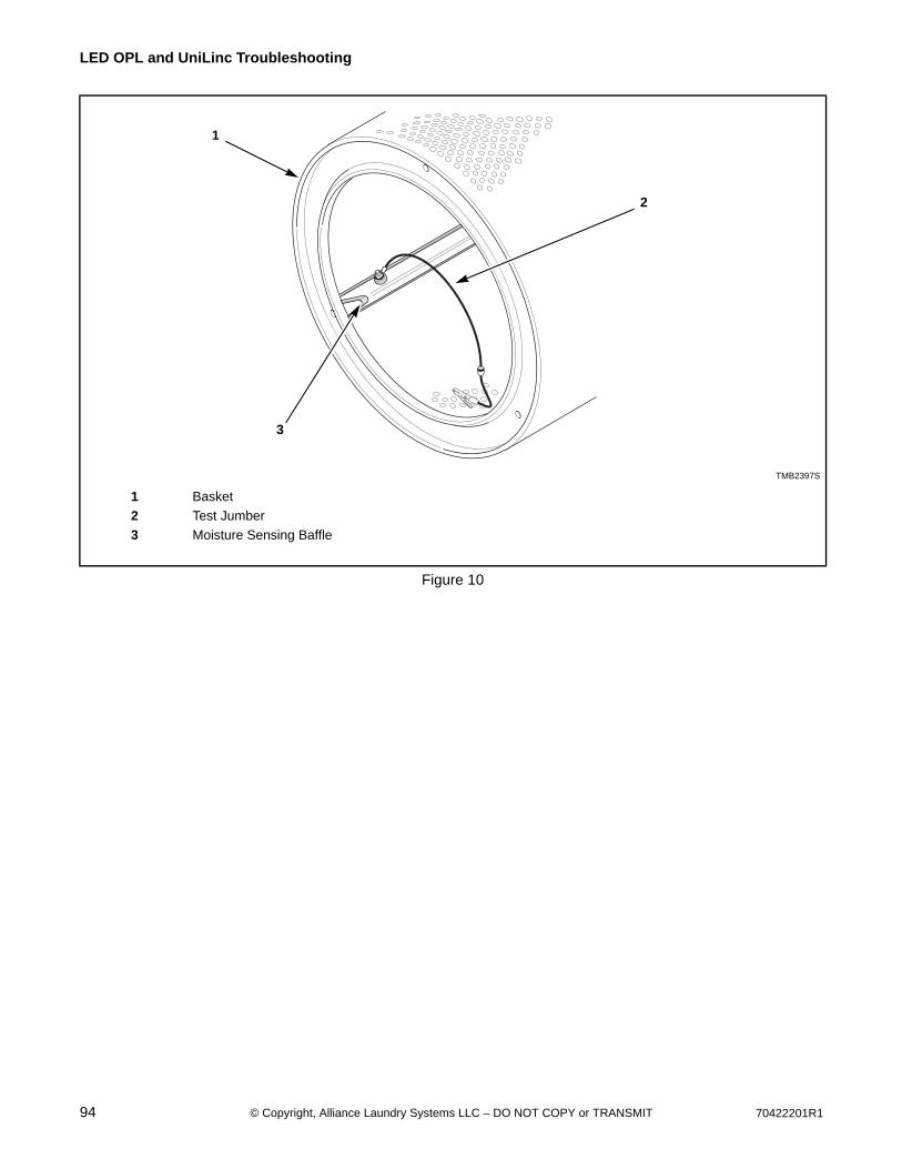
94 70422201R1© Copyright, Alliance Laundry Systems LLC – DO NOT COPY or TRANSMIT
LED OPL and UniLinc Troubleshooting
TMB2397S
1 Basket
2 Test Jumber
3 Moisture Sensing Baffle
Figure 10
1
2
3
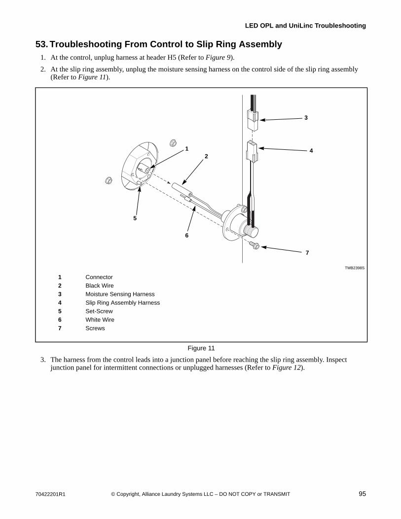
70422201R1 95© Copyright, Alliance Laundry Systems LLC – DO NOT COPY or TRANSMIT
LED OPL and UniLinc Troubleshooting
53. Troubleshooting From Control to Slip Ring Assembly1. At the control, unplug harness at header H5 (Refer to Figure 9).
2. At the slip ring assembly, unplug the moisture sensing harness on the control side of the slip ring assembly (Refer to Figure 11).
3. The harness from the control leads into a junction panel before reaching the slip ring assembly. Inspect junction panel for intermittent connections or unplugged harnesses (Refer to Figure 12).
TMB2398S
1 Connector
2 Black Wire
3 Moisture Sensing Harness
4 Slip Ring Assembly Harness
5 Set-Screw
6 White Wire
7 Screws
Figure 11
7
4
6
3
5
21
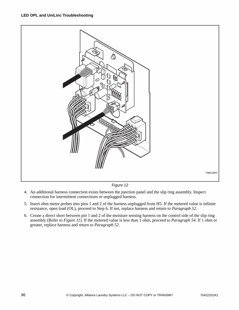
96 70422201R1© Copyright, Alliance Laundry Systems LLC – DO NOT COPY or TRANSMIT
LED OPL and UniLinc Troubleshooting
4. An additional harness connection exists between the junction panel and the slip ring assembly. Inspect connection for intermittent connections or unplugged harness.
5. Insert ohm meter probes into pins 1 and 2 of the harness unplugged from H5. If the metered value is infinite resistance, open load (OL), proceed to Step 6. If not, replace harness and return to Paragraph 52.
6. Create a direct short between pin 1 and 2 of the moisture sensing harness on the control side of the slip ring assembly (Refer to Figure 11). If the metered value is less than 1 ohm, proceed to Paragraph 54. If 1 ohm or greater, replace harness and return to Paragraph 52.
TMB2399S
Figure 12
TMB2399S
70422201R1 97© Copyright, Alliance Laundry Systems LLC – DO NOT COPY or TRANSMIT
LED OPL and UniLinc Troubleshooting
54. Troubleshooting At Slip Ring Assembly1. At the slip ring assembly, unplug the slip ring assembly harness on the control side of the slip ring assembly
(Refer to Figure 11).
2. Remove the three (3) screws holding the slip ring assembly to basket shaft.
3. Carefully disconnect the white wire of the slip ring assembly from the set-screw on the basket shaft.
4. Carefully disconnect the black wire of the slip ring assembly from the connector in the basket shaft.
5. Connect one ohm meter probe to the black wire on the basket side of the slip ring assembly, and connect the other ohm meter probe to the black wire of the slip ring assembly harness. If the metered value is less than 1 ohm, proceed to Step 6. If 1 ohm or greater, replace slip ring assembly and return to Paragraph 52.
6. Connect one ohm meter probe to white wire on the basket side of the slip ring assembly, and connect the other ohm meter probe to the white wire of the slip ring assembly harness. If the metered value is less than 1 ohm, proceed to Paragraph 55. If 1 ohm or greater, replace slip ring assembly and return to Paragraph 52.
55. Troubleshooting From Slip Ring Assembly to Moisture Sensing Baffle and Basket
1. Remove three (3) screws holding slip ring assembly to basket shaft.
2. Carefully disconnect the white wire of the slip ring assembly from the set-screw on the basket shaft.
3. Carefully disconnect the black wire of slip ring assembly from the connector in the basket shaft.
4. Connect one ohm meter probe to the connector in the basket shaft. Connect the other ohm meter probe to the basket shaft itself. If the metered value is infinite resistance, open load (OL), proceed to Step 5. If not, remove machine basket and proceed to Paragraph 56.
5. Create a direct short between basket and moisture sensing baffle (Refer to Figure 10).
6. Connect one ohm meter probe to the connector in the basket shaft. Connect the other ohm meter probe to the basket shaft itself. If the metered value is less than 1 ohm, circuit is functioning properly; double-check machine configuration and cycle programming. If 1 ohm or greater, remove machine basket and proceed to Paragraph 56.
56. Troubleshooting from Basket Shaft to Moisture Sensing Baffle with Machine Basket Removed
1. Disconnect and remove slip ring assembly before removing machine basket.
2. Remove machine basket.

98 70422201R1© Copyright, Alliance Laundry Systems LLC – DO NOT COPY or TRANSMIT
LED OPL and UniLinc Troubleshooting
3. Connect one ohm meter probe to the connector in the basket shaft (Refer to Figure 13).
4. Connect the other ohm meter probe to one of the gray wire harness terminals on the back end of the machine basket. If the metered value is less than 1 ohm, proceed to Step 5. If 1 ohm or greater, replace harness and return to Paragraph 52.
5. Connect one ohm meter probe to the connector in the basket shaft.
6. Connect the other ohm meter probe to the other gray wire harness terminal on the back end of the machine basket. If the metered value is less than 1 ohm, proceed to Step 7. If 1 ohm or greater, replace harness and return to Paragraph 52.
7. Connect one ohm meter probe to the connector in the basket shaft.
8. Connect the other ohm meter probe to one of the moisture sensing baffles (refer to Figure 10). If the metered value is less than 1 ohm, proceed to Step 9. If 1 ohm or greater, proceed to Paragraph 57.
9. Connect one ohm meter probe to the connector in the basket shaft.
10. Connect the other ohm meter probe to the other moisture sensing baffle. If the metered value is less than 1 ohm, circuit is functioning properly; double-check machine configuration and cycle programming. If 1 ohm or greater, proceed to Paragraph 57.
57. Troubleshooting at the Moisture Sensing Baffles with Machine Basket Removed
1. Disassemble moisture sensing baffle and inspect for lint buildup and foreign objects. Verify wire harness connections.
2. Disassemble other moisture sensing baffle and inspect for lint buildup and foreign objects. Verify wire harness connections.
3. Double-check machine configuration and cycle programming.
TMB2400S
1 Connector
2 Gray Wire Harness Terminal
Figure 13
1
2
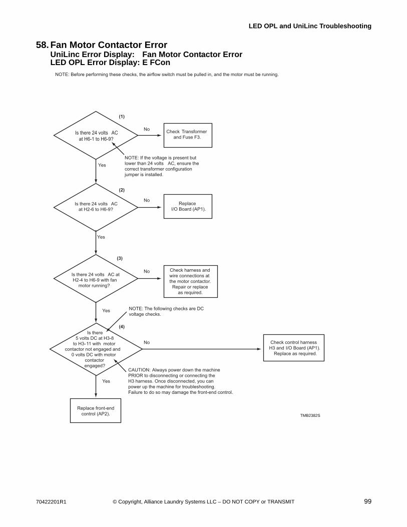
70422201R1 99© Copyright, Alliance Laundry Systems LLC – DO NOT COPY or TRANSMIT
LED OPL and UniLinc Troubleshooting
58. Fan Motor Contactor ErrorUniLinc Error Display: Fan Motor Contactor ErrorLED OPL Error Display: E FCon
Is there 24 volts AC
at H6-1 to H6-9?
Is there 24 volts AC
at H2-6 to H6-9?
Check Transformer
and Fuse F3.
Replace
I/O Board (AP1).
Check harness and
wire connections at
the motor contactor.
Repair or replace
as required.
No
Yes
Yes
Yes
Yes
No
NOTE: Before performing these checks, the airflow switch must be pulled in, and the motor must be running.
NOTE: If the voltage is present but
lower than 24 volts AC, ensure the
correct transformer configuration
jumper is installed.
Is there 24 volts AC at
H2-4 to H6-9 with fan
motor running?
No
Check control harness
H3 and I/O Board (AP1).
Replace as required.
No
Is there
5 volts DC at H3-8
to H3-11 with motor
contactor not engaged and
0 volts DC with motor
contactor
engaged?
(1)
(2)
(3)
(4)
CAUTION: Always power down the machine
PRIOR to disconnecting or connecting the
H3 harness. Once disconnected, you can
power up the machine for troubleshooting.
Failure to do so may damage the front-end control.
NOTE: The following checks are DC
voltage checks.
Replace front-end
control (AP2). TMB2382S
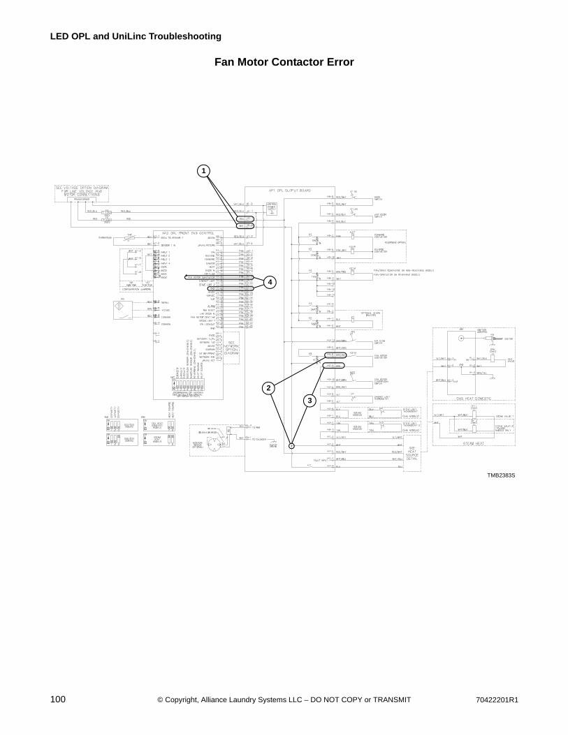
100 70422201R1© Copyright, Alliance Laundry Systems LLC – DO NOT COPY or TRANSMIT
LED OPL and UniLinc Troubleshooting
Fan Motor Contactor Error
TMB2383S
TMB2383S
3
1
4
2
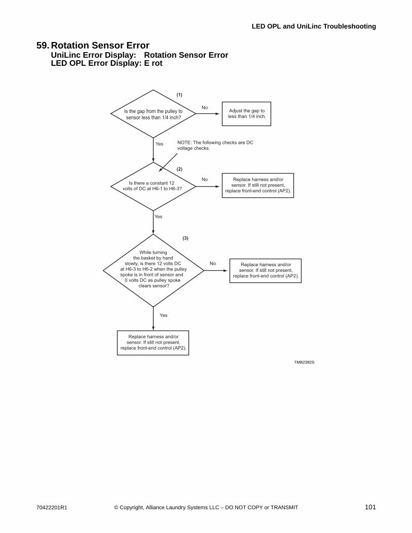
70422201R1 101© Copyright, Alliance Laundry Systems LLC – DO NOT COPY or TRANSMIT
LED OPL and UniLinc Troubleshooting
59. Rotation Sensor ErrorUniLinc Error Display: Rotation Sensor ErrorLED OPL Error Display: E rot
TMB2392S
Is the gap from the pulley tosensor less than 1/4 inch?
Is there a constant 12 volts of DC at H6-1 to H6-3?
Adjust the gap toless than 1/4 inch.
No
Yes
Yes
Yes
No
While turning the basket by hand
slowly, is there 12 volts DCat H6-3 to H6-2 when the pulleyspoke is in front of sensor and
0 volts DC as pulley spoke clears sensor?
No
(1)
(2)
(3)
NOTE: The following checks are DC voltage checks.
Replace harness and/orsensor. If still not present,
replace front-end control (AP2).
Replace harness and/orsensor. If still not present,
replace front-end control (AP2).
Replace harness and/orsensor. If still not present,
replace front-end control (AP2).
TMB2392S
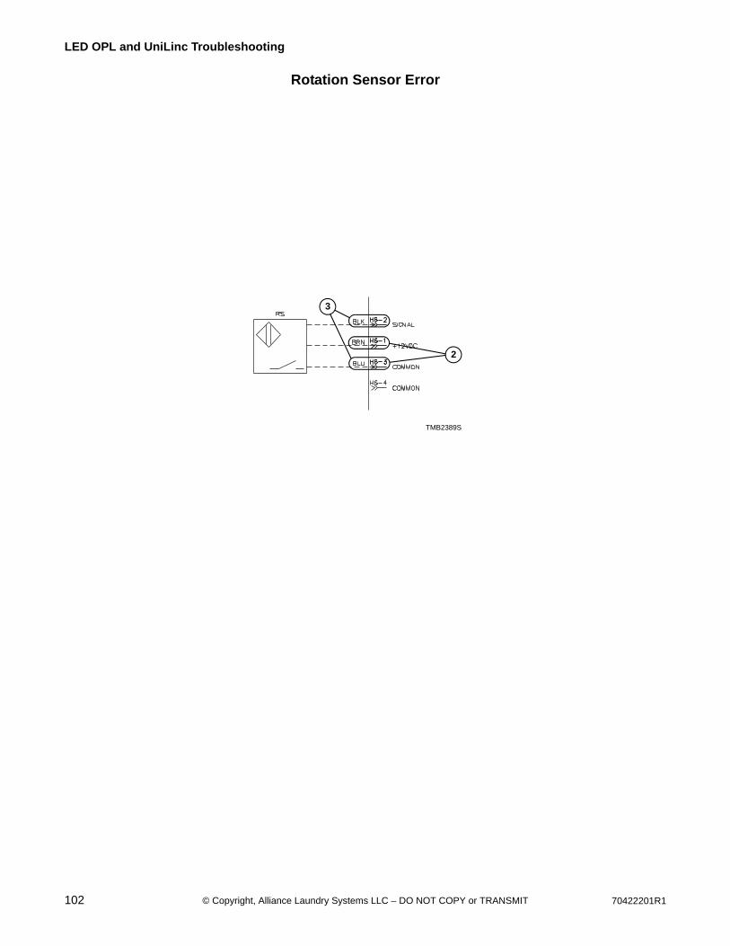
102 70422201R1© Copyright, Alliance Laundry Systems LLC – DO NOT COPY or TRANSMIT
LED OPL and UniLinc Troubleshooting
Rotation Sensor Error
TMB2389STMB2389S
2
3

70422201R1 103© Copyright, Alliance Laundry Systems LLC – DO NOT COPY or TRANSMIT
LED OPL and UniLinc Troubleshooting
60. Shorted or Open ThermistorUniLinc Error Display: Shorted Thermistor
Open ThermistorLED OPL Error Display: ESH
EoP
No
Yes
(1)
NOTE: This resistance will vary with cabinet air temperature:
the higher the temperature, the lower the resistance.
Replace front-end
control (AP2).
Is there approximately
50k ohms of resistance at 77°F
across H7-1 and H7-2?
Check each wire for possible
ground fault. Replace temperature
sensor and/or harness.
TMB2393S
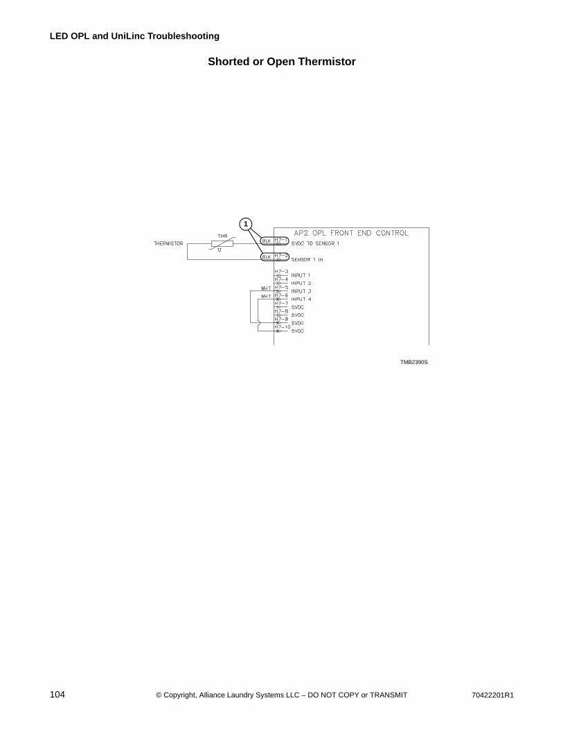
104 70422201R1© Copyright, Alliance Laundry Systems LLC – DO NOT COPY or TRANSMIT
LED OPL and UniLinc Troubleshooting
Shorted or Open Thermistor
TMB2390STMB2390S
1
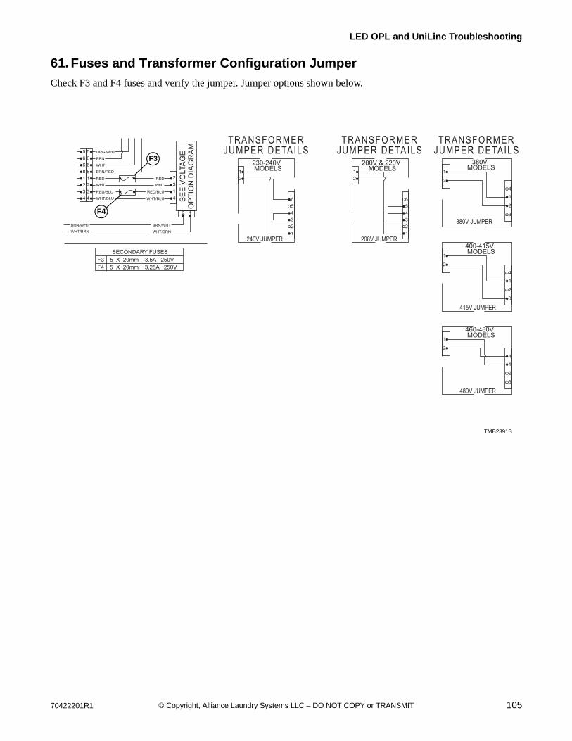
70422201R1 105© Copyright, Alliance Laundry Systems LLC – DO NOT COPY or TRANSMIT
LED OPL and UniLinc Troubleshooting
61. Fuses and Transformer Configuration Jumper
Check F3 and F4 fuses and verify the jumper. Jumper options shown below.
TMB2391S
TRANSFORMER
JUMPER DETAILS
TRANSFORMER
JUMPER DETAILS
TRANSFORMER
JUMPER DETAILS
SE
E V
OLTA
GE
OP
TIO
N D
IAG
RA
M
SECONDARY FUSES
5 X 20mm 3.5A 250VF3
5 X 20mm 3.25A 250VF4
240V JUMPER
230-240VMODELS
208V JUMPER
200V & 220VMODELS
1
2
3
4
5
64 4
1
3
2
2 1
ORG/WHT
BRN
WHT
BRN/RED
RED
WHT
RED/BLU
WHT/BLU
BRN/WHT
WHT/BRN
BRN/WHT
WHT/BRN
RED
WHT
RED/BLU
WHT/BLU
2
1
1
2
3
4
5
6
2
1
380V JUMPER
380VMODELS
3
2
1
4
2
1
415V JUMPER
400-415VMODELS
3
2
1
4
2
1
480V JUMPER
460-480VMODELS
3
2
1
4
2
1
3
2
1
8
6
6
5
4
3
2
1
8
6
6
5
TMB2391S
F4
F3
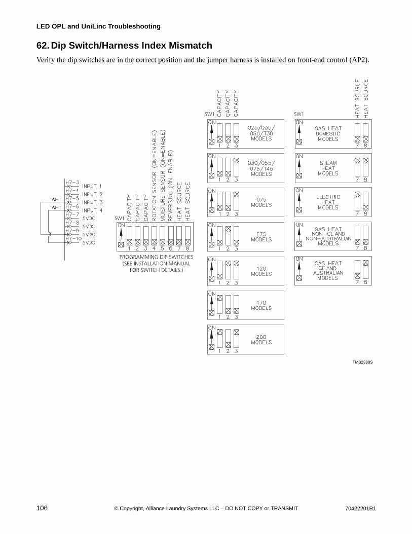
106 70422201R1© Copyright, Alliance Laundry Systems LLC – DO NOT COPY or TRANSMIT
LED OPL and UniLinc Troubleshooting
62. Dip Switch/Harness Index Mismatch
Verify the dip switches are in the correct position and the jumper harness is installed on front-end control (AP2).
TMB2388S
PROGRAMMING DIP SWITCHES(SEE INSTALLATION MANUAL
FOR SWITCH DETAILS.)
SW1
SW1 SW1
TMB2388S
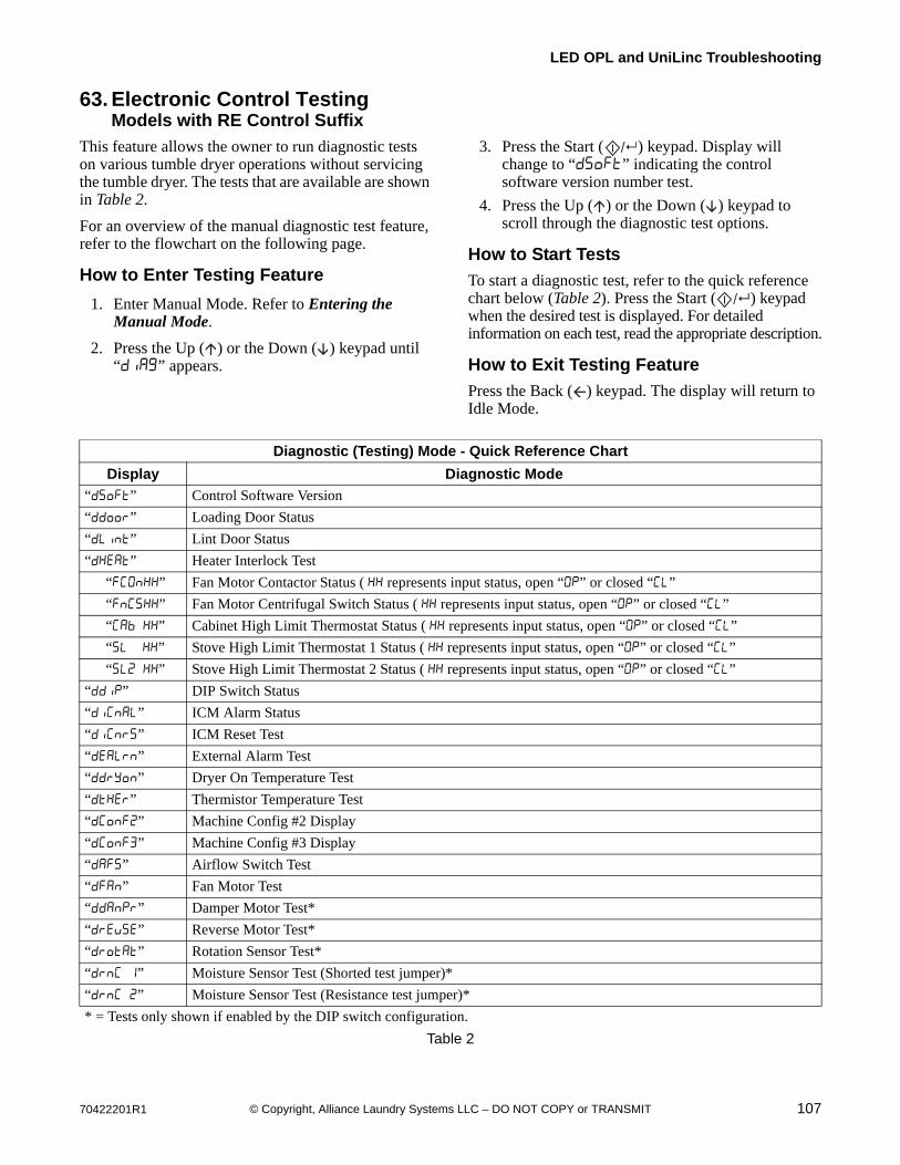
70422201R1 107© Copyright, Alliance Laundry Systems LLC – DO NOT COPY or TRANSMIT
LED OPL and UniLinc Troubleshooting
63. Electronic Control TestingModels with RE Control Suffix
This feature allows the owner to run diagnostic tests on various tumble dryer operations without servicing the tumble dryer. The tests that are available are shown in Table 2.
For an overview of the manual diagnostic test feature, refer to the flowchart on the following page.
How to Enter Testing Feature
1. Enter Manual Mode. Refer to Entering the Manual Mode.
2. Press the Up ( ) or the Down ( ) keypad until “” appears.
3. Press the Start ( ) keypad. Display will change to “” indicating the control software version number test.
4. Press the Up ( ) or the Down ( ) keypad to scroll through the diagnostic test options.
How to Start Tests
To start a diagnostic test, refer to the quick reference chart below (Table 2). Press the Start ( ) keypad when the desired test is displayed. For detailed information on each test, read the appropriate description.
How to Exit Testing Feature
Press the Back ( ) keypad. The display will return to Idle Mode.
Table 2
Diagnostic (Testing) Mode - Quick Reference Chart
Display Diagnostic Mode
“” Control Software Version
“” Loading Door Status
“” Lint Door Status
“” Heater Interlock Test
“” Fan Motor Contactor Status ( represents input status, open “” or closed “”
“” Fan Motor Centrifugal Switch Status ( represents input status, open “” or closed “”
“ ” Cabinet High Limit Thermostat Status ( represents input status, open “” or closed “”
“ ” Stove High Limit Thermostat 1 Status ( represents input status, open “” or closed “”
“ ” Stove High Limit Thermostat 2 Status ( represents input status, open “” or closed “”
“” DIP Switch Status
“” ICM Alarm Status
“” ICM Reset Test
“” External Alarm Test
“” Dryer On Temperature Test
“” Thermistor Temperature Test
“” Machine Config #2 Display
“” Machine Config #3 Display
“” Airflow Switch Test
“” Fan Motor Test
“” Damper Motor Test*
“” Reverse Motor Test*
“” Rotation Sensor Test*
“ ” Moisture Sensor Test (Shorted test jumper)*
“ ” Moisture Sensor Test (Resistance test jumper)*
* = Tests only shown if enabled by the DIP switch configuration.
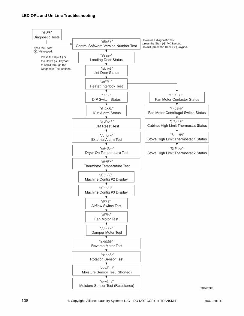
108 70422201R1© Copyright, Alliance Laundry Systems LLC – DO NOT COPY or TRANSMIT
LED OPL and UniLinc Troubleshooting
TMB1374R
“dSoft”
Control Software Version Number Test
Press the Up (�) or
the Down (�) keypad
to scroll through the
Diagnostic Test options.
“diAg”
Diagnostic Tests
“ddoor”
Loading Door Status
“dLint”
Lint Door Status
“dHEAt”
Heater Interlock Test
“FCOnXX”
Fan Motor Contactor Status
“FnCSXX”
Fan Motor Centrifugal Switch Status
“SL2 XX”
Stove High Limit Thermostat 2 Status
“ddiP”
DIP Switch Status
“diCnAL”
ICM Alarm Status
“diCnrS”
ICM Reset Test
“dEALrn”
External Alarm Test
“ddryon”
Dryer On Temperature Test
“dtHEr”
Thermistor Temperature Test
“dConF2”
Machine Config #2 Display
“dConF3”
Machine Config #3 Display
“dAFS”
Airflow Switch Test
“dFAn”
Fan Motor Test
“ddAnPr”
Damper Motor Test
“drEuSE”
Reverse Motor Test
“drotAt”
Rotation Sensor Test
“drnC 1”
Moisture Sensor Test (Shorted)
“drnC 2”
Moisture Sensor Test (Resistance)
Press the Start
( /� ) keypad.
To enter a diagnostic test,
press the Start ( /� ) keypad.
To exit, press the Back (�) keypad.
“Cab XX”
Cabinet High Limit Thermostat Status
“SL XX”
Stove High Limit Thermostat 1 Status
TMB1374R
70422201R1 109© Copyright, Alliance Laundry Systems LLC – DO NOT COPY or TRANSMIT
LED OPL and UniLinc Troubleshooting
Diagnostic Test Descriptions
Control Software Version Number Test “”
This option displays the control software version number. To start test, control must be in the Testing Mode. Refer to “How to Enter Testing Feature” at the beginning of this section.
To enter, press the Start ( ) keypad. The display will show “” where “” is the software version number.
To exit the Software Version Number Test, press the Back ( ) keypad. The control will return to the testing mode.
Loading Door Test “”
This option tests the loading door switch. To start test, control must be in the Testing Mode. Refer to “How to Enter Testing Feature” at the beginning of this section.
To enter, press the Start ( ) keypad. The display will show “” when the loading door switch is open and “” when the loading door switch is closed.
The loading door switch has to be closed or open for at least one second for the control to register the switch as closed or open.
To exit the Loading Door Test, press the Back ( ) keypad. The control will return to the testing mode.
Lint Door Test “ ”
This option tests the lint door switch. To start test, control must be in the Testing Mode. Refer to “How to Enter Testing Feature” at the beginning of this section.
To enter, press the Start ( ) keypad. The display will show “” when the lint door switch is open and “ ” when the lint door switch is closed.
The lint door switch has to be closed or open for at least one second for the control to register the switch as closed or open.
NOTE: Loading door must be closed while testing lint door.
To exit the Lint Door Test, press the Back ( ) keypad. The control will return to the testing mode.
Heater Interlock Test “”
While this test is running, the control will show the status of the following inputs for two seconds each. The control will continue scrolling through the input status displays until the test is aborted.
To start test, the control must be in the Testing Mode. Refer to “How to Enter Testing Feature” at the beginning of this section.
To enter, press Start ( ). Refer to five sections below for more details on individual statuses.
NOTE: These switches are tested in sequence. If one switch is sensed open, the rest will be open as well. For example, if the fan motor contactor switch is open, all of the switches will be open.
To exit the test, press the Back ( ) keypad. The control will return to the testing mode.
Fan Motor Contactor Switch “”
The display will show “” if the switch is sensed open and “” if the switch is sensed closed.
Fan Motor Centrifugal Switch “”
The display will show “” if the switch is sensed open and “” if the switch is sensed closed.
Cabinet High Limit Thermostat “ ”
The display will show “ ” if sensed open for at least 1.5 seconds and “ ” if sensed closed for at least one second.
Stove High Limit Thermostat 1 “ ”
The display will show “ ” if sensed open for at least 1.5 seconds and “ ” if sensed closed for at least one second.
Stove High Limit Thermostat 2 “ ”
The display will show “ ” if sensed open for at least 1.5 seconds and “ ” if sensed closed for at least one second.
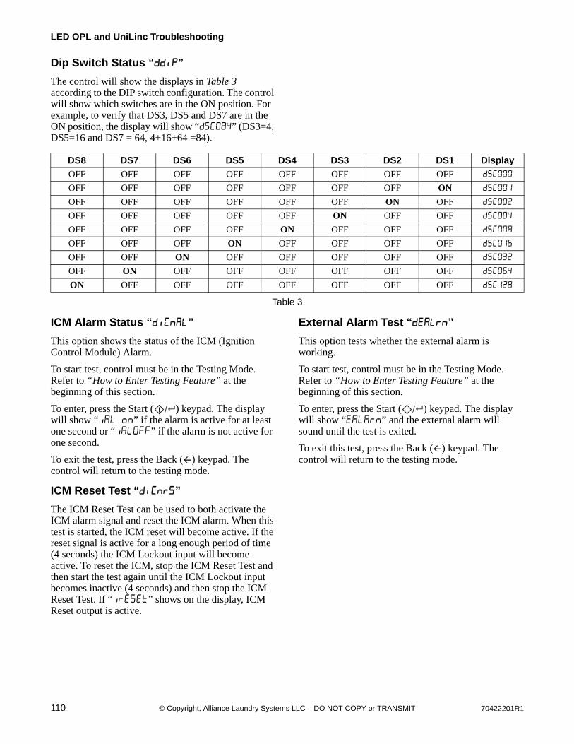
110 70422201R1© Copyright, Alliance Laundry Systems LLC – DO NOT COPY or TRANSMIT
LED OPL and UniLinc Troubleshooting
Dip Switch Status “ ”
The control will show the displays in Table 3 according to the DIP switch configuration. The control will show which switches are in the ON position. For example, to verify that DS3, DS5 and DS7 are in the ON position, the display will show “” (DS3=4, DS5=16 and DS7 = 64, 4+16+64 =84).
Table 3
ICM Alarm Status “”
This option shows the status of the ICM (Ignition Control Module) Alarm.
To start test, control must be in the Testing Mode. Refer to “How to Enter Testing Feature” at the beginning of this section.
To enter, press the Start ( ) keypad. The display will show “ ” if the alarm is active for at least one second or “” if the alarm is not active for one second.
To exit the test, press the Back ( ) keypad. The control will return to the testing mode.
ICM Reset Test “ ”
The ICM Reset Test can be used to both activate the ICM alarm signal and reset the ICM alarm. When this test is started, the ICM reset will become active. If the reset signal is active for a long enough period of time (4 seconds) the ICM Lockout input will become active. To reset the ICM, stop the ICM Reset Test and then start the test again until the ICM Lockout input becomes inactive (4 seconds) and then stop the ICM Reset Test. If “” shows on the display, ICM Reset output is active.
External Alarm Test “”
This option tests whether the external alarm is working.
To start test, control must be in the Testing Mode. Refer to “How to Enter Testing Feature” at the beginning of this section.
To enter, press the Start ( ) keypad. The display will show “” and the external alarm will sound until the test is exited.
To exit this test, press the Back ( ) keypad. The control will return to the testing mode.
DS8 DS7 DS6 DS5 DS4 DS3 DS2 DS1 Display
OFF OFF OFF OFF OFF OFF OFF OFF
OFF OFF OFF OFF OFF OFF OFF ON
OFF OFF OFF OFF OFF OFF ON OFF
OFF OFF OFF OFF OFF ON OFF OFF
OFF OFF OFF OFF ON OFF OFF OFF
OFF OFF OFF ON OFF OFF OFF OFF
OFF OFF ON OFF OFF OFF OFF OFF
OFF ON OFF OFF OFF OFF OFF OFF
ON OFF OFF OFF OFF OFF OFF OFF
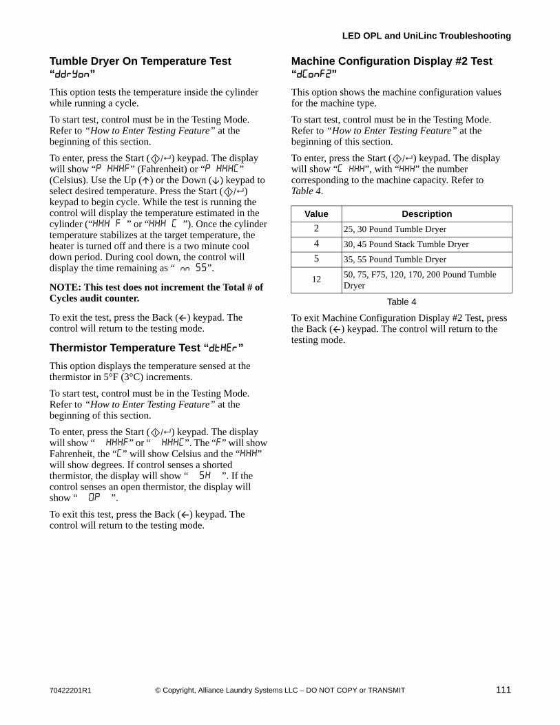
70422201R1 111© Copyright, Alliance Laundry Systems LLC – DO NOT COPY or TRANSMIT
LED OPL and UniLinc Troubleshooting
Tumble Dryer On Temperature Test “”
This option tests the temperature inside the cylinder while running a cycle.
To start test, control must be in the Testing Mode. Refer to “How to Enter Testing Feature” at the beginning of this section.
To enter, press the Start ( ) keypad. The display will show “ ” (Fahrenheit) or “ ” (Celsius). Use the Up ( ) or the Down ( ) keypad to select desired temperature. Press the Start ( ) keypad to begin cycle. While the test is running the control will display the temperature estimated in the cylinder (“ ” or “ ”). Once the cylinder temperature stabilizes at the target temperature, the heater is turned off and there is a two minute cool down period. During cool down, the control will display the time remaining as “ ”.
NOTE: This test does not increment the Total # of Cycles audit counter.
To exit the test, press the Back ( ) keypad. The control will return to the testing mode.
Thermistor Temperature Test “”
This option displays the temperature sensed at the thermistor in 5°F (3°C) increments.
To start test, control must be in the Testing Mode. Refer to “How to Enter Testing Feature” at the beginning of this section.
To enter, press the Start ( ) keypad. The display will show “ ” or “ ”. The “” will show Fahrenheit, the “” will show Celsius and the “” will show degrees. If control senses a shorted thermistor, the display will show “ ”. If the control senses an open thermistor, the display will show “ ”.
To exit this test, press the Back ( ) keypad. The control will return to the testing mode.
Machine Configuration Display #2 Test “”
This option shows the machine configuration values for the machine type.
To start test, control must be in the Testing Mode. Refer to “How to Enter Testing Feature” at the beginning of this section.
To enter, press the Start ( ) keypad. The display will show “ ”, with “” the number corresponding to the machine capacity. Refer to Table 4.
To exit Machine Configuration Display #2 Test, press the Back ( ) keypad. The control will return to the testing mode.
Value Description
2 25, 30 Pound Tumble Dryer
4 30, 45 Pound Stack Tumble Dryer
5 35, 55 Pound Tumble Dryer
12 50, 75, F75, 120, 170, 200 Pound Tumble Dryer
Table 4
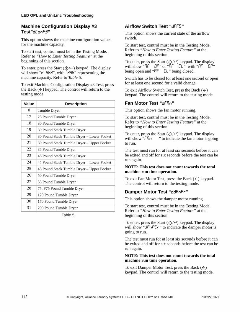
112 70422201R1© Copyright, Alliance Laundry Systems LLC – DO NOT COPY or TRANSMIT
LED OPL and UniLinc Troubleshooting
Machine Configuration Display #3 Test””
This option shows the machine configuration values for the machine capacity.
To start test, control must be in the Testing Mode. Refer to “How to Enter Testing Feature” at the beginning of this section.
To enter, press the Start ( ) keypad. The display will show “ ”, with “” representing the machine capacity. Refer to Table 5.
To exit Machine Configuration Display #3 Test, press the Back ( ) keypad. The control will return to the testing mode.
Airflow Switch Test “”
This option shows the current state of the airflow switch.
To start test, control must be in the Testing Mode. Refer to “How to Enter Testing Feature” at the beginning of this section.
To enter, press the Start ( ) keypad. The display will show “ ” or “ ”, with “ ” being open and “ ” being closed.
Switch has to be closed for at least one second or open for at least one second for a valid change.
To exit Airflow Switch Test, press the Back ( ) keypad. The control will return to the testing mode.
Fan Motor Test “”
This option shows the fan motor running.
To start test, control must be in the Testing Mode. Refer to “How to Enter Testing Feature” at the beginning of this section.
To enter, press the Start ( ) keypad. The display will show “ ” to indicate the fan motor is going to run.
The test must run for at least six seconds before it can be exited and off for six seconds before the test can be run again.
NOTE: This test does not count towards the total machine run time operation.
To exit Fan Motor Test, press the Back ( ) keypad. The control will return to the testing mode.
Damper Motor Test “”
This option shows the damper motor running.
To start test, control must be in the Testing Mode. Refer to “How to Enter Testing Feature” at the beginning of this section.
To enter, press the Start ( ) keypad. The display will show “” to indicate the damper motor is going to run.
The test must run for at least six seconds before it can be exited and off for six seconds before the test can be run again.
NOTE: This test does not count towards the total machine run time operation.
To exit Damper Motor Test, press the Back ( ) keypad. The control will return to the testing mode.
Value Description
0 Tumble Dryer
17 25 Pound Tumble Dryer
18 30 Pound Tumble Dryer
19 30 Pound Stack Tumble Dryer
20 30 Pound Stack Tumble Dryer – Lower Pocket
21 30 Pound Stack Tumble Dryer – Upper Pocket
22 35 Pound Tumble Dryer
23 45 Pound Stack Tumble Dryer
24 45 Pound Stack Tumble Dryer – Lower Pocket
25 45 Pound Stack Tumble Dryer – Upper Pocket
26 50 Pound Tumble Dryer
27 55 Pound Tumble Dryer
28 75, F75 Pound Tumble Dryer
29 120 Pound Tumble Dryer
30 170 Pound Tumble Dryer
31 200 Pound Tumble Dryer
Table 5
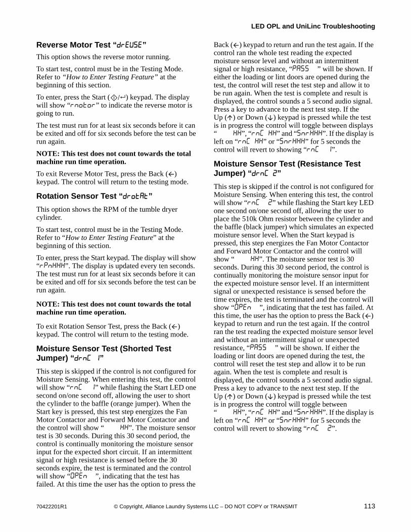
70422201R1 113© Copyright, Alliance Laundry Systems LLC – DO NOT COPY or TRANSMIT
LED OPL and UniLinc Troubleshooting
Reverse Motor Test “”
This option shows the reverse motor running.
To start test, control must be in the Testing Mode. Refer to “How to Enter Testing Feature” at the beginning of this section.
To enter, press the Start ( ) keypad. The display will show “” to indicate the reverse motor is going to run.
The test must run for at least six seconds before it can be exited and off for six seconds before the test can be run again.
NOTE: This test does not count towards the total machine run time operation.
To exit Reverse Motor Test, press the Back ( ) keypad. The control will return to the testing mode.
Rotation Sensor Test “”
This option shows the RPM of the tumble dryer cylinder.
To start test, control must be in the Testing Mode. Refer to “How to Enter Testing Feature” at the beginning of this section.
To enter, press the Start keypad. The display will show “”. The display is updated every ten seconds. The test must run for at least six seconds before it can be exited and off for six seconds before the test can be run again.
NOTE: This test does not count towards the total machine run time operation.
To exit Rotation Sensor Test, press the Back ( ) keypad. The control will return to the testing mode.
Moisture Sensor Test (Shorted Test Jumper) “ ”
This step is skipped if the control is not configured for Moisture Sensing. When entering this test, the control will show “ ” while flashing the Start LED one second on/one second off, allowing the user to short the cylinder to the baffle (orange jumper). When the Start key is pressed, this test step energizes the Fan Motor Contactor and Forward Motor Contactor and the control will show “ ”. The moisture sensor test is 30 seconds. During this 30 second period, the control is continually monitoring the moisture sensor input for the expected short circuit. If an intermittent signal or high resistance is sensed before the 30 seconds expire, the test is terminated and the control will show “ ”, indicating that the test has failed. At this time the user has the option to press the
Back ( ) keypad to return and run the test again. If the control ran the whole test reading the expected moisture sensor level and without an intermittent signal or high resistance, “ ” will be shown. If either the loading or lint doors are opened during the test, the control will reset the test step and allow it to be run again. When the test is complete and result is displayed, the control sounds a 5 second audio signal. Press a key to advance to the next test step. If the Up ( ) or Down ( ) keypad is pressed while the test is in progress the control will toggle between displays “ ”, “ ” and “”. If the display is left on “ ” or “” for 5 seconds the control will revert to showing “ ”.
Moisture Sensor Test (Resistance Test Jumper) “ ”
This step is skipped if the control is not configured for Moisture Sensing. When entering this test, the control will show “ ” while flashing the Start key LED one second on/one second off, allowing the user to place the 510k Ohm resistor between the cylinder and the baffle (black jumper) which simulates an expected moisture sensor level. When the Start keypad is pressed, this step energizes the Fan Motor Contactor and Forward Motor Contactor and the control will show “ ”. The moisture sensor test is 30 seconds. During this 30 second period, the control is continually monitoring the moisture sensor input for the expected moisture sensor level. If an intermittent signal or unexpected resistance is sensed before the time expires, the test is terminated and the control will show “ ”, indicating that the test has failed. At this time, the user has the option to press the Back ( ) keypad to return and run the test again. If the control ran the test reading the expected moisture sensor level and without an inttermittent signal or unexpected resistance, “ ” will be shown. If either the loading or lint doors are opened during the test, the control will reset the test step and allow it to be run again. When the test is complete and result is displayed, the control sounds a 5 second audio signal. Press a key to advance to the next test step. If the Up ( ) or Down ( ) keypad is pressed while the test is in progress the control will toggle between “ ”, “ ” and “”. If the display is left on “ ” or “” for 5 seconds the control will revert to showing “ ”.
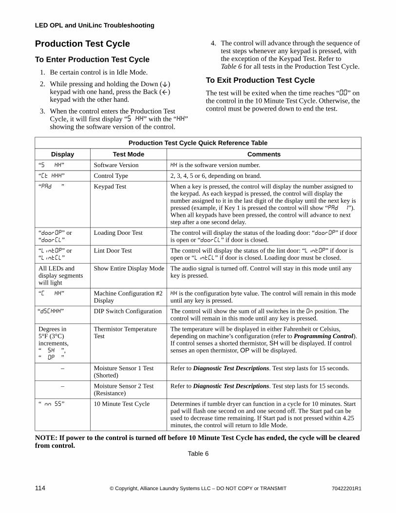
114 70422201R1© Copyright, Alliance Laundry Systems LLC – DO NOT COPY or TRANSMIT
LED OPL and UniLinc Troubleshooting
Production Test Cycle
To Enter Production Test Cycle
1. Be certain control is in Idle Mode.
2. While pressing and holding the Down ( ) keypad with one hand, press the Back ( ) keypad with the other hand.
3. When the control enters the Production Test Cycle, it will first display “ ” with the “” showing the software version of the control.
4. The control will advance through the sequence of test steps whenever any keypad is pressed, with the exception of the Keypad Test. Refer to Table 6 for all tests in the Production Test Cycle.
To Exit Production Test Cycle
The test will be exited when the time reaches “” on the control in the 10 Minute Test Cycle. Otherwise, the control must be powered down to end the test.
NOTE: If power to the control is turned off before 10 Minute Test Cycle has ended, the cycle will be cleared from control.
Table 6
Production Test Cycle Quick Reference Table
Display Test Mode Comments
“ ” Software Version is the software version number.
“ ” Control Type 2, 3, 4, 5 or 6, depending on brand.
“ ” Keypad Test When a key is pressed, the control will display the number assigned to the keypad. As each keypad is pressed, the control will display the number assigned to it in the last digit of the display until the next key is pressed (example, if Key 1 is pressed the control will show “ ”). When all keypads have been pressed, the control will advance to next step after a one second delay.
“” or “”
Loading Door Test The control will display the status of the loading door: “” if door is open or “” if door is closed.
“” or “”
Lint Door Test The control will display the status of the lint door: “” if door is open or “” if door is closed. Loading door must be closed.
All LEDs and display segments will light
Show Entire Display Mode The audio signal is turned off. Control will stay in this mode until any key is pressed.
“ ” Machine Configuration #2 Display
is the configuration byte value. The control will remain in this mode until any key is pressed.
“” DIP Switch Configuration The control will show the sum of all switches in the position. The control will remain in this mode until any key is pressed.
Degrees in 5°F (3°C) increments, “ ”, “ ”
Thermistor Temperature Test
The temperature will be displayed in either Fahrenheit or Celsius, depending on machine’s configuration (refer to Programming Control). If control senses a shorted thermistor, SH will be displayed. If control senses an open thermistor, OP will be displayed.
– Moisture Sensor 1 Test (Shorted)
Refer to Diagnostic Test Descriptions. Test step lasts for 15 seconds.
– Moisture Sensor 2 Test (Resistance)
Refer to Diagnostic Test Descriptions. Test step lasts for 15 seconds.
“ ” 10 Minute Test Cycle Determines if tumble dryer can function in a cycle for 10 minutes. Start pad will flash one second on and one second off. The Start pad can be used to decrease time remaining. If Start pad is not pressed within 4.25 minutes, the control will return to Idle Mode.
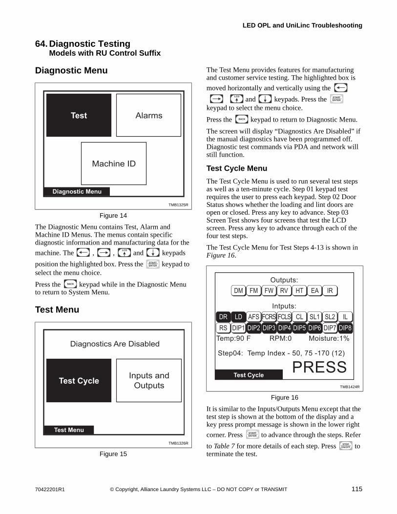
70422201R1 115© Copyright, Alliance Laundry Systems LLC – DO NOT COPY or TRANSMIT
LED OPL and UniLinc Troubleshooting
64. Diagnostic TestingModels with RU Control Suffix
Diagnostic Menu
The Diagnostic Menu contains Test, Alarm and Machine ID Menus. The menus contain specific diagnostic information and manufacturing data for the
machine. The , , and keypads
position the highlighted box. Press the keypad to select the menu choice.
Press the keypad while in the Diagnostic Menu to return to System Menu.
Test Menu
The Test Menu provides features for manufacturing and customer service testing. The highlighted box is
moved horizontally and vertically using the
and keypads. Press the keypad to select the menu choice.
Press the keypad to return to Diagnostic Menu.
The screen will display “Diagnostics Are Disabled” if the manual diagnostics have been programmed off. Diagnostic test commands via PDA and network will still function.
Test Cycle Menu
The Test Cycle Menu is used to run several test steps as well as a ten-minute cycle. Step 01 keypad test requires the user to press each keypad. Step 02 Door Status shows whether the loading and lint doors are open or closed. Press any key to advance. Step 03 Screen Test shows four screens that test the LCD screen. Press any key to advance through each of the four test steps.
The Test Cycle Menu for Test Steps 4-13 is shown in Figure 16.
It is similar to the Inputs/Outputs Menu except that the test step is shown at the bottom of the display and a key press prompt message is shown in the lower right
corner. Press to advance through the steps. Refer
to Table 7 for more details of each step. Press to terminate the test.
TMB1325R
Figure 14
TMB1326R
Figure 15
TMB1325R
Machine ID
Test
Diagnostic Menu
Alarms
TMB1326R
Test Cycle
Test Menu
Inputs and
Outputs
Diagnostics Are Disabled
TMB1424R
Figure 16
Test Cycle
Outputs:
Intputs:
RPM:0Temp:90 F
Step04: Temp Index - 50, 75 -170 (12)
Moisture:1%
PRESS
DM FM FW RV HT EA IR
DR LD AFS FCRS FCLS CL SL1 SL2 ILRS DIP1 DIP2 DIP3 DIP4 DIP5 DIP6 DIP7 DIP8
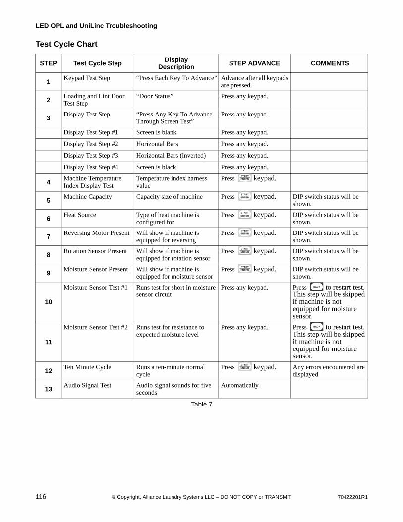
116 70422201R1© Copyright, Alliance Laundry Systems LLC – DO NOT COPY or TRANSMIT
LED OPL and UniLinc Troubleshooting
Test Cycle Chart
STEP Test Cycle Step DisplayDescription STEP ADVANCE COMMENTS
1Keypad Test Step “Press Each Key To Advance” Advance after all keypads
are pressed.
2Loading and Lint Door Test Step
“Door Status” Press any keypad.
3Display Test Step “Press Any Key To Advance
Through Screen Test”Press any keypad.
Display Test Step #1 Screen is blank Press any keypad.
Display Test Step #2 Horizontal Bars Press any keypad.
Display Test Step #3 Horizontal Bars (inverted) Press any keypad.
Display Test Step #4 Screen is black Press any keypad.
4Machine Temperature Index Display Test
Temperature index harness value
Press keypad.
5Machine Capacity Capacity size of machine Press keypad. DIP switch status will be
shown.
6Heat Source Type of heat machine is
configured forPress keypad. DIP switch status will be
shown.
7Reversing Motor Present Will show if machine is
equipped for reversingPress keypad. DIP switch status will be
shown.
8Rotation Sensor Present Will show if machine is
equipped for rotation sensorPress keypad. DIP switch status will be
shown.
9Moisture Sensor Present Will show if machine is
equipped for moisture sensorPress keypad. DIP switch status will be
shown.
10
Moisture Sensor Test #1 Runs test for short in moisture sensor circuit
Press any keypad. Press to restart test. This step will be skipped if machine is not equipped for moisture sensor.
11
Moisture Sensor Test #2 Runs test for resistance to expected moisture level
Press any keypad. Press to restart test. This step will be skipped if machine is not equipped for moisture sensor.
12Ten Minute Cycle Runs a ten-minute normal
cyclePress keypad. Any errors encountered are
displayed.
13Audio Signal Test Audio signal sounds for five
secondsAutomatically.
Table 7

70422201R1 117© Copyright, Alliance Laundry Systems LLC – DO NOT COPY or TRANSMIT
LED OPL and UniLinc Troubleshooting
Inputs Outputs Menu
When the Inputs Outputs Menu is accessed through the Diagnostic Menu, the user can manually turn on outputs. The user can scroll through the outputs using any of the arrow keys, the cursor is indicated by flashing the active output on the screen. The user must
“setup” the outputs to be turned on. The keypad is used to select individual outputs to be turned on or
off. After the keypad is pressed the control will turn the selected outputs on and display the text “RUNNING”. The outputs cannot be selected until
the keypad is pressed. The text “RUNNING” is no longer displayed. The screen will still show the selected outputs on the screen and the user can again
select outputs to be turned on or off. If the or
keypad is pressed at any time during this test, the control will turn off all outputs if the test is running or return to the previous screen if the test is not running.
If the Inputs Outputs Menu is accessed through the
Run Diagnostic Menu (pressing the keypad during a running cycle) the menu shows only what is turned on and off as the cycle runs. Refer to Figure 17.
Abbreviations for the Inputs and Outputs are defined in the following table:
Table 8
TMB1425R
Figure 17
Inputs Outputs
Outputs:
Intputs:
RPM:25 Moisture:30%
DM FM FW RV HT EA IR
DR LD AFS FCRS FCLS CL SL1 SL2 ILRS DIP1 DIP2 DIP3 DIP4 DIP5 DIP6 DIP7 DIP8
30:29
Temp:180 F
Inputs
DR Loading Door
LD Lint Door
AFS Airflow Switch
FCRS Fan Motor Contactor Switch
FCLS Fan Motor Centrifugal Switch
CL Cabinet High Limit
SL1 Store 1 High Limit
SL2 Store 2 High Limit
IL Ignition Lockout
RS Rotation Sensed
DIP1 Dip Switch 1
DIP2 Dip Switch 2
DIP3 Dip Switch 3
DIP4 Dip Switch 4
DIP5 Dip Switch 5
DIP6 Dip Switch 6
DIP7 Dip Switch 7
DIP8 Dip Switch 8
Temp Temperature
RPM Rotations per Minute
Moisture Moisture Level
Outputs
DM Damper Motor
FM Fan Motor
FW Forward Contactor
RV Reverse Contactor
HT Heater
EA External Alarm
IR Ignition Reset
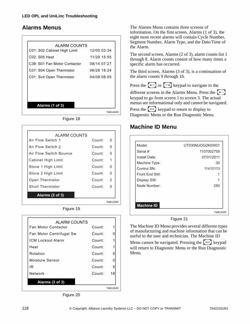
118 70422201R1© Copyright, Alliance Laundry Systems LLC – DO NOT COPY or TRANSMIT
LED OPL and UniLinc Troubleshooting
Alarms Menus The Alarms Menu contains three screens of information. On the first screen, Alarms (1 of 3), the eight most recent alarms will contain Cycle Number, Segment Number, Alarm Type, and the Date/Time of the Alarm.
The second screen, Alarms (2 of 3), alarm counts list 1 through 8. Alarm counts consist of how many times a specific alarm has occurred.
The third screen, Alarms (3 of 3), is a continuation of the alarm counts 9 through 16.
Press the or keypad to navigate to the
different screens in the Alarms Menu. Press the keypad to go from screen 1 to screen 3. The actual menus are informational only and cannot be navigated.
Press the keypad to return to display to Diagnostic Menu or the Run Diagnostic Menu.
Machine ID Menu
The Machine ID Menu provides several different types of manufacturing and machine information that can be useful to the user and technician. The Machine ID
Menu cannot be navigated. Pressing the keypad will return to Diagnostic Menu or the Run Diagnostic Menu.
TMB1400R
Figure 18
TMB1330R
Figure 19
TMB1363R
Figure 20
Alarms (1 of 3)
ALARM COUNTSC01: S02 Cabinet High Limit 12/05 03:34
C02: S05 Heat 11/29 15:55
C38: S01 Fan Motor Contactor 08/14 07:27
C07: S04 Open Thermistor 06/28 18:24
C01: Scd Open Thermistor 04/08 08:05
Alarms (2 of 3)
ALARM COUNTS
Air Flow Switch 1 Count: 0
Air Flow Switch 2 Count: 0
Air Flow Switch Bounce Count: 0
Cabinet High Limit Count: 1
Stove 1 High Limit Count: 0
Stove 2 High Limit Count: 0
Open Thermistor Count: 2
Short Thermistor Count: 0
Alarms (3 of 3)
ALARM COUNTSFan Motor Contactor Count: 1
Fan Motor Centrifugal Sw Count: 0
ICM Lockout Alarm Count: 1
Heat Count: 1
Rotation Count: 0
Moisture Sensor Count:
IR Count: 5
0
Network Count: 18
TMB1332R
Figure 21
Machine ID
Model: UT030NUOG2K0W01
Serial #: 1107002759
Install Date: 07/01/2011
Machine Type: 30
Control SN: 11410113
Front End SW: 1
Display SW: 1
Node Number: 250