Embed Size (px)
Citation preview
creating sustainable change through education, communication and leadership © 2010 GSES P/L Sustainable change through education, engineering and communication © 2017 GSES P/L
Training • Consulting • Engineering • Publications
Trouble Shooting and Fault Finding
creating sustainable change through education, communication and leadership © 2010 GSES P/L Sustainable change through education, engineering and communication © 2017 GSES P/L
LARGERSGRID CONNECT SOLAR SYSTEM
creating sustainable change through education, communication and leadership © 2010 GSES P/L Sustainable change through education, engineering and communication © 2017 GSES P/L
Fault Detection
• Faults and failures in the system can range from being very minor, such as temporary ground fault due to rain, to serious issues, such as output from the plant failing to synchronise with the grid in terms of voltage, PF or frequency.
• It is important that operations personnel are notified in some way of the fault or failure so that appropriate action can be taken based on the severity of issue.
• String monitoring remains the convention, but as systems become increasingly larger, the level and type of monitoring may change over time.
• String faults will be detected by string monitoring which are basically current transformers, and are typically built into string combiner boxes.
• DC isolation is also built into string combiner boxes, and often has the ability to remote trip as signalled by the SCADA system.
creating sustainable change through education, communication and leadership © 2010 GSES P/L Sustainable change through education, engineering and communication © 2017 GSES P/L
Fault Detection
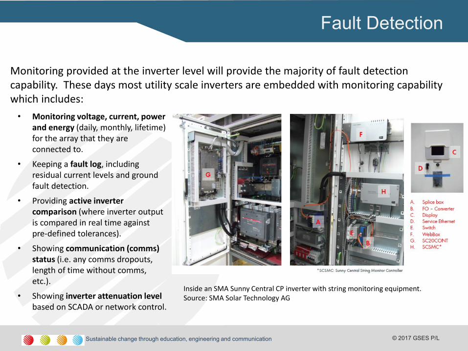
Monitoring provided at the inverter level will provide the majority of fault detection capability. These days most utility scale inverters are embedded with monitoring capability which includes:
• Monitoring voltage, current, power and energy (daily, monthly, lifetime) for the array that they are connected to.
• Keeping a fault log, including residual current levels and ground fault detection.
• Providing active inverter comparison (where inverter output is compared in real time against pre-defined tolerances).
• Showing communication (comms) status (i.e. any comms dropouts, length of time without comms, etc.).
• Showing inverter attenuation level based on SCADA or network control.
Inside an SMA Sunny Central CP inverter with string monitoring equipment. Source: SMA Solar Technology AG
creating sustainable change through education, communication and leadership © 2010 GSES P/L Sustainable change through education, engineering and communication © 2017 GSES P/L
Fault Detection
The operational personnel may be notified of a fault or failure in the system via either of the following ways:
• An alarm or error report sent from the monitoring system
• Routine inspection conducted by maintenance personnel
• Performance analysis of the power plant
• An alarm or error report sent from a third party such as network service provider.
creating sustainable change through education, communication and leadership © 2010 GSES P/L Sustainable change through education, engineering and communication © 2017 GSES P/L
LOOKING AT COMPONENTS
creating sustainable change through education, communication and leadership © 2010 GSES P/L Sustainable change through education, engineering and communication © 2017 GSES P/L creating sustainable change through education, communication and leadership © 2010 GSES P/L Sustainable change through education, engineering and communication © 2017 GSES P/L
Trouble shooting
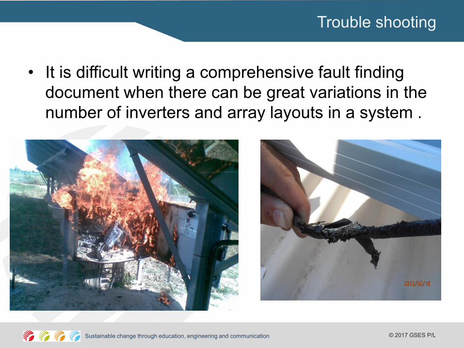
• It is difficult writing a comprehensive fault finding
document when there can be great variations in the
number of inverters and array layouts in a system .
creating sustainable change through education, communication and leadership © 2010 GSES P/L Sustainable change through education, engineering and communication © 2017 GSES P/L creating sustainable change through education, communication and leadership © 2010 GSES P/L Sustainable change through education, engineering and communication © 2017 GSES P/L
Training
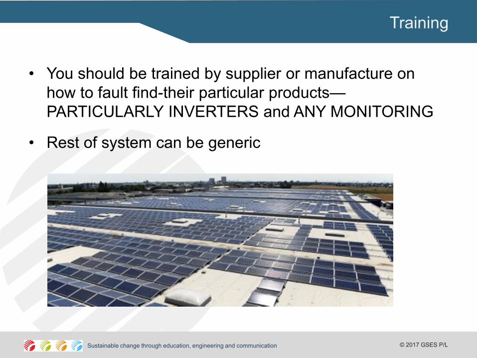
• You should be trained by supplier or manufacture on
how to fault find-their particular products—
PARTICULARLY INVERTERS and ANY MONITORING
• Rest of system can be generic
creating sustainable change through education, communication and leadership © 2010 GSES P/L Sustainable change through education, engineering and communication © 2017 GSES P/L creating sustainable change through education, communication and leadership © 2010 GSES P/L Sustainable change through education, engineering and communication © 2017 GSES P/L
System Faults
• Easier to talk basic systems first--
• If it is small system then you will notice that there
ism a fault when the system is not working or it is
underperforming, that is not providing the kWh that
was expected.
• Larger systems it will be a case where part of the
system is not working and your indicator will be
underperforming system
creating sustainable change through education, communication and leadership © 2010 GSES P/L Sustainable change through education, engineering and communication © 2017 GSES P/L creating sustainable change through education, communication and leadership © 2010 GSES P/L Sustainable change through education, engineering and communication © 2017 GSES P/L
What do you do?
• If it is large system then you might be able to identify
which part of the system is underperforming through
monitoring.
• Might be able to identify data collected from either large
inverter based system that it is one or more strings have
failed or under preforming
• If it is multiple inverters in the system –
– there might be central data source that provides data from each
of the inverters
– These inform you that one or more inverters are not producing
energy or under performing.
creating sustainable change through education, communication and leadership © 2010 GSES P/L Sustainable change through education, engineering and communication © 2017 GSES P/L creating sustainable change through education, communication and leadership © 2010 GSES P/L Sustainable change through education, engineering and communication © 2017 GSES P/L
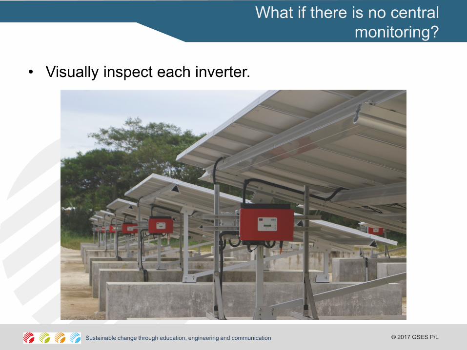
What if there is no central
monitoring?
• Visually inspect each inverter.
creating sustainable change through education, communication and leadership © 2010 GSES P/L Sustainable change through education, engineering and communication © 2017 GSES P/L creating sustainable change through education, communication and leadership © 2010 GSES P/L Sustainable change through education, engineering and communication © 2017 GSES P/L
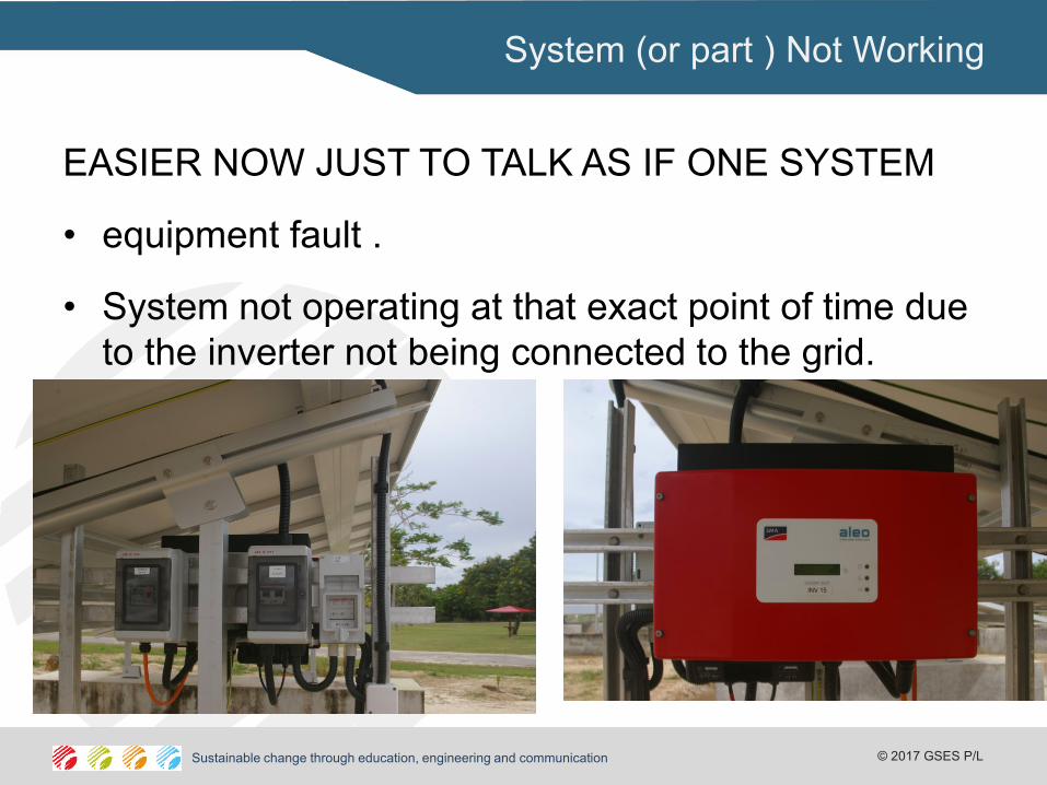
System (or part ) Not Working
EASIER NOW JUST TO TALK AS IF ONE SYSTEM
• equipment fault .
• System not operating at that exact point of time due
to the inverter not being connected to the grid.
creating sustainable change through education, communication and leadership © 2010 GSES P/L Sustainable change through education, engineering and communication © 2017 GSES P/L creating sustainable change through education, communication and leadership © 2010 GSES P/L Sustainable change through education, engineering and communication © 2017 GSES P/L
What to do when if system is not
working?
• visit should occur during daylight hours
• Have sufficient hours to do proper testing
• check
– array d.c. main switch
– array a.c main switch
– breaker at the point of attachment to the grid supply (If exists)
• If all the breakers and switches are on, then undertake a visual check of the inverter. Make sure there has not been a failure
creating sustainable change through education, communication and leadership © 2010 GSES P/L Sustainable change through education, engineering and communication © 2017 GSES P/L creating sustainable change through education, communication and leadership © 2010 GSES P/L Sustainable change through education, engineering and communication © 2017 GSES P/L
Voltage Measurements
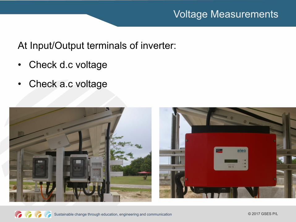
At Input/Output terminals of inverter:
• Check d.c voltage
• Check a.c voltage
creating sustainable change through education, communication and leadership © 2010 GSES P/L Sustainable change through education, engineering and communication © 2017 GSES P/L creating sustainable change through education, communication and leadership © 2010 GSES P/L Sustainable change through education, engineering and communication © 2017 GSES P/L
No a.c. at inverter – all
switches on etc-
systematically check all the way back to the point
of supply to find the fault. This will involve
measuring whether a.c voltage is present :
• at the meters; then
• on the inverter side followed by the supply side
of the array a.c mains switch; then
• at the point of attachment to the grid supply.
creating sustainable change through education, communication and leadership © 2010 GSES P/L Sustainable change through education, engineering and communication © 2017 GSES P/L creating sustainable change through education, communication and leadership © 2010 GSES P/L Sustainable change through education, engineering and communication © 2017 GSES P/L
No d.c. input at inverter – all
switches on etc-
systematically check all the way back to the point of supply
to find the fault. This will involve measuring whether d.c
voltage is present :
• at the d.c main switch; then
• At the array junction box; then
• The solar array.
creating sustainable change through education, communication and leadership © 2010 GSES P/L Sustainable change through education, engineering and communication © 2017 GSES P/L creating sustainable change through education, communication and leadership © 2010 GSES P/L Sustainable change through education, engineering and communication © 2017 GSES P/L
Trouble shooting PV arrays
If there is no d.c. voltage at the junction box (for single strings) or there is no voltage at junction box for one string in multiple strings arrays then the fault is in the string. The fault will be either:
• cable disconnected or plug failure if plugs are used in connecting the string;
• loose connection within the junction box;
• failed bypass diode; or
• failed module
creating sustainable change through education, communication and leadership © 2010 GSES P/L Sustainable change through education, engineering and communication © 2017 GSES P/L creating sustainable change through education, communication and leadership © 2010 GSES P/L Sustainable change through education, engineering and communication © 2017 GSES P/L
System Underperforming
• You are expecting more from their system than the system can actually deliver.
• poor system design such that the PV array operates at voltages outside the voltage window of the inverter and the inverter disconnects from the grid for long periods.
• from unstable grids such that the grid operates for long periods outside the a.c. voltage window and the inverter disconnects from the grid for long periods
• partial failure of some of the array
• Poor matching between the array and inverter so that the inverter is operating very inefficiently.
creating sustainable change through education, communication and leadership © 2010 GSES P/L Sustainable change through education, engineering and communication © 2017 GSES P/L creating sustainable change through education, communication and leadership © 2010 GSES P/L Sustainable change through education, engineering and communication © 2017 GSES P/L
If the system is under-performing but it is
working when you first arrive:
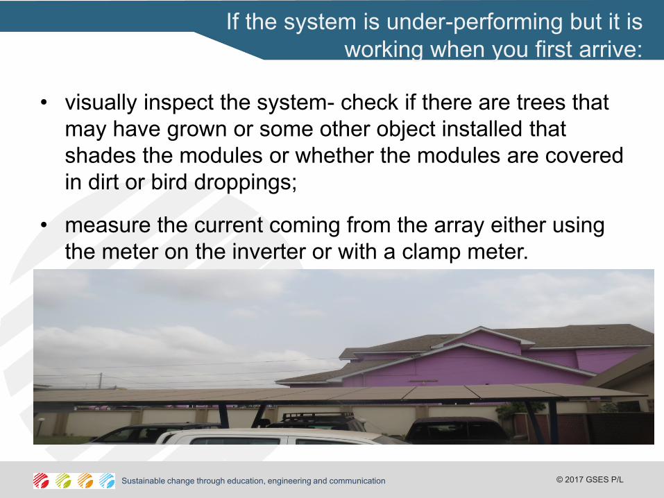
• visually inspect the system- check if there are trees that
may have grown or some other object installed that
shades the modules or whether the modules are covered
in dirt or bird droppings;
• measure the current coming from the array either using
the meter on the inverter or with a clamp meter.
creating sustainable change through education, communication and leadership © 2010 GSES P/L Sustainable change through education, engineering and communication © 2017 GSES P/L creating sustainable change through education, communication and leadership © 2010 GSES P/L Sustainable change through education, engineering and communication © 2017 GSES P/L
If there is no shading problem but the
current is lower then expected then:
• if it is a single string array then the string will need to be tested as described above- but this time looking for why the string is providing less current- it could be one faulty module.
• If there are multiple strings then systematically turn off each string and see whether the current changes. If one of the strings is not providing power then there will be no change in the current when that string has been turned off.
creating sustainable change through education, communication and leadership © 2010 GSES P/L Sustainable change through education, engineering and communication © 2017 GSES P/L creating sustainable change through education, communication and leadership © 2010 GSES P/L Sustainable change through education, engineering and communication © 2017 GSES P/L
Trouble shooting
inverters
• If there is d.c. voltage and a.c. voltage at the inverter
terminal (and the solar power is sufficient) but the
inverter is not on then the inverter has possibly failed.
• Refer to the manual on the inverter as supplied by the
manufacturer
creating sustainable change through education, communication and leadership © 2010 GSES P/L Sustainable change through education, engineering and communication © 2017 GSES P/L creating sustainable change through education, communication and leadership © 2010 GSES P/L Sustainable change through education, engineering and communication © 2017 GSES P/L
Trouble shooting inverters
General Faults
• Grid voltage too high or too low - check the grid
and contact electricity distributor if fault is
consistent.
• Grid frequency out of range: check the grid and
contact electricity distributor if fault is consistent.
• d.c. voltage from array too low: follow advice
provided earlier in the section with respect to
insufficient modules or temperature problem.
creating sustainable change through education, communication and leadership © 2010 GSES P/L Sustainable change through education, engineering and communication © 2017 GSES P/L creating sustainable change through education, communication and leadership © 2010 GSES P/L Sustainable change through education, engineering and communication © 2017 GSES P/L
Trouble shooting inverters
General Faults
• d.c. voltage too high - NOTE: This could damage the inverter. Immediately disconnect the array (turn off d.c. array main switch) and investigate why?
• line impedance too high; check that none of the connections on a.c. side are loose then possibly contact electricity distributor if fault persists.
• For transformerless inverters: Leakage current is too high, need to investigate why there is happening- refer to manual for that inverter.