Embed Size (px)
Citation preview

Tropos® Control Element Management System User Guide
Release 7.5
Tropos Networks, Inc.555 Del Rey Ave.Sunnyvale, CA 94085 USAwww.troposnetworks.com408-331-6800
Part No. 200033-75 Rev C02011_05_13_00
Copyright Notice©2003-2011 Tropos Networks, Inc. All rights reserved. Tropos and PWRP are registered trademarks of Tropos Networks, Inc. Tropos Networks, AMCE, TMCX, SABRE, CMDP, MESM and Metro-Scale Mesh Networking Defined are trademarks of Tropos Networks, Inc. All other brand or product names are trademarks or registered trademarks of their respective holder(s).
Information contained herein is subject to change without notice. The only warranties for Tropos products and services are set forth in the express warranty statements accompanying such products and services. Nothing herein should be construed as constituting an additional warranty. Tropos shall not be liable for technical or editorial errors or omissions contained herein.
This product includes technology protected by U.S. Patents 6,704,301; 6,965,575; 7,016,328; 7,031,293; 7,058,021; 7,362,737; 7,376,087; 7,382,778; 7,397,789; 7,450,552; 7,460,489; 7,489,932; 7,499,409; 7,505,426; 7,542,421; 7,551,562; 7,564,781; 7,564,862; 7,580,393, 7,580,705; 7,586,879
Restricted Rights LegendUse, duplication, or disclosure by the United States Government is subject to restrictions as set forth in subparagraph (c)(1)(II) of the Rights in Technical Data and Computer Software clause at DFARS 252.227-7013.
Notwithstanding any other license agreement that may pertain to, or accompany the delivery of, this computer software, the rights of the United States Government regarding its use, reproduction, and disclosure are as set forth in the Commercial Computer Software-Restricted Rights clause at FAR52.227-19.
Important Note to UsersThis software is provided by Tropos Networks, Inc. as is and any express or implied warranties, including, but not limited to, implied warranties of merchantability and fitness for a particular purpose are disclaimed. In no event shall Tropos Networks, or its affiliates, subsidiaries or suppliers be liable for any direct, indirect, incidental, special, exemplary, or consequential damages (including, but not limited to, procurement of substitute goods or services; loss of use, data or profits; or business interruption) however caused and on any theory of liability, whether in contract, strict liability, or tort (including negligence or otherwise) arising in any way out of the use of this software, even if advised of the possibility of such damage.
Tropos reserves the right to make changes without further notice to any products herein.
FCC Notice to Users and OperatorsTropos routers comply with Part 15 of the FCC rules. Operation of the Tropos router is subject to the following two conditions:
1. This device may not cause harmful interference, and2. This device must accept any interference received, including interference that may cause undesired operation.This equipment has been tested and found to comply with the limits of a Class A digital device, pursuant to Part 15 of the FCC Rules. These limits are designed to provide reasonable protection against harmful interference when the equipment is operated in an office environment. This equipment generates, uses and radiates radio frequency energy, and if not installed and used in accordance with the instructions, the device may cause harmful interference. However, there is no guarantee that interference will not occur. If this equipment does cause interference to radio or television reception, which can be determined by turning the equipment off and on, the user is encouraged to correct the interference by using one of the following measures:
Reorient or relocate the receiving antenna. Increase separation between the equipment and receiver. Connect the equipment to an outlet on a circuit different from that to which the receiver is connected. Consult the dealer or an experienced radio/TV technician.
Tropos Control EMS User Guide ii

This Part 15 radio device operates on a non-interference basis with other devices operating at this frequency. Any changes or modification to said product not expressly approved by Tropos Networks could void the user's authority to operate this device.
Tropos Control EMS User Guide iii
Contents
Preface . . . . . . . . . . . . . . . . . . . . . . . . . . . . . . . . . . . . . . . . . . . . . . . . . . . . . vii
1 Overview . . . . . . . . . . . . . . . . . . . . . . . . . . . . . . . . . . . . . . . . . . . . . . . . . . . . . 1Product Overview . . . . . . . . . . . . . . . . . . . . . . . . . . . . . . . . . . . . . . . . 2Product Features . . . . . . . . . . . . . . . . . . . . . . . . . . . . . . . . . . . . . . . . 3Mid-Tier Mesh Architecture . . . . . . . . . . . . . . . . . . . . . . . . . . . . . . . . 4
Mobile Router Networks . . . . . . . . . . . . . . . . . . . . . . . . . . . . . . . . . 6Network Management and Administration . . . . . . . . . . . . . . . . . . . . . 8
2 Installation . . . . . . . . . . . . . . . . . . . . . . . . . . . . . . . . . . . . . . . . . . . . . . . . . . . 9Pre-Installation Requirements . . . . . . . . . . . . . . . . . . . . . . . . . . . . . 10Installing Tropos Control . . . . . . . . . . . . . . . . . . . . . . . . . . . . . . . . . 12Updating ARP Cache Settings . . . . . . . . . . . . . . . . . . . . . . . . . . . . . 14Uninstalling the System . . . . . . . . . . . . . . . . . . . . . . . . . . . . . . . . . . 14Backing Up and Restoring the Tropos Control Server . . . . . . . . . . . 15Upgrading the Server . . . . . . . . . . . . . . . . . . . . . . . . . . . . . . . . . . . . 16Resetting the Administrative Password . . . . . . . . . . . . . . . . . . . . . . 16
3 Getting Started . . . . . . . . . . . . . . . . . . . . . . . . . . . . . . . . . . . . . . . . . . . . . . . 17Getting Ready to Manage the Network . . . . . . . . . . . . . . . . . . . . . . 18Starting and Stopping the Server . . . . . . . . . . . . . . . . . . . . . . . . . . . 18Using the Web Interface. . . . . . . . . . . . . . . . . . . . . . . . . . . . . . . . . . 19
Accessing and Exiting the Web Interface . . . . . . . . . . . . . . . . . . . 19Navigating the Web Interface . . . . . . . . . . . . . . . . . . . . . . . . . . . . 20
Discovery . . . . . . . . . . . . . . . . . . . . . . . . . . . . . . . . . . . . . . . . . . . . . 23
4 Viewing Network Health Information . . . . . . . . . . . . . . . . . . . . . . . . . . . . . 24Preparing to Access the Network Health Panels . . . . . . . . . . . . . . . 25Using the Dashboard . . . . . . . . . . . . . . . . . . . . . . . . . . . . . . . . . . . . 25
Viewing Geographic Maps . . . . . . . . . . . . . . . . . . . . . . . . . . . . . . 27Using the Network Optimization Panels . . . . . . . . . . . . . . . . . . . . . . 30Using the Client Optimization Panels . . . . . . . . . . . . . . . . . . . . . . . . 34
Tropos Control EMS User Guide iv
Understanding the Client Query Reports . . . . . . . . . . . . . . . . . . . 36Using the Voice Optimization Panels . . . . . . . . . . . . . . . . . . . . . . . . 39Using the Device Ping Utility . . . . . . . . . . . . . . . . . . . . . . . . . . . . . . 40Modifying Network Health Thresholds and Report Options . . . . . . . 42
Modifying Network Health Thresholds. . . . . . . . . . . . . . . . . . . . . . 42Modifying Report Options . . . . . . . . . . . . . . . . . . . . . . . . . . . . . . . 44
5 Viewing Fault Information . . . . . . . . . . . . . . . . . . . . . . . . . . . . . . . . . . . . . . 49Viewing Network Events. . . . . . . . . . . . . . . . . . . . . . . . . . . . . . . . . . 50Viewing Alarms. . . . . . . . . . . . . . . . . . . . . . . . . . . . . . . . . . . . . . . . . 51Viewing Event Counts . . . . . . . . . . . . . . . . . . . . . . . . . . . . . . . . . . . 52Configuring Alarms. . . . . . . . . . . . . . . . . . . . . . . . . . . . . . . . . . . . . . 53SNMP Trap Forwarding . . . . . . . . . . . . . . . . . . . . . . . . . . . . . . . . . . 57
6 Viewing Network Configuration Information . . . . . . . . . . . . . . . . . . . . . . . 58Network Configuration Panels . . . . . . . . . . . . . . . . . . . . . . . . . . . . . 59Configuration View Actions . . . . . . . . . . . . . . . . . . . . . . . . . . . . . . . 60Updating the Device Database. . . . . . . . . . . . . . . . . . . . . . . . . . . . . 62
Creating Custom Views. . . . . . . . . . . . . . . . . . . . . . . . . . . . . . . . . 64Configuring Gateways for Multi-Subnet Roaming . . . . . . . . . . . . . . 65
7 Provisioning . . . . . . . . . . . . . . . . . . . . . . . . . . . . . . . . . . . . . . . . . . . . . . . . . 68About Provisioning Operations. . . . . . . . . . . . . . . . . . . . . . . . . . . . . 69Provisioning Routers Using Web Forms . . . . . . . . . . . . . . . . . . . . . 74
Provisioning from Forms - Tasks. . . . . . . . . . . . . . . . . . . . . . . . . . 74Provisioning Routers From a File . . . . . . . . . . . . . . . . . . . . . . . . . . . 76
Provisioning from Files - Tasks . . . . . . . . . . . . . . . . . . . . . . . . . . . 77Provisioning Forms. . . . . . . . . . . . . . . . . . . . . . . . . . . . . . . . . . . . . . 78
Router Identity Page . . . . . . . . . . . . . . . . . . . . . . . . . . . . . . . . . . . 79IP and VLAN Page . . . . . . . . . . . . . . . . . . . . . . . . . . . . . . . . . . . . 81Wireless Page . . . . . . . . . . . . . . . . . . . . . . . . . . . . . . . . . . . . . . . . 86Client Access. . . . . . . . . . . . . . . . . . . . . . . . . . . . . . . . . . . . . . . . . 92DHCP Server. . . . . . . . . . . . . . . . . . . . . . . . . . . . . . . . . . . . . . . . . 97SNMP . . . . . . . . . . . . . . . . . . . . . . . . . . . . . . . . . . . . . . . . . . . . . . 98Time . . . . . . . . . . . . . . . . . . . . . . . . . . . . . . . . . . . . . . . . . . . . . . 100DHCP Clients . . . . . . . . . . . . . . . . . . . . . . . . . . . . . . . . . . . . . . . 102Static IP Client. . . . . . . . . . . . . . . . . . . . . . . . . . . . . . . . . . . . . . . 103Packet Filtering . . . . . . . . . . . . . . . . . . . . . . . . . . . . . . . . . . . . . . 105P2P Blocking . . . . . . . . . . . . . . . . . . . . . . . . . . . . . . . . . . . . . . . . 109Multi-Subnet Roaming. . . . . . . . . . . . . . . . . . . . . . . . . . . . . . . . . 110Backhaul Routing . . . . . . . . . . . . . . . . . . . . . . . . . . . . . . . . . . . . 111Rate Limiting . . . . . . . . . . . . . . . . . . . . . . . . . . . . . . . . . . . . . . . . 112QoS . . . . . . . . . . . . . . . . . . . . . . . . . . . . . . . . . . . . . . . . . . . . . . . 115
Tropos Control EMS User Guide v
Voice . . . . . . . . . . . . . . . . . . . . . . . . . . . . . . . . . . . . . . . . . . . . . . 118Software . . . . . . . . . . . . . . . . . . . . . . . . . . . . . . . . . . . . . . . . . . . 120Security . . . . . . . . . . . . . . . . . . . . . . . . . . . . . . . . . . . . . . . . . . . . 120
Other Provisioning Operations . . . . . . . . . . . . . . . . . . . . . . . . . . . . 123Provisioning Tasks - Administration . . . . . . . . . . . . . . . . . . . . . . 125
Auditing Provisioning Jobs . . . . . . . . . . . . . . . . . . . . . . . . . . . . . . . 126
8 Performing Administrative Tasks . . . . . . . . . . . . . . . . . . . . . . . . . . . . . . 129Generating Diagnostic Information. . . . . . . . . . . . . . . . . . . . . . . . . 130Upgrading Router Software . . . . . . . . . . . . . . . . . . . . . . . . . . . . . . 131Tracking Router Inventory . . . . . . . . . . . . . . . . . . . . . . . . . . . . . . . 134Backing Up Router Configurations . . . . . . . . . . . . . . . . . . . . . . . . . 136Restoring Router Configurations . . . . . . . . . . . . . . . . . . . . . . . . . . 140Supporting RADIUS Authentication . . . . . . . . . . . . . . . . . . . . . . . . 143Managing Administrative Users . . . . . . . . . . . . . . . . . . . . . . . . . . . 144Using Router Auto Discovery . . . . . . . . . . . . . . . . . . . . . . . . . . . . . 145Viewing the User Audit Log . . . . . . . . . . . . . . . . . . . . . . . . . . . . . . 149Configuring Banner Text . . . . . . . . . . . . . . . . . . . . . . . . . . . . . . . . 149Configuring FIPS Mode . . . . . . . . . . . . . . . . . . . . . . . . . . . . . . . . . 150
A Redundant Tropos Control Servers for Failover . . . . . . . . . . . . . . . . . . 152Primary and Secondary Servers . . . . . . . . . . . . . . . . . . . . . . . . . . 152Set Up the Primary and Secondary Servers . . . . . . . . . . . . . . . . . 152Set Up the Secondary Server as Backup. . . . . . . . . . . . . . . . . . . . 153Perform Failover from the Primary to Secondary Server . . . . . . . . 153Returning to the Primary Server when it Recovers . . . . . . . . . . . . 154
Glossary . . . . . . . . . . . . . . . . . . . . . . . . . . . . . . . . . . . . . . . . . . . . . . . . . . . 155
Index . . . . . . . . . . . . . . . . . . . . . . . . . . . . . . . . . . . . . . . . . . . . . . . . . . . . . 162
Tropos Control EMS User Guide vi
Preface
This guide contains the information and instructions needed to install, configure and use the Tropos® Control Element Management System to manage your wireless network.
About this GuideTropos Control is a comprehensive, real-time management system for Tropos wireless networks. The system allows you to view the status of all Tropos gateways and nodes, modify configurations, and assess network performance, all from a central management station.
This guide contains information and instructions on installing, configuring, and optimizing Tropos Control, and is divided into the following chapters:
Chapter 1, “Overview,” provides an overview of the Tropos network architecture and introduces the system features.
Chapter 2, “Installation,” contains information needed to install the Tropos Control server, including system requirements and step-by-step installation instructions.
Chapter 3, “Getting Started,” contains basic information on using Tropos Control, including how to start and stop the server, establish a new wireless network, and perform discovery.
Chapter 4, “Viewing Network Health Information,” describes how to display detailed information on network connectivity and performance using the Network Health panels in the web interface.
Chapter 5, “Viewing Fault Information,” describes how to display alarm and network event information using the Fault Management panels in the web interface.
Chapter 6, “Viewing Network Configuration Information,” describes how to display device information using the Network Configuration panels in the web interface.
Chapter 7, “Provisioning,” describes how to use the web interface to provision Tropos routers for operation in the wireless network.
Chapter 8, “Performing Administrative Tasks,” describes how to manage router inventory, upgrade router software, and generate diagnostic information using the web interface.
“Glossary” contains definitions of terms relating to Tropos wireless networking.
Tropos Control EMS User Guide vii
Chapter 1
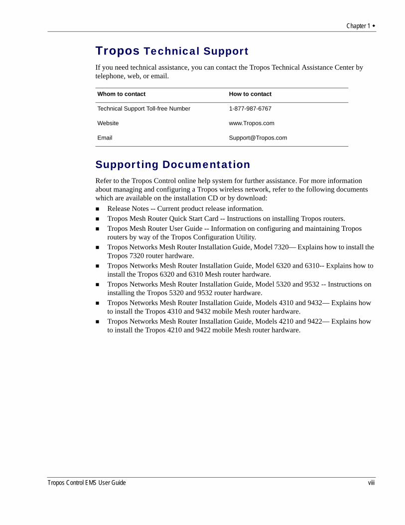
Tropos Technical SupportIf you need technical assistance, you can contact the Tropos Technical Assistance Center by telephone, web, or email.
Supporting DocumentationRefer to the Tropos Control online help system for further assistance. For more information about managing and configuring a Tropos wireless network, refer to the following documents which are available on the installation CD or by download:
Release Notes -- Current product release information.Tropos Mesh Router Quick Start Card -- Instructions on installing Tropos routers.Tropos Mesh Router User Guide -- Information on configuring and maintaining Tropos routers by way of the Tropos Configuration Utility.Tropos Networks Mesh Router Installation Guide, Model 7320— Explains how to install the Tropos 7320 router hardware.Tropos Networks Mesh Router Installation Guide, Model 6320 and 6310-- Explains how to install the Tropos 6320 and 6310 Mesh router hardware.Tropos Networks Mesh Router Installation Guide, Model 5320 and 9532 -- Instructions on installing the Tropos 5320 and 9532 router hardware.Tropos Networks Mesh Router Installation Guide, Models 4310 and 9432— Explains how to install the Tropos 4310 and 9432 mobile Mesh router hardware.Tropos Networks Mesh Router Installation Guide, Models 4210 and 9422— Explains how to install the Tropos 4210 and 9422 mobile Mesh router hardware.
Whom to contact How to contact
Technical Support Toll-free Number 1-877-987-6767
Website www.Tropos.com
Email [email protected]
Tropos Control EMS User Guide viii
Chapter 1
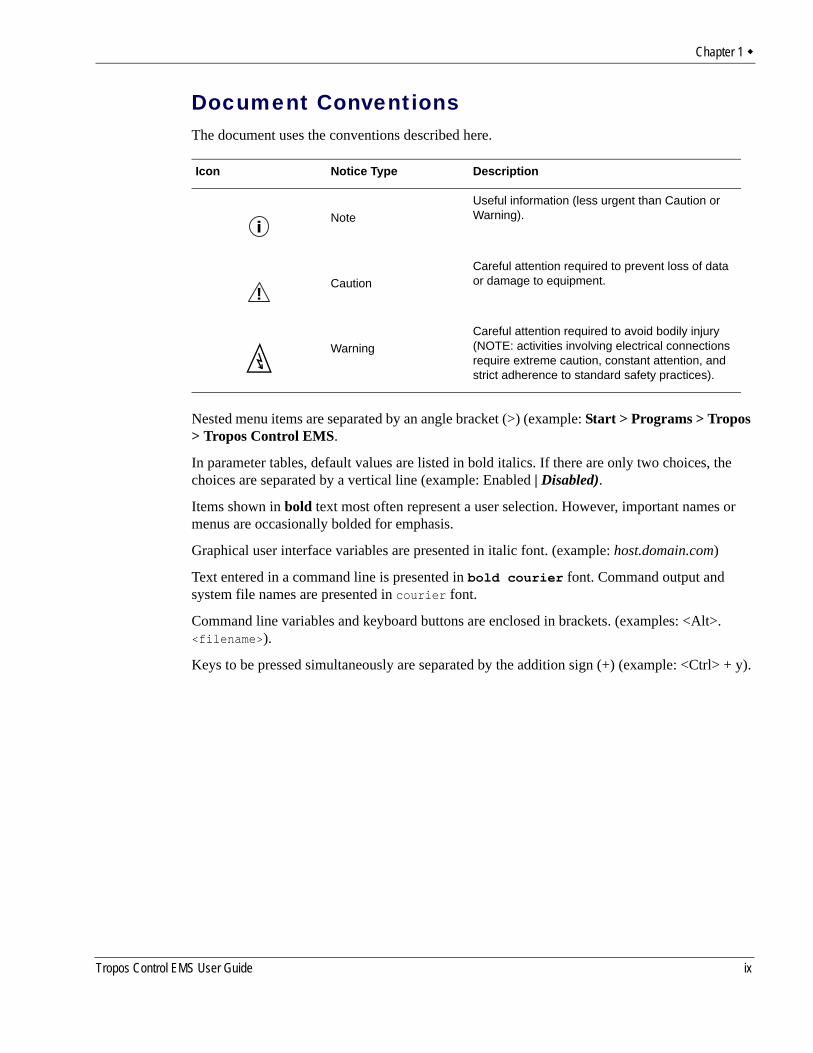
Document ConventionsThe document uses the conventions described here.
Nested menu items are separated by an angle bracket (>) (example: Start > Programs > Tropos > Tropos Control EMS.
In parameter tables, default values are listed in bold italics. If there are only two choices, the choices are separated by a vertical line (example: Enabled | Disabled).
Items shown in bold text most often represent a user selection. However, important names or menus are occasionally bolded for emphasis.
Graphical user interface variables are presented in italic font. (example: host.domain.com)
Text entered in a command line is presented in bold courier font. Command output and system file names are presented in courier font.
Command line variables and keyboard buttons are enclosed in brackets. (examples: <Alt>. <filename>).
Keys to be pressed simultaneously are separated by the addition sign (+) (example: <Ctrl> + y).
Icon Notice Type Description
NoteUseful information (less urgent than Caution or Warning).
CautionCareful attention required to prevent loss of data or damage to equipment.
WarningCareful attention required to avoid bodily injury (NOTE: activities involving electrical connections require extreme caution, constant attention, and strict adherence to standard safety practices).
Tropos Control EMS User Guide ix
1 Overview
This chapter provides an overview of the Tropos Networks wireless network architecture and introduces the features of the Tropos Control Element Management System.
Chapter contents:Product OverviewProduct FeaturesMid-Tier Mesh ArchitectureNetwork Management and Administration
Tropos Control EMS User Guide 1
Chapter 1
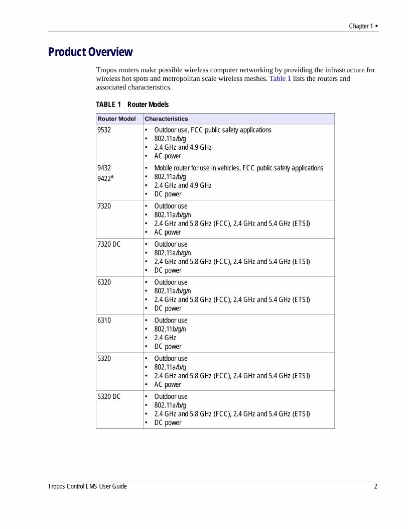
Product OverviewTropos routers make possible wireless computer networking by providing the infrastructure for wireless hot spots and metropolitan scale wireless meshes. Table 1 lists the routers and associated characteristics.
TABLE 1 Router Models
Router Model Characteristics
9532 • Outdoor use, FCC public safety applications• 802.11a/b/g• 2.4 GHz and 4.9 GHz• AC power
94329422a
• Mobile router for use in vehicles, FCC public safety applications• 802.11a/b/g• 2.4 GHz and 4.9 GHz• DC power
7320 • Outdoor use• 802.11a/b/g/n• 2.4 GHz and 5.8 GHz (FCC), 2.4 GHz and 5.4 GHz (ETSI)• AC power
7320 DC • Outdoor use• 802.11a/b/g/n• 2.4 GHz and 5.8 GHz (FCC), 2.4 GHz and 5.4 GHz (ETSI)• DC power
6320 • Outdoor use• 802.11a/b/g/n• 2.4 GHz and 5.8 GHz (FCC), 2.4 GHz and 5.4 GHz (ETSI)• DC power
6310 • Outdoor use• 802.11b/g/n• 2.4 GHz• DC power
5320 • Outdoor use• 802.11a/b/g• 2.4 GHz and 5.8 GHz (FCC), 2.4 GHz and 5.4 GHz (ETSI)• AC power
5320 DC • Outdoor use• 802.11a/b/g• 2.4 GHz and 5.8 GHz (FCC), 2.4 GHz and 5.4 GHz (ETSI)• DC power
Tropos Control EMS User Guide 2
Chapter 1
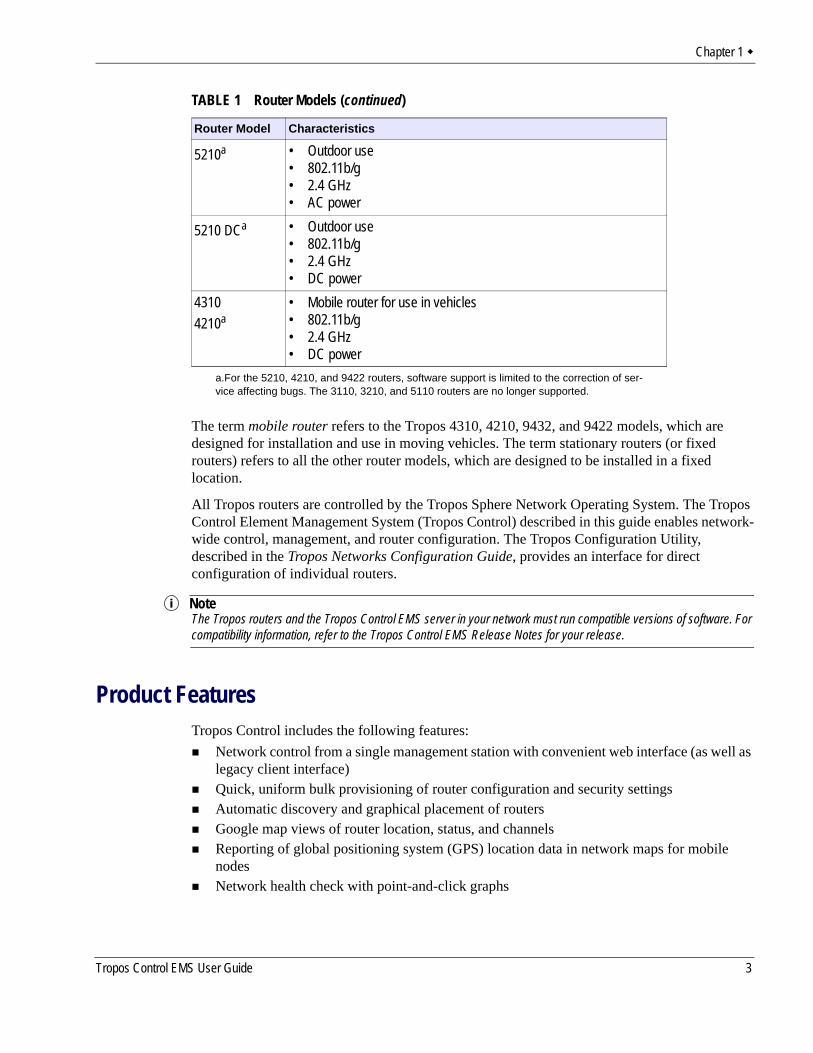
The term mobile router refers to the Tropos 4310, 4210, 9432, and 9422 models, which are designed for installation and use in moving vehicles. The term stationary routers (or fixed routers) refers to all the other router models, which are designed to be installed in a fixed location.
All Tropos routers are controlled by the Tropos Sphere Network Operating System. The Tropos Control Element Management System (Tropos Control) described in this guide enables network-wide control, management, and router configuration. The Tropos Configuration Utility, described in the Tropos Networks Configuration Guide, provides an interface for direct configuration of individual routers.
NoteThe Tropos routers and the Tropos Control EMS server in your network must run compatible versions of software. For compatibility information, refer to the Tropos Control EMS Release Notes for your release.
Product FeaturesTropos Control includes the following features:
Network control from a single management station with convenient web interface (as well as legacy client interface)Quick, uniform bulk provisioning of router configuration and security settingsAutomatic discovery and graphical placement of routersGoogle map views of router location, status, and channelsReporting of global positioning system (GPS) location data in network maps for mobile nodesNetwork health check with point-and-click graphs
5210a • Outdoor use• 802.11b/g• 2.4 GHz• AC power
5210 DCa • Outdoor use• 802.11b/g• 2.4 GHz• DC power
43104210a
• Mobile router for use in vehicles• 802.11b/g • 2.4 GHz• DC power
a.For the 5210, 4210, and 9422 routers, software support is limited to the correction of ser-vice affecting bugs. The 3110, 3210, and 5110 routers are no longer supported.
TABLE 1 Router Models (continued)
Router Model Characteristics
Tropos Control EMS User Guide 3
Chapter 1
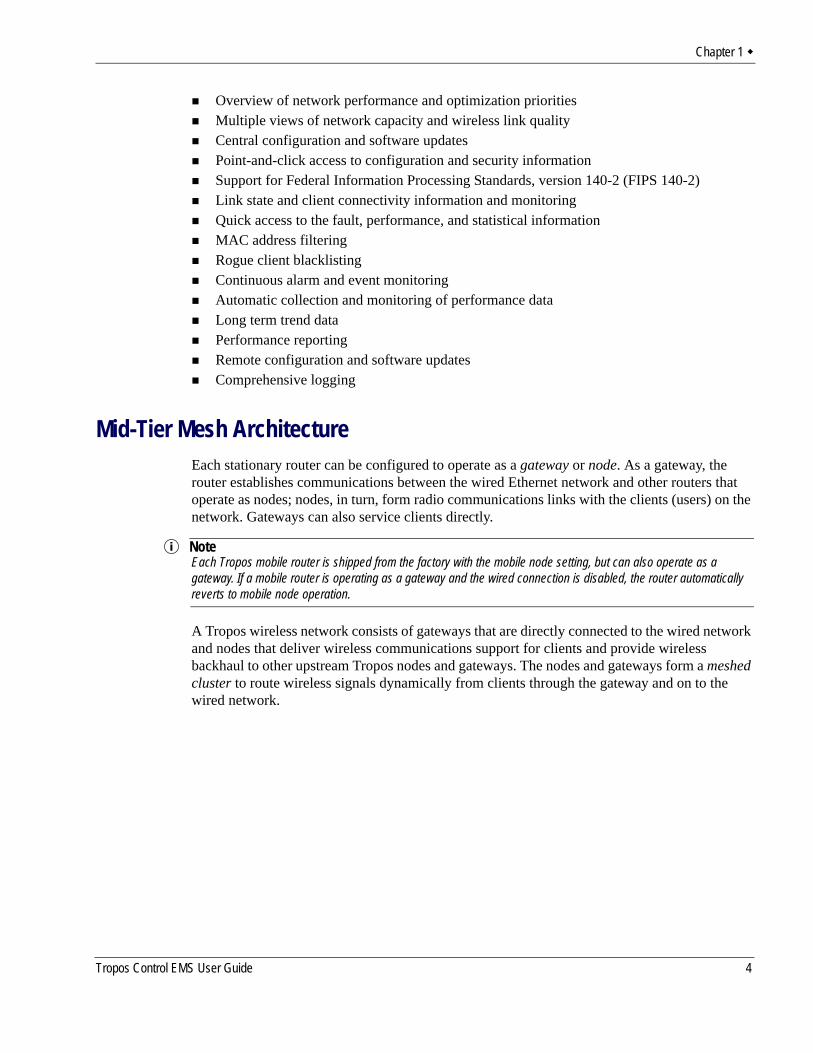
Overview of network performance and optimization prioritiesMultiple views of network capacity and wireless link qualityCentral configuration and software updatesPoint-and-click access to configuration and security informationSupport for Federal Information Processing Standards, version 140-2 (FIPS 140-2)Link state and client connectivity information and monitoringQuick access to the fault, performance, and statistical informationMAC address filtering Rogue client blacklistingContinuous alarm and event monitoringAutomatic collection and monitoring of performance dataLong term trend dataPerformance reportingRemote configuration and software updatesComprehensive logging
Mid-Tier Mesh ArchitectureEach stationary router can be configured to operate as a gateway or node. As a gateway, the router establishes communications between the wired Ethernet network and other routers that operate as nodes; nodes, in turn, form radio communications links with the clients (users) on the network. Gateways can also service clients directly.
NoteEach Tropos mobile router is shipped from the factory with the mobile node setting, but can also operate as a gateway. If a mobile router is operating as a gateway and the wired connection is disabled, the router automatically reverts to mobile node operation.
A Tropos wireless network consists of gateways that are directly connected to the wired network and nodes that deliver wireless communications support for clients and provide wireless backhaul to other upstream Tropos nodes and gateways. The nodes and gateways form a meshed cluster to route wireless signals dynamically from clients through the gateway and on to the wired network.
Tropos Control EMS User Guide 4
Chapter 1
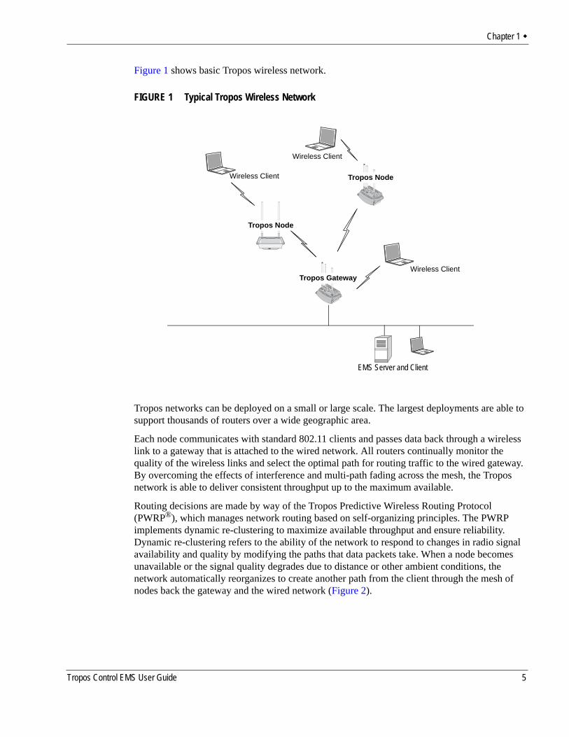
Figure 1 shows basic Tropos wireless network.
FIGURE 1 Typical Tropos Wireless Network
Tropos networks can be deployed on a small or large scale. The largest deployments are able to support thousands of routers over a wide geographic area.
Each node communicates with standard 802.11 clients and passes data back through a wireless link to a gateway that is attached to the wired network. All routers continually monitor the quality of the wireless links and select the optimal path for routing traffic to the wired gateway. By overcoming the effects of interference and multi-path fading across the mesh, the Tropos network is able to deliver consistent throughput up to the maximum available.
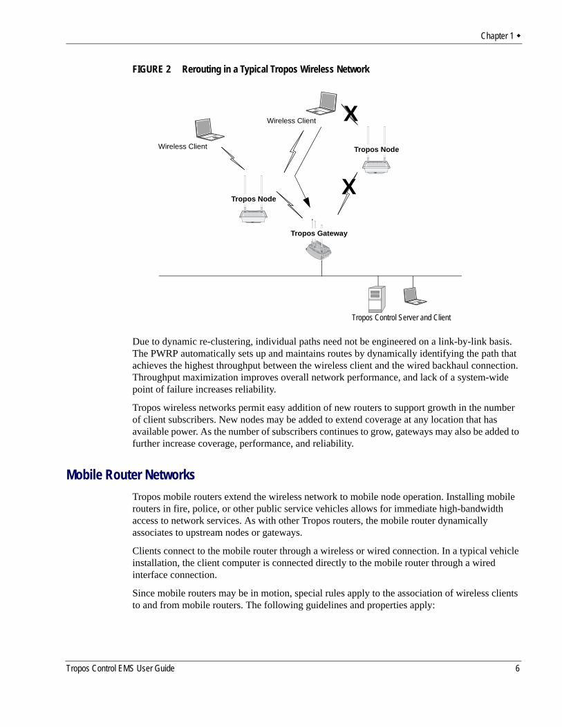
Routing decisions are made by way of the Tropos Predictive Wireless Routing Protocol (PWRP®), which manages network routing based on self-organizing principles. The PWRP implements dynamic re-clustering to maximize available throughput and ensure reliability. Dynamic re-clustering refers to the ability of the network to respond to changes in radio signal availability and quality by modifying the paths that data packets take. When a node becomes unavailable or the signal quality degrades due to distance or other ambient conditions, the network automatically reorganizes to create another path from the client through the mesh of nodes back the gateway and the wired network (Figure 2).
Wireless Client
Wireless Client
Tropos Node
EMS Server and Client
Tropos Gateway
Tropos Node
Wireless Client
Tropos Control EMS User Guide 5
Chapter 1
FIGURE 2 Rerouting in a Typical Tropos Wireless Network
Due to dynamic re-clustering, individual paths need not be engineered on a link-by-link basis. The PWRP automatically sets up and maintains routes by dynamically identifying the path that achieves the highest throughput between the wireless client and the wired backhaul connection. Throughput maximization improves overall network performance, and lack of a system-wide point of failure increases reliability.
Tropos wireless networks permit easy addition of new routers to support growth in the number of client subscribers. New nodes may be added to extend coverage at any location that has available power. As the number of subscribers continues to grow, gateways may also be added to further increase coverage, performance, and reliability.
Mobile Router NetworksTropos mobile routers extend the wireless network to mobile node operation. Installing mobile routers in fire, police, or other public service vehicles allows for immediate high-bandwidth access to network services. As with other Tropos routers, the mobile router dynamically associates to upstream nodes or gateways.
Clients connect to the mobile router through a wireless or wired connection. In a typical vehicle installation, the client computer is connected directly to the mobile router through a wired interface connection.
Since mobile routers may be in motion, special rules apply to the association of wireless clients to and from mobile routers. The following guidelines and properties apply:
Wireless Client
Wireless Client
X
XTropos Node
Tropos Control Server and Client
Tropos Gateway
Tropos Node
Tropos Control EMS User Guide 6
Chapter 1
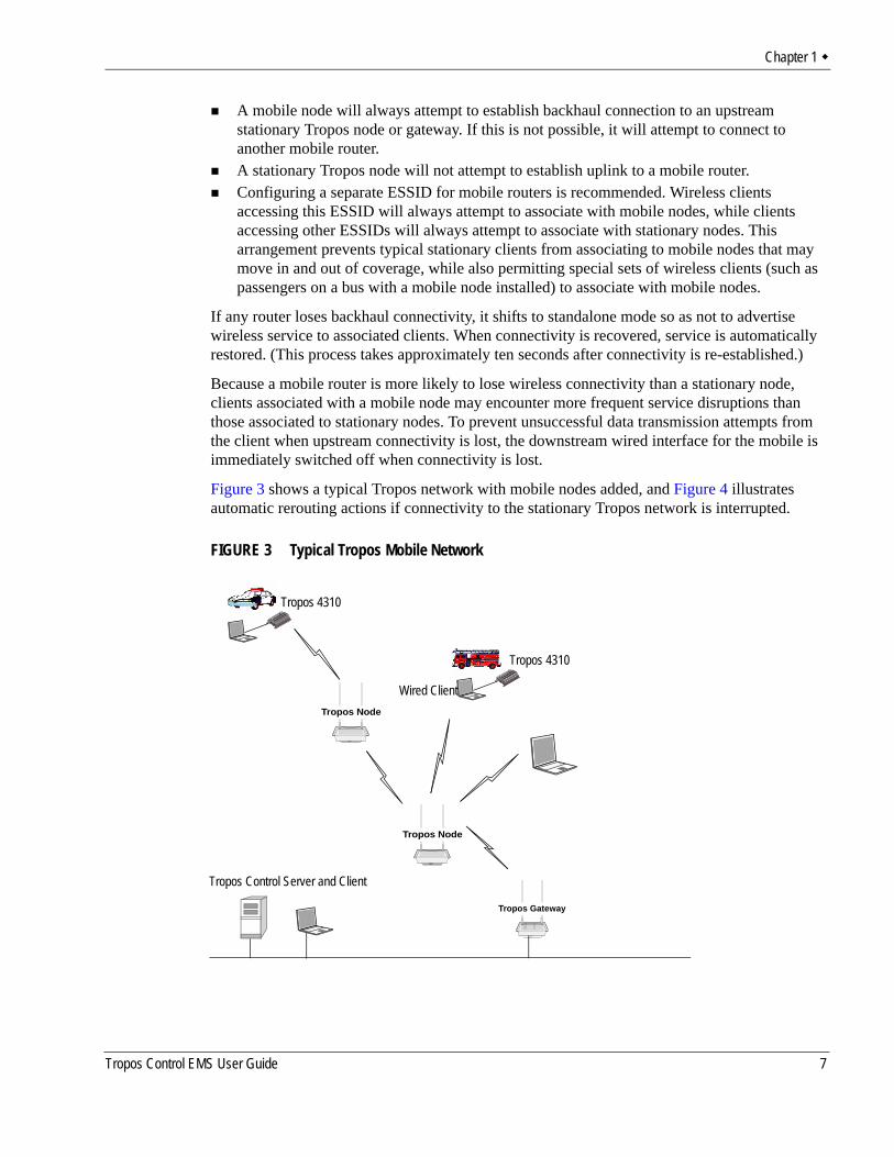
A mobile node will always attempt to establish backhaul connection to an upstream stationary Tropos node or gateway. If this is not possible, it will attempt to connect to another mobile router.A stationary Tropos node will not attempt to establish uplink to a mobile router.Configuring a separate ESSID for mobile routers is recommended. Wireless clients accessing this ESSID will always attempt to associate with mobile nodes, while clients accessing other ESSIDs will always attempt to associate with stationary nodes. This arrangement prevents typical stationary clients from associating to mobile nodes that may move in and out of coverage, while also permitting special sets of wireless clients (such as passengers on a bus with a mobile node installed) to associate with mobile nodes.
If any router loses backhaul connectivity, it shifts to standalone mode so as not to advertise wireless service to associated clients. When connectivity is recovered, service is automatically restored. (This process takes approximately ten seconds after connectivity is re-established.)
Because a mobile router is more likely to lose wireless connectivity than a stationary node, clients associated with a mobile node may encounter more frequent service disruptions than those associated to stationary nodes. To prevent unsuccessful data transmission attempts from the client when upstream connectivity is lost, the downstream wired interface for the mobile is immediately switched off when connectivity is lost.
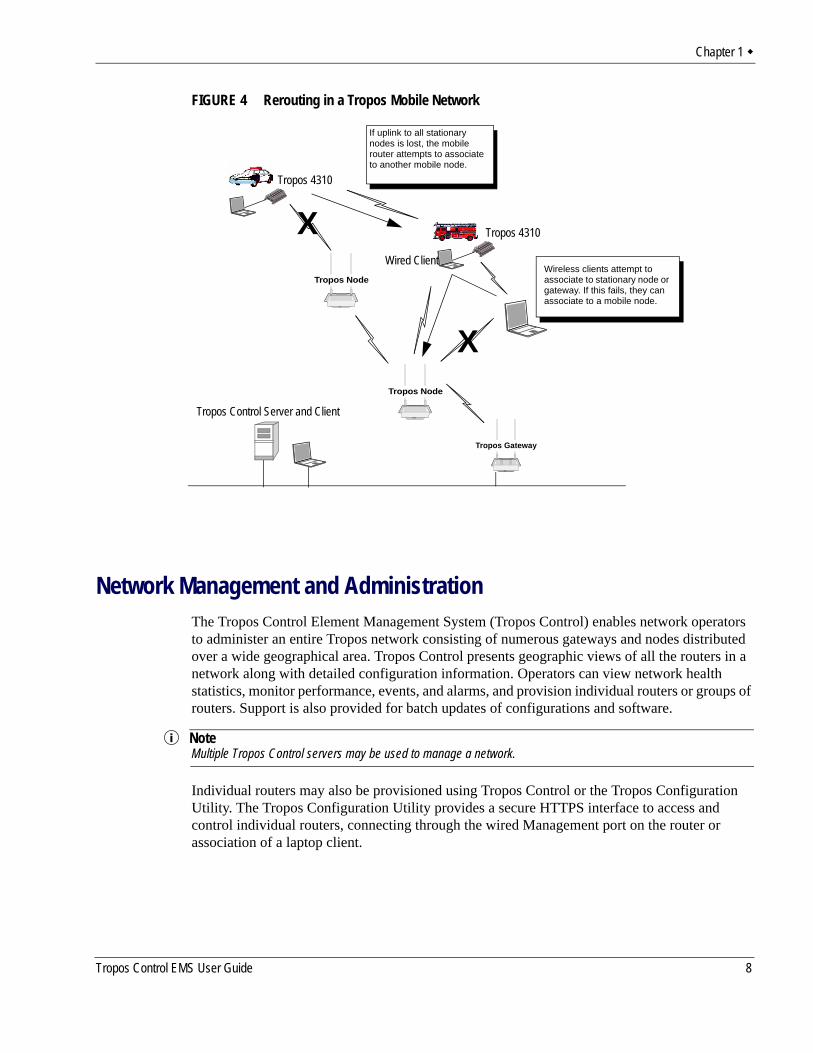
Figure 3 shows a typical Tropos network with mobile nodes added, and Figure 4 illustrates automatic rerouting actions if connectivity to the stationary Tropos network is interrupted.
FIGURE 3 Typical Tropos Mobile Network
Tropos Gateway
Tropos Node
Tropos 4310
Tropos 4310
Wired ClientTropos Node
Tropos Control Server and Client
Tropos Control EMS User Guide 7
Chapter 1
FIGURE 4 Rerouting in a Tropos Mobile Network
Network Management and AdministrationThe Tropos Control Element Management System (Tropos Control) enables network operators to administer an entire Tropos network consisting of numerous gateways and nodes distributed over a wide geographical area. Tropos Control presents geographic views of all the routers in a network along with detailed configuration information. Operators can view network health statistics, monitor performance, events, and alarms, and provision individual routers or groups of routers. Support is also provided for batch updates of configurations and software.
NoteMultiple Tropos Control servers may be used to manage a network.
Individual routers may also be provisioned using Tropos Control or the Tropos Configuration Utility. The Tropos Configuration Utility provides a secure HTTPS interface to access and control individual routers, connecting through the wired Management port on the router or association of a laptop client.
X
Tropos Gateway
Tropos Node
Tropos 4310
Tropos 4310
Wired ClientTropos Node
Wireless clients attempt to associate to stationary node or gateway. If this fails, they can associate to a mobile node.
X
Tropos Control Server and Client
If uplink to all stationary nodes is lost, the mobile router attempts to associate to another mobile node.
Tropos Control EMS User Guide 8
2 Installation
This chapter provides Tropos Control installation instructions.
Chapter contents:Pre-Installation RequirementsInstalling Tropos ControlUpdating ARP Cache SettingsUninstalling the SystemBacking Up and Restoring the Tropos Control ServerUpgrading the ServerResetting the Administrative Password
Tropos Control EMS User Guide 9
Chapter 2
Pre-Installation RequirementsSizing RequirementsServer and Client System RequirementsSupported RoutersFirewall Requirements
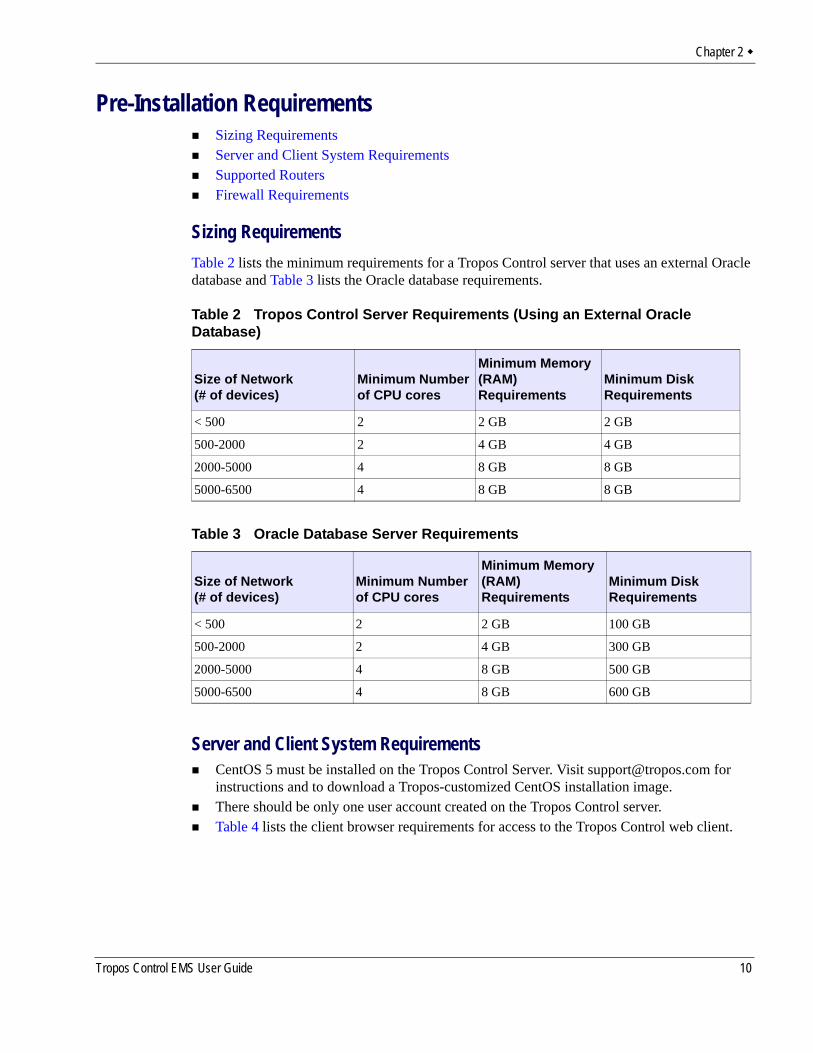
Sizing RequirementsTable 2 lists the minimum requirements for a Tropos Control server that uses an external Oracle database and Table 3 lists the Oracle database requirements.
Server and Client System RequirementsCentOS 5 must be installed on the Tropos Control Server. Visit [email protected] for instructions and to download a Tropos-customized CentOS installation image.There should be only one user account created on the Tropos Control server.Table 4 lists the client browser requirements for access to the Tropos Control web client.
Table 2 Tropos Control Server Requirements (Using an External Oracle Database)
Size of Network (# of devices)
Minimum Number of CPU cores
Minimum Memory (RAM) Requirements
Minimum Disk Requirements
< 500 2 2 GB 2 GB
500-2000 2 4 GB 4 GB
2000-5000 4 8 GB 8 GB
5000-6500 4 8 GB 8 GB
Table 3 Oracle Database Server Requirements
Size of Network(# of devices)
Minimum Number of CPU cores
Minimum Memory (RAM) Requirements
Minimum Disk Requirements
< 500 2 2 GB 100 GB
500-2000 2 4 GB 300 GB
2000-5000 4 8 GB 500 GB
5000-6500 4 8 GB 600 GB
Tropos Control EMS User Guide 10
Chapter 2
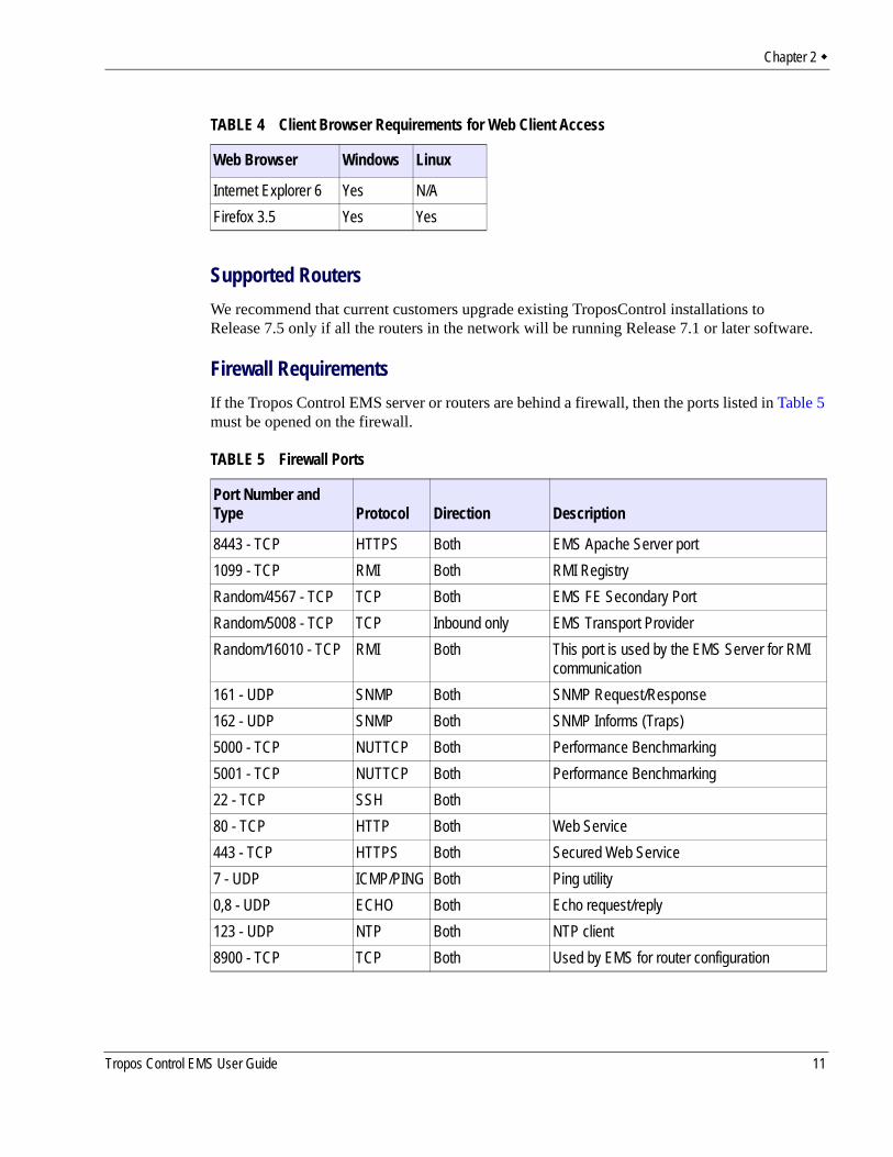
Supported RoutersWe recommend that current customers upgrade existing TroposControl installations to Release 7.5 only if all the routers in the network will be running Release 7.1 or later software.
Firewall RequirementsIf the Tropos Control EMS server or routers are behind a firewall, then the ports listed in Table 5 must be opened on the firewall.
TABLE 4 Client Browser Requirements for Web Client Access
Web Browser Windows Linux
Internet Explorer 6 Yes N/AFirefox 3.5 Yes Yes
TABLE 5 Firewall Ports
Port Number and Type Protocol Direction Description
8443 - TCP HTTPS Both EMS Apache Server port 1099 - TCP RMI Both RMI Registry Random/4567 - TCP TCP Both EMS FE Secondary Port Random/5008 - TCP TCP Inbound only EMS Transport Provider Random/16010 - TCP RMI Both This port is used by the EMS Server for RMI
communication 161 - UDP SNMP Both SNMP Request/Response 162 - UDP SNMP Both SNMP Informs (Traps) 5000 - TCP NUTTCP Both Performance Benchmarking 5001 - TCP NUTTCP Both Performance Benchmarking 22 - TCP SSH Both 80 - TCP HTTP Both Web Service 443 - TCP HTTPS Both Secured Web Service 7 - UDP ICMP/PING Both Ping utility 0,8 - UDP ECHO Both Echo request/reply 123 - UDP NTP Both NTP client 8900 - TCP TCP Both Used by EMS for router configuration
Tropos Control EMS User Guide 11
Chapter 2
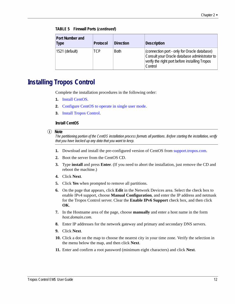
Installing Tropos ControlComplete the installation procedures in the following order:1. Install CentOS.2. Configure CentOS to operate in single user mode.3. Install Tropos Control.
Install CentOS
NoteThe partitioning portion of the CentOS installation process formats all partitions. Before starting the installation, verify that you have backed up any data that you want to keep.
1. Download and install the pre-configured version of CentOS from support.tropos.com. 2. Boot the server from the CentOS CD.3. Type install and press Enter. (If you need to abort the installation, just remove the CD and
reboot the machine.)4. Click Next.5. Click Yes when prompted to remove all partitions.6. On the page that appears, click Edit in the Network Devices area. Select the check box to
enable IPv4 support, choose Manual Configuration, and enter the IP address and netmask for the Tropos Control server. Clear the Enable IPv6 Support check box, and then click OK.
7. In the Hostname area of the page, choose manually and enter a host name in the form host.domain.com.
8. Enter IP addresses for the network gateway and primary and secondary DNS servers.9. Click Next.10. Click a dot on the map to choose the nearest city in your time zone. Verify the selection in
the menu below the map, and then click Next.11. Enter and confirm a root password (minimum eight characters) and click Next.
1521 (default) TCP Both (connection port - only for Oracle database)Consult your Oracle database administrator to verify the right port before installing Tropos Control
TABLE 5 Firewall Ports (continued)
Port Number and Type Protocol Direction Description
Tropos Control EMS User Guide 12
Chapter 2
The installation begins. This process may take up to 20 minutes. When the process is complete, the system reboots automatically.
12. Remove the CD.Log in as root using the password that you configured in step 11. If the graphical user interface does not start automatically, enter the command startx.
Configure CentOS to operate in single user mode1. Log in as the root user. 2. Edit the /etc/passwd and /etc/shadow files and remove all the users except root and the
pseudo-users. Make sure that the password fields in /etc/shadow for the pseudo-users are either a star (*) or double exclamation mark (!!). This prevents users from logging in as the pseudo-users.
3. Edit the /etc/nsswitch.conf system file and make files the only option for passwd, shadow, and group. This disables Network Information Service (NIS) and other name services for users and groups.
4. In the /etc/xinetd.d directory, edit the files eklogin, gssftp, klogin, krb5-telnet, kshell, rexec, rlogin, rsh, rsync, telnet, and tftp, and set the value of disable to yes.
5. Reboot the system for the changes to take effect.
Install Tropos Control1. Obtain a static IP address in your network for the Tropos Control server (management
station).2. Obtain the Tropos Control software image (<imagefile>.bin) and copy it to a temporary
folder.3. Set the permission on the image file to execute:
chmod +x <imagefile>.bin
4. If you are upgrading Tropos Control, stop the server.service watchdog stop
5. Run the executable file../<imagefile>.bin
The installation wizard opens and asks whether you want to install a new release or upgrade from a previous release. Select an option and choose OK.If you choose Install Fresh 7.5, the wizard presents the following prompts:a. License - Choose OK to accept the terms of the license agreement.b. Administrative password - Enter the administrative password (minimum eight
characters) for the ems user, and choose Next. Reenter the password and choose Next. c. Router password - Enter the router admin password (minimum eight characters) and
choose Next. Reenter the password and choose Next. For instructions on changing the
Tropos Control EMS User Guide 13
Chapter 2
router admin password at a later time, see “Resetting the Administrative Password” on page 16.
d. Select database - Enter Y if you want to use bundled MySQL database or N if you want to use your own Oracle database.
e. (Oracle only) Enter host address - Enter the host IP address where the Oracle database is running.
f. (Oracle only) Enter port number - Enter the port number used by the Oracle database.g. (Oracle only) Enter global database name - Enter the Oracle global database name.h. (Oracle only) Enter user name - Enter the user name to connect to Oracle database.
NoteThe oracle user must have RESOURCE and Create Session privileges and must be a dedicated user for Tropos Control (not shared with any other applications). If possible, there should be a dedicated tablespace associated with the user.
i. (Oracle only) Enter password - Enter the password for the user.If you choose Upgrade to 7.5, the installation begins automatically. If the existing Tropos Control installation uses an Oracle database, then the upgrade process prompts for database details as in step e - step i above. If the installation uses a MySQL database, the upgrade continues without the need for any user intervention.
6. When the installation is complete, choose OK.The server automatically starts, and you can access the web interface. See “Using the Web Interface” on page 19.
Updating ARP Cache SettingsIn environments where the devices under management are on the same subnet as the Tropos Control Server, default Address Resolution Protocol (ARP) cache settings on the Linux server should be changed. Execute the following commands to modify the ARP cache settings, and also add the same command lines to the /etc/rc.local file.echo "1024" > /proc/sys/net/ipv4/neigh/default/gc_thresh1
echo "4096" > /proc/sys/net/ipv4/neigh/default/gc_thresh2
echo "8192" > /proc/sys/net/ipv4/neigh/default/gc_thresh3
Uninstalling the SystemFollow the steps in this section to remove the Tropos Control server from your system.
NoteFor installations with an Oracle database: The uninstall script does not remove data from the Oracle database. It removes only files and folders. After uninstalling Tropos Control, you must manually delete the data stored in the database.
Tropos Control EMS User Guide 14
Chapter 2
Uninstall Tropos Control1. Go to the bin directory in the Tropos Control installation directory:
cd /<installdirectory>/bin
2. Shut down the Tropos Control server:service watchdog stop
3. Run the uninstall command:./uninstall.sh
The Tropos Control system is uninstalled and removed from the system.
Backing Up and Restoring the Tropos Control Server Follow the procedures in this section to back up and restore the Tropos Control server.
NoteFor installations with an Oracle database: The backup/restore script does not back up or restore any data from the Oracle database. Follow the Oracle procedures to back up and restore your data.
Back up the TroposControl server 1. Go to the bin directory in the Tropos Control installation directory:
cd /<installdirectory>/binn
2. Execute the backup script:./backup.sh /<installdirectory>
3. Enter the database password for the root account. This is the password for the ems user account, not the root password for the machine.The backup is created and stored in the current directory. The following files are created:— backup file - Tropos_EMS_Backup_<date>.tar.gz— checksum file - Tropos_EMS_Backup_<date>.md5
4. Move the backup and checksum files to /tmp or another temporary location that is not part of the TC installation tree.
Restore the server1. Copy the backup and checksum files to the bin directory in the Tropos Control installation
directory, and go to that directory:cd /<installdirectory>/bin
2. Stop the server:service watchdog stop
Tropos Control EMS User Guide 15
Chapter 2
3. Execute the restore script, using the name of the previously-backed up tar.gz and .md5 files: ./restore_ems.sh /<installdirectory> Tropos_EMS_Backup_<date>.tar.gz Tropos_EMS_Backup_<date>.md5
4. Enter Y to continue. 5. Enter the password for the root account, as prompted.
The database is restored and the server is restarted.
Upgrading the ServerTropos Control upgrades are supported only from Release 7.3. If you have an earlier version of Tropos Control, you must upgrade to Release 7.3 before upgrading to Release 7.5.
Upgrade the Tropos Control server from 7.3
Follow the procedure to install Tropos Control (“Install Tropos Control” on page 13). Choose the Upgrade to Release 7.5 option.
Resetting the Administrative PasswordFollow these steps to reset the Tropos Control administrative password.
NoteThe administrative password must have a minimum of eight characters. The password change doesn't affect the password stored in the router; it only changes the password that is stored in the Tropos Control server and used for communication between Tropos Control and the routers.
Reset the administrative password1. Go to /<installdirectory>/ems/bin and execute the following command:
./setRouterPasswd
2. Respond to the prompts to enter and confirm the password.
Tropos Control EMS User Guide 16
3 Getting Started
This chapter describes how to start using Tropos Control to manage the network.
Chapter contents:Getting Ready to Manage the NetworkStarting and Stopping the ServerUsing the Web InterfaceDiscovery
Tropos Control EMS User Guide 17
Chapter 3
Getting Ready to Manage the NetworkTo use Tropos Control to manage the Tropos network, you must first configure each router to recognize the Tropos Control server and verify that all routers are in the same wireless routing domain. Use the Tropos Configuration Utility to perform these tasks, as outlined in this section. For detailed information on using the Tropos Configuration Utility, see the Tropos Networks User Guide.
NoteUse the following procedure for initial device configuration after installing Tropos Control. See “About Provisioning Operations” on page 69 for information on configuring devices on an existing network.
Configure routers1. Perform these tasks as described in the Tropos Mesh Router User Guide.2. Open the Tropos Configuration Utility for the router. 3. Open the Passwords and Security page and enter the Router-EMS Authentication Key.
Confirm that each router in the network has the same wireless routing domain ID. If you make a change, click Store Changes.
4. Commit any changes.5. Repeat for all the routers to be managed by Tropos Control.
You can now use Tropos Control to discover and manage the routers.
Starting and Stopping the ServerStart the server
Issue the following command on the server:service watchdog start
Stop the serverIssue the following command on the server:service watchdog stop
Tropos Control EMS User Guide 18
Chapter 3
Using the Web InterfaceThe web interface may be reached from the Tropos Control server or from any other web-enabled computer on the network.
Accessing and Exiting the Web InterfaceFollow the instructions in this section to access and exit the web interface, display details about the current login session, and access the online help system.
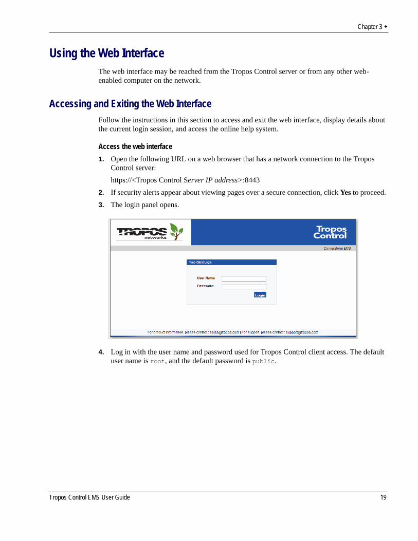
Access the web interface1. Open the following URL on a web browser that has a network connection to the Tropos
Control server:https://<Tropos Control Server IP address>:8443
2. If security alerts appear about viewing pages over a secure connection, click Yes to proceed. 3. The login panel opens.
4. Log in with the user name and password used for Tropos Control client access. The default user name is root, and the default password is public.
Tropos Control EMS User Guide 19
Chapter 3
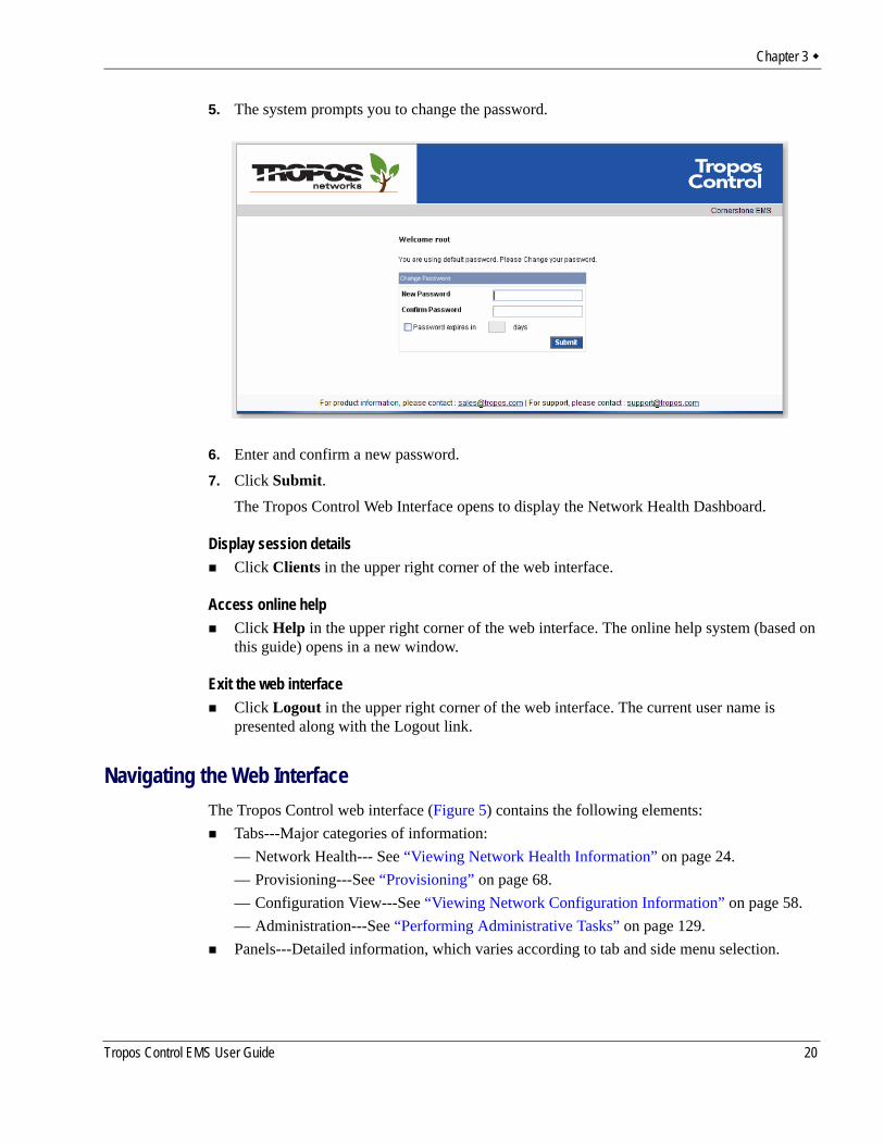
5. The system prompts you to change the password.
6. Enter and confirm a new password.7. Click Submit.
The Tropos Control Web Interface opens to display the Network Health Dashboard.
Display session detailsClick Clients in the upper right corner of the web interface.
Access online helpClick Help in the upper right corner of the web interface. The online help system (based on this guide) opens in a new window.
Exit the web interfaceClick Logout in the upper right corner of the web interface. The current user name is presented along with the Logout link.
Navigating the Web InterfaceThe Tropos Control web interface (Figure 5) contains the following elements:
Tabs---Major categories of information:— Network Health--- See “Viewing Network Health Information” on page 24.— Provisioning---See “Provisioning” on page 68.— Configuration View---See “Viewing Network Configuration Information” on page 58.— Administration---See “Performing Administrative Tasks” on page 129.Panels---Detailed information, which varies according to tab and side menu selection.
Tropos Control EMS User Guide 20
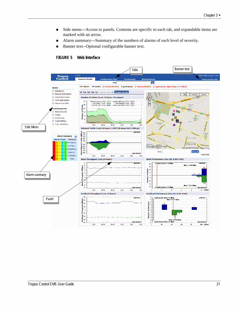
Chapter 3
Side menu---Access to panels. Contents are specific to each tab, and expandable items are marked with an arrow.Alarm summary---Summary of the numbers of alarms of each level of severity.Banner text--Optional configurable banner text.
FIGURE 5 Web Interface
Alarm summary
Side Menu
Panel
Tabs Banner text
Tropos Control EMS User Guide 21
Chapter 3
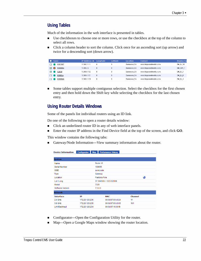
Using TablesMuch of the information in the web interface is presented in tables.
Use checkboxes to choose one or more rows, or use the checkbox at the top of the column to select all rows.Click a column header to sort the column. Click once for an ascending sort (up arrow) and twice for a descending sort (down arrow).
Some tables support multiple contiguous selection. Select the checkbox for the first chosen entry and then hold down the Shift key while selecting the checkbox for the last chosen entry.
Using Router Details WindowsSome of the panels list individual routers using an ID link.
Do one of the following to open a router details window:Click an underlined router ID in any of web interface panels.Enter the router IP address in the Find Device field at the top of the screen, and click GO.
This window contains the following tabs:Gateway/Node Information---View summary information about the router.
Configurator---Open the Configuration Utility for the router.Map---Open a Google Maps window showing the router location.
Tropos Control EMS User Guide 22
Chapter 3
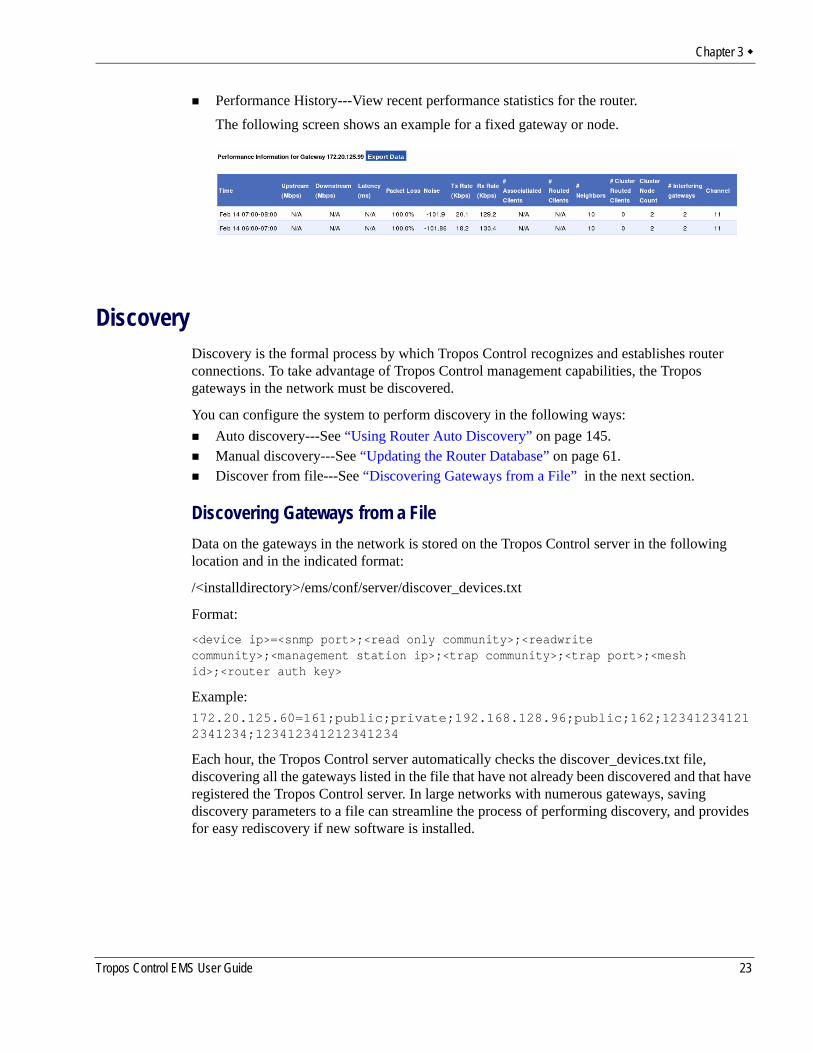
Performance History---View recent performance statistics for the router.The following screen shows an example for a fixed gateway or node.
DiscoveryDiscovery is the formal process by which Tropos Control recognizes and establishes router connections. To take advantage of Tropos Control management capabilities, the Tropos gateways in the network must be discovered.
You can configure the system to perform discovery in the following ways:Auto discovery---See “Using Router Auto Discovery” on page 145.Manual discovery---See “Updating the Router Database” on page 61.Discover from file---See “Discovering Gateways from a File” in the next section.
Discovering Gateways from a FileData on the gateways in the network is stored on the Tropos Control server in the following location and in the indicated format:
/<installdirectory>/ems/conf/server/discover_devices.txt
Format:
<device ip>=<snmp port>;<read only community>;<readwrite community>;<management station ip>;<trap community>;<trap port>;<mesh id>;<router auth key>
Example: 172.20.125.60=161;public;private;192.168.128.96;public;162;123412341212341234;123412341212341234
Each hour, the Tropos Control server automatically checks the discover_devices.txt file, discovering all the gateways listed in the file that have not already been discovered and that have registered the Tropos Control server. In large networks with numerous gateways, saving discovery parameters to a file can streamline the process of performing discovery, and provides for easy rediscovery if new software is installed.
Tropos Control EMS User Guide 23

4 Viewing Network Health Information
This chapter describes the Network Health panels in the web interface and how network health thresholds are defined.
Chapter contents:Preparing to Access the Network Health PanelsUsing the DashboardUsing the Network Optimization PanelsUsing the Client Optimization PanelsUsing the Voice Optimization PanelsUsing the Device Ping UtilityModifying Network Health Thresholds
Tropos Control EMS User Guide 24
Chapter 4
Preparing to Access the Network Health PanelsIf client side certificates are enabled on the routers, you must configure the /<installdirectory>/ems/networkhealth/certificateconf file to support Network Health. Configure the following parameters in the file (the file contains an example for each):
CIPHER - Signature algorithm (for example, SHA1)CLIENTCERT - location of certificate file CLIENTCERTPASS - password for the key store file CACERTKEY - location of the key file
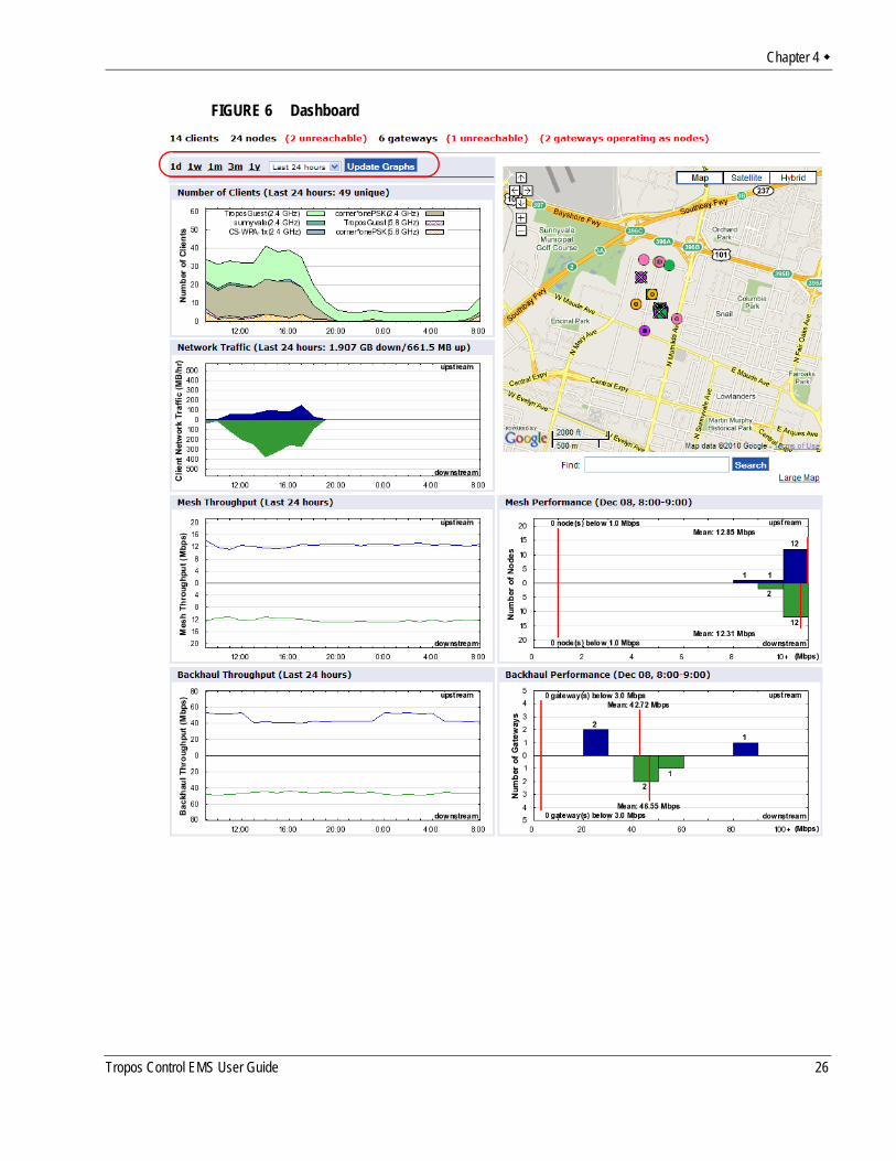
Using the DashboardWhen you access the web interface, the Dashboard opens. The Dashboard presents summary network status and performance information. The top line shows the total number of clients, nodes, and gateways in the network. It also shows the number of gateways that are currently operating as nodes, and vice versa. You can return to the Dashboard at any time by choosing Dashboard from the side menu on the Network Health tab.
Tropos Control EMS User Guide 25
Chapter 4
FIGURE 6 Dashboard
Tropos Control EMS User Guide 26
Chapter 4
You can display information for the past day (1d), week (1w), month (1m), three months (3m), or year (1yr) by clicking the appropriate link near the top of the page (see circled area in Figure 6). If you choose the days option, you can view historical information for a specific time period within the past week by selecting the time period (last 24 hours - 6 days ago) from the drop-down list.
Graphs display the following information:Number of Clients---Total number of distinct clients, color-coded and labeled by SSID. Client Network Traffic---Total upstream (blue) and downstream (green) traffic for all clients (MB).Mesh Throughput---Average Upstream (blue) and downstream (green) wireless throughput between nodes and the gateway (Mbps).Backhaul Throughput---Average upstream (blue) and downstream (green) throughput between the gateway and the Tropos Control server (Mbps). Mesh Performance---Performance of the mesh for the past hour (Mbps). Backhaul Performance---Backhaul performance for the past hour (Mbps).
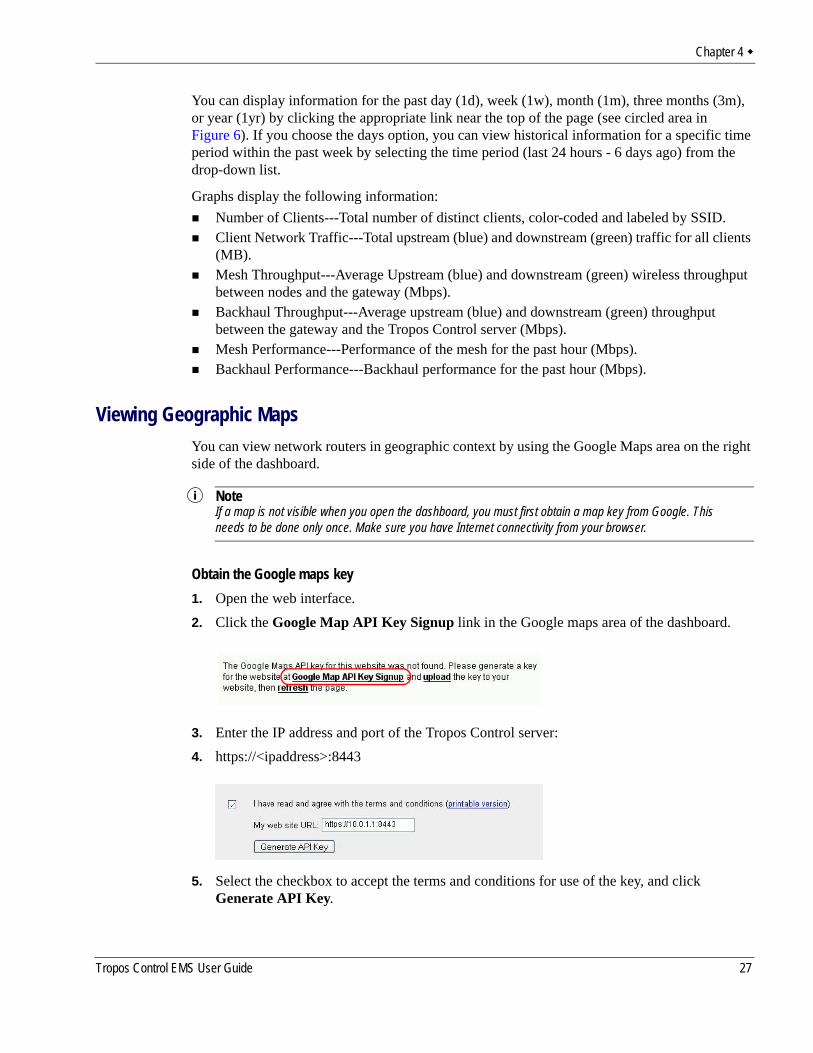
Viewing Geographic MapsYou can view network routers in geographic context by using the Google Maps area on the right side of the dashboard.
NoteIf a map is not visible when you open the dashboard, you must first obtain a map key from Google. This needs to be done only once. Make sure you have Internet connectivity from your browser.
Obtain the Google maps key1. Open the web interface. 2. Click the Google Map API Key Signup link in the Google maps area of the dashboard.
3. Enter the IP address and port of the Tropos Control server:4. https://<ipaddress>:8443
5. Select the checkbox to accept the terms and conditions for use of the key, and click Generate API Key.
Tropos Control EMS User Guide 27
Chapter 4
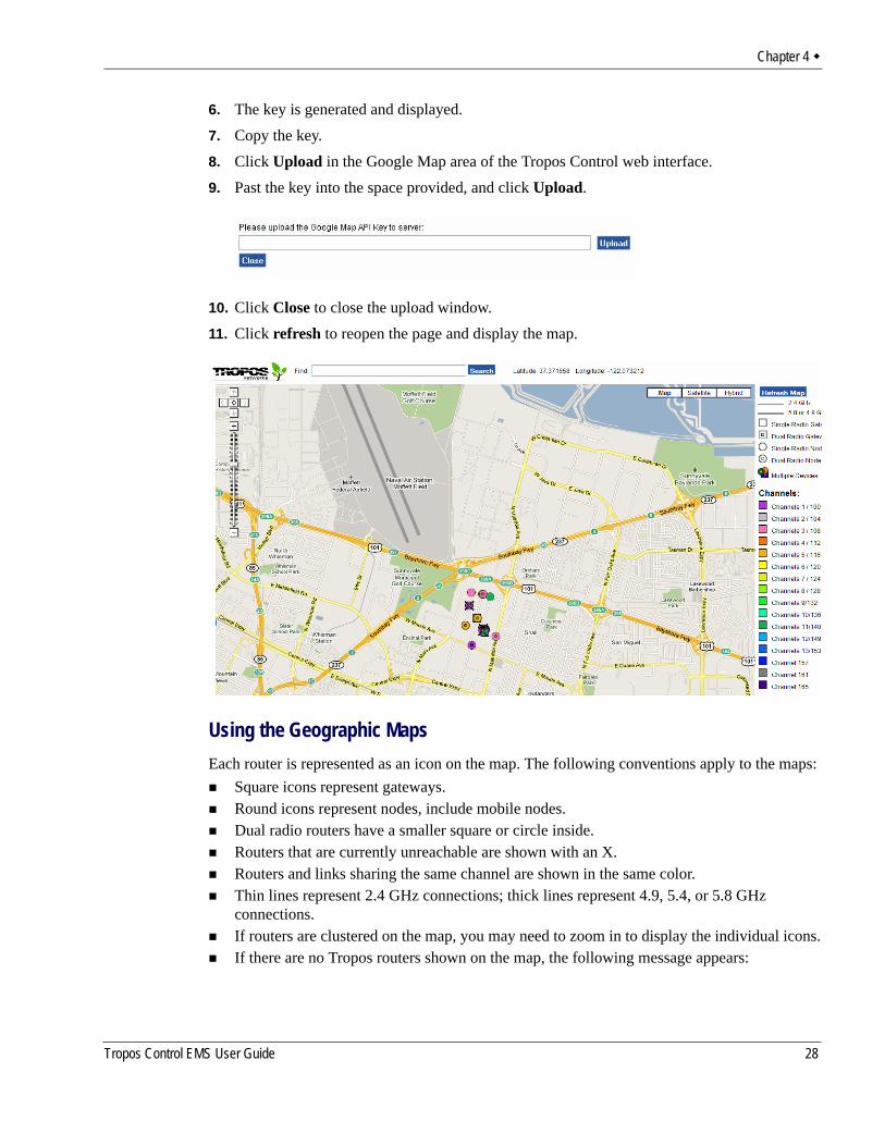
6. The key is generated and displayed. 7. Copy the key.8. Click Upload in the Google Map area of the Tropos Control web interface.9. Past the key into the space provided, and click Upload.
10. Click Close to close the upload window.11. Click refresh to reopen the page and display the map.
Using the Geographic MapsEach router is represented as an icon on the map. The following conventions apply to the maps:
Square icons represent gateways.Round icons represent nodes, include mobile nodes.Dual radio routers have a smaller square or circle inside.Routers that are currently unreachable are shown with an X.Routers and links sharing the same channel are shown in the same color.Thin lines represent 2.4 GHz connections; thick lines represent 4.9, 5.4, or 5.8 GHz connections.If routers are clustered on the map, you may need to zoom in to display the individual icons.If there are no Tropos routers shown on the map, the following message appears:
Tropos Control EMS User Guide 28
Chapter 4
“We are sorry, but we don’t have maps at this zoom level for this region.”If you see this message, zoom out and pan as necessary to bring your network into view.
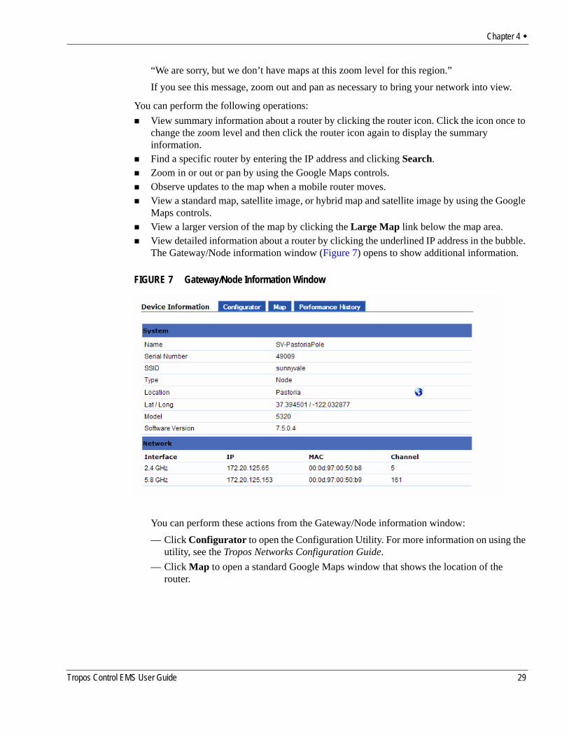
You can perform the following operations:View summary information about a router by clicking the router icon. Click the icon once to change the zoom level and then click the router icon again to display the summary information.Find a specific router by entering the IP address and clicking Search.Zoom in or out or pan by using the Google Maps controls.Observe updates to the map when a mobile router moves.View a standard map, satellite image, or hybrid map and satellite image by using the Google Maps controls.View a larger version of the map by clicking the Large Map link below the map area.View detailed information about a router by clicking the underlined IP address in the bubble. The Gateway/Node information window (Figure 7) opens to show additional information.
FIGURE 7 Gateway/Node Information Window
You can perform these actions from the Gateway/Node information window:— Click Configurator to open the Configuration Utility. For more information on using the
utility, see the Tropos Networks Configuration Guide.— Click Map to open a standard Google Maps window that shows the location of the
router.
Tropos Control EMS User Guide 29
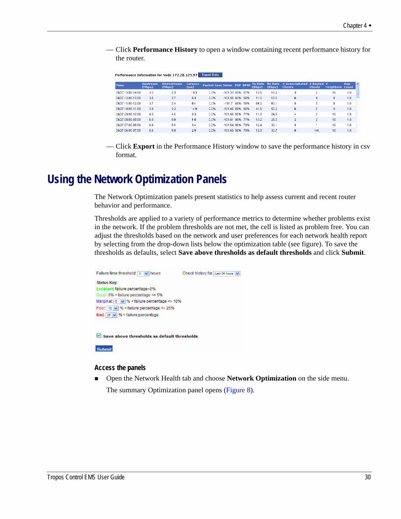
Chapter 4
— Click Performance History to open a window containing recent performance history for the router.
— Click Export in the Performance History window to save the performance history in csv format.
Using the Network Optimization PanelsThe Network Optimization panels present statistics to help assess current and recent router behavior and performance.
Thresholds are applied to a variety of performance metrics to determine whether problems exist in the network. If the problem thresholds are not met, the cell is listed as problem free. You can adjust the thresholds based on the network and user preferences for each network health report by selecting from the drop-down lists below the optimization table (see figure). To save the thresholds as defaults, select Save above thresholds as default thresholds and click Submit.
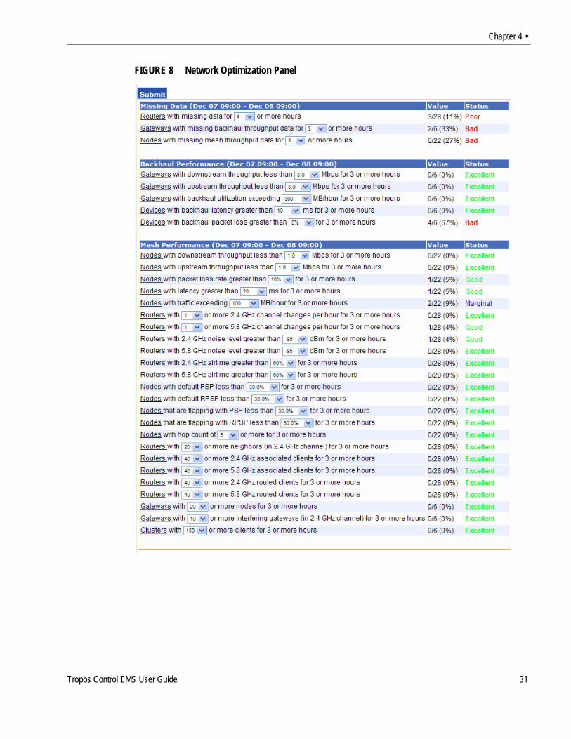
Access the panelsOpen the Network Health tab and choose Network Optimization on the side menu.The summary Optimization panel opens (Figure 8).
Tropos Control EMS User Guide 30
Chapter 4
FIGURE 8 Network Optimization Panel
Tropos Control EMS User Guide 31
Chapter 4
The Network Optimization panel presents summary statistics for the following categories:Missing Data---Nodes, gateways, and all routers with errors in transmitting or receiving data.Backhaul performance---Gateways with throughput, latency, packet loss, and utilization relative to specified thresholds.Mesh performance---Mesh links, nodes, gateways, and all routers with performance statistics relative to specified thresholds.
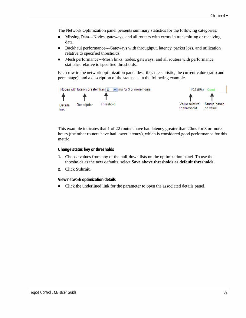
Each row in the network optimization panel describes the statistic, the current value (ratio and percentage), and a description of the status, as in the following example.
This example indicates that 1 of 22 routers have had latency greater than 20ms for 3 or more hours (the other routers have had lower latency), which is considered good performance for this metric.
Change status key or thresholds1. Choose values from any of the pull-down lists on the optimization panel. To use the
thresholds as the new defaults, select Save above thresholds as default thresholds.2. Click Submit.
View network optimization detailsClick the underlined link for the parameter to open the associated details panel.
Tropos Control EMS User Guide 32
Chapter 4
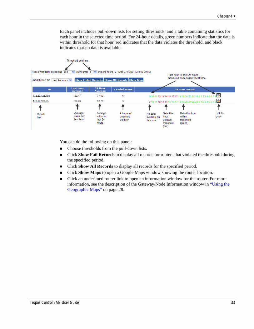
Each panel includes pull-down lists for setting thresholds, and a table containing statistics for each hour in the selected time period. For 24-hour details, green numbers indicate that the data is within threshold for that hour, red indicates that the data violates the threshold, and black indicates that no data is available.
You can do the following on this panel:Choose thresholds from the pull-down lists.Click Show Fail Records to display all records for routers that violated the threshold during the specified period.Click Show All Records to display all records for the specified period.Click Show Maps to open a Google Maps window showing the router location.Click an underlined router link to open an information window for the router. For more information, see the description of the Gateway/Node Information window in “Using the Geographic Maps” on page 28.
Tropos Control EMS User Guide 33
Chapter 4
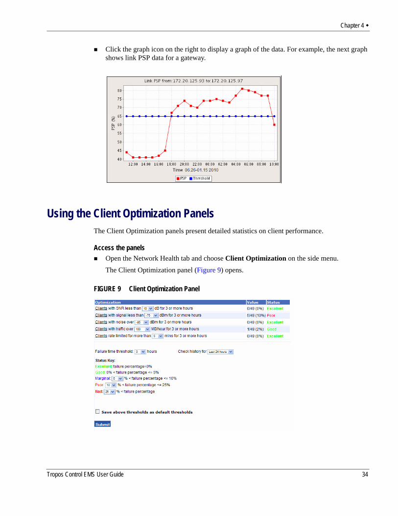
Click the graph icon on the right to display a graph of the data. For example, the next graph shows link PSP data for a gateway.
Using the Client Optimization PanelsThe Client Optimization panels present detailed statistics on client performance.
Access the panelsOpen the Network Health tab and choose Client Optimization on the side menu.The Client Optimization panel (Figure 9) opens.
FIGURE 9 Client Optimization Panel
Tropos Control EMS User Guide 34
Chapter 4
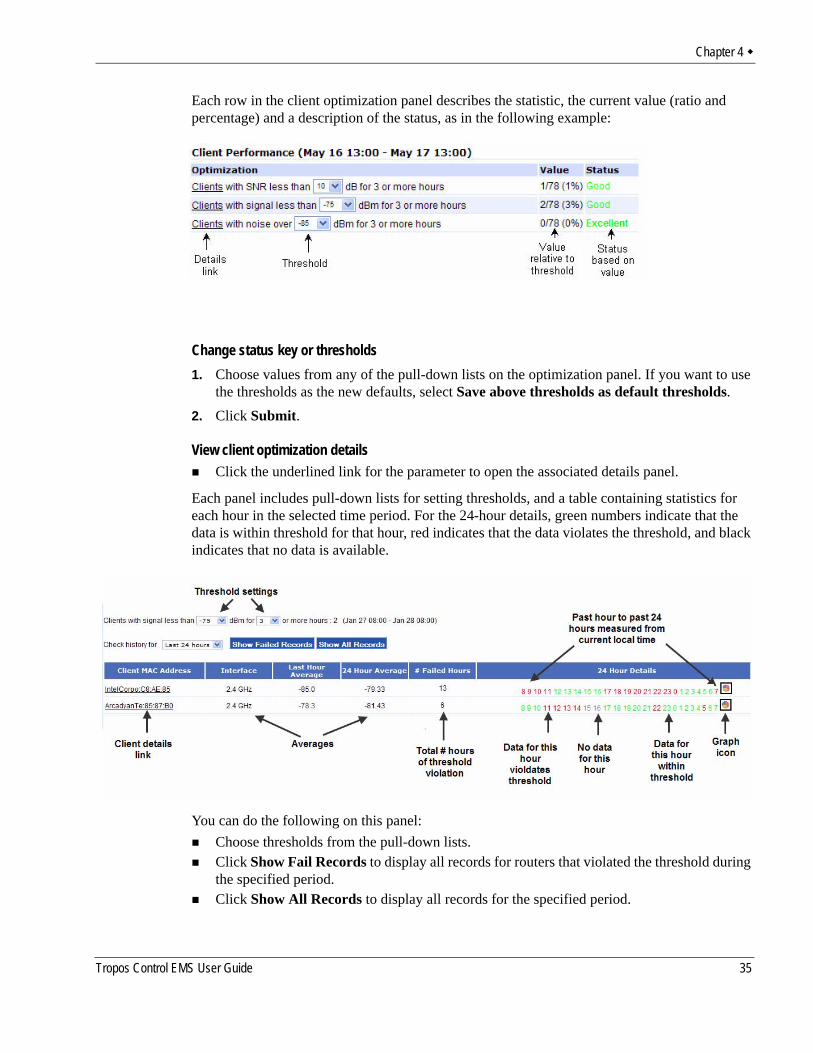
Each row in the client optimization panel describes the statistic, the current value (ratio and percentage) and a description of the status, as in the following example:
Change status key or thresholds1. Choose values from any of the pull-down lists on the optimization panel. If you want to use
the thresholds as the new defaults, select Save above thresholds as default thresholds.2. Click Submit.
View client optimization detailsClick the underlined link for the parameter to open the associated details panel.
Each panel includes pull-down lists for setting thresholds, and a table containing statistics for each hour in the selected time period. For the 24-hour details, green numbers indicate that the data is within threshold for that hour, red indicates that the data violates the threshold, and black indicates that no data is available.
You can do the following on this panel:Choose thresholds from the pull-down lists. Click Show Fail Records to display all records for routers that violated the threshold during the specified period.Click Show All Records to display all records for the specified period.
Tropos Control EMS User Guide 35
Chapter 4
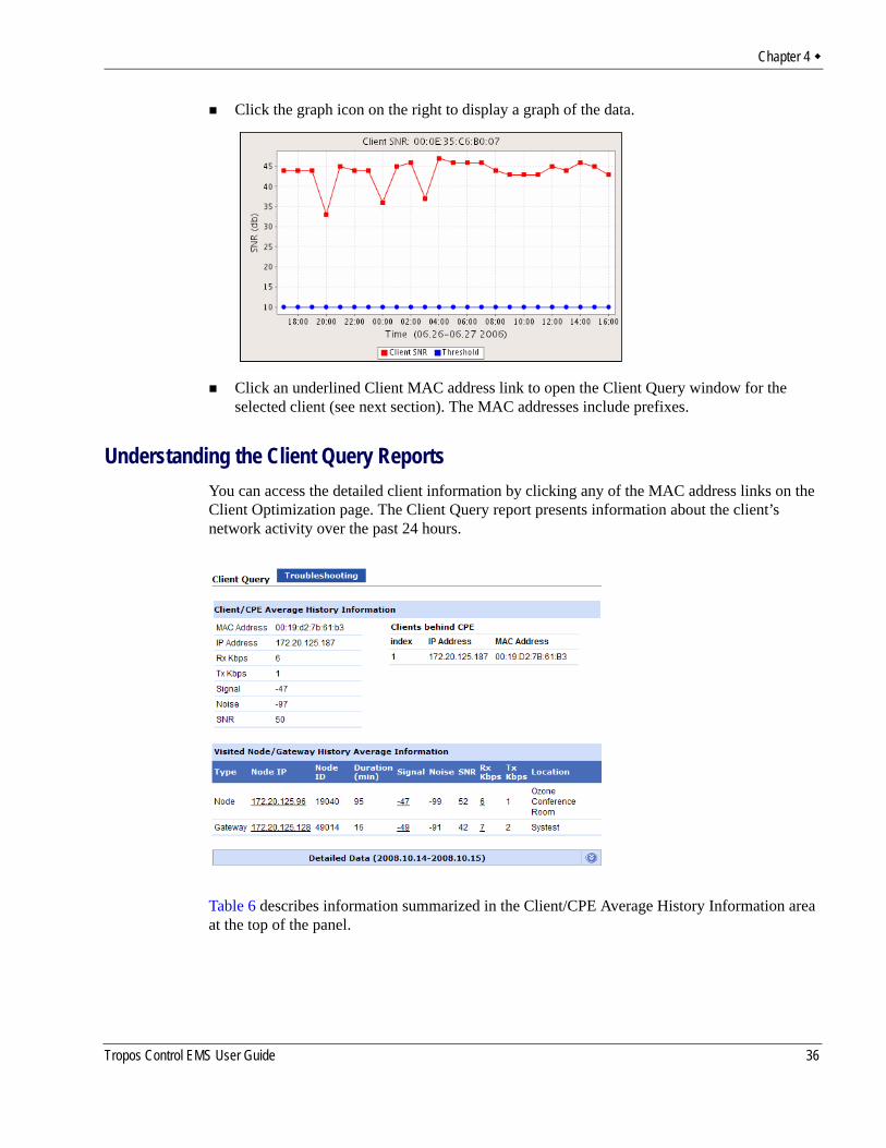
Click the graph icon on the right to display a graph of the data.
Click an underlined Client MAC address link to open the Client Query window for the selected client (see next section). The MAC addresses include prefixes.
Understanding the Client Query ReportsYou can access the detailed client information by clicking any of the MAC address links on the Client Optimization page. The Client Query report presents information about the client’s network activity over the past 24 hours.
Table 6 describes information summarized in the Client/CPE Average History Information area at the top of the panel.
Tropos Control EMS User Guide 36
Chapter 4
The Visited Node/Gateway History Average Information area lists statistics for node and gateway associations. Each row presents information for a node or gateway to which the client associated over the past 24 hours. Table 7 lists the information reported for each associated node and gateway.
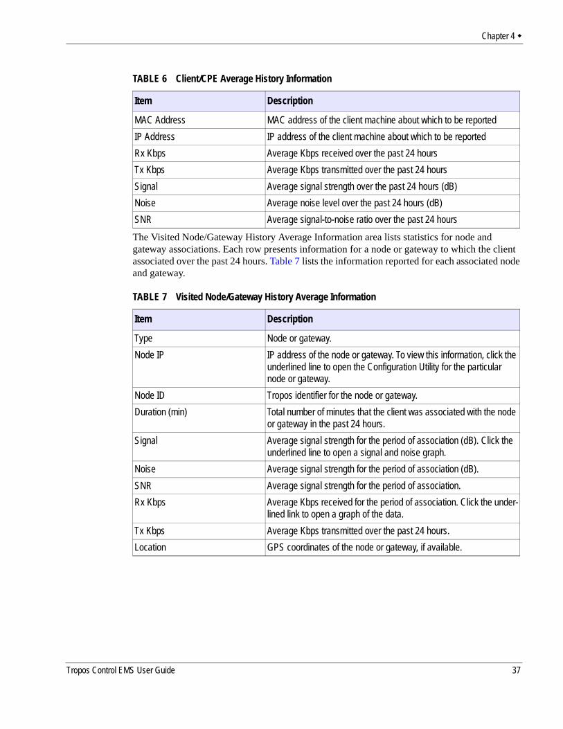
TABLE 6 Client/CPE Average History Information
Item Description
MAC Address MAC address of the client machine about which to be reportedIP Address IP address of the client machine about which to be reportedRx Kbps Average Kbps received over the past 24 hoursTx Kbps Average Kbps transmitted over the past 24 hoursSignal Average signal strength over the past 24 hours (dB)Noise Average noise level over the past 24 hours (dB)SNR Average signal-to-noise ratio over the past 24 hours
TABLE 7 Visited Node/Gateway History Average Information
Item Description
Type Node or gateway.Node IP IP address of the node or gateway. To view this information, click the
underlined line to open the Configuration Utility for the particular node or gateway.
Node ID Tropos identifier for the node or gateway.Duration (min) Total number of minutes that the client was associated with the node
or gateway in the past 24 hours.Signal Average signal strength for the period of association (dB). Click the
underlined line to open a signal and noise graph.Noise Average signal strength for the period of association (dB).SNR Average signal strength for the period of association.Rx Kbps Average Kbps received for the period of association. Click the under-
lined link to open a graph of the data.Tx Kbps Average Kbps transmitted over the past 24 hours.Location GPS coordinates of the node or gateway, if available.
Tropos Control EMS User Guide 37
Chapter 4
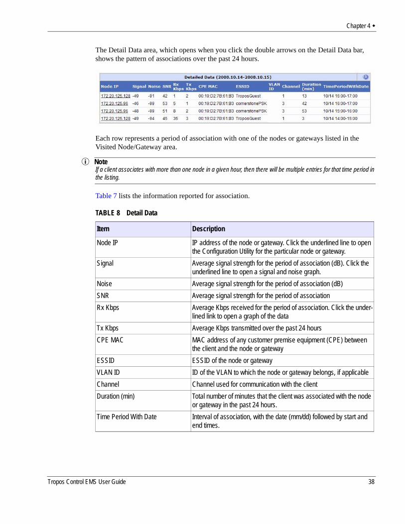
The Detail Data area, which opens when you click the double arrows on the Detail Data bar, shows the pattern of associations over the past 24 hours.
Each row represents a period of association with one of the nodes or gateways listed in the Visited Node/Gateway area.
NoteIf a client associates with more than one node in a given hour, then there will be multiple entries for that time period in the listing.
Table 7 lists the information reported for association.
TABLE 8 Detail Data
Item Description
Node IP IP address of the node or gateway. Click the underlined line to open the Configuration Utility for the particular node or gateway.
Signal Average signal strength for the period of association (dB). Click the underlined line to open a signal and noise graph.
Noise Average signal strength for the period of association (dB)SNR Average signal strength for the period of associationRx Kbps Average Kbps received for the period of association. Click the under-
lined link to open a graph of the dataTx Kbps Average Kbps transmitted over the past 24 hoursCPE MAC MAC address of any customer premise equipment (CPE) between
the client and the node or gatewayESSID ESSID of the node or gatewayVLAN ID ID of the VLAN to which the node or gateway belongs, if applicableChannel Channel used for communication with the clientDuration (min) Total number of minutes that the client was associated with the node
or gateway in the past 24 hours.Time Period With Date Interval of association, with the date (mm/dd) followed by start and
end times.
Tropos Control EMS User Guide 38
Chapter 4
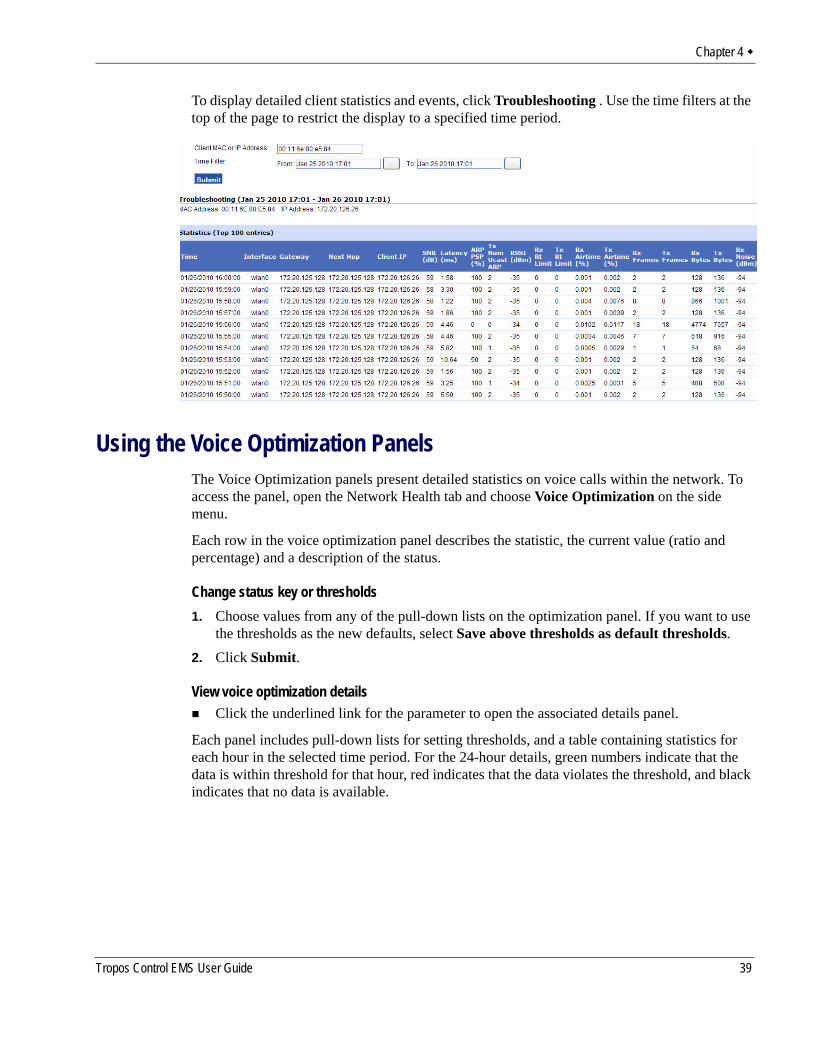
To display detailed client statistics and events, click Troubleshooting . Use the time filters at the top of the page to restrict the display to a specified time period.
Using the Voice Optimization PanelsThe Voice Optimization panels present detailed statistics on voice calls within the network. To access the panel, open the Network Health tab and choose Voice Optimization on the side menu.
Each row in the voice optimization panel describes the statistic, the current value (ratio and percentage) and a description of the status.
Change status key or thresholds1. Choose values from any of the pull-down lists on the optimization panel. If you want to use
the thresholds as the new defaults, select Save above thresholds as default thresholds.2. Click Submit.
View voice optimization detailsClick the underlined link for the parameter to open the associated details panel.
Each panel includes pull-down lists for setting thresholds, and a table containing statistics for each hour in the selected time period. For the 24-hour details, green numbers indicate that the data is within threshold for that hour, red indicates that the data violates the threshold, and black indicates that no data is available.
Tropos Control EMS User Guide 39
Chapter 4
You can do the following on this panel:Choose thresholds from the pull-down lists. Click Show Fail Records to display all records for routers that violated the threshold during the specified period.Click Show All Records to display all records for the specified period.Click the graph icon on the right to display a graph of the data.Click an underlined Client MAC address link to open the Client Query window for the selected client (see next section).
Using the Device Ping UtilityThe Device Ping Utility panel reports on ping operations for specified devices or for all discovered routers. The Ping utility is off by default, but it can be turned on from the web interface.
By default, the devices included in the ping list are listed in the device_pinglist.txt file, which is found in the following location:
/<installdirectory>/ems/conf/tropos/device_pinglist.txt. The default file contents are as follows:# number of threads to do ping
number_threads=20
# interval between every ping cycle, in seconds
ping_interval=20
# number of retries
retries=1
# timeout for each ping request in seconds
timeout=1
# list of IPAddress need to be pinged here
# for gateway use: IPAddress=G,<backhaul IPAddress>
# example: 192.168.128.3=G,192.168.128.4
# for node use: IPAddress=N
# example: 192.168.128.5=N
Add specific devices to the ping list1. Open the device_pinglist.txt file.2. Enter the IP addresses of the devices, according to the format given in the comment text. N
refers to note, G to gateway, and B to any non-Tropos device.3. Save the file.
The entered devices will now appear in the device ping list.
Tropos Control EMS User Guide 40
Chapter 4
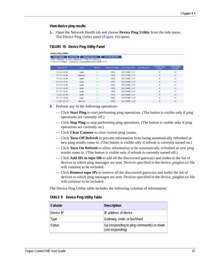
View device ping results1. Open the Network Health tab and choose Device Ping Utility from the side menu.
The Device Ping Utility panel (Figure 10) opens.
FIGURE 10 Device Ping Utility Panel
2. Perform any of the following operations:— Click Start Ping to start performing ping operations. (The button is visible only if ping
operations are currently off.)— Click Stop Ping to stop performing ping operations. (The button is visible only if ping
operations are currently on.)— Click Clear Counter to clear current ping counts.— Click Turn Off Refresh to prevent information from being automatically refreshed as
new ping results come in. (This button is visible only if refresh is currently turned on.)— Click Turn On Refresh to allow information to be automatically refreshed as new ping
results come in. (This button is visible only if refresh is currently turned off.)— Click Add IPs in topo DB to add all the discovered gateways and nodes to the list of
devices to which ping messages are sent. Devices specified in the device_pinglist.txt file will continue to be included.
— Click Remove topo IPs to remove all the discovered gateways and nodes the list of devices to which ping messages are sent. Devices specified in the device_pinglist.txt file will continue to be included.
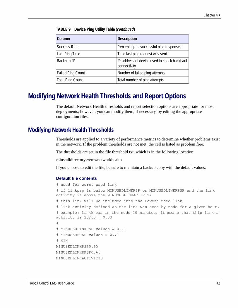
The Device Ping Utility table includes the following columns of information:
TABLE 9 Device Ping Utility Table
Column Description
Device IP IP address of deviceType Gateway, node, or backhaulStatus Up (responding to ping commands) or down
(not responding)
Tropos Control EMS User Guide 41
Chapter 4
Modifying Network Health Thresholds and Report OptionsThe default Network Health thresholds and report selection options are appropriate for most deployments; however, you can modify them, if necessary, by editing the appropriate configuration files.
Modifying Network Health ThresholdsThresholds are applied to a variety of performance metrics to determine whether problems exist in the network. If the problem thresholds are not met, the cell is listed as problem free.
The thresholds are set in the file threshold.txt, which is in the following location:
/<installdirectory>/ems/networkhealth
If you choose to edit the file, be sure to maintain a backup copy with the default values.
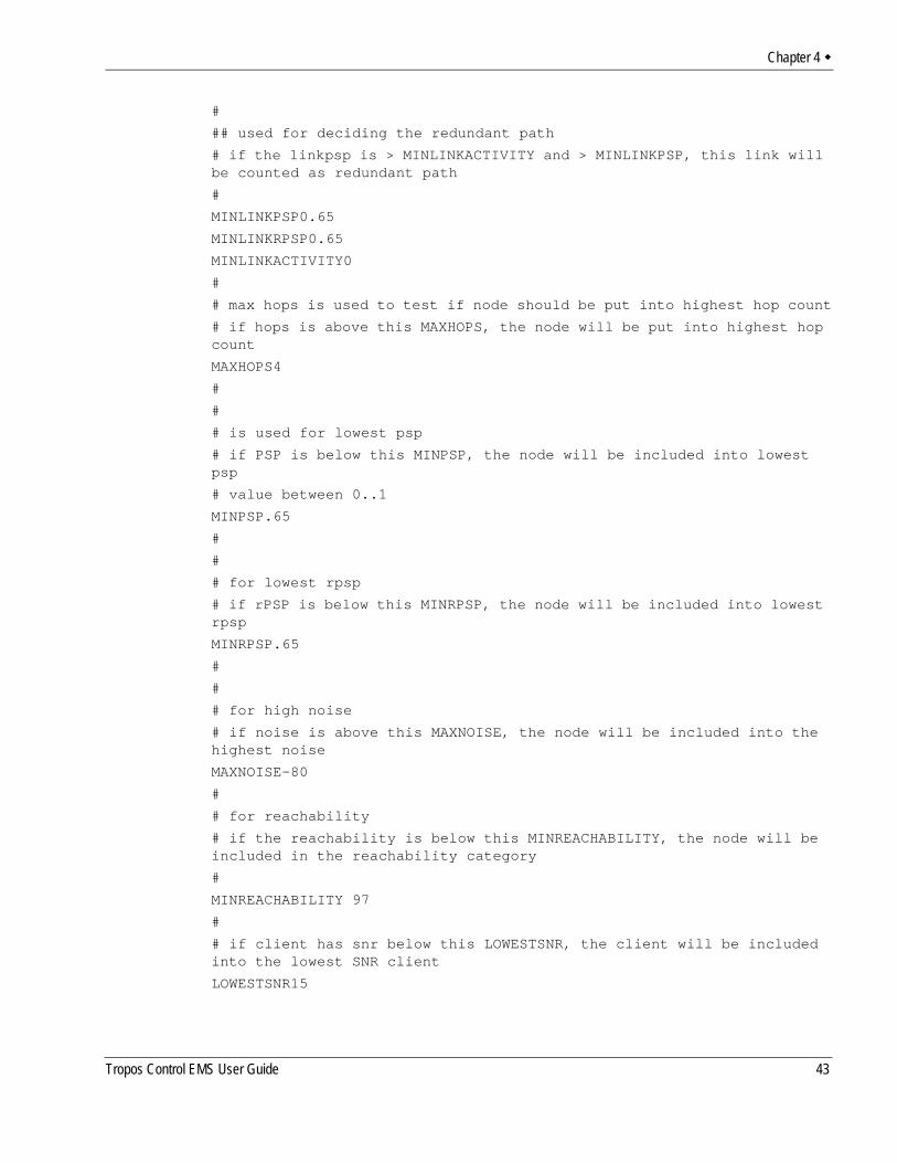
Default file contents# used for worst used link
# if linkpsp is below MINUSEDLINKPSP or MINUSEDLINKRPSP and the link activity is above the MINUSEDLINKACTIVITY
# this link will be included into the Lowest used link
# link activity defined as the link was seen by node for a given hour.
# example: linkA was in the node 20 minutes, it means that this link's activity is 20/60 = 0.33
#
# MINUSEDLINKPSP values = 0..1
# MINUSEDRPSP values = 0..1
# MIN
MINUSEDLINKPSP0.65
MINUSEDLINKRPSP0.65
MINUSEDLINKACTIVITY0
Success Rate Percentage of successful ping responsesLast Ping Time Time last ping request was sentBackhaul IP IP address of device used to check backhaul
connectivityFailed Ping Count Number of failed ping attemptsTotal Ping Count Total number of ping attempts
TABLE 9 Device Ping Utility Table (continued)
Column Description
Tropos Control EMS User Guide 42
Chapter 4
#
## used for deciding the redundant path
# if the linkpsp is > MINLINKACTIVITY and > MINLINKPSP, this link will be counted as redundant path
#
MINLINKPSP0.65
MINLINKRPSP0.65
MINLINKACTIVITY0
#
# max hops is used to test if node should be put into highest hop count
# if hops is above this MAXHOPS, the node will be put into highest hop count
MAXHOPS4
#
#
# is used for lowest psp
# if PSP is below this MINPSP, the node will be included into lowest psp
# value between 0..1
MINPSP.65
#
#
# for lowest rpsp
# if rPSP is below this MINRPSP, the node will be included into lowest rpsp
MINRPSP.65
#
#
# for high noise
# if noise is above this MAXNOISE, the node will be included into the highest noise
MAXNOISE-80
#
# for reachability
# if the reachability is below this MINREACHABILITY, the node will be included in the reachability category
#
MINREACHABILITY 97
#
# if client has snr below this LOWESTSNR, the client will be included into the lowest SNR client
LOWESTSNR15
Tropos Control EMS User Guide 43
Chapter 4
#
# if node has redundancy below this LOWESTREDUNDANCY, the node will be included into the Insufficient Redundancy
LOWESTREDUNDANCY2
#
#
# if node throughput (up/down) is lower than MINTHROUGHPUT(UP/DOWN), the node will be included into
# the Lowest estimated throughput
MINTHROUGHPUTUP 256
MINTHROUGHPUTDOWN 512
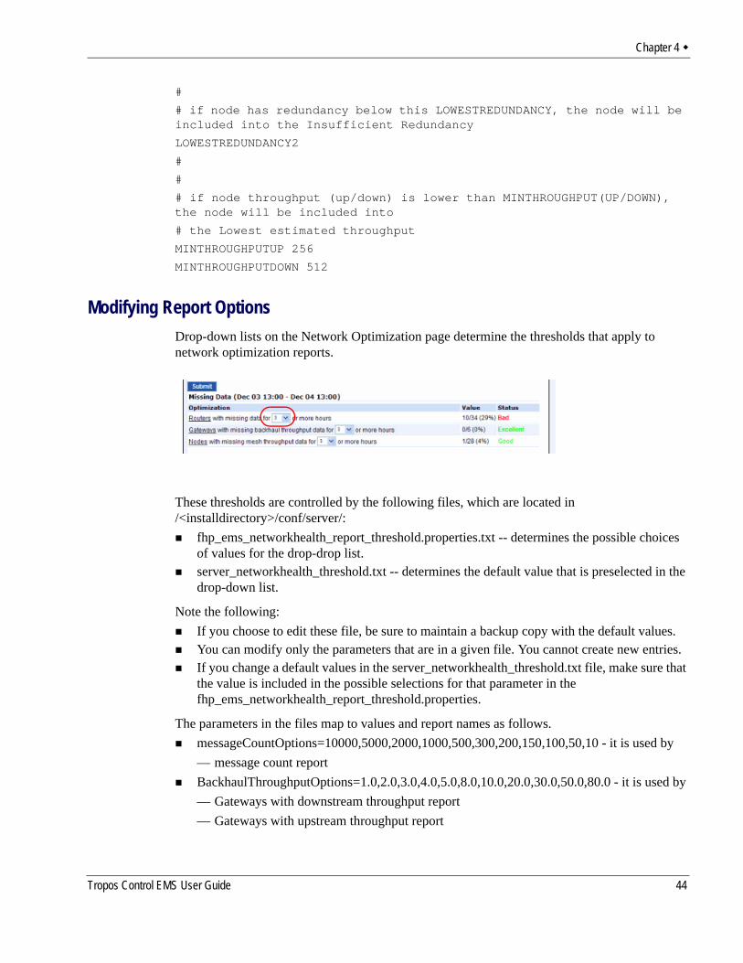
Modifying Report OptionsDrop-down lists on the Network Optimization page determine the thresholds that apply to network optimization reports.
These thresholds are controlled by the following files, which are located in /<installdirectory>/conf/server/:
fhp_ems_networkhealth_report_threshold.properties.txt -- determines the possible choices of values for the drop-drop list.server_networkhealth_threshold.txt -- determines the default value that is preselected in the drop-down list.
Note the following:If you choose to edit these file, be sure to maintain a backup copy with the default values.You can modify only the parameters that are in a given file. You cannot create new entries.If you change a default values in the server_networkhealth_threshold.txt file, make sure that the value is included in the possible selections for that parameter in the fhp_ems_networkhealth_report_threshold.properties.
The parameters in the files map to values and report names as follows. messageCountOptions=10000,5000,2000,1000,500,300,200,150,100,50,10 - it is used by — message count reportBackhaulThroughputOptions=1.0,2.0,3.0,4.0,5.0,8.0,10.0,20.0,30.0,50.0,80.0 - it is used by — Gateways with downstream throughput report— Gateways with upstream throughput report
Tropos Control EMS User Guide 44
Chapter 4
ThroughputOptions=0.25,0.5,0.75,1.0,1.5,2.0,2.5,3.0,3.5,4.0,5.0 - it is used by— Nodes with downstream report— Nodes with upstream reportLatencyOptions=2000,500,200,100,50,30,20,15,10,5,1 it is used by— Devices with backhaul latency report— Nodes with latency reportLinkOptions=30,40,50,60,65,70,80,90,100 it is used by— Nodes with default PSP report— Nodes with default RPSP report— Nodes that are flapping with PSP report— Nodes that are flapping with RPSP reportNoiseOptions=-150,-100,-90,-85,-80,-70,-60,-50 - it is used by— Clients with noise report— Routers with 2.4 GHz noise level report— Routers with 5.8 GHz noise level report— Routers with 24.9 GHz noise level reportChChangeOptions=1,2,3,4,5,6,7,8,9,10 - it is used by— Routers with 2.4 GHz channel change report— Routers with 5.8 GHz channel change report— Routers with 4.9 GHz channel change reportAirtimeOptions=40,50,60,70,80,90 - it is used by— Routers with 2.4 GHz airtime report— Routers with 5.8 GHz airtime report— Routers with 4.9 GHz airtime reportMissingDataOptions=1,2,3,4,6,8,12,24 -it is used by the:— Routers with missing data report— Gateways with missing backhaul report— Nodes with missing mesh throughput reportvoiceMissingDataOptions=1 - not currently usedMissingDataOptionsWithZero=0,1,2,3,4,6,8,12,24 - not currently usednodeNumberOptions=1,2,3,4,5,6,7,8,9,10,15,20,30,40,50,60,70,80 - it is used by— Routers with 2.4 GHz associated client report— Routers with 5.8 GHz associated client report— Routers with 4.9 GHz associated client report— Routers with 2.4 GHz routed client report— Routers with 5.8 GHz routed client report— Routers with 4.9 GHz routed client report— Gateways with nodes report
Tropos Control EMS User Guide 45
Chapter 4
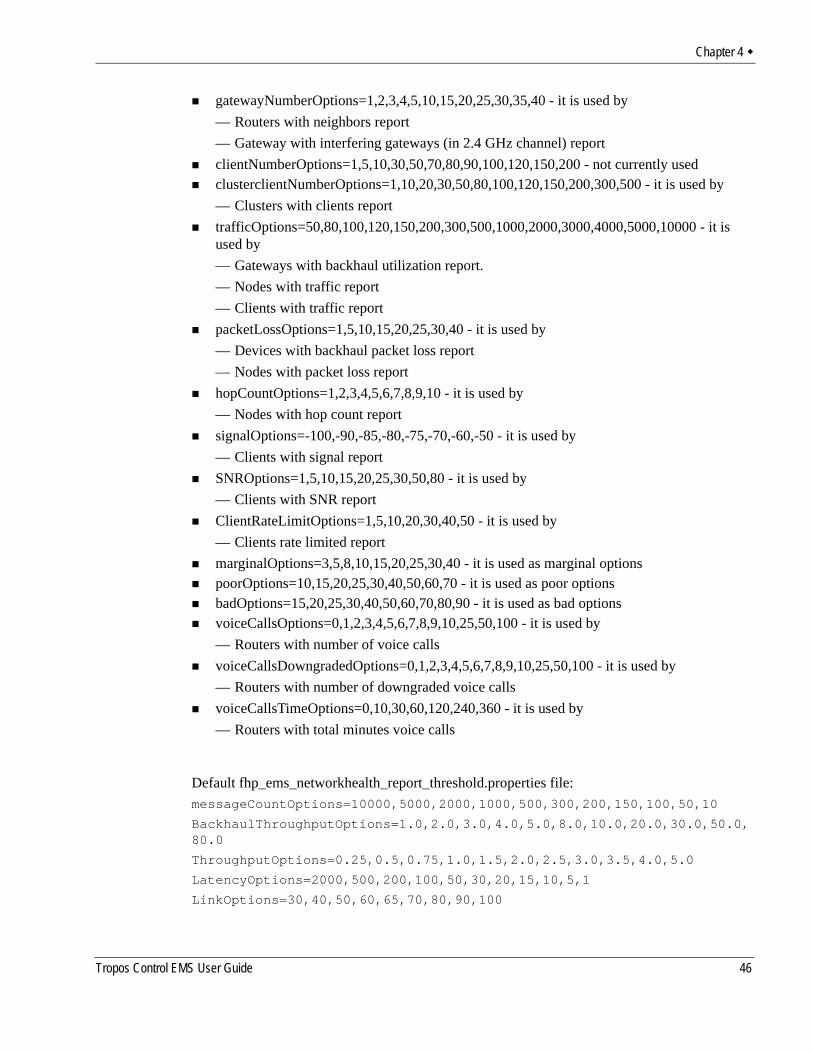
gatewayNumberOptions=1,2,3,4,5,10,15,20,25,30,35,40 - it is used by— Routers with neighbors report— Gateway with interfering gateways (in 2.4 GHz channel) reportclientNumberOptions=1,5,10,30,50,70,80,90,100,120,150,200 - not currently usedclusterclientNumberOptions=1,10,20,30,50,80,100,120,150,200,300,500 - it is used by— Clusters with clients reporttrafficOptions=50,80,100,120,150,200,300,500,1000,2000,3000,4000,5000,10000 - it is used by — Gateways with backhaul utilization report.— Nodes with traffic report— Clients with traffic reportpacketLossOptions=1,5,10,15,20,25,30,40 - it is used by— Devices with backhaul packet loss report— Nodes with packet loss reporthopCountOptions=1,2,3,4,5,6,7,8,9,10 - it is used by — Nodes with hop count reportsignalOptions=-100,-90,-85,-80,-75,-70,-60,-50 - it is used by— Clients with signal reportSNROptions=1,5,10,15,20,25,30,50,80 - it is used by— Clients with SNR reportClientRateLimitOptions=1,5,10,20,30,40,50 - it is used by— Clients rate limited reportmarginalOptions=3,5,8,10,15,20,25,30,40 - it is used as marginal optionspoorOptions=10,15,20,25,30,40,50,60,70 - it is used as poor optionsbadOptions=15,20,25,30,40,50,60,70,80,90 - it is used as bad optionsvoiceCallsOptions=0,1,2,3,4,5,6,7,8,9,10,25,50,100 - it is used by— Routers with number of voice callsvoiceCallsDowngradedOptions=0,1,2,3,4,5,6,7,8,9,10,25,50,100 - it is used by— Routers with number of downgraded voice callsvoiceCallsTimeOptions=0,10,30,60,120,240,360 - it is used by— Routers with total minutes voice calls
Default fhp_ems_networkhealth_report_threshold.properties file:messageCountOptions=10000,5000,2000,1000,500,300,200,150,100,50,10
BackhaulThroughputOptions=1.0,2.0,3.0,4.0,5.0,8.0,10.0,20.0,30.0,50.0,80.0
ThroughputOptions=0.25,0.5,0.75,1.0,1.5,2.0,2.5,3.0,3.5,4.0,5.0
LatencyOptions=2000,500,200,100,50,30,20,15,10,5,1
LinkOptions=30,40,50,60,65,70,80,90,100
Tropos Control EMS User Guide 46
Chapter 4
NoiseOptions=-150,-100,-90,-85,-80,-70,-60,-50
ChChangeOptions=1,2,3,4,5,6,7,8,9,10
AirtimeOptions=40,50,60,70,80,90
MissingDataOptions=1,2,3,4,6,8,12,24
voiceMissingDataOptions=1
MissingDataOptionsWithZero=0,1,2,3,4,6,8,12,24
nodeNumberOptions=1,2,3,4,5,6,7,8,9,10,15,20,30,40,50,60,70,80
gatewayNumberOptions=1,2,3,4,5,10,15,20,25,30,35,40
clientNumberOptions=1,5,10,30,50,70,80,90,100,120,150,200
clusterclientNumberOptions=1,10,20,30,50,80,100,120,150,200,300,500
trafficOptions=50,80,100,120,150,200,300,500,1000,2000,3000,4000,5000,10000
packetLossOptions=1,5,10,15,20,25,30,40
hopCountOptions=1,2,3,4,5,6,7,8,9,10
signalOptions=-100,-90,-85,-80,-75,-70,-60,-50
SNROptions=1,5,10,15,20,25,30,50,80
ClientRateLimitOptions=1,5,10,20,30,40,50
marginalOptions=3,5,8,10,15,20,25,30,40
poorOptions=10,15,20,25,30,40,50,60,70
badOptions=15,20,25,30,40,50,60,70,80,90
voiceCallsOptions=0,1,2,3,4,5,6,7,8,9,10,25,50,100
voiceCallsDowngradedOptions=0,1,2,3,4,5,6,7,8,9,10,25,50,100
voiceCallsTimeOptions=0,10,30,60,120,240,360
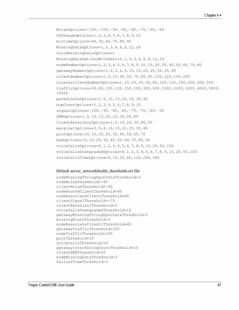
Default server_networkhealth_thresholds.txt filenodeMissingThroughputDataThreshold=3nodeNoiseThreshold=-85clientNoiseThreshold=-85nodeRoutedClientThreshold=40nodeAssociateClientThreshold=40clientSignalThreshold=-75clientRateLimitThreshold=5voiceCallsDowngradedThreshold=10gatewayMissingThroughputDataThreshold=3missingStatsThreshold=3nodeAssociateClient1Threshold=40gatewayTrafficThreshold=300nodeTrafficThreshold=100poorThreshold=10voiceCallsThreshold=10gatewayInterferingCountThreshold=10clientSNRThreshold=10nodeMissingDataThreshold=3failureTimeThreshold=3
Tropos Control EMS User Guide 47

Chapter 4
clientTrafficThreshold=100nodeNoise1Threshold=-85nodeNoise4_9Threshold=-85;nodeAssociateClient4_9Threshold=40nodeRoutedClient4_9Threshold=40nodeChChangeThreshold=1nodeChChange1Threshold=1nodeChChange4_9Threshold=1nodeAirtimeThreshold=60nodeAirtime1Threshold=60nodeAirtime4_9Threshold=60
Tropos Control EMS User Guide 48
5 Viewing Fault Information
This chapter describes the Fault Management panels in the web interface.
Chapter contents:Viewing Network EventsViewing AlarmsViewing Event CountsConfiguring Alarms
Tropos Control EMS User Guide 49
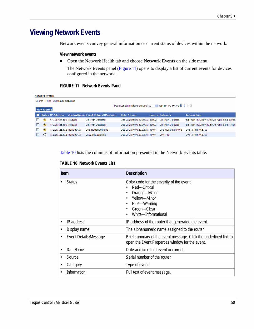
Chapter 5
Viewing Network EventsNetwork events convey general information or current status of devices within the network.
View network eventsOpen the Network Health tab and choose Network Events on the side menu.The Network Events panel (Figure 11) opens to display a list of current events for devices configured in the network.
FIGURE 11 Network Events Panel
Table 10 lists the columns of information presented in the Network Events table.
TABLE 10 Network Events List
Item Description
• Status Color code for the severity of the event: • Red---Critical• Orange---Major• Yellow---Minor• Blue---Warning• Green---Clear• White---Informational
• IP address IP address of the router that generated the event.• Display name The alphanumeric name assigned to the router.• Event Details/Message Brief summary of the event message. Click the underlined link to
open the Event Properties window for the event.• Date/Time Date and time that event occurred.• Source Serial number of the router.• Category Type of event.• Information Full text of event message.
Tropos Control EMS User Guide 50
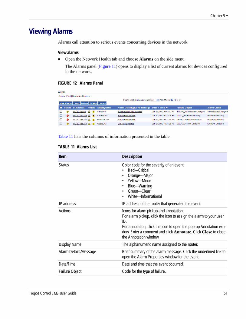
Chapter 5
Viewing AlarmsAlarms call attention to serious events concerning devices in the network.
View alarmsOpen the Network Health tab and choose Alarms on the side menu.The Alarms panel (Figure 11) opens to display a list of current alarms for devices configured in the network.
FIGURE 12 Alarms Panel
Table 11 lists the columns of information presented in the table.
TABLE 11 Alarms List
Item Description
Status Color code for the severity of an event:• Red---Critical• Orange---Major• Yellow---Minor• Blue---Warning• Green---Clear• White---Informational
IP address IP address of the router that generated the event.Actions Icons for alarm pickup and annotation:
For alarm pickup, click the icon to assign the alarm to your user ID. For annotation, click the icon to open the pop-up Annotation win-dow. Enter a comment and click Annotate. Click Close to close the Annotation window.
Display Name The alphanumeric name assigned to the router.Alarm Details/Message Brief summary of the alarm message. Click the underlined link to
open the Alarm Properties window for the event.Date/Time Date and time that the event occurred.Failure Object Code for the type of failure.
Tropos Control EMS User Guide 51
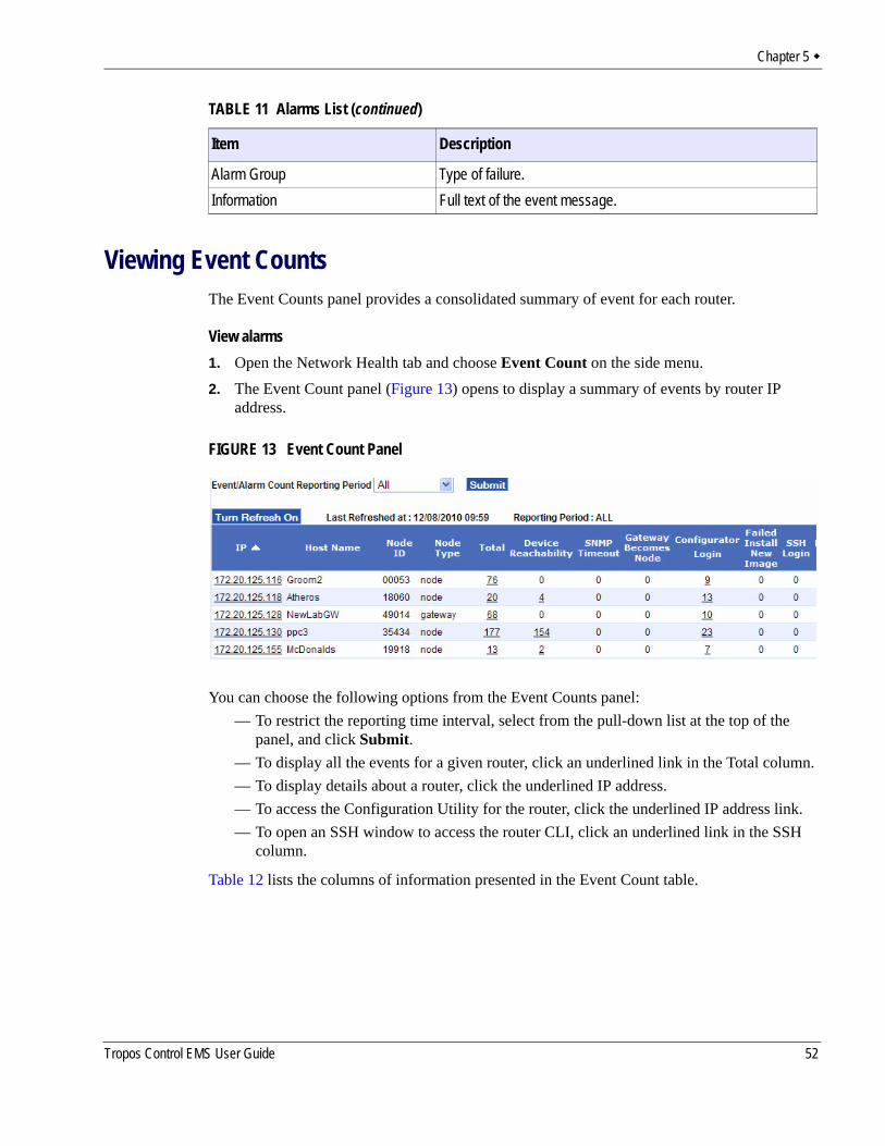
Chapter 5
Viewing Event CountsThe Event Counts panel provides a consolidated summary of event for each router.
View alarms1. Open the Network Health tab and choose Event Count on the side menu.2. The Event Count panel (Figure 13) opens to display a summary of events by router IP
address.
FIGURE 13 Event Count Panel
You can choose the following options from the Event Counts panel:— To restrict the reporting time interval, select from the pull-down list at the top of the
panel, and click Submit.— To display all the events for a given router, click an underlined link in the Total column.— To display details about a router, click the underlined IP address.— To access the Configuration Utility for the router, click the underlined IP address link.— To open an SSH window to access the router CLI, click an underlined link in the SSH
column.
Table 12 lists the columns of information presented in the Event Count table.
Alarm Group Type of failure.Information Full text of the event message.
TABLE 11 Alarms List (continued)
Item Description
Tropos Control EMS User Guide 52
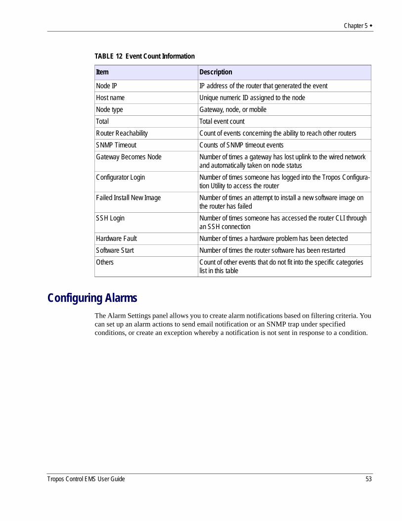
Chapter 5
Configuring AlarmsThe Alarm Settings panel allows you to create alarm notifications based on filtering criteria. You can set up an alarm actions to send email notification or an SNMP trap under specified conditions, or create an exception whereby a notification is not sent in response to a condition.
TABLE 12 Event Count Information
Item Description
Node IP IP address of the router that generated the eventHost name Unique numeric ID assigned to the nodeNode type Gateway, node, or mobileTotal Total event countRouter Reachability Count of events concerning the ability to reach other routersSNMP Timeout Counts of SNMP timeout eventsGateway Becomes Node Number of times a gateway has lost uplink to the wired network
and automatically taken on node statusConfigurator Login Number of times someone has logged into the Tropos Configura-
tion Utility to access the routerFailed Install New Image Number of times an attempt to install a new software image on
the router has failedSSH Login Number of times someone has accessed the router CLI through
an SSH connectionHardware Fault Number of times a hardware problem has been detectedSoftware Start Number of times the router software has been restartedOthers Count of other events that do not fit into the specific categories
list in this table
Tropos Control EMS User Guide 53
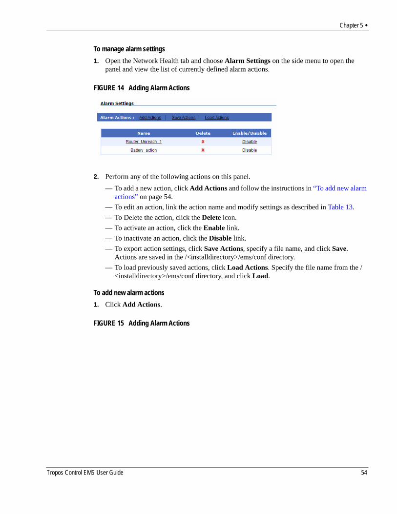
Chapter 5
To manage alarm settings1. Open the Network Health tab and choose Alarm Settings on the side menu to open the
panel and view the list of currently defined alarm actions.
FIGURE 14 Adding Alarm Actions
2. Perform any of the following actions on this panel.— To add a new action, click Add Actions and follow the instructions in “To add new alarm
actions” on page 54.— To edit an action, link the action name and modify settings as described in Table 13.— To Delete the action, click the Delete icon.— To activate an action, click the Enable link. — To inactivate an action, click the Disable link.— To export action settings, click Save Actions, specify a file name, and click Save.
Actions are saved in the /<installdirectory>/ems/conf directory.— To load previously saved actions, click Load Actions. Specify the file name from the /
<installdirectory>/ems/conf directory, and click Load.
To add new alarm actions1. Click Add Actions.
FIGURE 15 Adding Alarm Actions
Tropos Control EMS User Guide 54
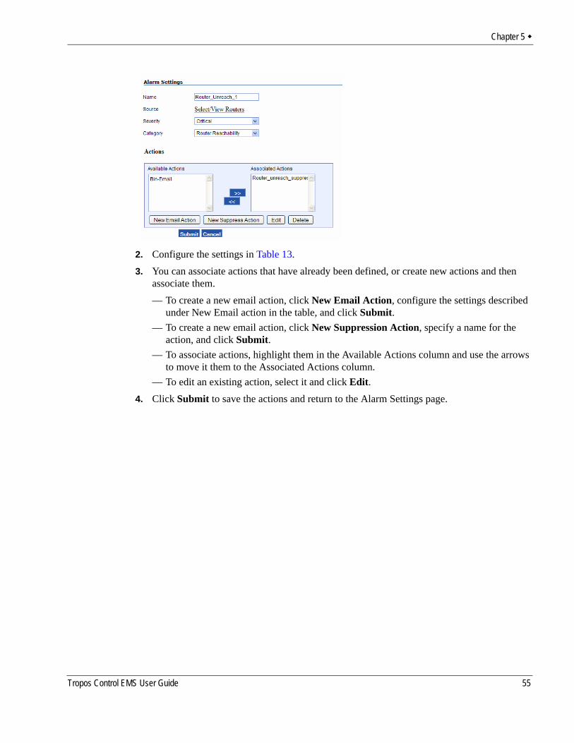
Chapter 5
2. Configure the settings in Table 13.3. You can associate actions that have already been defined, or create new actions and then
associate them.— To create a new email action, click New Email Action, configure the settings described
under New Email action in the table, and click Submit.— To create a new email action, click New Suppression Action, specify a name for the
action, and click Submit.— To associate actions, highlight them in the Available Actions column and use the arrows
to move it them to the Associated Actions column.— To edit an existing action, select it and click Edit.
4. Click Submit to save the actions and return to the Alarm Settings page.
Tropos Control EMS User Guide 55
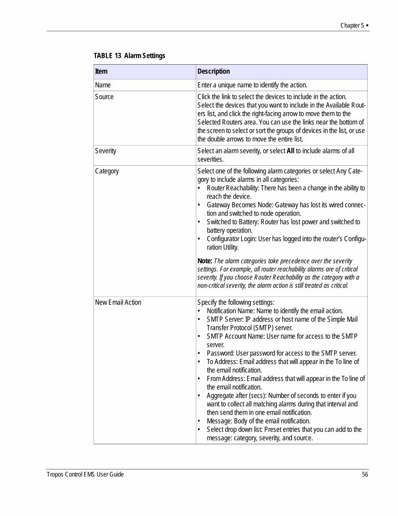
Chapter 5
TABLE 13 Alarm Settings
Item Description
Name Enter a unique name to identify the action.Source Click the link to select the devices to include in the action.
Select the devices that you want to include in the Available Rout-ers list, and click the right-facing arrow to move them to the Selected Routers area. You can use the links near the bottom of the screen to select or sort the groups of devices in the list, or use the double arrows to move the entire list.
Severity Select an alarm severity, or select All to include alarms of all severities.
Category Select one of the following alarm categories or select Any Cate-gory to include alarms in all categories:• Router Reachability: There has been a change in the ability to
reach the device.• Gateway Becomes Node: Gateway has lost its wired connec-
tion and switched to node operation.• Switched to Battery: Router has lost power and switched to
battery operation.• Configurator Login: User has logged into the router’s Configu-
ration Utility.
Note: The alarm categories take precedence over the severity settings. For example, all router reachability alarms are of critical severity. If you choose Router Reachability as the category with a non-critical severity, the alarm action is still treated as critical.
New Email Action Specify the following settings:• Notification Name: Name to identify the email action.• SMTP Server: IP address or host name of the Simple Mail
Transfer Protocol (SMTP) server.• SMTP Account Name: User name for access to the SMTP
server.• Password: User password for access to the SMTP server.• To Address: Email address that will appear in the To line of
the email notification.• From Address: Email address that will appear in the To line of
the email notification.• Aggregate after (secs): Number of seconds to enter if you
want to collect all matching alarms during that interval and then send them in one email notification.
• Message: Body of the email notification.• Select drop down list: Preset entries that you can add to the
message: category, severity, and source.
Tropos Control EMS User Guide 56
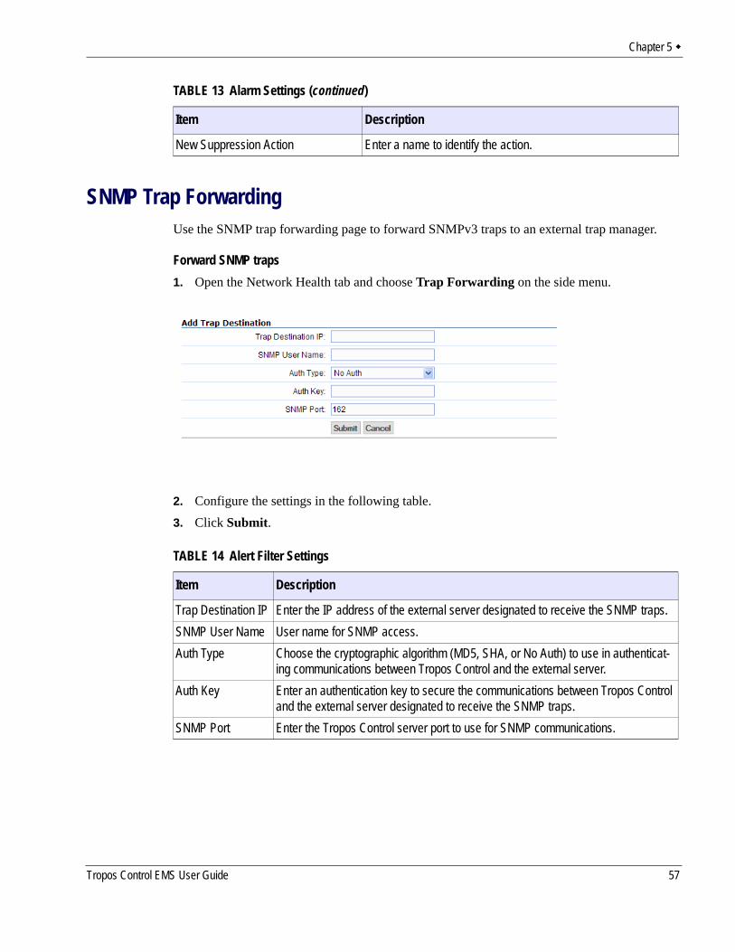
Chapter 5
SNMP Trap ForwardingUse the SNMP trap forwarding page to forward SNMPv3 traps to an external trap manager.
Forward SNMP traps1. Open the Network Health tab and choose Trap Forwarding on the side menu.
2. Configure the settings in the following table.3. Click Submit.
New Suppression Action Enter a name to identify the action.
TABLE 13 Alarm Settings (continued)
Item Description
TABLE 14 Alert Filter Settings
Item Description
Trap Destination IP Enter the IP address of the external server designated to receive the SNMP traps.SNMP User Name User name for SNMP access.Auth Type Choose the cryptographic algorithm (MD5, SHA, or No Auth) to use in authenticat-
ing communications between Tropos Control and the external server.Auth Key Enter an authentication key to secure the communications between Tropos Control
and the external server designated to receive the SNMP traps.SNMP Port Enter the Tropos Control server port to use for SNMP communications.
Tropos Control EMS User Guide 57
6 Viewing Network Configuration Information
This chapter describes how to display device information using the Network Configuration panels in the web interface.
Chapter contents:Network Configuration PanelsConfiguration View ActionsUpdating the Device DatabaseConfiguring Gateways for Multi-Subnet Roaming
Tropos Router Reference Guide 58
Chapter 6
Network Configuration PanelsThe Configuration View tab presents device information from the Tropos Control database. The information shown in each panel is described in “Provisioning Forms” on page 78.
NoteThe Configuration View displays only the menu items that are included in your product.
The Configuration View tab includes the following panels:Complete View---General status informationRouter Synchronization---Make router configurations consistent with each otherInventory---List of routers in the database.Router Identity---Identity and location informationDevice and IP---Interface and network address informationWireless---Information on wireless signal characteristicsDHCP Server---Status of the on-board DHCP serverTime---Time configuration and Network Time Protocol (NTP) server informationPacket Filtering Predefined Rules---Rules currently defined, listed by router and protocol type — Customized Rules---Special filtering rules— Deny Rules---Rules to deny accessVLAN---VLAN configuration informationVLAN Information---Provides status information and lists the type of VLANRate Limiting---Information status, caps, and triggers for rate limitingQoS---Information on Quality of service (QoS) settingsQoS ESSID Parameters---Information on QoS settings defined for specific ESSIDsStatic IP Client---Information on clients that are configured with static IP addressesP2P Blocking---Information on blocking of communications between clients in specified subnetsBackhaul Routing---Information on neighboring Border Gateway Protocol (BGP) routers that are one Layer 3 hop awayMulti-ESSID---Information on secondary ESSIDs and multiple BSSIDsRouter Access Control---Information on access restrictions for packet filteringMulti-Subnet---Source and destination information for multi-subnet roaming— Gateway List---Gateway information for multi-subnet roaming— Additional Subnets---Subnets available for roamingVoice---Information on voice parametersSecurity--Information on security settingsSNMP users--List of current SNMP usersSNMP--List of configured SNMP trap destinations
Tropos Router Reference Guide 59
Chapter 6
Configuration View ActionsYou can perform all of the following actions from the Configuration View panels:
View configuration informationSearch in a configuration view panelPrint the configuration view listExport the configuration view listView alarms or events for selected routersCustomize the configuration view columnsAdd a deviceDelete routersSynchronize routersCustomize the configuration view columns
View configuration information1. Open the web interface and choose Configuration View.2. Choose the desired panel from the side menu.
Search in a configuration view panel1. Click Search to open the Search window.2. Choose an item to match from the pull-down list.3. Choose the matching criterion from the pull-down list.4. Enter the text to match. To match additional items:
a. Click More and choose additional criteria. You can continue to request more items by clicking More repeatedly.
b. Select a radio button to match any one of the criteria (OR match) or all of the criteria (AND match).
5. Click Search.The window opens to display the matching items.
Print the configuration view list1. Click Print to open a window containing a print-formatted version of the list.2. Click Print.
Export the configuration view list1. Click Export.
A pop-up window prompts you to open or save the view information in csv (comma-separated) format.
2. Click Save, browse for a file location, enter the file name, and click Save.
Tropos Router Reference Guide 60
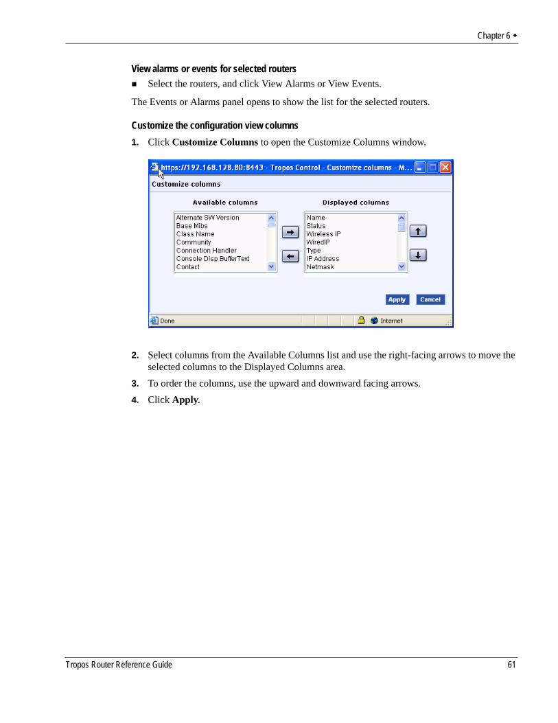
Chapter 6
View alarms or events for selected routersSelect the routers, and click View Alarms or View Events.
The Events or Alarms panel opens to show the list for the selected routers.
Customize the configuration view columns1. Click Customize Columns to open the Customize Columns window.
2. Select columns from the Available Columns list and use the right-facing arrows to move the selected columns to the Displayed Columns area.
3. To order the columns, use the upward and downward facing arrows.4. Click Apply.
Tropos Router Reference Guide 61
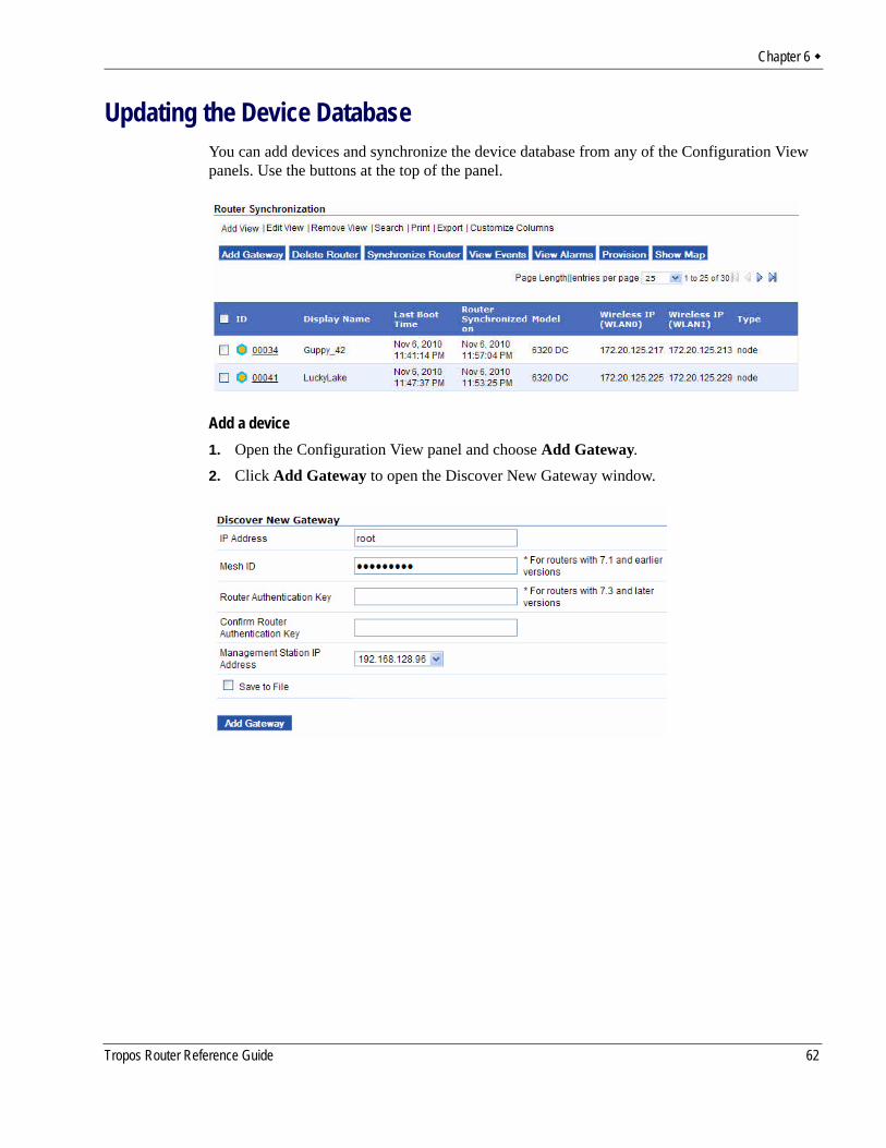
Chapter 6
Updating the Device DatabaseYou can add devices and synchronize the device database from any of the Configuration View panels. Use the buttons at the top of the panel.
Add a device1. Open the Configuration View panel and choose Add Gateway.2. Click Add Gateway to open the Discover New Gateway window.
Tropos Router Reference Guide 62
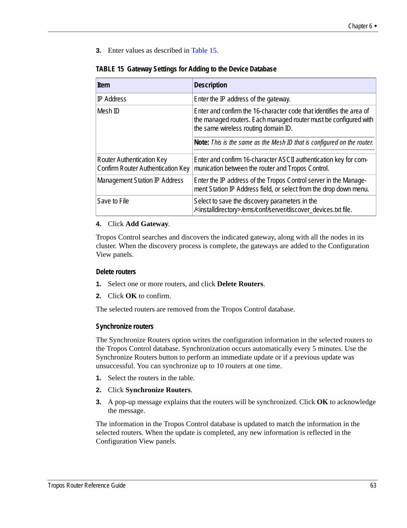
Chapter 6
3. Enter values as described in Table 15.
4. Click Add Gateway.
Tropos Control searches and discovers the indicated gateway, along with all the nodes in its cluster. When the discovery process is complete, the gateways are added to the Configuration View panels.
Delete routers1. Select one or more routers, and click Delete Routers.2. Click OK to confirm.
The selected routers are removed from the Tropos Control database.
Synchronize routers
The Synchronize Routers option writes the configuration information in the selected routers to the Tropos Control database. Synchronization occurs automatically every 5 minutes. Use the Synchronize Routers button to perform an immediate update or if a previous update was unsuccessful. You can synchronize up to 10 routers at one time.1. Select the routers in the table.2. Click Synchronize Routers.3. A pop-up message explains that the routers will be synchronized. Click OK to acknowledge
the message.
The information in the Tropos Control database is updated to match the information in the selected routers. When the update is completed, any new information is reflected in the Configuration View panels.
TABLE 15 Gateway Settings for Adding to the Device Database
Item Description
IP Address Enter the IP address of the gateway.Mesh ID Enter and confirm the 16-character code that identifies the area of
the managed routers. Each managed router must be configured with the same wireless routing domain ID.
Note: This is the same as the Mesh ID that is configured on the router.
Router Authentication KeyConfirm Router Authentication Key
Enter and confirm 16-character ASCII authentication key for com-munication between the router and Tropos Control.
Management Station IP Address Enter the IP address of the Tropos Control server in the Manage-ment Station IP Address field, or select from the drop down menu.
Save to File Select to save the discovery parameters in the /<installdirectory>/ems/conf/server/discover_devices.txt file.
Tropos Router Reference Guide 63
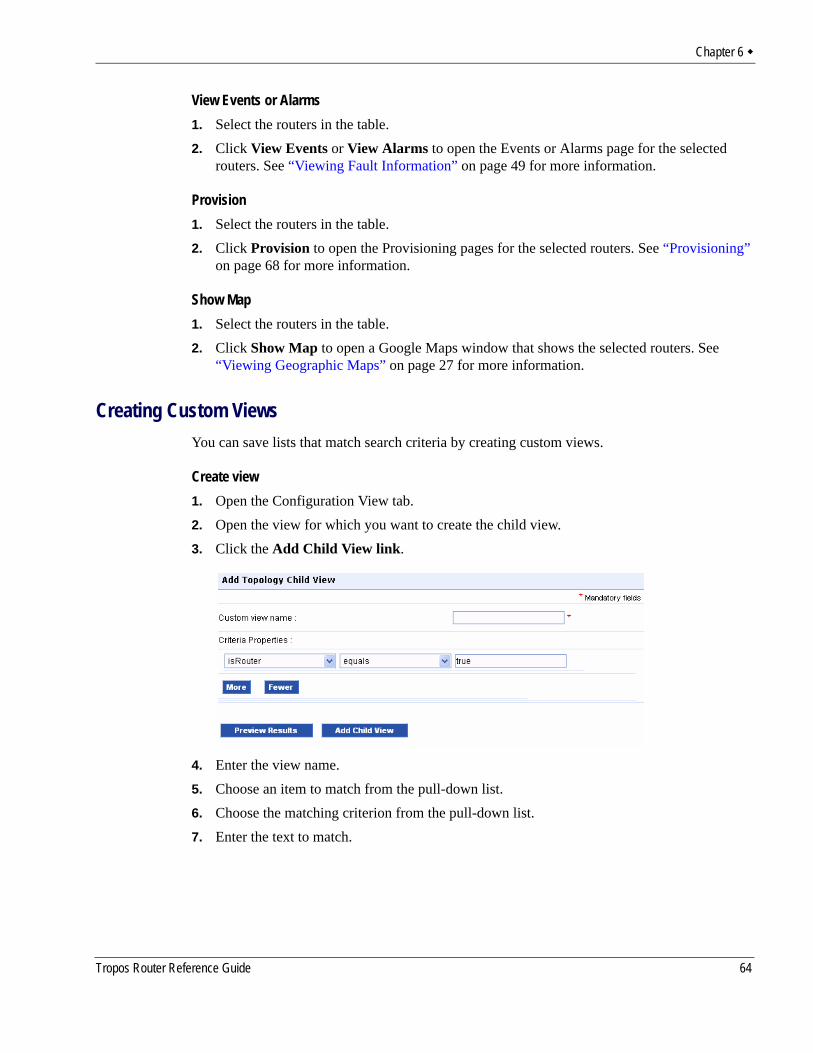
Chapter 6
View Events or Alarms1. Select the routers in the table.2. Click View Events or View Alarms to open the Events or Alarms page for the selected
routers. See “Viewing Fault Information” on page 49 for more information.
Provision1. Select the routers in the table.2. Click Provision to open the Provisioning pages for the selected routers. See “Provisioning”
on page 68 for more information.
Show Map1. Select the routers in the table.2. Click Show Map to open a Google Maps window that shows the selected routers. See
“Viewing Geographic Maps” on page 27 for more information.
Creating Custom ViewsYou can save lists that match search criteria by creating custom views.
Create view1. Open the Configuration View tab.2. Open the view for which you want to create the child view. 3. Click the Add Child View link.
4. Enter the view name.5. Choose an item to match from the pull-down list.6. Choose the matching criterion from the pull-down list.7. Enter the text to match.
Tropos Router Reference Guide 64
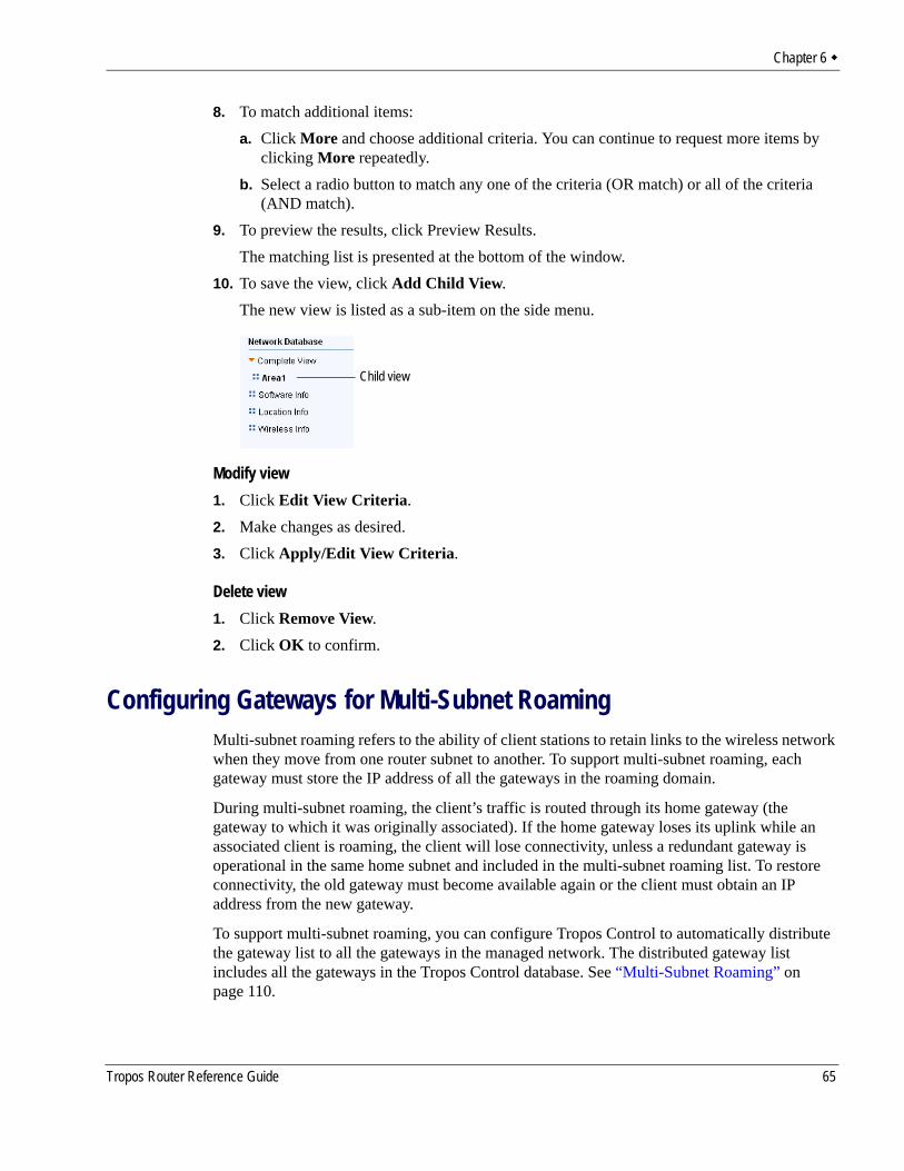
Chapter 6
8. To match additional items:a. Click More and choose additional criteria. You can continue to request more items by
clicking More repeatedly.b. Select a radio button to match any one of the criteria (OR match) or all of the criteria
(AND match).9. To preview the results, click Preview Results.
The matching list is presented at the bottom of the window.10. To save the view, click Add Child View.
The new view is listed as a sub-item on the side menu.
Modify view1. Click Edit View Criteria.2. Make changes as desired.3. Click Apply/Edit View Criteria.
Delete view1. Click Remove View.2. Click OK to confirm.
Configuring Gateways for Multi-Subnet RoamingMulti-subnet roaming refers to the ability of client stations to retain links to the wireless network when they move from one router subnet to another. To support multi-subnet roaming, each gateway must store the IP address of all the gateways in the roaming domain.
During multi-subnet roaming, the client’s traffic is routed through its home gateway (the gateway to which it was originally associated). If the home gateway loses its uplink while an associated client is roaming, the client will lose connectivity, unless a redundant gateway is operational in the same home subnet and included in the multi-subnet roaming list. To restore connectivity, the old gateway must become available again or the client must obtain an IP address from the new gateway.
To support multi-subnet roaming, you can configure Tropos Control to automatically distribute the gateway list to all the gateways in the managed network. The distributed gateway list includes all the gateways in the Tropos Control database. See “Multi-Subnet Roaming” on page 110.
Child view
Tropos Router Reference Guide 65
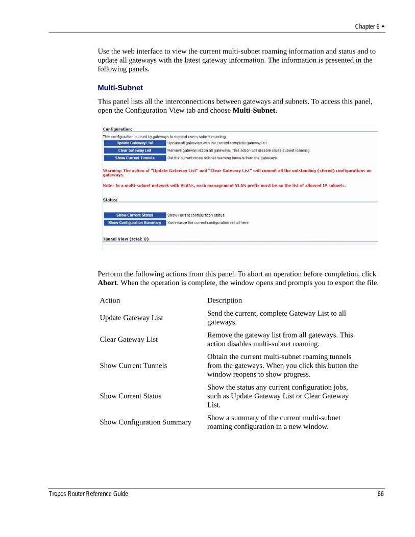
Chapter 6
Use the web interface to view the current multi-subnet roaming information and status and to update all gateways with the latest gateway information. The information is presented in the following panels.
Multi-Subnet
This panel lists all the interconnections between gateways and subnets. To access this panel, open the Configuration View tab and choose Multi-Subnet.
Perform the following actions from this panel. To abort an operation before completion, click Abort. When the operation is complete, the window opens and prompts you to export the file.
Action Description
Update Gateway List Send the current, complete Gateway List to all gateways.
Clear Gateway List Remove the gateway list from all gateways. This action disables multi-subnet roaming.
Show Current TunnelsObtain the current multi-subnet roaming tunnels from the gateways. When you click this button the window reopens to show progress.
Show Current StatusShow the status any current configuration jobs, such as Update Gateway List or Clear Gateway List.
Show Configuration Summary Show a summary of the current multi-subnet roaming configuration in a new window.
Tropos Router Reference Guide 66
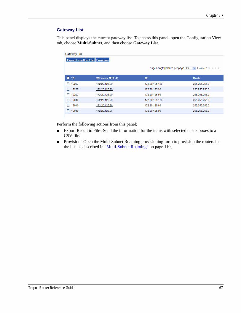
Chapter 6
Gateway List
This panel displays the current gateway list. To access this panel, open the Configuration View tab, choose Multi-Subnet, and then choose Gateway List.
Perform the following actions from this panel:Export Result to File--Send the information for the items with selected check boxes to a CSV file.Provision--Open the Multi-Subnet Roaming provisioning form to provision the routers in the list, as described in “Multi-Subnet Roaming” on page 110.
Tropos Router Reference Guide 67
7 Provisioning
Provisioning refers to the process of configuring Tropos routers to operate in the wireless network. Tropos Control supports XML-based provisioning through the web interface to assure that configurations are consistent across the network. This chapter explains how to provision devices.
Chapter contents:About Provisioning OperationsProvisioning Routers Using Web FormsProvisioning Routers From a FileProvisioning FormsOther Provisioning OperationsAuditing Provisioning Jobs
Tropos Control EMS User Guide 68
Chapter 7
About Provisioning OperationsThe web interface supports the following types of provisioning:
Provisioning from Forms---Use the web interface forms to specify the configuration parameters to provision (“Provisioning Routers Using Web Forms” on page 74).Provisioning from Files---Provision router identity or client black list/white list using information stored in files (“Provisioning Routers From a File” on page 76).Administrative Operations---Perform a variety of router administration tasks (“Other Provisioning Operations” on page 123).
CautionIt is possible for conflicts to arise in applying provisioning changes if multiple administrators are logged in and performing provisioning operations as the same time.
Each provisioning operation involves the tasks listed in Table 16.
TABLE 16 Provisioning Tasks
Step Task Description
1 Router selection Choose the routers that will receive the new configuration values (“Select routers to provision” on page 70).
2 Configuration Specify any of the following changes to be made:Configure values and store them on the Tropos Control server. See “Con-figure router parameters” on page 75.Specify the type of file provisioning and the source file. See “Specify the type of provisioning and the source file.” on page 77.Choose an administrative task. See “Other Provisioning Operations” on page 123.
3 Schedule the provision-ing job
Send the stored configuration values or file to the designated routers (“Schedule the provisioning job” on page 72).
4 Commit Activate the new configuration values on the designated routers (“Commit the provisioning job” on page 73).
Tropos Control EMS User Guide 69
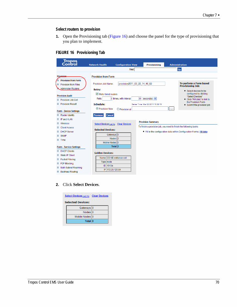
Chapter 7
Select routers to provision1. Open the Provisioning tab (Figure 16) and choose the panel for the type of provisioning that
you plan to implement.
FIGURE 16 Provisioning Tab
2. Click Select Devices.
Tropos Control EMS User Guide 70
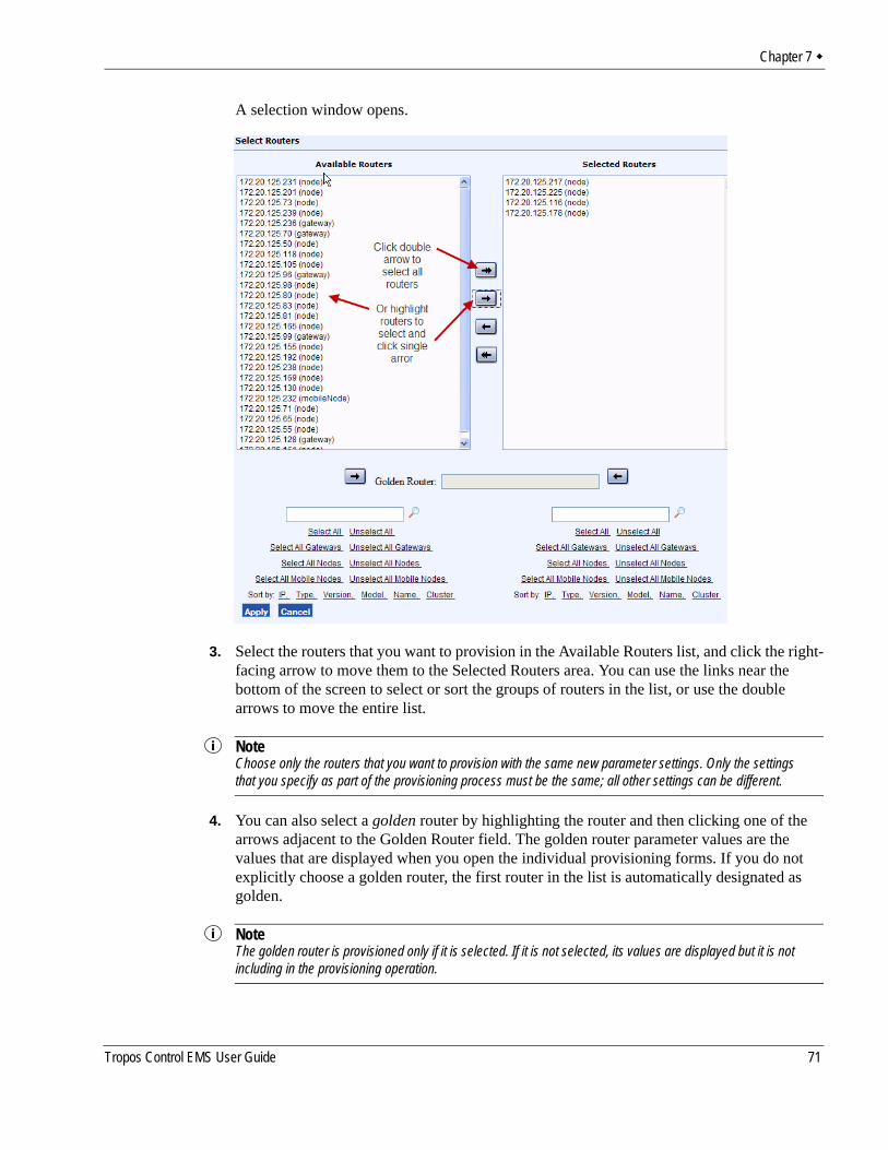
Chapter 7
A selection window opens.
3. Select the routers that you want to provision in the Available Routers list, and click the right-facing arrow to move them to the Selected Routers area. You can use the links near the bottom of the screen to select or sort the groups of routers in the list, or use the double arrows to move the entire list.
NoteChoose only the routers that you want to provision with the same new parameter settings. Only the settings that you specify as part of the provisioning process must be the same; all other settings can be different.
4. You can also select a golden router by highlighting the router and then clicking one of the arrows adjacent to the Golden Router field. The golden router parameter values are the values that are displayed when you open the individual provisioning forms. If you do not explicitly choose a golden router, the first router in the list is automatically designated as golden.
NoteThe golden router is provisioned only if it is selected. If it is not selected, its values are displayed but it is not including in the provisioning operation.
Tropos Control EMS User Guide 71
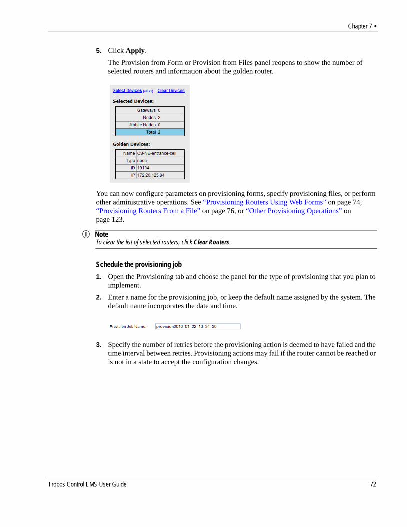
Chapter 7
5. Click Apply. The Provision from Form or Provision from Files panel reopens to show the number of selected routers and information about the golden router.
You can now configure parameters on provisioning forms, specify provisioning files, or perform other administrative operations. See “Provisioning Routers Using Web Forms” on page 74, “Provisioning Routers From a File” on page 76, or “Other Provisioning Operations” on page 123.
NoteTo clear the list of selected routers, click Clear Routers.
Schedule the provisioning job1. Open the Provisioning tab and choose the panel for the type of provisioning that you plan to
implement.2. Enter a name for the provisioning job, or keep the default name assigned by the system. The
default name incorporates the date and time.
3. Specify the number of retries before the provisioning action is deemed to have failed and the time interval between retries. Provisioning actions may fail if the router cannot be reached or is not in a state to accept the configuration changes.
Tropos Control EMS User Guide 72
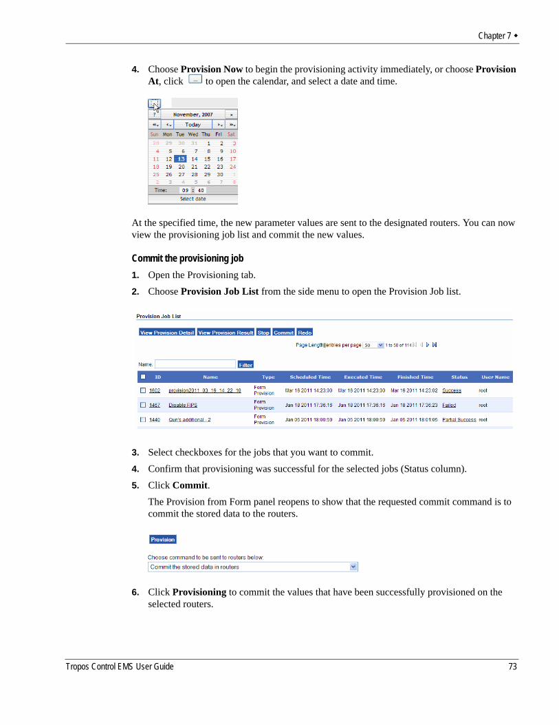
Chapter 7
4. Choose Provision Now to begin the provisioning activity immediately, or choose Provision At, click to open the calendar, and select a date and time.
At the specified time, the new parameter values are sent to the designated routers. You can now view the provisioning job list and commit the new values.
Commit the provisioning job1. Open the Provisioning tab.2. Choose Provision Job List from the side menu to open the Provision Job list.
3. Select checkboxes for the jobs that you want to commit.4. Confirm that provisioning was successful for the selected jobs (Status column).5. Click Commit.
The Provision from Form panel reopens to show that the requested commit command is to commit the stored data to the routers.
6. Click Provisioning to commit the values that have been successfully provisioned on the selected routers.
Tropos Control EMS User Guide 73
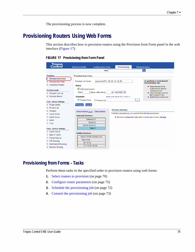
Chapter 7
The provisioning process is now complete.
Provisioning Routers Using Web FormsThis section describes how to provision routers using the Provision from Form panel in the web interface (Figure 17).
FIGURE 17 Provisioning from Form Panel
Provisioning from Forms - TasksPerform these tasks in the specified order to provision routers using web forms:1. Select routers to provision (on page 70)2. Configure router parameters (on page 75)3. Schedule the provisioning job (on page 72)4. Commit the provisioning job (on page 73)
Tropos Control EMS User Guide 74
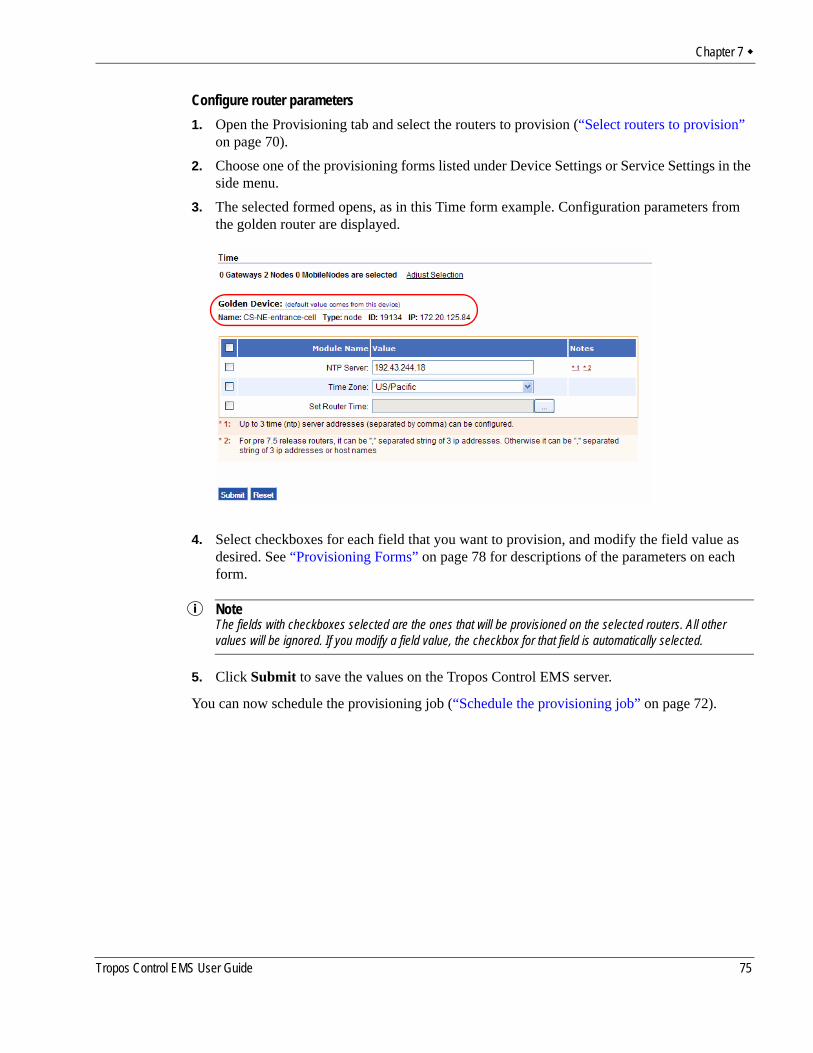
Chapter 7
Configure router parameters1. Open the Provisioning tab and select the routers to provision (“Select routers to provision”
on page 70).2. Choose one of the provisioning forms listed under Device Settings or Service Settings in the
side menu.3. The selected formed opens, as in this Time form example. Configuration parameters from
the golden router are displayed.
4. Select checkboxes for each field that you want to provision, and modify the field value as desired. See “Provisioning Forms” on page 78 for descriptions of the parameters on each form.
NoteThe fields with checkboxes selected are the ones that will be provisioned on the selected routers. All other values will be ignored. If you modify a field value, the checkbox for that field is automatically selected.
5. Click Submit to save the values on the Tropos Control EMS server.
You can now schedule the provisioning job (“Schedule the provisioning job” on page 72).
Tropos Control EMS User Guide 75
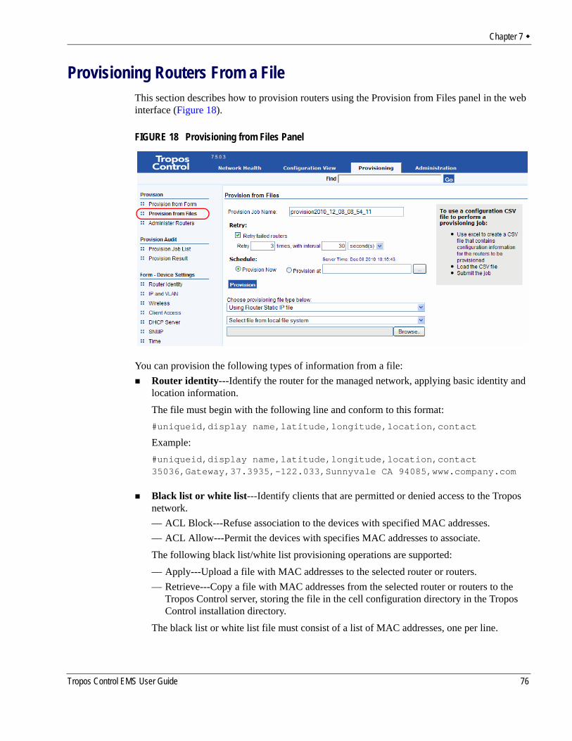
Chapter 7
Provisioning Routers From a FileThis section describes how to provision routers using the Provision from Files panel in the web interface (Figure 18).
FIGURE 18 Provisioning from Files Panel
You can provision the following types of information from a file:Router identity---Identify the router for the managed network, applying basic identity and location information.The file must begin with the following line and conform to this format:#uniqueid,display name,latitude,longitude,location,contact
Example:#uniqueid,display name,latitude,longitude,location,contact35036,Gateway,37.3935,-122.033,Sunnyvale CA 94085,www.company.com
Black list or white list---Identify clients that are permitted or denied access to the Tropos network. — ACL Block---Refuse association to the devices with specified MAC addresses.— ACL Allow---Permit the devices with specifies MAC addresses to associate.The following black list/white list provisioning operations are supported:— Apply---Upload a file with MAC addresses to the selected router or routers.— Retrieve---Copy a file with MAC addresses from the selected router or routers to the
Tropos Control server, storing the file in the cell configuration directory in the Tropos Control installation directory.
The black list or white list file must consist of a list of MAC addresses, one per line.
Tropos Control EMS User Guide 76
Chapter 7
Example:00:11:22:33:44:55aa:bb:cc:dd:ee:ff
Static IP addresses--Add routers with static IP address assignments.The file must begin with the following line and conform to this format:#uniqueid,wiredip,wiredmask,wlan0ip,wlan0mask,wlan1ip,wlan1mask,defaultgw
Example:#uniqueid,wiredip,wiredmask,wlan0ip,wlan0mask,wlan1ip,wlan1mask,defaultgw19040,172.20.125.95,255.255.255.0,172.20.125.96,255.255.255.0,,,172.20.125.25418505,,,172.20.125.105,255.255.255.0,,,
Provisioning from Files - TasksPerform these tasks in order to provision routers from files:1. Select routers to provision (on page 70)2. Specify the type of provisioning and the source file. (on page 77)3. Schedule the provisioning job (on page 72)4. Commit the provisioning job (on page 73)
Specify the type of provisioning and the source file.1. Open the Provisioning tab and select the routers to provision (“Select routers to provision”
on page 70).2. Select the type of provisioning:
For router identity:— Choose Using Router Identity CSV file from the provisioning type pull-down list.For black list/ white list:— Choose Using Black List or White List file from the provisioning type pull-down list.— Choose whether to provision the list to the routers or retrieve the list from the routers.— Choose whether the clients in the list will be allowed to access the network or blocked
from accessing the network.For static provisioning:— Choose Using Router Static IP file from the provisioning type pull-down list.
3. Choose whether to select the file from your local file server or the Tropos Control server, and browse to locate and open the file.
Tropos Control EMS User Guide 77
Chapter 7
4. Click Provision.
Provisioning FormsThe following notes apply to use of the provisioning forms in the web interface:
Fields marked as unique can be provisioned only to one router at a time. Fields marked with a version apply only to routers with the indicated software release.Fields that do not apply to the selected routers are grayed out (such as gateway-only fields if only nodes are selected for provisioning). Only the fields that have a check box selected are included in the provisioning job. When you enter or modify a value, the associated check box is automatically selected.
This section lists the available provisioning forms and fields:
Device SettingsRouter Identity PageIP and VLAN PageWireless PageClient AccessDHCP ServerSNMPTime
Service SettingsDHCP ClientsStatic IP ClientPacket FilteringP2P BlockingMulti-Subnet RoamingBackhaul RoutingRate LimitingQoSVoice
AdministrationSoftwareSecurity
Tropos Control EMS User Guide 78
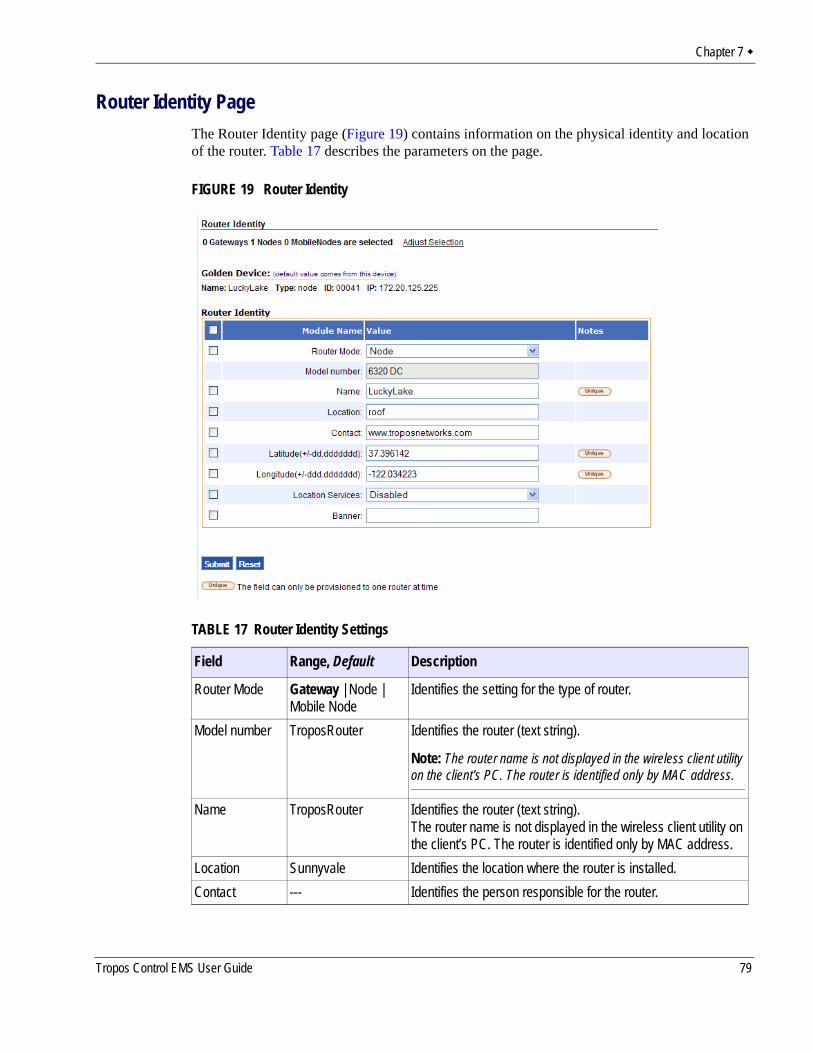
Chapter 7
Router Identity PageThe Router Identity page (Figure 19) contains information on the physical identity and location of the router. Table 17 describes the parameters on the page.
FIGURE 19 Router Identity
TABLE 17 Router Identity Settings
Field Range, Default Description
Router Mode Gateway | Node | Mobile Node
Identifies the setting for the type of router.
Model number TroposRouter Identifies the router (text string).
Note: The router name is not displayed in the wireless client utility on the client’s PC. The router is identified only by MAC address.
Name TroposRouter Identifies the router (text string).The router name is not displayed in the wireless client utility on the client’s PC. The router is identified only by MAC address.
Location Sunnyvale Identifies the location where the router is installed.Contact --- Identifies the person responsible for the router.
Tropos Control EMS User Guide 79
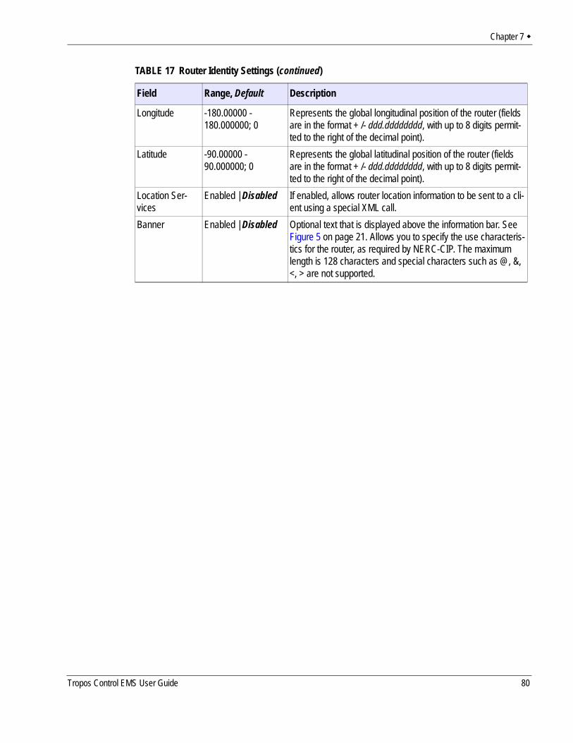
Chapter 7
Longitude -180.00000 - 180.000000; 0
Represents the global longitudinal position of the router (fields are in the format + /- ddd.dddddddd, with up to 8 digits permit-ted to the right of the decimal point).
Latitude -90.00000 - 90.000000; 0
Represents the global latitudinal position of the router (fields are in the format + /- ddd.dddddddd, with up to 8 digits permit-ted to the right of the decimal point).
Location Ser-vices
Enabled | Disabled If enabled, allows router location information to be sent to a cli-ent using a special XML call.
Banner Enabled | Disabled Optional text that is displayed above the information bar. SeeFigure 5 on page 21. Allows you to specify the use characteris-tics for the router, as required by NERC-CIP. The maximumlength is 128 characters and special characters such as @, &,<, > are not supported.
TABLE 17 Router Identity Settings (continued)
Field Range, Default Description
Tropos Control EMS User Guide 80
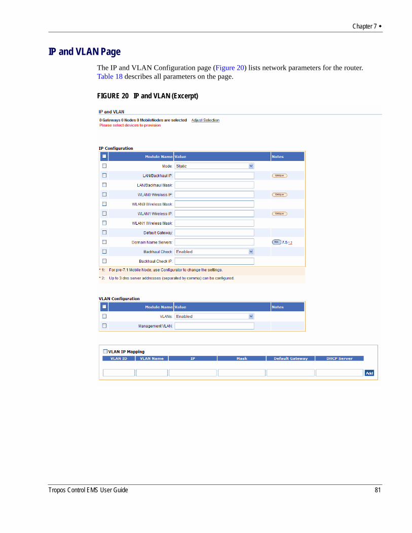
Chapter 7
IP and VLAN PageThe IP and VLAN Configuration page (Figure 20) lists network parameters for the router. Table 18 describes all parameters on the page.
FIGURE 20 IP and VLAN (Excerpt)
Tropos Control EMS User Guide 81
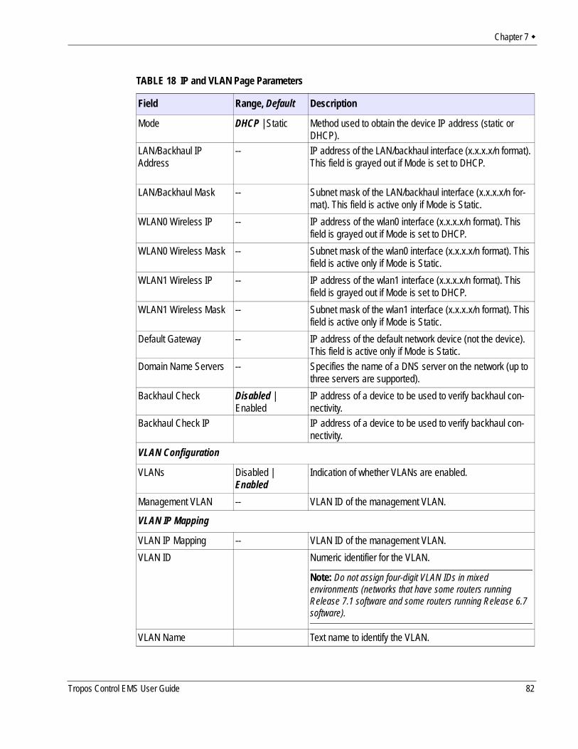
Chapter 7
TABLE 18 IP and VLAN Page Parameters
Field Range, Default Description
Mode DHCP | Static Method used to obtain the device IP address (static or DHCP).
LAN/Backhaul IP Address
-- IP address of the LAN/backhaul interface (x.x.x.x/n format). This field is grayed out if Mode is set to DHCP.
LAN/Backhaul Mask -- Subnet mask of the LAN/backhaul interface (x.x.x.x/n for-mat). This field is active only if Mode is Static.
WLAN0 Wireless IP -- IP address of the wlan0 interface (x.x.x.x/n format). This field is grayed out if Mode is set to DHCP.
WLAN0 Wireless Mask -- Subnet mask of the wlan0 interface (x.x.x.x/n format). This field is active only if Mode is Static.
WLAN1 Wireless IP -- IP address of the wlan1 interface (x.x.x.x/n format). This field is grayed out if Mode is set to DHCP.
WLAN1 Wireless Mask -- Subnet mask of the wlan1 interface (x.x.x.x/n format). This field is active only if Mode is Static.
Default Gateway -- IP address of the default network device (not the device). This field is active only if Mode is Static.
Domain Name Servers -- Specifies the name of a DNS server on the network (up to three servers are supported).
Backhaul Check Disabled | Enabled
IP address of a device to be used to verify backhaul con-nectivity.
Backhaul Check IP IP address of a device to be used to verify backhaul con-nectivity.
VLAN Configuration
VLANs Disabled | Enabled
Indication of whether VLANs are enabled.
Management VLAN -- VLAN ID of the management VLAN.
VLAN IP Mapping
VLAN IP Mapping -- VLAN ID of the management VLAN.VLAN ID Numeric identifier for the VLAN.
Note: Do not assign four-digit VLAN IDs in mixed environments (networks that have some routers running Release 7.1 software and some routers running Release 6.7 software).
VLAN Name Text name to identify the VLAN.
Tropos Control EMS User Guide 82
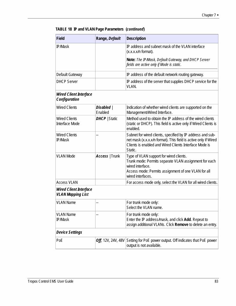
Chapter 7
IP/Mask IP address and subnet mask of the VLAN interface (x.x.x.x/n format).
Note: The IP/Mask, Default Gateway, and DHCP Server fields are active only if Mode is static.
Default Gateway IP address of the default network routing gateway.DHCP Server IP address of the server that supplies DHCP service for the
VLAN.
Wired Client Interface Configuration
Wired Clients Disabled | Enabled
Indication of whether wired clients are supported on the Management/Wired Interface.
Wired ClientsInterface Mode
DHCP | Static Method used to obtain the IP address of the wired clients (static or DHCP). This field is active only if Wired Clients is enabled.
Wired ClientsIP/Mask
-- Subnet for wired clients, specified by IP address and sub-net mask (x.x.x.x/n format). This field is active only if Wired Clients is enabled and Wired Clients Interface Mode is Static.
VLAN Mode Access | Trunk Type of VLAN support for wired clients.Trunk mode: Permits separate VLAN assignment for each wired interface.Access mode: Permits assignment of one VLAN for all wired interfaces.
Access VLAN For access mode only, select the VLAN for all wired clients.Wired Client Interface VLAN Mapping List
VLAN Name -- For trunk mode only:Select the VLAN name.
VLAN NameIP/Mask
-- For trunk mode only:Enter the IP address/mask, and click Add. Repeat to assign additional VLANs. Click Remove to delete an entry.
Device Settings
PoE Off, 12V, 24V, 48V Setting for PoE power output. Off indicates that PoE power output is not available.
TABLE 18 IP and VLAN Page Parameters (continued)
Field Range, Default Description
Tropos Control EMS User Guide 83
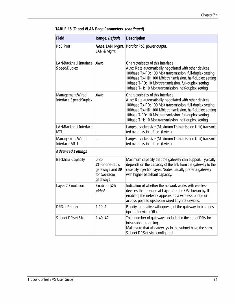
Chapter 7
PoE Port None, LAN, Mgmt, LAN & Mgmt
Port for PoE power output.
LAN/Backhaul Interface Speed/Duplex
Auto Characteristics of this interface.Auto: Rate automatically negotiated with other devices100base Tx-FD: 100 Mbit transmission, full-duplex setting100base Tx-HD: 100 Mbit transmission, half-duplex setting10base T-FD: 10 Mbit transmission, full-duplex setting10base T-H: 10 Mbit transmission, half-duplex setting
Management/Wired Interface Speed/Duplex
Auto Characteristics of this interface.Auto: Rate automatically negotiated with other devices100base Tx-FD: 100 Mbit transmission, full-duplex setting100base Tx-HD: 100 Mbit transmission, half-duplex setting10base T-FD: 10 Mbit transmission, full-duplex setting10base T-H: 10 Mbit transmission, half-duplex setting
LAN/Backhaul Interface MTU
-- Largest packet size (Maximum Transmission Unit) transmit-ted over this interface. (bytes)
Management/Wired Interface MTU
-- Largest packet size (Maximum Transmission Unit) transmit-ted over this interface. (bytes)
Advanced Settings
Backhaul Capacity 0-3025 for one-radiogateways and 30for two-radiogateways
Maximum capacity that the gateway can support. Typically depends on the capacity of the link from the gateway to the capacity injection layer. Nodes usually prefer a gateway with higher backhaul capacity.
Layer 2 Emulation Enabled | Dis-abled
Indication of whether the network works with wireless devices that operate at Layer 2 of the OSI hierarchy. If enabled, the network appears as a wireless bridge or access point to upstream wired Layer 2 devices.
DRSet Priority 1-10, 2 Priority, or relative willingness, of the gateway to be a des-ignated device (DR).
Subnet DRset Size 1-40, 10 Total number of gateways included in the set of DRs for intra-subnet roaming.Make sure that all gateways in the subnet have the same Subnet DRSet size configured.
TABLE 18 IP and VLAN Page Parameters (continued)
Field Range, Default Description
Tropos Control EMS User Guide 84
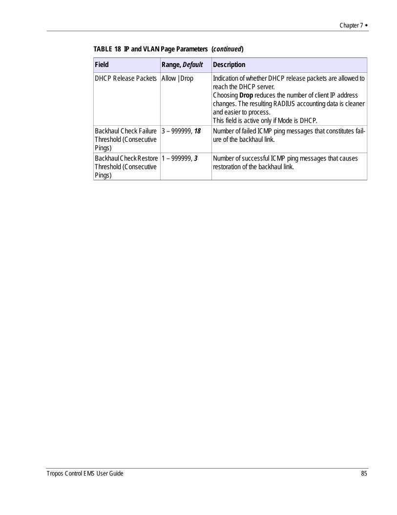
Chapter 7
DHCP Release Packets Allow | Drop Indication of whether DHCP release packets are allowed to reach the DHCP server. Choosing Drop reduces the number of client IP address changes. The resulting RADIUS accounting data is cleaner and easier to process.This field is active only if Mode is DHCP.
Backhaul Check Failure Threshold (Consecutive Pings)
3 – 999999, 18 Number of failed ICMP ping messages that constitutes fail-ure of the backhaul link.
Backhaul Check Restore Threshold (Consecutive Pings)
1 – 999999, 3 Number of successful ICMP ping messages that causes restoration of the backhaul link.
TABLE 18 IP and VLAN Page Parameters (continued)
Field Range, Default Description
Tropos Control EMS User Guide 85
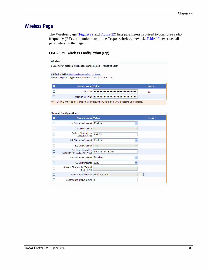
Chapter 7
Wireless PageThe Wireless page (Figure 22 and Figure 22) lists parameters required to configure radio frequency (RF) communications in the Tropos wireless network. Table 19 describes all parameters on the page.
FIGURE 21 Wireless Configuration (Top)
Tropos Control EMS User Guide 86
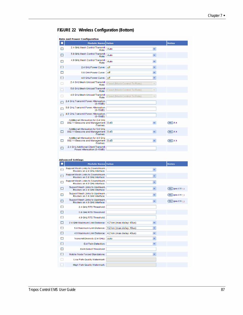
Chapter 7
FIGURE 22 Wireless Configuration (Bottom)
Tropos Control EMS User Guide 87
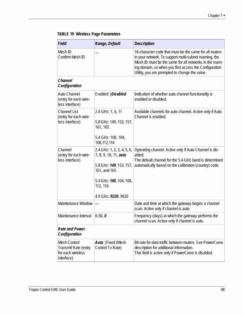
Chapter 7
TABLE 19 Wireless Page Parameters
Field Range, Default Description
Mesh IDConfirm Mesh ID
--- 16-character code that must be the same for all routers in your network. To support multi-subnet roaming, the Mesh ID must be the same for all networks in the roam-ing domain, so when you first access the Configuration Utility, you are prompted to change the value.
Channel Configuration
Auto Channel (entry for each wire-less interface)
Enabled | Disabled Indication of whether auto channel functionality is enabled or disabled.
Channel List(entry for each wire-less interface)
2.4 GHz: 1, 6, 11
5.8 GHz: 149, 153, 157, 161, 165
5.4 GHz: 100, 104, 108,112,116
Available channels for auto channel. Active only if Auto Channel is enabled.
Channel(entry for each wire-less interface)
2.4 GHz: 1, 2, 3, 4, 5, 6, 7, 8, 9, 10, 11, auto
5.8 GHz: 149, 153, 157, 161, and 165
5.4 GHz: 100, 104, 108, 112, 116
4.9 GHz: 9220, 9620
Operating channel. Active only if Auto Channel is dis-abled.The default channel for the 5.4 GHz band is determined automatically based on the calibration (country) code.
Maintenance Window --- Date and time at which the gateway begins a channel scan. Active only if channel is auto.
Maintenance Interval 0-30, 0 Frequency (days) at which the gateway performs the channel scan. Active only if channel is auto.
Rate and Power Configuration
Mesh Control Transmit Rate (entry for each wireless interface)
Auto | Fixed (Mesh Control Tx Rate)
Bit rate for data traffic between routers. See PowerCurve description for additional information.This field is active only if PowerCurve is disabled.
Tropos Control EMS User Guide 88
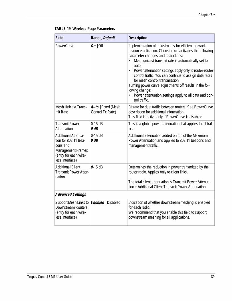
Chapter 7
PowerCurve On | Off Implementation of adjustments for efficient network resource utilization. Choosing on activates the following parameter changes and restrictions:• Mesh unicast transmit rate is automatically set to
auto.• Power attenuation settings apply only to router-router
control traffic. You can continue to assign data rates for mesh control transmission.
Turning power curve adjustments off results in the fol-lowing change:• Power attenuation settings apply to all data and con-
trol traffic.Mesh Unicast Trans-mit Rate
Auto | Fixed (Mesh Control Tx Rate)
Bit rate for data traffic between routers. See PowerCurve description for additional information.This field is active only if PowerCurve is disabled.
Transmit Power Attenuation
0-15 dB0 dB
This is a global power attenuation that applies to all traf-fic.
Additional Attenua-tion for 802.11 Bea-cons and Management Frames (entry for each wire-less interface)
0-15 dB0 dB
Additional attenuation added on top of the Maximum Power Attenuation and applied to 802.11 beacons and management traffic.
Additional Client Transmit Power Atten-uation
0-15 dB Determines the reduction in power transmitted by the router radio. Applies only to client links.
The total client attenuation is Transmit Power Attenua-tion + Additional Client Transmit Power Attenuation
Advanced Settings
Support Mesh Links to Downstream Routers(entry for each wire-less interface)
Enabled | Disabled Indication of whether downstream meshing is enabled for each radio.We recommend that you enable this field to support downstream meshing for all applications.
TABLE 19 Wireless Page Parameters
Field Range, Default Description
Tropos Control EMS User Guide 89
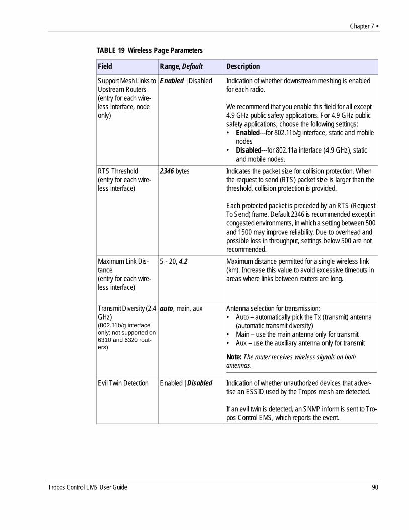
Chapter 7
Support Mesh Links to Upstream Routers(entry for each wire-less interface, node only)
Enabled | Disabled Indication of whether downstream meshing is enabled for each radio.
We recommend that you enable this field for all except 4.9 GHz public safety applications. For 4.9 GHz public safety applications, choose the following settings:• Enabled---for 802.11b/g interface, static and mobile
nodes• Disabled---for 802.11a interface (4.9 GHz), static
and mobile nodes.RTS Threshold(entry for each wire-less interface)
2346 bytes Indicates the packet size for collision protection. When the request to send (RTS) packet size is larger than the threshold, collision protection is provided.
Each protected packet is preceded by an RTS (Request To Send) frame. Default 2346 is recommended except in congested environments, in which a setting between 500 and 1500 may improve reliability. Due to overhead and possible loss in throughput, settings below 500 are not recommended.
Maximum Link Dis-tance(entry for each wire-less interface)
5 - 20, 4.2 Maximum distance permitted for a single wireless link (km). Increase this value to avoid excessive timeouts in areas where links between routers are long.
Transmit Diversity (2.4 GHz)(802.11b/g interface only; not supported on 6310 and 6320 rout-ers)
auto, main, aux Antenna selection for transmission:• Auto – automatically pick the Tx (transmit) antenna
(automatic transmit diversity)• Main – use the main antenna only for transmit• Aux – use the auxiliary antenna only for transmit
Note: The router receives wireless signals on both antennas.
Evil Twin Detection Enabled | Disabled Indication of whether unauthorized devices that adver-tise an ESSID used by the Tropos mesh are detected.
If an evil twin is detected, an SNMP inform is sent to Tro-pos Control EMS, which reports the event.
TABLE 19 Wireless Page Parameters
Field Range, Default Description
Tropos Control EMS User Guide 90
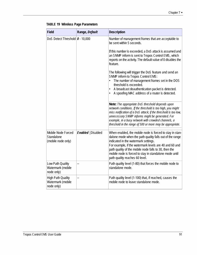
Chapter 7
DoS Detect Threshold 0 - 10,000 Number of management frames that are acceptable to be sent within 5 seconds.
If this number is exceeded, a DoS attack is assumed and an SNMP inform is sent to Tropos Control EMS, which reports on the activity. The default value of 0 disables the feature.
The following will trigger the DoS feature and send an SNMP inform to Tropos Control EMS:• The number of management frames set in the DOS
threshold is exceeded.• A broadcast deauthentication packet is detected.• A spoofing MAC address of a router is detected.
Note: The appropriate DoS threshold depends upon network conditions. If the threshold is too high, you might miss notification of a DoS attack; if the threshold is too low, unnecessary SNMP informs might be generated. For example, in a busy network with crowded channels, a threshold in the range of 500 or more may be appropriate.
Mobile Node Forced Standalone(mobile node only)
Enabled | Disabled When enabled, the mobile node is forced to stay in stan-dalone mode when the path quality falls out of the range indicated in the watermark settings. For example, if the watermark levels are 40 and 60 and path quality of the mobile node falls to 30, then the mobile node is forced to stay in standalone mode until path quality reaches 60 level.
Low Path Quality Watermark (mobile node only)
-- Path quality level (1-80) that forces the mobile node to standalone mode.
High Path Quality Watermark (mobile node only)
-- Path quality level (1-100) that, if reached, causes the mobile node to leave standalone mode.
TABLE 19 Wireless Page Parameters
Field Range, Default Description
Tropos Control EMS User Guide 91
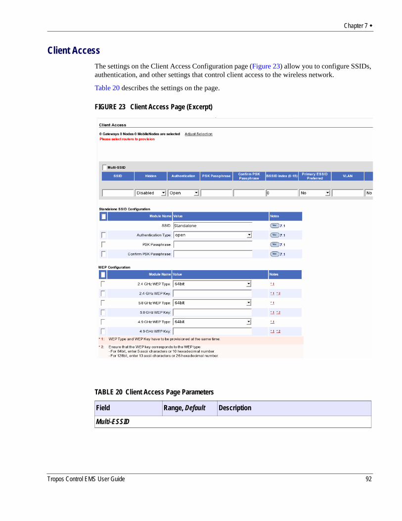
Chapter 7
Client AccessThe settings on the Client Access Configuration page (Figure 23) allow you to configure SSIDs, authentication, and other settings that control client access to the wireless network.
Table 20 describes the settings on the page.
FIGURE 23 Client Access Page (Excerpt)
TABLE 20 Client Access Page Parameters
Field Range, Default Description
Multi-ESSID
Tropos Control EMS User Guide 92
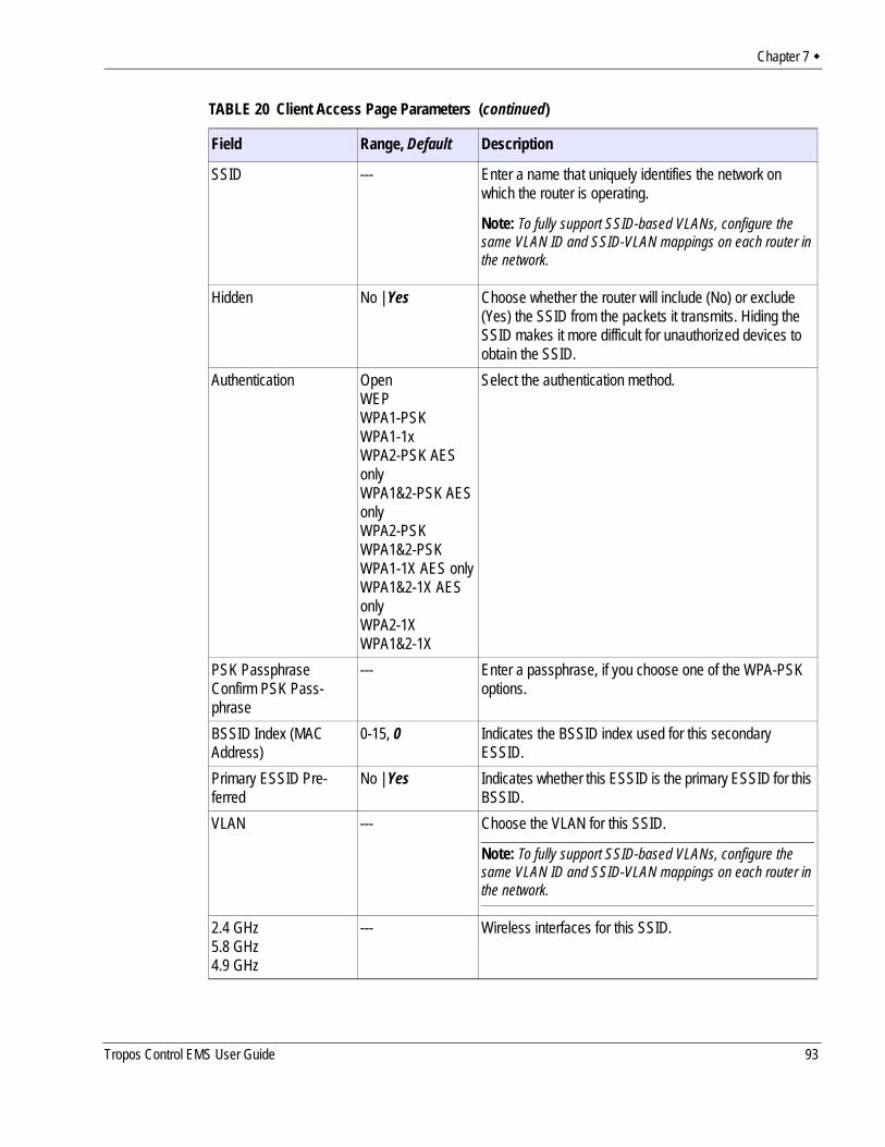
Chapter 7
SSID --- Enter a name that uniquely identifies the network on which the router is operating.
Note: To fully support SSID-based VLANs, configure the same VLAN ID and SSID-VLAN mappings on each router in the network.
Hidden No | Yes Choose whether the router will include (No) or exclude (Yes) the SSID from the packets it transmits. Hiding the SSID makes it more difficult for unauthorized devices to obtain the SSID.
Authentication OpenWEPWPA1-PSKWPA1-1xWPA2-PSK AES onlyWPA1&2-PSK AES onlyWPA2-PSKWPA1&2-PSKWPA1-1X AES onlyWPA1&2-1X AES onlyWPA2-1XWPA1&2-1X
Select the authentication method.
PSK PassphraseConfirm PSK Pass-phrase
--- Enter a passphrase, if you choose one of the WPA-PSK options.
BSSID Index (MAC Address)
0-15, 0 Indicates the BSSID index used for this secondary ESSID.
Primary ESSID Pre-ferred
No | Yes Indicates whether this ESSID is the primary ESSID for this BSSID.
VLAN --- Choose the VLAN for this SSID.
Note: To fully support SSID-based VLANs, configure the same VLAN ID and SSID-VLAN mappings on each router in the network.
2.4 GHz5.8 GHz4.9 GHz
--- Wireless interfaces for this SSID.
TABLE 20 Client Access Page Parameters (continued)
Field Range, Default Description
Tropos Control EMS User Guide 93
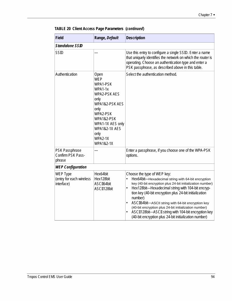
Chapter 7
Standalone SSIDSSID --- Use this entry to configure a single SSID. Enter a name
that uniquely identifies the network on which the router is operating. Choose an authentication type and enter a PSK passphrase, as described above in this table.
Authentication OpenWEPWPA1-PSKWPA1-1xWPA2-PSK AES onlyWPA1&2-PSK AES onlyWPA2-PSKWPA1&2-PSKWPA1-1X AES onlyWPA1&2-1X AES onlyWPA2-1XWPA1&2-1X
Select the authentication method.
PSK PassphraseConfirm PSK Pass-phrase
--- Enter a passphrase, if you choose one of the WPA-PSK options.
WEP ConfigurationWEP Type(entry for each wireless interface)
Hex64bitHex128bitASCII64bitASCII128bit
Choose the type of WEP key:• Hex64bit---Hexadecimal string with 64-bit encryption
key (40-bit encryption plus 24-bit initialization number) • Hex128bit---Hexadecimal string with 104-bit encryp-
tion key (40-bit encryption plus 24-bit initialization number)
• ASCII64bit---ASCII string with 64-bit encryption key (40-bit encryption plus 24-bit initialization number)
• ASCII128bit---ASCII string with 104-bit encryption key (40-bit encryption plus 24-bit initialization number)
TABLE 20 Client Access Page Parameters (continued)
Field Range, Default Description
Tropos Control EMS User Guide 94
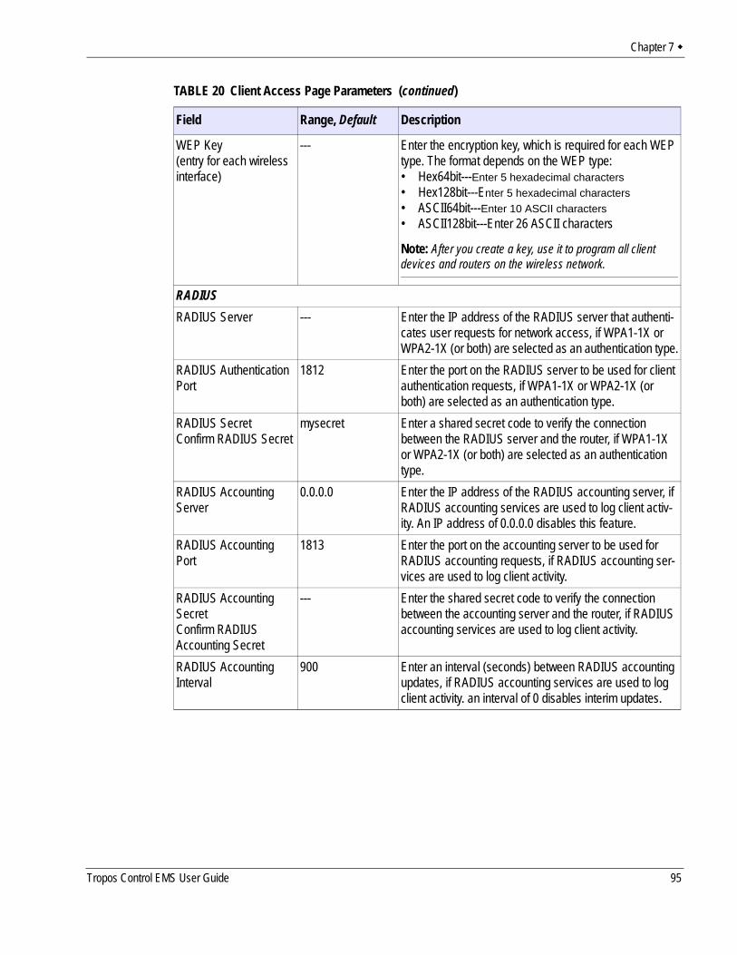
Chapter 7
WEP Key(entry for each wireless interface)
--- Enter the encryption key, which is required for each WEP type. The format depends on the WEP type:• Hex64bit---Enter 5 hexadecimal characters• Hex128bit---Enter 5 hexadecimal characters• ASCII64bit---Enter 10 ASCII characters• ASCII128bit---Enter 26 ASCII characters
Note: After you create a key, use it to program all client devices and routers on the wireless network.
RADIUSRADIUS Server --- Enter the IP address of the RADIUS server that authenti-
cates user requests for network access, if WPA1-1X or WPA2-1X (or both) are selected as an authentication type.
RADIUS Authentication Port
1812 Enter the port on the RADIUS server to be used for client authentication requests, if WPA1-1X or WPA2-1X (or both) are selected as an authentication type.
RADIUS SecretConfirm RADIUS Secret
mysecret Enter a shared secret code to verify the connection between the RADIUS server and the router, if WPA1-1X or WPA2-1X (or both) are selected as an authentication type.
RADIUS Accounting Server
0.0.0.0 Enter the IP address of the RADIUS accounting server, if RADIUS accounting services are used to log client activ-ity. An IP address of 0.0.0.0 disables this feature.
RADIUS Accounting Port
1813 Enter the port on the accounting server to be used for RADIUS accounting requests, if RADIUS accounting ser-vices are used to log client activity.
RADIUS Accounting SecretConfirm RADIUS Accounting Secret
--- Enter the shared secret code to verify the connection between the accounting server and the router, if RADIUS accounting services are used to log client activity.
RADIUS Accounting Interval
900 Enter an interval (seconds) between RADIUS accounting updates, if RADIUS accounting services are used to log client activity. an interval of 0 disables interim updates.
TABLE 20 Client Access Page Parameters (continued)
Field Range, Default Description
Tropos Control EMS User Guide 95
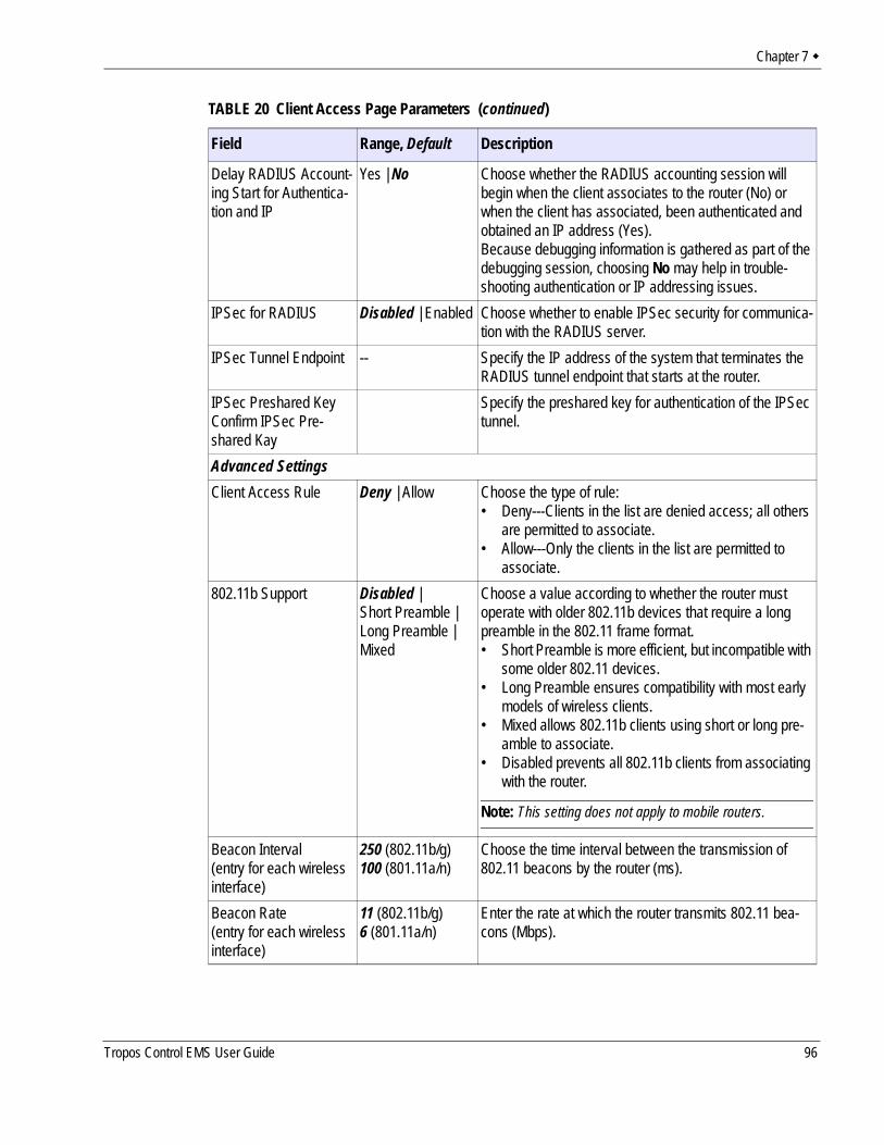
Chapter 7
Delay RADIUS Account-ing Start for Authentica-tion and IP
Yes | No Choose whether the RADIUS accounting session will begin when the client associates to the router (No) or when the client has associated, been authenticated and obtained an IP address (Yes).Because debugging information is gathered as part of the debugging session, choosing No may help in trouble-shooting authentication or IP addressing issues.
IPSec for RADIUS Disabled | Enabled Choose whether to enable IPSec security for communica-tion with the RADIUS server.
IPSec Tunnel Endpoint -- Specify the IP address of the system that terminates the RADIUS tunnel endpoint that starts at the router.
IPSec Preshared KeyConfirm IPSec Pre-shared Kay
Specify the preshared key for authentication of the IPSec tunnel.
Advanced SettingsClient Access Rule Deny | Allow Choose the type of rule:
• Deny---Clients in the list are denied access; all others are permitted to associate.
• Allow---Only the clients in the list are permitted to associate.
802.11b Support Disabled | Short Preamble | Long Preamble | Mixed
Choose a value according to whether the router must operate with older 802.11b devices that require a long preamble in the 802.11 frame format.• Short Preamble is more efficient, but incompatible with
some older 802.11 devices.• Long Preamble ensures compatibility with most early
models of wireless clients.• Mixed allows 802.11b clients using short or long pre-
amble to associate.• Disabled prevents all 802.11b clients from associating
with the router.
Note: This setting does not apply to mobile routers.
Beacon Interval(entry for each wireless interface)
250 (802.11b/g)100 (801.11a/n)
Choose the time interval between the transmission of 802.11 beacons by the router (ms).
Beacon Rate(entry for each wireless interface)
11 (802.11b/g)6 (801.11a/n)
Enter the rate at which the router transmits 802.11 bea-cons (Mbps).
TABLE 20 Client Access Page Parameters (continued)
Field Range, Default Description
Tropos Control EMS User Guide 96
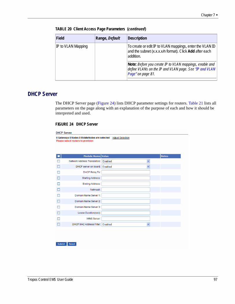
Chapter 7
DHCP ServerThe DHCP Server page (Figure 24) lists DHCP parameter settings for routers. Table 21 lists all parameters on the page along with an explanation of the purpose of each and how it should be interpreted and used.
FIGURE 24 DHCP Server
IP to VLAN Mapping To create or edit IP to VLAN mappings, enter the VLAN ID and the subnet (x.x.x.x/n format). Click Add after each addition.
Note: Before you create IP to VLAN mappings, enable and define VLANs on the IP and VLAN page. See “IP and VLAN Page” on page 81.
TABLE 20 Client Access Page Parameters (continued)
Field Range, Default Description
Tropos Control EMS User Guide 97
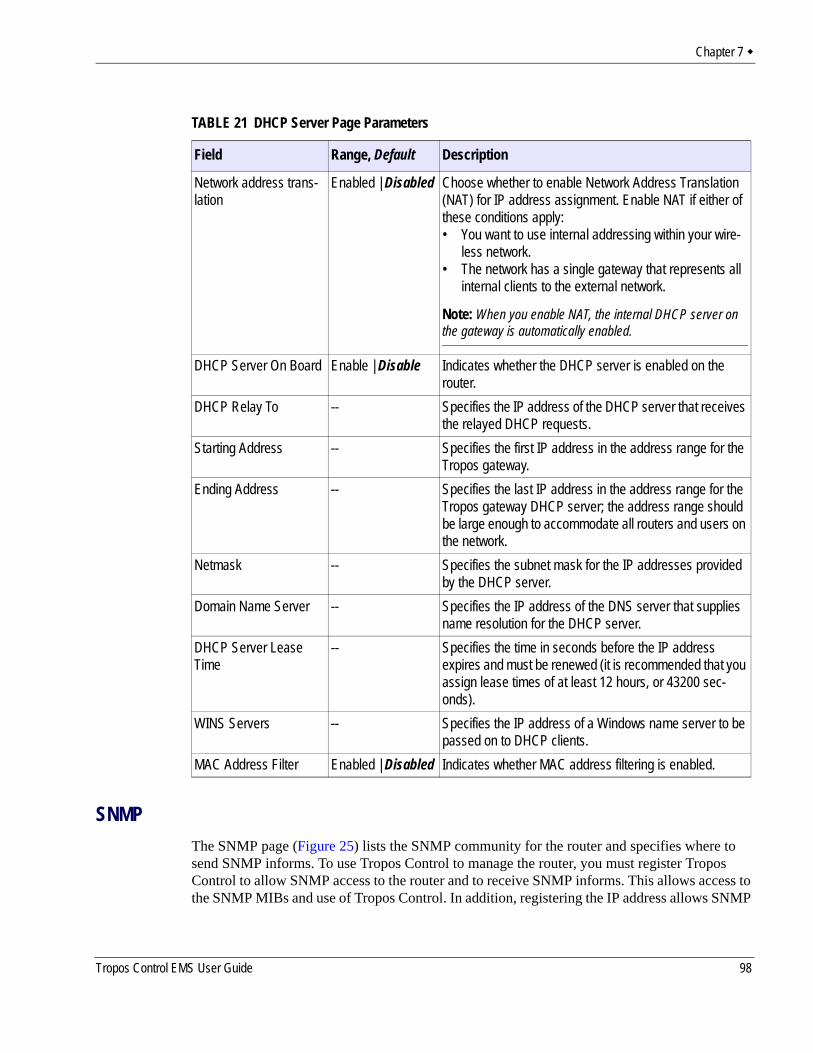
Chapter 7
SNMPThe SNMP page (Figure 25) lists the SNMP community for the router and specifies where to send SNMP informs. To use Tropos Control to manage the router, you must register Tropos Control to allow SNMP access to the router and to receive SNMP informs. This allows access to the SNMP MIBs and use of Tropos Control. In addition, registering the IP address allows SNMP
TABLE 21 DHCP Server Page Parameters
Field Range, Default Description
Network address trans-lation
Enabled | Disabled Choose whether to enable Network Address Translation (NAT) for IP address assignment. Enable NAT if either of these conditions apply:• You want to use internal addressing within your wire-
less network.• The network has a single gateway that represents all
internal clients to the external network.
Note: When you enable NAT, the internal DHCP server on the gateway is automatically enabled.
DHCP Server On Board Enable | Disable Indicates whether the DHCP server is enabled on the router.
DHCP Relay To -- Specifies the IP address of the DHCP server that receives the relayed DHCP requests.
Starting Address -- Specifies the first IP address in the address range for the Tropos gateway.
Ending Address -- Specifies the last IP address in the address range for the Tropos gateway DHCP server; the address range should be large enough to accommodate all routers and users on the network.
Netmask -- Specifies the subnet mask for the IP addresses provided by the DHCP server.
Domain Name Server -- Specifies the IP address of the DNS server that supplies name resolution for the DHCP server.
DHCP Server Lease Time
-- Specifies the time in seconds before the IP address expires and must be renewed (it is recommended that you assign lease times of at least 12 hours, or 43200 sec-onds).
WINS Servers -- Specifies the IP address of a Windows name server to be passed on to DHCP clients.
MAC Address Filter Enabled | Disabled Indicates whether MAC address filtering is enabled.
Tropos Control EMS User Guide 98
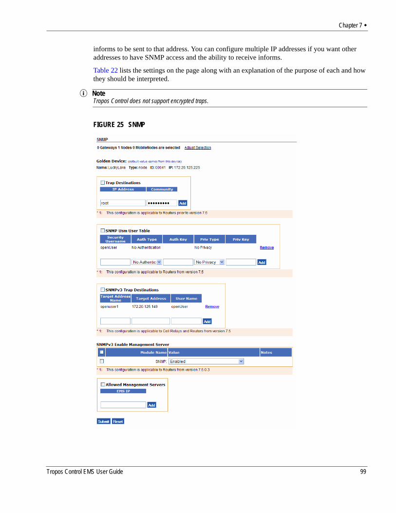
Chapter 7
informs to be sent to that address. You can configure multiple IP addresses if you want other addresses to have SNMP access and the ability to receive informs.
Table 22 lists the settings on the page along with an explanation of the purpose of each and how they should be interpreted.
NoteTropos Control does not support encrypted traps.
FIGURE 25 SNMP
Tropos Control EMS User Guide 99
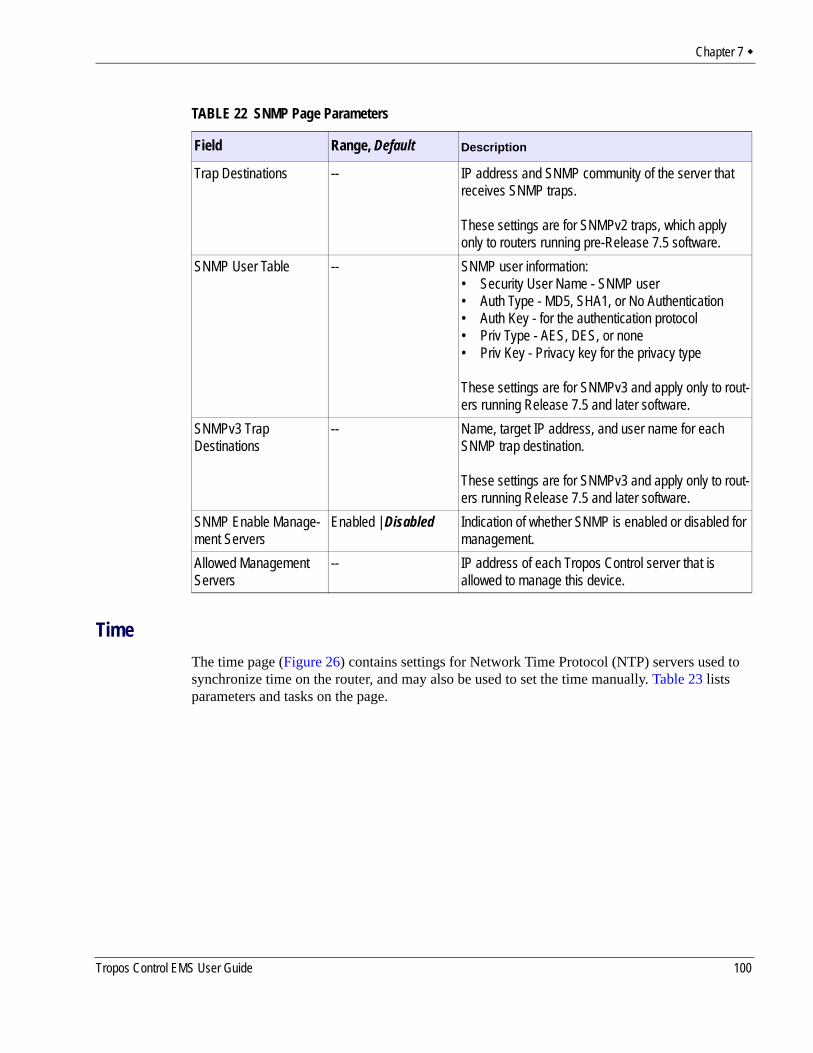
Chapter 7
TimeThe time page (Figure 26) contains settings for Network Time Protocol (NTP) servers used to synchronize time on the router, and may also be used to set the time manually. Table 23 lists parameters and tasks on the page.
TABLE 22 SNMP Page Parameters
Field Range, Default Description
Trap Destinations -- IP address and SNMP community of the server that receives SNMP traps.
These settings are for SNMPv2 traps, which apply only to routers running pre-Release 7.5 software.
SNMP User Table -- SNMP user information:• Security User Name - SNMP user• Auth Type - MD5, SHA1, or No Authentication• Auth Key - for the authentication protocol• Priv Type - AES, DES, or none• Priv Key - Privacy key for the privacy type
These settings are for SNMPv3 and apply only to rout-ers running Release 7.5 and later software.
SNMPv3 Trap Destinations
-- Name, target IP address, and user name for each SNMP trap destination.
These settings are for SNMPv3 and apply only to rout-ers running Release 7.5 and later software.
SNMP Enable Manage-ment Servers
Enabled | Disabled Indication of whether SNMP is enabled or disabled for management.
Allowed Management Servers
-- IP address of each Tropos Control server that is allowed to manage this device.
Tropos Control EMS User Guide 100
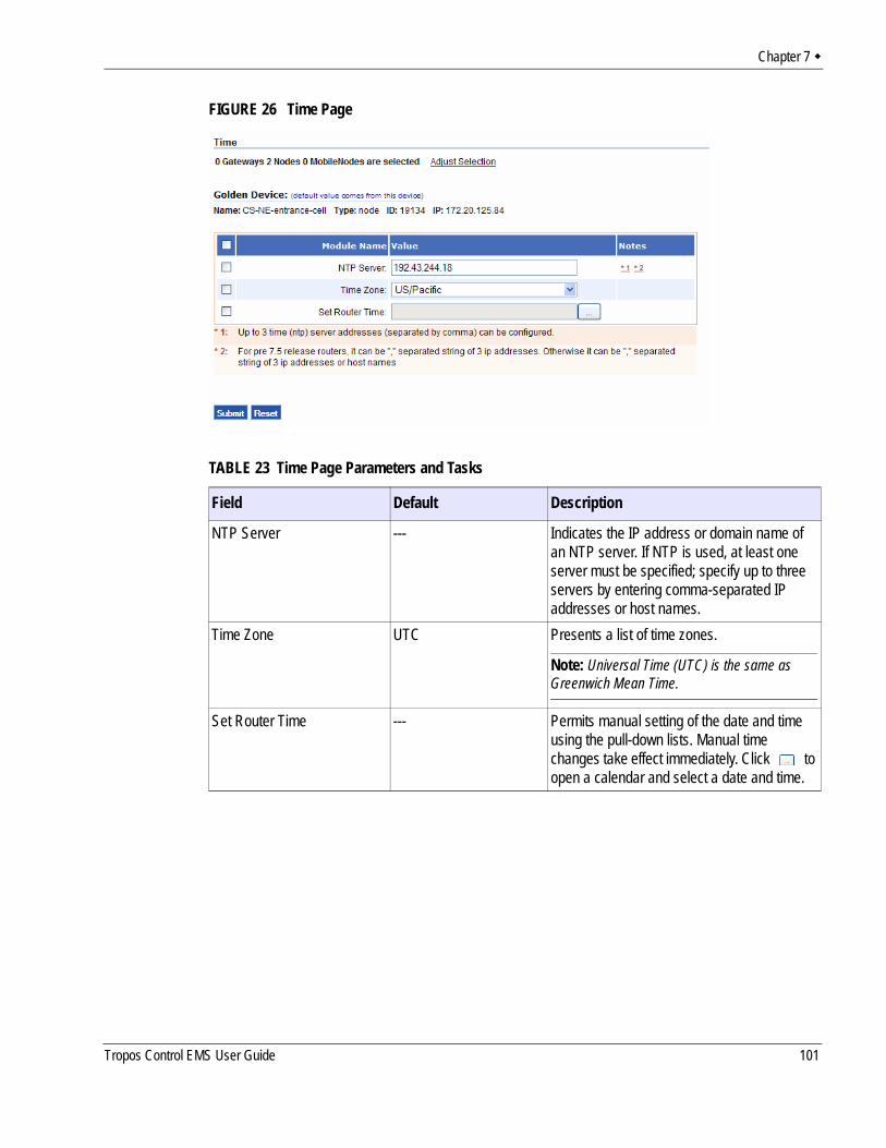
Chapter 7
FIGURE 26 Time Page
TABLE 23 Time Page Parameters and Tasks
Field Default Description
NTP Server --- Indicates the IP address or domain name of an NTP server. If NTP is used, at least one server must be specified; specify up to three servers by entering comma-separated IP addresses or host names.
Time Zone UTC Presents a list of time zones.
Note: Universal Time (UTC) is the same as Greenwich Mean Time.
Set Router Time --- Permits manual setting of the date and time using the pull-down lists. Manual time changes take effect immediately. Click to open a calendar and select a date and time.
Tropos Control EMS User Guide 101
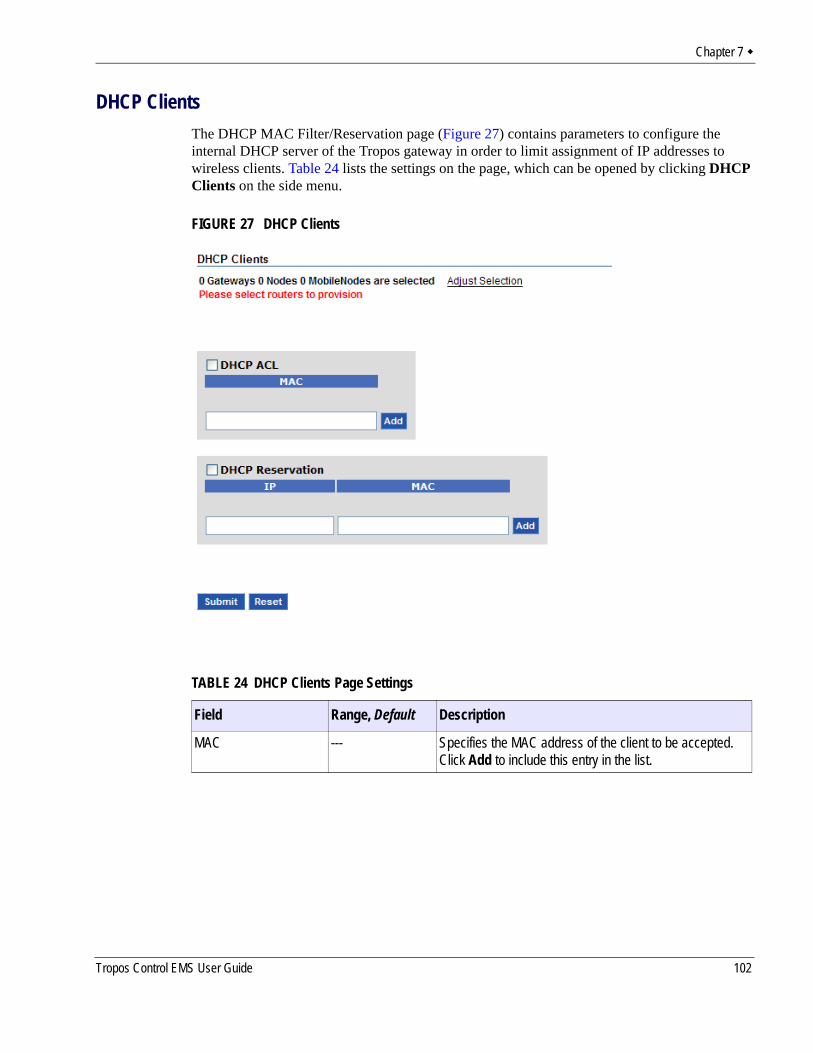
Chapter 7
DHCP ClientsThe DHCP MAC Filter/Reservation page (Figure 27) contains parameters to configure the internal DHCP server of the Tropos gateway in order to limit assignment of IP addresses to wireless clients. Table 24 lists the settings on the page, which can be opened by clicking DHCP Clients on the side menu.
FIGURE 27 DHCP Clients
TABLE 24 DHCP Clients Page Settings
Field Range, Default Description
MAC --- Specifies the MAC address of the client to be accepted.Click Add to include this entry in the list.
Tropos Control EMS User Guide 102
Chapter 7
Static IP ClientThe Static IP Client Configuration page (Figure 28) contains settings for clients that require static IP addresses rather than DHCP-supplied addresses. The Static IP Client Configuration page also provides the ability to configure static IP addresses for clients behind customer premise equipment (CPE), such as Wireless-to-Ethernet bridges. Table 25 lists the parameters on the page.
NoteIf you use auto-detection, you must enable it on all the gateways and nodes in the wireless routing domain (WRD). If the WRD is changed in Tropos Control, all gateways and nodes must be deleted from the Tropos Control using the Configuration View
NoteFor static IP clients, you must add the client entries on all gateways in the wireless routing domain in order for the clients to be able to roam across the full domain.
IP --- Specifies the IP address to be reserved for the client with the specified MAC address. The reserved IP addresses must be in the range of the DHCP server. Reservations simply reserve an IP address for a particular MAC address; they do not control access. Therefore, do not enable ACL when adding reservations unless you would like to control access as well. Click Add to include this entry in the list.
MAC --- Specifies the MAC address to be reserved for the client with the specified IP address. Click Add to include this entry in the list.
TABLE 24 DHCP Clients Page Settings (continued)
Field Range, Default Description
Tropos Control EMS User Guide 103
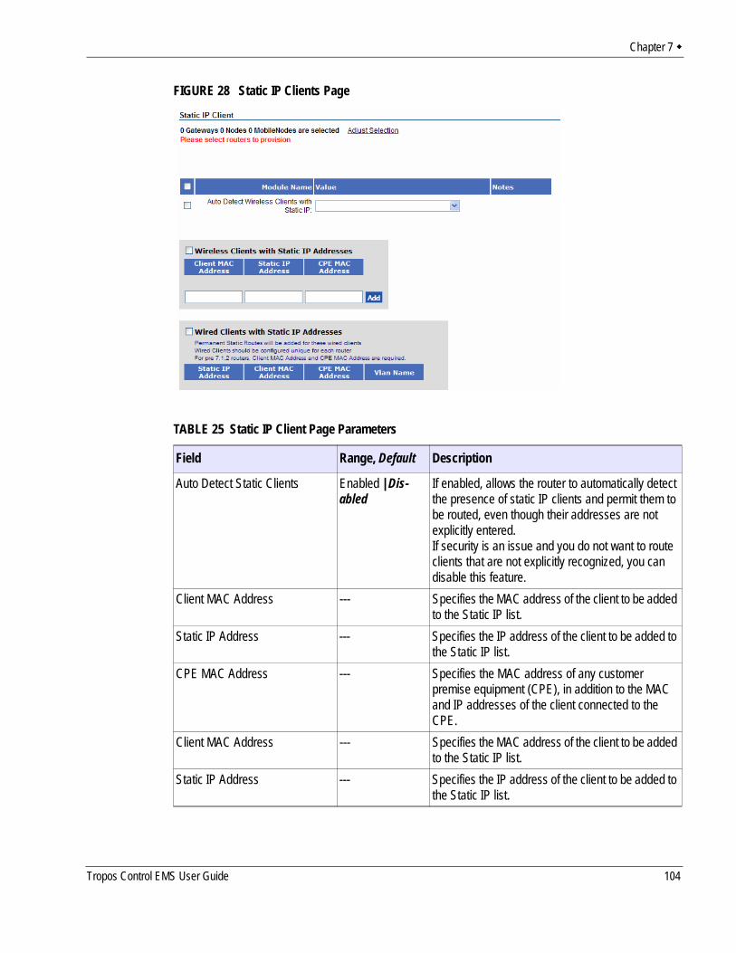
Chapter 7
FIGURE 28 Static IP Clients Page
TABLE 25 Static IP Client Page Parameters
Field Range, Default Description
Auto Detect Static Clients Enabled | Dis-abled
If enabled, allows the router to automatically detect the presence of static IP clients and permit them to be routed, even though their addresses are not explicitly entered. If security is an issue and you do not want to route clients that are not explicitly recognized, you can disable this feature.
Client MAC Address --- Specifies the MAC address of the client to be added to the Static IP list.
Static IP Address --- Specifies the IP address of the client to be added to the Static IP list.
CPE MAC Address --- Specifies the MAC address of any customer premise equipment (CPE), in addition to the MAC and IP addresses of the client connected to the CPE.
Client MAC Address --- Specifies the MAC address of the client to be added to the Static IP list.
Static IP Address --- Specifies the IP address of the client to be added to the Static IP list.
Tropos Control EMS User Guide 104
Chapter 7
Packet FilteringPacket Filtering (Figure 29) determines the types of packets forwarded or rejected by the router. Forwarding applies to packets that pass through the router, not those that begin or terminate at the router. Usage for the Packet Filter Forwarding page differs according to whether the default packet filter forwarding policy is Permitted or Denied (see Table 26).
CPE MAC Address --- Specifies the MAC address of any customer premise equipment (CPE), in addition to the MAC and IP addresses of the client connected to the CPE.
VLAN Name --- Specifies the VLAN for the wired client.
TABLE 25 Static IP Client Page Parameters (continued)
Field Range, Default Description
Tropos Control EMS User Guide 105
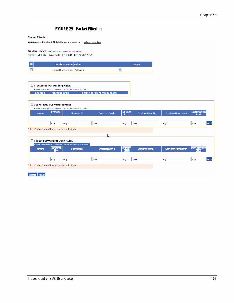
Chapter 7
FIGURE 29 Packet Filtering
Tropos Control EMS User Guide 106
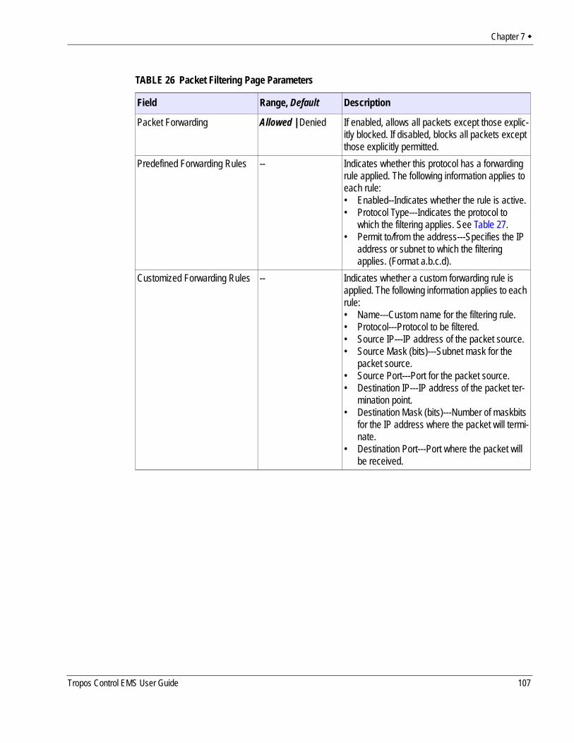
Chapter 7
TABLE 26 Packet Filtering Page Parameters
Field Range, Default Description
Packet Forwarding Allowed | Denied If enabled, allows all packets except those explic-itly blocked. If disabled, blocks all packets except those explicitly permitted.
Predefined Forwarding Rules -- Indicates whether this protocol has a forwarding rule applied. The following information applies to each rule:• Enabled--Indicates whether the rule is active.• Protocol Type---Indicates the protocol to
which the filtering applies. See Table 27.• Permit to/from the address---Specifies the IP
address or subnet to which the filtering applies. (Format a.b.c.d).
Customized Forwarding Rules -- Indicates whether a custom forwarding rule is applied. The following information applies to each rule:• Name---Custom name for the filtering rule.• Protocol---Protocol to be filtered.• Source IP---IP address of the packet source.• Source Mask (bits)---Subnet mask for the
packet source.• Source Port---Port for the packet source.• Destination IP---IP address of the packet ter-
mination point.• Destination Mask (bits)---Number of maskbits
for the IP address where the packet will termi-nate.
• Destination Port---Port where the packet will be received.
Tropos Control EMS User Guide 107
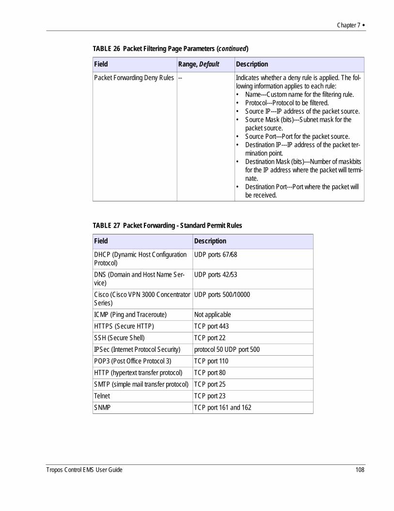
Chapter 7
Packet Forwarding Deny Rules -- Indicates whether a deny rule is applied. The fol-lowing information applies to each rule:• Name---Custom name for the filtering rule.• Protocol---Protocol to be filtered.• Source IP---IP address of the packet source.• Source Mask (bits)---Subnet mask for the
packet source.• Source Port---Port for the packet source.• Destination IP---IP address of the packet ter-
mination point.• Destination Mask (bits)---Number of maskbits
for the IP address where the packet will termi-nate.
• Destination Port---Port where the packet will be received.
TABLE 27 Packet Forwarding - Standard Permit Rules
Field Description
DHCP (Dynamic Host Configuration Protocol)
UDP ports 67/68
DNS (Domain and Host Name Ser-vice)
UDP ports 42/53
Cisco (Cisco VPN 3000 Concentrator Series)
UDP ports 500/10000
ICMP (Ping and Traceroute) Not applicableHTTPS (Secure HTTP) TCP port 443SSH (Secure Shell) TCP port 22IPSec (Internet Protocol Security) protocol 50 UDP port 500POP3 (Post Office Protocol 3) TCP port 110HTTP (hypertext transfer protocol) TCP port 80SMTP (simple mail transfer protocol) TCP port 25Telnet TCP port 23SNMP TCP port 161 and 162
TABLE 26 Packet Filtering Page Parameters (continued)
Field Range, Default Description
Tropos Control EMS User Guide 108
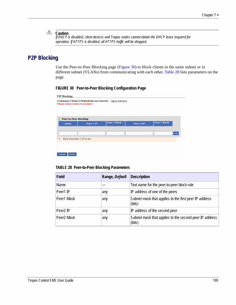
Chapter 7
CautionIf DHCP is disabled, client devices and Tropos nodes cannot obtain the DHCP lease required for operation. If HTTPS is disabled, all HTTPS traffic will be dropped.
P2P BlockingUse the Peer-to-Peer Blocking page (Figure 30) to block clients in the same subnet or in different subnet (VLANs) from communicating with each other. Table 28 lists parameters on the page.
FIGURE 30 Peer-to-Peer Blocking Configuration Page
TABLE 28 Peer-to-Peer Blocking Parameters
Field Range, Default Description
Name --- Text name for the peer-to-peer block rulePeer1 IP any IP address of one of the peersPeer1 Mask any Subnet mask that applies to the first peer IP address
(bits)Peer2 IP any IP address of the second peerPeer2 Mask any Subnet mask that applies to the second peer IP address
(bits)
Tropos Control EMS User Guide 109
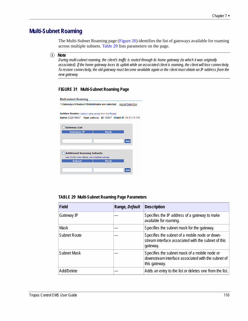
Chapter 7
Multi-Subnet RoamingThe Multi-Subnet Roaming page (Figure 20) identifies the list of gateways available for roaming across multiple subnets. Table 29 lists parameters on the page.
NoteDuring multi-subnet roaming, the client’s traffic is routed through its home gateway (to which it was originally associated). If the home gateway loses its uplink while an associated client is roaming, the client will lose connectivity. To restore connectivity, the old gateway must become available again or the client must obtain an IP address from the new gateway.
FIGURE 31 Multi-Subnet Roaming Page
TABLE 29 Multi-Subnet Roaming Page Parameters
Field Range, Default Description
Gateway IP --- Specifies the IP address of a gateway to make available for roaming.
Mask --- Specifies the subnet mask for the gateway.Subnet Route --- Specifies the subnet of a mobile node or down-
stream interface associated with the subnet of this gateway.
Subnet Mask --- Specifies the subnet mask of a mobile node or downstream interface associated with the subnet of this gateway.
Add/Delete --- Adds an entry to the list or deletes one from the list.
Tropos Control EMS User Guide 110

Chapter 7
Backhaul RoutingThe Backhaul Routing page (Figure 20) permits selection of advanced routing protocols such as Border Gateway Protocol (BGP) to support backhaul traffic. The Tropos gateway establishes BGP sessions with configured neighbors and exchanges routes for all multi-subnet roaming clients. The clients’ upstream traffic is sent directly to the neighbor without requiring tunneling between the home and foreign subnets.
Table 29 lists parameters on the page.
FIGURE 32 Backhaul Routing Page
TABLE 30 Backhaul Routing Page Parameters
Field Range, Default Description
Backhaul Routing Type Disabled | Enabled
Specifies whether gateway-to-gateway tunnels are automatically set up for multi-subnet roaming.
Neighbor Name --- Specifies the name of an Internet or IP router that will serve as a BGP neighbor.
Neighbor IP --- Specifies the IP address of the neighbor.Local AS Number --- Identifies the assigned local autonomous system
(AS) number for the BGP neighbor.Remote AS Number --- Identifies the assigned remote autonomous system
(AS) number for the BGP neighbor.
Tropos Control EMS User Guide 111
Chapter 7
Rate LimitingRate Limiting page (Figure 33) contains settings to limit the bandwidth available to individual clients. Rate limiting provides the joint benefits of limiting the impact of denial of service (DoS) attacks and users who consume too much bandwidth. Users can exceed bandwidth in brief bursts, but if they send more than the permitted amount of data (trigger) in a specified period of time, they are temporarily subjected to rate limits.
Remote AS Number --- Identifies the assigned remote autonomous system (AS) number for the BGP neighbor.
Service/VLAN ID --- Specifies the VLAN that is served by the BGP neighbor. If VLANs are disabled, leave the Service/VLAN ID field blank, or enter 0.
TABLE 30 Backhaul Routing Page Parameters (continued)
Field Range, Default Description
Tropos Control EMS User Guide 112
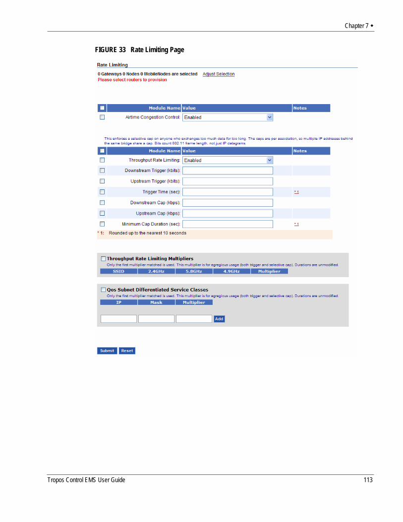
Chapter 7
FIGURE 33 Rate Limiting Page
Tropos Control EMS User Guide 113
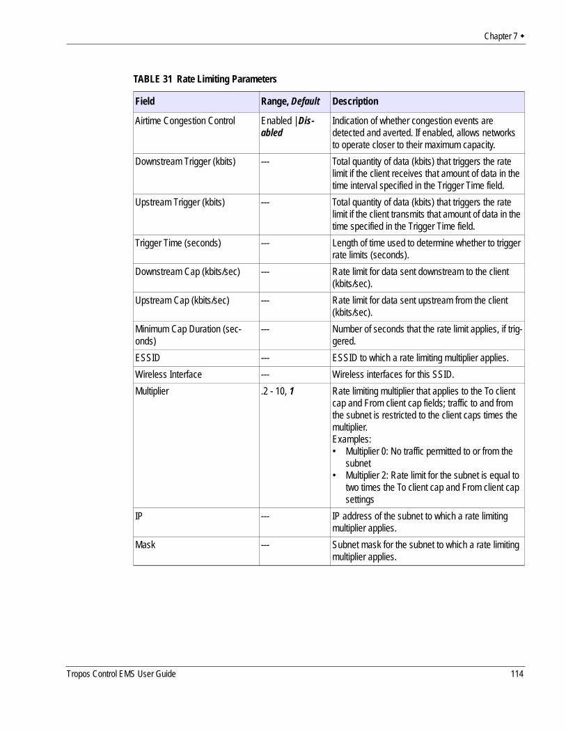
Chapter 7
TABLE 31 Rate Limiting Parameters
Field Range, Default Description
Airtime Congestion Control Enabled | Dis-abled
Indication of whether congestion events are detected and averted. If enabled, allows networks to operate closer to their maximum capacity.
Downstream Trigger (kbits) --- Total quantity of data (kbits) that triggers the rate limit if the client receives that amount of data in the time interval specified in the Trigger Time field.
Upstream Trigger (kbits) --- Total quantity of data (kbits) that triggers the rate limit if the client transmits that amount of data in the time specified in the Trigger Time field.
Trigger Time (seconds) --- Length of time used to determine whether to trigger rate limits (seconds).
Downstream Cap (kbits/sec) --- Rate limit for data sent downstream to the client (kbits/sec).
Upstream Cap (kbits/sec) --- Rate limit for data sent upstream from the client (kbits/sec).
Minimum Cap Duration (sec-onds)
--- Number of seconds that the rate limit applies, if trig-gered.
ESSID --- ESSID to which a rate limiting multiplier applies.Wireless Interface --- Wireless interfaces for this SSID.Multiplier .2 - 10, 1 Rate limiting multiplier that applies to the To client
cap and From client cap fields; traffic to and from the subnet is restricted to the client caps times the multiplier.Examples:• Multiplier 0: No traffic permitted to or from the
subnet• Multiplier 2: Rate limit for the subnet is equal to
two times the To client cap and From client cap settings
IP --- IP address of the subnet to which a rate limiting multiplier applies.
Mask --- Subnet mask for the subnet to which a rate limiting multiplier applies.
Tropos Control EMS User Guide 114
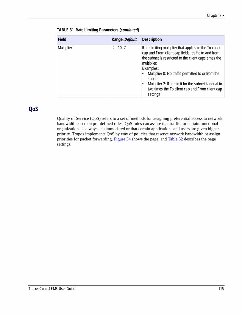
Chapter 7
QoSQuality of Service (QoS) refers to a set of methods for assigning preferential access to network bandwidth based on pre-defined rules. QoS rules can assure that traffic for certain functional organizations is always accommodated or that certain applications and users are given higher priority. Tropos implements QoS by way of policies that reserve network bandwidth or assign priorities for packet forwarding. Figure 34 shows the page, and Table 32 describes the page settings.
Multiplier .2 - 10, 1 Rate limiting multiplier that applies to the To client cap and From client cap fields; traffic to and from the subnet is restricted to the client caps times the multiplier.Examples:• Multiplier 0: No traffic permitted to or from the
subnet• Multiplier 2: Rate limit for the subnet is equal to
two times the To client cap and From client cap settings
TABLE 31 Rate Limiting Parameters (continued)
Field Range, Default Description
Tropos Control EMS User Guide 115
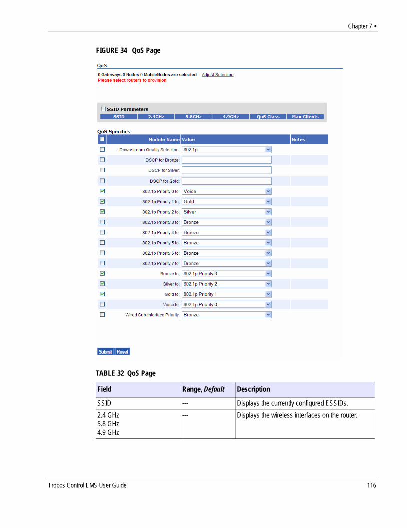
Chapter 7
FIGURE 34 QoS Page
TABLE 32 QoS Page
Field Range, Default Description
SSID --- Displays the currently configured ESSIDs.2.4 GHz5.8 GHz4.9 GHz
--- Displays the wireless interfaces on the router.
Tropos Control EMS User Guide 116
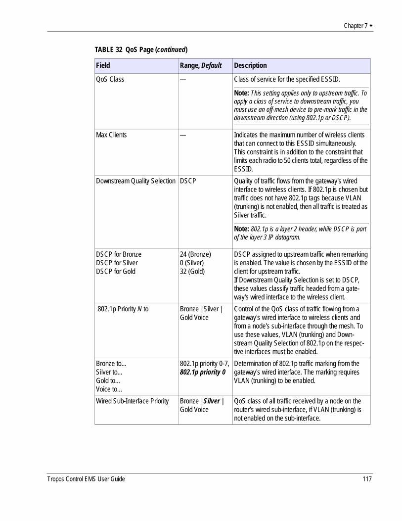
Chapter 7
QoS Class --- Class of service for the specified ESSID.
Note: This setting applies only to upstream traffic. To apply a class of service to downstream traffic, you must use an off-mesh device to pre-mark traffic in the downstream direction (using 802.1p or DSCP).
Max Clients --- Indicates the maximum number of wireless clients that can connect to this ESSID simultaneously. This constraint is in addition to the constraint that limits each radio to 50 clients total, regardless of the ESSID.
Downstream Quality Selection DSCP Quality of traffic flows from the gateway's wired interface to wireless clients. If 802.1p is chosen but traffic does not have 802.1p tags because VLAN (trunking) is not enabled, then all traffic is treated as Silver traffic.
Note: 802.1p is a layer 2 header, while DSCP is part of the layer 3 IP datagram.
DSCP for BronzeDSCP for SilverDSCP for Gold
24 (Bronze)0 (Silver)32 (Gold)
DSCP assigned to upstream traffic when remarking is enabled. The value is chosen by the ESSID of the client for upstream traffic. If Downstream Quality Selection is set to DSCP, these values classify traffic headed from a gate-way's wired interface to the wireless client.
802.1p Priority N to Bronze | Silver | Gold Voice
Control of the QoS class of traffic flowing from a gateway's wired interface to wireless clients and from a node's sub-interface through the mesh. To use these values, VLAN (trunking) and Down-stream Quality Selection of 802.1p on the respec-tive interfaces must be enabled.
Bronze to...Silver to...Gold to...Voice to...
802.1p priority 0-7, 802.1p priority 0
Determination of 802.1p traffic marking from the gateway's wired interface. The marking requires VLAN (trunking) to be enabled.
Wired Sub-Interface Priority Bronze | Silver | Gold Voice
QoS class of all traffic received by a node on the router’s wired sub-interface, if VLAN (trunking) is not enabled on the sub-interface.
TABLE 32 QoS Page (continued)
Field Range, Default Description
Tropos Control EMS User Guide 117
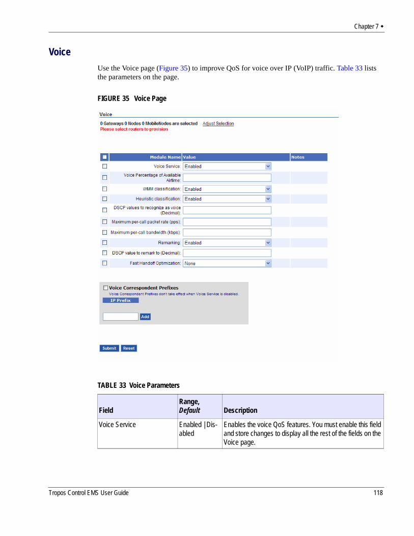
Chapter 7
VoiceUse the Voice page (Figure 35) to improve QoS for voice over IP (VoIP) traffic. Table 33 lists the parameters on the page.
FIGURE 35 Voice Page
TABLE 33 Voice Parameters
FieldRange, Default Description
Voice Service Enabled | Dis-abled
Enables the voice QoS features. You must enable this field and store changes to display all the rest of the fields on the Voice page.
Tropos Control EMS User Guide 118
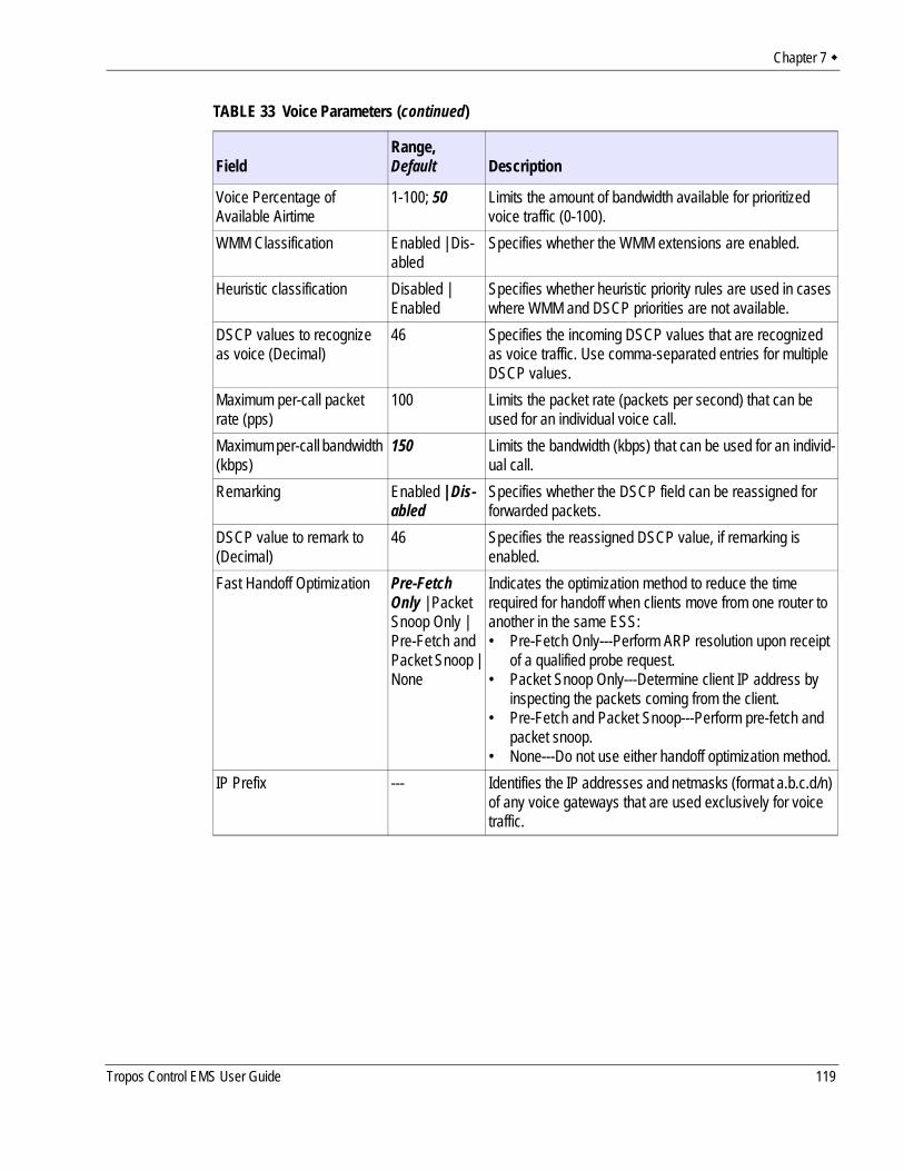
Chapter 7
Voice Percentage of Available Airtime
1-100; 50 Limits the amount of bandwidth available for prioritized voice traffic (0-100).
WMM Classification Enabled | Dis-abled
Specifies whether the WMM extensions are enabled.
Heuristic classification Disabled | Enabled
Specifies whether heuristic priority rules are used in cases where WMM and DSCP priorities are not available.
DSCP values to recognize as voice (Decimal)
46 Specifies the incoming DSCP values that are recognized as voice traffic. Use comma-separated entries for multiple DSCP values.
Maximum per-call packet rate (pps)
100 Limits the packet rate (packets per second) that can be used for an individual voice call.
Maximum per-call bandwidth (kbps)
150 Limits the bandwidth (kbps) that can be used for an individ-ual call.
Remarking Enabled | Dis-abled
Specifies whether the DSCP field can be reassigned for forwarded packets.
DSCP value to remark to (Decimal)
46 Specifies the reassigned DSCP value, if remarking is enabled.
Fast Handoff Optimization Pre-Fetch Only | Packet Snoop Only | Pre-Fetch and Packet Snoop | None
Indicates the optimization method to reduce the time required for handoff when clients move from one router to another in the same ESS:• Pre-Fetch Only---Perform ARP resolution upon receipt
of a qualified probe request.• Packet Snoop Only---Determine client IP address by
inspecting the packets coming from the client.• Pre-Fetch and Packet Snoop---Perform pre-fetch and
packet snoop.• None---Do not use either handoff optimization method.
IP Prefix --- Identifies the IP addresses and netmasks (format a.b.c.d/n) of any voice gateways that are used exclusively for voice traffic.
TABLE 33 Voice Parameters (continued)
FieldRange, Default Description
Tropos Control EMS User Guide 119
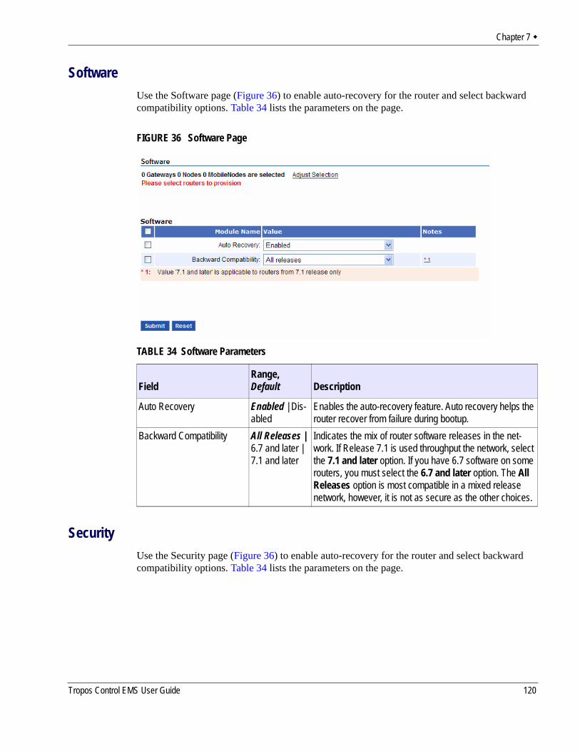
Chapter 7
SoftwareUse the Software page (Figure 36) to enable auto-recovery for the router and select backward compatibility options. Table 34 lists the parameters on the page.
FIGURE 36 Software Page
SecurityUse the Security page (Figure 36) to enable auto-recovery for the router and select backward compatibility options. Table 34 lists the parameters on the page.
TABLE 34 Software Parameters
FieldRange, Default Description
Auto Recovery Enabled | Dis-abled
Enables the auto-recovery feature. Auto recovery helps the router recover from failure during bootup.
Backward Compatibility All Releases | 6.7 and later | 7.1 and later
Indicates the mix of router software releases in the net-work. If Release 7.1 is used throughput the network, select the 7.1 and later option. If you have 6.7 software on some routers, you must select the 6.7 and later option. The All Releases option is most compatible in a mixed release network, however, it is not as secure as the other choices.
Tropos Control EMS User Guide 120
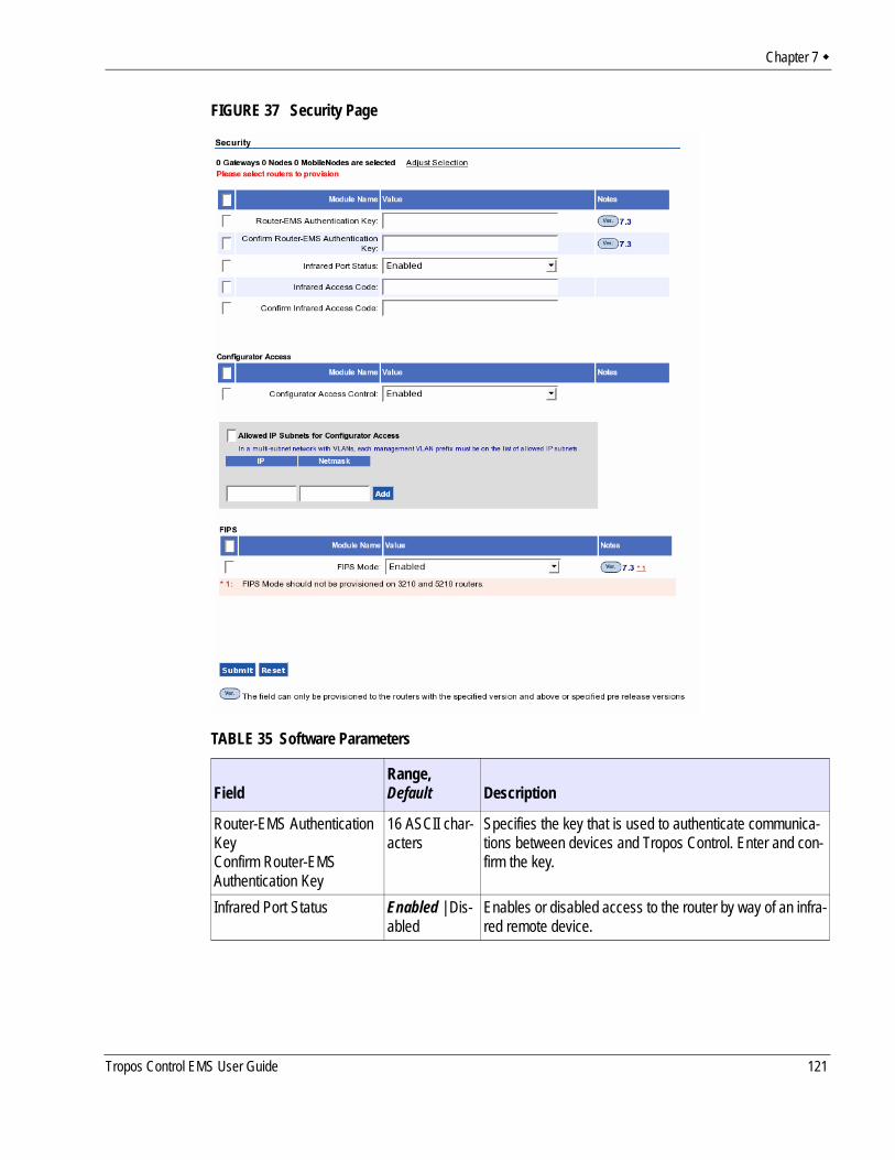
Chapter 7
FIGURE 37 Security Page
TABLE 35 Software Parameters
FieldRange, Default Description
Router-EMS Authentication KeyConfirm Router-EMS Authentication Key
16 ASCII char-acters
Specifies the key that is used to authenticate communica-tions between devices and Tropos Control. Enter and con-firm the key.
Infrared Port Status Enabled | Dis-abled
Enables or disabled access to the router by way of an infra-red remote device.
Tropos Control EMS User Guide 121
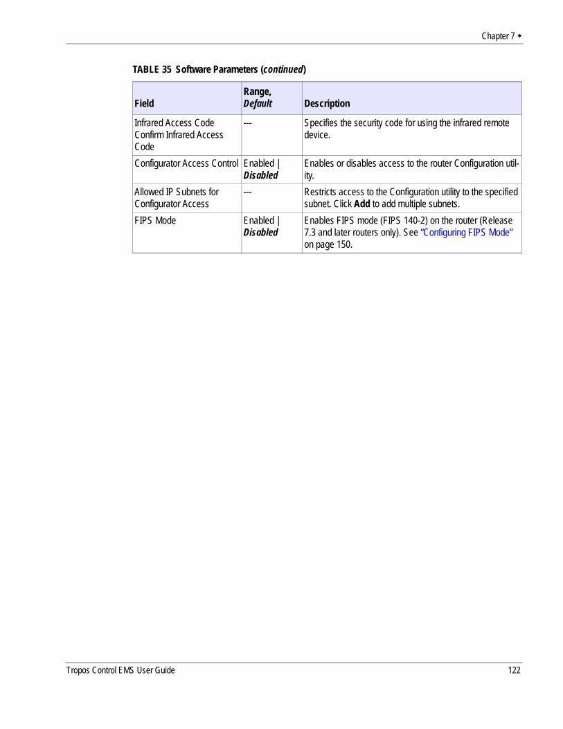
Chapter 7
Infrared Access CodeConfirm Infrared Access Code
--- Specifies the security code for using the infrared remote device.
Configurator Access Control Enabled | Disabled
Enables or disables access to the router Configuration util-ity.
Allowed IP Subnets for Configurator Access
--- Restricts access to the Configuration utility to the specified subnet. Click Add to add multiple subnets.
FIPS Mode Enabled | Disabled
Enables FIPS mode (FIPS 140-2) on the router (Release7.3 and later routers only). See “Configuring FIPS Mode” on page 150.
TABLE 35 Software Parameters (continued)
FieldRange, Default Description
Tropos Control EMS User Guide 122
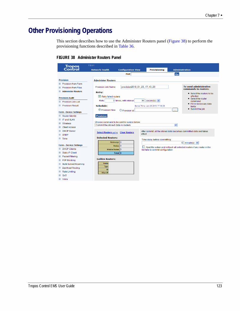
Chapter 7
Other Provisioning OperationsThis section describes how to use the Administer Routers panel (Figure 38) to perform the provisioning functions described in Table 36.
FIGURE 38 Administer Routers Panel
Tropos Control EMS User Guide 123
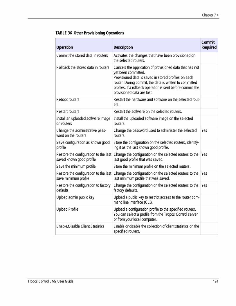
Chapter 7
TABLE 36 Other Provisioning Operations
Operation DescriptionCommit Required
Commit the stored data in routers Activates the changes that have been provisioned on the selected routers.
Rollback the stored data in routers Cancels the application of provisioned data that has not yet been committed. Provisioned data is saved in stored profiles on each router. During commit, the data is written to committed profiles. If a rollback operation is sent before commit, the provisioned data are lost.
Reboot routers Restart the hardware and software on the selected rout-ers.
Restart routers Restart the software on the selected routers.Install an uploaded software image on routers
Install the uploaded software image on the selected routers.
Change the administrative pass-word on the routers
Change the password used to administer the selected routers.
Yes
Save configuration as known good profile
Store the configuration on the selected routers, identify-ing it as the last known good profile.
Restore the configuration to the last saved known good profile
Change the configuration on the selected routers to the last good profile that was saved.
Yes
Save the minimum profile Store the minimum profile on the selected routers.Restore the configuration to the last save minimum profile
Change the configuration on the selected routers to the last minimum profile that was saved.
Yes
Restore the configuration to factory defaults
Change the configuration on the selected routers to the factory defaults.
Yes
Upload admin public key Upload a public key to restrict access to the router com-mand line interface (CLI).
Upload Profile Upload a configuration profile to the specified routers. You can select a profile from the Tropos Control server or from your local computer.
Enable/Disable Client Statistics Enable or disable the collection of client statistics on the specified routers.
Tropos Control EMS User Guide 124
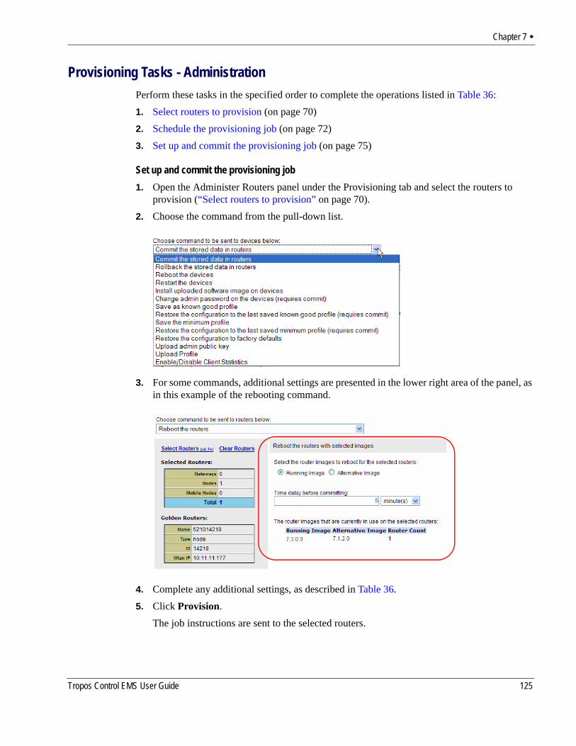
Chapter 7
Provisioning Tasks - AdministrationPerform these tasks in the specified order to complete the operations listed in Table 36:1. Select routers to provision (on page 70)2. Schedule the provisioning job (on page 72)3. Set up and commit the provisioning job (on page 75)
Set up and commit the provisioning job1. Open the Administer Routers panel under the Provisioning tab and select the routers to
provision (“Select routers to provision” on page 70).2. Choose the command from the pull-down list.
3. For some commands, additional settings are presented in the lower right area of the panel, as in this example of the rebooting command.
4. Complete any additional settings, as described in Table 36.5. Click Provision.
The job instructions are sent to the selected routers.
Tropos Control EMS User Guide 125
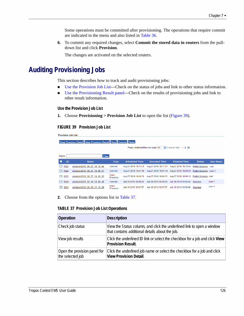
Chapter 7
Some operations must be committed after provisioning. The operations that require commit are indicated in the menu and also listed in Table 36.
6. To commit any required changes, select Commit the stored data in routers from the pull-down list and click Provision.The changes are activated on the selected routers.
Auditing Provisioning JobsThis section describes how to track and audit provisioning jobs:
Use the Provision Job List---Check on the status of jobs and link to other status information.Use the Provisioning Result panel---Check on the results of provisioning jobs and link to other result information.
Use the Provision Job List1. Choose Provisioning > Provision Job List to open the list (Figure 39).
FIGURE 39 Provision Job List
2. Choose from the options list in Table 37.
TABLE 37 Provision Job List Operations
Operation Description
Check job status View the Status column, and click the underlined link to open a window that contains additional details about the job.
View job results Click the underlined ID link or select the checkbox for a job and click View Provision Result.
Open the provision panel for the selected job
Click the underlined job name or select the checkbox for a job and click View Provision Detail.
Tropos Control EMS User Guide 126
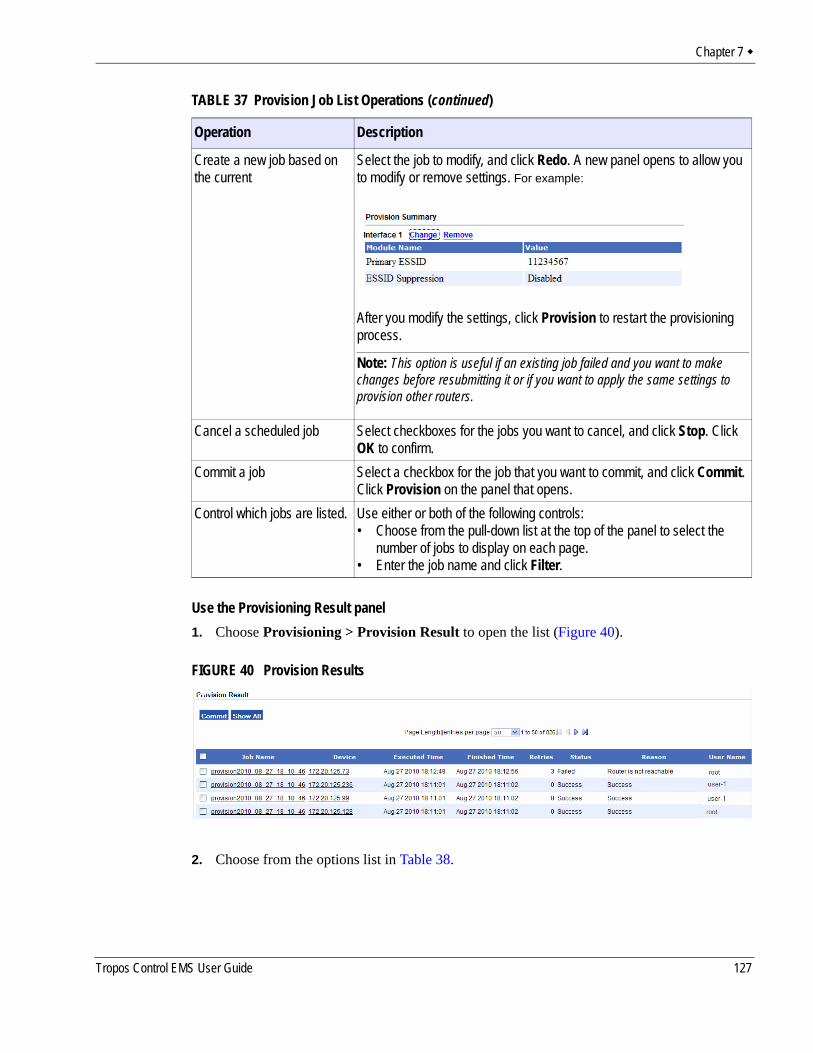
Chapter 7
Use the Provisioning Result panel1. Choose Provisioning > Provision Result to open the list (Figure 40).
FIGURE 40 Provision Results
2. Choose from the options list in Table 38.
Create a new job based on the current
Select the job to modify, and click Redo. A new panel opens to allow you to modify or remove settings. For example:
After you modify the settings, click Provision to restart the provisioning process.
Note: This option is useful if an existing job failed and you want to make changes before resubmitting it or if you want to apply the same settings to provision other routers.
Cancel a scheduled job Select checkboxes for the jobs you want to cancel, and click Stop. Click OK to confirm.
Commit a job Select a checkbox for the job that you want to commit, and click Commit. Click Provision on the panel that opens.
Control which jobs are listed. Use either or both of the following controls:• Choose from the pull-down list at the top of the panel to select the
number of jobs to display on each page.• Enter the job name and click Filter.
TABLE 37 Provision Job List Operations (continued)
Operation Description
Tropos Control EMS User Guide 127
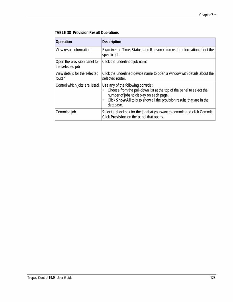
Chapter 7
TABLE 38 Provision Result Operations
Operation Description
View result information Examine the Time, Status, and Reason columns for information about the specific job.
Open the provision panel for the selected job
Click the underlined job name.
View details for the selected router
Click the underlined device name to open a window with details about the selected router.
Control which jobs are listed. Use any of the following controls:• Choose from the pull-down list at the top of the panel to select the
number of jobs to display on each page.• Click Show All to is to show all the provision results that are in the
database.Commit a job Select a checkbox for the job that you want to commit, and click Commit.
Click Provision on the panel that opens.
Tropos Control EMS User Guide 128
8 Performing Administrative Tasks
This chapter describes how to use the web interface to manage router inventory, upgrade router software, and generate diagnostic information to assist Tropos Customer Support in troubleshooting Tropos Control problems.
Chapter contents:Generating Diagnostic Information.Upgrading Router Software.Tracking Router InventoryBacking Up Router ConfigurationsRestoring Router ConfigurationsSupporting RADIUS AuthenticationManaging Administrative UsersUsing Router Auto DiscoveryViewing the User Audit LogConfiguring Banner Text
Tropos Control EMS User Guide 129
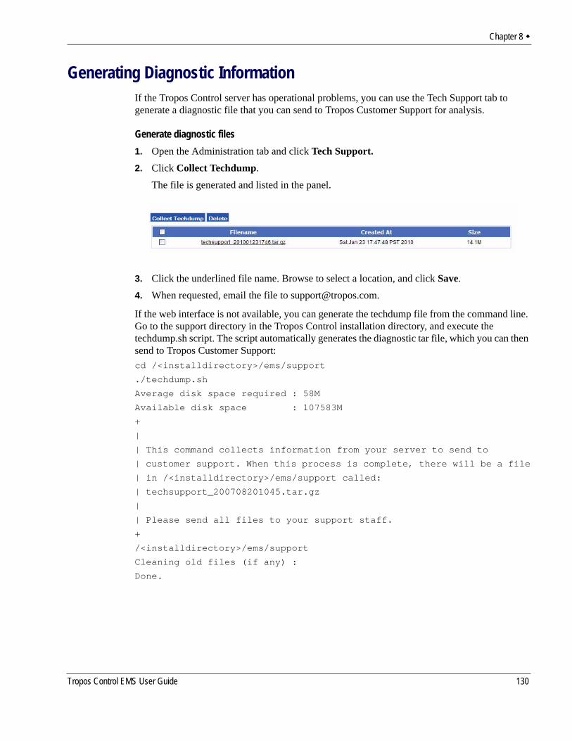
Chapter 8
Generating Diagnostic InformationIf the Tropos Control server has operational problems, you can use the Tech Support tab to generate a diagnostic file that you can send to Tropos Customer Support for analysis.
Generate diagnostic files1. Open the Administration tab and click Tech Support.2. Click Collect Techdump.
The file is generated and listed in the panel.
3. Click the underlined file name. Browse to select a location, and click Save.4. When requested, email the file to [email protected].
If the web interface is not available, you can generate the techdump file from the command line. Go to the support directory in the Tropos Control installation directory, and execute the techdump.sh script. The script automatically generates the diagnostic tar file, which you can then send to Tropos Customer Support:cd /<installdirectory>/ems/support
./techdump.sh
Average disk space required : 58M
Available disk space : 107583M
+
|
| This command collects information from your server to send to
| customer support. When this process is complete, there will be a file
| in /<installdirectory>/ems/support called:
| techsupport_200708201045.tar.gz
|
| Please send all files to your support staff.
+
/<installdirectory>/ems/support
Cleaning old files (if any) :
Done.
Tropos Control EMS User Guide 130
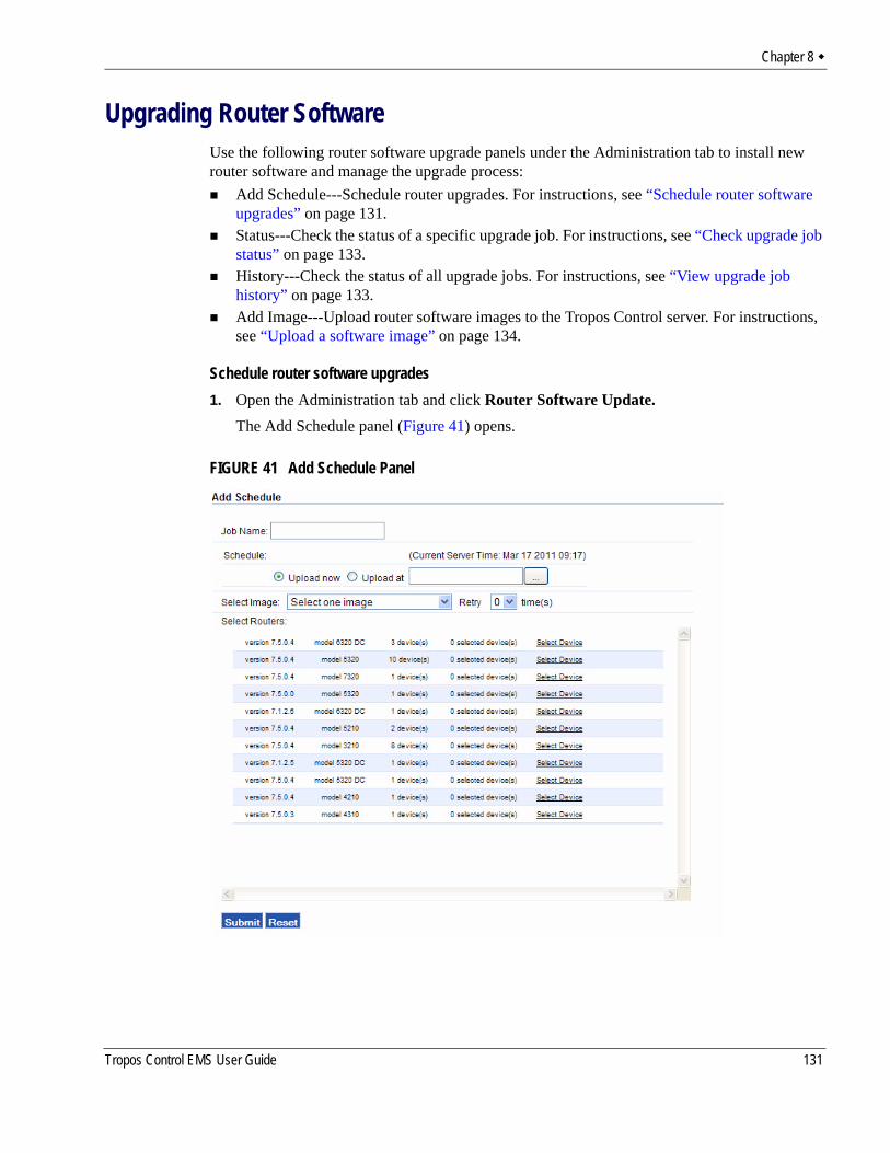
Chapter 8
Upgrading Router SoftwareUse the following router software upgrade panels under the Administration tab to install new router software and manage the upgrade process:
Add Schedule---Schedule router upgrades. For instructions, see “Schedule router software upgrades” on page 131.Status---Check the status of a specific upgrade job. For instructions, see “Check upgrade job status” on page 133.History---Check the status of all upgrade jobs. For instructions, see “View upgrade job history” on page 133.Add Image---Upload router software images to the Tropos Control server. For instructions, see “Upload a software image” on page 134.
Schedule router software upgrades1. Open the Administration tab and click Router Software Update.
The Add Schedule panel (Figure 41) opens.
FIGURE 41 Add Schedule Panel
Tropos Control EMS User Guide 131
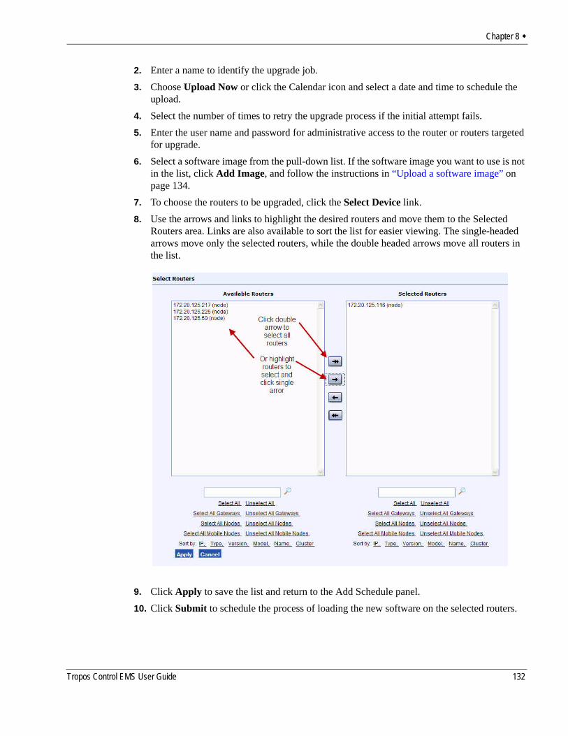
Chapter 8
2. Enter a name to identify the upgrade job.3. Choose Upload Now or click the Calendar icon and select a date and time to schedule the
upload.4. Select the number of times to retry the upgrade process if the initial attempt fails.5. Enter the user name and password for administrative access to the router or routers targeted
for upgrade.6. Select a software image from the pull-down list. If the software image you want to use is not
in the list, click Add Image, and follow the instructions in “Upload a software image” on page 134.
7. To choose the routers to be upgraded, click the Select Device link. 8. Use the arrows and links to highlight the desired routers and move them to the Selected
Routers area. Links are also available to sort the list for easier viewing. The single-headed arrows move only the selected routers, while the double headed arrows move all routers in the list.
9. Click Apply to save the list and return to the Add Schedule panel.10. Click Submit to schedule the process of loading the new software on the selected routers.
Tropos Control EMS User Guide 132
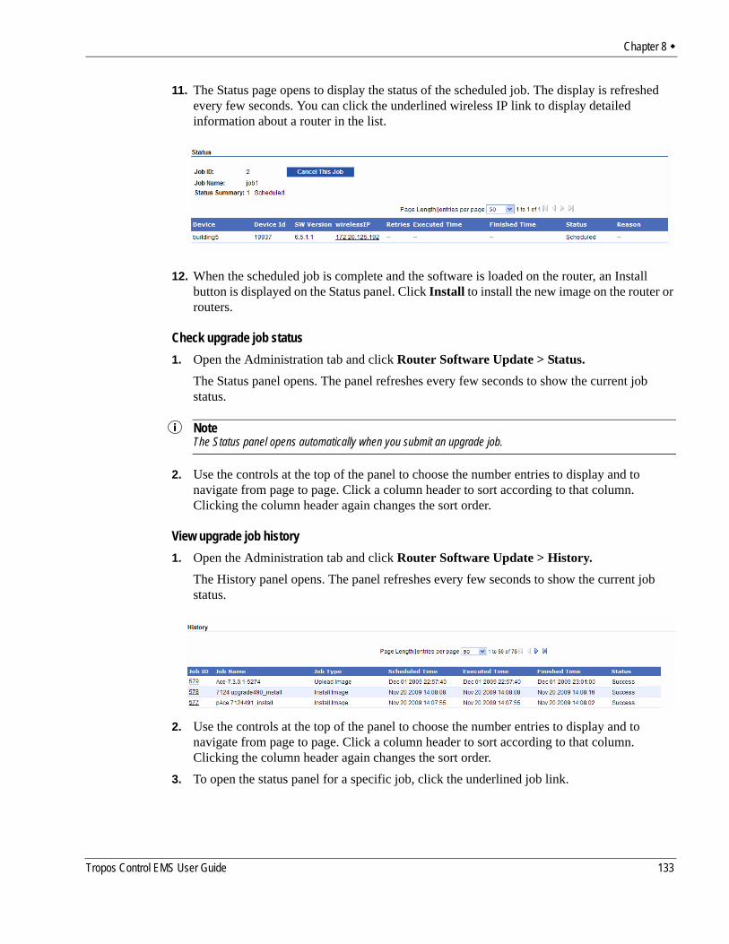
Chapter 8
11. The Status page opens to display the status of the scheduled job. The display is refreshed every few seconds. You can click the underlined wireless IP link to display detailed information about a router in the list.
12. When the scheduled job is complete and the software is loaded on the router, an Install button is displayed on the Status panel. Click Install to install the new image on the router or routers.
Check upgrade job status1. Open the Administration tab and click Router Software Update > Status.
The Status panel opens. The panel refreshes every few seconds to show the current job status.
NoteThe Status panel opens automatically when you submit an upgrade job.
2. Use the controls at the top of the panel to choose the number entries to display and to navigate from page to page. Click a column header to sort according to that column. Clicking the column header again changes the sort order.
View upgrade job history1. Open the Administration tab and click Router Software Update > History.
The History panel opens. The panel refreshes every few seconds to show the current job status.
2. Use the controls at the top of the panel to choose the number entries to display and to navigate from page to page. Click a column header to sort according to that column. Clicking the column header again changes the sort order.
3. To open the status panel for a specific job, click the underlined job link.
Tropos Control EMS User Guide 133
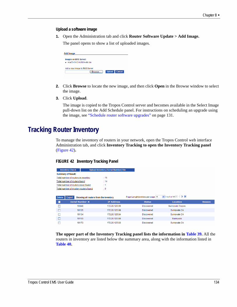
Chapter 8
Upload a software image1. Open the Administration tab and click Router Software Update > Add Image.
The panel opens to show a list of uploaded images.
2. Click Browse to locate the new image, and then click Open in the Browse window to select the image.
3. Click Upload.The image is copied to the Tropos Control server and becomes available in the Select Image pull-down list on the Add Schedule panel. For instructions on scheduling an upgrade using the image, see “Schedule router software upgrades” on page 131.
Tracking Router InventoryTo manage the inventory of routers in your network, open the Tropos Control web interface Administration tab, and click Inventory Tracking to open the Inventory Tracking panel (Figure 42).
FIGURE 42 Inventory Tracking Panel
The upper part of the Inventory Tracking panel lists the information in Table 39. All the routers in inventory are listed below the summary area, along with the information listed in Table 40.
Tropos Control EMS User Guide 134
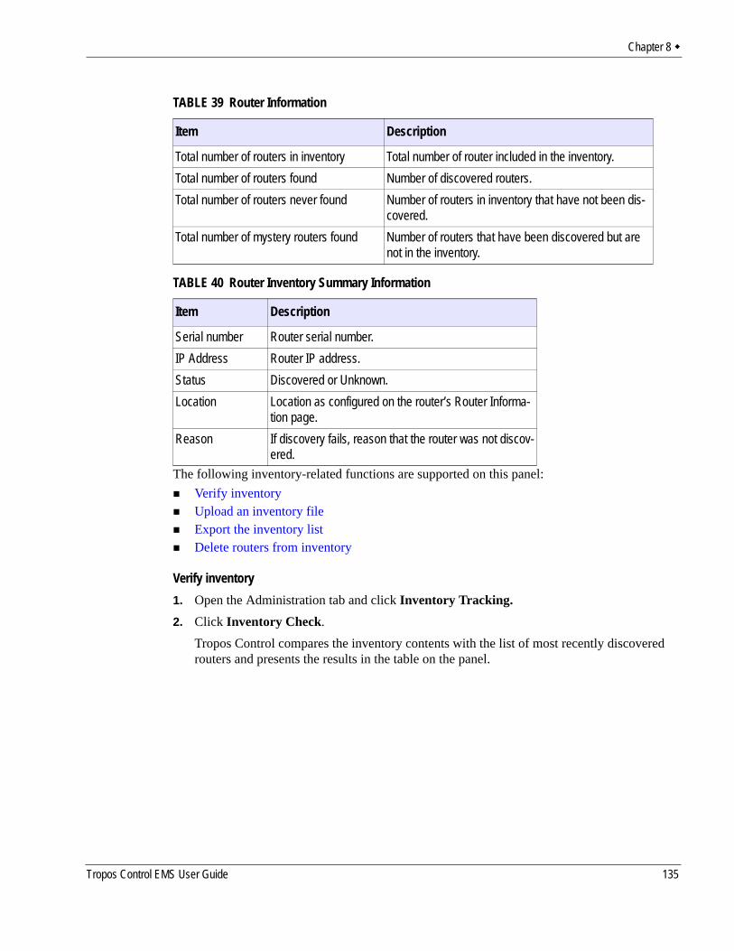
Chapter 8
The following inventory-related functions are supported on this panel:Verify inventoryUpload an inventory fileExport the inventory listDelete routers from inventory
Verify inventory1. Open the Administration tab and click Inventory Tracking.2. Click Inventory Check.
Tropos Control compares the inventory contents with the list of most recently discovered routers and presents the results in the table on the panel.
TABLE 39 Router Information
Item Description
Total number of routers in inventory Total number of router included in the inventory.Total number of routers found Number of discovered routers.Total number of routers never found Number of routers in inventory that have not been dis-
covered.Total number of mystery routers found Number of routers that have been discovered but are
not in the inventory.
TABLE 40 Router Inventory Summary Information
Item Description
Serial number Router serial number.IP Address Router IP address.Status Discovered or Unknown.Location Location as configured on the router’s Router Informa-
tion page.Reason If discovery fails, reason that the router was not discov-
ered.
Tropos Control EMS User Guide 135
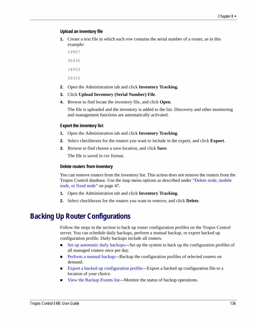
Chapter 8
Upload an inventory file1. Create a text file in which each row contains the serial number of a router, as in this
example:19967
35435
14563
50310
2. Open the Administration tab and click Inventory Tracking.3. Click Upload Inventory (Serial Number) File.4. Browse to find locate the inventory file, and click Open.
The file is uploaded and the inventory is added to the list. Discovery and other monitoring and management functions are automatically activated.
Export the inventory list1. Open the Administration tab and click Inventory Tracking.2. Select checkboxes for the routers you want to include in the export, and click Export.3. Browse to find choose a save location, and click Save.
The file is saved in csv format.
Delete routers from inventory
You can remove routers from the inventory list. This action does not remove the routers from the Tropos Control database. Use the map menu options as described under “Delete node, mobile node, or fixed node” on page 47.1. Open the Administration tab and click Inventory Tracking.2. Select checkboxes for the routers you want to remove, and click Delete.
Backing Up Router ConfigurationsFollow the steps in the section to back up router configuration profiles on the Tropos Control server. You can schedule daily backups, perform a manual backup, or export backed up configuration profile. Daily backups include all routers.
Set up automatic daily backups---Set up the system to back up the configuration profiles of all managed routers once per day.Perform a manual backup---Backup the configuration profiles of selected routers on demand.Export a backed up configuration profile---Export a backed up configuration file to a location of your choice.View the Backup Events list---Monitor the status of backup operations.
Tropos Control EMS User Guide 136
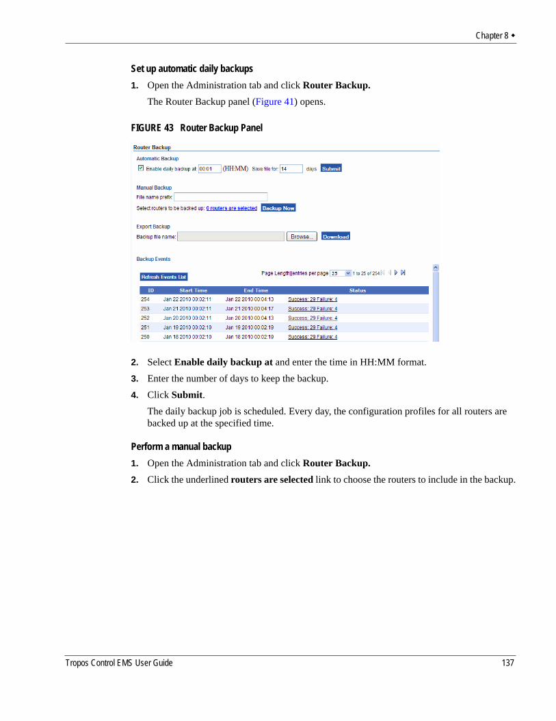
Chapter 8
Set up automatic daily backups1. Open the Administration tab and click Router Backup.
The Router Backup panel (Figure 41) opens.
FIGURE 43 Router Backup Panel
2. Select Enable daily backup at and enter the time in HH:MM format.3. Enter the number of days to keep the backup.4. Click Submit.
The daily backup job is scheduled. Every day, the configuration profiles for all routers are backed up at the specified time.
Perform a manual backup1. Open the Administration tab and click Router Backup.2. Click the underlined routers are selected link to choose the routers to include in the backup.
Tropos Control EMS User Guide 137
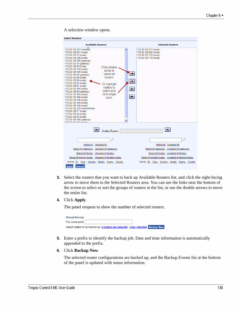
Chapter 8
A selection window opens.
3. Select the routers that you want to back up Available Routers list, and click the right-facing arrow to move them to the Selected Routers area. You can use the links near the bottom of the screen to select or sort the groups of routers in the list, or use the double arrows to move the entire list.
4. Click Apply. The panel reopens to show the number of selected routers.
5. Enter a prefix to identify the backup job. Date and time information is automatically appended to the prefix.
6. Click Backup Now.The selected router configurations are backed up, and the Backup Events list at the bottom of the panel is updated with status information.
Tropos Control EMS User Guide 138
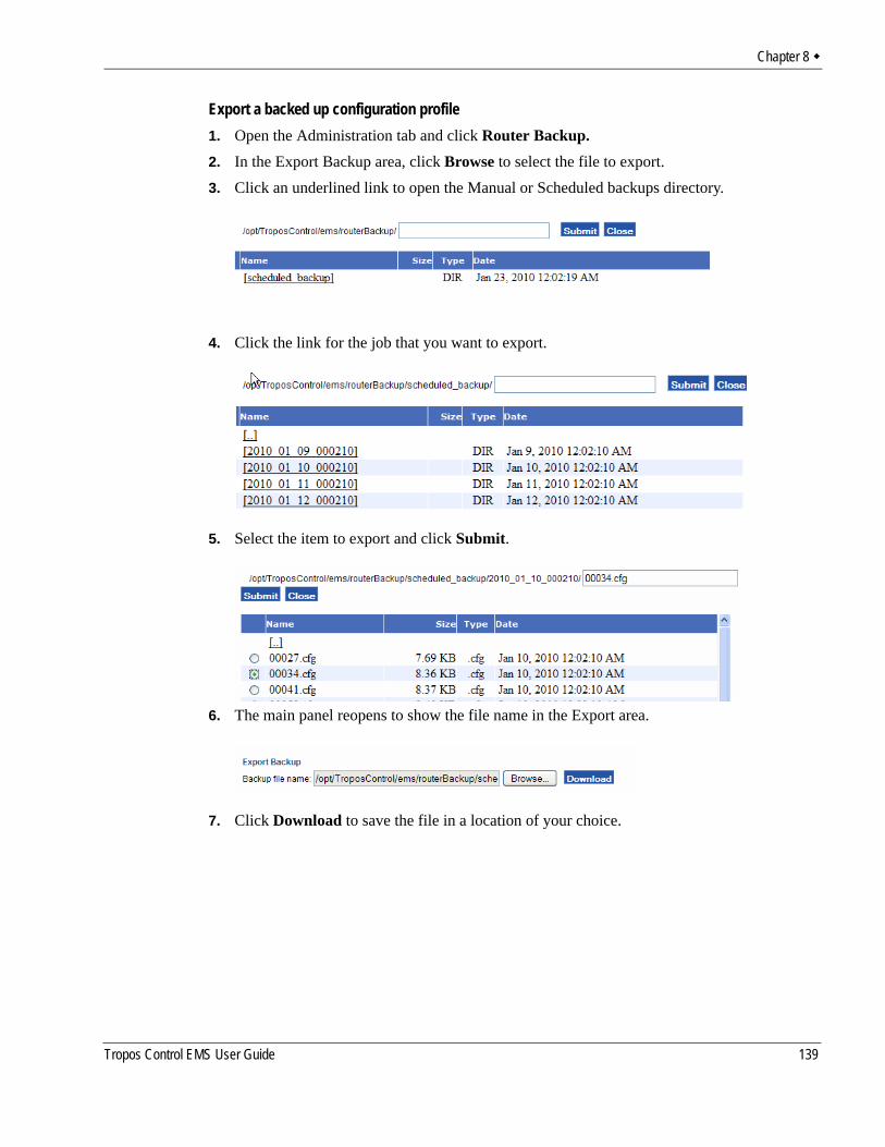
Chapter 8
Export a backed up configuration profile1. Open the Administration tab and click Router Backup.2. In the Export Backup area, click Browse to select the file to export.3. Click an underlined link to open the Manual or Scheduled backups directory.
4. Click the link for the job that you want to export.
5. Select the item to export and click Submit.
6. The main panel reopens to show the file name in the Export area.
7. Click Download to save the file in a location of your choice.
Tropos Control EMS User Guide 139
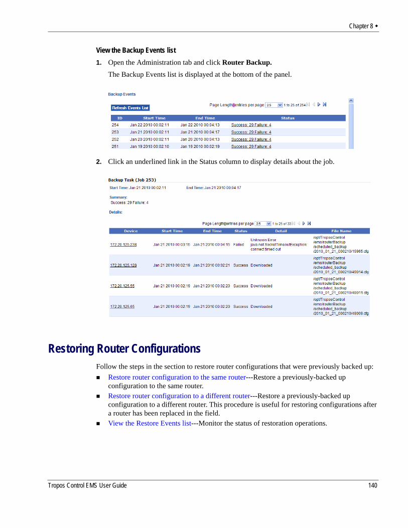
Chapter 8
View the Backup Events list1. Open the Administration tab and click Router Backup.
The Backup Events list is displayed at the bottom of the panel.
2. Click an underlined link in the Status column to display details about the job.
Restoring Router ConfigurationsFollow the steps in the section to restore router configurations that were previously backed up:
Restore router configuration to the same router---Restore a previously-backed up configuration to the same router.Restore router configuration to a different router---Restore a previously-backed up configuration to a different router. This procedure is useful for restoring configurations after a router has been replaced in the field.View the Restore Events list---Monitor the status of restoration operations.
Tropos Control EMS User Guide 140
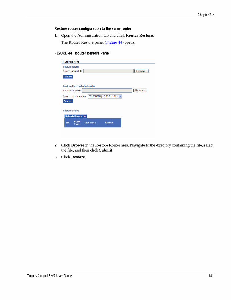
Chapter 8
Restore router configuration to the same router1. Open the Administration tab and click Router Restore.
The Router Restore panel (Figure 44) opens.
FIGURE 44 Router Restore Panel
2. Click Browse in the Restore Router area. Navigate to the directory containing the file, select the file, and then click Submit.
3. Click Restore.
Tropos Control EMS User Guide 141
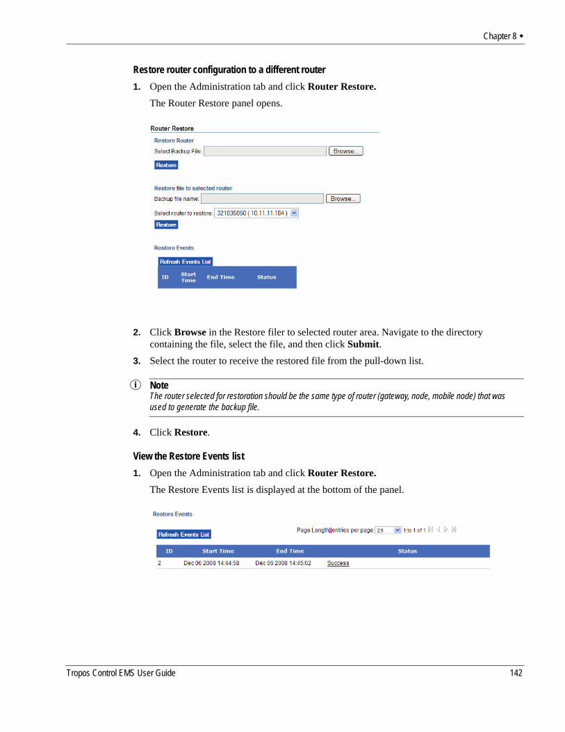
Chapter 8
Restore router configuration to a different router1. Open the Administration tab and click Router Restore.
The Router Restore panel opens.
2. Click Browse in the Restore filer to selected router area. Navigate to the directory containing the file, select the file, and then click Submit.
3. Select the router to receive the restored file from the pull-down list.
NoteThe router selected for restoration should be the same type of router (gateway, node, mobile node) that was used to generate the backup file.
4. Click Restore.
View the Restore Events list1. Open the Administration tab and click Router Restore.
The Restore Events list is displayed at the bottom of the panel.
Tropos Control EMS User Guide 142
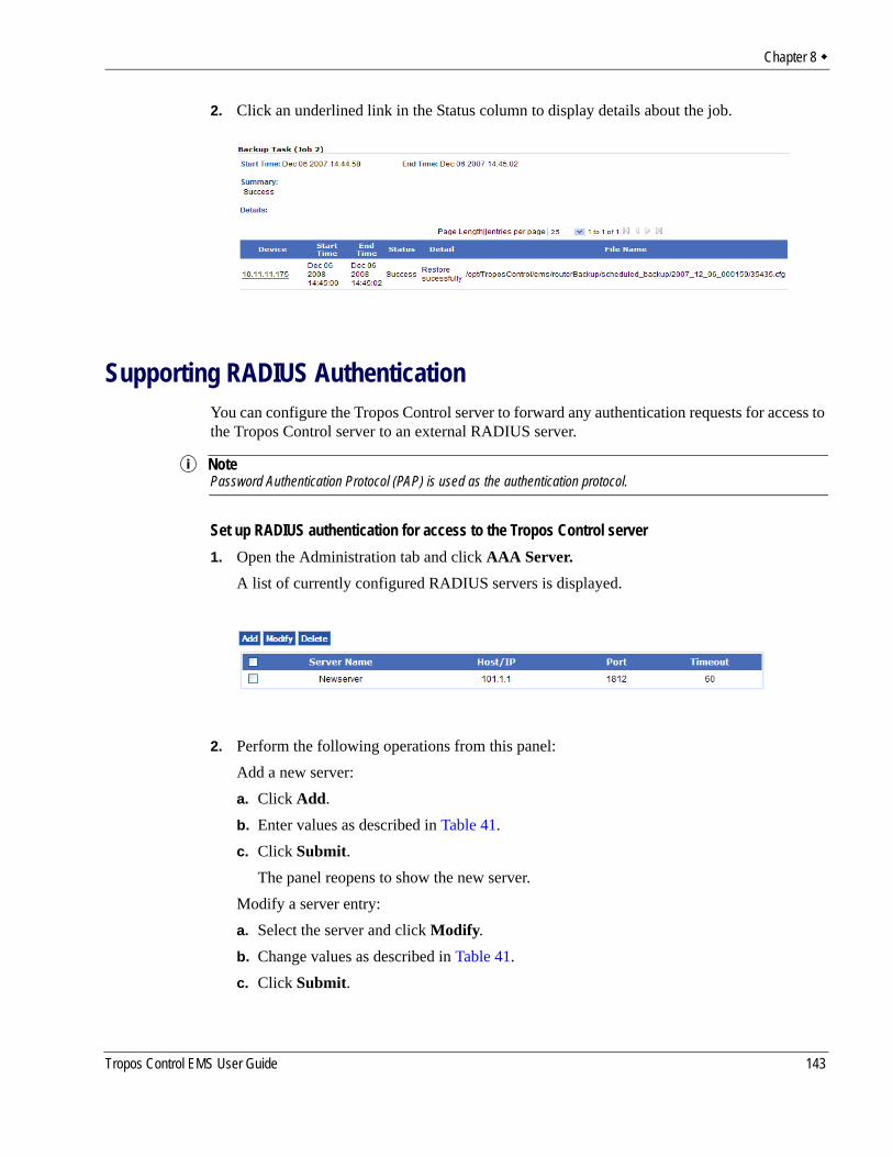
Chapter 8
2. Click an underlined link in the Status column to display details about the job.
Supporting RADIUS AuthenticationYou can configure the Tropos Control server to forward any authentication requests for access to the Tropos Control server to an external RADIUS server.
NotePassword Authentication Protocol (PAP) is used as the authentication protocol.
Set up RADIUS authentication for access to the Tropos Control server1. Open the Administration tab and click AAA Server.
A list of currently configured RADIUS servers is displayed.
2. Perform the following operations from this panel:Add a new server:a. Click Add. b. Enter values as described in Table 41.c. Click Submit.
The panel reopens to show the new server.Modify a server entry:a. Select the server and click Modify. b. Change values as described in Table 41.c. Click Submit.
Tropos Control EMS User Guide 143
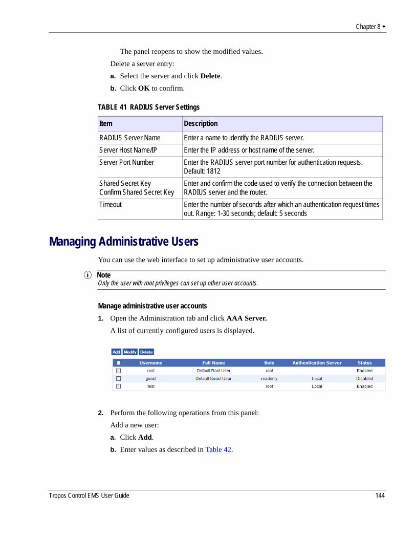
Chapter 8
The panel reopens to show the modified values.Delete a server entry:a. Select the server and click Delete. b. Click OK to confirm.
Managing Administrative UsersYou can use the web interface to set up administrative user accounts.
NoteOnly the user with root privileges can set up other user accounts.
Manage administrative user accounts1. Open the Administration tab and click AAA Server.
A list of currently configured users is displayed.
2. Perform the following operations from this panel:Add a new user:a. Click Add. b. Enter values as described in Table 42.
TABLE 41 RADIUS Server Settings
Item Description
RADIUS Server Name Enter a name to identify the RADIUS server. Server Host Name/IP Enter the IP address or host name of the server.Server Port Number Enter the RADIUS server port number for authentication requests.
Default: 1812Shared Secret KeyConfirm Shared Secret Key
Enter and confirm the code used to verify the connection between the RADIUS server and the router.
Timeout Enter the number of seconds after which an authentication request times out. Range: 1-30 seconds; default: 5 seconds
Tropos Control EMS User Guide 144
Chapter 8
c. Click Submit. The panel reopens to the list the new user.Modify a user entry:a. Select the user and click Modify. b. Change values as described in Table 42.c. Click Submit. The panel reopens to the list the modified values.Delete a user:a. Select the server and click Delete. b. Click OK to confirm.
Using Router Auto DiscoveryYou can set up the system to automatically discover all routers in a network from a single gateway (seed gateway). When auto discovery is configured, the Tropos Control server requests that the seed gateway obtain the list of available gateways in the network. When the list is obtained, the server contacts each gateway to obtain its local list of nodes. Auto discovery operations are run once per day.
NoteIf the network is composed of multiple subnets, a gateway from each subnet must be added.
TABLE 42 Administrative User Settings
Item Description
Username Enter a name that identifies the user.Full Name Enter the full name of the user.Role Select a role from the pull-down list.
• Root—Permitted to view all information and perform all tasks that relate to the system and to the server platform.
• Read/Write—Permitted to view information and perform most tasks.• Read Only—Permitted to view information but not make any changes to the sys-
tem.Status Choose whether the user account is active (Enabled) or inactive (Disabled).Authenticate with Choose whether authentication is performed from the server using username and
password, or by using a RADIUS server. If you choose Local, the password fields are activated; if you choose Remote, the Preferred Server field is activated.
Preferred Server If RADIUS is chosen for the Authenticate with field, select the RADIUS server.PasswordConfirm Password
If Local is chosen for the Authenticate with field, enter and confirm the password used for access.
Tropos Control EMS User Guide 145
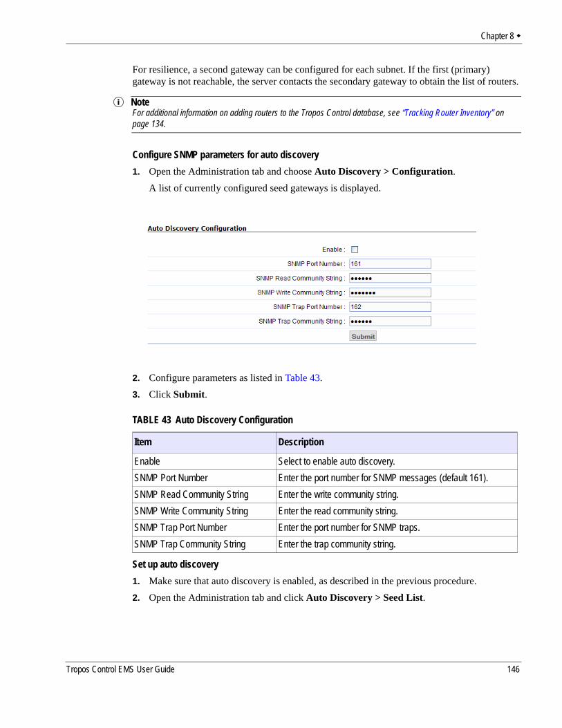
Chapter 8
For resilience, a second gateway can be configured for each subnet. If the first (primary) gateway is not reachable, the server contacts the secondary gateway to obtain the list of routers.
NoteFor additional information on adding routers to the Tropos Control database, see “Tracking Router Inventory” on page 134.
Configure SNMP parameters for auto discovery1. Open the Administration tab and choose Auto Discovery > Configuration.
A list of currently configured seed gateways is displayed.
2. Configure parameters as listed in Table 43.3. Click Submit.
Set up auto discovery1. Make sure that auto discovery is enabled, as described in the previous procedure.2. Open the Administration tab and click Auto Discovery > Seed List.
TABLE 43 Auto Discovery Configuration
Item Description
Enable Select to enable auto discovery.SNMP Port Number Enter the port number for SNMP messages (default 161).SNMP Read Community String Enter the write community string.SNMP Write Community String Enter the read community string.SNMP Trap Port Number Enter the port number for SNMP traps.SNMP Trap Community String Enter the trap community string.
Tropos Control EMS User Guide 146
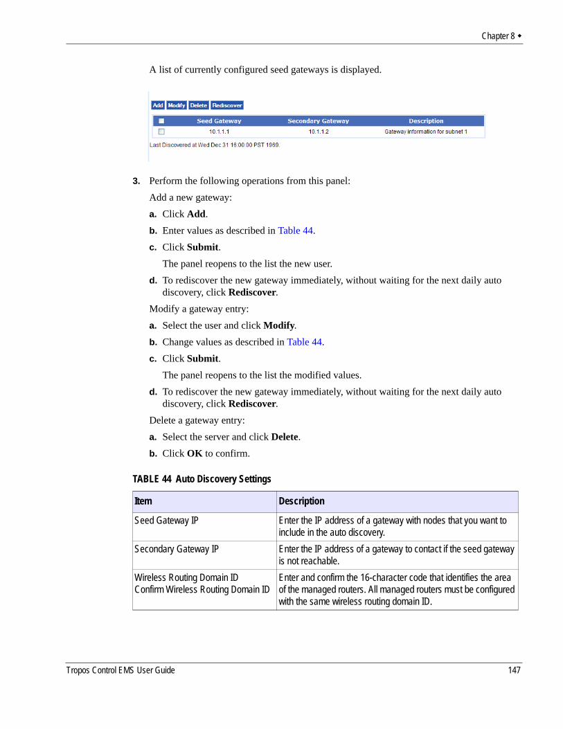
Chapter 8
A list of currently configured seed gateways is displayed.
3. Perform the following operations from this panel:Add a new gateway:a. Click Add. b. Enter values as described in Table 44.c. Click Submit.
The panel reopens to the list the new user. d. To rediscover the new gateway immediately, without waiting for the next daily auto
discovery, click Rediscover.Modify a gateway entry:a. Select the user and click Modify. b. Change values as described in Table 44.c. Click Submit.
The panel reopens to the list the modified values.d. To rediscover the new gateway immediately, without waiting for the next daily auto
discovery, click Rediscover.Delete a gateway entry:a. Select the server and click Delete. b. Click OK to confirm.
TABLE 44 Auto Discovery Settings
Item Description
Seed Gateway IP Enter the IP address of a gateway with nodes that you want to include in the auto discovery.
Secondary Gateway IP Enter the IP address of a gateway to contact if the seed gateway is not reachable.
Wireless Routing Domain IDConfirm Wireless Routing Domain ID
Enter and confirm the 16-character code that identifies the area of the managed routers. All managed routers must be configured with the same wireless routing domain ID.
Tropos Control EMS User Guide 147

Chapter 8
Admin User PasswordConfirm Admin User Password
Enter and confirm the password required for access to the gate-way.
Description Enter text to describe the gateway.
TABLE 44 Auto Discovery Settings (continued)
Item Description
Tropos Control EMS User Guide 148
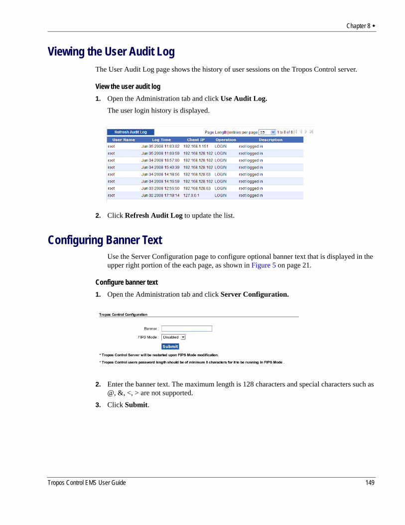
Chapter 8
Viewing the User Audit LogThe User Audit Log page shows the history of user sessions on the Tropos Control server.
View the user audit log1. Open the Administration tab and click Use Audit Log.
The user login history is displayed.
2. Click Refresh Audit Log to update the list.
Configuring Banner TextUse the Server Configuration page to configure optional banner text that is displayed in the upper right portion of the each page, as shown in Figure 5 on page 21.
Configure banner text1. Open the Administration tab and click Server Configuration.
2. Enter the banner text. The maximum length is 128 characters and special characters such as @, &, <, > are not supported.
3. Click Submit.
Tropos Control EMS User Guide 149
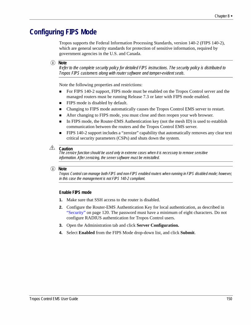
Chapter 8
Configuring FIPS ModeTropos supports the Federal Information Processing Standards, version 140-2 (FIPS 140-2), which are general security standards for protection of sensitive information, required by government agencies in the U.S. and Canada.
NoteRefer to the complete security policy for detailed FIPS instructions. The security policy is distributed to Tropos FIPS customers along with router software and tamper-evident seals.
Note the following properties and restrictions:For FIPS 140-2 support, FIPS mode must be enabled on the Tropos Control server and the managed routers must be running Release 7.3 or later with FIPS mode enabled. FIPS mode is disabled by default.Changing to FIPS mode automatically causes the Tropos Control EMS server to restart. After changing to FIPS mode, you must close and then reopen your web browser.In FIPS mode, the Router-EMS Authentication key (not the mesh ID) is used to establish communication between the routers and the Tropos Control EMS server.FIPS 140-2 support includes a “zeroize” capability that automatically removes any clear text critical security parameters (CSPs) and shuts down the system.
CautionThe zeroize function should be used only in extreme cases when it is necessary to remove sensitive information. After zeroizing, the server software must be reinstalled.
NoteTropos Control can manage both FIPS and non-FIPS enabled routers when running in FIPS disabled mode; however, in this case the management is not FIPS 140-2 compliant.
Enable FIPS mode1. Make sure that SSH access to the router is disabled.2. Configure the Router-EMS Authentication Key for local authentication, as described in
“Security” on page 120. The password must have a minimum of eight characters. Do not configure RADIUS authentication for Tropos Control users.
3. Open the Administration tab and click Server Configuration.4. Select Enabled from the FIPS Mode drop-down list, and click Submit.
Tropos Control EMS User Guide 150
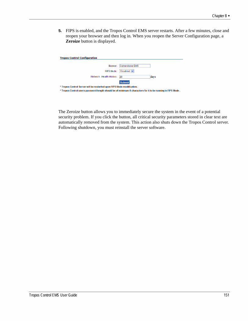
Chapter 8
5. FIPS is enabled, and the Tropos Control EMS server restarts. After a few minutes, close and reopen your browser and then log in. When you reopen the Server Configuration page, a Zeroize button is displayed.
The Zeroize button allows you to immediately secure the system in the event of a potential security problem. If you click the button, all critical security parameters stored in clear text are automatically removed from the system. This action also shuts down the Tropos Control server. Following shutdown, you must reinstall the server software.
Tropos Control EMS User Guide 151
B Redundant Tropos Control Servers for Failover
This appendix describes how to configure primary and secondary Tropos Control servers so that the secondary server takes over if the primary server is not available.• Primary and Secondary Servers• Set Up the Primary and Secondary Servers• Set Up the Secondary Server as Backup• Perform Failover from the Primary to Secondary Server• Returning to the Primary Server when it Recovers
Primary and Secondary ServersThe primary Tropos Control Server is responsible for managing the Tropos network. As part of its normal management function, the primary server maintains a current database of devices. When a secondary server is configured, the primary server automatically copies the database to the secondary server. If the primary server fails for any reason, the secondary server is able to immediately take over the management functions and discover any routers that it has not already discovered.
During failover, the secondary server can provide most management functions. An exception is that the secondary server cannot execute network performance measurements. Implementation is limited in that network performance data can run only on a single server. During normal operations, performance measurements are disabled on the secondary server. Following failover, they are enabled on the secondary server.
Set Up the Primary and Secondary ServersFollow this process to download, install, and configure the primary and secondary servers:1. Install Tropos Control on the primary and secondary servers, as described in Chapter 2,
“Installation.” Make sure that you install the same version of Tropos Control on both servers. Also, if you are using an Oracle database, make sure to stop the primary server (by
Tropos Control EMS User Guide 152
Chapter A
running the command service watchdog stop) before installing the secondary server. After the secondary server is installed, power off the secondary server to keep it in standby mode.
2. If you are using MySQL, start both the primary and secondary servers. If you are using Oracle, start only the primary server.
3. If you are using MySQL configure each server to discover the entire network, as described in “Discovery” on page 19.
Set Up the Secondary Server as Backup1. Log in to the primary server as root.2. Install the “expect” software package on CentOS if it is not installed:
[root@localhost]# yum install expect
3. Install the redundancy file by issuing the following commands in a terminal window:[root@localhost]# cd /<installdirectory>/ems/bin/redundancy [root@localhost]# chmod a+x *[root@localhost]# ./setupRedundantServer <Secondary IP Address> <Secondary root password>
Example:[root@localhost]# ./setupRedundantServer.sh 192.168.128.194 passwd1 Checking for secure password-less logins to 192.168.128.194, please wait... done2 Querying the system for all the devices, please wait... done3 Finding Control Server Installations on 192.168.128.194... done4 Copying discover_devices.txt to 192.168.128.194:/opt/ControlServer/ems/conf/server... done5 Setting up crontab on 192.168.128.194... done6 Setting up crontab on this server... done [root@localhost]#
Perform Failover from the Primary to Secondary ServerFollow these steps to move operations to the secondary server upon service interruption or failure of the primary server:1. Disconnect the primary server from the network. Unexpected results may arise if the
primary server is still active and managing the network.2. Issue the following commands on the secondary server to take over primary server
operations: For Oracle database:% service watchdog restart
Tropos Control EMS User Guide 153
Chapter A
For MySQL database:[root@localhost]# cd /<installdirectory>/ems/bin/redundancy [root@localhost]# chmod a+x *[root@localhost]# ./disableRedundancy.sh
Example:[root@localhost redundancy]# ./disableRedundancy.shDisabling secure password-less logins to this server, please wait... doneRestoring crontab... done[root@localhost redundancy]#
Make sure to provision all the gateways with the secondary server’s IP address in the SNMP page for Trap-Receiver-Registration and EMS-Registration so that the secondary server receives traps from the routers and generates alarms/notifications correctly.
Returning to the Primary Server when it RecoversFor the Oracle database, when the primary server becomes available again, first power off the secondary server to keep it in standby mode and then start the EMS watchdog service on the primary server.
For the MySQL database, when the primary server becomes available again, start the EMS watchdog service on the primary server and make sure to run the setupRedundantServer.sh script on it to enable redundancy and to keep the secondary server in standby mode.
Tropos Control EMS User Guide 154

Glossary
This glossary defines terms pertaining to wireless and networking technology.
802.11IEEE wireless networking standards developed by IEEE. There are multiple versions of the 802.11 specification; Tropos Networks products conform to the 802.11b specification.
802.1xIEEE standard for port-based client authentication using a central authentica-tion server to verify client identity.
AAA ServerServer that provides authentication, authorization and accounting services over a network.
Adaptive Noise Immunity (ANI)adaptive noise immunity (ANI).
Address Resolution Protocol (ARP)Standard protocol for mapping an IP address to a hardware (MAC) address.
Airtime Congestion ControlTropos Networks method of allowing networks to be operated close to their maximum capacity by detecting and averting congestion events.
Autonomous System (AS)Collection of networks under a single administrative structure and with a sin-gle, well-defined routing policy.
Advanced Encryption Standard (AES)Effective single-key encryption standard originally adopted by the National Institute of Standards and Technology for use by U.S. government organiza-tions and later adopted as an industry standard.
BackhaulProcess of transmitting data so it can be sent over a backbone network, typi-cally to the Internet. Tropos wireless networks provide wireless backhaul from client stations through the wireless Tropos mesh to the wired network.
Tropos Control EMS User Guide 155
Chapter 1
Basic Service Set (BSS)The set of all wireless client stations controlled by a single Tropos router. The BSS is identified by the BSS identifier (BSSID), often the MAC address of the router.
Border Gateway Protocol (BGP)Internet protocol that allows routers to share information and provides the routing mechanism for same-subnet roaming in the Tropos network.
Certificate Authority (CA)Trusted network entity that issues digital security credentials.
Call Admission Control (CAC)Mechanism for improving QoS for VoIP communications by causing calls to be rejected in the presence of contention.
Domain Name Service (DNS)Standard used to convert alphanumeric Internet domain names to IP addresses.
Dynamic Host Configuration Protocol (DHCP)Protocol used for central, dynamic management of IP addresses. A DHCP server leases DHCP addresses to individual network entities for a specified period of time. Leases can be renewed automatically when the lease period ends. DHCP assures flexibility in IP address assignment and precludes the necessity of generating and entering static IP addresses for each network entity.
Differentiated Services Code Point (DHCP)Integer value that is included in the DS field of an IP header and which desig-nates a specific QoS value.
Extended Service Set (ESS)A wireless network that consists of multiple Tropos routers, each of which provides wireless service to network clients.
Extensible Authentication Protocol (EAP)Effective authentication protocol that supports multiple authentication meth-ods, including passwords, tokens, certificates and public-key authentication.
ESSIDAlphanumeric name that uniquely identifies the wireless network.
Federal Information Processing Standards (FIPS)General security standards for protection of sensitive information, required by government agencies in the U.S. and Canada.
Tropos Control EMS User Guide 156
Chapter 1
GatewayTropos router that connects directly to the wired network and provides back-haul for downstream Tropos nodes and clients.
Generic Route Encapsulation (GRE)Protocol used in creating virtual private networks between clients or between clients and servers.
Global Positioning System (GPS)Satellite navigation system used for accuracy positioning.
Hypertext Transfer Protocol (HTTP)Protocol that manages data transfers between web browsers and servers.
Hypertext Transfer Protocol over SSL (HTTPS)Secure version of HTTP based on Secure Sockets Layer (SSL).
Internet Control Message Protocol (ICMP)Error and control message protocol for the Internet. ping uses ICMP echo requests and replies.
Internet Protocol (IP)Packet routing protocol operating at the network level which associates indi-vidual addresses with network nodes.
IP addressMethod of identifying a network entity as a 32-bit number, usually presented as four, period-separated 8-bit (3-digit) numbers according to the Internet Protocol specification.
Internet Protocol Security (IPSec)Internet security protocol used in virtual private networks (VPNs).
Management Information Base (MIB)A set of objects that can be managed by SNMP or another network manage-ment system.
Maximum Transmission Unit (MTU)The largest packet size in bytes transmitted over the network.
Media Access Control (MAC) AddressDevice-specific identifier, assigned during device manufacture, that uniquely identifies a network node. MAC address filters can be used to limit assign-ment of IP addresses to wireless clients.
Meshed clusterCollection of Tropos gateways and nodes providing wireless communica-tions services to network clients and establishing backhaul to the wired net-work. Clients communicate with Tropos nodes, which communicate in turn
Tropos Control EMS User Guide 157
Chapter 1
with other nodes, and finally to Tropos gateways, which connect to the wired network.
Mobile nodeTropos router that is designed to be mounted in a moving vehicle.
Netmask (subnet mask)The broadcast domain for a subnetwork, consisting of the subnet prefix for an IP address (example: 255.255.255.0).
Network Address Translation (NAT)Method whereby nodes within a local area network can access the Internet without having a public Internet address assigned. Administrators can assign local IP addresses from their own address pool and use NAT to translate these into publicly-accessible addresses. NAT can also be used to map multi-ple local nodes to a single globally-accessible IP address.
Network ModeOptimization level for 802.11 beacons and probe responses.
Network Time Protocol (NTP) Method of synchronizing clocks on network devices.
NodeTropos router that provides delivers wireless communications support for cli-ents and provides wireless backhaul to other upstream Tropos nodes and gateways.
Packet Success Probability (PSP)The probability that a transmitted packet will be received successfully.
Ping Packet Internet Groper (ping)Method of troubleshooting network connections by determining whether a specific IP address is reachable and the amount of time required for the addressed device to respond.
Post Office Protocol 3 (POP3)Industry standard protocol that permits users to receive email from an email server.
Power Over Ethernet (PoE)Method of supplying electrical power to a device through an Ethernet net-work data cable. This permits devices to be powered without a separate elec-trical power connection.
Predictive Wireless Routing Protocol (PWRP)Tropos technique for managing network routing based on self-organizing principles.
Tropos Control EMS User Guide 158
Chapter 1
Quality of Service (QoS)Any of a variety approaches to guaranteeing network performance for speci-fied uses. Tropos supports QoS through bandwidth reservations and priority-based forwarding.
Remote Authentication Dial-In User Service (RADIUS)Client/server protocol that allows organizations to store client account infor-mation in a centrally located database and call up the information as needed to verify client identity.
Request to send (RTS)Signal sent from a transmitting device to a receiving device that requests approval to send packets. To approve, the receiving device responds with a clear to send (CTS) message.
Reverse Packet Success Probability (PSP)The probability that a transmitted backhaul packet will be received success-fully.
RoamingThe ability to move from one wireless coverage area to another without loss of service. Client initiated roaming occurs when the client detects loss of association and associates with another router. Tropos supports client initi-ated roaming throughout the wireless routing domain.
Router (Tropos)Tropos Networks devices that provide the communications infrastructure for wireless mesh networks.
Secure SHell (SSH)Secure method of accessing a remote computer.
Service Set Identifier (SSID)Alphanumeric identifier for a network, used interchangeably with ESSID.
Secure Sockets Layer (SSL)A common protocol for message transmission security on the Internet. Exist-ing as a program layer between Internet's Hypertext Transfer Protocol (HTTP) and Transport Control Protocol (TCP) layers, SSL is a standard fea-ture in Internet Explorer, Netscape, and most web server products.
Simple Mail Transfer Protocol (SMTP)Protocol that governs transfer of email messages between email servers.
Simple Network Management Protocol (SNMP)Protocol used for device and network management.
Tropos Control EMS User Guide 159
Chapter 1
SNMP informSNMP message sent to a notification server, indicating noteworthy activity or events.
Static IP AddressPermanent IP address assigned to a node in a TCP/IP network.
SubnetPortion of a larger network, distinguished by a subnet mask or broadcast domain.
Subnet MaskMethod of addressing subnets. For example, the subnet mask 255.255.255.0 refers to the subnet in which the first three triplets of the IP address are fixed, and the available subnet addresses use the last triplet of the IP address.
TelnetTerminal emulation protocol for connecting to a remote computer.
Temporal Key Integrity Protocol (TKIP)Encryption standard included in the 802.11i specification, which improves on WEP encryption by adding effective key mixing and message integrity checks.
Transmission Control Protocol/Internet Protocol (TCP/IP)The suite of protocols on which Internet communications are based.
Transport Layer Security (TLS)Protocol that provides security for local and Internet applications. TLS is a newer generation version of Secure Sockets Layer (SSL).
Tunneled Transport Layer Security (TTLS)Security protocol that combines network-based certificates with token or password authentication. Often used in conjunction with EAP.
Universal Time Coordinated (UTC)Official world time, equivalent to Greenwich Mean Time.
User Datagram Protocol (UDP)Protocol that shares many commons attributes with TCP but without the reli-ability capabilities of TCP. UDP is often used for applications that can toler-ate some level of error.
Virtual LAN (VLAN)Logical grouping of client stations that enables them to function as if they are on the same subnetwork, regardless of their actual physical location.
Virtual Private Network (VPN)Network in which remote users are securely connected over the Internet and operate as if connected locally.
Tropos Control EMS User Guide 160
Chapter 1
Voice over IP (VoIP)Network in which remote users are securely connected over the Internet and operate as
Wi-Fi Protected Access (WPA)Effective wireless authentication security solution introduced by the Wi-Fi Alliance, an industry consortium. WPA is compatible with and now con-tained in the IEEE 802.11i specification.
Windows Name Service (WINS)Microsoft Windows standard for converting alphanumeric Internet domain names to IP addresses.
Wired Equivalent Privacy (WEP)Default security system for 802.11 networks.
Wireless Multimedia Extensions (WMM)Wi-Fi Alliance standard that specifies QoS capabilities for wireless networks with wireless traffic.
Wireless Network, or Wireless Local Area Network (WLAN)Local area network based on 802.11 wireless communications.
Wi-Fi Multimedia (WMM)IEEE 802.11e standard used voice QoS in 802.11 networks. Also known as Wireless Multimedia Extensions (WME).
Tropos Control EMS User Guide 161

Index
Numerics802.11 5802.1p 117
Aadditional client transmit power attenu-ation 89
administration tabinventory tracking 134router software update 131tech support 130
administration tagdiagnostic information 130
alarmsactions 51color codes 51configuration view button 64filters 53settings 53viewing on web 51
ARP cache 14AS number
local 111remote 111, 112
auto-detectstatic IP clients 104
automatic discovery 23
Bbackhaul
mobile routers 7standalone mode 7
backhaul routing 111service/VLAN ID 112
BGPand backhaul routing 111
CCisco 108Client Access page 92client optimization
statistics 34client reports
detailed data 38reported information 36visited nodes and gateways 37
cluster 4configuration information
viewing on web 59Configuration Utility 3, 18, 68, 77configuration view
actions 60exporting list 60panels 59printing 60searching 60selecting alarms and events 61
contact person 79CPE
and static IP clients 104MAC address 104, 105
custom views 64
Ddashboard
information 25database
Oracle 10updating router 62
detailed data for client reports 38DHCP
lease duration 98netmask 98packet filtering 108server on board 98
DHCP Server page 97diagnostic information 130Differentiated Services Code Point. See DSCP
discoveryautomatic 23manual 23
DNS 108downstream quality selection 117DSCP 117, 119dynamic re-clustering 5
EESSID
with mobile routers 7events
configuration view button 64counts 52list 50
Ffault information
alarms 51network events 50viewing on web 49
Federal Information Processing Stan-dards (FIPS) 3
filtersalarm 53configuring 53
FIPSand EMS authentication 121enabling 150properties and restrictions 150support 150zeroize capability 150
Ggateway
about 4adding cluster 62and multi-subnet roaming 65discovering 23IP address, subnet mask 110list 110
gateway list 66
HHTTP 108HTTPS 108
IICMP 108installing
overview 12Tropos Control 13
inventorytracking router 134
inventory tracking 134IP address
of Tropos Control server 13IPSec 108
Llease duration 98local ASN 111
Mmap
configuration view button 64mesh ID
Tropos Control EMS User Guide

description 88meshed cluster 4mobile router
ESSID 7losing backhaul 7network 6network example 7rules 6
multi-ESSIDprimary ESSID 93secondary ESSID 93
multiplier for rate limiting 114, 115multi-subnet roaming
BGP 111configuring gateways 65gateway list 66
Multi-Subnet Roaming page 110
Nnetwork
events list 50mobile router 6routing 5
network eventsviewing on web 50
network healthoverview 20thresholds file 30, 42
network optimizationactions 33backhaul performance 32change key or threshold 32, 35mesh performance 32missing data 32statistics 32view actions 40view details 32, 35, 39
nodeabout 4
OOracle database 10
Ppacket forwarding
permit rules 108permit rules 108ping
operations 40options 41view results 41
POP3 108Predictive Wireless Routing Protocol.
See PWRPproduct
features 3product overview 2provisioning
configuration view button 64
QQoS 115
Rrate limiting
multiplier 114, 115Rate Limiting page 113, 116remote ASN 111, 112router
checking upgrade status 133deleting 63fixed 3inventory tracking 134mobile 3models 2scheduling upgrades 131software update panel 131stationary 3synchronizing 63tracking inventory 134updating database 62upgrade 131
Router Identity page 79router-EMS authentication key 121, 150
routing 5RTS 90
Sserver
exiting 18show map button 64SMTP 108SNMP 108
parameters 100software
uploading image 134SSH 108standalone mode 7Static IP Client page 104static IP clients
auto-detect 104sub-interface
wired priority 117subnet route 110synchronizing
router databases 63system requirements
Tropos Control server 10
Ttables
in web interface 22tech support panel 130telnet 108threshold
network optimization 32, 35voice optimization 39
thresholds file 30, 42Time page 101time zone 101Tropos Control Element Management System (EMS) 3, 8
Tropos Control serverIP address 13system requirements 10
Tropos Sphere Network Operating System 3
tunnels, showing current roaming 66
Uuninstalling
server 15upgrading
checking status 133router software 131
UTC 101
VVLAN ID
and backhaul routing 112voice optimization
change key or threshold 39statistics 39view actions 35
voice over IP (VoIP)Voice page 118
Voice page 118
Wweb interface
accessing 19adding gateway cluster 62configuration information 59custom views 64tables 22
WINS 98wired sub-Interface priority 117
Tropos Control EMS User Guide

Wireless page 86, 87WMM 119
Tropos Control EMS User Guide