Embed Size (px)
Citation preview

NTNU
Trondheim CCS Conference (TCCS-6)
June 14-16, 2011, Trondheim, Norway
1
Andrew Tobiesena
Magne Hillestadb, Hanne M. Kvamsdala, Actor Chikukwaa
aSINTEF Materials and Chemistry, Postbox 4760 Sluppen,7494, Trondheim, Norway bNorwegian University of Science and Technology, NTNU, Sem Sælandsvei 4, Trondheim, 7491, Norway
A general column model in CO2SIM for transient modeling of CO2 absorption processesProgramming methods and code development
NTNU 2
Rationale• The objective of this work task is to implement a dynamic absorber in CO2SIM
– The model should be a ‘multipurpose’ packing model
• Focus is placed on competence building through use of simulation models that can be:– verified against experimental and plant data where feedback to the work is
done ‘fairly quickly’ (validation/verification through established routines)
– by developing dynamic simulation models based on already established computer architecture (efficient development)
• To assist in understanding CO2 capture processes (or any chemical process), we believe process simulation is beneficial to all phases in a projects lifetime
Dynamic modeling of CO2 absorption systemsProject description
ValidationSimulation studies
Summary
NTNU
Exhaust: CO2,N2, O2 ,H2O
GT
ST
GeneratorAir
Pressurized NG
HRSG
LP steam (3.8 bar, 140 °C)
N2,
O2,
H2OAmine absorption
Amine stripper
CO2-rich 30 wt % MEA/H2O
CO2-lean 30 wt % MEA/H2O
Condenser
CO2 to compression
40 °C
45 °C
Re-boiler
1.9 bar
3
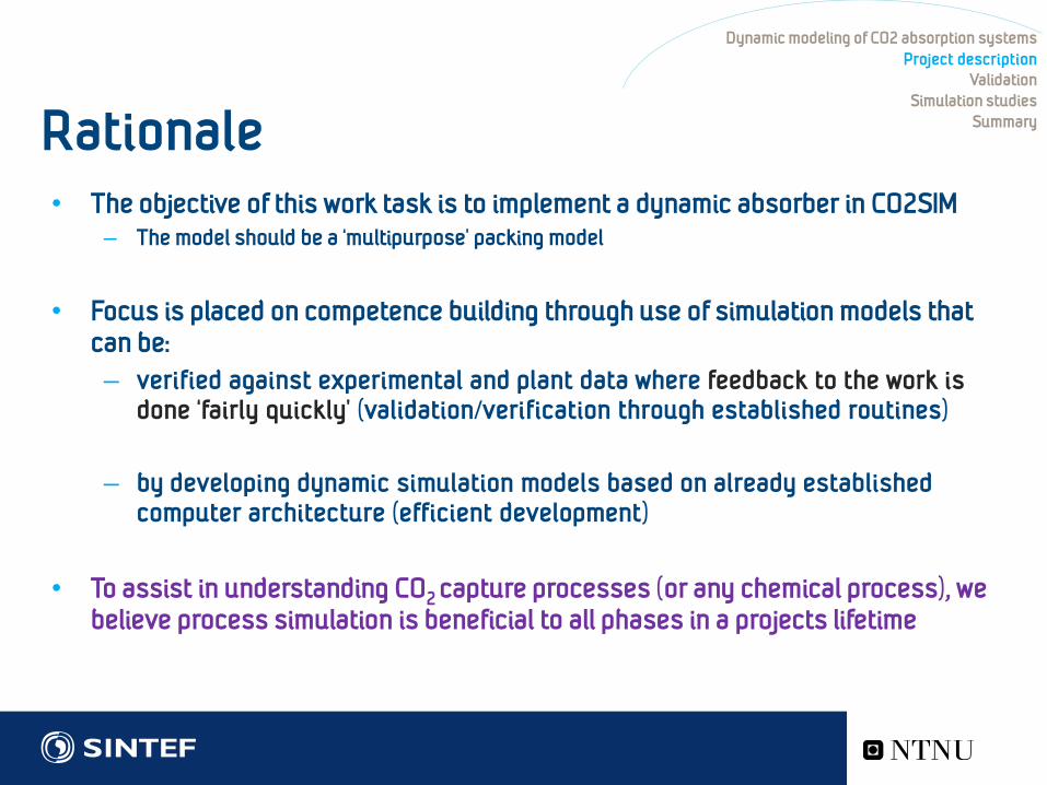
• Large and frequent load changes of the power plant requires understanding of dynamic operation
– How shall the capture plant be operated and controlled?
– What are the real consequences of varying loads at the CO2 removal plant?
– How do we handle unsteady behavior, shut down, start up?
– Or changes in load due to fluctuations in energy demand?
We are now moving towards building full scale plants
Reasons for developing a dynamic simulator Dynamic modeling of CO2 absorption systemsProject description
ValidationSimulation studies
Summary
NTNU 4
Development Strategy:
• Task 1: Implement a dynamic column model– Development of the model for absorption and desorption
– Test model and validate towards pilot plant data (steady state and dynamic)
• Task 2: Develop the connected unit operations, flash tanks, mixers, storage tanks and heat exchangers
– Definition of unit operations built into CO2SIM
• Task3: Develop the dynamic Network solver– Flowsheet model
– Programming techniques: information handling
– Information structure • relationship between an event (the cause) and a second event ( the effect) -> causality
Dynamic modeling of CO2 absorption systemsProject description
ValidationSimulation studies
Summary
This work is extensive... Our first requirement is therefore: We must have a platform for development

NTNU 5
CO2SIM programming techniques • Fundamental problem: Exponential
increase in complexity as code becomes larger
• Requires focus on structural planning and architectural patterns– Design patterns can speed up the
development process
– Provides fundamental development methods related to• program organization
• and common data structures (classes)
– In other words; the basic code elements at each layer are reusable
– The code design should be general enough to address future requirements also
Dynamic modeling of CO2 absorption systemsProject description
ValidationSimulation studies
Summary
Such design patterns provide general solutions, documented in a format that does not require specific ties to a particular problem
Development platform

NTNU 6
Example: Use of ‘Design patterns’ does generalize code development
Dynamic modeling of CO2 absorption systemsProject description
ValidationSimulation studies
Summary
Routine that minimizes the need for manually processing data
1. Obtain plant data for the full campaign
2. Duplicate plant flow sheet in the simulator
3. Simulate the complete campaign (one execution)
4. Evaluate statistics for the full campaign
5. Further use: optimization etc.
Development platform CO2SIM@SteadyState

NTNU 7
Dynamic modeling of CO2 absorption systemsProject description
ValidationSimulation studies
Summary
Development platform CO2SIM@SteadyState

NTNU 8
Development Strategy
• Task 1: Implement a dynamic CO2SIM column model– Model description and numerical methods
– Test model and validate towards pilot plant data (steady state and dynamic)
• Task 2: Develop the connected unit operations, flash tanks, mixers, storage tanks and heat exchangers
– Definition of unit operations built into CO2SIM
• Task3: Develop the dynamic Network solver– Flowsheet model
– Programming techniques: information handling
– Information structure:
• relationship between an event (the cause) and a second event ( the effect) -> causality
Dynamic modeling of CO2 absorption systemsProject description
ValidationSimulation studies
Summary

NTNU 9
Task 1: The transient column model• Based on first principle conservation laws
for energy and mass
• Adaptability of the code for different chemical systems and process configurations have been emphasized
Dynamic modeling of CO2 absorption systemsProject description
ValidationSimulation studies
Summary

NTNU 10
The transient column modelDynamic modeling of CO2 absorption systems
Project descriptionValidation
Simulation studiesSummary
Top view
Rich amine
Flue gas
Lean amine
Cleaned gas
dr normalizedheight (h)
0
1
ng,i,outHg,i,outP1Tg,out
nl,i,inHl,i,inP0Tl,in
ng,i,inHg,i,inP0Tg,in
nl,i,outHl,i,outP0Tl,out
( )
( )
G , ,
, G G
G /,
1
d d( )d d
1( )
i itot G tot G i i jj
n
tot Gjj
G GG G L L G
n i i p i G
y yC n N a y N at L z
n CN az tT T au h T Tt L z C C
ε
ε
ε
∂ ∂= − − −
∂ ∂
= − +
∂ ∂= − − ⋅ −
∂ ∂ ∑
∑
∑
( )
( )
L L ,
,
/ wall,
1
ddzdT 1 ( ) H (T - T )dt ( )
i itot L i i jj
n
tot Ljj
L LL L G L G j j L outj
n i i p i L
x xC n N a x N at L z
nN a
T au h T T H Nl L z C C
ε
ε
∂ ∂= + −
∂ ∂
= −
∂= − − − − ∆ −
∂ ∑
∑
∑
∑
,0 ,feed
, ,0 , ,
,0 ,
( )( )
( )
i n i
tot G n tot G feed
G n G feed
y z yn z nT z T
=
=
=
,1 ,feed
, ,1 ,
,1 ,
( )( )
( )
i n i
tot G n tot feed
L n L feed
x z xn z nT z T
=
=
=
G G/ ( )C P RT=
2/ /totn mol m s=
/nz z L=
Bondary conditions
Transport equations
Liquid phase
Gas phase
normalized column lenth
Ideal gas or SRK model
An extension of the model presented in: Kvamsdal, Jakobsen and Hoff, Chemical Engineering and Processing:, Volume 48, Issue 1, January 2009

NTNU 11
The transient column: numericsDynamic modeling of CO2 absorption systems
Project descriptionValidation
Simulation studiesSummaryNumerical solution to stiff DAE’s
• Two point differential algebraic problem (DAE) in a single dimension
• Discretization
– Time
• Higher order integrator
– Space
• Static collocation derivatives
• To increase robustness we need
• Stabilizing methods
1. Normalization
2. Dynamic relaxation (gives initial steadystateslopes)
Top view
Rich amine
Flue gas
Lean amine
Cleaned gas
dr normalizedheight (h)
0
1
ng,i,outHg,i,outP1Tg,out
nl,i,inHl,i,inP0Tl,in
ng,i,inHg,i,inP0Tg,in
nl,i,outHl,i,outP0Tl,out

NTNU 12
Outline• Dynamic modeling of CO2 absorption plants
• Project description• Simulator requirements/capabilities
• Short description of simulation model
• Verification/Validation (Preliminary) • Experimental validation using pilot plant data
• Simulation studies• Ramp behavior
• Robustness of code
• Summary
• Further work
• Acknowledgements
Dynamic modeling of CO2 absorption systemsProject description
ValidationSimulation studies
Summary

NTNU 13
Experimental validation of dynamic column model
• Tested against the “VOCC rig”
• Two time series cases (case A and B)
• 30wt%MEA
• Logging of input and output data every 5 seconds
– The cases give about 500 updates during simulation
• CO2SIM handles all these “events” automatically during integration to reflect process changes.
– The events are collected and systematically handled from log files (excel).
Dynamic modeling of CO2 absorption systemsProject description
ValidationSimulation studies
Summary
Validation of CO2 Capture - The VOCC-project (2007)
Absorber:Packing height = 5.4mID = 0.5m

NTNU
• Case B: Stepwise variations in CO2
gas concentration
• Inlet gas concentration of CO2 increased in two single step-changes
• then decreased in a large reverse single step-change
• All other process variables kept constant Stable liquid and gas flow over
the experiment.
14
VOCC test caseDynamic modeling of CO2 absorption systems
Project descriptionValidation
Simulation studiesSummary
1000 1500 2000 2500 3000 35000.02
0.025
0.03
0.035
0.04
0.045
0.05
0.055Property logging of inputs (only at events): molfracCO2vap and phase:vap
time [s]
Pro
perty
: mol
fracC
O2v
ap

NTNU 15
Comparing data from VOCC test with simulationDynamic modeling of CO2 absorption systemsProject description
ValidationSimulation studies
Summary
Blue line – SIMULATION
Simulated and measured:
Rich loading
Red line – PILOT data
Simulation time increased 30 times20-30 times faster than real-time

NTNU
1200 1400 1600 1800 2000 2200 2400 2600 2800 3000
312
313
314
315
316
317
318
319
320
321Property logging of outlets (only at events): temp and phase:liq
time [s]
Prop
erty
: tem
p
1200 1400 1600 1800 2000 2200 2400 2600 2800 30000.3
0.32
0.34
0.36
0.38
0.4
0.42Property logging of outlets (only at events): loading and phase:liq
time [s]
Prop
erty
: loa
ding
16
Simulated and measured:
Outlet Liquid Solvent temperature
Comparing data from VOCC test with simulationDynamic modeling of CO2 absorption systemsProject description
ValidationSimulation studies
Summary
Blue– SIMULATION
Red - PILOT
Simulated and measured:
Rich loading

NTNU
0 500 1000 1500 2000 2500 3000 3500 400080
85
90
95
100
105
110
115
120
125Property logging of inputs (only at events): flow and phase:vap
time [s]
Prop
erty
: flo
w
17
Simulation example
• Increasing molar ratio between the gas and liquid flowrate
– Varying the liquid and vapor input flow rates by ~50%?• In a time frame of 50 seconds
– Initially running at steady state then increase gas flow with 50% over a short time interval
– Observe the transients, then run end situation to steady state again
• 20 meter packing, identical inlet concentrations , only vary flow rate
Dynamic modeling of CO2 absorption systemsProject description
ValidationSimulation studies
Summary
Blue: gas flowrate (kmol/h)
Green: liquid flow rate (kmol/h)
Case A: Increasing gas load

NTNU
0 500 1000 1500 2000 2500 3000 3500 4000
0.65
0.7
0.75
0.8
0.85Property logging of inputs (only at events): gasremoved and phase:vap
time [s]
Pro
perty
: gas
rem
oved
0 500 1000 1500 2000 2500 3000 3500 40000.39
0.4
0.41
0.42
0.43Property logging of outputs (only at events): loading and phase:liq
time [s]
Prop
erty
: loa
ding
18
Dynamic modeling of CO2 absorption systemsProject description
ValidationSimulation studies
Summary
Case A: Increasing the flue gas loadEffect on loading
Effect on percent CO2 removed

NTNU 19
• Varying the molar ratio between the gas and liquid flow rate
– In a time frame of ~300 seconds
– Initially running at steady state then increase/reduce gas flow with 50%
– Observe the transients, then run end situation to steady state again
• 20 meter packing, identical inlet concentrations , only vary flow rate
Dynamic modeling of CO2 absorption systemsProject description
ValidationSimulation studies
Summary
Blue: gas flow rate (kmol/h)
Green: liquid flow rate (kmol/h)
0 50 100 150 200 250 300 350 400
75
80
85
90
95
100
105
110
115
120
125
130Property logging of inputs (only at events): flow and phase:vap
time [s]
Prop
erty
: flo
w
Case B: Varying flue gas load

NTNU 20
Dynamic modeling of CO2 absorption systemsProject description
ValidationSimulation studies
Summary
0 500 1000 1500 2000 2500 3000 3500 40000.39
0.4
0.41
0.42Property logging of outputs (only at events): loading and phase:liq
time [s]
Prop
erty
: loa
ding
Case B: Varying the flue gas loadEffect on loading
0 500 1000 1500 2000 2500 3000 3500 40000.76
0.77
0.78
0.79
0.8
0.81
0.82
0.83
0.84Property logging of inputs (only at events): gasremoved and phase:vap
time [s]
Pro
perty
: gas
rem
oved
Effect on percent CO2 removed

NTNU 21
Summary• At this stage in the project a robust codebase is developed for dynamic simulation
– Absorber, desorber packing model (this presentation)• Verified numerics
• Validated towards plant data (preliminary)
• The event updating procedures facilitates rapid simulation using plant data for validation
• Current model gives acceptable match towards data for MEA– Both at dynamic and steady state operation
• The implementation methodology allows for efficient simulation of the units’ transient behavior for continuously changes in input conditions or design parameters, part load operation, varying input conditions and ramping behavior
Dynamic modeling of CO2 absorption systemsProject description
ValidationSimulation studies
Summary
Further work• A few units implemented: Storage tank, dynamic flash, mixer tank and the
column model
• Network solver to handle sequential dynamic integration

NTNU 22
Dynamic modeling of CO2 absorption systemsProject description
ValidationSimulation studies
Summary
Acknowledgement This presentation forms a part of the BIGCO2 project, performed under the strategic Norwegian research program Climit. The authors acknowledge the partners: StatoilHydro, GE Global Research, Statkraft, Aker Clean Carbon, Shell, TOTAL, ConocoPhillips, ALSTOM, the Research Council of Norway (178004/I30 and 176059/I30) and Gassnova (182070) for their support.