Embed Size (px)
Citation preview
Trips and Fault Finding 7-1
590 Series DC Digital Converter
7 TRIPS AND FAULT FINDING
Trips
What Happens when a Trip Occurs When a trip occurs, the Converter’s power stage is immediately disabled causing the motor and
load to coast to a stop. The trip is latched until action is taken to reset it. This ensures that trips
due to transient conditions are captured and the Converter is disabled, even when the original
cause of the trip is no longer present.
MMI Indications If a trip condition is detected the unit displays and performs the following actions.
1. The HEALTH LED goes out indicating a Trip condition has occurred. The MMI displays
the activated alarm. (Investigate, find and remove the cause of the trip.)
2. Terminal B6 (Healthy) goes low (0V).
3. The alarm message(s) can be acknowledged by pressing the E key, however, the unit will
not restart at this point. Refer to Chapter 5: “The Man-Machine Interface (MMI)” - Alarm
Message Displays.
Resetting a Trip Condition All trips must be reset before the Converter can be re-enabled. A trip can only be reset once the
trip condition is no longer active, i.e. a trip due to a heatsink over-temperature will not reset
until the temperature is below the trip level.
Note: More than one trip can be active at any time. For example, it is possible for both the HEATSINK TRIP and the OVERVOLTS (VA) trips to be active. Alternatively it is possible for the Converter to trip due to a FIELD OVER I error and then for the HEATSINK TRIP trip to become active after the Converter has stopped (this may occur due to the thermal time constant of the heatsink).
You can reset the trip(s) in one of two ways:
1. Power -up, or remove and re-apply the auxiliary power supply.
2. Stop and start the converter, i.e. remove and re-apply the Start/Run signal (terminal C3 or
C4).
Success is indicated by the MMI’s HEALTH LED illuminating. The display will return to its
original display.
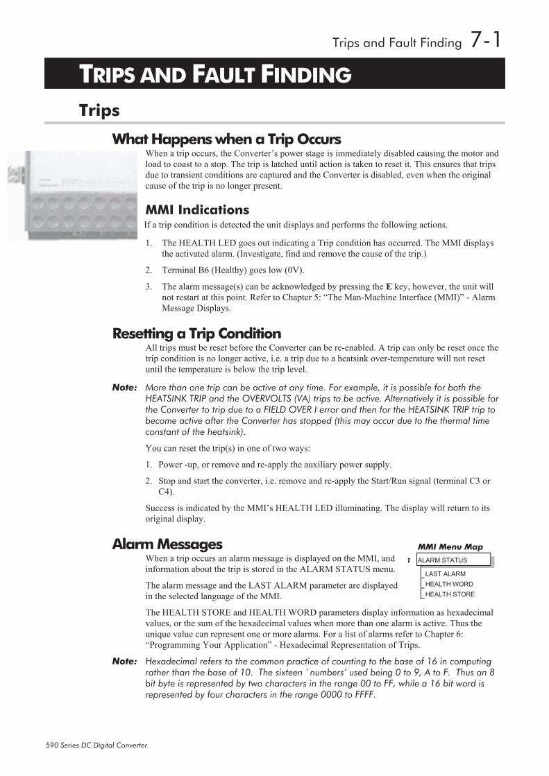
Alarm Messages When a trip occurs an alarm message is displayed on the MMI, and
information about the trip is stored in the ALARM STATUS menu.
The alarm message and the LAST ALARM parameter are displayed
in the selected language of the MMI.
The HEALTH STORE and HEALTH WORD parameters display information as hexadecimal
values, or the sum of the hexadecimal values when more than one alarm is active. Thus the
unique value can represent one or more alarms. For a list of alarms refer to Chapter 6:
“Programming Your Application” - Hexadecimal Representation of Trips.
Note: Hexadecimal refers to the common practice of counting to the base of 16 in computing rather than the base of 10. The sixteen `numbers’ used being 0 to 9, A to F. Thus an 8 bit byte is represented by two characters in the range 00 to FF, while a 16 bit word is represented by four characters in the range 0000 to FFFF.
MMI Menu Map
1 ALARM STATUS
LAST ALARM
HEALTH WORD
HEALTH STORE
7-2 Trips and Fault Finding
590 Series DC Digital Converter
LAST ALARM This display shows the last alarm message to have been displayed. To reset the parameter simply
press the (DOWN) key to clear the alarm. Alternatively, you can switch the auxiliary supply
off and on, causing NO ACTIVE ALARMS to be displayed.
HEALTH WORD This parameter is used to continuously monitor the status of the Converter. As alarms are added
or removed, the display will immediately update to show the hexadecimal sum of these alarms.
The value reverts to 0x0000 when the Start (C3) input is raised (+24V), and when no trip
condition is present.
HEALTH STORE This displays the hexadecimal value of the first (or only) alarm to occur causing the trip
condition.
The display reverts to 0x0000 when the Start (C3) input is raised (+24V).
Using the MMI to Manage Trips
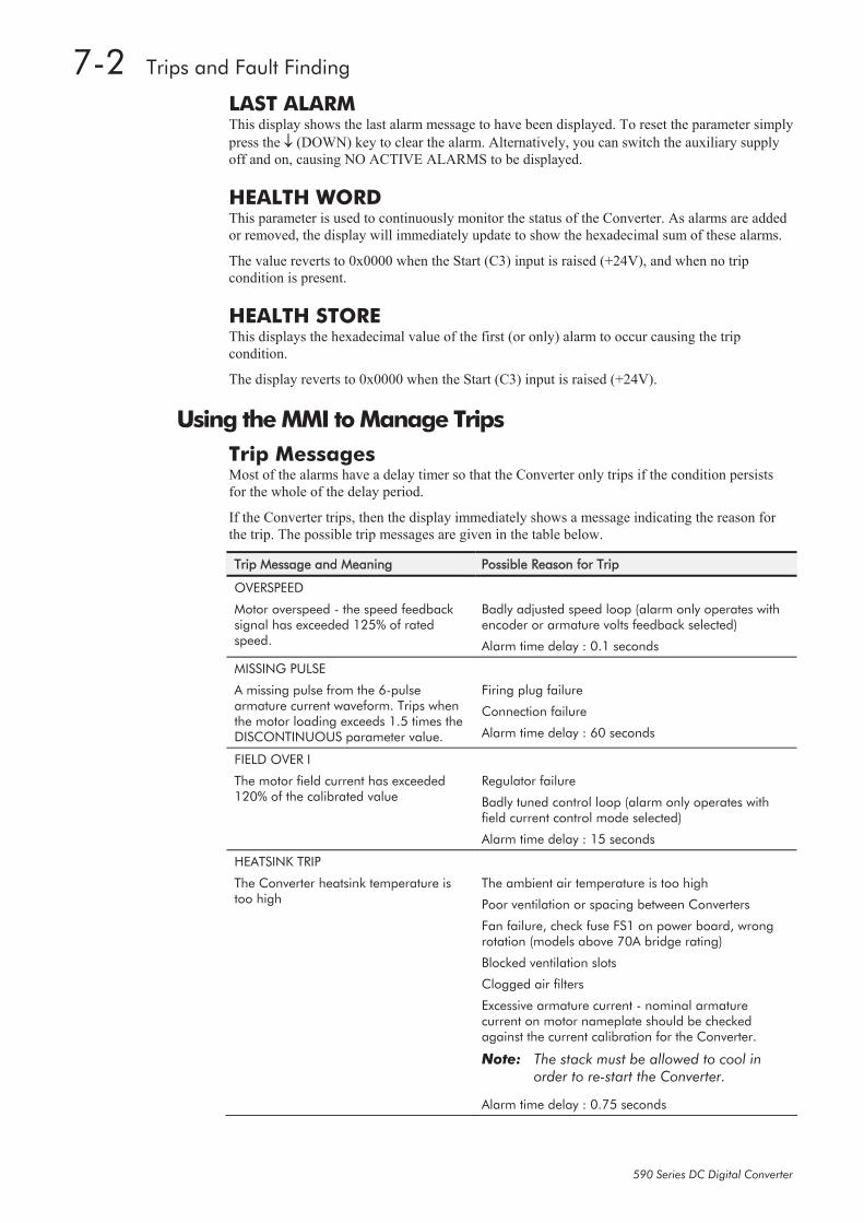
Trip Messages Most of the alarms have a delay timer so that the Converter only trips if the condition persists
for the whole of the delay period.
If the Converter trips, then the display immediately shows a message indicating the reason for
the trip. The possible trip messages are given in the table below.
Trip Message and Meaning Possible Reason for Trip
OVERSPEED
Motor overspeed - the speed feedback signal has exceeded 125% of rated speed.
Badly adjusted speed loop (alarm only operates with encoder or armature volts feedback selected)
Alarm time delay : 0.1 seconds
MISSING PULSE
A missing pulse from the 6-pulse armature current waveform. Trips when the motor loading exceeds 1.5 times the DISCONTINUOUS parameter value.
Firing plug failure
Connection failure
Alarm time delay : 60 seconds
FIELD OVER I
The motor field current has exceeded 120% of the calibrated value
Regulator failure
Badly tuned control loop (alarm only operates with field current control mode selected)
Alarm time delay : 15 seconds
HEATSINK TRIP
The Converter heatsink temperature is too high
The ambient air temperature is too high
Poor ventilation or spacing between Converters
Fan failure, check fuse FS1 on power board, wrong rotation (models above 70A bridge rating)
Blocked ventilation slots
Clogged air filters
Excessive armature current - nominal armature current on motor nameplate should be checked against the current calibration for the Converter.
Note: The stack must be allowed to cool in order to re-start the Converter.
Alarm time delay : 0.75 seconds
Trips and Fault Finding 7-3
590 Series DC Digital Converter
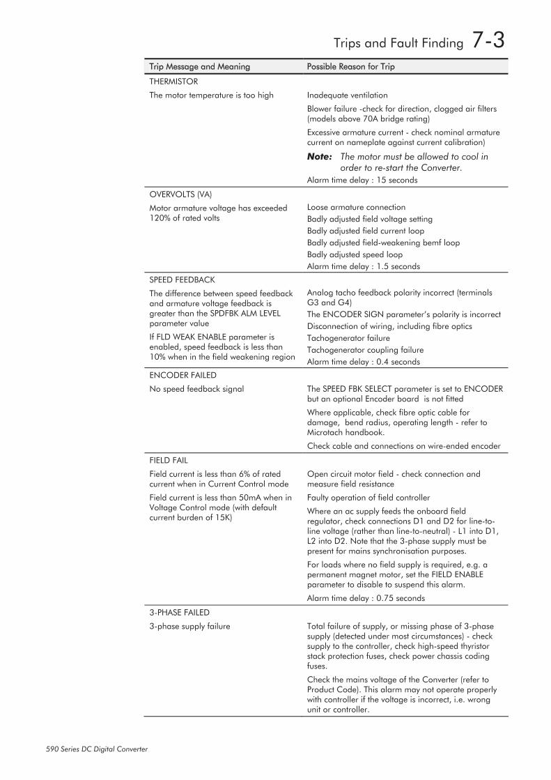
Trip Message and Meaning Possible Reason for Trip
THERMISTOR
The motor temperature is too high
Inadequate ventilation
Blower failure -check for direction, clogged air filters (models above 70A bridge rating)
Excessive armature current - check nominal armature current on nameplate against current calibration)
Note: The motor must be allowed to cool in order to re-start the Converter.
Alarm time delay : 15 seconds
OVERVOLTS (VA)
Motor armature voltage has exceeded 120% of rated volts
Loose armature connection
Badly adjusted field voltage setting
Badly adjusted field current loop
Badly adjusted field-weakening bemf loop
Badly adjusted speed loop
Alarm time delay : 1.5 seconds
SPEED FEEDBACK
The difference between speed feedback and armature voltage feedback is greater than the SPDFBK ALM LEVEL parameter value
If FLD WEAK ENABLE parameter is enabled, speed feedback is less than 10% when in the field weakening region
Analog tacho feedback polarity incorrect (terminals G3 and G4)
The ENCODER SIGN parameter’s polarity is incorrect
Disconnection of wiring, including fibre optics
Tachogenerator failure
Tachogenerator coupling failure
Alarm time delay : 0.4 seconds
ENCODER FAILED
No speed feedback signal
The SPEED FBK SELECT parameter is set to ENCODER but an optional Encoder board is not fitted
Where applicable, check fibre optic cable for damage, bend radius, operating length - refer to Microtach handbook.
Check cable and connections on wire-ended encoder
FIELD FAIL
Field current is less than 6% of rated current when in Current Control mode
Field current is less than 50mA when in Voltage Control mode (with default current burden of 15K)
Open circuit motor field - check connection and measure field resistance
Faulty operation of field controller
Where an ac supply feeds the onboard field regulator, check connections D1 and D2 for line-to-line voltage (rather than line-to-neutral) - L1 into D1, L2 into D2. Note that the 3-phase supply must be present for mains synchronisation purposes.
For loads where no field supply is required, e.g. a permanent magnet motor, set the FIELD ENABLE parameter to disable to suspend this alarm.
Alarm time delay : 0.75 seconds
3-PHASE FAILED
3-phase supply failure
Total failure of supply, or missing phase of 3-phase supply (detected under most circumstances) - check supply to the controller, check high-speed thyristor stack protection fuses, check power chassis coding fuses.
Check the mains voltage of the Converter (refer to Product Code). This alarm may not operate properly with controller if the voltage is incorrect, i.e. wrong unit or controller.
7-4 Trips and Fault Finding
590 Series DC Digital Converter
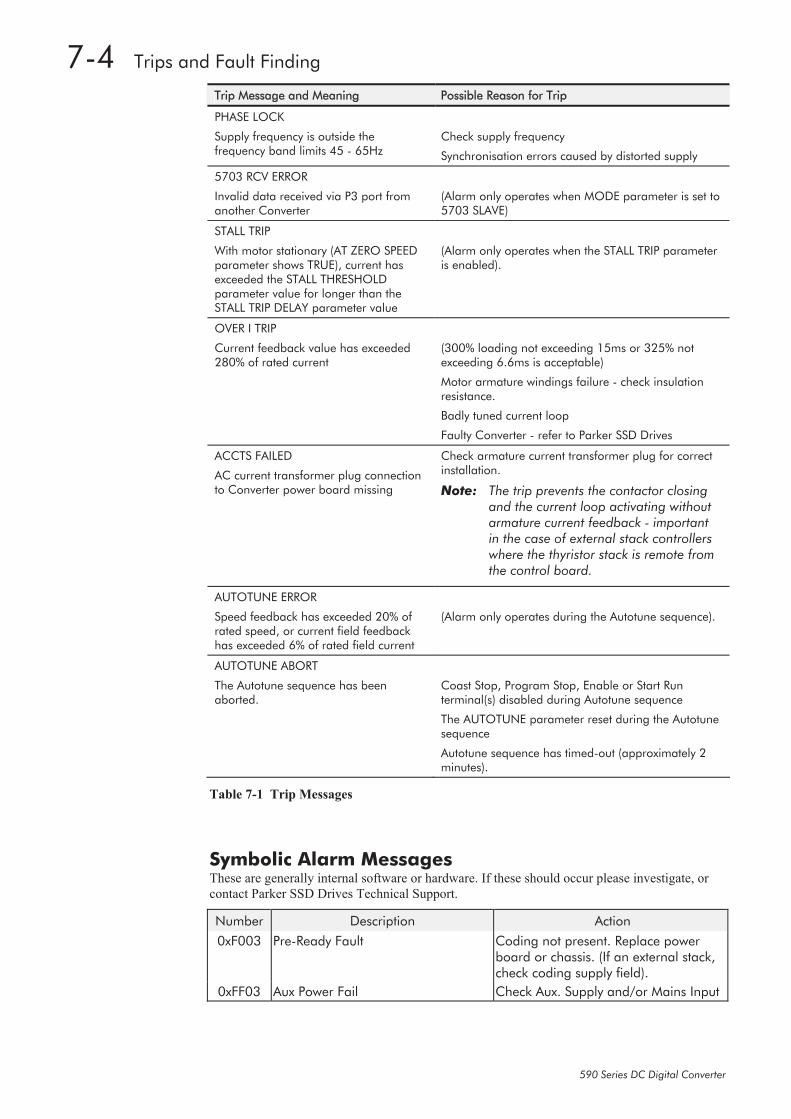
Trip Message and Meaning Possible Reason for Trip
PHASE LOCK
Supply frequency is outside the frequency band limits 45 - 65Hz
Check supply frequency
Synchronisation errors caused by distorted supply
5703 RCV ERROR
Invalid data received via P3 port from another Converter
(Alarm only operates when MODE parameter is set to 5703 SLAVE)
STALL TRIP
With motor stationary (AT ZERO SPEED parameter shows TRUE), current has exceeded the STALL THRESHOLD parameter value for longer than the STALL TRIP DELAY parameter value
(Alarm only operates when the STALL TRIP parameter is enabled).
OVER I TRIP
Current feedback value has exceeded 280% of rated current
(300% loading not exceeding 15ms or 325% not exceeding 6.6ms is acceptable)
Motor armature windings failure - check insulation resistance.
Badly tuned current loop
Faulty Converter - refer to Parker SSD Drives
ACCTS FAILED
AC current transformer plug connection to Converter power board missing
Check armature current transformer plug for correct installation.
Note: The trip prevents the contactor closing and the current loop activating without armature current feedback - important in the case of external stack controllers where the thyristor stack is remote from the control board.
AUTOTUNE ERROR
Speed feedback has exceeded 20% of rated speed, or current field feedback has exceeded 6% of rated field current
(Alarm only operates during the Autotune sequence).
AUTOTUNE ABORT
The Autotune sequence has been aborted.
Coast Stop, Program Stop, Enable or Start Run terminal(s) disabled during Autotune sequence
The AUTOTUNE parameter reset during the Autotune sequence
Autotune sequence has timed-out (approximately 2 minutes).
Table 7-1 Trip Messages
Symbolic Alarm Messages These are generally internal software or hardware. If these should occur please investigate, or
contact Parker SSD Drives Technical Support.
Number Description Action
0xF003 Pre-Ready Fault Coding not present. Replace power board or chassis. (If an external stack, check coding supply field).
0xFF03 Aux Power Fail Check Aux. Supply and/or Mains Input
Trips and Fault Finding 7-5
590 Series DC Digital Converter
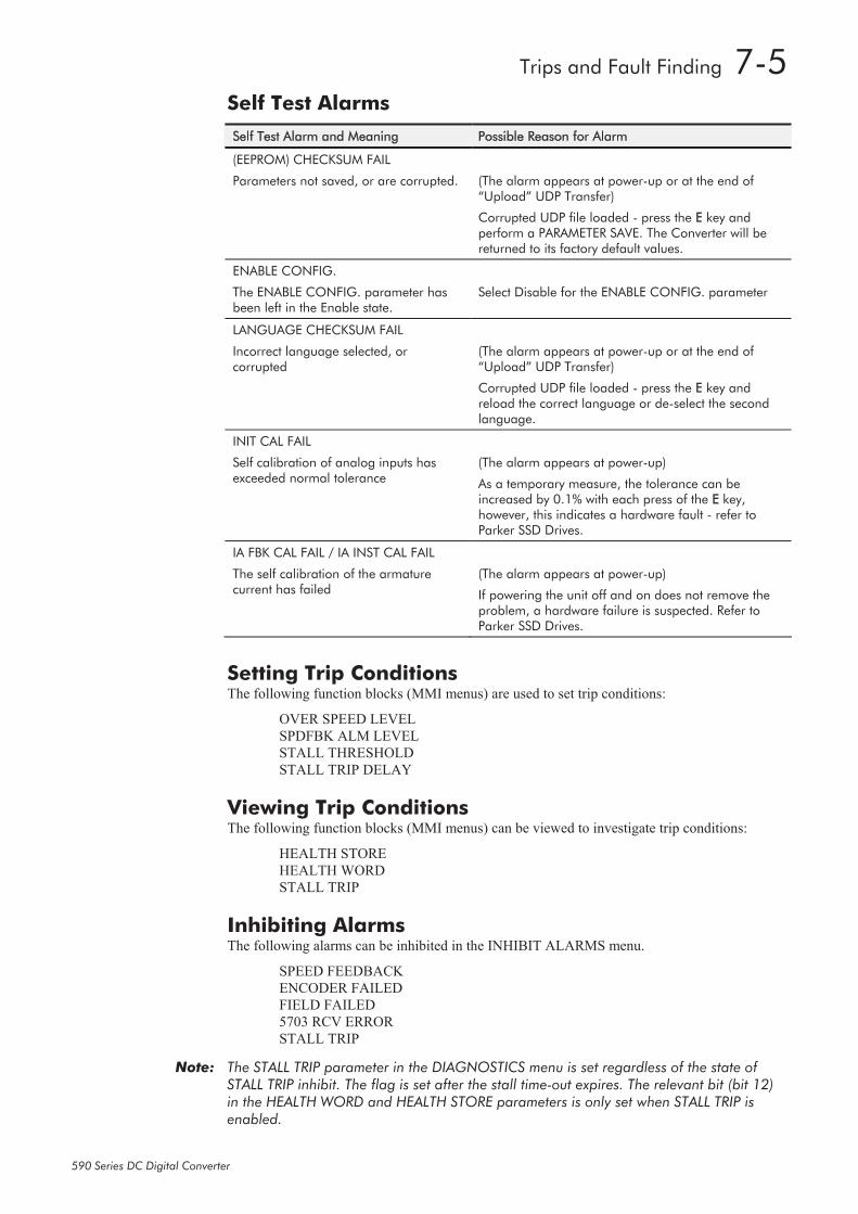
Self Test Alarms
Self Test Alarm and Meaning Possible Reason for Alarm
(EEPROM) CHECKSUM FAIL
Parameters not saved, or are corrupted.
(The alarm appears at power-up or at the end of “Upload” UDP Transfer)
Corrupted UDP file loaded - press the E key and perform a PARAMETER SAVE. The Converter will be returned to its factory default values.
ENABLE CONFIG.
The ENABLE CONFIG. parameter has been left in the Enable state.
Select Disable for the ENABLE CONFIG. parameter
LANGUAGE CHECKSUM FAIL
Incorrect language selected, or corrupted
(The alarm appears at power-up or at the end of “Upload” UDP Transfer)
Corrupted UDP file loaded - press the E key and reload the correct language or de-select the second language.
INIT CAL FAIL
Self calibration of analog inputs has exceeded normal tolerance
(The alarm appears at power-up)
As a temporary measure, the tolerance can be increased by 0.1% with each press of the E key, however, this indicates a hardware fault - refer to Parker SSD Drives.
IA FBK CAL FAIL / IA INST CAL FAIL
The self calibration of the armature current has failed
(The alarm appears at power-up)
If powering the unit off and on does not remove the problem, a hardware failure is suspected. Refer to Parker SSD Drives.
Setting Trip Conditions The following function blocks (MMI menus) are used to set trip conditions:
OVER SPEED LEVEL
SPDFBK ALM LEVEL
STALL THRESHOLD
STALL TRIP DELAY
Viewing Trip Conditions The following function blocks (MMI menus) can be viewed to investigate trip conditions:
HEALTH STORE
HEALTH WORD
STALL TRIP
Inhibiting Alarms The following alarms can be inhibited in the INHIBIT ALARMS menu.
SPEED FEEDBACK
ENCODER FAILED
FIELD FAILED
5703 RCV ERROR
STALL TRIP
Note: The STALL TRIP parameter in the DIAGNOSTICS menu is set regardless of the state of STALL TRIP inhibit. The flag is set after the stall time-out expires. The relevant bit (bit 12) in the HEALTH WORD and HEALTH STORE parameters is only set when STALL TRIP is enabled.
7-6 Trips and Fault Finding
590 Series DC Digital Converter
Fault Finding
Problem Possible Cause Remedy
Converter will not power-up Fuse blown Check supply details, replace with correct fuse.
Check Product Code against Model No.
Faulty cabling Check all connections are correct and secure.
Check cable continuity
Converter fuse keeps blowing Faulty cabling or connections wrong
Check for problem and rectify before replacing with correct fuse
Faulty Converter Contact Parker SSD Drives
Cannot obtain HEALTH state Incorrect or no supply available
Check supply details
Motor will not run at switch on Motor jammed Stop the Converter and clear the jam
Motor runs and stops Motor becomes jammed Stop the Converter and clear the jam
Motor runs at full speed only Reversed tachogenerator or open circuit tachogenerator
Check tachogenerator connections
Open circuit speed reference potentiometer
Check terminal
Table 7-2 Fault Finding
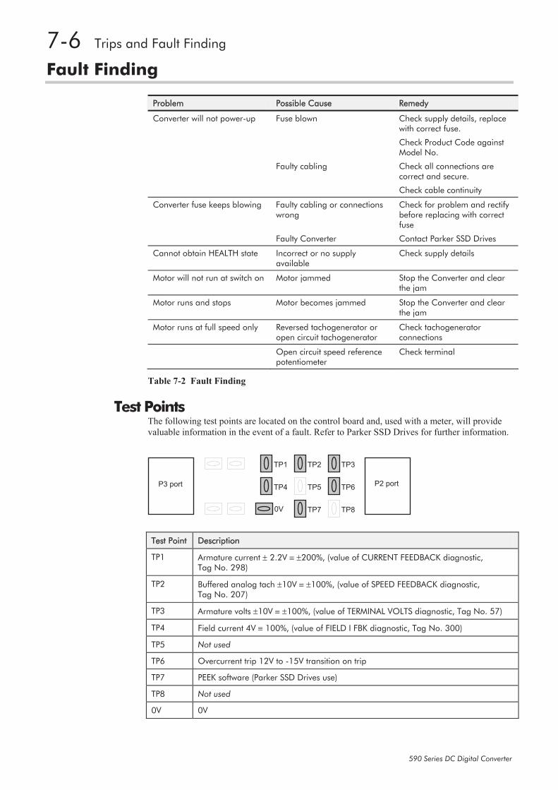
Test Points The following test points are located on the control board and, used with a meter, will provide
valuable information in the event of a fault. Refer to Parker SSD Drives for further information.
P3 port P2 port
TP1
TP4
0V
TP2
TP5
TP7
TP3
TP6
TP8
Test Point Description
TP1 Armature current 2.2V 200%, (value of CURRENT FEEDBACK diagnostic, Tag No. 298)
TP2 Buffered analog tach 10V 100%, (value of SPEED FEEDBACK diagnostic, Tag No. 207)
TP3 Armature volts 10V 100%, (value of TERMINAL VOLTS diagnostic, Tag No. 57)
TP4 Field current 4V 100%, (value of FIELD I FBK diagnostic, Tag No. 300)
TP5 Not used
TP6 Overcurrent trip 12V to -15V transition on trip
TP7 PEEK software (Parker SSD Drives use)
TP8 Not used
0V 0V