Embed Size (px)
Citation preview

Triple Power
---High Voltage Storage System
www.solaxpower.com
CONTENTS
1
3
4
OVERVIEW
INTRODUCTION
CERTIFICATION
INSTALLATION
STATUS INDICATOR
TROUBLESHOOTING
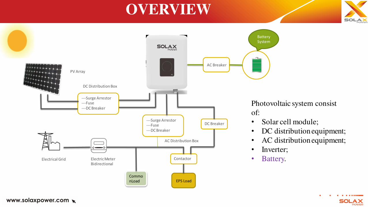
OVERVIEW
DC Distribution Box
AC Distribution Box
PV Array
Electrical Grid Electric Meter
Bidirectional
---Surge Arrestor
---Fuse
---DC Breaker
---Surge Arrestor
---Fuse
---DC Breaker
EPS Load
Commo
nLoad
DC Breaker
AC Breaker
Contactor
Battery
System
Photovoltaic system consist
of:
• Solar cell module;
• DC distribution equipment;
• AC distribution equipment;
• Inverter;
• Battery.
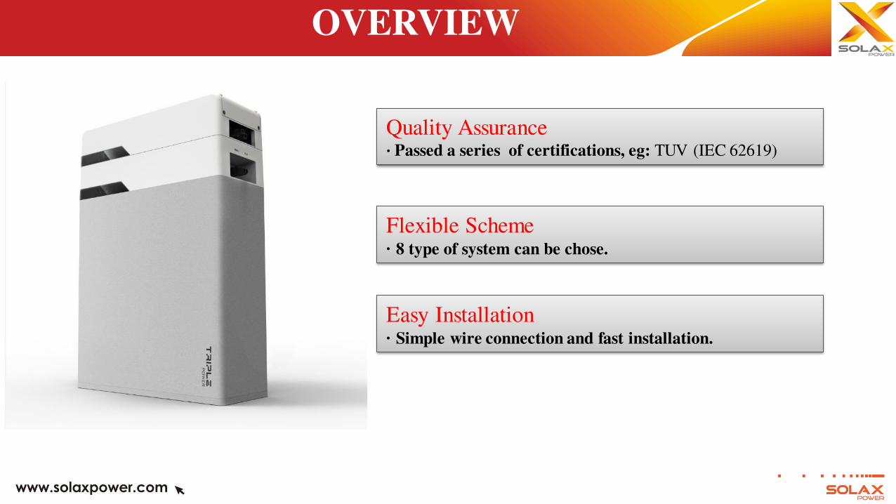
Flexible Scheme · 8 type of system can be chose.
Quality Assurance · Passed a series of certifications, eg: TUV (IEC 62619)
OVERVIEW
Easy Installation · Simple wire connection and fast installation.
Features of Product:
· 100% DOD;
· 99% Charge Efficiency;
· 95% Charge Discharge Cycle Efficiency;
· Charge Cycle Life>6000;
· Hardware Secondary Protection;
· Classified Protection: IP55;
· Safety & Reliable;
· Little Space Taking;
· Two Installation Methods: Floor Mounting & Wall Mounting;
· For Single Phase Storage Inverter can match with: 1-3 pack;
· For Three Phase Storage Inverter can match with: 2-4 packs;
OVERVIEW
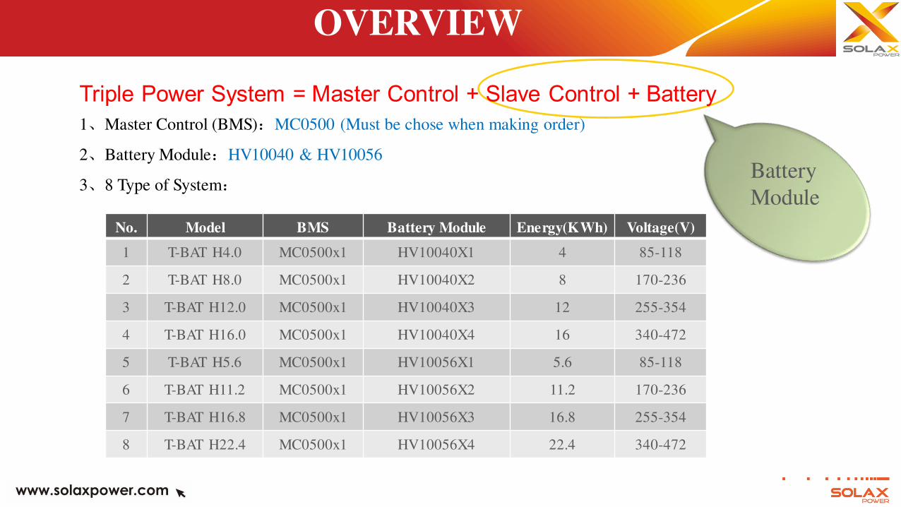
Triple Power System = Master Control + Slave Control + Battery
1、Master Control (BMS):MC0500 (Must be chose when making order)
2、Battery Module:HV10040 & HV10056
3、8 Type of System:
OVERVIEW
No. Model BMS Battery Module Energy(KWh) Voltage(V)
1 T-BAT H4.0 MC0500x1 HV10040X1 4 85-118
2 T-BAT H8.0 MC0500x1 HV10040X2 8 170-236
3 T-BAT H12.0 MC0500x1 HV10040X3 12 255-354
4 T-BAT H16.0 MC0500x1 HV10040X4 16 340-472
5 T-BAT H5.6 MC0500x1 HV10056X1 5.6 85-118
6 T-BAT H11.2 MC0500x1 HV10056X2 11.2 170-236
7 T-BAT H16.8 MC0500x1 HV10056X3 16.8 255-354
8 T-BAT H22.4 MC0500x1 HV10056X4 22.4 340-472
Battery
Module
OVERVIEW
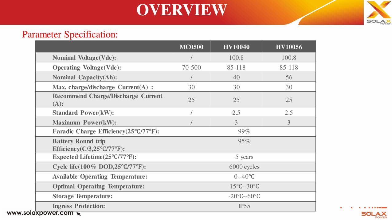
Parameter Specification:
MC0500 HV10040 HV10056
Nominal Voltage(Vdc): / 100.8 100.8
Operating Voltage(Vdc): 70-500 85-118 85-118
Nominal Capacity(Ah): / 40 56
Max. charge/discharge Current(A) : 30 30 30
Recommend Charge/Discharge Current
(A): 25 25 25
Standard Power(kW): / 2.5 2.5
Maximum Power(kW): / 3 3
Faradic Charge Efficiency(25℃/77℉): 99%
Battery Round trip
Efficiency(C/3,25℃/77℉):
95%
Expected Lifetime(25℃/77℉): 5 years
Cycle life(100% DOD,25℃/77℉): 6000 cycles
Available Operating Temperature: 0--40℃
Optimal Operating Temperature: 15℃--30℃
Storage Temperature: -20℃--60℃
Ingress Protection: IP55
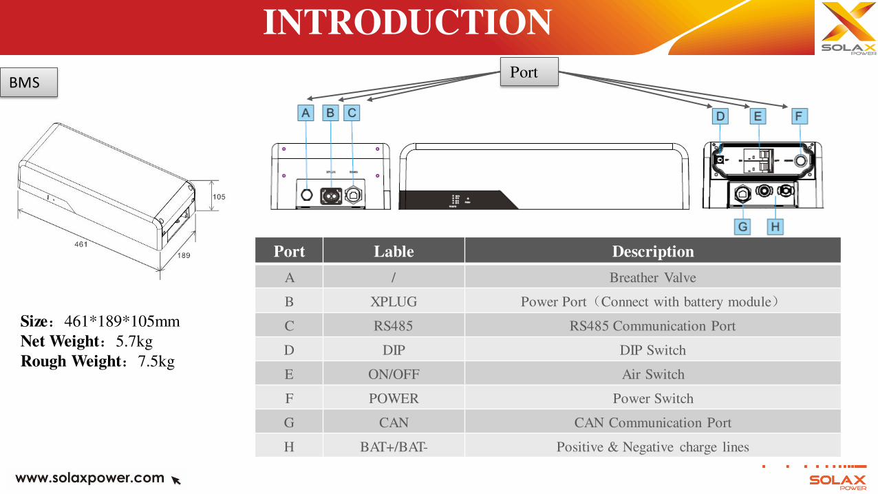
Size:461*189*105mm
Net Weight:5.7kg
Rough Weight:7.5kg
INTRODUCTION
BMS Port
Port Lable Description
A / Breather Valve
B XPLUG Power Port(Connect with battery module)
C RS485 RS485 Communication Port
D DIP DIP Switch
E ON/OFF Air Switch
F POWER Power Switch
G CAN CAN Communication Port
H BAT+/BAT- Positive & Negative charge lines
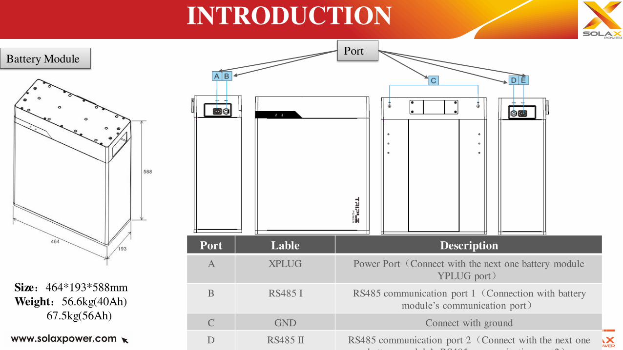
Size:464*193*588mm
Weight:56.6kg(40Ah)
67.5kg(56Ah)
INTRODUCTION
Battery Module Port
Port Lable Description
A XPLUG Power Port(Connect with the next one battery module
YPLUG port)
B RS485 I RS485 communication port 1(Connection with battery
module’s communication port)
C GND Connect with ground
D RS485 II RS485 communication port 2(Connect with the next one
battery module’s RS485 communication port2)
(Connect with the next one battery module’s )
CERTIFICATION
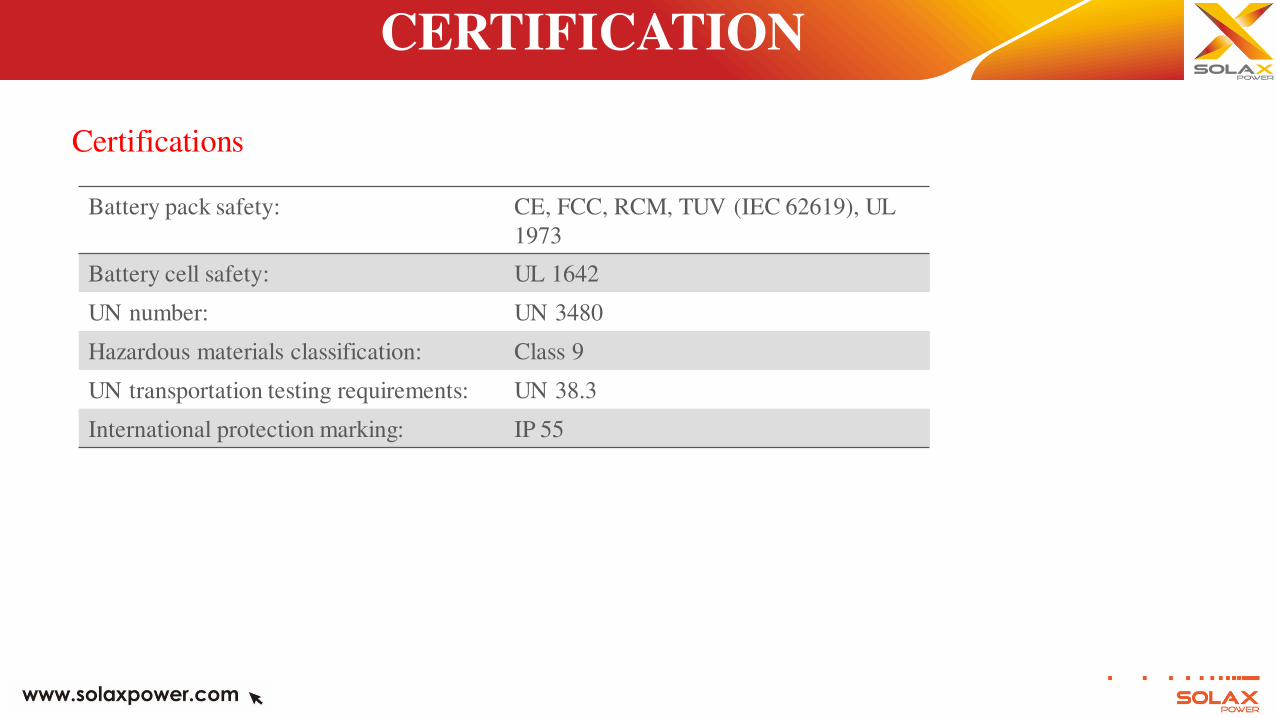
Certifications
Battery pack safety: CE, FCC, RCM, TUV (IEC 62619), UL
1973
Battery cell safety: UL 1642
UN number: UN 3480
Hazardous materials classification: Class 9
UN transportation testing requirements: UN 38.3
International protection marking: IP 55
INSTALLATION
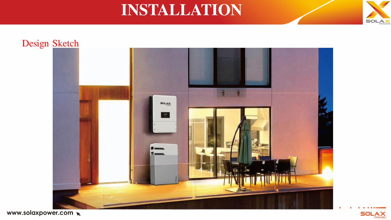
Design Sketch
INSTALLATION
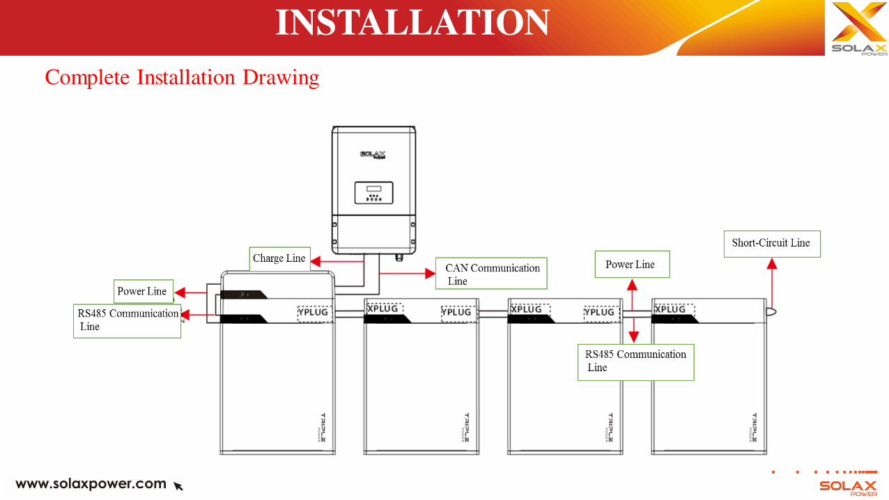
Complete Installation Drawing
INSTALLATION
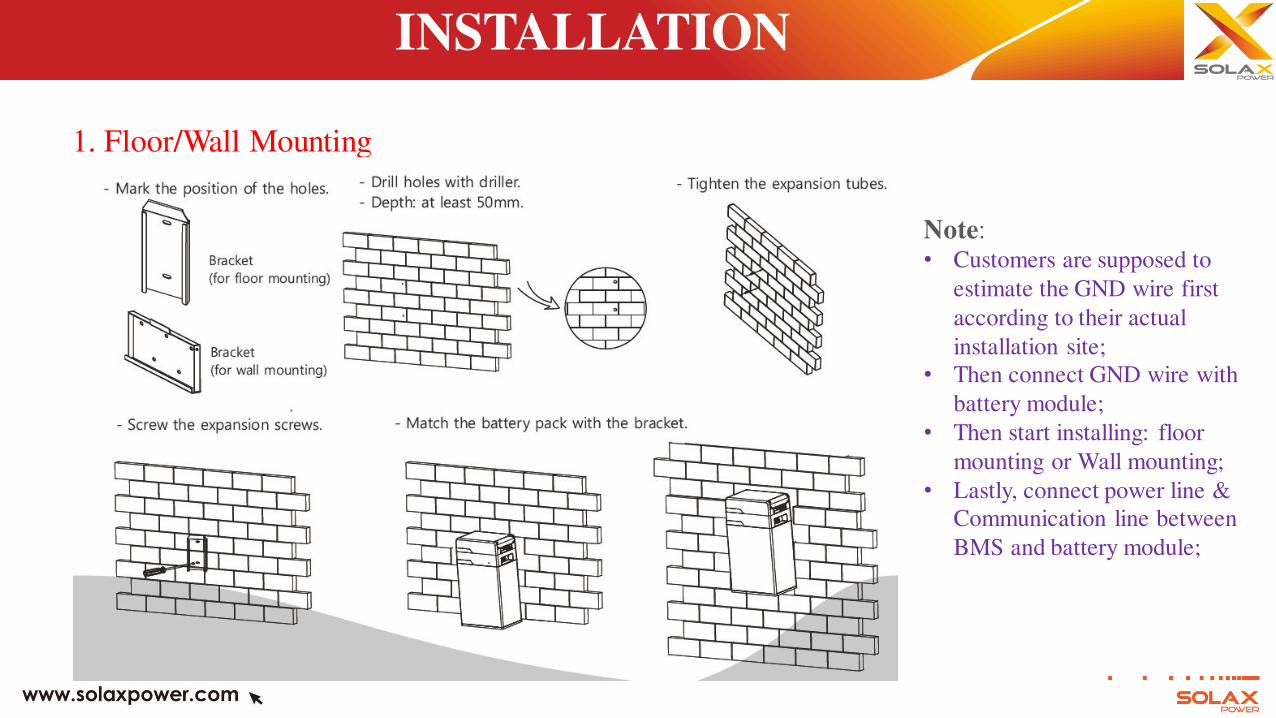
1. Floor/Wall Mounting
Note:
• Customers are supposed to
estimate the GND wire first
according to their actual
installation site;
• Then connect GND wire with
battery module;
• Then start installing: floor
mounting or Wall mounting;
• Lastly, connect power line &
Communication line between
BMS and battery module;
INSTALLATION
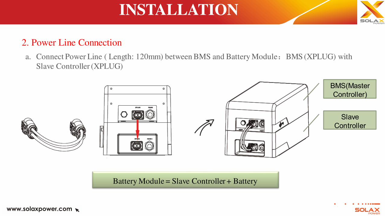
2. Power Line Connection
a. Connect Power Line ( Length: 120mm) between BMS and Battery Module:BMS (XPLUG) with
Slave Controller (XPLUG)
BMS(Master
Controller)
Slave
Controller
Battery Module = Slave Controller + Battery
INSTALLATION
2. Power Line Connection
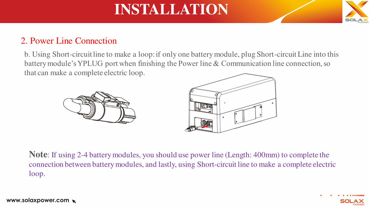
b. Using Short-circuit line to make a loop: if only one battery module, plug Short-circuit Line into this
battery module’s YPLUG port when finishing the Power line & Communication line connection, so that can make a complete electric loop.
Note: If using 2-4 battery modules, you should use power line (Length: 400mm) to complete the
connection between battery modules, and lastly, using Short-circuit line to make a complete electric
loop.
INSTALLATION
2. Power Line Connection
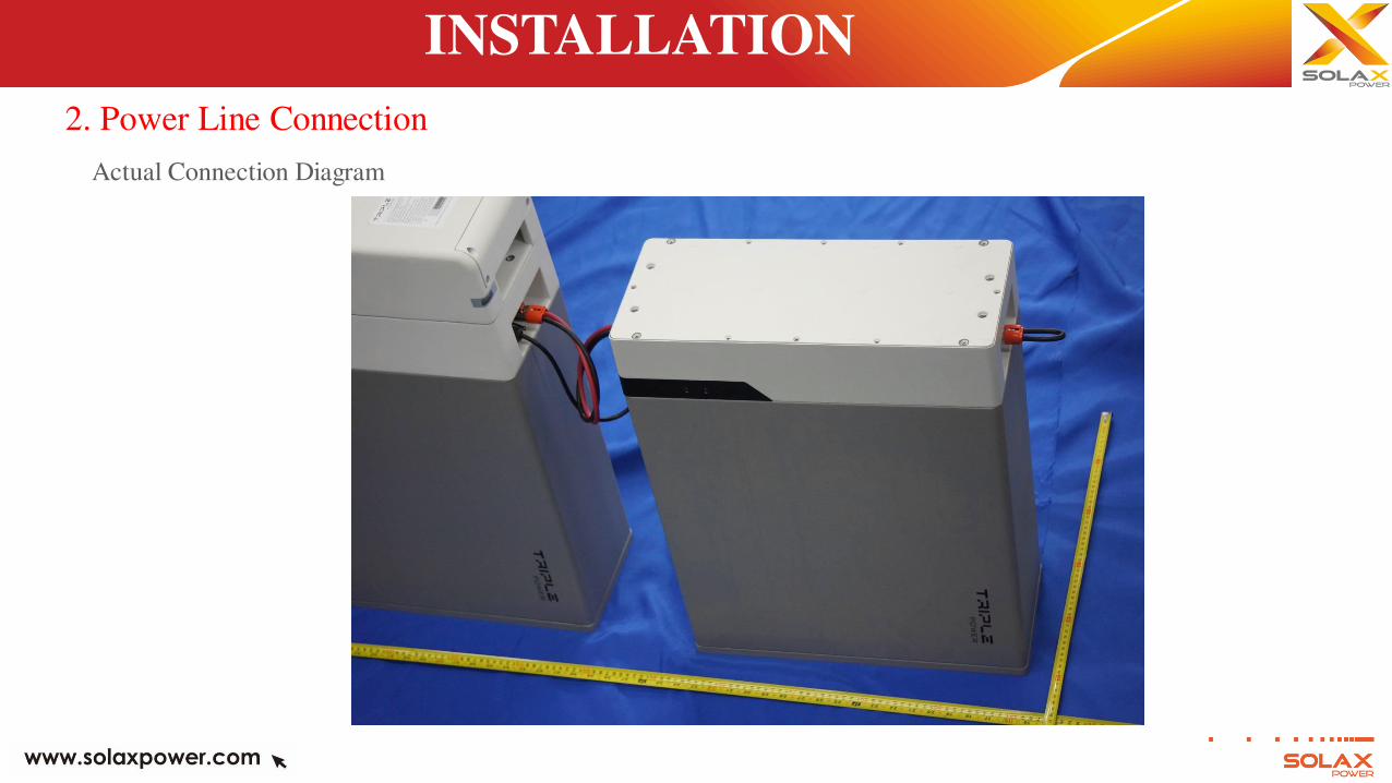
Actual Connection Diagram
INSTALLATION
3. Communication Line Connection
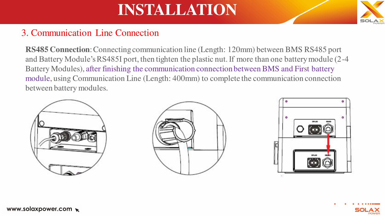
RS485 Connection: Connecting communication line (Length: 120mm) between BMS RS485 port
and Battery Module’s RS485I port, then tighten the plastic nut. If more than one battery module (2-4
Battery Modules), after finishing the communication connection between BMS and First battery
module, using Communication Line (Length: 400mm) to complete the communication connection
between battery modules.
INSTALLATION
3. Communication Line Connection
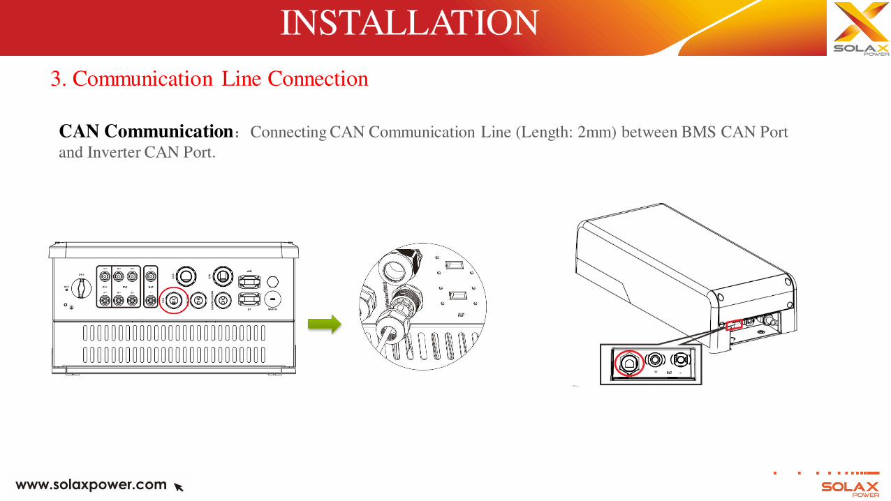
CAN Communication:Connecting CAN Communication Line (Length: 2mm) between BMS CAN Port
and Inverter CAN Port.
INSTALLATION
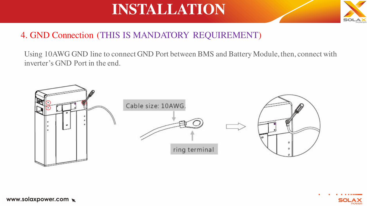
4. GND Connection (THIS IS MANDATORY REQUIREMENT)
Using 10AWG GND line to connect GND Port between BMS and Battery Module, then, connect with
inverter’s GND Port in the end.
INSTALLATION
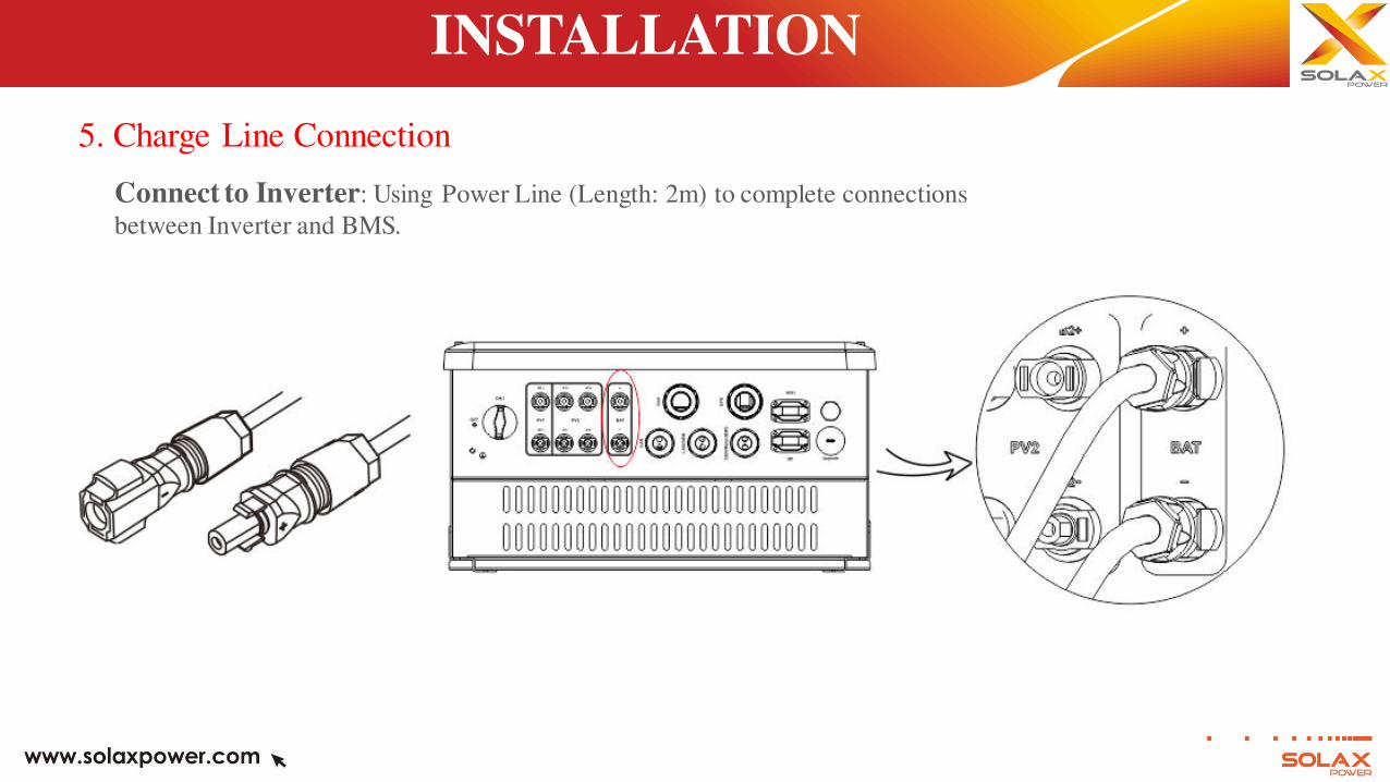
5. Charge Line Connection
Connect to Inverter: Using Power Line (Length: 2m) to complete connections
between Inverter and BMS.
INSTALLATION
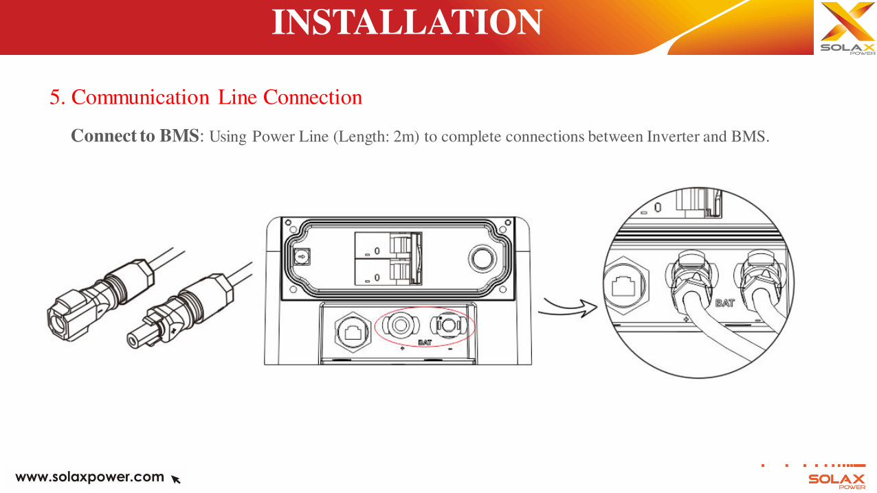
5. Communication Line Connection
Connect to BMS: Using Power Line (Length: 2m) to complete connections between Inverter and BMS.
INSTALLATION
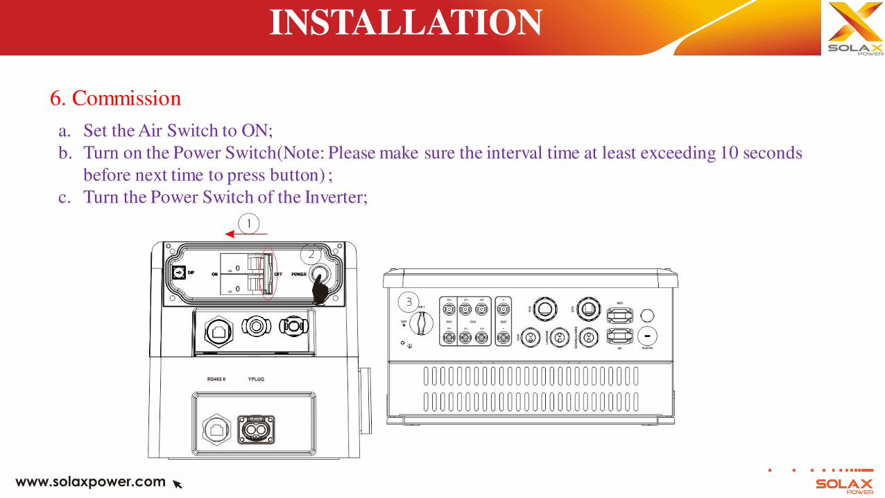
6. Commission
a. Set the Air Switch to ON;
b. Turn on the Power Switch(Note: Please make sure the interval time at least exceeding 10 seconds
before next time to press button) ;
c. Turn the Power Switch of the Inverter;
STATUS INDICATOR
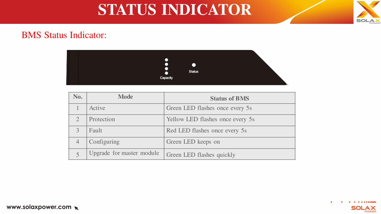
BMS Status Indicator:
No. Mode Status of BMS
1 Active Green LED flashes once every 5s
2 Protection Yellow LED flashes once every 5s
3 Fault Red LED flashes once every 5s
4 Configuring Green LED keeps on
5 Upgrade for master module Green LED flashes quickly
STATUS INDICATOR
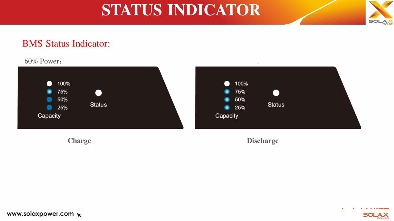
BMS Status Indicator:
Charge Discharge
60% Power:
STATUS INDICATOR
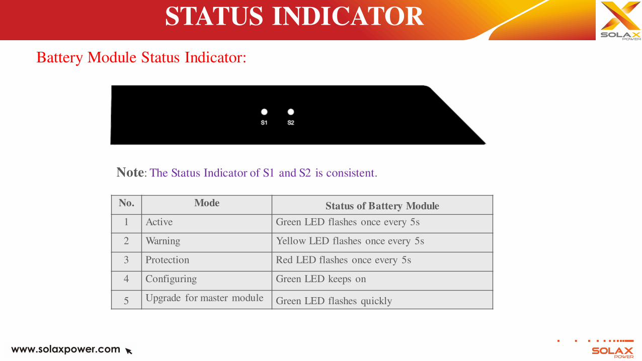
Battery Module Status Indicator:
No. Mode Status of Battery Module
1 Active Green LED flashes once every 5s
2 Warning Yellow LED flashes once every 5s
3 Protection Red LED flashes once every 5s
4 Configuring Green LED keeps on
5 Upgrade for master module Green LED flashes quickly
Note: The Status Indicator of S1 and S2 is consistent.
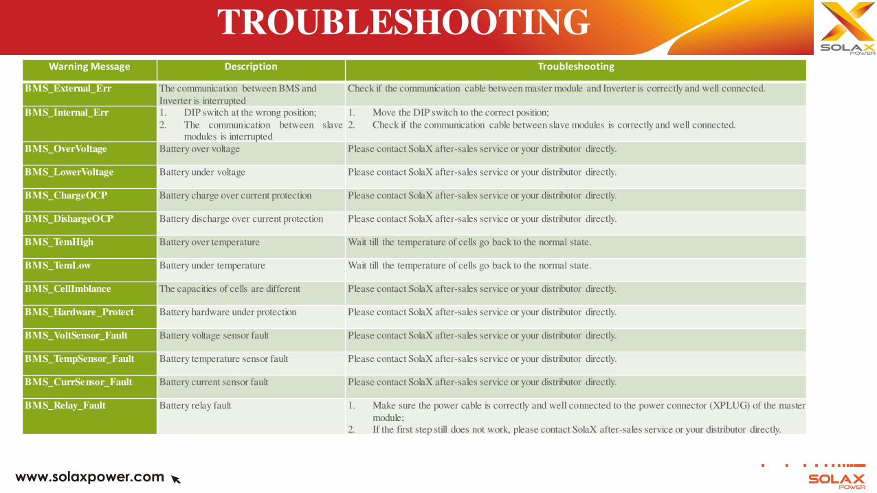
TROUBLESHOOTING Warning Message Description Troubleshooting
BMS_External_Err The communication between BMS and
Inverter is interrupted
Check if the communication cable between master module and Inverter is correctly and well connected.
BMS_Internal_Err 1. DIP switch at the wrong position;
2. The communication between slave
modules is interrupted
1. Move the DIP switch to the correct position;
2. Check if the communication cable between slave modules is correctly and well connected.
BMS_OverVoltage Battery over voltage Please contact SolaX after-sales service or your distributor directly.
BMS_LowerVoltage Battery under voltage Please contact SolaX after-sales service or your distributor directly.
BMS_ChargeOCP Battery charge over current protection Please contact SolaX after-sales service or your distributor directly.
BMS_DishargeOCP Battery discharge over current protection Please contact SolaX after-sales service or your distributor directly.
BMS_TemHigh Battery over temperature Wait till the temperature of cells go back to the normal state.
BMS_TemLow Battery under temperature Wait till the temperature of cells go back to the normal state.
BMS_CellImblance The capacities of cells are different Please contact SolaX after-sales service or your distributor directly.
BMS_Hardware_Protect Battery hardware under protection Please contact SolaX after-sales service or your distributor directly.
BMS_VoltSensor_Fault Battery voltage sensor fault Please contact SolaX after-sales service or your distributor directly.
BMS_TempSensor_Fault Battery temperature sensor fault Please contact SolaX after-sales service or your distributor directly.
BMS_CurrSensor_Fault Battery current sensor fault Please contact SolaX after-sales service or your distributor directly.
BMS_Relay_Fault Battery relay fault 1. Make sure the power cable is correctly and well connected to the power connector (XPLUG) of the master
module;
2. If the first step still does not work, please contact SolaX after-sales service or your distributor directly.

Thank you!