Embed Size (px)
Citation preview
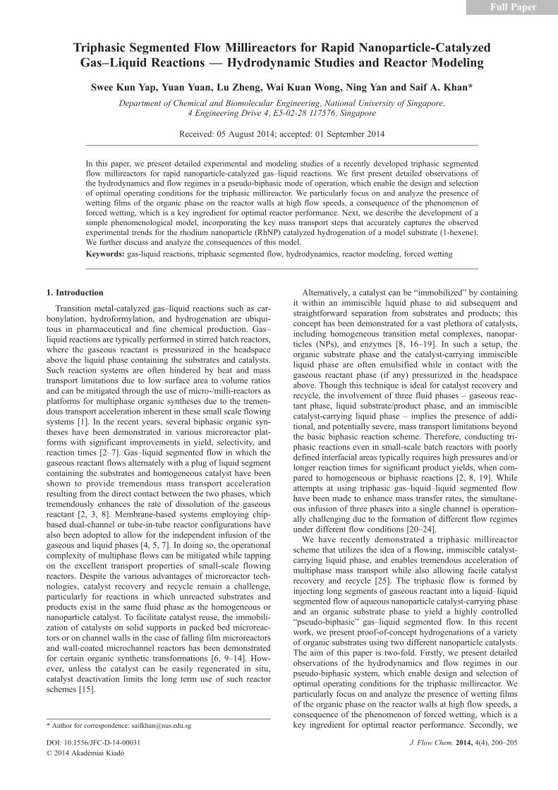
Triphasic Segmented Flow Millireactors for Rapid Nanoparticle-CatalyzedGas–Liquid Reactions — Hydrodynamic Studies and Reactor Modeling
Swee Kun Yap, Yuan Yuan, Lu Zheng, Wai Kuan Wong, Ning Yan and Saif A. Khan*
Department of Chemical and Biomolecular Engineering, National University of Singapore,4 Engineering Drive 4, E5-02-28 117576, Singapore
Received: 05 August 2014; accepted: 01 September 2014
In this paper, we present detailed experimental and modeling studies of a recently developed triphasic segmentedflow millireactors for rapid nanoparticle-catalyzed gas–liquid reactions. We first present detailed observations ofthe hydrodynamics and flow regimes in a pseudo-biphasic mode of operation, which enable the design and selectionof optimal operating conditions for the triphasic millireactor. We particularly focus on and analyze the presence ofwetting films of the organic phase on the reactor walls at high flow speeds, a consequence of the phenomenon offorced wetting, which is a key ingredient for optimal reactor performance. Next, we describe the development of asimple phenomenological model, incorporating the key mass transport steps that accurately captures the observedexperimental trends for the rhodium nanoparticle (RhNP) catalyzed hydrogenation of a model substrate (1-hexene).We further discuss and analyze the consequences of this model.
Keywords: gas-liquid reactions, triphasic segmented flow, hydrodynamics, reactor modeling, forced wetting
1. Introduction
Transition metal-catalyzed gas–liquid reactions such as car-bonylation, hydroformylation, and hydrogenation are ubiqui-tous in pharmaceutical and fine chemical production. Gas–liquid reactions are typically performed in stirred batch reactors,where the gaseous reactant is pressurized in the headspaceabove the liquid phase containing the substrates and catalysts.Such reaction systems are often hindered by heat and masstransport limitations due to low surface area to volume ratiosand can be mitigated through the use of micro-/milli-reactors asplatforms for multiphase organic syntheses due to the tremen-dous transport acceleration inherent in these small scale flowingsystems [1]. In the recent years, several biphasic organic syn-theses have been demonstrated in various microreactor plat-forms with significant improvements in yield, selectivity, andreaction times [2–7]. Gas–liquid segmented flow in which thegaseous reactant flows alternately with a plug of liquid segmentcontaining the substrates and homogeneous catalyst have beenshown to provide tremendous mass transport accelerationresulting from the direct contact between the two phases, whichtremendously enhances the rate of dissolution of the gaseousreactant [2, 3, 8]. Membrane-based systems employing chip-based dual-channel or tube-in-tube reactor configurations havealso been adopted to allow for the independent infusion of thegaseous and liquid phases [4, 5, 7]. In doing so, the operationalcomplexity of multiphase flows can be mitigated while tappingon the excellent transport properties of small-scale flowingreactors. Despite the various advantages of microreactor tech-nologies, catalyst recovery and recycle remain a challenge,particularly for reactions in which unreacted substrates andproducts exist in the same fluid phase as the homogeneous ornanoparticle catalyst. To facilitate catalyst reuse, the immobili-zation of catalysts on solid supports in packed bed microreac-tors or on channel walls in the case of falling film microreactorsand wall-coated microchannel reactors has been demonstratedfor certain organic synthetic transformations [6, 9–14]. How-ever, unless the catalyst can be easily regenerated in situ,catalyst deactivation limits the long term use of such reactorschemes [15].
Alternatively, a catalyst can be “immobilized” by containingit within an immiscible liquid phase to aid subsequent andstraightforward separation from substrates and products; thisconcept has been demonstrated for a vast plethora of catalysts,including homogeneous transition metal complexes, nanopar-ticles (NPs), and enzymes [8, 16–19]. In such a setup, theorganic substrate phase and the catalyst-carrying immiscibleliquid phase are often emulsified while in contact with thegaseous reactant phase (if any) pressurized in the headspaceabove. Though this technique is ideal for catalyst recovery andrecycle, the involvement of three fluid phases – gaseous reac-tant phase, liquid substrate/product phase, and an immisciblecatalyst-carrying liquid phase – implies the presence of addi-tional, and potentially severe, mass transport limitations beyondthe basic biphasic reaction scheme. Therefore, conducting tri-phasic reactions even in small-scale batch reactors with poorlydefined interfacial areas typically requires high pressures and/orlonger reaction times for significant product yields, when com-pared to homogeneous or biphasic reactions [2, 8, 19]. Whileattempts at using triphasic gas–liquid–liquid segmented flowhave been made to enhance mass transfer rates, the simultane-ous infusion of three phases into a single channel is operation-ally challenging due to the formation of different flow regimesunder different flow conditions [20–24].
We have recently demonstrated a triphasic millireactorscheme that utilizes the idea of a flowing, immiscible catalyst-carrying liquid phase, and enables tremendous acceleration ofmultiphase mass transport while also allowing facile catalystrecovery and recycle [25]. The triphasic flow is formed byinjecting long segments of gaseous reactant into a liquid–liquidsegmented flow of aqueous nanoparticle catalyst-carrying phaseand an organic substrate phase to yield a highly controlled“pseudo-biphasic” gas–liquid segmented flow. In this recentwork, we present proof-of-concept hydrogenations of a varietyof organic substrates using two different nanoparticle catalysts.The aim of this paper is two-fold. Firstly, we present detailedobservations of the hydrodynamics and flow regimes in ourpseudo-biphasic system, which enable design and selection ofoptimal operating conditions for the triphasic millireactor. Weparticularly focus on and analyze the presence of wetting filmsof the organic phase on the reactor walls at high flow speeds, aconsequence of the phenomenon of forced wetting, which is akey ingredient for optimal reactor performance. Secondly, we* Author for correspondence: [email protected]
DOI: 10.1556/JFC-D-14-00031 J. Flow Chem. 2014, 4(4), 200–205
© 2014 Akadémiai Kiadó
Full Paper
develop a simple phenomenological model, incorporating thekey mass transport steps that accurately captures the observedexperimental trends for the rhodium nanoparticle (RhNP) cata-lyzed hydrogenation of a model substrate (1-hexene). We fur-ther discuss and analyze the consequences of this model.
2. Materials and Methods
2.1. Rhodium Nanoparticles (RhNPs) Synthesis. RhNPsare synthesized using a classical ethanol–water reduction method[26]. Briefly, 5 mM RhNP stock solution is prepared by refluxing5 mM of RhCl3⋅xH2O (Alfa Aesar Rh 38.5–45.5%) and 0.555 gof polyvinylpyrrolidone (Alfa Aesar, M.W. 40 k) as the stabi-lizer in 30 mL of absolute ethanol (Fisher, ≥99.5%) and 20 mLof ultrapure water (Milli-Q, 18.2 MΩ⋅cm at 25 °C) at 120 °C for1 h. Thereafter, all solvent is vaporized at 60 °C under reducedpressure to afford a black residue before adding 50mL of ultrapurewater to obtain a 5-mM stock solution containing ~3 nm RhNPs.The 5 mM stock solution is then further diluted to 0.5 mM prior toits use for hydrogenation reactions in both batch and flowexperiments.
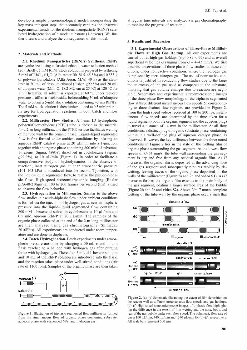
2.2. Millireactor Flow Studies. A 1-mm ID hydrophobicpolytetrafluoroethylene (PTFE) tube is chosen as the materialfor a 2-m long millireactor; the PTFE surface facilitates wettingof the tube wall by the organic phase. Liquid–liquid segmentedflow is first formed under ambient conditions by infusing anaqueous RhNP catalyst phase at 20 μL/min into a T-junction,together with an organic phase containing 800 mM of substrate,1-hexene (Sigma, ≥99%), dissolved in cyclohexane (Sigma,≥99.9%), at 10 μL/min (Figure 1). In order to facilitate acomprehensive study of hydrodynamics in the absence ofreaction, inert nitrogen gas at near atmospheric pressure(101–103 kPa) is introduced into the second T-junction, withthe liquid–liquid segmented flow, to realize the pseudo-bipha-sic flow. High-speed stereomicroscopic imaging (BaslerpiA640-210gm) at 100 to 200 frames per second (fps) is usedto observe the flow behavior.
2.3. Hydrogenation in Millireactor. Similar to the aboveflow studies, a pseudo-biphasic flow under ambient conditionsis formed via the injection of hydrogen gas at near atmosphericpressure into the liquid–liquid segmented flow containing800 mM 1-hexene dissolved in cyclohexane at 10 μL/min and0.5 mM aqueous RhNP at 20 μL/min. The samples of theorganic phase collected at the end of the 2-m long millireactorare then analyzed using gas chromatography (Shimadzu2010Plus). All experiments are conducted under room temper-ature and are done in duplicate.
2.4. Batch Hydrogenation. Batch experiments under atmos-pheric pressure are done by charging a 50-mL round-bottomflask attached to a balloon with hydrogen gas after purgingthrice with hydrogen gas. Thereafter, 5 mL of 1-hexene solutionand 10 mL of the RhNP solution are introduced into the flask,and the reaction takes place under well-stirred conditions (stirrate of 1100 rpm). Samples of the organic phase are then taken
at regular time intervals and analyzed via gas chromatographyto monitor the progress of reaction.
3. Results and Discussion
3.1. Experimental Observations of Three-Phase Milliflui-dic Flows at High Gas Holdup. All our experiments arecarried out at high gas holdups (εG=0.89–0.99) and at overallsuperficial velocities U
_ranging from U
_= 4–43 mm/s. We first
describe observations of three-phase flow studies at these con-ditions, under nonreactive conditions, where the hydrogen gasis replaced by inert nitrogen gas. The use of nonreactive con-ditions is justified in conducting flow studies due to the largemolar excess of the gas used as compared to the substrate,implying that gas volume changes due to reaction are negli-gible. Schematics and experimental stereomicroscopic imagesof the three-phase flow morphology of the triphasic segmentedflow at three different instantaneous flow speeds U, correspond-ing to three distinct flow regimes, are provided in Figure 2.From the high speed videos recorded at 100 to 200 fps, instan-taneous flow speeds are determined by the time taken for aliquid segment (both the organic segment and the aqueous plug)to travel a distance of ~4 mm in the millireactor. At all flowconditions, a distinct plug of organic substrate phase, containingwithin it a well-defined plug of aqueous catalyst phase, isobserved. However, the key difference between the three notedconditions in Figure 2 lies in the state of the wetting film oforganic phase surrounding the gas segment. At the lowest flowspeeds of U<4 mm/s, the tube wall surrounding the gas seg-ment is dry and free from any residual organic film. As Uincreases, the organic film is deposited at the advancing noseof the gas segment and subsequently ruptures rapidly by de-wetting, leaving traces of the organic phase deposited on thewalls of the millireactor (Figure 2a and 2d and video S1). As Uincreases further, the organic film extends to the main body ofthe gas segment, coating a larger surface area of the bubble(Figure 2b and 2e and video S2). Above U=17 mm/s, completewetting of the tube wall by the organic phase occurs such that
Figure 1. Illustration of triphasic segmented flow millireactor formedfrom the simultaneous flow of organic phase containing substrate,aqueous phase with suspended NPs, and hydrogen gas
Figure 2. (a)–(c) Schematic illustrating the extent of film deposition onthe reactor wall at different instantaneous flow speeds and gas holdups.(d)–(f) High speed stereomicroscope images of triphasic flow highlight-ing the difference in the extent of film wetting and the nose, body, andrear of the gas bubble under each flow speed. The volumetric flow rate ofgas is 160 μL/min, 440 μL/min and 1340 μL/min for (d)–(f), respectively.All scale bars represent 500 μm
S.K. Yap et al.
201
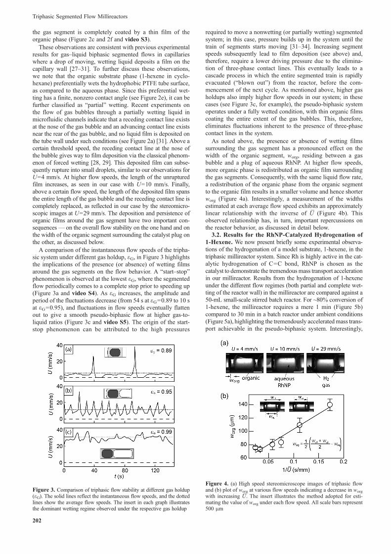
the gas segment is completely coated by a thin film of theorganic phase (Figure 2c and 2f and video S3).
These observations are consistent with previous experimentalresults for gas–liquid biphasic segmented flows in capillarieswhere a drop of moving, wetting liquid deposits a film on thecapillary wall [27–31]. To further discuss these observations,we note that the organic substrate phase (1-hexene in cyclo-hexane) preferentially wets the hydrophobic PTFE tube surface,as compared to the aqueous phase. Since this preferential wet-ting has a finite, nonzero contact angle (see Figure 2e), it can befurther classified as “partial” wetting. Recent experiments onthe flow of gas bubbles through a partially wetting liquid inmicrofluidic channels indicate that a receding contact line existsat the nose of the gas bubble and an advancing contact line existsnear the rear of the gas bubble, and no liquid film is deposited onthe tube wall under such conditions (see Figure 2a) [31]. Above acertain threshold speed, the receding contact line at the nose ofthe bubble gives way to film deposition via the classical phenom-enon of forced wetting [28, 29]. This deposited film can subse-quently rupture into small droplets, similar to our observations forU=4 mm/s. At higher flow speeds, the length of the unrupturedfilm increases, as seen in our case with U=10 mm/s. Finally,above a certain flow speed, the length of the deposited film spansthe entire length of the gas bubble and the receding contact line iscompletely replaced, as reflected in our case by the stereomicro-scopic images at U=29 mm/s. The deposition and persistence oforganic films around the gas segment have two important con-sequences— on the overall flow stability on the one hand and onthe width of the organic segment surrounding the catalyst plug onthe other, as discussed below.
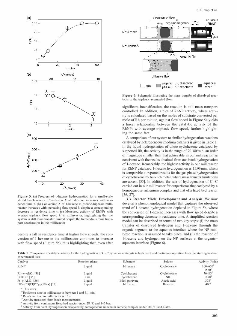
A comparison of the instantaneous flow speeds of the tripha-sic system under different gas holdup, εG, in Figure 3 highlightsthe implications of the presence (or absence) of wetting filmsaround the gas segments on the flow behavior. A “start–stop”phenomenon is observed at the lowest εG, where the segmentedflow periodically comes to a complete stop prior to speeding up(Figure 3a and video S4). As εG increases, the amplitude andperiod of the fluctuations decrease (from 54 s at εG=0.89 to 10 sat εG=0.95), and fluctuations in flow speeds eventually flattenout to give a smooth pseudo-biphasic flow at higher gas-to-liquid ratios (Figure 3c and video S5). The origin of the start-stop phenomenon can be attributed to the high pressures
required to move a nonwetting (or partially wetting) segmentedsystem; in this case, pressure builds up in the system until thetrain of segments starts moving [31–34]. Increasing segmentspeeds subsequently lead to film deposition (see above) and,therefore, require a lower driving pressure due to the elimina-tion of three-phase contact lines. This eventually leads to acascade process in which the entire segmented train is rapidlyevacuated (“blown out”) from the reactor, before the com-mencement of the next cycle. As mentioned above, higher gasholdups also imply higher flow speeds in our system; in thesecases (see Figure 3c, for example), the pseudo-biphasic systemoperates under a fully wetted condition, with thin organic filmscoating the entire extent of the gas bubbles. This, therefore,eliminates fluctuations inherent to the presence of three-phasecontact lines in the system.
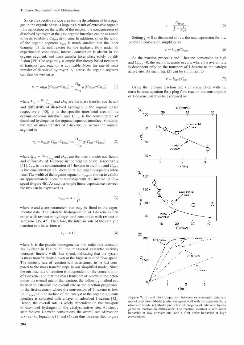
As noted above, the presence or absence of wetting filmssurrounding the gas segment has a pronounced effect on thewidth of the organic segment, worg, residing between a gasbubble and a plug of aqueous RhNP. At higher flow speeds,more organic phase is redistributed as organic film surroundingthe gas segments. Consequently, with the same liquid flow rate,a redistribution of the organic phase from the organic segmentto the organic film results in a smaller volume and hence shorterworg (Figure 4a). Interestingly, a measurement of the widthsestimated at each average flow speed exhibits an approximatelylinear relationship with the inverse of U
_(Figure 4b). This
observed relationship has, in turn, important repercussions onthe reactor behavior, as discussed in detail below.
3.2. Results for the RhNP-Catalyzed Hydrogenation of1-Hexene. We now present briefly some experimental observa-tions of the hydrogenation of a model substrate, 1-hexene, in thetriphasic millireactor system. Since Rh is highly active in the cat-alytic hydrogenation of C=C bond, RhNP is chosen as thecatalyst to demonstrate the tremendousmass transport accelerationin our millireactor. Results from the hydrogenation of 1-hexeneunder the different flow regimes (both partial and complete wet-ting of the reactor wall) in the millireactor are compared against a50-mL small-scale stirred batch reactor. For ~80% conversion of1-hexene, the millireactor requires a mere 1 min (Figure 5b)compared to 30 min in a batch reactor under ambient conditions(Figure 5a), highlighting the tremendously acceleratedmass trans-port achievable in the pseudo-biphasic system. Interestingly,
Figure 3. Comparison of triphasic flow stability at different gas holdup(εG). The solid lines reflect the instantaneous flow speeds, and the dottedlines show the average flow speeds. The insert in each graph illustratesthe dominant wetting regime observed under the respective gas holdup
Figure 4. (a) High speed stereomicroscope images of triphasic flowand (b) plot of worg at various flow speeds indicating a decrease in worg
with increasing U_. The insert illustrates the method adopted for esti-
mating the value of worg under each flow speed. All scale bars represent500 μm
Triphasic Segmented Flow Millireactors
202
despite a fall in residence time at higher flow speeds, the con-version of 1-hexene in the millireactor continues to increasewith flow speed (Figure 5b), thus highlighting that, even after
significant intensification, the reaction is still mass transportcontrolled. In addition, a plot of RhNP activity, where activ-ity is calculated based on the moles of substrate converted permole of Rh per minute, against flow speed in Figure 5c yieldsa linear relationship between the catalytic activity of theRhNPs with average triphasic flow speed, further highlight-ing the same fact.
A comparison of our system to similar hydrogenation reactionscatalyzed by heterogeneous rhodium catalysts is given in Table 1.In the liquid hydrogenation of dilute cyclohexene catalyzed bysupported Rh, the activity is in the range of 70–80/min, an orderof magnitude smaller than that achievable in our millireactor, asconsistent with the results obtained from our batch hydrogenationof 1-hexene. Remarkably, the highest activity in our millireactorfor RhNP catalyzed 1-hexene hydrogenation is 1550/min, whichis comparable to reported results for the gas phase hydrogenationof cyclohexene by bulk Rh metal, where mass transfer limitationsare absent [35]. In addition, the rate of hydrogenation of C=Ccarried out in our millireactor far outperforms that catalyzed by ahomogeneous ruthenium complex and that of a fixed bed reactor[36, 37].
3.3. Reactor Model Development and Analysis. We nowdevelop a phenomenological model that captures the observedtrend of 1-hexene hydrogenation depicted in Figure 5b, wherethe conversion of 1-hexene increases with flow speed despite acorresponding decrease in residence time. A simplified reactionmodel can be described in terms of two key steps: (i) the masstransfer of dissolved hydrogen and 1-hexene through theorganic segment to the aqueous interface where the NP-cata-lyzed reaction is assumed to take place, and (ii) the reaction of1-hexene and hydrogen on the NP surfaces at the organic–aqueous interface (Figure 6).
Figure 5. (a) Progress of 1-hexene hydrogenation for a small-scalestirred batch reactor. Conversion X of 1-hexene increases with resi-dence time τ. (b) Conversion X of 1-hexene in pseudo-biphasic milli-reactor increases with increasing flow speed U despite a correspondingdecrease in residence time τ. (c) Measured activity of RhNPs withaverage triphasic flow speed U
_in millireactor, highlighting that the
system is still mass transfer limited despite the tremendous mass trans-port acceleration in the millireactor
Table 1. Comparison of catalytic activity for the hydrogenation of C=C by various catalysts in both batch and continuous operation from literature against ourexperimental data
Catalyst Reaction phase Substrate Solvent Activity (/min)
RhNPa Liquid 1-Hexene Cyclohexane 100–650b
1550c
Rh–γ-Al2O3 [38] Liquid Cyclohexene Cyclohexane 70–80d
Bulk Rh [35] Gas Cyclohexene NIL 1870d
Pt–γ-Al2O3 [36] Liquid Ethyl pyruvate Acetic acid 378e
HRu(CO)Cl(PCy3)(IMes) [37] Liquid 1-Hexene Benzene 400f
a This work.bResidence time in millireactor is between 1 and 3.1 min.cResidence time in millireactor is 16 s.dActivity measured from batch measurements.eActivity from continuous fixed-bed reactor under 28 °C and 145 bar.fActivity from batch hydrogenation catalyzed by homogeneous ruthenium carbene complex under 100 °C and 4 atm.
Figure 6. Schematic illustrating the mass transfer of dissolved reac-tants in the triphasic segmented flow
S.K. Yap et al.
203
Since the specific surface area for the dissolution of hydrogengas in the organic phase is large as a result of extensive organicfilm deposition on the walls of the reactor, the concentration ofdissolved hydrogen at the gas–organic interface can be assumedto be its solubility CH2sat at ~1 atm. In addition, since the widthof the organic segment worg is much smaller than the innerdiameter of the millireactor for the triphasic flow under allexperimental conditions, internal convection is absent in theorganic segment, and mass transfer takes place solely by dif-fusion [39]. Consequently, a simple film theory-based treatmentof transport and reaction is applicable. Now, the rate of masstransfer of dissolved hydrogen, r1, across the organic segmentcan thus be written as
r1 ¼ kH2a� CH2sat−CH2;s
� � ¼ DH2
worga� CH2sat−CH2;s
� � ð1Þ
where kH2 ¼ DH2
�worg
and DH2 are the mass transfer coefficient
and diffusivity of dissolved hydrogen in the organic phaserespectively [40], a� is the specific interfacial area of theorganic–aqueous interface, and CH2;s is the concentration ofdissolved hydrogen at the organic–aqueous interface. Similarly,the rate of mass transfer of 1-hexene, r2, across the organicsegment is
r2 ¼ khexa� Chex−Chex;s
� � ¼ Dhex
worga� Chex−Chex;s
� � ð2Þ
where khex ¼ Dhex=worgand Dhex are the mass transfer coefficient
and diffusivity of 1-hexene in the organic phase, respectively[41], Chex is the concentration of 1-hexene in the film, and Chex,s
is the concentration of 1-hexene at the organic–aqueous inter-face. The width of the organic segment, worg, is shown to exhibitan approximately linear relationship with the inverse of flowspeed (Figure 4b). As such, a simple linear dependence betweenthe two can be expressed as
worg ¼ aþ b
U� ð3Þ
where a and b are parameters that may be fitted to the exper-imental data. The catalytic hydrogenation of 1-hexene is firstorder with respect to hydrogen and zero order with respect to1-hexene [35, 42]. Therefore, the intrinsic rate of the catalyticreaction can be written as
r3 ¼ krCH2 ð4Þ
where kr is the pseudo-homogeneous first order rate constant.As evident in Figure 5c, the measured catalytic activityincreases linearly with flow speed, indicating that the systemis mass transfer limited even at the highest studied flow speed.The intrinsic rate of reaction is thus assumed to be fast com-pared to the mass transfer steps in our simplified model. Sincethe intrinsic rate of reaction is independent of the concentrationof 1-hexene, and that the mass transport of 1-hexene too deter-mines the overall rate of the reaction, the following method canbe used to establish the overall rate as the reaction progresses.In the first scenario where the conversion of 1-hexene is low,i.e. Chex,s>0, the surface of the catalyst at the organic–aqueousinterface is saturated with a layer of adsorbed 1-hexene [42].Hence, the overall rate is solely dependent on the transportof dissolved hydrogen to the catalyst active site. At steadystate for low 1-hexene conversions, the overall rate of reactionis r=r1=r3. Equations (1) and (4) can thus be simplified to give
r ¼ CH2sat1krþ 1
kH2a�
: ð5Þ
Setting 1kr¼ 0 as discussed above, the rate expression for low
1-hexene conversion simplifies to
r ¼ kH2a�CH2sat: ð6ÞAs the reaction proceeds and 1-hexene conversion is high
and Chex,s=0, the second scenario occurs, where the overall rateis dependent only on the transport of 1-hexene to the catalystactive site. As such, Eq. (2) can be simplified to
r ¼ khexa�Chex: ð7ÞUsing the relevant reaction rate r in conjunction with the
mass balance equation for a plug flow reactor, the consumptionof 1-hexene can thus be expressed as
Figure 7. (a) and (b) Comparison between experimental data andmodel prediction. Model prediction agrees well with the experimentallyobserved trends. (c) Model prediction of progress of 1-hexene hydro-genation reaction in millireactor. The reaction exhibits a zero orderbehavior at low conversions, and a first order behavior at highconversions
Triphasic Segmented Flow Millireactors
204
dChex
dτ¼ −r ð8Þ
where τ ¼ LU� :
�
A comparison of the reactor model with the experimentallyobtained conversion in Figure 7a reveals that the model predic-tion agrees well with the experimentally observed trends — theincrease in 1-hexene conversion at higher flow speeds despite afall in residence time is adequately captured by the mathemat-ical model. In addition, the values of worg obtained via fittingwith experimentally obtained 1-hexene conversions are close tothe experimentally measured values (Figure 7b). A slight devi-ation between the measured and fitted worg values is observed athigher flow speeds due to the inaccuracies involved in measur-ing worg for short organic widths.
Further analysis of the reactor behavior under different flowspeeds shows that 1-hexene conversion follows a linear rela-tionship with residence time under low conversions and a firstorder trend under high conversions (Figure 7c). This is a directconsequence of the modeled scenario, where at low conversions,the overall rate of reaction is solely dependent on the masstransfer of dissolved hydrogen to the catalytic sites. Since thesupply of dissolved hydrogen from the reservoir comprised by thelarge hydrogen gas segment is in excess such that the gas–organicinterface is saturated with hydrogen at all times, the rate of masstransport of hydrogen from the gas–liquid interface to theorganic–aqueous interface, where the reaction takes place, is aconstant. Consequently, a zero order behavior is observed for low1-hexene conversions (i.e., Chex,s>0) under all flow speeds. Athigh conversions, the concentration of 1-hexene in the organicphase is low and the concentration of 1-hexene at the NP sur-face approaches zero. Being a larger molecule, the diffusivity of 1-hexene is lower than that of dissolved hydrogen in the organicphase. As such, the rate-determining step is now themass transportof 1-hexene to the catalytic sites at the organic–aqueous interface.With a first order relationship between the transport of 1-hexeneand its concentration, a nonlinear tail is observed in the curves athigh conversions. Such a phenomenon has also been reported byBoudart and Sajkowski in the liquid phase hydrogenation of cyclo-hexene catalyzed by heterogeneous rhodium catalyst, where a zeroorder trend is observed only for conversions <95% [42]. In addi-tion, our experimental results show that, for a residence time of1 min in a 2-m millireactor, the conversion of pure 1-hexene(~8000 mM) is 9%, ~10 times lower than that of a 800-mM1-hexene solution with 82% conversion. These, thus, indicatethat our model closely matches the experimental scenarios.
4. Conclusion
In this work, we present observations of the hydrodynamicsand flow regimes of a triphasic reaction scheme in millireactors.Despite the involvement of an additional immiscible fluid phasewherein catalysts are “immobilized,” the pseudo-biphasic reac-tor scheme is able to provide tremendous acceleration in masstransport due to the presence of wetting films of the organicphase on the reactor walls resulting from forced wetting. Wealso present a complete reactor model incorporating the effectsof these wetting films for the model case of 1-hexene
hydrogenation, which fully captures the experimental trends.With an understanding of the pseudo-biphasic millireactor oper-ation, we envision the facile extension and application of such areactor scheme to other similar catalytic reactions, includinghomogeneous catalysis.
Supporting Information
Electronic SupplementaryMaterial (ESM) – videos S1–S5 – isavailable in the online version at doi: 10.1556/JFC-D-14-00031.
References
1. Günther, A.; Jensen, K. F. Lab Chip 2006, 6, 1487.2. Rahman, M. T.; Fukuyama, T.; Kamata, N.; Sato, M.; Ryu, I. Chem.
Commun. 2006, 2236.3. Murphy, E. R.; Martinelli, J. R.; Zaborenko, N.; Buchwald, S. L.; Jensen,
K. F. Angew. Chem., Int. Ed. 2007, 46, 1734.4. Bourne, S. L.; O'Brien, M.; Kasinathan, S.; Koos, P.; Tolstoy, P.; Hu, D. X.;
Bates, R. W.; Martin, B.; Schenkel, B.; Ley, S. V. ChemCatChem 2013, 5, 159.5. Noël, T.; Hessel, V. ChemSusChem 2013, 6, 405.6. Yeong, K. K.; Gavriilidis, A.; Zapf, R.; Hessel, V. Catal. Today 2003, 81,
641.7. C. P. Park; D. P. Kim; J. Am. Chem. Soc. 2010, 132, 10102.8. Önal, Y.; Lucas, M.; Claus, P. Chem. Eng. Technol. 2005, 28, 972.9. Kobayashi, J.; Mori, Y.; Okamoto, K.; Akiyama, R.; Ueno, M.; Kitamori,
T.; Kobayashi, S. Science 2004, 304, 1305.10. Hessel, V.; Angeli, P.; Gavriilidis, A.; Löwe, H. Ind. Eng. Chem. Res.
2005, 44, 9750.11. Noël, T.; Naber, J. R.; Hartman, R. L.; McMullen, J. P.; Jensen, K. F.;
Buchwald, S. L. Chem. Sci. 2011, 2, 287.12. Losey, M. W.; Schmidt, M. A.; Jensen, K. F. Ind. Eng. Chem. Res. 2001,
40, 2555.13. Rebrov, E. B.; Murcia, A. B.; Skelton, H. E.; Johnson, B. F. G.; Wheatley,
A. E. H.; Schouten, J. C. Lab Chip 2009, 9, 503.14. Miller, P. W.; Long, N. J.; de Mello, A. J.; Vilar, R.; Audrain, H.; Bender,
D.; Passchier, J.; Gee, A. Angew. Chem., Int. Ed. 2007, 119, 2933.15. Kataoka, S.; Takeuchi, Y.; Harada, A.; Takagi, T.; Takenaka, Y.; Fukaya,
N.; Yasuda, H.; Ohmori, T.; Endo, A. Appl. Catal., A 2012, 119, 427–428.16. Arhancet, J. P.; Davis, M. E.; Merola, J. S.; Hanson, B. E. Nature 1989,
339, 454.17. Dupont, J.; Fonseca, G. S.; Umpierre, A. P.; Fichtner, P. F. P.; Teixeira, A.
R. J. Am. Chem. Soc. 2002, 124, 4228.18. Tjerneld, F.; Johansson, H. O. Int. Rev. Cytol. 1999, 192, 137.19. Yang, X.; Yan, N.; Fei, Z.; Quesada, R. M. C.; Laurenczy, G.; Minsker, L.
K.; Kou, Y.; Li, Y.; Dyson, P. J. Inorg. Chem. 2008, 47, 7444.20. Rajesh, V. M.; Buwa, V. V. Chem. Eng. J. 2012, 832, 207–208.21. Yue, J.; Rebrov, E. V.; Schouten, J. C. Lab Chip 2014, 14, 1632 (2014).22. Su, Y. AIChE J. 2009, 55, 1948.23. Khan, S. A.; Duraiswamy, S. Lab Chip 2009, 9, 1840.24. Sobieszuk, P.; Aubin, J.; Pohorecki, R.Chem. Eng. Technol. 2012, 35, 1346.25. Yap, S. K.; Yuan, Y.; Zheng, L.; Wong, W. K.; Zhang, J.; Yan, N.; Khan,
S. A. Green Chem., submitted for publication, 2014.26. Mu, X.; Evans, D. G.; Kou, Y. Catal. Lett. 2004, 97, 151.27. Kreutzer, M. T.; Kapteijn, F.; Moulijn, J. A.; Heiszwolf, J. J. Chem. Eng.
Sci. 2005, 60, 5895.28. Aussillous, P.; Quéré, D. Phys. Fluids 2000, 12, 2367.29. Bretherton, F. P. J. Fluid Mech. 1969, 10, 166.30. Bico, J.; Quéré, D. Europhys. Lett. 2000, 51, 546.31. Parthiban, P. Thesis, National University of Singapore, 2013.32. Adzima, B. J.; Velankar, S. S. J. Micromech. Microeng. 2006, 16, 1504.33. Rapolu, P.; Son, S. Y. Exp. Fluids 2011, 51, 1101.34. Ody, C. P. Microfluid. Nanofluid. 2010, 9, 397.35. Cruz, G. M. D. Appl. Catal. 1989, 46, 131.36. Künzle, N.; Solèr, J. W.; Baiker, A. Catal. Today 2003, 79–80, 503.37. Lee, H. M.; Smith, D. C. J.; He, Z.; Stevens, E. D.; Yi, C. S.; Nolan, S. P.
Organomet. 2001, 20, 794.38. Boudart, M. Appl. Catal. 1989, 46, 131.39. Fujioka, H.; Grotberg, J. B. J Biomech Eng-T ASME 2004, 126, 567.40. Deen, W. M. Analysis of Transport Phenomena; Oxford University Press,
Inc.: New York, USA, 1998.41. Welty, J.; Wicks, C. E.; Rorrer, G. L.; Wilson, R. E. Fundamentals of
Momentum, Heat and Mass Transfer, 5th ed.; Wiley: New York, USA, 2007.42. Boudart, M.; Sajkowski, D. J., Faraday Discuss. 1991, 92, 57.
S.K. Yap et al.
205