Embed Size (px)
Citation preview
7/31/2019 Trimmers Murata
http://slidepdf.com/reader/full/trimmers-murata 1/44
Cat.No.T13E-13
Ceramic Trimmer
Capacitors
• This PDF catalog is downloaded from the website of Murata Manufacturing co., ltd. Therefore, it’s specifications are subject to change or our products in it may be discontinued without advance notice. Please check wit h oursales representatives or product engineers before ordering.
• This PDF catalog has only typical specifications because there is no space for detailed specifications. Therefore, please approve our product specifications or transact the approval sheet for product specifications before ordering.
!Note T13E.pdf08.8.27
7/31/2019 Trimmers Murata
http://slidepdf.com/reader/full/trimmers-murata 2/44
for EU RoHS Compliant • All the products in this catalog comply with EU RoHS.
• EU RoHS is "the European Directive 2002/95/EC on the Restriction of the Use
of Certain Hazardous Substances in Electrical and Electronic Equipment".
• For more details, please refer to our website 'Murata's Approach for EU RoHS'
(http://www.murata.com/info/rohs.html).
!Note • Please read rating and !CAUTION (for storage, operating, rating, soldering, mounting and handling) in this catalog to prevent smoking and/or burning, etc.• This catalog has only typical specifications because there is no space for detailed specifications. Therefore, please approve our product specifications or transact the approval sheet for product specifications before ordering.
• This PDF catalog is downloaded from the website of Murata Manufacturing co., ltd. Therefore, it’s specifications are subject to change or our products in it may be discontinued without advance notice. Please check wit h oursales representatives or product engineers before ordering.
• This PDF catalog has only typical specifications because there is no space for detailed specifications. Therefore, please approve our product specifications or transact the approval sheet for product specifications before ordering.
!Note T13E.pdf08.8.27
7/31/2019 Trimmers Murata
http://slidepdf.com/reader/full/trimmers-murata 3/44
Part Numbering 2
Selection Guide of Ceramic Trimmer Capacitor 3
TZR1 Series 4
TZS2 Series 8
TZY2 Series 12
TZV2 Series 16
TZC3 Series 20
TZW4 Series 24
TZB4 Series 27
TZ03 Series 32
Packaging 37
Recommended Adjustment Tools 39
Qualified Standards 41
1
2
3
4
5
6
7
8
1
2
3
4
5
6
7
8
CONTENTS
Recycled Paper
!Note • Please read rating and !CAUTION (for storage, operating, rating, soldering, mounting and handling) in this catalog to prevent smoking and/or burning, etc.• This catalog has only typical specifications because there is no space for detailed specifications. Therefore, please approve our product specifications or transact the approval sheet for product specifications before ordering.
The Bluetooth trademarks are owned by Bluetooth SIG, Inc., U.S.A.
• This PDF catalog is downloaded from the website of Murata Manufacturing co., ltd. Therefore, it’s specifications are subject to change or our products in it may be discontinued without advance notice. Please check wit h oursales representatives or product engineers before ordering.
• This PDF catalog has only typical specifications because there is no space for detailed specifications. Therefore, please approve our product specifications or transact the approval sheet for product specifications before ordering.
!Note T13E.pdf08.8.27
7/31/2019 Trimmers Murata
http://slidepdf.com/reader/full/trimmers-murata 4/44
!Note • Please read rating and !CAUTION (for storage, operating, rating, soldering, mounting and handling) in this catalog to prevent smoking and/or burning, etc.• This catalog has only typical specifications because there is no space for detailed specifications. Therefore, please approve our product specifications or transact the approval sheet for product specifications before ordering.
2
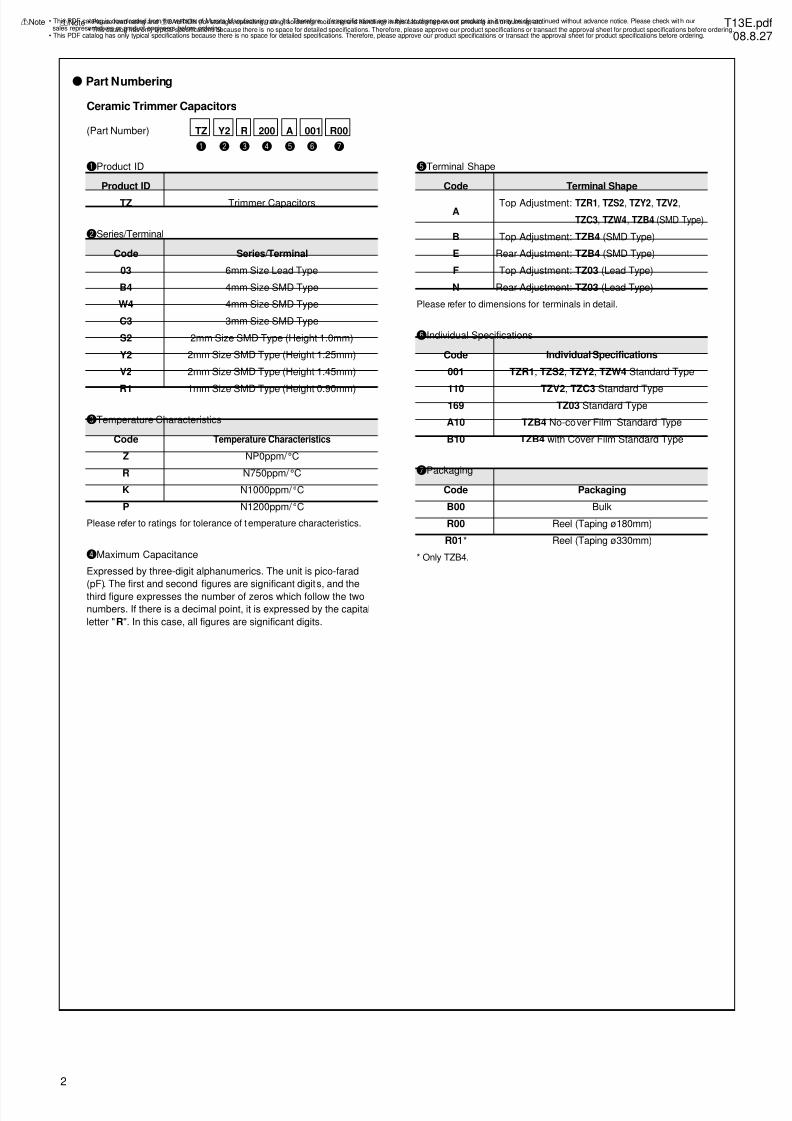
o Part Numbering
(Part Number)
qProduct ID
TZ Trimmer Capacitors
Product ID
rMaximum Capacitance
Expressed by three-digit alphanumerics. The unit is pico-farad
(pF). The first and second figures are significant digits, and the
third figure expresses the number of zeros which follow the two
numbers. If there is a decimal point, it is expressed by the capital
letter "R". In this case, all figures are significant digits.
Ceramic Trimmer Capacitors
tTerminal Shape
Code Terminal Shape
A
B
E
F
N
Top Adjustment:
Top Adjustment:
Rear Adjustment:
Top Adjustment:
Rear Adjustment:
TZR1, TZS2, TZY2, TZV2,
TZC3, TZW4, TZB4 (SMD Type)
TZB4 (SMD Type)
TZB4 (SMD Type)
TZ03 (Lead Type)
TZ03 (Lead Type)
uPackaging
Code
B00
R00
R01*
Bulk
Reel (Taping ø180mm)
Reel (Taping ø330mm)
Packaging
wSeries/Terminal
Code
03
B4
W4
C3
S2
Y2
V2
R1
6mm Size Lead Type
4mm Size SMD Type
4mm Size SMD Type
3mm Size SMD Type
2mm Size SMD Type (Height 1.0mm)
2mm Size SMD Type (Height 1.25mm)
2mm Size SMD Type (Height 1.45mm)
1mm Size SMD Type (Height 0.90mm)
Series/Terminal
eTemperature Characteristics
Code
Z
R
K
P
NP0ppm/ °C
N750ppm/ °C
N1000ppm/ °C
N1200ppm/ °C
Temperature Characteristics
Please refer to dimensions for terminals in detail.
* Only TZB4.
yIndividual Specifications
Code
001
110169
A10
B10
TZR1, TZS2, TZY2, TZW4 Standard Type
TZV2, TZC3 Standard TypeTZ03 Standard Type
TZB4 No-cover Film Standard Type
TZB4 with Cover Film Standard Type
Individual Specifications
Please refer to ratings for tolerance of t emperature characteristics.
t
A
y
001
q
TZ
u
R00
r
200
e
R
w
Y2
• This PDF catalog is downloaded from the website of Murata Manufacturing co., ltd. Therefore, it’s specifications are subject to change or our products in it may be discontinued without advance notice. Please check wit h oursales representatives or product engineers before ordering.
• This PDF catalog has only typical specifications because there is no space for detailed specifications. Therefore, please approve our product specifications or transact the approval sheet for product specifications before ordering.
!Note T13E.pdf08.8.27
7/31/2019 Trimmers Murata
http://slidepdf.com/reader/full/trimmers-murata 5/44
!Note • Please read rating and !CAUTION (for storage, operating, rating, soldering, mounting and handling) in this catalog to prevent smoking and/or burning, etc.• This catalog has only typical specifications because there is no space for detailed specifications. Therefore, please approve our product specifications or transact the approval sheet for product specifications before ordering.
3
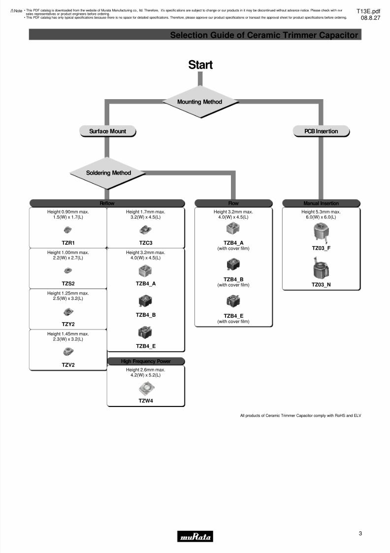
Selection Guide of Ceramic Trimmer Capacitor
• This PDF catalog is downloaded from the website of Murata Manufacturing co., ltd. Therefore, it’s specifications are subject to change or our products in it may be discontinued without advance notice. Please check wit h oursales representatives or product engineers before ordering.
• This PDF catalog has only typical specifications because there is no space for detailed specifications. Therefore, please approve our product specifications or transact the approval sheet for product specifications before ordering.
!Note T13E.pdf08.8.27
Start
Mounting Method
Soldering Method
Surface Mount PCB Insertion
Reflow Flow Manual Insertion
High Frequency Power
Height 2.6mm max.4.2(W) x 5.2(L)
TZW4
Height 1.45mm max.2.3(W) x 3.2(L)
TZV2
Height 1.25mm max.2.5(W) x 3.2(L)
TZY2
Height 1.00mm max.2.2(W) x 2.7(L)
TZS2
Height 0.90mm max.1.5(W) x 1.7(L)
TZR1
Height 1.7mm max.3.2(W) x 4.5(L)
TZC3
Height 3.2mm max.4.0(W) x 4.5(L)
TZB4_A
TZB4_B
TZB4_E
Height 3.2mm max.4.0(W) x 4.5(L)
TZB4_A(with cover film)
TZB4_B(with cover film)
TZB4_E(with cover film)
Height 5.3mm max.6.0(W) x 6.0(L)
TZ03_F
TZ03_N
All products of Ceramic Trimmer Capacitor comply with RoHS and ELV
7/31/2019 Trimmers Murata
http://slidepdf.com/reader/full/trimmers-murata 6/444
!Note • Please read rating and !CAUTION (for storage, operating, rating, soldering, mounting and handling) in this catalog to prevent smoking and/or burning, etc.• This catalog has only typical specifications because there is no space for detailed specifications. Therefore, please approve our product specifications or transact the approval sheet for product specifications before ordering.
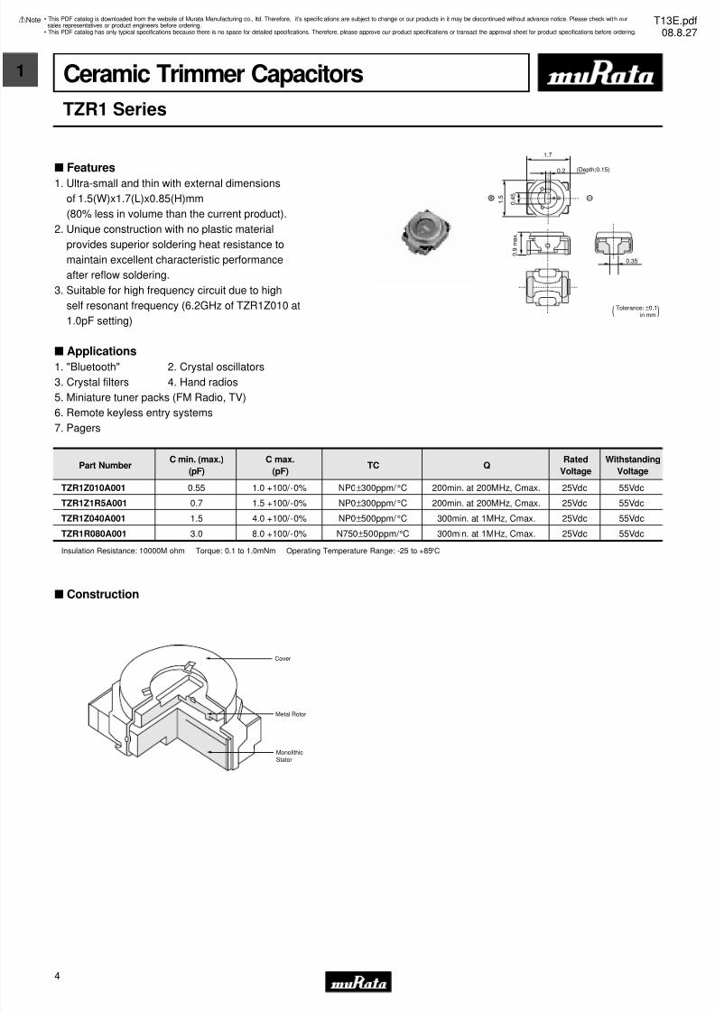
Ceramic Trimmer Capacitors
TZR1 Series
s Features
1. Ultra-small and thin with external dimensions
of 1.5(W)x1.7(L)x0.85(H)mm
(80% less in volume than the current product).
2. Unique construction with no plastic material
provides superior soldering heat resistance to
maintain excellent characteristic performance
after reflow soldering.
3. Suitable for high frequency circuit due to high
self resonant frequency (6.2GHz of TZR1Z010 at
1.0pF setting)
s Applications1. "Bluetooth" 2. Crystal oscillators
3. Crystal filters 4. Hand radios
5. Miniature tuner packs (FM Radio, TV)
6. Remote keyless entry systems
7. Pagers
0.35 0 . 9 m a x .
1 . 5
0 . 4
5
1.7
0.2 (Depth;0.15)
( Tolerance: ±0.1)in mm
Part NumberC min. (max.)
(pF)
C max.
(pF)TC Q
Rated
Voltage
Withstanding
Voltage
TZR1Z010A001 0.55 1.0 +100/-0% NP0±300ppm/ °C 200min. at 200MHz, Cmax. 25Vdc 55Vdc
TZR1Z1R5A001 0.7 1.5 +100/-0% NP0±300ppm/ °C 200min. at 200MHz, Cmax. 25Vdc 55Vdc
TZR1Z040A001 1.5 4.0 +100/-0% NP0±500ppm/ °C 300min. at 1MHz, Cmax. 25Vdc 55Vdc
TZR1R080A001 3.0 8.0 +100/-0% N750±500ppm/ °C 300min. at 1MHz, Cmax. 25Vdc 55Vdc
Insulation Resistance: 10000M ohm Torque: 0.1 to 1.0mNm Operating Temperature Range: -25 to +85°C
s Construction
Cover
Metal Rotor
MonolithicStator
• This PDF catalog is downloaded from the website of Murata Manufacturing co., ltd. Therefore, it’s specifications are subject to change or our products in it may be discontinued without advance notice. Please check wit h oursales representatives or product engineers before ordering.
• This PDF catalog has only typical specifications because there is no space for detailed specifications. Therefore, please approve our product specifications or transact the approval sheet for product specifications before ordering.
!Note T13E.pdf08.8.27
7/31/2019 Trimmers Murata
http://slidepdf.com/reader/full/trimmers-murata 7/445
1
!Note • Please read rating and !CAUTION (for storage, operating, rating, soldering, mounting and handling) in this catalog to prevent smoking and/or burning, etc.• This catalog has only typical specifications because there is no space for detailed specifications. Therefore, please approve our product specifications or transact the approval sheet for product specifications before ordering.
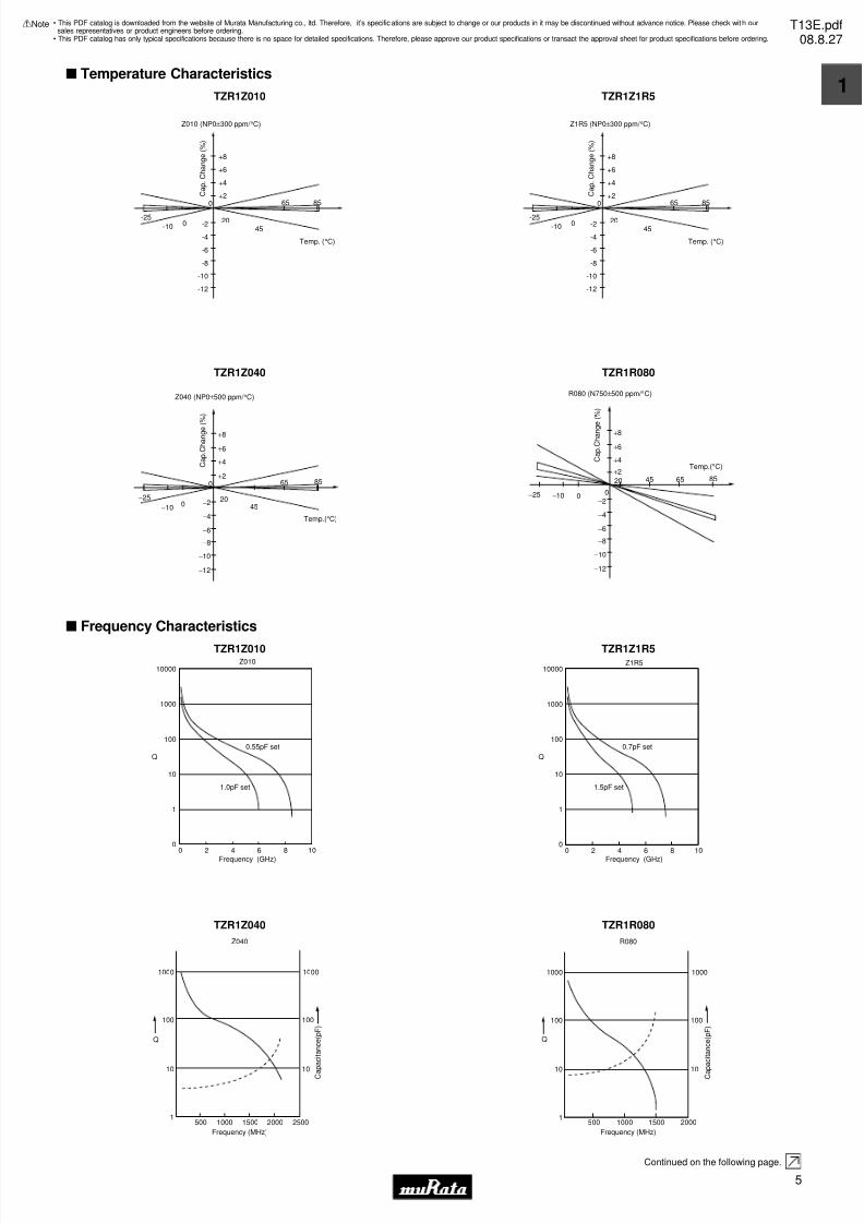
s Temperature Characteristics
TZR1Z010
+8
+6
+4
+2
2045
65 85
-2
-4
-6
-8
-10
-12
-25
-10 0
0
Z010 (NP0±300 ppm/ °C)
Temp. (°C)
C a p .
C h a n g e ( % )
TZR1Z1R5
+8
+6
+4
+2
2045
65 85
-2
-4
-6
-8
-10
-12
-25
-10 0
0
Z1R5 (NP0±300 ppm/ °C)
Temp. (°C)
C a p .
C h a n g e ( % )
TZR1Z040
+8
+6
+4
+2
200
−10
−25
45
65 85
−2
−4
−6
−8
−10
−12
0
Z040 (NP0±500 ppm/ °C)
C a p . C
h a n g e
( % )
Temp.(°C)
TZR1R080
+8
+6
+4
+2
20
0−10−25
45 65 85
−2
−4
−6
−8
−10
−12
0
R080 (N750±500 ppm/ °C)
C a p . C
h a n g
e ( % )
Temp.(°C)
s Frequency Characteristics
TZR1Z010
10000
1000
100
10
1
00 2 4 6
Frequency (GHz)
0.55pF set
1.0pF set
Z010
Q
8 10
TZR1Z1R5
10000
1000
100
10
1
00 2 4 6
Frequency (GHz)
0.7pF set
1.5pF set
Z1R5
Q
8 10
TZR1Z040
1000 1000
100
10
Q
1
10
100
500 1000 1500 2000 2500
Frequency (MHz)
C a
p a c i t a n c e ( p F )
Z040
TZR1R080
1000 1000
100
10
Q
1
10
100
500 1000 1500 2000
Frequency (MHz)
C a p a c i t a n c e ( p F )
R080
Continued on the following page.
• This PDF catalog is downloaded from the website of Murata Manufacturing co., ltd. Therefore, it’s specifications are subject to change or our products in it may be discontinued without advance notice. Please check wit h oursales representatives or product engineers before ordering.
• This PDF catalog has only typical specifications because there is no space for detailed specifications. Therefore, please approve our product specifications or transact the approval sheet for product specifications before ordering.
!Note T13E.pdf08.8.27
7/31/2019 Trimmers Murata
http://slidepdf.com/reader/full/trimmers-murata 8/446
!Note • Please read rating and !CAUTION (for storage, operating, rating, soldering, mounting and handling) in this catalog to prevent smoking and/or burning, etc.• This catalog has only typical specifications because there is no space for detailed specifications. Therefore, please approve our product specifications or transact the approval sheet for product specifications before ordering.
Continued from the preceding page.
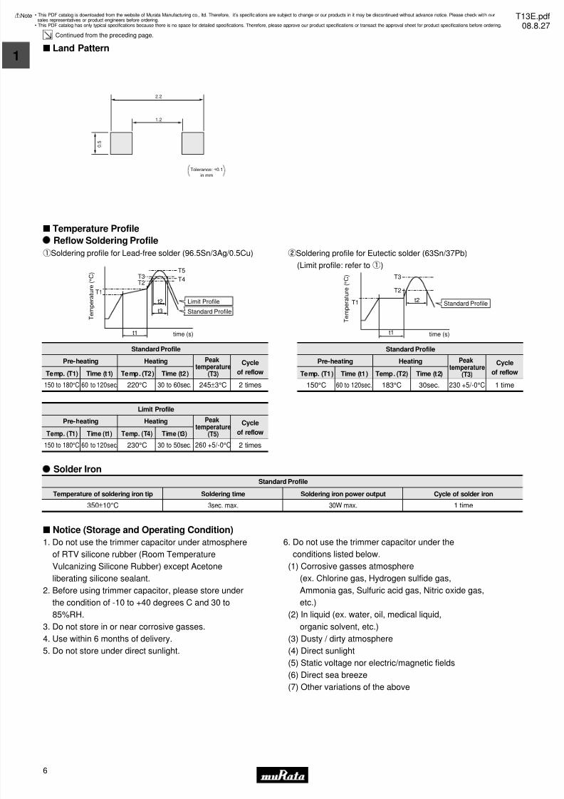
s Land Pattern
2.2
1.2
0 . 5
Tolerance: ±0.1in mm
s Temperature Profile
T e m p e r a t u r e ( °
C )
t3
t2
T3T2
T5
T4
T1
time (s)t1
Reflow Soldering Profile
qSoldering profile for Lead-free solder (96.5Sn/3Ag/0.5Cu)
Standard Profile
Pre-heating Heating Peaktemperature
(T3)
Cycle
of reflowTemp. (T1) Time (t1) Temp. (T2) Time (t2)
2 times245±3°C150 to 180°C 60 to 120sec. 220°C 30 to 60sec.
Limit Profile
Standard Profile
Standard Profile
Pre-heating Heating Cycle
of reflowTemp. (T1) Time (t1) Temp. (T2) Time (t2)
1 time230 +5/-0°C150°C 60 to 120sec. 183°C 30sec.
Limit Profile
Pre-heating Heating Cycle
of reflowTemp. (T1) Time (t1) Temp. (T4) Time (t3)
2 times260 +5/-0°C150 to 180°C 60 to 120sec. 230°C 30 to 50sec.
T e m p e r a t u r e ( ° C
)
time (s)
Standard Profile
t1
T1 t2
T3
T2
wSoldering profile for Eutectic solder (63Sn/37Pb)
(Limit profile: refer toq)
Solder Iron
Standard Profile
Temperature of soldering iron tip Soldering time Soldering iron power output
350±10°C 3sec. max. 30W max. 1 time
Cycle of solder iron
Peaktemperature
(T5)
Peaktemperature
(T3)
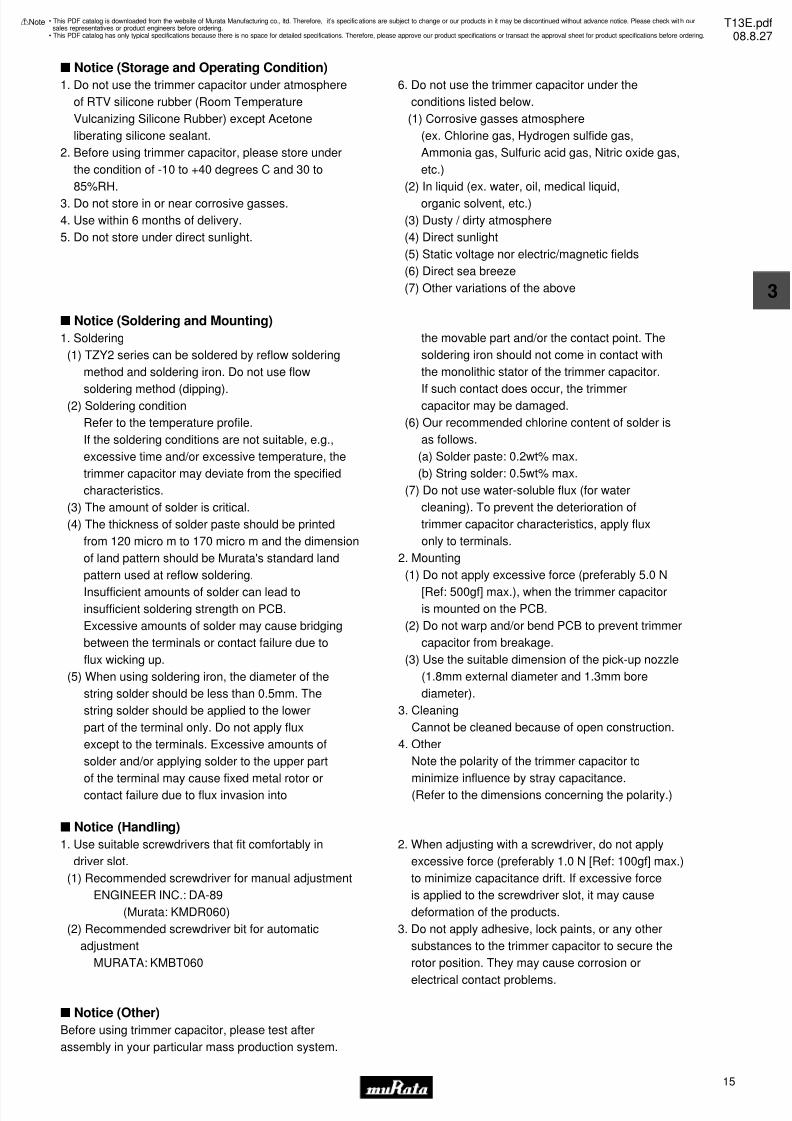
s Notice (Storage and Operating Condition)
1. Do not use the trimmer capacitor under atmosphere
of RTV silicone rubber (Room Temperature
Vulcanizing Silicone Rubber) except Acetone
liberating silicone sealant.
2. Before using trimmer capacitor, please store under
the condition of -10 to +40 degrees C and 30 to
85%RH.
3. Do not store in or near corrosive gasses.
4. Use within 6 months of delivery.
5. Do not store under direct sunlight.
6. Do not use the trimmer capacitor under the
conditions listed below.
(1) Corrosive gasses atmosphere
(ex. Chlorine gas, Hydrogen sulfide gas,
Ammonia gas, Sulfuric acid gas, Nitric oxide gas,
etc.)
(2) In liquid (ex. water, oil, medical liquid,
organic solvent, etc.)
(3) Dusty / dirty atmosphere
(4) Direct sunlight
(5) Static voltage nor electric/magnetic fields
(6) Direct sea breeze
(7) Other variations of the above
• This PDF catalog is downloaded from the website of Murata Manufacturing co., ltd. Therefore, it’s specifications are subject to change or our products in it may be discontinued without advance notice. Please check wit h oursales representatives or product engineers before ordering.
• This PDF catalog has only typical specifications because there is no space for detailed specifications. Therefore, please approve our product specifications or transact the approval sheet for product specifications before ordering.
!Note T13E.pdf08.8.27
7/31/2019 Trimmers Murata
http://slidepdf.com/reader/full/trimmers-murata 9/447
1
!Note • Please read rating and !CAUTION (for storage, operating, rating, soldering, mounting and handling) in this catalog to prevent smoking and/or burning, etc.• This catalog has only typical specifications because there is no space for detailed specifications. Therefore, please approve our product specifications or transact the approval sheet for product specifications before ordering.
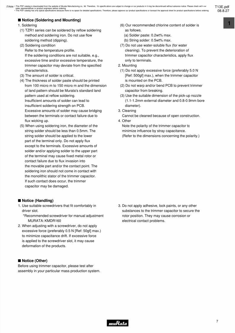
s Notice (Soldering and Mounting)
s Notice (Handling)
s Notice (Other)
Before using trimmer capacitor, please test after
assembly in your particular mass production system.
1. Soldering
(1) TZR1 series can be soldered by reflow soldering
method and soldering iron. Do not use flow
soldering method (dipping).
(2) Soldering condition
Refer to the temperature profile.
If the soldering conditions are not suitable, e.g.,
excessive time and/or excessive temperature, the
trimmer capacitor may deviate from the specified
characteristics.
(3) The amount of solder is critical.
(4) The thickness of solder paste should be printed
from 100 micro m to 150 micro m and the dimension
of land pattern should be Murata's standard land
pattern used at reflow soldering.
Insufficient amounts of solder can lead to
insufficient soldering strength on PCB.
Excessive amounts of solder may cause bridging
between the terminals or contact failure due toflux wicking up.
(5) When using soldering iron, the diameter of the
string solder should be less than 0.5mm. The
string solder should be applied to the lower
part of the terminal only. Do not apply flux
except to the terminals. Excessive amounts of
solder and/or applying solder to the upper part
of the terminal may cause fixed metal rotor or
contact failure due to flux invasion into
the movable part and/or the contact point. The
soldering iron should not come in contact with
the monolithic stator of the trimmer capacitor.
If such contact does occur, the trimmer
capacitor may be damaged.
(6) Our recommended chlorine content of solder is
as follows.
(a) Solder paste: 0.2wt% max.
(b) String solder: 0.5wt% max.
(7) Do not use water-soluble flux (for water
cleaning). To prevent the deterioration of
trimmer capacitor characteristics, apply flux
only to terminals.
2. Mounting
(1) Do not apply excessive force (preferably 5.0 N
[Ref: 500gf] max.), when the trimmer capacitor
is mounted on the PCB.
(2) Do not warp and/or bend PCB to prevent trimmer
capacitor from breaking.
(3) Use the suitable dimension of the pick-up nozzle
(1.1-1.2mm external diameter and 0.8-0.9mm bore
diameter).
3. Cleaning
Cannot be cleaned because of open construction.4. Other
Note the polarity of the trimmer capacitor to
minimize influence by stray capacitance.
(Refer to the dimensions concerning the polarity.)
1. Use suitable screwdrivers that fit comfortably in
driver slot.
*Recommended screwdriver for manual adjustment
MURATA: KMDR160
2. When adjusting with a screwdriver, do not apply
excessive force (preferably 0.5 N [Ref: 50gf] max.)
to minimize capacitance drift. If excessive force
is applied to the screwdriver slot, it may cause
deformation of the products.
3. Do not apply adhesive, lock paints, or any other
substances to the trimmer capacitor to secure the
rotor position. They may cause corrosion or
electrical contact problems.
• This PDF catalog is downloaded from the website of Murata Manufacturing co., ltd. Therefore, it’s specifications are subject to change or our products in it may be discontinued without advance notice. Please check wit h oursales representatives or product engineers before ordering.
• This PDF catalog has only typical specifications because there is no space for detailed specifications. Therefore, please approve our product specifications or transact the approval sheet for product specifications before ordering.
!Note T13E.pdf08.8.27
7/31/2019 Trimmers Murata
http://slidepdf.com/reader/full/trimmers-murata 10/448
2
!Note • Please read rating and !CAUTION (for storage, operating, rating, soldering, mounting and handling) in this catalog to prevent smoking and/or burning, etc.• This catalog has only typical specifications because there is no space for detailed specifications. Therefore, please approve our product specifications or transact the approval sheet for product specifications before ordering.
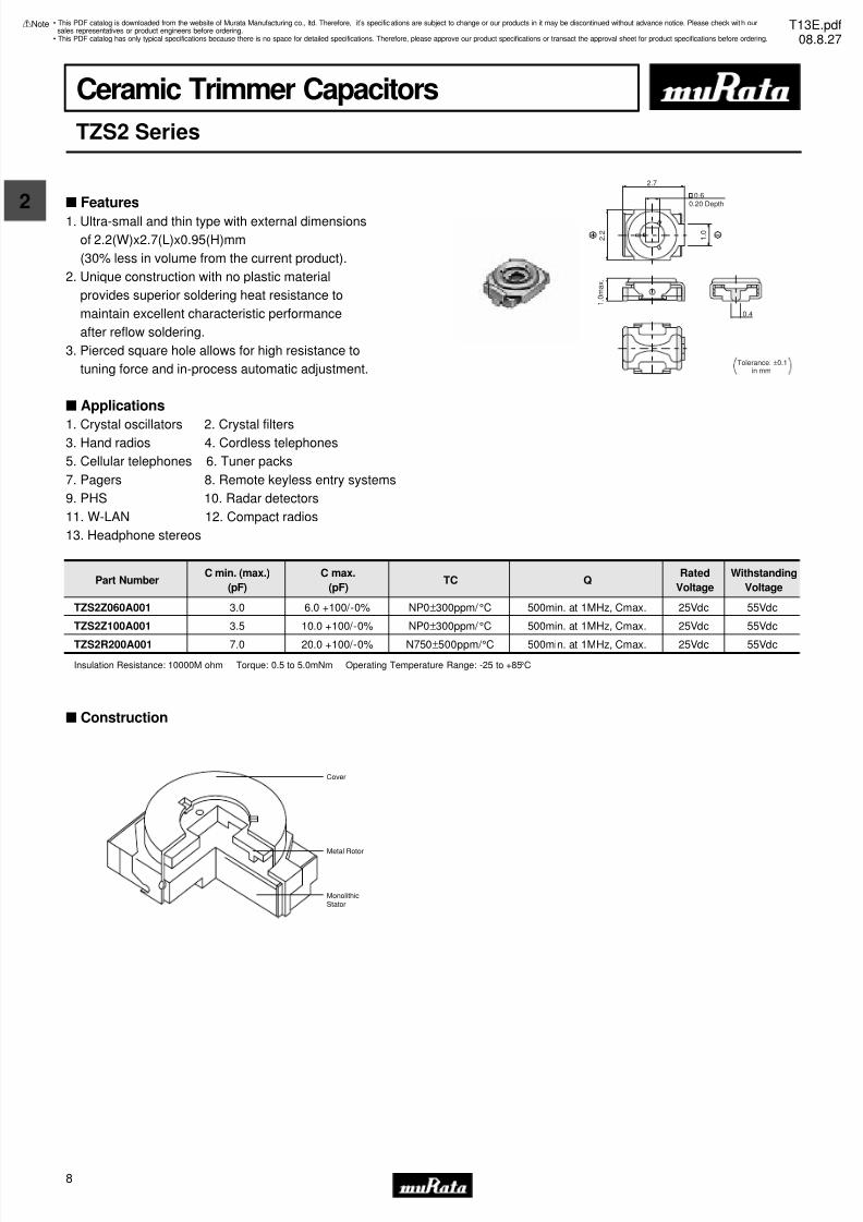
Ceramic Trimmer Capacitors
TZS2 Series
s Features
1. Ultra-small and thin type with external dimensions
of 2.2(W)x2.7(L)x0.95(H)mm
(30% less in volume from the current product).
2. Unique construction with no plastic material
provides superior soldering heat resistance to
maintain excellent characteristic performance
after reflow soldering.
3. Pierced square hole allows for high resistance to
tuning force and in-process automatic adjustment.
s Applications
1. Crystal oscillators 2. Crystal filters3. Hand radios 4. Cordless telephones
5. Cellular telephones 6. Tuner packs
7. Pagers 8. Remote keyless entry systems
9. PHS 10. Radar detectors
11. W-LAN 12. Compact radios
13. Headphone stereos
in mmTolerance: ±0.1
2.7
1 . 0
1 . 0 m a x .
2 . 2
0.6
0.4
0.20 Depth
Part NumberC min. (max.)
(pF)
C max.
(pF)TC Q
Rated
Voltage
Withstanding
Voltage
TZS2Z060A001 3.0 6.0 +100/-0% NP0±300ppm/ °C 500min. at 1MHz, Cmax. 25Vdc 55Vdc
TZS2Z100A001 3.5 10.0 +100/-0% NP0±300ppm/ °C 500min. at 1MHz, Cmax. 25Vdc 55Vdc
TZS2R200A001 7.0 20.0 +100/-0% N750±500ppm/ °C 500min. at 1MHz, Cmax. 25Vdc 55Vdc
s Construction
Cover
Metal Rotor
MonolithicStator
Insulation Resistance: 10000M ohm Torque: 0.5 to 5.0mNm Operating Temperature Range: -25 to +85°C
• This PDF catalog is downloaded from the website of Murata Manufacturing co., ltd. Therefore, it’s specifications are subject to change or our products in it may be discontinued without advance notice. Please check wit h oursales representatives or product engineers before ordering.
• This PDF catalog has only typical specifications because there is no space for detailed specifications. Therefore, please approve our product specifications or transact the approval sheet for product specifications before ordering.
!Note T13E.pdf08.8.27
7/31/2019 Trimmers Murata
http://slidepdf.com/reader/full/trimmers-murata 11/449
2
!Note • Please read rating and !CAUTION (for storage, operating, rating, soldering, mounting and handling) in this catalog to prevent smoking and/or burning, etc.• This catalog has only typical specifications because there is no space for detailed specifications. Therefore, please approve our product specifications or transact the approval sheet for product specifications before ordering.
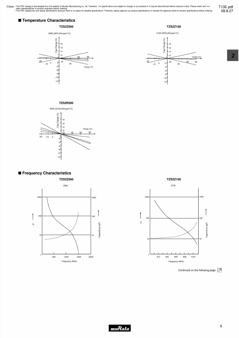
s Temperature Characteristics
TZS2Z060
+8
+6
+4
+2
200
−10
−25
45
65 85
−2
−4
−6
−8
−10
−12
0
Z060 (NP0±300 ppm/ °C)
C a p . C
h a n g e ( % )
Temp.(°C)
TZS2Z100
+8
+6
+4
+2
200
−10
−25
4565 85
−2
−4
−6
−8
−10
−12
0
Z100 (NP0±300 ppm/ °C)
C a p . C
h a n g e ( % )
Temp.(°C)
TZS2R200
+8
+6
+4
+2
20
0−10−25
45 65 85
−2
−4
−6
−8
−10
−12
0
R200 (N750±500 ppm/ °C)
C a p . C
h a n g
e ( % )
Temp.(°C)
s Frequency Characteristics
TZS2Z060
Z060
Q
1000
100
500 1000 1500 2000
10
1
1000
100
10
Frequency (MHz)
C
a p a c i t a n c e ( p F )
TZS2Z100
Z100
Q
1000
100
200 600400 800 1000
10
1
1000
100
10
Frequency (MHz)
C
a p a c i t a n c e ( p F )
Continued on the following page.
• This PDF catalog is downloaded from the website of Murata Manufacturing co., ltd. Therefore, it’s specifications are subject to change or our products in it may be discontinued without advance notice. Please check wit h oursales representatives or product engineers before ordering.
• This PDF catalog has only typical specifications because there is no space for detailed specifications. Therefore, please approve our product specifications or transact the approval sheet for product specifications before ordering.
!Note T13E.pdf08.8.27
7/31/2019 Trimmers Murata
http://slidepdf.com/reader/full/trimmers-murata 12/4410
2
!Note • Please read rating and !CAUTION (for storage, operating, rating, soldering, mounting and handling) in this catalog to prevent smoking and/or burning, etc.• This catalog has only typical specifications because there is no space for detailed specifications. Therefore, please approve our product specifications or transact the approval sheet for product specifications before ordering.
Continued from the preceding page.
s Frequency Characteristics
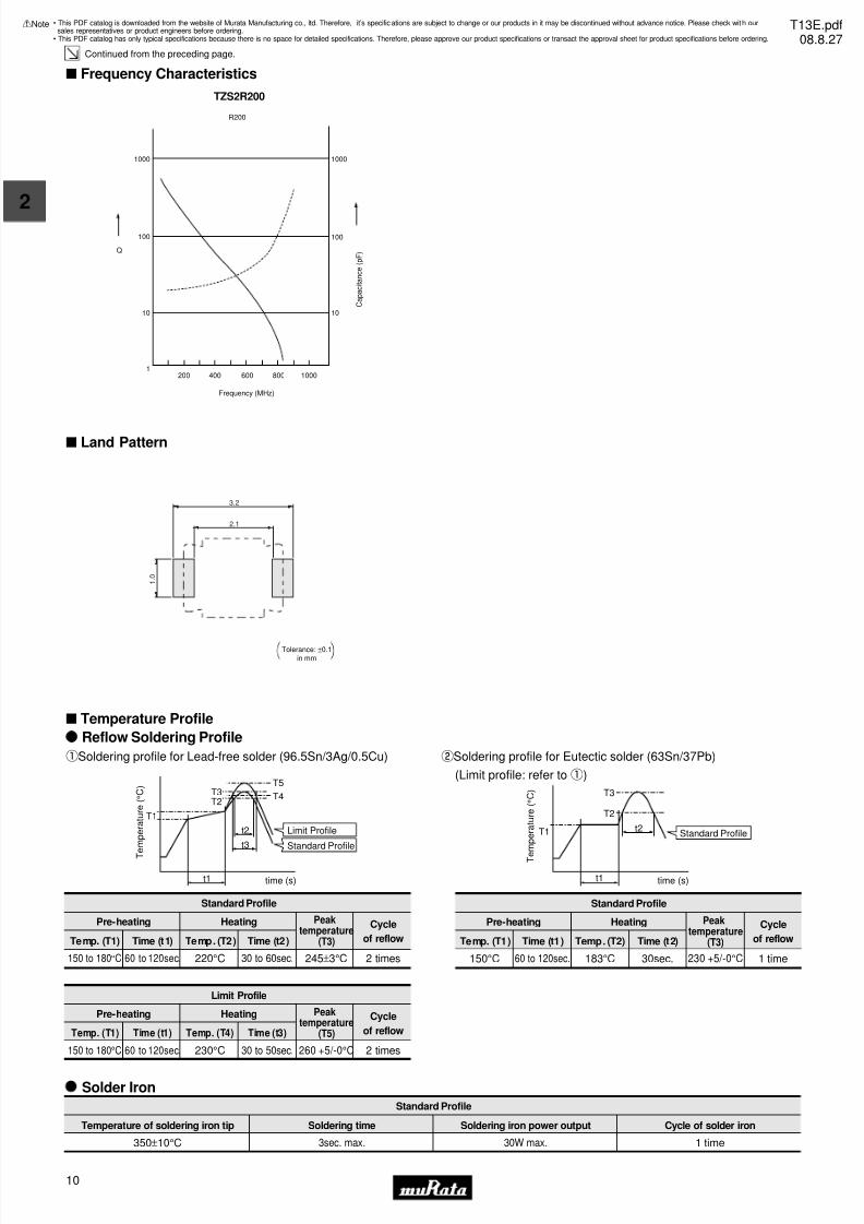
TZS2R200
R200
Q
1000
100
200 1000600 800400
10
1
1000
100
10
Frequency (MHz)
C a p a c i t a n c e ( p F )
s Land Pattern
3.2
2.1
1 . 0
Tolerance: ±0.1in mm
s Temperature Profile
T
e m p e r a t u r e ( ° C )
t3
t2
T3T2
T5
T4
T1
time (s)t1
Reflow Soldering Profile
qSoldering profile for Lead-free solder (96.5Sn/3Ag/0.5Cu)
Standard Profile
Pre-heating Heating Peaktemperature
(T3)
Cycle
of reflowTemp. (T1) Time (t1) Temp. (T2) Time (t2)
2 times245±3°C150 to 180°C 60 to 120sec. 220°C 30 to 60sec.
Limit Profile
Standard Profile
Standard Profile
Pre-heating Heating Cycle
of reflowTemp. (T1) Time (t1) Temp. (T2) Time (t2)
1 time230 +5/-0°C150°C 60 to 120sec. 183°C 30sec.
Limit Profile
Pre-heating Heating Cycle
of reflowTemp. (T1) Time (t1) Temp. (T4) Time (t3)
2 times260 +5/-0°C150 to 180°C 60 to 120sec. 230°C 30 to 50sec.
T e m p e r a t u r e ( ° C )
time (s)
Standard Profile
t1
T1 t2
T3
T2
wSoldering profile for Eutectic solder (63Sn/37Pb)
(Limit profile: refer toq)
Solder Iron
Standard Profile
Temperature of soldering iron tip Soldering time Soldering iron power output
350±10°C 3sec. max. 30W max. 1 time
Cycle of solder iron
Peaktemperature
(T5)
Peaktemperature
(T3)
• This PDF catalog is downloaded from the website of Murata Manufacturing co., ltd. Therefore, it’s specifications are subject to change or our products in it may be discontinued without advance notice. Please check wit h oursales representatives or product engineers before ordering.
• This PDF catalog has only typical specifications because there is no space for detailed specifications. Therefore, please approve our product specifications or transact the approval sheet for product specifications before ordering.
!Note T13E.pdf08.8.27
7/31/2019 Trimmers Murata
http://slidepdf.com/reader/full/trimmers-murata 13/4411
2
!Note • Please read rating and !CAUTION (for storage, operating, rating, soldering, mounting and handling) in this catalog to prevent smoking and/or burning, etc.• This catalog has only typical specifications because there is no space for detailed specifications. Therefore, please approve our product specifications or transact the approval sheet for product specifications before ordering.
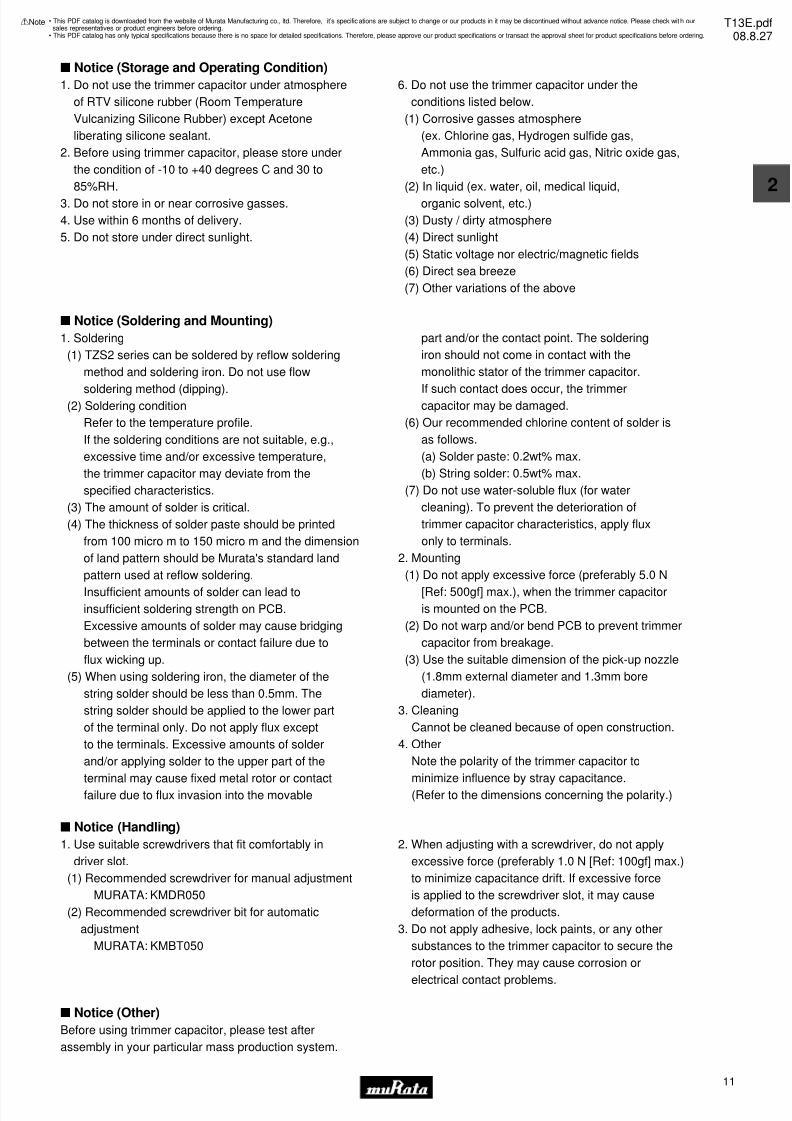
s Notice (Storage and Operating Condition)
s Notice (Soldering and Mounting)
1. Soldering
(1) TZS2 series can be soldered by reflow soldering
method and soldering iron. Do not use flow
soldering method (dipping).(2) Soldering condition
Refer to the temperature profile.
If the soldering conditions are not suitable, e.g.,
excessive time and/or excessive temperature,
the trimmer capacitor may deviate from the
specified characteristics.
(3) The amount of solder is critical.
(4) The thickness of solder paste should be printed
from 100 micro m to 150 micro m and the dimension
of land pattern should be Murata's standard land
pattern used at reflow soldering.
Insufficient amounts of solder can lead to
insufficient soldering strength on PCB.
Excessive amounts of solder may cause bridging
between the terminals or contact failure due to
flux wicking up.
(5) When using soldering iron, the diameter of the
string solder should be less than 0.5mm. The
string solder should be applied to the lower part
of the terminal only. Do not apply flux except
to the terminals. Excessive amounts of solder
and/or applying solder to the upper part of the
terminal may cause fixed metal rotor or contact
failure due to flux invasion into the movable
part and/or the contact point. The soldering
iron should not come in contact with the
monolithic stator of the trimmer capacitor.
If such contact does occur, the trimmercapacitor may be damaged.
(6) Our recommended chlorine content of solder is
as follows.
(a) Solder paste: 0.2wt% max.
(b) String solder: 0.5wt% max.
(7) Do not use water-soluble flux (for water
cleaning). To prevent the deterioration of
trimmer capacitor characteristics, apply flux
only to terminals.
2. Mounting
(1) Do not apply excessive force (preferably 5.0 N
[Ref: 500gf] max.), when the trimmer capacitoris mounted on the PCB.
(2) Do not warp and/or bend PCB to prevent trimmer
capacitor from breakage.
(3) Use the suitable dimension of the pick-up nozzle
(1.8mm external diameter and 1.3mm bore
diameter).
3. Cleaning
Cannot be cleaned because of open construction.
4. Other
Note the polarity of the trimmer capacitor to
minimize influence by stray capacitance.
(Refer to the dimensions concerning the polarity.)
s Notice (Handling)
1. Do not use the trimmer capacitor under atmosphere
of RTV silicone rubber (Room Temperature
Vulcanizing Silicone Rubber) except Acetone
liberating silicone sealant.
2. Before using trimmer capacitor, please store under
the condition of -10 to +40 degrees C and 30 to
85%RH.
3. Do not store in or near corrosive gasses.
4. Use within 6 months of delivery.
5. Do not store under direct sunlight.
6. Do not use the trimmer capacitor under the
conditions listed below.
(1) Corrosive gasses atmosphere
(ex. Chlorine gas, Hydrogen sulfide gas,
Ammonia gas, Sulfuric acid gas, Nitric oxide gas,
etc.)
(2) In liquid (ex. water, oil, medical liquid,
organic solvent, etc.)
(3) Dusty / dirty atmosphere
(4) Direct sunlight
(5) Static voltage nor electric/magnetic fields
(6) Direct sea breeze
(7) Other variations of the above
1. Use suitable screwdrivers that fit comfortably in
driver slot.
(1) Recommended screwdriver for manual adjustment
MURATA: KMDR050
(2) Recommended screwdriver bit for automatic
adjustment
MURATA: KMBT050
2. When adjusting with a screwdriver, do not apply
excessive force (preferably 1.0 N [Ref: 100gf] max.)
to minimize capacitance drift. If excessive force
is applied to the screwdriver slot, it may cause
deformation of the products.
3. Do not apply adhesive, lock paints, or any other
substances to the trimmer capacitor to secure the
rotor position. They may cause corrosion or
electrical contact problems.
s Notice (Other)
Before using trimmer capacitor, please test after
assembly in your particular mass production system.
• This PDF catalog is downloaded from the website of Murata Manufacturing co., ltd. Therefore, it’s specifications are subject to change or our products in it may be discontinued without advance notice. Please check wit h oursales representatives or product engineers before ordering.
• This PDF catalog has only typical specifications because there is no space for detailed specifications. Therefore, please approve our product specifications or transact the approval sheet for product specifications before ordering.
!Note T13E.pdf08.8.27
7/31/2019 Trimmers Murata
http://slidepdf.com/reader/full/trimmers-murata 14/4412
3
!Note • Please read rating and !CAUTION (for storage, operating, rating, soldering, mounting and handling) in this catalog to prevent smoking and/or burning, etc.• This catalog has only typical specifications because there is no space for detailed specifications. Therefore, please approve our product specifications or transact the approval sheet for product specifications before ordering.
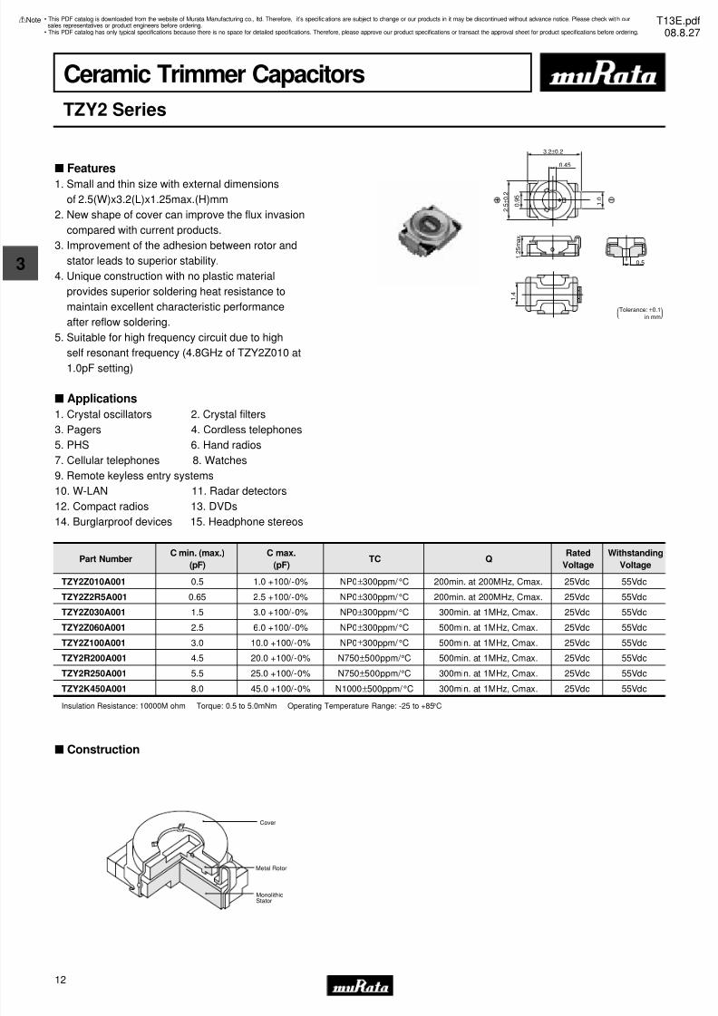
Ceramic Trimmer Capacitors
TZY2 Series
3.2±0.2
2 . 5
± 0 . 2
1 . 2
5 m a x .
0 . 9
5
1 . 0
0.45
0.5
1 . 4
(Tolerance: ±0.1)in mm
Part NumberC min. (max.)
(pF)
C max.
(pF)TC Q
Rated
Voltage
Withstanding
Voltage
TZY2Z010A001 0.5 1.0 +100/-0% NP0±300ppm/ °C 200min. at 200MHz, Cmax. 25Vdc 55Vdc
TZY2Z2R5A001 0.65 2.5 +100/-0% NP0±300ppm/ °C 200min. at 200MHz, Cmax. 25Vdc 55Vdc
TZY2Z030A001 1.5 3.0 +100/-0% NP0±300ppm/ °C 300min. at 1MHz, Cmax. 25Vdc 55Vdc
TZY2Z060A001 2.5 6.0 +100/-0% NP0±300ppm/ °C 500min. at 1MHz, Cmax. 25Vdc 55Vdc
TZY2Z100A001 3.0 10.0 +100/-0% NP0±300ppm/ °C 500min. at 1MHz, Cmax. 25Vdc 55Vdc
TZY2R200A001 4.5 20.0 +100/-0% N750±500ppm/ °C 500min. at 1MHz, Cmax. 25Vdc 55Vdc
TZY2R250A001 5.5 25.0 +100/-0% N750±500ppm/ °C 300min. at 1MHz, Cmax. 25Vdc 55Vdc
TZY2K450A001 8.0 45.0 +100/-0% N1000±500ppm/ °C 300min. at 1MHz, Cmax. 25Vdc 55Vdc
s Construction
Cover
Metal Rotor
MonolithicStator
Insulation Resistance: 10000M ohm Torque: 0.5 to 5.0mNm Operating Temperature Range: -25 to +85°C
s Features
1. Small and thin size with external dimensions
of 2.5(W)x3.2(L)x1.25max.(H)mm
2. New shape of cover can improve the flux invasion
compared with current products.
3. Improvement of the adhesion between rotor and
stator leads to superior stability.
4. Unique construction with no plastic material
provides superior soldering heat resistance to
maintain excellent characteristic performance
after reflow soldering.
5. Suitable for high frequency circuit due to high
self resonant frequency (4.8GHz of TZY2Z010 at1.0pF setting)
s Applications
1. Crystal oscillators 2. Crystal filters
3. Pagers 4. Cordless telephones
5. PHS 6. Hand radios
7. Cellular telephones 8. Watches
9. Remote keyless entry systems
10. W-LAN 11. Radar detectors
12. Compact radios 13. DVDs
14. Burglarproof devices 15. Headphone stereos
• This PDF catalog is downloaded from the website of Murata Manufacturing co., ltd. Therefore, it’s specifications are subject to change or our products in it may be discontinued without advance notice. Please check wit h oursales representatives or product engineers before ordering.
• This PDF catalog has only typical specifications because there is no space for detailed specifications. Therefore, please approve our product specifications or transact the approval sheet for product specifications before ordering.
!Note T13E.pdf08.8.27
7/31/2019 Trimmers Murata
http://slidepdf.com/reader/full/trimmers-murata 15/4413
3
!Note • Please read rating and !CAUTION (for storage, operating, rating, soldering, mounting and handling) in this catalog to prevent smoking and/or burning, etc.• This catalog has only typical specifications because there is no space for detailed specifications. Therefore, please approve our product specifications or transact the approval sheet for product specifications before ordering.
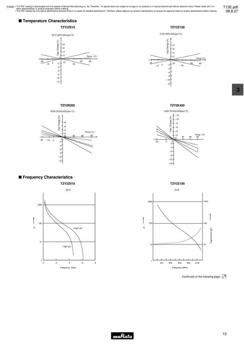
s Temperature Characteristics
TZY2Z010
+8
+6
+4
+2
2045
65 85-2
-4
-6
-8
-10
-12
-25
-10 0
0
Z010 (NP0±300 ppm/ °C)
Temp. (°C) C a p .
C h a n g e ( % )
TZY2Z100
+8
+6
+4
+2
200
−10
−25
4565 85
−2
−4
−6
−8
−10
−12
0
Z100 (NP0±300 ppm/ °C)
C a p . C
h a n g e ( % )
Temp.(°C)
TZY2R200
+8
+6
+4
+2
20
0−10−25
45 65 85
−2
−4
−6
−8
−10
−12
0
R200 (N750±500 ppm/ °C)
C a p . C
h a n g
e ( % )
Temp.(°C)
TZY2K450
K450 (N1000±500ppm/ °C)
Temp. (°C)
C a p .
C h a n g e ( % ) +12
+10
+8
+6
+4
+2
–20
–4
–6
–8
–10
–12
2045
025
65 85
s Frequency Characteristics
TZY2Z010
1000
100
1
10
0 2 4 6
Frequency (GHz)
0.5pF set
1.0pF set
Z010
8
Q
TZY2Z100
Z100
Q
1000
100
200 600400 800 1000
10
1
1000
100
10
Frequency (MHz)
C
a p a c i t a n c e ( p F )
Continued on the following page.
• This PDF catalog is downloaded from the website of Murata Manufacturing co., ltd. Therefore, it’s specifications are subject to change or our products in it may be discontinued without advance notice. Please check wit h oursales representatives or product engineers before ordering.
• This PDF catalog has only typical specifications because there is no space for detailed specifications. Therefore, please approve our product specifications or transact the approval sheet for product specifications before ordering.
!Note T13E.pdf08.8.27

7/31/2019 Trimmers Murata
http://slidepdf.com/reader/full/trimmers-murata 16/4414
3
!Note • Please read rating and !CAUTION (for storage, operating, rating, soldering, mounting and handling) in this catalog to prevent smoking and/or burning, etc.• This catalog has only typical specifications because there is no space for detailed specifications. Therefore, please approve our product specifications or transact the approval sheet for product specifications before ordering.
Continued from the preceding page.
s Frequency Characteristics
TZY2R200
R200
Q
1000
100
200 1000600 800400
10
1
1000
100
10
Frequency (MHz)
C a p a c i t a n c e ( p F )
TZY2K450
1000
100
10
1
1000
100
10
200
Q
400 600 800
C a p a c i t a n c e ( p F )
Frequency (MHz)
K450
1000
100
10
1
1000
100
10
200
Q
400 600 800
C a p a c i t a n c e ( p F )
Frequency (MHz)
K450
s Land Pattern
Tolerance: ±0.1in mm
4.0
2.4
1 . 2
s Temperature Profile
T
e m p e r a t u r e ( ° C )
t3
t2
T3T2
T5
T4
T1
time (s)t1
Reflow Soldering Profile
qSoldering profile for Lead-free solder (96.5Sn/3Ag/0.5Cu)
Standard Profile
Pre-heating Heating Peaktemperature
(T3)
Cycle
of reflowTemp. (T1) Time (t1) Temp. (T2) Time (t2)
2 times245±3°C150 to 180°C 60 to 120sec. 220°C 30 to 60sec.
Limit Profile
Standard Profile
Standard Profile
Pre-heating Heating Cycle
of reflowTemp. (T1) Time (t1) Temp. (T2) Time (t2)
1 time230 +5/-0°C150°C 60 to 120sec. 183°C 30sec.
Limit Profile
Pre-heating Heating Cycle
of reflowTemp. (T1) Time (t1) Temp. (T4) Time (t3)
2 times260 +5/-0°C150 to 180°C 60 to 120sec. 230°C 30 to 50sec.
T e m p e r a t u r e ( ° C )
time (s)
Standard Profile
t1
T1 t2
T3
T2
wSoldering profile for Eutectic solder (63Sn/37Pb)
(Limit profile: refer toq)
Solder Iron
Standard Profile
Temperature of soldering iron tip Soldering time Soldering iron power output
350±10°C 3sec. max. 30W max. 1 time
Cycle of solder iron
Peaktemperature
(T5)
Peaktemperature
(T3)
• This PDF catalog is downloaded from the website of Murata Manufacturing co., ltd. Therefore, it’s specifications are subject to change or our products in it may be discontinued without advance notice. Please check wit h oursales representatives or product engineers before ordering.
• This PDF catalog has only typical specifications because there is no space for detailed specifications. Therefore, please approve our product specifications or transact the approval sheet for product specifications before ordering.
!Note T13E.pdf08.8.27
7/31/2019 Trimmers Murata
http://slidepdf.com/reader/full/trimmers-murata 17/4415
3
!Note • Please read rating and !CAUTION (for storage, operating, rating, soldering, mounting and handling) in this catalog to prevent smoking and/or burning, etc.• This catalog has only typical specifications because there is no space for detailed specifications. Therefore, please approve our product specifications or transact the approval sheet for product specifications before ordering.
s Notice (Storage and Operating Condition)
s Notice (Soldering and Mounting)
1. Soldering
(1) TZY2 series can be soldered by reflow soldering
method and soldering iron. Do not use flow
soldering method (dipping).(2) Soldering condition
Refer to the temperature profile.
If the soldering conditions are not suitable, e.g.,
excessive time and/or excessive temperature, the
trimmer capacitor may deviate from the specified
characteristics.
(3) The amount of solder is critical.
(4) The thickness of solder paste should be printed
from 120 micro m to 170 micro m and the dimension
of land pattern should be Murata's standard land
pattern used at reflow soldering.
Insufficient amounts of solder can lead to
insufficient soldering strength on PCB.
Excessive amounts of solder may cause bridging
between the terminals or contact failure due to
flux wicking up.
(5) When using soldering iron, the diameter of the
string solder should be less than 0.5mm. The
string solder should be applied to the lower
part of the terminal only. Do not apply flux
except to the terminals. Excessive amounts of
solder and/or applying solder to the upper part
of the terminal may cause fixed metal rotor or
contact failure due to flux invasion into
the movable part and/or the contact point. The
soldering iron should not come in contact with
the monolithic stator of the trimmer capacitor.
If such contact does occur, the trimmercapacitor may be damaged.
(6) Our recommended chlorine content of solder is
as follows.
(a) Solder paste: 0.2wt% max.
(b) String solder: 0.5wt% max.
(7) Do not use water-soluble flux (for water
cleaning). To prevent the deterioration of
trimmer capacitor characteristics, apply flux
only to terminals.
2. Mounting
(1) Do not apply excessive force (preferably 5.0 N
[Ref: 500gf] max.), when the trimmer capacitoris mounted on the PCB.
(2) Do not warp and/or bend PCB to prevent trimmer
capacitor from breakage.
(3) Use the suitable dimension of the pick-up nozzle
(1.8mm external diameter and 1.3mm bore
diameter).
3. Cleaning
Cannot be cleaned because of open construction.
4. Other
Note the polarity of the trimmer capacitor to
minimize influence by stray capacitance.
(Refer to the dimensions concerning the polarity.)
s Notice (Handling)
1. Do not use the trimmer capacitor under atmosphere
of RTV silicone rubber (Room Temperature
Vulcanizing Silicone Rubber) except Acetone
liberating silicone sealant.
2. Before using trimmer capacitor, please store under
the condition of -10 to +40 degrees C and 30 to
85%RH.
3. Do not store in or near corrosive gasses.
4. Use within 6 months of delivery.
5. Do not store under direct sunlight.
6. Do not use the trimmer capacitor under the
conditions listed below.
(1) Corrosive gasses atmosphere
(ex. Chlorine gas, Hydrogen sulfide gas,
Ammonia gas, Sulfuric acid gas, Nitric oxide gas,
etc.)
(2) In liquid (ex. water, oil, medical liquid,
organic solvent, etc.)
(3) Dusty / dirty atmosphere
(4) Direct sunlight
(5) Static voltage nor electric/magnetic fields
(6) Direct sea breeze
(7) Other variations of the above
s Notice (Other)
Before using trimmer capacitor, please test after
assembly in your particular mass production system.
1. Use suitable screwdrivers that fit comfortably in
driver slot.
(1) Recommended screwdriver for manual adjustment
ENGINEER INC.: DA-89
(Murata: KMDR060)
(2) Recommended screwdriver bit for automatic
adjustment
MURATA: KMBT060
2. When adjusting with a screwdriver, do not apply
excessive force (preferably 1.0 N [Ref: 100gf] max.)
to minimize capacitance drift. If excessive force
is applied to the screwdriver slot, it may cause
deformation of the products.
3. Do not apply adhesive, lock paints, or any other
substances to the trimmer capacitor to secure the
rotor position. They may cause corrosion or
electrical contact problems.
• This PDF catalog is downloaded from the website of Murata Manufacturing co., ltd. Therefore, it’s specifications are subject to change or our products in it may be discontinued without advance notice. Please check wit h oursales representatives or product engineers before ordering.
• This PDF catalog has only typical specifications because there is no space for detailed specifications. Therefore, please approve our product specifications or transact the approval sheet for product specifications before ordering.
!Note T13E.pdf08.8.27
7/31/2019 Trimmers Murata
http://slidepdf.com/reader/full/trimmers-murata 18/4416
4
!Note • Please read rating and !CAUTION (for storage, operating, rating, soldering, mounting and handling) in this catalog to prevent smoking and/or burning, etc.• This catalog has only typical specifications because there is no space for detailed specifications. Therefore, please approve our product specifications or transact the approval sheet for product specifications before ordering.
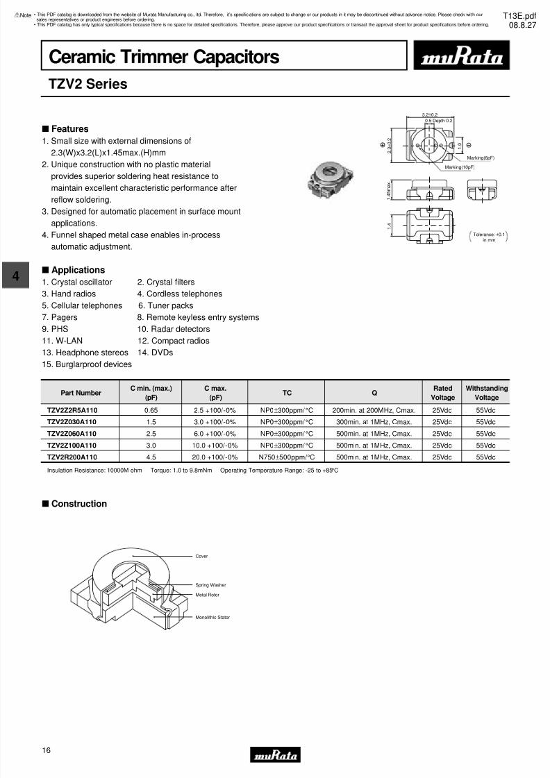
Ceramic Trimmer Capacitors
TZV2 Series
3.2±0.2
0.5 Depth 0.2
2 . 3
± 0 . 2
1 . 4
5 m a x .
1 . 4
Marking(6pF)
Marking(10pF)
Tolerance: ±0.1in mm
1 . 0
Part NumberC min. (max.)
(pF)
C max.
(pF)TC Q
Rated
Voltage
Withstanding
Voltage
TZV2Z2R5A110 0.65 2.5 +100/-0% NP0±300ppm/ °C 200min. at 200MHz, Cmax. 25Vdc 55Vdc
TZV2Z030A110 1.5 3.0 +100/-0% NP0±300ppm/ °C 300min. at 1MHz, Cmax. 25Vdc 55Vdc
TZV2Z060A110 2.5 6.0 +100/-0% NP0±300ppm/ °C 500min. at 1MHz, Cmax. 25Vdc 55Vdc
TZV2Z100A110 3.0 10.0 +100/-0% NP0±300ppm/ °C 500min. at 1MHz, Cmax. 25Vdc 55Vdc
TZV2R200A110 4.5 20.0 +100/-0% N750±500ppm/ °C 500min. at 1MHz, Cmax. 25Vdc 55Vdc
Insulation Resistance: 10000M ohm Torque: 1.0 to 9.8mNm Operating Temperature Range: -25 to +85°C
s Construction
Cover
Spring Washer
Metal Rotor
Monolithic Stator
s Features
1. Small size with external dimensions of
2.3(W)x3.2(L)x1.45max.(H)mm
2. Unique construction with no plastic material
provides superior soldering heat resistance to
maintain excellent characteristic performance after
reflow soldering.
3. Designed for automatic placement in surface mount
applications.
4. Funnel shaped metal case enables in-process
automatic adjustment.
s Applications1. Crystal oscillator 2. Crystal filters
3. Hand radios 4. Cordless telephones
5. Cellular telephones 6. Tuner packs
7. Pagers 8. Remote keyless entry systems
9. PHS 10. Radar detectors
11. W-LAN 12. Compact radios
13. Headphone stereos 14. DVDs
15. Burglarproof devices
• This PDF catalog is downloaded from the website of Murata Manufacturing co., ltd. Therefore, it’s specifications are subject to change or our products in it may be discontinued without advance notice. Please check wit h oursales representatives or product engineers before ordering.
• This PDF catalog has only typical specifications because there is no space for detailed specifications. Therefore, please approve our product specifications or transact the approval sheet for product specifications before ordering.
!Note T13E.pdf08.8.27
7/31/2019 Trimmers Murata
http://slidepdf.com/reader/full/trimmers-murata 19/4417
4
!Note • Please read rating and !CAUTION (for storage, operating, rating, soldering, mounting and handling) in this catalog to prevent smoking and/or burning, etc.• This catalog has only typical specifications because there is no space for detailed specifications. Therefore, please approve our product specifications or transact the approval sheet for product specifications before ordering.
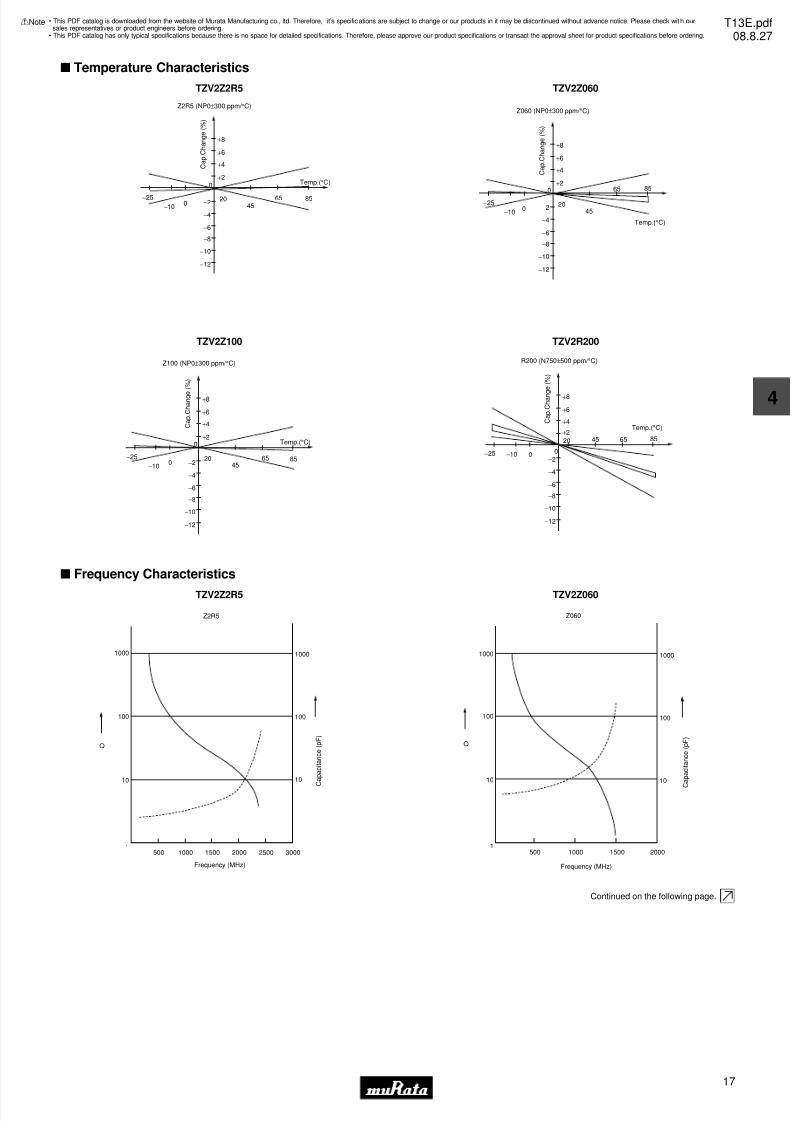
s Temperature Characteristics
TZV2Z2R5
+8
+6
+4
+2
200
−10
−2545
65 85−2
−4
−6
−8
−10
−12
0
Z2R5 (NP0±300 ppm/ °C)
Temp.(°C)
C a p . C
h a n g e ( % )
TZV2Z060
+8
+6
+4
+2
200
−10
−25
45
65 85
−2
−4
−6
−8
−10
−12
0
Z060 (NP0±300 ppm/ °C)
C a p . C
h a n g e ( % )
Temp.(°C)
TZV2Z100
+8
+6
+4
+2
200
−10
−25
4565 85
−2
−4
−6
−8
−10
−12
0
Z100 (NP0±300 ppm/ °C)
C a p . C
h a n g e
( % )
Temp.(°C)
TZV2R200
+8
+6
+4
+2
20
0−10−25
45 65 85
−2
−4
−6
−8
−10
−12
0
R200 (N750±500 ppm/ °C)
C a p . C
h a n g
e ( % )
Temp.(°C)
s Frequency Characteristics
TZV2Z2R5
Z2R5
1000
100
Q
500 1000 1500 2000 2500 3000
10
1
1000
100
10
Frequency (MHz)
C
a p a c i t a n c e ( p F )
TZV2Z060
Z060
Q
1000
100
500 1000 1500 2000
10
1
1000
100
10
Frequency (MHz)
C
a p a c i t a n c e ( p F )
Continued on the following page.
• This PDF catalog is downloaded from the website of Murata Manufacturing co., ltd. Therefore, it’s specifications are subject to change or our products in it may be discontinued without advance notice. Please check wit h oursales representatives or product engineers before ordering.
• This PDF catalog has only typical specifications because there is no space for detailed specifications. Therefore, please approve our product specifications or transact the approval sheet for product specifications before ordering.
!Note T13E.pdf08.8.27
7/31/2019 Trimmers Murata
http://slidepdf.com/reader/full/trimmers-murata 20/4418
4
!Note • Please read rating and !CAUTION (for storage, operating, rating, soldering, mounting and handling) in this catalog to prevent smoking and/or burning, etc.• This catalog has only typical specifications because there is no space for detailed specifications. Therefore, please approve our product specifications or transact the approval sheet for product specifications before ordering.
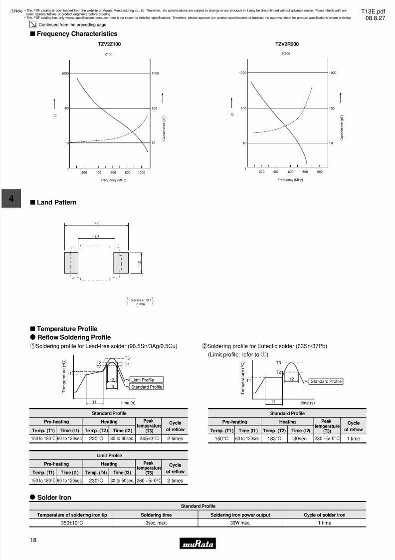
Continued from the preceding page.
s Frequency Characteristics
TZV2Z100
Z100
Q
1000
100
200 600400 800 1000
10
1
1000
100
10
Frequency (MHz)
C a p a c i t a n c e ( p F )
TZV2R200
R200
Q
1000
100
200 1000600 800400
10
1
1000
100
10
Frequency (MHz)
C a p a c i t a n c e ( p F )
s Land Pattern
Tolerance: ±0.1in mm
4.0
2.4
1 . 2
s Temperature Profile
T
e m p e r a t u r e ( ° C )
t3
t2
T3T2
T5
T4
T1
time (s)t1
Reflow Soldering Profile
qSoldering profile for Lead-free solder (96.5Sn/3Ag/0.5Cu)
Standard Profile
Pre-heating Heating Peaktemperature
(T3)
Cycle
of reflowTemp. (T1) Time (t1) Temp. (T2) Time (t2)
2 times245±3°C150 to 180°C 60 to 120sec. 220°C 30 to 60sec.
Limit Profile
Standard Profile
Standard Profile
Pre-heating Heating Cycle
of reflowTemp. (T1) Time (t1) Temp. (T2) Time (t2)
1 time230 +5/-0°C150°C 60 to 120sec. 183°C 30sec.
Limit Profile
Pre-heating Heating Cycle
of reflowTemp. (T1) Time (t1) Temp. (T4) Time (t3)
2 times260 +5/-0°C150 to 180°C 60 to 120sec. 230°C 30 to 50sec.
T e m p e r a t u r e ( ° C )
time (s)
Standard Profile
t1
T1 t2
T3
T2
wSoldering profile for Eutectic solder (63Sn/37Pb)
(Limit profile: refer toq)
Solder Iron
Standard Profile
Temperature of soldering iron tip Soldering time Soldering iron power output
350±10°C 3sec. max. 30W max. 1 time
Cycle of solder iron
Peaktemperature
(T5)
Peaktemperature
(T3)
• This PDF catalog is downloaded from the website of Murata Manufacturing co., ltd. Therefore, it’s specifications are subject to change or our products in it may be discontinued without advance notice. Please check wit h oursales representatives or product engineers before ordering.
• This PDF catalog has only typical specifications because there is no space for detailed specifications. Therefore, please approve our product specifications or transact the approval sheet for product specifications before ordering.
!Note T13E.pdf08.8.27

7/31/2019 Trimmers Murata
http://slidepdf.com/reader/full/trimmers-murata 21/4419
4
!Note • Please read rating and !CAUTION (for storage, operating, rating, soldering, mounting and handling) in this catalog to prevent smoking and/or burning, etc.• This catalog has only typical specifications because there is no space for detailed specifications. Therefore, please approve our product specifications or transact the approval sheet for product specifications before ordering.
s Notice (Storage and Operating Condition)
s Notice (Soldering and Mounting)
1. Soldering
(1) TZV2 series can be soldered by reflow soldering
method and soldering iron. Do not use flow
soldering method (dipping).(2) Soldering condition
Refer to the temperature profile.
If the soldering conditions are not suitable, e.g.,
excessive time and/or excessive temperature, the
trimmer capacitor may deviate from the specified
characteristics.
(3) The amount of solder is critical.
(4) The thickness of solder paste should be printed
from 120 micro m to 170 micro m and the dimension
of land pattern should be Murata's standard land
pattern used at reflow soldering.
Insufficient amounts of solder can lead to
insufficient soldering strength on PCB.
Excessive amounts of solder may cause
bridging between the terminals or contact
failure due to flux wicking up.
(5) When using soldering iron, the diameter of the
string solder should be less than 0.5mm. The
string solder should be applied to the lower
part of the terminal only. Do not apply flux
except to the terminals. Excessive amounts of
solder and/or applying solder to the upper part
of the terminal may cause fixed metal rotor or
contact failure due to flux invasion into
the movable part and/or the contact point. The
soldering iron should not come in contact with
the monolithic stator of the trimmer capacitor.
If such contact does occur, the trimmercapacitor may be damaged.
(6) Our recommended chlorine content of solder is
as follows.
(a) Solder paste: 0.2wt% max.
(b) String solder: 0.5wt% max.
(7) Do not use water-soluble flux (for water
cleaning). To prevent the deterioration of
trimmer capacitor characteristics, apply flux
only to terminals.
2. Mounting
(1) Do not apply excessive force (preferably 5.0 N
[Ref: 500gf] max.), when the trimmer capacitoris mounted on the PCB.
(2) Do not warp and/or bend PCB to prevent trimmer
capacitor from breakage.
(3) Use the suitable dimension of the pick-up nozzle
(1.8mm external diameter and 1.3mm bore
diameter).
3. Cleaning
Cannot be cleaned because of open construction.
4. Other
Note the polarity of the trimmer capacitor to
minimize influence by stray capacitance.
(Refer to the dimensions concerning the polarity.)
s Notice (Handling)
1. Do not use the trimmer capacitor under atmosphere
of RTV silicone rubber (Room Temperature
Vulcanizing Silicone Rubber) except Acetone
liberating silicone sealant.
2. Before using trimmer capacitor, please store under
the condition of -10 to +40 degrees C and 30 to
85%RH.
3. Do not store in or near corrosive gasses.
4. Use within 6 months of delivery.
5. Do not store under direct sunlight.
6. Do not use the trimmer capacitor under the
conditions listed below.
(1) Corrosive gasses atmosphere
(ex. Chlorine gas, Hydrogen sulfide gas,
Ammonia gas, Sulfuric acid gas, Nitric oxide gas,
etc.)
(2) In liquid (ex. water, oil, medical liquid,
organic solvent, etc.)
(3) Dusty / dirty atmosphere
(4) Direct sunlight
(5) Static voltage nor electric/magnetic fields
(6) Direct sea breeze
(7) Other variations of the above
s Notice (Other)
Before using trimmer capacitor, please test after
assembly in your particular mass production system.
1. Use suitable screwdrivers that fit comfortably in
driver slot.
(1) Recommended screwdriver for manual adjustment
VESSEL: No.9000 -0.9x30
(Murata: KMDR020)
(2) Recommended screwdriver bit for automatic
adjustment
MURATA: KMBT020
2. When adjusting with a screwdriver, do not apply
excessive force (preferably 1.0 N [Ref: 100gf] max.)
to minimize capacitance drift. If excessive force
is applied to the screwdriver slot, it may cause
deformation of the products.
3. Do not apply adhesive, lock paints, or any other
substances to the trimmer capacitor to secure the
rotor position. They may cause corrosion or
electrical contact problems.
• This PDF catalog is downloaded from the website of Murata Manufacturing co., ltd. Therefore, it’s specifications are subject to change or our products in it may be discontinued without advance notice. Please check wit h oursales representatives or product engineers before ordering.
• This PDF catalog has only typical specifications because there is no space for detailed specifications. Therefore, please approve our product specifications or transact the approval sheet for product specifications before ordering.
!Note T13E.pdf08.8.27
7/31/2019 Trimmers Murata
http://slidepdf.com/reader/full/trimmers-murata 22/4420
5
!Note • Please read rating and !CAUTION (for storage, operating, rating, soldering, mounting and handling) in this catalog to prevent smoking and/or burning, etc.• This catalog has only typical specifications because there is no space for detailed specifications. Therefore, please approve our product specifications or transact the approval sheet for product specifications before ordering.
Ceramic Trimmer Capacitors
TZC3 Series
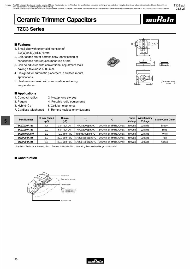
s Features
1. Small size with external dimension of
3.2(W)x4.5(L)x1.6(H)mm
2. Color coded stator permits easy identification of
capacitance and reduces mounting errors.
3. Can be adjusted with conventional adjustment tools
having a thickness of 0.5mm.
4. Designed for automatic placement in surface mount
applications.
5. Heat resistant resin withstands reflow soldering
temperatures.
s Applications1. Compact radios 2. Headphone stereos
3. Pagers 4. Portable radio equipments
5. Hybrid ICs 6. Cellular telephones
7. Cordless telephones 8. Remote keyless entry systems
0.5
2.5 dia.
4.5
0 . 7
5
3 . 2
0 . 8
0 . 3
5
1 . 6
4.5
0.6 0.6
0 . 8
Tolerance: ±0.1in mm
Part NumberC min. (max.)
(pF)
C max.
(pF)TC Q
Rated
Voltage
Withstanding
VoltageStator/Case Color
TZC3Z030A110 1.4 3.0 +50/-0% NP0±300ppm/ °C 300min. at 1MHz, Cmax. 100Vdc 220Vdc Brown
TZC3Z060A110 2.0 6.0 +50/-0% NP0±300ppm/ °C 500min. at 1MHz, Cmax. 100Vdc 220Vdc Blue
TZC3R100A110 3.0 10.0 +50/-0% N750±300ppm/ °C 500min. at 1MHz, Cmax. 100Vdc 220Vdc White
TZC3P200A110 5.0 20.0 +50/-0% N1200±500ppm/ °C 300min. at 1MHz, Cmax. 100Vdc 220Vdc Red
TZC3P300A110 6.5 30.0 +50/-0% N1200±500ppm/ °C 300min. at 1MHz, Cmax. 100Vdc 220Vdc Green
Insulation Resistance: 10000M ohm Torque: 1.5 to 9.8mNm Operating Temperature Range: -25 to +85°C
s Construction
Center axis
Rotor spring terminal
Ceramic plate
Stator(One molded injectionwith stator terminal)
Stator terminal
• This PDF catalog is downloaded from the website of Murata Manufacturing co., ltd. Therefore, it’s specifications are subject to change or our products in it may be discontinued without advance notice. Please check wit h oursales representatives or product engineers before ordering.
• This PDF catalog has only typical specifications because there is no space for detailed specifications. Therefore, please approve our product specifications or transact the approval sheet for product specifications before ordering.
!Note T13E.pdf08.8.27
7/31/2019 Trimmers Murata
http://slidepdf.com/reader/full/trimmers-murata 23/4421
5
!Note • Please read rating and !CAUTION (for storage, operating, rating, soldering, mounting and handling) in this catalog to prevent smoking and/or burning, etc.• This catalog has only typical specifications because there is no space for detailed specifications. Therefore, please approve our product specifications or transact the approval sheet for product specifications before ordering.
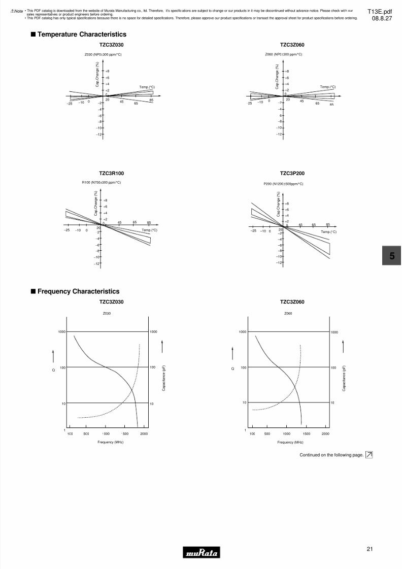
s Temperature Characteristics
TZC3Z030
+8
+6
+4
+2
200−10−2545
6585
−2
−4
−6
−8
−10
−12
Temp.(°C)
0
Z030 (NP0±300 ppm/ °C)
C a p . C
h a n g e ( % )
TZC3Z060
+8
+6
+4
+2
200−10−2545
65 85−2
−4
−6
−8
−10
−12
Temp.(°C)
0
Z060 (NP0±300 ppm/ °C)
C a p . C
h a n g e ( % )
TZC3R100
+8
+6
+4
+2
0−10−25
45 65 85
−2
20
−4
−6
−8
−10
−12
Temp.(°C)
0
R100 (N750±300 ppm/ °C)
C a p . C
h a n g e ( % )
TZC3P200
+8
+6
+4
+20
0 –10 –25
45 65 85
–2
–4
–6
–8
–10
–12
Temp.(°C)20
P200 (N1200±500ppm/ °C)
C a p . C
h a n g e
( % )
s Frequency Characteristics
TZC3Z030
Z030
1000
100Q
100 500 1000 1500
Frequency (MHz)
2000
10
1
1000
100
10
C a p a c i t a n c e ( p F )
TZC3Z060
Z060
Q
1000
100
100 500 200015001000
Frequency (MHz)
10
1
1000
100
10
C a p a c i t a n c e ( p F )
Continued on the following page.
• This PDF catalog is downloaded from the website of Murata Manufacturing co., ltd. Therefore, it’s specifications are subject to change or our products in it may be discontinued without advance notice. Please check wit h oursales representatives or product engineers before ordering.
• This PDF catalog has only typical specifications because there is no space for detailed specifications. Therefore, please approve our product specifications or transact the approval sheet for product specifications before ordering.
!Note T13E.pdf08.8.27
7/31/2019 Trimmers Murata
http://slidepdf.com/reader/full/trimmers-murata 24/4422
5
!Note • Please read rating and !CAUTION (for storage, operating, rating, soldering, mounting and handling) in this catalog to prevent smoking and/or burning, etc.• This catalog has only typical specifications because there is no space for detailed specifications. Therefore, please approve our product specifications or transact the approval sheet for product specifications before ordering.
Continued from the preceding page.
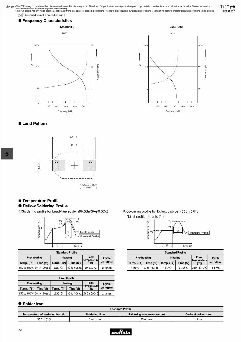
s Frequency Characteristics
TZC3R100
R100
Q
1000
100
200 600400 800 1000
Frequency (MHz)
10
1
1000
100
10
C a p a c i t a n c e ( p F )
TZC3P200
P200
Q
1000
100
200 1000600 800400
Frequency (MHz)
10
1
1000
100
10
C a p a c i t a n c e ( p F )
s Land Pattern
5.0+0−0.5
3.3±0.1
1 . 0
± 0 . 1
Tolerance: ±0.1in mm
s Temperature Profile
T
e m p e r a t u r e ( ° C )
t3
t2
T3T2
T5
T4
T1
time (s)t1
Reflow Soldering Profile
qSoldering profile for Lead-free solder (96.5Sn/3Ag/0.5Cu)
Standard Profile
Pre-heating Heating Peaktemperature
(T3)
Cycle
of reflowTemp. (T1) Time (t1) Temp. (T2) Time (t2)
2 times245±3°C150 to 180°C 60 to 120sec. 220°C 30 to 60sec.
Limit Profile
Standard Profile
Standard Profile
Pre-heating Heating Cycle
of reflowTemp. (T1) Time (t1) Temp. (T2) Time (t2)
1 time230 +5/-0°C150°C 60 to 120sec. 183°C 30sec.
Limit Profile
Pre-heating Heating Cycle
of reflowTemp. (T1) Time (t1) Temp. (T4) Time (t3)
2 times260 +5/-0°C150 to 180°C 60 to 120sec. 230°C 30 to 50sec.
T e m p e r a t u r e ( ° C )
time (s)
Standard Profile
t1
T1 t2
T3
T2
wSoldering profile for Eutectic solder (63Sn/37Pb)
(Limit profile: refer toq)
Solder Iron
Standard Profile
Temperature of soldering iron tip Soldering time Soldering iron power output
350±10°C 3sec. max. 30W max. 1 time
Cycle of solder iron
Peaktemperature
(T5)
Peaktemperature
(T3)
• This PDF catalog is downloaded from the website of Murata Manufacturing co., ltd. Therefore, it’s specifications are subject to change or our products in it may be discontinued without advance notice. Please check wit h oursales representatives or product engineers before ordering.
• This PDF catalog has only typical specifications because there is no space for detailed specifications. Therefore, please approve our product specifications or transact the approval sheet for product specifications before ordering.
!Note T13E.pdf08.8.27
7/31/2019 Trimmers Murata
http://slidepdf.com/reader/full/trimmers-murata 25/4423
5
!Note • Please read rating and !CAUTION (for storage, operating, rating, soldering, mounting and handling) in this catalog to prevent smoking and/or burning, etc.• This catalog has only typical specifications because there is no space for detailed specifications. Therefore, please approve our product specifications or transact the approval sheet for product specifications before ordering.
s Notice (Storage and Operating Condition)
s Notice (Soldering and Mounting)
s Notice (Handling)
1. Do not use the trimmer capacitor under atmosphere
of RTV silicone rubber (Room Temperature
Vulcanizing Silicone Rubber) except Acetone
liberating silicone sealant.
2. Before using trimmer capacitor, please store under
the condition of -10 to +40 degrees C and 30 to
85%RH.
3. Do not store in or near corrosive gasses.
4. Use within 6 months of delivery.
5. Do not store under direct sunlight.
6. Do not use the trimmer capacitor under the
conditions listed below.
(1) Corrosive gasses atmosphere
(ex. Chlorine gas, Hydrogen sulfide gas,
Ammonia gas, Sulfuric acid gas, Nitric oxide gas, etc.)
(2) In liquid (ex. water, oil, medical liquid,
organic solvent, etc.)
(3) Dusty / dirty atmosphere
(4) Direct sunlight
(5) Static voltage nor electric/magnetic fields
(6) Direct sea breeze
(7) Other variations of the above
1. Soldering
(1) TZC3 series can be soldered by reflow soldering
method and soldering iron. Do not use flow
soldering method (dipping).
(2) Soldering conditionRefer to the temperature profile.
If the soldering conditions are not suitable, e.g.,
excessive time and/or excessive temperature, the
trimmer capacitor may deviate from the specified
characteristics.
(3) The amount of solder is critical.
(4) The thickness of solder paste should be printed
from 150 micro m to 200 micro m and the dimension
of land pattern should be Murata's standard land
pattern used at reflow soldering.
Insufficient amounts of solder can lead to
insufficient soldering strength on PCB.
Excessive amounts of solder may cause bridging
between the terminals or contact failure due to
flux wicking up.
(5) When using soldering iron, the diameter of the
string solder should be less than 0.5mm. The
string solder should be applied to the lower
part of the terminal only. Do not apply flux
except to the terminals. Excessive amounts of
solder and/or applying solder to the upper part
of the terminal may cause fixed metal rotor or
contact failure due to flux invasion into the
movable part and/or the contact point. The
soldering iron should not come in contact with
the stator of the trimmer capacitor. If such
contact does occur, the trimmer capacitor may
be damaged.
(6) Our recommended chlorine content of solder is as follows.(a) Solder paste: 0.2wt% max.
(b) String solder: 0.5wt% max.
(7) Do not use water-soluble flux (for water
cleaning). To prevent the deterioration of
trimmer capacitor characteristics, apply flux
only to terminals.
(8) When soldering the TZC3 series, the solder
should not flow into the staking part of the
substrate. If such flow does occur, driver slot
rotation will be damaged.
2. Mounting
(1) Do not apply excessive force (preferably 5.0 N[Ref: 500gf] max.), when the trimmer capacitor
is mounted on the PCB.
(2) Do not warp and/or bend PCB to prevent trimmer
capacitor from breakage.
(3) Use the suitable dimension of the pick-up nozzle
(2.5mm external diameter and 1.5mm bore diameter).
3. Cleaning
Cannot be cleaned because of open construction.
4. Other
Note the polarity of the trimmer capacitor to
minimize influence by stray capacitance.
(Refer to the dimensions concerning the polarity.)
1. Use suitable screwdrivers that fit comfortably in
driver slot.
(1) Recommended screwdriver for manual adjustment
Standard type --> MURATA: KMDR010
(2) Recommended screwdriver bit for automatic
adjustment
Standard type --> MURATA: KMBT010
2. When adjusting with a screwdriver, do not apply
excessive force (preferably 1.0 N [Ref: 100gf] max.)
to minimize capacitance drift. If excessive force
is applied to the screwdriver slot, it may cause
deformation of the products.
3. Do not apply adhesive, lock paints, or any other
substances to the trimmer capacitor to secure the
rotor position. They may cause corrosion or
electrical contact problems.
s Notice (Other)
Before using trimmer capacitor, please test after
assembly in your particular mass production system.
• This PDF catalog is downloaded from the website of Murata Manufacturing co., ltd. Therefore, it’s specifications are subject to change or our products in it may be discontinued without advance notice. Please check wit h oursales representatives or product engineers before ordering.
• This PDF catalog has only typical specifications because there is no space for detailed specifications. Therefore, please approve our product specifications or transact the approval sheet for product specifications before ordering.
!Note T13E.pdf08.8.27
7/31/2019 Trimmers Murata
http://slidepdf.com/reader/full/trimmers-murata 26/4424
6
!Note • Please read rating and !CAUTION (for storage, operating, rating, soldering, mounting and handling) in this catalog to prevent smoking and/or burning, etc.• This catalog has only typical specifications because there is no space for detailed specifications. Therefore, please approve our product specifications or transact the approval sheet for product specifications before ordering.
Ceramic Trimmer Capacitors
TZW4 Series
5.2±0.2
4 . 2
± 0 . 2
2 . 8
± 0 . 2
2 . 6 m a x .
( Tolerance: ±0.1 )in mm
0 .
6
+0.1-0.20.3
1.6
0.4 Depth
3.0
2.2
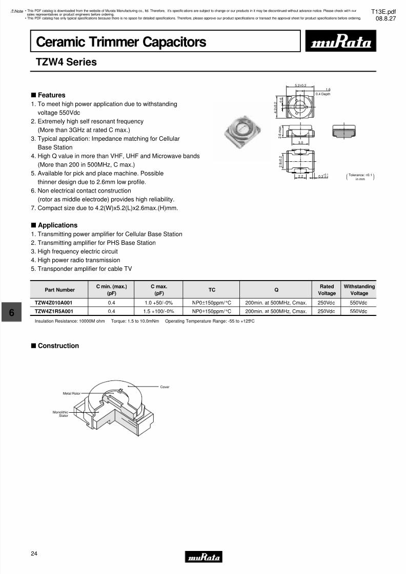
Part NumberC min. (max.)
(pF)
C max.
(pF)TC Q
Rated
Voltage
Withstanding
Voltage
TZW4Z010A001 0.4 1.0 +50/-0% NP0±150ppm/ °C 200min. at 500MHz, Cmax. 250Vdc 550Vdc
TZW4Z1R5A001 0.4 1.5 +100/-0% NP0±150ppm/ °C 200min. at 500MHz, Cmax. 250Vdc 550Vdc
Insulation Resistance: 10000M ohm Torque: 1.5 to 10.0mNm Operating Temperature Range: -55 to +125°C
s Construction
Cover
Metal Rotor
MonolithicStator
s Features
1. To meet high power application due to withstanding
voltage 550Vdc
2. Extremely high self resonant frequency
(More than 3GHz at rated C max.)
3. Typical application: Impedance matching for Cellular
Base Station
4. High Q value in more than VHF, UHF and Microwave bands
(More than 200 in 500MHz, C max.)
5. Available for pick and place machine. Possible
thinner design due to 2.6mm low profile.
6. Non electrical contact construction
(rotor as middle electrode) provides high reliability.7. Compact size due to 4.2(W)x5.2(L)x2.6max.(H)mm.
s Applications
1. Transmitting power amplifier for Cellular Base Station
2. Transmitting amplifier for PHS Base Station
3. High frequency electric circuit
4. High power radio transmission
5. Transponder amplifier for cable TV
• This PDF catalog is downloaded from the website of Murata Manufacturing co., ltd. Therefore, it’s specifications are subject to change or our products in it may be discontinued without advance notice. Please check wit h oursales representatives or product engineers before ordering.
• This PDF catalog has only typical specifications because there is no space for detailed specifications. Therefore, please approve our product specifications or transact the approval sheet for product specifications before ordering.
!Note T13E.pdf08.8.27
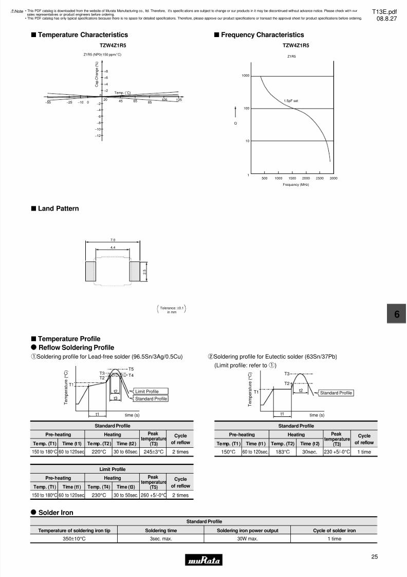
7/31/2019 Trimmers Murata
http://slidepdf.com/reader/full/trimmers-murata 27/4425
6
!Note • Please read rating and !CAUTION (for storage, operating, rating, soldering, mounting and handling) in this catalog to prevent smoking and/or burning, etc.• This catalog has only typical specifications because there is no space for detailed specifications. Therefore, please approve our product specifications or transact the approval sheet for product specifications before ordering.
s Temperature Characteristics
TZW4Z1R5
+8
+6
+4
+2
200−10−25−55 45 65 85 105 125−2
−4
−6
−8
−10
−12
0
Z1R5 (NP0±150 ppm/˚C)
Temp. (˚C)
C a p . C
h a n g e ( % )
s Frequency Characteristics
TZW4Z1R5
Z1R5
1000
100
Q
500 1000 1500 2000 2500 3000
10
1
Frequency (MHz)
1.5pF set
s Land Pattern
Tolerance: ±0.1in mm
4.4
7.0
2 . 5
s Temperature Profile
T
e m p e r a t u r e ( ° C )
t3
t2
T3T2
T5
T4
T1
time (s)t1
Reflow Soldering Profile
qSoldering profile for Lead-free solder (96.5Sn/3Ag/0.5Cu)
Standard Profile
Pre-heating Heating Peaktemperature
(T3)
Cycle
of reflowTemp. (T1) Time (t1) Temp. (T2) Time (t2)
2 times245±3°C150 to 180°C 60 to 120sec. 220°C 30 to 60sec.
Limit Profile
Standard Profile
Standard Profile
Pre-heating Heating Cycle
of reflowTemp. (T1) Time (t1) Temp. (T2) Time (t2)
1 time230 +5/-0°C150°C 60 to 120sec. 183°C 30sec.
Limit Profile
Pre-heating Heating Cycle
of reflowTemp. (T1) Time (t1) Temp. (T4) Time (t3)
2 times260 +5/-0°C150 to 180°C 60 to 120sec. 230°C 30 to 50sec.
T e m p e r a t u r e ( ° C )
time (s)
Standard Profile
t1
T1 t2
T3
T2
wSoldering profile for Eutectic solder (63Sn/37Pb)
(Limit profile: refer toq)
Solder Iron
Standard Profile
Temperature of soldering iron tip Soldering time Soldering iron power output
350±10°C 3sec. max. 30W max. 1 time
Cycle of solder iron
Peaktemperature
(T5)
Peaktemperature
(T3)
• This PDF catalog is downloaded from the website of Murata Manufacturing co., ltd. Therefore, it’s specifications are subject to change or our products in it may be discontinued without advance notice. Please check wit h oursales representatives or product engineers before ordering.
• This PDF catalog has only typical specifications because there is no space for detailed specifications. Therefore, please approve our product specifications or transact the approval sheet for product specifications before ordering.
!Note T13E.pdf08.8.27

7/31/2019 Trimmers Murata
http://slidepdf.com/reader/full/trimmers-murata 28/4426
6
!Note • Please read rating and !CAUTION (for storage, operating, rating, soldering, mounting and handling) in this catalog to prevent smoking and/or burning, etc.• This catalog has only typical specifications because there is no space for detailed specifications. Therefore, please approve our product specifications or transact the approval sheet for product specifications before ordering.
s Notice (Storage and Operating Condition)
s Notice (Soldering and Mounting)
1. Soldering
(1) TZW4 series can be soldered by reflow soldering
method and soldering iron. Do not use flow
soldering method (dipping).(2) Soldering condition
Refer to the temperature profile.
If the soldering conditions are not suitable, e.g.,
excessive time and/or excessive temperature, the
trimmer capacitor may deviate from the specified
characteristics.
(3) The amount of solder is critical.
(4) The thickness of solder paste should be printed
from 150 micro m to 200 micro m and the dimension
of land pattern should be Murata's standard land
pattern used at reflow soldering.
Insufficient amounts of solder can lead to
insufficient soldering strength on PCB.
Excessive amounts of solder may cause bridging
between the terminals or contact failure due to
flux wicking up.
(5) When using soldering iron, the diameter of the
string solder should be less than 0.5mm. The
string solder should be applied to the lower
part of the terminal only. Do not apply flux
except to the terminals. Excessive amounts of
solder and/or applying solder to the upper part
of the terminal may cause fixed metal rotor or
the contact failure due to flux invasion into
the movable part and/or the contact point. The
soldering iron should not come in contact withthe monolithic stator of the trimmer capacitor.
If such contact does occur, the trimmer
capacitor may be damaged.
(6) Our recommended chlorine content of solder is
as follows.
(a) Solder paste: 0.2wt% max.
(b) String solder: 0.5wt% max.
(7) Do not use water-soluble flux (for water
cleaning). To prevent the deterioration of
trimmer capacitor characteristics, apply flux
only to terminals.
2. Mounting(1) Do not apply excessive force (preferably 5.0 N
[Ref: 500gf] max.), when the trimmer capacitor
is mounted on the PCB.
(2) Do not warp and/or bend PCB to prevent trimmer
capacitor from breaking.
(3) Use the suitable dimension of the pick-up nozzle
(1.8mm external diameter and 1.1mm bore
diameter).
3. Cleaning
Cannot be cleaned because of open construction.
s Notice (Handling)
s Notice (Other)
Before using trimmer capacitor, please test after
assembly in your particular mass production system.
1. Do not use the trimmer capacitor under atmosphere
of RTV silicone rubber (Room Temperature
Vulcanizing Silicone Rubber) except Acetone
liberating silicone sealant.
2. Before using trimmer capacitor, please store under
the condition of -10 to +40 degrees C and 30
to 85%RH.
3. Do not store in or near corrosive gasses.
4. Use within 6 months of delivery.
5. Do not store under direct sunlight.
6. Do not use the trimmer capacitor under the
conditions listed below.
(1) Corrosive gasses atmosphere
(Ex. Chlorine gas, Hydrogen sulfide gas,
Ammonia gas, Sulfuric acid gas, Nitric oxie gas,
etc.)
(2) In liquid (Ex. water, oil, medical liquid,
organic solvent, etc.)
(3) Dusty/dirty atmosphere
(4) Direct sunlight
(5) Static voltage nor electric/magnetic fields
(6) Direct sea breeze
(7) Other variations of the above
1. Use suitable screwdrivers that fit comfortably in
driver slot.
-Recommended screwdriver for manual adjustment
VESSEL: No.9000 -1.3x30
(Murata: KMDR130)
2. When adjusting with a screwdriver, do not apply
excessive force (preferably 1.0 N [Ref: 100gf] max.)
to minimize capacitance drift. If excessive force
applied to the screwdriver slot, it may cause
deformation of the products.
3. Do not apply adhesive, lock paints, or any other
substances to the trimmer capacitor to secure the
rotor position. They may cause corrosion or
electrical contact problems.
• This PDF catalog is downloaded from the website of Murata Manufacturing co., ltd. Therefore, it’s specifications are subject to change or our products in it may be discontinued without advance notice. Please check wit h oursales representatives or product engineers before ordering.
• This PDF catalog has only typical specifications because there is no space for detailed specifications. Therefore, please approve our product specifications or transact the approval sheet for product specifications before ordering.
!Note T13E.pdf08.8.27
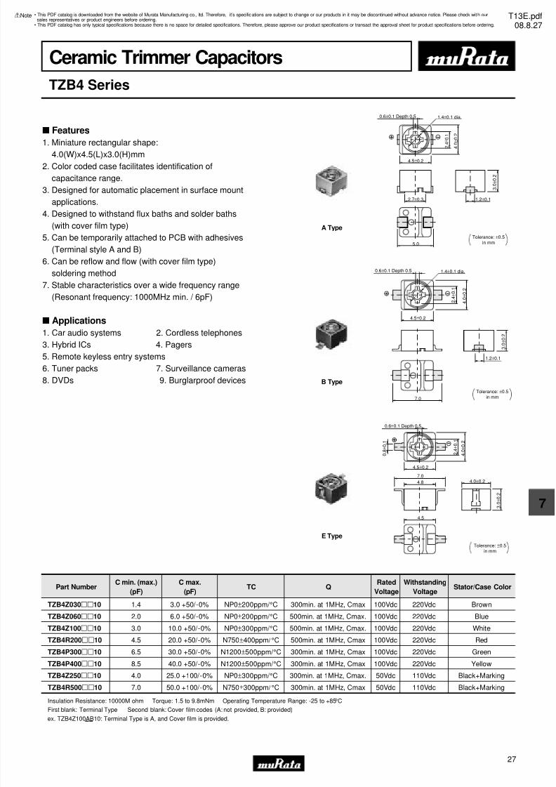
7/31/2019 Trimmers Murata
http://slidepdf.com/reader/full/trimmers-murata 29/4427
7
!Note • Please read rating and !CAUTION (for storage, operating, rating, soldering, mounting and handling) in this catalog to prevent smoking and/or burning, etc.• This catalog has only typical specifications because there is no space for detailed specifications. Therefore, please approve our product specifications or transact the approval sheet for product specifications before ordering.
Ceramic Trimmer Capacitors
TZB4 Series
0.6±0.1 Depth 0.5 1.4±0.1 dia.
2.7±0.3
2 . 4
± 0 . 1
4 . 0
± 0 . 2
4.5±0.2
5.0
1.2±0.1
3 . 0
± 0 . 2
Tolerance: ±0.5in mm
A Type
0.6±0.1 Depth 0.5 1.4±0.1 dia.
2 . 4
± 0 . 1
4 . 0
± 0 . 2
4.5±0.2
7.0
1.2±0.1
3 . 0
± 0 . 2
Tolerance: ±0.5in mm
B Type
0.6±0.1 Depth 0.5
4.8
2 . 4
± 0 . 1
4 . 0
± 0 . 2
4.5±0.2
4.5
4.0±0.2
3 . 0
± 0 . 2
Tolerance: ±0.5
in mm
7.0
0 . 8
± 0 . 1
E Type
Part NumberC min. (max.)
(pF)
C max.
(pF)TC Q
Rated
Voltage
Withstanding
VoltageStator/Case Color
TZB4Z030pp10 1.4 3.0 +50/-0% NP0±200ppm/ °C 300min. at 1MHz, Cmax 100Vdc 220Vdc Brown
TZB4Z060pp10 2.0 6.0 +50/-0% NP0±200ppm/ °C 500min. at 1MHz, Cmax. 100Vdc 220Vdc Blue
TZB4Z100pp10 3.0 10.0 +50/-0% NP0±300ppm/ °C 500min. at 1MHz, Cmax. 100Vdc 220Vdc White
TZB4R200pp10 4.5 20.0 +50/-0% N750±400ppm/ °C 500min. at 1MHz, Cmax 100Vdc 220Vdc Red
TZB4P300pp10 6.5 30.0 +50/-0% N1200±500ppm/ °C 300min. at 1MHz, Cmax 100Vdc 220Vdc Green
TZB4P400pp10 8.5 40.0 +50/-0% N1200±500ppm/ °C 300min. at 1MHz, Cmax 100Vdc 220Vdc Yellow
TZB4Z250pp10 4.0 25.0 +100/-0% NP0±300ppm/ °C 300min. at 1MHz, Cmax. 50Vdc 110Vdc Black+Marking
TZB4R500pp10 7.0 50.0 +100/-0% N750±300ppm/ °C 300min. at 1MHz, Cmax 50Vdc 110Vdc Black+MarkingInsulation Resistance: 10000M ohm Torque: 1.5 to 9.8mNm Operating Temperature Range: -25 to +85°C
First blank: Terminal Type Second blank: Cover film codes (A: not provided, B: provided)
ex. TZB4Z100AB10: Terminal Type is A, and Cover film is provided.
s Features
1. Miniature rectangular shape:
4.0(W)x4.5(L)x3.0(H)mm
2. Color coded case facilitates identification of
capacitance range.
3. Designed for automatic placement in surface mount
applications.
4. Designed to withstand flux baths and solder baths
(with cover film type)
5. Can be temporarily attached to PCB with adhesives
(Terminal style A and B)
6. Can be reflow and flow (with cover film type)
soldering method7. Stable characteristics over a wide frequency range
(Resonant frequency: 1000MHz min. / 6pF)
s Applications
1. Car audio systems 2. Cordless telephones
3. Hybrid ICs 4. Pagers
5. Remote keyless entry systems
6. Tuner packs 7. Surveillance cameras
8. DVDs 9. Burglarproof devices
• This PDF catalog is downloaded from the website of Murata Manufacturing co., ltd. Therefore, it’s specifications are subject to change or our products in it may be discontinued without advance notice. Please check wit h oursales representatives or product engineers before ordering.
• This PDF catalog has only typical specifications because there is no space for detailed specifications. Therefore, please approve our product specifications or transact the approval sheet for product specifications before ordering.
!Note T13E.pdf08.8.27
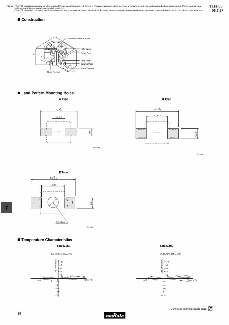
7/31/2019 Trimmers Murata
http://slidepdf.com/reader/full/trimmers-murata 30/4428
7
!Note • Please read rating and !CAUTION (for storage, operating, rating, soldering, mounting and handling) in this catalog to prevent smoking and/or burning, etc.• This catalog has only typical specifications because there is no space for detailed specifications. Therefore, please approve our product specifications or transact the approval sheet for product specifications before ordering.
s Construction
Plastic Case
Rotor Spring
Metal Rotor
Ceramic Plate
Stator Terminal
Cover Film (Cover film type)
Rotor Terminal
−
+
s Land Pattern/Mounting Holes
A Type
1 . 6
± 0 . 1
7.0+0- 0.5
2.4±0.2
(in mm)
B Type
(in mm)
4.0±0.2
1 . 6
± 0 . 1
8.0+0- 0.5
E Type
8.0+0- 0.5
4.2±0.2
1 . 2
± 0 . 1
3.2±0.2 dia.
(in mm)
s Temperature Characteristics
TZB4Z060
+8
+10
+6
+4
+2+20
0 –25
+55 +85
–2
–4
–6
–8
–10
0
Z060 (NP0±200ppm/ °C)
Temp. (°C)
C a p . C
h a n g e ( % )
TZB4Z100
+8
+10
+6
+4
+2+20
0 –25
+55+85
–2
–4
–6
–8
–10
0
Z100 (NP0±300ppm/ °C)
C a p . C
h a n g e ( % )
Temp. (°C)
Continued on the following page.
• This PDF catalog is downloaded from the website of Murata Manufacturing co., ltd. Therefore, it’s specifications are subject to change or our products in it may be discontinued without advance notice. Please check wit h oursales representatives or product engineers before ordering.
• This PDF catalog has only typical specifications because there is no space for detailed specifications. Therefore, please approve our product specifications or transact the approval sheet for product specifications before ordering.
!Note T13E.pdf08.8.27
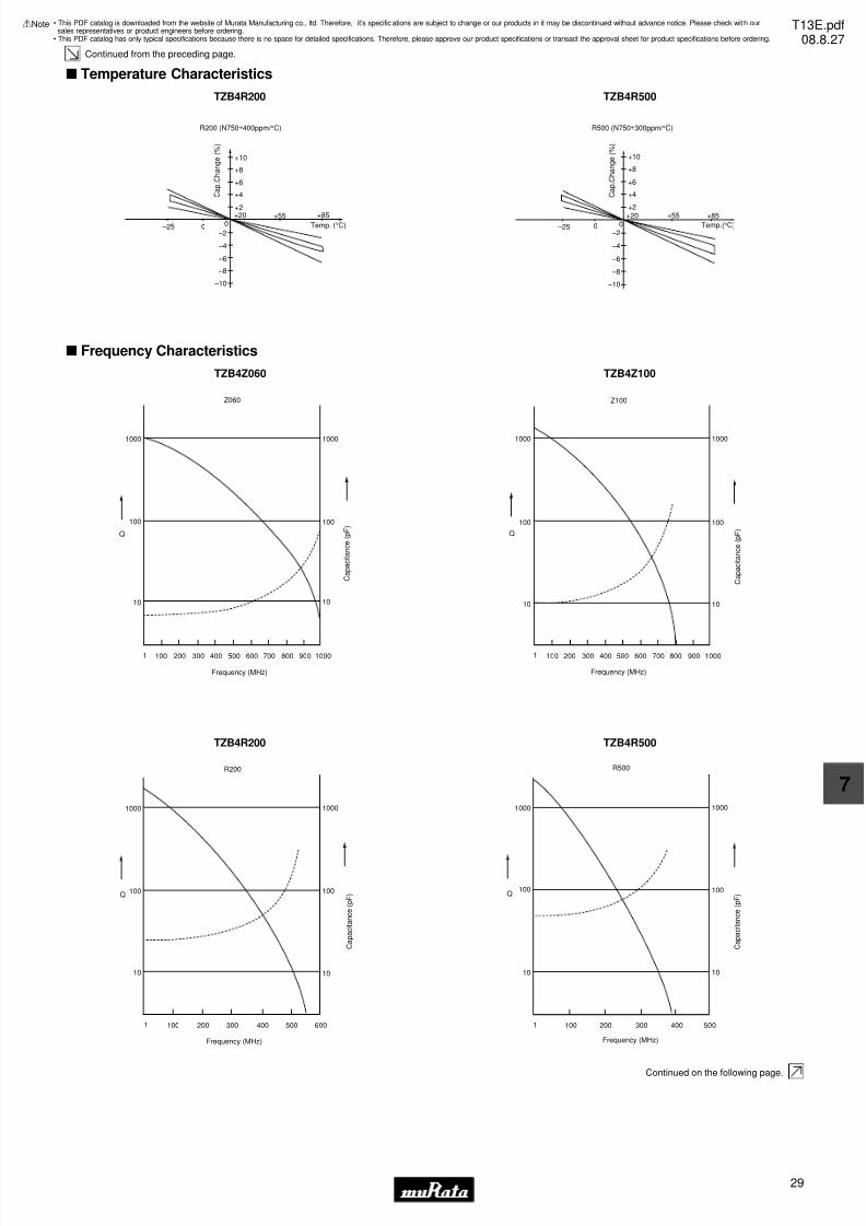
7/31/2019 Trimmers Murata
http://slidepdf.com/reader/full/trimmers-murata 31/4429
7
!Note • Please read rating and !CAUTION (for storage, operating, rating, soldering, mounting and handling) in this catalog to prevent smoking and/or burning, etc.• This catalog has only typical specifications because there is no space for detailed specifications. Therefore, please approve our product specifications or transact the approval sheet for product specifications before ordering.
Continued from the preceding page.
s Temperature Characteristics
TZB4R200
+8
+10
+6
+4
+2
+20
0 –25
+55 +85
–2
–4
–6
–8
–10
0
R200 (N750±400ppm/ °C)
C a p . C
h a n g e ( % )
Temp. (°C)
TZB4R500
+8
+10
+6
+4
+2
+200 –25
+55 +85
–2
–4
–6
–8
–10
0
R500 (N750±300ppm/ °C)
C a p . C
h a n g e ( % )
Temp.(°C)
s Frequency Characteristics
TZB4Z060
Z060
1000
100
Q
10
1000
100
10
800700600500400300200100 900 1000
Frequency (MHz)
1
C a p a c i t a n c e ( p F )
TZB4Z100
Z100
Q
1000
100
800700600500400300200100 900 1000
Frequency (MHz)
10
1
1000
100
10
C a p a c i t a n c e ( p F )
TZB4R200
R200
Q
1000
100
200100 400300 500 600
Frequency (MHz)
10
1
1000
100
10
C a p a c i t a n c e ( p F )
TZB4R500
R500
Q
1000
100
100 500300 400200
Frequency (MHz)
10
1
1000
100
10
C a p a c i t a n c e ( p F )
Continued on the following page.
• This PDF catalog is downloaded from the website of Murata Manufacturing co., ltd. Therefore, it’s specifications are subject to change or our products in it may be discontinued without advance notice. Please check wit h oursales representatives or product engineers before ordering.
• This PDF catalog has only typical specifications because there is no space for detailed specifications. Therefore, please approve our product specifications or transact the approval sheet for product specifications before ordering.
!Note T13E.pdf08.8.27

7/31/2019 Trimmers Murata
http://slidepdf.com/reader/full/trimmers-murata 32/4430
7
!Note • Please read rating and !CAUTION (for storage, operating, rating, soldering, mounting and handling) in this catalog to prevent smoking and/or burning, etc.• This catalog has only typical specifications because there is no space for detailed specifications. Therefore, please approve our product specifications or transact the approval sheet for product specifications before ordering.
Continued from the preceding page.
s Temperature Profile
T e m p e r a t u r e ( ° C )
t3
t2
T3T2
T5
T4
T1
time (s)t1
Soldering profile for Lead-free solder (96.5Sn/3Ag/0.5Cu), Eutectic solder (63Sn/37Pb)
T e m p e r a t u r e ( ° C )
t1
t2
T3T2
T1
time (s)
Limit Profile
Standard Profile
qSoldering profile for Lead-free solder (96.5Sn/3Ag/0.5Cu)
Limit Profile
Standard Profile
• Available for terminal shape A, B, and E..
• Immerse the body in solder bath, available for cover film type.
Standard Profile
Pre-heating Heating
Temp. (T1) Time (t1) Temp. (T2) Time (t2)
1 time150°C 60 to 120sec. 250°C 5sec. max.
T e m p e r a t u r e ( ° C )
time (s)
Standard Profile
t1
T1 t2
T3
T2
wSoldering profile for Eutectic solder (63Sn/37Pb)
(Limit profile: refer to q)
Flow Soldering Profile
Reflow Soldering Profile
Cycle
of reflow
Limit Profile
Pre-heating Heating
Temp. (T1) Time (t1) Temp. (T3) Time (t2)
2 times150°C 60 to 120sec. 265±3°C 5sec. max.
Cycle
of reflow
Standard Profile
Pre-heating Heating Peaktemperature
(T3)
Cycle
of reflowTemp. (T1) Time (t1) Temp. (T2) Time (t2)
2 times245±3°C150 to 180°C 60 to 120sec. 220°C 30 to 60sec.
Limit Profile
Pre-heating Heating Cycle
of reflowTemp. (T1) Time (t1) Temp. (T4) Time (t3)
2 times260 +5/-0°C150 to 180°C 60 to 120sec. 230°C 30 to 50sec.
Peaktemperature
(T5)
Standard Profile
Pre-heating Heating Cycle
of reflowTemp. (T1) Time (t1) Temp. (T2) Time (t2)
1 time230 +5/-0°C150°C 60 to 120sec. 183°C 30sec.
Peaktemperature
(T3)
Solder Iron
Standard Profile
Temperature of soldering iron tip Soldering time Soldering iron power output
350±10°C 3sec. max. 30W max. 1 time
Cycle of solder iron
s Notice (Storage and Operating Condition)
1. Do not use the trimmer capacitor under atmosphere
of RTV silicone rubber (Room Temperature
Vulcanizing Silicone Rubber) except Acetone
liberating silicone sealant.
2. Before using trimmer capacitor, please store under
the condition of -10 to +40 degrees C and 30 to
85%RH.
3. Do not store in or near corrosive gasses.
4. Use within 6 months of delivery.
5. Do not store under direct sunlight.
6. Do not use the trimmer capacitor under the
conditions listed below.
(1) Corrosive gasses atmosphere
(ex. Chlorine gas, Hydrogen sulfide gas,
Ammonia gas, Sulfuric acid gas, Nitric oxide gas,
etc.)
(2) In liquid (ex. water, oil, medical liquid,
organic solvent, etc.)
(3) Dusty / dirty atmosphere
(4) Direct sunlight
(5) Static voltage nor electric/magnetic fields
(6) Direct sea breeze
(7) Other variations of the above
• This PDF catalog is downloaded from the website of Murata Manufacturing co., ltd. Therefore, it’s specifications are subject to change or our products in it may be discontinued without advance notice. Please check wit h oursales representatives or product engineers before ordering.
• This PDF catalog has only typical specifications because there is no space for detailed specifications. Therefore, please approve our product specifications or transact the approval sheet for product specifications before ordering.
!Note T13E.pdf08.8.27

7/31/2019 Trimmers Murata
http://slidepdf.com/reader/full/trimmers-murata 33/4431
7
!Note • Please read rating and !CAUTION (for storage, operating, rating, soldering, mounting and handling) in this catalog to prevent smoking and/or burning, etc.• This catalog has only typical specifications because there is no space for detailed specifications. Therefore, please approve our product specifications or transact the approval sheet for product specifications before ordering.
s Notice (Soldering and Mounting)
s Notice (Handling)
1. Use suitable screwdrivers that fit comfortably in
driver slot.
(1) Recommended screwdriver for manual adjustment
MURATA: KMDR010
(2) Recommended screwdriver bit for automatic
adjustment
MURATA: KMBT010
2. When adjusting with a screwdriver, do not apply
excessive force (preferably 1.0 N [Ref: 100gf] max.)
to minimize capacitance drift. If excessive force
is applied to the screwdriver slot, it may cause
deformation of the products.
3. Do not apply adhesive, lock paints, or any other
substances to the trimmer capacitor to secure the
rotor position. They may cause corrosion or
electrical contact problems.
4. Do not break the cover film before the completion
of PCB mounting, soldering, and cleaning.
5. Do not clean the trimmer capacitor after the cover
film has been broken.
6. To break the cover film, first turn the screwdriver
more than 360 deg., and set the capacitance value.
(Only inserting the screwdriver cannot break the
cover film.)
s Notice (Other)
Before using trimmer capacitor, please test after
assembly in your particular mass production system.
1. Soldering
(1) Can be soldered by reflow soldering method, flow
soldering method, and soldering iron.
(2) Soldering condition
Refer to the temperature profile.
If the soldering conditions are not suitable, e.g.,
excessive time and/or excessive temperature, the
trimmer capacitor may deviate from the specified
characteristics.
(3) The amount of solder is critical.
(4) The thickness of solder paste should be printed
from 150 micro m to 200 micro m and the dimension
of land pattern should be Murata's standard land
pattern used at reflow soldering. Insufficient
amounts of solder can lead to insufficient
soldering strength on PCB. Excessive amounts of
solder may cause bridging between the terminals
or contact failure due to flux wicking up.
(5) When using soldering iron, the string soldershould be applied to the lower part of the
terminal only. Do not apply flux except to the
terminals. Excessive amounts of solder and/or
applying solder to the upper part of the
terminal may cause fixed rotor or contact failure
due to flux invasion into the movable part and/or
the contact point. The soldering iron should not
come in contact with the plastic case of the
trimmer capacitor. If such contact does occur,
the trimmer capacitor may be damaged.
(6) Our recommended chlorine content of solder is
as follows.
(a) Solder paste: 0.2wt% max.
(b) String solder: 0.5wt% max.
(7) Do not use water-soluble flux (for water
cleaning). To prevent the deterioration of
trimmer capacitor characteristics, apply flux
only to terminals.
2. Mounting
(1) Do not apply excessive force (preferably 5.0N
[Ref: 500gf] max.), when the trimmer capacitor
is mounted on the PCB.
(2) Do not warp and/or bend PCB to prevent trimmer
capacitor from breakage.
(3) In case of bending the terminals, do not apply
excessive force to the body of the product and
prevent the terminal fixing part from damaging.
(4) Use the suitable dimension of the pick-up nozzle.
> Without cover film type
- External dimensions of 4.5x4.0mm and
2.5mm bore diameter.
> With cover film type
- 4.0mm external diameter and 2.0mm borediameter.
3. Cleaning [with cover film type]
Isopropyl alcohol and Ethyl alcohol are available
material for cleaning. If you use any other types
of solvents, please evaluate performance by
your set. Moreover, please confirm no damage for
trimmer capacitor after cleaning by your conditions.
4. Other
Note the polarity of the trimmer capacitor to
minimize influence by stray capacitance.
(Refer to the dimensions concerning the polarity.)
• This PDF catalog is downloaded from the website of Murata Manufacturing co., ltd. Therefore, it’s specifications are subject to change or our products in it may be discontinued without advance notice. Please check wit h oursales representatives or product engineers before ordering.
• This PDF catalog has only typical specifications because there is no space for detailed specifications. Therefore, please approve our product specifications or transact the approval sheet for product specifications before ordering.
!Note T13E.pdf08.8.27

7/31/2019 Trimmers Murata
http://slidepdf.com/reader/full/trimmers-murata 34/4432
8
!Note • Please read rating and !CAUTION (for storage, operating, rating, soldering, mounting and handling) in this catalog to prevent smoking and/or burning, etc.• This catalog has only typical specifications because there is no space for detailed specifications. Therefore, please approve our product specifications or transact the approval sheet for product specifications before ordering.
Ceramic Trimmer Capacitors
TZ03 Series
s Features
1. Color coded case facilitates identification of
capacitance range.
2. Sealed construction prevents the penetration of
flux and dust.
3. Available in two adjustment styles: Top/Rear.
4. + (Cross-shaped) slot enables automatic adjustment.
s Applications
1. Car audio systems 2. Car clocks
3. Stereos 4. Radio cassette tape recorders
5. Cordless telephones 6. Video games
7. Compact radio equipment8. Remote keyless entry systems
9. Burglarproof devices
2.5±0.2 dia.
0.5±0.2 Depth 0.5 min.
6 d i a .
Tolerance: ±0.5in mm
4
6
1.0±0.11.0±0.1
6.6
0. 2 ±
0. 0 5
0 .2 5 ± 0 .0 5
4 . 8
3 . 3
F Type
2.5±0.2 dia.
0.5±0.2 Depth 0.5 min.
6 . 0
d i a .
6.0
1.2±0.1
7.8
6.4
3.0 3.41.0±0.1
Tolerance: ±0.5in mm
0. 2 5 ±
0. 0 5 0 .2 ±
0 .0 5
4 . 8
3 . 0
4 . 0
N Type
Part NumberC min. (max.)
(pF)
C max.
(pF)TC Q
Rated
Voltage
Withstanding
VoltageStator/Case Color
TZ03Z2R3p169 1.25 2.3 +50/-0% NP0±200ppm/ °C 300min. at 1MHz, Cmax. 100Vdc 220Vdc Black
TZ03Z050p169 1.5 5.0 +50/-0% NP0±200ppm/ °C 500min. at 1MHz, Cmax. 100Vdc 220Vdc Blue
TZ03Z070p169 2.0 7.0 +50/-0% NP0±200ppm/ °C 500min. at 1MHz, Cmax. 100Vdc 220Vdc Blue
TZ03Z100p169 2.7 10.0 +50/-0% NP0±200ppm/ °C 500min. at 1MHz, Cmax. 100Vdc 220Vdc Blue
TZ03R200p169 4.2 20.0 +50/-0% N750±300ppm/ °C 500min. at 1MHz, Cmax. 100Vdc 220Vdc Red
TZ03R300p169 5.2 30.0 +50/-0% N750±300ppm/ °C 500min. at 1MHz, Cmax. 100Vdc 220Vdc Green
TZ03P450p169 6.8 45.0 +50/-0% N1200±500ppm/ °C 300min. at 1MHz, Cmax. 100Vdc 220Vdc Yellow
TZ03P600p169 9.8 60.0 +50/-0% N1200±500ppm/ °C 300min. at 1MHz, Cmax. 100Vdc 220Vdc Brown
TZ03Z500p169 6.0 50.0 +100/-0% NP0±300ppm/ °C 300min. at 1MHz, Cmax. 50Vdc 110Vdc Orange
TZ03R900p169 9.0 90.0 +100/-0% N750±300ppm/ °C 300min. at 1MHz, Cmax. 50Vdc 110Vdc Black+Dot
TZ03R121p169 10.0 120.0 +100/-0% N750±300ppm/ °C 300min. at 1MHz, Cmax. 50Vdc 110Vdc Black
Insulation Resistance: 10000M ohm Torque: 2.0 to 14.7mNm Operating Temperature Range: -25 to +85°C
A blank column is filled with terminal type codes.
• This PDF catalog is downloaded from the website of Murata Manufacturing co., ltd. Therefore, it’s specifications are subject to change or our products in it may be discontinued without advance notice. Please check wit h oursales representatives or product engineers before ordering.
• This PDF catalog has only typical specifications because there is no space for detailed specifications. Therefore, please approve our product specifications or transact the approval sheet for product specifications before ordering.
!Note T13E.pdf08.8.27
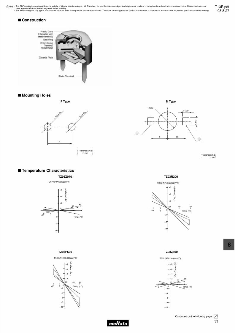
7/31/2019 Trimmers Murata
http://slidepdf.com/reader/full/trimmers-murata 35/4433
8
!Note • Please read rating and !CAUTION (for storage, operating, rating, soldering, mounting and handling) in this catalog to prevent smoking and/or burning, etc.• This catalog has only typical specifications because there is no space for detailed specifications. Therefore, please approve our product specifications or transact the approval sheet for product specifications before ordering.
s Construction
s Mounting Holes
F Type
1 . 3 ± 0 . 1 d i a .
1 . 3 ± 0 . 1 d i a .
5
Tolerance: ±0.5in mm
N Type
(Tolerance: ±0.5in mm)
1 . 3
± 0 . 1
1.1±0.1
3 3.3
3 dia.
s Temperature Characteristics
TZ03Z070
+6
+4
+2
20
–25
8555
–2
–4
–6
Temp. (°C)
00
C a p . C
h a n g e ( % )
Z070 (NP0±200ppm/ °C)
TZ03R200
+6
+4
+2
20
–25
8555
–2
–4
–6
Temp. (°C)00
C a p . C
h a n g e ( % )
R200 (N750±300ppm/ °C)
TZ03P600
+8
+6
+4
+2
20
–25
8555
–2
–4
–6
Temp. (°C)00
–8
–10
C a p . C
h a n g e ( % )
P600 (N1200±500ppm/ °C)
TZ03Z500
+8
+6
+4
+2
20
–25
8555
–2
–4
–6
Temp. (°C)00
–8
–10
C a p . C
h a n g e ( % )
Z500 (NP0±300ppm/ °C)
Continued on the following page.
• This PDF catalog is downloaded from the website of Murata Manufacturing co., ltd. Therefore, it’s specifications are subject to change or our products in it may be discontinued without advance notice. Please check wit h oursales representatives or product engineers before ordering.
• This PDF catalog has only typical specifications because there is no space for detailed specifications. Therefore, please approve our product specifications or transact the approval sheet for product specifications before ordering.
!Note T13E.pdf08.8.27
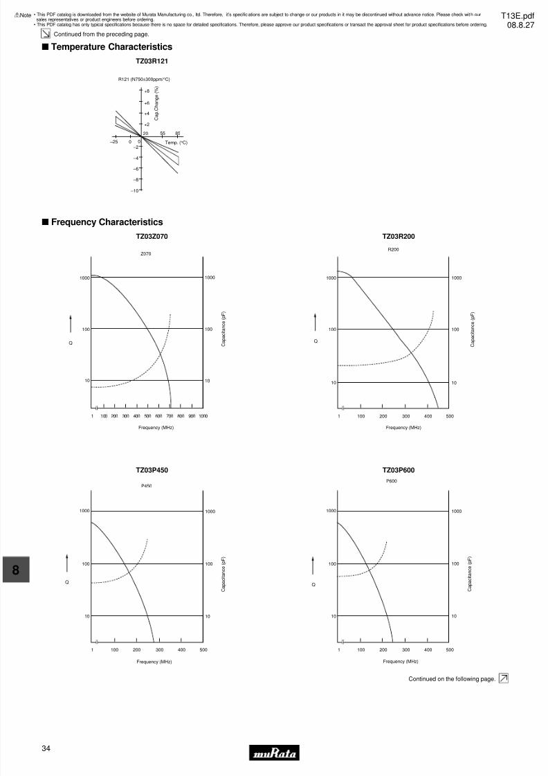
7/31/2019 Trimmers Murata
http://slidepdf.com/reader/full/trimmers-murata 36/4434
8
!Note • Please read rating and !CAUTION (for storage, operating, rating, soldering, mounting and handling) in this catalog to prevent smoking and/or burning, etc.• This catalog has only typical specifications because there is no space for detailed specifications. Therefore, please approve our product specifications or transact the approval sheet for product specifications before ordering.
Continued from the preceding page.
s Temperature Characteristics
TZ03R121
+8
+6
+4
+2
20 –25
8555
–2
–4
–6
Temp. (°C)00
–8
–10
C a p . C
h a n g e ( % )
R121 (N750±300ppm/ °C)
s Frequency Characteristics
TZ03Z070
1000
100
10
1001 200 300 400 500 600 700 800 900 1000
1000
100
10
Q
Frequency (MHz)
C a p a c i t a n c e ( p F )
Z070
TZ03R200
1000
100
10
1001 200 300 400 500
1000
100
10
Q
Frequency (MHz)
C a p a c i t a n c e ( p F )
R200
TZ03P450
1000
100
10
1001 200 300 400 500
1000
100
10
Q
Frequency (MHz)
C a p a c i t a n c e ( p F )
P450
TZ03P600
1000
100
10
1001 200 300 400 500
1000
100
10
Q
Frequency (MHz)
C a p a c i t a n c e ( p F )
P600
Continued on the following page.
• This PDF catalog is downloaded from the website of Murata Manufacturing co., ltd. Therefore, it’s specifications are subject to change or our products in it may be discontinued without advance notice. Please check wit h oursales representatives or product engineers before ordering.
• This PDF catalog has only typical specifications because there is no space for detailed specifications. Therefore, please approve our product specifications or transact the approval sheet for product specifications before ordering.
!Note T13E.pdf08.8.27
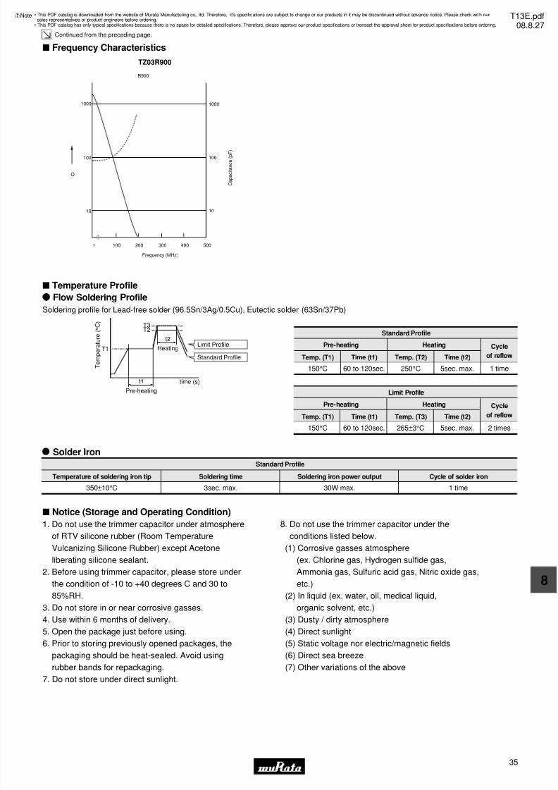
7/31/2019 Trimmers Murata
http://slidepdf.com/reader/full/trimmers-murata 37/4435
8
!Note • Please read rating and !CAUTION (for storage, operating, rating, soldering, mounting and handling) in this catalog to prevent smoking and/or burning, etc.• This catalog has only typical specifications because there is no space for detailed specifications. Therefore, please approve our product specifications or transact the approval sheet for product specifications before ordering.
Continued from the preceding page.
s Frequency Characteristics
TZ03R900
1000
100
10
1001 200 300 400 500
1000
100
10
Q
Frequency (MHz)
C a p a c i t a n c e ( p F )
R900
s Temperature Profile
Soldering profile for Lead-free solder (96.5Sn/3Ag/0.5Cu), Eutectic solder (63Sn/37Pb)
T e m p e r a t u r e ( ° C )
t1
t2
Pre-heating
Heating
T3T2
T1
time (s)
Limit Profile
Standard Profile
Standard Profile
Pre-heating Heating
Temp. (T1) Time (t1) Temp. (T2) Time (t2)
1 time150°C 60 to 120sec. 250°C 5sec. max.
Flow Soldering Profile
Cycle
of reflow
Limit Profile
Pre-heating Heating
Temp. (T1) Time (t1) Temp. (T3) Time (t2)
2 times150°C 60 to 120sec. 265±3°C 5sec. max.
Cycle
of reflow
Solder Iron
Standard Profile
Temperature of soldering iron tip Soldering time Soldering iron power output
350±10°C 3sec. max. 30W max. 1 time
Cycle of solder iron
s Notice (Storage and Operating Condition)
1. Do not use the trimmer capacitor under atmosphere
of RTV silicone rubber (Room Temperature
Vulcanizing Silicone Rubber) except Acetone
liberating silicone sealant.
2. Before using trimmer capacitor, please store under
the condition of -10 to +40 degrees C and 30 to
85%RH.
3. Do not store in or near corrosive gasses.
4. Use within 6 months of delivery.
5. Open the package just before using.
6. Prior to storing previously opened packages, the
packaging should be heat-sealed. Avoid using
rubber bands for repackaging.
7. Do not store under direct sunlight.
8. Do not use the trimmer capacitor under the
conditions listed below.
(1) Corrosive gasses atmosphere
(ex. Chlorine gas, Hydrogen sulfide gas,
Ammonia gas, Sulfuric acid gas, Nitric oxide gas,
etc.)
(2) In liquid (ex. water, oil, medical liquid,
organic solvent, etc.)
(3) Dusty / dirty atmosphere
(4) Direct sunlight
(5) Static voltage nor electric/magnetic fields
(6) Direct sea breeze
(7) Other variations of the above
• This PDF catalog is downloaded from the website of Murata Manufacturing co., ltd. Therefore, it’s specifications are subject to change or our products in it may be discontinued without advance notice. Please check wit h oursales representatives or product engineers before ordering.
• This PDF catalog has only typical specifications because there is no space for detailed specifications. Therefore, please approve our product specifications or transact the approval sheet for product specifications before ordering.
!Note T13E.pdf08.8.27
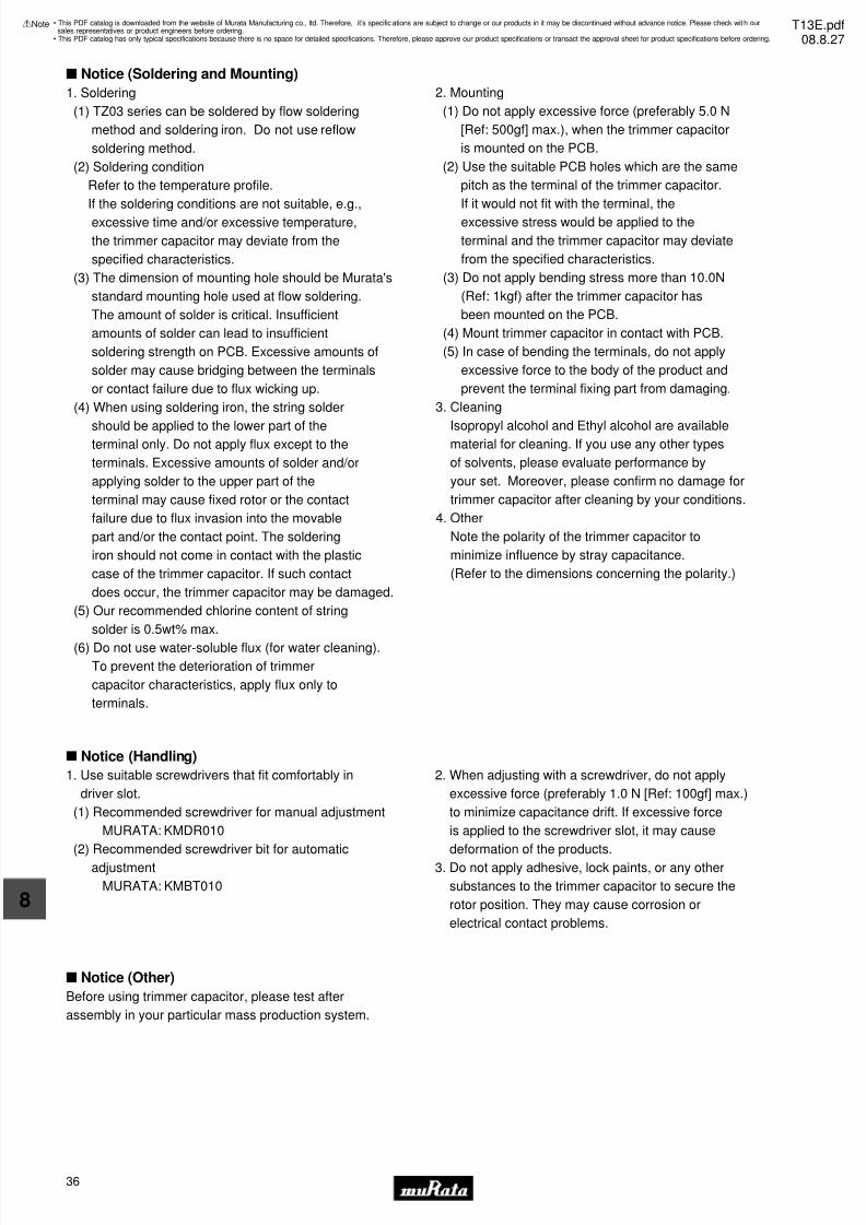
7/31/2019 Trimmers Murata
http://slidepdf.com/reader/full/trimmers-murata 38/4436
8
!Note • Please read rating and !CAUTION (for storage, operating, rating, soldering, mounting and handling) in this catalog to prevent smoking and/or burning, etc.• This catalog has only typical specifications because there is no space for detailed specifications. Therefore, please approve our product specifications or transact the approval sheet for product specifications before ordering.
s Notice (Soldering and Mounting)
s Notice (Handling)
s Notice (Other)
Before using trimmer capacitor, please test after
assembly in your particular mass production system.
1. Use suitable screwdrivers that fit comfortably in
driver slot.
(1) Recommended screwdriver for manual adjustment
MURATA: KMDR010
(2) Recommended screwdriver bit for automatic
adjustment
MURATA: KMBT010
2. When adjusting with a screwdriver, do not apply
excessive force (preferably 1.0 N [Ref: 100gf] max.)
to minimize capacitance drift. If excessive force
is applied to the screwdriver slot, it may cause
deformation of the products.
3. Do not apply adhesive, lock paints, or any other
substances to the trimmer capacitor to secure the
rotor position. They may cause corrosion or
electrical contact problems.
1. Soldering
(1) TZ03 series can be soldered by flow soldering
method and soldering iron. Do not use reflow
soldering method.
(2) Soldering condition
Refer to the temperature profile.
If the soldering conditions are not suitable, e.g.,
excessive time and/or excessive temperature,
the trimmer capacitor may deviate from the
specified characteristics.
(3) The dimension of mounting hole should be Murata's
standard mounting hole used at flow soldering.
The amount of solder is critical. Insufficient
amounts of solder can lead to insufficient
soldering strength on PCB. Excessive amounts of
solder may cause bridging between the terminals
or contact failure due to flux wicking up.
(4) When using soldering iron, the string solder
should be applied to the lower part of theterminal only. Do not apply flux except to the
terminals. Excessive amounts of solder and/or
applying solder to the upper part of the
terminal may cause fixed rotor or the contact
failure due to flux invasion into the movable
part and/or the contact point. The soldering
iron should not come in contact with the plastic
case of the trimmer capacitor. If such contact
does occur, the trimmer capacitor may be damaged.
(5) Our recommended chlorine content of string
solder is 0.5wt% max.
(6) Do not use water-soluble flux (for water cleaning).
To prevent the deterioration of trimmer
capacitor characteristics, apply flux only to
terminals.
2. Mounting
(1) Do not apply excessive force (preferably 5.0 N
[Ref: 500gf] max.), when the trimmer capacitor
is mounted on the PCB.
(2) Use the suitable PCB holes which are the same
pitch as the terminal of the trimmer capacitor.
If it would not fit with the terminal, the
excessive stress would be applied to the
terminal and the trimmer capacitor may deviate
from the specified characteristics.
(3) Do not apply bending stress more than 10.0N
(Ref: 1kgf) after the trimmer capacitor has
been mounted on the PCB.
(4) Mount trimmer capacitor in contact with PCB.
(5) In case of bending the terminals, do not apply
excessive force to the body of the product and
prevent the terminal fixing part from damaging.
3. Cleaning
Isopropyl alcohol and Ethyl alcohol are availablematerial for cleaning. If you use any other types
of solvents, please evaluate performance by
your set. Moreover, please confirm no damage for
trimmer capacitor after cleaning by your conditions.
4. Other
Note the polarity of the trimmer capacitor to
minimize influence by stray capacitance.
(Refer to the dimensions concerning the polarity.)
• This PDF catalog is downloaded from the website of Murata Manufacturing co., ltd. Therefore, it’s specifications are subject to change or our products in it may be discontinued without advance notice. Please check wit h oursales representatives or product engineers before ordering.
• This PDF catalog has only typical specifications because there is no space for detailed specifications. Therefore, please approve our product specifications or transact the approval sheet for product specifications before ordering.
!Note T13E.pdf08.8.27
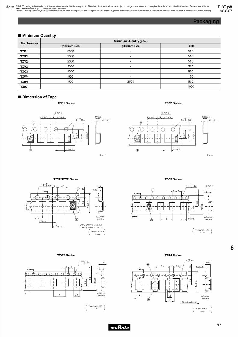
7/31/2019 Trimmers Murata
http://slidepdf.com/reader/full/trimmers-murata 39/44
Packaging
37
8
!Note • Please read rating and !CAUTION (for storage, operating, rating, soldering, mounting and handling) in this catalog to prevent smoking and/or burning, etc.• This catalog has only typical specifications because there is no space for detailed specifications. Therefore, please approve our product specifications or transact the approval sheet for product specifications before ordering.
s Minimum Quantity
Part Number
TZR1
TZS2
TZY2
TZV2
TZC3
TZW4
TZB4
TZ03
3000
3000
2000
2000
1000
500
500
-
φ180mm Reel
-
-
-
-
-
-
2500
-
φ330mm Reel
500
500
500
500
500
100
500
1000
Bulk
Minimum Quantity (pcs.)
s Dimension of Tape
TZR1 Series
4.0±0.1
8 . 0
± 0 . 3
2.0±0.1
4.0±0.1 1.5 Dia.
+0.1-0
2 . 0
± 0 . 2
1 .
7 5
± 0
. 1
3 . 5
± 0 . 1
1.8±0.2
1.05±0.2
0.25±0.1
(in mm)
TZS2 Series
4.0±0.1
8 . 0
± 0 . 3
2.0±0.1
4.0±0.1
1.5 -0 dia.+0.1
3 . 0
± 0 . 2
1 .
7 5 ±
0 . 1
3 . 5
± 0 . 1
2.5±0.2
1.25±0.2
0.25±0.1
(in mm)
TZY2/TZV2 Series
1.5+0.1− 0 dia.
2.0 4.0
A
A
2.7±0.2
4.0
3 . 5
0.25
t
8 . 0
± 0 . 2
1 . 7
5
A-Acrosssection
t=TZY2 (TZVY2) : 1.6±0.2TZV2 (TZV02) : 1.9±0.2
3 . 6
± 0 . 2
Tolerance: ±0.1
in mm
TZC3 Series
1.5+0.1− 0 dia.
4 . 9
± 0 . 2
A
2
8
4
5 . 5
1 . 7
5
1 2 ± 0 . 3
0.3
2.0±0.2
A
A-Acrosssection
Tolerance : ±0.1in mm
3.6±0.2
TZW4 Series
1 2 ± 0 . 2
1.5+0.1− 0 dia.
5 . 6
A
2
8
4
5 . 5
1 . 7
5 0.3
2.6
A
A-Across
section
Tolerance: ±0.1in mm
4.6
TZB4 Series
1.5+0.1− 0 dia.
8.0 2.0 4 .0A
A1.8
4.3
3.55±0.2
4 . 8 7 . 5
5 . 5
1 2 . 0
± 0 . 3
0.3±0.1
A-Acrosssection
Direction of feed
Tolerance: ±0.1in mm
1 . 7
5
• This PDF catalog is downloaded from the website of Murata Manufacturing co., ltd. Therefore, it’s specifications are subject to change or our products in it may be discontinued without advance notice. Please check wit h oursales representatives or product engineers before ordering.
• This PDF catalog has only typical specifications because there is no space for detailed specifications. Therefore, please approve our product specifications or transact the approval sheet for product specifications before ordering.
!Note T13E.pdf08.8.27
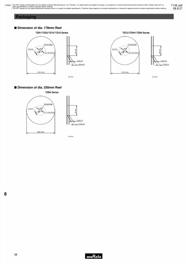
7/31/2019 Trimmers Murata
http://slidepdf.com/reader/full/trimmers-murata 40/44
Packaging
38
8
!Note • Please read rating and !CAUTION (for storage, operating, rating, soldering, mounting and handling) in this catalog to prevent smoking and/or burning, etc.• This catalog has only typical specifications because there is no space for detailed specifications. Therefore, please approve our product specifications or transact the approval sheet for product specifications before ordering.
s Dimension of dia. 178mm Reel
TZR1/TZS2/TZY2/TZV2 Series
(in mm)
13.0±0.5 Dia.
21.0±0.8 Dia.
2.0±0.5
178±2 Dia.
9.0±1.0
5 0 m i n .
13.0±1.0
TZC3/TZW4/TZB4 Series
(in mm)
13.0±0.5 Dia.
21.0±0.8 Dia.
2.0±0.5
178±2 Dia.
13.0±1.0
5 0 m i n .
17.0±1.0
s Dimension of dia. 330mm Reel
TZB4 Series
(in mm)
13.0±0.5 dia.
21.0±0.8 dia.
2.0±0.5
328±2 dia.
13.5±1.0
5 0 m i n .
17.5±1.0
• This PDF catalog is downloaded from the website of Murata Manufacturing co., ltd. Therefore, it’s specifications are subject to change or our products in it may be discontinued without advance notice. Please check wit h oursales representatives or product engineers before ordering.
• This PDF catalog has only typical specifications because there is no space for detailed specifications. Therefore, please approve our product specifications or transact the approval sheet for product specifications before ordering.
!Note T13E.pdf08.8.27
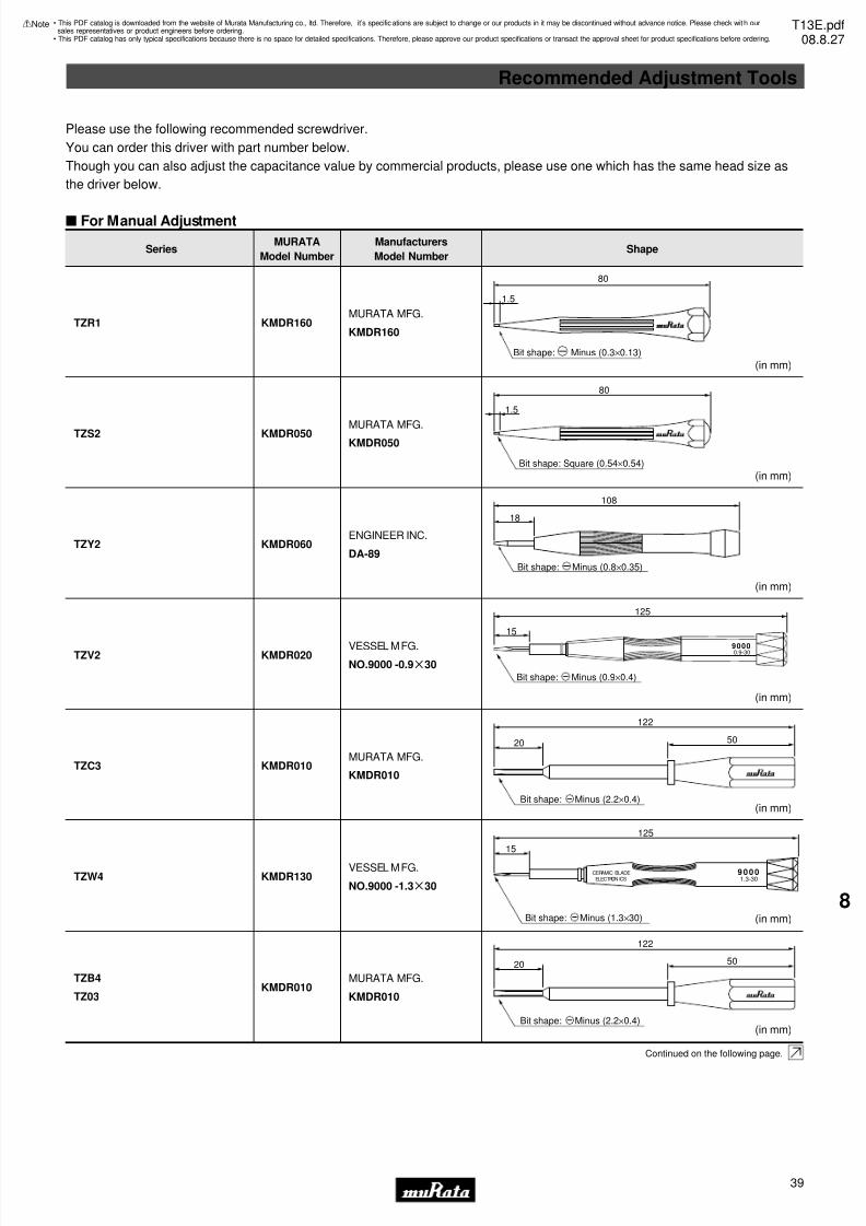
7/31/2019 Trimmers Murata
http://slidepdf.com/reader/full/trimmers-murata 41/44
s For Manual Adjustment
SeriesMURATA
Model Number
Manufacturers
Model NumberShape
TZR1
TZS2
TZY2
TZV2
TZC3
TZW4
TZB4
TZ03
KMDR160
KMDR050
KMDR060
KMDR020
KMDR010
KMDR130
KMDR010
MURATA MFG.
KMDR160
MURATA MFG.KMDR050
ENGINEER INC.
DA-89
VESSEL MFG.
NO.9000 -0.9g30
MURATA MFG.
KMDR010
VESSEL MFG.
NO.9000 -1.3g30
MURATA MFG.
KMDR010
Please use the following recommended screwdriver.
You can order this driver with part number below.
Though you can also adjust the capacitance value by commercial products, please use one which has the same head size as
the driver below.
Continued on the following page.
1.5
80
Bit shape: Minus (0.3×0.13)
(in mm)
(in mm)Bit shape: Square (0.54×0.54)
80
1.5
18
108
(in mm)
Bit shape: Minus (0.8×0.35)
(in mm)
90000.9-30
15
125
Bit shape: Minus (0.9×0.4)
(in mm)
50
122
20
Bit shape: Minus (2.2×0.4)
(in mm)
50
122
20
Bit shape: Minus (2.2×0.4)
(in mm)
125
15
90001.3-30
CERAMIC BLADE
ELECTRON ICS
Bit shape: Minus (1.3×30)
Recommended Adjustment Tools
39
8
!Note • Please read rating and !CAUTION (for storage, operating, rating, soldering, mounting and handling) in this catalog to prevent smoking and/or burning, etc.• This catalog has only typical specifications because there is no space for detailed specifications. Therefore, please approve our product specifications or transact the approval sheet for product specifications before ordering.
• This PDF catalog is downloaded from the website of Murata Manufacturing co., ltd. Therefore, it’s specifications are subject to change or our products in it may be discontinued without advance notice. Please check wit h oursales representatives or product engineers before ordering.
• This PDF catalog has only typical specifications because there is no space for detailed specifications. Therefore, please approve our product specifications or transact the approval sheet for product specifications before ordering.
!Note T13E.pdf08.8.27
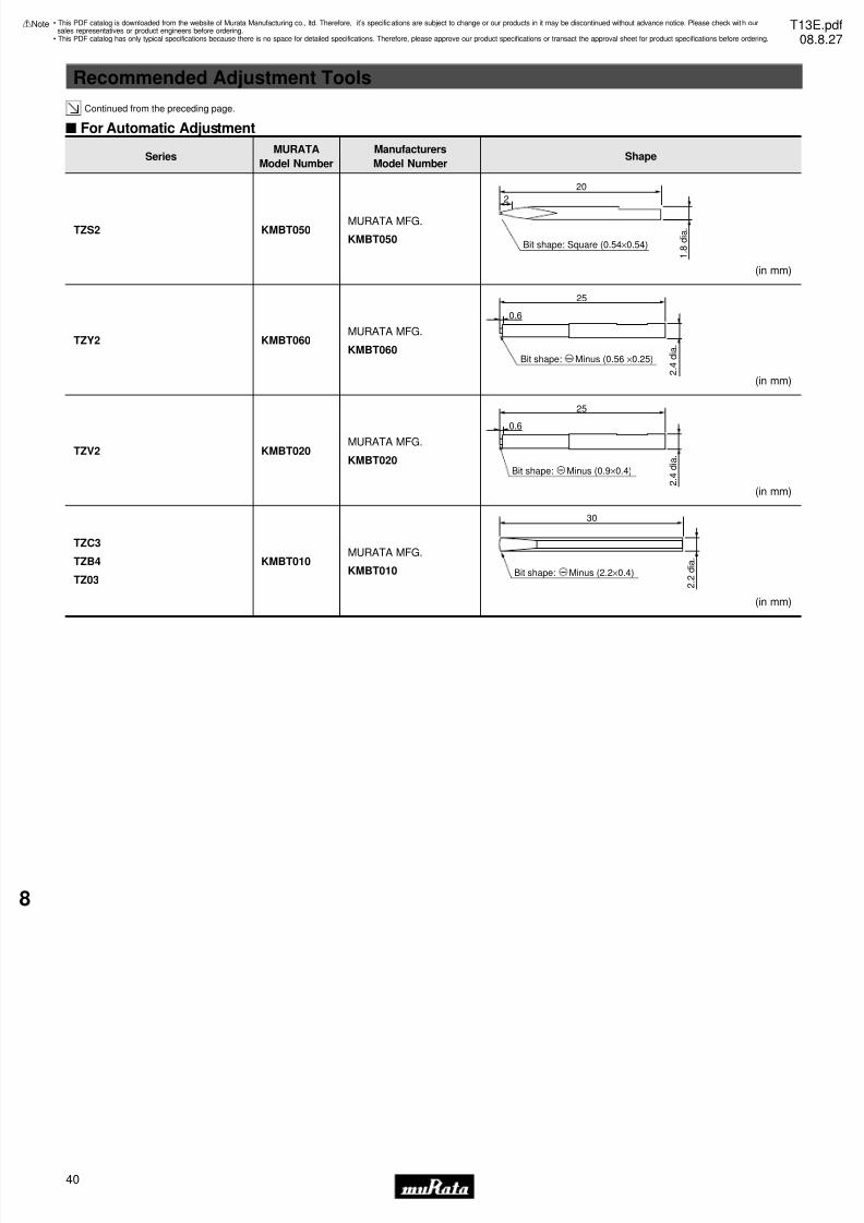
7/31/2019 Trimmers Murata
http://slidepdf.com/reader/full/trimmers-murata 42/44
s For Automatic Adjustment
TZS2
TZY2
TZV2
TZC3
TZB4
TZ03
KMBT050
KMBT060
KMBT020
KMBT010
MURATA MFG.
KMBT050
MURATA MFG.
KMBT060
MURATA MFG.
KMBT020
MURATA MFG.
KMBT010
Continued from the preceding page.
SeriesMURATA
Model Number
Manufacturers
Model NumberShape
(in mm)
20
1 . 8
d i a .
2
Bit shape: Square (0.54×0.54)
(in mm)
25
2 . 4
d i a .
0.6
Bit shape: Minus (0.56 ×0.25)
(in mm)
25
0.6
2 . 4
d i a .
Bit shape: Minus (0.9×0.4)
(in mm)
30
2 . 2
d i a .
Bit shape: Minus (2.2×0.4)
Recommended Adjustment Tools
40
8
!Note • Please read rating and !CAUTION (for storage, operating, rating, soldering, mounting and handling) in this catalog to prevent smoking and/or burning, etc.• This catalog has only typical specifications because there is no space for detailed specifications. Therefore, please approve our product specifications or transact the approval sheet for product specifications before ordering.
• This PDF catalog is downloaded from the website of Murata Manufacturing co., ltd. Therefore, it’s specifications are subject to change or our products in it may be discontinued without advance notice. Please check wit h oursales representatives or product engineers before ordering.
• This PDF catalog has only typical specifications because there is no space for detailed specifications. Therefore, please approve our product specifications or transact the approval sheet for product specifications before ordering.
!Note T13E.pdf08.8.27
7/31/2019 Trimmers Murata
http://slidepdf.com/reader/full/trimmers-murata 43/44
!Note • Please read rating and !CAUTION (for storage, operating, rating, soldering, mounting and handling) in this catalog to prevent smoking and/or burning, etc.• This catalog has only typical specifications because there is no space for detailed specifications. Therefore, please approve our product specifications or transact the approval sheet for product specifications before ordering.
MURATA FACTORY
Sabae Murata Mfg. Co., Ltd.
The products listed herein have been produced
by the QS9000 and ISO9001 certified factory
∗ No ODCs (Ozone Depleting Chemicals) are used on
any Murata trimmer potentiometers.
Qualified Standards
41
• This PDF catalog is downloaded from the website of Murata Manufacturing co., ltd. Therefore, it’s specifications are subject to change or our products in it may be discontinued without advance notice. Please check wit h oursales representatives or product engineers before ordering.
• This PDF catalog has only typical specifications because there is no space for detailed specifications. Therefore, please approve our product specifications or transact the approval sheet for product specifications before ordering.
!Note T13E.pdf08.8.27
7/31/2019 Trimmers Murata
http://slidepdf.com/reader/full/trimmers-murata 44/44
• This PDF catalog is downloaded from the website of Murata Manufacturing co., ltd. Therefore, it’s specifications are subject to change or our products in it may be discontinued without advance notice. Please check wit h oursales representatives or product engineers before ordering.
• This PDF catalog has only typical specifications because there is no space for detailed specifications. Therefore, please approve our product specifications or transact the approval sheet for product specifications before ordering.
!Note T13E.pdf08.8.27