Embed Size (px)
Citation preview

Version 2.0Revision CApril 2015
USER GUIDE
Trimble® Precision-IQ™ Application
1
Corporate OfficeTrimble Navigation Limited935 Stewart DriveSunnyvale, CA 94085USAwww.trimble.com
Heavy Highway business area10368WestmoorDriveWestminster, Colorado 80021USA800-361-1249 (toll free in USA)+1-937-245-5154 Phone+1-937-233-9441 Faxwww.trimble.comEmail: [email protected]
Copyright and Trademarks©2015 Trimble Navigation Limited. All rights reserved.Trimble, the Globe & Triangle logo, EZ-Boom, EZ-Guide, EZ-Pilot, EZ-Steer, FarmWorks Software, FmX,GreenSeeker, OmniSTAR, TrimbleReady, Tru Count Air Clutch, andWM-Drain are trademarks of TrimbleNavigation Limited, registered in the United States and in othercountries.Autopilot, AutoSense, CenterPoint, CFX-750, Connected Farm, EZ-Remote, Farm Works, FarmWorks Mapping, FarmWorks Software,Field-IQ, FieldLevel, FM-750, FM-1000, FreeForm, LiquiBlock, Rawson,RTX, T3, TMX-2050, TrueGuide, TrueTracker, VRS Now, VRS,WM-Topo,XCN-2050, xFill, and Zephyr are trademarks of Trimble NavigationLimited.For STL support, the software uses the Moscow Center for SPARCTechnology adaptation of the SGI Standard Template Library. Copyright©1994 Hewlett-Packard Company, Copyright©1996, 97 SiliconGraphics Computer Systems, Inc., Copyright©1997Moscow Center forSPARC Technology.Portions Copyright©2009 Nokia Corporation and/or its subsidiary(-ies).Portions Copyright©2003, Bitstream Inc.All other trademarks are the property of their respective owners.
Release NoticeThis is the April 2015 release (Revision C ) of the Precision-IQ fieldapplication documentation. It applies to version 2.0 of the displaysoftware.
Legal NoticesThe following limitedwarranties give you specific legal rights. Youmayhave others,which vary from state/jurisdiction to state/jurisdiction.
Product Limited WarrantyTrimble warrants that this Trimble product and its internal components(the 'Product") shall be free from defects inmaterials andworkmanshipandwill substantially conform to Trimble's applicable publishedspecifications for the Product for a period of one (1) year, starting fromthe earlier of (i) the date of installation, or (ii) six (6) months from thedate of original Product shipment from Trimble. This warranty appliesonly to the Product if installed by Trimble or a dealer authorized byTrimble to perform Product installation services.
Software ComponentsAll Product software components (sometimes hereinafter also referredto as "Software") are licensed solely for use as an integral part of theProduct and are not sold. Any software accompanied by a separate enduser license agreement ("EULA") shall be governed by the terms,conditions, restrictions and limitedwarranty terms of such EULAnotwithstanding the preceding paragraph.During the limitedwarranty period youwill be entitled to receive suchFixes to the Product software that Trimble releases andmakescommercially available and forwhich it does not charge separately,subject to the procedures for delivery to purchasers of Trimble productsgenerally. If you have purchased the Product from an authorizedTrimble dealer rather than from Trimble directly, Trimble may, at itsoption, forward the software Fix to the Trimble dealer for finaldistribution to you. MinorUpdates,MajorUpgrades, new products, orsubstantially new software releases, as identified by Trimble, areexpressly excluded from this update process and limitedwarranty.
Receipt of software Fixes or other enhancements shall not serve toextend the limitedwarranty period.For purposes of this warranty the following definitions shall apply: (1)"Fix(es)' means an error correction or other update created to fix aprevious software version that does not substantially conform to itsTrimble specifications; (2) "MinorUpdate" occurs when enhancementsare made to current features in a software program; and (3) "MajorUpgrade" occurs when significant new features are added to software,orwhen a new product containing new features replaces the furtherdevelopment of a current product line. Trimble reserves the right todetermine, in its sole discretion,what constitutes a Fix,MinorUpdate, orMajorUpgrade.Gson components licensed under the Apache 2.0 License. The source isavailable from http://code.google.com/p/google-gson/. GoogleMVEL components licensed under the Apache 2.0 Llicense. The source isavailable from http://code.google.com/p/mvel.codehause.org. GoogleGuava components listed under the Apache 2.0 License. The source isavailable from http://code.google.com/p/guava-libraries. MapQuestcontent licensed under the Open Data Commons Database License(DbCL). The source is available from http://developer.mapquest.com.APACE LICENSE (Version 2.0, January 2004)http://www.apache.org/licenses/TERMS AND CONDITIONS FOR USE,REPRODUCTION, AND DISTRIBUTION1. Definitions"License" shall mean the terms and conditions for use, reproduction, anddistribution as defined by Sections 1 through Section 9 of this document.""Licensor " shall mean the copyright owner or entity authorized by thecopyright owner that is granting the License."Legal Entity" shall mean the union of the acting entity and all otherentities that control, are controlled by, or are under common control withthat entity. For the purposes of this definition, "control" means (i) thepower, direct or indirect, to cause the direction ormanagement of suchentity,whether by contract or otherwise, or (ii) ownership of fifty percent(50%) ormore of the outstanding shares, or (iii) beneficial ownership ofsuch entity."You" (or "Your") shall mean an individual or Legal Entity exercisingpermissions granted by this License."Source" form shall mean the preferred form formaking modifications,including but not limited to software source code, documentation source,and configuration files."Object" form shall mean any form resulting frommechanicaltransformation or translation of a Source form, including but not limitedto compiled object code, generated documentation, and conversions toothermedia types."Work" shall mean the work of authorship,whether in Source orObjectform,made available under the License, as indicated by a copyrightnotice that is included in or attached to the work (an example is providedin the Appendix below)."Derivative Works" shall mean any work,whether in Source orObjectform, that is based on (or derived from) theWork and forwhich theeditorial revisions, annotations, elaborations, or othermodificationsrepresent, as a whole, an original work of authorship. For the purposesof this License, Derivative Works shall not include works that remainseparable from, ormerely link (or bind by name) to the interfaces of, theWork and Derivative Works thereof."Contribution" shall mean any work of authorship, including the originalversion of theWork and any modifications or additions to thatWork orDerivative Works thereof, that is intentionally submitted to Licensor forinclusion in theWork by the copyright owner or by an individual or LegalEntity authorized to submit on behalf of the copyright owner. For thepurposes of this definition, "submitted" means any form of electronic,verbal, orwritten communication sent to the Licensor or itsrepresentatives, including but not limited to communication on electronicmailing lists, source code control systems, and issue tracking systemsthat are managed by, or on behalf of, the Licensor for the purpose ofdiscussing and improving theWork, but excluding communication that isconspicuously marked or otherwise designated in writing by thecopyright owner as "Not a Contribution.""Contributor" shall mean Licensor and any individual or Legal Entity onbehalf of whom a Contribution has been received by Licensor andsubsequently incorporatedwithin theWork.2. Grant of Copyright License. Subject to the terms and conditions of thisLicense, each Contributor hereby grants to You a perpetual,worldwide,non-exclusive, no-charge, royalty-free, irrevocable copyright license toreproduce, prepare Derivative Works of, publicly display, publiclyperform, sublicense, and distribute theWork and such Derivative Worksin Source orObject form.
2 Trimble Precision-IQ Field Application User Guide Version 2.0, Revision C

3. Grant of Patent License. Subject to the terms and conditions of thisLicense, each Contributor hereby grants to You a perpetual,worldwide,non-exclusive, no-charge, royalty-free, irrevocable (except as stated inthis section) patent license tomake, have made, use, offer to sell, sell,import, and otherwise transfer theWork,where such license applies onlyto those patent claims licensable by such Contributor that are necessarilyinfringed by their Contribution(s) alone or by combination of theirContribution(s) with theWork towhich such Contribution(s) wassubmitted. If You institute patent litigation against any entity (includinga cross-claim or counterclaim in a lawsuit) alleging that theWork or aContribution incorporatedwithin theWork constitutes direct orcontributory patent infringement, then any patent licenses granted toYou under this License for thatWork shall terminate as of the date suchlitigation is filed.4. Redistribution. Youmay reproduce and distribute copies of theWorkorDerivative Works thereof in any medium,with orwithoutmodifications, and in Source orObject form, provided that Youmeet thefollowing conditions:Youmust give any other recipients of theWork orDerivative Works acopy of this License; andYoumust cause any modified files to carry prominent notices statingthat You changed the files; andYoumust retain, in the Source form of any Derivative Works that Youdistribute, all copyright, patent, trademark, and attribution notices fromthe Source form of theWork, excluding those notices that do not pertainto any part of the Derivative Works; andIf the Work includes a "NOTICE" text file as part of its distribution, thenany Derivative Works that You distribute must include a readable copyof the attribution notices containedwithin such NOTICE file, excludingthose notices that do not pertain to any part of the Derivative Works, inat least one of the following places: within a NOTICE text file distributedas part of the Derivative Works; within the Source form ordocumentation, if provided along with the Derivative Works; or,within adisplay generated by the Derivative Works, if andwherever such third-party notices normally appear. The contents of the NOTICE file are forinformational purposes only and do notmodify the License. Youmayadd Your own attribution notices within Derivative Works that Youdistribute, alongside or as an addendum to the NOTICE text from theWork, provided that such additional attribution notices cannot beconstrued as modifying the License.Youmay add Your own copyright statement to Yourmodifications andmay provide additional or different license terms and conditions for use,reproduction, or distribution of Yourmodifications, or for any suchDerivative Works as a whole, provided Your use, reproduction, anddistribution of theWork otherwise complies with the conditions stated inthis License.5. Submission of Contributions. Unless You explicitly state otherwise, anyContribution intentionally submitted for inclusion in theWork by You tothe Licensor shall be under the terms and conditions of this License,without any additional terms or conditions. Notwithstanding the above,nothing herein shall supersede ormodify the terms of any separatelicense agreement youmay have executedwith Licensor regarding suchContributions.6. Trademarks. This License does not grant permission to use the tradenames, trademarks, service marks, or product names of the Licensor,except as required for reasonable and customary use in describing theorigin of theWork and reproducing the content of the NOTICE file.7. Disclaimer of Warranty. Unless required by applicable law or agreedto in writing, Licensor provides theWork (and each Contributor providesits Contributions) on an "AS IS" BASIS,WITHOUTWARRANTIES ORCONDITIONS OF ANY KIND, either express or implied, including,withoutlimitation, any warranties or conditions of TITLE, NON-INFRINGEMENT,MERCHANTABILITY, or FITNESS FORA PARTICULAR PURPOSE. You aresolely responsible for determining the appropriateness of using orredistributing theWork and assume any risks associatedwith Yourexercise of permissions under this License.8. Limitation of Liability. In no event and under no legal theory,whetherin tort (including negligence), contract, or otherwise, unless required byapplicable law (such as deliberate and grossly negligent acts) or agreedto in writing, shall any Contributor be liable to You for damages, includingany direct, indirect, special, incidental, or consequential damages of anycharacter arising as a result of this License or out of the use or inability touse theWork (including but not limited to damages for loss of goodwill,work stoppage, computer failure ormalfunction, or any and all othercommercial damages or losses), even if such Contributor has beenadvised of the possibility of such damages.LWGL LICENSEODCDATABASE CONTENTS LICENSESGI FREE SOFTWARE LICENSE B (Version 2.0, Sept. 18, 2008)
Copyright©2013 Silicon Graphics, Inc. All Rights Reserved.Permission is hereby granted, free of charge, to any person obtaining acopy of this software and associated documentation files (the"Software"), to deal in the Software without restriction, including withoutlimitation the rights to use, copy,modify,merge, publish, distribute,sublicense, and/or sell copies of the Software, and to permit persons towhom the Software is furnished to do so, subject to the followingconditions:The above copyright notice including the dates of first publication andeither this permission notice or a reference tohttp://oss.sgi.com/projects/FreeB/ shall be included in all copies orsubstantial portions of the Software.THE SOFTWARE IS PROVIDED "AS IS",WITHOUTWARRANTY OF ANYKIND, EXPRESS OR IMPLIED, INCLUDING BUT NOT LIMITED TO THEWARRANTIES OF MERCHANTABILITY, FITNESS FORA PARTICULARPURPOSE ANDNONINFRINGEMENT. INNO EVENT SHALL SILICONGRAPHICS, INC. BE LIABLE FORANY CLAIM,DAMAGES OROTHERLIABILITY,WHETHER INANACTIONOF CONTRACT, TORT OROTHERWISE, ARISING FROM,OUT OF OR INCONNECTIONWITH THESOFTWARE ORTHE USE OROTHERDEALINGS IN THE SOFTWARE.Except as contained in this notice, the name of Silicon Graphics, Inc. shallnot be used in advertising or otherwise to promote the sale, use or otherdealings in this Software without priorwritten authorization from SiliconGraphics, Inc.MAPQUEST PLATFORM TERMS OF USE (Last Updated: November 1,2011)Community Edition License AgreementINTRODUCTION. MapQuest has been helping people find places andgetmaps and directions for over 40 years. We make the MapQuestAPIs, ourOpen Services (as described athttp://open.mapquestapi.com/), Community Accounts and otherdeveloper services (in short, the "MapQuest Services"), along with themaps, driving directions and other content delivered through theMapQuest Services (the "MapQuest Content"), available withoutcharge to encourage developers to use these services and content indeveloping their applications andwebsites. We want you to be creativeand build awesome applications andwebsites that thrill your users. Allwe ask is that you comply with the terms that are included in theseTerms of Use.We will provide the developer community at-large with support invarious forms, such as forums, blog posts or FAQs. Since we're providingthe MapQuest Services for free,we don't provide individual technicalsupport orwarranties for the Community Services, but if youwant toreceive technical support andwarranties,we have a product for you.Please check out ourMapQuest Platform Services Enterprise Edition andlearnmore about the services we will provide for reasonable fees.If you choose to use any of the MapQuest Services or if you set up aCommunity Account, you are agreeing to abide by these Terms of Useand are forming an agreement between yourself andMapQuest, Inc.("MapQuest"). If you do notwant to abide by these Terms of Use, thendon't use the MapQuest Services.LICENSES FROM MAPQUEST TO YOU.2.1. MapQuest Services License. MapQuest grants you a non-exclusive,non-assignable, non-sublicensable, revocable limited license to use theMapQuest Services during the Term of these Terms of Use as providedby MapQuest in the manner permitted in these Terms of Use.2.2. MapQuest Content License. MapQuest grants you a non-exclusive,non-assignable, non-sublicensable, revocable limited license access, use,publicly perform and publicly display the MapQuest Content as theMapQuest Content is provided through the MapQuest Services and inthe manner permitted by these Terms of Use.GENERAL RESTRICTIONS, ADDITIONAL LEGAL NOTICE, RESERVATIONOF RIGHTS.3.1. Restrictions. Except as expressly authorized by MapQuest, Youmust not:decompile, disassemble, reverse engineer, or otherwise attempt toderive any source code from theMapQuest Services orMapQuestContent, other than the Open Services;interfere or disruptMapQuest servers or networks, or disobey anynetwork access or security requirements, policies, procedures orregulations of MapQuest (including the enabling of any viruses, Trojanhorses, trap doors, back doors,worms, time bombs, cancelbots, adware,spyware or other computer programming routines designed or intendedto damage, detrimentally interfere with, surreptitiously intercept orexpropriate any system, data or personal information);use the MapQuest Services as a means to engage in conduct thatreflects poorly upon, disparages or devalues MapQuest's reputation orgoodwill, as determined inMapQuest's sole discretion;
Version 2.0, Revision C Trimble Precision-IQ Field Application User Guide 3

use the MapQuest Services, other than the Open Services, inconjunctionwith any commercial application not publicly availablewithout charge (other thanmobile applications forwhich users pay a feeto download/install the application). If your application does not fit thiscriteria and youwould like to discuss additional options for using theMapQuest Services please contact [email protected];use the MapQuest Services, other than the Open Services, to process orgenerate data for any third party (other than for end users as expresslypermitted hereunder);use the MapQuest Services with any content or product that falselyexpresses or implies that such content or product is sponsored orendorsed by MapQuest;use the MapQuest Services in conjunctionwith a site or applicationwhich contains or displays adult content or promotes illegal activities,gambling, or the sale of tobacco or alcohol to persons under twenty-one(21) years of age;3.2. Additional Legal Requirements. In addition to the restrictions setforth in Section 3.1, your use of the MapQuest Services andMapQuestContent is subject to the Additional Legal Requirements which areincorporated andmade a part of these Terms of Use. Please read theAdditional Legal Requirements carefully as they include usage limits andadditional restrictions thatmay impact your plans for development.3.3. Reservation of Rights. MapQuest reserves all rights not expresslygranted in these Terms of Use and youmay not use the MapQuestServices orMapQuest Content in any manner not expressly authorizedin these Terms of Use.LICENSE FROM YOUTO MAPQUEST. If you upload any data, feedback,ideas, suggestions, content, points of interest (including any points ofinterest that include Trademarks) or othermaterial toMapQuest(collectively "Your Content"), you hereby grantMapQuest a perpetual,worldwide, non-exclusive, royalty-free license to access, archive,reproduce, publicly display, translate,modify the format or the displayof, distribute, transmit, stream, cache, overlay, seam, perform,sublicense, and otherwise use Your Contentwith orwithout attributionandwithout financial obligation, in whole or in part, via any method forany purpose. MapQuestmakes no assertion of ownership over YourContent, and you retain all intellectual property rights to Your Content,subject to the license you grant toMapQuest above.MODIFICATIONS TO THESE TERMS OF USE AND THE SERVICES.MapQuest reserves the right to change ormodify these Terms of Use,the MapQuest Services and/or the MapQuest Content. Please checkthese Terms of Use, including the Additional Legal Requirementsperiodically for changes. Your continued use of the MapQuest ServicesorMapQuest Content following the posting of any changes to the Termsof Use constitutes acceptance of those changes.TERMINATION. MapQuestmay terminate these Terms of Use and/orthe provision of the MapQuest Services orMapQuest Content at anytime, for any reason,with orwithout notice.PRIVACY POLICY AND ENDUSER TERMS.7.1. Privacy Policy. MapQuest's collection and use of personallyidentifiable information is governed by the AOL Network Privacy Policy,available at http://about.aol.com/aolnetwork/aol_pp.7.2. End User Terms. End users shall only be entitled to use theMapQuest Services andMapQuest Content if they accept the thencurrent end user Terms of Use located athttp://info.mapquest.com/terms-of-use/. MapQuest reserves the rightto amend and/or replace these terms and the form andmanner ofpresentation. Youmust provide a hypertext link at the bottom of eachpage in yourwebsite or applicationwhere the MapQuest Services orMapQuest Content can be viewed or accessed, orwithin the terms ofuse of your application orwebsite, to the end user terms of use.ACCESS ANDUSAGE DATA.8.1. Credentials. MapQuest, at its discretion,may require you to createan account and obtain an access key and other related credentials(collectively "Credentials") to use the MapQuest Services or certainaspects of the MapQuest Services. You are responsible formaintainingthe confidentiality of your Credentials and for any usage or abuse of theMapQuest Services orMapQuest Content by anyone using yourCredentials.8.2. Usage Data. MapQuest's servers record informationwhen you visitMapQuestwebsites orwhen applications and/or Credentials call orinvoke the MapQuest Services. This informationmay include,withoutlimitation, the URL, IP address, browser type, Credential and access timesand dates. MapQuestmay use this information to promote, operate,and improve MapQuest services, products and properties.PROPRIETARY RIGHTS. You acknowledge and agree the MapQuestServices andMapQuest Content are works for purposes of copyrightlaw, and embody valuable, confidential, trade secret information of
MapQuest, the development of which required the expenditure ofsubstantial time andmoney. As betweenMapQuest and You,MapQuest retains exclusive ownership of any and all rights, title andinterest (including all intellectual property rights) in the MapQuestServices andMapQuest Content, and you shall not acquire any rights,express or implied, in the foregoing by virtue of these Terms of Use otherthan otherwise expressly set forth. For purposes of these Terms of Use,the term "Trademarks" means all trademarks, trade names, servicemarks, logos, domain names, along with any other distinctive brandfeatures of MapQuest or its suppliers. All use by You of Trademarksshall inure to the benefit of MapQuest. Further, You shall not (a) displaya Trademark as the most prominent element on any page of Yourwebsite, application or papermap; (b) display a Trademark in a mannerthat is misleading, defamatory, infringing, libelous, disparaging, obsceneor otherwise objectionable toMapQuest as determined by MapQuest inits sole discretion; or (c) remove, distort or alter any element of aTrademark.DISCLAIMEROF WARRANTIES. THE MAPQUEST SERVICES ANDMAPQUEST CONTENT ARE PROVIDED ONAN "AS IS" AND "ASAVAILABLE" BASIS. MAPQUEST DISCLAIMS ANY AND ALLWARRANTIES,WHETHER EXPRESS OR IMPLIED, INCLUDING BUT NOTLIMITED TO ANYWARRANTIES OF MERCHANTABILITY, FITNESS FORAPARTICULAR PURPOSE, ACCURACY ORNON-INFRINGEMENT.MAPQUEST DOES NOT REPRESENT ORWARRANT THAT THEMAPQUEST SERVICES ORCONTENT,ORANY PORTIONTHEREOF, IS ORWILL BE FREE OF DEFECTS OR ERRORS (OR THAT ANY SUCHDEFECTSOR ERRORS WILL BE CORRECTED), VIRUS FREE, ABLE TO OPERATE ONANUNINTERRUPTED BASIS,MEET YOURREQUIREMENTS,ORCAPABLEOF BEING INTEGRATED INTO ORWITH YOURCOMPUTER SYSTEM,APPLICATIONS ORNETWORK. FURTHER,MAPQUEST DOES NOTWARRANT ORMAKE ANY REPRESENTATIONS REGARDING THE USE ORTHE RESULTS OF THE USE OF THE MAPQUEST SERVICES,ORANYPORTIONTHEREOF, IN TERMS OF ITS CORRECTNESS, ACCURACY,QUALITY, RELIABILITY,OROTHERWISE. THIS DISCLAIMERCONSTITUTES ANESSENTIAL PART OF THESE TERMS OF USE. IF THISEXCLUSION IS HELD UNENFORCEABLE, THENALL EXPRESS ANDIMPLIEDWARRANTIES SHALL BE LIMITED INDURATIONTO A PERIODOF FIFTEEN (15) DAYS AFTER THE EFFECTIVE DATE, AND NOWARRANTIES SHALL APPLY AFTER THAT PERIOD.LIMITATIONONLIABILITY. NEITHERMAPQUEST NOR ITS AFFILIATESNORANY OF THEIR SUPPLIERS SHALL BE LIABLE TO YOUORANYOTHER THIRD PARTY FORANY DIRECT, INDIRECT, SPECIAL, INCIDENTALORCONSEQUENTIAL DAMAGES OF ANY NATURE ARISINGOUT OF THEPOSSESSIONOF, ACCESS TO,USE OF,OR INABILITY TO ACCESS ORUSE THE MAPQUEST SERVICES ORMAPQUEST CONTENT,ORANYPORTION, INCLUDING,WITHOUT LIMITATION, LOST PROFITS, DATALOSS, COST OF PROCUREMENT FOR SUBSTITUTE GOODS,ORCOMPUTER FAILURE ORMALFUNCTION, EVEN IF MAPQUEST HASBEENADVISED OF THE POSSIBILITY OF SUCHDAMAGES, ANDREGARDLESS OF WHETHER THE CLAIM OR LIABILITY IS BASED UPONANY CONTRACT, TORT, BREACHOF WARRANTY OROTHER LEGAL OREQUITABLE THEORY. INNO EVENT SHALLMAPQUEST'S TOTALAGGREGATE LIABILITY UNDER THESE TERMS OF USE EXCEED THELESSEROF (A) THE TOTAL AMOUNT OF FEES PAID BY YOUTOMAPQUEST UNDER THESE TERMS OF USEFOR THE TWELVE (12)MONTHS PRECEDING THE DATE OF THE EVENT GIVING RISE TO SUCHCLAIM; OR (B) FIVE HUNDRED DOLLARS ($500).YOUEXPRESSLY ACKNOWLEDGE AND AGREE THAT THEPARTICIPATION INANDUSE OF THE MAPQUEST SERVICES ANDMAPQUEST CONTENT IS DONE AT YOUROWNRISK AND THAT YOUARE SOLELY RESPONSIBLE AND LIABLE FORANY DAMAGE SUSTAINEDTO YOURCOMPUTER SYSTEM,NETWORKORDATA RESULTING FROMSUCH PARTICIPATIONORUSE.SOME JURISDICTIONS DO NOT ALLOW THE EXCLUSIONOF CERTAINWARRANTIES OR THE LIMITATIONOREXCLUSIONOF LIABILITY FORINCIDENTAL ORCONSEQUENTIAL DAMAGES.INDEMNITY. You agree to indemnify, defend and holdMapQuest andits affiliates, and each of their officers, directors, employees, agents, co-branders or other partners (as well as each of their suppliers), successorsand permitted assigns ("Indemnified Parties") harmless from andagainst any third party claim or action, including any liability, cost, losses,damages, expenses, and attorney's fees, arising from or in any wayrelated to Your access, use or participation in the MapQuest Services(including claims related to Your Content and any use of the MapQuestServices with software, data, content, systems, or other technology notprovided by MapQuest), any violation of these Terms of Use, or anyalleged infringement of a patent, copyright, trademark, trade secret, orother intellectual property right. MapQuest shall use good faith efforts
4 Trimble Precision-IQ Field Application User Guide Version 2.0, Revision C
to provide youwith prompt notice of any such claim or action; providedhowever, you agree that, uponMapQuest's written request,MapQuestshall control the defense or settlement of any such claim or action andyou shall provide reasonable cooperation toMapQuest. Youmay notsettle an indemnifiable claim without obtainMapQuest's priorwrittenconsent.EXPORT RESTRICTIONS. You agree to comply with all export and importlaws and restrictions and regulations of the United States or any foreignagency or authority, and not to export or re-exportMapQuest Servicesor any direct product thereof in violation of any such restrictions, laws orregulations, orwithout all necessary approvals.NOTICES AND TRANSACTING ELECTRONICALLY. You understand andagree thatMapQuest is an online service and that you are transactingwithMapQuest electronically. MapQuest shall provide electronicnotices by posting them on this website and/or by sending an email toany account associatedwith your Credentials.GENERAL PROVISIONS.15.1. Entire Agreement. These Terms of Use constitute the entireagreement betweenMapQuest and Youwith respect to the subjectmatter of these Terms of Use, and supersedes all prior agreements,understandings and communications betweenMapQuest and Youwithrespect to such subjectmatter. Nomodification or amendment to theseTerms of Use shall be effective unless in writing by MapQuest.15.2. Choice of Law; Jurisdiction. These Terms of Use are made underand shall be governed by and construed in accordance with the laws ofthe Commonwealth of Virginia (except for its conflicts of laws principles)and specifically excluding f the United Nations Convention on Contractsfor the International Sale of Goods. MapQuest and You expressly agreethat exclusive jurisdiction for any claim or dispute relating to or arisingout of these Terms of Use resides in the state courts in Loudoun County,Virginia and the federal courts of the Eastern District of Virginia(Alexandria Division) and further agree and expressly consent to theexercise of personal jurisdiction in such state and federal courts ofVirginia in connectionwith any such dispute.15.3. Severability; Waiver. If any provision in these Terms of Use shouldbe held illegal or unenforceable by a court having jurisdiction, suchprovision shall be modified to the extent necessary to render itenforceable without losing its intent, or severed from these Terms of Useif no suchmodification is possible, and other provisions of these Terms ofUse shall remain in full force and effect. A waiver by eitherMapQuest orYou (as applicable) of any term or condition of these Terms of Use or anybreach thereof, in any one instance, shall notwaive such term orcondition or any subsequent breach thereof.15.4. Public Statements. You acknowledge and agree thatMapQuestmay make any public statements regarding the existence of theseTerms of Use or the relationship described herein,without Your consent.15.5. Survival. Any term or condition of these Terms of Use that by itsnature would logically survive termination or expiration of these Termsof Use, including but not limited to protections of proprietary rights,indemnifications, and limitations of liability, shall survive suchtermination or expiration.15.6. Independent Contractors. The parties to these Terms of Use areindependent contractors. Neither party is an agent, representative orpartner of the other party. Neither party shall have any right, power orauthority to enter into any agreement for or on behalf of, or incur anyobligation or liability of, or otherwise to bind, the other party.15.7. Equitable Remedies. You acknowledge and agree thatmonetarydamages may be insufficient to compensate MapQuest for an actual oranticipated breach of these Terms of Use by you. You agree that in suchcircumstances MapQuest shall be entitled to seek equitable remedies(including preliminary and permanent injunctions), in addition to anyother remedies available toMapQuest at law or hereunder.15.8. Statute of Limitations. You agree that regardless of any statute orlaw to the contrary, any claim or cause of action arising out of or relatedto use of the MapQuest Services or these Terms of Use must be filed byyouwithin one (1) year after such claim or cause of action arose or beforever barred.15.9. Consent to Further Contacts. You agree thatMapQuestmaycontact Youwith respect to these Terms of Use, any otherMapQuestproducts and services, and in relation to any marketing related-purposes.ODCOpen Database License (ODbL)The Open Database License (ODbL) is a license agreement intended toallow users to freely share,modify, and use this Database whilemaintaining this same freedom for others. Many databases are coveredby copyright, and therefore this document licenses these rights. Somejurisdictions,mainly in the European Union, have specific rights thatcover databases, and so the ODbL addresses these rights, too. Finally,
the ODbL is also an agreement in contract for users of this Database toact in certain ways in return for accessing this Database.Databases can contain a wide variety of types of content (images,audiovisualmaterial, and sounds all in the same database, for example),and so the ODbL only governs the rights over the Database, and not thecontents of the Database individually. Licensors should use the ODbLtogetherwith another license for the contents, if the contents have asingle set of rights that uniformly covers all of the contents. If thecontents have multiple sets of different rights, Licensors should describewhat rights governwhat contents together in the individual record or insome otherway that clarifies what rights apply.Sometimes the contents of a database, or the database itself, can becovered by other rights not addressed here (such as private contracts,trade mark over the name, or privacy rights / data protection rights overinformation in the contents), and so you are advised that youmay haveto consult other documents or clear other rights before doing activitiesnot covered by this License.The Licensor (as defined below) and You (as defined below) agree asfollows:1.0 Definitions of CapitalisedWords"Collective Database" – Means this Database in unmodified form as partof a collection of independent databases in themselves that together areassembled into a collective whole. A work that constitutes a CollectiveDatabase will not be considered a Derivative Database."Convey" – As a verb,means Using the Database, a DerivativeDatabase, or the Database as part of a Collective Database in any waythat enables a Person tomake or receive copies of the Database or aDerivative Database. Conveying does not include interactionwith a userthrough a computer network, or creating and Using a ProducedWork,where no transfer of a copy of the Database or a Derivative Databaseoccurs."Contents" – The contents of this Database,which includes theinformation, independentworks, or othermaterial collected into theDatabase. For example, the contents of the Database could be factualdata orworks such as images, audiovisualmaterial, text, or sounds."Database" – A collection of material (the Contents) arranged in asystematic ormethodical way and individually accessible by electronicor othermeans offered under the terms of this License."Database Directive" – Means Directive 96/9/EC of the EuropeanParliament and of the Council of 11March 1996 on the legal protectionof databases, as amended or succeeded."Database Right" – Means rights resulting from the Chapter III("suigeneris") rights in the Database Directive (as amended and astransposed by member states),which includes the Extraction and Re-utilisation of the whole or a Substantial part of the Contents, as well asany similar rights available in the relevant jurisdiction under Section10.4."Derivative Database" – Means a database based upon the Database,and includes any translation, adaptation, arrangement,modification, orany other alteration of the Database or of a Substantial part of theContents. This includes, but is not limited to, Extracting or Re-utilising thewhole or a Substantial part of the Contents in a new Database."Extraction" – Means the permanent or temporary transfer of all or aSubstantial part of the Contents to anothermedium by any means or inany form."License" – Means this license agreement and is both a license of rightssuch as copyright and Database Rights and an agreement in contract."Licensor" – Means the Person that offers the Database under the termsof this License."Person" – Means a natural or legal person or a body of personscorporate or incorporate."ProducedWork" – a work (such as an image, audiovisualmaterial, text,or sounds) resulting from using the whole or a Substantial part of theContents (via a search or other query) from this Database, a DerivativeDatabase, or this Database as part of a Collective Database."Publicly" – means to Persons other than You or under Your control byeithermore than 50% ownership or by the power to direct their activities(such as contracting with an independent consultant)."Re-utilisation" – means any form of making available to the public all ora Substantial part of the Contents by the distribution of copies, byrenting, by online or other forms of transmission."Substantial" – Means substantial in terms of quantity or quality or acombination of both. The repeated and systematic Extraction or Re-utilisation of insubstantial parts of the Contents may amount to theExtraction or Re-utilisation of a Substantial part of the Contents."Use" – As a verb,means doing any act that is restricted by copyrightorDatabase Rights whether in the original medium or any other; andincludes without limitation distributing, copying, publicly performing,
Version 2.0, Revision C Trimble Precision-IQ Field Application User Guide 5

publicly displaying, and preparing derivative works of the Database, aswell as modifying the Database as may be technically necessary to useit in a differentmode or format."You" – Means a Person exercising rights under this License who has notpreviously violated the terms of this License with respect to theDatabase, orwho has received express permission from the Licensor toexercise rights under this License despite a previous violation.Words in the singular include the plural and vice versa.2.0What this License covers2.1. Legal effect of this document. This License is:a. A license of applicable copyright and neighbouring rights;b. A license of the Database Right; andc. An agreement in contract between You and the Licensor.2.2 Legal rights covered. This License covers the legal rights in theDatabase, including:a. Copyright. Any copyright or neighbouring rights in the Database. Thecopyright licensed includes any individual elements of the Database, butdoes not cover the copyright over the Contents independent of thisDatabase. See Section 2.4 for details. Copyright law varies betweenjurisdictions, but is likely to cover: the Database model or schema,whichis the structure, arrangement, and organization of the Database, and canalso include the Database tables and table indexes; the data entry andoutput sheets; and the Field names of Contents stored in the Database;b. Database Rights. Database Rights only extend to the Extraction andRe-utilisation of the whole or a Substantial part of the Contents.Database Rights can apply evenwhen there is no copyright over theDatabase. Database Rights can also apply when the Contents areremoved from the Database and are elected and arranged in a way thatwould not infringe any applicable copyright; andc. Contract. This is an agreement between You and the Licensor foraccess to the Database. In return you agree to certain conditions of useon this access as outlined in this License.2.3 Rights not covered.a. This License does not apply to computer programs used in the makingor operation of the Database;b. This License does not cover any patents over the Contents or theDatabase; andc. This License does not cover any trademarks associatedwith theDatabase.2.4 Relationship to Contents in the Database. The individual items of theContents contained in this Database may be covered by other rights,including copyright, patent, data protection, privacy, or personality rights,and this License does not cover any rights (other than Database Rightsor in contract) in individual Contents contained in the Database. Forexample, if used on a Database of images (the Contents), this Licensewould not apply to copyright over individual images,which could havetheir own separate licenses, or one single license covering all of therights over the images.3.0 Rights granted3.1 Subject to the terms and conditions of this License, the Licensorgrants to You a worldwide, royalty-free, non-exclusive, terminable (butonly under Section 9) license to Use the Database for the duration of anyapplicable copyright and Database Rights. These rights explicitly includecommercial use, and do not exclude any field of endeavour. To theextent possible in the relevant jurisdiction, these rights may be exercisedin all media and formats whether now known or created in the future.The rights granted cover, for example:a. Extraction and Re-utilisation of the whole or a Substantial part of theContents;b. Creation of Derivative Databases;c. Creation of Collective Databases;d. Creation of temporary or permanent reproductions by any means andin any form, in whole or in part, including of any Derivative Databases oras a part of Collective Databases; ande. Distribution, communication, display, lending,making available, orperformance to the public by any means and in any form, in whole or inpart, including of any Derivative Database or as a part of CollectiveDatabases.3.2 Compulsory license schemes. For the avoidance of doubt:a. Non-waivable compulsory license schemes. In those jurisdictions inwhich the right to collect royalties through any statutory or compulsorylicensing scheme cannot be waived, the Licensor reserves the exclusiveright to collect such royalties for any exercise by You of the rightsgranted under this License;b. Waivable compulsory license schemes. In those jurisdictions in whichthe right to collect royalties through any statutory or compulsorylicensing scheme can be waived, the Licensorwaives the exclusive right
to collect such royalties for any exercise by You of the rights grantedunder this License; and,c. Voluntary license schemes. The Licensorwaives the right to collectroyalties,whether individually or, in the event that the Licensor is amember of a collecting society that administers voluntary licensingschemes, via that society, from any exercise by You of the rights grantedunder this License.3.3 The right to release the Database under different terms, or to stopdistributing ormaking available the Database, is reserved. Note that thisDatabase may be multiple-licensed, and so Youmay have the choice ofusing alternative licenses for this Database. Subject to Section 10.4, allother rights not expressly granted by Licensor are reserved.4.0 Conditions of Use4.1 The rights granted in Section 3 above are expressly made subject toYour complying with the following conditions of use. These areimportant conditions of this License, and if You fail to follow them, Youwill be inmaterial breach of its terms.4.2 Notices. If You Publicly Convey this Database, any DerivativeDatabase, or the Database as part of a Collective Database, then Youmust:a. Do so only under the terms of this License or another licensepermitted under Section 4.4;b. Include a copy of this License (or, as applicable, a license permittedunder Section 4.4) or its Uniform Resource Identifier (URI) with theDatabase orDerivative Database, including both in the Database orDerivative Database and in any relevant documentation; andc. Keep intact any copyright orDatabase Right notices and notices thatrefer to this License.d. If it is not possible to put the required notices in a particular file due toits structure, then Youmust include the notices in a location (such as arelevant directory) where users would be likely to look for it.4.3 Notice for using output (Contents). Creating and Using a ProducedWork does not require the notice in Section 4.2. However, if you PubliclyUse a ProducedWork, Youmust include a notice associatedwith theProducedWork reasonably calculated tomake any Person that uses,views, accesses, interacts with, or is otherwise exposed to the ProducedWork aware that Contentwas obtained from the Database, DerivativeDatabase, or the Database as part of a Collective Database, and that it isavailable under this License.a. Example notice. The following text will satisfy notice underSection 4.3: Contains information from DATABASE NAME,which ismade available here under the Open Database License (ODbL).DATABASE NAME should be replacedwith the name of the Databaseand a hyperlink to the URI of the Database. "Open Database License"should contain a hyperlink to the URI of the text of this License. Ifhyperlinks are not possible, You should include the plain text of therequired URI's with the above notice.4.4 Share alike.a. Any Derivative Database that You Publicly Use must be only underthe terms of:i. This License;ii. A later version of this License similar in spirit to this License; oriii. A compatible license.If You license the Derivative Database under one of the licensesmentioned in (iii), Youmust comply with the terms of that license.b. For the avoidance of doubt, Extraction or Re-utilisation of the whole ora Substantial part of the Contents into a new database is a DerivativeDatabase andmust comply with Section 4.4.c. Derivative Databases and ProducedWorks. A Derivative Database isPublicly Used and somust comply with Section 4.4. if a ProducedWorkcreated from the Derivative Database is Publicly Used.d. Share Alike and additional Contents. For the avoidance of doubt, Youmust not add Contents to Derivative Databases under Section 4.4 a thatare incompatible with the rights granted under this License.e. Compatible licenses. Licensors may authorise a proxy to determinecompatible licenses under Section 4.4 a iii. If they do so, the authorisedproxy's public statement of acceptance of a compatible license grantsYou permission to use the compatible license.4.5 Limits of Share Alike. The requirements of Section 4.4 do not applyin the following:a. For the avoidance of doubt, You are not required to license CollectiveDatabases under this License if You incorporate this Database or aDerivative Database in the collection, but this License still applies to thisDatabase or a Derivative Database as a part of the Collective Database;b. Using this Database, a Derivative Database, or this Database as partof a Collective Database to create a ProducedWork does not create aDerivative Database for purposes of Section 4.4; and
6 Trimble Precision-IQ Field Application User Guide Version 2.0, Revision C
c. Use of a Derivative Database internally within an organisation is not tothe public and therefore does not fall under the requirements of Section4.4.4.6 Access to Derivative Databases. If You Publicly Use aDerivativeDatabase or a ProducedWork from a Derivative Database,Youmust also offer to recipients of the Derivative Database or ProducedWork a copy in a machine readable form of:a. The entire Derivative Database; orb. A file containing all of the alterations made to the Database or themethod of making the alterations to the Database (such as analgorithm), including any additional Contents, thatmake up all thedifferences between the Database and the Derivative Database. TheDerivative Database (under a.) or alteration file (under b.) must beavailable at nomore than a reasonable production cost for physicaldistributions and free of charge if distributed over the internet.4.7 Technological measures and additional termsa. This License does not allow You to impose (except subject to Section4.7 b.) any terms or any technological measures on the Database, aDerivative Database, or the whole or a Substantial part of the Contentsthat alter or restrict the terms of this License, or any rights granted underit, or have the effect or intent of restricting the ability of any person toexercise those rights.b. Parallel distribution. Youmay impose terms or technologicalmeasures on the Database, a Derivative Database, or the whole or aSubstantial part of the Contents (a "Restricted Database") incontravention of Section 4.74 a. only if You alsomake a copy of theDatabase or a Derivative Database available to the recipient of theRestricted Database:i. That is available without additional fee;ii. That is available in a medium that does not alter or restrict the termsof this License, or any rights granted under it, or have the effect or intentof restricting the ability of any person to exercise those rights (an"Unrestricted Database"); andiii. The Unrestricted Database is at least as accessible to the recipient asa practical matter as the Restricted Database.c. For the avoidance of doubt, Youmay place this Database or aDerivative Database in an authenticated environment, behind apassword, orwithin a similar access control scheme provided that You donot alter or restrict the terms of this License or any rights granted under itor have the effect or intent of restricting the ability of any person toexercise those rights.4.8 Licensing of others. Youmay not sublicense the Database. Each timeYou communicate the Database, the whole or Substantial part of theContents, or any Derivative Database to anyone else in any way, theLicensor offers to the recipient a license to the Database on the sameterms and conditions as this License. You are not responsible forenforcing compliance by third parties with this License, but Youmayenforce any rights that You have over a Derivative Database. You aresolely responsible for any modifications of a Derivative Database madeby You or another Person at Your direction. Youmay not impose anyfurther restrictions on the exercise of the rights granted or affirmedunder this License.5.0 Moral rights5.1 Moral rights. This section covers moral rights, including any rights tobe identified as the author of the Database or to object to treatment thatwould otherwise prejudice the author's honour and reputation, or anyother derogatory treatment:a. For jurisdictions allowing waiver of moral rights, Licensorwaives allmoral rights that Licensormay have in the Database to the fullest extentpossible by the law of the relevant jurisdiction under Section 10.4;b. If waiver of moral rights under Section 5.1 a in the relevant jurisdictionis not possible, Licensor agrees not to assert any moral rights over theDatabase andwaives all claims inmoral rights to the fullest extentpossible by the law of the relevant jurisdiction under Section 10.4; andc. For jurisdictions not allowing waiver or an agreement not to assertmoral rights under Section 5.1 a and b, the authormay retain theirmoralrights over certain aspects of the Database. Please note that somejurisdictions do not allow for the waiver of moral rights, and somoralrights may still subsist over the Database in some jurisdictions.6.0 Fair dealing, Database exceptions, and other rights not affected6.1 This License does not affect any rights that You or anyone else mayindependently have under any applicable law tomake any use of thisDatabase, including without limitation:a. Exceptions to the Database Right including: Extraction of Contentsfrom non-electronic Databases for private purposes, Extraction forpurposes of illustration for teaching or scientific research, and Extractionor Re-utilisation for public security or an administrative or judicialprocedure.
b. Fair dealing, fair use, or any other legally recognised limitation orexception to infringement of copyright or other applicable laws.6.2 This License does not affect any rights of lawful users to Extract andRe-utilise insubstantial parts of the Contents, evaluated quantitatively orqualitatively, for any purposes whatsoever, including creating aDerivative Database (subject to other rights over the Contents, seeSection 2.4). The repeated and systematic Extraction or Re-utilisation ofinsubstantial parts of the Contents may however amount to theExtraction or Re-utilisation of a Substantial part of the Contents.7.0Warranties and Disclaimer7.1 The Database is licensed by theLicensor "as is" andwithout any warranty of any kind, either express,implied, or arising by statute, custom, course of dealing, or trade usage.Licensor specifically disclaims any and all impliedwarranties orconditions of title, non-infringement, accuracy or completeness, thepresence or absence of errors, fitness for a particular purpose,merchantability, or otherwise.Some jurisdictions do not allow the exclusion of impliedwarranties, sothis exclusionmay not apply to You.8.0 Limitation of liability8.1 Subject to any liability thatmay not be excluded or limited by law,the Licensor is not liable for, and expressly excludes, all liability for loss ordamage however andwhenever caused to anyone by any use underthis License,whether by You or by anyone else, andwhether caused byany fault on the part of the Licensor or not. This exclusion of liabilityincludes, but is not limited to, any special, incidental, consequential,punitive, or exemplary damages such as loss of revenue, data,anticipated profits, and lost business. This exclusion applies even if theLicensor has been advised of the possibility of such damages.8.2 If liability may not be excluded by law, it is limited to actual anddirect financial loss to the extent it is caused by proved negligence on thepart of the Licensor.9.0 Termination of Your rights under this License9.1 Any breach by You of the terms and conditions of this Licenseautomatically terminates this License with immediate effect andwithoutnotice to You. For the avoidance of doubt, Persons who have receivedthe Database, the whole or a Substantial part of the Contents, DerivativeDatabases, or the Database as part of a Collective Database from Youunder this License will not have their licenses terminated provided theiruse is in full compliance with this License or a license granted underSection 4.8 of this License. Sections 1, 2, 7, 8, 9 and 10 will survive anytermination of this License.9.2 If You are not in breach of the terms of this License, the Licensorwillnot terminate Your rights under it.9.3 Unless terminated under Section 9.1, this License is granted to Youfor the duration of applicable rights in the Database.9.4 Reinstatement of rights. If you cease any breach of the terms andconditions of this License, then your full rights under this License will bereinstated:a. Provisionally and subject to permanent termination until the 60th dayafter cessation of breach;b. Permanently on the 60th day after cessation of breach unlessotherwise reasonably notified by the Licensor; orc. Permanently if reasonably notified by the Licensor of the violation, thisis the first time You have received notice of violation of this License fromthe Licensor, and You cure the violation prior to 30 days after yourreceipt of the notice.Persons subject to permanent termination of rights are not eligible to bea recipient and receive a license under Section 4.8.9.5 Notwithstanding the above, Licensor reserves the right to release theDatabase under different license terms or to stop distributing ormakingavailable the Database. Releasing the Database under different licenseterms or stopping the distribution of the Database will notwithdraw thisLicense (or any other license that has been, or is required to be, grantedunder the terms of this License), and this License will continue in full forceand effect unless terminated as stated above.10.0 General10.1 If any provision of this License is held to be invalid orunenforceable, thatmust not affect the validity or enforceability of theremainder of the terms and conditions of this License and eachremaining provision of this License shall be valid and enforced to thefullest extent permitted by law.10.2 This License is the entire agreement between the parties withrespect to the rights granted here over the Database. It replaces anyearlier understandings, agreements or representations with respect tothe Database.10.3 If You are in breach of the terms of this License, Youwill not beentitled to rely on the terms of this License or to complain of any breachby the Licensor.
Version 2.0, Revision C Trimble Precision-IQ Field Application User Guide 7
10.4 Choice of law. This License takes effect in andwill be governed bythe laws of the relevant jurisdiction in which the License terms aresought to be enforced. If the standard suite of rights granted underapplicable copyright law and Database Rights in the relevant jurisdictionincludes additional rights not granted under this License, these additionalrights are granted in this License in order tomeet the terms of thisLicense.
Warranty RemediesTrimble's sole liability and your exclusive remedy under the warrantiesset forth above shall be, at Trimble's option, to repair or replace anyProduct that fails to conform to suchwarranty ('NonconformingProduct"), and/or issue a cash refund up to the purchase price paid byyou for any such Nonconforming Product, excluding costs of installation,upon your return of the Nonconforming Product to Trimble in accordancewith Trimble's product return procedures than in effect. Such remedymay include reimbursement of the cost of repairs for damage to third-party equipment ontowhich the Product is installed, if such damage isfound to be directly caused by the Product as reasonably determined byTrimble following a root cause analysis.
Warranty Exclusions and DisclaimerThese warranties shall be applied only in the event and to the extentthat (a) the Products and Software are properly and correctly installed,configured, interfaced,maintained, stored, and operated in accordancewith Trimble's relevant operator's manual and specifications, and; (b)the Products and Software are notmodified ormisused. The precedingwarranties shall not apply to, and Trimble shall not be responsible fordefects or performance problems resulting from (i) the combination orutilization of the Product or Software with hardware or softwareproducts, information, data, systems, interfaces or devices notmade,supplied or specified by Trimble; (ii) the operation of the Product orSoftware under any specification other than, or in addition to, Trimble'sstandard specifications for its products; (iii) the unauthorized, installation,modification, or use of the Product or Software; (iv) damage caused byaccident, lightning or other electrical discharge, fresh or salt waterimmersion or spray (outside of Product specifications); or (v) normalwear and tear on consumable parts (e.g., batteries). Trimble does notwarrant or guarantee the results obtained through the use of the Productor that software components will operate error free.THE WARRANTIES ABOVE STATE TRIMBLE'S ENTIRE LIABILITY, ANDYOUREXCLUSIVE REMEDIES, RELATING TO THE PRODUCTS ANDSOFTWARE. EXCEPT AS OTHERWISE EXPRESSLY PROVIDED HEREIN,THE PRODUCTS, SOFTWARE, AND ACCOMPANYINGDOCUMENTATIONANDMATERIALS ARE PROVIDED "AS IS" ANDWITHOUT EXPRESS ORIMPLIEDWARRANTY OF ANY KIND BY EITHER TRIMBLE NAVIGATIONLIMITED ORANYONEWHO HAS BEEN INVOLVED IN ITS CREATION,PRODUCTION, INSTALLATION,ORDISTRIBUTION INCLUDING, BUT NOTLIMITED TO, THE IMPLIEDWARRANTIES OF MERCHANTABILITY ANDFITNESS FORA PARTICULAR PURPOSE, TITLE, ANDNONINFRINGEMENT. THE STATED EXPRESS WARRANTIES ARE IN LIEUOF ALL OBLIGATIONS OR LIABILITIES ONTHE PART OF TRIMBLEARISINGOUT OF,OR INCONNECTIONWITH, ANY PRODUCTS ORSOFTWARE. BECAUSE SOME STATES AND JURISDICTIONS DO NOTALLOW LIMITATIONS ONDURATIONORTHE EXCLUSIONOF ANIMPLIEDWARRANTY, THE ABOVE LIMITATIONMAY NOT APPLY ORFULLY APPLY TO YOU.NOTICE REGARDINGPRODUCTS EQUIPPEDWITH TECHNOLOGYCAPABLE OF TRACKING SATELLITE SIGNALS FROM SATELLITE BASEDAUGMENTATION SYSTEMS (SBAS) (WAAS/EGNOS, ANDMSAS),OMNISTAR, GPS, MODERNIZEDGPS OR GLONASS SATELLITES, ORFROM IALA BEACON SOURCES: TRIMBLE IS NOT RESPONSIBLEFOR THE OPERATION OR FAILURE OF OPERATION OF ANYSATELLITE BASED POSITIONING SYSTEM OR THE AVAILABILITYOF ANY SATELLITE BASED POSITIONING SIGNALS.
Limitation or LiabilityTRIMBLE'S ENTIRE LIABILITY UNDERANY PROVISIONHEREIN SHALL BELIMITED TO THE AMOUNT PAID BY YOUFORTHE PRODUCT ORSOFTWARE LICENSE. TO THE MAXIMUM EXTENT PERMITTED BYAPPLICABLE LAW, INNO EVENT SHALL TRIMBLE OR ITS SUPPLIERS BELIABLE FORANY INDIRECT, SPECIAL, INCIDENTAL ORCONSEQUENTIALDAMAGES WHATSOEVERUNDERANY CIRCUMSTANCE OR LEGALTHEORY RELATING INANYWAY TO THE PRODUCTS, SOFTWARE ANDACCOMPANYINGDOCUMENTATIONANDMATERIALS, (INCLUDING,WITHOUT LIMITATION,DAMAGES FOR LOSS OF BUSINESS PROFITS,BUSINESS INTERRUPTION, LOSS OF BUSINESS INFORMATION,ORANYOTHERPECUNIARY LOSS), REGARDLESS WHETHER TRIMBLE HAS BEEN
ADVISED OF THE POSSIBILITY OF ANY SUCH LOSS AND REGARDLESSOF THE COURSE OF DEALINGWHICH DEVELOPS ORHAS DEVELOPEDBETWEENYOUAND TRIMBLE. BECAUSE SOME STATES ANDJURISDICTIONS DO NOT ALLOW THE EXCLUSIONOR LIMITATIONOFLIABILITY FORCONSEQUENTIAL OR INCIDENTAL DAMAGES, THEABOVE LIMITATIONMAY NOT APPLY OR FULLY APPLY TO YOU.PLEASE NOTE: THE ABOVE TRIMBLE LIMITED WARRANTYPROVISIONS WILL NOT APPLY TO PRODUCTS PURCHASED INTHOSE JURISDICTIONS (E.G., MEMBER STATES OF THEEUROPEAN ECONOMIC AREA) IN WHICH PRODUCTWARRANTIES ARE THE RESPONSIBILITY OF THE LOCAL DEALERFROM WHOM THE PRODUCTS ARE ACQUIRED. IN SUCH ACASE, PLEASE CONTACT YOUR TRIMBLE DEALER FORAPPLICABLE WARRANTY INFORMATION.
Official LanguageTHE OFFICIAL LANGUAGE OF THESE TERMS AND CONDITIONS ISENGLISH. IN THE EVENT OF A CONFLICT BETWEENENGLISH ANDOTHER LANGUAGE VERSIONS, THE ENGLISH LANGUAGE SHALLCONTROL.
RegistrationTo receive information regarding updates and new products, pleasecontact your local dealer or visit the Trimble website atwww.trimble.com/register. Upon registration youmay select thenewsletter, upgrade or new product information you desire.
NoticesThis equipment has been tested and found to comply with the limits fora Class A digital device, pursuant to Part 15 of the FCC rules. These limitsare designed to provide reasonable protection against harmfulinterference when the equipment is operated in a commercialenvironment. This equipment generates, uses, and can radiate radiofrequency energy and, if not installed and used in accordance with theinstructionmanual,may cause harmful interference to radiocommunications. Operation of this equipment in a residential area islikely to cause harmful interference, in which case the userwill berequired to correct the interference at his own expense.Properly shielded and grounded cables and connectors must be used inorder tomeet FCC emission limits. TRIMBLE is not responsible for anyradio or television interference caused by using other thanrecommended cables and connectors or by unauthorized changes ormodifications to this equipment. Unauthorized changes ormodificationscould void the user's authority to operate the equipment.This device complies with Part 15 of the FCC rules. Operation is subjectto the following two conditions: (1) this device may not cause harmfulinterference, and (2) this device must accept any interference received,including interference thatmay cause undesired operation. ResponsibleParty:Trimble Navigation935 Stewart DriveSunnyvale CA 94085Telephone: 1-408 481 8000
CanadaThis Class A digital apparatus complies with Canadian ICES-003.Cet appareil numérique de la classe A est conforme à la norme NMB-003du Canada.This apparatus complies with Canadian RSS-GEN.Cet appareil est conforme à la norme CNR-GENdu Canada.
EuropeThis product has been tested and found to complywith the requirements for a Class A device pursuantto European Council Directive 2006/42/EC and1999/5/EC, thereby satisfying the requirements forCE Marking and sale within the European EconomicArea (EEA). Contains a radiomodule. These requirements are designedto provide reasonable protection against harmful interference when theequipment is operated in a residential or commercial environment.
Australia and New ZealandThis product conforms with the regulatory requirements ofthe Australian Communications andMedia Authority(ACMA) EMC framework, thus satisfying therequirements for C-Tick Marking and sale within Australiaand New Zealand.
8 Trimble Precision-IQ Field Application User Guide Version 2.0, Revision C

Waste Electrical and Electronic Equipment (WEEE)For product recycling instructions andmore information, pleasego towww.trimble.com/ev.shtml.Recycling in Europe: To recycle Trimble WEEE (Waste Electricaland Electronic Equipment, products that run on electrical power.), Call+31 497 53 24 30, and ask for the “WEEE Associate”. Or,mail a requestfor recycling instructions to:Trimble Europe BVc/oMenloWorldwide LogisticsMeerheide 455521 DZ Eersel, NL
Version 2.0, Revision C Trimble Precision-IQ Field Application User Guide 9

Safety InformationAlways follow the instructions that accompany aWarning or Caution. The information it provides isintended to minimize the risk of personal injury and/or damage to property. In particular, observesafety instructions that are presented in the following format:
WARNING – This alert warns of a potential hazard which, if not avoided, could result in severe injury or evendeath.
CAUTION – This alert warns of a potential hazard or unsafe practice which, if not avoided, could result in injury orproperty damage or irretrievable data loss.
Note – An absence of specific alerts does not mean that there are no safety risks involved.
Warnings
Auto guidance
WARNING – Auto guidance systems cannot avoid items in the field such as obstacles. Make sure you areadequately trained to operate the auto guidance system.
WARNING – Many large and sudden changes in satellite geometry caused by blocked satellites can causesignificant position shifts. If operating under these conditions, auto-guidance systems can react abruptly. To avoidpossible personal injury or damage to property under these conditions, disable the auto-guidance system and takemanual control of the vehicle until conditions have cleared.
Calibration
WARNING – Incorrect adjustment of Manual Override Sensitivity could cause this critical safety feature to fail,resulting in personal injury or damage to the vehicle. Do not to choose a setting that is either too sensitive or notsensitive enough. It is vital to avoid setting the sensitivity so low that the system will not detect any steeringwheel motion.
WARNING – During the Deadzone calibration, the system moves the vehicle’s steering wheel. To avoid injury, beprepared for sudden vehicle movement.
WARNING – During flow calibration, the machine will become operational. Take all necessary precautions toensure user safety. Failure to do so may result in serious injury or death.
WARNING – Material will be dispensed during calibration. Make sure that the implement is safe to operate.
10 Trimble Precision-IQ Field Application User Guide Version 2.0, Revision C
Safety Information
Display
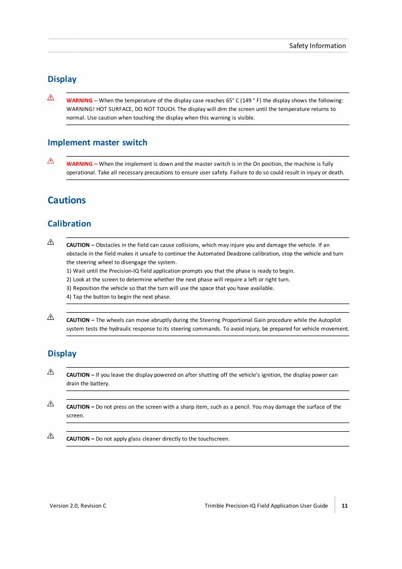
WARNING – When the temperature of the display case reaches 65° C (149 ° F) the display shows the following:WARNING! HOT SURFACE, DO NOT TOUCH. The display will dim the screen until the temperature returns tonormal. Use caution when touching the display when this warning is visible.
Implement master switch
WARNING – When the implement is down and the master switch is in the On position, the machine is fullyoperational. Take all necessary precautions to ensure user safety. Failure to do so could result in injury or death.
Cautions
Calibration
CAUTION – Obstacles in the field can cause collisions, which may injure you and damage the vehicle. If anobstacle in the field makes it unsafe to continue the Automated Deadzone calibration, stop the vehicle and turnthe steering wheel to disengage the system.1) Wait until the Precision-IQ field application prompts you that the phase is ready to begin.2) Look at the screen to determine whether the next phase will require a left or right turn.3) Reposition the vehicle so that the turn will use the space that you have available.4) Tap the button to begin the next phase.
CAUTION – The wheels can move abruptly during the Steering Proportional Gain procedure while the Autopilotsystem tests the hydraulic response to its steering commands. To avoid injury, be prepared for vehicle movement.
Display
CAUTION – If you leave the display powered on after shutting off the vehicle's ignition, the display power candrain the battery.
CAUTION – Do not press on the screen with a sharp item, such as a pencil. You may damage the surface of thescreen.
CAUTION – Do not apply glass cleaner directly to the touchscreen.
Version 2.0, Revision C Trimble Precision-IQ Field Application User Guide 11
Safety Information

GNSS interference
CAUTION – The GNSS antenna may experience interference if you operate the vehicle within 100 m (300 ft) ofany power line, radar dish, or cell phone tower.
Vehicle setup
CAUTION – If you select a Vehicle Profile that is not suitable for your vehicle, you may experience degradedsystem performance.
CAUTION – If you delete a vehicle, all information about the vehicle will be erased.
USB socket
CAUTION – Do not remove the USB drive from the socket while the display is writing to or from the drive. Thiswill corrupt the data.
CAUTION – Do not use a USB drive in each USB socket at the same time. If you are attempting to upgradefirmware using a USB drive and another USB drive is already in one of the sockets, the firmware upgrade willfail.
12 Trimble Precision-IQ Field Application User Guide Version 2.0, Revision C
Safety Information
Contents
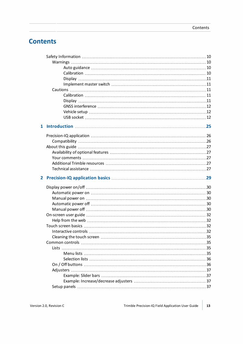
Safety Information 10Warnings 10
Auto guidance 10Calibration 10Display 11Implement master switch 11
Cautions 11Calibration 11Display 11GNSS interference 12Vehicle setup 12USB socket 12
1 Introduction 25
Precision-IQ application 26Compatibility 26
About this guide 27Availability of optional features 27Your comments 27Additional Trimble resources 27Technical assistance 27
2 Precision-IQ application basics 29
Display power on/off 30Automatic power on 30Manual power on 30Automatic power off 30Manual power off 30
On-screen user guide 32Help from the web 32
Touch screen basics 32Interactive controls 32Cleaning the touch screen 35
Common controls 35Lists 35
Menu lists 35Selection lists 36
On / Off buttons 36Adjusters 37
Example: Slider bars 37Example: Increase/decrease adjusters 37
Setup panels 37
Version 2.0, Revision C Trimble Precision-IQ Field Application User Guide 13
Contents
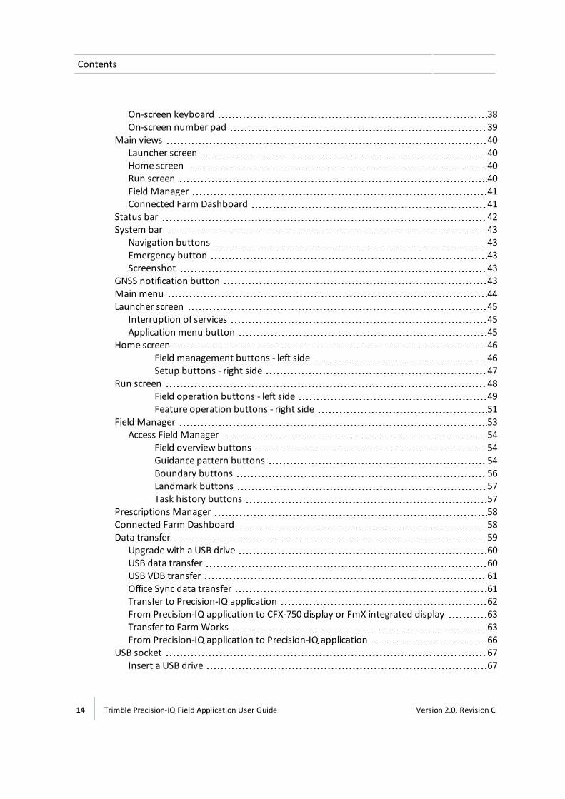
On-screen keyboard 38On-screen number pad 39
Main views 40Launcher screen 40Home screen 40Run screen 40Field Manager 41Connected Farm Dashboard 41
Status bar 42System bar 43
Navigation buttons 43Emergency button 43Screenshot 43
GNSS notification button 43Main menu 44Launcher screen 45
Interruption of services 45Application menu button 45
Home screen 46Field management buttons - left side 46Setup buttons - right side 47
Run screen 48Field operation buttons - left side 49Feature operation buttons - right side 51
Field Manager 53Access Field Manager 54
Field overview buttons 54Guidance pattern buttons 54Boundary buttons 56Landmark buttons 57Task history buttons 57
Prescriptions Manager 58Connected Farm Dashboard 58Data transfer 59
Upgrade with a USB drive 60USB data transfer 60USB VDB transfer 61Office Sync data transfer 61Transfer to Precision-IQ application 62From Precision-IQ application to CFX-750 display or FmX integrated display 63Transfer to Farm Works 63From Precision-IQ application to Precision-IQ application 66
USB socket 67Insert a USB drive 67
14 Trimble Precision-IQ Field Application User Guide Version 2.0, Revision C
Contents
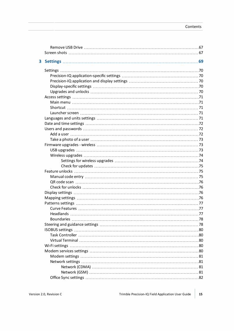
Remove USB Drive 67Screen shots 67
3 Settings 69
Settings 70Precision-IQ application-specific settings 70Precision-IQ application and display settings 70Display-specific settings 70Upgrades and unlocks 70
Access settings 71Main menu 71Shortcut 71Launcher screen 71
Languages and units settings 71Date and time settings 72Users and passwords 72
Add a user 72Take a photo of a user 73
Firmware upgrades - wireless 73USB upgrades 73Wireless upgrades 74
Settings for wireless upgrades 74Check for updates 75
Feature unlocks 75Manual code entry 75QR code scan 76Check for unlocks 76
Display settings 76Mapping settings 76Patterns settings 77
Curve Features 77Headlands 77Boundaries 78
Steering and guidance settings 78ISOBUS settings 80
Task Controller 80Virtual Terminal 80
Wi-Fi settings 80Modem services settings 80
Modem settings 81Network settings 81
Network (CDMA) 81Network (GSM) 81
Office Sync settings 82
Version 2.0, Revision C Trimble Precision-IQ Field Application User Guide 15
Contents

Restore defaults 82Admin User Options 83
System information 83
4 Connectivity 85
GNSS receiver settings 86SBAS corrections 88RangePoint RTX corrections 89OmniSTAR G2/HP/GR corrections setup 90CenterPoint RTX setup 91CenterPoint RTX setup 92
Modem corrections 93Satellite corrections 94
Standard convergence 95Fast convergence 95
VRS corrections 96RTK corrections 97CANmessage settings 100
DCM-300modem initial setup 100Office Sync setup 100
Requirements 101Settings 101
Connectivity concepts 103GNSS and drift 103xFill technology 103
Automatic guidance systems 103Accuracy 104
Dependence on satellite 104Dependence on base station position 104Base station survey 105Base station survey with AutoBase™ 105VRS base station 106Base station, survey unknown 106Estimating base station errors 106
When not to use xFill technology 107VRS 107
Network solution 107
5 Vehicles 109
Vehicle setup 110Overview of setup 110
Add a vehicle 110Delete a vehicle 112
16 Trimble Precision-IQ Field Application User Guide Version 2.0, Revision C
Contents

Edit a vehicle 113Save a vehicle 113
Save a complete vehicle profile 114Save an incomplete vehicle profile 114
Vehicle summary 114Select a vehicle 115Manual guidance setup 115Autopilot system setup 116
Guidance system settings for Autopilot system 116Controller settings for Autopilot system 117Sensor settings for Autopilot system 118Vehicle measurements for Autopilot system 119
OnSwath 121Autopilot system calibration 122
Calibration for non-tracked vehicles 122Manual override sensitivity calibration 123Steering sensor calibration 124Automated steering deadzone calibration 126
Pre-calibration steps 126Calibration steps 126
Automated Deadzone error messages 127Calibration steps 128Automated Deadzone error messages 129
Proportional steering gain 130Pre-calibration steps 130Calibration steps 131
Roll correction calibration 131Pre-calibration steps 132Calibration steps 132
Line acquisition 135Engage aggressiveness 136
EZ-Pilot system setup 137Guidance selection for the EZ-Pilot system 137Controller settings for EZ-Pilot system 137Steering speed settings for EZ-Pilot system 138Vehicle measurements for EZ-Pilot system 140
EZ-Pilot system calibrations 140Roll correction for EZ-Pilot system 140Angle per turn calibration for EZ-Pilot system 141Online aggressiveness calibration for EZ-Pilot system 141Line acquisition calibration for EZ-Pilot system 142
EZ-Steer system setup 144Guidance selection for EZ-Steer system 144Controller settings for EZ-Steer system 144
Version 2.0, Revision C Trimble Precision-IQ Field Application User Guide 17
Contents
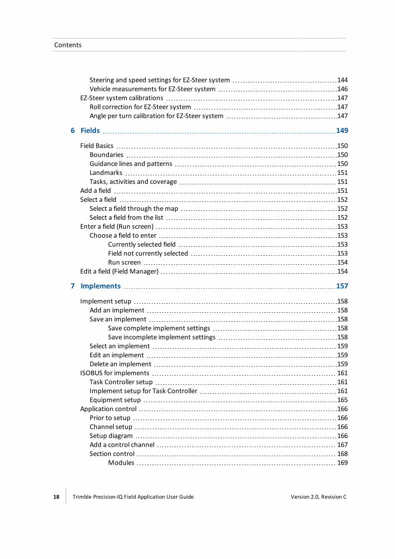
Steering and speed settings for EZ-Steer system 144Vehicle measurements for EZ-Steer system 146
EZ-Steer system calibrations 147Roll correction for EZ-Steer system 147Angle per turn calibration for EZ-Steer system 147
6 Fields 149
Field Basics 150Boundaries 150Guidance lines and patterns 150Landmarks 151Tasks, activities and coverage 151
Add a field 151Select a field 152
Select a field through themap 152Select a field from the list 152
Enter a field (Run screen) 153Choose a field to enter 153
Currently selected field 153Field not currently selected 153Run screen 154
Edit a field (Field Manager) 154
7 Implements 157
Implement setup 158Add an implement 158Save an implement 158
Save complete implement settings 158Save incomplete implement settings 158
Select an implement 159Edit an implement 159Delete an implement 159
ISOBUS for implements 161Task Controller setup 161Implement setup for Task Controller 161Equipment setup 165
Application control 166Prior to setup 166Channel setup 166Setup diagram 166Add a control channel 167Section control 168
Modules 169
18 Trimble Precision-IQ Field Application User Guide Version 2.0, Revision C
Contents

Width 170Latencies 170Overlaps 171
Rate control 172Valve/Drive 173Width 174Adjustments 174
Calibrate application control drives 175Virtual tank/bin 177Adjustments 177Summary 178Modify a control channel 178Remove a control channel 179
Boom height control 180Boom height control setup 180Sensor location 181Operation settings 182Calibrate boom height control 185
Boom height calibration steps 185Boom height manual control test 186
Inputs 189Add a sensor 189Type of sensor 189Location of sensor 189Alarms 190SIM 190Inputs / Sensors calibration 191
Review implement summary 192Prescriptions 193
Importing prescriptions 193Exporting prescriptions 193
8 Materials 195
Managing materials 196Material list 196
Anhydrous 196Granular fertilizer 196Liquid 196Granular seed 196Row crop seed 197
Add a material 197Edit a material 199Delete a material 199Assign a material to a channel 199
Version 2.0, Revision C Trimble Precision-IQ Field Application User Guide 19
Contents

Calibratematerial flow 200Pre-calibration steps 200Calibration steps 200
9 Operations 203
Preparing for operation 204Choose a field to enter 204
Currently selected field 204Field not currently selected 205Run screen 205
Fields and guidance 205Tasks 206Layers 206Adjustments during operation 206Automatic transfer of data 207Tasks 208
Data stored in each task 208Create a task 208Add a task (Run screen) 209Review existing tasks (Field Manager) 209Review existing tasks (Field Manager) 209Edit a task (Field Manager) 210
Coverage logging 211Manual coverage logging 211Automatic logging with engage 211Editing layers 211
Vehicle operation 212Vehicle position 212Engage status with auto guidance 212Steering adjustments 214Guidance adjustments 214
Guidance patterns 216Guidance creation buttons 216Boundary creation (Run screen) 218Boundary editing (Field Manager) 219Boundary activation/deactivation (Field Manager) 220AB guidance line creation (Run screen) 221A+ guidance line creation (Run screen) 222Curved line creation (Run screen) 222Headland and infill pattern creation (Run screen) 223Infill pattern shift 224Change the infill pattern 226Pivot pattern creation (Run screen) 228Guidance pattern editing (Field Manager) 229
20 Trimble Precision-IQ Field Application User Guide Version 2.0, Revision C
Contents

Pattern activation/deactivation (Field Manager) 229Guidance pattern adjustment (Run screen) 230Guidance pattern shifting (Field Manager) 231
Landmarks 233Landmark buttons 233Landmark point creation (Run screen) 234Landmark line creation (Run screen) 234Landmark area creation (Run screen) 235Landmark editing (Field Manager) 235
Layers 237View coverage layers 237Edit a coverage layer 238
Field-IQ system operations 240Field-IQ system Master Switch Box 240Field-IQ 12-section switch box 241
Relation to master switch box 241LED status indicators 242
Section control 243Buttons and indicators 243
Rate control adjustments 244Boom height control operation 246
Buttons and indicators 246Boom height adjustments 248
Prescriptions 250Assign a prescription 250Use a prescription 251
ISOBUS 252Task Controller operation 252
On-screen Task Controller switch 253Virtual Terminal operation 254
Delete previous data 255On-screen widgets 256
Access widgets 256Minimize/maximize, resize 256Move a widget 256Remove a widget 257Area status 257ISOBUS Task Controller widget 258Position status 259
On-screen lightbar for auto guidance 259Position 259Compass 260Digital compass 260Swath number 260
Version 2.0, Revision C Trimble Precision-IQ Field Application User Guide 21
Contents
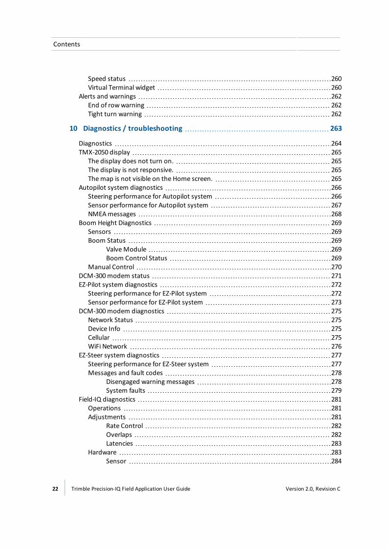
Speed status 260Virtual Terminal widget 260
Alerts and warnings 262End of rowwarning 262Tight turn warning 262
10 Diagnostics / troubleshooting 263
Diagnostics 264TMX-2050 display 265
The display does not turn on. 265The display is not responsive. 265Themap is not visible on the Home screen. 265
Autopilot system diagnostics 266Steering performance for Autopilot system 266Sensor performance for Autopilot system 267NMEAmessages 268
Boom Height Diagnostics 269Sensors 269Boom Status 269
ValveModule 269Boom Control Status 269
Manual Control 270DCM-300modem status 271EZ-Pilot system diagnostics 272
Steering performance for EZ-Pilot system 272Sensor performance for EZ-Pilot system 273
DCM-300modem diagnostics 275Network Status 275Device Info 275Cellular 275WiFi Network 276
EZ-Steer system diagnostics 277Steering performance for EZ-Steer system 277Messages and fault codes 278
Disengaged warning messages 278System faults 279
Field-IQ diagnostics 281Operations 281Adjustments 281
Rate Control 282Overlaps 282Latencies 283
Hardware 283Sensor 284
22 Trimble Precision-IQ Field Application User Guide Version 2.0, Revision C
Contents
GNSS and xFill technology status 285xFill technology status 285
Safety feature 285xFill technology status buttons 286
GNSS diagnostics 287Solution Information 287Skyplot 287Troubleshooting 288Poor accuracy (multipath) 289Intermittent loss of lock on satellite 289Loss of initialization 289Not tracking RTK corrections 290Poor signal / not receiving a clear signal 290The receiver is not tracking any satellites. 291
Office Sync Diagnostics 291ISOBUS diagnostics 293
Device tab 293Recording and saving CAN logs 293
System diagnostics 294System performance 294
Display 294Devices 294
TM-200Module diagnostics 295LED 1 295LED 2 295LED 3 295LED 3 and 4 combination 295LED 4 296
11 Glossary 297
298A 298B 298C 298D 299E 300F 300G 300H 301I 301L 301M 302N 302P 302
Version 2.0, Revision C Trimble Precision-IQ Field Application User Guide 23
Contents

R 303S 303T 304V 304W 304
24 Trimble Precision-IQ Field Application User Guide Version 2.0, Revision C
Contents

Introduction
In this chapter:
Precision-IQ application 26
About this guide 27
The Trimble® Precision IQ™ applicationavailable on the in-cab TMX-2050™ touchscreen display provides affordableguidance, steering and precisionagriculture functionality.
1C h a p t e r
Version 2.0, Revision C Trimble Precision-IQ Field Application User Guide 25

1 Introduction Precision-IQ application
Precision-IQ applicationThe Precision-IQ field application is an easy-to-use advanced field management system which runson the TMX-2050 display. The display consists of a 30 cm (12") touch-sensitive, color LCD screen.
CompatibilityPrecision-IQ application is compatible with the following automated guidance and steering:
l Trimble Autopilot™ automated steering system
l Trimble EZ-Steer® assisted steering system
l Trimble EZ-Pilot® steering system
Precision-IQ application can use an array of additional products to maximize efficiency, including:
l Creating fields and guidance patterns
l Using guidance patterns for automatic guidance systems
l Logging coverage data
l Output of information for analysis in office-based software (for example Farm Works Software®solutions)
l Field-IQ™ Boom Height Control and Spraying
l Variable rate control
26 Trimble Precision-IQ Field Application User Guide Version 2.0, Revision C

About this guide 1 Introduction
About this guideThis manual describes how to install, configure, troubleshoot and use the Precision-IQ fieldapplication .
Availability of optional featuresAll available functions are covered in this manual, however, you may not see all of them on yourscreen. The Precision-IQ field application includes many optional features. Only the features youhave unlocked will be available to you.
Your commentsYour feedback about the supporting documentation helps us to improve it with each revision. Emailyour comments to [email protected].
Additional Trimble resourcesSources of related information include the following:
l Product manuals and other publications: Access various publications (including productmanuals, release notes and quick reference guides) about Trimble products athttp://www.trimble.com/Support/Support_AZ.aspx.
l Trimble training courses - Consider a training course to help you use the Precision-IQ fieldapplication to its fullest potential. For more information, visithttp://www.trimble.com/Support/Index_Training.aspx.
Technical assistanceIf you cannot find the information you need in the product documentation, contact your localreseller.
Alternatively:
1. Visit http://www.trimble.com/support/index_support.aspx.
2. Select the type of support applicable to you.
If you need to contact Trimble technical support:
1. Visit http://www.trimble.com/global-services/support.aspx.
2. Click Request Technical Support and login to complete a support request.
Version 2.0, Revision C Trimble Precision-IQ Field Application User Guide 27

1 Introduction About this guide
28 Trimble Precision-IQ Field Application User Guide Version 2.0, Revision C

Precision-IQ application basics
In this chapter:
Display power on/off 30
On-screen user guide 32
Touch screen basics 32
Common controls 35
Main views 40
Status bar 42
System bar 43
GNSS notification button 43
Main menu 44
Launcher screen 45
Home screen 46
Run screen 48
Field Manager 53
Prescriptions Manager 58
Connected Farm Dashboard 58
Data transfer 59
USB socket 67
Screen shots 67
The Precision-IQ field application is atouch screen application that responds tocommon touch screen interactions. TheHome and Run screens as well as the FieldManager and Connected Farm™Dashboard are covered in this chapter.
2C h a p t e r
Version 2.0, Revision C Trimble Precision-IQ Field Application User Guide 29
2 Precision-IQ application basics Display power on/off
Display power on/offNote – The display must be correctly installed before powering on. For more information, see TMX-2050 Display Cabling Guide.
Automatic power onIf the display is connected to the ignition source, power on the vehicle. The TM-200Module sendspower to the display when the vehicle powers on.
The display powers on. After a short pause, the Launcher screen, 45 opens.
To open the Precision-IQ field application, tap .
Note – After you have initially powered on the display, the Precision-IQ field application may notopen until the TM-200Module has initialized or finished booting.
Manual power onTo turn on the display manually, hold the power button down briefly (about half a second).Thepower button is on the rear of the display.
The display powers on. After a short pause, the Launcher screen, 45 opens.
To open the Precision-IQ field application, tap .
Note – After you have initially powered on the display, the Precision-IQ field application may notopen until the TM-200Module has initialized or finished booting.
Automatic power offIf the display is connected to the ignition source, when you switch the ignition off, ashutdown/reboot dialog displays. If you do nothing the display shuts off in 60 seconds. If youchoose not to shutdown the display, it will remain powered on indefinitely.
CAUTION – If you leave the display powered on after shutting off the vehicle's ignition, the display power candrain the battery.
Manual power offTo manually turn the power off, hold the power down button for one to two seconds. See the stepsbelow.
30 Trimble Precision-IQ Field Application User Guide Version 2.0, Revision C

Display power on/off 2 Precision-IQ application basics
1. Turn off the display manually by holding the power button down for about two seconds.
2. Choose one of the following options:
ll Shutdown: Powers down the display
l Reboot: Restarts the display
l Cancel: Cancels the power off process
Note – Sometimes after you press the power button and tap Shutdown, the display does notimmediately turnoff. This is because the Precision-IQ field application is saving settings. The displaywill power off after all settings are saved.
If these steps do not cause the power to go off, you can force a shut down of the display by holdingthe power button for 5 seconds.
Version 2.0, Revision C Trimble Precision-IQ Field Application User Guide 31

2 Precision-IQ application basics On-screen user guide
On-screen user guideTo access the on-screen user guide for the Precision-IQ field application, you have two options:
Option 1: Tap on either theHome or Run screen. Then tap User Guide.
Option 2: Navigate to the Launcher screen, 45 and tap .
Note – If your system is engaged with an automatic steering system and you navigate to theLauncher screen to access the user guide, the steering system will disengage.
Help from the webTo obtain the User Guide from the web, go to http://www.trimble.com/Support/Support_AZ.aspx.
Touch screen basicsIf you are unfamiliar with using a touch screen, this section contains the basics of using a touchscreen and how to clean it.
Interactive controlsUse your fingers to interact with buttons, maps, lists and selectors.
CAUTION – Do not press on the screen with a sharp item, such as a pencil. You may damage the surface of thescreen.
Item Action Explanation
Buttons andselectors
Tapping Tapmeans to touch a point on the screen andthen remove your finger from the screen.A tap is a single touch. You do not move yourfinger while touching the screen. You tapbuttons, items in lists, points on a range, andso on.
32 Trimble Precision-IQ Field Application User Guide Version 2.0, Revision C
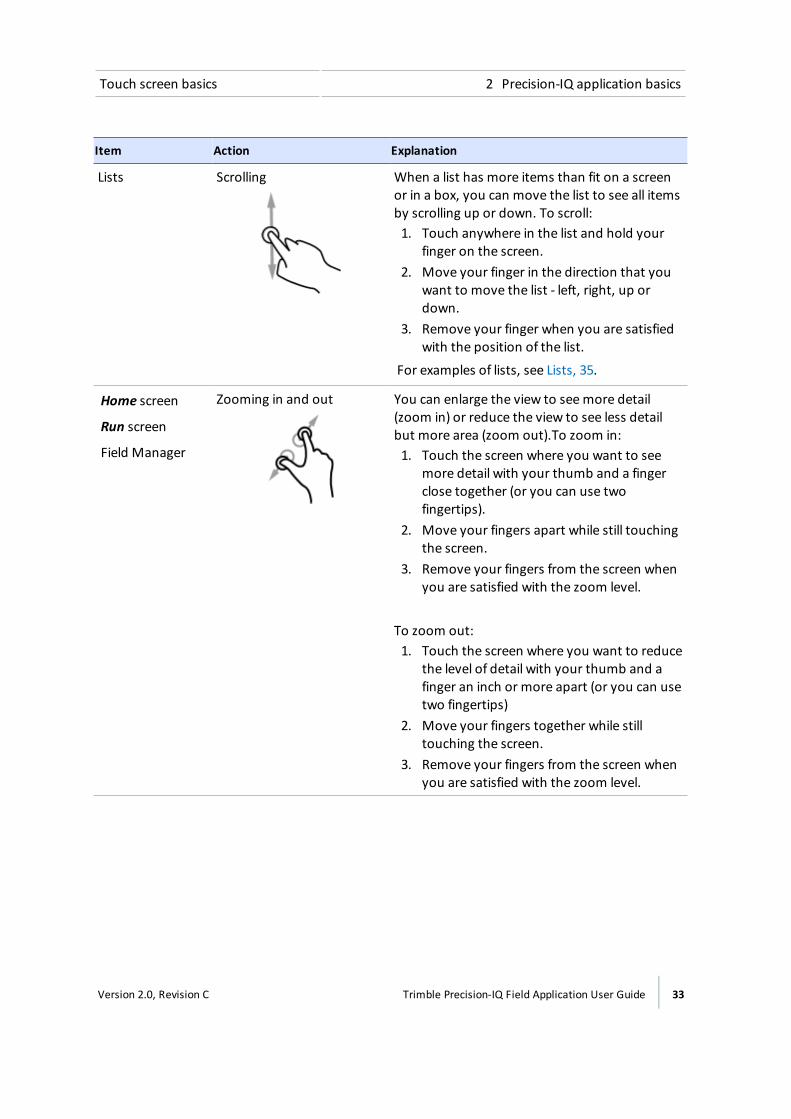
Touch screen basics 2 Precision-IQ application basics
Item Action Explanation
Lists Scrolling When a list has more items than fit on a screenor in a box, you can move the list to see all itemsby scrolling up or down. To scroll:1. Touch anywhere in the list and hold your
finger on the screen.2. Move your finger in the direction that you
want to move the list - left, right, up ordown.
3. Remove your finger when you are satisfiedwith the position of the list.
For examples of lists, see Lists, 35.
Home screen
Run screen
Field Manager
Zooming in and out You can enlarge the view to seemore detail(zoom in) or reduce the view to see less detailbut more area (zoom out).To zoom in:1. Touch the screen where you want to see
more detail with your thumb and a fingerclose together (or you can use twofingertips).
2. Move your fingers apart while still touchingthe screen.
3. Remove your fingers from the screen whenyou are satisfied with the zoom level.
To zoom out:1. Touch the screen where you want to reduce
the level of detail with your thumb and afinger an inch or more apart (or you can usetwo fingertips)
2. Move your fingers together while stilltouching the screen.
3. Remove your fingers from the screen whenyou are satisfied with the zoom level.
Version 2.0, Revision C Trimble Precision-IQ Field Application User Guide 33
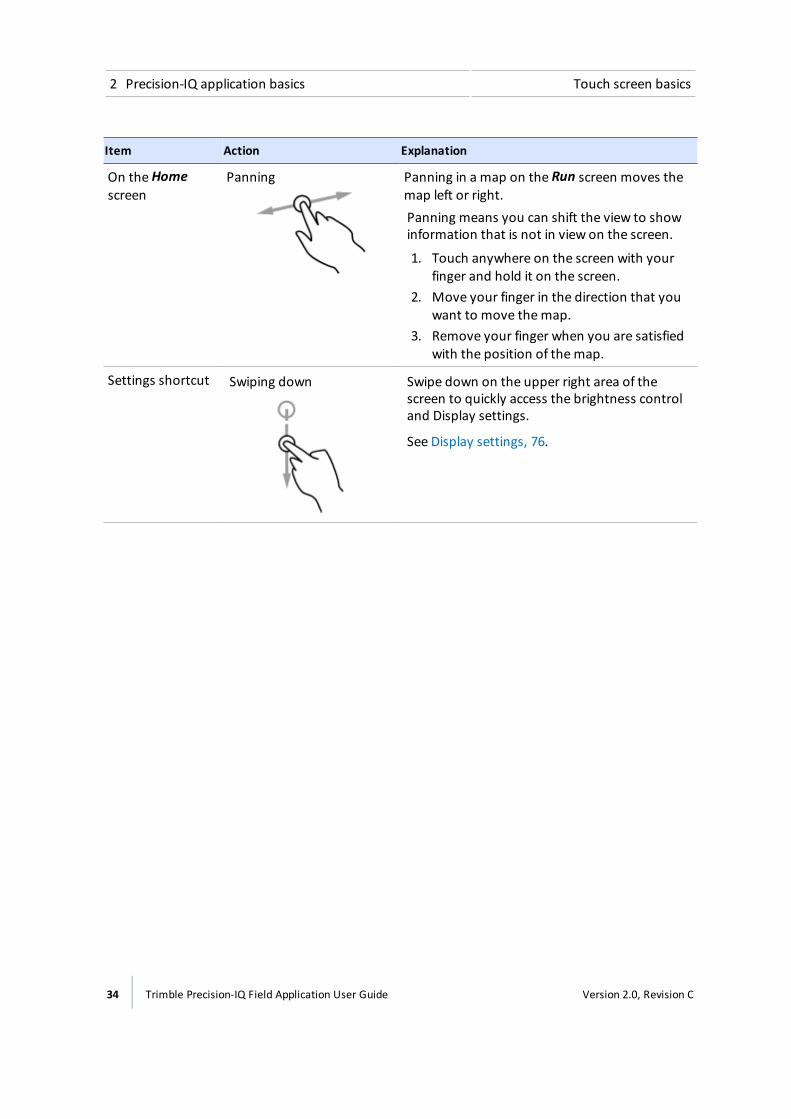
2 Precision-IQ application basics Touch screen basics
Item Action Explanation
On theHomescreen
Panning Panning in a map on the Run screen moves themap left or right.Panning means you can shift the view to showinformation that is not in view on the screen.
1. Touch anywhere on the screen with yourfinger and hold it on the screen.
2. Move your finger in the direction that youwant to move themap.
3. Remove your finger when you are satisfiedwith the position of themap.
Settings shortcut Swiping down Swipe down on the upper right area of thescreen to quickly access the brightness controland Display settings.
See Display settings, 76.
34 Trimble Precision-IQ Field Application User Guide Version 2.0, Revision C
Common controls 2 Precision-IQ application basics
Cleaning the touch screen
CAUTION – Do not press on the screen with a sharp item, such as a pencil. You may damage the surface of thescreen.
Use the following supplies to clean the touch screen of the display:
l Ammonia-free glass cleaner
l Soft, lint-free cotton cloth
l 50% isopropyl alcohol
CAUTION – Do not apply glass cleaner directly to the touchscreen.
1. Apply a small amount of ammonia-free glass cleaner to the cloth.
2. Gently rub the touchscreen with the cloth.
3. To remove stains or smudges, use a cotton cloth dampened with 50% isopropyl alcohol.
Tip – Clean the touch screen while it is powered down. It is easier to see dirt and fingerprints when the touchscreen is dark.
Common controlsCommon controls provide a way for you to:
l Complete settings and configuration with Setup panels, 37
l Enter information using an On-screen keyboard, 38 and On-screen number pad, 39
l Work with Lists, 35
l Turn an option on or off with On / Off buttons, 36
l Choose values within a range using Adjusters, 37
ListsLists vary depending on their function.
Menu listsMenu lists contain a list of items that lead to additional information or areas.
Version 2.0, Revision C Trimble Precision-IQ Field Application User Guide 35

2 Precision-IQ application basics Common controls
l Tap a list item to reveal additional information or choices to the right of themenu.
l Some lists have expand/collapse capabilities. Tap the up or down arrow to expand and collapsesections.
Tap a list item to reveal additionalinformation or choices to the right of themenu.
Some lists have expand/collapsecapabilities. Tap the up or down arrow toexpand and collapse sections.
Selection listsSome lists contain items for you to select. If the list is longer than what is in your view, a scroll bardisplays to the right of list items. You can use this to scroll up and down the list. After you tap yourselection on the list, the list closes.
On / Off buttonsOn/off buttons enable you to turn items on and off.
The red X indicates this item is turned off. Tap toturn the item on.
The green check mark indicates this item isturned on. Tap to turn the item off.
36 Trimble Precision-IQ Field Application User Guide Version 2.0, Revision C
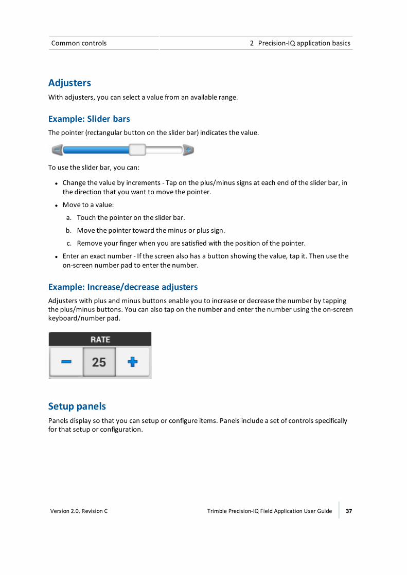
Common controls 2 Precision-IQ application basics
AdjustersWith adjusters, you can select a value from an available range.
Example: Slider barsThe pointer (rectangular button on the slider bar) indicates the value.
To use the slider bar, you can:
l Change the value by increments - Tap on the plus/minus signs at each end of the slider bar, inthe direction that you want to move the pointer.
l Move to a value:
a. Touch the pointer on the slider bar.
b. Move the pointer toward theminus or plus sign.
c. Remove your finger when you are satisfied with the position of the pointer.
l Enter an exact number - If the screen also has a button showing the value, tap it. Then use theon-screen number pad to enter the number.
Example: Increase/decrease adjustersAdjusters with plus and minus buttons enable you to increase or decrease the number by tappingthe plus/minus buttons. You can also tap on the number and enter the number using the on-screenkeyboard/number pad.
Setup panelsPanels display so that you can setup or configure items. Panels include a set of controls specificallyfor that setup or configuration.
Version 2.0, Revision C Trimble Precision-IQ Field Application User Guide 37
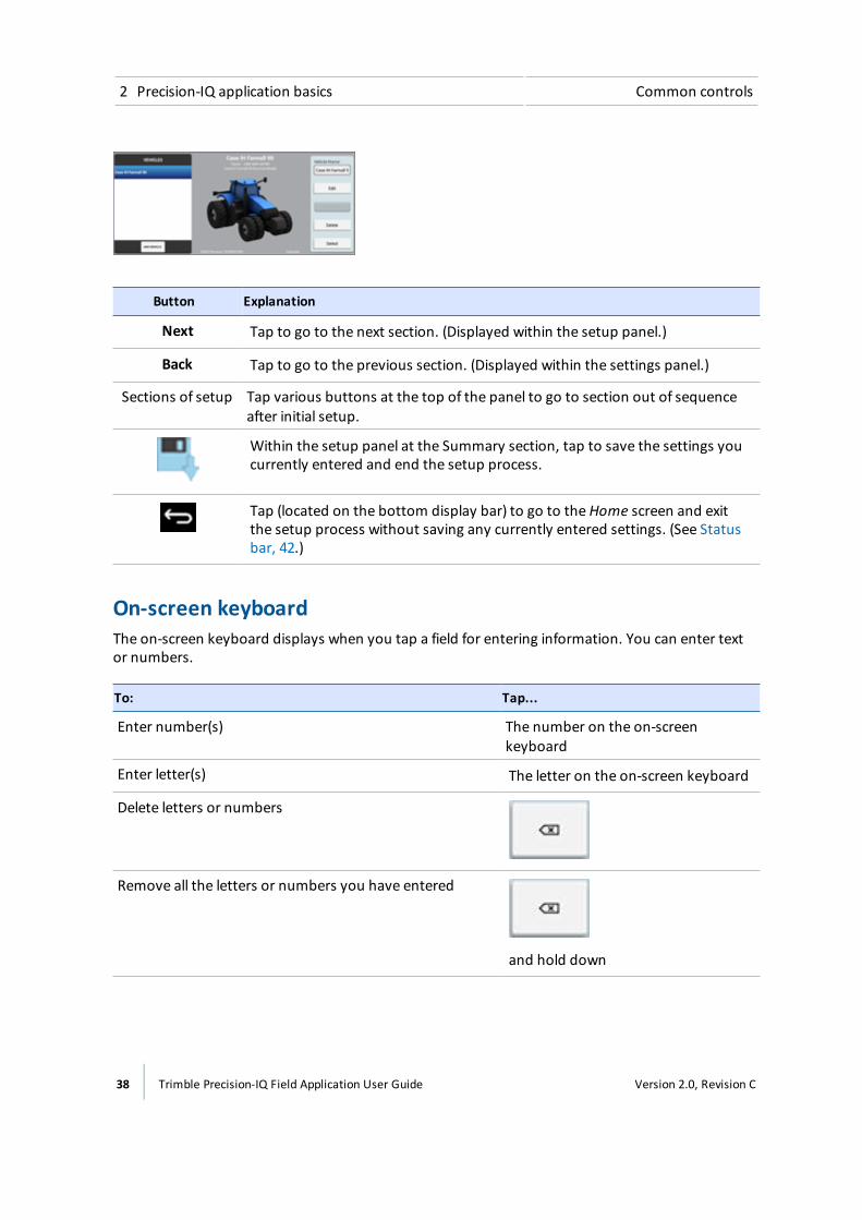
2 Precision-IQ application basics Common controls
Button Explanation
Next Tap to go to the next section. (Displayed within the setup panel.)
Back Tap to go to the previous section. (Displayed within the settings panel.)
Sections of setup Tap various buttons at the top of the panel to go to section out of sequenceafter initial setup.
Within the setup panel at the Summary section, tap to save the settings youcurrently entered and end the setup process.
Tap (located on the bottom display bar) to go to theHome screen and exitthe setup process without saving any currently entered settings. (See Statusbar, 42.)
On-screen keyboardThe on-screen keyboard displays when you tap a field for entering information. You can enter textor numbers.
To: Tap...
Enter number(s) The number on the on-screenkeyboard
Enter letter(s) The letter on the on-screen keyboard
Delete letters or numbers
Remove all the letters or numbers you have entered
and hold down
38 Trimble Precision-IQ Field Application User Guide Version 2.0, Revision C

Common controls 2 Precision-IQ application basics
To: Tap...
Cause the keyboard to no longer display
On-screen number padThe on-screen number pad displays when you tap a field for entering a number.
To: Tap...
Enter a number The number
Delete number(s)
Remove all the numbers you have entered
and hold down
Cause the keyboard to no longer display
Version 2.0, Revision C Trimble Precision-IQ Field Application User Guide 39

2 Precision-IQ application basics Main views
Main viewsThe Precision-IQ field application has different screens for your work.
Launcher screenThe Launcher screen, 45 displays the applications available on the TMX-2050 display in the sameway any Android application does. When you power on the display or reboot it, the Launcherscreen is the first screen to display.
To go to the Launcher screen, tap the Home button on the System bar, 43.
Home screenThe Home screen, 46 is primarily for set up, including:
l Adding fields
l Creating, setting up and calibrating vehicles, implements and materials
Run screenAt the Run screen, 48, you:
l Perform field activities
l Create guidancemapping elements (boundaries, guidance patterns, and landmarks)
l Make adjustments to steering guidance, and rate and section control
40 Trimble Precision-IQ Field Application User Guide Version 2.0, Revision C
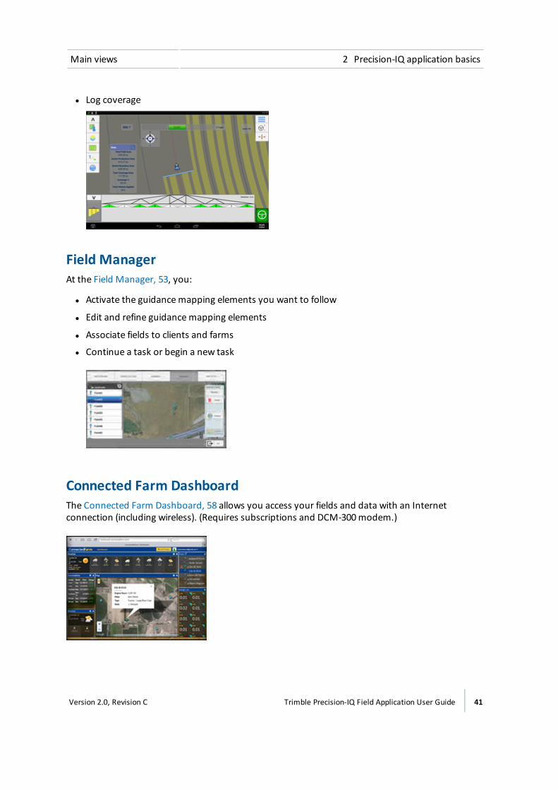
Main views 2 Precision-IQ application basics
l Log coverage
Field ManagerAt the Field Manager, 53, you:
l Activate the guidancemapping elements you want to follow
l Edit and refine guidancemapping elements
l Associate fields to clients and farms
l Continue a task or begin a new task
Connected Farm DashboardThe Connected Farm Dashboard, 58 allows you access your fields and data with an Internetconnection (including wireless). (Requires subscriptions and DCM-300modem.)
Version 2.0, Revision C Trimble Precision-IQ Field Application User Guide 41
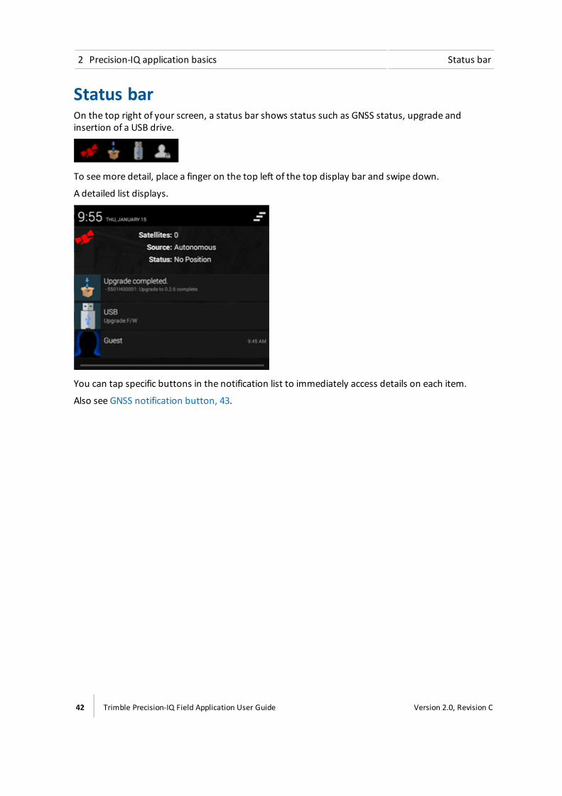
2 Precision-IQ application basics Status bar
Status barOn the top right of your screen, a status bar shows status such as GNSS status, upgrade andinsertion of a USB drive.
To seemore detail, place a finger on the top left of the top display bar and swipe down.
A detailed list displays.
You can tap specific buttons in the notification list to immediately access details on each item.
Also see GNSS notification button, 43.
42 Trimble Precision-IQ Field Application User Guide Version 2.0, Revision C
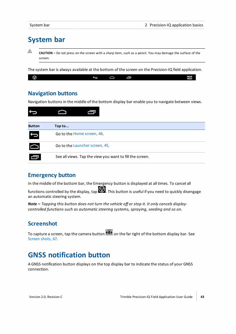
System bar 2 Precision-IQ application basics
System barCAUTION – Do not press on the screen with a sharp item, such as a pencil. You may damage the surface of thescreen.
The system bar is always available at the bottom of the screen on the Precision-IQ field application.
Navigation buttonsNavigation buttons in themiddle of the bottom display bar enable you to navigate between views.
Button Tap to...
Go to the Home screen, 46.
Go to the Launcher screen, 45.
See all views. Tap the view you want to fill the screen.
Emergency buttonIn themiddle of the bottom bar, the Emergency button is displayed at all times. To cancel all
functions controlled by the display, tap . This button is useful if you need to quickly disengagean automatic steering system.
Note – Tapping this button does not turn the vehicle off or stop it. It only cancels display-controlled functions such as automatic steering systems, spraying, seeding and so on.
ScreenshotTo capture a screen, tap the camera button on the far right of the bottom display bar. SeeScreen shots, 67.
GNSS notification buttonAGNSS notification button displays on the top display bar to indicate the status of your GNSSconnection.
Version 2.0, Revision C Trimble Precision-IQ Field Application User Guide 43

2 Precision-IQ application basics Main menu
Swipe to see the detail menu (see Status bar, 42). Tap the GNSS button on themenu. The systemtakes you to the Diagnostics screen for any troubleshooting you want to do.
Notification Button Indicates...
Green
GNSS connection is normal.
Yellow
GNSS connection is converging.
Red
No GNSS connection is available.
Main menuTap on either theHome or Run screen to access themain menu. A panel of buttons displaysthat you can tap to access the following areas:
l Diagnostics, 264: Open the Diagnostics screen.
l Settings, 70: Open the settings screen.
l Data transfer, 59: Go to the Data Transfer screen.
l On-screen user guide, 32: Display the on-screen user guide.
l Virtual Terminal: Open the Virtual Terminal to set up ISO-certified equipment for TaskController. (This button is not active unless you have turned on Virtual Terminal in Settings.See ISOBUS settings, 80.
44 Trimble Precision-IQ Field Application User Guide Version 2.0, Revision C

Launcher screen 2 Precision-IQ application basics
Launcher screen
You open applications from the Launcher screen by tapping them, including:
l Precision-IQ field application
l FmX® Plus application
l Connected Farm applications
The Precision-IQ field application and FmX Plus application cannot be open at the same time. If youare switching from Precision-IQ application to the FmX Plus application:
1. Reboot the display by holding down the power button for 1-2 seconds.
2. When the option menu displays, tap Reboot.
Interruption of servicesIf automatic steering, spraying, seeding or other services are engaged in the Precision-IQ fieldapplication and you go to the Launcher scren, the automatic systems will disengage.
Application menu button
To see all the application icons on the Launcher screen, tap the application menu button .
Version 2.0, Revision C Trimble Precision-IQ Field Application User Guide 45
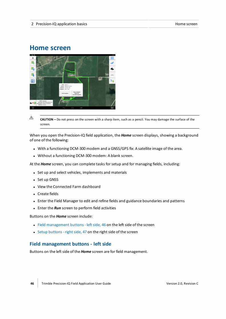
2 Precision-IQ application basics Home screen
Home screen
CAUTION – Do not press on the screen with a sharp item, such as a pencil. You may damage the surface of thescreen.
When you open the Precision-IQ field application, theHome screen displays, showing a backgroundof one of the following:
l With a functioning DCM-300modem and a GNSS/GPS fix: A satellite image of the area.
l Without a functioning DCM-300modem: A blank screen.
At theHome screen, you can complete tasks for setup and for managing fields, including:
l Set up and select vehicles, implements and materials
l Set up GNSS
l View the Connected Farm dashboard
l Create fields
l Enter the Field Manager to edit and refine fields and guidance boundaries and patterns
l Enter the Run screen to perform field activities
Buttons on theHome screen include:
l Field management buttons - left side, 46 on the left side of the screen
l Setup buttons - right side, 47 on the right side of the screen
Field management buttons - left sideButtons on the left side of theHome screen are for field management.
46 Trimble Precision-IQ Field Application User Guide Version 2.0, Revision C
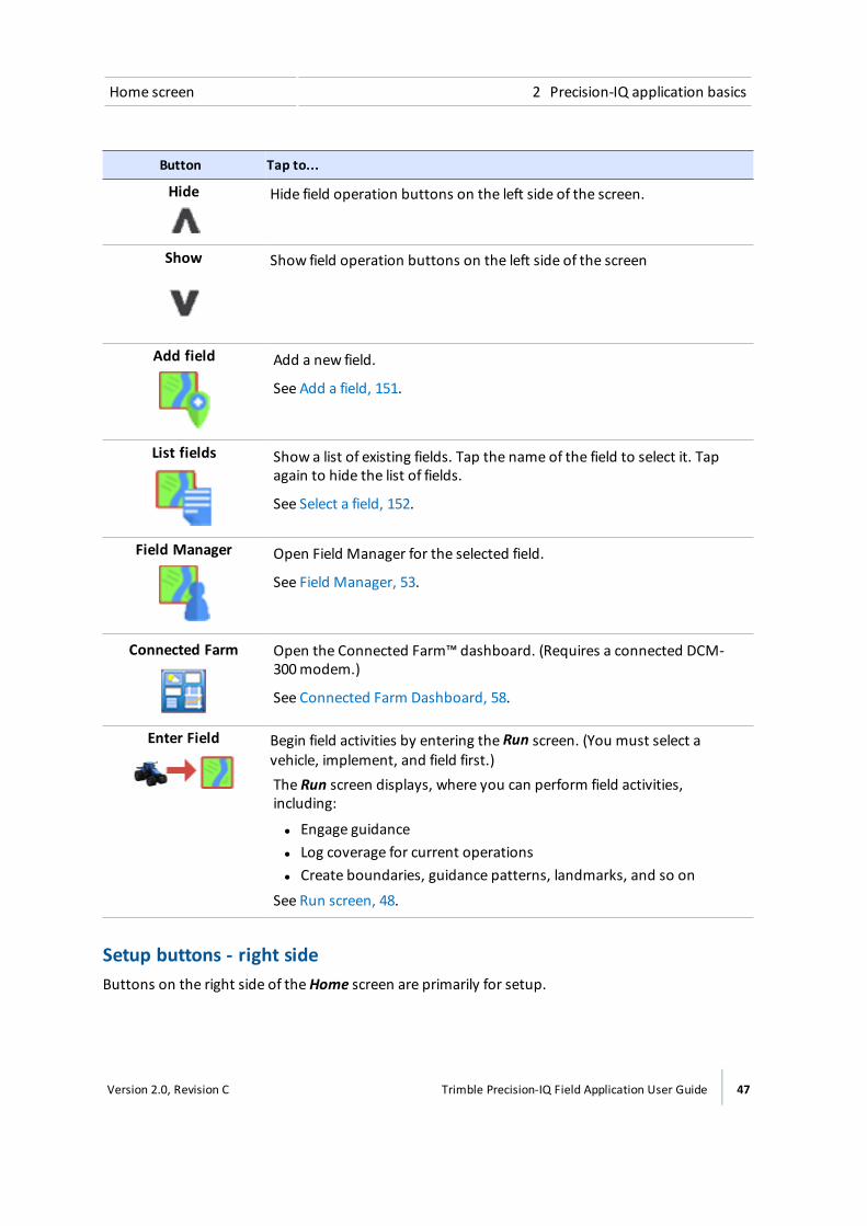
Home screen 2 Precision-IQ application basics
Button Tap to...
Hide Hide field operation buttons on the left side of the screen.
Show Show field operation buttons on the left side of the screen
Add field Add a new field.
See Add a field, 151.
List fields Show a list of existing fields. Tap the name of the field to select it. Tapagain to hide the list of fields.
See Select a field, 152.
Field Manager Open Field Manager for the selected field.
See Field Manager, 53.
Connected Farm Open the Connected Farm™ dashboard. (Requires a connected DCM-300modem.)
See Connected Farm Dashboard, 58.
Enter Field Begin field activities by entering the Run screen. (You must select avehicle, implement, and field first.)The Run screen displays, where you can perform field activities,including:
l Engage guidancel Log coverage for current operationsl Create boundaries, guidance patterns, landmarks, and so on
See Run screen, 48.
Setup buttons - right sideButtons on the right side of theHome screen are primarily for setup.
Version 2.0, Revision C Trimble Precision-IQ Field Application User Guide 47

2 Precision-IQ application basics Run screen
Button Tap to...
Menu Access themain menu.
SeeMain menu, 44.
GNSS Set up GNSS.See GNSS receiver settings, 86.
Vehicle Add, edit or select a vehicle, as well as set up and calibrate an assistedguidance system such as the Autopilot, EZ-Pilot, or EZ-Steer system.See Add a vehicle, 110.
Implement Add, edit or select an implement.
Set up and calibrate features for implements such as:
l The Field-IQ system Rate and Section Controll The Field-IQ system Boom Height Controll Implement lift switches and sensors
See Implement setup, 158 and Select an implement, 159.
Material Add, edit, and select materials.SeeManaging materials, 196.
Run screen
48 Trimble Precision-IQ Field Application User Guide Version 2.0, Revision C
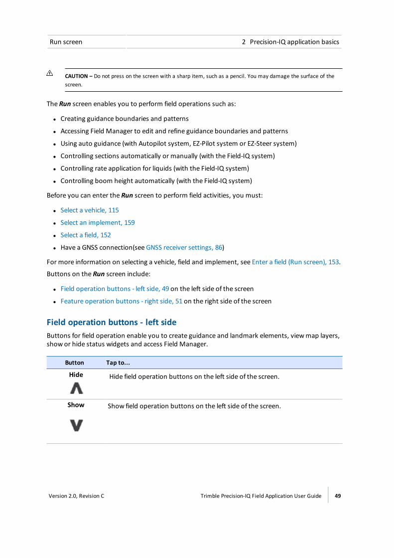
Run screen 2 Precision-IQ application basics
CAUTION – Do not press on the screen with a sharp item, such as a pencil. You may damage the surface of thescreen.
The Run screen enables you to perform field operations such as:
l Creating guidance boundaries and patterns
l Accessing Field Manager to edit and refine guidance boundaries and patterns
l Using auto guidance (with Autopilot system, EZ-Pilot system or EZ-Steer system)
l Controlling sections automatically or manually (with the Field-IQ system)
l Controlling rate application for liquids (with the Field-IQ system)
l Controlling boom height automatically (with the Field-IQ system)
Before you can enter the Run screen to perform field activities, you must:
l Select a vehicle, 115
l Select an implement, 159
l Select a field, 152
l Have a GNSS connection(see GNSS receiver settings, 86)
For more information on selecting a vehicle, field and implement, see Enter a field (Run screen), 153.
Buttons on the Run screen include:
l Field operation buttons - left side, 49 on the left side of the screen
l Feature operation buttons - right side, 51 on the right side of the screen
Field operation buttons - left sideButtons for field operation enable you to create guidance and landmark elements, viewmap layers,show or hide status widgets and access Field Manager.
Button Tap to...
Hide Hide field operation buttons on the left side of the screen.
Show Show field operation buttons on the left side of the screen.
Version 2.0, Revision C Trimble Precision-IQ Field Application User Guide 49
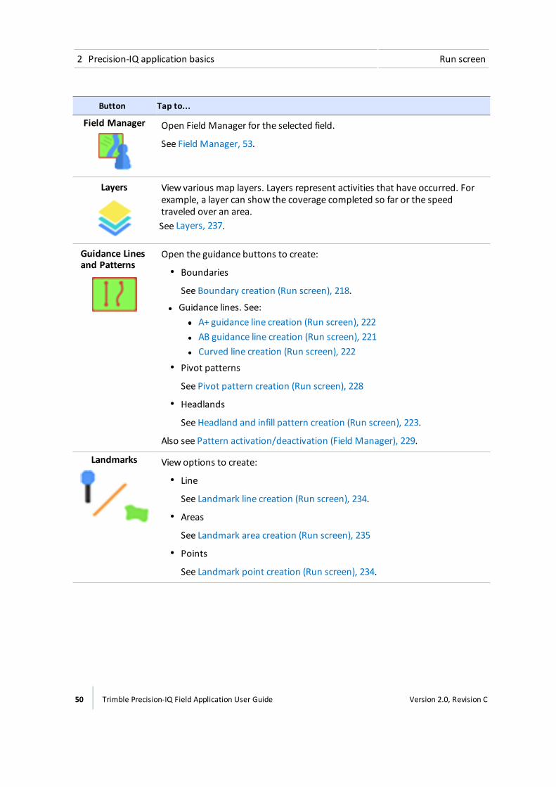
2 Precision-IQ application basics Run screen
Button Tap to...
Field Manager Open Field Manager for the selected field.
See Field Manager, 53.
Layers View various map layers. Layers represent activities that have occurred. Forexample, a layer can show the coverage completed so far or the speedtraveled over an area.See Layers, 237.
Guidance Linesand Patterns
Open the guidance buttons to create:l Boundaries
See Boundary creation (Run screen), 218.
l Guidance lines. See:ll A+ guidance line creation (Run screen), 222l AB guidance line creation (Run screen), 221l Curved line creation (Run screen), 222
l Pivot patterns
See Pivot pattern creation (Run screen), 228l Headlands
See Headland and infill pattern creation (Run screen), 223.
Also see Pattern activation/deactivation (Field Manager), 229.
Landmarks View options to create:l Line
See Landmark line creation (Run screen), 234.l Areas
See Landmark area creation (Run screen), 235l Points
See Landmark point creation (Run screen), 234.
50 Trimble Precision-IQ Field Application User Guide Version 2.0, Revision C
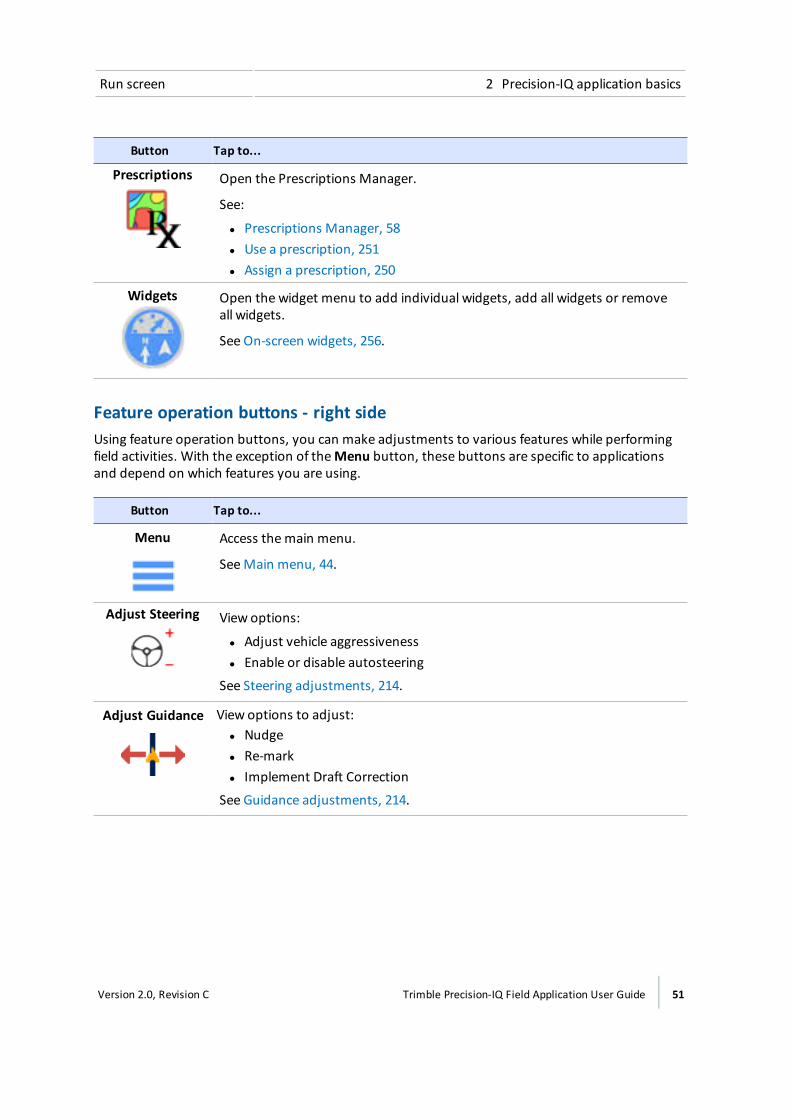
Run screen 2 Precision-IQ application basics
Button Tap to...
Prescriptions Open the Prescriptions Manager.
See:
l Prescriptions Manager, 58l Use a prescription, 251l Assign a prescription, 250
Widgets Open the widget menu to add individual widgets, add all widgets or removeall widgets.
See On-screen widgets, 256.
Feature operation buttons - right sideUsing feature operation buttons, you can make adjustments to various features while performingfield activities. With the exception of theMenu button, these buttons are specific to applicationsand depend on which features you are using.
Button Tap to...
Menu Access themain menu.
SeeMain menu, 44.
Adjust Steering View options:
l Adjust vehicle aggressivenessl Enable or disable autosteering
See Steering adjustments, 214.
Adjust Guidance View options to adjust:l Nudgel Re-markl Implement Draft Correction
See Guidance adjustments, 214.
Version 2.0, Revision C Trimble Precision-IQ Field Application User Guide 51
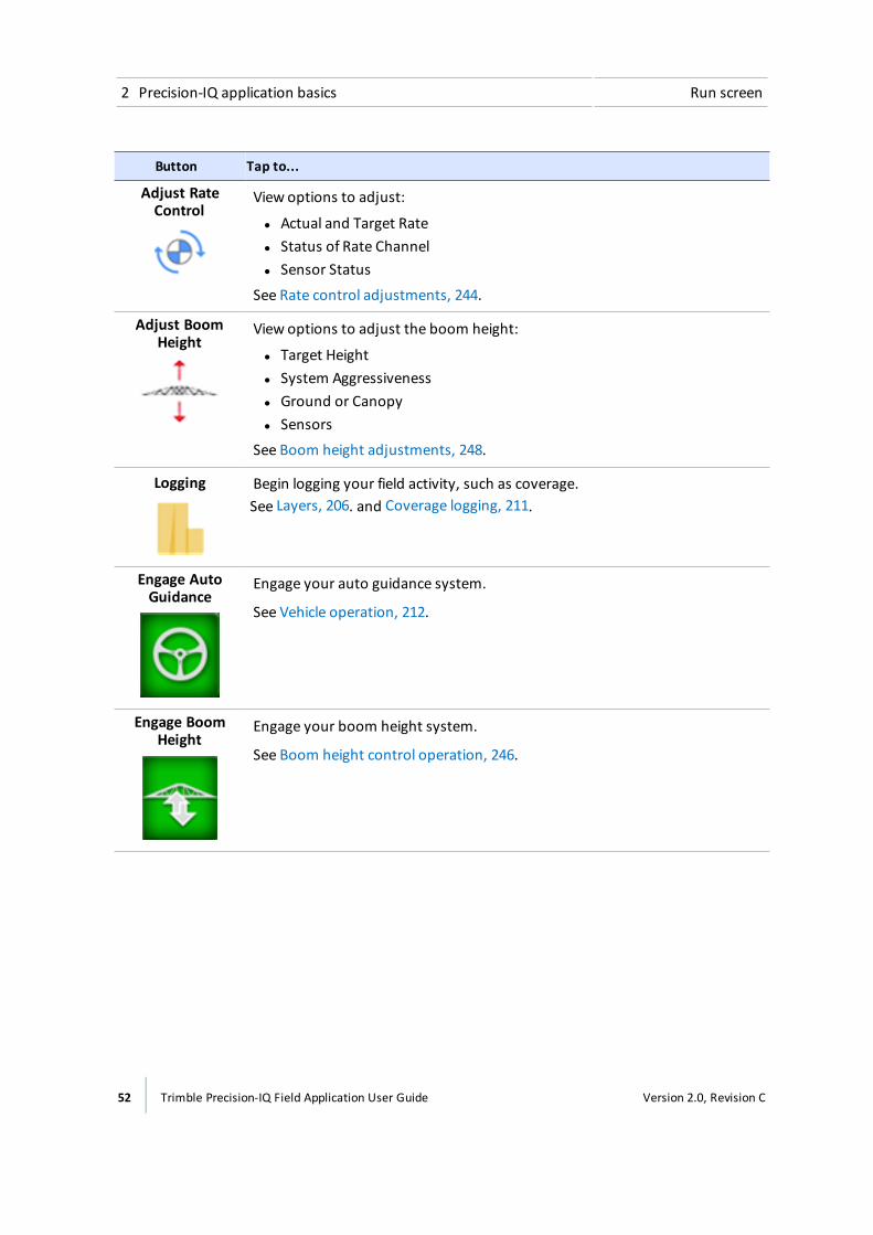
2 Precision-IQ application basics Run screen
Button Tap to...
Adjust RateControl
View options to adjust:
l Actual and Target Ratel Status of Rate Channell Sensor Status
See Rate control adjustments, 244.
Adjust BoomHeight
View options to adjust the boom height:
l Target Heightl System Aggressivenessl Ground or Canopyl Sensors
See Boom height adjustments, 248.
Logging Begin logging your field activity, such as coverage.See Layers, 206. and Coverage logging, 211.
Engage AutoGuidance
Engage your auto guidance system.
See Vehicle operation, 212.
Engage BoomHeight
Engage your boom height system.
See Boom height control operation, 246.
52 Trimble Precision-IQ Field Application User Guide Version 2.0, Revision C

Field Manager 2 Precision-IQ application basics
Field ManagerAt the Field Manager, you edit and refine elements in and associated with each field.
The Field Manager shows information directly associated with the field you have selected andenables you to perform functions listed in the following table.
Note – Add and select a field before entering Field Manager. See Add a field, 151 and Select a field,152.
Section Functions Available
Field Overview
See Field overview buttons,54.
l Rename the field, client and farm.l Delete the field.
See Edit a field (Field Manager), 154.
Guidance Patterns
See Guidance patternbuttons, 54.
l Activate or deactivate lines and patterns.l Shift a line.l Adjust the radius of a pattern.l Resize a shape (other than pivot shape).
See Guidance patterns, 216.
Boundaries
See Boundary buttons, 56.
l Activate or deactivate a boundary.l Resize a boundary.l Rename a boundary.
See Boundary editing (Field Manager), 219.
Landmarks
See Landmark buttons, 57.
l Edit, delete or rename a landmark.l Change the category that a landmark is assigned to.l See Landmark editing (Field Manager), 235.
Task History
See Task history buttons,57.
l Start a new task.l Rename a task.l See Tasks, 208.
Version 2.0, Revision C Trimble Precision-IQ Field Application User Guide 53
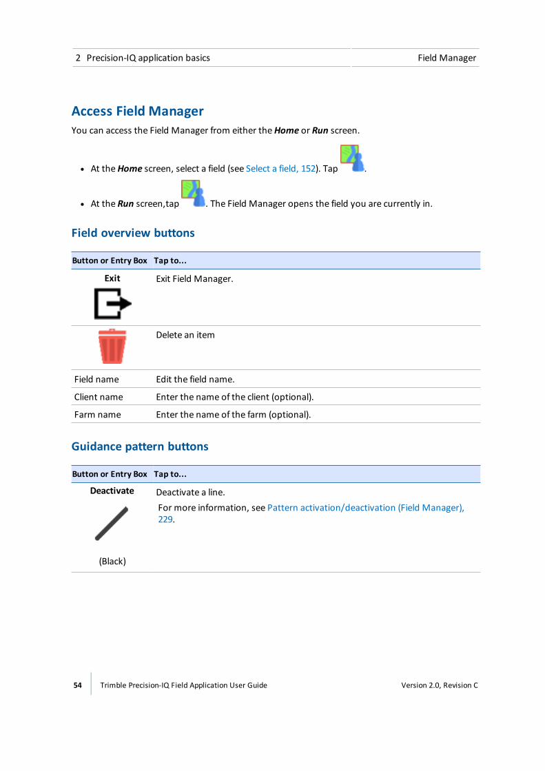
2 Precision-IQ application basics Field Manager
Access Field ManagerYou can access the Field Manager from either theHome or Run screen.
l At theHome screen, select a field (see Select a field, 152). Tap .
l At the Run screen,tap . The Field Manager opens the field you are currently in.
Field overview buttons
Button or Entry Box Tap to...
Exit Exit Field Manager.
Delete an item
Field name Edit the field name.
Client name Enter the name of the client (optional).
Farm name Enter the name of the farm (optional).
Guidance pattern buttons
Button or Entry Box Tap to...
Deactivate
(Black)
Deactivate a line.For more information, see Pattern activation/deactivation (Field Manager),229.
54 Trimble Precision-IQ Field Application User Guide Version 2.0, Revision C
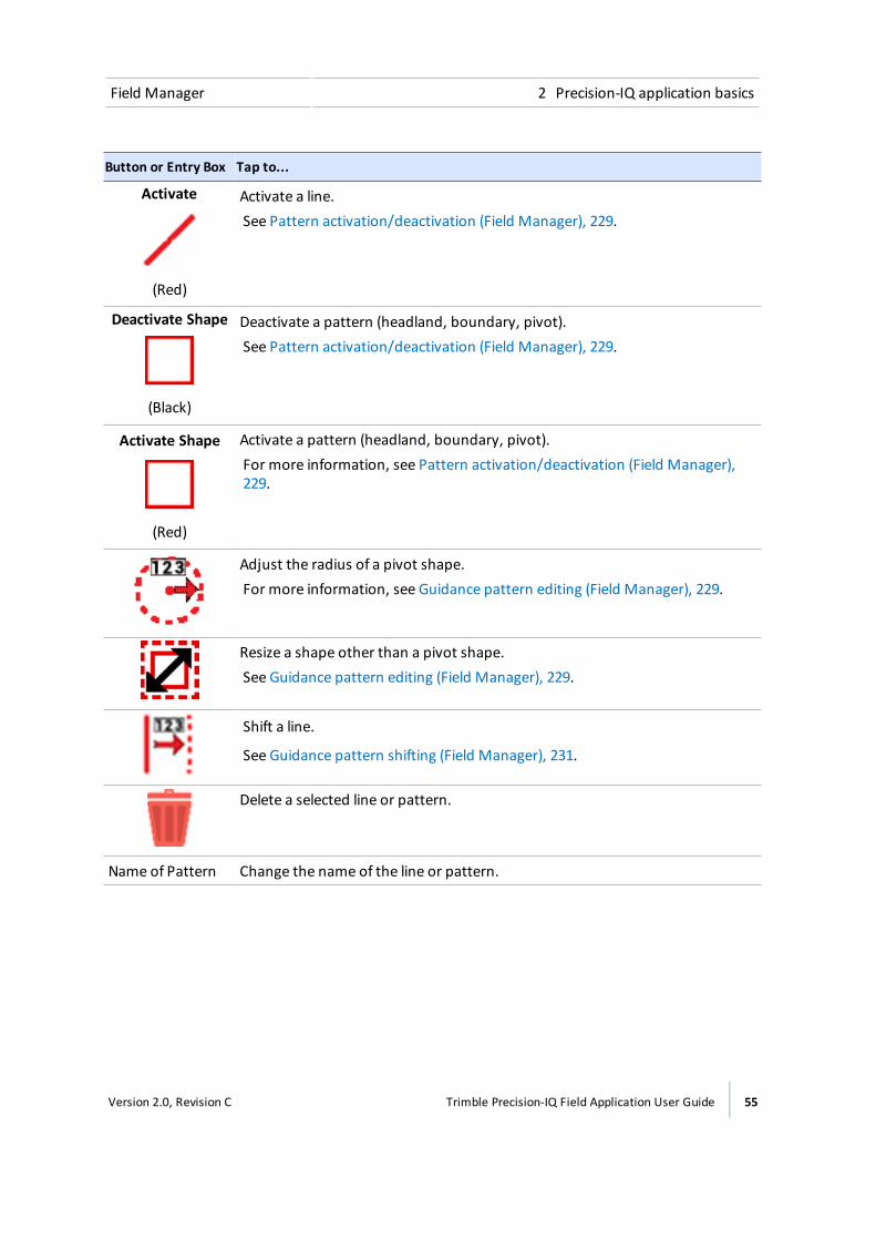
Field Manager 2 Precision-IQ application basics
Button or Entry Box Tap to...
Activate
(Red)
Activate a line.See Pattern activation/deactivation (Field Manager), 229.
Deactivate Shape
(Black)
Deactivate a pattern (headland, boundary, pivot).See Pattern activation/deactivation (Field Manager), 229.
Activate Shape
(Red)
Activate a pattern (headland, boundary, pivot).For more information, see Pattern activation/deactivation (Field Manager),229.
Adjust the radius of a pivot shape.For more information, see Guidance pattern editing (Field Manager), 229.
Resize a shape other than a pivot shape.See Guidance pattern editing (Field Manager), 229.
Shift a line.
See Guidance pattern shifting (Field Manager), 231.
Delete a selected line or pattern.
Name of Pattern Change the name of the line or pattern.
Version 2.0, Revision C Trimble Precision-IQ Field Application User Guide 55
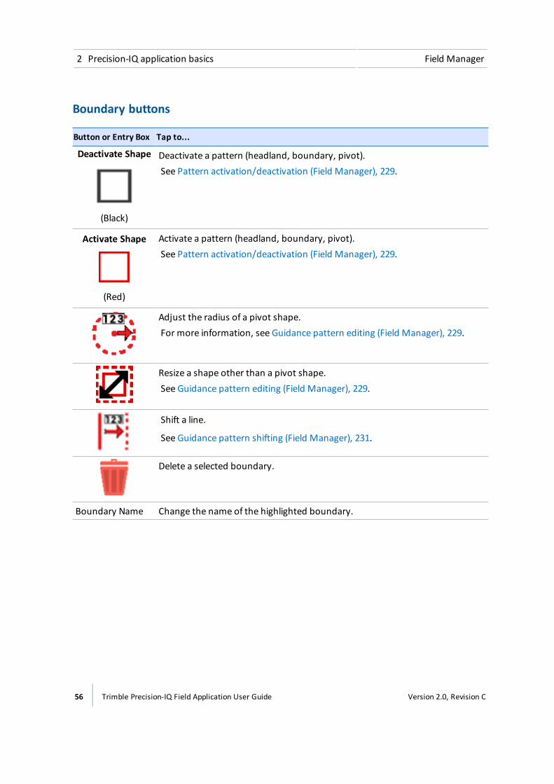
2 Precision-IQ application basics Field Manager
Boundary buttons
Button or Entry Box Tap to...
Deactivate Shape
(Black)
Deactivate a pattern (headland, boundary, pivot).See Pattern activation/deactivation (Field Manager), 229.
Activate Shape
(Red)
Activate a pattern (headland, boundary, pivot).See Pattern activation/deactivation (Field Manager), 229.
Adjust the radius of a pivot shape.For more information, see Guidance pattern editing (Field Manager), 229.
Resize a shape other than a pivot shape.See Guidance pattern editing (Field Manager), 229.
Shift a line.
See Guidance pattern shifting (Field Manager), 231.
Delete a selected boundary.
Boundary Name Change the name of the highlighted boundary.
56 Trimble Precision-IQ Field Application User Guide Version 2.0, Revision C
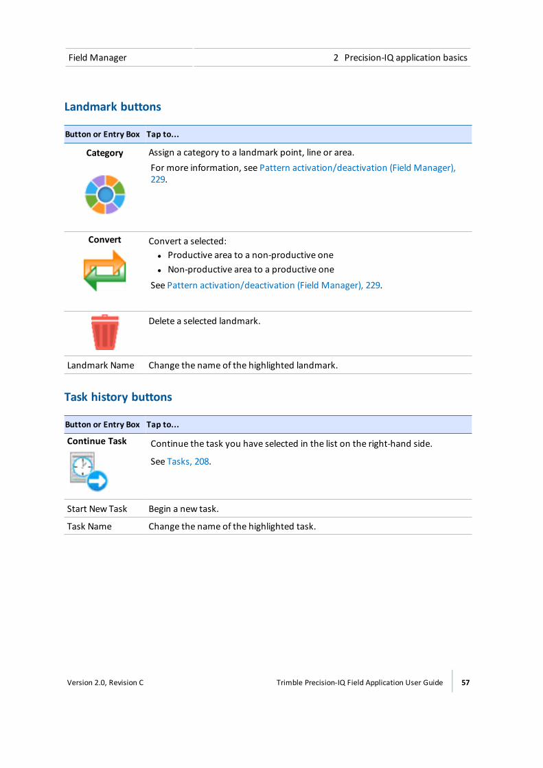
Field Manager 2 Precision-IQ application basics
Landmark buttons
Button or Entry Box Tap to...
Category Assign a category to a landmark point, line or area.For more information, see Pattern activation/deactivation (Field Manager),229.
Convert Convert a selected:l Productive area to a non-productive onel Non-productive area to a productive one
See Pattern activation/deactivation (Field Manager), 229.
Delete a selected landmark.
Landmark Name Change the name of the highlighted landmark.
Task history buttons
Button or Entry Box Tap to...
Continue Task Continue the task you have selected in the list on the right-hand side.
See Tasks, 208.
Start New Task Begin a new task.
Task Name Change the name of the highlighted task.
Version 2.0, Revision C Trimble Precision-IQ Field Application User Guide 57

2 Precision-IQ application basics Prescriptions Manager
Prescriptions ManagerAt the Prescriptions Manager, you assign a prescription to a channel and determine additionalsettings related to the prescription. You can access the Prescriptions Manager from the Run screen,
tap . The Prescriptions Manager displays.
Item Tap to...
Enabled Channels list Select the channel you want to assign a prescription to.
Prescription File Name Show a list of prescription files associated with the fieldyou have selected.
Column Name Show the columns that are a part of the prescription file.
Column Units Show the unit type you will be using for the prescription.
Lead Time Enter the lead time before the application begins.
When Outside Prescription Choose what happens when you are outside of theprescription boundary. Close (default), Default Rate or LastRate.
Finish Let the system know your entries are complete.
Next Go to the next settings for prescription assignment.
Back Go to the previous settings for prescription assignment.
Save your settings and exit the Prescriptions Manager.
Remove any edits to the settings and exit the PrescriptionManager.
Connected Farm DashboardThe Connected Farm dashboard enables you to access your fields from a wired connection, orwireless Internet connection using a DCM-300modem.
58 Trimble Precision-IQ Field Application User Guide Version 2.0, Revision C
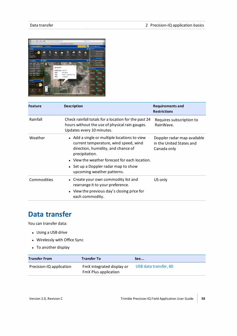
Data transfer 2 Precision-IQ application basics
Feature Description Requirements andRestrictions
Rainfall Check rainfall totals for a location for the past 24hours without the use of physical rain gauges.Updates every 10minutes.
Requires subscription toRainWave.
Weather l Add a single or multiple locations to viewcurrent temperature, wind speed, winddirection, humidity, and chance ofprecipitation.
l View the weather forecast for each location.l Set up a Doppler radar map to show
upcoming weather patterns.
Doppler radar map availablein the United States andCanada only
Commodities l Create your own commodity list andrearrange it to your preference.
l View the previous day’s closing price foreach commodity.
US only
Data transferYou can transfer data:
l Using a USB drive
l Wirelessly with Office Sync
l To another display
Transfer From Transfer To See...
Precision-IQ application FmX integrated display orFmX Plus application
USB data transfer, 60
Version 2.0, Revision C Trimble Precision-IQ Field Application User Guide 59

2 Precision-IQ application basics Data transfer
Transfer From Transfer To See...
Precision-IQ application CFX-750™ display USB data transfer, 60
FmX® integrated display orFmX Plus application
Precision-IQ application Transfer to Precision-IQ application, 62
CFX-750 display Precision-IQ application Transfer to Precision-IQ application, 62
Precision-IQ application Farm Works™ Transfer to Farm Works, 63
Precision-IQ application Precision-IQ application From Precision-IQ application toPrecision-IQ application, 66
Upgrade with a USB driveTo upgrade firmware with a USB drive, follow the next steps.
Note – Do NOT shut down the system during upgrades. The upgrade process can take at least 10minutes, depending on your system's configuration. The system will reboot automatically at leastonce. It can take up to two minutes for the reboot process to be complete.
1. Turn off the display manually by holding the power button down for about two seconds.
2. Tap Shutdown. The display powers off and saves a backup of the database.
3. Power on the display by holding down the power button briefly (about one half of a second).
4. Open the Precision-IQ field application.
5. Insert the USB drive in either socket of the TMX-2050 display.
6. Ensure you have the Precision-IQ field application open.
7. Swipe down on the top left of the top display bar.
8. When the detail menu displays, tap . The button displays.
9. Tap . The Settings screen displays.
10. Tap Firmware Upgrades to continue the upgrade process. See Firmware upgrades - wireless, 73.
11. The display notifies you that an upgrade is available.
12. Choose the version you want to upgrade to.
13. Tap the checkmark to continue the firmware upgrade.
USB data transferThe following steps explain how to transfer your data from the Precision-IQ field application to a USBdrive.
60 Trimble Precision-IQ Field Application User Guide Version 2.0, Revision C
Data transfer 2 Precision-IQ application basics
Note – Make sure your USB drive has the AgGPS folder on the root.
1. Make sure you have the Precision-IQ field application open.
2. Insert the USB drive into one of the USB sockets on the display.
3. Tap on theHome or Run screen, or on the notification list. (For instructions on how todisplay the notification list, see Status bar, 42.) The USB menu displays.
4. Tap Settings. The Data Transfer screen displays.
5. To expand an item on either list, tap a category name.
6. To select all files in a category, tap the box beside the category name. A check mark displays.
7. To deselect all files in a category, tap the box beside the name.
8. To select an individual file, tap the box beside the file name.
9. Tap to move the item to the USB drive.
10. To delete an item, tap the box next to the item in either list and tap .
Note – You cannot delete an item that is actively selected or currently being transferred.
For information on: See also:
USB socket USB socket, 67
USB VDB transferWhen you transfer data, saved vehicles do not include the vehicle configuration file (.vdb) forAutopilot. To transfer this configuration data:
1. Connect a laptop that has the Autopilot Toolbox software to the serial port of theNavController that contains the vehicle config file you want.
2. Using Autopilot Toolbox, save the config (.cfg) file to the laptop.
3. Transfer the saved config file from the laptop to a USB drive in the folder AgData/Profiles.
4. Make sure you have the Precision-IQ field application open.
5. Insert the USB drive containing the config file in the USB socket of the TMX-2050 display.
Office Sync data transferWith a DCM-300modem, and a subscription to Office Sync, information can wirelessly transfer fromthe display to the office or Connected Farm, including wireless upgrades. This requires:
l A Connected Farm account
l Unlock for Office Sync
Version 2.0, Revision C Trimble Precision-IQ Field Application User Guide 61
2 Precision-IQ application basics Data transfer
l DCM-300modem
l A data plan or access to WiFi
As part of Office Sync setup, you decide:
l Howoften you want the display to check the server for data transfer
l Howoften data is sent from the display to the office
l Whether to send the data automatically or after you have confirmed to send data
When Office Sync is transferring data, displays in the top display bar.
For information on: See:
Settings for Office Sync Modem services settings, 80
Diagnostics Office Sync Diagnostics, 291
Transfer to Precision-IQ applicationTo move files from the CFX-750™ display, FmX integrated display or FmX Plus application to thePrecision-IQ field application, follow the steps below.
Note – Make sure your USB drive has the AgGPS folder on the root.
1. Insert the USB drive into the CFX-750 display, FmX integrated display or TMX-2050 display.
If files were created on the CFX-750 display, change the file extension from .CFG to .cfg beforetransferring them to the Precision-IQ field application.
2. Transfer the files from the display to the USB drive.
3. Remove the USB drive from the CFX-750 display, FmX integrated display or TMX-2050 display.
4. Make sure you have the Precision-IQ field application open.
5. Insert the USB drive into one of the USB sockets on the TMX-2050 display.
See USB socket, 67.
6. Tap on theHome or Run screen.
7. Tap Data Transfer. The Data Transfer screen displays.
Note – Whether you are transferring data from the CFX-750 display, FmX integrated displayor FmX Plus application, the item in the USB list will show the data as FmX integrated displaydata.
8. Tap an item to expand it on the USB list.
9. Tap the item(s) you want to transfer.
62 Trimble Precision-IQ Field Application User Guide Version 2.0, Revision C
Data transfer 2 Precision-IQ application basics
10. Tap to move the item(s) to the internal list.
11. To delete an item, tap the item in either list and tap .
From Precision-IQ application to CFX-750 display or FmX integrateddisplayTo transfer from Precision-IQ field application to the CFX-750™ display, FmX integrated display orFmX Plus application using a USB drive, the same steps for USB data transfer, 60 apply, except: Alldata transferred from the Precision-IQ field application must be "decoded" by Farm Works softwarebefore it can be used by these legacy displays. See Transfer to Farm Works, 63.
Data can then be transferred by USB drive from the computer (using Farm Works) to the CFX-750™display, FmX integrated display or FmX Plus application.
Note – Make sure your USB drive has the AgGPS folder on the root.
Transfer to FarmWorksTo transfer files from the Precision-IQ field application to Farm Works, follow the steps below.
Note – Make sure your USB drive has the AgGPS folder on the root.
1. Transfer the files from Precision-IQ field application to a USB drive.
2. Insert the drive into your computer and open Farm Works. If you have transferred the datausing Office Sync, open FarmWorks.
3. Open the Read Job Data dialog by clicking either of these:
ll (Read Job Data icon)
l File menu and select Read Job Data from themenu
Version 2.0, Revision C Trimble Precision-IQ Field Application User Guide 63
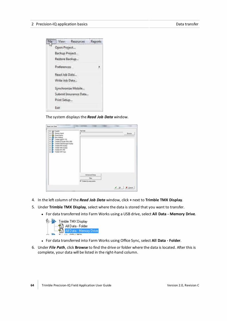
2 Precision-IQ application basics Data transfer
The system displays the Read Job Data window.
4. In the left column of the Read Job Data window, click + next to Trimble TMX Display.
5. Under Trimble TMX Display, select where the data is stored that you want to transfer.
ll For data transferred into Farm Works using a USB drive, select All Data - Memory Drive.
l For data transferred into Farm Works using Office Sync, select All Data - Folder.
6. Under File Path, click Browse to find the drive or folder where the data is located. After this iscomplete, your data will be listed in the right-hand column.
64 Trimble Precision-IQ Field Application User Guide Version 2.0, Revision C
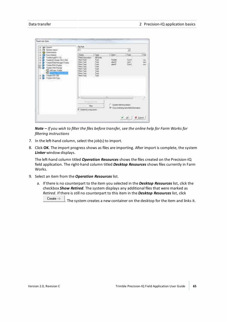
Data transfer 2 Precision-IQ application basics
Note – If you wish to filter the files before transfer, see the online help for Farm Works forfiltering instructions
7. In the left-hand column, select the job(s) to import.
8. Click OK. The import progress shows as files are importing. After import is complete, the systemLinkerwindow displays.
The left-hand column titled Operation Resources shows the files created on the Precision-IQfield application. The right-hand column titled Desktop Resources shows files currently in FarmWorks.
9. Select an item from theOperation Resources list.
a. If there is no counterpart to the item you selected in theDesktop Resources list, click thecheckbox Show Retired. The system displays any additional files that weremarked asRetired. If there is still no counterpart to this item in theDesktop Resources list, click
. The system creates a new container on the desktop for the item and links it.
Version 2.0, Revision C Trimble Precision-IQ Field Application User Guide 65

2 Precision-IQ application basics Data transfer
b. If there is a counterpart to this item in theDesktop Resources list, highlight the item and
click . The information is nowmoved to that location on the desktop.
10. After all items have been linked or created, click OK. All files are stored in Farm Works at thecorrect location.
From Precision-IQ application to Precision-IQ applicationFrom Precision-IQ field application to the office or another Precision-IQ field application:
Type of transfer(without Farm Works)
Instructions
USB To transfer data through a USB drive, see USB data transfer, 60.
Wireless (Office Sync) To transfer data using Office Sync:
l Ensure you meet the requirements for transferring using OfficeSync. See From Precision-IQ application to Precision-IQapplication, 66 in this section.
l Set up Office Sync. SeeModem services settings, 80.
66 Trimble Precision-IQ Field Application User Guide Version 2.0, Revision C

USB socket 2 Precision-IQ application basics
USB socketThe display has two USB sockets: one on the side of the display and one on the back of thePrecision-IQ field application.
You can use a USB drive to transfer data to and from your Precision-IQ field application.
CAUTION – Do not use a USB drive in each USB socket at the same time. If you are attempting to upgradefirmware using a USB drive and another USB drive is already in one of the sockets, the firmware upgrade willfail.
The display senses when a USB drive is inserted into either the side or rear socket, and shows the
icon on the top display bar.
Insert a USB drive1. Move the display so you that can see the USB socket on the side or back of the display.
2. Pull the rubber cover off the USB socket.
3. Insert the USB drive into the USB socket. On the display bar, a USB icon is displayed.
Remove USB Drive
CAUTION – Do not remove the USB drive from the socket while the display is writing to or from the drive. Thiswill corrupt the data.
1. Move the display so you that can see the USB socket.
2. Make sure the LED light of the USB drive is not blinking (indicating data transfer is occurring).
3. Pull the USB drive out of the USB socket.
4. Press the rubber cover back onto the USB socket.
Screen shotsOccasionally, you may want to save an image of the touch screen, for example to provideinformation for troubleshooting purposes. When you take a screen shot, the display saves a .jpg fileto a Pictures folder on the USB drive.
To take a screen shot:
Version 2.0, Revision C Trimble Precision-IQ Field Application User Guide 67

2 Precision-IQ application basics Screen shots
1. Insert a USB drive in one of the USB ports on the display. (See USB socket, 67.) The top displaybar will show a USB icon.
2. Tap to take a capture of the screen.
3. The display stores your screen shot on the USB drive under Pictures\screenshots.
CAUTION – Do not press on the screen with a sharp item, such as a pencil. You may damage the surface of thescreen.
Note – Make sure you have a USB drive inserted into a USB slot. If you take screen shots without aUSB drive in the TMX-2050 display, you will not be able to retrieve them.
68 Trimble Precision-IQ Field Application User Guide Version 2.0, Revision C

Settings
In this chapter:
Settings 70
Access settings 71
Languages and units settings 71
Date and time settings 72
Users and passwords 72
Firmware upgrades - wireless 73
Feature unlocks 75
Display settings 76
Mapping settings 76
Patterns settings 77
Steering and guidance settings 78
ISOBUS settings 80
Wi-Fi settings 80
Modem services settings 80
Restore defaults 82
System information 83
At the Settings screen, you can customizesettings and add user profiles.
3C h a p t e r
Version 2.0, Revision C Trimble Precision-IQ Field Application User Guide 69

3 Settings Settings
SettingsAt the Precision-IQ field application, you can customize and set up many options for both thePrecision-IQ field application and the TMX-2050 display.
Precision-IQ application-specific settingsSome settings are specific to the Precision-IQ field application only:
l Mapping settings, 76
l Patterns settings, 77
l ISOBUS settings, 80
l Steering and guidance settings, 78
l Wi-Fi settings, 80
Precision-IQ application and display settingsSome settings affect both Precision-IQ application and the display, including the Launcher screen:
l Languages and units settings, 71
l Date and time settings, 72
l Users and passwords, 72
l Restore defaults, 82
Display-specific settingsDisplay settings, 76 affect the volume, brightness and sounds from the display.
Upgrades and unlocksNavigate to these settings to upgrade firmware or unlock features:
Firmware upgrades - wireless, 73
Feature unlocks, 75
70 Trimble Precision-IQ Field Application User Guide Version 2.0, Revision C
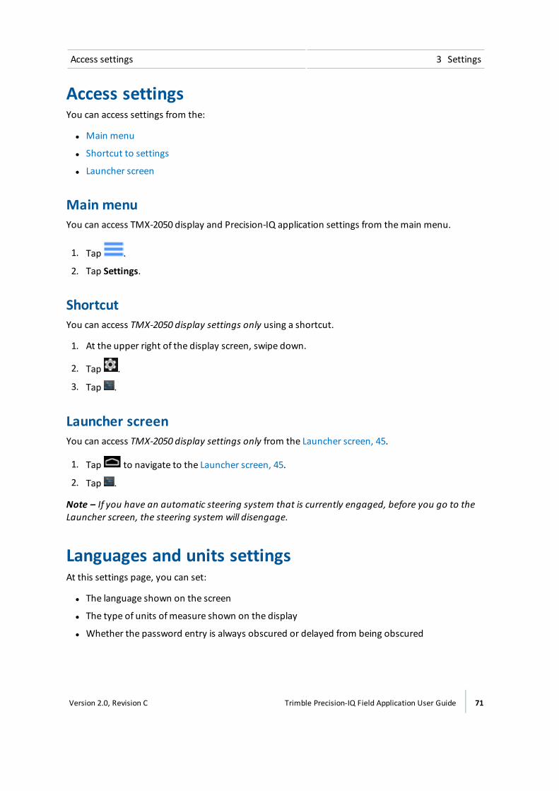
Access settings 3 Settings
Access settingsYou can access settings from the:
l Main menu
l Shortcut to settings
l Launcher screen
Main menuYou can access TMX-2050 display and Precision-IQ application settings from themain menu.
1. Tap .
2. Tap Settings.
ShortcutYou can access TMX-2050 display settings only using a shortcut.
1. At the upper right of the display screen, swipe down.
2. Tap .
3. Tap .
Launcher screenYou can access TMX-2050 display settings only from the Launcher screen, 45.
1. Tap to navigate to the Launcher screen, 45.
2. Tap .
Note – If you have an automatic steering system that is currently engaged, before you go to theLauncher screen, the steering system will disengage.
Languages and units settingsAt this settings page, you can set:
l The language shown on the screen
l The type of units ofmeasure shown on the display
l Whether the password entry is always obscured or delayed from being obscured
Version 2.0, Revision C Trimble Precision-IQ Field Application User Guide 71
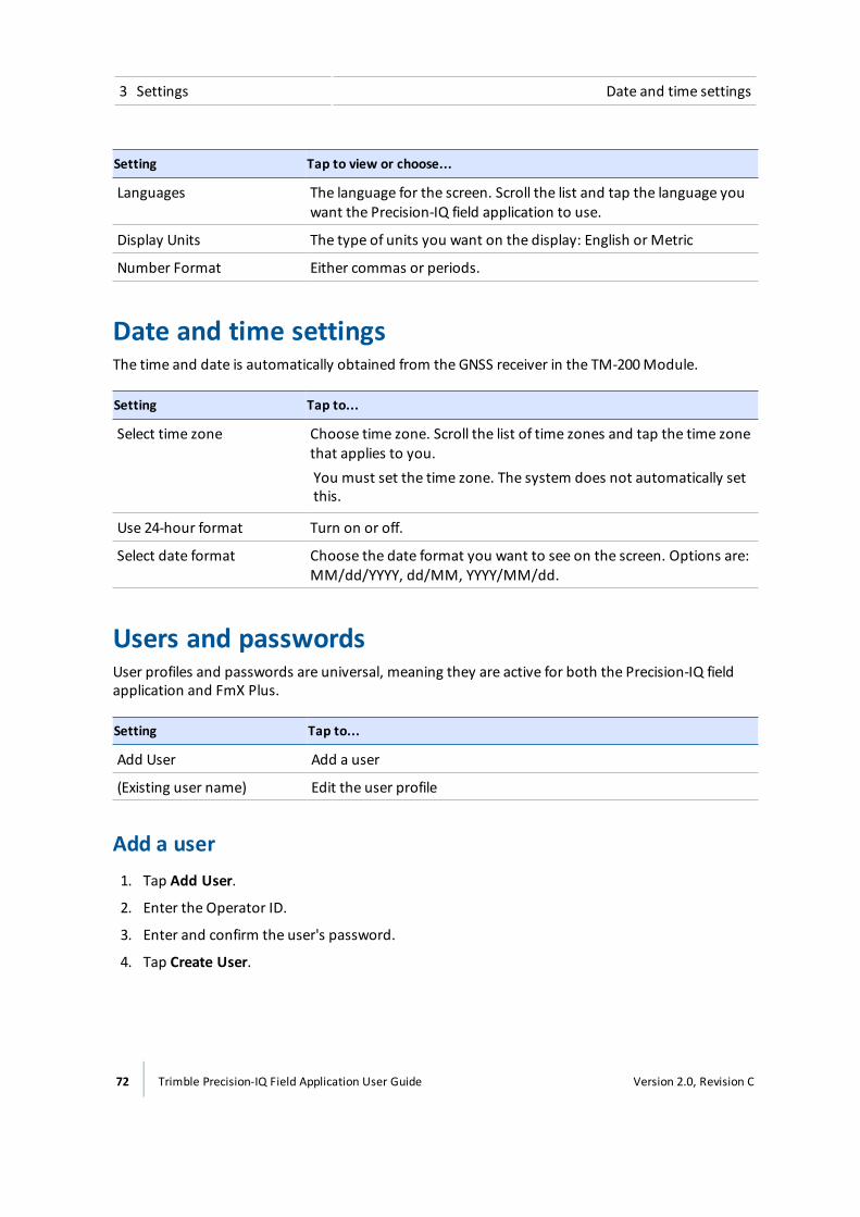
3 Settings Date and time settings
Setting Tap to view or choose...
Languages The language for the screen. Scroll the list and tap the language youwant the Precision-IQ field application to use.
Display Units The type of units you want on the display: English or Metric
Number Format Either commas or periods.
Date and time settingsThe time and date is automatically obtained from the GNSS receiver in the TM-200Module.
Setting Tap to...
Select time zone Choose time zone. Scroll the list of time zones and tap the time zonethat applies to you.You must set the time zone. The system does not automatically setthis.
Use 24-hour format Turn on or off.
Select date format Choose the date format you want to see on the screen. Options are:MM/dd/YYYY, dd/MM, YYYY/MM/dd.
Users and passwordsUser profiles and passwords are universal, meaning they are active for both the Precision-IQ fieldapplication and FmX Plus.
Setting Tap to...
Add User Add a user
(Existing user name) Edit the user profile
Add a user1. Tap Add User.
2. Enter the Operator ID.
3. Enter and confirm the user's password.
4. Tap Create User.
72 Trimble Precision-IQ Field Application User Guide Version 2.0, Revision C
Firmware upgrades - wireless 3 Settings
Take a photo of a userYou can capture a photo of the user, which will display:
l Next to the user's information in the Users and passwords section of Settings
l On the top display bar when the user is logged in
1. At the Users and passwords section, Tap the user icon on the right of the user information.
2. The camera activates and displays a frame on the screen. Make sure the user's face is containedwithin this frame.
3. To capture the photo, tap Capture. The photo displays on the lower right. You can continue totap Capture until you are satisfied with the photo.
4. When you are ready to save the photo, tap Done.
Firmware upgrades - wirelessNote – Do NOT shut down the system during upgrades. The upgrade process can take at least 10minutes, depending on your system's configuration. The system will reboot automatically at leastonce. It can take up to two minutes for the reboot process to be complete.
USB upgrades1. Turn off the display manually by holding the power button down for about two seconds.
2. Tap Shutdown. The display powers off and saves a backup of the database.
3. Power on the display by holding down the power button briefly (about one half of a second).
4. Open the Precision-IQ field application.
5. Insert the USB drive in either socket of the TMX-2050 display.
6. Ensure you have the Precision-IQ field application open.
7. On the upper right portion of the screen, swipe down.
8. Tap .
9. Tap .
10. Tap Firmware Upgrades.
11. The display notifies you that an upgrade is available.
12. Choose the version you want to upgrade to.
13. Tap the checkmark to continue the firmware upgrade.
Version 2.0, Revision C Trimble Precision-IQ Field Application User Guide 73
3 Settings Firmware upgrades - wireless
Wireless upgradesNote – Wireless upgrades require a DCM-300modem, a subscription to Office Sync and a dataplan or access to WiFi. See Wi-Fi settings, 80 and DCM-300modem initial setup, 100.
1. Tap Shutdown. The display powers off and saves a backup of the database.
2. Power on the display by holding down the power button briefly (about one half of a second).
3. Open the Precision-IQ field application.
4. Ensure you have the Precision-IQ field application open.
5. On the upper right portion of the screen, swipe down.
6. Tap .
7. Tap .
8. Tap Firmware Upgrades.
9. The display notifies you that an upgrade is available.
10. Choose the version you want to upgrade to.
11. Tap the checkmark to continue the firmware upgrade.
Note – Do NOT shut down the system during upgrades. The upgrade process can take at least10minutes, depending on your system's configuration. The system will reboot automaticallyat least once. It can take up to two minutes for the reboot process to be complete.
Settings for wireless upgradesYou can control how Precision-IQ application checks for upgrades and when to wirelessly downloadthem.
1. Tap .
2. Tap Settings.
3. Tap Firmware Upgrades.
4. Tap Settings.
Setting Explanation
Auto check for new upgrades If you activate this, the system will automatically check fornew upgrades.
74 Trimble Precision-IQ Field Application User Guide Version 2.0, Revision C
Feature unlocks 3 Settings
Setting Explanation
Auto download new upgradeswhen available
This choice is only available if you have chosen to have thesystem automatically check for new upgrades. The systemwill install the updates as they are available.
Auto install firmware on powerdown
This choice is only available if you have chosen to have thesystem automatically check for new upgrades. The systemwill install the updates before the display powers off.
Only download via WiFi This choice is only available if you have chosen to have thesystem automatically check for new upgrades. The systemwill download the updates only through aWiFi connection.
Show support beta releases inlist
The system includes beta releases available for you todownload.
Check for updates
1. Tap .
2. Tap Settings.
3. Tap Firmware Upgrades.
4. Tap Check for Updates. The system checks for updates and begins the upgrade processimmediately unless you have altered when the upgrade occurs in Settings.
Feature unlocksFor some optional features, you must enter the unlock password. If you do not have an unlockpassword, contact your local reseller.
1. Tap .
2. Tap Settings.
3. Tap Feature Unlocks. You can unlock features by manually entering the code, having thedisplay read the QR code of the unlock, or checking for unlocks.
At the bottom of the screen, the list of currently locked features displays.
Manual code entry1. Tap the Code text box and enter the code.
2. If the system accepts the code, tap Accept.
3. If the system rejects the code, you can try again or contact your reseller for help.
Version 2.0, Revision C Trimble Precision-IQ Field Application User Guide 75

3 Settings Display settings
QR code scan1. Tap Read QR.
2. Hold your code image in front of the camera for it to be read.
3. If the system accepts the code, Tap Accept.
4. If the system rejects the code, you can try again or contact your reseller for help.
Check for unlocks1. Tap Check for Unlocks.
2. The request will be sent for the display to check for any available service or licenses. It may takeseveral minutes for the unlocks to be processed.
Display settingsThese are basic settings for the display.
Setting Tap to...
Manually Change Brightness Adjust brightness of the display's backlight.
Volume Adjust the volume of the sound.
Touch Screen Sounds Turn on or off sounds associated with using the display.
Mapping settingsThese settings control guidancemapping features available on the Run screen.
Setting Tap to view or change...
Map Background Selection The ground color for the Run screen. Options are:l Color: Brown, green or greyl Color with texturel Color with gridlines
Map Color Scheme Day or night mode.
Map Orientation Which point of view displays on the Run screen when following theposition of the vehicle. Orientation options: North Up or Vehicle Up.
76 Trimble Precision-IQ Field Application User Guide Version 2.0, Revision C
Patterns settings 3 Settings
Setting Tap to view or change...
Record CoverageWhenEngaged
The system can switch on coverage when auto guidance is engaged,and switch off coverage when it is not engaged. Option for thissetting is on or off.
Patterns settingsAt pattern settings, you can:
l Activate the auto close feature to use when you create boundaries and headlands
l Activate smoothing for curves and turn radius when traveling on guidance lines
l Customize the tight turn warning angle and look-ahead time
Curve Features
Setting Tap to view or change...
Curve Smoothing The feature on or off. When curve smoothing is on, the systemsmooths out the guidance curve, making it wider.
Smooth Turn Radius The size of the circle that the system will guide to. The larger thecircle (degrees), the wider the turn.
Tight Turn Warning Angle The number of degrees that will trigger a warning about a tightturning angle. See Tight turn warning, 262.
Tight Turn Look Ahead Time The number of seconds before you approach a tight turn angle thatthe warning will show on the screen. See Tight turn warning, 262.
Headlands
Setting Tap to view or change...
Auto Close Automatically closes the beginning and end point when you createboundaries and headlands.
Auto Close Distance The distance between your beginning point and ending point for aheadland.
See Headland and infill pattern creation (Run screen), 223.
Version 2.0, Revision C Trimble Precision-IQ Field Application User Guide 77
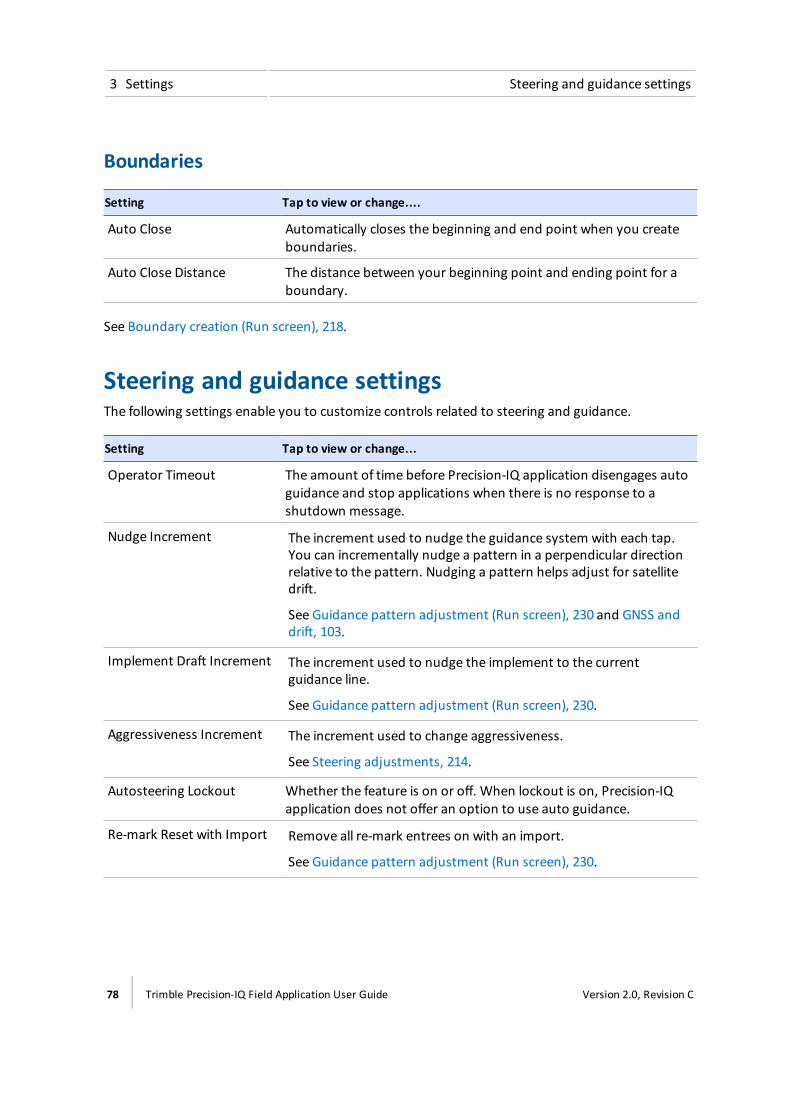
3 Settings Steering and guidance settings
Boundaries
Setting Tap to view or change....
Auto Close Automatically closes the beginning and end point when you createboundaries.
Auto Close Distance The distance between your beginning point and ending point for aboundary.
See Boundary creation (Run screen), 218.
Steering and guidance settingsThe following settings enable you to customize controls related to steering and guidance.
Setting Tap to view or change...
Operator Timeout The amount of time before Precision-IQ application disengages autoguidance and stop applications when there is no response to ashutdown message.
Nudge Increment The increment used to nudge the guidance system with each tap.You can incrementally nudge a pattern in a perpendicular directionrelative to the pattern. Nudging a pattern helps adjust for satellitedrift.
See Guidance pattern adjustment (Run screen), 230 and GNSS anddrift, 103.
Implement Draft Increment The increment used to nudge the implement to the currentguidance line.
See Guidance pattern adjustment (Run screen), 230.
Aggressiveness Increment The increment used to change aggressiveness.
See Steering adjustments, 214.
Autosteering Lockout Whether the feature is on or off. When lockout is on, Precision-IQapplication does not offer an option to use auto guidance.
Re-mark Reset with Import Remove all re-mark entrees on with an import.
See Guidance pattern adjustment (Run screen), 230.
78 Trimble Precision-IQ Field Application User Guide Version 2.0, Revision C

Steering and guidance settings 3 Settings
Setting Tap to view or change...
End of RowDistance Distance for the end of rowwarning to display.
See End of rowwarning, 262.
NMEA from AutopilotDiagnostics Port
On: NMEAmessages can be sent from the NavController
Off: No messages are sent
See NMEAmessages, 268.
Version 2.0, Revision C Trimble Precision-IQ Field Application User Guide 79

3 Settings ISOBUS settings
ISOBUS settings
Task ControllerTo use Task Controller when using ISO-certified equipment, tap to activate this feature.
Note – This feature is optional and requires an unlock.
For information on: See:
Task Controller implementsetup
Implement setup for Task Controller, 161
Setting up equipment fortask controller
Equipment setup, 165
Using Task Controller Task Controller operation, 252 and ISOBUS Task Controller widget,258
Virtual TerminalTo use Virtual Terminal when using ISO-certified equipment, tap to activate this feature.
For information on: See:
Using Virtual Terminal Virtual Terminal operation, 254 and Virtual Terminal widget, 260
Wi-Fi settingsWith a DCM-300modem and additional subscription services, Wi-Fi enables you to transfer datawirelessly from vehicle to office. You can useWi-Fi in addition to or instead of the cellular network.
At Wi-Fi network settings, turn on Wi-Fi.
At Available Networks, tap Refresh to scan for additional networks you can connect to.
For content on: See:
Diagnostics DCM-300modem diagnostics, 275
Modem status DCM-300modem status, 271
Modem services settingsModem settings include:
80 Trimble Precision-IQ Field Application User Guide Version 2.0, Revision C
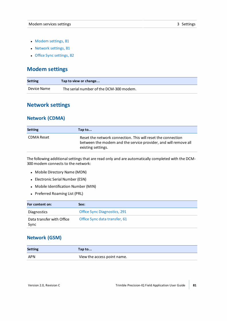
Modem services settings 3 Settings
l Modem settings, 81
l Network settings, 81
l Office Sync settings, 82
Modem settings
Setting Tap to view or change...
Device Name The serial number of the DCM-300modem.
Network settings
Network (CDMA)
Setting Tap to...
CDMA Reset Reset the network connection. This will reset the connectionbetween themodem and the service provider, and will remove allexisting settings.
The following additional settings that are read only and are automatically completed with the DCM-300modem connects to the network:
l Mobile Directory Name (MDN)
l Electronic Serial Number (ESN)
l Mobile Identification Number (MIN)
l Preferred Roaming List (PRL)
For content on: See:
Diagnostics Office Sync Diagnostics, 291
Data transfer with OfficeSync
Office Sync data transfer, 61
Network (GSM)
Setting Tap to...
APN View the access point name.
Version 2.0, Revision C Trimble Precision-IQ Field Application User Guide 81

3 Settings Restore defaults
Setting Tap to...
SIM PIN The PIN for the SIM.
Advanced Launch a displayed message to enter the GSM Username andGSM Password.
The following additional settings that are read only and are automatically completed with the DCM-300modem connects to the network:
l IMEI: InternationalMobile Equipment Identity
l SIM ICCID: IMS Charging Identifier
l SIM Status: Status of SIM
Office Sync settings
Setting Tap to...
Office Sync Turn the feature on or off.
Check Server Select how often you want Precision-IQ application to check theserver to send data to the office.
Send Data Select how often data is sent from the display to the office.
Auto-send without prompt Turn the feature on or off. When on, Precision-IQ application willsend data to the office without first asking for your confirmation.If this feature is on, data will be sent without notifying you. This canresult in large files being transferred or the transfer of data you donot want transferred.
For information on: See:
Initial setup DCM-300modem initial setup, 100
Diagnostics Office Sync Diagnostics, 291
Data transfer with OfficeSync
Office Sync data transfer, 61
Restore defaultsDuring troubleshooting, you may be asked by Support to perform a reset.
82 Trimble Precision-IQ Field Application User Guide Version 2.0, Revision C
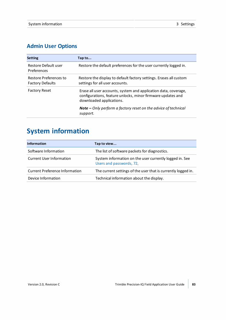
System information 3 Settings
Admin User Options
Setting Tap to...
Restore Default userPreferences
Restore the default preferences for the user currently logged in.
Restore Preferences toFactory Defaults
Restore the display to default factory settings. Erases all customsettings for all user accounts.
Factory Reset Erase all user accounts, system and application data, coverage,configurations, feature unlocks, minor firmware updates anddownloaded applications.
Note – Only perform a factory reset on the advice of technicalsupport.
System informationInformation Tap to view...
Software Information The list of software packets for diagnostics.
Current User Information System information on the user currently logged in. SeeUsers and passwords, 72.
Current Preference Information The current settings of the user that is currently logged in.
Device Information Technical information about the display.
Version 2.0, Revision C Trimble Precision-IQ Field Application User Guide 83

3 Settings System information
84 Trimble Precision-IQ Field Application User Guide Version 2.0, Revision C

Connectivity
In this chapter:
GNSS receiver settings 86
DCM-300 modem initial setup 100
Office Sync setup 100
Connectivity concepts 103
In addition to GNSS, you can use optionalcorrection services, the DCM-300modem,and Office Sync to transfer files to yourConnected Farm application.
4C h a p t e r
Version 2.0, Revision C Trimble Precision-IQ Field Application User Guide 85
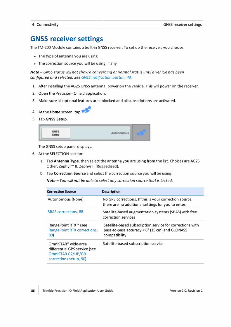
4 Connectivity GNSS receiver settings
GNSS receiver settingsThe TM-200Module contains a built-in GNSS receiver. To set up the receiver, you choose:
l The type of antenna you are using
l The correction source you will be using, if any
Note – GNSS status will not show a converging or normal status until a vehicle has beenconfigured and selected. See GNSS notification button, 43.
1. After installing the AG25 GNSS antenna, power on the vehicle. This will power on the receiver.
2. Open the Precision-IQ field application.
3. Make sure all optional features are unlocked and all subscriptions are activated.
4. At theHome screen, tap .
5. Tap GNSS Setup.
The GNSS setup panel displays.
6. At the SELECTION section:
a. Tap Antenna Type, then select the antenna you are using from the list. Choices are AG25,Other, Zephyr™ II, Zephyr II (Ruggedized).
b. Tap Correction Source and select the correction source you will be using.
Note – You will not be able to select any correction source that is locked.
Correction Source Description
Autonomous (None) No GPS corrections. If this is your correction source,there are no additional settings for you to enter.
SBAS corrections, 88 Satellite-based augmentation systems (SBAS) with freecorrection services
RangePoint RTX™ (seeRangePoint RTX corrections,89)
Satellite-based subscription service for corrections withpass-to-pass accuracy < 6" (15 cm) and GLONASScompatibility
OmniSTAR®wide-areadifferential GPS service (seeOmniSTAR G2/HP/GRcorrections setup, 90)
Satellite-based subscription service
86 Trimble Precision-IQ Field Application User Guide Version 2.0, Revision C
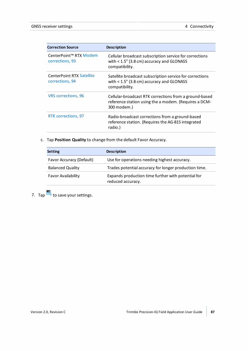
GNSS receiver settings 4 Connectivity
Correction Source Description
CenterPoint™ RTX Modemcorrections, 93
Cellular broadcast subscription service for correctionswith < 1.5" (3.8 cm) accuracy and GLONASScompatibility.
CenterPoint RTX Satellitecorrections, 94
Satellite broadcast subscription service for correctionswith < 1.5" (3.8 cm) accuracy and GLONASScompatibility.
VRS corrections, 96 Cellular-broadcast RTK corrections from a ground-basedreference station using the a modem. (Requires a DCM-300modem.)
RTK corrections, 97 Radio-broadcast corrections from a ground-basedreference station. (Requires the AG-815 integratedradio.)
c. Tap Position Quality to change from the default Favor Accuracy.
Setting Description
Favor Accuracy (Default) Use for operations needing highest accuracy.
Balanced Quality Trades potential accuracy for longer production time.
Favor Availability Expands production time further with potential forreduced accuracy.
7. Tap to save your settings.
Version 2.0, Revision C Trimble Precision-IQ Field Application User Guide 87

4 Connectivity GNSS receiver settings
SBAS corrections
The satellite-based augmentation systems (SBAS) with free correction services are:
l WAAS (Wide Area Augmentation System) in North America
l EGNOS (European Geostationary Navigation Overlay Service) in Europe
l MSAS (Multi-functional Satellite Augmentation System) in Asia Pacific regions
Setting Options
Correction Satellite Selection Choose Auto Select for automatic satellite selection, or select asatellite from the list.
Position Quality Select the appropriate choice:l Favor Accuracy (Default) : Use for operations needing highest
accuracy (such as row crop planting and strip-till).l Balanced Quality: Trades potential accuracy for longer
production time.l Favor Availability: Expands production time further with
potential for reduced accuracy.
88 Trimble Precision-IQ Field Application User Guide Version 2.0, Revision C
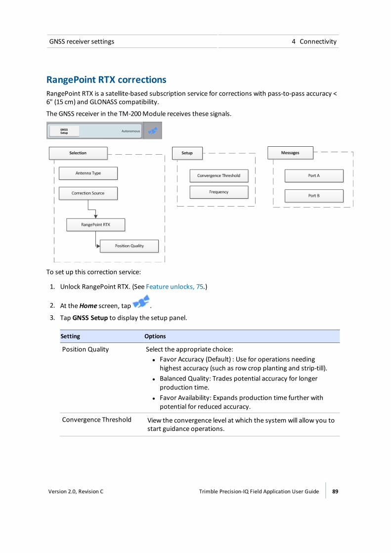
GNSS receiver settings 4 Connectivity
RangePoint RTX correctionsRangePoint RTX is a satellite-based subscription service for corrections with pass-to-pass accuracy <6" (15 cm) and GLONASS compatibility.
The GNSS receiver in the TM-200Module receives these signals.
To set up this correction service:
1. Unlock RangePoint RTX. (See Feature unlocks, 75.)
2. At theHome screen, tap .
3. Tap GNSS Setup to display the setup panel.
Setting Options
Position Quality Select the appropriate choice:ll Favor Accuracy (Default) : Use for operations needing
highest accuracy (such as row crop planting and strip-till).l Balanced Quality: Trades potential accuracy for longer
production time.l Favor Availability: Expands production time further with
potential for reduced accuracy.
Convergence Threshold View the convergence level at which the system will allow you tostart guidance operations.
Version 2.0, Revision C Trimble Precision-IQ Field Application User Guide 89
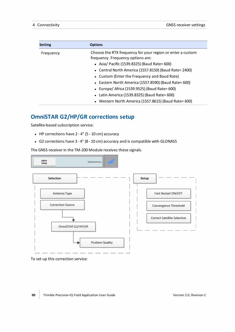
4 Connectivity GNSS receiver settings
Setting Options
Frequency Choose the RTX frequency for your region or enter a customfrequency. Frequency options are:ll Asia/ Pacific (1539.8325) (Baud Rate= 600)l Central North America (1557.8150) (Baud Rate= 2400)l Custom (Enter the Frequency and Baud Rate)l Eastern North America (1557.8590) (Baud Rate= 600)l Europe/ Africa (1539.9525) (Baud Rate= 600)l Latin America (1539.8325) (Baud Rate= 600)l Western North America (1557.8615) (Baud Rate= 600)
OmniSTAR G2/HP/GR corrections setupSatellite-based subscription service:
l HP corrections have 2 - 4" (5 - 10 cm) accuracy
l G2 corrections have 3 - 4" (8 - 10 cm) accuracy and is compatible with GLONASS
The GNSS receiver in the TM-200Module receives these signals.
To set up this correction service:
90 Trimble Precision-IQ Field Application User Guide Version 2.0, Revision C
GNSS receiver settings 4 Connectivity
1. Unlock OmniSTAR G2/HP/GR. (See Feature unlocks, 75.)
2. At theHome screen, tap .
3. Tap GNSS Setup to display the setup panel.
Setting Options
Position Quality Select the appropriate choice:l Favor Accuracy (Default) : Use for operations needing highest
accuracy (such as row crop planting and strip-till).l Balanced Quality: Trades potential accuracy for longer
production time.l Favor Availability: Expands production time further with
potential for reduced accuracy.
Fast Restart Choose a Fast Restart option:l On (Default): Reduces the time for position to converge so that
the system is ready for operation faster. Tap Onwhen thevehicle is parked in an area with a clear view of the sky, and willnot bemoved until next use.
l Off: Does not use Fast Restart.
Convergence Threshold Set the convergence level at which the system will allow you to startguidance operations.
l Enter a convergence value closer to 12 inches for broad acreapplications to begin working promptly.
l Enter a convergence value closer to 4 inches for row cropapplications to ensure desired accuracy is achieved beforebeginning work.
Correction SatelliteSelection
Tap Auto Select for automatic satellite selection, or select a satellitefrom the list. If you choose CUSTOM, enter the Frequency andBaud Rate.
CenterPoint RTX setupThere are three types of CenterPoint RTX corrections:
l Modem
l Satellite Standard
l Satellite Fast Convergence
Version 2.0, Revision C Trimble Precision-IQ Field Application User Guide 91
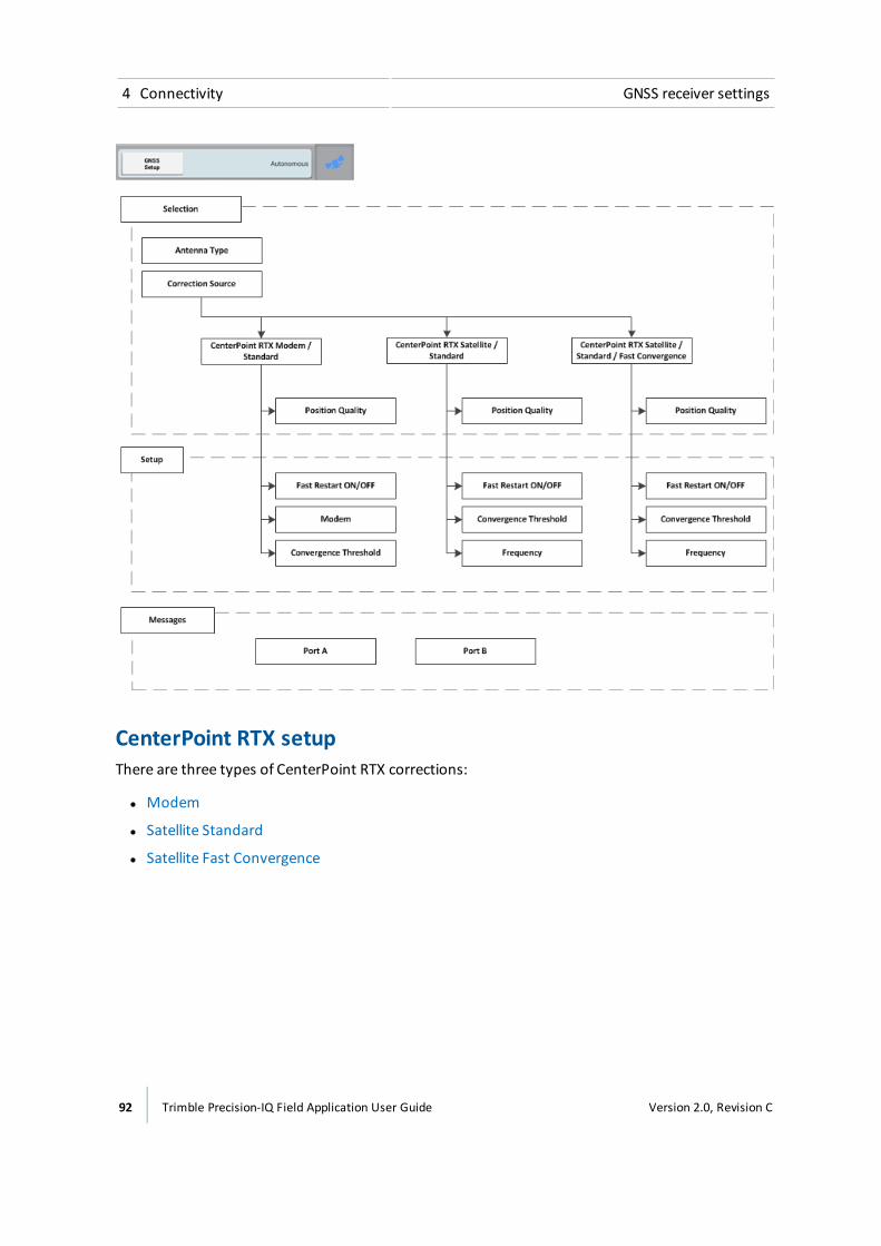
4 Connectivity GNSS receiver settings
CenterPoint RTX setupThere are three types of CenterPoint RTX corrections:
l Modem
l Satellite Standard
l Satellite Fast Convergence
92 Trimble Precision-IQ Field Application User Guide Version 2.0, Revision C
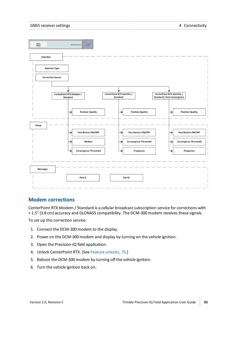
GNSS receiver settings 4 Connectivity
Modem correctionsCenterPoint RTX Modem / Standard is a cellular broadcast subscription service for corrections with< 1.5" (3.8 cm) accuracy and GLONASS compatibility. The DCM-300modem receives these signals.
To set up this correction service:
1. Connect the DCM-300modem to the display.
2. Power on the DCM-300modem and display by turning on the vehicle ignition.
3. Open the Precision-IQ field application.
4. Unlock CenterPoint RTX. (See Feature unlocks, 75.)
5. Reboot the DCM-300modem by turning off the vehicle ignition.
6. Turn the vehicle ignition back on.
Version 2.0, Revision C Trimble Precision-IQ Field Application User Guide 93
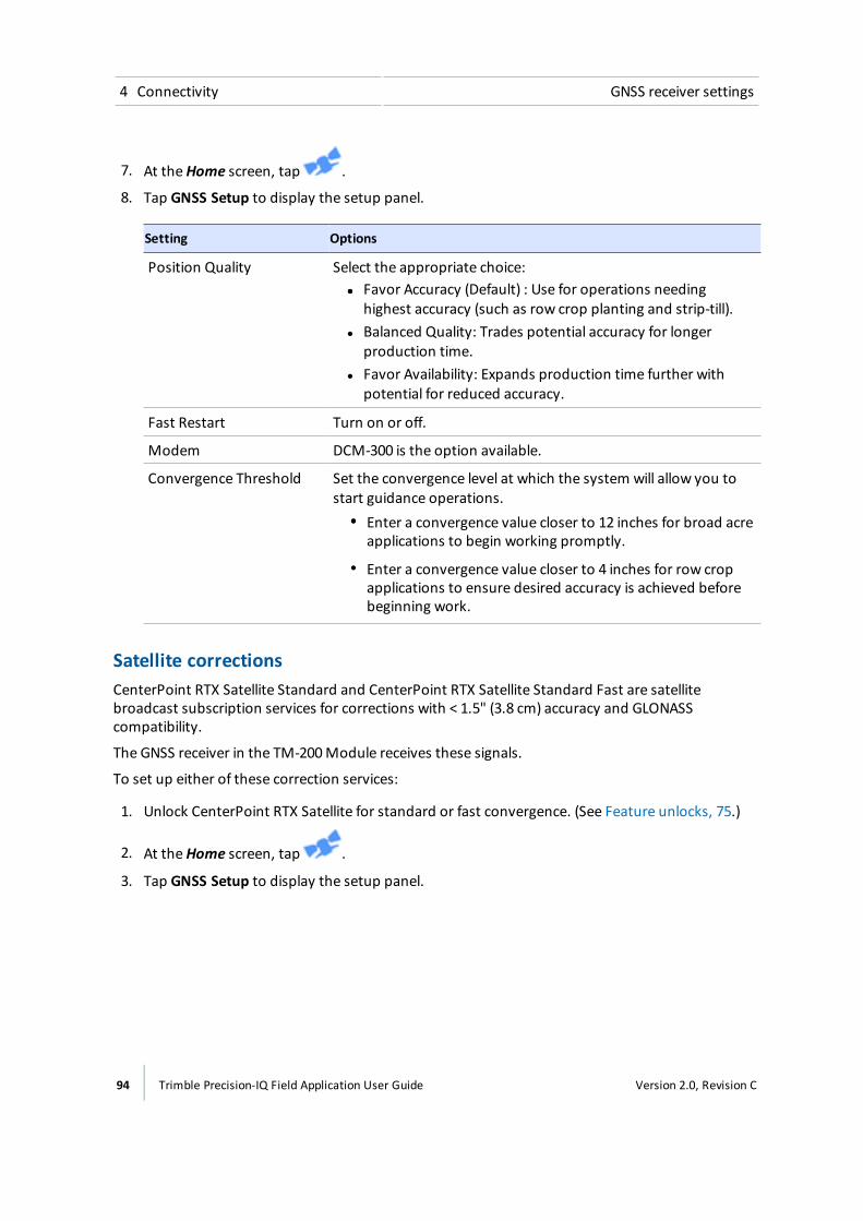
4 Connectivity GNSS receiver settings
7. At theHome screen, tap .
8. Tap GNSS Setup to display the setup panel.
Setting Options
Position Quality Select the appropriate choice:ll Favor Accuracy (Default) : Use for operations needing
highest accuracy (such as row crop planting and strip-till).l Balanced Quality: Trades potential accuracy for longer
production time.l Favor Availability: Expands production time further with
potential for reduced accuracy.
Fast Restart Turn on or off.
Modem DCM-300 is the option available.
Convergence Threshold Set the convergence level at which the system will allow you tostart guidance operations.
ll Enter a convergence value closer to 12 inches for broad acreapplications to begin working promptly.
l Enter a convergence value closer to 4 inches for row cropapplications to ensure desired accuracy is achieved beforebeginning work.
Satellite correctionsCenterPoint RTX Satellite Standard and CenterPoint RTX Satellite Standard Fast are satellitebroadcast subscription services for corrections with < 1.5" (3.8 cm) accuracy and GLONASScompatibility.
The GNSS receiver in the TM-200Module receives these signals.
To set up either of these correction services:
1. Unlock CenterPoint RTX Satellite for standard or fast convergence. (See Feature unlocks, 75.)
2. At theHome screen, tap .
3. Tap GNSS Setup to display the setup panel.
94 Trimble Precision-IQ Field Application User Guide Version 2.0, Revision C
GNSS receiver settings 4 Connectivity
Standard convergence
Setting Options
Position Quality Select the appropriate choice:l Favor Accuracy (Default) : Use for operations needing highest accuracy
(such as row crop planting and strip-till).l Balanced Quality: Trades potential accuracy for longer production time.l Favor Availability: Expands production time further with potential for
reduced accuracy.
Fast Restart Turn on or off.
Frequency Choose the RTX frequency for your region or enter a custom frequency.Frequency options are:l Asia/ Pacific (1539.8325) (Baud Rate= 600)l Central North America (1557.8150) (Baud Rate= 2400)l Custom (Enter the Frequency and Baud Rate)l Eastern North America (1557.8590) (Baud Rate= 600)l Europe/ Africa (1539.9525) (Baud Rate= 600)l Latin America (1539.8325) (Baud Rate= 600)l Western North America (1557.8615) (Baud Rate= 600)
ConvergenceThreshold
Set the convergence level at which the system will allow you to start guidanceoperations.
l Enter a convergence value closer to 12 inches for broad acre applicationsto begin working promptly.
l Enter a convergence value closer to 4 inches for row crop applications toensure desired accuracy is achieved before beginning work.
Fast convergence
Setting Options
Position Quality Select the appropriate choice:l Favor Accuracy (Default) : Use for operations needing highest accuracy
(such as row crop planting and strip-till).l Balanced Quality: Trades potential accuracy for longer production time.l Favor Availability: Expands production time further with potential for
reduced accuracy.
Fast Restart Turn on or off.
Version 2.0, Revision C Trimble Precision-IQ Field Application User Guide 95

4 Connectivity GNSS receiver settings
Setting Options
ConvergenceThreshold
Set the convergence level at which the system will allow you to start guidanceoperations.
l Enter a convergence value closer to 12 inches for broad acre applicationsto begin working promptly.
l Enter a convergence value closer to 4 inches for row crop applications toensure desired accuracy is achieved before beginning work.
Frequency Choose the RTX frequency for your region or enter a custom frequency.Frequency options are:l Asia/ Pacific (1539.8325) (Baud Rate= 600)l Central North America (1557.8150) (Baud Rate= 2400)l Custom (Enter the Frequency and Baud Rate)l Eastern North America (1557.8590) (Baud Rate= 600)l Europe/ Africa (1539.9525) (Baud Rate= 600)l Latin America (1539.8325) (Baud Rate= 600)l Western North America (1557.8615) (Baud Rate= 600)
VRS correctionsVRS is a cellular-broadcast RTK correction service from a ground-based reference station using the amodem. (Requires a DCM-300modem.)
To set up this correction service:
96 Trimble Precision-IQ Field Application User Guide Version 2.0, Revision C
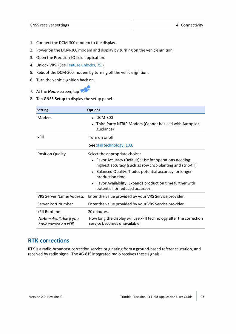
GNSS receiver settings 4 Connectivity
1. Connect the DCM-300modem to the display.
2. Power on the DCM-300modem and display by turning on the vehicle ignition.
3. Open the Precision-IQ field application.
4. Unlock VRS. (See Feature unlocks, 75.)
5. Reboot the DCM-300modem by turning off the vehicle ignition.
6. Turn the vehicle ignition back on.
7. At theHome screen, tap .
8. Tap GNSS Setup to display the setup panel.
Setting Options
Modem ll DCM-300l Third Party NTRIP Modem (Cannot be used with Autopilot
guidance)
xFill Turn on or off.
See xFill technology, 103.
Position Quality Select the appropriate choice:ll Favor Accuracy (Default) : Use for operations needing
highest accuracy (such as row crop planting and strip-till).l Balanced Quality: Trades potential accuracy for longer
production time.l Favor Availability: Expands production time further with
potential for reduced accuracy.
VRS Server Name/Address Enter the value provided by your VRS Service provider.
Server Port Number Enter the value provided by your VRS Service provider.
xFill Runtime
Note – Available if youhave turned on xFill.
20minutes.How long the display will use xFill technology after the correctionservice becomes unavailable.
RTK correctionsRTK is a radio-broadcast correction service originating from a ground-based reference station, andreceived by radio signal. The AG-815 integrated radio receives these signals.
Version 2.0, Revision C Trimble Precision-IQ Field Application User Guide 97

4 Connectivity GNSS receiver settings
To set up this correction service:
1. Unlock RTK. See Feature unlocks, 75.
2. Make sure the AG-815 integrated radio is installed.
3. At theHome screen, tap .
4. Tap GNSS Setup to display the setup panel.
Setting Options
Radio Choose the frequency of the AG-815 integrated radio: 450MHz or900MHz.
xFill Turn xFill technology on or off.
See xFill technology, 103.
98 Trimble Precision-IQ Field Application User Guide Version 2.0, Revision C
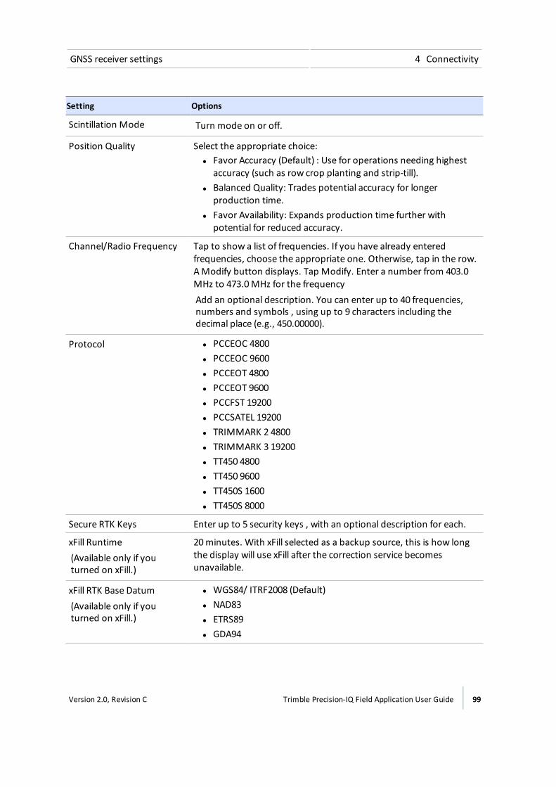
GNSS receiver settings 4 Connectivity
Setting Options
Scintillation Mode Turn mode on or off.
Position Quality Select the appropriate choice:l Favor Accuracy (Default) : Use for operations needing highest
accuracy (such as row crop planting and strip-till).l Balanced Quality: Trades potential accuracy for longer
production time.l Favor Availability: Expands production time further with
potential for reduced accuracy.
Channel/Radio Frequency Tap to show a list of frequencies. If you have already enteredfrequencies, choose the appropriate one. Otherwise, tap in the row.AModify button displays. Tap Modify. Enter a number from 403.0MHz to 473.0MHz for the frequencyAdd an optional description. You can enter up to 40 frequencies,numbers and symbols , using up to 9 characters including thedecimal place (e.g., 450.00000).
Protocol l PCCEOC 4800l PCCEOC 9600l PCCEOT 4800l PCCEOT 9600l PCCFST 19200l PCCSATEL 19200l TRIMMARK 2 4800l TRIMMARK 3 19200l TT450 4800l TT450 9600l TT450S 1600l TT450S 8000
Secure RTK Keys Enter up to 5 security keys , with an optional description for each.
xFill Runtime(Available only if youturned on xFill.)
20minutes. With xFill selected as a backup source, this is how longthe display will use xFill after the correction service becomesunavailable.
xFill RTK Base Datum(Available only if youturned on xFill.)
l WGS84/ ITRF2008 (Default)l NAD83l ETRS89l GDA94
Version 2.0, Revision C Trimble Precision-IQ Field Application User Guide 99

4 Connectivity DCM-300modem initial setup
CAN message settingsIf you wish to send messages from the GNSS receiver in the TM-200Module, you can set up whatmessages will be sent from CAN port A or B. If you are using an ISO-certified implement, use thissetting to sent information to the implement such as speed. See ISOBUS for implements, 161.
1. Tap the CAN port that you want to change settings for. Choose themessages for theGNSS receiver in the TM-200Module to send to ISO-certified equipment.
The list that displays for each CAN port shows themessages and their parameter group number (PGN). For each message, you can choose how often themessage is sent:
ll Off (never sent)
l 10 Hz, 5 Hz or 1 Hz
l Every 5, 10, 30 or 60 seconds
2. Tap to save your settings.
DCM-300 modem initial setupThe DCM-300modem ships as a locked unit until it is installed with the display.
To use VRS correction or data transfer features, activate and configure these services.
1. Connect the DCM-300modem to the display.
2. Power on the DCM-300modem and display.
3. Open the Precision-IQ field application.
4. Activate the required services on the display. See Feature unlocks, 75.
a. To use VRS corrections, activate RTK and VRS.
b. Vehicle Sync and Office Sync also require activation.
5. Reboot the DCM-300modem by turning off the vehicle ignition.
6. Open the Precision-IQ field application.
7. On theHome screen, tap , then tap Settings. The system settings screen displays.
8. TapModem Service.
9. Continue the instructions for setup at Modem services settings, 80.
Office Sync setupWith the Office Sync service, you can electronically transfer data from the display to the office and toConnected Farm dashboard. Data will be:
100 Trimble Precision-IQ Field Application User Guide Version 2.0, Revision C
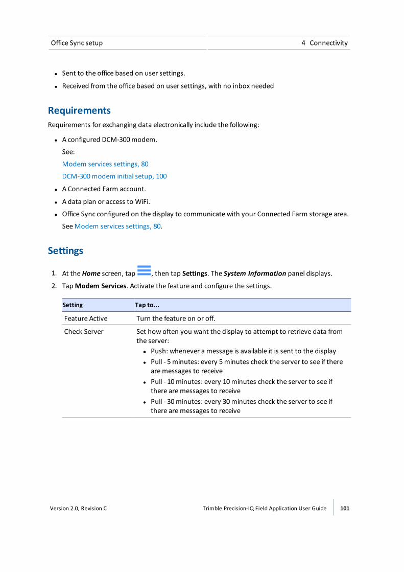
Office Sync setup 4 Connectivity
l Sent to the office based on user settings.
l Received from the office based on user settings, with no inbox needed
RequirementsRequirements for exchanging data electronically include the following:
l A configured DCM-300modem.
See:
Modem services settings, 80
DCM-300modem initial setup, 100
l A Connected Farm account.
l A data plan or access to WiFi.
l Office Sync configured on the display to communicate with your Connected Farm storage area.
SeeModem services settings, 80.
Settings
1. At theHome screen, tap , then tap Settings. The System Information panel displays.
2. TapModem Services. Activate the feature and configure the settings.
Setting Tap to...
Feature Active Turn the feature on or off.
Check Server Set how often you want the display to attempt to retrieve data fromthe server:ll Push: whenever a message is available it is sent to the displayl Pull - 5minutes: every 5minutes check the server to see if there
aremessages to receivel Pull - 10minutes: every 10minutes check the server to see if
there aremessages to receivel Pull - 30minutes: every 30minutes check the server to see if
there aremessages to receive
Version 2.0, Revision C Trimble Precision-IQ Field Application User Guide 101
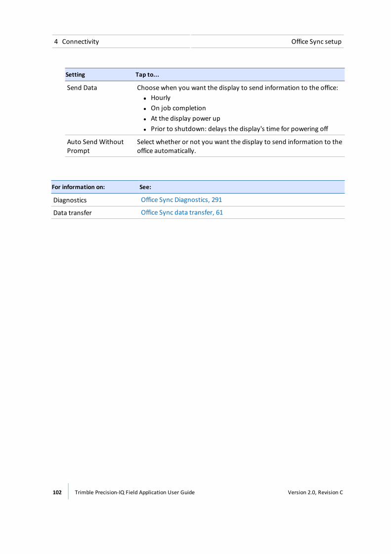
4 Connectivity Office Sync setup
Setting Tap to...
Send Data Choose when you want the display to send information to the office:ll Hourlyl On job completionl At the display power upl Prior to shutdown: delays the display's time for powering off
Auto Send WithoutPrompt
Select whether or not you want the display to send information to theoffice automatically.
For information on: See:
Diagnostics Office Sync Diagnostics, 291
Data transfer Office Sync data transfer, 61
102 Trimble Precision-IQ Field Application User Guide Version 2.0, Revision C
Connectivity concepts 4 Connectivity
Connectivity conceptsFor more information about concepts associated with GNSS, correction services, see:
l xFill technology, 103
l GNSS and drift, 103
l VRS, 107
GNSS and driftGNSS satellites are in continuous motion as they orbit the earth twice per day in a repeated pattern.Satellites transmit signals that the GNSS receiver translates to determine its position.
While performing field activities, you may notice differences in:
l Where the crop row is
l Where the guidance line was established
l Where the display is indicating the guidance line is now located.
This happens because GNSS satellite constellation patterns change over time and can experienceinterference.
Local and atmospheric conditions can impact signals. Temperature and humidity can delay signals.Signals can also be reflected from surrounding objects such as trees, causing multiple copies of thesignal or a delay in the signal reaching the receiver. Data errors from the satellite can also affectaccuracy.
xFill technologyxFill™ technology uses Trimble RTX technology to "fill in" for RTK corrections when there aretemporary radio or Internet connection outages. xFill technology is a standard feature and iscompatible with the AG25 GNSS antenna. The xFill technology can function with corrections fromsingle-baseline RTK, VRS and CORS systems.
When there is an interruption of the RTK correction signal (either from the radio base station orfrom the VRS cellular network), the xFill technology performs corrections. xFill technology uses thelast-known RTK position combined with the RTX precision satellite data to maintain a high level ofhorizontal positioning accuracy for up to 20minutes. There is a smooth transition from RTK to xFilltechnology and back to RTK.
Automatic guidance systemsIf an auto-steering system is engaged using RTK, the auto-steer system will stay engaged during the20minute xFill coverage. As soon as an RTK signal is available, the receiver will switch back to theRTK correction service and xFill will remain on standby in the background. If the system cannotresume an RTK Fixed status within 20minutes the system will fall back to DGPS correction and theauto-steer system will disengage.
Version 2.0, Revision C Trimble Precision-IQ Field Application User Guide 103
4 Connectivity Connectivity concepts
AccuracyxFill technology can maintain a relatively high level of horizontal accuracy throughout the RTKoutage period. However, accuracy is primarily dependent on three factors:
l GNSS satellite availability and obstructions between the satellite and receiver (trees, buildings,and so on)
l Exactness of the base station position
l Length of time since the last RTK position (maximum allowable time is 20minutes)
If you are concerned with maintaining sub-inch precision, disable the xFill feature.
Estimated accuracy over timewhile the xFill function has been active (with base station accuracy<20cm) is as follows:
l xFill runtime – no RTK corrections Estimated error
l 1-5minutes 1-5cm
l 6-10minutes 5-9cm
l 11-20minutes 10-15cm
Dependence on satellitexFill technology requires correction data from at least 5 satellites higher than 10 degrees from thehorizon. If GLONASS is unlocked at the RTK level, xFill technology will also be able to use GLONASSsatellites. Additionally, large objects such as trees, buildings, and grain bins will significantlydecrease or completely block signal reception from all satellite types, including GPS, GLONASS, andcorrections satellites. If these same obstructions are between the receiver and the satellite, theymay also block xFill signals.
WARNING – Many large and sudden changes in satellite geometry caused by blocked satellites can causesignificant position shifts. If operating under these conditions, auto-guidance systems can react abruptly. To avoidpossible personal injury or damage to property under these conditions, disable the auto-guidance system and takemanual control of the vehicle until conditions have cleared.
Dependence on base station positionWhen the RTK correction signal is lost, the RTX satellite begins providing correction based on thelast RTK position. When you setup xFill and select the datum in which you surveyed your basestation, the firmware translates your position into the ITRF datum reference frame to minimize drift.Any other inaccuracies in the base station position can cause a drift in position over time.
As time elapses, correction data from the satellites causes drift from the RTK line. The larger thedifference in surveyed base station position, the larger the drift as shown in following table.
The following table shows how the xFill drift over time is impacted by the accuracy of the basestation survey coordinates.
104 Trimble Precision-IQ Field Application User Guide Version 2.0, Revision C

Connectivity concepts 4 Connectivity
xFill Elapsed Time Survey Accuracy <20cm Survey Accuracy <2m Survey Accuracy <5m
0 to 5min 0 to 5 cm 0 to 15 cm 0 to 25 cm
5 to 15min 2 cm to 12 cm 10 cm to 0.3m 15cm to 0.5m
15 to 20min 9 cm to 15 cm 15 cm to 0.4m 0.3m to 0.8m
If you discover that the surveyed location of your base station is not accurate, your options are:
l Turn off xFill (recommended by Trimble).
l Resurvey your base station. However, this will cause themovement of any stored AB lines thatare reloaded/reused which is very undesirable to many RTK customers.
Base station surveyAt initial base station installation, Trimble recommends surveying base stations by taking a 24-hourlog and processing the data to receive position on your local datum. The accuracy of this position isstated in the report. Over time, primarily due to normal geological events, the base station positionmay change up to 7cm per year. Please refer to Trimble Support Note on this topic for furtherinformation.
When you select the datum used to survey your base station during the xFill technology setup, thereceiver will automatically convert your position in the datum you select to the equivalent positionin ITRF2008.
If your base station was properly surveyed within the last five years using one of the followingcoordinate systems, the xFill technology accuracy error will typically be less than 15cm over 20minutes.
l WGS84/ITRF2008
l NAD83
l ETRS89
l GDA94
When working within an area with several RTK base stations, each base station should have aunique Base ID. When moving in range of another base station, go to the GPS setup on the displayand enter the Base ID. This enables the receiver to recognize the new base station.
Base station survey with AutoBase™If the Trimble Auto Base feature was used to survey the base, the accuracy can be >5m, whichdecreases the xFill technology accuracy. The datum used for this feature is WGS84. Trimblerecommends testing xFill prior to using it in an application where the base station has only beensurveyed with Auto Base.
Version 2.0, Revision C Trimble Precision-IQ Field Application User Guide 105
4 Connectivity Connectivity concepts
VRS base stationIf using VRS, the accuracy is typically <1cm . Contact your VRS network owner to determine thedatum used for surveying and enter this datum during the xFill technology set-up. Trimble VRSNow™ network uses the following:
l VRS NowUS: NAD83
l VRS Now Europe: ETRS89
l VRS Now TEC Europe: ETRS89
l OmniSTAR® CORS Tasmania: GDA94
Base station, survey unknownIf you do not know if your base station has been surveyed or the datum used for surveying, youshould perform testing to approximate your base station errors or turn off xFill technology .
Estimating base station errorsTo estimate the error in the position f the base station, options include:
l Calculate Current Position and Compare to Set Position: Collect two hours of position logsand submit them for post-processing (using the same coordinate system as previously used).Then enter the current set position and the newly calculated position into a GPS distance toolcalculator.
l xFill Accuracy Detection Using Cross Track Error: Set-up your antenna and receiver in an openair environment (field or parking lot). Create an A+ line based on your parked position with RTKfixed. Unplug the radio or unplug the DCM-300modem if using cellular signal. xFill technologywill engage. Watch your cross track error (XTE) for a maximum of 20minutes. Repeat severaltimes. Keep in mind that this static test only tests the error in one direction (N/S or E/W).
l xFill Accuracy During Passes in a Field: To best see the drift of the xFill position over time:
Note – This procedure will only be accurate if you have already completed the Roll Calibrationfor auto-steering. See Vehicle setup, 110.
a. Create an A/B line in your field (or use an existing line). See AB guidance line creation (Runscreen), 221.
b. Drive the line and once your cross track error (XTE) is very small, stop and drop a flag in thecenter of your hitch.
c. Turn off RTK by changing the network ID or frequency.
d. Drive around the field for several minutes (to represent your typical outage time) andreturn to the A/B line.
e. Engage on the line and then when XTE is small and you’re over you previous flag, stop anddrop another flag. Compare the distance.
106 Trimble Precision-IQ Field Application User Guide Version 2.0, Revision C
Connectivity concepts 4 Connectivity
f. Make a pass in the other direction on the same A/B line and drop a third flag. Compare thedistance.
When not to use xFill technologyxFill technology is not recommended for:
l Land leveling and water management applications where a high degree of vertical accuracy isrequired.
l Any operation where you need accuracy better than 1” (2.4cm).
l When the base station has not been properly surveyed, or has been surveyed only with theAuto Base functionality and no tests have been performed to assess the risk of using xFilltechnology with that base station.
VRSVRS™, an integrated system available with a subscription, is complementary to RTK and providesRTK corrections over a large geographic area, where robust cellular data coverage is available.Network processing ensures high accuracy throughout the whole coverage area.
VRS consists of:
l GPS/GNSS reference stations spread out over a large area, typically 30-45miles (50-70 km)apart.
l A central server that uses Trimble proprietary software to create a correction model for theregion covered by the network. GPS rovers communicate using a cell modem with the VRSserver and receive RTK type corrections. The data from the reference stations is used to modelerrors throughout your region. Themodel is used to:
ll Create a network of virtual reference stations near your current location.
l Provide a localized set of standard format correction messages for your roving receiver.Since the error models are updated every second, all rovers receive an optimal correctionmodel after connecting on to the network. This ensures a high quality correction, andaccuracy.
Network solutionAll reference stations used in a VRS system can be interpreted as a network of continuouslyoperated reference stations. The difference between VRS and CORS is that VRS provides a networksolution. The position accuracy is maintained even if you move away from the single base but arestill within the network.
Due to the longer range, fewer base stations can cover a greater region. Additionally, VRS networksmay offer better signal coverage in rough terrain if the local cellular network is robust and providesgood data coverage.
Version 2.0, Revision C Trimble Precision-IQ Field Application User Guide 107

4 Connectivity Connectivity concepts
108 Trimble Precision-IQ Field Application User Guide Version 2.0, Revision C
Vehicles
In this chapter:
Vehicle setup 110
Add a vehicle 110
Delete a vehicle 112
Edit a vehicle 113
Save a vehicle 113
Vehicle summary 114
Select a vehicle 115
Manual guidance setup 115
Autopilot system setup 116
OnSwath 121
Autopilot system calibration 122
EZ-Pilot system setup 137
EZ-Pilot system calibrations 140
EZ-Steer system setup 144
EZ-Steer system calibrations 147
You can add, edit, save, delete and selectvehicles. Part of vehicle setup includesentering settings for auto guidancesystems, providing vehicle measurementsand calibrating the vehicle with theguidance system.
You must select a vehicle to be able toenter a field.
5C h a p t e r
Version 2.0, Revision C Trimble Precision-IQ Field Application User Guide 109

5 Vehicles Vehicle setup
Vehicle setupOn-screen vehicles in the Precision-IQ field application represent actual vehicles, and include basicinformation about your vehicle as well as its type of guidance system and calibrations.
Note – Prior to using a vehicle for field activities, you must complete all settings for a vehicle,including calibrations. Then you must select the vehicle.
Vehicles can be:
l Added (see Add a vehicle, 110)
l Saved in a partial or complete state (see Save a vehicle, 113)
l Removed (see Delete a vehicle, 112)
l Changed (see Edit a vehicle, 113)
l Viewed in a summary form (see Vehicle summary, 114)
l Selected for use in field activities (see Select a vehicle, 115)
Overview of setupAn overview of the steps for setting up a vehicle includes:
1. Selecting the vehicle type and entering basic vehicle information:
ll Guidance type: Manual, Autopilot, EZ-Pilot or EZ-Steer
l For the Autopilot and EZ-Steer systems, navigation controller orientation: How thecontroller is oriented in the vehicle
l For the EZ-Pilot system: How the label is facing on the IMD-600
l Settings for steering and speed
l Measurements: Measurements for the location of the antenna and other vehiclemeasurements
2. Calibrating the guidance system with the vehicle.
Add a vehicleNote – You must complete all vehicle setup and calibration steps before you can select and use thevehicle for field activities on the Run screen.
110 Trimble Precision-IQ Field Application User Guide Version 2.0, Revision C
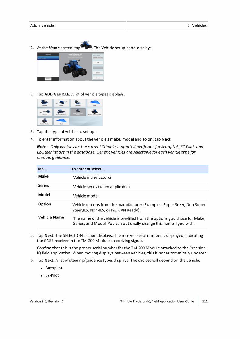
Add a vehicle 5 Vehicles
1. At theHome screen, tap . The Vehicle setup panel displays.
2. Tap ADD VEHICLE. A list of vehicle types displays.
3. Tap the type of vehicle to set up.
4. To enter information about the vehicle's make, model and so on, tap Next.
Note – Only vehicles on the current Trimble supported platforms for Autopilot, EZ-Pilot, andEZ-Steer list are in the database. Generic vehicles are selectable for each vehicle type formanual guidance.
Tap... To enter or select...
Make Vehicle manufacturer
Series Vehicle series (when applicable)
Model Vehicle model
Option Vehicle options from themanufacturer (Examples: Super Steer, Non SuperSteer,ILS, Non-ILS, or ISO CAN Ready)
Vehicle Name The name of the vehicle is pre-filled from the options you chose for Make,Series, and Model. You can optionally change this name if you wish.
5. Tap Next. The SELECTION section displays. The receiver serial number is displayed, indicatingthe GNSS receiver in the TM-200Module is receiving signals.
Confirm that this is the proper serial number for the TM-200Module attached to the Precision-IQ field application. When moving displays between vehicles, this is not automatically updated.
6. Tap Next. A list of steering/guidance types displays. The choices will depend on the vehicle:
ll Autopilot
l EZ-Pilot
Version 2.0, Revision C Trimble Precision-IQ Field Application User Guide 111
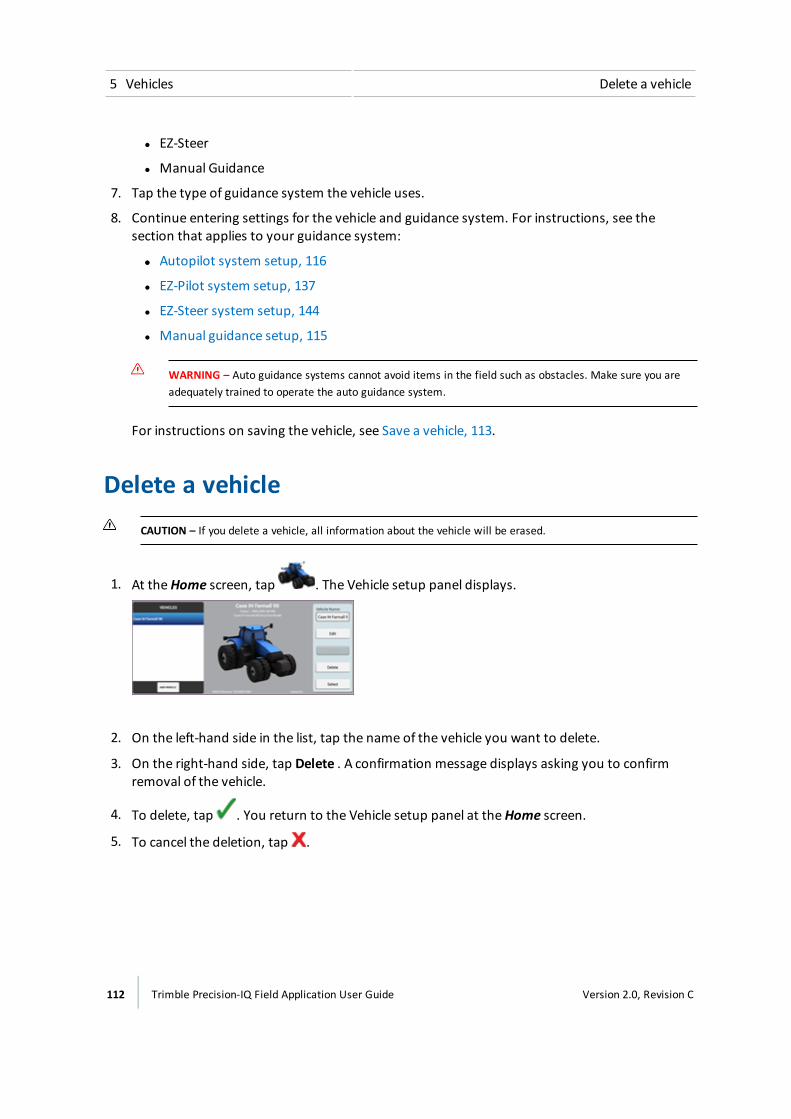
5 Vehicles Delete a vehicle
l EZ-Steer
l Manual Guidance
7. Tap the type of guidance system the vehicle uses.
8. Continue entering settings for the vehicle and guidance system. For instructions, see thesection that applies to your guidance system:
ll Autopilot system setup, 116
l EZ-Pilot system setup, 137
l EZ-Steer system setup, 144
l Manual guidance setup, 115
WARNING – Auto guidance systems cannot avoid items in the field such as obstacles. Make sure you areadequately trained to operate the auto guidance system.
For instructions on saving the vehicle, see Save a vehicle, 113.
Delete a vehicleCAUTION – If you delete a vehicle, all information about the vehicle will be erased.
1. At theHome screen, tap . The Vehicle setup panel displays.
2. On the left-hand side in the list, tap the name of the vehicle you want to delete.
3. On the right-hand side, tap Delete . A confirmation message displays asking you to confirmremoval of the vehicle.
4. To delete, tap . You return to the Vehicle setup panel at theHome screen.
5. To cancel the deletion, tap .
112 Trimble Precision-IQ Field Application User Guide Version 2.0, Revision C
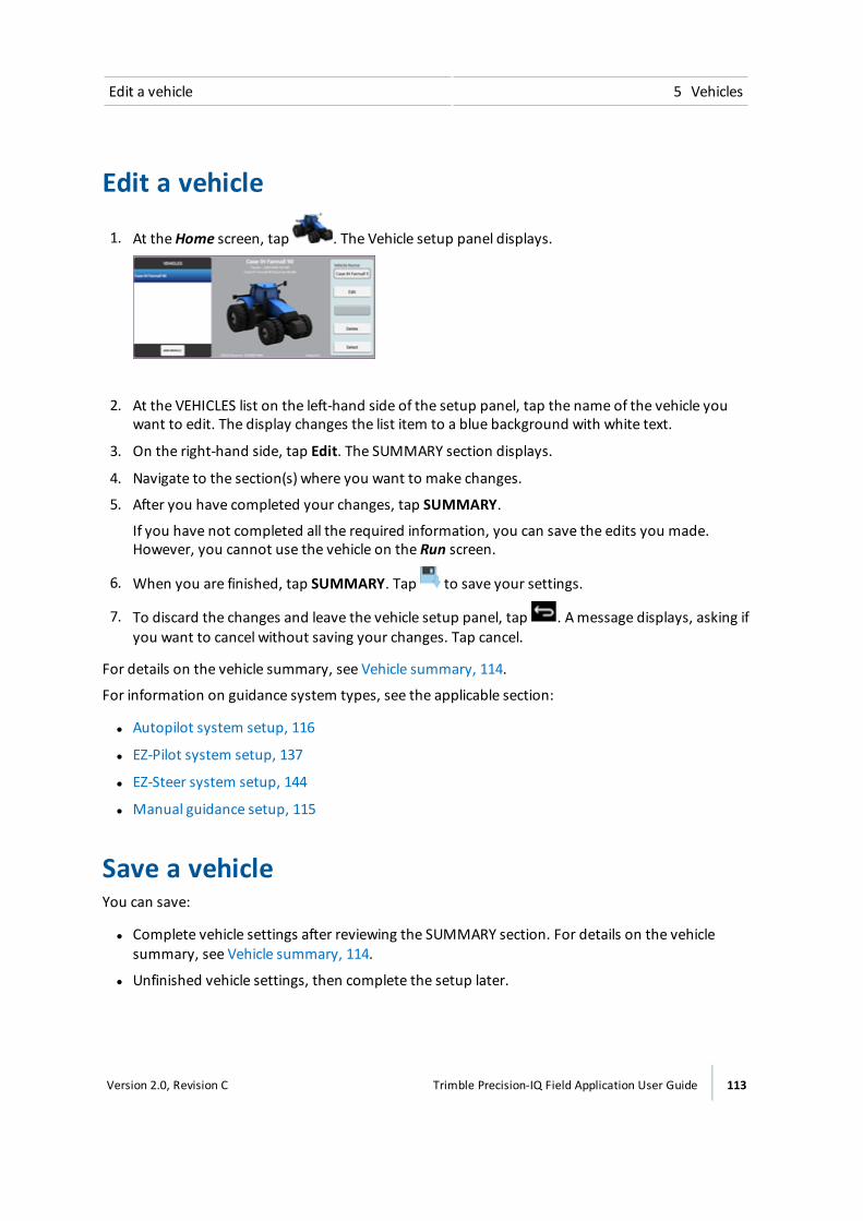
Edit a vehicle 5 Vehicles
Edit a vehicle
1. At theHome screen, tap . The Vehicle setup panel displays.
2. At the VEHICLES list on the left-hand side of the setup panel, tap the name of the vehicle youwant to edit. The display changes the list item to a blue background with white text.
3. On the right-hand side, tap Edit. The SUMMARY section displays.
4. Navigate to the section(s) where you want to make changes.
5. After you have completed your changes, tap SUMMARY.
If you have not completed all the required information, you can save the edits you made.However, you cannot use the vehicle on the Run screen.
6. When you are finished, tap SUMMARY. Tap to save your settings.
7. To discard the changes and leave the vehicle setup panel, tap . Amessage displays, asking ifyou want to cancel without saving your changes. Tap cancel.
For details on the vehicle summary, see Vehicle summary, 114.
For information on guidance system types, see the applicable section:
l Autopilot system setup, 116
l EZ-Pilot system setup, 137
l EZ-Steer system setup, 144
l Manual guidance setup, 115
Save a vehicleYou can save:
l Complete vehicle settings after reviewing the SUMMARY section. For details on the vehiclesummary, see Vehicle summary, 114.
l Unfinished vehicle settings, then complete the setup later.
Version 2.0, Revision C Trimble Precision-IQ Field Application User Guide 113
5 Vehicles Vehicle summary
If you have not completed all the required information, you can save the edits you made.However, you cannot use the vehicle profile in field activities on the Run screen.
Save a complete vehicle profile1. Complete all vehicle settings, including calibration.
2. At the SUMMARY section, tap . The display saves the vehicle and returns to the Vehiclesetup panel.
Save an incomplete vehicle profileNote – You must complete all vehicle setup and calibration steps before you can use the vehicle forfield activities on the Run screen.
1. At a minimum, enter some basic information: vehicle type, make and model.
2. At the SUMMARY section, tap . The display saves the vehicle and returns to the Vehiclesetup panel at theHome screen.
Vehicle summaryThe SUMMARY section of a vehicle profile contains the vehicle information and configurations.
Incomplete information will be noted as "Incomplete".
To... Tap...
Save the vehicle with any changes you havemade.
Exit the setup without saving changes. The display will askyou to either save the changes or exit without saving.
(on the System bar, 43)
Quickly access any part of the setup. The buttons at the top of the screen
114 Trimble Precision-IQ Field Application User Guide Version 2.0, Revision C
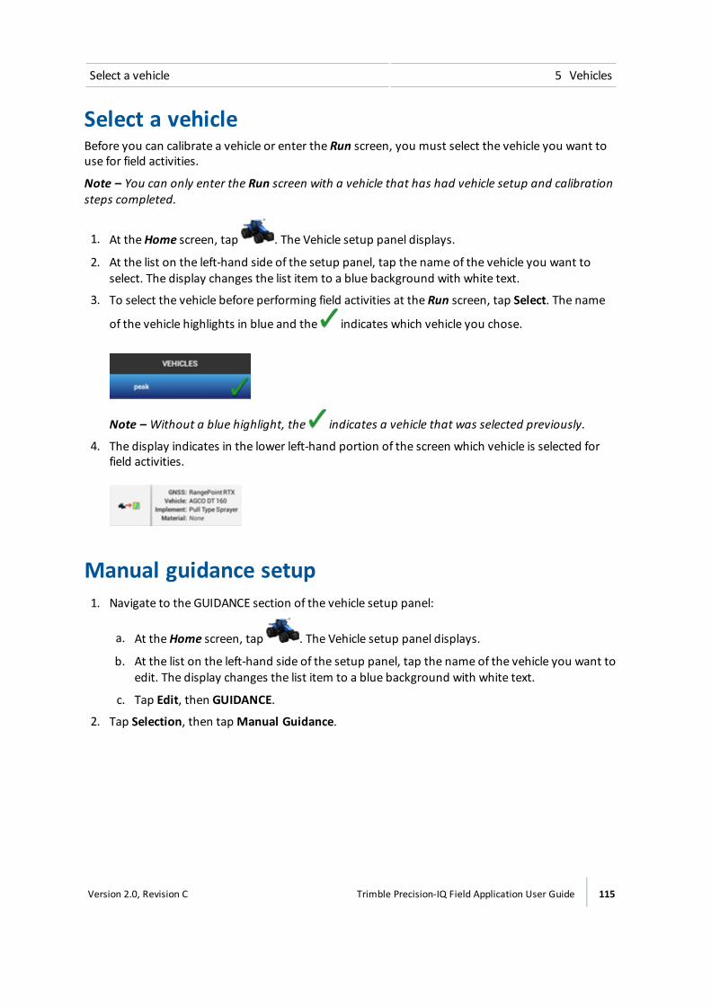
Select a vehicle 5 Vehicles
Select a vehicleBefore you can calibrate a vehicle or enter the Run screen, you must select the vehicle you want touse for field activities.
Note – You can only enter the Run screen with a vehicle that has had vehicle setup and calibrationsteps completed.
1. At theHome screen, tap . The Vehicle setup panel displays.
2. At the list on the left-hand side of the setup panel, tap the name of the vehicle you want toselect. The display changes the list item to a blue background with white text.
3. To select the vehicle before performing field activities at the Run screen, tap Select. The name
of the vehicle highlights in blue and the indicates which vehicle you chose.
Note – Without a blue highlight, the indicates a vehicle that was selected previously.
4. The display indicates in the lower left-hand portion of the screen which vehicle is selected forfield activities.
Manual guidance setup1. Navigate to the GUIDANCE section of the vehicle setup panel:
a. At theHome screen, tap . The Vehicle setup panel displays.
b. At the list on the left-hand side of the setup panel, tap the name of the vehicle you want toedit. The display changes the list item to a blue background with white text.
c. Tap Edit, then GUIDANCE.
2. Tap Selection, then tapManual Guidance.
Version 2.0, Revision C Trimble Precision-IQ Field Application User Guide 115
5 Vehicles Autopilot system setup
Autopilot system setupSettings for the Autopilot system include:
l The type of platform for the Autopilot system
l The origin of the vehicle profile
l Controller and sensor settings
l Vehicle measurements
l Calibrations
Guidance system settings for Autopilot system
WARNING – Auto guidance systems cannot avoid items in the field such as obstacles. Make sure you areadequately trained to operate the auto guidance system.
1. Navigate to the GUIDANCE section of the vehicle setup panel:
a. At theHome screen, tap . The Vehicle setup panel displays.
b. At the list on the left-hand side of the setup panel, tap the name of the vehicle you want toedit. The display changes the list item to a blue background with white text.
c. Tap Edit, then GUIDANCE.
2. At the SELECTIONS section, complete the settings:
Tap... Explanation
Selection Autopilot
Autopilot Platform The appropriate platform for your vehicle.
116 Trimble Precision-IQ Field Application User Guide Version 2.0, Revision C

Autopilot system setup 5 Vehicles
Tap... Explanation
Vehicle Profile Origin The source of the vehicle profile:ll Vehicle Profiles Database: contained in the displayl Import from Navigation controller: If your navigation
controller has already been set up for a differentTrimble display, the vehicle profile is stored in thecontroller.
l Import from USB: profile stored on USB drive (Theseconfiguration /.cfg files are located in theAgData/Profiles folder on the USB drive.) See USB VDBtransfer, 61.
CAUTION – If you select a Vehicle Profile that is not suitable foryour vehicle, you may experience degraded system performance.
GNSS Setup Selection If you have not completed GNSS setup. See GNSS receiversettings, 86.
Configure GNSS Setup GNSS if you have not already done so.
WARNING – Many large and sudden changes in satellite geometry caused by blocked satellites can causesignificant position shifts. If operating under these conditions, auto-guidance systems can react abruptly. Toavoid possible personal injury or damage to property under these conditions, disable the auto-guidancesystem and take manual control of the vehicle until conditions have cleared.
3. Tap Next to continue to Controller settings for Autopilot system, 117.
Controller settings for Autopilot systemThe navigation controller indicates to the Precision-IQ field application how your vehicle ispositioned. To set up the controller, you must indicate the position/orientation of the controller asit is currently installed in the vehicle.
For example, if the controller is positioned with the input jacks of the controller facing to the left sideof your vehicle, you indicate this in the Precision-IQ field application.
The CONTROLLER SETTINGS section of the vehicle setup panel shows an image of the controller asthough you are looking down on the vehicle from above, with the front of the vehicle at the top ofthe screen.
1. Navigate to the GUIDANCE section of the vehicle setup panel:
a. At theHome screen, tap . The Vehicle setup panel displays.
b. Tap Edit.
Version 2.0, Revision C Trimble Precision-IQ Field Application User Guide 117

5 Vehicles Autopilot system setup
c. At the list on the left-hand side of the setup panel, tap the name of the vehicle you want toedit. The display changes the list item to a blue background with white text.
d. Tap Edit, then GUIDANCE.
2. Tap CONTROLLER SETTINGS.
3. Rotate the on-screen controller to match the position of the actual controller in the vehicle asyou are looking down from the top, with the nose of the tractor point to the top of the screen.Tap the arrow buttons to move the on-screen navigation controller clockwise orcounterclockwise.
4. Optionally you can directly enter the degrees of the position by tapping Yaw, Pitch and Roll.Non-orthogonal entries will not show the orientation on the display.
5. When the controller position on the screen matches the controller installed in the vehicle,continue to the sensor settings. See Sensor settings for Autopilot system, 118.
Sensor settings for Autopilot systemNote – Adjust sensor settings only if necessary to improve steering performance.
1. Navigate to theGUIDANCE section of the vehicle setup panel:
a. At theHome screen, tap . The Vehicle setup panel displays.
b. Tap Edit.
c. At the list on the left-hand side of the setup panel, tap the name of the vehicle you want toedit. The display changes the list item to a blue background with white text.
d. Tap Edit, then GUIDANCE.
2. Tap SETTINGS. Complete the information at the SETTINGS section.
Note – Not all setting items will be available for all vehicles. Setting items are only available tothe applicable vehicle types.
118 Trimble Precision-IQ Field Application User Guide Version 2.0, Revision C
Autopilot system setup 5 Vehicles
Tap... To...
Steering Sensor Select the type of angle sensor installed on the vehicle:ll Potentiometerl AutoSense™ device
AutoSense Location Select the location of the AutoSense device:ll Left Wheell Right Wheel
AutoSense Orientation Indicate the direction the AutoSense label is facing:ll Label Upl Label Down
Note – If the orientation is not accurate, assisted steeringmay be affected.
Valve On Speed Select speed. For vehicles operating at very slow speeds,select Low or Ultra Low.ll Normal - 1.3 ft/s (0.4m/s)l Low - 0.3 ft/s (0.1m/s)l Ultra Low - 0.07 ft/s (0.02m/s)
Vehicle measurements for Autopilot systemNote – For Autopilot guidance with untracked or tracked vehicles, do not change vehiclemeasurements unless they are not correct.
At MEASUREMENTS, you can enter and access themeasurements that apply to the vehicle type youselected. In addition to measurements of the vehicle itself, measurements related to the antennalocation are important for accuracy.
1. Before you takemeasurements:
a. Park the vehicle on level ground.
b. Make sure the vehicle is straight, with the center line of the body parallel to the wheels.
2. Navigate to theMEASUREMENTS section of the vehicle setup panel:
a. At theHome screen, tap . The Vehicle setup panel displays.
b. Tap Edit.
c. At the list on the left-hand side of the setup panel, tap the name of the vehicle you want toedit. The display changes the list item to a blue background with white text.
d. Tap Edit, then GUIDANCE.
3. TapMEASUREMENTS. Based on your selections up to this point, somemeasurements will be
Version 2.0, Revision C Trimble Precision-IQ Field Application User Guide 119
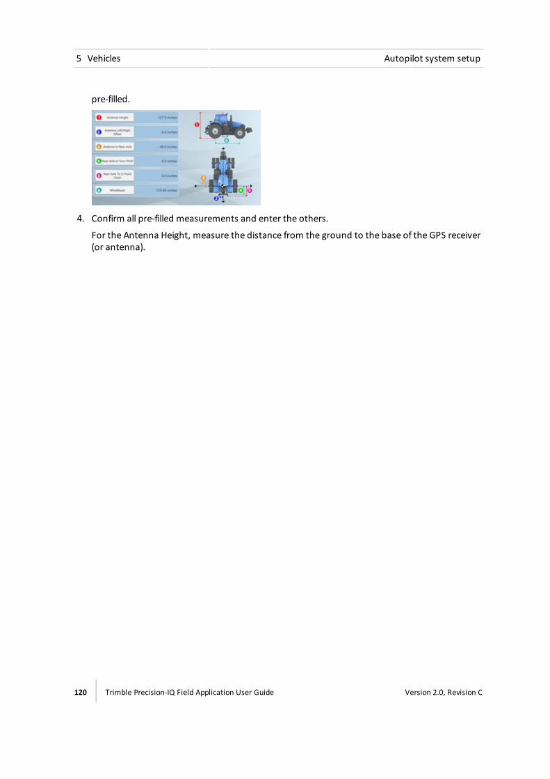
5 Vehicles Autopilot system setup
pre-filled.
4. Confirm all pre-filled measurements and enter the others.
For the Antenna Height, measure the distance from the ground to the base of the GPS receiver(or antenna).
120 Trimble Precision-IQ Field Application User Guide Version 2.0, Revision C
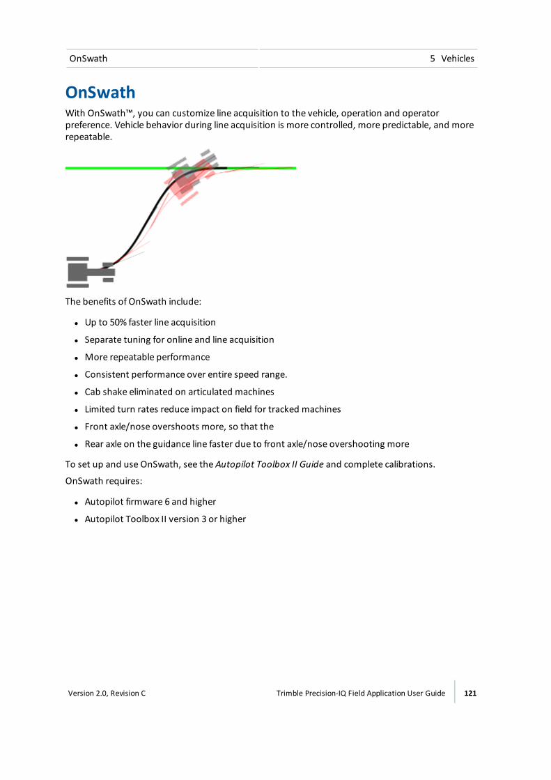
OnSwath 5 Vehicles
OnSwathWith OnSwath™, you can customize line acquisition to the vehicle, operation and operatorpreference. Vehicle behavior during line acquisition is more controlled, more predictable, and morerepeatable.
The benefits of OnSwath include:
l Up to 50% faster line acquisition
l Separate tuning for online and line acquisition
l More repeatable performance
l Consistent performance over entire speed range.
l Cab shake eliminated on articulated machines
l Limited turn rates reduce impact on field for tracked machines
l Front axle/nose overshoots more, so that the
l Rear axle on the guidance line faster due to front axle/nose overshooting more
To set up and use OnSwath, see the Autopilot Toolbox II Guide and complete calibrations.
OnSwath requires:
l Autopilot firmware 6 and higher
l Autopilot Toolbox II version 3 or higher
Version 2.0, Revision C Trimble Precision-IQ Field Application User Guide 121
5 Vehicles Autopilot system calibration
Autopilot system calibrationThe calibration process for the Autopilot system records additional details about your vehicle, whichhelps the system to steer the vehicle more accurately. For high accuracy systems, you must have allthe correct calibrations.
Note – Currently CAT hydraulic installation Challenger vehicles and John Deere Tracked vehiclesusing the SIU-200 Interface box cannot be calibrated with the Precision-IQ field application.
The CALIBRATION section lists only the calibrations required for the selected vehicle and steeringsystem.
Note – Calibration is only complete when all calibrations on the screen show results instead ofIncomplete. Prior to performing calibrations ensure you completed the steps to Controller settingsfor Autopilot system, 117.
1. Remove any implement from the vehicle. Drive the vehicle to an open area free of obstacles inwhich the vehicle can make long passes (400m/.25mile).
2. At the Vehicle setup panel, select the vehicle you want to work with. See for detailedinstructions.
3. Tap Calibrate. The display shows only the calibrations required for the vehicle you haveselected.
4. Perform each of the calibration procedure selections presented. Following the on-screeninstructions when applicable. More detailed information on each calibration follows.
5. When you are finished, tap to save the calibrations.
Calibration for non-tracked vehicles
Calibration Explanation
Manual override sensitivitycalibration, 123
Note – For vehicles that use apressure transducer or columnencoder for the manualoverride.
Adjusts howmuch force is required to disengage the systemwhen the driver turns the steering wheel.
Note – The system detects whether the vehicle configurationincludes this type of sensor. This option only appears ifrequired.
Automated steering deadzonecalibration, 126
Note – Only for front wheelsteered and articulatedvehicles.
For learning the vehicle’s steering dead zones. Determines theminimum valve command required for steering movement.
122 Trimble Precision-IQ Field Application User Guide Version 2.0, Revision C
Autopilot system calibration 5 Vehicles
Calibration Explanation
Proportional steering gain, 130 Sets the proportional gain to control steering overshoot andresponsiveness.
Steering sensor calibration, 124
Note – Only for vehicles with apotentiometer style steeringsensor.
Converts the voltage output of the steering angle sensor intoan equivalent steering angle measurement.
Line acquisition, 135 Controls how fast the guidance system attempts to steer thevehicle onto the current guidance line (50% - 150%).
Engage aggressiveness, 136 How aggressively the vehicle initially engages on the guidanceline (50% - 150%).
Roll correction calibration, 131 Compensates for minor variations in the placement of thenavigation controller and GNSS antenna.
For information on: See:
Diagnostics Autopilot system diagnostics, 266
Manual override sensitivity calibration
WARNING – Incorrect adjustment of Manual Override Sensitivity could cause this critical safety feature to fail,resulting in personal injury or damage to the vehicle. Do not to choose a setting that is either too sensitive or notsensitive enough. It is vital to avoid setting the sensitivity so low that the system will not detect any steeringwheel motion.
Note – This control is for platforms that use a pressure transducer or encoder for manual override.The software detects whether or not the system uses this type of sensor.
Oneway to disengage the Autopilot system is to turn the steering wheel or manually overrideautomatic steering. When you turn the steering wheel, there is a voltage spike that then tapers off.This spike and decline occurs at different levels for different models of tractor.
Manual Override Sensitivity sets the level that the voltagemust reach before the guidance systemdisengages. The voltagemust also drop below that level before automated steering can be engagedagain.
A high level of sensitivity causes the system to disengagemore quickly, and you must wait longerbefore you can re-engage. A low level of sensitivity causes the system to take longer to disengage,and you will be able to re-engagemore quickly.
Version 2.0, Revision C Trimble Precision-IQ Field Application User Guide 123
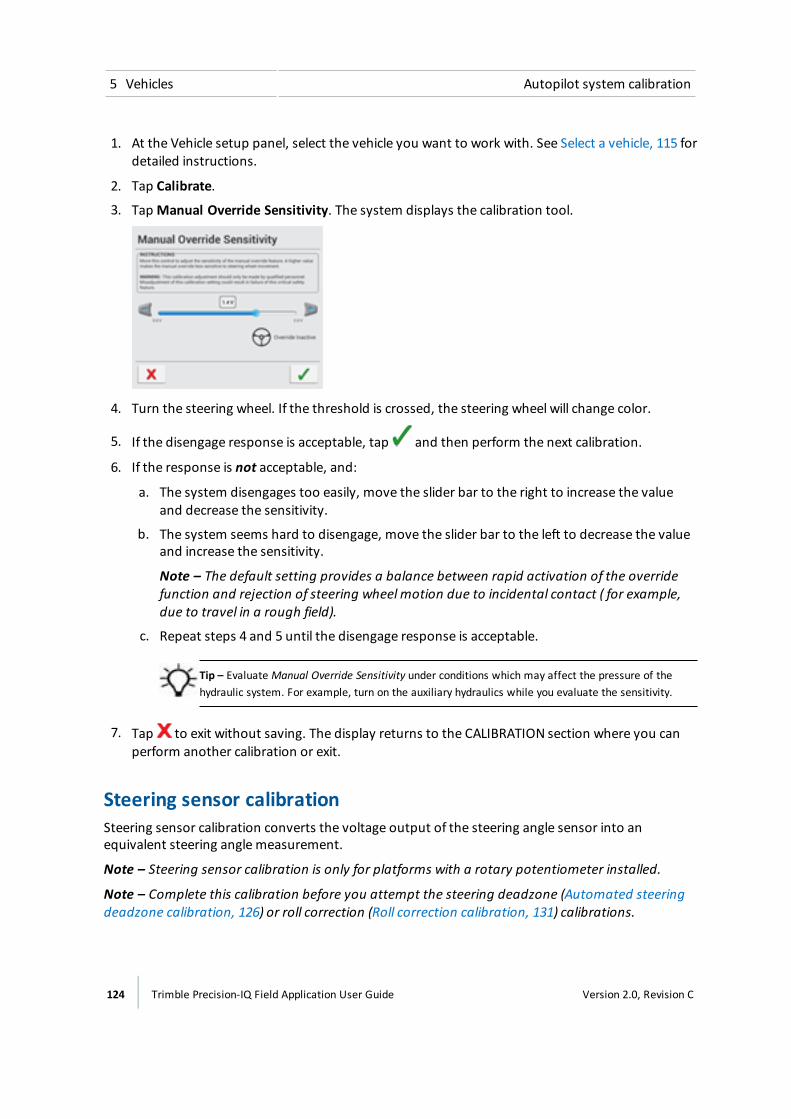
5 Vehicles Autopilot system calibration
1. At the Vehicle setup panel, select the vehicle you want to work with. See Select a vehicle, 115 fordetailed instructions.
2. Tap Calibrate.
3. TapManual Override Sensitivity. The system displays the calibration tool.
4. Turn the steering wheel. If the threshold is crossed, the steering wheel will change color.
5. If the disengage response is acceptable, tap and then perform the next calibration.
6. If the response is not acceptable, and:
a. The system disengages too easily, move the slider bar to the right to increase the valueand decrease the sensitivity.
b. The system seems hard to disengage, move the slider bar to the left to decrease the valueand increase the sensitivity.
Note – The default setting provides a balance between rapid activation of the overridefunction and rejection of steering wheel motion due to incidental contact ( for example,due to travel in a rough field).
c. Repeat steps 4 and 5 until the disengage response is acceptable.
Tip – Evaluate Manual Override Sensitivity under conditions which may affect the pressure of thehydraulic system. For example, turn on the auxiliary hydraulics while you evaluate the sensitivity.
7. Tap to exit without saving. The display returns to the CALIBRATION section where you canperform another calibration or exit.
Steering sensor calibrationSteering sensor calibration converts the voltage output of the steering angle sensor into anequivalent steering angle measurement.
Note – Steering sensor calibration is only for platforms with a rotary potentiometer installed.
Note – Complete this calibration before you attempt the steering deadzone (Automated steeringdeadzone calibration, 126) or roll correction (Roll correction calibration, 131) calibrations.
124 Trimble Precision-IQ Field Application User Guide Version 2.0, Revision C
Autopilot system calibration 5 Vehicles
1. Drive the vehicle to a field with a hard, level surface without obstructions.
2. At the Vehicle setup panel, select the vehicle you want to work with. See Select a vehicle, 115 fordetailed instructions.
3. Tap Calibrate.
4. Tap Steering Sensor. The calibration tool displays.
5. Read the instructions and tap theNext.
6. Steer straight ahead and drive forward slowly. Maintain a tractor speed above 1.6 kph (1mph).Tap Next.
7. Turn the steering wheel all the way to the left and continuemoving forward.
a. Note the sensor voltage value.
b. While the steering wheel is at the full left position, tap Next.
8. Turn the steering wheel all the way to the right.
a. Note the sensor voltage value.
b. While the steering wheel is at the full right position,tap Next.
9. Steer straight ahead and drive for a while to ensure you are traveling straight.
10. Check the value. The center should be approximately 2.5 volts. The calibration processattempts to map the values for a full left turn, a full right turn and center steering.
a. Note the sensor voltage value.
b. When the vehicle is going straight, press Next.
11. Turn the steering wheel to full left and full right.
a. Check that the voltage value and degree value does not stop changing before the steeringarticulation hits the end stops.
b. Ensure that the full left turn and the full right turn are at approximately the same value.
c. If the values are not approximately symmetrical, tap to discard the calibration andrepeat step 6 through step 9. The steering sensor may require adjustment or replacementif:
The value... Outcome
For sensor volt Not symmetrical for full left and full right turns
For degrees Not near 0
For voltage Stops changing before the articulation of the steering isto the full left or full right position
12. Tap to accept the calibration.
13. To restart the calibration, tap Steering Sensor.
Version 2.0, Revision C Trimble Precision-IQ Field Application User Guide 125
5 Vehicles Autopilot system calibration
Automated steering deadzone calibrationThe Automated Deadzone calibration runs a series of tests on the valve and steering hydraulics todetermine the steering signal where steering movement occurs. It determines theminimum valvecommand required for steering movement when you direct the vehicle to turn to the right or left.
In this test, the system independently calibrates both sides of the steering system to determine thepoint at which wheel movement occurs for each direction.
Note – Large obstacles or terrain variation may cause erratic steering position readings which maydegrade the calibration done smooth, level surface recommended for this calibration.
WARNING – During the Deadzone calibration, the system moves the vehicle’s steering wheel. To avoid injury, beprepared for sudden vehicle movement.
Pre-calibration stepsComplete these steps before you begin calibration:
1. Complete the vehicle profile steps for setup.
2. Warm up the vehicle. The hydraulic fluid must be at normal operating temperature fordeadzone calibration.
Note – On some vehicles with large reservoirs, it may take a longer amount of time for thefluid to reach operating level, especially if the implement circuit is lightly loaded. Consult thevehicle documentation to determine if the hydraulic fluid temperature can be shown on avehicle console.
3. If you perform the deadzone calibration while the system is cold, repeat both the AutomatedDeadzone and Steering Gain (see Proportional steering gain, 130) calibrations again when thesystem is at operating temperature.
4. Prepare the steering sensor:
a. If the vehicle has an AutoSense device, drive the vehicle in a straight line for at least oneminute.
b. If the vehicle has a Potentiometer, complete the Steering Sensor calibration first. SeeSteering sensor calibration, 124.
Calibration steps
1. Drive the vehicle to a large field without hazards or obstructions. The field should have smoothsoil that is loose but firm.
CAUTION – Obstacles in the field can cause collisions, which may injure you and damage the vehicle. If an
126 Trimble Precision-IQ Field Application User Guide Version 2.0, Revision C
Autopilot system calibration 5 Vehicles
obstacle in the field makes it unsafe to continue the Automated Deadzone calibration, stop the vehicle andturn the steering wheel to disengage the system.1) Wait until the Precision-IQ field application prompts you that the phase is ready to begin.2) Look at the screen to determine whether the next phase will require a left or right turn.3) Reposition the vehicle so that the turn will use the space that you have available.4) Tap the button to begin the next phase.
2. At the Vehicle setup panel, select the vehicle profile you want to work with. See Select a vehicle,115 for detailed instructions.
3. On the left-hand side, tap Calibrate.
4. Tap Automated Steering Dead Zone. The calibration panel displays.
5. Center The steering and tap Next.
6. Read each instruction and then tap Next.
7. Center the steering on the tractor and move forward in first gear at high RPM for at least fiveseconds.
8. Tap Test Right and continuemoving forward while the system performs a coarse right side test.
9. When the test is finished, center the steering again and drive forward for five seconds.
10. Tap Test Left and continuemoving forward while the system performs a coarse left side test.
11. Tap Accept to accept the calibration. The system displays the AutoPilot calibration panel again.
12. Continue driving ahead slowly and tap Test Right. The system will perform the first right handfine calibration.
13. Repeat the right and left hand fine calibrations until there is a change of less than .5 in each ofthe deadzone values
To minimize the total amount of space needed for the complete calibration, you can repositionthe vehicle between each calibration process. If available flate, smooth space is extremelylimited, re-align the vehicle after each calibration.
Note – If you encounter any error messages during calibration, refer to the AutomatedDeadzone error messages in this section.
Automated Deadzone error messages
Message: Error - .... Explanation
Manual Override Detected Manual override was detected before the calibration cycle could becompleted. Retry the calibration.
No GPS AGNSS receiver must be connected and outputting positions beforethe software can run the calibration procedure.
Version 2.0, Revision C Trimble Precision-IQ Field Application User Guide 127
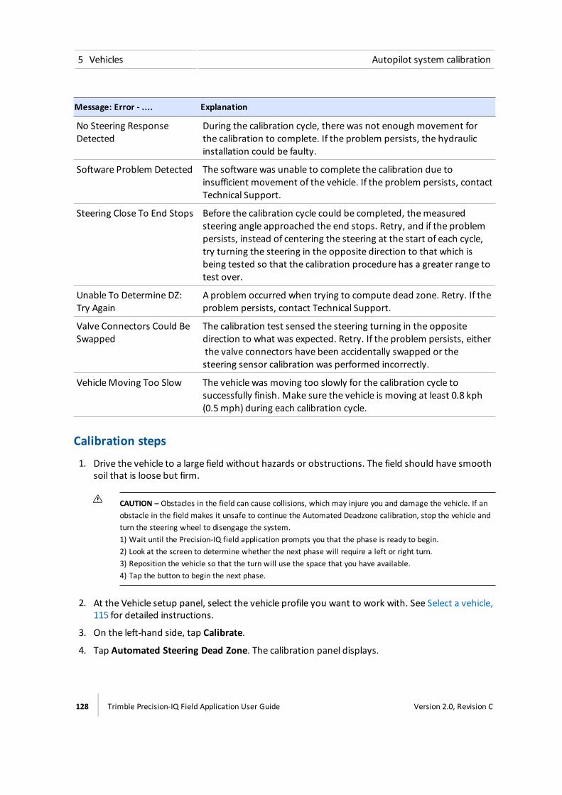
5 Vehicles Autopilot system calibration
Message: Error - .... Explanation
No Steering ResponseDetected
During the calibration cycle, there was not enough movement forthe calibration to complete. If the problem persists, the hydraulicinstallation could be faulty.
Software Problem Detected The software was unable to complete the calibration due toinsufficient movement of the vehicle. If the problem persists, contactTechnical Support.
Steering Close To End Stops Before the calibration cycle could be completed, themeasuredsteering angle approached the end stops. Retry, and if the problempersists, instead of centering the steering at the start of each cycle,try turning the steering in the opposite direction to that which isbeing tested so that the calibration procedure has a greater range totest over.
Unable To Determine DZ:Try Again
A problem occurred when trying to compute dead zone. Retry. If theproblem persists, contact Technical Support.
Valve Connectors Could BeSwapped
The calibration test sensed the steering turning in the oppositedirection to what was expected. Retry. If the problem persists, eitherthe valve connectors have been accidentally swapped or thesteering sensor calibration was performed incorrectly.
VehicleMoving Too Slow The vehicle was moving too slowly for the calibration cycle tosuccessfully finish. Make sure the vehicle is moving at least 0.8 kph(0.5mph) during each calibration cycle.
Calibration steps
1. Drive the vehicle to a large field without hazards or obstructions. The field should have smoothsoil that is loose but firm.
CAUTION – Obstacles in the field can cause collisions, which may injure you and damage the vehicle. If anobstacle in the field makes it unsafe to continue the Automated Deadzone calibration, stop the vehicle andturn the steering wheel to disengage the system.1) Wait until the Precision-IQ field application prompts you that the phase is ready to begin.2) Look at the screen to determine whether the next phase will require a left or right turn.3) Reposition the vehicle so that the turn will use the space that you have available.4) Tap the button to begin the next phase.
2. At the Vehicle setup panel, select the vehicle profile you want to work with. See Select a vehicle,115 for detailed instructions.
3. On the left-hand side, tap Calibrate.
4. Tap Automated Steering Dead Zone. The calibration panel displays.
128 Trimble Precision-IQ Field Application User Guide Version 2.0, Revision C

Autopilot system calibration 5 Vehicles
5. Center The steering and tap Next.
6. Read each instruction and then tap Next.
7. Center the steering on the tractor and move forward in first gear at high RPM for at least fiveseconds.
8. Tap Test Right and continuemoving forward while the system performs a coarse right side test.
9. When the test is finished, center the steering again and drive forward for five seconds.
10. Tap Test Left and continuemoving forward while the system performs a coarse left side test.
11. Tap Accept to accept the calibration. The system displays the AutoPilot calibration panel again.
12. Continue driving ahead slowly and tap Test Right. The system will perform the first right handfine calibration.
13. Repeat the right and left hand fine calibrations until there is a change of less than .5 in each ofthe deadzone values
To minimize the total amount of space needed for the complete calibration, you can repositionthe vehicle between each calibration process. If available flate, smooth space is extremelylimited, re-align the vehicle after each calibration.
Note – If you encounter any error messages during calibration, refer to the AutomatedDeadzone error messages in this section.
Automated Deadzone error messages
Message: Error - .... Explanation
Manual Override Detected Manual override was detected before the calibration cycle could becompleted. Retry the calibration.
No GPS AGNSS receiver must be connected and outputting positions beforethe software can run the calibration procedure.
No Steering ResponseDetected
During the calibration cycle, there was not enough movement forthe calibration to complete. If the problem persists, the hydraulicinstallation could be faulty.
Software Problem Detected The software was unable to complete the calibration due toinsufficient movement of the vehicle. If the problem persists, contactTechnical Support.
Steering Close To End Stops Before the calibration cycle could be completed, themeasuredsteering angle approached the end stops. Retry, and if the problempersists, instead of centering the steering at the start of each cycle,try turning the steering in the opposite direction to that which isbeing tested so that the calibration procedure has a greater range totest over.
Version 2.0, Revision C Trimble Precision-IQ Field Application User Guide 129
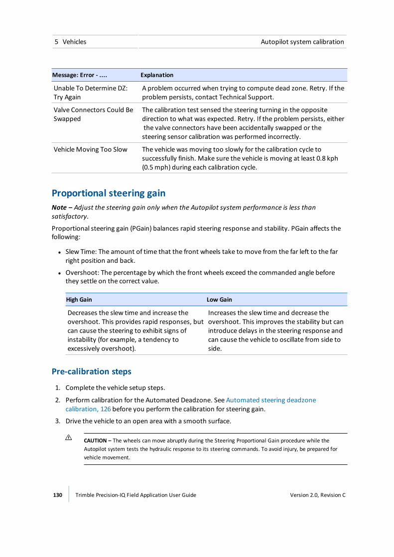
5 Vehicles Autopilot system calibration
Message: Error - .... Explanation
Unable To Determine DZ:Try Again
A problem occurred when trying to compute dead zone. Retry. If theproblem persists, contact Technical Support.
Valve Connectors Could BeSwapped
The calibration test sensed the steering turning in the oppositedirection to what was expected. Retry. If the problem persists, eitherthe valve connectors have been accidentally swapped or thesteering sensor calibration was performed incorrectly.
VehicleMoving Too Slow The vehicle was moving too slowly for the calibration cycle tosuccessfully finish. Make sure the vehicle is moving at least 0.8 kph(0.5mph) during each calibration cycle.
Proportional steering gainNote – Adjust the steering gain only when the Autopilot system performance is less thansatisfactory.
Proportional steering gain (PGain) balances rapid steering response and stability. PGain affects thefollowing:
l Slew Time: The amount of time that the front wheels take to move from the far left to the farright position and back.
l Overshoot: The percentage by which the front wheels exceed the commanded angle beforethey settle on the correct value.
High Gain Low Gain
Decreases the slew time and increase theovershoot. This provides rapid responses, butcan cause the steering to exhibit signs ofinstability (for example, a tendency toexcessively overshoot).
Increases the slew time and decrease theovershoot. This improves the stability but canintroduce delays in the steering response andcan cause the vehicle to oscillate from side toside.
Pre-calibration steps
1. Complete the vehicle setup steps.
2. Perform calibration for the Automated Deadzone. See Automated steering deadzonecalibration, 126 before you perform the calibration for steering gain.
3. Drive the vehicle to an open area with a smooth surface.
CAUTION – The wheels can move abruptly during the Steering Proportional Gain procedure while theAutopilot system tests the hydraulic response to its steering commands. To avoid injury, be prepared forvehicle movement.
130 Trimble Precision-IQ Field Application User Guide Version 2.0, Revision C
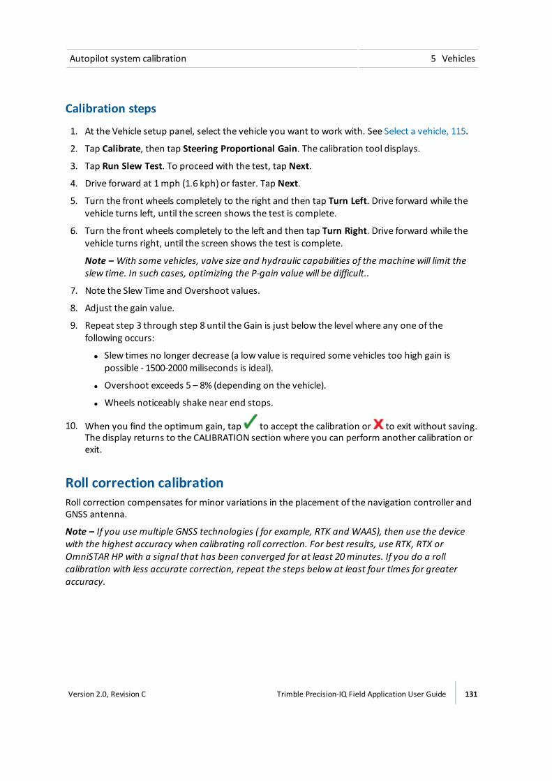
Autopilot system calibration 5 Vehicles
Calibration steps
1. At the Vehicle setup panel, select the vehicle you want to work with. See Select a vehicle, 115.
2. Tap Calibrate, then tap Steering Proportional Gain. The calibration tool displays.
3. Tap Run Slew Test. To proceed with the test, tap Next.
4. Drive forward at 1mph (1.6 kph) or faster. Tap Next.
5. Turn the front wheels completely to the right and then tap Turn Left. Drive forward while thevehicle turns left, until the screen shows the test is complete.
6. Turn the front wheels completely to the left and then tap Turn Right. Drive forward while thevehicle turns right, until the screen shows the test is complete.
Note – With some vehicles, valve size and hydraulic capabilities of the machine will limit theslew time. In such cases, optimizing the P-gain value will be difficult..
7. Note the Slew Time and Overshoot values.
8. Adjust the gain value.
9. Repeat step 3 through step 8 until the Gain is just below the level where any one of thefollowing occurs:
ll Slew times no longer decrease (a low value is required some vehicles too high gain ispossible - 1500-2000miliseconds is ideal).
l Overshoot exceeds 5 – 8% (depending on the vehicle).
l Wheels noticeably shake near end stops.
10. When you find the optimum gain, tap to accept the calibration or to exit without saving.The display returns to the CALIBRATION section where you can perform another calibration orexit.
Roll correction calibrationRoll correction compensates for minor variations in the placement of the navigation controller andGNSS antenna.
Note – If you use multiple GNSS technologies ( for example, RTK and WAAS), then use the devicewith the highest accuracy when calibrating roll correction. For best results, use RTK, RTX orOmniSTAR HP with a signal that has been converged for at least 20minutes. If you do a rollcalibration with less accurate correction, repeat the steps below at least four times for greateraccuracy.
Version 2.0, Revision C Trimble Precision-IQ Field Application User Guide 131
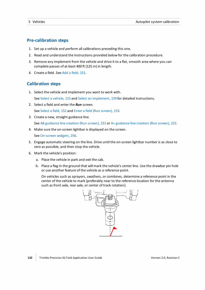
5 Vehicles Autopilot system calibration
Pre-calibration steps
1. Set up a vehicle and perform all calibrations preceding this one.
2. Read and understand the instructions provided below for the calibration procedure.
3. Remove any implement from the vehicle and drive it to a flat, smooth area where you cancomplete passes of at least 400 ft (125m) in length.
4. Create a field. See Add a field, 151.
Calibration steps
1. Select the vehicle and implement you want to work with.
See Select a vehicle, 115 and Select an implement, 159 for detailed instructions.
2. Select a field and enter the Run screen.
See Select a field, 152 and Enter a field (Run screen), 153.
3. Create a new, straight guidance line.
See AB guidance line creation (Run screen), 221 or A+ guidance line creation (Run screen), 222.
4. Make sure the on-screen lightbar is displayed on the screen.
See On-screen widgets, 256.
5. Engage automatic steering on the line. Drive until the on-screen lightbar number is as close tozero as possible, and then stop the vehicle.
6. Mark the vehicle's position:
a. Place the vehicle in park and exit the cab.
b. Place a flag in the ground that will mark the vehicle's center line. Use the drawbar pin holeor use another feature of the vehicle as a reference point.
On vehicles such as sprayers, swathers, or combines, determine a reference point in thecenter of the vehicle to mark (preferably near to the reference location for the antennasuch as front axle, rear axle, or center of track rotation).
132 Trimble Precision-IQ Field Application User Guide Version 2.0, Revision C
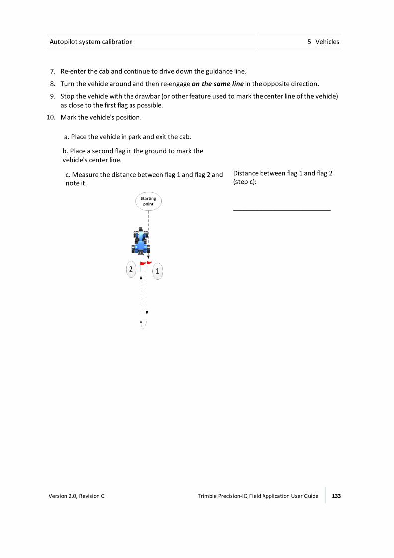
Autopilot system calibration 5 Vehicles
7. Re-enter the cab and continue to drive down the guidance line.
8. Turn the vehicle around and then re-engage on the same line in the opposite direction.
9. Stop the vehicle with the drawbar (or other feature used to mark the center line of the vehicle)as close to the first flag as possible.
10. Mark the vehicle's position.
a. Place the vehicle in park and exit the cab.
b. Place a second flag in the ground to mark thevehicle's center line.
c. Measure the distance between flag 1 and flag 2 andnote it.
Distance between flag 1 and flag 2(step c):
____________________________
Version 2.0, Revision C Trimble Precision-IQ Field Application User Guide 133

5 Vehicles Autopilot system calibration
d. Also note where the vehicle's current position is inrelation to flag 1 (in other words, the vehicle is eitherto the right or left of flag 1). The diagram, this exampleshows the vehicle is to the left of flag 1.
Vehicle is to right or left of flag 2(step d):
____________________________
e. Return to the cab and in the Run screen note thecross-track error (the number on the on-screenlightbar).
Cross-track error (number on Runscreen) (step e):
____________________________
f. Note the direction highlighted on the lightbar (left orright).
Direction highlighted on lightbar(left or right) (step f):
____________________________
11. Tap and then tap Diagnostics.
12. Tap Autopilot performance and tap the Advanced tab.
13. At the Roll Offset entry box and Vehicle Position selection box:
ll Calculate the roll offset and enter it in the display.
Refer to your notes and compare them to the following table to determine how tocalculate roll offset.
l Determine the direction of the Vehicle Position and enter it on the display.
Refer to your notes and compare them with the following table to find which VehiclePosition to select.
134 Trimble Precision-IQ Field Application User Guide Version 2.0, Revision C
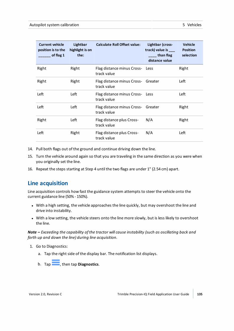
Autopilot system calibration 5 Vehicles
Current vehicleposition is to the______ of flag 1
Lightbarhighlight is on
the:
Calculate Roll Offset value: Lightbar (cross-track) value is _______ than flagdistance value
VehiclePositionselection
Right Right Flag distanceminus Cross-track value
Less Right
Right Right Flag distanceminus Cross-track value
Greater Left
Left Left Flag distanceminus Cross-track value
Less Left
Left Left Flag distanceminus Cross-track value
Greater Right
Right Left Flag distance plus Cross-track value
N/A Right
Left Right Flag distance plus Cross-track value
N/A Left
14. Pull both flags out of the ground and continue driving down the line.
15. Turn the vehicle around again so that you are traveling in the same direction as you were whenyou originally set the line.
16. Repeat the steps starting at Step 4 until the two flags are under 1" (2.54 cm) apart.
Line acquisitionLine acquisition controls how fast the guidance system attempts to steer the vehicle onto thecurrent guidance line (50% - 150%).
l With a high setting, the vehicle approaches the line quickly, but may overshoot the line anddrive into instability.
l With a low setting, the vehicle steers onto the linemore slowly, but is less likely to overshootthe line.
Note – Exceeding the capability of the tractor will cause instability (such as oscillating back andforth up and down the line) during line acquisition.
1. Go to Diagnostics:
a. Tap the right side of the display bar. The notification list displays.
b. Tap , then tap Diagnostics.
Version 2.0, Revision C Trimble Precision-IQ Field Application User Guide 135
5 Vehicles Autopilot system calibration
c. Under the Autopilot heading in the left-hand list, tap Performance.
d. Tap Steering at the top of the screen.
e. The display shows the tool for calibrating line approach aggressiveness and the cross-trackerror diagram.
2. Enter the Run screen and engage automatic steering on a straight guidance line.
a. At the Vehicle setup panel, select the vehicle and implement you want to work with. SeeSelect a vehicle, 115 and Select an implement, 159 for detailed instructions.
b. Select a field and enter the Run screen. See Select a field, 152 and Enter a field (Run screen),153.
c. Create a new, straight guidance line. See AB guidance line creation (Run screen), 221 or A+guidance line creation (Run screen), 222.
3. Drive until the lightbar shows that the cross-track error value is as close to zero as possible, andthen stop the vehicle.
4. Open the Diagnostics section for Autopilot performance again.
5. Evaluate the current accuracy of the vehicle during line acquisition with the default setting.
6. Touch and move the button with the percentage to move the slider to the left or right. Driveforward and re-engage auto-steering if necessary to test the setting.
Engage aggressivenessEngage aggressiveness controls how aggressively the vehicle initially turns towards the guidanceline.
l With a high setting, the vehicle will initially respond quickly.
l With low setting, the vehicle will respond more smoothly when initially engaged.
1. Enter the Run screen and engage automatic steering on a straight guidance line. See Enter afield (Run screen), 153 for more instructions on entering the Run screen.
2. Drive the vehicle approximately 10 seconds.
3. Open the Diagnostics section for the Autopilot system's performance.
a. Tap the right side of the display bar. The notification list displays.
b. Tap , then tap Diagnostics.
c. Tap Steering at the top of the screen.
4. Evaluate the current accuracy of the vehicle during line acquisition with the default setting .
5. Touch and move the button with the percentage to move the slider to the left or right. Driveforward and re-engage auto-steering if necessary to test the setting.
136 Trimble Precision-IQ Field Application User Guide Version 2.0, Revision C
EZ-Pilot system setup 5 Vehicles
EZ-Pilot system setupThe EZ-Pilot system turns the steering wheel for you with an electric motor drive. It uses GNSSguidance from the Precision-IQ field application.
Initial setup steps are:
l Guidance selection for the EZ-Pilot system, 137
l Controller settings for EZ-Pilot system, 137
l Vehicle measurements for EZ-Pilot system, 140
l Steering speed settings for EZ-Pilot system, 138
Guidance selection for the EZ-Pilot system
WARNING – Auto guidance systems cannot avoid items in the field such as obstacles. Make sure you areadequately trained to operate the auto guidance system.
1. Navigate to theGUIDANCE section of the vehicle setup panel:
a. At theHome screen, tap . The Vehicle setup panel displays.
b. At the list on the left-hand side of the setup panel, tap the name of the vehicle you want toedit. The display changes the list item to a blue background with white text.
c. Tap Edit, then GUIDANCE.
2. At the SELECTION section,tap EZ-Pilot.
WARNING – Many large and sudden changes in satellite geometry caused by blocked satellites can causesignificant position shifts. If operating under these conditions, auto-guidance systems can react abruptly. Toavoid possible personal injury or damage to property under these conditions, disable the auto-guidancesystem and take manual control of the vehicle until conditions have cleared.
3. Tap Next to set up the controller orientation. See Controller settings for EZ-Pilot system, 137.
Controller settings for EZ-Pilot systemThe EZ-Pilot system ueses the IMD-600 to provide roll compensation when the vehicle is on a slopeor drives over a bump. For roll compensation to work correctly, the IMD-600must be calibrated.IMD stands for Inertial Measurement Device.
To set up the IMD-600 controller, you must indicate the position/orientation of the controller as it iscurrently installed in the vehicle.
For example, if the controller is positioned with the input jacks of the controller facing to the left sideof your vehicle, you indicate this in the Precision-IQ field application.
Version 2.0, Revision C Trimble Precision-IQ Field Application User Guide 137
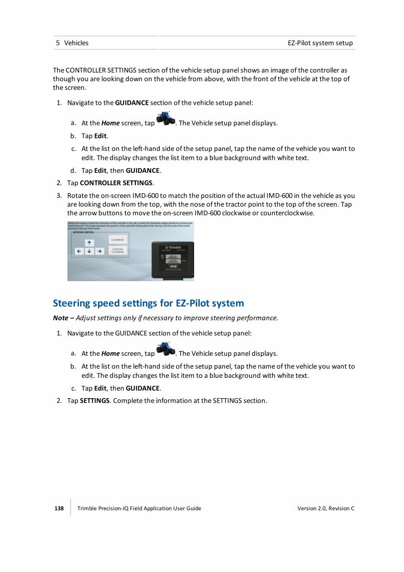
5 Vehicles EZ-Pilot system setup
The CONTROLLER SETTINGS section of the vehicle setup panel shows an image of the controller asthough you are looking down on the vehicle from above, with the front of the vehicle at the top ofthe screen.
1. Navigate to theGUIDANCE section of the vehicle setup panel:
a. At theHome screen, tap . The Vehicle setup panel displays.
b. Tap Edit.
c. At the list on the left-hand side of the setup panel, tap the name of the vehicle you want toedit. The display changes the list item to a blue background with white text.
d. Tap Edit, then GUIDANCE.
2. Tap CONTROLLER SETTINGS.
3. Rotate the on-screen IMD-600 to match the position of the actual IMD-600 in the vehicle as youare looking down from the top, with the nose of the tractor point to the top of the screen. Tapthe arrow buttons to move the on-screen IMD-600 clockwise or counterclockwise.
Steering speed settings for EZ-Pilot systemNote – Adjust settings only if necessary to improve steering performance.
1. Navigate to the GUIDANCE section of the vehicle setup panel:
a. At theHome screen, tap . The Vehicle setup panel displays.
b. At the list on the left-hand side of the setup panel, tap the name of the vehicle you want toedit. The display changes the list item to a blue background with white text.
c. Tap Edit, then GUIDANCE.
2. Tap SETTINGS. Complete the information at the SETTINGS section.
138 Trimble Precision-IQ Field Application User Guide Version 2.0, Revision C
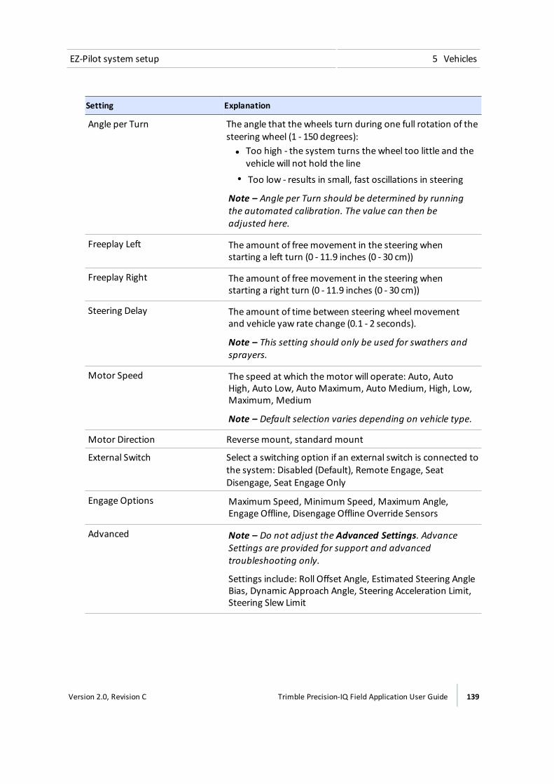
EZ-Pilot system setup 5 Vehicles
Setting Explanation
Angle per Turn The angle that the wheels turn during one full rotation of thesteering wheel (1 - 150 degrees):ll Too high - the system turns the wheel too little and the
vehicle will not hold the linel Too low - results in small, fast oscillations in steering
Note – Angle per Turn should be determined by runningthe automated calibration. The value can then beadjusted here.
Freeplay Left The amount of freemovement in the steering whenstarting a left turn (0 - 11.9 inches (0 - 30 cm))
Freeplay Right The amount of freemovement in the steering whenstarting a right turn (0 - 11.9 inches (0 - 30 cm))
Steering Delay The amount of time between steering wheel movementand vehicle yaw rate change (0.1 - 2 seconds).
Note – This setting should only be used for swathers andsprayers.
Motor Speed The speed at which themotor will operate: Auto, AutoHigh, Auto Low, Auto Maximum, Auto Medium, High, Low,Maximum, Medium
Note – Default selection varies depending on vehicle type.
Motor Direction Reversemount, standard mount
External Switch Select a switching option if an external switch is connected tothe system: Disabled (Default), Remote Engage, SeatDisengage, Seat Engage Only
Engage Options Maximum Speed, Minimum Speed, Maximum Angle,Engage Offline, Disengage Offline Override Sensors
Advanced Note – Do not adjust the Advanced Settings. AdvanceSettings are provided for support and advancedtroubleshooting only.
Settings include: Roll Offset Angle, Estimated Steering AngleBias, Dynamic Approach Angle, Steering Acceleration Limit,Steering Slew Limit
Version 2.0, Revision C Trimble Precision-IQ Field Application User Guide 139
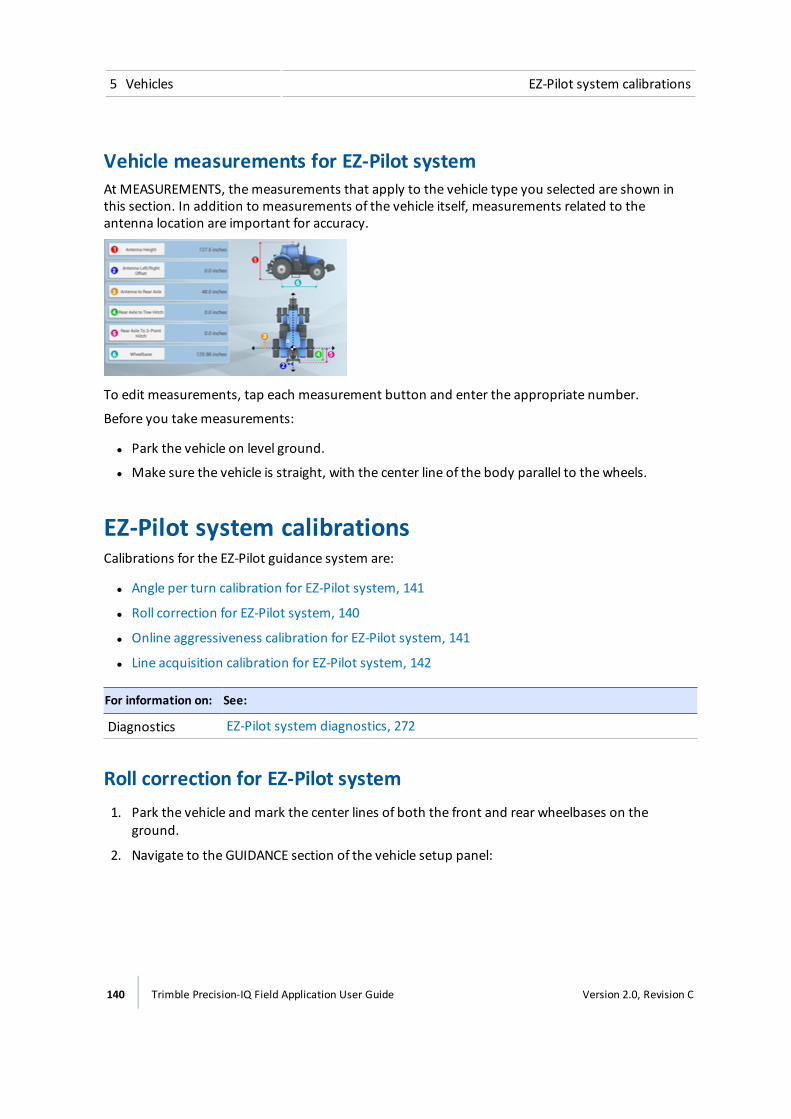
5 Vehicles EZ-Pilot system calibrations
Vehicle measurements for EZ-Pilot systemAt MEASUREMENTS, themeasurements that apply to the vehicle type you selected are shown inthis section. In addition to measurements of the vehicle itself, measurements related to theantenna location are important for accuracy.
To edit measurements, tap each measurement button and enter the appropriate number.
Before you takemeasurements:
l Park the vehicle on level ground.
l Make sure the vehicle is straight, with the center line of the body parallel to the wheels.
EZ-Pilot system calibrationsCalibrations for the EZ-Pilot guidance system are:
l Angle per turn calibration for EZ-Pilot system, 141
l Roll correction for EZ-Pilot system, 140
l Online aggressiveness calibration for EZ-Pilot system, 141
l Line acquisition calibration for EZ-Pilot system, 142
For information on: See:
Diagnostics EZ-Pilot system diagnostics, 272
Roll correction for EZ-Pilot system1. Park the vehicle and mark the center lines of both the front and rear wheelbases on the
ground.
2. Navigate to the GUIDANCE section of the vehicle setup panel:
140 Trimble Precision-IQ Field Application User Guide Version 2.0, Revision C

EZ-Pilot system calibrations 5 Vehicles
a. At theHome screen, tap . The Vehicle setup panel displays.
b. At the list on the left-hand side of the setup panel, tap the name of the vehicle you want tocalibrate. The display changes the list item to a blue background with white text.
3. Tap Calibrate.
4. Tap Roll Calibration. The calibration tool displays.
5. Follow the instructions on the calibration tool.
6. To accept the calibration, tap .
7. To discard the calibration and start it again, tap .
Angle per turn calibration for EZ-Pilot systemNote – Complete the roll correction calibration before performing this calibration.
1. Navigate to the GUIDANCE section of the vehicle setup panel:
a. At theHome screen, tap . The Vehicle setup panel displays.
b. At the list on the left-hand side of the setup panel, tap the name of the vehicle you want tocalibrate. The display changes the list item to a blue background with white text.
2. Tap Calibrate.
3. Tap Angle Per Turn. The calibration tool displays.
4. Follow the steps on the calibration tool.
Online aggressiveness calibration for EZ-Pilot systemOnline aggressiveness controls how aggressively the vehicle reacts to cross track error whileoperating on the guidance line (50% - 150%).
l With a high setting, the vehicle will bemore reactive to cross track error. A high setting maycause the system to overreact and become unstable.
l With low setting, the vehicle will make less of a steering correction to the online cross trackerror.
1. Enter the Run screen and engage automatic steering on a straight guidance line. See Enter afield (Run screen), 153 for more instructions on entering the Run screen.
2. Drive the vehicle approximately 10 seconds.
Version 2.0, Revision C Trimble Precision-IQ Field Application User Guide 141
5 Vehicles EZ-Pilot system calibrations
3. Open the Diagnostics section for the EZ-Pilot system's performance.
a. Tap the right side of the display bar. The notification list displays.
b. Tap , then tap Diagnostics.
c. Tap Steering at the top of the screen.
4. Evaluate the current accuracy of the vehicle during online operation with the default setting .
5. Touch and move the button with the percentage to move the slider to the left or right. Driveforward and re-engage auto-steering if necessary to test the setting.
Line acquisition calibration for EZ-Pilot systemLine acquisition controls how fast the guidance system attempts to steer the vehicle onto thecurrent guidance line (50% - 150%).
l With a high setting, the vehicle approaches the line quickly, but may overshoot the line anddrive itself to instability.
l With a low setting, the vehicle steers onto the linemore slowly, but is less likely to overshootthe line.
Note – Exceeding the capability of the tractor will cause instability (such as oscillating back andforth up and down the line) during line acquisition.
1. Go to Diagnostics:
a. Tap the right side of the display bar. The notification list displays.
b. Tap , then tap Diagnostics.
c. Under the EZ-Pilot heading in the left-hand list, tap Performance.
d. Tap Steering at the top of the screen.
e. The display shows the adjustments for calibrating line approach aggressiveness and thecross-track error diagram.
2. Enter the Run screen and engage automatic steering on a straight guidance line.
a. At the Vehicle setup panel, select the vehicle and implement you want to work with. SeeSelect a vehicle, 115 and Select an implement, 159 for detailed instructions.)
b. Select a field and enter the Run screen. See Select a field, 152 and Enter a field (Run screen),153.
c. Create a new, straight guidance line. See AB guidance line creation (Run screen), 221 or A+guidance line creation (Run screen), 222.
3. Drive until the lightbar shows that the cross-track error value is as close to zero as possible, andthen stop the vehicle.
4. Open the Diagnostics section for Autopilot performance again.
142 Trimble Precision-IQ Field Application User Guide Version 2.0, Revision C

EZ-Pilot system calibrations 5 Vehicles
5. Evaluate the current accuracy of the vehicle during line acquisition with the default setting.
6. Touch and move the button with the percentage to move the slider to the left or right. Driveforward and re-engage auto-steering if necessary to test the setting.
7. Drive until the lightbar shows that the cross-track error value is as close to zero as possible, andthen stop the vehicle.
8. Open the Diagnostics section for EZ-Pilot performance again.
9. Evaluate the current accuracy of the vehicle during line acquisition with the default setting.
10. Touch and move the button with the percentage to move the slider to the left or right. Driveforward and re-engage auto-steering if necessary to test the setting.
Version 2.0, Revision C Trimble Precision-IQ Field Application User Guide 143
5 Vehicles EZ-Steer system setup
EZ-Steer system setupThe EZ-Steer system turns the steering wheel for you by combining a friction wheel and a motorwith guidance from the Precision-IQ field application.
Initial setup steps are:
l Guidance selection for EZ-Steer system, 144
l Controller settings for EZ-Steer system, 144
l Steering and speed settings for EZ-Steer system, 144
l Vehicle measurements for EZ-Steer system, 146
Guidance selection for EZ-Steer system
WARNING – Auto guidance systems cannot avoid items in the field such as obstacles. Make sure you areadequately trained to operate the auto guidance system.
1. Navigate to theGUIDANCE section of the vehicle setup panel:
a. At theHome screen, tap . The Vehicle setup panel displays.
b. At the list on the left-hand side of the setup panel, tap the name of the vehicle you want toedit. The display changes the list item to a blue background with white text.
c. Tap Edit, then GUIDANCE.
2. At the SELECTIONS section,tap Selection and then tap EZ-Steering.
WARNING – Many large and sudden changes in satellite geometry caused by blocked satellites can causesignificant position shifts. If operating under these conditions, auto-guidance systems can react abruptly. Toavoid possible personal injury or damage to property under these conditions, disable the auto-guidancesystem and take manual control of the vehicle until conditions have cleared.
3. Tap Next to set up the controller orientation. See Controller settings for EZ-Steer system, 144.
Controller settings for EZ-Steer system
Setting Explanation
Connector Faces Indicate how the connector on the navigation controller faces: Back, Floor,Front
Steering and speed settings for EZ-Steer systemNote – Adjust settings only if necessary to improve steering performance.
144 Trimble Precision-IQ Field Application User Guide Version 2.0, Revision C
EZ-Steer system setup 5 Vehicles
1. Navigate to the GUIDANCE section of the vehicle setup panel:
a. At theHome screen, tap . The Vehicle setup panel displays.
b. At the list on the left-hand side of the setup panel, tap the name of the vehicle you want toedit. The display changes the list item to a blue background with white text
c. Tap Edit, then GUIDANCE.
2. Tap SETTINGS. Complete the information at the SETTINGS section.
Steering Sensor Setting Description
Angle per Turn The angle that the wheels turn during one full rotation ofthe steering wheel (1 - 150 degrees):
ll Too high - the system turns the wheel too little and thevehicle will not hold the line
l Too low - results in small, fast oscillations in steering
Angle per turn values should be calibrated first using EZ-Steer calibration and then adjusted here if necessary.
Freeplay Left The amount of freemovement in the steering whenstarting a left turn (0 - 11.9 inches (0 - 30 cm))
Freeplay Right The amount of freemovement in the steering whenstarting a right turn (0 - 11.9 inches (0 - 30 cm))
Steering Delay
Note – Only available ifvehicle is sprayer or swather.
The amount of time between steering wheel movementand vehicle yaw rate change (0.1-1.5 seconds)
Note – This value should only be used for swathers andsprayers.
Motor Speed The speed at which themotor will operate:
ll Auto, Auto Low, Auto Medium, Auto High, or AutoMaximum
l Manual Low,ManualMedium (Default),Manual High,orManualMaximum
Note – Auto mode determines the proper speed for thesteering action required.
Motor Direction The direction the EZ-Steer system motor is installed:
ll Standard Mountl Reversed Mount
Version 2.0, Revision C Trimble Precision-IQ Field Application User Guide 145
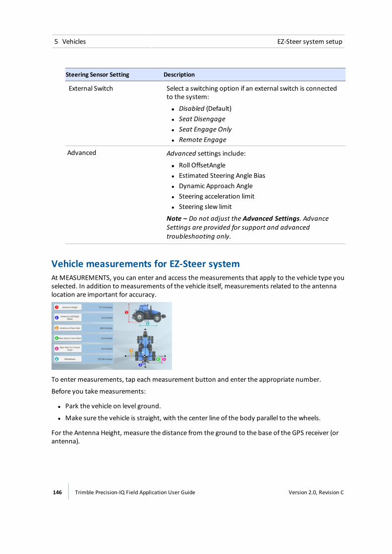
5 Vehicles EZ-Steer system setup
Steering Sensor Setting Description
External Switch Select a switching option if an external switch is connectedto the system:
ll Disabled (Default)l Seat Disengagel Seat Engage Onlyl Remote Engage
Advanced Advanced settings include:
ll Roll OffsetAnglel Estimated Steering Angle Biasl Dynamic Approach Anglel Steering acceleration limitl Steering slew limit
Note – Do not adjust the Advanced Settings. AdvanceSettings are provided for support and advancedtroubleshooting only.
Vehicle measurements for EZ-Steer systemAt MEASUREMENTS, you can enter and access themeasurements that apply to the vehicle type youselected. In addition to measurements of the vehicle itself, measurements related to the antennalocation are important for accuracy.
To enter measurements, tap each measurement button and enter the appropriate number.
Before you takemeasurements:
l Park the vehicle on level ground.
l Make sure the vehicle is straight, with the center line of the body parallel to the wheels.
For the Antenna Height, measure the distance from the ground to the base of the GPS receiver (orantenna).
146 Trimble Precision-IQ Field Application User Guide Version 2.0, Revision C
EZ-Steer system calibrations 5 Vehicles
EZ-Steer system calibrationsCalibrations for the EZ-Steer auto guidance system include:
l Angle per turn calibration for EZ-Steer system, 147
l Roll correction for EZ-Steer system, 147
For information on: See:
Diagnostics EZ-Steer system diagnostics, 277
Roll correction for EZ-Steer system1. Park the vehicle and mark the center lines of both the front and rear wheelbases on the
ground.
2. Navigate to the GUIDANCE section of the vehicle setup panel:
a. At theHome screen, tap . The Vehicle setup panel displays.
b. At the list on the left-hand side of the setup panel, tap the name of the vehicle you want tocalibrate. The display changes the list item to a blue background with white text.
3. Tap Calibrate.
4. Tap Roll Calibration. The calibration tool displays.
5. Follow the instructions on the calibration tool.
6. To accept the calibration, tap .
7. To discard the calibration and start it again, tap .
Angle per turn calibration for EZ-Steer systemPerform the Roll calibration before performing the angle per turn calibration.
1. Navigate to the GUIDANCE section of the vehicle setup panel:
a. At theHome screen, tap . The Vehicle setup panel displays.
b. At the list on the left-hand side of the setup panel, tap the name of the vehicle you want tocalibrate. The display changes the list item to a blue background with white text.
2. Tap Calibrate.
3. Tap Angle Per Turn. The calibration wizard displays.
4. Begin the steps on the calibration procedure by driving the vehicle between 2 and 4mph.
Version 2.0, Revision C Trimble Precision-IQ Field Application User Guide 147

5 Vehicles EZ-Steer system calibrations
148 Trimble Precision-IQ Field Application User Guide Version 2.0, Revision C

Fields
In this chapter:
Field Basics 150
Add a field 151
Select a field 152
Enter a field (Run screen) 153
Edit a field (Field Manager) 154
You can createmultiple fields and thenselect one to enter. Using the FieldManager, you can also edit and deletefields.
6C h a p t e r
Version 2.0, Revision C Trimble Precision-IQ Field Application User Guide 149
6 Fields Field Basics
Field BasicsA field is an item you create in the Run screen that represents an area of land. A field can contain oneor more boundaries (perimeters) (or no boundaries). Information associated with each fieldincludes:
l Boundaries, guidance lines and patterns for steering assistance
l Landmarks such as points, lines and area features
l Tasks
l Coverage information recorded during field activities when logging is activated
l Attributes such as Clients and Farms
To edit and refine boundaries, guidance lines and patterns, and landmarks, open the Field Manager(see Field Manager, 53).
BoundariesThe perimeter around your field is a boundary. A boundary line begins when you tap a button torecord the start of your boundary. After driving the length of the boundary, you tap a button tostop recording the path of the boundary. For more information, see Boundary creation (Runscreen), 218 and Boundary editing (Field Manager), 219.
Guidance lines and patternsWith a steering assistance feature, your vehicle can be set to drive on guidance lines and patterns.This improves the accuracy of planting, applications and harvesting. The types of lines are:
l AB line: A straight line that begins at point A. After driving the direction of the line path, youend the line at point B. See AB guidance line creation (Run screen), 221.
l A+ line: A straight line that you begin with point A and choose the direction you want the lineto draw.
l Curve: A curved line begins when you tap a button to start recording the line path and thendrive in a curved direction. The line ends when you tap a button to stop recording the line path.See Curved line creation (Run screen), 222.
The types of patterns are:
l Headlands: An area you can create by recording your beginning point and stopping therecording when you are finished. You have the option to create an infill pattern of straight orcurved lines. See Headland and infill pattern creation (Run screen), 223.
l Pivots: A circular area you create by recording your beginning point and stopping recordingwhen you are finished. See Pivot pattern creation (Run screen), 228.
150 Trimble Precision-IQ Field Application User Guide Version 2.0, Revision C

Add a field 6 Fields
LandmarksYou create landmarks to indicate productive and non-productive areas, as well as items that youwant the display to warn the driver about. Landmarks can be:
l Lines
l Points
l Areas
For more information, see
l Landmark line creation (Run screen), 234
l Landmark point creation (Run screen), 234
l Landmark area creation (Run screen), 235
l Landmark editing (Field Manager), 235
Tasks, activities and coverageA task is a set of information that includes:
l One or more activities being completed in a field (such as planting, spraying, and so on)
l Amap layer showing the activity's coverage on the field
The Precision-IQ field application stores field activities related to each unique operation and fieldcombination together as a task. By using tasks, you do not have to continually configure fields thatyou frequently use.
For more information, see:
l Tasks, 208
l Coverage logging, 211
Add a field
1. At theHome screen, tap .
2. Enter a name for the field and then tap .
The system saves the field name and its location.
To work with the field, see Preparing for operation, 204.
Version 2.0, Revision C Trimble Precision-IQ Field Application User Guide 151

6 Fields Select a field
Select a fieldTo work with a field to work within it, you select it. When you add a field, it is selected automatically.
If you havemultiple fields, you can select a field from:
l The point on themap at theHome screen.
l The list of fields.
Select a field through the map
The points on themap ( ) of theHome screen indicate fields you have created. Tap the point thatrepresents the field.
Select a field from the listThe outlines on themap of theHome screen indicate fields you have created.
1. At theHome screen, tap . A list of fields you previously created displays.
2. To reduce the number of fields in the list, tap . A filter tool displays, showing the clientname and the farms associated with the client.
3. Deselect (uncheck) the options you do not want to see and tap Accept. The Fields list nowshows fields associated with the client and/or farm that you left checked.
4. Tap the name of the field to select it.
152 Trimble Precision-IQ Field Application User Guide Version 2.0, Revision C
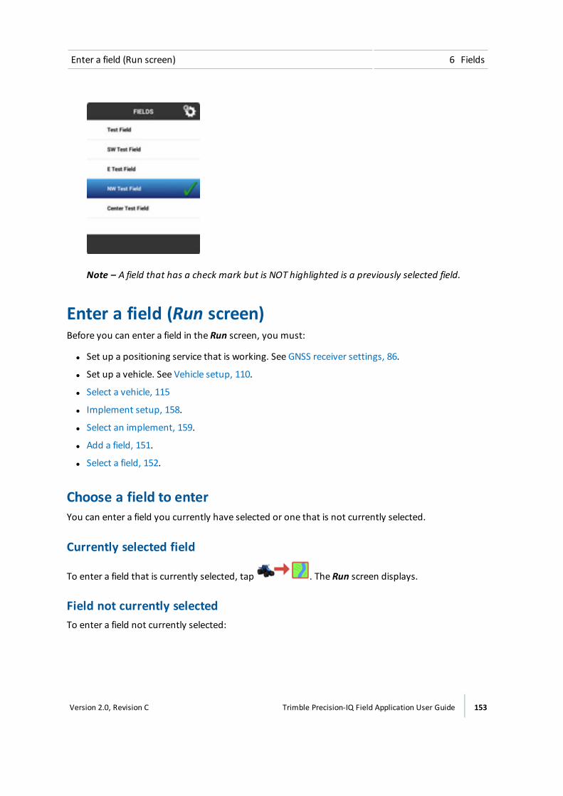
Enter a field (Run screen) 6 Fields
Note – A field that has a check mark but is NOT highlighted is a previously selected field.
Enter a field (Run screen)Before you can enter a field in the Run screen, you must:
l Set up a positioning service that is working. See GNSS receiver settings, 86.
l Set up a vehicle. See Vehicle setup, 110.
l Select a vehicle, 115
l Implement setup, 158.
l Select an implement, 159.
l Add a field, 151.
l Select a field, 152.
Choose a field to enterYou can enter a field you currently have selected or one that is not currently selected.
Currently selected field
To enter a field that is currently selected, tap . The Run screen displays.
Field not currently selectedTo enter a field not currently selected:
Version 2.0, Revision C Trimble Precision-IQ Field Application User Guide 153
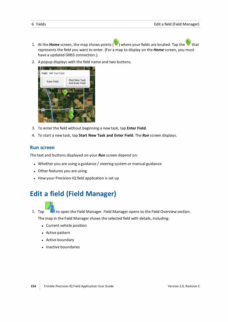
6 Fields Edit a field (Field Manager)
1. At theHome screen, themap shows points ( ) where your fields are located. Tap the thatrepresents the field you want to enter. (For a map to display on theHome screen, you musthave a updated GNSS connection.).
2. A popup displays with the field name and two buttons.
3. To enter the field without beginning a new task, tap Enter Field.
4. To start a new task, tap Start New Task and Enter Field. The Run screen displays.
Run screenThe text and buttons displayed on your Run screen depend on:
l Whether you are using a guidance / steering system or manual guidance
l Other features you are using
l How your Precision-IQ field application is set up
Edit a field (Field Manager)
1. Tap to open the Field Manager. Field Manager opens to the Field Overview section.
Themap in the Field Manager shows the selected field with details, including:
ll Current vehicle position
l Active pattern
l Active boundary
l Inactive boundaries
154 Trimble Precision-IQ Field Application User Guide Version 2.0, Revision C
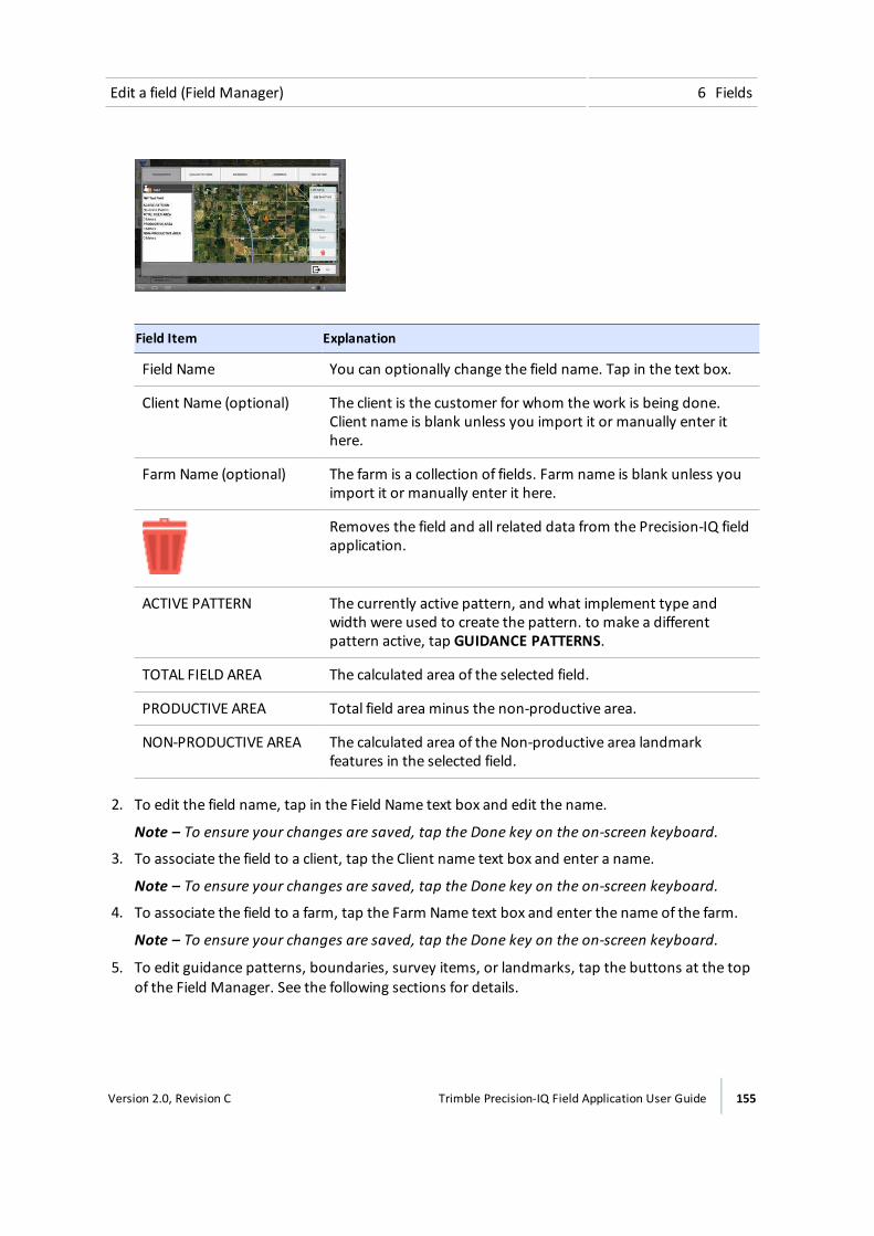
Edit a field (Field Manager) 6 Fields
Field Item Explanation
Field Name You can optionally change the field name. Tap in the text box.
Client Name (optional) The client is the customer for whom the work is being done.Client name is blank unless you import it or manually enter ithere.
Farm Name (optional) The farm is a collection of fields. Farm name is blank unless youimport it or manually enter it here.
Removes the field and all related data from the Precision-IQ fieldapplication.
ACTIVE PATTERN The currently active pattern, and what implement type andwidth were used to create the pattern. to make a differentpattern active, tap GUIDANCE PATTERNS.
TOTAL FIELD AREA The calculated area of the selected field.
PRODUCTIVE AREA Total field area minus the non-productive area.
NON-PRODUCTIVE AREA The calculated area of the Non-productive area landmarkfeatures in the selected field.
2. To edit the field name, tap in the Field Name text box and edit the name.
Note – To ensure your changes are saved, tap the Done key on the on-screen keyboard.
3. To associate the field to a client, tap the Client name text box and enter a name.
Note – To ensure your changes are saved, tap the Done key on the on-screen keyboard.
4. To associate the field to a farm, tap the Farm Name text box and enter the name of the farm.
Note – To ensure your changes are saved, tap the Done key on the on-screen keyboard.
5. To edit guidance patterns, boundaries, survey items, or landmarks, tap the buttons at the topof the Field Manager. See the following sections for details.
Version 2.0, Revision C Trimble Precision-IQ Field Application User Guide 155

6 Fields Edit a field (Field Manager)
ll Guidance pattern shifting (Field Manager), 231
l Boundary editing (Field Manager), 219
l Landmark editing (Field Manager), 235
6. Tap to save the changes and close the Field Manager.
156 Trimble Precision-IQ Field Application User Guide Version 2.0, Revision C

Implements
In this chapter:
Implement setup 158
ISOBUS for implements 161
Application control 166
Boom height control 180
Inputs 189
Review implement summary 192
Prescriptions 193
Implements can be added, edited anddeleted at the Implement setup panel.You can also calibrate boom height andsection and rate control.
You must select an implement before youcan enter the Run screen.
7C h a p t e r
Version 2.0, Revision C Trimble Precision-IQ Field Application User Guide 157

7 Implements Implement setup
Implement setupUse the Implement setup panel to select, add, edit, calibrate or delete an implement. Implementscan be pull-type equipment or attachments for self-propelled equipment.
Before you set up an implement, create a vehicle. See Add a vehicle, 110.
Add an implement
1. At theHome screen, tap . The Implement setup panel displays.
Tap ADD IMPLEMENT.
2. At the OPERATION section, tap the type of operation that you will use the implement toperform.
3. At the IMPLEMENT / Type section, tap the type of implement you will be using. Then tap Nextto continue.
4. At the NAME section, the system has pre-named the implement by giving it the name of thetype. You have the option to enter a different name if you want to change it.
5. Tap Next to continue to theMEASUREMENTS section. See for further instructions.
Save an implementYou can save complete or incomplete implements.
Save complete implement settings
1. Complete all of the implement setup and calibration steps for your operation, based on theimplement type and features/plugins you have unlocked on the device.
2. When you complete the implement setup, your last step is the SUMMARY section.
3. Tap to save the implement and return to theHome screen.
Save incomplete implement settingsThe display allows you to save an incomplete implementand return to it later to complete.
Note – You cannot enter the run screen without a completed implement that you have selected.
158 Trimble Precision-IQ Field Application User Guide Version 2.0, Revision C
Implement setup 7 Implements
1. Select an operation type, make, model and name the implement.
2. At any point after you complete the NAME section, tap SUMMARY, then tap .
Select an implementNote – You can only enter the Run screen with an implement when the required implement setupand calibration steps are complete. When you change implements, make sure that all relatedconfigurations are accurate for the current operation.
To select an implement that is already set up:
1. Tap at theHome screen.
2. To select an implement in the list, tap the implement.
3. Tap Select. The name of the implement highlights in blue and a displays next to the name.
Note – Without a blue highlight, the indicates an implement that was selected previously.
Edit an implement
1. Tap on theHome screen. The Implement setup panel displays.
2. In the list of implements, tap the implement that you want to edit.
3. Tap Edit.
4. Tap the section where you want to make edits.
5. When you are finished, tap Summary at the top right corner of the screen. For details, seeReview implement summary, 192.
If any part of the setup is Not Complete, you can save the changes but you cannot use theimplement on the Run screen.
6. To save your changes to the implement, tap . TheHome screen displays.
7. To cancel/remove your edits and not change the existing profile, tap . Amessage displays,asking if you want to cancel without saving your changes. Tap cancel.
Delete an implementYou can delete an implement. However, when you do so, all settings associated with thatimplement will also be deleted.
Version 2.0, Revision C Trimble Precision-IQ Field Application User Guide 159

7 Implements Implement setup
1. Tap on theHome screen.
2. Tap the implement you want to delete.
3. Tap Delete. A confirmation message displays for you to confirm you want to remove theimplement.
4. Tap to delete the implement.
160 Trimble Precision-IQ Field Application User Guide Version 2.0, Revision C

ISOBUS for implements 7 Implements
ISOBUS for implementsISOBUS is a set of software and hardware standards that makes possible the communicationbetween equipment made by different manufacturers.
With ISOBUS, you can use the Precision-IQ field application to control an ISO-certified implementwithout an additional display. An ISO-certified implement has small computers called electroniccontrol units (ECUs) which send signals to the Precision-IQ field application. An ISO-certified tractorhas a tractor ECU (TECU) installed on it. ECUs on implements enable you to control the operation:
l With the Precision-IQ field application, using Task Controller (an optional feature)
l With Virtual Terminal, an on-screen window that opens on the Precision-IQ field application toaccess directly the functions provided by the ECUs
Task Controller setupTo set up the implement and Precision-IQ field application for Task Controller:
1. Connect the display to the ISO-certified implement with ISO cabling. See theGetting StartedGuide for ISOBUS on the Precision-IQ field application.
2. Set up the GNSS receiver to send messages to the implement. See CANmessage settings, 100.
3. Unlock Task Controller. See Feature unlocks, 75.
4. Turn on the Task Controller feature. See ISOBUS settings, 80.
5. Set up the implement for Task Controller. See Implement setup for Task Controller, 161.
For information on: See:
Using Task Controller Task Controller operation, 252
Using Virtual Terminal Virtual Terminal operation, 254
Implement setup for Task ControllerNote – Before you set up Task Controller, you must unlock the feature (see Feature unlocks, 75)and have turned Task Controller on in the display settings (see ISOBUS settings, 80).
Version 2.0, Revision C Trimble Precision-IQ Field Application User Guide 161
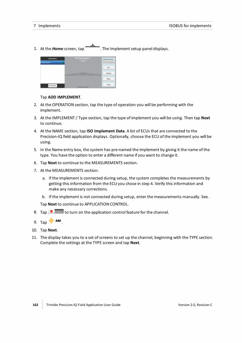
7 Implements ISOBUS for implements
1. At theHome screen, tap . The Implement setup panel displays.
Tap ADD IMPLEMENT.
2. At the OPERATION section, tap the type of operation you will be performing with theimplement.
3. At the IMPLEMENT / Type section, tap the type of implement you will be using. Then tap Nextto continue.
4. At the NAME section, tap ISO Implement Data. A list of ECUs that are connected to thePrecision-IQ field application displays. Optionally, choose the ECU of the implement you will beusing.
5. In the Name entry box, the system has pre-named the implement by giving it the name of thetype. You have the option to enter a different name if you want to change it.
6. Tap Next to continue to theMEASUREMENTS section.
7. At theMEASUREMENTS section:
a. If the implement is connected during setup, the system completes themeasurements bygetting this information from the ECU you chose in step 4. Verify this information andmake any necessary corrections.
b. If the implement is not connected during setup, enter themeasurements manually. See .
Tap Next to continue to APPLICATION CONTROL.
8. Tap to turn on the application control feature for the channel.
9. Tap .
10. Tap Next.
11. The display takes you to a set of screens to set up the channel, beginning with the TYPE section.Complete the settings at the TYPE screen and tap Next.
162 Trimble Precision-IQ Field Application User Guide Version 2.0, Revision C
ISOBUS for implements 7 Implements
Tap... To...
Material Type Select thematerial you will be applying:
ll Anhydrousl Granular Fertilizerl Granular Seedl Liquidl RowCrop Seed
ISO Implement Data Select the ECU of the implement you are using to assign this ECU tothis channel.
Note – This is required before you can use this channel.
12. At the SETTINGS screen, tap to turn on:
a. Rate Control to use rate control. There is no need to complete any other settings becausethe ECU provides this information.
b. Rate Snapping to use rate snapping.This setting smooths out rate fluctuations seen on thescreen.
Setting Explanation
Off The display shows instant readings from the feedback sensor. This mayshow frequent minor rate fluctuations.
On The display smooths out the values. You will see the target rate as theapplied rate whenever the applied rate is within 10% of the target rate.
c. Section Control if you want to use section control.
13. If you chose to use section control:
a. While still at the SETTINGS screen, tap Number of Sections. The ECU sends thisinformation to the system. Verify the number of sections and tap Next.
b. At theWIDTH screen the system shows the number of sections you indicated in theprevious screen and the width of each section. This information is obtained from the ECU.
c. Tap Next to continue to LATENCIES.
d. At LATENCIES, enter the applicable settings for section control and tap Next.
Latency refers to the delay between when the command occurs (to turn a section on or
Version 2.0, Revision C Trimble Precision-IQ Field Application User Guide 163
7 Implements ISOBUS for implements
off) and when application of thematerial actually starts or stops.
Tap... To...
On Latency Enter the length of time (seconds) from when a section is turnedon to when the system begins to apply material.
Off Latency Enter the length of time (seconds) from when a section is turnedoff to when the system stops applying material.
Apply Latency toBoundary
Turn setting on or off by tapping. This setting applies to fieldsthat have a boundary, and when you exit an exclusion zone andreturn to the workable area of the field.
On: The system uses on latency to begin applying materialimmediately when crossing a boundary.
Off: The system starts when the boundary is reached and anymechanical delay could leave a gap between the boundary andwhere the product is applied. When GPS accuracy is low, this isthe preferred selection.
Sections Off whenStopped
Turn setting on or off:On: The sections shut down when the vehicle is stopped.
Off: The sections remain open (turned on) when the vehicle isstopped.
e. At OVERLAPS enter the appropriate settings for section control and tap Next.
Tap... To...
Start Overlap Enter the amount of overlap (distance) you want when startingcoverage.
When you are in a previously covered area driving toward annon-covered area, the system will begin turning sections on atthis distance before reaching the non-covered area.
End Overlap Enter the amount of overlap (distance) you want when stoppingcoverage.When you are applying material and driving toward a previouslycovered area, the system will keep sections on until they are thisfar into the previously covered area.
164 Trimble Precision-IQ Field Application User Guide Version 2.0, Revision C
ISOBUS for implements 7 Implements
Tap... To...
Coverage SwitchingOverlap
Enter the percentage of a section's width that must be in apreviously covered area before the system switches the sectionoff. The higher the number, the greater the overlapped areabefore the section is turned off.
Boundary SwitchingOverlap
Enter the percentage of a section's width that must be past aboundary before the system switches the section off. The higherthe number, the greater the overlapped area before the section isturned off.
14. At the SUMMARY screen, review the settings and tap to save the settings for this channel.
15. For each additional channel, complete steps 9 through 14.
16. Complete the implement setupand save the Implement Summary. For instructions on BoomHeight, Inputs and Summary, see:
ll Boom height control setup, 180
l Inputs, 189
l Review implement summary, 192
17. If you have not already done so, complete the setup for sending GNSS signals to theimplement. See CANmessage settings, 100.
18. Set up the ISO-certified equipment to use Task Controller. See ISOBUS settings, 80.
To operate the Task Controller, see Task Controller operation, 252.
Equipment setupAs part of getting the implement ready to be controlled by Task Controller, you use Virtual Terminalto set the configuration for the implement.
1. Make sure the ISO-certified implement is connected and Virtual Terminal is turned on inSettings. See ISOBUS settings, 80.
2. At any screen access themain menu by tapping . Themain menu displays.
3. Tap . The Virtual Terminal displays.
4. Follow the instructions for the equipment you are using to set the implement for using TaskController. See the ISOBUS Getting Started Guide for the TMX-2050 Display.
Version 2.0, Revision C Trimble Precision-IQ Field Application User Guide 165

7 Implements Application control
Application controlNote – For the correct connection of equipment, refer to the Connecting the Field-IQ system's CropInput Control Systems chapter in the TMX-2050 Display Cabling Guide.
Note – If you will be using Task Controller with an ISO-certified implement, see Implement setup forTask Controller, 161 to set up application control.
Application Control includes settings for rate and section control. When the Field-IQ feature isinstalled, the Precision-IQ field application can control spraying.
Prior to setupBefore you can set up Field-IQ Rate and/or Section Control, you must complete the following:
l Install Field-IQ Rate and/or Section Control.
l Add, configure and calibrate a vehicle. See Add a vehicle, 110.
l Set up an implement. See Implement setup, 158.
Channel setupTo set up application control for the Field-IQ system, complete the following steps:
1. Turn on application control and Add a control channel, 167.
2. For each control channel, complete the following settings as they apply to your equipment:
ll Section control, 168
l Rate control, 172
l Adjustments, 174
Review the channel configuration, see Summary, 178.
To calibrate drives for Rate and Section Control, see Calibrate application control drives, 175.
Setup diagramThe following diagram shows the setup sequence for a sprayer with Rate and Section Control.
166 Trimble Precision-IQ Field Application User Guide Version 2.0, Revision C
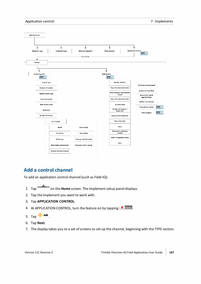
Application control 7 Implements
Add a control channelTo add an application control channel (such as Field-IQ):
1. Tap on theHome screen. The Implement setup panel displays.
2. Tap the implement you want to work with.
3. Tap APPLICATION CONTROL.
4. At APPLICATION CONTROL, turn the feature on by tapping .
5. Tap .
6. Tap Next.
7. The display takes you to a set of screens to set up the channel, beginning with the TYPE section.
Version 2.0, Revision C Trimble Precision-IQ Field Application User Guide 167
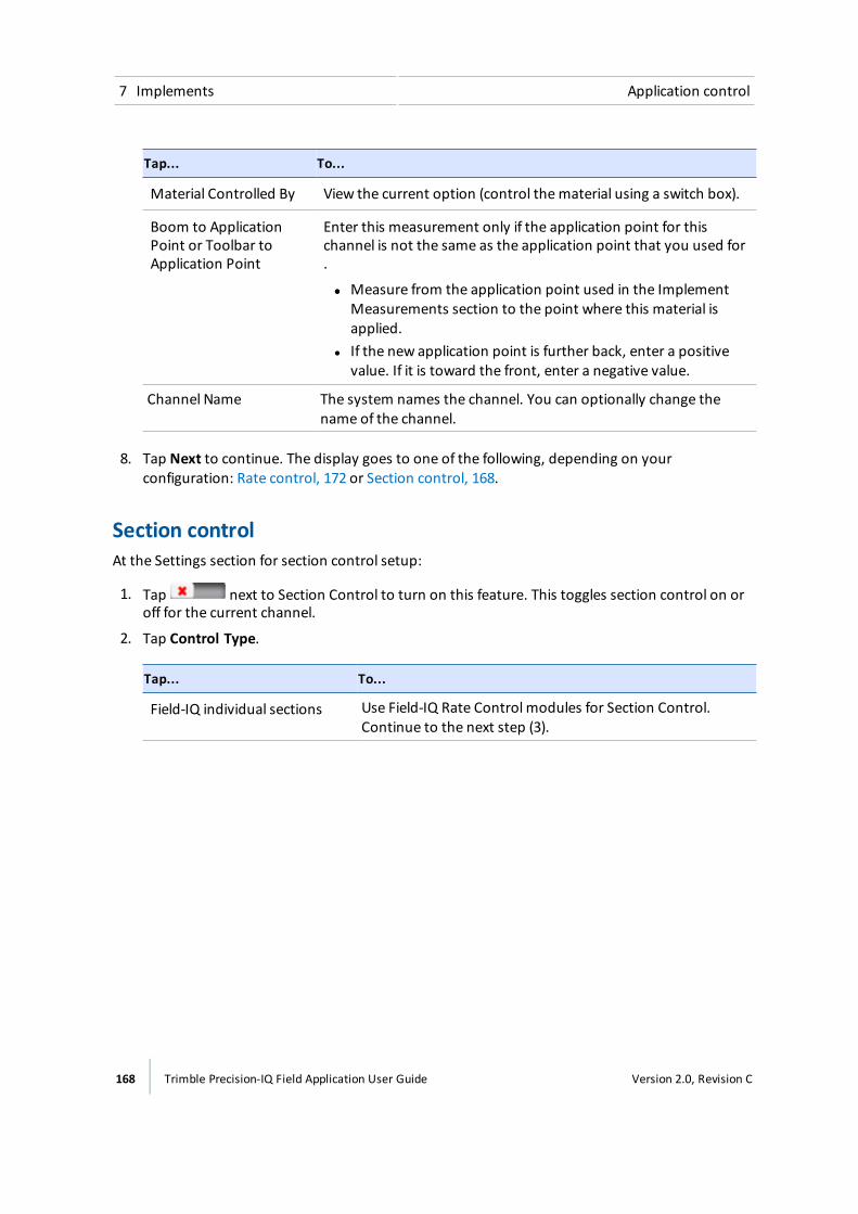
7 Implements Application control
Tap... To...
Material Controlled By View the current option (control thematerial using a switch box).
Boom to ApplicationPoint or Toolbar toApplication Point
Enter this measurement only if the application point for thischannel is not the same as the application point that you used for.
ll Measure from the application point used in the ImplementMeasurements section to the point where this material isapplied.
l If the new application point is further back, enter a positivevalue. If it is toward the front, enter a negative value.
Channel Name The system names the channel. You can optionally change thename of the channel.
8. Tap Next to continue. The display goes to one of the following, depending on yourconfiguration: Rate control, 172 or Section control, 168.
Section controlAt the Settings section for section control setup:
1. Tap next to Section Control to turn on this feature. This toggles section control on oroff for the current channel.
2. Tap Control Type.
Tap... To...
Field-IQ individual sections Use Field-IQ Rate Control modules for Section Control.Continue to the next step (3).
168 Trimble Precision-IQ Field Application User Guide Version 2.0, Revision C
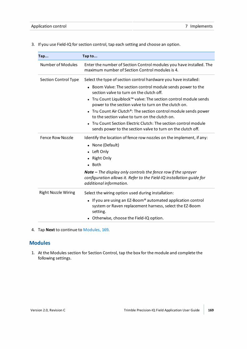
Application control 7 Implements
3. If you use Field-IQ for section control, tap each setting and choose an option.
Tap... Tap to...
Number ofModules Enter the number of Section Control modules you have installed. Themaximum number of Section Control modules is 4.
Section Control Type Select the type of section control hardware you have installed:
ll Boom Valve: The section control module sends power to thesection valve to turn on the clutch off.
l Tru Count Liquiblock™ valve: The section control module sendspower to the section valve to turn on the clutch on.
l Tru Count Air Clutch®: The section control module sends powerto the section valve to turn on the clutch on.
l Tru Count Section Electric Clutch: The section control modulesends power to the section valve to turn on the clutch off.
Fence RowNozzle Identify the location of fence row nozzles on the implement, if any:
ll None (Default)l Left Onlyl Right Onlyl Both
Note – The display only controls the fence row if the sprayerconfiguration allows it. Refer to the Field-IQ installation guide foradditional information.
Right NozzleWiring Select the wiring option used during installation:
ll If you are using an EZ-Boom® automated application controlsystem or Raven replacement harness, select the EZ-Boomsetting.
l Otherwise, choose the Field-IQ option.
4. Tap Next to continue to Modules, 169.
Modules
1. At theModules section for Section Control, tap the box for themodule and complete thefollowing settings.
Version 2.0, Revision C Trimble Precision-IQ Field Application User Guide 169

7 Implements Application control
Setting Options
Serial Number Select the serial number of the Section ControlModule installed atthis location. The display reads the serial numbers from the installedmodules.
Number of Sections Enter the number of sections physically wired into this module (up to12 sections per control module).
2. Tap when you have completed the settings for each module. Then tap Next to continue toWidth, 170.
Note – When you upgrade the Precision-IQ field application firmware, the firmware for Field-IQmodules are also upgraded. There are no additional steps required to upgrade modules.
Width
1. At theWIDTH section for Section Control, review the width of each section per module.
2. To change a width of a the section, tap it. Begin with the first one on the left, and work from leftto right.
3. The system will not allow you to change the width of the sections to bemore or less than thetotal width of the implement.
4. Tap Next to continue to Latencies, 170.
LatenciesLatency refers to the delay between when the command occurs (to turn a section on or off) andwhen application of thematerial actually starts or stops.
1. At the Latencies section for Section Control, review and make changes as necessary to thesettings.
Tap... To...
On Latency Enter the length of time (seconds) from when a section is turned onto when the system begins to apply material.
Off Latency Enter the length of time (seconds) from when a section is turned offto when the system stops applying material.
170 Trimble Precision-IQ Field Application User Guide Version 2.0, Revision C
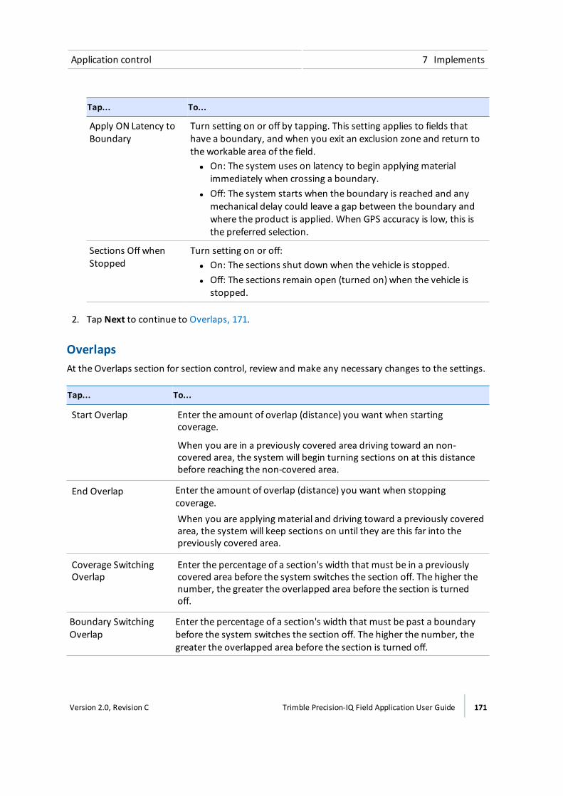
Application control 7 Implements
Tap... To...
Apply ON Latency toBoundary
Turn setting on or off by tapping. This setting applies to fields thathave a boundary, and when you exit an exclusion zone and return tothe workable area of the field.ll On: The system uses on latency to begin applying material
immediately when crossing a boundary.l Off: The system starts when the boundary is reached and any
mechanical delay could leave a gap between the boundary andwhere the product is applied. When GPS accuracy is low, this isthe preferred selection.
Sections Off whenStopped
Turn setting on or off:ll On: The sections shut down when the vehicle is stopped.l Off: The sections remain open (turned on) when the vehicle is
stopped.
2. Tap Next to continue to Overlaps, 171.
OverlapsAt the Overlaps section for section control, review and make any necessary changes to the settings.
Tap... To...
Start Overlap Enter the amount of overlap (distance) you want when startingcoverage.
When you are in a previously covered area driving toward an non-covered area, the system will begin turning sections on at this distancebefore reaching the non-covered area.
End Overlap Enter the amount of overlap (distance) you want when stoppingcoverage.When you are applying material and driving toward a previously coveredarea, the system will keep sections on until they are this far into thepreviously covered area.
Coverage SwitchingOverlap
Enter the percentage of a section's width that must be in a previouslycovered area before the system switches the section off. The higher thenumber, the greater the overlapped area before the section is turnedoff.
Boundary SwitchingOverlap
Enter the percentage of a section's width that must be past a boundarybefore the system switches the section off. The higher the number, thegreater the overlapped area before the section is turned off.
Version 2.0, Revision C Trimble Precision-IQ Field Application User Guide 171
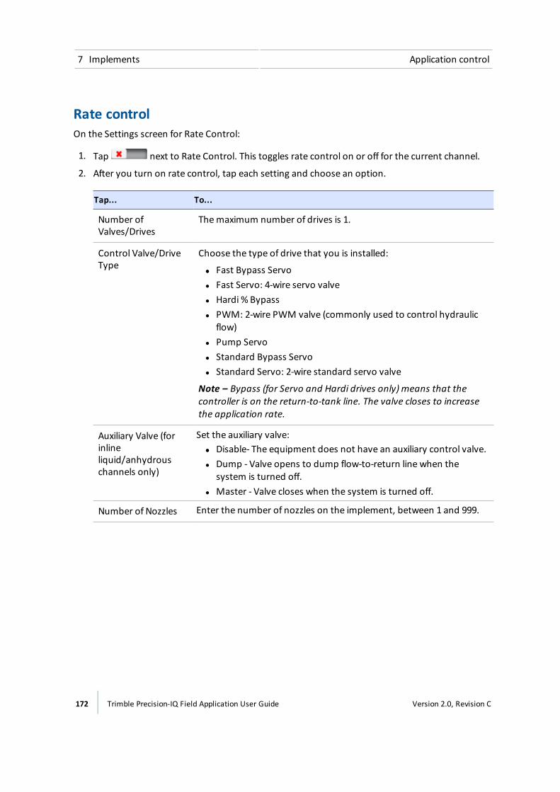
7 Implements Application control
Rate controlOn the Settings screen for Rate Control:
1. Tap next to Rate Control. This toggles rate control on or off for the current channel.
2. After you turn on rate control, tap each setting and choose an option.
Tap... To...
Number ofValves/Drives
Themaximum number of drives is 1.
Control Valve/DriveType
Choose the type of drive that you is installed:
ll Fast Bypass Servol Fast Servo: 4-wire servo valvel Hardi % Bypassl PWM: 2-wire PWM valve (commonly used to control hydraulic
flow)l Pump Servol Standard Bypass Servol Standard Servo: 2-wire standard servo valve
Note – Bypass (for Servo and Hardi drives only) means that thecontroller is on the return-to-tank line. The valve closes to increasethe application rate.
Auxiliary Valve (forinlineliquid/anhydrouschannels only)
Set the auxiliary valve:ll Disable- The equipment does not have an auxiliary control valve.l Dump - Valve opens to dump flow-to-return line when the
system is turned off.l Master - Valve closes when the system is turned off.
Number of Nozzles Enter the number of nozzles on the implement, between 1 and 999.
172 Trimble Precision-IQ Field Application User Guide Version 2.0, Revision C
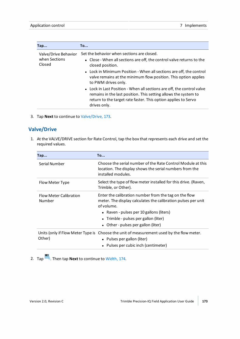
Application control 7 Implements
Tap... To...
Valve/Drive Behaviorwhen SectionsClosed
Set the behavior when sections are closed.ll Close -When all sections are off, the control valve returns to the
closed position.l Lock in Minimum Position -When all sections are off, the control
valve remains at theminimum flow position. This option appliesto PWM drives only.
l Lock in Last Position -When all sections are off, the control valveremains in the last position. This setting allows the system toreturn to the target rate faster. This option applies to Servodrives only.
3. Tap Next to continue to Valve/Drive, 173.
Valve/Drive
1. At the VALVE/DRIVE section for Rate Control, tap the box that represents each drive and set therequired values.
Tap... To...
Serial Number Choose the serial number of the Rate ControlModule at thislocation. The display shows the serial numbers from theinstalled modules.
FlowMeter Type Select the type of flowmeter installed for this drive. (Raven,Trimble, or Other).
FlowMeter CalibrationNumber
Enter the calibration number from the tag on the flowmeter. The display calculates the calibration pulses per unitof volume.ll Raven - pulses per 10 gallons (liters)l Trimble - pulses per gallon (liter)l Other - pulses per gallon (liter)
Units (only if FlowMeter Type isOther)
Choose the unit ofmeasurement used by the flowmeter.ll Pulses per gallon (liter)l Pulses per cubic inch (centimeter)
2. Tap . Then tap Next to continue to Width, 174.
Version 2.0, Revision C Trimble Precision-IQ Field Application User Guide 173
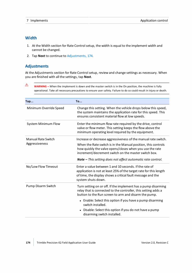
7 Implements Application control
Width
1. At theWidth section for Rate Control setup, the width is equal to the implement width andcannot be changed.
2. Tap Next to continue to Adjustments, 174.
AdjustmentsAt the Adjustments section for Rate Control setup, review and change settings as necessary. Whenyou are finished with all the settings, tap Next.
WARNING – When the implement is down and the master switch is in the On position, the machine is fullyoperational. Take all necessary precautions to ensure user safety. Failure to do so could result in injury or death.
Tap... To...
Minimum Override Speed Change this setting. When the vehicle drops below this speed,the system maintains the application rate for this speed. Thisensures consistent material flow at low speeds.
System Minimum Flow Enter theminimum flow rate required by the drive, controlvalve or flowmeter. This setting keeps the flow above theminimum operating level required by the equipment.
Manual Rate SwitchAggressiveness
Increase or decrease aggressiveness of themanual rate switch.When the Rate switch is in theManual position, this controlshow quickly the valve opens/closes when you use the rateincrement/decrement switch on themaster switch box.
Note – This setting does not affect automatic rate control.
No/Low Flow Timeout Enter a value between 1 and 10 seconds. If the rate ofapplication is not at least 25% of the target rate for this lengthof time, the display shows a critical fault message and thesystem shuts down.
Pump Disarm Switch Turn setting on or off. If the implement has a pump disarmingrelay that is connected to the controller, this setting adds abutton to the Run screen to arm and disarm the pump.
l Enable: Select this option if you have a pump disarmingswitch installed.
l Disable: Select this option if you do not have a pumpdisarming switch installed.
174 Trimble Precision-IQ Field Application User Guide Version 2.0, Revision C

Application control 7 Implements
Tap... To...
Rate Snapping Turn setting on or off. This setting smooths out ratefluctuations seen on the screen.l Off: The display shows instant readings from the feedback
sensor. This may show frequent minor rate fluctuations.l On: The display smoothes out the values. You will see the
target rate as the applied rate whenever the applied rate iswithin 10% of the target rate.
Calibrate application control drives
WARNING – When the implement is down and the master switch is in the On position, the machine is fullyoperational. Take all necessary precautions to ensure user safety. Failure to do so could result in injury or death.
1. At theHome screen, tap . The Implement setup panel displays.
2. At the list on the left-hand side, tap the implement you want to calibrate, then tap Select.
3. Tap Calibrate. The calibration section opens at the Summary section.
4. Tap Application Control.
5. Tap the channel to calibrate it. A popup displays.
6. Tap Calibrate. The calibration tool displays, beginning at the Drive Limits section.
ll IfMaximum Flow is unknown, use the default (0.00) to allow the system to determinemaximum flow.
l You can also use this formula to calculateMaximum Flow:boom width x ground speed x application rate x calculation factor
l For metric systems, usemeters for width and kph for ground speed, with a calculationfactor of 0.00167.
l For standard systems, use feet for width and mph for ground speed, with a calculationfactor of 0.00202.
7. Tap Next to continue to the Drive Settings section.
Setting Description
Target Speed Enter the test speed to use during calibration. The systemwill apply material at the rate required to reach the TargetRate if the vehicle travels at this speed.
Version 2.0, Revision C Trimble Precision-IQ Field Application User Guide 175
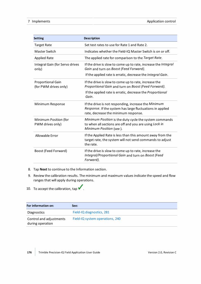
7 Implements Application control
Setting Description
Target Rate Set test rates to use for Rate 1 and Rate 2.
Master Switch Indicates whether the Field-IQ Master Switch is on or off.
Applied Rate The applied rate for comparison to the Target Rate.
Integral Gain (for Servo drivesonly)
If the drive is slow to come up to rate, increase the IntegralGain and turn on Boost (Feed Forward).If the applied rate is erratic, decrease the Integral Gain.
Proportional Gain(for PWM drives only)
If the drive is slow to come up to rate, increase theProportional Gain and turn on Boost (Feed Forward).If the applied rate is erratic, decrease the ProportionalGain.
Minimum Response If the drive is not responding, increase theMinimumResponse. If the system has large fluctuations in appliedrate, decrease theminimum response.
Minimum Position (forPWM drives only)
Minimum Position is the duty cycle the system commandsto when all sections are off and you are using Lock inMinimum Position (see ).
Allowable Error If the Applied Rate is less than this amount away from thetarget rate, the system will not send commands to adjustthe rate.
Boost (Feed Forward) If the drive is slow to come up to rate, increase theIntegral/Proportional Gain and turn on Boost (FeedForward).
8. Tap Next to continue to the Information section.
9. Review the calibration results. Theminimum and maximum values indicate the speed and flowranges that will apply during operations.
10. To accept the calibration, tap .
For information on: See:
Diagnostics Field-IQ diagnostics, 281
Control and adjustmentsduring operation
Field-IQ system operations, 240
176 Trimble Precision-IQ Field Application User Guide Version 2.0, Revision C
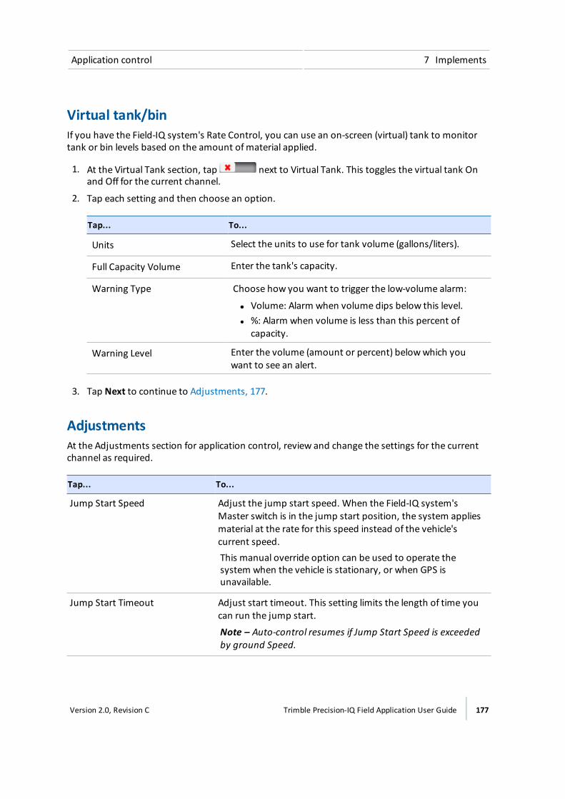
Application control 7 Implements
Virtual tank/binIf you have the Field-IQ system's Rate Control, you can use an on-screen (virtual) tank to monitortank or bin levels based on the amount ofmaterial applied.
1. At the Virtual Tank section, tap next to Virtual Tank. This toggles the virtual tank Onand Off for the current channel.
2. Tap each setting and then choose an option.
Tap... To...
Units Select the units to use for tank volume (gallons/liters).
Full Capacity Volume Enter the tank's capacity.
Warning Type Choose how you want to trigger the low-volume alarm:
ll Volume: Alarm when volume dips below this level.l %: Alarm when volume is less than this percent of
capacity.
Warning Level Enter the volume (amount or percent) belowwhich youwant to see an alert.
3. Tap Next to continue to Adjustments, 177.
AdjustmentsAt the Adjustments section for application control, review and change the settings for the currentchannel as required.
Tap... To...
Jump Start Speed Adjust the jump start speed. When the Field-IQ system'sMaster switch is in the jump start position, the system appliesmaterial at the rate for this speed instead of the vehicle'scurrent speed.This manual override option can be used to operate thesystem when the vehicle is stationary, or when GPS isunavailable.
Jump Start Timeout Adjust start timeout. This setting limits the length of time youcan run the jump start.
Note – Auto-control resumes if Jump Start Speed is exceededby ground Speed.
Version 2.0, Revision C Trimble Precision-IQ Field Application User Guide 177

7 Implements Application control
Tap... To...
Shut Off Speed Adjust shut off speed. The system shuts down if the implementdrops below this speed.
When you have completed these settings, tap Next to continue to Summary, 178.
SummaryThe Summary section shows an overview of all the settings for the channel.
1. Review the channel details.
2. To change channel settings, tap Back until you reach the section you wish to edit..
3. Tap . The display saves the channel and returns to the Application Control section forimplement setup.
4. Tap Next to continue to:
a. Boom height control setup, 180, if applicable
b. Inputs, 189, if applicable
Modify a control channelTo edit an application control channel:
1. Tap on theHome screen. The Implement setup panel displays.
2. Tap the implement you want to work with.
3. Tap APPLICATION CONTROL.
4. Tap the control channel that you want to change, then tapModify.
5. Tap the button at the top of the screen for the channel setting that you want to change.
6. When you finish making changes, tap Summary at the top right corner of the screen.
7. If any part of the setup is not complete, you can save the changes but you cannot use theimplement on the Run screen.
8. To save the channel and return to the Application Control section , tap . The display returnsyou to the Implement setup panel.
9. To exit channel setup without saving, tap . Amessage displays, asking if you want to cancelwithout saving your changes. Tap cancel.
178 Trimble Precision-IQ Field Application User Guide Version 2.0, Revision C
Application control 7 Implements
Remove a control channelTo remove an application control channel:
1. Tap on theHome screen. The Implement setup panel displays.
2. Tap the implement you want to work with.
3. Tap APPLICATION CONTROL.
4. Tap the control channel that you want to remove, then tap Remove. The system displays aconfirmation message for you to confirm that you want to remove the channel.
5. Tap to confirm the removal. Otherwise, tap to cancel the removal.
6. When you finish making changes, tap Summary at the top right corner of the screen.
7. If any part of the setup is Not Complete, you can save the changes but you cannot use theimplement on the Run screen.
8. To save the channel and return to the Application Control section , tap . The display returnsyou to the Implement setup panel.
9. To exit channel setup without saving, tap . Amessage displays, asking if you want to cancelwithout saving your changes. Tap cancel.
Version 2.0, Revision C Trimble Precision-IQ Field Application User Guide 179
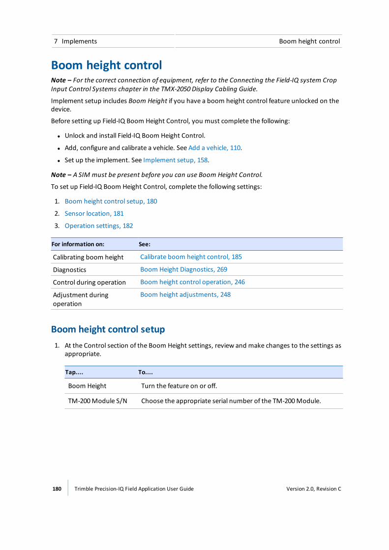
7 Implements Boom height control
Boom height controlNote – For the correct connection of equipment, refer to the Connecting the Field-IQ system CropInput Control Systems chapter in the TMX-2050 Display Cabling Guide.
Implement setup includes Boom Height if you have a boom height control feature unlocked on thedevice.
Before setting up Field-IQ Boom Height Control, you must complete the following:
l Unlock and install Field-IQ Boom Height Control.
l Add, configure and calibrate a vehicle. See Add a vehicle, 110.
l Set up the implement. See Implement setup, 158.
Note – A SIM must be present before you can use Boom Height Control.
To set up Field-IQ Boom Height Control, complete the following settings:
1. Boom height control setup, 180
2. Sensor location, 181
3. Operation settings, 182
For information on: See:
Calibrating boom height Calibrate boom height control, 185
Diagnostics Boom Height Diagnostics, 269
Control during operation Boom height control operation, 246
Adjustment duringoperation
Boom height adjustments, 248
Boom height control setup1. At the Control section of the Boom Height settings, review and make changes to the settings as
appropriate.
Tap.... To....
Boom Height Turn the feature on or off.
TM-200Module S/N Choose the appropriate serial number of the TM-200Module.
180 Trimble Precision-IQ Field Application User Guide Version 2.0, Revision C
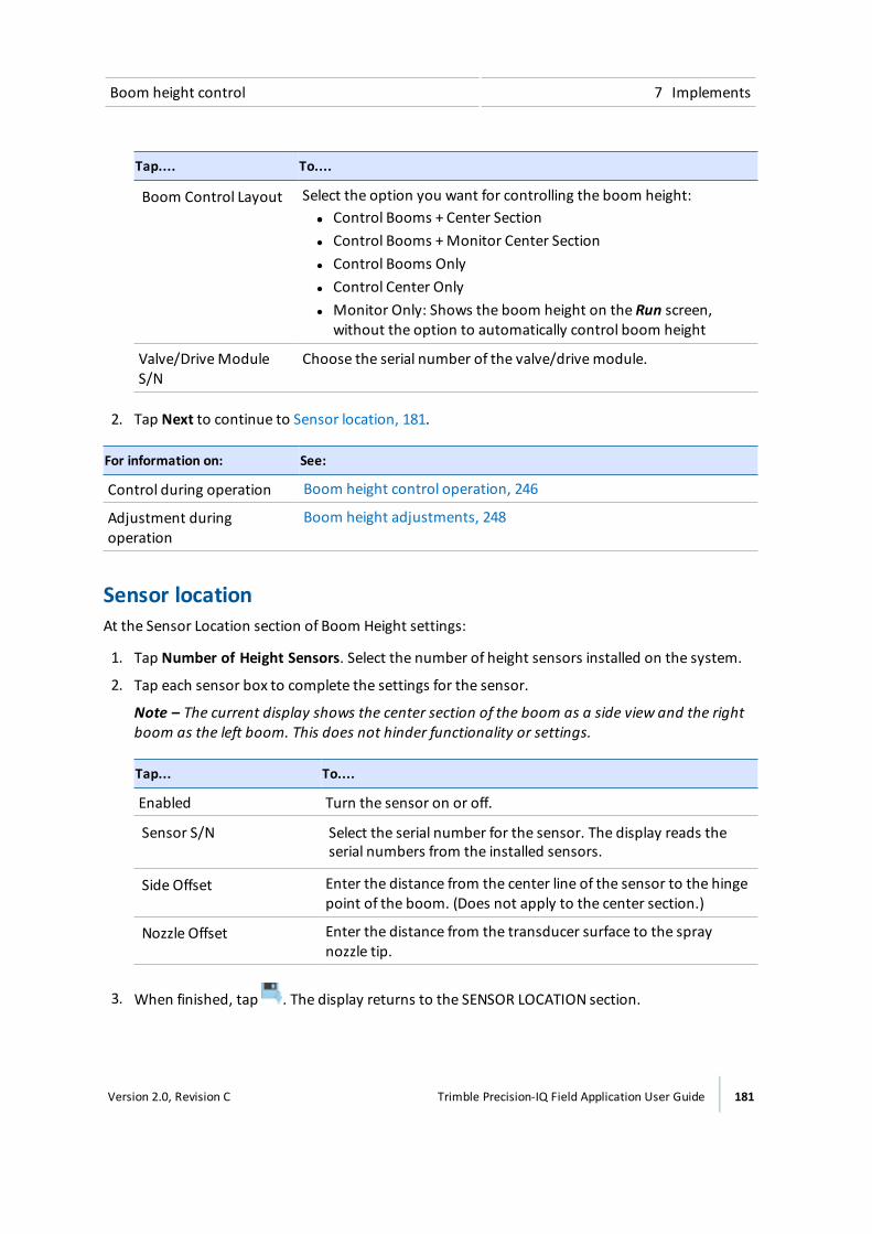
Boom height control 7 Implements
Tap.... To....
Boom Control Layout Select the option you want for controlling the boom height:ll Control Booms + Center Sectionl Control Booms + Monitor Center Sectionl Control Booms Onlyl Control Center Onlyl Monitor Only: Shows the boom height on the Run screen,
without the option to automatically control boom height
Valve/DriveModuleS/N
Choose the serial number of the valve/drivemodule.
2. Tap Next to continue to Sensor location, 181.
For information on: See:
Control during operation Boom height control operation, 246
Adjustment duringoperation
Boom height adjustments, 248
Sensor locationAt the Sensor Location section of Boom Height settings:
1. Tap Number of Height Sensors. Select the number of height sensors installed on the system.
2. Tap each sensor box to complete the settings for the sensor.
Note – The current display shows the center section of the boom as a side view and the rightboom as the left boom. This does not hinder functionality or settings.
Tap... To....
Enabled Turn the sensor on or off.
Sensor S/N Select the serial number for the sensor. The display reads theserial numbers from the installed sensors.
Side Offset Enter the distance from the center line of the sensor to the hingepoint of the boom. (Does not apply to the center section.)
Nozzle Offset Enter the distance from the transducer surface to the spraynozzle tip.
3. When finished, tap . The display returns to the SENSOR LOCATION section.
Version 2.0, Revision C Trimble Precision-IQ Field Application User Guide 181
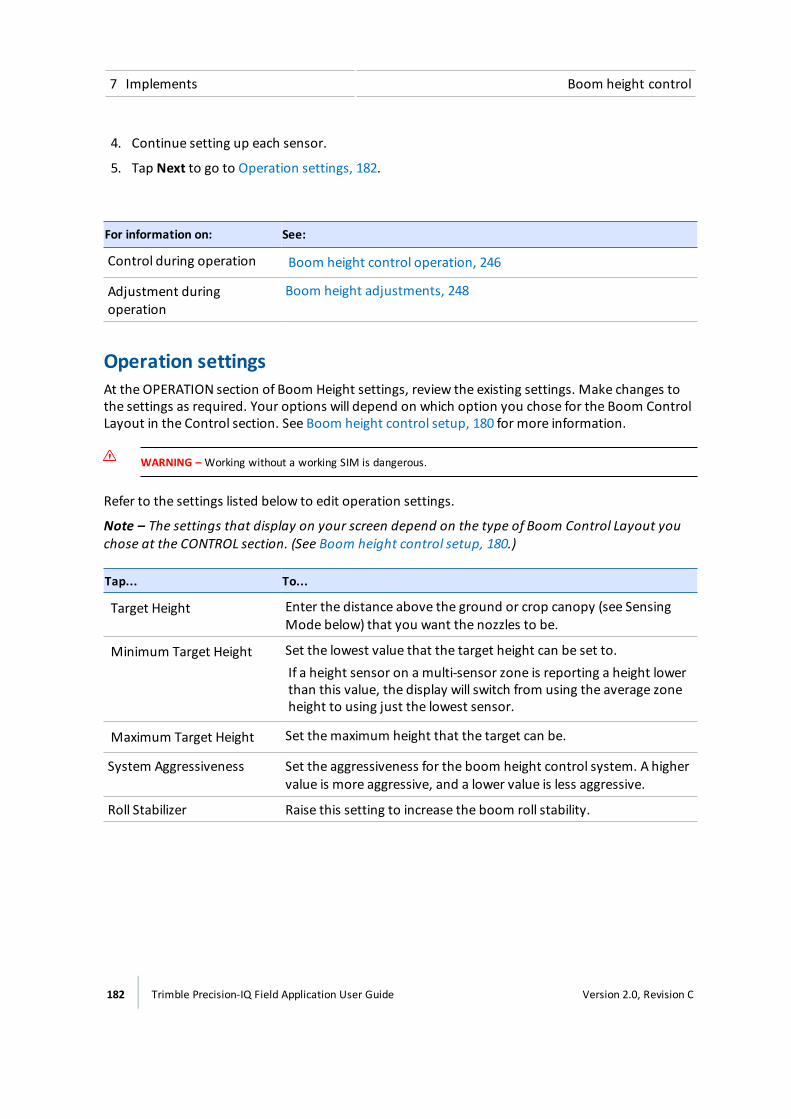
7 Implements Boom height control
4. Continue setting up each sensor.
5. Tap Next to go to Operation settings, 182.
For information on: See:
Control during operation Boom height control operation, 246
Adjustment duringoperation
Boom height adjustments, 248
Operation settingsAt the OPERATION section of Boom Height settings, review the existing settings. Make changes tothe settings as required. Your options will depend on which option you chose for the Boom ControlLayout in the Control section. See Boom height control setup, 180 for more information.
WARNING – Working without a working SIM is dangerous.
Refer to the settings listed below to edit operation settings.
Note – The settings that display on your screen depend on the type of Boom Control Layout youchose at the CONTROL section. (See Boom height control setup, 180.)
Tap... To...
Target Height Enter the distance above the ground or crop canopy (see SensingMode below) that you want the nozzles to be.
Minimum Target Height Set the lowest value that the target height can be set to.If a height sensor on a multi-sensor zone is reporting a height lowerthan this value, the display will switch from using the average zoneheight to using just the lowest sensor.
Maximum Target Height Set themaximum height that the target can be.
System Aggressiveness Set the aggressiveness for the boom height control system. A highervalue is more aggressive, and a lower value is less aggressive.
Roll Stabilizer Raise this setting to increase the boom roll stability.
182 Trimble Precision-IQ Field Application User Guide Version 2.0, Revision C
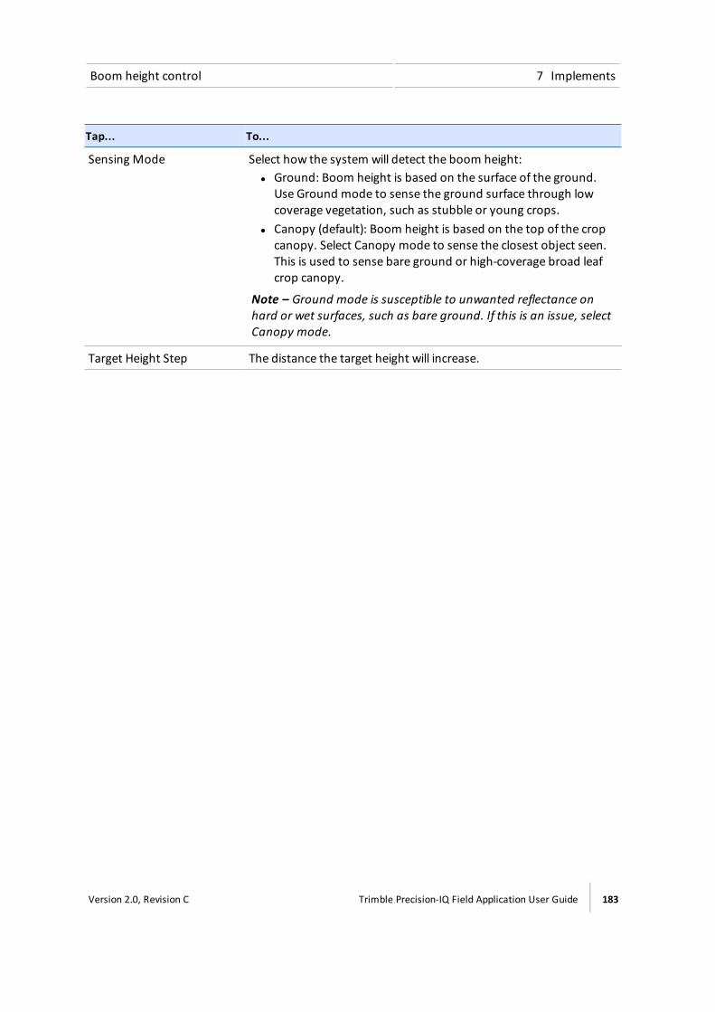
Boom height control 7 Implements
Tap... To...
Sensing Mode Select how the system will detect the boom height:l Ground: Boom height is based on the surface of the ground.
Use Ground mode to sense the ground surface through lowcoverage vegetation, such as stubble or young crops.
l Canopy (default): Boom height is based on the top of the cropcanopy. Select Canopy mode to sense the closest object seen.This is used to sense bare ground or high-coverage broad leafcrop canopy.
Note – Ground mode is susceptible to unwanted reflectance onhard or wet surfaces, such as bare ground. If this is an issue, selectCanopy mode.
Target Height Step The distance the target height will increase.
Version 2.0, Revision C Trimble Precision-IQ Field Application User Guide 183
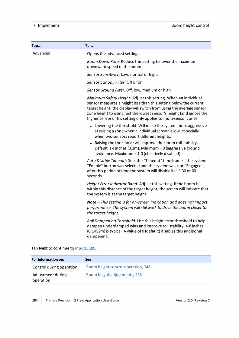
7 Implements Boom height control
Tap... To...
Advanced Opens the advanced settings:
Boom Down Rate: Reduce this setting to lower themaximumdownward speed of the boom.
Sensor Sensitivity: Low, normal or high.
Sensor Canopy Filter: Off or on
Sensor Ground Filter: Off, low, medium or high
Minimum Safety Height: Adjust this setting. When an individualsensor measures a height less than this setting below the currenttarget height, the display will switch from using the average sensorzone height to using just the lowest sensor's height (and ignore thehigher sensor). This setting only applies to multi-sensor zones.
l Lowering the threshold: Will make the system more aggressiveat raising a zone when a individual sensor is low, especiallywhen two sensors report different heights.
l Raising the threshold: will improve the boom roll stability.Default is 4 inches (0.1m). Minimum = 0 (aggressive groundavoidance. Maximum = 1.0 (effectively disabled).
Auto Disable Timeout: Sets the "Timeout" time frame if the system"Enable" button was selected and the system was not "Engaged",after this period of time the system will disable itself. 30 or 60seconds.
Height Error Indicator Band: Adjust this setting. If the boom iswithin this distance of the target height, the screen will indicate thatthe system is at the target height.
Note – This setting is for on-screen indication and does not impactperformance. The system will still work to drive the boom closer tothe target height.
Roll Dampening Threshold: Use this height error threshold to helpdampen underdamped wins and improve roll stability. 4-8 inches(0.1-0.2m) is typical. A value of 0 (default) disables this additionaldampening.
Tap Next to continue to Inputs, 189.
For information on: See:
Control during operation Boom height control operation, 246
Adjustment duringoperation
Boom height adjustments, 248
184 Trimble Precision-IQ Field Application User Guide Version 2.0, Revision C
Boom height control 7 Implements
Calibrate boom height controlEach boom's hydraulic drivemust be calibrated before you can use the Field-IQ system BoomHeight Control on the Run screen. Before you calibrate boom height control:
l Complete the implement and boom height configuration.
l Take the equipment to a field with a firm, natural surface (not concrete, not freshly tilled).
l Make sure that the hydraulic fluid is at normal operating temperature.
Note – On some vehicles with large reservoirs, it may take a longer amount of time for thefluid to reach operating level, especially if the implement circuit is lightly loaded. Consult thevehicle documentation to determine if the hydraulic fluid temperature can be shown on avehicle console.
l Use themanual control panel to test the system prior to calibration. See Boom height manualcontrol test, 186.
For information on: See:
Diagnostics Boom Height Diagnostics, 269
Control during operation Boom height control operation, 246
Adjustment duringoperation
Boom height adjustments, 248
Boom height calibration steps
1. Access the calibration for boom height control.
a. At theHome screen, tap .
b. Tap the implement you want to calibrate, and then tap Select.
c. Tap Calibration.
d. Tap Boom Height. The boom height calibration panel displays.
e. Tap Calibrate for the boom you want to calibrate.
2. Tap BOOM CALIBRATION.
Version 2.0, Revision C Trimble Precision-IQ Field Application User Guide 185
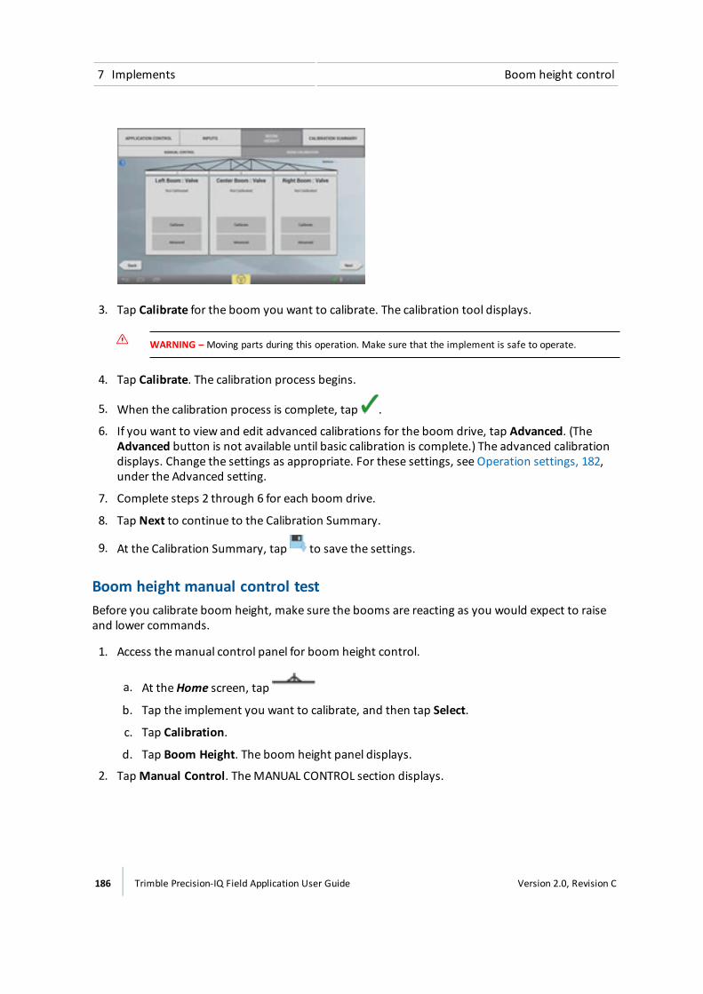
7 Implements Boom height control
3. Tap Calibrate for the boom you want to calibrate. The calibration tool displays.
WARNING – Moving parts during this operation. Make sure that the implement is safe to operate.
4. Tap Calibrate. The calibration process begins.
5. When the calibration process is complete, tap .
6. If you want to view and edit advanced calibrations for the boom drive, tap Advanced. (TheAdvanced button is not available until basic calibration is complete.) The advanced calibrationdisplays. Change the settings as appropriate. For these settings, see Operation settings, 182,under the Advanced setting.
7. Complete steps 2 through 6 for each boom drive.
8. Tap Next to continue to the Calibration Summary.
9. At the Calibration Summary, tap to save the settings.
Boom height manual control testBefore you calibrate boom height, make sure the booms are reacting as you would expect to raiseand lower commands.
1. Access themanual control panel for boom height control.
a. At theHome screen, tap
b. Tap the implement you want to calibrate, and then tap Select.
c. Tap Calibration.
d. Tap Boom Height. The boom height panel displays.
2. TapManual Control. TheMANUAL CONTROL section displays.
186 Trimble Precision-IQ Field Application User Guide Version 2.0, Revision C
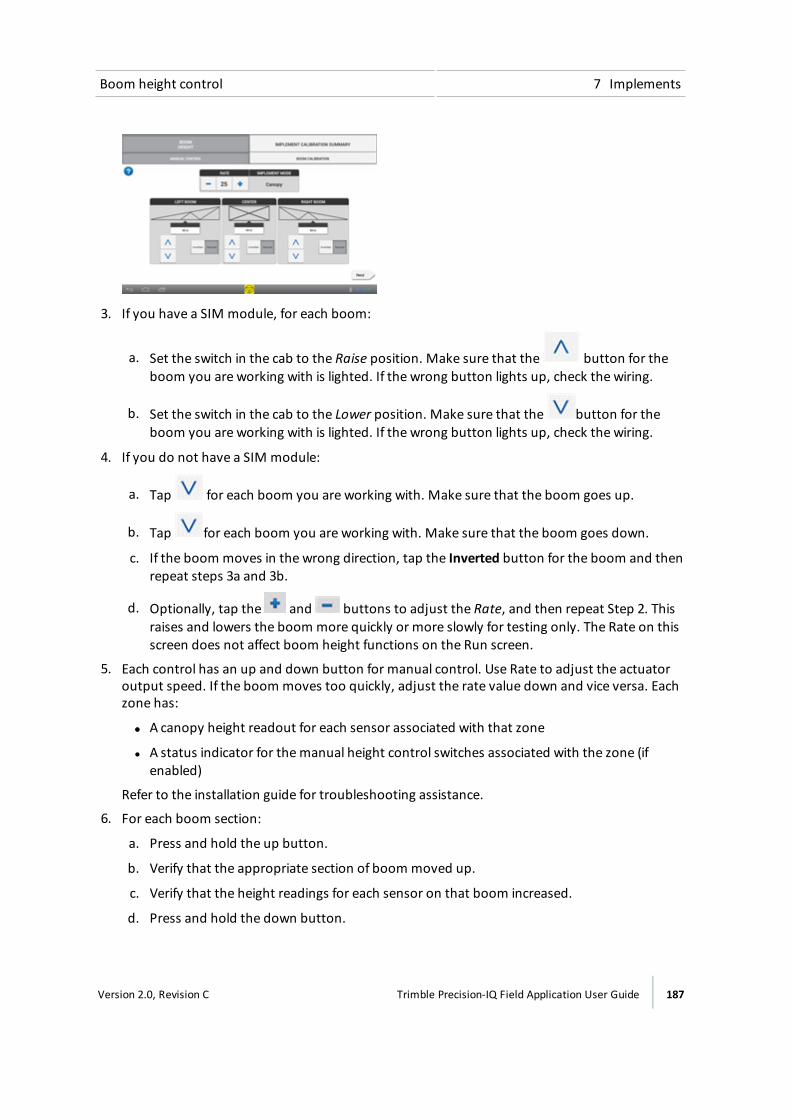
Boom height control 7 Implements
3. If you have a SIM module, for each boom:
a. Set the switch in the cab to the Raise position. Make sure that the button for theboom you are working with is lighted. If the wrong button lights up, check the wiring.
b. Set the switch in the cab to the Lower position. Make sure that the button for theboom you are working with is lighted. If the wrong button lights up, check the wiring.
4. If you do not have a SIM module:
a. Tap for each boom you are working with. Make sure that the boom goes up.
b. Tap for each boom you are working with. Make sure that the boom goes down.
c. If the boom moves in the wrong direction, tap the Inverted button for the boom and thenrepeat steps 3a and 3b.
d. Optionally, tap the and buttons to adjust the Rate, and then repeat Step 2. Thisraises and lowers the boom more quickly or more slowly for testing only. The Rate on thisscreen does not affect boom height functions on the Run screen.
5. Each control has an up and down button for manual control. Use Rate to adjust the actuatoroutput speed. If the boom moves too quickly, adjust the rate value down and vice versa. Eachzone has:
ll A canopy height readout for each sensor associated with that zone
l A status indicator for themanual height control switches associated with the zone (ifenabled)
Refer to the installation guide for troubleshooting assistance.
6. For each boom section:
a. Press and hold the up button.
b. Verify that the appropriate section of boom moved up.
c. Verify that the height readings for each sensor on that boom increased.
d. Press and hold the down button.
Version 2.0, Revision C Trimble Precision-IQ Field Application User Guide 187

7 Implements Boom height control
e. Verify that the appropriate section of boom moved down.
f. Verify that the height readings for each sensor on that boom decreased.
g. Verify external switches are connected correctly by pressing each vehicle manual boomcontrol switch. The switch status corresponding to each input should turn green while theswitch is pressed.
7. If the booms operate as you expect, tap Next to continue to boom calibration. See Boomheight calibration steps, 185.
8. If the booms are not operating as you expect, you will not be able to calibrate and you will haveto troubleshoot the system.
188 Trimble Precision-IQ Field Application User Guide Version 2.0, Revision C
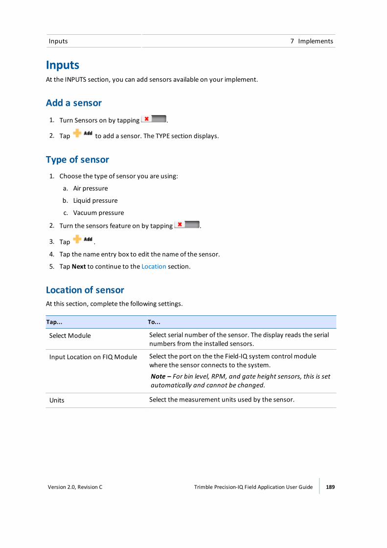
Inputs 7 Implements
InputsAt the INPUTS section, you can add sensors available on your implement.
Add a sensor1. Turn Sensors on by tapping .
2. Tap to add a sensor. The TYPE section displays.
Type of sensor1. Choose the type of sensor you are using:
a. Air pressure
b. Liquid pressure
c. Vacuum pressure
2. Turn the sensors feature on by tapping .
3. Tap .
4. Tap the name entry box to edit the name of the sensor.
5. Tap Next to continue to the Location section.
Location of sensorAt this section, complete the following settings.
Tap... To...
Select Module Select serial number of the sensor. The display reads the serialnumbers from the installed sensors.
Input Location on FIQ Module Select the port on the the Field-IQ system control modulewhere the sensor connects to the system.
Note – For bin level, RPM, and gate height sensors, this is setautomatically and cannot be changed.
Units Select themeasurement units used by the sensor.
Version 2.0, Revision C Trimble Precision-IQ Field Application User Guide 189

7 Implements Inputs
Tap... To...
Display in Control Channel Shows name of channel.Selected whether or not the sensorshows up in the Sensors Area of the Rate ControlWidget forthe channel.
l No - if you do not want to see the sensorl Channel number (1-6) - thematerial control channel where
you want to see the sensor
Tap Next to continue to Alarms.
AlarmsAt the Alarm section, you can set up alarms for sensors.
1. Turn on Alarms by tapping .
2. Change the settings as appropriate.
Tap... To...
Alarm Turn this feature on or off.
Warn If Below Enter the value that will trigger the alarm when the sensor reading isbelow this value.
Warn if Above Enter the value that will trigger the alarm when the sensor reading isabove this value.
Warn After Adjust the number of seconds before the alarm triggers.
3. Tap . The display saves your settings and returns to the Inputs section. See Inputs, 189.
4. Tap to add another sensor.
5. Tap Next to go to the SIM section (see .
Note – All pressure sensors must be calibrated. When you are ready to perform thecalibration, see Inputs / Sensors calibration, 191.
SIMNote – If you are using Boom Height Control, a SIM is required.
If your system has a SIM, at the SIM section choose the type of sprayer. If your system does nothave a SIM, tap Next.
You may also choose to enable or disable boom height here.
190 Trimble Precision-IQ Field Application User Guide Version 2.0, Revision C

Inputs 7 Implements
1. For some self propelled sprayers that are using the SIM to control sections for Field-IQ on thefactory joystick or console, tap Application Control FIQ and select the sprayer you are using.
2. If you need to disable the override feature on the booms, tap Boom Height and choosedisable. This will cause the joystick controls to no longer disengage automatic boom heightcontrol.
3. Tap Next to continue to the Summary section.
Inputs / Sensors calibration
1. At the Home screen, tap . The Implements panel displays.
2. Select the implement and then tap Select.
3. Tap Calibrate.
4. Tap INPUTS.
5. Tap the sensor you want to calibrate. A popup displays.
6. Tap Calibrate.
7. Tap Enabled.
8. Tap Calibration Type and select the type of calibration you wish to perform:
a. High/Low -More accurate and requires a pressure gauge for reading the actual pressure.(If you chose this type, continue to step 9.)
b. Point/Slope - Requires a slope value for the equipment from themanufacturer of theimplement. (If you chose this type, continue to step 10.)
9. To complete calibration for the High/Lowmethod:
a. Tap Start Calibration.
b. Read the instructions on the screen and then tap Next to begin.
c. Without the system running, take a reading. Enter this value into the Actual Pressure fieldand then tap Next.
d. Run the system at normal working pressure and take a reading. Enter this value into theActual Pressure field.
e. Tap Next.
f. Run the system at normal working pressure and take a reading. Enter this value into theActual Pressure field.
g. Run the system from low to high levels to verify the change in sensor readings.
h. Tap Accept or tap Recalibrate to repeat the process
Version 2.0, Revision C Trimble Precision-IQ Field Application User Guide 191
7 Implements Review implement summary
10. To complete calibration for the Point/SlopeMethod:
a. Enter the Slope value for the sensor from themanufacturer.
b. Tap Start Calibration.
c. For Actual Pressure, enter the current pressure. Tap Next to continue.
d. Review the results. If theMeasured Pressure is not accurate, tap Recalibrate and repeatthe calibration with a new Slope value.
e. Tap Acceptwhen theMeasured Pressure is accurate.
11. Repeat Step 5 through Step 10 for each sensor. When finished, tap .
Review implement summaryThe SUMMARY section displays when you complete all of the setup and configurations steps, orwhen you edit an implement.
To ... Tap ...
Save the implement with any changes you havemade.
Exit the setup without saving changes. The display will let you choose to savethe changes or exit without saving.
192 Trimble Precision-IQ Field Application User Guide Version 2.0, Revision C
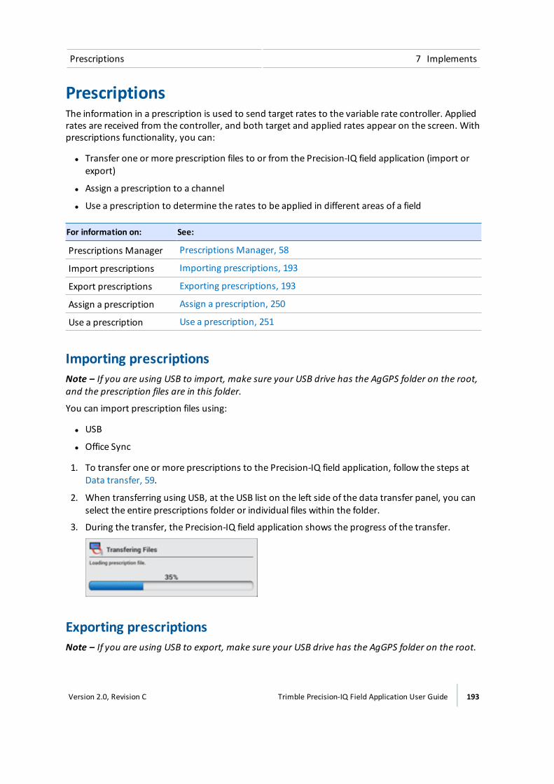
Prescriptions 7 Implements
PrescriptionsThe information in a prescription is used to send target rates to the variable rate controller. Appliedrates are received from the controller, and both target and applied rates appear on the screen. Withprescriptions functionality, you can:
l Transfer one or more prescription files to or from the Precision-IQ field application (import orexport)
l Assign a prescription to a channel
l Use a prescription to determine the rates to be applied in different areas of a field
For information on: See:
Prescriptions Manager Prescriptions Manager, 58
Import prescriptions Importing prescriptions, 193
Export prescriptions Exporting prescriptions, 193
Assign a prescription Assign a prescription, 250
Use a prescription Use a prescription, 251
Importing prescriptionsNote – If you are using USB to import, make sure your USB drive has the AgGPS folder on the root,and the prescription files are in this folder.
You can import prescription files using:
l USB
l Office Sync
1. To transfer one or more prescriptions to the Precision-IQ field application, follow the steps atData transfer, 59.
2. When transferring using USB, at the USB list on the left side of the data transfer panel, you canselect the entire prescriptions folder or individual files within the folder.
3. During the transfer, the Precision-IQ field application shows the progress of the transfer.
Exporting prescriptionsNote – If you are using USB to export, make sure your USB drive has the AgGPS folder on the root.
Version 2.0, Revision C Trimble Precision-IQ Field Application User Guide 193

7 Implements Prescriptions
You can export prescription files from the Precision-IQ field application using a USB drive. See USBdata transfer, 60.
194 Trimble Precision-IQ Field Application User Guide Version 2.0, Revision C

Materials
In this chapter:
Managing materials 196
Material list 196
Add a material 197
Edit a material 199
Delete a material 199
Assign a material to a channel 199
Calibrate material flow 200
At theMaterials setup panel, you can addand edit materials as well as calibratematerial flow.
8C h a p t e r
Version 2.0, Revision C Trimble Precision-IQ Field Application User Guide 195
8 Materials Managing materials
Managing materialsYou assign materials to material control channels for the Field-IQ system Rate and Section Control.
If you have the Field-IQ system Rate Control or Section Control, material setup requires:
l Add a material, 197
l Assign a material to a channel, 199
You must also calibrate thematerial flow. See Calibratematerial flow, 200.
Use thematerial setup panel to add, edit, assign, or deletematerials.
Material listThe categories and types ofmaterials in theMaterials library are listed below.
AnhydrousThematerials in this category are Anhydrous and Other.
Granular fertilizer
l Adjuvant l Herbicide l Other
l Fertilizer/Lime l Insecticide l Rodenticide
l Fungicide l Manure
l Growth Regulator l Nematacide
Liquid
l Adjuvant l Herbicide l Other
l Fertilizer/Lime l Insecticide l Rodenticide
l Fungicide l Manure l Water
l Growth Regulator l Nematacide
Granular seed
l Barley l Millet l Rice
l Beans, Dry l Oats l Rye
196 Trimble Precision-IQ Field Application User Guide Version 2.0, Revision C
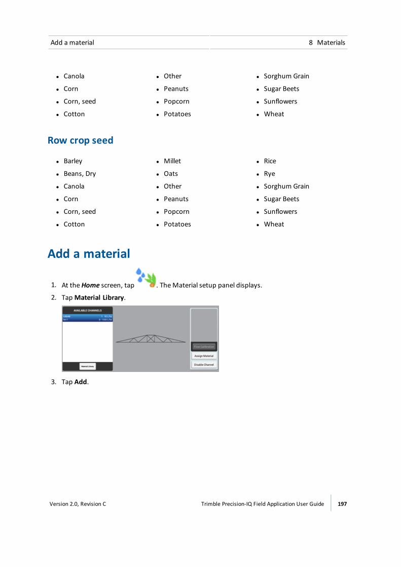
Add a material 8 Materials
l Canola l Other l Sorghum Grain
l Corn l Peanuts l Sugar Beets
l Corn, seed l Popcorn l Sunflowers
l Cotton l Potatoes l Wheat
Row crop seed
l Barley l Millet l Rice
l Beans, Dry l Oats l Rye
l Canola l Other l Sorghum Grain
l Corn l Peanuts l Sugar Beets
l Corn, seed l Popcorn l Sunflowers
l Cotton l Potatoes l Wheat
Add a material
1. At theHome screen, tap . TheMaterial setup panel displays.
2. TapMaterial Library.
3. Tap Add.
Version 2.0, Revision C Trimble Precision-IQ Field Application User Guide 197

8 Materials Add a material
4. Tap each setting and then select or enter a value.
Tap... To...
Material Name Tap the text entry box and then use the on-screen keyboard to enter aname for thematerial.
MaterialCategory
Select the type ofmaterial being applied:ll Anhydrousl Granular fertilizerl Granular seedl Liquidl Row crop seed
Type Type ofmaterial (seeMaterial list, 196)
Distributed Units Select the units to use with the selected material.
Target 1 Control the volume that the implement supplies when Rate 1 is selected.
Target 2 Control the volume that the implement supplies when Rate 2 is selected.
Rate Increment Set rate increment. When you increment/decrement Rate 1 or Rate 2 onthe Run screen, the current application rate increases or decreases by thisamount.
Minimum Rate Set theminimum rate that will be applied.
Maximum Rate Set themaximum rate that will be applied.
Material Details(optional)
Set additional details, if needed:ll EPA Product Number: Enter the registration number for thematerial
from the environmental protection agency for the area, if applicable.l Manufacturer: Enter thematerial manufacturer's name.l Restricted Use: Tap Yes orNo to record whether use of thematerial is
restricted by local, regional, or national laws.l Posting requiredl Buffer Distance: Enter the buffer distance from the product label of
thematerial.l MaxWind Speed: Enter themaximum wind speed from the product
label of thematerial.l Notes: Enter any other notes that you want to record with the
material.
5. Tap each setting and then select or enter a value.
198 Trimble Precision-IQ Field Application User Guide Version 2.0, Revision C
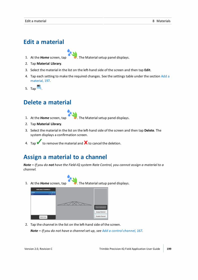
Edit a material 8 Materials
Edit a material
1. At theHome screen, tap . TheMaterial setup panel displays.
2. TapMaterial Library.
3. Select thematerial in the list on the left-hand side of the screen and then tap Edit.
4. Tap each setting to make the required changes. See the settings table under the section Add amaterial, 197.
5. Tap .
Delete a material
1. At theHome screen, tap . TheMaterial setup panel displays.
2. TapMaterial Library.
3. Select thematerial in the list on the left-hand side of the screen and then tap Delete. Thesystem displays a confirmation screen.
4. Tap to remove thematerial and to cancel the deletion.
Assign a material to a channelNote – If you do not have the Field-IQ system Rate Control, you cannot assign a material to achannel.
1. At theHome screen, tap . TheMaterial setup panel displays.
2. Tap the channel in the list on the left-hand side of the screen.
Note – If you do not have a channel set up, see Add a control channel, 167.
Version 2.0, Revision C Trimble Precision-IQ Field Application User Guide 199

8 Materials Calibratematerial flow
3. Tap Assign Material on the right-hand side of the screen.
4. Tap thematerial that you want to assign to the channel. The list shows only thematerials thatare the same type as the control channel's Material Type.
If you have not set up thematerial that you want to assign, tapMaterial Library.
If a material is already assigned to the channel, the item in the list has a next to thatmaterial.
Note – For the most accurate application, calibrate the flow. See Calibrate material flow, 200.
Calibrate material flowFor themost accurate application, calibrate the flow.
WARNING – During flow calibration, the machine will become operational. Take all necessary precautions toensure user safety. Failure to do so may result in serious injury or death.
WARNING – Material will be dispensed during calibration. Make sure that the implement is safe to operate.
Pre-calibration stepsBefore you calibrate flow:
1. Complete the implement and rate control configuration and calibrations.
2. Select a control channel and assign a material. SeeManaging materials, 196.
Calibration steps
1. At theHome screen, tap . TheMaterial setup panel displays.
2. Tap the channel name in the list on the left-hand side of the screen.
3. Tap Flow Calibration on the right-hand side of the screen.
4. Tap the drive you want to calibrate. The calibration tool displays.
5. Review the settings and update if necessary.
Note – For information about the appropriate values for your sprayer, refer to the supportnote Field-IQ crop Input Control System: For Sprayers and Spreaders.
200 Trimble Precision-IQ Field Application User Guide Version 2.0, Revision C

Calibratematerial flow 8 Materials
Tap... To...
Target Rate Enter the rate to use for the calibration.
Speed Enter the test speed to use during calibration. The system willapply material at the rate required to reach the Target Rate if thevehicle was traveling at this speed.
WARNING – Moving parts during this operation. Make sure that the implement is safe to operate.
6. Tap Run Calibration.
7. Follow the on-screen instructions to complete the flow calibration.
8. To accept the new values, tap .
9. To use the new values but recalibrate with them, tap Recalibrate.
10. To discard the new values and begin again, tap .
Version 2.0, Revision C Trimble Precision-IQ Field Application User Guide 201

8 Materials Calibratematerial flow
202 Trimble Precision-IQ Field Application User Guide Version 2.0, Revision C

Operations
In this chapter:
Preparing for operation 204
Fields and guidance 205
Tasks 206
Layers 206
Adjustments during operation 206
Automatic transfer of data 207
Tasks 208
Coverage logging 211
Vehicle operation 212
Guidance patterns 216
Landmarks 233
Layers 237
Field-IQ system operations 240
Prescriptions 250
ISOBUS 252
On-screen widgets 256
Alerts and warnings 262
During operations while working in theRun screen, you can:
l Create and adjust guidance patternsl Engage or disengage the steering
systeml Start a new task, include status
widgets on the screenl Make adjustments to steering,
guidance, rate and section control andboom height control
9C h a p t e r
Version 2.0, Revision C Trimble Precision-IQ Field Application User Guide 203
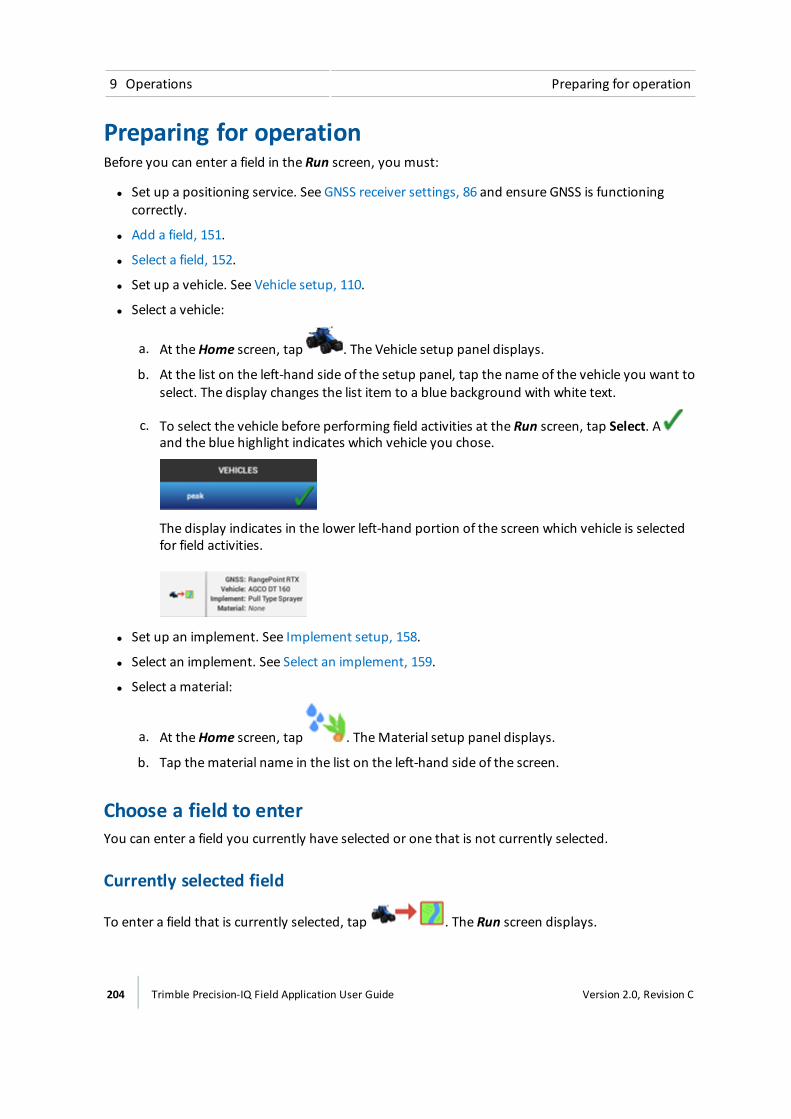
9 Operations Preparing for operation
Preparing for operationBefore you can enter a field in the Run screen, you must:
l Set up a positioning service. See GNSS receiver settings, 86 and ensure GNSS is functioningcorrectly.
l Add a field, 151.
l Select a field, 152.
l Set up a vehicle. See Vehicle setup, 110.
l Select a vehicle:
a. At theHome screen, tap . The Vehicle setup panel displays.
b. At the list on the left-hand side of the setup panel, tap the name of the vehicle you want toselect. The display changes the list item to a blue background with white text.
c. To select the vehicle before performing field activities at the Run screen, tap Select. Aand the blue highlight indicates which vehicle you chose.
The display indicates in the lower left-hand portion of the screen which vehicle is selectedfor field activities.
l Set up an implement. See Implement setup, 158.
l Select an implement. See Select an implement, 159.
l Select a material:
a. At theHome screen, tap . TheMaterial setup panel displays.
b. Tap thematerial name in the list on the left-hand side of the screen.
Choose a field to enterYou can enter a field you currently have selected or one that is not currently selected.
Currently selected field
To enter a field that is currently selected, tap . The Run screen displays.
204 Trimble Precision-IQ Field Application User Guide Version 2.0, Revision C

Fields and guidance 9 Operations
Field not currently selectedTo enter a field not currently selected:
1. At theHome screen, themap shows points ( ) where your fields are located. Tap the thatrepresents the field you want to enter. (For a map to display on theHome screen, you musthave a updated GNSS connection.).
2. A popup displays with the field name and two buttons.
3. To enter the field without beginning a new task, tap Enter Field.
4. To start a new task, tap Start New Task and Enter Field. The Run screen displays.
Run screenThe text and buttons displayed on your Run screen depend on:
l Whether you are using a guidance / steering system or manual guidance
l Other features you are using
l How your Precision-IQ field application is set up
Fields and guidanceWhen you enter a field, you can create boundaries, guidance patterns and landmarks within thatfield. To edit any of these elements, open the Field Manager. Here you can rename your field, andinclude the name of your client and the name of the farm where the field is located.
For information on: See:
Fields Field Basics, 150
Field Manager Field Manager, 53
Version 2.0, Revision C Trimble Precision-IQ Field Application User Guide 205
9 Operations Tasks
TasksWhile in the Run screen, you can log coverage of the activity you are performing in the field. As youractivity is logged, applicable information is saved in a task. The information related to each taskincludes (but is not limited to):
l The field in which the task took place
l Time and date
l The type of operation performed
When you pause during a field activity, you can continue the same task or you can begin a new task(if you will be performing a different type of operation). At the Field Manager, you can view thehistory of tasks completed for each field.
For information on: See:
Field Manager Field Manager, 53
Tasks Tasks, 208
LayersWhile the system is logging your field activity, you have the option to view one layer of activity at atime. For example, you can view overlaps in coverage or the speed of your vehicle throughout theoperation. You must have logging on to see layers of coverage.
For information on: See:
Layers Coverage logging, 211
Adjustments during operationWhile you are performing field activities, you can make adjustments to:
l Steering adjustments, 214
l Guidance pattern adjustment (Run screen), 230
l Boom height adjustments, 248
l Field-IQ system operations, 240
206 Trimble Precision-IQ Field Application User Guide Version 2.0, Revision C
Automatic transfer of data 9 Operations
Automatic transfer of dataThe Precision-IQ field application can wirelessly transfer information recorded during your fieldactivities to Connected Farm and the office. This requires:
l ADCM-300modem
l A subscription to Office Sync
l A data plan or access to WiFi
l A Connected Farm account
For information on: See:
DCM-300modem DCM-300modem initial setup, 100
Modem services settings, 80
Office Sync Office Sync settings, 82
Data transfer, 59
Version 2.0, Revision C Trimble Precision-IQ Field Application User Guide 207
9 Operations Tasks
TasksA task consists of the combination of implement type and the selected field. The Precision-IQ fieldapplication stores field activities related to each task. By using tasks, you do not have to continuallyconfigure frequently used field profiles.
When you enter a field with the same operation and implement that you used previously, thedisplay continues the previous task unless theMax Task Time has already passed.
When you change operation, implement, or field, the display automatically starts a new task.
Use the Task History section in Field Manager to:
l Open a previous task.
This is helpful if you enter a field and do not see coverage that you want to see from an earlieractivity. This shows the coverage from the previous task in the field, and adds the new activityto the previous task
l Start a new task.
This is helpful if you enter a field and you see coverage from an earlier activity that you do notwant to see for the current activity. When you start a new task the display removes theprevious coverage from the Run screen and saves the current activity in a new task.
Data stored in each taskThe data stored in each task includes:
l The field you are working in
l Date and time for starting and stopping task
l Coverage list: The list of task coverages for the field
l Coverage overlap: The area of coverage overlap
l Height: Mean height above sea level
l Speed: The speed of the vehicle
l Material: Thematerial being applied, if applicable
l Guidance engaged: When the automatic guidance system was and was not engaged
l Applied rate: The ratematerial is applied
l GPS Quality: The quality of GPS
Create a taskThere are three ways you can create a task:
l Automatically: If you enter a field with an implement with operation that does not match anycurrently stored task, a new task will be created automatically.
208 Trimble Precision-IQ Field Application User Guide Version 2.0, Revision C

Tasks 9 Operations
l At the Field Manager Task History: Tap to enter the Field Manager, select the task history andstart a new operation. For this option, an implement must be selected. If not, the display popsup a message to tell you what is required to create the task.
l At theHome screen: Select . The system displays the field name along with the option to goto the field and create a new task.
Add a task (Run screen)Tap Start New Task to begin a new task. The display will not show previous related map coveragelayers on the Run screen.
Review existing tasks (Field Manager)1. Select the field. See Select a field, 152.
2. Tap to open the Field Manager.
3. Tap Task History.
4. Tap the tasks on the left-hand side of the screen to review previous tasks:
ll Tap + or - to show or hide tasks for each operation.
l Tap a specific task to select it. Each task is shown with its start and end date and time.
l Themap shows the coverage layer(s) saved for the selected task
Version 2.0, Revision C Trimble Precision-IQ Field Application User Guide 209

9 Operations Tasks
Edit a task (Field Manager)1. Add a task or select an existing task.
2. Tap Continue Task to add current coverage to the selected task. The display will show theprevious related coverage on the Run screen.
Note – This option is only available if the implement you have selected is for the same type ofoperation.
3. Make sure that theMax Task Time is suitable.
a. If the implement and operation do not change, the display adds coverage to the currenttask until the task exceeds theMax Task Time.
b. If theMax Task Time is not acceptable, tap the number of days to change it.
4. Tap Exit to save the changes and close the Field Manager.
210 Trimble Precision-IQ Field Application User Guide Version 2.0, Revision C
Coverage logging 9 Operations
Coverage loggingCoverage logging:
l Records the area that you have covered when you carry out an operation, for example applyingfertilizer to a field
l Allows you to see different map layers of your coverage as you are working in the field.
Manual coverage logging
To activate coverage logging, tap .
Automatic logging with engageIf your system has been configured to do so, coverage will start when your auto guidance system isengaged. Coverage will stop when auto guidance is disengaged. To turn on this capability, seePatterns settings, 77.
If automatic logging is activated, you can still turn logging on or off when engaged or whendisengaged.
Editing layersTo edit settings for layers, see Edit a coverage layer, 238.
Version 2.0, Revision C Trimble Precision-IQ Field Application User Guide 211
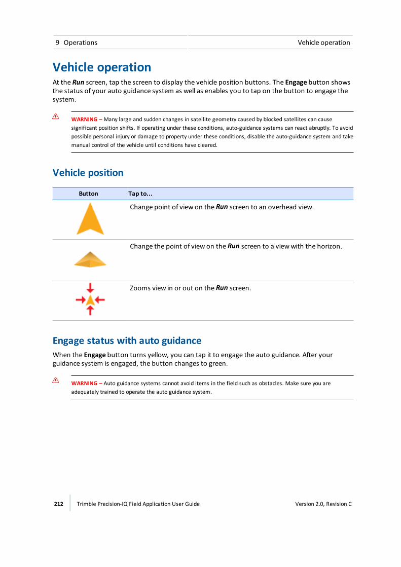
9 Operations Vehicle operation
Vehicle operationAt the Run screen, tap the screen to display the vehicle position buttons. The Engage button showsthe status of your auto guidance system as well as enables you to tap on the button to engage thesystem.
WARNING – Many large and sudden changes in satellite geometry caused by blocked satellites can causesignificant position shifts. If operating under these conditions, auto-guidance systems can react abruptly. To avoidpossible personal injury or damage to property under these conditions, disable the auto-guidance system and takemanual control of the vehicle until conditions have cleared.
Vehicle position
Button Tap to...
Change point of view on the Run screen to an overhead view.
Change the point of view on the Run screen to a viewwith the horizon.
Zooms view in or out on the Run screen.
Engage status with auto guidanceWhen the Engage button turns yellow, you can tap it to engage the auto guidance. After yourguidance system is engaged, the button changes to green.
WARNING – Auto guidance systems cannot avoid items in the field such as obstacles. Make sure you areadequately trained to operate the auto guidance system.
212 Trimble Precision-IQ Field Application User Guide Version 2.0, Revision C

Vehicle operation 9 Operations
Indicator/Button Auto guidance system is...
Gray
Engage Disabled
Disabled. Enable it in the steering control panel. This is an indicator only.
Red
Cannot Engage
Does not have the proper conditions met to engage. Tap to determinethe reason.
Yellow
Ready to Engage
Ready to engage (yellow). Tap to engage the auto guidance system.
Green
Engaged
Engaged (green). Indicates you are engaged on a pattern or line and areusing auto guidance. Tap to disengage.
Version 2.0, Revision C Trimble Precision-IQ Field Application User Guide 213
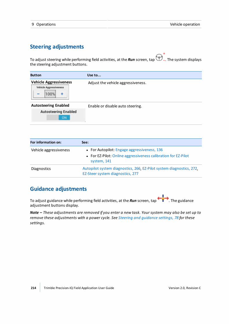
9 Operations Vehicle operation
Steering adjustments
To adjust steering while performing field activities, at the Run screen, tap . The system displaysthe steering adjustment buttons.
Button Use to...
Vehicle Aggressiveness Adjust the vehicle aggressiveness.
Autosteering Enabled Enable or disable auto steering.
For information on: See:
Vehicle aggressiveness l For Autopilot: Engage aggressiveness, 136l For EZ-Pilot: Online aggressiveness calibration for EZ-Pilot
system, 141
Diagnostics Autopilot system diagnostics, 266, EZ-Pilot system diagnostics, 272,EZ-Steer system diagnostics, 277
Guidance adjustments
To adjust guidance while performing field activities, at the Run screen, tap . The guidanceadjustment buttons display.
Note – These adjustments are removed if you enter a new task. Your system may also be set up toremove these adjustments with a power cycle. See Steering and guidance settings, 78 for thesesettings.
214 Trimble Precision-IQ Field Application User Guide Version 2.0, Revision C
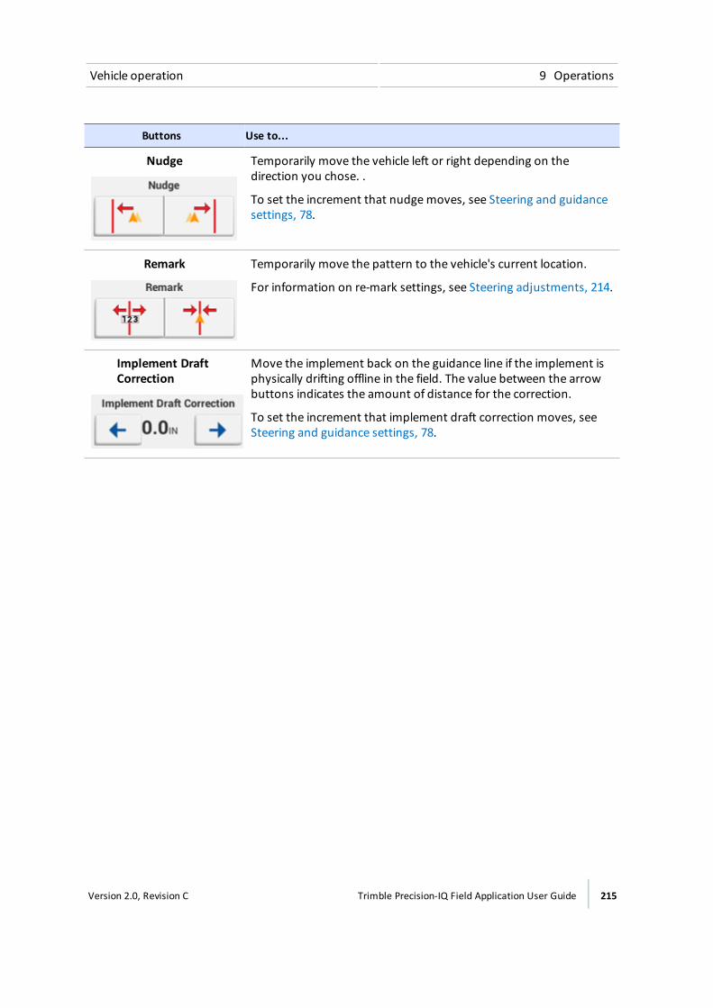
Vehicle operation 9 Operations
Buttons Use to...
Nudge Temporarily move the vehicle left or right depending on thedirection you chose. .
To set the increment that nudgemoves, see Steering and guidancesettings, 78.
Remark Temporarily move the pattern to the vehicle's current location.
For information on re-mark settings, see Steering adjustments, 214.
Implement DraftCorrection
Move the implement back on the guidance line if the implement isphysically drifting offline in the field. The value between the arrowbuttons indicates the amount of distance for the correction.
To set the increment that implement draft correction moves, seeSteering and guidance settings, 78.
Version 2.0, Revision C Trimble Precision-IQ Field Application User Guide 215
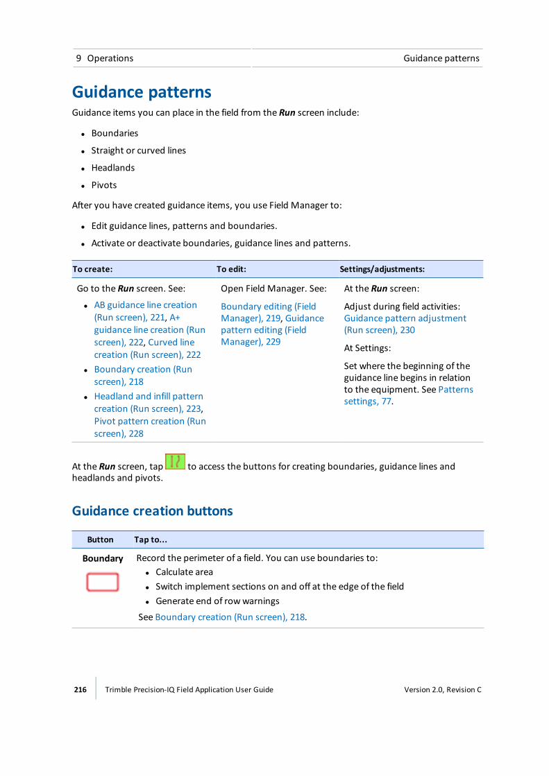
9 Operations Guidance patterns
Guidance patternsGuidance items you can place in the field from the Run screen include:
l Boundaries
l Straight or curved lines
l Headlands
l Pivots
After you have created guidance items, you use Field Manager to:
l Edit guidance lines, patterns and boundaries.
l Activate or deactivate boundaries, guidance lines and patterns.
To create: To edit: Settings/adjustments:
Go to the Run screen. See:
l AB guidance line creation(Run screen), 221, A+guidance line creation (Runscreen), 222, Curved linecreation (Run screen), 222
l Boundary creation (Runscreen), 218
l Headland and infill patterncreation (Run screen), 223,Pivot pattern creation (Runscreen), 228
Open Field Manager. See:
Boundary editing (FieldManager), 219, Guidancepattern editing (FieldManager), 229
At the Run screen:
Adjust during field activities:Guidance pattern adjustment(Run screen), 230
At Settings:
Set where the beginning of theguidance line begins in relationto the equipment. See Patternssettings, 77.
At the Run screen, tap to access the buttons for creating boundaries, guidance lines andheadlands and pivots.
Guidance creation buttons
Button Tap to...
Boundary Record the perimeter of a field. You can use boundaries to:l Calculate areal Switch implement sections on and off at the edge of the fieldl Generate end of rowwarnings
See Boundary creation (Run screen), 218.
216 Trimble Precision-IQ Field Application User Guide Version 2.0, Revision C
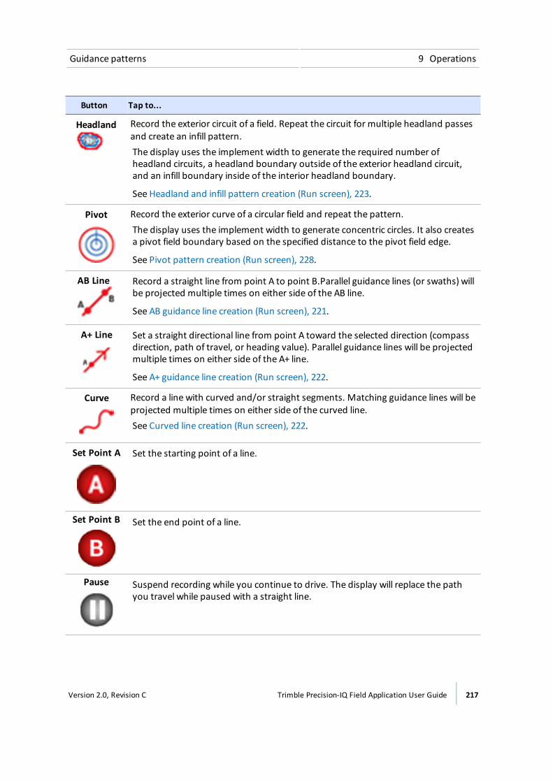
Guidance patterns 9 Operations
Button Tap to...
Headland Record the exterior circuit of a field. Repeat the circuit for multiple headland passesand create an infill pattern.The display uses the implement width to generate the required number ofheadland circuits, a headland boundary outside of the exterior headland circuit,and an infill boundary inside of the interior headland boundary.
See Headland and infill pattern creation (Run screen), 223.
Pivot Record the exterior curve of a circular field and repeat the pattern.The display uses the implement width to generate concentric circles. It also createsa pivot field boundary based on the specified distance to the pivot field edge.
See Pivot pattern creation (Run screen), 228.
AB Line Record a straight line from point A to point B.Parallel guidance lines (or swaths) willbe projected multiple times on either side of the AB line.
See AB guidance line creation (Run screen), 221.
A+ Line Set a straight directional line from point A toward the selected direction (compassdirection, path of travel, or heading value). Parallel guidance lines will be projectedmultiple times on either side of the A+ line.
See A+ guidance line creation (Run screen), 222.
Curve Record a line with curved and/or straight segments. Matching guidance lines will beprojected multiple times on either side of the curved line.See Curved line creation (Run screen), 222.
Set Point A Set the starting point of a line.
Set Point B Set the end point of a line.
Pause Suspend recording while you continue to drive. The display will replace the pathyou travel while paused with a straight line.
Version 2.0, Revision C Trimble Precision-IQ Field Application User Guide 217

9 Operations Guidance patterns
Button Tap to...
Record Begin recording a path as you drive it.
Complete Finishes the guidance item you have created and saves it.
Cancel Exits the process of creating a guidance item and does not save it.
CompassPoint
Set the heading direction for an A+ line to a compass direction.See A+ guidance line creation (Run screen), 222.
Use CurrentHeading
Set the heading direction for an A+ line based on the vehicle's current position.See A+ guidance line creation (Run screen), 222.
Lock the current angle of the vehicle.See A+ guidance line creation (Run screen), 222.
Boundary creation (Run screen)You can change the point on the implement's swath where you wish to record the boundary's edge:
Right, Center, or Left. To make this change, tap before you begin driving.
1. Enter the field where you want to create the boundary.See Enter a field (Run screen), 153.
2. Tap . The pattern buttons display.
218 Trimble Precision-IQ Field Application User Guide Version 2.0, Revision C
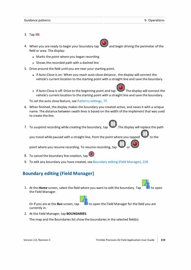
Guidance patterns 9 Operations
3. Tap .
4. When you are ready to begin your boundary tap and begin driving the perimeter of thefield or area. The display:
ll Marks the point where you began recording
l Shows the recorded path with a dashed line
5. Drive around the field until you are near your starting point.
ll If Auto-Close is on: When you reach auto-close distance , the display will connect thevehicle's current location to the starting point with a straight line and save the boundary.
l If Auto-Close is off: Drive to the beginning point and tap The display will connect thevehicle's current location to the starting point with a straight line and save the boundary.
To set the auto close feature, see Patterns settings, 77.
6. When finished, the display makes the boundary you created active, and saves it with a uniquename. The distance between swath lines is based on the width of the implement that was usedto create the line.
7. To suspend recording while creating the boundary, tap .The display will replace the path
you travel while paused with a straight line, from the point where you tapped to the
point where you resume recording. To resume recording, tap or .
8. To cancel the boundary line creation, tap .
9. To edit any boundary you have created, see Boundary editing (Field Manager), 219.
Boundary editing (Field Manager)
1. At theHome screen, select the field where you want to edit the boundary. Tap to openthe Field Manager.
Or if you are at the Run screen, tap to open the Field Manager for the field you arecurrently in.
2. At the Field Manager, tap BOUNDARIES.
Themap and the Boundaries list show the boundaries in the selected field(s).
Version 2.0, Revision C Trimble Precision-IQ Field Application User Guide 219
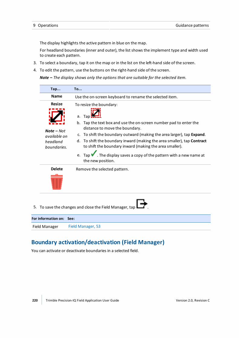
9 Operations Guidance patterns
The display highlights the active pattern in blue on themap.
For headland boundaries (inner and outer), the list shows the implement type and width usedto create each pattern.
3. To select a boundary, tap it on themap or in the list on the left-hand side of the screen.
4. To edit the pattern, use the buttons on the right-hand side of the screen.
Note – The display shows only the options that are suitable for the selected item.
Tap... To...
Name Use the on-screen keyboard to rename the selected item.
Resize
Note – Notavailable onheadlandboundaries.
To resize the boundary:
a. Tap .b. Tap the text box and use the on-screen number pad to enter the
distance to move the boundary.c. To shift the boundary outward (making the area larger), tap Expand.d. To shift the boundary inward (making the area smaller), tap Contract
to shift the boundary inward (making the area smaller).
e. Tap . The display saves a copy of the pattern with a new name atthe new position.
Delete Remove the selected pattern.
5. To save the changes and close the Field Manager, tap .
For information on: See:
Field Manager Field Manager, 53
Boundary activation/deactivation (Field Manager)You can activate or deactivate boundaries in a selected field.
220 Trimble Precision-IQ Field Application User Guide Version 2.0, Revision C
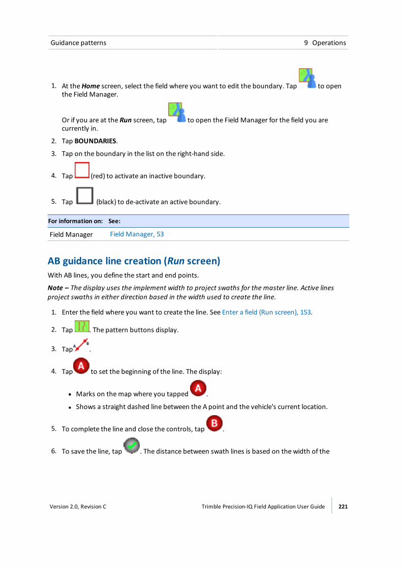
Guidance patterns 9 Operations
1. At theHome screen, select the field where you want to edit the boundary. Tap to openthe Field Manager.
Or if you are at the Run screen, tap to open the Field Manager for the field you arecurrently in.
2. Tap BOUNDARIES.
3. Tap on the boundary in the list on the right-hand side.
4. Tap (red) to activate an inactive boundary.
5. Tap (black) to de-activate an active boundary.
For information on: See:
Field Manager Field Manager, 53
AB guidance line creation (Run screen)With AB lines, you define the start and end points.
Note – The display uses the implement width to project swaths for the master line. Active linesproject swaths in either direction based in the width used to create the line.
1. Enter the field where you want to create the line. See Enter a field (Run screen), 153.
2. Tap . The pattern buttons display.
3. Tap .
4. Tap to set the beginning of the line. The display:
ll Marks on themap where you tapped .
l Shows a straight dashed line between the A point and the vehicle's current location.
5. To complete the line and close the controls, tap .
6. To save the line, tap . The distance between swath lines is based on the width of the
Version 2.0, Revision C Trimble Precision-IQ Field Application User Guide 221

9 Operations Guidance patterns
implement that was used to create the line.
7. To cancel the AB line creation, tap .
A+ guidance line creation (Run screen)With A+ lines, you define a point on the line and the direction the line is heading.
1. Select a vehicle, implement and field. See Select a field, 152.
Note – The display uses the implement width to project swaths for the master line.
2. Enter the field where you want to create the line. See Enter a field (Run screen), 153.
3. Tap . The pattern buttons display.
4. Tap . The display changes to overhead view if you were in trailing view. The A point is set atthe vehicle's current location. The A+ line controls appear in the center of the screen.
5. Select the direction you want for the A+ line.
6. To set the direction of the line, you can do any of the following:
ll To use the direction that the vehicle is facing as the heading, tap .
l To use the on-screen number pad to enter an exact heading, tap the number.
l To use a cardinal (N, S, E, W) or ordinal (NE, SE, SW, NW) direction, tap that direction on
the compass ( ).
The display saves the line. The distance between swath lines is based on the width of theimplement that was used to create the line.
7. To accept the line and direction and close the controls, tap . The display saves the line.The distance between swath lines is based on the width of the implement that was used tocreate the line.
8. To cancel the line creation, tap .
Curved line creation (Run screen)1. Enter the field where you want to create the boundary. See Enter a field (Run screen), 153.
2. Tap . The pattern buttons display.
3. Tap .
222 Trimble Precision-IQ Field Application User Guide Version 2.0, Revision C
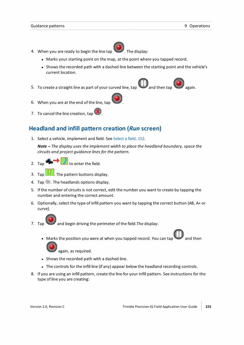
Guidance patterns 9 Operations
4. When you are ready to begin the line tap . The display:
ll Marks your starting point on themap, at the point where you tapped record.
ll Shows the recorded path with a dashed line between the starting point and the vehicle'scurrent location.
5. To create a straight line as part of your curved line, tap and then tap again.
6. When you are at the end of the line, tap .
7. To cancel the line creation, tap .
Headland and infill pattern creation (Run screen)1. Select a vehicle, implement and field. See Select a field, 152.
Note – The display uses the implement width to place the headland boundary, space thecircuits and project guidance lines for the pattern.
2. Tap to enter the field.
3. Tap . The pattern buttons display.
4. Tap . The headlands options display.
5. If the number of circuits is not correct, edit the number you want to create by tapping thenumber and entering the correct amount.
6. Optionally, select the type of infill pattern you want by tapping the correct button (AB, A+ orcurve).
7. Tap and begin driving the perimeter of the field.The display:
ll Marks the position you were at when you tapped record. You can tap and then
again, as required.
l Shows the recorded path with a dashed line.
l The controls for the infill line (if any) appear below the headland recording controls.
8. If you are using an infill pattern, create the line for your infill pattern. See instructions for thetype of line you are creating:
Version 2.0, Revision C Trimble Precision-IQ Field Application User Guide 223

9 Operations Guidance patterns
ll AB guidance line creation (Run screen), 221
l A+ guidance line creation (Run screen), 222
l Curved line creation (Run screen), 222
9. Continue driving around the field until you are near your starting point.
ll If Auto-Close is on: When you reach auto-close distance , the display will connect thevehicle's current location to the starting point with a straight line and save the pattern.
l If Auto-Close is off: Drive to the beginning point and tap . The display will connect thevehicle's current location to the starting point with a straight line and save the pattern.
To set the auto close feature, see Patterns settings, 77.
10. When finished, the display:
a. Saves the headland pattern with a unique name (for example, HL01).
b. Generates an inner boundary and an outer boundary based on the recorded path and thewidth of the implement. The headland boundaries are saved with a unique name relatedto the headland (for example, HL01 inner boundary and HL01 outer boundary).
c. Generates an infill swath based on the number of circuits selected and the width of theimplement. The infill swath is saved with a unique name related to the headland (forexample, DefaultInfillSwath).
11. To cancel the pattern creation, tap .
Infill pattern shiftTo shift the infill pattern, complete the following steps.
1. At the Run screen, open the Field Manager by tapping .
2. Tap GUIDANCE PATTERNS.
3. In the list of patterns, tap to select the infill pattern you want to shift, and tap Activate.
4. Tap Shift. The Shift Pattern tool displays.
224 Trimble Precision-IQ Field Application User Guide Version 2.0, Revision C
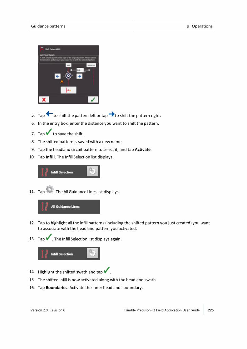
Guidance patterns 9 Operations
5. Tap to shift the pattern left or tap to shift the pattern right.
6. In the entry box, enter the distance you want to shift the pattern.
7. Tap to save the shift.
8. The shifted pattern is saved with a new name.
9. Tap the headland circuit pattern to select it, and tap Activate.
10. Tap Infill. The Infill Selection list displays.
11. Tap . The All Guidance Lines list displays.
12. Tap to highlight all the infill patterns (including the shifted pattern you just created) you wantto associate with the headland pattern you activated.
13. Tap . The Infill Selection list displays again.
14. Highlight the shifted swath and tap .
15. The shifted infill is now activated along with the headland swath.
16. Tap Boundaries. Activate the inner headlands boundary.
Version 2.0, Revision C Trimble Precision-IQ Field Application User Guide 225
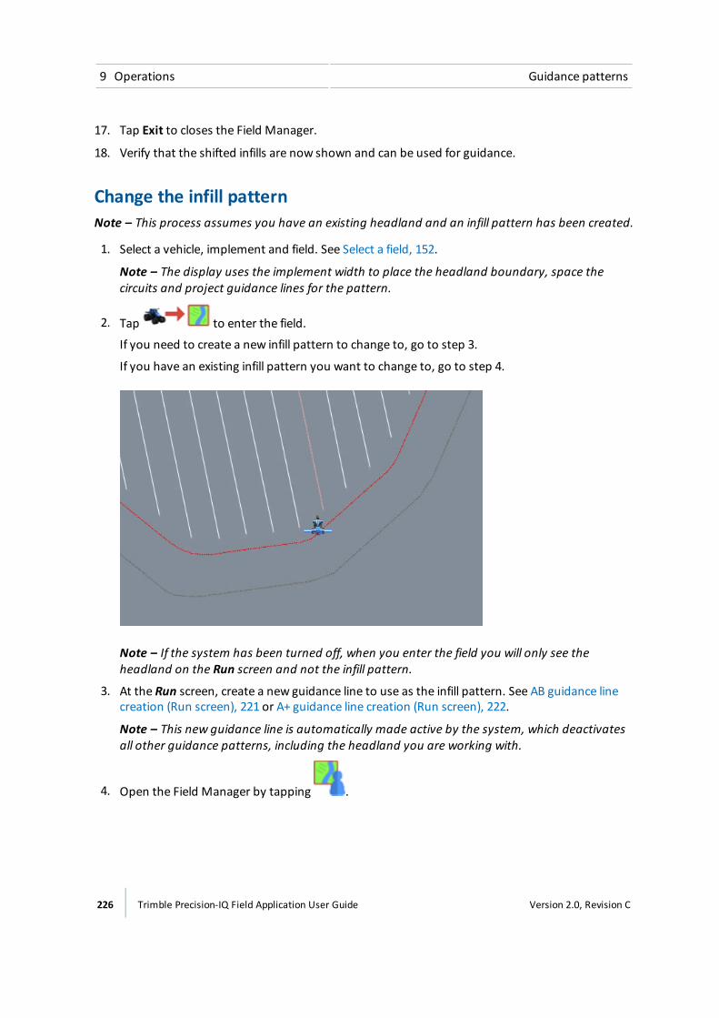
9 Operations Guidance patterns
17. Tap Exit to closes the Field Manager.
18. Verify that the shifted infills are now shown and can be used for guidance.
Change the infill patternNote – This process assumes you have an existing headland and an infill pattern has been created.
1. Select a vehicle, implement and field. See Select a field, 152.
Note – The display uses the implement width to place the headland boundary, space thecircuits and project guidance lines for the pattern.
2. Tap to enter the field.
If you need to create a new infill pattern to change to, go to step 3.
If you have an existing infill pattern you want to change to, go to step 4.
Note – If the system has been turned off, when you enter the field you will only see theheadland on the Run screen and not the infill pattern.
3. At the Run screen, create a new guidance line to use as the infill pattern. See AB guidance linecreation (Run screen), 221 or A+ guidance line creation (Run screen), 222.
Note – This new guidance line is automatically made active by the system, which deactivatesall other guidance patterns, including the headland you are working with.
4. Open the Field Manager by tapping .
226 Trimble Precision-IQ Field Application User Guide Version 2.0, Revision C

Guidance patterns 9 Operations
5. At theGuidance Patterns tab:
a. Highlight the headland circuit pattern you want to work with and tap Activate. (This is notnecessary if you want to change to an existing line and did not need to create a new one instep 3.)
b. Tap Infill. The Infill Selection list displays. This lists the infill pattern that is currentlyassigned to use with the headland.
c. Tap .
The All Guidance Lines list displays. This lists all guidance lines that have been created forthis field that are within the headland boundary.
d. Tap to highlight the guidance lines you want to associate with the headland (including thenew guidance line you created in step 3).
Tap . The Infill Selection list displays again.
e. At the Infill Selection list, highlight the guidance line you want to change to and tap .This assigns the guidance line to the headland.
6. Tap Boundaries. In the Boundaries list on the left-hand side, tap the inner boundary of theheadland, then tap Activate.
Version 2.0, Revision C Trimble Precision-IQ Field Application User Guide 227

9 Operations Guidance patterns
7. Exit the Field Manager by tapping Exit.
The new infill pattern will show in the inner boundary of the headland.
Pivot pattern creation (Run screen)1. Enter the field where you want to create the pivot.See Enter a field (Run screen), 153.
2. Tap . The pattern buttons display.
3. Tap .
4. Tap and begin driving the outer perimeter of the field. The display:
ll Marks your starting point on themap, at the vehicle's location when you tapped record.
l Shows the recorded path with a dashed line.
5. Drive at least 50 feet on an outer tower rut and then tap .
6. Enter the distance to the Pivot Field Edge and tap .
7. When finished, the display:
ll Saves the pivot pattern with a unique name (for example, P01).
l Generates a pivot boundary based on the recorded path and the width of the implement.The pivot boundary is saved with a unique name related to the headland (for example, P01Boundary).
l Makes the pivot boundary active.
228 Trimble Precision-IQ Field Application User Guide Version 2.0, Revision C
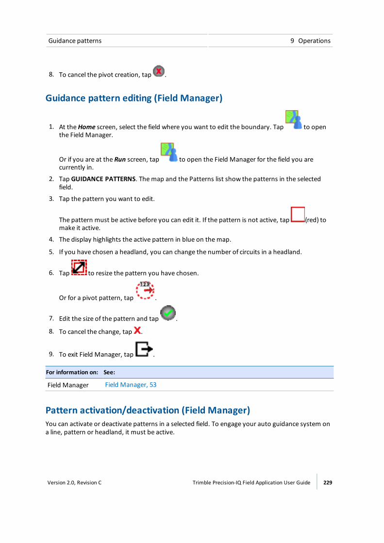
Guidance patterns 9 Operations
8. To cancel the pivot creation, tap .
Guidance pattern editing (Field Manager)
1. At theHome screen, select the field where you want to edit the boundary. Tap to openthe Field Manager.
Or if you are at the Run screen, tap to open the Field Manager for the field you arecurrently in.
2. Tap GUIDANCE PATTERNS. Themap and the Patterns list show the patterns in the selectedfield.
3. Tap the pattern you want to edit.
The pattern must be active before you can edit it. If the pattern is not active, tap (red) tomake it active.
4. The display highlights the active pattern in blue on themap.
5. If you have chosen a headland, you can change the number of circuits in a headland.
6. Tap to resize the pattern you have chosen.
Or for a pivot pattern, tap .
7. Edit the size of the pattern and tap .
8. To cancel the change, tap .
9. To exit Field Manager, tap .
For information on: See:
Field Manager Field Manager, 53
Pattern activation/deactivation (Field Manager)You can activate or deactivate patterns in a selected field. To engage your auto guidance system ona line, pattern or headland, it must be active.
Version 2.0, Revision C Trimble Precision-IQ Field Application User Guide 229

9 Operations Guidance patterns
1. Tap to open the Field Manager. Field Manager opens to the Field Overview section.
2. Tap GUIDANCE PATTERNS.
3. Tap on the line, headland or pivot area in the list on the right-hand side.
4. To activate:
ll An inactive pattern, tap (red).
l An inactive guidance line, tap (red).
5. To de-activate:
ll An active pattern, tap (black).
l An active guidance line, tap (black).
For information on: See:
Field Manager Field Manager, 53
Guidance pattern adjustment (Run screen)
To adjust guidance while performing field activities, at the Run screen, tap .
The system displays the guidance adjustment buttons.
Note – These adjustments are called "temporary" because they are not stored in the system. Afterreboot or power off, the system returns to the original settings.
Button Use to...
Nudge Moves the position of the vehicle in a perpendicular direction (leftor right) to the line you are engaged on currently.
To adjust the size of the increments, see Steering and guidancesettings, 78.
Remark Temporarily move the line or pattern to the vehicle's currentlocation or the value entered by you.
230 Trimble Precision-IQ Field Application User Guide Version 2.0, Revision C
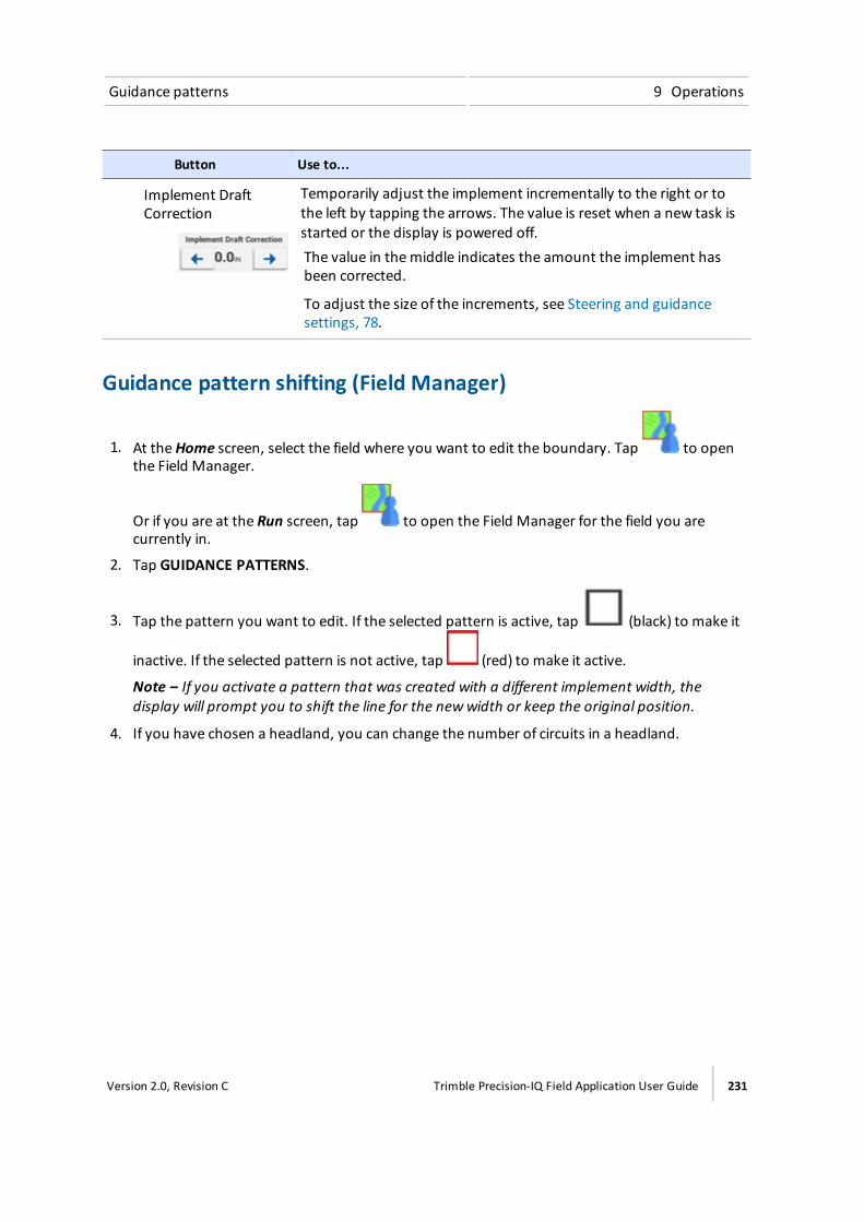
Guidance patterns 9 Operations
Button Use to...
Implement DraftCorrection
Temporarily adjust the implement incrementally to the right or tothe left by tapping the arrows. The value is reset when a new task isstarted or the display is powered off.The value in themiddle indicates the amount the implement hasbeen corrected.
To adjust the size of the increments, see Steering and guidancesettings, 78.
Guidance pattern shifting (Field Manager)
1. At theHome screen, select the field where you want to edit the boundary. Tap to openthe Field Manager.
Or if you are at the Run screen, tap to open the Field Manager for the field you arecurrently in.
2. Tap GUIDANCE PATTERNS.
3. Tap the pattern you want to edit. If the selected pattern is active, tap (black) to make it
inactive. If the selected pattern is not active, tap (red) to make it active.
Note – If you activate a pattern that was created with a different implement width, thedisplay will prompt you to shift the line for the newwidth or keep the original position.
4. If you have chosen a headland, you can change the number of circuits in a headland.
Version 2.0, Revision C Trimble Precision-IQ Field Application User Guide 231
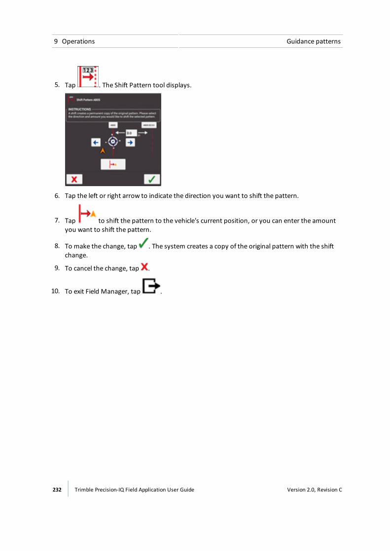
9 Operations Guidance patterns
5. Tap . The Shift Pattern tool displays.
6. Tap the left or right arrow to indicate the direction you want to shift the pattern.
7. Tap to shift the pattern to the vehicle's current position, or you can enter the amountyou want to shift the pattern.
8. To make the change, tap . The system creates a copy of the original pattern with the shiftchange.
9. To cancel the change, tap .
10. To exit Field Manager, tap .
232 Trimble Precision-IQ Field Application User Guide Version 2.0, Revision C

Landmarks 9 Operations
LandmarksWhen you are in the Run screen, you can place field items in the field, including:
l Lines, such as fences
l Points, such as trees
l Areas, such as ponds
After you have created landmarks, you can edit them and assign them to categories using FieldManager. See Landmark editing (Field Manager), 235.
At the Run screen, tap to access the controls for creating landmark points, lines and areas.
Landmark buttons
Button Tap to...
Point Place a point indicator on the field map marking a point. Available types:l Generic (such as a gate, riser, tile inlet, water trough, well)l Rockl Pest (insects, weeds)l Obstacle (hole, tree, hazard)
Line Record a linemarking a landmark. Available types:l Generic (such as border, drip tape, gate, path, road)l Obstacle (cable, ditch, fence, hazard, pipe, river, stream, terrace, trees)
Area Record a shapemarking a landmark. Area landmarks are not used to switchsections on and off.Available types:l Genericl Pestl Obstacle
Non-ProductiveArea
Record a shapemarking a landmark. Non-productive area landmarks can beused to switch sections on and off.
Available types:
l Generic (such as clover, exclusion, grassed waterway, slough, waterway)l Obstacle (hazard, hole, lagoon, pond, rocks, tree)l Pest (disease, weed)
Version 2.0, Revision C Trimble Precision-IQ Field Application User Guide 233
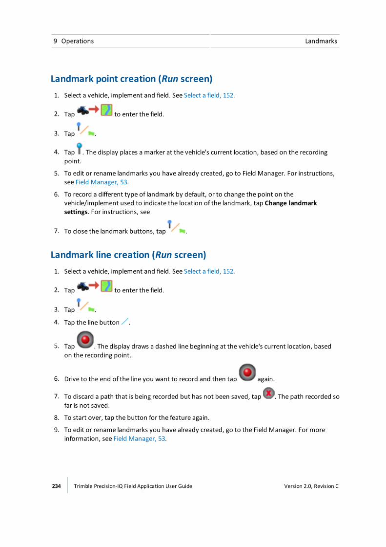
9 Operations Landmarks
Landmark point creation (Run screen)1. Select a vehicle, implement and field. See Select a field, 152.
2. Tap to enter the field.
3. Tap .
4. Tap . The display places a marker at the vehicle's current location, based on the recordingpoint.
5. To edit or rename landmarks you have already created, go to Field Manager. For instructions,see Field Manager, 53.
6. To record a different type of landmark by default, or to change the point on thevehicle/implement used to indicate the location of the landmark, tap Change landmarksettings. For instructions, see
7. To close the landmark buttons, tap .
Landmark line creation (Run screen)1. Select a vehicle, implement and field. See Select a field, 152.
2. Tap to enter the field.
3. Tap .
4. Tap the line button .
5. Tap . The display draws a dashed line beginning at the vehicle's current location, basedon the recording point.
6. Drive to the end of the line you want to record and then tap again.
7. To discard a path that is being recorded but has not been saved, tap . The path recorded sofar is not saved.
8. To start over, tap the button for the feature again.
9. To edit or rename landmarks you have already created, go to the Field Manager. For moreinformation, see Field Manager, 53.
234 Trimble Precision-IQ Field Application User Guide Version 2.0, Revision C

Landmarks 9 Operations
10. To record a different type of landmark by default, or to change the point on thevehicle/implement used to indicate the location of the landmark, tap Change landmarksettings. For more information, see .
11. To close the landmark buttons, tap .
Landmark area creation (Run screen)Follow the steps below to create a productive or non-productive area. Non-productive areas can beused to switch sections off when you use section control.
1. Select a vehicle, implement and field. See Select a field, 152.
2. Tap to enter the field.
3. Tap .
4. Tap or .
5. Tap the record button . The display places a marker at the vehicle's current location,based on the recording point.
6. Drive around the area you want to record and then tap the record button again.
7. To close the landmark controls, tap .
8. To discard the recorded path and close the controls, tap . The path recorded so far is notsaved.
9. To start over, tap the button for the feature again.
10. To edit or rename landmarks you have already created, see Landmark editing (Field Manager),235.
11. To record a different type of landmark by default, or to change the point on thevehicle/implement used to indicate the location of the landmark, see .
Landmark editing (Field Manager)At the Field Manager, you can edit any landmarks you have created in the Run screen.
Version 2.0, Revision C Trimble Precision-IQ Field Application User Guide 235

9 Operations Landmarks
1. Open the Field Manager, 53.
2. Tap Landmarks. Themap and the Landmarks list show recorded landmark items including:
ll Points
l Lines
l Areas
l Non-productive areas
3. To select a landmark, tap it on themap or in the list on the left-hand side of the screen.
4. Use the buttons on the right-hand side of the screen to edit the landmark.
Note – The display shows only the options that are suitable for the selected item.
Tap... To...
Name Rename the selected item.
Category Change the classification of a point, line or area landmark. Options are:
ll Genericl Obstacle
Note – To identify a point more specifically, change the name of thepoint.
Convert Tap to:ll Change an area to a non-productive area.l Change a non-productive area to an area.
Delete Remove the selected landmark from the display.
5. To exit Field Manager, tap .
236 Trimble Precision-IQ Field Application User Guide Version 2.0, Revision C
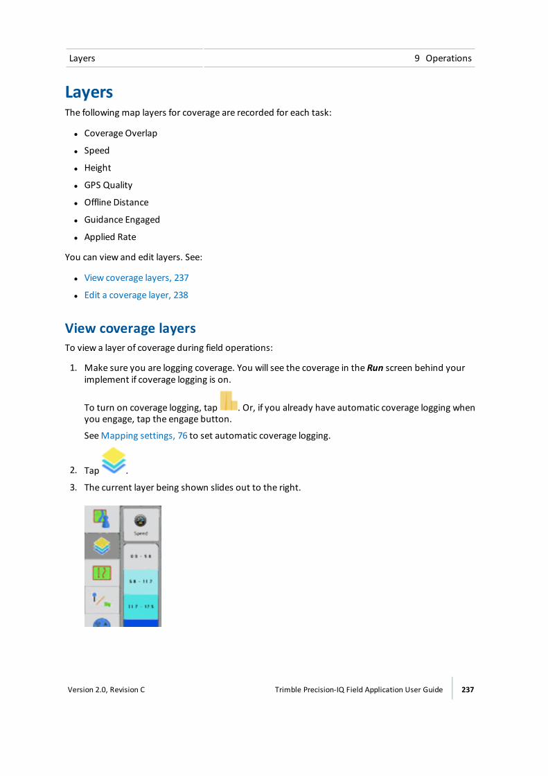
Layers 9 Operations
LayersThe following map layers for coverage are recorded for each task:
l Coverage Overlap
l Speed
l Height
l GPS Quality
l Offline Distance
l Guidance Engaged
l Applied Rate
You can view and edit layers. See:
l View coverage layers, 237
l Edit a coverage layer, 238
View coverage layersTo view a layer of coverage during field operations:
1. Make sure you are logging coverage. You will see the coverage in the Run screen behind yourimplement if coverage logging is on.
To turn on coverage logging, tap . Or, if you already have automatic coverage logging whenyou engage, tap the engage button.
SeeMapping settings, 76 to set automatic coverage logging.
2. Tap .
3. The current layer being shown slides out to the right.
Version 2.0, Revision C Trimble Precision-IQ Field Application User Guide 237
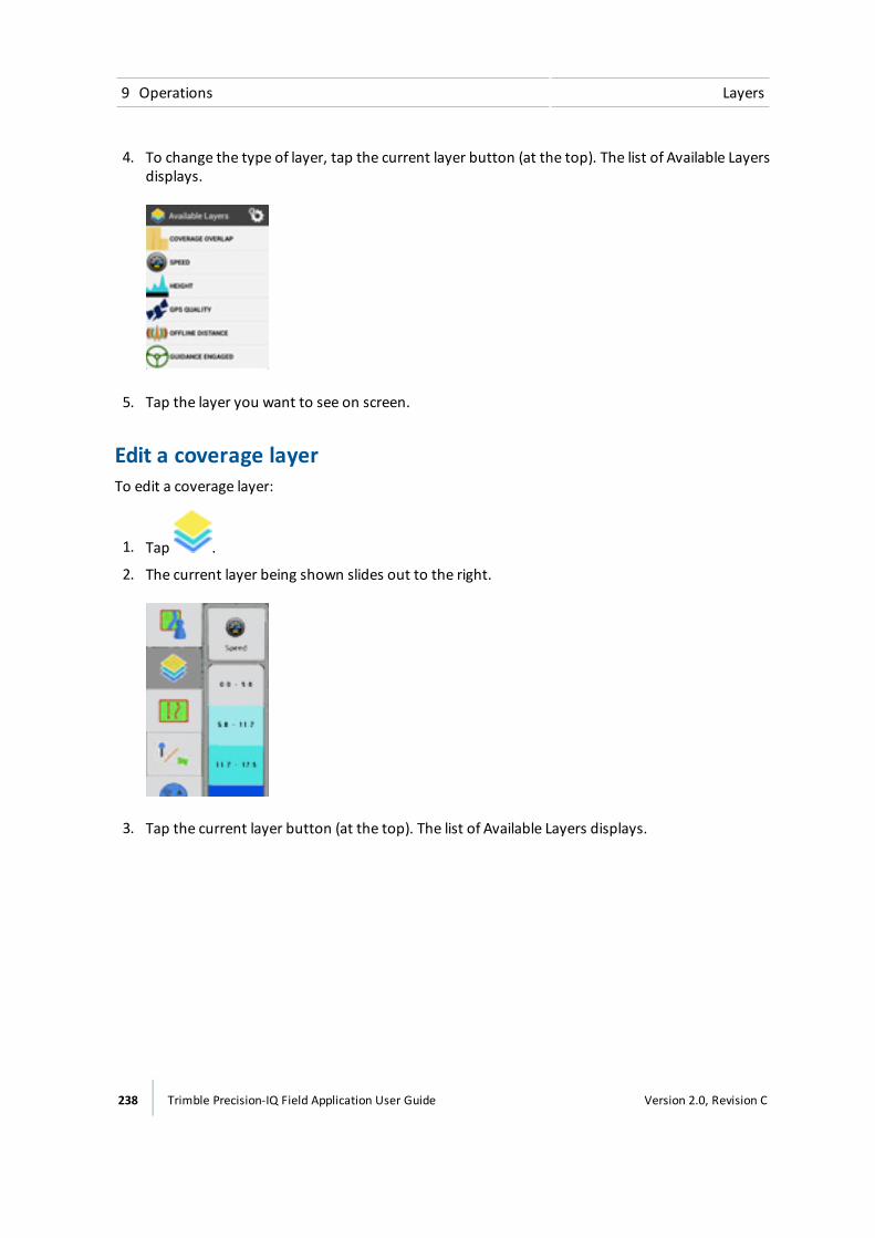
9 Operations Layers
4. To change the type of layer, tap the current layer button (at the top). The list of Available Layersdisplays.
5. Tap the layer you want to see on screen.
Edit a coverage layerTo edit a coverage layer:
1. Tap .
2. The current layer being shown slides out to the right.
3. Tap the current layer button (at the top). The list of Available Layers displays.
238 Trimble Precision-IQ Field Application User Guide Version 2.0, Revision C

Layers 9 Operations
4. Tap button. The edit panel for available layers displays.
5. Change the settings of the layer to better meet your needs:
ll Auto scale
l Steps
l Color scheme
6. Tap to save your changes or to cancel your changes.
Version 2.0, Revision C Trimble Precision-IQ Field Application User Guide 239
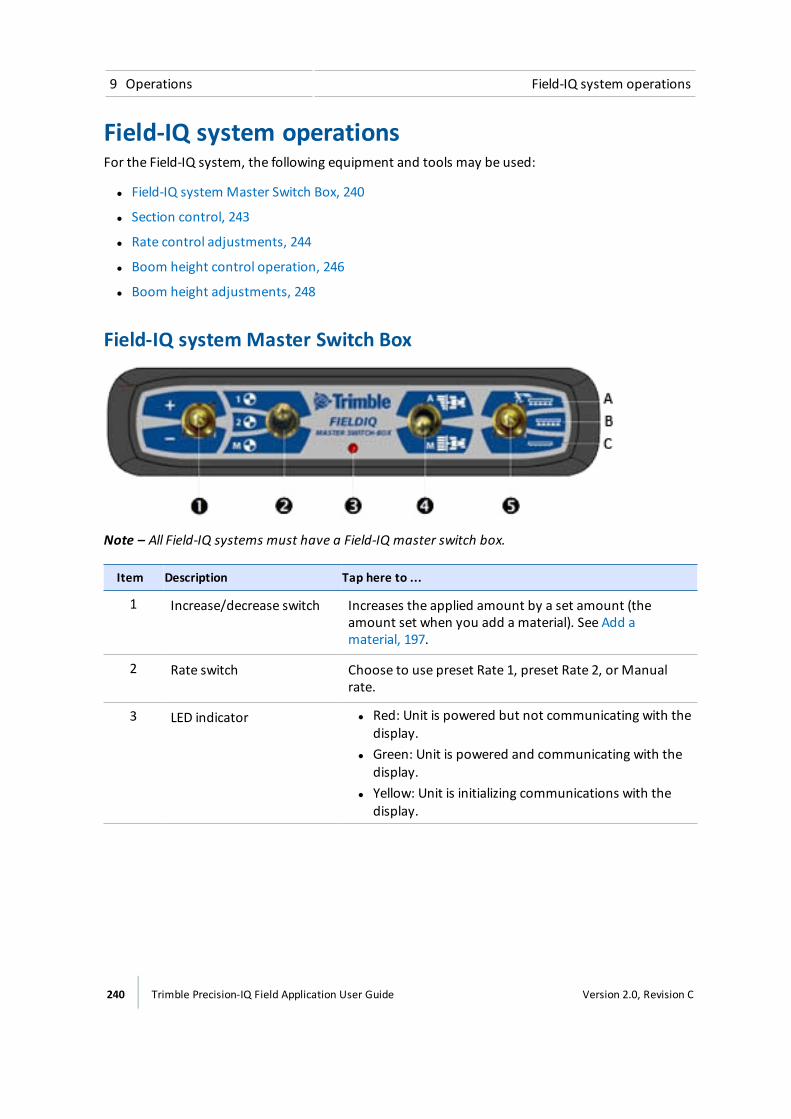
9 Operations Field-IQ system operations
Field-IQ system operationsFor the Field-IQ system, the following equipment and tools may be used:
l Field-IQ system Master Switch Box, 240
l Section control, 243
l Rate control adjustments, 244
l Boom height control operation, 246
l Boom height adjustments, 248
Field-IQ systemMaster Switch Box
Note – All Field-IQ systems must have a Field-IQ master switch box.
Item Description Tap here to ...
1 Increase/decrease switch Increases the applied amount by a set amount (theamount set when you add a material). See Add amaterial, 197.
2 Rate switch Choose to use preset Rate 1, preset Rate 2, or Manualrate.
3 LED indicator l Red: Unit is powered but not communicating with thedisplay.
l Green: Unit is powered and communicating with thedisplay.
l Yellow: Unit is initializing communications with thedisplay.
240 Trimble Precision-IQ Field Application User Guide Version 2.0, Revision C
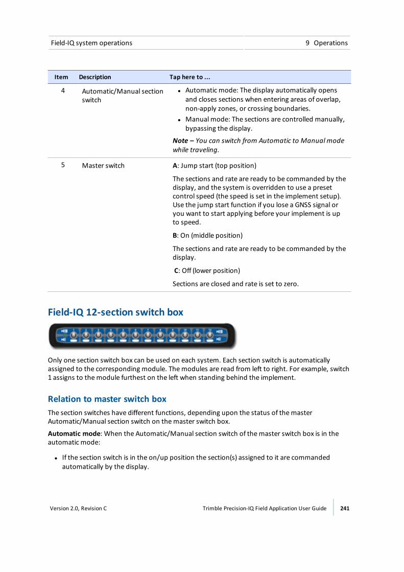
Field-IQ system operations 9 Operations
Item Description Tap here to ...
4 Automatic/Manual sectionswitch
l Automatic mode: The display automatically opensand closes sections when entering areas of overlap,non-apply zones, or crossing boundaries.
l Manual mode: The sections are controlled manually,bypassing the display.
Note – You can switch from Automatic to Manual modewhile traveling.
5 Master switch A: Jump start (top position)
The sections and rate are ready to be commanded by thedisplay, and the system is overridden to use a presetcontrol speed (the speed is set in the implement setup).Use the jump start function if you lose a GNSS signal oryou want to start applying before your implement is upto speed.
B: On (middle position)
The sections and rate are ready to be commanded by thedisplay.
C: Off (lower position)
Sections are closed and rate is set to zero.
Field-IQ 12-section switch box
Only one section switch box can be used on each system. Each section switch is automaticallyassigned to the corresponding module. Themodules are read from left to right. For example, switch1 assigns to themodule furthest on the left when standing behind the implement.
Relation to master switch boxThe section switches have different functions, depending upon the status of themasterAutomatic/Manual section switch on themaster switch box.
Automatic mode: When the Automatic/Manual section switch of themaster switch box is in theautomatic mode:
l If the section switch is in the on/up position the section(s) assigned to it are commandedautomatically by the display.
Version 2.0, Revision C Trimble Precision-IQ Field Application User Guide 241

9 Operations Field-IQ system operations
l If the section switch is in the off/down position the section(s) assigned to it are commanded tobe off.
Manual mode: When the Automatic/Manual section switch of themaster switch box is in themanual mode:
l If the section switch is in the on/up position, the section(s) assigned to it are commanded to beon. This overrides the display and coverage logging is ignored.
l If the section switch is in the off/down position, the section(s) assigned to it are commanded tobe off. This overrides the display and coverage logging is ignored.
LED status indicatorsThe LED has the following status indicators:
l Green: The unit is powered and is communicating with the display.
l Yellow: The unit is initializing communications with the display.
l Red: The unit is powered but not communicating with the display.
242 Trimble Precision-IQ Field Application User Guide Version 2.0, Revision C
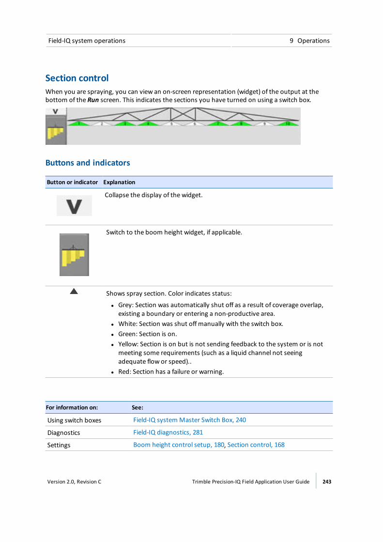
Field-IQ system operations 9 Operations
Section controlWhen you are spraying, you can view an on-screen representation (widget) of the output at thebottom of the Run screen. This indicates the sections you have turned on using a switch box.
Buttons and indicators
Button or indicator Explanation
Collapse the display of the widget.
Switch to the boom height widget, if applicable.
Shows spray section. Color indicates status:
l Grey: Section was automatically shut off as a result of coverage overlap,existing a boundary or entering a non-productive area.
l White: Section was shut off manually with the switch box.l Green: Section is on.l Yellow: Section is on but is not sending feedback to the system or is not
meeting some requirements (such as a liquid channel not seeingadequate flow or speed)..
l Red: Section has a failure or warning.
For information on: See:
Using switch boxes Field-IQ system Master Switch Box, 240
Diagnostics Field-IQ diagnostics, 281
Settings Boom height control setup, 180, Section control, 168
Version 2.0, Revision C Trimble Precision-IQ Field Application User Guide 243
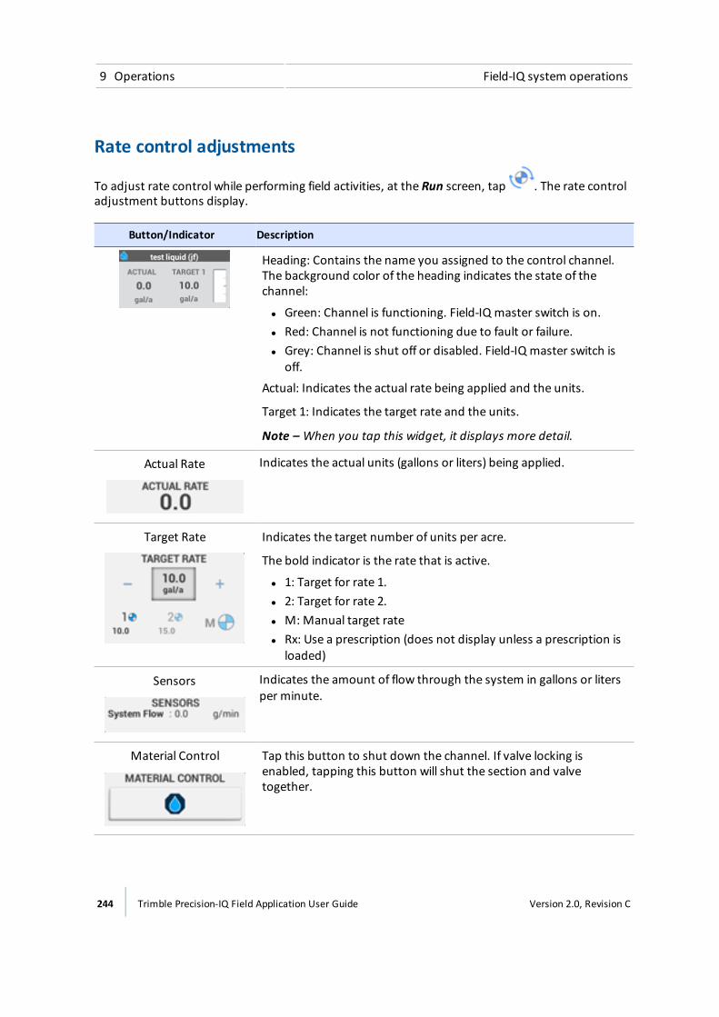
9 Operations Field-IQ system operations
Rate control adjustments
To adjust rate control while performing field activities, at the Run screen, tap . The rate controladjustment buttons display.
Button/Indicator Description
Heading: Contains the name you assigned to the control channel.The background color of the heading indicates the state of thechannel:
l Green: Channel is functioning. Field-IQ master switch is on.l Red: Channel is not functioning due to fault or failure.l Grey: Channel is shut off or disabled. Field-IQ master switch is
off.
Actual: Indicates the actual rate being applied and the units.
Target 1: Indicates the target rate and the units.
Note – When you tap this widget, it displays more detail.
Actual Rate Indicates the actual units (gallons or liters) being applied.
Target Rate Indicates the target number of units per acre.
The bold indicator is the rate that is active.
l 1: Target for rate 1.l 2: Target for rate 2.l M:Manual target ratel Rx: Use a prescription (does not display unless a prescription is
loaded)
Sensors Indicates the amount of flow through the system in gallons or litersper minute.
Material Control Tap this button to shut down the channel. If valve locking isenabled, tapping this button will shut the section and valvetogether.
244 Trimble Precision-IQ Field Application User Guide Version 2.0, Revision C
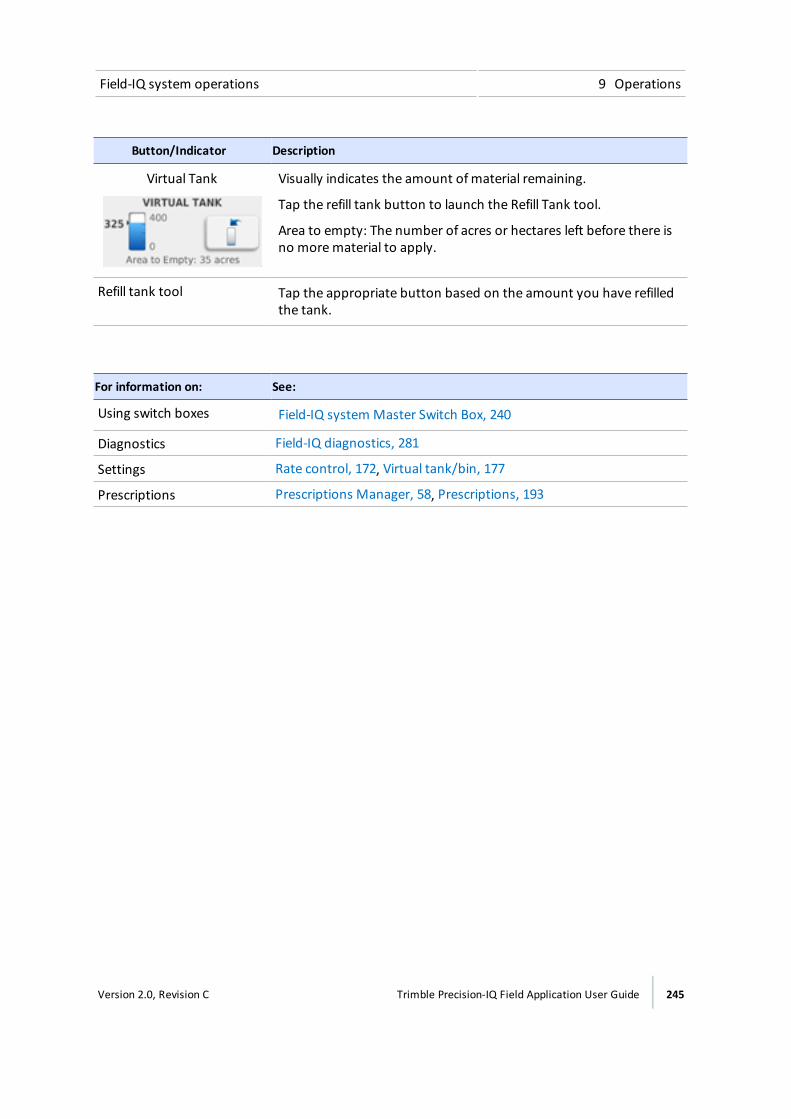
Field-IQ system operations 9 Operations
Button/Indicator Description
Virtual Tank Visually indicates the amount ofmaterial remaining.
Tap the refill tank button to launch the Refill Tank tool.
Area to empty: The number of acres or hectares left before there isno morematerial to apply.
Refill tank tool Tap the appropriate button based on the amount you have refilledthe tank.
For information on: See:
Using switch boxes Field-IQ system Master Switch Box, 240
Diagnostics Field-IQ diagnostics, 281
Settings Rate control, 172, Virtual tank/bin, 177
Prescriptions Prescriptions Manager, 58, Prescriptions, 193
Version 2.0, Revision C Trimble Precision-IQ Field Application User Guide 245
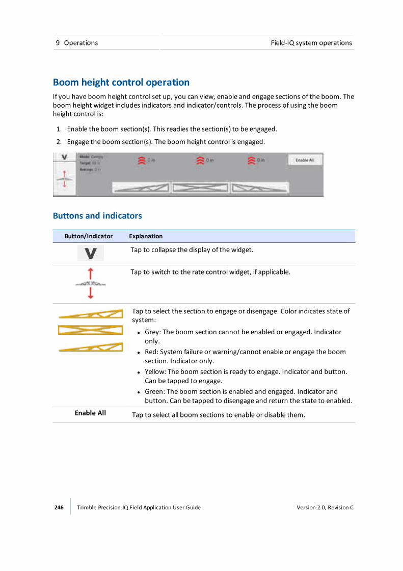
9 Operations Field-IQ system operations
Boom height control operationIf you have boom height control set up, you can view, enable and engage sections of the boom. Theboom height widget includes indicators and indicator/controls. The process of using the boomheight control is:
1. Enable the boom section(s). This readies the section(s) to be engaged.
2. Engage the boom section(s). The boom height control is engaged.
Buttons and indicators
Button/Indicator Explanation
Tap to collapse the display of the widget.
Tap to switch to the rate control widget, if applicable.
Tap to select the section to engage or disengage. Color indicates state ofsystem:
l Grey: The boom section cannot be enabled or engaged. Indicatoronly.
l Red: System failure or warning/cannot enable or engage the boomsection. Indicator only.
l Yellow: The boom section is ready to engage. Indicator and button.Can be tapped to engage.
l Green: The boom section is enabled and engaged. Indicator andbutton. Can be tapped to disengage and return the state to enabled.
Enable All Tap to select all boom sections to enable or disable them.
246 Trimble Precision-IQ Field Application User Guide Version 2.0, Revision C

Field-IQ system operations 9 Operations
Button/Indicator Explanation
(red)
Cannot Engage
Red background: Indicator only. Cannot engage the boom(s) to adjustboom height of the enabled sections.
(yellow)
Ready to Engage
Yellow background: Ready to engage the boom(s) adjust the sections ofthe boom you have selected. Tap to engage the boom.
(green)
Engaged
Green background: Indicates the sections of the boom you have selectedare engaged. Tap to disengage the boom.
(gray)
Disabled
Grey background: Indicator only. Boom(s) cannot be engaged becausethe boom system is disabled.
Shows the number of inches the boom is above or below the targetheight using arrows and color:
l One green arrow: Slightly above/below target heightl Two yellow arrows: Somewhat above/below target heightl Three red arrows: Significantly above/below target height
Shows the:
l Model Target heightl Average height of all boom sections
Version 2.0, Revision C Trimble Precision-IQ Field Application User Guide 247

9 Operations Field-IQ system operations
Boom height adjustments
To adjust boom height while performing field activities, at the Run screen, tap . The boomheight adjustment buttons display.
Button/Indicator Description
Target Height Increase or decrease height of boom by using plus or minus signs. Orenter the value by tapping on the number
Tap Set Target to Average to set the target height to an average.
System Aggressiveness Increase or decrease the aggressiveness of lowering or raising theboom by tapping the plus or minus signs. Or enter the value bytapping on the number and entering a different number.
Mode Tap either Ground or Canopy to change themode.
Tap to seemore detail on boom height control.
248 Trimble Precision-IQ Field Application User Guide Version 2.0, Revision C
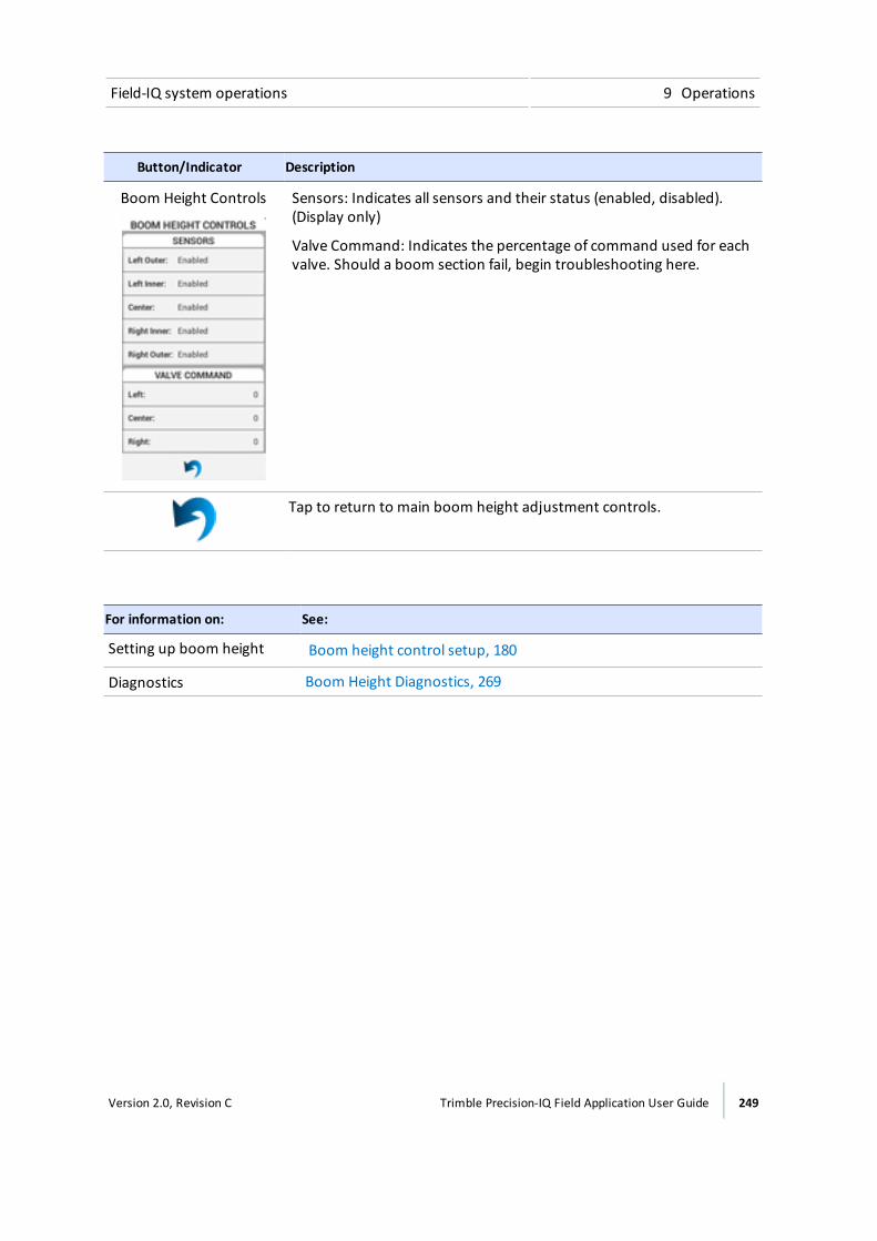
Field-IQ system operations 9 Operations
Button/Indicator Description
Boom Height Controls Sensors: Indicates all sensors and their status (enabled, disabled).(Display only)
Valve Command: Indicates the percentage of command used for eachvalve. Should a boom section fail, begin troubleshooting here.
Tap to return to main boom height adjustment controls.
For information on: See:
Setting up boom height Boom height control setup, 180
Diagnostics Boom Height Diagnostics, 269
Version 2.0, Revision C Trimble Precision-IQ Field Application User Guide 249
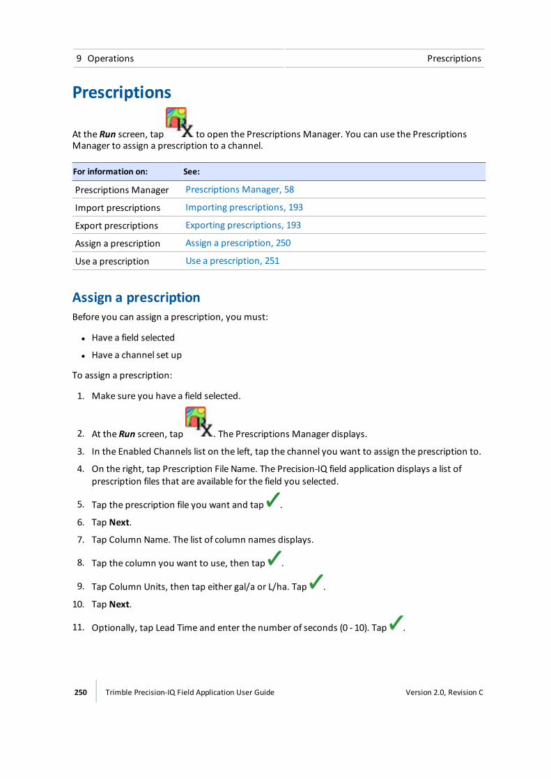
9 Operations Prescriptions
Prescriptions
At the Run screen, tap to open the Prescriptions Manager. You can use the PrescriptionsManager to assign a prescription to a channel.
For information on: See:
Prescriptions Manager Prescriptions Manager, 58
Import prescriptions Importing prescriptions, 193
Export prescriptions Exporting prescriptions, 193
Assign a prescription Assign a prescription, 250
Use a prescription Use a prescription, 251
Assign a prescriptionBefore you can assign a prescription, you must:
l Have a field selected
l Have a channel set up
To assign a prescription:
1. Make sure you have a field selected.
2. At the Run screen, tap . The Prescriptions Manager displays.
3. In the Enabled Channels list on the left, tap the channel you want to assign the prescription to.
4. On the right, tap Prescription File Name. The Precision-IQ field application displays a list ofprescription files that are available for the field you selected.
5. Tap the prescription file you want and tap .
6. Tap Next.
7. Tap Column Name. The list of column names displays.
8. Tap the column you want to use, then tap .
9. Tap Column Units, then tap either gal/a or L/ha. Tap .
10. Tap Next.
11. Optionally, tap Lead Time and enter the number of seconds (0 - 10). Tap .
250 Trimble Precision-IQ Field Application User Guide Version 2.0, Revision C
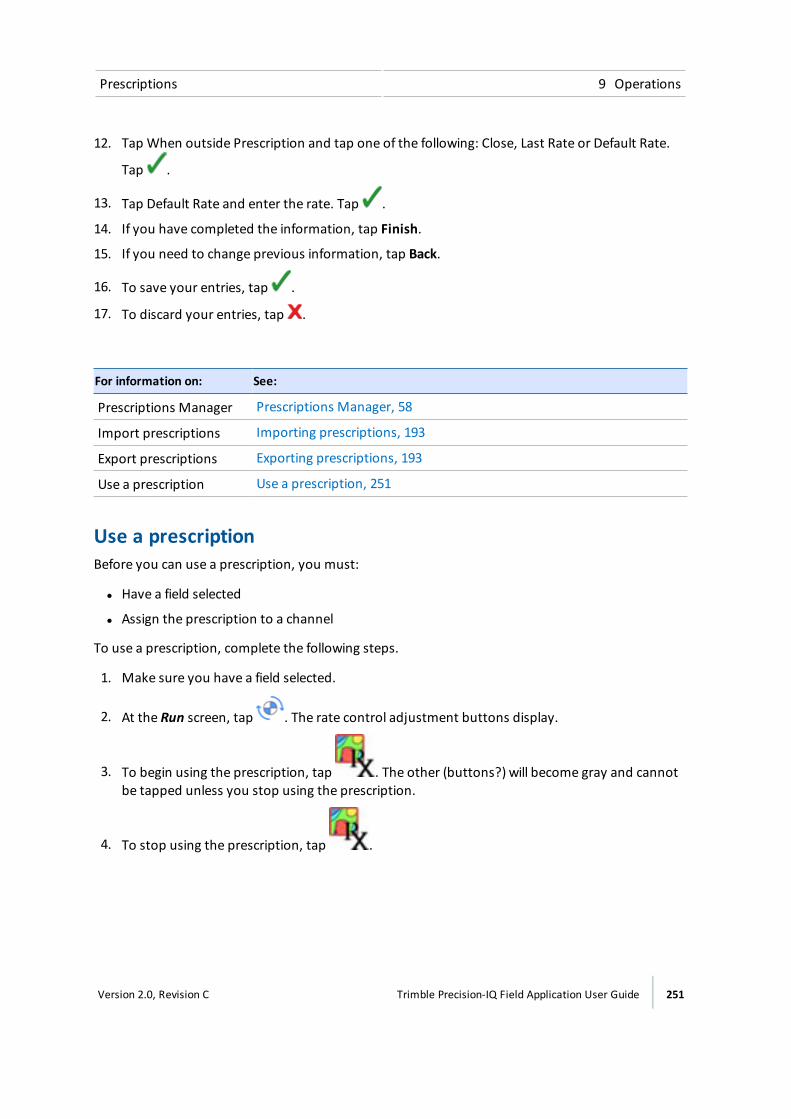
Prescriptions 9 Operations
12. Tap When outside Prescription and tap one of the following: Close, Last Rate or Default Rate.
Tap .
13. Tap Default Rate and enter the rate. Tap .
14. If you have completed the information, tap Finish.
15. If you need to change previous information, tap Back.
16. To save your entries, tap .
17. To discard your entries, tap .
For information on: See:
Prescriptions Manager Prescriptions Manager, 58
Import prescriptions Importing prescriptions, 193
Export prescriptions Exporting prescriptions, 193
Use a prescription Use a prescription, 251
Use a prescriptionBefore you can use a prescription, you must:
l Have a field selected
l Assign the prescription to a channel
To use a prescription, complete the following steps.
1. Make sure you have a field selected.
2. At the Run screen, tap . The rate control adjustment buttons display.
3. To begin using the prescription, tap . The other (buttons?) will become gray and cannotbe tapped unless you stop using the prescription.
4. To stop using the prescription, tap .
Version 2.0, Revision C Trimble Precision-IQ Field Application User Guide 251
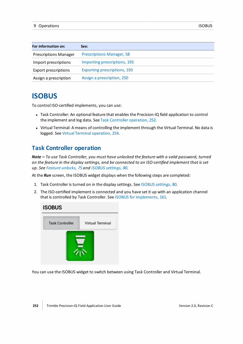
9 Operations ISOBUS
For information on: See:
Prescriptions Manager Prescriptions Manager, 58
Import prescriptions Importing prescriptions, 193
Export prescriptions Exporting prescriptions, 193
Assign a prescription Assign a prescription, 250
ISOBUSTo control ISO-certified implements, you can use:
l Task Controller: An optional feature that enables the Precision-IQ field application to controlthe implement and log data. See Task Controller operation, 252.
l Virtual Terminal: Ameans of controlling the implement through the Virtual Terminal. No data islogged. See Virtual Terminal operation, 254.
Task Controller operationNote – To use Task Controller, you must have unlocked the feature with a valid password, turnedon the feature in the display settings, and be connected to an ISO-certified implement that is setup. See Feature unlocks, 75 and ISOBUS settings, 80.
At the Run screen, the ISOBUS widget displays when the following steps are completed:
1. Task Controller is turned on in the display settings. See ISOBUS settings, 80.
2. The ISO-certified implement is connected and you have set it up with an application channelthat is controlled by Task Controller. See ISOBUS for implements, 161.
You can use the ISOBUS widget to switch between using Task Controller and Virtual Terminal.
252 Trimble Precision-IQ Field Application User Guide Version 2.0, Revision C
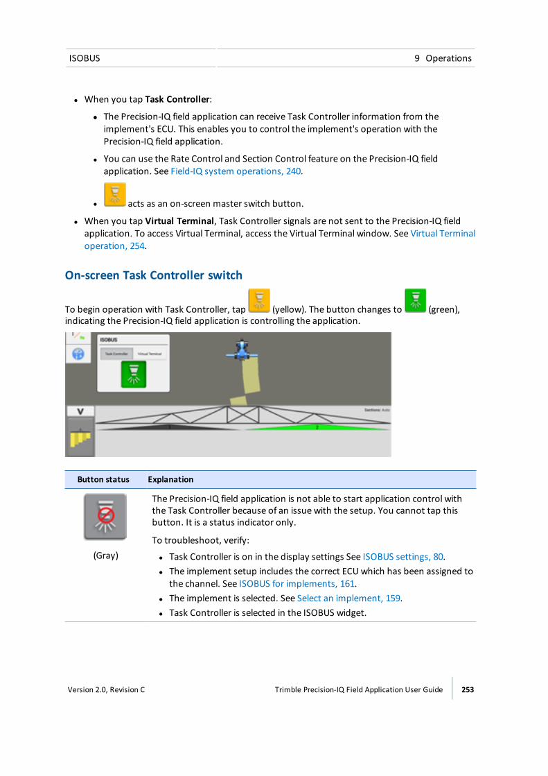
ISOBUS 9 Operations
l When you tap Task Controller:
ll The Precision-IQ field application can receive Task Controller information from theimplement's ECU. This enables you to control the implement's operation with thePrecision-IQ field application.
l You can use the Rate Control and Section Control feature on the Precision-IQ fieldapplication. See Field-IQ system operations, 240.
l acts as an on-screen master switch button.
l When you tap Virtual Terminal, Task Controller signals are not sent to the Precision-IQ fieldapplication. To access Virtual Terminal, access the Virtual Terminal window. See Virtual Terminaloperation, 254.
On-screen Task Controller switch
To begin operation with Task Controller, tap (yellow). The button changes to (green),indicating the Precision-IQ field application is controlling the application.
Button status Explanation
(Gray)
The Precision-IQ field application is not able to start application control withthe Task Controller because of an issue with the setup. You cannot tap thisbutton. It is a status indicator only.
To troubleshoot, verify:
l Task Controller is on in the display settings See ISOBUS settings, 80.l The implement setup includes the correct ECUwhich has been assigned to
the channel. See ISOBUS for implements, 161.l The implement is selected. See Select an implement, 159.l Task Controller is selected in the ISOBUS widget.
Version 2.0, Revision C Trimble Precision-IQ Field Application User Guide 253
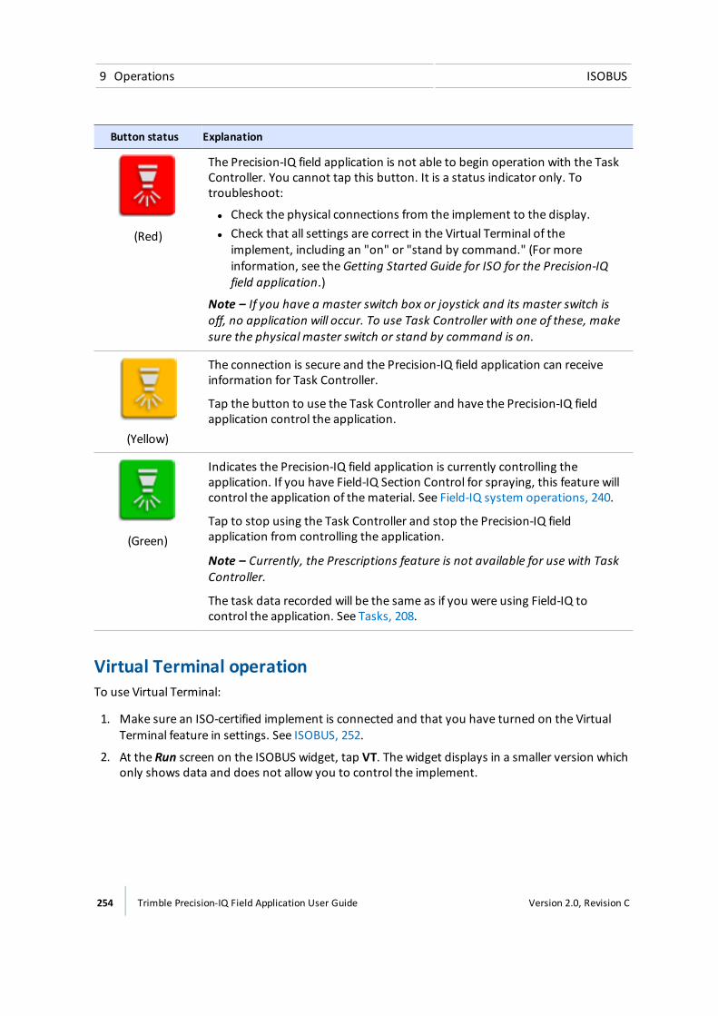
9 Operations ISOBUS
Button status Explanation
(Red)
The Precision-IQ field application is not able to begin operation with the TaskController. You cannot tap this button. It is a status indicator only. Totroubleshoot:
l Check the physical connections from the implement to the display.l Check that all settings are correct in the Virtual Terminal of the
implement, including an "on" or "stand by command." (For moreinformation, see theGetting Started Guide for ISO for the Precision-IQfield application.)
Note – If you have a master switch box or joystick and its master switch isoff, no application will occur. To use Task Controller with one of these, makesure the physical master switch or stand by command is on.
(Yellow)
The connection is secure and the Precision-IQ field application can receiveinformation for Task Controller.
Tap the button to use the Task Controller and have the Precision-IQ fieldapplication control the application.
(Green)
Indicates the Precision-IQ field application is currently controlling theapplication. If you have Field-IQ Section Control for spraying, this feature willcontrol the application of thematerial. See Field-IQ system operations, 240.
Tap to stop using the Task Controller and stop the Precision-IQ fieldapplication from controlling the application.
Note – Currently, the Prescriptions feature is not available for use with TaskController.
The task data recorded will be the same as if you were using Field-IQ tocontrol the application. See Tasks, 208.
Virtual Terminal operationTo use Virtual Terminal:
1. Make sure an ISO-certified implement is connected and that you have turned on the VirtualTerminal feature in settings. See ISOBUS, 252.
2. At the Run screen on the ISOBUS widget, tap VT. The widget displays in a smaller version whichonly shows data and does not allow you to control the implement.
254 Trimble Precision-IQ Field Application User Guide Version 2.0, Revision C

ISOBUS 9 Operations
To increase the size of theminimized Virtual Terminal widget, touch the upper right corner ofthe widget and hold. Arrows display on all sides of the widget. Touch and drag an arrow toincrease the widget's size.
3. Tap the upper right corner of the Virtual Terminal widget to maximize it. The Virtual Terminalexpands to full screen.
At the full-screen view, you can control the implement using Virtual Terminal.
4. To minimize Virtual Terminal to only show data, tap the upper right corner.
Delete previous dataData loaded from previously used ECUs will take up storage space. To remove this data from thePrecision-IQ field application:
1. At themaximized Virtual Terminal, tap .
2. Tap Delete.
3. All previous data is removed.
Version 2.0, Revision C Trimble Precision-IQ Field Application User Guide 255
9 Operations On-screen widgets
On-screen widgetsWidgets are software gadgets on the screen that can provide functionality control, information andstatus on the Run screen during field activities.
There are two types of widgets:
l Status widgets: Provide information only and do not control any function
l Control widgets: Enable you to control a function, and may include status information
For somewidgets, you can choose to display or not display them.
Other widgets display when you are performing a specific task, such as operating with the TaskController. See Task Controller operation, 252.
Access widgetsTo access the list of widgets available on your Precision-IQ field application:
1. At the Run screen, tap .
2. To display all widgets, tap Add All Widgets.
3. To remove all widgets, tap Remove All Widgets.
Minimize/maximize, resizeSomewidgets can bemaximized from their normal minimized size. To maximize a widget, tap theupper right corner of the widget. To make it smaller, tap the same upper right corner.
Other widgets can be re-sized to a customized size. To make a widget larger, touch the upper rightcorner of the widget and hold. Arrows display on all sides of the widget. Touch and drag one of thearrows to resize. When you are satisfied with the size, remove your finger. The following widgets canbe re-sized:
l Position status, 259: On-screen lightbar, compass, digital compass and swath number
l Speed status, 260
l Virtual Terminal widget, 260
Move a widgetYou can position somewidgets on the screen where it makes sense for you. The position on thescreen where you have chosen to display each widget is saved and associated with your user profile.That way, the next time you use the display, the widgets are where you previously placed them.
256 Trimble Precision-IQ Field Application User Guide Version 2.0, Revision C
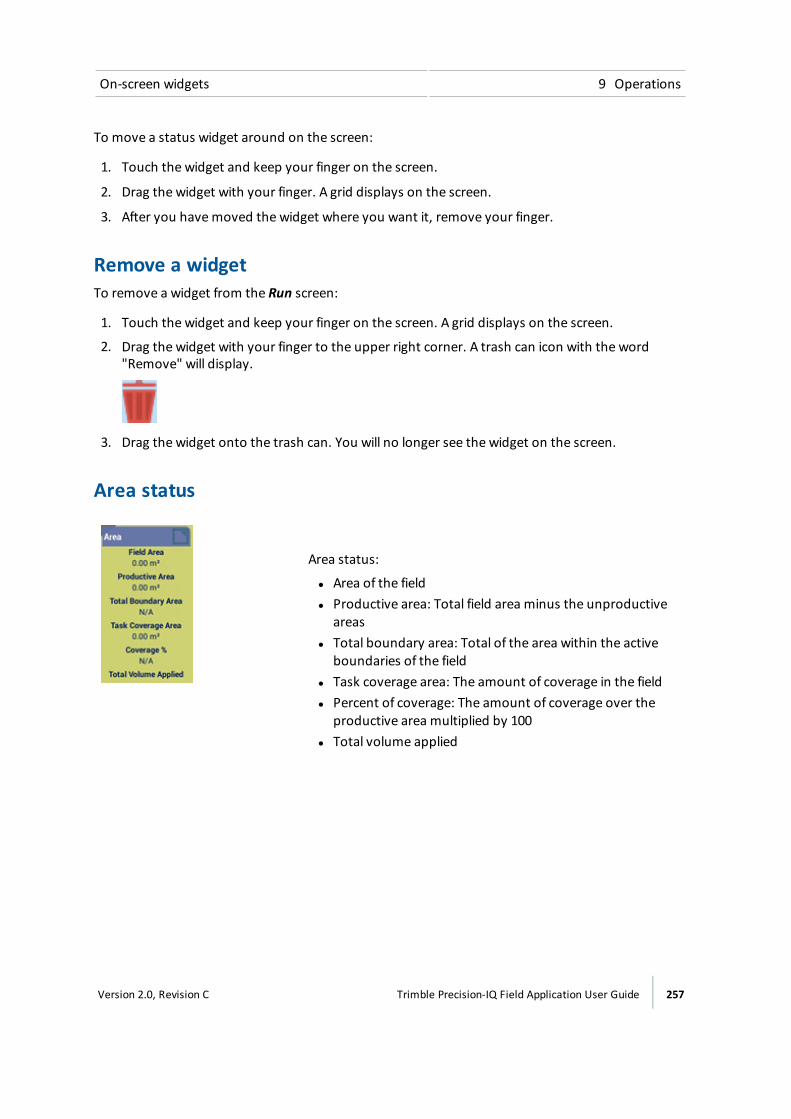
On-screen widgets 9 Operations
To move a status widget around on the screen:
1. Touch the widget and keep your finger on the screen.
2. Drag the widget with your finger. A grid displays on the screen.
3. After you havemoved the widget where you want it, remove your finger.
Remove a widgetTo remove a widget from the Run screen:
1. Touch the widget and keep your finger on the screen. A grid displays on the screen.
2. Drag the widget with your finger to the upper right corner. A trash can icon with the word"Remove" will display.
3. Drag the widget onto the trash can. You will no longer see the widget on the screen.
Area status
Area status:
l Area of the fieldl Productive area: Total field area minus the unproductive
areasl Total boundary area: Total of the area within the active
boundaries of the fieldl Task coverage area: The amount of coverage in the fieldl Percent of coverage: The amount of coverage over the
productive area multiplied by 100l Total volume applied
Version 2.0, Revision C Trimble Precision-IQ Field Application User Guide 257

9 Operations On-screen widgets
ISOBUS Task Controller widget
You can move this widget around on the screen.
Button Explanation
Task Controller Switches to Task Controller.
See Task Controller operation, 252.
Virtual Terminal Switches off access to Task Controller.
See Virtual Terminal operation, 254 and Virtual Terminal widget, 260.
(Gray)
The Precision-IQ field application is not able to start application control withthe Task Controller because of an issue with the setup.
(Red)
The Precision-IQ field application is not able to begin operation with the TaskController.
(Yellow)
The connection is secure and the Precision-IQ field application can receiveinformation for Task Controller.
258 Trimble Precision-IQ Field Application User Guide Version 2.0, Revision C
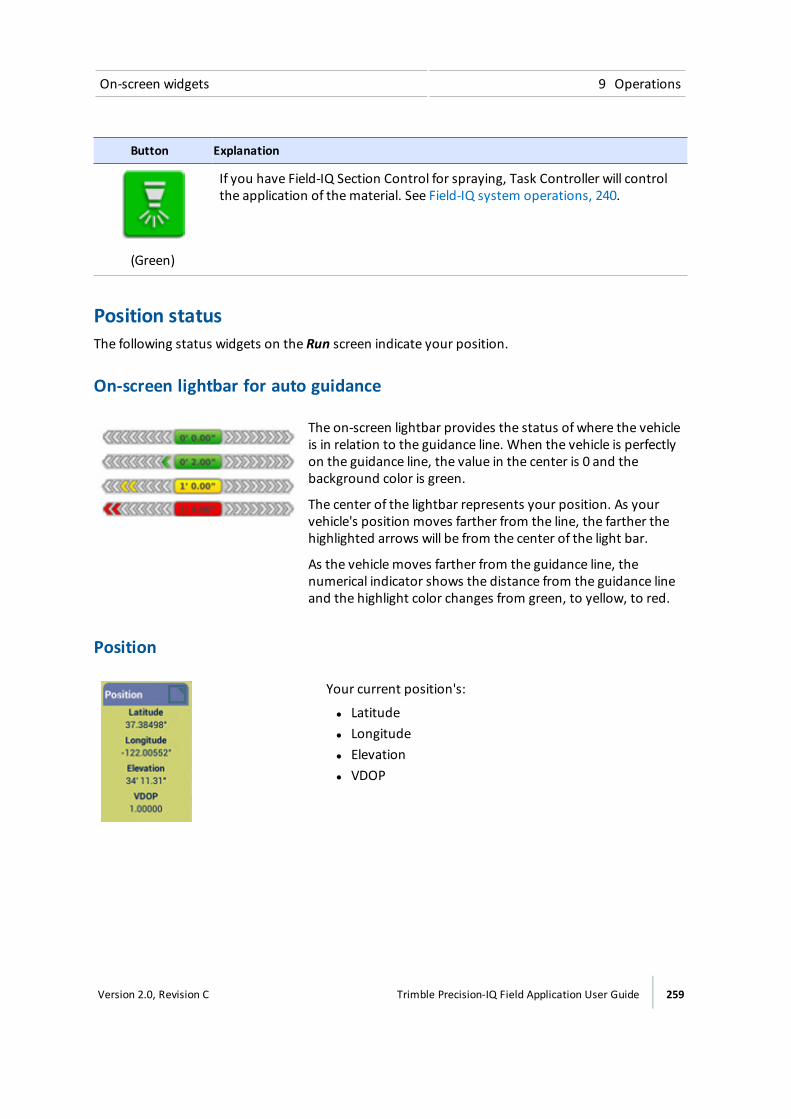
On-screen widgets 9 Operations
Button Explanation
(Green)
If you have Field-IQ Section Control for spraying, Task Controller will controlthe application of thematerial. See Field-IQ system operations, 240.
Position statusThe following status widgets on the Run screen indicate your position.
On-screen lightbar for auto guidance
The on-screen lightbar provides the status of where the vehicleis in relation to the guidance line. When the vehicle is perfectlyon the guidance line, the value in the center is 0 and thebackground color is green.
The center of the lightbar represents your position. As yourvehicle's position moves farther from the line, the farther thehighlighted arrows will be from the center of the light bar.
As the vehicle moves farther from the guidance line, thenumerical indicator shows the distance from the guidance lineand the highlight color changes from green, to yellow, to red.
Position
Your current position's:
l Latitudel Longitudel Elevationl VDOP
Version 2.0, Revision C Trimble Precision-IQ Field Application User Guide 259

9 Operations On-screen widgets
Compass
The direction in which you are traveling.
Digital compass
The degrees of the angle you are traveling.
Swath number
The number of the swath guidance line youare currently following.
Speed statusThe speed status widget indicates the speed at which you are traveling.
The speed at which you are traveling.
Virtual Terminal widgetWhen using Virtual Terminal, initially theminimized version displays on the Run screen.
260 Trimble Precision-IQ Field Application User Guide Version 2.0, Revision C
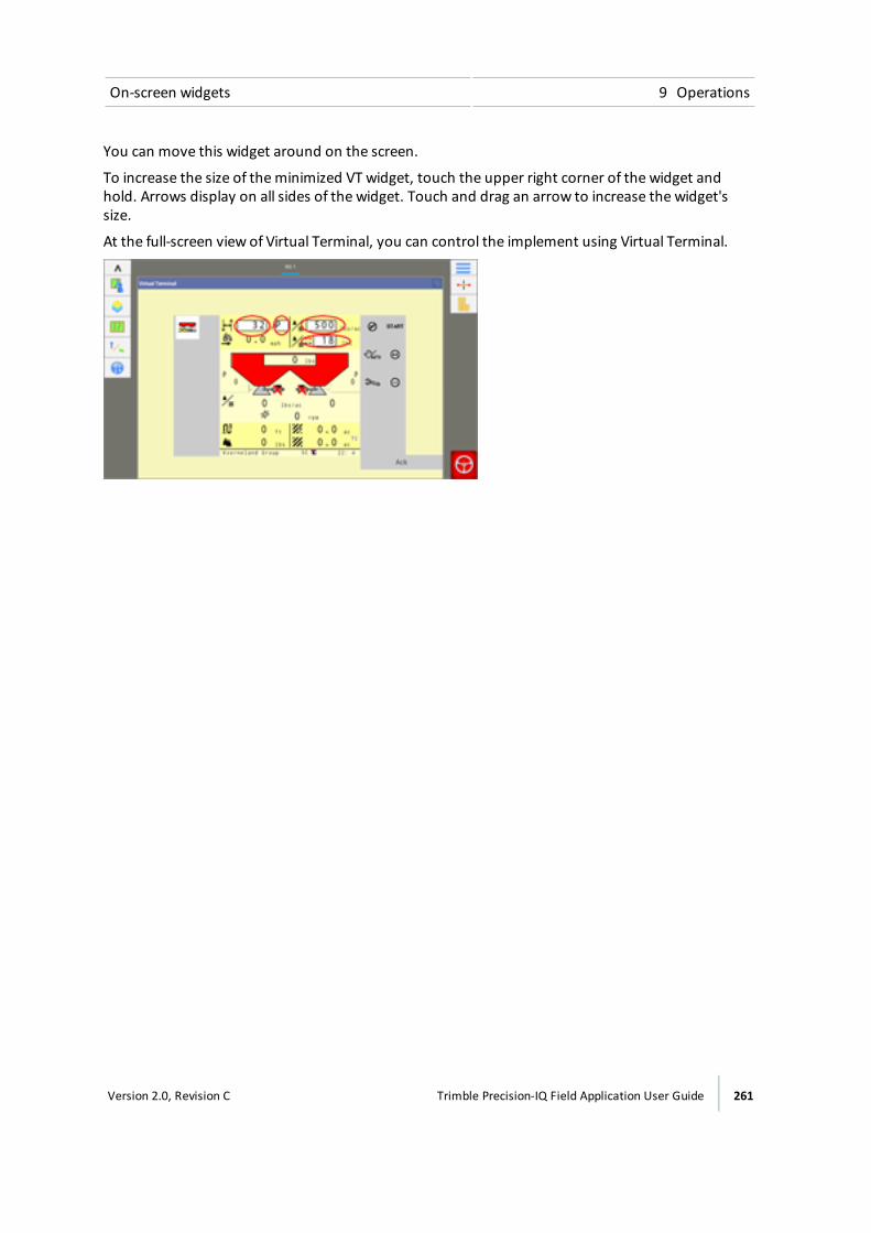
On-screen widgets 9 Operations
You can move this widget around on the screen.
To increase the size of theminimized VT widget, touch the upper right corner of the widget andhold. Arrows display on all sides of the widget. Touch and drag an arrow to increase the widget'ssize.
At the full-screen view of Virtual Terminal, you can control the implement using Virtual Terminal.
Version 2.0, Revision C Trimble Precision-IQ Field Application User Guide 261

9 Operations Alerts and warnings
Alerts and warningsThe Precision-IQ field application will display warnings and alerts, depending on your features andthe situation. For example, warnings and alerts will display regarding:
l Loss of GNSS coverage
l Using auto guidance and:
ll The vehicle is approaching a tight turns or the end of a row
l The system detects the steering wheel is being used
l A lack of interaction with the display after a specific amount of time
This list is not comprehensive, rather a few examples of alerts and warnings.
End of row warningIf your Autopilot system is on and following a guidance line, when you begin approaching the end ofa row, an End of Rowwarning displays.
For information on: See:
Settings Steering and guidance settings, 78
Tight turn warningIf you are using an auto guidance system, when you are approaching a tight turn, the systemdisplays a tight turn warning.
To customize your settings for tight turn warnings (including the angle of the turn and how soon thewarning displays before the turn), see Patterns settings, 77.
262 Trimble Precision-IQ Field Application User Guide Version 2.0, Revision C

Diagnostics / troubleshooting
In this chapter:
Diagnostics 264
TMX-2050 display 265
Autopilot system diagnostics 266
Boom Height Diagnostics 269
DCM-300 modem status 271
EZ-Pilot system diagnostics 272
DCM-300 modem diagnostics 275
EZ-Steer system diagnostics 277
Field-IQ diagnostics 281
GNSS and xFill technology status 285
GNSS diagnostics 287
Office Sync Diagnostics 291
ISOBUS diagnostics 293
System diagnostics 294
TM-200 Module diagnostics 295
This chapter covers information about thestatus of equipment and services, as wellas troubleshooting and diagnosticsinformation.
10C h a p t e r
Version 2.0, Revision C Trimble Precision-IQ Field Application User Guide 263
10 Diagnostics / troubleshooting Diagnostics
DiagnosticsYou can access Diagnostics in either of the following ways:
l Tap at theHome or Run screen. Themain menu displays. Tap Diagnostics.
l Tap the right-hand side of the display bar. When the popup notification list displays, tap .Themain menu displays. Tap Diagnostics.
Diagnostics has two sections:
l The left sidemenu lists products and services active on the display.
l The right side shows information about the item you selected on themenu.
Tap themenu items on the left-hand side of the screen to access the diagnostic sections you wantto view.
264 Trimble Precision-IQ Field Application User Guide Version 2.0, Revision C
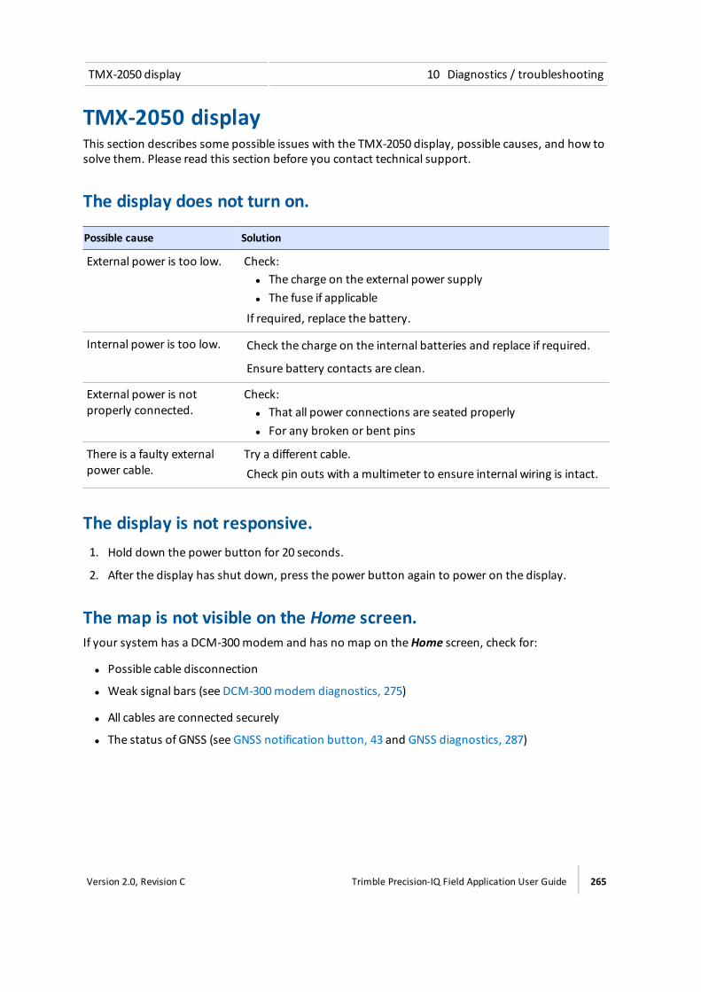
TMX-2050 display 10 Diagnostics / troubleshooting
TMX-2050 displayThis section describes some possible issues with the TMX-2050 display, possible causes, and how tosolve them. Please read this section before you contact technical support.
The display does not turn on.
Possible cause Solution
External power is too low. Check:l The charge on the external power supplyl The fuse if applicable
If required, replace the battery.
Internal power is too low. Check the charge on the internal batteries and replace if required.
Ensure battery contacts are clean.
External power is notproperly connected.
Check:l That all power connections are seated properlyl For any broken or bent pins
There is a faulty externalpower cable.
Try a different cable.Check pin outs with a multimeter to ensure internal wiring is intact.
The display is not responsive.1. Hold down the power button for 20 seconds.
2. After the display has shut down, press the power button again to power on the display.
The map is not visible on the Home screen.If your system has a DCM-300modem and has no map on theHome screen, check for:
l Possible cable disconnection
l Weak signal bars (see DCM-300modem diagnostics, 275)
l All cables are connected securely
l The status of GNSS (see GNSS notification button, 43 and GNSS diagnostics, 287)
Version 2.0, Revision C Trimble Precision-IQ Field Application User Guide 265

10 Diagnostics / troubleshooting Autopilot system diagnostics
Autopilot system diagnosticsYou can use diagnostics for AutoPilot to:
l View the degree of the steering angle being given by the navigation controller and the actualdegree of angle.
l Calibrate:
ll Manual override sensitivity
l Vehicle system aggressiveness
l Line approach aggressiveness
l Engage aggressiveness
l Proportional steering gain (P gain)
l Roll calibration
l Make incremental adjustments to a pattern using the nudge increment tool
l View:
ll Vehicle roll and yaw
l Navigation controller orientation
l IMU parameters
l Sensor settings
l Set the NavController to output NMEA messages.
Steering performance for Autopilot system1. At the Diagnostics panel, tap Performance under Autopilot.
2. Tap Steering.
Button/Control Explanation
System Feedback, AngleDesired
The degree of the steering angle command being given bythe navigation controller.
266 Trimble Precision-IQ Field Application User Guide Version 2.0, Revision C
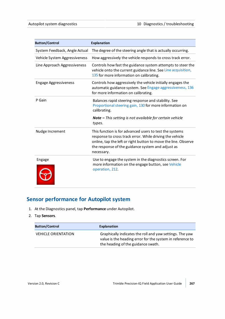
Autopilot system diagnostics 10 Diagnostics / troubleshooting
Button/Control Explanation
System Feedback, Angle Actual The degree of the steering angle that is actually occurring.
Vehicle System Aggressiveness How aggressively the vehicle responds to cross track error.
Line Approach Aggressiveness Controls how fast the guidance system attempts to steer thevehicle onto the current guidance line. See Line acquisition,135 for more information on calibrating.
Engage Aggressiveness Controls how aggressively the vehicle initially engages theautomatic guidance system. See Engage aggressiveness, 136for more information on calibrating.
P Gain Balances rapid steering response and stability. SeeProportional steering gain, 130 for more information oncalibrating.
Note – This setting is not available for certain vehicletypes.
Nudge Increment This function is for advanced users to test the systemsresponse to cross track error. While driving the vehicleonline, tap the left or right button to move the line. Observethe response of the guidance system and adjust asnecessary.
Engage Use to engage the system in the diagnostics screen. Formore information on the engage button, see Vehicleoperation, 212.
Sensor performance for Autopilot system1. At the Diagnostics panel, tap Performance under Autopilot.
2. Tap Sensors.
Button/Control Explanation
VEHICLE ORIENTATION Graphically indicates the roll and yaw settings. The yawvalue is the heading error for the system in reference tothe heading of the guidance swath.
Version 2.0, Revision C Trimble Precision-IQ Field Application User Guide 267
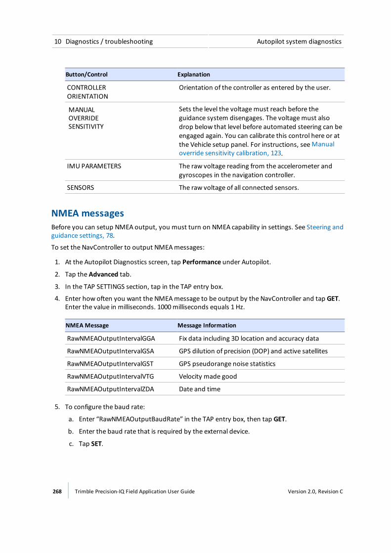
10 Diagnostics / troubleshooting Autopilot system diagnostics
Button/Control Explanation
CONTROLLER ORIENTATION
Orientation of the controller as entered by the user.
MANUALOVERRIDESENSITIVITY
Sets the level the voltagemust reach before theguidance system disengages. The voltagemust alsodrop below that level before automated steering can beengaged again. You can calibrate this control here or atthe Vehicle setup panel. For instructions, seeManualoverride sensitivity calibration, 123.
IMU PARAMETERS The raw voltage reading from the accelerometer andgyroscopes in the navigation controller.
SENSORS The raw voltage of all connected sensors.
NMEA messagesBefore you can setup NMEA output, you must turn on NMEA capability in settings. See Steering andguidance settings, 78.
To set the NavController to output NMEAmessages:
1. At the Autopilot Diagnostics screen, tap Performance under Autopilot.
2. Tap the Advanced tab.
3. In the TAP SETTINGS section, tap in the TAP entry box.
4. Enter how often you want the NMEAmessage to be output by the NavController and tap GET.Enter the value in milliseconds. 1000milliseconds equals 1 Hz.
NMEA Message Message Information
RawNMEAOutputIntervalGGA Fix data including 3D location and accuracy data
RawNMEAOutputIntervalGSA GPS dilution of precision (DOP) and active satellites
RawNMEAOutputIntervalGST GPS pseudorange noise statistics
RawNMEAOutputIntervalVTG Velocity made good
RawNMEAOutputIntervalZDA Date and time
5. To configure the baud rate:
a. Enter “RawNMEAOutputBaudRate” in the TAP entry box, then tap GET.
b. Enter the baud rate that is required by the external device.
c. Tap SET.
268 Trimble Precision-IQ Field Application User Guide Version 2.0, Revision C

Boom Height Diagnostics 10 Diagnostics / troubleshooting
Boom Height DiagnosticsAt the Diagnostics panel, tap Performance under Boom Height.
SensorsThis information is display only.
Item Explanation
Status The sensor's status: connected or disconnected
S/N The serial number for the sensor. The display reads the serial numbers fromthe installed sensors.
Version Firmware version of the sensor
Sensor Height Current height of sensor
Side Offset The distance from the center line of the sensor to the hinge point of the boom.(Does not apply to the center section.)
Nozzle Offset The distance from the bottom edge of the sensor cone to the outlet of thespray nozzle tip.
Boom Status
Valve ModuleThis information is display only.
Item Explanation
Module Type ofmodule
Status Connected, disconnected
S/N Serial number of valvemodule
Version Version of firmware
Boom Control StatusThis information is display only.
Item Explanation
Control Left, right or center
Valve Command Normal, inverted
Version 2.0, Revision C Trimble Precision-IQ Field Application User Guide 269
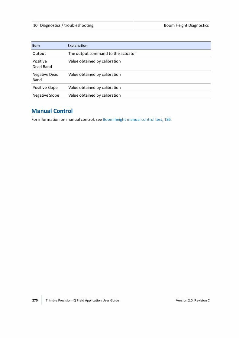
10 Diagnostics / troubleshooting Boom Height Diagnostics
Item Explanation
Output The output command to the actuator
PositiveDead Band
Value obtained by calibration
Negative DeadBand
Value obtained by calibration
Positive Slope Value obtained by calibration
Negative Slope Value obtained by calibration
Manual ControlFor information on manual control, see Boom height manual control test, 186.
270 Trimble Precision-IQ Field Application User Guide Version 2.0, Revision C
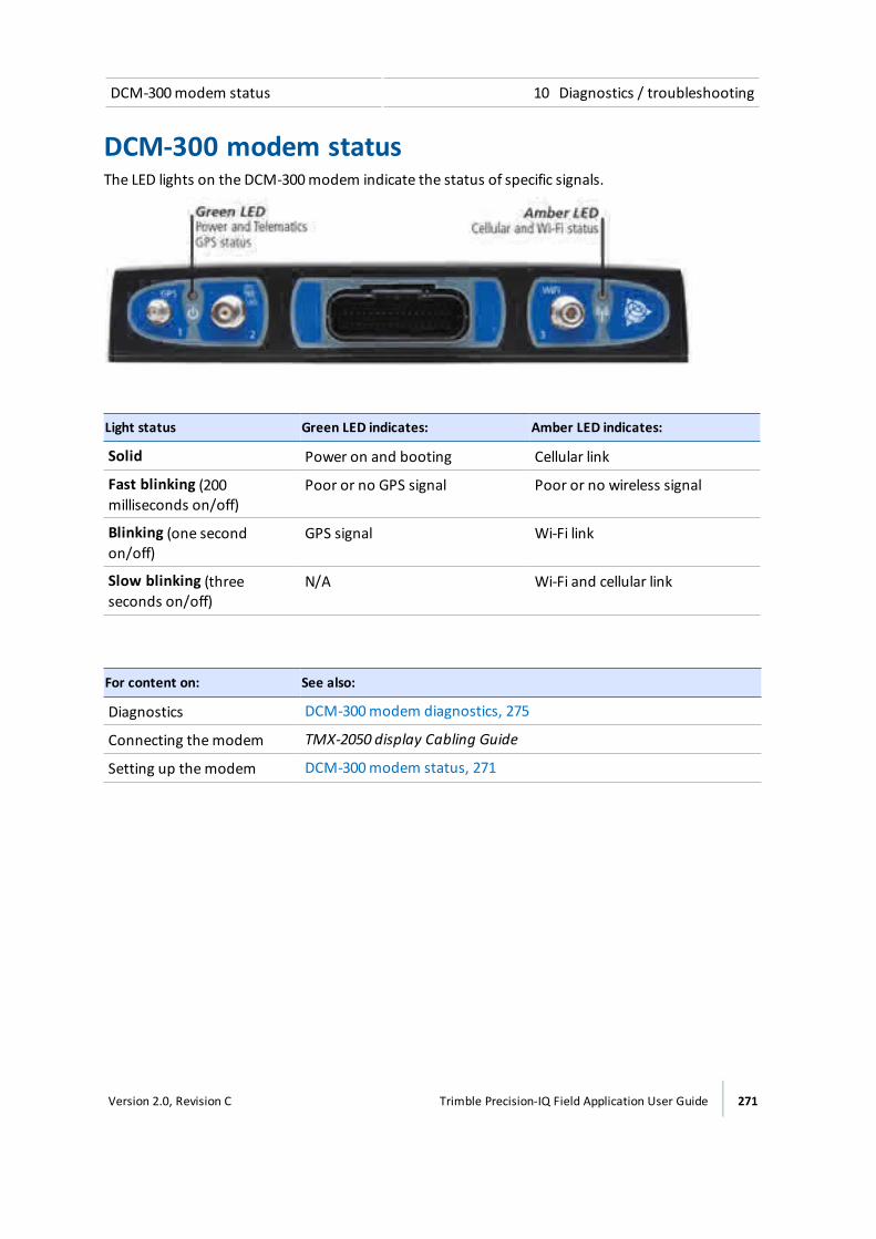
DCM-300modem status 10 Diagnostics / troubleshooting
DCM-300 modem statusThe LED lights on the DCM-300modem indicate the status of specific signals.
Light status Green LED indicates: Amber LED indicates:
Solid Power on and booting Cellular link
Fast blinking (200milliseconds on/off)
Poor or no GPS signal Poor or no wireless signal
Blinking (one secondon/off)
GPS signal Wi-Fi link
Slow blinking (threeseconds on/off)
N/A Wi-Fi and cellular link
For content on: See also:
Diagnostics DCM-300modem diagnostics, 275
Connecting themodem TMX-2050 display Cabling Guide
Setting up themodem DCM-300modem status, 271
Version 2.0, Revision C Trimble Precision-IQ Field Application User Guide 271
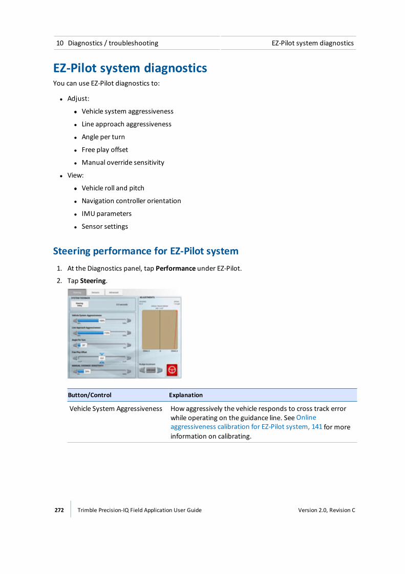
10 Diagnostics / troubleshooting EZ-Pilot system diagnostics
EZ-Pilot system diagnosticsYou can use EZ-Pilot diagnostics to:
l Adjust:
ll Vehicle system aggressiveness
l Line approach aggressiveness
l Angle per turn
l Free play offset
l Manual override sensitivity
l View:
ll Vehicle roll and pitch
l Navigation controller orientation
l IMU parameters
l Sensor settings
Steering performance for EZ-Pilot system1. At the Diagnostics panel, tap Performance under EZ-Pilot.
2. Tap Steering.
Button/Control Explanation
Vehicle System Aggressiveness How aggressively the vehicle responds to cross track errorwhile operating on the guidance line. See Onlineaggressiveness calibration for EZ-Pilot system, 141 for moreinformation on calibrating.
272 Trimble Precision-IQ Field Application User Guide Version 2.0, Revision C
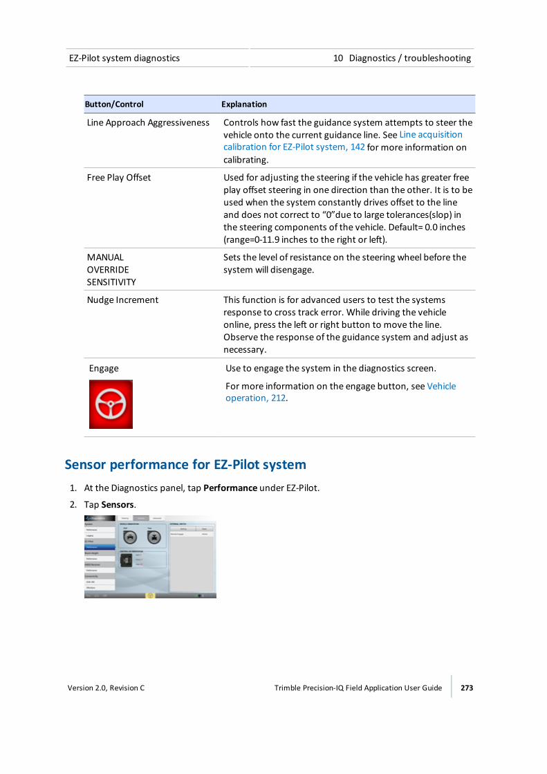
EZ-Pilot system diagnostics 10 Diagnostics / troubleshooting
Button/Control Explanation
Line Approach Aggressiveness Controls how fast the guidance system attempts to steer thevehicle onto the current guidance line. See Line acquisitioncalibration for EZ-Pilot system, 142 for more information oncalibrating.
Free Play Offset Used for adjusting the steering if the vehicle has greater freeplay offset steering in one direction than the other. It is to beused when the system constantly drives offset to the lineand does not correct to “0”due to large tolerances(slop) inthe steering components of the vehicle. Default= 0.0 inches(range=0-11.9 inches to the right or left).
MANUAL OVERRIDE SENSITIVITY
Sets the level of resistance on the steering wheel before thesystem will disengage.
Nudge Increment This function is for advanced users to test the systemsresponse to cross track error. While driving the vehicleonline, press the left or right button to move the line.Observe the response of the guidance system and adjust asnecessary.
Engage Use to engage the system in the diagnostics screen.
For more information on the engage button, see Vehicleoperation, 212.
Sensor performance for EZ-Pilot system1. At the Diagnostics panel, tap Performance under EZ-Pilot.
2. Tap Sensors.
Version 2.0, Revision C Trimble Precision-IQ Field Application User Guide 273

10 Diagnostics / troubleshooting EZ-Pilot system diagnostics
Button/Control Explanation
VEHICLE ORIENTATION Graphically indicates the roll and yaw settings.
CONTROLLER ORIENTATION Orientation of the controller as entered by the user.
EXTERNAL SWITCH Setting and state of the external switch.
274 Trimble Precision-IQ Field Application User Guide Version 2.0, Revision C
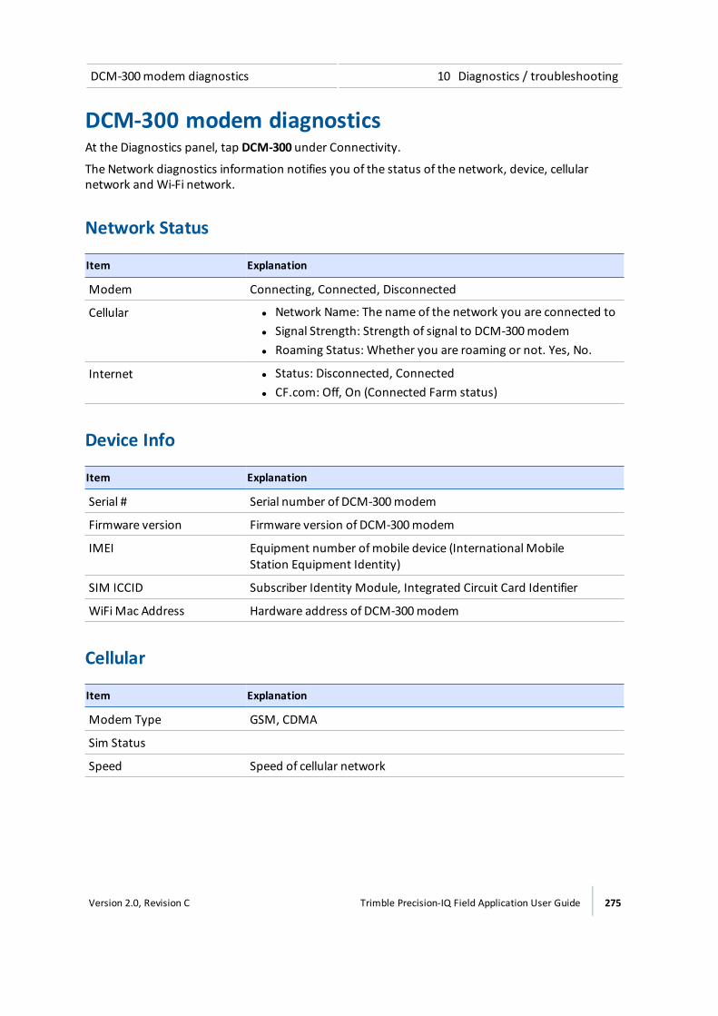
DCM-300modem diagnostics 10 Diagnostics / troubleshooting
DCM-300 modem diagnosticsAt the Diagnostics panel, tap DCM-300 under Connectivity.
The Network diagnostics information notifies you of the status of the network, device, cellularnetwork and Wi-Fi network.
Network Status
Item Explanation
Modem Connecting, Connected, Disconnected
Cellular l Network Name: The name of the network you are connected tol Signal Strength: Strength of signal to DCM-300modeml Roaming Status: Whether you are roaming or not. Yes, No.
Internet l Status: Disconnected, Connectedl CF.com: Off, On (Connected Farm status)
Device Info
Item Explanation
Serial # Serial number of DCM-300modem
Firmware version Firmware version of DCM-300modem
IMEI Equipment number ofmobile device (InternationalMobileStation Equipment Identity)
SIM ICCID Subscriber Identity Module, Integrated Circuit Card Identifier
WiFi Mac Address Hardware address of DCM-300modem
Cellular
Item Explanation
Modem Type GSM, CDMA
Sim Status
Speed Speed of cellular network
Version 2.0, Revision C Trimble Precision-IQ Field Application User Guide 275
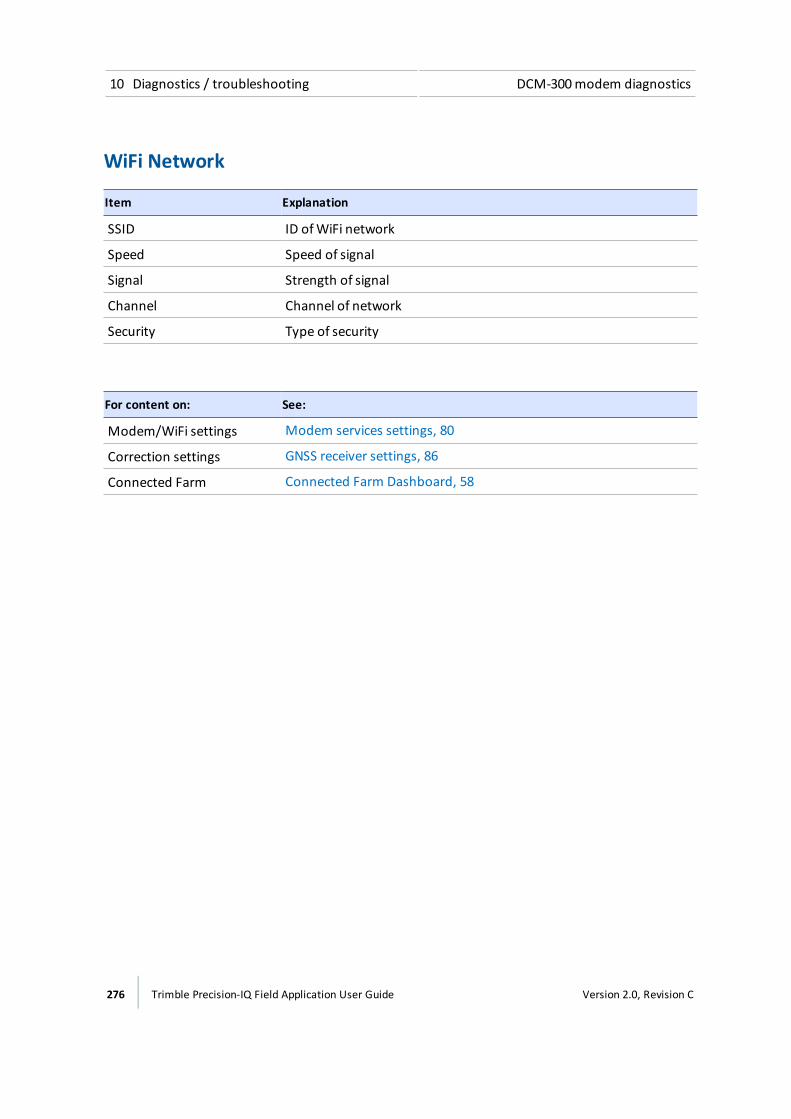
10 Diagnostics / troubleshooting DCM-300modem diagnostics
WiFi Network
Item Explanation
SSID ID ofWiFi network
Speed Speed of signal
Signal Strength of signal
Channel Channel of network
Security Type of security
For content on: See:
Modem/WiFi settings Modem services settings, 80
Correction settings GNSS receiver settings, 86
Connected Farm Connected Farm Dashboard, 58
276 Trimble Precision-IQ Field Application User Guide Version 2.0, Revision C
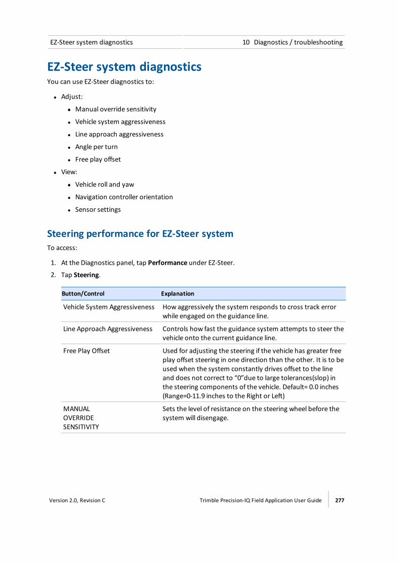
EZ-Steer system diagnostics 10 Diagnostics / troubleshooting
EZ-Steer system diagnosticsYou can use EZ-Steer diagnostics to:
l Adjust:
ll Manual override sensitivity
l Vehicle system aggressiveness
l Line approach aggressiveness
l Angle per turn
l Free play offset
l View:
ll Vehicle roll and yaw
l Navigation controller orientation
l Sensor settings
Steering performance for EZ-Steer systemTo access:
1. At the Diagnostics panel, tap Performance under EZ-Steer.
2. Tap Steering.
Button/Control Explanation
Vehicle System Aggressiveness How aggressively the system responds to cross track errorwhile engaged on the guidance line.
Line Approach Aggressiveness Controls how fast the guidance system attempts to steer thevehicle onto the current guidance line.
Free Play Offset Used for adjusting the steering if the vehicle has greater freeplay offset steering in one direction than the other. It is to beused when the system constantly drives offset to the lineand does not correct to “0”due to large tolerances(slop) inthe steering components of the vehicle. Default= 0.0 inches(Range=0-11.9 inches to the Right or Left)
MANUAL OVERRIDE SENSITIVITY
Sets the level of resistance on the steering wheel before thesystem will disengage.
Version 2.0, Revision C Trimble Precision-IQ Field Application User Guide 277

10 Diagnostics / troubleshooting EZ-Steer system diagnostics
Button/Control Explanation
Nudge Increment This function is for advanced users to test the systemsresponse to cross track error. While driving the vehicleonline, press the left or right button to move the line.Observe the response of the guidance system and adjust asnecessary.
Engage Use to engage the system in the diagnostics screen.
For more information on the engage button, see Vehicleoperation, 212.
Messages and fault codesThe following are warning messages that display when the EZ-Steer system becomes disengaged orthere are system faults.
Disengaged warning messages
DISENGAGED!... EZ-Steer system...
Too fast Disengaged because the vehicle is traveling above themaximum speed.
Too slow Disengaged because the vehicle is traveling below theminimumspeed.
Too far offline Disengaged because the vehicle has gone offline beyond theDisengage Offline value.
Manual override Was manually disengaged when the steering wheel was turned.
Manual disengage Was manually disengaged when the engage button wastapped, or the external foot switch or remote switch wasengaged.
No GPS Disengaged because the GPS positions have been lost.
No Corrections Disengaged because of old or no corrections. This occurs only ifLowAccuracy Warning is set to High Accuracy Only.
Unexpected Error Disengaged due to an unexpected error with the system.
Control fault Disengaged due to a control fault.
278 Trimble Precision-IQ Field Application User Guide Version 2.0, Revision C
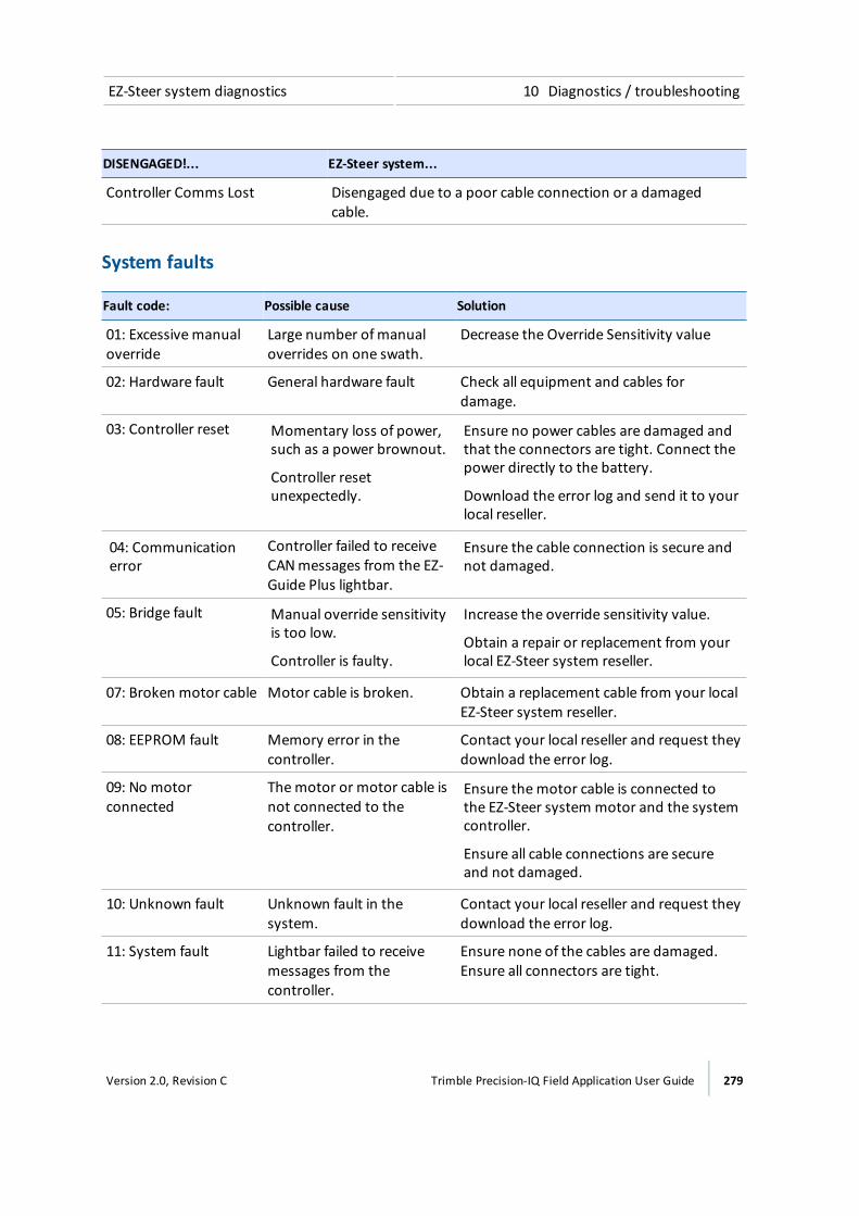
EZ-Steer system diagnostics 10 Diagnostics / troubleshooting
DISENGAGED!... EZ-Steer system...
Controller Comms Lost Disengaged due to a poor cable connection or a damagedcable.
System faults
Fault code: Possible cause Solution
01: Excessivemanualoverride
Large number ofmanualoverrides on one swath.
Decrease the Override Sensitivity value
02: Hardware fault General hardware fault Check all equipment and cables fordamage.
03: Controller reset Momentary loss of power,such as a power brownout.
Controller resetunexpectedly.
Ensure no power cables are damaged andthat the connectors are tight. Connect thepower directly to the battery.
Download the error log and send it to yourlocal reseller.
04: Communicationerror
Controller failed to receiveCANmessages from the EZ-Guide Plus lightbar.
Ensure the cable connection is secure andnot damaged.
05: Bridge fault Manual override sensitivityis too low.
Controller is faulty.
Increase the override sensitivity value.
Obtain a repair or replacement from yourlocal EZ-Steer system reseller.
07: Broken motor cable Motor cable is broken. Obtain a replacement cable from your localEZ-Steer system reseller.
08: EEPROM fault Memory error in thecontroller.
Contact your local reseller and request theydownload the error log.
09: No motorconnected
Themotor or motor cable isnot connected to thecontroller.
Ensure themotor cable is connected tothe EZ-Steer system motor and the systemcontroller.
Ensure all cable connections are secureand not damaged.
10: Unknown fault Unknown fault in thesystem.
Contact your local reseller and request theydownload the error log.
11: System fault Lightbar failed to receivemessages from thecontroller.
Ensure none of the cables are damaged.Ensure all connectors are tight.
Version 2.0, Revision C Trimble Precision-IQ Field Application User Guide 279
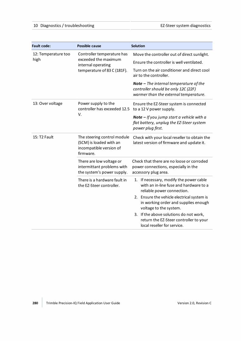
10 Diagnostics / troubleshooting EZ-Steer system diagnostics
Fault code: Possible cause Solution
12: Temperature toohigh
Controller temperature hasexceeded themaximuminternal operatingtemperature of 83 C (181F).
Move the controller out of direct sunlight.
Ensure the controller is well ventilated.
Turn on the air conditioner and direct coolair to the controller.
Note – The internal temperature of thecontroller should be only 12C (22F)warmer than the external temperature.
13: Over voltage Power supply to thecontroller has exceeded 12.5V.
Ensure the EZ-Steer system is connectedto a 12 V power supply.
Note – If you jump start a vehicle with aflat battery, unplug the EZ-Steer systempower plug first.
15: T2 Fault The steering control module(SCM) is loaded with anincompatible version offirmware.
Check with your local reseller to obtain thelatest version of firmware and update it.
There are low voltage orintermittant problems withthe system's power supply.
Check that there are no loose or corrodedpower connections, especially in theaccessory plug area.
There is a hardware fault inthe EZ-Steer controller.
1. If necessary, modify the power cablewith an in-line fuse and hardware to areliable power connection.
2. Ensure the vehicle electrical system isin working order and supplies enoughvoltage to the system.
3. If the above solutions do not work,return the EZ-Steer controller to yourlocal reseller for service.
280 Trimble Precision-IQ Field Application User Guide Version 2.0, Revision C
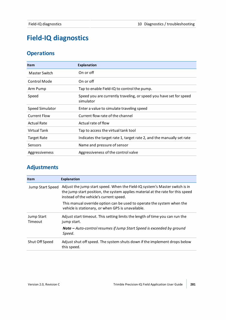
Field-IQ diagnostics 10 Diagnostics / troubleshooting
Field-IQ diagnostics
Operations
Item Explanation
Master Switch On or off
ControlMode On or off
Arm Pump Tap to enable Field-IQ to control the pump.
Speed Speed you are currently traveling, or speed you have set for speedsimulator
Speed Simulator Enter a value to simulate traveling speed
Current Flow Current flow rate of the channel
Actual Rate Actual rate of flow
Virtual Tank Tap to access the virtual tank tool
Target Rate Indicates the target rate 1, target rate 2, and themanually set rate
Sensors Name and pressure of sensor
Aggressiveness Aggressiveness of the control valve
Adjustments
Item Explanation
Jump Start Speed Adjust the jump start speed. When the Field-IQ system's Master switch is inthe jump start position, the system applies material at the rate for this speedinstead of the vehicle's current speed.This manual override option can be used to operate the system when thevehicle is stationary, or when GPS is unavailable.
Jump StartTimeout
Adjust start timeout. This setting limits the length of time you can run thejump start.
Note – Auto-control resumes if Jump Start Speed is exceeded by groundSpeed.
Shut Off Speed Adjust shut off speed. The system shuts down if the implement drops belowthis speed.
Version 2.0, Revision C Trimble Precision-IQ Field Application User Guide 281
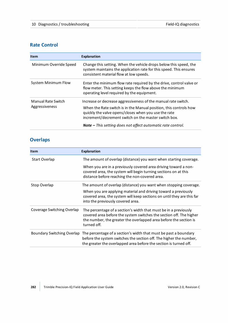
10 Diagnostics / troubleshooting Field-IQ diagnostics
Rate Control
Item Explanation
Minimum Override Speed Change this setting. When the vehicle drops below this speed, thesystem maintains the application rate for this speed. This ensuresconsistent material flow at low speeds.
System Minimum Flow Enter theminimum flow rate required by the drive, control valve orflowmeter. This setting keeps the flow above theminimumoperating level required by the equipment.
Manual Rate SwitchAggressiveness
Increase or decrease aggressiveness of themanual rate switch.When the Rate switch is in theManual position, this controls howquickly the valve opens/closes when you use the rateincrement/decrement switch on themaster switch box.
Note – This setting does not affect automatic rate control.
Overlaps
Item Explanation
Start Overlap The amount of overlap (distance) you want when starting coverage.
When you are in a previously covered area driving toward a non-covered area, the system will begin turning sections on at thisdistance before reaching the non-covered area.
Stop Overlap The amount of overlap (distance) you want when stopping coverage.When you are applying material and driving toward a previouslycovered area, the system will keep sections on until they are this farinto the previously covered area.
Coverage Switching Overlap The percentage of a section's width that must be in a previouslycovered area before the system switches the section off. The higherthe number, the greater the overlapped area before the section isturned off.
Boundary Switching Overlap The percentage of a section's width that must be past a boundarybefore the system switches the section off. The higher the number,the greater the overlapped area before the section is turned off.
282 Trimble Precision-IQ Field Application User Guide Version 2.0, Revision C
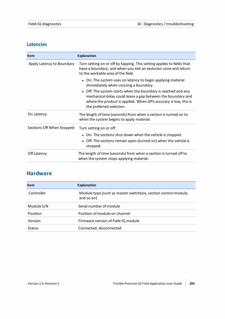
Field-IQ diagnostics 10 Diagnostics / troubleshooting
Latencies
Item Explanation
Apply Latency to Boundary Turn setting on or off by tapping. This setting applies to fields thathave a boundary, and when you exit an exclusion zone and returnto the workable area of the field.
l On: The system uses on latency to begin applying materialimmediately when crossing a boundary.
l Off: The system starts when the boundary is reached and anymechanical delay could leave a gap between the boundary andwhere the product is applied. When GPS accuracy is low, this isthe preferred selection.
On Latency The length of time (seconds) from when a section is turned on towhen the system begins to apply material.
Sections OffWhen Stopped Turn setting on or off:
l On: The sections shut down when the vehicle is stopped.l Off: The sections remain open (turned on) when the vehicle is
stopped.
Off Latency The length of time (seconds) from when a section is turned off towhen the system stops applying material.
Hardware
Item Explanation
Controller Module type (such as master switchbox, section control module,and so on)
Module S/N Serial number ofmodule
Position Position ofmodule on channel
Version Firmware version of Field IQ module
Status Connected, disconnected
Version 2.0, Revision C Trimble Precision-IQ Field Application User Guide 283

10 Diagnostics / troubleshooting Field-IQ diagnostics
Sensor
Item Explanation
ChannelName: Material
Name of channel
Module S/N Serial number ofmodule
Sensor Name of sensor
Feedback Sensor information
284 Trimble Precision-IQ Field Application User Guide Version 2.0, Revision C

GNSS and xFill technology status 10 Diagnostics / troubleshooting
GNSS and xFill technology statusGNSS status is available on the Status bar, 42 and the popup notification menu accessed by tappingthe right side of the display bar.
Notification Button Indicates...
Green
GNSS connection is converged (green).
Yellow
GNSS connection is converging (yellow).
Red
No GNSS connection is available (red).
For more information on GNSS, see:
l DCM-300modem initial setup, 100
l GNSS receiver settings, 86
l GNSS diagnostics, 287
l DCM-300modem diagnostics, 275
xFill technology statusIn the event of an RTK or VRS signal interruption, the display switches to xFill mode, and the xFillicon changes to a blue color.
When 5minutes of xFill technology time remains (15minutes have elapsed), the xFill icon changes toa red color and a warning appears on the display.
if you lose corrections from the satellite, you will go into DGPS corrections. Even if you regainexposure to the satellites, the xFill technology will not resume. Anytime xFill degrades to DGPS, thereceiver must receive RTK corrections before xFill can be ready in the background again.
Additionally, if you lose any of your satellites during xFill, they will not be able to be used for theentire xFill duration of 20minutes.
Safety featurexFill technology estimates the drift in position. If the distance back to the original path is too large,xFill technology discontinues Fixed position, which disengages auto-steering.In this case, you can
Version 2.0, Revision C Trimble Precision-IQ Field Application User Guide 285
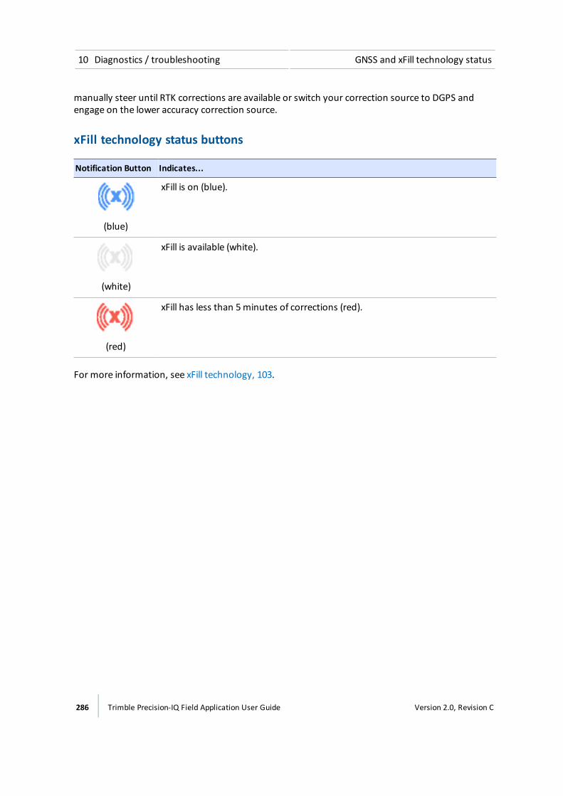
10 Diagnostics / troubleshooting GNSS and xFill technology status
manually steer until RTK corrections are available or switch your correction source to DGPS andengage on the lower accuracy correction source.
xFill technology status buttons
Notification Button Indicates...
(blue)
xFill is on (blue).
(white)
xFill is available (white).
(red)
xFill has less than 5minutes of corrections (red).
For more information, see xFill technology, 103.
286 Trimble Precision-IQ Field Application User Guide Version 2.0, Revision C

GNSS diagnostics 10 Diagnostics / troubleshooting
GNSS diagnosticsAt the Diagnostics panel, tap Performance under GNSS.
For information on GNSS settings, see GNSS receiver settings, 86.
CAUTION – The GNSS antenna may experience interference if you operate the vehicle within 100 m (300 ft) ofany power line, radar dish, or cell phone tower.
Solution Information
Solution Information Explanation
Number of Satellites Indicates number of satellites currently being used.
Correction Type The correction service indicated at setup.
Correction Source Modem, satellite / fast, satellite /SBAS, OmniStar HP/G2
Correction Status Fixed, Float or x-Fill
Position Quality Tap to change. Favor accuracy, balance quality or favor availability.
SkyplotAt the Skyplot screen, you can view the number of satellites nearest to your position.
Version 2.0, Revision C Trimble Precision-IQ Field Application User Guide 287

10 Diagnostics / troubleshooting GNSS diagnostics
TroubleshootingThe GNSS positioning method influences the accuracy of the GNSS position reflected inyour GNSS receiver. Additionally, the following conditions can affect GNSS accuracy.
Condition Explanation
Atmospheric effects GNSS signals are degraded as they travel through theionosphere. The error introduced is in the range of 10meters.The error is removed by using a differential or RTK positioningmethod.
Number of satellites used To calculate a 3D position (latitude and longitude, altitude, andtime), four or more satellites must be visible. To calculate a 2Dposition (latitude and longitude, and time), three or moresatellites must be visible. For RTK positioning, five satellites areneeded for initialization. Once initialized, four or more satellitesprovide RTK positions. The number of visible satellitesconstantly changes and is typically in the range 5 through 9.The receiver can track up to 44 satellites simultaneously.
Maximum PDOP Position Dilution of Precision (PDOP) is a unitless, computedmeasurement of the geometry of satellites above the currentlocation of the receiver. A low PDOP means that the positioningof satellites in the sky is good, and therefore good positionalaccuracy is obtained.
Signal-to-noise ratio Signal-to-noise ratio (SNR) is a measure of the signal strengthagainst electrical background noise. A high SNR gives betteraccuracy. SNR can be degraded by other electronic equipmentoperating nearby, including transmitters, cell phones, or datamodems. It may also be degraded by solar flares and changingatmospheric conditions.
Minimum elevation Satellites that are low on the horizon typically produce weakand noisy signals and aremore difficult for the receiver to track.Satellites below theminimum elevation angle are not tracked.
Multipath environment Multipath errors are caused when GNSS signals are reflected offnearby objects and reach the receiver by two or more differentpaths.
288 Trimble Precision-IQ Field Application User Guide Version 2.0, Revision C

GNSS diagnostics 10 Diagnostics / troubleshooting
Condition Explanation
RTK Base station coordinateaccuracy
For RTK positioning, it is important to know the base stationcoordinates accurately. Any error in the position of the basestation affects the position of the rover; every 10m of error ina base station coordinate can introduce up to 1 ppm scaleerror on every measured baseline. For example, an error of 10m in the base station position produces an error of 10mmover a 10 km baseline to the rover.
For more information about how to make sure the position ofyour base station is accurate, refer to themanual for yourbase station receiver.
Multiple RTK base stations If you are using several base stations to provide RTKcorrections to a large site area, all base stations must becoordinated relative to one another. If they are not, theabsolute positions at the rover will be in error.
For more information about how to use several base stationsto cover your site, contact your local Trimble Reseller.
Poor accuracy (multipath)Poor accuracy can be due to GNSS signals reflecting off nearby trees and/or metal buildings andhorizontal surfaces. (Reflection is also called multipath.)
To reducemultipath noise, mount the GNSS receiver so that it has a clear view of the sky. Thereceiver must be away from trees and largemetal objects.
Intermittent loss of lock on satellitel The receiver loses the satellite signal from time to time: Make sure that the receiver is mounted
on the highest point of the vehicle and is clear ofmetal surfaces.
l Signal takes a long time to initialize
ll In RTK mode, longer baselines require longer initialization times. (The baseline is thedistance between the base receiver and the rover receivers.)
l Wait for the receiver to initialize or consider repositioning the base receiver to shorten thebaseline. Make sure the rover receiver is in a clear area.
Loss of initializationIn RTK mode initialization can be lost when the rover receiver is close to trees or buildings and thenumber of satellites falls below four. Additionally, initialization may be lost if the receiver has notbeen tracking RTK corrections for some time.
Version 2.0, Revision C Trimble Precision-IQ Field Application User Guide 289
10 Diagnostics / troubleshooting GNSS diagnostics
l Move away from trees and obstructions to initialize. Once initialized, approach the obstructedarea again. If the obstructions are severe, GNSS positioning may not work in that area.
l Because the GNSS satellites move, theremay be times of the day when you are working in anarea with obstructions.
Not tracking RTK correctionsThe radio link is down or intermittent. Ensure that:
l The line-of-sight between the base and rover receivers is not obstructed.
l The rover receiver is within range of the radio.
l The radio power supply is on.
Poor signal / not receiving a clear signall Interference from 2-way radios
Transmitting FM 2-way radios can interfere with OmniSTAR, WAAS, and GNSS signal reception.Make sure that there is at least 1m (3 ft) between the FM 2-way radio antenna and thereceiver.
l Vehicle issues
An unshielded ignition system can cause enough noise to block reception of a differentialsignal. Use resistor spark plug wires on the vehicle ignition system.
An alternator can cause noise that interferes with a differential signal.
Note – Before replacing engine parts in an attempt to solve this problem, make sure that theproblem is not caused by a computer or power source near the receiver. Some computers andtheir power sources cause noise that disrupts GNSS and satellite DGNSS signals.
Possible solutions include:
ll Use bypass capacitors, commonly available in automotive stores for cleaning upinterference to CB and other radios. If the problem persists, shield engine componentswith aluminum foil.
l Relocate the antenna on themachine. Determine the optimal antenna location.
l GNSS receiver issues:
ll Mounting location: The receiver may not be picking up a clear signal due to mountinglocation. Mount the receiver on the centerline of the vehicle, away from any sources ofinterference and with a clear view of the sky.
l Cable problems: Use an ohmmeter to check the cable. The resistance of a good cablebetween connector pins at each end of the cable is zero. If the cable is sound, but theproblem persists, try exchanging the cable with one that you know is working. If the cable
290 Trimble Precision-IQ Field Application User Guide Version 2.0, Revision C

Office Sync Diagnostics 10 Diagnostics / troubleshooting
is defective, contact your local Trimble Reseller for an RMAnumber (if the Trimble productis still under warranty), or to purchase a replacement cable.
l Battery: A Lithium-ion battery in the receiver powers the internal real-time clock and soenables the receiver to get a first fix faster. The battery has a life of 7.5 years. When thebattery fails, the internal clock cannot keep accurate time and the receiver may take longerto output GNSS positions. Please contact your local Trimble Reseller to get the batteriesreplaced. You cannot replace the battery yourself.
The receiver is not tracking any satellites.
Possible cause Solution
The GNSS antenna does not have clearline of sight to the sky.
Ensure the antenna has a clear line of sight.
The cable between the receiver and theGNSS antenna is damaged.
Replace the cable.
The cable connections at receiver orantenna are not tightly seated, or areconnected incorrectly.
Check all cable connections.
Office Sync DiagnosticsAt the Diagnostics panel, tap Office Sync under Connectivity.
Office Sync wirelessly transfers files between the display and Connected Farm and the office. As filesare created from field activities, Office Sync places these in an outbox. At the time you have specifiedfor transfers to occur, Office Sync sends the files from the outbox in the display to the office.
At Office Sync diagnostics, the following information displays:
Section Explanation
Current State The state of sending or receiving files using Office Sync. Options include:l Disconnected: Display is not authorized for Office Syncl Authenticating: Display is checking for permission to use Office Syncl Ready for file transfer: Display is connected to the Internet and Office Sync
is enabledl Checking for files: Display is checking for updates to be transferredl Receiving files (and percentage): Display is receiving files from the office.
Percentage indicates the progress of the download.l Sending files (and percentage): Display is sending files to the office.
Percentage indicates the progress of the send.
Version 2.0, Revision C Trimble Precision-IQ Field Application User Guide 291
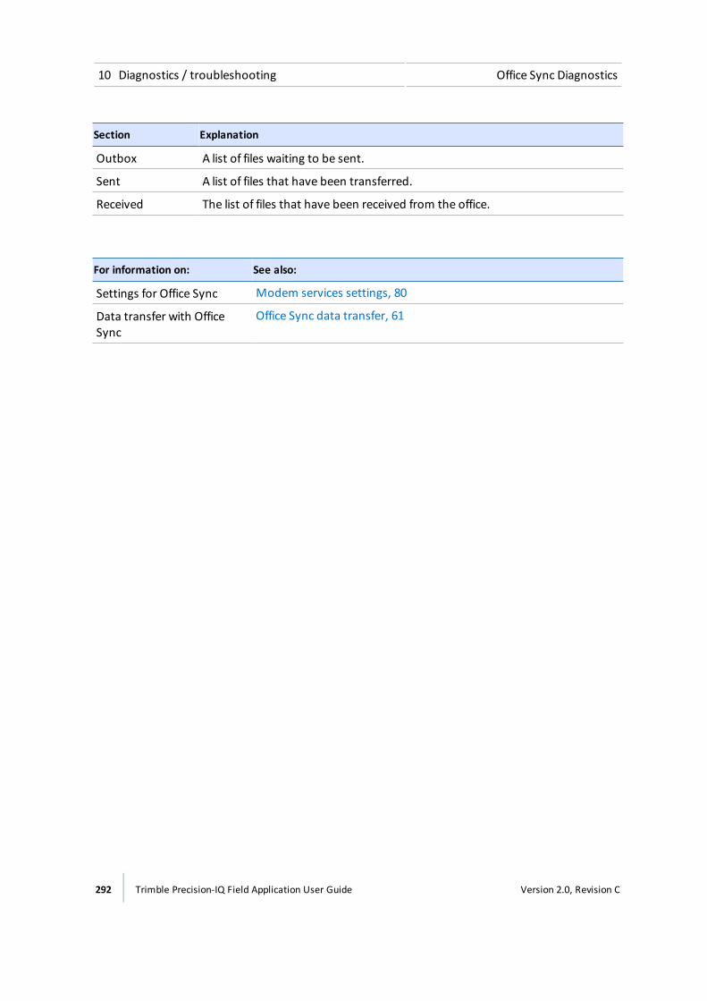
10 Diagnostics / troubleshooting Office Sync Diagnostics
Section Explanation
Outbox A list of files waiting to be sent.
Sent A list of files that have been transferred.
Received The list of files that have been received from the office.
For information on: See also:
Settings for Office Sync Modem services settings, 80
Data transfer with OfficeSync
Office Sync data transfer, 61
292 Trimble Precision-IQ Field Application User Guide Version 2.0, Revision C
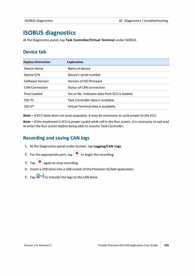
ISOBUS diagnostics 10 Diagnostics / troubleshooting
ISOBUS diagnosticsAt the Diagnostics panel, tap Task Controller/Virtual Terminal under ISOBUS.
Device tab
Display Information Explanation
Device Name Name of device
Device S/N Device's serial number
Software Version Version of ISO firmware
CAN Connection Status of CAN connection
Pool Loaded Yes or No. Indicates data from ECU is loaded.
ISO-TC Task Controller data is available.
ISO-VT Virtual Terminal data is available.
Note – If ECU data does not auto-populate, it may be necessary to cycle power to the ECU.
Note – If the implement's ECU is power cycled while still in the Run screen, it is necessary to exit andre-enter the Run screen before being able to resume Task Controller.
Recording and saving CAN logs1. At the Diagnostics panel under System, tap Logging/CAN Logs.
2. For the appropriate port, tap to begin the recording.
3. Tap again to stop recording.
4. Insert a USB drive into a USB socket of the Precision-IQ field application.
5. Tap to transfer the logs to the USB drive.
Version 2.0, Revision C Trimble Precision-IQ Field Application User Guide 293
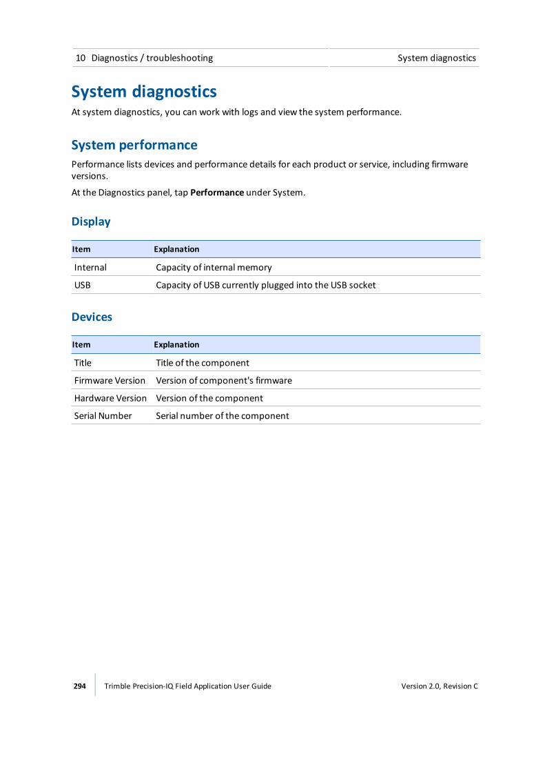
10 Diagnostics / troubleshooting System diagnostics
System diagnosticsAt system diagnostics, you can work with logs and view the system performance.
System performancePerformance lists devices and performance details for each product or service, including firmwareversions.
At the Diagnostics panel, tap Performance under System.
Display
Item Explanation
Internal Capacity of internal memory
USB Capacity of USB currently plugged into the USB socket
Devices
Item Explanation
Title Title of the component
Firmware Version Version of component's firmware
Hardware Version Version of the component
Serial Number Serial number of the component
294 Trimble Precision-IQ Field Application User Guide Version 2.0, Revision C

TM-200Module diagnostics 10 Diagnostics / troubleshooting
TM-200 Module diagnosticsThe TM-200Module has LED lights that shows the status of connections to it.
Note – Fast LED flash is approximately 3 flashes per second. Slow LED flash is approximately 1 flashper second.
LED 1
Indicates the status of the link and traffic between the TM-200Module port marked withand the DCM-300modem.
LED 2Indicates the status of the link and traffic between the TM-200Module port and the display.
LED 3For future use.
LED 3 and 4 combinationBlinking between red and green indicates the TM-200Module is either starting up or loading newfirmware.
Version 2.0, Revision C Trimble Precision-IQ Field Application User Guide 295

10 Diagnostics / troubleshooting TM-200Module diagnostics
LED 4Orange fast flash = no position
LED Indicator Autonomous SBAS RangePoint RTX OmniSTAR HP/G2
Orange solid N/A Autonomous, hasSBAS signal
Autonomous/DGPS,has RTX signal
Autonomous/ DGPS,has OmniSTAR signal
Orange slowflash
N/A Autonomous, noSBAS signal
Autonomous/DGPS,no RTX signal
Autonomous/ DGPS,no OmniSTAR signal
Green solid Autonomousposition
DGPS, has SBASsignal
Converged Converged
Green slowflash
N/A DGPS, no SBASsignal,using recentcorrections
Unconverged Unconverged
Green fastflash
N/A Converged/unconverged,using oldcorrections
Subscriptionexpired or othererror
Converged/unconverged,using old corrections
LED Indicator CenterPoint RTX (satellite) CenterPoint RTX (modem) CenterPoint VRS/RTK
Orange solid Autonomous/DGPS, hasRTX signal
Autonomous/ DGPS,connected to RTX server
Autonomous/DGPS,no CMR or RTCM3corrections
Orange slow flash N/A Autonomous, noSBAS signal
Autonomous/DGPS,no RTX signal
Green solid Converged Converged Fixed
Green slow flash Not converged Not converged Float
Green fast flash Converged/unconverged,using old corrections
Converged/unconverged, using old corrections
Fixed/float, usingold corrections
296 Trimble Precision-IQ Field Application User Guide Version 2.0, Revision C

Glossary
11C h a p t e r
Version 2.0, Revision C Trimble Precision-IQ Field Application User Guide 297
11 Glossary
AA+ line
A guidance line you define on your field. The A+ line is defined fixing a point, then heading in adirection. Guidance lines are for use with automated steering.
AB line
A guidance line you define on your field. You set a beginning point (A) and an end point (B). You useguidance lines for use with automated steering.
Accelerometer
A device that measures non-gravitational acceleration.
Aggressiveness
Themeasure of how strongly the system makes steering changes.
Autonomous GNSS positioning
Autonomous GNSS positioning uses no corrections. The rover receiver calculates its position usingonly the GNSS signals it receives. This method does not have high absolute accuracy, but therelative accuracy is comparable to the other methods.
RTK GNSS positioning uses the RTK positioning method to achieve centimeter-level accuracy. To usethe RTK method, you must first set up a base station. The base station uses a radio link to broadcastRTK corrections to one or more rover receivers.
BBoundary
A line indicating the border surrounding a field.
CCenterPoint™ RTK for radio
Positioning correction service for radio communication systems. Requires access to a base stationlocated within a eight-mile radius (approximately) from your farm. An RTK base station sendscorrections via a radio transmitter to a mobile receiver attached to your vehicle. Works well forfarms within 8miles of an established RTK base station or base station network, without line-of-sight obstructions such hilly terrain or an abundance of trees.
298 Trimble Precision-IQ Field Application User Guide Version 2.0, Revision C

D 11 Glossary
CenterPoint™ RTX™
Positioning correction service for satellite communication systems. Delivers GPS or GNSS enabledcorrections via satellite directly to your receiver. Does not require a base station or cellular dataplan. CenterPoint RTX corrections are provided on as subscription basis.
CenterPoint™ RTX™ for cellular
Positioning correction service for cellular communications. Delivers corrections via cellular networkdirectly to your receiver. Requires a cellular data plan.
CenterPoint™ VRS™
Virtual reference station. Positioning correction service for cellular communication systems. EnablesRTK (Real-Time Kinetic) corrections over a large geographic area where robust cellular data coverageis available. Provides high accuracy for guidance applications throughout the whole coverage area.Requires a cellular data plan. Uses a cellular communication modem, such as the DCM-300 orAg3000. Relies on CORS.
Client
The customer for whom the work is being done.
Controller orientation
Correctly associate the outputs of the Autopilot controller sensors with the direction of the vehicle.
Correction service
A service which provides corrections to create a higher GPS accuracy.
CORS (Continuously Operating Reference Station) network
A network of GPS/GNSS reference stations situated within the coverage area to transmit RTK (Real-Time Kinetic) corrections to the cellular modem. The distance between the reference stations andthemodem on the vehicle does not affect accuracy. CORS works well in areas with spotty RTK radiotower coverage.
Curved line
A guidance line you define on your field. You begin recording and drive until you are at the end ofthe curved line or segment, then stop recording. Guidance lines are for use with automatedsteering.
DDGNSS
Differential GNSS positioning. The GNSS receiver uses corrections fromWAAS/EGNOS satellites orfrom OmniSTAR HP, XP, G2, or VBS satellites. These differential systems use special algorithms toprovide differential corrections that allow the rover receiver to calculate its position moreaccurately. Not all corrections services support the use of GLONASS satellites in their solution.
DGPS
Differentially corrected Global Positioning System (GPS).
Version 2.0, Revision C Trimble Precision-IQ Field Application User Guide 299
11 Glossary E
EEGNOS
European Geostationary Navigation Overlay Service. An SBAS operated by the European SpaceAgency.
Event
A precision agriculture activity on a particular field. For example: planting seed, applying fertilizer orlime, or spraying with fungicide, herbicide or insecticide.
FFarm
A collection of fields.
Field
Settings created in the Precision-IQ field application to represent an actual field, one or more partsof an actual field, or a group of two or more fields. Field profiles include guidance lines for steering,pivot patterns and landmarks.
Freeplay
Movement in the steering linkage through which a movement of the steering wheel will cause nochange in wheel angle.
Freeplay offset
A value entered to give the control system a way to account for freeplay during guidance.
GGLONASS
A Russian space-based satellite navigation system.
GNSS
Global Navigation Satellite System. A system of GPS US and Russian satellites that provideinformation about geo-spatial positioning. A GNSS receiver can determine its longitude, latitude andaltitude. In the future, GNSS will also use Chinese GPS satellites.
GPS
Global Positioning System. A space-based satellite navigation system. A GPS receiver can determineits position by using GPS satellites.
300 Trimble Precision-IQ Field Application User Guide Version 2.0, Revision C
H 11 Glossary
GPS autonomous positioning
Amode of operation in which a GPS receiver computes position fixes in real time from satellite dataalone, without reference to data supplied by a base station. Autonomous positioning is the leastprecise positioning procedure a GPS receiver can perform, yielding position fixes that are precise to±100meters.
HHDOP
The horizontal component of PDOP.
Headland
A guidance pattern that contains straight lines within a boundary. Guidance patterns are for usewith automated steering.
IIMD
Inertial Measurement Device.
IMEI
InternationalMobile Station Equipment Identity. A number to identify mobile equipment. The GSMnetwork uses this number to identify valid devices. The IMEI number has no relationship to thesubscriber.
IMU
Inertial Measurement Unit. An electronic device that measures and reports on a vehicle's velocity,orientation, and gravitational forces, using a combination of accelerometers and gyroscopes.
Integrated radio
Trimble integrated radios contain a radio antenna integrated with the GNSS receiver or display in asingle unit. These integrated radios receive corrections transmitted by Trimble GNSS RTK basestations.
LLogging
Also called coverage logging. Logging records the area that you have covered when you carry out anoperation, for example applying fertilizer to a field.
Version 2.0, Revision C Trimble Precision-IQ Field Application User Guide 301
11 Glossary M
License
A license enables a software feature, and is valid for an unlimited duration. A license does not needto be activated, but does need to be assigned to and delivered to a specific display. Assignment anddelivery of a license occurs on the reseller portal.
MManual override
Required for platforms that employ a pressure transducer for themanual override function. Changethe default only if the operation of themanual override function is unacceptable.
Material
A product that is controlled by a PWM valve, Servo valve, or Rawson™ drive. You can use a planter(seed), liquid, granular seed and granular fertilizer, all of which have different setup parameters.
Multipath error
An error caused by the interference of the same signal reaching the receiver by two different paths:once via the direct path, and once via a reflection. Amajor cause of GPS errors.
NNMEA standard
An electrical, hardware and data standard designed by the NationalMarine Electronics Associationthat dictates the content and format of communication between GPS receivers and other devices.NMEA messages include data that provides location and accuracy, the number of satellites beingused, the dilution of precision and signal strength.
PPDOP
Position Dilution of Precision. A calculation that takes into account the satellites that can be seen,how high they are and their bearing. The outcome of the calculation is an estimation of how proneto error your GPS position is. The lower the value, themore accurate your position. You may wish toplan your field work for periods of low PDOP. Generally, themore satellites in view, the better(lower) the PDOP.
Pivot
302 Trimble Precision-IQ Field Application User Guide Version 2.0, Revision C
R 11 Glossary
A guidance pattern you define for your field by recording the outer circular boundary of the pivotarea and then entering a value to compute the rows within the pivot. Guidance patterns are for usewith automated steering.
RRangePoint™ RTX™
Positioning service for satellite communication systems. RangePoint RTX works with a built-in GNSSreceiver. Does not require a base station or cellular data plan.
Rate switch for Field IQ
Used to select Preset Rate 1, Preset Rate 2, or Manual Rate Control.
Real Time Kinematic (RTK)
A navigation technique to improve the information received from satellite-based positioningsystems. Used with GPS, GLONASS and Galileo.
Roll correction
Compensates for antenna height and static roll caused by minor variations in the navigationcontroller and themounting of the GPS receiver.
Run screen
The screen where you perform field activities.
SSBAS
Space Based Augmentation System. A system of Earth-based systems at points surveyed forlocation accuracy that measure satellites, signals and factors that can impact the signals. The SBASthen broadcasts corrections to satellite signals to improve accuracy.
Scintillation
Causes extreme fluctuations in signals that are received. Scintillation can be caused by turbulencethat creates air pockets with different temperatures and densities.
Section
A number of rows or spray nozzles that are controlled by existing shut-off valve, Tru Count airclutches, or Tru Count LiquiBlock™ valves. A section can have either a single row/nozzle or multiplerows/nozzles depending on how the system is set up.
Section Control Module
Controls 12 sections/rows per module with up to 4modules (48module sections / rows).
Service
Version 2.0, Revision C Trimble Precision-IQ Field Application User Guide 303

11 Glossary T
A service is a subscription to an application that lasts for a specific amount of time, such as one ortwo years. You associate a service with a specific display that can be delivered wirelessly, through aQR code included in an email or through download to a computer.
Signal Input Module
The percentage of time an individual seed is placed for every intended drop.
Slew time
The amount of time that the front wheels take to move from the far left to the far right position andback.
Steering deadzone
The amount of pressure that the system must apply to the hydraulics before the wheels begin toturn.
TTAP
Tuning parameter for guidance algorithms.
VVDOP
Ameasurement of the vertical PDOP.
Valve calibration for Field-IQ
The process for adjusting the valve performance parameters to get the best performance out of avalve.
WWAAS
Wide Area Augmentation System. An SBAS operated by the US Federal Aviation Administration.
Wheelbase
The distance between the front and rear axles. On tracked vehicles, the wheelbase is exactly half thelength of the track.
304 Trimble Precision-IQ Field Application User Guide Version 2.0, Revision C