Embed Size (px)
Citation preview
Trimble MEPCASE STUDY
MTECH, Inc.
Inside MTech’s BIM-Based Workflow on the Trimble Westminster Headquarters Project
The Trimble Westminster Headquarters project in Westminster, Colo., has become a test bed for the implementation
of innovative tools and more efficient processes, particularly for specialty contractors such as MTech, a top
Colorado-based mechanical contractor.
MTech is already a leader in pre-construction design and engineering services using building information modeling (BIM) to facilitate the fabrication and implementation of mechanical systems. Now the innovative contractor is pushing the technology envelope using Trimble technologies to create more streamlined, coordinated and precise connections to design, fabrication and field activities.
Brandon Miller, CAD/Coordinator for MTech, says, “We believe that mechanical contractors should be one of the leaders in today’s more collaborative projects, helping coordinate all the details that are part of the commercial construction process. We’re continually looking for ways to improve field production and deliver a comprehensive as-constructed model to the owner.”
The contractor’s efforts are already visible on the project in
the way of improved accuracy, faster production and a more comprehensive deliverable.
The coordinated community
From the start, the Trimble Westminster project scope called for BIM and other advanced tools and techniques to facilitate design coordination, conflict checking and constructability reviews and field layout.
Mechanical, plumbing, electrical and fire sprinkler specialty contractors were required to complete initial scope utilizing 3D intelligent models. MTech modeled all mechanical systems from air handling equipment to ductwork, including flanges and insulation and every required damper. All piping was modeled to ¼-inch and refrigerant line-sets show each required weld and connection.
The Trimble Westminster Headquarters Project has given us the rare opportunity to have all coordination finished before construction starts.
Brandon Miller, MTECH, Inc. CAD/Coordinator
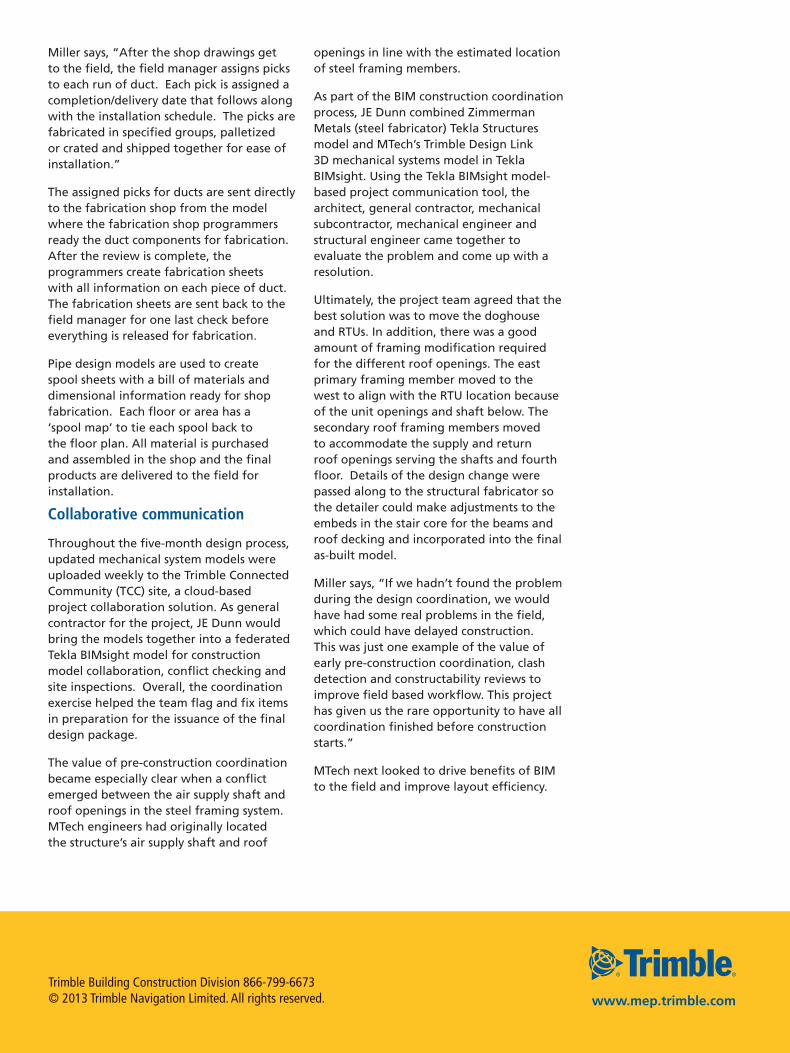
Miller adds, “Every hanger or brace for either system was modeled to ensure constructability, coordinated between all trades and fabricated from the model. If we’re building and/or installing it, it is shown in the model.”
In particular, MTech relies on tools such as Trimble QuickPen PipeDesigner 3D, AutoCAD-based solution, to develop piping concepts for fabrication and installation.
Miller says, “The biggest benefit leading us to use this software was the ease of spooling and creation of an accurate bill of materials. The accurate bill of materials populated on each spool sheet gives estimators the ability to verify budgets, order correct materials and initiate field reviews before pre-fabrication processes begin.”
He also points to the simplicity of the Trimble QuickPen PipeDesigner 3D database and standard building equipment blocks. “We can have multiple people edit the same server database, which allows for faster job setup so we can spend more time resolving any complexities.”
Another nice feature, particularly on a collaborative design and construction project such as the Westminster building, is the ability to share files with other trades. MTech uses the Trimble QuickPen PipeDesigner 3D file conversion tool to export items into a 3D solid object, which eliminates the need for object enablers.
Here’s how the process works for pipe and ductwork design, fabrication and installation.
Design development
As a first step, the MTech CAD designers create a pressure
class database about the pipe or duct network such as metal type, gauge thickness, internal stiffeners or external support, pipe connectors and fabrication methods. Every pressure class is assigned to different pieces of duct or pipe throughout the building.
The subsequent model that results from the database is used to create shop drawings and coordinate with other trades. Each piece of duct or pipe is given a unique number for fabrication and all duct runs are dimensioned for installation. The shop drawings are sent to the shop, out to the field and to vendors providing equipment.
Every hanger or brace for either system was modeled to ensure constructability, coordinated between all trades and fabricated from the model. If we’re building and/or installing it, it is shown in the model.
Brandon Miller, MTECH, Inc. CAD/Coordinator
Trimble Building Construction Division 866-799-6673© 2013 Trimble Navigation Limited. All rights reserved. www.mep.trimble.com
Miller says, “After the shop drawings get to the field, the field manager assigns picks to each run of duct. Each pick is assigned a completion/delivery date that follows along with the installation schedule. The picks are fabricated in specified groups, palletized or crated and shipped together for ease of installation.”
The assigned picks for ducts are sent directly to the fabrication shop from the model where the fabrication shop programmers ready the duct components for fabrication. After the review is complete, the programmers create fabrication sheets with all information on each piece of duct. The fabrication sheets are sent back to the field manager for one last check before everything is released for fabrication.
Pipe design models are used to create spool sheets with a bill of materials and dimensional information ready for shop fabrication. Each floor or area has a ‘spool map’ to tie each spool back to the floor plan. All material is purchased and assembled in the shop and the final products are delivered to the field for installation.
Collaborative communication
Throughout the five-month design process, updated mechanical system models were uploaded weekly to the Trimble Connected Community (TCC) site, a cloud-based project collaboration solution. As general contractor for the project, JE Dunn would bring the models together into a federated Tekla BIMsight model for construction model collaboration, conflict checking and site inspections. Overall, the coordination exercise helped the team flag and fix items in preparation for the issuance of the final design package.
The value of pre-construction coordination became especially clear when a conflict emerged between the air supply shaft and roof openings in the steel framing system. MTech engineers had originally located the structure’s air supply shaft and roof
openings in line with the estimated location of steel framing members.
As part of the BIM construction coordination process, JE Dunn combined Zimmerman Metals (steel fabricator) Tekla Structures model and MTech’s Trimble Design Link 3D mechanical systems model in Tekla BIMsight. Using the Tekla BIMsight model-based project communication tool, the architect, general contractor, mechanical subcontractor, mechanical engineer and structural engineer came together to evaluate the problem and come up with a resolution.
Ultimately, the project team agreed that the best solution was to move the doghouse and RTUs. In addition, there was a good amount of framing modification required for the different roof openings. The east primary framing member moved to the west to align with the RTU location because of the unit openings and shaft below. The secondary roof framing members moved to accommodate the supply and return roof openings serving the shafts and fourth floor. Details of the design change were passed along to the structural fabricator so the detailer could make adjustments to the embeds in the stair core for the beams and roof decking and incorporated into the final as-built model.
Miller says, “If we hadn’t found the problem during the design coordination, we would have had some real problems in the field, which could have delayed construction. This was just one example of the value of early pre-construction coordination, clash detection and constructability reviews to improve field based workflow. This project has given us the rare opportunity to have all coordination finished before construction starts.”
MTech next looked to drive benefits of BIM to the field and improve layout efficiency.
Trimble Building Construction Division 866-799-6673© 2013 Trimble Navigation Limited. All rights reserved. www.mep.trimble.com
Robotic speed
Once all of the hanger locations were modeled and coordinated with other trades, MTech used Trimble Point Creator Pro to begin the office-to-field process. Trimble Point Creator Pro enables users to create 2D and 3D points directly within familiar CAD and BIM platforms, such as Autodesk Revit, and then share layout data with Trimble field solutions for a more streamlined process. Once field points are created in the model, Trimble Point Creator Pro generates a job file that is properly scaled and aligned for work in the field.
The points were exported into the Trimble Field Link for MEP software and installed with the robotic total station and Trimble Tablet, which incorporates a ruggedized 7-inch touch screen display.
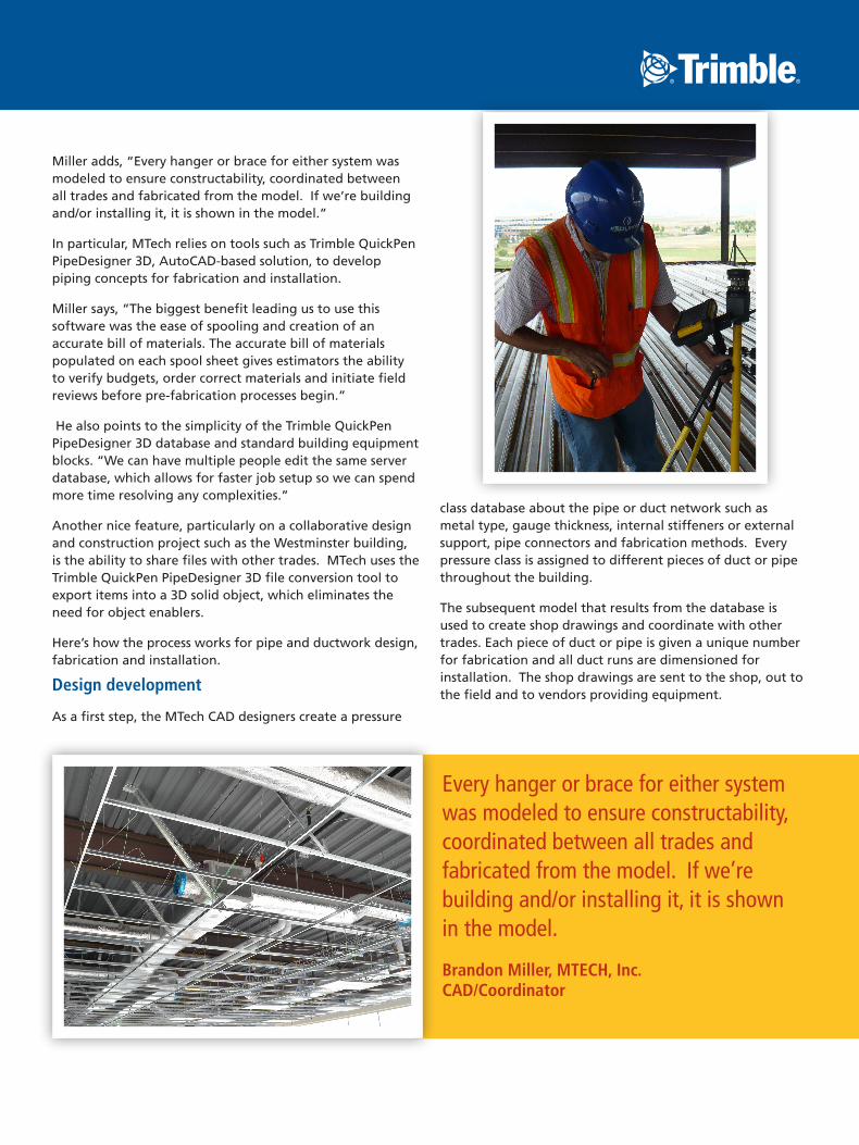
Joe Bright, field pipe manager for MTech, says, “The most effective use of the robotic total station is to place embeds in decking before concrete is poured. We particularly like the instant file download functionality, the Point Manager and layout features in Trimble Field Link. We are able to install embeds on top of the deck, rather than below, which would require climbing a ladder many times in a day. With the Trimble Point Creator Pro/Trimble Field Link/robotic total station process, we can install hangers faster and safer with fewer people”
Using conventional methods, a two-person field crew would have required about 3 weeks to layout 500 points.
“Now we have two people laying out 500 points in 3 days, plus about 4 days of CAD time. While we spend more time in the up-front modeling and coordination, the overall design and installation time has decreased dramatically,” Bright says. “And we’ve taken some of the human error out of the equation.”
For example, if the field crew has a long string of dimensions from one base point, and that base point is 5-inches off during
layout on the floor, every dimension pulled from that line will be off.
Overall, MTech installed 5,600 points in 24 working days including 15,000 ft of duct strap. As a side note, MTech’s main layout person broke his foot at the beginning of layout and wasn’t able continue field layout. Undaunted, MTech trained an apprentice on how to use the tablet and robot. Within one week, the apprentice was locating 200 hangers a day.
When asked about MTech’s recent upgrade from Trimble MEP (Trimble’s first generation MEP layout solution) to Trimble Field Link for MEP, Bright had the following to say about the process: “Access to the Internet to upload and transfer files back and forth from the field to the office has been a huge benefit. The availability of the 3D model on a larger screen for review during layout is also helpful.”
Thus far, the MTech field team has not had to update mechanical system locations in the 3D model. Miller concludes, “Since 95% of the fabrication comes from the model, it is always updating to what is being built/installed. When we do have things that are changed in design or an unforeseen coordination issue, they are changed in the model, and then sent back to the shops for fabrication. We’ve had no as-built changes yet. Everything is falling into place as designed, which is good news for the BIM coordination team.”