Embed Size (px)
Citation preview
1
ASNE High Speed Craft Conference, Annapolis, Jan 24, 2007
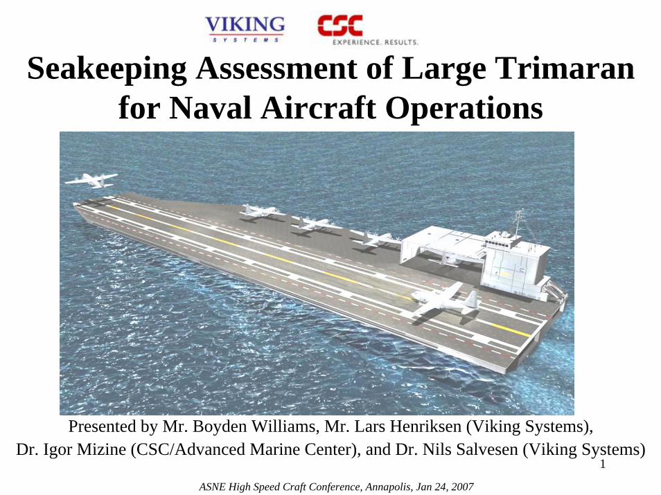
Seakeeping Assessment of Large Trimaran for Naval Aircraft Operations
Presented by Mr. Boyden Williams, Mr. Lars Henriksen (Viking Systems), Dr. Igor Mizine (CSC/Advanced Marine Center), and Dr. Nils Salvesen (Viking Systems)
Seakeeping Assessment of Large Trimaran for Naval Aircraft Operations
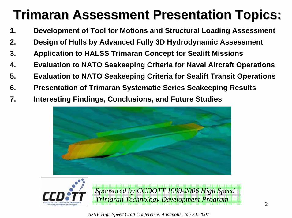
Trimaran Assessment Presentation Topics:Trimaran Assessment Presentation Topics:1. Development of Tool for Motions and Structural Loading Assessment2. Design of Hulls by Advanced Fully 3D Hydrodynamic Assessment3. Application to HALSS Trimaran Concept for Sealift Missions4. Evaluation to NATO Seakeeping Criteria for Naval Aircraft Operations5. Evaluation to NATO Seakeeping Criteria for Sealift Transit Operations6. Presentation of Trimaran Systematic Series Seakeeping Results7. Interesting Findings, Conclusions, and Future Studies
2
ASNE High Speed Craft Conference, Annapolis, Jan 24, 2007
Sponsored by CCDOTT 1999-2006 High Speed Trimaran Technology Development Program
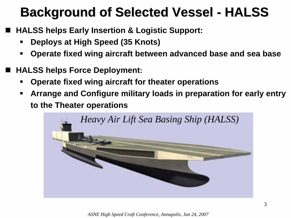
Background of Selected Vessel Background of Selected Vessel -- HALSSHALSSHALSS helps Early Insertion & Logistic Support:
Deploys at High Speed (35 Knots) Operate fixed wing aircraft between advanced base and sea base
HALSS helps Force Deployment:Operate fixed wing aircraft for theater operationsArrange and Configure military loads in preparation for early entry to the Theater operations
Heavy Air Lift Sea Basing Ship (HALSS)
3
ASNE High Speed Craft Conference, Annapolis, Jan 24, 2007

HALSS Principal CharacteristicsHALSS Principal CharacteristicsFlight Deck Length 1,100 FTFlight Deck Width / Docking Hull Beam 274 FT / 180 FTDraft 37.9 FTDepth 100 FTPayload:
Combat forces sustainment 8,900 STAircraft Fuel Supply 2,650 ST
Fixed Wing Aircraft Six C-130JStowage Factor
Main (Flight) Deck 185,900 SQFTII Cargo Deck 141,000 SQFTIII (Crossover) & IV Decks 51,100 SQFT
HALSS Stowage Factor 46.7 SQFT/MT
Unrefueled Range of Sea Voyage - CONUS to Advanced Base or to JOA10,000 NM at 35 knots>15,000 NM at 25 knots Followed by 10 days endurance in JOA
4
ASNE High Speed Craft Conference, Annapolis, Jan 24, 2007

High Speed Trimaran Seakeeping Study High Speed Trimaran Seakeeping Study -- ObjectivesObjectives
Establish Reliable Trimaran Analysis Procedure:Displacement, Velocities, Accelerations; Relative Motions for Slamming and Emergence; Hull Girder Loads and Local Pressures; Interaction between Main and Side Hulls.
Determine Criteria for Assessment: Naval Air Operations (NATO STANAG 4154, 1997) Transit (NATO Generic Frigate)
Assess Motion, Slamming, Emergence & Hull Girder Loads:Sea States 4 through 7; Vessel Speeds of 15, 25, 35 knots; Vessel Headings of 0, 45, 90, 135, 180 degrees;Multiple Hull Configurations
5
ASNE High Speed Craft Conference, Annapolis, Jan 24, 2007
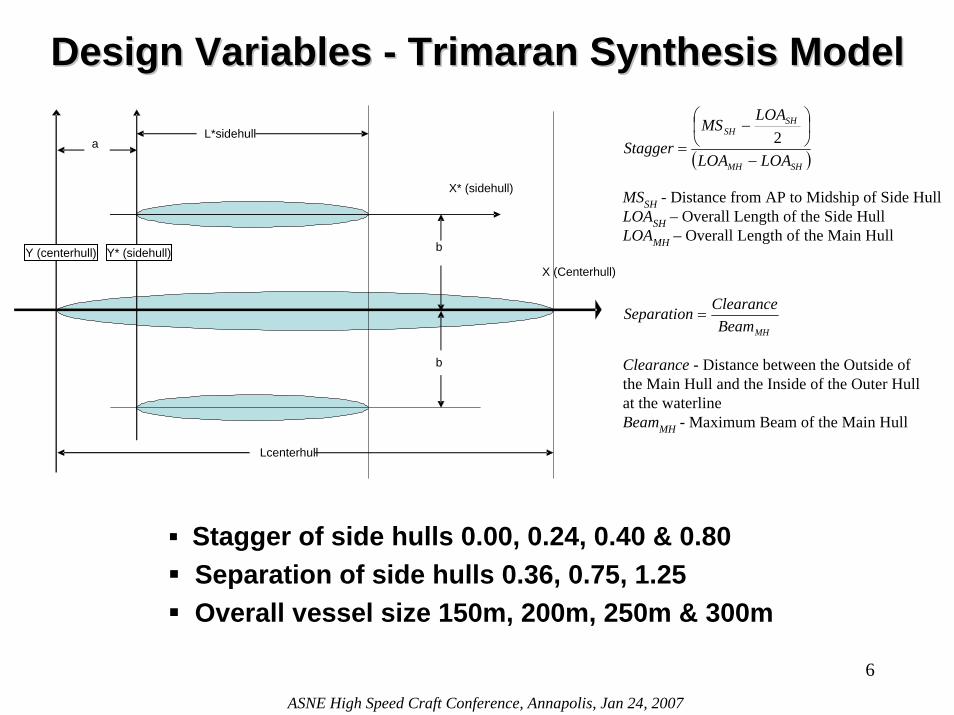
Design Variables Design Variables -- Trimaran Synthesis Model Trimaran Synthesis Model
a
b
L*sidehull
Lcenterhull
b
X (Centerhull)Y (centerhull)
X* (sidehull)
Y* (sidehull)
MHBeamClearanceSeparation =
( )SHMH
SHSH
LOALOA
LOAMS
Stagger−
⎟⎠⎞
⎜⎝⎛ −
=2
MSSH - Distance from AP to Midship of Side HullLOASH – Overall Length of the Side HullLOAMH – Overall Length of the Main Hull
Clearance - Distance between the Outside of the Main Hull and the Inside of the Outer Hull at the waterlineBeamMH - Maximum Beam of the Main Hull
Stagger of side hulls 0.00, 0.24, 0.40 & 0.80Separation of side hulls 0.36, 0.75, 1.25Overall vessel size 150m, 200m, 250m & 300m
6
ASNE High Speed Craft Conference, Annapolis, Jan 24, 2007
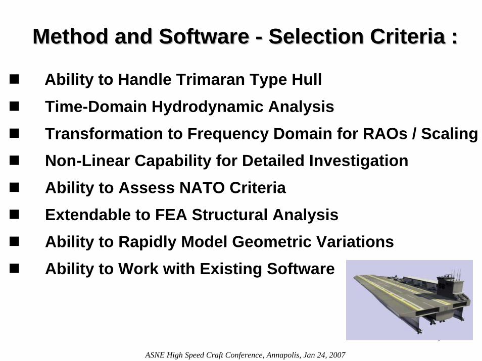
Method and Software Method and Software -- Selection Criteria :Selection Criteria :
Ability to Handle Trimaran Type HullTime-Domain Hydrodynamic AnalysisTransformation to Frequency Domain for RAOs / Scaling Non-Linear Capability for Detailed InvestigationAbility to Assess NATO CriteriaExtendable to FEA Structural AnalysisAbility to Rapidly Model Geometric VariationsAbility to Work with Existing Software
7
ASNE High Speed Craft Conference, Annapolis, Jan 24, 2007
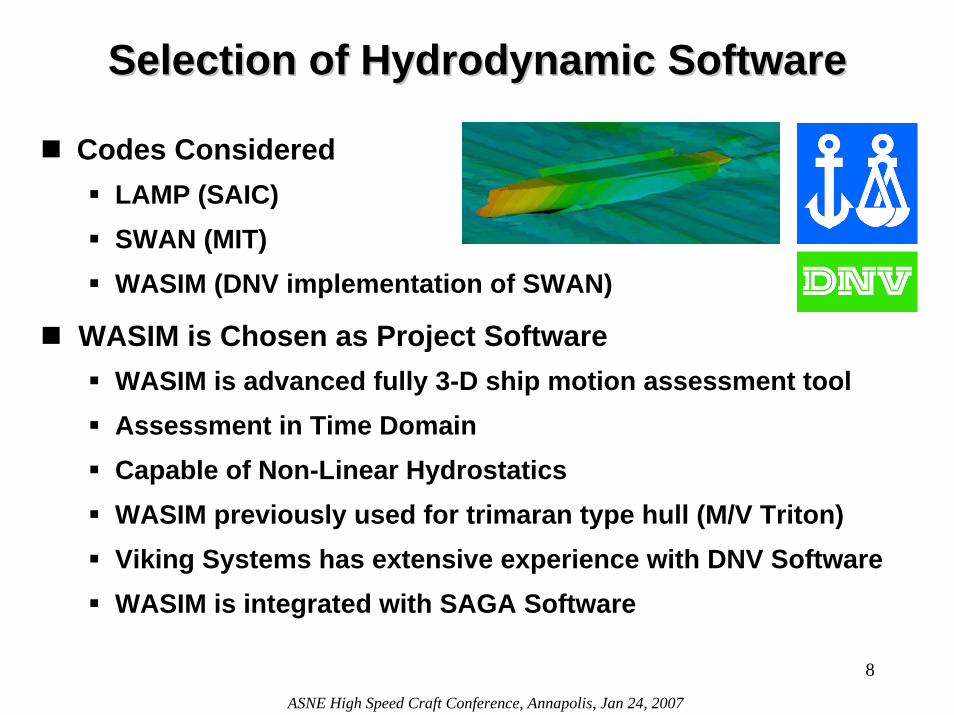
Selection of Hydrodynamic SoftwareSelection of Hydrodynamic Software
Codes Considered LAMP (SAIC)SWAN (MIT)WASIM (DNV implementation of SWAN)
WASIM is Chosen as Project SoftwareWASIM is advanced fully 3-D ship motion assessment toolAssessment in Time DomainCapable of Non-Linear Hydrostatics WASIM previously used for trimaran type hull (M/V Triton)Viking Systems has extensive experience with DNV SoftwareWASIM is integrated with SAGA Software
8
ASNE High Speed Craft Conference, Annapolis, Jan 24, 2007
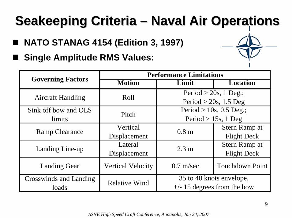
Seakeeping Criteria Seakeeping Criteria –– Naval Air OperationsNaval Air OperationsNATO STANAG 4154 (Edition 3, 1997)Single Amplitude RMS Values:
Motion Limit Location
Aircraft Handling Roll
Sink off bow and OLS limits Pitch
Ramp Clearance Vertical Displacement 0.8 m Stern Ramp at
Flight Deck
Landing Line-up Lateral Displacement 2.3 m Stern Ramp at
Flight Deck
Landing Gear Vertical Velocity 0.7 m/sec Touchdown Point
Crosswinds and Landing loads Relative Wind
35 to 40 knots envelope, +/- 15 degrees from the bow
Governing Factors Performance Limitations
Period > 20s, 1 Deg.; Period > 20s, 1.5 Deg
Period > 10s, 0.5 Deg.; Period > 15s, 1 Deg
9
ASNE High Speed Craft Conference, Annapolis, Jan 24, 2007

Naval Air Naval Air Operations Operations
--Environment Environment Conditions
Wind Speed Over Deck for Flight Operations
0
10
20
30
40
50
60
0 1 2 3 4 5 6 7Sea State
Win
d Sp
eed
(Kno
Wind Speed
Minimum Required Speed Over Deck
Maximum Required Speed Over Deck
Wind - Sea State
Wind - Vessel
Conditions
Wind Speed Minimum Vessel Speed
Maximum Vessel Speed
(Knots) (Knots) (Knots)0 0.0 35.0 40.01 3.0 32.0 37.02 8.5 26.5 31.53 13.5 21.5 26.54 19.0 16.0 21.05 24.5 10.5 15.5
5.5 30.0 5.0 10.06 37.5 -2.5 2.57 51.5 -16.5 -11.5
Head Sea Cases used for AnalysisInsufficient Forward Speed to Maintain Maneuverability
Sea State Using Wind Speed Criteria:
The wind associated with a Sea State defines the required vessel speed to maintain 35 -40 knot apparent wind speed over flight deck
10
ASNE High Speed Craft Conference, Annapolis, Jan 24, 2007
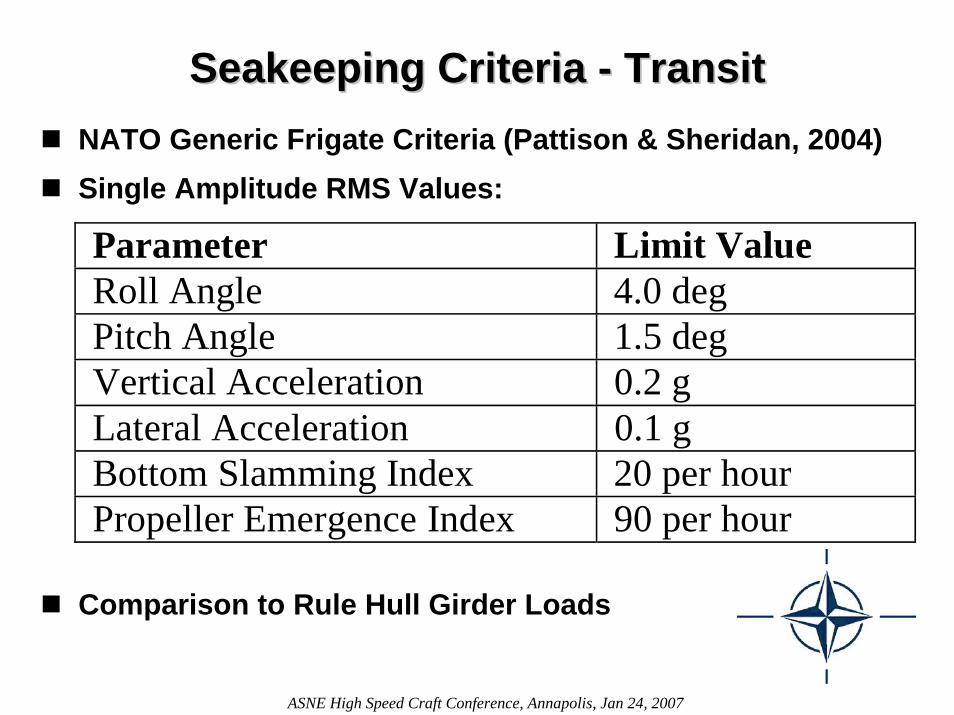
Seakeeping Criteria Seakeeping Criteria -- TransitTransitNATO Generic Frigate Criteria (Pattison & Sheridan, 2004)Single Amplitude RMS Values:
Parameter Limit Value Roll Angle 4.0 deg Pitch Angle 1.5 deg Vertical Acceleration 0.2 g Lateral Acceleration 0.1 g Bottom Slamming Index 20 per hour Propeller Emergence Index 90 per hour
11
ASNE High Speed Craft Conference, Annapolis, Jan 24, 2007
Comparison to Rule Hull Girder Loads
12
ASNE High Speed Craft Conference, Annapolis, Jan 24, 2007
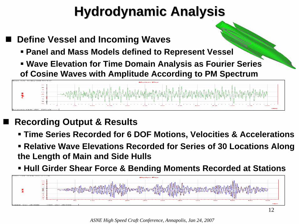
Hydrodynamic AnalysisHydrodynamic Analysis
Define Vessel and Incoming WavesPanel and Mass Models defined to Represent Vessel Wave Elevation for Time Domain Analysis as Fourier Series
of Cosine Waves with Amplitude According to PM Spectrum
Recording Output & ResultsTime Series Recorded for 6 DOF Motions, Velocities & Accelerations Relative Wave Elevations Recorded for Series of 30 Locations Along
the Length of Main and Side HullsHull Girder Shear Force & Bending Moments Recorded at Stations
Result Processing Result Processing -- Time vs. FrequencyTime vs. FrequencyHydrodynamic Analysis is Performed in the Time Domain, Results can be Transformed into Frequency Domain.
Result Processing in the Time Domain - BenefitsStatistical Analysis of Time Series for Result VariablesAbility to Track Occurrence of Individual PhenomenonUnique Analysis Run for Each Sea State, Heading & Speed
Result Processing in the Frequency Domain - BenefitsResults Transformed into Response Amplitude Operators (RAO)Response to Unit Wave (RAO) Combined with Sea SpectrumRequires Fewer Analysis Runs – Saves Computational TimeResults can be Scaled for Vessels of Varying Length
Reliable and Repeatable Post-Processing of Data is Essential13
ASNE High Speed Craft Conference, Annapolis, Jan 24, 2007
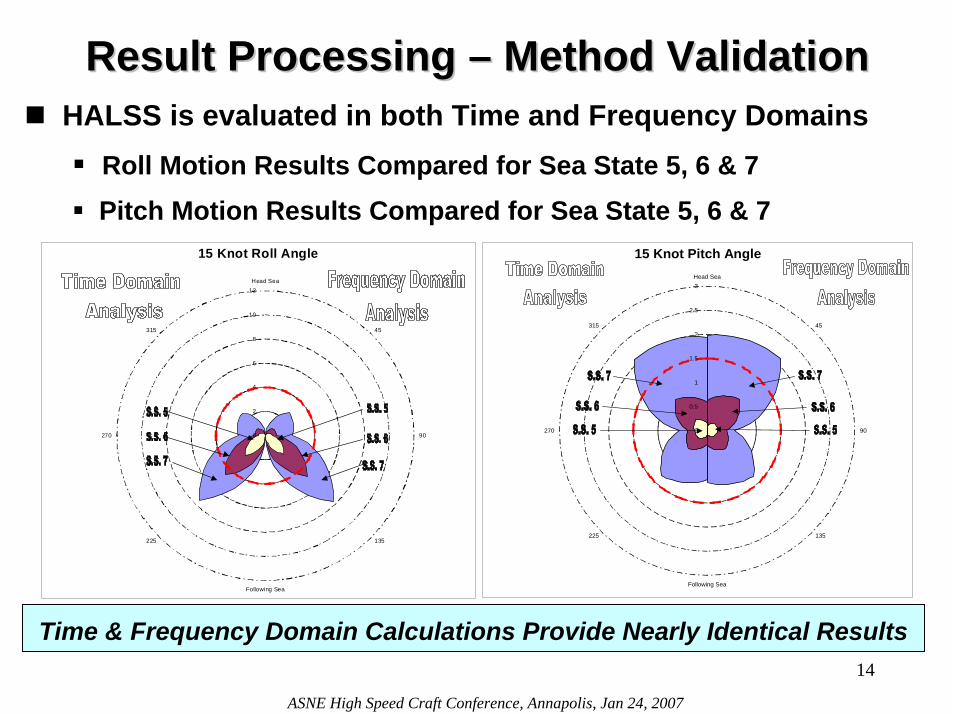
Result Processing Result Processing –– Method ValidationMethod ValidationHALSS is evaluated in both Time and Frequency Domains
Roll Motion Results Compared for Sea State 5, 6 & 7Pitch Motion Results Compared for Sea State 5, 6 & 7
15 Knot Pitch Angle
0
0.5
1
1.5
2
2.5
3Head Sea
45
90
135
Following Sea
225
270
315
15 Knot Roll Angle
0
2
4
6
8
10
12Head Sea
45
90
135
Following Sea
225
270
315
Time & Frequency Domain Calculations Provide Nearly Identical Results14
ASNE High Speed Craft Conference, Annapolis, Jan 24, 2007
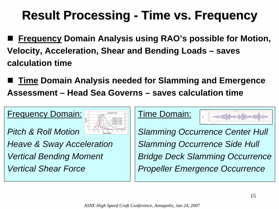
Result Processing Result Processing -- Time vs. FrequencyTime vs. Frequency
Frequency Domain Analysis using RAO’s possible for Motion, Velocity, Acceleration, Shear and Bending Loads – saves calculation time
Time Domain Analysis needed for Slamming and Emergence Assessment – Head Sea Governs – saves calculation time
Frequency Domain:
Pitch & Roll MotionHeave & Sway Acceleration Vertical Bending MomentVertical Shear Force
Time Domain:
Slamming Occurrence Center HullSlamming Occurrence Side HullBridge Deck Slamming OccurrencePropeller Emergence Occurrence
0
0.5
1
1.5
2
2.5
3
0 0.2 0.4 0.6 0.8 1 1.2 1.4
Frequency (Rad/s)
Am
plitu
d
00.511.522.533.544.55
Wave Spectrum - SS6
Pitch RAO - L = 300m
Pitch RAO - L = 250m
Pitch RAO - L = 200m
Pitch RAO - L = 150m
15
ASNE High Speed Craft Conference, Annapolis, Jan 24, 2007
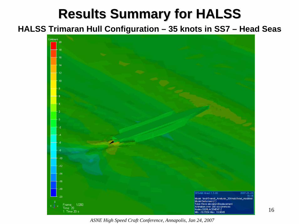
Results Summary for HALSSResults Summary for HALSS
16
ASNE High Speed Craft Conference, Annapolis, Jan 24, 2007
HALSS Trimaran Hull Configuration – 35 knots in SS7 – Head Seas
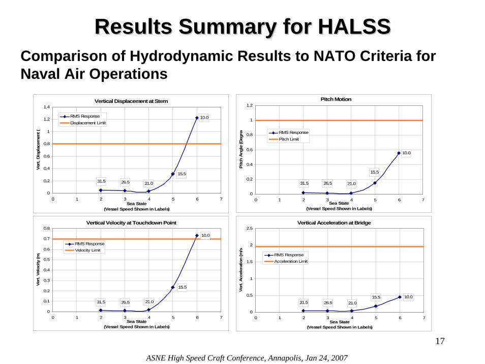
Results Summary for HALSSResults Summary for HALSSComparison of Hydrodynamic Results to NATO Criteria for Naval Air Operations
Vertical Displacement at Stern
10.0
15.5
21.026.531.5
0
0.2
0.4
0.6
0.8
1
1.2
1.4
0 1 2 3 4 5 6 7Sea State
(Vessel Speed Shown in Labels)
Ver
t. D
ispl
acem
ent (
RMS ResponseDisplacement Limit
Pitch Motion
10.0
15.5
21.026.531.5
0
0.2
0.4
0.6
0.8
1
1.2
0 1 2 3 4 5 6 7Sea State
(Vessel Speed Shown in Labels)
Pitc
h A
ngle
(Deg
ree RMS Response
Pitch Limit
Vertical Velocity at Touchdown Point
10.0
15.5
21.026.531.5
0
0.1
0.2
0.3
0.4
0.5
0.6
0.7
0.8
0 1 2 3 4 5 6 7Sea State
(Vessel Speed Shown in Labels)
Vert.
Vel
ocity
(m/
RMS ResponseVelocity Limit
Vertical Acceleration at Bridge
31.5 26.5 21.015.5 10.0
0
0.5
1
1.5
2
2.5
0 1 2 3 4 5 6 7Sea State
(Vessel Speed Shown in Labels)
Ver
t. Ac
cele
ratio
n (m
/s
RMS ResponseAcceleration Limit
17
ASNE High Speed Craft Conference, Annapolis, Jan 24, 2007
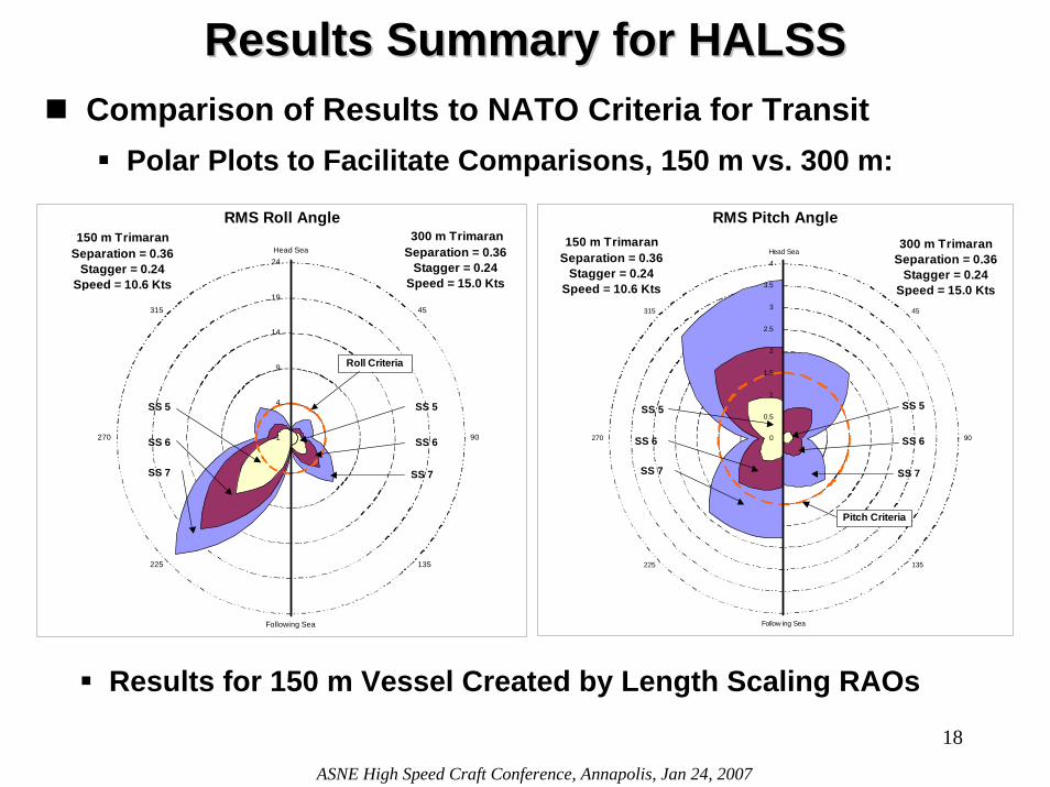
Results Summary for HALSSResults Summary for HALSSComparison of Results to NATO Criteria for Transit
Polar Plots to Facilitate Comparisons, 150 m vs. 300 m:
RMS Pitch Angle
0
0.5
1
1.5
2
2.5
3
3.5
4Head Sea
45
90
135
Follow ing Sea
225
270
315
150 m TrimaranSeparation = 0.36
Stagger = 0.24Speed = 10.6 Kts
300 m Trimaran
Separation = 0.36Stagger = 0.24
Speed = 15.0 Kts
SS 5
Pitch Criteria
SS 6
SS 7
SS 6
SS 7
SS 5
RMS Roll Angle
-1
4
9
14
19
24Head Sea
45
90
135
Following Sea
225
270
315
150 m TrimaranSeparation = 0.36
Stagger = 0.24Speed = 10.6 Kts
Roll Criteria
300 m TrimaranSeparation = 0.36
Stagger = 0.24Speed = 15.0 Kts
SS 6
SS 7
SS 5
SS 6
SS 7
SS 5
Results for 150 m Vessel Created by Length Scaling RAOs
18
ASNE High Speed Craft Conference, Annapolis, Jan 24, 2007
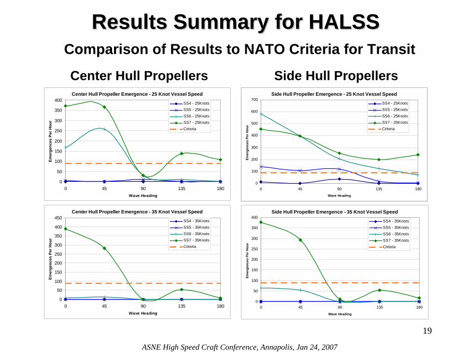
Results Summary for HALSSResults Summary for HALSSComparison of Results to NATO Criteria for Transit
Center Hull Propeller Emergence - 25 Knot Vessel Speed
0
50
100
150
200
250
300
350
400
0 45 90 135 180Wave Heading
Emer
genc
es P
er H
our
SS4 - 25KnotsSS5 - 25KnotsSS6 - 25KnotsSS7 - 25KnotsCriteria
Center Hull Propeller Emergence - 35 Knot Vessel Speed
0
50
100
150
200
250
300
350
400
450
0 45 90 135 180Wave Heading
Emer
genc
es P
er H
our
SS4 - 35KnotsSS5 - 35KnotsSS6 - 35KnotsSS7 - 35KnotsCriteria
Side Hull Propeller Emergence - 25 Knot Vessel Speed
0
100
200
300
400
500
600
700
0 45 90 135 180Wave Heading
Emer
genc
es P
er H
our
SS4 - 25KnotsSS5 - 25KnotsSS6 - 25KnotsSS7 - 25KnotsCriteria
Side Hull Propeller Emergence - 35 Knot Vessel Speed
0
50
100
150
200
250
300
350
400
0 45 90 135 180Wave Heading
Emer
genc
es P
er H
our
SS4 - 35KnotsSS5 - 35KnotsSS6 - 35KnotsSS7 - 35KnotsCriteria
Side Hull Propeller Emergence - 25 Knot Vessel Speed
0
100
200
300
400
500
600
700
0 45 90 135 180Wave Heading
Emer
genc
es P
er H
our
SS4 - 25KnotsSS5 - 25KnotsSS6 - 25KnotsSS7 - 25KnotsCriteria
Center Hull Propellers Side Hull Propellers
19
ASNE High Speed Craft Conference, Annapolis, Jan 24, 2007
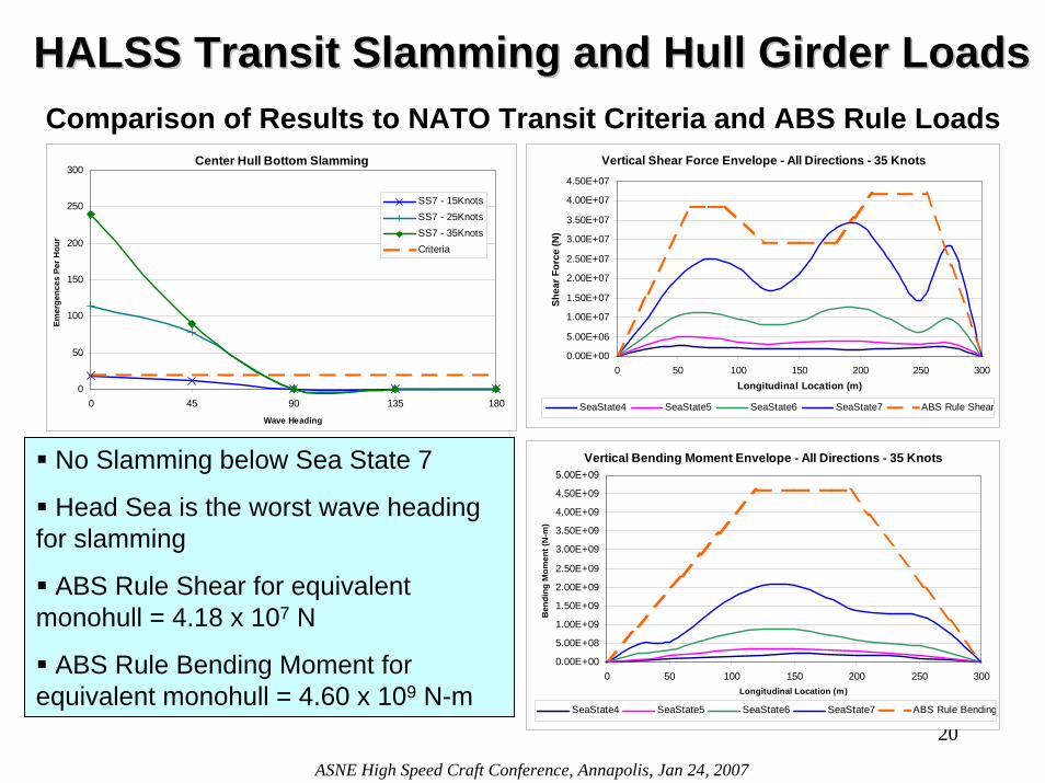
HALSS Transit Slamming and Hull Girder LoadsHALSS Transit Slamming and Hull Girder Loads
20
ASNE High Speed Craft Conference, Annapolis, Jan 24, 2007
Center Hull Bottom Slamming
0
50
100
150
200
250
300
0 45 90 135 180Wave Heading
Emer
genc
es P
er H
our
SS7 - 15KnotsSS7 - 25KnotsSS7 - 35KnotsCriteria
No Slamming below Sea State 7
Head Sea is the worst wave heading for slamming
ABS Rule Shear for equivalent monohull = 4.18 x 10⁷ N
ABS Rule Bending Moment for equivalent monohull = 4.60 x 10⁹ N-m
Vertical Shear Force Envelope - All Directions - 35 Knots
0.00E+00
5.00E+06
1.00E+07
1.50E+07
2.00E+07
2.50E+07
3.00E+07
3.50E+07
4.00E+07
4.50E+07
0 50 100 150 200 250 300Longitudinal Location (m)
Shea
r For
ce (N
)
SeaState4 SeaState5 SeaState6 SeaState7 ABS Rule Shear
Vertical Bending Moment Envelope - All Directions - 35 Knots
0.00E+00
5.00E+08
1.00E+09
1.50E+09
2.00E+09
2.50E+09
3.00E+09
3.50E+09
4.00E+09
4.50E+09
5.00E+09
0 50 100 150 200 250 300Longitudinal Location (m)
Ben
ding
Mom
ent (
N-m
)
SeaState4 SeaState5 SeaState6 SeaState7 ABS Rule Bending
Comparison of Results to NATO Transit Criteria and ABS Rule Loads
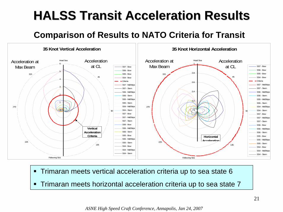
HALSS Transit Acceleration ResultsHALSS Transit Acceleration ResultsComparison of Results to NATO Criteria for Transit
35 Knot Vertical Acceleration
0
1
2
3
4
5
6Head Sea
45
90
135
Following Sea
225
270
315
SS7 - Bow
SS6 - Bow
SS5 - Bow
SS4 - Bow
Criteria
SS7 - MidShips
SS7 - Stern
SS6 - MidShips
SS6 - Stern
SS5 - MidShips
SS5 - Stern
SS4 - MidShips
SS4 - Stern
SS7 - Bow
SS7 - MidShips
SS7 - Stern
SS6 - Bow
SS6 - MidShips
SS6 - Stern
SS5 - Bow
SS5 - MidShips
SS5 - Stern
SS4 - Bow
SS4 - MidShips
SS4 - Stern
Acceleration at CL
Acceleration at Max Beam
Vertical Acceleration
Criteria
35 Knot Horizontal Acceleration
0
0.2
0.4
0.6
0.8
1Head Sea
45
90
135
Following Sea
225
270
315
SS7 - Bow
SS6 - Bow
SS5 - Bow
SS4 - Bow
Criteria
SS7 - MidShips
SS7 - Stern
SS6 - MidShips
SS6 - Stern
SS5 - MidShips
SS5 - Stern
SS4 - MidShips
SS4 - Stern
SS7 - Bow
SS7 - MidShips
SS7 - Stern
SS6 - Bow
SS6 - MidShips
SS6 - Stern
SS5 - Bow
SS5 - MidShips
SS5 - Stern
SS4 - Bow
SS4 - MidShips
SS4 - Stern
Acceleration at CL
Acceleration at Max Beam
Horizontal Acceleration
Trimaran meets vertical acceleration criteria up to sea state 6
Trimaran meets horizontal acceleration criteria up to sea state 7
21
ASNE High Speed Craft Conference, Annapolis, Jan 24, 2007
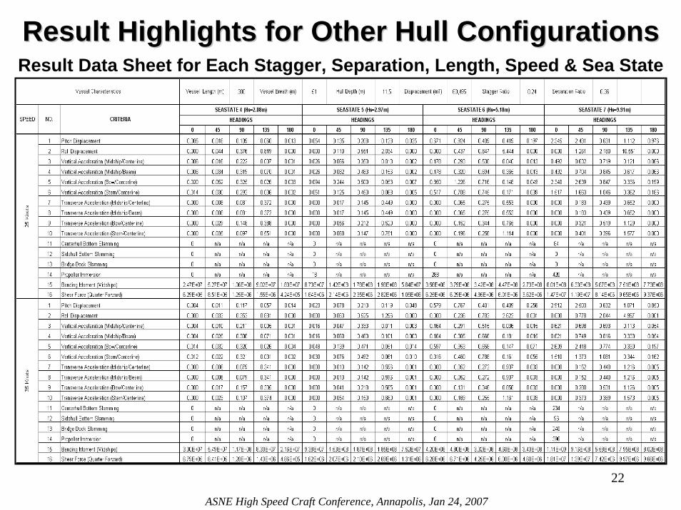
Result Highlights for Other Hull ConfigurationsResult Highlights for Other Hull ConfigurationsResult Data Sheet for Each Stagger, Separation, Length, Speed & Sea State
22
ASNE High Speed Craft Conference, Annapolis, Jan 24, 2007
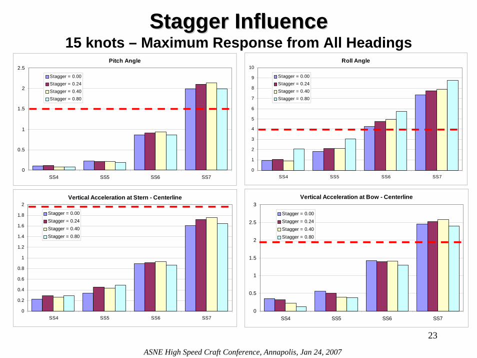
Stagger InfluenceStagger Influence15 knots – Maximum Response from All Headings
Pitch Angle
0
0.5
1
1.5
2
2.5
SS4 SS5 SS6 SS7
Stagger = 0.00Stagger = 0.24Stagger = 0.40Stagger = 0.80
Roll Angle
0
1
2
3
4
5
6
7
8
9
10
SS4 SS5 SS6 SS7
Stagger = 0.00Stagger = 0.24Stagger = 0.40Stagger = 0.80
Vertical Acceleration at Bow - Centerline
0
0.5
1
1.5
2
2.5
3
SS4 SS5 SS6 SS7
Stagger = 0.00Stagger = 0.24Stagger = 0.40Stagger = 0.80
Vertical Acceleration at Stern - Centerline
0
0.2
0.4
0.6
0.8
1
1.2
1.4
1.6
1.8
2
SS4 SS5 SS6 SS7
Stagger = 0.00Stagger = 0.24Stagger = 0.40Stagger = 0.80
23
ASNE High Speed Craft Conference, Annapolis, Jan 24, 2007
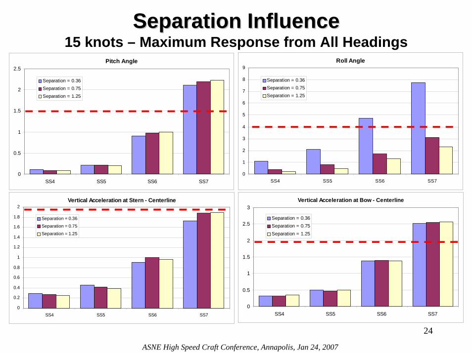
Pitch Angle
0
0.5
1
1.5
2
2.5
SS4 SS5 SS6 SS7
Separation = 0.36Separation = 0.75Separation = 1.25
Roll Angle
0
1
2
3
4
5
6
7
8
9
SS4 SS5 SS6 SS7
Separation = 0.36Separation = 0.75Separation = 1.25
Vertical Acceleration at Bow - Centerline
0
0.5
1
1.5
2
2.5
3
SS4 SS5 SS6 SS7
Separation = 0.36Separation = 0.75Separation = 1.25
Vertical Acceleration at Stern - Centerline
0
0.2
0.4
0.6
0.8
1
1.2
1.4
1.6
1.8
2
SS4 SS5 SS6 SS7
Separation = 0.36
Separation = 0.75
Separation = 1.25
Separation InfluenceSeparation Influence15 knots – Maximum Response from All Headings
24
ASNE High Speed Craft Conference, Annapolis, Jan 24, 2007

Wave Train Interaction Wave Train Interaction vs. Trimaran Configurationvs. Trimaran ConfigurationEffect of Separation along the Center Hull Effect of Stagger along the Center Hull
25
ASNE High Speed Craft Conference, Annapolis, Jan 24, 2007
The wave train interaction between the hulls increases the amplitude of the standing wave along the length of the center hull for certain hull configurations. This amplification of center hull waves leads to additional bending moment in the hull girder loads and a wave trough in way of the props, which can induce excessive amounts of propeller emergences.
Wave Train Interaction can have large impact on trimarans performance
Phenomenon can guide the choice
of trimaran hull configuration
More studies are needed to fully
comprehend the impact on design
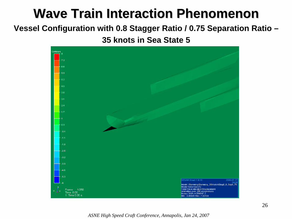
Wave Train Interaction PhenomenonWave Train Interaction PhenomenonVessel Configuration with 0.8 Stagger Ratio / 0.75 Separation Ratio –
35 knots in Sea State 5
26
ASNE High Speed Craft Conference, Annapolis, Jan 24, 2007
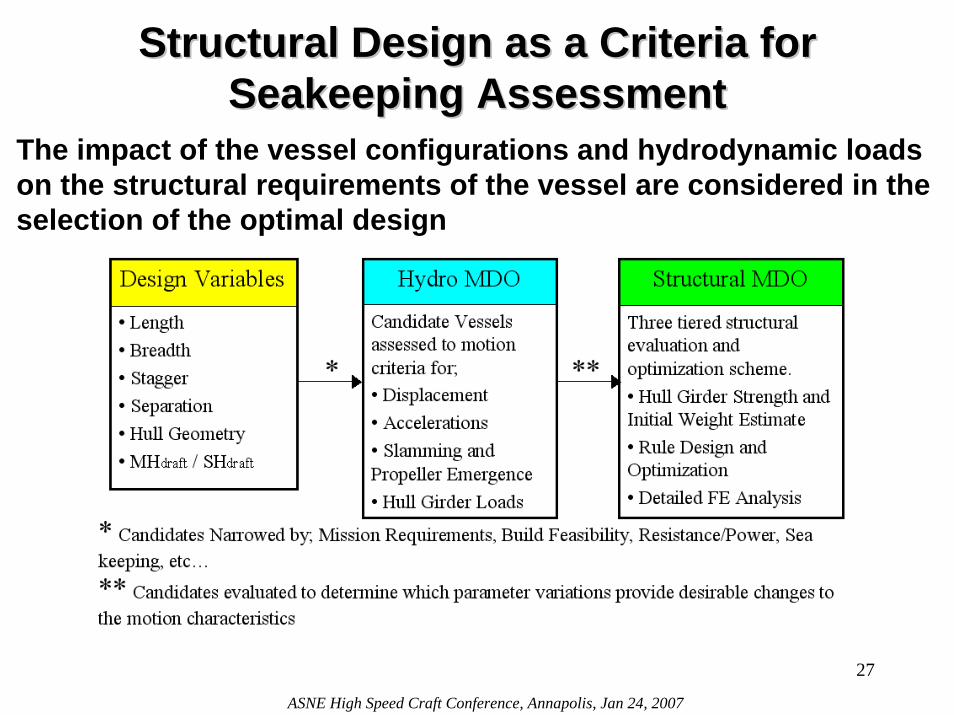
Structural Design as a Criteria for Structural Design as a Criteria for Seakeeping AssessmentSeakeeping Assessment
The impact of the vessel configurations and hydrodynamic loads on the structural requirements of the vessel are considered in the selection of the optimal design
27
ASNE High Speed Craft Conference, Annapolis, Jan 24, 2007
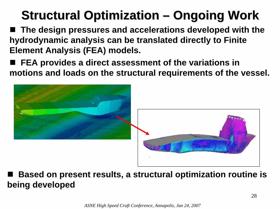
Structural Optimization Structural Optimization –– Ongoing Work Ongoing Work The design pressures and accelerations developed with the
hydrodynamic analysis can be translated directly to Finite Element Analysis (FEA) models.
FEA provides a direct assessment of the variations in motions and loads on the structural requirements of the vessel.
Based on present results, a structural optimization routine isbeing developed
28
ASNE High Speed Craft Conference, Annapolis, Jan 24, 2007
ConclusionsConclusionsSystematic Seakeeping Database Established for Trimarans
Valuable for synthesis level of design
Useful as concept evaluation tools
Will be expanded with future work to include structural optimization
WASIM / SAGA is a reliable and expandable design tool
Strong Wave Train Interaction Phenomenon Identified
Early detection allows problem to be addressed at the hull form development stage
HALSS Provides Favorable Seakeeping Performance
Side hull propeller emergence – limiting factor
29
ASNE High Speed Craft Conference, Annapolis, Jan 24, 2007


![Practical Hydrodynamic Optimization of a Trimaran ship/Yang... · Practical Hydrodynamic Optimization of a Trimaran ... quations and thr e e line ar p otential ... sin()] cos(b ):](https://img.pdfslide.us/doc/110x75/5b9d2c7909d3f2a4348b530c/practical-hydrodynamic-optimization-of-a-shipyang-practical-hydrodynamic.jpg)