Embed Size (px)
Citation preview

P.J. Wilson - 10 Nov 20021Triggering in Particle Physics: System Design
Triggering in Particle Physics Experiments
IEEE Nuclear Science Sypmosium10 November 2002
Levan Babukhadia – SUNY StoneybrookSidhara Dasu – U. WisconsinGiovanni Punzi – INFN PisaPeter J. Wilson - Fermilab
P.J. Wilson - 10 Nov 20022Triggering in Particle Physics: System Design
Course Introduction
Schedule
8:30 Trigger System Design 10:15 Break10:45 Calorimeter and Muon based
Triggers 12:15 Lunch1:30 Track Trigger Processors3:00 Break3:30 Detached Vertex Triggers
Who We Are
Levan Bubakhadia (SUNY Stoneybrook) Ø D0 Fiber Tracker and
Preshower readout and TriggerSridhara Dasu (Univ of Wisconsin)Ø CMS Level 1 Calorimeter
TriggerGiovanni Punzi (INFN – Pisa)
Ø CDF Silicon Vertex TriggerPeter Wilson (Fermilab)Ø CDF L1 and L2 Trigger
SystemsBias: hadron collider physics

P.J. Wilson - 10 Nov 20023Triggering in Particle Physics: System Design
Creditsn Material for this talk has come from many sources including:Ø Sridhara Dasu (CMS)Ø Wesley Smith (Zeus, CMS)Ø Gordon Watts (D0, general)Ø Levan Babukhadia (D0)Ø Erik Gottshalk (BTeV)Ø David Nitz (Auger)Ø Ted Liu (Babar)Ø LHC Electronics Workshop pages: http://lhc-electronics-workshop.web.cern.ch/LHC-electronics-workshop/

P.J. Wilson - 10 Nov 20024Triggering in Particle Physics: System Design
Why do you need a trigger?n Select the interesting events of interest for further analysis.n Rate of data accumulated in the experiment is too high to
practically record directly to mass median Effort of storing and filtering the large volume of data is
time consuming and expensiven Need to make time stamp on readout or gate eventn Example: CDF and D0 for Run 2 at the TevatronØ Beam crossing rate = 7.6MHz (currently 1.7MHz)Ø About 750K channels at ~4 Bytes each = 3 MbytesØ Rate ~ 20 TeraBytes/SecØ Use zero suppression of unoccupied channels Ô 250kB/eventØ Still rate ~ 2 TeraByte/secØ After the trigger, CDF or D0 Rate to tape ~ 20MB/sec!Ø Trigger rejects 99.999% of crossings! (at 1.7MHz only
99.997%)

P.J. Wilson - 10 Nov 20025Triggering in Particle Physics: System Design
Early Accelerator Expts: Bubble Chambers
n Bubble Chambers, Cloud Chambers, etc. (4π)Ø DAQ was a stereo photograph!Ø Effectively no Trigger:
• Each expansion was photographed based on accelerator cycle
• High level trigger was human (scanners).Ø Slow repetition rate.
• Only most common processes were observed.Ø Some of the high repetition experiments (>40
Hz) had some attempt at triggering.
n Emulsions still used in some ν experiments (eg CHORUS, DONUT).Ø Events selected with electronically readout
detectors ⇒ scanning of emulsion seeded by external tracks

P.J. Wilson - 10 Nov 20026Triggering in Particle Physics: System Design
Early Fixed Target Triggers1964 Cronin & Fitch CP Violation
Experiment:Ø K2
0 mesons produced from 30 BeV protons bombarding Be target
Ø Two arm spectrometer with Spark Chambers, Cernkov counters and Trigger scintillators
Ø Spark chambers require fast (~20ns) HV pulse to develop spark, followed by triggering camera to photograph tracks
Ø Trigger on coincidence of Scintillators and Water Cerenkov counters
Ø Only one trigger levelØ Deadtime incurred while film
advances
Christenson, Cronin, Fitch and Turlay PRL 13, 138 (1964)
Detector Layout of K20→ππ
Experiment of Cronin and Fitch (1964)

P.J. Wilson - 10 Nov 20027Triggering in Particle Physics: System Design
System Design Constraints

P.J. Wilson - 10 Nov 20028Triggering in Particle Physics: System Design
Experimental ConstraintsDifferent experiments have very different trigger requirements due
to operating environmentsØ Timing structure of beamØ Rate of producing physics signals of interestØ Rate of producing backgrounds
n Cosmic Ray Expts – no periodic timing structure, background/calibration source for many other experiments.
n Fixed Target Expts – close spacing between bunches in train which comes at low rep rate (~Hz)Ø Backgrounds from un-desirable spray from targetØ Cosmics are particularly a background for neutrino beams
n e+e- collider – very close bunch spacing (few nsec), beam gas and beam wall collisions
n ep collider – short bunch spacing (96ns), beam gas backgroundsn pp/ppbar collider – modest bunch spacing (25-400ns), low produced
soft QCD

P.J. Wilson - 10 Nov 20029Triggering in Particle Physics: System Design
Cross-sections and Luminosityn Standard method of characterizing rates is:
Rate = σ Lσ - cross-section (units of cm2 or barn=1024cm2), probability that an
interaction will occur. If this were a game of darts, the larger the area of the dart board the more likely you will get the darton the board.
L - luminosity (units of cm-2s-1 or barn-1 sec-1), cross sectional density of the beams. The more particles per beam or the more compact (transverse) the higher the luminosity. For colliding beam, goes as the product of the two beam currents.
Convenient conversion: L = 1030cm-2s-1 = 1µb-1s-1

P.J. Wilson - 10 Nov 200210Triggering in Particle Physics: System Design
Cross Sections for e+e-n At Ecm=10.6 GeV B-Factories
(from CLEO III)
Total rates of few hundred Hz at current luminosities
n At Ecm = 90 GeV (LEP, SLC on Z-boson)Ø 30nb to hadronsØ 2nb to τ+τ− or µ+µ−Total rates of 5-10 Hz at LEP and
LEPII
To
tal
Cro
ss S
ecti
on
(pb
)
Center of Mass Energy (GeV)
σ(Tot) (nb)
σ(Barrel) (nb)
σ(Endcap) (nb)
e+e− → e+e− 72 19 53
e+e− → γγ 6.2 3.7 2.5
e+e− → µ+µ− 0.72 0.60 0.12
e+e− → τ+τ− 0.72 0.60 0.12
e+e− → hadrons 4 Total 84

P.J. Wilson - 10 Nov 200211Triggering in Particle Physics: System Design
Cross Sections for pp/ppn pp Cross Section at 1960 GeV
(Tevatron)Ø About 50mb Ø Dominated by inelastic
scatteringØ At Run 2 luminosities:
interaction rate is 2-20MHzn pp Cross Section at 14TeV
(LHC)Ø About 70mbØ Dominated by inelastic
scatteringØ At LHC design luminosity:
interaction rate close to 1GHz
Cro
ss S
ecti
on
(m
b)

P.J. Wilson - 10 Nov 200212Triggering in Particle Physics: System Design
Multiple Interactionsn For hadron colliders (and some
fixed target expts) the interaction rate exceeds the machine bunch spacing causing multiple interactions per crossing:µ = <Inter/X-ing>
= σ ∗ L / Crossing Raten The number of interactions for
each crossing is poissondistributed about the mean µ

P.J. Wilson - 10 Nov 200213Triggering in Particle Physics: System Design
Colliding Beam Machines
PDG 2002: K. Hagiwara et al., Phys. Rev. D 66, 010001 (2002) or http://pdg.lbl.gov and experiment web sites
Accelerator TypeEnergy (GeV)
Bunch Spacing
Luminosity
(µb-1s-1)Int. per Crossing
CESR (CLEO) e+e- 10.6 (3-4) 14 1280 ~10-5
KEKB (Belle) e+e- 10.6(3.5x8) 8 (2) 8256 ~10-5
PEP-II (Babar) e+e- 10.6(3.1x9) 4.2 4600 ~10-5
LEP (Aleph, Opal, Delphi, L3) e+e- 90-210 22,000 24-100 ~10-3
HERA (H1, Zeus) ep 27x920 96 75 <<1Tevatron (CDF, D0, BTeV) pp 1960 396(132) 36(200-500) 1(3-10)LHC (Atlas, CMS, LHCb, Alice) pp 14,000 25 10,000 25
For e+e- and ep machines, cross sections are small and multiple interactions are negligible at all current machinesn For e+e- even pileup in slow detectors (~1µs) not a large problemn At HERA beam-gas background (50-100kHz) can be problemFor hadron colliders: multiple interactions are a major issue for detector design, particularly tracking chambers, DAQ and Trigger

P.J. Wilson - 10 Nov 200214Triggering in Particle Physics: System Design
Particle Spectrum in ppl Cross sections for particle
production vary by a factor of ~ 1010 (diffraction to Higgs)
l Spectrum is similar for Higher Energy machine (eg LHC) except higher mass particles are more accessible
l Triggering challenge is to reject low PT/Mass objects while keeping high PT/mass
l Of course CDF, D0 and particularly BTeV and LHCbwant to keep a large fraction of b events as well so need to se

P.J. Wilson - 10 Nov 200215Triggering in Particle Physics: System Design
Efficiency and Dead-timeGoal of Trigger and DAQ is to maximize data for desired process to storage
for analysis with minimal cost
n Relevant efficiency is for events that will be useful for later analyis:
n Low rate process (eg e+e- Ô hadrons, Higgs production at Tevatron or LHC),try to accept all in trigger ï Maximize efficiency
n Deadtime incurred do to fluctuations when rate into a stage of trigger (or readout) approaches the rate it can handle. Simple case of no buffering:
n Buffering incoming data reduces dead time, more buffering less dead time Ø If <Incoming Rate> > 1/<Execution Time>, dead no matter what!
n Minimizing dead-time helps all processesØ 1% of machine time * 1 year = $$$$$
ε = εoperations * εtrigger * (1-deadtime)
εtrigger = Ngood(accepted)/Ngood(Produced)
Dead-time = (Rate In) ∗ (Execution Time)

P.J. Wilson - 10 Nov 200216Triggering in Particle Physics: System Design
Efficiency and Dead Time (2)n Need to ensure full efficiency when detector channels are
broken, masking registers are used at the input from front-endsØ For tracking mask on dead channelsØ For calorimeter mask off hot channels
n Need precise measurements of εtrigger and dead-time for cross-section (hence production limit) measurementsØ Other cases (eg particle lifetime) need to evaluate other biases
that trigger may introduce (eg removing long lived decays) n Measure dead time by scaling rates of operational states of
Trigger/DAQ system n Need Mechanisms to evaluate the efficiency and biasesØ Redundant, independent pathsØ Lower bias triggers with accepted with a pre-scaleØ Zero bias - trigger on accelerator clock structureØ Minimum bias – trigger on very low energy scattering
P.J. Wilson - 10 Nov 200217Triggering in Particle Physics: System Design
Signatures in Detectors
P.J. Wilson - 10 Nov 200218Triggering in Particle Physics: System Design
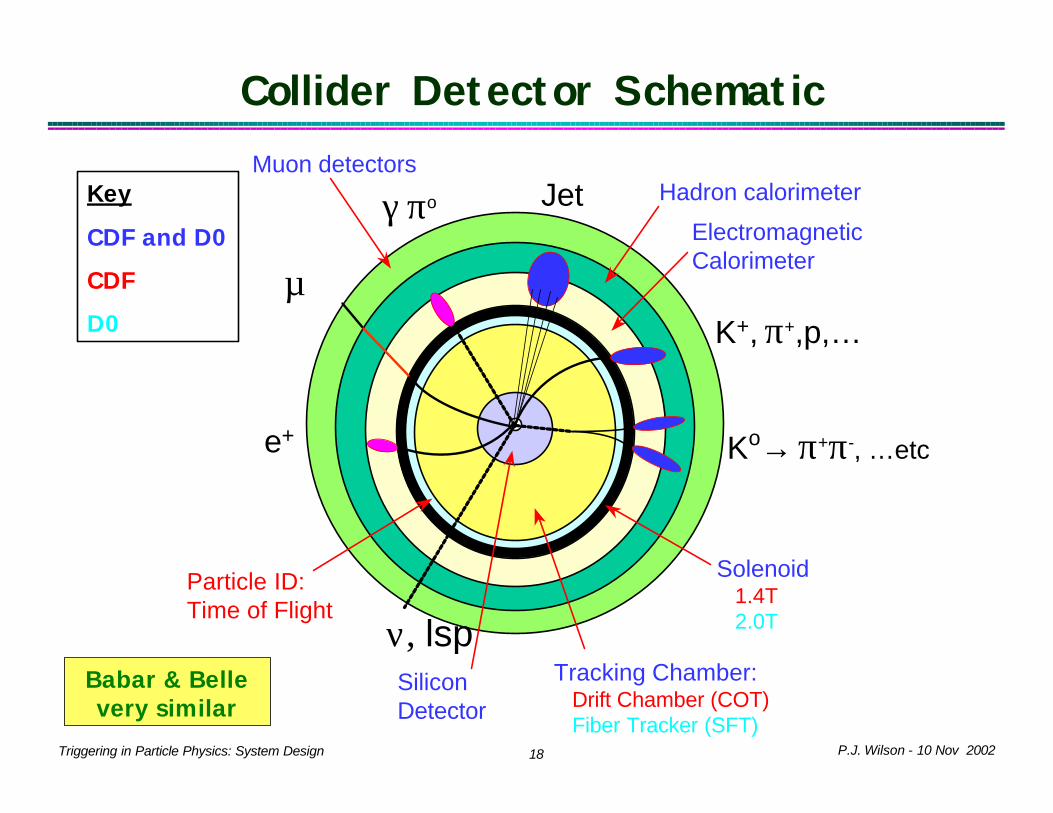
ccc
µ+
e+
γ πo
K+, π+,p,…
ν, lsp
Muon detectorsHadron calorimeter
Electromagnetic Calorimeter
Solenoid1.4T2.0T
Tracking Chamber:Drift Chamber (COT)Fiber Tracker (SFT)
SiliconDetector
Ko→ π+π-, …etc
Collider Detector Schematic
Particle ID:Time of Flight
Key
CDF and D0
CDF
D0
Jet
Babar & Belle very similar

P.J. Wilson - 10 Nov 200219Triggering in Particle Physics: System Design
Recent Collider Detectors
L1: 7 MHzL2: 10-50 kHzL3: .3-1 kHzTape: 50 Hz
L1: 45 kHzTape: 15 Hz
L1: 10 MHzL2: 50 kHzL3: 500 HzL4: 50 HzTape: 2 Hz
L1: 10 MHzL2: 1 kHzL3: 100 HzTape: 2-4 Hz
L1: 25 MHzL3: 2 kHzTape: 100 Hz
L1: 50 MHzL2: 500 HzTape: 100 Hz
L1: 72 MHzL2: 1 kHzTape: <100 Hz
Input Trigger Rate
Beam-wire scatteringInelastics
Yes (L2)600KHERA-B
Beam-gasNo500KH1, ZEUS
QCD, pileup (multiple interactions)
Yes (L2)750K-1MCDF (Run 2),DØ (Run 2)
Beam-gasNo250-500kAleph, Opal, L3, Delphi
Electron Pairs & γγBeam-Wall
No150KBaBar
Largest (Non) Physics Background
Silicon Partof Trigger?
Number ofChannels
Detector
Electron pairs & γγBeam-wall
Not Yet150KBelle
Electron pairs & γγNo400KCLEO III
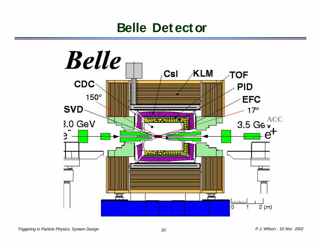
P.J. Wilson - 10 Nov 200220Triggering in Particle Physics: System Design
Belle Detector
ACC

P.J. Wilson - 10 Nov 200221Triggering in Particle Physics: System Design
Tracker (Si, Fiber, Solenoid 2T)
p p-bar
20 m
Electronics
Calorimeters
Muon System
DDNewOldPartially
New
Front End ElectronicsTriggers / DAQ (pipeline)Online & Offline Software
PreShowerScint. Fiber Central and
Forward
Trigger Scint and Forward drift tubes
D0 Run 2 Detector
P.J. Wilson - 10 Nov 200222Triggering in Particle Physics: System Design
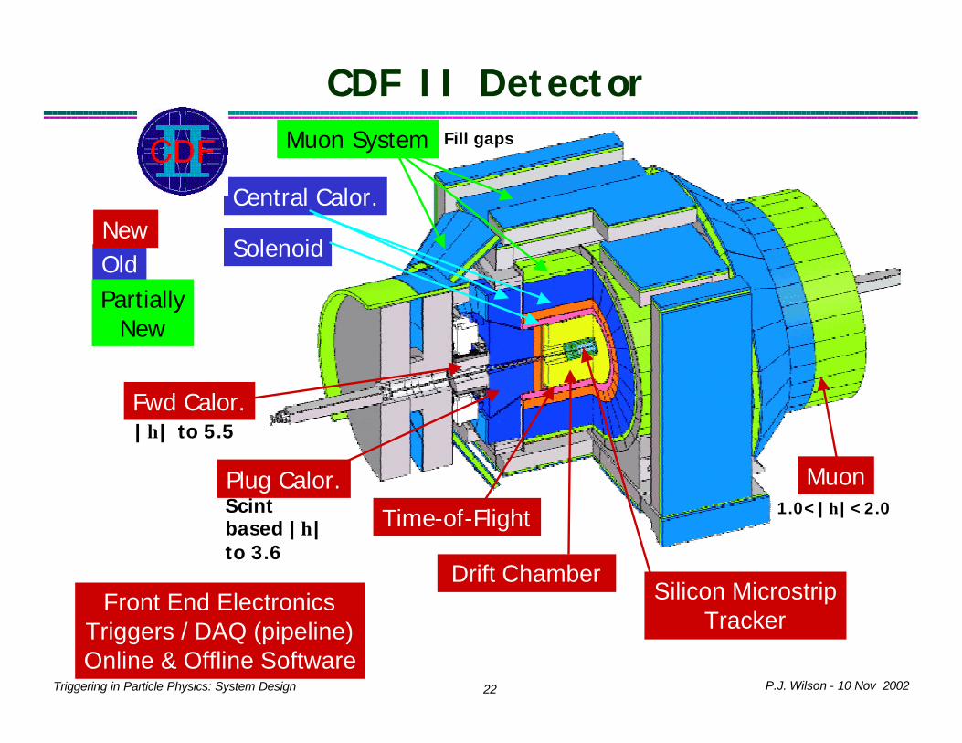
Front End ElectronicsTriggers / DAQ (pipeline)Online & Offline Software
Silicon Microstrip Tracker
Time-of-Flight
Drift Chamber
Plug Calor. Muon
OldNew
PartiallyNew
Muon System
Solenoid
Central Calor.
Fwd Calor.|η| to 5.5
Scint based |η| to 3.6
1.0<|η|<2.0
Fill gaps
CDF II Detector

P.J. Wilson - 10 Nov 200223Triggering in Particle Physics: System Design
Requirements for e+e- TriggeringAccept: (almost) all real
collisionsReject:Ø very low angle e+e-Ø Beam-gas/wall events - tracks
not from beam spot in r or zTrigger on simple event topologyØ Time-Of-Flight coincidenceØ Multiplicity of good tracks (from
beam spot) – low pt cuts (100s of MeV/c)
Ø Calorimeter activity: global energy and clustered energy in relative coarse spatial bins
Ø Simple combinationsTime stampingØ Beam Xing << detector response
times (few nsec vs 100-1000ns)
Very Clean Events

P.J. Wilson - 10 Nov 200224Triggering in Particle Physics: System Design
e+e+ vs pp Environment
Aleph ZÔµ+µ− Event Only 2 Tracks
Hits in Muon systems
CDF ZÔµ+µ− Event Many Tracks over 500MeV/c
(_)

P.J. Wilson - 10 Nov 200225Triggering in Particle Physics: System Design
Signatures for pp Triggering
Accept specific decays modesØ High PT leptons from W, Z, top,
W/Z+Higgs QCD: High Et jetsØ ψ Ô µµ, medium pt leptons for B
physics
Reject:Ø Lower PT objects (QCD)
Select on object/event kinematics:Ø ET of in Calor Tower (cluster),
missing ET
Ø µ PT (+ track PT)Ø Track PT (+ impact
parameter/detached vertex)
DD
(_)

P.J. Wilson - 10 Nov 200226Triggering in Particle Physics: System Design
Multilevel Trigger Systems
P.J. Wilson - 10 Nov 200227Triggering in Particle Physics: System Design
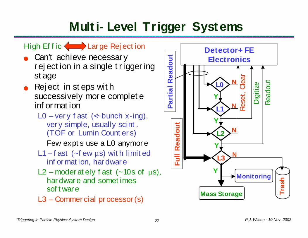
Multi-Level Trigger SystemsHigh Effic Large Rejectionn Can’t achieve necessary
rejection in a single triggering stage
n Reject in steps with successively more complete informationL0 – very fast (<~bunch x-ing),
very simple, usually scint. (TOF or Lumin Counters)Few expts use a L0 anymore
L1 – fast (~few µs) with limited information, hardware
L2 – moderately fast (~10s of µs), hardware and sometimes software
L3 – Commercial processor(s)
Detector+FE Electronics
Y
L0
L3
L2
L1
Y
YN
N
N
N
Y
Res
et, Cle
ar
Dig
itize
Rea
dout
Mass Storage
Monitoring
Tra
sh
Full
Rea
do
ut
Par
tial
Rea
do
ut

P.J. Wilson - 10 Nov 200228Triggering in Particle Physics: System Design
Example: D0 Run 1 (1991-95)L0 Trigger (285kHz in, 150kHz
out)Ø Beam hodoscopes
L1 Trigger (200Hz out)Ø Single Cal trigger towers
(4 thresh)Ø Global ET and missing ET (EM,
HAD)Ø Muon chamber tracks Ø No deadtime, exec. time <1 µs
L1.5(2) Trigger (100Hz out)Ø Higher resolution muon chamber
tracksØ TRD confirmation for electronsØ Execution time: up to 100µs
L2(3) Trigger (2Hz out)Ø Farm of Vaxes running offline
type code
S. Abachi et al NIM A338 (1994) 185.
D0 Trigger and DAQ System

P.J. Wilson - 10 Nov 200229Triggering in Particle Physics: System Design
Example: CDF Run 1 (1988-95)Every 3.5ms (bunch spacing):
Ø Calorimeter Sample and Hold get resetØ Muon and CTC TDC get stop
L1 Trigger (285kHz in, 1.5kHz out)Ø Trigger decision on fast output of Beam-
Beam, Calorimeter, and MuonØ Execution <3.5µs ï no dead-timeL1 Accept ï stop gating detectorL1 Reject ï continue gating detector
L2 Trigger (up to 50Hz out)Ø Add CTC tracks and match to muon and
Calorimeter clustersØ Execution 30-50µs ï dead-time <10%L1 Accept ï digitize and readoutL1 Reject ï resume gating detector
L3 Trigger (up to 5-8Hz out)Ø Event size 300kB in, 100kB outØ Farm of SGIs running offline type code Ø Readout ~3ms, Readout deadtime <10%
D Amidei et al NIM A269 (1988) 51.

P.J. Wilson - 10 Nov 200230Triggering in Particle Physics: System Design
CDF/D0 Run 1 ImplementationsCDFn Fastbus: ~20 designs, ~20 crates
in counting roomsn Calorimeter Trigger
Ø 0.2x0.2 Tower η−φ – analog sum and sin θ weight
Ø Sample and hold (>50µs), DACs and comparators for thresholds (2)
Ø ΣET and Missing ET: analog Σ, FADC, digital Σ
Ø ∼3µs L1 executionØ L2 analog/digital clustering
(contiguous towers)n Muon Trigger
Ø Time difference in pairs of layers (two Pt thresholds)
Ø Scintillator and Hadron Cal confirmation
n Global L1 Decision (in RAM)Ø 12 Inputs, 16 outputsØ Counts of muon stubs by region,
Cal tower, no φ info
D0n VME (9U): crates in moving and
fixed counting housesn Calorimeter Trigger:
Ø 0.2x0.2 Tower η−φ –analog sum and sin θ weight
Ø FADC on sum, digital threshold (4)Ø ΣET and Missing ET: RAM and
digital sum (z-vertex correct)Ø Pipelined <1µs execution
n Muon TriggerØ 3 layer patterns of hitsØ Apply Pt threshold for L2
n Global L1 Decision (and-or network)Ø Up to 256 inputs, 32 outputsØ Counts of towers, muons above
threshold by region Ø If L2 confirmation required wait
for L2

P.J. Wilson - 10 Nov 200231Triggering in Particle Physics: System Design
CDF/D0 Run 1 ImplementationCDF L2n Drift Chamber Tracks
Ø Digital pipeline finds tracks serially scanning 360o in φ
Ø Eight PT bins from Ø Track PT, φ0 feed Cal and Muon
matching hardware (15o, 5o match respectively)
Ø Fast CMOS rams and AS TTL logicn Other: Fine grain shower max info
for electrons and Calorimeter Isolation trigger using analog NN chip
n Programmable processors (custom Fastbus) apply final event cuts:Ø 1A: Motorola bit sliceØ 1B: DEC Alpha
n Up to 64 different L2 triggers possible
n Other than track processor almost completely based on ECL logic
D0 L2n No drift chamber tracking (no
solenoid)n 16 muon bits from finer
matchingn L2 Triggers pre-requisite on L1
triggersn Uses same global decision (L1
Framework) logic as L1

P.J. Wilson - 10 Nov 200232Triggering in Particle Physics: System Design
Example: CLEO II Trigger (ca 1989)TOF (Cal) trigger (L0,L1,L2): Ø discriminators on each bar
(Σ 16 X-tals) and OR’d into 30(32) sectors
Ø >1 sector, 2 opposite, non-adjacent
BLT, TSP triggers (L1,L2):Ø Count low PT tracks
(threshold algorithm) and determine charge (BLT)
C. Bebek et al NIM A302 (1991) 261
CLEO Trigger System
Stage Devices Used OutputExecution
TimeDead Time
L0 Cal, TOF, VD 20kHz <360ns 0L1 Cal, DR, TOF, VD 20Hz 2.56ms 5%L2 Cal, DR, VD 5Hz 50ms 0.10%
ReadOut N.A. 5Hz 12ms 1.20%
Continuously gating sample and holds
PD trigger (L2):Ø Vertex chamber
path consistent with coming from beam spot
Hadron TriggerL0 TOF non-adjacentL1 Three tracks L2 Two PD tracks

P.J. Wilson - 10 Nov 200233Triggering in Particle Physics: System Design
Pipelined Trigger Systems
P.J. Wilson - 10 Nov 200234Triggering in Particle Physics: System Design
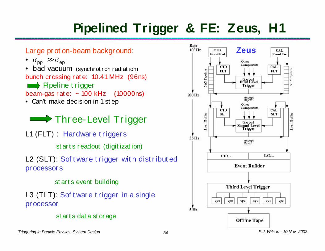
Large proton-beam background:• σpp >> σep• bad vacuum (synchrotron radiation)bunch crossing rate: 10.41 MHz (96ns)
Pipeline triggerbeam-gas rate: ~ 100 kHz (10000ns)• Can’t make decision in 1 step
Three-Level TriggerL1 (FLT) : Hardware triggers
starts readout (digitization)
L2 (SLT): Software trigger with distributed processors
starts event building
L3 (TLT): Software trigger in a single processor
starts data storage
Pipelined Trigger & FE: Zeus, H1Zeus

P.J. Wilson - 10 Nov 200235Triggering in Particle Physics: System Design
Pipelined Trigger Operation: Zeus
Detector
ReadoutElectronics
96ns
p
e
Component A
readout
Trigger
Component Z
GFLT
ZEUS FLT•Synchronous pipeline system•Deadtime-free trigger
HERA clock
96nS clock
0µS
4.6µS
4.6µS+prop.delay
TOF+Detector response
<2.6µSTiming

P.J. Wilson - 10 Nov 200236Triggering in Particle Physics: System Design
Rejecting Beam-Gas at Zeus and H1 Primary task is rejecting
Beam-Gas background:n Timing of TOF hits (H1)
rejects out of time eventsn Track processors reject
events with large impact parameter in r-φ and r-z planes to remove beam-wall and beam-gas backgrounds
n Example: Look for patterns in r/z across layers:Ø Good tracks constant r/zØ Tracks not from
interaction region will have wrong pattern
Zeus Track Z0 Finding
GP Heath etal, NIMA 315(1992) 431.
Also can be effective for beam backgrounds at e+e- machines
(OPAL, M. Arignon etal NIM A313 (1992) 103.)
P.J. Wilson - 10 Nov 200237Triggering in Particle Physics: System Design
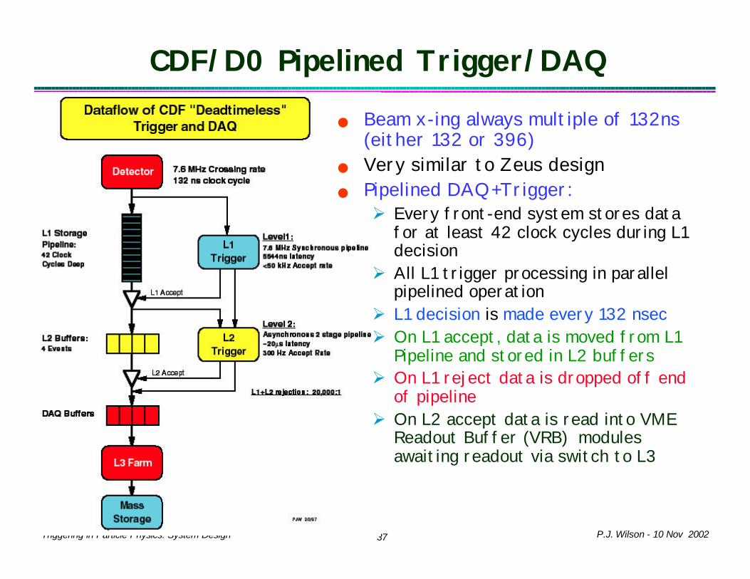
n Beam x-ing always multiple of 132ns (either 132 or 396)
n Very similar to Zeus designn Pipelined DAQ+Trigger:Ø Every front-end system stores data
for at least 42 clock cycles during L1 decision
Ø All L1 trigger processing in parallel pipelined operation
Ø L1 decision is made every 132 nsecØ On L1 accept, data is moved from L1
Pipeline and stored in L2 buffersØ On L1 reject data is dropped off end
of pipelineØ On L2 accept data is read into VME
Readout Buffer (VRB) modules awaiting readout via switch to L3
CDF/D0 Pipelined Trigger/DAQ

P.J. Wilson - 10 Nov 200238Triggering in Particle Physics: System Design
Getting Pipelines in Synch
12345678910111213141516
Data for BX #
L1Cal BX 1L1Cal BX 2L1Cal BX 3L1CAl BX 4L1Cal BX 5L1Cal BX 6L1Cal BX 7
L1 Cal Out
L1Muon BX 1L1Muon BX 2L1muon BX 3L1Muon BX 4L1Muon BX 5L1Muon BX 6L1Muon BX 7L1Muon BX 8L1Muon BX 9
L1 Muon Out
Dec. for BX 1Dec. for BX 2Dec. for BX 3Dec. for BX 4
Trigger Output
Delay L1 Muon by 2 clocks to align with L1 Cal before combining Cable and Processing
Delays
Need to design in time alignment wherever comes together

P.J. Wilson - 10 Nov 200239Triggering in Particle Physics: System Design
Keeping Pipelines in Synch: Bx Countersn Critical for pipeline system design to provide method(s)
of determining if pipelines are staying in Synchn Common method: bunch x-ing counters in each component
or passed which reset once per accel turnØ Count fundamental clock even for unfilled bucketsØ CDF and D0: count 7.6MHz (132ns) clocks (0-158), actual number
of beam x-ing per accelerator turn is 36 (104) for 396ns (132ns) accelerator operation (its actually a clock counter).
Ø Distribute to each component: fundamental clock and beginning of turn marker, called bunch 0 (b0) at Tevatron

P.J. Wilson - 10 Nov 200240Triggering in Particle Physics: System Design
Staying in Synch: Bunch X-ing Checks
n CDF: bunch counter readout from each board into event data Ø Compare between boards in VME readout controller (PowerPC
SBC). Out of synch pull local error line. Ø Compare between crates at event building time. Out of synch
send error message Ø Can miss occasional short term synch problems Ø Most frequent problem: errors in bunch counter logic on board
n Zeus passes BX number along with data in L1 pipe to test synch at decision timeØ Some CDF components pass B0 mark: test every 21µs

P.J. Wilson - 10 Nov 200241Triggering in Particle Physics: System Design
Dead-time in Pipelined TriggerDead-time cannot be incurred by L1 Trigger. Always complete before data comes off end of pipeline. L1 Deadtime Broken System
L2 incurs Dead-time if all L2 buffers fill up before completing L2 decision.
L1A must be held off.
Read-out incurs Dead-time if VRB buffers fill up then L2 buffers
will fill and L1A must be held off.
L3 incurs deadtime if the switch has no node to send output to. Again
system backs up until L1A is stopped..
Dead-time is only incurred when all L2 buffers are full

P.J. Wilson - 10 Nov 200242Triggering in Particle Physics: System Design
CDF/D0 Si Readout effects Trigger Designn L1 pipelines implemented many
ways: capacitor array, RAM, shift register (eg in FPGA), discrete FIFO
n L2 buffering also implemented many ways: capacitor array, RAM, discrete buffer chips
n CDF and D0 Si strip detectors use a capacitor array for the L1 pipeline and digitize on L1AØ Capacitors are controlled as
circular buffer. Ø 128 Channels on digitized
sequentially Ø CDF uses SVX3 chip: has 4
additional capacitors and skip logic that permit additional L1As during readout
Ø D0 uses SVX2 chip: dead during digitization and readout (~10µs).
CDF Silicon
SVX3 Chip
L1 P
ipel
ine
42 C
apac
itors
L1A
Cap to Digitize
Digitize
L2 Buffer on VME Readout Buffer
4 Events 16 Events
D0 Silicon
SVX2 Chip

P.J. Wilson - 10 Nov 200243Triggering in Particle Physics: System Design
Impact of Si Readout on CDF Triggern All CDF frontends are designed with
4 L2 buffers like SVX3 chip. All others are digitized before L1 pipeØ Could not put additional capacitors
on SVX3 dieØ Hard to put more buffers on TDC
ASIC for drift chamber (JMC96 from U.Mich)
Ø Queuing simulations showed system could operate with low ~5% deadtime at L1A=45kHz if L2 execution kept <20µs in two stage pipeline
Ø Little benefit from pushing for more L2 buffering in VME Readout Board (VRB)
èDesign high rate L1 trigger (45kHz) (B→hadrons)
èDesign fast L2 processing (~20µs)
CDF Silicon
SVX3 Chip
L1 P
ipel
ine
42 C
apac
itors
L1A
Cap to Digitize
Digitize
L2 Buffer on VRB Board
4 Events 16 Events
D0 Silicon
SVX2 Chip

P.J. Wilson - 10 Nov 200244Triggering in Particle Physics: System Design
Impact of Si Readout on D0 Triggern Since D0 has SVX2 chip for Silicon
and Fiber tracker readout, detector is dead for ~10ms after L1Aè Limit L1A to ~5-10kHzèQueuing simulations show benefit
from more VRB bufferingèWith low L1 rate and more
buffering, can take more time for L2 processing ~100µs
èSee later how this impacts L2 design
CDF Silicon
SVX3 Chip
L1 P
ipel
ine
42 C
apac
itors
L1A
Cap to Digitize
Digitize
L2 Buffer on VRB Board
4 Events 16 Events
D0 Silicon
SVX2 Chip

P.J. Wilson - 10 Nov 200245Triggering in Particle Physics: System Design
Components of Modern Trigger Systems

P.J. Wilson - 10 Nov 200246Triggering in Particle Physics: System Design
CDF Trigger Subsystems
TOF
TOF
FWD
FWD
FE – 66 9U VME Crates
L1 – 15 9U VME Crates
L2 – 15 9U VME Crates
Trigger Supervisor 3 9U VME
Crates

P.J. Wilson - 10 Nov 200247Triggering in Particle Physics: System Design
D0 Trigger Block Diagram
L2FW:Combined objects (e, µ, j)
L1FW: towers, tracks, correlations
L1CAL
L2STT
Global L2L2CFT
L2PS
L2Cal
L1 CTT
L2 MuonL1 Muon
L1FPD
Detector L1 Trigger L2 Trigger7 MHz 5-10 kHz
CAL
FPS/CPS
CFT
SMT
Muon
FPD
1000 Hz

P.J. Wilson - 10 Nov 200248Triggering in Particle Physics: System Design
L1 Trigger Systems: Belle and Babar
Babar L1 Trigger
Similar approaches… similar performance
No L2 Triggers

P.J. Wilson - 10 Nov 200249Triggering in Particle Physics: System Design
L1 Trigger Strategyn Select objects: muon, electron (photon), jet, track
by applying threshold cuts in subsystem processors (custom hardware)Ø Tevatron – fine granularity and lots of ET/PT thresholds for different
physics (eg top vs B’s) Ø B-Factories , LEP – coarse granularity few thresholdsØ Hera – combination of above
n Track finding differenceØ Tevatron Ô Cut on PT, god resolution and many binsØ B-Factories, LEP and HERA Ô Number and φ correlation of tracks above
minimal PT, z information to reject beam background
n Two strategies for combining objects:Ø CDF (and D0 muon) Ô fine Track match in subsystems, pass global count
to decision logic. Complex subsystem logic, Simpler final decision logicØ B-Factories, LEP and HERA Ô Send counts in coarse geometric regions
to global and do correlations there. Simpler subsystem logic, more complicated final decision

P.J. Wilson - 10 Nov 200250Triggering in Particle Physics: System Design
Comparison of L1 Trigger Systems
CDF D0 Babar Belle ZeusL1 In (MHz) 7.6 7.6 <<238 <<125 10.4L1 Out (kHz) 45 10-May 2 2 1Latency (µs) 5.5 4.2 12 2.2 5Clock (MHz) 7.6 (30.4) 7.6 14.8/30.6/? 16/32/64 10.4
Tracking r-φ (48 PT Bins) r-φ (20 PT Bins) r-φ r-φ, r-z r-φ, r-z
Track δPT/PT2 1.5%, <1% w/Si 1-1.5% w/Si 3 Threshold 2 Threshold 2 Threshold
Muon µ stub&track µ stub&track Track, MIP Track, MIP MIP&ISOCalorimeter Seg. 0.2x0.2 (η−φ) 0.2x0.2 (η−φ) 18ο φ wedge 4x4 or 17 θ bins 896 TowerPhoton ET&HAD/EM ET& PreShow E E E&ISOElectron ET&HAD/EM&Track ET& PreShow&Track E, Track E, Track E&ISOJet Total ET ET (Tile) NA NA NA
Global Energy ΣET , Missing ET ΣET , Missing ET E EE, ΣET,
Missing ET
TOF MIP, HIP N/A N/A MIP Coinc N/AForward (Diff) Yes Yes N/A N/A N/A
Decision: Input bits 64 256 138 48 314Decision: Triggers 64 128 24 48 64
Decision LogicTwo stage: X-Point +
Ram Multistage: AND-ORTwo Stage: φ
corel RAM, RAM RAMMultilayer
RAM

P.J. Wilson - 10 Nov 200251Triggering in Particle Physics: System Design
L1 Framework/Global Decision Logic
Input (N)PrescaleM M
Scalers
L1-Accept
Bac
kpla
ne o
r Fro
nt P
anel
Inpu
t
1st
Sta
ge
Nth
Sta
ge
OR
Decision logic typically implemented in RAM very flexible in allowed combinations
Combinations limited by software to configure the RAM
Can be arranged in several stages to allow more flexible combination
Prescale counters used for monitoring trigger
Scalers are used to count both in puts and outputs
N Prog. Delays

P.J. Wilson - 10 Nov 200252Triggering in Particle Physics: System Design
CDF/D0 L2 Trigger StrategyTwo stage process:1. Reconstruct objects: muon, electron/photon,
jet, tracks in pre-processors and pass object kinematics to central processing Ø Some input information will be the same as used at
L1 (e.g. tracks from central tracker)Ø Remaining information will be newly formed (e.g.
Silicon tracks with impact parameter measurement)2. Assemble event in processor memory and run
event filters much like a L3 trigger except on a very limited scaleØ Processor is custom VME module based on DEC Alpha
chipØ Filters written C/C++ and run

P.J. Wilson - 10 Nov 200253Triggering in Particle Physics: System Design
CDF/D0 L2 Triggering
:
CDF Global Level 2 Crate
Magic Bus
AlphaProcessor
L2SVT
ClusterList
L2XCES
L2Muon
L2Tracking
FRED
TIMINGCONTROL
46 bits /track
35 bits /track
16 bits /wedge
49 bits /cluster
2770 bitsEast/West
D0
D0 CDFExecution (design) 100µs (10+10)µsSiTracker Hardware HardwareOther PreProcesors DSP+Alpha HardwareDecision Proc Alpha AlphaOS Linux Native
Same architecture and Processor but different
implementation

P.J. Wilson - 10 Nov 200254Triggering in Particle Physics: System Design
Level 2 Alpha Processor n Custom MagicBus – 128bit wide on
P3 for Trigger I/On Processor is based on DEC Alpha
PC164 board designn Three custom circuits
Ø PCI-VME InterfaceØ Magic Bus DMA inputØ PCI-Magic Bus Interface
n Very low PCB yieldØ Via’s failed after bed of nails
test due to incorrect manufacture
Ø Ok for CDF near term (need 1-4 + spares)
Ø Bad for D0 need >20Ø Many Parts obsolete
n Replace with new design as Run 2B upgrade:Ø D0 Beta – commercial PCI SBC
on custom adapter (PCI-VME and PCI-MagicBus). Prototyping complete.
Ø CDF L2 Pulsar – new generic L2 interface with S-link output to LINUX-PC. Prototype being testedL2 Alpha Processor

P.J. Wilson - 10 Nov 200255Triggering in Particle Physics: System Design
CDF L2 Trigger PerformanceCDF L2 designed as 2 stage
pipeline (10-15µs/stage)Ø L1 Bandwidth closely tied to
performance of this pipelineØ First stage loading limited by
Si Readout + SVT execution (currently 9µs+13µs=22µs)
Ø Algorithm time is much faster than first stage but has long tails
Ø Total Si Readout limited at 25µs (L00 readout). Need to keep this less than total of 2 stages.
Ø It doesn’t matter yet because: L1A rate currently limit set at 12kHz due to SVX chip wirebond failures
Loading
Algorithms

P.J. Wilson - 10 Nov 200256Triggering in Particle Physics: System Design
CDF/D0 DAQ and L3 Systemsn Mostly commercial hardware
(switch, links etc)n Custom VME Readout BufferØ G-Link or Taxi input available
n Custom interfaces to L1/L2 triggersØ CDF Trigger SupervisorØ D0 contained in Trigger
Frameworkn L3 runs off-line based
algorithms
D0 CDFVME FE Crates 300 110
VRB Crates 20 15Switch Gb Ethernet ATM
L3 -Linux 80 dual 250 dual

P.J. Wilson - 10 Nov 200257Triggering in Particle Physics: System Design
Trigger Managers/SupervisorsTrigger decision hardware determines if event
should be stored need to determine if it canbe (eg full buffers)
ï Trigger Supervisor (CDF)ï Part of Trigger Framework (D0) n Distribute commands to and receive
acknowledges from front-end and trigger cratesØ L1 and L2 Accept/RejectØ L2 Buffer assignments (CDF)Ø Start scan (readout)Ø Event ID (L2 only at CDF)Ø Read list number (up to 8 different ones)Ø Done Ø BusyØ Error
n Manage L2 buffer assignment (CDF)Ø Different L1 Pipeline and L2 buffers
implementations, one control interface n Manage and measure live/dead timen Count Triggers in Scalers
Trigger
Supervisor
Trigger
Serial
Crosspoints
Return
Crosspoints
Scalers
. . . . . . . .to front-end from front-end
CDF Trigger System Interface
8
P.J. Wilson - 10 Nov 200258Triggering in Particle Physics: System Design
System Features for Debuggingn Multi-partitioningØ Parallel independent DAQ systems (8 at CDF)Ø At CDF only one partition with real triggerØ At D0 can have specific triggers for Geographic sections
n Internally generated triggersØ Bunch 0 (CDF)Ø Arbitrary bunch 0-158 (D0)
n CDF “Myron” Mode (after Myron Campbell)Ø Use L2 buffers on all systems as shallow (4 deep) logic analyzer
with up to 750K input channels Ø One L1A from Trigger results in L1A from TS for 4 successive
clock cycles (system dead from L1A to completion of readout)Ø Two start points: triggered clock or previous clock (“Early Myron
Mode”)Ø Only makes sense with L2 in auto-accept modeØ Very useful for timing detector elements with each other both
horizontally and vertically in decision chain

P.J. Wilson - 10 Nov 200259Triggering in Particle Physics: System Design
CDF Pipeline as Big Logic Analyzer
FE Pipelines201918171615141312111098765
BX 9 L1RBX 8 L1RBX7 L1RBX6 L1A
L1 Trigger Output
BX9 L1RBX8 L1ABX7 L1ABX6 L1ABX5 L1A
TS Output
BX4 L1R BX5 L1R 4
TS Early Myron Mode
5 6 7 8L2 Buffers

P.J. Wilson - 10 Nov 200260Triggering in Particle Physics: System Design
Supporting Softwaren Triggers configured from a list of requirements (“Table”,
“List”…). Determine thresholds, logic of L1 Decision hardware, L2 software loadedØ Kept in a database for trackingØ Software must interpret and convert into down load information
n For verification and monitoring, data is read out from locations along trigger decision path. Used in monitoring code to verify correct operation in comparison to an emulation of algorithms.
n Online monitoringØ Rates of trigger decisions and inputs Ø Run emulation on subset of eventsØ Look at occupancy distributions for objects

P.J. Wilson - 10 Nov 200261Triggering in Particle Physics: System Design
Hardware Implementation Development
P.J. Wilson - 10 Nov 200262Triggering in Particle Physics: System Design
Trigger Hardware Progressn Need to condense a large number of signals to a final in a
short time n Premium on fast, high density processing, preferably re-
programmable Ø c 1980 – ECL (high power dissipation)Ø c 1990 – RAM, Shift registers, PALs, small CPLDs, gate arrays,
multiple layers for complicated tasksØ c 2000 – CPLDs, FPGAs, large RAM, FPGAs with embedded RAM
ASICs see less use than in FE due to high initial costn Analog Ô Digital triggers:Ø 1988 CDF Cal trigger – analog summing, discriminators
• Digitize after accept, hard to confirm trigger decision offline Ø 1990-92 D0, Zeus initial analog sum, digitize then final sum and
thresholds • Readout of trigger data used for decision
Ø 2000 CDF uses same digitized input for readout and Trigger in Calorimeter and Silicon (D0 too with Silicon)

P.J. Wilson - 10 Nov 200263Triggering in Particle Physics: System Design
CDF/D0 Upgrade Implementationsn While ASICs are abundantly in use for Front-end readout
they are only used in a limited way in our triggersØ CDF SVT Associative memory (INFN Pisa), could done in FPGA
now (see Giovanni this afternoon)? Ø CDF Data-phasing chip (U. Michigan), could easily do in small
FPGA of CPLDØ D0 none?
n Extensive use of XILINX and Altera FPGAsØ CDF L1 Calorimeter trigger could now be built on much smaller
boards (designed ~95-96)n New designs can be very flexible: CDF L2 Pulsar card Ø Pattern generator for L2 test standØ Planned to be centerpiece of L2 upgrade
n Boards that were most easily integrated at CDF were the ones with lots of test features such as ways to load and readback diagnostic data (e.g. SVT has circular buffer at input and output of each board.

P.J. Wilson - 10 Nov 200264Triggering in Particle Physics: System Design
Trigger Hardware – 9Un Choice of 9U VME: Lots of
board space for logicØ Large amount of front panel
space for I/OØ Transition (Aux) card space
for additional I/O
Zeus Calorimeter Trigger: 16 9U Crates
CDF L1&L2 Calorimeter Triggers: 12 9U Crates

P.J. Wilson - 10 Nov 200265Triggering in Particle Physics: System Design
Deep Down they are all the same!

P.J. Wilson - 10 Nov 200266Triggering in Particle Physics: System Design
Or maybe not?
VME/DAQ Interface
Trigger LogicCustom BP
CLEO III
Track Segment Finder (x24)Babar
XFT FINDER - CDF
Zeus Calorimeter Trigger Adder Card

P.J. Wilson - 10 Nov 200267Triggering in Particle Physics: System Design
Moore’s LawIn 1965 Gordon Moore (Intel co-founder) observed that transistor densities on ICs were doubling every year.
S.S. CittolinCittolin CERN/EPCERN/EP--CMDCMD LECC Workshop 2002 LECC Workshop 2002
P.J. Wilson - 10 Nov 200268Triggering in Particle Physics: System Design
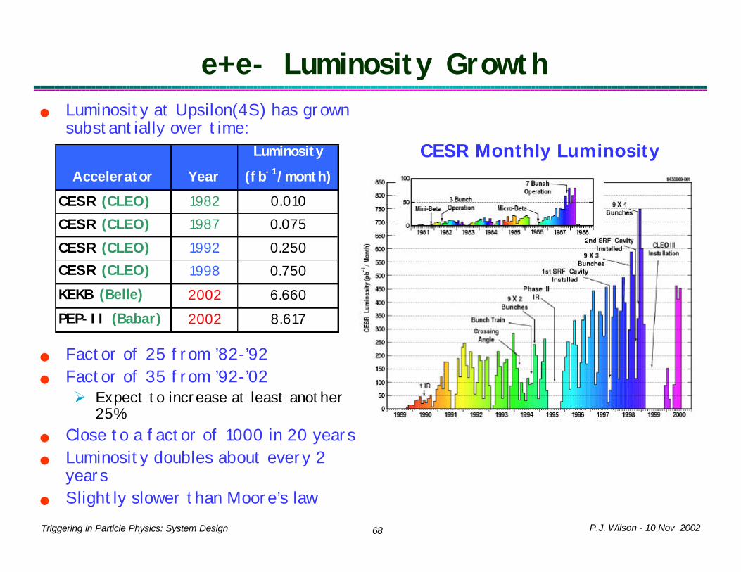
e+e- Luminosity Growthn Luminosity at Upsilon(4S) has grown
substantially over time:
n Factor of 25 from ’82-’92n Factor of 35 from ’92-’02
Ø Expect to increase at least another 25%
n Close to a factor of 1000 in 20 yearsn Luminosity doubles about every 2
yearsn Slightly slower than Moore’s law
CESR Monthly LuminosityAccelerator Year
Luminosity
(fb-1/month)
CESR (CLEO) 1982 0.010CESR (CLEO) 1987 0.075CESR (CLEO) 1992 0.250CESR (CLEO) 1998 0.750KEKB (Belle) 2002 6.660PEP-II (Babar) 2002 8.617

P.J. Wilson - 10 Nov 200269Triggering in Particle Physics: System Design
pp Luminosity Growth n Factor of ~10 in 10 yearsØ Smaller than CESRØ Trigger on lower Pt (expand B
physics programs)n Expect large increase going to
LHC Ø Bigger than CESR to B-factory
0 Run 1A 1B 1C
Accelerator Year
Luminosity
(µb-1s-1)
Tevatron (0) 1989 2.0Tevatron (1A) 1993 9.0Tevatron (1B) 1995 25.0
Tevatron (2A) 2002 36.0
Tevatron (2A) 2003 80.0
Tevatron (2B) 2006? 200-400
LHC 2008? 10,000
(_)

P.J. Wilson - 10 Nov 200270Triggering in Particle Physics: System Design
Trigger and data acquisition trends
S.S. CittolinCittolin CERN/EPCERN/EP--CMDCMD LECC Workshop 2002 LECC Workshop 2002

P.J. Wilson - 10 Nov 200271Triggering in Particle Physics: System Design
Triggering in Future Experiments

P.J. Wilson - 10 Nov 200272Triggering in Particle Physics: System Design
Near Future Experiments (before 2010)
TypeL1 In (MHz)
L1 Out (kHz)
L2 Out (kHz)
Ev Size (kB)
Bandwidth RO (GB/s)
L3 Out (Hz)
ATLAS pp 40 100 NA 1000 10 100CMS pp 40 100 100 1000 100 100LHCb pp 40 1000 1000 200 4 200BTeV ppbar 7.6 80 8 100-200 800* 4000CKM K+-> π+νν 44MHz debunched beam 100? 100?Minos ν oscill 19ns RF for 8µs spill, rep rate ~1s 40MB/s few
* BTeV is read out before L1 trigger
With increasing link and switch capabilities less selection in hardware
Will Trigger PC boards start to get smaller again?

P.J. Wilson - 10 Nov 200273Triggering in Particle Physics: System Design
ccc
µ+
e+
γ πo
K+, π+,p,…
ν, lsp
Muon detectorsHadron calorimeter
Electromagnetic Calorimeter
Solenoid 4T, 2TAir core torroids (muons)
Tracker:µstrip gas chambersStraw, Transition Rad Tracker
Silicon Detector:Pixels and Strips
Ko→ π+π-, …etc
LHC Detector Schematic
Key
CMS and ATLAS
CMS
ATLAS
Jet
LHCb, BTeV and Numi look VERY
Different

P.J. Wilson - 10 Nov 200274Triggering in Particle Physics: System Design
Collisions (p-p) at LHC
Event size: ~1 MByteProcessing Power: ~X TFlopEvent size: ~1 MByteProcessing Power: ~X TFlop
All charged tracks with pt > 2 GeV
Reconstructed tracks with pt > 25 GeV
Operating conditions:one “good” event (e.g Higgs in 4 muons )
+ ~20 minimum bias events)Event rate
S.S. CittolinCittolin CERN/EPCERN/EP--CMDCMD LECC Workshop 2002 LECC Workshop 2002

P.J. Wilson - 10 Nov 200275Triggering in Particle Physics: System Design
ATLAS/CMS Trigger Ratesn Same challenges as Tevatron but higher energies, much higher
luminosity Ô more interactions/crossing (20-25)n Cut on ET and PT to discriminate against QCD backgroundsØ Higher ET cuts than Tevtron neededØ More boost Ô don’t loose efficiency
n Unprescaled High PT trigger thresholds and rates:
PT Cut Rate (HZ) PT Cut Rate (Hz) Pt Cut Rate (Hz)
Single µ 4 GeV/c 280 12 GeV/c 25 20 GeV 10kSingle e 8 GeV 240 16 GeV 30 30 GeV 20kSingle γ 8 GeV 2400 18 GeV 60 30 (GeV) 20kSingle Jet 10 GeV 10K 90 GeV 10 300 (GeV) 200
CDF L1 CDF L2 LHC L1
CDF Rates for 2x1032cm-2 s-1, scaled from 3x1031 cm-2 s-1 (no L2 µ)
LHC rates for 1034 cm-2 s-1, from N. Ellis, LECC Workshop 2002 at Colmar

P.J. Wilson - 10 Nov 200276Triggering in Particle Physics: System Design
ATLAS and CMS Trigger ArchitectureLarge improvements in FPGA size, speed and link bandwidth
ÔOnly L1 trigger in custom hardware
ÔNo L2 trigger for CMSATLAS
Levels 3LV-1 rate 100 kHzReadout 10 GB/sStorage 100 MB/s
CMS
Levels 2LV-1 rate 100 kHzReadout 100 GB/sStorage 100 MB/s

P.J. Wilson - 10 Nov 200277Triggering in Particle Physics: System Design
Collision rate 40 MHzLevel-1 Maximum trigger rate 100 kHz(*)Average event size ˜ 1 MbyteEvent Flow Control ˜ 106
Mssg/s
No. of In-Out units ˜ 500Readout network bandwidth ˜ 1 Terabit/s Event filter computing power ˜ 5 TFlopData production ˜ Tbyte/dayNo. of PC motherboards ˜ Thousands
CMS DAQ/Trigger Structure

P.J. Wilson - 10 Nov 200278Triggering in Particle Physics: System Design
ATLAS and CMS L1 Triggern CMS and ATLAS L1 triggers
both use data from Calorimeters and Muon detectorsØ No data from inner trackers –
very high track densityØ ET of clusters for e/γ/Jet
triggersØ Missing ET for ν or SUSY LSPØ PT of Muon in flux return
(CMS), air torroids (ATLAS)n Same general functions as
CDF/D0 Run 1 L1 TriggersØ Better muon PT
Ø More sophisticated algorithmsØ Many more channels to handle
CMS L1 Trigger System

P.J. Wilson - 10 Nov 200279Triggering in Particle Physics: System Design
CMS L1 Latency
Budget of 128bx =3.2µs
CDF/D0 (30-42bx) ~ 4-5.5µs

P.J. Wilson - 10 Nov 200280Triggering in Particle Physics: System Design
Atlas L2: Regions of Interestn L2 Trigger uses same data as
goes to L3n On L1 subsystems store
regional information about decisionØ On L1A, pass to Region of
interest builder in L2Ø Fetch complete detector data
only for Regions of Interest (ROI). Data remains in buffers of readout system
Ø Make fast decision in L2 Processor farm. Reduce rate by factor of 10
n ROI builder gathers packets from different parts of detector and align to same even. Then pass to farm.
n Links: S-Link and/or GB ethernet
80
P.J. Wilson - 10 Nov 200281Triggering in Particle Physics: System Design
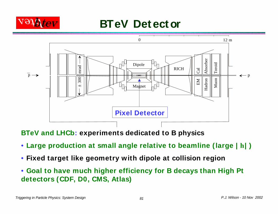
BTeV Detector0 12 m
pp
DipoleRICH
EM
Cal
Had
ron
A
bsor
ber
Muo
n
Tor
oid
± 30
0 m
rad
Magnet
Pixel Detector
BTeV and LHCb: experiments dedicated to B physics
• Large production at small angle relative to beamline (large |η|)
• Fixed target like geometry with dipole at collision region
• Goal to have much higher efficiency for B decays than High Pt detectors (CDF, D0, CMS, Atlas)

P.J. Wilson - 10 Nov 200282Triggering in Particle Physics: System Design
BTeV Trigger and DAQBTeV detector
L1 muon
L1 vertex
GlobalLevel-1
Level-1
Level 2/3 Crossing Switch
Data Logging
Front-end electronics
Level-1 Buffers
Level-2/3 Buffers
Information Transfer Control Hardware
ITCH
Level-2/3 Processor Farm#1
#2#m-1
#m
RDY
Crossing #N
Req. data for crossing #N
Level-3 accept
GL1 accept
PIX µ
> 2 x 10 channels7
800 GB/s7.6 MHz
L1 rate reduction: ~100x
L2/3 rate reduction: ~20x
4 KHz 200 MB/s
Read data in memory before L1 decision: total of 400 Gbytes for L1, L2, L3 Buffers

P.J. Wilson - 10 Nov 200283Triggering in Particle Physics: System Design
BTeV TriggerL1 Vertex Trigger uses data from pixel detector to select events with detached vertices (long lifetimes) using a combination of FPGAs and DSPs on custom boards . L1 Muon Trigger provides alternate path for B Õ J/ψ +X with higher efficiency
• Use to measure efficiency of vertex trigger• Also for useful for BS Õ J/ψ +X in its own right
L1 Buffers may be managed as a circular buffer or as RAM. Optimization not completeL2 and L3 Triggers implemented in commodity processors (eg Linux PCs)
• L2 seeded of tracks found at L1, improved fit to L1 tracks• L3 full event data available• Write only reconstructed data to tape, raw data only stored for a prescaled subset
Event Size 100-200kBytesNumber of 1Gb/s Links 5000Number of L1 DSPs 2500Number of L2/3 Processors 2500

P.J. Wilson - 10 Nov 200284Triggering in Particle Physics: System Design
L2/L3 Trigger Performance Overview
130ms24KHz
50KB/s200MB/s
7.5KHz100KB/event
800 MB/s
Level 3uses full event
data
13ms107.5KHz
100KB/event800 MB/s
75KHz100KB/event
8 GB/s
Level 2refined
tracking, vertex cut
Processing Time
Reduction FactorOutput RateInput Rate
Trigger ParametersTrigger Level
§ L2 and L3 triggers are implemented in the same hardware, a PC Farm§ L2 Uses tracking information to look for detached vertices and detached tracks§ L3 does the full reconstruction and writes DSTs (similar to traditional offline)

P.J. Wilson - 10 Nov 200285Triggering in Particle Physics: System Design
MINOS Far Detector• Two detectors – near and far
(730km separation)• 8m Octagonal Tracking
Calorimeter• 486 layers of 2.54cm Fe• 2 sections, each 15m long • 4cm wide solid scintillator
strips with WLS fiber readout• 25,800 m2 active detector
planes• Magnet coil provides
<B> ≈ 1.3T• 5.4kt total mass
Half of the MINOS Detector

P.J. Wilson - 10 Nov 200286Triggering in Particle Physics: System Design
TimingGen
GPS
4
TP
TP
IP
n
splitters
Trigger Farm
fibre
1
1
NC NCOP
NC
NC
NC
DAQUser Interface
ROBROB
FEPVME
NC
12 FEBsFront EndVME Crate
FECTiming
13FEB
ROB
3FEB
1 Front End BoardsReadout Crates
16
MINOS Readout and TriggerTwo detectors – near and far (730km separation)
• time synch date <1ms (GPS)
No hardware trigger
Beam structure:
• ~10ms spill at ~1Hz
• 53MHz structure within spill
Continuous digitization at 53MHz
Readout into Trigger farm in overlapping ~4ms long frames of data
Readout rate: 40MB/s

P.J. Wilson - 10 Nov 200287Triggering in Particle Physics: System Design
Pierre Auger ObservatorySearch for Origin of cosmic
rays with E>1020eV
Rate ˜ 1 / km2 / sr / century above 1020 eV!
Large scale detector:
ü 1600 Cherenkov tanks, covering 3000 km2
ü 24 Fluorescence Detector telescopes

P.J. Wilson - 10 Nov 200288Triggering in Particle Physics: System Design
Auger Cerenkov Stations n Highly Distributed Particle
physics detectorn Autonomous systems at each
detector Ø Communicate via wireless
technologyØ Timing via GPS (~10ns)Ø Cannot trigger globallyØ Two FADC (gain factor of 8) at
40MHz into buffer on each tube
n Backgrounds Ø PMT noise few kHz/PMTØ Cosmics ~ 3kHz/station
P.J. Wilson - 10 Nov 200289Triggering in Particle Physics: System Design
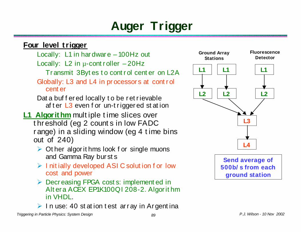
Auger TriggerFour level trigger
Locally: L1 in hardware – 100Hz outLocally: L2 in µ-controller – 20Hz
Transmit 3Bytes to control center on L2A Globally: L3 and L4 in processors at control
centerData buffered locally to be retrievable
after L3 even for un-triggered stationL1 Algorithm multiple time slices over
threshold (eg 2 counts in low FADC range) in a sliding window (eg 4 time bins out of 240)Ø Other algorithms look for single muons
and Gamma Ray burstsØ Initially developed ASIC solution for low
cost and powerØ Decreasing FPGA costs: implemented in
Altera ACEX EP1K100QI208-2. Algorithm in VHDL.
Ø In use: 40 station test array in Argentina
L1 L1L1
Fluorescence Detector
Ground Array Stations
L2 L2L2
L4
L3
Send average of 500b/s from each
ground station

P.J. Wilson - 10 Nov 200290Triggering in Particle Physics: System Design
Future AcceleratorsWhat will trigger systems look like
in the future?n Accelerator energy continues to
grow… however rate of change may be decreasing
n Processing power, network bandwidth and storage media are all growing faster than increases in luminosity
n Trend is toward fewer (zero?) hardware levels
n Future MachinesØ Linear Collider (500-1000 GeV)Ø Super B-Factory (1036cm-2s-1)Ø ν factory?Ø Muon Collider?Ø VLHC pp at 40-200 TeV
Livingston Plot
M. Tigner, Physics Today Jan 2001 p36

P.J. Wilson - 10 Nov 200291Triggering in Particle Physics: System Design
Linear Colliders
Trigger-less (hardware) designn Tesla conceptual detector: readout detector continuously to
L3 farm
Tesla NLC/JLCRep Rate (Hz) 5 120Bunch Spacing (ns) 337 1.4Bunch/Pulse 2820 190Pulse length (ms) 950 0.266Average xing rate (kHz) 14 23
Low Beam X-ing Rate for Either Tesla or NLC/JLC

P.J. Wilson - 10 Nov 200292Triggering in Particle Physics: System Design
Super Babarn Bunch spacing is already essentially DC (<10ns)n Even with factor of 100 in luminosity the general character
stays the same although slow calorimeters (CsI with Tldoping) might start to see pile-up
n Given a 10 year minimum timescale it seems likely that current schemes with a L1 hardware trigger and L3 farm would work.
P.J. Wilson - 10 Nov 200293Triggering in Particle Physics: System Design
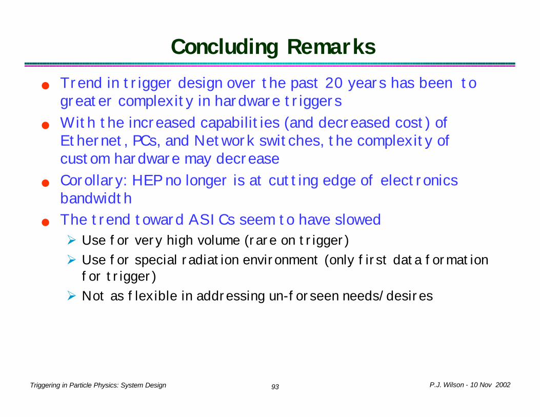
Concluding Remarksn Trend in trigger design over the past 20 years has been to
greater complexity in hardware triggersn With the increased capabilities (and decreased cost) of
Ethernet, PCs, and Network switches, the complexity of custom hardware may decrease
n Corollary: HEP no longer is at cutting edge of electronics bandwidth
n The trend toward ASICs seem to have slowedØ Use for very high volume (rare on trigger)Ø Use for special radiation environment (only first data formation
for trigger)Ø Not as flexible in addressing un-forseen needs/desires