Embed Size (px)
Citation preview
Instruction Manual
TCM_COMO_S_EN_170118_E006
TRICOR® Modbus (RTU)
Version
Version: TCM_COMO_S_EN_170118_E006 2
Manual-Version TCM_COMO_S_EN_170118_E006
SW-Version This manual is valid for
Main SW: Mv3.40 and higher
Display SW: Dv3.40 and higher
Index
Version: TCM_COMO_S_EN_170118_E006 3
Index
1. ELECTRICAL CONNECTION OF RS485 .................................................................................................... 5
1.1. Single-mode connection ........................................................................................................................... 5 1.2. Operating TCE in multi-drop network ....................................................................................................... 6
2. EX INSTALLATION OF RS485 .................................................................................................................... 6
3. TCE MODBUS RTU INTERFACE OVERVIEW ............................................................................................ 7
3.1. RS485 settings ......................................................................................................................................... 7 3.2. Frame structure ........................................................................................................................................ 7 3.2.1. Address = Slave address ......................................................................................................................... 7 3.2.2. Function Code .......................................................................................................................................... 7 3.2.3. Data Field ................................................................................................................................................. 8 3.2.4. Error Checking Field................................................................................................................................. 9 3.3. Exception responses ................................................................................................................................ 9 3.4. TCE Modbus data model ......................................................................................................................... 9 3.5. Write protection (Custody Transfer Option) ........................................................................................... 10 3.6. Event Logging ........................................................................................................................................ 10 3.6.1. Data format ............................................................................................................................................. 11 3.6.2. Example ................................................................................................................................................. 11 3.7. Examples of use ..................................................................................................................................... 12 3.7.1. ModScan64 ............................................................................................................................................ 12 3.8. TRICOR Configurator ............................................................................................................................. 13 3.9. TCE Modbus register map ..................................................................................................................... 14 3.10. Meter Parameter Description ................................................................................................................. 23 3.10.1. Meter Mode ............................................................................................................................................ 23 3.10.2. Gas Density Ref ..................................................................................................................................... 24 3.10.3. Multiphase Comp. Mode ........................................................................................................................ 24 3.10.4. Multiphase Min Drive Current ................................................................................................................. 24 3.10.5. Multiphase Max Drive Current ................................................................................................................ 24 3.10.6. Multiphase Min Valid Period ................................................................................................................... 25 3.10.7. Data Update Period ................................................................................................................................ 25 3.10.8. Gauge Data Request.............................................................................................................................. 25 3.10.9. Fluid Volume Flow Rate Ref .................................................................................................................. 26 3.10.10. Fluid Volume Accumulator Ref ............................................................................................................... 26 3.10.11. Data Valid Period ................................................................................................................................... 26 3.10.12. Max Fluid Volume Flow Rate ................................................................................................................. 26 3.10.13. Min Fluid Volume Flow Rate .................................................................................................................. 27 3.10.14. Max Fluid Density ................................................................................................................................... 27 3.10.15. Min Fluid Density .................................................................................................................................... 27 3.10.16. Max Drive Current .................................................................................................................................. 27 3.10.17. Min Drive Current ................................................................................................................................... 27 3.10.18. Gauged Fluid Volume Ref ...................................................................................................................... 28 3.10.19. Raw Fluid Volume Flow Rate Ref .......................................................................................................... 28
Version
Version: TCM_COMO_S_EN_170118_E006 4
3.11. Tables ..................................................................................................................................................... 29 3.11.1. “Fault Word 1” code descriptions ........................................................................................................... 29 3.11.2. “Fault Word 2” code descriptions ........................................................................................................... 29 3.11.3. “Warning Word” code descriptions ......................................................................................................... 29 3.11.4. “Mass Flow Rate Units” .......................................................................................................................... 30 3.11.5. “Density Units” ........................................................................................................................................ 30 3.11.6. “Temperature Units” ............................................................................................................................... 31 3.11.7. “Volume Flow Rate Units” ...................................................................................................................... 31 3.11.8. “Mass Flow Total Units”.......................................................................................................................... 32 3.11.9. “Volume Flow Total Units” ...................................................................................................................... 33 3.11.10. “Pressure Units” ..................................................................................................................................... 33
4. CONTACT ................................................................................................................................................... 34
Version: TCM_COMO_S_EN_170118_E006
5
Electrical connection of RS485
TCE Modbus RTU Communication
Modbus is an application layer messaging protocol for client/server communication between devices connected on different types of buses or networks. On TCE Modbus is implemented using the asynchronous serial transmission over the RS485 physical interface. The TCE is equipped with an RS485 Interface as a standard.
1. Electrical connection of RS485
Prepare the TCE and the cable as described in chapter 3.3.2. or 3.3.3. in the TRICOR manual.
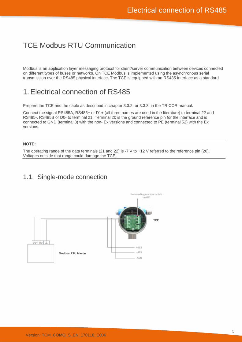
Connect the signal RS485A, RS485+ or D1+ (all three names are used in the literature) to terminal 22 and RS485-, RS485B or D0- to terminal 21. Terminal 20 is the ground reference pin for the interface and is connected to GND (terminal 8) with the non- Ex versions and connected to PE (terminal 52) with the Ex versions.
NOTE: The operating range of the data terminals (21 and 22) is -7 V to +12 V referred to the reference pin (20). Voltages outside that range could damage the TCE.
1.1. Single-mode connection
TCE
Modbus RTU Master
Version: TCM_COMO_S_EN_170118_E006
6
Ex installation of RS485
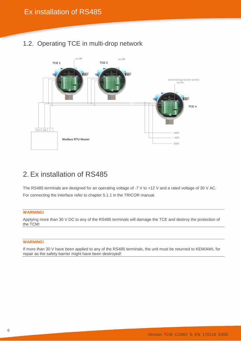
1.2. Operating TCE in multi-drop network
2. Ex installation of RS485
The RS485 terminals are designed for an operating voltage of -7 V to +12 V and a rated voltage of 30 V AC.
For connecting the interface refer to chapter 5.1.1 in the TRICOR manual.
WARNING! Applying more than 30 V DC to any of the RS485 terminals will damage the TCE and destroy the protection of the TCM!
WARNING! If more than 30 V have been applied to any of the RS485 terminals, the unit must be returned to KEM/AWL for repair as the safety barrier might have been destroyed!
TCE n
TCE 1 TCE 2
Modbus RTU Master
Version: TCM_COMO_S_EN_170118_E006
7
TCE Modbus RTU Interface Overview
3. TCE Modbus RTU Interface Overview
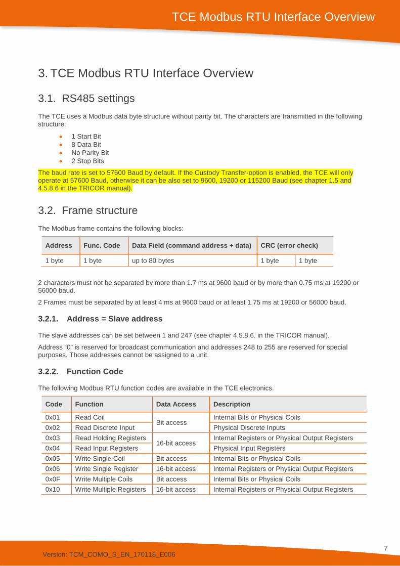
3.1. RS485 settings The TCE uses a Modbus data byte structure without parity bit. The characters are transmitted in the following structure:
• 1 Start Bit • 8 Data Bit • No Parity Bit • 2 Stop Bits
The baud rate is set to 57600 Baud by default. If the Custody Transfer-option is enabled, the TCE will only operate at 57600 Baud, otherwise it can be also set to 9600, 19200 or 115200 Baud (see chapter 1.5 and 4.5.8.6 in the TRICOR manual).
3.2. Frame structure The Modbus frame contains the following blocks:
Address Func. Code Data Field (command address + data) CRC (error check)
1 byte 1 byte up to 80 bytes 1 byte 1 byte
2 characters must not be separated by more than 1.7 ms at 9600 baud or by more than 0.75 ms at 19200 or 56000 baud.
2 Frames must be separated by at least 4 ms at 9600 baud or at least 1.75 ms at 19200 or 56000 baud.
3.2.1. Address = Slave address
The slave addresses can be set between 1 and 247 (see chapter 4.5.8.6. in the TRICOR manual).
Address “0” is reserved for broadcast communication and addresses 248 to 255 are reserved for special purposes. Those addresses cannot be assigned to a unit.
3.2.2. Function Code
The following Modbus RTU function codes are available in the TCE electronics.
Code Function Data Access Description
0x01 Read Coil Bit access
Internal Bits or Physical Coils 0x02 Read Discrete Input Physical Discrete Inputs 0x03 Read Holding Registers
16-bit access Internal Registers or Physical Output Registers
0x04 Read Input Registers Physical Input Registers 0x05 Write Single Coil Bit access Internal Bits or Physical Coils 0x06 Write Single Register 16-bit access Internal Registers or Physical Output Registers 0x0F Write Multiple Coils Bit access Internal Bits or Physical Coils 0x10 Write Multiple Registers 16-bit access Internal Registers or Physical Output Registers
Version: TCM_COMO_S_EN_170118_E006
8
TCE Modbus RTU Interface Overview
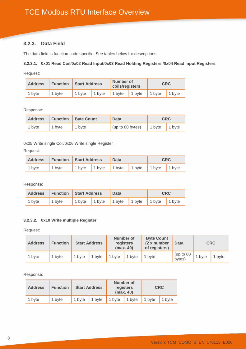
3.2.3. Data Field
The data field is function code specific. See tables below for descriptions:
3.2.3.1. 0x01 Read Coil/0x02 Read Input/0x03 Read Holding Registers /0x04 Read Input Registers
Request:
Address Function Start Address Number of coils/registers CRC
1 byte 1 byte 1 byte 1 byte 1 byte 1 byte 1 byte 1 byte
Response:
Address Function Byte Count Data CRC
1 byte 1 byte 1 byte (up to 80 bytes) 1 byte 1 byte
0x05 Write single Coil/0x06 Write single Register
Request:
Address Function Start Address Data CRC
1 byte 1 byte 1 byte 1 byte 1 byte 1 byte 1 byte 1 byte
Response:
Address Function Start Address Data CRC
1 byte 1 byte 1 byte 1 byte 1 byte 1 byte 1 byte 1 byte
3.2.3.2. 0x10 Write multiple Register
Request:
Address Function Start Address Number of registers (max. 40)
Byte Count (2 x number of registers)
Data CRC
1 byte 1 byte 1 byte 1 byte 1 byte 1 byte 1 byte (up to 80 bytes) 1 byte 1 byte
Response:
Address Function Start Address Number of registers (max. 40)
CRC
1 byte 1 byte 1 byte 1 byte 1 byte 1 byte 1 byte 1 byte
Version: TCM_COMO_S_EN_170118_E006
9
TCE Modbus RTU Interface Overview
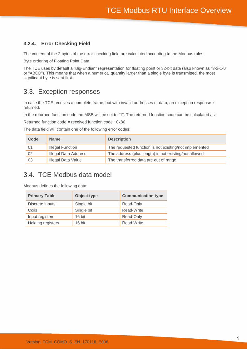
3.2.4. Error Checking Field
The content of the 2 bytes of the error-checking field are calculated according to the Modbus rules.
Byte ordering of Floating Point Data
The TCE uses by default a “Big-Endian” representation for floating point or 32-bit data (also known as “3-2-1-0” or “ABCD”). This means that when a numerical quantity larger than a single byte is transmitted, the most significant byte is sent first.
3.3. Exception responses In case the TCE receives a complete frame, but with invalid addresses or data, an exception response is returned.
In the returned function code the MSB will be set to “1”. The returned function code can be calculated as:
Returned function code = received function code +0x80
The data field will contain one of the following error codes:
Code Name Description
01 Illegal Function The requested function is not existing/not implemented 02 Illegal Data Address The address (plus length) is not existing/not allowed 03 Illegal Data Value The transferred data are out of range
3.4. TCE Modbus data model Modbus defines the following data:
Primary Table Object type Communication type
Discrete inputs Single bit Read-Only Coils Single bit Read-Write Input registers 16 bit Read-Only Holding registers 16 bit Read-Write
Version: TCM_COMO_S_EN_170118_E006
10
TCE Modbus RTU Interface Overview
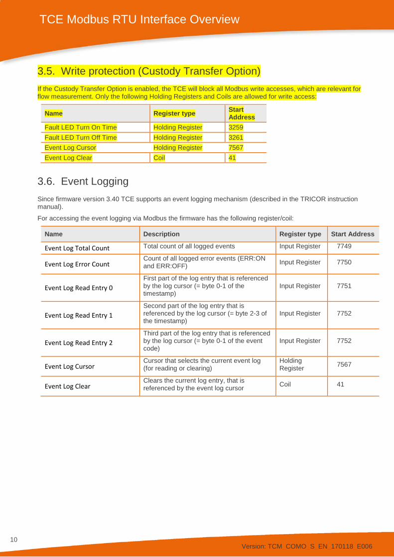
3.5. Write protection (Custody Transfer Option) If the Custody Transfer Option is enabled, the TCE will block all Modbus write accesses, which are relevant for flow measurement. Only the following Holding Registers and Coils are allowed for write access:
Name Register type Start Address
Fault LED Turn On Time Holding Register 3259 Fault LED Turn Off Time Holding Register 3261 Event Log Cursor Holding Register 7567 Event Log Clear Coil 41
3.6. Event Logging Since firmware version 3.40 TCE supports an event logging mechanism (described in the TRICOR instruction manual).
For accessing the event logging via Modbus the firmware has the following register/coil:
Name Description Register type Start Address
Event Log Total Count Total count of all logged events Input Register 7749
Event Log Error Count Count of all logged error events (ERR:ON and ERR:OFF) Input Register 7750
Event Log Read Entry 0 First part of the log entry that is referenced by the log cursor (= byte 0-1 of the timestamp)
Input Register 7751
Event Log Read Entry 1 Second part of the log entry that is referenced by the log cursor (= byte 2-3 of the timestamp)
Input Register 7752
Event Log Read Entry 2 Third part of the log entry that is referenced by the log cursor (= byte 0-1 of the event code)
Input Register 7752
Event Log Cursor Cursor that selects the current event log (for reading or clearing)
Holding Register 7567
Event Log Clear Clears the current log entry, that is referenced by the event log cursor Coil 41
Version: TCM_COMO_S_EN_170118_E006
11
TCE Modbus RTU Interface Overview
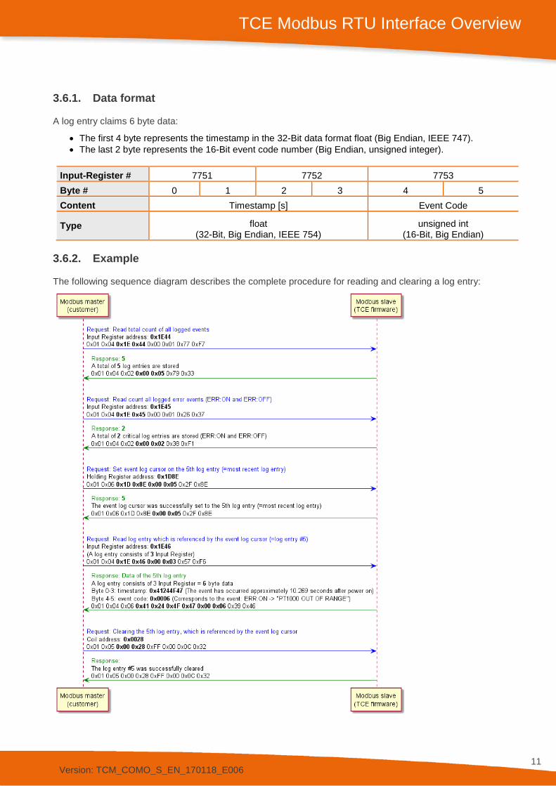
3.6.1. Data format
A log entry claims 6 byte data:
• The first 4 byte represents the timestamp in the 32-Bit data format float (Big Endian, IEEE 747). • The last 2 byte represents the 16-Bit event code number (Big Endian, unsigned integer).
Input-Register # 7751 7752 7753 Byte # 0 1 2 3 4 5 Content Timestamp [s] Event Code
Type float (32-Bit, Big Endian, IEEE 754)
unsigned int (16-Bit, Big Endian)
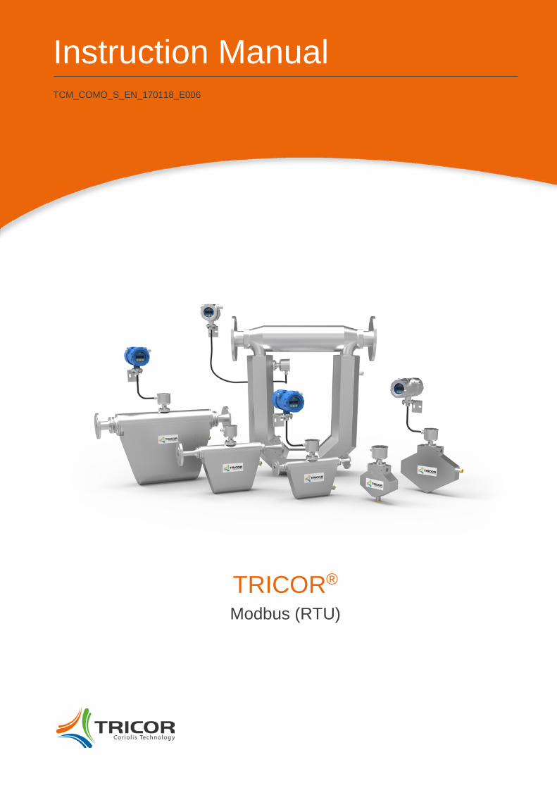
3.6.2. Example
The following sequence diagram describes the complete procedure for reading and clearing a log entry:
Version: TCM_COMO_S_EN_170118_E006
12
TCE Modbus RTU Interface Overview
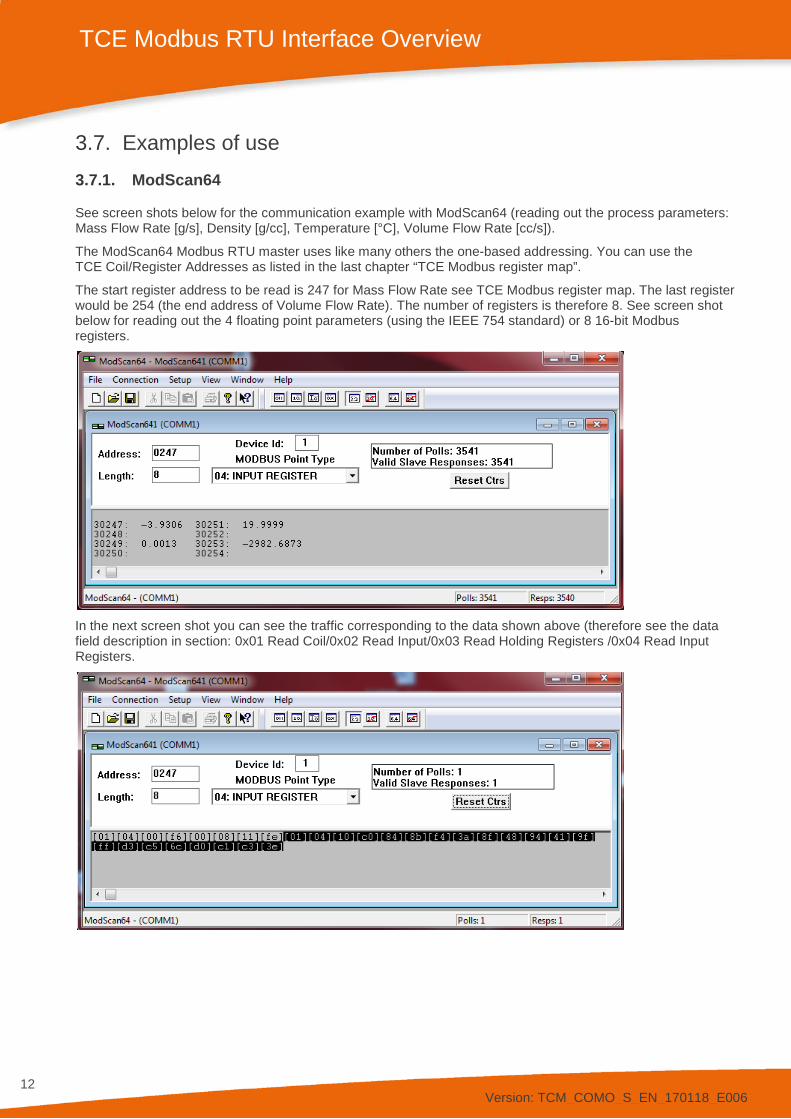
3.7. Examples of use 3.7.1. ModScan64
See screen shots below for the communication example with ModScan64 (reading out the process parameters: Mass Flow Rate [g/s], Density [g/cc], Temperature [°C], Volume Flow Rate [cc/s]).
The ModScan64 Modbus RTU master uses like many others the one-based addressing. You can use the TCE Coil/Register Addresses as listed in the last chapter “TCE Modbus register map”.
The start register address to be read is 247 for Mass Flow Rate see TCE Modbus register map. The last register would be 254 (the end address of Volume Flow Rate). The number of registers is therefore 8. See screen shot below for reading out the 4 floating point parameters (using the IEEE 754 standard) or 8 16-bit Modbus registers.
In the next screen shot you can see the traffic corresponding to the data shown above (therefore see the data field description in section: 0x01 Read Coil/0x02 Read Input/0x03 Read Holding Registers /0x04 Read Input Registers.
Version: TCM_COMO_S_EN_170118_E006
13
TCE Modbus RTU Interface Overview
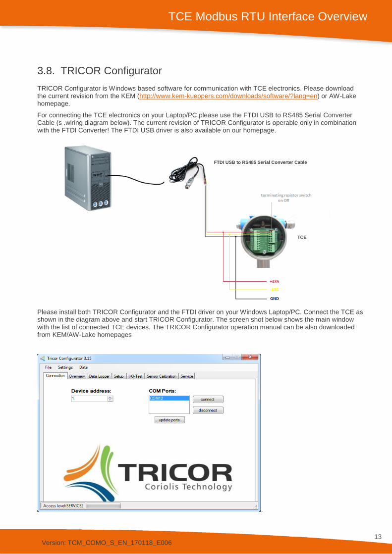
3.8. TRICOR Configurator TRICOR Configurator is Windows based software for communication with TCE electronics. Please download the current revision from the KEM (http://www.kem-kueppers.com/downloads/software/?lang=en) or AW-Lake homepage.
For connecting the TCE electronics on your Laptop/PC please use the FTDI USB to RS485 Serial Converter Cable (s .wiring diagram below). The current revision of TRICOR Configurator is operable only in combination with the FTDI Converter! The FTDI USB driver is also available on our homepage.
Please install both TRICOR Configurator and the FTDI driver on your Windows Laptop/PC. Connect the TCE as shown in the diagram above and start TRICOR Configurator. The screen shot below shows the main window with the list of connected TCE devices. The TRICOR Configurator operation manual can be also downloaded from KEM/AW-Lake homepages
.
FTDI USB to RS485 Serial Converter Cable
TCE
Version: TCM_COMO_S_EN_170118_E006
14
TCE Modbus RTU Interface Overview
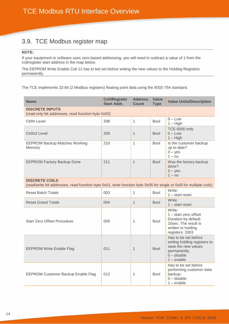
3.9. TCE Modbus register map NOTE: If your equipment or software uses zero-based addressing, you will need to subtract a value of 1 from the coil/register start address in the map below.
The EEPROM Write Enable Coil 11 has to bet set before writing the new values to the Holding Registers permanently.
The TCE implements 32-bit (2 Modbus registers) floating point data using the IEEE-754 standard.
Name Coil/Register Start Addr.
Address Count
Value Type Value Units/Description
DISCRETE INPUTS (read-only bit addresses, read function byte 0x02)
CtrlIn Level 208 1 Bool 0 – Low 1 – High
CtrlIn2 Level 209 1 Bool TCE 6000 only 0 – Low 1 – High
EEPROM Backup Matches Working Memory
210 1 Bool Is the customer backup up to date? 0 – yes 1 – no
EEPROM Factory Backup Done 211 1 Bool Was the factory backup done? 0 – yes 1 – no
DISCRETE COILS (read/write bit addresses, read function byte 0x01, write function byte 0x05 for single or 0x0f for multiple coils)
Reset Batch Totals 003 1 Bool Write: 1 – start reset
Reset Grand Totals 004 1 Bool Write: 1 – start reset
Start Zero Offset Procedure 005 1 Bool
Write: 1 – start zero offset Duration by default: 10sec. The result is written to holding registers: 3303
EEPROM Write Enable Flag 011 1 Bool
Has to be set before writing holding registers to save the new values permanently. 0 – disable 1 – enable
EEPROM Customer Backup Enable Flag 012 1 Bool
Has to be set before performing customer data backup: 0 – disable 1 – enable
Version: TCM_COMO_S_EN_170118_E006
15
TCE Modbus RTU Interface Overview
Name Coil/Register Start Addr.
Address Count
Value Type Value Units/Description
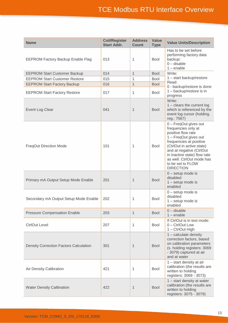
EEPROM Factory Backup Enable Flag 013 1 Bool
Has to be set before performing factory data backup: 0 – disable 1 – enable
EEPROM Start Customer Backup 014 1 Bool Write: 1 – start backup/restore Read: 0 - backup/restore is done 1 – backup/restore is in progress
EEPROM Start Customer Restore 015 1 Bool EEPROM Start Factory Backup 016 1 Bool
EEPROM Start Factory Restore 017 1 Bool
Event Log Clear 041 1 Bool
Write: 1 – clears the current log which is referenced by the event log cursor (holding. reg.: 7567)
FreqOut Direction Mode 101 1 Bool
0 – FreqOut gives out frequencies only at positive flow rate 1 – FreqOut gives out frequencies at positive (CtrlOut in active state) and at negative (CtrlOut in inactive state) flow rate as well. CtrlOut mode has to be set to FLOW DIRECTION
Primary mA Output Setup Mode Enable 201 1 Bool
0 – setup mode is disabled 1 – setup mode is enabled
Secondary mA Output Setup Mode Enable 202 1 Bool
0 – setup mode is disabled 1 – setup mode is enabled
Pressure Compensation Enable 203 1 Bool 0 – disable 1 – enable
CtrlOut Level 207 1 Bool If CtrlOut is in test mode: 0 – CtrlOut Low 1 – CtrlOut High
Density Correction Factors Calculation 301 1 Bool
1 – calculate density correction factors, based on calibration parameters (s. holding registers: 3069 - 3079) captured at air and at water
Air Density Calibration 421 1 Bool 1 – start density at air calibration (the results are written to holding registers: 3069 - 3073)
Water Density Calibration 422 1 Bool
1 – start density at water calibration (the results are written to holding registers: 3075 - 3079)
Version: TCM_COMO_S_EN_170118_E006
16
TCE Modbus RTU Interface Overview
Name Coil/Register Start Addr.
Address Count
Value Type Value Units/Description
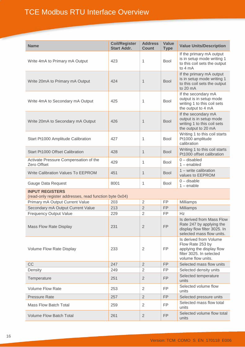
Write 4mA to Primary mA Output 423 1 Bool
If the primary mA output is in setup mode writing 1 to this coil sets the output to 4 mA
Write 20mA to Primary mA Output 424 1 Bool
If the primary mA output is in setup mode writing 1 to this coil sets the output to 20 mA
Write 4mA to Secondary mA Output 425 1 Bool
If the secondary mA output is in setup mode writing 1 to this coil sets the output to 4 mA
Write 20mA to Secondary mA Output 426 1 Bool
If the secondary mA output is in setup mode writing 1 to this coil sets the output to 20 mA
Start Pt1000 Amplitude Calibration 427 1 Bool Writing 1 to this coil starts Pt1000 amplitude calibration
Start Pt1000 Offset Calibration 428 1 Bool Writing 1 to this coil starts Pt1000 offset calibration
Activate Pressure Compensation of the Zero Offset 429 1 Bool 0 – disabled
1 – enabled
Write Calibration Values To EEPROM 451 1 Bool 1 – write calibration values to EEPROM
Gauge Data Request 8001 1 Bool 0 – disable 1 – enable
INPUT REGISTERS (read-only register addresses, read function byte 0x04) Primary mA Output Current Value 203 2 FP Milliamps Secondary mA Output Current Value 213 2 FP Milliamps Frequency Output Value 229 2 FP Hz
Mass Flow Rate Display 231 2 FP
Is derived from Mass Flow Rate 247 by applying the display flow filter 3025. In selected mass flow units.
Volume Flow Rate Display 233 2 FP
Is derived from Volume Flow Rate 253 by applying the display flow filter 3025. In selected volume flow units.
CC 247 2 FP Selected mass flow units Density 249 2 FP Selected density units
Temperature 251 2 FP Selected temperature units
Volume Flow Rate 253 2 FP Selected volume flow units
Pressure Rate 257 2 FP Selected pressure units
Mass Flow Batch Total 259 2 FP Selected mass flow total units
Volume Flow Batch Total 261 2 FP Selected volume flow total units
Version: TCM_COMO_S_EN_170118_E006
17
TCE Modbus RTU Interface Overview
Name Coil/Register Start Addr.
Address Count
Value Type Value Units/Description
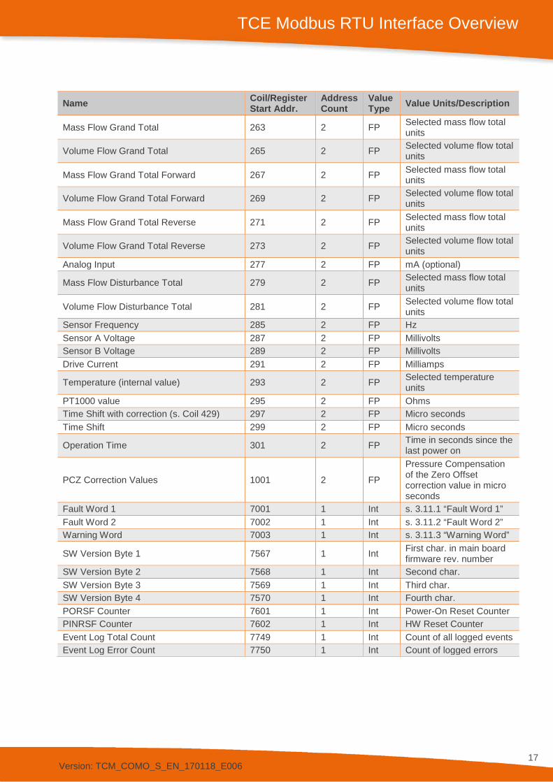
Mass Flow Grand Total 263 2 FP Selected mass flow total units
Volume Flow Grand Total 265 2 FP Selected volume flow total units
Mass Flow Grand Total Forward 267 2 FP Selected mass flow total units
Volume Flow Grand Total Forward 269 2 FP Selected volume flow total units
Mass Flow Grand Total Reverse 271 2 FP Selected mass flow total units
Volume Flow Grand Total Reverse 273 2 FP Selected volume flow total units
Analog Input 277 2 FP mA (optional)
Mass Flow Disturbance Total 279 2 FP Selected mass flow total units
Volume Flow Disturbance Total 281 2 FP Selected volume flow total units
Sensor Frequency 285 2 FP Hz Sensor A Voltage 287 2 FP Millivolts Sensor B Voltage 289 2 FP Millivolts Drive Current 291 2 FP Milliamps
Temperature (internal value) 293 2 FP Selected temperature units
PT1000 value 295 2 FP Ohms Time Shift with correction (s. Coil 429) 297 2 FP Micro seconds Time Shift 299 2 FP Micro seconds
Operation Time 301 2 FP Time in seconds since the last power on
PCZ Correction Values 1001 2 FP
Pressure Compensation of the Zero Offset correction value in micro seconds
Fault Word 1 7001 1 Int s. 3.11.1 “Fault Word 1” Fault Word 2 7002 1 Int s. 3.11.2 “Fault Word 2” Warning Word 7003 1 Int s. 3.11.3 “Warning Word”
SW Version Byte 1 7567 1 Int First char. in main board firmware rev. number
SW Version Byte 2 7568 1 Int Second char. SW Version Byte 3 7569 1 Int Third char. SW Version Byte 4 7570 1 Int Fourth char. PORSF Counter 7601 1 Int Power-On Reset Counter PINRSF Counter 7602 1 Int HW Reset Counter Event Log Total Count 7749 1 Int Count of all logged events Event Log Error Count 7750 1 Int Count of logged errors
Version: TCM_COMO_S_EN_170118_E006
18
TCE Modbus RTU Interface Overview
Name Coil/Register Start Addr.
Address Count
Value Type Value Units/Description
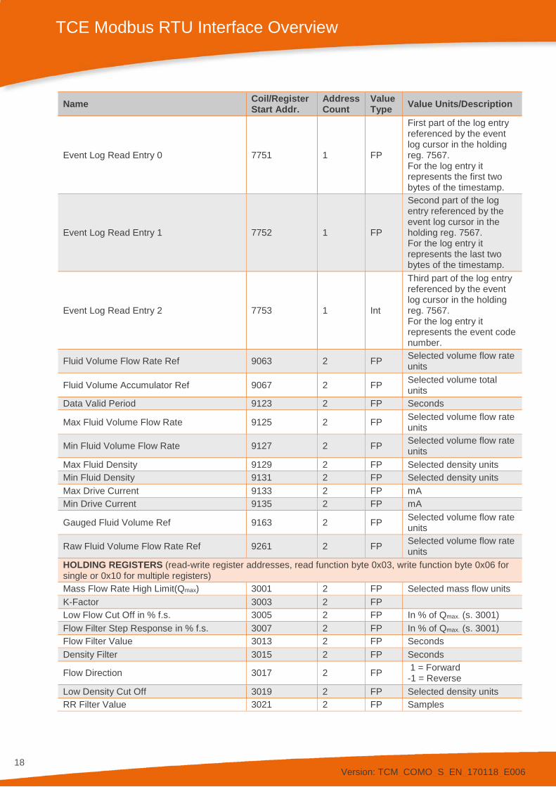
Event Log Read Entry 0 7751 1 FP
First part of the log entry referenced by the event log cursor in the holding reg. 7567. For the log entry it represents the first two bytes of the timestamp.
Event Log Read Entry 1 7752 1 FP
Second part of the log entry referenced by the event log cursor in the holding reg. 7567. For the log entry it represents the last two bytes of the timestamp.
Event Log Read Entry 2 7753 1 Int
Third part of the log entry referenced by the event log cursor in the holding reg. 7567. For the log entry it represents the event code number.
Fluid Volume Flow Rate Ref 9063 2 FP Selected volume flow rate units
Fluid Volume Accumulator Ref 9067 2 FP Selected volume total units
Data Valid Period 9123 2 FP Seconds
Max Fluid Volume Flow Rate 9125 2 FP Selected volume flow rate units
Min Fluid Volume Flow Rate 9127 2 FP Selected volume flow rate units
Max Fluid Density 9129 2 FP Selected density units Min Fluid Density 9131 2 FP Selected density units Max Drive Current 9133 2 FP mA Min Drive Current 9135 2 FP mA
Gauged Fluid Volume Ref 9163 2 FP Selected volume flow rate units
Raw Fluid Volume Flow Rate Ref 9261 2 FP Selected volume flow rate units
HOLDING REGISTERS (read-write register addresses, read function byte 0x03, write function byte 0x06 for single or 0x10 for multiple registers) Mass Flow Rate High Limit(Qmax) 3001 2 FP Selected mass flow units K-Factor 3003 2 FP Low Flow Cut Off in % f.s. 3005 2 FP In % of Qmax. (s. 3001) Flow Filter Step Response in % f.s. 3007 2 FP In % of Qmax. (s. 3001) Flow Filter Value 3013 2 FP Seconds Density Filter 3015 2 FP Seconds
Flow Direction 3017 2 FP 1 = Forward -1 = Reverse
Low Density Cut Off 3019 2 FP Selected density units RR Filter Value 3021 2 FP Samples
Version: TCM_COMO_S_EN_170118_E006
19
TCE Modbus RTU Interface Overview
Name Coil/Register Start Addr.
Address Count
Value Type Value Units/Description
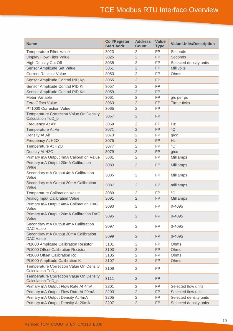
Temperature Filter Value 3023 2 FP Seconds Display Flow Filter Value 3025 2 FP Seconds High Density Cut Off 3035 2 FP Selected density units Sensor Amplitude Set Value 3051 2 FP Millivolts Current Resistor Value 3053 2 FP Ohms Sensor Amplitude Control PID Kp 3055 2 FP Sensor Amplitude Control PID Ki 3057 2 FP Sensor Amplitude Control PID Kd 3059 2 FP Meter Variable 3061 2 FP g/s per µs Zero Offset Value 3063 2 FP Timer ticks PT1000 Correction Value 3065 2 FP Temperature Correction Value On Density Calculation ToD_b 3067 2 FP
Frequency At Air 3069 2 FP Hz Temperature At Air 3071 2 FP °C Density At Air 3073 2 FP g/cc Frequency At H2O 3075 2 FP Hz Temperature At H2O 3077 2 FP °C Density At H2O 3079 2 FP g/cc Primary mA Output 4mA Calibration Value 3081 2 FP Milliamps Primary mA Output 20mA Calibration Value 3083 2 FP Milliamps
Secondary mA Output 4mA Calibration Value 3085 2 FP Milliamps
Secondary mA Output 20mA Calibration Value 3087 2 FP milliamps
Temperature Calibration Value 3089 2 FP °C Analog Input Calibration Value 3091 2 FP Milliamps Primary mA Output 4mA Calibration DAC Value 3093 2 FP 0-4095
Primary mA Output 20mA Calibration DAC Value 3095 2 FP 0-4095
Secondary mA Output 4mA Calibration DAC Value 3097 2 FP 0-4095
Secondary mA Output 20mA Calibration DAC Value 3099 2 FP 0-4095
Pt1000 Amplitude Calibration Resistor 3101 2 FP Ohms Pt1000 Offset Calibration Resistor 3103 2 FP Ohms Pt1000 Offset Calibration Ro 3105 2 FP Ohms Pt1000 Amplitude Calibration K 3107 2 FP Ohms Temperature Correction Value On Density Calculation ToD_a 3109 2 FP
Temperature Correction Value On Density Calculation ToD_c 3111 2 FP
Primary mA Output Flow Rate At 4mA 3201 2 FP Selected flow units Primary mA Output Flow Rate At 20mA 3203 2 FP Selected flow units Primary mA Output Density At 4mA 3205 2 FP Selected density units Primary mA Output Density At 20mA 3207 2 FP Selected density units
Version: TCM_COMO_S_EN_170118_E006
20
TCE Modbus RTU Interface Overview
Name Coil/Register Start Addr.
Address Count
Value Type Value Units/Description
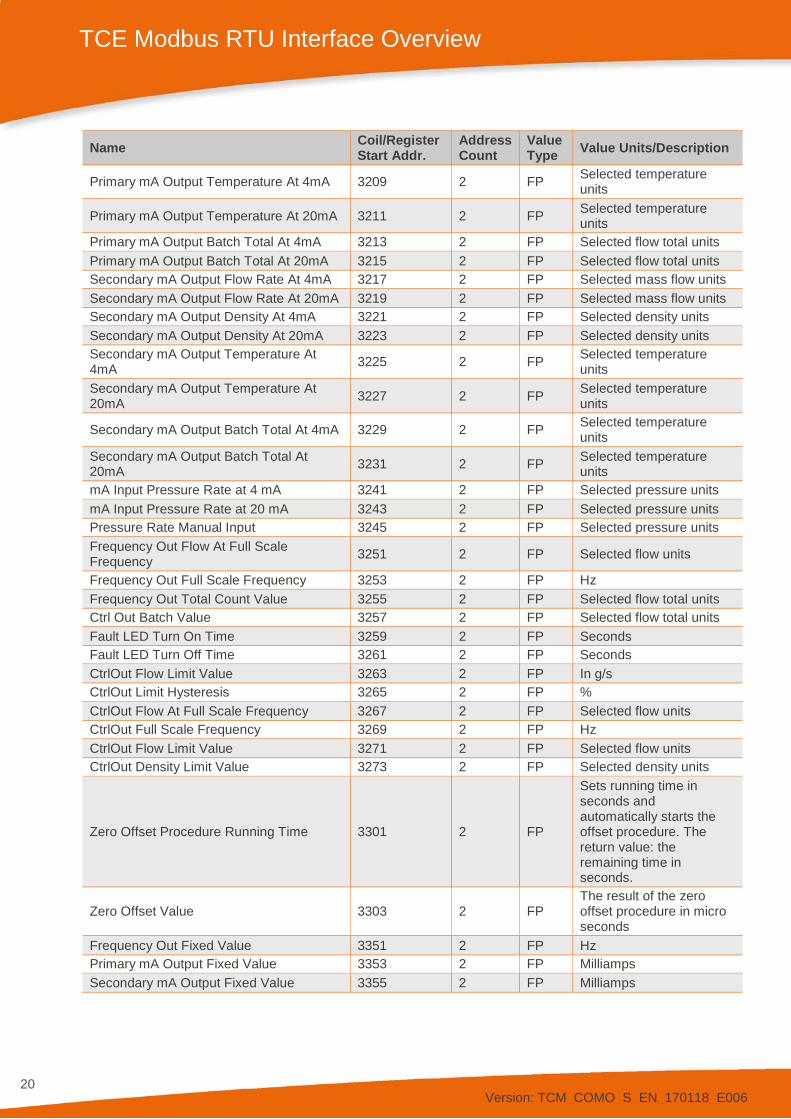
Primary mA Output Temperature At 4mA 3209 2 FP Selected temperature units
Primary mA Output Temperature At 20mA 3211 2 FP Selected temperature units
Primary mA Output Batch Total At 4mA 3213 2 FP Selected flow total units Primary mA Output Batch Total At 20mA 3215 2 FP Selected flow total units Secondary mA Output Flow Rate At 4mA 3217 2 FP Selected mass flow units Secondary mA Output Flow Rate At 20mA 3219 2 FP Selected mass flow units Secondary mA Output Density At 4mA 3221 2 FP Selected density units Secondary mA Output Density At 20mA 3223 2 FP Selected density units Secondary mA Output Temperature At 4mA 3225 2 FP Selected temperature
units Secondary mA Output Temperature At 20mA 3227 2 FP Selected temperature
units
Secondary mA Output Batch Total At 4mA 3229 2 FP Selected temperature units
Secondary mA Output Batch Total At 20mA 3231 2 FP Selected temperature
units mA Input Pressure Rate at 4 mA 3241 2 FP Selected pressure units mA Input Pressure Rate at 20 mA 3243 2 FP Selected pressure units Pressure Rate Manual Input 3245 2 FP Selected pressure units Frequency Out Flow At Full Scale Frequency 3251 2 FP Selected flow units
Frequency Out Full Scale Frequency 3253 2 FP Hz Frequency Out Total Count Value 3255 2 FP Selected flow total units Ctrl Out Batch Value 3257 2 FP Selected flow total units Fault LED Turn On Time 3259 2 FP Seconds Fault LED Turn Off Time 3261 2 FP Seconds CtrlOut Flow Limit Value 3263 2 FP In g/s CtrlOut Limit Hysteresis 3265 2 FP % CtrlOut Flow At Full Scale Frequency 3267 2 FP Selected flow units CtrlOut Full Scale Frequency 3269 2 FP Hz CtrlOut Flow Limit Value 3271 2 FP Selected flow units CtrlOut Density Limit Value 3273 2 FP Selected density units
Zero Offset Procedure Running Time 3301 2 FP
Sets running time in seconds and automatically starts the offset procedure. The return value: the remaining time in seconds.
Zero Offset Value 3303 2 FP The result of the zero offset procedure in micro seconds
Frequency Out Fixed Value 3351 2 FP Hz Primary mA Output Fixed Value 3353 2 FP Milliamps Secondary mA Output Fixed Value 3355 2 FP Milliamps
Version: TCM_COMO_S_EN_170118_E006
21
TCE Modbus RTU Interface Overview
Name Coil/Register Start Addr.
Address Count
Value Type Value Units/Description
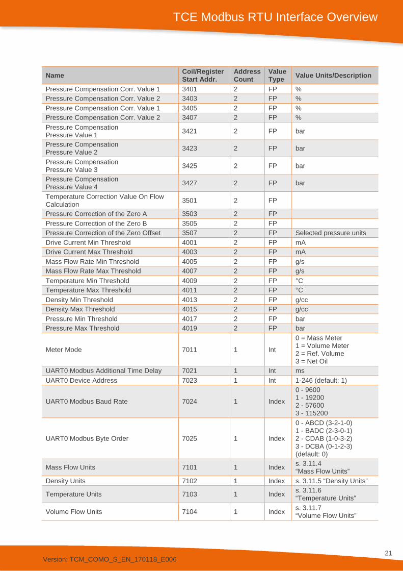
Pressure Compensation Corr. Value 1 3401 2 FP % Pressure Compensation Corr. Value 2 3403 2 FP % Pressure Compensation Corr. Value 1 3405 2 FP % Pressure Compensation Corr. Value 2 3407 2 FP % Pressure Compensation Pressure Value 1 3421 2 FP bar
Pressure Compensation Pressure Value 2 3423 2 FP bar
Pressure Compensation Pressure Value 3 3425 2 FP bar
Pressure Compensation Pressure Value 4 3427 2 FP bar
Temperature Correction Value On Flow Calculation 3501 2 FP
Pressure Correction of the Zero A 3503 2 FP Pressure Correction of the Zero B 3505 2 FP Pressure Correction of the Zero Offset 3507 2 FP Selected pressure units Drive Current Min Threshold 4001 2 FP mA Drive Current Max Threshold 4003 2 FP mA Mass Flow Rate Min Threshold 4005 2 FP g/s Mass Flow Rate Max Threshold 4007 2 FP g/s Temperature Min Threshold 4009 2 FP °C Temperature Max Threshold 4011 2 FP °C Density Min Threshold 4013 2 FP g/cc Density Max Threshold 4015 2 FP g/cc Pressure Min Threshold 4017 2 FP bar Pressure Max Threshold 4019 2 FP bar
Meter Mode 7011 1 Int
0 = Mass Meter 1 = Volume Meter 2 = Ref. Volume 3 = Net Oil
UART0 Modbus Additional Time Delay 7021 1 Int ms UART0 Device Address 7023 1 Int 1-246 (default: 1)
UART0 Modbus Baud Rate 7024 1 Index
0 - 9600 1 - 19200 2 - 57600 3 - 115200
UART0 Modbus Byte Order 7025 1 Index
0 - ABCD (3-2-1-0) 1 - BADC (2-3-0-1) 2 - CDAB (1-0-3-2) 3 - DCBA (0-1-2-3) (default: 0)
Mass Flow Units 7101 1 Index s. 3.11.4 “Mass Flow Units”
Density Units 7102 1 Index s. 3.11.5 “Density Units”
Temperature Units 7103 1 Index s. 3.11.6 “Temperature Units”
Volume Flow Units 7104 1 Index s. 3.11.7 “Volume Flow Units”
Version: TCM_COMO_S_EN_170118_E006
22
TCE Modbus RTU Interface Overview
Name Coil/Register Start Addr.
Address Count
Value Type Value Units/Description
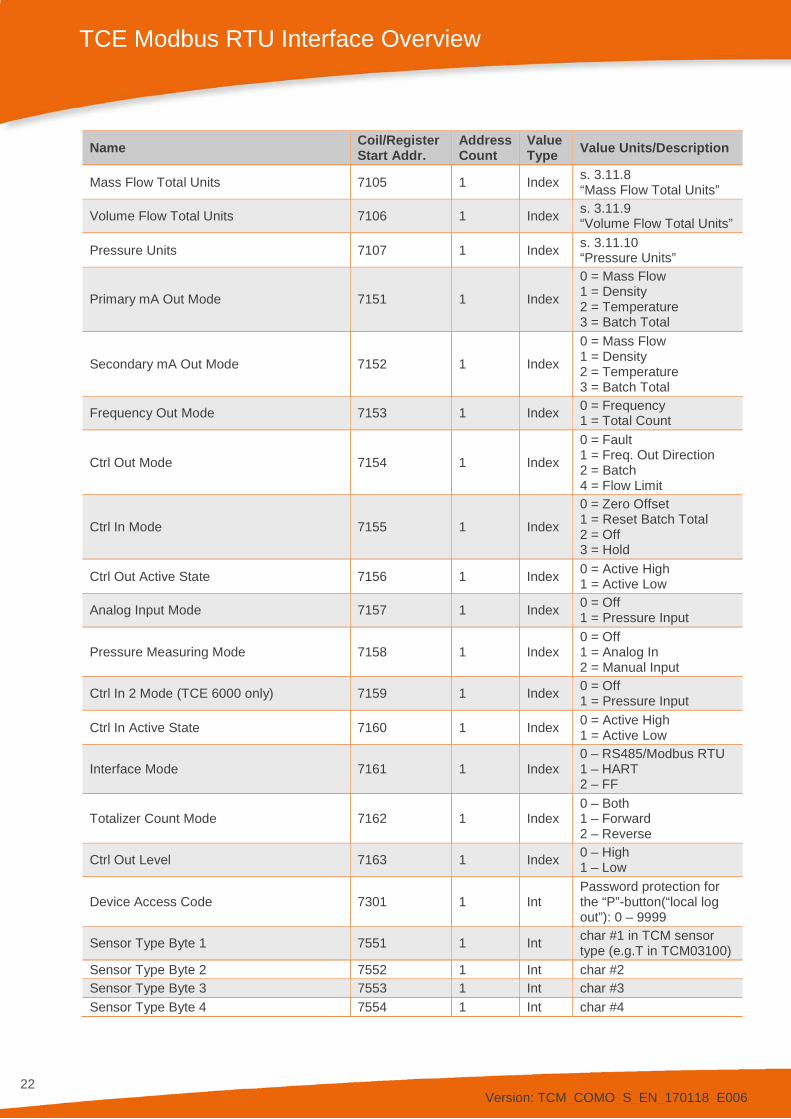
Mass Flow Total Units 7105 1 Index s. 3.11.8 “Mass Flow Total Units”
Volume Flow Total Units 7106 1 Index s. 3.11.9 “Volume Flow Total Units”
Pressure Units 7107 1 Index s. 3.11.10 “Pressure Units”
Primary mA Out Mode 7151 1 Index
0 = Mass Flow 1 = Density 2 = Temperature 3 = Batch Total
Secondary mA Out Mode 7152 1 Index
0 = Mass Flow 1 = Density 2 = Temperature 3 = Batch Total
Frequency Out Mode 7153 1 Index 0 = Frequency 1 = Total Count
Ctrl Out Mode 7154 1 Index
0 = Fault 1 = Freq. Out Direction 2 = Batch 4 = Flow Limit
Ctrl In Mode 7155 1 Index
0 = Zero Offset 1 = Reset Batch Total 2 = Off 3 = Hold
Ctrl Out Active State 7156 1 Index 0 = Active High 1 = Active Low
Analog Input Mode 7157 1 Index 0 = Off 1 = Pressure Input
Pressure Measuring Mode 7158 1 Index 0 = Off 1 = Analog In 2 = Manual Input
Ctrl In 2 Mode (TCE 6000 only) 7159 1 Index 0 = Off 1 = Pressure Input
Ctrl In Active State 7160 1 Index 0 = Active High 1 = Active Low
Interface Mode 7161 1 Index 0 – RS485/Modbus RTU 1 – HART 2 – FF
Totalizer Count Mode 7162 1 Index 0 – Both 1 – Forward 2 – Reverse
Ctrl Out Level 7163 1 Index 0 – High 1 – Low
Device Access Code 7301 1 Int Password protection for the “P”-button(“local log out”): 0 – 9999
Sensor Type Byte 1 7551 1 Int char #1 in TCM sensor type (e.g.T in TCM03100)
Sensor Type Byte 2 7552 1 Int char #2 Sensor Type Byte 3 7553 1 Int char #3 Sensor Type Byte 4 7554 1 Int char #4
Version: TCM_COMO_S_EN_170118_E006
23
TCE Modbus RTU Interface Overview
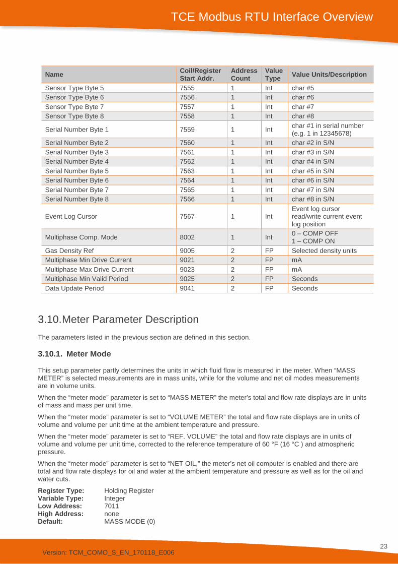
3.10. Meter Parameter Description The parameters listed in the previous section are defined in this section.
3.10.1. Meter Mode
This setup parameter partly determines the units in which fluid flow is measured in the meter. When “MASS METER” is selected measurements are in mass units, while for the volume and net oil modes measurements are in volume units.
When the “meter mode” parameter is set to “MASS METER” the meter’s total and flow rate displays are in units of mass and mass per unit time.
When the “meter mode” parameter is set to “VOLUME METER” the total and flow rate displays are in units of volume and volume per unit time at the ambient temperature and pressure.
When the “meter mode” parameter is set to “REF. VOLUME” the total and flow rate displays are in units of volume and volume per unit time, corrected to the reference temperature of 60 °F (16 °C ) and atmospheric pressure.
When the “meter mode” parameter is set to “NET OIL,” the meter’s net oil computer is enabled and there are total and flow rate displays for oil and water at the ambient temperature and pressure as well as for the oil and water cuts.
Register Type: Holding Register Variable Type: Integer Low Address: 7011 High Address: none Default: MASS MODE (0)
Name Coil/Register Start Addr.
Address Count
Value Type Value Units/Description
Sensor Type Byte 5 7555 1 Int char #5 Sensor Type Byte 6 7556 1 Int char #6 Sensor Type Byte 7 7557 1 Int char #7 Sensor Type Byte 8 7558 1 Int char #8
Serial Number Byte 1 7559 1 Int char #1 in serial number (e.g. 1 in 12345678)
Serial Number Byte 2 7560 1 Int char #2 in S/N Serial Number Byte 3 7561 1 Int char #3 in S/N Serial Number Byte 4 7562 1 Int char #4 in S/N Serial Number Byte 5 7563 1 Int char #5 in S/N Serial Number Byte 6 7564 1 Int char #6 in S/N Serial Number Byte 7 7565 1 Int char #7 in S/N Serial Number Byte 8 7566 1 Int char #8 in S/N
Event Log Cursor 7567 1 Int Event log cursor read/write current event log position
Multiphase Comp. Mode 8002 1 Int 0 – COMP OFF 1 – COMP ON
Gas Density Ref 9005 2 FP Selected density units Multiphase Min Drive Current 9021 2 FP mA Multiphase Max Drive Current 9023 2 FP mA Multiphase Min Valid Period 9025 2 FP Seconds Data Update Period 9041 2 FP Seconds
Version: TCM_COMO_S_EN_170118_E006
24
TCE Modbus RTU Interface Overview
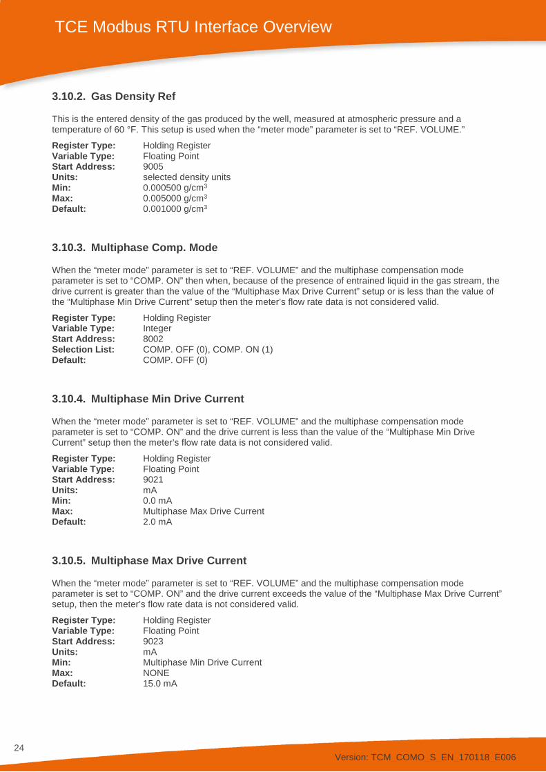
3.10.2. Gas Density Ref
This is the entered density of the gas produced by the well, measured at atmospheric pressure and a temperature of 60 °F. This setup is used when the “meter mode” parameter is set to “REF. VOLUME.”
Register Type: Holding Register Variable Type: Floating Point Start Address: 9005 Units: selected density units Min: 0.000500 g/cm3 Max: 0.005000 g/cm3 Default: 0.001000 g/cm3
3.10.3. Multiphase Comp. Mode
When the “meter mode” parameter is set to “REF. VOLUME” and the multiphase compensation mode parameter is set to “COMP. ON” then when, because of the presence of entrained liquid in the gas stream, the drive current is greater than the value of the “Multiphase Max Drive Current” setup or is less than the value of the “Multiphase Min Drive Current” setup then the meter’s flow rate data is not considered valid.
Register Type: Holding Register Variable Type: Integer Start Address: 8002 Selection List: COMP. OFF (0), COMP. ON (1) Default: COMP. OFF (0)
3.10.4. Multiphase Min Drive Current
When the “meter mode” parameter is set to “REF. VOLUME” and the multiphase compensation mode parameter is set to “COMP. ON” and the drive current is less than the value of the “Multiphase Min Drive Current” setup then the meter’s flow rate data is not considered valid.
Register Type: Holding Register Variable Type: Floating Point Start Address: 9021 Units: mA Min: 0.0 mA Max: Multiphase Max Drive Current Default: 2.0 mA
3.10.5. Multiphase Max Drive Current
When the “meter mode” parameter is set to “REF. VOLUME” and the multiphase compensation mode parameter is set to “COMP. ON” and the drive current exceeds the value of the “Multiphase Max Drive Current” setup, then the meter’s flow rate data is not considered valid.
Register Type: Holding Register Variable Type: Floating Point Start Address: 9023 Units: mA Min: Multiphase Min Drive Current Max: NONE Default: 15.0 mA
Version: TCM_COMO_S_EN_170118_E006
25
TCE Modbus RTU Interface Overview
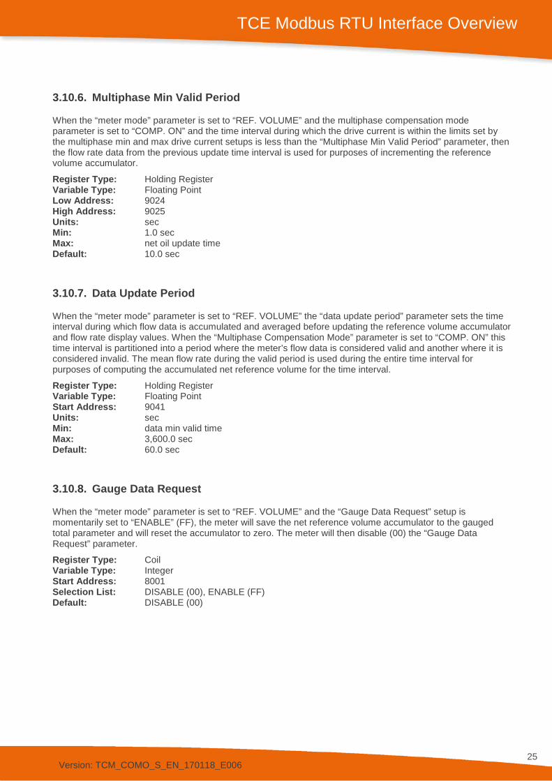
3.10.6. Multiphase Min Valid Period
When the “meter mode” parameter is set to “REF. VOLUME” and the multiphase compensation mode parameter is set to “COMP. ON” and the time interval during which the drive current is within the limits set by the multiphase min and max drive current setups is less than the “Multiphase Min Valid Period” parameter, then the flow rate data from the previous update time interval is used for purposes of incrementing the reference volume accumulator.
Register Type: Holding Register Variable Type: Floating Point Low Address: 9024 High Address: 9025 Units: sec Min: 1.0 sec Max: net oil update time Default: 10.0 sec
3.10.7. Data Update Period
When the “meter mode” parameter is set to “REF. VOLUME” the “data update period” parameter sets the time interval during which flow data is accumulated and averaged before updating the reference volume accumulator and flow rate display values. When the “Multiphase Compensation Mode” parameter is set to “COMP. ON” this time interval is partitioned into a period where the meter’s flow data is considered valid and another where it is considered invalid. The mean flow rate during the valid period is used during the entire time interval for purposes of computing the accumulated net reference volume for the time interval.
Register Type: Holding Register Variable Type: Floating Point Start Address: 9041 Units: sec Min: data min valid time Max: 3,600.0 sec Default: 60.0 sec
3.10.8. Gauge Data Request
When the “meter mode” parameter is set to “REF. VOLUME” and the “Gauge Data Request” setup is momentarily set to “ENABLE” (FF), the meter will save the net reference volume accumulator to the gauged total parameter and will reset the accumulator to zero. The meter will then disable (00) the “Gauge Data Request” parameter.
Register Type: Coil Variable Type: Integer Start Address: 8001 Selection List: DISABLE (00), ENABLE (FF) Default: DISABLE (00)
Version: TCM_COMO_S_EN_170118_E006
26
TCE Modbus RTU Interface Overview
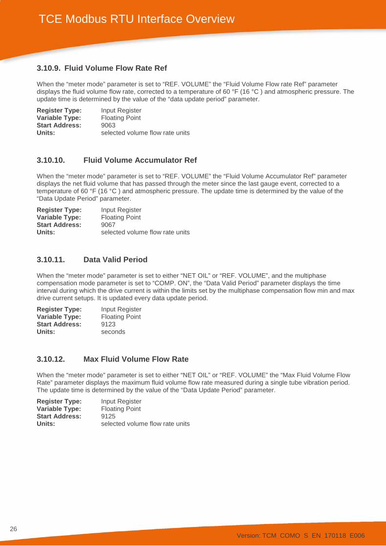
3.10.9. Fluid Volume Flow Rate Ref
When the “meter mode” parameter is set to “REF. VOLUME” the “Fluid Volume Flow rate Ref” parameter displays the fluid volume flow rate, corrected to a temperature of 60 °F (16 °C ) and atmospheric pressure. The update time is determined by the value of the “data update period” parameter.
Register Type: Input Register Variable Type: Floating Point Start Address: 9063 Units: selected volume flow rate units
3.10.10. Fluid Volume Accumulator Ref
When the “meter mode” parameter is set to “REF. VOLUME” the “Fluid Volume Accumulator Ref” parameter displays the net fluid volume that has passed through the meter since the last gauge event, corrected to a temperature of 60 °F (16 °C ) and atmospheric pressure. The update time is determined by the value of the “Data Update Period” parameter.
Register Type: Input Register Variable Type: Floating Point Start Address: 9067 Units: selected volume flow rate units
3.10.11. Data Valid Period
When the “meter mode” parameter is set to either “NET OIL” or “REF. VOLUME”, and the multiphase compensation mode parameter is set to “COMP. ON”, the “Data Valid Period” parameter displays the time interval during which the drive current is within the limits set by the multiphase compensation flow min and max drive current setups. It is updated every data update period.
Register Type: Input Register Variable Type: Floating Point Start Address: 9123 Units: seconds
3.10.12. Max Fluid Volume Flow Rate
When the “meter mode” parameter is set to either “NET OIL” or “REF. VOLUME” the “Max Fluid Volume Flow Rate” parameter displays the maximum fluid volume flow rate measured during a single tube vibration period. The update time is determined by the value of the “Data Update Period” parameter.
Register Type: Input Register Variable Type: Floating Point Start Address: 9125 Units: selected volume flow rate units
Version: TCM_COMO_S_EN_170118_E006
27
TCE Modbus RTU Interface Overview
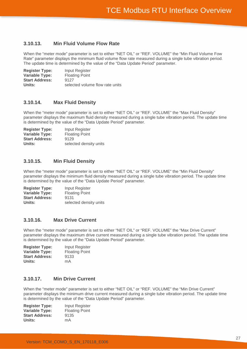
3.10.13. Min Fluid Volume Flow Rate
When the “meter mode” parameter is set to either “NET OIL” or “REF. VOLUME” the “Min Fluid Volume Fow Rate” parameter displays the minimum fluid volume flow rate measured during a single tube vibration period. The update time is determined by the value of the “Data Update Period” parameter.
Register Type: Input Register Variable Type: Floating Point Start Address: 9127 Units: selected volume flow rate units
3.10.14. Max Fluid Density
When the “meter mode” parameter is set to either “NET OIL” or “REF. VOLUME” the “Max Fluid Density” parameter displays the maximum fluid density measured during a single tube vibration period. The update time is determined by the value of the “Data Update Period” parameter.
Register Type: Input Register Variable Type: Floating Point Start Address: 9129 Units: selected density units
3.10.15. Min Fluid Density
When the “meter mode” parameter is set to either “NET OIL” or “REF. VOLUME” the “Min Fluid Density” parameter displays the minimum fluid density measured during a single tube vibration period. The update time is determined by the value of the “Data Update Period” parameter.
Register Type: Input Register Variable Type: Floating Point Start Address: 9131 Units: selected density units
3.10.16. Max Drive Current
When the “meter mode” parameter is set to either “NET OIL” or “REF. VOLUME” the “Max Drive Current” parameter displays the maximum drive current measured during a single tube vibration period. The update time is determined by the value of the “Data Update Period” parameter.
Register Type: Input Register Variable Type: Floating Point Start Address: 9133 Units: mA
3.10.17. Min Drive Current
When the “meter mode” parameter is set to either “NET OIL” or “REF. VOLUME” the “Min Drive Current” parameter displays the minimum drive current measured during a single tube vibration period. The update time is determined by the value of the “Data Update Period” parameter.
Register Type: Input Register Variable Type: Floating Point Start Address: 9135 Units: mA
Version: TCM_COMO_S_EN_170118_E006
28
TCE Modbus RTU Interface Overview
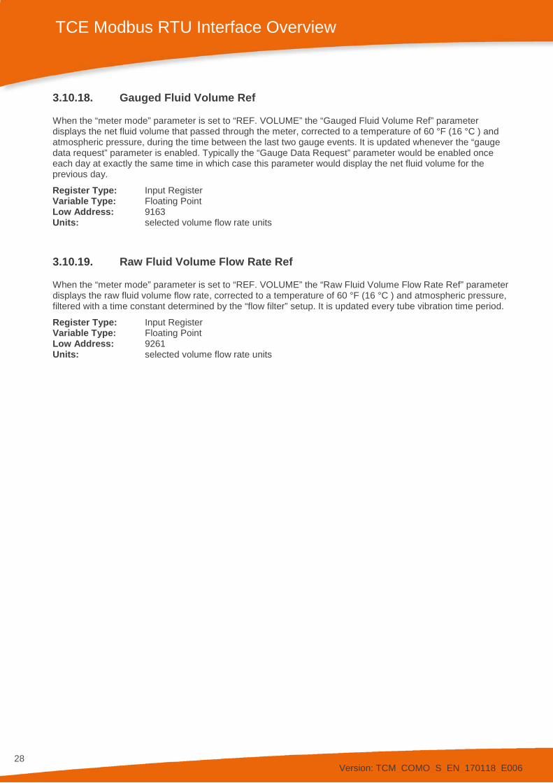
3.10.18. Gauged Fluid Volume Ref
When the “meter mode” parameter is set to “REF. VOLUME” the “Gauged Fluid Volume Ref” parameter displays the net fluid volume that passed through the meter, corrected to a temperature of 60 °F (16 °C ) and atmospheric pressure, during the time between the last two gauge events. It is updated whenever the “gauge data request” parameter is enabled. Typically the “Gauge Data Request” parameter would be enabled once each day at exactly the same time in which case this parameter would display the net fluid volume for the previous day.
Register Type: Input Register Variable Type: Floating Point Low Address: 9163 Units: selected volume flow rate units
3.10.19. Raw Fluid Volume Flow Rate Ref
When the “meter mode” parameter is set to “REF. VOLUME” the “Raw Fluid Volume Flow Rate Ref” parameter displays the raw fluid volume flow rate, corrected to a temperature of 60 °F (16 °C ) and atmospheric pressure, filtered with a time constant determined by the “flow filter” setup. It is updated every tube vibration time period.
Register Type: Input Register Variable Type: Floating Point Low Address: 9261 Units: selected volume flow rate units
Version: TCM_COMO_S_EN_170118_E006
29
TCE Modbus RTU Interface Overview
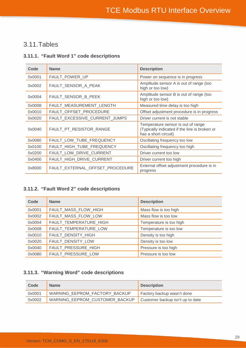
3.11. Tables 3.11.1. “Fault Word 1” code descriptions
Code Name Description
0x0001 FAULT_POWER_UP Power on sequence is in progress
0x0002 FAULT_SENSOR_A_PEAK Amplitude sensor A is out of range (too high or too low)
0x0004 FAULT_SENSOR_B_PEEK Amplitude sensor B is out of range (too high or too low)
0x0008 FAULT_MEASUREMENT_LENGTH Measured time delay is too high 0x0010 FAULT_OFFSET_PROCEDURE Offset adjustment procedure is in progress 0x0020 FAULT_EXCESSIVE_CURRENT_JUMPS Driver current is not stable
0x0040 FAULT_PT_RESISTOR_RANGE Temperature sensor is out of range (Typically indicated if the line is broken or has a short circuit)
0x0080 FAULT_LOW_TUBE_FREQUENCY Oscillating frequency too low 0x0100 FAULT_HIGH_TUBE_FREQUENCY Oscillating frequency too high 0x0200 FAULT_LOW_DRIVE_CURRENT Driver current too low 0x0400 FAULT_HIGH_DRIVE_CURRENT Driver current too high
0x8000 FAULT_EXTERNAL_OFFSET_PROCEDURE External offset adjustment procedure is in progress
3.11.2. “Fault Word 2” code descriptions
Code Name Description
0x0001 FAULT_MASS_FLOW_HIGH Mass flow is too high 0x0002 FAULT_MASS_FLOW_LOW Mass flow is too low 0x0004 FAULT_TEMPERATURE_HIGH Temperature is too high 0x0008 FAULT_TEMPERATURE_LOW Temperature is too low 0x0010 FAULT_DENSITY_HIGH Density is too high 0x0020 FAULT_DENSITY_LOW Density is too low 0x0040 FAULT_PRESSURE_HIGH Pressure is too high 0x0080 FAULT_PRESSURE_LOW Pressure is too low
3.11.3. “Warning Word” code descriptions
Code Name Description
0x0001 WARNING_EEPROM_FACTORY_BACKUP Factory backup wasn’t done 0x0002 WARNING_EEPROM_CUSTOMER_BACKUP Customer backup isn’t up to date
Version: TCM_COMO_S_EN_170118_E006
30
TCE Modbus RTU Interface Overview
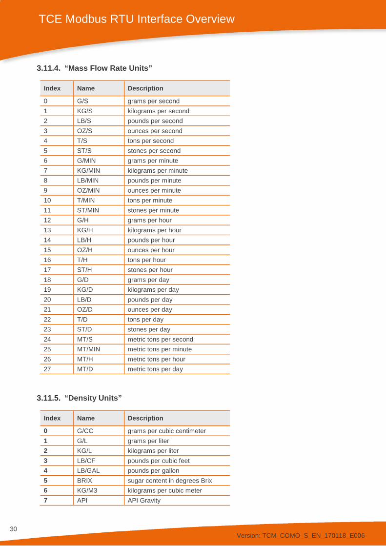
3.11.4. “Mass Flow Rate Units”
Index Name Description
0 G/S grams per second 1 KG/S kilograms per second 2 LB/S pounds per second 3 OZ/S ounces per second 4 T/S tons per second 5 ST/S stones per second 6 G/MIN grams per minute 7 KG/MIN kilograms per minute 8 LB/MIN pounds per minute 9 OZ/MIN ounces per minute 10 T/MIN tons per minute 11 ST/MIN stones per minute 12 G/H grams per hour 13 KG/H kilograms per hour 14 LB/H pounds per hour 15 OZ/H ounces per hour 16 T/H tons per hour 17 ST/H stones per hour 18 G/D grams per day 19 KG/D kilograms per day 20 LB/D pounds per day 21 OZ/D ounces per day 22 T/D tons per day 23 ST/D stones per day 24 MT/S metric tons per second 25 MT/MIN metric tons per minute 26 MT/H metric tons per hour 27 MT/D metric tons per day
3.11.5. “Density Units”
Index Name Description
0 G/CC grams per cubic centimeter 1 G/L grams per liter 2 KG/L kilograms per liter 3 LB/CF pounds per cubic feet 4 LB/GAL pounds per gallon 5 BRIX sugar content in degrees Brix 6 KG/M3 kilograms per cubic meter 7 API API Gravity
Version: TCM_COMO_S_EN_170118_E006
31
TCE Modbus RTU Interface Overview
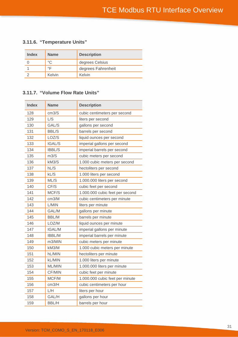
3.11.6. “Temperature Units”
Index Name Description
0 °C degrees Celsius 1 °F degrees Fahrenheit 2 Kelvin Kelvin
3.11.7. “Volume Flow Rate Units”
Index Name Description
128 cm3/S cubic centimeters per second 129 L/S liters per second 130 GAL/S gallons per second 131 BBL/S barrels per second 132 LOZ/S liquid ounces per second 133 IGAL/S imperial gallons per second 134 IBBL/S imperial barrels per second 135 m3/S cubic meters per second 136 kM3/S 1.000 cubic meters per second 137 hL/S hectoliters per second 138 kL/S 1.000 liters per second 139 ML/S 1.000.000 liters per second 140 CF/S cubic feet per second 141 MCF/S 1.000.000 cubic feet per second 142 cm3/M cubic centimeters per minute 143 L/MIN liters per minute 144 GAL/M gallons per minute 145 BBL/M barrels per minute 146 LOZ/M liquid ounces per minute 147 IGAL/M imperial gallons per minute 148 IBBL/M imperial barrels per minute 149 m3/MIN cubic meters per minute 150 kM3/M 1.000 cubic meters per minute 151 hL/MIN hectoliters per minute 152 kL/MIN 1.000 liters per minute 153 ML/MIN 1.000.000 liters per minute 154 CF/MIN cubic feet per minute 155 MCF/M 1.000.000 cubic feet per minute 156 cm3/H cubic centimeters per hour 157 L/H liters per hour 158 GAL/H gallons per hour 159 BBL/H barrels per hour
Version: TCM_COMO_S_EN_170118_E006
32
TCE Modbus RTU Interface Overview
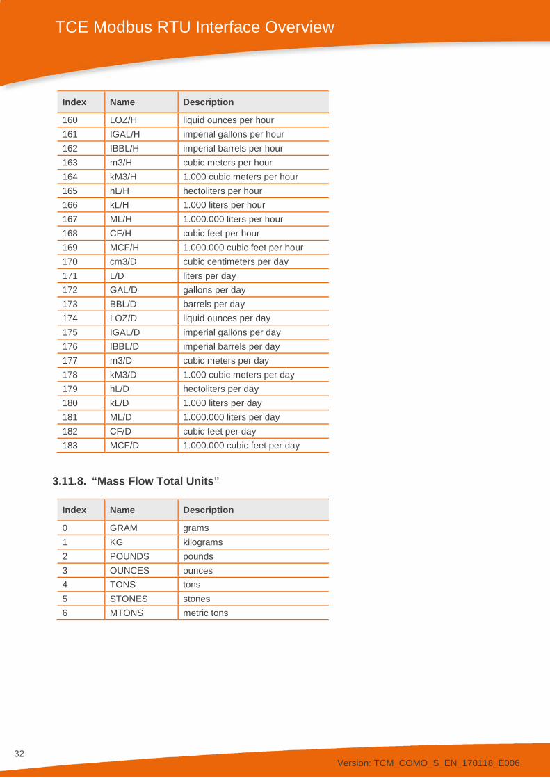
Index Name Description
160 LOZ/H liquid ounces per hour 161 IGAL/H imperial gallons per hour 162 IBBL/H imperial barrels per hour 163 m3/H cubic meters per hour 164 kM3/H 1.000 cubic meters per hour 165 hL/H hectoliters per hour 166 kL/H 1.000 liters per hour 167 ML/H 1.000.000 liters per hour 168 CF/H cubic feet per hour 169 MCF/H 1.000.000 cubic feet per hour 170 cm3/D cubic centimeters per day 171 L/D liters per day 172 GAL/D gallons per day 173 BBL/D barrels per day 174 LOZ/D liquid ounces per day 175 IGAL/D imperial gallons per day 176 IBBL/D imperial barrels per day 177 m3/D cubic meters per day 178 kM3/D 1.000 cubic meters per day 179 hL/D hectoliters per day 180 kL/D 1.000 liters per day 181 ML/D 1.000.000 liters per day 182 CF/D cubic feet per day 183 MCF/D 1.000.000 cubic feet per day
3.11.8. “Mass Flow Total Units”
Index Name Description
0 GRAM grams 1 KG kilograms 2 POUNDS pounds 3 OUNCES ounces 4 TONS tons 5 STONES stones 6 MTONS metric tons
Version: TCM_COMO_S_EN_170118_E006
33
TCE Modbus RTU Interface Overview
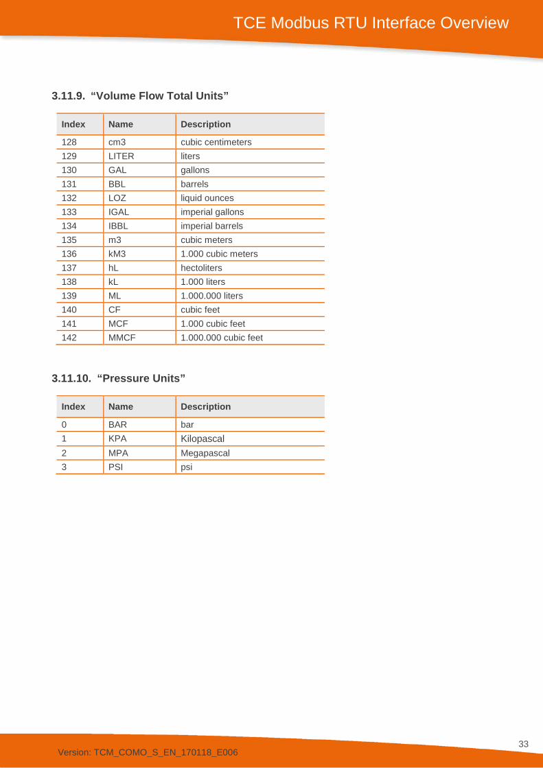
3.11.9. “Volume Flow Total Units”
Index Name Description
128 cm3 cubic centimeters 129 LITER liters 130 GAL gallons 131 BBL barrels 132 LOZ liquid ounces 133 IGAL imperial gallons 134 IBBL imperial barrels 135 m3 cubic meters 136 kM3 1.000 cubic meters 137 hL hectoliters 138 kL 1.000 liters 139 ML 1.000.000 liters 140 CF cubic feet 141 MCF 1.000 cubic feet 142 MMCF 1.000.000 cubic feet
3.11.10. “Pressure Units”
Index Name Description
0 BAR bar 1 KPA Kilopascal 2 MPA Megapascal 3 PSI psi

Version: TCM_COMO_S_EN_170118_E006
34
Contact
4. Contact
TRICOR web page www.tricorflow.com
Sales North and South America: AW-Lake Company 2440 W. Corporate Preserve Dr. #600 Oak Creek WI 53154 USA
Tel.: +1 414 574 4300 [email protected] www.aw-lake.com
China: KEM Flow China Rm. 430, JInYuan Building, No. 36 BeiyuanLu, CN- Chaoyang District, Beijing 100012 P.R.CHINA Tel.:+86 10 84929567 / +86 10 84929577 Fax:+86 10 52003739 [email protected] www.kem-kueppers.cn
Southeast Asia: KEM Küppers Elektromechanik GmbH Representative Office (RO) Singapore 1003 Bukit Merah Central #06-32 Singapore 159836
UEN: T15RF0080G
Tel.: +65 6274 1130 [email protected] www.kem-kueppers.cn
Europe: KEM Küppers Elektromechanik GmbH Liebigstraße 5 DE-85757 Karlsfeld Germany
Tel.: +49 8131 593910 [email protected] www.kem-kueppers.com
Manufacturer KEM Küppers Elektromechanik GmbH Liebigstraße 5 DE-85757 Karlsfeld Germany
Tel.: +49 8131 593910 [email protected] www.kem-kueppers.com
AW-Lake Company 2440 W. Corporate Preserve Dr. #600 Oak Creek WI 53154 USA
Tel.: +1 414 574 4300 [email protected] www.aw-lake.com

Version: TCM_COMO_S_EN_170118_E006
35
Original KEM/AWL document: TCM_COMO_S_EN_170118_E006 Copyright KEM/AWL, Subject to change without notice