Embed Size (px)
Citation preview

TriCoder Users
Manual
Version 9 TriCoders

�������� �������
How to Use this Manual.......................................... i
TriCoder Quickstart ............................................... ii
Program #0 Quickstart........................................1-1 Getting into Data Collection Mode ..................................... 1-1 Collecting Data ................................................................... 1-2 Uploading Data ................................................................... 1-3
Program #1 Quickstart........................................2-1 Collecting Data ................................................................... 2-1 Reviewing and Editing Data ............................................... 2-3 Uploading Data ................................................................... 2-5 Tips on choosing a program for Data Collection ................ 2-5
Non Portable Mode .............................................3-1 Getting in and out of NON PORTABLE mode................... 3-1 Establishing communication in Non Portable Mode........... 3-2
Keyboard Wedge Interface.......................................... 3-2 PC Serial Interface ...................................................... 3-3
Uploading Data....................................................4-1 File Formats ........................................................................ 4-1
Carriage Return Separated Files.................................. 4-1 Comma Separated Files............................................... 4-2 Flat File Formats ......................................................... 4-4
Uploading the data .............................................................. 4-5 PC Keyboard Upload .......................................................... 4-6 Serial Upload ...................................................................... 4-8
TriCoder Connection...........................................5-1 Keyboard Wedge Interface ................................................. 5-1 Connecting the Hardware.................................................... 5-1
PC Keyboard Wedge Installation ................................ 5-1 Macintosh Keyboard Wedge Installation .................... 5-3 USB interface - PC and Mac....................................... 5-4 Configuring the TriCoder............................................ 5-5 Testing using NON PORTABLE .............................. 5-6
Serial Interface .................................................................... 5-7 Connecting the Hardware.................................................... 5-7
Serial Installation - PC with a Serial Port................... 5-7 Serial Wedge Interface - dumb terminal and host ....... 5-8 Serial Interface on a Macintosh................................... 5-9 Configuring the TriCoder.......................................... 5-11 Testing using NON PORTABLE mode .................... 5-12
TriCoder Setup ....................................................6-1 Using the bar code TriCoder Setup Menu........................... 6-1 Using the keypad to setup the TriCoder.............................. 6-1 TriCoder Setup Parameters ................................................. 6-4
Chapter 1
Chapter 2
Chapter 3
Chapter 4
Chapter 5
Chapter 6

Powering the TriCoder........................................7-1 Turning the TriCoder ON and OFF .....................................7-1 Battery Power and Wall Power............................................7-1 Storing the TriCoder............................................................7-4
Creating a custom program ................................8-1 Program Statements.............................................................8-1 Program Name.....................................................................8-3 Statement Entry Types ........................................................8-4 Prompt Text.........................................................................8-9 Voice Message Frequency.................................................8-10 Message Numbers .............................................................8-10 Data ID ..............................................................................8-11 Data Type ..........................................................................8-14 Maximum Data Length......................................................8-14 Minimum Data Length ......................................................8-15 Input Device ......................................................................8-15 Yes/Next Statement ...........................................................8-16 No/End Statement..............................................................8-16 Upload Prefix ....................................................................8-17 Upload Suffix ....................................................................8-21 Programming the TriCoder by scanning bar codes only....8-21 Finishing and checking your program ...............................8-22 Reviewing and Modifying programs .................................8-23
Creating TriCoder Programs on your PC ..........9-1 Installing the Virtual TriCoder Utility .................................9-1 Creating a program..............................................................9-5
Voice Messages..................................................10-1 Why Use Voice Messages and Prompts? ..........................10-1 Tips for Using Voice Prompts ...........................................10-1 TriCoder's Voice Message Mapping .................................10-2 Accessing Voice Message Operations...............................10-3 From the Programming Mode menu…..............................10-3 Using the "hotkey"… ........................................................10-3 Recording and Playback of Voice Messages .....................10-4 Voice Message Options.....................................................10-5 Default Voice Messages ....................................................10-6 Cloning Voice Messages from TriCoder to TriCoder........10-6 Changing the Speaker Volume ..........................................10-8
Transmitting and Receiving Programs and Setup ..........................................11-1
Receiving a program on the TriCoder or host ...................11-1 Windows Utilities..............................................................11-3 Transmitting a program from the TriCoder or host ...........11-4
Partitioning memory for data files and tables..12-1 Partitioning Memory .........................................................12-1 Using Multiple Data Files..................................................12-2 Partitioning memory for tables ..........................................12-4
Chapter 7
Chapter 8
Chapter 9
Chapter 10
Chapter 11
Chapter 12

Tables and Pick Lists.........................................13-1 Partitioning memory for table use..................................... 13-1 Data Validation using Tables ............................................ 13-2 Data Maintenance using tables.......................................... 13-4 Downloading a table to the TriCoder ................................ 13-7 Pick Lists .......................................................................... 13-9
Modem Uploads.................................................14-1 Successful modem communications ................................. 14-1 Dial-up by TriCoder to Host ............................................. 14-1 XMODEM Upload............................................................ 14-3 Unattended Dial-up by Host to TriCoder .......................... 14-4
Troubleshooting ................................................15-1 Display and Error Messages.............................................. 15-1 General Troubleshooting................................................... 15-6 Keyboard Wedge mode troubleshooting........................... 15-8 Serial mode troubleshooting ............................................. 15-9 Program troubleshooting................................................. 15-11 Error messages for special consideration ........................ 15-13 Fail-safe Re-initialization Procedure............................... 15-14 Planning for success….................................................... 15-15 If you have a problem… ................................................. 15-17
Specifications for Code 39 ................................. A-1 Code 39 Advanced Features and Functions ....................... A-2 Mod 43 Check Character ................................................... A-2 Full ASCII Extension to Code 39 ...................................... A-3 Function/Control Key Support in Wedge Mode ................ A-4 Function/Control Key Support with PortKey..................... A-6 Accumulate Mode.............................................................. A-7
Codabar Specifications....................................... B-1
Code 128 Specifications ..................................... C-1 UCC-128/ EAN-128 ...........................................................C-1
Interleaved 2 of 5 Code ......................................D-1
UPC Specifications............................................. E-1
MSI/Plessey Specifications ................................ F-1
Code 93 Specifications .......................................G-1
ASCII Code Equivalent Table ...........................H-1
Cable Pin-outs ..................................................... I-1
Piggyback Laser Installation ..............................J-1
Firmware and Model Upgrades ......................... K-1
How to scan a bar code ...................................... L-1
Chapter 13
Chapter 14
Chapter 15
Appendix A
Appendix B
Appendix C
Appendix D
Appendix E
Appendix F
Appendix G
Appendix H
Appendix I
Appendix J
Appendix K
Appendix L

Optional Features.............................................. M-1
RS-422.................................................................N-1
Polling and how it works....................................O-1
Buffered Terminal Mode.................................... P-1
Using the TriCoder as a Time Clock .................Q-1
Appendix M
Appendix N
Appendix O
Appendix P
Appendix Q

i
���������������� ���� The TriCoder is an extremely versatile bar code reader. It functions as both a portable data collection device as well as a fixed on-line bar code reader. Although the TriCoder can perform complex data collection functions, it's true value is in its simplicity. With very little instruction, a user can collect data using one of the built-in programs, upload it and process the data. This manual is provided with the intention of acting as a guide or reference. Sometimes the best way to learn to use the TriCoder is to simply turn it on and start following the prompts. Other times, more guidance is desired, especially if the user wants to get up and running quickly. Two data collection tutorials are provided as well as detailed instruction on using the TriCoder as a fixed reader using NON PORTABLE mode. The first Quickstart Tutorial uses the built-in Program #0, a simple one prompt (ITEM) data collection program that is useful for simple inventory applications. The second Quickstart Tutorial demonstrates Program #1, an editable program that by default, prompts the operator for an item number, then a quantity. To get started quickly, we suggest using one of the Quickstart Tutorials, then move on to the PROGRAMMING section if you find that neither Program #0 nor Program #1 offers exactly what you need. Although most people use the TriCoder as a portable data collector, it is frequently used in NON PORTABLE mode as a fixed reader for library and POS applications. NON PORTABLE mode is most useful for testing communication before beginning data collection. Chapter 3, Using NON PORTABLE mode, covers all areas of fixed use. The remainder of the manual is a reference guide. Chapters 5, 6, and 7 of the CONNECTION AND SETUP section provide details on configuring the TriCoder as well as the actual hardware connections. If you need use some of the advanced features of the TriCoder, Chapters 8 and 9 of the PROGRAMMING section of the manual details usage of such features as Xtra Statements, Voice Messaging, and Data Identifiers. Chapters 10-14 of the ADVANCED USAGE section describe Voice Messaging, Transmitting and Receiving programs, Tables and Pick Lists and Modem Protocol. The TROUBLESHOOTING section provides reference for error messages, solving problems and details on how to reach Worthington Data Solutions. The REFERENCE section offers bar code specifications and other useful information.

ii
������������������
As powerful as the TriCoder is, its basic operation is quite simple. Many people can use Program #0 or Program #1 to satisfy their data collection needs. This Chapter helps you get started quickly using Program #0 or Program #1. It also will refer you to the correct place if you want to customize or expand on Program #1. We highly recommend going to Chapter 3; Non Portable Mode and establishing communication between the TriCoder and the PC before you continue with either of the tutorials. It is easier to establish communication with one data item in the TriCoder rather than trying to do so during a massive batch upload. The chapters in this section are:
• Program #0 Tutorial Uses the fixed program #0 to collect and upload data for a single ITEM prompt to your computer. If you need a program that prompts for an item number and then a quantity, go to the Program #1 Tutorial. If Program #0 works for you except that you have trouble with the upload (you need delays), see Program #2. It is identical to program #0 but allows editing of the Upload Prefix and Suffix. See Chapter 8;Creating a custom program for information on the Upload Prefix and Suffix.
• Program #1 Tutorial Uses the editable program #1, which prompts for Item Number, then Quantity. The tutorial includes collecting, reviewing, and uploading data as well as providing outlines for different file formats and voice messaging. Since Program #1 is editable, the tutorial also discusses use of the following popular features:
− Data Security Restricting user to Data Collection mode or to data collection in one program only.
− Xtra Statement Automatically enter a quantity of 1 without the user having to input any data.
• Non Portable Mode Provides details on Non Portable use and establishes communication between TriCoder and host computer both serially and through the keyboard. Includes installation instructions for the Windows TriCoder Utilities program
• Uploading Data Guides the user through the uploading of data through the keyboard and serially for both tutorials described above.

1-1
Chapter 1
��������������������� The default data collection program, Program #0, is a simple program, repeatedly prompting the operator for data entry of the same type. This TriCoder program works well for a simple inventory where each item is scanned. This chapter is in the form of a tutorial. Even if you don’t intend to use Program #0, working through the tutorial will prepare you for creating your own programs and learning the basics of data collection.
���� �� ���������������� ������The first step involves turning on the TriCoder (make sure you have good batteries), getting into DATA COLLECTION mode and choosing Program #0.
Turn on the TriCoder by pressing the ON/OFF key. The TriCoder will power up and display its opening screen:
TRICODER Sx9xxxx HIT ANY KEY_
Press any key on the TriCoder keypad. If the TriCoder was in NON PORTABLE MODE when it was shut off earlier, it will automatically go back into NON PORTABLE MODE now. If this is the case, press the F1 key to get to the DATA COLLECTION prompt. If the TriCoder was in any other mode at shutoff, DATA COLLECTION is the first prompt you will see after pressing any key at the opening screen.
DATA COLLECTION? KEY [YES/NO]?_
At the DATA COLLECTION prompt, press the YES key on the TriCoder keypad. Press “0” on the TriCoder keypad to select the default Program #0.
PROGRAM NO.? KEY [0-3]?_
Step 1

1-2
������� �������The second step involves collecting data in the TriCoder. This is a good time to practice scanning. If you are not familiar with scanning bar codes, see Appendix L; How to scan a bar code for details and suggestions. If you don’t intend on using bar codes later, you can just enter the same data from the keypad.
Pressing “0” at the PROGRAM NO.? prompt begins the data collection process by displaying this prompt for the operator:
ENTER DATA _ For the purposes of this tutorial, we will use the sample bar codes as our data. Upon scanning, the TriCoder will beep once and display the following:
ENTER DATA (� original prompt) 00001 (� bar code #1) ENTER DATA (� new data entry prompt)
After scanning, the TriCoder displays the original prompt, then the data just entered, then the new data entry prompt. For the tutorial, our second piece of data will be 00002. Go ahead and scan sample bar code #2 or key in 00002:
00001 (� original data)
ENTER DATA (� 2nd data entry prompt)
00002 (� 2nd piece of data entered) ENTER DATA (� new data entry prompt)
Continue to scan the sample bar codes or enter the data from the keypad. The TriCoder display will scroll with each entry as shown immediately above. As soon as you are finished entering all 10 bar codes, press the END key to exit DATA COLLECTION.
Step 2

1-3
Program #0 Sample Bar Codes
�
������ �������Once you have collected your data in Program #0, uploading that data to the computer is the final step. For the tutorial, we assume that you have successfully established communication between the computer and the TriCoder. If you have not, go
to Chapter 3; Non Portable Mode, and establish communication first. If you are ready to upload, go to Chapter 4; Uploading Data and proceed with your upload.
Step 3
01 02
03 04
05 06
07 08
09 10

2-1
Chapter 2
��������������������� Program #1 prompts the operator for "Item" and then "Quantity". What makes this program different from program #0 (other than the additional "Quantity" prompt) is that Program #1 is editable. It can be customized to allow for additional prompts, voice messaging and file formatting. The tutorial for Program #1 includes collecting data, reviewing and editing data, using popular uploaded file formats and finally, uploading the data
������� �������Collecting data in Program #1 requires two pieces of data; an item and a quantity. By default, Program #1 is set up to accept data from either the scanner or the keypad for the item, but only from the keypad for the quantity.
Program #1 also features voice messaging. By default, Program #1 plays a voice prompt of “Item” for the visual “ENTER ITEM NO.” prompt and a voice prompt of “Quantity” for the visual “ENTER QUANTITY” prompt. Program #1 only plays each voice message the first 5 times the prompt is displayed. The TriCoder can be programmed to play the voice message every time the visual prompt is displayed if desired. See Chapter 8; Creating a custom program or Chapter 10; Voice Messaging for details. Using the bar code samples on the next page, scan an item number bar code, then enter the quantity of “123” on the TriCoder keypad.
Step 1

2-2
Continue to scan bar codes and enter quantities until you have at least 10 records. You can check to see how many times you have scanned an item number by pressing the following keys while at the ENTER ITEM prompt:
− Press SHIFT − Press F1 − Press T You can use the same key sequence to check the number of times you have entered data for any prompt.
Remember, the only thing SHIFT F1 T can do is simply tell you how many times you have entered data for a particular prompt.
����� ���� �
����� ����� �
���� ������ �
���� ����� �
����� ���� �
���� ����� �
����� ���� �
����� �����
���� ������
����� ����� �

2-3
To end data collection in Program #1, simply press the END key. If you forget to exit Data Collection and simply turn the TriCoder off, do not panic – the TriCoder has saved your data. Pressing the F1 key while in Data Collection also exits data collection and returns you to the Mode Menu. Using the END key to end Data Collection is the preferred method.
�!�� ��� ��"�� �������During or after collecting data, it is possible to review and edit the data while it is still in the TriCoder. You can also delete data entirely. Data Review Mode is a handy tool – especially if you know you’ve made a mistake and want to correct it before you upload your data.
For the tutorial, lets say that we just wanted to take a break from collecting data, exited DATA COLLECTION (by pressing the END key), turned off the TriCoder and went to lunch. We’re back now and want to resume our data collection. Turn the TriCoder back on and just as in step 1; get into DATA COLLECTION mode. Since there is already data in the TriCoder, instead of simply displaying the prompt, the TriCoder plays the “DATA FILE EXISTS” voice message, and displays the same message on the TriCoder screen:
DATA FILE EXISTS HIT ANY KEY_
then immediately displays the ENTER DATA prompt.
Say we want to review the data already in the TriCoder - maybe we made a mistake or think we missed some data. To review data already in the TriCoder, press the “UP ARROW” key on
the TriCoder keypad. The TriCoder will beep – 2 low beeps then 2 high beeps and display:
Data Review Request Press <BEGIN> key to Start or <F1> for Data Collection_
If we just wanted to go into DATA COLLECTION, we would simply press F1 and start scanning again, but we want to review the data already collected so press the BEGIN key to get into DATA REVIEW mode. Once in DATA REVIEW
mode, the TriCoder displays the last data collected. To get to the beginning of your data file, press the BEGIN key. The TriCoder displays:
ENTER QUANTITY XXX (last quantity data entered) BEGIN OF FILE HIT ANY KEY_
Step 3

2-4
Press any key on the TriCoder keypad. The TriCoder displays the first record of data. To scroll through the data record by record, press the RIGHT ARROW key.
To immediately go to the end of the data, press the END KEY. At the END OF FILE prompt, hit any key to get to the last record of data in the file.
To scroll backwards through the data record by record, press the LEFT ARROW key. To edit individual characters in a data record, use the right and left arrow keys to find the data you want to edit.
If you know what data you are looking for (or want to look for all data that has certain characters) you can use the SEARCH key. After pressing the SEARCH key, the TriCoder displays the
SEARCH PATTERN prompt. Enter the data you want to search for (ie. 22) then press ENTER. The TriCoder begins its search at the beginning of the file and moves forward until a match is found. If using our example of 22, the TriCoder would find all data that contains 22, regardless of its position in the data (ie. 22345, 32245, 34522).
Pressing the DELETE key deletes characters to the left. Replace characters simply by pressing a key. To replace an entire data entry, use the right and left arrow keys to find the data, then press the CLEAR key to delete the entry. You can re-enter data at this point by entering data from either the keypad or by scanning. If you enter data from the keypad (when either editing single characters or replacing an entire entry) you must press ENTER on the keypad for the change to take place. If you want to completely delete the data, after pressing CLEAR, the
TriCoder will prompt you with DELETE THIS FIELD? If you are sure you want to delete the data, press ENTER.
You can use the STATUS key at any time during data collection to check the amount of memory you have left as well as the battery levels:
mm/dd/yy hh:mm:ss xxxk BYTES FREE AAaBAT�����������-xx% LI – BAT�����������-xx%
If during data collection, the TriCoder displays the following message:
WARNING 2K LEFT HIT STATUS KEY_
it means that the TriCoder has only 2K of memory left to collect data. This is a

2-5
good time to go and upload your data. You can continue to collect data but you will eventually get this message:
OUT OF MEMORY HIT ANY KEY_
Pressing a key will take you out of Data Collection mode and back to the Mode Menu. You will have to upload your data before you can collect any more.
When you are ready to go back to collecting data, press the F1 key at any time to begin appending data to the existing data file. The F1 key also backs you out of any mode you are in; for
example, if you are in Non Portable mode, pressing F1 takes you back to the Data Collection prompt of the Mode Menu.
������ �������Once you have collected your data in Program #1, uploading that data to the computer is the final step. For the tutorial, we assume that you have successfully established communication between the computer and the TriCoder. If
you have not, go to Chapter 3; Non Portable Mode, and establish communication first. If you are ready to upload, go to Chapter 4; Uploading Data and proceed with your upload. �
����� ����� ������������#���������������� ��The TriCoder comes with 3 programs pre-installed. Program #0 is a simple un-editable program prompting repeatedly for an ITEM. Program #2 is identical to Program #0 except that it allows for customization (ie. the Upload Prefix and Upload Suffix). See Chapter 8; Creating custom programs for details on what the Upload Prefix and Upload Suffix can do for you. Program #1 differs from Program #0 and #2 in that it has two prompts - "ENTER ITEM NO." and then "ENTER QUANTITY". Program #1 is also fully editable and lends itself well to the use of several features in particular. Two of these features are there to protect your data. The first safety feature, Data Security, confines the user to data collection mode ONLY. The user is not allowed into any mode other than DATA COLLECTION mode. In addition to using Data Security to restrict the user to DATA COLLECTION mode, you can use the second security feature, Program Restriction, to confine the user to one particular program in the TriCoder. For details on how to use these Data Security features, see Chapter 6; TriCoder Setup. Another useful programming feature, the Xtra Statement, works with the "ENTER QUANTITY" prompt by automatically entering a quantity of “1” if the
Step 4

2-6
user enters another ITEM number instead of a quantity. See Chapter 8, Creating a custom program for details on the Xtra program statement. Program #1 is extremely versatile. Use it if you can, making modifications to fit your application. If you require a customized program, these are just a few of the options and features offered by custom programming:
• Additional user prompts for other types of data
• Program timing delays to facilitate uploading directly into an application
• Branching to different areas in the program, depending on the input from the user
• Downloading tables of data to validate or edit into the TriCoder
• Recording customized Voice Messages If any of the above features (or anything not offered by Program #1) appears to be something you are interested in, move on to the PROGRAMMING section of the manual. The Chapters 8 and 9 in the PROGRAMMING section cover all aspects of creating and maintaining custom programs in the TriCoder.
3-1
Chapter 3
$� ������%�������� NON PORTABLE mode allows the user to transmit data directly from the TriCoder to the host computer immediately without saving the data in the TriCoder's memory. Once data is entered via scanning a bar code or using the keypad, it is transmitted immediately by the TriCoder to the host. This mode is used with the PC keyboard wedge interface, on a PC RS-232 serial port (with Portkey if you want keyboard emulation) and with an RS-232 terminal-host connection. NON PORTABLE mode is used to enter data directly into an application. Common applications include library check in/out, document tracking and Point-Of-Sale. NON PORTABLE mode should also be used to establish communication between the TriCoder and host computer before data uploads are attempted.
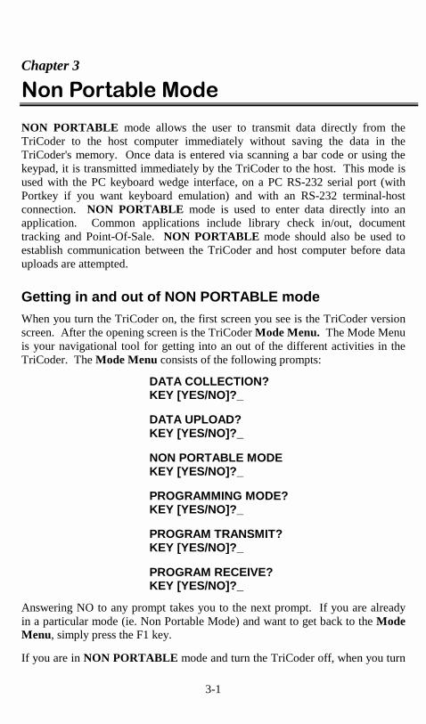
Getting in and out of NON PORTABLE mode When you turn the TriCoder on, the first screen you see is the TriCoder version screen. After the opening screen is the TriCoder Mode Menu. The Mode Menu is your navigational tool for getting into an out of the different activities in the TriCoder. The Mode Menu consists of the following prompts:
DATA COLLECTION? KEY [YES/NO]?_ DATA UPLOAD? KEY [YES/NO]?_ NON PORTABLE MODE KEY [YES/NO]?_ PROGRAMMING MODE? KEY [YES/NO]?_ PROGRAM TRANSMIT? KEY [YES/NO]?_ PROGRAM RECEIVE? KEY [YES/NO]?_
Answering NO to any prompt takes you to the next prompt. If you are already in a particular mode (ie. Non Portable Mode) and want to get back to the Mode Menu, simply press the F1 key.
If you are in NON PORTABLE mode and turn the TriCoder off, when you turn
3-2
the TriCoder back on and press a key at the opening screen you are automatically brought back into NON PORTABLE mode. If you are in any other mode, simply answer NO to all prompts until you see:
NONPORTABLE MODE KEY [YES/NO]?_
Press YES to enter NON PORTABLE mode. The TriCoder now displays:
NONPORTABLE MODE
on the display and is ready and waiting for input. If you want to leave NON PORTABLE mode, simply press the F1 key to return to the beginning of the MODE MENU. Typically, the TriCoder is used in NON PORTABLE mode while it's connected to the host computer either by keyboard splitter cable or via serial connection. See Chapter 5; TriCoder Connection, for more information and diagrams to help you correctly connect the TriCoder to your computer.
Establishing communication in Non Portable Mode
Keyboard Wedge or USB Interface To test communication as a keyboard wedge, all you need is a program capable of accepting data from the keyboard – for example, Windows Notepad. Typically, most applications work this way but for testing, a simple text editor (Notepad) or word processor is all that is needed. The key to testing communications is to keep it simple – you don’t want to have to determine whether it’s your software or the TriCoder causing a problem. 1. Start the software you are going to use to test the TriCoder. If it is a text
editor or word processor, make sure to start with a new document Use Windows Notepad if you can.
2. Turn the TriCoder on. Press the NO key in response to all prompts until
you see the NON PORTABLE mode prompt. Press the YES key. 3. Scan the TEST LABEL on the next page. If you are not using the TriCoder
with a bar code scanner, type several numbers on the TriCoder keypad, then press the ENTER key. You should see the word TEST LABEL (or data you entered on the keypad) on the TriCoder screen AND on your computer screen.

3-3
4. If you do NOT see your data displayed on your computer screen, or you see
partial data (letters or numbers missing), go to Chapter 6; TriCoder Setup and review the Computer Interface settings. These symptoms are typical of when the timing between the TriCoder and keyboard is not quite right. If attached to a USB port, you must use Computer Interface 1.
Use the “LEARNING” mode settings under the Computer Interface parameter to allow the TriCoder to match the timing of the keyboard. If “LEARNING” mode does not solve the problem, see the Intercharacter Delay parameter for a possible solution. Do not use the "LEARNING" mode settings for USB.
PC Serial Interface Testing communication between a serial interface TriCoder and a PC needs some kind of software to read the serial port. Windows users should use the Windows TriCoder Utilities program that comes with the TriCoder. If using a dumb terminal/host configuration, the testing is identical to that of a PC keyboard wedge. Windows Users 1. Install the Windows TriCoder Utilities program by inserting the diskette in
your floppy drive and clicking on Start, then choosing Run. Type in A:/Setup.exe (substitute your drive letter if not A) then click on OK. Follow the directions on your screen to install the program.
2. After installing the Windows TriCoder Utilities program, run the program
by clicking on the TriCoder Utilities icon. After the program is up and running, click on the tab labeled “Port Settings”.
3. Choose the correct serial port - COM1, COM2, COM3 or COM4. The
default Baud Rate is 9600, the Parity is None, the Data Bits is 8, and the Stop Bits is 1. These are the default settings in the TriCoder also. For testing purposes, it is best to work with the default settings.
3-4
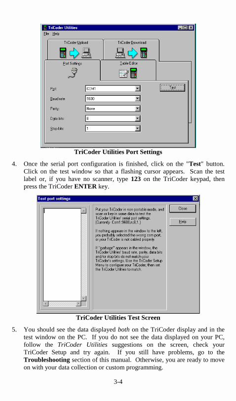
TriCoder Utilities Port Settings
4. Once the serial port configuration is finished, click on the "Test" button. Click on the test window so that a flashing cursor appears. Scan the test label or, if you have no scanner, type 123 on the TriCoder keypad, then press the TriCoder ENTER key.
TriCoder Utilities Test Screen
5. You should see the data displayed both on the TriCoder display and in the test window on the PC. If you do not see the data displayed on your PC, follow the TriCoder Utilities suggestions on the screen, check your TriCoder Setup and try again. If you still have problems, go to the Troubleshooting section of this manual. Otherwise, you are ready to move on with your data collection or custom programming.

4-1
Chapter 4
������ ������� If you are ready to upload data, we assume you have established correct communication between your TriCoder and host and have collected some sample data, preferably using the Program #0 or Program #1 Tutorials. By default, the TriCoder uploads using a Carriage Return Separated format. For many users, the default file format works fine, but others may require more complex or even custom upload file formats. By default, the TriCoder transmits it’s data in the following order:
ID + Prefix + data + Checksum chs + Suffix + Terminator
You should keep the above order in mind when determining how to upload your data. Before we actually upload any data, lets discuss some of the most common file formats.
File Formats The program you are using to process your data will determine what format the uploaded file needs to use. There are several commonly used formats – Carriage Return separated, Comma separated; and Flat File formats. By default, the TriCoder uploads using the CR (Carriage Return) separated format. We will cover each format in order of ease of use, with the default uploading format first.
Carriage Return Separated Files By default, the TriCoder uploads its data in the following format: DATA(CR) 11111111 DATA(CR) data looks like: 22222222 DATA(CR) 33333333 This format is called Carriage Return separated. Each piece of data is followed by a Carriage Return (or Carriage Return/ Line Feed if Serial Interface), causing each piece of data to appear on a separate line. The TriCoder does this by using the Terminator Character. The Terminator Character is the character that follows each piece of data either when the TriCoder is uploaded or when data is transmitted in NON PORTABLE mode. The default Terminator Character for a keyboard wedge is CR (carriage return) and CR/LF (carriage return/line feed) for a serial interface. To upload the TriCoder with a Carriage Return delimited file, simply leave the Terminator Character set to the default settings and upload the TriCoder.

4-2
Comma Separated Files Another common file format is a Comma Separated File. A TriCoder setup to upload in this format uploads data like this: “DATA”,”DATA”(CR) “111111”,”22” “DATA”,”DATA”(CR) data looks like: “222222”,”33” “DATA”,”DATA”(CR) “333333”,”44” Each data item is surrounded by double quotes, creating a field. Fields of data are separated by commas. The double quotes allow commas to be used as actual data as well as separaters (see the example below). At the end of all of the fields of data, a Carriage Return is added to create a complete record. Modifying Program #1 as an example, the data uploaded would look like this: “ITEM NUMBER”, “QUANTITY” “0123456,12oz”, “15” “ITEM NUMBER”, “QUANTITY” “889384,8oz”, “940” “ITEM NUMBER”, “QUANTITY” “32834,20oz” , “7” where ITEM NUMBER is the first field, QUANTITY is the second field, and both fields together make a record. To program the TriCoder to upload in this format, the first thing we must do is set the Terminator Character to “None”. The idea is first, to stop the TriCoder from automatically sending the same character after each field of data, then second, customize the program in the TriCoder to transmit a double quote before and after each data item, a comma after each field and a carriage return after each record. To customize the program in the TriCoder, we use the Upload Suffix to specify which character we want to precede or follow each particular field. Using Program #1 as our example, we will walk through the steps required to upload Program #1 in a Comma delimited format: 1. Set the Terminator Character to NONE
Change the Terminator Character either by scanning the bar coded setup menu or by keypad in PROGRAMMING MODE. To change it using the bar coded Setup Menu, scan these bar codes in the following order:
− Scan START SETUP − Scan TERMINATOR CHARACTER − Scan 2 (sets it to None) − Scan END SETUP To change the Terminator Character using the keypad:
− get into PROGRAMMING MODE − choose 5 for Change Setup

4-3
− choose 1 for Computer − Press ENTER until you see TERMINATOR CHAR. − Press 2 − Press F1 − Press F1 again to exit PROGRAMMING MODE
2. Program the Upload Prefix and Upload Suffix
After setting the Terminator Character to NONE, the next step is to enter PROGRAMMING MODE and program the Upload Prefix and Upload Suffix for each field of data. For Program #1, we will program the Upload Prefix and Upload Suffix as follows:
Statement Prompt Upload Prefix Upload Suffix
ENTER ITEM NO. “ (double quote) “, (double quote comma)
ENTER QUANTITY “ (double quote) “CR (double quote carriage return)
− Put the TriCoder in PROGRAMMING MODE − Press 1 at the Create Programs prompt (to edit program #1) − Press YES at the EDIT PROGRAM #1? prompt
If you have no data collected in the TriCoder, press ENTER until you see:
UPLOAD PREFIX 01 _
If you have data collected in the TriCoder (assuming you are following the tutorial), you will see the Upload Prefix prompt immediately. This is because the TriCoder will allow you to edit ONLY the Upload Prefix and Upload Suffix if data is currently in memory. At the Upload Prefix 01 prompt, scan the “double quote” bar code on the Full Ascii Menu.:
UPLOAD PREFIX 01 “_
Press the ENTER key to complete the change. Press the ENTER key again until you see:
UPLOAD SUFFIX 01 _
The Terminator Character follows each piece of data in Non Portable Mode also. If you change it to NONE and still need a CR while in Non Portable mode, program the POSTAMBLE setup parameter to be a CR (carriage return). Use the bar coded setup menu and Full Ascii Menu to scan:
START SETUP POSTAMBLE CR LF (if serial) SET END SETUP

4-4
Scan the bar code for “double quote” then scan the bar code for the “comma”.
UPLOAD SUFFIX 01 “,_
Press the ENTER key until you get to the UPLOAD PREFIX 02 prompt. At the prompt scan the “double quote” bar code.
UPLOAD PREFIX 02 “_
Press the ENTER key until you see the UPLOAD SUFFIX 02 prompt. Scan the “double quote” bar code, then, scan the “CR” bar code if using the TriCoder as a keyboard wedge, or the “CR” and the “LF” if using the TriCoder as a Serial interface:
UPLOAD SUFFIX 02 “?_
Press ENTER to complete the change. If you do not press ENTER after each change, the change will not be permanent. Press the F1 key to exit the program, then F1 again to exit PROGRAMMING MODE. The TriCoder is now programmed to upload its data in a comma separated file format.
Flat File Formats Flat Files are the most complicated file format of the three we are covering in the tutorial. The format of a Flat File is mostly dependent upon the host program you will use to process the data you are uploading. A Flat File uses what we call “Refer-backs”. Each record has at least one field that remains constant while other fields may contain variable data. “Refer-backs” allow the operator to enter the data for the constant fields only once, letting the TriCoder append the data to each record as it uploads. “Refer-backs” are specified in the Upload Prefix and Upload Suffix of each field. We will use a program that prompts for operator name, item number and finally a quantity to demonstrate how “Refer-backs” work. Lets say that the data for the first field in every record must be the operators initials (3 characters). The second field in each record must be an item number and the third field is a quantity. It doesn’t make sense to require the operator to enter their initials every time they scan an item number and enter a quantity. The solution is to create a program that uses a “Refer-back” to attach the data from prompt #1 (operator name) and the data for prompt #2 (item number) to the data for prompt #3 (quantity) every time. We do this by using the upload prefix or upload suffix.

4-5
Specifiying these characters:
}xx where xx is the number of the statement you want to take data from, in the Upload Prefix or Upload Suffix of the statement you want to attach the “Refer-back” data to. The following TriCoder Coding Form shows the program we have described above (only the relevant entries on the form are shown):
Stmt # Entry Type
Prompt Yes/Next Stmt
No/End Stmt
Upload Prefix
Upload Suffix
01 D Operator Name 02 99 ~0
02 D Enter Item No. 03 99 ~0
03 D Enter Quantity 02 99 }01}02 CR
Refer-back programming example The above program would prompt for Operator Name once, then repeatedly prompt for Item, then Quantity, attaching the Operator Name data and the Item data to the front of every quantity upon upload. If the data for Operator Name entered is WDS, and variable data is entered at each Item and Quantity prompt, the uploaded file would look like this:
Operator Name
Item # Quantity Uploaded data looks like:
WDS 123456 124 WDS123456124
892938 880 WDS892938880
345890 3 WDS3458903
99540 75 WDS9954075 Flat File sample data
The TriCoder is not limited to uploading using only the three file formats - Carriage Return delimited, Comma delimited and Flat File - described above. By using different characters in the Upload Prefix and Upload Suffix of each program statement, you can create a file in just about any format – the three described above are simply the most commonly used. For more information on using the Upload Prefix and Upload Suffix, see Chapter 8; Creating custom programs in the PROGRAMMING section of this manual. For the tutorial, use either the Carriage Return separated or Comma delimited formats.
������ ����������DATA UPLOAD mode is used to extract the data collected while in DATA COLLECTION mode. DATA UPLOAD mode uses either the wedge or serial interface and requires that you have established communication between the host computer and the TriCoder. Before collecting and uploading large amounts

4-6
of data, try a small amount of data to make sure your upload works correctly. Data can be uploaded either into a separate file that is then merged or processed by your application or it can be uploaded into your application directly. Before you upload directly into an application, back up any files that will be altered by the upload – work only with copies, not with your actual data, until you know your upload works correctly. For this tutorial, we will describe a keyboard interface upload using Windows and DOS, then a serial upload on a PC Serial Port using the Windows TriCoder Utilities. To get to DATA UPLOAD mode on the TriCoder, answer NO to all prompts until you see:
DATA UPLOAD? KEY [YES/NO]?_
Do NOT press YES until you have your PC ready for the data upload to begin. If you have a T63 Keyboard Interface TriCoder, proceed to the next section, PC Keyboard Upload for step-by-step instructions on uploading data from your TriCoder. If you have a or T53 Serial Interface TriCoder, turn to page 4-7 for the Serial Upload instructions.
PC Keyboard Upload
Windows PC Users
• To upload in Windows, for purposes of the Tutorial we will use Windows Notepad. If you want to use another Windows text editor or Word Processor, the specifics may vary but the basic upload will be the same.
• In Windows, open Notepad (or program of your choice). Remove the
jumper block from the end of the splitter cable (the jumper block allows you to use your keyboard while the TriCoder is not attached), turn on the TriCoder and attach it to the splitter cable. In Notepad, make sure you are working in a new file and not in an existing one. Put the jumper block in a safe place for later use.
• By default, the TriCoder's Terminator Character is set to CR, which means
the TriCoder will insert a Carriage Return (like pressing the ENTER key on your PC) after each record of data it uploads. If you have changed the Terminator Character to a setting other than the default and are uploading data collected in the Tutorials, change it back to the default now.
• After verifying the setup of your TriCoder, follow the prompts until you get
to the DATA UPLOAD? prompt. If you are ready to upload your data, press the YES key on the TriCoder. Watch the PC screen to see your data

4-7
appear - one piece of data per line. When the TriCoder is done uploading your data it will display the following message:
END OF TRANSMIT DEL FILE [Y/N]?_
If all of your data appears correct on the PC screen, you can press the YES key on the TriCoder to delete the data in the TriCoder. If you need your data in a different format (ie. Comma delimited or Flat File formats) go back to the beginning of this chapter and read the section on File Formats. If deleting the data, the TriCoder will display:
ARE YOU SURE? KEY [YES/NO]_
Press YES again to delete the file from the TriCoder. If your data does not appear on the PC screen or is incorrect, press the NO key on the TriCoder, check your TriCoder setup and try the upload again. If you still have problems, consult the Troubleshooting section of this manual.
• You can use Notepad (or your program) to save the file.

4-8
Serial Upload
Windows Serial PC Users
• The Windows TriCoder Utilities program has the ability to upload the TriCoder via the serial port. Plug the serial cable into the TriCoder and turn it on.
• After installing the TriCoder Utilities (see Chapter 3, Non Portable Mode for installation instructions) run the program by clicking on the TriCoder Utilities program icon. Once the program is up, click on the PORT SETTINGS tab.
Port Settings
• Make sure the serial port is configured the same as the TriCoder defaults - baud 9600, parity none, data bits 8, stop bits 1. Verify that you are choosing the correct com port; 1, 2, 3 or 4. For the purposes of the tutorial, we assume you have tested the TriCoder communications in NON PORTABLE mode. If you have not, go to Chapter 3; Non Portable Mode, establish communications in NON PORTABLE mode and then continue with the tutorial.
• Click on the TRICODER UPLOAD tab. Choose Data File as the “File
Type”, then choose whether to Append (add on to the end of an existing file) or Overwrite (replace an existing file) the data file under the “For Data Files” section Enter the name (and directory path if needed) of the file you want to upload to. Click on the START button to start the program. You must start the upload program before you start the TriCoder.

4-9
TriCoder Upload • Follow the prompts on the TriCoder until you see the following:
DATA UPLOAD? KEY [YES/NO]?_
• Press the YES key to begin the upload on the TriCoder. Wait for the TriCoder and the uploading program to indicated that the upload is finished. Close the TriCoder Utilities program, then open Windows Notepad and open the file you created. The TriCoder should be displaying:
END OF TRANSMIT DEL FILE [Y/N]?_
• If the data in Notepad is correct, press the YES key on the TriCoder to delete the data in the TriCoder. If there is a problem with the data in the file, press the NO key on the TriCoder, check the TriCoder setup and try the upload again. If you still have a problem, go to the TROUBLESHOOTING section of this manual.
You have now successfully collected, reviewed and uploaded data using the TriCoder as a portable device. If Program #0 or Program #1 is sufficient for your needs, you are ready to continue by collecting your own data and doing a test run with your data and application. If your data collection needs are more complex, Chapters 8 and 9 of the PROGRAMMING section of this manual provide detailed information concerning the more advanced programming features of the TriCoder.

5-1
Chapter 5
���������������� Interfacing with the computer is possibly the most critical operation. Without proper communication between the computer and TriCoder, all that data you collected for hours and hours really isn’t doing you much good. Whether you are using the keyboard wedge interface or the serial interface, before you even begin collecting data you need to establish communication in NON PORTABLE MODE, then move on to uploading stored data. There are several steps involved in establishing communication:
• Connecting the hardware • Configuring the TriCoder • Testing in NON-PORTABLE MODE
We will explain each of these steps for the Keyboard Wedge Interface and the Serial Interface. If you are using your TriCoder as a keyboard wedge, continue on with the next section. If you are using your TriCoder as a serial interface, turn to page 5-6 and begin there.
�� ��������������������
Connecting the Hardware The TriCoder can operate as a keyboard wedge on both a PC and a Macintosh. A simple cable and configuration change is all that is needed.
PC Keyboard Wedge Installation To install the TriCoder as a keyboard wedge on a PC (XT, AT, PS2 etc…) the keyboard Splitter cable (F30-1) is required. Use the following procedure and Fig. 5-1 to install the TriCoder between the keyboard and computer: 1. Before unplugging or plugging in anything, the computer must be turned
OFF. With the power OFF, locate the cable coming out of the keyboard and follow it to the back of the computer where it plugs in. Unplug the keyboard cable, look at the connector and note whether it is large and has 5 pins or small with 6 pins. Take the F30-1 Y cable and check whether the female end of the cable matches (5 pin or 6 pin) the male end of the keyboard cable. If it does not, remove the adapter from the Splitter cable (it may be on either end), flip it over and place it on the correct end. You should now have the two ends of the Splitter cable and the keyboard cable all with the same size connector.
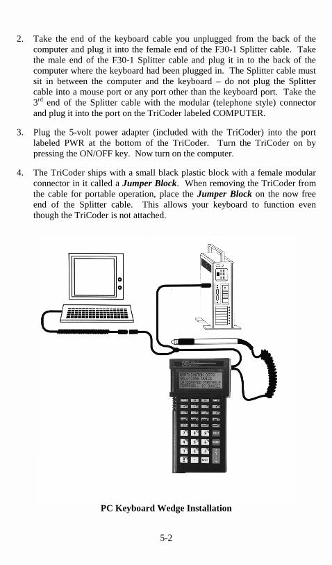
5-2
2. Take the end of the keyboard cable you unplugged from the back of the computer and plug it into the female end of the F30-1 Splitter cable. Take the male end of the F30-1 Splitter cable and plug it in to the back of the computer where the keyboard had been plugged in. The Splitter cable must sit in between the computer and the keyboard – do not plug the Splitter cable into a mouse port or any port other than the keyboard port. Take the 3rd end of the Splitter cable with the modular (telephone style) connector and plug it into the port on the TriCoder labeled COMPUTER.
3. Plug the 5-volt power adapter (included with the TriCoder) into the port
labeled PWR at the bottom of the TriCoder. Turn the TriCoder on by pressing the ON/OFF key. Now turn on the computer.
4. The TriCoder ships with a small black plastic block with a female modular
connector in it called a Jumper Block. When removing the TriCoder from the cable for portable operation, place the Jumper Block on the now free end of the Splitter cable. This allows your keyboard to function even though the TriCoder is not attached.
PC Keyboard Wedge Installation

5-3
Macintosh Keyboard Wedge Installation 1. Before you do anything, shut down the Macintosh and turn the power
OFF. Locate the cable coming from the keyboard and follow it to the ADB port. Unplug the keyboard cable from the ADB port then take the male end of the F42 Splitter cable and plug it into the ADB port where you just unplugged the keyboard. Be careful to orient the round din connector of the Splitter cable correctly when plugging it in – the connector and port are keyed and will only fit in a particular orientation. If the Splitter cable does not fit easily into the ADB port, do not force the connector; check the orientation of the pins and try again. The F42 cable will work with any Macintosh that has an ADB port. The TriCoder can be used with the iMac but requires the use of an USB to ADB converter. You can get the iMate USB to ADB Adapter from Griffin Technologies – 615-255-0990.
2. Take the end of the keyboard cable you unplugged from the Mac and plug it
in to the female end of the F42 Splitter cable. Plug the 3rd end of the Splitter cable (it has a modular connector) into the port on the TriCoder labeled COMPUTER.
3. Plug the 5-volt power adapter (included with the TriCoder) into the port
labeled PWR at the bottom of the TriCoder. Turn the TriCoder on by pressing the ON/OFF key. Now turn on the Macintosh.
4. The TriCoder ships with a small black plastic block with a female modular
connector called a Jumper Block. When removing the TriCoder from the cable for portable operation, place the Jumper Block on the end of the Splitter cable that plugs into the TriCoder. This allows your keyboard to function even though the TriCoder is not attached.
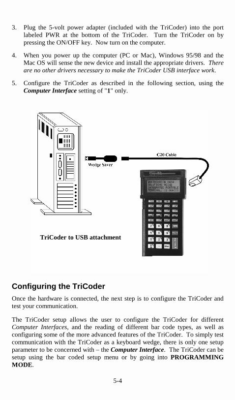
USB interface - PC and Mac The TriCoder can be attached to a PC or Mac via a Universal Serial Bus (USB) port. Many newer PC's do not have standard 5 or 6 pin keyboard connections - a USB port is the only type of connection available. To connect a TriCoder to a USB port, it should be configured as a keyboard wedge interface and requires the USBW kit consisting of the Wedge Saver and C20 cable.
1. Before unplugging or plugging in anything, the computer must be turned OFF. With the power OFF, plug the Wedge Saver into the USB port located on the back of the PC or Macintosh.
2. Plug the 6 pin mini-din end of the C20 cable into the Wedge Saver, then plug the modular RJ45 end of the C20 cable into the "COMPUTER" port on the TriCoder.
5-4
3. Plug the 5-volt power adapter (included with the TriCoder) into the port labeled PWR at the bottom of the TriCoder. Turn the TriCoder on by pressing the ON/OFF key. Now turn on the computer.
4. When you power up the computer (PC or Mac), Windows 95/98 and the Mac OS will sense the new device and install the appropriate drivers. There are no other drivers necessary to make the TriCoder USB interface work.
5. Configure the TriCoder as described in the following section, using the Computer Interface setting of "1" only.
Configuring the TriCoder Once the hardware is connected, the next step is to configure the TriCoder and test your communication. The TriCoder setup allows the user to configure the TriCoder for different Computer Interfaces, and the reading of different bar code types, as well as configuring some of the more advanced features of the TriCoder. To simply test communication with the TriCoder as a keyboard wedge, there is only one setup parameter to be concerned with – the Computer Interface. The TriCoder can be setup using the bar coded setup menu or by going into PROGRAMMING MODE.
TriCoder to USB attachment

5-5
Using the bar coded TriCoder Setup Menu To use the bar coded TriCoder Setup Menu, scan these bar codes in this order:
• Start Setup • Setup Parameter bar code (i.e. “Beep Tone”) • Number bar code that corresponds to the appropriate setting (i.e. “3” to
change the Beep Tone to “high”) • End Setup
More than one Setup Parameter can be changed before you scan END SETUP. For example, scan START SETUP, then “Beep Tone”, then 3, then “Operation Mode”, then 0, then END SETUP. This series of scans changes the beep tone to “high”, and puts the TriCoder into NON PORTABLE mode. For details on TriCoder Setup Parameters, see Chapter 6; TriCoder Setup. If you are using a Laser Scanner to setup the TriCoder, the beam will often cover more than one bar code. Cover any adjacent bar codes before scanning. Check the TriCoder display to make sure the correct setting was entered.
Using Programming Mode to change the TriCoder Setup The same Setup Parameters can be changed using the TriCoder keypad (no bar codes necessary) by going into PROGRAMMING MODE. Answer NO to all of the prompts until you see:
PROGRAMMING MODE KEY [YES/NO]?_
Press the YES key, then enter the password, WDTRI. At the menu prompt, press 5 to CHANGE SETUP. Once in the TriCoder Setup, press the number of the group you want to enter. Then press ENTER until you see the Setup Parameter you want to change (i.e. BEEP TONE), then enter the number for the correct setting (i.e. 3 to change the BEEP TONE to “high”). To enter an alpha character (ie. “A” ), press the SHIFT key, then press the corresponding alpha key (the alpha character is in the upper right corner of each key). You will know if the TriCoder is in “shifted” mode by the cursor – it will be a black square when shifted, a straight line when a narrow underline. More than one Setup Parameter can be changed before you exit the setup. Pressing F1 while in a Setup Parameter will take you back to the Setup Menu; from there choose a new group of settings. Pressing F1 again at the Setup Menu will exit PROGRAMMING MODE.

5-6
Keyboard and USB Interface Configuration With PC’s, determining the type of computer you have is usually pretty simple. Sometimes though it is hard to tell exactly which model it is and which interface to use. When in doubt or your have trouble (garbled or incomplete data on a test scan) using the standard #0, #1,or #2, try the “Learning” mode settings, #8 or #9. “Learning” mode will make the correct adjustments for keyboard timing problems. If connecting the TriCoder to a USB port, use only Computer Interface setting 1. To use the TriCoder as a Keyboard Interface, use the following chart to determine what the correct setup parameters are for the type of computer you are using:
Computer Interface
Setting Description
PC or XT 0 Use with original PC and XT class 8088 processor computers – not commonly used anymore.
AT and Compatibles USB PC/MAC
1 Use with AT machines including 286, 386, 486 and Pentium class machines. USB attachment, PC and Macintosh require this setting. No other settings are required for USB.
PS/2 2 Use with newer PS/2 machines. PS/2’s are sometimes difficult to set up correctly.
Alternative AT Learned timing
8 If you power the TriCoder with the external power supply, you can use LEARNING mode. On the setup menu, scan START SETUP, Computer Interface, then scan the 8. Press any key on the PC keyboard, (the TriCoder should beep once) then scan END SETUP. The Tricoder then watches the key codes coming from the PC and “learns” the timing, setting it in the EEPROM until you change it.
Alternative PS/2 Learned timing
9 If using same models PS/2 as for setting #2, see setting #8 for detailed instructions on how to use “Learning” mode.
Macintosh ADB
A If using any Macintosh with ADB keyboard connections or iMac with adapter
Testing Communication using NON PORTABLE mode To test communication as a keyboard wedge, go to Chapter 3; Non Portable Mode for detailed instruction on how to use NON PORTABLE mode to establish communication between the TriCoder and the host computer. The key to testing communications is to keep it simple – you don’t want to have to determine whether it’s your software or the TriCoder causing a problem.
�

5-7
���������������
Connecting the Hardware The TriCoder can operate as a serial interface reader on both PC’s and dumb terminal/host configurations. There are different cables required for each configuration as well as some differences in setup and operation. On a dumb terminal/host configuration, the TriCoder works as a “serial wedge” – it displays data on the terminal as if it came from the keyboard. On a PC, you must have software reading the serial port directly, or a keyboard emulation program like PortKey. PortKey allows a serial interface TriCoder to look like it’s working as a keyboard wedge. The TriCoder Utilities diskette that is included with each TriCoder has both DOS and Windows utilities that are extremely useful on a PC serial port. Use the following procedures and illustrations to connect the TriCoder to the serial interface you are using.
• Serial Installation on a PC serial port • Serial Wedge Installation between a dumb terminal and host • Serial Installation on a Macintosh serial port
Serial Installation on a PC with a Dedicated Serial Port The RS-232 serial ports on a PC are commonly called COM ports and are referred to as COM1, COM2, COM3, and COM4. Typically you will be using COM1 or COM2. 1. If you ordered the TriCoder as a serial interface and planned to use it on a
PC, you should have also ordered one of two cables, either the 25 pin F34 cable or the 9 pin F36 cable. The F34 25pin female null modem cable is designed to work directly off of a 25 pin PC serial port. The F36 9pin female straight cable is wired to connect directly to a 9 pin PC serial port. Both cables have a female 9 pin or 25 pin end and a modular (telephone style) 8 pin end.
2. If the 9 or 25 pin port you are plugging the cable into is also female,
chances are it’s not a serial port. 3. If you have the wrong cable (9 pin cable and you have a 25 pin port, or vice
versa) you can get a 9 to 25 or 25 to 9 adapter at your computer store. The easier solution is to get the right cable from us!
4. The easy part is the connection – simply plug the 25 pin or 9 pin end of
your cable into the open serial port in the back of your computer. Plug the modular end of the cable into the port labeled COMPUTER on the side of the TriCoder. If your serial ports are labeled (COM1 or COM2), make a note of which port you are plugged into – the software you use will need to know which COM port you are using.

5-8
Serial Installation on PC
Serial Wedge Interface between a dumb terminal and host This installation is generally the most complicated. Once the TriCoder is installed, it works on the terminal as it does with the PC keyboard wedge installation – data is transmitted and displays on the terminal as if it were typed from the keyboard. Although it seems to emulate the keyboard, the installation is actually between the host and the terminal. The F45-1 Dual Port Serial Y Cable is necessary for this installation. There are 3 ends to this cable; the host end (25 pin female), the terminal end (25 pin male) and the TriCoder end (modular 8 pin). 1. Unplug the host cable from the 25 pin port in the back of the terminal. Take
the male end of the F45-A cable and plug it into the back of the terminal where the host cable was.

5-9
2. Take the cable coming from the host (you just unplugged it from the back of the terminal) and plug it in to the female end of the F45-1 cable. At this point we are assuming that the cable coming from the host has pins 2 and 3 crossed.
3. Plug the third end, the 8 pin modular connector, into the port labeled COMPUTER on the side of the TriCoder.
4. The TriCoder ships with a small beige plastic block with a female modular
connector called a Jumper Block. When removing the TriCoder from the cable for portable operation, place the Jumper Block on the end of the Y cable that plugs into the TriCoder. This allows your terminal to function even though the TriCoder is not attached.
Terminal/Host Installation Serial Interface on a Macintosh We do not recommend using the TriCoder as a serial interface on the Macintosh but it is possible. As with a dedicated serial port on a PC, your application software must read the serial port directly, or you can use our Uploader program for the Macintosh to emulate the keyboard.

5-10
To connect the TriCoder to the Mac, use the F34 DB25 null modem cable connected to a Macintosh DB25 Modem cable which is in turn connected to the Macintosh serial port. If you have experience making your own cables or have someone who does it for you, you can make your own cable to go directly from the serial port on the Mac to the TriCoder. These are the pin-outs:
TriCoder RJ45 Male pin #
Macintosh 8 pin Mini-din pin #
Transmit
2
Receive
5
Receive
3
Transmit
3
Ground
4
Ground
4
Serial Interface Communications Software If you install the TriCoder on a PC or a Mac as a serial interface, you are responsible for software to communicate with the serial port. Some applications read the serial port directly; no additional software is required. If this is not the case, you have several choices, depending upon how your application is looking for data. 1. If you want to connect to the serial port yet emulate the keyboard, use our
Portkey software. Portkey takes data coming from the serial port and re-directs it through the keyboard buffer, allowing you to emulate most keys on your keyboard. Portkey comes in both DOS and Windows versions and has its own users manual. Follow the manual for installation and setup instructions. If you are using a Macintosh, using the serial interface and want keyboard emulation, use our Uploader program. It is similar to the Portkey software for DOS and Windows.
2. The TriCoder comes with a TriCoder Utilities diskette that contains several
programs for both DOS and Windows. The DOS utilities consist of both source BASIC programs as well as executable programs. These programs provide for examples of simple communication – for example, the program RS232.EXE or RS232.BAS simply displays data from the TriCoder in NON-PORTABLE mode on the computer screen. This is an easy way to test for communication between your serial port and the TriCoder. The Windows version of the TriCoder Utilities program is an actual Windows application. The TriCoder Utilities allows you to configure your serial port, test your communications, upload data and programs, download programs and tables and edit tables. The Windows TriCoder Utilities is the easiest way to test communications – use it if you can.
3. Other communications programs such as Procomm or HyperTerminal can
also help you establish communication. If you are using a program other than any of those supplied by Worthington Data Solutions, follow the installation and setup instructions for that program.

5-11
Configuring the TriCoder Once the hardware is connected, the next step is to configure the TriCoder and test your communication. If you are using the serial interface, you should have installed the serial communication software you want to use (see the previous section). The TriCoder setup allows the user to configure the TriCoder for different computer interfaces, and reading of different types of bar codes, as well as configuring some of the more advanced features of the TriCoder. The TriCoder can be setup using the bar coded setup menu or by going into PROGRAMMING MODE.
Using the bar coded TriCoder Setup Menu To use the bar coded TriCoder Setup Menu, scan these bar codes in this order:
1. Start Setup 2. Setup Parameter bar code (i.e. “Beep Tone”) 3. Number bar code that corresponds to the appropriate setting
(i.e. 3 to change the Beep Tone to “high”) 4. End Setup More than one Setup Parameter can be changed before you scan END SETUP. For example, scan START SETUP, then “Beep Tone”, then 3, then “Operation Mode”, then 0, then END SETUP. This series of scans changes the beep tone to “high”, and puts the TriCoder into NON PORTABLE mode. For details on TriCoder Setup Parameters, see Chapter 6; TriCoder Setup. Using Programming Mode to change the TriCoder Setup The same Setup Parameters can be changed using the TriCoder keypad (no bar codes necessary) by going into PROGRAMMING MODE. Answer NO to all of the prompts until you see:
PROGRAMMING MODE KEY [YES/NO]?_
Press the YES key, then enter the password, WDTRI. At the menu prompt, press the 5 key to CHANGE SETUP. Once in the TriCoder Setup, press the number of the group you want to enter. Press ENTER until you see the Setup Parameter you want to change (i.e. BEEP TONE), then enter the number for the correct setting (i.e. 3 to change the BEEP TONE to “high”). More than one Setup Parameter can be changed before you exit the setup. Pressing F1 while in a Setup Parameter will take you back to the Setup Menu; from there choose a new group of settings. Pressing F1 again at the Setup Menu will exit PROGRAMMING MODE.
5-12
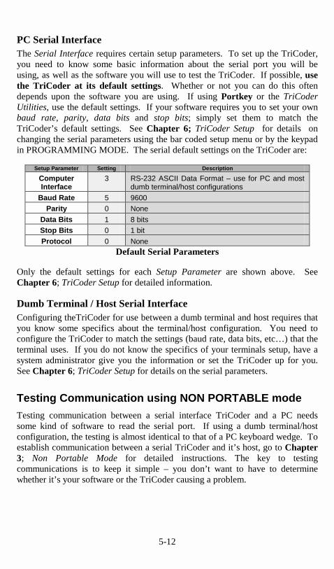
PC Serial Interface The Serial Interface requires certain setup parameters. To set up the TriCoder, you need to know some basic information about the serial port you will be using, as well as the software you will use to test the TriCoder. If possible, use the TriCoder at its default settings. Whether or not you can do this often depends upon the software you are using. If using Portkey or the TriCoder Utilities, use the default settings. If your software requires you to set your own baud rate, parity, data bits and stop bits; simply set them to match the TriCoder’s default settings. See Chapter 6; TriCoder Setup for details on changing the serial parameters using the bar coded setup menu or by the keypad in PROGRAMMING MODE. The serial default settings on the TriCoder are:
Setup Parameter Setting Description
Computer Interface
3 RS-232 ASCII Data Format – use for PC and most dumb terminal/host configurations
Baud Rate 5 9600 Parity 0 None
Data Bits 1 8 bits Stop Bits 0 1 bit
Protocol 0 None
Default Serial Parameters
Only the default settings for each Setup Parameter are shown above. See Chapter 6; TriCoder Setup for detailed information. Dumb Terminal / Host Serial Interface Configuring theTriCoder for use between a dumb terminal and host requires that you know some specifics about the terminal/host configuration. You need to configure the TriCoder to match the settings (baud rate, data bits, etc…) that the terminal uses. If you do not know the specifics of your terminals setup, have a system administrator give you the information or set the TriCoder up for you. See Chapter 6; TriCoder Setup for details on the serial parameters.
Testing Communication using NON PORTABLE mode Testing communication between a serial interface TriCoder and a PC needs some kind of software to read the serial port. If using a dumb terminal/host configuration, the testing is almost identical to that of a PC keyboard wedge. To establish communication between a serial TriCoder and it’s host, go to Chapter 3; Non Portable Mode for detailed instructions. The key to testing communications is to keep it simple – you don’t want to have to determine whether it’s your software or the TriCoder causing a problem.

5-1
Chapter 5
��������������� Most, but not all of the Setup Parameters can be changed by either using the TriCoder keypad in Programming Mode or scanning the appropriate bar codes on the TriCoder Setup Menu Using the bar code TriCoder Setup Menu To access the Setup using the bar coded TriCoder Setup Menu, scan the START SETUP bar code in the upper left hand corner of the bar coded TriCoder Setup Menu. You should hear two beeps from the TriCoder upon scanning START SETUP and the words START SETUP should appear on the TriCoder display. At this point you are ready to scan and change as many parameters as you wish, following this order: 1. Scan the bar code for the parameter you want to change
2. Scan the number on the Barpad Table (to the right) that corresponds to the setting you want to choose.
3. If the parameter requires it, scan the SET bar code. SET is normally used to terminate a setup parameter that can have variable input, ie. Preamble or Postamble.
4. If you want to make more changes, go back and start at step 1
5. If you are finished, scan the END SETUP bar code in the upper right hand corner. You should hear 3 beeps at END SETUP.
6. To reset the TriCoder back to the default settings at any time, scan START SETUP, RESET, then END SETUP. Resetting the TriCoder will lose any changes you have made and set the TriCoder to the default settings (indicated by a * on the bar coded setup menu).
Using the keypad to setup the TriCoder To use the keypad to setup the TriCoder, you must first get into PROGRAMMING MODE. To do this, answer NO to all Mode Menu prompts until you see:
PROGRAMMING MODE KEY [YES/NO]?_
Press the YES key. A password is required to proceed into PROGRAMMING MODE:
PROGRAMMING MODE PASSWORD?_

5-2
Enter the password, WDTRI using the TriCoder keypad, then press ENTER. The TriCoder now displays the PROGRAM FUNCTION menu:
PROGRAM FUNCTION KEY Create Programs-> 1-3 Voice Operations-->4 Change Setup------->5
Press the 5 key to select Change Setup. The keypad setup menu is now displayed:
BarCodes-->0 DateTime->4 Computer->1 Speaker--->5 RS-232------>2 Other------->6 Security---->3 Exit-------->F1
The setup parameters are distributed in the groups as follows:
Menu Selection
Setup Parameters
Menu Selection Setup Parameters
BAR CODES Code 3 of 9 DATE TIME Set Time
“0” UPC & EAN “4” Set Date
Code 25 / I 25 Date Format
2 of 5 Length Display of Year
Code 128
Codabar
MSI/Plessey
Code 93
COMPUTER Computer Interface SPEAKER Speaker /Batteries
“1” Intercharacter Delay “5” Beep Tone
Terminator Character
Beep Tone
Single Cycle Transmit
Country Code
RS232 Baud Rate OTHER Shut Down Time
“2” Protocol “6” Preamble
Dialing String Postamble
Parity EOF String
Data Bits Partitions
Stop Bits Voice Messages
Set ID Character Scanner Options
Host Response Delay
Modem Redial Delay
Transmit Mode
SECURITY Data Security
“3”
To select a particular category, press the corresponding number key on the TriCoder keypad. Once you are in a category, pressing ENTER will scroll through the parameters in the order shown above. When you get to the one you

5-3
want to change, enter the new character (see the Parameter details later on in this appendix), then press ENTER. Some changes must be made by scanning bar codes from the FULL ASCII MENU. You can set a parameter back to the default settings by pressing the CLEAR key. You can use the arrow keys to help you navigate the menu: Up Arrow moves to beginning of category Down Arrow moves to end of category Left Arrow moves up one in the category Right Arrow moves down one in the category Press the F1 key to go back to the category selection screen.

5-4
��������������������������Default settings are shown in bold print. The number or letter associated with the setting is the same whether configuring the TriCoder using the bar coded Setup Menu or via the keypad in PROGRAMMING MODE. Some parameters are set only by the bar code setup menu or only by the TriCoder keypad.
Beep Tone
Lowest 0 Low 1 Medium 2 High 3 Highest 4 No Beep 5 The Tricoder allows five different beep pitches or no beep at all.
Code 3 of 9 (Code 39)
Enable Code 3 of 9 0 Disable Code 3 of 9 1 Enable Full ASCII Code 39 2 Disable Full ASCII Code 39 3 Enable Code 39 Accumulate Mode 4 Disable Code 39 Accumulate Mode 5 Enable Start/Stop character transmission 6 Disable Start/Stop character transmission 7 Enable Mod 43 Check Digit 8 Disable Mod43 Check Digit 9 Enable Check Digit transmission A Disable Check Digit transmission B Caps Lock ON C Caps Lock OFF D • The Start and Stop character for Code 39 is the * character. Settings 6 and
7 determine whether or not those characters are transmitted to the computer along with the data. For example, at setting 6, the data of 1234 would be transmitted as *1234*. Transmitting the start and stop characters can be useful if you need to differentiate between data that comes from a bar code versus data coming from the keyboard.
• Enabling use of the Mod 43 check character requires that the last character of your bar code conform to the Mod 43 check character specifications. See Appendix A; Code 39 for more information. Enable transmission (A) will send the check digit data along with the rest of the bar code data to your computer. To use A, you must also be using 8.

5-5
• Caps Lock ON causes lower case letters read as data to be transmitted to the computer as UPPER CASE, and upper case letters to be transmitted as LOWER CASE. Numbers, puctuation and control characters are not affected. This setting applies to all bar code types.
��������Enable UPC/EAN 0 Disable UPC/EAN 1 Enable UPC/EAN Supplements 2 Disable UPC/EAN Supplements 3 Enable transmission of UPC-A NSC or EAN 2 Flags 4 Disable transmission of UPC-A NSC or EAN 2 Flags 5 Enable transmission of UPC-A and EAN-13 check digit 6 Disable transmission of UPC-A and EAN-13 check digit 7 Enable transmission of UPC-E NSC and EAN-8 Flag character 8 Disable transmission of UPC-E and EAN-8 Flag ch. 9 Enable transmission of UPC-E and EAN-8 Check digit A Disable transmission of UPC-E and EAN-8 check digit B UPC-E Compressed C UPC-E Expanded D EAN-8 observing 9&A E EAN-8 forced to transmit 8 digits always F • Use setting 2 to enable reading of the 2 and 5 digit UPC/EAN supplements
commonly found on magazines and paperback books. Using this setting forces left to right reading of UPC codes to assure that the supplement code is not missed.
• ISBN (International Standard Book Numbering) bar codes are EAN-13 with a 5 digit supplement. If the “Bookland” bar code uses 978 (books) or 977 (periodicals) as the first three digits, then it can be transmitted by the TriCoder in the ISBN format. The settings for this can be found under the Terminator Character parameter. For details on ISBN, see Appendix E;UPC/EAN.
• Use setting 4 and 9 to enable transmission of the NSC character to your computer. The Number System Character is the leading character in the bar code. For details, see Appendix E,; UPC/EAN.
• Use setting 6 and A to enable transmission of the check digit character to your computer. The check digit is the last character and is based upon a calculation performed on the other characters.
• Setting C transmits UPC-E0 bar codes as is; setting D transmits them with
inserted zero’s to make them the same length as a UPC-A bar code. A NSC

5-6
of 0 is assumed. It is possible to read UPC-E1 bar codes; by default this option is disabled. Do not enable UPC-E1 if you plan on reading EAN-13 bar codes; you may experience partial reads when reading EAN-13. The UPC-E1 option is set in the 2 of 5 Code parameter. To enable UPC-E1 reading, set the 2 of 5 Code parameter to 8. To turn off UPC-E1 reading, set it back to the default of 9.
• If you prefer to transmit UPC-E bar codes in a 6 digit format while EAN-8
is transmitted in its original 8 digit format, use setting F. This will allow you to use settings 9 and A and still transmit EAN-8 as 8 digits.
• UPC-A can be transmitted in EAN-13 format by adding a leading 0 (USA
county code) to the UPC-A data. This setting is found in the Terminator Character parameter.
��������Enable Codabar 0 Disable Codabar 1 Enable CLSI Codabar 2 Disable CLSI Codabar 3 Disable Start/Stop character transmission 4 Enable Start/Stop character transmission 5 • CLSI is a form of Codabar often used by libraries. • Setting 5 will transmit the Codabar start and stop characters with the bar
code data to your computer. If you are varying the start and stop characters to differentiate between different labels, transmitting the start and stop can be helpful. See Appendix B; Codabar for more information.
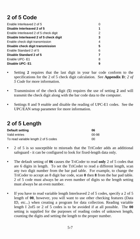
5-7
����!������Enable Interleaved 2 of 5 0 Disable Interleaved 2 of 5 1 Enable Interleaved 2 of 5 check digit 2 Disable Interleaved 2 of 5 check digit 3 Enable check digit transmission 4 Disable check digit transmission 5 Enable Standard 2 of 5 6 Disable Standard 2 of 5 7 Enable UPC- E1 8 Disable UPC- E1 9 • Setting 2 requires that the last digit in your bar code conform to the
specifications for the 2 of 5 check digit calculation. See Appendix D; 2 of 5 Code for more information.
• Transmission of the check digit (5) requires the use of setting 2 and will
transmit the check digit along with the bar code data to the computer. • Settings 8 and 9 enable and disable the reading of UPC-E1 codes. See the
UPC/EAN setup parameter for more information.
����!�"���#�Default setting 06 Valid entries 00-98 To read variable length 2 of 5 codes 00 • 2 of 5 is so susceptible to misreads that the TriCoder adds an additional
safeguard - it can be configured to look for fixed-length data only. • The default setting of 06 causes the TriCoder to read only 2 of 5 codes that
are 6 digits in length. To set the TriCoder to read a different length, scan any two digit number from the bar pad table. For example, to change the TriCoder to accept an 8 digit bar code, scan 0 then 8 from the bar pad table. 2 of 5 code must always be an even number of digits so the length setting must always be an even number.
• If you have to read variable length Interleaved 2 of 5 codes, specify a 2 of 5
length of 00, however, you will want to use other checking features (Data ID, etc...) when creating a program for data collection. Reading variable length I 2of5 or 2 of 5 codes is to be avoided if at all possible. The 00 setting is supplied for the purposes of reading codes of unknown length, counting the digits and setting the length to the proper number.

5-8
$��������� �Disable MSI & Plessey bar codes 0 Enable MSI, 1 Mod 10 check digit 1 Enable MSI, 2 Mod 10 check digits 2 Enable MSI, 1 Mod 11/ Mod 10 check digit 3 Transmit no check digits 4 Transmit 1 check digit 5 Transmit 2 check digits 6 Enable Plessey bar code (mutually exclusive w/MSI) 7 Enable LabelCode5 (mutually exclusive w/MSI & Plessey) 8 Enable LabelCode4 (mutually exclusive w/all above) 9 • LabelCode 5 and LabelCode 4 are proprietary bar code types used by Follet. • For more information regarding MSI or Plessey Code, see Appendix F; MSI
Plessey Code.
�����% &�Disable Code 128 0 Enable Code 128 1 Enable UCC/EAN-128 2 Disable UCC/EAN-128 3 Enable Storage Tek Tape Label Code C Disable Storage Tek Tape Label Code D Bar Code ID’s transmitted E Bar Code ID’s not transmitted F • UCC/EAN-128 is a subset of Code 128 that follows certain specifications
regarding character content, length and check digits. Enabling UCC/EAN-128 (2) causes the TriCoder to look for a Code 128 bar code that begins with the Code 128 F1 (Function 1) character. See Appendix C; Code 128 for more details.
• The StorageTek Tape Label code is a proprietary variation of Code 39 code
used for the storage of computer data tapes. Enabling the tape label code (C) does not disable reading of Code 128 bar codes.
• Bar Code ID’s are characters assigned to each bar code type to identify that
particular type of code. These Bar Code ID’s can be used to identify what type of bar code you are using when you are not sure or you want your application to differentiate between the different types. The Bar Code ID’s are assigned as follows:

5-9
Bar Code ID Bar Code ID
Codabar a Code 39 b
UPC-A c EAN-13 d
I 2of5 e 2 of 5 f
Code 128 g Code 93 i
MSI j UPC-E(0) n
UPC-E (1) o EAN-8 p
StorageTek s Plessey x
LabelCode 4 y LabelCode 5 z
The ID character is transmitted in front of the bar code data.
�����'(�Enable Code 93 0 Disable Code 93 1 Enable Full ASCII Code 93 2 Disable Full ASCII Code 93 3 • Code 93 is similar in character set to Code 39. See Appendix G;Code 93
for more information. Code 93 is not a commonly used bar code symbology.
����������������������The Preamble and Postamble apply to data entered in NON-PORTABLE MODE only. Upload Prefixes are used in programs for portable data collection. • Preambles are user-defined data that is transmitted at the beginning of data
(bar code or keyed) that is entered in the TriCoder in NON PORTABLE mode. For example, if you set a preamble of @@ and scanned bar code data of 12345, @@12345 would be transmitted to the computer.
• Postambles are user-defined data that is transmitted at the end of data (bar
code or keyed) that is entered in the TriCoder in NON PORTABLE mode. For example, if you set a preamble of @@ and scanned bar code data of 12345, 12345@@ would be transmitted to the computer.
• By default, the TriCoder has no preambles or postambles configured.
Preambles and Postambles can each contain up to 15 characters scanned from the bar coded FULL ASCII Menu. To set a preamble or postamble:
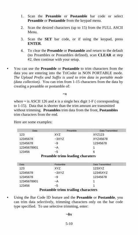
5-10
1. Scan the Preamble or Postamble bar code or select Preamble or Postamble from the keypad menu.
2. Scan the desired characters (up to 15) from the FULL ASCII Menu.
3. Scan the SET bar code, or if using the keypad, press ENTER.
4. To clear the Preamble or Postamble and return to the default (no Preambles or Postambles defined), scan CLEAR at step #2, then continue with your setup.
• You can use the Preamble or Postamble to trim characters from the
data you are entering into the TriCoder in NON PORTABLE mode. The Upload Prefix and Suffix is used to trim data in portable mode (data collection). You can trim from 1-15 characters from the data by creating a preamble or postamble of:
~x
where ~ is ASCII 126 and x is a single hex digit 1-F ( corresponding to 1-15). Data that is shorter than the trim amount are transmitted without trimming. Preambles trim data from the front, Postambles trim characters from the end.
Here are some examples:
Data Preamble Data Transmitted
123 XYZ XYZ123 12345678 ~3XYZ XYZ45678 12345678 ~9 12345678 12345678901 ~A 1 123456 ~5 6
Preamble trims leading charaters
Data Postamble Data Transmitted
123 XYZ 123XYZ 12345678 ~3XYZ 12345XYZ 12345678 ~9 12345678 12345678901 ~A 1 123456 ~5 1
Postamble trims trailing characters
• Using the Bar Code ID feature and the Preamble or Postamble, you can trim data selectively, trimming characters only on the bar code type specified. To use selective trimming, enter:
~bx

5-11
where b is the Bar Code ID character (see the Code 128 setup parameter) and x is the number of characters to trim from the front of the data. For example, ~b2~c1 says “trim 2 characters from Code 39 data and 1 character from UPC-A data”. Remember that the Preamble trims leading data and the Postamble trims trailing data.
• The Preamble and Postamble can also be used to create “line feeds” on the TriCoder display before the data is displayed. To enter “line feeds” before or after your data enter:
}x
where x is 1-3, depending on how may lines you want to scroll . For example, it you wanted skip 3 lines, you would enter }3.
• Lastly, the Preamble and Postamble can be used to check a minimum and maximum character length for data entered in NON PORTABLE mode. In portable data collection, min and max character lengths are set using the Max Data Len and the Min Data Len in the programming statements. To check for length in the Preamble or Postamble, enter:
|nnmm
where | is ASCII 124, nn is the two-digit minimum and mm is the two-digit maximum. |0210 would check for a minimum of 2 characters and a maximum of 10.
�����������#�������CR - Carriage Return 0 HT - Horizontal Tab 1 None 2 CR/LF - Carriage Return/Line Feed 3 Do not transmit EAN-13 data with 5 digit supplement as ISBN C Transmit EAN-13 data with 5 digit supplement as ISBN format D No country code transmitted for UPC-A E Transmit UPC-A in EAN-13 format (Country Code 0) F
• The Terminator Character is the character sent at the end of each data entry in NON PORTABLE mode and at the end of each field when uploading after data collection (Portable use). Your application will determine what Terminator Character (if any) you use.
• In Keyboard Wedge mode, CR (0) is the default. For Serial Interface, CR/LF (3) is the default.
• Settings C, D, E and F correspond to settings for UPC bar codes only. See the UPC/EAN section for details.

5-12
�����������������PC/XT Keyboard Wedge 0 AT and compatibles Keyboard Wedge/ USB PC or Mac 1 PS/2 Keyboard Wedge 2 RS-232 ASCII Data Format 3 RS-232 “PC-Terminal Mode” Data Format 4 RS-422 ASCII Data Format 5 If setting 1 or setting 2 and Non-Dedicated Server 7 Learning Mode for Timing with AT keyboard wedge 8 Learning Mode for Timing with PS/2 keyboard wedge 9 Macintosh ADB Interface A • When in Keyboard Wedge mode, the default setting is for an AT class
machine (ie. 386,486, Pentium); when in serial mode the default is RS-232 ASCII Data.
• If attaching the TriCoder to a USB port (PC or Mac) using the Wedge Saver, you must use setting 1. No other settings are required.
• If you have an IBM PS/2, use setting 2. • The easy way to select an interface if using Keyboard Wedge mode is to use
Learning Mode (8,9). Learning Mode requires that you plug in the external 5 volt power supply that came with the TriCoder. Once plugged in, follow these instructions:
1. Scan Start Setup 2. Scan Computer Interface 3. Scan 8 (for AT) or 9 (for PS/2) 4. Press any key on your PC keyboard 5. Scan End Setup
The TriCoder watches the key codes coming from the computer, “learns” the keyboard timing and sets it in the EEPROM until you change it.
• In Serial mode, the “PC Terminal Mode” data format is only used with Concurrent DOS, VM etc... connected between a serial terminal set up in PC-Term mode and the host. This mode does not apply to Unix or Pick.
• RS-422 is for use with RS-422 boards only. If your computer is using a
RS-422 board, you must order the 422 option at the same time you order your TriCoder as this feature is not field-installable. RS-422 also requires special cables. RS-422 and RS-232 are mutually exclusive; only one or the other is available.

5-13
����#�������)��� �None 0 Short Delay 1 Medium-short Delay 2 Medium-long Delay 3 Long Delay 4
• Intercharacter Delay is a setting that allows the TriCoder to match the keyboard timing on your PC. Most computers work fine with no delay at all, but due to the variety of BIOS and clock speeds, some PC’s may need a timing delay.
• The best way to determine whether you need to program a delay or not is to start at setting 0 (None). Try reading a bar code in NON PORTABLE mode while connected to your computer. If your data transmits with no problems, leave your delay at 0. If you have garbled or missing data, try each delay starting with 1 until you have complete and correct data. Between setting changes, try typing on your keyboard to make sure you still have correct characters coming from your keyboard. In some instances, you may need to re-boot the computer between delay setting changes.
• Use Computer Interface setting 8 or 9 for Learning Mode whenever possible. This allows the TriCoder to figure out the timing on its own and set it in the EEPROM for you.
• Intercharacter Delay settings are generally for Keyboard Wedge mode but will work in Serial Mode (usually only if using Portkey and emulating keyboard data). Garbled data in Serial Mode is usually the result of the wrong Baud Rate or Parity setting. Check these first before you start changing the Intercharacter Delay.
����*�����+���������Speaker ON 0 Speaker OFF 1 Alkaline Batteries or Alkaline Rechargeables 2 Nickel Metal Hydride or NiCad Rechargeable Batteries 3 • If you are using the earphone option, you can conserve battery power by
turning the Speaker OFF (1).
• In order to get an accurate Battery Status reading, you must select the correct battery type. The default is Alkaline (2). Battery Status can be displayed by pressing the STATUS key on the TriCoder keypad while in NON PORTABLE mode or while collecting data (portable).

5-14
�����,������Switch Wand (for all modes) 7 Non-switched Wand (for NON PORTABLE mode only) 8
• The TriCoder normally uses a “switched” wand to conserve battery power. A “switched” wand is turned on by squeezing a rubber band on the wand. A “non-switched” wand can be used, but only in NON PORTABLE mode and only with the 5v power supply. The decode jumper (see TriCoder diagram in Appendix K) must also be set to "L".
�� ����������� �US 00 French 01 German 02 Belgian 03 French Canadian 04 Danish 05 Dutch 06 Italian 07 Latin American 08 Norwegian 09 Portuguese 10 Spanish 11 Swedish 12 Swiss German 13 United Kingdom 14 • This parameter applies only to TriCoders operating in Keyboard Wedge
mode or PC-Terminal Mode (RS-232). The default setting is US (00) and requires a two-digit entry for all settings.
• Setting 01 (French) and 02 (German) also apply to the displayed messages
on the TriCoder. Displayed messages will appear on the TriCoder in the language choosen. If you want to use a US keyboard yet display messages in French or German, scan 51 for French or 52 for German.

5-15
,��������$����Non Portable Mode 0 Programming Mode 1 Data Collection Mode 2 Data Upload Mode 3 Program Transmit Mode 4 Program Receive Mode 5 Buffered Terminal Mode 6 • Non Portable Mode is used to read data directly into the Computer from
the TriCoder, both in Keyboard Wedge and Serial modes. If using the TriCoder as a serial interface, setting Protocol to Host Response Accepted can turn the TriCoder into a dumb terminal, displaying prompts from the host and transmitting data back.
• Programming Mode is used to create or modify a program, record and test
voice prompts and to change the Setup using the TriCoder keypad. The TriCoder requires entry of a password before you are allowed to access Programming Mode. The password, WDTRI, is the same for all TriCoders.
• Data Collection Mode is a portable mode used to collect data using one of the TriCoder's four available programs. Program #0 and Program #1 are pre-programmed into the TriCoder when you receive it. Program #0 is a fixed program while Program #1 is a simple inventory program that is user-editable. Programs #2 and #3 are not set and are available for custom programming. See Chapter 1 and Chapter 2 for data collection tutorials using Program #0 and #1.
• Data Upload Mode is used to transfer data collected in the TriCoder to the host computer both for Keyboard Wedge mode and Serial mode.
• Program Transmit Mode is used to transmit a TriCoder program, setup or voice messages to another TriCoder or to a host computer. Voice messages can only be transferred from TriCoder to TriCoder. “Cloning” (copying the entire setup and programs) is handy when setting up multiple TriCoders.
• Program Receive Mode is used to receive a TriCoder program, setup or voice messages from another TriCoder or host computer. Voice messages can only be received from another TriCoder.
• Buffered Terminal Mode allows the TriCoder to function as an online intelligent buffered terminal using Program #1 and uploading upon request by a host computer polling with ACK/NAK protocol. This mode requires programming at the computer end.

5-16
-����$��������This parameter partitions the total amount of voice messages into different message lengths. The default setting is:
303015 xx yy zz
where: xx is number of ½ second messages yy is the number of 1 second messages zz is the number of 2 second messages
The total time allotted must not exceed 75 seconds. To change the partitions, scan 6 digits total; 2 for the number of ½ second messages, 2 for the number of 1 second messages and 2 for the number of 2 second messages. See the default setting as an example.
WARNING: changing this parameter after you have recorded messages could result in having to re-record some of them; they would still be there but longer messages may get cut up and shorter ones combined.
����)����Using the barpad table, scan a 6 digit date in the mmddyy format. For example, to set a date of 1/1/99, you would scan 010199. Press the STATUS key to view the current date and time in both NON PORTABLE mode and during data collection. To set the time in the TriCoder from a host computer, see Appendix J; Using the TriCoder as a Time Clock for details. There are alternative date formats available for the TriCoder. See the Protocol parameter for details. Changing the date format requires resetting the actual date in that format also. If you setup the TriCoder using the keypad in PROGRAMMING MODE, you can choose to have the TriCoder display the year in a 4 digit format instead of a 2 digit format. This setting will help you comply with Y2K requirements.
���������Using the barpad table, scan a 4 digit time in the military hhmm format. For example, to enter a time of 3:35 p.m., scan 1535. Press the STATUS key in NON PORTABLE mode or during data collection to view the current time. The time can also be set from a host computer; see Appendix J; Using the TriCoder as a Time Clock for details. The real-time clock is maintained by batteries. Fresh batteries will keep your real-time clock as accurate as possible.
5-17
��������.��)��������������������See the Protocol parameter for details on how to set the TriCoder to use alternative Date and Time formats. The default formats use mmddyy and hhmm. Formats include:
• A - short format - no separators between characters • B - long format - date uses / separators, time uses : separator • C - US format - mmddyy, hhmm • D - European Format- ddmmyy, hhmm
Combinations are AC, AD, BC and BD. To use the European format, first change the format in the Protocol parameter, then reset the date and time, entering the digits in the correct order. Follow the same procedure to set it back to the US format.
������� �����������Single Cycle Transmit OFF 0 Single Cycle Transmit ON 1
• Single Cycle Transmit allows the TriCoder to upload one field at a time to the host, controlled by the pressing of any key (except F1) on the TriCoder each time the operator wants to transmit a field.
• Single Cycle Transmit is used to test complex upload prefix and suffix sequences. This is typically used when a TriCoder is used in Keyboard Wedge mode and you are uploading directly into an application. Single Cycle Transmit allows you to test key sequences and delays before you collect alot of data and try an upload. Pressing F1 terminates the upload session.
�
�,/�������The EOF String setting allows you to choose up to 8 characters to be transmitted at the end of a TriCoder file upload. It is typically used to signal to the receiving host program that the TriCoder is done uploading its data and has transferred its last piece of data. The characters chosen are often characters not available on the TriCoder keypad; they are scanned from the FULL ASCII MENU. To program an EOF String:
• Scan EOF String • Scan up to 8 characters from the FULL ASCII MENU • Scan the SET bar code
If you do not program an EOF String, the TriCoder sends a Ctrl Z (ASCII 26).

5-18
Undisplayable characters are displayed on the TriCoder as ?. To view the ASCII equivalent (so you know what characters are there) press the F2 key while in the EOF String parameter.
�#���)�0������By default, if the TriCoder is inactive for more than 5 minutes, it will shut itself down in order to conserve batteries. To resume operation, you must turn the TriCoder back on using the ON/OFF key. To change the amount of time the TriCoder waits before shutting down:
• Scan Shut Down Time • Scan two digits - the default is 05 (5 minutes)- to correspond to the length
of time in minutes. For example, 01 would be 1 minute.
If you want to prevent the TriCoder from shutting off automatically at all, set the Shut Down Time to 00.
����������The Partitions setting is where you specify how you want to divide the memory in the TriCoder. Memory can be allocated for data files (up to 3) and tables (up to 3). Memory is partitioned in 32K size pages. The TriCoder has 256k, or 8 pages, of memory to allocate. Partitions are specified using a six digit number:
abcxyz
where: a is the number of pages of memory allocated to Data File #1. b is the number of pages of memory allocated to Data File #2 c is the number of pages of memory allocated to Data File #3 x is the number of pages of memory allocated to Table #1 y is the number of pages of memory allocated to Table #2 z is the number of pages of memory allocated to Table #3
• The default is for all memory to be allocated to Data File #1.
• The total amount of memory partitioned must equal the total amount of memory available. You must specify 8 pages (in whatever combination) for the TriCoder.
• The Partitions cannot be changed while there is data collected in the TriCoder. You must upload and delete the data first.
• All downloaded tables currently in the TriCoder will be lost when the Partitions are changed. You will have to re-download the tables once the change is complete.

5-19
�#��������This setting allows the TriCoder to output chosen ASCII characters in place of the actual characters entered. For example, if you scanned the number 1 (hex 31) and wanted the TriCoder to output hex 92 instead, you would enter 3192 for the Characters parameter. This would re-assign the output characters , with the TriCoder outputting hex 92 every time it sees hex 31. To re-assign characters:
• Scan Characters
• Scan up to seven 4 digit pairings where the first 2 digits represent the hex number to replace and the second 2 digits represent the hex number to insert. You can have up to seven character re-assignments.
• Scan SET You can eliminate the output of a character by using FF as the hex number to insert. For example, if you wanted to eliminate all $, following the above instructions, enter 24FF.
��������Settings 0 - 6 apply only to Serial Interface TriCoders only. None 0 XON / XOFF 1 ACK/ NAK without Polling 2 Polled - No ACK / NAK* 3 Polled - with ACK / NAK* 4 Host Response Accepted* 5 Host Response Ignored 6 Data Security ON 7 Data Security OFF 8 XMODEM 9 Date Format mmddyyhhmm A Date Format mm/dd/yy hh:mm B US Date Format mm/dd/yy C European Date Format dd/mm/yy D
• Settings with the * require the use of the 5 volt external power supply. • None means that the TriCoder will transmit to the host computer without
waiting for a request or a response. Unless you are using multiple TriCoders on one port (multi-dropping), None is the setting you will probably want to use.

5-20
• XON / XOFF is a protocol where the host sends an XOFF (Ctrl S / ASCII 19) character to the TriCoder when it is busy, and an XON (Ctrl Q / ASCII 17) when it is ready to receive data again from the TriCoder. This allows the host to perform other tasks without missing data coming from the TriCoder. XON / XOFF should only be used when the TriCoder does not share a port with a Terminal waiting for data from the host - the TriCoder may miss the XON or XOFF and lock up indefinitely. We suggest using this protocol only when the TriCoder is communicating with a dedicated serial port.
• ACK / NAK without polling adds the ACK / NAK protocol for data
accuracy. This protocol causes the TriCoder to add 2 checksum characters to its data - calculated from all data (data ID + prefix + data + suffix) except the Terminator Character. The host compares calculated checksums to the checksums transmitted by the TriCoder. If they match, the host sends an ACK, if they do not match, it sends a NAK. If you need to use a protocol for data accuracy, we recommend using XMODEM instead of ACK / NAK whenever possible.
• Polled - No ACK /NAK puts the TriCoder in a “polling” mode, waiting for the host to send the TriCoders ID character before the TriCoder sends its data.
• Polled - with ACK /NAK adds ACK /NAK protocol to the “polling”
mode described above. You can change the length of time the TriCoder will wait for a response by using the Host Response Delay setting.
• Host Response Accepted causes the TriCoder to act upon data received
from the host. Data received from the host can cause the TriCoder to beep, display data or output a voice message. These are the controls for this protocol:
Data from Host Response by TriCoder Ctrl G ( “BEL” - ASCII 7) one short beep Ctrl R ( “DC2” - ASCII 18) two long beeps nnDC4 nnENQ
-nn is the two-digit voice message -DC4 is ASCII 20 -ENQ is ASCII 05, used to send a voice message without data entry as the next step.
xxxxxxxxxxCR -xxxxxxxxx is variable-length data for display as a prompt on the TriCoder
-CR is ASCII 13 - used to terminate the data prompt.
Selecting Host Response Accepted allows the TriCoder and host to operate interactively with prompts and error messages from the host. Host

5-21
Response Accepted works with the other Protocol settings of None, ACK / NAK, and both Polling settings. If your TriCoder is connected between a dumb terminal and host, select Host Response Ignored to prevent data intended for the Terminal from causing continual beeping on the TriCoder. There are restrictions on the use of Host Response Accepted: 1. To prevent conflict between TriCoder ID characters (used to identify
individual TriCoders for polling) and data characters, the displayable data characters are limited to ASCII 32 - 95. In other words, no lower case characters are allowed. TriCoder ID characters must be ASCII 96-127 only.
2. A displayable prompt must be terminated by a CR (carriage return)
unless terminated by one of the other controls - BEL, DC2, nnDC4 or nnENQ. A prompt can also be a single character of CR, BEL, DC2, nnDC4 or nnENQ.
3. With Host Response Accepted, before data can be entered on the
TriCoder, a valid prompt must have been received from the host. In order to keep from missing a message from the host, the TriCoder locks out keyboard or scanner input until it receives the prompt from the host. While the TriCoder is waiting for the host prompt it displays:
WAITING ON PMPT_
If you want to enter data without receiving the expected prompt from the host, press the CLEAR key.
• Host Response Ignored tells the TriCoder to ignore all data received from the host, except ACK/NAK and XON/XOFF if configured to use those protocols.
• Data Security OFF allows the operator full access to all TriCoder functions.
• Data Security ON prevents the operator from editing any data or leaving DATA COLLECTION mode. To exit DATA COLLECTION mode, Data Security must be turned off either by scanning the bar coded Setup Menu or by using the keypad - press F1, then SHIFT, then D.
• XMODEM is a file transfer communications protocol widely supported and used by programs including Windows HyperTerminal and Procomm. XMODEM has significant data error-checking, making it reliable for data transmission over phone lines. XMODEM is the protocol of choice for file transfers.

5-22
• The Date and Time Formats allow you to change the display and output formats of the date and time. When changing the TriCoder to use the European format, remember to change the format first, then go to the SET DATE parameter and enter the date using the European DD/MM/YY format. See Alternative Date Formats for details.
+����1����Set the Baud Rate to match your terminal or serial port. 300 0 600 1 1200 2 2400 3 4800 4 9600 5 19,200 6 38,400 7
����� �None 0 Even 1 Odd 2 The Parity should match the parity setting of your Terminal. Parity can vary on a PC serial port - None is usually used in conjunction with the 8 data bits setting while Even or Odd is associated with 7 data bits.
)����+����7 bits 0 8 bits 1 Set the Data Bits to match the setting used by your terminal or serial port.
�����+����1 bit 0 2 bits 1 Set the Stop Bits to match the setting used by your terminal or serial port.

5-23
)������������This parameter allows you to program an automatic dialing string for use with a modem. The Dialing String can contain up to 24 characters scanned from the FULL ASCII MENU. To program the Dialing String:
• Scan Dialing String • Scan up to 24 characters from the FULL ASCII MENU • Scan the SET bar code
Typical Dialing String characters are modem control characters such as ATDT1nnnnnnnnnn; where nnnnnnnnnn is the phone number to be dialed. The last character should not be a CR (carriage return).
The Dialing String is transmitted by pressing the F2 key in response to the
DATA UPLOAD? KEY [YES/NO]?_
prompt. When in SETUP MODE, you can display the three-digit ASCII value for any characters entered for the Dialing String. See Chapter 11, Modem Protocol for details on TriCoder/ Modem communications.
�����)��#�������The ID Character is used with the polling functions only. It allows you to assign each TriCoder a unique ASCII character used by the host to poll the TriCoders. The TriCoder will not transmit its data until it has been polled with its ID Character by the host.
ID Characters are limited to ASCII characters 96-127. These characters are the lower case letters found in the last two columns of bar codes on the FULL ASCII MENU. To set the ID Character, simply scan the desired character from the FULL ASCII MENU (scan “a” to assign an ID Character of “a”). If polling, all TriCoders must be assigned an ID Character.
The order of the data transmitted in Non Portable mode is:
ID+Preamble+DATA+Postamble+Chksum chs+Terminator �
2����1�������)��� �This setting is used only with ACK/ NAK protocol and Buffered Terminal Mode. It is used to set a time-out for the TriCoder while it is waiting for a response from the host. The default is infinite delay - it will wait forever for the host to respond. If you want the TriCoder to time-out rather than waiting forever, set the number of seconds you want to wait as a two-digit number. For example, to set a 5 second delay, enter 05. Setting the delay to 00 sets an infinite delay.
5-24
�����������$����The Transmission Mode setting is used only with a Terminal/Host configuration using a F45 or F45-1 Serial Y Cable.
Full Duplex 0 Half Duplex 1 Normal Cables and F45 Serial Y Cable 2 Normal Cables and F45-1 Serial Y Cable 3
• Using the default setting (0, 3), data is transmitted from the female DB25 end of the cable only. Using half duplex (1) causes data to be transmitted out of both ends of the cable. It is typically used for troubleshooting transmission problems only.
$�����1������)��� �Automatically, the TriCoder resets the modem before the first dialing attempt and between dialing attempts. You can vary the length of the delay between dialing attempts (Retry Delay) from the standard default of 30 seconds to anything from 01-99 seconds. You cannot make this change by scanning the bar coded TriCoder setup menu; it can only be made through the keyboard setup on the TriCoder.
)���������� �/��������The TriCoder has two features that are there it ensure the integrity of your data. The first feature is Data Security, which is found in the Protocol setup parameter. Turning Data Security on prevents the operator from editing data as well as not allowing them to exit Data Collection mode. There is another security feature called Program Restriction that restricts the user to one data collection program only. Program Restriction is set only by keypad – at the
NON PORTABLE MODE KEY [YES/NO]?_
prompt, press the following keys on the TriCoder keypad:
F1 remember to press and release the key before pressing the next key SHIFT D remember to press and release SHIFT before pressing D or P
SHIFT P you will see the prompt: ENTER PROGRAM # [0-3]_
0,1,2, OR 3 press the number of the program you want to restrict the user to
F1 To reset the program restriction back to all programs, simply press the ENTER key at the “ENTER PROGRAM # [0-3]” prompt.

6-1
Chapter 6
��0������#����������� The TriCoder can be powered by batteries or by the 5-volt power adapter included with the unit. The TriCoder also has a programmable automatic shutoff intended to conserve power. The following information explains how to turn the TriCoder ON and OFF, the differences between battery power and wall power, the two different batteries the TriCoder uses and how to change them. The final section of this chapter provides details on both short and long term storage of the TriCoder.
�������#�����������,�����,//�The ON/OFF key on the TriCoder keypad powers the TriCoder ON and OFF whether the TriCoder is using battery power or accessing wall power with the 5-volt power adapter. To use the 5-volt power adapter, plug the power adapter into the wall outlet, then into the TriCoder (the power jack is on the bottom of the TriCoder). Turn the TriCoder on by pressing the ON/OFF key. Whether using batteries or wall power, upon power up the TriCoder displays the following message:
TRICODER xx9xxxx HIT ANY KEY_
Pressing a key on the TriCoder keypad takes you to the Mode Menu. If you were in NON-PORTABLE mode when you turned OFF the TriCoder, it will bring you back into NON-PORTABLE mode upon pressing a key. Exit NON-PORTABLE mode by pressing the F1 key on the TriCoder keypad. This will bring you to the beginning of the Mode Menu, displaying the following prompt:
DATA COLLECTION? KEY [YES/NO]?
+����� ���0�������������0���For portable use, the TriCoder is usually operated using battery power. Non-portable applications where the TriCoder is stationary typically use the 5-volt power adapter to utilize wall power and conserve batteries.

6-2
Wall Power The ON/OFF key powers up the TriCoder once the 5-volt power adapter is plugged in. If accessing wall power with the power adapter, it is critical that you use ONLY the 5-volt power adapter that comes with the TriCoder. DO NOT plug in any other power adapter you may have even if the voltage matches – other specifications may not. Plugging in an adapter other that the correct one can cause SEVERE damage to your TriCoder costing hundreds of dollars to repair or replace.
Battery Power For portable use, there are two levels of batteries used by the TriCoder. Three AA batteries provide the main power for the scanner, display and electrical circuitry. Either alkaline (including Alkaline rechargeables), Nickel Metal Hydride rechargeable batteries or NiCad rechargeables may be used. Nickel Metal Hydride (NiMH) are preferred over NiCad. Alkaline batteries (including Alkaline rechargeables) should provide approximately 20 hours of continuous scanning (without accessing voice messages), as well as retain the data in memory and provide for real-time clock operation for several months before tapping the backup battery source. NiMH or NiCad rechargeable batteries will give approximately 40% less operational time than alkalines. If you are using rechargeable batteries, there is recharging circuitry built in to the TriCoder. To use the recharging circuitry, you must change a jumper inside the TriCoder itself and then plug in our F10 5v Power Adapter. For best results, use only NiMH or NiCad rechargeable batteries. By default, theTriCoder is set up to use regular alkaline batteries with the recharging circuitry OFF. If you are going to use the recharging feature, be VERY CAREFUL to double-check the jumper setting. Recharging Alkaline batteries may cause the batteries to explode and leak battery acid throughout the TriCoder. Only use rechargeable batteries (NiMH, and NiCad) if using the recharging feature. The jumper inside the TriCoder is located above the AUX jack and is labeled JP7. The jumper must cover BOTH pins in order for the recharging to work. See Appendix K; Firmware and Model Upgrades for an internal diagram of the TriCoder. Recharging takes approximately 8 hours for a full charge if batteries are fully discharged first. If you are using alkaline batteries (either regular or rechargeables) and have selected the NiCad/Rechargeables setting in the Speaker/Battery setup parameter (See Chapter 6; TriCoder Setup), the TriCoder generates the following error message:
Warning Alkaline Batteries Detected Nicads Are Specified Do Not Recharge

6-3
The TriCoder can detect the battery type and compare it to the Speaker/Battery setting. If it detects Alkalines when NiCads are specified, you should NOT use the recharging feature. Make sure the JP7 jumper is not installed and change the Speaker/Battery setting to ALKALINE. Recharging regular alkaline batteries can cause severe damage to the TriCoder.
The second battery is a lithium battery, used for backup of the data in memory and updating of the real-time clock. The battery model is CR2032 3v and is available wherever you can buy watch or camera batteries. This battery should last for approximately 6 months, even if the AA batteries are removed. Even though the lithium backup battery can last for at least 6 months, we recommend not keeping valuable data in the TriCoder any longer than necessary. Upload your data to the computer – do not risk losing data if you don’t have to. Once you have uploaded, back up your data file on a diskette or tape if the information is extremely critical. The TriCoder can detect low AA batteries as well as a low lithium battery. If the TriCoder detects low AA batteries, it displays the following message for 20 seconds, then turns itself off to protect any data that may be in memory:
CHANGE BATTERIES UNIT SHUT DOWN_
The TriCoder also has a battery life indicator that can be accessed in NON PORTABLE mode or during Data Collection. To display the remaining battery life of both the AA and the lithium battery (as well as the date, time and remaining memory) press the STATUS key:
mm/dd/yy hh:mm nnnk BYTES FREE AAxBATII II II II II II II II II II99% LI - BATII II II II II - - - - -50%
x=a when Alkaline batteries used x=n when NiMH or NiCad batteries used Press the STATUS key again resume processing. To change the AA batteries:
1. Turn OFF the TriCoder and unplug the 5-volt power adapter if plugged in.
2. Remove the battery holder door on the back of the TriCoder by
pressing down on the grooved portion of the door and pushing outward.
3. Remove the old batteries and insert the new ones, making sure to orient

6-4
the batteries according to the diagram inside the battery holder. The positive (+) end of the battery should be facing down toward the bottom of the TriCoder.
4. If using rechargeable batteries and the TriCoder's built-in recharging
circuitry, make sure the jumper labeled JP7 is configured correctly. The jumper should be ON for rechargeable, and OFF for regular ALKALINE.
5. Replace the battery door and turn the reader on using the ON/OFF
switch. Changing the Lithium Battery:
1. The model of the lithium battery is CR2032 3v. You can find them at most stores that carry watch or camera batteries.
2. Turn OFF the TriCoder and unplug the 5-volt power adapter if plugged in.
3. Open up the TriCoder by removing the 4 screws holding the two halves together. The TriCoder opens like a book, with a ribbon cable connecting the two halves. The lithium battery is located in the lower right hand corner of the left half.
4. Remove the old battery and quickly insert the new one.
5. Close the TriCoder and replace the 4 screws that hold the TriCoder together. Turn the reader on using the ON/OFF switch.
��������#������������Daily storage of the TriCoder does not require any special care. If the TriCoder is used on a daily basis, the AA batteries should remain in the unit and changed when low.
If you are going to store the TriCoder for several months, replace your current AA batteries with brand new AA Alkaline batteries. Storing the TriCoder with AA batteries that have low or no charge will result in the lithium battery being drained after the AA’s are depleted. The SRAM needs small amounts of power to maintain its status, relying first on the AA’s, then on the lithium battery. If both batteries (AA and lithium) are dead, it is likely that programs and data in the TriCoder will be lost.
For long-term storage (6 months or more) we recommend that you upload any stored data and programs, then remove both sets of batteries - the AA and the lithium - to prevent any possible damage to the TriCoder due to battery leakage. After removing the batteries, the SRAM will be reset to its original factory settings.

6-5
If you have removed both batteries and are using the TriCoder for the first time after long-term storage, you will get some LITHIUM BATTERY messages upon power up. CHECK LITHIUM BATTERY means that data is probably not lost, but, flag bytes that the TriCoder monitors for change have indicated some kind of modification. CHANGE LITHIUM BATTERY means that both programs and data have been lost and the unit has been set back to factory default settings. You will probably see this message if both sets of batteries have been removed.

8-1
Chapter 8
������������ ��� ���� You can create a program in the TriCoder to prompt the operator for anything. You can tell the operator what to do next, notify them of errors, date and time stamp the data or review and edit previous data. The TriCoder has room for 4 programs; program #0 is fixed and cannot be changed or deleted, program #1 is editable and prompts for item and quantity, program #2 is based on Program #0 but with some editing allowed and #3 is not pre-set and can be programmed by the user as desired. Programs are constructed of statements, with each program capable of containing up to 97 statements. Statements determine what happens at each step of the program - one statement might prompt the user to enter data, another statement may add a date stamp. Statements in turn are constructed of fields, each one determining certain properties of the statement. Programs can be created on the TriCoder itself or created on your computer (if you have Windows) and downloaded to the TriCoder via serial port. The remainder of this chapter is directed towards programming the TriCoder itself; if after completing this chapter you decide you want to create programs on your PC, go to Chapter 9; Creating programs on your computer for details. We have provided a form to help you chart out programs before they are entered into the TriCoder. TriCoder Coding Forms can be found at the very back of the manual. We will also use sections of the TriCoder Coding Form to illustrate coding of certain features. You may find it helpful to have a TriCoder Coding Form in front of you while using this section of the manual.
�� ��������������The following information is provided in the order in which it is referenced in the TriCoder when creating a program. To create a program in the TriCoder, the first thing that has to happen is to get the TriCoder into PROGRAMMING mode. After turning on the TriCoder, press NO in response to all of the prompts until you see:
PROGRAMMING MODE? KEY [YES/NO]?_
If you were in NON PORTABLE mode when you turned on the TriCoder, press F1, then answer NO to all prompts until you see the PROGRAMMING MODE? prompt.

8-2
Press YES at the PROGRAMMING MODE? prompt, then enter the password, WDTRI to get to the Programming Menu. If you entered the password incorrectly, you will get the message:
INCORRECT PASSWORD HIT ANY KEY_
Entering the password incorrectly 2 times will generate the following message:
ACCESS DENIED HIT ANY KEY_
At this point, you will be returned to the Mode Menu to start again. If you have entered the password correctly, you will see the PROGRAM FUNCTION menu:
PROGRAM FUNCTION KEY Create Programs ------>1-3 Voice Operations------->4 Change Setup----------->5
Press the number of the program you wish to create; 1,2, or 3. The TriCoder then displays:
EDIT PROGRAM x? (x is 1, 2, or 3) KEY [YES/NO]
Press YES. If you press NO, the TriCoder asks if you want to delete the program. Use this if you want to delete an existing program and create a new one in it's place. After answering YES to the EDIT PROGRAM prompt, the TriCoder is ready to create a program.
Parts of the TriCoder programming screen Before you start programming the TriCoder, it helps to know what the TriCoder is asking you at each step. The text below is an example of what you will see on the TriCoder screen when creating a program.
PROMPT 01 _
The word PROMPT describes what field in the program statement you are working on; in the example above we are at the Prompt Text field. The 01 tells us what statement number we are working on. In the above example, we are working on statement #01. If we were working on statement #03, the text would look like this:
PROMPT 03 _

8-3
The cursor beneath the word PROMPT is waiting for input. In our example above, we would then type the text we want to use for our user prompt for statement #03. The remainder of this chapter will explain each step in creating program statements. They are described in the order that they appear when programming the TriCoder.
Program Name The first prompt the TriCoder displays when creating a program is the PROGRAM NAME prompt. This primary use for this prompt is to give a name to the program for internal
reference only - it does not display this name when the user accesses the program. The PROGRAM NAME can consist of alpha-numeric data and can be up to 20 characters. The PROGRAM NAME prompt has another function besides simply naming the program. When collecting data , programs usually start with statement #1, or if data has already been collected, it starts at the statement number where the user left off. You can force the TriCoder to ALWAYS start at a particular statement number whether starting a new data file or resuming collection in an existing one. This is done using the first 3 characters in the PROGRAM NAME prompt. The first character must be ~, followed by the two digit statement number you want to start with. You can then follow with an actual program name if you want to. This feature can cause partial data records since resuming data collection after some data has been collected may start at a statement number other than where you left off. Because of possible partial records, the host program that processes this data needs to handle the partial records in a special way or ignore them completely. The following example shows a program named INVENTORY that always starts at statement #4:
PROGRAM NAME? ~04INVENTORY
This example shows a program named RECEIVING:
PROGRAM NAME? RECEIVING
This program starts with statement #1 if the data file is empty. If you are resuming a previous data collection and you still have data present (you didn’t upload and delete your data file), the program will resume at the statement number following the statement at which the user last entered data.
Program Prompt
1

8-4
Statement Entry Types The next prompt in the program process is the ENTRY TYPE prompt. This prompt determines what type of data is entered for this statement. This is the most important prompt as it
determines exactly what happens at this step in the program. After entering a name at the PROGRAM NAME prompt, you will see:
ENTRY TYPE 01 _
These are the Statement Entry types available:
Statement Entry Type Code used for TriCoder Coding
Form
Data D
Branch B
Question Q
Date and Time Stamp S
Time Stamp only T
Date Stamp only Y
Xtra X
None N Details on each Statement Entry Type are as follows:
Data • Data entry prompts are program statements that prompt the operator to
enter data for storage in memory. A typical Data Statement would be prompting the operator for an Item Number or a Quantity. This is the most commonly used statement type.
A program statement used to enter data looks like this:
ENTRY TYPE 01 D_
The previous example indicates a Statement Entry Type of Data for statement #01.
Branch • A branch statement allows the program to jump to anywhere between 1 and
15 different statements depending on the character entered at the branch prompt. The data entered at a branch statement is not saved to memory; it simply acts as a pointer, directing the program to the appropriate statement. When creating a branch statement, the programmer will only see 3 program statement fields; ENTRY TYPE, PROMPT and STMT TO BRANCH.
Program Prompt
2

8-5
The ENTRY TYPE for a branch statement should look like this:
ENTRY TYPE 01 B_
The next field is the PROMPT field. This field is the prompt text that the user will see when executing the branch statement. This is an example of a PROMPT field for a branch statement:
PROMPT 01 TRANSACTION?_
The final field for a branch statement if the STMT TO BRANCH field. This field tells the program what statements to go to when particular characters are entered. At this point you can enter up to 15 groups of 3 digit codes for a total of 45 characters.
The first character in each 3 digit code is the conditional character; this is the character that determines the branch when entered. The * character is used to mean any character other than the conditional characters already specified.
The next 2 characters in the 3 digit code determine which statement to go to when the conditional character is entered. For example, lets say you wanted the following branches to happen:
Go to statement 18 if a R is keyed/scanned Go to statement 34 if a 5 is keyed/scanned Go to statement 02 if anything else is keyed/scanned The STMT TO BRANCH field would look like this:
STMT TO BRANCH 01 R18534*02_
Question • A question statement creates a program prompt that the user answers YES
or NO to. Data is not stored to memory for this type of statement; a YES answer directs the program to one statement number while a NO answer directs the program to another statement number. The question statement is answered by pressing the YES or NO key on the TriCoder keypad.
When creating a question statement, the programmer will only see 5 program statement fields; ENTRY TYPE, PROMPT, VOICE MESSAGES, YES/NEXT STMT and NO/END STMT.

8-6
The ENTRY TYPE prompt for a question statement looks like this:
ENTRY TYPE 01 Q_
The PROMPT field determines what the user sees on the display screen for this field. Here is an example of a PROMPT field for a question statement:
PROMPT 01 DAMAGED GOODS?_
The MESSAGE NUMBER field defines the voice messages you want to play for this statement.
MESSAGE NUMBERS 01 0200_
The next field prompt, the YES/NEXT STMT prompt, determines which statement the YES key takes the program to. For example, if we wanted the program to jump to statement #05 if we answer YES to statement #01, the prompt should look like this:
YES/NEXT STMT 01 05_
The NO/END STMT prompt determines where the program goes if the question is answered with the NO key. If we wanted the NO key to take us to statement #03 in the example above, our NO/END STMT prompt should look like this:
NO/END STMT 01 03_
Date and Time Stamp • The Date and Time Stamp statement requires no action from the user. By
specifying S as the statement ENTRY TYPE, the TriCoder accesses its internal real-time clock and writes the current date and time information to memory when the program statement is executed. By default, this information is not displayed by the TriCoder when the statement is executed, but it can be displayed simply by entering DIS in the DATA ID field of the program statement.
The default format of the date and time stamp is
MMDDYYHHMM (if USA) The format can be changed using the Alternative Date Formats setup parameter.

8-7
If you want to add seconds to the time portion of the Date and Time stamp, use s instead of S.
ENTRY TYPE 01 s_
The Date and Time Stamp statement uses only 3 programming statement fields; ENTRY TYPE, DATA ID and YES/NEXT STMT.
Time Stamp • The Time Stamp statement type records only the time information to
memory in the HHMM format. Just as with the Date and Time Stamp statement, using DIS in the DATA ID field will display the time information on the TriCoder screen when the statement is executed. Use t instead of T to record seconds in addition to the hours and minutes:
ENTRY TYPE 01 t_
The Time Stamp statement uses the same program fields as the Date and Time Stamp statement.
Date Stamp • The Date Stamp statement stores only the date information in a MMDDYY
format. As in the other Date/Time stamp statements, using DIS in the DATA ID field will display the Date information on the TriCoder when the statement is executed. The date format can be changed using the Altenative Date Format settings in the TriCoder setup.
ENTRY TYPE 01 Y_
The Date Stamp statement uses the same program fields as the other Date and Time Stamp statements.
Xtra • The Xtra Statement works with the "ENTER QUANTITY" prompt by
automatically entering a quantity of “1” if the user enters another Item number instead of a quantity. The user has the option of entering an actual quantity if it is more than “1”. Using this feature in Program #1 is a good way to demonstrate its value. The XTRA Statement must be set before you begin your data collection. To use the XTRA Statement, three things must happen:
1. The statement type for the “ENTER QUANTITY” prompt must be “X”
(Xtra)

8-8
2. The maximum data length of the “ENTER QUANTITY” statement
must be less than the minimum data length for the next statement to be executed - in program #1, the next statement to be executed is the “ENTER ITEM NO.” statement.
3. The length of the data entered at the “ENTER QUANTITY” prompt
must be between the minimum data length and the maximum data length of the next statement to be executed (ITEM in program #1).
Using Program #1 as an example: If the number of characters entered at the “ENTER QUANTITY” prompt is less than the minimum data length of the “ENTER ITEM NO.” prompt, then the data entered is stored as the quantity. If the number of characters entered at the “ENTER QUANTITY” prompt is between the maximum data length and the minimum data length for the “ENTER ITEM NO.” prompt, then a “1” is stored as the data for the “ENTER QUANTITY” and the data entered at the “ENTER QUANTITY” prompt is stored as the data for the “ENTER ITEM NO.” prompt. If it seems confusing, use the following TriCoder Coding Form as an example:
Stmt # Entry
Type Prompt Min Data Len Max Data Len Next Stmt
01 D ENTER ITEM NO. 06 13 02
02 X ENTER QUANTITY 01 04 01
While collecting data using the program shown above, if data between 6 and 12 digits in length is scanned or entered at the “ENTER QUANTITY” prompt, data of "1" is automatically entered. In other words, if you continually scan your item numbers (as long as they are all between 6 and 12 digits in length) you will automatically enter a quantity of 1 for each item. To enter a quantity other than 1, simply enter the quantity by using the keypad, making sure the length of the quantity data does not exceed the maximum data length for the quantity field (4 digits). The very last quantity entered at the end of data collection must be keyed in from the TriCoder keypad, even if it is 1.
None • The None statement entry type is used as a “dummy” statement, recording
no data and transmitting only the Upload prefix and suffix. It is typically used as a destination for a branch statement, allowing you to record what action the operator took without recording any data. The program goes on without any input from the operator.
To illustrate it’s use, lets say that a branch statement (statement #3) goes to

8-9
statement #04 (None statement) if the operator enters the letter A.
ENTRY TYPE 04 N_
Even though the operator enters the letter A at statement #3, the A will not be written to memory and uploaded because branch statements record no data. What if your application requires the A as part of its data? By making statement #04 a None statement and entering an A as the upload prefix or suffix, an A will upload as the data for statement #04.
UPLOAD PREFIX 04 A_
Prompt Text The next field in the TriCoder programming is the PROMPT text. This prompt is asking you to enter the text you want displayed to the user. If you have chosen D (Data) for the
STATEMENT ENTRY TYPE, typical PROMPT text might be something like "ENTER DATA" or "SCAN BARCODE". A "Q" (Question) statement might display text such as "DAMAGED GOODS?". The PROMPT Text statement has other uses besides just displaying an operator prompt. By using an @ as the first character in the statement text, you can display the last data entered for this prompt as the default data . To accept this displayed data as the data you want to enter for the prompt, press the ENTER key. For example, if the PROMPT text is "ENTER ITEM NO.", and the data entered for the prompt is 1234, then the next time the PROMPT text is displayed, it would display as follows:
ENTER ITEM NO.? 1234_
To accept 1234 as the actual data (instead of entering new data), simply press the ENTER key on the TriCoder. Entering ! as the first character for the PROMPT text field will cause the TriCoder to increment the last data entered for the statement by 1. To accept this data, the user simply presses the ENTER key on the TriCoder. To enter different data, press CLEAR, then enter the new data via the scanner or the TriCoder keypad. Here is an example of how this works:
PROMPT 01 !ENTER ITEM NO.
Lets say that while collecting data in our program, we enter the number 12345 at the ENTER ITEM NO. Prompt when it is displayed on the TriCoder. By using
Program Prompt
3

8-10
the ! as shown above, the next time we see the ENTER ITEM NO. Prompt, the TriCoder will increment the last data entered and display it as the input data:
ENTER ITEM NO. 12346_
To accept the data, press ENTER. To enter different data press CLEAR, then the new data.
Voice Message Frequency The next programming field is the FREQUENCY field. This field determines how often the voice messages for this statement are played.
FREQUENCY 01 _
There are two choices for the FREQUENCY field:
E Exception - the voice message is played the first five times that the prompt for this statement is displayed. If the Frequency field is left blank, E is the default.
A Always - the voice message is played every time the prompt for this statement is displayed.
Voice message prompts can be turned off while in data collection using the following key sequences:
− press SHIFT − press F1 − press P
For total silence, including prompts and error messages, use this key sequence: − press SHIFT − press F1 − press S
Message Numbers The MESSAGE NUMBER field is where the voice messages are specified for the current statement. Up to 2 voice messages can be specified for each statement:
MESSAGE NUMBERS 01 0000_
Program Prompt
4
Program Prompt
5

8-11
Each voice message is identified using a 2 digit number. If two messages are specified, the first message is played, followed immediately by the second message. For example, the following program field would play message #5 (ENTER), then message #7 (ITEM):
MESSAGE NUMBERS 01 0507
To play no voice messages, specify 0000. At this point in programming, you can get into the Voice Operations menu by pressing :
− press SHIFT − press F1 − press F2
This allows you to record or listen to voice messages while you are programming. To exit back to programming, press the F1 key. For complete details and information on Voice Messages and their uses, see Chapter 10; Voice Messaging.
Data ID The next field in the TriCoder programming is the DATA ID field.
DATA ID 01 _
The DATA ID field has 5 different functions, depending on what is entered at the prompt:
1. Data Identifiers 2. UPC/EAN Check Digit verification 3. Table Access 4. Display Date/Time 5. Prevent Duplicate Entry
1. Data Identifiers The first function of the DATA ID field is to specify Data Identifiers for the data entered for the current statement. Data Identifiers are commonly used by the Automotive and Retail industries and are used to make sure the correct type of data is entered. For example, to make sure the TriCoder only accepts data for this prompt that starts with 1A1, put 1A1 in the Data ID field:
DATA ID 01 1A1_
Program Prompt
6

8-12
Data Identifiers can be up to 3 characters long and can be position specific. To only accept data where the second character is “S”, put S in the second character position in the Data ID field:
DATA ID 01 S _ (data is “space” “S” “space”)
In this example, the data in positions 1 and 3 can be anything, put position 2 must be an “S”.
2. UPC/EAN Check digit verification for keyed-in data The second function of the Data ID field is to have the TriCoder verify the check digit on an UPC or EAN bar code when the data has be entered on the TriCoder keypad (not scanned). This scenario happens often when bar codes are damaged or missing and the data has to be entered by hand. To avoid errors when the data is keyed in, the TriCoder will calculate a check digit for the data and compare it to the check digit that was keyed in. If the two digits do not match, the TriCoder generates the following error message:
INVALID INPUT HIT ANY KEY_
To use this feature, enter the following characters at the DATA ID prompt: U10 - Use this to verify UPC 12 or 8 digit entries E10 - Use this to verify EAN 13 or 8 digit entries B10 - Use this to check for both UPC and EAN 13, 12 or 8 digit entries. UPC/EAN 2 and 5 digit supplements are not supported.
3. Specifying Tables and Pick Lists
The TriCoder can access downloaded tables and pick lists during data collection. Tables are lists of data that can be either validated (compares the entered data to the table data) or maintained (finds the entered data in the table and allows editing of associated data). Pick Lists serve as instruction to the user in order filling and warehousing applications. The TriCoder has room for up to 3 tables in memory at a time. Table validation uses data records that consist of a single field. The user enters a piece of data into the TriCoder and the TriCoder checks the table to see if there is matching data. If so, the TriCoder writes the data to the data file and goes to the next program statement. To use Table Validation enter the following characters at the DATA ID prompt: A1A, (validates data from table #1) A2A or (validates data from table #2) A3A (validates data from table #3)

8-13
Not only can the TriCoder validate the data but can prevent the user from entering the same data twice by entering these characters at the DATA ID prompt:
D1D D2D or D3D Table maintenance uses tables of data that contain records made up of multiple fields. An example would be a price checking application that lists the item number, a description, a size and a price. Upon scanning the item number, the associated data (description, size and price) would be displayed on the TriCoder. Any of these fields may be designated as updatable and can be then edited and written to the data file. To use Table maintenance, enter these characters:
M1M (table 1) M2M or (table 2) M3M (table 3)
Pick Lists are a specific type of application that is usually associated with order filling or other warehouse activities. Pick Lists typically tell the user where to go to find an item, the item number and how many to pick for the order. To access a Pick List, use:
P1P P2P or P3P
To transfer the order number from the pick list to the data file to be uploaded, use:
O1O O2O or O3O
4. Display Date and Time Normally, a date or time stamp statement does not display any data when executed but sometimes you may want the user to see the data being written to the data file. To display the date and or time, use:
DIS
in the DATA ID field.
5. Prevent duplicate entry of data To prevent the duplication of data entered at a particular statement, use
DUP

8-14
in the DATA ID field. During Data Collection, if data is entered at a statement prompt that had been entered previously for the same statement prompt, the user will see the message:
DUPLICATE ACCESS PRESS ENTER_
Press ENTER to discard the data and repeat the statement prompt. To accept the data and write it to the data file, press the F1 key. The program will then advance to the next statement prompt.
Data Type The DATA TYPE field determines what kind of data - alphabetic, numeric or both - is accepted for a particular statement. There are five options for the DATA TYPE field:
D Digits Only; digits are 0-9 N Numeric Only; numeric data is 0-9, SPACE + - / $ , . A Alphabetic Only; alphabetic data is A-Z a-z SPACE - ,
. ENTER Allow input of all characters S Start the data entry Shifted for all characters
If the data is alphabetic (A), data entry is started with the cursor shifted to allow for entry from the TriCoder keypad. The DATA TYPE field is intended to work in a manner similar to the DATA ID field - it is meant to minimize operator data entry errors. For example, if the statement prompt text is QUANTITY, and you want only digits entered at this statement, use D in the DATA TYPE field.
Maximum Data Length The next field in the TriCoder programming is the MAX DATA LEN field. This field determines the maximum number of characters allowed for a statement.
The TriCoder reserves memory for a data field based on the Maximum Data Length. If you specify a maximum data length longer than than you know you’ll need, you will be able to collect less data due to the extra memory. For example, specifying 10 characters instead of 12 would allow for almost 100 more pieces of 10- character data. Maximum Data Length can be between 01 and 99 and should include Data Identifiers if your data uses them.
Program Prompt
7
Program Prompt
8

8-15
MAX DATA LEN 01 01_
To clear the MAX DATA LEN and enter a new value, press CLEAR on the TriCoder keypad and enter the new value. The MAX DATA LEN is important when using the Xtra Statement. See the section on the XTRA STATEMENT for more information.
Minimum Data Length The MIN DATA LEN field tells the TriCoder the fewest number of characters to accept for a particular program statement. Specifying a Minimum Data Length can reduce
data entry errors and is particularly important when using an Xtra Statement. The Minimum Data Length should take into consideration Data Identifiers if your data uses them.
MIN DATA LEN 01 01_
The minimum data length can be anywhere from 00 to 99. 00 would be used if you wanted the user to be able to simply press the ENTER key without actually entering any data for the statement. To enter a minimum data length, press the CLEAR key (or use the DELETE key) to clear the current setting and enter the new value using the TriCoder keypad.
Input Device The INPUT DEVICE field tells the TriCoder where the data will be coming from. There are 3 valid entries for this field: K - TriCoder keypad entry only
W - Wand input only. This includes any bar code
scanner (Laser, wand , CCD) attached or built into the TriCoder.
R - Serial device input. Use for scales or other serial
interface instruments. Data must be terminated by carriage return (CR). Upload prefix /suffix and max/min data length are not supported.
Pressing ENTER allows for both keyboard and wand/scanner input.
Program Prompt
9
Program Prompt
10

8-16
Yes/Next Statement The YES/NEXT STMT field allows you to tell the TriCoder which statement to go to next or, in the case of a Question statement, where to go if the question is answered by the YES key.
YES/NEXT STMT 01 02_
Make sure the statement number you specify is a valid statement. If your program is a simple one statement program (assuming it is statement #01), you would specify statement #01 as the YES/NEXT STMT. When editing a program, you cannot delete or remove statements, but you can simply not go to them. For example, lets say statement #01 is the item number, statement #02 is the bin number and statement #03 is the quantity. Maybe you decide you don’t need to prompt for the bin number anymore and want to remove the statement. Change the YES/NEXT STMT field for statement #01 to go to statement #03. See the coding form example below to see how this would work.
Stmt # Prompt Text Yes/Next Stmt
01 ITEM NUMBER 03
02 BIN NUMBER 03
03 QUANTITY 01
No/End Statement The NO/END STMT field determines where the program goes if the END key is pressed, or in the case of a question statement, where the program goes if the NO key is pressed.
NO/END STMT 01 99_
For a question statement, this field simply tells the TriCoder where to go next when the question is answered with NO. In the instance of the END key, what can happen next can vary. Pressing the END key can have a different effect, depending on what statement you go to next:
• Go to any valid statement by specifying that statement number in the NO/END STMT field. Besides simply going to another statement, this allows you to use the END key to break out of complex data collection loops. For example, say you have a program that prompts for (1)BLDG., then (2)AISLE, then (3)ITEM, then (4)QUANTITY, with a loop that goes
Program Prompt
11
Program Prompt
12

8-17
back to ITEM after QUANTITY. To break out of the loop at ITEM and go back to BLDG, use 01 in the NO/END STMT for ITEM. To break out of the loop at QUANTITY and go to AISLE, use 02 in the NO/END STMT for QUANTITY.
• If you want to exit data collection when the END key is pressed, specify 99 in the NO/END STMT field.
• If you want to disable the END key (have it do nothing), specify statement #00 in the NO/END STMT field.
Upload Prefix The Upload Prefix field allows you to specify a unique 1-15 character string to be uploaded BEFORE the data for this statement, every time the statement is executed. The Upload
Prefix is an extremely useful tool, as it has more uses than simply adding characters to a field of data. Here are the six functions of the Upload Prefix field:
1. Identification of a field 2. Adding key sequences for uploading into an application 3. Timing Delays 4. Appending data to another field 5. Trimming data from the front of a field 6. Padding data with spaces or zeros at the front of a field
1. Identification of a field By specifying particular characters in the Upload Prefix, you can help the host computer program identify or distinguish one field of data from another. For example, if your software identifies part numbers by seeing the letter P before each part number, specify P in the Upload Prefix. Think of it as a way to add Data Identifiers when they aren’t already part of your bar code.
UPLOAD PREFIX 01 P_
2. Adding key sequences for uploading into an application If you are uploading your data directly into an application, the upload prefix (and suffix) can add any keystrokes necessary for your program to accept the data. You would have to get the application to the point where you would normally type the data in, then upload the TriCoder and let it type it for you. For example, if you are uploading into a program that requires that you press the F1 key before you enter a particular field of a data, you would program an “F1” into the Upload Prefix for that statement by scanning the
Program Prompt
13

8-18
correct bar codes on the TriCoder FULL ASCII MENU. If you use the Upload Prefix or Upload Suffix to emulate keystrokes, the first thing you must do is carefully note (we suggest writing it down) which keys must be pressed at what point in your application to get the data in the TriCoder to go into the right spots in your program. The SINGLE CYCLE TRANSMIT feature can help you with this process by uploading one piece of data at a time, allowing you to check each field as it uploads.
3. Timing Delays for this field only Timing delays of .10 seconds to 9.9 seconds can be programmed into the Upload Prefix (and Suffix). This inserts a time delay before or after a field of data, allowing your application to keep up with the data coming from the TriCoder. This is especially important when uploading directly into an application using the TriCoder as a keyboard wedge. As well as giving your application time to process the data coming from the TriCoder, delays also allow you to keep pace with screen changes and avoid overloading the keyboard buffer. Delays are often required when uploading into programs such as EXCEL. Timing delays are programmed by scanning the DEL (ASCII 127) from the Full Ascii Menu , then entering two characters - use any combination between 01 (.10 seconds) and 99 (9.9 seconds). Use as small a delay as possible to avoid a slow upload.
UPLOAD PREFIX 01 ?05_
The example above shows a . 5 second delay.
4. Appending data to another field A very common use of the Upload Prefix (or Suffix) is to append data to a field every time that field is uploaded. Use the characters:
}xx
where xx is the number of the statement you want to attach. To save space (you are allowed only 15 characters in a prefix or suffix), a single digit can be used when the statement number is a single digit - }2 is the same as }02 - as long as it is not followed by another valid digit. As an example, lets say you wanted to attach an aisle number as a prefix to every item number you entered. Assuming the aisle number is statement #02, entering }02 in the Upload Prefix of the item number statement would attach the aisle number to every item number. Only the data in statement #02 would be attached; any Upload Prefix or Upload Suffix characters for statement #02 will not be uploaded. The field that is appended (#02 in our example) is typically not uploaded by itself - it is only uploaded in conjunction with another field. To suppress

8-19
the transmission of a field entirely upon uploading, use:
~0
in the Upload Prefix or Upload Suffix (either will work) for that field.
UPLOAD PREFIX 03 }01
The example above would upload the data in statement #01 attached in front of the data for statement #03 every time it is uploaded.
5. Trimming data from a field
The Upload Prefix can be used to trim 1-15 leading characters from the specified statements data. Trimming can happen in 3 ways:
~x -where x is a single hex digit corresponding to the number of
characters you want to remove from the data. Valid entries are 1 - F (corresponding to 1-15). Trimming characters using the ~ waits to trim the data until it is uploaded.
UPLOAD PREFIX 01 ~A
The example above would trim 10 characters from the front of the data for statement #01. The data is not trimmed until it is uploaded; the TriCoder displays and stores the data in its original form. If the data in statement #01 was less than 10 characters, no trimming would occur and the data would be transmitted in it’s entirety.
{x -where x is a single hex digit corresponding to the number of
characters you want to remove from the data. As above, valid entries are 1-F. Trimming characters using the { character trims the data BEFORE displaying it on the TriCoder screen and before checking data lengths and data ID’s.
UPLOAD PREFIX 01 {4
The example above would trim 4 characters from the front of the data in statement #01. The trimming would occur immediately, diplaying the trimmed data on the TriCoder screen. If the data is less than 4 characters, no trimming would occur and the data would display in it’s entirety. Because the data is trimmed BEFORE it is checked for its data length and data ID’s, remember to take those fields into consideration when trimming your data.

8-20
{zx -where z is the bar code ID character and x is a single hex digit corresponding to the number of characters you want to remove from the data. As above, valid entries are 1-F. This type of trimming is called “selective” trimming. It only trims characters from the specified bar code type if it is scanned. See Chapter 6; TriCoder Setup - Code 128 Parameters for the correct bar code ID characters for each bar code type.
UPLOAD PREFIX 01 {b3
The example above would trim 3 characters off of a Code 39 bar code scanned for statement #01. If you scanned a UPC bar code instead, no trimming would occur.
6. Padding data with zeros or spaces
The Upload Prefix can be used to add zeros or spaces before the data up to the Maximum Data Length specified for the statement. Padding and Trimming are mutually exclusive; trimming always takes precedence. To pad data with zeros, use:
^0
To pad data with spaces, use:
^S
For example, if statement #01 has a Maximum Data Length of 10 and you scan the number 12345, the following Upload Prefix for statement #1 would produce data of 0000012345.
UPLOAD PREFIX 01 ^0
When programming an Upload Prefix, you must press the ENTER key on the TriCoder to terminate the entry, whether you have entered data from the keypad or scanned it from the Full Ascii Menu. If you try to scan ENTER from the Full Ascii Menu, the TriCoder will think you want to add an ENTER (carriage return) to the Upload Prefix. When entering unprintable characters from the Full Ascii Menu as Upload Prefix data, each character will display on the TriCoder as ?. If you want to know what ASCII character is there, press the F2 key and the three-digit ASCII equivalent of your entry will appear. For example, if you scanned the CR from the Full Ascii Menu, it would display on the TriCoder as ?. Pressing F2 will display the CR as 013 (the ASCII for CR). See Appendix H; Ascii Code Equivalent Table for a chart of all ASCII characters. Upload Prefixes and Upload Suffixes are the only program statement fields that

8-21
can be edited after data has already been collected in the TriCoder. All other statement fields are not editable until the current data file is deleted.
Upload Suffix The Upload Suffix is just like the Upload Prefix, only it is appended AFTER the data for the statement. All of the properties of the Upload Prefix apply to the Upload Suffix also:
1. Identification of a field 2. Simulating keystrokes 3. Timing Delays 4. Appending data to another field 5. Trimming Data (from the END of the data) 6. Padding Data (padding at the END of the data)
For details on any of the above uses, see the previous section on Upload Prefixes. By default, Upload Suffix data is transmitted AFTER the data but BEFORE the Terminator Character. The default transmission format when using Upload Prefixes and Suffixes is as follows: (ID)(Prefix) DATA (Checksum Chs)(Suffix) (Terminator Ch) To transmit the Upload Suffix after the Terminator, change the Terminator Character to 5 (the default is 4).
Programming the TriCoder by scanning bar codes only A program can be entered into the TriCoder entirely by scanning a sequence of bar codes. This is particularly useful for resellers who want to distribute a program that their users can scan in at any time. Using a bar code printing program such as Worthington Data Solutions LabelRIGHT, you can print a sheet of bar codes that when scanned in sequence, creates an entire program in the TriCoder. This method can also be used to edit existing programs. You can find out what bar codes you need to print (ie. Code 39, Preamble etc.) by scanning the bar coded TriCoder Setup Menu. To do this, you must first set the TriCoder to Disable Full ASCII Code 39 (Code 39 Setup parameter). The only code you will not be able to read is Start Setup (see below for the bar code equivalent). There are some functions needed to create a program that you will not find corresponding bar codes for on the TriCoder Setup Menu. See Appendix A; Specification for Code 39 for help in creating Code 39 bar codes. Here is a listing of the functions (many of which are keys on the TriCoder keypad),
Program Prompt
14

8-22
along with their associated bar codes:
Function Bar Code
Start Setup /+/ CLEAR key -+- F1 key -/- DELETE key -B- Down Arrow key -D- Right Arrow 01 to 15 fields, set nn to number of fields -nn- ENTER key to terminate string (for Pre/Postamble, EOF String) -C- YES CR ($M) NO 0 END CAN ($X) End Setup /-/
������������������� ���� ����When you have finished entering your program, press the F1 key to have the TriCoder check your program for errors. If you have referenced a statement number that doesn’t exist or hasn’t been defined properly, you will see the message:
INVALID STMT. # HIT ANY KEY_
Pressing a key will take you to the statement number where the TriCoder found the problem. Make the appropriate corrections then press the F1 key again. If the TriCoder finds no other problems, you will see the Programming menu prompt:
PROGRAM FUNCTION KEY Create Programs�1-3 Voice Operations�4 Change Setup----�5
You can now create another program by pressing 1-3, or to exit PROGRAMMING MODE entirely, press the F1 key to return to the Mode Menu. If you don’t press the F1 key when you are finished creating your program and the TriCoder shuts off (goes to sleep in the middle of programming – maybe you were interrupted and left to do something else), when you turn the TriCoder back on, you may get the following message:
INCOMPLETE PROGRAM HIT ANY KEY_
Press a key to get to this prompt:
PROGRAMMING MODE

8-23
PASSWORD?_
Enter the password (WDTRI), then choose the number of the program you were working on when you see the PROGRAM FUNCTION menu:
PROGRAM FUNCTION KEY Create Programs�1-3 Voice Operations�4 Change Setup---�5
Press the number of the program you were working on. Answer YES to EDIT PROGRAM?. Once inside the program, press the F1 key to locate the problem. If the program doesn’t resemble what you were working on before, it is possible you have had some kind of memory problem. See Chapter 15; Troubleshooting for more information. Otherwise, fix the problem, then press F1 to check and exit.
������������� ��������� �����You can review or modify a program at any time. If you have data collected for that program, the only portions you can review or modify are the Upload Prefix and Upload Suffix. This is a safeguard to make sure you do not damage data already collected before it is uploaded. If you need to modify a program field other than the Upload Prefix and Suffix, upload your data then proceed. To review or modify your program, get in to PROGRAMMING MODE just as you did when you originally created your program. Enter the number of your program at the Create Programs�1-3 prompt, then press YES at the EDIT PROGRAM? prompt. • Use the arrow keys (down, up, right, left) to move through your program.
The DOWN and UP arrows move you to the next/previous statement of the same prompt; the RIGHT and LEFT arrows move to the next/previous prompt entry.
• You can use the SEARCH key to search for a particular pattern of data (ie.
all prompts starting with ENTER). Press the SEARCH key and enter the data you want to search for at the SEARCH PATTERN prompt. The search begins at the beginning of the file and moves forward until a match is found. Once you press the SEARCH key, you will stay in Search mode until you press the SEARCH key again. While in Search mode, use the arrow keys as follows:
Right Arrow next matching field Left Arrow previous matching field Down Arrow next matching statement numbers' matching field Up Arrow previous matching statement numbers' matching field

8-24
The BEGIN key takes you to the first statement in your program file. Pressing END takes you to the END OF FILE - the last statement filled out with an Entry Type. You may have unused statements in a program; maybe you deleted a statement (remember that it reserves the statement number even though you have cleared all prompts) or you may have left gaps on purpose, to insert new statements later. If you attempt to edit a program but can only see the Upload Prefix and Upload Suffix, you have data collected in the TriCoder and need to upload before you can edit other fields in your program.

9-1
Chapter 9
������������ ����� ����� �� ���� You can also create custom TriCoder programs on your PC and download them to the TriCoder using our Virtual TriCoder Utility. The program is configured to download the files via the serial port, requiring your TriCoder to be set up as a serial unit (T53). For simple programs, entering them directly on the TriCoder is faster and easier. If you are using your TriCoder as a keyboard wedge only, you will have to enter programs on the TriCoder; the Virtual TriCoder Utility is for serial interface only. The Virtual TriCoder Utility creates programs using the same program prompts that you would use if creating the program on the TriCoder itself. You can even test your program by running the Virtual TriCoder as you would the real TriCoder. Since the Virtual TriCoder uses the same prompts and format as the real TriCoder, using a TriCoder Coding Form to plot out your program (especially if it is a complicated one) still makes sense. In fact, the Virtual TriCoder Utility includes an interface that looks like the TriCoder Coding Form. Simply use the TriCoder Coding Form to enter the correct data into the Virtual TriCoder. The TriCoder does not know the difference between a program created on the TriCoder and one created using the Virtual TriCoder Utility. Programs can be uploaded from the TriCoder to the Virtual TriCoder, edited, then downloaded back into the TriCoder. Voice messages can only be recorded on the TriCoder and only transferred from TriCoder to TriCoder.
Installing the Virtual TriCoder Utility
• Insert the diskette into your floppy drive. • Click on Start, then Run • Type a:\setup.exe at the prompt (use your drive letter in place of “a” if it
is different) • Follow the directions on screen to install the Virtual TriCoder Utility
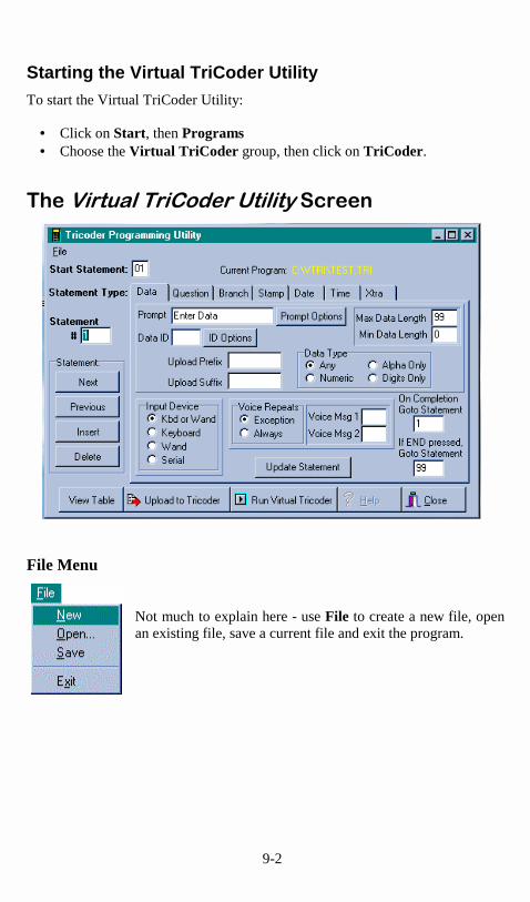
9-2
Starting the Virtual TriCoder Utility To start the Virtual TriCoder Utility:
• Click on Start, then Programs • Choose the Virtual TriCoder group, then click on TriCoder.
��������������� ��������������
File Menu
Not much to explain here - use File to create a new file, open an existing file, save a current file and exit the program.
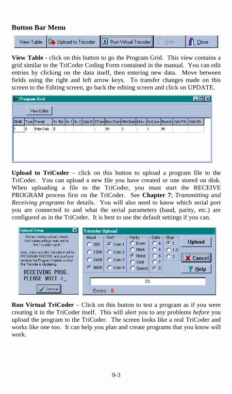
9-3
Button Bar Menu
View Table - click on this button to go the Program Grid. This view contains a grid similar to the TriCoder Coding Form contained in the manual. You can edit entries by clicking on the data itself, then entering new data. Move between fields using the right and left arrow keys. To transfer changes made on this screen to the Editing screen, go back the editing screen and click on UPDATE.
Upload to TriCoder – click on this button to upload a program file to the TriCoder. You can upload a new file you have created or one stored on disk. When uploading a file to the TriCoder, you must start the RECEIVE PROGRAM process first on the TriCoder. See Chapter 7; Transmitting and Receiving programs for details. You will also need to know which serial port you are connected to and what the serial parameters (baud, parity, etc.) are configured as in the TriCoder. It is best to use the default settings if you can.
Run Virtual TriCoder – Click on this button to test a program as if you were creating it in the TriCoder itself. This will alert you to any problems before you upload the program to the TriCoder. The screen looks like a real TriCoder and works like one too. It can help you plan and create programs that you know will work.
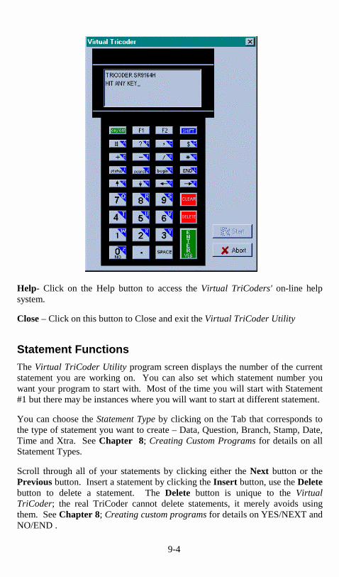
9-4
Help- Click on the Help button to access the Virtual TriCoders' on-line help system. Close – Click on this button to Close and exit the Virtual TriCoder Utility
Statement Functions The Virtual TriCoder Utility program screen displays the number of the current statement you are working on. You can also set which statement number you want your program to start with. Most of the time you will start with Statement #1 but there may be instances where you will want to start at different statement. You can choose the Statement Type by clicking on the Tab that corresponds to the type of statement you want to create – Data, Question, Branch, Stamp, Date, Time and Xtra. See Chapter 8; Creating Custom Programs for details on all Statement Types. Scroll through all of your statements by clicking either the Next button or the Previous button. Insert a statement by clicking the Insert button, use the Delete button to delete a statement. The Delete button is unique to the Virtual TriCoder; the real TriCoder cannot delete statements, it merely avoids using them. See Chapter 8; Creating custom programs for details on YES/NEXT and NO/END .
9-5
����������� ����We recommend reading Chapter 8; Creating Custom Programs to become familiar with all of the programming features before you try to create programs using the Virtual TriCoder Utility. After you are familiar with the program features, creating a program using the TriCoder Programming Utility screen is easy if you follow these simple steps:
Choose the type of statement you want to create for statement #1. Click on the tab that corresponds to the type of statement you want to create. Each tab displays a screen with all of the required data for each type of statement. Fill in the data for the
desired statement, then click on Update Statement. To add another statement, click on Insert. For details on each statement type and all program prompts, see Chapter 8; Creating custom programs.
Continue to add statements until you have created your entire program. After adding a new statement, click on Next to advance to the new statement. As in Step 1, choose the statement type, then enter the necessary data. Decide which statetment number you want to begin data collection with and specify that in
the Start Statement box. Remember that if you choose a statement other than #1 for your Start Statement, you may have partial records if you resume data collection without uploading and deleting the current data file. When you have added all the statements you want for your program, it is time to test your program using the Virtual TriCoder.
Test your program using the Virtual TriCoder. After you have completed your program, click on the Virtual TriCoder button to run the Virtual TriCoder to test your program. Use this utility to make sure your program flows correctly and is prompting your operator for the correct information. Upload your program to the TriCoder. Click on the Upload to TriCoder button to transmit the program to your TriCoder. Programs can only be transmitted via serial port so your TriCoder must be configured as a serial unit. Be sure to start the
Receiving program on the TriCoder before you begin transmitting the program from the Virtual TriCoder Utility. Click on File,
The on-line help system of the Virtual TriCoder Utility goes into detail on all features. Use the Windows TriCoder Utility to download programs from the TriCoder to the host (see Chapter 10; Transmitting and Receiving programs ), then edit and upload them using the Virtual TriCoder Utility.
Step 1
Step 2
Step 3
Step 4

10-1
Chapter 10
������������� The TriCoder's exclusive use of voice prompts allows you to overcome problems such as literacy, language and lighting. With proper planning, voice prompting can make data collection significantly faster and simpler.
�� ������������������������������
• Voice messages can be in any language.
• The operator does not have to be able to read to perform some jobs.
• Audible instructions can be heard in poor lighting where it is difficult to read a LCD screen.
• MOST IMPORTANTLY, the data collection process is faster because the operator does not have to continually look at the screen for instructions. This is especially useful when you do not want or need to enter data from the keypad. Scanning bar coded numbers from a Quantity BARPAD can make keying unnecessary.
Voice messages and prompts are a good way to keep the operator’s attention focused on the job at hand. Audible error messages and warnings also help to limit mistakes and downtime.
����������������������������Voice prompts can make data collection easier and faster, but only if used wisely. Here are some tips on making your voice prompts user-friendly:
• Short messages are preferable for prompts; most English prompts can be stated in ½ second. Instead of saying, "Enter the Item Number" say "Item". During data collection, the typical TriCoder operator does not want to hear long messages thousands of times. Error messages are typically longer because they are the exception and need to provide more precise instruction to the user.
• Record your voice prompts calmly. A frantic sounding voice can
become irritating, especially when heard repeatedly. • Speak clearly. Correct pronunciation will make the voice prompts
easier to follow for all users. Use common words that all users will understand.

10-2
• Vary the tone of your voice for different prompts. For example, the pre-programmed prompts for Program #1; “Item” and “Quantity”, are recorded in a female voice while all error messages are recorded in a male voice. Using a different tone of voice or even a different voice for consecutive prompts or error messages will make it easier for the user to distinguish between them.
• Consider using the “Data Security” option to prevent the operator
from accidentally exiting “Data Collection” by pressing the F1 key instead of the intended F2 key (the F2 key replays the current voice message).
• Be sure to record error messages for all possible problems that
the user may encounter during a data collection session. Once the operator becomes accustomed to listening to the voice prompts, it may become easy to overlook a “display only” error message.
• Use a barpad table and Accumulate Mode to enter numeric
data. This allows the operator to scan everything and avoid using the keypad. Data collection becomes a simple “listen and scan” operation. This has the potential to greatly speed up the entire data collection process.
�
�����������������������������The TriCoder is shipped with 75 seconds of total recording time. The time allotted for each message is partitioned as follows:
30 – ½ second messages (message numbers 01-30) 30 - 1 second messages (message numbers 31-60) 15 - 2 second messages (message numbers 61-75)
Messages are sequentially numbered beginning with the ½ second messages, followed by the 1 second messages, and finally the 2 second messages. You can change the partitions to allow for more or less of a particular length message. For example, if you decide you do not want any ½ second messages and you want 15 more 1 second messages, your allocation would look like this:
00 – ½ second messages 45 - 1 second messages (message numbers 01-45) 15 - 2 second messages (message numbers 46-60)
Voice message partitions are set in the TriCoder either from the bar coded Setup Menu or by the keypad setup. From the Setup Menu, scan the bar code for “Voice Messages”, then scan six digits. The first 2 digits correspond to the ½ second messages, the second 2 digits for the 1 second messages and the last 2
10-3
digits for the 2 second messages. Remember that the total amount of time must add up to 75 seconds.
�������������������������������Voice Operations are accessed two ways. The first way is the usual access from the Programming Mode menu. The second way is “hotkey” access when you are creating a program or assigning errors messages
From the Programming Mode menu… Enter the Programming Mode by answering “NO” to all Operation Mode prompts until you get to:
PROGRAMMING MODE KEY [YES/NO]?
Press “YES”. The TriCoder then asks for a password. Key in the password WDTRI (this is the same password discussed previously in this manual). Entering the correct password produces the following prompt:
PROGRAM FUNCTION KEY Create Programs->1- 3 Voice Operations->4 Change Setup----->5
Press the “4” key to select Voice Operations. The next prompt displayed is:
VOICE OPERATIONS KEY Record/Playback->1 Assign Errors----->2
Pressing the “1” key takes you into the voice recording and playback function. Pressing the “2” key allows you to assign voice message numbers to error conditions.
Using the "hotkey"… The other way to get into the voice recording and playback function is by using a “hotkey” sequence. If you are in “PROGRAMMING MODE” and have chosen “Create Programs”, press the SHIFT key, then the F1 key, and then the F2 key. This key combination will take you to the “Record/Playback” function. This same “hotkey” sequence of SHIFT F1 F2 will work if you are in the “Assign Errors” function and want to record or playback a message. Pressing F1 while in the “Record/Playback” function will take you back to the program or error message you were working on.

10-4
�������������� �� �����������������If you respond with a “1” at the VOICE OPERATIONS prompt or use the SHIFT F1 F2 hotkey, you will see the following Record/Playback prompt:
RECORD/PLAYBACK? KEY [R/P]?
First, we will playback a message that has already been recorded. Let’s use message #01 for this example. Press the P key (for Playback) to get to the next prompt:
KEY [R/P]? MESSAGE #: _
At this prompt, enter a two digit number for the message number you want to listen to. Enter “01” and then press the ENTER/YES key. You will probably hear the “ITEM” prompt recorded at the factory unless you have edited or reset the default messages. If you heard nothing, a new message can be safely recorded in the area assigned to message # 01. After you have heard the message (or static if no message has been recorded), the TriCoder displays the RECORD/PLAYBACK prompt again:
RECORD/PLAYBACK? KEY [R/P]?
To record a message, get out the microphone (no, it’s not an earphone) shipped with the TriCoder and plug it into the AUX jack located next to the POWER jack on the bottom of the TriCoder. Answer the prompt by pressing the R key to record a message. The display now reads:
KEY [R/P]? MESSAGE #: _
Enter the message number you are going to record. For this example, enter message #03 (by default this is a blank message) by pressing 03, then the ENTER/YES key. The TriCoder screen now shows:
HIT ANY KEY TO START RECORDING
To record a message, press any key and hold it down. When you release the key, immediately start speaking into the microphone. To practice, let's record something we can use in the default program #1.

10-5
Get ready to say ITEM (in English or your language) into the microphone of the TriCoder. When ready, press the ENTER/YES key and the instant you release it, speak ITEM into the microphone. Remember to speak clearly – you have plenty of time to say ITEM in ½ second. When the message time is over, you will hear two beeps. The display is back to the RECORD/PLAYBACK prompt:
RECORD/PLAYBACK? KEY [R/P]?
Now you're ready to listen to your first recording. Press the P key and key in 03 for the message number. Do not be discouraged if you didn’t record the entire message. Our first attempt produced “EM” in a very frantic tone of voice. Practice speaking clearly and calmly (think of the poor guy who has to hear it 10,000 times next week) as soon as the key is released. You will get the hang of it with just a little practice. That is the way all messages – prompts and errors - are recorded. If you are not sure which message numbers are blank, you can listen to messages until you find a blank for recording.
��������������������To play back the voice messages you have recorded, they must be designated for use when creating a data collection program in the TriCoder. Once the programming is complete, the operator has the following options available from the TriCoder keypad:
Operation Keypad Sequence To turn OFF all 1. Press the SHIFT key voice messages 2. Press the F1 key 3. Press the S key To turn ON all 1. Press the SHIFT key voice messages 2. Press the F1 key 3. Press the V key To turn OFF prompt 1. Press the SHIFT key Messages but not 2. Press the F1 key error messages 3. Press the P key
To replay the current 1. Press the F2 key voice message

10-6
!��"����������������The TriCoder comes from the factory with some voice prompts and error messages pre-recorded. You can change any of these messages but keep in mind that the error conditions that the voice error messages are linked to are fixed. For example, the “Change Batteries” message is located at message #31. Whenever the TriCoder detects very low batteries, it will play message #31, regardless of what is recorded there. You could record “Happy Birthday” and the TriCoder would broadcast it any time it detected the low battery condition. To avoid confusion, try to keep the error messages somewhat related to the error condition they represent. Here are the default messages and the message numbers they are recorded under:
Message Recorded Message #
Prompts
ITEM #01
QUANTITY #02
Error messages
CHANGE BATTERIES #31
DATA FILE EXISTS #32
DATA TOO LONG #33
DATA TOO SHORT #34
DATA TYPE ERROR #35
DUPLICATE ACCESS #36
IDENTIFIER ERROR #37
ITEM NOT FOUND #38
OUT OF MEMORY #39
WRONG INPUT DEVICE #40
WARNING 2K LEFT #61
�
����������������������������������������������If you have several TriCoders, you can record all of your voice messages in one TriCoder and simply “clone” them to your other TriCoders. Cloning can also copy programs, tables, and the TriCoder setup. Cloning does have certain conditions that need to be met before you start:
• The TriCoders must be set to the same Computer Interface and if set for Serial instead of Keyboard, all TriCoders must be set to the same baud rate, parity, stop bits and data bits.
10-7
• Upload any data in the TriCoders before you start. The TriCoder will not allow you to receive a program if there is a data file present.
• Plug in the power supply. This eliminates the possibility of your batteries running out during the cloning process.
• You need 2 cables to clone voice messages, the Data Cloning Cable #F38 and the Voice Cloning Cable #T15. The Data Cloning Cable plugs into the “Computer” port on each TriCoder. One jack on the Voice Cloning Cable has two black rings on it – this end must plug in to the RECEIVING TriCoder.
If you want to clone voice messages only, follow these steps:
1. Plug in the Data Cloning Cable and the Voice Cloning Cable. 2. On the TriCoder you are cloning to (the one without your custom
voice prompts), answer NO to the MODE MENU prompts until you see:
PROGRAM RECEIVE KEY [YES/NO]?_
3. Answer YES by pressing the ENTER/YES key. The TriCoder will
display a message saying:
RECEIVE PROGRAM KEY ------------------------------------ Programs [1-3]?--->1–3 Clone TriCoder?------>0
4. To clone only the voice messages, press the 9 key. The receiving
TriCoder MUST be started first. The TriCoder will display the following message:
RECEIVING PROGRAM PLEASE WAIT
5. On the master TriCoder (the one you have recorded your prompts in), answer NO to the prompts on the MODE MENU until you see:
PROGRAM TRANSMIT KEY [YES/NO]?_

10-8
6. Answer YES by pressing the ENTER/YES key. The TriCoder will display a message saying:
PROGRAM TRANSMIT KEY ------------------------------------- Programs [1-3]?-- >1 – 3 Clone Tricoder?-------->0
7. Transmit only the voice messages by pressing the 9 key. The TriCoder will display:
SENDING PROGRAM PLEASE WAIT_
The voice messages will play as they are transmitted. If you do not hear the correct messages or you hear no messages at all, you may have transmitted from the wrong TriCoder.
8. When the voice messages have been successfully transmitted and
received, the TriCoders will display these messages:
END OF PGM. XMIT HIT ANY KEY
and
END OF PGM. RECV HIT ANY KEY
Pressing any key takes you back to the MODE MENU. If an error occurs (or you press any of the keys on the TriCoder) during the transfer, the TriCoder will display the following error message:
DATA XMIT ERROR CYCLE POWER
If you get the DATA XMIT ERROR message, you have to restart the whole cloning procedure.
����������#�� ������"����The volume of the speaker can be increased significantly by adjusting a tiny potentiometer inside the TriCoder. Changing the speaker volume also changes the headphone volume. The Headphone is an optional feature, Part #T12 and can be ordered with the TriCoder or separately afterward. Because static discharge can cause damage to the TriCoder’s circuit board, it is recommended that you use a ground strap or other grounding device when you are touching the

10-9
inside of the TriCoder. As a precaution, upload all data and programs before opening up the TriCoder. To open the TriCoder, turn the TriCoder OFF, unplug the power supply and remove the four screws on the back of the TriCoder (one in each corner). Lay the connected halves of the TriCoder on a desk or flat surface. You now have access to the EPROM, the lithium battery and several jumpers as well as the volume potentiometer. Using Figure 10-1, locate the volume control and make adjustments within the red lines marked on the potentiometer. Use a knife or a very fine blade flat screwdriver to turn the volume control. Turn it clockwise to increase volume or counter clockwise to decrease the volume.
If you are in a noisy environment, try using the headphone that plugs into the AUX jack on the bottom of the TriCoder. When using the headphone, you can conserve power by turning off the speaker. Go into the SETUP MODE, Speaker Operations and specify 1 for Speaker OFF.

10-1
Chapter 10
�������������������$�������������#��"�� The TriCoder has the ability to transmit and receive programs and setup information. Transmitting and receiving can occur between two TriCoders or between a TriCoder and a host computer. Transferring the entire setup configuration, voice messages and programs from one TriCoder to another is called “cloning”. If you want to clone only voice messages, see Chapter 10; Voice Messages for complete information. If your programs are complex or large, transmitting them from TriCoder to TriCoder is faster and easier than manually entering all of the information every time. Transmitting programs to a host computer allows you to store a back-up copy (excluding Voice Messages) available for download if anything happens to your TriCoder.
�����$����������������������������������There are several things you need to do before receiving programs or setup from another TriCoder or host computer:
• Receiving and transmitting programs from one TriCoder to another requires the correct cables. The TriCoder Data Cloning Cable (F38) is needed to clone or transmit/receive programs, tables and setup information. The TriCoder Voice Cloning Cable (T15) is required to "clone" or transmit and receive voice messages. Voice messages can only be transmitted or received from TriCoder to TriCoder. They cannot be transmitted via host computer. The Data Cloning Cable is attached to each TriCoders Computer port. The connector on the Voice Cloning Cable that has two black rings on the tip plugs into the auxillary jack on the bottom of the receiving TriCoder. The tip with the single ring plugs into the transmitting TriCoder.
• Transmitting and receiving programs from a host computer requires the cables normally used for TriCoder serial communication.
• Make sure all data is uploaded and deleted from the receiving TriCoder. The TriCoder will not allow you to receive data unless the TriCoders data files are empty.
• Plug in the 5 volt power adapter. You want to make sure you don’t have a low-battery situation in the middle of a transfer.

10-2
• Always start the receiving TriCoder first. • When transmitting between two TriCoders, both TriCoders must be
configured to use the same Computer Interface. If configured as serial interface, the serial parameters must be the same on both TriCoders; baud rate, parity, data bits and stop bits must match.
Cloning to or from older TriCoders If you are cloning to or from an older TriCoder that only has 64k memory with memory partitions, use the following table to see how the partition configuration will transfer:
64k partition configuration to 256k partition configuration 200000 800000 110000 440000 100100 400400 256k partition configuration to 64k partition configuration 800000 200000 any other configuration "Partitions Not Cloned"
"Press Any Key" message displayed on TriCoder after cloning is complete.
Receiving a program on the TriCoder Make sure all cables are attached correctly and the 5 volt power adapter is plugged in. To start the receiving TriCoder, answer NO to all prompts until you see:
PROGRAM RECEIVE? KEY [YES/NO]?_
Press YES to get to the RECEIVE PROGRAM menu:
RECEIVE PROGRAM KEY ------------------------------------------ Programs [1-3]?-------->1 - 3 Clone TriCoder?----------> 0
Press 0 to Clone the entire TriCoder. Cloning receives the programs, tables, Setup and voice messages (if using a voice cloning cable T15 ) from another TriCoder. If Cloning from a host computer, only the programs, tables and Setup can be received. Press 1, 2 or 3 to receive a program only. Pressing 1, 2 or 3 determines which program number you are assigning - it does not have to correspond to the

10-3
program number being transmitted from the other TriCoder or host. After making a selection, the TriCoder displays:
RECEIVING PROGRAM PLEASE WAIT�
At this point, you can start the transmitting TriCoder or host program. Once the transmission is complete, the receiving TriCoder displays:
END OF PGM. RECV HIT ANY KEY_
Press any key to return to the Mode Menu. If the TriCoder has a problem during the transmission, the transfer will end and the TriCoder will display the following error message:
DATA XMIT ERROR CYCLE POWER
If you receive this message while receiving a program, the program transfer is incomplete and the transmit/receive session will have to be restarted. To avoid any problems, do not press any keys on the TriCoder once the transmission has started.
Receiving a program on the host computer using the TriCoder Windows Utilities The Windows TriCoder Utilities gives you the ability to receive a program from a TriCoder (serial interface only) and either store the program/setup for later use or download it to another TriCoder. Voice messages cannot be received by the host computer. To start a transfer using the TriCoder Utilities, make sure your cables are connected correctly. Start the Windows TriCoder Utilities program and click on the TRICODER UPLOAD tab. Choose either “Program” or “Clone TriCoder”, depending on what it is you want to receive from the TriCoder. Enter a file name to save either the cloned information or the program to. Include the path if you want to save the file somewhere other that the default TriCoder Utilities directory. Click on START. The program displays the “Waiting for TriCoder to begin transmit...” message and waits for the TriCoder to begin the transmission. Upon completion, the program displays the “File Transfer Complete” message.

10-4
If you are using DOS, use the RECEIVEP program included on the TriCoder Utilities diskette to transmit a program or setup to your PC.
����������� � ������ ����� ���� ��������� ��������Transmitting a program from the TriCoder requires the same preparation as receiving a program. Before you begin:
• Check your cables - both data and voice • Plug in the 5 volt power supply • Always start the receiving TriCoder first.
To start transmitting programs or setup from a TriCoder, answer NO to all prompts until you see:
PROGRAM TRANSMIT? KEY [YES/NO]?_
Press YES to get to the TRANSMIT PROGRAM menu:
TRANSMIT PROGRAM KEY ------------------------------------------ Programs [1-3]?-------->1 - 3 Clone TriCoder?----------> 0

10-5
Press 0 to Clone the entire TriCoder. Cloning transmits the programs, tables, Setup and voice messages (if using a voice cloning cable T15 ) to another TriCoder. If Cloning to a host computer, only the programs, tables and Setup can be transmitted. Press 1, 2 or 3 to transmit a program only. Pressing 1, 2 or 3 determines which program number you are transmitting - it does not have to correspond to the program number chosen by the receiving TriCoder or host. After making a selection, the TriCoder displays:
SENDING PROGRAM PLEASE WAIT�
Once the transmission is complete, the transmitting TriCoder displays:
END OF PGM. XMIT HIT ANY KEY_
Press any key to return to the Mode Menu. The protocol for program transmission is different than that for data transmission. During program transmission, the TriCoder transmits each character one at a time, expecting the receiving TriCoder to echo the character back. If the characters match, then the transmitting TriCoder sends the next character. If the characters don’t match, the transmitting TriCoder sends a NAK to the receiving unit. At that point, the transmitter re-sends the last character. If the transmitter ends up sending 10 NAKS, it will abort the transmission (there is obviously something wrong) by sending EOT (ASCII 4). and display the following error message:
DATA XMIT ERROR CYCLE POWER
If all data is echoed back correctly, the last character sent to the receiving unit is ASCII 128. If you see this message while transmitting a program, the program transfer is incomplete and the transmit/receive session will have to be restarted. To avoid any problems, do not press any keys on the TriCoder once the transmission has started.

10-6
Transmitting programs to a TriCoder from the Windows TriCoder Utilities The Windows TriCoder Utilities program can transmit a program previously received from a TriCoder back into another TriCoder. TriCoders can also be “cloned” in this manner. To transmit a program from your PC using the Windows TriCoder Utilities, start the TriCoder Utilities program and click on the “TRICODER DOWNLOAD” tab. Enter the name of the program file or cloning file you want to transmit to the TriCoder. Remember to start the TriCoder before you begin transmitting the program. Click on START to begin the transfer.

11-1
Chapter 11
���������������� ����������������������� Storage memory in the TriCoder can be divided and used for different purposes. Some memory can be allocated to store collected data while the remaining memory might be set aside to store table data (see Chapter 13, Tables and Pick Lists for details). Memory is allocated or “partitioned” using the Partitions setup parameter. Up to 3 data files and 3 tables can be defined in the Partitions parameter. The 256k of memory in the TriCoder is divided into eight 32k blocks called "pages". The TriCoder can have a maximum of 3 data files and 3 tables which can be of varying memory sizes, as long as they add up to 256k.
Partitioning Memory Each 32k block of memory is called a “page”. The TriCoder has 8 pages of memory available. Memory is partitioned by assigning a number of pages to a particular data file or table. Once you are in the Partitions setup parameter, you will see the following information on your TriCoder screen:
PARTITIONS? abcdef_
where: a is the allocation for data file #1 b is the allocation for data file #2 c is the allocation for data file #3 d is the allocation for table #1 e is the allocation for table #2 f is the allocation for table #3
PARTITIONS? 700100_
The total number of pages must equal 8. In this example above, data file #1 is allotted 7 pages (224k), data files #2 and #3 none, table #1 is allotted 1 page (32k) and tables #2 and #3 are given none (0k). The size of a table will determine how much memory needs to be set aside for it. In our example, the largest table allowed would be 32K.

11-2
Using Multiple Data Files Creating multiple data files in the TriCoder makes it easier to use different programs in the TriCoder concurrently. If you have your memory partitioned for only 1 data file, you can collect data for 1 program only – you cannot collect data for another program until you have uploaded and deleted the current data file. A good example might be that you have created separate programs for shipping and receiving and need to be able to switch back and forth between them at any time. With only 1 data file defined, this is not possible. By partitioning the TriCoder memory into 2 data files, you can assign one file to your shipping program and the other file to your receiving program, switching back and forth as necessary. Once you have partitioned the memory into multiple data files, when you begin data collection, you will see the following series of prompts:
DATA COLLECTION?_ KEY [YES/NO]?_ PROGRAM NO.? KEY [0-3]?_ (enter the program number)
DATA FILE NO.? KEY [1-3]?_
Linking a data file with a data collection program Once you choose a data file number and collect some data, the TriCoder remembers which program you used. If you currently have data in the data file and try to use the same data file to collect data using a different program, the TriCoder displays:
FILE USED BY Pn HIT ANY KEY_
where n is the program number, 0-3. This prompt forces you to choose another data file number to collect data in this program.
Continuing to collect data using an existing data file If you have used a particular program and data file to collect data and have not uploaded the data, you have the option of collecting more data in that program and data file by “appending” the new data to the end of the existing file. After selecting your program number and data file number (one that is still current in the TriCoder and has not been uploaded), the TriCoder will display the following prompt:

11-3
APPEND DATA FILE?_ KEY [YES/NO]?_
This prompt is simply letting you know that if you press YES, you will add data to an existing data file. If you press NO, you will go back to the DATA FILE NO. If you try to select a data file number that has not been defined, the TriCoder will display:
FILE NOT DEFINED HIT ANY KEY_
Using the STATUS key to view data file partitions Once you have partitioned your memory, you can use the STATUS key to review the amount of memory left in each data file and to see which program a data file is linked to. Normally, pressing the STATUS key simply displays the date and time information along with the total amount of unused memory. When you have data files partitioned, the STATUS key returns a two-screen status report that looks as follows:
first screen: mm/dd/yy hh:mm:ss xxxk BYTES FREE AAaBAT�����������-xx% LI – BAT�����������-xx%
press ENTER
second screen: AAaBAT�����������-xx% LI – BAT�����������-xx% P1-015K PX-032K PX-000K
In the example above, the first screen displays the date (mm/dd/yy) and time (hh:mm:ss) on the first line, then the number of bytes of memory free (xxxk, where xxx is the number) on the second line. The third and fourth line is the battery status (see Chapter 7; Powering the TriCoder for details). The second screen again displays the battery status (lines 1&2), the displays the status of the data files on lines 3&4. In the example above it shows:
• P1-015k - Data file 1 is defined, is currently used by Program 1 and has 15k of memory available (some memory has been used).
• PX-032k - Data file 2 is defined, is not currently in use by any program and has 32k of memory available (no memory has been used). The X shows that a program does not currently use this file.

11-4
• PX-000k - Data file 3 has not been defined – the 000K designates that no memory has been allocated for this file.
The same rules that apply to single data files apply to multiple data files:
1. You won’t be able to change anything in the program itself except for the Upload Prefix and Upload Suffix while you have data in the TriCoder.
2. You cannot re-define your memory partitions using the Partitions
setup parameter while you have data in the TriCoder.
Partitioning memory for tables Memory partitions for tables are specified in the second half of the Partitions setting and follow the same parameters as data files. Memory is allocated in 32k “pages” and is specified as the number of pages in the Partitions setting. The constraining factor in partitioning memory for tables comes from the table size itself – you must allow enough memory in the table partition to accommodate the table. See Chapter 13, Tables and Pick Lists for details on using and creating tables.

12-1
Chapter 12
������������ �%����� The TriCoder has a valuable feature that allows you to download information into the TriCoder (a table) and then reference that table of information during data collection. There are 3 functions that the table feature performs:
• Table data validation • Table data maintenance • Pick Lists
Partitioning memory for table use In order to use tables with the TriCoder, the TriCoder memory must first be partitioned into areas for table data and areas for data storage. Memory is allocated using the Partitions setup parameter, either by scanning the bar coded Setup Menu or accessing the TriCoder Setup via the keypad. TriCoder memory is partitioned into 32k pages, with 8 pages total. The TriCoder Partitions parameter is as follows:
PARTITIONS? abcdef_
where: a is the allocation for data file #1 b is the allocation for data file #2 c is the allocation for data file #3 d is the allocation for table #1 e is the allocation for table #2 f is the allocation for table #3
PARTITIONS? 700100_
The total number of pages defined must equal 8. In this example, data file #1 is allotted 7 pages (224k), data files #2 and #3 none, table #1 is allotted 1 page (32k) and tables #2 and #3 are given none (0k). The size of the table will determine how much memory needs to be set aside. In our example, the largest table allowed would be 32K.

12-2
Data Validation using Tables Lets say you have a warehouse application where you want to use the TriCoder to record items being loaded onto a truck. You can use a table of data downloaded into the TriCoder to validate what is being loaded on the truck. When the worker scans the item to be loaded, the TriCoder checks the item number against the item numbers in the table; if they match, the item number is written to the data file and he moves on to the next item. If the item number he scans is not found in the table, the TriCoder would alert the worker that the item he is loading is not on the list, avoiding a possible mis-shipment or loss. Data Validation validates a single field of entered data against a table constructed of single pieces of data. The TriCoder uses the DATA ID field to specify which table you want to use to validate the data entered for that statement.
Data ID entry Description
A1A validate data using table 1 A2A validate data using table 2 A3A validate data using table 3
When the operator enters an item found in the table, the TriCoder writes the item to the data file and goes to the next statement in the program. If the item is not found in the table, the TriCoder displays:
ITEM NOT FOUND HIT ANY KEY_
and displays the statement prompt over again. Data validation table file format The file format used to create a table for data validation is a simple ASCII text file with CR/LF delimiters. The first line in the data file is a variable-length header record that defines the data in the table. The first 2 digits indicate the data length of each record in the table. The next 9 digits are always 0’s (zero), indicating that the data is for validation only. The following characters can be whatever you want - it is optional and for reference only, the TriCoder does not use it . The following header would indicate a 6 digit length data table, using the word EXAMPLE1 as the reference:
06000000000EXAMPLE1
After the header come the lines of data to validate. The only constraint on the file size is the amount of memory you have allotted for the table data. If the data file is created in DOS, the file needs to have a Ctrl Z (ASCII 26 or Hex 1A) to

12-3
indicate the END OF FILE. A sample file using the example header above might look like this:
06000000000EXAMPLE1 111111 222222 333333 324211 365667 Ctrl Z (ASCII 26) (use if a DOS file)
Preventing duplicate entry of data Sometimes you might want to make sure that an item in your table is not scanned or entered twice. You can prevent duplicate data when using a data validation table by specifying the following in the DATA ID field:
Data ID entry description
D1D prevent duplicate entry for table 1 data D2D prevent duplicate entry for table 2 data D3D prevent duplicate entry for table 3 data
If you have specified DxD in the DATA ID field and happen to enter the same data twice, the TriCoder will respond with the following error message:
DUPLICATE ACCESS HIT ANY KEY_
Hit any key to return to the statement prompt again. The file format to prevent duplicate access for table data validation looks almost identical to the above example for simple data validation with a few exceptions: As with the original example, the header record uses the first 2 digits to specify the data length, but the next 3 characters are F01 (specifies duplicate entry) and each data record has an additional 0 added to the low order position:
06F01000000EXAMPLE1 1111110 2222220 3333330 3242110 3656670 Ctrl Z (ASCII 26)
The TriCoder uses the 0 (zero) at the end of each record to determine whether a record in the table has been accessed or not. When a record is accessed, the 0

12-4
(zero) changes to a 1. If the user enters the same data twice, the TriCoder will look at the table and see a 1 at the end of the matching data, indicating that the record had been accessed previously. Once accessed, the table cannot be reset to its original status. You would have to re-download the table to use the table in its original format.
Data Maintenance using tables Data maintenance refers to using a table consisting of multiple fields per record to maintain or update a master file. Tables that are used for maintenance can consist of up to 4 fields per record, including the “key” field. The “key” field is the data that is entered while collecting data by scanning or keying and then looked up in the table by the TriCoder. An example of this type of application might be a retailer who wants to use the TriCoder to verify that their shelf prices match the prices in the computer, or that their inventory counts in the computer match what is actually on the floor. The retailer can download a table of data into the TriCoder that consists of the item number (the “key” field), a short description, the price and finally, the inventory count. He can choose to make any or all of the fields “updatable” or “fixed”. Fixed fields cannot be changed by the user collecting the data; they are simply for information purposes only. The “key” field is also fixed as it is what the TriCoder uses to reference the data in the table. “Updatable” fields are fields that the user can change or update in the TriCoder when they access that particular record in the table. When the operator scans the item number, the TriCoder looks up the number in the table and displays the entire record (description, price, quantity), with the cursor stopped on the first “updatable” field. The operator compares the data displayed by the TriCoder to the item information on the shelf and edits the data in the TriCoder if needed. Pressing ENTER takes the operator to the next “updatable” field and he repeats the process. Once the record is edited, it is written to a data file for uploading to the host computer. The table maintenance may only be one step in a multi-statement program. After the table data is written to file, the TriCoder moves on to the next program statement. While collecting data, if the operator wants to display the key field again, he/she can press the F2 key, then press it again to return to the rest of the data items in the table. When finished, the retailer can now use the edited table information to update their master records in the computer when he uploads.

12-5
Table Maintenance is specified in the DATA ID field while programming the TriCoder:
DATA ID entry description
M1M data maintenance on table 1 M2M data maintenance on table 2 M3M data maintenance on table 3
Table Maintenance file format The file format for a table used for maintenance is similar to a that used by table data validation in that it uses a header record to describe the table format to the TriCoder. The header consists of at least 11 characters plus a comment or reference name. The table maintenance header uses the following format:
aaxbbxccxddcomment
Position data allowed description
x U 0r F U indicates field is UPDATABLE
F indicated field is FIXED aa 01-30 determines the data length of the key field xbb x00-x30 determines data length of field #2, use x00 if field is
not present xcc x00-x30 determines data length of field #3, use x00 if field is
not present xdd x00-x30 determines data length of field #4, use x00 if field is
not present comment 1-15
alphanumeric name of file or comment used for internal use; this field is not used by the TriCoder.
Lets say we wanted to create a file that had a 5 digit item number (the key field), a Fixed 16 character description, an Updatable 6 digit price, an Updatable 4 digit quantity count and a file reference of INVENTORY. The header for such a file would look like this:
05F16U06U04INVENTORY
The entire file might look something like this:
05F16U06U04INVENTORY 11111TWINKIES - 4OZ $1.39 21 22222CANDLES - 3FEET $10.95 180 33333SALMON, SOCKEY12 $5.95 48 Ctrl Z (ASCII 26)

12-6
There are several points to remember when creating a table maintenance file:
• There are no physical delimiters between fields; the TriCoder is using the field length from the header to determine each field length.
• If the length of your data for a field is not the same as the data length you have specified in the header, you must pad the data out to the specified data length by adding spaces to the end of the data. Field #1 must always be the same length, regardless of the length of the actual data. The same is true for all fields. The example above shows this. When the operator edits data in the table, they do not have to include the spaces.
• Each line in the file must be terminated with a CR/LF. CR is ASCII 13 and LF is ASCII 10. The file itself should be terminated with a Ctrl Z (ASCII 26)
• It is critical that the header and file use the correct syntax and format. The TriCoder checks the file before it downloads it and will display the appropriate error message if it finds a problem:
Error Message Condition/Solution
INVALID HEADER HIT ANY KEY_
There is a problem with the format or syntax of the header. Check the header for syntax errors.
TABLE FORMAT ERR HIT ANY KEY_
There is a problem with the format of the actual table data. Check the table data for format and field lengths.
TABLE TOO BIG HIT ANY KEY_
The table size is larger than the amount of memory you have allotted in the TriCoder or, there is a format error in one of the records. Increase the memory in the PARTITIONS setup parameter and if using TBLSEND.BAS to download the table, check the record just after the one displaying on the screen.
Output data file format for Table Maintenance When a record is accessed from the table during data collection, that entire record is written to one of the TriCoders data files. When it is time to upload the TriCoder, it is the data file, not the actual table that is uploaded. When a data file created during Table Maintenance is uploaded, it is uploaded in a “comma delimited” format. This format is used to make the data easier to process for most applications. The following example shows what the record looks like in the table:
11111TWINKIES - 4OZ $1.39 21
and what it will look like when it is uploaded to the computer:
“111111”,”TWINKIES - 4OZ ”,”$1.39 ”,” 21”

12-7
Downloading a table to the TriCoder Tables are downloaded to the TriCoder through a computers serial port. Before you can download a table, you must have:
• partitioned the memory using the PARTITIONS setup parameter
• setup the TriCoder as a serial interface and have a serial cable
• plugged in the 5 volt power supply. A program to download a table to a TriCoder is supplied for DOS and Windows as part of the TriCoder Utilities diskette. Once you have defined at least one table using the Partitions Setup parameter, the Mode Menu will have an additional selection. To get to it, turn on the TriCoder and answer NO to all Mode Menu selections until you see:
TABLE DOWNLOAD? KEY [YES/NO]?_
Press the YES key on the TriCoder. The next prompt will be:
TABLE NUMBER? KEY [1-3]?_
Press the appropriate number TriCoder key to start the download process at the TriCoder end. If you key an number that is not valid (anything other than 1, 2, or 3), you will see:
INVALID TABLE # HIT ANY KEY_
If you enter a table number that has not been defined in the Partitions setup parameter, you will see:
TABLE UNDEFINED HIT ANY KEY_
Using Windows to download a table The Windows TriCoder Utilities program is the easiest way to download a table to the TriCoder. The Windows TriCoder Utilities program can even be used to create a table to download (more about this later). Once the TriCoder is ready to accept the table, start the TriCoder Utilities program, then click on the DOWNLOAD tab.

12-8
Follow the instructions on the Windows TriCoder Utility screen. When the TriCoder is done, it will display:
END OF TBL RECEIVE HIT ANY KEY_
Editing or creating a table using the Windows TriCoder Utility You can edit or create tables using the Windows TriCoder Utility. After starting the program, click on the TABLE EDITOR tab. If you want to load an existing table, click on File, then choose Open Table from the menu. This menu also allows you to save Tables, create new Tables and save an existing Table under a different name. Enter the appropriate information in each section, designating either F, U or V for fields 2-4. See the section in this chapter about table format requirements for more information on how to create a table.

12-9
Pick Lists Pick Lists are tables that provide instruction to the user. Typically they are used in an order-picking type application where the pick list instructs the user as to what product to pick, where to find it and how many to pick. The logic used for a pick list can be used for other applications such as meter reading (address of meter, where it is located, the meter reading). A Pick List is really just a table, similar to that used for data validation and data maintenance. To access a Pick List, use
P1P -accesses table 1 P2P -accesses table 2 P3P -accesses table 3
in the DATA ID to reference the correct table. When the operator uses the data collection program, each item in the specified table (pick list) is sequentially displayed until all items are picked by the operator. A Pick List is downloaded to the TriCoder much the same way a regular table is downloaded. Just as with a table, you can download the pick list using the Windows TriCoder Utilities program or the DOS utilities. Upon uploading, if the TriCoder sends and SO (ASCII 14) as the EOF String, the TriCoder can prompt the host to download a new picklist without user intervention. Up to 4 fields are allowed in each pick list record. Each field can be from 1 to 19 characters long and can have one of the following properties:

12-10
• Fixed Displayable Only - nothing to enter or scan • Verifiable - used to verify that the user is at the correct location,
item, etc..., or to force no partial picks. • Updatable - items can be changed
If you do not want to use all four fields, put 00 in the field length. Pick List Format Just as with regular tables, the first line of the pick list is the header record which defines the pick lists format. The following header example is a pick list that states:
1. the location of the item 2. the item description, 3. the item number 4. the quantity to pick 5. the Pick List or Order Number
18F19V06U03PICK LIST 1 Aisle 23,Bin 14M Aspirin 12oz. PinkL111111014 Aisle 24,Bin 15H No-Doz Large Pills 222222012 Aisle 12,Bin 01L Vitamin C, Large Hi 333333005 Aisle 01,Bin 12L Soy Sauce Large Br444444001
The 18 in the header record is the length of the first field in the pick list. Since the first field in a table/pick list is always fixed, you don’t have to specify F for fixed. In the example above, the first field is the location:
Aisle 23,Bin 14M Aisle 24,Bin 15H Aisle 12,Bin 01L Aisle 01,Bin 12L
The next field is F19 - a fixed field, 19 characters long. This field is for display only and requires no action by the operator. In the example above, it is the description of each item:
Aspirin 12oz. PinkL No-Doz Large Pills Vitamin C, Large Hi Soy Sauce Large Br

12-11
The third field is V06 - indicating a Verifiable field with a length of 6 characters. Verifiable fields must be entered by the operator exactly as they appear on the TriCoder. When the pick list record is displayed by the TriCoder, the cursor stops on the first Verifiable or Updatable field and waits for the operator to enter data. In this example, the third field is the Item Number - the operator is forced to enter the item number of the item he is picking. It is typically scanned off of the item or bin:
111111 222222 333333 444444
The fourth field is U03 - describing a field that is three characters long and is Updatable. Updatable fields can be changed by keying or scanning. The cursor of the TriCoder will stop at the Updatable field and wait for operator input. The fourth field in this example is the quantity to pick:
014 012 005 001
The last field in the header; Pick List 1, is the Order Number that may be uploaded as the first record in the data file. This allows the computer to tell which order was picked. This field can be from 1 to 20 characters long. If you do not specify that you want the Order Number written to the data file, it is ignored.
If you want the Order Number to be written to the data file for uploading, you must specify
O1O -order number for table 1 O2O -order number for table 2 O3O -order number for table 3
in the DATA ID field of the programming statement when programming the TriCoder. Programming the TriCoder for Pick Lists There are some special considerations to think about when programming the TriCoder to use a Pick List:
• When using O1O, O2O or O3O to upload the order number for a pick list, remember that the program statement should be executed only once, and should be at the beginning of the program. This program statement will not cause the TriCoder to pause for operator input so the Prompt Text is not that important. An Upload Prefix and Suffix can be specified for the statement.

12-12
• When the TriCoder executes a statement with P1P, P2P or P3P in the Data ID, the TriCoder displays the next incomplete item in the Pick List. When all items in the Pick List have been picked, and the TriCoder executes the PxP statement again, the TriCoder will display:
PICK LIST COMPLETED HIT ANY KEY_
Press a key and the TriCoder displays:
DATA UPLOAD? KEY [YES/NO]?_
If you want to upload a partially-picked Pick List, simply bypass the warning message the TriCoder will display indicating that the Pick List is incomplete.
Pick List Examples The following example illustrates a program that would both output the order number and output the items on the pick list:
Stmt #
Entry Type
Data ID Yes/Next No/End Description
1 D O1O 02 00 outputs order number
2 D P1P 02 02 outputs items picked In the example above, if you press the END key while executing statement #2 you can bypass a record in the Pick List and go to the next one. A program that uses a Pick List can still utilize other statement types. In the following example, not only does the program access the Pick List but also records the serial number:
Stmt #
Entry Type
Prompt Text Data ID Yes/ Next
No/End Description
1 D Picker No.? 02 99 outputs picker no.
2 D O1O 03 00 outputs order number
3 D P1P 04 03 outputs items picked
4 D Scan Serial # 04 03 loops on serial # In the example above, the program requires the operator to enter the number picked, then scan or enter the serial numbers of each item picked. When all serial numbers have been scanned or entered, the user presses the END key to get to the next record in the pick list. You can skip items in the Pick List by pressing the END key while executing statement #3. To prevent the user from skipping items, enter 00 in the No/END field of statement #3.

12-13
Computer/TriCoder Interface for Pick Lists To the TriCoder, Pick Lists are simply tables to download. To really utilize Pick Lists, the system should be as automated for the operator as possible. Here’s how we envision Pick Lists being used:
• Take the orders and create a pick list to downloaded to a system server, making the file available from remote locations.
• At the remote warehouse location, the user plugs the TriCoder onto a workstation (PC or terminal) and selects Table Download from the TriCoder Mode Menu.
• The user then starts a table downloading program on the workstation, downloading a pick list that has been sorted by location to minimize the time needed to fill the pick list.
• When the download is complete, the user starts the Data Collection program that references the pick list on the TriCoder.
• When the Pick List is complete, the TriCoder displays
PICK LIST COMPLETED HIT ANY KEY_
pressing any key brings this prompt:
DATA UPLOAD? KEY [YES/NO]?_
At this point, the user takes the TriCoder back to the workstation, attaches the TriCoder, starts the uploading program on the computer, then presses YES to start the Data Upload on the TriCoder. If the user has specified an EOF STRING of SO (ASCII 14), after finishing its upload, the TriCoder sends the EOF STRING of SO, indicating to the host computer that the TriCoder wants to receive a new Pick List.
• After receiving the SO (ASCII 14) from the TriCoder, the host computer can do one of 6 things by transmitting a particular ASCII character to the TriCoder:
ASCII Character Action
ASCII 01 Begins downloading pick list into Table #1, erases current data file.
ASCII 02 Begins downloading pick list into Table #2, erases current data file.
ASCII 03 Begins downloading pick list into Table #3, erases current data file.
ASCII 04 (EOT) Does not download a new file,erases current data file.
ASCII 06 (ACK) Does not download a new file,saves current data file.
ASCII 21 (NAK) retransmits EOF String

12-14
After completing the upload, the TriCoder waits for 10 seconds to receive one of the above characters from the host. If it receives nothing, the TriCoder displays:
DELETE DATA FILE KEY [Y/N]?_
If the TriCoder receives ASCII 01, 02 or 03, the TriCoder displays:
DOWNLOADING TABLE PLEASE WAIT_
• In order to make this operation truly automated, you need to have a
way to for the TriCoder to query the host periodically as to whether or not the host has a pick list to download to the TriCoder. To do this, when the user sees the prompt:
TABLE DOWNLOAD? KEY [YES/NO]?_
Instead of pressing YES or NO, the user presses the F2 key, causing the TriCoder to transmit it’s EOF STRING to the host computer.
• If the user has set the EOF STRING as SO (ASCII 14), this transmission tells the host that the TriCoder is ready and waiting to receive a Pick List. The TriCoder will wait 10 seconds for a response from the host. If the host is not ready and does not respond, the TriCoder displays:
HOST NOT RESPONDING HIT ANY KEY_
• If the host is ready for the TriCoder, it sends back the ASCII
character that corresponds to the action it wants to take (ASCII 01, 02, 03, 04, 06 or 21).
• While a Pick List is downloading, the TriCoder displays
TABLE DOWNLOADING PLEASE WAIT_
If there is no Pick List to download (ASCII 04 or 06), the TriCoder displays:
NO TABLE AVAILABLE HIT ANY KEY_

12-15
• It is highly recommended that operators be cautioned against uploading an incomplete Pick List. If the operator attempts to upload and incomplete Pick List, the TriCoder displays:
PICK LIST INCOMPLETE ARE YOU SURE? KEY[Y/N]?_
If they press Y, the upload results may be unpredictable. If you key N, the TriCoder goes to the DATA COLLECTION prompt, allowing the operator to complete the Pick List.
• If the operator wants to see what Order Number they are working on, the can :
Press SHIFT Press F2 Press O (the letter O, not zero)
to display the following information:
nnnnnnnnnn -the order number or name xxx -number of items picked yyy -number of items remaining
• You can review data while using a Pick List but blank spaces are replaced with an asterisk (*) character while in data review mode in order to differentiate between items picked (data file) and items not picked (Pick List).
Uploaded Data File Format In Pick Lists, the accessed records are written to one of the TriCoders three possible data files. When the TriCoder is finished with the Pick List and is uploaded, it is uploading the data file to the host computer, not the actual Pick List. When a Pick List data file is uploaded, it writes a “comma delimited” format, making it easy to process on the host computer. Table data is also uploaded with trailing spaces if they exist in the original table. For example, the following Pick List record looks like this when part of the Pick List:
Aisle 23,Bin 14M Aspirin 12oz. PinkL 111111014
but looks like this when it uploads to the host computer:
“Aisle 23,Bin 14M “,”Aspirin 12oz. PinkL ”,”111111”,”014”

13-1
Chapter 13
������������� Data collected in the TriCoder can be uploaded to a host via a Hayes-compatible modem. Either the host or the TriCoder can initiate the upload by dialing and establishing the connection. Modem communication is simple on the TriCoder side – it is the host application that can be difficult. Only someone experienced with modem communications in general and has a good understanding of their host application should attempt this type of uploading.
Successful modem communications Cabling can be the deciding factor in your success or failure to upload via modem. Getting your cables from us can help to eliminate the possibility that your cabling is causing a problem. The F32A and F46A are specially wired for modems; DSR is cut and RTS is jumpered to CTS to defeat the "RTS/CTS enabled" feature on some modems. Portable modems often require the DTR line to be forced high. The top jumper on the TriCoder circuit board can be set from its default setting of NC to H. Separate the halves of the TriCoder (by removing the four recessed screws on the back of the Tricoder) and locate the top jumper above the EPROM (labeled with a COPYRIGHT MESSAGE) on the left edge of the board. Move the top jumper from NC setting to the H side to force DTR to always be high. See diagram K-1 in Appendix K, Firmware and Model Upgrades for a picture of the TriCoder circuit board.
!��&"��� �������������'����Dial-up to a host by the TriCoder is fairly simple as long as you make sure that the TriCoder is configured properly. XMODEM is the protocol of choice but Polled with ACK/NAK can be used also. Using XMODEM with common applications such as Procomm and Windows' Hyperterminal is a popular choice for modem uploads.

13-2
Configuring the TriCoder… To get to the host through an external modem, the TriCoder needs to dial the receiving computer. Use the Dialing String parameter (which is limited to use with only the “Polling with ACK/NAK” or XMODEM protocols) on the Setup Menu. The Dialing String parameter is specified by scanning the following bar codes on the Setup Menu:
1. Start Setup 2. Dialing String 3. Up to 24 Characters scanned from the Full ASCII
Menu, the last character must NOT be a CR 4. SET 5. End Setup
• The dialing string is typically ATDTnnnnnnnn, where n is any other
modem commands and the phone number you are dialing. One command you may find useful is a “pause” in the dialing string. A ½ second pause can be inserted by putting a “~” in the dialing string. Any Hayes-compatible commands can be programmed, but the length of the entire string must be limited to 24 characters.
• Automatically, the TriCoder resets the modem before the first dialing attempt and between dialing attempts. You can vary the length of the delay between dialing attempts (Retry Delay) from the standard default of 30 seconds to anything from 01-99 seconds. You cannot make this change by scanning the bar coded TriCoder setup menu; it can only be made through the keyboard setup on the TriCoder.
Dialing the host… After setting the TriCoder to the correct protocol (Polled with ACK/NAK or XMODEM), and specifying the Dialing String, return to the Mode Menu and answer NO to the prompts until you see:
DATA UPLOAD? KEY [Y/N]?
• Press the TriCoders “F2” key (not the “Yes” key) to start the transmission of the Dialing String to the Modem.
• The TriCoder first transmits the dialing string, then waits for the modem to answer. If the modem answers, it responds by transmitting a CONNECT message which the TriCoder displays on its screen. Because the CONNECT message comes so fast, some of the characters in the word CONNECT may be missing on the TriCoder display.

13-3
• If the TriCoder is unable to make a connection on the first try, it attempts to connect by redialing two more times. The TriCoder uses the Retry Delay setup in the TriCoder to determine how long to wait before it tries to dial again. If you do not want the TriCoder to redial, simply turn the TriCoder OFF. If the TriCoder is still unable to connect after three attempts, it displays the following message :
FAILED TO CONNECT HIT ANY KEY
XMODEM Upload XMODEM is by far the modem protocol of choice. It is available in most communications software packages, many of which do not require extensive programming by the user. You can also use XMODEM to upload by cable without a modem attached, simply by not specifying a dialing string in the setup. The TriCoder does not try to dial; it just waits to be polled by the host computer.
The following information describes what happens during an XMODEM upload:
• After the TriCoder has received the CONNECT message from the modem, the TriCoder sends out the following message to the host computer :
PREPARE TO RECEIVE TRICODER DATA BY XMODEM
• Once the host begins the file transfer, the TriCoder transmits its data in accordance with XMODEM protocol.
• At the end of the data transmission, the TriCoder waits 2 seconds then sends out its EOF String (if you have one programmed), signaling to the host that the TriCoder is ready to continue. XMODEM does not use the TriCoder's EOF String as an actual End-Of-File marker; instead, XMODEM uses the Hex 1A character at the end of the file.
• The TriCoder now waits 10 seconds to receive either an ACK (hex 06) or an EOT (hex 04). An ACK (hex 06) tells the TriCoder to retain the data file just transmitted, an EOT (hex 04) tells it to delete the data file. If the TriCoder receives either character within the 10 seconds, the TriCoder displays the appropriate message:
ACK, FILE SAVED (If ACK is received)
Or EOT, FILE ERASED (If EOT is received)

13-4
After displaying either message, the TriCoder hangs up the line by sending +++ATH0.
• If neither an ACK nor an EOT is received by the end of the 10 seconds, the TriCoder disconnects the line and displays the following prompt, waiting for action by the operator:
DELETE DATA FILE? KEY [YES/NO]?
Xmodem Procomm Script File The following Procomm script file is an example of an automated Xmodem file upload from the Tricoder to the host.
TRANSMIT “+++ATSO=1^M” WAITFOR “CONNECT” 86400 PAUSE 15 GETFILE XMODEM “FLE0.DAT” PAUSE 3 TRANSMIT “CHR$(04)” *insert ASCII character 04 to delete the file from the TriCoder PAUSE 3 HANGUP PAUSE 3 EXIT
����������!��&"��� �'����������������The TriCoder can also upload its data by waiting for a host computer to initiate the upload. Dialing up a TriCoder from a remote host computer requires the following procedures:
• Use the 5 volt power supply to conserve batteries.
• Set the modem to “Auto-Answer”.
• Set the TriCoder to use “Polled with ACK/NAK” or “XMODEM” Protocol. XMODEM is the most commonly used and easiest to set up.
• If desired, you can initialize the modem by scanning a bar code "ATS0=1" while in Non-Portable mode.
• Start the TriCoder’s upload by responding with YES to the DATA UPLOAD? prompt. The TriCoder then waits to be polled.
See the previous sections on XMODEM Upload for details on what happens after the connection is made.

15-1
Chapter 15
������������ �
�
����������������������� ���The following is an alphabetical list of all messages the TriCoder can display. Some describe an error state, others are simply instruction.
Message Meaning Operator Action
ACCESS DENIED HIT ANY KEY
You have failed twice to enter the correct password
Press any key to go to Mode Menu
APPEND DATA FILE KEY [YES/NO]?_
Data file selected already has data in it. Do you want to append data to it?
Press YES or NO.
ARE YOU SURE? KEY [YES/NO]?_
You have asked to delete a file. Are you sure? Just checking.
YES deletes the file NO does not delete the file
BEGIN OF FILE HIT ANY KEY_
You are at the beginning of a data file or program file.
PRESS ANY KEY to view the beginning of the file.
CHANGE BATTERIES UNIT SHUT DOWN
The batteries are too low to continue. The TriCoder automatically shuts down.
Change the batteries and resume operation.
CHECK LITHIUM BATTERY Possible Data Loss Press Any Key
A minor memory problem has been detected - probably due to a low lithium battery.
Check STATUS of Lithium battery for anything less than 10%. Change if low.
CHANGE LITHIUM BATTERY Memory has been lost Press any Key
A major memory problem has been detected - probably due to a low lithium cell - Unit has been reset to factory defaults.
Check STATUS of Lithium battery for anything less than 10%. Change if low.
DATA COLLECTION? KEY [YES/NO]?_
Do you want to use Data Collection mode?
Press YES or NO
DATA FILE EXISTS PRESS ANY KEY_
You are trying to edit a program or enter Data Collection with data already in memory.
Upload data file and delete it if you need to edit program other than prefix and suffix, or if you want to start new data file.
DATA FILE EXISTS CYCLE POWER_
You cannot enter Buffered Terminal mode with a data file in memory.
Upload the data file and delete it if you need to enter Buffered Terminal mode.
DATA NOT FOUND HIT ANY KEY_
You either hit BEGIN to review data and no data was found or you attempted to upload and no data was found.
HIT ANY KEY to resume
Data Review Request Press <BEGIN> key to Start or <F1> for Data Collection
You pressed the UP ARROW key. Press the BEGIN key to enter Data Review Mode or press F1 to resume data collection.
DATA TOO LONG PRESS ANY KEY_
Too many characters were entered. Enter fewer characters or increase your Maximum Character Length.
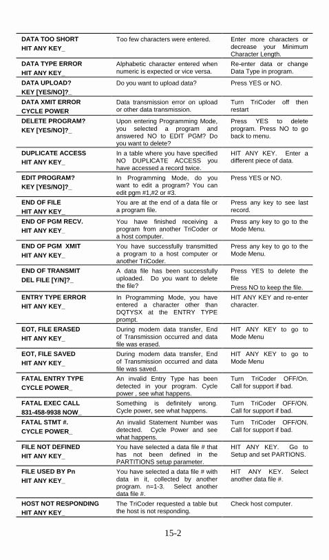
15-2
DATA TOO SHORT HIT ANY KEY_
Too few characters were entered. Enter more characters or decrease your Minimum Character Length.
DATA TYPE ERROR HIT ANY KEY_
Alphabetic character entered when numeric is expected or vice versa.
Re-enter data or change Data Type in program.
DATA UPLOAD? KEY [YES/NO]?_
Do you want to upload data? Press YES or NO.
DATA XMIT ERROR CYCLE POWER
Data transmission error on upload or other data transmission.
Turn TriCoder off then restart
DELETE PROGRAM? KEY [YES/NO]?_
Upon entering Programming Mode, you selected a program and answered NO to EDIT PGM? Do you want to delete?
Press YES to delete program. Press NO to go back to menu.
DUPLICATE ACCESS HIT ANY KEY_
In a table where you have specified NO DUPLICATE ACCESS you have accessed a record twice.
HIT ANY KEY. Enter a different piece of data.
EDIT PROGRAM? KEY [YES/NO]?_
In Programming Mode, do you want to edit a program? You can edit pgm #1,#2 or #3.
Press YES or NO.
END OF FILE HIT ANY KEY_
You are at the end of a data file or a program file.
Press any key to see last record.
END OF PGM RECV. HIT ANY KEY_
You have finished receiving a program from another TriCoder or a host computer.
Press any key to go to the Mode Menu.
END OF PGM XMIT HIT ANY KEY_
You have successfully transmitted a program to a host computer or another TriCoder.
Press any key to go to the Mode Menu.
END OF TRANSMIT DEL FILE [Y/N]?_
A data file has been successfully uploaded. Do you want to delete the file?
Press YES to delete the file Press NO to keep the file.
ENTRY TYPE ERROR HIT ANY KEY_
In Programming Mode, you have entered a character other than DQTYSX at the ENTRY TYPE prompt.
HIT ANY KEY and re-enter character.
EOT, FILE ERASED HIT ANY KEY_
During modem data transfer, End of Transmission occurred and data file was erased.
HIT ANY KEY to go to Mode Menu
EOT, FILE SAVED HIT ANY KEY_
During modem data transfer, End of Transmission occurred and data file was saved.
HIT ANY KEY to go to Mode Menu
FATAL ENTRY TYPE CYCLE POWER_
An invalid Entry Type has been detected in your program. Cycle power , see what happens.
Turn TriCoder OFF/On. Call for support if bad.
FATAL EXEC CALL 831-458-9938 NOW_
Something is definitely wrong. Cycle power, see what happens.
Turn TriCoder OFF/ON. Call for support if bad.
FATAL STMT #. CYCLE POWER_
An invalid Statement Number was detected. Cycle Power and see what happens.
Turn TriCoder OFF/ON. Call for support if bad.
FILE NOT DEFINED HIT ANY KEY_
You have selected a data file # that has not been defined in the PARTITIONS setup parameter.
HIT ANY KEY. Go to Setup and set PARTIONS.
FILE USED BY Pn HIT ANY KEY_
You have selected a data file # with data in it, collected by another program. n=1-3. Select another data file #.
HIT ANY KEY. Select another data file #.
HOST NOT RESPONDING HIT ANY KEY_
The TriCoder requested a table but the host is not responding.
Check host computer.

15-3
IDENTIFIER ERROR HIT ANY KEY_
You have entered data which doesn’t match the DATA ID specified.
Re-enter your data or change the DATA ID.
IN DIAG MODE HIT ANY KEY_
TriCoder was shipped without being re-initialized. See Troubleshooting section.
Re-initialize TriCoder
INIT FAILED CYCLE POWER_
Initialization failed. Power OFF/ON.
INCOMPLETE PGM PRESS ANY KEY_
Unit was shut off or went to sleep during programming.
Check program for errors.
INVALID DATA LEN HIT ANY KEY_
You have tried to enter 00 for Max Data Length. Entry must be at least 01.
HIT ANY KEY. Re-enter data length.
INVALID DEVICE HIT ANY KEY_
You have specified a character other than K W or ENTER for the INPUT DEVICE.
HIT ANY KEY. Enter a valid character.
INVALID FILE # HIT ANY KEY_
You have entered a character other than 0,1,2,or 3 at the Data File No. Prompt.
HIT ANY KEY. Enter a valid number.
INVALID HEADER HIT ANY KEY_
The Header Record in a table has an invalid format.
Check header record, fix and retry.
INVALID TABLE # HIT ANY KEY_
You have entered a character other than 1,2, or 3 for the Table Number prompt
HIT ANY KEY. Enter a valid number.
INVALID PASSWORD HIT ANY KEY_
You have not entered the correct password.
HIT ANY KEY. Enter the correct password - WDTRI.
INVALID PGM # HIT ANY KEY_
You have entered something other than 0,1,2, or 3 in Programming Mode or 1,2, or 3 for Data Collection Mode
HIT ANY KEY. Enter the correct number.
INVALID STMT. # HIT ANY KEY_
Your program has an undefined statement # in it.
HIT ANY KEY to go to error.
ITEM NOT FOUND n HIT ANY KEY_
An item entered in the TriCoder has not been found in table n.
HIT ANY KEY. Enter another item number or check table data.
LITHIUM BATTERY LOW Press any key_
The backup lithium coin battery is low and needs replacing
Press any key. Change lithium battery.
Memory has been lost Press any key_
BIG memory problems. This is not a low lithium battery problem.
Call for repair.
NMI ERROR Cycle Power_
This is not a problem unless it repeats itself.
Cycle Power. If error repeats itself, call for support.
NONPORTABLE MODE _
You are operating in Non Portable mode - the TriCoder transmits data immediately to the host computer without saving in memory.
Continue to enter data. Press F1 to get to Mode Menu.
NOT ALLOW TO RCV HIT ANY KEY_
You are trying to receive a program on the TriCoder but there is data still present in the TriCoder.
HIT ANY KEY. You must upload and delete any data in TriCoder before you can receive a program.
OUT OF MEMORY HIT ANY KEY_
You have filled the memory and must upload before you can collect any more data.
HIT ANY KEY. Upload data and continue with data collection.
PLEASE ENTER DIAG COMMAND_
TriCoder is in diagnostic mode, waiting for a command.
Enter the correct diagnostic code or press F1 to exit.

15-4
Possible Data Loss Press Any Key_
Slight memory problem. Not a problem with the lithium battery. Watch TriCoder closely.
Call for support if problem continues.
PROGRAMMING MODE? KEY [YES/NO]?_
Do you want to write, edit , review or delete a program? Also allows access to voice operations.
Press YES to enter PROGRAMMING MODE. Press NO to return to Mode Menu.
PROGRAMMING MODE PASSWORD?_
You are trying to enter Programming Mode and need to enter the password. The password prevents programming accidents.
Key in the password - WDTRI
PROGRAM FUNCTION KEY Create Programs---->1-3 Voice Operations---->4 Change Setup-------->5
You have correctly entered the password and are in Programming Mode. Select the function you want by pressing the correct key.
Key the number that corresponds to what you want to do.
PROGRAM NOT SET HIT ANY KEY_
You have requested to collect data in a program that has not been defined, or you are trying to transmit a program that has not been defined.
HIT ANY KEY. Enter the correct program number or go to Programming Mode to create a new program.
PROGRAM NO.? KEY [0-3]?_
You are in Data Collection mode and need to select a program to use.
Key 0, 1,2 or 3.
PROGRAM RECEIVE KEY [Y/N]?_
Do you want to receive a program from another TriCoder or host computer?
Press YES to go to Receiving Menu. Press NO to go to the Mode Menu.
PROGRAM TRANSMIT KEY [Y/N]?_
Do you want to transmit a program to another TriCoder or a host computer?
Press YES to go to Transmit Menu. Press NO to go to Mode Menu.
RECEIVE PROGRAM KEY Programs[1-3]?�1-3 Clone TriCoder?->0
You have answered YES to program receive mode. Choose the program to receive into or choose to clone.
Press the Program # or 0 to Clone.
RECEIVING PROG. PLEASE WAIT>
A program is being received by the TriCoder.
Wait for next message.
RECEIVING INTERRUPTED Key Pressed In Error Restart Transmission Hit any Key_
A key was pressed on the TriCoder after program transfer had started, aborting the transmission. TriCoder contains invalid program information.
Hit any Key. Restart transmission. Do not press any keys on TriCoder once transmission has begun.
RTC ERROR Call 831-458-9938
This error should not occur and indicates a firmware problem. Try to record what led to this error.
Cycle Power to clear, Call for support.
SEARCH PATTERN _
The SEARCH key was pressed. Enter data to search for or press ENTER key to exit.
SENDING PROGRAM PLEASE WAIT_
You are transmitting a program from the TriCoder. Wait for completion.
Wait for next message.
SRAM WRITE ERROR CYCLE POWER_
A serious error was detected. If persistant, call for RMA.
Turn TriCoder OFF/ON. Call for support if error continues to occur.
TABLE DOWNLOAD? KEY [YES/NO]?_
A table has been defined in the memory partitions - you can now download a table into the TriCoder.
Press YES to continue with table download. Press NO to return to Mode Menu.

15-5
TABLE FORMAT ERR PRESS ANY KEY_
The table header is in an invalid format or EOF Ctrl Z (ASCII 26) is missing.
Check table file for format errors. Try again.
TABLE NOT AVAILABLE HIT ANY KEY_
The host program has told the TriCoder it has no table to download.
Try again later.
TABLE NOT DEFINED HIT ANY KEY_
You are trying to download a table to a table number that is not defined in the Partitions.
Go to Setup and define the table in the Partitions parameter.
TABLE NOT FOUND HIT ANY KEY_
A table referrenced in a data collection program does not exist.
Download table or correct program to reference correct table.
TABLE NUMBER KEY [1-3]?_
You have requested to download a table. Now choose which table number you want to download to.
Choose a defined table number to download to.
TABLE DOWNLOAD? KEY [YES/NO]?_
A table is defined and ready for download. Do you want to download?
Press YES to proceed with download process.
Press NO to return to Mode Menu.
TABLE TOO BIG PRESS ANY KEY_
Not enough memory was allocated to accept the table you are downloading.
Re-allocate memory or change table size.
TRANSMIT PROGRAM KEY Programs [1-3]------->1-3 Clone TriCoder?----->0
You have answered YES to Transmit Program? prompt. Choose program to transmit or clone entire TriCoder.
Press 1,2, or 3 to transmit that program or Press 0 to clone entire TriCoder.
TRICODER x9nnn HIT ANY KEY_
TriCoder opening screen. Displays firmware version.
HIT ANY KEY.
UPLOADING DATA PLEASE WAIT_
Collected data is being uploaded to host.
Wait for upload to finish.
VOICE OPERATIONS KEY Record/Playback------>1 Assign Errors----------->2
Voice Operations Menu accessed through Programming Mode.
Press 1 to record or playback voice messages. Press 2 to assign error messages.
WAITING ON PMPT_ TriCoder is in Non-Portable Mode, operating with HOST RESPONSE ACCEPTED and is waiting from a prompt from the host.
Wait for prompt from Host or press F1 to bypass.
WARNING 2K LEFT HIT STATUS KEY_
You are running out of memory. Finish what you are doing and upload your data.
Press STATUS key to see exact amount of memory left. Finish what you are doing and go upload your data
WRONG INPUT DEVICE HIT ANY KEY_
The input device you are using is not what is specified in your program.
Use the correct input device or change the specification in your program.
XMISSION INCOMPLETE Key Pressed in Error Restart Transmission Hit any Key_
A key was pressed on a transmitting TriCoder during the program transmission. The transmission has been aborted and the receiving TriCoder had invalid program information.
Hit any Key. Restart program transmission.

15-6
�������������������� � If you are unsure about the settings of the TriCoder (maybe another person has changed some of them), you can return the TriCoder to the default settings by scanning:
• Start Setup • Reset • End Setup
then reconfigure the TriCoder for your system using the bar coded TriCoder Setup Menu or by using the keypad in PROGRAMMING MODE. Use the following information to troubleshoot any problems you might be having:
The TriCoder won’t read your bar codes…
• Recheck all hardware connections using Chapter 5; TriCoder Connection as a guide. Try reading a bar code you know is valid and readable – try the Test Label in Chapter 4; Non Portable Mode.
• If you are reading Code 39 bar codes with leading spaces (see the Barpad
in Appendix A; Code 39, Accumulate Mode) and you have enabled Accumulate Mode in the setup, the reader will beep twice upon reading a bar code and will not transmit data to the computer until it reads a bar code without a leading space.
• Recheck the TriCoder setup and make sure you have enabled the bar code
type you are trying to read. • If you are having problems reading Interleaved 2 of 5 codes, make sure
the data length of the bar code is the same as the 2 of 5 Length set on the TriCoder.
• Make sure you have not enabled check digits for Code 39 or Interleaved 2
of 5 if your bar codes do not have check digits. • Make sure the scanner is plugged into the SCANNER port and not the
COMPUTER port.

15-7
The TriCoder transmits extra characters at the start or end of bar code data…
• Clear the preamble and postamble. • Check to make sure you have not setup the TriCoder to transmit start/stop
characters, check digits, NSC characters or terminator characters that you don’t want transmitted.
• For UPC-E, select Compressed transmission if you don’t want your data
padded out with extra zeroes.
No Transmission – upload or NON PORTABLE
• Make sure SERIAL/KEYBOARD jumper is firmly seated on either setting. If the jumper is loose it can cause transmission problems even though the TriCoder seems to be working correctly otherwise. See Appendix K; Firmware and Model Upgrades for a diagram of the inside of the TriCoder and the location of the jumper.
Poor read rates…
• Try reading the bar code below as an example of a known “good” bar code. This bar code is a Code 39 bar code and is readable by the TriCoder set to its default settings.
• Make sure your bar codes have clearly defined dark bars and clean white
spaces. If the bars are so light that they are grey instead of black or are so dark that they “bleed” into the white spaces, the printing of the bar codes is the problem. Whoever is printing the bar codes needs to make the necessary corrections.
• The bar code should also have a “quiet zone” of at least ¼” to the left of
the first bar and to the right of the last bar. Make sure to start your scanning to the left of the bar code in the “quiet zone”, moving the scanner quickly and smoothly as if drawing a line through the bar code. If using a

15-8
laser scanner or CCD scanner, make sure the beam covers the bar code completely.
• Make sure you are using the correct type of scanner for the type of bar
code you are reading. If you are using an infrared scanner, your bar code must be printed using infrared-quality ink.
• If using a wand scanner, clean the tip. You would be amazed at how
many wands we see where the only problem is that it needs to be cleaned. You would also be amazed at what we have found inside the tips of some of these wands. We cannot stress this enough – CLEAN YOUR WAND. In fact, make it a habit to clean your wand on a regular basis. Use only warm soapy water and a soft cloth; alcohol and other solvents can fog the lens of the tip – do not use them. If using a laser or CCD, clean the window of the scanner with a soft cloth.
Sometimes I get long beeps and sometimes short beeps…
• When the TriCoder is in NON PORTABLE MODE or using the power adapter, is uses a longer beep which can vary in tone – see Chapter 6; TriCoder Setup for details on changing the beep tone. If the TriCoder is in a “portable” mode (ie. Data Collection), it uses a shorter beep to conserve power.
������������ ������������������ �The following problems are specific to a TriCoder used in keyboard wedge model T63.
You get a “keyboard error” or a “301 keyboard error” when you power up your system…
• Check the cables to make sure all connections are secure and the TriCoder is ON.
• Make sure the keyboard splitter cable is plugged into the keyboard port
and not the mouse port. • Remove any keyboard extension cables or adapters. Plug directly into the
port using the TriCoders keyboard splitter cable to eliminate the possibility that the extensions or adapters may be causing the problem.

15-9
The TriCoder transmits incorrect or no data to the PC’s screen…
• If the TriCoder is transmitting punctuation characters (!@#$%^&*) when reading numeric bar codes, or transmitting letters in the wrong case (upper vs. lower), you could have a Num Lock, Caps Lock, Shift or timing delay problem. Check your keyboard to see if your Num Lock or Caps Lock is on. Try typing numbers (the upper row of keys on your keyboard) and see if you get the correct output on your screen. If you don’t, make sure to reboot your PC before changing any delays on the TriCoder. See Chapter 6; TriCoder Setup for details on the Intercharacter Delay setting.
• If you scan a bar code and correct data shows up on your PC screen but
some is missing, you need to change the Intercharacter Delay. See Chapter 6; TriCoder Setup for details on how to change this setting. Test your keyboard after every change made to the TriCoder setup. If the keyboard does not work correctly, you will have to reboot before you make another change to the reader.
• Make sure you have configured the TriCoder to use the correct Computer
Interface.
The TriCoder reads one bar code and stops reading after that…
• Double-check the Computer Interface setting. Selecting Macintosh as the interface when you are not physically connected to a Mac will hang up the TriCoder.
�
����������������������� �The following problems pertain mostly to TriCoders setup in serial mode – T53.
Using the 5 volt power adapter, the TriCoder does not beep when turned on…
• Plug something else into the wall outlet to make sure the outlet is working or plug the TriCoder’s power adapter into an outlet that is working with something else. If the outlet is good, either the power adapter or the TriCoder is not working correctly. If you have more than one TriCoder, try the other TriCoder with the suspect power adapter. If you find a problem with either the TriCoder or the power adapter, call for repair or replacement.

15-10
The TriCoder beeps, but nothing appears on your computer screen…
• Recheck the installation instructions – Chapter 5; TriCoder Connection – to make sure all cables are properly connected. If you are connecting directly to a serial port on a PC, use the following checklist:
1. What kind of computer and port are you plugging into?
• XT – Male 25 pin port. A 25 pin female port is a parallel port. • AT – Male 9 pin port. A 9 pin female port is a video port. • Laptop COM ports are almost always 9 pin male.
2. What cable are you using?
• F34 – 25 pin null-modem cable • F36 – 9 pin female cable • If you have a 9 pin COM port and have the F34 cable, use a 9 to 25
null modem adapter or get the right cable (F36).
3. What Computer Interface is the TriCoder set for? • “3” is the correct setting for RS-232
4. What Baud Rate, Parity and Start and Stop bits are you using?
• Make sure the settings on the TriCoder match what the host program is expecting. When all else fails, try the default settings.
5. If you are using PORTKEY… • If using DOS Portkey, issue the MODE command before loading
Portkey. See the Portkey manual for details. Also, “BAD COMMAND OR FILE NAME” is not a bad message – look one line up on your screen for the bar code data. Do not use Portkey if you are already using a BASIC program to read the COM port. Your computer will hang up if you do.
• If using Windows Portkey, make sure you have not loaded the DOS
version also. They cannot be used simultaneously. Be sure Portkey is configured for the correct COM port and that the serial parameters match – Baud rate, etc…
• If you are using your own software to read the serial port, verify that
the problem is not with your software by using some modem or communication software (ie. Procomm or Hyperterminal) to read to the port. If you get data on the screen using the modem or communication software, the problem lies with your own software.

15-11
• Try using a “null modem” adapter to switch pins 2 and 3 on your cable or get a technician with a breakout box to modify your cable for you. Your serial port may need some handshaking lines tied high.
The TriCoder reads one bar code and stops reading after that…
• Double-check the Computer Interface setting. Selecting Macintosh as the interface when you are not physically connected to a Mac will hang up the TriCoder.
• If you selected polling protocol, the TriCoder needs to be polled by your
computer before it will read another bar code. If you selected Polling with ACK/NAK, you also need to send an ACK or NAK back to the TriCoder after each read (unless you specify a finite time-out) as well as the poll, before it will read another code.
The TriCoder transmits data to your screen or serial port but some characters are garbled or missing…
• Check your serial parameters. Do the baud rate, parity, start and stop bits match on both the TriCoder and the serial port?
• Make sure you have selected the correct Data Format. RS-232 ASCII is
the most commonly used. See Chapter 6; TriCoder Setup for details on when to choose PC Term Mode.
• If you are using your own software to read the serial port, consider that not
all software can keep up with the serial port at a hight baud rate. Try setting the TriCoder and serial port to a lower Baud Rate, or use a larger Intercharacter Delay.
• Try an Intercharacter Delay – especially if you are using Portkey.
I can’t communicate with my RS-232 port on the host…
• This is one of the most common problems we hear. Check your cables first. If you made your own cables, don’t call us for help – you are on your own! See Appendix I; Cable Pin-outs to check your wiring.
The TriCoder transmits a few messages then hangs…
• If you are using a terminal/ host configuration and are using XON/XOFF protocol on the terminal, disable XON/XOFF on the TriCoder – it may be missing the XON after intercepting a XOFF.

15-12
��� ��������������� �The following examples have to do with programming the TriCoder.
When editing a program, all I can see are the upload prefixes and suffixes…
• If there is a data file currently in the TriCoder, you cannot edit any part of the programs except for the Upload Prefix or Upload Suffix. This is to protect the integrity of the data that is currently still in the TriCoder. You will know if you still have a data file in the TriCoder if you see the
DATA FILE EXISTS PRESS ANY KEY_
message when you enter PROGRAMMING MODE and enter the password.
To edit or create a program, upload and delete the data from the TriCoder.
I can’t delete a programming statement while editing a program in the TriCoder…
• You cannot actually “remove” a statement from a program when editing a program in the TriCoder. You can clear all of the program prompts for the statement but the statement number will remain “occupied” by a blank programming statement. The best thing to do is simply not “go to” that statement in your program. If that bothers you, the alternative is to delete the entire program and re-enter it without the offending statement. See Chapter 8; Creating custom programs for details.
My uploaded data has the old data followed by my new data…
• If you upload your data and fail to delete it from the TriCoder, when you enter DATA COLLECTION mode again, the TriCoder assumes you want to collect more data and append it to the end of the data file which already exists. To avoid this, be sure to press YES when the TriCoder asks if you want to delete the data file. When it asks ARE YOU SURE?, press YES.
I want to read more than one length I 2of 5 bar code…
• To scan any length I 2of 5 bar code, use 00 when setting the 2 of 5 Length. If you are going to do this, you should use check digits or check the length in DATA COLLECTION to minimize the possibility of partial reads. I 2 of 5 is very susceptible to misreads so using 00 to read all lengths is risky and not recommended.

15-13
I need more than 15 characters for upload prefix and suffix to upload multiple operator entered fields that I want outputted with my main field…
• When using Refer-backs, use {2 instead of {02 to refer back to a particular statement. Substitute your statement numbers for the 2 in the example above. See Chapter 8; Creating custom programs for details on Refer-backs.
����������� ����������������������������The error messages below relate to problems that can either be solved by resetting the TriCoder or may require repair:
CHECK LITHIUM BATTERY
This message indicates a minor memory problem that has occurred in a Flag Byte area monitored by the TriCoder each time the TriCoder is powered up. Further memory loss could have occurred but the TriCoder was not able to detect a bad statement number, invalid entry type etc… The TriCoder corrected the Flag Bytes and is letting you know that the error has occurred. If you get this message you should:
1. Check the STATUS on the lithium battery to be sure it has at least 10% life reamaining.
2. Check the existing programs, data and tables to be sure some undetected
memory loss has not occurred. This message can occur if both batteries (AA and Lithium) have been removed or if both have been depleted. If the Lithium battery is OK and other problems appear with your programs, data or tables, call your dealer or Worthington Data Solutions for an RMA number.
CHANGE LITHIUM BATTERY
Your TriCoder’s memory was detected as having been altered. The unit was reset to it’s original factory default settings. Voice messages are still there but their number assignments have been returned to the factory default assignments. Unless you have removed both types of batteries (or both are dead), call Worthington Data Solutions for an RMA number to return and fix your unit. If you have removed both batteries, follow the re-initialization procedure (Fail-safe Reinitialization Procedure) outlined at the end of this section.

15-14
FATAL EXEC
This is a problem. The TriCoder is attempting to execute instructions from SRAM. Turn the TriCoder off, then back on and hope for the best. If you continue to have problems, call Worthington Data Solutions for an RMA number.
INCOMPLETE PGM
This may not necessarily be bad news. This error can occur by not completing the writing of a program - maybe you were interrupted while writing a program and the TriCoder went into sleep mode after 5 minutes of inactivity. If this happens, the program should be checked by pressing the F1 key while in the program itself. This causes the TriCoder to check the program for valid statement numbers and their references. If you are referencing a statement number which does not exist or is incomplete, trying to power up the TriCoder will result in the INCOMPLETE PGM message. You can check programs quickly by:
1. Going into PROGRAMMING MODE and choosing to edit the program. 2. Once in the program, scroll through the statements to see if the program
makes sense and still looks reasonable. 3. Press the F1 key to have the TriCoder validate and check the program. 4. Follow the instructions for correcting the program in Chapter 8; Creating
custom programs. If the problem persists and you have not removed both sets of batteries, you may have a TriCoder that has a problem we need to fix.
�
���������� ���������!���������������Here is a fail-safe way to re-initialize the TriCoder and set it back to the factory defaults:
1. After turning on the TriCoder, answer NO to all prompts until you see NON PORTABLE MODE? KEY [YES/NO]?_
At the NON PORTABLE MODE prompt, press the F1 key.
2. Press the SHIFT key.

15-15
3. Press the D key. After pressing the D key, you should see the prompt:
ENTER DIAG COMMAND_ 4. Press the SHIFT key. 5. Now press one of the following keys depending on what you want to
happen:
��Press the 6 key to delete only the current data file. Or
��Press the 7 key to delete programs 1-3.
Or
��Press the 8 key to load default programs, sets program voice
messages to 00, leaves error voice messages unassigned.
Or
��Press the 9 key to load default programs, sets program voice and error messages to defaults.
Or ��Press the 0 key to load default programs but clear all voice to
unassigned and all program voice messages to 00. 6. Press the F1 key to go back to the opening screen.
������� ������������"�Before you set out on your first big inventory or other data collection event, there are a few things you can do to better your chances for success. Planning and testing before the big day can help you avoid headaches as well as numerous calls to tech support. The whole point of using the TriCoder is to reduce data entry errors and speed up the data collection process. Here is a list of things you can do to make sure both of these things actually happen:
1. Establish communication in non-portable mode first. Don’t collect data and try to upload it without having thoroughly tested your computer interface settings. Keyboard wedge interface users can set their computer interface and test using Non-Portable Mode in any text editor such as Notepad, Wordpad or DOS Edit. Serial interface users will need to use the Windows or DOS programs provided on the TriCoder Utilities diskette.

15-16
2. Use the Default Program #0 or Sample Program #1 if you can. These programs require no special programming and can greatly cut down on the amount of time you will spend getting your application to work correctly.
3. If you create a custom program, collect and upload a small amount of
data before you go for the whole thing. If you have problems with a small amount of data, think of the disaster you would have uploading your entire inventory without proper testing first.
4. Stop data entry errors at the source by using the TriCoders data
integrity features. Using data identifiers, data type checking, minimum and maximum data lengths and table validation and maintenance can greatly reduce operator error. See the section on Programming for details on each of these features.
5. Use Voice Messages to speed up data entry. With proper planning, voice
prompts and error messages can reduce the amount of time the operator has to look at the display, making data collection faster and more efficient.
6. Use outside help when you need it. You don’t have to be a programmer to
write programs for the TriCoder, but if you are a computer novice and are stuck, save time by asking for help. Borrowing a little of a knowledgeable colleagues time or buying a few hours worth of help from a consultant will save you time and money in the long run. If you have technical problems with the TriCoder itself and cannot remedy the problem using the troubleshooting guide in the manual, call your Dealer or Worthington Data Solutions.

15-17
#�������$�����������"�• Save the shipping box. If you ever need to send the TriCoder or any of
its’ parts back for repair, you will need the original shipping box.
• If you have a problem with your TriCoder, consult the troubleshooting section of this manual FIRST. If you cannot find the answer here, call your Dealer or Worthington Data Solutions for help.
• Before you call your dealer or Worthington Data Solutions for technical
support, have your TriCoder and related equipment in front of you and be prepared to explain your problem in detail to the Technical Support Engineer.
• The Engineer may ask you to go through some troubleshooting
procedures while on the telephone. This will help them determine what is wrong and what the course of action should be. Many problems can be resolved over the telephone and will not require that you return the equipment to us. If you do need to return the TriCoder to Worthington Data Solutions, the Engineer will issue an RMA number.
• If you do need to return the TriCoder for ANY reason, you MUST have
an RMA number first. Write the RMA number on the outside of the original shipping box and make sure to insure the shipment. All RMAs should be shipped back to the following address unless directed otherwise:
RMA #XXXXXX Worthington Data Solutions 623 Swift St. Santa Cruz, CA 95060 831-458-9938

A-1
Appendix A
�������������� �������� Code 39 (or Code 3 of 9) is the de facto standard of non-retail American industry. It is widely used in the automotive industry (AIAG specifications) as well as in government and military applications (LOGMARS specifications). Code 39 is flexible, features a large character set, variable data length and density, and bi-directional readability. Code 39 is extremely accurate; substitution errors are almost nonexistent. Its character set consists of numbers 0 through 9, upper case A-Z, and characters Space, $, %. / + and -.
The name "Code 39" comes from both the fact that its character set originally contained 39 characters (it now has 43) and from its structure. Each character is formed of three wide and six narrow elements, made up of five bars and four spaces. Code 39's density can vary from a low of .75
characters per inch (cpi) to a high of 9.4 cpi. There should be a ¼" "quiet zone" (white space) to the left and right of the bar code.
Code 39 uses an asterisk (*) as a start and stop character. This character must precede and follow the data in the bar code. The TriCoder gives you the option of transmitting or not transmitting these characters when the bar code is read. Exact specifications for Code 39 and other bar code symbologies can be obtained from ANSI at the address below:
American National Standards Institute Customer Service 11 West 42nd St. New York, NY 10036 http://web.ansi.org document ANSI/AIM BC1-1995 The cost is $36
Code 39 has several advanced features and functions that are discussed further in this appendix.
*C39*

A-2
�������������������� �������������
Mod 43 Check Character Standard Code 39 can be printed with a "Mod 43 Check Character". This Mod 43 check character cannot be used with Full Ascii Code 39. The check character is derived by assigning a value to each character in the data to be bar coded from the table as follows:
Char value Char value Char value Char value
0 0 B 11 M 22 X 33
1 1 C 12 N 23 Y 34
2 2 D 13 O 24 Z 35
3 3 E 14 P 25 - 36
4 4 F 15 Q 26 . 37
5 5 G 16 R 27 space 38
6 6 H 17 S 28 $ 39
7 7 I 18 T 29 / 40
8 8 J 19 U 30 + 41
9 9 K 20 V 31 % 42
A 10 L 21 W 32
Table A-1. Mod 43 Check character calculation for Code 39
Here is an example to illustrate how the check character is calculated for bar code data of 123XYZ:
1. Take the sum of the values assigned to each character:
1 + 2 + 3 + 33 + 34 + 35 = 108 1 2 3 X Y Z
2. Divide the sum by 43: (thus the name modulus 43)
108/43 = 2 with a Remainder of 22
3. Find the character corresponding with the remainder.
M (value 22) is the CHECK CHARACTER
The data becomes 123XYZM, with M added as the Mod-43 check character.

A-3
Full ASCII Extension to Code 39 "Full-ASCII Code 39" expands the Code 39 character set to include all 128 ASCII characters. Symbols 0-9, A-Z and punctuation characters . and - are identical to their Code 39 representations. Lower-case letters, additional punctuation characters and control characters are represented by sequences of two Code 39 characters. This table depicts the Full ASCII character set as a function of Code 39 characters:
ASCII Code 39 ASCII Code 39 ASCII Code 39 ASCII Code 39
NUL %U SP Space @ %V ‘ %W
SOH $A ! /A A A a +A
STX $B “ /B B B b +B
ETX $C # /C C C c +C
EOT $D $ /D D D d +D
ENQ $E % /E E E e +E
ACK $F & /F F F f +F
BEL $G ‘ /G G G g +G
BS $H ( /H H H h +H
HT $I ) /I I I i +I
LF $J * /J J J j +J
VT $K + /K K K k +K
FF $L , /L L L l +L
CR* $M - - M M m +M
SO $N . . N N n +N
SI $O / /O O O o +O
DLE $P 0 0 P P p +P
DC1 $Q 1 1 Q Q q +Q
DC2 $R 2 2 R R r +R
DC3 $S 3 3 S S s +S
DC4 $T 4 4 T T t +T
NAK $U 5 5 U U u +U
SYN $V 6 6 V V v +V
ETB $W 7 7 W W w +W
CAN $X 8 8 X X x +X
EM $Y 9 9 Y Y y +Y
SUB $Z : /Z Z Z z +Z
ESC %A ; %F [ %K } %P
FS %B < %G \ %L | %Q
GS %C = %H ] %M { %R
RS %D > %I ^ %N ~ %S
US %E ? %J _ %O DEL %T, %X
Table A-2. Full Ascii Table

A-4
Function/Control Key Support in Wedge Mode The TriCoder, when in keyboard wedge mode or serial PC Terminal mode, can transmit Function, Control, Alt and Shift Keys for use with software programs that use these keys for menus or commands. For example, when the TriCoder reads a bar code containing the Code 39 characters for SOH (Control-A), it will transmit the corresponding function key, F1 to your computer. These "keys" are created by combining two Code 39 characters. In order to read them and have them interpreted as the correct keystroke, the bar code reader must have "Full ASCII Code 39" reading enabled. The following chart shows the encoding scheme for both IBM and Macintosh computers.
Full Ascii Code Code 39 IBM PC key transmitted Mac key transmitted
SOH $A F1 F1
STX $B F2 F2
ETX $C F3 F3
EOT $D F4 F4
ENQ $E F5 F5
ACK $F F6 F6
BEL $G F7 F7
SO $N F8 F8
LF $J Num Pad 5 Enter
CR $M Enter Return
SI $O F9 F9
DLE $P F10 Command On
DC1 $Q Del Del
DC2 $R Insert Command Off
DC3 $S Left Arrow Left Arrow
DC4 $T Right Arrow Right Arrow
NAK $U Down Arrow Down Arrow
SYN $V Up Arrow Up Arrow
VT $K Page Up Page Up
FF $L Page Down Page Down
ETB $W Home Home
CAN $X End End
EM $Y Shift On Shift On
SUB $Z Shift Off Shift Off
FS %B Control On Control On
GS %C Control Off Control Off
RS %D Alt On Option On
US %E Alt Off Option Off
Table A-3. C39 Keyboard Support for IBM and Mac

The SHMAC) kreleasedfunctionCtrl-C, yOFF.
You canexampleArrow 5 on num
F11and NULLF2page, theF12 wou
Special key sequences forIf you are using the TriCod"Windows" key on a PC or thpressed) and OFF (key release Older TriCoders (pre-06/99programming "make" and "br(NON PORTABLE mode onl
where E01F is the "make" codON, N is any keystroke, and EOFF or "Command key" OFFexactly as shown in the code a
Ctrl C
ASCII 250
F11
A-5
IFT, CTRL, &eys must use
) bar codes s. For exampleou would creat
also enter an, to enter AS(number 2 on
ber pad), Inse
F12 are cre as bar codes coding seque
ld be %U$B
USB er attached toe "Command" d) sequences.
) can emulaeak" hex scan cy).
`E01F´N`E0F
e for "Window0F01F is the "
. You must usebove.
ALT (Command and Option for ON (key pressed) and OFF (key
to properly emulate keyboard , to encode a bar code sequence for e a bar code of Ctrl ON, C, and Ctrl
y value from ASCII 000 to 255. For CII 250, encode Alt On, Down
number pad), LF (for the unmarked rt (number pad for 0) & Alt OFF.
ated by encoding NULLF1 and . Using the table on the previous nce for F11 would be %U$A and
a USB port, you can emulate the key on a Mac by encoding ON (key %UC is ON, %UD is OFF.
te the same key sequences by odes in the Preamble or Postamble
01F´
s key " ON or "Command key" break" code for "Windows key" the right ´ and left ` apostrophes

A-6
Function/Control Key Support with PortKey The TriCoder in RS-232 ASCII mode using PortKey can emulate the special keys on the PC keyboard. PortKey expects the "extended key code" convention outlined in the BASIC manuals and most compiler manuals. For example, to transmit a F1 key from a serial TriCoder to the keyboard, a null (ASCII 0) followed by a semicolon (ASCII 59) would be required. You can use Full ASCII Code 39 or Code 128 to transmit the required sequences. The following is a list of the most common keys, the required codes and the equivalent Code 39 characters:
PC Key ASCII Character Code 39
Ctrl @ 0,3 %U$C Ctrl A 2 (SOH) $A Ctrl B 3 (STX) $B Ctrl C 4 (ETX) $C Ctrl D 5 (EOT) $D Ctrl E – Ctrl Y 6 (ENQ) – 25 (EM) $E - $Y Ctrl Z 26 (SUB) $Z Ctrl [ 27 (ESC) %A Ctrl \ 28 (FS) %B Ctrl ] 29 (GS) %C Ctrl ^ 30 (RS) %D Ctrl _ 31 (US) %E F1 0,59 (Null ;) %U%F F2 0,60 (Null<) %U%G F3 0,61 (Null=) %U%H F4 – F9 0,62 (Null>) – 0,67 (NullC) %U%I -%UC F10 0,68 (Null D) %UD (or %U /D) Home 0,71 (Null G) %UG (or %U /G) Up Arrow 0,72 (Null H) %UH Pg Up 0,73 (Null I) %UI Left Arrow 0,75 (Null K) %UK Right Arrow 0,77 (Null M) %UM End key 0,79 (Null O) %UO Down Arrow 0,80 (Null P) %UP Pg Dn 0,81 (Null Q) %UQ Ins 0,82 (Null R) %UR Del 0,83 (Null S) %US Shift F1 0,84 (Null T) %UT Shift F2 – Shift F9 0,85 (Null U) – 0,92 (Null \) %UU – %U%L Shift F10 0,93 (Null ]) %U%M Ctrl F1 0,94 (Null ^) %U%N Ctrl F2 – Ctrl F9 0,95 (Null _) – 0,102 (Null f) %U%O – %U+F Ctrl F10 0,103 (Null g) %U +G Alt F1 0,104 (Null h) %U +H Alt F2 – Alt F9 0,105 (Null i) – 0,112 (Null p) %U+i - %U+p Alt F10 0,113 (Null q) %U +q
Table A-4. Function and Control Key Support with Portkey

A-7
Accumulate Mode Accumulate Mode is an option allowing the TriCoder to accumulate multiple bar codes in its buffer, then transmit them to the computer as if they had been a single bar code. This is useful for entering quantities and other variable data. Accumulate Mode works with Code 39, Code 93 and Code 128 only and can't be used with a check digit. When the TriCoder reads a bar code with a space as the first character, it beeps and buffers the data without transmission. It continues to read and buffer bar codes (up to 40 characters) until it reads a bar code without a leading space. Once it reads this last bar code, the entire buffer (including that last code) is transmitted as one long bar code. A “double-minus” sign (--) bar code clears the buffer. Scanning a “backspace” code ($H in Code 39) backspaces in Full ASCII mode. The ENTER code on this Barpad is a Code 39 Start/Stop Character only and assumes you have a Terminator Character specified. If you do not have a Terminator Character programmed in your TriCoder, substitute the bar code for CR. Accumulate Mode must be turned on using the bar coded Setup Menu or by using the keypad and going into "Change Setup" while in PROGRAMMING MODE. Accumulate Mode is located in the Code 39 parameters. Choose 4 to Enable or 5 to Disable this feature. This numeric Code 39 "Barpad" illustrates ACCUMULATE Mode. Scan 5, 3, 8, and Enter. The TriCoder transmits a single message of “538”.
0 1 2
3 4 5
6 7 8
9 Clear Backspace
CR Enter

B-1
a12345b
Appendix B
����� ��������������
�Codabar is widely used in libraries, blood banks, the cotton industry and transportation industries. Its' character set consists of numbers 0 through 9, and punctuation characters + . - / : and $. Symbols a, b, c, d, t, n, * and e are used as start and stop characters. Characters are constructed of four bars and three spaces.
Codabar is a numeric-only code, but different combinations of start and stop characters can be used to identify different types of labels. Codabar's variable data length and extremely low error rate make for a versatile bar code.
Codabar start/stop transmission The Codabar section on the TriCoder Setup Menu lets you determine whether Codabar start/stop characters are transmitted or not. If you are varying start/stop characters with different types of labels, you'll want to "Enable Stop/Start character Transmission". Start/stop character transmission can also be helpful if you want your program to differentiate between data coming from the TriCoder and data coming from the keyboard. If neither of these situations apply, you'll probably want to disable it.

C-1
Appendix C
��������������������� Code 128 is a very powerful bar code, combining an extensive character set and variable length with compactness and error checking. The character set contains all 128 ASCII characters with each character made up of three bars and three spaces. Each element (bar or space) varies from one to four units in width, totaling 11 units of width per character. Code 128 contains two levels of error checking:
• Each character is checked for internal parity, and • The last character is a checksum.
Code 128 has three subsets, A, B and C. Subset A contains alphanumeric characters and unprintable control characters, subset B contains alphanumeric characters plus printable control characters and subset C contains only numeric characters and uses a 2-character encoding
scheme to create a more compact bar code. Code 128 uses an internal Mod 103 check character that is no played by the bar code reader. Code 128 bar codes can be made up of only o bset or may be a combination of several. The Code 39 features of Accumulate ModOFF also apply to Code 128.
UCC-128/ EAN-128 UCC-128/EAN-128 Code is a subset of CoEAN council’s for use as a shipping label symalways start with a Function Code 1 charactefields are terminated by a Function Code 1 chin the bar code. The TriCoder outputs the following for thesequences:
]C1 Start C/Function Code 1 ^] (GS) Function Code 1 as a variable s
If MOD 10 UCC 128 is enabled, the TriCodonly 128 codes starting with a Function 1 cha
12345
t disne su
e, Caps Lock ON and Caps lock
de 128 adopted by the UCC and bology. UCC/EAN-128 bar codes r. In addition, all variable length
aracter unless they are the last field
special function codes and start
tring terminator
er expects only 20 digit, numeric-racter and terminating with a MOD

C-2
UCC 128 Shipping Container Code
10 Check Digit. This is to comply with the Uniform Code Council's Serial Shipping Container Code specification. The Mod 10 Check digit is calculated the same as the Interleaved 2 of 5 example in Appendix D. It is the MOD 10 check digit that distinguishes the Serial Shipping Container Code from other UCC /EAN 128 bar codes. MOD 10 UCC 128 is enabled by scanning the appropriate bar codes on the TriCoder Setup Menu or by keypad in the PROGRAMMING MODE "Change Setup" option. If MOD 10 UCC 128 is enabled, you will NOT be able to read a standard Code 128 bar code that does not have the Function 1 character and the Mod 10 check character.
The UCC 128 specification is used extensively by the retail industry. If you have a requirement for a UCC 128 Serial Shipping Container bar code, be sure to follow the specification as closely as possible as many vendors will impose fines for non-conformance. For more information on UCC 128, contact the Uniform Code Council at:
Uniform Product Code Council, Inc. 8163 Old Yankee Road, Suite J Dayton, Ohio 45458 (513) 435-3870
Many of the specifications are available online at:
http://www.uc-council.org

D-1
Appendix D
��� ���������� ������� Interleaved 2 of 5 Code is a numeric-only, even-number-of-digits bar code. It is widely used in warehouse and industrial applications. A combination of five elements, two wide and three narrow represent each character. Odd-number position digits are encoded in the bars, even-number positions in the spaces.
Interleaved 2 of 5 Code is so susceptible to partial scans being interpreted as valid reads that we recommend at least one of the following safeguards:
• Use one length of I 2 of 5 code. Using one length of data allows you to tell the TriCoder to look for one length of I 2 of 5 code only. By default, the TriCoder is set to look for a 6 digit I 2 of 5 code but you can set the length to something different using the TriCoder Setup Menu. Setting the length to 00 digits allows variable length bar codes scanning. If you must use the 00 setting, we recommend that you then use the “Minimum/Maximum” data length field when creating a program in the TriCoder to check each field for the proper length.
• Use a check digit. Worthington Data Solutions' LabelRIGHT printing program automatically calculates and prints a check digit upon request using the method below:
Interleaved 2 of 5 Mod 10 check digit calculation
1. Assume that the bar code data is 1987.
2. Starting with the least significant digit (in this case, a 7), label the digits alternatively even and odd.
7 - even 8 - odd 9 - even 1 – odd
3. Take the sum of the odd digits:
8 + 1 = 9
4. Multiply the sum of the even digits by 3:
(7 + 9) x 3 = 48
123456

D-2
5. Add the results of steps 3 and 4:
9 + 48 = 57
6. Subtract the result of step 5 from the next highest multiple of 10:
60 - 57 = 3
7. The checksum becomes the low-order digit:
19873
8. Because the data now has an odd length, a leading zero is added, for the final result of
019873

����� ��� �
Appendix E
���������������
UPC syproductcode mfixed-lethe firassignmand UPC
code. Each digit is constructed of tprecise standards of code size, structur
EAN is an int13 digits, withcode. The finEAN-8 is a containing sevchecksum.
The exact UPC/EAN symbol specifica
Uniform Pr8163 Old YDayton, Oh(513) 435-3
Specifications are also available via th
http://www Keep the following guidelines in mind
• If you plan to use a "supermthe codes, specify a bar code hread rate.
• Make it an early practice to the UPC Council. Do not lacode whose numbers may coproducts with these numberslikely to be in the future, causi
E-1
��
mbols are found on almost all grocery s and many other retail items. The UPC ost people are familiar with (UPC-A) is a ngth (12 digits) numeric only code, with st digit controlled by UPC coding ents and the last digit a checksum. UPC-E -E1 are variations of the standard UPC-A
wo bars and two spaces. UPC has very e, and numbers to be used.
ernational superset of UPC. EAN-13 has the first two digits representing a country al digit is, as with UPC, a check digit. shorter version on the EAN-13 code en data digits and ending again with a
tions are available from:
oduct Code Council, Inc. ankee Road, Suite J io 45458 870
e internet at:
.uc-council.org
when printing UPC bar codes:
arket-type" in-counter scanner to read eight of at least .9" for an optimal first
observe the numbering conventions of bel unmarked merchandise with a bar nflict with those already assigned. If are not in your store now, they are ng conflicts in your inventory system.

E-2
• The leading Number System Character, (the first number of the 11 digits to be entered) should conform to these UPC assignments:
0,6,7 Regular UPC 12 digit codes with numbers assigned by the
UPC Council. (Do not use 0 as the leading number for in-store marking).
2 Store-marked random weight items of meat and produce.
3 Reserved for National Drug Code and Health Related Items.
4 Use this leading digit for in-store marking of non-food items.
5 Reserved for coupons. Do not use this today, or you will not be able to process coupons through your system tomorrow.
UPC 2 and 5-character supplemental codes The UPC standards include the addition of a 2 or 5-character supplemental code used with magazines and paperback books. To read the supplements, you must first enable them using the TriCoder Setup Menu.
NOTE: Enabling the supplements disallows the reading of UPC codes from right to left to assure that the supplement does not get missed.
ISBN Specifications ISBN (International Standard Book Numbering) bar codes are essentially EAN-13 with a 5 digit supplement, where the first 3 digits are the Bookland country codes of 978 for books and 977 for periodicals. Although the bar code contains 18 characters, the ISBN format uses only 9 of them, along with a newly calculated Mod-11 check digit. For example, a bar code containing the numbers 978055337062153495 would transmit as 0553370626 in the ISBN format. The TriCoder has the option of transmitting in the ISBN format.
��
����� ��� �
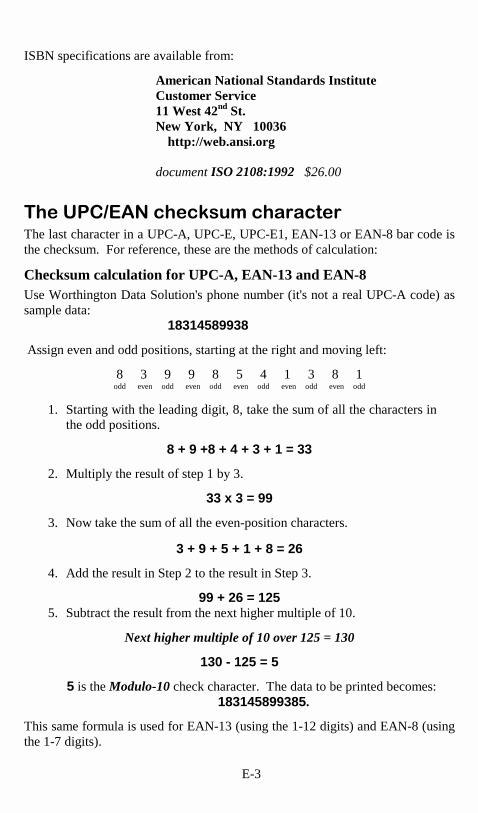
E-3
ISBN specifications are available from:
American National Standards Institute Customer Service 11 West 42nd St. New York, NY 10036 http://web.ansi.org document ISO 2108:1992 $26.00
� �����!"�#�� ��$��%�� � ���� �The last character in a UPC-A, UPC-E, UPC-E1, EAN-13 or EAN-8 bar code is the checksum. For reference, these are the methods of calculation:
Checksum calculation for UPC-A, EAN-13 and EAN-8 Use Worthington Data Solution's phone number (it's not a real UPC-A code) as sample data:
18314589938
Assign even and odd positions, starting at the right and moving left:
8 3 9 9 8 5 4 1 3 8 1 odd even odd even odd even odd even odd even odd
1. Starting with the leading digit, 8, take the sum of all the characters in the odd positions.
8 + 9 +8 + 4 + 3 + 1 = 33
2. Multiply the result of step 1 by 3.
33 x 3 = 99
3. Now take the sum of all the even-position characters.
3 + 9 + 5 + 1 + 8 = 26
4. Add the result in Step 2 to the result in Step 3.
99 + 26 = 125 5. Subtract the result from the next higher multiple of 10.
Next higher multiple of 10 over 125 = 130
130 - 125 = 5
5 is the Modulo-10 check character. The data to be printed becomes: 183145899385.
This same formula is used for EAN-13 (using the 1-12 digits) and EAN-8 (using the 1-7 digits).

E-4
UPC-E Checksum Calculation Use the sample data of 123456 to demonstrate the UPC-E checksum calculation:
1. The 6 digit UPC-E code is converted to a 10-digit code, using an expansion scheme based on the sixth digit:
If the code
ends in: UPC-E Data Insertion Digits Insertion
Position 10 digit code
0 abcde0 00000 3 ab00000cde 1 abcde1 10000 3 ab10000cde 2 abcde2 20000 3 ab20000cde 3 abcde3 00000 4 abc00000de 4 abcde4 00000 5 abcd00000e 5 abcde5 0000 6 abcde00005 6 abcde6 0000 6 abcde00006 7 abcde7 0000 6 abcde00007 8 abcde8 0000 6 abcde00008 9 abcde9 0000 6 abcde00009
Because the sample UPC-E code ends in a 6, the insertion digits 0000 are inserted at the sixth digit (insertion position 6):
1234500006
2. Add the Number System Character of 0 to the sample data:
01234500006
3. Use the UPC-A check digit calculation described in the previous section to produce a check digit as if it were a UPC-A code. The check digit for the sample data is:
5
4. The complete 8 digit code consists of the Number System Character, the original 6 digit code and the check digit:
01234565

F-1
Appendix F
&��!������'�������������� Plessey is a variable length numeric only bar code. MSI Bar Code is a variable length, numeric-only code with an automatically appended Modulus 10 check digit. MSI is sometimes called Modified Plessey Code. If the user specifies an additional check digit, the MSI code can be 14 digits long, otherwise it has a maximum length of 13 characters. This is how the MSI check digit(s) are calculated: The MSI Mod 10 check digit is calculated as follows:
The example bar code data is: 82345
1. Form a number from the odd positions, starting in the units position.
835
2. Multiply the new number by 2
(835) x 2 = 1670
3. Add the digits of product
1 + 6 + 7 + 0 = 14
4. Add the even digits of the original number to the result in 3
2 + 4 + 14 = 20
5. Subtract the result from the next highest multiple of 10
20 - 20 = 0
6. New Check Digit
0
7. Data with check digit is:
823450

F-2
The MSI Mod 11 check digit is calculated as follows:
The example bar code data is:
943457842
1. Assign a checking factor to each number, starting with the units position of the number (in this example, the 2) up to the highest order position (the 9). Use checking factors of:
2,3,4,5,6,7,2,3,4,5,6,7... 2. Multiply the checking factor with its assigned number and add the
products:
4 + 12 + 32 + 35 + 30 + 28 + 6 + 12 + 36 = 195 3. Divide the sum by 11
195/11 = 17 remainder 8 4. Subtract remainder from 11
11 - 8 = 3 5. New Check Digit
3 (If the remainder is 10, no check digit is added.)
6. Data with check digit is:
943457823

G-1
Appendix G
�������������������� Code 93 is variable length, continuous, bi-directional, compact code. Code 93 is an alphanumeric bar code which consists of 43 data characters (0-9,A-Z,$/+%.- and Space), 4 control characters, and a unique start/stop character. The entire set of 128 ASCII characters is represented in Code 93 using combinations of control characters and data characters.
The control characters are , , , and . Full ASCII 93 is created by pairing these control characters with normal data characters. It is almost identical to the pairings for Code 39; Code 39 uses $M to produce a Carriage
Return (ASCII 13) character -- Code 93 uses M to produce the Carriage Return. Code 93's two built-in check digits greatly minimize the possibility of reader substitution errors. These check digits are never transmitted by the bar code reader. Code 93's Start and Stop characters are also never transmitted. If you have not decided which bar code type to use for your application and are considering using Code 93, while we agree that Code 93 is an excellent code, we believe that Code 128 is generally preferable because:
1. Code 93 does not have the numeric compression capability that 128 does, and
2. Code 93 requires pairings to make all Full ASCII characters while
128 does not.

H-1
Appendix H
����������"(�������������� The 128 ASCII codes and their 3 digit decimal equivalents are detailed in the below table. The RS232 Models use the ASCII; the keyboard wedge models have some of the unprintable ASCII characters reassigned to specific keys, (i.e. SOH is f1).
char
hex
3 digit ASCII
char
hex
3 digit ASCII
char
hex
3 digit ASCII
char
hex
3 digit ASCII
NUL 00 000 SP 20 032 @ 40 064 ‘ 60 096
SOH 01 001 ! 21 033 A 41 065 a 61 097
STX 02 002 " 22 034 B 42 066 b 62 098
ETX 03 003 # 23 035 C 43 067 c 63 099
EOT 04 004 $ 24 036 D 44 068 d 64 100
ENQ 05 005 % 25 037 E 45 069 e 65 101
ACK 06 006 & 26 038 F 46 070 f 66 102
BEL 07 007 ' 27 039 G 47 071 g 67 103
BS 08 008 ( 28 040 H 48 072 h 68 104
HT 09 009 ) 29 041 I 49 073 i 69 105
LF 0A 010 * 2A 042 J 4A 074 j 6A 106
VT 0B 011 + 2B 043 K 4B 075 k 6B 107
FF 0C 012 , 2C 044 L 4C 076 l 6C 108
CR 0D 013 - 2D 045 M 4D 077 m 6D 109
SO 0E 014 . 2E 046 N 4E 078 n 6E 110
SI 0F 015 / 2F 047 O 4F 079 o 6F 111
DLE 10 016 0 30 048 P 50 080 p 70 112
DC1 11 017 1 31 049 Q 51 081 q 71 113
DC2 12 018 2 32 050 R 52 082 r 72 114
DC3 13 019 3 33 051 S 53 083 s 73 115
DC4 14 020 4 34 052 T 54 084 t 74 116
NAK 15 021 5 35 053 U 55 085 u 75 117
SYN 16 022 6 36 054 V 56 086 v 76 118
ETB 17 023 7 37 055 W 57 087 w 77 119
CAN 18 024 8 38 056 X 58 088 x 78 120
EM 19 025 9 39 057 Y 59 089 y 79 121
SUB 1A 026 : 3A 058 Z 5A 090 z 7A 122
ESC 1B 027 ; 3B 059 [ 5B 091 } 7B 123
FS 1C 028 < 3C 060 \ 5C 092 | 7C 124
GS 1D 029 = 3D 061 ] 5D 093 { 7D 125
RS 1E 030 > 3E 062 ^ 5E 094 ~ 7E 126
US 1F 031 ? 3F 063 _ 5F 095 DEL 7F 127
Table H-1. Full Ascii Equivalent Table

I-1
Appendix I
��������)���� Below are the pin-outs for our RS-232 and RS-422 cables. All cables showing a Worthington Data Solutions part number (Fxx or Txx) are available for purchase. Unless you have experience making your own cables, we recommend buying your cables from us. For all RJ45 cables, number pins from left to right, with the metal pin side of the connector facing you and the cable down.
F34 DB25 Null Modem Cable Pin-outs These are the pin-outs for Cable F34, a DB25 Female to 8 pin modular RJ45 with pins 2 and 3 crossed, used for connection directly to a 25 pin male host serial port.
Mod 8 RJ45
Function
DB25 Female
1 Frame Ground 1 2 Transmit Data 3 3 Receive Data 2 4 Signal Ground 7
Table I-1. F34 Null Modem Cable
*Pins 5-8 are connected but not used by the TriCoder. This cable is not for Modem use. If you are using the TriCoder with a modem, see Table I- and Table I- for the correct cable.
F36 DB9 Straight Cable Pin-outs These are the pin-outs for Cable F36, a DB9 Female to 8 pin modular RJ45. This is a straight-through cable used for direct connection of the TriCoder to a 9 pin Male host serial port.
Mod 8 RJ45
Function
DB 9 Female
1
Shell (chassis ground)
Shell
2 Transmit Data 2 3 Receive Data 3 4 Signal Ground 5
Table I-2. F36 9 pin cable
*Pins 5-8 are connected, but are not used by the TriCoder.

I-2
F32A 25 Pin Modem Cable This cable is for use in Modem communications. It is a DB25 male to 8 pin modular cable.
Mod 8 RJ45
Function
DB25 Male
1 Frame Ground 1 2 Transmit Data 2 3 Receive Data 3 4 Signal Ground 7 5 6 7 20 8 4
Table I-3. F34A Modem Cable
Pins 5 and 6 are not connected at the DB25 end. Pins 20 and 4 are tied together.
F46B 9 Pin Modem Cable This cable is for use in Modem communications. It is a DB9 male to 8 pin modular cable.
Mod 8 RJ45
Function
DB 9 Male
1
Shell (chassis ground)
Shell
2 Transmit Data 3 3 Receive Data 2 4 Signal Ground 5 5 6 7 4 8 7
Table I-4. F46B 9 Pin Modem Cable
Pins 5 and 6 are not connected at the DB9 end. Pins 4 and 7 are tied together.

I-3
F45-1 Dual Port Serial Cable Installation of the TriCoder between a serial terminal and a host computer, (as with Unix, NX386, VM386,etc.), requires the F45-1 Dual Port Serial Port Cable. This cable has three connectors:
1. DB 25 pin Female Host end 2. DB 25 pin Male Terminal end 3. 8 pin modular RJ45 Tricoder end
This cable is configured so that the Terminal End connects directly into the female main port of the Terminal and the female Host End connects into the DB25 male cable coming from the host. We assume that the cable coming from the host has pins 2 and 3 crossed. The Terminal-Host Y cable configuration requires that you set the Transmission Mode on the Setup Menu to a 3 (Normal Cables and F45-1 Serial Y Cable). When the TriCoder is removed from the Y cable, install the jumper block (included with the TriCoder) to maintain host -to-terminal communication.
F45 Cable Host connector
Pin
F45 Cable Terminal connector
Frame Ground 1 Frame Ground Transmit Data 2 Receive Data Receive Data 3 Transmit Data RTS 4 RTS CTS 5 CTS DSR 6 DSR Signal Ground 7 Signal Ground DTR, CD 8,20 CD, DTR
Table I-5. F45-1 Serial Y Cable
In some configurations, it may be necessary to cut the 8-20 jumper.
Macintosh Serial Cable pin-outs To connect the TriCoder to a Macintosh serial port, use our F34 DB25 Null Modem Cable attached to a Macintosh DB25 Modem cable, or connect directly with a cable you make with the following pin-outs:
TriCoder RJ45 Male Macintosh 8 pin Minidin pin function pin function 2 transmit 5 receive 3 receive 3 transmit 4 ground 4 ground
Table I-6. Macintosh Serial Cable
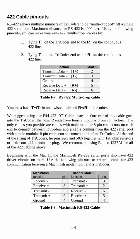
I-4
422 Cable pin-outs RS-422 allows multiple numbers of TriCoders to be "multi-dropped" off a single 422 serial port. Maximum distance for RS-422 is 4000 feet. Using the following pin-outs, you can make your own 422 "multi-drop" cables by:
1. Tying T+ on the TriCoder end to the R+ on the continuous 422 line.
2. Tying T- on the TriCoder end to the R- on the continuous
422 line.
Function Mod 8 Transmit Data + (T+) 2 Transmit Data - (T-) 3 Ground 4 Receive Data + (R+) 5 Receive Data - (R-) 6
Table I-7. RS-422 Multi-drop cable
You must have T+/T- in one twisted pair and R+/R- in the other. We suggest using our F44 422 "Y" Cable instead. One end of this cable goes into the TriCoder, the other 2 ends have female modular 8 pin connectors. The only cables you provide are cables with male modular 8 pin connectors on each end to connect between TriCoders and a cable coming from the 422 serial port with a male modular 8 pin connector to connect to the first TriCoder. At the end of the string of TriCoders, tie pins 2&3 and 5&6 together with 120 ohm resistors or order our 422 terminator plug. We recommend using Belden 1227AI for all of the 422 cabling above. Beginning with the Mac II, the Macintosh RS-232 serial ports also have 422 driver circuits on them. Use the following pin-outs to create a cable for 422 communication between a Macintosh modem port and a TriCoder.
Macintosh Tricoder Mod 8 function pin function pin Receive - 5 Transmit - 3 Receive + 8 Transmit + 2 Transmit - 3 Receive - 6 Transmit + 6 Receive + 5 Ground 4 Ground 4
Table I-8. Macintosh RS-422 Cable

I-5
Beside the standard cable pin-outs provided above, there are several other cable pin-outs which may prove useful to users.
F38 Data Cloning Cable The pin-outs for the F38 TriCoder Data cloning cable (Male RJ45 on both ends) are:
Wedge/RS-232
RS-422
RJ45 male
RJ45 male
RJ45 male
RJ45 male
1 1 2 5 2 3 3 6 3 2 4 4 4 4 5 2 6 6 6 3
Table I-9. F38 Data Cloning Cable
Wands The wand pin-outs of the RJ45 end are:
Pin Function
1 5 volts 2 Data 4 Enable 7 Shield (drain) 8 Ground
Table I-10. Wand RJ45 Pin-outs
Wand emulation devices ( ie. CCD’s with wand output) will not work with the TriCoder due to improper enable lines supported – don’t bother trying to make them work.

I-6
Laser and CCD The laser and CCD TTL pin-outs are:
Pin Function 1 5 volts 2 Data 3 Phase 4 LED 5 Trigger 6 Enable 7 Shield(drain) 8 Ground
Table I-11. Laser and CCD Pin-outs
Remember: If you make your own cables, you are on your own. We accept NO RESPONSIBILITY for damages resulting from incorrect wiring.

J-1
Appendix J
��**'���$�+��� ����������� The TriCoder can use a hand-held Laser scanner (such as the LZ100,LZ200 and 3200 models) in what we call a "Piggyback" configuration. This configuration has the TriCoder connected to the laser with a short cable and velcro strips to secure the TriCoder to the top of the laser. This creates an all-in-one TriCoder/Laser scanner. Follow these steps to complete the Piggyback installation:
1. If the normal long coiled laser cable is still plugged into the LZx00 laser, use a pencil or flat head screwdriver to depress the tab on the RJ45 connector of the cable at the base of the laser scanner. Pull out the cable while depressing the tab.
2. Insert the untagged end of the T24 Piggyback cable into the laser.
This cable is considerably shorter than the original laser cable. 3. Place the velcro strips on the top of the laser and the back of the
TriCoder separately according to the diagram below. Firmly press on the velcro surface to be sure the sticky back makes complete contact with the surface of the laser and TriCoder.
4. Plug the tagged end of the T24 Piggyback cable into the TriCoder
SCANNER port. A carrying case, the T48 is available for this configuration. It is a one piece carrying case designed to help stabilize and protect the Tricoder and Laser. See Appendix M for greater detail.

J-2
Figure J-1. Piggyback attachment for laser and TriCoder

K-1
Appendix K
�� %,� �����&������* �����
Firmware Upgrades Before you attempt any firmware upgrade, it is very important to:
• Upload all data and programs from the TriCoder. At the conclusion of the firmware upgrade, you must re-initialize the TriCoder, which wipes out all programs and data currently in the TriCoder. Uploading the data and programs before the upgrade assures that you will not lose any valuable information.
• Turn the TriCoder off and unplug the AC power adapter. You do not want any power going to the TriCoder while you have it open and are touching any of it's components.
Read the instructions for replacing the EPROM before you begin. Refer to the diagram so you are familiar with the location of the components inside the TriCoder. It is recommended that you use a ground strap or other grounding device to discharge any static electricity whenever you are working with electronic equipment.
To replace the EPROM: 1. Remove the four screws on the back that hold the two halves of the
TriCoder together. Carefully separate the two halves. A flexible cable connects the two halves, allowing the unit to lay flat when open. Orient the halves so that the watch battery is on the left half at the bottom as shown in diagram H-1.
2. Opening the TriCoder exposes two elements available for
replacement – the lithium watch battery and the labeled EPROM. At one end of the EPROM, insert a small flat-head screwdriver (or use an EPROM puller if you have one) between the EPROM and the socket. Gently pry upward at each end of the EPROM, alternating ends to keep from bending the metal legs.
3. Before inserting the new EPROM, notice that both the EPROM and
its' socket have a small groove in one end. The end of the EPROM with the groove in it must match the groove in the socket. Do not insert the chip backwards. The EPROM may also have fewer pins than the socket (2 on each side). Place the EPROM in the bottom of the socket so that the unused holes are at the top of the socket.
4. You may have to slightly bend the legs of the EPROM toward the

K-2
center of the chip to make it easier to insert the EPROM into the socket. Line up the legs of the EPROM in the socket and gently push the chip into the socket. Check the legs of the EPROM as you push; it is easy to bend one of the legs not in a hole underneath the chip. One leg not in the socket will make your TriCoder non-functional.
5. Once you are sure all legs are positioned in the holes correctly, push
hard until the chip is firmly seated in the socket.
6. Turn on the TriCoder. You should hear 3 beeps and see the Tricoder message displaying the version of the TriCoder as well as the HIT ANY KEY message. Now you are ready to re-initialize the TriCoder.
Figure K-1. TriCoder EPROM/Interface jumper diagram
JP 7 -�-�

K-3
Reinitializing the TriCoder After you upgrade the firmware by installing a new EPROM, you have to re-initialize the TriCoder for it to work correctly. Re-initializing the TriCoder will wipe out all data files and programs currently in the TriCoder and set everything back to the factory defaults. Once this is done, you can put your custom programs back in by either downloading them from the PC, transferring them from another TriCoder or entering them back in using the TriCoder keypad. Follow these instructions to re-initialize the TriCoder:
1. After turning on the TriCoder, hit any key and get into the Mode Menu by pressing the F1 key.
2. Respond with NO to the prompts on the Mode Menu until you see
the prompt: NONPORTABLE MODE? KEY [YES/NO]?
3. At the NONPORTABLE MODE prompt, press the F1 key and
release it.
4. Now press the Shift Key, release it, press the D key, and release it. You will see the prompt:
PLEASE ENTER DIAG. COMMAND
5. Press the SHIFT key, release it, press the 9 key, and release it. Now
press the F1 key to get back to the Mode Menu. Once you have pressed the F1 key, the TriCoder will reset (you should hear 3 beeps) and display the new EPROM version on the screen.
Model Changes – from Serial to Wedge & back All that is required to change a serial model TriCoder to a Wedge model TriCoder (or wedge to serial) is to simply move a block of jumpers inside the TriCoder and change the cable. Although this sounds like an easy change to make, it is not necessarily a convenient one. It is especially advantageous for Dealers (they only have to stock one model) and for the user who utilizes the TriCoder as a wedge for most of the year, and changes to serial only occasionally to do an inventory or other periodic activity. The serial interface is much faster for uploading large files. If you find yourself changing back and forth from serial to wedge quite often, you may want to consider investing in another reader or using Portkey with a serial reader to get

K-4
keyboard wedge-like operation. As with the Firmware Upgrade, use these precautionary measures when changing the interface:
• Upload all data and programs from the TriCoder. • Turn the TriCoder off and unplug the AC power adapter.
Follow these steps to change the interface:
1. Open the TriCoder and lay the two halves flat as explained in the Firmware Upgrade section.
2. Referring to TriCoder diagram H-1, locate the Keyboard/Serial
jumper positioned next to the two RJ45 scanner and computer ports. The jumper block is 9 positions long and has 3 rows of pins.
3. Before you move the jumper block, note whether the jumper block is
positioned on the Keyboard side or the Serial side. Use a small flathead screwdriver to loosen the jumper block and move it to the correct side. Be sure to press firmly on the jumper to make sure it is all the way down.
4. Once you have changed the jumper, all that is left is to change the
cable. The Keyboard interface requires an F30-1 PC Splitter Cable or a F42 Macintosh Splitter cable. The Serial interface requires one of several cables, depending on what type of computer you are using. A PC requires either a F34 25 pin serial cable or the F36 9 pin serial cable. Check your serial port for its pin configuration. If you are using a dumb terminal, use the F45-1 Serial Y Cable. See Appendix I; Cable Pin-outs for more information on cables and pin-outs.

L-1
Appendix L
.,����������� ����� The TriCoder can be used with a variety of scanners – wands, lasers, CCD’s and slot scanners. Which one you choose is dependent upon your application and the quality and density of your bar codes. This section will include information on different scanners as well as how to use each one.
/������� ��The most common scanner used with the TriCoder is the wand scanner. The TriCoder uses a power conserving “switch scanner” available in two different resolutions. The “switch” is a black rubber 1-inch wide band that wraps around the stainless-steel body of the wand. When squeezed, the band activates the LED light and you are ready to scan. The F57 Medium Resolution Switch Wand Scanner is a versatile, general purpose visible-red LED wand scanner capable of reading well printed dot matrix codes and good quality high density codes (up to 12 cpi for Code 39). It can read high density codes almost as well as a high-resolution wand when held almost perpendicular to the bar code. The F58 High Resolution Switch Wand Scanner is designed to read any high quality printed bar code other than those printed by a dot matrix printer. They can read a high density Code 39 bar code up to 13 cpi. The high-resolution wand is also available as an IR (Infrared) scanner. A non-switched wand can be used with the TriCoder. See Chapter 6; TriCoder Setup for more information. It can be used only in NON PORTABLE mode and only with the power adapter plugged in.
Wand Scanning Technique Using Figure L-2 as a guide, follow these tips for proper scanning:
1. Hold the “switch scanner” as you would a pencil, lightly placing your fingers around the black rubber band on the wand. Activate the red LED light by gently squeezing the black band. If you do not see a red light at the tip of the wand upon squeezing the black band, check to make sure that you are using a VISIBLE light wand, not an INFRARED light wand. Infrared wands show no light at the tip of the wand.
2. Your scanning should start in the white space about ¼” to the left or
right of the bar code. This area is called the “quiet zone”. If you are reading a UPC code with a supplement, you MUST scan from left to right; otherwise, you can scan from either direction.

L-2
3. You should be holding the wand as if it were a pencil, approximately 30 degrees from perpendicular. Some bar codes, especially those that are high density, may require that you adjust the angle of the wand to be almost perpendicular to the bar code. Starting in the “quiet zone”, quickly and lightly draw an imaginary line through the entire bar code, ending within the ¼” “quiet zone” at the other end of the bar code. DO NOT scan slowly or press down hard with the wand – neither one will make it easier to read your bar code.
4. Never stop in the middle of the bar code. Pass the wand smoothly across
the bar code, stopping only when you have reached the “quiet zone” at the other end.
5. Do not move the wand tip above or below the lines of the bar code.
Keep the wand tip within the confines of the bar code during the entire scan; the whole point is to draw as straight a line as possible through the middle of the bar code.
To practice scanning, turn on the TriCoder and press any key to get to the Mode Menu. If the screen reads NON-PORTABLE MODE, you are ready to start. If you see the “data collection” prompt:
DATA COLLECTION? KEY [YES/NO]?_
Press NO until you see the “NON-PORTABLE” mode prompt.
NON PORTABLE MODE? KEY [YES/NO]?_
Press YES. Use the Test Label in Figure L-1 and the technique diagram, Figure L-2 to practice scanning with your wand. You should hear an audible beep and see TEST LABEL displayed on the TriCoder screen after every scan. If you do not see TEST LABEL, check your technique, especially the angle and speed of the scan.

L-3
Figure L-2. Wand Scanning Technique

L-4
+��� ����� ��If you are using a laser scanner, technique is not as critical. The laser scanner is typically easier to use than a wand, requiring less operator training. Another difference between the wand scanner and the laser scanner is in the scan rate. The wand scanner scans one time, when you physically run the wand over the bar code. If you do not get a good read, you have to physically scan the bar code again. The laser scanner, upon triggering the beam, scans the bar code multiple times (36 scans per second) until it has a good read. The laser scanner also scans from a distance, allowing for less wear on the bar code as well as letting you scan bar codes you might not be able to get to with a wand. Different laser scanners have different scanning specifications. Table L-1 describes the laser scanners available from Worthington Data Solutions and the scanning requirements for each one.
Model Bar Code Density Range
LZ100
6 mil
0” – 4”
10 mil
0” – 10”
40 mil
1” – 21”
50 mil
36” – 48”
LZ200
6 mil
2” – 7”
LT – TriCoders
10 mil
.5” – 15”
(integrated laser models)
40 mil
3” – 54”
50 mil
24” – 84”
Symbol 3200 ER
6 mil
4” – 10”
Long Range Scanner
10 mil
3” – 18”
40 mil
24” – 72”
50 mil
36” – 20 feet
100 mil
Up to 35 feet*
Table L-1. Laser Comparison Chart
6 mil = high density 10 mil = medium density 40 mil = low density 50 mil = low density with retro-reflective label stock
* absolutely requires special retro-reflective label stock To scan a bar code using your laser scanner (whether it be a handheld or an integrated laser) point the laser scanner at the bar code, making sure you are within the distance range specified above. Pull the trigger (or push the button on an integrated model) and line up the beam on the bar code. Just as with the wand, the idea is to scan through the center of the bar code. Use the same procedure as described earlier for the wand, using the Test Label in Fig. L-1 to practice scanning with the laser scanner.

L-5
���0����� ��CCD Scanners are not considered a wand scanner but neither are they a laser scanner. Some CCD scanners are “touch” scanners that require that the scanner actually touch the bar code. Worthington Data Solutions F86 “Laser Like” CCD can actually scan up to 3” away from the bar code. Like a laser scanner, the CCD scanner scans multiple times per second until it gets a good read. Aiming the CCD is a little trickier as the CCD doesn’t have as distinct a beam as the laser. The F86 CCD scanner can read a bar code up to 3.7” wide. To practice scanning with an F86 CCD scanner, position the CCD about 1-2 inches away from the bar code, pull the trigger and make sure that the block of light emitted by the CCD covers the bar code completely from end to end. If the bar code is not covered completely, pull the CCD back even further, up to about 3” away (for a medium density 10 mil bar code). Follow the same procedure as described earlier for the wand scanner on the TriCoder to use NON-PORTABLE mode and the Test Label in Fig. L-1 to practice scanning.
Special Laser and CCD Settings There are several hidden settings on the TriCoder Setup Menu designed specifically for laser and CCD performance:
Feature Menu Setting Description
Single Decode Code 39 -F Any decode is transmitted.
Double Decode Code 39 -E Takes 2 decodes for xmission.
CCD Trigger Required
Computer Intf.-C triggered reading only
CCD Trigger Off Computer Intf.-D continuous reading – no trigger req’d, use with stand
Quiet Zones Computer Intf.-E Default is normal size
Computer Intf.-F small quiet zones
Short Decode 2 of 5 Code-E 2.5 Second laser beam
Long Decode 2 of 5 Code-F 5 second laser beam
Difficult Code 2of5 Code-C or D for difficult codes
Normal Code 2of5 Code-B normal code reading For laser scanning through automobile windshields, use Difficult Code set to C or D (go to D if C doesn't work) and turn OFF Double Decode.

M-1
Appendix M
1����������� ��� The following are the features available for the TriCoder:
Item # Description
F10 5V/110V Power Supply
F11 5V/220V Euro/South American Pwr Supply
F14 5V/220V UK Power Supply
F13 5V/240V Australian/New Zealand Pwr Supply
F30-1 PC 5 pin/6 pin Keyboard Splitter Cable
F42 Macintosh SE,II,Portable,LC,FX,SI Keyboard Splitter Cable
F32A 25 Pin Hayes Compatible Modem Cable
F46A 9 Pin Hayes Compatible Modem Cable
F34 RS-232 Null Modem 8 Pin Modular to 25Pin Female
F36 RS-232 Straight 8 Pin Modular to 9 Pin Female
F45A Dual Port Serial Cable for inline attachment
F44 422 Multi-drop "T" Cable
F37 20' 232 Daisy Chain - 8 Pin Male to 8 Pin Male
F35 25' Wand Extension Cable
F38 TriCoder Cloning Cable
T15 Voice Cloning Cable
USBW Wedge Saver for Worthington Data Solutions Reader
T12 Headphone for Version 9
T12 Microphone for Version 9
T24 Piggyback Cable for LZ100 or LZ200
B10 Rubber Boot for LZxx Laser
B11 Rubber Boot for TriCoder
F40 TriCoder Carrying Case
T46 Holster for TriCoder using Rubber Boot (B11)
T47 Piggyback Laser TriCoder Carrying Case
T48 Integrated Laser TriCoder Carrying Case
T49 Integrated Laser TriCoder Belt Holster
F88 Belt Holster for tethered Laser Scanner Gun
H10 Laser Holder Clip
H11 Laser Holder for LZxx with or without B10 rubber boot
F56 Wand - Switch Scanner, Low Res Vis
F57 Wand - Switch Scanner, Med Res Vis
F58 Wand - Switch Scanner, High Res Vis
F59 Bar Code Slot Badge Scanner (non-portable)
LZ100 Laser Scanner
LZ200 Laser Scanner
3200ER Symbol Long Range Laser Scanner
F86 Laser-Like CCD Scanner

M-2
2� ������������� �Depending on your non-portable application, you may wish to use a slot scanner as your bar code scanning device instead of a wand. The slot scanner is especially useful for reading bar codes printed on badges or ID cards. Worthington Data Solutions sells a bar code slot scanner that plugs into the TriCoder's SCANNER port for scanning in Non Portable mode. We recommend using the 5-volt power adapter as the slot scanner drains the batteries very quickly. To read a card or badge with the bar code slot scanner, orient the card so its bar code faces the lighted side of the scanner. Slide the card in a continuous swipe motion through the slot. For optimum use with the slot scanner, bar codes should be printed or applied so that the center of the bar code is 1/2 inch from the edge of the card. The Slot Scanner can be permanently mounted to a desk or wall.
+��� ����� ��The TriCoder is available with an integrated laser scanner for one-handed scanning. This laser uses the Symbol 1200 Scan Engine with a lifetime warranty on the scan element. The models that have the laser scanner built into the top of the TriCoder are the LT53 and LT63. We also offer cabled laser scanners (the LZ100, LZ200 and Symbol 3200ER) as an add-on, plugging directly into the SCANNER port of the TriCoder. In addition, we offer the TriCoder “piggybacked” on a laser scanner. This option uses the T24 cable to attach the TriCoder to the top of the laser. A one-piece carrying case, the T49 is available for the TriCoder in this “piggyback” configuration. The TriCoder is shipped with the decode light on the laser scanner deactivated so that the TriCoder can operate interchangeably with a wand or laser. If you want to restrict the TriCoder's operation to a laser scanner only with the decode light activated, simply move the jumper on the inside of the TriCoder from its setting of Wand to Laser. See Appendix K; Firmware and Model Upgrades, for instructions on how to get inside of the TriCoder. The Laser jumper is located immediately above the EPROM. Move the jumper to the “L” side and put the TriCoder back together again.
LZ100 Laser Scanner This laser scanner uses the Symbol 1200WA Scan Engine with a lifetime warranty on the scan element. The 10 ft. cable is durability rated for 1,000,000 bends. It reads all densities of bar codes down to a 3 mil narrow bar and reads a typical UPC code at about 10". The warranty on the LZ100 is 2 years.

M-3
LZ200 Laser Scanner This laser scanner is the equivalent of the lasers used in the integrated models of the TriCoder. The LZ200 uses the Symbol 1200 Scan Engine with a lifetime warranty on the scan element. The LZ200 is the laser scanner of choice if you want to use the TriCoder in the Piggyback configuration. It can read a 10 mil bar code at 15", a 40 mil bar code at 4.5 ft., and a reflective 100 mil bar code at 14 ft. It can read high density codes down to a 3 mil narrow bar width. Durability features include a cable tested to withstand 1,000,000 bends of operation, as well as a scan engine tested to withstand 2000 G's of force. It is an extremely rugged product, made to withstand harsh treatment including repeated drops.
Symbol 3200ER Scanner This laser is a long-range laser (it reads a 100 mil reflective bar code from up to 35 ft.), but it also reads normal codes. The scan element is the same as that used in the LZ100 and LZ200, including the lifetime warranty on the scan element. It has a two position trigger; the first position stop is an aiming spot, the second position stop triggers the beam. Warranty is 1 year.
+��� ������� ����B10 Rubber Laser Boot The B10 Rubber Laser Boot fits both the LZ100 and LZ200 laser scanners, and the F86 Laser-like CCD scanner. The durable rubber cover was designed to substantially decrease the chance of damaging a laser or CCD scanner if dropped.
Install the B10 Rubber Laser Boot by placing the boot on the windowed end of the laser first, then pulling the boot toward the back of the Laser scanner. The H11 Laser Holder can accommodate the laser with or without the rubber boot.

M-4
H11 Laser Holder The H11 Laser Holder is for the LZ100 and LZ200 laser scanners as well as the F86 Laser-like CCD scanner. The holder comes with a removable insert to allow the holder to be used with Lasers or CCDs using the B10 Rubber Laser Boot. The H11 Laser Holder can be mounted vertically (wall) or horizontally (table top). Double-sided tape is included to use for mounting, or you can use wood or metal screws (not provided) to mount the holder. If you are not using the B10 rubber boot, do not remove the Laser Holder insert. If you are using the rubber boot, remove the screw located on the back of the Laser Holder and remove the insert. The holder is now large enough to accommodate the laser scanner with the rubber boot.
�
�
�
�
�
�
�
�
��0����� ��F86 Worthington CCD This fast "laser-like" CCD scanner reads typical UPC codes from a 0"-4" distance. Its laser-like qualities also include using the same case as the LZ100 and LZ200 lasers as well as using the same cable (rated for 1,000,000 bends). The continuous scanning setup for use in non-portable mode allows the CCD beam to stay on (useful for scanning columns of bar codes) instead of shutting off after it reads the bar code. The CCD reverts to triggered operation when the TriCoder is disconnected from the power supply. The warranty is 3 years.

M-5
S10 and S20 Hands Free Laser/CCD Stand There is a stand available for use with the LZ100 and LZ200 lasers as well as the F86 CCD Scanner. The stand is available as a mountable “goose neck” (S10) or in a free-standing version with a weighted base (S20). Either stand allows for hands free scanning of bar codes but is only for use in Non-Portable Mode and requires the TriCoder’s use of the 5 volt power adapter. To use the stand, simply scan the “Stand on/off” bar code on the base to turn on the automatic reading mode, then place the scanner in the stand. When a bar code is placed under the narrow search beam of the scanner, it activates the full beam and scans the bar code. When you want to use the laser or CCD as a hand held again, simply scan the bar code on the base again to turn off automatic scanning. To use the F86 CCD Scanner with the stand, set the CCD to “Trigger-less Reading” as described in the settings table defined below. You must present the bar code within 3-4 inches from the scanner and use the 5 volt power adapter. Under no circumstances will the stand work properly while the TriCoder is using battery power. The drawing below shows an LZx00 Laser Scanner mounted into the S20 weighted-base stand.

M-6
� ���� ����������.���� ��The TriCoder has a variety of carrying cases and holsters available for use, depending upon the configuration and function of your TriCoder. Choosing the correct carrying case or holster can increase productivity by making the TriCoder more accessible and portable. The TriCoder can use the following carrying cases and holsters: F40 Leather TriCoder Carrying Case
The F40 Leather Carrying Case features either a shoulder strap or belt loop attachment, as well as a convenient holster-style wand holder. The TriCoder is worn upside down to make it easier for the operator to simply lift the TriCoder up and view the display and keypad in the correct orientation. The case has
openings for all cable and scanner attachments, making it unnecessary to remove the case for uploading. This case has open access to the TriCoder keypad but is also available with a clear plastic keypad window to protect the TriCoder keypad from the elements. T48 Integrated Laser Carrying Case
The T48 Integrated Laser Carrying Case is made specifically for the Integrated laser TriCoder (LT63 or LT53) models. The case is worn and used the same way as the F40 Carrying Case; either on the belt or over the shoulder. As with the F40 case, this case is also available with a clear plastic window to protect the keypad.
T49 Piggyback Terminal Carrying Case The T49 Piggyback case allows you to cover a TriCoder and laser mounted in the piggyback configuration. The case protects the laser and TriCoder and makes the unit easier for the operator to handle. See Appendix J for details on how to connect a TriCoder and laser in the piggyback configuration.

M-7
B11 Rubber Boot for Integrated Laser TriCoder
The B11 Rubber Boot is for use only with the LT63 and LT53 models of the TriCoder. The B11 is a rugged, protective rubber boot intended to protect the TriCoder in the most hostile environments. The B11 is included with every LT53 or LT63 TriCoder. T46 Holster for LT model TriCoder with B11 Rubber Boot The T46 holster was designed with ample room in order to accommodate the LT TriCoder
while encased in the B11 Rubber Boot. The holster is worn on the belt and gives the operator a convenient place to store and carry their TriCoder during use. T49 Holster for TriCoder
The T49 TriCoder holster is worn on a belt and provides a convenient way to store and carry the TriCoder during use. The holster can accommodate all models of the TriCoder without the B11 rubber boot - including the LT integrated models. For TriCoders using the B11 boot, see the T46 Holster shown above.

N-1
Appendix N
3�)4��� Using the TriCoder with an RS-422 board instead of a standard RS-232 serial port allows multiple TriCoders to be multi-dropped off of a single RS-422 port at a distance up to 4000 feet. Multiple TriCoders can then be polled periodically while they are collecting data. To be used with a RS-422 board, the TriCoder must have the 422 option factory installed. RS-422 boards are available from a variety of sources. Worthington Data Solutions sells a board as well as the cable from the 422 board to the first 422 T-Cable. Because the specifications vary for different RS-422 boards, we recommend getting the board and cable from us to eliminate problems with communication. The biggest problem we see with RS-422 multi-dropping has to do with cabling. Follow the specifications for the cabling exactly as they are shown. Use only the wire specified (don’t use whatever is lying around) and be sure to test your communications thoroughly before going on-line with a large installation. You can use the following pin-outs to create your own RS-422 multi-drop cables or you can order RS-422 “T” cables (part #F44) from us:
1. Tying T+ on the TriCoder end to the R+ on the continuous 422 line.
2. Tying T- on the TriCoder end to the R- on the continuous 422
line.
Function Mod 8 Transmit Data + (T+) 2 Transmit Data - (T-) 3 Ground 4 Receive Data + (R+) 5 Receive Data - (R-) 6
Table N-1. RS-422 Multi-drop cable
You must have T+/T- in one twisted pair and R+/R- in the other. We suggest using our F44 422 "Y" Cable instead. One end of this cable goes into the TriCoder, the other 2 ends have female modular 8 pin connectors. The only cables you provide are cables with male modular 8 pin connectors on each end to connect between TriCoders and a cable coming from the 422 serial port with a male modular 8 pin connector to connect to the first TriCoder. At the end of the string of TriCoders, tie pins 2&3 and 5&6 together with 120 ohm resistors or order our 422

N-2
terminator plug. We recommend using Belden 1227AI for all of the 422 cabling above. Beginning with the Mac II, the Macintosh RS-232 serial ports also have 422 driver circuits on them. Use the following pin-outs to create a cable for 422 communication between a Macintosh modem port and a TriCoder.
Macintosh Tricoder Mod 8 function pin function pin Receive - 5 Transmit - 3 Receive + 8 Transmit + 2 Transmit - 3 Receive - 6 Transmit + 6 Receive + 5 Ground 4 Ground 4
Table N-2. Macintosh RS-422 Cable

O-1
Appendix O
����*���� ,����, $�� Polling is the operation where a TriCoder records data (either scanned or entered on the keypad) and buffers it until the host computer asks the TriCoder to transmit the data. The request for the data from the host is called a "poll". The TriCoder then transmits its data (along with its ID character to identify which TriCoder the data came from) to the host and goes on to record another piece of information and wait for it's next poll. Polling is not considered a "portable" operation and requires that you use the 5 volt power adapter with the TriCoder. Polling works only with serial interface readers.
����*�,�� �� ��� ���� �Here is what polling looks like on the TriCoder: The TriCoder reads a code, beeps once, and displays the data on the 1st line and WAITING ON POLL on the 2nd line. The TriCoder stores the data in its buffer, waiting for the host to ask for it. For the purposes of this explanation, let's suppose that the person using a TriCoder with the ID character “a” just read the bar code 123456 and the person using TriCoder “b” is on a lunch break. The software running on the host computer transmits each of your TriCoders' ID characters one by one over the serial port. As each TriCoder's ID character is transmitted, the TriCoder with the matching ID character responds with one of the following:
1. If the TriCoder has no data in its buffer to transmit, it sends back its ID CHARACTER only.
2. If the TriCoder has data to transmit, it sends back its ID CHARACTER
followed by the data.
When the host program transmits an “a”, the TriCoder with the ID character of “a” responds with “a123456”. The TriCoder screen goes blank and is ready for more data. When the host computer sends out a “b” polling character, TriCoder “b” responds with a “b” only (its operator is at lunch and has recorded no data). TriCoder “b” then clears its screen and is ready for data. The host software reads the transmitted data from the serial port and processes it according to your needs.
The software can tell which TriCoder transmitted which piece of data by the ID character preceding the data. If you don’t care what belongs to what, the ID can be discarded. The computer and TriCoders poll and respond very quickly. People using the TriCoders are seldom conscious of any delay due to polling. The TriCoder Utilities diskette contains a basic program that polls and differentiates between data from three TriCoders that have been assigned ID characters of “a”,”b”, and ”c”.

O-2
Polling with “Host Response Accepted” Host Response Accepted is one of the protocols used with Polling. Host Response Accepted allows the TriCoder to act on data received from the host computer. The host can send data to the TriCoder to control the beeper, display data on the TriCoder screen or broadcast a voice message. If you are using the Host Response Accepted Protocol setup option, observe the following rules:
1. To prevent conflict between ID characters and data characters, the displayable data characters must be limited to ASCII 32-95. In other words, no lower case letters are permissible.
2. ID characters must be ASCII 96-127.
3. A displayable prompt must be terminated by a CR unless you are sending TriCoder beeper control characters BEL, DC2, or nnDC4 (where nn is the voice message number). The beeper control characters are the termination for the prompt instead of a CR. A displayable prompt can also be a single character of CR, BEL, DC2, or nnDC4.
4. In order to prevent the loss of a message from the host, the TriCoder locks out scanning or keyboard data entry until it receives a valid prompt from the host. The Tricoder displays the following message until it receives the prompt:
WAITING ON PMPT
If you want to change anything (including scanning the Setup Menu) without receiving the expected prompt from the host, you must first press the CLEAR key on the TriCoder keypad.
Polling with ACK/NAK The Polled with ACK/NAK option allows for greater data accuracy by using ACK/NAK protocol while polling. The TriCoder appends two checksum characters upon transmission of its data. The host computer receives this data, calculates the checksum then compares it to the checksums transmitted by the TriCoder. If they are the same, the host sends an ACK (ASCII 6). If they are different, the host sends a NAK (ASCII 21). If the TriCoder receives 10 NAK's in a row, it suspends operation.
Sometimes it is desirable to know whether the TriCoder is "waiting on a poll" or "waiting on an ACK/NAK". A setup parameter is available that displays either the message WAITING ON POLL or WAIT ON ACK/NAK, depending on which condition is present. This feature is activated through the bar coded TriCoder Setup Menu by scanning Terminator Character, then A. To get rid of the extra messages, scan B. For more information on Polling with ACK/NAK and a sample program (BASIC), see the TriCoder Utilities disk.

P-1
Appendix P
2���� ����� %����&���
Buffered Terminal Mode is a serial on-line mode, not a portable mode. Using the data prompts in Program #1, the TriCoder prompts the operator for input, writes the data to the TriCoder RAM, and transmits the data upon request from the Host computer using a Polled with ACK/NAK protocol. Buffered Terminal Mode is designed for the user who has several multi-dropped 422 T53 TriCoders and wants to collect data all day with periodic requests from the host to transmit the data. This mode uses Program #1, Data File #1, and Table #1 only.
Configuring the TriCoder for Buffered Terminal Mode… Before setting the Tricoder in Buffered Terminal Mode, you must complete the following:
1. Upload any data file currently in the TriCoder.
2. Select RS-422 as the Computer Interface on the TriCoder setup.
3. Specify ID Characters for each TriCoder in the string. ID characters must be ASCII 96-127.
4. Set the Baud Rate, Parity, Data Bits, Stop Bits, and EOF String to match what the host computer program expects.
5. Enter the program you intend to use as prompts in Program #1.
6. The 5Vpower supply must be plugged into the TriCoder.
Getting into Buffered Terminal Mode… Once you have met all of the requirements, put the TriCoder in Buffered Terminal Mode by scanning Operation Mode, then 6 on the TriCoder Setup Menu. This automatically sets the TriCoder to prompt the operator using Program #1 and use a variation of the Polling with ACK/NAK communication protocol. Upon entering Buffered Terminal Mode, if Program #1 does not exist, or if there is a data file still in the TriCoder, the TriCoder displays an error message then resets itself. It will display the opening screen as though it was turned off then back on.
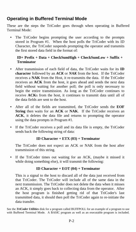
P-2
Operating in Buffered Terminal Mode These are the steps the TriCoder goes through when operating in Buffered Terminal Mode:
• The TriCoder begins prompting the user according to the prompts stored in Program #1. When the host polls the TriCoder with its ID Character, the TriCoder suspends prompting the operator and transmits the first stored data field in the format of:
ID+ Prefix + Data + CheckSumHigh + CheckSumLow + Suffix + Terminator
• After transmission of each field of data, the TriCoder waits for its ID character followed by an ACK or NAK from the host. If the TriCoder receives a NAK from the Host, it re-transmits the data. If the TriCoder receives an ACK from the host, it goes ahead and sends the next data field without waiting for another poll; the poll is only necessary to begin the entire transmission. As long as the TriCoder continues to receive ACKs from the host, it continues to transmit data until all of the data fields are sent to the host.
• After all of the fields are transmitted, the TriCoder sends the EOF String then waits for an ACK or NAK. If the TriCoder receives an ACK, it deletes the data file and returns to prompting the operator using the data prompts in Program #1.
• If the TriCoder receives a poll and its data file is empty, the TriCoder sends back the following string of data:
ID Character + ETX (03) + Terminator
The TriCoder does not expect an ACK or NAK from the host after transmission of this string.
• If the TriCoder times out waiting for an ACK, (maybe it missed it while doing something else), it will transmit the following:
ID Character + EOT (04) + Terminator
This is a signal to the host to discard all of the data just received from that TriCoder. The TriCoder will include all of the same data in the next transmission. The TriCoder does not delete the data when it misses an ACK, it simply goes back to collecting data from the operator. After the host program is finished getting rid of that TriCoder's last transmitted data, it should then poll the TriCoder again to re-initiate the data transfer.
See the TriCoder Utilities disk for a program called BUFFPOLL for an example of a program to use with Buffered Terminal Mode. A BASIC program as well as an executable program is included.

Q-1
Appendix Q
���*�� ��� ���� ��
�������%�����$�
Time clock applications are a popular use for the Tricoder. The most common ways to use the TriCoder as a time clock utilize either Buffered Terminal Mode or Data Collection Mode. In either case, you will want to display the time on the screen of the TriCoder. This is done while creating a program by specifying "DIS" (for DISplay date and time) in the DATA ID field of a:
• T (Time Stamp) • Y (Date Stamp) • S (Date and Time Stamp) or • D (Data)
programming "Statement Entry Type". The time and/or date is displayed above the next Data prompt. If you have a power failure… If you are plugged into wall power and there is a power failure, the TriCoder batteries do not take over until you press the ON/OFF key. If you are running in Buffered Terminal Mode and this happens, once you go to battery power the TriCoder will display the opening message and go right back to where it was when the power was interrupted. �
�����*�� ����%���� ��� ���� ��To use the time clock function efficiently, you will want the host to be able to set the time on the attached TriCoders. Setting all of the TriCoders from the host ensures that they are all set the same. The TriCoder uses the following protocol to set the time:
1. The host sends ID+SOH
2. The TriCoder responds with ID+<CR>
3. The host sends ID+mmddyyhhmmss + 2 chksum bytes + <CR>
4. If the TriCoder computed checksums match the received checksums, then the TriCoder responds with ID+ACK. If the checksums don't match, then the TriCoder responds with: ID+NAK

Q-2
5. If the host gets a NAK, then start the whole sequence over again by going back to step 1.
See the TriCoder Utilities diskette for a program called TIMESET for an example of a program written to set the time on multiple TriCoders. A BASIC program as well as an executable program is included.
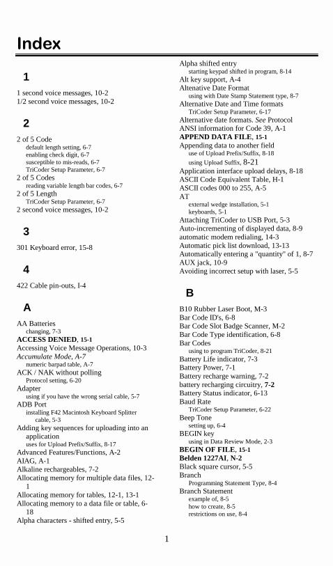
1
������
1 1 second voice messages, 10-2 1/2 second voice messages, 10-2
2 2 of 5 Code
default length setting, 6-7 enabling check digit, 6-7 susceptible to mis-reads, 6-7 TriCoder Setup Parameter, 6-7
2 of 5 Codes reading variable length bar codes, 6-7
2 of 5 Length TriCoder Setup Parameter, 6-7
2 second voice messages, 10-2
3 301 Keyboard error, 15-8
4 422 Cable pin-outs, I-4
A AA Batteries
changing, 7-3 ACCESS DENIED, 15-1 Accessing Voice Message Operations, 10-3 Accumulate Mode, A-7
numeric barpad table, A-7 ACK / NAK without polling
Protocol setting, 6-20 Adapter
using if you have the wrong serial cable, 5-7 ADB Port
installing F42 Macintosh Keyboard Splitter cable, 5-3
Adding key sequences for uploading into an application uses for Upload Prefix/Suffix, 8-17
Advanced Features/Functions, A-2 AIAG, A-1 Alkaline rechargeables, 7-2 Allocating memory for multiple data files, 12-
1 Allocating memory for tables, 12-1, 13-1 Allocating memory to a data file or table, 6-
18 Alpha characters - shifted entry, 5-5
Alpha shifted entry starting keypad shifted in program, 8-14
Alt key support, A-4 Altenative Date Format
using with Date Stamp Statement type, 8-7 Alternative Date and Time formats
TriCoder Setup Parameter, 6-17 Alternative date formats. See Protocol ANSI information for Code 39, A-1 APPEND DATA FILE, 15-1 Appending data to another field
use of Upload Prefix/Suffix, 8-18
using Upload Suffix, 8-21 Application interface upload delays, 8-18 ASCII Code Equivalent Table, H-1 ASCII codes 000 to 255, A-5 AT
external wedge installation, 5-1 keyboards, 5-1
Attaching TriCoder to USB Port, 5-3 Auto-incrementing of displayed data, 8-9 automatic modem redialing, 14-3 Automatic pick list download, 13-13 Automatically entering a "quantity" of 1, 8-7 AUX jack, 10-9 Avoiding incorrect setup with laser, 5-5
B B10 Rubber Laser Boot, M-3 Bar Code ID's, 6-8 Bar Code Slot Badge Scanner, M-2 Bar Code Type identification, 6-8 Bar Codes
using to program TriCoder, 8-21 Battery Life indicator, 7-3 Battery Power, 7-1 Battery recharge warning, 7-2 battery recharging circuitry, 7-2 Battery Status indicator, 6-13 Baud Rate
TriCoder Setup Parameter, 6-22 Beep Tone
setting up, 6-4 BEGIN key
using in Data Review Mode, 2-3 BEGIN OF FILE, 15-1 Belden 1227AI, N-2 Black square cursor, 5-5 Branch
Programming Statement Type, 8-4 Branch Statement
example of, 8-5 how to create, 8-5 restrictions on use, 8-4

2
Branching logic, 8-5 Breaking out of loops in program
using END key, 8-17 Buffered Terminal Mode, P-1
setting in Operation Mode, 6-15 using Host Response Delay, 6-23
Button Bar Menu Virtual TriCoder Utility, 9-3
C C20 Cable
needed for USB attachment, 5-3 Cable Pin-outs, I-1 Cables
choosing the correct cables for a PC serial port, 5-7
needed for cloning or transmitting/receiving programs, 11-1
needed for voice message cloning, 10-7 cables for Hayes compatible modems, 14-1 Cabling
F32A 25 pin modem cable, I-2 F34 DB25 Null Modem serial cable, I-1 F36 DB9 straight serial cable, I-1 F45-1 Dual Port serial cable, I-3 F46B 9 pin modem cable, I-2 Macintosh 422, I-4 Macintosh serial, I-3 PC 422, I-4
Can't edit program, 15-12 Can't read your bar codes, 15-6 Caps Lock ON
Code 39 setup parameter, 6-5 Carriage Return Separated Files, 4-1 Causing the reader to beep, 6-20 Caution on direct updating of data on upload,
4-6 CCD Continous On, L-5 CCD pin-outs, I-6 CCD Scanners, L-5 CHANGE BATTERIES, 15-1 CHANGE LITHIUM BATTERY, 15-1 CHANGE LITHIUM BATTERY message, 7-
5 Changing batteries, 7-3 Changing character output, 6-19 Changing from serial to wedge, K-3 Changing from wedge to serial, K-3 Changing memory allotments, 6-18 Changing more than one setup parameter at a
time using the bar coded setup menu, 5-5
Changing more than one Setup parameter at a time using the keypad in PROGRAMMING MODE,
5-5 Changing setup parameters using the keypad,
6-2
Changing the adapter on an F30 PC Keyboard Splitter cable, 5-1
Changing the default voice messages, 10-6 Changing the Speaker Volume, 10-8 Changing the TriCoders automatic shut-off
time, 6-18 Changing the voice message partitions, 10-2 Changing voice message time allotments. See Character codes
reassigning, 6-19 Characters
TriCoder Setup Parameter, 6-19 Check Character, A-2 CHECK LITHIUM BATTERY. See CHECK LITHIUM BATTERY message, 7-5 Checking keyed UPC code data, 8-12 Checking to see how many times you have
scanned an item number, 2-2 Choosing a COM port in the Windows
TriCoder Utilities, 4-8 CLEAR key
using to edit an entire data record, 2-4 Clock
using to date and time stamp data, 8-6 using TriCoder as a time clock, Q-1 using TriCoder to display date and time, 8-13
Cloning using the Windows TriCoder Utilities, 11-3
Cloning cable pin-outs, I-5 Cloning the entire TriCoder, 11-2 Cloning the TriCoder, 11-5 Cloning to or from older TriCoders, 11-2 Cloning voice messages, 10-6
cables for, 10-7 cloning voice ONLY, 10-7 requirements for, 10-6
Cloning Voice Messages from TriCoder to TriCoder, 10-6
CLSI format for Codabar, 6-6 CLSI format of Codabar, 6-6 Codabar, B-1
CLSI format, 6-6 Start/Stop transmission, B-1 transmitting start and stop characters, 6-6 TriCoder Setup Parameters, 6-6
Code 128 TriCoder Setup Parameter, 6-8
Code 128 Specifications, C-1 Code 128 subsets, C-1 Code 3 of 9
setting up, 6-4 Code 39
about Accumulate mode, A-7 enabling the Mod 43 check character, 6-4 Function/Control key support, A-4 transmitting start and stop characters, 6-4 turning Accumulate mode on/off, 6-4 using Caps Lock ON, 6-5
Code 39 Advanced Features/Functions, A-2

3
Code 93 TriCoder Setup Parameters, 6-9
Code 93 Specifications, G-1 Collecting Data
in Program #0, 1-2 in Program #1, 2-1
Comma Separated Files, 4-2 setting the Terminator Character, 4-2
Command key for Macintosh how to emulate using Code 39 barcode, A-4
Completed pick list, 13-13 Computer Interface
default settings for wedge and serial mode, 6-12 Learning Mode, 6-12 PC Terminal Mode, 6-12 TriCoder Setup Parameter, 6-12 USB, 5-6 when transmitting / receiving programs, 11-2
Computer/TriCoder Interface for Pick Lists, 13-13
Configuring 2 of 5 to look for fixed length data only, 6-7
Configuring the TriCoder after hardware is connected, 5-4 in serial mode, 5-11
Configuring TriCoder for RS422, 6-12 Connecting in-line on a terminal, 5-8 Connecting the Hardware
Keyboard wedge interface, 5-1 serial interface, 5-7
Conserving data memory, 8-14 Conserving power
by turning off speaker with earphone, 10-9 Continual beeping on RS-232 Terminal, 6-21 Continuous On setting for lasers/CCD's, L-5 Control key support, A-4 Converting from serial to wedge
or wedge to serial, K-3 Creating a custom program, 8-1
getting into PROGRAMMING MODE, 8-1 Creating a program
in Virtual TriCoder Utility, 9-5 Creating a table using the Windows TriCoder
Utility, 13-8 Creating mulitple data files, 12-2 Creating TriCoder Programs on your PC, 9-1 Ctrl Z as End Of File marker, 6-18 Cursor keys
moving around in Data Review mode, 2-3 Cursor size
shifted alpha vs. numeric entry, 5-5
D Data
Programming Statement Type, 8-4 Data Bits
7 bits or 8 bits, 6-22 TriCoder Setup Parameter, 6-22
Data Collection Mode
getting into from NON PORTABLE mode, 1-1 Program #0 tutorial, 1-1 setting in Operation Mode, 6-15
Data entry prompts, 8-4 DATA FILE EXISTS, 15-1
prompt displayed when entering Data Review Mode, 2-3
Data file formats, 4-1 Data format for portable transmission, 4-1 Data ID
specifying Pick List operation, 8-13 specifying Table Maintenance, 8-13 specifying Table Validation, 8-12 TriCoder Programming Prompt, 8-11 use to prevent duplicate data entry, 8-13 use to specify tables and pick lists, 8-12 using to prevent duplicate entry in tables, 13-3 using for Data Identifiers, 8-11 using for Pick Lists, 13-9 using to check UPC/EAN check digits for keyed
data, 8-12 using to display Date and Time, 8-13 using to specify Table Maintenance, 13-5
Data Identifiers example of use of, 8-12 use of Data ID field, 8-11
Data Maintenance using tables, 13-4 DATA NOT FOUND, 15-1 Data Review Mode, 2-3
editing individual characters in a data record, 2-4 restrictions on using with Pick list, 13-15 scrolling through the data record by record, 2-4 using the BEGIN key to go to start of file, 2-3 using the Clear key to edit, 2-4 using the END key to go to the end of file, 2-4 using the F1 key to collect data, 2-5 using the LEFT ARROW key to scroll
backwards through data, 2-4 using the UP ARROW key to enter Data Review
Mode, 2-3 Data Security
exiting by using keypad, 6-21 turning On/Off, 6-21
Data Security Features, 6-24 Data Security OFF/ON
Protocol setting, 6-21 Data Statement
example of, 8-4 DATA TOO LONG, 15-1 DATA TOO SHORT, 15-2 Data transmission format
for portable mode, 4-1 Non Portable mode, 6-23
Data Type Alphabetic only, 8-14 digits only, 8-14 numeric only, 8-14 starting data "shifted", 8-14 TriCoder Programming Prompt, 8-14
DATA TYPE ERROR, 15-2 Data Upload Mode
setting in Operation Mode, 6-15

4
Data Validation example for, 13-2
Data validation table file format, 13-2 Data Validation using Tables, 13-2 DATA XMIT ERROR, 15-2 Date and Time Formats. See Alternative Date
Formats Protocol setting, 6-22
Date and Time Stamp Programming statement type, 8-6
Date and Time Stamp Statements example of, 8-6
Date set, 6-16 Date Stamp
Programming statement type, 8-7 Date Stamp Statement
example of, how to use, 8-7 DB9 Straight Cable Pin-outs, I-1 Default data displayed, 8-9 Default data incremented
using Prompt text statement, 8-9 Default programs
tutorials, ii Default serial interface settings
using them if you can, 5-12 Default Serial Parameters
diagram, 5-12 Default voice message partitions, 10-2 Default Voice Messages, 10-6 Default voice messages and numbers, 10-6 Delay for modem re-dialing, 6-24, 14-2 Delays
example of delay in Upload Prefix/Suffix, 8-18 using Upload Prefix/Suffix, 8-18
Delays on transmission, 6-13 DELETE key
using to delete individual characters in a data record, 2-4
Deleting a program from the TriCoder, 8-2 Deleting program statements, 8-16 Determining the correct Computer Interface
for Keyboard Wedge Mode, 5-6 Dialing String, 14-1
TriCoder Setup Parameter, 6-23 Dial-up by TriCoder to Host, 14-1 Difficult code
using special settings to read, L-5 Direct uploading into an application
using upload prefix and suffix, 8-17 DIS
use as Data ID to display date and time, 8-13 Disabling END key in Data Collection, 8-17 Disabling F1 key in Data Collection
see also Data Security, 6-21 Disconnecting from the PC Keyboard splitter
cable, 5-2, 5-4 Disconnecting the Serial Y Cable, 5-9 Display and Error Messages, 15-1 Display Date and Time
use for Data ID field, 8-13
Displaying host messages, 6-20 Displaying last data collected for prompt as
default, 8-9 Displaying messages in another language, 6-
14 Displaying the total number of times you
have entered data for a prompt, 2-2 Displaying unprintable characters
in Upload Prefix/Suffix, 8-21 Dot matrix printed bar codes
best wand for reading, L-1 Double decode
for lasers, L-5 Double quotes used in Comma separated
files, 4-2 Down Arrow
during keypad setup, 6-3 Downloading a Pick List, 13-9 Downloading a table to the TriCoder, 13-7 DTR
forcing it high, 14-1 Dual port serial Y cable, 5-8 Dumb Terminal / Host Serial Interface
setting up TriCoder, 5-12 DUP
use in Data ID field to prevent duplicate data, 8-13
DUPLICATE ACCESS, 15-2
E Earphone volume. See Speaker volume
changing, 10-8 Editing a program, 8-23 Editing a table using Windows, 13-8 Editing individual characters in a data record,
2-4 Editing or deleting program statements, 8-16 Editing Upload Prefix/Suffix with data
present, 8-20 Eliminating the output of a character, 6-19 Emulating keyboard entry, 8-18 Emulating keystrokes using the Upload
Prefix/Suffix, 8-18 Enabling 2 of 5 check digit, 6-7 Enabling transmission of NSC character, 6-5 Enabling UPC/EAN check digits, 6-5 END key
in Data Review Mode, 2-4 use in No/End Statement, 8-16 using to end Data Collection, 2-3
End of File for uploaded data, 6-17 in Programming mode, 2-4
End of File marker for tables, 13-3
END OF PGM. RECV, 11-3 END OF TRANSMIT, 4-9

5
End Setup scanning to exit Setup mode, 5-5
Ending Data Collection Mode in Program #1, 2-3
ENTER key in Data Review Mode, 2-4
Entering a program using bar codes only, 8-21
Entering data from a serial device, 8-15 Entering data using a scanner only, 8-15 Entering data using the keypad only, 8-15 ENTRY TYPE ERROR, 15-2 Entry types, 8-4 EOF
how to set, 6-17 EOF String
TriCoder Setup Parameter, 6-17 EOT, FILE ERASED, 15-2 EOT, FILE SAVED, 15-2 Equivalent bar codes
for emulating keystrokes in programming, 8-21 Error Messages, 15-1 Establishing communication in Non Portable
Mode, 3-1 Keyboard Wedge Interface, 3-2
European date format dd/mm/yy, 6-17
Exiting Data Collection, 1-2 Exiting Non Portable mode, 3-1 External wedge, 5-1
F F1 key
using in Data Review Mode, 2-5 using to return to Mode Menu, 2-3 using while in Data Review Mode, 2-3
F2 key using to display ASCII characters, 8-21
F30 PC Keyboard Splitter cable changing the adapter for a 5 pin or 6 pin
keyboard, 5-1 installing, 5-1, 5-3
F32A 25 Pin Modem Cable, I-2 F34 DB25 Null Modem Cable Pin-outs, I-1 F34 serial cable
PC serial port connection, 5-7 F36
DB9 Cable Pin-outs, I-1 F36 DB9 Straight Cable Pin-outs, I-1 F36 Serial Cable
PC serial port connection, 5-7 F38 Data Cloning Cable, I-5 F42 Macintosh Keyboard Splitter cable
using Jumper block to allow funtioning without TriCoder, 5-3
F45-1 Dual Port Serial Cable, I-3 F45-1 Serial Y Cable
setting Transmission Mode when using, 6-24 F45-A Dual Port Serial Y Cable
installing between host and terminal, 5-8 F46B 9 Pin Modem Cable, I-2 F86 Worthington CCD, M-4 Fail-safe Re-initialization Procedure, 15-14 FATAL ENTRY TYPE, 15-2 FATAL EXEC CALL, 15-2 FATAL STMT #., 15-2 File formats
for uploaded data, 4-1 FILE NOT DEFINED, 12-3, 15-2 FILE USED BY Pn, 12-2, 15-2 Firmware and Model Upgrades, K-1 Fixed fields
in a pick list, 13-10 Flat File format
using Refer-backs, 4-4 Flat File Formats, 4-4 Flat File sample data, 4-5 Forcing 1 program only, 6-24 Forcing DTR high, 14-1 Foreign keyboards, 6-14 Format of data uploaded to host, 8-21 Formats
for data files, 4-1 Formats for date/time stamp, 8-6 Frequency of voice messages, 8-10 Full ASCII Extension to Code 39, A-3 Function Keys 11-29, A-5 Function Keys from PortKey, A-6
G General Troubleshooting, 15-6 Getting in and out of NON PORTABLE
mode, 3-1 Getting out of any mode
using the F1 key, 2-5 Griffin Technologies
USB to ADB adapter, 5-3
H Hayes-compatible modems, 14-1 Header record
for Pick Lists, 13-10 High resolution wands, L-1 Host controlled beeper, 6-20 Host controlled display enabled, 6-20 HOST NOT RESPONDING, 15-2 Host Response Accepted
displayable prompts, 6-21 entering data without receiving prompt, 6-21 no lower case characters allowed, 6-21 Protocol setting, 6-20 restrictions on using, 6-21 using to cause output on TriCoder, 6-20

6
Host Response Delay TriCoder Setup Parameter, 6-23
Host Response Ignored Protocol setting, 6-21
How to change the memory partitions, 6-18 How to configure TriCoder for USB
attachement, 5-6 How to look at collected data, 2-3 How to partition memory, 12-1 How to reach Worthington Data Solutions,
15-17 How to record voice messages, 10-5 How to scan a bar code, L-1 How to Use this Manual, i
I ID Characters
setting in TriCoder for polling, 6-23 ID’s for bar code type, 6-8 Identification of a field
Upload Suffix, 8-21 uses for Upload Prefix/Suffix, 8-17
IDENTIFIER ERROR, 15-3 Identifying the type of bar code read, 6-8 If you have the wrong serial port cable, 5-7 iMac
keyboard wedge installation, 5-3 INCOMPLETE PGM, 15-14 INCOMPLETE PROGRAM HIT ANY KEY,
8-22 INCORRECT PASSWORD, 8-2 Incrementing last data entered for a prompt,
8-9. See Prompt Text INIT FAILED, 15-3 Initialization procedures, 15-14 In-line connection, 5-8 Input Device
TriCoder Programming Prompt, 8-15 Installation
between host & dumb terminal, 5-8 dedicated serial port - PC, 5-7 for polling, N-1 Macintosh keyboard wedge, 5-3 multi-dropped 422, N-1 PC Keyboard Wedge, 5-1
Installing the F30 PC Keyboard Splitter cable, 5-1, 5-3
Installing the Virtual TriCoder Utility, 9-1 Installing the Windows TriCoder Utilities, 3-3 Interactive polling rules, O-2 Intercharacter Delay
TriCoder Setup Parameters, 6-13 using in Serial mode, 6-13 using Learning Mode to find timing, 6-13 using to match keyboard timing in wedge mode,
6-13 Interface conversion, K-3 Interfacing with the computer, 5-1
Interleaved 2 of 5 check digit calculation, D-1
Interleaved 2 of 5 Code, D-1 INVALID DEVICE, 15-3 INVALID HEADER, 15-3 Inventory Program, 2-1 ISBN bar codes
transmitting in ISBN format, 6-5 ISBN format output, 6-5, 6-11 ISBN Specifications, E-2 Item count, 2-2
J Jumper Block
installing on an F30 PC Keyboard Splitter cable, 5-2, 5-4
installing on an F42 Macintosh Keyboard Splitter cable, 5-3
removing before attaching TriCoder to splitter cable, 4-6
using with the F45 Serial Y cable, 5-9 Jumper change for serial/wedge, K-3 Jumper to change interface, K-3
K Key sequences not on keyboard, A-5 Keyboard Country
TriCoder Setup Parameters, 6-14 Keyboard error, 15-8 Keyboard Interface Configuration
determining configuration after hardware is installed, 5-6
Keyboard interface delays use Upload Prefix/Suffix, 8-17
Keyboard splitter cable using jumper block, 5-2, 5-4
Keyboard timing using Intercharacter Delay, 6-13
Keyboard Wedge Interface connecting the hardware, 5-1
Keyboard Wedge mode troubleshooting, 15-8 Keyboards
AT/PS2, 5-1 Macintosh, 5-3
Keyed UPC data with check digit, 8-12 Keying UPC numbers, 8-12 keypad sequence to turn off Data Security, 6-
21
L Label Code 4 and 5
enabling reading of, 6-8 Language problems during data collection,
10-1 Laser pin-outs, I-6

7
Laser scanners technique for using Setup Menu, 5-5
Laser Scanners, L-4, M-2 protective rubber boot, M-3
Laser Terminal feature, J-1 Last data displayed on data entry, 8-9 Last data incremented on data display, 8-9 Leading spaces or zeros padding, 8-20 Learning Mode
using in Non Portable Mode, 3-3 using to setup TriCoder in Keyboard Wedge
mode, 5-6 Left Arrow
during keypad setup, 6-3 LEFT ARROW key
using in Data Review Mode, 2-4 Length
Maximum Data length, 8-14 Minimum data length, 8-15
Line feeds before data display, 6-11 Literacy as a data collection problem, 10-1 Lithium backup battery, 7-3 Lithium battery
model CR2032 3v, 7-4 Lithium Battery
changing, 7-4 Lithium Battery messages after long-term
storage, 7-5 Location sequence for a pick list, 13-13 Locking out programs, 6-24 LOGMARS, A-1 Long decode, L-5 Long term storage of TriCoder, 7-4 Looking back one record in data file, 2-4 Low Battery message, 7-3 LZ100 Laser Scanner, M-2 LZ200 Laser Scanner, M-3
M Macintosh
Command key, A-4 keyboard wedge installation, 5-3 Option key, A-4 RS-422 cabling, N-2 special key code support, A-4
Macintosh Keyboard Wedge Installation, 5-3 Macintosh Serial Cable pin-outs, I-3 Mapping of voice messages, 10-2 MAX DATA LEN, 8-14 Maximum Data Length, 8-14. See Xtra
Statement TriCoder Programming Prompt, 8-14
Medium resolution wands, L-1 Memory
"pages", 12-1 dividing to accomodate multiple data files and
tables, 12-1 Memory partitions
examples of, 13-1 Memory remaining
using STATUS key to check, 12-3 Memory status, 2-4 Menu setup by keypad, 5-5 Message Numbers
TriCoder Programming Prompts, 8-10 Messages
alphabetical list, 15-1 Meter- reading applications, 13-9 Microphone, 10-4
plugging in to AUX jack, 10-4 Min/max length checks in Non Portable
mode, 6-11 Min/max limits in Non Portable mode, 6-11 Minimum Data Length. See Xtra Statement
TriCoder Programming Prompt, 8-15 Minimum length, 8-15 Mode Menu, 3-1 Mode to Mode transitions, 3-1 Model Changes
Serial to Wedge, K-3 modem cables, 14-1 modem redial delay
varying, 14-2 modem reset, 14-2 Modem Retry Delay, 14-2 Modem Uploads, 14-1 modem usage, 14-1 Modems
configuring the TriCoder to upload via, 14-2 dialing the host, 14-2 programming a dialing string in the TriCoder, 6-
23 transmitting the dialing string using F2, 14-2
Modifying programs, 8-23 Modulus 43 Check Characters, A-2 MSI/Plessey
TriCoder Setup Parameter, 6-8 MSI/Plessey code, F-1 Multi-dropped TriCoders, N-1
Buffered Terminal Mode, P-1 Multiple data files, 12-1 Multiple program entry points, 8-3
N Naming a program, 8-3 NiCad batteries
checking jumpers when recharging, 7-4 NiCad Batteries
using built-in recharging feature, 7-2, 7-3 NiCad rechargeables, 7-2 Nickel Metal Hydride rechargeable batteries,
7-2 NiMH, 7-2 NiMH and NiCad batteries
battery life, 7-2 NMI ERROR, 15-3

8
No communication with serial port, 15-11 No/End Statement
TriCoder Programming Prompt, 8-16 what END key can do, 8-16
Non Portable Mode, 3-1 getting in and out of, 3-2 missing characters or partial data, 3-3 PC Serial Interface, 3-3 setting in Operation Mode, 6-15 Test Label for use with, 3-2 using Learning Mode if you have problems, 3-3 using Windows Notepad, 3-2 using Windows TriCoder Utilities to test, 3-3
None Programming statement type, 8-8 Protocol setting, 6-19
None Statement example of, 8-8 using to create a "dummy" statement, 8-8 using with Branch Statements, 8-8
Normal code settings for Laser scanners, L-5
NSC assignments, E-2 NSC characters
enabling transmission, 6-5 Null Modem Cable Pin-outs
F34, I-1 Numeric "Barpad", A-7
O One program
forcing use of, 6-24 On-line help in Virtual TriCoder Utility, 9-5 Opening the TriCoder to change the speaker
volume, 10-9 Operation Mode
TriCoder Setup Parameters, 6-15 Operator screw-ups
preventing before they happen, 15-15 Operator-entered constant data, 8-18 Option key
Macintosh, A-4 Optional Features, M-1 Order Number
programming for in Pick Lists, 13-11 writing to data file for pick list, 13-11
OUT OF MEMORY, 2-5, 15-3 Output data file format for Table
Maintenance, 13-6 Outputting ASCII characters
in place of actual characters entered, 6-19
P Padding data with zeros or spaces
using the Upload Prefix/Suffix, 8-20 Padding the end of data with zeros and
spaces, 8-21 Parity
None, even or odd, 6-22 TriCoder Setup Parameter, 6-22
Partial reads on EAN-13, 6-6 Partitioning memory for table use, 13-1 Partitions
allocating memory for tables. See Tables and Pick Lists
changing for voice messages, 10-2 creating for tables, 13-1 defining for multiple data files, 12-1 for voice messages, 10-2 restrictions on changing, 12-4 TriCoder Setup Parameter, 6-18
Parts of the TriCoder programming screen, 8-2
Password, 8-2 PC Keyboard Upload, 4-6 PC Keyboard Wedge Installation, 5-1 PC program
to receive a program from the TriCoder, 11-2 PC Program
to transmit a program to the TriCoder, 11-4 PC Serial Interface
setup, 5-12 PC Terminal Mode
configuring TriCoder for, 6-12 Pick List
automatic download, 13-13 PICK LIST COMPLETED message, 13-13
Pick List data review, 13-15 Pick List Examples, 13-12 Pick List File Format, 13-10 Pick Lists, 13-9
Computer/TriCoder interface, 13-13 Data ID, 13-9 example of file format, 13-10 header record, 13-10 specifications, 13-9 Uploaded data file format, 13-15 viewing the Order Number, 13-15 writing the Order Number as part of the data file,
13-11 Piggyback Feature, J-1 Piggyback Laser Installation, J-1 Pin-outs
25 pin modem cable, I-2 25 pin null modem for PC, I-1 9 pin modem cable, I-2 9 pin straight cable for PC, I-1 cloning cable, I-5 Dual Port Serial cable, I-3 Laser and CCD, I-6 Macintosh 422, I-4 Macintosh serial, I-3 Multi-drop 422, I-4 wand, I-5
Planning for success, 15-15 Playing back a recorded voice message, 10-4 Plessey code, F-1

9
Pocket Modems, 14-1 Polled - No ACK /NAK
Protocol setting, 6-20 Polled - with ACK /NAK
Protocol setting, 6-20 Polling
ID characters for, O-1 interactive rules, O-2 setting an ID character for each TriCoder, 6-23 terminating prompts for interactive polling, O-2 with Host Response Accepted, O-2
Polling and how it works, O-1 Polling with ACK/NAK, O-2 Poor lighting situations
suggestions for dealing with, 10-1 Poor read rates, 15-7 Portable Modem, 14-1 Portkey
description of, 5-10 using with the TriCoder in serial interface, 5-7
Postamble TriCoder Setup Parameters, 6-9 using to check data length in NON PORTABLE
mode, 6-11 using to create line feeds, 6-11
Postambles for ASCII 000 to 255, A-5 selective trimming, 6-10
Power supply using while cloning voice messages, 10-7
Powering the TriCoder, 7-1 Preamble
selective trimming, 6-10 TriCoder Setup Parameters, 6-9 using to check data length in NON PORTABLE
mode, 6-11 Preamble
using to create line feeds on TriCoder, 6-11 Preambles
for ASCII 000 to 255, A-5 Prefix, 8-17, 8-18, 8-19, 8-20 Preparing to receive a program on the
TriCoder, 11-1 Preparing to transmit a program from the
TriCoder, 11-4 Prevent duplicate entry of data
use for Data ID field, 8-13 Preventing alpha character entry, 8-14 Preventing data entry errors, 15-16 Preventing duplicate access
differences in data file format, 13-3 Preventing duplicate entry of data
in tables, 13-3 Preventing exit from Data Collection, 6-21 Price verification, 13-4 Problems during transmitting / receiving, 11-3 Problems while transmitting a program, 11-5 Procomm
using to test communication in serial mode, 5-10 Program #0
Tutorial, 1-1
Program #0 Quickstart, 1-1 Program #0 Sample Bar Codes, 1-3 Program #1
voice messaging, 2-1 Program #1 overview, 2-1 Program #1 Quickstart, 2-1 Program #1 sample bar codes, 2-2 Program #2
same as program #0 but with prefix/suffix, 2-5 Program distribution, 8-21 Program name
functions of the prompt, 8-3 Program Name
TriCoder program prompt, 8-3 using to determinine what statement number to
start at, 8-3 Program Receive Mode
setting in Operation Mode, 6-15 Program re-entry statement, 8-3 Program Restriction, 6-24 Program statement field number, 8-2 Program statements
deleting or editing, 8-16 Program Statements, 8-1 Program Transmit Mode
setting in Operation Mode, 6-15 Program troubleshooting, 15-12 Programming an End Of File marker, 6-17 Programming by scanning bar codes, 8-21 Programming Mode
only prefix and suffix available, 8-23 password, 8-2 setting in Operation Mode, 6-15
PROGRAMMING MODE using to get into Voice Message Operations, 10-
3 Programming prompt
Program Name, 8-3 Statement Entry Types, 8-4
Programming Prompt Data ID, 8-11 Input Device, 8-15 Maximum Data Length, 8-14 Minimum Data Length, 8-15 No/End Statement, 8-16 Upload Suffix, 8-21 Voice Message Frequency, 8-10 Yes/Next Statement, 8-16
Programming Prompts Data Type, 8-14 Message Numbers, 8-10 Prompt Text, 8-9 Upload Prefix, 8-17
Programming the TriCoder by scanning bar codes only, 8-21
Programming the TriCoder for Pick Lists special considerations, 13-11
Programming voice messages, 10-1

10
Prompt Text other uses for, 8-9 TriCoder programming prompt, 8-9 using to accept last data entered for prompt as
new data, 8-9 using to increment last data entered, 8-9
Prompt Text statement using to display last data collected, 8-9 using to increment last data entered, 8-9
Protocol ACK/NAK without polling, 6-20 Data Security On/Off, 6-21 Date and Time Formats, 6-22 Host Response Accepted, 6-20 Host Response Ignored, 6-21 Polled with ACK/NAK, 6-20 Polled, No ACK/NAK, 6-20 TriCoder Setup Parameter, 6-19 using XON/XOFF, 6-20 XMODEM, 6-21
Protocol for program transmission, 11-5 PS/2
keyboard wedge installation, 5-1
Q Question
Programming Statement Types, 8-5 Question Statement
how to create, 8-5 restrictions on use, 8-6
Quiet zones, L-5
R Reading bar codes through a windshield, L-5 Reading problems
keyboard interface, 15-9 serial interface, 15-10
Reading UPC-E1, 6-6 Reading variable length I2 of 5 codes, 15-12 Real-time clock
setting time on multiple TriCoders, Q-1 using to stamp data collected, 8-6 using TriCoder as timeclock, Q-1
Re-assigning character codes, 6-19 RECEIVEP. See TriCoder Utilities diskette Receiving a certain program only, 11-2 Receiving a program on the host computer
using the TriCoder Windows Utilities, 11-3
Receiving a program on the TriCoder, 11-2 Receiving a program on the TriCoder or host,
11-1 RECEIVING INTERRUPTED, 15-4 Recording a voice message using the
microphone, 10-4 Recording and Playback of Voice Messages,
10-4 Recording time alloted for voice messages,
10-2 redialing on modem upload, 14-3 Refer-back programming example, 4-5 Refer-backs
using Upload Prefix/Suffix, 8-18 Reinitializing the TriCoder, K-3 Re-initializing the TriCoder, 15-14 Replacing the EPROM, K-1 Replaying a voice prompt, 10-5 Reset, 6-1 Reseting program restriction, 6-24 Restricting programs, 6-24 Restrictions on cloning, 11-5 Retry delay
for Modem dialing, 14-2 Return procedures, 15-17 Reversing order of suffix and terminator ch,
8-21 Reviewing and Editing Data
Tutorial for Program #1, 2-3 Reviewing data already in the TriCoder, 2-3 Right Arrow
during keypad setup, 6-3 RMA's, 15-17 RS-232
cable pin-outs, I-1 Macintosh cable pin-outs, I-3 serial installation on PC, 5-7 setting the Computer Interface, 6-12
RS-422, N-1 cabling, N-1 configuring TriCoder for, 6-12 distance limits, N-1
RTC ERROR, 15-4
S S10 and S20 Hands Free Laser/CCD Stand,
M-5 Sabotage
preventing, 6-21 Scale or instrument input, 8-15 Scanner Options
TriCoder Setup Parameters, 6-14 using a "non-switched" wand, 6-14
Scanner pin-outs laser and CCD, I-6 wand, I-5
Scanning technique, L-1 Scrolling through the data record by record,
2-4 SEARCH PATTERN, 2-4 Seconds
how to select for date/time stamp, 8-7 Securing your data, 2-5 Security, 6-21, 6-24 See Xtra Statement 1. Selective data trimming
by bar code type, 6-10

11
Selective trimming using Upload Prefix/Suffix, 8-20
Serial Installation on a PC with a Dedicated Serial Port, 5-7
Serial Installation on PC diagram of, 5-8
Serial interface polling setup, O-1
Serial Interface connecting the hardware, 5-7
Serial Interface Communications Software overview, 5-10
Serial Interface on a Macintosh, 5-9 Serial interface vs. wedge interface, K-3 Serial mode troubleshooting, 15-9 Serial settings
Baud rate, 6-22 Serial Upload, 4-8 Serial Wedge Interface between a dumb
terminal and host, 5-8 Serial Y cable
jumper block usage, 5-8 jumper block usage', 5-8
Serial Y Cable, 5-8 SET
using in setup, 6-1 Set Date
TriCoder Setup Parameters, 6-16 Set ID Character
TriCoder Setup Parameter, 6-23 Set Time
TriCoder Setup Parameter, 6-16 Setting the time automatically, Q-1 Setting the time in the TriCoder, 6-16 Setting the time on the TriCoders, Q-1 Setup by keypad, 6-1 Setup menu
using bar coded menu to configure, 6-1 Setup or playback voice messages, 10-4 SHIFT key
cursor identification, 5-5 Shifted data entry
specifying, 8-14 Shift-F1-F2
key sequence to access Voice message operations, 10-3
Short decode, L-5 Short term storage of TriCoder, 7-4 Short voice messages
preferable to use, 10-1 Shut Down Time
TriCoder Setup Parameter, 6-18 Shutting down
keeping the TriCoder from automatically turning off, 6-18
Silencing all voice messages, 10-5 Simple inventory program
Program #0, 1-1 Simple physical inventory, 2-1 Simulating keystrokes
using Upload Suffix, 8-21 Single Cycle Transmit
TriCoder Setup Parameter, 6-17 using to test complex upload prefix and suffix, 6-
17 Single decode, L-5 Skipping items in a pick list, 13-12 Slot Badge Scanner
Bar Code, M-2 Spaces
adding to front of data uploaded, 8-20 Speaker / Batteries
TriCoder Setup Parameters, 6-13 Speaker volume
changing, 10-8 Special Laser and CCD Settings, L-5 Specifications for Code 39, A-1 Specifying a maximum data length, 8-14 Specifying a minimum data length, 8-15 Specifying numeric only data, 8-14 Specifying Tables and Pick Lists
using Data ID field, 8-12 Speeding up data collection by using Voice
Prompts, 10-1 Splitter cable for Macintosh keyboard
using jumper block, 5-3 Squeezing in refer-backs, 15-13 SRAM WRITE ERROR, 15-4 Stamping
date and time, 8-6 Start Setup
scanning to enter Setup mode, 5-5 Start/stop characters
transmitting for Codabar, 6-6 transmitting for Code 39, 6-4
Starting data collection at a statement other than #1, 8-3
Starting data entry "shifted", 8-14 Starting the receiving TriCoder first, 11-2 Starting the Virtual TriCoder Utility, 9-2 Statement Entry Type
None, 8-8 Statement Entry Types
Branch, 8-4 Data, 8-4 Date and Time Stamp, 8-6 Date Stamp only, 8-7 in Virtual TriCoder, 9-4 Question, 8-5 Time Stamp only, 8-7 TriCoder program prompt, 8-4 Xtra, 8-7
Statement Functions in Virtual TriCoder, 9-4
STATUS of multiple data files, 12-3
STATUS key, 2-4 using to check battery levels, 7-3 using to see memory free in data files, 12-3 using to view status of data file partitions, 12-3

12
STK bar code, 6-8 STMT TO BRANCH, 8-5 Stop Bits
1 bit or 2 bits, 6-22 TriCoder Setup Parameters, 6-22
Stopping data collection exit by mistake, 6-21 Storage Tek bar code, 6-8 Storage Tek Tape Label code, 6-8 Storing a TriCoder program on your PC, 11-3 Storing the TriCoder, 7-4 Suffix, 8-21 Suppressing transmission of a field, 8-19 Switch scanners, L-1 Symbol 3200ER Scanner, M-3
T Tab character entry, 6-11 Table download
messages, 13-7 procedures, 13-7 using Windows program to download, 13-7
Table file format header record, 13-2
TABLE FORMAT ERR, 15-5 Table Maintenance, 13-4
error messages, 13-6 Fixed fields, 13-4 specifications, 13-4 Updatable fields, 13-4 using F2 key to display field again, 13-4
Table Maintenance file format, 13-5 points to remember, 13-6
Table size and memory partitions, 12-1, 13-1 Tables
Data Maintenance, 13-4 trailing spaces in table data, 13-6
Tables and Pick Lists, 13-1 Tape library bar code, 6-8 Terminal/Host Installation
diagram, 5-9 Terminating data collection, 2-3 Terminating transmission with EOF, 6-17 Terminator character
for serial interface, 6-11 Terminator Character
role in upload file formats, 4-1 TriCoder Setup Parameter, 6-11
Test Label, 3-3, L-2 Testing Communication using NON
PORTABLE mode Keyboard Wedge Mode, 5-6 terminal / host, 5-12
Testing your program in Virtual TriCoder, 9-5
Time and date display in Data Collection, 8-13
Time Clock functions, Q-1 Time recorded in seconds, 8-7
Time set, 6-16 Time Stamp
Programming statement type, 8-7 Time Stamp Statement
example of, how to use, 8-7 Time stamping, 8-7 Timing Delays
uses for Upload Prefix/Suffix, 8-18
using Upload Suffix, 8-21 Tips for Using Voice Prompts, 10-1 Tips on choosing a program for Data
Collection, 2-5 Total count display, 2-2 Trailing spaces
padding data with, 8-20 Trailing spaces in table entries, 13-6 Trailing zeros
padding data with, 8-20 Transmission Mode
TriCoder Setup Parameter, 6-24 Transmitting / Receiving programs
starting the receiver first, 11-2 using the 5 volt power supply, 11-1
Transmitting a country code for UPC, 6-11 Transmitting a program, 11-4 Transmitting a program from the TriCoder or
host, 11-4 Transmitting and Receiving Programs and
Setup, 11-1 Transmitting Bar Code ID's, 6-8 Transmitting characters before or after bar
code data, 6-9 Transmitting Codabar start and stop
characters, 6-6 Transmitting EAN-8/UPC-E in original
formats, 6-6 Transmitting incorrect data to screen, 15-9 Transmitting one field of data at a time, 6-17 Transmitting programs to a TriCoder from the
Windows TriCoder Utilities, 11-6 Transmitting UPC-A as EAN-13, 6-6 Transmitting Upload Suffix after Terminator,
8-21 TriCoder Coding Forms
about, 8-1 TriCoder Connection, 5-1 TriCoder memory
how it is partitioned for tables, 13-1 TriCoder pin-outs, I-1 TriCoder Quickstart, ii TriCoder Setup, 6-1
using the bar coded Setup Menu, 6-1 using the keypad to setup the TriCoder, 6-1
TriCoder Setup Parameter Host Response Delay, 6-23 Intercharacter Delay, 6-13 Operation Mode, 6-15 Scanner Options, 6-14 Terminator Character, 6-11

13
Transmission Mode, 6-24 Voice Messages, 6-16
TriCoder Setup Parameters, 6-4 2 of 5 Code, 6-7 2 of 5 Length, 6-7 Alternative Date and Time Formats, 6-17 Baud Rate, 6-22 Beep Tone, 6-4 Characters, 6-19 Codabar, 6-6 Code 128, 6-8 Code 3 of 9, 6-4 Code 93, 6-9 Computer Interface, 6-12 Data Bits, 6-22 Dialing String, 6-23 EOF String, 6-17 Keyboard Country, 6-14 MSI/Plessey, 6-8 Parity, 6-22 Partitions, 6-18 Postamble, 6-9 Preamble, 6-9 Protocol, 6-19 Set Date, 6-16 Set ID Character, 6-23 Set Time, 6-16 Shut Down Time, 6-18 Single Cycle Transmit, 6-17 Speaker / Batteries, 6-13 Stop Bits, 6-22 UPC/EAN, 6-5
TriCoder transmits extra characters at the start or end of bar code data, 15-7
TriCoder Utilities description of Windows and DOS versions, 5-10
TriCoder Windows Utilities program using to receive programs from a TriCoder, 11-3
Trimming by bar code type using bar code ID and preamble/postamble, 6-11
Trimming characters from data in NON PORTABLE MODE, 6-10
Trimming data according to bar code type in Upload Prefix/Suffix, 8-20
Trimming data from a field use for Upload Prefix/Suffix, 8-19
Trimming Data from end of data using Upload Suffix, 8-21
Trimming leading characters using Preamble in Non Portable mode, 6-9 using Prefix for portable mode, 8-19
Trimming trailing characters using Postamble in Non Portable mode, 6-9 using Suffix for portable mode, 8-19
Troubleshooting, 15-1 Keyboard Wedge, 15-8 programming problems, 15-12 Serial Mode, 15-9
Turning off prompts not errors, 10-5 Turning off the speaker
when using the earphone, 10-9 Turning off voice messages, 8-10, 10-5 Turning the speaker off to conserve batteries,
6-13 Turning the TriCoder ON and OFF, 7-1 Tutorial
Program #0, 1-1 Program #1, 2-1
Types of programming statements, 8-1
U UCC/EAN Code 128
enabling/disabling, 6-8 UCC-128/ EAN-128, C-1 unattended dial by Host, 14-4 Unattended Dial-up by Host to TriCoder, 14-
4 Unattended pick list download, 13-14 Universal Serial Bus, 5-3 unprintable characters
displaying, 8-20 Up Arrow
during keypad setup, 6-3 UP ARROW key
using to review data, 2-3 UPC
checking UPC data that is keyed in, 8-12 UPC 2 and 5-character supplemental codes,
E-2 UPC Specifications, E-1 UPC/EAN
NSC and check digit, 6-5 transmitting UPC-A in EAN-13 format, 6-6 TriCoder setup parameter, 6-5
UPC/EAN Check digit verification for keyed-in data using Data ID for, 8-12
UPC/EAN check digits enabling transmission of, 6-5
UPC/EAN checksum character. See UPC/EAN Supplements
enabling/disabling, 6-5 UPC-E Checksum Calculation, E-4 UPC-E0 and UPC-E1, 6-6 UPC-E1
enabling reading of, 6-7 Updatable fields in a pick list, 13-10 Upgrading, K-1 Upload by Xmodem protocol, 14-3 Upload File Formats
Comma Separated, 4-2 Flat files, 4-4
Upload Prefix creating Refer-backs, 8-18 TriCoder Programming Prompt, 8-17 uses for, 8-17 using Single Cycle Transmit to test keyboard
emulation, 8-18 using to emulate keystrokes in an application, 8-
17 using to identify a field, 8-17 using to insert delays when uploading, 8-18
14
using to pad data with zeros or spaces, 8-20 using to trim data from a field, 8-19
Upload Prefix and Suffix using to create comma separated file format, 4-3 using to create additional upload file formats, 4-5
Upload Suffix TriCoder Programming Prompt, 8-21
Uploader program Macintosh serial interface, 5-9
Uploading a program in the Virtual TriCoder, 9-3
Uploading data backing up application files first, 4-6 before you clone voice messages, 10-6 before you transmit or receive programs on the
TriCoder, 11-1 using the Windows TriCoder Utilities to do a
serial upload, 4-8 Uploading Data, 4-1
Carriage Return separated format, 4-1 establishing communication before you upload,
4-1 for Program #0 tutorial, 1-3 in Program #1, 2-5
Uploading data into an application using Upload Prefix/Suffix to insert delays, 8-18
Uploading File Formats, 4-1 USB attachment
correct Computer Interface, 5-6 Using the 5-volt power adapter, 7-1 Using a slot badge scanner, M-2 Using an adapter on your PC serial port cable,
5-7 Using Programming Mode to change the
TriCoder Setup, 5-5 in serial mode, 5-11
Using the bar code TriCoder Setup Menu, 6-1 Using the bar coded TriCoder Setup Menu
to configure the TriCoder, 5-5 to setup the TriCoder in serial mode, 5-11
Using the keypad to setup the TriCoder, 6-1 Using the STATUS key to view data file
partions, 12-3 Using the TriCoder as a Time Clock, Q-1 Using the Upload Prefix and Suffix to create
additional file formats, 4-5 Using the Windows TriCoder Utilities to
upload data from the serial port, 4-8 Using Windows Notepad to upload data, 4-6 Using Windows to download a table, 13-7
V Variable length key fields in table, 13-6 Verifiable fields in a pick list, 13-10 Viewing the previous data entry, 2-4 Virtual TriCoder Utility, 9-1
about the File Menu, 9-2 Button Bar Menu, 9-3 Close button, 9-4
Help button, 9-4 Run Virtual TriCoder button, 9-3 Upload to TriCoder button, 9-3 View Table button, 9-3
Virtual TriCoder Utility Screen, 9-2 Voice Message Frequency
Exception or Always, 8-10 TriCoder Programming Prompt, 8-10
Voice message mapping, 10-2 Voice Message Operations
getting into, 10-3 using the hotkey to access, 10-3
Voice Message Options, 10-5 Voice message partitions
changing, 10-2 Voice messages
cloning from TriCoder to TriCoder, 10-6 eaphone only option, 6-13 error conditions, 10-6 frequency, 8-10 initiated by computer, 6-20 playback, 10-4 record error messages for all situations, 10-2 silencing, 10-5 speaking clearly when recording, 10-1 use a calm voice when recording, 10-1 using Accumulate Mode to save time, 10-2 varying your tone of voice when recording, 10-2
Voice Messages, 10-1 changing the time allotments, 6-16 specifying two messages for a prompt, 8-11 TriCoder Setup Parameters, 6-16
Voice messaging in Program #1, 2-1 short messages are preferable, 10-1
Voice Messaging using Data Security in conjunction with, 10-2
Voice Operations menu using hotkey to get there while programming, 8-
11 Voice Prompts
helping to limit mistakes, 10-1 Volume potentiometer, 10-8
W WAIT ON ACK/NAK, O-2 WAITING ON PMPT message, 6-21 WAITING ON POLL, O-2 Wall Power
using the 5 volt power adapter, 7-1 warnings, 7-1
Wand emulation scanner restriction, I-5 wand pin-outs, I-5 Wand Scanners, L-1 Wand Scanning Technique, L-1 Wanding bar codes to enter a program, 8-21 wanding variable data, A-7 Wanding variable data, A-7

15
Wands high resolution, L-1 medium resolution, L-1 use of non-switched wand, L-1
WARNING 2K LEFT, 2-4 Warning on recharging batteries, 7-2 WDTRI
password for PROGRAMMING MODE, 8-2 using password to enter PROGRAMMING
MODE, 5-5 Wedge, 5-1 Wedge interface vs. serial interface, K-3 Wedge mode
selecting, 5-4 Wedge Saver
needed for USB attachment, 5-3 Why Use Voice Messages and Prompts?, 10-
1 Windows Notepad
using to upload data in keyboard wedge mode, 4-6
Windows TriCoder Utilities installing and running, 3-3
Windows TriCoder Utilities program using to test communication in Non Portable
Mode, 3-3 Windshield
reading bar codes through, L-5 WRONG INPUT DEVICE, 15-5
X XMISSION INCOMPLETE, 15-5 XMODEM
Protocol setting, 6-21
Xmodem Procomm Script File, 14-4 Xmodem protocol procedures, 14-3 Xmodem Upload, 14-3 XON / XOFF
Protocol setting, 6-20 XT
setup for, 5-1 Xtra
Programming statement type, 8-7 Xtra Statement
conditions of it's use, 8-7 data length requirements, 8-8
Y Y cable for keyboard
using jumper block, 5-2, 5-4 Y cable for Macintosh keyboard
using jumper block, 5-3 Y Cable for Serial installation
using jumper block, 5-9 Y2K
displaying year in 4 digit format, 6-16 Year 2000 compliance
displaying year in 4 digit format, 6-16 Yes/Next Statement
TriCoder Programming Prompt, 8-16 using to specify next statement to execute, 8-16
Z Zeros
adding to front of data uploaded, 8-20

MaxChs
01-99
TriCoder Coding FormProgram Name: Date:St
atem
ent N
o.EntryType
D-DataQ-QuestT-TimeY-DateS-Both
B-BrnchXtra
Prompt Text
Data ID Unique3 Chars
or table IDor
TimeDisplay Da
ta T
ype:
D N
A, o
r Bla
nk
MinChs
00-99(2-Chs)
Inpu
t Dev
ice:
K, W
or B
lank
Next StmtNum.
or Yes
Branch
EndBranch
orNo
Branch
Upload Prefix Upload Suffix(or Stmt to
Branch)
Voic
e Fr
eque
ncy
A, E
VoiceMessageNumbers
Msg 1 Msg 2