Embed Size (px)
Citation preview

260
Vol. 39, No. 2 (2017) 260-269, DOI: 10.24874/ti.2017.39.02.14
Tribology in Industry
www.tribology.fink.rs
Aspects of Lubrication in a Reciprocating Single-ring Test Rig and Further Implementation to
Engine Applications P.S. Dellis
a a School of Mechanical Engineering Educators, ASPETE Greece, Heraklion, Athens, Attiki, 14121, Greece.
Keywords:
Piston-ring lubrication Single-ring test rig Engine experiments Oil film Friction and pressure measurements Visualisation Cavitation Laser induced fluorescence
A B S T R A C T
A major concern in modern engine design is the issue of the lubrication regime at the piston-liner assembly. To fully understand the complex lubrication phenomena between the piston-rings and cylinder liner in reciprocating engines and at the same time achieve minimal energy losses with the oncoming emission regulations, it is important to characterize the developing oil film. This dynamic process involves many factors, such as piston-ring and piston dynamics, starved lubrication, liner geometry deformation, lubricant - additive degradation and blow-by, which, in turn, enhance the difficulty of interpreting engine experimental results. The simplified test rig is used as a platform to develop oil film measuring techniques and study experimental results from different sensors by means of a robust and solid technique without the engine testing ambiguities, at different lubrication regimes. This paper is focused on experimental findings from the simplified test rig and how these can be applied on specially modified engines, with the respective sensors fitted. A comparison between the single-ring test rig and the engine visualization results is attempted so that similar forms of cavitation identified, be further studied. Moreover, a calibration coefficient for LIF engine experiments can be derived via the simplified test rig arrangement.
© 2017 Published by Faculty of Engineering
Corresponding author:
Polychronis S. Dellis School of Mechanical Engineering Educators, ASPETE, Heraklion, Athens, Attiki, 14121, Greece. Email: [email protected]
1. INTRODUCTION
The lubrication regime formed in the piston-ring cylinder liner interface which is one of the biggest contributor to mechanical losses, is critical to the amount of surface contact, friction, oil consumption and wear. The optimum lubrication of the piston-rings is necessary to reduce friction and also limit oil consumption.
The lubricant film formed between the piston-ring and cylinder liner is very thin and the measurement of this essential variable is difficult. All the proposed methods (capacitance, resistance, Laser Induced Fluorescence – LIF, ultrasound, inductance) are combined with respective error sources. Therefore, it is of great importance to have tools available for evaluation of friction, oil film thickness and pressure, at the interface
RE
SEA
RC
H
P.S. Dellis, Tribology in Industry Vol. 39, No. 2 (2017) 260-269
261
between the piston-ring and liner. The test rig can be used for investigation of effects of different components and running conditions and also for validation of numerical simulation models [1]. Of particular interest is the role of cavitation in the performance of the piston-ring pack. When considering lubricant flow, it is known that when the pressure becomes too low (drops below the lubricant vaporisation pressure or the saturation pressure of dissolved air), the continuous film will rupture and air bubbles are formed. Once the pressure drops to a critical value, the oil will cavitate, separating into liquid and vapor [2]. In the 2011 European Comission White Paper on transport a reduction of at least 60% of greenhouse gas emissions from transport by 2050, with respect to 1990 levels, was called for. Therefore, the efficiency and frictional losses in a vehicles powertrain are areas of great importance [3]. This manuscript presents the comparison between cavitation visualisation results from a simplified experimental single ring test rig and the extension of the same method applied to a motored single cylinder engine. Since in an engine the liner and piston–ring configuration are reversed relative to the examined test rig, any direct extrapolations of the conclusions should be treated with some extra caution [4]. The solid results derived from the simplified test rig are also presented and used for Laser Induced Fluorescence calibration that can be applied to the simplified test rig at first and the engine afterwards.
2. EXPERIMENTAL SET-UP Both engine and simplified test rig measurements were accomplished. Data from the simplified single-ring test rig were going to be verified from the engine test rigs. At the same time, the many uncertainties that follow the engine experiments, that can introduce certain difficulties during data interpretation when studied, were going to be eliminated. The test rig, with its inherent and purposed simplicity can be used as a test bed for developing new advanced sensor fittings and signal output, prior to their installation in an engine test bed.
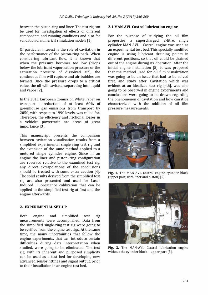
2.1 MAN-AVL Castrol lubrication engine For the purpose of studying the oil film properties, a supercharged, 2-litre, single cylinder MAN AVL - Castrol engine was used as an experimental test bed. This specially modified engine is using lubricant draining points in different positions, so that oil could be drained out of the engine during its operation. After the initial engine installation [5], it was proposed that the method used for oil film visualization was going to be an issue that had to be solved first, and study after. Cavitation which was evident at an idealized test rig [4,6], was also going to be observed in engine experiments and conclusions were going to be drawn regarding the phenomenon of cavitation and how can it be characterized with the addition of oil film pressure measurements.
Fig. 1. The MAN-AVL Castrol engine cylinder block (upper part, with liner and piston) [5].
Fig. 2. The MAN-AVL Castrol lubrication engine without the cylinder block – upper part [5].
P.S. Dellis, Tribology in Industry Vol. 39, No. 2 (2017) 260-269
262
(a)
(b)
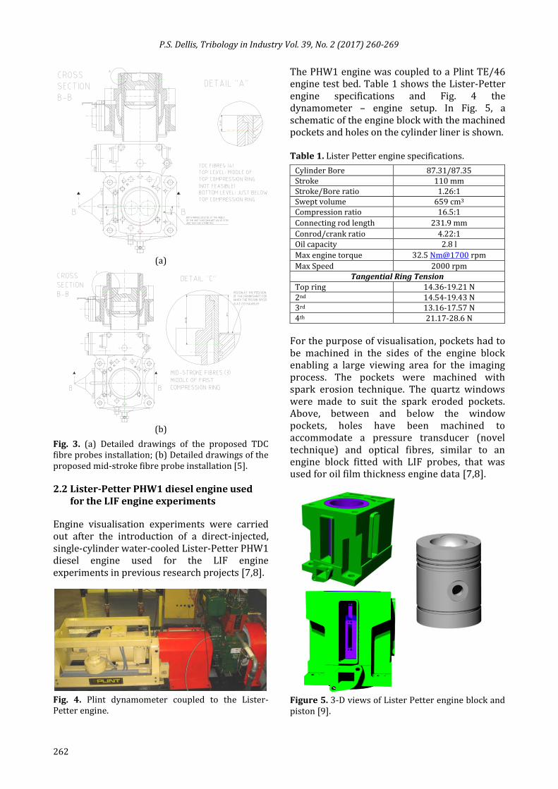
Fig. 3. (a) Detailed drawings of the proposed TDC fibre probes installation; (b) Detailed drawings of the proposed mid-stroke fibre probe installation [5].
2.2 Lister-Petter PHW1 diesel engine used
for the LIF engine experiments
Engine visualisation experiments were carried out after the introduction of a direct-injected, single-cylinder water-cooled Lister-Petter PHW1 diesel engine used for the LIF engine experiments in previous research projects [7,8].
Fig. 4. Plint dynamometer coupled to the Lister-Petter engine.
The PHW1 engine was coupled to a Plint TE/46 engine test bed. Table 1 shows the Lister-Petter engine specifications and Fig. 4 the dynamometer – engine setup. In Fig. 5, a schematic of the engine block with the machined pockets and holes on the cylinder liner is shown. Table 1. Lister Petter engine specifications.
Cylinder Bore 87.31/87.35 Stroke 110 mm Stroke/Bore ratio 1.26:1 Swept volume 659 cm3 Compression ratio 16.5:1
Connecting rod length 231.9 mm
Conrod/crank ratio 4.22:1 Oil capacity 2.8 l
Max engine torque 32.5 Nm@1700 rpm
Max Speed 2000 rpm Tangential Ring Tension
Top ring 14.36-19.21 N 2nd 14.54-19.43 N 3rd 13.16-17.57 N 4th 21.17-28.6 N
For the purpose of visualisation, pockets had to be machined in the sides of the engine block enabling a large viewing area for the imaging process. The pockets were machined with spark erosion technique. The quartz windows were made to suit the spark eroded pockets. Above, between and below the window pockets, holes have been machined to accommodate a pressure transducer (novel technique) and optical fibres, similar to an engine block fitted with LIF probes, that was used for oil film thickness engine data [7,8].
Figure 5. 3-D views of Lister Petter engine block and piston [9].
P.S. Dellis, Tribology in Industry Vol. 39, No. 2 (2017) 260-269
263
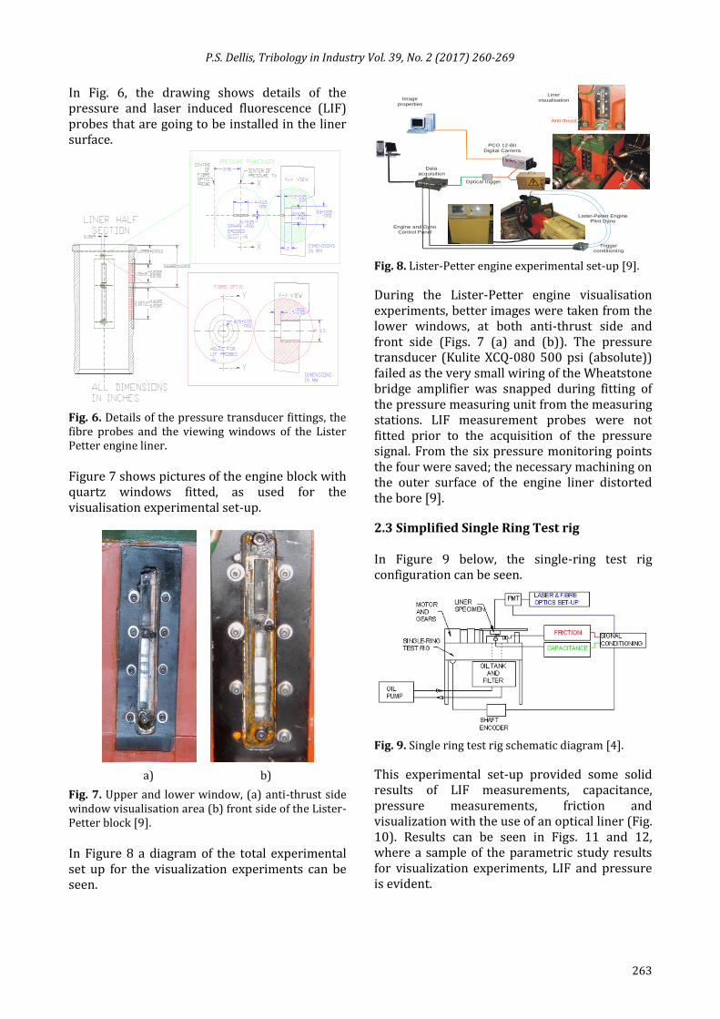
In Fig. 6, the drawing shows details of the pressure and laser induced fluorescence (LIF) probes that are going to be installed in the liner surface.
Fig. 6. Details of the pressure transducer fittings, the fibre probes and the viewing windows of the Lister Petter engine liner.
Figure 7 shows pictures of the engine block with quartz windows fitted, as used for the visualisation experimental set-up.
a) b)
Fig. 7. Upper and lower window, (a) anti-thrust side window visualisation area (b) front side of the Lister-Petter block [9].
In Figure 8 a diagram of the total experimental set up for the visualization experiments can be seen.
Fig. 8. Lister-Petter engine experimental set-up [9].
During the Lister-Petter engine visualisation experiments, better images were taken from the lower windows, at both anti-thrust side and front side (Figs. 7 (a) and (b)). The pressure transducer (Kulite XCQ-080 500 psi (absolute)) failed as the very small wiring of the Wheatstone bridge amplifier was snapped during fitting of the pressure measuring unit from the measuring stations. LIF measurement probes were not fitted prior to the acquisition of the pressure signal. From the six pressure monitoring points the four were saved; the necessary machining on the outer surface of the engine liner distorted the bore [9].
2.3 Simplified Single Ring Test rig
In Figure 9 below, the single-ring test rig configuration can be seen.
Fig. 9. Single ring test rig schematic diagram [4].
This experimental set-up provided some solid results of LIF measurements, capacitance, pressure measurements, friction and visualization with the use of an optical liner (Fig. 10). Results can be seen in Figs. 11 and 12, where a sample of the parametric study results for visualization experiments, LIF and pressure is evident.
Data acquisition
PCO 12-Bit Digital Camera
Image properties
Engine and Dyno Control Panel
Lister-Petter Engine Plint Dyno
Liner visualisation
Trigger conditioning
Optical trigger
Anti-thrust
P.S. Dellis, Tribology in Industry Vol. 39, No. 2 (2017) 260-269
264
a) b)
c)
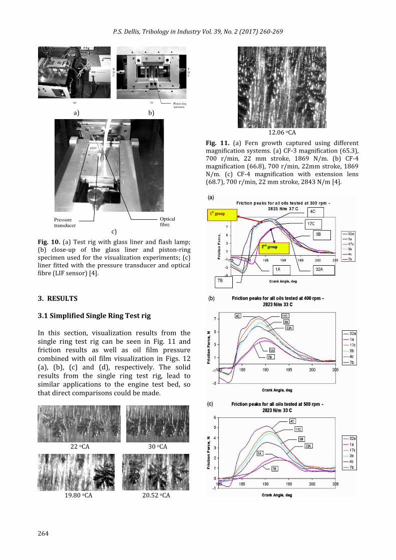
Fig. 10. (a) Test rig with glass liner and flash lamp; (b) close-up of the glass liner and piston-ring specimen used for the visualization experiments; (c) liner fitted with the pressure transducer and optical fibre (LIF sensor) [4].
3. RESULTS
3.1 Simplified Single Ring Test rig
In this section, visualization results from the single ring test rig can be seen in Fig. 11 and friction results as well as oil film pressure combined with oil film visualization in Figs. 12 (a), (b), (c) and (d), respectively. The solid results from the single ring test rig, lead to similar applications to the engine test bed, so that direct comparisons could be made.
22 oCA 30 oCA
19.80 oCA 20.52 oCA
12.06 oCA
Fig. 11. (a) Fern growth captured using different magnification systems. (a) CF-3 magnification (65.3), 700 r/min, 22 mm stroke, 1869 N/m. (b) CF-4 magnification (66.8), 700 r/min, 22mm stroke, 1869 N/m. (c) CF-4 magnification with extension lens (68.7), 700 r/min, 22 mm stroke, 2843 N/m [4].
P.S. Dellis, Tribology in Industry Vol. 39, No. 2 (2017) 260-269
265
Piston-ring width
Cavitatio
n
boundary
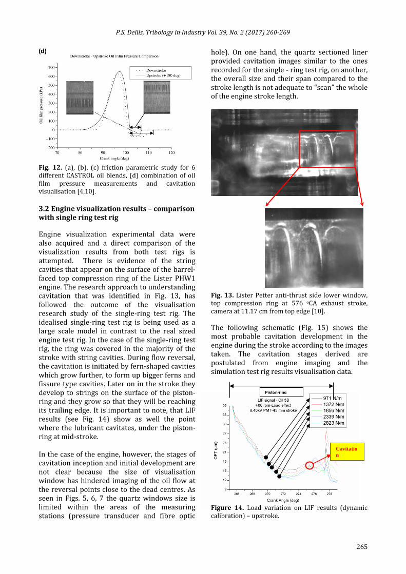
(d)
Fig. 12. (a), (b), (c) friction parametric study for 6 different CASTROL oil blends, (d) combination of oil film pressure measurements and cavitation visualisation [4,10].
3.2 Engine visualization results – comparison with single ring test rig
Engine visualization experimental data were also acquired and a direct comparison of the visualization results from both test rigs is attempted. There is evidence of the string cavities that appear on the surface of the barrel-faced top compression ring of the Lister PHW1 engine. The research approach to understanding cavitation that was identified in Fig. 13, has followed the outcome of the visualisation research study of the single-ring test rig. The idealised single-ring test rig is being used as a large scale model in contrast to the real sized engine test rig. In the case of the single-ring test rig, the ring was covered in the majority of the stroke with string cavities. During flow reversal, the cavitation is initiated by fern-shaped cavities which grow further, to form up bigger ferns and fissure type cavities. Later on in the stroke they develop to strings on the surface of the piston-ring and they grow so that they will be reaching its trailing edge. It is important to note, that LIF results (see Fig. 14) show as well the point where the lubricant cavitates, under the piston-ring at mid-stroke. In the case of the engine, however, the stages of cavitation inception and initial development are not clear because the size of visualisation window has hindered imaging of the oil flow at the reversal points close to the dead centres. As seen in Figs. 5, 6, 7 the quartz windows size is limited within the areas of the measuring stations (pressure transducer and fibre optic
hole). On one hand, the quartz sectioned liner provided cavitation images similar to the ones recorded for the single - ring test rig, on another, the overall size and their span compared to the stroke length is not adequate to “scan” the whole of the engine stroke length.
Fig. 13. Lister Petter anti-thrust side lower window, top compression ring at 576 oCA exhaust stroke, camera at 11.17 cm from top edge [10].
The following schematic (Fig. 15) shows the most probable cavitation development in the engine during the stroke according to the images taken. The cavitation stages derived are postulated from engine imaging and the simulation test rig results visualisation data.
Figure 14. Load variation on LIF results (dynamic calibration) – upstroke.
P.S. Dellis, Tribology in Industry Vol. 39, No. 2 (2017) 260-269
266
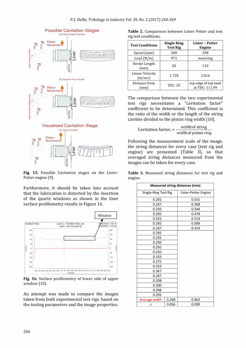
Fig. 15. Possible Cavitation stages on the Lister-Petter engine [9].
Furthermore, it should be taken into account that the lubrication is distorted by the insertion of the quartz windows as shown in the liner surface profilometry results in Figure 16.
Fig. 16. Surface profilometry of lower side of upper window [10].
An attempt was made to compare the images taken from both experimental test rigs, based on the testing parameters and the image properties.
Table 2. Comparison between Lister Petter and test rig test conditions.
Test Conditions Single Ring
Test Rig Lister – Petter
Engine
Speed (rpm) 300 398
Load (N/m) 971 motoring
Stroke Length (mm)
50 110
Linear Velocity (m/sec)
1.728 2.016
Distance from (mm)
TDC: 25 top edge of top land
at TDC: 111.99
The comparison between the two experimental test rigs necessitates a “cavitation factor” coefficient to be determined. This coefficient is the ratio of the width or the length of the string cavities divided to the piston ring width [10].
Cavitation factori = ring piston of width
string of width
Following the measurement scale of the image, the string distances for every case (test rig and engine) are presented (Table 3), so that averaged string distances measured from the images can be taken for every case. Table 3. Measured string distances for test rig and engine.
Measured string distances (mm)
Single-Ring Test Rig Lister-Petter Engine
0.292 0.531
0.167 0.368
0.250 0.344
0.292 0.478
0.333 0.514
0.292 0.589
0.167 0.414
0.292
0.292
0.250
0.292
0.250
0.333
0.275
0.333
0.367
0.267
0.208
0.200
0.208
0.292
Average width 0.268 0.463
σ 0.056 0.090
Window

P.S. Dellis, Tribology in Industry Vol. 39, No. 2 (2017) 260-269
267
Cavitation factors CF calculated for the engine CFengine = 0.194 and respectively for the test rig CFtest rig = 0.054. CFengine is 72.16 % greater than CFtest rig. In the case of the single ring test rig, the strings are covering approximately 50 % of the piston ring length and have a very uniform shape, due to the limited factors affecting the lubrication of the single ring test rig [10]. 3.3 LIF Calibration The identification of cavitation, which was first evident during the LIF experiments and further on identified in the visualization experiments in both the simplified test rig and the engine, imposed the necessity of calibrating the LIF results in order to get a complete picture of the oil film thickness and the point where the oil film breaks. The process of calibrating the LIF signal is described in [11], where the single-ring test rig is used again as a safe method to acquire the results from LIF and surface profilometry of a specially machined groove on the surface of the piston-ring specimen.
Groove data were acquired at the area where the fitted fiber on the liner specimen travels. Since the stylus of the profilometer was acquiring data for the groove every 10 μm of groove length, five (5) profiles in sequence have been averaged to get the averaged data that were going to be compared to the LIF signal (the diameter of the fiber core is 50 μm). Eventually the area of the groove over which the fiber travels was covered in the best way possible.
Figure 17 shows the fibre travelling over the groove of known depth used for the LIF calibration [11] and in Figure 18 the LIF grove data are matched to the groove surface profilometry results.
Figure 17. The groove with the blue - highlighted line shows the area over which the optical fiber travels [11].
Figure 18. Matching of groove data and averaged LIF data [11].
It is evident, that this specially machined piston-ring can be used for LIF calibration of the engine experiments. As it was stated before, from the MAN-AVL engine lubricant stations, used lubricant can be extracted and when poured into the single-ring test rig, it can be used for the calculation of a calibration coefficient as described above. This coefficient can calibrate the LIF data derived from the engine and this time a more accurate calibration coefficient can be derived because the oil used for the calculation of the coefficient and the oil used in the engine experiments is exactly the same (meaning that its chemical composition has been degraded to the same extent). This is very important because the chemistry of the lubricant is a factor that alters its fluorescence properties and according to this procedure it is taken into account when calibration is attempted. As already stated, LIF results from the single-ring test rig showed, at first, the point where the lubricant cavitated (oil film rupture shown in Fig. 14). In Table 4, calibration coefficients are derived, and data are given for a specific Castrol lubricant blend, at four different temperatures [11].
Table 4. Temperature results for the calibration coefficients [11].
Oil Temperature (oC) 38 50 60 70
Calibration Coefficient (μm/Volt)
295 364 353 389
Standard Deviation (μm/Volts)
14 26.9 21 55.37
Error (%) 5 7 6 14
P.S. Dellis, Tribology in Industry Vol. 39, No. 2 (2017) 260-269
268
4. CONCLUSIONS
The single-ring test rig is a tool that provides robust results in terms of lubricant film thickness, LIF, oil film pressure, friction measurements, and visualization – cavitation results. It is therefore, important to study and test whichever experimental method used, first at the test rig and afterwards in the engine test bed. The test rig results improve the researcher’s confidence in experimental testing, thus minimizing the risk when applying the same method in engine experiments. Another supporting factor is that the experimental results can be interpreted in a much safer and easier manner. The engine experiments are inherited with many uncertainties, which will be further enhanced from cycle to cycle inconsistencies. Even without the engine application, the single ring test rig results can strongly support parametric study of different lubricants, different piston-ring curvature and its effect on oil film pressure and even so friction results throughout the stroke and study the different lubrication regimes (hydrodynamic, elastohydrodynamic, boundary and mixed) with the inclusion of the parametric study, that is mentioned above. It is therefore a necessity to simulate realistic engine speed and strokes, so that the results are as close as possible to a real engine. The usefulness of the single ring test rig is easily recognizable from:
the identification of cavitation in the LIF results,
the successful implementation of the optical liner to acquire lubricant cavitation images and the miniature pressure transducer for the oil film pressure results prior to applying the same method to an engine and
the proximity of the LIF calibration testing (low rpm and no hydrodynamic film) and the recognition of the many parameters that affect the derivation of a solid lubricant calibration coefficient.
Acknowledgement
The participation of the author in this study was made possible by a scholarship from the Greek State Scholarship Foundation (S.S.F). The
lubrication project is part of an on-going project first at Imperial College, Thermofluids Section, Internal Combustion Engines Laboratory and then at CITY University, London, Research Center for Energy and the Environment, funded by CASTROL/BP, which provided the lubricants. Many thanks are due to Professor C. Arcoumanis, (FREng, City University, London), supervisor of the project. The author gratefully acknowledges these contributions.
REFERENCES [1] M. Söderfjäll, A. Almqvist and R. Larsson,
'Component test for simulation of piston ring – Cylinder liner friction at realistic speeds', Tribology International, vol. 104, pp. 57-63, 2016.
[2] A. Almqvist and P. Wall, 'Modelling cavitation in (elasto)hydrodynamic lubrication', in Pranav H. Darji (Ed.): Advances in tribology doi:10.5772/63533, INTECH, pp. 197-213, 2016.
[3] A. Spencer, 'A Simulation Tool for Optimising Combustion Engine Cylinder Liner Surface Texture', PhD thesis, Department of Engineering Sciences and Mathematics, Lulea University of Technology, Lulea, 2013.
[4] P. Dellis and C. Arcoumanis, 'Cavitation development in the lubricant film of the piston-ring assembly', Proc. IMechE, Part J: J. Engineering Tribology, 218, pp. 157–171, DOI: 10.1243/1350650041323340, 2004.
[5] P. Dellis, 'Piston ring lubrication and its link to exhaust particulates emissions in internal combustion engines', MPhil to PhD transfer report, Department of Mechanical Engineering, Imperial College of Science, Technology and Medicine, London, 2000.
[6] C. Arcoumanis, M. Duszynski, H. Flora and P. Ostovar, Development of a piston-ring lubrication test-rig and investigation of boundary conditions for modelling lubricant film purposes, SAE Technical Paper 952468, 1995.
[7] M. Duszynski, 'Measurement of Lubricant Film Thickness in Reciprocating Engines', PhD thesis, Imperial College of Science, Technology and Medicine, London, 1999.
[8] E.A. Pyke, 'Investigation of Piston Ring Lubrication Using Laser Induced Fluorescence', PhD thesis, Imperial College of Science, Technology and Medicine, London, 2000.

P.S. Dellis, Tribology in Industry Vol. 39, No. 2 (2017) 260-269
269
[9] P. Dellis and C. Arcoumanis, 'Measurements of lubricant film thickness in reciprocating piston cylinder assemblies and engines', in Journal of Physics, Conference Series, vol. 45, pp. 161-161, 2006.
[10] P. Dellis, 'Aspects of lubrication in piston cylinder assemblies', PhD thesis, Imperial College
London, Department of Mechanical Engineering, London, 2005.
[11] P. Dellis, 'An Attempt to Calibrate the Laser Induced Fluorescence (LIF) Signal used for Oil Film Thickness (OFT) Measurements in Simulating Test Rigs', Tribology in Industry, vol. 38, no. 4, pp. 525-538, 2015.

P.S. Dellis, Tribology in Industry Vol. 39, No. 2 (2017) 260-269
2