Embed Size (px)
Citation preview

TRIBOLOGICAL STUDIES OF LASER TEXTURED
TOOL INSERTS IN TURNING PROCESS
A dissertation
Submitted in partial fulfilment of the requirements for the
award of the degree
of
BACHELOR OF TECHNOLOGY
in
MECHANICAL ENGINEERING
Submitted By
P. Deepak Kumar (1209540038)
Ashish Bhatt (1209540012)
Prashant Kumar Rajput (1209540043)
Under the supervision of
Mr. Umesh Yadav
Assistant Professor
Department Of Mechanical Engineering
Mahatma Gandhi Mission’s College of Engineering and Technology
Affiliated to Dr. A.P.J. Abdul Kalam Technical University, Lucknow
April, 2016

ii
CERTIFICATE
This is to certify that Project Report entitled “Tribological Studies of Laser Textured
Tool Inserts in Turning Operation” which is submitted by P. Deepak Kumar, Prashant
Kumar Rajput and Ashish Bhatt in partial fulfilment of the requirement for the award of
degree Bachelor of Technology in Department of Mechanical Engineering of Dr. A.P.J.
Abdul Kalam Technical University, Lucknow is a record of the candidates own work
carried out by them under my supervision. The matter embodied in this thesis is original
and has not been submitted for the award of any other degree.
Supervisor Project Coordinator HOD
External Viva
Name of Examiner Signature with date

iii
DECLARATION
I hereby declare that this submission is my own work and that, to the best of my
knowledge and belief, it contains no material previously published or written by another
person nor material which to a substantial extent has been accepted for the award of any
other degree or diploma of the university or other institute of higher learning, except where
due acknowledgment has been made in the text.
Signature: Signature:
Name : P. Deepak Kumar Name : Ashish Bhatt
Roll No. : 1209540038 Roll No. : 1209540012
Date : /04/2016 Date : /04/2016 Signature:
Name : Prashant Kumar Rajput
Roll No. : 1209540043
Date : /04/2016

iv
ACKNOWLEDGEMENT It gives us a great sense of pleasure to present the report of the Bachelor of Technology
Project undertaken during the final year. We owe special debt of gratitude to Assistant
Professor Mr. Umesh Yadav, Department of Mechanical Engineering, Mahatma Gandhi
Missions College of Engineering and Technology affiliated to Dr. A.P.J. Abdul Kalam
University, Lucknow for his constant support and guidance throughout the course of our
work. His sincerity, thoroughness and perseverance have been a constant source of
inspiration for us.
We also do not like to miss the opportunity to acknowledge the contribution of all teaching
and non-teaching staff of the Department for their kind assistance and cooperation during
the development of our project. We also acknowledge our friends for their contribution,
continuous support and encouragement in the completion of the project.
Signature: Signature:
Name : P. Deepak Kumar Name : Ashish Bhatt
Roll No. : 1209540038 Roll No. : 1209540012
Date : /04/2016 Date : /04/2016 Signature:
Name : Prashant Kumar Rajput
Roll No. : 1209540043
Date : /04/2016
v
ABSTRACT
Metal forming and machining processes are used for converting the raw materials into the products in the
industries. During these processes large amount is energy is consumed in the form of friction energy. In
order to conserve this energy and prevent wear of tools, there is a need of green manufacturing. In this
project work, an attempt has been made in order to increase the tool life and conserve energy. The
comparative study has been done by taking conventional tungsten carbide tool inserts and textured tungsten
carbide tool inserts. Turning process has been done on mild steel rod (C-20) with these carbide tool inserts
at various parameters like spindle speed, depth of cut and feed rate.
Keywords: Laser texture, friction, wears, dry condition and conventional tool insert

vi
CONTENT
Page No.
Certificate ii
Declaration iii
Acknowledgements iv
Abstract v
Content vi
List of Figures v
List of Tables vii
Chapter-1 Introduction 1
1.1 Introduction 1
1.2 Types of cutting tool 2
1.3 Material of cutting tool 2
1.4 Tool geometry 4
Chapter-2 Literature Review and Problem Definition 7
2.1 Literature Review 7
2.2 Motivation 8
2.3 Objective of Study 9
Chapter-3 Methodology 10
3.1 Block diagram of work process 11
Chapter-4 Experimental Setup 12
4.1 Equipment’s 12
4.1.1 Lathe machine 12
4.1.2 Non-contact thermometer 13
4.1.3 Tungsten carbide tool insert 13

vii
4.1.4 Tool holder 14
4.1.5 Workpiece 14
4.1.6 Fiber laser machine 15
4.1.7 Lapping machine 16
4.1.8 Confocal microscopy machine 17
4.2 Procedure of the experiment 17
Chapter-5 Result and Discussions 18
5.1 Result of temperature rise 20
5.2 Confocal microscopic image of conventional and textured tool inserts 24
5.3 Wear behaviour of tool inserts 27
Chapter-6 Conclusions and Scope for Future work 33
6.1 Conclusions 33
6.2 Scope for future work 33
Gantt chart 34
References 35

viii
LIST OF FIGURES
FIG. NO. DETAIL PAGE NO.
1.1 Rake and clearance angle of cutting tools (http://doubtpoint.com) 4
1.2 Basic features of single point in turning operation
(www.slideshare.net) 5
1.3 Planes and axes of reference in ASA system (www.nitc.ac.in) 6
4.1 Pioneer-175 lathe machine 12
4.2 Non-contact thermometer of Work Zome 13
4.3 Carbide tool inserts 14
4.4 Tool holder 14
4.5 Mild steel rod and turning has been done up to 12.5 cm 15
4.6 Fiber laser machine 16
4.7 Lapping machine 16
4.8 Confocal microscopy machine 17
5.1 Variation of temperature with spindle speed at 0.12 mm
depth of cut and 0.4 mm/rev feed rate 20
5.2 Variation of temperature with spindle speed at 0.12 mm
depth of cut and 1.6 mm/rev feed rate 21
5.3 Variation of temperature with spindle speed at 0.16 mm
depth of cut and 0.4 mm/rev feed rate 21
5.4 Variation of temperature with spindle speed at 0.16 mm
depth of cut and 1.6 mm/rev feed rate 22
5.5 Variation of temperature with spindle speed at 0.20 mm
depth of cut and 0.4 mm/rev feed rate 23
5.6 Variation of temperature with spindle speed at 0.20 mm
depth of cut and 1.6 mm/rev feed rate 23
5.7 Confocal microscopic image of conventional and textured
tool insert after turning operation at 315 rpm, 0.12 mm
depth of cut and 0.4 mm/rev feed rate 24
5.8 Confocal microscopic image of conventional and textured
tool insert after turning operation at 500 rpm, 0.12 mm

ix
depth of cut and 0.8 mm/s feed rate 24
5.9 Confocal microscopic image of conventional and textured
tool insert after turning operation at 775 rpm, 0.12 mm
depth of cut and 1.6 mm/s feed rate 25
5.10 Confocal microscopic image of conventional and textured
tool insert after turning operation at 500 rpm, 0.16 mm
depth of cut and 0.8 mm/s feed rate 25
5.11 Confocal microscopic image of conventional and textured
tool insert after turning operation at 775 rpm, 0.16 mm
depth of cut and 1.6 mm/s feed rate 26
5.12 Confocal microscopic image of conventional and textured
tool insert after turning operation at 500 rpm, 0.2 mm
depth of cut and 0.8 mm/s feed rate 26
5.13 Wear of conventional tool inserts at various rpm, feed rate
and at 0.12 mm depth of cut 27
5.14 Wear of conventional tool inserts at various rpm, feed rate
and at 0.16 mm depth of cut 28
5.15 Wear of conventional tool inserts at various rpm, feed rate
and at 0.2 mm depth of cut 29
5.16 Wear of textured tool inserts at various rpm, feed rate and
at 0.12 mm depth of cut 30
5.17 Wear of textured tool inserts at various rpm, feed rate and
at 0.16 mm depth of cut 31
5.18 Wear of textured tool inserts at various rpm, feed rate and
at 0.2 mm depth of cut 32

x
LIST OF TABLES
TABLE NO. DETAIL PAGE NO.
1.1 Tool insert material with their properties 3
4.1 Parameters of fiber laser machine for texturing 15
5.1 Result obtained after the experiment 18

1
CHAPTER 1
INTRODUCTION
1.1 Introduction
Manufacturing is a very important component of any engineering realization. It involves
providing the different shapes, sizes and cross sections to the components of the
products/systems. It is worth noting that high percentage of GDP of many nations comes
from the manufacturing sector. Manufacturing sector also provides maximum jobs to the
people. This is also one of the reasons for launching the “Make in India” programme by
our prime minister in 2014. For large scale manufacturing in any country, there is a
requirement for efficient and quality machining for its sustainability. Thus, there is need for
in-depth research in manufacturing processes for making it more energy efficient with
better finished quality. It is worth noting here that setting up of large manufacturing
industries for boosting the GDP and providing the employment can harm the nature
through its emissions and effluent disposals. Thus a need arises for development of energy
efficient green manufacturing for protecting the environment. However the increasing
price of energy and the current trend of sustainability have created thrust on the
manufacturing sector for reducing the energy consumption keeping in the mind both cost
saving and environmental issues. Therefore in the current scenario, the objectives of
manufacturing are to reduce the cost, time, and energy consumption without sacrificing the
quality of products. Thus, there is a need for sustainable manufacturing, which involves
environmental, economic and social issues. The sustainable manufacturing is also termed
as “green manufacturing”. It must be noted here that there is growing demand in industries
for green manufacturing strategies due to depletion of natural resources that is causing the
rise of cost of raw materials and energy involved. In order to achieve a better energy
efficiency associated with a manufacturing process, the tribological studies at the tool ( or
tool insert) and work piece interface are essential for exploring the improvement of tool (or
tool insert) life (low wear) and reduction of friction (which is reflected in terms of
reduction in temperature rise). It is worth mentioning here that the surface modifications of
tool insert by heat treatment, profiling, and texturing, are being used for improving the
tribological performances at the insert and work piece interface. Therefore, it is worth
exploring the turning process of carbon steels for assessing, improving and comparing the

2
tribological performance behaviours at the tool insert and work piece interface with
conventional and textured tool inserts. It is essential to mention here that the combination
of turning operation (manufacturing) and carbon steel work piece is proposed for
investigation due to their extensive use in industries.
1.2 Types of Cutting tool
Cutting tools have been used in metal machine shops since the late 19th
century and
manufacturers are continuing to evolve these mechanisms to become more efficient within
the industry. Cutting tools come into contact with the raw material, cutes, removes debris
and chips from the material. Cutting tools may be classified according to the number of
major cutting edges involved as follows:
Single point: e.g., turning tools, shaping, planning and slotting tools and boring tools
Double (two) point: e.g., drills
Multipoint (more than two): e.g., milling cutters, broaching tools, hobs, gear shaping
cutters etc.
1.3 Material of Cutting tool
To produce quality product, a cutting tool must have three characteristics:
Hardness: hardness and strength at high temperatures.
Toughness: so that tools do not fracture.
Wear resistance: having acceptable tool life before needing to be replaced.
Cutting tool materials can be divided into two main categories: stable and unstable.
Unstable materials are substances that start at a relatively low hardness point and are then
heat treated to promote the growth of hard particles which increases the overall hardness of
the material at the expense of some its original toughness. Since heat is the mechanism to
alter the structure of the substance and at the same time the cutting action produces a lot of
heats, such substances are inherently unstable under machining conditions.
Stable materials are substances that remain relatively stable under the heat produced by
most machining conditions, as they don't attain their hardness through heat. They wear
3
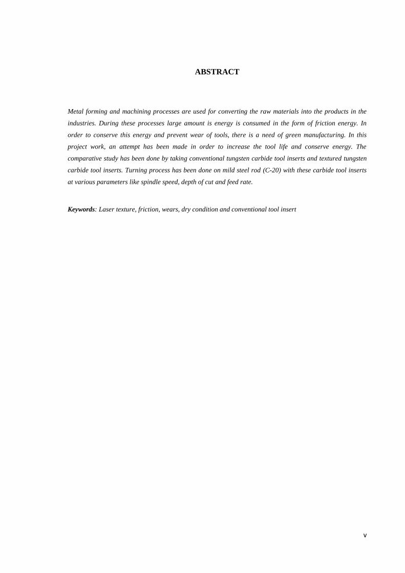
down due to abrasion, but generally don't change their properties much during use. Most
stable materials are hard enough to break before flexing, which makes them very fragile.
Unstable materials being softer and tough can stand a bit of flexing without breaking,
which makes them much more suitable for unfavourable machining conditions.
Table 1.1 Tool insert material with their properties
Tool
material Properties
Carbon tool
steels
It is unstable and also not very inexpensive. These are extremely sensitive
to heat.
High speed
steel (HSS)
These are unstable and inexpensive. HSS retains its hardness at moderate
temperatures. They are most commonly cutting tool material used today.
HSS cobalt
These are unstable and moderately expensive. The high cobalt versions of
high speed steel are very resistant to heat and thus excellent for machining
abrasive and/or work hardening materials such as titanium and stainless
steel.
Cast cobalt
alloys
It is stable, expensive and somewhat fragile material. Despite its stability
it doesn't allow for high machining speed due to low hardness.
Cemented
carbide
It is stable and moderately expensive material. It is the most common
material used in the industry today.
Ceramics
Ceramics are stable and not very expensive. These are chemically inert
and extremely resistant to heat, ceramics are usually desirable in high
speed applications, the only drawback being their high fragility. The most
common ceramic materials are based on alumina (aluminium oxide),
silicon nitride and silicon carbide.
Cermets This is stable and expensive material. It provides higher abrasion
resistance compared to tungsten carbide at the expense of some toughness.
Cubic boron
nitride
(CBN)
CBN is stable and expensive tool material. It offers extremely high
resistance to abrasion at the expense of much toughness. It is generally
used for hard machining.

4
Diamond
It is most stable and very expensive tool material. Superior resistance to
abrasion but also high chemical affinity to iron which results in being
unsuitable for steel machining. It is used where abrasive materials would
wear anything else. It is extremely fragile.
1.4 Tool Geometry
Material and geometry of the cutting tools are important in achieving effectiveness,
efficiency and overall economy of machining.
(i) Concept of rake angle and clearance angle of cutting tool
The word tool geometry is basically referred to some specific angles or slope of the salient
faces and edges of the tools at their cutting point. Rake angle and clearance angle are the
most significant for all the cutting tools. The rake angle and clearance angle will be clear
from turning operation shown in Fig. 1.1.
Fig. 1.1 Rake and clearance angle of cutting tools (www.doubtpoint.com)
• Rake angle (γ): Angle of inclination of rake surface from reference plane. Rake angle may
be positive, or negative or even zero. Relative advantages of such rake angles are:
• Positive rake – helps reduce cutting force and thus cutting power requirement.
• Negative rake – to increase edge-strength and life of the tool
• Zero rake – to simplify design and manufacture of the form tools.
• Clearance angle (α): Angle of inclination of clearance or flank surface from the finished
surface Rake angle is provided for ease of chip flow and overall machining. Clearance

5
angle is provided to avoid rubbing of the tool (flank) with the machined surface which
causes loss of energy and damages both the tool and the job surface.
(ii) Tool geometry systems
• Tool-in-Hand System – where only the salient features of the cutting tool point are
identified or visualized. There is no quantitative information, i.e., value of the angles.
• Machine Reference System – ASA system
• Tool Reference Systems ∗ Orthogonal Rake System – ORS ∗ Normal Rake System – NRS
• Work Reference System – WRS
(iii) Expression of tool geometry in ASA system:
ASA stands for American Standards Association. Geometry of a cutting tool is related to
its angles or slope of working surfaces and cutting edges. Those angles are expressed with
respect to some planes of reference. In ASA system, three planes of reference and the
coordinates are chosen based on the configuration and axes of the machine tool. The planes
and axes used for expressing tool geometry in ASA system for turning operation are shown
in Fig. 1.2.
Fig. 1.2 Basic features of single point in turning operation (www.slideshare.net)

6
Fig. 1.3 Planes and axes of reference in ASA system (www.nitc.ac.in)
The plane of references and the coordinates used in ASA system for tool geometry are:
πR - πX - πY and Xm – Ym - Zm
Where,
πR= Reference plane; plane perpendicular to the velocity vector (shown in Fig. 1.3)
πX= Machine longitudinal plane; plane perpendicular to πR and taken in the direction of
assumed longitudinal feed
πY= Machine Transverse plane; plane perpendicular to both πR and πX

7
CHAPTER 2
LITERATURE REVIEW AND PROBLEM DEFINITION
2.1 Literature review
Metal forming and machining processes are used for converting the raw materials into the
products in the industries. It is worth mentioning here that 15-20% of gross domestic
product (GDP) of industrialised nations comes from the manufacturing sector. Moreover, it
is essential to mention here that one third (about 33%) of all the energy consumed in the
industries including the energy consumed in the manufacturing processes (forming and
machining) goes to overcome the friction. It is worth noting here that high friction yields
an energy inefficient industrial process. Therefore, reducing the friction in industrial
processes is one of the major challenges toward the attempt to reach a sustainable society
with low energy consumption and reduced environmental consequences. Thus, great
efforts are being made by the researchers across the globe to explore and develop the
friction reduction techniques in every step of the industrial processes where friction
presence is not desirable. Due to global warming and resource conservation issues, now
great efforts are being made by the engineers/scientists to implement the concept of “Green
manufacturing”, which mainly involves low friction, reduced wear, and minimum energy
consumption. Therefore moving ahead in the direction of green manufacturing, in this
project it is planned to explore the possibilities of friction and wear reduction of tool
inserts in the turning process of metals without compromising the surface quality of the
machined product. It has been proposed herein to improve the tribological performance of
tool inserts by mimicking the textures present on the biological surfaces (banana leaf and
scorpion skin) over the insert surface. Literature survey in the field of proposed research
title has been carried out in the paragraphs to come for understanding the current status of
the research and accordingly setting the objectives for study.
In the past, many attempts have been made by the researchers [1-18] for investigating and
improving the tribo-performance behaviours involved in the turning process for extending
the tool life and improving the surface quality of machined work piece efficiently. Good
surface finish is an essential requirement in a machining process, which is very sensitive to
the form accuracy of the tool. It is worth noting here that due to the rapid wear of tool (due

8
to poor lubrication and lack of cooling at the tool and work piece interface); the quality of
surface finish deteriorates. Grzesik [1] has tried in his research work to quantify the
surface finish on the turned hardened alloy steel parts in terms of cutting time (leading to
tool wear) produced by differently shaped ceramic tool tips. To supress the adhesion
during the milling of aluminium alloy at the cutter face, nano/micro textured surfaces of
cutter promoted anti-adhesiveness features as said by Sugihara et al [2-3] in his work. For
improving the turning process on lathe machine, Enomoto et al [6] have used textured
WC/Co carbide tools filled with MoS2 solid lubricants on the rake-face close to the main
cutting edge of the tool. Turning operations were performed in dry conditions using the
rake-face textured tools and conventional one. It has been reported by the authors that the
cutting performance of the rake-face textured tools is significantly improved over that of
the conventional one. The studies related to turning of AISI 52100 bearing steel with CBN
tool has been reported by Jianxin et al [7]. The combined effects of process parameters
(cutting speed, feed rate, depth of cut and cutting time) on the performance characteristics
(tool wear, surface roughness, cutting forces and metal volume removed) are investigated
by the authors [7] using ANOVA analysis. The relationship between process parameters
and performance characteristics through the response surface methodology (RSM) are
modelled. The results show that the cutting speed exhibits maximum influence on abrasive
tool wear. The depth of cut affects strongly the cutting forces; however, it has a negligible
influence on surface roughness. The cutting time has a considerable effect on all
performance characteristics. The power consumption and roughness characteristics of
surface generated in turning operation of EN-31 alloy steel (bearing steel) with
TiN+Al2O3+TiCN coated tungsten carbide tool under different cutting parameters have
been assessed by experimental work of Neves et al [8]. The study investigated the
influences of the spindle speed, depth of cut and feed rate on surface roughness as well as
power consumption. The study presents the results for five different spindle speeds (in the
range of 700 -1200 rpm) keeping feed rate between 0.4 mm/s to 1.6 mm/s and depth of cut
between 0.12 mm to 0.20 mm.

9
2.2 Motivation
Based on the literature review, it is noticed that there is dearth of research work carried out
in turning process for improving the machining efficiency, insert life, and surface quality
by employing the biological textures, which nature has created through passes of time for
drag reductions.
2.3 Objectives of the study
Based on the literature review, the following objectives for study in the project have been
set:
Tribological (wear by loss of weight and geometric dimension and temperature rise)
studies of conventional tool inserts employed in the turning process of carbon steel (C-
20) at various operating parameters (depth of cut, feed rate, spindle speed) for dry
condition.
Tribological (wear by loss of weight and geometric dimension and temperature rise)
studies of textured (with biological surface patterns) tool inserts employed in the
turning process of carbon steel (C-20) at various operating parameters (depth of cut,
feed rate, spindle speed) for dry condition.
Comparisons of tribological parameters achieved with conventional and textured
inserts.

10
CHAPTER 3
METHODOLOGY
To accomplish the objectives of the project, the following steps have been planned for the
investigation:
Identification of lathe machine and work piece material (C-20) for conducting the
experiments as turning process.
Selection of tool insert material (Carbon carbide) for employing in the turning of carbon
steel (C-20) material.
Operating parameters in turning process: Three different spindle speeds (in the range of
300 -1200 rpm), three feed rates (0.12 and 0.20 mm/s), four depth of cuts (0.4 and 1.6
mm), dry condition machining
Understanding the 2-D and 3-D topographies of scorpion skin, scanning electron
microscope (SEM) for copying the biological textures on the tool inserts using fiber
laser textures.
Lapping of tool inserts for cleaning the surface and taking scanning electron
microscopic image of that textured insert surface.
Wear investigation: by measuring/assessing the weight, physical dimensions, confocal
microscopic image of tool inserts before and after the turning operations of C-20
material.
Friction investigation: Due to unavailability of dynamometer with the lathe machine on
which experiments have been planned, it is thought to measure the temperature rise at
the interface of tool insert and work piece using non-contacting thermometer. Less
temperature will indicate low presence of friction at the interface during the turning
process.

11
3.1 Block Diagram of work process
Literature Review Determination of
Objectives Market survey of
materials
Material selection of tool insert and
workpiece
Selection of operation to be
performed
Composition testing of tool
insert and workpiece
Selection of parameters to be
varied
Laser texturing of tool insert susing
fiber laser
Physical dimensions and weight of tool
inserts
Environmental Temperature
Turning Operation
Temperature rise during the operation
Physical dimensions and
weight loss of tool inserts
Confocal microscopic image of both type of tool inserts before and
after experiment
Tabulation of result
Conclusions

12
CHAPTER 4
EXPERIMENTAL SETUP
In the beginning of this experiment the equipment’s that are required for successfully
completing the project are discussed in this chapter. The experimental setup for the
conduction of this experiment includes lathe machine, non-contact thermometer, tool
holder, tool inserts (Tungsten carbide tool insert), work piece (mild steel rod C-20),
weighing machine, confocal microscopy machine, lapping machine and fiber laser
machine.
4.1 Equipment’s
4.1.1 Lathe Machine
Pioneer-175 lathe machine (shown in fig.4.1) was identified for turning operation. This
machine has speed variation from 54 rpm to 1200 rpm, with least feed rate as 0.2 mm/rev
and least depth of cut as 0.04 mm.
Fig.4.1 Pioneer-175 lathe machine

13
4.1.2 Non-Contact Thermometer
The non-contact thermometer of Work Zome (as shown in fig. 4.2) is used for measuring
the temperature rise (first measuring the temperature of the tool insert tip before the
turning operation and then after the turning operation). The temperature range of this
thermometer is from -50oC to 1100
oC. The validation of this equipment has been done.
The temperature shown by this thermometer is 2oC more than the actual temperature. So
the temperature has been noted by taking this error in consideration.
Fig.4.2 Non-Contact thermometer of Work Zome
4.1.3 Tungsten carbide tool insert
The carbide tool inserts which are shown in fig.4.3 are used for the turning operation are
triangular in shape. The dimensions of the tool inserts have been noted down along with
the weight of each carbide tool insert. The dimensions are measured using Vernier calliper
and protector. The length of tool insert is 15.148 mm and width is 6.128 mm. The angle
formed by sides of tool insert is 60o. The rake angle is 0
o during turning operation.

14
Fig. 4.3 Carbide tool inserts
4.1.4 Tool Holder
Tool holder shown in fig.4.4 is used for holding the tool inserts. This tool holder is
mounted on the tool post of the lathe machine. Tool holder is made of cast iron as it has
high compressive strength. The length of tool holder which is outside the tool post also
contributes in force which acts on the workpiece. Same length of tool holder is outside the
tool post so that same force is applied on every workpiece.
Fig.4.4 Tool holder
4.1.5 Workpiece
Mild steel rod (C-20) is used as workpiece which around 20 cm in length. The turning has
been done up to 12.5 cm in the length as shown in fig.4.5.

15
Fig.4.5 Mild steel rod and turning has been done up to 12.5 cm
4.1.6 Fiber laser machine
The texturing of the specified dimensions on the surface of tungsten carbide tool insert has
been done from Noida (Uttar Pradesh). For this project work, fiber laser (shown in fig.4.6)
was used to generate the texture and the parameters are given in table 4.1.
Preliminary trials were performed to correlate the laser parameters like frequency of laser
pulse, power of laser, scanning speed, and distance between two grooves. Varying these
parameters allows optimization of the dimensions and the quality of shape produced.
Table 4.1 Parameters of Fiber Laser Machine for Texturing
S. No. LASER Parameters Values
1. Crystal used for LASER Nd:YAG
(Neodymium: Yttrium-Aluminium-Garnet)
2. Laser Power (W) 20
3. Wavelength (nm) 1064
4. Pulse Frequency (kHz) 2
5. Distance between two grooves (mm) 0.2
6. Scanning speed (mm/s) 5

16
Fig. 4.6 Fiber laser cutting machine
4.1.7 Lapping machine
The laser texturing was done on the surface of tool insert. Lapping machine (as shown in
fig.4.7) is used to do lapping operation on the tool surface to clean it from the particles of
the tool material which are there on the surface after the texturing. Lapping machine is
similar to polishing machine. First the diamond paste is applied on the surface to be
cleaned and then surface is kept on the rotating disc. The disc rotates and removes the dirt
particles.
Fig.4.7 EFCO Lapping machine

17
4.1.8 Confocal Microscopy Machine
Confocal microscopy machine is based on optical imaging technique which is used to
increase optical resolution and contrast. It eliminates the out of focus light by using spatial
pinhole placed at confocal plane of the lens. It reconstructs the 3-D structures from the
obtained images.
Fig.4.8 Confocal microscopy machine
4.2 Procedure of the experiment
The experiment was performed by a sequence of steps.
1. First the dimension and weight of the tool inserts are taken before the experiment.
2. We mount the rod in chuck of lathe machine and mount the tool holder on tool post.
3. The tool insert is mounted on tool holder and the temperature at the tip of tool insert is
measured and noted down.
4. The parameters are set on the lathe machine and turning operation is performed. The
turning operation is performed 15 times for both textured tool insert and conventional
tool insert but the temperature is taken when first turning operation is performed.
5. After the turning process the temperature at the tip of the tool insert is measured.
6. Same above steps are repeated for the rest of the conventional tool tip and laser textured
tool inserts.
7. After the turning operation the dimensions and weight of the tool inserts are measured.

18
CHAPTER 5
RESULT AND DISCUSSIONS
After conducting the experiments for the conventional tool inserts and textured tool inserts
the following results are obtained and is shown in tabulated form. The table includes the
condition of tool insert, spindle speed, depth of cut, feed rate, and weight of the tool inserts
before and after the experiments, wear and temperature rise at the interface of the tool inert
and chip interface.
Table 5.1 Result obtained after the experiment
S.
No.
Tool Insert
Condition
Spindle
Speed
(RPM)
Depth
of Cut
(mm)
Feed
Rate
(mm/re
v)
Weight
of the
tool
inserts
before
(gm)
Weight
of the
tool
inserts
before
(gm)
Wear
(10-4
)
(gm)
Temperature
rise (oC) at
the tool
insert-chip
interface
1. Conventional 315 0.12 0.4 5.9506 5.9499 7 1.0
2. Conventional 315 0.12 0.8 5.9376 5.9371 5 1.1
3. Conventional 315 0.12 1.2 5.9584 5.9580 4 1.0
4. Conventional 315 0.12 1.6 5.9589 5.9583 6 1.2
5. Conventional 500 0.12 0.4 5.8944 5.8944 0 1.0
6. Conventional 500 0.12 0.8 5.9316 5.9314 2 1.2
7. Conventional 500 0.12 1.2 5.9496 5.9495 1 1.4
8. Conventional 500 0.12 1.6 5.9523 5.9520 3 4.4
9. Conventional 775 0.12 0.4 5.9387 5.9385 2 2.8
10. Conventional 775 0.12 0.8 5.9091 5.9088 3 2.5
11. Conventional 775 0.12 1.2 5.9482 5.9480 2 6.2
12. Conventional 775 0.12 1.6 5.9362 5.9358 4 6.3
13. Conventional 315 0.16 0.4 5.9552 5.9551 1 0.9
14. Conventional 315 0.16 0.8 5.9398 5.9398 0 3.4
15. Conventional 315 0.16 1.2 5.9028 5.9026 2 3.1
16. Conventional 315 0.16 1.6 5.9510 5.9509 1 2.2
17. Conventional 500 0.16 0.4 5.9363 5.9361 2 2.7
18. Conventional 500 0.16 0.8 5.9170 5.9168 2 4.3
19. Conventional 500 0.16 1.2 5.8974 5.8973 1 2.1
20. Conventional 500 0.16 1.6 5.9729 5.9729 0 2.0
21. Conventional 775 0.16 0.4 5.9564 5.9560 4 3.3
22. Conventional 775 0.16 0.8 5.9263 5.9263 0 3.4
23. Conventional 775 0.16 1.2 5.9388 5.9390 -2 4.4
24. Conventional 775 0.16 1.6 5.9558 5.9557 1 4.9
25. Conventional 315 0.20 0.4 5.9378 5.9380 -2 1.4
26. Conventional 315 0.20 0.8 5.9539 5.9539 0 2.9
27. Conventional 315 0.20 1.2 5.9605 5.9605 0 3.5
28. Conventional 315 0.20 1.6 5.9740 5.9734 6 5.3

19
29. Conventional 500 0.20 0.4 5.9376 5.9373 3 2.0
30. Conventional 500 0.20 0.8 5.9543 5.9540 3 3.8
31. Conventional 500 0.20 1.2 5.9264 5.9261 3 4.3
32. Conventional 500 0.20 1.6 5.9336 5.9335 1 4.6
33. Conventional 775 0.20 0.4 5.9418 5.9416 2 3.7
34. Conventional 775 0.20 0.8 5.9325 5.9321 4 4.5
35. Conventional 775 0.20 1.2 5.9323 5.9321 2 5.0
36. Conventional 775 0.20 1.6 5.9181 5.9179 2 5.2
37. Scorpion 315 0.12 0.4 5.9360 5.9369 -9 3.8
38. Scorpion 315 0.12 0.8 5.9296 5.9314 -18 3.3
39. Scorpion 315 0.12 1.2 5.9054 5.9060 -6 3.0
40. Scorpion 315 0.12 1.6 5.9482 5.9482 0 2.8
41. Scorpion 500 0.12 0.4 6.7258 6.7256 -2 1.0
42. Scorpion 500 0.12 0.8 5.9496 5.9505 -9 1.4
43. Scorpion 500 0.12 1.2 5.9420 5.9442 -22 1.6
44. Scorpion 500 0.12 1.6 5.9522 5.9530 -8 2.0
45. Scorpion 775 0.12 0.4 5.9515 5.9520 -5 1.4
46. Scorpion 775 0.12 0.8 5.9568 5.9580 -12 3.4
47. Scorpion 775 0.12 1.2 5.9404 5.9424 -20 2.2
48. Scorpion 775 0.12 1.6 5.9462 5.9467 -5 2.1
49. Scorpion 315 0.16 0.4 5.9402 5.9416 -14 3.5
50. Scorpion 315 0.16 0.8 5.9203 5.9222 -19 4.3
51. Scorpion 315 0.16 1.2 5.9463 5.9478 -15 4.0
52. Scorpion 315 0.16 1.6 5.9453 5.9462 -9 3.7
53. Scorpion 500 0.16 0.4 5.9348 5.9349 -1 0.7
54. Scorpion 500 0.16 0.8 5.9377 5.9384 -7 1.6
55. Scorpion 500 0.16 1.2 5.9440 5.9443 -3 1.8
56. Scorpion 500 0.16 1.6 5.9512 5.9515 -3 3.1
57. Scorpion 775 0.16 0.4 5.9250 5.9264 -14 5.0
58. Scorpion 775 0.16 0.8 5.9520 5.9524 -4 2.0
59. Scorpion 775 0.16 1.2 5.9595 5.9600 -5 2.7
60. Scorpion 775 0.16 1.6 5.9523 5.9529 -6 2.0
61. Scorpion 315 0.20 0.4 5.9244 5.9255 -11 2.1
62. Scorpion 315 0.20 0.8 5.9338 5.9343 -5 2.6
63. Scorpion 315 0.20 1.2 5.9319 5.9337 -18 2.2
64. Scorpion 315 0.20 1.6 5.9417 5.9420 -3 2.4
65. Scorpion 500 0.20 0.4 5.9539 5.9540 -1 2.9
66. Scorpion 500 0.20 0.8 5.9420 5.9431 -11 2.9
67. Scorpion 500 0.20 1.2 5.9430 5.9438 -8 3.0
68. Scorpion 500 0.20 1.6 5.9104 5.9119 -15 3.0
69. Scorpion 775 0.20 0.4 5.9496 5.9501 -5 2.8
70. Scorpion 775 0.20 0.8 5.9194 5.9220 -26 2.7
71. Scorpion 775 0.20 1.2 5.9460 5.9471 -11 3.0
72. Scorpion 775 0.20 1.6 5.9255 5.9265 -10 2.9

20
From table 5.1, we can observe that the temperatures and wear of the conventional and
textured tool inserts are varying with change in the parameters. We can also observe that
for some parameters there is arbitrary change in temperature and wear and this is due to
environmental conditions, vibration of the mild steel rod, and manufacturing defect in
workpiece like non-uniform cross section and some errors in measuring instruments.
5.1 Result of Temperature rise
In this section we will discuss the temperature rise for textured and conventional tool insert
for various parameters. In the end this section, we will come to a conclusion that which
type of tool insert is best suited of that set of parameters.
Fig 5.1 Variation of temperature with spindle speeds at 0.12 mm depth of cut and
0.4 mm/rev feed rate
The variation of temperature in relation with various spindle speeds at 0.12 mm depth of
cut and 0.4 mm/rev feed rate can be seen in fig. 5.1. The temperature rise is more for
texture tool insert at 315 rpm. For spindle speed 500 rpm and 775 rpm the temperature rise
of textured tool insert is less than the conventional tool insert. This shows that textured tool
insert is better at 500 rpm and 775 rpm.
0
0.5
1
1.5
2
2.5
3
3.5
4
315 500 775
Tem
per
atu
re R
ise
(oC
)
Spindle Speed (rpm)
Variation of temperature with spindle speed at
0.12 mm depth of cut and 0.4 mm/rev feed rate
Conventional
Texture

21
Fig 5.2 Variation of temperature with spindle speeds at 0.12 mm depth of cut and
1.6 mm/rev feed rate
For depth of cut 0.12 mm and feed rate 1.6 mm/rev as shown in fig 5.2, the variation in
temperature rise of textured and conventional tool insert for various spindle speed can be
observed. The temperature rise of textured tool insert is more than conventional tool insert
at 315 rpm. When the spindle speed has increased from 315 rpm to 500 rpm and 775 rpm
then the temperature rise for textured tool insert is less in comparison to conventional tool
insert.
Fig 5.3 Variation of temperature with spindle speed at 0.16 mm depth of cut and
0.4 mm/rev feed rate
0
1
2
3
4
5
6
7
315 500 775
Tem
per
atu
re R
ise
(oC
)
Spindle speed (rpm)
Variation of temperature with spindle speed at
0.12 mm depth of cut and 1.6 mm/rev feed rate
Conventional
Textured
0
1
2
3
4
5
6
7
8
9
315 500 775
Tem
per
atu
re R
ise
(oC
)
Spindle Speed (rpm)
Variation of temperature with spindle speed at
0.16 mm depth of cut and 0.4 mm/rev feed rate
Textured
Conventional

22
The variation of temperature in relation with various spindle speeds at 0.16 mm depth of
cut and 0.4 mm/rev feed rate has been shown in fig. 5.3. The temperature rise is more for
texture tool insert at all the spindle speeds. Therefore for this parameter conventional tool
inserts are better.
Fig 5.4 Variation of temperature with spindle speed at 0.16 mm depth of cut and
1.6 mm/rev feed rate
The temperature rise for conventional tool insert is less as compared to textured tool insert
for 315 rpm and 500 rpm spindle speed, 0.16 mm depth of cut and 1.6 mm/rev feed rate as
shown in fig.5.4. When spindle speed increases to 775 rpm, the temperature rise for
textured tool insert is less than conventional tool insert.
0
1
2
3
4
5
6
315 500 775
Tem
per
atu
re R
ise
(oC
)
Spindle Speed (rpm)
Variation of temperature with spindle speed at
0.16 mm depth of cut and 1.6 mm/rev feed rate
Conventional
Textured

23
Fig 5.5 Variation of temperature with spindle speed at 0.20 mm depth of cut and
0.4 mm/rev feed rate
The temperature rise for conventional tool insert is less as compared to textured tool insert
for 315 rpm and 500 rpm spindle speed, 0.20 mm depth of cut and 0.4 mm/rev feed rate as
shown in fig.5.5. When spindle speed increases to 775 rpm, the temperature rise for
textured tool insert is less than conventional tool insert.
Fig 5.6 Variation of temperature with spindle speed at 0.20 mm depth of cut and
1.6 mm/rev feed rate
0
0.5
1
1.5
2
2.5
3
3.5
4
315 500 775
Tem
per
atu
re R
ise
(oC
)
Spindle Speed (rpm)
Variation of temperature with spindle speed at
0.20 mm depth of cut and 0.4 mm/rev feed rate
Conventional
Textured
0
1
2
3
4
5
6
315 500 775
Tem
per
atu
re R
ise
(oC
)
Spindle Speed (rpm)
Variation of temperature with spindle speed at
0.20 mm depth of cut and 1.6 mm/rev feed rate
Conventional
Textured

24
The temperature rise of textured tool insert (as shown in fig. 5.6) is less when compared to
conventional tool insert for all the spindle speeds at 0.20 mm depth of cut and 1.6 mm/rev
feed rate. These are the best parameters for using textured tool insert.
5.2 Confocal microscopic image of conventional and textured tool inserts
In this section the wear pattern can be observed for both conventional and textured tool
inserts. The image of both type of tool inserts are shown together for same set of
parameters.
Fig. 5.7 Confocal microscopic image of conventional and textured tool inserts after
turning operation at 315 rpm, 0.12 mm depth of cut and 0.4 mm/rev feed rate
The wear pattern can be seen in fig. 5.7, the confocal microscopic image of both
conventional and insert after turning operation at 315 rpm, 0.12 mm depth of cut and 0.4
mm/rev feed rate. The images are magnified at 120 times magnified.
Fig. 5.8 Confocal microscopic image of conventional and textured tool inserts after
turning operation at 500 rpm, 0.12 mm depth of cut and 0.8 mm/rev feed rate

25
As shown in fig. 5.8, the wear pattern can be seen in the confocal microscopic image of
conventional and textured tool insert after turning operation at 500 rpm, 0.12 mm depth of
cut and 0.8 mm/s feed rate. The images are magnified at 120 times magnified.
Fig. 5.9 Confocal microscopic image of conventional and textured tool inserts after
turning operation at 775 rpm, 0.12 mm depth of cut and 1.6 mm/rev feed rate
Confocal microscopic image of conventional and textured tool insert reveals the wear
pattern turning operation at 775 rpm, 0.12 mm depth of cut and 1.6 mm/rev feed rate which
is shown in fig. 5.9. The images are magnified at 120 times magnified.
Fig. 5.10 Confocal microscopic image of conventional and textured tool inserts after
turning operation at 500 rpm, 0.16 mm depth of cut and 0.8 mm/rev feed rate
Confocal microscopic image of conventional and textured tool insert shows the wear
pattern after turning operation at 500 rpm, 0.16 mm depth of cut and 0.8 mm/rev feed rate
(as shown in fig. 5.10). The images are magnified at 120 times magnified.

26
Fig. 5.11 Confocal microscopic image of conventional and textured tool inserts after
turning operation at 775 rpm, 0.16 mm depth of cut and 1.6 mm/rev feed rate
Confocal microscopic image of conventional and textured tool insert shows (as shown in
fig. 5.11) the wear pattern after turning operation at 775 rpm, 0.16 mm depth of cut and 1.6
mm/rev feed rate. The images are magnified at 120 times magnified.
Fig. 5.12 Confocal microscopic image of conventional and textured tool inserts after
turning operation at 500 rpm, 0.2 mm depth of cut and 0.8 mm/rev feed rate
Confocal microscopic image of conventional and textured tool insert shows the wear
pattern after turning operation at 500 rpm, 0.2 mm depth of cut and 0.8 mm/rev feed rate
which is shown in fig. 5.12. The images are magnified at 120 times magnified.

27
5.3 Wear behaviour of tool inserts
In this section, the wear behaviour of conventional and textured tool inserts for various
parameters are shown.
Fig. 5.13 Wear of conventional tool inserts at various rpm, feed rate and at 0.12 mm
depth of cut
The graphical representation of wear corresponding to various feed rate for various spindle
speed at 0.12 mm depth of cut as shown in fig. 5.13. From the above figure it can be seen
that wear of tool insert changes when the feed rate and spindle speed changes. For feed rate
0.4 mm/rev corresponding spindle speed 315 rpm and 500 rpm, the wear is minimum.
Wear increases when feed rate changes to 0.8 mm/rev then again it decreases 1.2 mm/rev
feed rate and again increases at 1.6 mm/rev feed rate. The wear behaviour is different for
spindle speed 775 rpm.
0
1
2
3
4
5
6
7
8
0.4 0.8 1.2 1.6
Wea
r (1
0-4
gm
)
Feed Rate (mm/rev)
Wear Behaviour of conventional tool inserts at various
rpm, feed rate and at 0.12 mm depth of cut
315 rpm
500 rpm
775 rpm

28
Fig. 5.14 Wear of conventional tool inserts at various rpm, feed rate and at 0.16 mm
depth of cut
The graphical representation of wear corresponding to various feed rate at various spindle
speed at 0.16 mm depth of cut can be seen in fig. 5.14. From the above figure it can be
seen that wear of tool insert changes as the feed rate and the spindle speed changes. For
feed rate 0.4 mm/rev, wear is maximum for spindle speed 775 rpm and minimum at 315
rpm. For feed rate 0.8 mm/rev, maximum wear is at 500 rpm and is minimum at 315 and
775 rpm. For feed rate 1.2 mm/rev, unexpected wear behaviour is found. There is addition
of material due to heating and weight of tool insert increases.
-3
-2
-1
0
1
2
3
4
5
0.4 0.8 1.2 1.6
Wea
r (1
0-4
gm
)
Feed Rate (mm/rev)
Wear Behaviour of conventional tool inserts at various
rpm, feed rate and at 0.16 mm depth of cut
315 rpm
500 rpm
775 rpm

29
Fig. 5.15 Wear of conventional tool inserts at various rpm, feed rate and at 0.20 mm
depth of cut
The graphical representation of wear corresponding to various feed rate at various spindle
speed (rpm) at constant depth of cut of 0.20 mm is shown in fig. 5.15. Wear behaviour of
various tool inserts changes as the feed rate changes at various spindle speed. For feed rate
0.4 mm/rev, wear changes from minimum at 315 rpm to maximum at 775 rpm. At 315 rpm
we can observe that there is addition of material rather than removal and this is due to dirt
and impurities getting attached to the tool insert. For feed rate 0.8 mm/rev, maximum wear
is at 500 rpm and almost zero wear at 315 rpm. For feed rate 1.2 mm/rev, there is no
significant wear of tool insert at 315 rpm and maximum wear is at 500 rpm. For feed rate
1.6 mm/rev, wear of tool insert is maximum at 315 rpm and minimum at 500 rpm.
-3
-2
-1
0
1
2
3
4
5
6
7
0.4 0.8 1.2 1.6
Wea
r (
10
-4 g
m)
Feed Rate (mm/rev)
Wear Behaviour conventional tool inserts at various rpm,
feed rate and at 0.20 mm depth of cut
315 rpm
500 rpm
775 rpm

30
Fig. 5.16 Wear of textured tool inserts at various rpm, feed rate and at 0.12 mm depth
of cut
The graphical representation of wear corresponding to various feed rate at various spindle
speed (rpm) at 0.12 mm depth of cut is shown in fig. 5.16. From the above figure it can be
seen that no wear of textured tool insert takes place with change in the feed rate at various
spindle speed instead there is addition of material. This addition has taken place as the
chips of workpiece and particles of tool inserts gets trapped inside the texture.
-25
-20
-15
-10
-5
0
0.4 0.8 1.2 1.6
Wea
r (1
0-4
gm
)
Feed Rate (mm/rev)
Wear Behaviour of textured tool inserts at various rpm,
feed rate and at 0.12 mm depth of cut
315 rpm
500 rpm
775 rpm

31
Fig. 5.17 Wear of textured tool inserts at various rpm, feed rate and at 0.16 mm depth
of cut
The graphical representation of wear corresponding to various feed rate, spindle speed at
0.16 mm depth of cut can be seen in fig. 5.17. From the above figure it can be seen that no
wear of textured tool insert takes place with change in the feed rate at various spindle
speed instead there is addition of material. This addition has taken place as the chips of
workpiece and particles of tool inserts gets trapped inside the texture. When the spindle
speed is 315 rpm the addition of material is more in comparison to 500 rpm and 775 rpm
for all the feed rates.
-20
-18
-16
-14
-12
-10
-8
-6
-4
-2
0
0.4 0.8 1.2 1.6
Wea
r (1
0-4
gm
)
Feed Rate (mm/rev)
Wear Behaviour of textured tool inserts at various rpm, feed
rate and at 0.16 mm depth of cut
315 rpm
500 rpm
775 rpm

32
Fig. 5.18 Wear of textured tool inserts at various rpm, feed rate and at 0.20 mm depth
of cut
The graphical representation of wear corresponding to various feed rate, spindle speed and
at constant depth of cut of 0.20 mm is shown in fig. 5.18. From the above figure it can be
seen that no wear of textured tool insert takes place with change in the feed rate at various
spindle speed instead there is addition of material. This addition has taken place as the
chips of workpiece and particles of tool inserts gets trapped inside the texture. When the
spindle speed is 775 rpm the addition of material is more in comparison to 500 rpm and
775 rpm at 0.8 mm/rev feed rate.
-30
-25
-20
-15
-10
-5
0
0.4 0.8 1.2 1.6
Wea
r (
10
-4 g
m)
Feed Rate (mm/rev)
Wear Behaviour conventional tool inserts at various rpm,
feed rate and at 0.20 mm depth of cut
315 rpm
500 rpm
775 rpm

33
CHAPTER 6
CONCLUSIONS AND SCOPE FOR FUTURE WORK
Based on the experimental studies reported in the previous chapters of this report,
conclusions drawn are reported herein.
6.1 Conclusions
Based on studies the following conclusions have been drawn:
Temperature rise is in increasing order when the spindle speed, feed rate and depth of
cut is increased for both textured and conventional tool insert. The rise in temperature
of textured tool insert is less in comparison to conventional tool insert.
Weights of conventional tool inserts have decreased after the turning operation.
Whereas the weight of textured tool inserts has increased because the chips of
workpiece and tool insert articles gets trapped inside the texture.
Wear of conventional and textured tool inserts changes with change in parameters like
spindle speed, feed rate and depth of cut. Wear is more for conventional tool inserts in
comparison to textured tool inserts.
6.2 Scope for Future Work
The tribological study on tungsten carbide tool insert has been performed for the first time
using this type of texture pattern. In this study various experiments have been carried out
with conventional tungsten carbide tool insert and textured tungsten carbide tool insert. In
future different materials can be used with different shapes of texture can be studied to
improve the tribological behaviour of material. Even different workpiece material can be
used to see the tribological effect on the quality of the workpiece.

34
PROJECT ACTIVITY CHART (GANTT CHART)
S.
No.
Activity Aug.-
2015
Sept.-
2015
Oct.-
2015
Nov.-
2015
Dec.-
2015
Jan.-
2016
Feb.-
2016
Mar.-
2016
April-
2016
1. Literature review
2. Identification and purchase of tool inserts
and work piece
3. Laser surface texturing on tool inserts
4. Conducting experiments on lathe machine
5. Report writing and presentation of project
6. Conducting experiments
7. Final report writing and presentation of
project
Work to do Work in progress Work done

35
REFERENCES
1. W. Grzesik, Influence of tool wear on surface roughness in hard turning using
differently shaped ceramic tools, Wear, Vol. 265, 2008, PP. 327-335.
2. T. Sugihara, T. Enomoto, Development of cutting tool with nano/micro textured
surface- improvement of anti-adhesive effect by considering the texture patterns,
Precision Engineering, Vol. 33, 2009, PP. 425-429.
3. T. Enomoto, T. Sugihara, Improvement of anti-adhesive properties of cutting tool by
nano/ micro textures and its mechanism, 1st CIRP Conference on Surface Integrity, Vol.
19, 2011, PP. 100-105.
4. M. A. El Hakim, M. D. Abad, M. M. Abdelhameed, M. A. Shalaby, S. C. Veldhuis,
Wear behaviour of some cutting tool materials in hard turning of HSS, Tribology
International, Vol 44, 2011, PP. 1174-1181.
5. I. Asilturk, H. Akkus, Determining the effect of cutting parameters on surface
roughness in hard turning using Taguchi method, Measurement, Vol 44, 2011, PP.
1697-1704.
6. T. Enomoto, T. Sugihara, S. Yukinaga, K. Hirose, U. Satake, Highly wear resistant
cutting tools with textured surfaces in steel cutting, Manufacturing Technology, Vol.
61, 2012, PP. 571-574.
7. D. Jianxin, Wuze, L. Yunsong, Q. Ting, C. Jie, Performance of carbide tools with
textured rake face filled with solid lubricants in dry cutting processes, Refractory &
Hard Materials, Vol. 30, 2012, PP. 164-172.
8. D. Neves, A. Diniz, M.S.F Lima, Microstructural analysis and wear behaviour of the
cemented carbide tools after laser surface treatment and PVD coating, Applied Surface
Science, Vol. 282, 2013, PP. 680-688.
9. M. A. Shalaby, M. A. El Hakim, M. M. Abdelhameed, J. E. Krzanowski, S. C.
Veldhuis, G. K. Dosbaeva, Wear mechanisms of several cutting tool materials in hard
turning of high carbon- chromium tool steel, Tribology International, Vol 70, 2014,
PP.148-154.
10. K. Zhang, Y. Xing, J. Deng, J. Zhao, G. Zhang, Cutting performance and wear
mechanism of nanoscale and microscale textured Al2O3/TiC ceramic tools in dry cutting

36
of hardened steel, International Journal of Refractory Metals and Hard Materials, Vol
43, 2014, PP. 46-58.
11. K. Bouacha, M. A. Yallese, S. Khamel, S. Belhadi, Analysis and optimization of hard
turning operation using cubic boron nitride tool, International Journal of Refractory
Metals and Hard Materials, Vol. 45, 2014, PP. 160-178.
12. H. Y. Valera, S. N. Bhavsar, Experimental investigation of surface roughness and
power consumption in turning operation of EN 31 alloy steel, 2nd International
Conference on Innovations in Automation and Mechatronics Engineering, ICIAME
2014, Vol 14, 2014, PP. 528-534.
13. J. Kummel, D. Braun, J. Gibmeier, J. Schneider, C. Greiner, V. Schulze, A. Wanner,
Study on micro texturing of uncoated cemented carbide cutting tools for wear
improvement and built-up edge stablilisation, Journal of Materials Processing
Technology, Vol 215, 2015, PP. 62-70.
14. A. Murali, S. Chen, I. Kaufmann, A tool holder for clamping cutting inserts used for
turning in a metal cutting operation, 3rd
CIRP Global Web Conference, Vol 28, 2015,
PP. 40-45.
15. C. Brecher, A. Epple, S. Neus, M. Fey, Optimal process parameters for parallel turning
operation on shared surfaces, International Journal of Machine Tools and Manufacture,
Vol 95, 2015, PP. 13-19.
![On Design and Tribological Behaviour of Laser Textured ......laser-material interaction regimes, i.e. thermal (ns pulse durations) [10,14] and athermal (fs pulse durations) [15,19]](https://img.pdfslide.us/doc/110x75/60f9a42f8726dd1bb14178e9/on-design-and-tribological-behaviour-of-laser-textured-laser-material-interaction.jpg)