Embed Size (px)
Citation preview

Tribological Aspects of the
Self-Loosening of
Threaded Fasteners
William Eccles
July 2010
JOST INSTITUTE FOR TRIBOTECHNOLOGY
UNIVERSITY OF CENTRAL LANCASHIRE
Submitted in partial fulfilment of the requirements for the degree of
DOCTOR OF PHILOSOPHY

Page 2 of 149
Tribological Aspects of the Self-Loosening of Threaded Fasteners
William Eccles
ABSTRACT
Practically every engineering product with any degree of complexity uses threaded
fasteners. Although threaded fasteners are generally considered a mature technology,
significant problems exist with their use. This study has investigated a number of
issues with the tightening and self-loosening of threaded fasteners.
o It was found that upon repeated tightening of electro-zinc plated fasteners significant
wear of the contact surfaces of the bolt/nut thread and nut face occurred. This wear
was accompanied by an increase in the friction coefficient causing a reduction in the
clamp force provided for an assembly when tightened to a specific torque value.
o The self-loosening characteristics of prevailing torque nuts were also investigated. It
was found that there was a significant loss of prevailing torque when a fastener self-
loosened when compared to the prevailing torque when being deliberately
disassembled. The current standard test for prevailing torque nuts on re-use does
not reflect this surprising result and leads to a significant over-estimate of the
capability of this class of nut to resist self-loosening. This is a contribution to
knowledge on this topic.
o A further major original finding of this study has been that if an axial load is also
acting on a joint which is experiencing transverse slip, prevailing torque nuts can
continue to self-loosen leading to their possible detachment from bolts. A number of
accidents have been caused by such detachments, but the cause was not
understood partly because this detachment could not be reproduced on the
standard loosening test. Work reported in this thesis has been found that if an
external axial load is acting whilst the joint is experiencing transverse slip, under the
appropriate conditions, the loosening process will continue until nut detachment
occurs.
o A series of tests has been completed in which the forces needed to tighten and
loosen threaded fasteners were measured whilst the joint was being subjected to
transverse slip/vibration. Measurements were made of the frictional resistance
forces in the circumferential direction and the loosening torque acting on a fastener
under transverse slip conditions. It was found that the loosening torque range varied
between two positive limits rather than between zero and an upper limit as
anticipated by theory. It was also found that the friction coefficient in the
circumferential direction in the threads is greater than that on the nut face bearing
surface during conditions of transverse slip.
Page 3 of 149
CONTENTS
ABSTRACT..................................................................................................................................2
LIST OF TABLES AND ILLUSTRATIVE MATERIAL .......................................................7
ACKNOWLEDGEMENTS ......................................................................................................10
NOMENCLATURE...................................................................................................................11
1. INTRODUCTION..................................................................................................................12
1.1 LOOSENING OF THREADED FASTENERS AND THE JUSTIFICATION FOR STUDY ....................12
1.2 ROTATIONAL AND NON-ROTATIONAL LOOSENING...........................................................14
1.3 TYPES AND CLASSIFICATION OF FASTENER LOCKING METHODS ........................................17
1.3.1 Prevention of self-loosening by design ........................................................................17
1.3.2 The use of fastener locking devices..............................................................................17
1.3.3 Preload independent locking methods.........................................................................19
1.3.4 Free spinning preload dependent locking methods .....................................................19
1.3.5 Prevailing torque locking methods ..............................................................................19
1.3.6 Adhesive Locking Methods ..........................................................................................20
1.4 STRUCTURE OF THE THESIS ................................................................................................22
2. LITERATURE SURVEY......................................................................................................23
2.1 INTRODUCTION ...................................................................................................................23
2.2 NON-ROTATIONAL LOOSENING...........................................................................................24
2.2.1 Embedding loss............................................................................................................24
2.2.2 Gasket creep ................................................................................................................24
2.2.3 Creep from surface coatings........................................................................................25
2.2.4 Stress Relaxation .........................................................................................................25
2.2.5 Yielding from applied loading .....................................................................................26
2.2.6 Differential thermal expansion ....................................................................................26
2.2.7 Loosening through wear ..............................................................................................27
2.2.8 Plastic deformation of the fastener and the joint.........................................................27
2.3 INTRODUCTION TO THE SELF-LOOSENING OF THREADED FASTENERS...............................28
2.4 LOOSENING FROM AXIAL LOADING AND VIBRATION..........................................................29
2.5 LOOSENING FROM TORSIONAL LOADING ............................................................................32
2.6 LOOSENING BY IMPACT ......................................................................................................34
2.7 LOOSENING BY TRANSVERSE VIBRATION ...........................................................................37
2.7.1 The work of Junker ......................................................................................................37
Page 4 of 149
2.7.2 Research on transverse slip subsequent to Junker ......................................................39
2.7.3 Design of fasteners to resist self-loosening .................................................................46
2.7.4 Critical slip ..................................................................................................................49
2.8 THE FRICTION COEFFICIENT OF THREADED FASTENERS ...................................................52
2.9 THE EFFECT OF TRANSVERSE VIBRATION ON THE FRICTION FORCES ACTING ON
THREADED FASTENERS ............................................................................................................52
3. OVERVIEW OF THE EXPERIMENTAL PROGRAMME.............................................55
3.1 INTRODUCTION ...................................................................................................................55
3.2 TESTS ON THE DETERMINATION OF THE FRICTION COEFFICIENT OF FASTENERS ..............56
3.3 LOOSENING OF THREADED FASTENERS BY TRANSVERSE VIBRATION...............................56
3.4 COMPLETE SELF-LOOSENING OF PREVAILING TORQUE FASTENERS..................................57
3.5 THE EFFECT OF TRANSVERSE VIBRATION ON THE FRICTION FORCES ACTING ON
THREADED FASTENERS ............................................................................................................58
4. DETERMINATION OF THE FRICTION COEFFICIENT OF FASTENERS..............60
4.1 INTRODUCTION ...................................................................................................................60
4.2 TEST METHODS...................................................................................................................61
4.3 DETAILS OF THE TEST APPARATUS .....................................................................................62
4.3.1 Measurement of the Nut Face and Thread Friction Coefficients ................................62
4.3.2 Measurement of the Nut Face Friction Coefficients under a Constant Load ..............63
4.4 COMPUTATION OF THE FRICTION COEFFICIENTS ................................................................64
4.5 RESULTS OF TESTS ON ELECTRO-ZINC PLATED FASTENERS................................................68
4.5.1 Nut Face and Thread Friction Coefficients .................................................................68
4.5.2 SEM Investigation........................................................................................................73
4.6 NUT FACE FRICTION COEFFICIENT TESTS UNDER CONSTANT LOAD ................................77
4.7 DISCUSSION AND CONCLUSIONS ........................................................................................79
5. LOOSENING OF FASTENERS BY TRANSVERSE VIBRATION................................81
5.1 INTRODUCTION ...................................................................................................................81
5.2 DETAILS OF THE TEST MACHINE .........................................................................................81
5.3 LOOSENING CHARACTERISTICS OF VARIOUS TYPES OF FASTENERS ...................................83
5.3.1 Introduction .................................................................................................................83
5.3.2 Plain Nuts with and without helical spring washers ...................................................84
5.3.3 Tests on prevailing torque nuts....................................................................................85
5.4 THE EFFECT OF LOOSENING ON THE PREVAILING TORQUE .................................................90
5.4.1 Introduction .................................................................................................................90
5.4.2 Tests on the Binx Nut ...................................................................................................91
5.4.3 Tests on non-metallic insert nuts .................................................................................92
Page 5 of 149
5.4.4 Comparison of Test Results from Metallic and Polymer Insert Prevailing Torque Nuts
..............................................................................................................................................92
6. COMPLETE SELF-LOOSENING OF PREVAILING TORQUE FASTENERS ..........94
6.1 INTRODUCTION ...................................................................................................................94
6.2 MODIFICATIONS MADE TO THE TEST MACHINE ..................................................................96
6.3 RESULTS .............................................................................................................................97
6.4 ANALYTICAL MODEL .......................................................................................................105
6.5 DISCUSSION ......................................................................................................................110
6.6 CONCLUSIONS...................................................................................................................110
7. THE EFFECT OF TRANSVERSE VIBRATION ON THE FRICTION FORCES
ACTING ON THREADED FASTENERS ............................................................................113
7.1 INTRODUCTION .................................................................................................................113
7.2 DETAILS OF THE TESTS COMPLETED ................................................................................113
7.3 EXPERIMENTAL RESULTS .................................................................................................116
7.3.1 Loosening Torque Measurements..............................................................................116
7.3.2 Tightening Torque Measurements .............................................................................118
7.3.3 Nut Rotation Torque Measurements ..........................................................................121
7.4. DEVELOPMENT OF THE ANALYTICAL MODEL .................................................................124
7.5 DISCUSSION ......................................................................................................................125
7.6 CONCLUSIONS...................................................................................................................129
8. CONCLUSIONS ..................................................................................................................130
8.1 INTRODUCTION .................................................................................................................130
8.2 DETERMINATION OF THE FRICTION COEFFICIENT OF FASTENERS ...................................130
8.3 LOOSENING OF FASTENERS BY TRANSVERSE VIBRATION................................................132
8.4 COMPLETE SELF-LOOSENING OF PREVAILING TORQUE FASTENERS................................133
8.5 THE EFFECT OF TRANSVERSE VIBRATION ON THE FRICTION FORCES ACTING ON
THREADED FASTENERS ..........................................................................................................134
8.6 APPLICATION OF THE RESULTS OF THIS RESEARCH .........................................................135
9. FURTHER WORK..............................................................................................................136
9.1 INTRODUCTION .................................................................................................................136
9.2 EFFECT OF RETIGHTENING FASTENERS ON THE FRICTION COEFFICIENT...........................136
9.3 LOOSENING OF PREVAILING TORQUE NUTS .....................................................................137
9.4 FRICTION FORCES ACTING UNDER TRANSVERSE SLIP .......................................................138
9.5 SELF-LOOSENING AND FATIGUE FAILURE........................................................................139
REFERENCES.........................................................................................................................141
Page 6 of 149
PUBLISHED MATERIAL .....................................................................................................149
The Effect of Lubricants on the Repeated Use of Threaded Fasteners...............................149
Frictional changes during repeated tightening of zinc plated threaded fasteners. ............149
Towards an understanding of the loosening characteristics of prevailing torque nuts......149
Page 7 of 149
LIST OF TABLES AND ILLUSTRATIVE MATERIAL
Table 1.1 Preload independent locking methods
Table 1.2 Free spinning preload dependent locking methods
Table 1.3 Prevailing torque locking methods
Table 1.4 Adhesive locking methods
Table 4.1 Fastener Dimensional Details
Table 4.2 Nut Face Friction Coefficient Results
Table 4.3 Comparison of Actual versus Predicted Friction Coefficient and Bolt
Preload Values
Table 6.1 Results from Junker tests with and without axial loading being present.
The initial preload in all the tests was 15 kN. The test duration was
typically 2 minutes (1500 transverse movement cycles).
Table 7.1 Results of the calibration tests
Table 7.2 Measurements of the torque required to rotate a M6 flanged nut with
transverse vibration at a 4 kN preload.
Figure 1.1 Non-Rotational and Rotational Loosening
Figure 1.2 Free body diagram for a nut being tightened onto a bolt.
Figure 1.3 Examples of types of fastener locking devices
Figure 2.1 Test apparatus used by Goodier and Sweeney
Figure 2.2 Average loosening curves from Sauer et al. (1950)
Figure 2.3 Effect of loading ratio on the loss of tension in coarse and fine threaded
bolts – from Gambrell (1968)
Figure 2.4 Clark and Cook Test Apparatus
Figure 2.5 Loosening curve for ½-13 cap screw from Clark and Cook (1966)
Figure 2.6 NASM-1312-7 Test Fixture
Figure 2.7 Bolt fitted in arbour and located in the test fixture.
Figure 2.8 The Junker Test Machine
Figure 2.9 The Effect of Preload on the Self-loosening Characteristics of a
Fastener (Finkelston (1972))
Figure 2.10 Test Apparatus used by Pearce
Figure 2.11 Test results from Pearce (1973)
Figure 2.12 Acceleration apparatus built by Sase and co-workers
Figure 2.13 Test Apparatus (from Satoh et al. (1997))
Figure 2.14 The Step Lock Bolt (SLB)
Figure 2.15 Bolt bending and rotation under transverse loading (from Yamamoto and
Kasei (1984))
Figure 2.16 Loosening curves at two different preload levels from Jiang et al. (2004)
Page 8 of 149
Figure 4.1 Section through the Test Rig
Figure 4.2 Test apparatus for determining the nut face friction coefficient under a
constant load
Figure 4.3 Forces acting on the inclined plane of the thread
Figure 4.4 Forces acting on the thread flank
Figure 4.5 Effect of re-tightening the nut on the friction coefficient
Figure 4.6 Effect of re-tightening the nut on the clamp force generated
Figure 4.7 The Variation in the Friction Coefficient with the Number of Tightenings
Figure 4.8 Thread Tightened Once - 25x Magnification – Rectangular region
magnifed in figure 4.9
Figure 4.9 Thread Tightened Once - 100x Magnification
Figure 4.10 Thread Tightened Five Times - 25x Magnification
Figure 4.11 Thread Tightened Five Times - 500x Magnification
Figure 4.12 Thread Tightened 10 Times – 25x Magnification
Figure 4.13 Graph Showing the Onset of Surface Failure – 20 kN Load
Figure 5.1 Diagram of the Junker Machine used in the Experiments
Figure 5.2 Section through the test machine showing the arrangement for testing a
nut.
Figure 5.3 Preload decay curves for a plain nut and plain nut with a helical spring
washer
Figure 5.4 Boxplot comparing the slope of the preload decay curves
Figure 5.5 Preload decay curves for various types of prevailing torque nuts
Figure 5.6 Prevailing torque tests on M8 Binx nuts
Figure 5.7 Prevailing torque tests on non-metallic insert nuts
Figure 5.8 Residual bolt preload after 1000 transverse vibration cycles for two
types of prevailing torque nuts
Figure 6.1 Overall view of the test machine
Figure 6.2 Section through the test machine
Figure 6.3 Typical preload decay graph with transverse joint displacement and
axial loading applied to the joint.
Figure 6.4 Effect of transverse joint displacement and axial loading on the
loosening of a M8 all-metal prevailing torque nut
Figure 6.5 Effect of transverse joint displacement and an intermittent axial loading
on the loosening characteristics of M8 all metal prevailing torque nuts.
Figure 6.6 Loosening torque generated by movement of the nut thread on the bolt
thread
Figure 7.1 Test Arrangement to determine the loosening torque under transverse
vibration
Page 9 of 149
Figure 7.2 Test Arrangement to determine the tightening torque under transverse
vibration
Figure 7.3 Test Arrangement to determine the nut bearing torque under transverse
vibration
Figure 7.4 Loosening torque measured for a M8 Fastener over a one second
period
Figure 7.5 Measure of the loosening torque over one second periods for preload
values from 1 to 15 kN
Figure 7.6 Comparison of the upper and lower limits of the loosening torque for bolt
preload values from 1 to 15 kN
Figure 7.7 Torque-bolt preload characteristics when tightening a bolted joint with
and without transverse movement
Figure 7.8 Measurement of the coefficient of friction for a fastener with a joint
undergoing transverse movement
Figure 7.9 Boxplot of upper and lower friction values during transverse joint
movement
Figure 7.10 Torque required to rotate a M6 flanged nut with and without transverse
vibration at a 4 kN preload (friction values are the range of measured
values).
Figure 7.11 Preload decay curve for a M8 plain nut
Figure 7.12 Bolt and nut threads remaining perpendicular during transverse slip
Figure 7.13 Bolt bending causing angular rotation of the nut
Figure 9.1 Fatigue failure of a M8 bolt with a nut having an asymmetric thread form
Page 10 of 149
ACKNOWLEDGEMENTS
I would like to express thanks to Professors Ian Sherrington and Derek Arnall for their
encouragement and advice. Finally, I would like to express special thanks to
my wife, Wyn, for her love, understanding, encouragement and patience during my
years of study.
Page 11 of 149
NOMENCLATURE
Aslip Area of the screw contact surface
De The effective bearing diameter of the nut
F Bolt preload
FA The axial force applied to the joint
T Total tightening torque applied to the fastener
TL The torque required to loosen a bolt.
Tloosen Total torque acting in the loosening direction
Tps The prevailing torque from the nut whilst transverse slip is occurring
TR The torque resisting loosening
Tss Loosening torque generated from the differences in the resistance offered
between the ascending and descending sides of the nut thread whilst it is
sliding on the bolt thread
Ttm The torque reacted in the thread of the fastener
do The outer bearing diameter of the nut
di The inner bearing diameter of the nut face
d2 The basic pitch diameter of the thread
n The number of tightenings sustained by the fastener
p Pitch of the thread
r1 Inside diameter of the screw contact surface
r2 Outside diameter of the screw contact surface
α The half included angle for the thread flank (30 degrees for metric threads)
Lead angle of the thread
μn Coefficient of friction for the nut face or bolt head (whichever is rotated during
tightening)
μns Nut face friction coefficient in the rotational direction when transverse slip is
occurring
μt Coefficient of friction for the threads
μts Thread friction coefficient in the rotational direction when transverse slip is
occurring
μloosen The maximum friction value that would lead to self-loosening when the joint is
being subjected to transverse slip
μtotalslip A reference coefficient for characterising the overall friction behaviour of a
bolt/nut assembly under transverse slip conditions μtotalslip = μts = μns
Page 12 of 149
1. INTRODUCTION
1.1 LOOSENING OF THREADED FASTENERS AND THE JUSTIFICATION
FOR STUDY
Practically every engineering product with any degree of complexity uses threaded
fasteners. A key advantage of threaded fasteners over the majority of other joining
methods is that they can readily be disassembled and re-used. This feature is often the
reason why threaded fasteners are used in preference to other joining methods.
Although threaded fasteners are generally considered a mature technology, significant
problems exist with their use. The preload is the initial clamp force imparted into a joint
by tightening a fastener. The vast majority of joints rely upon this preload for their
structural integrity. The preload acts on the fastener thread creates a torque in the
circumferential direction which is resisted by friction. Self-loosening of fasteners leads
to a reduction and sometimes, the elimination, of this preload which frequently leads to
joint failure. Such joint failures are widespread across many industries and often
involve material loss and sometimes fatalities (RAIB (2008), Institute of Road Transport
Engineers (2003)).
Although it is known in principle (Verein Deutscher Ingenieure, 2003) how to design
bolted joints in which self-loosening does not occur, in practice loose fasteners are
common. Uncertainties about the applied forces, friction and the magnitude of the
preload achieved in practice can result in joints whose fasteners are prone to self-
loosening. Although specific conditions have been identified that it is known will cause
self-loosening, mechanisms and loading conditions by which some types of fasteners
loosen is unexplained. For example, the complete detachment of prevailing torque nuts
is known to occur and has been the cause of major accidents, but prior to this study
has been left unexplained in the literature. Prevailing torque nuts have a locking feature
in which a small torque (the “prevailing torque”) is needed to rotate the nut down the
thread of an untightened bolt. One reason for this was that it was not possible to
replicate such detachment under laboratory testing.
In a Ford study of mechanical devices (Munro, 1989), it was found that between 70%
and 90% of all failures were directly attributed to threaded fasteners. Loosening of such
fasteners is a particular problem. A survey of automobile dealer service managers in
the United States by Holmes (1988) indicated that 23% of all service problems were
traced to loose fasteners and even 12% of all new cars were found to have loose
fasteners.
Page 13 of 149
In the machine tool industry, a paper by Kaminskaya and Lipov (1990) reported that
self-loosening of fasteners accounted for more than 20% of all failures of the
mechanical systems of machine tools. The time taken to rectify such failures was found
to represent 10% of the life to failure of the machine.
The integrity of many structures is reliant upon the clamp force generated by tightened
fasteners being maintained for the life of the product. If the fastener generated preload
is diminished as a result of the nut self-loosening, the joint’s structural integrity is
jeopardised. Self-loosening of fasteners is not an uncommon occurrence and has been
found to have been the cause of several accidents. Due to the dynamic environment,
self-loosening of fasteners in the transportation sector is not an uncommon problem.
This is illustrated with the following three examples taken from the road, rail and
aerospace sectors:
The Institute of Road Transport Engineers (1986) have reported on the loosening of
nuts which secure wheels on commercial vehicles, leading to wheel detachment. A
study by Knight et al. (2006) completed for the Department of Transport indicated that
annually in the UK there are between 150 and 400 wheel detachments on commercial
vehicles. Of the wheel detachments between 50 and 134 result in damage only
accidents, 10 to 27 in injury accidents and 3 to 7 in fatal accidents. Hagelthorn (1992)
indicated that such problems are not isolated to the UK.
On Friday 23 February 2007 a high speed train derailed on points at Lambrigg, near
Grayrigg in Cumbria, UK (RAIB, 2008). This accident was as a result of both plain and
prevailing torque nuts becoming detached from the bolts allowing the switch rail to be
struck by the inner faces of passing train wheels. This caused subsequent failures of
other parts of the switch structure and ultimately the derailment of the train leading to
the injury of several people and the death of one person. Nuts coming loose are also
now considered to be the cause of the Potter’s Bar accident (HSE Investigation Board,
2003) in 2002 when seven people died.
In 1999, a Tupolev passenger jet crashed in China killing 61 people. A bolt that
connected the pull rod and bell crank in the elevator control system became detached
because a self-locking nut had self-loosened. This subsequently led to the loss of the
aircraft’s pitch control that resulted in the plane nose diving into the ground killing all
on-board. Other accidents have also been reported on aircraft involving the self-
loosening of nuts (FAA, 1982; AAIB, 2005; AAIB, 2006).
Page 14 of 149
Civil engineering is not immune to the problem of self-loosening. An analytical review
by Plaut and Davis (2007) has recently been published discussing the well known
Tacoma Narrows Bridge accident in which it totally collapsed on the 7th November
1940. The paper indicates that the root cause of the failure was due to the loosening of
bolts on a frictional grip joint that held a cable band whose failure led to the torsional
motion of the deck and to the bridge’s demise.
Loosening issues tend to occur where dynamic loads act on joints secured with
threaded fasteners. Threaded fasteners are commonly used to secure various implants
to bone within the body. Loosening of single-tooth implant screws is an ongoing
problem. An American paper reports that 43% structural screws came loose in the first
year (Aboyoussef et al. 2000). A Japanese paper reports that 26% of screws needed
re-tightening in the first year (Khraisat et al. 2004). Researchers have investigated
performance comparisons between various designs in terms of loosening resistance
(Dixon et al. 1995) and how coating the dental implant can influence loosening (Elias et
al. 2006). Some experimental testing of the loosening process has also been
completed (Binon, 1998; Lee et al. 2002). Loosening of screws used to attach implants
in joint replacements is also an ongoing issue (Möller et al. 2004; Ahn and Suh, 2009).
Although research over the last sixty years has revealed specific mechanisms that can
cause fasteners to loosen, significant outstanding issues exist. The loosening in regard
to threaded fasteners relates to a loss of preload. The loss of preload can either be as
a result of rotation of the fastener, frequently referred to as self-loosening, or non-
rotational loosening as a result of creep like processes. This study has focused on self-
loosening.
1.2 ROTATIONAL AND NON-ROTATIONAL LOOSENING
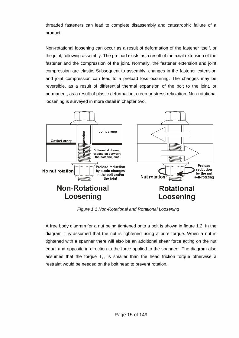
Self-loosening, is when the fastener rotates under the action of external loading. Non-
rotational loosening is when no relative movement occurs between the internal and
external threads but a preload loss occurs. These two types of loosening process are
illustrated in figure 1.1.
One characteristic of threaded fasteners is that they allow complex assemblies to be
built and dismantled as necessary. Under certain conditions, a threaded fastener can
self-loosen, that is, it can rotate by itself. The detailed mechanisms that result in self-
loosening have been a subject of research for the last sixty years. The research
presented here is one contribution to this body of knowledge. Self-loosening of
Page 15 of 149
Figure 1.1 Non-Rotational and Rotational Loosening
threaded fasteners can lead to complete disassembly and catastrophic failure of a
product.
Non-rotational loosening can occur as a result of deformation of the fastener itself, or
the joint, following assembly. The preload exists as a result of the axial extension of the
fastener and the compression of the joint. Normally, the fastener extension and joint
compression are elastic. Subsequent to assembly, changes in the fastener extension
and joint compression can lead to a preload loss occurring. The changes may be
reversible, as a result of differential thermal expansion of the bolt to the joint, or
permanent, as a result of plastic deformation, creep or stress relaxation. Non-rotational
loosening is surveyed in more detail in chapter two.
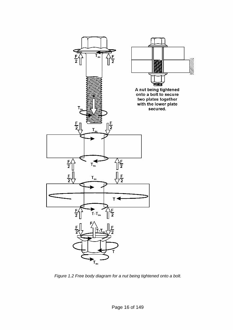
A free body diagram for a nut being tightened onto a bolt is shown in figure 1.2. In the
diagram it is assumed that the nut is tightened using a pure torque. When a nut is
tightened with a spanner there will also be an additional shear force acting on the nut
equal and opposite in direction to the force applied to the spanner. The diagram also
assumes that the torque Ttm is smaller than the head friction torque otherwise a
restraint would be needed on the bolt head to prevent rotation.
Page 16 of 149
Figure 1.2 Free body diagram for a nut being tightened onto a bolt.
Page 17 of 149
1.3 TYPES AND CLASSIFICATION OF FASTENER LOCKING METHODS
1.3.1 Prevention of self-loosening by design
Experience indicates that self-loosening will not occur if a bolted joint is designed so
that the residual preload after any non-rotational loosening losses has occurred is
sufficient to resist the applied external forces without joint movement occurring.
Systematic design procedures such as VDI 2230 (2003) allow joints to be designed on
this basis so that plain non-locking fasteners can be used in dynamically loaded
applications.
The computational and intellectual burden associated with designing joints to VDI 2230
means that its usage is not widely understood or applied. Over the last ten years, the
development of software implementing the methodology is leading to its wider
adoption, although its use is still generally limited to larger organisations. Experience of
the application of VDI 2230 by the large automotive companies indicates that when the
procedure is systematically applied, self-loosening of fasteners does not, in general,
occur. The VDI requires detailed knowledge of the forces being applied to the joint. In
many applications outside the automotive and aerospace sectors such information is
frequently not available. This is one reason why self-loosening of threaded fasteners is
likely to remain an ongoing problem.
1.3.2 The use of fastener locking devices
Based upon the author's experience, there are several circumstances when the use of
a locking device may be appropriate on a threaded fastener, specifically:
1. In many applications the forces acting on a joint are either difficult to predict or
would require a large amount of research effort to establish. In such situations the
engineer uses his or her judgement to estimate the likely forces acting on an
appropriately sized joint. Testing can help to verify the design, however, if the
application is subject to complex load pattern there will be uncertainty that the all
the conditions and combinations of loading have been evaluated.
2. The bolted joint is a complex structural assembly and the knowledge to analyses
effectively is not widespread in the engineering community. On low volume
products the size and strength of bolts are often based upon past experience and
judgement rather than a detailed analysis or test programme.
3. Friction plays a critical role in controlling the preload developed from an applied
torque to a fastener as well as the slip resistance of two joint surfaces. Assumptions
have to be made about the friction coefficient which develop between sliding
Page 18 of 149
surface that may prove to be false on occasions. For example, contamination by
grease between two joint surfaces can significantly lower the joint’s slip resistance.
4. In some applications it can be difficult to define the difference between reasonable
use and abuse of a product, for example, the driving of off-road vehicles. Designing
for extreme loads may impose too high a cost or weight penalty. In such situations
joints may be designed to slip or separate in the rare instances when extreme
loading occurs.
5. Differential thermal expansion can cause joint movement that cannot be prevented
without incurring structural problems. Examples of this are fishplates connecting rail
sections together. The rails expand and contract depending upon the ambient
temperature, the fishplates facilitate this movement whilst holding the rails together.
6. Many standard designs have had to sustain increased loads since their inception as
a result of changes in practice. For example, wheel rim sizes on commercial
vehicles. Improved braking efficiencies, higher engine power and increased axle
loading have all contributed to increasing the loading severity on the joint.
7. The initial tightening of the fasteners of a manufactured product can be closely
controlled giving some predictability in the resulting bolt preload. In service,
controlled tightening can be erratic and problematic being dependent upon the tools
being available.
8. The causes of loosening are not widely understood by practising engineers. In
engineering magazines there is a significant amount of advertising advocating the
use of various proprietry locking devices. As a result, in the authors experience,
locking devices are sometimes used in applications in which their use is of
questionable benefit.
For the reasons given above, locking devices are frequently applied to threaded
fasteners. What is generally demanded in the above situations is that although partial
loosening may occur, detachment of the nut from the bolt should not occur. Such
detachment has historically been the cause of several serious accidents. In a chapter
on self loosening, Hess (Bickford and Nassar 1998) classifies fastener locking devices
into four groups:
Preload independent locking methods.
Free spinning preload dependent locking methods.
Prevailing torque locking methods.
Adhesive locking methods.
Page 19 of 149
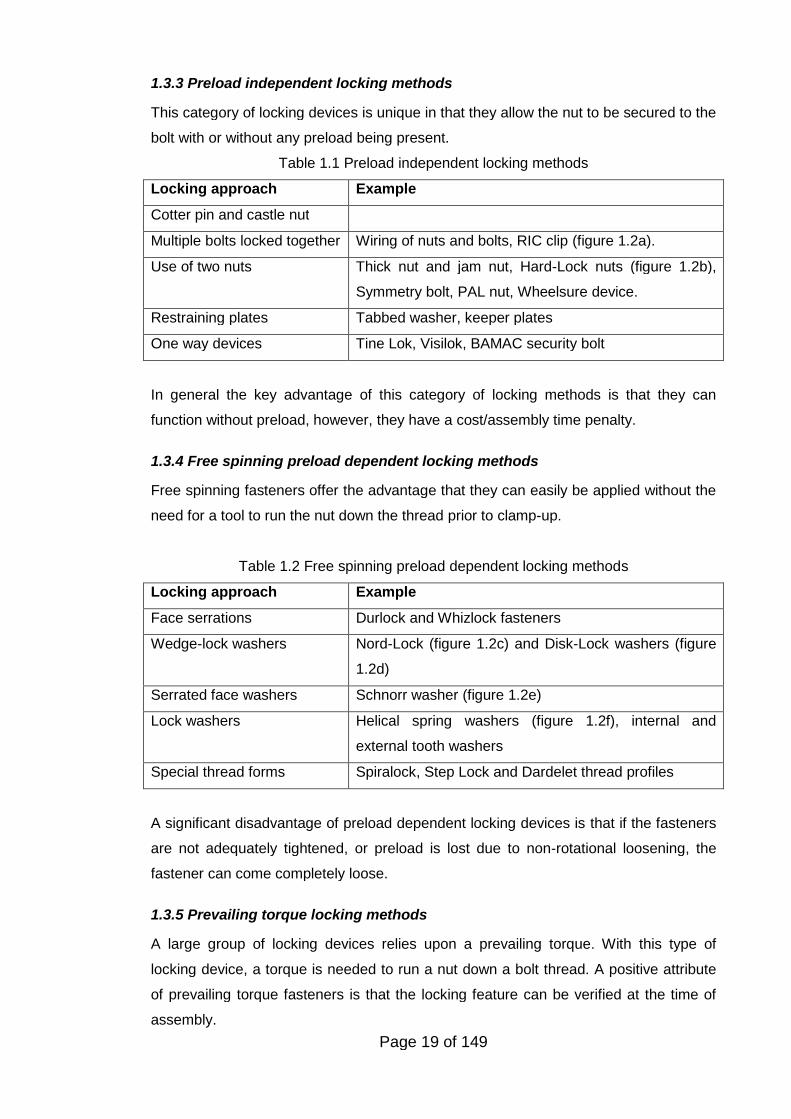
1.3.3 Preload independent locking methods
This category of locking devices is unique in that they allow the nut to be secured to the
bolt with or without any preload being present.
Table 1.1 Preload independent locking methods
Locking approach Example
Cotter pin and castle nut
Multiple bolts locked together Wiring of nuts and bolts, RIC clip (figure 1.2a).
Use of two nuts Thick nut and jam nut, Hard-Lock nuts (figure 1.2b),
Symmetry bolt, PAL nut, Wheelsure device.
Restraining plates Tabbed washer, keeper plates
One way devices Tine Lok, Visilok, BAMAC security bolt
In general the key advantage of this category of locking methods is that they can
function without preload, however, they have a cost/assembly time penalty.
1.3.4 Free spinning preload dependent locking methods
Free spinning fasteners offer the advantage that they can easily be applied without the
need for a tool to run the nut down the thread prior to clamp-up.
Table 1.2 Free spinning preload dependent locking methods
Locking approach Example
Face serrations Durlock and Whizlock fasteners
Wedge-lock washers Nord-Lock (figure 1.2c) and Disk-Lock washers (figure
1.2d)
Serrated face washers Schnorr washer (figure 1.2e)
Lock washers Helical spring washers (figure 1.2f), internal and
external tooth washers
Special thread forms Spiralock, Step Lock and Dardelet thread profiles
A significant disadvantage of preload dependent locking devices is that if the fasteners
are not adequately tightened, or preload is lost due to non-rotational loosening, the
fastener can come completely loose.
1.3.5 Prevailing torque locking methods
A large group of locking devices relies upon a prevailing torque. With this type of
locking device, a torque is needed to run a nut down a bolt thread. A positive attribute
of prevailing torque fasteners is that the locking feature can be verified at the time of
assembly.
Page 20 of 149
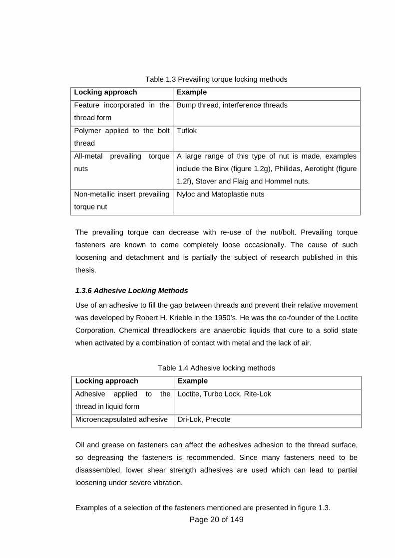
Table 1.3 Prevailing torque locking methods
Locking approach Example
Feature incorporated in the
thread form
Bump thread, interference threads
Polymer applied to the bolt
thread
Tuflok
All-metal prevailing torque
nuts
A large range of this type of nut is made, examples
include the Binx (figure 1.2g), Philidas, Aerotight (figure
1.2f), Stover and Flaig and Hommel nuts.
Non-metallic insert prevailing
torque nut
Nyloc and Matoplastie nuts
The prevailing torque can decrease with re-use of the nut/bolt. Prevailing torque
fasteners are known to come completely loose occasionally. The cause of such
loosening and detachment and is partially the subject of research published in this
thesis.
1.3.6 Adhesive Locking Methods
Use of an adhesive to fill the gap between threads and prevent their relative movement
was developed by Robert H. Krieble in the 1950’s. He was the co-founder of the Loctite
Corporation. Chemical threadlockers are anaerobic liquids that cure to a solid state
when activated by a combination of contact with metal and the lack of air.
Table 1.4 Adhesive locking methods
Locking approach Example
Adhesive applied to the
thread in liquid form
Loctite, Turbo Lock, Rite-Lok
Microencapsulated adhesive Dri-Lok, Precote
Oil and grease on fasteners can affect the adhesives adhesion to the thread surface,
so degreasing the fasteners is recommended. Since many fasteners need to be
disassembled, lower shear strength adhesives are used which can lead to partial
loosening under severe vibration.
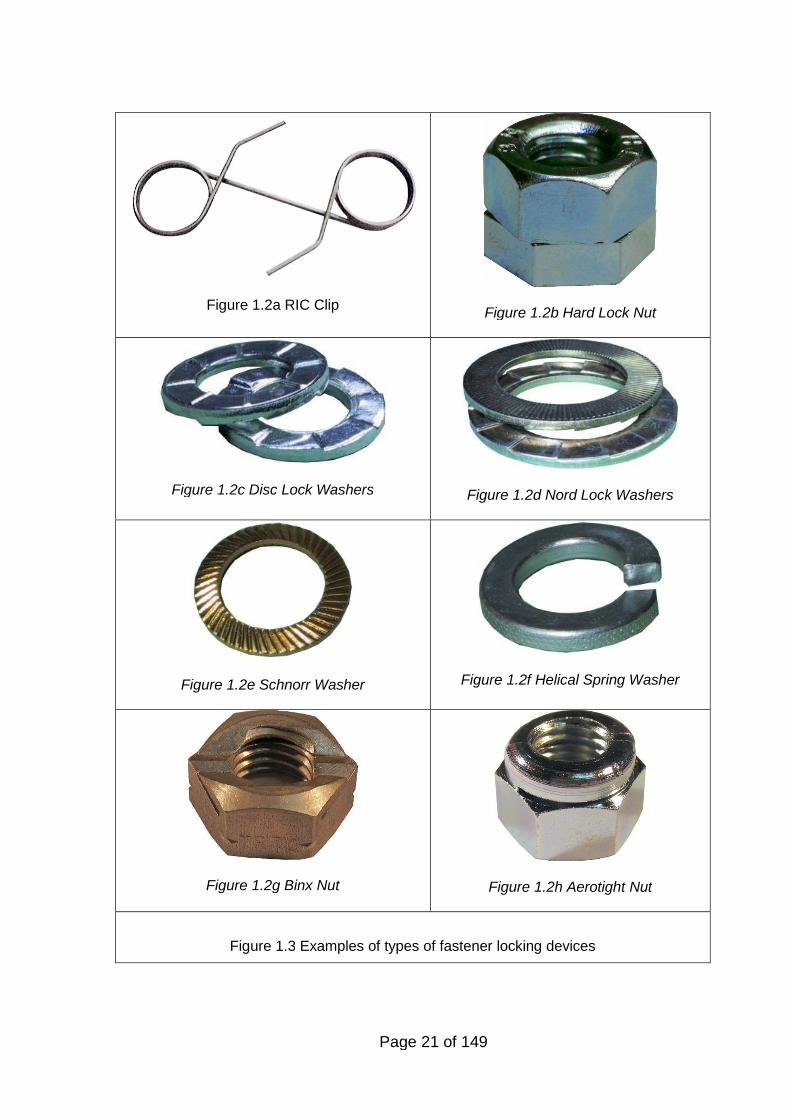
Examples of a selection of the fasteners mentioned are presented in figure 1.3.
Page 21 of 149
Figure 1.2a RIC ClipFigure 1.2b Hard Lock Nut
Figure 1.2c Disc Lock Washers Figure 1.2d Nord Lock Washers
Figure 1.2e Schnorr Washer Figure 1.2f Helical Spring Washer
Figure 1.2g Binx Nut Figure 1.2h Aerotight Nut
Figure 1.3 Examples of types of fastener locking devices
Page 22 of 149
1.4 STRUCTURE OF THE THESIS
The subject of this thesis is the loosening of threaded fasteners and the role which
friction plays in this process. The structure of the thesis is in five main sections:
1. A review of the literature on the loosening of threaded fasteners with particular
focus on rotational loosening.
2. Details of measurements completed of the coefficient of friction of threaded
fasteners. Particular emphasis is on the effect on the coefficient of friction of re-
tightening electro-zinc plated fasteners.
3. Details of experiments completed on the self-loosening of threaded fasteners by
purely transverse vibration using a standard test approach. Several types of
prevailing torque nuts were tested.
4. Details of experiments completed on the self-loosening of threaded fasteners by
transverse vibration with simultaneous axial loading. Modifications were made to a
test machine to allow axial loading to be simultaneously applied to the joint as well
as transverse vibration. A theoretical model is also presented
5. Details of experiments are described in which the reduction in the apparent friction
is measured when the joint is subjected to transverse vibration. The almost total
elimination of the friction force in the circumferential direction of a fastener when the
joint experiences transverse vibration is an interesting phenomenon which has not
been extensively studied.
Page 23 of 149
2. LITERATURE SURVEY
2.1 INTRODUCTION
The aim of this literature review is to provide a critical look at the research that has
been completed on the subject to date and evaluate the importance of some of the key
work.
The demand for fasteners dramatically increased during the Industrial Revolution.
James Watts' development of the steam engine in 1765 resulted in the need to attach
large metal parts together securely so that significant load could be sustained.
According to the Industrial Fastener Institute (1991) increasing mechanisation
generated a strong demand for threaded fasteners that was initially met by small
manufacturers producing essentially proprietary parts. The nuts and bolts could be
interchanged between the same manufacturer, but not between manufacturers due to
the lack of nationwide standards. On the 15 June 1841, in a paper titled “A Uniform
System of Screw Threads” presented to the Institution of Civil Engineers, Joseph
Whitworth proposed that threads should have identical depth, pitch and form for a
given diameter (Whitworth, 1841). Prior to his work, the screw threads were made to
designs and sizes determined by the individual engineer or manufacturer.
In 1864, in the United States, William Sellers proposed a thread form based upon the
now standard 60 degree flank angle (Surowiecki, 2002). During the First and Second
World Wars problems arose because of lack of compatibility between the Whitworth
and the Sellers thread forms. This led to the adoption in 1948 of the unified thread
which has a thread angle of 60 degrees like the Sellers but incorporates a rounded
thread root like the Whitworth. Also in 1948 the International Organisation for
Standardisation (ISO) started work on a standard screw thread system for world-wide
adoption. In 1964, agreement was reached on the ISO metric thread system that is in
world-wide use today.
Interestingly, for the perspective of this thesis, patents started to appear in the middle
of the nineteenth century proposing improvements in bolt and nut design to prevent
them unintentionally coming loose. David Cumming in his patent of the 16th June 1868
states that his design would improve the bolt-nut assembly by ‘… thereby preventing
the nut from being shaken off as is frequently the case where screw-bolts are used in
Page 24 of 149
the construction of railroad-cars, carriages, bridges and other structures’ (Cumming,
1868).
2.2 NON-ROTATIONAL LOOSENING
A tightened threaded fastener can lose preload without rotating. The loss of preload
can be temporary; such as can occur as a result of differential thermal expansion, or
permanent, such as can result from creep. There are several causes of non-rotational
loosening all of which involve either the bolt additionally elongating or the joint
additionally compressing following installation. Relaxation and permanent set are
sometimes used as coverall terms to include all types of plastic deformation that can
occur in the bolt and the joint. This thesis covers self-loosening in which the fastener
self rotates under the action of external forces. Non-rotational loosening will be first
covered since this can initiate self-loosening once a reduction in the preload has
occurred. The main causes of non-rotational loosening are discussed below:
2.2.1 Embedding loss
Embedding is localised plastic deformation that occurs under the nut face, in the joint
faces and in the threads as a result of plastic flattening of the surface roughness. This
occurs even when the loading is below the yield point of the bolt or limiting surface
pressure of the joint material, and is the result of the real area of contact between
surfaces being less than the apparent area. See (Rabinowicz, 1995) for a discussion
on this topic. It is known that the majority of embedding losses arise when the working
load is first applied to a joint, changing the contact pressures. Guideline values for
embedding loss per interface for steel have been published (VDI, 2003). Research into
this phenomenon (Meyer and Strelow, 1972) indicates that, once tightening has
stopped, approximately 80% of the embedding loss occurs on first loading by a static or
dynamic service load while the remaining 20% is caused by further loading. For typical
structural joints whose joint faces are machined faces, about 10% of the preload (or
thereabouts) is lost by this process. To account for this effect the VDI methodology
(VDI 2003) allows the embedding loss on a particular joint to be included in the design
calculations so that a reliable joint is achieved.
2.2.2 Gasket creep
Many joints contain gaskets whose purpose is to create a seal between two flanges to
confine fluid or gas. A relatively soft gasket material is frequently used so that a good
sealing performance is achieved. Most gasket types rely upon a certain minimum
seating pressure, usually provided by bolts, to effect a seal. With such joints usually a
reduction in the seating stress occurs over time as a result of creep of the gasket
Page 25 of 149
relieving the bolt preload. Although present design calculation procedures do not fully
account for creep adequately (Nechache and Bouzid, 2006), recent developments
(Zerres and Guerout, 2004) allow an improvement of the leak-tightness of the joint and
the prevention of fugitive emissions. Practical steps are usually taken when tightening
the bolts to ensure that preload reduction from creep does not impair the sealing
performance of the joint. These steps often include re-tightening the bolts after a period
of time to compensate for creep .
2.2.3 Creep from surface coatings
To protect steel fasteners from corrosion they are usually coated with a material lower
than steel in the galvanic series. Zinc is a popular coating used primarily for cost
reasons. Zinc is applied either via an electro plating process, giving a coating thickness
of the order of 8µm, or a hot dip galvanising process giving a coating thickness of a
minimum of 40µm or more. Essentially thicker coatings give greater corrosion
resistance. When the joint is made up of several layers, the zinc thickness can be
several times the bolt extension. This can be a problem because zinc is a relatively soft
metal and creep reduces the coating thickness causing a preload loss. Research has
been completed on the creep characteristics of bolted galvanised joints. Yang and
DeWolf (1999) discuss this in some detail. Based upon their research, they show that
the creep strain follows the relationship:
( ) mt t
where ( )t is the creep strain at time t, , and m are constants and t is the time
Although some reports (e.g. Langill (2001)) state that the relaxation from the coating
occurs over the first five days it is clear that from the work completed by Yang and
DeWolf (1999) and these test results that the creep will continue for extended periods of
time.
Paints of various types are commonly applied to structural members for corrosion and
cosmetic reasons. Satoh, Nagatomo et al. (1997) have completed experiments to
evaluate the influence of paint film upon the loosening of fasteners. Thick paint films give
rise to a significant reduction in bolt preload following tightening and can also assist self-
loosening. Thinner paint films based upon etch primer result in a lower amount of preload
loss and a reduced tendency to self-loosen.
2.2.4 Stress Relaxation
A significant problem with bolting at high temperatures is a phenomenon known as
stress relaxation (Sachs and Evans (1973)). Commonly creep occurs when a material
Page 26 of 149
is subjected to an elevated temperature and a constant load. Stress relaxation is a form
of creep and occurs when a high stress present in a material is relieved over time; the
stress is relaxed with a subsequent reduction in the bolt’s preload. Previous research
by Sachs and Evans (1973) provides useful information on the stress relaxation
characteristics of common bolting materials. However, stress relaxation remains a
significant problem when bolting at elevated temperatures. In recent years,
standardised test methods published by the British Standards Institute (2006) have
been developed for the determination of stress relaxation of bolts. The basis of the
tests is for a bolt to be tightened to a specified initial elastic strain, subjecting the bolt to
that strain for a specific temperature and time and determining the residual stress in the
bolt by loosening at the end of the test.
2.2.5 Yielding from applied loading
When an external force is applied to a bolted joint, usually the majority of the force
relieves the clamp force on the interface. However the bolt does sustain a proportion of
the applied force. Since bolts are usually tightened to a significant percentage of their
yield strength, there exists the possibility that the bolt material could yield as a result of
the application of an external force. Modern design codes such as those developed by
VDI (2003) allow for this possibility, but at ambient temperatures such yielding is
unusual (Newnham and Curley, 1990) even when yield controlled tightening is used.
(Yield controlled tightening involves measuring the applied torque and angle of rotation
of the nut so that by determining the torque-angle gradient, yielding of the bolt can be
detected and the tightening stopped at this point.) In bolted joints operating at elevated
temperatures, significant reduction in the bolt material yield strength does occur. In
such applications, the target preload is usually reduced and the joint designed
accordingly. For example on flange bolting the typical criteria is a tensile stress of 50%
of the minimum yield strength of the bolt (ASME (2010)) whereas it is more typical in
mechanical engineering to use an equivalent (combined tension and torsion) stress of
90% of the bolt's minimum yield strength (VDI (2003)).
2.2.6 Differential thermal expansion
Bolts are typically tightened at ambient temperature even though they may operate at
elevated or cryogenic temperatures. If the joint and bolt materials differ then the load
sustained by the bolt may increase or decrease depending upon the
expansion/contraction characteristics. Changes in Young’s modulus can also lead to
preload change at temperature. Transient problems can occur even when the bolt and
joint materials have the same expansion coefficients. Normally the air gap in the hole
insulates the bolt so that the joint heats/cools faster that the bolt leading to changes in
Page 27 of 149
the clamp force, which on flanged joints, can lead to fugitive emissions (Sear and King,
2004).
2.2.7 Loosening through wear
Bolted joints can sustain fretting wear resulting in a dark brown powder that is called
“cocoa” (Sakai, 2008). One cause of this fretting wear is micro-slip which is the result of
regions away from the bolt hole experiencing slip while those close to the hole do not
slip (Ibrahim and Pettit, 2005). Micro-slip in joints assists in damping vibrations
(Padmanabhan and Murty, 1990), but quantifying the details can be difficult to
investigate and compute (Ouyang, Oldfield et al. 2006). Investigations on the transition
from micro-slip to gross-slip conditions (Olofsson, 1995) found that the situation is
complex and can occur in a number of different ways. Progress has been made in
explaining the physical processes involved in micro-slip and in the development of the
governing laws (Hagman and Olofsson, 1998; Sellgren and Olofsson, 1999). Pai and
Hess (2003) conducted detailed finite element modelling which led them to conclude
that localised slip can accumulate and lead to complete slip and self-loosening of a
fastener.
On some joints, movement of the plates comprising the joint occurs by design.
Fishplates for example, which secure rail sections together, sustain movement as a
result of the rails expanding and contracting. Under such circumstances loosening of
the fasteners by wear processes can occur. Higher rates of wear are associated with
high friction coefficients (Fouvry, Kapsa et al. 2001) and, when joint movement cannot
be prevented by increasing the clamp force from the bolt, Sakai (2008) suggests
lubricating the joint surface to minimise wear effects.
2.2.8 Plastic deformation of the fastener and the joint
High surface pressures are created under a bolt head and nut face. On soft materials
this can lead to indentation by the nut or bolt head into the joint. When applied loads
are sustained by the joint further collapse of the surface asperities can occur resulting
in a loss of bolt extension and consequent preload loss. An example of this can occur
when large clearance or slotted holes are used to reduce manufacturing costs. When
standard washers are used, which are usually mild steel, the washer can collapse to a
concave shape. When the joint is loaded, further deformation of the washer occurs
resulting in preload loss. To assist in overcoming this problem flange headed nuts and
bolts are often used with soft joint materials or when large clearance holes are used.
Page 28 of 149
Jiang et al. (2001) found that when a joint is subjected to transverse cyclic loading and
the nut is locked onto the bolt using a high strength adhesive, significant preload loss
can still occur. Depending upon the loading magnitude, they found that preload
reductions between 10% and 41% could occur. They considered that this loss, based
upon a finite element study they had completed, was due to local cyclic plasticity
occurring at the roots of the threads resulting in cyclic strain ratchetting. This cyclic
plastic deformation led to a redistribution of the stresses in the bolt and a gradual loss
of clamping force. Leonavicius et al. (2006) investigated crack propagation and
shakedown in threads. They found that a 25% loss of initial preload could occur prior to
complete fracture as a result of crack propagation. The author of this thesis has noted
similar losses on a locked fastener on a Junker test as a fatigue crack propagates
across the thread.
2.3 INTRODUCTION TO THE SELF-LOOSENING OF THREADED
FASTENERS
As previously noted, self-loosening of threaded fasteners was observed in the middle
of the nineteenth century. The focus was on practical measures to enhance fastener
design to resist loosening. Many of the locking methods in use today can be traced to
patents lodged over 100 years ago. Some early tests were conducted at the National
Physical Laboratory to assess the resistance of fasteners to vibration. One article
(Engineering Magazine, 1930) reports on how the performance of nuts and bolts made
to the Dardelet thread form were assessed. The test consisted of the bolts being used
to attach 12 lb masses to a vibration rig. The frame was oscillated at 1230 rpm with
amplitude from 1/8" to 3/16". The test was continued for over 70 hours during which the
frame received 5250000 cycles. At the end of the test no movement of the nuts on the
bolts could be detected. In an article, Boomsma reviews the work completed on bolt
loosening up to that date (Boomsma, 1955). He reports that researchers in Germany in
the 1930s attributed loosening to plastic deformation of the fastener and joint surfaces.
It was not clear initially what process was the cause of self-loosening of threaded
fasteners. Researchers studied axial loading and impact but it was Junker (Junker
1969) with his discovery that transverse joint movement could completely loosen
fasteners who changed the focus of subsequent research.
Page 29 of 149
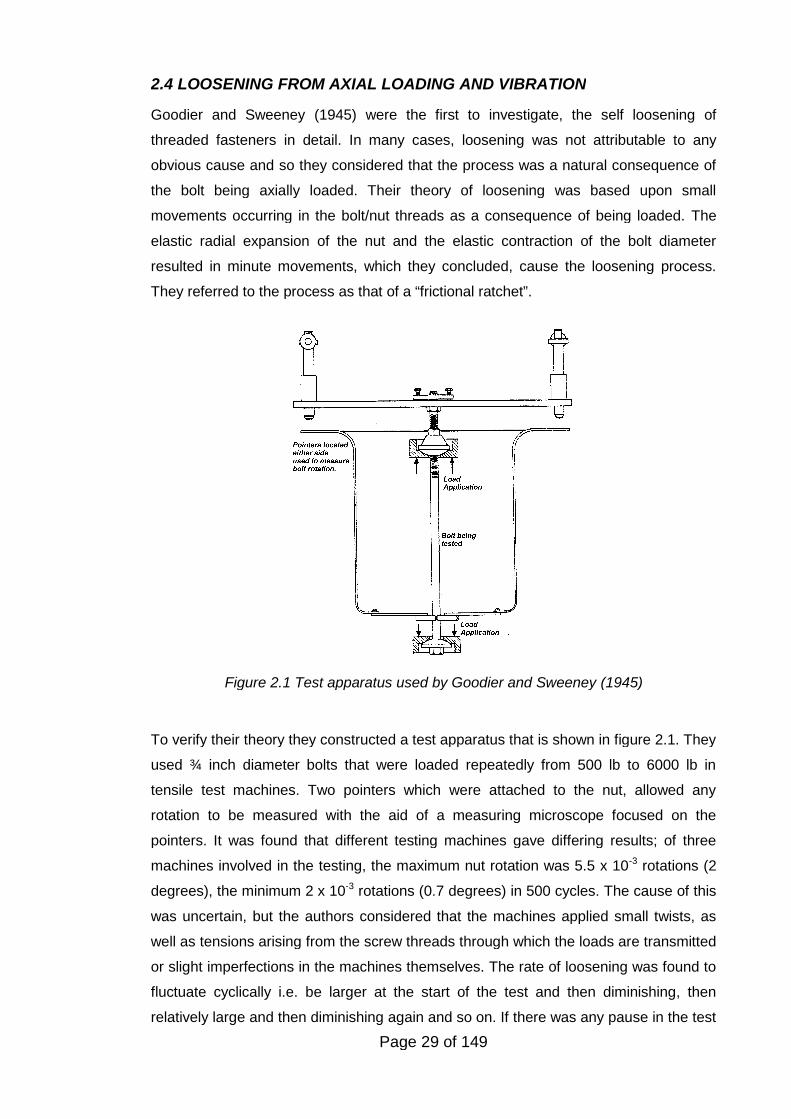
Figure 2.1 Test apparatus used by Goodier and Sweeney (1945)
2.4 LOOSENING FROM AXIAL LOADING AND VIBRATION
Goodier and Sweeney (1945) were the first to investigate, the self loosening of
threaded fasteners in detail. In many cases, loosening was not attributable to any
obvious cause and so they considered that the process was a natural consequence of
the bolt being axially loaded. Their theory of loosening was based upon small
movements occurring in the bolt/nut threads as a consequence of being loaded. The
elastic radial expansion of the nut and the elastic contraction of the bolt diameter
resulted in minute movements, which they concluded, cause the loosening process.
They referred to the process as that of a “frictional ratchet”.
To verify their theory they constructed a test apparatus that is shown in figure 2.1. They
used ¾ inch diameter bolts that were loaded repeatedly from 500 lb to 6000 lb in
tensile test machines. Two pointers which were attached to the nut, allowed any
rotation to be measured with the aid of a measuring microscope focused on the
pointers. It was found that different testing machines gave differing results; of three
machines involved in the testing, the maximum nut rotation was 5.5 x 10⁻³ rotations (2
degrees), the minimum 2 x 10⁻³ rotations (0.7 degrees) in 500 cycles. The cause of this
was uncertain, but the authors considered that the machines applied small twists, as
well as tensions arising from the screw threads through which the loads are transmitted
or slight imperfections in the machines themselves. The rate of loosening was found to
fluctuate cyclically i.e. be larger at the start of the test and then diminishing, then
relatively large and then diminishing again and so on. If there was any pause in the test
Page 30 of 149
Load Ratio = 400/500 = 0.8
Load Ratio = 450/500 = 0.9
Load Ratio = 400/500 = 0.8
Load Ratio = 450/500 = 0.9
0 4 8 12 2016
0.5
1.0
1.5
2.0
Lo
ose
nin
g(d
eg
ree
s)
1000 Cycles
Once used nuts
Virgin specimens
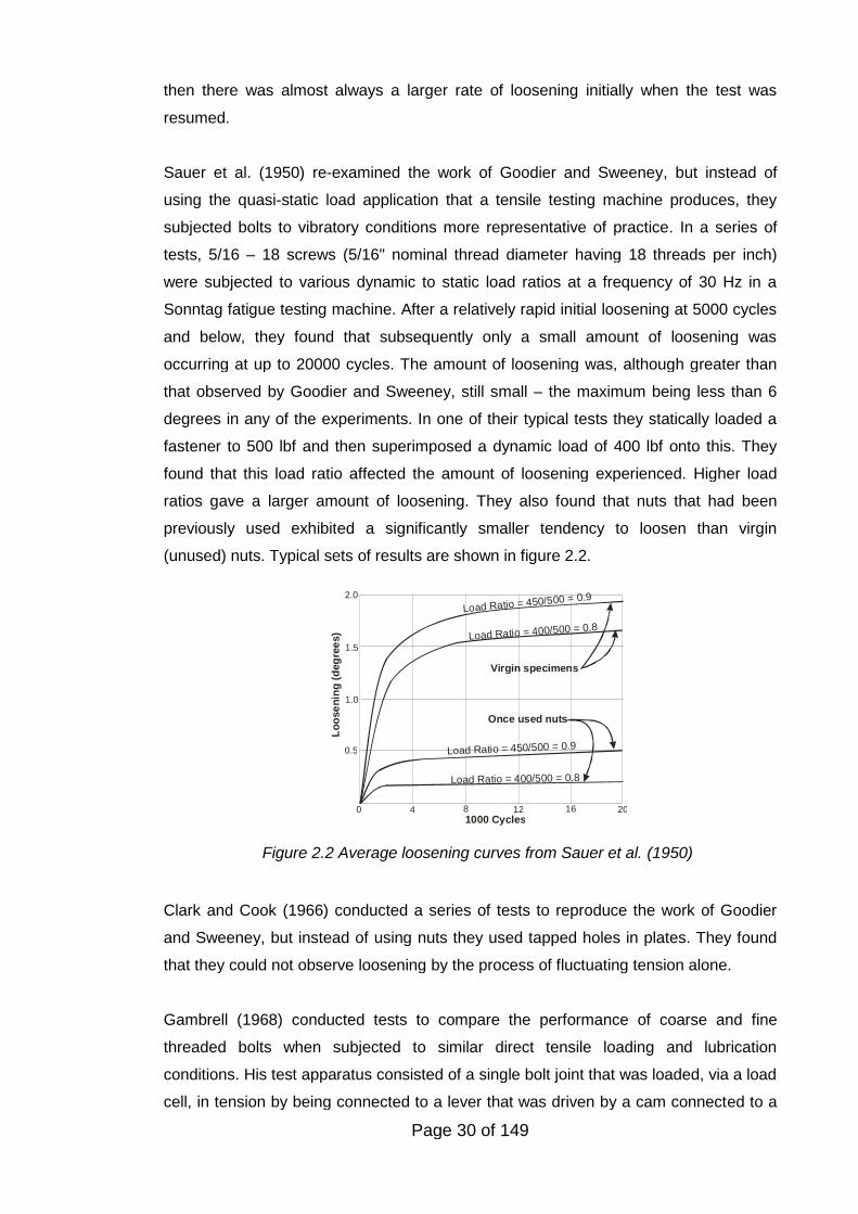
Figure 2.2 Average loosening curves from Sauer et al. (1950)
then there was almost always a larger rate of loosening initially when the test was
resumed.
Sauer et al. (1950) re-examined the work of Goodier and Sweeney, but instead of
using the quasi-static load application that a tensile testing machine produces, they
subjected bolts to vibratory conditions more representative of practice. In a series of
tests, 5/16 – 18 screws (5/16" nominal thread diameter having 18 threads per inch)
were subjected to various dynamic to static load ratios at a frequency of 30 Hz in a
Sonntag fatigue testing machine. After a relatively rapid initial loosening at 5000 cycles
and below, they found that subsequently only a small amount of loosening was
occurring at up to 20000 cycles. The amount of loosening was, although greater than
that observed by Goodier and Sweeney, still small – the maximum being less than 6
degrees in any of the experiments. In one of their typical tests they statically loaded a
fastener to 500 lbf and then superimposed a dynamic load of 400 lbf onto this. They
found that this load ratio affected the amount of loosening experienced. Higher load
ratios gave a larger amount of loosening. They also found that nuts that had been
previously used exhibited a significantly smaller tendency to loosen than virgin
(unused) nuts. Typical sets of results are shown in figure 2.2.
Clark and Cook (1966) conducted a series of tests to reproduce the work of Goodier
and Sweeney, but instead of using nuts they used tapped holes in plates. They found
that they could not observe loosening by the process of fluctuating tension alone.
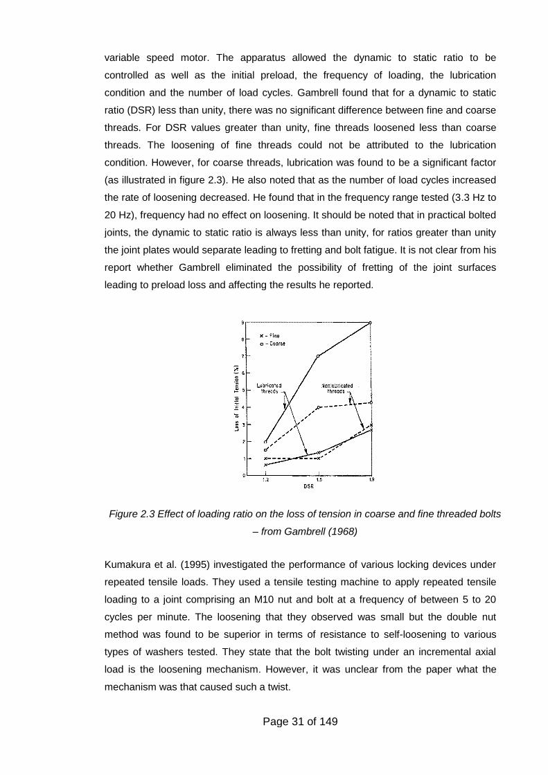
Gambrell (1968) conducted tests to compare the performance of coarse and fine
threaded bolts when subjected to similar direct tensile loading and lubrication
conditions. His test apparatus consisted of a single bolt joint that was loaded, via a load
cell, in tension by being connected to a lever that was driven by a cam connected to a
Page 31 of 149
Figure 2.3 Effect of loading ratio on the loss of tension in coarse and fine threaded bolts
– from Gambrell (1968)
variable speed motor. The apparatus allowed the dynamic to static ratio to be
controlled as well as the initial preload, the frequency of loading, the lubrication
condition and the number of load cycles. Gambrell found that for a dynamic to static
ratio (DSR) less than unity, there was no significant difference between fine and coarse
threads. For DSR values greater than unity, fine threads loosened less than coarse
threads. The loosening of fine threads could not be attributed to the lubrication
condition. However, for coarse threads, lubrication was found to be a significant factor
(as illustrated in figure 2.3). He also noted that as the number of load cycles increased
the rate of loosening decreased. He found that in the frequency range tested (3.3 Hz to
20 Hz), frequency had no effect on loosening. It should be noted that in practical bolted
joints, the dynamic to static ratio is always less than unity, for ratios greater than unity
the joint plates would separate leading to fretting and bolt fatigue. It is not clear from his
report whether Gambrell eliminated the possibility of fretting of the joint surfaces
leading to preload loss and affecting the results he reported.
Kumakura et al. (1995) investigated the performance of various locking devices under
repeated tensile loads. They used a tensile testing machine to apply repeated tensile
loading to a joint comprising an M10 nut and bolt at a frequency of between 5 to 20
cycles per minute. The loosening that they observed was small but the double nut
method was found to be superior in terms of resistance to self-loosening to various
types of washers tested. They state that the bolt twisting under an incremental axial
load is the loosening mechanism. However, it was unclear from the paper what the
mechanism was that caused such a twist.
Page 32 of 149
Hess and Davis (1996) investigated the response of threaded fasteners to axial
harmonic vibration experimentally. They found that the direction of rotation of a
fastener, either in the loosening or tightening direction, depended upon the frequency
and amplitude of the vibratory input. The tests were performed on ¼ - 28 UNF threads
that were loose, i.e. no preload present. Hess (1996) subsequently completed a
kinematic analysis of the twisting of threaded components loaded by gravity and
subjected to axial harmonic vibration. He further developed a theoretical model for the
loosening process with co-workers (Hess, Basava et al. 1996; Hess and
Sudhirkashyap, 1997; Rashquinha and Hess, 1997; Basava and Hess, 1998). This
work presents a mechanism by which a nut can become detached from a bolt once it is
completely loose.
2.5 LOOSENING FROM TORSIONAL LOADING
There are many applications in which a single bolt secures two or more parts together
on a shaft and are subjected to a fluctuating torque. An example is a pulley secured by
a central bolt to a shaft.
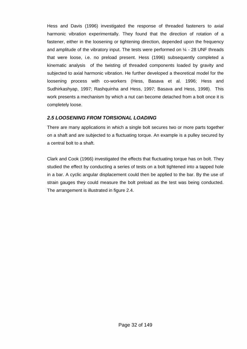
Clark and Cook (1966) investigated the effects that fluctuating torque has on bolt. They
studied the effect by conducting a series of tests on a bolt tightened into a tapped hole
in a bar. A cyclic angular displacement could then be applied to the bar. By the use of
strain gauges they could measure the bolt preload as the test was being conducted.
The arrangement is illustrated in figure 2.4.
Page 33 of 149
Figure 2.4 Clark and Cook Test Apparatus
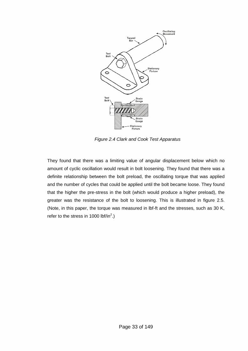
They found that there was a limiting value of angular displacement below which no
amount of cyclic oscillation would result in bolt loosening. They found that there was a
definite relationship between the bolt preload, the oscillating torque that was applied
and the number of cycles that could be applied until the bolt became loose. They found
that the higher the pre-stress in the bolt (which would produce a higher preload), the
greater was the resistance of the bolt to loosening. This is illustrated in figure 2.5.
(Note, in this paper, the torque was measured in lbf-ft and the stresses, such as 30 K,
refer to the stress in 1000 lbf/in2.)
Page 34 of 149
Figure 2.5 Loosening curve for ½-13 cap screw from Clark and Cook (1966)
Sakai (1978) in an important paper on this aspect of loosening presented experimental
and theoretical work completed at the Toyota Motor company. From this work he
derived the condition for bolts to self-loosen. He showed there is a minimum relative
rotation angle between the clamped parts that is necessary for self-loosening to occur.
If movement occurs below this critical angle then loosening will occur without bolt
rotation as a result of fretting wear. He also noted that even though a key or pin is
commonly inserted between the pulley and the shaft, small relative movement could
occur as a result of clearance and elastic/plastic deformation. This generally leads to
fretting wear and subsequent loosening over a period of time (greater than 106 cycles).
Modern practice on joints subjected to rapidly changing dynamic loads, such as the
joint between the crankshaft and the damper on an engine, is to transmit the load via
friction grip. A central bolt provides a clamp force that allows torque to be transmitted
by friction between the joint surfaces. Friction enhancing shims can be inserted
between the joint surfaces to further increase torque transmission.
2.6 LOOSENING BY IMPACT
During the mid 1960s investigative tests into the cause of fastener loosening were
conducted at the Union, New Jersey Plant of the Elastic Stop Nut Company of America
Page 35 of 149
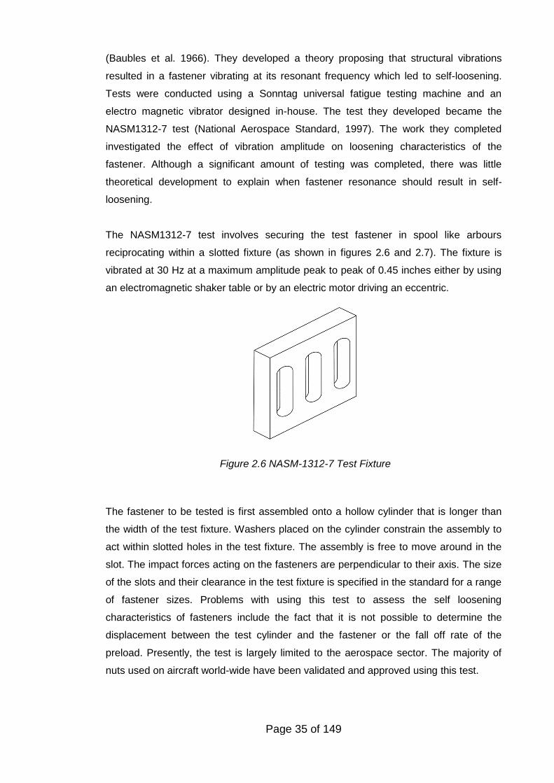
Figure 2.6 NASM-1312-7 Test Fixture
(Baubles et al. 1966). They developed a theory proposing that structural vibrations
resulted in a fastener vibrating at its resonant frequency which led to self-loosening.
Tests were conducted using a Sonntag universal fatigue testing machine and an
electro magnetic vibrator designed in-house. The test they developed became the
NASM1312-7 test (National Aerospace Standard, 1997). The work they completed
investigated the effect of vibration amplitude on loosening characteristics of the
fastener. Although a significant amount of testing was completed, there was little
theoretical development to explain when fastener resonance should result in self-
loosening.
The NASM1312-7 test involves securing the test fastener in spool like arbours
reciprocating within a slotted fixture (as shown in figures 2.6 and 2.7). The fixture is
vibrated at 30 Hz at a maximum amplitude peak to peak of 0.45 inches either by using
an electromagnetic shaker table or by an electric motor driving an eccentric.
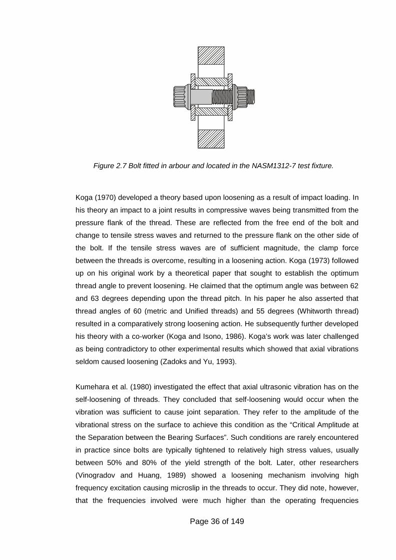
The fastener to be tested is first assembled onto a hollow cylinder that is longer than
the width of the test fixture. Washers placed on the cylinder constrain the assembly to
act within slotted holes in the test fixture. The assembly is free to move around in the
slot. The impact forces acting on the fasteners are perpendicular to their axis. The size
of the slots and their clearance in the test fixture is specified in the standard for a range
of fastener sizes. Problems with using this test to assess the self loosening
characteristics of fasteners include the fact that it is not possible to determine the
displacement between the test cylinder and the fastener or the fall off rate of the
preload. Presently, the test is largely limited to the aerospace sector. The majority of
nuts used on aircraft world-wide have been validated and approved using this test.
Page 36 of 149
Figure 2.7 Bolt fitted in arbour and located in the NASM1312-7 test fixture.
Koga (1970) developed a theory based upon loosening as a result of impact loading. In
his theory an impact to a joint results in compressive waves being transmitted from the
pressure flank of the thread. These are reflected from the free end of the bolt and
change to tensile stress waves and returned to the pressure flank on the other side of
the bolt. If the tensile stress waves are of sufficient magnitude, the clamp force
between the threads is overcome, resulting in a loosening action. Koga (1973) followed
up on his original work by a theoretical paper that sought to establish the optimum
thread angle to prevent loosening. He claimed that the optimum angle was between 62
and 63 degrees depending upon the thread pitch. In his paper he also asserted that
thread angles of 60 (metric and Unified threads) and 55 degrees (Whitworth thread)
resulted in a comparatively strong loosening action. He subsequently further developed
his theory with a co-worker (Koga and Isono, 1986). Koga’s work was later challenged
as being contradictory to other experimental results which showed that axial vibrations
seldom caused loosening (Zadoks and Yu, 1993).
Kumehara et al. (1980) investigated the effect that axial ultrasonic vibration has on the
self-loosening of threads. They concluded that self-loosening would occur when the
vibration was sufficient to cause joint separation. They refer to the amplitude of the
vibrational stress on the surface to achieve this condition as the “Critical Amplitude at
the Separation between the Bearing Surfaces”. Such conditions are rarely encountered
in practice since bolts are typically tightened to relatively high stress values, usually
between 50% and 80% of the yield strength of the bolt. Later, other researchers
(Vinogradov and Huang, 1989) showed a loosening mechanism involving high
frequency excitation causing microslip in the threads to occur. They did note, however,
that the frequencies involved were much higher than the operating frequencies
Page 37 of 149
encountered in most industries. They also found that transverse vibration was more
likely to cause loosening than axial vibration.
Fu discusses the loosening of threaded couplings used in percussive rock drilling (Fu,
1993). His explanation of the loosening process was based upon by Goodier and
Sweeney (1945), suggesting that loosening is driven by fluctuation in the bolt tension.
The coupling illustrated in the paper would result in minimal thread extension making it
prone to loosening from embedding and similar non-rotational processes. This
possibility is not discussed by Fu.
2.7 LOOSENING BY TRANSVERSE VIBRATION
2.7.1 The work of Junker
The most influential paper on the self-loosening of threaded fasteners to-date was by
Gerhard H. Junker. Junker (1969) reports a theory developed to predict self-loosening
under vibratory loading occurs. Junker found that transverse dynamic loads generate a
far more severe condition for self-loosening than dynamic axial loads. The reason for
this is that radial movement under axial loading is significantly smaller than that which
is sustained under transverse loading.
Junker showed that preloaded fasteners self-loosen when relative movement occurs
between the mating threads and the fastener bearing surface. Such relative movement
will occur when the transverse force acting on the joint is larger than the frictional
resisting force generated by the bolt’s preload. For small transverse displacements,
relative motion can occur between the thread flanks and bearing area contact surface.
Once the thread clearances are overcome the bolt will be subject to bending forces,
and if the transverse slippage continues slippage of the bolt head bearing surface will
occur. According to Junker, once this is initiated the thread and the bolt head will be
momentarily free from friction. The internal off torque, present as a result of the preload
acting on the thread helix angle, generates a rotation between the nut and the bolt.
Under repeated transverse movements this mechanism can completely loosen
fasteners.
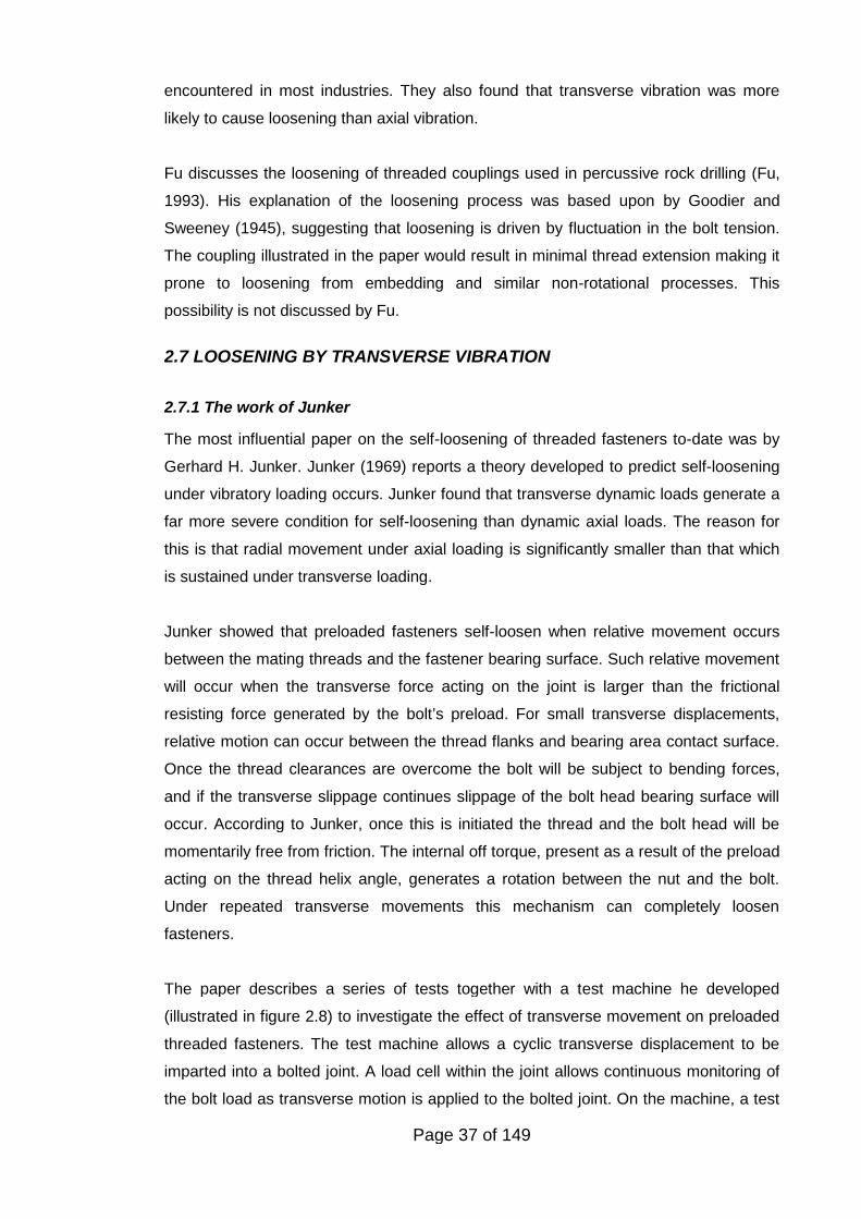
The paper describes a series of tests together with a test machine he developed
(illustrated in figure 2.8) to investigate the effect of transverse movement on preloaded
threaded fasteners. The test machine allows a cyclic transverse displacement to be
imparted into a bolted joint. A load cell within the joint allows continuous monitoring of
the bolt load as transverse motion is applied to the bolted joint. On the machine, a test
Page 38 of 149
Figure 2.8 The Junker Test Machine
specimen bolt passes through a bush that clamps the load cell to a fixed base plate.
The nut is attached to the bolt and onto a moving base. The moving and fixed base
plates are separated by needle roller bearings. The purpose of these bearings is to
reduce any friction between the joint surfaces that would resist transverse movement to
a minimum.
An eccentric cam connected to an electric motor generated the transverse movement.
The motion was transmitted through flexure plates into the moving base of the joint. A
load cell between the flexure plates and the joint was used to measure the magnitude
of the transverse force being applied. Transverse movement was measured by a
displacement transducer, whilst a potentiometer was used to simultaneously measure
nut rotation.
A graph was produced from the test results in which bolt preload is plotted against the
number of cycles of transverse displacement. Such graphs have subsequently been
referred to as a preload decay curves. Junker found that the rate of loosening was
dependent upon the magnitude of the amplitude of transverse displacement, but
independent of the frequency of movement. The test machine allowed, for the first time,
the performance of various fastener designs to be quantitatively compared in terms of
their resistance to self-loosening.
Junker proposed that a criterion of the locking ability of a screw was the vibration
product – this is the product of transverse force times joint displacement. The ability of
the fastener to absorb a particular value of vibration product was, he found, an indicator
of the fastener’s locking ability. A particular fastener could either withstand a particular
vibration product or would self-loosen in a relatively short period of time. He tested the
same type of fastener to a number of different levels of the vibration product. Junker
found that if the preload level was not going to decrease then the fastener had to
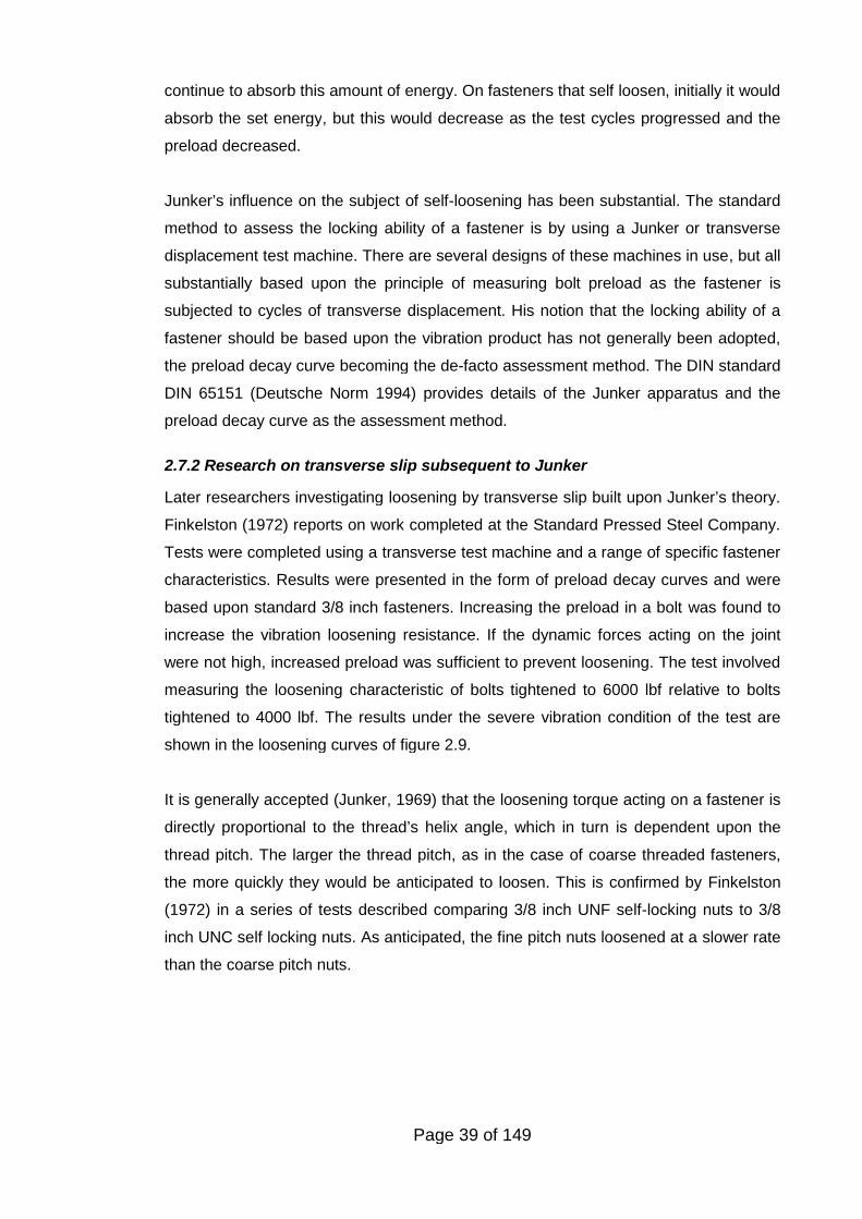
Page 39 of 149
continue to absorb this amount of energy. On fasteners that self loosen, initially it would
absorb the set energy, but this would decrease as the test cycles progressed and the
preload decreased.
Junker’s influence on the subject of self-loosening has been substantial. The standard
method to assess the locking ability of a fastener is by using a Junker or transverse
displacement test machine. There are several designs of these machines in use, but all
substantially based upon the principle of measuring bolt preload as the fastener is
subjected to cycles of transverse displacement. His notion that the locking ability of a
fastener should be based upon the vibration product has not generally been adopted,
the preload decay curve becoming the de-facto assessment method. The DIN standard
DIN 65151 (Deutsche Norm 1994) provides details of the Junker apparatus and the
preload decay curve as the assessment method.
2.7.2 Research on transverse slip subsequent to Junker
Later researchers investigating loosening by transverse slip built upon Junker’s theory.
Finkelston (1972) reports on work completed at the Standard Pressed Steel Company.
Tests were completed using a transverse test machine and a range of specific fastener
characteristics. Results were presented in the form of preload decay curves and were
based upon standard 3/8 inch fasteners. Increasing the preload in a bolt was found to
increase the vibration loosening resistance. If the dynamic forces acting on the joint
were not high, increased preload was sufficient to prevent loosening. The test involved
measuring the loosening characteristic of bolts tightened to 6000 lbf relative to bolts
tightened to 4000 lbf. The results under the severe vibration condition of the test are
shown in the loosening curves of figure 2.9.
It is generally accepted (Junker, 1969) that the loosening torque acting on a fastener is
directly proportional to the thread’s helix angle, which in turn is dependent upon the
thread pitch. The larger the thread pitch, as in the case of coarse threaded fasteners,
the more quickly they would be anticipated to loosen. This is confirmed by Finkelston
(1972) in a series of tests described comparing 3/8 inch UNF self-locking nuts to 3/8
inch UNC self locking nuts. As anticipated, the fine pitch nuts loosened at a slower rate
than the coarse pitch nuts.
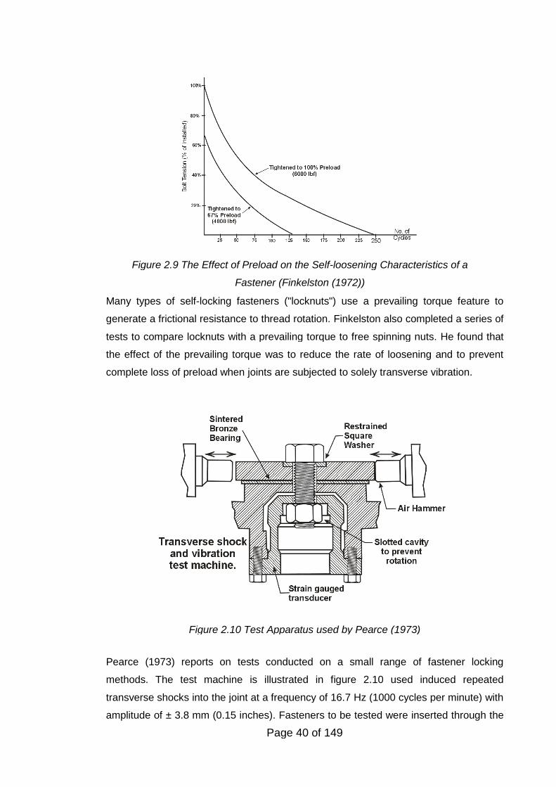
Page 40 of 149
Figure 2.10 Test Apparatus used by Pearce (1973)
Figure 2.9 The Effect of Preload on the Self-loosening Characteristics of a
Fastener (Finkelston (1972))
Many types of self-locking fasteners ("locknuts") use a prevailing torque feature to
generate a frictional resistance to thread rotation. Finkelston also completed a series of
tests to compare locknuts with a prevailing torque to free spinning nuts. He found that
the effect of the prevailing torque was to reduce the rate of loosening and to prevent
complete loss of preload when joints are subjected to solely transverse vibration.
Pearce (1973) reports on tests conducted on a small range of fastener locking
methods. The test machine is illustrated in figure 2.10 used induced repeated
transverse shocks into the joint at a frequency of 16.7 Hz (1000 cycles per minute) with
amplitude of ± 3.8 mm (0.15 inches). Fasteners to be tested were inserted through the
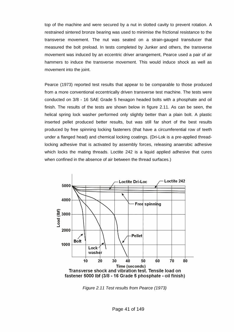
Page 41 of 149
Figure 2.11 Test results from Pearce (1973)
top of the machine and were secured by a nut in slotted cavity to prevent rotation. A
restrained sintered bronze bearing was used to minimise the frictional resistance to the
transverse movement. The nut was seated on a strain-gauged transducer that
measured the bolt preload. In tests completed by Junker and others, the transverse
movement was induced by an eccentric driver arrangement, Pearce used a pair of air
hammers to induce the transverse movement. This would induce shock as well as
movement into the joint.
Pearce (1973) reported test results that appear to be comparable to those produced
from a more conventional eccentrically driven transverse test machine. The tests were
conducted on 3/8 - 16 SAE Grade 5 hexagon headed bolts with a phosphate and oil
finish. The results of the tests are shown below in figure 2.11. As can be seen, the
helical spring lock washer performed only slightly better than a plain bolt. A plastic
inserted pellet produced better results, but was still far short of the best results
produced by free spinning locking fasteners (that have a circumferential row of teeth
under a flanged head) and chemical locking coatings. (Dri-Lok is a pre-applied thread-
locking adhesive that is activated by assembly forces, releasing anaerobic adhesive
which locks the mating threads. Loctite 242 is a liquid applied adhesive that cures
when confined in the absence of air between the thread surfaces.)
Page 42 of 149
During the 1970s and early 1980s automotive and aerospace companies completed
extensive tests (Riches, 1971; Riches, 1975; Light, 1976; Dick, 1983; Light, 1983; Dick,
1984) used Junker machines to assess the loosening resistance of many of the
fasteners then used. The effect of this work was to rationalise the type of fasteners
used eliminating those from their group standards that were ineffective in resisting
loosening.
Haviland (1981) showed that transverse joint movement and subsequent loosening can
arise from other mechanisms besides direct shear loading. Differential thermal
expansion due to temperature differences or dissimilar joint material can lead to joint
slip. Bending of the joint can also lead to displacement and joint slip.
Sakai (1978) also made an important contribution in showing that there is an additional
loosening torque, besides the torque resulting from the preload acting on the thread
helix, due to the movement of the nut thread on the bolt thread. This is discussed in
more detail in chapter 6.
Yamamoto and Kasei (1984) established an equation for determining the transverse
force required to cause slip on the nut face allowing for bolt bending. This led to the
concept of critical slip discussed in section 2.7.4. They promoted the idea that a cause
of loosening is elastic torsion generated in the bolt shank during relative motion in the
mating threads, similar in many respects to Sakai’s work. Kasei et al. (1989) developed
this work and showed that some loosening is possible without bearing surface slip
occurring. Although rapid loosening does occur with transverse slip, their tests and
experimental work focused on the possibility of it happening when the existence of
microscopic sliding was absent or minute. They considered this stage to be the
beginning of the loosening process and one that led to allowing transverse joint
movement and significant fastener preload loss. To investigate the process they
constructed a test apparatus that allowed the measurement of the torque in the
fastener during testing. Their tests did indicate that this loosening process does occur,
and is relatively small, but can be significant since any loosening will result in a preload
reduction allowing further loosening to be made more readily. Kasei and Sawai (1986)
also applied the staircase method, commonly used in fatigue testing, to the evaluation
of the locking performance of threaded fasteners.
Kerley (1987) used a structured method, called retroduction, for the analysis and
testing of the self-loosening of fasteners. His test method involved a cantilever beam
consisting of two plates clamped together by a single bolt, the beam being excited via a
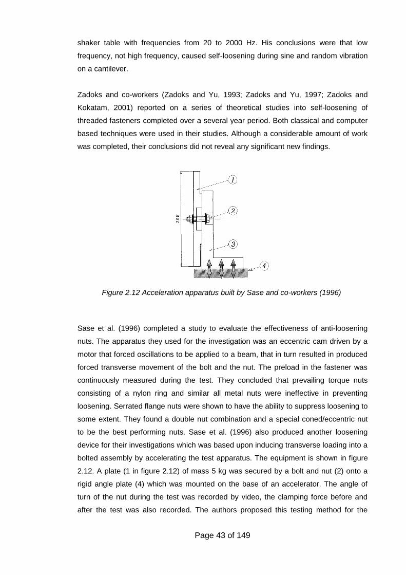
Page 43 of 149
Figure 2.12 Acceleration apparatus built by Sase and co-workers (1996)
shaker table with frequencies from 20 to 2000 Hz. His conclusions were that low
frequency, not high frequency, caused self-loosening during sine and random vibration
on a cantilever.
Zadoks and co-workers (Zadoks and Yu, 1993; Zadoks and Yu, 1997; Zadoks and
Kokatam, 2001) reported on a series of theoretical studies into self-loosening of
threaded fasteners completed over a several year period. Both classical and computer
based techniques were used in their studies. Although a considerable amount of work
was completed, their conclusions did not reveal any significant new findings.
Sase et al. (1996) completed a study to evaluate the effectiveness of anti-loosening
nuts. The apparatus they used for the investigation was an eccentric cam driven by a
motor that forced oscillations to be applied to a beam, that in turn resulted in produced
forced transverse movement of the bolt and the nut. The preload in the fastener was
continuously measured during the test. They concluded that prevailing torque nuts
consisting of a nylon ring and similar all metal nuts were ineffective in preventing
loosening. Serrated flange nuts were shown to have the ability to suppress loosening to
some extent. They found a double nut combination and a special coned/eccentric nut
to be the best performing nuts. Sase et al. (1996) also produced another loosening
device for their investigations which was based upon inducing transverse loading into a
bolted assembly by accelerating the test apparatus. The equipment is shown in figure
2.12. A plate (1 in figure 2.12) of mass 5 kg was secured by a bolt and nut (2) onto a
rigid angle plate (4) which was mounted on the base of an accelerator. The angle of
turn of the nut during the test was recorded by video, the clamping force before and
after the test was also recorded. The authors proposed this testing method for the
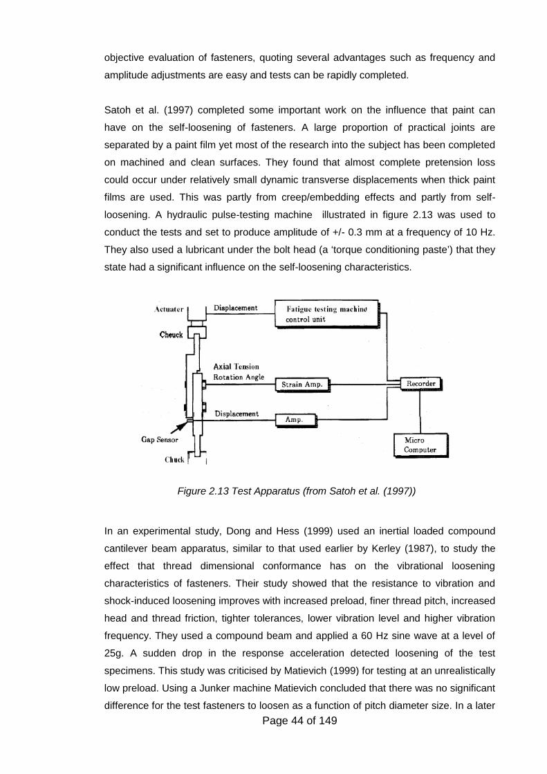
Page 44 of 149
Figure 2.13 Test Apparatus (from Satoh et al. (1997))
objective evaluation of fasteners, quoting several advantages such as frequency and
amplitude adjustments are easy and tests can be rapidly completed.
Satoh et al. (1997) completed some important work on the influence that paint can
have on the self-loosening of fasteners. A large proportion of practical joints are
separated by a paint film yet most of the research into the subject has been completed
on machined and clean surfaces. They found that almost complete pretension loss
could occur under relatively small dynamic transverse displacements when thick paint
films are used. This was partly from creep/embedding effects and partly from self-
loosening. A hydraulic pulse-testing machine illustrated in figure 2.13 was used to
conduct the tests and set to produce amplitude of +/- 0.3 mm at a frequency of 10 Hz.
They also used a lubricant under the bolt head (a ‘torque conditioning paste’) that they
state had a significant influence on the self-loosening characteristics.
In an experimental study, Dong and Hess (1999) used an inertial loaded compound
cantilever beam apparatus, similar to that used earlier by Kerley (1987), to study the
effect that thread dimensional conformance has on the vibrational loosening
characteristics of fasteners. Their study showed that the resistance to vibration and
shock-induced loosening improves with increased preload, finer thread pitch, increased
head and thread friction, tighter tolerances, lower vibration level and higher vibration
frequency. They used a compound beam and applied a 60 Hz sine wave at a level of
25g. A sudden drop in the response acceleration detected loosening of the test
specimens. This study was criticised by Matievich (1999) for testing at an unrealistically
low preload. Using a Junker machine Matievich concluded that there was no significant
difference for the test fasteners to loosen as a function of pitch diameter size. In a later
Page 45 of 149
study (Dong and Hess, 2000), investigated the influence of thread non-conformity by
using the NASM 1312-7 test method (National Aerospace Standard 1997). In this study
they found that undersized bolt threads and oversized nut threads could have a
significant effect on loosening. The loosening time for a thread within specification was
as much as 97% greater than the expected value for time to loosen for non-conforming
product. Hess’s conclusion that thread fit has a significant effect on self-loosening was
subsequently confirmed by Nassar and his co-workers (Nassar and Housari, 2006;
Housari, Nassar et al. 2007).
Pai and Hess (2001) used a finite element model to study different loosening
processes caused by localised or complete slip at the bolt head or in the threads. They
concluded that their FEM model was capable of modelling the factors that influence slip
and self-loosening. In a further paper Pai and Hess (2004) stated that a fastener can
loosen at roughly half the shear load required for complete head slip. They state that
this is critical for joint design, but current design methodology (VDI, 2003) is based
upon sizing the fastener so that the friction grip provided by the preload prevents
complete slip. A significant amount of experience in the application of this methodology
indicates that fasteners do not come loose if designed on a friction grip basis.
Pai and Hess (2003) also investigated the ideal location for fasteners in a structure to
avoid the tendency for self loosening. They modelled a compound beam that was
secured by a single bolt using the FE method and experimentally assessed their model
by testing. They suggest that fasteners should be placed at vibration anti-nodes in
assemblies so that the local shear force acting is minimised. Sanclemente and Hess
(2007) completed a parametric study investigating the resistance to loosening caused
by some basic parameters such as preload, material elastic modulus, nominal
diameter, thread pitch, hole fit and lubrication. Based upon a statistical analysis they
concluded that the preload and fastener elasticity are the most influencing parameters.
In some novel work Antonios et al. (2006) investigated the ability of a washer made
from shape memory alloy (SMA) to compensate for preload loss from loosening. After a
certain amount of preload is lost a heater enveloping the washer is activated allowing
an axial constrained recovery of the SMA and control of the bolt preload.
Nassar and his co-workers have completed several studies over a several year period
(Nassar and Housari, 2005; Housari and Nassar, 2006; Nassar and Housari, 2006;
Nassar and Housari, 2006; Nassar and Yang, 2009) on various aspects of the self-
loosening of fasteners. The majority of these studies repeated work completed earlier
Page 46 of 149
elsewhere. In one study on the effect of adhesive coating on the performance of
threaded fasteners (Ganeshmurthy, Housari et al. 2007) it was found that the locking
adhesive used was successful in preventing the nut from becoming detached from the
bolt, but a significant amount of preload was lost.
Hashimura (2007) investigated the transition between loosening and fatigue of
threaded fasteners when subjected to transverse vibration. He found that if bolts had
loosened within 103 ~104 vibration cycles, damage such as crack nucleation at the root
of the thread was not observed. However, if loosening is not observed until
approximately 105 ~106 cycles, a crack was observed at the root of all threads in all his
experiments. His test apparatus used air vibrators to induce transverse movement into
a plate clamped with a bolt whose preload was monitored by a load cell. He
investigated the effect of material strength and tightening method on the loosening-
fatigue characteristics of bolts transversely loaded. He found, like other researchers
(Burguete, 1995; VDI, 2003), that bolt material strength does not influence the
loosening-fatigue life. He also found that tightening the bolt into the plastic region also
decreased the loosening-fatigue life. (The author of this thesis notes that in practice
this may not be the case since, if additional preload is achieved by either increasing the
bolt material strength or by tightening into the plastic region, then the resistance to joint
slip will be increased and the loosening-fatigue performance improved.)
In a study on the locking performance of threaded inserts (Cheatham et al. 2008) it was
found that inserts which had a prevailing torque feature exhibited loosening
characteristics similar to prevailing torque nuts. That is, when tested on a Junker type
machine a significant amount of preload loss occurred initially but a fraction of the
residual preload is retained.
2.7.3 Design of fasteners to resist self-loosening
For over 150 years developments have been made in the design of fasteners to resist
self-loosening. Since Junker’s work (1969), study has been made into the locking
performance of specific types of fasteners. In cases when it is not possible to prevent
transverse joint movement by having a sufficient preload, then use of a fastener that
resists loosening maybe a suitable approach.
The use of two nuts to prevent self-loosening is well known. For the method to work a
thin nut must be tightened first to a preload typically in the order of 30% to 50% of the
target preload. The main nut is then tightened on the top of the thin nut which is held
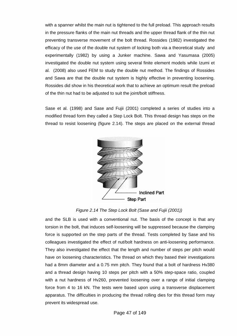
Page 47 of 149
Figure 2.14 The Step Lock Bolt (Sase and Fujii (2001))
with a spanner whilst the main nut is tightened to the full preload. This approach results
in the pressure flanks of the main nut threads and the upper thread flank of the thin nut
preventing transverse movement of the bolt thread. Rossides (1982) investigated the
efficacy of the use of the double nut system of locking both via a theoretical study and
experimentally (1982) by using a Junker machine. Sawa and Yasumasa (2005)
investigated the double nut system using several finite element models while Izumi et
al. (2008) also used FEM to study the double nut method. The findings of Rossides
and Sawa are that the double nut system is highly effective in preventing loosening.
Rossides did show in his theoretical work that to achieve an optimum result the preload
of the thin nut had to be adjusted to suit the joint/bolt stiffness.
Sase et al. (1998) and Sase and Fujii (2001) completed a series of studies into a
modified thread form they called a Step Lock Bolt. This thread design has steps on the
thread to resist loosening (figure 2.14). The steps are placed on the external thread
and the SLB is used with a conventional nut. The basis of the concept is that any
torsion in the bolt, that induces self-loosening will be suppressed because the clamping
force is supported on the step parts of the thread. Tests completed by Sase and his
colleagues investigated the effect of nut/bolt hardness on anti-loosening performance.
They also investigated the effect that the length and number of steps per pitch would
have on loosening characteristics. The thread on which they based their investigations
had a 8mm diameter and a 0.75 mm pitch. They found that a bolt of hardness Hv380
and a thread design having 10 steps per pitch with a 50% step-space ratio, coupled
with a nut hardness of Hv260, prevented loosening over a range of initial clamping
force from 4 to 16 kN. The tests were based upon using a transverse displacement
apparatus. The difficulties in producing the thread rolling dies for this thread form may
prevent its widespread use.
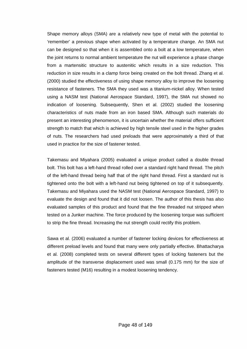
Page 48 of 149
Shape memory alloys (SMA) are a relatively new type of metal with the potential to
‘remember’ a previous shape when activated by a temperature change. An SMA nut
can be designed so that when it is assembled onto a bolt at a low temperature, when
the joint returns to normal ambient temperature the nut will experience a phase change
from a martensitic structure to austenitic which results in a size reduction. This
reduction in size results in a clamp force being created on the bolt thread. Zhang et al.
(2000) studied the effectiveness of using shape memory alloy to improve the loosening
resistance of fasteners. The SMA they used was a titanium-nickel alloy. When tested
using a NASM test (National Aerospace Standard, 1997), the SMA nut showed no
indication of loosening. Subsequently, Shen et al. (2002) studied the loosening
characteristics of nuts made from an iron based SMA. Although such materials do
present an interesting phenomenon, it is uncertain whether the material offers sufficient
strength to match that which is achieved by high tensile steel used in the higher grades
of nuts. The researchers had used preloads that were approximately a third of that
used in practice for the size of fastener tested.
Takemasu and Miyahara (2005) evaluated a unique product called a double thread
bolt. This bolt has a left-hand thread rolled over a standard right hand thread. The pitch
of the left-hand thread being half that of the right hand thread. First a standard nut is
tightened onto the bolt with a left-hand nut being tightened on top of it subsequently.
Takemasu and Miyahara used the NASM test (National Aerospace Standard, 1997) to
evaluate the design and found that it did not loosen. The author of this thesis has also
evaluated samples of this product and found that the fine threaded nut stripped when
tested on a Junker machine. The force produced by the loosening torque was sufficient
to strip the fine thread. Increasing the nut strength could rectify this problem.
Sawa et al. (2006) evaluated a number of fastener locking devices for effectiveness at
different preload levels and found that many were only partially effective. Bhattacharya
et al. (2008) completed tests on several different types of locking fasteners but the
amplitude of the transverse displacement used was small (0.175 mm) for the size of
fasteners tested (M16) resulting in a modest loosening tendency.
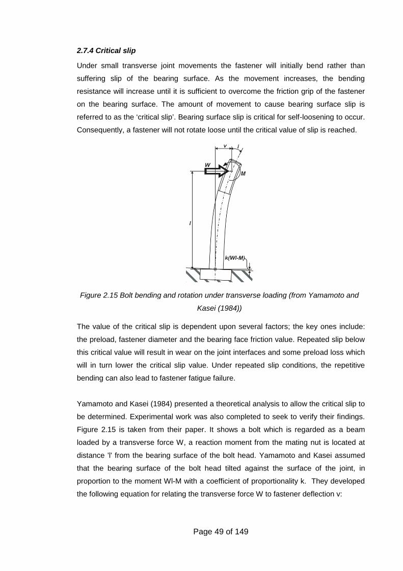
Page 49 of 149
Figure 2.15 Bolt bending and rotation under transverse loading (from Yamamoto and
Kasei (1984))
2.7.4 Critical slip
Under small transverse joint movements the fastener will initially bend rather than
suffering slip of the bearing surface. As the movement increases, the bending
resistance will increase until it is sufficient to overcome the friction grip of the fastener
on the bearing surface. The amount of movement to cause bearing surface slip is
referred to as the ‘critical slip’. Bearing surface slip is critical for self-loosening to occur.
Consequently, a fastener will not rotate loose until the critical value of slip is reached.
The value of the critical slip is dependent upon several factors; the key ones include:
the preload, fastener diameter and the bearing face friction value. Repeated slip below
this critical value will result in wear on the joint interfaces and some preload loss which
will in turn lower the critical slip value. Under repeated slip conditions, the repetitive
bending can also lead to fastener fatigue failure.
Yamamoto and Kasei (1984) presented a theoretical analysis to allow the critical slip to
be determined. Experimental work was also completed to seek to verify their findings.
Figure 2.15 is taken from their paper. It shows a bolt which is regarded as a beam
loaded by a transverse force W, a reaction moment from the mating nut is located at
distance 'l' from the bearing surface of the bolt head. Yamamoto and Kasei assumed
that the bearing surface of the bolt head tilted against the surface of the joint, in
proportion to the moment Wl-M with a coefficient of proportionality k. They developed
the following equation for relating the transverse force W to fastener deflection v:
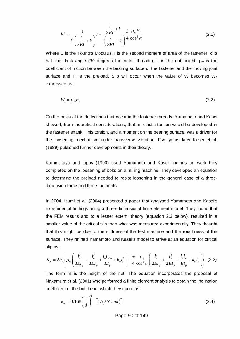
Page 50 of 149
22
1 24 cos
3 3
w f
lk FLEIW v
l ll k l k
EI EI
(2.1)
Where E is the Young’s Modulus, I is the second moment of area of the fastener, α is
half the flank angle (30 degrees for metric threads), L is the nut height, µw is the
coefficient of friction between the bearing surface of the fastener and the moving joint
surface and Ff is the preload. Slip will occur when the value of W becomes W1
expressed as:
1 w fW F (2.2)
On the basis of the deflections that occur in the fastener threads, Yamamoto and Kasei
showed, from theoretical considerations, that an elastic torsion would be developed in
the fastener shank. This torsion, and a moment on the bearing surface, was a driver for
the loosening mechanism under transverse vibration. Five years later Kasei et al.
(1989) published further developments in their theory.
Kaminskaya and Lipov (1990) used Yamamoto and Kasei findings on work they
completed on the loosening of bolts on a milling machine. They developed an equation
to determine the preload needed to resist loosening in the general case of a three-
dimension force and three moments.
In 2004, Izumi et al. (2004) presented a paper that analysed Yamamoto and Kasei’s
experimental findings using a three-dimensional finite element model. They found that
the FEM results and to a lesser extent, theory (equation 2.3 below), resulted in a
smaller value of the critical slip than what was measured experimentally. They thought
that this might be due to the stiffness of the test machine and the roughness of the
surface. They refined Yamamoto and Kasei’s model to arrive at an equation for critical
slip as:
3 3 2 2
2
22
3 3 4 cos 2 2
g p g p n g p g pscr s w w n w n
g p g g p g
l l l l l l l l lmS F k l k l
EI EI EI EI EI EI
(2.3)
The term m is the height of the nut. The equation incorporates the proposal of
Nakamura et al. (2001) who performed a finite element analysis to obtain the inclination
coefficient of the bolt head which they quote as:
3
10.168 1/wk kN mm
d
(2.4)
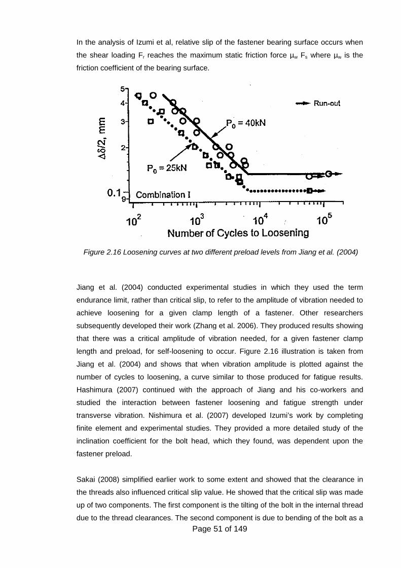
Page 51 of 149
Figure 2.16 Loosening curves at two different preload levels from Jiang et al. (2004)
In the analysis of Izumi et al, relative slip of the fastener bearing surface occurs when
the shear loading Fr reaches the maximum static friction force µw Fs where µw is the
friction coefficient of the bearing surface.
Jiang et al. (2004) conducted experimental studies in which they used the term
endurance limit, rather than critical slip, to refer to the amplitude of vibration needed to
achieve loosening for a given clamp length of a fastener. Other researchers
subsequently developed their work (Zhang et al. 2006). They produced results showing
that there was a critical amplitude of vibration needed, for a given fastener clamp
length and preload, for self-loosening to occur. Figure 2.16 illustration is taken from
Jiang et al. (2004) and shows that when vibration amplitude is plotted against the
number of cycles to loosening, a curve similar to those produced for fatigue results.
Hashimura (2007) continued with the approach of Jiang and his co-workers and
studied the interaction between fastener loosening and fatigue strength under
transverse vibration. Nishimura et al. (2007) developed Izumi’s work by completing
finite element and experimental studies. They provided a more detailed study of the
inclination coefficient for the bolt head, which they found, was dependent upon the
fastener preload.
Sakai (2008) simplified earlier work to some extent and showed that the clearance in
the threads also influenced critical slip value. He showed that the critical slip was made
up of two components. The first component is the tilting of the bolt in the internal thread
due to the thread clearances. The second component is due to bending of the bolt as a
Page 52 of 149
result of the friction grip of the bolt head on the bearing surface. The amount of bolt
bending being within the unconstrained and fully constrained head conditions.
2.8 THE FRICTION COEFFICIENT OF THREADED FASTENERS
Many equipment manufacturers specify that new fasteners should be used if the
assembly is dismantled. However, because of a lack of availability of fasteners, or for
economic reasons, fasteners are often re-used following the disassembly of a joint. A
number of researchers have reported a change in the friction characteristics of
fasteners on repeated tightening. Morgan and Henshall (1996) report that wheel studs
can experience a significant (50%) reduction in their axial tension after several re-uses.
However, they found that recovery to the original condition could be achieved by the
use of oil as a lubricant. Jiang and Zhang and Park (2002) report that a doubling in
thread friction can occur on distorted head type prevailing torque nuts.
Previous studies (Sakai, 1978; Jiang et al. 2002) have established that the friction
coefficients are largely independent of the speed of tightening of the fastener and
substantially independent of the preload. Jiang, Zhang and Park (2002) also concluded
that the thread friction coefficient is substantially independent of the bolt’s preload and
that the bearing head friction coefficient decreased with increasing preload. They also
noted that repeated tightening and loosening generally increases the friction present in
bolted joints especially when the contact surfaces are coated. Their tests were
conducted on flanged nuts and they speculated that this was attributable to a change in
the pressure distribution over the contact area with increasing clamp force.
Despite these studies, there appears to have been little work conducted on the re-use
of the commonly used electro-zinc plated nuts, bolts and washers. Jiang, Zhang and
Park (2002) completed some work on some combinations of zinc plated washers, nuts
and bolts, but their focus was on additional finish conditions typically used in the
automotive industry. Electro-zinc plating (EZP) without additional surface treatments is
so widely used on fasteners because it offers good corrosion protection at a low cost.
2.9 THE EFFECT OF TRANSVERSE VIBRATION ON THE FRICTION
FORCES ACTING ON THREADED FASTENERS
In 1978 Sakai (1978) showed that the apparent friction coefficient of a bolt with the
clamped joint in the sliding state was between 0.005 and 0.02. He stated that this was
measured by determining the torque needed to tighten a bolt whilst the joint was being
subjected to transverse slip. He also showed that, from theoretical considerations,
Page 53 of 149
there was an additional loosening torque component acting when the thread surfaces
were sliding over each other. He stated that a necessary condition for the bolt to self-
loosen with the clamped parts slipping was for the apparent friction coefficient to be
smaller than 0.03. In 2001 Sakai (2001) built upon his previous work and investigated
further the role that friction plays in the loosening process. He re-stated that the
coefficient of friction in the direction of rotation around the bolt axis when the bolt head
and thread surfaces are sliding should be extremely small, a range 0.00 ~ 0.02 is
quoted. Sakai advocates tribological research to seek surface treatment conditions to
maintain a high coefficient of friction under slip conditions.
In recent years several researchers have investigated the loosening process by using
detailed three-dimensional finite element models. Such models have been developed
by Zadocks and Yu (1993; 1997), Pai and Hess (Pai and Hess, 2002; Pai, 2004), Izumi
et al (2005), Shoji and Sawa (2005), Fujioka and Sakai (2005), Wang and Jiang (2006),
Nisimura et al (2007) and Izumi et al (2008). Due to the nature of the method, the
friction coefficient is an input rather than an output from the models. Additionally these
researchers had to make other assumptions regarding the frictional force in the
circumferential direction when transverse slip occurred.
In 2002 Pai and Hess (2002) used a detailed three-dimensional model to investigate
the loosening process. With their model they investigated the effect of three different
levels of friction and the effect of localised slip on the loosening process. They
developed a theory (Pal and Hess, 2004) in which loosening, caused by complete slip
as indicated by Junker (1969), could also result from the accumulation of localised slip
in the form of elastic deformation. Their test data indicated that a fastener could loosen
at roughly half the shear load required for complete head slip. The model assumed that
once the tangential friction forces are overcome, either from complete slip or an
accumulation of localised slip, the fastener would be free to rotate in the circumferential
direction.
In 2005, Izumi et al published an investigation into the loosening process by using a
three-dimension finite element model in which they assumed the friction coefficient was
a constant 0.15 (Izumi et al. 2005). One of their conclusions was that complete thread
slip occurred prior to bolt head slip which was previously considered the initial point of
loosening. In the same year Shoji and Sawa also used a three-dimensional finite
element model to investigate loosening, this time based upon a constant friction value
of 0.1 (Shoji and Sawa, 2005). They concluded that alternating shear stress on the
contact surfaces of the threads induces the loosening process.
Page 54 of 149
In 2005 Fujioka and Sakai (2005) showed that friction had a significant influence on the
rotational loosening of fasteners. They investigated the theory that friction can influence
loosening by using a fine mesh three-dimension finite element model. They found that
it was not just the overall magnitude of the friction that was important, but the relative
value of the thread friction compared to the head face friction.
Housari and Nassar (2006) developed a mathematical model to assess the effect that
variations in the static friction coefficient has on the loosening rate. However, they did
not discuss how the apparent friction in a circumferential direction, when transverse slip
occurred, might be influenced by the static friction value. Wang and Jiang (2006) used
FEM to study the role that a stick-slip mechanism plays in the self-loosening of
threaded fasteners. Their study found that localised stick-slip action results in the
gradual displacement between two contact surfaces, this contributes to the rotation of
the nut. They assumed a friction coefficient of 0.09. Nisimura et al (2007) used a
friction coefficient of 0.2, Izumi et al (2008) used 0.15 and appeared to ignore the
reduction in the friction force in a circumferential direction when transverse slip of the
contact surfaces occurs.
Page 55 of 149
3. OVERVIEW OF THE EXPERIMENTAL PROGRAMME
3.1 INTRODUCTION
A bolted joint would not remain tight without the presence of friction. When a bolt is
tightened the preload acting on the thread helix results in an off torque that, without
friction, would cause the nut to spin off. By resisting movement, friction also plays a
central role in determining the conversion of applied torque into bolt preload. Based
upon the literature research completed in chapter 2, as well as the authors own
experience, the role that friction plays in the loosening process has not been
extensively studied. Friction is central to threaded fastener tightening and loosening
processes and deserves further study. The studies in the Thesis can be considered in
three groups. Namely:
1. The first phase of testing involved the measurement of friction exhibited when
threaded fasteners are tightened, removed and re-tightened. The focus of the study
was the effect on the friction coefficient of re-used electro-zinc plated fasteners. The
reason why it was decided to investigate this particular type of finish is that it is one of
the most popular in use today.
2. A large number of tests were completed using a standard fastener transverse
vibration test machine commonly referred to as a ‘Junker machine’ which induces
transverse vibration on a joint. These tests largely replicated tests that had previously
been completed by other researchers. Focus was made on the loosening
characteristics of prevailing torque nuts. The essential characteristic of such nuts is that
a torque is needed to rotate the nut down the thread of an untightened bolt. This type of
nut is probably the most common type of anti self-loosening fastener in present use.
A standard Junker machine was modified to allow axial loading to be imparted into the
bolted joint whilst it was experiencing transverse vibration. This novel arrangement was
used to conduct original studies into the complete self-loosening of prevailing torque
nuts under circumstances when transverse vibration is accompanied by axial load.
3. In the final series of original tests, the self-loosening forces acting on a fastener
being subjected to transverse vibration were investigated. A study was also made of
the drop in the circumferential frictional forces when transverse joint movement was
being experienced.
Page 56 of 149
3.2 TESTS ON THE DETERMINATION OF THE FRICTION COEFFICIENT OF
FASTENERS
Fasteners are often re-used, either for economic reasons or due to lack of immediate
availability of a replacement. (Such as when replacing a punctured car tyre). Re-use of
fasteners involves repeated sliding contact between surfaces. Such sliding can have a
detrimental effect on the performance of the fastener.
The effect of such repeated sliding contact was investigated experimentally by the
study of repeated use of electro-zinc plated (EZP) fasteners. Zinc plating is an
extremely common coating used on fasteners. The tests involved measuring the
coefficient of friction present between the threads and under the nut face. To do these
tests, novel apparatus was designed and made.
In this series of tests the approach was to measure the applied torque, the thread
reaction torque and the bolt preload simultaneously. From these measurements the
thread friction and nut face friction torque was established allowing the coefficient of
friction to be determined for the thread and nut face.
To investigate the effect of sliding distance on the nut face/washer interface, a test
apparatus was used that allowed a nut to be rotated on a test surface indefinitely at a
pre-determined load. (Normally the bolt load changes when the nut rotates which
makes comparison with conventional friction tests difficult.) Based upon studies of
existing methods of measuring thread and nut face friction, a design was developed
that would economically allow the preload, the total applied torque and the thread
torque component to be measured. The test apparatus consisted of a load cell and
thrust bearing mounted in series. A bolt passed through the middle of the assembly. A
series of disc springs was used in order to increase the resilience of the bolted
assembly so that once the bolt had been tightened it would be insensitive to clamp
force variation due to wear on the nut face.
3.3 LOOSENING OF THREADED FASTENERS BY TRANSVERSE
VIBRATION
Junker and other researchers (Junker (1969), Finelston (1972), Haviland (1981)) have
shown that transverse vibration could fully loosen non-locked threaded fasteners. A
large number of tests were completed to investigate the self-loosening of fasteners
under transverse vibration. The tests were completed using a standard transverse
vibration test machine commonly referred to as a "Junker machine".
Page 57 of 149
The focus of these tests was to study the performance of a particular type of lock nut
referred to generically as a "prevailing torque" nut. This popular form of lock nut has a
locking feature in which a small torque, the “prevailing torque”, is needed to rotate the
nut down the thread of an untightened bolt. This type of nut is in extensive use across
most industries and is probably the most common type of locking device for threaded
fasteners.
There are many varieties of prevailing torque nuts, but in general they can all be
classified into one of two categories, those with a non-metallic insert and those which
are all-metal. Non-metallic insert nuts typically generate a prevailing torque by
incorporating in the top of the nut a polymer insert that is deformed by the bolt thread.
All-metal nuts generate prevailing torque by incorporating a means of deformation in
their form. Tests were performed on both types of nut.
Further tests have been completed to establish the effect on the prevailing torque of re-
use of the nut. The performance requirements for such nuts are specified in the ISO
2230 standard (British Standards, 2008). The standard stipulates that a minimum level
of prevailing torque, for a given thread size, must be maintained for up to five re-uses.
In many industries such nuts are re-used, and in some industries, such as the rail
industry, re-tightened if found to be loose. As a performance requirement for re-use,
the standard specifies that the nut is to be untightened and then re-tightened. The tests
completed compared this standard procedure to a test involving the nuts being self-
loosened due to transverse vibration. Self-loosening, which happens in practice, should
be more severe in that many repetitions of relative thread movement will occur during
the loosening process and these will lead to wear of the prevailing torque locking
arrangement in the nut. This wear can be anticipated to lower the prevailing torque to a
greater extent than that which occurs by manually untightening the nut.
3.4 COMPLETE SELF-LOOSENING OF PREVAILING TORQUE FASTENERS
Instances of the detachment of prevailing torque nuts from bolts have occurred with
sometimes catastrophic consequences, but to-date, there has been a lack of
understanding of the precise conditions that can lead to such separation. One reason
for the lack of understanding is that such complete loosening has not been
reproducible on a Junker machine.
The author's study of incidents in which detachments of prevailing torque nuts have
Page 58 of 149
occurred indicate that the joint has been be subjected to axial as well as transverse
loading. Previous published research had indicated that axial loading alone acting on a
joint does not result in any significant self-loosening (Goodier and Sweeney (1945),
Sauer et al. (1950)). As part of the author's research programme the suspicion arose
that axial loading in the presence of transverse joint movement would affect the
loosening characteristics of prevailing torque nuts.
In order to investigate the causes of the detachment of prevailing torque nuts from
bolts, the Junker machine used in previous experiments was modified to allow axial as
well as transverse loading to be introduced into a joint. Miniature hydraulic jacks were
used to allow axial loads to be imposed upon the joint whilst transverse movement was
occurring. The arrangement allowed axial loading alone, transverse displacement
alone or a combination of both to be imposed on the joint. The results revealed that by
combining axial loading with transverse vibration complete loosening of prevailing
torque nuts could occur. Further investigation revealed the precise conditions under
which such detachment occurs.
3.5 THE EFFECT OF TRANSVERSE VIBRATION ON THE FRICTION
FORCES ACTING ON THREADED FASTENERS
Central to understanding the root cause of the loosening is knowledge of the forces
tending to loosen fasteners and why there is an apparent reduction in the friction
coefficient under certain circumstances. A series of tests was completed measuring
both the torque acting in the loosening direction and the apparent reduction in the
friction coefficient of a threaded fastener when a joint is experiencing repeated
transverse movement.
The Junker machine used in the previous tests was modified to allow torque
measurements to be completed on threaded fasteners whilst they were subjected to
transverse vibration. The machine was used to perform three types of tests:
1. Measurement of the torque tending to loosen fasteners whilst they were subjected
to transverse vibration.
2. Tightening of fasteners whilst they were subjected to transverse vibration.
3. Measurement of the torque needed to rotate nuts in the tightening direction whilst
they were subjected to transverse vibration.
The first series of tests involved measurement of the loosening torque being exerted on
M8 electro-zinc plated bolts and plain non-locking nuts whilst being subjected to
transverse vibration. A torque transducer was mounted on the moving top plate of the
Page 59 of 149
machine so that it would react the loosening torque being generated by the fastener
undergoing transverse slip.
The second series of tests reproduced the work of another researcher (Sakai, 1978)
and allowed the overall friction coefficient of the fastener to be determined following the
DIN 946 method (Deutsche Norm, 1991). The torque needed to tighten an M8 plain
non-locking electro-zinc plated nuts onto bolts under the conditions of transverse slip
was measured.
In the third series of tests an electro-zinc plated flanged nut (with a Spiralock thread
form) was locked onto an M6 threaded rod using a high strength chemical threadlocker
so that no self-loosening would occur. The torque needed to rotate the fastener under
transverse vibration was measured. From the torque measurements obtained it was
possible to determine the circumferential coefficient of friction of the nut face under
conditions of transverse slip.
Page 60 of 149
4. DETERMINATION OF THE FRICTION COEFFICIENT OF
FASTENERS
4.1 INTRODUCTION
Without friction, threaded fasteners could not retain their tension without the addition of
a locking mechanism and would subsequently be highly restricted in their application.
When a nut is tightened onto a bolt, it is friction that holds it in place preventing it from
spinning off. Friction is essential, but too high a friction value can also be a problem to
the functioning of a threaded fastener. In the majority of applications, it is the preload
that is the primary design requirement. The preload results from the axial stress
generated when the bolt is tightened. High thread friction results in a high torsional
stress in the threaded section that limits the axial stress available and hence the
preload achievable from the tightening process. Preload is difficult and expensive to
measure and so usually its control is indirectly achieved by specifying a tightening
torque. Friction plays a large part in determining the effectiveness of the conversion of
applied torque to fastener preload. To control preload by torque control it is essential to
have some limits placed on the range of the coefficient of friction.
When the application sustains purely static loading, it is desirable to keep the friction as
low as possible so that the torsional stress in the bolt is minimised. In dynamic
applications, a concern is that low friction will aid self-loosening. Most of the major
automotive companies specify the acceptable friction range on fasteners they use so
as to provide some control over the torque-tension relationship. For example based
upon the author's investigations and discussions, Ford, Renault and Peugeot-Citroen
specify an acceptable friction range of 0.12 to 0.18. German manufacturers typically
specify a lower minimum value, for example Porsche and Volkswagen specify 0.09 –
0.14. Company standards are used (such as the Ford standard WZ 101 (Ford, 2002))
for checking the compliance of the fasteners, such standards being usually based upon
relevant national standards (such as DIN 946 (Deutsche Norm, 1991)) adjusted to suit
the particular requirements of the company.
In the automotive industry, zinc flake and other coatings that incorporate PTFE or other
dry lubricants are typically used to control the friction characteristics. In other
industries, electro zinc plated (EZP) coatings are used which typically do not have a
coating to modify the friction characteristics. As part of this research project, the friction
characteristics of fasteners coated with electro-zinc plating were investigated.
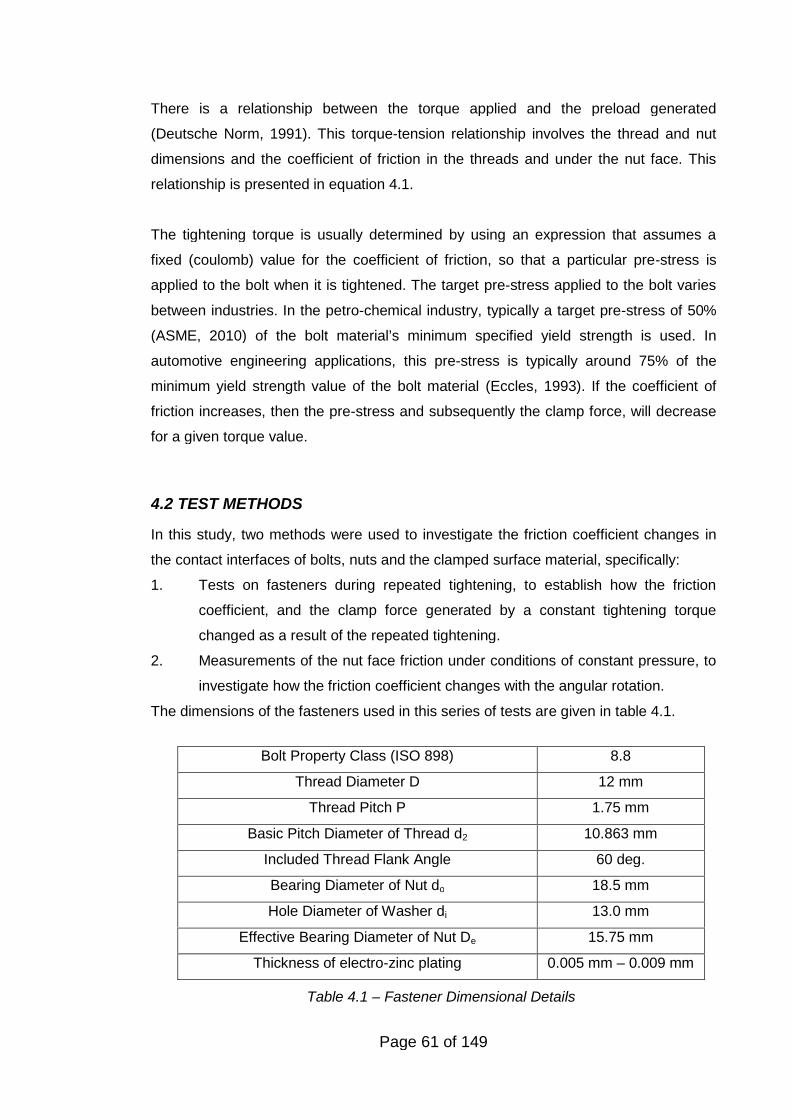
Page 61 of 149
Bolt Property Class (ISO 898) 8.8
Thread Diameter D 12 mm
Thread Pitch P 1.75 mm
Basic Pitch Diameter of Thread d2 10.863 mm
Included Thread Flank Angle 60 deg.
Bearing Diameter of Nut do 18.5 mm
Hole Diameter of Washer di 13.0 mm
Effective Bearing Diameter of Nut De 15.75 mm
Thickness of electro-zinc plating 0.005 mm – 0.009 mm
Table 4.1 – Fastener Dimensional Details
There is a relationship between the torque applied and the preload generated
(Deutsche Norm, 1991). This torque-tension relationship involves the thread and nut
dimensions and the coefficient of friction in the threads and under the nut face. This
relationship is presented in equation 4.1.
The tightening torque is usually determined by using an expression that assumes a
fixed (coulomb) value for the coefficient of friction, so that a particular pre-stress is
applied to the bolt when it is tightened. The target pre-stress applied to the bolt varies
between industries. In the petro-chemical industry, typically a target pre-stress of 50%
(ASME, 2010) of the bolt material’s minimum specified yield strength is used. In
automotive engineering applications, this pre-stress is typically around 75% of the
minimum yield strength value of the bolt material (Eccles, 1993). If the coefficient of
friction increases, then the pre-stress and subsequently the clamp force, will decrease
for a given torque value.
4.2 TEST METHODS
In this study, two methods were used to investigate the friction coefficient changes in
the contact interfaces of bolts, nuts and the clamped surface material, specifically:
1. Tests on fasteners during repeated tightening, to establish how the friction
coefficient, and the clamp force generated by a constant tightening torque
changed as a result of the repeated tightening.
2. Measurements of the nut face friction under conditions of constant pressure, to
investigate how the friction coefficient changes with the angular rotation.
The dimensions of the fasteners used in this series of tests are given in table 4.1.
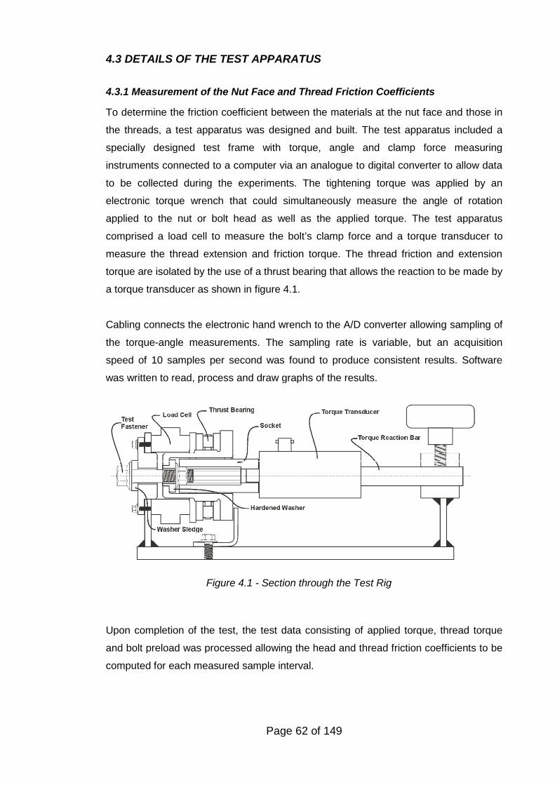
Page 62 of 149
4.3 DETAILS OF THE TEST APPARATUS
4.3.1 Measurement of the Nut Face and Thread Friction Coefficients
To determine the friction coefficient between the materials at the nut face and those in
the threads, a test apparatus was designed and built. The test apparatus included a
specially designed test frame with torque, angle and clamp force measuring
instruments connected to a computer via an analogue to digital converter to allow data
to be collected during the experiments. The tightening torque was applied by an
electronic torque wrench that could simultaneously measure the angle of rotation
applied to the nut or bolt head as well as the applied torque. The test apparatus
comprised a load cell to measure the bolt’s clamp force and a torque transducer to
measure the thread extension and friction torque. The thread friction and extension
torque are isolated by the use of a thrust bearing that allows the reaction to be made by
a torque transducer as shown in figure 4.1.
Cabling connects the electronic hand wrench to the A/D converter allowing sampling of
the torque-angle measurements. The sampling rate is variable, but an acquisition
speed of 10 samples per second was found to produce consistent results. Software
was written to read, process and draw graphs of the results.
Upon completion of the test, the test data consisting of applied torque, thread torque
and bolt preload was processed allowing the head and thread friction coefficients to be
computed for each measured sample interval.
Figure 4.1 - Section through the Test Rig
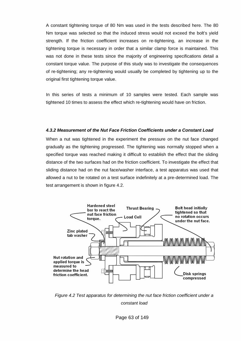
Page 63 of 149
A constant tightening torque of 80 Nm was used in the tests described here. The 80
Nm torque was selected so that the induced stress would not exceed the bolt’s yield
strength. If the friction coefficient increases on re-tightening, an increase in the
tightening torque is necessary in order that a similar clamp force is maintained. This
was not done in these tests since the majority of engineering specifications detail a
constant torque value. The purpose of this study was to investigate the consequences
of re-tightening; any re-tightening would usually be completed by tightening up to the
original first tightening torque value.
In this series of tests a minimum of 10 samples were tested. Each sample was
tightened 10 times to assess the effect which re-tightening would have on friction.
4.3.2 Measurement of the Nut Face Friction Coefficients under a Constant Load
When a nut was tightened in the experiment the pressure on the nut face changed
gradually as the tightening progressed. The tightening was normally stopped when a
specified torque was reached making it difficult to establish the effect that the sliding
distance of the two surfaces had on the friction coefficient. To investigate the effect that
sliding distance had on the nut face/washer interface, a test apparatus was used that
allowed a nut to be rotated on a test surface indefinitely at a pre-determined load. The
test arrangement is shown in figure 4.2.
Figure 4.2 Test apparatus for determining the nut face friction coefficient under a
constant load
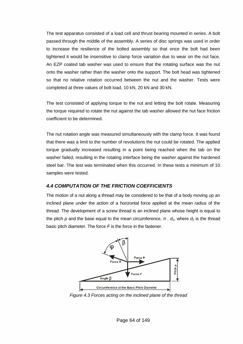
Page 64 of 149
The test apparatus consisted of a load cell and thrust bearing mounted in series. A bolt
passed through the middle of the assembly. A series of disc springs was used in order
to increase the resilience of the bolted assembly so that once the bolt had been
tightened it would be insensitive to clamp force variation due to wear on the nut face.
An EZP coated tab washer was used to ensure that the rotating surface was the nut
onto the washer rather than the washer onto the support. The bolt head was tightened
so that no relative rotation occurred between the nut and the washer. Tests were
completed at three values of bolt load, 10 kN, 20 kN and 30 kN.
The test consisted of applying torque to the nut and letting the bolt rotate. Measuring
the torque required to rotate the nut against the tab washer allowed the nut face friction
coefficient to be determined.
The nut rotation angle was measured simultaneously with the clamp force. It was found
that there was a limit to the number of revolutions the nut could be rotated. The applied
torque gradually increased resulting in a point being reached when the tab on the
washer failed, resulting in the rotating interface being the washer against the hardened
steel bar. The test was terminated when this occurred. In these tests a minimum of 10
samples were tested.
4.4 COMPUTATION OF THE FRICTION COEFFICIENTS
The motion of a nut along a thread may be considered to be that of a body moving up an
inclined plane under the action of a horizontal force applied at the mean radius of the
thread. The development of a screw thread is an inclined plane whose height is equal to
the pitch p and the base equal to the mean circumference, π . d2, where d2 is the thread
basic pitch diameter. The force F is the force in the fastener.
Figure 4.3 Forces acting on the inclined plane of the thread
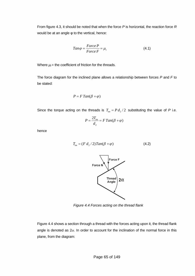
Page 65 of 149
From figure 4.3, it should be noted that when the force P is horizontal, the reaction force R
would be at an angle φ to the vertical, hence:
t
Force PTan
Force F (4.1)
Where μt = the coefficient of friction for the threads.
The force diagram for the inclined plane allows a relationship between forces P and F to
be stated:
( )P F Tan
Since the torque acting on the threads is 2 / 2tmT P d substituting the value of P i.e.
2
2( )tmT
P F Tand
hence
2( / 2) ( )tmT F d Tan (4.2)
Figure 4.4 shows a section through a thread with the forces acting upon it, the thread flank
angle is denoted as 2. In order to account for the inclination of the normal force in this
plane, from the diagram:
Figure 4.4 Forces acting on the thread flank
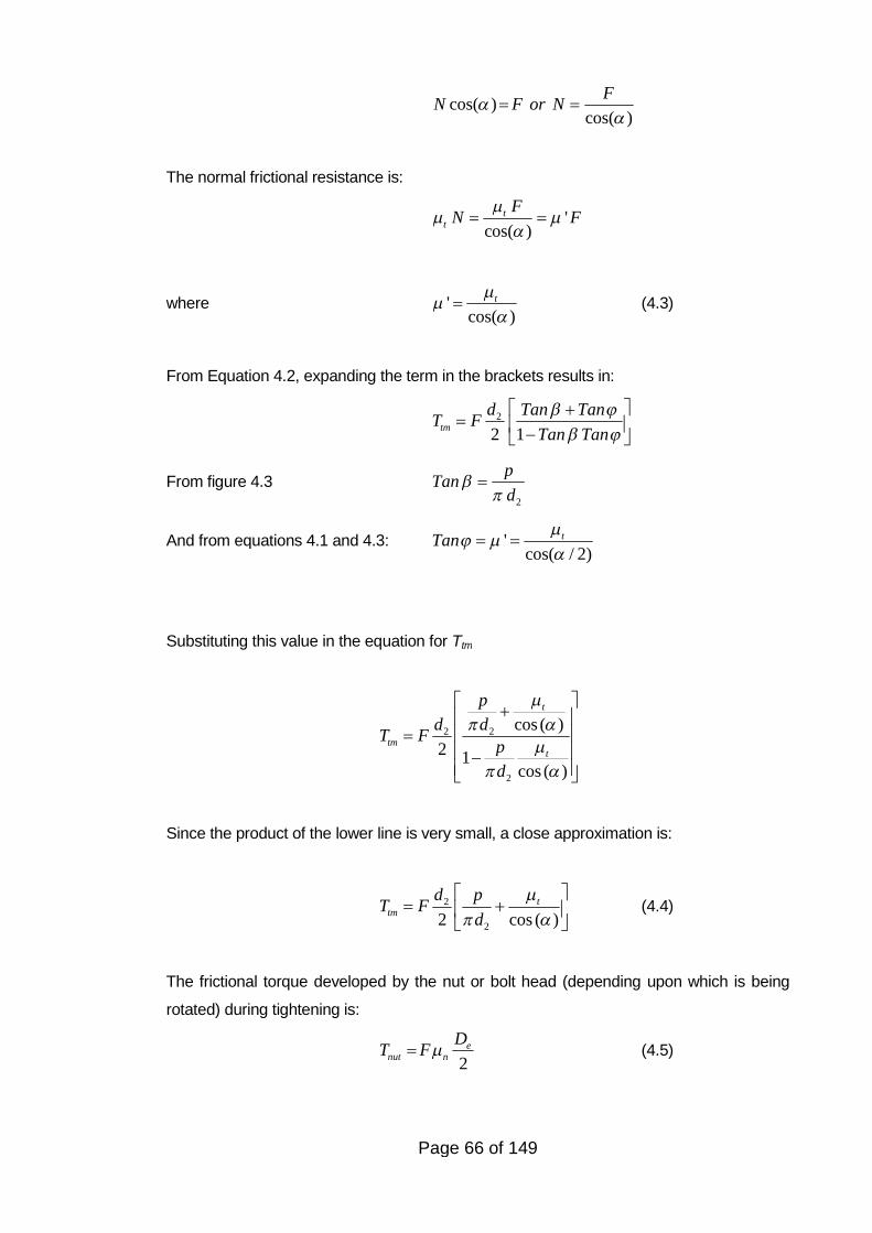
Page 66 of 149
cos( )cos( )
FN F or N
The normal frictional resistance is:
'cos( )
tt
FN F
where 'cos( )
t
(4.3)
From Equation 4.2, expanding the term in the brackets results in:
2
2 1tm
d Tan TanT F
Tan Tan
From figure 4.32
pTan
d
And from equations 4.1 and 4.3: 'cos( / 2)
tTan
Substituting this value in the equation for Ttm
2 2
2
cos ( )
2 1cos ( )
t
tmt
p
d dT F
p
d
Since the product of the lower line is very small, a close approximation is:
2
22 cos ( )t
tm
d pT F
d
(4.4)
The frictional torque developed by the nut or bolt head (depending upon which is being
rotated) during tightening is:
2e
nut n
DT F (4.5)
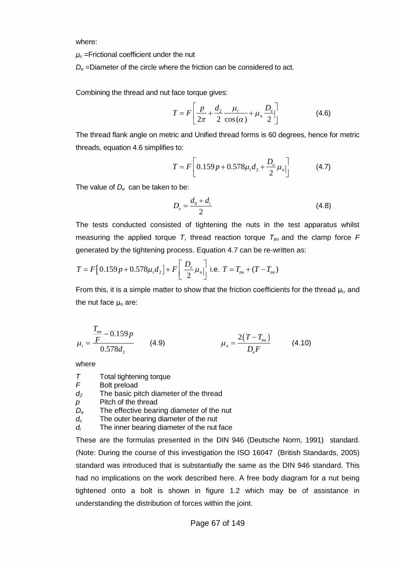
Page 67 of 149
where:
μn =Frictional coefficient under the nut
De =Diameter of the circle where the friction can be considered to act.
Combining the thread and nut face torque gives:
2
2 2 cos ( ) 2t e
n
DdpT F
(4.6)
The thread flank angle on metric and Unified thread forms is 60 degrees, hence for metric
threads, equation 4.6 simplifies to:
20.159 0.5782
et n
DT F p d
(4.7)
The value of De can be taken to be:
0
2i
e
d dD
(4.8)
The tests conducted consisted of tightening the nuts in the test apparatus whilst
measuring the applied torque T, thread reaction torque Ttm and the clamp force F
generated by the tightening process. Equation 4.7 can be re-written as:
20.159 0.5782
et n
DT F p d F
i.e. ( )tm tmT T T T
From this, it is a simple matter to show that the friction coefficients for the thread μt, and
the nut face μn are:
2
0.159
0.578
tm
t
Tp
Fd
(4.9) 2 tm
n
e
T T
D F
(4.10)
where
T Total tightening torqueF Bolt preloadd2 The basic pitch diameter of the threadp Pitch of the threadDe The effective bearing diameter of the nutdo The outer bearing diameter of the nutdi The inner bearing diameter of the nut face
These are the formulas presented in the DIN 946 (Deutsche Norm, 1991) standard.
(Note: During the course of this investigation the ISO 16047 (British Standards, 2005)
standard was introduced that is substantially the same as the DIN 946 standard. This
had no implications on the work described here. A free body diagram for a nut being
tightened onto a bolt is shown in figure 1.2 which may be of assistance in
understanding the distribution of forces within the joint.
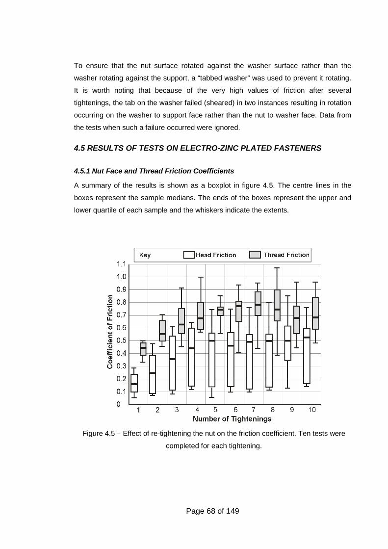
Page 68 of 149
To ensure that the nut surface rotated against the washer surface rather than the
washer rotating against the support, a “tabbed washer” was used to prevent it rotating.
It is worth noting that because of the very high values of friction after several
tightenings, the tab on the washer failed (sheared) in two instances resulting in rotation
occurring on the washer to support face rather than the nut to washer face. Data from
the tests when such a failure occurred were ignored.
4.5 RESULTS OF TESTS ON ELECTRO-ZINC PLATED FASTENERS
4.5.1 Nut Face and Thread Friction Coefficients
A summary of the results is shown as a boxplot in figure 4.5. The centre lines in the
boxes represent the sample medians. The ends of the boxes represent the upper and
lower quartile of each sample and the whiskers indicate the extents.
Figure 4.5 – Effect of re-tightening the nut on the friction coefficient. Ten tests were
completed for each tightening.
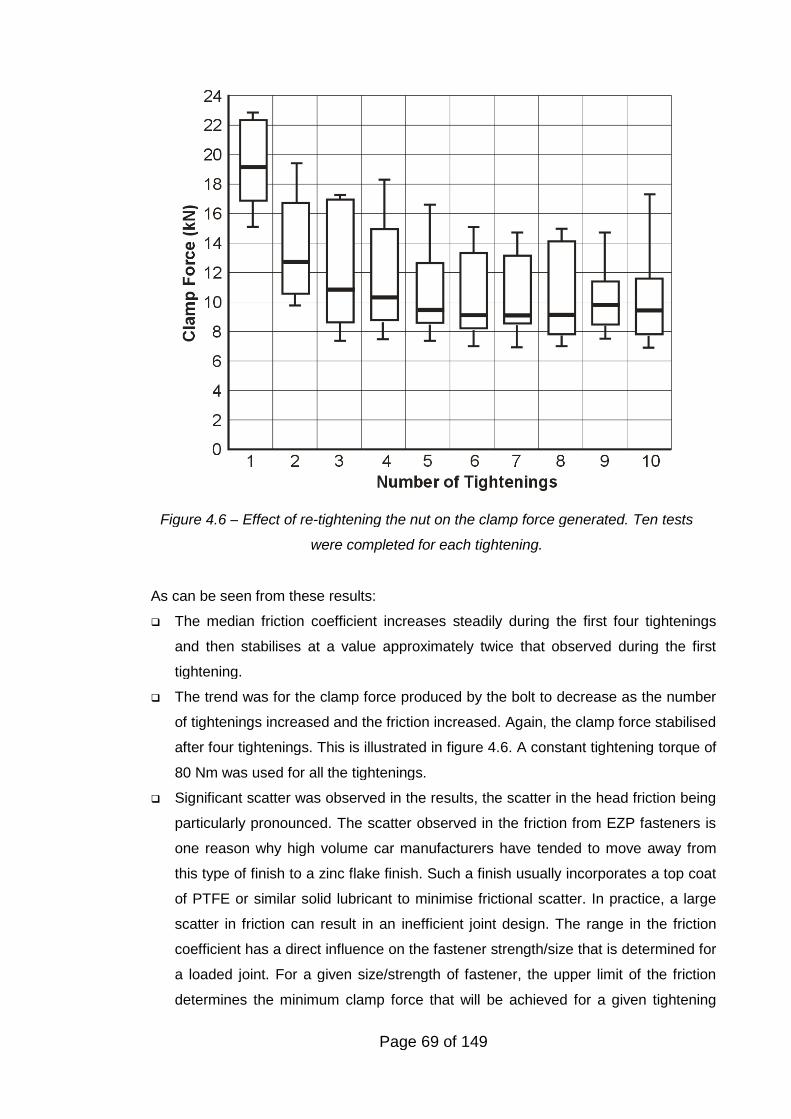
Page 69 of 149
As can be seen from these results:
The median friction coefficient increases steadily during the first four tightenings
and then stabilises at a value approximately twice that observed during the first
tightening.
The trend was for the clamp force produced by the bolt to decrease as the number
of tightenings increased and the friction increased. Again, the clamp force stabilised
after four tightenings. This is illustrated in figure 4.6. A constant tightening torque of
80 Nm was used for all the tightenings.
Significant scatter was observed in the results, the scatter in the head friction being
particularly pronounced. The scatter observed in the friction from EZP fasteners is
one reason why high volume car manufacturers have tended to move away from
this type of finish to a zinc flake finish. Such a finish usually incorporates a top coat
of PTFE or similar solid lubricant to minimise frictional scatter. In practice, a large
scatter in friction can result in an inefficient joint design. The range in the friction
coefficient has a direct influence on the fastener strength/size that is determined for
a loaded joint. For a given size/strength of fastener, the upper limit of the friction
determines the minimum clamp force that will be achieved for a given tightening
Figure 4.6 – Effect of re-tightening the nut on the clamp force generated. Ten tests
were completed for each tightening.
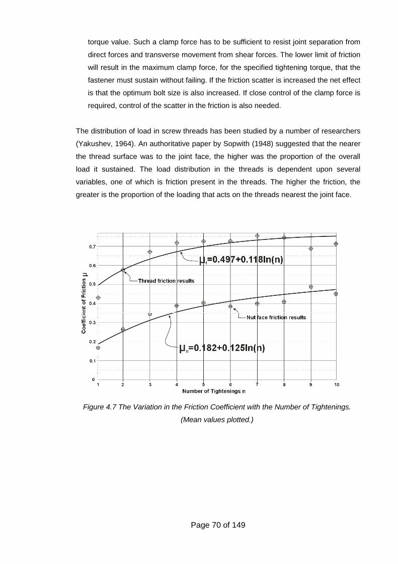
Page 70 of 149
torque value. Such a clamp force has to be sufficient to resist joint separation from
direct forces and transverse movement from shear forces. The lower limit of friction
will result in the maximum clamp force, for the specified tightening torque, that the
fastener must sustain without failing. If the friction scatter is increased the net effect
is that the optimum bolt size is also increased. If close control of the clamp force is
required, control of the scatter in the friction is also needed.
The distribution of load in screw threads has been studied by a number of researchers
(Yakushev, 1964). An authoritative paper by Sopwith (1948) suggested that the nearer
the thread surface was to the joint face, the higher was the proportion of the overall
load it sustained. The load distribution in the threads is dependent upon several
variables, one of which is friction present in the threads. The higher the friction, the
greater is the proportion of the loading that acts on the threads nearest the joint face.
Figure 4.7 The Variation in the Friction Coefficient with the Number of Tightenings.
(Mean values plotted.)
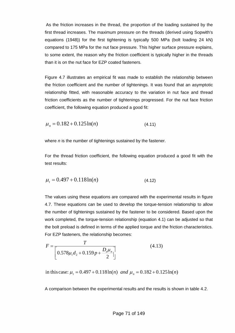
Page 71 of 149
As the friction increases in the thread, the proportion of the loading sustained by the
first thread increases. The maximum pressure on the threads (derived using Sopwith's
equations (1948)) for the first tightening is typically 500 MPa (bolt loading 24 kN)
compared to 175 MPa for the nut face pressure. This higher surface pressure explains,
to some extent, the reason why the friction coefficient is typically higher in the threads
than it is on the nut face for EZP coated fasteners.
Figure 4.7 illustrates an empirical fit was made to establish the relationship between
the friction coefficient and the number of tightenings. It was found that an asymptotic
relationship fitted, with reasonable accuracy to the variation in nut face and thread
friction coefficients as the number of tightenings progressed. For the nut face friction
coefficient, the following equation produced a good fit:
0.182 0.125ln( )n n (4.11)
where n is the number of tightenings sustained by the fastener.
For the thread friction coefficient, the following equation produced a good fit with the
test results:
0.497 0.118ln( )t n (4.12)
The values using these equations are compared with the experimental results in figure
4.7. These equations can be used to develop the torque-tension relationship to allow
the number of tightenings sustained by the fastener to be considered. Based upon the
work completed, the torque-tension relationship (equation 4.1) can be adjusted so that
the bolt preload is defined in terms of the applied torque and the friction characteristics.
For EZP fasteners, the relationship becomes:
2
(4.13)
0.578 0.1592
in thiscase: 0.497 0.118ln( ) 0.182 0.125ln( )
e nt
t n
TF
Dd p
n and n
A comparison between the experimental results and the results is shown in table 4.2.
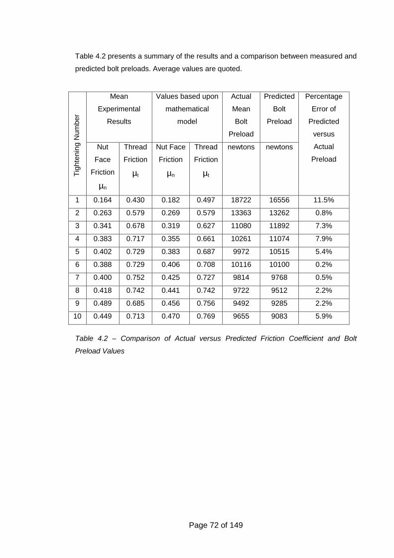
Page 72 of 149
Table 4.2 presents a summary of the results and a comparison between measured and
predicted bolt preloads. Average values are quoted.
Table 4.2 – Comparison of Actual versus Predicted Friction Coefficient and Bolt
Preload Values
Mean
Experimental
Results
Values based upon
mathematical
model
Actual
Mean
Bolt
Preload
Predicted
Bolt
Preload
Tig
hte
nin
gN
um
ber
Nut
Face
Friction
µn
Thread
Friction
µt
Nut Face
Friction
µn
Thread
Friction
µt
newtons newtons
Percentage
Error of
Predicted
versus
Actual
Preload
1 0.164 0.430 0.182 0.497 18722 16556 11.5%
2 0.263 0.579 0.269 0.579 13363 13262 0.8%
3 0.341 0.678 0.319 0.627 11080 11892 7.3%
4 0.383 0.717 0.355 0.661 10261 11074 7.9%
5 0.402 0.729 0.383 0.687 9972 10515 5.4%
6 0.388 0.729 0.406 0.708 10116 10100 0.2%
7 0.400 0.752 0.425 0.727 9814 9768 0.5%
8 0.418 0.742 0.441 0.742 9722 9512 2.2%
9 0.489 0.685 0.456 0.756 9492 9285 2.2%
10 0.449 0.713 0.470 0.769 9655 9083 5.9%
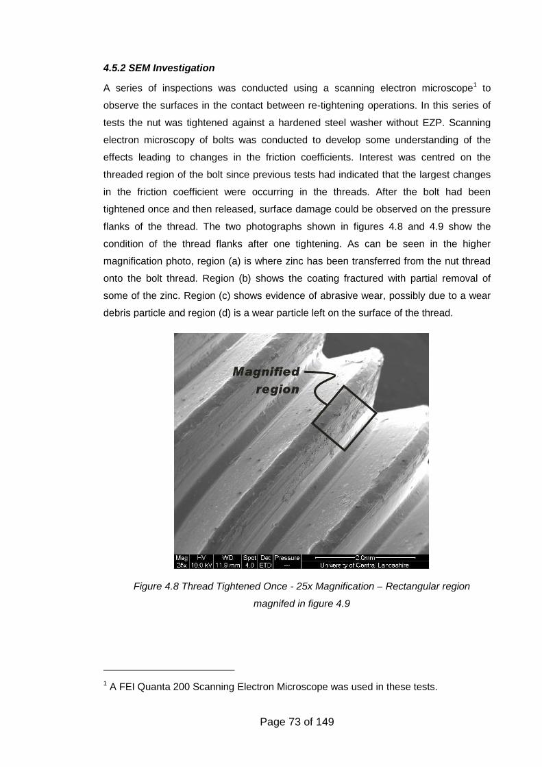
Page 73 of 149
Figure 4.8 Thread Tightened Once - 25x Magnification – Rectangular region
magnifed in figure 4.9
4.5.2 SEM Investigation
A series of inspections was conducted using a scanning electron microscope1 to
observe the surfaces in the contact between re-tightening operations. In this series of
tests the nut was tightened against a hardened steel washer without EZP. Scanning
electron microscopy of bolts was conducted to develop some understanding of the
effects leading to changes in the friction coefficients. Interest was centred on the
threaded region of the bolt since previous tests had indicated that the largest changes
in the friction coefficient were occurring in the threads. After the bolt had been
tightened once and then released, surface damage could be observed on the pressure
flanks of the thread. The two photographs shown in figures 4.8 and 4.9 show the
condition of the thread flanks after one tightening. As can be seen in the higher
magnification photo, region (a) is where zinc has been transferred from the nut thread
onto the bolt thread. Region (b) shows the coating fractured with partial removal of
some of the zinc. Region (c) shows evidence of abrasive wear, possibly due to a wear
debris particle and region (d) is a wear particle left on the surface of the thread.
1 A FEI Quanta 200 Scanning Electron Microscope was used in these tests.
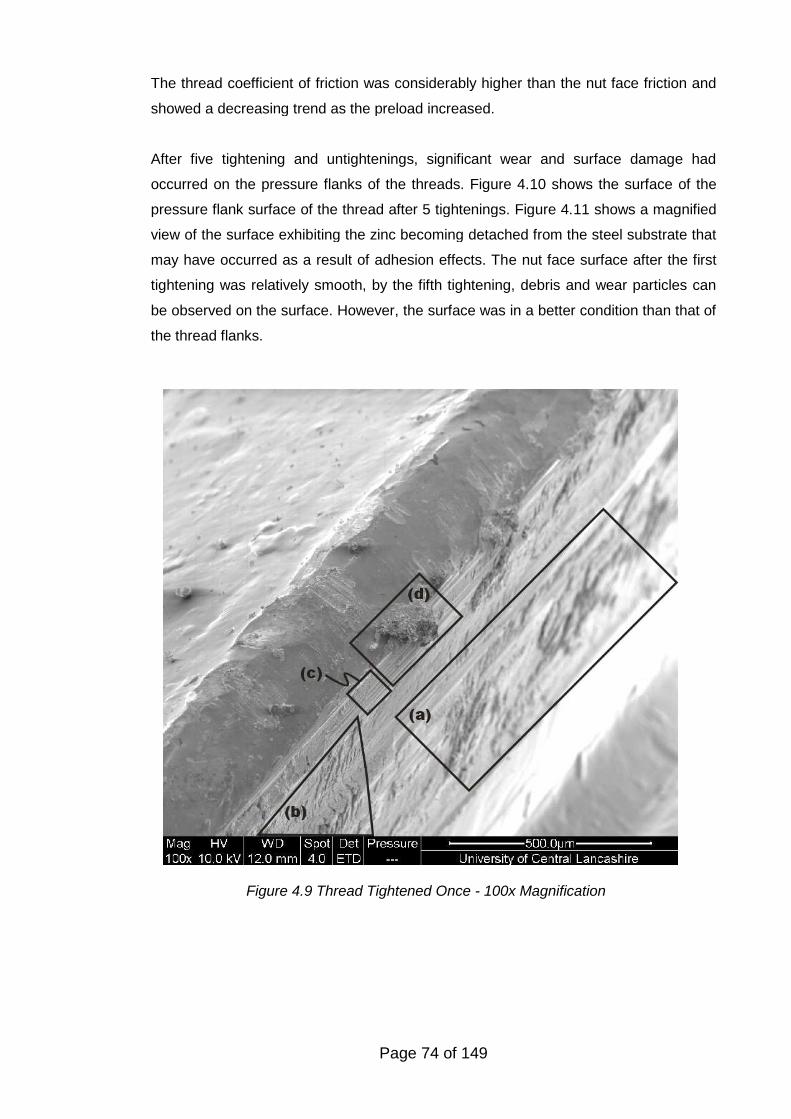
Page 74 of 149
Figure 4.9 Thread Tightened Once - 100x Magnification
The thread coefficient of friction was considerably higher than the nut face friction and
showed a decreasing trend as the preload increased.
After five tightening and untightenings, significant wear and surface damage had
occurred on the pressure flanks of the threads. Figure 4.10 shows the surface of the
pressure flank surface of the thread after 5 tightenings. Figure 4.11 shows a magnified
view of the surface exhibiting the zinc becoming detached from the steel substrate that
may have occurred as a result of adhesion effects. The nut face surface after the first
tightening was relatively smooth, by the fifth tightening, debris and wear particles can
be observed on the surface. However, the surface was in a better condition than that of
the thread flanks.
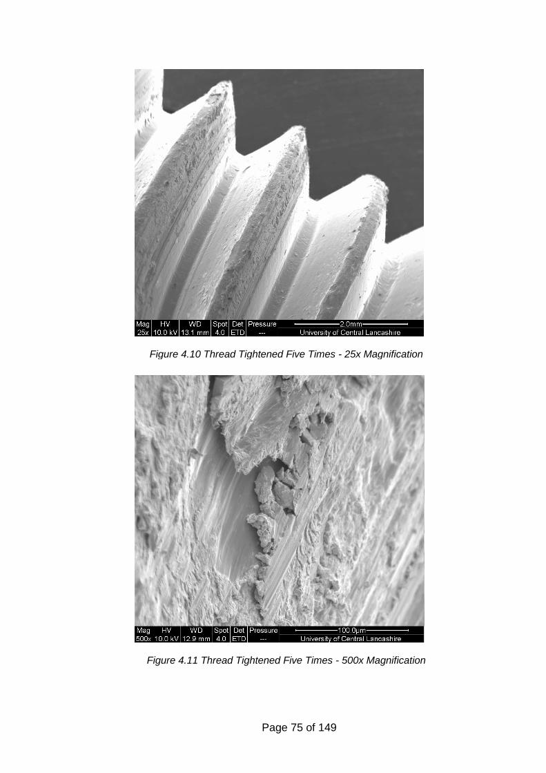
Page 75 of 149
Figure 4.10 Thread Tightened Five Times - 25x Magnification
Figure 4.11 Thread Tightened Five Times - 500x Magnification
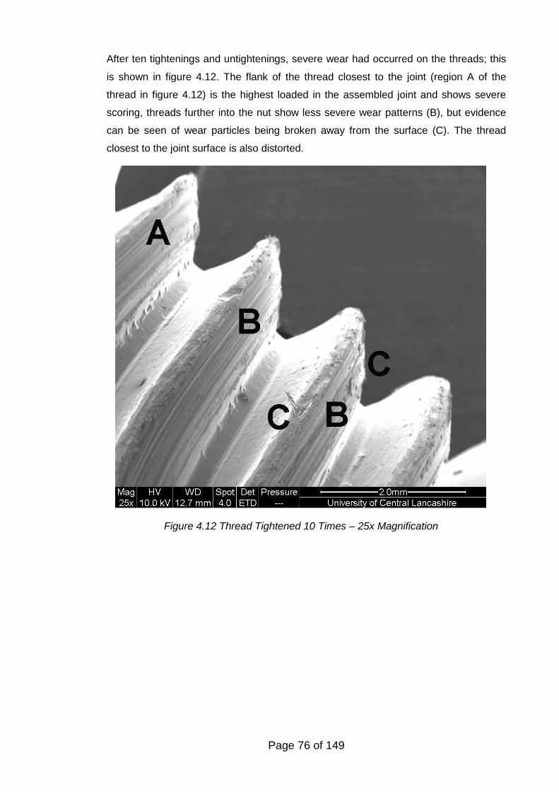
Page 76 of 149
After ten tightenings and untightenings, severe wear had occurred on the threads; this
is shown in figure 4.12. The flank of the thread closest to the joint (region A of the
thread in figure 4.12) is the highest loaded in the assembled joint and shows severe
scoring, threads further into the nut show less severe wear patterns (B), but evidence
can be seen of wear particles being broken away from the surface (C). The thread
closest to the joint surface is also distorted.
Figure 4.12 Thread Tightened 10 Times – 25x Magnification
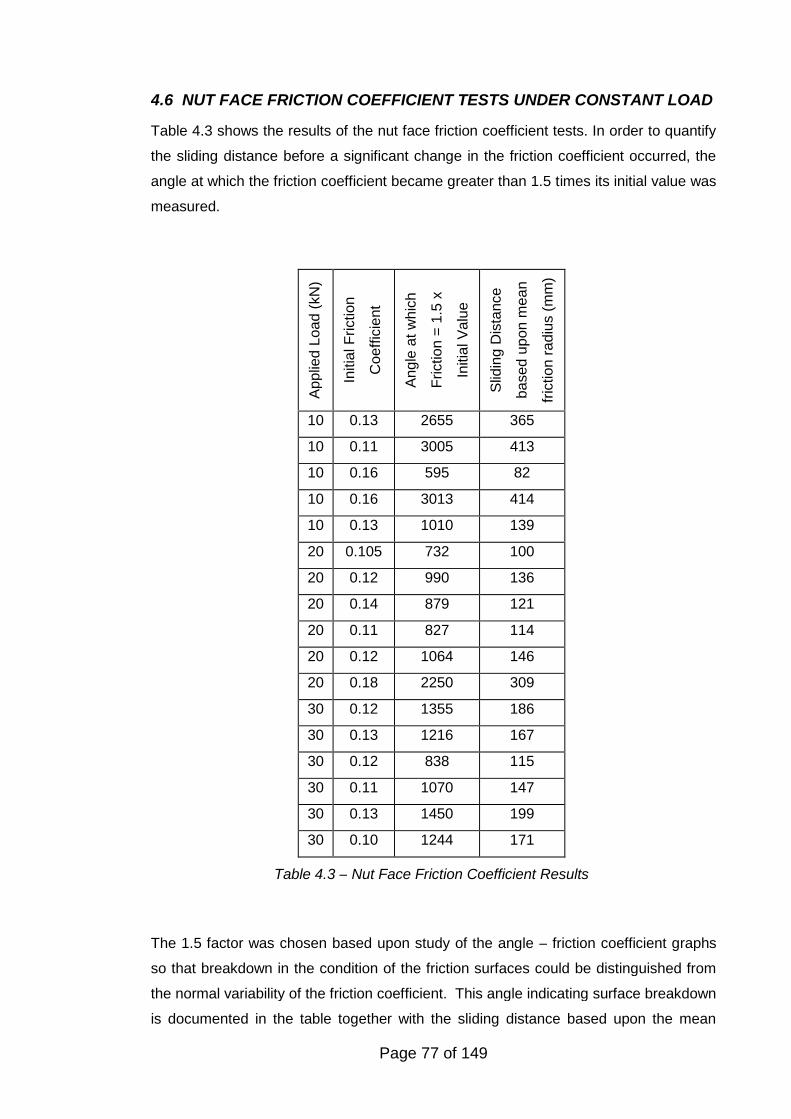
Page 77 of 149
Applie
dLoad
(kN
)
Initia
lF
riction
Coeff
icie
nt
Angle
at
whic
h
Friction
=1.5
x
Initia
lV
alu
e
Slid
ing
Dis
tance
based
upon
mean
fric
tion
radiu
s(m
m)
10 0.13 2655 365
10 0.11 3005 413
10 0.16 595 82
10 0.16 3013 414
10 0.13 1010 139
20 0.105 732 100
20 0.12 990 136
20 0.14 879 121
20 0.11 827 114
20 0.12 1064 146
20 0.18 2250 309
30 0.12 1355 186
30 0.13 1216 167
30 0.12 838 115
30 0.11 1070 147
30 0.13 1450 199
30 0.10 1244 171
Table 4.3 – Nut Face Friction Coefficient Results
4.6 NUT FACE FRICTION COEFFICIENT TESTS UNDER CONSTANT LOAD
Table 4.3 shows the results of the nut face friction coefficient tests. In order to quantify
the sliding distance before a significant change in the friction coefficient occurred, the
angle at which the friction coefficient became greater than 1.5 times its initial value was
measured.
The 1.5 factor was chosen based upon study of the angle – friction coefficient graphs
so that breakdown in the condition of the friction surfaces could be distinguished from
the normal variability of the friction coefficient. This angle indicating surface breakdown
is documented in the table together with the sliding distance based upon the mean
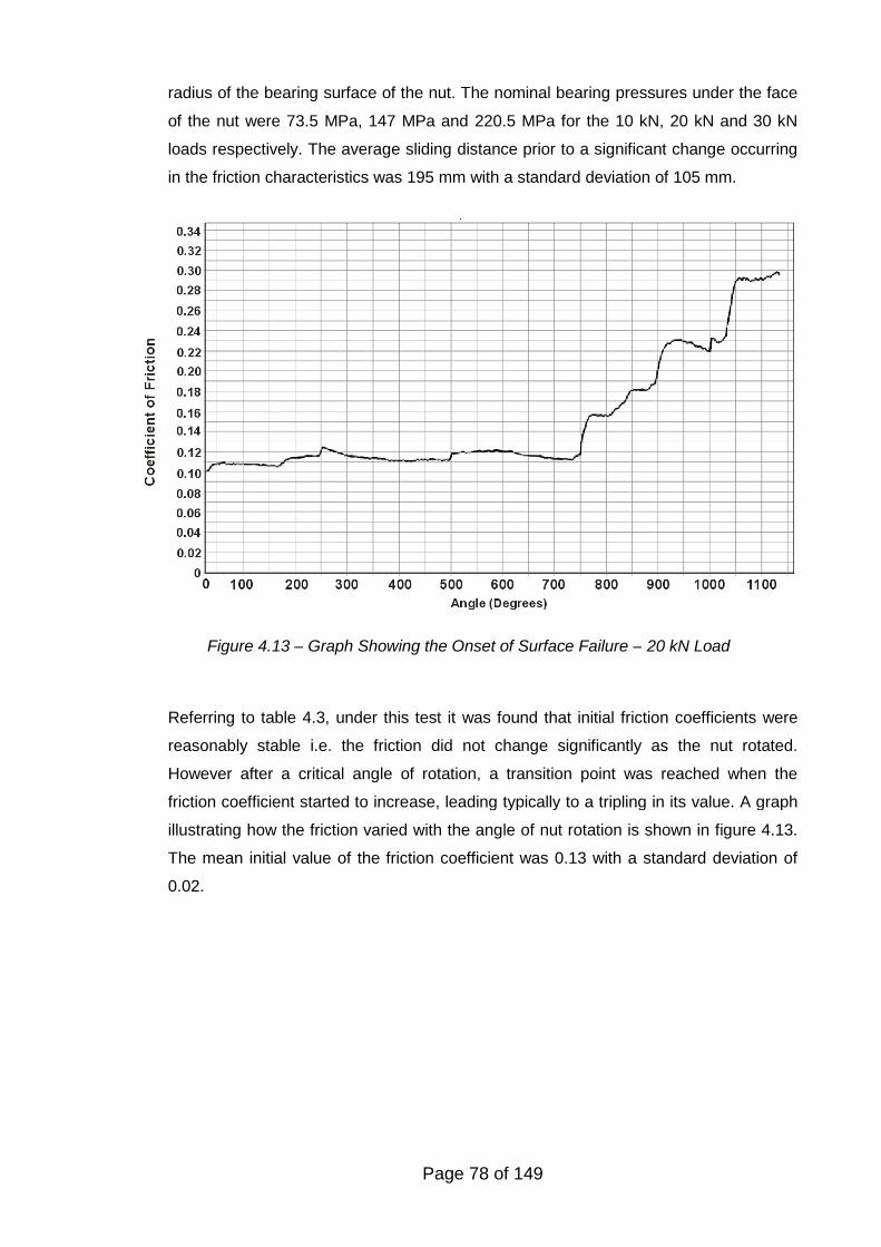
Page 78 of 149
radius of the bearing surface of the nut. The nominal bearing pressures under the face
of the nut were 73.5 MPa, 147 MPa and 220.5 MPa for the 10 kN, 20 kN and 30 kN
loads respectively. The average sliding distance prior to a significant change occurring
in the friction characteristics was 195 mm with a standard deviation of 105 mm.
Referring to table 4.3, under this test it was found that initial friction coefficients were
reasonably stable i.e. the friction did not change significantly as the nut rotated.
However after a critical angle of rotation, a transition point was reached when the
friction coefficient started to increase, leading typically to a tripling in its value. A graph
illustrating how the friction varied with the angle of nut rotation is shown in figure 4.13.
The mean initial value of the friction coefficient was 0.13 with a standard deviation of
0.02.
Figure 4.13 – Graph Showing the Onset of Surface Failure – 20 kN Load
Page 79 of 149
4.7 DISCUSSION AND CONCLUSIONS
Based upon the experiments completed and the measurements made, a change in the
friction between the contact surfaces of the bolt/nut thread and nut face occurs upon
repeated tightening. This breakdown of these surfaces resulting from fracture and
partial removal of the coating results in an increase in the friction coefficient present
which causes a reduction in the clamp force provided for an assembly when tightened
to a specified torque value. This reduction in the clamp force is significant, the clamp
force on the sixth re-tightening typically being half that obtained on the first tightening
which could have an adverse effect on the structural integrity of the assembly.
The process of the friction increasing to a peak value prior to falling to a stable value is
achieved is described by Suh and Sin (1981). The process is dependent upon the
distance slid by the two surfaces and is equated, in the re-use of fasteners, with the
number of times the fastener has been tightened. This change in the friction conditions
is considered to be due to damage to the contact surfaces resulting from sliding and
the high pressures involved. The primary processes for causing the friction variation
are the ploughing effect of trapped wear particles and adhesion. Wear particles trapped
between the surfaces results in ploughing by the entrapped particles further increasing
friction. Levelling off of the frictional resistance occurs as the number of particles
entrapped between the surfaces becomes constant.
Higher levels of friction were noted for the threads than were present under the nut
face. This is thought to be due to a number of factors. Thread friction is somewhat
complicated by the non-linear pressure distribution on the thread surfaces and that this
non-linearity is itself partially a function of the friction value (Sopwith, 1948). The higher
pressures being present in the thread that leads to increased wear particle generation
and ploughing. The enclosed nature of the mating threads also results in wear particles
created at the surface closest to the joint face, which is under the highest pressure,
being moved further up the thread as the nut rotates. Work hardening is occurring due
to thread deformation (that can be seen in figure 4.11). Under such circumstances,
besides surface friction there will also be a component of the overall friction force due
to work deforming the thread (Bellemare et al. 2008). The thread contact geometry and
the elastic-plastic properties of the steel will influence the magnitude of this effect. A
third factor that will influence the friction force measured is due to distortion of the
thread flanks as the tightening process progresses. An implicit assumption in the
determination of the friction coefficient is that the flank angle is a constant 60 degrees.
Page 80 of 149
The distorted pressure flank that can be seen in the SEM photographs will increase the
frictional force even if the friction coefficient remained constant.
Although the magnitude of the thread friction coefficient is higher than that present
under the nut face, the friction becoming approximately constant after five or six
tightenings is similar to the effect observed for the nut face friction.
It was also noted that the magnitude of the thread friction coefficient became
dependent upon the pressure (clamp force) as the number of tightenings increased.
The mechanism for this effect is not completely understood, but is thought to be due to
the increase in pressure causing a change from wear particle ploughing to adhesive
friction.
Tests completed to determine the nut face friction coefficient under a constant loading
clearly indicated that a change occurs in the friction characteristics after a certain
amount of angular movement. By using the mean nut radius, this angular movement
was converted to a linear movement. The average distance prior to a significant
change in friction occurring was 195 mm. The initial average friction coefficient of 0.13
is less than the mean value noted in the tightening tests (mean value on first tightening
of 0.19). However the scatter in the results on the tightening tests observed on the nut
face tests under constant loading was less than that observed in the full tightening
tests.
Based upon these results, the reuse of unlubricated EZP threaded fasteners cannot be
recommended. The increase in friction resulting from reuse could have an adverse
effect on a joint’s structural integrity due to the corresponding decrease in the
generated clamp force that occurs.
Page 81 of 149
5. LOOSENING OF FASTENERS BY TRANSVERSE VIBRATION
5.1 INTRODUCTION
One reason why bolted joints suffer integrity problems is due to self-loosening of the
fasteners. Junker (1969) and other researchers have shown that transverse vibration
could fully loosen non-locked threaded fasteners. Frequently the Engineering Designer
specifies a lock nut to attempt to prevent such loosening. The term ‘lock nut’ is generic
and is usually used to describe any nut that incorporates some feature to prevent self-
loosening. The vast majority of lock nuts do not fully lock the nut to the bolt and will
sustain some degree of self-loosening under transverse vibration. In this study the
loosening characteristics of a popular form of lock nut are investigated. Prevailing
torque nuts have a locking feature in which a small torque (the “prevailing torque”) is
needed to rotate the nut down the thread of an untightened bolt. A large number of
transverse vibration tests have been performed on various types of prevailing torque
nuts to investigate their loosening characteristics. Further tests have been completed to
establish the effect on the prevailing torque of re-use of the nut.
5.2 DETAILS OF THE TEST MACHINE
The machine that was used in the experiments conducted by the author is usually
described as a Junker machine, after its inventor Gerhard Junker and is described in
his major paper on fastener loosening (Junker, 1969). The machine allows tests to be
completed to the DIN 65151 standard (Deutsche Norm, 1994). An outline of the
machine is shown in figure 5.1. The test machine was obtained from SPS
Technologies. The machine required some renovation to make it operative. This
included the provision of new instrumentation, hardened bearing plates and adapters.
The instrumentation was connected to an analogue to digital converter so that the
results could be recorded directly onto a computer. Software was written (in the Delphi
language by the author) to allow the results to be displayed graphically.
Figure 5.2 shows the test arrangement when the loosening characteristics of a nut is to
be tested. The machine has a fixed frequency of transverse motion of 12.5 Hz and
provides a displacement amplitude of +/- 0.65 mm. By the use of a suitable adapter
(1), the machine allows screws, nuts or lock washers to be tested. An electric motor
drives a cam that induces transverse reciprocating movement into a top plate (2), the
top plate rests upon needle roller bearings (3) that rests on a fixed support (4) so that
friction is minimised. The test fastener passes from an adapter (1) within the machine
and through a fastener bearing plate (5). The adapter (1) clamps a load cell (6) to allow
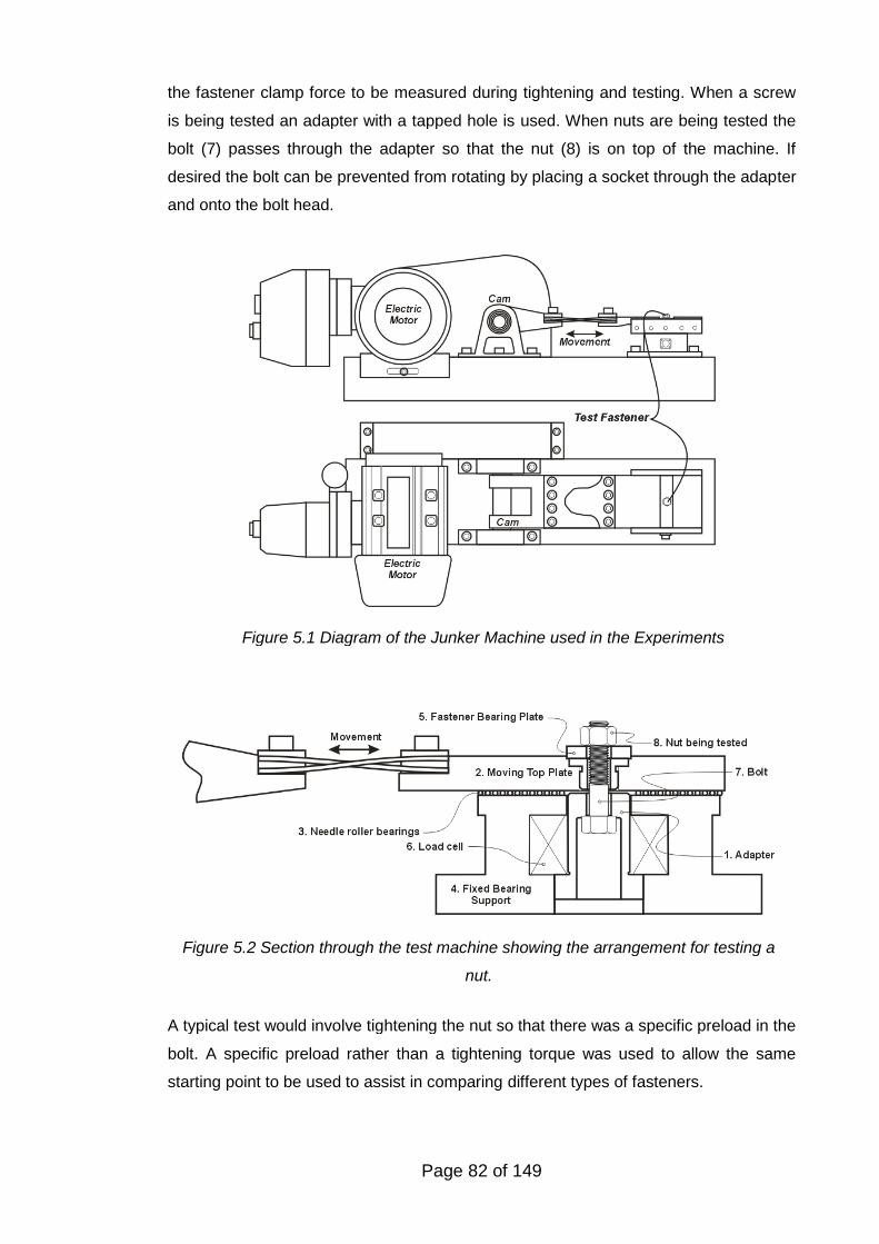
Page 82 of 149
the fastener clamp force to be measured during tightening and testing. When a screw
is being tested an adapter with a tapped hole is used. When nuts are being tested the
bolt (7) passes through the adapter so that the nut (8) is on top of the machine. If
desired the bolt can be prevented from rotating by placing a socket through the adapter
and onto the bolt head.
A typical test would involve tightening the nut so that there was a specific preload in the
bolt. A specific preload rather than a tightening torque was used to allow the same
starting point to be used to assist in comparing different types of fasteners.
Figure 5.1 Diagram of the Junker Machine used in the Experiments
Figure 5.2 Section through the test machine showing the arrangement for testing a
nut.
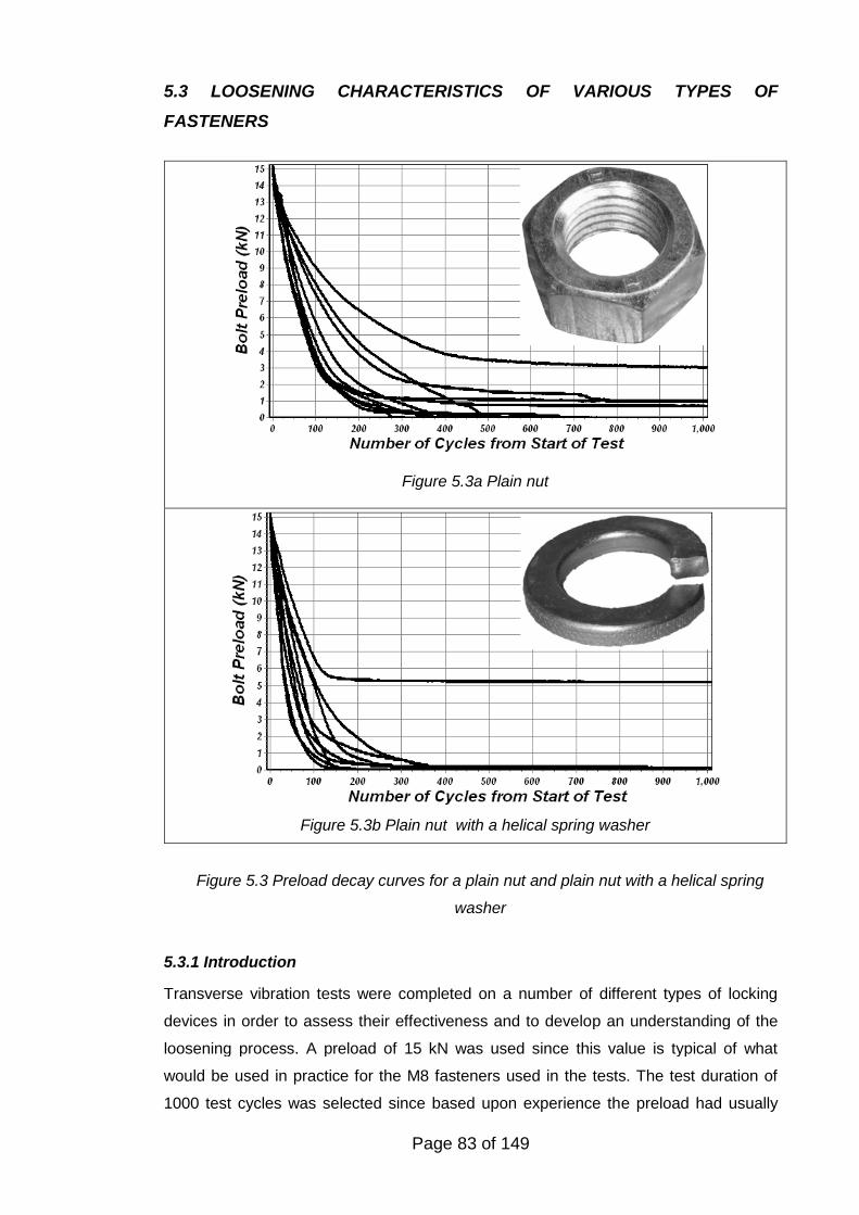
Page 83 of 149
5.3 LOOSENING CHARACTERISTICS OF VARIOUS TYPES OF
FASTENERS
5.3.1 Introduction
Transverse vibration tests were completed on a number of different types of locking
devices in order to assess their effectiveness and to develop an understanding of the
loosening process. A preload of 15 kN was used since this value is typical of what
would be used in practice for the M8 fasteners used in the tests. The test duration of
1000 test cycles was selected since based upon experience the preload had usually
Figure 5.3a Plain nut
Figure 5.3b Plain nut with a helical spring washer
Figure 5.3 Preload decay curves for a plain nut and plain nut with a helical spring
washer
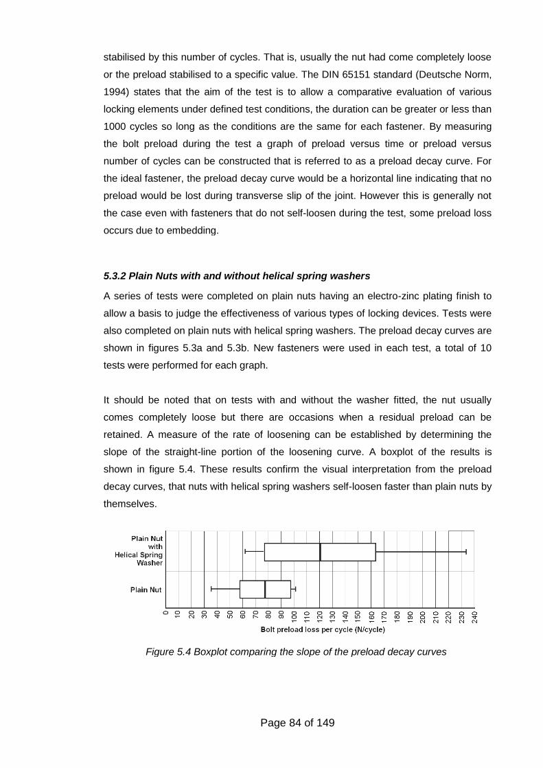
Page 84 of 149
stabilised by this number of cycles. That is, usually the nut had come completely loose
or the preload stabilised to a specific value. The DIN 65151 standard (Deutsche Norm,
1994) states that the aim of the test is to allow a comparative evaluation of various
locking elements under defined test conditions, the duration can be greater or less than
1000 cycles so long as the conditions are the same for each fastener. By measuring
the bolt preload during the test a graph of preload versus time or preload versus
number of cycles can be constructed that is referred to as a preload decay curve. For
the ideal fastener, the preload decay curve would be a horizontal line indicating that no
preload would be lost during transverse slip of the joint. However this is generally not
the case even with fasteners that do not self-loosen during the test, some preload loss
occurs due to embedding.
5.3.2 Plain Nuts with and without helical spring washers
A series of tests were completed on plain nuts having an electro-zinc plating finish to
allow a basis to judge the effectiveness of various types of locking devices. Tests were
also completed on plain nuts with helical spring washers. The preload decay curves are
shown in figures 5.3a and 5.3b. New fasteners were used in each test, a total of 10
tests were performed for each graph.
It should be noted that on tests with and without the washer fitted, the nut usually
comes completely loose but there are occasions when a residual preload can be
retained. A measure of the rate of loosening can be established by determining the
slope of the straight-line portion of the loosening curve. A boxplot of the results is
shown in figure 5.4. These results confirm the visual interpretation from the preload
decay curves, that nuts with helical spring washers self-loosen faster than plain nuts by
themselves.
Figure 5.4 Boxplot comparing the slope of the preload decay curves
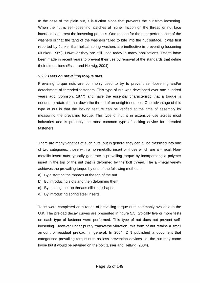
Page 85 of 149
In the case of the plain nut, it is friction alone that prevents the nut from loosening.
When the nut is self-loosening, patches of higher friction on the thread or nut face
interface can arrest the loosening process. One reason for the poor performance of the
washers is that the tang of the washers failed to bite into the nut surface. It was first
reported by Junker that helical spring washers are ineffective in preventing loosening
(Junker, 1969). However they are still used today in many applications. Efforts have
been made in recent years to prevent their use by removal of the standards that define
their dimensions (Esser and Hellwig, 2004).
5.3.3 Tests on prevailing torque nuts
Prevailing torque nuts are commonly used to try to prevent self-loosening and/or
detachment of threaded fasteners. This type of nut was developed over one hundred
years ago (Johnson, 1877) and have the essential characteristic that a torque is
needed to rotate the nut down the thread of an untightened bolt. One advantage of this
type of nut is that the locking feature can be verified at the time of assembly by
measuring the prevailing torque. This type of nut is in extensive use across most
industries and is probably the most common type of locking device for threaded
fasteners.
There are many varieties of such nuts, but in general they can all be classified into one
of two categories, those with a non-metallic insert or those which are all-metal. Non-
metallic insert nuts typically generate a prevailing torque by incorporating a polymer
insert in the top of the nut that is deformed by the bolt thread. The all-metal variety
achieves the prevailing torque by one of the following methods:
a) By distorting the threads at the top of the nut.
b) By introducing slots and then deforming them
c) By making the top threads elliptical shaped.
d) By introducing spring steel inserts.
Tests were completed on a range of prevailing torque nuts commonly available in the
U.K. The preload decay curves are presented in figure 5.5, typically five or more tests
on each type of fastener were performed. This type of nut does not prevent self-
loosening. However under purely transverse vibration, this form of nut retains a small
amount of residual preload, in general. In 2004, DIN published a document that
categorised prevailing torque nuts as loss prevention devices i.e. the nut may come
loose but it would be retained on the bolt (Esser and Hellwig, 2004).
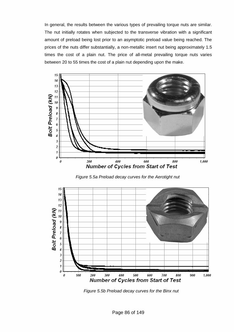
Page 86 of 149
In general, the results between the various types of prevailing torque nuts are similar.
The nut initially rotates when subjected to the transverse vibration with a significant
amount of preload being lost prior to an asymptotic preload value being reached. The
prices of the nuts differ substantially, a non-metallic insert nut being approximately 1.5
times the cost of a plain nut. The price of all-metal prevailing torque nuts varies
between 20 to 55 times the cost of a plain nut depending upon the make.
Figure 5.5a Preload decay curves for the Aerotight nut
Figure 5.5b Preload decay curves for the Binx nut
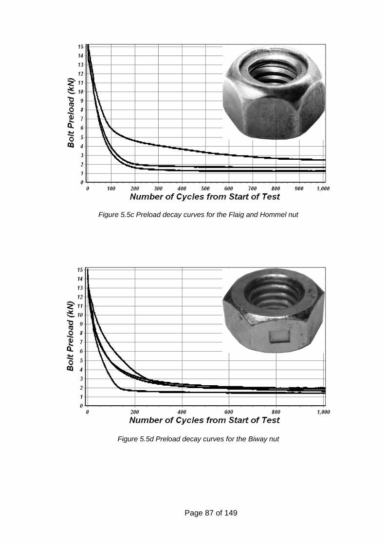
Page 87 of 149
Figure 5.5c Preload decay curves for the Flaig and Hommel nut
Figure 5.5d Preload decay curves for the Biway nut
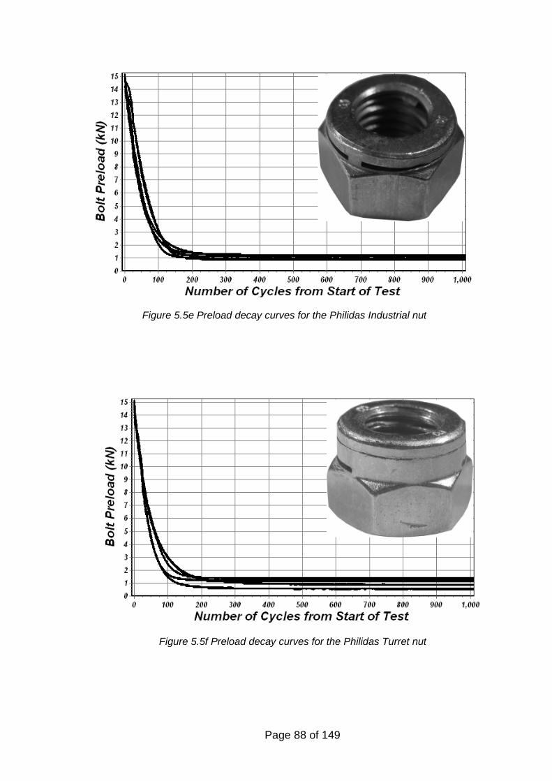
Page 88 of 149
Figure 5.5e Preload decay curves for the Philidas Industrial nut
Figure 5.5f Preload decay curves for the Philidas Turret nut
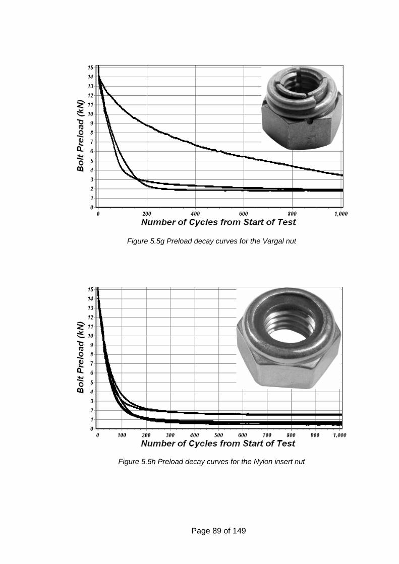
Page 89 of 149
Figure 5.5g Preload decay curves for the Vargal nut
Figure 5.5h Preload decay curves for the Nylon insert nut
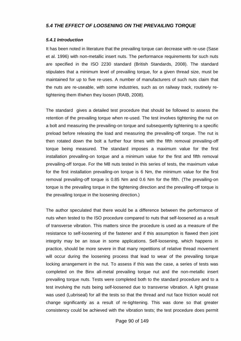
Page 90 of 149
5.4 THE EFFECT OF LOOSENING ON THE PREVAILING TORQUE
5.4.1 Introduction
It has been noted in literature that the prevailing torque can decrease with re-use (Sase
et al. 1996) with non-metallic insert nuts. The performance requirements for such nuts
are specified in the ISO 2230 standard (British Standards, 2008). The standard
stipulates that a minimum level of prevailing torque, for a given thread size, must be
maintained for up to five re-uses. A number of manufacturers of such nuts claim that
the nuts are re-useable, with some industries, such as on railway track, routinely re-
tightening them if/when they loosen (RAIB, 2008).
The standard gives a detailed test procedure that should be followed to assess the
retention of the prevailing torque when re-used. The test involves tightening the nut on
a bolt and measuring the prevailing-on torque and subsequently tightening to a specific
preload before releasing the load and measuring the prevailing-off torque. The nut is
then rotated down the bolt a further four times with the fifth removal prevailing-off
torque being measured. The standard imposes a maximum value for the first
installation prevailing-on torque and a minimum value for the first and fifth removal
prevailing-off torque. For the M8 nuts tested in this series of tests, the maximum value
for the first installation prevailing-on torque is 6 Nm, the minimum value for the first
removal prevailing-off torque is 0.85 Nm and 0.6 Nm for the fifth. (The prevailing-on
torque is the prevailing torque in the tightening direction and the prevailing-off torque is
the prevailing torque in the loosening direction.)
The author speculated that there would be a difference between the performance of
nuts when tested to the ISO procedure compared to nuts that self-loosened as a result
of transverse vibration. This matters since the procedure is used as a measure of the
resistance to self-loosening of the fastener and if this assumption is flawed then joint
integrity may be an issue in some applications. Self-loosening, which happens in
practice, should be more severe in that many repetitions of relative thread movement
will occur during the loosening process that lead to wear of the prevailing torque
locking arrangement in the nut. To assess if this was the case, a series of tests was
completed on the Binx all-metal prevailing torque nut and the non-metallic insert
prevailing torque nuts. Tests were completed both to the standard procedure and to a
test involving the nuts being self-loosened due to transverse vibration. A light grease
was used (Lubriseal) for all the tests so that the thread and nut face friction would not
change significantly as a result of re-tightening. This was done so that greater
consistency could be achieved with the vibration tests; the test procedure does permit
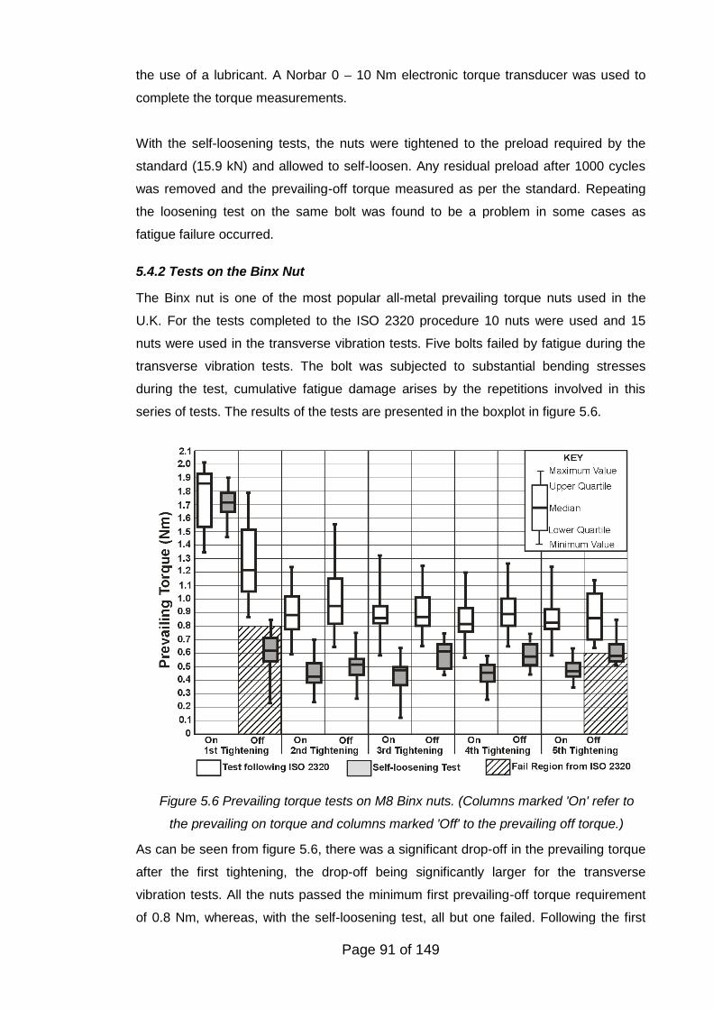
Page 91 of 149
the use of a lubricant. A Norbar 0 – 10 Nm electronic torque transducer was used to
complete the torque measurements.
With the self-loosening tests, the nuts were tightened to the preload required by the
standard (15.9 kN) and allowed to self-loosen. Any residual preload after 1000 cycles
was removed and the prevailing-off torque measured as per the standard. Repeating
the loosening test on the same bolt was found to be a problem in some cases as
fatigue failure occurred.
5.4.2 Tests on the Binx Nut
The Binx nut is one of the most popular all-metal prevailing torque nuts used in the
U.K. For the tests completed to the ISO 2320 procedure 10 nuts were used and 15
nuts were used in the transverse vibration tests. Five bolts failed by fatigue during the
transverse vibration tests. The bolt was subjected to substantial bending stresses
during the test, cumulative fatigue damage arises by the repetitions involved in this
series of tests. The results of the tests are presented in the boxplot in figure 5.6.
As can be seen from figure 5.6, there was a significant drop-off in the prevailing torque
after the first tightening, the drop-off being significantly larger for the transverse
vibration tests. All the nuts passed the minimum first prevailing-off torque requirement
of 0.8 Nm, whereas, with the self-loosening test, all but one failed. Following the first
Figure 5.6 Prevailing torque tests on M8 Binx nuts. (Columns marked 'On' refer to
the prevailing on torque and columns marked 'Off' to the prevailing off torque.)
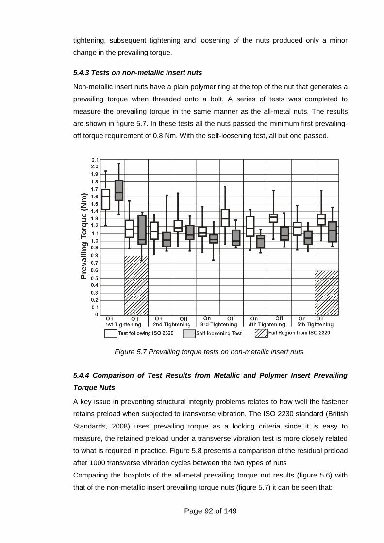
Page 92 of 149
tightening, subsequent tightening and loosening of the nuts produced only a minor
change in the prevailing torque.
5.4.3 Tests on non-metallic insert nuts
Non-metallic insert nuts have a plain polymer ring at the top of the nut that generates a
prevailing torque when threaded onto a bolt. A series of tests was completed to
measure the prevailing torque in the same manner as the all-metal nuts. The results
are shown in figure 5.7. In these tests all the nuts passed the minimum first prevailing-
off torque requirement of 0.8 Nm. With the self-loosening test, all but one passed.
5.4.4 Comparison of Test Results from Metallic and Polymer Insert Prevailing
Torque Nuts
A key issue in preventing structural integrity problems relates to how well the fastener
retains preload when subjected to transverse vibration. The ISO 2230 standard (British
Standards, 2008) uses prevailing torque as a locking criteria since it is easy to
measure, the retained preload under a transverse vibration test is more closely related
to what is required in practice. Figure 5.8 presents a comparison of the residual preload
after 1000 transverse vibration cycles between the two types of nuts
Comparing the boxplots of the all-metal prevailing torque nut results (figure 5.6) with
that of the non-metallic insert prevailing torque nuts (figure 5.7) it can be seen that:
Figure 5.7 Prevailing torque tests on non-metallic insert nuts
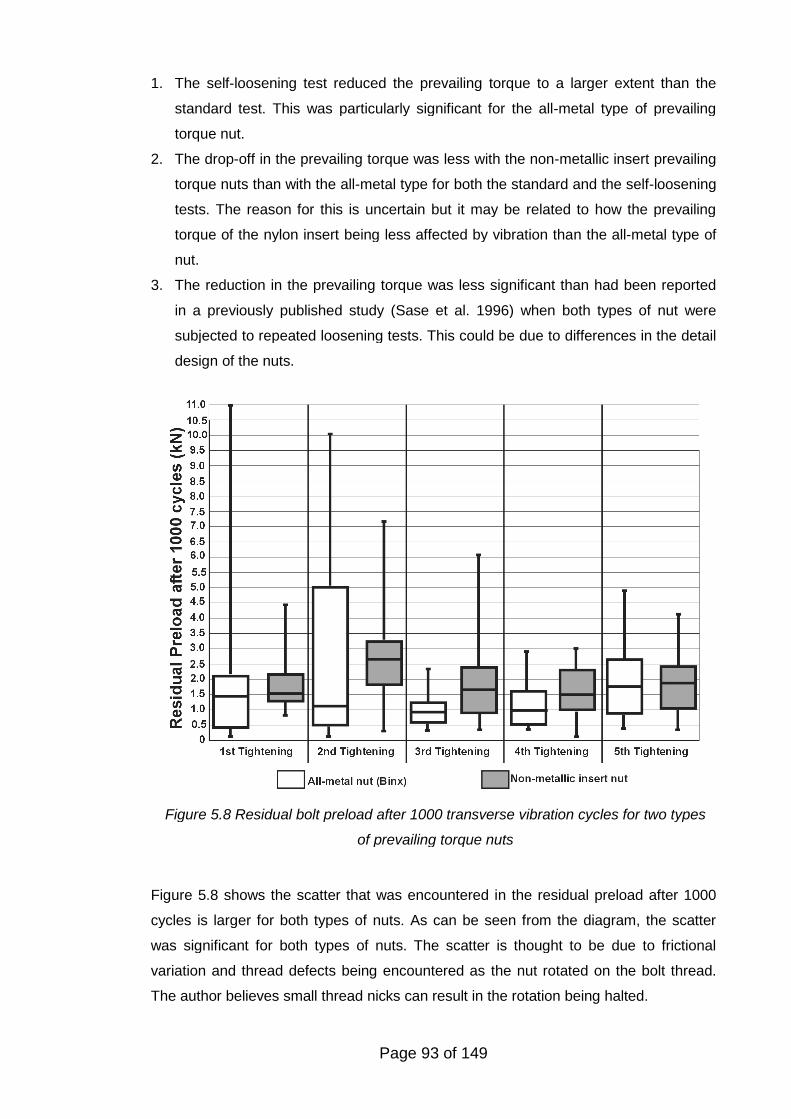
Page 93 of 149
1. The self-loosening test reduced the prevailing torque to a larger extent than the
standard test. This was particularly significant for the all-metal type of prevailing
torque nut.
2. The drop-off in the prevailing torque was less with the non-metallic insert prevailing
torque nuts than with the all-metal type for both the standard and the self-loosening
tests. The reason for this is uncertain but it may be related to how the prevailing
torque of the nylon insert being less affected by vibration than the all-metal type of
nut.
3. The reduction in the prevailing torque was less significant than had been reported
in a previously published study (Sase et al. 1996) when both types of nut were
subjected to repeated loosening tests. This could be due to differences in the detail
design of the nuts.
Figure 5.8 shows the scatter that was encountered in the residual preload after 1000
cycles is larger for both types of nuts. As can be seen from the diagram, the scatter
was significant for both types of nuts. The scatter is thought to be due to frictional
variation and thread defects being encountered as the nut rotated on the bolt thread.
The author believes small thread nicks can result in the rotation being halted.
Figure 5.8 Residual bolt preload after 1000 transverse vibration cycles for two types
of prevailing torque nuts
Page 94 of 149
Based upon these tests on two types of prevailing torque nuts, no evidence was found
that the prevailing torque reduced to zero as a result of re-tightening. Self-loosening
was found to be a more severe case than the ISO 2230 test in terms of the reduction in
the prevailing torque that occurs with re-use. This was the case for both types of nuts
but in particular for the all-metal type of nut.
6. COMPLETE SELF-LOOSENING OF PREVAILING TORQUE
FASTENERS
6.1 INTRODUCTION
As discussed in chapter 5, prevailing torque type nuts are commonly used to try to
prevent self-loosening and/or detachment of threaded fasteners. There have been
instances when new prevailing torque nuts that still retain a prevailing torque have
become detached from assemblies. One example relates to the use of a prevailing
torque nut fitted to a control rod on the elevator control system on a Tupolev 154M
operated by China Southwest Airlines2. Over time the nut self-loosened and became
detached from the bolt. As a direct result of this loss, on the 24th February 1999 whilst
approaching the coastal city of Wenzhou, the aircraft suddenly pitched down and
crashed resulting in the death of all the 61 people on board. The causes of such
failures have not been understood since the standard method of test, the Junker DIN
65151 (Deutsche Norm, 1994) test, has been unable to reproduce such complete
loosening.
Goodier and Sweeney (1945) followed by Sauer et al. (1950) showed that dynamic
axial loading would only loosen nuts by at most a few degrees of rotation. Junkers’
work (1969) showed that transverse vibration could completely loosen fasteners.
Subsequent researchers have built upon this early work but to date have not
demonstrated the precise conditions that can lead to the detachment of prevailing
torque nuts.
Based upon the study of problematic joints in service, the author speculated that axial
loading combined with transverse movement might induce complete self-loosening and
subsequent detachment of prevailing torque nuts. The present standard test method
(DIN 65151) based upon purely transverse vibration is not able to replicate some
2 See http://aviation-safety.net/database/record.php?id=19990224-0
Page 95 of 149
service experience for prevailing torque nuts. Combined axial and shear loads on joints
are common in many applications such as for example the wheel to hub joints on a
road vehicle (shear loads can be imposed onto the joint by braking and axial loads from
cornering).
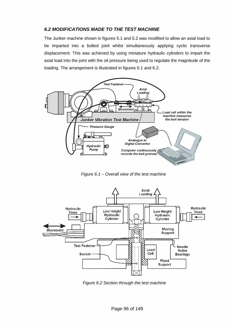
Page 96 of 149
Figure 6.2 Section through the test machine
6.2 MODIFICATIONS MADE TO THE TEST MACHINE
The Junker machine shown in figures 5.1 and 5.2 was modified to allow an axial load to
be imparted into a bolted joint whilst simultaneously applying cyclic transverse
displacement. This was achieved by using miniature hydraulic cylinders to impart the
axial load into the joint with the oil pressure being used to regulate the magnitude of the
loading. The arrangement is illustrated in figures 6.1 and 6.2.
Figure 6.1 – Overall view of the test machine
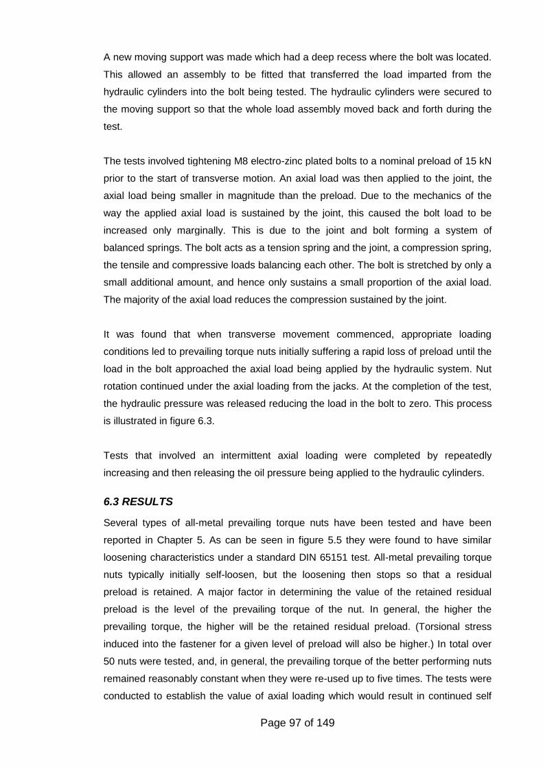
Page 97 of 149
A new moving support was made which had a deep recess where the bolt was located.
This allowed an assembly to be fitted that transferred the load imparted from the
hydraulic cylinders into the bolt being tested. The hydraulic cylinders were secured to
the moving support so that the whole load assembly moved back and forth during the
test.
The tests involved tightening M8 electro-zinc plated bolts to a nominal preload of 15 kN
prior to the start of transverse motion. An axial load was then applied to the joint, the
axial load being smaller in magnitude than the preload. Due to the mechanics of the
way the applied axial load is sustained by the joint, this caused the bolt load to be
increased only marginally. This is due to the joint and bolt forming a system of
balanced springs. The bolt acts as a tension spring and the joint, a compression spring,
the tensile and compressive loads balancing each other. The bolt is stretched by only a
small additional amount, and hence only sustains a small proportion of the axial load.
The majority of the axial load reduces the compression sustained by the joint.
It was found that when transverse movement commenced, appropriate loading
conditions led to prevailing torque nuts initially suffering a rapid loss of preload until the
load in the bolt approached the axial load being applied by the hydraulic system. Nut
rotation continued under the axial loading from the jacks. At the completion of the test,
the hydraulic pressure was released reducing the load in the bolt to zero. This process
is illustrated in figure 6.3.
Tests that involved an intermittent axial loading were completed by repeatedly
increasing and then releasing the oil pressure being applied to the hydraulic cylinders.
6.3 RESULTS
Several types of all-metal prevailing torque nuts have been tested and have been
reported in Chapter 5. As can be seen in figure 5.5 they were found to have similar
loosening characteristics under a standard DIN 65151 test. All-metal prevailing torque
nuts typically initially self-loosen, but the loosening then stops so that a residual
preload is retained. A major factor in determining the value of the retained residual
preload is the level of the prevailing torque of the nut. In general, the higher the
prevailing torque, the higher will be the retained residual preload. (Torsional stress
induced into the fastener for a given level of preload will also be higher.) In total over
50 nuts were tested, and, in general, the prevailing torque of the better performing nuts
remained reasonably constant when they were re-used up to five times. The tests were
conducted to establish the value of axial loading which would result in continued self
Page 98 of 149
loosening of M8 prevailing torque nuts. The conditions for these tests are presented in
table 6.1 along with a summary of some of the results.
The procedure for testing involved first determining the residual preload retained by the
prevailing torque nut with zero axial loading applied to the joint using a conventional
Junker test. The result from one such test are shown in the graph in figure 6.4a. The
residual preload retained by the bolt in this case is 3.1 kN. Figures 6.4b and 6.4c show
decay curves when axial loading of 1.1 kN and 2.7 kN was applied. In both situations
the bolt preload was retained at approximately the same level as if no axial loading has
been applied. However figure 6.4d shows the decay curve when an axial load of 3.1 kN
is applied. In this case the nut continued to rotate, the axial load was maintained and
compensated for the load loss that occurred from nut rotation. At the end of the test
when the axial load was removed by releasing the pressure from the hydraulic
cylinders, the residual preload was observed to be zero.
Figure 6.3 - Typical preload decay graph with transverse joint displacement and axial
loading applied to the joint.
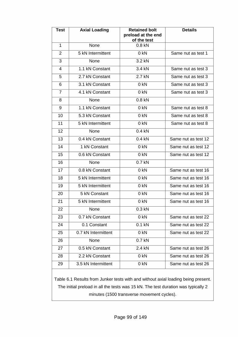
Page 99 of 149
Test Axial Loading Retained boltpreload at the end
of the test
Details
1 None 0.8 kN
2 5 kN Intermittent 0 kN Same nut as test 1
3 None 3.2 kN
4 1.1 kN Constant 3.4 kN Same nut as test 3
5 2.7 kN Constant 2.7 kN Same nut as test 3
6 3.1 kN Constant 0 kN Same nut as test 3
7 4.1 kN Constant 0 kN Same nut as test 3
8 None 0.8 kN
9 1.1 kN Constant 0 kN Same nut as test 8
10 5.3 kN Constant 0 kN Same nut as test 8
11 5 kN Intermittent 0 kN Same nut as test 8
12 None 0.4 kN
13 0.4 kN Constant 0.4 kN Same nut as test 12
14 1 kN Constant 0 kN Same nut as test 12
15 0.6 kN Constant 0 kN Same nut as test 12
16 None 0.7 kN
17 0.8 kN Constant 0 kN Same nut as test 16
18 5 kN Intermittent 0 kN Same nut as test 16
19 5 kN Intermittent 0 kN Same nut as test 16
20 5 kN Constant 0 kN Same nut as test 16
21 5 kN Intermittent 0 kN Same nut as test 16
22 None 0.3 kN
23 0.7 kN Constant 0 kN Same nut as test 22
24 0.1 Constant 0.1 kN Same nut as test 22
25 0.7 kN Intermittent 0 kN Same nut as test 22
26 None 0.7 kN
27 0.5 kN Constant 2.4 kN Same nut as test 26
28 2.2 kN Constant 0 kN Same nut as test 26
29 3.5 kN Intermittent 0 kN Same nut as test 26
Table 6.1 Results from Junker tests with and without axial loading being present.
The initial preload in all the tests was 15 kN. The test duration was typically 2
minutes (1500 transverse movement cycles).
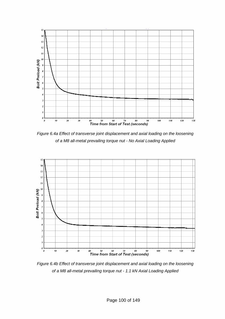
Page 100 of 149
Figure 6.4a Effect of transverse joint displacement and axial loading on the loosening
of a M8 all-metal prevailing torque nut - No Axial Loading Applied
Figure 6.4b Effect of transverse joint displacement and axial loading on the loosening
of a M8 all-metal prevailing torque nut - 1.1 kN Axial Loading Applied
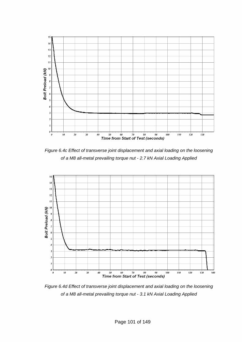
Page 101 of 149
Figure 6.4d Effect of transverse joint displacement and axial loading on the loosening
of a M8 all-metal prevailing torque nut - 3.1 kN Axial Loading Applied
Figure 6.4c Effect of transverse joint displacement and axial loading on the loosening
of a M8 all-metal prevailing torque nut - 2.7 kN Axial Loading Applied
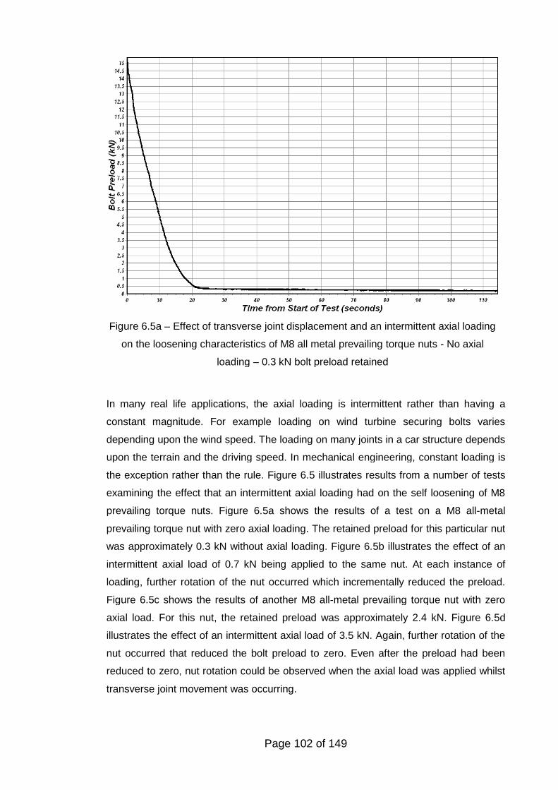
Page 102 of 149
Figure 6.5a – Effect of transverse joint displacement and an intermittent axial loading
on the loosening characteristics of M8 all metal prevailing torque nuts - No axial
loading – 0.3 kN bolt preload retained
In many real life applications, the axial loading is intermittent rather than having a
constant magnitude. For example loading on wind turbine securing bolts varies
depending upon the wind speed. The loading on many joints in a car structure depends
upon the terrain and the driving speed. In mechanical engineering, constant loading is
the exception rather than the rule. Figure 6.5 illustrates results from a number of tests
examining the effect that an intermittent axial loading had on the self loosening of M8
prevailing torque nuts. Figure 6.5a shows the results of a test on a M8 all-metal
prevailing torque nut with zero axial loading. The retained preload for this particular nut
was approximately 0.3 kN without axial loading. Figure 6.5b illustrates the effect of an
intermittent axial load of 0.7 kN being applied to the same nut. At each instance of
loading, further rotation of the nut occurred which incrementally reduced the preload.
Figure 6.5c shows the results of another M8 all-metal prevailing torque nut with zero
axial load. For this nut, the retained preload was approximately 2.4 kN. Figure 6.5d
illustrates the effect of an intermittent axial load of 3.5 kN. Again, further rotation of the
nut occurred that reduced the bolt preload to zero. Even after the preload had been
reduced to zero, nut rotation could be observed when the axial load was applied whilst
transverse joint movement was occurring.
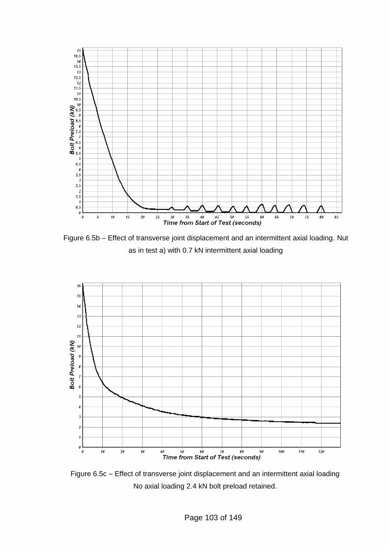
Page 103 of 149
Figure 6.5b – Effect of transverse joint displacement and an intermittent axial loading. Nut
as in test a) with 0.7 kN intermittent axial loading
Figure 6.5c – Effect of transverse joint displacement and an intermittent axial loading
No axial loading 2.4 kN bolt preload retained.
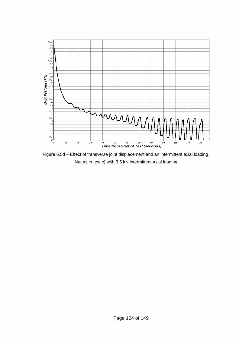
Page 104 of 149
Figure 6.5d – Effect of transverse joint displacement and an intermittent axial loading.
Nut as in test c) with 3.5 kN intermittent axial loading
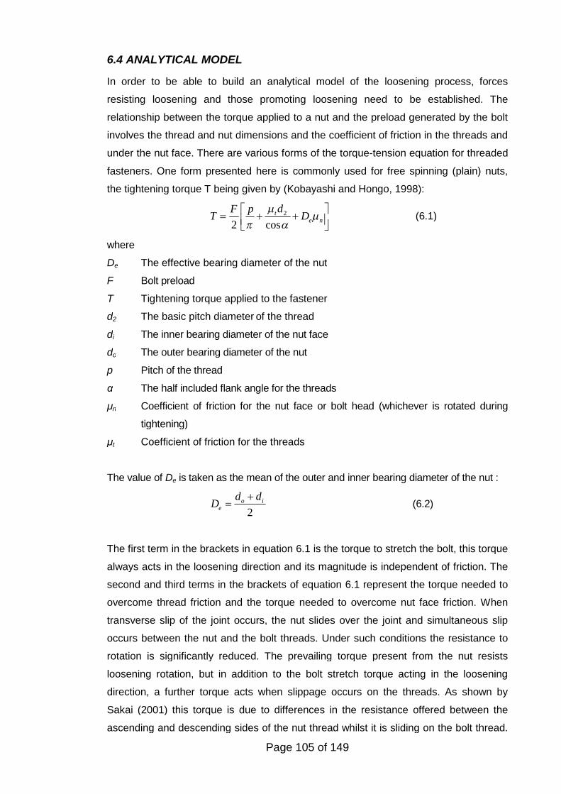
Page 105 of 149
6.4 ANALYTICAL MODEL
In order to be able to build an analytical model of the loosening process, forces
resisting loosening and those promoting loosening need to be established. The
relationship between the torque applied to a nut and the preload generated by the bolt
involves the thread and nut dimensions and the coefficient of friction in the threads and
under the nut face. There are various forms of the torque-tension equation for threaded
fasteners. One form presented here is commonly used for free spinning (plain) nuts,
the tightening torque T being given by (Kobayashi and Hongo, 1998):
2
2 cost
e n
dF pT D
(6.1)
where
De The effective bearing diameter of the nut
F Bolt preload
T Tightening torque applied to the fastener
d2 The basic pitch diameter of the thread
di The inner bearing diameter of the nut face
do The outer bearing diameter of the nut
p Pitch of the thread
α The half included flank angle for the threads
μn Coefficient of friction for the nut face or bolt head (whichever is rotated during
tightening)
μt Coefficient of friction for the threads
The value of De is taken as the mean of the outer and inner bearing diameter of the nut :
2o i
e
d dD
(6.2)
The first term in the brackets in equation 6.1 is the torque to stretch the bolt, this torque
always acts in the loosening direction and its magnitude is independent of friction. The
second and third terms in the brackets of equation 6.1 represent the torque needed to
overcome thread friction and the torque needed to overcome nut face friction. When
transverse slip of the joint occurs, the nut slides over the joint and simultaneous slip
occurs between the nut and the bolt threads. Under such conditions the resistance to
rotation is significantly reduced. The prevailing torque present from the nut resists
loosening rotation, but in addition to the bolt stretch torque acting in the loosening
direction, a further torque acts when slippage occurs on the threads. As shown by
Sakai (2001) this torque is due to differences in the resistance offered between the
ascending and descending sides of the nut thread whilst it is sliding on the bolt thread.
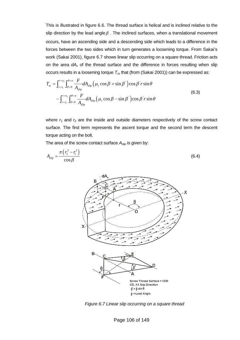
Page 106 of 149
This is illustrated in figure 6.6. The thread surface is helical and is inclined relative to the
slip direction by the lead angle . The inclined surfaces, when a translational movement
occurs, have an ascending side and a descending side which leads to a difference in the
forces between the two sides which in turn generates a loosening torque. From Sakai’s
work (Sakai 2001), figure 6.7 shows linear slip occurring on a square thread. Friction acts
on the area dAs of the thread surface and the difference in forces resulting when slip
occurs results in a loosening torque Tss that (from (Sakai 2001)) can be expressed as:
2
1
2
1
' '
0
' '
0
cos sin cos sin
cos sin cos sin
r r
ss slip tr rslip
r r
slip tr r
slip
FT dA r
A
FdA r
A
(6.3)
where r1 and r2 are the inside and outside diameters respectively of the screw contact
surface. The first term represents the ascent torque and the second term the descent
torque acting on the bolt.
The area of the screw contact surface Aslip is given by:
2 22 1
cosslip
r rA
(6.4)
Figure 6.6 Loosening torque generated by movement of the nut thread on the bolt
thread
Figure 6.7 Linear slip occurring on a square thread
Page 107 of 149
From figure 6.7, 'tan tan sin and since the lead angle is small (3 degrees for the
M8 threads used in this study) we have ' sin and 'cos 1 In this case, Tss will
assume the following approximate equation:
2
1
2
0
2sin
r r
ssr r
slip
FT r d dr
A
(6.5)
Integration of equation 6.5 leads to:
2 22 2 1 13 3
2 1
2 13 3ss
slip
F r r r rFT r r
A r r
(6.6)
The author's extension to Sakai's work (2001) involves using the basic pitch diameter of
the thread, denoted by d2., and taking this as being equal to r1+r2, Also from this r1= d2 - r2
Substituting these values into equation 6.6 gives: 2
1
4ssT Fd (6.7)
If p is the pitch of the thread and d2 the basic pitch diameter, the lead angle is the
transverse movement of the screw completed in one revolution divided by the
circumference around the thread at the pitch diameter:
1
2
pTan
d
(6.8)
Since the angle is small, equation 6.8 can be approximated as:
2
p
d
(6.9)
Substituting this value into equation 6.7 gives:4
ss
FpT
(6.10)
From equation 6.1, the first term in the equation represents the torque needed to stretch
the fastener which always acts in the loosening direction. The second term represents the
torque needed to overcome friction in the threads and the third term is the torque needed
to overcome friction under the nut face. Friction resists nut rotation in both the loosening
and tightening directions. Considering the loosening direction and adding the prevailing
torque which also resists nut movement in any rotation direction gives the torque TL
needed to loosen a nut as:
2
2 2cos 2t e
L n P
d DpT F T
(6.11)
Page 108 of 149
The above equation applies to static situations. Due to the negative term, the loosening
torque is typically 15% to 20% lower than the tightening torque which can be readily
practically demonstrated. (This applies when the nut is untightened immediately after
being tightened. If the joint is left for a period of time friction changes can occur that can
affect the situation such that the loosening torque can be either smaller or greater than the
initial tightening torque.) When transverse slip is occurring to the joint, the torque acting in
the loosening direction will be the torque given by equation 6.10 and the first term in
equation 6.11. Combining these terms to establish the total torque acting in the loosening
direction Tloosen under transverse slip conditions gives:
3
4 2 4loosen
Fp Fp FpT
(6.12)
Under the conditions of slip under the nut face and in the threads, friction has been
overcome in the transverse direction by external forces to the joint. Under such conditions
Junker (1969) considered that a non-locking nut would be free from friction in the
circumferential direction. Sakai (2001) has concluded that under slip conditions, the
resistance of the nut to rotation is extremely small, he quotes friction coefficients of
between 0.00 and 0.02. Strictly what are quoted are not true friction coefficients since
friction has already been overcome by the external force causing transverse joint slip.
The friction values he quotes are based upon the additional force/torque to rotate the nut
under slip conditions. Applications which include this effect include floor polishing
machines, the machine being easier to move when the polishing disk is rotating. Also, a
cork is easier to remove from a bottle if the cork is first rotating before being pulled.
Overcome friction in one direction and the resistance to movement in another direction
reduces dramatically. To differentiate between thread and head friction values under static
conditions and values under the conditions of transverse slip, the terms μns and μts will be
used for the nut face and thread friction coefficients in the rotational direction when
transverse slip is occurring. Also the term TPs will be used to denote the prevailing torque
under transverse slip. The torque TR that resists loosening under the conditions of
transverse slip is then given by:
Page 109 of 149
2
2cos 2ts e
R ns Ps
d DT F T
(6.13)
For rotation of the nut in the loosening direction to occur, the torque acting in the
loosening direction Tloosen must be greater than the torque TR resisting loosening, hence
for loosening to occur:
23
4 2cos 2ts e
ns Ps
d DFPF T
(6.14)
Since the thread and head friction coefficients in the rotational direction when
transverse slip is occurring (μts and μns) are close to zero (Sakai, 2001), equations 6.14
simplifies to give the condition for self loosening to occur with prevailing torque nuts:
3
4ps
FpT
(6.15)
For the M8 nuts used in this test series, the retained preload is typically in the range of
1 to 3 kN. This implies that Tps is in the range of 0.3 Nm to 0.9 Nm. The relevant
standard quotes a maximum first assembly prevailing torque of 6 Nm for this size and
grade of nut and a minimum fifth removal prevailing torque of 0.6 Nm. The prevailing
torque measured on the nuts used in these tests was between 1.5 Nm and 2.3 Nm.
The frictional drag generating the prevailing torque is likely to be reduced under
transverse slip conditions which is one explanation for the difference. The prevailing
torque is generated by pressure applied by the nut to the bolt thread. Just as
transverse joint movement reduces the rotational resistance of a plain nut, a prevailing
torque will probably also be reduced under such conditions when transverse slip of the
threads is occurring.
When a tensile axial load FA is applied to a joint held together by a tightened bolt, the
bolt does not sustain the full effect of the load, but usually only a small part of it. The
majority of the applied load, typically 90% for structural joints, reduces the clamp force
on the joint provided by the bolt. The remaining 10% of the load will increase the force
in the bolt. This applies until joint separation occurs, that is, the applied force exceeds
the clamp force on the joint and a gap occurs in the joint. Under conditions of
transverse joint slip, once self-loosening reduces the bolt preload such that joint
separation will occur, it is the tensile axial load FA that will be the cause of further nut
rotation. The bolt would essentially act as if it had not been tightened, all the axial load
being sustained as a tensile load in the bolt. Under the such conditions, FA can replace
F in equation 6.13.which can be re-arranged to give the following condition for FA in
order to ensure that continued rotation of the nut would not occur:
Page 110 of 149
4
3
ps
A
TF
p
(6.16)
If the condition given by equation 6.16 was not met, continued rotation would occur
until the nut detached from the bolt. For free spinning nuts under transverse slip
conditions, Tps is zero or close to zero and subsequently detachment of the nut from the
bolt can occur with even very small axial loads applied to the joint.
6.5 DISCUSSION
Based upon the experiments completed and the measurements made, the effect of
applying an axial load when transverse joint movement is occurring is to aid the self
loosening tendency of prevailing torque nuts. Whether or not complete loosening will
occur depends upon the magnitude of the applied axial load.
Tests have also shown that when an intermittent axial load occurs when a joint
experiences transverse slip this can also result in the complete self-loosening of
prevailing torque nuts and their possible detachment from bolts. In mechanical
engineering applications, dynamic conditions often result in any axial loading being
applied to a joint being variable in magnitude. The results of these tests point towards
an occasional peak in axial load being especially detrimental to the security of
prevailing torque nuts if the loading is assumed to be purely shear in nature.
The feature that increases friction that results in the prevailing torque on the majority of
this type of nut is located generally on the top of the nut. Junker (1969) speculated that
some degree of resistance to loosening will be provided by such features restricting the
thread movement of the nut relative to the bolt. However, tests have indicated that this
effect can be routinely overcome under the right conditions.
6.6 CONCLUSIONS
It has been shown that under certain conditions loosening and the complete
detachment of prevailing torque nuts can occur. Such a loosening process involves the
application of an axial load when joint slip is occurring. The tests described here
indicate that if the magnitude of the axial loading exceeds the residual preload in the
bolt retained from sustaining transverse movement alone, all-metal prevailing torque
nuts can completely detach from bolts.
A key finding of this study is that prevailing torque nuts cannot be defined as loss
prevention devices when axial loading as well as transverse movement is applied to a
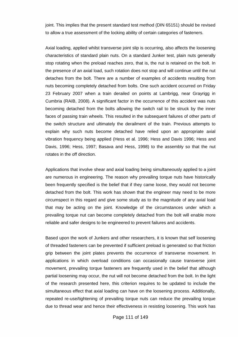
Page 111 of 149
joint. This implies that the present standard test method (DIN 65151) should be revised
to allow a true assessment of the locking ability of certain categories of fasteners.
Axial loading, applied whilst transverse joint slip is occurring, also affects the loosening
characteristics of standard plain nuts. On a standard Junker test, plain nuts generally
stop rotating when the preload reaches zero, that is, the nut is retained on the bolt. In
the presence of an axial load, such rotation does not stop and will continue until the nut
detaches from the bolt. There are a number of examples of accidents resulting from
nuts becoming completely detached from bolts. One such accident occurred on Friday
23 February 2007 when a train derailed on points at Lambrigg, near Grayrigg in
Cumbria (RAIB, 2008). A significant factor in the occurrence of this accident was nuts
becoming detached from the bolts allowing the switch rail to be struck by the inner
faces of passing train wheels. This resulted in the subsequent failures of other parts of
the switch structure and ultimately the derailment of the train. Previous attempts to
explain why such nuts become detached have relied upon an appropriate axial
vibration frequency being applied (Hess et al. 1996; Hess and Davis 1996; Hess and
Davis, 1996; Hess, 1997; Basava and Hess, 1998) to the assembly so that the nut
rotates in the off direction.
Applications that involve shear and axial loading being simultaneously applied to a joint
are numerous in engineering. The reason why prevailing torque nuts have historically
been frequently specified is the belief that if they came loose, they would not become
detached from the bolt. This work has shown that the engineer may need to be more
circumspect in this regard and give some study as to the magnitude of any axial load
that may be acting on the joint. Knowledge of the circumstances under which a
prevailing torque nut can become completely detached from the bolt will enable more
reliable and safer designs to be engineered to prevent failures and accidents.
Based upon the work of Junkers and other researchers, it is known that self loosening
of threaded fasteners can be prevented if sufficient preload is generated so that friction
grip between the joint plates prevents the occurrence of transverse movement. In
applications in which overload conditions can occasionally cause transverse joint
movement, prevailing torque fasteners are frequently used in the belief that although
partial loosening may occur, the nut will not become detached from the bolt. In the light
of the research presented here, this criterion requires to be updated to include the
simultaneous effect that axial loading can have on the loosening process. Additionally,
repeated re-use/tightening of prevailing torque nuts can reduce the prevailing torque
due to thread wear and hence their effectiveness in resisting loosening. This work has

Page 112 of 149
concluded that the maximum simultaneous axial load that can be sustained when
transverse joint movement occurs is equivalent to the preload retained by the prevailing
torque nut on a normal Junkers test.
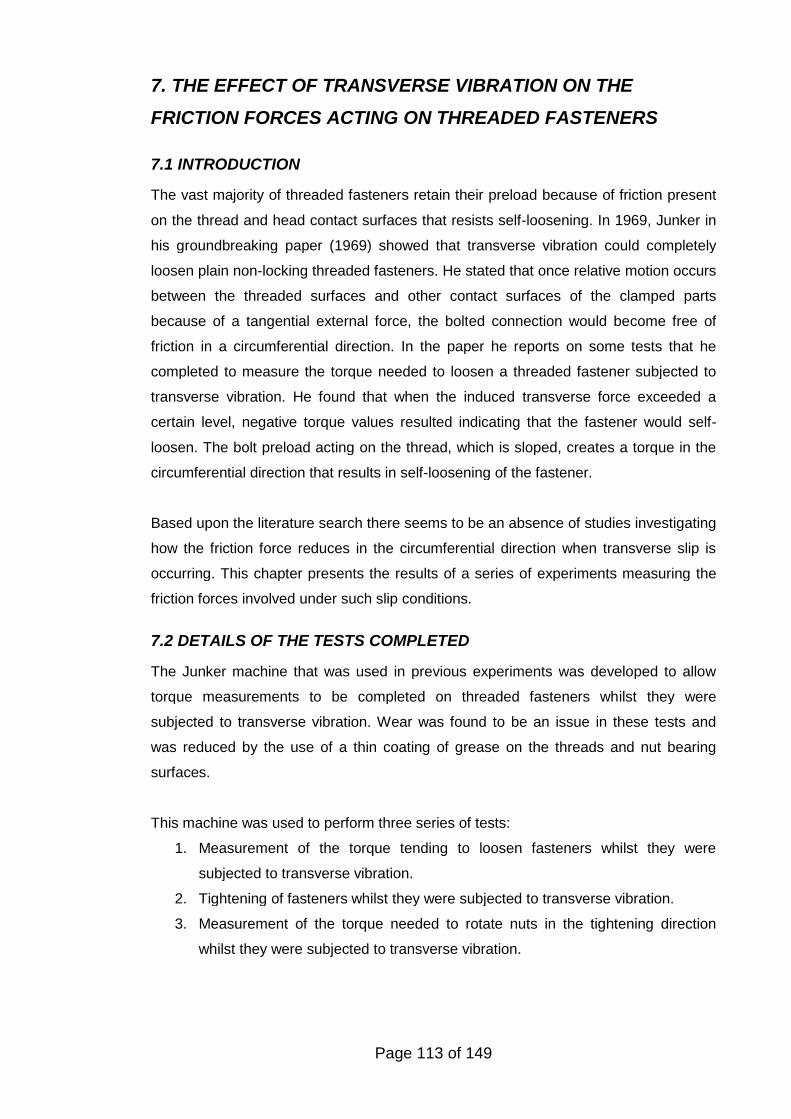
Page 113 of 149
7. THE EFFECT OF TRANSVERSE VIBRATION ON THE
FRICTION FORCES ACTING ON THREADED FASTENERS
7.1 INTRODUCTION
The vast majority of threaded fasteners retain their preload because of friction present
on the thread and head contact surfaces that resists self-loosening. In 1969, Junker in
his groundbreaking paper (1969) showed that transverse vibration could completely
loosen plain non-locking threaded fasteners. He stated that once relative motion occurs
between the threaded surfaces and other contact surfaces of the clamped parts
because of a tangential external force, the bolted connection would become free of
friction in a circumferential direction. In the paper he reports on some tests that he
completed to measure the torque needed to loosen a threaded fastener subjected to
transverse vibration. He found that when the induced transverse force exceeded a
certain level, negative torque values resulted indicating that the fastener would self-
loosen. The bolt preload acting on the thread, which is sloped, creates a torque in the
circumferential direction that results in self-loosening of the fastener.
Based upon the literature search there seems to be an absence of studies investigating
how the friction force reduces in the circumferential direction when transverse slip is
occurring. This chapter presents the results of a series of experiments measuring the
friction forces involved under such slip conditions.
7.2 DETAILS OF THE TESTS COMPLETED
The Junker machine that was used in previous experiments was developed to allow
torque measurements to be completed on threaded fasteners whilst they were
subjected to transverse vibration. Wear was found to be an issue in these tests and
was reduced by the use of a thin coating of grease on the threads and nut bearing
surfaces.
This machine was used to perform three series of tests:
1. Measurement of the torque tending to loosen fasteners whilst they were
subjected to transverse vibration.
2. Tightening of fasteners whilst they were subjected to transverse vibration.
3. Measurement of the torque needed to rotate nuts in the tightening direction
whilst they were subjected to transverse vibration.
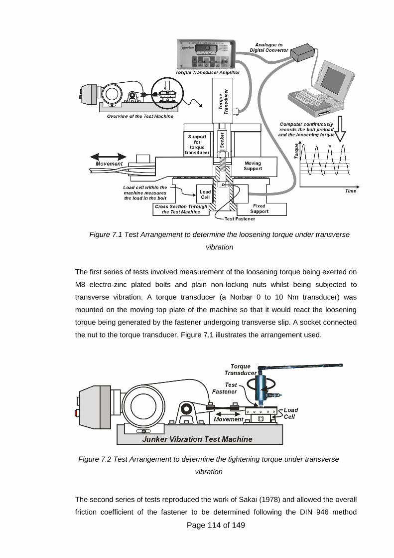
Page 114 of 149
The first series of tests involved measurement of the loosening torque being exerted on
M8 electro-zinc plated bolts and plain non-locking nuts whilst being subjected to
transverse vibration. A torque transducer (a Norbar 0 to 10 Nm transducer) was
mounted on the moving top plate of the machine so that it would react the loosening
torque being generated by the fastener undergoing transverse slip. A socket connected
the nut to the torque transducer. Figure 7.1 illustrates the arrangement used.
The second series of tests reproduced the work of Sakai (1978) and allowed the overall
friction coefficient of the fastener to be determined following the DIN 946 method
Figure 7.1 Test Arrangement to determine the loosening torque under transverse
vibration
Figure 7.2 Test Arrangement to determine the tightening torque under transverse
vibration
Page 115 of 149
(Deutsche Norm, 1991). The torque needed to tighten a M8 plain non-locking electro-
zinc plated nuts onto bolts under the conditions of transverse slip was measured.
Figure 7.2 shows the test arrangement used. The torque was applied to the nut in a
slow and deliberate manner by hand.
In the third series of tests an electro-zinc plated flanged nut (with a Spiralock thread
form) was locked onto a M6 threaded rod using a high strength chemical threadlocker
(Loctite 272) so that no self-loosening would occur. The torque needed to rotate the
fastener under transverse vibration was measured. From the torque measurements
obtained it was possible to determine the circumferential coefficient of friction of the nut
face under conditions of transverse slip. Figure 7.3 illustrates the test arrangement
used. In order to reduce friction on the bottom face, the nut clamped a thrust bearing.
In order to allow the drag torque of the bearing to be determined, tests were completed
with an identical thrust bearing mounted on the moving surface, and the torque needed
to rotate the assembly measured. It was assumed that one bearing would have half the
frictional drag torque of two. The torque absorbed by the rotation of the nut could be
established by subtracting the bearing torque from the overall applied torque.
Figure 7.3 Test Arrangement to determine the nut bearing torque under transverse
vibration
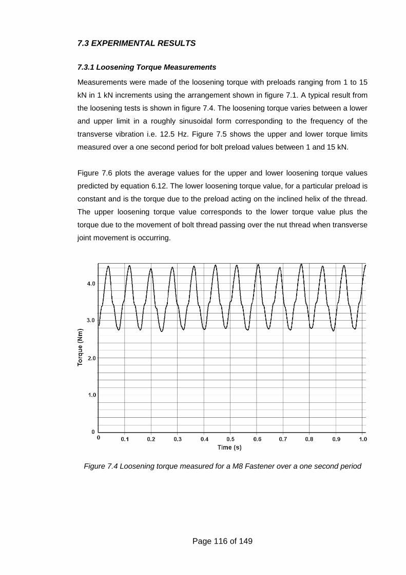
Page 116 of 149
Figure 7.4 Loosening torque measured for a M8 Fastener over a one second period
7.3 EXPERIMENTAL RESULTS
7.3.1 Loosening Torque Measurements
Measurements were made of the loosening torque with preloads ranging from 1 to 15
kN in 1 kN increments using the arrangement shown in figure 7.1. A typical result from
the loosening tests is shown in figure 7.4. The loosening torque varies between a lower
and upper limit in a roughly sinusoidal form corresponding to the frequency of the
transverse vibration i.e. 12.5 Hz. Figure 7.5 shows the upper and lower torque limits
measured over a one second period for bolt preload values between 1 and 15 kN.
Figure 7.6 plots the average values for the upper and lower loosening torque values
predicted by equation 6.12. The lower loosening torque value, for a particular preload is
constant and is the torque due to the preload acting on the inclined helix of the thread.
The upper loosening torque value corresponds to the lower torque value plus the
torque due to the movement of bolt thread passing over the nut thread when transverse
joint movement is occurring.
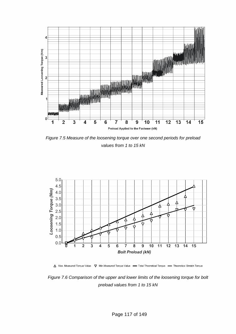
Page 117 of 149
Figure 7.5 Measure of the loosening torque over one second periods for preload
values from 1 to 15 kN
Figure 7.6 Comparison of the upper and lower limits of the loosening torque for bolt
preload values from 1 to 15 kN
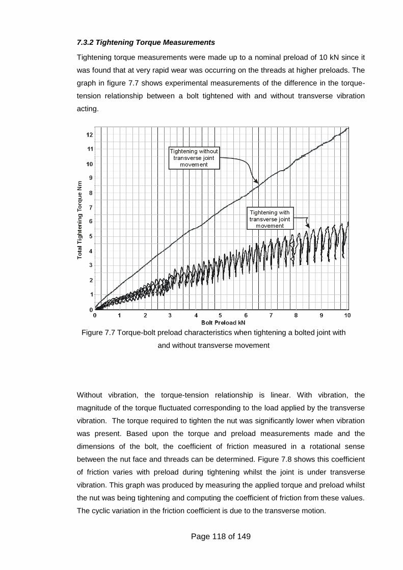
Page 118 of 149
7.3.2 Tightening Torque Measurements
Tightening torque measurements were made up to a nominal preload of 10 kN since it
was found that at very rapid wear was occurring on the threads at higher preloads. The
graph in figure 7.7 shows experimental measurements of the difference in the torque-
tension relationship between a bolt tightened with and without transverse vibration
acting.
Without vibration, the torque-tension relationship is linear. With vibration, the
magnitude of the torque fluctuated corresponding to the load applied by the transverse
vibration. The torque required to tighten the nut was significantly lower when vibration
was present. Based upon the torque and preload measurements made and the
dimensions of the bolt, the coefficient of friction measured in a rotational sense
between the nut face and threads can be determined. Figure 7.8 shows this coefficient
of friction varies with preload during tightening whilst the joint is under transverse
vibration. This graph was produced by measuring the applied torque and preload whilst
the nut was being tightening and computing the coefficient of friction from these values.
The cyclic variation in the friction coefficient is due to the transverse motion.
Figure 7.7 Torque-bolt preload characteristics when tightening a bolted joint with
and without transverse movement
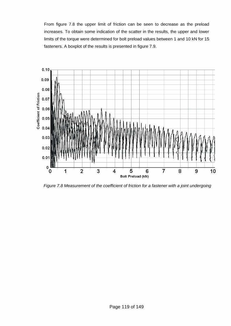
Page 119 of 149
From figure 7.8 the upper limit of friction can be seen to decrease as the preload
increases. To obtain some indication of the scatter in the results, the upper and lower
limits of the torque were determined for bolt preload values between 1 and 10 kN for 15
fasteners. A boxplot of the results is presented in figure 7.9.
Figure 7.8 Measurement of the coefficient of friction for a fastener with a joint undergoing
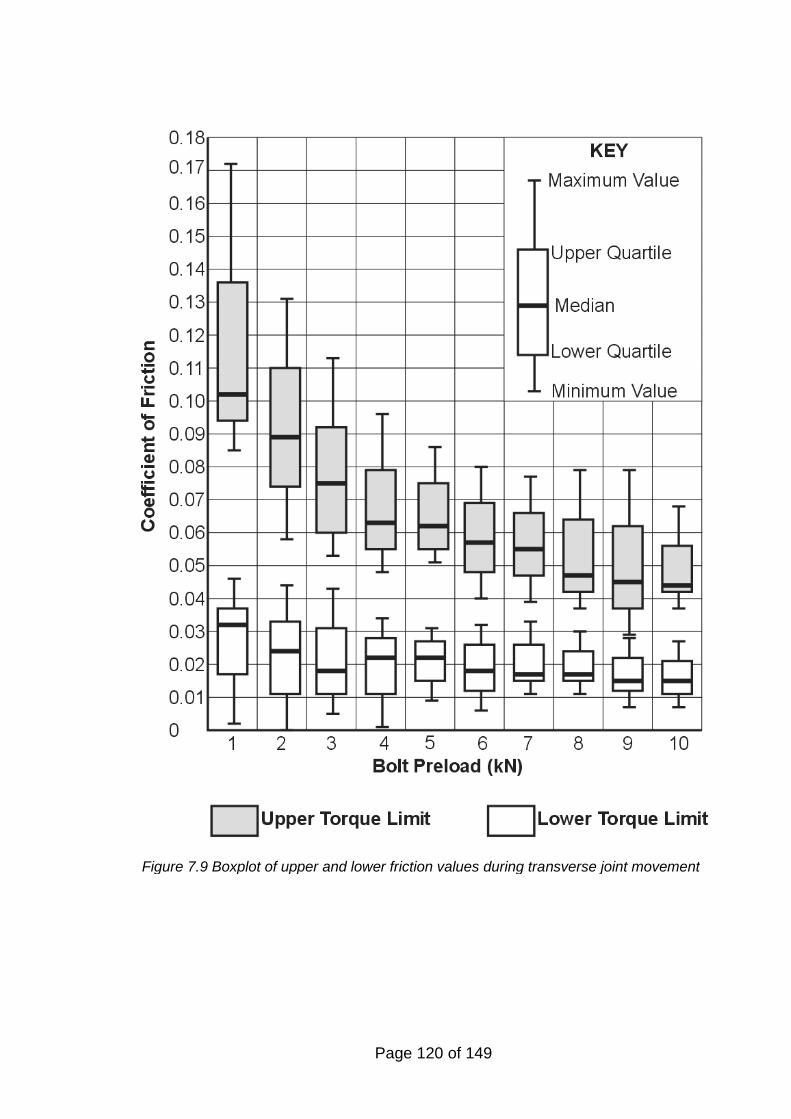
Page 120 of 149
Figure 7.9 Boxplot of upper and lower friction values during transverse joint movement
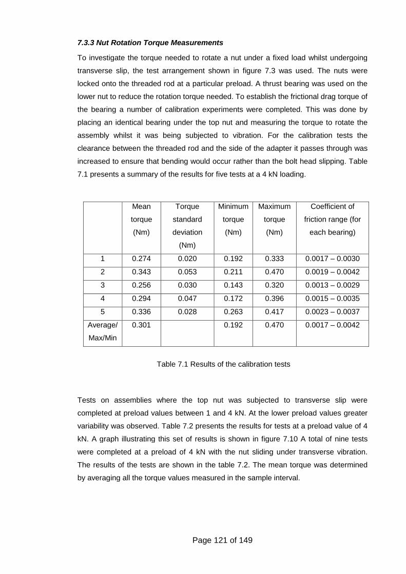
Page 121 of 149
7.3.3 Nut Rotation Torque Measurements
To investigate the torque needed to rotate a nut under a fixed load whilst undergoing
transverse slip, the test arrangement shown in figure 7.3 was used. The nuts were
locked onto the threaded rod at a particular preload. A thrust bearing was used on the
lower nut to reduce the rotation torque needed. To establish the frictional drag torque of
the bearing a number of calibration experiments were completed. This was done by
placing an identical bearing under the top nut and measuring the torque to rotate the
assembly whilst it was being subjected to vibration. For the calibration tests the
clearance between the threaded rod and the side of the adapter it passes through was
increased to ensure that bending would occur rather than the bolt head slipping. Table
7.1 presents a summary of the results for five tests at a 4 kN loading.
Tests on assemblies where the top nut was subjected to transverse slip were
completed at preload values between 1 and 4 kN. At the lower preload values greater
variability was observed. Table 7.2 presents the results for tests at a preload value of 4
kN. A graph illustrating this set of results is shown in figure 7.10 A total of nine tests
were completed at a preload of 4 kN with the nut sliding under transverse vibration.
The results of the tests are shown in the table 7.2. The mean torque was determined
by averaging all the torque values measured in the sample interval.
Mean
torque
(Nm)
Torque
standard
deviation
(Nm)
Minimum
torque
(Nm)
Maximum
torque
(Nm)
Coefficient of
friction range (for
each bearing)
1 0.274 0.020 0.192 0.333 0.0017 – 0.0030
2 0.343 0.053 0.211 0.470 0.0019 – 0.0042
3 0.256 0.030 0.143 0.320 0.0013 – 0.0029
4 0.294 0.047 0.172 0.396 0.0015 – 0.0035
5 0.336 0.028 0.263 0.417 0.0023 – 0.0037
Average/
Max/Min
0.301 0.192 0.470 0.0017 – 0.0042
Table 7.1 Results of the calibration tests
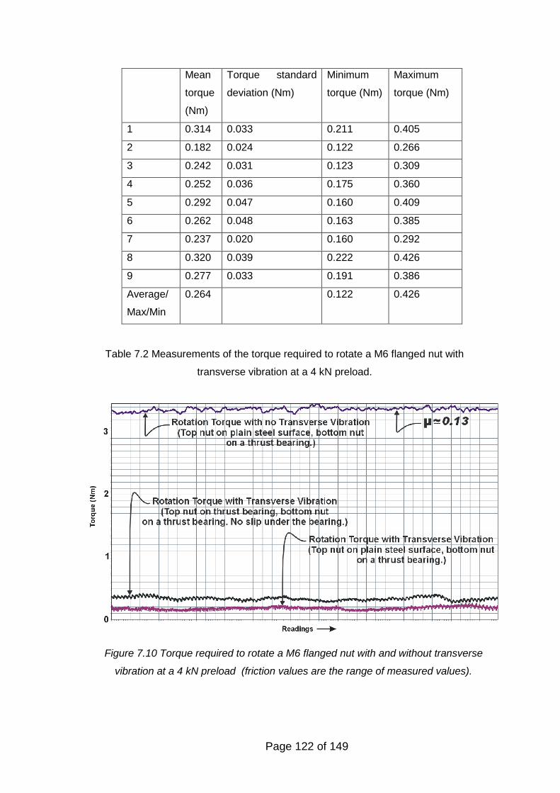
Page 122 of 149
Figure 7.10 Torque required to rotate a M6 flanged nut with and without transverse
vibration at a 4 kN preload (friction values are the range of measured values).
Mean
torque
(Nm)
Torque standard
deviation (Nm)
Minimum
torque (Nm)
Maximum
torque (Nm)
1 0.314 0.033 0.211 0.405
2 0.182 0.024 0.122 0.266
3 0.242 0.031 0.123 0.309
4 0.252 0.036 0.175 0.360
5 0.292 0.047 0.160 0.409
6 0.262 0.048 0.163 0.385
7 0.237 0.020 0.160 0.292
8 0.320 0.039 0.222 0.426
9 0.277 0.033 0.191 0.386
Average/
Max/Min
0.264 0.122 0.426
Table 7.2 Measurements of the torque required to rotate a M6 flanged nut with
transverse vibration at a 4 kN preload.

Page 123 of 149
As can be seen from figure 7.10, it was found that the torque needed to rotate the nut
under conditions of transverse slip with a thrust bearing on the lower nut was lower
than that needed to rotate the assembly with a thrust bearing top and bottom
From equation 4.2 the value of the effective bearing diameter of the nut De can be
determined for the size of nut used in these tests di = 8.8 mm and do = 13 mm, giving:
13 8.810.9
2 2o i
e
d dD mm
The torque needed to rotate the bearing at the bottom of the threaded rod will be
assumed to be half the value used to rotate the threaded rod assembly with bearings
top and bottom. Hence based upon the average value from table 7.1:
Bearing drag torque = 0.301 /2 = 0.150 Nm
Using the average torque value from table 7.2, the torque needed to rotate the nut =
0.264 – 0.150 = 0.114 Nm
The apparent bearing head friction in the circumferential direction when the nut is
experiencing transverse slip can be determined using:
2 2 0.1140.0052
4 10.9e
T x
FD x
Based upon mean torque values from each test shown in table 7.2, the minimum
friction value is 0.0015 and the maximum 0.0078.
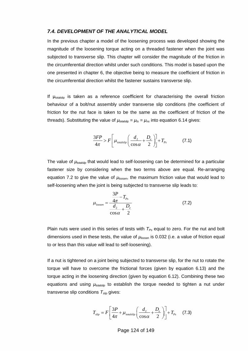
Page 124 of 149
7.4. DEVELOPMENT OF THE ANALYTICAL MODEL
In the previous chapter a model of the loosening process was developed showing the
magnitude of the loosening torque acting on a threaded fastener when the joint was
subjected to transverse slip. This chapter will consider the magnitude of the friction in
the circumferential direction whilst under such conditions. This model is based upon the
one presented in chapter 6, the objective being to measure the coefficient of friction in
the circumferential direction whilst the fastener sustains transverse slip.
If μtotalslip is taken as a reference coefficient for characterising the overall friction
behaviour of a bolt/nut assembly under transverse slip conditions (the coefficient of
friction for the nut face is taken to be the same as the coefficient of friction of the
threads). Substituting the value of μtotalslip = μts = μns into equation 6.14 gives:
23
4 cos 2e
totalslip Ps
DdFPF T
(7.1)
The value of μtotalslip that would lead to self-loosening can be determined for a particular
fastener size by considering when the two terms above are equal. Re-arranging
equation 7.2 to give the value of μloosen, the maximum friction value that would lead to
self-loosening when the joint is being subjected to transverse slip leads to:
2
3
4
cos 2
Ps
loosene
PT
Dd
(7.2)
Plain nuts were used in this series of tests with TPs equal to zero. For the nut and bolt
dimensions used in these tests, the value of μloosen is 0.032 (i.e. a value of friction equal
to or less than this value will lead to self-loosening).
If a nut is tightened on a joint being subjected to transverse slip, for the nut to rotate the
torque will have to overcome the frictional forces (given by equation 6.13) and the
torque acting in the loosening direction (given by equation 6.12). Combining these two
equations and using μtotalslip to establish the torque needed to tighten a nut under
transverse slip conditions Tslip gives:
23
4 cos 2e
slip totalslip Ps
DdPT F T
(7.3)
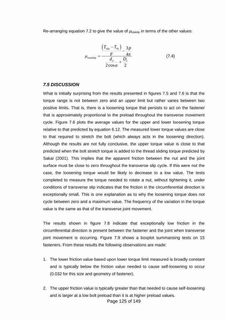
Page 125 of 149
Re-arranging equation 7.2 to give the value of μtotalslip in terms of the other values:
2
3
4
2cos 2
slip Ps
totalslipe
T T p
FDd
(7.4)
7.5 DISCUSSION
What is initially surprising from the results presented in figures 7.5 and 7.6 is that the
torque range is not between zero and an upper limit but rather varies between two
positive limits. That is, there is a loosening torque that persists to act on the fastener
that is approximately proportional to the preload throughout the transverse movement
cycle. Figure 7.6 plots the average values for the upper and lower loosening torque
relative to that predicted by equation 6.12. The measured lower torque values are close
to that required to stretch the bolt (which always acts in the loosening direction).
Although the results are not fully conclusive, the upper torque value is close to that
predicted when the bolt stretch torque is added to the thread sliding torque predicted by
Sakai (2001). This implies that the apparent friction between the nut and the joint
surface must be close to zero throughout the transverse slip cycle. If this were not the
case, the loosening torque would be likely to decrease to a low value. The tests
completed to measure the torque needed to rotate a nut, without tightening it, under
conditions of transverse slip indicates that the friction in the circumferential direction is
exceptionally small. This is one explanation as to why the loosening torque does not
cycle between zero and a maximum value. The frequency of the variation in the torque
value is the same as that of the transverse joint movement.
The results shown in figure 7.8 indicate that exceptionally low friction in the
circumferential direction is present between the fastener and the joint when transverse
joint movement is occurring. Figure 7.9 shows a boxplot summarising tests on 15
fasteners. From these results the following observations are made:
1. The lower friction value based upon lower torque limit measured is broadly constant
and is typically below the friction value needed to cause self-loosening to occur
(0.032 for this size and geometry of fastener).
2. The upper friction value is typically greater than that needed to cause self-loosening
and is larger at a low bolt preload than it is at higher preload values.
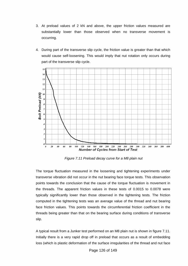
Page 126 of 149
3. At preload values of 2 kN and above, the upper friction values measured are
substantially lower than those observed when no transverse movement is
occurring.
4. During part of the transverse slip cycle, the friction value is greater than that which
would cause self-loosening. This would imply that nut rotation only occurs during
part of the transverse slip cycle.
The torque fluctuation measured in the loosening and tightening experiments under
transverse vibration did not occur in the nut bearing face torque tests. This observation
points towards the conclusion that the cause of the torque fluctuation is movement in
the threads. The apparent friction values in these tests of 0.0015 to 0.0078 were
typically significantly lower than those observed in the tightening tests. The friction
computed in the tightening tests was an average value of the thread and nut bearing
face friction values. This points towards the circumferential friction coefficient in the
threads being greater than that on the bearing surface during conditions of transverse
slip.
A typical result from a Junker test performed on an M8 plain nut is shown in figure 7.11.
Initially there is a very rapid drop off in preload that occurs as a result of embedding
loss (which is plastic deformation of the surface irregularities of the thread and nut face
Figure 7.11 Preload decay curve for a M8 plain nut
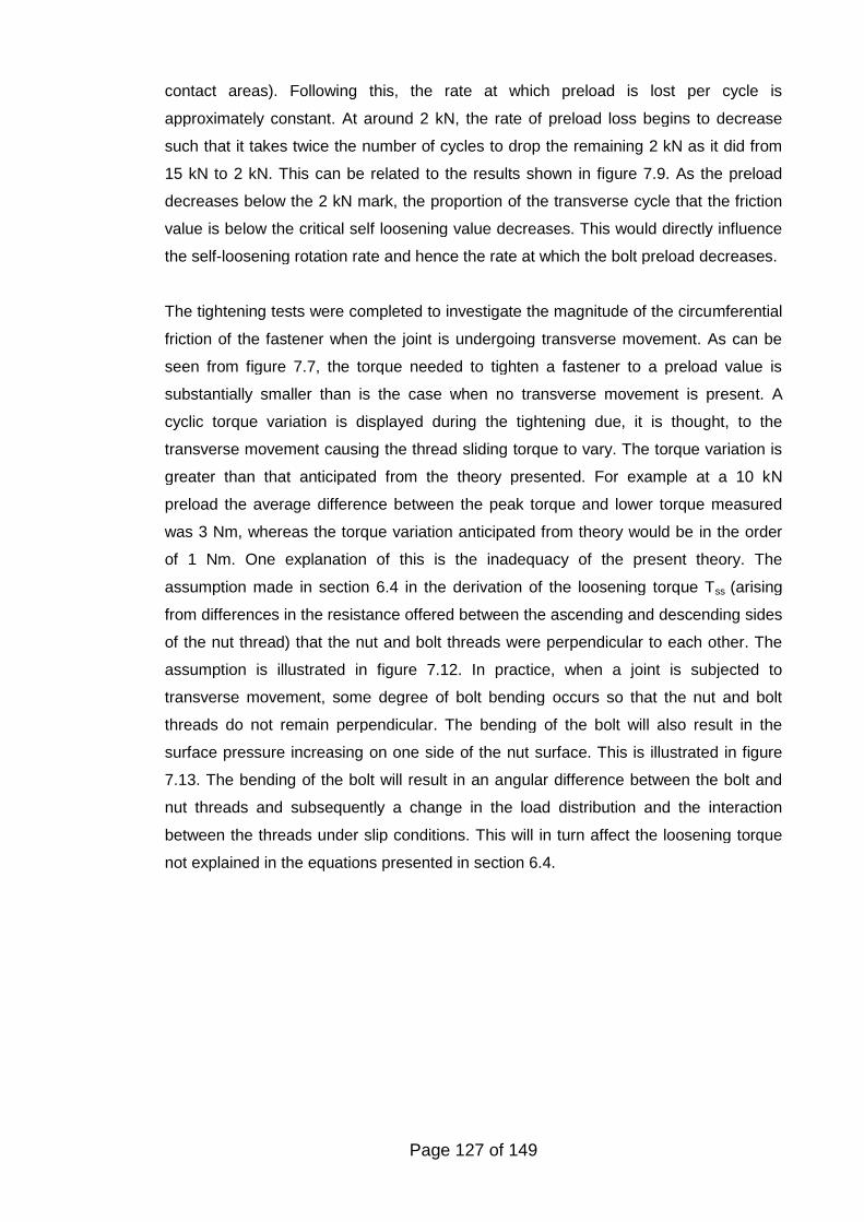
Page 127 of 149
contact areas). Following this, the rate at which preload is lost per cycle is
approximately constant. At around 2 kN, the rate of preload loss begins to decrease
such that it takes twice the number of cycles to drop the remaining 2 kN as it did from
15 kN to 2 kN. This can be related to the results shown in figure 7.9. As the preload
decreases below the 2 kN mark, the proportion of the transverse cycle that the friction
value is below the critical self loosening value decreases. This would directly influence
the self-loosening rotation rate and hence the rate at which the bolt preload decreases.
The tightening tests were completed to investigate the magnitude of the circumferential
friction of the fastener when the joint is undergoing transverse movement. As can be
seen from figure 7.7, the torque needed to tighten a fastener to a preload value is
substantially smaller than is the case when no transverse movement is present. A
cyclic torque variation is displayed during the tightening due, it is thought, to the
transverse movement causing the thread sliding torque to vary. The torque variation is
greater than that anticipated from the theory presented. For example at a 10 kN
preload the average difference between the peak torque and lower torque measured
was 3 Nm, whereas the torque variation anticipated from theory would be in the order
of 1 Nm. One explanation of this is the inadequacy of the present theory. The
assumption made in section 6.4 in the derivation of the loosening torque Tss (arising
from differences in the resistance offered between the ascending and descending sides
of the nut thread) that the nut and bolt threads were perpendicular to each other. The
assumption is illustrated in figure 7.12. In practice, when a joint is subjected to
transverse movement, some degree of bolt bending occurs so that the nut and bolt
threads do not remain perpendicular. The bending of the bolt will also result in the
surface pressure increasing on one side of the nut surface. This is illustrated in figure
7.13. The bending of the bolt will result in an angular difference between the bolt and
nut threads and subsequently a change in the load distribution and the interaction
between the threads under slip conditions. This will in turn affect the loosening torque
not explained in the equations presented in section 6.4.
Page 128 of 149
Figure 7.13 Bolt bending causing angular rotation of the nut
Figure 7.12 Bolt and nut threads remaining perpendicular during transverse slip
Page 129 of 149
7.6 CONCLUSIONS
The main conclusions obtained in this study can be summarised as follows:
1. The loosening torque measured under transverse joint movement is close to that
theoretically predicted. The lower limit of the torque measured at each cycle is close to
the bolt stretch torque. This torque is preload dependent and is normally resisted by
friction in the threads and on the nut face. The peak torque is the addition to the stretch
torque of the torque generated as a result of thread movement.
2. The findings of these tests are in broad agreement with the earlier work of Sakai
(1978; 2001). Under conditions of transverse slip very low values of friction in the
circumferential direction are measured. However what was found in this study was that
the friction value varied within the vibration cycle. At lower levels of preload the
proportion of the cycle in which the friction was lower than the critical level decreased.
Such a decrease would slow the rate of loosening that is typically observed in a Junker
vibration test.
3. It can be inferred from the results that the nut is not in continuous rotation during the
loosening process. Typically it is only during part of the transverse movement cycle that
friction is at a low enough level for self-loosening to occur. It can also be inferred that
as the bolt preload decreases there is a smaller proportion of the cycle when friction is
below the self-loosening critical level. For these tests, at low preload levels (<= 1 kN),
the upper friction value approximately corresponds to that present for the static case.
(When there is no transverse joint movement).
The results indicate that head friction in the rotation direction is lower than that of the
thread under transverse slip conditions. The results in this study also indicate that the
head friction was relatively constant whereas the thread friction varied within the
vibration cycle. Izumi et al (2005) suggested, based upon FE modelling, that complete
thread slip is achieved prior to bolt head slip and torsion is induced into the bolt shank.
However, if as this present study indicates, the friction is less under the head, then this
is unlikely to occur.
Page 130 of 149
8. CONCLUSIONS
8.1 INTRODUCTION
Threaded fasteners are used in almost every engineering product, but their complexity
in the detail of their operation is often under-estimated. This complexity is due in part to
the multifaceted nature of friction. The preload being imparted into a joint depends
upon two thread surfaces being rotated on each other under load and the frictional
resistance sustained. The vast majority of joints rely upon this preload for their
structural integrity.
Friction plays a central part in the use of threaded fasteners. Without friction, threaded
fasteners would not retain the preload; the nut would spin off after tightening when the
socket was removed. The conversion of the torque applied to the nut into preload is
largely controlled by friction.
Two of the significant issues involved in the use of threaded fasteners have been
investigated in this study. The first part of the study investigated the relationship
between torque and preload. In particular, a study was made of the changes in the
frictional forces that occur with the re-use of electro-zinc plated fasteners. The second
and major part of the study, considered the self-loosening of threaded fasteners.
8.2 DETERMINATION OF THE FRICTION COEFFICIENT OF FASTENERS
Experiments to determine the friction coefficient of fasteners indicated that a change in
the friction between the contact surfaces of the bolt/nut thread and nut face occurred
upon repeated tightening of fasteners with a zinc electro plated finish. This caused a
reduction in the preload when the fastener was tightened to a specified torque value.
The reduction in the preload was found to be significant, the preload on the sixth re-
tightening typically being half that obtained on the first tightening. Such a reduction
would have an adverse effect on the structural integrity of the assembly.
Higher levels of friction were noted for the threads than for under the nut face. This is
thought to be due to several factors. Thread friction is somewhat complicated by the
non-linear pressure distribution on the thread surfaces and this non-linearity is itself
partially a function of the friction value. The higher pressures that are present in the
thread lead to increased wear particle generation and ploughing. The enclosed nature
of the mating threads also results in wear particles, created at the surface closest to the
joint face, which is under the highest pressure, being moved further up the thread as
the nut rotates. Energy dissipation also arises during the tightening process due to
Page 131 of 149
thread deformation. In such circumstances, besides surface friction there will be a
component of the overall friction force due to work deforming the thread. The elastic-
plastic properties of the steel will influence the magnitude of this effect and hence is
likely to be higher on lower strength fasteners than those of higher strength. The
strength of the nut relative to that of the bolt will also influence this effect. It is known
that thread deformation is less when a high strength nut is used (Alexander, 1977). The
higher strength nut assists in resisting thread bending, which in turn improves the
resistance to thread stripping. The relative rigidity of the nut and bolt threads also has a
further influence. An implicit assumption in the determination of the friction coefficient is
that the flank angle is a constant 60 degrees. The distorted pressure flank of the
threads nearest the joint surface that was observed in this study will increase the
frictional force even if the friction coefficient remained constant because an increase in
the flank angle will have a greater the wedging effect. Effects such as those just
described are not adequately covered in present approaches to the computation of the
torque-tension relationship of fasteners.
Although the magnitude of the thread friction coefficient is higher than that which is
under the nut face, the increase in the nut face friction follows a similar increasing trend
on re-tightening becoming approximately constant after five or six tightenings. It was
also noted that the magnitude of the thread friction coefficient became dependent upon
the pressure (clamp force) as the number of tightenings increased. The mechanism for
this effect is not completely understood, but is thought to be due to the increase in
pressure causing a change from wear particle ploughing to adhesive friction.
Tests completed to determine the nut face friction coefficient under a constant loading
clearly indicated that a change occurs in the friction characteristics after a certain
amount of angular movement. By using the mean nut radius, this angular movement
was converted to a linear movement. The average distance prior to a significant
change in friction occurring was 195 mm. The initial average friction coefficient of 0.13
is less than the mean value noted in the tightening tests (mean value on first tightening
of 0.19). However the scatter in the results on the tightening tests observed on the nut
face tests under constant loading was less than that observed in the full tightening
tests.
Based upon these results, the reuse of unlubricated EZP threaded fasteners cannot be
recommended. The increase in friction resulting from reuse could have an adverse
effect on a joint’s structural integrity due to the corresponding decrease in the
generated clamp force that occurs. EZP is a common type of finish used on fasteners.
Page 132 of 149
Many prevailing torque nuts for example use such a finish. The present tests on re-use
of such nuts, such as ISO 2320 (British Standards, 2008), assess the prevailing torque
characteristics with re-use but not the effect that such re-use will have on friction and
subsequently the bolt preload.
8.3 LOOSENING OF FASTENERS BY TRANSVERSE VIBRATION
The loosening of threaded fasteners is a complex phenomenon. Some degree of
preload reduction usually occurs when a joint is placed under an external load as a
result of non-rotational loosening involving localised collapse and plasticity of the
contact surfaces. For a fastener to come completely loose however, usually involves
some degree of self-loosening i.e. fastener rotation. Previous research indicated that
transverse vibration is the principal cause of self-loosening. In this study a large
number of tests have been performed to study the loosening characteristics of various
types of fasteners. The focus was on prevailing torque nuts, a common type of lock nut.
The tests confirmed the findings of previous research in that under transverse vibration
this type of nut initially rotates until a relatively small asymptotic preload value is
reached. It was also found that all the prevailing torque nuts tested had similar
loosening characteristics.
Novel investigations were conducted into the loss of prevailing torque when a fastener
was reused. The present standard test code defined in the ISO 2230 standard (British
Standards, 2008) is applicable for a joint being deliberately disassembled for
maintenance or other purposes. In some industries, for example the rail industry, the
practice is to retighten nuts that are found loose. Self-loosening involves relative
movement of the threads. This movement could be anticipated to have a greater effect
on the efficacy of the prevailing torque feature than normal untightening. This was
indeed found to be the case. Based upon these findings, it would be wise to discard
any nut found to have self-loosened and replace with new following an investigation
into the cause of self-loosening. The finding that nylon insert nuts performed better
than the all-metal type of nut is of economic interest. A non-metallic insert nut costs
typically between 10 to 40 times less than the all-metal type of nut. The reason for the
better performance may be that the thread movement caused elastic movement of the
locking element rather than wear and plastic deformation that would be likely to occur
with the all-metal type of nut.
Page 133 of 149
8.4 COMPLETE SELF-LOOSENING OF PREVAILING TORQUE FASTENERS
The structural integrity of the majority of bolted joints is dependent upon achieving and
maintaining sufficient preload. If the preload is insufficient to prevent joint slip from
applied shear loads, self-loosening of the fastener becomes likely. Prevailing torque
nuts are used to limit the loosening and ensure that the nut does not become detached
from the bolt. What this study has revealed is that if an axial load is also acting on a
joint which is experiencing transverse slip, prevailing torque nuts can continue to self-
loosen leading to their possible detachment from bolts.
It is the tensile load in the bolt that generates the loosening torque under transverse
slip conditions. The tensile load can be from the initial preload or an axial loading. The
other effect of the transverse slip is to apparently reduce the frictional resistance in the
circumferential direction to a very low value. These two effects are responsible for self-
loosening.
On the majority of assemblies, fasteners are tightened prior to the application of an
external load. The bolt acts as a tension spring and the joint a compression spring, the
tensile and compressive loads in the spring system balancing each other. When the
joint sustains an external load, the bolt is stretched by only a small additional amount
since the joint stiffness is usually far greater than the bolt stiffness. Subsequently, the
bolt usually only sustains a small proportion of the external axial load. This assumes
that the external load does not completely relieve the compression on the joint from the
preload. If the compression is completely relieved, joint separation occurs and the bolt
sustains the full magnitude of the external load. The mechanism by which prevailing
torque nuts can become detached from bolts can be explained as follows. Under the
appropriate conditions of transverse slip, self-loosening will occur reducing the preload
to a fraction of its original value. If an external axial load is also acting once the preload
reduces to a value so that joint separation occurs, it is axial load that will drive the
loosening process. As long as the axial load is maintained and transverse slip is
occurring, the nut will continue to rotate until it becomes detached.
The study reported in this thesis also sheds some light on why detachment of the nut
from the bolt can readily occur. Frequently on a standard Junker test, once a plain nut
has come loose it stops rotating as the absence of the preload eliminates the torque
driving the loosening process. In practice the presence of corrosion would sometimes
inhibit rotation once the preload is eliminated. However, the detachment of plain non-
locking nuts is commonplace. Often such detachments have been put down to
‘vibration’ and some work has been completed on this aspect (Hess and
Page 134 of 149
Sudhirkashyap, 1997). This thesis, however, proposes another explanation, plain nuts
in the presence of transverse vibration and axial loading will readily become detached.
The presence of even a small constant or intermittent axial load acting on the joint in
the presence of transverse slip will lead to the continued rotation of plain nuts until they
detach.
8.5 THE EFFECT OF TRANSVERSE VIBRATION ON THE FRICTION
FORCES ACTING ON THREADED FASTENERS
Considering that friction effects are central to the self-loosening of threaded fasteners,
it is surprising that other researchers have not studied this aspect in more detail. The
apparent reduction in frictional resistance in the circumferential when transverse slip is
experienced and the torque in the untightening direction exerted on the nut under such
conditions, are the key to the understanding the self-loosening phenomenon.
One surprising aspect of the tests was that the loosening torque range under
transverse slip conditions was not between zero and an upper limit, but varied between
two positive limits. That is, there is a loosening torque that persists to act on the
fastener that is approximately proportional to the preload throughout the transverse
movement cycle.
The results also indicated that exceptionally low apparent friction in the circumferential
direction is present between the fastener and the joint when transverse joint movement
occurs. It was found that the frictional resistance varied during the transverse slip
cycle. The lower friction value based upon the lower torque limit measured was broadly
constant and was typically below the friction value needed to cause self-loosening to
occur. The upper friction value was typically greater than that needed to cause self-
loosening and was larger at a low bolt preload than at higher preload values.
At preload values of 2 kN and above, the upper friction values measured were
substantially lower than those observed when no transverse movement occurred.
During part of the transverse slip cycle, the friction value was greater than that which
would cause self-loosening. This would imply that nut rotation only arises during part of
the transverse slip cycle.
The torque fluctuation measured in the loosening and tightening experiments under
transverse vibration did not occur in the nut bearing face torque tests. This observation
points towards the conclusion that the cause of the torque fluctuation is movement in
Page 135 of 149
the threads. The apparent friction values in these tests of 0.0015 to 0.0078 were
typically, significantly lower than those observed in the tightening tests. The friction
computed in the tightening tests was an average value of the thread and nut bearing
face friction values. This points towards the apparent friction in the circumferential
direction in the threads being greater than that on the bearing surface during conditions
of transverse slip.
8.6 APPLICATION OF THE RESULTS OF THIS RESEARCH
Key points relating to the application of this research include:
o The re-use of unlubricated fasteners with an EZP coating is not advisable for
critical applications. Since it is normal practice for the fasteners to be tightened
to a specific torque value, the preload achieved will reduce if the fasteners are
re-used. The addition of a suitable lubricant, such as molybdenum disulfide, will
stabilise the friction coefficient so that a similar preload would be achieved
when the fasteners are re-tightened.
o A key finding of this research is how prevailing torque nuts can become
detached from bolts. They can no longer be defined as loss prevention devices
because their locking performance depends upon the loading conditions to
which they are subjected. A modification of the DIN 65151 test is needed so
that the effect of axial loading can be included. Design Engineers should also
consider the loading conditions that joints will be subjected to prior to specifying
torque prevailing nuts.
o The investigations completed on the loosening torque being applied to
fasteners and the friction forces present in the circumferential direction whilst
they are subjected to transverse vibration will be useful in developing
understanding as to why fasteners self-loosen.
Page 136 of 149
9. FURTHER WORK
9.1 INTRODUCTION
Although threaded fasteners can be considered a mature technology there are
significant problems with their reliable use. This in part arises from the inability to
inexpensively measure the fastener preload in an assembled joint. The structural
integrity of the majority of bolted joints depends upon the preload generated by the
tightening process achieving a certain minimum value. As a consequence of the
difficulties in measuring the preload, other approaches are introduced such as
controlling the torque applied to tighten the fastener. As discussed previously, the
applied torque only controls the fastener preload indirectly. To achieve some degree of
control over the preload using the applied torque, the friction conditions need to be
known. The first part of this study investigated friction related to tightening of fasteners.
Later the friction forces acting on a fastener experiencing transverse slip were
investigated.
9.2 EFFECT OF RETIGHTENING FASTENERS ON THE FRICTION
COEFFICIENT
In a study completed on retightening wheel fasteners Morgan and Henshall (1996)
demonstrated a substantial decrease of up to 60-70 percent in the preload for
degreased fasteners in self-finish after 5 re-tightenings compared to the as-received
performance. The study showed that full recovery of the preload on subsequent
tightenings could be achieved by applying engine oil. Wheel fasteners typically have a
self-finish i.e. have no coating. An investigation into whether the application of
lubrication would recover the first time tightening characteristics of coated fasteners
would assist in developing guidelines on reuse.
During this study a number of fasteners were tested having a zinc flake coating
(Geomet). It was observed that a change in the frictional characteristics occurred with
fasteners having this type of finish. These fastenings are commonly used in automotive
applications and further work on other fastener finishes would be of interest.
As part of this study, a series of tests were completed by the author on the effect of
lubricants in the repeated use of EZP threaded fasteners with the findings being
presented at LUBMAT 2006 (Eccles, 2006). The results indicated that the use of
certain lubricants, such as molybdenum disulphide paste, lithium grease and Copaslip,
could prevent friction increase on re-tightening. The use of oil did not prevent an
Page 137 of 149
increase in friction, the friction coefficient approximately doubling after the tenth cycle.
Re-use of stainless steel bolts indicated that a factor of three increase occurs. Even the
use of molybdenum disulphide paste only moderated the friction increase, but did not
prevent it. Whilst many equipment manufacturers advocate that new fasteners must be
used if their product is disassembled, fasteners are widely re-used, especially if made
in stainless steel. Investigation into appropriate dry lubricant coatings that will allow
fastener reuse without a decrease in properties would be economically and
environmentally beneficial.
9.3 LOOSENING OF PREVAILING TORQUE NUTS
Prevailing torque nuts have made an important contribution to fastener security since
they eliminate the possibility of the locking element being omitted as can be the case
with lock washers. However this study has shown that they are not effective under
certain conditions.
Tests have been conducted on an all-metal variety of prevailing torque nut. Beside the
non-metallic insert nut, many other types of locking devices have a prevailing torque
feature. Adhesive locking involves the application of a liquid to the threads that cures to
form a void filling solid that subsequently restricts relative movement. Adhesive having
too high a bond strength has the consequence that disassembly is hindered with the
nuts often having to be cut off. Also high bond strength adhesives tend to exhibit high
friction values. Such high strength adhesives, called "studlocker" adhesives, are often
used to lock studs in place. However, when they are used on bolt threads the preload
is restricted, relative to what could be achieved, due to the high torsional stresses
induced due to the higher friction. Owing to these factors, medium strength adhesives
are frequently used. Under a conventional Junkers test, such medium strength
threadlockers exhibit self loosening characteristics similar to prevailing torque nuts.
Investigating the effect of axial loading and transverse vibration on adhesive locking
and other types of prevailing torque fasteners could extend this study. Prevailing torque
features are also applied to bolts, such as a fused polymer patch applied to the thread,
such fasteners behave in a similar manner to prevailing torque nuts on a conventional
Junker test.
Prevailing torque nuts retain less preload on a transverse vibration test than would be
anticipated. The expectation is that self-loosening would stop when the loosening
torque was equal to the prevailing torque. Typically this is not the case, a lower preload
being retained than would be expected by the statically measured prevailing torque.
The static measurement of the prevailing torque (without transverse vibration) may be
Page 138 of 149
the cause of the anomaly. The magnitude of the prevailing torque may reduce under
transverse vibration conditions. The relative movement of the threads may influence
the pressure being applied by the nut to the bolt thread by the prevailing torque feature
and hence the torque being generated. To assess if this hypothesis is true, a
comparison is needed between the prevailing torque measured statically with that
under transverse vibration conditions. This will not necessarily be easy to complete
since a test method would need to be developed that could measure the prevailing
torque under such conditions.
The current study has revealed a need for the development of a modified standard to
assess the loosening characteristics of threaded fasteners. The present Junker test as
defined in the DIN 65151 standard (Deutsche Norm, 1994) has been found to be
inadequate to fully loosen prevailing torque nuts. The development of an updated
standard is needed that could evaluate the effect of axial loading in addition to
transverse slip on the resistance to loosening of fasteners. Presently fastener
companies promote the results of a Junker’s test as proof that a fastener will retain
preload under vibration. This study has revealed that this is not always the case. To
develop an improved standard, further work is needed to investigate the level of axial
loading appropriate for a given size of fastener.
9.4 FRICTION FORCES ACTING UNDER TRANSVERSE SLIP
The torque fluctuation that arises when tightening the fastener, when transverse
movement is occurring, is higher than that which current theory predicts. One possible
explanation for this is that there is a direct shear force acting on the fastener when the
torque is applied via a wrench. This shear force could influence the results. The tests
should be repeated with a pure torque being applied to assess if the torque fluctuation
reduces.
The results from the current study point towards the nut rotation being discontinuous
during the transverse movement cycle as the friction value fluctuates above and below
the critical self-loosening value. Future work should include the measurement of this
rotation during the transverse movement cycle and determination of how the nut
rotation varies with each stage of the vibration cycle.
As the static friction coefficient increases, so does the resistance of a fastener to self-
loosening. Further work should be done to measure the apparent friction coefficient
under transverse slip for different fastener finish (friction) conditions. It is possible that
Page 139 of 149
as the static friction coefficient increases, the period of the transverse movement cycle
when the apparent friction dips below the critical level decreases.
A test should be devised to allow the determination of both the nut face and thread
friction coefficients under transverse slip conditions. It is known that the pressure
distribution under the nut face is non-linear (Cullimore and Eckhart, 1972). The highest
pressure is next to the hole and decreases towards the outer face of the nut. Further
understanding of the loosening process would be gleaned by measuring the pressure
distribution under the nut during transverse slip conditions. Due to the side loading it is
anticipated that the pressure distribution would be asymmetric under such conditions.
9.5 SELF-LOOSENING AND FATIGUE FAILURE
The two common failure modes of threaded fasteners under transverse vibration are
self-loosening and fatigue. In general, if the fastener does not self-loosen when
subjected to transverse vibration and the bending stress in the bolt is sufficiently high
then fatigue will occur. The ‘critical slip’ concept which applies to non-locking fasteners
was discussed in section 2.7.4. On fasteners having some locking facility, slip which
would self-loosen non-locking fasteners can be sustained. The bending stress in the
bolt will be increased when larger joint slip is encountered. The machine used by the
author had a transverse amplitude of +/- 0.65 mm, M8 bolts would usually sustain a
fatigue failure between 1000 and 3000 cycles. A graph illustrating fatigue failure is
shown in figure 9.1.
In the test there was no self-loosening of the nut, preload loss was as a result of non-
rotational loosening. Initially there was a rapid reduction in the preload. This was
probably due to a combination of embedding loss as a consequence of flattening of the
surface roughness and localised plastic deformation in the threads. The gradual loss of
preload that followed the initial rapid drop was probably as a result of continued plastic
deformation in the bolt thread. The rapid drop off in the preload that occurs at
approximately 1600 cycles is as a result of the fatigue crack propagating through the
bolt. Complete fracture occurs at 1700 cycles.
The thread in the nut used had an asymmetric thread form that enabled the bolt thread
crest to contact the nut thread on a 30 degree ramp rather than the conventional 60
degrees. As the bolt was tightened the bolt thread was pulled onto this ramp preventing
relative movement under vibration. On tests performed on this type of thread and
another similar thread form (the ‘Bump thread’), prevention of thread movement would
appear to lead to a reduction in the fatigue life. This may be as a result of the locking
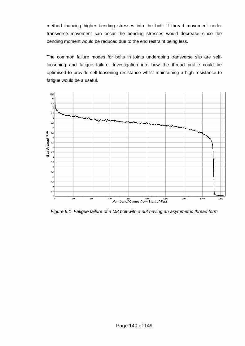
Page 140 of 149
method inducing higher bending stresses into the bolt. If thread movement under
transverse movement can occur the bending stresses would decrease since the
bending moment would be reduced due to the end restraint being less.
The common failure modes for bolts in joints undergoing transverse slip are self-
loosening and fatigue failure. Investigation into how the thread profile could be
optimised to provide self-loosening resistance whilst maintaining a high resistance to
fatigue would be a useful.
Figure 9.1 Fatigue failure of a M8 bolt with a nut having an asymmetric thread form
Page 141 of 149
REFERENCES
AAIB (2005). Air Accident Investigation Branch Report on a Ran S6-ESD XL Aircraft.http://www.aaib.gov.uk/.
AAIB (2006). Air Accident Investigation Branch Report into the crash of a Light Aircraftdue to the loss of a stiffnut. http://www.aaib.gov.uk/.
Aboyoussef, H., S. Weiner, et al. (2000). "Effect of an antirotation resistance form onscrew loosening for single implant-supported crowns." The Journal of ProstheticDentistry 83(4): 450-455.
Ahn, J.-M. and J.-T. Suh (2009). "Detection of Locking Bolt Loosening in the Stem-Condyle Junction of a Modular Femoral Stem in Revision Total KneeArthroplasty." The Journal of Arthroplasty In Press, Corrected Proof.
Alexander, E. M. (1977). "Analysis and Design of Threaded Assemblies." SAE Paper770420.
Antonios, C., D. J. Inman, et al. (2006). "Experimental and theoretical behavior of self-healing bolted joints." Journal of Intelligent Material Systems and Structures17(6): 499-509.
ASME (2010). "Guidelines for Pressure Boundary Bolted Joint Assembly".Basava, S. and D. P. Hess (1998). "Bolted Joint Clamping Force Variation Due To
Axial Vibration." Journal of Sound and Vibration 210(2): 255-265.Baubles, R. C., G. J. McCormick, et al. (1966). Loosening of Fasteners by Vibration,
ESNA Report No. ER272-2177, Elastic Stop Nut Corporation of America.Bellemare, S. C., M. Dao, et al. (2008). "Effects of mechanical properties and surface
friction on elasto-plastic sliding contact." Mechanics of Materials 40: 206-219.Bhattacharya, A., A. Sen, et al. (2008). "An investigation on the anti-loosening
characteristics of threaded fasteners under vibratory conditions." Mechanismand Machine Theory 10.1016.
Bickford, J. H. and S. Nassar (1998). Handbook of Bolts and Bolted Joints. J. H.Bickford and S. Nassar, Marcel Dekker Inc. 1.
Binon, P. P. (1998). "Evaluation of the effectiveness of a technique to prevent screwloosening, ,." The Journal of Prosthetic Dentistry 79(4): 430-432.
Boomsma, M. (1955). Loosening and Fatigue Strength of Bolted Joints. The Engineer,26 August 1955.
British Standards (2005). "BS EN ISO 16047: 2005 - Fasteners - Torque/clamp forcetesting."
British Standards (2006). "BS EN 10319-2 Metallic materials. Tensile stress relaxationtesting. Procedure for bolted joint models."
British Standards (2008). "BS EN ISO 2320 - 2008: Prevailing torque type steelhexagon nuts - Mechanical and performance requirements."
Burguete, R. L. P., E. A., (1995). "The Effect of Mean Stress on the Fatigue Limit ofHigh Tensile Bolts." Proceedings of the Institution of Mechanical Engineers 209.
Cheatham, C. A., C. F. Acosta, et al. (2008). "Tests and analysis of secondary lockingfeatures in threaded inserts." Engineering Failure Analysis 16: 39-57.
Clark, S. K. and J. J. Cook (1966). "Vibratory loosening of bolts." SAE Paper 660432.Cullimore, M. S. G. and J. B. Eckhart (1972). "The distribution of the clamping pressure
in friction grip bolted joints." The Structural Engineer No. 4, Vol 62.Cumming, D. (1868). Improvement in Method of Locking Nuts. U.S.: 2.Deutsche Norm (1991). DIN 946 - Determination of coefficient of friction of bolt-nut
assemblies under specified conditions, Deutsche Norm.Deutsche Norm (1994). DIN 65151 - Dynamic testing of the locking characteristics of
fasteners under transverse loading conditions.Dick, S. J. (1983). Comparison of locking devices on Grade 8.8 Screwed Assemblies.
British Leyland Engineering Department Report 83/1096-50-11.Dick, S. J. (1984). "Vibrational loosening of threaded fasteners - Effect of Various
corrosion resistant finishes." Austin Rover Report No. 84/1190-50-11.
Page 142 of 149
Dixon, D. L., L. C. Breeding, et al. (1995). "Comparison of screw loosening, rotation,and deflection among three implant designs." The Journal of ProstheticDentistry 74(3): 270-278.
Dong, Y. and D. P. Hess (1999). "Effect of thread dimensional conformance onvibration-induced loosening." Journal of Vibration and Acoustics, Transactionsof the ASME 121(2): 209-213.
Dong, Y. and D. P. Hess (2000). "Shock-Induced Loosening Of Dimensionally Non-Conforming Threaded Fasteners." Journal of Sound and Vibration 231(2): 451-459.
Eccles, W. (1993). "Design Guidelines for Torque Controlled Tightening of BoltedJoints." Society of Automotive Engineers Technical Paper 930578.
Eccles, W. (2006). "The Effect of Lubricants on the Repeated Use of ThreadedFasteners." Proceedings of the 1st European Conference on LubricationManagement and Technology LUBMAT 2006.: 271-278.
Elias, C. N., D. C. Figueira, et al. (2006). "Influence of the coating material on theloosing of dental implant abutment screw joints." Materials Science andEngineering: C
Proceedings of the First TMS Symposium on Biological Materials Science 26(8): 1361-1366.
Engineering Magazine (1930). The Dardelet Self-Locking Screw Thread. EngineeringAugust 29.
Esser, J. and G. Hellwig (2004). "Consequences for Standardisation - Ineffective ScrewLocking." DIN Notices 4 - 2004.
FAA (1982). "Federal Aviation Authority Accident Investigation on a engine failure."http://www.ntsb.gov/ntsb/GenPDF.asp?id=ATL83LA023&rpt=fi.
Finkelston, R. J. (1972). How much shake can bolted joints take. Machine Design. 44:122-125.
Ford (2002). "Ford Worldwide Fastener Standard WZ 101 Steel Metric ThreadedFasteners Torque/Clamping Force Performance."
Fouvry, S., P. Kapsa, et al. (2001). "An elastic-plastic shakedown analysis of frettingwear." Wear 247(1): 41-54.
Fu, C. C. (1993). "Rattling Loose of Thread Connected Steels in Percussive RockDrilling." Transactions of the ASME 115.
Fujioka, Y. and T. Sakai (2005). Calculated behavior and effective factors for bolt self-loosening under a transverse cyclic load generated by a linearly vibratingwasher. Proceedings of the ASME Design Engineering Division 2005, Nov 5-112005, Orlando, FL, United States, American Society of Mechanical Engineers,New York, NY 10016-5990, United States.
Gambrell, S. C. (1968). Why bolts loosen. Machine Design. 40: 163-167.Ganeshmurthy, S., B. Housari, et al. (2007). "Invetsigation of the Effect of Adhesive
Coating on the Performance of Threaded Fasteners." SAE Paper 2007-01-1671.
Goodier, J. N. and R. J. Sweeney (1945). Loosening by vibration of threadedfastenings. Mechanical Engineer. 67: 798-802.
Hagelthorn, G. (1992). "Principle Modes of Failure Causing Lost Wheels from Tractor-Trailer Combination Vehicles." Society of Automotive Engineers 922446.
Hagman, L. A. and U. Olofsson (1998). "A model for micro-slip between flat surfacesbased on deformation of ellipsoidal elastic asperities—parametric study andexperimental investigation." Tribology International 31(4): 209-217.
Hashimura, S. (2007). "Influences of various factors of bolt tightening on looseningfatigue failure under transverse vibration." SAE Paper 2007-01-0807.
Haviland, G. S. (1981). "Unraveling the Myths of the Fastener World." SAE Paper810509.
Hess, D. P. (1996). "Threaded components under axial harmonic vibration, Part 2:kinematic analysis." Journal of Vibration and Acoustics, Transactions of theASME 118(3): 423-429.
Page 143 of 149
Hess, D. P., S. Basava, et al. (1996). "Variation of clamping force in a single-boltassembly subjected to axial vibration." American Society of MechanicalEngineers, Design Engineering Division 90: 97-102.
Hess, D. P. and K. Davis (1996). "Threaded components under axial harmonicvibration, Part 1: Experiments." Journal of Vibration and Acoustics,Transactions of the ASME 118(3): 417-422.
Hess, D. P. and Davis. K (1996). "Threaded components under axial harmonicvibration, Part 2: Kinematic Analysis." Journal of Vibration and Acoustics,Transactions of the ASME 118(3): 423-429.
Hess, D. P. and S. V. Sudhirkashyap (1997). "Dynamic Loosening and Tightening of aSingle Bolt Assembly." Journal of Sound and Acoustics 119: 311-316.
Hess, D. P. and S. V. Sudhirkashyap (1997). "Dynamic loosening and tightening of asingle-bolt assembly." Journal of Vibration and Acoustics, Transactions of theASME 119(3): 311-316.
Hess. D. P and S. S. V. (1997). "Dynamic Loosening and Tightening of a Single BoltAssembly." Journal of Sound and Acoustics 119: 311-316.
Holmes, H. (1988). "Seeking the perfect locking method for threaded fasteners."Automation: 4.
Housari, B., S. A. Nassar, et al. (2007). "DOE Investigation on the Effect ofDimensional Thread Tolerance on the Vibration-Induced Loosening ofFasteners." SAE Paper 2007-01-1663.
Housari, B. A. and S. A. Nassar (2006). Effect of coating and lubrication on thevibration-induced loosening of threaded fasteners. 2006 ASME InternationalMechanical Engineering Congress and Exposition, IMECE2006, November 5,2006 - November 10, 2006, Chicago, IL, United states, American Society ofMechanical Engineers.
HSE Investigation Board (2003). "Train Derailment at Potters Bar 10 May 2002."http://www.rail-reg.gov.uk/.
Ibrahim, R. A. and C. L. Pettit (2005). "Uncertainties and dynamic problems of boltedjoints and other fasteners." Journal of Sound and Vibration 279(3-5): 857-936.
Industrial Fasteners Institute (1991). The Heritage of Mechanical Fasteners, TheIndustrial Fasteners Institute.
Institute of Road Transport Engineers (1986). "The Lost Wheels Mystery." Institute ofRoad Transport Engineers(2nd edition).
Izumi, S., T. Yokoyama, et al. (2004). "Three-dimensional finite element analysis oftightening and loosening mechanism of threaded fastener." Engineering FailureAnalysis 12.
Izumi, S., T. Yokoyama, et al. (2005). "Three-dimensional finite element analysis oftightening and loosening mechanism of threaded fastener." Engineering FailureAnalysis 12(4): 604-615.
Izumi, S., T. Yokoyama, et al. (2005). "Three-dimensional finite element analysis ontightening and loosening mechanism of bolted joint." Nihon Kikai GakkaiRonbunshu, A Hen/Transactions of the Japan Society of Mechanical Engineers,Part A 71(2): 204-212.
Izumi, S., T. Yokoyama, et al. (2008). "Loosening resistance evaluation of double nuttightening method and spring washer by three dimensional finite elementanalysis." Engineering Failure Analysis 10.1016.
Izumi S, Y. T., Iwasaki A, Sakai S (2005). "Three-dimensional finite element analysis oftightening and loosening mechanism of threaded fastener." Engineering FailureAnalysis 12.
Jiang, Y., B. Huang, et al. (2001). A study of early stage self-loosening of bolted joints.2001 ASME International Mechanical Engineering Congress and Exposition,November 11, 2001 - November 16, 2001, New York, NY, United states,American Society of Mechanical Engineers.
Jiang, Y., M. Zhang, et al. (2002). "An Experimental Investigation on FrictionalProperties of Bolted Joints." ASME Analysis of Bolted Joints - 2002 PVP-Vol433: 59-66.
Page 144 of 149
Jiang, Y., M. Zhang, et al. (2004). "An Experimental Study of Self Loosening of BoltedJoints." Journal of Mechanical Design 126.
Johnson, A. (1877). "Improvement in Nut-Locks." US Patent 188055.Junker, G. (1969). "New criteria for self-loosening of fasteners under vibration." SAE
Paper 690055.Kaminskaya, V. and A. Lipov (1990). "Self-loosening of bolted joints in machine tools
during service." Stanki i Instrument Vol. 61 No. 8 pp4-6.Kasei S, I. M., Ohashi N; (1989). "On self-loosening of threaded joints in the case of
absence of macroscopic bearing-surface sliding." Bull. Jpn. Soc. Precision Eng.Vol 23, No. 1.
Kasei, S., M. Ishimura, et al. (1989). "On self-loosening of threaded joints in the case ofabsence of macroscopic bearing-surface sliding - loosening mechanism under arepetition of transverse force." Bulletin of the Japan Society of PrecisionEngineeringBulletin of the Japan Society of Precision Engineering v 23(No. 1):31-36.
Kasei, S. and M. Sawai (1986). "On thread-loosening test by means of staircasemethod." Bulletin of the Japan Society of Precision Engineering 20(n 2): 109-114.
Kerley, J. J. (1987). "An Application of Retroduction to Analyzing and Testing theBacking Off of Nuts and Bolts During Dynamic Loading." NASA TechnicalMemorandum 4001.
Khraisat, A., A. Hashimoto, et al. (2004). "Effect of lateral cyclic loading on abutmentscrew loosening of an external hexagon implant system." The Journal ofProsthetic Dentistry 91(4): 326-334.
Knight I., Dodd M., et al. (2006). "Heavy Vehicle Wheel Detachment: Frequency ofOccurrence, Current Best Practice and Potential Solutions." TRL Limited.
Kobayashi, M. and K. Hongo (1998). "Tribology in Threaded Joints - Tightening andLoosening." Japanese Journal Of Tribology 43 Number 2: 209-218.
Koga, K. (1970). "Loosening by repeated impact of threaded fastenings." Bulletin of theJSME 13(55): 140-149.
Koga, K. (1973). "The effect of thread angle on loosening by impact." Bulletin of theJSME 16: 1010-1019.
Koga, K. and H. Isono (1986). "Study on self-loosening of bolted joints taking accountof characteristics of impulsive friction." Bulletin of the JSME 29(249): 1004-1012.
Kumakura, S., S. Hosokawa, et al. (1995). "On the self-loosening of bolts nuts underrepeated tensile loads." PVP Current Topics in Computational Mechanics 305:119-124.
Kumehara, H., K. Maruyama, et al. (1980). "Self-Loosening of Threaded Joints underUltrasonic Vibration - On Separating Phenomena between Bearing Surfaces."Bull. Jpn. Soc. Precision Eng. 46.
Langill, T. (2001). "Torque Tensioning of Galvanized Bolts." Fastener TechnologyInternational.
Lee, J., Y.-S. Kim, et al. (2002). "Wave analysis of implant screw loosening using an aircylindrical cyclic loading device." The Journal of Prosthetic Dentistry 88(4): 402-408.
Leonavicius, M., A. Krenevicius, et al. (2006). "Experimental and analyticalinvestigation of loosening and shakedown of the threaded joints." Indian Journalof Engineering & Material Sciences 13: 411-416.
Light, D. (1976). An investigation into the effects of vibration of threaded fastenersPhase II - Final Report (Report No.ST13394), British Aircraft Corporation.
Light, D. (1983). Vibration Loosening of Threaded Fastenings. Chartered MechanicalEngineer: 56-61.
Matievich, W. (1999). "Vibration tests confirm conclusions of IFI Research Report."Fastener Technology International: 93-94.
Meyer, G. and D. Strelow (1972). "How to Calculate Preload Loss due to PermanentSet in Bolted Joints." Assembly Engineering.
Page 145 of 149
Möller, K., M. Geijer, et al. (2004). "Radiographic evaluation of osseointegration andloosening of titanium implants in the MCP and PIP joints." The Journal of HandSurgery 29(1): 32-38.
Morgan, R. C. and J. L. Henshall (1996). "The torque-tension behaviour of 22 x 1.5bolts for fixing spigot located wheels on heavy commercial vehicles."Proceedings of the Institution of Mechanical Engineers, Part D: Journal ofAutomobile Engineering 210: 209-214.
Munro, S. (1989). Design for Assembly, MTS for Productivity Inc.Nakamura, M., T. Hattori, et al. (2001). "Estimation of back-off loosening limit for bolted
joints under transverse cyclic loading." Trans Jpn Mech Eng 67(Part C):2976-80. (in Japanese).
Nassar, A. and X. Yang (2009). "A Mathematical Model for Vibration-Induced looseningof Preloaded Threaded Fasteners." Journal of Vibration and Acoustics, 131 /021009.
Nassar, S. A. and B. A. Housari (2005). Self-loosening of threaded fasteners due tocyclic transverse loads. 2005 ASME Pressure Vessels and Piping Conference,PVP2005, July 17, 2005 - July 21, 2005, Denver, CO, United states, AmericanSociety of Mechanical Engineers.
Nassar, S. A. and B. A. Housari (2006). "Effect of thread pitch and initial tension on theself-loosening of threaded fasteners." Transactions of the ASME. Journal ofPressure Vessel Technology 128(4): 590-8.
Nassar, S. A. and B. A. Housari (2006). Study of the effect of hole clearance andthread fit on the self-loosening of threaded fasteners. 2006 ASME InternationalMechanical Engineering Congress and Exposition, IMECE2006, November 5,2006 - November 10, 2006, Chicago, IL, United states, American Society ofMechanical Engineers.
National Aerospace Standard (1997). NASM1312-7 Fastener Test Methods - Test 7 -Vibration, National Aerospace Standard.
Nechache, A. and A. H. Bouzid (2006). "Creep analysis of bolted flanged joints."International Journal of Pressure Vessels and Piping (2006),doi:10.1016/j.ijpvp.2006.06.004.
Newnham, J. and L. Curley (1990). "Safely Using Yield Control." Machine Design.Nishimura, N., T. Hattori, et al. (2007). "Self loosening behavior of metal thread joints
under transverse cyclic loading." Key Engineering Materials 340-341 II: 1467-1472.
Olofsson, U. (1995). "Cyclic micro-slip under unlubricated conditions." TribologyInternational 24(4): 207-217.
Ouyang, H., M. J. Oldfield, et al. (2006). "Experimental and theoretical studies of abolted joint excited by a torsional dynamic load." International Journal ofMechanical Sciences 48: 1447-1455.
Padmanabhan, K. K. and A. S. R. Murty (1990). "Damping in structural joints totangential loads." Proceedings of the Institution of Mechanical Engineers Vol205.
Pai N G, H. D. P. (2004). "Dynamic loosening of threaded fasteners." Noise andVibration Worldwide February 2004.
Pai, N. G. and D. P. Hess (2001). "Three-dimensional finite element analysis ofthreaded fastener loosening due to dynamic shear load." Engineering FailureAnalysis 9: 383-402.
Pai, N. G. and D. P. Hess (2002). "Three-dimensional finite element analysis ofthreaded fastener loosening due to dynamic shear load." Engineering FailureAnalysis 9(4): 383-402.
Pai, N. G. and D. P. Hess (2003). "Influence of fastener placement on vibration inducedloosening." Journal of Sound and Vibration Letter to the Editor(March 2003).
Pai, N. G. and D. P. Hess (2003). "Influence of fastener placement on vibration-inducedloosening." Journal of Sound and Vibration In Press, Corrected Proof.
Pal, N. G. and D. P. Hess (2004). "Dynamic loosening of threaded fasteners." Noiseand Vibration Worldwide 35(2): 13-19.
Page 146 of 149
Pearce, M. B. (1973). "A study of vibration-resistant fasteners." SAE Paper 730825.Plaut, R. H. and F. M. Davis (2007). "Sudden lateral asymmetry and torsional
oscillations of section models of suspension bridges." Journal of Sound andVibration 307(3-5): 894-905.
Rabinowicz, E. (1995). Friction and Wear of Materials, John Wiley & Sons, Inc.RAIB (2008). "Rail Accident Report - Derailment at Greyrigg 23 February 2007."
http://www.raib.gov.uk/ Report 20/2008: 255.Rashquinha, I. A. and D. P. Hess (1997). "Modelling nonlinear dynamics of bolted
assemblies." Applied Mathematical Modelling 21(12): 801-810.Riches, D. M. (1971). Report on Vibration Testing of Threaded Fasteners, British
Aircraft Corporation Report L74/2O/RES/Fds/MS268.Riches, D. M. (1975). "An investigation into the effects of vibration on threaded
fasteners - Phase II Final Report." BAC Report No. ST 13394.Rossides, S. D. (1982). Investigation into the Vibration Loosening Characteristics of the
Double Plain LockNut Locking System - Part 1 - Theoretical Study of LockingSystem, British Aircraft Corporation.
Rossides, S. D. (1982). Investigation into the vibration loosening characteristics of thedouble plain locknut locking system - Part 2 Experimental Investigation, BritishAircraft Corporation.
Sachs, K. and D. G. Evans (1973). "The Relaxation of Bolts at High Temperatures."Proceedings of the Institution of Mechanical Engineers 1973: 59-67.
Sakai, T. (1978). "The Friction Coefficient of Fasteners." Bulletin of the JSME 21: 333-340.
Sakai, T. (1978). "Investigations of bolt loosening mechanisms, 1st Report. Bolts oftransversely loaded joints." Bulletin of the JSME 21(159): 1385-1390.
Sakai, T. (1978). "Investigations of bolt loosening mechanisms, 2nd Report. Centerbolts of twisted joints." Bulletin of the JSME 21(159): 1391-1394.
Sakai, T. (2001). "Effect of Friction Coefficient on Screw Thread Loosening inAutomobiles." Japanese Journal Of Tribology 46(6): 369-380.
Sakai, T. (2008). Bolted Joint Engineering, DIN.Sanclemente, J. A. and D. P. Hess (2007). "Parametric study of threaded fastener
loosening due to cyclic transverse loads." Engineering Failure Analysis 14: 239-249.
Sase, N. and H. Fujii (2001). "Optimizing study of SLBs for higher anti-looseningperformance." Journal of Materials Processing Technology 119(1-3): 174-179.
Sase, N., S. Koga, et al. (1996). "Evaluation of anti-loosening nuts for screw fasteners."Journal Of Materials Processing Technology 56(1/4): 321-332.
Sase, N., K. Nishioka, et al. (1998). "An anti-loosening screw-fastener innovation andits evaluation." Journal of Materials Processing Technology 77(1-3): 209-215.
Satoh, Y., T. Nagatomo, et al. (1997). "An evaluation test for influences of the paint-filmupon self-loosening of fasteners." Quarterly Report of RTRI (Railway TechnicalResearch Institute) (Japan) 38(2): 61-65.
Sauer, J. A., D. C. Lemmon, et al. (1950). Bolts: How to prevent their loosening.Machine Design. 22: 133-139.
Sawa, T., M. Ishimura, et al. (2006). Experimental evaluation of screw thread looseningin bolted joint with some parts for preventing the loosening under transverserepeated loadings. ASME PVP2006/ICPVT-11 Conference, Jul 23-27 2006,Vancouver, BC, Canada, American Society of Mechanical Engineers, NewYork, NY 10016-5990, United States.
Sawa, T. and S. Yasumasa (2005). "Analytical research on a mechanism of boltloosening due to lateral loads." Proceedings of PVP2005 - 2005 ASMEPressure Vessels & Piping Division Conference PVP2005-71333.
Sear, D. and D. King (2004). "Joint integrity management of critical flanges."International Journal of Pressure Vessels and Piping 81 (2004) 513–519.
Sellgren, U. and U. Olofsson (1999). "Application of a constitutive model for micro-slipin finite element analysis." Computer Methods in Applied Mechanics andEngineering 170: 65-77.
Page 147 of 149
Shen, Y., Y. Du, et al. (2002). A study of SMA used for threaded connections havingloosening-proof and anti-break functions. Shape Memory Materials and ItsApplications. International Conference on Shape Memory and SuperelasticTechnologies and Shape Memory and Superelastic Technologies and ShapeMemory Materials (SMST-SMM 2001), 2-6 Sept. 2001
Materials Science Forum, Kunming, China, Trans Tech Publications.Shoji, Y. and T. Sawa (2005). "Analytical Research on Mechanism of Bolt Loosening
due to Lateral Loads." Proceedings of 2005 ASME Preesure Vessels andPiping Division Conference PVP2005-71333.
Shoji Y, S. T. (2005). "Analytical Research on Mechanism of Bolt Loosening due toLateral Loads." Proceedings of 2005 ASME Preesure Vessels and PipingDivision Conference PVP2005-71333.
Sopwith, D. G. (1948). "The Distribution of Load in Screw Threads." Proceedings of theInstitution of Mechanical Engineers 159: 373-383.
Suh, N. P. and H. C. Sin (1981). "The genesis of friction." Wear 69(1): 91-114.Surowiecki, J. (2002). Turn of the Century. Wired: 5-9.Takemasu, T. and H. Miyahara (2005). "Development of thread rolled anti-loosening
bolts based on the double thread mechanism and a performance evaluation."JSME International Journal, Series A (Solid Mechanics and MaterialEngineering) 48(4): 305-10.
VDI (2003). "VDI 2230 - Systematic calculation of high duty bolted joints." VereinDeutscher Ingenieure.
Verein Deutscher Ingenieure (2003). "VDI 2230 - Part 1 Systematic calculation of highduty bolted joints. Joints with one cylindrical bolt."
Vinogradov, O. and X. Huang (1989). On a high frequency mechanism of self-loosening of fasteners. Vibration Analysis - Techniques and Applications,September 17, 1989 - September 21, 1989, Montreal, Que, Can, Publ byASME.
Wang, Z. and Y. Jiang (2006). Study of a major mechanism for self-loosening of boltedjoints. ASME PVP2006/ICPVT-11 Conference, Jul 23-27 2006, Vancouver, BC,Canada, American Society of Mechanical Engineers, New York, NY 10016-5990, United States.
Whitworth, J. (1841). "On a Uniform System of Screw Threads." Minutes of theProceedings of the Institution of Civil Engineers 1: 157-160.
Yakushev, A. I. (1964). Effect of Manufacturing Technology and Basic ThreadParameters on the Strength of Threaded Connexions, Pergamon Press Limited.
Yamamoto, A. and S. Kasei (1984). "A solution for self-loosening mechanism ofthreaded fasteners under transverse vibration." Bull. Jpn. Soc. Precision Eng.18: 261-266.
Yang, J. and J. DeWolf (1999). "Mathematical Model for Relaxation in High StrengthBolted Connections." Journal of Structural Engineering 125(8).
Zadoks, R. I. and D. P. R. Kokatam (2001). "Investigation Of The Axial Stiffness Of ABolt Using A Three-Dimensional Finite Element Model." Journal of Sound andVibration 246(2): 349-373.
Zadoks, R. I. and X. Yu (1993). "A Preliminary study of self-loosening in boltedconnections." American Society of Mechanical Engineers, Design EngineeringDivision (Publication) DE v 54, Nonlinear Vibrations: 79-88.
Zadoks, R. I. and X. Yu (1997). "An Investigation Of The Self-Loosening Behavior OfBolts Under Transverse Vibration." Journal of Sound and Vibration 208(2): 189-209.
Zerres, H. and Y. Guerout (2004). "Present calculation methods dedicated to boltedflanged connections." International Journal of Pressure Vessels and Piping 81(2004) 211–216.
Zhang, M., Y. Jiang, et al. (2006). "An experimental investigation of the effects ofclamped length and loading direction on self-loosening of bolted joints." Journalof Pressure Vessel Technology, Transactions of the ASME 128(3): 388-393.
Page 148 of 149
Zhang, X., J. Nie, et al. (2000). "Development of Anti-Loosening Nuts using ShapeMemory Alloys." Materials Science Forum 327-328: 35-38.
Page 149 of 149
PUBLISHED MATERIAL
The Effect of Lubricants on the Repeated Use of Threaded Fasteners.
Proceedings of the 1st European Conference on Lubrication Management and
Technology LUBMAT 2006.: 271-278
Frictional changes during repeated tightening of zinc plated threaded fasteners.
Tribology International 43 (2010) 700-707
Towards an understanding of the loosening characteristics of prevailing torque
nuts. Proceedings of the Institution of Mechanical Engineers, Journal of Mechanical
Engineering Science, 2010, 224(C2), 483-495. DOI: 10.1243/09544062JMES1493
1
The Effect of Lubricants on the Repeated Use of ThreadedFasteners
W. Eccles 1, I. Sherrington 2, T. Sperring 2
1 Bolt Science Limited, Chorley, Lancashire, PR7 2PU, UK also Jost Institute for Tribotechnology,University of Central Lancashire, Preston PR1 2HE, UK
2 Jost Institute for Tribotechnology, University of Central Lancashire, Preston PR1 2HE, UK
ABSTRACT
Threaded fasteners are used widely in critical applications in engineering plant and equipment world-wide. They are usually supplied dry, with a surface finish applied for corrosion protection purposes butwithout any lubricant being present. Practice varies between industries and companies on the use oflubricants with fasteners. Due to a lack of availability, or for economic reasons, fasteners are often re-usedfollowing disassembly of a joint. To understand the impact of differing practice, this study reports on theeffect that a range of lubricants (including oil, lithium grease and molybdenum disulphide) can have onthe repeated use of fasteners compared to fasteners without a lubricant applied. The study focuses onfasteners having an electro-zinc plated (EZP) finish that are commonly used across a wide range ofindustries. Results of torque-tension tests, used to determine friction coefficients during tightening, arereported together with the effect that repeated use, with and without, lubricants has on the frictioncoefficient.
A significant reduction (54%) in the bolt preload occurs between the first and tenth tightening of an EZPbolt tested in the “as-received” condition with no lubricant applied; with a 51% reduction occurringbetween the first and fourth tightenings. This contrasts with the cases where lubricants were used wherethere was no significant reduction in the preload values between the first and tenth tightening. Theseresults indicate that the use of an appropriate lubricant can ensure that a consistent preload is achievedfrom bolts re-tightened to a constant torque value. The effect of using a dry lubricant on stainless steelalso resulted in a consistently higher preload when the fastener was reused compared to the unlubricatedcondition.
This study shows that there exists a potential for large economic savings if lubricants are employed on re-used fasteners. Presently when parts are removed from assemblies for repair or servicing, OEM’s typicallyrecommend using new fasteners. By ensuring that a consistent preload is achieved when the fasteners arere-tightened, the use of lubricants could allow fasteners to be reused in many instances.
Keywords: Fastener, Lubricant Testing, Bolt, Nut, Preload, Coefficient of Friction
1. INTRODUCTIONReplacing parts on most items of mechanical equipment requires the removal and subsequent re-tighteningof threaded fasteners. It is the fastener’s preload (the clamp force that is generated when the fastener istightened) that ensures the structural integrity of the joint. The preload clamps the joint together andprevents relative movement between its constituent parts. Insufficient preload generally results in the jointmoving and the fasteners failing by fatigue or self loosening and subsequently being dislodged leading tosignificant problems [1-4].
2
In the majority of applications, the preload provided by the fastener is indirectly controlled by specifying atightening torque. The relationship between the applied torque and preload during the tightening process islinear and so increasing the torque value leads to a proportional increase in the preload. To provideguidance and a measure of quality control, many manufacturers provide the appropriate tightening torqueto which specific fasteners should be tightened on assembly drawings and in their maintenancehandbooks, . Such torque specifications are usually based upon values quoted in a table that was compiledon the basis of knowing the friction conditions present in the fastener derived from tests.
It is not widely appreciated that re-tightening a threaded fastener can significantly affect its performance.Damage to the fastener’s surface, incurred during the tightening process, affects the friction characteristicsthat prevail under the nut face and the bolt head. If the friction increases as a result of surface damagesustained during previous tightenings then the fastener’s preload will decrease for a given tighteningtorque. It is usual to specify a single tightening torque in a maintenance handbook, independent of thenumber of times the fastener has been tightened. If the performance of the product was proven based uponthe preload achieved on the fastener’s first tightening then there is the risk of structural integrity problemsif a decrease in preload occurs as a result of an increase in friction due to the fastener being re-tightened.
Many OEM’s specify that if a part is removed, the fasteners should be replaced. However in manyapplications this is not feasible for economic or practical reasons. The market for threaded fasteners isconsiderable. According to the Freedonia Group [5], the world-wide demand for fasteners in 2006 isexpected to be US$46.3 billion. The policy of disposing of fasteners that are capable of providing asatisfactory function can be regarded as wasteful in both in economic and environmental terms.
There has been little published work on the influence that re-tightening has on the performance ofthreaded fasteners. One paper by Morgan and Henshall [6] reports on the effect of re-tightening M22 x 1.5nuts on commercial vehicle wheels with and without a lubricant (engine oil). Their report indicated thatdegreasing the nuts resulted in a 70% reduction in the preload after three tightenings.
In this present study, the effect of re-tightening M12 x 1.75 electro-zinc plated (EZP) bolts and nuts ontheir torque-preload characteristics is investigated. Fasteners are commonly zinc plated to preventcorrosion of the underlying steel - the zinc providing both a barrier and sacrificial protection. Thefasteners were not degreased in the tests but used in their ‘as received’ condition. The majority of the testswere performed on property class 8.8 bolts [7] however a number of tests were also completed onstainless steel bolts and nuts of property class A4-70 [8]. Stainless steel fasteners are used across a rangeof industries for their corrosion resistance properties and their retention of fracture toughness at lowtemperatures. A common issue with the assembly of such fasteners is galling in the threads that can resultin problematic tightening.
2. EQUIPMENT
To allow the bolt preload to be measured, a test apparatus was designed and built. This device included aspecially designed test frame, with torque, angle and clamp-force measuring instruments. These wereconnected to a computer via an analogue to digital converter to allow data to be collected throughout anexperiment.
Nuts were “hand tightened” using an electronic torque wrench which was used for tightening the nuts hadcabling that connected to the A/D converter allowing sampling of the torque-angle measurements to bemade. A 12 bit analogue to digital (A/D) converter was used to sample the analogue signals from the loadcell and the electronic torque wrench. The sampling rate is variable, but an acquisition speed of 10
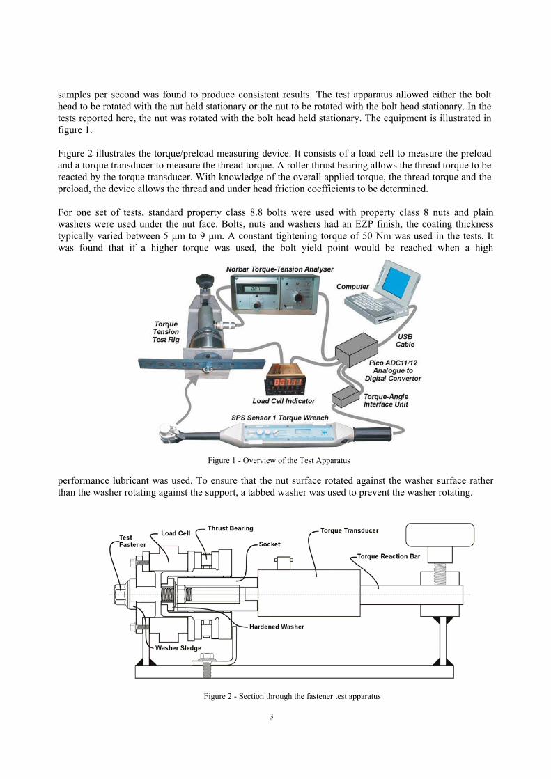
3
samples per second was found to produce consistent results. The test apparatus allowed either the bolthead to be rotated with the nut held stationary or the nut to be rotated with the bolt head stationary. In thetests reported here, the nut was rotated with the bolt head held stationary. The equipment is illustrated infigure 1.
Figure 2 illustrates the torque/preload measuring device. It consists of a load cell to measure the preloadand a torque transducer to measure the thread torque. A roller thrust bearing allows the thread torque to bereacted by the torque transducer. With knowledge of the overall applied torque, the thread torque and thepreload, the device allows the thread and under head friction coefficients to be determined.
For one set of tests, standard property class 8.8 bolts were used with property class 8 nuts and plainwashers were used under the nut face. Bolts, nuts and washers had an EZP finish, the coating thicknesstypically varied between 5 µm to 9 µm. A constant tightening torque of 50 Nm was used in the tests. Itwas found that if a higher torque was used, the bolt yield point would be reached when a high
performance lubricant was used. To ensure that the nut surface rotated against the washer surface ratherthan the washer rotating against the support, a tabbed washer was used to prevent the washer rotating.
Figure 1 - Overview of the Test Apparatus
Figure 2 - Section through the fastener test apparatus
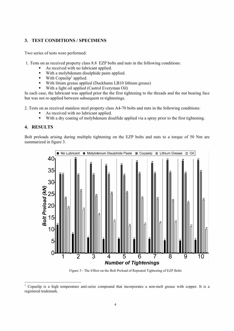
4
3. TEST CONDITIONS / SPECIMENS
Two series of tests were performed:
1. Tests on as received property class 8.8 EZP bolts and nuts in the following conditions:� As received with no lubricant applied.� With a molybdenum disulphide paste applied.� With Copaslip1 applied.� With litium grease applied (Duckhams LB10 lithium grease)� With a light oil applied (Castrol Everyman Oil)
In each case, the lubricant was applied prior the the first tightening to the threads and the nut bearing facebut was not re-applied between subsequent re-tightenings.
2. Tests on as received stainless steel property class A4-70 bolts and nuts in the following conditions:� As received with no lubricant applied.� With a dry coating of molybdenum disulfide applied via a spray prior to the first tightening.
4. RESULTS
Bolt preloads arising during multiple tightening on the EZP bolts and nuts to a torque of 50 Nm aresummarized in figure 3.
1 Copaslip is a high temperature anti-seize compound that incorporates a non-melt grease with copper. It is aregistered trademark.
Figure 3 - The Effect on the Bolt Preload of Repeated Tightening of EZP Bolts
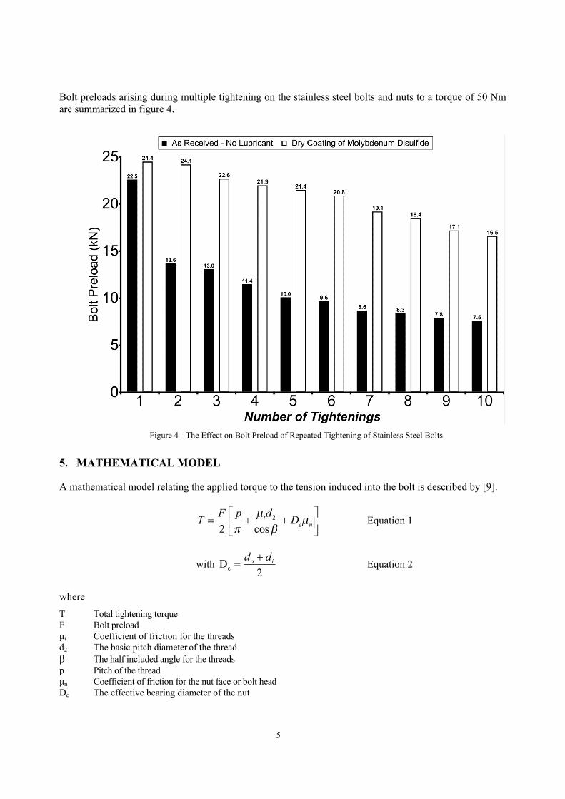
5
Bolt preloads arising during multiple tightening on the stainless steel bolts and nuts to a torque of 50 Nmare summarized in figure 4.
5. MATHEMATICAL MODEL
A mathematical model relating the applied torque to the tension induced into the bolt is described by [9].
2
2 cost
e nF p dT Dµ µ
π β
= + +
Equation 1
with eD2
o id d+= Equation 2
whereT Total tightening torqueF Bolt preloadµt Coefficient of friction for the threadsd2 The basic pitch diameter of the threadβ The half included angle for the threadsp Pitch of the threadµn Coefficient of friction for the nut face or bolt headDe The effective bearing diameter of the nut
Figure 4 - The Effect on Bolt Preload of Repeated Tightening of Stainless Steel Bolts
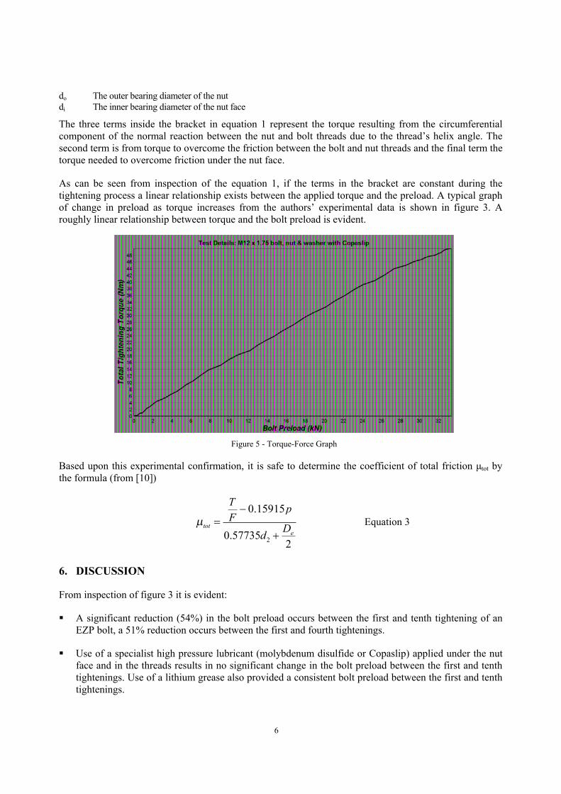
6
do The outer bearing diameter of the nutdi The inner bearing diameter of the nut face
The three terms inside the bracket in equation 1 represent the torque resulting from the circumferentialcomponent of the normal reaction between the nut and bolt threads due to the thread’s helix angle. Thesecond term is from torque to overcome the friction between the bolt and nut threads and the final term thetorque needed to overcome friction under the nut face.
As can be seen from inspection of the equation 1, if the terms in the bracket are constant during thetightening process a linear relationship exists between the applied torque and the preload. A typical graphof change in preload as torque increases from the authors’ experimental data is shown in figure 3. Aroughly linear relationship between torque and the bolt preload is evident.
Based upon this experimental confirmation, it is safe to determine the coefficient of total friction µtot bythe formula (from [10])
2
0.15915
0.577352
tote
T pF
Ddµ
−=
+Equation 3
6. DISCUSSION
From inspection of figure 3 it is evident:
� A significant reduction (54%) in the bolt preload occurs between the first and tenth tightening of anEZP bolt, a 51% reduction occurs between the first and fourth tightenings.
� Use of a specialist high pressure lubricant (molybdenum disulfide or Copaslip) applied under the nutface and in the threads results in no significant change in the bolt preload between the first and tenthtightenings. Use of a lithium grease also provided a consistent bolt preload between the first and tenthtightenings.
Figure 5 - Torque-Force Graph
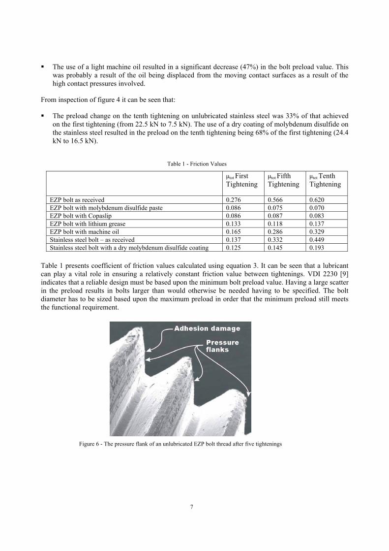
7
� The use of a light machine oil resulted in a significant decrease (47%) in the bolt preload value. Thiswas probably a result of the oil being displaced from the moving contact surfaces as a result of thehigh contact pressures involved.
From inspection of figure 4 it can be seen that:
� The preload change on the tenth tightening on unlubricated stainless steel was 33% of that achievedon the first tightening (from 22.5 kN to 7.5 kN). The use of a dry coating of molybdenum disulfide onthe stainless steel resulted in the preload on the tenth tightening being 68% of the first tightening (24.4kN to 16.5 kN).
Table 1 presents coefficient of friction values calculated using equation 3. It can be seen that a lubricantcan play a vital role in ensuring a relatively constant friction value between tightenings. VDI 2230 [9]indicates that a reliable design must be based upon the minimum bolt preload value. Having a large scatterin the preload results in bolts larger than would otherwise be needed having to be specified. The boltdiameter has to be sized based upon the maximum preload in order that the minimum preload still meetsthe functional requirement.
Table 1 - Friction Values
µtot FirstTightening
µtot FifthTightening
µtot TenthTightening
EZP bolt as received 0.276 0.566 0.620EZP bolt with molybdenum disulfide paste 0.086 0.075 0.070EZP bolt with Copaslip 0.086 0.087 0.083EZP bolt with lithium grease 0.133 0.118 0.137EZP bolt with machine oil 0.165 0.286 0.329Stainless steel bolt – as received 0.137 0.332 0.449Stainless steel bolt with a dry molybdenum disulfide coating 0.125 0.145 0.193
Figure 6 - The pressure flank of an unlubricated EZP bolt thread after five tightenings
8
As can be seen from the results, there is a significant increase in friction occurs with unlubricated EZPbolts as the number of tightenings is increased. Previous work [11] using a scanning electron microscopeindicated that, in an unlubricated condition, a significant amount of surface damage can be observed onthe pressure flanks of the threads. This is shown in figure 6 which illustrates damage on a thread pressureflank i.e. the side of the thread that sustains the loading, after five tightenings.
7. CONCLUSIONSThis study has shown that the use of high pressure lubricants, such as molybdenum disulfide, on threadedfasteners offers considerable potential in ensuring that a high and repeatable preload is achieved when thefasteners are re-tightened after parts are removed from an assembly. By reducing the thread friction andhence the torsional stress incurred during tightening, lubricants also provide the opportunity for a greaterutilization of the bolt strength. That is, a greater preload is achievable using a lubricated fastener since theyield point is reached as a combination of tensile and torsional stresses. Decreasing the torsional stress dueto lower friction allows a higher tensile stress to be present when the yield point is reached and hence ahigher preload.
Considering that many companies specify that the fasteners should be replaced if parts are removed, thisstudy shows that with the use of lubricants, fasteners tightened using the torque control method can be re-used so that an repeatable preload is achieved. Detailed advice on how the fasteners could be reused, byusing a lubricant, could be provided in maintenance handbooks and similar publications. The potentialeconomic savings that could be made if this was adopted would be considerable. This approach is also inline with the increasing importance of re-cycling and sustainability.
REFERENCES
1. M.E. Stevenson, J.L.M., and K.G. Cline, Metallurgical Failure Analysis of Titanium Wing AttachmentBolts. Practical Failure Analysis. 3 (4).
2. Graves, F.E., Fastener Failure and Product Liability. Fastener Technology, 1981.3. Trilling, J.A., Causes and Prevention of Fastener Failures. Machine Design, 1972.4. Eliza, N., Failures of bolts in helicopter main rotor drive plate assembly due to improper application of
lubricant. Engineering Failure Analysis, 2003. 10: p. 443-451.5. World Fasteners. Freedonia Group Report 1545, 2002: p. 344.6. Morgan, R.C. and J.L. Henshall, The torque-tension behaviour of 22 x 1.5 bolts for fixing spigot located
wheels on heavy commercial vehicles. Proceedings of the Institution of Mechanical Engineers, 1996. 210:p. 209-214.
7. ISO 898-1 Mechanical properties of fasteners made of carbon steel - Part 1: Bolts, screws and studs. 1999.8. ISO 3506-1 Mechanical properties of corrosion-resistant stainless steel fasteners - Part 1: Bolts, screws
and studs. 1997.9. VDI 2230 - Part 1 Systematic calculation of high duty bolted joints. Joints with one cylindrical bolt. 2003,
Verein Deutscher Ingenieure.10. ISO 16047:2005 - Fasteners - Torque/clamp force testing.11. W. Eccles, I.S., T. Sperring, Changes in Friction during Repeated Tightening of Zinc Plated Fasteners. In
preparation, 2006.
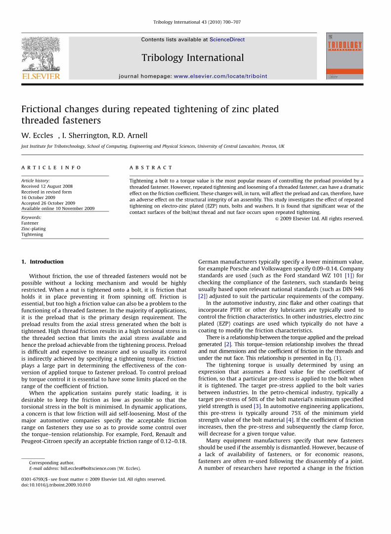
Author's personal copy
Frictional changes during repeated tightening of zinc platedthreaded fasteners
W. Eccles �, I. Sherrington, R.D. Arnell
Jost Institute for Tribotechnology, School of Computing, Engineering and Physical Sciences, University of Central Lancashire, Preston, UK
a r t i c l e i n f o
Article history:
Received 12 August 2008
Received in revised form
16 October 2009
Accepted 26 October 2009Available online 10 November 2009
Keywords:
Fastener
Zinc-plating
Tightening
a b s t r a c t
Tightening a bolt to a torque value is the most popular means of controlling the preload provided by a
threaded fastener. However, repeated tightening and loosening of a threaded fastener, can have a dramatic
effect on the friction coefficient. These changes will, in turn, will affect the preload and can, therefore, havean adverse effect on the structural integrity of an assembly. This study investigates the effect of repeated
tightening on electro-zinc plated (EZP) nuts, bolts and washers. It is found that significant wear of the
contact surfaces of the bolt/nut thread and nut face occurs upon repeated tightening.
& 2009 Elsevier Ltd. All rights reserved.
1. Introduction
Without friction, the use of threaded fasteners would not bepossible without a locking mechanism and would be highlyrestricted. When a nut is tightened onto a bolt, it is friction thatholds it in place preventing it from spinning off. Friction isessential, but too high a friction value can also be a problem to thefunctioning of a threaded fastener. In the majority of applications,it is the preload that is the primary design requirement. Thepreload results from the axial stress generated when the bolt istightened. High thread friction results in a high torsional stress inthe threaded section that limits the axial stress available andhence the preload achievable from the tightening process. Preloadis difficult and expensive to measure and so usually its controlis indirectly achieved by specifying a tightening torque. Frictionplays a large part in determining the effectiveness of the con-version of applied torque to fastener preload. To control preloadby torque control it is essential to have some limits placed on therange of the coefficient of friction.
When the application sustains purely static loading, it isdesirable to keep the friction as low as possible so that thetorsional stress in the bolt is minimised. In dynamic applications,a concern is that low friction will aid self-loosening. Most of themajor automotive companies specify the acceptable frictionrange on fasteners they use so as to provide some control overthe torque–tension relationship. For example, Ford, Renault andPeugeot-Citroen specify an acceptable friction range of 0.12–0.18.
German manufacturers typically specify a lower minimum value,for example Porsche and Volkswagen specify 0.09–0.14. Companystandards are used (such as the Ford standard WZ 101 [1]) forchecking the compliance of the fasteners, such standards beingusually based upon relevant national standards (such as DIN 946[2]) adjusted to suit the particular requirements of the company.
In the automotive industry, zinc flake and other coatings thatincorporate PTFE or other dry lubricants are typically used tocontrol the friction characteristics. In other industries, electro zincplated (EZP) coatings are used which typically do not have acoating to modify the friction characteristics.
There is a relationship between the torque applied and the preloadgenerated [2]. This torque–tension relationship involves the threadand nut dimensions and the coefficient of friction in the threads andunder the nut face. This relationship is presented in Eq. (1).
The tightening torque is usually determined by using anexpression that assumes a fixed value for the coefficient offriction, so that a particular pre-stress is applied to the bolt whenit is tightened. The target pre-stress applied to the bolt variesbetween industries. In the petro-chemical industry, typically atarget pre-stress of 50% of the bolt material’s minimum specifiedyield strength is used [3]. In automotive engineering applications,this pre-stress is typically around 75% of the minimum yieldstrength value of the bolt material [4]. If the coefficient of frictionincreases, then the pre-stress and subsequently the clamp force,will decrease for a given torque value.
Many equipment manufacturers specify that new fastenersshould be used if the assembly is dismantled. However, because ofa lack of availability of fasteners, or for economic reasons,fasteners are often re-used following the disassembly of a joint.A number of researchers have reported a change in the friction
ARTICLE IN PRESS
Contents lists available at ScienceDirect
journal homepage: www.elsevier.com/locate/triboint
Tribology International
0301-679X/$ - see front matter & 2009 Elsevier Ltd. All rights reserved.
doi:10.1016/j.triboint.2009.10.010
� Corresponding author.
E-mail address: [email protected] (W. Eccles).
Tribology International 43 (2010) 700–707
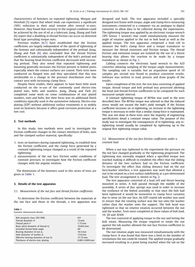
Author's personal copyARTICLE IN PRESS
characteristics of fasteners on repeated tightening. Morgan andHenshall [5] report that wheel studs can experience a significant(50%) reduction in their axial tension after several re-uses.However, they found that recovery to the original condition couldbe achieved by the use of oil as a lubricant. Jiang, Zhang and Park[6] report that a doubling in thread friction can occur on distortedhead type prevailing torque nuts.
Previous studies [6,7] have established that the frictioncoefficients are largely independent of the speed of tightening ofthe fastener and substantially independent of the preload. Jiang,Zhang and Park [6] also concluded that the thread frictioncoefficient is substantially independent of the bolt’s preload andthat the bearing head friction coefficient decreased with increas-ing preload. They also noted that repeated tightening andloosening generally increases the friction present in bolted jointsespecially when the contact surfaces are coated. Their tests wereconducted on flanged nuts and they speculated that this wasattributable to a change in the pressure distribution over thecontact area with increasing clamp force.
Despite these studies, there appears to have been little workconducted on the re-use of the commonly used electro-zincplated nuts, bolts and washers. Jiang, Zhang and Park [6]completed some work on some combinations of zinc platedwashers, nuts and bolts, but their focus was on additional finishconditions typically used in the automotive industry. Electro-zincplating (EZP) without additional surface treatments is so widelyused on fasteners because it offers good corrosion protection at alow cost.
2. Test methods
In this study, two methods were used to investigate thefriction coefficient changes in the contact interfaces of bolts, nutsand the clamped surface material, specifically:
1. tests on fasteners during repeated tightening, to establish howthe friction coefficient, and the clamp force generated by aconstant tightening torque changed as a result of the repeatedtightening;
2. measurements of the nut face friction under conditions ofconstant pressure, to investigate how the friction coefficientchanges with the angular rotation.
The dimensions of the fasteners used in this series of tests aregiven in Table 1.
3. Details of the test apparatus
3.1. Measurement of the nut face and thread friction coefficients
To determine the friction coefficient between the materials atthe nut face and those in the threads, a test apparatus was
designed and built. The test apparatus included a speciallydesigned test frame with torque, angle and clamp force measuringinstruments connected to a computer via an analogue to digitalconverter to allow data to be collected during the experiments.The tightening torque was applied by an electronic torque wrench(SPS Sensor 1 wrench) that could simultaneously measure theangle of rotation applied to the nut or bolt head as well as theapplied torque. The test apparatus comprised a load cell tomeasure the bolt’s clamp force and a torque transducer tomeasure the thread extension and friction torque. The threadfriction and extension torque are isolated by the use of a thrustbearing that allows the reaction to be made by a torquetransducer as shown in Fig. 1.
Cabling connects the electronic hand wrench to the A/Dconverter allowing sampling of the torque–angle measurements.The sampling rate is variable, but an acquisition speed of 10samples per second was found to produce consistent results.Software was written to read, process and draw graphs of theresults.
Upon completion of the test, the test data consisting of appliedtorque, thread torque and bolt preload was processed allowingthe head and thread friction coefficients to be computed for eachmeasured sample interval.
A constant tightening torque of 80 Nm was used in the testsdescribed here. The 80 Nm torque was selected so that the inducedstress would not exceed the bolt’s yield strength. If the frictioncoefficient increases on re-tightening, an increase in the tighteningtorque is necessary in order that a similar clamp force is maintained.This was not done in these tests since the majority of engineeringspecifications detail a constant torque value. The purpose of thisstudy was to investigate the consequences of re-tightening; any re-tightening would usually be completed by tightening up to theoriginal first tightening torque value.
3.2. Measurement of the nut face friction coefficients under a
constant load
When a nut was tightened in the experiment the pressure onthe nut face changed gradually as the tightening progressed. Thetightening was normally stopped when a specified torque wasreached making it difficult to establish the effect that the slidingdistance of the two surfaces had on the friction coefficient.To investigate the effect that sliding distance had on the nutface/washer interface, a test apparatus was used that allowed anut to be rotated on a test surface indefinitely at a pre-determinedload. The test arrangement is shown in Fig. 2.
The test apparatus consisted of a load cell and thrust bearingmounted in series. A bolt passed through the middle of theassembly. A series of disc springs was used in order to increasethe resilience of the bolted assembly so that once the bolt hadbeen tightened it would be insensitive to clamp force variationdue to wear on the nut face. An EZP coated tab washer was usedto ensure that the rotating surface was the nut onto the washerrather than the washer onto the support. The bolt head wastightened so that no relative rotation occurred between the nutand the washer. Tests were completed at three values of bolt load,10, 20 and 30 kN.
The test consisted of applying torque to the nut and letting thebolt rotate. Measuring the torque required to rotate the nutagainst the tab washer allowed the nut face friction coefficient tobe determined.
The nut rotation angle was measured simultaneously with theclamp force. It was found that there was a limit to the number ofrevolutions the nut could be rotated. The applied torque graduallyincreased resulting in a point being reached when the tab on the
Table 1Fastener dimensional details.
Bolt property class (ISO 898) 8.8
Thread diameter D 12 mm
Thread pitch P 1.75 mm
Basic pitch diameter of thread d2 10.863 mm
Included thread flank angle 601Bearing diameter of nut do 18.5 mm
Hole diameter of washer di 13.0 mm
Effective bearing diameter of nut De 15.75 mm
Thickness of electro-zinc plating 0.005–0.009 mm
W. Eccles et al. / Tribology International 43 (2010) 700–707 701
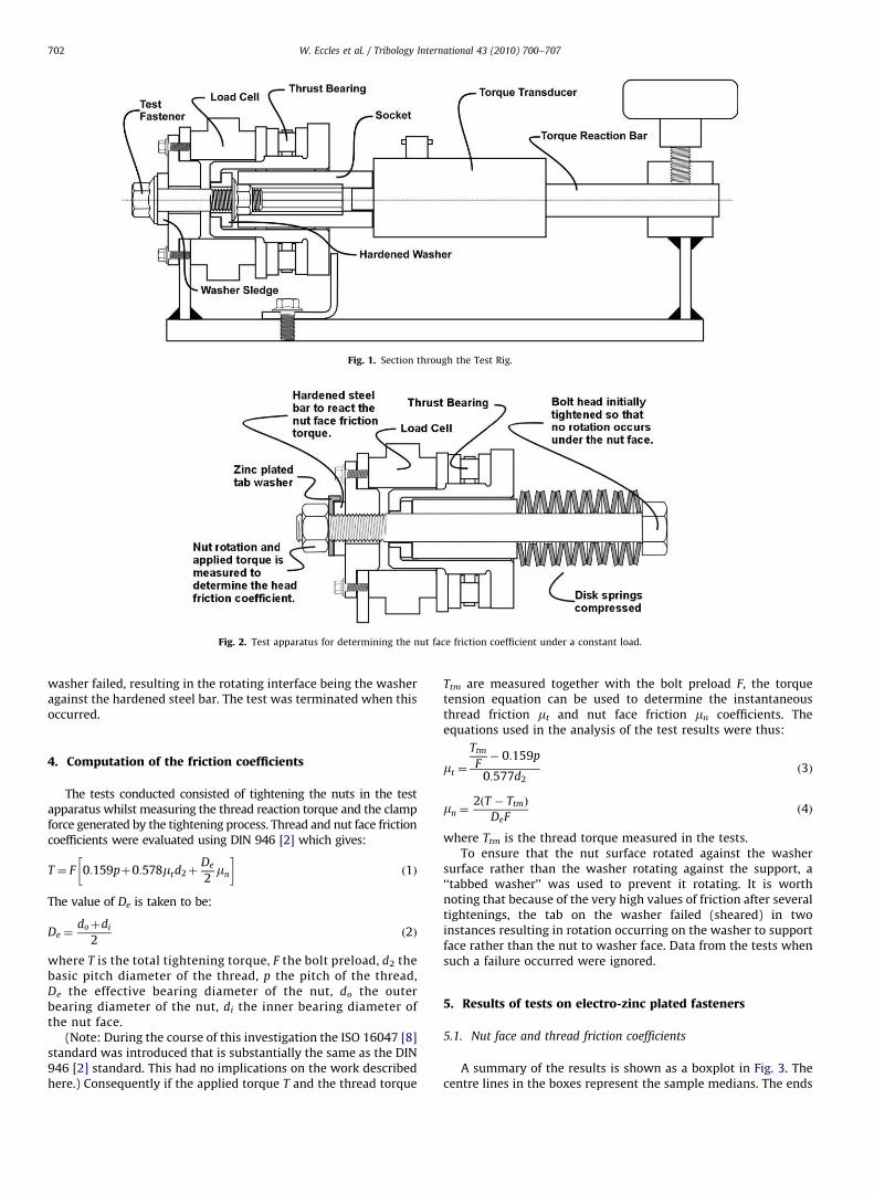
Author's personal copyARTICLE IN PRESS
washer failed, resulting in the rotating interface being the washeragainst the hardened steel bar. The test was terminated when thisoccurred.
4. Computation of the friction coefficients
The tests conducted consisted of tightening the nuts in the testapparatus whilst measuring the thread reaction torque and the clampforce generated by the tightening process. Thread and nut face frictioncoefficients were evaluated using DIN 946 [2] which gives:
T ¼ F 0:159pþ0:578mtd2þDe
2mn
� �ð1Þ
The value of De is taken to be:
De ¼doþdi
2ð2Þ
where T is the total tightening torque, F the bolt preload, d2 thebasic pitch diameter of the thread, p the pitch of the thread,De the effective bearing diameter of the nut, do the outerbearing diameter of the nut, di the inner bearing diameter ofthe nut face.
(Note: During the course of this investigation the ISO 16047 [8]standard was introduced that is substantially the same as the DIN946 [2] standard. This had no implications on the work describedhere.) Consequently if the applied torque T and the thread torque
Ttm are measured together with the bolt preload F, the torquetension equation can be used to determine the instantaneousthread friction mt and nut face friction mn coefficients. Theequations used in the analysis of the test results were thus:
mt ¼
Ttm
F� 0:159p
0:577d2ð3Þ
mn ¼2ðT � TtmÞ
DeFð4Þ
where Ttm is the thread torque measured in the tests.To ensure that the nut surface rotated against the washer
surface rather than the washer rotating against the support, a‘‘tabbed washer’’ was used to prevent it rotating. It is worthnoting that because of the very high values of friction after severaltightenings, the tab on the washer failed (sheared) in twoinstances resulting in rotation occurring on the washer to supportface rather than the nut to washer face. Data from the tests whensuch a failure occurred were ignored.
5. Results of tests on electro-zinc plated fasteners
5.1. Nut face and thread friction coefficients
A summary of the results is shown as a boxplot in Fig. 3. Thecentre lines in the boxes represent the sample medians. The ends
Fig. 1. Section through the Test Rig.
Fig. 2. Test apparatus for determining the nut face friction coefficient under a constant load.
W. Eccles et al. / Tribology International 43 (2010) 700–707702
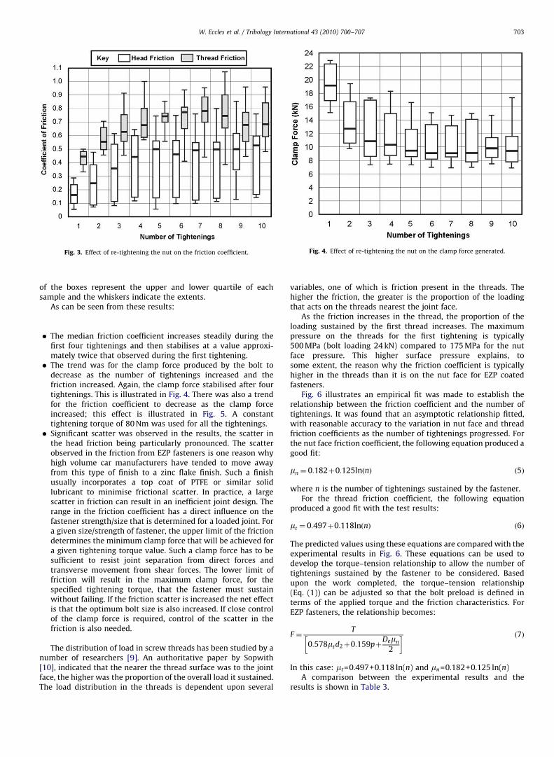
Author's personal copyARTICLE IN PRESS
of the boxes represent the upper and lower quartile of eachsample and the whiskers indicate the extents.
As can be seen from these results:
� The median friction coefficient increases steadily during thefirst four tightenings and then stabilises at a value approxi-mately twice that observed during the first tightening.� The trend was for the clamp force produced by the bolt to
decrease as the number of tightenings increased and thefriction increased. Again, the clamp force stabilised after fourtightenings. This is illustrated in Fig. 4. There was also a trendfor the friction coefficient to decrease as the clamp forceincreased; this effect is illustrated in Fig. 5. A constanttightening torque of 80 Nm was used for all the tightenings.� Significant scatter was observed in the results, the scatter in
the head friction being particularly pronounced. The scatterobserved in the friction from EZP fasteners is one reason whyhigh volume car manufacturers have tended to move awayfrom this type of finish to a zinc flake finish. Such a finishusually incorporates a top coat of PTFE or similar solidlubricant to minimise frictional scatter. In practice, a largescatter in friction can result in an inefficient joint design. Therange in the friction coefficient has a direct influence on thefastener strength/size that is determined for a loaded joint. Fora given size/strength of fastener, the upper limit of the frictiondetermines the minimum clamp force that will be achieved fora given tightening torque value. Such a clamp force has to besufficient to resist joint separation from direct forces andtransverse movement from shear forces. The lower limit offriction will result in the maximum clamp force, for thespecified tightening torque, that the fastener must sustainwithout failing. If the friction scatter is increased the net effectis that the optimum bolt size is also increased. If close controlof the clamp force is required, control of the scatter in thefriction is also needed.
The distribution of load in screw threads has been studied by anumber of researchers [9]. An authoritative paper by Sopwith[10], indicated that the nearer the thread surface was to the jointface, the higher was the proportion of the overall load it sustained.The load distribution in the threads is dependent upon several
variables, one of which is friction present in the threads. Thehigher the friction, the greater is the proportion of the loadingthat acts on the threads nearest the joint face.
As the friction increases in the thread, the proportion of theloading sustained by the first thread increases. The maximumpressure on the threads for the first tightening is typically500 MPa (bolt loading 24 kN) compared to 175 MPa for the nutface pressure. This higher surface pressure explains, tosome extent, the reason why the friction coefficient is typicallyhigher in the threads than it is on the nut face for EZP coatedfasteners.
Fig. 6 illustrates an empirical fit was made to establish therelationship between the friction coefficient and the number oftightenings. It was found that an asymptotic relationship fitted,with reasonable accuracy to the variation in nut face and threadfriction coefficients as the number of tightenings progressed. Forthe nut face friction coefficient, the following equation produced agood fit:
mn ¼ 0:182þ0:125lnðnÞ ð5Þ
where n is the number of tightenings sustained by the fastener.For the thread friction coefficient, the following equation
produced a good fit with the test results:
mt ¼ 0:497þ0:118lnðnÞ ð6Þ
The predicted values using these equations are compared with theexperimental results in Fig. 6. These equations can be used todevelop the torque–tension relationship to allow the number oftightenings sustained by the fastener to be considered. Basedupon the work completed, the torque–tension relationship(Eq. (1)) can be adjusted so that the bolt preload is defined interms of the applied torque and the friction characteristics. ForEZP fasteners, the relationship becomes:
F ¼ T
0:578mtd2þ0:159pþDemn
2
� � ð7Þ
In this case: mt=0.497+0.118 ln(n) and mn=0.182+0.125 ln(n)A comparison between the experimental results and the
results is shown in Table 3.
Fig. 3. Effect of re-tightening the nut on the friction coefficient. Fig. 4. Effect of re-tightening the nut on the clamp force generated.
W. Eccles et al. / Tribology International 43 (2010) 700–707 703
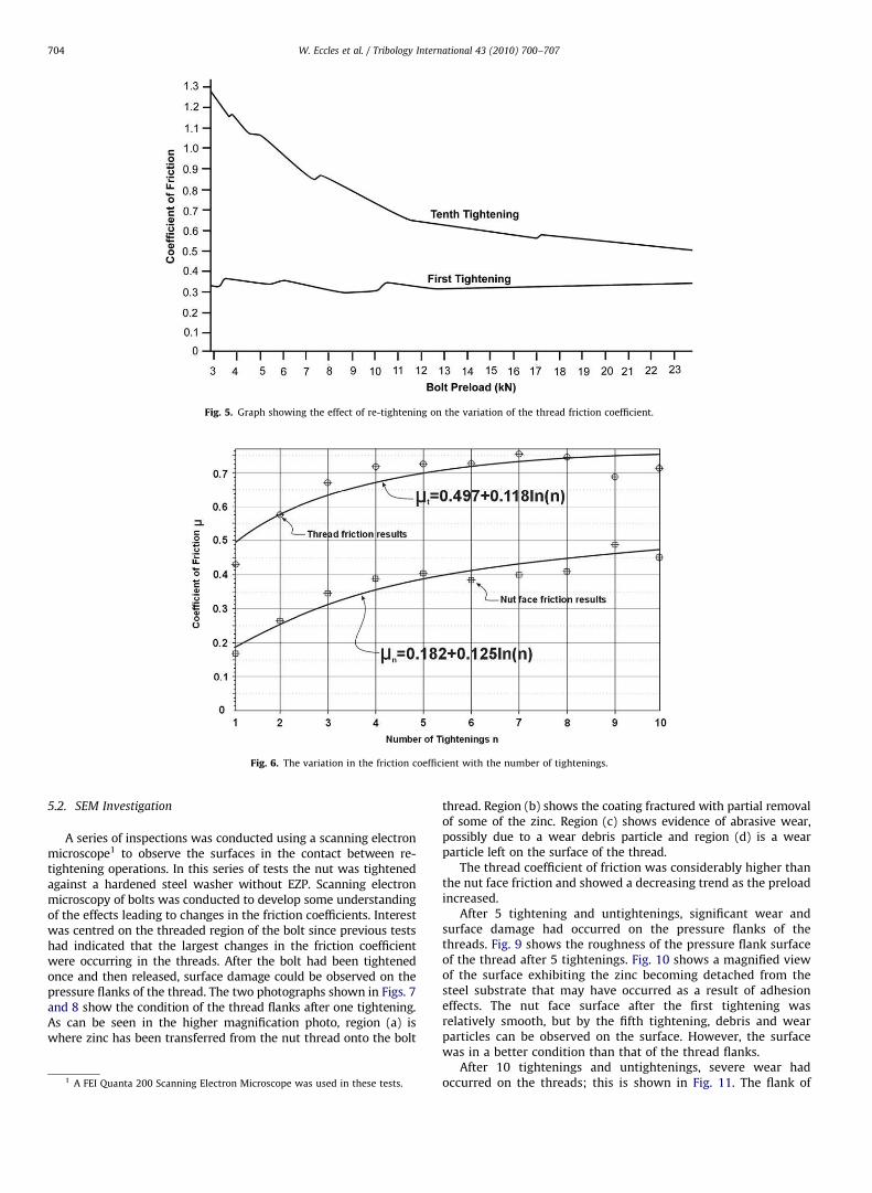
Author's personal copyARTICLE IN PRESS
5.2. SEM Investigation
A series of inspections was conducted using a scanning electronmicroscope1 to observe the surfaces in the contact between re-tightening operations. In this series of tests the nut was tightenedagainst a hardened steel washer without EZP. Scanning electronmicroscopy of bolts was conducted to develop some understandingof the effects leading to changes in the friction coefficients. Interestwas centred on the threaded region of the bolt since previous testshad indicated that the largest changes in the friction coefficientwere occurring in the threads. After the bolt had been tightenedonce and then released, surface damage could be observed on thepressure flanks of the thread. The two photographs shown in Figs. 7and 8 show the condition of the thread flanks after one tightening.As can be seen in the higher magnification photo, region (a) iswhere zinc has been transferred from the nut thread onto the bolt
thread. Region (b) shows the coating fractured with partial removalof some of the zinc. Region (c) shows evidence of abrasive wear,possibly due to a wear debris particle and region (d) is a wearparticle left on the surface of the thread.
The thread coefficient of friction was considerably higher thanthe nut face friction and showed a decreasing trend as the preloadincreased.
After 5 tightening and untightenings, significant wear andsurface damage had occurred on the pressure flanks of thethreads. Fig. 9 shows the roughness of the pressure flank surfaceof the thread after 5 tightenings. Fig. 10 shows a magnified viewof the surface exhibiting the zinc becoming detached from thesteel substrate that may have occurred as a result of adhesioneffects. The nut face surface after the first tightening wasrelatively smooth, but by the fifth tightening, debris and wearparticles can be observed on the surface. However, the surfacewas in a better condition than that of the thread flanks.
After 10 tightenings and untightenings, severe wear hadoccurred on the threads; this is shown in Fig. 11. The flank of
Fig. 5. Graph showing the effect of re-tightening on the variation of the thread friction coefficient.
Fig. 6. The variation in the friction coefficient with the number of tightenings.
1 A FEI Quanta 200 Scanning Electron Microscope was used in these tests.
W. Eccles et al. / Tribology International 43 (2010) 700–707704
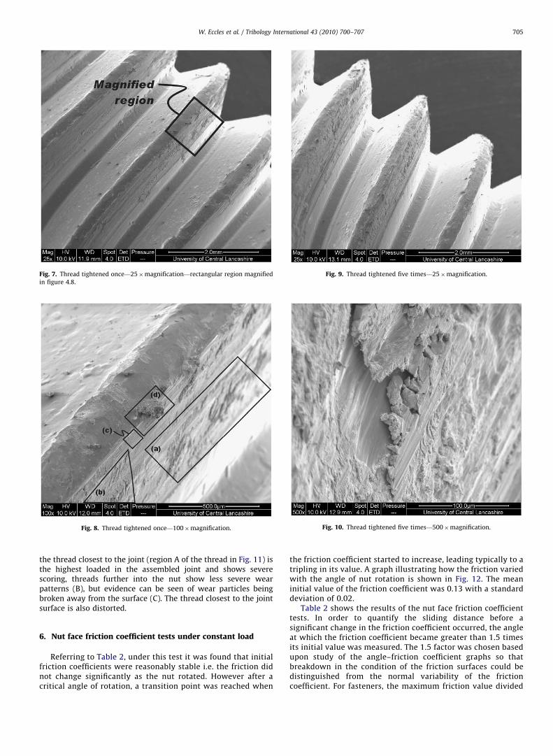
Author's personal copyARTICLE IN PRESS
the thread closest to the joint (region A of the thread in Fig. 11) isthe highest loaded in the assembled joint and shows severescoring, threads further into the nut show less severe wearpatterns (B), but evidence can be seen of wear particles beingbroken away from the surface (C). The thread closest to the jointsurface is also distorted.
6. Nut face friction coefficient tests under constant load
Referring to Table 2, under this test it was found that initialfriction coefficients were reasonably stable i.e. the friction didnot change significantly as the nut rotated. However after acritical angle of rotation, a transition point was reached when
the friction coefficient started to increase, leading typically to atripling in its value. A graph illustrating how the friction variedwith the angle of nut rotation is shown in Fig. 12. The meaninitial value of the friction coefficient was 0.13 with a standarddeviation of 0.02.
Table 2 shows the results of the nut face friction coefficienttests. In order to quantify the sliding distance before asignificant change in the friction coefficient occurred, the angleat which the friction coefficient became greater than 1.5 timesits initial value was measured. The 1.5 factor was chosen basedupon study of the angle–friction coefficient graphs so thatbreakdown in the condition of the friction surfaces could bedistinguished from the normal variability of the frictioncoefficient. For fasteners, the maximum friction value divided
Fig. 7. Thread tightened once—25�magnification—rectangular region magnified
in figure 4.8.
Fig. 8. Thread tightened once—100�magnification.
Fig. 9. Thread tightened five times—25�magnification.
Fig. 10. Thread tightened five times—500�magnification.
W. Eccles et al. / Tribology International 43 (2010) 700–707 705
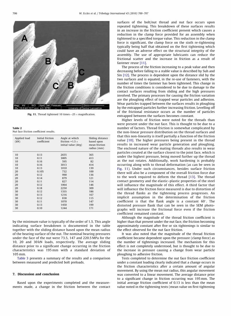
Author's personal copyARTICLE IN PRESS
by the minimum value is typically of the order of 1.5. This angleindicating surface breakdown is documented in the tabletogether with the sliding distance based upon the mean radiusof the bearing surface of the nut. The nominal bearing pressuresunder the face of the nut were 73.5, 147 and 220.5 MPa for the10, 20 and 30 kN loads, respectively. The average slidingdistance prior to a significant change occurring in the frictioncharacteristics was 195 mm with a standard deviation of105 mm.
Table 3 presents a summary of the results and a comparisonbetween measured and predicted bolt preloads.
7. Discussion and conclusion
Based upon the experiments completed and the measure-ments made, a change in the friction between the contact
surfaces of the bolt/nut thread and nut face occurs uponrepeated tightening. This breakdown of these surfaces resultsin an increase in the friction coefficient present which causes areduction in the clamp force provided for an assembly whentightened to a specified torque value. This reduction in the clampforce is significant, the clamp force on the sixth re-tighteningtypically being half that obtained on the first tightening whichcould have an adverse effect on the structural integrity of theassembly. The use of appropriate lubricants can reduce thefrictional scatter and the increase in friction as a result offastener reuse [11].
The process of the friction increasing to a peak value and thendecreasing before falling to a stable value is described by Suh andSin [12]. The process is dependent upon the distance slid by thetwo surfaces and is equated, in the re-use of fasteners, with thenumber of times the fastener has been tightened. This change inthe friction conditions is considered to be due to damage to thecontact surfaces resulting from sliding and the high pressuresinvolved. The primary processes for causing the friction variationare the ploughing effect of trapped wear particles and adhesion.Wear particles trapped between the surfaces results in ploughingby the entrapped particles further increasing friction. Levelling offof the frictional resistance occurs as the number of particlesentrapped between the surfaces becomes constant.
Higher levels of friction were noted for the threads thanwere present under the nut face. This is thought to be due to anumber of factors. Thread friction is somewhat complicated bythe non-linear pressure distribution on the thread surfaces andthat this non-linearity is itself partially a function of the frictionvalue [10]. The higher pressures being present in the threadresults in increased wear particle generation and ploughing.The enclosed nature of the mating threads also results in wearparticles created at the surface closest to the joint face, which isunder the highest pressure, being moved further up the threadas the nut rotates. Additionally, work hardening is probablyoccurring along with to thread deformation (as can be seen inFig. 11). Under such circumstances, besides surface frictionthere will also be a component of the overall friction force dueto the work required to deform the thread [13]. The threadcontact geometry and the elastic–plastic properties of the steelwill influence the magnitude of this effect. A third factor thatwill influence the friction force measured is due to distortion ofthe thread flanks as the tightening process progresses. Animplicit assumption in the determination of the frictioncoefficient is that the flank angle is a constant 601. Thedistorted pressure flank that can be seen in the SEM photo-graphs will increase the frictional force even if the frictioncoefficient remained constant.
Although the magnitude of the thread friction coefficient ishigher than that present under the nut face, the friction becomingapproximately constant after five or six tightenings is similar tothe effect observed for the nut face friction.
It was also noted that the magnitude of the thread frictioncoefficient became dependent upon the pressure (clamp force) asthe number of tightenings increased. The mechanism for thiseffect is not completely understood, but is thought to be due tothe increase in pressure causing a change from wear particleploughing to adhesive friction.
Tests completed to determine the nut face friction coefficientunder a constant loading clearly indicated that a change occurs inthe friction characteristics after a certain amount of angularmovement. By using the mean nut radius, this angular movementwas converted to a linear movement. The average distance priorto a significant change in friction occurring was 195 mm. Theinitial average friction coefficient of 0.13 is less than the meanvalue noted in the tightening tests (mean value on first tightening
Fig. 11. Thread tightened 10 times—25�magnification.
Table 2Nut face friction coefficient results.
Applied load
(kN)
Initial friction
coefficient
Angle at which
friction =1.5�initial value (deg)
Sliding distance
based upon
mean friction
radius (mm)
10 0.13 2655 365
10 0.11 3005 413
10 0.16 595 82
10 0.16 3013 414
10 0.13 1010 139
20 0.105 732 100
20 0.12 990 136
20 0.14 879 121
20 0.11 827 114
20 0.12 1064 146
20 0.18 2250 309
30 0.12 1355 186
30 0.13 1216 167
30 0.12 838 115
30 0.11 1070 147
30 0.13 1450 199
30 0.10 1244 171
W. Eccles et al. / Tribology International 43 (2010) 700–707706
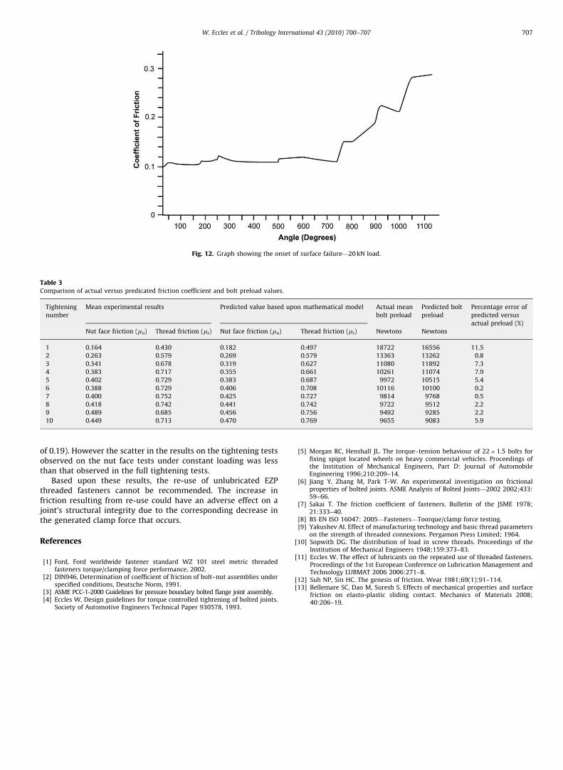
Author's personal copyARTICLE IN PRESS
of 0.19). However the scatter in the results on the tightening testsobserved on the nut face tests under constant loading was lessthan that observed in the full tightening tests.
Based upon these results, the re-use of unlubricated EZPthreaded fasteners cannot be recommended. The increase infriction resulting from re-use could have an adverse effect on ajoint’s structural integrity due to the corresponding decrease inthe generated clamp force that occurs.
References
[1] Ford, Ford worldwide fastener standard WZ 101 steel metric threadedfasteners torque/clamping force performance, 2002.
[2] DIN946, Determination of coefficient of friction of bolt–nut assemblies underspecified conditions, Deutsche Norm, 1991.
[3] ASME PCC-1-2000 Guidelines for pressure boundary bolted flange joint assembly.[4] Eccles W, Design guidelines for torque controlled tightening of bolted joints.
Society of Automotive Engineers Technical Paper 930578, 1993.
[5] Morgan RC, Henshall JL. The torque–tension behaviour of 22�1.5 bolts forfixing spigot located wheels on heavy commercial vehicles. Proceedings ofthe Institution of Mechanical Engineers, Part D: Journal of AutomobileEngineering 1996;210:209–14.
[6] Jiang Y, Zhang M, Park T-W. An experimental investigation on frictionalproperties of bolted joints. ASME Analysis of Bolted Joints—2002 2002;433:59–66.
[7] Sakai T. The friction coefficient of fasteners. Bulletin of the JSME 1978;21:333–40.
[8] BS EN ISO 16047: 2005—Fasteners—Toorque/clamp force testing.[9] Yakushev AI. Effect of manufacturing technology and basic thread parameters
on the strength of threaded connexions. Pergamon Press Limited; 1964.[10] Sopwith DG. The distribution of load in screw threads. Proceedings of the
Institution of Mechanical Engineers 1948;159:373–83.[11] Eccles W. The effect of lubricants on the repeated use of threaded fasteners.
Proceedings of the 1st European Conference on Lubrication Management andTechnology LUBMAT 2006 2006:271–8.
[12] Suh NP, Sin HC. The genesis of friction. Wear 1981;69(1):91–114.[13] Bellemare SC, Dao M, Suresh S. Effects of mechanical properties and surface
friction on elasto-plastic sliding contact. Mechanics of Materials 2008;40:206–19.
Fig. 12. Graph showing the onset of surface failure—20 kN load.
Table 3Comparison of actual versus predicated friction coefficient and bolt preload values.
Tightening
number
Mean experimental results Predicted value based upon mathematical model Actual mean
bolt preload
Predicted bolt
preload
Percentage error of
predicted versus
actual preload (%)
Nut face friction (mn) Thread friction (mt) Nut face friction (mn) Thread friction (mt) Newtons Newtons
1 0.164 0.430 0.182 0.497 18722 16556 11.5
2 0.263 0.579 0.269 0.579 13363 13262 0.8
3 0.341 0.678 0.319 0.627 11080 11892 7.3
4 0.383 0.717 0.355 0.661 10261 11074 7.9
5 0.402 0.729 0.383 0.687 9972 10515 5.4
6 0.388 0.729 0.406 0.708 10116 10100 0.2
7 0.400 0.752 0.425 0.727 9814 9768 0.5
8 0.418 0.742 0.441 0.742 9722 9512 2.2
9 0.489 0.685 0.456 0.756 9492 9285 2.2
10 0.449 0.713 0.470 0.769 9655 9083 5.9
W. Eccles et al. / Tribology International 43 (2010) 700–707 707
483
Towards an understanding of the looseningcharacteristics of prevailing torque nutsW Eccles∗, I Sherrington, and R D ArnellJost Institute for Tribotechnology, School of Computing, Engineering and Physical Sciences, University of CentralLancashire, Lancashire, UK
The manuscript was received on 20 December 2008 and was accepted after revision for publication on 4 August 2009.
DOI: 10.1243/09544062JMES1493
Abstract: Prevailing torque nuts are an extremely popular method of providing resistance tovibration-induced self-loosening of fasteners. Such nuts have a self-contained prevailing torquefeature that provides a degree of resistance to rotation. Although such nuts are frequently used,it is not widely realized that they can occasionally come completely detached from bolts. Themechanism by which this can occur has hitherto been unidentified since it has not been possibleto replicate detachment under laboratory testing. This article identifies a general condition thatcan result in the complete loosening and detachment of prevailing torque type nuts. This mecha-nism involves the application of an axial load when transverse joint slip is occurring. This articledescribes a modified Junker test machine that allows the application of axial loading to a jointwhile experiencing transverse displacement. Tests have been completed using an intermittentas well as a constant axial load. Loading in both modes has been demonstrated to result in thecomplete detachment of this nut type. Based on this investigation, if the magnitude of the axialloading exceeds the residual preload in the bolt retained from sustaining transverse movementalone, the all-metal type of prevailing torque nut can completely detach. Applications that involveshear and axial loading being simultaneously applied to a joint are numerous in engineering.
Keywords: prevailing torque type nut, self-loosening, Junker test, vibration, fastener, nutdetachment
1 INTRODUCTION
Prevailing torque type nuts are commonly used totry to prevent self-loosening and/or detachment ofthreaded fasteners. Prevailing torque nuts were devel-oped over 100 years ago [1] and have the essentialcharacteristic that a torque is needed to rotate the nutdown the thread of an untightened bolt. One advan-tage of this type of nut is that the locking feature can beverified at the time of assembly by measuring the pre-vailing torque. A problem with re-use of nylon insertnuts is that the prevailing torque can decrease as aresult of wear [2]. Modern standards for all-metal pre-vailing torque nuts, however, stipulate that a minimumlevel of prevailing torque, for a given thread size, mustbe maintained for up to five re-uses [3]. This type of
∗Corresponding author: Department of Technology, University of
Central Lancashire, Preston, Lancashire PR1 2HE, UK.
email: [email protected]
nut is in extensive use across most industries and isprobably the most common type of locking device forthreaded fasteners.
There are many varieties of such nuts, but in generalthey can all be classified into one of two categories,those with a non-metallic insert or those which areall-metal. Non-metallic insert nuts typically generate aprevailing torque by incorporating a polymer insert inthe top of the nut that is deformed by the bolt thread. (Anut of this type is illustrated in Fig. 1(a)). The all-metalvariety achieves the prevailing torque by either distort-ing the top nut threads by introducing slots (Fig. 1(b)),making the top threads elliptical shaped (Fig. 1(c)), orintroducing spring steel inserts (Fig. 1(d)).
There have been instances when new prevailingtorque nuts that still retain a prevailing torque havebecome detached from assemblies. The causes of suchfailures have not been understood since the standardmethod of test, the Junker (Deutsches Institut für Nor-mung (DIN) 65151) test, has been unable to reproducesuch loosening. One such failure is shown in Fig. 2;
JMES1493 Proc. IMechE Vol. 224 Part C: J. Mechanical Engineering Science
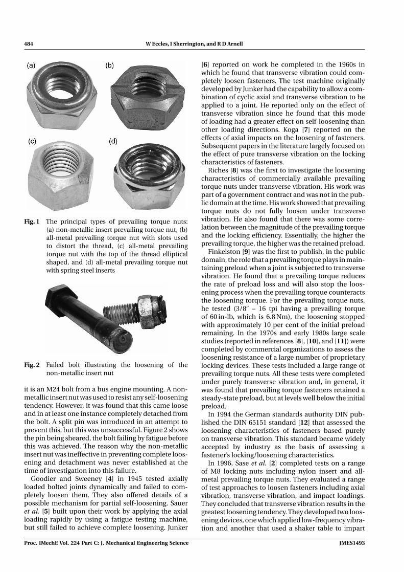
484 W Eccles, I Sherrington, and R D Arnell
Fig. 1 The principal types of prevailing torque nuts:(a) non-metallic insert prevailing torque nut, (b)all-metal prevailing torque nut with slots usedto distort the thread, (c) all-metal prevailingtorque nut with the top of the thread ellipticalshaped, and (d) all-metal prevailing torque nutwith spring steel inserts
Fig. 2 Failed bolt illustrating the loosening of thenon-metallic insert nut
it is an M24 bolt from a bus engine mounting. A non-metallic insert nut was used to resist any self-looseningtendency. However, it was found that this came looseand in at least one instance completely detached fromthe bolt. A split pin was introduced in an attempt toprevent this, but this was unsuccessful. Figure 2 showsthe pin being sheared, the bolt failing by fatigue beforethis was achieved. The reason why the non-metallicinsert nut was ineffective in preventing complete loos-ening and detachment was never established at thetime of investigation into this failure.
Goodier and Sweeney [4] in 1945 tested axiallyloaded bolted joints dynamically and failed to com-pletely loosen them. They also offered details of apossible mechanism for partial self-loosening. Saueret al. [5] built upon their work by applying the axialloading rapidly by using a fatigue testing machine,but still failed to achieve complete loosening. Junker
[6] reported on work he completed in the 1960s inwhich he found that transverse vibration could com-pletely loosen fasteners. The test machine originallydeveloped by Junker had the capability to allow a com-bination of cyclic axial and transverse vibration to beapplied to a joint. He reported only on the effect oftransverse vibration since he found that this modeof loading had a greater effect on self-loosening thanother loading directions. Koga [7] reported on theeffects of axial impacts on the loosening of fasteners.Subsequent papers in the literature largely focused onthe effect of pure transverse vibration on the lockingcharacteristics of fasteners.
Riches [8] was the first to investigate the looseningcharacteristics of commercially available prevailingtorque nuts under transverse vibration. His work waspart of a government contract and was not in the pub-lic domain at the time. His work showed that prevailingtorque nuts do not fully loosen under transversevibration. He also found that there was some corre-lation between the magnitude of the prevailing torqueand the locking efficiency. Essentially, the higher theprevailing torque, the higher was the retained preload.
Finkelston [9] was the first to publish, in the publicdomain, the role that a prevailing torque plays in main-taining preload when a joint is subjected to transversevibration. He found that a prevailing torque reducesthe rate of preload loss and will also stop the loos-ening process when the prevailing torque counteractsthe loosening torque. For the prevailing torque nuts,he tested (3/8′′ – 16 tpi having a prevailing torqueof 60 in-lb, which is 6.8 Nm), the loosening stoppedwith approximately 10 per cent of the initial preloadremaining. In the 1970s and early 1980s large scalestudies (reported in references [8], [10], and [11]) werecompleted by commercial organizations to assess theloosening resistance of a large number of proprietarylocking devices. These tests included a large range ofprevailing torque nuts. All these tests were completedunder purely transverse vibration and, in general, itwas found that prevailing torque fasteners retained asteady-state preload, but at levels well below the initialpreload.
In 1994 the German standards authority DIN pub-lished the DIN 65151 standard [12] that assessed theloosening characteristics of fasteners based purelyon transverse vibration. This standard became widelyaccepted by industry as the basis of assessing afastener’s locking/loosening characteristics.
In 1996, Sase et al. [2] completed tests on a rangeof M8 locking nuts including nylon insert and all-metal prevailing torque nuts. They evaluated a rangeof test approaches to loosen fasteners including axialvibration, transverse vibration, and impact loadings.They concluded that transverse vibration results in thegreatest loosening tendency. They developed two loos-ening devices, one which applied low-frequency vibra-tion and another that used a shaker table to impart
Proc. IMechE Vol. 224 Part C: J. Mechanical Engineering Science JMES1493
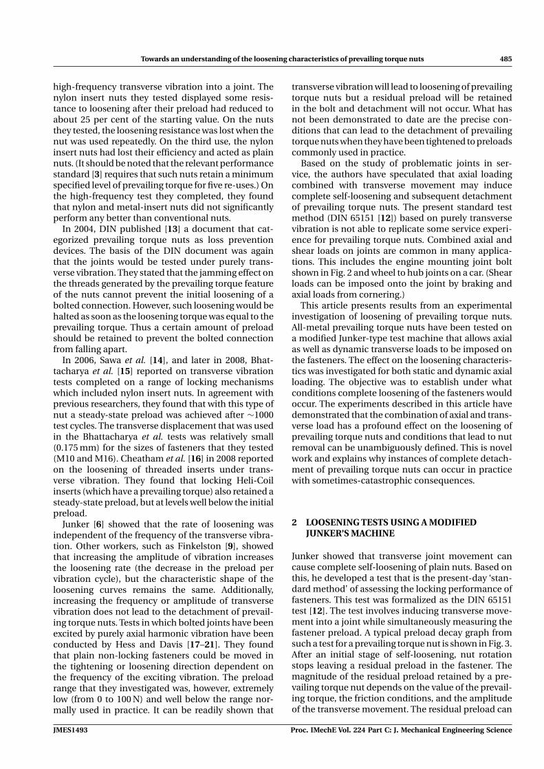
Towards an understanding of the loosening characteristics of prevailing torque nuts 485
high-frequency transverse vibration into a joint. Thenylon insert nuts they tested displayed some resis-tance to loosening after their preload had reduced toabout 25 per cent of the starting value. On the nutsthey tested, the loosening resistance was lost when thenut was used repeatedly. On the third use, the nyloninsert nuts had lost their efficiency and acted as plainnuts. (It should be noted that the relevant performancestandard [3] requires that such nuts retain a minimumspecified level of prevailing torque for five re-uses.) Onthe high-frequency test they completed, they foundthat nylon and metal-insert nuts did not significantlyperform any better than conventional nuts.
In 2004, DIN published [13] a document that cat-egorized prevailing torque nuts as loss preventiondevices. The basis of the DIN document was againthat the joints would be tested under purely trans-verse vibration. They stated that the jamming effect onthe threads generated by the prevailing torque featureof the nuts cannot prevent the initial loosening of abolted connection. However, such loosening would behalted as soon as the loosening torque was equal to theprevailing torque. Thus a certain amount of preloadshould be retained to prevent the bolted connectionfrom falling apart.
In 2006, Sawa et al. [14], and later in 2008, Bhat-tacharya et al. [15] reported on transverse vibrationtests completed on a range of locking mechanismswhich included nylon insert nuts. In agreement withprevious researchers, they found that with this type ofnut a steady-state preload was achieved after ∼1000test cycles. The transverse displacement that was usedin the Bhattacharya et al. tests was relatively small(0.175 mm) for the sizes of fasteners that they tested(M10 and M16). Cheatham et al. [16] in 2008 reportedon the loosening of threaded inserts under trans-verse vibration. They found that locking Heli-Coilinserts (which have a prevailing torque) also retained asteady-state preload, but at levels well below the initialpreload.
Junker [6] showed that the rate of loosening wasindependent of the frequency of the transverse vibra-tion. Other workers, such as Finkelston [9], showedthat increasing the amplitude of vibration increasesthe loosening rate (the decrease in the preload pervibration cycle), but the characteristic shape of theloosening curves remains the same. Additionally,increasing the frequency or amplitude of transversevibration does not lead to the detachment of prevail-ing torque nuts. Tests in which bolted joints have beenexcited by purely axial harmonic vibration have beenconducted by Hess and Davis [17–21]. They foundthat plain non-locking fasteners could be moved inthe tightening or loosening direction dependent onthe frequency of the exciting vibration. The preloadrange that they investigated was, however, extremelylow (from 0 to 100 N) and well below the range nor-mally used in practice. It can be readily shown that
transverse vibration will lead to loosening of prevailingtorque nuts but a residual preload will be retainedin the bolt and detachment will not occur. What hasnot been demonstrated to date are the precise con-ditions that can lead to the detachment of prevailingtorque nuts when they have been tightened to preloadscommonly used in practice.
Based on the study of problematic joints in ser-vice, the authors have speculated that axial loadingcombined with transverse movement may inducecomplete self-loosening and subsequent detachmentof prevailing torque nuts. The present standard testmethod (DIN 65151 [12]) based on purely transversevibration is not able to replicate some service experi-ence for prevailing torque nuts. Combined axial andshear loads on joints are common in many applica-tions. This includes the engine mounting joint boltshown in Fig. 2 and wheel to hub joints on a car. (Shearloads can be imposed onto the joint by braking andaxial loads from cornering.)
This article presents results from an experimentalinvestigation of loosening of prevailing torque nuts.All-metal prevailing torque nuts have been tested ona modified Junker-type test machine that allows axialas well as dynamic transverse loads to be imposed onthe fasteners. The effect on the loosening characteris-tics was investigated for both static and dynamic axialloading. The objective was to establish under whatconditions complete loosening of the fasteners wouldoccur. The experiments described in this article havedemonstrated that the combination of axial and trans-verse load has a profound effect on the loosening ofprevailing torque nuts and conditions that lead to nutremoval can be unambiguously defined. This is novelwork and explains why instances of complete detach-ment of prevailing torque nuts can occur in practicewith sometimes-catastrophic consequences.
2 LOOSENING TESTS USING A MODIFIEDJUNKER’S MACHINE
Junker showed that transverse joint movement cancause complete self-loosening of plain nuts. Based onthis, he developed a test that is the present-day ‘stan-dard method’ of assessing the locking performance offasteners. This test was formalized as the DIN 65151test [12]. The test involves inducing transverse move-ment into a joint while simultaneously measuring thefastener preload. A typical preload decay graph fromsuch a test for a prevailing torque nut is shown in Fig. 3.After an initial stage of self-loosening, nut rotationstops leaving a residual preload in the fastener. Themagnitude of the residual preload retained by a pre-vailing torque nut depends on the value of the prevail-ing torque, the friction conditions, and the amplitudeof the transverse movement. The residual preload can
JMES1493 Proc. IMechE Vol. 224 Part C: J. Mechanical Engineering Science
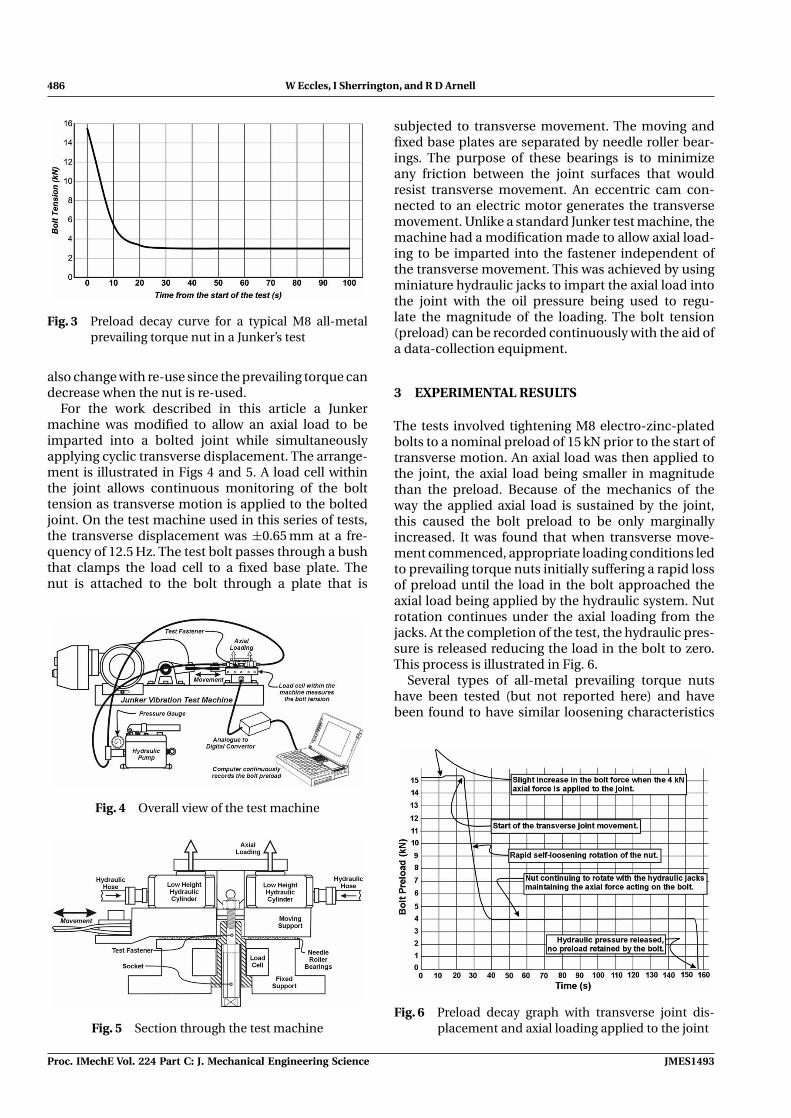
486 W Eccles, I Sherrington, and R D Arnell
Fig. 3 Preload decay curve for a typical M8 all-metalprevailing torque nut in a Junker’s test
also change with re-use since the prevailing torque candecrease when the nut is re-used.
For the work described in this article a Junkermachine was modified to allow an axial load to beimparted into a bolted joint while simultaneouslyapplying cyclic transverse displacement. The arrange-ment is illustrated in Figs 4 and 5. A load cell withinthe joint allows continuous monitoring of the bolttension as transverse motion is applied to the boltedjoint. On the test machine used in this series of tests,the transverse displacement was ±0.65 mm at a fre-quency of 12.5 Hz. The test bolt passes through a bushthat clamps the load cell to a fixed base plate. Thenut is attached to the bolt through a plate that is
Fig. 4 Overall view of the test machine
Fig. 5 Section through the test machine
subjected to transverse movement. The moving andfixed base plates are separated by needle roller bear-ings. The purpose of these bearings is to minimizeany friction between the joint surfaces that wouldresist transverse movement. An eccentric cam con-nected to an electric motor generates the transversemovement. Unlike a standard Junker test machine, themachine had a modification made to allow axial load-ing to be imparted into the fastener independent ofthe transverse movement. This was achieved by usingminiature hydraulic jacks to impart the axial load intothe joint with the oil pressure being used to regu-late the magnitude of the loading. The bolt tension(preload) can be recorded continuously with the aid ofa data-collection equipment.
3 EXPERIMENTAL RESULTS
The tests involved tightening M8 electro-zinc-platedbolts to a nominal preload of 15 kN prior to the start oftransverse motion. An axial load was then applied tothe joint, the axial load being smaller in magnitudethan the preload. Because of the mechanics of theway the applied axial load is sustained by the joint,this caused the bolt preload to be only marginallyincreased. It was found that when transverse move-ment commenced, appropriate loading conditions ledto prevailing torque nuts initially suffering a rapid lossof preload until the load in the bolt approached theaxial load being applied by the hydraulic system. Nutrotation continues under the axial loading from thejacks. At the completion of the test, the hydraulic pres-sure is released reducing the load in the bolt to zero.This process is illustrated in Fig. 6.
Several types of all-metal prevailing torque nutshave been tested (but not reported here) and havebeen found to have similar loosening characteristics
Fig. 6 Preload decay graph with transverse joint dis-placement and axial loading applied to the joint
Proc. IMechE Vol. 224 Part C: J. Mechanical Engineering Science JMES1493
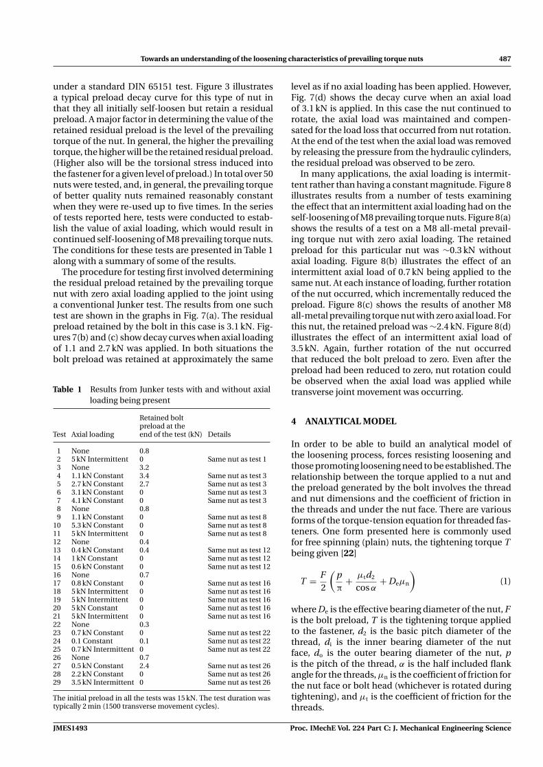
Towards an understanding of the loosening characteristics of prevailing torque nuts 487
under a standard DIN 65151 test. Figure 3 illustratesa typical preload decay curve for this type of nut inthat they all initially self-loosen but retain a residualpreload. A major factor in determining the value of theretained residual preload is the level of the prevailingtorque of the nut. In general, the higher the prevailingtorque, the higher will be the retained residual preload.(Higher also will be the torsional stress induced intothe fastener for a given level of preload.) In total over 50nuts were tested, and, in general, the prevailing torqueof better quality nuts remained reasonably constantwhen they were re-used up to five times. In the seriesof tests reported here, tests were conducted to estab-lish the value of axial loading, which would result incontinued self-loosening of M8 prevailing torque nuts.The conditions for these tests are presented in Table 1along with a summary of some of the results.
The procedure for testing first involved determiningthe residual preload retained by the prevailing torquenut with zero axial loading applied to the joint usinga conventional Junker test. The results from one suchtest are shown in the graphs in Fig. 7(a). The residualpreload retained by the bolt in this case is 3.1 kN. Fig-ures 7(b) and (c) show decay curves when axial loadingof 1.1 and 2.7 kN was applied. In both situations thebolt preload was retained at approximately the same
Table 1 Results from Junker tests with and without axialloading being present
Retained boltpreload at the
Test Axial loading end of the test (kN) Details
1 None 0.82 5 kN Intermittent 0 Same nut as test 13 None 3.24 1.1 kN Constant 3.4 Same nut as test 35 2.7 kN Constant 2.7 Same nut as test 36 3.1 kN Constant 0 Same nut as test 37 4.1 kN Constant 0 Same nut as test 38 None 0.89 1.1 kN Constant 0 Same nut as test 8
10 5.3 kN Constant 0 Same nut as test 811 5 kN Intermittent 0 Same nut as test 812 None 0.413 0.4 kN Constant 0.4 Same nut as test 1214 1 kN Constant 0 Same nut as test 1215 0.6 kN Constant 0 Same nut as test 1216 None 0.717 0.8 kN Constant 0 Same nut as test 1618 5 kN Intermittent 0 Same nut as test 1619 5 kN Intermittent 0 Same nut as test 1620 5 kN Constant 0 Same nut as test 1621 5 kN Intermittent 0 Same nut as test 1622 None 0.323 0.7 kN Constant 0 Same nut as test 2224 0.1 Constant 0.1 Same nut as test 2225 0.7 kN Intermittent 0 Same nut as test 2226 None 0.727 0.5 kN Constant 2.4 Same nut as test 2628 2.2 kN Constant 0 Same nut as test 2629 3.5 kN Intermittent 0 Same nut as test 26
The initial preload in all the tests was 15 kN. The test duration wastypically 2 min (1500 transverse movement cycles).
level as if no axial loading has been applied. However,Fig. 7(d) shows the decay curve when an axial loadof 3.1 kN is applied. In this case the nut continued torotate, the axial load was maintained and compen-sated for the load loss that occurred from nut rotation.At the end of the test when the axial load was removedby releasing the pressure from the hydraulic cylinders,the residual preload was observed to be zero.
In many applications, the axial loading is intermit-tent rather than having a constant magnitude. Figure 8illustrates results from a number of tests examiningthe effect that an intermittent axial loading had on theself-loosening of M8 prevailing torque nuts. Figure 8(a)shows the results of a test on a M8 all-metal prevail-ing torque nut with zero axial loading. The retainedpreload for this particular nut was ∼0.3 kN withoutaxial loading. Figure 8(b) illustrates the effect of anintermittent axial load of 0.7 kN being applied to thesame nut. At each instance of loading, further rotationof the nut occurred, which incrementally reduced thepreload. Figure 8(c) shows the results of another M8all-metal prevailing torque nut with zero axial load. Forthis nut, the retained preload was ∼2.4 kN. Figure 8(d)illustrates the effect of an intermittent axial load of3.5 kN. Again, further rotation of the nut occurredthat reduced the bolt preload to zero. Even after thepreload had been reduced to zero, nut rotation couldbe observed when the axial load was applied whiletransverse joint movement was occurring.
4 ANALYTICAL MODEL
In order to be able to build an analytical model ofthe loosening process, forces resisting loosening andthose promoting loosening need to be established. Therelationship between the torque applied to a nut andthe preload generated by the bolt involves the threadand nut dimensions and the coefficient of friction inthe threads and under the nut face. There are variousforms of the torque-tension equation for threaded fas-teners. One form presented here is commonly usedfor free spinning (plain) nuts, the tightening torque Tbeing given [22]
T = F2
(pπ
+ μtd2
cos α+ Deμn
)(1)
where De is the effective bearing diameter of the nut, Fis the bolt preload, T is the tightening torque appliedto the fastener, d2 is the basic pitch diameter of thethread, di is the inner bearing diameter of the nutface, do is the outer bearing diameter of the nut, pis the pitch of the thread, α is the half included flankangle for the threads, μn is the coefficient of friction forthe nut face or bolt head (whichever is rotated duringtightening), and μt is the coefficient of friction for thethreads.
JMES1493 Proc. IMechE Vol. 224 Part C: J. Mechanical Engineering Science
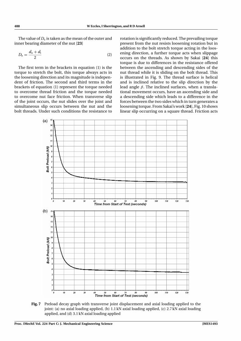
488 W Eccles, I Sherrington, and R D Arnell
The value of De is taken as the mean of the outer andinner bearing diameter of the nut [23]
De = do + di
2(2)
The first term in the brackets in equation (1) is thetorque to stretch the bolt, this torque always acts inthe loosening direction and its magnitude is indepen-dent of friction. The second and third terms in thebrackets of equation (1) represent the torque neededto overcome thread friction and the torque neededto overcome nut face friction. When transverse slipof the joint occurs, the nut slides over the joint andsimultaneous slip occurs between the nut and thebolt threads. Under such conditions the resistance to
rotation is significantly reduced. The prevailing torquepresent from the nut resists loosening rotation but inaddition to the bolt stretch torque acting in the loos-ening direction, a further torque acts when slippageoccurs on the threads. As shown by Sakai [24] thistorque is due to differences in the resistance offeredbetween the ascending and descending sides of thenut thread while it is sliding on the bolt thread. Thisis illustrated in Fig. 9. The thread surface is helicaland is inclined relative to the slip direction by thelead angle β. The inclined surfaces, when a transla-tional movement occurs, have an ascending side anda descending side which leads to a difference in theforces between the two sides which in turn generates aloosening torque. From Sakai’s work [24], Fig. 10 showslinear slip occurring on a square thread. Friction acts
Fig. 7 Preload decay graph with transverse joint displacement and axial loading applied to thejoint: (a) no axial loading applied, (b) 1.1 kN axial loading applied, (c) 2.7 kN axial loadingapplied, and (d) 3.1 kN axial loading applied
Proc. IMechE Vol. 224 Part C: J. Mechanical Engineering Science JMES1493
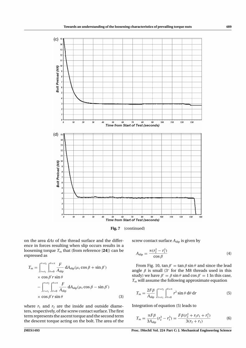
Towards an understanding of the loosening characteristics of prevailing torque nuts 489
Fig. 7 (continued)
on the area dAs of the thread surface and the differ-ence in forces resulting when slip occurs results in aloosening torque Tss that (from reference [24]) can beexpressed as
Tss =∫ r=r2
r=r1
∫ θ=π
θ=0
FAslip
dAslip(μt cos β + sin β ′)
× cos β ′r sin θ
−∫ r=r2
r=r1
∫ θ=π
θ=0
FAslip
dAslip(μt cos β − sin β ′)
× cos β ′r sin θ (3)
where r1 and r2 are the inside and outside diame-ters, respectively, of the screw contact surface. The firstterm represents the ascent torque and the second termthe descent torque acting on the bolt. The area of the
screw contact surface Aslip is given by
Aslip = π(r22 − r2
1 )
cos β(4)
From Fig. 10, tan β ′ = tan β sin θ and since the leadangle β is small (3◦ for the M8 threads used in thisstudy) we have β ′ = β sin θ and cos β ′ = 1 In this case,Tss will assume the following approximate equation
Tss = 2Fβ
Aslip
∫ r=r2
r=r1
∫ θ=π
θ=0r2 sin θ dθ dr (5)
Integration of equation (5) leads to
Tss = πFβ
3Aslip(r3
2 − r31 ) = Fβ(r2
2 + r2r1 + r21 )
3(r2 + r1)(6)
JMES1493 Proc. IMechE Vol. 224 Part C: J. Mechanical Engineering Science
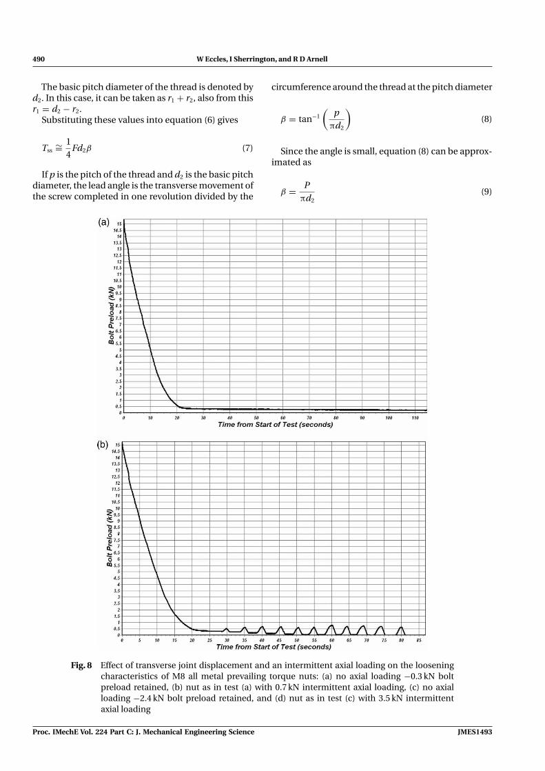
490 W Eccles, I Sherrington, and R D Arnell
The basic pitch diameter of the thread is denoted byd2. In this case, it can be taken as r1 + r2, also from thisr1 = d2 − r2.
Substituting these values into equation (6) gives
Tss∼= 1
4Fd2β (7)
If p is the pitch of the thread and d2 is the basic pitchdiameter, the lead angle is the transverse movement ofthe screw completed in one revolution divided by the
circumference around the thread at the pitch diameter
β = tan−1
(p
πd2
)(8)
Since the angle is small, equation (8) can be approx-imated as
β = Pπd2
(9)
Fig. 8 Effect of transverse joint displacement and an intermittent axial loading on the looseningcharacteristics of M8 all metal prevailing torque nuts: (a) no axial loading −0.3 kN boltpreload retained, (b) nut as in test (a) with 0.7 kN intermittent axial loading, (c) no axialloading −2.4 kN bolt preload retained, and (d) nut as in test (c) with 3.5 kN intermittentaxial loading
Proc. IMechE Vol. 224 Part C: J. Mechanical Engineering Science JMES1493
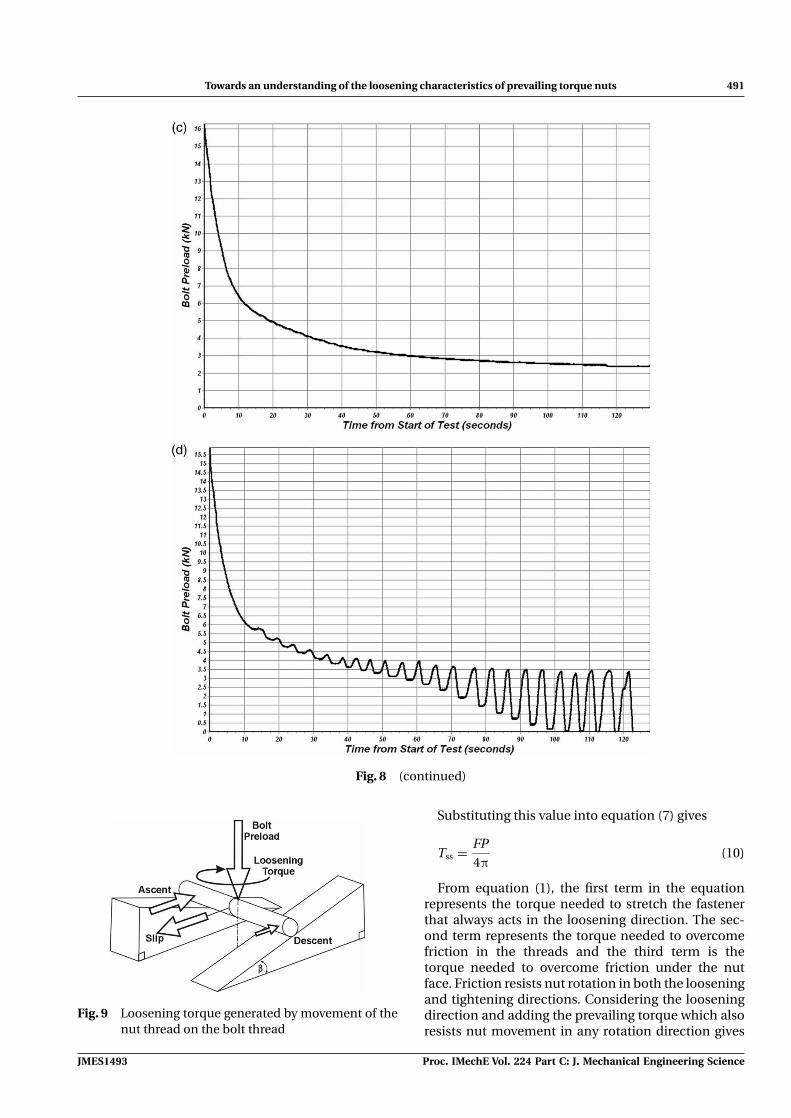
Towards an understanding of the loosening characteristics of prevailing torque nuts 491
Fig. 8 (continued)
Fig. 9 Loosening torque generated by movement of thenut thread on the bolt thread
Substituting this value into equation (7) gives
Tss = FP4π
(10)
From equation (1), the first term in the equationrepresents the torque needed to stretch the fastenerthat always acts in the loosening direction. The sec-ond term represents the torque needed to overcomefriction in the threads and the third term is thetorque needed to overcome friction under the nutface. Friction resists nut rotation in both the looseningand tightening directions. Considering the looseningdirection and adding the prevailing torque which alsoresists nut movement in any rotation direction gives
JMES1493 Proc. IMechE Vol. 224 Part C: J. Mechanical Engineering Science
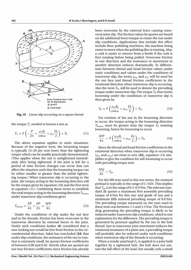
492 W Eccles, I Sherrington, and R D Arnell
Fig. 10 Linear slip occurring on a square thread
the torque TL needed to loosen a nut as
TL = F(
− P2π
+ μtd2
cos α+ μn
De
2
)+ TP (11)
The above equation applies to static situations.Because of the negative term, the loosening torqueis typically 15–20 per cent lower than the tighteningtorque which can be readily practically demonstrated.(This applies when the nut is untightened immedi-ately after being tightened. If the joint is left for aperiod of time friction changes can occur that canaffect the situation such that the loosening torque canbe either smaller or greater than the initial tighten-ing torque.) When transverse slip is occurring to thejoint, the torque acting in the loosening direction willbe the torque given by equation (10) and the first termin equation (11). Combining these terms to establishthe total torque acting in the loosening direction Tloosen
under transverse slip conditions gives
Tloosen = FP4π
+ FP2π
= 3FP4π
(12)
Under the conditions of slip under the nut faceand in the threads, friction has been overcome in thetransverse direction by external forces to the joint.Under such conditions Junker [6] considered that anon-locking nut would be free from friction in the cir-cumferential direction. Sakai has concluded [24] thatunder slip conditions, the resistance of the nut to rota-tion is extremely small, he quotes friction coefficientsof between 0.00 and 0.02. Strictly what are quoted arenot true friction coefficients since friction has already
been overcome by the external force causing trans-verse joint slip. The friction values he quotes are basedon the additional force/torque to rotate the nut underslip conditions. Applications that include this effectinclude floor polishing machines, the machine beingeasier to move when the polishing disc is rotating. Also,a cork is easier to remove from a bottle if the cork isfirst rotating before being pulled. Overcome frictionin one direction and the resistance to movement inanother direction reduces dramatically. To differen-tiate between thread and head friction values understatic conditions and values under the conditions oftransverse slip, the terms μns and μts will be used forthe nut face and thread friction coefficients in therotational direction when transverse slip is occurring.Also the term TPs will be used to denote the prevailingtorque under transverse slip. The torque TR that resistsloosening under the conditions of transverse slip isthen given by
TR = F(
μtsd2
cos α+ μns
De
2
)+ TPs (13)
For rotation of the nut in the loosening directionto occur, the torque acting in the loosening directionTloosen must be greater than the torque TR resistingloosening, hence for loosening to occur
3FP4π
> F(
μtsd2
cos α+ μns
De
2
)+ TPs (14)
Since the thread and head friction coefficients in therotational direction when transverse slip is occurring(μts and μns) are close to zero [24], equation (14) sim-plifies to give the condition for self-loosening to occurwith prevailing torque nuts
3Fp4π
> Tps (15)
For the M8 nuts used in this test series, the retainedpreload is typically in the range of 1–3 kN. This impliesthat Tps is in the range of 0.3–0.9 Nm. The relevant stan-dard [3] quotes a maximum first assembly prevailingtorque of 6 Nm for this size and grade of nut and aminimum fifth removal prevailing torque of 0.6 Nm.The prevailing torque measured on the nuts used inthese tests was between 1.5 and 2.3 Nm. The frictionaldrag generating the prevailing torque is likely to bereduced under transverse slip conditions, which is oneexplanation for the difference. The prevailing torque isgenerated by pressure applied by the nut to the boltthread. Just as transverse joint movement reduces therotational resistance of a plain nut, a prevailing torquewill probably also be reduced under such conditionswhen transverse slip of the threads is occurring.
When a tensile axial load FA is applied to a joint heldtogether by a tightened bolt, the bolt does not sus-tain the full effect of the load, but usually only a small
Proc. IMechE Vol. 224 Part C: J. Mechanical Engineering Science JMES1493
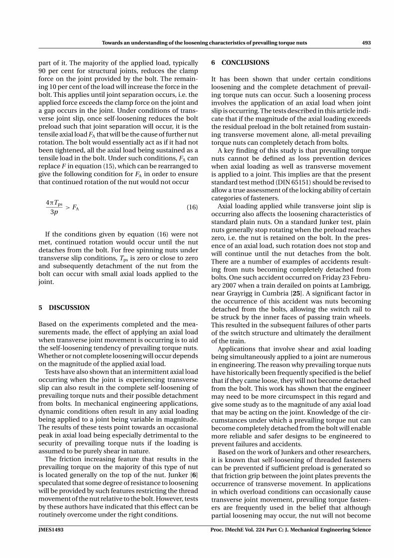
Towards an understanding of the loosening characteristics of prevailing torque nuts 493
part of it. The majority of the applied load, typically90 per cent for structural joints, reduces the clampforce on the joint provided by the bolt. The remain-ing 10 per cent of the load will increase the force in thebolt. This applies until joint separation occurs, i.e. theapplied force exceeds the clamp force on the joint anda gap occurs in the joint. Under conditions of trans-verse joint slip, once self-loosening reduces the boltpreload such that joint separation will occur, it is thetensile axial load FA that will be the cause of further nutrotation. The bolt would essentially act as if it had notbeen tightened, all the axial load being sustained as atensile load in the bolt. Under such conditions, FA canreplace F in equation (15), which can be rearranged togive the following condition for FA in order to ensurethat continued rotation of the nut would not occur
4πTps
3p> FA (16)
If the conditions given by equation (16) were notmet, continued rotation would occur until the nutdetaches from the bolt. For free spinning nuts undertransverse slip conditions, Tps is zero or close to zeroand subsequently detachment of the nut from thebolt can occur with small axial loads applied to thejoint.
5 DISCUSSION
Based on the experiments completed and the mea-surements made, the effect of applying an axial loadwhen transverse joint movement is occurring is to aidthe self-loosening tendency of prevailing torque nuts.Whether or not complete loosening will occur dependson the magnitude of the applied axial load.
Tests have also shown that an intermittent axial loadoccurring when the joint is experiencing transverseslip can also result in the complete self-loosening ofprevailing torque nuts and their possible detachmentfrom bolts. In mechanical engineering applications,dynamic conditions often result in any axial loadingbeing applied to a joint being variable in magnitude.The results of these tests point towards an occasionalpeak in axial load being especially detrimental to thesecurity of prevailing torque nuts if the loading isassumed to be purely shear in nature.
The friction increasing feature that results in theprevailing torque on the majority of this type of nutis located generally on the top of the nut. Junker [6]speculated that some degree of resistance to looseningwill be provided by such features restricting the threadmovement of the nut relative to the bolt. However, testsby these authors have indicated that this effect can beroutinely overcome under the right conditions.
6 CONCLUSIONS
It has been shown that under certain conditionsloosening and the complete detachment of prevail-ing torque nuts can occur. Such a loosening processinvolves the application of an axial load when jointslip is occurring. The tests described in this article indi-cate that if the magnitude of the axial loading exceedsthe residual preload in the bolt retained from sustain-ing transverse movement alone, all-metal prevailingtorque nuts can completely detach from bolts.
A key finding of this study is that prevailing torquenuts cannot be defined as loss prevention deviceswhen axial loading as well as transverse movementis applied to a joint. This implies are that the presentstandard test method (DIN 65151) should be revised toallow a true assessment of the locking ability of certaincategories of fasteners.
Axial loading applied while transverse joint slip isoccurring also affects the loosening characteristics ofstandard plain nuts. On a standard Junker test, plainnuts generally stop rotating when the preload reacheszero, i.e. the nut is retained on the bolt. In the pres-ence of an axial load, such rotation does not stop andwill continue until the nut detaches from the bolt.There are a number of examples of accidents result-ing from nuts becoming completely detached frombolts. One such accident occurred on Friday 23 Febru-ary 2007 when a train derailed on points at Lambrigg,near Grayrigg in Cumbria [25]. A significant factor inthe occurrence of this accident was nuts becomingdetached from the bolts, allowing the switch rail tobe struck by the inner faces of passing train wheels.This resulted in the subsequent failures of other partsof the switch structure and ultimately the derailmentof the train.
Applications that involve shear and axial loadingbeing simultaneously applied to a joint are numerousin engineering. The reason why prevailing torque nutshave historically been frequently specified is the beliefthat if they came loose, they will not become detachedfrom the bolt. This work has shown that the engineermay need to be more circumspect in this regard andgive some study as to the magnitude of any axial loadthat may be acting on the joint. Knowledge of the cir-cumstances under which a prevailing torque nut canbecome completely detached from the bolt will enablemore reliable and safer designs to be engineered toprevent failures and accidents.
Based on the work of Junkers and other researchers,it is known that self-loosening of threaded fastenerscan be prevented if sufficient preload is generated sothat friction grip between the joint plates prevents theoccurrence of transverse movement. In applicationsin which overload conditions can occasionally causetransverse joint movement, prevailing torque fasten-ers are frequently used in the belief that althoughpartial loosening may occur, the nut will not become
JMES1493 Proc. IMechE Vol. 224 Part C: J. Mechanical Engineering Science
494 W Eccles, I Sherrington, and R D Arnell
detached from the bolt. In the light of the researchpublished here, this criterion requires to be updated toinclude the simultaneous effect that axial loading canhave on the loosening process. Additionally, repeatedre-use/tightening of prevailing torque nuts can reducethe prevailing torque due to thread wear and hencetheir effectiveness in resisting loosening. This work hasconcluded that the maximum simultaneous axial loadthat can be sustained when transverse joint move-ment occurs is equivalent to the preload retained bythe prevailing torque nut on a normal Junkers test.
7 FURTHER WORK
These tests have been conducted on an all-metal vari-ety of prevailing torque nut. Beside the non-metallicinsert nut, many other types of locking devices havea prevailing torque feature. Adhesive applied to thethreads is a commonly used locking method. Usingtoo high a bond strength results in the nuts having tobe cut off, so medium-strength adhesives are used sothat removal is possible. Under a conventional Junkerstest, such medium-strength threadlockers experiencea degree of self-loosening similar to prevailing torquenuts. From a limited amount of work conducted todate, it appears that the presence of axial loading whiletransverse slip occurs also influences the looseningcharacteristics of other types of ‘locking’ devices.Further work in this area is needed.
In general, the prevailing torque is generated bypressure applied by the nut to the bolt thread; thisappears to change if transverse movement of thethreads relative to each other arises. The indicationsare that the value of prevailing torque under condi-tions of transverse slip is smaller than that which ismeasured under static conditions. The author intendsto measure the prevailing torque under such con-ditions to facilitate the determination of the mag-nitude of the axial loading that the joint can sus-tain before complete self-loosening and subsequentpossible detachment of the nut from the bolt.
© Authors 2010
REFERENCES
1 Johnson, A. Improvement in nut-locks. US Patent188055, 1877.
2 Sase,N.,Koga,S.,Nishioka,K.,and Fujii,H. Evaluation ofanti-loosening nuts for screw fasteners. J. Mater. Process.Technol., 1996, 56(1/4), 321–332.
3 BS EN ISO 2320. Prevailing torque type steel hexagonnuts – mechanical and performance requirements, 2008.
4 Goodier, J. N. and Sweeney, R. J. Loosening by vibrationof threaded fastenings. Mech. Eng., 1945, 67, 798–802.
5 Sauer, J. A., Lemmon, D. C., and Lynn, E. K. Bolts: how toprevent their loosening. Mach. Des., 1950, 22, 133–139.
6 Junker, G. New criteria for self-loosening of fastenersunder vibration. SAE paper 690055, 1969.
7 Koga, K. Loosening by repeated impact of threadedfastenings. Bull. JSME, 1970, 13(55), 140–149.
8 Riches, D. M. Report on vibration testing ofthreaded fasteners, British Aircraft Corporation reportL74/2O/RES/Fds/MS268, 1971.
9 Finkelston, R. J. How much shake can bolted joints take.Mach. Des., 1972, 44, 122–125.
10 Light, D. An investigation into the effects of vibrationof threaded fasteners phase II – final report, Report no.ST13394, British Aircraft Corporation, 1976.
11 Dick, S.Vibration testing of threaded fasteners – compar-ison of locking devices on grade 8.8 assemblies, Report83/1096-50-11, BL Technology, 1983.
12 DIN65151. Dynamic testing of the locking characteristicsof fasteners under transverse loading conditions, 1994.
13 Esser, J. and Hellwig, G. Consequences for standardis-ation – ineffective screw locking. DIN Notices 4 – 2004,2004.
14 Sawa, T., Ishimura, M., and Yamanaka, H. Experimentalevaluation of screw thread loosening in bolted joint withsome parts for preventing the loosening under trans-verse repeated loadings. In Proceedings of the ASMEPVP2006/ICPVT-11 Conference, Vancouver, BC, Canada,23–27 July 2006 (American Society of Mechanical Engi-neers, New York, USA).
15 Bhattacharya, A., Sen, A., and Das, S. An investigationon the anti-loosening characteristics of threaded fas-teners under vibratory conditions. Mech. Mach. Theory,2008, (in press) DOI: 10.1016/j.mechmachtheory.2008.08.004.
16 Cheatham, C. A., Acosta, C. F., and Hess, D. P. Testsand analysis of secondary locking features in threadedinserts. Eng. Failure Anal., 2008, 16, 39–57.
17 Hess, D. P. and Davis, K. Threaded components underaxial harmonic vibration, part 1: experiments. J. Vibr.Acoust. Trans. ASME, 1996, 118(3), 417–422.
18 Hess, D. P. and Davis, K. Threaded components underaxial harmonic vibration, part 2: kinematic analysis.Trans. ASME, J. Vibr. Acoust., 1996, 118(3), 423–429.
19 Hess, D. P., Basava, S., and Rasquinha, I. A. Variationof clamping force in a single-bolt assembly subjected toaxial vibration. Am. Soc. Mech. Engrs. Des. Eng. Div., 1996,90, 97–102.
20 Hess, D. P. and Sudhirkashyap, S. V. Dynamic looseningand tightening of a single bolt assembly. J. Sound Acoust.,1997, 119, 311–316.
21 Basava, S. and Hess, D. P. Bolted joint clamping forcevariation due to axial vibration. J. Sound Vibr., 1998,210(2), 255–265.
22 Kobayashi, M. and Hongo, K. Tribology in threadedjoints – tightening and loosening. Jpn. J. Tribol., 1998,43(2), 209–218.
23 BS EN ISO 16047: 2005. Fasteners – torque/clamp forcetesting.
24 Sakai, T. Effect of friction coefficient on screw threadloosening in automobiles. Jpn. J. Tribol., 2001, 46(6),369–380.
25 RAIB. Rail accident report – derailment at Greyrigg,23 February 2007, available from http://www.raib.gov.uk/publications/investigation_reports/reports_2008/report202008.cfm, 2008. Report 20/2008, p. 255.
Proc. IMechE Vol. 224 Part C: J. Mechanical Engineering Science JMES1493
Towards an understanding of the loosening characteristics of prevailing torque nuts 495
APPENDIX
Notation
Aslip area of the screw contact surfacedi the inner bearing diameter of the nut facedo the outer bearing diameter of the nutd2 the basic pitch diameter of the threadDe the effective bearing diameter of the nutF bolt preloadFA the axial force applied to the jointp pitch of the threadr1 inside diameter of the screw contact
surfacer2 outside diameter of the screw contact
surfaceT tightening torque applied to the fastenerTloosen total torque acting in the loosening
directionTL the torque required to loosen a bolt
Tps the prevailing torque from the nut whiletransverse slip is occurring
TR the torque resisting looseningTss loosening torque is due to differences in
the resistance offered between theascending and descending sides of the nutthread while it is sliding on the bolt thread
α the half included angle for the threadsβ lead angle of the threadμn coefficient of friction for the nut face or
bolt head (whichever is rotated duringtightening)
μns nut face friction coefficient in therotational direction when transverse slip isoccurring
μt coefficient of friction for the threadsμts thread friction coefficient in the rotational
direction when transverse slip isoccurring
JMES1493 Proc. IMechE Vol. 224 Part C: J. Mechanical Engineering Science