Embed Size (px)
Citation preview
[email protected] Paper No. 8 571-272-7822 Entered: December 15, 2017
UNITED STATES PATENT AND TRADEMARK OFFICE ____________
BEFORE THE PATENT TRIAL AND APPEAL BOARD
____________
BECTON, DICKINSON AND COMPANY,
Petitioner,
v.
B. BRAUN MELSUNGEN AG, Patent Owner.
____________
Case IPR2017-01585 Patent 8,337,463 B2
____________
Before SCOTT A. DANIELS, MICHAEL L. WOODS, and
ROBERT L. KINDER, Administrative Patent Judges. DANIELS, Administrative Patent Judge.
DECISION Denying Institution of Inter Partes Review
37 C.F.R. § 42.108

IPR2017-01585 Patent 8,337,463 B2
2
I. INTRODUCTION
A. Background
Becton, Dickinson and Company (“Petitioner”) filed a Petition
requesting inter partes review of claims 1, 2, 10, 12, 25, and 28 of U.S.
Patent No. 8,337,463 B2 (“the ’463 patent”). Paper 3, (“Pet.”). B. Braun
Melsungen AG (“Patent Owner”) filed a Preliminary Response contending
that the Petition should be denied as to all challenged claims. Paper 7,
(“Prelim. Resp.”).
We have jurisdiction under 37 C.F.R. § 42.4(a) and 35 U.S.C. § 314,
which provides that an inter partes review may not be instituted unless the
information presented in the Petition “shows that there is a reasonable
likelihood that the petitioner would prevail with respect to at least 1 of the
claims challenged in the petition.” Having considered the arguments and the
evidence presented, for the reasons described below, we do not institute an
inter partes review of any of the challenged claims.
B. Additional Proceedings
Petitioner represents that the ’463 patent is at issue in B. Braun
Melsungen AG et al. v. Becton, Dickinson & Co. et al., No. 1:16-cv-00411
(D. Del.). Pet. 1. Petitioner also represents that petitions for inter partes
review were also filed challenging related patents US. Patent Nos.:
8,328,762; 8,333,735; 8,540,728; 9,149,626; 8,597,249; 8,460,247; and

IPR2017-01585 Patent 8,337,463 B2
3
9,370,641. Id. Below is a chart that associates the inter partes reviews with
each patent:
IPR Number Patent Number
IPR2017-01583 8,333,735
IPR2017-01584 8,540,728
IPR2017-01585 8,337,463
IPR2017-01586 8,328,762
IPR2017-01587 9,149,626
IPR2017-01588 8,460,247
IPR2017-01589 8,597,249
IPR2017-01590 9,370,641
C. The ’463 Patent (Ex. 1001)
The ’463 patent, titled “Catheter Insertion Device,” purports to
prevent “an outflow of blood from the catheter . . . after removal of the
hollow needle with [a] needle guard element.” Ex. 1001, 1:33–34. Figure 1
of the ’463 patent’s catheter insertion device is reproduced below:
According to the ’463 patent, Figure 1 depicts catheter insertion
device 1 with catheter 4, needle hub 8, to which hollow needle 9 is fixed and
which needle 9 passes through valve disc 7 and extends through catheter 4.

IPR2017-01585 Patent 8,337,463 B2
4
Ex. 1001, 2:8–9, 19–22. Between needle hub 8 and valve disc 7 is valve
actuating element 10, which has a truncated cone-shaped section 10a, which
serves to open valve disc 7. Id. at 2:20–24. Also shown is needle guard
element 13 in the form of a spring clip. Id. at 2:27–29. Needle guard
element 13 serves to cover needle tip 9a upon withdrawal of needle 9 from
the catheter hub, thereby “completely protecting and blocking it,” as shown
in Figure 2. See id. at 2:31–39.
To illustrate the removal of needle 9 from catheter hub 2, we
reproduce Figure 2, below:
Figure 2, above, depicts the catheter insertion device with needle 9
removed from catheter hub 2. Ex. 1001, 1:57–58, 2:33–38. As shown,
when needle guard element/spring clip 13 is removed from the catheter hub
along with needle 9, the spring clip’s spring arms 13a, 13b cover the
needle’s tip. Id. at 2:38–41. Figure 2 depicts also valve disc 7—which is
elastic—as closing the through-hole from which needle 9 is removed to
prevent blood flow from exiting the catheter. Id. at 2:41–44.
D. Illustrative Claim
Of the challenged claims, claims 1, 10, and 25 are independent. Each
of dependent claims 2, 12, and 28 depend directly from respective
independent claims 1, 10, and 25. Claim 1 illustrates the claimed subject
matter and is reproduced below:

IPR2017-01585 Patent 8,337,463 B2
5
1. A catheter insertion device comprising:
a catheter hub comprising an interior cavity, an opening at a proximal end, and a catheter tube attached thereto and extending from a distal end;
a needle having a needle shaft defining a needle axis projecting distally of an end of a needle hub, said needle projecting through the catheter tube and comprising a needle tip;
a valve sized and shaped to obstruct fluid flow through the catheter hub comprising a wall surface comprising a slit positioned inside the interior cavity of the catheter hub and abutting a shoulder in the interior cavity of the
catheter hub; said valve remaining inside the interior cavity when the needle is removed from the catheter tube and the catheter hub;
a valve actuating element slidingly disposed in the catheter hub to actuate the valve, the valve actuating element comprising a nose section having a tapered end for pushing the valve to open the slit of the valve and at least two plunger elements extending proximally of the nose section and having a gap therebetween to permit fluid flow to flow therethrough; the two plunger elements structured to transfer a distally directed force to the nose section to push the valve to open the slit;
a needle protective device spaced from the needle tip in a ready position and movable relative to the needle tip to a protective position, at least in part, distally of the needle tip to prevent unintended needle sticks.
Ex. 1001, 5:2–30 (emphasis added).
E. The Alleged Grounds of Unpatentability
Petitioner contends that the challenged claims are unpatentable on the
following specific grounds.1
1 Petitioner supports its challenge with a Declaration of Jack Griffis, III, (Ex. 1002), and in its Preliminary Response, Patent Owner relies upon a Declaration of Richard Meyst (Ex. 2001). See infra.

IPR2017-01585 Patent 8,337,463 B2
6
References Basis Claims Challenged
Woehr,2 Tauschinski,3 and Arnett4 § 103 1, 2, 10, 12, 25, and 28
Van Heugten5 and Arnett § 103 1, 2, 10, 12, 25, and 28
II. CLAIM CONSTRUCTION
A. Legal Standard
“A claim in an unexpired patent that will not expire before a final
written decision is issued shall be given its broadest reasonable construction
in light of the specification of the patent in which it appears.” 37 C.F.R.
§ 42.100(b). When applying that standard, we interpret the claim language
as it would be understood by one of ordinary skill in the art in light of the
specification. In re Suitco Surface, Inc., 603 F.3d 1255, 1260 (Fed. Cir.
2010). Under that standard, claim terms are generally given their ordinary
and customary meaning as would be understood by one of ordinary skill in
the art in the context of the entire disclosure. See In re Translogic Tech.,
Inc., 504 F.3d 1249, 1257 (Fed. Cir. 2007) (“The ordinary and customary
meaning ‘is the meaning that the term would have to a person of ordinary
skill in the art in question.’”). Only terms which are in controversy need to
be construed, and then only to the extent necessary to resolve the
controversy. Vivid Techs., Inc. v. Am. Sci. & Eng’g, Inc., 200 F.3d 795, 803
(Fed. Cir. 1999).
B. Needle Protective Device
Although Petitioner and Patent Owner disagree about the
interpretation of the claimed term “needle protective device” (Compare Pet.
2 (Ex. 1003) US 6,117,108, issued Sept. 12, 2000. 3 (Ex. 1004) US 4,387,879, issued June 14, 1983. 4 (Ex. 1005) US 5,817,069, issued Oct. 6, 1998. 5 (Ex. 1006) US 5,053,014, issued Oct. 1, 1991.

IPR2017-01585 Patent 8,337,463 B2
7
7–8, with Prelim. Resp. 6–8), we determine that no term requires express
construction for the purposes of this Decision. See Wellman, Inc. v.
Eastman Chem. Co., 642 F.3d 1355, 1361 (Fed. Cir. 2011) (“[C]laim terms
need only be construed ‘to the extent necessary to resolve the controversy’”)
(quoting Vivid Techs., Inc. v. Am. Sci. & Eng’g, Inc., 200 F.3d 795, 803
(Fed. Cir. 1999)). Here, regardless of the interpretation of the claimed term
“needle protective device,” we determine that the information presented in
the Petition fails to show that there is a reasonable likelihood that Petitioner
would prevail with respect to at least one of the claims challenged in the
Petition.
III. ANALYSIS
A. Principles of Law
A claim is unpatentable under 35 U.S.C. § 103(a) if “the differences
between the subject matter sought to be patented and the prior art are such
that the subject matter as a whole would have been obvious at the time the
invention was made to a person having ordinary skill in the art to which said
subject matter pertains.” KSR Int’l Co. v. Teleflex Inc., 550 U.S. 398, 406
(2007). The question of obviousness is resolved on the basis of underlying
factual determinations, including (1) the scope and content of the prior art;
(2) any differences between the claimed subject matter and the prior art; (3)
the level of skill in the art; and (4) objective evidence of nonobviousness,
i.e., secondary considerations. Graham v. John Deere Co., 383 U.S. 1,
17–18 (1966).
“In an [inter partes review], the petitioner has the burden from the
onset to show with particularity why the patent it challenges is
unpatentable.” Harmonic Inc. v. Avid Tech., Inc., 815 F.3d 1356, 1363 (Fed.

IPR2017-01585 Patent 8,337,463 B2
8
Cir. 2016). This burden never shifts to Patent Owner. Dynamic Drinkware,
LLC v. Nat’l Graphics, Inc., 800 F.3d 1375, 1378 (Fed. Cir. 2015).
B. Level of Ordinary Skill in the Art
In determining whether an invention would have been obvious at the
time it was made, we consider the level of ordinary skill in the pertinent art
at the time of the invention. Graham, 383 U.S. at 17.
Petitioner relies upon the declaration of Mr. Jack Griffis (Ex. 1002)
and contends that a person of ordinary skill in the art (“POSITA”) would
have been either “a medical practitioner with experience using vascular
access devices and with training, experience and/or familiarity applying
principles of engineering to the design, development, and/or testing of
vascular access devices,” or “an engineer having at least a bachelor of
science degree and with several years of experience in the design,
development, and/or testing of vascular access devices and their clinical use;
a higher level of education could reduce the number of years of experience
required.” Pet. 6 (citing Ex. 1002 ¶ 30).
Patent Owner relies upon the declaration of Mr. Richard Meyst (Ex.
2001) and contends that a POSITA would have had “at least an associate’s
degree in engineering or Physics or the equivalent, and at least five years of
experience with IV catheters. Alternatively, more education, such as a
Bachelor of Science degree, could reduce the number of years of experience
to at least two years of experience.” Prelim. Resp. 4 (citing Ex. 2001
¶¶ 26–28).
Based on our review of the ’463 patent, the types of problems and
solutions described in the ’463 patent and applied prior art, and the
testimony of Mr. Griffis and Mr. Meyst, we determine that a POSITA would
IPR2017-01585 Patent 8,337,463 B2
9
include a medical practitioner (e.g., a nurse or doctor) having at least some
experience with vascular catheter devices, or a person with a technical
degree (e.g., associate’s degree in engineering or physics) and having at least
some experience with vascular catheter devices. Further, the applied prior
art reflects the appropriate level of skill at the time of the claimed invention.
See Okajima v. Bourdeau, 261 F.3d 1350, 1355 (Fed. Cir. 2001).
C. Alleged Obviousness over Woehr, Tauschinski, and Arnett
Petitioner contends that claims 1, 2, 10, 12, 25, and 28 are
unpatentable over Woehr, Tauschinski, and Arnett. Pet. 3, 10–40.
1. Woehr (Ex. 1003)
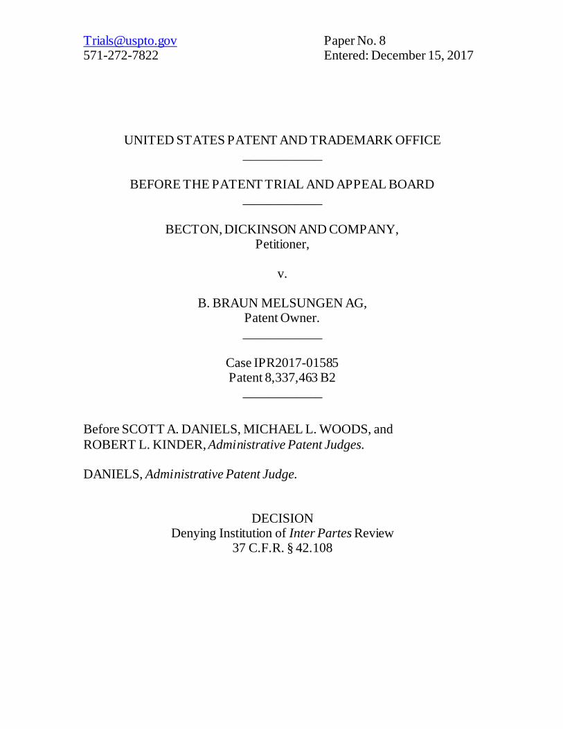
Woehr is a U.S. Patent titled “Spring Clip Safety IV Catheter” and
discloses a “catheter in which the needle tip is automatically covered after
needle withdrawal to prevent the health-care worker from making accidental
contact with the needle tip.” Ex. 1003, [54], 1:8–11. Figure 1A illustrating
Woehr’s catheter is reproduced below:
Woehr describes Figure 1A as depicting catheter 10 including needle hub
12, needle 16 with needle tip 18, catheter hub 26, and needle guard 40 in the
form of a unitary spring clip. Id. at 4:8–28, 50–51. Functionally speaking,
as needle 16 is withdrawn from a patient, needle guard 40 “automatically

IPR2017-01585 Patent 8,337,463 B2
10
snaps into a retracted position” to block needle tip 18 to prevent accidental
contact to the health care practitioner. Id. at 4:43–49.
2. Tauschinski (Ex. 1004)
Tauschinski is a U.S. Patent titled “Self-Sealing Connector for Use
with Plastic Cannulas and Vessel Catheters” and discloses a connector that
will close automatically when a corresponding catheter is pulled from the
connector, thereby “prevent[ing] an emergence of blood or an ingress of air”
through the connector. See Ex. 1004, [54], 2:7–29. To illustrate the
disclosed connector, we reproduce Tauschinski’s Figures 2 and 3, below:
Tauschinski’s Figures 2 and 3 depict a connector with a slit sealing disc. See
id. at 2:62–68. In particular, these figures depict member 10 slidable within
hollow-conical portion 2 and disc 3 provided with central slit 8. See id. at
3:17–25. Figure 2 depicts disc 3 as closed, with Figure 3 depicting member

IPR2017-01585 Patent 8,337,463 B2
11
10 advanced downward and within slit 8 of disc 3 to open the slit. See id. at
3:29–36.
3. Arnett (Ex. 1005)
Arnett is a U.S. Patent titled “Valve Assembly” and discloses a “valve
assembly having a body, an end cap, a resilient septum, and an actuator.”
Ex. 1005, [54], [57]. Arnett alleges that its inventive valve assembly
provides a “superior seal” to prevent leakage. Id. at 1:12–17. Arnett
discloses that its “actuator moves the shoulder surface of the septum away
from the septum shoulder of the body to allow fluid to flow through the
body fluid passageway, the chamber fluid passageways and the end cap fluid
passageway.” Id. at 1:51–55. To illustrate an embodiment of Arnett’s
invention—which Petitioner itself relies upon (Pet. 18–19)—we reproduce
Figure 11 of Arnett, below:
Figure 11 depicts a catheter and valve assembly in the open position and
when a needle is not used. See id. at 2:29–36; see also id. at 5:51–58
(describing a different but similar embodiment of Figure 6 “[w]hen the valve
assembly 10 is used in a needleless access system . . .”).

IPR2017-01585 Patent 8,337,463 B2
12
In particular, Figure 11 depicts valve assembly 10 including septum
216 and actuator 220. Septum 216 “is made of a resilient, compressible
elastomeric material . . . that can be compressed or deformed numerous
times without losing its original shape.” Id. at 7:15–18. In operation, when
actuator 220 is pressed against septum 216, a seal between shoulder surface
284 and septum shoulder 246 breaks, thus, allowing fluid to flow from luer
140 through fluid passageway 306 and through fluid passageways 290. See
id. at 8:26–44. Assembly 10 can be resealed by removing luer 140 from
body 212, which removes the force applied by actuator 220 onto septum
216, “thereby causing septum 216 to regain its original shape to form a seal
between the shoulder surface 284 and the septum shoulder 246.” See id. at
8:45–50. To better illustrate Arnett’s actuator 220, we reproduce Figure 12,
below:
Arnett’s Figure 12 depicts actuator 220 including septum contact surface
312, an opposed fitting contact surface 314, and fluid passageway 306. Id.
at 7:29–39. As discussed above in connection with Figure 11, fluid
passageway 306 allows fluid to flow around septum 216 and through fluid
passageways 290. See id. at Fig. 11, 8:41–44.

IPR2017-01585 Patent 8,337,463 B2
13
4. Petitioner’s Challenge to Claims 1, 2, 10, 12, 25, and
28 In challenging the claims, Petitioner submits that Woehr discloses a
“catheter insertion device” comprising a “catheter hub” (or “first hub”),
“needle,” and “needle protective device.” See Pet. 13–15, 25–28
(challenging independent claim 1); see also id. at 28–29 (challenging
independent claim 10); see also id. at 34 (challenging independent claim 18).
To illustrate these findings, Petitioner submits several annotated Figures,
including several annotated figures of Woehr’s Figure 10A (id. at 14, 15,
26), two of which we reproduce, below:
According to Petitioner, and referring to annotated Figure 10A,
Woehr discloses a “catheter insertion device” comprising the claimed

IPR2017-01585 Patent 8,337,463 B2
14
“catheter hub” 26, “needle” 16, and “needle protection device” 120. Id. at
13–15, 25–28.
Addressing the claimed “valve,” Petitioner relies on Tauschinski and
reasons that it would have been obvious to modify Woehr to include
Tauschinski’s valve. See id. at 16–19 (citations omitted). In relying on
Tauschinski, Petitioner submits an annotated version of Tauschinski’s Figure
2 (id. at 18), which we reproduce below:
Petitioner asserts that Tauschinski discloses valve 3 with slit 8
configured to obstruct fluid flow through catheter hub 1. Id. at 14 (citing
in-part Ex. 1004, 2:7–19). Petitioner reasons that it would have been
obvious to modify Woehr “by adding protective elements, such as a valve to

IPR2017-01585 Patent 8,337,463 B2
15
prevent the emergence of blood,” as disclosed by Tauschinski. Id. at 19
(citing Ex. 1002 ¶¶ 68).
In addressing the claimed “valve actuating element comprising a nose
section having a tapered end . . . and at least two plunger elements extending
proximally of the nose section and having a gap therebetween,” Petitioner
relies on both Tauschinski and Arnett. Id. at 20–25.
To address the claimed “valve actuating element comprising a nose
section having a tapered end,” Petitioner submits annotated versions of
Tauschinski’s Figures 2 and 3 (id. at 22), which we reproduce below:
According to Petitioner, and as shown in the above Figures 2 and 3,
Tauschinski discloses valve actuating element 10 with a nose section having
a tapered end, slidingly disposed in catheter hub 1, and configured to actuate
valve 3 to open slit 8. Id. at 20–21 (citing Ex. 1002 ¶ 71; Ex. 1004, 3:21–
36).
To address the claimed “valve actuating element comprising . . . at
least two plunger elements extending proximally of the nose section and
having a gap therebetween to permit fluid flow to flow therethrough,”

IPR2017-01585 Patent 8,337,463 B2
16
Petitioner relies on Arnett and submits annotated versions of Arnett’s
Figures 11 and 12 (id. at 22–23), which we reproduce below:
According to Petitioner, Figure 11 (above-left) depicts valve actuating
element 220, and as shown in Figure 12 (above-right), valve actuating
element 220 that has two plungers and gap 306 “therebetween to permit
fluid flow to flow therethrough.” Pet. 22 (citing Ex. 1005, 7:34–36; Ex.
1002 ¶ 73).
In combining Woehr with Tauschinski and Arnett to arrive at the
claimed “valve actuating element,” Petitioner reasons that it would have
been obvious to use Tauschinski’s valve actuator, including its tapered nose,
in order to actuate Tauschinski’s valve, and that it would have been further
obvious to modify Tauschinski’s actuator “to contain two plunger elements
. . . to open a valve as described in Arnett.” Id. at 24. In particular, we
reproduce Petitioner’s reasoning for modifying Tauschinski’s valve actuator
to include Arnett’s two “plunger elements . . . having a gap therebetween,”
below:
Further, it would have been obvious to modify the actuator disclosed in Tauschinski to contain two plunger elements on the proximal end of the valve actuating element that are pushed by an external force to open a valve as described in Arnett. (Ex.

IPR2017-01585 Patent 8,337,463 B2
17
1002, Griffis Decl. ¶¶ 69, 74–75.) Both Tauschinski and Arnett
disclose valves and valve actuators with a central passageway that can be used with catheter devices, and both recognize the need to include such valves and valve actuators to prevent leakage. (Id.) Adding another passageway at the proximal end of the actuator is a known design choice in IV catheter blood control actuators that still allows the actuator to transfer a distally directed force to open the valve slit. (Id.) Further, adding a gap in the actuator is one of a finite number of predictable solutions
for creating space to accommodate the spring clip in the catheter hub, while also allowing a male luer to push on the actuator open the valve, and permit fluid flow in the device. (Id.) Thus, it would have been obvious to a POSA to modify the valve actuator of Tauschinski to add plungers as described in Arnett, and to include that actuator in the spring clip safety IV catheter of Woehr ’108. (Id.)
Pet. 24–25 (emphases added). In summary, Petitioner reasons that a person
having ordinary skill in the art would have modified Tauschinski’s actuator
to include Arnett’s “plungers” and “gap” simply as a matter of “design
choice,” because it is “one of a finite number of predictable solutions for
creating space to accommodate the spring clip in the catheter hub.” Id. at
25.
5. Patent Owner’s Argument
Patent Owner argues that Petitioner’s reason for adding Arnett’s
“plunger elements . . . having a gap therebetween,” “is based on an illogical
analysis and mere[] conclusory statements.” See Prelim. Resp. 48. In
support of this argument, Patent Owner asserts that a “POSITA would have
no reason to, and would not want to, modify Tauschinski’s existing actuator
to include two plunger elements based on Arnett.” Id. Patent Owner argues
further that “the mode of operation of the valve actuating element and
septum of Arnett is completely different from the valve actuating element

IPR2017-01585 Patent 8,337,463 B2
18
and ‘disc consisting of elastic material and having a central slit’ of
Tauschinski.” Id. at 51.
We agree with Patent Owner.
6. Analysis
We are not convinced that Petitioner has articulated a persuasive
reason and, more specifically, has not shown sufficient evidentiary
underpinnings supporting the assertion that a person having ordinary skill in
the art would have modified Tauschinski’s actuator to include Arnett’s “two
plunger elements” as a matter of design choice because that is “one of a
finite number of predictable solutions for creating space to accommodate the
spring clip.” See Pet. 24–25.
Importantly, Petitioner’s assertion that it is simply a matter of design
choice to alter Tauschinski’s actuator with Arnett’s plunger and gap
elements lacks rational underpinnings. See In re Kahn, 441 F.3d 977, 988
(Fed. Cir. 2006), cited with approval in KSR, 550 U.S. at 418 (“rejections on
obvious[] grounds cannot be sustained by mere conclusory statements;
instead, there must be some articulated reasoning with some rational
underpinning to support the legal conclusion of obviousness.”). While it
may be possible to design Tauschinski’s actuator to include the plunger and
gap elements disclosed by Arnett, Petitioner has not explained adequately
why one of ordinary skill in the art would have plucked this particular
structure from Arnett to add to Tauschinski.
As discussed above, Petitioner reasons initially that a person of skill in
the art would add a gap between two plungers as a matter of design choice
because “that still allows the actuator to transfer a distally directed force to
open the valve slit.” Pet. 25 (citing Ex. 1002 ¶¶ 69, 74–75). This statement,

IPR2017-01585 Patent 8,337,463 B2
19
as it is essentially reiterated by Mr. Griffis’s testimony, articulates a result, a
mechanical design that would probably functionally and structurally work to
transfer force, but it is not a persuasive reason or explanation as to why one
of skill in the art would design an actuator with the particular elements from
Arnett, as added to Tauschinski. See Ex. 1002 ¶ 74 (Mr. Griffis testifies that
“[a]dding another passageway at the proximal end of the actuator is a known
design choice . . . that still allows the actuator to transfer a distally directed
force to open the valve slit.”). It is not enough that Arnett’s two plunger
design and gap structure exists and can impart a valve opening force, there
must be a particular reason a person of skill in the art would decide to use
such a two plunger and gap design. See KSR, 550 U.S. at 418 (“a patent
composed of several elements is not proved obvious merely by
demonstrating that each of its elements was, independently, known in the
prior art”).
The closest that Petitioner comes to articulating a rationale to use
Arnett’s proximal end structure is Mr. Griffis assertion that
adding a gap in the actuator is one of a finite number of
predictable solutions for creating space to accommodate the valve, actuator, and spring clip in the catheter hub while also allowing a male luer to push on the actuator and permit fluid flow in the device.
Ex. 1002 ¶ 75. However, neither Petitioner, nor Mr. Griffis, points to any
evidence in the record or reasoning suggesting that the possible approaches
to creating space for a spring clip and transferring force to open the valve in
a catheter insertion hub are “known and finite.” See Takeda Chem. Indus. v.
Alphapharm Pty., 492 F.3d 1350, 1359 (Fed. Cir. 2007) (discussing the
requirements of an “obvious to try”-type obviousness rejection). Without
sufficient evidence or explanation that the structural and technical
IPR2017-01585 Patent 8,337,463 B2
20
constraints of accommodating a spring clip within a catheter hub along with
a valve and actuator structure was somehow limited, this allegation is simply
a hindsight statement based on the invention described in the ’463 patent.
See Ortho-McNeil Pharm., Inc. v. Mylan Labs., Inc., 520 F.3d 1358, 1364
(Fed. Cir. 2008) (Considering KSR, and the issue of a finite number of
design options for an inventor, the Federal Circuit found in Ortho-McNeil
that the record “does not present a finite (and small in the context of the art)
number of options easily traversed to show obviousness.”). Indeed,
Petitioner explains that catheter insertion assemblies designed to address
needle safety have been known “[s]ince at least the 1980’s,” and that “many
books, papers, and patents that identified the need for needle safety and
suggested designs to achieve it.” Pet. 3 (citing Ex. 1002 ¶¶ 31–33). We
appreciate that not all needle safety designs may utilize a “spring clip” as
illustrated and described in the ’463 patent, but neither Petitioner nor its
declarant provide any relative comparison or examples in the prior art which
evidence that the universe of design options for such medical devices, and
specifically the accommodation of a needle sheath or spring clip within a
catheter insertion device, is technically or structurally limited. See, e.g., Ex.
1002 ¶¶ 33–34 (discussing generally that OSHA had “identified ‘self-
sheathing needles’ as an engineering control to reduce employee exposure to
hazardous pathogens”) (citing Ex. 1015).
Petitioner’s reasoning also “picks and chooses” the structure of
Arnett’s actuator 220 and “gap” 306 to the exclusion of Arnett’s extensive
disclosure regarding the purpose and operation of these components, which
understanding of is “necessary to the full appreciation of what [Arnett] fairly
suggests.” Pet. 22–26. “It is impermissible within the framework of section

IPR2017-01585 Patent 8,337,463 B2
21
103 to pick and choose from any one reference only so much of it as will
support a given position, to the exclusion of other parts necessary to the full
appreciation of what such reference fairly suggests.” In re Hedges, 783 F.2d
1038, 1041 (Fed. Cir. 1986)) (citation and inner quotes omitted).
In the present case, Petitioner’s reasoning excerpts Arnett’s actuator
220 and “gap” 306 to the exclusion of Arnett’s extensive disclosure
regarding the purpose and operation of these components, which
understanding of is “necessary to the full appreciation of what [Arnett] fairly
suggests.” Pet. 22 – 26. As pointed out correctly by Patent Owner (see
Prelim. Resp. 48–49) Arnett’s “at least two plunger elements . . . having a
gap therebetween” 306 function to direct fluid around Arnett’s “valve”
(septum 216) (see Ex. 1005, 8:26–44). To explain Arnett’s operation, we
reproduce an annotated partial view of Arnett’s Figure 11, below:
As shown in annotated Figure 11, and denoted by arrows and yellow
highlights, when Arnett’s actuator 220 presses against septum 216, a seal

IPR2017-01585 Patent 8,337,463 B2
22
between shoulder surface 284 and septum shoulder 246 breaks, thus,
allowing fluid to flow through fluid passageway 306 and radially outward
to fluid passageways 290. See Ex. 1005, 8:41–43 (“fluid is free to flow from
the luer 140 through the fluid passageway 306 of the actuator 220 to the
chamber fluid passageways 290”).
Petitioner’s modification proposes to use Tauschinski’s valve 3,
which directs fluid through a central slit and not radially around the outside
of the valve as occurs with the fluid flow around Arnett’s septum 216. See
Pet. 20–21 (citing Ex. 1002 ¶¶ 71). See id. Because fluid is directed in
Tauschinski’s valve through a central slit “through which a metal cannula or
a vessel catheter can be pushed without obstruction,” (Ex. 1004, 2:9–13), we
are not persuaded that a person having ordinary skill in the art would have
looked to Arnett to modify Tauschinski’s actuator to include Arnett’s “at
least two plunger elements . . . having a gap [306] therebetween,” simply as
a matter of design choice to “permit fluid flow.” Pet. 22. Rather, we find
that Petitioner’s reasoning selectively ignores Arnett’s specific disclosure
regarding the operation of Arnett’s “gap” 306 and fails to give full
appreciation to what Arnett’s “gap” fairly suggests to a person having
ordinary skill in the art—that is the redirection of fluid radially around the
septum 216 in Arnett. See In re Hedges, 783 F.2d at 1041, see also In re
Gal, 980 F.2d 717, 719–20 (Fed. Cir. 1992) (reversing as improper the
Board’s holding that a difference in structure between an applicant’s claimed
invention and the prior art was simply a matter of design choice, where the
different structures of the applicant and the prior art achieve different
purposes).

IPR2017-01585 Patent 8,337,463 B2
23
Petitioner proposes the combination of Arnett with Tauschinski and
Woehr to address the valve actuating element, plunger and gap limitations
recited in independent claims 1, 10, and 25. See Pet. 20–25, 30–32, 36–38.
Based on the record before us, we determine that Petitioner has not
established a reasonable likelihood of prevailing on its contention that the
combined teachings of Woehr, Tauschinski, and Arnett render obvious
claims 1, 2, 10, 12, 25, and 28.
D. Alleged Obviousness over Van Heugten and Arnett
Petitioner contends that claims 1, 2, 10, 12, 25, and 28 are
unpatentable over Van Heugten and Arnett. Pet. 3, 40–63.
1. Van Heugten (Ex. 1006)
Van Heugten is a U.S. Patent titled “Catheter with Controlled Valve.”
Ex. 1006, [54]. Van Heugten discloses a “catheter hub assembly . . .
wherein the assembly contains a membrane useful in preventing backflow of
blood.” Id. at [57]. To illustrate Van Heugten’s catheter assembly, we
reproduce Figure 2, below:
Figure 2 depicts a cross-sectional view of Van Heugten’s catheter
assembly 10. Id. at 2:6–10, 19. In particular, Figure 2 illustrates catheter
assembly 10 with catheter 50 and needle 24, which needle guard 30 covers
upon retraction of needle 24 “to prevent inadvertent needle injury to the user
or others.” Id. at 2:36–39, 3:34–58. Catheter assembly 10 also includes

IPR2017-01585 Patent 8,337,463 B2
24
valve membrane 110, which is illustrated in Figures 4a and 4b, which we
also reproduce, below:
As disclosed in Van Heugten, Figures 4a and 4b further show
membrane assembly 100 comprising a one-directional valve membrane 110.
Id. at 3:59–63. Figure 4a (above-left) depicts membrane 110 as being
“punctured” by needle 24 (id. at 3:58–4:3), while Figure 4b (above-right)
depicts needle 24 removed, where upon “removal from the catheter hub 52,
the valve membrane closes” (id. at 4:6–9). Valve member 110 is “generally
configured as a ‘duck bill’ valve or a valve of similar configuration and
smoothly allows removal of . . . needle 24[, so that upon] removal of the
needle 24 from the catheter 50, the valve membrane unidirectionally closes
so that blood will not flow into flash chamber 26.” Id. at 4:23–30.
2. Petitioner’s Challenge
Petitioner asserts that Van Heugten discloses a “catheter insertion
device” comprising the claimed “catheter hub” or “first hub,” “needle,”
“valve,” and “needle protective device.” Pet. 41–47, 49–50 (independent
claim 1); id. at 51–53, 55–56 (independent claim 10); id. at 57–59, 61–62
(independent claim 25). In support of these findings, Petitioner submits
annotated versions of Van Heugten’s Figure 2 (id. at 43), which we
reproduce, below:

IPR2017-01585 Patent 8,337,463 B2
25
According to Petitioner, and as shown above, Figure 2 depicts Van
Heugten’s “catheter hub” 52, “needle” 24, and “needle protective device”
30. Id. at 35, 36, 42.
Petitioner also submits an annotated version of Van Heugten’s Figure
3 (id. at 44), which we also reproduce, below:

IPR2017-01585 Patent 8,337,463 B2
26
According to Petitioner, and as shown in Figure 3, Van Heugten also
discloses the claimed “valve” 100, 110. See id. at 44–45 (“a POSA would
have understood Van Heugten to disclose the valve membrane 110 having a
slit”) (citing Ex. 1002 ¶ 114).
In addressing the claimed “valve actuating element,” Petitioner relies
on a combination of Van Heugten and Arnett. Id. at 47. In particular,
Petitioner relies on Van Heugten for disclosing a “valve actuating element
comprising a nose section having a tapered end” 122 for “pushing the valve
to open the slit of the valve,” and submits an annotated version of Van
Heutgen’s Figure 4c (id. at 48), which we reproduce, below:

IPR2017-01585 Patent 8,337,463 B2
27
According to Petitioner, Figure 4c depicts “valve actuating element”
120 comprising a nose section with a tapered end 122. Pet. 48 (citing Ex.
1006, 4:31–36, 4:43–49).
To address the claimed “valve actuating element comprising . . . at
least two plunger elements . . . having a gap therebetween,” and as with the
previous ground, Petitioner relies on Arnett’s actuator 220 with “two
plungers with a gap between these elements.” Id. at 49. Petitioner reasons
that it would have been obvious to modify Van Heugten’s “valve actuator”
120 to include Arnett’s “plungers with a gap,” as follows:
It would have been obvious for a POSA to combine the catheter insertion device of Van Heugten with the valve actuating
elements disclosed in Van Heugten and Arnett. Both Van Heugten and Arnett disclose catheter insertion assemblies with a valve, an actuator, and needle protection. It would have been obvious to a POSA to modify Van Heugten’s valve actuating element to put two plunger elements on the proximal end that are pushed by an external force to open a valve as described in Arnett. Adding structure at the end of the actuator to create two plungers with a gap between these elements was a known
actuator configuration. Further, it had a known advantage to
IPR2017-01585 Patent 8,337,463 B2
28
allow fluid to flow from an external infusion set. A POSA would
have found it obvious to improve Van Heugten by adding an actuator based on the known technique disclosed in Arnett to improve a similar catheter insertion device actuator that could be used for its intended purpose of actuating the valve and promoting fluid flow. (Ex.1002, Griffis Decl. ¶122.)
Id. at 48-49 (emphases added). In summary, Petitioner proposes to modify
Van Heugten’s actuator because Arnett’s “two plungers with a gap between
these elements was a known configuration . . . [and] it had a known
advantage to allow fluid to flow from an external infusion set.” Id. at 49.
3. Patent Owner’s Argument
Patent Owner argues that “there is no reason to modify the already
existing actuator of Van Heugten based on Arnett.” Prelim. Resp. 51. In
support of this argument, Patent Owner points out that in Van Heugten, fluid
flows through the center of its valve membrane, whereas Arnett’s actuator
pushes on the periphery of its septum “to allow fluid to flow around its
thick, deformable septum.” See id. at 57. Patent Owner argues that
Petitioner’s proposed modification “would weaken [Van Heugten’s] device,
and the side openings would detract from fluid through the center of the
device; such detracted flow would dead-end and stagnate on the interior
walls of the Van Heugten catheter hub.” Id. at 58 (citing Ex. 2001 ¶¶
85–89).
Patent Owner’s argument is persuasive.
4. Analysis
As with the prior ground, we are not persuaded that a person having
ordinary skill in the art would have looked to Arnett to modify
Van Heugten’s actuator to include Arnett’s “two plunger elements . . .
having a gap therebetween.”

IPR2017-01585 Patent 8,337,463 B2
29
The Federal Circuit has stated that “rejections on obviousness grounds
cannot be sustained by mere conclusory statements; instead, there must be
some articulated reasoning with some rational underpinning to support the
legal conclusion of obviousness.” In re Kahn, 441 F.3d at 988, cited with
approval in KSR, 550 U.S. at 418. In the present case, Petitioner proposes to
modify Van Heugten’s actuator because Arnett’s “two plungers with a gap
between these elements was a known configuration . . . [and] it had a known
advantage to allow fluid to flow from an external infusion set.” Pet. 49
(emphasis added). Petitioner’s reasoning implies that Van Heugten’s device
is not able to connect to an “external infusion set,” and that Arnett’s
“plunger elements” advantageously provide for such a connection. See id.
Upon reviewing Van Heugten, however, we find that Van Heugten’s
actuator is already configured for connection to an infusion set. See, e.g.,
Ex. 1006, 2:50–53 (“The larger diameter proximal portion 56 of the catheter
hub 52 is flanged at its proximal end for connection to an infusion set.”).
Accordingly, Petitioner’s reasoning is not supported by rational
underpinnings. See KSR, 550 U.S. at 418.
Furthermore, and as discussed above in the previous ground,
Petitioner’s reasoning “picks and chooses” the structure of Arnett’s actuator
220 and “gap” 306 to the exclusion of Arnett’s extensive disclosure
regarding the purpose and operation of these components, which
understanding of is “necessary to the full appreciation of what [Arnett] fairly
suggests.” In re Hedges, 783 F.2d at 1041. Petitioner’s modification
proposes to use Van Heugten’s valve membrane 110, which upon insertion
of membrane opener 120, is opened. See Pet. 47–48 (citing Ex. 1006,
4:31–36, 4:43–49, Fig. 4c). Van Heugten’s valve membrane 110, however,

IPR2017-01585 Patent 8,337,463 B2
30
operates very differently from Arnett’s septum 216, by directing fluid
through, and not around, membrane 110. See id. at 47. Because fluid is not
directed around Van Heugten’s valve membrane 110, we are not persuaded
that a person having ordinary skill in the art would have looked to Arnett to
modify Van Heugten’s membrane opener 120 to include Arnett’s “plunger
elements” “having a gap [306] therebetween,” as Petitioner proposes. See
id. at 48. Rather, we find that Petitioner’s reasoning selectively ignores
Arnett’s extensive disclosure regarding the operation of Arnett’s “gap” 306
and fails to give full appreciation to what Arnett’s “gap” fairly suggests to a
person having ordinary skill in the art. In re Hedges, 783 F.2d at 1041.
Petitioner proposes the combination of Arnett with Van Heugten and
to address the valve actuating element, plunger and gap limitations recited in
independent claims 1, 10 and 25. See Pet. 47–49, 53–55, 59–61. Based on
the record before us, we determine that Petitioner has not established a
reasonable likelihood of prevailing on its contention that the combined
teachings of Van Heugten and Arnett render obvious claims 1, 2, 10, 12, 25,
and 28.
IV. ORDER
For the reasons given, it is
ORDERED that no inter partes review is instituted.
IPR2017-01585 Patent 8,337,463 B2
31
For PETITIONER:
Heather M. Petruzzi Natalie Pous David L. Cavanaugh WILMER CUTLER PICKERING HALE AND DORR LLP [email protected] [email protected] [email protected]
PATENT OWNER: Barry J. Schindler Heath J. Briggs Julie P. Bookbinder Joshua L. Raskin
GREENBERG TRAURIG, LLP [email protected] [email protected] [email protected] [email protected]


![Impact of a Modified Needle Tip Geometry on Penetration ... · Multiple factors impact subcutaneous insulin injection pain. Injection devices [e.g., syringe or pen needle (PN)] affect](https://img.pdfslide.us/doc/110x75/5ea621ddc0be5f67aa36cdbb/impact-of-a-modified-needle-tip-geometry-on-penetration-multiple-factors-impact.jpg)