Embed Size (px)
Citation preview
Specifications and Ordering Information Part Number 162513-01
Rev. C (04/07)
Page 1 of 6
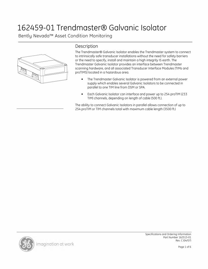
162459-01 Trendmaster® Galvanic Isolator
Description The Trendmaster® Galvanic Isolator enables the Trendmaster system to connect to intrinsically safe transducer installations without the need for safety barriers or the need to specify, install and maintain a high integrity IS earth. The Trendmaster Galvanic Isolator provides an interface between Trendmaster scanning hardware, and all associated Transducer Interface Modules (TIMs and proTIMS) located in a hazardous area.
• The Trendmaster Galvanic Isolator is powered from an external power supply which enables several Galvanic Isolators to be connected in parallel to one TIM line from DSM or SPA.
• Each Galvanic Isolator can interface and power up to 254 proTIM (233 TIM) channels, depending on length of cable (500 ft.).
The ability to connect Galvanic Isolators in parallel allows connection of up to 254 proTIM or TIM channels total with maximum cable length (3500 ft.)
Specifications and Ordering Information Part Number 162513-01
Rev. C (04/07)
Page 2 of 6
Specifications
All values are specified over the full operating temperature range unless stated otherwise. All voltages are specified with respect to COM. References to proTIMs relates to proTIM-R and proTIM-C. References to TIM and flexiTIM™ relate to the Trendmaster 2000 Transducer Interface Modules
External Power Input.
Nominal Input Voltage:
+24 V ± 5 %
Maximum Current Draw:
100 mA
Power Dissipation.
Including power supply to 32 proTIMs (64 TIMs) and associated transducers.
1.7 Watts @ +24 V, Typical
Environmental Specification
Operating Temperature range:
-20 to +70 °C
Storage Temperature Range:
-40 to +85 °C
Relative humidity:
100 % condensing, non-submerged, power on when installed in a weatherproof housing.
Electromagnetic Compatibility.
Emissions:
EN61000-6-4
Immunity:
EN 61000-6-2
Hazardous Area Approvals.
CSA (C/US):
A / Ex nA [ia] IIC T4@ = –20°C < Ta < +70°C
Zone 2/ (0)
Exia Class 1, Groups A, B, C, D
CENELEC:
II (1)GD [EEx ia] IIC –20°C < Ta < +70°C
SIRA 02ATEX2215
II 3GD EEx nA IIC T4
SIRA 02ATEX4216X
Must be housed in NEMA type 4 or IP 54 weatherproof housing when installed in a Zone 2 Area.
Install per Control Drawing 166857 in a safe area, Division 2 / Zone 2 area. 0.33 megohm static dissipation resistor fitted within the Galvanic Isolator per EN60079-14
Certification Parameters.
Uo Total= 23.9 V
Uo PWR = 15 Vac
Uo Signal =12 Vac
Io PWR= 161 mA
Io Signal = 12 mA
Po Total = 555 Mw
Co = 126 nF
Lo/Ro = 21 µµµµH/ΩΩΩΩ
Ta = - 20 to + 70 °C
Physical.
Weight:
0.25 Kg (0.55 lb)
Dimensions:
94 mm x 150 mm x 45 mm
(3.7” x 5.9” x 1.77”)
Mounting:
DIN Rail.
Specifications and Ordering Information Part Number 162513-01
Rev. C (04/07)
Page 3 of 6
ac Performance.
Accuracy:
± 1 %
Noise Floor:
± 0.5% Trendmaster full-scale
Bandwidth
1 % dc to 10 kHz
ac Phase:
+ 3.0° @ 600 Hz absolute
± 1.5° @ 600 Hz unit-to-unit skew1
1For phase-critical measurements all measured signals should be connected through isolators to preserve phase.
dc Performance.
Accuracy:
± 1 % or 15 mV whichever is the greater
Inputs.
Safe area connection to the following Trendmaster Host scanning hardware.
Dynamic Scanning Module (DSM):
149744 PCI Signal Processing Adapter (SPA):
147127 Wireless Remote Module:
145908-01 Maximum of Four Galvanic Isolators connected to each TIM line from DSM or SPA.
Ouputs:
Hazardous area connection to the following intrinsically Safe Transducer Interface Module types:
TIM.
flexiTIM ™
proTIM - C
proTIM - R
Number of TIMs.
The number of TIMs / proTIMs allowed per Galvanic Isolator output is determined by the maximum cable length connected to the Galvanic Isolator output and all the subsequent TIMs per the table below:
Table 1:
Max Cable
Length
Max Number of flexiTIM, TIM
channels
Max Number of proTIM-R or
proTIM C channels
500 ft 233 254 1000 ft 199 236 1500 ft 170 205 2000 ft 145 177 2500 ft 122 153 3000 ft 102 131 3500 ft 84 112
Ordering Information
Trendmaster Galvanic Isolator.
Including connectors required for installation.
162459-01
Accessories.
02200627
Power Supply
162222-01
Weatherproof Housing
164046
TIM Line Connector from SPA.
164045
TIM line Connector to TIMs
164314
Power Supply Connector
Specifications and Ordering Information Part Number 162513-01
Rev. C (04/07)
Page 4 of 6
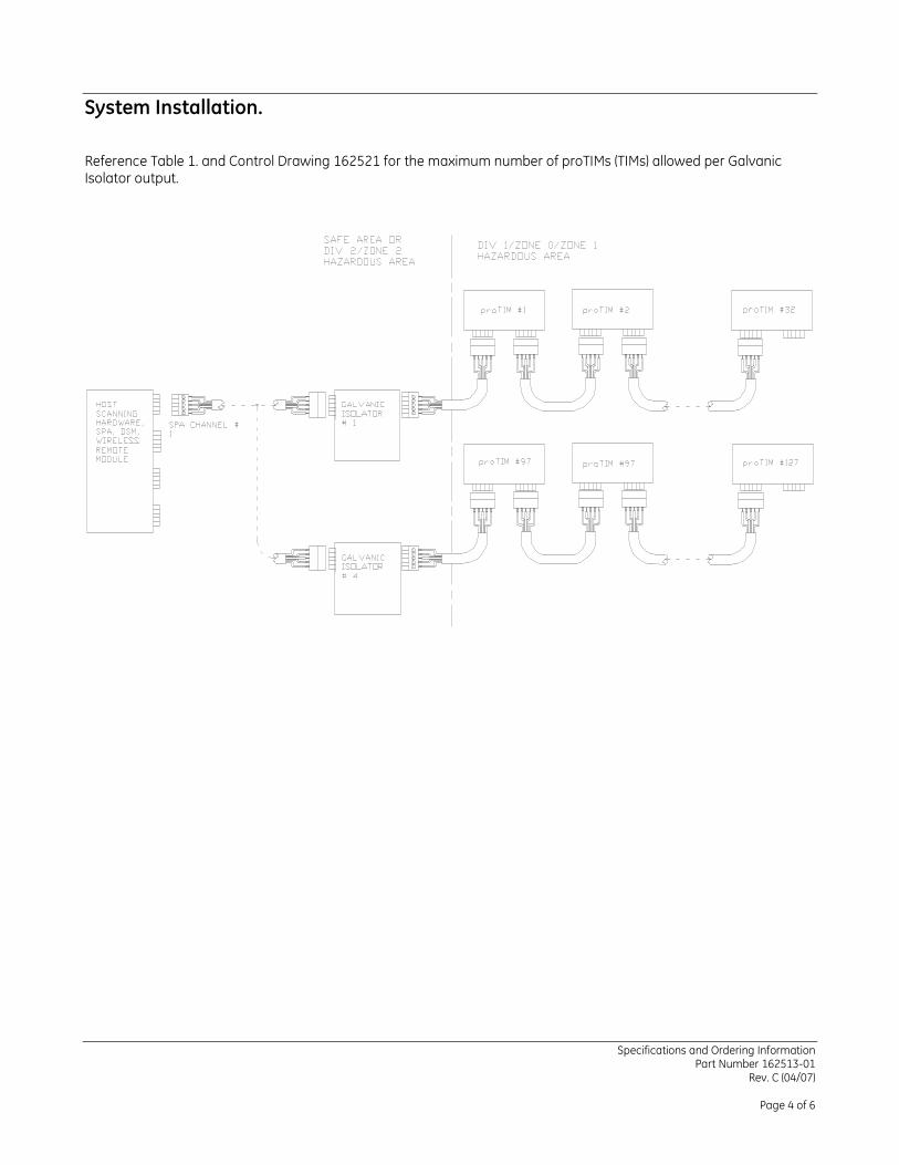
System Installation.
Reference Table 1. and Control Drawing 162521 for the maximum number of proTIMs (TIMs) allowed per Galvanic Isolator output.
Specifications and Ordering Information Part Number 162513-01
Rev. C (04/07)
Page 5 of 6
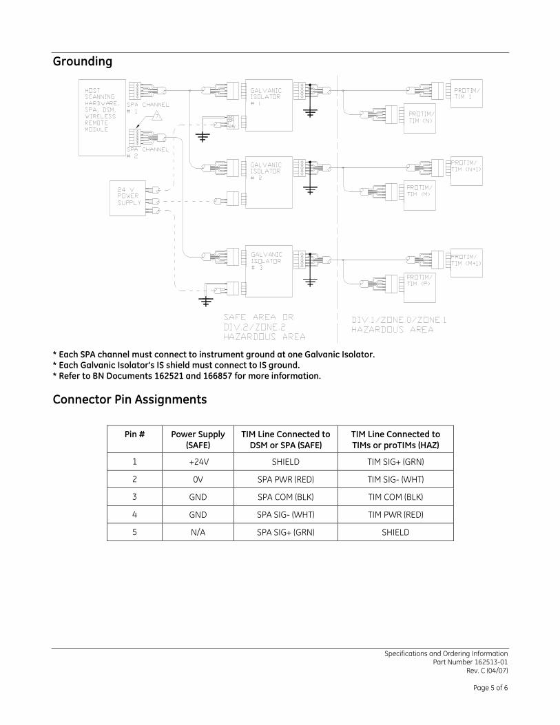
Grounding
* Each SPA channel must connect to instrument ground at one Galvanic Isolator. * Each Galvanic Isolator’s IS shield must connect to IS ground. * Refer to BN Documents 162521 and 166857 for more information.
Connector Pin Assignments
Pin # Power Supply (SAFE)
TIM Line Connected to DSM or SPA (SAFE)
TIM Line Connected to TIMs or proTIMs (HAZ)
1 +24V SHIELD TIM SIG+ (GRN)
2 0V SPA PWR (RED) TIM SIG- (WHT)
3 GND SPA COM (BLK) TIM COM (BLK)
4 GND SPA SIG- (WHT) TIM PWR (RED)
5 N/A SPA SIG+ (GRN) SHIELD
Specifications and Ordering Information Part Number 162513-01
Rev. C (04/07)
Page 6 of 6
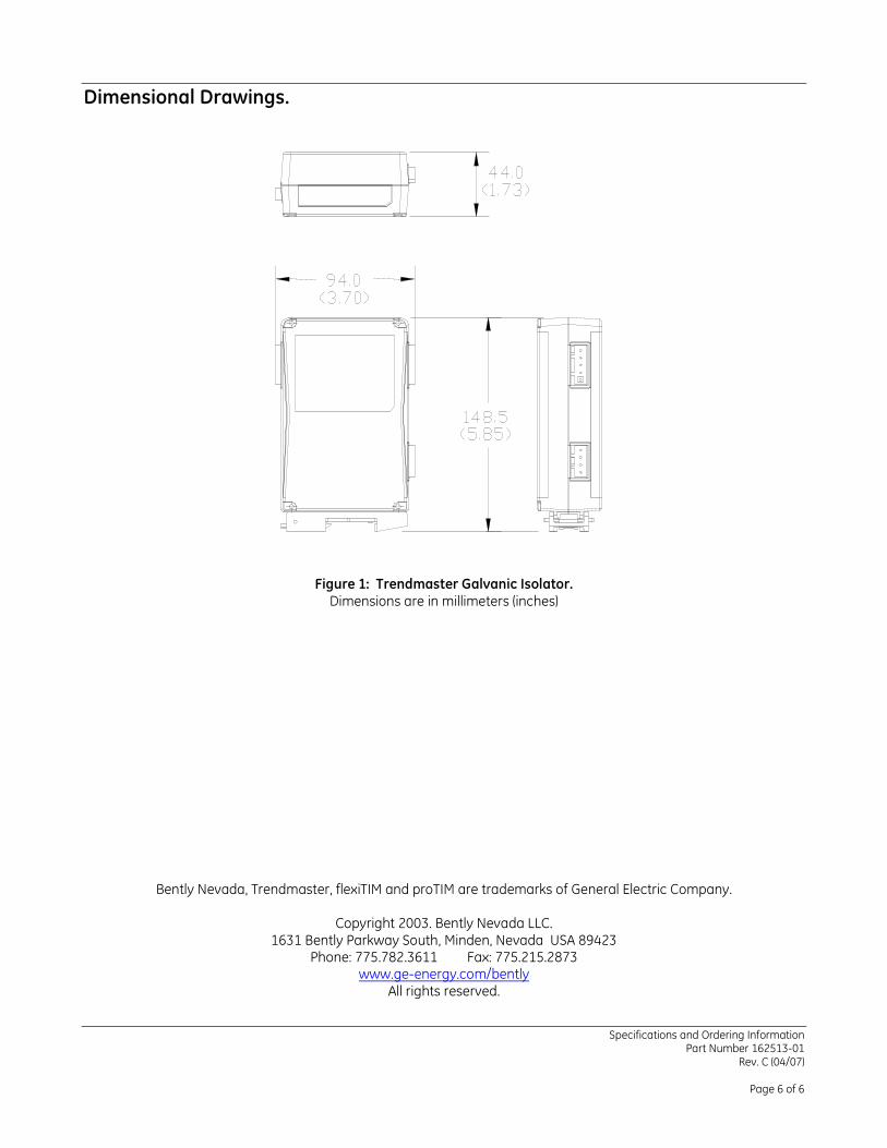
Dimensional Drawings.
Figure 1: Trendmaster Galvanic Isolator. Dimensions are in millimeters (inches)
Bently Nevada, Trendmaster, flexiTIM and proTIM are trademarks of General Electric Company.
Copyright 2003. Bently Nevada LLC. 1631 Bently Parkway South, Minden, Nevada USA 89423
Phone: 775.782.3611 Fax: 775.215.2873 www.ge-energy.com/bently
All rights reserved.