Embed Size (px)
Citation preview
Treatment BMP Technology Report April 2008
CTSW-RT-08-167.02.02
Final Report California Department of Transportation
Division of Environmental Analysis
1120 N Street, Sacramento, California 95814

blank for double sided printing
Caltrans Treatment BMP Technology Report April 2008
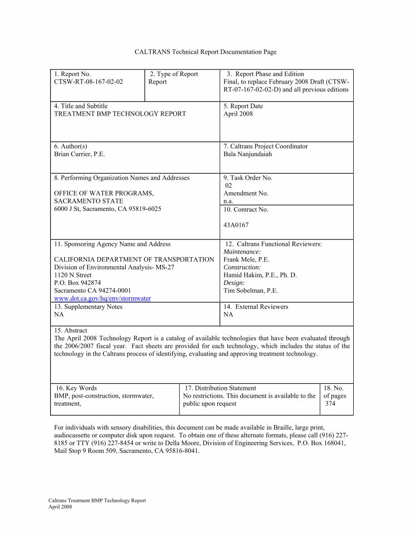
CALTRANS Technical Report Documentation Page
1. Report No. CTSW-RT-08-167-02-02
2. Type of Report Report
3. Report Phase and Edition Final, to replace February 2008 Draft (CTSW-RT-07-167-02-02-D) and all previous editions
4. Title and Subtitle TREATMENT BMP TECHNOLOGY REPORT
5. Report Date April 2008
6. Author(s) Brian Currier, P.E.
7. Caltrans Project Coordinator Bala Nanjundaiah
9. Task Order No. 02 Amendment No. n.a.
8. Performing Organization Names and Addresses OFFICE OF WATER PROGRAMS, SACRAMENTO STATE 6000 J St, Sacramento, CA 95819-6025
10. Contract No. 43A0167
11. Sponsoring Agency Name and Address CALIFORNIA DEPARTMENT OF TRANSPORTATION Division of Environmental Analysis- MS-27 1120 N Street P.O. Box 942874 Sacramento CA 94274-0001 www.dot.ca.gov/hq/env/stormwater
12. Caltrans Functional Reviewers: Maintenance: Frank Mele, P.E. Construction: Hamid Hakim, P.E., Ph. D. Design: Tim Sobelman, P.E.
13. Supplementary Notes NA
14. External Reviewers NA
15. Abstract The April 2008 Technology Report is a catalog of available technologies that have been evaluated through the 2006/2007 fiscal year. Fact sheets are provided for each technology, which includes the status of the technology in the Caltrans process of identifying, evaluating and approving treatment technology.
16. Key Words BMP, post-construction, stormwater, treatment,
17. Distribution Statement No restrictions. This document is available to the public upon request
18. No. of pages 374
For individuals with sensory disabilities, this document can be made available in Braille, large print, audiocassette or computer disk upon request. To obtain one of these alternate formats, please call (916) 227-8185 or TTY (916) 227-8454 or write to Della Moore, Division of Engineering Services, P.O. Box 168041, Mail Stop 9 Room 509, Sacramento, CA 95816-8041.

blank for double sided printing
TABLE OF CONTENTS
Caltrans Treatment BMP Technology Report April 2008
i
1.0 Introduction......................................................................................................... 1
2.0 Identifying and Evaluating New Technology.................................................... 1
3.0 Catalog of Treatment BMPs............................................................................... 3
4.0 References .......................................................................................................... 9
APPENDIX A: BMP Fact Sheet Description and Format ..................................... A-1
APPENDIX B: Technology Fact Sheets ................................................................ B-1
APPENDIX C: Pilot Study Fact Sheets.................................................................. C-1
APPENDIX D: Caltrans Approved BMP Fact Sheets............................................ D-1

blank for double sided printing
ii Treatment BMP Technology Report April 2008

Caltrans Treatment BMP New Technology Report 1 April 2008
1.0 INTRODUCTION The annual Treatment BMP Technology Report represents part of the Department’s BMP identification, evaluation, and approval process as described in Section 3.3.2 of the Storm Water Management Plan (SWMP) (Caltrans, 2003). This report consolidates information about technologies in a standardized manner by using a fact sheet format. The BMP fact sheets in Appendices B and C summarize available design, construction, performance, and cost information for unapproved BMPs. These BMPs are being considered for pilot testing, approval, or have been tested and subsequently rejected. For comparison, Appendix D contains fact sheets for BMPs approved by the Department.
To introduce products to the Department, manufacturers and suppliers must contact the New Product Coordinator at (916) 227-7185. Fact sheets are prepared for identified technologies and added to this report. The Department reviews the fact sheets to determine if a BMP warrants further research, which may include full-scale pilot testing.
The Department’s ongoing review of technologies consists of evaluating the latest innovations in stormwater treatment and control, including technologies used by municipal or other Department of Transportation (DOT) stormwater management programs.
2.0 IDENTIFYING AND EVALUATING NEW TECHNOLOGY The Department, with input from universities, consultants, regulators, third parties, and manufacturers, continually reviews BMP information reported in literature. Manufacturers’ exhibits at professional conferences also provide an opportunity to identify new technologies. After identification, an evaluation of the technology is made using several criteria (discussed below) and a fact sheet of the BMP is developed for this report.
2.1 Evaluation Criteria and Fact Sheet Content
BMP fact sheets are developed using a standard format to facilitate comparison among BMPs. Each fact sheet addresses a standard series of topics. This summary information is used to evaluate the potential applicability of BMPs to the Department. Topics covered include: design, operations, maintenance, construction, treatment effectiveness, costs, advantages and constraints. Appendix A describes how these topics are addressed in the fact sheet. Appendix A includes criteria for establishing reliable pollutant removal performance data for typical Caltrans runoff (Section A.2.3).
Each fact sheets contains technology-specific references. The Stormwater Monitoring and BMP Development Status Report (CTSW-RT-08-167.02.01) describes current pilot studies in more detail.
Department-Approved Treatment BMPs: Biofiltration (strips and
swales) Detention Basins Dry Weather Flow
Diversions GSRDs (inclined screen and
linear radial) Infiltration (basins and
trenches) Media Filters (Austin and
Delaware sand filters) Multi-Chambered
Treatment Trains Traction Sand Traps Wet Basins

2 Treatment BMP Technology Report April 2008
2.2 Fact Sheet Organization and Technology Approval
Completed BMP fact sheets are presented in Appendices B, C, and D. Section 3 provides an alphabetical list of all the BMPs to aid in locating fact sheets for specific BMPs. New fact sheets that were added since the 2007 report are highlighted in Section 3 and in the tables of contents at the beginning of Appendices B, C, and D.
Fact sheets in Appendix B summarize information for technologies that are neither tested nor approved by the Department. Favorable evaluations of BMP technologies can lead to pilot studies to gather cost and performance data. In most cases, there is a specific fact sheet for each BMP product, but in a couple of cases (e.g. porous pavers) a group of similar BMPs are represented on a single fact sheet.
Fact sheets in Appendix C summarize information of unapproved technologies tested in full-scale pilot projects by the Department.
Piloted technologies may be approved and listed in the Department’s SWMP. Fact sheets in Appendix D summarize information for these BMPs. Approvals are earned according to the process outlined in Section 3.3 of the SWMP. The Caltrans Storm Water Project Planning and Design Guide should be consulted for more details on approved BMPs (Caltrans, 2007).
2.3 Identifying Low Impact Development (LID) Technologies
LID is a design approach that uses land use planning, treatment BMPs, and other design detailing to concurrently reduce the load of pollutants to surface waters and reduce the duration and magnitude of stormwater flows for a range of rainfall return periods. For the purposes of this document, technologies are identified that could potentially be used in LID site design. These technologies are those that have substantial evapo-transpiration aspects, and/or infiltration to reduce the quantity of stormwater. The Department is currently investigating methods to quantify the benefit of these practices to meet LID goals, specifically to match post-project flows to pre-project flows for a range of rainfall return periods.
Many of the technologies that are identified in the fact sheets may not meet LID goals if not properly sized and if soil conditions are not suitable, but it is beyond the needs of this document to specifically identify these conditions for each technology.
NEW FACT SHEETS! Appendix B has 18 new fact sheets in this edition.
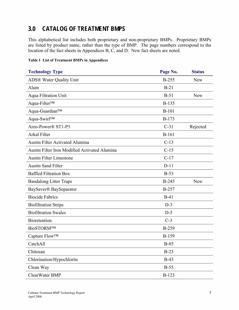
Caltrans Treatment BMP Technology Report 3April 2008
3.0 CATALOG OF TREATMENT BMPS This alphabetical list includes both proprietary and non-proprietary BMPs. Proprietary BMPs are listed by product name, rather than the type of BMP. The page numbers correspond to the location of the fact sheets in Appendices B, C, and D. New fact sheets are noted.
Table 1 List of Treatment BMPs in Appendices Technology Type Page No. Status
ADS® Water Quality Unit B-255 New
Alum B-21
Aqua Filtration Unit B-51 New
Aqua-Filter™ B-135
Aqua-Guardian™ B-101
Aqua-Swirl™ B-173
Areo-Power® ST1-P3 C-31 Rejected
Arkal Filter B-161
Austin Filter Activated Alumina C-13
Austin Filter Iron Modified Activated Alumina C-15
Austin Filter Limestone C-17
Austin Sand Filter D-11
Baffled Filtration Box B-53
Bandalong Litter Traps B-245 New
BaySaver® BaySeparator B-257
Biocide Fabrics B-41
Biofiltration Strips D-3
Biofiltration Swales D-5
Bioretention C-3
BioSTORM™ B-259
Capture Flow™ B-159
CatchAll B-85
Chitosan B-23
Chlorination/Hypochlorite B-43
Clean Way B-55
ClearWater BMP B-123

4 Treatment BMP Technology Report April 2008
Technology Type Page No. Status
Compost StormFilter™ (CSF) C-21 Discontinued
Con/Storm™ B-15
Constructed Wetland B-285
Continuous Deflective Separation™ (CDS™) C-23
Corrugated Pipe B-17
CrystalStream™ B-261
Cultec Contactor and HVLV™ Recharger B-217
Curb Inlet Basket B-57
DC - Sandfilter B-137
DeepRoot® Silva Cell B-7 New
Delaware Sand Filter D-13
Detention Basins D-7
Diamond Flow B-59
Double Barrel - Traction Sand Trap D-25
Downstream Defender™ B-175
Drain Diaper™ B-87
Drain Guard™ B-89
DrainPac™ B-91
Dry Weather Flow Diversion D-9
Ecology Embankment B-139
EcoRain B-219 New
EcoSense B-61 New
EcoSep® B-263
Ecostorm® B-177
EcoStormPlus® B-179
Electrocoagulation B-163
Eljen IN Drain™ System B-201
Enviorpod B-63
Enviro-Drain® B-103
Envriosafe™ B-105
Escol RSF 100/GSP B-65
Filterra® B-9

Caltrans Treatment BMP New Technology Report 5 April 2008
Technology Type Page No. Status
First Flush - 1640FF B-265 New
First-Flush Partitioned Basin B-13
FloGard Dual-Vortex™ B-181
FloGard Plus B-67
FossilFilter™ C-11 Discontinued
GAC or IX Media - Detention/Sedimentation B-27
GAC or IX Media – Filtration Bed B-141
GAC Sandwich Filter and Blanket B-143
Granular Activated Carbon B-147
Grate Inlet Skimmer Box B-69
Gross Pollutant Trap (GPT) B-231
GSR Basket (Mechanically Removed) B-71
GSRD - Inclined Screen D-19
GSRD - Linear Radial D-21
GSRD / Baffle Box C-25 Rejected
GSRD / Litter Inlet Deflector C-27 Rejected
GSRD / V-Screen C-29 Rejected
Hancor®-Storm Water Quality Unit B-267
Hanson Oil and Grit Separator B-269 New
HD Q-Pac® B-271
High Flow Debris Basket B-125 New
Hold and Release C-5
Hydro-Cartridge B-49
HydroFilter B-183
HydroGuard B-185
Hydro-Kleen™ B-107
Hydroscreen B-127
Inceptor B-73
Infiltration - Basins D-15
Infiltration Trenches D-17
Infitration Vault B-203
Ion Exchange Column B-29
6 Treatment BMP Technology Report April 2008
Technology Type Page No. Status
Kleerwater™ B-273
Linear Bioretention Trench B-11
Linear Filtration Trench B-145
Linear Infiltration Filter Trench B-205
Manhole Filter B-99
Matrix™ B-207
Media Filtration System B-149
Multi-Chambered Treatment Trains D-23
MWS - Linear HYBRID B-283 New
Net Cassette™ B-233
Netting Trash Trap™ B-235
Nutrient Separating Baffle Box B-237
Ozone B-45
Passive Skimmer B-83
Piranha B-75
Plate and Tube Settlers B-37
Polyacrylamide (PAM) B-25
Porous Surfaces - Asphalt B-247
Porous Surfaces - Concrete B-249
Porous Surfaces - Permeable Pavers / Cellular Confinement B-251
Porous Surfaces - Subsurface Drainage Structures B-253
Pressure Filter B-167
PSI Separator B-275
Puristorm™ B-151
Rainstore® B-209
Raynfiltr™ B-109
Rotondo - Detention w/Recharge B-221 New
SAGES™ B-171
SeaLife Saver™ B-77
Sewer Eco-Collar B-93
SIFT Filter B-111
Skimmer C-7

Caltrans Treatment BMP New Technology Report 7 April 2008
Technology Type Page No. Status
SNOUT® B-277
Storm PURE™ B-113 New
StormBasin®/StormPad® B-115
Stormcell® B-223
Stormceptor® B-187
StormChamber™ B-211
Stormfilter 400® B-165 New
StormFilter™ B-153
StormFilter™ C-19
StormPlex® B-155
StormScreen® B-239
Stormtank B-213
Stormtech B-215
StormTEE® B-241 New
StormTrap™, DoubleTrap™ B-19
StormTreat™ B-287
StormTrooper® B-189
StormVault™ B-279
StreamGuard™ C-9 Rejected
StreamSaver™ Catch Basin Insert B-95
SuperFlo II Downspout B-129
Terre Arch™ B-225 New
Terre Kleen™ B-191
Thirsty Duck B-31 New
Trash Guard TG Series B-79
Trashmaster® B-243
Triton Catch Basin Filter™ B-117
Triton Curb Inlet Filter™ B-119
Triton T-DAM Filter™ B-131
Triton TT3 Filter™ B-133
Triton™ Chambers B-227 New
Ultra Trench Filter® B-97

8 Treatment BMP Technology Report April 2008
Technology Type Page No. Status
Ultra-Urban Filter™ B-121
Ultraviolet B-47
Unistorm™ B-193
UpFlo™ B-169
V2B1™ B-195
Vault Filter Fabric - Traction Sand Trap C-33
Vegetated Rock Filter B-289
Versicell® B-229
VortClarex B-281
Vortechs® B-197
VortFilter B-157
VortSentry™ B-199
Watermann™ B-33
WEIR GUARD™ B-35 New
Wet Basin D-27
Wet Pond with Aeration Systems B-39
Wire Catch Basin Insert B-81

Caltrans Treatment BMP New Technology Report 9 April 2008
4.0 REFERENCES Caltrans, 2003. Statewide Storm Water Management Plan (SWMP). CTSW-RT-03-008. May
2003.
Caltrans, 2007. Storm Water Quality Handbooks, Storm Water Planning and Design Guide. http://www.dot.ca.gov/hq/oppd/stormwtr/Final-PPDG_Master_Document-6-04-07.pdf, May 2007.


Treatment BMP Technology Report A-1 April 2008
APPENDIX A: BMP FACT SHEET DESCRIPTION AND FORMAT This appendix describes the information contained in the fact sheets in Appendices B, C, and D. Each fact sheet is divided into a standard series of topics, which are described below in the order in which they occur in the columns of the fact sheets.
A.1 Header Information: BMP Category, Name, and Quick Reference Symbols The left side of the header contains a broad BMP category and more specific subcategory. If necessary, a more specific name of designation is found on the right side. Reference symbols, located in the upper right-hand corner of fact sheets identify technology attributes. Symbols represented are:
Special material handling requirements; potential toxicity
Power is required for this technology
Vactor equipment recommended for maintenance
Vector concern because of permanent standing water
A potential stormwater volume reduction technology that may be appropriate as a component of low impact development site design
A.2 BMP Description A description of the BMP is presented at the top of each fact sheet. The description provides a summary of the configuration of the BMP and a general overview of the treatment process, how the BMP operates, and considerations that need to be addressed to promote maximum treatment effectiveness and functionality.
A.3 Constituent Removal The constituent removal section displays the degree to which the BMP reduces constituents from levels typical of Caltrans stormwater runoff. The groups of constituents examined have been previously identified as pollutants of concern (Caltrans, 2007).

Treatment BMP Technology Report A-2 April 2008
A.3.1 Constituent Groups
Estimates of the technology’s performance removal abilities are made for each of the following constituent groups:
• Sediment (total suspended solids [TSS])
• Total nitrogen
• Total phosphorus
• Pesticides
• Total metals
• Dissolved metals
• Microbiological (including pathogens)
• Litter
• Biochemical oxygen demand (BOD)
• Total dissolved solids (TDS)
A.3.2 Constituent Group Removal Efficiency
The fact sheets report removal efficiencies for each of the ten constituents (or constituent groups). Constituent removal percentages were derived from a review of test results found in the literature. These are approximate estimates because removal efficiencies depend on the conditions of the test. All percentages are based on concentration reductions, except for nutrients and BOD which are based on load reductions.
Removal efficiencies were classified as high, medium or low. Constituent removal was quantified by calculating the average removal percentage for all constituents within a given constituent category. The overall assessment was then defined using the following criteria:
• High: average removal percentage was equal to or greater than 80 percent
• Medium: average removal percentage was between 40 and 80 percent
• Low: average removal percentage was less than or equal to 40 percent
• N.A.: constituent was not assessed and no performance claim was made by the manufacturer
The fact sheets provide notes with additional information regarding the assessment of removal efficiencies.
A.3.3 Level of Confidence
The level of confidence is based on water quality monitoring studies of BMPs that have demonstrated some level of effective treatment of highway stormwater runoff. To ensure that data is of the highest quality, stormwater monitoring should be conducted according to standard procedures, such as the Guidance Manual: Stormwater Monitoring Protocols (Caltrans, 2000),
Caltrans Treatment BMP New Technology Report A-3 April 2008
or equivalent procedures. Levels of confidence criteria for a high, medium or low assessment are defined as:
High: The constituent removal information came from either the Department’s research or a study that met the Department’s quality assurance and quality control monitoring protocols. Test conditions were typical of the Department’s facilities and all of the following criteria were met:
• Full-scale field testing of a stabilized (erosion-free) post-construction transportation-related impervious drainage area
• Sampling and analysis in accordance to the Guidance Manual: Stormwater Monitoring Protocols, (Caltrans, 2000), or other recognized protocol such as the International BMP Database (www.bmpdatabase.org)
• Testing at flow rates and volumes typical of Caltrans drainage areas (areas vary, but usually between 0.1 and 15 acres and flows and volumes can be found by using Caltrans’ Basin Sizer [available at http://www.owp.csus.edu/research/stormwatertools/])
• Mean influent concentrations must be below the 90th percentile of statewide characterization data found in the Caltrans Discharge Characterization Study Report, (Caltrans, 2003) See Table A-1 for select constituents.
• At least eight storm events over a minimum period of two years
• Particle size distribution (PSD) similar to the proposed field conditions (e.g. state whether or not traction sand was applied)
• A mean removal estimate that corroborates the performance claim
• Demonstration of statistically significant removal (p-values ≤ 0.1)
Further, the study report must include the following:
• Rainfall record for the study area or its vicinity during the evaluation period
• Operation and maintenance records and costs for the evaluation period Table A-1. The 90th percentile concentrations of select constituents as estimated from Appendix B of the Caltrans Discharge Characterization Study Report, CTSW-RT-06-065 (Caltrans, 2003)
Constituent Units 90th percentile* Constituent Units
90th percentile
TDS mg/L 200 Ammonia nitrogen mg/L as N 1.4 TSS mg/L 300 Total Kjeldahl
Nitrogen (TKN) mg/L as N 4.4
Turbidity (filtered)
NTU 44 Nitrite mg/L as N 0.32
Turbidity NTU 900 Nitrate mg/L as N 2 Oil & Grease mg/L 6.6 Phosphorus
(dissolved) mg/L as P 0.37
TPH (diesel) mg/L 9.3 Phosphorus (total) mg/L as P 0.84
Copper (dissolved)
μg/L 30 Orthophosphate mg/L as P 0.3
Treatment BMP Technology Report A-4 April 2008
Copper (total) μg/L 80 Diazinon μg/L 0.4
Lead (dissolved) μg/L 7 Diuron μg/L 11
Lead (total) μg/L 100 Glyphosate μg/L 50 Zinc (dissolved) μg/L 140 Pyrene μg/L 0.96 Zinc (total) μg/L 400 * 90th percentile is the concentration at which 90% of all measurements are below.
Alternatively, a ‘high’ score is assigned to infiltration or reuse BMP technologies that provided “no discharge” to surface waters under design conditions. Constituent removal was assumed to be 100 percent removal although it was recognized that certain large storm events would not receive treatment and that infiltration may not provide full removal of constituents for discharge to groundwater or subsequent re-entry to surface waters.
Medium: The criteria for high level of confidence were not completely met; however, one of the following must apply:
• Statistically significant (p-value < 0.1) constituent removal was established from independent stormwater field monitoring for at least one year
• Removal efficiency based on best professional evaluation of unit operations and processes that are well established for treatment of other waters
• Load reduction of nutrients or BOD due to partial infiltration
• Statistically significant (p-value < 0.1) constituent removal was established from independent laboratory testing that follows the Technology Assessment Protocol – Ecology (TAPE) from Washington State (Wash DOE, 2004) and testing used a volume of water equivalent of one year of runoff for a typical installation. Alternatively, a laboratory loading using actual stormwater could be used as with the Tahoe Small Scale Research Facility (http://www.dot.ca.gov/hq/env/stormwater/ongoing/tahoe/index.htm).
Low: There are no available data or data does not meet the above criteria for medium level of confidence. For example, a manufacturer’s performance claim, without supporting data, would get a low score.
A.3.4 Notes
This section gives a quick explanation, if necessary, of the logic used to score the technologies for both removal efficiency and level-of-confidence.
A.4 Caltrans Evaluation Status This section documents the stage of evaluation process. The stages are:
• Under evaluation for pilot study
• Pilot testing and evaluation ongoing

Caltrans Treatment BMP New Technology Report A-5 April 2008
Figure A-1. – Rating key for cost effectiveness.
• Pilot testing complete: under evaluation for additional pilot study
• Pilot testing complete: text inconclusive
• Pilot testing complete: rejected
• Pilot testing complete: rejected for post-construction
• Product discontinued
• Approved
A.5 Schematic If appropriate, a schematic figure is provided to depict a typical design plan or a cross-section that identifies major components.
A.6 Key Design Elements This section identifies important design considerations that have been highlighted by vendors or discovered through testing. Ancillary facilities to be used in conjunction with each technology are also listed in this section. An example would be including a detention basin downstream of a chemical treatment technology to capture flocculated particles.
A.7 Relative Cost Effectiveness This section provides an assessment of cost and pollutant removal effectiveness relative to detention basins. This section is for general comparisons of overall cost effectiveness and not for cost effectiveness comparison for treatment of an individual constituent. Detention basins were chosen because they are common BMPs that have relatively well established cost and performance information. Relative cost assessments include the cost to build, operate, and maintain each BMP. Two pieces of information are provided on BMP costs:
• Level of confidence in the available data
• General assessment of the BMP’s overall costs compared to detention basins.
A.7.1 Cost Effectiveness Assessment
The cost for each BMP was assessed in terms of its equivalent uniform annual cost (EUAC) relative to detention basins. The baseline lifecycle cost (20-year present worth) per water quality design volume of an extended detention basin is $673/m3 (1999 dollars), as reported in Appendix D of the BMP Retrofit Pilot Program (Caltrans, 2004). The effectiveness of each BMP was also assessed in terms of its overall constituent removal expectations relative to a detention basin. A four-quadrant system was used as a tool to rate each BMP (e.g. ). One of the four quadrants was colored based on the rating key.
The relative 20 year EUAC to detention basins was estimated based on the size and complexity of the technology compared to a detention basin sized for the same drainage area.
Benefit ↑ Benefit ↑ Cost ↓ Cost ↑ Benefit ↓ Benefit ↓ Cost ↓ Cost ↑

Treatment BMP Technology Report A-6 April 2008
The benefit of the BMP was evaluated relative to the performance of Caltrans-tested detention basin (see page D-7). If the overall constituent removal was greater than that of a detention basin, then the BMP was marked as having a greater benefit.
A.7.2 Level of Confidence
The level of confidence in the costs to build and operate a BMP depends on the type and quantity of information found in the literature. Use of cost information developed for municipal stormwater programs was not considered to be directly relevant to the Department’s facilities. The right-of-way costs and construction costs of major highway transportation projects are typically much greater than the typical suburban street or arterial road that might be constructed by a municipal public works department. Furthermore, operations and maintenance costs of facilities along major freeways are typically much more expensive than similar municipal facilities because of limited access and the need for traffic control. The level of confidence was assessed in terms of being high, medium, or low. The criteria applied for defining the confidence level of the cost estimates were:
• High: Unit cost information was available from a facility constructed by the Department or a similar state’s department of transportation.
• Medium: Cost information was available from several similar facilities constructed under municipal stormwater programs.
• Low: No cost information was available from a similar BMP facility that could be independently verified. Construction costs were extrapolated from available pricing information.
A.8 Issues and Concerns This section presents issues and concerns to be considered when evaluating the appropriateness of a BMP for any of the Department’s facilities. This information is divided into two categories: maintenance and project development. Within each category is a standard set of topics.
A.8.1 Maintenance Issues
• Requirements: Summarizes routine maintenance tasks required to keep the BMP functional.
• Training: Identifies the special training required to perform the maintenance.
A.8.2 Project Development Issues
• Right-of-Way Requirements: Identifies relative space required to install the BMP.
• Siting Constraints: Identifies unique siting considerations and limitations, such as soil types, slope of the land, distance from existing infrastructure or other natural features, power requirements, and regulatory requirements. Common siting constraints such as maintenance access are not listed.
• Construction: Identifies unique construction precautions and requirements, such as unwanted soil compaction.

Caltrans Treatment BMP New Technology Report A-7 April 2008
A.9 BMP Specific Advantages and Constraints This section lists additional advantages and constraints of the BMP that were not covered in the previous sections. Information presented may include impacts from hydrologic characteristics and weather conditions in California, experiences from actual installations, and expansion of particular points discussed in previous sections of the fact sheet.
A.10 Sources for Design, Cost or Maintenance Requirements This section includes sources of information for design, construction, maintenance and cost sources.
A.11 Sources for Performance Demonstrations This section provides the references from which performance was evaluated.
A.12 Certifications, Verifications, or Designations This section provides approvals or performance certifications issued by state or federal agencies or cooperatives. The following abbreviations are commonly used in the fact sheets:
Wa TAPE: State of Washington, Technology Assessment Protocol, Ecology
ETV: Environmental Technology Verification, Environmental Protection Agency
NJCAT: New Jersey Corporation for Advanced Technology
LA RWQCB: Los Angeles Regional Water Quality Control Board (issues Full Capture Certifications for trash TMDL compliance)
TCEQ: Texas Committee on Environmental Quality (issues
A.13 References Caltrans, 2000. Guidance Manual: Stormwater Monitoring Protocols. CTSW-RT-00-005. July
2000.
Caltrans, 2003. Discharge Characterization Study Report. CTSW-RT-03-065. November 2003. www.dot.ca.gov/hq/env/stormwater, (accessed February 21, 2007).
Caltrans, 2004. BMP Retrofit Pilot Program Final Report. p. 14-14. CTSW-RT-01-050. April 2004. http://www.dot.ca.gov/hq/env/stormwater/index.htm (accessed February 21, 2007).
Caltrans, 2007. Storm Water Quality Handbooks, Storm Water Planning and Design Guide. May 2007. http://www.dot.ca.gov/hq/oppd/stormwtr/Final-PPDG_Master_Document-6-04-07.pdf. (accessed January 31, 2008)

Treatment BMP Technology Report A-8 April 2008
Department of Ecology, Washington State (Wash DOE), 2004. Guidance for Evaluating Emerging Stormwater Treatment Technologies. Publication number 02-10-037. p.24. October 2002 (Revised June 2004). http://www.ecy.wa.gov/pubs/0210037.pdf (accessed February 4, 2008).

Caltrans Treatment BMP Technology Report B-1 April 2008
APPENDIX B: TECHNOLOGY FACT SHEETS Appendix B presents fact sheets for technologies that have not been pilot tested, approved, or rejected by the Department. Evaluation of these technologies is ongoing and may be revised in future reports. The evaluations that appear were derived from a review of information that may be limited to manufacturer’s claims. Professional judgment was used where information was lacking. Fact sheets included in this appendix for the first time are marked NEW in the Table of Contents.
TABLE OF CONTENTS
Technology Type Available Stormwater Products Page No. Status Bioretention DeepRoot® Silva Cell B-7 New Filterra® B-9 Linear Bioretention Trench B-11 Detention/Sedimentation First-Flush Partitioned Basin B-13 Below Grade Storage Con/Storm™ B-15
Corrugated Pipe (various suppliers) B-17
StormTrap™, DoubleTrap™ B-19 Chemical Treatment Alum B-21 Chitosan B-23 Polyacrylamide (PAM) B-25 GAC or IX Media various suppliers B-27 Ion Exchange Column various suppliers B-29 Outlet Improvement Thirsty Duck B-31 New Watermann™ B-33 Weir Guard™ B-35 New Plate and Tube Settlers various suppliers B-37 Wet Pond with Aeration Systems various suppliers B-39 Disinfection Biocide Fabrics various suppliers B-41 Chlorination/Hypochlorite various suppliers B-43 Ozone various suppliers B-45 Ultraviolet various suppliers B-47 Drain Inlet Insert Baffle Boxes Hydro-Cartridge B-49 Baskets/Boxes Aqua Filtration Unit B-51 New Baffled Filtration Box B-53 Clean Way B-55 Curb Inlet Basket B-57

Caltrans Treatment BMP Technology Report B-2 April 2008
Technology Type Available Stormwater Products Page No. Status Diamond Flow B-59 EcoSense B-61 New Enviorpod B-63 Escol RSF 100/GSP B-65 FloGard Plus B-67 Grate Inlet Skimmer Box B-69
GSR Basket (Mechanically Removed) B-71
Inceptor B-73 Piranha B-75 SeaLife Saver™ B-77 Trash Guard TG Series B-79 Wire Catch Basin Insert B-81 Enhancements Passive Skimmer B-83 Fabric CatchAll B-85 Drain Diaper™ B-87 Drain Guard™ B-89 DrainPac™ B-91 Sewer Eco-Collar B-93 StreamSaver™ Catch Basin Insert B-95 Ultra Trench Filter® B-97 Manhole Cover Manhole Filter B-99 Media Filters Aqua-Guardian™ B-101 Enviro-Drain® B-103 Envriosafe™ B-105 Hydro-Kleen™ B-107 Raynfiltr™ B-109 SIFT Filter B-111 Storm PURE™ B-113 New StormBasin®/StormPad® B-115 Triton Catch Basin Filter™ B-117 Triton Curb Inlet Filter™ B-119 Ultra-Urban Filter™ B-121 Screens ClearWater BMP B-123 High Flow Debris Basket B-125 New Hydroscreen B-127 SuperFlo II Downspout B-129 Trench Drain Insert Triton T-DAM Filter™ B-131 Triton TT3 Filter™ B-133

Caltrans Treatment BMP Technology Report B-3 April 2008
Technology Type Available Stormwater Products Page No. Status Filtration Bed Aqua-Filter™ B-135 DC – Sand Filter B-137 Ecology Embankment B-139 GAC or IX Media B-141 GAC Sandwich Filter and Blanket B-143 Linear Filtration Trench B-145 Cartridge/Canister Granular Activated Carbon B-147 Media Filtration System B-149 Puristorm™ B-151 StormFilter™ B-153 StormPlex® B-155 VortFilter B-157 Catch Basin Filters Capture Flow™ B-159 Disc Arkal Filter B-161 Electrocoagulation various suppliers B-163 Fabric Stormfilter 400® B-165 New Pressure Filter various suppliers B-167 Upflow UpFlo™ B-169 Well SAGES™ B-171 Hydrodynamic Separators Aqua-Swirl™ B-173 Downstream Defender™ B-175 Ecostorm® B-177 EcoStormPlus® B-179 FloGard Dual-Vortex™ B-181 HydroFilter B-183 HydroGuard B-185 Stormceptor® B-187 StormTrooper® B-189 Terre Kleen™ B-191 Unistorm™ B-193 V2B1™ B-195 Vortechs® B-197 VortSentry™ B-199 Infiltration Below Grade Eljen IN Drain™ System B-201 Infitration Vault B-203 Linear Infiltration Filter Trench B-205

Caltrans Treatment BMP Technology Report B-4 April 2008
Technology Type Available Stormwater Products Page No. Status Matrix™ B-207 Rainstore® B-209 StormChamber™ B-211 Stormtank B-213 Stormtech B-215
Below Grade Storage Cultec Contactor and HVLV™ Recharger B-217
EcoRain B-219 New Rotondo - Detention w/Recharge B-221 New Stormcell® B-223 Terre Arch™ B-225 New Triton™ Chambers B-227 New Versicell® B-229 Litter and Debris Removal Breakaway Bags Gross Pollutant Trap (GPT) B-231 Litter Screens Net Cassette™ B-233 Netting Trash Trap™ B-235 Nutrient Separating Baffle Box B-237 StormScreen® B-239 StormTEE® B-241 New Trashmaster® B-243 Screens Bandalong Litter Traps B-245 New Porous Surfaces Asphalt non-proprietary B-247 Concrete non-proprietary B-249 Permeable Pavers / Cellular Confinement non-proprietary B-251 Subsurface Drainage Structures non-proprietary B-253 Water Quality Inlets Oil/Water Separators ADS® Water Quality Unit B-255 New BaySaver® BaySeparator B-257 BioSTORM™ B-259 CrystalStream™ B-261 EcoSep® B-263 First Flush - 1640FF B-265 New
Hancor®-Storm Water Quality Unit B-267
Hanson Oil and Grit Separator B-269 New HD Q-Pac® B-271

Caltrans Treatment BMP Technology Report B-5 April 2008
Technology Type Available Stormwater Products Page No. Status Kleerwater™ B-273 PSI Separator B-275 SNOUT® B-277 StormVault™ B-279 VortClarex B-281 Wetland Systems Constructed Wetland MWS - Linear HYBRID B-283 New non-proprietary B-285 StormTreat™ B-287 Vegetated Rock Filter B-289

Caltrans Treatment BMP Technology Report B-6 April 2008
blank for double sided printing
BMP Fact Sheet
DeepRoot® Silva CellBioretention
Description:DeepRoot® Silvia Cell is an urban tree planter system that can be constructed as a bioretention system. A porous surface such as porous pavers, are placed over a section of Silva Cells drainage modules to allow for stormwater infiltration into the planting soil. Curb inlets also convey stormwater to the soil.
Removal Efficiency
Level-of-Confidence
Total Suspended SolidsTotal NitrogenTotal PhosphorusPesticidesTotal MetalsDissolved MetalsMicrobiologicalLitterBODTDS
Constituent GroupConstituent Removal:
Notes:Removal efficiencies based on non-proprietary bioretention studies, as reported in Appendix C.level-of-confidence is low due to lack of performance data available for this system.
Key Design Elements:SizeVegetationUnderground drain systemPonding depthDrainage areaFlow capacity
CostEffectiveness:
Level-of-Confidence
Cost Effectiveness Relative to Detention Basins:
Benifit ↑Cost ↓
Benefit ↓Cost ↓
Benefit ↑Cost ↑
Benefit ↓Cost ↑
High Medium Low
Rating Key for ConstituentRemoval Efficiency and
Level-of-Confidence
Rating Key for CostEffectiveness Relative to
Detention Basins
Source: www.deeproot.com
Notes:Cost effectiveness determination pending evaluation.
Schematic:
Caltrans Evaluation Status:Under evaluation for pilot study
B-7Caltrans Treatment BMP Technology ReportApril 2008

BMP Fact Sheet
DeepRoot® Silva CellBioretention
Requirements:Regular vegetation management is required.Training:No special requirements identified.
Maintenance Issues:
Project Development Issues:Right-of-Way-Requirements:Installation is typically within existing sidewalk footprint.Siting Constraints: Some considerations are depth to groundwater, subgrade permeability, and soil type. Buried utilities are often an issue for technologies located in sidewalk areas. May need supplemental irrigation in dry areas, depending on plant selection.Construction:Vegetation establishment period may be required. Water should bypass until construction is complete and the drainage is stabilized.
Constraints: May not be appropriate along highways where safety considerations preclude use of large trees or plantings that obscure sight lines. May be difficult to maintain vegetation under a variety of flow conditions, particularly during dry weather periods.Use of planting soil to fill the basin may increase costs compared to infiltration basins. It takes time for bioretention facilities to become established while vegetation develops, though filtering still occurs.Proprietary device.
Advantages:Pollutant removal effectiveness is potentially high, accomplished primarily by physical filtration of particulates through the soil profile; and adsorption of constituents by the soil. It can provide an aesthetic vegetated appearance.Reduces water discharge by soil retention and evapotransporation.
Literature Sources of Performance Demonstrations:None identified.
Design, Construction, Maintenance and Cost SourcesNone identified
Certifications, Verifications, or Designations:None identified.
B-8Caltrans Treatment BMP Technology ReportApril 2008

BMP Fact Sheet
Filterra®Bioretention
Description:Filterra® is a modular bioretention system that has been used in urban areas as an alternative to traditional curb-side landscape plantings. It functions similarly to non-proprietary designs.
Removal Efficiency
Level-of-Confidence
Total Suspended SolidsTotal NitrogenTotal PhosphorusPesticidesTotal MetalsDissolved MetalsMicrobiologicalLitterBODTDS
Constituent GroupConstituent Removal:
Notes:Removal efficiencies of TSS and total phosphorus based on best estimate of Efficiency ratio of uncensored data (80.5% and 49.9% respectivley) (Yu, S.L. et al, 2006). Removal efficiencies of total metals based on best estimate of Efficiencies Ratio of censored data foe copper and zinc (33.2% and 48.1%) (Yu, S.L. et al, 2006).Yu, S.L. et al , alson analyzed total cadnium and lead, but effiiciency ratios were not developed due to no influent concentrations. Level of Confidence for TSS, total phosphorus, and total metals demonstration by Yu, S.L. et al., which followed Technology Acceptance Reciprocity Partnership (TARP). Removal efficiencies and Levels of Confidence for total nitrogen, Pesticides, dissolved metals, microbiological, litter, BOD, and TDS based on non-proprietary bioretention studies, as reported in Appendix C.
Key Design Elements:Size.Vegetation.Drainage Area.Flow Capacity.Underground drain System.Ponding Depth.
CostEffectiveness:
Level-of-Confidence
Cost Effectiveness Relative to Detention Basins:
Benifit ↑Cost ↓
Benefit ↓Cost ↓
Benefit ↑Cost ↑
Benefit ↓Cost ↑
High Medium Low
Rating Key for ConstituentRemoval Efficiency and
Level-of-Confidence
Rating Key for CostEffectiveness Relative to
Detention Basins
Source: http://www.filterra.com/
Notes:Cost effectiveness determination pending further evaluation.
Schematic:
Caltrans Evaluation Status:Under evaluation for pilot study
B-9Caltrans Treatment BMP Technology ReportApril 2008

BMP Fact Sheet
Filterra®Bioretention
Requirements:Regular vegetation management is required.Training:No special requirements identified.
Maintenance Issues:
Project Development Issues:Right-of-Way-Requirements:Installation is typically within existing sidewalk footprint.Siting Constraints:May need supplemental irrigation in dry areas, depending on plant selection.Buried utilities are often an issue for technologies located in sidewalk areas.Construction:Vegetation establishment period may be required. Water should bypass until construction is complete and the drainage is stabilized.
Constraints: It takes time for bioretention facilities to become established while vegetation develops, though filtering still occurs.In areas with prolonged dry periods, vegetation may require irrigation. Proprietary device.
Advantages:Pollutant removal effectiveness is potentially high, accomplished primarily by physical filtration of particulates through the soil profile; and adsorption of constituents by the soil. It can provide an aesthetic vegetated appearance.Reduces water discharge by soil retention and evapotransporation.
Literature Sources of Performance Demonstrations:Yu, S.L. et al University of Virginia. A Final Technology Report Field Evaluation of the Filterra® Stromwater Bioretention Filtration System. May 2006
Design, Construction, Maintenance and Cost SourcesAmericast, Filterra®, www.filterra.com
Certifications, Verifications, or Designations:WA TAPE - Conditional Short-Term Use Level Designation for basic TSS, and phosphorus treatment and Pilot Use Level Designation (PULD) for Enhanced and Oil treatment. November 2006.
B-10Caltrans Treatment BMP Technology ReportApril 2008

BMP Fact Sheet
Linear Bioretention TrenchBioretention
Description:Linear Bioretention Trenches are an adation of existing biofiltration designs. The concept developed by Caltrans is essentially a bioretention cell that accepts sheet flow. It is designed for narrow right-of-way typical of roadside areas. Removal mechanisms include filtration and infiltration. Strips can be used as pretreatment.
Removal Efficiency
Level-of-Confidence
Total Suspended SolidsTotal NitrogenTotal PhosphorusPesticidesTotal MetalsDissolved MetalsMicrobiologicalLitterBODTDS
Constituent GroupConstituent Removal:
NANA
Notes:Removal efficiencies based on non-proprietary bioretention studies, as reported in Appendix C.level-of-confidence is low due to lack of performance data available for this system.
Key Design Elements:Ponding Depth. Drainage Area. Flow Capacity. Underground drain system. Size, and shape bioretention relative to site conditions. Self-sustaining vegetation.
CostEffectiveness:
Level-of-Confidence
Cost Effectiveness Relative to Detention Basins:
Benifit ↑Cost ↓
Benefit ↓Cost ↓
Benefit ↑Cost ↑
Benefit ↓Cost ↑
High Medium Low
Rating Key for ConstituentRemoval Efficiency and
Level-of-Confidence
Rating Key for CostEffectiveness Relative to
Detention Basins
Notes:Cost effectiveness determination pending study completion.
Schematic:
Caltrans Evaluation Status:Under evaluation for pilot study
B-11Caltrans Treatment BMP Technology ReportApril 2008

BMP Fact Sheet
Linear Bioretention TrenchBioretention
Requirements:Regular vegetation management is required.Training:No special requirements identified.
Maintenance Issues:
Project Development Issues:Right-of-Way-Requirements:Designed to fit in a narrow right-of-way.Siting Constraints:May need supplemental irrigation in dry areas, depending on plant selection.Construction:Vegetation establishment period may be required. Water should bypass until construction is complete and the drainage area is stabilized.
Constraints: In areas with prolonged dry periods, vegetation may require irrigation. It takes time for bioretention facilities to become established while vegetation develops, though filtering still occurs.
Advantages:Pollutant removal effectiveness is typically high, accomplished primarily by physical filtration of particulates through the soil profile; and adsorption of constituents by the soil. It can provide an aesthetic vegetated appearance. Reduces water discharge by soil retention and evapotransporation.
Literature Sources of Performance Demonstrations:None identified.
Design, Construction, Maintenance and Cost SourcesNone identified
Certifications, Verifications, or Designations:None identified.
B-12Caltrans Treatment BMP Technology ReportApril 2008

BMP Fact Sheet
First-Flush Partitioned BasinDetention/Sedimentation
Description:Extension Basin Systems are inlet improvement structures, designed to reduce peak-flow runoff in detention and infiltration basins. Main inflow stormwater passes through an external control structure where a diverting weir sends low-flows through a bypass, or, when significant head develops, high-flows are sent into to a storage basin or treatment structure. If a treatment structures is employed for high flows, treatment is achieved through a series of baffles and chambers that capture sediment.
Removal Efficiency
Level-of-Confidence
Total Suspended SolidsTotal NitrogenTotal PhosphorusPesticidesTotal MetalsDissolved MetalsMicrobiologicalLitterBODTDS
Constituent GroupConstituent Removal:
NA
NANA
Notes:Removal efficiencies based on Detention Basin factsheet (See page D-7).level-of-confidence is low due to lack of performance data.
Key Design Elements:Reduces the amount of storage (~50%) required from conventional detention basin. (Mastromonaco, 2000).
CostEffectiveness:
NA
Level-of-Confidence
NA
Cost Effectiveness Relative to Detention Basins:
Benifit ↑Cost ↓
Benefit ↓Cost ↓
Benefit ↑Cost ↑
Benefit ↓Cost ↑
High Medium Low
Rating Key for ConstituentRemoval Efficiency and
Level-of-Confidence
Rating Key for CostEffectiveness Relative to
Detention Basins
Source: www.extentionbasin.com
Notes:Cost effectiveness determination pending study completion.
Schematic:
Caltrans Evaluation Status:Under evaluation for pilot study
B-13Caltrans Treatment BMP Technology ReportApril 2008

BMP Fact Sheet
First-Flush Partitioned BasinDetention/Sedimentation
Requirements:As listed for Detention Basin (D-11).Training:As listed for Detention Basin (D-11).
Maintenance Issues:
Project Development Issues:Right-of-Way-Requirements:As listed for Detention Basin (D-11).Siting Constraints:As listed for Detention Basin (D-11).Construction:As listed for Detention Basin (D-11).
Constraints: As listed for Detention Basins.
Advantages:Potentially reduces size required for detention basin.Other advantages as listed for Detention Basins (D-11).
Vaughan, B.T., and Jarrett, A.R. “Experimental Evaluation of Novel Floating Risers for Sedimentation Basin Dewatering,” Paper 012025, 2001 ASAE Annual Meeting , American Society of Agricultural and Biological Engineers, St. Joseph MI.
Massoudieh, A., Abrishamchi, A., and Kayhanian, M. Mathematical Modeling of First Flush and Treatment Simulation for a Detention Basin. Final Report. Prepared for California Department of Transportation, CTSW-RT-06-168-08.1. April 2007.
Literature Sources of Performance Demonstrations:Mastromonaco, R. G. P.E., “The Extention Basin as a Storm Water Control Device,” Mastromonaco Consulting Engineers, Croton-on-Hudson, NY. August 2000
Design, Construction, Maintenance and Cost SourcesExtension Basin Systems, Inc., www.extentionbasin.com/
Certifications, Verifications, or Designations:None identified.
B-14Caltrans Treatment BMP Technology ReportApril 2008

BMP Fact Sheet
Con/Storm™Below Grade StorageDetention/Sedimentation
Description:Con/Storm™ is a below-grade stormwater detention system. Detained water can be reused or drained to the storm sewer or surface drainage. Con/Storm™ is a modular system designed to support overhead loads. An internal weir restricts flows, enhances sedimentation and reduces short circuiting and scour. It can be designed to completely drain.
Removal Efficiency
Level-of-Confidence
Total Suspended SolidsTotal NitrogenTotal PhosphorusPesticidesTotal MetalsDissolved MetalsMicrobiologicalLitterBODTDS
Constituent GroupConstituent Removal:
NANA
Notes:Removal efficiencies based on Detention Basin factsheet (D-11).level-of-confidence is low based on no identified performance data.
Key Design Elements:Cover requirements.Storage Capacity.Class V injection well determination if designed to infiltrate.Filter fabric or equivalent to prevent migration of fines.
CostEffectiveness:
Level-of-Confidence
Cost Effectiveness Relative to Detention Basins:
Benifit ↑Cost ↓
Benefit ↓Cost ↓
Benefit ↑Cost ↑
Benefit ↓Cost ↑
High Medium Low
Rating Key for ConstituentRemoval Efficiency and
Level-of-Confidence
Rating Key for CostEffectiveness Relative to
Detention Basins
Source: www.contech-cpi.com
Notes:Cost effectiveness determination pending further evaluation.
Schematic:
Caltrans Evaluation Status:Under evaluation for pilot study
B-15Caltrans Treatment BMP Technology ReportApril 2008
BMP Fact Sheet
Con/Storm™Below Grade StorageDetention/Sedimentation
Requirements:Sediment removal.Training:Most likely vactor equipment with the ability to clean horizontal lines.Training needed for confined space entry.
Maintenance Issues:
Project Development Issues:Right-of-Way-Requirements:Large area requirements, but area above storage system can be used for parking, recreational areas, etc.Siting Constraints:Not feasible for high groundwater areas.Construction:Proper compaction required to support overhead loading.
Constraints: Buried systems may be difficult to assure complete draining.Difficult to inspect and maintain because it is buried.Standing water may create mosquito habitat.High construction costs.Proprietary device.
Advantages:May use area above storage system for parking recreational areas, etc.No negative aesthetic impact.
Literature Sources of Performance Demonstrations:None identified
Design, Construction, Maintenance and Cost SourcesContech® Stormwater Solutions, Inc., www.contech-cpi.com
Certifications, Verifications, or Designations:None identified.
B-16Caltrans Treatment BMP Technology ReportApril 2008

BMP Fact Sheet
Corrugated Pipe (various suppliers)Below Grade StorageDetention/Sedimentation
Description:Subsurface corrugated pipe can be used as below grade storage stormwater detention systems. Corrugated pipe systems accomplish capture volume by interconnecting plastic or metal corrugated pipe. Detained water can be reused or directed to the storm sewer or surface drainage.
Removal Efficiency
Level-of-Confidence
Total Suspended SolidsTotal NitrogenTotal PhosphorusPesticidesTotal MetalsDissolved MetalsMicrobiologicalLitterBODTDS
Constituent GroupConstituent Removal:
NANA
Notes:Removal efficiencies based on Detention Basin factsheet (D-11).level-of-confidences are low due to no identified performance data.
Key Design Elements:Cover Requirements.Storage Capacity.Class V injection well determination if designed to infiltrate.Filter fabric or equivalent to prevent migration of fines.
CostEffectiveness:
Level-of-Confidence
Cost Effectiveness Relative to Detention Basins:
Benifit ↑Cost ↓
Benefit ↓Cost ↓
Benefit ↑Cost ↑
Benefit ↓Cost ↑
High Medium Low
Rating Key for ConstituentRemoval Efficiency and
Level-of-Confidence
Rating Key for CostEffectiveness Relative to
Detention Basins
Source: http://www.epa.gov/region1/assistance/ceitts/stormwater/techs/adss
Notes:Cost effectiveness determination pending study completion.
Schematic:
Caltrans Evaluation Status:Under evaluation for pilot study
B-17Caltrans Treatment BMP Technology ReportApril 2008
BMP Fact Sheet
Corrugated Pipe (various suppliers)Below Grade StorageDetention/Sedimentation
Requirements:Unknown frequency. Sediment removal. System may be difficult to completely drain.Training:Likely vactor equipment with the ability to clean horizontal lines. Training needed for confined space entry.
Maintenance Issues:
Project Development Issues:Right-of-Way-Requirements:Large area requirements, but area above storage system can be used for parking, recreational use, etc. if constructed properly.Siting Constraints:A minimum cover requirement in a non-traffic installation site is 12” (top of pipe to the top of grade). If traffic is present with a flexible pavement the minimum cover is 12” (top of pipe to the bottom of bituminous) for a pipe up to 36” in diameter, and 24” (top of pipe to the bottom of bituminous) for a pipe of 42”-60” in diameter. If traffic is present with a rigid pavement the minimum cover is 36” (top of pipe to top of pavement) for a pipe up to 36” in diameter, and 24” (top of pipe to top of pavement) for a pipe of 42”-60” in diameter. Buried systems may be difficult to drain completely. Not feasible for high groundwater areas.Construction:Proper compaction and backfill required to support overhead loading.
Constraints: Buried systems may be difficult to assure complete draining.Difficult to inspect and maintain because it is buried.Standing water may create mosquito habitat.High construction costs.
Advantages:May use area above storage system for parking, recreational use, etc.No negative aesthetic impact.
Baughman Tile Co., www.baughmantile.comContech® Stormwater Solutions, Inc., Contech® Construction Products Inc. www.contech-cpi.comLane-Enterprises, www.lane-enterprises.com
Literature Sources of Performance Demonstrations:U.S. Environmental Protection Agency, www.epa.gov/region1/assistance/ceitts/stormwater/techs/adssystems.html
Design, Construction, Maintenance and Cost SourcesAdvanced Drainage Systems, Inc., www.ads-pipe.com
Certifications, Verifications, or Designations:None identified.
B-18Caltrans Treatment BMP Technology ReportApril 2008

BMP Fact Sheet
StormTrap™, DoubleTrap™Below Grade StorageDetention/Sedimentation
Description:Below grade storage are stormwater detention systems using subsurface piping. Detained water can be reused or drained to the storm sewer or surface drainage. StormTrap™ is a modular system designed to support overhead loads.
Removal Efficiency
Level-of-Confidence
Total Suspended SolidsTotal NitrogenTotal PhosphorusPesticidesTotal MetalsDissolved MetalsMicrobiologicalLitterBODTDS
Constituent GroupConstituent Removal:
NANA
Notes:Removal efficiencies based on Detention Basin factsheet (D-11). level-of-confidence is low due to lack of performance data. Load removal may be less than in standard detention basins (above grade) due to lack of infiltration.
Key Design Elements:Cover requirements. Storage capacity. Filter fabric or equivalent to prevent migration of fines.
CostEffectiveness:
Level-of-Confidence
Cost Effectiveness Relative to Detention Basins:
Benifit ↑Cost ↓
Benefit ↓Cost ↓
Benefit ↑Cost ↑
Benefit ↓Cost ↑
High Medium Low
Rating Key for ConstituentRemoval Efficiency and
Level-of-Confidence
Rating Key for CostEffectiveness Relative to
Detention Basins
Source: www.stormtrap.com
Notes:Cost effectiveness determination pending study completion.
Schematic:
Caltrans Evaluation Status:Under evaluation for pilot study
B-19Caltrans Treatment BMP Technology ReportApril 2008
BMP Fact Sheet
StormTrap™, DoubleTrap™Below Grade StorageDetention/Sedimentation
Requirements:Unknown frequency. Sediment removal. System may be difficult to completely drain. Could allow standing water and promote mosquito breeding.Training:Most likely vactor equipment with the ability to clean horizontal lines.Training needed for confined space entry.
Maintenance Issues:
Project Development Issues:Right-of-Way-Requirements:Large area requirements, but area above storage system can be used for parking, recreational areas, etc; if constructed properly.Siting Constraints:Minimum cover requirements.Construction:Proper compaction required to support product loading.
Constraints: Buried systems may be difficult to assure complete draining.Difficult to inspect and maintain because it is buried.Standing water may create mosquito habitat.High construction costs.
Advantages:May use area above storage system for parking recreational areas, etc.No negative aesthetic impact.
Literature Sources of Performance Demonstrations:None identified
Design, Construction, Maintenance and Cost SourcesStormTrapTM, DoubleTrapTM, www.stormtrap.com
Certifications, Verifications, or Designations:None identified.
B-20Caltrans Treatment BMP Technology ReportApril 2008

BMP Fact Sheet
AlumChemical TreatmentDetention/Sedimentation
Description:Adding chemical coagulants to stormwater influent is one way to remove more sediment and associated contaminants in a detention basin. For alum, the aluminum hydroxide precipitate, forms a floc that attracts and absorbs colloidal particles. Removal of additional dissolved phosphorus occurs. Alum can be injected into major storm sewer lines on a flow-weighted basis during rain events. When added to runoff, alum forms non-toxic precipitates that combine with phosphorus, suspended solids and heavy metals, causing them to be rapidly removed from the treated water. In a typical alum stormwater treatment system, the coagulant is injected into the stormwater by a variable-speed chemical metering pump on a flow-weighted basis so the same dose is added regardless of the storm sewer discharge rate.
Removal Efficiency
Level-of-Confidence
Total Suspended SolidsTotal NitrogenTotal PhosphorusPesticidesTotal MetalsDissolved MetalsMicrobiologicalLitterBODTDS
Constituent GroupConstituent Removal:
NA
NANA
Notes:Removal efficiencies for total phosphorus, total nitrogen, total metals and microbiological based on reports by Harper et al., 1996.Removal efficiencies for total phosphorus, total nitrogen, total metals and microbiological based on reports by Harper et al., 1996.level-of-confidence for total phosphorus, total nitrogen, total metals, and Microbiological are low due to lack of statistical analysis in Harper et a., 1996.
Key Design Elements:Chemical dose.Chemical feed and storage facilities.Mixing facilities.Detention basin must be provided downstream to capture flocculated particles.
CostEffectiveness:
Level-of-Confidence
Cost Effectiveness Relative to Detention Basins:
Benifit ↑Cost ↓
Benefit ↓Cost ↓
Benefit ↑Cost ↑
Benefit ↓Cost ↑
High Medium Low
Rating Key for ConstituentRemoval Efficiency and
Level-of-Confidence
Rating Key for CostEffectiveness Relative to
Detention Basins
Notes:Cost includes cost of sedimentation.
Schematic:
Caltrans Evaluation Status:Under evaluation for pilot study
B-21Caltrans Treatment BMP Technology ReportApril 2008

BMP Fact Sheet
AlumChemical TreatmentDetention/Sedimentation
Requirements:Mechanical equipment dosing system must be inspected and maintained on a regular basis. Sludge might need to be removed periodically. Other requirements as listed for Detention Basins (D-11)Training:Crews must be trained to maintain chemical addition system. Other trainings listed for Detention Basin (D-3).
Maintenance Issues:
Project Development Issues:Right-of-Way-Requirements:Small footprint for chemical addition system, but downstream detention requirement increases footprint. Other issues for Detention Basin (D-11)Siting Constraints:May require access to electricity and be large enough for a central housing unit and storage tank. Need enough head for mixing. Other constraints as listed for Detention Basins (D-11).Construction:No unique requirements identified.
Constraints: The pH must be maintained within a range of 5.5 to 7.5 to prevent formation of Al+3, which has toxic effects on aquatic life.Safety issues related to the chemical storage facility need to be considered.Alum forms voluminous metal hydroxides that are very difficult to dewater.Appropriate mixing must be provided at the point of chemical addition.Sludge removal frequency and method will have to be studied.Optimum alum dose may vary with each storm.
Advantages:The observed accumulation rate of alum floc in sediments of receiving waters is low due to floc consolidation over time and incorporation of alum floc into existing sediment.Alum treatment achieves high nutrient, heavy metal and fecal coliform removals.Dry alum sludge has chemical characteristics suitable for general land application or in agricultural sites.Construction costs for alum stormwater treatment feed systems are largely independent of the drainage area to be treated and depend primarily upon the number of outfalls to be retrofitted.Other advantages as listed for Detention Basin (D-11).
Harper, H. H., et al. Alum Treatment of Stormwater Runoff: An Innovative BMP for Urban Runoff Problems. Environmental Research & Design, Inc. 1996.
Harper, H. H., et al. “An Assessment of An In-Line Alum Injection Facility Used To Treat Stormwater Runoff in Pinellas County, Florida.” Sixth Biennial Stormwater Research and Watershed Management Conference. September 14, 1999
Harper, H. H., et al. “The Evaluation & Design of an Alum Stormwater Treatment System to Improve Water Quality in Lake Maggiore in St. Petersburg, Florida.” Fifth Biennial Storm water Research Conference. Nov 5 to 7, 1997.Harper, H. H., et al. “Removal of Microbial Indicators from Stormwater Using Sand Filtration, Wet Detention, & Alum Treatment Best Management Practices.” Sixth Biennial Stormwater Research and Watershed Management Conference. September 14, 1999.Harper, H. H., “Long-Term Performance Evaluation of the Alum Stormwater Treatment System at Lake Ella, Florida.” Final Report Submitted to the Florida Department of Environmental Regulation, Project WM339. December 1990.Price, F. A. and Yonge, D. R. Enhancing Containment Removal in Stormwater Detention Basins by Coagulation. Washington State University: Department of Civil and Environmental Engineering.
Literature Sources of Performance Demonstrations:Harper, H. H., et al. Alum Treatment of Stormwater: The First Ten Years Environmental Research & Design. 1997.
Design, Construction, Maintenance and Cost SourcesNone identified
Certifications, Verifications, or Designations:None identified.
B-22Caltrans Treatment BMP Technology ReportApril 2008

BMP Fact Sheet
ChitosanChemical TreatmentDetention/Sedimentation
Description:Adding chemical coagulants to stormwater influent is one way to remove more sediment and associated contaminants and nutrients in a Detention Basin without physically modifying the basin. Several coagulants have been developed for this application, such as chitosan. Storm-Klear™ is a proprietary device that delivers chitosan to treat water.
Removal Efficiency
Level-of-Confidence
Total Suspended SolidsTotal NitrogenTotal PhosphorusPesticidesTotal MetalsDissolved MetalsMicrobiologicalLitterBODTDS
Constituent GroupConstituent Removal:
NANA
Notes:Removal efficiencies based on expected enhanced performance of detention basin (See page D-7) by Chitosan treatment.Level of confidence is low due to lack of performance data.
Key Design Elements:Dosing rate.Flow variation.Detention time.
CostEffectiveness:
Level-of-Confidence
Cost Effectiveness Relative to Detention Basins:
Benifit ↑Cost ↓
Benefit ↓Cost ↓
Benefit ↑Cost ↑
Benefit ↓Cost ↑
High Medium Low
Rating Key for ConstituentRemoval Efficiency and
Level-of-Confidence
Rating Key for CostEffectiveness Relative to
Detention Basins
Notes:Cost includes cost of sedimentation or filtration.
Schematic:
Caltrans Evaluation Status:Under evaluation for pilot study
B-23Caltrans Treatment BMP Technology ReportApril 2008

BMP Fact Sheet
ChitosanChemical TreatmentDetention/Sedimentation
Requirements:Difficult to predict. The frequency of inspection depends upon the loading rate. Increased inspection frequency over detention basins. Access to the chemical storage facility will be needed for deliveries. Other requirements as listed for Detention Basin.Training:Training required for inspection and replacement of Gel-Floc. Other training as listed for Detention Basins.
Maintenance Issues:
Project Development Issues:Right-of-Way-Requirements:Slightly increases footsteps for detention basin.Siting Constraints:Need enough head for a mixing zone. Other constraints as listed for Detention Basins.Construction:No unique requirements identified
Constraints: Storm-Klear is designed to treat specific flow rates and quantities of stormwater, evaluation of the site is essential to fit the site with the correct number of units.Chitosan effectively treats runoff containing a pH between 6.5 and 8.5. If pH is outside this range, the stormwater will need to be neutralized before the chitosan.Inspection and maintenance increases are unknown.Consistent dosing for a variety of flows may be difficult.Do not leave chitosan submerged in water when not in use, as it will continue to dissolve.Other constraints as listed for Detention Basins (See page D-7).
Advantages:May decrease the size of detention basins.Increases performance of detention basins.Other advantages as listed for detention basins (See page D-7).
Literature Sources of Performance Demonstrations:None identified
Design, Construction, Maintenance and Cost SourcesNatural Site Solutions, www.naturalsitesolutions.com
Certifications, Verifications, or Designations:None identified.
B-24Caltrans Treatment BMP Technology ReportApril 2008

BMP Fact Sheet
Polyacrylamide (PAM)Chemical TreatmentDetention/Sedimentation
Description:Adding chemical coagulants to stormwater influent is one way to remove more sediment and associated contaminants and nutrients in a detention basin. Polyacrylamide (PAM) is one of several water-soluble coagulants that have demonstrated proficiency at reducing soil erosion when added at low concentrations to irrigation water. This reduction is accomplished by improving the stability of soil aggregates and flocculating suspended solids. When added to stormwater, PAM reduces sediments, phosphorus, and pesticides. PAM could be used in a gel log or composite block placed in a basket or nylon mesh bag.
Removal Efficiency
Level-of-Confidence
Total Suspended SolidsTotal NitrogenTotal PhosphorusPesticidesTotal MetalsDissolved MetalsMicrobiologicalLitterBODTDS
Constituent GroupConstituent Removal:
NA
NANA
Notes:Removal efficiencies based on Detention Basin factsheet (See page D-7).Removal efficiency of TSS based on expected enhancement of detention basin performance by PAM treatment.level-of-confidences are low due to lack of performance data.
Key Design Elements:Chemical does.Delivery and storage system.Mixing facilities.Detention basin must be provided downstream to capture floccuated particles.
CostEffectiveness:
Level-of-Confidence
Cost Effectiveness Relative to Detention Basins:
Benifit ↑Cost ↓
Benefit ↓Cost ↓
Benefit ↑Cost ↑
Benefit ↓Cost ↑
High Medium Low
Rating Key for ConstituentRemoval Efficiency and
Level-of-Confidence
Rating Key for CostEffectiveness Relative to
Detention Basins
Notes:Cost effectiveness determination pending study completion.
Schematic:
Caltrans Evaluation Status:Under evaluation for pilot study
B-25Caltrans Treatment BMP Technology ReportApril 2008

BMP Fact Sheet
Polyacrylamide (PAM)Chemical TreatmentDetention/Sedimentation
Requirements:Mechanical equipment must be inspected and maintained on a regular basis. Sludge might need to be removed periodically. After each storm the sedimentation basin and the dosing systems should be inspected. The sedimentation basin would need to be cleaned when necessary. The dosing system should be recharged with PAM or PAM/CaCO3 composite mixture when there is no residual gel. Depends on type of BMP it is used with.Training:Staff and equipment necessary to replenish PAM supply. Depends on type of BMP it is used with; training required for inspection and replacement of PAM.
Maintenance Issues:
Project Development Issues:Right-of-Way-Requirements:Small footprint for chemical addition system, but downstream BMP requirement increases footprint.Siting Constraints:Need enough head for mixing.Construction:No unique requirements identified.
Constraints: Consistent dosing for a variety of flows may be difficult. PAM dissolves very slowly before reaching full hydration and activation. Polymer activation is also a critical step that requires appropriate mixing. PAM must be added to stormwater where turbulence is high enough to simulate a rapid-mix system.Aqueous PAM concentrations are limited to about 3% active ingredient because viscosity increases so rapidly.An odorless, free-flowing crystalline called acrylamide (AMD) is a chemical intermediate in the production and synthesis of PAM. AMD is regulated under National Primary Drinking Water Regulations, CFR 141.32(e)(23).
Advantages:Effective dose for anionic PAM is 3 to 50 times less than inorganic flocculants such as alum and ferric chlorides.Treating stormwater with PAM does not require power or mechanical dosing equipment.Anionic PAM produces a large, stable floc, which settles much more rapidly than floc generated from voluminous metal hydroxides that are very difficult to dewater.PAM works over a very wide range of pH values, while inorganic flocculants are pH-sensitive and must be adjusted to be effective. Inorganic flocculants consume alkalinity and lower system pH, while PAM has a negligible effect on system pH.When collected, pond sediments may be used as road fill or taken to disposal sites where excavated (clean) soils are usually deposited. These options assume that the concentrations of metals and other contaminants associated with sediments are low enough to be disposed of in these conditions.
To ensure compliance, it will be necessary to estimate AMD concentrations in the pond effluent and in the groundwater at sites where infiltration occurs.
PAM Research Project Washington State Department of Transportation (WSDOT). www.wsdot.wa.gov/eesc/environmental/pam.htm. April 2000.
Literature Sources of Performance Demonstrations:None identified
Design, Construction, Maintenance and Cost SourcesApplied Polymer Systems, INC. Floc Log®, www.siltstop.com
Certifications, Verifications, or Designations:None identified.
B-26Caltrans Treatment BMP Technology ReportApril 2008

BMP Fact Sheet
various suppliersGAC or IX MediaDetention/Sedimentation
Description:Influent stormwater could be mixed with granular activated carbon (GAC), ion exchange (IX) resin or both at the inlet of a detention basin. A structure can be installed at the inlet flow distribution system for mixing. As the stormwater enters the mixing chamber tank, it comes in contact with GAC and IX resin. After mixing, the stormwater flows to the sedimentation basin. The GAC and IX resin is in suspension with the stormwater until it settles with other solids in the sedimentation tank. As an alternative, the detention pond influent stormwater could flow over a bag or sack filled with GAC or IX resin, or both. These sacks could be placed in detention basin inlets or other structures.
Removal Efficiency
Level-of-Confidence
Total Suspended SolidsTotal NitrogenTotal PhosphorusPesticidesTotal MetalsDissolved MetalsMicrobiologicalLitterBODTDS
Constituent GroupConstituent Removal:
NANA
Notes:Removal efficiencies of TSS, total nitrogen + phosphorus, total and dissolved metals, microbiological, litter, BOD and TDS based on Detention Basin factsheet (See page D-7).Removal efficiency of pesticides based on best professional judgment.Level of confidence is low due to lack of literature that addresses this treatment combination.
Key Design Elements:Media type and dosing rate.Media feed and storage systems.
CostEffectiveness:
Level-of-Confidence
Cost Effectiveness Relative to Detention Basins:
Benifit ↑Cost ↓
Benefit ↓Cost ↓
Benefit ↑Cost ↑
Benefit ↓Cost ↑
High Medium Low
Rating Key for ConstituentRemoval Efficiency and
Level-of-Confidence
Rating Key for CostEffectiveness Relative to
Detention Basins
Notes:Cost includes cost of pretreatment.
Schematic:
Caltrans Evaluation Status:Under evaluation for pilot study
B-27Caltrans Treatment BMP Technology ReportApril 2008
BMP Fact Sheet
various suppliersGAC or IX MediaDetention/Sedimentation
Requirements:Needs replacement of spent GAC/IX resin and maintenance of the media dosing system. The replacement frequency of the GAC/IX resin would depend on stormwater flow and constituent concentrations. The replacement will be easier for the option using a bag than for the option using resin.Training:Requires training for inspection and maintenance of the media dosing system and mixing chamber.
Maintenance Issues:
Project Development Issues:Right-of-Way-Requirements:Posing system mixing chamber increases space requirement for stand alone detention basins.Siting Constraints:Requires a wet pond, wet basin, or a detention basin.Construction:No unique requirements identified.
Constraints: The GAC/IX resin will accumulate in the sedimentation chamber unless the design is such that the influent flows over a GAC/IX bag.Resin media may cause frequent clogging of filter.Other constraints as listed for stand alone detention basin (See page D-7).
Advantages:This BMP may enhance removal of dissolved pesticides and constituents compared to stand alone detention basins.Other advantages as listed for stand alone detention basins (See page D-7).
Literature Sources of Performance Demonstrations:None identified
Design, Construction, Maintenance and Cost SourcesMercado, Shery or Jimmy Lam. GAC Stormwater Application. Calgon Carbon Corporation, www.calgoncarbon.com
Certifications, Verifications, or Designations:None identified.
B-28Caltrans Treatment BMP Technology ReportApril 2008
BMP Fact Sheet
various suppliersIon Exchange ColumnDetention/Sedimentation
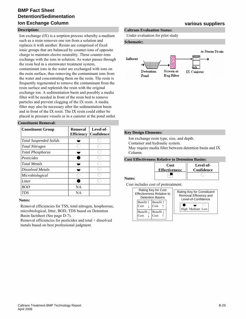
Description:Ion exchange (IX) is a sorption process whereby a medium such as a resin removes one ion from a solution and replaces it with another. Resins are comprised of fixed ionic groups that are balanced by counter-ions of opposite charge to maintain electro neutrality. These counter-ions exchange with the ions in solution. As water passes through the resin bed in a stormwater treatment system, contaminant ions in the water are exchanged with ions on the resin surface, thus removing the contaminant ions from the water and concentrating them on the resin. The resin is frequently regenerated to remove the contaminant from the resin surface and replenish the resin with the original exchange ion. A sedimentation basin and possibly a media filter will be needed in front of the resin bed to remove particles and prevent clogging of the IX resin. A media filter may also be necessary after the sedimentation basin and in front of the IX resin. The IX resin could either be placed in pressure vessels or in a canister at the pond outlet.
Removal Efficiency
Level-of-Confidence
Total Suspended SolidsTotal NitrogenTotal PhosphorusPesticidesTotal MetalsDissolved MetalsMicrobiologicalLitterBODTDS
Constituent GroupConstituent Removal:
NANA
Notes:Removal efficiencies for TSS, total nitrogen, hosphorous, microbiological, litter, BOD, TDS based on Detention Basin factsheet (See page D-7).Removal efficiencies for pesticides and total + dissolved metals based on best professional judgment.
Key Design Elements:Ion exchange resin type, size, and depth.Container and hydraulic system.May require media filter between detention basin and IX Column.
CostEffectiveness:
Level-of-Confidence
Cost Effectiveness Relative to Detention Basins:
Benifit ↑Cost ↓
Benefit ↓Cost ↓
Benefit ↑Cost ↑
Benefit ↓Cost ↑
High Medium Low
Rating Key for ConstituentRemoval Efficiency and
Level-of-Confidence
Rating Key for CostEffectiveness Relative to
Detention Basins
Notes:Cost includes cost of pretreatment.
Schematic:
Caltrans Evaluation Status:Under evaluation for pilot study
B-29Caltrans Treatment BMP Technology ReportApril 2008
BMP Fact Sheet
various suppliersIon Exchange ColumnDetention/Sedimentation
Requirements:Resin must be periodically inspected. Spent resin or regenerant brines must be removed and disposed of properly. Measures must be taken to make sure that the resins do not dry out during dry season. Mechanical equipment must be maintained. Because of the constraints, on-site regeneration is not considered feasible. The IX resin must be shipped off-site for regeneration or disposal by a licensed company. Other requirements as listed for Detention Basin. Standing water will occur when column is clogged.Training:Requires training for inspection and maintenance of ion exchange column and handling and disposal of waste products.
Maintenance Issues:
Project Development Issues:Right-of-Way-Requirements:Small footprint if the pretreatment (e.g. sedimentation BMP) is pre-existing. Total system has large space requirements.Siting Constraints:Requires a wet pond, wet basin, or a detention basin.Construction:No unique requirements identified
Constraints: Potential clogging of the resin if pretreatment does not remove enough suspended solids, oil and grease.Exhausted IX has potential to be considered a hazardous material and will need to be disposed of properly.IX resins could dry out if not kept wet.May require monitoring to determine when the IX unit should be replaced.Other constraints as listed for detention Basin (See page D-7).
Advantages:They provide a compact system at the detention basin outlet.Removal of dissolved pollutants.Other advantages as listed for Detention Basin (See page D-7).
James M. Montgomery Consulting Engineers, Inc. Water Treatment Principles and Design, 1985
Vaughan, B.T., and Jarrett, A.R. Experimental Evaluation of Novel Floating Risers for Sedimentation Basin Dewatering, Paper 012025, 2001 ASAE Annual Meeting , American Society of Agricultural and Biological Engineers, St. Joseph MI.
Literature Sources of Performance Demonstrations:Clifford, D. A., Department of Civil and Environmental Engineering, University of Houston, Texas, Water Quality and Treatment: A Handbook of Community Water Supplies 4th edition, 1990
Design, Construction, Maintenance and Cost SourcesMonat, J.P. Synergies Between Ultrafiltration and Ion Exchange. Ultra Pure Water. pp 33-38. July/Aug 1997.
Certifications, Verifications, or Designations:None identified.
B-30Caltrans Treatment BMP Technology ReportApril 2008

BMP Fact Sheet
Thirsty DuckOutlet ImprovementDetention/Sedimentation
Description:The Thirsty Duck is a skimmer outlet. It appears to work in conjuction with a standing-water BMP such as a wet basin. The Thirsty Duck provides a constant discharge until the device returns to its pre-storm level (presumably level of the permanent pool). It appears that the Thirsty Duck can not completely drain a basin.
Removal Efficiency
Level-of-Confidence
Total Suspended SolidsTotal NitrogenTotal PhosphorusPesticidesTotal MetalsDissolved MetalsMicrobiologicalLitterBODTDS
Constituent GroupConstituent Removal:
NA
NANA
Notes:Removal efficiencies based on Detention Basin (See page D-7)Level of Confidence are low due to lack of performance data for the BMP.
Key Design Elements:Flow rate Draw down time
CostEffectiveness:
NA
Level-of-Confidence
NA
Cost Effectiveness Relative to Detention Basins:
Benifit ↑Cost ↓
Benefit ↓Cost ↓
Benefit ↑Cost ↑
Benefit ↓Cost ↑
High Medium Low
Rating Key for ConstituentRemoval Efficiency and
Level-of-Confidence
Rating Key for CostEffectiveness Relative to
Detention Basins
Source: www.thirstyduckinc.com
Notes:Cost effectiveness determination pending further evaluation of the effect of the technology on basin size.
Schematic:
Caltrans Evaluation Status:Under evaluation for pilot study
B-31Caltrans Treatment BMP Technology ReportApril 2008
BMP Fact Sheet
Thirsty DuckOutlet ImprovementDetention/Sedimentation
Requirements:May be similar to a wet basin (Appendix D) if standing water causes vegetation growth.Training:No special requirements identified.
Maintenance Issues:
Project Development Issues:Right-of-Way-Requirements:None identified.Siting Constraints:Requires a wet pond, wet basin, or a detention basin.Construction:No special requirements identified.
Constraints: Constraints as listed for detention basins (See page D-7).Proprietary device.
Advantages:Decreases clogging.Potentially increases flow path (and performance) compared to detention basin.
Literature Sources of Performance Demonstrations:None identified
Design, Construction, Maintenance and Cost Sourceswww.thirstyduckinc.com
Certifications, Verifications, or Designations:None identified.
B-32Caltrans Treatment BMP Technology ReportApril 2008

BMP Fact Sheet
Watermann™Outlet ImprovementDetention/Sedimentation
Description:The Watermann™ is an outlet improvement structure for detention basins. It sits inside a 48” perforated section of pipe. It is secured in the wall of the outlet control structure and is grouted into place inside and outside of the outlet control structure in order to prevent leaking. Underneath the Watermann™ is a concrete or gravel base. The Watermann™ is completely exposed for inspection and maintenance. Surrounding the perforated section pipe is #4 stone which is used as added filtration for the water before entering the Watermann™. Inside the structure, attached to the Watermann™, is a removable end cap where the water quality orifice is drilled in the invert of the cap. As stormwater enters the pond it travels to the outlet control structure, through the #4 stone and the perforated section of pipe into the Watermann™ and out of the water quality orifice.
Removal Efficiency
Level-of-Confidence
Total Suspended SolidsTotal NitrogenTotal PhosphorusPesticidesTotal MetalsDissolved MetalsMicrobiologicalLitterBODTDS
Constituent GroupConstituent Removal:
NA
NANA
Notes:Removal efficiencies based on Detention Basin (See page D-7).Level of Confidence are low due to lack of performance data for the BMP.
Key Design Elements:Device used to treat the first 1.2” of rainfall in Extended Dry Detention Ponds.Completely exposed for easy inspection and maintenance.
CostEffectiveness:
NA
Level-of-Confidence
NA
Cost Effectiveness Relative to Detention Basins:
Benifit ↑Cost ↓
Benefit ↓Cost ↓
Benefit ↑Cost ↑
Benefit ↓Cost ↑
High Medium Low
Rating Key for ConstituentRemoval Efficiency and
Level-of-Confidence
Rating Key for CostEffectiveness Relative to
Detention Basins
Source: www.watermannwaterquality.com
Notes:Cost and performance expected to be roughly equivalent to current Caltrans detention basin design. Approximate unit cost is $350. Cost assessment is not applicable because cost effectiveness is relative to detention basins.
Schematic:
Caltrans Evaluation Status:Under evaluation for pilot study
B-33Caltrans Treatment BMP Technology ReportApril 2008

BMP Fact Sheet
Watermann™Outlet ImprovementDetention/Sedimentation
Requirements:None identified beyond normal detention basin.Training:No special requirements identified.
Maintenance Issues:
Project Development Issues:Right-of-Way-Requirements:None identified.Siting Constraints:Requires a detention basin.Construction:No special requirements identified
Constraints: Constraints as listed for stand alone Detention Basins (See page D-7).Design and utility patents.
Advantages:Potentially increases surface area for water intake compared to stand alone detention basin.Potentially increases flow direction compared to stand alone detention basin.Potentially increases cleanout availability compared to stand alone detention basin.Potentially increases ease of compared to stand alone detention basin inspection/maintenance.Other advantages as listed for stand alone detention basins (See page D-7).
Literature Sources of Performance Demonstrations:None identified
Design, Construction, Maintenance and Cost Sourceswww.watermannwaterquality.com/index.htm
Certifications, Verifications, or Designations:None identified.
B-34Caltrans Treatment BMP Technology ReportApril 2008

BMP Fact Sheet
Weir Guard™Outlet ImprovementDetention/Sedimentation
Description:The WEIR GUARD™ is an outlet control for water quality inlets or other weir-discharged BMPs such as wet basins. It can also be used on the overflow of detention basins. The WEIR GUARD™ has the potential to prevent litter from escaping BMPs. It attaches to the outlet structure and water flows through the screens. Angled screens underneath the unit are less likely to clos as water flows upward. For emergency releases, the top of the WEIR GUARD™ is not screened
Removal Efficiency
Level-of-Confidence
Total Suspended SolidsTotal NitrogenTotal PhosphorusPesticidesTotal MetalsDissolved MetalsMicrobiologicalLitterBODTDS
Constituent GroupConstituent Removal:
NANANANANANANA
NANA
Notes:Litter removal efficiency based on professional judgment considering that neutrally buoyant material can escape.Could enhance litter capture performance of other BMPs with standing water, such as wet basins and wet vaults.
Key Design Elements:Ion Exchange resin type, size and depth. Container and hydraulic system.May require media filter between detention basin and IX Column.
CostEffectiveness:
Level-of-Confidence
Cost Effectiveness Relative to Detention Basins:
Benifit ↑Cost ↓
Benefit ↓Cost ↓
Benefit ↑Cost ↑
Benefit ↓Cost ↑
High Medium Low
Rating Key for ConstituentRemoval Efficiency and
Level-of-Confidence
Rating Key for CostEffectiveness Relative to
Detention Basins
Source: www.jenhill.com
Notes:As a retrofit or added feature to existing basins, this low-cost device could have a high benefit if it would assure the basin could be classified as a "full-capture" litter BMP.
Schematic:
Caltrans Evaluation Status:Under evaluation for pilot study
B-35Caltrans Treatment BMP Technology ReportApril 2008

BMP Fact Sheet
Weir Guard™Outlet ImprovementDetention/Sedimentation
Requirements:Depends on existing structure.Training:Depends on existing sturcture.
Maintenance Issues:
Project Development Issues:Right-of-Way-Requirements:None identified.Siting Constraints:Requires a basin-type BMP.Installed to a flat-faced outlet structure. Adaption is required for cylindrical outlets.Construction:No unique requirements identified.
Constraints: Proprietary device.
Advantages:Easy to install. May allow basins to be considered complient with trash TMDL treatment stadards.
Literature Sources of Performance Demonstrations:None identified
Design, Construction, Maintenance and Cost SourcesNone identified
Certifications, Verifications, or Designations:None identified.
B-36Caltrans Treatment BMP Technology ReportApril 2008

BMP Fact Sheet
various suppliersPlate and Tube SettlersDetention/Sedimentation
Description:Improving sedimentation in the first chamber of an Austin filter or in a concrete detention basin can be achieved by installing plate or tube settlers in this chamber. Sedimentation of aqueous suspensions is accelerated by decreasing the distance particles must fall prior to removal. One approach is to provide parallel plates or inclined tubes that permit solids to reach the plate or tube after only short distances of settling.
Removal Efficiency
Level-of-Confidence
Total Suspended SolidsTotal NitrogenTotal PhosphorusPesticidesTotal MetalsDissolved MetalsMicrobiologicalLitterBODTDS
Constituent GroupConstituent Removal:
NA
NANA
Notes:Removal efficiencies and level-of-confidence of TSS based on performance data reported by Ellingson et. al., 2006.Removal efficiencies for total nitrogen and phosphorus, pesticides, total and dissolved metals, microbiological litter, BOD and TDS based on Detention Basin fact sheet (See page D-7).Level- of- confidences are low for all constituent groups except TSS due to lack of performance data.Removal efficiencies may be greater when used with a filtration chamber.
Key Design Elements:Effective overflow rate (for sizing the sedimentation chamber).Size and mounting of plates or tubes.Sludge collection and removal facilities.Plate or tube settlers must be installed in a sedimentation basin that may or may not precede a filter.
CostEffectiveness:
Level-of-Confidence
Cost Effectiveness Relative to Detention Basins:
Benifit ↑Cost ↓
Benefit ↓Cost ↓
Benefit ↑Cost ↑
Benefit ↓Cost ↑
High Medium Low
Rating Key for ConstituentRemoval Efficiency and
Level-of-Confidence
Rating Key for CostEffectiveness Relative to
Detention Basins
Notes:
Schematic:
Caltrans Evaluation Status:Under evaluation for pilot study
B-37Caltrans Treatment BMP Technology ReportApril 2008

BMP Fact Sheet
various suppliersPlate and Tube SettlersDetention/Sedimentation
Requirements:Cleaning and maintenance of the plate or tube settlers may require removing the plate settler structure. Litter may get trapped in the tube settler structure. None identified if designed to gravity drain.Training:Training needed for confined space entry.
Maintenance Issues:
Project Development Issues:Right-of-Way-Requirements:Similar to detention basins - less area may be required due to enhanced settling.Siting Constraints:Similar to detention basinsConstruction:No unique requirements identified.
Constraints: Maintenance is more difficult than an open basin.Water must be introduced so that it flows through the settlers.Other constraints as listed for Detention Basins (See page D-7)
Advantages:Enhances particle removal of detention/sedimentation BMPs.May reduce footprint of detention / sedimentation BMP.Other advantages as listed Detention Basins (See page D-7).
High-Rate Sedimentation, “WWF Plan Project Number 4.19.” EPA Urban Watershed Management Branch. http://www.epa.gov/ednnrmrl/projects/control/high.htm. April 2000.
James M. Montgomery Consulting Engineers, Inc, “Water Treatment Principles and Design”. 1985.
Keblin, M., et al. “Effectiveness of Permanent Highway Runoff Controls: Sedimentation/Filtration Systems”. October 1997.Meinholtz, T. L., et al. “Screening/Floatation Treatment of Combined Sewer Outflows, Volume II: Full-Scale Operation Racine,” Wisconsin. EPA-600/2-79-106a. Aug 1979.Pitt, R., et al. “Stormwater Treatment at Critical Areas, Vol. 1: The Multi-Chambered Treatment Train.” Cincinnati: US EPA. 1997.United States Department of Transportation, Federal Highway Administration, “Office of Environmental Planning: Evaluation and Management of Highway Runoff Water Quality,” Washington, DC. June 1996.
Literature Sources of Performance Demonstrations:Harper, H. H., et al. “Performance Evaluation of Dry Detention Stormwater Management Systems.” Sixth Biennial Stormwater Research Watershed Management Conference. September 1999.
Design, Construction, Maintenance and Cost SourcesTerre Kleen™ Stormwater Runoff Solutions, Terre Hill, PA. www.terrehill.com
Certifications, Verifications, or Designations:None identified.
B-38Caltrans Treatment BMP Technology ReportApril 2008

BMP Fact Sheet
various suppliersWet Pond with Aeration SystemsDetention/Sedimentation
Description:Aeration raises dissolved oxygen levels in water. This can be used in conjunction with wet basins to allow BOD removal while minimizing depression of dissolved oxygen levels. All available types of aeration are addressed in this fact sheet: Waterfalls, Fountains, Aerators, Circulators, Diffusers, Propellers.
Removal Efficiency
Level-of-Confidence
Total Suspended SolidsTotal NitrogenTotal PhosphorusPesticidesTotal MetalsDissolved MetalsMicrobiologicalLitterBODTDS
Constituent GroupConstituent Removal:
NANA
Notes:Removal efficiencies of TSS, total nitrogen and phosphorus, pesticide, total + dissolved metals, microbiological, and TDS based on Wet Basin factsheet (See page D-27).Removal efficiency of BOD based on best professional judgment.level-of-confidences are low due to lack of performance date for this combined system.
Key Design Elements:Power requirements.Dissolved oxygen requirements.Basin Size (retention time).
CostEffectiveness:
Level-of-Confidence
Cost Effectiveness Relative to Detention Basins:
Benifit ↑Cost ↓
Benefit ↓Cost ↓
Benefit ↑Cost ↑
Benefit ↓Cost ↑
High Medium Low
Rating Key for ConstituentRemoval Efficiency and
Level-of-Confidence
Rating Key for CostEffectiveness Relative to
Detention Basins
Source: Kasco Marine, Inc.
Notes:Cost effectiveness determination pending study completion.
Schematic:
Caltrans Evaluation Status:Under evaluation for pilot study
B-39Caltrans Treatment BMP Technology ReportApril 2008

BMP Fact Sheet
various suppliersWet Pond with Aeration SystemsDetention/Sedimentation
Requirements:Varies by type of aeration. Other requirements as listed by wet basinTraining:Training needed for timers, operation system, power supply operation, and mechanical system maintenance. Other training as listed by wet basin.
Maintenance Issues:
Project Development Issues:Right-of-Way-Requirements:As listed by wet basin.Siting Constraints:Requires power. Other constraints as listed for wet basins.Construction:No unique requirements identified, other than constraints as listed for wet basins.
Constraints: Limited pollutant removal; not stand alone system.Other constraints as listed for wet basin (See page D-27).
Advantages:Can be aesthetically pleasing and increase public acceptance of the stormwater treatment systems.Other advantages as listed for wet basins (See page D-27).
Aqua Control Inc., www.aquacontrol.comAqua Master®, www.aquamasterfountains.comKasco® Aeration, www.kascomarine.comSolarBee, www.solarbee.comStamford Scientific International, Inc., MicrogenTM, www.stamfordscientific.com
Literature Sources of Performance Demonstrations:None identified
Design, Construction, Maintenance and Cost SourcesAirmaster Aerator, Turbo, www.airmasteraerator.com
Certifications, Verifications, or Designations:None identified.
B-40Caltrans Treatment BMP Technology ReportApril 2008
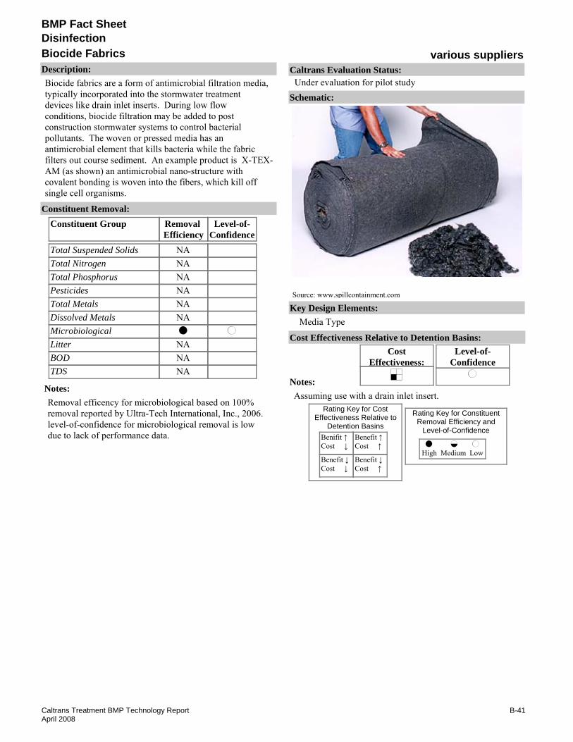
BMP Fact Sheet
various suppliersBiocide FabricsDisinfection
Description:Biocide fabrics are a form of antimicrobial filtration media, typically incorporated into the stormwater treatment devices like drain inlet inserts. During low flow conditions, biocide filtration may be added to post construction stormwater systems to control bacterial pollutants. The woven or pressed media has an antimicrobial element that kills bacteria while the fabric filters out course sediment. An example product is X-TEX-AM (as shown) an antimicrobial nano-structure with covalent bonding is woven into the fibers, which kill off single cell organisms.
Removal Efficiency
Level-of-Confidence
Total Suspended SolidsTotal NitrogenTotal PhosphorusPesticidesTotal MetalsDissolved MetalsMicrobiologicalLitterBODTDS
Constituent GroupConstituent Removal:
NANANANANANA
NANANA
Notes:Removal efficency for microbiological based on 100% removal reported by Ultra-Tech International, Inc., 2006.level-of-confidence for microbiological removal is low due to lack of performance data.
Key Design Elements:Media Type
CostEffectiveness:
Level-of-Confidence
Cost Effectiveness Relative to Detention Basins:
Benifit ↑Cost ↓
Benefit ↓Cost ↓
Benefit ↑Cost ↑
Benefit ↓Cost ↑
High Medium Low
Rating Key for ConstituentRemoval Efficiency and
Level-of-Confidence
Rating Key for CostEffectiveness Relative to
Detention Basins
Source: www.spillcontainment.com
Notes:Assuming use with a drain inlet insert.
Schematic:
Caltrans Evaluation Status:Under evaluation for pilot study
B-41Caltrans Treatment BMP Technology ReportApril 2008

BMP Fact Sheet
various suppliersBiocide FabricsDisinfection
Requirements:Unknown replacement frequency.Training:No special requirements identified.
Maintenance Issues:
Project Development Issues:Right-of-Way-Requirements:None identifiedSiting Constraints:Requires use with a BMP that has a filter, baffle, or outlet that can be retrofitted with the fabric.Construction:None identified
Constraints: Debris and sediment may exceed filter capacity depending on design.Requires long contact time (hours).Microbial reductions reported by Ultra-Tech International, Inc. require much longer contact time (hours) than that for currently used filter fabrics.
Advantages:Covalent bonding process that disinfects without chemicals.Suitable for retrofit to existing facilities.No chemical residual, which minimizes the impact on receiving waters.
Literature Sources of Performance Demonstrations:Ultra-Tech International, Inc., X-Tex-Am, www.attitudetechnology.com
Design, Construction, Maintenance and Cost SourcesUltra-Tech International, Inc., X-Tex-Am, www.attitudetechnology.com
Certifications, Verifications, or Designations:None identified.
B-42Caltrans Treatment BMP Technology ReportApril 2008

BMP Fact Sheet
various suppliersChlorination/HypochloriteDisinfection
Description:This technology consists of chemical disinfection of stormwater using hypochlorous acid solution. The product of concentration (C) and contact time (t) may be adjusted to achieve various levels of disinfection as defined by the U.S. EPA. This process has proven successful for many years at inactivating pathogens and other microbial contaminants in drinking water and wastewater. The hypochlorous solution is to be injected at the end of a pipe before the baffled contact chamber or existing sedimentation basin. A chemical storage tank and chemical feed system capable of adjusting feed based on pipe flow is required. Hypochlorous acid dosing sufficient to achieve the desired Ct value is necessary. A contact chamber will be designed to achieve desired Ct value at high flows. Chlorine residual will be monitored. Dechlorination may be needed prior to discharge to receiving waters.
Removal Efficiency
Level-of-Confidence
Total Suspended SolidsTotal NitrogenTotal PhosphorusPesticidesTotal MetalsDissolved MetalsMicrobiologicalLitterBODTDS
Constituent GroupConstituent Removal:
PretreatedNANANANANA
PretreatedNANA
Notes:Removal efficiency for microbiological based on the best professional judgment.level-of-confidence for microbiological removal is low due to lack of performance data.
Key Design Elements:Chlorine dose and contact time (Ct).Chemical feed and storage facilities.Mixing facilities.Pretreatment to remove particles is required to achieve reliable disinfection. This will normally require sedimentation and filtration facilities upstream. Contact time must be provided in a contact basin or sedimentation basin downstream. A Dechlorination system may also be required.
CostEffectiveness:
Level-of-Confidence
Cost Effectiveness Relative to Detention Basins:
Benifit ↑Cost ↓
Benefit ↓Cost ↓
Benefit ↑Cost ↑
Benefit ↓Cost ↑
High Medium Low
Rating Key for ConstituentRemoval Efficiency and
Level-of-Confidence
Rating Key for CostEffectiveness Relative to
Detention Basins
Notes:Cost effectiveness determination pending study completion.
Schematic:
Caltrans Evaluation Status:Under evaluation for pilot study
B-43Caltrans Treatment BMP Technology ReportApril 2008

BMP Fact Sheet
various suppliersChlorination/HypochloriteDisinfection
Requirements:Mechanical equipment must be maintained. Chemicals must be replenished. Chemical concentration must be monitored.Training:Trained staff is required for mechanical equipment maintenance. Requires flow measurement device designed for a large range of flow conditions. Requires monitoring of chemical dosing concentrations.
Maintenance Issues:
Project Development Issues:Right-of-Way-Requirements:Space requirements will depend on size of contact chamber needed to accommodate design flow. Pretreatment space requirement may be high.Siting Constraints:Restricted to sites with available power.Construction:May have start-up and testing requirements.
Constraints: Harmful to receiving water biota.Formation of disinfection by-products (DBPs).Pre-treatment (e.g., removal of suspended solids) required.Requires special handling procedures and chemical storage tank on site.Substantial excavation is needed and may require special permitting and discharge water quality monitoring.May result in unnatural looking conditions.Some organics may be converted to other (possibly more harmful) products.
Advantages:Specific use guidelines available and proven effectiveness on microbial contaminants.Mosquitoes not an issue with chlorinated water.
www.ionics.com
Literature Sources of Performance Demonstrations:None identified
Design, Construction, Maintenance and Cost Sourceswww.jajagroup.com
Certifications, Verifications, or Designations:None identified.
B-44Caltrans Treatment BMP Technology ReportApril 2008
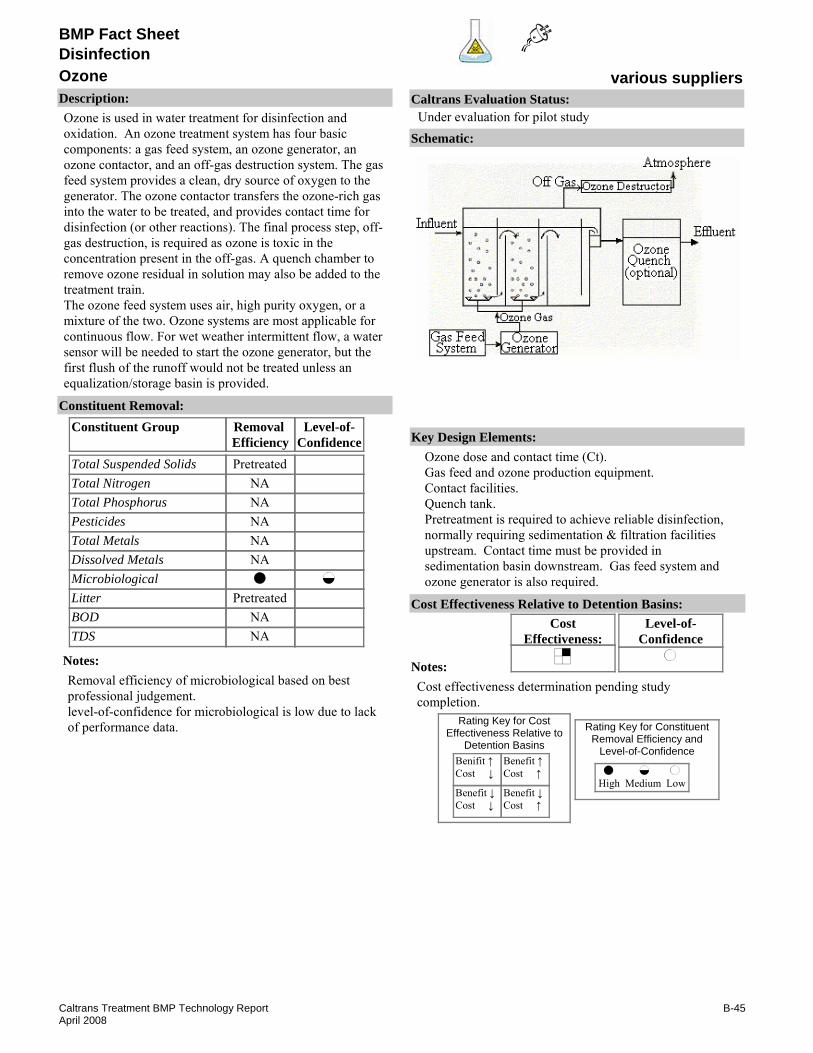
BMP Fact Sheet
various suppliersOzoneDisinfection
Description:Ozone is used in water treatment for disinfection and oxidation. An ozone treatment system has four basic components: a gas feed system, an ozone generator, an ozone contactor, and an off-gas destruction system. The gas feed system provides a clean, dry source of oxygen to the generator. The ozone contactor transfers the ozone-rich gas into the water to be treated, and provides contact time for disinfection (or other reactions). The final process step, off-gas destruction, is required as ozone is toxic in the concentration present in the off-gas. A quench chamber to remove ozone residual in solution may also be added to the treatment train.The ozone feed system uses air, high purity oxygen, or a mixture of the two. Ozone systems are most applicable for continuous flow. For wet weather intermittent flow, a water sensor will be needed to start the ozone generator, but the first flush of the runoff would not be treated unless an equalization/storage basin is provided.
Removal Efficiency
Level-of-Confidence
Total Suspended SolidsTotal NitrogenTotal PhosphorusPesticidesTotal MetalsDissolved MetalsMicrobiologicalLitterBODTDS
Constituent GroupConstituent Removal:
PretreatedNANANANANA
PretreatedNANA
Notes:Removal efficiency of microbiological based on best professional judgement.level-of-confidence for microbiological is low due to lack of performance data.
Key Design Elements:Ozone dose and contact time (Ct).Gas feed and ozone production equipment.Contact facilities.Quench tank.Pretreatment is required to achieve reliable disinfection, normally requiring sedimentation & filtration facilities upstream. Contact time must be provided in sedimentation basin downstream. Gas feed system and ozone generator is also required.
CostEffectiveness:
Level-of-Confidence
Cost Effectiveness Relative to Detention Basins:
Benifit ↑Cost ↓
Benefit ↓Cost ↓
Benefit ↑Cost ↑
Benefit ↓Cost ↑
High Medium Low
Rating Key for ConstituentRemoval Efficiency and
Level-of-Confidence
Rating Key for CostEffectiveness Relative to
Detention Basins
Notes:Cost effectiveness determination pending study completion.
Schematic:
Caltrans Evaluation Status:Under evaluation for pilot study
B-45Caltrans Treatment BMP Technology ReportApril 2008

BMP Fact Sheet
various suppliersOzoneDisinfection
Requirements:Generators should be checked daily when in operation. Manual start-up of the ozone generator is preferable since it needs to be purged before each start-up. Filters and desiccant in air preparation systems should be changed periodically.Training:Operation and maintenance of gas feed system, ozone generator and contact chamber.
Maintenance Issues:
Project Development Issues:Right-of-Way-Requirements:Space requirements will depend on size of contract chamber needed to accommodate design flow. Pretreatment space requirement may be high.Siting Constraints:Restricted to sites with available power.Construction:Avoid sediments in the contact chamber during construction. May have start-up and testing requirements.
Constraints: The ozone must be produced on site because it cannot be stored.Ozonation technology has a very high energy requirement.Some ozonation by-products may be harmful to the receiving water.In the presence of many compounds commonly encountered in water treatment, ozone decomposition forms hydroxyl free radicals.Ozone escaping to atmosphere may contribute to air pollution problems.The ozone diffusers can easily be damaged by debris and sediments. The pre-treatment step will have to remove most of the sediments as well as the oil and grease.
Advantages:Ozone is a strong disinfectant and has a limited number of by-products.Low doses are required to complete disinfection.The process does not provide residual ozone concentration in the treated effluent, which minimizes the impact on receiving waters.Even though ozone systems are complex, using highly technical instruments, the process is highly automated and very reliable.
Bioxide Corporation, Vanguard Stormwater Treatment System, www.bioxide.com/water.htm.PCI-Wedeco Environmental Technologies, Inc. One Fairfield Crescent, West Caldwell, NJ 07006.
Literature Sources of Performance Demonstrations:The City of Malibu, California, approved the use of Bioxide’s technology to treat their runoff before it reaches the lagoon near the beach for a “dry-flow” run.
Design, Construction, Maintenance and Cost SourcesEPA Guidance Manual, Alternative Disinfectants and Oxidants, April 1999.
Certifications, Verifications, or Designations:None identified.
B-46Caltrans Treatment BMP Technology ReportApril 2008

BMP Fact Sheet
various suppliersUltravioletDisinfection
Description:Ultraviolet (UV) light disinfects water by altering the genetic material (DNA) in the cells so bacteria, viruses and other microorganisms can no longer reproduce or infect. In UV disinfection systems, the light is produced by germicidal lamps (200 to 300 nanometers) enclosed in a pressure vessel or submerged in a water channel. As the water flows past the UV lamps, the microorganisms are exposed to a lethal dose of UV energy. The UV dose is the product of the light intensity and contact time. The UV disinfection treatment is an in-line device downstream of another treatment process. Potential applications could be downstream of a BMP such as a multiple chamber treatment train (MCTT); sedimentation basin or media filter.
Removal Efficiency
Level-of-Confidence
Total Suspended SolidsTotal NitrogenTotal PhosphorusPesticidesTotal MetalsDissolved MetalsMicrobiologicalLitterBODTDS
Constituent GroupConstituent Removal:
PretreatedNANANANANA
PretreatedNANA
Notes:Removal efficiency for microbiological is based on the best professional judgment.level-of-confidence for microbiological removal is low due to lack of performance data.
Key Design Elements:Light intensity and contact time.Hydraulic system for moving water past lamps.Facilities for cleaning lamps.Pretreatment to remove particles is required to achieve reliable disinfection. This will normally require sedimentation and filtration facilities upstream.
CostEffectiveness:
Level-of-Confidence
Cost Effectiveness Relative to Detention Basins:
Benifit ↑Cost ↓
Benefit ↓Cost ↓
Benefit ↑Cost ↑
Benefit ↓Cost ↑
High Medium Low
Rating Key for ConstituentRemoval Efficiency and
Level-of-Confidence
Rating Key for CostEffectiveness Relative to
Detention Basins
Notes:Cost effectiveness determination pending study completion.
Schematic:
Caltrans Evaluation Status:Under evaluation for pilot study
B-47Caltrans Treatment BMP Technology ReportApril 2008
BMP Fact Sheet
various suppliersUltravioletDisinfection
Requirements:Each lamp must be cleaned periodically – typically every two weeks for wastewater discharges, but probably less frequently for intermittent stormwater discharges. Pumps must be maintained.Training:Highly trained staff is required for mechanical equipment maintenance.
Maintenance Issues:
Project Development Issues:Right-of-Way-Requirements:May be compact, but pretreatment space requirement may be high.Siting Constraints:Restricted to sites with available nearby power.Requires a volume-capture BMP to provide flow control.Construction:Significant start-up and testing requirements.
Constraints: Pretreatment requirement may be substantial.Clumping microorganism and turbidity can impact disinfection by harboring pathogens in the aggregates.Specific design parameters vary for individual waters (UV transmittance).Under certain conditions, some organisms are capable of repairing damaged DNA and reverting back to an active state to reproduce again (photoreactivation). This can be minimized by shielding the process stream or limiting the exposure of disinfected water to sunlight immediately following disinfection.Organic and inorganic fouling usually occurs on UV lamp sleeves. Inorganic fouling, which is related to the high temperature of the lamp, is the most difficult to clean because inorganics such as iron and manganese bind to the quartz sleeve.
Advantages:Natural process that disinfects without chemicals and low maintenance requirements.UV disinfection can meet water quality standards that have stringent requirements for total and fecal coliform (from 2 to 200 MPN/100ml) without generating disinfection by-products (DBPs) or handling chemicals.Automated operations and controls.Compact system, small footprint compared to other disinfection technologies.Suitable for retrofit to existing facilities.No impact on other processes following UV treatment.No chemical residual, which minimizes the impact to receiving waters.
PCI-Wedeco Environmental Technologies, Inc. One Fairfield Crescent, West Caldwell, NJ 07006
Literature Sources of Performance Demonstrations:None identified
Design, Construction, Maintenance and Cost SourcesHanovia Ltd, www.hanovia.com
Certifications, Verifications, or Designations:None identified.
B-48Caltrans Treatment BMP Technology ReportApril 2008
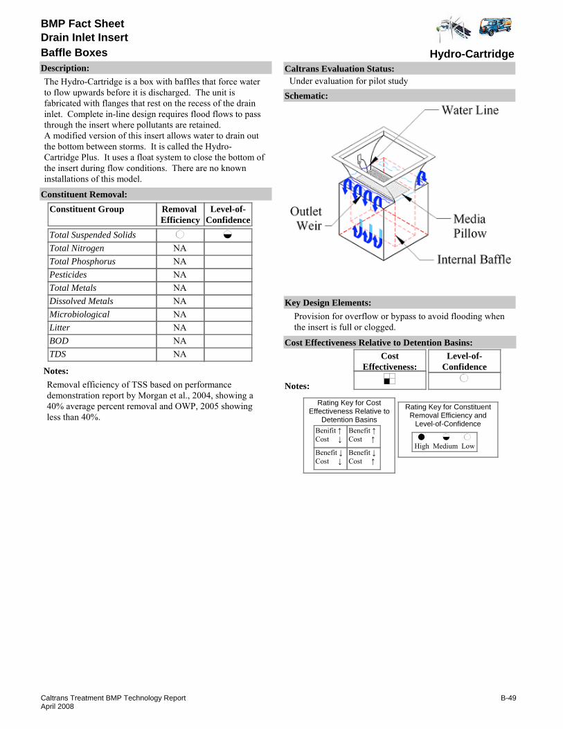
BMP Fact Sheet
Hydro-CartridgeBaffle BoxesDrain Inlet Insert
Description:The Hydro-Cartridge is a box with baffles that force water to flow upwards before it is discharged. The unit is fabricated with flanges that rest on the recess of the drain inlet. Complete in-line design requires flood flows to pass through the insert where pollutants are retained.A modified version of this insert allows water to drain out the bottom between storms. It is called the Hydro-Cartridge Plus. It uses a float system to close the bottom of the insert during flow conditions. There are no known installations of this model.
Removal Efficiency
Level-of-Confidence
Total Suspended SolidsTotal NitrogenTotal PhosphorusPesticidesTotal MetalsDissolved MetalsMicrobiologicalLitterBODTDS
Constituent GroupConstituent Removal:
NANANANANANANANANA
Notes:Removal efficiency of TSS based on performance demonstration report by Morgan et al., 2004, showing a 40% average percent removal and OWP, 2005 showing less than 40%.
Key Design Elements:Provision for overflow or bypass to avoid flooding when the insert is full or clogged.
CostEffectiveness:
Level-of-Confidence
Cost Effectiveness Relative to Detention Basins:
Benifit ↑Cost ↓
Benefit ↓Cost ↓
Benefit ↑Cost ↑
Benefit ↓Cost ↑
High Medium Low
Rating Key for ConstituentRemoval Efficiency and
Level-of-Confidence
Rating Key for CostEffectiveness Relative to
Detention Basins
Notes:
Schematic:
Caltrans Evaluation Status:Under evaluation for pilot study
B-49Caltrans Treatment BMP Technology ReportApril 2008

BMP Fact Sheet
Hydro-CartridgeBaffle BoxesDrain Inlet Insert
Requirements:If there is high solids loading (often caused by vegetation within the drainage area), frequent inspection and maintenance is required.Training:No special requirements identified.
Maintenance Issues:
Project Development Issues:Right-of-Way-Requirements:Installed within a stormwater inlet.Siting Constraints:Requires a grated drop inletConstruction:A watertight installation of the product is important to capture low flows.
Constraints: Holds standing water.High flows may flush accumulated material.Previous Caltrans study of DIIs discourages the use of DII along highway drain inlets due to safety considerations (CTSW-RT-01-050, p.16-9).Capacity (size of basket) is constrained by the size of the drain inlet to be retrofitted.
Advantages:The devices can be installed relatively easily in new and existing facilities without structural modification.
Office of Water Programs (OWP), Sacramento State. 2005. California Integrated Waste Management Board Used Oil Demonstration Grant by CSUS Office of Water Programs. “Laboratory Evaluation of Four Storm Drain Inlet Filters for Oil Removal,” April 2005.
Literature Sources of Performance Demonstrations:Edwards, Findlay, Kristofor Brye, Robert Morgan, and Steven Burian. 2004 “Evaluation of Stormwater Catchbasin Inserts for Transportation Facilities.” In Proceedings of Transportation Research Board 2004 Annual Meeting. January 11-15, 2004. Washington D.C. 2004.
Design, Construction, Maintenance and Cost SourcesAdvanced Aquatic Products Int’l, Inc., www.hydro-cartridge.com
Certifications, Verifications, or Designations:None identified.
B-50Caltrans Treatment BMP Technology ReportApril 2008

BMP Fact Sheet
Aqua Filtration UnitBaskets/BoxesDrain Inlet Insert
Description:The Aqua Filtration Unit is a box with a filtration unit at its center. To maximize use of available space, this unit rests on the bottom of the drain inlet and the height is cut to match the drain inlet. Stormwater fills the main cavity where litter and debris is trapped. Filtration of sediments is carried out as water flows through the center filter and before it is discharged at the bottom of the unit.
Removal Efficiency
Level-of-Confidence
Total Suspended SolidsTotal NitrogenTotal PhosphorusPesticidesTotal MetalsDissolved MetalsMicrobiologicalLitterBODTDS
Constituent GroupConstituent Removal:
NANANANANANA
NANA
Notes:Removal efficiency of TSS and litter based on best performance judgment.level-of-confidence is medium assuming device has at least 2 cubic ft. of pollutant storage capacity, which is roughly adequate to capture annual litter from 1/2 acre.
Key Design Elements:Hydraulic capacity and pollutant storage capacity.Provision for overflow or bypass to avoid flooding when the insert is full or clogged.Provision for overflow or bypass to avoid flooding when the insert is full or clogged
CostEffectiveness:
Level-of-Confidence
Cost Effectiveness Relative to Detention Basins:
Benifit ↑Cost ↓
Benefit ↓Cost ↓
Benefit ↑Cost ↑
Benefit ↓Cost ↑
High Medium Low
Rating Key for ConstituentRemoval Efficiency and
Level-of-Confidence
Rating Key for CostEffectiveness Relative to
Detention Basins
Source: www.gh2os.com
Notes:
Schematic:
Caltrans Evaluation Status:Under evaluation for pilot study
B-51Caltrans Treatment BMP Technology ReportApril 2008

BMP Fact Sheet
Aqua Filtration UnitBaskets/BoxesDrain Inlet Insert
Requirements:If there is high solids loading (often caused by vegetation within the drainage area), frequent inspection and maintenance is required.Training:No special requirements identified.
Maintenance Issues:
Project Development Issues:Right-of-Way-Requirements:Installed within a stormwater inlet.Siting Constraints:Requires a grated drop inlet.Construction:A watertight installation of the product is important to capture low flows.
Constraints: May hold standing water when filled with litter and debris.High flows may flush accumulated material.Regular maintenance necessary to clean and maintain flow pathway.Previous Caltrans study of DIIs discourages the use of DII along highway drain inlets due to safety considerations (CTSW-RT-01-050, p.16-9).Capacity is constrained by the size of the drain inlet to be retrofitted.Proprietary device.
Advantages:The devices can be installed relatively easily in new and existing facilities without structural modification.
Literature Sources of Performance Demonstrations:None Identified
Design, Construction, Maintenance and Cost SourcesGlobal H20 Solutions, www.gh2os.com
Certifications, Verifications, or Designations:None identified.
B-52Caltrans Treatment BMP Technology ReportApril 2008

BMP Fact Sheet
Baffled Filtration BoxBaskets/BoxesDrain Inlet Insert
Description:The Baffled Filtration Box, developed by Caltrans, is an open-bottom filtration Drain Inlet Insert (DII) device that seeks to optimize sedimentation, filtration and adsorption. A curved baffle directs flows into a filter bag made of a non-woven geo-textile fabric. Surface filtration occurs as water flows through the geotextile. Sedimentation occurs as water flow exceeds the capacity of the fabric and spills over the side. Water flowing through the fabric and overtopping the bag is further filtered by an arrangement of fabric and media at the bottom of the insert. Adsorption of different pollutants will vary according to the media used.
Removal Efficiency
Level-of-Confidence
Total Suspended SolidsTotal NitrogenTotal PhosphorusPesticidesTotal MetalsDissolved MetalsMicrobiologicalLitterBODTDS
Constituent GroupConstituent Removal:
NANANA
NA
NANA
Notes:Removal efficinecies based on laboratroy tests by CSUS Office of Water Programs( unpublished preliminary results).level-of-confidence is low because laboratory evaluation is not complete.
Key Design Elements:Hydraulic capacity and pollutant storage capacity.Provision for overflow or bypass to avoid flooding when the insert is full or clogged.
CostEffectiveness:
Level-of-Confidence
Cost Effectiveness Relative to Detention Basins:
Benifit ↑Cost ↓
Benefit ↓Cost ↓
Benefit ↑Cost ↑
Benefit ↓Cost ↑
High Medium Low
Rating Key for ConstituentRemoval Efficiency and
Level-of-Confidence
Rating Key for CostEffectiveness Relative to
Detention Basins
Notes:
Schematic:
Caltrans Evaluation Status:Under evaluation for pilot study
B-53Caltrans Treatment BMP Technology ReportApril 2008

BMP Fact Sheet
Baffled Filtration BoxBaskets/BoxesDrain Inlet Insert
Requirements:If there is high solids loading (often caused by vegetation within the drainage area), frequent inspection and maintenance is required.Training:No special requirements identified.
Maintenance Issues:
Project Development Issues:Right-of-Way-Requirements:Installed within a stormwater inlet.Siting Constraints:Requires a grated drop inlet.Construction:A watertight installation of the product is important to capture low flows.
Constraints: Capacity is constrained by the size of the drain inlet insert.Previous Caltrans study of DIIs discourages the use of DIIs along highway drain inlets due to saefty considerations (CTSW-RT-01-050, p. 16-9).
Advantages:The devices can be installed relatively easily in new and existing facilities without structural modification.Different media options can be used to address constituents.
Literature Sources of Performance Demonstrations:None identified.
Design, Construction, Maintenance and Cost SourcesOffice of Water Programs, Sacramento, CA. www.owp.csus.edu
Certifications, Verifications, or Designations:None identified.
B-54Caltrans Treatment BMP Technology ReportApril 2008
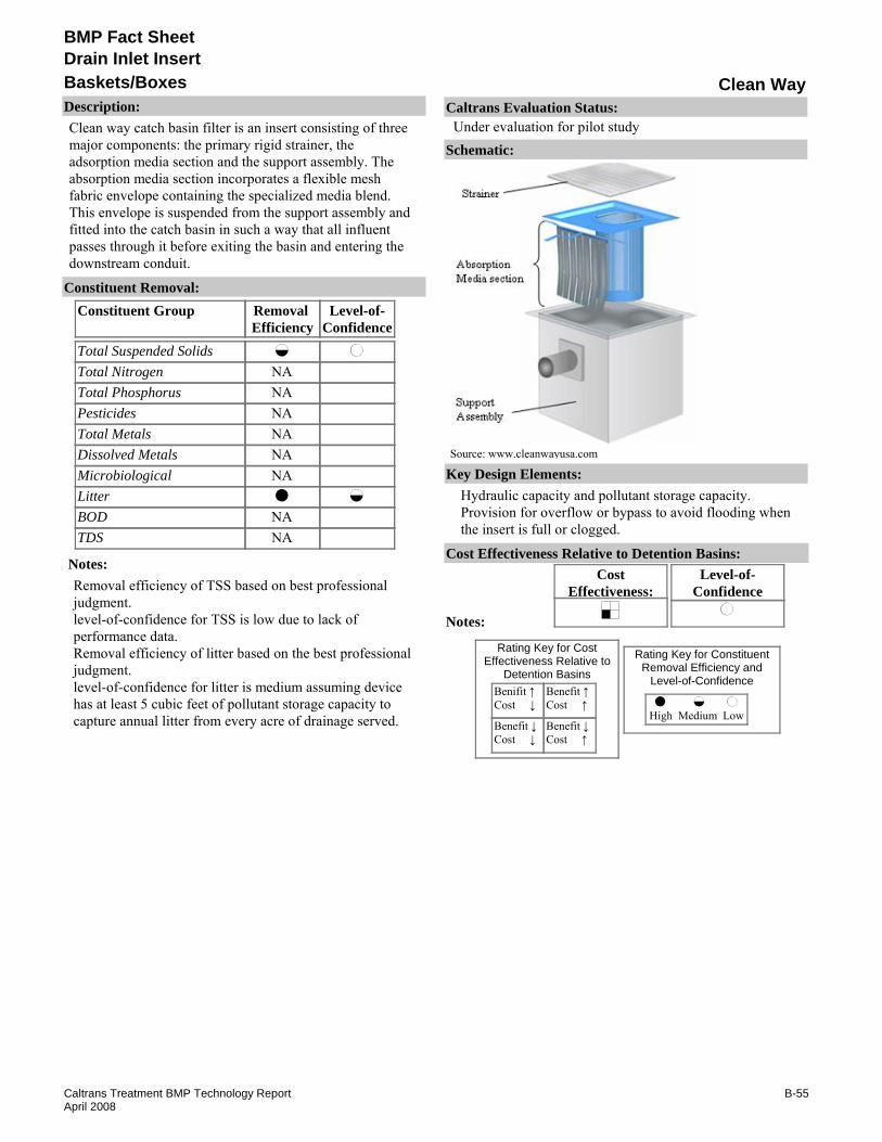
BMP Fact Sheet
Clean WayBaskets/BoxesDrain Inlet Insert
Description:Clean way catch basin filter is an insert consisting of three major components: the primary rigid strainer, the adsorption media section and the support assembly. The absorption media section incorporates a flexible mesh fabric envelope containing the specialized media blend. This envelope is suspended from the support assembly and fitted into the catch basin in such a way that all influent passes through it before exiting the basin and entering the downstream conduit.
Removal Efficiency
Level-of-Confidence
Total Suspended SolidsTotal NitrogenTotal PhosphorusPesticidesTotal MetalsDissolved MetalsMicrobiologicalLitterBODTDS
Constituent GroupConstituent Removal:
NANANANANANA
NANA
Notes:Removal efficiency of TSS based on best professional judgment.level-of-confidence for TSS is low due to lack of performance data.Removal efficiency of litter based on the best professional judgment.level-of-confidence for litter is medium assuming device has at least 5 cubic feet of pollutant storage capacity to capture annual litter from every acre of drainage served.
Key Design Elements:Hydraulic capacity and pollutant storage capacity.Provision for overflow or bypass to avoid flooding when the insert is full or clogged.
CostEffectiveness:
Level-of-Confidence
Cost Effectiveness Relative to Detention Basins:
Benifit ↑Cost ↓
Benefit ↓Cost ↓
Benefit ↑Cost ↑
Benefit ↓Cost ↑
High Medium Low
Rating Key for ConstituentRemoval Efficiency and
Level-of-Confidence
Rating Key for CostEffectiveness Relative to
Detention Basins
Source: www.cleanwayusa.com
Notes:
Schematic:
Caltrans Evaluation Status:Under evaluation for pilot study
B-55Caltrans Treatment BMP Technology ReportApril 2008
BMP Fact Sheet
Clean WayBaskets/BoxesDrain Inlet Insert
Requirements:If there is high solids loading (often caused by vegetation within the drainage area), frequent inspection and maintenance is required.Training:None identified.
Maintenance Issues:
Project Development Issues:Right-of-Way-Requirements:Installed within a stormwater inlet.Siting Constraints:Requires a grated drop inletConstruction:A watertight installation of the product is important to capture low flows
Constraints: Capacity (size of basket) is constrained by the size of the drain inlet to be retrofitted.Previous Caltrans study of DIIs discourages the use of DII along highway drain inlets due to safety considerations (CTSW-RT-01-050, p.16-9).Debris and liter may exceed drain inlet insert capacity.Maintenance activities may require traffic control if located along a shoulder or median.Proprietary device.
Advantages:There is a range of sizes and shapes that can be retrofitted to storm drain requirements.They are easy to install and clean; maintenance can be simple and quick.Adsorption booms can be attached.
Literature Sources of Performance Demonstrations:None identified.
Design, Construction, Maintenance and Cost SourcesClean Way Environmental partners www.cleanwayusa.com
Certifications, Verifications, or Designations:None identified.
B-56Caltrans Treatment BMP Technology ReportApril 2008

BMP Fact Sheet
Curb Inlet BasketBaskets/BoxesDrain Inlet Insert
Description:The Curb Inlet Basket is attached to the sidewall of a drain inlet. An oil boom may be added. Flood flow bypass occurs by overtopping the basket.
Removal Efficiency
Level-of-Confidence
Total Suspended SolidsTotal NitrogenTotal PhosphorusPesticidesTotal MetalsDissolved MetalsMicrobiologicalLitterBODTDS
Constituent GroupConstituent Removal:
NANANANANANANA
NANA
Notes:Removal efficiency of litter based on best performance judgment.level-of-confidence for litter is medium assuming device has at least 5 cubic feet of pollutant storage capacity to capture annual litter from every acre of drainage served.
Key Design Elements:Hydraulic capacity and pollutant storage capacity.Provision for overflow or bypass to avoid flooding when the insert is full or clogged.
CostEffectiveness:
Level-of-Confidence
Cost Effectiveness Relative to Detention Basins:
Benifit ↑Cost ↓
Benefit ↓Cost ↓
Benefit ↑Cost ↑
Benefit ↓Cost ↑
High Medium Low
Rating Key for ConstituentRemoval Efficiency and
Level-of-Confidence
Rating Key for CostEffectiveness Relative to
Detention Basins
Source: www.suntreetech.com
Notes:
Schematic:
Caltrans Evaluation Status:Under evaluation for pilot study
B-57Caltrans Treatment BMP Technology ReportApril 2008

BMP Fact Sheet
Curb Inlet BasketBaskets/BoxesDrain Inlet Insert
Requirements:If there is high solids loading (often caused by vegetation within the drainage area), frequent inspection and maintenance is required.Training:None identified.
Maintenance Issues:
Project Development Issues:Right-of-Way-Requirements:Installed within a stormwater inlet.Siting Constraints:Requires a curb inletConstruction:Attachment to sidewalls required, not a “drop in” device. A watertight installation of the product is important to capture low flows.
Constraints: Capacity (size of basket) is constrained by the size of the drain inlet to be retrofitted.Previous Caltrans study of DIIs discourages the use of DII along highway drain inlets due to safety considerations (CTSW-RT-01-050, p.16-9). Maintenance activities may require traffic control if located along a shoulder or median. Proprietary device.
Advantages:There is a range of sizes that can be retrofitted to storm drain requirements. They are easy to install and clean; maintenance can be simple and quick. Adsorption booms can be attached.
Bio Clean Environmental Services, Inc. www.biocleanenvironmental.net
Literature Sources of Performance Demonstrations:None identified
Design, Construction, Maintenance and Cost SourcesSuntree Technologies Inc., www.suntreetech.com/catalog1/page6.html
Certifications, Verifications, or Designations:None identified.
B-58Caltrans Treatment BMP Technology ReportApril 2008
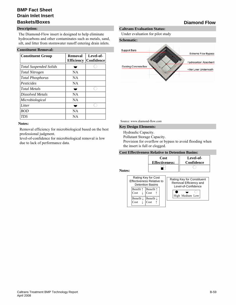
BMP Fact Sheet
Diamond FlowBaskets/BoxesDrain Inlet Insert
Description:The Diamond-Flow insert is designed to help eliminate hydrocarbons and other contaminates such as metals, sand, silt, and litter from stormwater runoff entering drain inlets.
Removal Efficiency
Level-of-Confidence
Total Suspended SolidsTotal NitrogenTotal PhosphorusPesticidesTotal MetalsDissolved MetalsMicrobiologicalLitterBODTDS
Constituent GroupConstituent Removal:
NANANA
NANA
NANA
Notes:Removal efficiency for microbiological based on the best professional judgment.level-of-confidence for microbiological removal is low due to lack of performance data.
Key Design Elements:Hydraulic Capacity.Pollutant Storage Capacity.Provision for overflow or bypass to avoid flooding when the insert is full or clogged.
CostEffectiveness:
Level-of-Confidence
Cost Effectiveness Relative to Detention Basins:
Benifit ↑Cost ↓
Benefit ↓Cost ↓
Benefit ↑Cost ↑
Benefit ↓Cost ↑
High Medium Low
Rating Key for ConstituentRemoval Efficiency and
Level-of-Confidence
Rating Key for CostEffectiveness Relative to
Detention Basins
Source: www.diamond-flow.com
Notes:
Schematic:
Caltrans Evaluation Status:Under evaluation for pilot study
B-59Caltrans Treatment BMP Technology ReportApril 2008

BMP Fact Sheet
Diamond FlowBaskets/BoxesDrain Inlet Insert
Requirements:If there is high solids loading (often caused by vegetation within the drainage area), frequent inspection and maintenance is required.Training:No special requirements identified.
Maintenance Issues:
Project Development Issues:Right-of-Way-Requirements:Installed within a stormwater inlet.Siting Constraints:Grated drop inlet requiredConstruction:A watertight installation of the product is important to capture low flows
Constraints: May not fit into some existing trenches without modification.Previous Caltrans study of DIIs discourages the use of DII along highway drain inlets due to safety considerations (CTSW-RT-01-050, p.16-9).Maintenance activities may require traffic control if located along a shoulder or median.Proprietary device.
Advantages:Maintenance is quick and easy.
Literature Sources of Performance Demonstrations:None identified
Design, Construction, Maintenance and Cost SourcesStorm Drain Filters, Inc., www.diamond-flow.com
Certifications, Verifications, or Designations:None identified.
B-60Caltrans Treatment BMP Technology ReportApril 2008

BMP Fact Sheet
EcoSenseBaskets/BoxesDrain Inlet Insert
Description:The EcoSense Filter is a drain inlet insert that uses canister filters. The filters hang form a support structure that is installed to the sides of the drain inlet. Operation of overflow tubes is unclear.
Removal Efficiency
Level-of-Confidence
Total Suspended SolidsTotal NitrogenTotal PhosphorusPesticidesTotal MetalsDissolved MetalsMicrobiologicalLitterBODTDS
Constituent GroupConstituent Removal:
NANANANANANANA
NANA
Notes:Removal claim for TSS and metals is unclear.Removal efficiency of litter based on the best professional judgment.
Key Design Elements:Hydraulic capacity and pollutant storage capacity.Provision for overflow or bypass to avoid flooding when the insert is full or clogged.
CostEffectiveness:
Level-of-Confidence
Cost Effectiveness Relative to Detention Basins:
Benifit ↑Cost ↓
Benefit ↓Cost ↓
Benefit ↑Cost ↑
Benefit ↓Cost ↑
High Medium Low
Rating Key for ConstituentRemoval Efficiency and
Level-of-Confidence
Rating Key for CostEffectiveness Relative to
Detention Basins
Source: www.ipexinc.com
Notes:
Schematic:
Caltrans Evaluation Status:Under evaluation for pilot study
B-61Caltrans Treatment BMP Technology ReportApril 2008
BMP Fact Sheet
EcoSenseBaskets/BoxesDrain Inlet Insert
Requirements:If there is high solids loading (often caused by vegetation within the drainage area), frequent inspection and maintenance is required.Training:No special requirements identified.
Maintenance Issues:
Project Development Issues:Right-of-Way-Requirements:Installed within a stormwater inlet.Siting Constraints:Requires a graded drop inlet.Construction:A watertight installation of the product is important to capture low flows. Requires some fabrication and installation to drain inlet sidewalls.
Constraints: Capacity (size of basket) is constrained by size of the drain inlet to be retrofitted.Previous Caltrans study of DIIs discourages the use of DII along highway drain inlets due to safety considerations (CTSW-RT-01-050, p.16-9).Debris and litter may exceed drain inlet insert capacity.Maintenance activities may require traffic control if located along a shoulder or median.Proprietary device.
Advantages:There is a range of sizes and shapes that can be retrofitted to storm drain requirements.They are easy to install and clean; maintenance can be simple and quick
Literature Sources of Performance Demonstrations:None identified
Design, Construction, Maintenance and Cost SourcesIPEX, EcoSense, www.ipexinc.com
Certifications, Verifications, or Designations:None identified.
B-62Caltrans Treatment BMP Technology ReportApril 2008

BMP Fact Sheet
EnviorpodBaskets/BoxesDrain Inlet Insert
Description:Enviropod™ is a stainless-steel frame basket attached to the side walls of a curb inlet or flat-grate catch basin. Lining within the basket allows for passive screening at different degrees of filtration depending on the media / screen(s) chosen. Flood flow is directed into the center of the basket by direction panels along the top of the basket. In the event of basket clogging or extreme high flows there are bypass slots just below the direction panels where water can overtop the basket.
Removal Efficiency
Level-of-Confidence
Total Suspended SolidsTotal NitrogenTotal PhosphorusPesticidesTotal MetalsDissolved MetalsMicrobiologicalLitterBODTDS
Constituent GroupConstituent Removal:
NANANANANANA
NANA
Notes:One installation at the Caltrans Kearny Mesa maintenance station is being monitored by the manufacturer.Removal efficiency for TSS reported by the manufacturer indicates an average of 78% removal of TSS (Enviropod™ Filter Wairau Rd Trail) and Butler . al. report 9 to 23 % removal for particles <100 micron; 77 to 94 % removal for particles 100 to 500 micron.level-of-confidence for TSS is medium based on performance demonstrations referenced.Removal efficiency for litter based on best professional judgment.level-of-confidence for litter is medium assuming device has at least 5 cubic feet of pollutant storage capacity to capture annual litter from every acre of drainage served.
Key Design Elements:Hydraulic capacity and pollutant storage capacity.Provision for overflow or bypass to avoid flooding when the insert is full or clogged.
CostEffectiveness:
Level-of-Confidence
Cost Effectiveness Relative to Detention Basins:
Benifit ↑Cost ↓
Benefit ↓Cost ↓
Benefit ↑Cost ↑
Benefit ↓Cost ↑
High Medium Low
Rating Key for ConstituentRemoval Efficiency and
Level-of-Confidence
Rating Key for CostEffectiveness Relative to
Detention Basins
Source: www.contech-cpi.com
Notes:
Schematic:
Caltrans Evaluation Status:Under evaluation for pilot study
B-63Caltrans Treatment BMP Technology ReportApril 2008

BMP Fact Sheet
EnviorpodBaskets/BoxesDrain Inlet Insert
Requirements:If there is high solids loading (often caused by vegetation within the drainage area), frequent inspection and maintenance is required.Training:No special requirements identified.
Maintenance Issues:
Project Development Issues:Right-of-Way-Requirements:Installed within a stormwater inlet.Siting Constraints:Requires a grated drop inletConstruction:A watertight installation of the product is important to capture low flows
Constraints: Capacity (size of basket) is constrained by the size of the drain inlet to be retrofitted.Previous Caltrans study of DIIs discourages the use of DII along highway drain inlets due to safety considerations (CTSW-RT-01-050, p.16-9).Maintenance activities may require traffic controls if installed along a shoulder or median.Level of efficiency varies with media selected.Proprietary device.
Advantages:There is a range of sizes that can be retrofitted to storm drain requirements.They are easy to install and clean; maintenance can be simple and quick.Adsorption booms can be attached.
Evaluation of ENVIROPOD stormwater treatment units, www.ingalenviro.com (Oct. 2006)
City of Beaverton, OR. "Case Study-Controlling the flow: Innovative Screening Device Solves Detention Maintenance Issues," Contech® Stormwater Solutions, www.contech-cpi.com (Sep. 2006).
U.S. Environmental Protection Agency, "Stormwater Management, Inc., StormScreen® Treatment System Verification Report," www.epa.gov/region1/assistance/ceitts/stormwater/techs/vortechs.html (Apr. 2005).
Literature Sources of Performance Demonstrations:EnviropodTM Filter Wairau Rd Trail, www.ingalenviro.com (Oct. 2006)
Design, Construction, Maintenance and Cost SourcesContech® Stormwater Solutions, Inc., www.contech-cpi.com/stormwater/products/screening/stormscreen/75
Certifications, Verifications, or Designations:None identified.
B-64Caltrans Treatment BMP Technology ReportApril 2008

BMP Fact Sheet
Escol RSF 100/GSPBaskets/BoxesDrain Inlet Insert
Description:The Ecosol™ Rapid Stormwater Filtration (RSF) uses a basket to separate debris from stormwater. The basket is attached to weir splash plates that attach to the side walls of the drain inlet. Flood flow bypass is accomplished by overtopping the basket.
Removal Efficiency
Level-of-Confidence
Total Suspended SolidsTotal NitrogenTotal PhosphorusPesticidesTotal MetalsDissolved MetalsMicrobiologicalLitterBODTDS
Constituent GroupConstituent Removal:
NANANANANANANA
NANA
Notes:Removal efficiency for litter based on best professional judgment.level-of-confidence for litter is medium assuming device has at least 5 cubic feet of pollutant storage capacity to capture annual litter from every acre of drainage served.
Key Design Elements:Hydraulic capacity and pollutant storage capacity.Provision for overflow or bypass to avoid flooding when the insert is full or clogged.
CostEffectiveness:
Level-of-Confidence
Cost Effectiveness Relative to Detention Basins:
Benifit ↑Cost ↓
Benefit ↓Cost ↓
Benefit ↑Cost ↑
Benefit ↓Cost ↑
High Medium Low
Rating Key for ConstituentRemoval Efficiency and
Level-of-Confidence
Rating Key for CostEffectiveness Relative to
Detention Basins
Source: Ecosol™ Wastewater Filtration Systems
Notes:
Schematic:
Caltrans Evaluation Status:Under evaluation for pilot study
B-65Caltrans Treatment BMP Technology ReportApril 2008

BMP Fact Sheet
Escol RSF 100/GSPBaskets/BoxesDrain Inlet Insert
Requirements:If there is high solids loading (often caused by vegetation within the drainage area), frequent inspection and maintenance is requiredTraining:No special requirements identified.
Maintenance Issues:
Project Development Issues:Right-of-Way-Requirements:Installed within a stormwater inlet.Siting Constraints:Requires a grated curb or drop inlet.Construction:Attachment to sidewalls required, not a “drop in” device. A watertight installation of the product is important to capture low flows.
Constraints: Capacity (size of basket) is constrained by the size of the drain inlet to be retrofitted.Previous Caltrans study of DIIs discourages the use of DII along highway drain inlets due to safety considerations (CTSW-RT-01-050, p.16-9).Maintenance activities may requi9are traffic control if located along a shoulder or median.Limited to trapping material 1.5mm and greater (www.ecosol.com.au).Proprietary device.
Advantages:There is a range of sizes that can be retrofitted to storm drain requirements. They are easy to install and clean. Maintenance can be simple and quick. Adsorption booms can be attached.
www.sydneycoastalcouncils.com.au/stormwater/SWFeb2002.htm
Literature Sources of Performance Demonstrations:www.uprct.nsw.gov.au/cleanstreams/results.htm
Design, Construction, Maintenance and Cost SourcesEcosolTM Wastewater Filtration Systems, www.ecosol.com.au
Certifications, Verifications, or Designations:None identified.
B-66Caltrans Treatment BMP Technology ReportApril 2008

BMP Fact Sheet
FloGard PlusBaskets/BoxesDrain Inlet Insert
Description:The FloGard Plus is a basket system that is attached to splash plates which rests on the recess of a drain inlet. The basket is lined with fabric mesh. Oil absorbing pillows can be placed in the basket. Flood flow bypass is accomplished by overtopping the basket and flowing under the splash plates.
Removal Efficiency
Level-of-Confidence
Total Suspended SolidsTotal NitrogenTotal PhosphorusPesticidesTotal MetalsDissolved MetalsMicrobiologicalLitterBODTDS
Constituent GroupConstituent Removal:
NANANANANANA
NANA
Notes:Removal efficiency for TSS based on laboratory tests using ground silica (OWP, 2005).Level of confidence for TSS is medium based on referenced performance demonstration.Removal efficiency for litter based on best professional judgment.level-of-confidence for litter is medium assuming device has at least 5 cubic feet of pollutant storage capacity to capture annual litter from every acre of drainage served.
Key Design Elements:Hydraulic capacity and pollutant storage capacity.Provision for overflow or bypass to avoid flooding when the insert is full or clogged.
CostEffectiveness:
Level-of-Confidence
Cost Effectiveness Relative to Detention Basins:
Benifit ↑Cost ↓
Benefit ↓Cost ↓
Benefit ↑Cost ↑
Benefit ↓Cost ↑
High Medium Low
Rating Key for ConstituentRemoval Efficiency and
Level-of-Confidence
Rating Key for CostEffectiveness Relative to
Detention Basins
Source: www.kristar.com
Notes:
Schematic:
Caltrans Evaluation Status:Under evaluation for pilot study
B-67Caltrans Treatment BMP Technology ReportApril 2008
BMP Fact Sheet
FloGard PlusBaskets/BoxesDrain Inlet Insert
Requirements:If there is high solids loading (often caused by vegetation within the drainage area), frequent inspection and maintenance is requiredTraining:No special requirements identified.
Maintenance Issues:
Project Development Issues:Right-of-Way-Requirements:Installed within a stormwater inlet.Siting Constraints:Requires a grated drop inletConstruction:A watertight installation of the product is important to capture low flows
Constraints: Capacity (size of basket) is constrained by the size of the drain inlet to be retrofitted.Previous Caltrans study of DIIs discourages the use of DII along highway drain inlets due to safety considerations (CTSW-RT-01-050, p.16-9).Maintenance activities may require traffic control if installed along a shoulder or median.Proprietary device.
Advantages:There is a range of sizes that can be retrofitted to storm drain requirements.They are easy to install and clean; maintenance can be simple and quick.Adsorption booms can be attached.
Literature Sources of Performance Demonstrations:Office of Water Programs (OWP), Sacramento State. 2005. "CIWMB Used Oil Demonstration Grant Laboratory Evaluation of Four Storm Drain Inlet Filters for Oil Removal." July 2005. http://www.owp.csus.edu/research/papers/papers/ciwmbusedoilB-2.pdf
Design, Construction, Maintenance and Cost SourcesKriStar Enterprises, http://kristar.com/level2/products/hicap.html
Certifications, Verifications, or Designations:None identified.
B-68Caltrans Treatment BMP Technology ReportApril 2008

BMP Fact Sheet
Grate Inlet Skimmer BoxBaskets/BoxesDrain Inlet Insert
Description:The Grate Inlet Skimmer Box has large cutouts that are covered with expanded metal screens that retain litter and debris. The box has weirs that hold absorbent booms. The weirs hang from the recess on the storm drain. Flood flow bypass occurs by overtopping the box.
Removal Efficiency
Level-of-Confidence
Total Suspended SolidsTotal NitrogenTotal PhosphorusPesticidesTotal MetalsDissolved MetalsMicrobiologicalLitterBODTDS
Constituent GroupConstituent Removal:
NANANANANANA
NANA
Notes:Sediment removal tests sponsored by manufacturer do not seem typical of stormwater because of dumping of sediment near inlet and subsequent washing into the inlet.Removal efficiencies are based on best professional judgment.level-of-confidence for all constituents except litter is low due to lack of adequate performance data.level-of-confidence for litter is medium assuming device has at least 5 cubic feet of pollutant storage capacity to capture annual litter from every acre of drainage served.
Key Design Elements:Hydraulic capacity and pollutant storage capacity.Provision for overflow or bypass to avoid flooding when the insert is full or clogged.
CostEffectiveness:
Level-of-Confidence
Cost Effectiveness Relative to Detention Basins:
Benifit ↑Cost ↓
Benefit ↓Cost ↓
Benefit ↑Cost ↑
Benefit ↓Cost ↑
High Medium Low
Rating Key for ConstituentRemoval Efficiency and
Level-of-Confidence
Rating Key for CostEffectiveness Relative to
Detention Basins
Source: www.suntreetech.com
Notes:
Schematic:
Caltrans Evaluation Status:Under evaluation for pilot study
B-69Caltrans Treatment BMP Technology ReportApril 2008
BMP Fact Sheet
Grate Inlet Skimmer BoxBaskets/BoxesDrain Inlet Insert
Requirements:If there is high solids loading (often caused by vegetation within the drainage area), frequent inspection and maintenance is requiredTraining:No special requirements identified.
Maintenance Issues:
Project Development Issues:Right-of-Way-Requirements:Installed within a stormwater inlet.Siting Constraints:Requires a grated drop inlet.Construction:A watertight installation of the product is important to capture low flows.
Constraints: Previous Caltrans study of DIIs discourages the use of DII along highway drain inlets due to safety considerations (CTSW-RT-01-050, p.16-9).Maintenance activities may require traffic control if the device is installed along a shoulder or median.Proprietary device.
Advantages:The devices can be installed relatively easily in new and existing facilities without structural modification.There are options to install fine sediment screens.
Bio Clean Environmental Services, Inc. www.biocleanenvironmental.net
Literature Sources of Performance Demonstrations:Creech Engineers, 2001. "Pollutant Removal Testing For Suntree Technologies Grate Inlet Skimmer Box." Prepared for Suntree Technologies, Inc. www.suntreetech.com
Design, Construction, Maintenance and Cost SourcesSuntree Technologies, Inc., www.suntreetech.com
Certifications, Verifications, or Designations:None identified.
B-70Caltrans Treatment BMP Technology ReportApril 2008

BMP Fact Sheet
GSR Basket (Mechanically Removed)Baskets/BoxesDrain Inlet Insert
Description:This device is a Caltrans-sponsored concept that is similar to other basket inserts that rest on the sidewalls of standard drain inlets. This insert has a unique design that allows for automated removal of the entire basket similar to mechanisms used by garbage trucks. Flood flow bypass occurs through ports on the sides of the basket.
Removal Efficiency
Level-of-Confidence
Total Suspended SolidsTotal NitrogenTotal PhosphorusPesticidesTotal MetalsDissolved MetalsMicrobiologicalLitterBODTDS
Constituent GroupConstituent Removal:
NANANANANANANA
NANA
Notes:Removal efficiency for litter based on best professional judgment.level-of-confidence for litter is medium assuming device has at least 5 cubic feet of pollutant storage capacity to capture annual litter from every acre of drainage served.
Key Design Elements:Hydraulic capacity and pollutant storage capacity.Provision for overflow or bypass to avoid flooding when the insert is full or clogged.
CostEffectiveness:
Level-of-Confidence
Cost Effectiveness Relative to Detention Basins:
Benifit ↑Cost ↓
Benefit ↓Cost ↓
Benefit ↑Cost ↑
Benefit ↓Cost ↑
High Medium Low
Rating Key for ConstituentRemoval Efficiency and
Level-of-Confidence
Rating Key for CostEffectiveness Relative to
Detention Basins
Notes:
Schematic:
Caltrans Evaluation Status:Under evaluation for pilot study
B-71Caltrans Treatment BMP Technology ReportApril 2008

BMP Fact Sheet
GSR Basket (Mechanically Removed)Baskets/BoxesDrain Inlet Insert
Requirements:If there is high solids loading (often caused by vegetation within the drainage area), frequent inspection and maintenance is required.Special modified garbage trucks. A cushion truck may also be required to protect maintenance activities, if roadside.Training:Operator training will be necessary for mechanized removel equipment.
Maintenance Issues:
Project Development Issues:Right-of-Way-Requirements:Installed within a stormwater inlet.Siting Constraints:Requires a curb inlet.Construction:Replaces the inlet gate
Constraints: Debris and litter may exceed drain inlet insert capacity.Capacity (size of basket) is constrained by the size of the drain inlet to be retrofitted.If located along a shoulder or median, maintenance activities may require traffic control.Previous Caltrans study of DIIs discourages the use of DII along highway drain inlets due to safety considerations (CTSW-RT-01-050, p.16-9).
Advantages:Maintenance can be simple and quick.No space requirement. May allow TMDL compliance where end-of-pipe GSRDs are not feasible.Non-proprietary device.
Literature Sources of Performance Demonstrations:None identified
Design, Construction, Maintenance and Cost SourcesNone identified
Certifications, Verifications, or Designations:None identified.
B-72Caltrans Treatment BMP Technology ReportApril 2008

BMP Fact Sheet
InceptorBaskets/BoxesDrain Inlet Insert
Description:Inceptors are stainless steel baskets that suspend from drain inlet grates. The frame contains a “PolyDak” filter pillow. Flood flow bypass is accomplished by overtopping the basket.
Removal Efficiency
Level-of-Confidence
Total Suspended SolidsTotal NitrogenTotal PhosphorusPesticidesTotal MetalsDissolved MetalsMicrobiologicalLitterBODTDS
Constituent GroupConstituent Removal:
NANANA
NANA
NANA
Notes:Removal efficiency for TSS based on EPA website (EPA, 2006), claiming greater than 90% removal for solids larger than 40 micron.Removal efficiency for litter is based on professional judgment and experience with other tray-type filters (see Fossil Filter, Appendix C) and level-of-confidence for litter is low because of uncertain storage capacity.level-of-confidence for TSS & total metals is low due to lack of adequate performance data.Removal efficiency for total metals based on calculated 99% copper removal, 91% lead removal, and 100% zinc removal of (EPA 2006) and adjusted following best professional judgment.
Key Design Elements:Hydraulic capacity and pollutant storage capacity.Provision for overflow or bypass to avoid flooding when the insert is full or clogged.
CostEffectiveness:
Level-of-Confidence
Cost Effectiveness Relative to Detention Basins:
Benifit ↑Cost ↓
Benefit ↓Cost ↓
Benefit ↑Cost ↑
Benefit ↓Cost ↑
High Medium Low
Rating Key for ConstituentRemoval Efficiency and
Level-of-Confidence
Rating Key for CostEffectiveness Relative to
Detention Basins
Source: www.stormdrains.com
Notes:
Schematic:
Caltrans Evaluation Status:Under evaluation for pilot study
B-73Caltrans Treatment BMP Technology ReportApril 2008

BMP Fact Sheet
InceptorBaskets/BoxesDrain Inlet Insert
Requirements:If there is high solids loading (often caused by vegetation within the drainage area), frequent inspection and maintenance is required. Manufacturer recommends annual replacement of filter pillow.Training:Basket is retrieved by pulling the drain inlet grate.
Maintenance Issues:
Project Development Issues:Right-of-Way-Requirements:Installed within a stormwater inlet.Siting Constraints:Requires a grated drop inlet.Construction:A watertight installation of the product is important to capture low flows.
Constraints: Debris and litter may exceed drain inlet insert capacity.Capacity (size of basket) is constrained by the size of the drain inlet to be retrofitted.Previous Caltrans study of DIIs discourages the use of DII along highway drain inlets due to safety considerations (CTSW-RT-01-050, p.16-9).It is unclear as to wether low flows will be captured by the suspended filter assembly.If located along a shoulder or median, maintenance activities may require traffic control.
Advantages:There is a range of sizes that can be retrofitted to storm drain requirements. They are easy to install and clean.Maintenance can be simple and quick.
Literature Sources of Performance Demonstrations:U.S. Environmental Protection Agency. "Storm Water Virtual Trade Show Stormdrain Solutions Catch Basin Insert ‘Inceptor’." January 2006, www.epa.gov/region1/assistance/ceitts/stormwater/techs/inceptor.html
Design, Construction, Maintenance and Cost SourcesStormdrain Solutions, Devon, PA. www.stormdrains.com
Certifications, Verifications, or Designations:None identified.
B-74Caltrans Treatment BMP Technology ReportApril 2008

BMP Fact Sheet
PiranhaBaskets/BoxesDrain Inlet Insert
Description:Piranha inserts are stainless steel baskets that suspend from drain inlet grates. The frame contains a filter pillow and refuse bag. Flood flow bypass is accomplished by overtopping the basket.
Removal Efficiency
Level-of-Confidence
Total Suspended SolidsTotal NitrogenTotal PhosphorusPesticidesTotal MetalsDissolved MetalsMicrobiologicalLitterBODTDS
Constituent GroupConstituent Removal:
NANANANANANANA
NANA
Notes:Oil removal data is available from the manufacturer.Removal efficiency for litter based on professional judgement.level-of-confidence for litter is medium assuming device has at least 5 cubic feet of pollutant storage capacity to capture annual litter from every acre of drainage served.
Key Design Elements:Hydraulic capacity and pollutant storage capacity.Provision for overflow or bypass to avoid flooding when the insert is full or clogged.
CostEffectiveness:
Level-of-Confidence
Cost Effectiveness Relative to Detention Basins:
Benifit ↑Cost ↓
Benefit ↓Cost ↓
Benefit ↑Cost ↑
Benefit ↓Cost ↑
High Medium Low
Rating Key for ConstituentRemoval Efficiency and
Level-of-Confidence
Rating Key for CostEffectiveness Relative to
Detention Basins
Source: www.go-tsm.com
Notes:
Schematic:
Caltrans Evaluation Status:Under evaluation for pilot study
B-75Caltrans Treatment BMP Technology ReportApril 2008
BMP Fact Sheet
PiranhaBaskets/BoxesDrain Inlet Insert
Requirements:If there is high solids loading (often caused by vegetation within the drainage area), frequent inspection and maintenance is required.Basket is retrieved by pulling the drain inlet grate.Training:No special requirements identified.
Maintenance Issues:
Project Development Issues:Right-of-Way-Requirements:Installed within a stormwater inlet.Siting Constraints:Requires a grated drop inletConstruction:A watertight installation of the product is important to capture low flows
Constraints: Debris and litter may exceed drain inlet insert capacity.Capacity (size of basket) is constrained by the size of the drain inlet to be retrofitted.Previous Caltrans study of DIIs discourages the use of DII along highway drain inlets due to safety considerations (CTSW-RT-01-050, p.16-9).It is unclear that low flows will be captured by the suspended filter assembly.If located along a shoulder or median, maintenance activities may require traffic control.Proprietary device.
Advantages:There is a range of sizes that can be retrofitted to storm drain requirements. They are easy to install and clean. Maintenance can be simple and quick.
Literature Sources of Performance Demonstrations:None identified
Design, Construction, Maintenance and Cost SourcesPollution Solution Inc., www.psiyes.com/links.htm
Certifications, Verifications, or Designations:None identified.
B-76Caltrans Treatment BMP Technology ReportApril 2008

BMP Fact Sheet
SeaLife Saver™Baskets/BoxesDrain Inlet Insert
Description:Sea Life Saver™ is a basket insert that hangs from a flange which rests on the drain inlet recess. The basket contains absorbent pads. Flood flow bypass is accomplished through slots in the side of the basket.
Removal Efficiency
Level-of-Confidence
Total Suspended SolidsTotal NitrogenTotal PhosphorusPesticidesTotal MetalsDissolved MetalsMicrobiologicalLitterBODTDS
Constituent GroupConstituent Removal:
NANANANANANANA
NANA
Notes:Removal efficiency for litter based on professional judgment.level-of-confidence is medium assuming the device has at least 2 cubic ft. of pollutant storage capacity, which is roughly adequate for capture of annual litter from ½ acre.
Key Design Elements:Hydraulic capacity and litter storage capacity.Provision for overflow or bypass to avoid flooding when the insert is full or clogged.
CostEffectiveness:
Level-of-Confidence
Cost Effectiveness Relative to Detention Basins:
Benifit ↑Cost ↓
Benefit ↓Cost ↓
Benefit ↑Cost ↑
Benefit ↓Cost ↑
High Medium Low
Rating Key for ConstituentRemoval Efficiency and
Level-of-Confidence
Rating Key for CostEffectiveness Relative to
Detention Basins
Source: www.lucasstorm.com
Notes:
Schematic:
Caltrans Evaluation Status:Under evaluation for pilot study
B-77Caltrans Treatment BMP Technology ReportApril 2008

BMP Fact Sheet
SeaLife Saver™Baskets/BoxesDrain Inlet Insert
Requirements:If there is high solids loading (often caused by vegetation within the drainage area), frequent inspection and maintenance is required.Training:None identified.
Maintenance Issues:
Project Development Issues:Right-of-Way-Requirements:Installed within a stormwater inlet.Siting Constraints:Requires a grated drop inlet.Construction:A watertight installation of the product is important to capture low flows.
Constraints: Debris and litter may exceed drain inlet insert capacity.Capacity (size of basket) is constrained by the size of the drain inlet to be retrofitted.Previous Caltrans study of DIIs discourages the use of DII along highway drain inlets due to safety considerations (CTSW-RT-01-050, p.16-9).If located along a shoulder or median, maintenance activities may require traffic control.Proprietary device.
Advantages:There is a range of sizes that can be retrofitted to storm drain requirements. They are easy to install and clean. Maintenance can be simple and quick. Adsorption booms can be attached.
Literature Sources of Performance Demonstrations:None identified
Design, Construction, Maintenance and Cost SourcesLucas Environmental Stormwater Services, Inc., www.lucasstorm.com
Certifications, Verifications, or Designations:None identified.
B-78Caltrans Treatment BMP Technology ReportApril 2008

BMP Fact Sheet
Trash Guard TG SeriesBaskets/BoxesDrain Inlet Insert
Description:The Trash Guard TG-Series is a drain inlet insert basket designed to capture large debris.
Removal Efficiency
Level-of-Confidence
Total Suspended SolidsTotal NitrogenTotal PhosphorusPesticidesTotal MetalsDissolved MetalsMicrobiologicalLitterBODTDS
Constituent GroupConstituent Removal:
NANANANANANANA
NANA
Notes:Removal efficiency of litter based on best professional judgment.level-of-confidence for litter is medium assuming device has at least 5 cubic feet of pollutant storage capacity to capture annual litter from every acre of drainage served.
Key Design Elements:Hydraulic capacity and pollutant storage capacity.Provision for overflow or bypass to avoid flooding when the insert is full or clogged.
CostEffectiveness:
Level-of-Confidence
Cost Effectiveness Relative to Detention Basins:
Benifit ↑Cost ↓
Benefit ↓Cost ↓
Benefit ↑Cost ↑
Benefit ↓Cost ↑
High Medium Low
Rating Key for ConstituentRemoval Efficiency and
Level-of-Confidence
Rating Key for CostEffectiveness Relative to
Detention Basins
Source: http://remfilters.com
Notes:
Schematic:
Caltrans Evaluation Status:Under evaluation for pilot study
B-79Caltrans Treatment BMP Technology ReportApril 2008

BMP Fact Sheet
Trash Guard TG SeriesBaskets/BoxesDrain Inlet Insert
Requirements:If there is high solids loading (often caused by vegetation within the drainage area), frequent inspection and maintenance is required.Training:No special requirements identified.
Maintenance Issues:
Project Development Issues:Right-of-Way-Requirements:Installed within a stormwater inlet.Siting Constraints:Requires a grated drop inletConstruction:A watertight installation of the product is important to capture low flows
Constraints: Debris and litter may exceed drain inlet insert capacity.Capacity (size of basket) is constrained by the size of the drain inlet to be retrofitted.Previous Caltrans study of DIIs discourages the use of DII along highway drain inlets due to safety considerations (CTSW-RT-01-050, p.16-9).If located along a shoulder or median, maintenance activities may require traffic control.Proprietary device.
Advantages:They are easy to install and clean. Maintenance can be simple and quick. Adsorption booms can be attached.
Literature Sources of Performance Demonstrations:None identified
Design, Construction, Maintenance and Cost SourcesRevel Environmental Manufacturing, Inc., http://www.remfilters.com
Certifications, Verifications, or Designations:None identified.
B-80Caltrans Treatment BMP Technology ReportApril 2008

BMP Fact Sheet
Wire Catch Basin InsertBaskets/BoxesDrain Inlet Insert
Description:Wire catch basin inserts are simple basket type inserts with a flood bypass slot cut just underneath the top support frame from witch the basket hangs. This frame has flanges that sit in the recess of a drain inlet. Oil absorbing filter socks can be place in the basket. Booms are available to tether to the outside.
Removal Efficiency
Level-of-Confidence
Total Suspended SolidsTotal NitrogenTotal PhosphorusPesticidesTotal MetalsDissolved MetalsMicrobiologicalLitterBODTDS
Constituent GroupConstituent Removal:
NANANANANANANA
NANA
Notes:Removal efficiency for litter based on best professional judgment.level-of-confidence for litter is medium assuming device has at least 5 cubic feet of pollutant storage capacity to capture annual litter from every acre of drainage served.
Key Design Elements:Hydraulic capacity and pollutant storage capacity.Provision for overflow or bypass to avoid flooding when the insert is full or clogged.
CostEffectiveness:
Level-of-Confidence
Cost Effectiveness Relative to Detention Basins:
Benifit ↑Cost ↓
Benefit ↓Cost ↓
Benefit ↑Cost ↑
Benefit ↓Cost ↑
High Medium Low
Rating Key for ConstituentRemoval Efficiency and
Level-of-Confidence
Rating Key for CostEffectiveness Relative to
Detention Basins
Source: www.gullywasher.com/litter.html
Notes:
Schematic:
Caltrans Evaluation Status:Under evaluation for pilot study
B-81Caltrans Treatment BMP Technology ReportApril 2008

BMP Fact Sheet
Wire Catch Basin InsertBaskets/BoxesDrain Inlet Insert
Requirements:If there is high solids loading (often caused by vegetation within the drainage area), frequent inspection and maintenance is required.Training:No special requirements identified.
Maintenance Issues:
Project Development Issues:Right-of-Way-Requirements:Installed within a stormwater inlet.Siting Constraints:Requires a grated drop inletConstruction:A watertight installation of the product is important to capture low flows
Constraints: Debris and litter may exceed drain inlet insert capacity.Capacity (size of basket) is constrained by the size of the drain inlet to be retrofitted.Previous Caltrans study of DIIs discourages the use of DII along highway drain inlets due to safety considerations (CTSW-RT-01-050, p.16-9).If located along a shoulder or median, maintenance activities may require traffic control.Proprietary device.
Advantages:There is a range of sizes that can be retrofitted to storm drain requirements.They are easy to install and clean; maintenance can be simple and quick.Adsorption booms can be attached.
Literature Sources of Performance Demonstrations:None identified
Design, Construction, Maintenance and Cost SourcesAdvanced Environmental Solutions, Inc., www.advenvironmental.com, formerly known as Gullywasher, www.gullywasher.com
Certifications, Verifications, or Designations:None identified.
B-82Caltrans Treatment BMP Technology ReportApril 2008

BMP Fact Sheet
Passive SkimmerEnhancementsDrain Inlet Insert
Description:Passive Skimmers float directly on the water surface within a drain inlet and absorb floating hydrocarbons. Hydrocarbons are transformed into manageable solid waste. Besides drain inlet inserts passive skimmers can float in stormwater catch basins, sumps, vaults, holding tanks, and oil/water separators.
Removal Efficiency
Level-of-Confidence
Total Suspended SolidsTotal NitrogenTotal PhosphorusPesticidesTotal MetalsDissolved MetalsMicrobiologicalLitterBODTDS
Constituent GroupConstituent Removal:
NANANANANANANANANANA
Notes:Performance sources only applies to the Passive Skimmer's removal ability of floatable hydrocarbons.
Key Design Elements:None identified
CostEffectiveness:
Level-of-Confidence
Cost Effectiveness Relative to Detention Basins:
Benifit ↑Cost ↓
Benefit ↓Cost ↓
Benefit ↑Cost ↑
Benefit ↓Cost ↑
High Medium Low
Rating Key for ConstituentRemoval Efficiency and
Level-of-Confidence
Rating Key for CostEffectiveness Relative to
Detention Basins
Source: www.epa.gov/region1/assistance/ceitts/stormwater/techs/streamgua
Notes:
Schematic:
Caltrans Evaluation Status:Under evaluation for pilot study
B-83Caltrans Treatment BMP Technology ReportApril 2008

BMP Fact Sheet
Passive SkimmerEnhancementsDrain Inlet Insert
Requirements:Must be regularly inspected. Maintenance consists of pulling the skimmer out and replacing it.Training:No special requirements identified.
Maintenance Issues:
Project Development Issues:Right-of-Way-Requirements:None identifiedSiting Constraints:None identifiedConstruction:Simple Instillation
Constraints: Skimmers only trap hydrocarbons, and do not contribute to sediment control.Previous Caltrans study of DIIs discourages the use of DII along highway drain inlets due to safety considerations (CTSW-RT-01-050, p.16-9).If a skimmer has adsorbed to its maximum capacity, hydrocarbons will not be captured until the device is replaced.If located along a shoulder or median, maintenance activities may require traffic control.
Advantages:Absorb hydrocarbons with minimal leaching, so skimmers can remain in place for long periods.Maintenance is quick and easy.Requires no structural modifications to existing drainage structures or oil/water separators.
Bowhead Manufacturing Company, LLC., www.bmccatalog.com, [see StreamGuardTM Passive Skimmer].
U.S. Environmental Protection Agency, www.epa.gov/region1/assistance/ceitts/stormwater/techs/abtechskimmer.html
Literature Sources of Performance Demonstrations:U.S. Environmental Protection Agency, www.epa.gov/region1/assistance/ceitts/stormwater/techs/streamguardskimmer.html
Design, Construction, Maintenance and Cost SourcesAbTech Industries, www.abtechindustries.com, [see OARS® Passive Skimmer].
Certifications, Verifications, or Designations:None identified.
B-84Caltrans Treatment BMP Technology ReportApril 2008

BMP Fact Sheet
CatchAllFabricDrain Inlet Insert
Description:The Catch-All uses a steel frame to sit on the recess of a storm drain inlet and holds a polypropylene filter fabric bag. The bag is reinforced by a polyester shell. The bags are attached to the steel support by a steel band. Flood flow surcharges are accomplished through opening the steel support frame. A hydrocarbon filtering pillow is available that fits inside the bag.
Removal Efficiency
Level-of-Confidence
Total Suspended SolidsTotal NitrogenTotal PhosphorusPesticidesTotal MetalsDissolved MetalsMicrobiologicalLitterBODTDS
Constituent GroupConstituent Removal:
NANANANANANANA
NANA
Notes:Caltrans tested a fabric drain inlet insert (see StreamGuard, Appendix C).Removal efficiency for litter based on professional judgment and level-of-confidence is medium for litter assuming the device has at least 2 cubic ft. of pollutant storage capacity, which is roughly adequate to capture annual litter fro ½ acre.
Key Design Elements:Hydraulic capacity and pollutant storage capacity.Provision for overflow or bypass to avoid flooding when the insert is full or clogged.
CostEffectiveness:
Level-of-Confidence
Cost Effectiveness Relative to Detention Basins:
Benifit ↑Cost ↓
Benefit ↓Cost ↓
Benefit ↑Cost ↑
Benefit ↓Cost ↑
High Medium Low
Rating Key for ConstituentRemoval Efficiency and
Level-of-Confidence
Rating Key for CostEffectiveness Relative to
Detention Basins
Source: www.marathonmaterials.com
Notes:
Schematic:
Caltrans Evaluation Status:Under evaluation for pilot study
B-85Caltrans Treatment BMP Technology ReportApril 2008

BMP Fact Sheet
CatchAllFabricDrain Inlet Insert
Requirements:If there is high solids loading (often caused by vegetation within the drainage area), frequent inspection and maintenance is required.Training:It may be a challenge for one person to lift up the storm grate and remove a full sock beneath it.
Maintenance Issues:
Project Development Issues:Right-of-Way-Requirements:Installed within a stormwater inlet.Siting Constraints:Requires a grated drop inlet.Construction:A watertight installation of the product is important to capture low flows.
Constraints: If the socks become too full they may be difficult to lift out of the drain to clean/replace.Previous Caltrans study of DIIs discourages the use of DII along highway drain inlets due to safety considerations (CTSW-RT-01-050, p.16-9).Excess debris may affect drain inlet capacity.If located along a shoulder or median, maintenance activities may require traffic control.Debris and litter may exceed drain inlet insert capacity.Capacity (size of basket) is constrained by the size of the drain inlet to be retrofitted.Proprietary device
Advantages:Easy to install and maintain.
Literature Sources of Performance Demonstrations:None identified.
Design, Construction, Maintenance and Cost SourcesMarathon Materials, www.marathonmaterials.com
Certifications, Verifications, or Designations:None identified.
B-86Caltrans Treatment BMP Technology ReportApril 2008
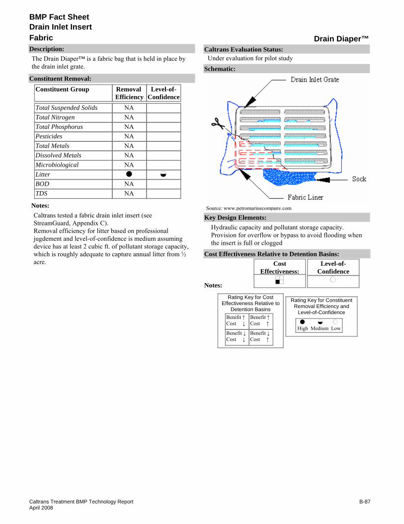
BMP Fact Sheet
Drain Diaper™FabricDrain Inlet Insert
Description:The Drain Diaper™ is a fabric bag that is held in place by the drain inlet grate.
Removal Efficiency
Level-of-Confidence
Total Suspended SolidsTotal NitrogenTotal PhosphorusPesticidesTotal MetalsDissolved MetalsMicrobiologicalLitterBODTDS
Constituent GroupConstituent Removal:
NANANANANANANA
NANA
Notes:Caltrans tested a fabric drain inlet insert (see StreamGuard, Appendix C).Removal efficiency for litter based on professional jugdement and level-of-confidence is medium assuming device has at least 2 cubic ft. of pollutant storage capacity, which is roughly adequate to capture annual litter from ½ acre.
Key Design Elements:Hydraulic capacity and pollutant storage capacity.Provision for overflow or bypass to avoid flooding when the insert is full or clogged
CostEffectiveness:
Level-of-Confidence
Cost Effectiveness Relative to Detention Basins:
Benifit ↑Cost ↓
Benefit ↓Cost ↓
Benefit ↑Cost ↑
Benefit ↓Cost ↑
High Medium Low
Rating Key for ConstituentRemoval Efficiency and
Level-of-Confidence
Rating Key for CostEffectiveness Relative to
Detention Basins
Source: www.petromarinecompany.com
Notes:
Schematic:
Caltrans Evaluation Status:Under evaluation for pilot study
B-87Caltrans Treatment BMP Technology ReportApril 2008

BMP Fact Sheet
Drain Diaper™FabricDrain Inlet Insert
Requirements:If there is high solids loading (often caused by vegetation within the drainage area), frequent inspection and maintenance is required.Training:It may be a challenge for one person to lift up the storm grate and remove a full sock beneath it.
Maintenance Issues:
Project Development Issues:Right-of-Way-Requirements:Installed within a stormwater inletSiting Constraints:Requires a grated drop inlet.Construction:Bag may slip under the weight of water and debris if not tightly held by inlet grate. Shims may be required.
Constraints: If the socks become too full they may be difficult to lift out of the drain to clean/replace.Previous Caltrans study of DIIs discourages the use of DII along highway drain inlets due to safety considerations (CTSW-RT-01-050, p.16-9).If located along a shoulder or median, maintenance activities may require traffic control.Debris and litter may exceed drain inlet insert capacity.Capacity (size of basket) is constrained by the size of the drain inlet to be retrofitted.Proprietary device.
Advantages:Easy to install and maintain.
Literature Sources of Performance Demonstrations:None identified
Design, Construction, Maintenance and Cost SourcesPetro-Marine, Inc., www.petromarinecompany.com/petro-marine/noname.html
Certifications, Verifications, or Designations:None identified.
B-88Caltrans Treatment BMP Technology ReportApril 2008

BMP Fact Sheet
Drain Guard™FabricDrain Inlet Insert
Description:The Drain Guard™ is a fabric bag that is held in place by the drain inlet grate.
Removal Efficiency
Level-of-Confidence
Total Suspended SolidsTotal NitrogenTotal PhosphorusPesticidesTotal MetalsDissolved MetalsMicrobiologicalLitterBODTDS
Constituent GroupConstituent Removal:
NANANANANANA
NANA
Notes:Removal efficiency and level-of-confidence for TSS are low based on conflicting performance data. EPA reports up to 80% removal while a Caltrans test of a similar unit showed less than 30%. (see StreamGuard, Appendix C).Removal efficiency for litter based on professional jugdement and level-of-confidence is medium assuming device has at least 2 cubic ft. of pollutant storage capacity, which is roughly adequate to capture annual litter from ½ arce.
Key Design Elements:Hydraulic capacity and pollutant storage capacity.Hydraulic capacity and pollutant storage capacity.Provision for overflow or bypass to avoid flooding when the insert is full or clogged.
CostEffectiveness:
Level-of-Confidence
Cost Effectiveness Relative to Detention Basins:
Benifit ↑Cost ↓
Benefit ↓Cost ↓
Benefit ↑Cost ↑
Benefit ↓Cost ↑
High Medium Low
Rating Key for ConstituentRemoval Efficiency and
Level-of-Confidence
Rating Key for CostEffectiveness Relative to
Detention Basins
Source: www.stormwater-products.com
Notes:
Schematic:
Caltrans Evaluation Status:Under evaluation for pilot study
B-89Caltrans Treatment BMP Technology ReportApril 2008

BMP Fact Sheet
Drain Guard™FabricDrain Inlet Insert
Requirements:If there is high solids loading (often caused by vegetation within the drainage area), frequent inspection and maintenance is required.Training:It may be a challenge for one person to lift up the storm grate and remove a full sock beneath it.
Maintenance Issues:
Project Development Issues:Right-of-Way-Requirements:Installed within a stormwater inlet.Siting Constraints:Requires a grated drop inletConstruction:Bag may slip under the weight of water and debris if not tightly held by inlet grate. Shims may be required.
Constraints: If the bags become too full they may be difficult to lift out of the drain to clean/replace.Previous Caltrans study of DIIs discourages the use of DII along highway drain inlets due to safety considerations (CTSW-RT-01-050, p.16-9).If located along a shoulder or median, maintenance activities may require traffic control.Debris and litter may exceed drain inlet insert capacity.Capacity (size of basket) is constrained by the size of the drain inlet to be retrofitted.
Advantages:Easy to install and maintain.Some designs have a pop-up capacity Indicator that alerts maintenance personnel that the sock needs to be replaced or emptied.
Literature Sources of Performance Demonstrations:U.S. Environmental Protection Agency, www.epa.gov/region1/assistance/ceitts/stormwater/techs/ultradrainguard.html
Design, Construction, Maintenance and Cost SourcesAdvanced Environmental Solutions, Inc., www.advenvironmental.com
Certifications, Verifications, or Designations:None identified.
B-90Caltrans Treatment BMP Technology ReportApril 2008

BMP Fact Sheet
DrainPac™FabricDrain Inlet Insert
Description:The Drain Pac™ is a polypropylene non-woven bag that is attached to a metal frame. This frame rests on the recess of a drain inlet. Buoyant flaps cover holes in the bag that provide flood flow surcharge.
Removal Efficiency
Level-of-Confidence
Total Suspended SolidsTotal NitrogenTotal PhosphorusPesticidesTotal MetalsDissolved MetalsMicrobiologicalLitterBODTDS
Constituent GroupConstituent Removal:
NANANANANANANA
NANA
Notes:Caltrans tested a fabric drain inlet insert (see StreamGuard, Appendix C).Removal efficiency for litter based on professional judgment and level-of-confidence for litter is medium assuming device has at least 5 cubic feet of pollutant storage capacity to capture annual litter from every acre of drainage served.
Key Design Elements:Hydraulic capacity and pollutant storage capacity.Hydraulic capacity and pollutant storage capacity.Provision for overflow or bypass to avoid flooding when the insert is full or clogged.
CostEffectiveness:
Level-of-Confidence
Cost Effectiveness Relative to Detention Basins:
Benifit ↑Cost ↓
Benefit ↓Cost ↓
Benefit ↑Cost ↑
Benefit ↓Cost ↑
High Medium Low
Rating Key for ConstituentRemoval Efficiency and
Level-of-Confidence
Rating Key for CostEffectiveness Relative to
Detention Basins
Source: www.unitedstormwater.com
Notes:
Schematic:
Caltrans Evaluation Status:Under evaluation for pilot study
B-91Caltrans Treatment BMP Technology ReportApril 2008

BMP Fact Sheet
DrainPac™FabricDrain Inlet Insert
Requirements:If there is high solids loading (often caused by vegetation within the drainage area), frequent inspection and maintenance is required.Training:It may be a challenge for one person to lift up the storm grate and remove a full sock beneath it.
Maintenance Issues:
Project Development Issues:Right-of-Way-Requirements:Installed within a stormwater inlet.Siting Constraints:Requires a grated drop inletConstruction:A watertight installation of the product is important to capture low flows
Constraints: If the socks become too full they may be difficult to lift out of the drain to clean/replace.Previous Caltrans study of DIIs discourages the use of DII along highway drain inlets due to safety considerations (CTSW-RT-01-050, p.16-9).If located along a shoulder or median, maintenance activities may require traffic control.Debris and litter may exceed drain inlet insert capacity.Capacity (size of basket) is constrained by the size of the drain inlet to be retrofitted.
Advantages:Easy to install and maintain.
NELP, "Completes Stormwater Catch Basin Insert Evaluation Study," December 2003, www.mayportnelp.com/succedd/press_releases?StormWater.html (21 August 2003).
Stenstorm, M. K., Drain Pac Filter Results "personal communication", September 25, 1998).
Bourelle, A., "Tahoe Keys Installs DrainPacs", Tahoe Tribune, November 5, 1999Happel, T., Reedy Creek Report 3, December 23, 1999 (many field test have been performed but noe officially published.)
Literature Sources of Performance Demonstrations:Morgan, R., Edwards, F., Brye, K., and Burian, S., "Evaluation of Stormwater Catchbasin Inserts for Transportation Facilities" TRB 2004 Annual Meeting. 2004
Design, Construction, Maintenance and Cost SourcesPacTec, Inc., www.unitedstormwater.com
Certifications, Verifications, or Designations:None identified.
B-92Caltrans Treatment BMP Technology ReportApril 2008

BMP Fact Sheet
Sewer Eco-CollarFabricDrain Inlet Insert
Description:The Sewer Eco-Collar has bags that are suspended from troughs. The troughs are attached to the side walls of the drain inlet and they direct flow to the bags. As a spill response, hooks on the trough allow for temporary use of buckets to capture accidental spills.
Removal Efficiency
Level-of-Confidence
Total Suspended SolidsTotal NitrogenTotal PhosphorusPesticidesTotal MetalsDissolved MetalsMicrobiologicalLitterBODTDS
Constituent GroupConstituent Removal:
NANANANANANANANANANA
Notes:Caltrans tested a fabric drain inlet insert (see StreamGuard, Appendix C).Litter capture volume could not be estimated or assumed from the available information.
Key Design Elements:Hydraulic capacity and pollutant storage capacity.Provision for overflow or bypass to avoid flooding when the insert is full or clogged.
CostEffectiveness:
Level-of-Confidence
Cost Effectiveness Relative to Detention Basins:
Benifit ↑Cost ↓
Benefit ↓Cost ↓
Benefit ↑Cost ↑
Benefit ↓Cost ↑
High Medium Low
Rating Key for ConstituentRemoval Efficiency and
Level-of-Confidence
Rating Key for CostEffectiveness Relative to
Detention Basins
Source: www.swp3.com
Notes:
Schematic:
Caltrans Evaluation Status:Under evaluation for pilot study
B-93Caltrans Treatment BMP Technology ReportApril 2008
BMP Fact Sheet
Sewer Eco-CollarFabricDrain Inlet Insert
Requirements:If there is high solids loading (often caused by vegetation within the drainage area), frequent inspection and maintenance is required.Training:No special requirements identified.
Maintenance Issues:
Project Development Issues:Right-of-Way-Requirements:Installed within a stormwater inlet.Siting Constraints:Requires a grated drop inlet.Construction:A watertight installation of the product is important to capture low flows.
Constraints: Excess debris may affect drain inlet capacity.If located along a shoulder or median, maintenance activities may require traffic control.Previous Caltrans study of DIIs discourages the use of DII along highway drain inlets due to safety considerations (CTSW-RT-01-050, p.16-9).Debris and litter may exceed drain inlet insert capacity.Capacity (size of basket) is constrained by the size of the drain inlet to be retrofitted.Proprietary device.
Advantages:Easy to install and maintain.
Literature Sources of Performance Demonstrations:None identified
Design, Construction, Maintenance and Cost SourcesSewer Eco-Collar, www.swp3.com
Certifications, Verifications, or Designations:None identified.
B-94Caltrans Treatment BMP Technology ReportApril 2008

BMP Fact Sheet
StreamSaver™ Catch Basin InsertFabricDrain Inlet Insert
Description:StreamSaver™ is held in place by the drain inlet grate. The insert is made of cellulose fiber. Flood flow bypass is accomplished via slats in the side of the insert near the grate. StreamSaverTM is also available in a double bag configuration. This side-by-side model is the “Double G Series.”
Removal Efficiency
Level-of-Confidence
Total Suspended SolidsTotal NitrogenTotal PhosphorusPesticidesTotal MetalsDissolved MetalsMicrobiologicalLitterBODTDS
Constituent GroupConstituent Removal:
NANANANANANANA
NANA
Notes:Removal efficiency and level-of-confidence for TSS based on conflicting evidence. Manufacturer reports 70% reduction of sediment, though tests of other fabric inserts indicate low sediment removal (see StreamGuard, Appendix C).Removal efficiency for litter based on professional judgment.Level-of –Confidence is medium assuming device has at least 2 cubic ft. of pollutant storage capacity, which is roughly adequate to capture annual litter from ½ acre.
Key Design Elements:Hydraulic capacity and pollutant storage capacity.Hydraulic capacity and pollutant storage capacity.Provision for overflow or bypass to avoid flooding when the insert is full or clogged.The size of the debris must be estimated accurately so that the wire mesh can be sized accordingly.
CostEffectiveness:
Level-of-Confidence
Cost Effectiveness Relative to Detention Basins:
Benifit ↑Cost ↓
Benefit ↓Cost ↓
Benefit ↑Cost ↑
Benefit ↓Cost ↑
High Medium Low
Rating Key for ConstituentRemoval Efficiency and
Level-of-Confidence
Rating Key for CostEffectiveness Relative to
Detention Basins
Source: ww.emeraldseedandsupply.com
Notes:
Schematic:
Caltrans Evaluation Status:Under evaluation for pilot study
B-95Caltrans Treatment BMP Technology ReportApril 2008

BMP Fact Sheet
StreamSaver™ Catch Basin InsertFabricDrain Inlet Insert
Requirements:If there is high solids loading (often caused by vegetation within the drainage area), frequent inspection and maintenance is requiredTraining:No special requirements identified.
Maintenance Issues:
Project Development Issues:Right-of-Way-Requirements:Installed within a stormwater inlet.Siting Constraints:Requires a grated drop inletConstruction:Simple installation. A watertight installation of the product is important to capture low flows.
Constraints: Previous Caltrans study of DIIs discourages the use of DII along highway drain inlets due to safety considerations (CTSW-RT-01-050, p.16-9).If located along a shoulder or median, maintenance activities may require traffic control.Capacity (size of basket) is constrained by the size of the drain inlet to be retrofitted.Debris and litter may exceed drain inlet insert capacity.Proprietary device.
Advantages:There is a range of sizes that can be retrofitted to storm drain requirements. They are easy to install and clean.Maintenance can be simple and quick.
Literature Sources of Performance Demonstrations:None identified
Design, Construction, Maintenance and Cost SourcesZymark, Inc., www.streamsaver.net
Certifications, Verifications, or Designations:None identified.
B-96Caltrans Treatment BMP Technology ReportApril 2008

BMP Fact Sheet
Ultra Trench Filter®FabricDrain Inlet Insert
Description:The Ultra-Trench Filter® is designed to reduce oil and sediment as stormwater flows through trench drains and pipes. Stormwater is forced to pass through a series of Tex filter strips that trap sand, silt, and sediment while hydrocarbons are absorbed by the X-Tex material. A nylon cord is sewn along the entire length of the fabric which is used to secure the Ultra-Trench Filter® to the trench drain or pipe.
Removal Efficiency
Level-of-Confidence
Total Suspended SolidsTotal NitrogenTotal PhosphorusPesticidesTotal MetalsDissolved MetalsMicrobiologicalLitterBODTDS
Constituent GroupConstituent Removal:
NANANANANANANANANANA
Notes:No performance information found related to these constituents
Key Design Elements:Hydraulic capacity and pollutant storage capacity.Provision for overflow or bypass to avoid flooding when the insert is full or clogged.
CostEffectiveness:
Level-of-Confidence
Cost Effectiveness Relative to Detention Basins:
Benifit ↑Cost ↓
Benefit ↓Cost ↓
Benefit ↑Cost ↑
Benefit ↓Cost ↑
High Medium Low
Rating Key for ConstituentRemoval Efficiency and
Level-of-Confidence
Rating Key for CostEffectiveness Relative to
Detention Basins
Source: www.spillcontainment.com
Notes:
Schematic:
Caltrans Evaluation Status:Under evaluation for pilot study
B-97Caltrans Treatment BMP Technology ReportApril 2008

BMP Fact Sheet
Ultra Trench Filter®FabricDrain Inlet Insert
Requirements:If there is high solids loading (often caused by vegetation within the drainage area), frequent inspection and maintenance is required.Training:Crews must be trained to repair or replace part(s) associated with the facility or contact for maintenance.
Maintenance Issues:
Project Development Issues:Right-of-Way-Requirements:Installed within a stormwater drain/pipeSiting Constraints:None identifiedConstruction:Reconstruction of drain area
Constraints: If the filters become too full they may be difficult to lift out of the drain to clean/replace.If located along a shoulder or median, maintenance activities may require traffic control.Previous Caltrans study of DIIs discourages the use of DII along highway drain inlets due to safety considerations (CTSW-RT-01-050, p.16-9).Debris and litter may exceed drain inlet insert capacity.Capacity (size of basket) is constrained by the size of the drain inlet to be retrofitted.Proprietary device.
Advantages:None identified.
Western Safety Products, www.westernsafety.comUltraTech International, Inc., www.spillcontainment.comBen Meadows Company, www.benmeadows.com
Literature Sources of Performance Demonstrations:None identified
Design, Construction, Maintenance and Cost SourcesBasco Right Container Products, www.bascousa.com
Certifications, Verifications, or Designations:None identified.
B-98Caltrans Treatment BMP Technology ReportApril 2008

BMP Fact Sheet
Manhole FilterManhole CoverDrain Inlet Insert
Description:The Manhole Filter by Revel Environmental Manufacturing, Inc. is designed to filter contaminants entering stormwater drainage through manholes using a removable sand/silt media filter, hydrocarbon media filter, and a filter trough. An overflow bypass system is also included for large flows. The filter is installed on a manhole in place of the catch basin grate. It protrudes above the top of the manhole.
Removal Efficiency
Level-of-Confidence
Total Suspended SolidsTotal NitrogenTotal PhosphorusPesticidesTotal MetalsDissolved MetalsMicrobiologicalLitterBODTDS
Constituent GroupConstituent Removal:
NANANANANANANA
NANA
Notes:Removal efficiency of litter based on best professional judgment.level-of-confidence is medium assuming device has at least 2 cubic ft. of pollutant storage capacity, which is roughly adequate to capture annual litter from 1/2 acre.
Key Design Elements:Provision for overflow or bypass to avoid flooding when the insert is full or clogged.Hydraulic capacity and pollutant storage capacity.Sand/Silt Media combined with Hydrocarbon Media.Flow capacity (flood and water quality flow).Overflow Bypass System.
CostEffectiveness:
Level-of-Confidence
Cost Effectiveness Relative to Detention Basins:
Benifit ↑Cost ↓
Benefit ↓Cost ↓
Benefit ↑Cost ↑
Benefit ↓Cost ↑
High Medium Low
Rating Key for ConstituentRemoval Efficiency and
Level-of-Confidence
Rating Key for CostEffectiveness Relative to
Detention Basins
Source: www.remfilters.com
Notes:
Schematic:
Caltrans Evaluation Status:Under evaluation for pilot study
B-99Caltrans Treatment BMP Technology ReportApril 2008

BMP Fact Sheet
Manhole FilterManhole CoverDrain Inlet Insert
Requirements:If there is high solids loading (often caused by vegetation within the drainage area), frequent inspection and maintenance is required.Training:None identified.
Maintenance Issues:
Project Development Issues:Right-of-Way-Requirements:Installed on top of an existing a manhole inlet.Siting Constraints:Requires a circular drain inlet manholeConstruction:A watertight installation of the product is important to capture low flows.
Constraints: Previous Caltrans study of DIIs discourages the use of DII along highway drain inlets due to safety considerations (CTSW-RT-01-050, p.16-9).If located along a shoulder or median, maintenance activities may require traffic control.Proprietary device.
Advantages:There are 24” and 36” diameter sizes that can be retrofitted to manholes. Maintenance can be simple and quick.
Literature Sources of Performance Demonstrations:None identified
Design, Construction, Maintenance and Cost SourcesRevel Environmental Manufacturing, Inc. www.remfilters.com
Certifications, Verifications, or Designations:None identified.
B-100Caltrans Treatment BMP Technology ReportApril 2008
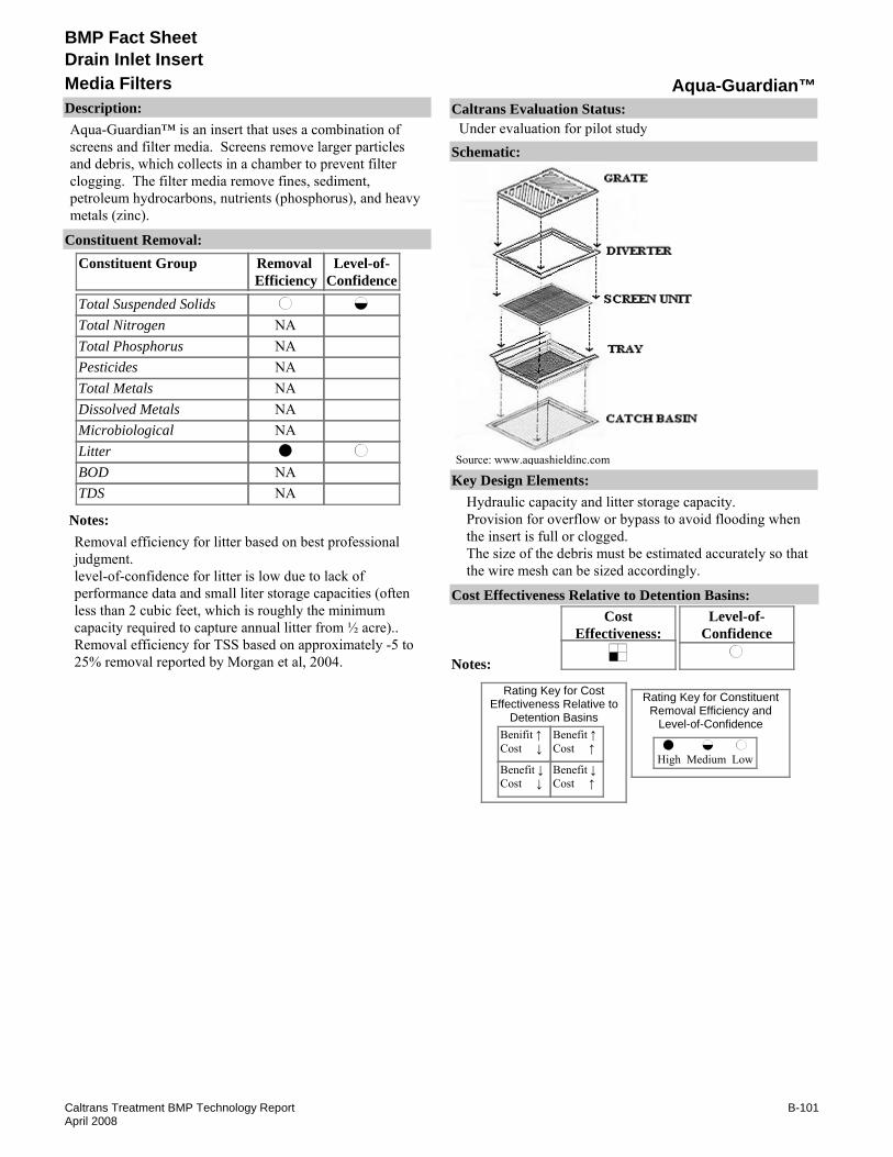
BMP Fact Sheet
Aqua-Guardian™Media FiltersDrain Inlet Insert
Description:Aqua-Guardian™ is an insert that uses a combination of screens and filter media. Screens remove larger particles and debris, which collects in a chamber to prevent filter clogging. The filter media remove fines, sediment, petroleum hydrocarbons, nutrients (phosphorus), and heavy metals (zinc).
Removal Efficiency
Level-of-Confidence
Total Suspended SolidsTotal NitrogenTotal PhosphorusPesticidesTotal MetalsDissolved MetalsMicrobiologicalLitterBODTDS
Constituent GroupConstituent Removal:
NANANANANANA
NANA
Notes:Removal efficiency for litter based on best professional judgment.level-of-confidence for litter is low due to lack of performance data and small liter storage capacities (often less than 2 cubic feet, which is roughly the minimum capacity required to capture annual litter from ½ acre)..Removal efficiency for TSS based on approximately -5 to 25% removal reported by Morgan et al, 2004.
Key Design Elements:Hydraulic capacity and litter storage capacity.Provision for overflow or bypass to avoid flooding when the insert is full or clogged.The size of the debris must be estimated accurately so that the wire mesh can be sized accordingly.
CostEffectiveness:
Level-of-Confidence
Cost Effectiveness Relative to Detention Basins:
Benifit ↑Cost ↓
Benefit ↓Cost ↓
Benefit ↑Cost ↑
Benefit ↓Cost ↑
High Medium Low
Rating Key for ConstituentRemoval Efficiency and
Level-of-Confidence
Rating Key for CostEffectiveness Relative to
Detention Basins
Source: www.aquashieldinc.com
Notes:
Schematic:
Caltrans Evaluation Status:Under evaluation for pilot study
B-101Caltrans Treatment BMP Technology ReportApril 2008

BMP Fact Sheet
Aqua-Guardian™Media FiltersDrain Inlet Insert
Requirements:If there is high solids loading (often caused by vegetation within the drainage area), frequent inspection and maintenance is required.Training:No special requirements identified.
Maintenance Issues:
Project Development Issues:Right-of-Way-Requirements:Installed within a stormwater inlet.Siting Constraints:Requires a grated drop inletConstruction:A watertight installation of the product is important to capture low flows
Constraints: Debris and litter may exceed drain inlet insert capacity.Capacity of insert is constrained by the size of the drain inlet to be retrofitted.Previous Caltrans study of DIIs discourages the use of DII along highway drain inlets due to safety considerations (CTSW-RT-01-050, p.16-9).Morgan et. al. noted that bypass occurs at relatively low flow 0.00038 m3/s (6 gpm).If located along a shoulder or median, maintenance activities may require traffic control.Proprietary device.
Advantages:There is a range of sizes that can be retrofitted to storm drain requirements.They are easy to install and clean; maintenance can be simple and quick.Adsorption booms can be attached.
Morgan, R., Edwards, F., Brye, K., and Burian, S.. "Evaluation of Stormwater Catchbasin Inserts for Transportation Facilities," TRB 2004 Annual Meeting
NELP, "Completes Stormwater Catch Basin Insert Evaluation Study," December 2003, www.mayportnelp.com/success/press_releases/stormwater.htm, (21 August 2003).
Literature Sources of Performance Demonstrations:U.S. Environmental Protection Agency, www.epa.gov/region1/assistance/ceitts/stormwater/techs/aquaguard.html
Design, Construction, Maintenance and Cost SourcesAquaShieldTM Inc., www.aquashieldinc.com
Certifications, Verifications, or Designations:None identified.
B-102Caltrans Treatment BMP Technology ReportApril 2008
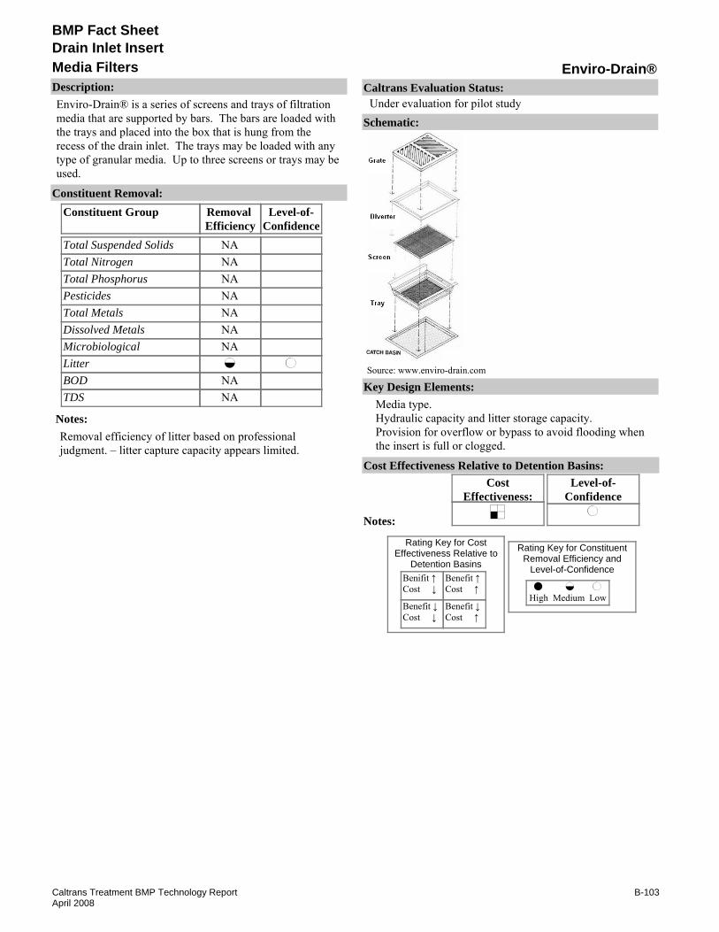
BMP Fact Sheet
Enviro-Drain®Media FiltersDrain Inlet Insert
Description:Enviro-Drain® is a series of screens and trays of filtration media that are supported by bars. The bars are loaded with the trays and placed into the box that is hung from the recess of the drain inlet. The trays may be loaded with any type of granular media. Up to three screens or trays may be used.
Removal Efficiency
Level-of-Confidence
Total Suspended SolidsTotal NitrogenTotal PhosphorusPesticidesTotal MetalsDissolved MetalsMicrobiologicalLitterBODTDS
Constituent GroupConstituent Removal:
NANANANANANANA
NANA
Notes:Removal efficiency of litter based on professional judgment. – litter capture capacity appears limited.
Key Design Elements:Media type.Hydraulic capacity and litter storage capacity.Provision for overflow or bypass to avoid flooding when the insert is full or clogged.
CostEffectiveness:
Level-of-Confidence
Cost Effectiveness Relative to Detention Basins:
Benifit ↑Cost ↓
Benefit ↓Cost ↓
Benefit ↑Cost ↑
Benefit ↓Cost ↑
High Medium Low
Rating Key for ConstituentRemoval Efficiency and
Level-of-Confidence
Rating Key for CostEffectiveness Relative to
Detention Basins
Source: www.enviro-drain.com
Notes:
Schematic:
Caltrans Evaluation Status:Under evaluation for pilot study
B-103Caltrans Treatment BMP Technology ReportApril 2008

BMP Fact Sheet
Enviro-Drain®Media FiltersDrain Inlet Insert
Requirements:If there is high solids loading (often caused by vegetation within the drainage area), frequent inspection and maintenance is required.Training:No special requirements identified.
Maintenance Issues:
Project Development Issues:Right-of-Way-Requirements:Installed within a stormwater inlet.Siting Constraints:Requires a grated drop inlet.Construction:A watertight installation of the product is important to capture low flows.
Constraints: Previous Caltrans study of DIIs discourages the use of DII along highway drain inlets due to safety considerations (CTSW-RT-01-050, p.16-9).Capacity (size of basket) is constrained by the size of the drain inlet to be retrofitted.Excess litter can cause flow to bypass the media.Proprietary device.
Advantages:The system is easy to install.The trays can be recharged with different media.
Literature Sources of Performance Demonstrations:Savelle, J., Catching Water Pollutants at the Source, Journal Environment, September 15, 1998.
Design, Construction, Maintenance and Cost SourcesEnviro-Drain®, Inc., www.enviro-drain.com
Certifications, Verifications, or Designations:None identified.
B-104Caltrans Treatment BMP Technology ReportApril 2008

BMP Fact Sheet
Envriosafe™Media FiltersDrain Inlet Insert
Description:Envirosafe™ is a canister type filter that retains captured pollutants as stormwater passes through filter cartridges. The basic canister design can be fitted to either round or rectangular drain inlets. Water flows through an open-cell foam that restricts sediment and debris prior to a series of optional filtration media. Oil absorbing pads collect oil, grease, and other petroleum based chemicals, while Mycelx™ and Fablite II filtration media collect dissolved metals before water is sent out of the system. High volume flows are allowed to by-pass the system through outlet holes at the top inlet insert.
Removal Efficiency
Level-of-Confidence
Total Suspended SolidsTotal NitrogenTotal PhosphorusPesticidesTotal MetalsDissolved MetalsMicrobiologicalLitterBODTDS
Constituent GroupConstituent Removal:
NANANANANA
NANA
Notes:CLARRC, 2004 reported TSS concentrations greater than 90th percentile Caltrans concentrations (influent was around 350 to 450 mg/L). Data insufficient to draw conclusions on statistical significance. TSS reduction was 50% and 82% for the two samples.CLARRC, 2004 Lab tests for microbiological reduction were contact tests with no moving water. Reduction of water-borne bacteria seems unlikely.Mailloux 2005 reported greater than 90% removal for 4 samples; however level of confidence low due to high influent concentrations.Litter removal based on professional judgment and level-of-confidence is medium assuming device has at least 2 cubic feet of storage capacity.
Key Design Elements:Media type and depth.Hydraulic capacity and litter storage capacity.Provision for overflow or bypass to avoid flooding when the insert is full or clogged.
CostEffectiveness:
Level-of-Confidence
Cost Effectiveness Relative to Detention Basins:
Benifit ↑Cost ↓
Benefit ↓Cost ↓
Benefit ↑Cost ↑
Benefit ↓Cost ↑
High Medium Low
Rating Key for ConstituentRemoval Efficiency and
Level-of-Confidence
Rating Key for CostEffectiveness Relative to
Detention Basins
Source: www.transo.com/envirosafe.htm
Notes:
Schematic:
Caltrans Evaluation Status:Under evaluation for pilot study
B-105Caltrans Treatment BMP Technology ReportApril 2008
BMP Fact Sheet
Envriosafe™Media FiltersDrain Inlet Insert
Requirements:If there is high solids loading (often caused by vegetation within the drainage area), frequent inspection and maintenance is required. Water can pool if clogged.Training:No special requirements identified.
Maintenance Issues:
Project Development Issues:Right-of-Way-Requirements:Installed within a stormwater inlet.Siting Constraints:Requires a grated drop inletConstruction:A watertight installation of the product is important to capture low flows
Constraints: Potential for clogging may cause frequent bypass.Previous Caltrans study of DIIs discourages the use of DII along highway drain inlets due to safety considerations (CTSW-RT-01-050, p.16-9).Capacity (size of basket) is constrained by the size of the drain inlet to be retrofitted.Small surface area filter seems likely to clog.Proprietary device.
Advantages:The system is easy to install.
Contaminated Land Assessment & Remediation Research Centre (CLARRC), "Contract Research Report Laboratory and Field Testing of PermaKleen," June 21, 2005. www.transpo.com/envirosafe.htm
Consolidated Edison, Co., Environmental Testing Labs, Inc., "Testing on Total Petroleum Hydrocarbons (TPH)," www.transpo.com/envirosafe.htm
Mailloux, J., "Suspended Solids Removal Test of a 22x44-inch Stormbasin Modular Stormwater Filtration System," Alden Research Laboratory, Inc., Holden, MA. June 2005
Literature Sources of Performance Demonstrations:AEGIS Environments, "A New Technology for Producing Stability Foams Having Antimicrobial Activity," Midland, MI, January 2005. www.aegismicrobeshield.com
Design, Construction, Maintenance and Cost SourcesTranspo® Industries, Inc., New Rochelle, NY, www.transpo.com
Certifications, Verifications, or Designations:None identified.
B-106Caltrans Treatment BMP Technology ReportApril 2008

BMP Fact Sheet
Hydro-Kleen™Media FiltersDrain Inlet Insert
Description:The Hydro-Kleen™ is a box and baffle system that uses a series of filter media. Bypass of flood flows occurs through the baffle system and discharges prior to the filter beds.
Removal Efficiency
Level-of-Confidence
Total Suspended SolidsTotal NitrogenTotal PhosphorusPesticidesTotal MetalsDissolved MetalsMicrobiologicalLitterBODTDS
Constituent GroupConstituent Removal:
NANANANANANA
NANA
Notes:Removal efficiency of litter based on professional judgment. level-of-confidence for litter is medium assuming device has at least 5 cubic feet of pollutant storage capacity to capture annual litter from every acre of drainage served.Removal efficiency of TSS based on NSF et al., 2003, which showed 68% removal. level-of-confidence is medium based on above referenced performance data.
Key Design Elements:Provision for overflow or bypass to avoid flooding when the insert is full or clogged.Hydraulic capacity and litter storage capacity.Flow capacity (flood and water quality flow).
CostEffectiveness:
Level-of-Confidence
Cost Effectiveness Relative to Detention Basins:
Benifit ↑Cost ↓
Benefit ↓Cost ↓
Benefit ↑Cost ↑
Benefit ↓Cost ↑
High Medium Low
Rating Key for ConstituentRemoval Efficiency and
Level-of-Confidence
Rating Key for CostEffectiveness Relative to
Detention Basins
Source: www.hydrocompliance.com
Notes:
Schematic:
Caltrans Evaluation Status:Under evaluation for pilot study
B-107Caltrans Treatment BMP Technology ReportApril 2008

BMP Fact Sheet
Hydro-Kleen™Media FiltersDrain Inlet Insert
Requirements:If there is high solids loading (often caused by vegetation within the drainage area), frequent inspection and maintenance is required.Unclear if openings are large enough to allow vactor truck cleaning.Training:No special requirements identified.
Maintenance Issues:
Project Development Issues:Right-of-Way-Requirements:Installed within a stormwater inlet.Siting Constraints:Requires a grated drop inlet.Construction:A watertight installation of the product is important to capture low flows
Constraints: Previous Caltrans study of DIIs discourages the use of DII along highway drain inlets due to safety considerations (CTSW-RT-01-050, p.16-9).If located along a shoulder or median, maintenance activities may require traffic control.Debris and litter may exceed drain inlet insert capacity.Capacity (size of basket) is constrained by the size of the drain inlet to be retrofitted.Solids accumulated in the baffle section may be flushed out by high flows.Holds standing water.Proprietary device.
Advantages:The devices can be installed relatively easily in new and existing facilities without much structural modification.
Literature Sources of Performance Demonstrations:NSF Internation, Scherger Associates. "Environmental Technology Verification Report - Hydro Compliance Management, Inc. Hydro-Kleen Filtration System." September, 2003.
Design, Construction, Maintenance and Cost SourcesHydro Compliance Management, Inc., www.hydrocompliance.com
Certifications, Verifications, or Designations:ETV - Verification statement issued September 2003. In drain treatment technology.
B-108Caltrans Treatment BMP Technology ReportApril 2008

BMP Fact Sheet
Raynfiltr™Media FiltersDrain Inlet Insert
Description:The RaynFiltr® is a canister of media that is supported by risers that rests on the bottom of the drain inlet. Overflow orifices on the top of the canister accommodate flood flows. The media is peat-based to remove metals and phosphorus and it reportedly has properties to remove organics.
Removal Efficiency
Level-of-Confidence
Total Suspended SolidsTotal NitrogenTotal PhosphorusPesticidesTotal MetalsDissolved MetalsMicrobiologicalLitterBODTDS
Constituent GroupConstituent Removal:
NANANANANANANA
NANA
Notes:Manufacturer claims that peat-based media removes metals, phosphorus, and organics.level-of-confidence is medium assuming device has at least 2 cubic ft. of pollutant storage capacity, which is roughly adequate to capture annual litter from 1/2 acre.
Key Design Elements:Hydraulic capacity and pollutant storage capacity.Media type and depth.Hydraulic capacity and litter storage capacity.Provision for overflow or bypass to avoid flooding when the insert is full or clogged.
CostEffectiveness:
Level-of-Confidence
Cost Effectiveness Relative to Detention Basins:
Benifit ↑Cost ↓
Benefit ↓Cost ↓
Benefit ↑Cost ↑
Benefit ↓Cost ↑
High Medium Low
Rating Key for ConstituentRemoval Efficiency and
Level-of-Confidence
Rating Key for CostEffectiveness Relative to
Detention Basins
Source: www.raynfiltr.com
Notes:
Schematic:
Caltrans Evaluation Status:Under evaluation for pilot study
B-109Caltrans Treatment BMP Technology ReportApril 2008
BMP Fact Sheet
Raynfiltr™Media FiltersDrain Inlet Insert
Requirements:If there is high solids loading (often caused by vegetation within the drainage area), frequent inspection and maintenance is required. Water can pool if clogged.Need hoist to remove unit when replacing media.Training:No special requirements identified.
Maintenance Issues:
Project Development Issues:Right-of-Way-Requirements:Installed within a stormwater inlet.Siting Constraints:Requires a grated drop inlet.Construction:A watertight installation of the product is important to capture low flows.
Constraints: Low debris storage capacity may cause high maintance requirements if solids loading is high (typical of drainage areas with vegetations, erosion,etc.).Potential for clogging and flooding due to insufficient flood bypass. Potential clogging may cause frequent bypass of media.If located along a shoulder or median, maintenance activities may require traffic control.Debris and litter may exceed drain inlet insert capacity.Capacity (size of basket) is constrained by the size of the drain inlet to be retrofitted.It appears that low flows may by pass the filter.It also appears that the size of the canister may substantially reduce the drain inlet capacity because of a tight fit into the inlet.Previous Caltrans study of DIIs discourages the use of DII along highway drain inlets due to safety considerations (CTSW-RT-01-050, p.16-9).Proprietary device.
Advantages:The system is easy to install.Performance may be enhanced compared to other filters because of a greater media depth.
Literature Sources of Performance Demonstrations:None identified
Design, Construction, Maintenance and Cost SourcesEnviromental Filtration, Inc., www.raynfiltr.org
Certifications, Verifications, or Designations:None identified.
B-110Caltrans Treatment BMP Technology ReportApril 2008

BMP Fact Sheet
SIFT FilterMedia FiltersDrain Inlet Insert
Description:The S.I.F.T. Filter™ uses trays to hold filter media. The insert rests on the recess of the drain inlet. Flood flow bypass occurs by an opening in the center of the insert.
Removal Efficiency
Level-of-Confidence
Total Suspended SolidsTotal NitrogenTotal PhosphorusPesticidesTotal MetalsDissolved MetalsMicrobiologicalLitterBODTDS
Constituent GroupConstituent Removal:
NANANANANANANA
NANA
Notes:Removal efficiency of litter based on professional judgment and previous Caltrans testing of similar tray type product (see Fossil Filter, Appendix C).
Key Design Elements:Provision for overflow or bypass to avoid flooding when the insert is full or clogged.Hydraulic capacity and litter storage capacity.
CostEffectiveness:
Level-of-Confidence
Cost Effectiveness Relative to Detention Basins:
Benifit ↑Cost ↓
Benefit ↓Cost ↓
Benefit ↑Cost ↑
Benefit ↓Cost ↑
High Medium Low
Rating Key for ConstituentRemoval Efficiency and
Level-of-Confidence
Rating Key for CostEffectiveness Relative to
Detention Basins
Source: Revel Environmental Marketing, Inc.
Notes:
Schematic:
Caltrans Evaluation Status:Under evaluation for pilot study
B-111Caltrans Treatment BMP Technology ReportApril 2008

BMP Fact Sheet
SIFT FilterMedia FiltersDrain Inlet Insert
Requirements:S.I.F.T. Filter should be inspected for trash and debris that could interfere with the normal functioning of the inlets, or debris that tends to accumulate on top of the trays, deflecting runoff water. The S.I.F.T. FilterTM adsorbent should be replaced when significant oil and grease are present on the absorbent granules. The media should be replaced annually.Training:No special requirement identified.
Maintenance Issues:
Project Development Issues:Right-of-Way-Requirements:Installed within a stormwater inlet.Siting Constraints:Requires a grated drop inletConstruction:A watertight installation of the product is important to capture low flows.
Constraints: If located along a shoulder or median, maintenance activities may require traffic control.Previous Caltrans study of DIIs discourages the use of DII along highway drain inlets due to safety considerations (CTSW-RT-01-050, p.16-9).Debris and litter may exceed drain inlet insert capacity.Capacity (size of basket) is constrained by the size of the drain inlet to be retrofitted.Proprietary device.
Advantages:Available in a variety of shapes, including custom design.S.I.F.T. FilterTM are relatively inexpensive to install.Easily retrofitted to existing drain inlets.Easily to install and maintain.Constructed of heavy 16-18ga. Galvanized G-90 Zinc coated framing.
Literature Sources of Performance Demonstrations:None identified
Design, Construction, Maintenance and Cost SourcesRevel Environmental Marketing, Inc.
Certifications, Verifications, or Designations:None identified.
B-112Caltrans Treatment BMP Technology ReportApril 2008

BMP Fact Sheet
Storm PURE™Media FiltersDrain Inlet Insert
Description:The StormPure™ captures sediment and debris as stormwater passes through a geotextile filter bag and metal catch basket in the upper half of the device. Filtered water then passes through a series of patented filters, Mycelx® and PermaKleen®, that are designed to remove suspended solids and hydrocarbons. The current model is made for a 24 inch cylindrical drop inlet (or catch basin). The unit hangs from the top of the inlet.
Removal Efficiency
Level-of-Confidence
Total Suspended SolidsTotal NitrogenTotal PhosphorusPesticidesTotal MetalsDissolved MetalsMicrobiologicalLitterBODTDS
Constituent GroupConstituent Removal:
NA
NANA
Notes:Performance on litter removal efficiencies are based on professional judgment.Low level-of-confidence is based on study parameters that could not be verified from the information submitted by manufacturer.
Key Design Elements:Media typeHydraulic capacity and litter storage capacityProvision for overflow or bypass to avoid flooding when the insert is full or clogged
CostEffectiveness:
Level-of-Confidence
Cost Effectiveness Relative to Detention Basins:
Benifit ↑Cost ↓
Benefit ↓Cost ↓
Benefit ↑Cost ↑
Benefit ↓Cost ↑
High Medium Low
Rating Key for ConstituentRemoval Efficiency and
Level-of-Confidence
Rating Key for CostEffectiveness Relative to
Detention Basins
Source: www.nyloplast-us.com
Notes:
Schematic:
Caltrans Evaluation Status:Under evaluation for pilot study
B-113Caltrans Treatment BMP Technology ReportApril 2008

BMP Fact Sheet
Storm PURE™Media FiltersDrain Inlet Insert
Requirements:If there is high solids loading (often caused by vegetation within the drainage area), frequent inspection and maintenance is required.Training:No special requirements identified.
Maintenance Issues:
Project Development Issues:Right-of-Way-Requirements:Same as drop inlets.Siting Constraints:Same as drop inlets.Construction:A watertight installation of the product is important to capture low flows.
Constraints: Potential for clogging and flooding road. Especially with a bypass system that only passes material smaller than 1/8 inch.Previous Caltrans study of DIIs discourages the use of DII along highway drain inlets due to safety considerations (CTSW-RT-01-050, p.16-9).
Advantages:The system is easy to install. The device can be installed in parallel to increase treatment capacity. Water can pass through freely (if void of solids). Some filter cartridges can be recharged. Filter media can easily be site-specific. Some devices are delivered precast.
Literature Sources of Performance Demonstrations:None identified
Design, Construction, Maintenance and Cost SourcesNone identified
Certifications, Verifications, or Designations:None identified.
B-114Caltrans Treatment BMP Technology ReportApril 2008
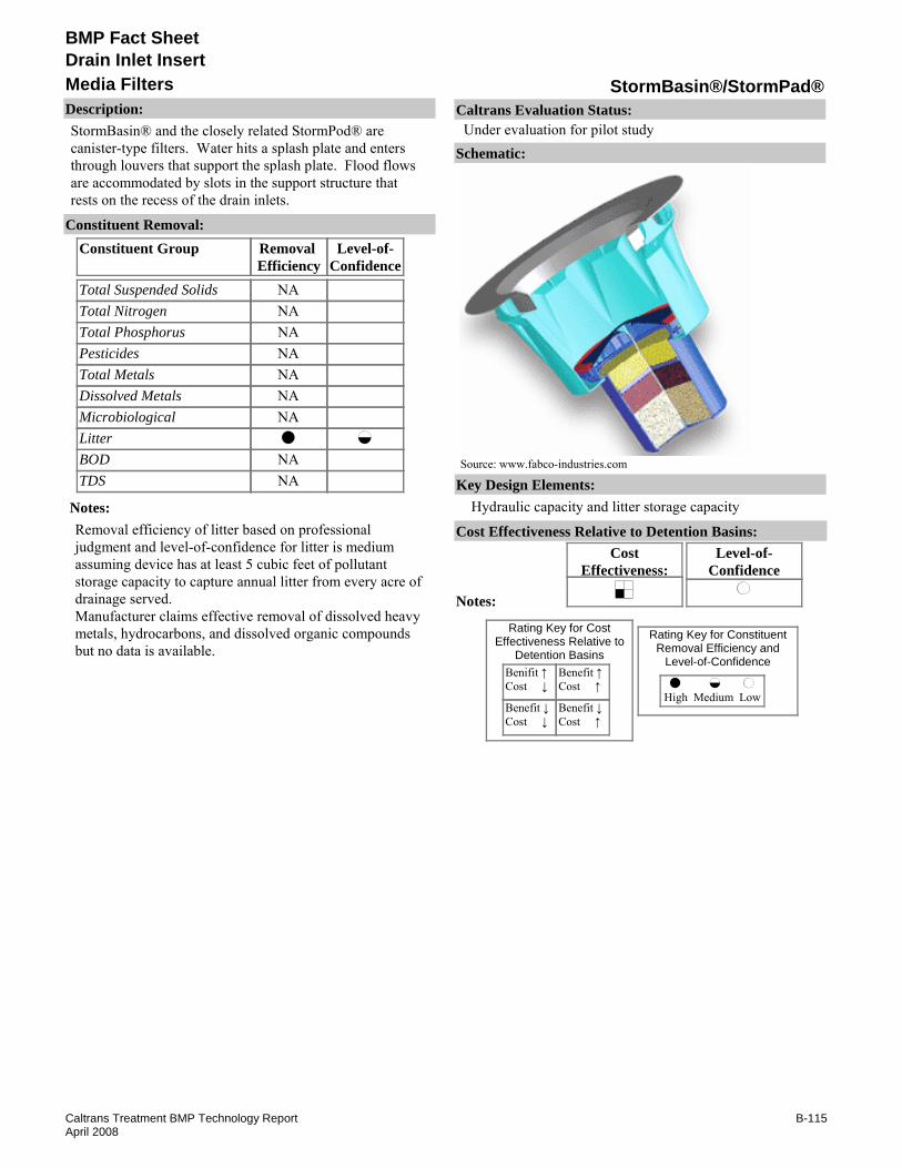
BMP Fact Sheet
StormBasin®/StormPad®Media FiltersDrain Inlet Insert
Description:StormBasin® and the closely related StormPod® are canister-type filters. Water hits a splash plate and enters through louvers that support the splash plate. Flood flows are accommodated by slots in the support structure that rests on the recess of the drain inlets.
Removal Efficiency
Level-of-Confidence
Total Suspended SolidsTotal NitrogenTotal PhosphorusPesticidesTotal MetalsDissolved MetalsMicrobiologicalLitterBODTDS
Constituent GroupConstituent Removal:
NANANANANANANA
NANA
Notes:Removal efficiency of litter based on professional judgment and level-of-confidence for litter is medium assuming device has at least 5 cubic feet of pollutant storage capacity to capture annual litter from every acre of drainage served.Manufacturer claims effective removal of dissolved heavy metals, hydrocarbons, and dissolved organic compounds but no data is available.
Key Design Elements:Hydraulic capacity and litter storage capacity
CostEffectiveness:
Level-of-Confidence
Cost Effectiveness Relative to Detention Basins:
Benifit ↑Cost ↓
Benefit ↓Cost ↓
Benefit ↑Cost ↑
Benefit ↓Cost ↑
High Medium Low
Rating Key for ConstituentRemoval Efficiency and
Level-of-Confidence
Rating Key for CostEffectiveness Relative to
Detention Basins
Source: www.fabco-industries.com
Notes:
Schematic:
Caltrans Evaluation Status:Under evaluation for pilot study
B-115Caltrans Treatment BMP Technology ReportApril 2008

BMP Fact Sheet
StormBasin®/StormPad®Media FiltersDrain Inlet Insert
Requirements:If there is high solids loading (often caused by vegetation within the drainage area), frequent inspection and maintenance is required.Training:No special requirements identified.
Maintenance Issues:
Project Development Issues:Right-of-Way-Requirements:Installed within a stormwater inlet.Siting Constraints:Requires a grated drop inletConstruction:A watertight installation of the product is important to capture low flows.
Constraints: Potential for clogging may cause frequent bypass.If located along a shoulder or median, maintenance activities may require traffic control.Previous Caltrans study of DIIs discourages the use of DII along highway drain inlets due to safety considerations (CTSW-RT-01-050, p.16-9).Debris and litter may exceed drain inlet insert capacity.Capacity (size of basket) is constrained by the size of the drain inlet to be retrofitted.Small surface area of filter seems likely to clog.Proprietary device.
Advantages:The system is easy to install and maintain.Insert is made of durable, light-weight material.Provision for overflow or bypass to avoid flooding when the insert is full of clogged.
Literature Sources of Performance Demonstrations:None identified
Design, Construction, Maintenance and Cost SourcesFabco Industries Inc., www.fabco-industries.com
Certifications, Verifications, or Designations:None identified.
B-116Caltrans Treatment BMP Technology ReportApril 2008

BMP Fact Sheet
Triton Catch Basin Filter™Media FiltersDrain Inlet Insert
Description:Triton Catch Basin Filter™ is a filter cartridge that removes hydrocarbons and other contaminants such as antifreeze, metals, sand, silt and litter from stormwater runoff. High density polyethylene plastic cartridges in various shapes (round, square, rectangular, and custom) filter out hydrocarbons and other pollutants by means of single and double walled Media Pak. Disposable cartridge Media Pak’s are constructed from durable geo-textile polypropylene fabric.
Removal Efficiency
Level-of-Confidence
Total Suspended SolidsTotal NitrogenTotal PhosphorusPesticidesTotal MetalsDissolved MetalsMicrobiologicalLitterBODTDS
Constituent GroupConstituent Removal:
NANANANANANANANANANA
Notes:No literature reviewed for removal efficiency.
Key Design Elements:Hydraulic capacity and pollutant storage capacity.Provision for overflow of bypass to avoid flooding when the insert is full or clogged.
CostEffectiveness:
Level-of-Confidence
Cost Effectiveness Relative to Detention Basins:
Benifit ↑Cost ↓
Benefit ↓Cost ↓
Benefit ↑Cost ↑
Benefit ↓Cost ↑
High Medium Low
Rating Key for ConstituentRemoval Efficiency and
Level-of-Confidence
Rating Key for CostEffectiveness Relative to
Detention Basins
Source: www.remfilters.com
Notes:
Schematic:
Caltrans Evaluation Status:Under evaluation for pilot study
B-117Caltrans Treatment BMP Technology ReportApril 2008

BMP Fact Sheet
Triton Catch Basin Filter™Media FiltersDrain Inlet Insert
Requirements:If there is high solids loading (often caused by vegetation within the drainage area), frequent inspection and maintenance is requiredTraining:No special requirements identified.
Maintenance Issues:
Project Development Issues:Right-of-Way-Requirements:Installed within a storm drain inlet.Siting Constraints:Requires a grated drop inletConstruction:A watertight installation of the product is important to capture low flows
Constraints: Debris and litter may exceed drain inlet insert capacity.Capacity (size of basket) is constrained by the size of the drain inlet to be retrofitted.Previous Caltrans study of DIIs discourages the use of DII along highway drain inlets due to safety considerations (CTSW-RT-01-050, p.16-9).If located along a shoulder or median, maintenance activities may require traffic control.Proprietary device.
Advantages:Custom sizes available.The system is easy to install.Filter cartridges can be easily removed for replacement.High nominal flow and high overflow capacities.Spent adsorbents are recycable.
Literature Sources of Performance Demonstrations:None identified
Design, Construction, Maintenance and Cost SourcesRevel Environmental Manufacturing Inc www.remfilters.com
Certifications, Verifications, or Designations:None identified.
B-118Caltrans Treatment BMP Technology ReportApril 2008
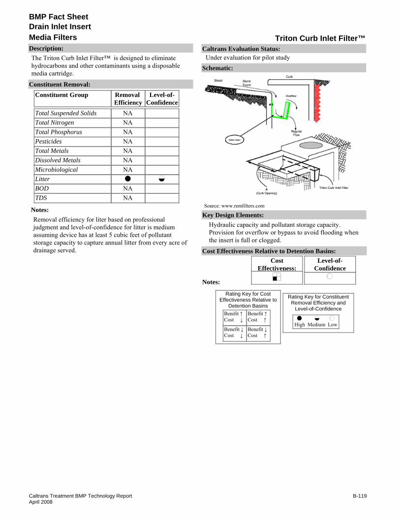
BMP Fact Sheet
Triton Curb Inlet Filter™Media FiltersDrain Inlet Insert
Description:The Triton Curb Inlet Filter™ is designed to eliminate hydrocarbons and other contaminants using a disposable media cartridge.
Removal Efficiency
Level-of-Confidence
Total Suspended SolidsTotal NitrogenTotal PhosphorusPesticidesTotal MetalsDissolved MetalsMicrobiologicalLitterBODTDS
Constituent GroupConstituent Removal:
NANANANANANANA
NANA
Notes:Removal efficiency for liter based on professional judgment and level-of-confidence for litter is medium assuming device has at least 5 cubic feet of pollutant storage capacity to capture annual litter from every acre of drainage served.
Key Design Elements:Hydraulic capacity and pollutant storage capacity.Provision for overflow or bypass to avoid flooding when the insert is full or clogged.
CostEffectiveness:
Level-of-Confidence
Cost Effectiveness Relative to Detention Basins:
Benifit ↑Cost ↓
Benefit ↓Cost ↓
Benefit ↑Cost ↑
Benefit ↓Cost ↑
High Medium Low
Rating Key for ConstituentRemoval Efficiency and
Level-of-Confidence
Rating Key for CostEffectiveness Relative to
Detention Basins
Source: www.remfilters.com
Notes:
Schematic:
Caltrans Evaluation Status:Under evaluation for pilot study
B-119Caltrans Treatment BMP Technology ReportApril 2008

BMP Fact Sheet
Triton Curb Inlet Filter™Media FiltersDrain Inlet Insert
Requirements:Regular maintenance is required to meet local and State BMPs.Training:No special requirements identified.
Maintenance Issues:
Project Development Issues:Right-of-Way-Requirements:Installed in existing storm drain filtersSiting Constraints:Requires a curb inletConstruction:Exterior cage of cartridge shall be made of stainless steel Type 304, having .063 gauge welded 1” square openings
Constraints: Excess litter can cause flow to bypass the media.If located along a shoulder or median, maintenance activities may require traffic control.Previous Caltrans study of DIIs discourages the use of DII along highway drain inlets due to safety considerations (CTSW-RT-01-050, p.16-9).Debris and litter may exceed drain inlet insert capacity.Proprietary device.
Advantages:The system is easy to install.The trays can be changed with different media.Range of sizes can be retrofitted to storm drain.
Literature Sources of Performance Demonstrations:None identified
Design, Construction, Maintenance and Cost SourcesRevel Environmental Manufacturing, Inc., www.remfilter.com
Certifications, Verifications, or Designations:None identified.
B-120Caltrans Treatment BMP Technology ReportApril 2008

BMP Fact Sheet
Ultra-Urban Filter™Media FiltersDrain Inlet Insert
Description:The Ultra-Urban Filter is a box with media built into the bottom and two opposite sides of the box. The box is suspended from splash plates that rest on the drain inlet recess. Flood flow bypass is accomplished by overtopping the box.
Removal Efficiency
Level-of-Confidence
Total Suspended SolidsTotal NitrogenTotal PhosphorusPesticidesTotal MetalsDissolved MetalsMicrobiologicalLitterBODTDS
Constituent GroupConstituent Removal:
NANANANANA
NANA
Notes:Up to 80% hydrocarbon removal reported by UCLA (EPA website). Sil-Co-Sil 106 laboratory tests resulted in 16.5% removal (Galicki et al, 2003) and <40% (OWP, 2005). Laboratory tests using street sweepings resulted in approximately 15 to 60% removal of TSS (Morgan et al, 2004).Removal efficiency of TSS based on above referenced performance demonstrations. Removal efficiency for litter based on OWP, 2005.level-of-confidence for TSS is medium based on report by Morgan et al, 2004 and Galicki et al, 2003. level-of-confidence for microbiological is low based on lack of adequate, statistically significant, flow-through performance data.level-of-confidence is medium assuming device has at least 2 cubic ft. of pollutant storage capacity, which is roughly adequate to capture annual litter from 1/2 acre.
Key Design Elements:Media type and depth.Hydraulic capacity and pollutant storage capacity.Provision for overflow or bypass to avoid flooding when the insert is full or clogged.
CostEffectiveness:
Level-of-Confidence
Cost Effectiveness Relative to Detention Basins:
Benifit ↑Cost ↓
Benefit ↓Cost ↓
Benefit ↑Cost ↑
Benefit ↓Cost ↑
High Medium Low
Rating Key for ConstituentRemoval Efficiency and
Level-of-Confidence
Rating Key for CostEffectiveness Relative to
Detention Basins
Source: www.abtechindustries.com
Notes:
Schematic:
Caltrans Evaluation Status:Under evaluation for pilot study
B-121Caltrans Treatment BMP Technology ReportApril 2008

BMP Fact Sheet
Ultra-Urban Filter™Media FiltersDrain Inlet Insert
Requirements:If there is high solids loading (often caused by vegetation within the drainage area), frequent inspection and maintenance is required.Training:No special requirements identified.
Maintenance Issues:
Project Development Issues:Right-of-Way-Requirements:Installed within a stormwater inlet.Siting Constraints:Requires a grated drop inletConstruction:A watertight installation of the product is important to capture low flows.
Constraints: Potential for clogging and bypass of media.If located along a shoulder or median, maintenance activities may require traffic control.Previous Caltrans study of DIIs discourages the use of DII along highway drain inlets due to safety considerations (CTSW-RT-01-050, p.16-9).Debris and litter may exceed drain inlet insert capacity.Capacity (size of basket) is constrained by the size of the drain inlet to be retrofitted.Proprietary device.
Advantages:The system is easy to install.
Galicki, S., Johnson, A., and Williams, A., Final Report, Sediment Removal from Stormwater Runoff AbTech Industries Ultra-Urban® Filter Series in Laboratory Flume Tests, Millsaps College, June 31, 2003. Available on www.abtechindustries.com
Morgan, R., Edwards, F., Brye, K., and Burian, S.. "Evaluation of Stormwater Catchbasin Inserts for Transportation Facilities" TRB 2004 Annual Meeting
Asbury Environmental Stormwater Division, "Smart Sponge® Plus Antimicrobial Technology, Background & Field Test Results" February 26, 2004Office Of Water Programs (OWP), Sacramento State. 2005. "CLWWB Used Oil Demonstration Grant-Laboratory Evaluation of Four Storm Drain Inlet Filters for Oil Removal." April 2005
Literature Sources of Performance Demonstrations:U.S. Environmental Protection Agency, www.epa.gov/region1/assistance/ceitts/stormwater/techs/abtechfilter.html
Design, Construction, Maintenance and Cost SourcesAbTech Industries, www.abtechindustries.com
Certifications, Verifications, or Designations:TARP - Studies underway that offer promise for reliable data in the near future for addressing E. coli & Enterococcus removal efficiency claims.
B-122Caltrans Treatment BMP Technology ReportApril 2008

BMP Fact Sheet
ClearWater BMPScreensDrain Inlet Insert
Description:The ClearWater BMP uses a series of screens, baskets, and baffles. The unit is attached to the side of the drain inlet just below the curb inlet. The initial screens divert large debris to the baskets. Water passes through this screen and into a baffle system with finer, built-in screens.
Removal Efficiency
Level-of-Confidence
Total Suspended SolidsTotal NitrogenTotal PhosphorusPesticidesTotal MetalsDissolved MetalsMicrobiologicalLitterBODTDS
Constituent GroupConstituent Removal:
NANANA
NANA
NANA
Notes:Removal efficiency for TSS and total metals based on Gurol et al 2003 (97% TSS removal, 28% copper, removal, 81% lead removal and 83% zinc removal).level-of-confidence for TSS and total metals is low due to limitations no particles <75u, unknown duration, and one sample for each of four flow rates.level-of-confidence for zinc concentrations over triple (792 ug/L versus 187 ug/L) typical San Diego State University lab tested. Limitations on confidence level due to no particles <75micron, unknown duration, and one sample for each of four flow rates.Removal efficiency for litter based on professional judgment.level-of-confidence for litter is medium assuming device has at least 5 cubic feet of pollutant storage capacity to capture annual litter from every acre of drainage served.
Key Design Elements:Hydraulic capacity and pollutant storage capacity.Provision for overflow or bypass to avoid flooding when the insert is full or clogged.
CostEffectiveness:
Level-of-Confidence
Cost Effectiveness Relative to Detention Basins:
Benifit ↑Cost ↓
Benefit ↓Cost ↓
Benefit ↑Cost ↑
Benefit ↓Cost ↑
High Medium Low
Rating Key for ConstituentRemoval Efficiency and
Level-of-Confidence
Rating Key for CostEffectiveness Relative to
Detention Basins
Source: www.clearwaterbmp.com
Notes:
Schematic:
Caltrans Evaluation Status:Under evaluation for pilot study
B-123Caltrans Treatment BMP Technology ReportApril 2008

BMP Fact Sheet
ClearWater BMPScreensDrain Inlet Insert
Requirements:If there is high solids loading (often caused by vegetation within the drainage area), frequent inspection and maintenance is requiredTraining:Confined space entry may be an issue if the unit can not be serviced from above ground (see schematic).
Maintenance Issues:
Project Development Issues:Right-of-Way-Requirements:Installed within a stormwater inlet.Siting Constraints:Requires a curb inlet.Construction:Attached to sidewalls required, not a “drop in” device. A watertight installation of the product is important to capture low flows.
Constraints: Causes standing water.If located along a shoulder or median, maintenance activities may require traffic control.Previous Caltrans study of DIIs discourages the use of DII along highway drain inlets due to safety considerations (CTSW-RT-01-050, p.16-9).Debris and litter may exceed drain inlet insert capacity.Capacity (size of basket) is constrained by the size of the drain inlet to be retrofitted.Proprietary device.
Advantages:Requires no structural modifications to existing drainage structures.
Literature Sources of Performance Demonstrations:Gurol, M. and Loraine, G., "Performance Testing of Clean Water Solutions Storm Water Treatment Prototype." San Diego State University November 25, 2003.
Design, Construction, Maintenance and Cost SourcesClearWater Solutions, www.clearwaterbmp.com
Certifications, Verifications, or Designations:None identified.
B-124Caltrans Treatment BMP Technology ReportApril 2008

BMP Fact Sheet
High Flow Debris BasketScreensDrain Inlet Insert
Description:The High Flow Debris Basket is a cylindrical screen that can be placed in both rectangular and round drain inlets due to a steel support plate that is cut to size the drain inlet. There does not appear to be a overflow or bypass.
Removal Efficiency
Level-of-Confidence
Total Suspended SolidsTotal NitrogenTotal PhosphorusPesticidesTotal MetalsDissolved MetalsMicrobiologicalLitterBODTDS
Constituent GroupConstituent Removal:
NANANANANANANA
NANA
Notes:Removal efficiency of litter based on the best professional judgment.
Key Design Elements:Hydraulic capacity and pollutant storage capacity.Provision for overflow or bypass to avoid flooding when the insert is full or clogged.
CostEffectiveness:
Level-of-Confidence
Cost Effectiveness Relative to Detention Basins:
Benifit ↑Cost ↓
Benefit ↓Cost ↓
Benefit ↑Cost ↑
Benefit ↓Cost ↑
High Medium Low
Rating Key for ConstituentRemoval Efficiency and
Level-of-Confidence
Rating Key for CostEffectiveness Relative to
Detention Basins
Source: www.cleanwayusa.com
Notes:
Schematic:
Caltrans Evaluation Status:Under evaluation for pilot study
B-125Caltrans Treatment BMP Technology ReportApril 2008
BMP Fact Sheet
High Flow Debris BasketScreensDrain Inlet Insert
Requirements:If there is high solids loading (often caused by vegetation within the drainage area), frequent inspection and maintenance is required.Training:No special requirements identified.
Maintenance Issues:
Project Development Issues:Right-of-Way-Requirements:Installed within a stormwater inlet.Siting Constraints:Requires a graded drop inlet.Construction:A watertight installation of the product is important to capture low flows.
Constraints: Capacity (size of basket) is constrained by size of the drain inlet to be retrofitted.Previous Caltrans study of DIIs discourages the use of DII along highway drain inlets due to safety considerations (CTSW-RT-01-050, p.16-9).Debris and litter may exceed drain inlet insert capacity.Maintenance activities may require traffic control if located along a shoulder or median.High flow bypass.Proprietary device.
Advantages:There is a range of sizes and shapes that can be retrofitted to storm drain requirements.They are easy to install and clean; maintenance can be simple and quick.
Literature Sources of Performance Demonstrations:None identified
Design, Construction, Maintenance and Cost SourcesNone identified
Certifications, Verifications, or Designations:None identified.
B-126Caltrans Treatment BMP Technology ReportApril 2008

BMP Fact Sheet
HydroscreenScreensDrain Inlet Insert
Description:Hydroscreen is a slanted screen made of wedge wire. Water flows through the screen while litter and debris are collected on top. Flood flow bypass is accomplished by overtopping the box that holds the screen. The box is attached to the side of the drain inlet just under the curb inlet.
Removal Efficiency
Level-of-Confidence
Total Suspended SolidsTotal NitrogenTotal PhosphorusPesticidesTotal MetalsDissolved MetalsMicrobiologicalLitterBODTDS
Constituent GroupConstituent Removal:
NANANANANANANA
NANA
Notes:Hydroscreen is a small version of the GSRD-Inclined Screen approved by Caltrans (see page D-11).Removal efficiency for litter based on professional judgment and level-of-confidence is medium assuming device has capacity, which is roughly adequate to capture annual litter from ½ acre.
Key Design Elements:Provision for overflow or bypass to avoid flooding when the insert is clogged.
CostEffectiveness:
Level-of-Confidence
Cost Effectiveness Relative to Detention Basins:
Benifit ↑Cost ↓
Benefit ↓Cost ↓
Benefit ↑Cost ↑
Benefit ↓Cost ↑
High Medium Low
Rating Key for ConstituentRemoval Efficiency and
Level-of-Confidence
Rating Key for CostEffectiveness Relative to
Detention Basins
Source: www.hydroscreen.com
Notes:
Schematic:
Caltrans Evaluation Status:Under evaluation for pilot study
B-127Caltrans Treatment BMP Technology ReportApril 2008

BMP Fact Sheet
HydroscreenScreensDrain Inlet Insert
Requirements:If there is high solids loading (often caused by vegetation within the drainage area), frequent inspection and maintenance is required.Training:No special requirements identified.
Maintenance Issues:
Project Development Issues:Right-of-Way-Requirements:Installed within a stormwater inlet.Siting Constraints:Requires a curb inlet.Construction:Attached to sidewalls required, not a “drop in” device. A watertight installation of the product is important to capture low flows.
Constraints: Captured litter may escape over the top of the basket during higher flows.If located along a shoulder or median, maintenance activities may require traffic control.Previous Caltrans study of DIIs discourages the use of DII along highway drain inlets due to safety considerations (CTSW-RT-01-050, p.16-9).Debris and litter may exceed drain inlet insert capacity.Capacity (size of basket) is constrained by the size of the drain inlet to be retrofitted.Proprietary device.
Advantages:Maintenance is quick and easy.Hydroscreen is a small version of the GSRD-Inclined Screen approved by Caltrans (fact sheet D-15).
Literature Sources of Performance Demonstrations:None identified
Design, Construction, Maintenance and Cost SourcesHydroscreen, LLC., www.hydroscreen.com
Certifications, Verifications, or Designations:None identified.
B-128Caltrans Treatment BMP Technology ReportApril 2008

BMP Fact Sheet
SuperFlo II DownspoutScreensDrain Inlet Insert
Description:The SuperFlo II Downspout is an enhanced version of the original SuperFlo insert, designed for installation on downspouts. A box contains a screen made of wedge wire. Water flows through the screen while debris is collected in a side compartment that is accessible by a door in the box.
Removal Efficiency
Level-of-Confidence
Total Suspended SolidsTotal NitrogenTotal PhosphorusPesticidesTotal MetalsDissolved MetalsMicrobiologicalLitterBODTDS
Constituent GroupConstituent Removal:
NANANANANANANA
NANA
Notes:Performance testing in progress (as of February 2007), according to manufacturer website.Removal efficiency for litter based on professional judgment and level-of-confidence for litter is medium assuming device has at least 5 cubic feet of pollutant storage capacity to capture annual litter from every acre of drainage served.
Key Design Elements:Provision for overflow or bypass to avoid flooding when the insert is clogged
CostEffectiveness:
Level-of-Confidence
Cost Effectiveness Relative to Detention Basins:
Benifit ↑Cost ↓
Benefit ↓Cost ↓
Benefit ↑Cost ↑
Benefit ↓Cost ↑
High Medium Low
Rating Key for ConstituentRemoval Efficiency and
Level-of-Confidence
Rating Key for CostEffectiveness Relative to
Detention Basins
Source: www.stormfilters.com
Notes:
Schematic:
Caltrans Evaluation Status:Under evaluation for pilot study
B-129Caltrans Treatment BMP Technology ReportApril 2008

BMP Fact Sheet
SuperFlo II DownspoutScreensDrain Inlet Insert
Requirements:If there is high solids loading (often caused by vegetation within the drainage area), frequent inspection and maintenance is requiredTraining:No special requirements identified.
Maintenance Issues:
Project Development Issues:Right-of-Way-Requirements:Can be attached to bridge column or building structure.Siting Constraints:Requires a down spout.Construction:Attaches to a wall or other vertical support.
Constraints: May not fit into drain inlets without modification.If located along a shoulder or median, maintenance activities may require traffic control.Previous Caltrans study of DIIs discourages the use of DII along highway drain inlets due to safety considerations (CTSW-RT-01-050, p.16-9).Debris and litter may exceed drain inlet insert capacity.Proprietary device.
Advantages:Maintenance is quick and easy.
Literature Sources of Performance Demonstrations:None identified
Design, Construction, Maintenance and Cost SourcesStorm Water Systems, www.stormfilters.com
Certifications, Verifications, or Designations:None identified.
B-130Caltrans Treatment BMP Technology ReportApril 2008

BMP Fact Sheet
Triton T-DAM Filter™Trench Drain InsertDrain Inlet Insert
Description:The Triton T- Dam Filter™ is designed to be inserted below the grade of trench drain inlets. Filter Media Paks are available for the removal of hydrocarbons, metals, sand, silt, and debris. The trench itself is used as part of the capture device.
Removal Efficiency
Level-of-Confidence
Total Suspended SolidsTotal NitrogenTotal PhosphorusPesticidesTotal MetalsDissolved MetalsMicrobiologicalLitterBODTDS
Constituent GroupConstituent Removal:
NANANANANANANA
NANA
Notes:Removal efficiency for litter is based on professional judgment and level-of-confidence for litter is medium assuming device has at least 5 cubic feet of pollutant storage capacity to capture annual litter from every acre of drainage served.
Key Design Elements:Provision for overflow or bypass to avoid flooding when the insert is clogged
CostEffectiveness:
Level-of-Confidence
Cost Effectiveness Relative to Detention Basins:
Benifit ↑Cost ↓
Benefit ↓Cost ↓
Benefit ↑Cost ↑
Benefit ↓Cost ↑
High Medium Low
Rating Key for ConstituentRemoval Efficiency and
Level-of-Confidence
Rating Key for CostEffectiveness Relative to
Detention Basins
Source: http://www.remfilters.com/products/
Notes:
Schematic:
Caltrans Evaluation Status:Under evaluation for pilot study
B-131Caltrans Treatment BMP Technology ReportApril 2008

BMP Fact Sheet
Triton T-DAM Filter™Trench Drain InsertDrain Inlet Insert
Requirements:If there is high solids loading (often caused by vegetation within the drainage area), frequent inspection and maintenance is required.Training:Vactor cleaning of the trench drain may be preferred over hand removal.
Maintenance Issues:
Project Development Issues:Right-of-Way-Requirements:Installed in existing trench drainSiting Constraints:None identifiedConstruction:None identified
Constraints: Seems prone to clogging because of small filter area.Limited performance is expected due to small size.Patent was pending as of 2004.Previous Caltrans study of DIIs discourages the use of DII along highway drain inlets due to safety considerations (CTSW-RT-01-050, p.16-9).Proprietary device.
Advantages:Easy to install.Filter media easily removed.
Literature Sources of Performance Demonstrations:None identified
Design, Construction, Maintenance and Cost SourcesRevel Environmental Manufacturing, Inc., www.remfilters.com
Certifications, Verifications, or Designations:None identified.
B-132Caltrans Treatment BMP Technology ReportApril 2008

BMP Fact Sheet
Triton TT3 Filter™Trench Drain InsertDrain Inlet Insert
Description:The Triton TT3 Filter™ Insert is designed to help eliminate hydrocarbons and other contaminates such as metals, sand, silt, and litter from stormwater runoff entering trench drains. Stormwater flows through the trench drain and passes through a primary sand/silt dam, where large particles are filtered out. Water then passes through a Trap Chamber where floatables are collected. A secondary sand/silt filtration is performed after the Trap Chamber, removing the last of the sediment. Hydrocarbons are retained by the ABSORB media in the Hydrocarbon Collection Cartridge. Clean water passes to the end of the trench and into the stormwater system.
Removal Efficiency
Level-of-Confidence
Total Suspended SolidsTotal NitrogenTotal PhosphorusPesticidesTotal MetalsDissolved MetalsMicrobiologicalLitterBODTDS
Constituent GroupConstituent Removal:
NANANANANANANA
NANA
Notes:Removal efficiency for litter based on professional judgment.level-of-confidence for litter is medium assuming device has at least 5 cubic feet of pollutant storage capacity to capture annual litter from every acre of drainage served..
Key Design Elements:Provision for overflow or bypass to avoid flooding when the insert is clogged. Hydraulic capacity and pollutant storage capacity.
CostEffectiveness:
Level-of-Confidence
Cost Effectiveness Relative to Detention Basins:
Benifit ↑Cost ↓
Benefit ↓Cost ↓
Benefit ↑Cost ↑
Benefit ↓Cost ↑
High Medium Low
Rating Key for ConstituentRemoval Efficiency and
Level-of-Confidence
Rating Key for CostEffectiveness Relative to
Detention Basins
Source: http://www.remfilters.com/products/
Notes:
Schematic:
Caltrans Evaluation Status:Under evaluation for pilot study
B-133Caltrans Treatment BMP Technology ReportApril 2008

BMP Fact Sheet
Triton TT3 Filter™Trench Drain InsertDrain Inlet Insert
Requirements:If there is high solids loading (often caused by vegetation within the drainage area), frequent inspection and maintenance is requiredTraining:No special requirements identified.
Maintenance Issues:
Project Development Issues:Right-of-Way-Requirements:Installed in existing trench drain.Siting Constraints:None identifiedConstruction:None identified
Constraints: Previous Caltrans study of DIIs discourages the use of DII along highway drain inlets due to safety considerations (CTSW-RT-01-050, p.16-9).May not fit into existing trenches without modification.Proprietary device.
Advantages:Constructed of over 40% recycled material.Maintenance is quick and easy.Non-reactive high impact polystyrene plastic.Spent adsorbents can be recycled.Optional Antimicrobial Media Pac, which adds prevention of bacterial growth and the protection against odor-causing water-borne pathogens.
Literature Sources of Performance Demonstrations:None identified
Design, Construction, Maintenance and Cost SourcesRevel Environmental Manufacturing, Inc., www.remfilter.com
Certifications, Verifications, or Designations:None identified.
B-134Caltrans Treatment BMP Technology ReportApril 2008

BMP Fact Sheet
Aqua-Filter™BedFiltration
Description:The Aqua-Filter™ is a open-bed filter suspended above the insert of a vault. It is attached to the vault’s sidewalls. It has an internal high-flow bypass. It appears to retain standing water, but lowering the outlet pipe may remedy this.
Removal Efficiency
Level-of-Confidence
Total Suspended SolidsTotal NitrogenTotal PhosphorusPesticidesTotal MetalsDissolved MetalsMicrobiologicalLitterBODTDS
Constituent GroupConstituent Removal:
NANANA
NANANA
NA
Notes:Manufacturer claims third party testing showed greater than 80% TSS removal, 95% removal of dissolved petroleum and oils, 69%BOD removal, 95% chromium removal, and 85% lead removal.Removal efficiencies for TSS, total metals, and BOD based on manufacture claim and professional judgment.level-of-confidences for TSS, total metals, and BOD are low due to lack of statistically significant performance data.
Key Design Elements:Type of media.Peak Flow.Offline vs. Online.Water quality design flow.Residence time (BMP sizing vs. Water quality flow rate).
CostEffectiveness:
Level-of-Confidence
Cost Effectiveness Relative to Detention Basins:
Benifit ↑Cost ↓
Benefit ↓Cost ↓
Benefit ↑Cost ↑
Benefit ↓Cost ↑
High Medium Low
Rating Key for ConstituentRemoval Efficiency and
Level-of-Confidence
Rating Key for CostEffectiveness Relative to
Detention Basins
Source: www.aquashieldinc.com
Notes:Cost effectiveness determination pending study completion.
Schematic:
Caltrans Evaluation Status:Under evaluation for pilot study
B-135Caltrans Treatment BMP Technology ReportApril 2008

BMP Fact Sheet
Aqua-Filter™BedFiltration
Requirements:Inspection and replacement of media when clogged.Training:Training required for filter bed inspection and maintenance.
Maintenance Issues:
Project Development Issues:Right-of-Way-Requirements:Space requirements depend on sizing criteria, typically smaller than basins.Siting Constraints:Head requirement for gravity drain.Construction:No unique requirements identified
Constraints: Standing water may create mosquito habitat.Proprietary device.
Advantages:Typically smaller than basin type BMPs.
Literature Sources of Performance Demonstrations:U.S. Environmental Protection Agency, www.epa.gov/region1/assistance/ceitts/stormwater/ techs/aquafiltersys.html
Design, Construction, Maintenance and Cost SourcesAquaShield, Inc., www.aquashieldinc.com
Certifications, Verifications, or Designations:NJCAT - TSS removal rate of 80% at a flow rate of 20 gpm with SIL-CO-SIL 106silica. WA TAPE - Pilot Use Level Designation (PLD) for basic TSS, Enhanced, Phosphorus and oil treatment, Dec 2003.
B-136Caltrans Treatment BMP Technology ReportApril 2008
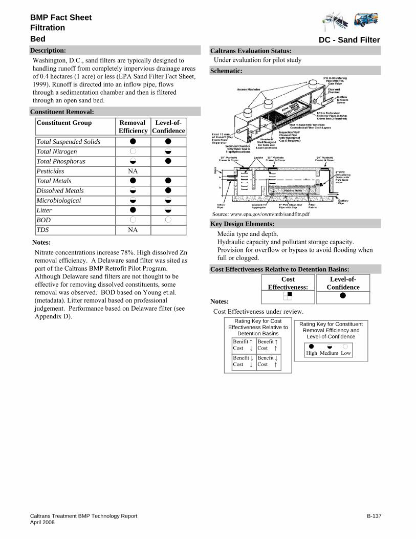
BMP Fact Sheet
DC - Sand FilterBedFiltration
Description:Washington, D.C., sand filters are typically designed to handling runoff from completely impervious drainage areas of 0.4 hectares (1 acre) or less (EPA Sand Filter Fact Sheet, 1999). Runoff is directed into an inflow pipe, flows through a sedimentation chamber and then is filtered through an open sand bed.
Removal Efficiency
Level-of-Confidence
Total Suspended SolidsTotal NitrogenTotal PhosphorusPesticidesTotal MetalsDissolved MetalsMicrobiologicalLitterBODTDS
Constituent GroupConstituent Removal:
NA
NA
Notes:Nitrate concentrations increase 78%. High dissolved Zn removal efficiency. A Delaware sand filter was sited as part of the Caltrans BMP Retrofit Pilot Program. Although Delaware sand filters are not thought to be effective for removing dissolved constituents, some removal was observed. BOD based on Young et.al. (metadata). Litter removal based on professional judgement. Performance based on Delaware filter (see Appendix D).
Key Design Elements:Media type and depth.Hydraulic capacity and pollutant storage capacity.Provision for overflow or bypass to avoid flooding when full or clogged.
CostEffectiveness:
Level-of-Confidence
Cost Effectiveness Relative to Detention Basins:
Benifit ↑Cost ↓
Benefit ↓Cost ↓
Benefit ↑Cost ↑
Benefit ↓Cost ↑
High Medium Low
Rating Key for ConstituentRemoval Efficiency and
Level-of-Confidence
Rating Key for CostEffectiveness Relative to
Detention Basins
Source: www.epa.gov/owm/mtb/sandfltr.pdf
Notes:Cost Effectiveness under review.
Schematic:
Caltrans Evaluation Status:Under evaluation for pilot study
B-137Caltrans Treatment BMP Technology ReportApril 2008

BMP Fact Sheet
DC - Sand FilterBedFiltration
Requirements:Maintenance for smaller, underground filters is usually best done manually. Normal maintenance requirements include disposal of accumulated trash and replacement of the upper few inches of sand when the filter clogs.Training:Training required for media removal.
Maintenance Issues:
Project Development Issues:Right-of-Way-Requirements:Space requirements are relatively high for sedimentation basin and sand filter.Siting Constraints:Sand filters should not be sited where runoff from bare soil or contruction activities will be allowed to enter the filter. Minimum head requirments identified.Construction:No special requirements identified.
Constraints: Sand filters are relatively expensive to construct and have only limited pollutant removal capabilities for nutrients. The sedimentation basin holds a permanent pool of water and has potential to provide breeding opportunities for mosquitoes.
Advantages:DC sand filters are installed in urban settings with covers appropriate for the intended above ground land use, such as sidewalk or landscaping. Performance is similar to the Delaware sand filter and Austin sand filter (see Appendix D) with principal advantages. They have a narrower footprint and require less head then Austin filters and are designed to receive concentrated flows at one end were the Delaware filters are designed for sheet flows along one side. Waste media from the filter does not appear to be toxic.
Rotondo Environmental Solutions LLC. www.rotondo-es.com
Schueler, T.R. 1992. "A Current Assessment of Urban Best Management Practices." Metropolitan Washington Council of Governments.
Schueler, T.R. 1994. Developments in Sand Filter Technology to Improve Stormwater Runoff Quality. Watershed Protection Techniques 1(2):47-54
Young, G.K., et. al. 1996. Evaluation and Management of Highway Runoff Water Quality. FHWA-PD-96-032. Federal Highway Administration, Office of Environment and Planning.
Literature Sources of Performance Demonstrations:Bell, W. and Nguyen, T. 1993. "Structural Best Management Practices for Stormwater Quality in the Ultra-Urban Environment." Proceedings of the Water Environment Federation 66th Annual Conference. Vol. 7 Surface Water and Ecology 223-234. Anaheim, CA.
Design, Construction, Maintenance and Cost Sourceswww.epa.gov/owm.mtb/sandfltr.pdf has information on design, performance, operation, maintenance and cost of sand filters.
Certifications, Verifications, or Designations:None identified.
B-138Caltrans Treatment BMP Technology ReportApril 2008

BMP Fact Sheet
Ecology EmbankmentBedFiltration
Description:“The Ecology Embankment is a flow-through water quality treatment device developed for use where available right-of-way is limited and longitudinal gradients are less than 5%. The Ecology Embankment, which can be sited on both highway side slopes and medians, uses infiltration through a pervious, alkalinity-generating media, called the Ecology Mix, that was designed to remove suspended solids and soluble metals from highway runoff through physical straining, ion exchange, carbonate precipitation, and biofiltration.” (WA State Department of Ecology, 2006)
Removal Efficiency
Level-of-Confidence
Total Suspended SolidsTotal NitrogenTotal PhosphorusPesticidesTotal MetalsDissolved MetalsMicrobiologicalLitterBODTDS
Constituent GroupConstituent Removal:
NA
NA
NANANANA
Notes:Washington DOT monitored 13 storm events having TSS influent concentrations above 100 mg/L, with median removal of 96% (WDOT, 2006).Overall results for the dissolved metals constituent group were based upon a median removal percent of 81% for zinc and 41% copper from the Washington DOT study (WDOT, 2006).WDOT, 2006 reported a median percent removal of total phosphorus of 85.7%.Removal efficiencies and level-of-confidences for TSS, phosphorus, and total and dissolved metals based on WDOT, 2006 studies and results.
Key Design Elements:Limited right-of-way requirement.Preferable lateral slopes less than 4:1 (less than 25%).Preferable longitudinal slope less than 5%.Bed mixture and dimensions.
CostEffectiveness:
Level-of-Confidence
Cost Effectiveness Relative to Detention Basins:
Benifit ↑Cost ↓
Benefit ↓Cost ↓
Benefit ↑Cost ↑
Benefit ↓Cost ↑
High Medium Low
Rating Key for ConstituentRemoval Efficiency and
Level-of-Confidence
Rating Key for CostEffectiveness Relative to
Detention Basins
Source: WA State Depart. of Ecology, Pierce County Stormwater Maintena
Notes:Cost effectiveness determination pending study completion.
Schematic:
Caltrans Evaluation Status:Under evaluation for pilot study
B-139Caltrans Treatment BMP Technology ReportApril 2008

BMP Fact Sheet
Ecology EmbankmentBedFiltration
Requirements:System performance is dependent upon distributed influent stormwater sheet flow.Training:Minimal roadside maintenance as needed.
Maintenance Issues:
Project Development Issues:Right-of-Way-Requirements:Designed to fit in a narrow right-of-way.Siting Constraints:Not advised in longitudinal slopes steeper than 5%, wetlands & wetland buffers, or unstable slopes.Construction:Certain soil types may require perforated pipe in the under-drain trench to ensure proper runoff through ecology bed-mix.
Constraints: Concentrated flow locations under a variety of flow conditions may reduce performance.Periodic Media Maintenance.Limited to embankments with longitudinal slopes no greater than 5% and stable.Maximum recommended traverse (side) slope of 4:1.Not recommended in areas near wetlands or wetland buffer zones unless an additional interception system is used to capture runoff.
Advantages:Enhances roadside aesthetics.Good pollutant removal performance.Passive system with little to no mechanical equipment or energy necessary for operation.No vector concerns, since water treatment is accomplished below surface.Limited roadside ROW requirements.
WA State Department of Ecology, "General Use Level Designation for Basic (TSS), Enhanced & Phosphorus Treatment, and Pilot Use Level Designation for Oil Treatment," Washington Department of Transportation (WDOT), November 2006. www.wsdot.wa.gov
Literature Sources of Performance Demonstrations:Herrera Environmental Consultants, Inc., "Technology Evaluation and Engineering Report, WSDOT Ecology Embankments," Prepared for Washington Department of Transportation (WDOT), July 2006.
Design, Construction, Maintenance and Cost SourcesWA Department of Transportation (WA DOT), "Highway Runoff Manual, Stormwater Best Management Practices, RT.07 Ecology Embankment," Washington DOT, M 31-16, May 2006. www.wsdot.wa.gov.
Certifications, Verifications, or Designations:WA TAPE - General Use Level Designation (GULD) for basic TSS, Enhanced and phosphorus treatment, November 2006.
B-140Caltrans Treatment BMP Technology ReportApril 2008

BMP Fact Sheet
GAC or IX MediaBedFiltration
Description:Influent stormwater could be mixed with granular activated carbon (GAC), ion exchange (IX) resin or both at the inlet of a sedimentation chamber preceding a sand filter. A structure can be installed at the inlet flow distribution system of a sedimentation chamber for mixing. As the stormwater enters the mixing chamber tank, it comes in contact with GAC and IX resin. After mixing, the stormwater flows to the sedimentation chamber. The GAC and IX resin is in suspension with the stormwater until it settles with other solids in the sedimentation tank. As an alternative, the sedimentation chamber influent stormwater could flow over a bag or sack filled with GAC or IX resin, or both, placed in sedimentation chamber inlets or other structures.
Removal Efficiency
Level-of-Confidence
Total Suspended SolidsTotal NitrogenTotal PhosphorusPesticidesTotal MetalsDissolved MetalsMicrobiologicalLitterBODTDS
Constituent GroupConstituent Removal:
Notes:Removal efficiencies of TSS, total nitrogen + phosphorus, Total & dissolved metals, microbiological, litter, BOD, TDS based on Austin Sand Filter factsheet (D-3).Removal efficiencies of pesticides based on professional judgment.level-of-confidences are low due to lack of performance data for this combined system.
Key Design Elements:Media type and dosing rate.Media feed and storage systems.Sedimentation chamber between mixing and filtration chambers.
CostEffectiveness:
Level-of-Confidence
Cost Effectiveness Relative to Detention Basins:
Benifit ↑Cost ↓
Benefit ↓Cost ↓
Benefit ↑Cost ↑
Benefit ↓Cost ↑
High Medium Low
Rating Key for ConstituentRemoval Efficiency and
Level-of-Confidence
Rating Key for CostEffectiveness Relative to
Detention Basins
Notes:Cost effectiveness determination pending study completion.
Schematic:
Caltrans Evaluation Status:Under evaluation for pilot study
B-141Caltrans Treatment BMP Technology ReportApril 2008

BMP Fact Sheet
GAC or IX MediaBedFiltration
Requirements:Similar to the Austin sand filter (see Appendix D). Also needs replacement of spent GAC/IX powder and maintenance of the media dosing system.Training:Requires training for inspection and maintenance of the media dosing system and filtration chamber. Other training as listed for Austin Sand Filter (see Appendix D) and other filtration factsheets.
Maintenance Issues:
Project Development Issues:Right-of-Way-Requirements:Likely high for this three chambered system. This three chamber system will significantly increase space requirements for stand alone filtration systems like Austin Sand Filter (see Appendix D).Siting Constraints:High head requirement. Other constraints as listed as listed for Austin Sand Filter (see Appendix D) and other filtration factsheets.Construction:No unique requirements identified
Constraints: The GAC/IX powder will accumulate in the sedimentation chamber unless the design is such that the influent flows over a GAC/IX bag.Powder media may cause frequent clogging of filter.Other constraints as listed for Austin Sand Filters (see Appendix D) and other filtration systems.
Advantages:This BMP will enhance removal of dissolved constituents compared to detention basins or sand filters.Other advantage as listed for Austin Sand Filters (see Appendix D) and other filtration systems.
Literature Sources of Performance Demonstrations:None identified
Design, Construction, Maintenance and Cost SourcesMercado, Shery or Jimmy Lam. GAC Stormwater Application. Calgon Carbon Corporation, www.calgoncarbon.com
Certifications, Verifications, or Designations:None identified.
B-142Caltrans Treatment BMP Technology ReportApril 2008

BMP Fact Sheet
GAC Sandwich Filter and BlanketBedFiltration
Description:To help remove organics from stormwater, GAC can be added to the treatment train of existing or proposed sand filters. A GAC layer could act as both a filtering media and adsorption layer, but would require a detention pond upstream of the filter to provide sufficient pretreatment. The GAC Sandwich Filter from Calgon Carbon Corporation (patent-pending) removes a pesticides and herbicides. Calgon claims their product improves the effectiveness of slow sand filters by using a layer of GAC between two layers of sand. The system retains the advantages of traditional slow sand filtration while incorporating GAC’s ability to remove organic compounds. Existing slow sand filters can be used for retrofit applications, which eliminates the need for a major capital investment and substantially reduces the time required to install GAC facilities.
Removal Efficiency
Level-of-Confidence
Total Suspended SolidsTotal NitrogenTotal PhosphorusPesticidesTotal MetalsDissolved MetalsMicrobiologicalLitterBODTDS
Constituent GroupConstituent Removal:
NA
Notes:Nitrate and nitrite levels may actually increase due to nitrification.Removal efficiences based on combined GAC and sand filter chamber system.Removal efficiency of pesticides based on professional judgment.Removal efficiency of other constituents based on Austin Sand Filter factsheet (see Appendix D).Levels-of-Confidence are low due to lack of performance data.
Key Design Elements:Adsorption media type and depth.Sand specifications and depth.Upstream sedimentation facilities required.Normally the GAC layer would be used in conjunction with a sand filter.
CostEffectiveness:
Level-of-Confidence
Cost Effectiveness Relative to Detention Basins:
Benifit ↑Cost ↓
Benefit ↓Cost ↓
Benefit ↑Cost ↑
Benefit ↓Cost ↑
High Medium Low
Rating Key for ConstituentRemoval Efficiency and
Level-of-Confidence
Rating Key for CostEffectiveness Relative to
Detention Basins
Notes:Cost effectiveness determination pending study completion.
Schematic:
Caltrans Evaluation Status:Under evaluation for pilot study
B-143Caltrans Treatment BMP Technology ReportApril 2008
BMP Fact Sheet
GAC Sandwich Filter and BlanketBedFiltration
Requirements:Routine maintenance may include periodic sediment and debris removal as well as spent GAC disposal/regeneration. Layered media may complicate maintenance. Standing water will occur when filter is clogged.Training:Requires training for GAC removal/replacement and sand removal/replacement.
Maintenance Issues:
Project Development Issues:Right-of-Way-Requirements:Space requirements are relatively high for sedimentation basin and sand filter.Siting Constraints:Similar to full sedimentation Austin sand filters (about 1.2 meter minimum head requirement).Construction:No unique requirements identified
Constraints: Frequent clogging and short bed-life.Bacterial growth.Spent GAC may be a hazardous waste.
Advantages:The GAC layer will act as both an adsorption layer and a filtering media. This option will provide removal of some organic constituents.Can be retrofitted to existing sand filters.
Literature Sources of Performance Demonstrations:
Design, Construction, Maintenance and Cost SourcesMercado, Shery or Jimmy Lam. GAC Stormwater Application. Calgon Carbon Corporation., wwwcalgoncarbon.com
Certifications, Verifications, or Designations:None identified.
B-144Caltrans Treatment BMP Technology ReportApril 2008

BMP Fact Sheet
Linear Filtration TrenchBedFiltration
Description:The Linear Filter Trench is a concept developed by Caltrans, based on Delaware sand filters. Delaware filters are typically constructed in curb-side areas and the filter is contained in a concrete vault. The Linear Filter Trench is constructed away from load-bearing areas so that trench construction can help reduce cost. A layer of gravel equivalent cover overlays the sedimentation area to prevent mosquito access to standing water. The use of a high-porosity backfill will support the overlay, while maintaining the capture volume of the sedimentatio chamber.Linear Filter Trenches are designed for the narrow right-of-way that is typical of roadside areas.
Removal Efficiency
Level-of-Confidence
Total Suspended SolidsTotal NitrogenTotal PhosphorusPesticidesTotal MetalsDissolved MetalsMicrobiologicalLitterBODTDS
Constituent GroupConstituent Removal:
NA
NA
Notes:Removal efficiencies and level-of-confidences based on Delaware Sand Filter (see page D-23).
Key Design Elements:As recommended for Delaware Sand Filters, unit should be designed and installed according to the guidelines described by Young et al. (1996). It should be noted that if a linear filter trench is designed according to these guidelines, there is only storage in the unit for 5 min of runoff (0.2 in.); consequently the unit acts as a flow-through device. The filter is sized using unit values for the sedimentation chamber volume and filter bed area per acre of tributary are treated.
CostEffectiveness:
Level-of-Confidence
Cost Effectiveness Relative to Detention Basins:
Benifit ↑Cost ↓
Benefit ↓Cost ↓
Benefit ↑Cost ↑
Benefit ↓Cost ↑
High Medium Low
Rating Key for ConstituentRemoval Efficiency and
Level-of-Confidence
Rating Key for CostEffectiveness Relative to
Detention Basins
Notes:Cost effectiveness determination pending study completion.
Schematic:
Caltrans Evaluation Status:Under evaluation for pilot study
B-145Caltrans Treatment BMP Technology ReportApril 2008

BMP Fact Sheet
Linear Filtration TrenchBedFiltration
Requirements:Maintenance for smaller filters is usually best done manually. Normal maintenance requirements include disposal of accumulated trash and replacement of the upper few inches of sand when the filter clogs.Training:Training required for media removal.
Maintenance Issues:
Project Development Issues:Right-of-Way-Requirements:Designed to fit in a narrow right-of-way.Siting Constraints:Should not be sited where runoff from bare soil or construction activities will be allowed to enter the filter. Minimum head requirement of 1.0 meters (based on Delaware design).Construction:No special requirements identified
Constraints: Sand filters have only limited pollutant removal capability for nutrients.The sedimentation chamber holds a permanent pool of water and has the potential to provide breeding opportunities for mosquitoes.
Advantages:They are similar in performance to the Austin Sand Filter design with the principal advantage being smaller in size.Waste media from the filters does not appear to be toxic and is likely to be environmentally safe for landfill disposal.
The US Department of Transportation. "Evaluation and Management of Highway Runoff Water Quality." Young et al. 1996 contains information on the citing, design, and performance of Delaware sand filters
Bell, W., Stokes, L., Gavan, L. J., Nguyen, T. N. 1995. "Assessment of the Pollutant Removal Efficiencies of Delaware Sand Filter BMP’s. Department of Transportation and Environmental Services." Alexandria, V.A. 140pp.
Horner, R. R. and Horner, C. R. 1995. "Design, Construction, and Evaluation of a Sand Filter Stormwater Treatment System. Part III." Performance monitoring. Report to Alaska Marine Lines, Seattle, WA.Shaver, E. and Baldwin, R. 1991. "Sand Filter Design for Water Quality Treatment" Delaware Dept. of Natural Resources and Environmental Control. Dover, DE. 14pp.
Literature Sources of Performance Demonstrations:Caltrans, 2004. "BMP Retrofit Pilot Program Final Report," CTSW-RT-01-050 available at www.dot.ca.gov/hq/env/stormwater
Design, Construction, Maintenance and Cost Sourceswww.epa.gov/owm/mtb/sandfltr.pdf
Certifications, Verifications, or Designations:None identified.
B-146Caltrans Treatment BMP Technology ReportApril 2008

BMP Fact Sheet
Granular Activated CarbonCartridge/CanisterFiltration
Description:Granulated Activated Carbon (GAC) adsorption is typically used to remove volatile organic compounds (VOCs) in water for potable uses. In addition to reported removal efficiency greater than 99% for VOCs, it is effective for treatment of synthetic organic chemicals. With GAC treatment, contaminated water passes through a column of GAC where organic compounds are removed by adsorption onto the carbon granule surface. Once the carbon can no longer adsorb pollutants from the water, it must be regenerated or replaced. Two types of designs are commonly employed for GAC: the pressurized contactor unit and the gravity-flow unit (which is similar to the gravity media filter). Columns typically are pressurized. Though typically designed for pressurized flow, the GAC system can be designed to operate by gravity. For stormwater application, a GAC canister could be placed at the outlet of a detention basin, and the basin effluent would be allowed to flow through it by gravity. Performance of the GAC canister at a sedimentation pond outlet will depend highly on the performance of the pretreatment. The sedimentation pond will also provide flow equalization to the GAC canisters. Some proprietary products in Appendix B are available with GAC.
Removal Efficiency
Level-of-Confidence
Total Suspended SolidsTotal NitrogenTotal PhosphorusPesticidesTotal MetalsDissolved MetalsMicrobiologicalLitterBODTDS
Constituent GroupConstituent Removal:
PretreatedNANA
NANA
PretreatedNANA
Notes:Removal efficiencies based on professional judgment.level-of-confidences are low due to lack of performance data.
Key Design Elements:Absorption media type and depth.Container and hydraulic system.Requires pretreatment such as a detention/sedimentation BMP.
CostEffectiveness:
Level-of-Confidence
Cost Effectiveness Relative to Detention Basins:
Benifit ↑Cost ↓
Benefit ↓Cost ↓
Benefit ↑Cost ↑
Benefit ↓Cost ↑
High Medium Low
Rating Key for ConstituentRemoval Efficiency and
Level-of-Confidence
Rating Key for CostEffectiveness Relative to
Detention Basins
Notes:Cost effectiveness determination pending study completion.
Schematic:
Caltrans Evaluation Status:Under evaluation for pilot study
B-147Caltrans Treatment BMP Technology ReportApril 2008

BMP Fact Sheet
Granular Activated CarbonCartridge/CanisterFiltration
Requirements:The mechanical equipment needs to be maintained. Spent GAC will have to be replaced or regenerated periodically. Standing water will occur when column is clogged.Training:Requires training for inspection and maintenance of GAC canister
Maintenance Issues:
Project Development Issues:Right-of-Way-Requirements:Small footprint if the pretreatment (e.g. sedimentation BMP) is pre-existing. Total system has large space requirements.Siting Constraints:High head requirementConstruction:No unique requirements identified
Constraints: Potential clogging of the GAC if pretreatment does not remove enough suspended solids, oil and grease.Spent GAC has the potential of being considered a hazardous material and will need to be disposed of properly.The carbon must be shipped off-site for regeneration or disposal by a licensed company. One option would be to dispose of the spent GAC and replace it with new GAC. Regeneration of the GAC onsite is considered to be technically infeasible and cost prohibitive. Another is to replace regenerated GAC cylinders and regenerate spent cylinders at an off-site location, which is commonly done by small-scale commercial and industrial users.GAC may promote considerable microbial growth on the carbon surface.Disinfection prior to GAC adsorption is not viable since the GAC removes disinfectants.
Advantages:Compact system at the detention basin outlet.Reduces pesticides.Consistent effluent quality.Can be retrofitted to existing detention basins with sufficient downstream head.
McMillen, Brent. Faxed document. Activated Carbon Contaminants and Costs. CPL Carbon Link CorporationNitchman, Craig. Faxed Document. Carbon Usage Rate. Calgon Carbon CorporationWilburn, Tom. Phone Conversation. GAC Quilted Blanket Filter Production. D. R. Shannon Company, (800) 255-1032Mercado, Shery or Jimmy Lam. GAC Stormwater Application. Calgon Carbon Corporation. www.calgoncarbon.com
Literature Sources of Performance Demonstrations:Wanielista, M. P., et al. "Evaluation of the Stormwater Treatment Facilities at the Lake Angel Detention Pond, Orange County, Florida." Florida State Department of Transportation and University of Central Florida, Gainesville. June 1991.
Design, Construction, Maintenance and Cost SourcesEvans, Max. Mailed Correspondence. Oil or Gas Recovery from Parking Areas. Culligan Water.
Certifications, Verifications, or Designations:None identified.
B-148Caltrans Treatment BMP Technology ReportApril 2008
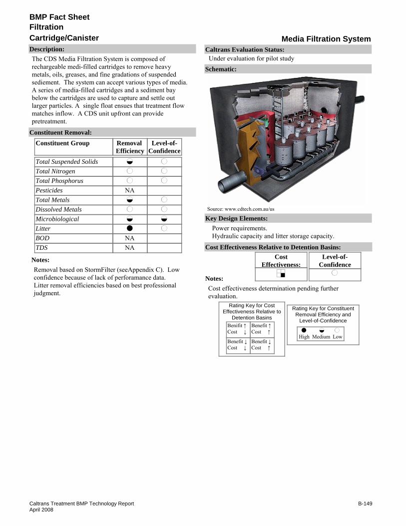
BMP Fact Sheet
Media Filtration SystemCartridge/CanisterFiltration
Description:The CDS Media Filtration System is composed of rechargeable medi-filled cartridges to remove heavy metals, oils, greases, and fine gradations of suspended sediement. The system can accept various types of media. A series of media-filled cartridges and a sediment bay below the cartridges are used to capture and settle out larger particles. A single float ensues that treatment flow matches inflow. A CDS unit upfront can provide pretreatment.
Removal Efficiency
Level-of-Confidence
Total Suspended SolidsTotal NitrogenTotal PhosphorusPesticidesTotal MetalsDissolved MetalsMicrobiologicalLitterBODTDS
Constituent GroupConstituent Removal:
NA
NANA
Notes:Removal based on StormFilter (seeAppendix C). Low confidence because of lack of perforamance data.Litter removal efficiencies based on best professional judgment.
Key Design Elements:Power requirements.Hydraulic capacity and litter storage capacity.
CostEffectiveness:
Level-of-Confidence
Cost Effectiveness Relative to Detention Basins:
Benifit ↑Cost ↓
Benefit ↓Cost ↓
Benefit ↑Cost ↑
Benefit ↓Cost ↑
High Medium Low
Rating Key for ConstituentRemoval Efficiency and
Level-of-Confidence
Rating Key for CostEffectiveness Relative to
Detention Basins
Source: www.cdtech.com.au/us
Notes:Cost effectiveness determination pending further evaluation.
Schematic:
Caltrans Evaluation Status:Under evaluation for pilot study
B-149Caltrans Treatment BMP Technology ReportApril 2008

BMP Fact Sheet
Media Filtration SystemCartridge/CanisterFiltration
Requirements:Inspecting the facility, removing litter and sediment and all spent filter cartridges, repairing or replacing inoperative controls, valve or filter canister, and cleaning the filter cartridges and canister if necessary. May have standing water if filters do not drain completely.Training:Crews must be trained to repair or replace any cartridge filter or part associated with the facility.
Maintenance Issues:
Project Development Issues:Right-of-Way-Requirements:Space requirements depend on sizing criteria, typically smaller than basins.Siting Constraints:Must have sufficient hydraulic head.Construction:No special requirements identified
Constraints: Removal of fine sediment in cartridge filters is not as effective as in open bed media filters.Proprietary device.
Advantages:Smaller footprint than for conventional sedimentation/gravity sand filters.
Literature Sources of Performance Demonstrations:None identified
Design, Construction, Maintenance and Cost SourcesCDS Technologies, Inc., www.cdstech.com.au/us/
Certifications, Verifications, or Designations:WA TAPE - General Use Level Designation for basic TSS Treatment, August 2007.
B-150Caltrans Treatment BMP Technology ReportApril 2008

BMP Fact Sheet
Puristorm™Cartridge/CanisterFiltration
Description:The Puristorm™ is a standard pre-cast concrete vault with a filter cartridge system. Outlet flow is a two-stage system with low head loss (less than 0.2 ft) that does not require flow bypassing.
Removal Efficiency
Level-of-Confidence
Total Suspended SolidsTotal NitrogenTotal PhosphorusPesticidesTotal MetalsDissolved MetalsMicrobiologicalLitterBODTDS
Constituent GroupConstituent Removal:
NANANANANANA
NANA
Notes:Manufacturer claims 95% TSS removal for sandy sediment.Litter removal based on professional judgment.Removal efficiency for TSS based on best professional judgment.level-of-confidence is low for TSS based on lack of statistically significant performance data.
Key Design Elements:Flow capacity (flood and water quality flow).Pollutant storage capacity.Detention time.
CostEffectiveness:
Level-of-Confidence
Cost Effectiveness Relative to Detention Basins:
Benifit ↑Cost ↓
Benefit ↓Cost ↓
Benefit ↑Cost ↑
Benefit ↓Cost ↑
High Medium Low
Rating Key for ConstituentRemoval Efficiency and
Level-of-Confidence
Rating Key for CostEffectiveness Relative to
Detention Basins
Source: www.env21.com
Notes:Cost effectiveness determination pending further evaluation.
Schematic:
Caltrans Evaluation Status:Under evaluation for pilot study
B-151Caltrans Treatment BMP Technology ReportApril 2008

BMP Fact Sheet
Puristorm™Cartridge/CanisterFiltration
Requirements:If there is high solids loading (often caused by vegetation within the drainage area), frequent inspection and maintenance is required.Training:Spent filter cartridges are to be replaced as warranted.
Maintenance Issues:
Project Development Issues:Right-of-Way-Requirements:Relatively small footprintSiting Constraints:Requires a curb or drop inlet. Can also be used in a pond or swaleConstruction:No unique requirements identified
Constraints: Proprietary device.Vector concerns.
Advantages:Small footprint.
Literature Sources of Performance Demonstrations:None identified
Design, Construction, Maintenance and Cost SourcesEnvironmental 21, LLC, www.env21.com
Certifications, Verifications, or Designations:None identified.
B-152Caltrans Treatment BMP Technology ReportApril 2008
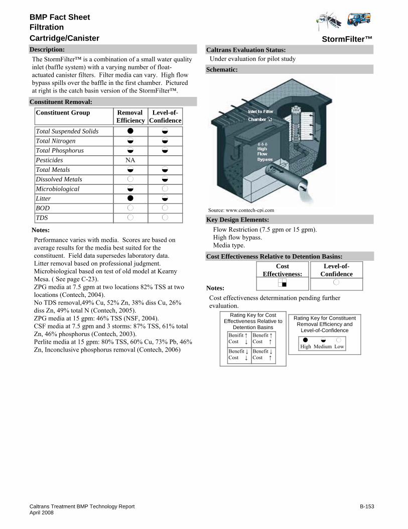
BMP Fact Sheet
StormFilter™Cartridge/CanisterFiltration
Description:The StormFilter™ is a combination of a small water quality inlet (baffle system) with a varying number of float-actuated canister filters. Filter media can vary. High flow bypass spills over the baffle in the first chamber. Pictured at right is the catch basin version of the StormFilter™.
Removal Efficiency
Level-of-Confidence
Total Suspended SolidsTotal NitrogenTotal PhosphorusPesticidesTotal MetalsDissolved MetalsMicrobiologicalLitterBODTDS
Constituent GroupConstituent Removal:
NA
Notes:Performance varies with media. Scores are based on average results for the media best suited for the constituent. Field data supersedes laboratory data. Litter removal based on professional judgment.Microbiological based on test of old model at Kearny Mesa. ( See page C-23).ZPG media at 7.5 gpm at two locations 82% TSS at two locations (Contech, 2004).No TDS removal,49% Cu, 52% Zn, 38% diss Cu, 26% diss Zn, 49% total N (Contech, 2005).ZPG media at 15 gpm: 46% TSS (NSF, 2004).CSF media at 7.5 gpm and 3 storms: 87% TSS, 61% total Zn, 46% phosphorus (Contech, 2003). Perlite media at 15 gpm: 80% TSS, 60% Cu, 73% Pb, 46% Zn, Inconclusive phosphorus removal (Contech, 2006)
Key Design Elements:Flow Restriction (7.5 gpm or 15 gpm).High flow bypass.Media type.
CostEffectiveness:
Level-of-Confidence
Cost Effectiveness Relative to Detention Basins:
Benifit ↑Cost ↓
Benefit ↓Cost ↓
Benefit ↑Cost ↑
Benefit ↓Cost ↑
High Medium Low
Rating Key for ConstituentRemoval Efficiency and
Level-of-Confidence
Rating Key for CostEffectiveness Relative to
Detention Basins
Source: www.contech-cpi.com
Notes:Cost effectiveness determination pending further evaluation.
Schematic:
Caltrans Evaluation Status:Under evaluation for pilot study
B-153Caltrans Treatment BMP Technology ReportApril 2008

BMP Fact Sheet
StormFilter™Cartridge/CanisterFiltration
Requirements:Inspecting the facility, removing litter and sediment and all spent filter cartridges, repairing or replacing inoperative controls, valve or filter canister, and cleaning the filter cartridges and canister if necessary.Training:Crews must be trained to repair or replace any cartridge filter or part associated with the facility or contract for maintenance.
Maintenance Issues:
Project Development Issues:Right-of-Way-Requirements:Space requirements depend on sizing criteria, typically smaller than basins.Siting Constraints:Must have sufficient hydraulic head.Construction:No unique requirements identified
Constraints: Removal of fine sediment in cartridge filters is not as effective as in open bed media filters.Proprietary device.Vector concerns.
Advantages:Smaller footprint than for conventional sedimentation/gravity sand filters.Noling, et al, report toxicity reduction for high levels of influent metals.
U.S. Environmental Protection Agency, www.epa.gov/region1/assistance/ceitts/stormwater/techs/stormfilter.html
Contech Storm Water Solutions 2004. "Performance of the Stormwater Management StormFilter relative to Ecology Performance Goals for Basin Treatment" (available by request of manufacturer)
Contech Storm Water Solutions 2005. "heritage Marketplace Field Evaluation: Stormwater Management StormFilter with ZPG Media" (available by request of manufacturer)
Contech Storm Water Solutions 2006. "Greenville Yards Storm water Treatment System Field Evaluation: Storm water Management Storm Filter with Perlite Media at 57 L/min/cart" (available by request of manufacturer)Calvin, N. and Barry, K. "Successful Demonstration of the Storm water management StormFilter® Enhanced Filtration System for Toxicity Reduction of shipyard Storm water conducted at National Steel and Shipbuilding Company (NASSCO)." Presented at: the Prevention of Pollution from Ships, Shipyards, Drydocks, Ports, and Harbors: 3rd International Symposium on November 5 - 7, 2003 at the University of New Orleans, LA http://www.hartcrowser.com/PDFs/Stormfilter.pdfNSF International July, 2004. "Environmental Technology Verification Report: Storm water Source Area Treatment Device, the Storm water Management StormFilter® using ZPG Filter Media." www.epa.gov/etv/pdfs/vrvs/600etv06039/600etv06039s.pdf
Literature Sources of Performance Demonstrations:Contech Storm Water Solutions 2003. "Heritage Marketplace Field Evaluation: Stormwater Management StormFilter with CSF Leaf Media." (available by request of manufacturer)
Design, Construction, Maintenance and Cost SourcesContech® Stormwater Solutions, Inc., www.contech-cpi.com/stormwater/products
Certifications, Verifications, or Designations:ETV - Verification statement issued July 2004 for suspended solids.TCEQ - Approval of Innovative Technology: Each cartridge must be limited to a maximum flow rate of 7.5 gpm.TARP - Compliant or similar reliable data on this technology to be able to evaluate pollution removal efficiency claims for TSS, SSC.
B-154Caltrans Treatment BMP Technology ReportApril 2008

BMP Fact Sheet
StormPlex®Cartridge/CanisterFiltration
Description:The StormPlex® uses a baffle and filter. The unit can accept pipe flow as well as grate inlet flow. Units may be installed in series. Water flow under the baffle and up through a media called Fablite. High flows pass over the baffle through a screen.
Removal Efficiency
Level-of-Confidence
Total Suspended SolidsTotal NitrogenTotal PhosphorusPesticidesTotal MetalsDissolved MetalsMicrobiologicalLitterBODTDS
Constituent GroupConstituent Removal:
NANANANANANANA
NANA
Notes:Removal efficiency for litter based on best professional judgment.level-of-confidence for litter is medium assuming device has at least 5 cubic feet of pollutant storage capacity to capture annual litter from every acre of drainage served.
Key Design Elements:Provision for overflow or bypass to avoid flooding when the insert is full or clogged.Hydraulic capacity and pollutant storage capacity.Media type.
CostEffectiveness:
Level-of-Confidence
Cost Effectiveness Relative to Detention Basins:
Benifit ↑Cost ↓
Benefit ↓Cost ↓
Benefit ↑Cost ↑
Benefit ↓Cost ↑
High Medium Low
Rating Key for ConstituentRemoval Efficiency and
Level-of-Confidence
Rating Key for CostEffectiveness Relative to
Detention Basins
Source: www.fabco-industries.com
Notes:
Schematic:
Caltrans Evaluation Status:Under evaluation for pilot study
B-155Caltrans Treatment BMP Technology ReportApril 2008

BMP Fact Sheet
StormPlex®Cartridge/CanisterFiltration
Requirements:Unknown. May require confined space entry.Training:No special requirements identified.
Maintenance Issues:
Project Development Issues:Right-of-Way-Requirements:Same as drop inletsSiting Constraints:Same as drop inletsConstruction:No special requirements identified
Constraints: Potential for blinding of bypass.Bypass has a screen that may be blinded by floating debris.Unit seems to retain standing water.Proprietary device.
Advantages:The device can be installed in parallel to increase treatment capacity.Filters can be recharged.Delivered precast.
Literature Sources of Performance Demonstrations:None identified
Design, Construction, Maintenance and Cost SourcesFabco Industries Inc., StormPlex®, www.fabco-industries.com
Certifications, Verifications, or Designations:None identified.
B-156Caltrans Treatment BMP Technology ReportApril 2008

BMP Fact Sheet
VortFilterCartridge/CanisterFiltration
Description:The VortFilter™ is media cartridge that is mounted within a concrete vault to treat flows between 12 and 20 gpm. It has an outer cylinder housing that acts as a baffle and an inner cylinder screen that holds the media. Media choices include; Perlite, Granular Activated Carbon (GAC), and Zeolite. Untreated stormwater flows into the lower half of a partitioned vault. The upper half is divided by a deck that holds the filter cartridges. An increasing hydraulic head forces water into the media cartridge, up through a center dome outlet and into the upper chamber. During peak flows, above 20-gpm per cartridge, water can bypass the filter cartridges through an overflow pipe that directs waste from the lower chamber to the upper chamber, by passing the filter, and out of the system.
Removal Efficiency
Level-of-Confidence
Total Suspended SolidsTotal NitrogenTotal PhosphorusPesticidesTotal MetalsDissolved MetalsMicrobiologicalLitterBODTDS
Constituent GroupConstituent Removal:
NANANANANANA
NANA
Notes:Some performance claims based on restricting flows per cartridge to 9-gpm. Test at 15-gpm achieved low to high removal of TSS..Manufacturer reports 80% particle removal in laboratory tests.Removal efficiencies for TSS based on best professional judgment.level-of-confidence for litter is medium assuming device has at least 5 cubic feet of pollutant storage capacity to capture annual litter from every acre of drainage served.level-of-confidence for TSS is low due to lack of statistically significant performance data.
Key Design Elements:Provision for overflow or bypass to avoid flooding when the insert is full or clogged.Restricting flow to design flows.Hydraulic capacity.Media type.
CostEffectiveness:
Level-of-Confidence
Cost Effectiveness Relative to Detention Basins:
Benifit ↑Cost ↓
Benefit ↓Cost ↓
Benefit ↑Cost ↑
Benefit ↓Cost ↑
High Medium Low
Rating Key for ConstituentRemoval Efficiency and
Level-of-Confidence
Rating Key for CostEffectiveness Relative to
Detention Basins
Source: www.contech-cpi.com
Notes:Cost effectiveness determination pending study completion.
Schematic:
Caltrans Evaluation Status:Under evaluation for pilot study
B-157Caltrans Treatment BMP Technology ReportApril 2008
BMP Fact Sheet
VortFilterCartridge/CanisterFiltration
Requirements:Periodic maintenance is required to remove sediment that accumulates in the vaults. Vactor equipment recommended for cleaning.Training:Training in cartridge handling, installation and removal required.
Maintenance Issues:
Project Development Issues:Right-of-Way-Requirements:Moderate to large footprint depending on system size and configuration.Siting Constraints:UnknownConstruction:Precast structure typically installed within three to four months after select site has been stabilized.
Constraints: Depending on the system size, cost of construction can be high.Maintenance could be costly depending on system size.Standing water may be a vector concern.Proprietary device.
Advantages:Moderate constituent removal.Potentially small footprint with limited space since the system is underground.
Literature Sources of Performance Demonstrations:Votechnics, Inc., "NJCAT Technology Verification," September, 2005.
Design, Construction, Maintenance and Cost SourcesContech® Stormwater Solutions, Inc., www.contech-cpi.com/stormwater/13
Certifications, Verifications, or Designations:NJCAT - Based on evaluation VortFilter™ cartridge in combination with the VortFilter™ sump sized at a treatment rate of no more than 15 gpm with a perlite media and an event mean concentration influent in the range 100 - 300 mg/L, has been shown to have a regressed TSS removal efficiency (measured as SSC) of greater than 80% for two manufactured silica products with average particle sizes of 22 and 32 microns respectively in laboratory studies using simulated stormwaterVortFilter™ cartridge in combination with the VortFilter™ sump sized at a treatment rate of no more than 15 gpm with a perlite media and an event mean concentration influent in the range 100 - 300 mg/L, has been shown to have aregressed TSS removal efficiency (measured as SSC) of greater than 80% for two manufactured silica products with average particle sizes of 22 and 32 microns respectively in laboratory studies using simulated stormwater.
B-158Caltrans Treatment BMP Technology ReportApril 2008

BMP Fact Sheet
Capture Flow™Catch Basin FiltersFiltration
Description:CaptureFlow™ is an alternative catch basin system with drain-inlet-insert style filters and a secondary filter at the outflow. The flood flow bypass system claims to filter 1/8 inch material.
Removal Efficiency
Level-of-Confidence
Total Suspended SolidsTotal NitrogenTotal PhosphorusPesticidesTotal MetalsDissolved MetalsMicrobiologicalLitterBODTDS
Constituent GroupConstituent Removal:
NANANANANANANA
NANA
Notes:No performance data encountered and no claims by the manufacturer.Scores based on professional judgment.
Key Design Elements:Provision for overflow or bypass to avoid flooding when the insert is full or clogged.Hydraulic capacity and litter storage capacity.Media type.
CostEffectiveness:
Level-of-Confidence
Cost Effectiveness Relative to Detention Basins:
Benifit ↑Cost ↓
Benefit ↓Cost ↓
Benefit ↑Cost ↑
Benefit ↓Cost ↑
High Medium Low
Rating Key for ConstituentRemoval Efficiency and
Level-of-Confidence
Rating Key for CostEffectiveness Relative to
Detention Basins
Source: www.carsonind.com
Notes:Cost effectiveness determination pending study completion.
Schematic:
Caltrans Evaluation Status:Under evaluation for pilot study
B-159Caltrans Treatment BMP Technology ReportApril 2008

BMP Fact Sheet
Capture Flow™Catch Basin FiltersFiltration
Requirements:If there is high solids loading (often caused by vegetation within the drainage area), frequent inspection and maintenance is required.Training:No special requirements identified.
Maintenance Issues:
Project Development Issues:Right-of-Way-Requirements:Same as drop inletsSiting Constraints:Same as drop inletsConstruction:Confined space situations may be an issue.
Constraints: Capacity is constrained by the size of the drain inlet insert. It may be no more efficient than drain inlet insert technologies, yet construction is more complicated.Proprietary device.
Advantages:The system is easy to install.The device can be installed in parallel to increase treatment capacity. Water can pass through freely (if void of solids). Some filter cartridges can be recharged. Filter media can easily be site-specific. Some devices are delivered precast.
Literature Sources of Performance Demonstrations:None identified.
Design, Construction, Maintenance and Cost SourcesCarson Industries LLC, www.carsonind.com
Certifications, Verifications, or Designations:None identified.
B-160Caltrans Treatment BMP Technology ReportApril 2008

BMP Fact Sheet
Arkal FilterDiscFiltration
Description:A disc filtration device, one of such designed by Arkal Filtration Systems/Zeta Technologies, is referred to as a Spin Klin. The Spin Klin self-backwashing disc filter was designed for filtration of solids from irrigation water, but may be applicable on pressurized pipes downstream of stormwater sedimentation basins. The filter consists of a spring-loaded spine that holds a number of stacked, diagonally-grooved polyproplylene discs enclosed in a corrosion and pressure-resistant housing. The stacked discs create a filtration element with a statistically significant series of valleys and traps. During filtration, the discs are compressed by the spring and the differential pressure of the water, which flows from the peripheral end to the core of the element. Backwashing involves release of the compression spring and high-pressure flow of clean water through nozzles at the center of the spine. The discs spin free and solids are efficiently flushed out through the drain. Modular batteries allow for easy expansion of system in various space-saving configurations.(Source:www.arkal-filters.com)
Removal Efficiency
Level-of-Confidence
Total Suspended SolidsTotal NitrogenTotal PhosphorusPesticidesTotal MetalsDissolved MetalsMicrobiologicalLitterBODTDS
Constituent GroupConstituent Removal:
NA
NANA
PretreatedNA
Notes:Level of confidence is not higher because no p-values were found in literature to warrant a high level of confidence (EPA, 2006) and unit tested also employed a pressurized sand filter so performance of the disk filter by itself could only be estimated.Litter and debris removal must be accomplished prior to this unit.TSS and metals removal based on professional judgment.
Key Design Elements:Litter and debris capture required upstream.Backwash water storage and disposal facilities..Power requirements.Upstream equalization volume.Flow rate.
CostEffectiveness:
Level-of-Confidence
Cost Effectiveness Relative to Detention Basins:
Benifit ↑Cost ↓
Benefit ↓Cost ↓
Benefit ↑Cost ↑
Benefit ↓Cost ↑
High Medium Low
Rating Key for ConstituentRemoval Efficiency and
Level-of-Confidence
Rating Key for CostEffectiveness Relative to
Detention Basins
Source: www.arkal-filters.com
Notes:Cost effectiveness determination pending study completion.
Schematic:
Caltrans Evaluation Status:Under evaluation for pilot study
B-161Caltrans Treatment BMP Technology ReportApril 2008

BMP Fact Sheet
Arkal FilterDiscFiltration
Requirements:Mechanical equipment maintenanceTraining:Crews would need to be trained to maintain equipment. Service contract may be preferred.
Maintenance Issues:
Project Development Issues:Right-of-Way-Requirements:Building may be required to house the unit.Siting Constraints:Needs powerConstruction:No unique requirements identified
Constraints: Removes only solids-associated contaminants.Designed for installation on pressurized pipes. Not designed to remove larger solids so upstream litter and debris would be needed. May not be suitable for use at side of freeway.Limited application.Requires power.Proprietary device.
Advantages:Micron-precise filtration of solids. Claimed by the manufacturer to retain large amount of solids for long filtration cycles (Note: solids in irrigation water may differ from those of settled stormwater).Low maintenance self-backwashing design. Self-contained.
Literature Sources of Performance Demonstrations:U.S. Environmental Protection Agency, http://www.epa.gov/etv/pdfs/vrvs/09_vs_arkal.pdf. January 2006.
Design, Construction, Maintenance and Cost SourcesArkal Filtration Systems, www.arkal-filters.com
Certifications, Verifications, or Designations:ETV - Verification statement issued April 2004 for sediment removal.TARP - Studies underway that offer promise for reliable data in the near future for addressing TKN, TP, TDS, TSS & SSC removal efficiency claims.
B-162Caltrans Treatment BMP Technology ReportApril 2008

BMP Fact Sheet
various suppliersElectrocoagulationFiltration
Description:Electrocoagulation (EC) System™ has been an effective technology for removal of emulsified oils, TPH, suspended solids and heavy metals from industrial wastewater and stormwater runoff that is exceptionally polluted. EC technology is an alternative to the use of Alum, metal salts or polymers and polyelectrolyte addition(s) for breaking stable emulsions and suspensions. EC technology removes metals, colloidal solids and particles, and soluble inorganic pollutants from aqueous media by introducing highly charged polymeric metal hydroxide species. Neutralized suspended solids and oil droplets facilitate agglomeration or coagulation and result in precipitation of certain metals and salts
Removal Efficiency
Level-of-Confidence
Total Suspended SolidsTotal NitrogenTotal PhosphorusPesticidesTotal MetalsDissolved MetalsMicrobiologicalLitterBODTDS
Constituent GroupConstituent Removal:
NA
NANANANA
PretreatedNANA
Notes:Level of confidence based on proven application to other waste streams (See Appendix A).
Key Design Elements:Influent Water Quality ( minimum EC Required).Sludge collection by detention basin or tank(s).Filtration Equalization.Power requirements.
CostEffectiveness:
Level-of-Confidence
Cost Effectiveness Relative to Detention Basins:
Benifit ↑Cost ↓
Benefit ↓Cost ↓
Benefit ↑Cost ↑
Benefit ↓Cost ↑
High Medium Low
Rating Key for ConstituentRemoval Efficiency and
Level-of-Confidence
Rating Key for CostEffectiveness Relative to
Detention Basins
Source: www.stormwaterinc.com
Notes:Cost effectiveness determination pending study completion.
Schematic:
Caltrans Evaluation Status:Under evaluation for pilot study
B-163Caltrans Treatment BMP Technology ReportApril 2008
BMP Fact Sheet
various suppliersElectrocoagulationFiltration
Requirements:Mechanical equipment must be maintained.Training:Crews will need to be trained to maintain and operate equipment
Maintenance Issues:
Project Development Issues:Right-of-Way-Requirements:Used in construction with sedimentation tanks.Siting Constraints:Restricted to sites with available nearby power and possibly a sewer connection.Construction:Significant start-up and test requirements.
Constraints: Sacrificial electrodes are dissolved into wastewater streams as a result of oxidation, and need to be regularly replaced.Use of electricity in many places may be expensive.Impermeable oxide film may be formed on the cathode leading to loss of efficiency of EC unit. However, this does not occur in the Haivala unit for the process water is forced into turbulence and this oxide is never allowed to form.High conductivity of the water suspension is required. This is compensated for in the Haibala unit.
Advantages:Sludge formed by EC tends to be readily settable and easy to de-water, because it is composed of mainly metallic oxides/hydroxides.Gas bubbles produced during electrolysis can carry the pollutant to the top of the solution where it can be more easily be concentrated, collected and removed.Electrolytic processes in the EC cell are controlled electrically and with no moving parts.EC techniques may be used in rural areas where electricity is not available, if a solar panel attachment to the unit provides sufficient power.
Beagles, Abe PhD. "Electrocoagulation - Science and Applications." Cal-Neva Water Quality Research Institute, Inc. May 2004. Accessed Jul 2006 via www.eco-web.com/editorial/050526.htmlElectrocoagulation System, Contech® Stormwater Solutions, Inc. Stormwater Management Inc. www.contech-cpi.com
Carmona, M., Khemis, M., Leclerc, J., and Lapicque, F. "A Simple model to Predict the Removal of Oil Suspensions from Water Using the Electocoagulation Technique." Elsevier Ltd. Jul 2005.
Literature Sources of Performance Demonstrations:Barkley, N. P., Farrell, C., and Williams, T., "Emerging Technology Summary: Electro-Pure Alternating Current Electrocoagulation" Superfund Innovative Technology Evaluation. EPA/540-S-93-504 Sep 1993.
Design, Construction, Maintenance and Cost SourcesKaselco by Kaspar Electroplating Corp. http://www.kaselco.com
Certifications, Verifications, or Designations:None identified.
B-164Caltrans Treatment BMP Technology ReportApril 2008

BMP Fact Sheet
Stormfilter 400®FabricFiltration
Description:Stormfilter 400® technology is a patented in-line polyethylene filter system. Stormwater flows through a sequence of baffle walls in a sediment chamber that removes and separates debris and sediment before passing through a filter fabric (70 U.S. Sieve). The filter can be used as pretreatment for a recharge system, as shown in the image. It has a treatment capacity of 100 gpm.
Removal Efficiency
Level-of-Confidence
Total Suspended SolidsTotal NitrogenTotal PhosphorusPesticidesTotal MetalsDissolved MetalsMicrobiologicalLitterBODTDS
Constituent GroupConstituent Removal:
NANANANANANA
NANA
Notes:Removal efficiency for litter based on professional judgment.
Key Design Elements:Media type and depthHydraulic capacity and pollutant storage capacityProvision for overflow or bypass to avoid flooding when the insert is full or clogged
CostEffectiveness:
Level-of-Confidence
Cost Effectiveness Relative to Detention Basins:
Benifit ↑Cost ↓
Benefit ↓Cost ↓
Benefit ↑Cost ↑
Benefit ↓Cost ↑
High Medium Low
Rating Key for ConstituentRemoval Efficiency and
Level-of-Confidence
Rating Key for CostEffectiveness Relative to
Detention Basins
Source: www.cultec.com
Notes:
Schematic:
Caltrans Evaluation Status:Under evaluation for pilot study
B-165Caltrans Treatment BMP Technology ReportApril 2008

BMP Fact Sheet
Stormfilter 400®FabricFiltration
Requirements:Replace filter fabric dividers. Because of site-specific laoding, seveeral wet season inspections may be required to determine appropriate replacement frequency.Training:Training needed for confined space entry.
Maintenance Issues:
Project Development Issues:Right-of-Way-Requirements:Space requirements are limited to the size of right-of-way areas.Siting Constraints:May not be feasible for high groundwater areas.Construction:Proper installation and soil compaction necessary for prolonged loading.
Constraints: Buried system may be difficult to assure complete draining.Difficult to inspect and maintain because it is buried.High construction cost.Proprietary device.
Advantages:No negative aesthetic impact.Area above system can be uesd as parking structure or green space.
Literature Sources of Performance Demonstrations:None identified
Design, Construction, Maintenance and Cost SourcesNone identified
Certifications, Verifications, or Designations:None identified.
B-166Caltrans Treatment BMP Technology ReportApril 2008

BMP Fact Sheet
various suppliersPressure FilterFiltration
Description:Media filters treat water primarily by physical filtration of undissolved pollutants as the fluid passes through granular media or compressed media (fuzzy filter). Strainers can be added prior to the filter to remove trash and debris. Pressure filter systems use pressure provided by an external pump to force water through the filter. Solids collect at the top of the sand media as the stormwater passes through the media bed. The treated effluent exits the bottom of the filter and is discharged to receiving water. Pressure filters also require backwashing, a process that requires water to be forced through the media bed by an external pump. The backwash wastewater containing sediments trapped during filtration can be discharged to a sanitary sewer or a drying bed for disposal. Pressure filtration is more common for construction site runoff, than for post-construction.
Removal Efficiency
Level-of-Confidence
Total Suspended SolidsTotal NitrogenTotal PhosphorusPesticidesTotal MetalsDissolved MetalsMicrobiologicalLitterBODTDS
Constituent GroupConstituent Removal:
NA
PretreatedNANA
Notes:Scores based on professional judgment considering slow rate filter performance for stormwater.No post-construction performance data identified.Litter and debris removal must be accomplished prior to this unit.
Key Design Elements:Capture volume facilities required upstream. Backwash water storage and disposal facilities.Facilities for containing media and passing water through the filter bed.Media type and depth.Backwash cycle.Filtration rate.
CostEffectiveness:
Level-of-Confidence
Cost Effectiveness Relative to Detention Basins:
Benifit ↑Cost ↓
Benefit ↓Cost ↓
Benefit ↑Cost ↑
Benefit ↓Cost ↑
High Medium Low
Rating Key for ConstituentRemoval Efficiency and
Level-of-Confidence
Rating Key for CostEffectiveness Relative to
Detention Basins
Notes:Cost effectiveness determination pending study completion.
Schematic:
Caltrans Evaluation Status:Under evaluation for pilot study
B-167Caltrans Treatment BMP Technology ReportApril 2008

BMP Fact Sheet
various suppliersPressure FilterFiltration
Requirements:Residual handling. Mechanical equipment must be maintained.Training:Crews will need to be trained to maintain equipment.
Maintenance Issues:
Project Development Issues:Right-of-Way-Requirements:Not AvailableSiting Constraints:Restricted to sites with available nearby power and possibly a sewer connectionConstruction:No unique requirements identified
Constraints: Connection to sewer or drying bed for backwash waste water is needed.Connection to a potable water supply or backwash water tank for backwashing is needed.Electric power supply for pump is required.Potentially higher capital costs due to pump and pressure tank.More maintenance is needed for a pressure filter than for a gravity filter because of the use of mechanical equipment.
Advantages:The use of pressure, rather than gravity, to force water through a media bed allows a smaller footprint. Backwashing cycle cleans sediment from the filter media as opposed to periodically excavating a portion of the media as required for slow sand gravity filters. Pressure filter technology uses pumps, which allow more layout flexibility than gravity filtration.
Huber Technologies, www.huber.de/produktee/cfsfe.htm, [see Contiflow Sand Filter]Infilco Degremont, Inc., www.infilcodegremont.comFuzzy Filter: High Rate Filtration System. Schreiber Wastewater Treatment Technologies, http://www.schreiberwater.com/indexframeset.html accessed: February 2007US Filter, www.usfilter.com/waterBaker Filtration, www.bakerfiltration.com
Literature Sources of Performance Demonstrations:Media Filtration Case Studies for Clear Creek Systems, http://www.clearcreeksystems.com/default.htm
Design, Construction, Maintenance and Cost SourcesArkal Filtration Systems, www.arkal-filters.com
Certifications, Verifications, or Designations:None identified.
B-168Caltrans Treatment BMP Technology ReportApril 2008
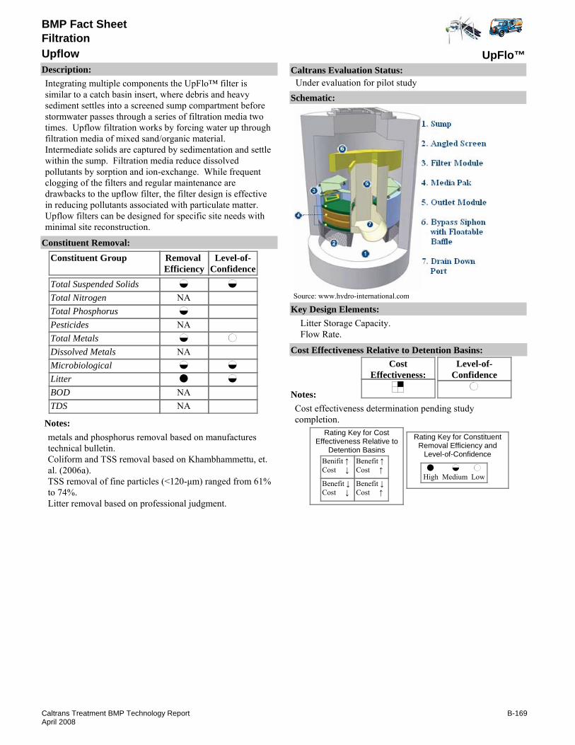
BMP Fact Sheet
UpFlo™UpflowFiltration
Description:Integrating multiple components the UpFlo™ filter is similar to a catch basin insert, where debris and heavy sediment settles into a screened sump compartment before stormwater passes through a series of filtration media two times. Upflow filtration works by forcing water up through filtration media of mixed sand/organic material. Intermediate solids are captured by sedimentation and settle within the sump. Filtration media reduce dissolved pollutants by sorption and ion-exchange. While frequent clogging of the filters and regular maintenance are drawbacks to the upflow filter, the filter design is effective in reducing pollutants associated with particulate matter. Upflow filters can be designed for specific site needs with minimal site reconstruction.
Removal Efficiency
Level-of-Confidence
Total Suspended SolidsTotal NitrogenTotal PhosphorusPesticidesTotal MetalsDissolved MetalsMicrobiologicalLitterBODTDS
Constituent GroupConstituent Removal:
NA
NA
NA
NANA
Notes:metals and phosphorus removal based on manufactures technical bulletin.Coliform and TSS removal based on Khambhammettu, et. al. (2006a).TSS removal of fine particles (<120-μm) ranged from 61% to 74%.Litter removal based on professional judgment.
Key Design Elements:Litter Storage Capacity.Flow Rate.
CostEffectiveness:
Level-of-Confidence
Cost Effectiveness Relative to Detention Basins:
Benifit ↑Cost ↓
Benefit ↓Cost ↓
Benefit ↑Cost ↑
Benefit ↓Cost ↑
High Medium Low
Rating Key for ConstituentRemoval Efficiency and
Level-of-Confidence
Rating Key for CostEffectiveness Relative to
Detention Basins
Source: www.hydro-international.com
Notes:Cost effectiveness determination pending study completion.
Schematic:
Caltrans Evaluation Status:Under evaluation for pilot study
B-169Caltrans Treatment BMP Technology ReportApril 2008

BMP Fact Sheet
UpFlo™UpflowFiltration
Requirements:Initially the sump should be monitored frequently in order to determine the required cleaning frequency.Training:Crews will need to be trained to maintain equipment and replace filter modules and media.
Maintenance Issues:
Project Development Issues:Right-of-Way-Requirements:Space requirements depend on sizing criteria, typically smaller than basins.Siting Constraints:Must have sufficient hydraulic head.Construction:No unique requirements identified
Constraints: Connection to sewer or drying bed for backwash waste water is needed.Connection to a potable water supply or backwash water tank for backwashing is needed.Electric power supply for pump is required.Potentially higher capital costs due to pump and pressure tank.More maintenance is needed for a pressure filter than for a gravity filter because of the use of mechanical equipment.Proprietary device.
Advantages:The use of pressure, rather than gravity, to force water through a media bed allows a smaller footprint. Backwashing cycle cleans sediment from the filter media as opposed to periodically excavating a portion of the media as required for slow sand gravity filters. Pressure filter technology uses pumps, which allow more layout flexibility than gravity filtration
Khambhammettu, U., Pitt, R., Andoh, R., and Clark, S.. "Performance of Upflow Filtration for Treatment Stormwater." World Environmental & Resources Congress, ASCE/EWRI. May 2006
Khambhammettu, U., Pitt, R., Andoh, R., Woelkers, D.. "Full Scale Evaluation of The Upflow Filter - A Catchbasin Insert for the Treatment of Stormwater at Critical Source Areas." WEFTEC 2006.
Literature Sources of Performance Demonstrations:Clark, S. E. PhD., P.E., Johnson, P., PhD., Pitt, R., PhD., Pratap, M., M.S.C.E., M.E.P.C. "Filtration for Metals Removal from Stormwater." Penn State Schoole of Science, Engineering and Technology. Aug 2005 10th Int’l Conf. of Urban Drainage.
Design, Construction, Maintenance and Cost SourcesHydro International, www.hydro-international.biz/us/stormwater_us/upflo.php
Certifications, Verifications, or Designations:None identified.
B-170Caltrans Treatment BMP Technology ReportApril 2008
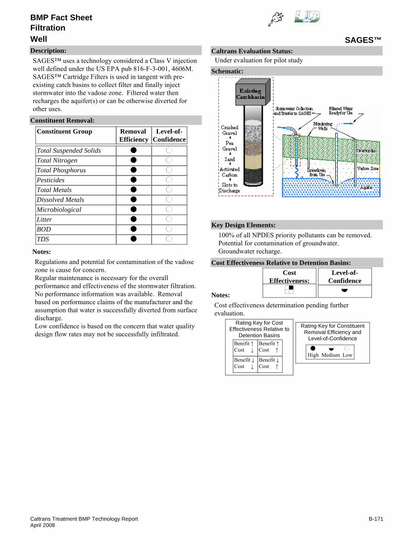
BMP Fact Sheet
SAGES™WellFiltration
Description:SAGES™ uses a technology considered a Class V injection well defined under the US EPA pub 816-F-3-001, 4606M. SAGES™ Cartridge Filters is used in tangent with pre-existing catch basins to collect filter and finally inject stormwater into the vadose zone. Filtered water then recharges the aquifer(s) or can be otherwise diverted for other uses.
Removal Efficiency
Level-of-Confidence
Total Suspended SolidsTotal NitrogenTotal PhosphorusPesticidesTotal MetalsDissolved MetalsMicrobiologicalLitterBODTDS
Constituent GroupConstituent Removal:
Notes:Regulations and potential for contamination of the vadose zone is cause for concern.Regular maintenance is necessary for the overall performance and effectiveness of the stormwater filtration.No performance information was available. Removal based on performance claims of the manufacturer and the assumption that water is successfully diverted from surface discharge.Low confidence is based on the concern that water quality design flow rates may not be successfully infiltrated.
Key Design Elements:100% of all NPDES priority pollutants can be removed.Potential for contamination of groundwater.Groundwater recharge.
CostEffectiveness:
Level-of-Confidence
Cost Effectiveness Relative to Detention Basins:
Benifit ↑Cost ↓
Benefit ↓Cost ↓
Benefit ↑Cost ↑
Benefit ↓Cost ↑
High Medium Low
Rating Key for ConstituentRemoval Efficiency and
Level-of-Confidence
Rating Key for CostEffectiveness Relative to
Detention Basins
Notes:Cost effectiveness determination pending further evaluation.
Schematic:
Caltrans Evaluation Status:Under evaluation for pilot study
B-171Caltrans Treatment BMP Technology ReportApril 2008

BMP Fact Sheet
SAGES™WellFiltration
Requirements:Initially the sire should be monitored frequently in order to determine the required cleaning frequency.Training:Crews will need to be trained to maintain equipment.
Maintenance Issues:
Project Development Issues:Right-of-Way-Requirements:Space requirements would depend on sizing criteria.Siting Constraints:Must have sufficient hydraulic head and suitable underlying soilsConstruction:A retrofit of existing catch basins is required.
Constraints: Federal requirements, permits, and regulations may make this technology impractical.More maintenance and training required for different components.Risk of vadose zone contamination from contaminant spills.Electric power supply for pump is required.Proprietary device.
Advantages:Water can be supplied to the region that would otherwise be lost.Overburdened aquifers can be replenished.Addresses flooding issues by reducing peak-flow runoff.Eliminates most surface water discharges.
U.S. EPA, Office of Water. 4602 "Class V Injection Wells Regulatory Amendments." EPA 813-F-95-003. Aug 1995. www.epa.govKoustas, Richard N., VanEgmond, John, "Stormwater Infiltration Device," EPA Risk Management Research Laboratory, Proceedings of the World Water and Environmental Resources Congress. May 20-24, 2001. ISBN: 0-7844-0569-7.
Literature Sources of Performance Demonstrations:None identified
Design, Construction, Maintenance and Cost SourcesEgmond Associates Ltd., Minneapolis, MN. www.egmondassociates.com/index.html
Certifications, Verifications, or Designations:None identified.
B-172Caltrans Treatment BMP Technology ReportApril 2008

BMP Fact Sheet
Aqua-Swirl™Hydrodynamic Separators
Description:Aqua-Swirl™ uses an inlet pipe that introduces water tangentially to the cylindrical unit. A baffle is used at the outlet pipe to discourage short circuiting.
Removal Efficiency
Level-of-Confidence
Total Suspended SolidsTotal NitrogenTotal PhosphorusPesticidesTotal MetalsDissolved MetalsMicrobiologicalLitterBODTDS
Constituent GroupConstituent Removal:
NANANANANANA
NANA
Notes:Litter removal based on professional judgment and assuming that neutrally buoyant litter could escape.TSS removal based on NJCAT (2005) report of laboratory results using Sil-Co-Sil 106.
Key Design Elements:Flow capacity (flood and water quality flow).Bypass of scouring flows.Storage capacity.Detention time.
CostEffectiveness:
Level-of-Confidence
Cost Effectiveness Relative to Detention Basins:
Benifit ↑Cost ↓
Benefit ↓Cost ↓
Benefit ↑Cost ↑
Benefit ↓Cost ↑
High Medium Low
Rating Key for ConstituentRemoval Efficiency and
Level-of-Confidence
Rating Key for CostEffectiveness Relative to
Detention Basins
Source: www.aquashield.com
Notes:Cost effectiveness determination pending study completion.
Schematic:
Caltrans Evaluation Status:Under evaluation for pilot study
B-173Caltrans Treatment BMP Technology ReportApril 2008

BMP Fact Sheet
Aqua-Swirl™Hydrodynamic Separators
Requirements:Initially the site should be monitored frequently in order to determine the required cleaning frequency.Vactor equipment recommended for cleaning.Training:No special requirements identified.
Maintenance Issues:
Project Development Issues:Right-of-Way-Requirements:Relatively small footprintSiting Constraints:Check for underground utility conflicts.Construction:No unique requirements identified
Constraints: Scour may limit effectiveness.Proprietary device.Vector concerns.
Advantages:Small footprint, all underground, and no additional ROW or easement required, low head requirement.
U.S. Environmental protection Agency, www.epa.gov/region1/assistance/ceitts/stormwater/techs/aquaswirl.html
Literature Sources of Performance Demonstrations:NJCAT Technology Verification. 2005. Aqua-SwirlTM Concentrator and Aqua-FilterTM Stormwater Treatment Systems. September 2005.
Design, Construction, Maintenance and Cost SourcesAquaShield, www.aquashieldinc.com
Certifications, Verifications, or Designations:NJCAT - At a stormwater treatment design rate of 50.5 gpm/ft2, the SSC removal efficiency is approximately 60%. WA TAPE - General Use Level Designation (GULD) for basic TSS, Dec 2003..
B-174Caltrans Treatment BMP Technology ReportApril 2008

BMP Fact Sheet
Downstream Defender™Hydrodynamic Separators
Description:Downstream Defender™ uses a system of deflector plates and cones to encourage sedimentation and discourage resuspension.
Removal Efficiency
Level-of-Confidence
Total Suspended SolidsTotal NitrogenTotal PhosphorusPesticidesTotal MetalsDissolved MetalsMicrobiologicalLitterBODTDS
Constituent GroupConstituent Removal:
NA
NANA
NANA
Notes:Clausen et. al. (2002) report 45% TSS removal, 28% phosphorous removal, 16% TKN removal and an export of metals; however, no results where statistically significant
Key Design Elements:Flow capacity (flood and water quality flow).Bypass of scouring flows.Storage capacity.Detention time.
CostEffectiveness:
Level-of-Confidence
Cost Effectiveness Relative to Detention Basins:
Benifit ↑Cost ↓
Benefit ↓Cost ↓
Benefit ↑Cost ↑
Benefit ↓Cost ↑
High Medium Low
Rating Key for ConstituentRemoval Efficiency and
Level-of-Confidence
Rating Key for CostEffectiveness Relative to
Detention Basins
Source: www.hil-tech.com
Notes:Cost effectiveness determination pending study completion.
Schematic:
Caltrans Evaluation Status:Under evaluation for pilot study
B-175Caltrans Treatment BMP Technology ReportApril 2008
BMP Fact Sheet
Downstream Defender™Hydrodynamic Separators
Requirements:Initially the site should be monitored frequently in order to determine the required cleaning frequency.Vactor equipment recommended for cleaning.Training:No special requirements identified.
Maintenance Issues:
Project Development Issues:Right-of-Way-Requirements:Relatively small footprintSiting Constraints:Similar to drop inletsConstruction:No unique requirements identified
Constraints: Scour may limit effectiveness.Proprietary device.Vector concerns.
Advantages:Small footprint, all underground, and no additional ROW or easement required, low head requirement.
Literature Sources of Performance Demonstrations:U.S. Environmental Protection Agency, www.epa.gov/region1/assistance/ceitts/stormwater/techs/downstreamdefender.html
Design, Construction, Maintenance and Cost SourcesHIL Technology, Inc., www.hil-tech.com
Certifications, Verifications, or Designations:WA TAPE - General Use Level Designation (GULD) for basic TSS, February 2005.TARP - Studies underway that offer promise for reliable data in the near future for addressing TSS removal efficiency claims.
B-176Caltrans Treatment BMP Technology ReportApril 2008
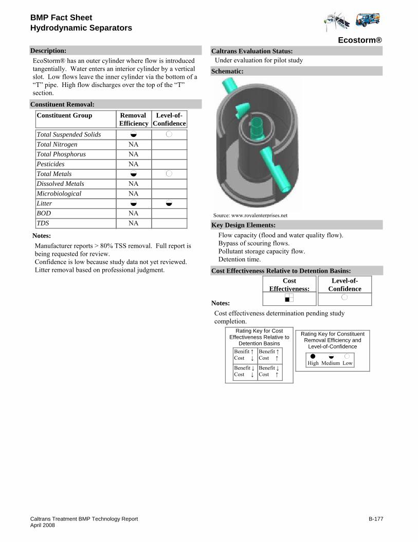
BMP Fact Sheet
Ecostorm®Hydrodynamic Separators
Description:EcoStorm® has an outer cylinder where flow is introduced tangentially. Water enters an interior cylinder by a vertical slot. Low flows leave the inner cylinder via the bottom of a “T” pipe. High flow discharges over the top of the “T” section.
Removal Efficiency
Level-of-Confidence
Total Suspended SolidsTotal NitrogenTotal PhosphorusPesticidesTotal MetalsDissolved MetalsMicrobiologicalLitterBODTDS
Constituent GroupConstituent Removal:
NANANA
NANA
NANA
Notes:Manufacturer reports > 80% TSS removal. Full report is being requested for review.Confidence is low because study data not yet reviewed.Litter removal based on professional judgment.
Key Design Elements:Flow capacity (flood and water quality flow).Bypass of scouring flows.Pollutant storage capacity flow.Detention time.
CostEffectiveness:
Level-of-Confidence
Cost Effectiveness Relative to Detention Basins:
Benifit ↑Cost ↓
Benefit ↓Cost ↓
Benefit ↑Cost ↑
Benefit ↓Cost ↑
High Medium Low
Rating Key for ConstituentRemoval Efficiency and
Level-of-Confidence
Rating Key for CostEffectiveness Relative to
Detention Basins
Source: www.royalenterprises.net
Notes:Cost effectiveness determination pending study completion.
Schematic:
Caltrans Evaluation Status:Under evaluation for pilot study
B-177Caltrans Treatment BMP Technology ReportApril 2008

BMP Fact Sheet
Ecostorm®Hydrodynamic Separators
Requirements:Initially the site should be monitored frequently in order to determine the required cleaning frequency.Vactor equipment recommended for cleaning.Training:No special requirements identified.
Maintenance Issues:
Project Development Issues:Right-of-Way-Requirements:Relatively small footprintSiting Constraints:Similar to drop inlets.Construction:No unique requirements identified
Constraints: Proprietary device.Vector concerns.
Advantages:Small footprint.
Literature Sources of Performance Demonstrations:Sources of Performance Demonstrations:www.ecotechnic.at
Design, Construction, Maintenance and Cost SourcesRoyal Environmental Systems, Inc., www.royalenterprises.net
Certifications, Verifications, or Designations:None identified.
B-178Caltrans Treatment BMP Technology ReportApril 2008

BMP Fact Sheet
EcoStormPlus®Hydrodynamic Separators
Description:EcoStorm Plus® is a cylinder that introduces stormwater flows tangentially creating a vortex within the chamber. Gravity separation cause heavy sediments to collect at the bottom, while other pollutants are trapped as they are forced through a filtration system at the top. A high flow bypass and maintenance access is located in the center of the chamber.
Removal Efficiency
Level-of-Confidence
Total Suspended SolidsTotal NitrogenTotal PhosphorusPesticidesTotal MetalsDissolved MetalsMicrobiologicalLitterBODTDS
Constituent GroupConstituent Removal:
NANANA
NANA
NANA
Notes:Manufacturer reports removal of TSS ( >95%), zinc ( >80%), lead ( >95%), copper ( >90%), hydrocarbons ( >98%) from field tests. Full report is being requested for review.Confidence is low because study data not yet reviewed.Litter removal based on professional judgment.
Key Design Elements:Flow capacity (flood and water quality flow).Bypass of scouring flows.Pollutant storage capacity.Detention time.
CostEffectiveness:
Level-of-Confidence
Cost Effectiveness Relative to Detention Basins:
Benifit ↑Cost ↓
Benefit ↓Cost ↓
Benefit ↑Cost ↑
Benefit ↓Cost ↑
High Medium Low
Rating Key for ConstituentRemoval Efficiency and
Level-of-Confidence
Rating Key for CostEffectiveness Relative to
Detention Basins
Source: www.royalenterprises.net
Notes:Cost effectiveness determination pending study completion.
Schematic:
Caltrans Evaluation Status:Under evaluation for pilot study
B-179Caltrans Treatment BMP Technology ReportApril 2008

BMP Fact Sheet
EcoStormPlus®Hydrodynamic Separators
Requirements:Initially the site should be monitored frequently in order to determine the required cleaning frequency.Vactor equipment recommended for cleaning.Training:No special requirements identified.
Maintenance Issues:
Project Development Issues:Right-of-Way-Requirements:Relatively small footprintSiting Constraints:Similar to drop inletsConstruction:No unique requirements identified
Constraints: Proprietary device.Vector concerns.
Advantages:Small footprint.
Literature Sources of Performance Demonstrations:Ecotechnic GmnH & Co KG, "EcoStorm Plus® Stormwater Treatment Process," www.ecotechnic.at, (January 2006)
Design, Construction, Maintenance and Cost SourcesRoyal Environmental Systems, Inc., www.royalenterprises.net
Certifications, Verifications, or Designations:WA TAPE - General Use Level Designation (GULD) for TSS, September 2007.
B-180Caltrans Treatment BMP Technology ReportApril 2008

BMP Fact Sheet
FloGard Dual-Vortex™Hydrodynamic Separators
Description:Dual-Vortex™ uses a system of pipe to direct flow to two tubes that are designed to enhance sedimentation. Flood flow bypass is accomplished through a riser attached to the top of the inlet pipe.
Removal Efficiency
Level-of-Confidence
Total Suspended SolidsTotal NitrogenTotal PhosphorusPesticidesTotal MetalsDissolved MetalsMicrobiologicalLitterBODTDS
Constituent GroupConstituent Removal:
NANANANANANA
NANA
Notes:Removal efficiencies based on professional judgment.No performance information identified.
Key Design Elements:Flow capacity (flood and water quality flow).Bypass of scouring flows.Storage capacity.Detention time.
CostEffectiveness:
Level-of-Confidence
Cost Effectiveness Relative to Detention Basins:
Benifit ↑Cost ↓
Benefit ↓Cost ↓
Benefit ↑Cost ↑
Benefit ↓Cost ↑
High Medium Low
Rating Key for ConstituentRemoval Efficiency and
Level-of-Confidence
Rating Key for CostEffectiveness Relative to
Detention Basins
Source: www.kristar.com
Notes:Cost effectiveness determination pending study completion.
Schematic:
Caltrans Evaluation Status:Under evaluation for pilot study
B-181Caltrans Treatment BMP Technology ReportApril 2008

BMP Fact Sheet
FloGard Dual-Vortex™Hydrodynamic Separators
Requirements:Initially the site should be monitored frequently in order to determine the required cleaning frequency.Vactor equipment recommended for cleaning.Training:No special requirements identified.
Maintenance Issues:
Project Development Issues:Right-of-Way-Requirements:Relatively small footprintSiting Constraints:Similar to drop inletsConstruction:No unique requirements identified
Constraints: Scour may limit effectiveness.Proprietary device.Vector concerns.
Advantages:Small footprint, all underground, and no additional ROW or easement required, low head requirement.
Literature Sources of Performance Demonstrations:None identified
Design, Construction, Maintenance and Cost SourcesKriStar Enterprises, Inc., www.kristar.com
Certifications, Verifications, or Designations:TARP - Studies underway that offer promise for reliable data in the near future for addressing TSS removal efficiency claims.
B-182Caltrans Treatment BMP Technology ReportApril 2008
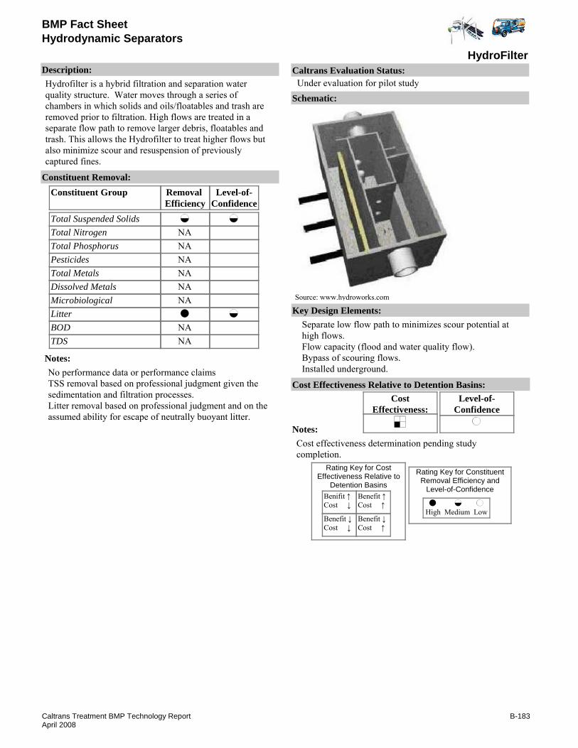
BMP Fact Sheet
HydroFilterHydrodynamic Separators
Description:Hydrofilter is a hybrid filtration and separation water quality structure. Water moves through a series of chambers in which solids and oils/floatables and trash are removed prior to filtration. High flows are treated in a separate flow path to remove larger debris, floatables and trash. This allows the Hydrofilter to treat higher flows but also minimize scour and resuspension of previously captured fines.
Removal Efficiency
Level-of-Confidence
Total Suspended SolidsTotal NitrogenTotal PhosphorusPesticidesTotal MetalsDissolved MetalsMicrobiologicalLitterBODTDS
Constituent GroupConstituent Removal:
NANANANANANA
NANA
Notes:No performance data or performance claimsTSS removal based on professional judgment given the sedimentation and filtration processes.Litter removal based on professional judgment and on the assumed ability for escape of neutrally buoyant litter.
Key Design Elements:Separate low flow path to minimizes scour potential at high flows.Flow capacity (flood and water quality flow).Bypass of scouring flows.Installed underground.
CostEffectiveness:
Level-of-Confidence
Cost Effectiveness Relative to Detention Basins:
Benifit ↑Cost ↓
Benefit ↓Cost ↓
Benefit ↑Cost ↑
Benefit ↓Cost ↑
High Medium Low
Rating Key for ConstituentRemoval Efficiency and
Level-of-Confidence
Rating Key for CostEffectiveness Relative to
Detention Basins
Source: www.hydroworks.com
Notes:Cost effectiveness determination pending study completion.
Schematic:
Caltrans Evaluation Status:Under evaluation for pilot study
B-183Caltrans Treatment BMP Technology ReportApril 2008

BMP Fact Sheet
HydroFilterHydrodynamic Separators
Requirements:Initially the site should be monitored frequently in order to determine the required cleaning frequency.Vactor equipment recommended for cleaning.Training:No special requirements identified.
Maintenance Issues:
Project Development Issues:Right-of-Way-Requirements:Relatively small footprintSiting Constraints:Similar to drop inlets.Construction:No unique requirements identified.
Constraints: Scour may limit effectiveness.Proprietary device.Vector concerns.
Advantages:Small footprint, all underground, and no additional ROW or easement required, low head requirement.
Literature Sources of Performance Demonstrations:None identified
Design, Construction, Maintenance and Cost SourcesHydrworks LLC, www.Hydroworks.com
Certifications, Verifications, or Designations:None identified.
B-184Caltrans Treatment BMP Technology ReportApril 2008

BMP Fact Sheet
HydroGuardHydrodynamic Separators
Description:Hydroguard is a hybrid filtration and separation water quality structure. Water moves through a series of chambers in which solids and oils/floatables and trash are removed prior to filtration. High flows are treated in a separate flow path to remove larger debris, floatables and trash. This allows the Hydroguard to treat higher flows but also minimize scour and resuspension of previously captured fines.
Removal Efficiency
Level-of-Confidence
Total Suspended SolidsTotal NitrogenTotal PhosphorusPesticidesTotal MetalsDissolved MetalsMicrobiologicalLitterBODTDS
Constituent GroupConstituent Removal:
NANANANANANANA
NANA
Notes:No performance data or performance claims.Litter removal based on best professional judgment and on the assumed ability for escape of neutrally buoyant litter.
Key Design Elements:Separate low flow path to minimize scour potential at high flows.Flow capacity (flood and water quality flow).Bypass of scouring flows.Installed underground.
CostEffectiveness:
Level-of-Confidence
Cost Effectiveness Relative to Detention Basins:
Benifit ↑Cost ↓
Benefit ↓Cost ↓
Benefit ↑Cost ↑
Benefit ↓Cost ↑
High Medium Low
Rating Key for ConstituentRemoval Efficiency and
Level-of-Confidence
Rating Key for CostEffectiveness Relative to
Detention Basins
Source: www.hydroworks.com
Notes:Cost effectiveness determination pending study completion.
Schematic:
Caltrans Evaluation Status:Under evaluation for pilot study
B-185Caltrans Treatment BMP Technology ReportApril 2008

BMP Fact Sheet
HydroGuardHydrodynamic Separators
Requirements:Initially the site should be monitored frequently in order to determine the required cleaning frequency.Vactor equipment recommended for cleaning.Training:No special requirements identified.
Maintenance Issues:
Project Development Issues:Right-of-Way-Requirements:Relatively small footprintSiting Constraints:Similar to drop inlets.Construction:No unique requirements identified
Constraints: Scour may limit effectiveness.Proprietary device.Vector concerns.
Advantages:Small footprint, all underground, and no additional ROW or easement required, low head requirement.
Literature Sources of Performance Demonstrations:None identified
Design, Construction, Maintenance and Cost SourcesHydroworks LLC, www.Hydroworks.com
Certifications, Verifications, or Designations:None identified.
B-186Caltrans Treatment BMP Technology ReportApril 2008

BMP Fact Sheet
Stormceptor®Hydrodynamic Separators
Description:Stormceptor® introduces flow into a tube that is designed to settle material into an area protected from high flows. Water circulates back up through the clean-out access port.
Removal Efficiency
Level-of-Confidence
Total Suspended SolidsTotal NitrogenTotal PhosphorusPesticidesTotal MetalsDissolved MetalsMicrobiologicalLitterBODTDS
Constituent GroupConstituent Removal:
NA
NANA
NANA
Notes:Clausen et.al. only reports statistically significant removal for TSS; but average influent concentrations (315 mg/L) were above the Caltrans 90th percentile (200mg/L), so level-of-confidence is medium.Litter removal based on ability of litter to escape if neutrally buoyant.
Key Design Elements:Flow capacity (flood and water quality flow).Detention time.Storage capacity.Bypass of scouring flows.
CostEffectiveness:
Level-of-Confidence
Cost Effectiveness Relative to Detention Basins:
Benifit ↑Cost ↓
Benefit ↓Cost ↓
Benefit ↑Cost ↑
Benefit ↓Cost ↑
High Medium Low
Rating Key for ConstituentRemoval Efficiency and
Level-of-Confidence
Rating Key for CostEffectiveness Relative to
Detention Basins
Source: www.rinkermaterials.com/stormceptor
Notes:Cost effectiveness determination pending study completion.
Schematic:
Caltrans Evaluation Status:Under evaluation for pilot study
B-187Caltrans Treatment BMP Technology ReportApril 2008

BMP Fact Sheet
Stormceptor®Hydrodynamic Separators
Requirements:Initially the site should be monitored frequently in order to determine the required cleaning frequency.Vactor equipment recommended for cleaning.Training:
Maintenance Issues:
Project Development Issues:Right-of-Way-Requirements:Relatively small footprintSiting Constraints:Similar to drop inletsConstruction:No unique requirements identified
Constraints: Scour may limit effectiveness.Proprietary device.Vector concerns.
Advantages:Small footprint, all underground, and no additional ROW or easement required, low head requirement.
U.S. Environmental Protection Agency, www.epa.gov/region1/assistance/ceitts/stormwater/techs/stormceptor.html
Literature Sources of Performance Demonstrations:Clausen, J., Belanger, P., Board, S., Dietz, M., Phillips, R., Sonstrom, R. 2002. Stormwater Treatment Devices Section 319 Project, Final Report, April 15, 2002. submitted to Connecticut Department of Environmental Protection. P.29.
Design, Construction, Maintenance and Cost SourcesStormceptor, Inc., www.rinkermaterials.com/stormceptor/
Certifications, Verifications, or Designations:WA TAPE - General Use Level Designation for pretreatment TSS, for September 2007. NJCAT - Based on evaluation has been shown to have 69% TSS removal efficiency, as measured as suspended solids concentration (SSC) (as per the NJDEP methodology for calculation of treatment efficiency) using OK-110 silica sand with an average d50 particle size of approximately 100 microns, an average influent concentration of 202 mg/L and 50% initial sediment loading in laboratory studies using simulated stormwater.TCEQ - Approval of Innovative Technology: (See TCEQ for sizing restrictions).TARP - Studies underway that offer promise for reliable data in the near future for addressing TSS & SSC removal efficiency claims.
B-188Caltrans Treatment BMP Technology ReportApril 2008

BMP Fact Sheet
StormTrooper®Hydrodynamic Separators
Description:Storm Trooper® is an off-line separator. A flow diversion carries lower flows to the separator. Water flows through coalescing plates and exits the separator.
Removal Efficiency
Level-of-Confidence
Total Suspended SolidsTotal NitrogenTotal PhosphorusPesticidesTotal MetalsDissolved MetalsMicrobiologicalLitterBODTDS
Constituent GroupConstituent Removal:
NANANANANANA
NANA
Notes:Southwest Research Institute, 2002 confirmed reports of 85% to 97% TSS removal for range of particle diameter sized 44 to 840 micron, with influent concentration of 590 mg/L (much higher that typical highway runoff concentrations).Level of confidence is medium because TSS concentration were higher than typical Caltrans runoff.Removal efficiency for TSS based on SWRI, 2002 letter referencing performance data.level-of-confidence for litter is low due to lack of performance data.Removal efficiency for litter based on professional judgment.
Key Design Elements:Elevation of weir in sepertor relative to wire in diversion box.Flow capacity (flood and water quality flow).Bypass of scouring flows.Detention time.Storage capacity.
CostEffectiveness:
Level-of-Confidence
Cost Effectiveness Relative to Detention Basins:
Benifit ↑Cost ↓
Benefit ↓Cost ↓
Benefit ↑Cost ↑
Benefit ↓Cost ↑
High Medium Low
Rating Key for ConstituentRemoval Efficiency and
Level-of-Confidence
Rating Key for CostEffectiveness Relative to
Detention Basins
Source: www.storm-trooper.com
Notes:Cost effectiveness determination pending study completion.
Schematic:
Caltrans Evaluation Status:Under evaluation for pilot study
B-189Caltrans Treatment BMP Technology ReportApril 2008

BMP Fact Sheet
StormTrooper®Hydrodynamic Separators
Requirements:Initially the site should be monitored frequently in order to determine the required cleaning frequency.Vactor equipment recommended for cleaning.Training:
Maintenance Issues:
Project Development Issues:Right-of-Way-Requirements:Relatively small footprintSiting Constraints:Similar to drop inletsConstruction:No unique requirements identified
Constraints: Scour may limit effectiveness.Proprietary device.Vector concerns.
Advantages:Small footprint, all underground, and no additional ROW or easement required, low head requirement.
U.S. Environmental Protection Agency, www.epa.gov/region1/assistance/ceitts/stormwater/techs/Storm Trooper.html
Literature Sources of Performance Demonstrations:Johnson, J. 2002. Surveillance of tests Conducted on Representative StormTrooper Interceptor Models ST-06C and ST-08, Southwest Research Institue Project No. 01.06061.01.901. November 1, 2002. www.swri.org. accessed via www.storm-trooper.com.
Design, Construction, Maintenance and Cost SourcesPark Environmental Equipment Company, Ltd., www.storm-trooper.com
Certifications, Verifications, or Designations:None identified.
B-190Caltrans Treatment BMP Technology ReportApril 2008

BMP Fact Sheet
Terre Kleen™Hydrodynamic Separators
Description:Terre-Kleen™ is an in-line treatment device. Terre-Kleen™ can be installed underground. Stormwater flows into the concrete vault where sediment contacts inclined plates and settles along the bottom of the concrete vault.
Removal Efficiency
Level-of-Confidence
Total Suspended SolidsTotal NitrogenTotal PhosphorusPesticidesTotal MetalsDissolved MetalsMicrobiologicalLitterBODTDS
Constituent GroupConstituent Removal:
NANANANANANA
NANA
Notes:Penn State, 2006 reported 47% TSS removal.Litter removal efficiencies based on professional judgment.level-of-confidence for TSS is medium based on Penn State, 2006 study and lack of statistically significant performance data.
Key Design Elements:Flow capacity (flood and water quality flow).Pollutant storage capacity.Bypass of scouring flows.Detention time.
CostEffectiveness:
Level-of-Confidence
Cost Effectiveness Relative to Detention Basins:
Benifit ↑Cost ↓
Benefit ↓Cost ↓
Benefit ↑Cost ↑
Benefit ↓Cost ↑
High Medium Low
Rating Key for ConstituentRemoval Efficiency and
Level-of-Confidence
Rating Key for CostEffectiveness Relative to
Detention Basins
Source: www.terrehill.com/terrekleen.asp
Notes:Cost effectiveness determination pending study completion.
Schematic:
Caltrans Evaluation Status:Under evaluation for pilot study
B-191Caltrans Treatment BMP Technology ReportApril 2008

BMP Fact Sheet
Terre Kleen™Hydrodynamic Separators
Requirements:Initially the site should be monitored frequently in order to determine the required cleaning frequency.Training:Vactor equipment recommended for cleaning.
Maintenance Issues:
Project Development Issues:Right-of-Way-Requirements:Relatively small footprintSiting Constraints:Check for underground utility conflicts.Construction:Stormwater runoff evaluation needed for proper sizing of storage vault
Constraints: Proprietary device.Vector concerns.
Advantages:Small footprint.
Literature Sources of Performance Demonstrations:Penn State Harrisburg, "Stormwater Source Area Treatment Device, The Terre Hill Concrete Products Terre-Kleen- 09," EPA/600/R-06/136, Prepared by Penn State Harrisburg, Middletown, PA September 2006.
Design, Construction, Maintenance and Cost SourcesTerre Hill Concrete Products, www.terrehill.com/terrekleen.asp
Certifications, Verifications, or Designations:NJCAT - Based on evaluation has been shown to have a 78% total suspended solids (TSS) removal efficiency, measured as suspended solids concentration (SSC) (as per the NJDEP methodology for calculation of treatment efficiency) for a mixture of sand and Sil-Co-Sil 250 with an average d50 particle size of 86 microns, an average influent concentration of 228 mg/L and 50% initial sediment loading inlaboratory studies using simulated stormwater. However, there are uncertainties associated with the laboratory data and these should be considered when assessing the 78% removal demonstrated. The estimated minimum and maximum removal efficiencies are 61% and 90%, respectively, January 2007.TARP - Studies underway that offer promise for reliable data in the near future for addressing TSS & SSC removal efficiency claims.
B-192Caltrans Treatment BMP Technology ReportApril 2008

BMP Fact Sheet
Unistorm™Hydrodynamic Separators
Description:Unistorm™ is a dual in-line tank system with no internal by-pass. Surface water enters the first of two cylindrical tanks trapping floatables in a filtration media while heavy sediment settles on the bottom. Fine to medium sediment then passes through a baffle wall that controls flow entering the second tank before leaving the system.
Removal Efficiency
Level-of-Confidence
Total Suspended SolidsTotal NitrogenTotal PhosphorusPesticidesTotal MetalsDissolved MetalsMicrobiologicalLitterBODTDS
Constituent GroupConstituent Removal:
NANANANANANANA
NANA
Notes:Litter removal efficiency based on best professional judgment.
Key Design Elements:Flow capacity (flood and water quality flow).Pollutant storage capacity.Bypass of scouring flows.Detention time.
CostEffectiveness:
Level-of-Confidence
Cost Effectiveness Relative to Detention Basins:
Benifit ↑Cost ↓
Benefit ↓Cost ↓
Benefit ↑Cost ↑
Benefit ↓Cost ↑
High Medium Low
Rating Key for ConstituentRemoval Efficiency and
Level-of-Confidence
Rating Key for CostEffectiveness Relative to
Detention Basins
Source: www.env21.com
Notes:Cost effectiveness determination pending study completion.
Schematic:
Caltrans Evaluation Status:Under evaluation for pilot study
B-193Caltrans Treatment BMP Technology ReportApril 2008

BMP Fact Sheet
Unistorm™Hydrodynamic Separators
Requirements:Initially the site should be monitored frequently in order to determine the required cleaning frequency.Vactor equipment recommended for cleaning.Training:
Maintenance Issues:
Project Development Issues:Right-of-Way-Requirements:Relatively small footprintSiting Constraints:Similar to drop inletsConstruction:No unique requirements identified
Constraints: Proprietary device.Vector concerns.
Advantages:Small footprint.
U.S. Environmental Protection Agency, www.epa.gov/region1/assistance/ceitts/stormwater/techs/v2b1.html
Literature Sources of Performance Demonstrations:None identified
Design, Construction, Maintenance and Cost SourcesEnvironmental 21, LLC, www.env21.com
Certifications, Verifications, or Designations:None identified.
B-194Caltrans Treatment BMP Technology ReportApril 2008

BMP Fact Sheet
V2B1™Hydrodynamic Separators
Description:V2B1™ is a dual tank in-line system. Surface water enters the first of two cylindrical tanks by means of a tangential inlet pipe. Heavy sediment is collected in the sediment sump of the first chamber as water is decanted off the top by an upturned pipe. The second “floatables” chamber restrains lighter floating oil and organic debris through the use of a baffle wall before surface water is directed out of the system. During high flow events an optional second pipe, located higher in the first chamber, allows water to internally bypass the system.
Removal Efficiency
Level-of-Confidence
Total Suspended SolidsTotal NitrogenTotal PhosphorusPesticidesTotal MetalsDissolved MetalsMicrobiologicalLitterBODTDS
Constituent GroupConstituent Removal:
NANANANANANANA
NANA
Notes:Letter removal efficiency based on best professional judgment.
Key Design Elements:Flow capacity (flood and water quality flow).Pollutant storage capacity.Bypass of scouring flows.Detention time.
CostEffectiveness:
Level-of-Confidence
Cost Effectiveness Relative to Detention Basins:
Benifit ↑Cost ↓
Benefit ↓Cost ↓
Benefit ↑Cost ↑
Benefit ↓Cost ↑
High Medium Low
Rating Key for ConstituentRemoval Efficiency and
Level-of-Confidence
Rating Key for CostEffectiveness Relative to
Detention Basins
Source: www.env21.com
Notes:Cost effectiveness determination pending study completion.
Schematic:
Caltrans Evaluation Status:Under evaluation for pilot study
B-195Caltrans Treatment BMP Technology ReportApril 2008

BMP Fact Sheet
V2B1™Hydrodynamic Separators
Requirements:Initially the site should be monitored frequently in order to determine the required cleaning frequency.Vactor equipment recommended for cleaning.Training:
Maintenance Issues:
Project Development Issues:Right-of-Way-Requirements:Relatively small footprintSiting Constraints:Similar to drop inlets.Construction:No unique requirements identified
Constraints: Proprietary device.Vector concerns.
Advantages:Small footprint.
U.S. Environmental Protection Agency, www.epa.gov/region1/assistance/ceitts/stormwater/techs/v2b1.html
Literature Sources of Performance Demonstrations:None identified
Design, Construction, Maintenance and Cost SourcesEnvironmental 21, LLC, www.env21.com
Certifications, Verifications, or Designations:None identified.
B-196Caltrans Treatment BMP Technology ReportApril 2008

BMP Fact Sheet
Vortechs®Hydrodynamic Separators
Description:Vortechs® is similar to other water quality inlets that utilize hydrodynamic separation to remove sediment. The tangential inlet creates a vortex within a grit chamber that directs sediment toward the center of the water column where it will eventually settle at the bottom of the grit chamber. A series of baffle walls control the water level through the system during dry weather and peak flows, holding back floating contaminates and debris caught in previous storms.
Removal Efficiency
Level-of-Confidence
Total Suspended SolidsTotal NitrogenTotal PhosphorusPesticidesTotal MetalsDissolved MetalsMicrobiologicalLitterBODTDS
Constituent GroupConstituent Removal:
NA
NANA
NANA
Notes:Field test are based on TSS influent concentrations 3 to 8 times higher than typical highway concentrations (around 100mg/L) so removal efficiencies were estimated. (Board, 2001).Sand and salt applied (13.6 tones) between Dec.-Apr. Monitored Jan-Apr. Particle Size Distribution higher than average. (Board, 2001).Litter removal based on ability of litter to escape if neutrally bouyant.Removal efficiency based on above-referenced studies.
Key Design Elements:Flow capacity (flood and water quality flow).Bypass of scouring flows.Storage capacity.Detention time.
CostEffectiveness:
Level-of-Confidence
Cost Effectiveness Relative to Detention Basins:
Benifit ↑Cost ↓
Benefit ↓Cost ↓
Benefit ↑Cost ↑
Benefit ↓Cost ↑
High Medium Low
Rating Key for ConstituentRemoval Efficiency and
Level-of-Confidence
Rating Key for CostEffectiveness Relative to
Detention Basins
Source: www.comtech-cpi.com
Notes:Cost effectiveness determination pending study completion.
Schematic:
Caltrans Evaluation Status:Under evaluation for pilot study
B-197Caltrans Treatment BMP Technology ReportApril 2008

BMP Fact Sheet
Vortechs®Hydrodynamic Separators
Requirements:Initially the site should be monitored frequently in order to determine the required cleaning frequency.Training:Vactor equipment recommended for cleaning.
Maintenance Issues:
Project Development Issues:Right-of-Way-Requirements:Relatively small footprintSiting Constraints:Similar to drop inletsConstruction:No unique requirements identified
Constraints: Scour may limit effectiveness.Proprietary device.Vector concerns.
Advantages:Small footprint, all underground, and no additional ROW or easement required, low head requirement.
U.S. Environmental Protection Agency, www.epa.gov/region1/assistance/ceitts/stormwater/techs/vortechs.html
Greenway, A. R., "Stormwater Treatment Demonstration Project Oil Water/Grit Separation followed by a Sand Filter," RTP Environmental Associates, Inc., 2000.
CT Dept. Natural Resources Management & Engineering, Clausen, John C. et. al., Stormwater Treatment Devices Section 319 Project #99-07.West, T. A., Sutherland, J. W., Bloomfield, J. A., Lake, D. W. Jr., "A Study of the Effectiveness of a VortechsTM Stormwater Treatment System for Removal of Total Suspended Solids and Other Pollutants in the Marine Village Watershed, Village of Lake George, New York," New York State Department of Environmental Conservation, January 2001.
Literature Sources of Performance Demonstrations:Board, S. M., "Vortechnics Treatment Of Parking Lot Runoff," Master’s Thesis University of Connecticut, 2001.
Design, Construction, Maintenance and Cost SourcesContech® Stormwater Solutions Inc., www. contech-cpi.com
Certifications, Verifications, or Designations:ETV - Verification statement issued September 2005. Suspended solids and roadway pollutant treatment. NJCAT - Entered into verification program May 2004. WA TAPE - General Use Level Designation (GULD) for pretreatment Total suspended solids (TSS).TARP - Studies underway that offer promise for reliable data in the near future for addressing TSS & SSC removal efficiency claims.
B-198Caltrans Treatment BMP Technology ReportApril 2008

BMP Fact Sheet
VortSentry™Hydrodynamic Separators
Description:VortSentry™ uses vanes to direct the incoming flow downward. The water then flows under a baffle before discharging the unit. Flood flows are passed internally by overtopping a flow partition on the inlet.
Removal Efficiency
Level-of-Confidence
Total Suspended SolidsTotal NitrogenTotal PhosphorusPesticidesTotal MetalsDissolved MetalsMicrobiologicalLitterBODTDS
Constituent GroupConstituent Removal:
NANANANANANA
NANA
Notes:Manufacturer claims 80% sediment removal based on laboratory evaluation of particles of d50 = 240um (F-55 commercial sand).Litter removal efficiency based on professional judgment.
Key Design Elements:Mazimum treatment flows are HS48: 1.2-cfs; HS72: 3.7-cfs; HS96: 8.1-cfs.Flow capacity (flood and water quality flow).Detention time.Storage capacity.Bypass of scouring flows.
CostEffectiveness:
Level-of-Confidence
Cost Effectiveness Relative to Detention Basins:
Benifit ↑Cost ↓
Benefit ↓Cost ↓
Benefit ↑Cost ↑
Benefit ↓Cost ↑
High Medium Low
Rating Key for ConstituentRemoval Efficiency and
Level-of-Confidence
Rating Key for CostEffectiveness Relative to
Detention Basins
Source: www.contech-cpi.com
Notes:Cost effectiveness determination pending study completion.
Schematic:
Caltrans Evaluation Status:Under evaluation for pilot study
B-199Caltrans Treatment BMP Technology ReportApril 2008

BMP Fact Sheet
VortSentry™Hydrodynamic Separators
Requirements:Initially the site should be monitored frequently in order to determine the required cleaning frequency.Training:Vactor equipment recommended for cleaning.
Maintenance Issues:
Project Development Issues:Right-of-Way-Requirements:Relatively small footprintSiting Constraints:Similar to drop inlets.Construction:No unique requirements identified
Constraints: Scour may limit effectiveness.Proprietary device.Vector concerns.
Advantages:Small footprint, all underground, and no additional ROW or easement required, low head requirement.
Literature Sources of Performance Demonstrations:None identified
Design, Construction, Maintenance and Cost SourcesContech® Stormwater Solutions Inc., www. contech-cpi.com
Certifications, Verifications, or Designations:NJCAT - Based on evaluation VortSentry® Stormwater Treatment System,Model VS40, sized at a loading rate of 9.8 gpm/ft3 (0.022cfs/ft3) of treatment volume, has been shown to have a 69% total suspended solids (TSS) removal efficiency, as measured as suspended solids concentration (SSC) (as per the NJDEP methodology for calculation of treatment efficiency) for F-95 silica sand with an average d50 particle size of 120 microns, an average influent concentration of 209 mg/L and 50% initial sediment loading in laboratory studies using simulated stormwater.TARP - Studies underway that offer promise for reliable data in the near future for addressing SSC removal efficiency claims.
B-200Caltrans Treatment BMP Technology ReportApril 2008

BMP Fact Sheet
Eljen IN Drain™ SystemBelow GradeInfiltration
Description:Eljen In-Drain™ filtration system is designed to treat stormwater along roadside drainage areas using a patented prefabricated arrangement of pipes, geo-textile fabrics, and treated media. Perforated pipe distributes storm flows into a primary treatment zone where sediment and oil are collected with the aid of a Bio-Matt™ fabric. Partially treated flows pass through a secondary treatment zone made up of sand (approx. 6-in.) as stormwater is discharged into native soil and groundwater.
Removal Efficiency
Level-of-Confidence
Total Suspended SolidsTotal NitrogenTotal PhosphorusPesticidesTotal MetalsDissolved MetalsMicrobiologicalLitterBODTDS
Constituent GroupConstituent Removal:
Notes:Removal efficiency for infiltration is assumed to be 100% for the design water quality volume since no water is discharged to surface waters.
Key Design Elements:Permeability of soil.Distance to groundwater.Class V injection well determination may be required.
CostEffectiveness:
Level-of-Confidence
Cost Effectiveness Relative to Detention Basins:
Benifit ↑Cost ↓
Benefit ↓Cost ↓
Benefit ↑Cost ↑
Benefit ↓Cost ↑
High Medium Low
Rating Key for ConstituentRemoval Efficiency and
Level-of-Confidence
Rating Key for CostEffectiveness Relative to
Detention Basins
Source: www.eljen.com
Notes:Cost effectiveness determination pending study completion.
Schematic:
Caltrans Evaluation Status:Under evaluation for pilot study
B-201Caltrans Treatment BMP Technology ReportApril 2008

BMP Fact Sheet
Eljen IN Drain™ SystemBelow GradeInfiltration
Requirements:Rehabilitation is required when the system is clogged or overloaded. Infiltration trenched may require reconstruction every ten years (Young et. al. 1996).Rehabilitation requires construction equipment.Training:
Maintenance Issues:
Project Development Issues:Right-of-Way-Requirements:Space requirements are limited to the size of right-of-way areasSiting Constraints:Permeable soils, adequate separation to groundwaterConstruction:Must avoid clogging filter by compaction from vehicles or by fines introduced during or after construction.
Constraints: Rehabilitation cost per unit of treatment water volume is high.Water percolation may impact structural integrity and stability.Vulnerable to clogging.Must be placed on permeable soil and Must avoid high groundwater.Must avoid areas prone to spills of groundwater contaminants.Must address EPA Class V injection well regulations.May have higher construction costs per capture volume than infiltration basins.Maintenance of underground system is difficult.Proprietary device.
Advantages:These BMPs prevent the design surface runoff from reaching receiving water (i.e., they are “no surface discharge BMPs).They are not limited to a length-to-width ratio; layout and design are based on available space and drainage surface area.Below grade infiltration reduces the risk of mosquito breeding and vector propagation.Underground BMPs, have limited aesthetic impacts.No power is required, making them good candidates for retrofitting in the freeway right-of-way.
U.S. EPA Environmental Protection Agency, When Are Storm Water Discharges regulated As Class V Wells?", www.epa.gov/safewater/uic/pdfs/fact_class5_stormwater.pdfASCE/WEF, 1998, Urban Runoff Quality Management, ASCE No. 87., WEF No. 23 1998.Young, G. Kenneth, Stuart Stein, Pamela Cole, Traci Kammer, Frank Graziano, Fred Bank, 1996, "Evaluation and Management of Highway Runoff Water Quality, Federal Highway Administration, June 1996
Sansalone, J. J., et al. "Infiltration Device as a Best Management Practice for Immobilizing Heavy Metals in Urban Highway Runoff."
Young, G. K., Stein, S., Cole, P., Kammer, T., Graziano, F., Bank, F., "Evaluation and Management of Highway Runoff Water Quality," Federal Highway Administration, June 1996.
Literature Sources of Performance Demonstrations:ASCE, Manual and Report on Engineering Practice No. 87. 1998.
Design, Construction, Maintenance and Cost SourcesEljen Corporation, www.eljen.com
Certifications, Verifications, or Designations:None identified.
B-202Caltrans Treatment BMP Technology ReportApril 2008

BMP Fact Sheet
Infitration VaultBelow GradeInfiltration
Description:Infiltration Vaults promote stormwater infiltration and provide temporary storage of runoff through the use of bottomless underground structures. This non-proprietary device channels stormwater into large, typically concrete cylinders and through a perforated base. Having similar treatment capabilities as infiltration ponds, these devices do not have the same siting constraints difficulties because stormwater treatment and storage is below the surface. It should be noted that because stormwater flows are filtered and sent directly into the surrounding groundwater their use would be subject to the same rules governing Class V underground injection wells.
Removal Efficiency
Level-of-Confidence
Total Suspended SolidsTotal NitrogenTotal PhosphorusPesticidesTotal MetalsDissolved MetalsMicrobiologicalLitterBODTDS
Constituent GroupConstituent Removal:
Notes:Removal efficiency for infiltration is assumed to be 100% for the design water quality volume since no water is discharged to surface waters.
Key Design Elements:Permeability of soils.Distance to groundwater.Overhead load bearing capacity for errant vehicles.Class V injection well determination may be required.
CostEffectiveness:
Level-of-Confidence
Cost Effectiveness Relative to Detention Basins:
Benifit ↑Cost ↓
Benefit ↓Cost ↓
Benefit ↑Cost ↑
Benefit ↓Cost ↑
High Medium Low
Rating Key for ConstituentRemoval Efficiency and
Level-of-Confidence
Rating Key for CostEffectiveness Relative to
Detention Basins
Source: Washington Dept. of Tranportation, Highway Runoff Manual, 2006
Notes:
Schematic:
Caltrans Evaluation Status:Under evaluation for pilot study
B-203Caltrans Treatment BMP Technology ReportApril 2008
BMP Fact Sheet
Infitration VaultBelow GradeInfiltration
Requirements:Sediment removal. Rehabilitation is required when system clogs.Training:No special requirements identified.
Maintenance Issues:
Project Development Issues:Right-of-Way-Requirements:Space requirements are limited to the size of right-of-way areas..Siting Constraints:Permeable soils, adequate seperation to groundwaterConstruction:Must avoid clogging the filter by compaction from vehicles or by fines introduced during or after construction. Bypass water until drainage is stabilized.
Constraints: Vulnerable to clogging.Must be placed on permeable soil.Must avoid high groundwater.Must avoid areas prone to spills of groundwater contaminants.Must address EPA class V injection well regulations.May have higher construction costs per capture volume than infiltration basins.Maintenance of underground systems is difficult.Water percolation may impact structural integrity and stability.Proprietary device.
Advantages:These BMPs prevent the design surface runoff from reaching receiving water (i.e., they are no surface discharge BMPs).Infiltration addresses all pollutants.Below grade infiltration reduces the risk of mosquito breeding and vector propagation.They are not limited to a length-to-width ratio; layout and design are based on available space and drainage surface area.Underground BMPs, have limited aesthetic impacts.No power is required, making them good candidates for retrofitting in the freeway right-of-way.
U.S. EPA Environmental Protection Agency, "When Are Storm Water Discharges regulated As Class V Wells?", www.epa.gov/safewater/uic/pdfs/fact_class5_stormwater.pdfASCE/WEF, 1998, Urban Runoff Quality Management, ASCE No. 87., WEF No. 23 1998."Young, G. Kenneth, Stuart Stein, Pamela Cole, Traci Kammer, Frank Graziano, Fred Bank, 1996, "Evaluation and Management of Highway Runoff Water Quality," Federal Highway Administration, June 1996
Young, G. K., Stein, S., Cole, P., Kammer, T., Graziano, F., Bank, F., "Evaluation and Management of Highway Runoff Water Quality," Federal Highway Administration, June 1996.
ASCE, Manual and Report on Engineering Practice No. 87. 1998.
Literature Sources of Performance Demonstrations:Sansalone, J. J., et al. "Infiltration Device as a Best Management Practice for Immobilizing Heavy Metals in Urban Highway Runoff."
Design, Construction, Maintenance and Cost SourcesWashington Department of Transportation (WADOT), "Highway Runoff Manual, Infiltration Vault" IN.04, Ch. 5, P. 5-131, Stormwater Best Management Practices, May, 2006.
Certifications, Verifications, or Designations:None identified.
B-204Caltrans Treatment BMP Technology ReportApril 2008

BMP Fact Sheet
Linear Infiltration Filter TrenchBelow GradeInfiltration
Description:Linear Infiltration Filter Trench is a non-proprietary design devoloped by Caltrans in which stormwater flows in sheets through a sand filter prior to infiltration. Pretreatment within the sand layer reduces clogging of the trench and protects against access by mosquitoes in areas where poor soils infiltrate slowly and result in standing water. The trench is backfilled with a high porosity media that is available from several suppliers.
Removal Efficiency
Level-of-Confidence
Total Suspended SolidsTotal NitrogenTotal PhosphorusPesticidesTotal MetalsDissolved MetalsMicrobiologicalLitterBODTDS
Constituent GroupConstituent Removal:
Notes:Removal efficiency for infiltration is assumed to be 100% for the design water quality volume since no water is discharged to surface waters.In areas of poor infiltration, treatment may be similar to other sand filters.
Key Design Elements:Permeability of soils.Distance to groundwater.Overhead load bearing capacity for errant vehicles.Class V injection well determination, if horizontal piping is used.
CostEffectiveness:
Level-of-Confidence
Cost Effectiveness Relative to Detention Basins:
Benifit ↑Cost ↓
Benefit ↓Cost ↓
Benefit ↑Cost ↑
Benefit ↓Cost ↑
High Medium Low
Rating Key for ConstituentRemoval Efficiency and
Level-of-Confidence
Rating Key for CostEffectiveness Relative to
Detention Basins
Notes:Cost effectiveness determination further evaluation.
Schematic:
Caltrans Evaluation Status:Under evaluation for pilot study
B-205Caltrans Treatment BMP Technology ReportApril 2008

BMP Fact Sheet
Linear Infiltration Filter TrenchBelow GradeInfiltration
Requirements:Sediment removal. Rehabilitation is required when system clogs.Training:No special requirements identified.
Maintenance Issues:
Project Development Issues:Right-of-Way-Requirements:Designed to fit in a narrow right-of-way.Siting Constraints:Permeable soils, adequate separation to groundwaterConstruction:Must avoid clogging the filter by compaction from vehicles or by fines introduced during or after construction. Bypass water until drainage is stabilized.
Constraints: Vulnerable to clogging.Must avoid high groundwaterMay have higher construction costs per capture volume than infiltration basins.Maintenance of underground systems is difficult.Water percolation may impact structural integrity and stability.
Advantages:These BMPs prevent the design surface runoff from reaching receiving water (i.e., they are “no surface discharge BMPs”).nfiltration addresses all pollutants.
ASCE/WEF, 1998, Urban Runoff Quality Management, ASCE No. 87., WEF No. 23 1998.Young, G. Kenneth, Stuart Stein, Pamela Cole, Traci Kammer, Frank Graziano, Fred Bank, 1996, "Evaluation and Management of Highway Runoff Water Quality," Federal Highway Administration, June 1996
Literature Sources of Performance Demonstrations:None identified
Design, Construction, Maintenance and Cost SourcesU.S. Environmental Protection Agency, "When Are Storm Water Discharges regulated As Class V Wells?", www.epa.gov/safewater/uic/pdfs/fact_class5_stormwater.pdf
Certifications, Verifications, or Designations:None identified.
B-206Caltrans Treatment BMP Technology ReportApril 2008

BMP Fact Sheet
Matrix™Below GradeInfiltration
Description:Matrix™ is a high void space storage system for below grade infiltration systems. Siting and operational considerations may limit their use as an urban water quality BMP. They include: the need for a soil substrate with relatively high infiltration rates; the high incidence of clogging for this technology, especially when pollutant loads from construction are allowed to enter the facility; the potential threat to local groundwater; and the expense of remediation for a clogged trench.
Removal Efficiency
Level-of-Confidence
Total Suspended SolidsTotal NitrogenTotal PhosphorusPesticidesTotal MetalsDissolved MetalsMicrobiologicalLitterBODTDS
Constituent GroupConstituent Removal:
Notes:Removal efficiency for infiltration is assumed to be 100% for the design water quality volume since no water is discharged to surface waters.
Key Design Elements:Sizing based on infiltration rate.Class V injection well determination.Pretreatment to remove particles is required to avoid clogging the infiltration surface. This will normally require sedimentation and filtration facilities upstream.
CostEffectiveness:
Level-of-Confidence
Cost Effectiveness Relative to Detention Basins:
Benifit ↑Cost ↓
Benefit ↓Cost ↓
Benefit ↑Cost ↑
Benefit ↓Cost ↑
High Medium Low
Rating Key for ConstituentRemoval Efficiency and
Level-of-Confidence
Rating Key for CostEffectiveness Relative to
Detention Basins
Source: www.atlantiscorp.com.au
Notes:
Schematic:
Caltrans Evaluation Status:Under evaluation for pilot study
B-207Caltrans Treatment BMP Technology ReportApril 2008

BMP Fact Sheet
Matrix™Below GradeInfiltration
Requirements:Rehabilitation is required when the system clogs. Infiltration trenches may require reconstruction every ten years (Young et. al., 1996).Training:Rehabilitation requires construction equipment.
Maintenance Issues:
Project Development Issues:Right-of-Way-Requirements:Space requirements are reduced rock filled compared to trenches.Siting Constraints:Permeable soils, adequate separation to groundwater.Construction:Must avoid clogging the filter by compaction from vehicles or by fines introduced during or after construction. Bypass water until drainage is stabilized.
Constraints: Rehabilitation cost per unit of treated water volume is high.Water percolation may impact structural integrity and stability.Vulnerable to clogging.Must be placed on permeable soil.Must avoid high groundwater.Must avoid areas prone to spills of groundwater contaminants.Must address EPA class V injection well regulations.May have higher construction costs per capture volume than infiltration basins.Maintenance of underground systems is difficult.Proprietary device.
Advantages:These BMPs prevent the design surface runoff from reaching receiving water (i.e., they are “no surface discharge BMPs”).They are not limited to a length-to-width ratio and can be fitted along the road in the freeway right-of-way; and layout and design are based on available space and drainage surface area.Below-grade infiltration reduces the risk of mosquito breeding. Underground BMPs, have limited aesthetic impacts. They do not require power, making them good candidates for retrofitting in the freeway right-of-way. Few or no mechanical devices would be needed, depending on the pretreatment device selected.
U.S. Environmental Protection Agency, "When Are Storm Water Discharges regulated As Class V Wells?", www.epa.gov/safewater/uic/pdfs/fact_class5_stormwater.pdfASCE/WEF, 1998, Urban Runoff Quality Management, ASCE No. 87., WEF No. 23 1998.Young, G. Kenneth, Stuart Stein, Pamela Cole, Traci Kammer, Frank Graziano, Fred Bank, 1996, "Evaluation and Management of Highway Runoff Water Quality," Federal Highway Administration, June 1996
Literature Sources of Performance Demonstrations:None identified
Design, Construction, Maintenance and Cost SourcesAtlantis Water Management, MatrixTM, www.atlantiscorp.com.au
Certifications, Verifications, or Designations:None identified.
B-208Caltrans Treatment BMP Technology ReportApril 2008

BMP Fact Sheet
Rainstore®Below GradeInfiltration
Description:Rainstore® is a high void space storage system for below grade infiltration systems. Siting and operational considerations may limit their use as an urban water quality BMP. They include: the need for a soil substrate with relatively high infiltration rates; the high incidence of clogging for this technology, especially when pollutant loads from construction are allowed to enter the facility; the potential threat to local groundwater; and the expense of remediation for a clogged trench.
Removal Efficiency
Level-of-Confidence
Total Suspended SolidsTotal NitrogenTotal PhosphorusPesticidesTotal MetalsDissolved MetalsMicrobiologicalLitterBODTDS
Constituent GroupConstituent Removal:
Notes:Removal efficiency for infiltration is assumed to be 100% for the design water quality volume since no water is discharged to surface waters.
Key Design Elements:Sizing based on infiltration rate.Class V injection well determination.Pretreatment to remove particles is required to avoid clogging the infiltration surface. This will normally require sedimentation and filtration facilities upstream.
CostEffectiveness:
Level-of-Confidence
Cost Effectiveness Relative to Detention Basins:
Benifit ↑Cost ↓
Benefit ↓Cost ↓
Benefit ↑Cost ↑
Benefit ↓Cost ↑
High Medium Low
Rating Key for ConstituentRemoval Efficiency and
Level-of-Confidence
Rating Key for CostEffectiveness Relative to
Detention Basins
Source: www.invisiblesturctures.com
Notes:
Schematic:
Caltrans Evaluation Status:Under evaluation for pilot study
B-209Caltrans Treatment BMP Technology ReportApril 2008

BMP Fact Sheet
Rainstore®Below GradeInfiltration
Requirements:Rehabilitation is required when the system clogs. Infiltration trenches may require reconstruction every ten years (Young et. al. Evaluation and Management of Highway Runoff Water Quality, June 1996). Rehabilitation requires construction equipment.Training:No special requirements identified.
Maintenance Issues:
Project Development Issues:Right-of-Way-Requirements:Space requirements are reduced rock filled compared to trenches. Pretreatment is required.Siting Constraints:Permeable soils, adequate separation to groundwater.Construction:Must avoid clogging the filter by compaction from vehicles or by fines introduced during or after construction. Bypass water until drainage is stabilized.
Constraints: Rehabilitation cost per unit of treated water volume is high.Water percolation may impact structural integrity and stability.Vulnerable to clogging.Must be placed on permeable soil.Must avoid high groundwater.Must avoid areas prone to spills of groundwater contaminants.Must address EPA class V injection well regulations.Higher construction costs per capture volume than basins.Maintenance of underground systems is difficult.Proprietary device.
Advantages:These BMPs prevent the design surface runoff from reaching receiving water (i.e., they are “no surface discharge BMPs”). They are not limited to a length-to-width ratio and can be fitted along the road in the freeway right-of-way; and layout and design are based on available space and drainage surface area. Below grade infiltration reduces the risk of mosquito breeding and vector propagation. Underground BMPs, have limited aesthetic impacts. They do not require power, making them good candidates for retrofitting in the freeway right-of-way. Few or no mechanical devices would be needed, depending on the pretreatment device selected.
U.S. Environmental Protection Agency, "When Are Storm Water Discharges regulated As Class V Wells?", www.epa.gov/safewater/uic/pdfs/fact_class5_stormwater.pdfASCE/WEF, 1998, Urban Runoff Quality Management, ASCE No. 87., WEF No. 23 1998Young, G. Kenneth, Stuart Stein, Pamela Cole, Traci Kammer, Frank Graziano, Fred Bank, 1996, "Evaluation and Management of Highway Runoff Water Quality," Federal Highway Administration, June 1996
Sansalone, J. J., et al. "Infiltration Device as a Best Management Practice for Immobilizing Heavy Metals in Urban Highway Runoff."
Young, G. K., Stein, S., Cole, P., Kammer, T., Graziano, F., Bank, F., "Evaluation and Management of Highway Runoff Water Quality," Federal Highway Administration, June 1996.
Literature Sources of Performance Demonstrations:ASCE, Manual and Report on Engineering Practice No. 87. 1998.
Design, Construction, Maintenance and Cost SourcesInvisible Structures, Inc., www.invisiblestructures.com
Certifications, Verifications, or Designations:None identified.
B-210Caltrans Treatment BMP Technology ReportApril 2008

BMP Fact Sheet
StormChamber™Below GradeInfiltration
Description:StormChamber™ is a subsurface plastic leaching system used for retention or detention stormwater management. StormChamber™ provides an open bottom interface. The stormwater is leached into the surrounding backfill or directly absorbed into the soil. High flow bypasses can be incorparated for flood flow conveyance.
Removal Efficiency
Level-of-Confidence
Total Suspended SolidsTotal NitrogenTotal PhosphorusPesticidesTotal MetalsDissolved MetalsMicrobiologicalLitterBODTDS
Constituent GroupConstituent Removal:
Notes:Removal efficiency for infiltration is assumed to be 100% for the design water quality volume since no water is discharged to surface waters.
Key Design Elements:Minimum cover.Permeability of soils.Distance to groundwater.Load bearing capacity.Class V injection well determination.
CostEffectiveness:
Level-of-Confidence
Cost Effectiveness Relative to Detention Basins:
Benifit ↑Cost ↓
Benefit ↓Cost ↓
Benefit ↑Cost ↑
Benefit ↓Cost ↑
High Medium Low
Rating Key for ConstituentRemoval Efficiency and
Level-of-Confidence
Rating Key for CostEffectiveness Relative to
Detention Basins
Source: www.hydrologicsolutions.com
Notes:Cost effectiveness determination pending further evaluation.
Schematic:
Caltrans Evaluation Status:Under evaluation for pilot study
B-211Caltrans Treatment BMP Technology ReportApril 2008

BMP Fact Sheet
StormChamber™Below GradeInfiltration
Requirements:Likely vactor equipment with the ability to clean horizontal lines. Sediment removal pretreatment.Training:Training needed for confined space entry.
Maintenance Issues:
Project Development Issues:Right-of-Way-Requirements:Large area requirements, but area above grade can be used if constructed properly.Siting Constraints:Permeable soils, adequate separation to groundwater.Construction:Must avoid clogging the filter by compaction from vehicles or by fines introduced during or after construction. Bypass water until drainage is stabilized.
Constraints: Vulnerable to clogging.Must be placed on permeable soil.Must avoid high groundwater.Must avoid areas prone to spills of groundwater contaminants.Must address EPA class V injection well regulations.May have higher construction costs per capture volume than infiltration basins.Maintenance of underground systems is difficult.Water percolation may impact structural integrity and stability.Proprietary device.
Advantages:These BMPs prevent the design surface runoff from reaching receiving water (i.e., they are “no surface discharge BMPs”).Total drainage interface averages more than 60% higher than conventional PVC pipe and stone system of comparable size.Infiltration addresses all pollutants.
Contech® Stormwater Solutions, Inc., www.contech-cpi.comU.S. Environmental Protection Agency, "When Are Storm Water Discharges regulated As Class V Wells?", www.epa.gov/safewater/uic/pdfs/fact_class5_stormwater.pdfASCE/WEF, 1998, Urban Runoff Quality Management, ASCE No. 87., WEF No. 23 1998."Young, G. Kenneth, Stuart Stein, Pamela Cole, Traci Kammer, Frank Graziano, Fred Bank, 1996, "Evaluation and Management of Highway Runoff Water Quality," Federal Highway Administration, June 1996U.S. Environmental Protection Agency, "When Are Storm Water Discharges regulated As Class V Wells?", www.epa.gov/safewater/uic/pdfs/fact_class5_stormwater.pdf
Literature Sources of Performance Demonstrations:None identified.
Design, Construction, Maintenance and Cost SourcesHydroLogic Solutions, www.hydrologicsolutions.com
Certifications, Verifications, or Designations:None identified.
B-212Caltrans Treatment BMP Technology ReportApril 2008
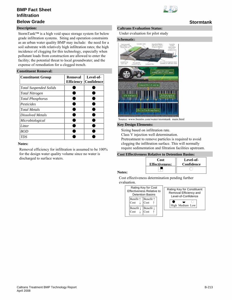
BMP Fact Sheet
StormtankBelow GradeInfiltration
Description:StormTank™ is a high void space storage system for below grade infiltration systems. Siting and operation constraints as an urban water quality BMP may include: the need for a soil substrate with relatively high infiltration rates; the high incidence of clogging for this technology, especially when pollutant loads from construction are allowed to enter the facility; the potential threat to local groundwater; and the expense of remediation for a clogged trench.
Removal Efficiency
Level-of-Confidence
Total Suspended SolidsTotal NitrogenTotal PhosphorusPesticidesTotal MetalsDissolved MetalsMicrobiologicalLitterBODTDS
Constituent GroupConstituent Removal:
Notes:Removal efficiency for infiltration is assumed to be 100% for the design water quality volume since no water is discharged to surface waters.
Key Design Elements:Sizing based on infiltration rate.Class V injection well determination.Pretreatment to remove particles is required to avoid clogging the infiltration surface. This will normally require sedimentation and filtration facilities upstream.
CostEffectiveness:
Level-of-Confidence
Cost Effectiveness Relative to Detention Basins:
Benifit ↑Cost ↓
Benefit ↓Cost ↓
Benefit ↑Cost ↑
Benefit ↓Cost ↑
High Medium Low
Rating Key for ConstituentRemoval Efficiency and
Level-of-Confidence
Rating Key for CostEffectiveness Relative to
Detention Basins
Source: www.brentw.com/water/stormtank main.html
Notes:Cost effectiveness determination pending further evaluation.
Schematic:
Caltrans Evaluation Status:Under evaluation for pilot study
B-213Caltrans Treatment BMP Technology ReportApril 2008
BMP Fact Sheet
StormtankBelow GradeInfiltration
Requirements:Rehabilitation is required when the system clogs. Infiltration trenches may require reconstruction every ten years (Young et. al. Evaluation and Management of Highway Runoff Water Quality, June 1996).Rehabilitation requires construction equipment.Training:No special requirements identified.
Maintenance Issues:
Project Development Issues:Right-of-Way-Requirements:Space requirements are reduced rock filled compared to trenches. Pretreatment is required.Siting Constraints:Permeable soils, adequate separation to groundwater.Construction:Must avoid clogging the filter by compaction from vehicles or by fines introduced during or after construction. Bypass water until drainage is stabilized.
Constraints: Rehabilitation cost per unit of treated water volume is high.Water percolation may impact structural integrity and stability.Vulnerable to clogging.Must be placed on permeable soil.Must avoid high groundwater.Must avoid areas prone to spills of groundwater contaminants.Must address EPA class V injection well regulations.Higher construction costs per capture volume than basins.Maintenance of underground systems is difficult.Proprietary device.
Advantages:These BMPs prevent the design surface runoff from reaching receiving water (i.e., they are “no surface discharge BMPs”).They are not limited to a length-to-width ratio and can be fitted along the road in the freeway right-of-way; and layout and design are based on available space and drainage surface area.Infiltration designs offer lesser chance for mosquito breeding and vector propagation. Underground BMPs, have limited aesthetic impacts. They do not require power, making them good candidates for retrofitting in the freeway right-of-way. Few or no mechanical devices would be needed, depending on the pretreatment device selected.
U.S. Environmental Protection Agency, When Are Storm Water Discharges regulated As Class V Wells?", www.epa.gov/safewater/uic/pdfs/fact_class5_stormwater.pdf
Sansalone, J. J., et al. "Infiltration Device as a Best Management Practice for Immobilizing Heavy Metals in Urban Highway Runoff."
Young, G. K., Stein, S., Cole, P., Kammer, T., Graziano, F., Bank, F., "Evaluation and Management of Highway Runoff Water Quality," Federal Highway Administration, June 1996.
Literature Sources of Performance Demonstrations:ASCE, Manual and Report on Engineering Practice No. 87. 1998.
Design, Construction, Maintenance and Cost SourcesBrentwood Industries, Inc., StormTank Stormwater Storage Modules, www.brentw.com/water/stormtank_main.html
Certifications, Verifications, or Designations:None identified.
B-214Caltrans Treatment BMP Technology ReportApril 2008
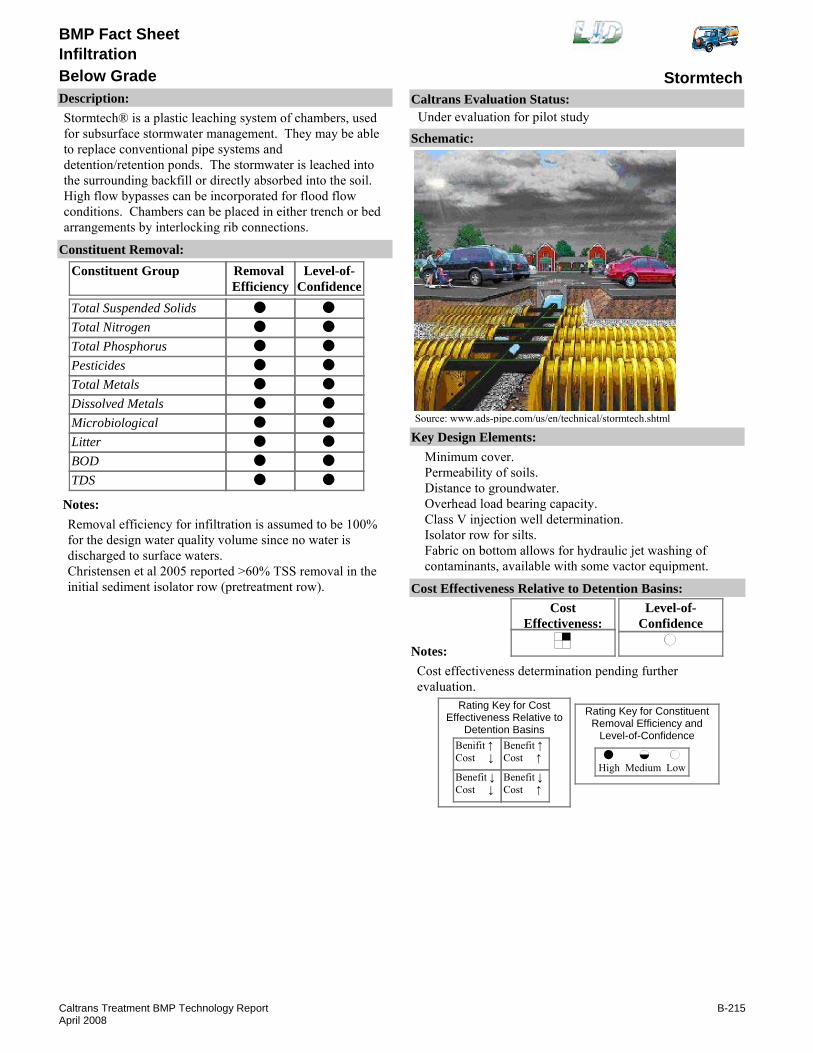
BMP Fact Sheet
StormtechBelow GradeInfiltration
Description:Stormtech® is a plastic leaching system of chambers, used for subsurface stormwater management. They may be able to replace conventional pipe systems and detention/retention ponds. The stormwater is leached into the surrounding backfill or directly absorbed into the soil. High flow bypasses can be incorporated for flood flow conditions. Chambers can be placed in either trench or bed arrangements by interlocking rib connections.
Removal Efficiency
Level-of-Confidence
Total Suspended SolidsTotal NitrogenTotal PhosphorusPesticidesTotal MetalsDissolved MetalsMicrobiologicalLitterBODTDS
Constituent GroupConstituent Removal:
Notes:Removal efficiency for infiltration is assumed to be 100% for the design water quality volume since no water is discharged to surface waters.Christensen et al 2005 reported >60% TSS removal in the initial sediment isolator row (pretreatment row).
Key Design Elements:Minimum cover.Permeability of soils.Distance to groundwater.Overhead load bearing capacity.Class V injection well determination.Isolator row for silts. Fabric on bottom allows for hydraulic jet washing of contaminants, available with some vactor equipment.
CostEffectiveness:
Level-of-Confidence
Cost Effectiveness Relative to Detention Basins:
Benifit ↑Cost ↓
Benefit ↓Cost ↓
Benefit ↑Cost ↑
Benefit ↓Cost ↑
High Medium Low
Rating Key for ConstituentRemoval Efficiency and
Level-of-Confidence
Rating Key for CostEffectiveness Relative to
Detention Basins
Source: www.ads-pipe.com/us/en/technical/stormtech.shtml
Notes:Cost effectiveness determination pending further evaluation.
Schematic:
Caltrans Evaluation Status:Under evaluation for pilot study
B-215Caltrans Treatment BMP Technology ReportApril 2008

BMP Fact Sheet
StormtechBelow GradeInfiltration
Requirements:Sediment removal. Rehabilitation is required when system clogs.Likely vactor equipment with the ability to clean horizontal lines.Training:
Training needed for confined space entry.
Maintenance Issues:
Project Development Issues:Right-of-Way-Requirements:Large area requirements, but area above grade can be used if constructed properly.Siting Constraints:Permeable soils and adequate depth to groundwater.Construction:Must avoid clogging the filter by compaction from vehicles or by fines introduced during or after construction. Bypass water until drainage area is stabilized.
Constraints: Vulnerable to clogging.Must be placed on permeable soil.Must avoid high groundwater.Must avoid areas prone to spills of groundwater contaminents.Must address EPA class V injection well regulations.May have higher construction costs per capture volume than infiltration basins.Maintenance of underground systems is difficult.Water percolation may impact structural integrity and stability.Proprietary device.
Advantages:These BMPs prevent the design surface runoff from reaching receiving water (i.e., they are “no surface discharge BMPs”).Total drainage interface averages more than 60% higher than conventional PVC pipe and stone system of comparable size.Infiltration addresses all pollutants.
Advanced Drainage Systems, Inc., www.ads-pipe.com/us/en/technical/stormtech.shtmlU.S. Environmental Protection Agency, "When Are Storm Water Discharges regulated As Class V Wells?", www.epa.gov/safewater/uic/pdfs/fact_class5_stormwater.pdfASCE/WEF, 1998, Urban Runoff Quality Management, ASCE No. 87., WEF No. 23 1998.Young, G. K., et.al., 1996, "Evaluation and Management of Highway Runoff Water Quality," Federal Highway Administration, June 1996
Literature Sources of Performance Demonstrations:Christensen, A., Vince N., "Hydraulic Performance and sediment Trap Efficiency for the StormTech@ SC-740 IsolatorTM Row," Tennessee Technology University, February 2005.
Design, Construction, Maintenance and Cost SourcesStormtech, Subsurface Stormwater Mangement, www.StormTech.com
Certifications, Verifications, or Designations:None identified.
B-216Caltrans Treatment BMP Technology ReportApril 2008

BMP Fact Sheet
Cultec Contactor and HVLV™ RechargerBelow Grade StorageInfiltration
Description:Cultec Contactor™ and Recharger™ plastic leaching systems are examples of subsurface stormwater management. Sometimes they replace conventional pipe systems and retention ponds. Cultec chambers provide an open bottom interface. The stormwater is leached into the surrounding backfill or directly absorbed into the soil. High flow bypasses can be incorparated for overflow conditions. Chambers can be placed in either trench or bed configurations by utilizing the patented interlocking rib connection.
Removal Efficiency
Level-of-Confidence
Total Suspended SolidsTotal NitrogenTotal PhosphorusPesticidesTotal MetalsDissolved MetalsMicrobiologicalLitterBODTDS
Constituent GroupConstituent Removal:
Notes:Removal efficiency for infiltration is assumed to be 100% for the design water quality volume since no water is discharged to surface waters.
Key Design Elements:Class V injection well determination.Overhead load bearing capacity.Distance to groundwater.Permeability of soils.Minimum cover.
CostEffectiveness:
Level-of-Confidence
Cost Effectiveness Relative to Detention Basins:
Benifit ↑Cost ↓
Benefit ↓Cost ↓
Benefit ↑Cost ↑
Benefit ↓Cost ↑
High Medium Low
Rating Key for ConstituentRemoval Efficiency and
Level-of-Confidence
Rating Key for CostEffectiveness Relative to
Detention Basins
Source: www.cultec.com
Notes:
Schematic:
Caltrans Evaluation Status:Under evaluation for pilot study
B-217Caltrans Treatment BMP Technology ReportApril 2008

BMP Fact Sheet
Cultec Contactor and HVLV™ RechargerBelow Grade StorageInfiltration
Requirements:Sediment removal. Rehabilitation is required when system clogsTraining:Likely vactor equipment with the ability to clean horizontal lines.Training needed for confined space entry.
Maintenance Issues:
Project Development Issues:Right-of-Way-Requirements:Large area requirements, but area above grade can be used if constructed properly.Siting Constraints:Permeable soils, adequate separation to groundwaterConstruction:Must avoid clogging the filter by compaction from vehicles or by fines introduced during or after construction. Bypass water until drainage is stabilized.
Constraints: Vulnerable to clogging.Must be placed on permeable soil.Must avoid high groundwater.Must avoid areas prone to spills of groundwater contaminants.Must address EPA class V injection well regulations.May have higher construction costs per capture volume than infiltration basins.Maintenance of underground systems is difficult.Water percolation may impact structural integrity and stability.Proprietary device.
Advantages:These BMPs prevent the design surface runoff from reaching receiving water (i.e., they are “no surface discharge BMPs”).Total drainage interface averages more than 60% higher than conventional PVC pipe and stone system of comparable size.Infiltration addresses all pollutants.
U.S. Environmental Protection Agency, "When Are Storm Water Discharges regulated As Class V Wells?" www.epa.gov/safewater/uic/pdfs/fact_class5_stormwater.pdfASCE/WEF, 1998, Urban Runoff Quality Management, ASCE No. 87., WEF No. 23 1998.Young, G. Kenneth, Stuart Stein, Pamela Cole, Traci Kammer, Frank Graziano, Fred Bank, 1996, "Evaluation and Management of Highway Runoff Water Quality," Federal Highway Administration, June 1996
Literature Sources of Performance Demonstrations:None identified
Design, Construction, Maintenance and Cost SourcesCultec, Inc., www.cultec.com
Certifications, Verifications, or Designations:None identified.
B-218Caltrans Treatment BMP Technology ReportApril 2008

BMP Fact Sheet
EcoRainBelow Grade StorageInfiltration
Description:The EcoRain System is a high void storage system for below grade infitration systems. Siting and operational considerations may limit their use as an urban water quality BMP. They include: the need for soil substrate with relatively high infiltration rates; the high incidence of clogging for this technology, especially when pollutant loads from construction are allowed to enter the facility ; the potential threat to local groundwater; and the expense of remediation for clogged trench. Plastic panels snap together to form a shell. The panels themselves may be suitable as underdrains or edgedrains.
Removal Efficiency
Level-of-Confidence
Total Suspended SolidsTotal NitrogenTotal PhosphorusPesticidesTotal MetalsDissolved MetalsMicrobiologicalLitterBODTDS
Constituent GroupConstituent Removal:
Notes:Removal efficiency for infiltration is assumed to be 100% for design water quality volume since no water is discharged to surface waters.
Key Design Elements:Distance to groundwater.Permeability of soils.Class V injection well determination may be required.Overhead load bearing capacity for errant vehicles.
CostEffectiveness:
Level-of-Confidence
Cost Effectiveness Relative to Detention Basins:
Benifit ↑Cost ↓
Benefit ↓Cost ↓
Benefit ↑Cost ↑
Benefit ↓Cost ↑
High Medium Low
Rating Key for ConstituentRemoval Efficiency and
Level-of-Confidence
Rating Key for CostEffectiveness Relative to
Detention Basins
Source: www.stormh2osolutions.com
Notes:
Schematic:
Caltrans Evaluation Status:Under evaluation for pilot study
B-219Caltrans Treatment BMP Technology ReportApril 2008

BMP Fact Sheet
EcoRainBelow Grade StorageInfiltration
Requirements:Sediment removal. Rehabilitation is required when system clogs.Rehabilitation requires construction equipment.Training:
Maintenance Issues:
Project Development Issues:Right-of-Way-Requirements:Space requirements are reduced rock filed compared to trenches.Siting Constraints:Permeable soils, adequate separation to groundwater.Construction:No unique requirements identified.
Constraints: Must be placed on permeable soil.Must avoid high groundwater.Must avoid areas prone to spills of groundwater contaminants.Must address EPA class V injection well regulations.May have higher construction costs per capture volume than infiltration basins.Maintenance of underground systems is difficult.Water percolation may impact structural integrity and stability.Proprietary device.
Advantages:These BMPs prevent the design surface runoff from reaching receiving water (i.e., they are “no surface discharge BMPs”).Infiltration addresses all pollutants.Below grade infiltration reduces the risk of mosquito breeding and vector propagation.Layout flexibility allows use of available space.Underground BMPs, have limited aesthetic impacts.
Literature Sources of Performance Demonstrations:None identified
Design, Construction, Maintenance and Cost SourcesStormwater Solutions, EcoRain Systems, inc, www.stormh2osolutions.com
Certifications, Verifications, or Designations:None identified.
B-220Caltrans Treatment BMP Technology ReportApril 2008

BMP Fact Sheet
Rotondo - Detention w/RechargeBelow Grade StorageInfiltration
Description:Rotondo systems are concrete structures designed to provide detention and infiltration (and sand filters - see Filter Fact Sheets) while providing for HS-20 design live loads with a minimum of 6 inches cover. The detention installation has a concrete floor and a low-flow orifice as an outlet control. The infiltration installation is placed on a bed of stone.
Removal Efficiency
Level-of-Confidence
Total Suspended SolidsTotal NitrogenTotal PhosphorusPesticidesTotal MetalsDissolved MetalsMicrobiologicalLitterBODTDS
Constituent GroupConstituent Removal:
Notes:Removal efficiency for infiltration is assumed to be 100% for design water quality volume since no water is discharged to surface waters.There is no performance data for the stand-alone detention systems.
Key Design Elements:Distance to groundwater.Permeability of soils.Class V injection well determination may be required.Load bearing capacity.
CostEffectiveness:
Level-of-Confidence
Cost Effectiveness Relative to Detention Basins:
Benifit ↑Cost ↓
Benefit ↓Cost ↓
Benefit ↑Cost ↑
Benefit ↓Cost ↑
High Medium Low
Rating Key for ConstituentRemoval Efficiency and
Level-of-Confidence
Rating Key for CostEffectiveness Relative to
Detention Basins
Source: www.rotondo-es.com
Notes:
Schematic:
Caltrans Evaluation Status:Under evaluation for pilot study
B-221Caltrans Treatment BMP Technology ReportApril 2008

BMP Fact Sheet
Rotondo - Detention w/RechargeBelow Grade StorageInfiltration
Requirements:Sediment removal. Rehabilitation is required when system clogs.Training:Training needed for confined space entry.
Maintenance Issues:
Project Development Issues:Right-of-Way-Requirements:Space requirements are limited to the size of right-of-way areas.Siting Constraints:Permeable soils, adequate separation to groundwater.Construction:No unique requirements identified.
Constraints: Must be placed on permeable soil.Must avoid high groundwater.Must avoid areas prone to spills of groundwater contaminants.Must address EPA class V injection well regulations.May have higher construction costs per capture volume than infiltration basins.Maintenance of underground systems is difficult.Water percolation may impact structural integrity and stability.Proprietary device.
Advantages:These BMPs prevent the design surface runoff from reaching receiving water (i.e., they are “no surface discharge BMPs”).Infiltration addresses all pollutants.
Literature Sources of Performance Demonstrations:None identified
Design, Construction, Maintenance and Cost SourcesNone identified
Certifications, Verifications, or Designations:None identified.
B-222Caltrans Treatment BMP Technology ReportApril 2008

BMP Fact Sheet
Stormcell®Below Grade StorageInfiltration
Description:Stormcell® is a high void space storage system for below grade infiltration systems. Siting and operational considerations may limit their use as an urban water quality BMP. They include: the need for a soil substrate with relatively high infiltration rates; the high incidence of clogging for this technology, especially when pollutant loads from construction are allowed to enter the facility; the potential threat to local groundwater; and the expense of remediation for a clogged trench.
Removal Efficiency
Level-of-Confidence
Total Suspended SolidsTotal NitrogenTotal PhosphorusPesticidesTotal MetalsDissolved MetalsMicrobiologicalLitterBODTDS
Constituent GroupConstituent Removal:
Notes:Removal efficiency for infiltration is assumed to be 100% for the design water quality volume since no water is discharged to surface waters.
Key Design Elements:Sizing based on infiltration rate.Class V injection well determination.Pretreatment to remove particles is required to avoid clogging the infiltration surface. This will normally require sedimentation and filtration facilities upstream.
CostEffectiveness:
Level-of-Confidence
Cost Effectiveness Relative to Detention Basins:
Benifit ↑Cost ↓
Benefit ↓Cost ↓
Benefit ↑Cost ↑
Benefit ↓Cost ↑
High Medium Low
Rating Key for ConstituentRemoval Efficiency and
Level-of-Confidence
Rating Key for CostEffectiveness Relative to
Detention Basins
Source: www.hydro-international.biz
Notes:Cost effectiveness determination pending further evaluation.
Schematic:
Caltrans Evaluation Status:Under evaluation for pilot study
B-223Caltrans Treatment BMP Technology ReportApril 2008

BMP Fact Sheet
Stormcell®Below Grade StorageInfiltration
Requirements:Rehabilitation is required when the system clogs. Infiltration trenches may require reconstruction every ten years (Young et. al. Evaluation and Management of Highway Runoff Water Quality, June 1996).Training:Rehabilitation requires construction equipment
Maintenance Issues:
Project Development Issues:Right-of-Way-Requirements:Space requirements are reduced rock filled compared to trenches. Pretreatment is required.Siting Constraints:Permeable soils, adequate separation to groundwater.Construction:Must avoid clogging the filter by compaction from vehicles or by fines introduced during or after construction. Bypass water until drainage is stabilized.
Constraints: Rehabilitation cost per unit of treated water volume is high.Water percolation may impact structural integrity and stability.Vulnerable to clogging.Must be placed on permeable soil.Must avoid high groundwater.Must avoid areas prone to spills of groundwater contaminants.Must address EPA class V injection well regulations.May have higher construction costs per capture volume than infiltration basins.Maintenance of underground systems is difficult.Proprietary device.
Advantages:These BMPs prevent the design surface runoff from reaching receiving water (i.e., they are “no surface discharge BMPs”).They are not limited to a length-to-width ratio and can be fitted along the road in the freeway right-of-way; and layout and design are based on available space and drainage surface area.Below grade infiltration reduces the risk of mosquito breeding and vector propagation. Underground BMPs, have limited aesthetic impacts. They do not require power, making them good candidates for retrofitting in the freeway right-of-way. Few or no mechanical devices would be needed, depending on the pretreatment device selected.
U.S. Environmental Protection Agency, "When Are Storm Water Discharges regulated As Class V Wells?", www.epa.gov/safewater/uic/pdfs/fact_class5_stormwater.pdfASCE/WEF, 1998, Urban Runoff Quality Management, ASCE No. 87., WEF No. 23 1998.Young, G. Kenneth, Stuart Stein, Pamela Cole, Traci Kammer, Frank Graziano, Fred Bank, 1996, "Evaluation and Management of Highway Runoff Water Quality," Federal Highway Administration, June 1996
Sansalone, J. J., et al. "Infiltration Device as a Best Management Practice for Immobilizing Heavy Metals in Urban Highway Runoff."
Young, G. K., Stein, S., Cole, P., Kammer, T., Graziano, F., Bank, F., "Evaluation and Management of Highway Runoff Water Quality," Federal Highway Administration, June 1996.
Literature Sources of Performance Demonstrations:ASCE, Manual and Report on Engineering Practice No. 87. 1998.
Design, Construction, Maintenance and Cost SourcesHydro International, www.hydro-international.biz
Certifications, Verifications, or Designations:None identified.
B-224Caltrans Treatment BMP Technology ReportApril 2008

BMP Fact Sheet
Terre Arch™Below Grade StorageInfiltration
Description:Terre Arch stormwater systems are below grade concrete storage system that can be constructed for subsurface infiltration gallies. HS-25 loading is attainable.
Removal Efficiency
Level-of-Confidence
Total Suspended SolidsTotal NitrogenTotal PhosphorusPesticidesTotal MetalsDissolved MetalsMicrobiologicalLitterBODTDS
Constituent GroupConstituent Removal:
Notes:Removal efficiency for infiltration is assumed to be 100% for the design water quality volume since no water is discharged to surface waters.
Key Design Elements:Distance to groundwater.Permeability of soils. Class V injection well determination may be required.Load bearing capacity.
CostEffectiveness:
Level-of-Confidence
Cost Effectiveness Relative to Detention Basins:
Benifit ↑Cost ↓
Benefit ↓Cost ↓
Benefit ↑Cost ↑
Benefit ↓Cost ↑
High Medium Low
Rating Key for ConstituentRemoval Efficiency and
Level-of-Confidence
Rating Key for CostEffectiveness Relative to
Detention Basins
Source: www.terrehill.com
Notes:Cost effectiveness determination pending study completion.
Schematic:
Caltrans Evaluation Status:Under evaluation for pilot study
B-225Caltrans Treatment BMP Technology ReportApril 2008
BMP Fact Sheet
Terre Arch™Below Grade StorageInfiltration
Requirements:Sediment removal. Rehabilitation is required when system clogs.Training:Training needed for confined space entry.
Maintenance Issues:
Project Development Issues:Right-of-Way-Requirements:Space requirements are limited to the size of right-of-way areas.Siting Constraints:Permeable soils, adequate separation to groundwater.Construction:No unique requirements identified.
Constraints: Must be placed on permeable soil.Must avoid high groundwater.Must avoid areas prone to spills of groundwater contaminants.Must address EPA class V injection well regulations.May have higher construction costs per capture volume than infiltration basins.Maintenance of underground systems is difficult.Water percolation may impact structural integrity and stability.Proprietary device.
Advantages:These BMPs prevent the design surface runoff from reaching receiving water (i.e., they are “no surface discharge BMPs”).Infiltration addresses all pollutants.
Literature Sources of Performance Demonstrations:None identified
Design, Construction, Maintenance and Cost SourcesNone identified
Certifications, Verifications, or Designations:None identified.
B-226Caltrans Treatment BMP Technology ReportApril 2008

BMP Fact Sheet
Triton™ ChambersBelow Grade StorageInfiltration
Description:The Triton™ Chambers is a plastic subsurface infiltration system used for subsurface stormwater management simular to Stormtech. Three models are avilable all of which exceed H-20 loading standards with a minimum cover of 18 inches.
Removal Efficiency
Level-of-Confidence
Total Suspended SolidsTotal NitrogenTotal PhosphorusPesticidesTotal MetalsDissolved MetalsMicrobiologicalLitterBODTDS
Constituent GroupConstituent Removal:
Notes:Removal efficiency for infiltration is assumed to be 100% for design water quality volume since no water is discharged to surface waters
Key Design Elements:Distance to groundwater.Permeability of soils.Load bearing capacity.Class V injection well determination may be required.
CostEffectiveness:
Level-of-Confidence
Cost Effectiveness Relative to Detention Basins:
Benifit ↑Cost ↓
Benefit ↓Cost ↓
Benefit ↑Cost ↑
Benefit ↓Cost ↑
High Medium Low
Rating Key for ConstituentRemoval Efficiency and
Level-of-Confidence
Rating Key for CostEffectiveness Relative to
Detention Basins
Source: www.tritonsws.com
Notes:
Schematic:
Caltrans Evaluation Status:Under evaluation for pilot study
B-227Caltrans Treatment BMP Technology ReportApril 2008
BMP Fact Sheet
Triton™ ChambersBelow Grade StorageInfiltration
Requirements:Sediment removal. Rehabilitation is required when system clogs.Training:Training needed for confined space entry.
Maintenance Issues:
Project Development Issues:Right-of-Way-Requirements:Space requirements are limited to the size of right-of-way areas.Siting Constraints:Permeable soils, adequate separation to groundwater.Construction:No unique requirements identified.
Constraints: Must be placed on permeable soil.Must avoid high groundwater.Must avoid areas prone to spills of groundwater contaminants.Must address EPA class V injection well regulations.May have higher construction costs per capture volume than infiltration basins.Maintenance of underground systems is difficult.Water percolation may impact structural integrity and stability.Proprietary device.
Advantages:These BMPs prevent the design surface runoff from reaching receiving water (i.e., they are “no surface discharge BMPs”).Infiltration addresses all pollutants.
Literature Sources of Performance Demonstrations:None identified
Design, Construction, Maintenance and Cost SourcesNone identified
Certifications, Verifications, or Designations:None identified.
B-228Caltrans Treatment BMP Technology ReportApril 2008

BMP Fact Sheet
Versicell®Below Grade StorageInfiltration
Description:VersiCell® is a high void space storage system for below grade infiltration systems. Siting and operational considerations may limit their use as an urban water quality BMP. They include: the need for a soil substrate with relatively high infiltration rates; the high incidence of clogging for this technology, especially when pollutant loads from construction are allowed to enter the facility; the potential threat to local groundwater; and the expense of remediation for a clogged trench.
Removal Efficiency
Level-of-Confidence
Total Suspended SolidsTotal NitrogenTotal PhosphorusPesticidesTotal MetalsDissolved MetalsMicrobiologicalLitterBODTDS
Constituent GroupConstituent Removal:
Notes:Removal efficiency for infiltration is assumed to be 100% for the design water quality volume since no water is discharged to surface waters.
Key Design Elements:Sizing based on infiltration rate.Class V injection well determination.Pretreatment to remove particles is required to avoid clogging the infiltration surface. This will normally require sedimentation and filtration facilities upstream.
CostEffectiveness:
Level-of-Confidence
Cost Effectiveness Relative to Detention Basins:
Benifit ↑Cost ↓
Benefit ↓Cost ↓
Benefit ↑Cost ↑
Benefit ↓Cost ↑
High Medium Low
Rating Key for ConstituentRemoval Efficiency and
Level-of-Confidence
Rating Key for CostEffectiveness Relative to
Detention Basins
Source: www.vesproinc.com
Notes:Cost effectiveness determination pending study completion.
Schematic:
Caltrans Evaluation Status:Under evaluation for pilot study
B-229Caltrans Treatment BMP Technology ReportApril 2008

BMP Fact Sheet
Versicell®Below Grade StorageInfiltration
Requirements:Rehabilitation is required when the system clogs. Infiltration trenches may require reconstruction every ten years (Young et. al. Evaluation and Management of Highway Runoff Water Quality, June 1996).Rehabilitation requires construction equipment.Training:No special requirements identified.
Maintenance Issues:
Project Development Issues:Right-of-Way-Requirements:Space requirements are reduced rock filled compared to trenches. Pretreatment is required.Siting Constraints:Permeable soils, adequate separation to groundwater.Construction:Must avoid clogging the filter by compaction from vehicles or by fines introduced during or after construction. Bypass water until drainage is stabilized.
Constraints: Rehabilitation cost per unit of treated water volume is high.Water percolation may impact structural integrity and stability.Vulnerable to clogging.Must be placed on permeable soil.Must avoid high groundwater.Must avoid areas prone to spills of groundwater contaminants.Must address EPA class V injection well regulations.May have higher construction costs per capture volume than infiltration basins.Maintenance of underground systems is difficult.Proprietary device.
Advantages:These BMPs prevent the design surface runoff from reaching receiving water (i.e., they are “no surface discharge BMPs].They are not limited to a length-to-width ratio and can be fitted along the road in the freeway right-of-way; and layout and design are based on available space and drainage surface area.Below grade infiltration reduces the risk of mosquito breeding and vector propagation. Underground BMPs, have limited aesthetic impacts. They do not require power, making them good candidates for retrofitting in the freeway right-of-way. Few or no mechanical devices would be needed, depending on the pretreatment device selected.
ASCE/WEF, 1998, Urban Runoff Quality Management, ASCE No. 87., WEF No. 23 1998.Young, G. Kenneth, Stuart Stein, Pamela Cole, Traci Kammer, Frank Graziano, Fred Bank, 1996, "Evaluation and Management of Highway Runoff Water Quality," Federal Highway Administration, June 1996
Literature Sources of Performance Demonstrations:None identified
Design, Construction, Maintenance and Cost SourcesU.S. Environmental Protection Agency, "When Are Storm Water Discharges regulated As Class V Wells?", www.epa.gov/safewater/uic/pdfs/fact_class5_stormwater.pdf
Certifications, Verifications, or Designations:None identified.
B-230Caltrans Treatment BMP Technology ReportApril 2008

BMP Fact Sheet
Gross Pollutant Trap (GPT)Breakaway BagsLitter and Debris Removal
Description:A breakaway litter bag installed at the stormwater outfall is designed to capture litter. When the bag fills up, it is pushed off the pipe and ties off automatically. It can be used as a stand-alone litter removal device or as inlet to an extended detention basin.
Removal Efficiency
Level-of-Confidence
Total Suspended SolidsTotal NitrogenTotal PhosphorusPesticidesTotal MetalsDissolved MetalsMicrobiologicalLitterBODTDS
Constituent GroupConstituent Removal:
NANANANANANANA
NANA
Notes:Litter removal efficiencies based on best professional judgment.level-of-confidence for litter is medium assuming device has at least 5 cubic feet of pollutant storage capacity to capture annual litter from every acre of drainage served.
Key Design Elements:Bag capacity.
CostEffectiveness:
Level-of-Confidence
Cost Effectiveness Relative to Detention Basins:
Benifit ↑Cost ↓
Benefit ↓Cost ↓
Benefit ↑Cost ↑
Benefit ↓Cost ↑
High Medium Low
Rating Key for ConstituentRemoval Efficiency and
Level-of-Confidence
Rating Key for CostEffectiveness Relative to
Detention Basins
Source: www.nettech.com.au
Notes:Cost effectiveness determination pending further evaluation.
Schematic:
Caltrans Evaluation Status:Under evaluation for pilot study
B-231Caltrans Treatment BMP Technology ReportApril 2008

BMP Fact Sheet
Gross Pollutant Trap (GPT)Breakaway BagsLitter and Debris Removal
Requirements:Requires access road for maintenance. Frequent inspections may be required to check on the nets.Training:No special requirements identified.
Maintenance Issues:
Project Development Issues:Right-of-Way-Requirements:MinimalSiting Constraints:Little or no site development needed to implement.Construction:Patented devices are required.
Constraints: Regular and possibly frequent maintenance/ inspections are required.Possibility of mosquito breeding and litter decomposition.Proprietary device.
Advantages:Ability to retrofit onto stormwater outfalls, pipe culverts and channels of any shape.Low maintenance cost.Low construction cost.Requires minor site work.
Nettech Environmental Solutions, www.nettech.com.au
Literature Sources of Performance Demonstrations:None identified
Design, Construction, Maintenance and Cost SourcesKriStar Enterprises, Inc., www.kristar.com
Certifications, Verifications, or Designations:None identified.
B-232Caltrans Treatment BMP Technology ReportApril 2008

BMP Fact Sheet
Net Cassette™Litter ScreensLitter and Debris Removal
Description:Net Cassette™ is a netting system for capturing litter and debris. Configurations include in-line, end-of-pipe, and floating applications.
Removal Efficiency
Level-of-Confidence
Total Suspended SolidsTotal NitrogenTotal PhosphorusPesticidesTotal MetalsDissolved MetalsMicrobiologicalLitterBODTDS
Constituent GroupConstituent Removal:
NANANANANANANA
NANA
Notes:Litter removal efficiencies based on best professional judgment.level-of-confidence for litter is medium assuming device has at least 5 cubic feet of pollutant storage capacity to capture annual litter from every acre of drainage served.
Key Design Elements:Ease of use.Low maintenance.Simple Installation.
CostEffectiveness:
Level-of-Confidence
Cost Effectiveness Relative to Detention Basins:
Benifit ↑Cost ↓
Benefit ↓Cost ↓
Benefit ↑Cost ↑
Benefit ↓Cost ↑
High Medium Low
Rating Key for ConstituentRemoval Efficiency and
Level-of-Confidence
Rating Key for CostEffectiveness Relative to
Detention Basins
Source: www.pjhannah.com
Notes:Cost effectiveness determination pending study completion.
Schematic:
Caltrans Evaluation Status:Under evaluation for pilot study
B-233Caltrans Treatment BMP Technology ReportApril 2008

BMP Fact Sheet
Net Cassette™Litter ScreensLitter and Debris Removal
Requirements:Maintenance expected to be similar to the other litter and debris removal BMP’s.Training:For routine maintenance, requires staff and equipment to remove and replace bags.
Maintenance Issues:
Project Development Issues:Right-of-Way-Requirements:Requires access for maintenance.Siting Constraints:Minimal head loss requirementConstruction:No special requirements identified.
Constraints: Regular maintenance and inspection is required.Proprietary device.
Advantages:Easy maintenance.Requires minor site work.Low construction cost.
Literature Sources of Performance Demonstrations:None identified
Design, Construction, Maintenance and Cost SourcesP.J. Hannah Equipment Sales Corp., www.pjhannah.com/
Certifications, Verifications, or Designations:None identified.
B-234Caltrans Treatment BMP Technology ReportApril 2008

BMP Fact Sheet
Netting Trash Trap™Litter ScreensLitter and Debris Removal
Description:Netting TrashTrap™ is a system that uses replaceable bags to capture litter and debris while bypassing higher flows.
Removal Efficiency
Level-of-Confidence
Total Suspended SolidsTotal NitrogenTotal PhosphorusPesticidesTotal MetalsDissolved MetalsMicrobiologicalLitterBODTDS
Constituent GroupConstituent Removal:
NANANANANANANA
NANA
Notes:Litter removal efficiencies based on best professional judgment.level-of-confidence for litter is medium assuming device has at least 5 cubic feet of pollutant storage capacity to capture annual litter from every acre of drainage served.
Key Design Elements:Disposable Litter Bag
CostEffectiveness:
Level-of-Confidence
Cost Effectiveness Relative to Detention Basins:
Benifit ↑Cost ↓
Benefit ↓Cost ↓
Benefit ↑Cost ↑
Benefit ↓Cost ↑
High Medium Low
Rating Key for ConstituentRemoval Efficiency and
Level-of-Confidence
Rating Key for CostEffectiveness Relative to
Detention Basins
Source: www.freshcreek.com
Notes:Cost effectiveness determination pending study completion.
Schematic:
Caltrans Evaluation Status:Under evaluation for pilot study
B-235Caltrans Treatment BMP Technology ReportApril 2008

BMP Fact Sheet
Netting Trash Trap™Litter ScreensLitter and Debris Removal
Requirements:Maintenance expected to be similar to the other litter and debris removal BMP’s.Training:For routine maintenance, requires staff and equipment to remove and replace bags.
Maintenance Issues:
Project Development Issues:Right-of-Way-Requirements:Requires access for maintenance.Siting Constraints:Minimal head loss requirementConstruction:No special requirements identified
Constraints: Proprietary device.
Advantages:Easy maintenance.
Literature Sources of Performance Demonstrations:U.S. Environmental Protection Agency. "Combined Sewer Overflow Technology Fact Sheet - Netting Systems for Floatables Control" Sep 1999. EPA 832-F-99-037. www.epa.gov/owmitnet/mtb/nettrash1.pdf
Design, Construction, Maintenance and Cost SourcesFresh Creek Technologies, Inc., www.freshcreek.com
Certifications, Verifications, or Designations:LA RWQCB: Full Capture certification for trash.
B-236Caltrans Treatment BMP Technology ReportApril 2008

BMP Fact Sheet
Nutrient Separating Baffle BoxLitter ScreensLitter and Debris Removal
Description:Nutrient Separating Baffle Box uses an elevated basket to capture litter and debris. The basket is above the permanent pool of water to reduce the decomposition of captured material into dissolved and fine-particle material that commonly escape treatment BMPs. Baffles are designed to enhance sediment removal and reduce scour.It appears to retain standing water, but lowering the outlet pipe may remedy this.Nutrient Separating Baffle Box uses an elevated basket to capture litter and debris. The basket is above the permanent pool of water to reduce the decomposition of captured material into dissolved and fine-particle material that commonly escape treatment BMPs. Baffles are designed to enhance sediment removal and reduce scour.It appears to retain standing water, but lowering the outlet pipe may remedy this.
Removal Efficiency
Level-of-Confidence
Total Suspended SolidsTotal NitrogenTotal PhosphorusPesticidesTotal MetalsDissolved MetalsMicrobiologicalLitterBODTDS
Constituent GroupConstituent Removal:
NANANANANANANA
NANA
Notes:Litter removal efficiencies based on best professional judgment.level-of-confidence for litter is medium assuming device has at least 5 cubic feet of pollutant storage capacity to capture annual litter from every acre of drainage served.
Key Design Elements:Gross solids storage capacity.Flood Flow Conveyance.
CostEffectiveness:
Level-of-Confidence
Cost Effectiveness Relative to Detention Basins:
Benifit ↑Cost ↓
Benefit ↓Cost ↓
Benefit ↑Cost ↑
Benefit ↓Cost ↑
High Medium Low
Rating Key for ConstituentRemoval Efficiency and
Level-of-Confidence
Rating Key for CostEffectiveness Relative to
Detention Basins
Source: www.suntreetech.com
Notes:Cost effectiveness determination pending further evaluation.
Schematic:
Caltrans Evaluation Status:Under evaluation for pilot study
B-237Caltrans Treatment BMP Technology ReportApril 2008
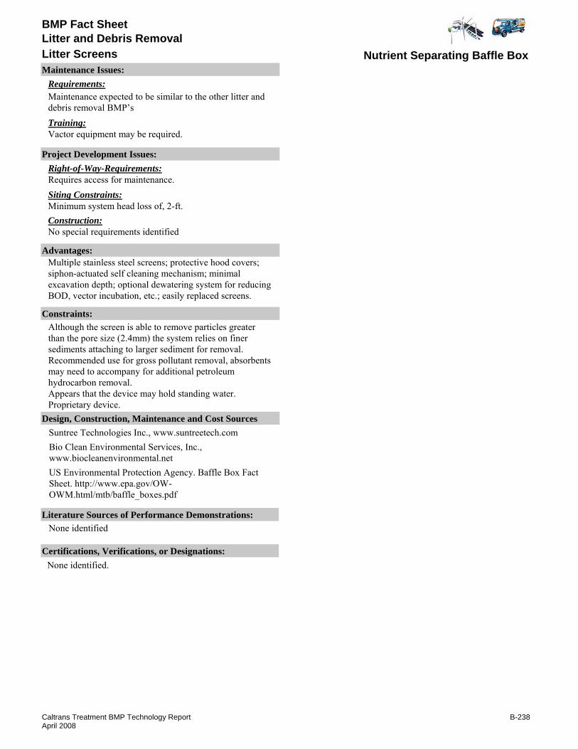
BMP Fact Sheet
Nutrient Separating Baffle BoxLitter ScreensLitter and Debris Removal
Requirements:Maintenance expected to be similar to the other litter and debris removal BMP’sTraining:Vactor equipment may be required.
Maintenance Issues:
Project Development Issues:Right-of-Way-Requirements:Requires access for maintenance.Siting Constraints:Minimum system head loss of, 2-ft.Construction:No special requirements identified
Constraints: Although the screen is able to remove particles greater than the pore size (2.4mm) the system relies on finer sediments attaching to larger sediment for removal. Recommended use for gross pollutant removal, absorbents may need to accompany for additional petroleum hydrocarbon removal.Appears that the device may hold standing water.Proprietary device.
Advantages:Multiple stainless steel screens; protective hood covers; siphon-actuated self cleaning mechanism; minimal excavation depth; optional dewatering system for reducing BOD, vector incubation, etc.; easily replaced screens.
Bio Clean Environmental Services, Inc., www.biocleanenvironmental.netUS Environmental Protection Agency. Baffle Box Fact Sheet. http://www.epa.gov/OW-OWM.html/mtb/baffle_boxes.pdf
Literature Sources of Performance Demonstrations:None identified
Design, Construction, Maintenance and Cost SourcesSuntree Technologies Inc., www.suntreetech.com
Certifications, Verifications, or Designations:None identified.
B-238Caltrans Treatment BMP Technology ReportApril 2008
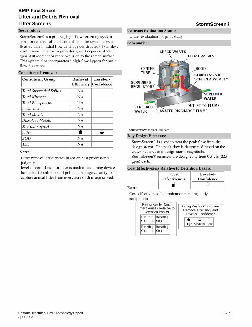
BMP Fact Sheet
StormScreen®Litter ScreensLitter and Debris Removal
Description:StormScreen® is a passive, high-flow screening system used for removal of trash and debris. The system uses a float-actuated, radial flow cartridge constructed of stainless steel screen. The cartridge is designed to operate at 225 gpm at 80-percent or more occusion to the screen surface. This system also incorporates a high flow bypass for peak flow diversion.
Removal Efficiency
Level-of-Confidence
Total Suspended SolidsTotal NitrogenTotal PhosphorusPesticidesTotal MetalsDissolved MetalsMicrobiologicalLitterBODTDS
Constituent GroupConstituent Removal:
NANANANANANANA
NANA
Notes:Litter removal efficiencies based on best professional judgment.level-of-confidence for litter is medium assuming device has at least 5 cubic feet of pollutant storage capacity to capture annual litter from every acre of drainage served.
Key Design Elements:StormScreen® is sized to treat the peak flow from the design storm. The peak flow is determined based on the watershed area and design storm magnitude.StormScreen® canisters are designed to treat 0.5-cfs (225-gpm) each.
CostEffectiveness:
Level-of-Confidence
Cost Effectiveness Relative to Detention Basins:
Benifit ↑Cost ↓
Benefit ↓Cost ↓
Benefit ↑Cost ↑
Benefit ↓Cost ↑
High Medium Low
Rating Key for ConstituentRemoval Efficiency and
Level-of-Confidence
Rating Key for CostEffectiveness Relative to
Detention Basins
Source: www.contech-cpi.com
Notes:Cost effectiveness determination pending study completion.
Schematic:
Caltrans Evaluation Status:Under evaluation for pilot study
B-239Caltrans Treatment BMP Technology ReportApril 2008

BMP Fact Sheet
StormScreen®Litter ScreensLitter and Debris Removal
Requirements:Maintenance expected to be similar to the other litter and debris removal BMP’s.For routine maintenance, requires staff and equipment to remove sediment and debris.Training:No special requirements identified.
Maintenance Issues:
Project Development Issues:Right-of-Way-Requirements:Requires access for maintenance.Siting Constraints:Minimum system head loss of 2-ft.Construction:No special requirements identified.
Constraints: The pore size (2.4-mm) may limit the system removal to gross pollutants.Proprietary device.
Advantages:Multiple stainless steel screens; protective hood covers; siphon-actuated self cleaning mechanism; minimal excavation depth; optional dewatering system for reducing vector incubation.StormScreen® and StormFilter® systems can be used in combination for larger sites with a high flow rate or volume that need to be treated or a large amount of trash and debris that needs to be captured.Stormwater drain-down systems can be incorporated with StormScreen® devices.Screens can be replaced easily.
U.S. Environmental Protection Agency, "Stormwater Management, Inc., StormScreen® Treatment System Verification Report, www.epa.gov/region1/assistance/ceitts/stormwater/techs/vortechs.html (April 2005).
Literature Sources of Performance Demonstrations:City of Beaverton, OR. "Case Study-Controlling the flow: Innovative Screening Device Solves Detention Maintenance Issues," Contech® Stormwater Solutions, (2006).
Design, Construction, Maintenance and Cost SourcesContech® Stormwater Solutions, Inc.., www.contech-cpi.com/stormwater/products/screening/stormscreen/75
Certifications, Verifications, or Designations:ETV - Verification statement issued June 2005. Studies show claims are reliable for SSC trash/debris and large particulate removal .
B-240Caltrans Treatment BMP Technology ReportApril 2008
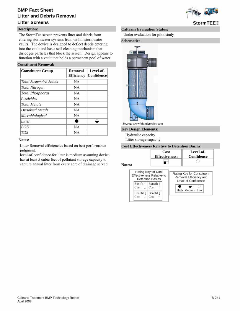
BMP Fact Sheet
StormTEE®Litter ScreensLitter and Debris Removal
Description:The StormTee screen prevents litter and debris from entering stormwater systems from within stormwater vaults. The device is designed to deflect debris entering into the vault and has a self-cleaning mechanism that dislodges particles that block the screen. Design appears to function with a vault that holds a permanent pool of water.
Removal Efficiency
Level-of-Confidence
Total Suspended SolidsTotal NitrogenTotal PhosphorusPesticidesTotal MetalsDissolved MetalsMicrobiologicalLitterBODTDS
Constituent GroupConstituent Removal:
NANANANANANANA
NANA
Notes:Litter Removal efficiencies based on best performance judgment.level-of-confidence for litter is medium assuming device has at least 5 cubic feet of pollutant storage capacity to capture annual litter from every acre of drainage served.
Key Design Elements:Hydraulic capacity.Litter storage capacity.
CostEffectiveness:
Level-of-Confidence
Cost Effectiveness Relative to Detention Basins:
Benifit ↑Cost ↓
Benefit ↓Cost ↓
Benefit ↑Cost ↑
Benefit ↓Cost ↑
High Medium Low
Rating Key for ConstituentRemoval Efficiency and
Level-of-Confidence
Rating Key for CostEffectiveness Relative to
Detention Basins
Source: www.biomicrobics.com
Notes:
Schematic:
Caltrans Evaluation Status:Under evaluation for pilot study
B-241Caltrans Treatment BMP Technology ReportApril 2008

BMP Fact Sheet
StormTEE®Litter ScreensLitter and Debris Removal
Requirements:Maintenance expected to be similar to the other litter and debris removal BMP’s.For routine maintenance, requires staff and equipment to remove sediment and debris.Training:No special requirements identified.
Maintenance Issues:
Project Development Issues:Right-of-Way-Requirements:Requires access for maintenance.Siting Constraints:Requires existing drop inlet structure.Construction:No special requirements identified.
Constraints: Proprietary device.Vector concerns.
Advantages:Easy maintenance.
Literature Sources of Performance Demonstrations:None identified
Design, Construction, Maintenance and Cost SourcesBio-microbics, Inc., www.biomicrobics.com
Certifications, Verifications, or Designations:None identified.
B-242Caltrans Treatment BMP Technology ReportApril 2008
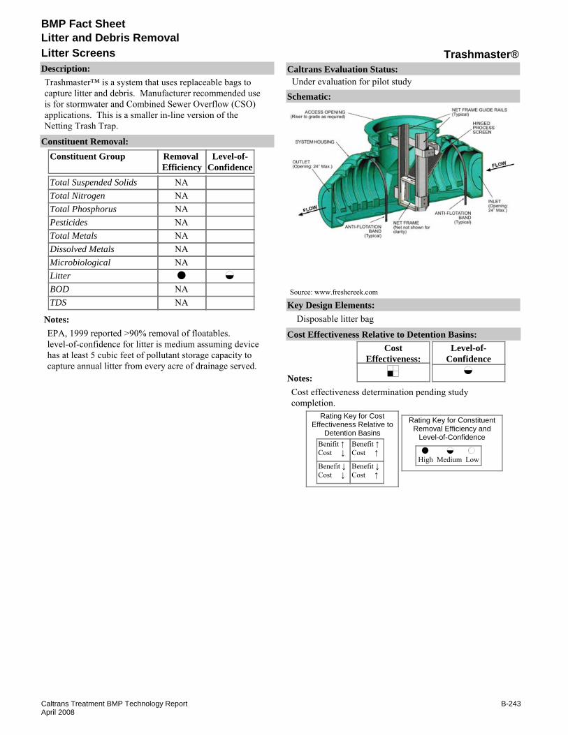
BMP Fact Sheet
Trashmaster®Litter ScreensLitter and Debris Removal
Description:Trashmaster™ is a system that uses replaceable bags to capture litter and debris. Manufacturer recommended use is for stormwater and Combined Sewer Overflow (CSO) applications. This is a smaller in-line version of the Netting Trash Trap.
Removal Efficiency
Level-of-Confidence
Total Suspended SolidsTotal NitrogenTotal PhosphorusPesticidesTotal MetalsDissolved MetalsMicrobiologicalLitterBODTDS
Constituent GroupConstituent Removal:
NANANANANANANA
NANA
Notes:EPA, 1999 reported >90% removal of floatables.level-of-confidence for litter is medium assuming device has at least 5 cubic feet of pollutant storage capacity to capture annual litter from every acre of drainage served.
Key Design Elements:Disposable litter bag
CostEffectiveness:
Level-of-Confidence
Cost Effectiveness Relative to Detention Basins:
Benifit ↑Cost ↓
Benefit ↓Cost ↓
Benefit ↑Cost ↑
Benefit ↓Cost ↑
High Medium Low
Rating Key for ConstituentRemoval Efficiency and
Level-of-Confidence
Rating Key for CostEffectiveness Relative to
Detention Basins
Source: www.freshcreek.com
Notes:Cost effectiveness determination pending study completion.
Schematic:
Caltrans Evaluation Status:Under evaluation for pilot study
B-243Caltrans Treatment BMP Technology ReportApril 2008

BMP Fact Sheet
Trashmaster®Litter ScreensLitter and Debris Removal
Requirements:EPA fact Sheet recommends nets changed at least once a month on Combined Sewer Overflow (CSO) facilities. Maintenance for stormwater treatment will likely depend on net size and litter load. For routine maintenance, requires staff and equipment to remove and replace bags.Training:No special requirements identified.
Maintenance Issues:
Project Development Issues:Right-of-Way-Requirements:Requires access for maintenance.Siting Constraints:Minimal head loss requirement.Construction:No special requirements identified.
Constraints: Proprietary device.
Advantages:Easy maintenance.
Literature Sources of Performance Demonstrations:U.S. Environmental Protection Agency. "Combined Sewer Overflow Technology Fact Sheet - Netting Systems for Floatables Control" Sep 1999. EPA 832-F-99-037. www.epa.gov/owmitnet/mtb/nettrash1.pdf
Design, Construction, Maintenance and Cost SourcesFresh Creek Technologies, Inc., www.freshcreek.com
Certifications, Verifications, or Designations:None identified.
B-244Caltrans Treatment BMP Technology ReportApril 2008
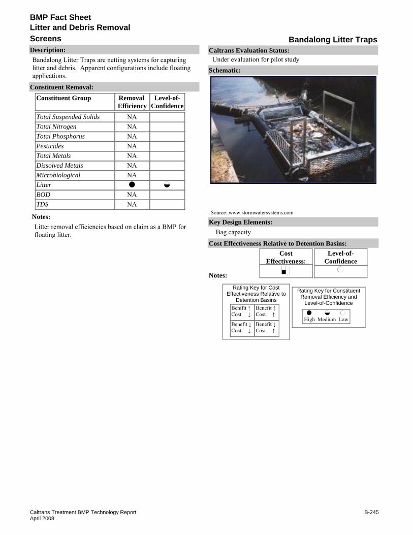
BMP Fact Sheet
Bandalong Litter TrapsScreensLitter and Debris Removal
Description:Bandalong Litter Traps are netting systems for capturing litter and debris. Apparent configurations include floating applications.
Removal Efficiency
Level-of-Confidence
Total Suspended SolidsTotal NitrogenTotal PhosphorusPesticidesTotal MetalsDissolved MetalsMicrobiologicalLitterBODTDS
Constituent GroupConstituent Removal:
NANANANANANANA
NANA
Notes:Litter removal efficiencies based on claim as a BMP for floating litter.
Key Design Elements:Bag capacity
CostEffectiveness:
Level-of-Confidence
Cost Effectiveness Relative to Detention Basins:
Benifit ↑Cost ↓
Benefit ↓Cost ↓
Benefit ↑Cost ↑
Benefit ↓Cost ↑
High Medium Low
Rating Key for ConstituentRemoval Efficiency and
Level-of-Confidence
Rating Key for CostEffectiveness Relative to
Detention Basins
Source: www.stormwatersystems.com
Notes:
Schematic:
Caltrans Evaluation Status:Under evaluation for pilot study
B-245Caltrans Treatment BMP Technology ReportApril 2008

BMP Fact Sheet
Bandalong Litter TrapsScreensLitter and Debris Removal
Requirements:Requires access for maintenance. Frequent inspections may be required to check on the nets.Training:No special requirements identified.
Maintenance Issues:
Project Development Issues:Right-of-Way-Requirements:Installed within existing structures.Siting Constraints:Little or no site development needed to implement.Construction:Patented devices are required.
Constraints: An regular and possibly frequent maintenance/ inspections are required until a routine schedule can be determined to prevent possibility of mosquito breeding and litter decomposition.Proprietary device.
Advantages:Requires minor site workLow maintenance costLow construction costAbility to retrofit onto stormwater outfalls and open channels of any shape
Literature Sources of Performance Demonstrations:None identified
Design, Construction, Maintenance and Cost SourcesNone identified
Certifications, Verifications, or Designations:None identified.
B-246Caltrans Treatment BMP Technology ReportApril 2008

BMP Fact Sheet
AsphaltPorous Surfaces
Description:Porous asphalt pavement, with a life span of 20 years or more, provides stormwater storage and infiltration. Porous asphalt pavement is compromised of a permeable asphalt surface placed over a granular “choke” course on top of a reservoir of large stone. The asphalt surface is made permeable by designing it as an open-graded friction course. The lower reservoir layer is designed for load requirements and for water storage capacity. An overflow mechanism is recommended in case of clogging. The pavement may also be designed to receive off-site runoff.
Removal Efficiency
Level-of-Confidence
Total Suspended SolidsTotal NitrogenTotal PhosphorusPesticidesTotal MetalsDissolved MetalsMicrobiologicalLitterBODTDS
Constituent GroupConstituent Removal:
Notes:Removal efficiency for infiltration is assumed to be 100% for the design water quality volume since no water is discharged to surface waters
Key Design Elements:Load requirements.Volume capture / infiltration requirements.
CostEffectiveness:
Level-of-Confidence
Cost Effectiveness Relative to Detention Basins:
Benifit ↑Cost ↓
Benefit ↓Cost ↓
Benefit ↑Cost ↑
Benefit ↓Cost ↑
High Medium Low
Rating Key for ConstituentRemoval Efficiency and
Level-of-Confidence
Rating Key for CostEffectiveness Relative to
Detention Basins
Source: http://international.fhwa.dot.gov/quiet pav/chapter two c.htm
Notes:Cost effectiveness determination pending further evaluation.
Schematic:
Caltrans Evaluation Status:Under evaluation for pilot study
B-247Caltrans Treatment BMP Technology ReportApril 2008

BMP Fact Sheet
AsphaltPorous Surfaces
Requirements:All porous pavements should be inspected several times in the first few months after construction, and at least annually thereafter.Training:Vacuum style street sweepers are recommended.
Maintenance Issues:
Project Development Issues:Right-of-Way-Requirements:Under pavement design requires no additional ROW.Siting Constraints:Similar to infiltration BMPs. Some considerations are depth to groundwater, subgrade permeability, and soil type.Construction:Construction requires special care and some changes to normal practices and scheduling. Sub-grade compaction should be avoided to prevent reducing the permeability. Erosion control should be in place until vegetation established before installation. Recommended last item of construction.
Constraints: Low permeable subgrade that increase runoff through the over drain will decrease removal efficiency.Not feasible where traction sand is applied.More costly that traditional asphalt concrete.Durability affected by temperature.
Advantages:Reduces or eliminates space needed for other BMPs.
Land Development Today, "From the Ground Up," Aug. 8, 2005, Article #331, Accessed Jan. 2006, www.landdevelopmenttoday.com/Article331.htmCahill Associates, "Porous Asphalt with Subsurface Infiltration/Storage Bed," Jan 2006, www.thcahill.com/pasphalt.htmlUni Eco-Stone®, Uni-Group U.S.A., Jan 2006, www.uni-groupusa.orgSF-Rima, SF Matoro®-Drain, SF-Eco®-Duct, SF Concrete Technology Inc., www.sfconcrete.comSoil Stabilization Products Company, Inc. www.sspco.com
Literature Sources of Performance Demonstrations:Brattebo, B. O. and D. B. Booth, Draft 7/1/2003, "Long-Term Stormwater Quality and Quality Performance of Permeable Pavement Systems," http://depts.washington.edu/cwws/Research/Reports/permeableparking.pdf, Accessed Jan 2006, Center for Water and Watershed Studies Dept. of Civil & Environmental Engineering., University of Washington
Design, Construction, Maintenance and Cost SourcesNational Asphalt Pavement Association (NAPA) Porous Asphalt Pavement. www.hotmix.org/
Certifications, Verifications, or Designations:None identified.
B-248Caltrans Treatment BMP Technology ReportApril 2008

BMP Fact Sheet
ConcretePorous Surfaces
Description:An alternative to traditional asphalt and concrete surfaces, pervious concrete pavement, allows infiltration into either storage basins or into the soil and ultimately recharge existing groundwater. The unique cement-based concrete product with a porous structure is comprised of a special blend of Portland cement, coarse aggregate rock, and water. The porous texture of cured pervious concrete allows water to drain through it at a rate of 8 to 12 gallons per minute per square foot. Water is the main contributor in the deterioration of standard concrete; where as, the durability of pervious concrete actually becomes stronger and more stable when it gets wet. Because water infiltrates directly into the ground hazards associated with standing water are less likely. Pervious concrete can be mixed and delivered by same suppliers as denser concrete. Unique physical characteristics require specialized training for the installation process.
Removal Efficiency
Level-of-Confidence
Total Suspended SolidsTotal NitrogenTotal PhosphorusPesticidesTotal MetalsDissolved MetalsMicrobiologicalLitterBODTDS
Constituent GroupConstituent Removal:
Notes:Removal efficiency for infiltration is assumed to be 100% for the design water quality volume since no water is discharged to surface waters.
Key Design Elements:Load requirements.Volume capture / infiltration requirements.
CostEffectiveness:
Level-of-Confidence
Cost Effectiveness Relative to Detention Basins:
Benifit ↑Cost ↓
Benefit ↓Cost ↓
Benefit ↑Cost ↑
Benefit ↓Cost ↑
High Medium Low
Rating Key for ConstituentRemoval Efficiency and
Level-of-Confidence
Rating Key for CostEffectiveness Relative to
Detention Basins
Source: http://www.psat.wa.gov/Publications/LID studies/permeable pave
Notes:Cost effectiveness determination pending further evaluation.
Schematic:
Caltrans Evaluation Status:Under evaluation for pilot study
B-249Caltrans Treatment BMP Technology ReportApril 2008
BMP Fact Sheet
ConcretePorous Surfaces
Requirements:All porous pavements should be inspected several times in the first few months after construction, and at least annually thereafter.Training:Vacuum style street sweepers are recommended.
Maintenance Issues:
Project Development Issues:Right-of-Way-Requirements:Under pavement design requires no additional ROW.Siting Constraints:Similar to infiltration BMPs. Some considerations are depth to groundwater, subgrade permeability, and soil type.Construction:Construction requires special care and some changes to normal practices and scheduling. Sub-grade compaction should be avoided to prevent reducing the permeability. Erosion control should be in place until vegetation established before installation. Recommended last item of construction.
Constraints: Low permeable subgrade that increase runoff through the over drain will decrease removal efficiency.Durability affected by temperature.More costly that traditional asphalt concrete.Not feasible where traction sand is applied.
Advantages:Reduces or eliminates space needed for other BMPs.
Portland Cement Association (www.cement.org) & National Ready Mixed Concrete Association (www.nrmca.org) September 2007. "Pervious Concrete Pavements" Brochure.Uni Eco-Stone®, Uni-Group U.S.A., Jan 2006, www.uni-groupusa.orgSoil Stabilization Products Company, Inc. Jul 2006, www.sspco.comPermeable Interlocking Concrete Pavements, Jul 2006, www.icpi.orgNational Ready Mixed Concrete Association, Pervious Concrete Site, Jul 2006, www.perviouspavement.orgSF-Rima, SF Matoro®-Drain, SF-Eco®-Duct, SF Concrete Technology Inc., www.sfconcrete.comSoil Retention Products Inc., Drivable Grass®, Vendura® 10, Vendura® 30, Vendura® 40, Vendura® 50, Vendura® 60, Vendura® 60W, Candura® 35, Enviroflex®, Jan 2008, www.soilretention.com
Booth, D. "Field Evaluation of Permeable Pavements for Stormwater Management, Olympia, Washington," Oct 2000. Center for Urban Water Resources Management, Univ. of Washington. U.S. EPA
Literature Sources of Performance Demonstrations:Brattebo, B. O. and D. B. Booth. "Long-Term Stormwater Quality and Quality Performance of Permeable Pavement Systems," Draft 7/1/2003. http://depts.washington.edu/cwws/Research/Reports/permeableparking.pdf, Accessed Jan 2006, Center for Water and Watershed Studies Dept. of Civil & Environmental Engineering., University of Washington.
Design, Construction, Maintenance and Cost SourcesLand Development Today, "From the Ground Up," Aug. 8, 2005, Article #331, Accessed Jan. 2006, www.landdevelopmenttoday.com/Article331.htm
Certifications, Verifications, or Designations:None identified.
B-250Caltrans Treatment BMP Technology ReportApril 2008

BMP Fact Sheet
Permeable Pavers / Cellular ConfinementPorous Surfaces
Description:An alternative to traditional asphalt and concrete surfaces, permeable pavers, allow infiltration into either storage basins or into the soil and ultimately recharge existing groundwater. Permeable surfaces are fairly durable with a life span of approximately 20 years, possibly more with proper maintenance. Typically built on an open-graded, crushed stone base, permeable pavers interlock or have a minimal sand-filled gap between them. As with most permeable surfaces, the lower reservoir layer is designed for load requirements and for water storage capacity. An overflow mechanism is recommended in case of clogging. The pavement may also be designed to receive off-site runoff.
Removal Efficiency
Level-of-Confidence
Total Suspended SolidsTotal NitrogenTotal PhosphorusPesticidesTotal MetalsDissolved MetalsMicrobiologicalLitterBODTDS
Constituent GroupConstituent Removal:
Notes:Removal efficiency for infiltration is assumed to be 100% for the design water quality volume since no water is discharged to surface waters.
Key Design Elements:Load requirements.Volume capture / infiltration requirements.
CostEffectiveness:
Level-of-Confidence
Cost Effectiveness Relative to Detention Basins:
Benifit ↑Cost ↓
Benefit ↓Cost ↓
Benefit ↑Cost ↑
Benefit ↓Cost ↑
High Medium Low
Rating Key for ConstituentRemoval Efficiency and
Level-of-Confidence
Rating Key for CostEffectiveness Relative to
Detention Basins
Source: http://www.ia.nrcs.usda.gov/features/urbanphotos.html
Notes:Cost effectiveness determination pending study completion.
Schematic:
Caltrans Evaluation Status:Under evaluation for pilot study
B-251Caltrans Treatment BMP Technology ReportApril 2008

BMP Fact Sheet
Permeable Pavers / Cellular ConfinementPorous Surfaces
Requirements:All porous pavements should be inspected several times in the first few months after construction, and at least annually thereafter.Training:Vacuum style street sweepers are recommended.
Maintenance Issues:
Project Development Issues:Right-of-Way-Requirements:Under pavement design requires no additional ROW.Siting Constraints:Similar to infiltration BMPs. Some considerations are depth to groundwater, subgrade permeability, and soil type.Construction:Construction requires special care and some changes to normal practices and scheduling. Sub-grade compaction should be avoided to prevent reducing the permeability. Erosion control should be in place until vegetation established before installation. Recommended last item of construction.
Constraints: Low permeable subgrade that increase runoff through the over drain will decrease removal efficiency.Not feasible where traction sand is applied.More costly that traditional asphalt concrete.Durability affected by temperature.
Advantages:Reduces or eliminates space needed for other BMPs.
Cahill Associates, "Porous Asphalt with Subsurface Infiltration/Storage Bed," Jan 2006, www.thcahill.com/pasphalt.htmlUni Eco-Stone®, Uni-Group U.S.A., Jan 2006, www.uni-groupusa.orgPermeable Interlocking Concrete Pavements, Jul 2006, www.icpi.orgSF-Rima, SF Matoro®-Drain, SF-Eco®-Duct, SF Concrete Technology Inc., www.sfconcrete.comRehbein Environmental Solutions, Jan 2008, www.rehbeinsolutions.comGeoblock® Porous Pavement Systems, 2005 Soil Stabilization Products Company, Inc. Www.sspco.comInterlooking Concrete Pavement Institute , 20025 Accheieving LEED® Credits with Segmental Concrete Pavements, www.icpa.og
James, W. and von Langsdorf, H. "The Use of Permeable Concrete Block Pavement in Controlling Environmental Stressors in Urban Areas" Oct 2003. Proceedings of the 7th Int’l Conf. on Concrete Block Paving, ISBN 0-958-46091-4, Sun City South Africa.
Booth, D. "Field Evaluation of Permeable Pavements for Stormwater Management, Olympia, Washington," Oct 2000. Center for Urban Water Resources Management, Univ. of Washington. U.S. EPA.
Shackel, B., Ball, J., and Mearing, M. "Using Permeable Eco-Paving to Achieve Improved Water Quality for Urban Pavements," Oct 2003. Proceedings of the 7th Int’l Conf. on Concrete Block Paving. ISBN: 0-958-46091-4. Sun City, South Africa.
Literature Sources of Performance Demonstrations:Brattebo, B. O. and D. B. Booth. "Long-Term Stormwater Quality and Quality Performance of Permeable Pavement Systems," Draft 7/1/2003. http://depts.washington.edu/cwws/Research/Reports/permeableparking.pdf, Accessed Jan 2006, Center for Water and Watershed Studies Dept. of Civil & Environmental Engineering., University of Washington.
Design, Construction, Maintenance and Cost SourcesSoil Retention Products Inc., Sept 2007, www.soilretention.com
Certifications, Verifications, or Designations:None identified.
B-252Caltrans Treatment BMP Technology ReportApril 2008

BMP Fact Sheet
Subsurface Drainage StructuresPorous Surfaces
Description:The cellular design of these structures increase the shear resistance of the granular infill materials allowing the use of lower quality aggregates such as sand and gravel to carry concentrated loads that would otherwise require crushed stone or bituminous mixes to prevent localized, near-surface, shear failure. These structures are most commonly components of a larger stormwater management installation.
Removal Efficiency
Level-of-Confidence
Total Suspended SolidsTotal NitrogenTotal PhosphorusPesticidesTotal MetalsDissolved MetalsMicrobiologicalLitterBODTDS
Constituent GroupConstituent Removal:
Notes:Removal depends on application, specifically on the amount of filtration and infiltration allowed.Removal efficiency for infiltration is assumed to be 100% for the design water quality volume since no water is discharged to surface waters.
Key Design Elements:Load requirements.Volume capture / infiltration requirements.
CostEffectiveness:
Level-of-Confidence
Cost Effectiveness Relative to Detention Basins:
Benifit ↑Cost ↓
Benefit ↓Cost ↓
Benefit ↑Cost ↑
Benefit ↓Cost ↑
High Medium Low
Rating Key for ConstituentRemoval Efficiency and
Level-of-Confidence
Rating Key for CostEffectiveness Relative to
Detention Basins
Source: http://www.rehbeinsolutions.com/
Notes:Cost effectiveness determination pending study completion.
Schematic:
Caltrans Evaluation Status:Under evaluation for pilot study
B-253Caltrans Treatment BMP Technology ReportApril 2008

BMP Fact Sheet
Subsurface Drainage StructuresPorous Surfaces
Requirements:All porous pavements should be inspected several times in the first few months after construction, and at least annually thereafter.Training:Vacuum style street sweepers are recommended.
Maintenance Issues:
Project Development Issues:Right-of-Way-Requirements:Under pavement design requires no additional ROW.Siting Constraints:Similar to infiltration BMPs. Some considerations are depth to groundwater, subgrade permeability, and soil type.Construction:Construction requires special care and some changes to normal practices and scheduling. Sub-grade compaction should be avoided to prevent reducing the permeability. Erosion control should be in place until vegetation established before installation. Recommended last item of construction.
Constraints: Low permeable subgrade that increase runoff through the over drain will decrease removal efficiency.Not feasible where traction sand is applied.More costly that traditional asphalt concrete.Durability affected by temperature.
Advantages:Reduces or eliminates space needed for other BMPs.
Land Development Today, "From the Ground Up," Aug. 8, 2005, Article #331, Accessed Jan. 2006, www.landdevelopmenttoday.com/Article331.htmCahill Associates, "Porous Asphalt with Subsurface Infiltration/Storage Bed," Jan 2006, www.thcahill.com/pasphalt.htmlUni Eco-Stone®, Uni-Group U.S.A., Jan 2006, www.uni-groupusa.orgSoil Stabilization Products Company, Inc. July 2006, www.sspco.comPermeable Interlocking Concrete Pavements, Jul 2006, www.icpi.orgSF-Rima, SF Matoro®-Drain, SF-Eco®-Duct, SF Concrete Technology Inc., www.sfconcrete.com
James, W. and von Langsdorf, H. "The Use of Permeable Concrete Block Pavement in Controlling Environmental Stressors in Urban Areas," Oct 2003. Proceedings of the 7th Int’l Conf. on Concrete Block Paving, ISBN 0-958-46091-4, Sun City South Africa
Booth, D. "Field Evaluation of Permeable Pavements for Stormwater Management, Olympia, Washington," Oct 2000. Center for Urban Water Resources Management, Univ. of Washington. U.S. EPA.
Shackel, B., Ball, J., and Mearing, M. "Using Permeable Eco-Paving to Achieve Improved Water Quality for Urban Pavements," Oct 2003. Proceedings of the 7th Int’l Conf. on Concrete Block Paving. ISBN: 0-958-46091-4. Sun City, South Africa.
Literature Sources of Performance Demonstrations:Brattebo, B. O. and D. B. Booth. "Long-Term Stormwater Quality and Quality Performance of Permeable Pavement Systems," Draft 7/1/2003. http://depts.washington.edu/cwws/Research/Reports/permeableparking.pdf, Accessed Jan 2006, Center for Water and Watershed Studies Dept. of Civil & Environmental Engineering., University of Washington
Design, Construction, Maintenance and Cost SourcesInvisible Structures, Inc., "Gravelpave2"Jul 2006, www.grasspave.com
Certifications, Verifications, or Designations:ETV - Verification report for testing September 2005. No record of Statement
B-254Caltrans Treatment BMP Technology ReportApril 2008

BMP Fact Sheet
ADS® Water Quality UnitOil/Water SeparatorsWater Quality Inlets
Description:ADS® Water Quality Unit is a baffled vault that is designed to remove heavy particles and lighter-than-water pollutants sucha as oil and some litter.
Removal Efficiency
Level-of-Confidence
Total Suspended SolidsTotal NitrogenTotal PhosphorusPesticidesTotal MetalsDissolved MetalsMicrobiologicalLitterBODTDS
Constituent GroupConstituent Removal:
NANANANANANA
NANA
Notes:Test for statistical significance were not performed. Litter removal based on professional judgment. TSS based on small scale laboratory removal of particles with a d90 of approximately 50 micron up to 65 L/min (0.038 c.f.s.). Full-scale laboratory investigation was not considered because the sediment source is larger than typical stomwater runoff. Field tests are ongoing at the Univ. of New Hampshire and in Mississippi. Field test from a Nashville study was not considered because test parameters could not be verified.
Key Design Elements:Detention timePollutant storage capacity
CostEffectiveness:
Level-of-Confidence
Cost Effectiveness Relative to Detention Basins:
Benifit ↑Cost ↓
Benefit ↓Cost ↓
Benefit ↑Cost ↑
Benefit ↓Cost ↑
High Medium Low
Rating Key for ConstituentRemoval Efficiency and
Level-of-Confidence
Rating Key for CostEffectiveness Relative to
Detention Basins
Source: www.ads-pipe.com
Notes:
Schematic:
Caltrans Evaluation Status:Under evaluation for pilot study
B-255Caltrans Treatment BMP Technology ReportApril 2008

BMP Fact Sheet
ADS® Water Quality UnitOil/Water SeparatorsWater Quality Inlets
Requirements:Because of site-specific laoding, several wet season inspections may be required to determien appropriate replacement frequency.Vactor equipment recommended for cleaning.Training:No special training identified.
Maintenance Issues:
Project Development Issues:Right-of-Way-Requirements:Relatively small footprint.Siting Constraints:Minimal head requirement.Construction:No special requirement identified.
Constraints: Proprietary device.Vector concerns.
Advantages:Small footprints.
Alden labs Maine DEP Laboratory Testing Protocol Hoden, Mass. For conformace with Maine Department of Environmental Protection Protocol for TSS removal.
Univerisity of New Hampshire Center for Stormwater Technology
Nashville Study of Eight Water Quality Units, June 23, 2005Mississippi Testing of Water Quality Units, in progress.ADS. 2007. Technical Note, 1.04. "Testing of Stormwater Quality Units." February 2007. www.ads-pipe.com
Literature Sources of Performance Demonstrations:Ohio Univeristy Scale Model Lab Testing 2003
Design, Construction, Maintenance and Cost SourcesAdvanced Drainage Systems, Inc 2007 www.ads-pipe.com
Certifications, Verifications, or Designations:None identified.
B-256Caltrans Treatment BMP Technology ReportApril 2008

BMP Fact Sheet
BaySaver® BaySeparatorOil/Water SeparatorsWater Quality Inlets
Description:BaySaver® is a dual tank system. Low flows are diverted to the offline tank. High flow passes through the primary tank.
Removal Efficiency
Level-of-Confidence
Total Suspended SolidsTotal NitrogenTotal PhosphorusPesticidesTotal MetalsDissolved MetalsMicrobiologicalLitterBODTDS
Constituent GroupConstituent Removal:
NANANANANANANA
NANA
Notes:Litter removal efficiencies based on best professional judgment.
Key Design Elements:Detention time.Pollutant storage capacity.Flow capacity (flood and water quality flow).
CostEffectiveness:
Level-of-Confidence
Cost Effectiveness Relative to Detention Basins:
Benifit ↑Cost ↓
Benefit ↓Cost ↓
Benefit ↑Cost ↑
Benefit ↓Cost ↑
High Medium Low
Rating Key for ConstituentRemoval Efficiency and
Level-of-Confidence
Rating Key for CostEffectiveness Relative to
Detention Basins
Source: www.baysaver.com
Notes:Cost effectiveness determination pending further evaluation.
Schematic:
Caltrans Evaluation Status:Under evaluation for pilot study
B-257Caltrans Treatment BMP Technology ReportApril 2008

BMP Fact Sheet
BaySaver® BaySeparatorOil/Water SeparatorsWater Quality Inlets
Requirements:Initially the site should be monitored frequently in order to determine the required cleaning frequency.Vactor equipment recommended for cleaning.Training:No special requirements identified.
Maintenance Issues:
Project Development Issues:Right-of-Way-Requirements:Relatively small footprint.Siting Constraints:Minimal head requirement.Construction:No special requirements identified.
Constraints: It appears that some floating litter may accumulate in the primary tank and discharge during high flows.Proprietary device.Vector concerns.
Advantages:Small footprint.
U.S. Environmental Protection Agency, www.epa.gov/OW-OWM.html/mtb/wtrqlty.pdfU.S. Environmental Protection Agency, www.epa.gov/region1/assistance/ceitts/stormwater/techs/baysaver.html
Literature Sources of Performance Demonstrations:None identified
Design, Construction, Maintenance and Cost SourcesBaySaver, Inc., www.baysaver.com
Certifications, Verifications, or Designations:TARP - Studies underway that offer promise for reliable data in the near future for addressing SSC removal efficiency claims.
B-258Caltrans Treatment BMP Technology ReportApril 2008

BMP Fact Sheet
BioSTORM™Oil/Water SeparatorsWater Quality Inlets
Description:BioSTORM™ is a double vault system that uses coalescing plates in the second tank. Despite its name, there does not appear to be any biological component to the system. It is designed as an offline device so high flows bypass the system
Removal Efficiency
Level-of-Confidence
Total Suspended SolidsTotal NitrogenTotal PhosphorusPesticidesTotal MetalsDissolved MetalsMicrobiologicalLitterBODTDS
Constituent GroupConstituent Removal:
NANANANANANA
NANA
Notes:Litter removal efficiencies based on best professional judgment.Other performance estimates based on Caltrans study of similar technology (See Oil/Water Separator, Appendix C).
Key Design Elements:Detention time.Flow capacity.
CostEffectiveness:
Level-of-Confidence
Cost Effectiveness Relative to Detention Basins:
Benifit ↑Cost ↓
Benefit ↓Cost ↓
Benefit ↑Cost ↑
Benefit ↓Cost ↑
High Medium Low
Rating Key for ConstituentRemoval Efficiency and
Level-of-Confidence
Rating Key for CostEffectiveness Relative to
Detention Basins
Source: www.biomicrobics.com
Notes:Cost effectiveness determination pending further evaluation.
Schematic:
Caltrans Evaluation Status:Under evaluation for pilot study
B-259Caltrans Treatment BMP Technology ReportApril 2008

BMP Fact Sheet
BioSTORM™Oil/Water SeparatorsWater Quality Inlets
Requirements:Initially the site should be monitored frequently in order to determine the required cleaning frequency.Vactor equipment recommended for cleaning.Training:No special requirements identified.
Maintenance Issues:
Project Development Issues:Right-of-Way-Requirements:Relatively small footprint.Siting Constraints:Check for underground utility conflicts.Construction:No special requirements identified.
Constraints: Proprietary device.Vector concerns.
Advantages:Small footprint.
Literature Sources of Performance Demonstrations:None identified
Design, Construction, Maintenance and Cost SourcesBio-Microbics, Inc., www.biomicrobics.com
Certifications, Verifications, or Designations:None identified.
B-260Caltrans Treatment BMP Technology ReportApril 2008

BMP Fact Sheet
CrystalStream™Oil/Water SeparatorsWater Quality Inlets
Description:CrystalStream™ is a system of baffles and screens contained within a concrete vault. A trash basket is followed by two baffles and a reservoir for captured oil. Water then passes through a fiber mesh before leaving the unit. All these components are removable. It is unclear how high flows are passed through the unit without going through the mesh.
Removal Efficiency
Level-of-Confidence
Total Suspended SolidsTotal NitrogenTotal PhosphorusPesticidesTotal MetalsDissolved MetalsMicrobiologicalLitterBODTDS
Constituent GroupConstituent Removal:
NANANANA
NANA
Notes:Tests for statistical significance were not performed.Litter removal based on professional judgment.
Key Design Elements:Detention time.Capacity from 6 to 36 cfs.Pollutant storage capacity.Flow capacity (flood and water quality flow).
CostEffectiveness:
Level-of-Confidence
Cost Effectiveness Relative to Detention Basins:
Benifit ↑Cost ↓
Benefit ↓Cost ↓
Benefit ↑Cost ↑
Benefit ↓Cost ↑
High Medium Low
Rating Key for ConstituentRemoval Efficiency and
Level-of-Confidence
Rating Key for CostEffectiveness Relative to
Detention Basins
Source: www.crystalstream.com
Notes:Cost effectiveness determination pending further evaluatioin.
Schematic:
Caltrans Evaluation Status:Under evaluation for pilot study
B-261Caltrans Treatment BMP Technology ReportApril 2008

BMP Fact Sheet
CrystalStream™Oil/Water SeparatorsWater Quality Inlets
Requirements:Initially the site should be monitored frequently in order to determine the required cleaning frequency. Environmental Technology Verification (ETV) study experienced 3 to 4 cleanings per year.Vactor equipment recommended for cleaning.Training:No special requirements identified.
Maintenance Issues:
Project Development Issues:Right-of-Way-Requirements:Relatively small footprint.Siting Constraints:Minimal head requirements. Effective operation of similar technologies usually requires influent concentrations above 50 mg/L (CTSW-RT-01-05) P16-20.Construction:No special requirements identified.
Constraints: Proprietary device.Vector concerns.
Advantages:Small footprint.
Literature Sources of Performance Demonstrations:Environmental Technology Verification Program, NSF International, June 2005, 05/21/WQPC-WWF, EPA 600/R-05/085. p. 21. www.epa.gov/etv/pdfs/vrvs/09_vr_pbm.pdf
Design, Construction, Maintenance and Cost SourcesCrystalStreamTM Technologies, www.crystalstream.com
Certifications, Verifications, or Designations:ETV - Verification statement issued June 2005. Studies show claims are reliable for SSC trash/debris and large particulate removal .
B-262Caltrans Treatment BMP Technology ReportApril 2008

BMP Fact Sheet
EcoSep®Oil/Water SeparatorsWater Quality Inlets
Description:EcoSep® is a two chambered system. Water enters the first cylinder and hits a flow splitter. Water leaves the chamber through a down turned elbow. The final chamber has a coalescing outlet structure. Ability to pass high flow is unclear. The unit may need to be installed off-line.
Removal Efficiency
Level-of-Confidence
Total Suspended SolidsTotal NitrogenTotal PhosphorusPesticidesTotal MetalsDissolved MetalsMicrobiologicalLitterBODTDS
Constituent GroupConstituent Removal:
NANANANANANANA
NANA
Notes:Litter removal efficiency based on best professional judgment.
Key Design Elements:Detention time.Pollutant storage capacity.Flow capacity (flood and water quality flow).
CostEffectiveness:
Level-of-Confidence
Cost Effectiveness Relative to Detention Basins:
Benifit ↑Cost ↓
Benefit ↓Cost ↓
Benefit ↑Cost ↑
Benefit ↓Cost ↑
High Medium Low
Rating Key for ConstituentRemoval Efficiency and
Level-of-Confidence
Rating Key for CostEffectiveness Relative to
Detention Basins
Source: www.royalenterprises.net
Notes:Cost effectiveness determination pending further evaluation.
Schematic:
Caltrans Evaluation Status:Under evaluation for pilot study
B-263Caltrans Treatment BMP Technology ReportApril 2008

BMP Fact Sheet
EcoSep®Oil/Water SeparatorsWater Quality Inlets
Requirements:Initially the site should be monitored frequently in order to determine the required cleaning frequency.Vactor equipment recommended for cleaning.Training:No special requirements identified.
Maintenance Issues:
Project Development Issues:Right-of-Way-Requirements:Relatively small footprint.Siting Constraints:Minimal head requirements. Effective operation of similar technologies usually requires influent concentrations above 50 mg/L (CTSW-RT-01-05) P16-20.Construction:No special requirements identified
Constraints: Proprietary device.Vector concerns.
Advantages:Small footprint.
Literature Sources of Performance Demonstrations:None identified
Design, Construction, Maintenance and Cost SourcesRoyal Environmental Systems, Inc., www.royalenterprises.net
Certifications, Verifications, or Designations:WA TAPE - Pilot Use Level Designation (PLD) as an oil treatment option, October 2007..
B-264Caltrans Treatment BMP Technology ReportApril 2008
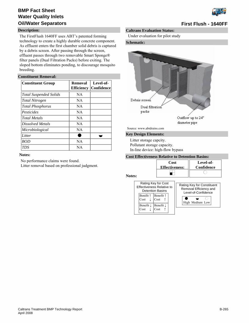
BMP Fact Sheet
First Flush - 1640FFOil/Water SeparatorsWater Quality Inlets
Description:The FirstFlush 1640FF uses ABT’s patented forming technology to create a highly durable concrete component. As effluent enters the first chamber solid debris is captured by a debris screen. After passing through the screen, effluent passes through two removable Smart Sponge® filter panels (Dual Filtration Packs) before exiting. The sloped bottom eliminates ponding, to discourage mosquito breeding.
Removal Efficiency
Level-of-Confidence
Total Suspended SolidsTotal NitrogenTotal PhosphorusPesticidesTotal MetalsDissolved MetalsMicrobiologicalLitterBODTDS
Constituent GroupConstituent Removal:
NANANANANANANA
NANA
Notes:No performance claims were found.Litter removal based on professional judgment.
Key Design Elements:Litter storage capcity. Pollutant storage capacity.In-line device: high-flow bypass
CostEffectiveness:
Level-of-Confidence
Cost Effectiveness Relative to Detention Basins:
Benifit ↑Cost ↓
Benefit ↓Cost ↓
Benefit ↑Cost ↑
Benefit ↓Cost ↑
High Medium Low
Rating Key for ConstituentRemoval Efficiency and
Level-of-Confidence
Rating Key for CostEffectiveness Relative to
Detention Basins
Source: www.abtdrains.com
Notes:
Schematic:
Caltrans Evaluation Status:Under evaluation for pilot study
B-265Caltrans Treatment BMP Technology ReportApril 2008

BMP Fact Sheet
First Flush - 1640FFOil/Water SeparatorsWater Quality Inlets
Requirements:Initially the site should be monitored frequently in order to determine the required cleaning frequency.Vactor equipment recommended for cleaning.Training:No special requirements identified.
Maintenance Issues:
Project Development Issues:Right-of-Way-Requirements:Relatively small footprint.Siting Constraints:Minimal head requirement.Construction:No special requirement identified.
Constraints: Proprietary device.
Advantages:Small footprint.
Literature Sources of Performance Demonstrations:None identified
Design, Construction, Maintenance and Cost SourcesABT, Inc., www.abtdrains.com
Certifications, Verifications, or Designations:None identified.
B-266Caltrans Treatment BMP Technology ReportApril 2008

BMP Fact Sheet
Hancor®-Storm Water Quality UnitOil/Water SeparatorsWater Quality Inlets
Description:Hancor® stormwater quality unit has five sections within a horizontal cylinder. The first three sections are separated by a weir and a unique baffle system mounted at an incline. The fourth compartment has coalescing media. Water discharges the final section via a down turned elbow. Ability to pass high flow is unclear. The unit may need to be installed offline.
Removal Efficiency
Level-of-Confidence
Total Suspended SolidsTotal NitrogenTotal PhosphorusPesticidesTotal MetalsDissolved MetalsMicrobiologicalLitterBODTDS
Constituent GroupConstituent Removal:
NANANANANANA
NANA
Notes:Litter removal based on professional judgment.Other performance estimates based on Caltrans study of similar technology (see Oil/Water Separator, Appendix C).
Key Design Elements:Detention time.Pollutant storage capacity.Flow capacity (flood and water quality flow).
CostEffectiveness:
Level-of-Confidence
Cost Effectiveness Relative to Detention Basins:
Benifit ↑Cost ↓
Benefit ↓Cost ↓
Benefit ↑Cost ↑
Benefit ↓Cost ↑
High Medium Low
Rating Key for ConstituentRemoval Efficiency and
Level-of-Confidence
Rating Key for CostEffectiveness Relative to
Detention Basins
Source: www.hancor.com
Notes:Cost effectiveness determination pending further evaluation.
Schematic:
Caltrans Evaluation Status:Under evaluation for pilot study
B-267Caltrans Treatment BMP Technology ReportApril 2008

BMP Fact Sheet
Hancor®-Storm Water Quality UnitOil/Water SeparatorsWater Quality Inlets
Requirements:Initially the site should be monitored frequently in order to determine the required cleaning frequency.Vactor equipment recommended for cleaning.Training:No special requirements identified.
Maintenance Issues:
Project Development Issues:Right-of-Way-Requirements:Relatively small footprint.Siting Constraints:Minimal head requirements. Effective operation of similar technologies usually requires influent concentrations above 50 mg/L (CTSW-RT-01-05) P16-20.Construction:No special requirements identified.
Constraints: Proprietary device.Vector concerns.
Advantages:Small footprint.
Literature Sources of Performance Demonstrations:None identified
Design, Construction, Maintenance and Cost SourcesHancor, Inc., www.hancor.com
Certifications, Verifications, or Designations:WA TAPE - Conditional Use Level Designation for Pretreatment TSS and Pilot Use Level Designation (PLD) for oil treatment, January 2006.
B-268Caltrans Treatment BMP Technology ReportApril 2008

BMP Fact Sheet
Hanson Oil and Grit SeparatorOil/Water SeparatorsWater Quality Inlets
Description:Hanson Oil and Grit Separator Unit is a below grade detention and sedimentation vault with weir plates to remove sediments and oil.
Removal Efficiency
Level-of-Confidence
Total Suspended SolidsTotal NitrogenTotal PhosphorusPesticidesTotal MetalsDissolved MetalsMicrobiologicalLitterBODTDS
Constituent GroupConstituent Removal:
NANANANANANANA
NANA
Notes:No performance claims were found.Litter removal based on professional judgment.
Key Design Elements:Detention timePollutant storage capacity
CostEffectiveness:
Level-of-Confidence
Cost Effectiveness Relative to Detention Basins:
Benifit ↑Cost ↓
Benefit ↓Cost ↓
Benefit ↑Cost ↑
Benefit ↓Cost ↑
High Medium Low
Rating Key for ConstituentRemoval Efficiency and
Level-of-Confidence
Rating Key for CostEffectiveness Relative to
Detention Basins
Source: www.hansonpipeandprecast.com
Notes:
Schematic:
Caltrans Evaluation Status:Under evaluation for pilot study
B-269Caltrans Treatment BMP Technology ReportApril 2008

BMP Fact Sheet
Hanson Oil and Grit SeparatorOil/Water SeparatorsWater Quality Inlets
Requirements: Initially the site should be monitored frequently in order to determine the required cleaning frequency.Vactor equipment recommended for cleaning.Training:No special requirements identified.
Maintenance Issues:
Project Development Issues:Right-of-Way-Requirements:Relatively small footprint.Siting Constraints:Minimal head requirement.Construction:No special requirement identified.
Constraints: Proprietary device.Vector concerns.
Advantages:Small footprints.
Literature Sources of Performance Demonstrations:None identified
Design, Construction, Maintenance and Cost SourcesNone identified
Certifications, Verifications, or Designations:None identified.
B-270Caltrans Treatment BMP Technology ReportApril 2008

BMP Fact Sheet
HD Q-Pac®Oil/Water SeparatorsWater Quality Inlets
Description:HD Q-Pac® is a coalescing media for separation of suspended solids containing oils in stormwater runoff. Used traditionally in pilot-plants and industrial oil-water separators, removal efficiencies show promise for use in stormwater runoff scenarios. Stormwater passes through the device by means of an influent tube where the media attracts oil laden sediments. When a critical mass is reached deposits slough off the polypropylene surfaces into a sludge compartment within the device for later collection/cleanup. The HD Q-Pac® cube matrix has a specific surface area of 132-ft2/ft3 for collection of oily sediments oil & water separators, larger than typical corrugated sheet media used in similar oil & water separators.
Removal Efficiency
Level-of-Confidence
Total Suspended SolidsTotal NitrogenTotal PhosphorusPesticidesTotal MetalsDissolved MetalsMicrobiologicalLitterBODTDS
Constituent GroupConstituent Removal:
NANANANANANA
NANA
Notes:Litter removal based on professional judgment.Other performance estimates based on Caltrans study of similar technology (see page C-31).
Key Design Elements:Detention time.Pollutant storage capacity.Flow capacity (flood and water quality flow).
CostEffectiveness:
Level-of-Confidence
Cost Effectiveness Relative to Detention Basins:
Benifit ↑Cost ↓
Benefit ↓Cost ↓
Benefit ↑Cost ↑
Benefit ↓Cost ↑
High Medium Low
Rating Key for ConstituentRemoval Efficiency and
Level-of-Confidence
Rating Key for CostEffectiveness Relative to
Detention Basins
Source: www.lantecp.com
Notes:Cost effectiveness determination pending furhter evaluation.
Schematic:
Caltrans Evaluation Status:Under evaluation for pilot study
B-271Caltrans Treatment BMP Technology ReportApril 2008

BMP Fact Sheet
HD Q-Pac®Oil/Water SeparatorsWater Quality Inlets
Requirements:Initially the site should be monitored frequently in order to determine the required cleaning frequency.Vactor equipment recommended for cleaning.Training:No special requirements identified.
Maintenance Issues:
Project Development Issues:Right-of-Way-Requirements:Relatively small footprint.Siting Constraints:Low head requirements.Construction:No special requirements identified.
Constraints: Proprietary device.Vector concerns.
Advantages:No additional ROW or easement required.Small footprint.Low head requirement.All underground
Literature Sources of Performance Demonstrations:None identified
Design, Construction, Maintenance and Cost SourcesLantec Products, Inc., www.lantecp.com
Certifications, Verifications, or Designations:None identified.
B-272Caltrans Treatment BMP Technology ReportApril 2008
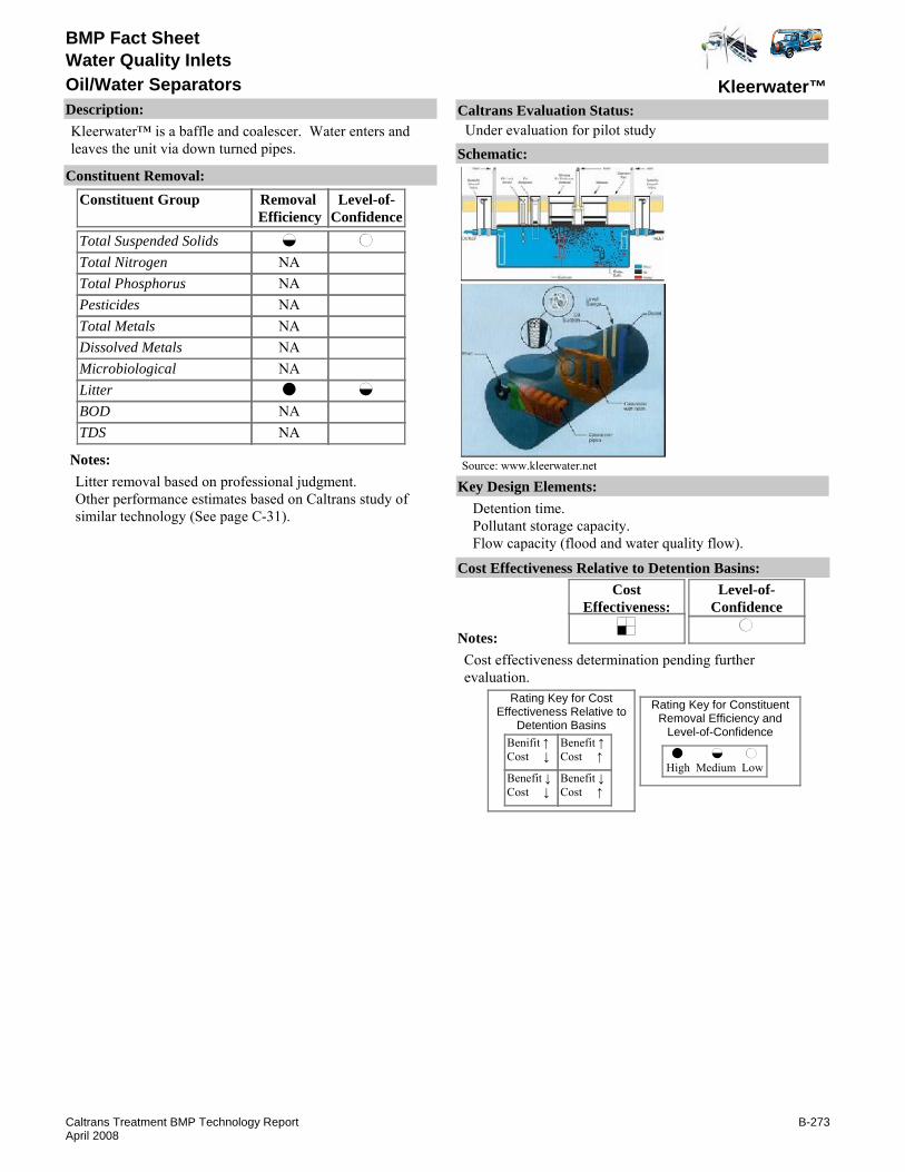
BMP Fact Sheet
Kleerwater™Oil/Water SeparatorsWater Quality Inlets
Description:Kleerwater™ is a baffle and coalescer. Water enters and leaves the unit via down turned pipes.
Removal Efficiency
Level-of-Confidence
Total Suspended SolidsTotal NitrogenTotal PhosphorusPesticidesTotal MetalsDissolved MetalsMicrobiologicalLitterBODTDS
Constituent GroupConstituent Removal:
NANANANANANA
NANA
Notes:Litter removal based on professional judgment.Other performance estimates based on Caltrans study of similar technology (See page C-31).
Key Design Elements:Detention time.Pollutant storage capacity.Flow capacity (flood and water quality flow).
CostEffectiveness:
Level-of-Confidence
Cost Effectiveness Relative to Detention Basins:
Benifit ↑Cost ↓
Benefit ↓Cost ↓
Benefit ↑Cost ↑
Benefit ↓Cost ↑
High Medium Low
Rating Key for ConstituentRemoval Efficiency and
Level-of-Confidence
Rating Key for CostEffectiveness Relative to
Detention Basins
Source: www.kleerwater.net
Notes:Cost effectiveness determination pending further evaluation.
Schematic:
Caltrans Evaluation Status:Under evaluation for pilot study
B-273Caltrans Treatment BMP Technology ReportApril 2008
BMP Fact Sheet
Kleerwater™Oil/Water SeparatorsWater Quality Inlets
Requirements:Initially the site should be monitored frequently in order to determine the required cleaning frequency.Vactor equipment recommended for cleaning.Training:No special requirements identified.
Maintenance Issues:
Project Development Issues:Right-of-Way-Requirements:Relatively small footprint.Siting Constraints:Minimal head requirement. Effective operation of similar technologies usually requires influent concentrations above 50 mg/L (CTSW-RT-01-05) P16-20.Construction:No special requirements identified.
Constraints: Proprietary device.Vector concerns.
Advantages:Small footprint.
U.S. Environmental Protection Agency, www.epa.gov/region1/assistance/ceitts/stormwater/techs/kleerwater.html
Literature Sources of Performance Demonstrations:None identified
Design, Construction, Maintenance and Cost SourcesKleerwater Technologies, LLC, www.kleerwater.net
Certifications, Verifications, or Designations:None identified.
B-274Caltrans Treatment BMP Technology ReportApril 2008

BMP Fact Sheet
PSI SeparatorOil/Water SeparatorsWater Quality Inlets
Description:PSI Separator is a coalescing type separator that also uses baffles and a down-turned outlet pipe to trap oil within the unit.
Removal Efficiency
Level-of-Confidence
Total Suspended SolidsTotal NitrogenTotal PhosphorusPesticidesTotal MetalsDissolved MetalsMicrobiologicalLitterBODTDS
Constituent GroupConstituent Removal:
NANANANANANA
NANA
Notes:Litter removal based on professional judgment.Other performance estimates based on Caltrans study of similar technology (See Hancor®-Storm Water Quality Unit).
Key Design Elements:Pollutant storage capacity.Flow capacity.Offline.
CostEffectiveness:
Level-of-Confidence
Cost Effectiveness Relative to Detention Basins:
Benifit ↑Cost ↓
Benefit ↓Cost ↓
Benefit ↑Cost ↑
Benefit ↓Cost ↑
High Medium Low
Rating Key for ConstituentRemoval Efficiency and
Level-of-Confidence
Rating Key for CostEffectiveness Relative to
Detention Basins
Source: www.psinternational.com
Notes:Cost effectiveness determination pending study completion.
Schematic:
Caltrans Evaluation Status:Under evaluation for pilot study
B-275Caltrans Treatment BMP Technology ReportApril 2008

BMP Fact Sheet
PSI SeparatorOil/Water SeparatorsWater Quality Inlets
Requirements:Initially the site should be monitored frequently in order to determine the required cleaning frequency.Vactor equipment recommended for cleaning.Training:No special requirements identified.
Maintenance Issues:
Project Development Issues:Right-of-Way-Requirements:Relatively small footprint.Siting Constraints:Minimal head requirement. Effective operation of similar technologies usually requires influent concentrations above 50 mg/L (CTSW-RT-01-05) P16-20.Construction:No special requirements identified.
Constraints: Proprietary device.Vector Concerns.
Advantages:Small footprint.
Literature Sources of Performance Demonstrations:None identified
Design, Construction, Maintenance and Cost SourcesPS International, Inc., www.psinternational.com
Certifications, Verifications, or Designations:None identified.
B-276Caltrans Treatment BMP Technology ReportApril 2008

BMP Fact Sheet
SNOUT®Oil/Water SeparatorsWater Quality Inlets
Description:SNOUT® is a hood that fits on the outlet of a trapping catch basin or other structures that holds a permanent pool of water.
Removal Efficiency
Level-of-Confidence
Total Suspended SolidsTotal NitrogenTotal PhosphorusPesticidesTotal MetalsDissolved MetalsMicrobiologicalLitterBODTDS
Constituent GroupConstituent Removal:
NANANANANANANA
NANA
Notes:Litter removal efficiency based on professional judgment considering that neutrally buoyant material can escape.Could enhance performance of other BMPs with standing water, such as wet basins and wet vaults.
Key Design Elements:Detention time.Pollutant storage capacity.Flow capacity (flood and water quality volume).
CostEffectiveness:
Level-of-Confidence
Cost Effectiveness Relative to Detention Basins:
Benifit ↑Cost ↓
Benefit ↓Cost ↓
Benefit ↑Cost ↑
Benefit ↓Cost ↑
High Medium Low
Rating Key for ConstituentRemoval Efficiency and
Level-of-Confidence
Rating Key for CostEffectiveness Relative to
Detention Basins
Source: www.epa.gov
Notes:Cost effectiveness determination pending further evaluation.
Schematic:
Caltrans Evaluation Status:Under evaluation for pilot study
B-277Caltrans Treatment BMP Technology ReportApril 2008

BMP Fact Sheet
SNOUT®Oil/Water SeparatorsWater Quality Inlets
Requirements:Depends on existing structure.Training:Depends on existing structure.
Maintenance Issues:
Project Development Issues:Right-of-Way-Requirements:None identified.Siting Constraints:None identified.Construction:No special requirements identified.
Constraints: The existing structure retrofitted with the SNOUT® may create mosquito habitat.Proprietary device.
Advantages:Easy to install.
U.S. Environmental Protection Agency, www.epa.gov/region1/assistance/ceitts/stormwater/techs/snout.html
Literature Sources of Performance Demonstrations:None identified
Design, Construction, Maintenance and Cost SourcesBest Management Products, Inc., www.bestmp.com
Certifications, Verifications, or Designations:None identified.
B-278Caltrans Treatment BMP Technology ReportApril 2008

BMP Fact Sheet
StormVault™Oil/Water SeparatorsWater Quality Inlets
Description:StormVault™ is a below grade detention and sedimentation vault. Treatment is provided by a series of baffles for sediment detention, an orifice-controlled outlet and an outlet screen to prevent clogging.
Removal Efficiency
Level-of-Confidence
Total Suspended SolidsTotal NitrogenTotal PhosphorusPesticidesTotal MetalsDissolved MetalsMicrobiologicalLitterBODTDS
Constituent GroupConstituent Removal:
NA
NANA
NANA
Notes:Removal efficiencies and level-of-confidence based on above-referenced data.Total metals removal efficiency based on reports of 10% zinc load removal, 10% copper removal, and 39% lead removal (Wright Waters, 2006a).Nutrient removal based on total phosphorus. Nitrogen removal was inconclusive because nitrate was not analyzed (Wright Waters, 2006a and b).Average TSS efficiency was 77% (Wright Waters, 2006b) and 61% (Wright Waters 2006a). Only one influent event was above the Caltrans 90th percentile of 350 mg/L.
Key Design Elements:Detention time.Pollutant storage capacity.Flow capacity (flood and water quality flow).
CostEffectiveness:
Level-of-Confidence
Cost Effectiveness Relative to Detention Basins:
Benifit ↑Cost ↓
Benefit ↓Cost ↓
Benefit ↑Cost ↑
Benefit ↓Cost ↑
High Medium Low
Rating Key for ConstituentRemoval Efficiency and
Level-of-Confidence
Rating Key for CostEffectiveness Relative to
Detention Basins
Source: www.contech-cpi.com
Notes:Cost effectiveness determination pending study completion.
Schematic:
Caltrans Evaluation Status:Under evaluation for pilot study
B-279Caltrans Treatment BMP Technology ReportApril 2008

BMP Fact Sheet
StormVault™Oil/Water SeparatorsWater Quality Inlets
Requirements:: Initially the site should be monitored frequently in order to determine the required cleaning frequency.Vactor equipment recommended for cleaning.Training:No special requirements identified.
Maintenance Issues:
Project Development Issues:Right-of-Way-Requirements:Relatively small footprint.Siting Constraints:Minimal head requirementConstruction:No special requirements identified.
Constraints: Depending on the system size, cost of construction can be high.Maintenance could be costly depending on system size.Standing water may be a vector concern.Proprietary device.
Advantages:Potentially small footprint with limited space since the system is underground.
Jensen Precast, www.jensenprecast.com
Wright Water Engineers, Inc., "Testing Of The Jensen Precast StormVaultTM, Albemarle County Office Building Parking Lot Charlottesville, Va., 2001 Monitoring Report." March 2002b.
U.S. Environmental Protection Agency, www.epa.gov/region1/assistance/ceitts/stormwater/techs/stormvault.html
Literature Sources of Performance Demonstrations:Wright Water Engineers, Inc., CH2M HILL, "Testing Of The Jensen Precast StormVaultTM, Paratransit Bus Lot Sacrament, Ca, 2001 Monitoring Report." February 2002a.
Design, Construction, Maintenance and Cost SourcesContech® Stormwater Solutions, Inc., www.contech-cpi.com
Certifications, Verifications, or Designations:None identified.
B-280Caltrans Treatment BMP Technology ReportApril 2008

BMP Fact Sheet
VortClarexOil/Water SeparatorsWater Quality Inlets
Description:VortClarex™ employs baffles and coalescing media for stormwater treatment where industrial effluent concentrations must be wet (eg. 10 mg/l oil & grease). Flow enters the pre-cast concrete vault and is diffused allowing heavy sediment to settle. Lighter pollutants travel over a baffle and pass through a coalescing media that traps oil & other pollutants.
Removal Efficiency
Level-of-Confidence
Total Suspended SolidsTotal NitrogenTotal PhosphorusPesticidesTotal MetalsDissolved MetalsMicrobiologicalLitterBODTDS
Constituent GroupConstituent Removal:
NANANANANANA
NANA
Notes:Litter removal based on professional judgment.Other performance estimates based on Caltrans study of similar technology (See Hancor®-Storm Water Quality Unit).
Key Design Elements:Flow capacity (flood and water quality flow)Pollutant storage capacityDetention time.
CostEffectiveness:
Level-of-Confidence
Cost Effectiveness Relative to Detention Basins:
Benifit ↑Cost ↓
Benefit ↓Cost ↓
Benefit ↑Cost ↑
Benefit ↓Cost ↑
High Medium Low
Rating Key for ConstituentRemoval Efficiency and
Level-of-Confidence
Rating Key for CostEffectiveness Relative to
Detention Basins
Source: www.contech-cpi.com
Notes:Cost effectiveness determination pending study completion.
Schematic:
Caltrans Evaluation Status:Under evaluation for pilot study
B-281Caltrans Treatment BMP Technology ReportApril 2008

BMP Fact Sheet
VortClarexOil/Water SeparatorsWater Quality Inlets
Requirements:Initially the site should be monitored frequently in order to determine the required cleaning frequency. Vactor equipment recommended for cleaning.Training:No special requirements identified.
Maintenance Issues:
Project Development Issues:Right-of-Way-Requirements:Relatively small footprint.Siting Constraints:Low head requirements. Effective operation of similar technologies usually requires influent concentrations above 50 mg/L (CTSW-RT-01-05) P16-20.Construction:No special requirements identified.
Constraints: Proprietary device.Vector concerns.
Advantages:No additional ROW or easement required.Low head requirement.All underground.Small footprint.
Literature Sources of Performance Demonstrations:No known evaluation; However, similar to Oil/Water Separator
Design, Construction, Maintenance and Cost SourcesContech® Stormwater Solutions, Inc., www.contech-cpi.com
Certifications, Verifications, or Designations:None identified.
B-282Caltrans Treatment BMP Technology ReportApril 2008

BMP Fact Sheet
Constructed WetlandWetland Systems
Description:Constructed wetlands (aka: free water surface wetland) attempt to replicate some of the conditions in natural wetlands. Constructed wetlands for stormwater treatment typically are shallow (less than 2 meters) ponds with a variety of wetland plant species. The ponds often incorporate forebays to localize sediment accumulation, shallow zones to encourage filtration by plant material, and deeper zones to allow further sedimentation. The water quality benefits of treatment in natural or constructed wetlands include nutrient cycling and removal, and reduction in suspended solids (TSS), total dissolved solids (TDS), trace metals, and BOD. Constructed wetlands are shallower than wet basins and water is forced to flow through the vegetation in shallower areas. Wet basins are generally designed to only have vegetation along the edges of the basin.
Removal Efficiency
Level-of-Confidence
Total Suspended SolidsTotal NitrogenTotal PhosphorusPesticidesTotal MetalsDissolved MetalsMicrobiologicalLitterBODTDS
Constituent GroupConstituent Removal:
Notes:Increased removal efficiency is dependant on flow volume and shallow depth of water. An increased amount of adsorption is believed to occur on bottom sediments. (Dormann, et. al., 1988). Designs that increase the contact time increase the overall removal capability. "A mixed flow pattern will increase the overall pollutant removal efficiency." (Dormann, et. al., 1988).May be similar to Wet Basin (see Appendix D).
Key Design Elements:Sediment forebays are recommended to decrease the velocity and sediment loading to the wetland. The forebay should contain at least 10 percent of the wetlands treatment volume and should be 4 to 6 feet deep. The wetland design should include a buffer to separate the wetland from surrounding land. Above ground berms or high marsh wedges should be placed at 50 foot intervals. Site must have adequate water flow and appropriate underlying soils. 4A four-to-six foot deep micropool should be included in the design to prevent the outlet from clogging.
CostEffectiveness:
Level-of-Confidence
Cost Effectiveness Relative to Detention Basins:
Benifit ↑Cost ↓
Benefit ↓Cost ↓
Benefit ↑Cost ↑
Benefit ↓Cost ↑
High Medium Low
Rating Key for ConstituentRemoval Efficiency and
Level-of-Confidence
Rating Key for CostEffectiveness Relative to
Detention Basins
Source: FHWA, Evaluation and Management of Highway Runoff Water Qu
Notes:Cost effectiveness determination pending study completion.
Schematic:
Caltrans Evaluation Status:Under evaluation for pilot study
B-283Caltrans Treatment BMP Technology ReportApril 2008

BMP Fact Sheet
Constructed WetlandWetland Systems
Requirements:Active management of the hydrology and vegetation during the first few years or growing seasons is necessary. Vegetation thinning or removal may be necessary for vector control. Wildlife may limit activities or limit them to a particular season and mosquito fish planting.Training:No special requirements identified.
Maintenance Issues:
Project Development Issues:Right-of-Way-Requirements:High area requirements.Siting Constraints:Low permeable soil is required if a liner is not used. Dry weather flow may be required to keep vegetation alive.Construction:Plant establishment period is recommended. If a liner is used, it must be carefully constructed to avoid punctures.
Constraints: May be difficult to maintain vegetation under a variety of flow conditions.Relatively high construction costs in comparison to other BMP’s.Wetland must have a source flow, ideally with a high water table.Species may restrict maintenance.
Advantages:Enhances aesthetics.Enhances wildlife habitat.Good pollutant removal.
Schueler, Thomas R., 1987. "Controlling Urban Runoff: A Practical Manual for Planning and Designing Urban BMP’s. July.
Schueler T. R., et.al. "A current Assessment of Urban Best Management Practices." 1992.
Schueler, T.R., Krumble, M.A. and Heraty, M.A. "BMP: Techniques for Reducing Non-Point Source Pollution in the Coastal Zone." 126pp. Metropolitan WA Council of Governments. 1992.
Strecker, T.R., F.J. Galli, L. Herson, P. Kumble and D. Shepp, " Developing Effective BMP Systems for Urban Watersheds." Urban Non-Point Workshops, New Orleans, LA. Jan 27-29 1991.WA Dept. of Ecology, 2000. "Stormwater Management Manual for Western Washington," 251pp., Vol. V, Runoff Treatment BMP's Aug 2000.Strecker, E.W. Kersnar J.M. Driscoll E.D., "The Use of Wetlands for Controlling Stormwater Pollution: Final Report," Prepared for Reg. 5 Water Div., Wetlands & Watershet Mgmt. Unit, USEPA, Chicago, IL. Prepared by Woodward Clyde Consultants, Portland OR. 1992Hey, D. L., Barrett, K. R., and Biegen, C. "The Hydrology of Four Experimental Constructed Wetlands." 3:319-343, Ecological Engineering. 1994b.
Literature Sources of Performance Demonstrations:Kadlec and Knight, "Treatment Wetlands", Lewis Publishers, NY, NY. 1996.
Design, Construction, Maintenance and Cost SourcesSchueler, T.R., "Design of Stormwater Pond Systems". Metropolitan Washington Council of Governments, Washington, DC.
Certifications, Verifications, or Designations:None identified.
B-284Caltrans Treatment BMP Technology ReportApril 2008

BMP Fact Sheet
MWS - Linear HYBRIDConstructed WetlandWetland Systems
Description:Modular Wetlands(MWS) - Linear HYBRID is a modular subsurface-flow system used in urban areas as an alternative to traditional curbside landscape plantings. It functions similarly to subsurface wetlands used to treat other waste streams. Water first enters a sedimentation/filtration chamber. Water is fed into the wetland planting media via a staged manifold.
Removal Efficiency
Level-of-Confidence
Total Suspended SolidsTotal NitrogenTotal PhosphorusPesticidesTotal MetalsDissolved MetalsMicrobiologicalLitterBODTDS
Constituent GroupConstituent Removal:
NA
NA
NANA
Notes:Performance based on vegetated rock filter, so level of confidence is low.
Key Design Elements:Size. Vegetation. Drainage Area.Flow capacity (flood and water quality flow).Bypass of scouring flows.Underground drain System.Ponding Depth.
CostEffectiveness:
Level-of-Confidence
Cost Effectiveness Relative to Detention Basins:
Benifit ↑Cost ↓
Benefit ↓Cost ↓
Benefit ↑Cost ↑
Benefit ↓Cost ↑
High Medium Low
Rating Key for ConstituentRemoval Efficiency and
Level-of-Confidence
Rating Key for CostEffectiveness Relative to
Detention Basins
Source: www.modularwetlands.com
Notes:
Schematic:
Caltrans Evaluation Status:Under evaluation for pilot study
B-285Caltrans Treatment BMP Technology ReportApril 2008
BMP Fact Sheet
MWS - Linear HYBRIDConstructed WetlandWetland Systems
Requirements:Regular vegetation management is required.Training:No special requirements identified.
Maintenance Issues:
Project Development Issues:Right-of-Way-Requirements:No special requirements identified.Siting Constraints:No special requirements identified.Construction:Vegetation establishment period may be required. Water should bypass until construction is complete and the drainage is stabilized.
Constraints: May not be suitable in areas with a long dry season.Proprietary device.
Advantages:No unique advantages identifed compared to similar BMPs.
Literature Sources of Performance Demonstrations:None identified
Design, Construction, Maintenance and Cost SourcesModular Wetlands, MWS-Linear HYBRID, www.modularwetlands.com
Certifications, Verifications, or Designations:None identified.
B-286Caltrans Treatment BMP Technology ReportApril 2008

BMP Fact Sheet
StormTreat™Constructed WetlandWetland Systems
Description:StormTreat™ System (STS) consists of a series of sedimentation chambers and constructed wetlands. These wetlands are contained within a modular, 2.9-meter (9.5-ft) diameter recycled-polyethylene tank that is roughly four feet in height. Unlike most constructed wetlands systems, STS conveys the stormwater directly into the subsurface of the wetland and through the root zone. Pollutants are then removed through filtration, adsorption, and biochemical reactions. Stormwater is retained in the wetlands for five to ten days prior to discharge when flow to the unit is restricted.
Removal Efficiency
Level-of-Confidence
Total Suspended SolidsTotal NitrogenTotal PhosphorusPesticidesTotal MetalsDissolved MetalsMicrobiologicalLitterBODTDS
Constituent GroupConstituent Removal:
NA
NA
NANANA
Notes:May need to be tested in geographical locations more typical of California. Total nitrogen, phosphorus, TSS, and total metals from Winkler et. al. (1997) Clausen et. al. report lower performance (2002). Microbiological based on Clausen et. al.
Key Design Elements:Modular, 2.9-meter (9.5-foot) diameter recycled-polyethylene tank containing a series of sedimentation chambers and constructed wetlands. Flow is conveyed from the final sedimentation chamber through four, slotted PVC outlet pipes, each 10-cm (4 inches) in diameter, into the wetland. Mature vegetation in the outer ring should have roots that extend into the permanent 15-cm (6 inches) of water in the bottom of the tank. Effluent from the wetland is discharged through a 5-cm (2-inch) diameter pipe that is controlled by a valve. Volume storage of 5.3-m3 (1,400-gal). Design flow of 1 to 5-gpm per unit.
CostEffectiveness:
Level-of-Confidence
Cost Effectiveness Relative to Detention Basins:
Benifit ↑Cost ↓
Benefit ↓Cost ↓
Benefit ↑Cost ↑
Benefit ↓Cost ↑
High Medium Low
Rating Key for ConstituentRemoval Efficiency and
Level-of-Confidence
Rating Key for CostEffectiveness Relative to
Detention Basins
Source: www.stormtreat.com
Notes:Cost effectiveness determination pending study completion.
Schematic:
Caltrans Evaluation Status:Under evaluation for pilot study
B-287Caltrans Treatment BMP Technology ReportApril 2008
BMP Fact Sheet
StormTreat™Constructed WetlandWetland Systems
Requirements:Annual inspections and replacement of grit filter bag and sediment pumping once every three to five years using standard septic system pumper.Training:No special requirements identified.
Maintenance Issues:
Project Development Issues:Right-of-Way-Requirements:The low design flow may result in moderate space requirements.Siting Constraints:Requires approximately four feet of hydraulic head.Construction:No special requirements identified.
Constraints: Small flow rate capacity (average outflow of 1-5 gpm). A flow of 0.25-gpm is recommended (Krahforst, 1999).May not be suitable in areas with a long dry season.Proprietary device.
Advantages:No unique advantages identifed compared to similar BMPs.
Winkler, E. "Technology Assessment Report StormTreat System "StormTreat Systems Inc." Center for Energy Efficient and Renewable Energy and Univ. of Massachusetts at Amherst. Sep 1997
Krahforst, C., MCKenna, S., Sargent, D., Knowles, R.. "An Evaluation of Innovative Stormwater Treatment Technology Installations." Section 319 NPS Project #95-02. Prepared for the Massachusetts Dept. of Environmental Protection Bureau of Resource Protection and EPA Region 1. 1998-99.
Clausen, J., Belanger, P., Board, S., Dietz, M., Phillips, R., Sonstrom, R. 2002. Stormwater Treatment Devices Section 319 Project, Final Report, April 15, 2002. submitted to Connecticut Department of Environmental Protection.
Literature Sources of Performance Demonstrations:U.S. Environmental Protection Agency. "Storm Water Virtual Trade Show StormTreat" Accessed Jul 2006. http://www.epa.gov/region1/assistance/ceitts/stormwater/techs/stormtreat.html
Design, Construction, Maintenance and Cost SourcesStormTreatTM Systems, Inc., www.stormtreat.com
Certifications, Verifications, or Designations:MA Strategic Environmental Partnership (STEP) - 98% TSS removal when sized according to design critera.
B-288Caltrans Treatment BMP Technology ReportApril 2008

BMP Fact Sheet
Vegetated Rock FilterWetland Systems
Description:Vegetated Rock Filter consist of a sealed, shallow basin or channel filled with substrate media (gravel, rock or other material) and emergent aquatic plants. This BMP attempts to replicate some of the conditions in natural wetlands and is known elsewhere as a subsurface wetland. Treatment (load removal) is primarily accomplished via filtration by the substrate media, with some contribution from plants. A forebay or other pre-treatment method of removing large solids is recommended to extend the life of the substrate media and improve overall performance. The Vegetated Rock Filter may be lined to protect underlying groundwater.
Removal Efficiency
Level-of-Confidence
Total Suspended SolidsTotal NitrogenTotal PhosphorusPesticidesTotal MetalsDissolved MetalsMicrobiologicalLitterBODTDS
Constituent GroupConstituent Removal:
NA
NA
NANA
Notes:Egan et al. reported 81% TSS mass removal. Reuter et al. reported 80-88% TSS mass removal.Egan et al. reported mass removal of TKN, NO3, and total-N at 63%, 75%, and 63%, respectively.Egan et al. reported 82.5% total phosphorus mass removal. Reuter et al. reported 44-47% particulate phosphorus mass removal and 28-41% soluble reactive phosphorus mass export, possibly due to the unwashed gravel used to form the wetland bed.Egan et al. reported mass removal of Cd, Cr, Cu, Pb, and Zn of 80%, 38%, 21%, 73%, and 55%, respectively. Reuter et al. reported 80-88% total iron mass removal, 8% TDS mass removal.Reuter et al. reported 85-87% NO3 mass removal, but 53-58% NH4 mass export. Export may have resulted from the mineralization of organic nitrogen in the gravel and lack of nitrification due to infrequency of aerobic conditions.
Key Design Elements:The wetland design should include a buffer to separate the wetland from surrounding land.Depth of the media selected will depend on the type of media that can support typical vegetation with a root structure depth of 0.6-m (2-ft.).Include a fore bay or other pretreatment method for removing large solids to extend substrate media life.Site must have adequate water flow and appropriate underlying soils.Liner may be required to prevent contamination of high groundwater.
CostEffectiveness:
Level-of-Confidence
Cost Effectiveness Relative to Detention Basins:
Benifit ↑Cost ↓
Benefit ↓Cost ↓
Benefit ↑Cost ↑
Benefit ↓Cost ↑
High Medium Low
Rating Key for ConstituentRemoval Efficiency and
Level-of-Confidence
Rating Key for CostEffectiveness Relative to
Detention Basins
Notes:Cost effectiveness determination pending study completion.
Schematic:
Caltrans Evaluation Status:Under evaluation for pilot study
B-289Caltrans Treatment BMP Technology ReportApril 2008

BMP Fact Sheet
Vegetated Rock FilterWetland Systems
Requirements:Plants should be cut to ground level annually before the spring growth season. The gravel bed should also be inspected for sediment build-up annual. Inlet and outlet devices should be checked for clogging at least twice during the rainy season. During the first year, more maintenance might be required to establish aquatic plant growth. After the plants have been established, water may be required once or twice during the summer dry period.Training:No special requirements identified.
Maintenance Issues:
Project Development Issues:Right-of-Way-Requirements:High area requirements.Siting Constraints:Low permeable soil surrounding the bottom sides of the substrate media is required if a liner is not used. Dry weather flow may be required to keep vegetation alive.Construction:Plant establishment period is recommended. If a liner is used, it must be carefully constructed to avoid punctures.
Constraints: May be difficult to maintain vegetation under a variety of flow conditions, particularly during dry weather periods.While effective in their contaminant removal, this renewable process requires long-term maintenance to remove the metals and persistent organics that accumulate in wetland sediments over time.Cost or availability of substrate media required for subsurface drainage may reduce the viability of using subsurface wetlands as a BMP option.Cold-climates have a reduced rate of constituent removal and may not be feasible or technically possible given certain design constraints.Can be expensive to construct with large land areas requirements.
Advantages:Minimal vector concerns, since water treatment is accomplished below surface.Low O&M costs associated with trained personnel.Passive system with little to no mechanical equipment or energy necessary for operation.Good pollutant removal.Enhances aesthetics and wildlife habitat.
Reuter, J. T., Djohan, T., and Goldman, C. R., 1991. "The Use of Wetlands for Nutrient Removal from Surface Runoff in a Cold Climate Region of California - Results from Newly Constructed Wetland at Lake Tahoe." Div. of Environmental Studies, Univ. of Calif. Davis. May
Literature Sources of Performance Demonstrations:Egan, T.J.S. Burroughs and T. Attaway. 1995. "Packed Bed Filter." Proceedings of 4th Biennial Symposium on Stormwater Quality. Southwest Florida Water Management District. Brookeville, FL. P. 264-274.
Design, Construction, Maintenance and Cost SourcesSchueler, Thomas R. and Holland, Heather K., "The Practice of Watershed Protection; Article 95 - Performance of Gravel-Based Wetland in a Cold, High Altitude Climate, and Article 97 - Vegetated Rock Filter Treats Stormwater Pollutants in Florida," p.493-494 and p. 498-499, Center for Watershed Protection, 2002
Certifications, Verifications, or Designations:None identified.
B-290Caltrans Treatment BMP Technology ReportApril 2008

Caltrans Treatment BMP Technology Report C-1 April 2008
APPENDIX C: PILOT STUDY FACT SHEETS Appendix C presents fact sheets for the full-scale BMP pilot studies listed in Section 2.2, Table 2-1. Some technology evaluations in the attached fact sheets are ongoing, and the assessment of these technologies may be revised in future reports. The evaluations were derived from available literature and information gathered from the pilot studies. BMPs that have completed testing and are not being considered further for testing are given a “REJECTED” watermark on the fact sheet. BMPs that are no longer supplied or supported by the manufacturer are marked as “DISCONTINUED”. Unapproved treatment BMP technologies that have been or are being tested by Caltrans are presented in the following order:
TABLE OF CONTENTS
Technology Type Available Stormwater Products Page No. Status
Bioretention C-3 Detention Basins Outlet Improvement-Bladder Valve C-5 Outlet Improvement-Skimmer C-7 Drain Inlet Insert Fabric StreamGuard™ C-9 Rejected Media Filters FossilFilter™ C-11 DiscontinuedFiltration Bed Austin Filter - Activated Alumina C-13
Austin Filter - Iron Modified Activated Alumina C-15
Austin Filter - Limestone C-17 Cartridge/Canister StormFilter™ C-19 Open Bed Compost Compost StormFilter™ (CSF) C-21 Discontinued
Hydrodynamic Separators Continuous Deflective Separation™ (CDS™) C-23
Litter and Debris Removal GSRD / Baffle Box C-25 Rejected GSRD / Litter Inlet Deflector C-27 Rejected GSRD / V-Screen C-29 Rejected Oil & Water Separator Areo-Power® ST1-P3 C-31 Rejected Traction Sand Trap Vault Filter - Fabric C-33

blank for double sided printing
Treatment BMP New Technology Report C-2 April 2008
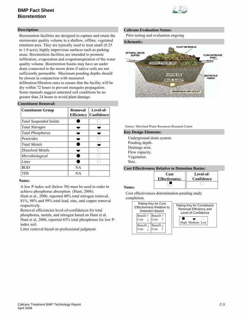
BMP Fact SheetBioretention
Description:Bioretention facilities are designed to capture and retain the stormwater quality volume in a shallow, offline, vegetated retention area. They are typically used to treat small (0.25 to 1.0 acre), highly impervious surfaces such as parking areas. Bioretention facilities are intended to promote infiltration, evaporation and evapotranspiration of the water quality volume. Bioretention basins may have an under drain connected to the storm drain if native soils are not sufficiently permeable. Maximum ponding depths should be chosen in conjunction with measured infiltration/filtration rates to ensure that the facility will be dry within 72 hours to prevent mosquito propagation. Some manuals suggest saturated soil conditions be no greater than 24 hours to avoid plant damage.
Removal Efficiency
Level-of-Confidence
Total Suspended SolidsTotal NitrogenTotal PhosphorusPesticidesTotal MetalsDissolved MetalsMicrobiologicalLitterBODTDS
Constituent GroupConstituent Removal:
NANA
Notes:A low P-index soil (below 50) must be used in order to achieve phosphorus absorption (Hunt, 2006).Hunt et al., 2006, reported 40% total nitrogen removal, 81%, 98% and 99% total lead, zinc, and copper removal respectively.Removal efficiencies level-of-confidences for total phosphorus, metals, and nitrogen based on Hunt et al.Hunt et al, 2006, reported 65% total phosphorus for low P-index soil.Litter removal based on professional judgment.
Key Design Elements:Underground drain system. Ponding depth.Drainage area.Flow capacity.Vegetation.Size.
CostEffectiveness:
Level-of-Confidence
Cost Effectiveness Relative to Detention Basins:
Benifit ↑Cost ↓
Benefit ↓Cost ↓
Benefit ↑Cost ↑
Benefit ↓Cost ↑
High Medium Low
Rating Key for ConstituentRemoval Efficiency and
Level-of-Confidence
Rating Key for CostEffectiveness Relative to
Detention Basins
Source: Maryland Water Resources Research Center
Notes:Cost effectiveness determination pending study completion.
Schematic:
Caltrans Evaluation Status:Pilot testing and evaluation ongoing
C-3Caltrans Treatment BMP Technology ReportApril 2008

BMP Fact SheetBioretention
Requirements:Regular vegetation management is required.Training:No special requirements identified.
Maintenance Issues:
Project Development Issues:Right-of-Way-Requirements:Space requirements are relatively high to accommodate shallow water quality storage depths.Siting Constraints:May need supplemental irrigation in dry areas, depending on plant selection.Construction:Vegetation establishment period is recommended. Water should bypass until construction is complete and the drainage area is stabilized.
Constraints: May not be appropriate along highways where safety considerations preclude use of large trees or plantings that obscure sight lines.In areas with prolonged dry periods, maintenance of trees, shrubs and grass between rainfalls may require irrigation.Use of planting soil to fill the basin may increase costs compared to infiltration basins.It takes time for bioretention facilities to become established while vegetation develops, though filtering still occurs.
Advantages:Pollutant removal effectiveness is typically high, accomplished primarily by physical filtration of particulates through the soil profile; and adsorption of constituents by the soil.It can provide an aesthetic vegetated appearance.
Schuler, T. R. et al Draft Maryland Stormwater Design Manual, Maryland Dept of the Environment in Cooperation with the Maryland Dept of Natural Resources Coastal Zone Management Program. 1998.Engineering Technologies Assoc., Inc. (ETA). "Design Manual for Use of Bioretention in Stormwater Management," prepared for Prince George’s County, Maryland, Dept of Env. Res.Maryland Dept of the Environment and Center for Watershed Protection 2000. "Maryland Storm water Design Manual, Volumes I & II."Loomis & Moore et al 1998. Draft Integrated Solutions Development Study Watersheds Master Plan, Prepared for the City of Austin Watershed Protection Dept.U.S. Environmental Protection Agency. Bioretention Fact Sheet. http://www.epa.gov/OW-OWM.html/mtb/biortn.pdf
Davis, A.P., et al. "Water Quality Improvement through Bioretention: Lead, Copper and Zinc," Water Environment Research. 75(1), 73-82. 2003.
Hunt, W.F., et al, "Evaluating Bioretention Hydrology and Nutrient Removal at Three Field Sites in North Carolina," ASCE Journal of Irrigation and Drainage Engineering, p. 600-608, 2006.
Sharkey, L. J., "The Performance of Bioretention Areas in North Carolina: A Study of Water Quality, Water Quantity, and Soil Media," North Carolina State University Graduate Thesis. 2006. www.bae.ncsu.edu/stormwater/PublicationFiles/SHARKEYthesis2006.pdfHunt, W.F., et al., "City of Charlotte Pilot BMP Monitoring Program, Marshall Bioretention Final Monitoring Report," North Carolina University Study prepared for City of Charlotte-Stormwater Services. 2007. www.bae.ncsu.edu/stormwater/PublicationFiles/CLT_HalMarshallBioretention_2007.pdfDavis, A., et. al. 1998. "Optimization of Bioretention for Water Quality and Hydrological Characteristics. Final Report: 01-4-31032." University of Maryland Dept. of Civil Engineering, Prince George’s County Dept. of Environmental Resources. Landover, MD. 237 pp.Caltrans. 2003. "SR-73 Stormwater BMP Replacement Project at CSF System 1149L Bioretention Area: Basis of Design Report." 2003. CTSW-RT-03-006.51.39
Literature Sources of Performance Demonstrations:Hsieh, C., et al , "Bioretention Column Studies of Phosphorus Removal from Urban Stormwater Runoff," Water Environment Research, 79, 177, 2007.
Design, Construction, Maintenance and Cost SourcesCaltrans. 2007. Stormwater Quality Hanbooks: Project Planning & Design Guide. May 2007. CTSW-RT-07-172.19.1
Certifications, Verifications, or Designations:None identified.
C-4Caltrans Treatment BMP Technology ReportApril 2008

BMP Fact Sheet
Hold and ReleaseOutlet ImprovementDetention Basins
Description:Hold and release valves can be used to increase detention time. In one design, a pneumatic bladder located in the sedimentation chamber outlet drain is inflated when sensors detect rain to provide a set sedimentation time.
Removal Efficiency
Level-of-Confidence
Total Suspended SolidsTotal NitrogenTotal PhosphorusPesticidesTotal MetalsDissolved MetalsMicrobiologicalLitterBODTDS
Constituent GroupConstituent Removal:
NA
NANA
Notes:No performance data encountered in field demonstrations or in literature for post construction stormwater treatment.TSS, total nitrogen, and phosphorus, are from Barrett et. al. (1997).Other constituents are based on approved detention basin performance (Appendix D).Litter removal based on professional judgment.
Key Design Elements:Power and controls system for operating outlet bladder or valve.Means of removing water when skimmer is at its lowest position.Extended detention basin.Hydraulic capacity.
CostEffectiveness:
Level-of-Confidence
Cost Effectiveness Relative to Detention Basins:
Benifit ↑Cost ↓
Benefit ↓Cost ↓
Benefit ↑Cost ↑
Benefit ↓Cost ↑
High Medium Low
Rating Key for ConstituentRemoval Efficiency and
Level-of-Confidence
Rating Key for CostEffectiveness Relative to
Detention Basins
Notes:Cost effectiveness determination pending study completion.
Schematic:
Caltrans Evaluation Status:Pilot testing and evaluation ongoing
C-5Caltrans Treatment BMP Technology ReportApril 2008
BMP Fact Sheet
Hold and ReleaseOutlet ImprovementDetention Basins
Requirements:Mechanical skimmer or bladder will require inspection and periodic replacement.Training:Training required to inspect and maintain outlet.
Maintenance Issues:
Project Development Issues:Right-of-Way-Requirements:Equivalent to detention basin.Siting Constraints:Equivalent to detention basin. May require power.Construction:No special requirements identified.
Constraints: Maintenance costs for sedimentation basins will be increased slightly since more sediments will accumulate in the sedimentation basin.May require draining the basin if the outlet fails.
Advantages:Potentially increased removal of suspended solids.
www.epa.gov/ednnrmrl/projects/cpntrol/high.htm. April 2000.
Vaughan, B.T., and Jarrett, A.R. "Experimental Evaluation of Novel Floating Risers for Sedimentation Basin Dewatering," Paper 012025, 2001 ASAE Annual Meeting , American Society of Agricultural and Biological Engineers, St. Joseph MI.
Literature Sources of Performance Demonstrations:Barrett, M. E., Keblin, M. V., Walsh, P. M., Malina, J. F., Jr., 1997, Evaluation of the Performance of Permanent Runoff Controls: Summary and Conclusions. P. 30.
Design, Construction, Maintenance and Cost SourcesCaltrans, 2001. Detention basin Optimization - Reconnaissance Study. CTSW-RT-01-029. Final Report. June 2001. p 3-7.
Certifications, Verifications, or Designations:None identified.
C-6Caltrans Treatment BMP Technology ReportApril 2008

BMP Fact Sheet
Outlet Improvement-SkimmerDetention Basins
Description:Improved detention basin outlet drains water from the top of the basin to improve the sedimentation efficiency. The sedimentation process could be improved by adding an outflow device composed of a skimmer, drainage hose and float to the current BMP design of the detention basin outlet or to the outlet of a stand-alone detention basin. The tank will be drained or “decanted” from the surface in order to allow more time for sediments to collect in the sedimentation chamber.
Removal Efficiency
Level-of-Confidence
Total Suspended SolidsTotal NitrogenTotal PhosphorusPesticidesTotal MetalsDissolved MetalsMicrobiologicalLitterBODTDS
Constituent GroupConstituent Removal:
NA
NANA
Notes:No performance data encountered in field demonstrations or in literature for post construction stormwater treatment.Performance based on approved detention basin performance (Appendix D).Litter removal based on professional judgment.
Key Design Elements:Power and controls system for operating outlet bladder or valve.Means of removing water when skimmer is at its lowest position.Extended detention basin.Hydraulic capacity.
CostEffectiveness:
Level-of-Confidence
Cost Effectiveness Relative to Detention Basins:
Benifit ↑Cost ↓
Benefit ↓Cost ↓
Benefit ↑Cost ↑
Benefit ↓Cost ↑
High Medium Low
Rating Key for ConstituentRemoval Efficiency and
Level-of-Confidence
Rating Key for CostEffectiveness Relative to
Detention Basins
Source: www.abe.psu.edu
Notes:Cost effectiveness determination pending study completion.
Schematic:
Caltrans Evaluation Status:Pilot testing and evaluation ongoing
C-7Caltrans Treatment BMP Technology ReportApril 2008

BMP Fact Sheet
Outlet Improvement-SkimmerDetention Basins
Requirements:Mechanical skimmer or bladder will require inspection and periodic replacement. Complete drainage of the basin may a challenge in the ongoing study.Training:Training required to inspect and maintain outlet.
Maintenance Issues:
Project Development Issues:Right-of-Way-Requirements:Equivalent to detention basin.Siting Constraints:None identified. Equivalent to detention basin.Construction:No special requirements identified
Constraints: Unless the skimmer can drain all the water from the detention pond, a secondary outlet should be provided at the bottom of the basin to avoid water stagnation and the potential for mosquito propagation.Maintenance costs for sedimentation basins will be increased slightly since more sediments will accumulate in the sedimentation basin.May require draining the basin if the outlet fails.
Advantages:Potentially increased removal of suspended solids.
Jarrett, A. R., "Proper Sizing of the Control Orifice for the Faircloth Skimmer." Fact sheet F252. Agricultural and Biological Engineering. College of Agricultural Sciences, Coorperative Extension. U.S. Department of Agriculture and Pennsylvania Counties Cooperating. University Park, Pa.Jarrett, A. R., "Controlling the Dewatering of Sedimentation Basins." Fact sheet F253. Agricultural and Biological Engineering. College of Agricultural Sciences, Coorperative Extension. U.S. Department of Agriculture and Pennsylvania Counties Cooperating. University Park, Pa.Caltrans, 2001. Detention basin Optimization - Reconnaissance Study. CTSW-RT-01-029. Final Report. June 2001. p 3-6.http://www.fairclothskimmer.com/
Vaughan, B.T., and Jarrett, A.R. "Experimental Evaluation of Novel Floating Risers for Sedimentation Basin Dewatering," Paper 012025, 2001 ASAE Annual Meeting , American Society of Agricultural and Biological Engineers, St. Joseph MI.
Hoechst, L. M. and Ross, B. B. PhD. "Evaluating the Effectiveness of the Skimmer Versus the Perforated Riser in Sedimentation Basins," Masters Thesis Virginia Polytechnic Institute and State University, Blackburg, VA Dec 1997.
Harper, H. H. et al "Performance Evaluation of Dry Detention Sotrmwater Management Systems." 6th Biennial Stormwater Research Watershed Management Conference. September 1999.Keblin, Michael, et al Effectiveness of Permanent Highway Runoff Controls: Sedimentation/Filtration Systems. October 1997.Meinboltz, T.L. et al Screening/Floatation Treatment of Combined Sewer Outflows, Vol II: Full-Scale Operation Racine, WI. EPA600/2-79-106a. Aug 1979.US Dept of Transportation, Federal Highway Administration, Office of Environmental Planning: Evaluation and Management of Higway Runoff Water Quality, Washington, DC. June 1996.
Literature Sources of Performance Demonstrations:Barrett, M. E., Keblin, M. V., Walsh, P. M., Malina, J. F., Jr., 1997, Evaluation of the Performance of Permanent Runoff Controls: Summary and Conclusions. P. 30
Design, Construction, Maintenance and Cost Sourceswww.epa.gov/ednnrmrl/projects/cpntrol/high.htm. April 2000.
Certifications, Verifications, or Designations:None identified.
C-8Caltrans Treatment BMP Technology ReportApril 2008

BMP Fact Sheet
StreamGuard™FabricDrain Inlet Insert
Description:StreamGuard™ is placed in the inlet to a storm drain where stormwater flows through the insert, and the geotextile fabric absorbs oil and retains sediment and gross pollutants. The body of the unit fills with stormwater and sediment, and gross pollutants are collected in the bottom of the insert. Floating oil and grease are absorbed by the filter pack contained in a poly-net bag fixed within the unit.
Removal Efficiency
Level-of-Confidence
Total Suspended SolidsTotal NitrogenTotal PhosphorusPesticidesTotal MetalsDissolved MetalsMicrobiologicalLitterBODTDS
Constituent GroupConstituent Removal:
NANANA
NANA
NANA
Notes:Three StreamGuard™ DIIs were sited, constructed, and monitored as part of the Caltrans BMP retrofit pilot program.Escaped litter was not monitored. Litter removal is based on professional judgment.Analyzed for TSS, metals, and oil and grease. Medium confidence is because a mass balance approach was used.
Key Design Elements:StreamGuard™ should be installed into the inlet of the storm drain according to the manufacturer's recommendations.The insert should have a high-flow bypass to prevent resuspension and washout.A tight seal is necessary between the frame of the drain inlet and the insert.
CostEffectiveness:
Level-of-Confidence
Cost Effectiveness Relative to Detention Basins:
Benifit ↑Cost ↓
Benefit ↓Cost ↓
Benefit ↑Cost ↑
Benefit ↓Cost ↑
High Medium Low
Rating Key for ConstituentRemoval Efficiency and
Level-of-Confidence
Rating Key for CostEffectiveness Relative to
Detention Basins
Source: www.fossenv.com
Notes:
Schematic:
Caltrans Evaluation Status:Pilot testing complete: rejected
C-9Caltrans Treatment BMP Technology ReportApril 2008

BMP Fact Sheet
StreamGuard™FabricDrain Inlet Insert
Requirements:Sediment should be removed when accumulation is more than 6 inches. StreamGuard™ should be inspected for trash and debris that could interfere with the normal functioning of the inlets. The StreamGuard™ adsorbent should be replaced when significant oil and grease are present on the absorbent polymer. The media should be replaced annually.Training:None identified.
Maintenance Issues:
Project Development Issues:Right-of-Way-Requirements:Minimal space requirements for drain inlet insertSiting Constraints:Requires a grated drop inletConstruction:Bag may slip under the weight of water and debris if not tightly held by inlet grate. Shims may be required.
Constraints: Previous Caltrans study of DIIs discourages the use of DII along highway drain inlets due to safety considerations (CTSW-RT-01-050, p.16-9).Constituent removal is relatively small.Proprietary device.
Advantages:StreamGuard™ DIIs are relatively inexpensive to install, and are easily retrofitted to existing drain inlets. Designed for construction site storm drain inlet protection.
StreamGuard is a proprietary device. Information provided by manufacturer can be found on their website at http://www.fossenv.com/
Caltrans, 2004. BMP Retrofit Pilot Program Final Report, CTSW-RT-01-050 available at www.dot.ca.gov/hq/env/stormwater
Literature Sources of Performance Demonstrations:Othmer, Edward F., Jr., et al, May 20-24, 2001. "Performance Evaluation of Structural BMPs: Drain Inlet Inserts and Oil/Water Separator," presented at American Society of Civil Engineers (ASCE) World Water & Environmental Resources Congress 2001, Orlando, FL.
Design, Construction, Maintenance and Cost SourcesFoss EnvironmentalPO Box 80327 Seattle, Washington 98108 USATel (800) 909-3677 fax (888) 234-3677 e-mail [email protected]
Certifications, Verifications, or Designations:None identified.
C-10Caltrans Treatment BMP Technology ReportApril 2008

BMP Fact Sheet
FossilFilter™Media FiltersDrain Inlet Insert
Description:FossilFilter™ inserts are proprietary devices that contain filter media (Amorphous Alumina Silicate) just under the grates of the stormwater system’s catch basins. The water runoff flows into the inlet, through the filter where the target contaminants are removed, and then into the drainage system. This model was discontinued.
Removal Efficiency
Level-of-Confidence
Total Suspended SolidsTotal NitrogenTotal PhosphorusPesticidesTotal MetalsDissolved MetalsMicrobiologicalLitterBODTDS
Constituent GroupConstituent Removal:
NANANA
NANA
NANA
Notes:Three FossilFilter™ DIIs were sited, constructed, and monitored as part of the Caltrans BMP retrofit pilot program.Analyzed for TSS, metals, and oil and grease. Medium confidence is because a mass balance approach was used.Escaped litter was not monitored. Litter removal is based on professional judgment. There was initial litter capture, but bypass flows allowed litter to escape.
Key Design Elements:FossilFilter™ should be installed into the inlet of the storm drain according to the manufacturer's recommendations.Concentrated flow (as in a swale) creates a jet entering the inlet which can result in by-pass.Even sheet flow to all sites of the inlet is optimal.The design loading rate is 12 gpm per foot of filter.
CostEffectiveness:
Level-of-Confidence
Cost Effectiveness Relative to Detention Basins:
Benifit ↑Cost ↓
Benefit ↓Cost ↓
Benefit ↑Cost ↑
Benefit ↓Cost ↑
High Medium Low
Rating Key for ConstituentRemoval Efficiency and
Level-of-Confidence
Rating Key for CostEffectiveness Relative to
Detention Basins
Source: www.kristar.com
Notes:
Schematic:
Caltrans Evaluation Status:Product discontinued
C-11Caltrans Treatment BMP Technology ReportApril 2008

BMP Fact Sheet
FossilFilter™Media FiltersDrain Inlet Insert
Requirements:FossilFilter™ should be inspected for trash and debris that could interfere with the normal functioning of the inlets, or debris that tends to accumulate on top of the trays, deflecting runoff water. The FossilFilter™ adsorbent should be replaced when significant oil and grease are present on the absorbent granules. The media should be replaced annually.Training:No special requirements identified.
Maintenance Issues:
Project Development Issues:Right-of-Way-Requirements:Space requirements are very small.Siting Constraints:Requires a grated drop inlet.Construction:The edge where the device tray meets the inlet wall must be sealed to prevent runoff from by-passing the tray.
Constraints: Maintenance is dispersed rather than centralized at the storm drain outlet.Previous Caltrans study of DIIs discourages the use of DII along highway drain inlets due to safety considerations (CTSW-RT-01-050, p.16-9).They are not suitable for locations such as freeway shoulders where maintenance access is hazardous.Potential for clogging and bypass of media.Proprietary device.
Advantages:FossilFilter™ are relatively inexpensive to install.Easily retrofitted to existing drain inlets.
KriStar Enterprises, Inc.P.O. Box 7352Santa Rosa, CA 95407-0352(800) 579-8819 FAX: (707) 524-8186
Othmer, E. F., Jr., et al, May 20-24, 2001. "Performance Evaluation of Structural BMPs: Drain Inlet Inserts and Oil/Water Separator," presented at American Society of Civil Engineers: World Water & Environmental Resources Congress 2001, Orlando, FL.
Literature Sources of Performance Demonstrations:Caltrans, 2004. BMP Retrofit Pilot Program Final Report, CTSW-RT-01-050 available at www.dot.ca.gov/hq/env/stormwater
Design, Construction, Maintenance and Cost SourcesFossilFilter is a proprietary device. Information provided by manufacturer can be found on their website at http://www.kristar.com/
Certifications, Verifications, or Designations:None identified.
C-12Caltrans Treatment BMP Technology ReportApril 2008

BMP Fact Sheet
Austin Filter Activated AluminaBedFiltration
Description:Alternative Media Austin Sand - Activated Alumina is similar to an Austin sand filter. In the filter, the water passes through two media layers, a geotextile layer, and 6” of gravel. Particulate removal is achieved primarily by physical filtration of pollutants through the filtration media and settling of solids in the sedimentation basin. Dissolved pollutants are adsorbed to the media. The second media typically has properties conducive to adsorption. The arrangement tested by Caltrans consists of 0.6m (24”) of activated alumina overlain by 0.2m (0.6”) of sand. The top layer of sand will clog first. Replacement of clogged sand will be less expensive than activated alumina.
Removal Efficiency
Level-of-Confidence
Total Suspended SolidsTotal NitrogenTotal PhosphorusPesticidesTotal MetalsDissolved MetalsMicrobiologicalLitterBODTDS
Constituent GroupConstituent Removal:
Notes:Data based first two years of data from the Highway 50 Activated Alumina Media Filter Pilot Study (CTSW-RT-05-129.02.2).No high level of confidence because of interim study results. Study is ongoing.BOD based on professional judgment considering nutrient removal.Litter removal based on professional judgment.
Key Design Elements:Pollutant storage capacityOrifice plate for media contact time.Media area and depth.
CostEffectiveness:
Level-of-Confidence
Cost Effectiveness Relative to Detention Basins:
Benifit ↑Cost ↓
Benefit ↓Cost ↓
Benefit ↑Cost ↑
Benefit ↓Cost ↑
High Medium Low
Rating Key for ConstituentRemoval Efficiency and
Level-of-Confidence
Rating Key for CostEffectiveness Relative to
Detention Basins
Source: California Department of Transportation
Notes:Cost effectiveness determination pending study completion.
Schematic:
Caltrans Evaluation Status:Pilot testing and evaluation ongoing
C-13Caltrans Treatment BMP Technology ReportApril 2008
BMP Fact Sheet
Austin Filter Activated AluminaBedFiltration
Requirements:Media scraping.Sediment removal.Media replacement.Training:Training required for media removal and replacement.
Maintenance Issues:
Project Development Issues:Right-of-Way-Requirements:Space requirements are relatively high for sedimentation basin and sand filter.Siting Constraints:Should not be sited where runoff from bare soil or construction activities will be allowed to enter the filter. Head requirement of about 4 feet. Dual media Austin filters should be sited where enough vertical clearance (head) is provided, about 1.5 feet. Avoid locations with base flow.Construction:No special requirements identified.
Constraints: Dual Media Austin filters can be relatively expensive to construct and maintain.If sufficient head is not available, the use of pumps may be required, which result in higher costs and more frequent maintenance.Limited pollutant removal for total nitrogen.
Advantages:The Activated Alumina Austin filters have good constituent removal for suspended solids, total phosphorus, total metals, and bacteria.
US Environmental Protection Agency, "Sand Filter Fact Sheet." http://www.epa.gov/owm/mtb/sandfltr.pdf
Caltrans. 2006. SR-267 Media Filter Pilot Study - Post Construction Report. September 2006. CTSW-RT-06-172-18.2
Caltrans. 2005. SR-267 Media Filter Pilot Study - Basis of Design Report. May 2005. CTSW-RT-05-138-06.1
Caltrans. 2006. SR-267 Media Filter Pilot Study - Final Design Report. September 2006. CTSW-RT-06-172-18.1Caltrans. 2006. Caltrans Tahoe Basin SR 267 Media Filter Pilot Study. Interim Report, Monitoring Season 2005-2006. October 2006. CTSW-RT-06--157.03.1Caltrans. 2007. Caltrans Tahoe Basin Highway 50, Activated Alumina Media Filter Pilot Study. 2003-2006 Pilot Study. May 2007. CTSW-RT-157.02.1
Literature Sources of Performance Demonstrations:Caltrans. 2006. Highway 50 Activated Alumina Media Filter Pilot Study. 2004-2005 Interim Report. September 2006. CTSW-RT-05-129.02.2.
Design, Construction, Maintenance and Cost SourcesCaltrans. 2007. Stormwater Quality Hanbooks: Project Planning and Design Guide. May 2007. CTSW-RT-07-172.19.1
Certifications, Verifications, or Designations:None identified.
C-14Caltrans Treatment BMP Technology ReportApril 2008

BMP Fact Sheet
Austin Filter Iron Modified Activated AluminaBedFiltration
Description:Dual Media Austin Sand - Iron Modified Activated Alumina is similar to an Austin sand filter. In the filter, the water passes through two media layers, a geotextile layer, and 6” of gravel. Particulate removal is achieved primarily by physical filtration of pollutants through the filtration media and settling of solids in the sedimentation basin. Dissolved pollutants are absorbed to the media. The second media typically has properties conducive to absorption. The arrangement tested by Caltrans consists of 0.4m (12”) of iron modified activated alumina overlain by 0.2m (0.6”) of sand. The sand on top is expected to clog first. Replacement of clogged sand will be less expensive than if the top layer were iron modified activated alumina.
Removal Efficiency
Level-of-Confidence
Total Suspended SolidsTotal NitrogenTotal PhosphorusPesticidesTotal MetalsDissolved MetalsMicrobiologicalLitterBODTDS
Constituent GroupConstituent Removal:
Notes:Data based on first three years of data from the ongoing Highway 50 Activated Alumina Media Filter Pilot Study (CTSW-RT-05-129.02.2).No high level of confidence because of interim study results.BOD based on professional judgment considering nutrient removal.Litter removal based on professional judgment
Key Design Elements:Pollutant storage capacityOrifice plate for media contact time.Media area and depth.
CostEffectiveness:
Level-of-Confidence
Cost Effectiveness Relative to Detention Basins:
Benifit ↑Cost ↓
Benefit ↓Cost ↓
Benefit ↑Cost ↑
Benefit ↓Cost ↑
High Medium Low
Rating Key for ConstituentRemoval Efficiency and
Level-of-Confidence
Rating Key for CostEffectiveness Relative to
Detention Basins
Source: California Department of Transportation
Notes:Cost effectiveness determination pending study completion.
Schematic:
Caltrans Evaluation Status:Pilot testing and evaluation ongoing
C-15Caltrans Treatment BMP Technology ReportApril 2008

BMP Fact Sheet
Austin Filter Iron Modified Activated AluminaBedFiltration
Requirements:Media scraping.Sediment removal.Media replacement.Training:Training required for media removal and replacement.
Maintenance Issues:
Project Development Issues:Right-of-Way-Requirements:Space requirements are relatively high for sedimentation basin and sand filter.Siting Constraints:Should not be sited where runoff from bare soil or construction activities will be allowed to enter the filter. Head requirement of about 4 feet. Sand filters should be sited where enough vertical clearance (head) is provided, about 5 feet. Detailed geotechnical investigation prior to construction is recommended.Construction:No special requirements identified
Constraints: Dual Media Austin filters can be relatively expensive to construct and maintain.If sufficient head is not available, the use of pumps may be required, which result in higher costs and more frequent maintenance.Limited pollutant removal total nitrogen.
Advantages:The Iron-Modified Activated Alumina Austin filters have good constituent removal for suspended solids, total phosphorus, total metals, and bacteria. They can treat runoff from drainage areas up to 20 hectares.
Caltrans. 2006. SR-267 Media Filter Pilot Study - Post Construction Report. September 2006. CTSW-RT-06-172-18.2
Caltrans. 2005. SR-267 Media Filter Pilot Study - Basis of Design Report. May 2005. CTSW-RT-05-138-06.1
Caltrans. 2006. SR-267 Media Filter Pilot Study - Final Design Report. September 2006. CTSW-RT-06-172-18.1Caltrans. 2006. Caltrans Tahoe Basin SR 267 Media Filter Pilot Study. Interim Report, Monitoring Season 2005-2006. October 2006. CTSW-RT-06--157.03.1
Literature Sources of Performance Demonstrations:Caltrans. 2006. Highway 50 Activated Alumina Media Filter Pilot Study. 2004-2005 Interim Report. September 2006. CTSW-RT-05-129.02.2.
Design, Construction, Maintenance and Cost SourcesCaltrans. 2007. Stormwater Quality Hanbooks: Project Planning and Design Guide. May 2007. CTSW-RT-07-172.19.1
Certifications, Verifications, or Designations:None identified.
C-16Caltrans Treatment BMP Technology ReportApril 2008
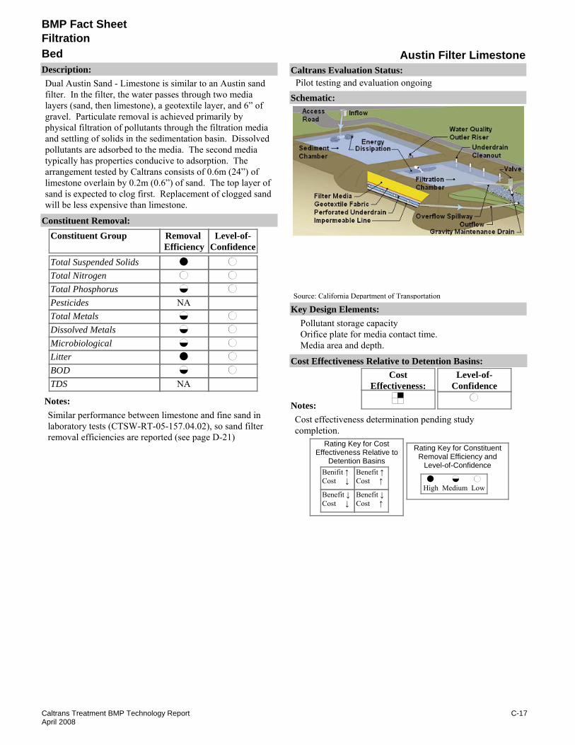
BMP Fact Sheet
Austin Filter LimestoneBedFiltration
Description:Dual Austin Sand - Limestone is similar to an Austin sand filter. In the filter, the water passes through two media layers (sand, then limestone), a geotextile layer, and 6” of gravel. Particulate removal is achieved primarily by physical filtration of pollutants through the filtration media and settling of solids in the sedimentation basin. Dissolved pollutants are adsorbed to the media. The second media typically has properties conducive to adsorption. The arrangement tested by Caltrans consists of 0.6m (24”) of limestone overlain by 0.2m (0.6”) of sand. The top layer of sand is expected to clog first. Replacement of clogged sand will be less expensive than limestone.
Removal Efficiency
Level-of-Confidence
Total Suspended SolidsTotal NitrogenTotal PhosphorusPesticidesTotal MetalsDissolved MetalsMicrobiologicalLitterBODTDS
Constituent GroupConstituent Removal:
NA
NA
Notes:Similar performance between limestone and fine sand in laboratory tests (CTSW-RT-05-157.04.02), so sand filter removal efficiencies are reported (see page D-21)
Key Design Elements:Pollutant storage capacityOrifice plate for media contact time.Media area and depth.
CostEffectiveness:
Level-of-Confidence
Cost Effectiveness Relative to Detention Basins:
Benifit ↑Cost ↓
Benefit ↓Cost ↓
Benefit ↑Cost ↑
Benefit ↓Cost ↑
High Medium Low
Rating Key for ConstituentRemoval Efficiency and
Level-of-Confidence
Rating Key for CostEffectiveness Relative to
Detention Basins
Source: California Department of Transportation
Notes:Cost effectiveness determination pending study completion.
Schematic:
Caltrans Evaluation Status:Pilot testing and evaluation ongoing
C-17Caltrans Treatment BMP Technology ReportApril 2008

BMP Fact Sheet
Austin Filter LimestoneBedFiltration
Requirements:Media scraping.Sediment removal.Media replacement.Training:Training required for media removal and replacement.
Maintenance Issues:
Project Development Issues:Right-of-Way-Requirements:Space requirements are relatively high for sedimentation basin and sand filter.Siting Constraints:Should not be sited where runoff from bare soil or construction activities will be allowed to enter the filter. Head requirement of about 4 feet. Sand filters should be sited where enough vertical clearance (head) is provided, about 5 feet. Detailed geotechnical investigation prior to construction is recommended.Construction:No special requirements identified.
Constraints: If sufficient head is not available, the use of pumps may be required, which result in higher costs and more frequent maintenance.Sand filters can be relatively expensive to construct and maintain.Limited pollutant removal for nutrients.
Advantages:The Limestone Austin filters have good constituent removal for suspended solids, total metals, and bateria.
Caltrans. 2006. SR-267 Media Filter Pilot Study - Post Construction Report. September 2006. CTSW-RT-06-172-18.2
Caltrans. 2005. SR-267 Media Filter Pilot Study - Basis of Design Report. May 2005. CTSW-RT-05-138-06.1
Caltrans. 2006. SR-267 Media Filter Pilot Study - Final Design Report. September 2006. CTSW-RT-06-172-18.1Caltrans. 2006. Caltrans Tahoe Basin SR 267 Media Filter Pilot Study. Interim Report, Monitoring Season 2005-2006. October 2006. CTSW-RT-06--157.03.1
Literature Sources of Performance Demonstrations:Caltrans. 2006. Highway 50 Activated Alumina Media Filter Pilot Study. 2004-2005 Interim Report. September 2006. CTSW-RT-05-129.02.2.
Design, Construction, Maintenance and Cost SourcesCaltrans. 2007. Stormwater Quality Hanbooks: Project Planning and Design Guide. May 2007. CTSW-RT-07-172.19.1
Certifications, Verifications, or Designations:None identified.
C-18Caltrans Treatment BMP Technology ReportApril 2008

BMP Fact Sheet
StormFilter™Cartridge/CanisterFiltration
Description:StormFilter™ is a flow-through system consisting of a vault with canisters filled with filter media. The media traps particulate and adsorbs pollutants such as suspended solids, oil and grease, some metals, nutrients and organics. Various media can be specified (depending on the constituent of concern) including perlite, composted leaf media, zeolite, fabric inserts, GAC, and iron-infused media. A perlite and zeolite mixture was tested in the Caltrans study.
Removal Efficiency
Level-of-Confidence
Total Suspended SolidsTotal NitrogenTotal PhosphorusPesticidesTotal MetalsDissolved MetalsMicrobiologicalLitterBODTDS
Constituent GroupConstituent Removal:
NA
NANA
Notes:A perlite/zeolite StormFilter™ was sited as part of the Caltrans BMP retrofit pilot program.Litter removal based on professional judgment.See appendix B fact sheet for performance results of updated models and other types of media.
Key Design Elements:StormFilter™ is sized to treat the peak flow from the design storm.The peak flow is determined based on the watershed area and design storm magnitude.StormFilter™ canisters were designed to treat 14.8-gpm each or 30 media canisters per c.f.s. of stormwater runoff.See appendix B fact sheet for recent guidelines on flow restriction.
CostEffectiveness:
Level-of-Confidence
Cost Effectiveness Relative to Detention Basins:
Benifit ↑Cost ↓
Benefit ↓Cost ↓
Benefit ↑Cost ↑
Benefit ↓Cost ↑
High Medium Low
Rating Key for ConstituentRemoval Efficiency and
Level-of-Confidence
Rating Key for CostEffectiveness Relative to
Detention Basins
Source: www.contech-cpi.com
Notes:
Schematic:
Caltrans Evaluation Status:Pilot testing complete: under evaluation for additional pilot study
C-19Caltrans Treatment BMP Technology ReportApril 2008

BMP Fact Sheet
StormFilter™Cartridge/CanisterFiltration
Requirements:Periodic sediment removal and canister replacement is required. Vector monitoring and abatement is required if not fully draining.Training:The use of equipment is needed to remove media canisters and to clean out pretreatment vault. Crews must be trained to repair or replace any cartridge filter or part associated with the facility or contract for maintenance. Training needed for confined space entry.
Maintenance Issues:
Project Development Issues:Right-of-Way-Requirements:Space requirements depend on sizing criteria, typically smaller than basins.Siting Constraints:Runoff from bare soil or construction activities should not be allowed to enter the filter. Sufficient hydraulic head is needed to operate the filter, about 28 inches. StormFilter is a proprietary system.Construction:No special requirements identified.
Constraints: Major maintenance may be costly due to the large number of filter canisters required (72 canisters for a 1.5 acre drainage area).A permanent pool of water is held in the pretreatment vault that provides breeding opportunities for mosquitoes.StormFilter™ can be expensive to construct.Proprietary device.
Advantages:It can be applied in confined urban areas and areas with limited space since it is an underground vault.
StormFilter is a proprietary system, check the manufacturers website for information on the product. www.contech-cpi.com.Caltrans. 2007. Stormwater Quality Hanbooks: Project Planning and Design Guide. May 2007. CTSW-RT-07-172.19.1
See Appendix B fact sheet for sources for other filter media and flow scenarios.
Literature Sources of Performance Demonstrations:Caltrans, 2004. BMP Retrofit Pilot Program Final Report, CTSW-RT-01-050 available at www.dot.ca.gov/hq/env/stormwater.
Design, Construction, Maintenance and Cost SourcesCONTECH Construction Products Inc.9025 Centre Pointe Drive, suite 400West Chester, OH 450691-800-338-1122513-645-7000
Certifications, Verifications, or Designations:ETV - Verification statement issued July 2004 for suspended solids.TCEQ - Approval of Innovative Technology: Each cartridge must be limited to a maximum flow rate of 7.5 gpm.TARP - Compliant or similar reliable data on this technology to be able to evaluate pollution removal efficiency claims for TSS, SSC.
C-20Caltrans Treatment BMP Technology ReportApril 2008

BMP Fact Sheet
Compost StormFilter™ (CSF)Open Bed CompostFiltration
Description:This filter is conceptually similar to the Austin Sand Filter (see page D-3, Appendix D), but uses a composted leaf filter media instead. Stormwater Management, Inc. has discountinued manufacturing these systems and now supplies a canister arrangement (see StormFilter™ fact sheets in Appendix B and C). The filter is open to the atmosphere and requires a sedimentation basin upstream. The media is typically housed in a large below-grade vault. In some designs the vault is sectioned off by removable weirs, and under high flow conditions the stormwater will overflow the first filter section to be treated in the subsequent ones. The filter media is reported to remove sediment, oil, particulate and dissolved metals, and a variety of organic contaminants. The assumption is that, compared to sand, these systems will have enhanced removal for many pollutant compounds due to the increased cation exchange capacity of organic matter. This technology is designed for use at the stormwater pipe outlet. Currently available configurations use cylindrical filter modules to save space and reduce filter clogging.
Removal Efficiency
Level-of-Confidence
Total Suspended SolidsTotal NitrogenTotal PhosphorusPesticidesTotal MetalsDissolved MetalsMicrobiologicalLitterBODTDS
Constituent GroupConstituent Removal:
NA
NANA
Notes:Based on monitoring on SR-78 (CTSW-RT-03-036).
Key Design Elements:Sedimentation facilities required upstream of filter.
CostEffectiveness:
Level-of-Confidence
Cost Effectiveness Relative to Detention Basins:
Benifit ↑Cost ↓
Benefit ↓Cost ↓
Benefit ↑Cost ↑
Benefit ↓Cost ↑
High Medium Low
Rating Key for ConstituentRemoval Efficiency and
Level-of-Confidence
Rating Key for CostEffectiveness Relative to
Detention Basins
Source: www.contech-cpi.com
Notes:
Schematic:
Caltrans Evaluation Status:Product discontinued
C-21Caltrans Treatment BMP Technology ReportApril 2008
BMP Fact Sheet
Compost StormFilter™ (CSF)Open Bed CompostFiltration
Requirements:Sediment accumulation in filters and vegetation growth may occur. Nutrient concentrations (especially nitrates and phosphate) have been shown to increase. Media clogging issues may increase maintenance.Training:Training required for media removal.
Maintenance Issues:
Project Development Issues:Right-of-Way-Requirements:: Space requirements depend on sizing criteria, typically smaller than basins.Siting Constraints:Safety barrier surrounding open basin. Open basins may not be suitable close to freeways.Construction:No special requirements identified.
Constraints: Proprietary device.Nutrient leaching.
Advantages:Sedimentation shown to occur. May reduce concentrations of many metals, turbidity, suspended solids, BOD, and ammonia.
Literature Sources of Performance Demonstrations:Compost Storm Water Filter System Monitoring Report , State Route 73 CSTW-RT-03-036 http://www.dot.ca.gov/hq/env/stormwater/special/newsetup/index.htm
Design, Construction, Maintenance and Cost SourcesDiscontinued product.
Certifications, Verifications, or Designations:None identified.
C-22Caltrans Treatment BMP Technology ReportApril 2008

BMP Fact Sheet
Continuous Deflective Separation™ (CDS™)Hydrodynamic Separators
Description:Continuous Deflective Separation (CDS™) units are placed downstream of drain inlets to capture sediment, trash, and debris (gross pollutants). The units create a vortex of water that allows the water to escape through a screen while contaminants are contained in the unit sump. The vortex action of the water tends to keep the screen clear from trash and debris. A storm by-pass weir is incorporated to allow excess flows to bypass the system, rather than entering the CDS™ unit. This is to prevent the unit from flooding or losing its captured material.
Removal Efficiency
Level-of-Confidence
Total Suspended SolidsTotal NitrogenTotal PhosphorusPesticidesTotal MetalsDissolved MetalsMicrobiologicalLitterBODTDS
Constituent GroupConstituent Removal:
NA
NANA
Notes:Information based on chemistry data from the Caltrans BMP Retrofit Pilot Program. 2400 micron screen can remove: 100% of particles 425 um or greater, 96% of particles 300-425 um, 76 % of particles 150-300 um, 42% of particles 75-150 um; 4700 micron screen can remove: 100% of particles 2,350 um or greater, 93% of particles 1,551-2,350 um, 50 % of particles 940-1,551 um.Five studies have been performed on CDS™ units. These studies focused on characteristics of litter and sediments rather than efficiency.A low score for level of confidence is because all results where not statistically significant. For TSS, a contributing factor may be the influent TSS was less than half of typical highway concentrations.Two CDS™ units were tested as part of the Caltrans BMP retrofit pilot program.
Key Design Elements:Flow must be sub-critical entering the unit. Mosquito screens to prevent access.Flow capacity (flood and water quality flows).Bypass of scouring flows.Design flows up to 300cfs.Sump size for litter capture.
CostEffectiveness:
Level-of-Confidence
Cost Effectiveness Relative to Detention Basins:
Benifit ↑Cost ↓
Benefit ↓Cost ↓
Benefit ↑Cost ↑
Benefit ↓Cost ↑
High Medium Low
Rating Key for ConstituentRemoval Efficiency and
Level-of-Confidence
Rating Key for CostEffectiveness Relative to
Detention Basins
Source: www.cdstech.com
Notes:
Schematic:
Caltrans Evaluation Status:Pilot testing and evaluation ongoing
C-23Caltrans Treatment BMP Technology ReportApril 2008

BMP Fact Sheet
Continuous Deflective Separation™ (CDS™)Hydrodynamic Separators
Requirements:The CDS™ units are designed to retain captured pollution over multiple rain events. The CDS™ unit should be inspected, floatables should be removed, and the sump cleaned when the sump is above 85% full. There are three methods for cleaning out a CDS™ unit - vactor truck, removable basket, and underflow pump. Vector monitoring and abatement. Vactor equipment recommended for cleaning.Training:No special requirements identified.
Maintenance Issues:
Project Development Issues:Right-of-Way-Requirements:Small footprint.Siting Constraints:Low head requirement.Construction:No special requirements identified.
Constraints: Unit is developed for the removal of gross pollutants only. Sites with continuous dry weather flow are not recommended. Permanent pool of water is maintained, creating a breeding opportunity for mosquitoes.Proprietary device.
Advantages:Stormwater can be treated at the end of pipe, and therefore stormwater treatment devices are not needed at each storm drain inlet. The unit is non-mechanical, non-electrical, reducing maintenance issues related to mechanical and electrical devices. Relatively limited head is needed to operate the device (0.5 ft).
www.CDStech.com.au/articles/StenstromReport.pdfwww.CDStech.com.au/articles/Coarse&Medium-FineSedimentRemoval.pdfwww.stormwater-resources.com/Library/065BCDSFinal.pdfUS Head Office - West Coast, CDS Technologies Morgan Hill, CA 95037 email: [email protected]
Literature Sources of Performance Demonstrations:Caltrans, 2004. BMP Retrofit Pilot Program Final Report, CTSW-RT-01-050 available at www.dot.ca.gov/hq/env/stormwater
Design, Construction, Maintenance and Cost SourcesCaltrans. 2007. Stormwater Quality Hanbooks: Project Planning and Design Guide. May 2007. CTSW-RT-07-172.19.1
Certifications, Verifications, or Designations:LA RWQCB: Full Capture certification for trash.
C-24Caltrans Treatment BMP Technology ReportApril 2008

BMP Fact Sheet
GSRD / Baffle BoxLitter and Debris Removal
Description:The baffle box Gross Solids Removal Device (GSRD) is a non-proprietary device whose primary function is to remove gross solids (litter and vegetative material) from stormwater runoff. The Baffle Box applies a two-chamber concept: the first chamber utilizes an underflow wire to trap floatable gross solids; and the second chamber utilizes a bar rack to screen out any material that passes through from the first chamber. This device was rejected from approval due to excessive maintenance.
Removal Efficiency
Level-of-Confidence
Total Suspended SolidsTotal NitrogenTotal PhosphorusPesticidesTotal MetalsDissolved MetalsMicrobiologicalLitterBODTDS
Constituent GroupConstituent Removal:
NANANANANANANA
NANA
Notes:Litter and vegetative material are the target constituents for the device.No long-term water quality monitoring studies have been conducted to evaluate the treatment effectiveness of the baffle box on other water quality constituents.
Key Design Elements:Baffle boxes should be sized to hold gross solids to be deposited during a 1-year period and pass the design flow (e.g., 25-year flow).Annual Estimated Gross Solids Loading Rate.Hydraulic Head.
CostEffectiveness:
Level-of-Confidence
Cost Effectiveness Relative to Detention Basins:
Benifit ↑Cost ↓
Benefit ↓Cost ↓
Benefit ↑Cost ↑
Benefit ↓Cost ↑
High Medium Low
Rating Key for ConstituentRemoval Efficiency and
Level-of-Confidence
Rating Key for CostEffectiveness Relative to
Detention Basins
Notes:
Schematic:
Caltrans Evaluation Status:Pilot testing complete: rejected
C-25Caltrans Treatment BMP Technology ReportApril 2008
BMP Fact Sheet
GSRD / Baffle BoxLitter and Debris Removal
Requirements:Periodic inspections required to ensure that the device is functional. Routine maintenance may include sediment/debris removal. Clogging increased cleanout frequency to an unacceptable level relative to other GSRD designs.Training:No special requirements identified.
Maintenance Issues:
Project Development Issues:Right-of-Way-Requirements:Small footprint.Siting Constraints:Must provide sufficient hydraulic head to operate by gravity.Construction:Traffic control may be required for retrofits due to close proximity to roadway.
Constraints: Based on pilot studies, regular maintenance is required to keep the device functioning properly.Maintenance required to unclog screens and drainage fixtures.Subject to clogging.
Advantages:Baffle box is a “small footprint device” that can be installed in existing right of way.Based on pilot studies, when regular maintenance is supplied, the device removes nearly all the gross solids from stormwater runoff.
Literature Sources of Performance Demonstrations:California Department of Transportation, Phase I Gross Solids Removal Devices Pilot Study: 2000-2002, Final Report. CTSW-RT-03-072.31.22
Design, Construction, Maintenance and Cost SourcesCaltrans. 2007. Stormwater Quality Hanbooks: Project Planning and Design Guide. May 2007. CTSW-RT-07-172.19.1
Certifications, Verifications, or Designations:None identified.
C-26Caltrans Treatment BMP Technology ReportApril 2008

BMP Fact Sheet
GSRD / Litter Inlet DeflectorLitter and Debris Removal
Description:Standard Caltrans inlet and grate is replaced with a curb inlet and flap gate. This BMP was rejected due to insignificant impact on litter loads.
Removal Efficiency
Level-of-Confidence
Total Suspended SolidsTotal NitrogenTotal PhosphorusPesticidesTotal MetalsDissolved MetalsMicrobiologicalLitterBODTDS
Constituent GroupConstituent Removal:
NANANANANANANA
NANA
Notes:Caltrans studies did not show statistically significant improvement in runoff quality or litter load.
Key Design Elements:Curbed roadway is required
CostEffectiveness:
Level-of-Confidence
Cost Effectiveness Relative to Detention Basins:
Benifit ↑Cost ↓
Benefit ↓Cost ↓
Benefit ↑Cost ↑
Benefit ↓Cost ↑
High Medium Low
Rating Key for ConstituentRemoval Efficiency and
Level-of-Confidence
Rating Key for CostEffectiveness Relative to
Detention Basins
Notes:
Schematic:
Caltrans Evaluation Status:Pilot testing complete: rejected
C-27Caltrans Treatment BMP Technology ReportApril 2008
BMP Fact Sheet
GSRD / Litter Inlet DeflectorLitter and Debris Removal
Requirements:Flap gate requires periodic clean-out.Training:No special requirements identified.
Maintenance Issues:
Project Development Issues:Right-of-Way-Requirements:Small-footprint.Siting Constraints:Curbed roadway is required.Construction:No special requirements identified.
Constraints: Larger items can enter the LID than the standard inlet grate during storms.Flap gate may require maintenance and system clean out.
Advantages:Keeps dry-weather deposition out of stormwater conveyance system and allows most gross pollutants to be collected by the street sweeper. Most effective in arid or semi-arid climates.
Caltrans, 2001. Litter Inlet Deflector (LID) Study, August 2001. CTSW-RT-01-027. p. 6-6.
Literature Sources of Performance Demonstrations:Caltrans, 2000. District 7 Litter Management Pilot Study. June 26, 2000. CTSW-RT-00-013. p 8-3.
Design, Construction, Maintenance and Cost SourcesCaltrans. 2007. Stormwater Quality Hanbooks: Project Planning and Design Guide. May 2007. CTSW-RT-07-172.19.1
Certifications, Verifications, or Designations:None identified.
C-28Caltrans Treatment BMP Technology ReportApril 2008

BMP Fact Sheet
GSRD / V-ScreenLitter and Debris Removal
Description:The V-Screens (VS) Gross Solids Removal Devices (GSRDs) are non-proprietary devices whose primary function is to remove gross solids (litter and vegetative material) from stormwater runoff. Currently, there are two configurations of VS GSRDs:
Configuration #1. This VS GSRD utilizes a forward sloping V-shaped 5 mm wedge-wire screen. The screen is sloped forward so that the top of the screen is downstream from the bottom of the screen. Configuration #1 is not pictured.
Configuration #2. This VS GSRD utilizes a reverse sloping V-shaped 5 mm wedge-wire screen. The screen is sloped backward (or reverse) so that the bottom of the screen is downstream from the top of the screen. See picture to the right.
Removal Efficiency
Level-of-Confidence
Total Suspended SolidsTotal NitrogenTotal PhosphorusPesticidesTotal MetalsDissolved MetalsMicrobiologicalLitterBODTDS
Constituent GroupConstituent Removal:
NANANANANANANA
NANA
Notes:Litter and vegetative material are the target constituents for the device.No long-term water quality monitoring studies have been conducted to evaluate treatment effectiveness of the VS GSRDs on other water quality constituents.
Key Design Elements:VS GSRDs should be sized to hold gross solids to be deposited during a 1-year period and pass the design flow (e.g., 25-year flow).Annual Estimated Gross Solids Loading Rate.Hydraulic Head.
CostEffectiveness:
Level-of-Confidence
Cost Effectiveness Relative to Detention Basins:
Benifit ↑Cost ↓
Benefit ↓Cost ↓
Benefit ↑Cost ↑
Benefit ↓Cost ↑
High Medium Low
Rating Key for ConstituentRemoval Efficiency and
Level-of-Confidence
Rating Key for CostEffectiveness Relative to
Detention Basins
Notes:
Schematic:
Caltrans Evaluation Status:Pilot testing complete: rejected
C-29Caltrans Treatment BMP Technology ReportApril 2008

BMP Fact Sheet
GSRD / V-ScreenLitter and Debris Removal
Requirements:Periodic inspections required to ensure that the device is functional. Routine maintenance may include sediment/debris removal.Training:Routine maintenance requires staff and equipment to clear the screen module if it becomes clogged and remove accumulated sediment.
Maintenance Issues:
Project Development Issues:Right-of-Way-Requirements:Small footprint.Siting Constraints:Must provide sufficient hydraulic head to operate by gravity.Construction:No special requirements identified.
Constraints: Hydraulic head requirement.
Advantages:The IS GSRDs are a “small footprint device” that can be installed in existing right of way.Based on pilot studies, the devices remove nearly all the gross solids from stormwater runoff with minimal maintenance requirements.
Literature Sources of Performance Demonstrations:California Department of Transportation, Phase III Gross Solids Removal Devices Pilot Study: 2002-2003, Interim Report. CTSW-RT-03-099.31.24.
Design, Construction, Maintenance and Cost SourcesCaltrans. 2007. Stormwater Quality Hanbooks: Project Planning and Design Guide. May 2007. CTSW-RT-07-172.19.1
Certifications, Verifications, or Designations:None identified.
C-30Caltrans Treatment BMP Technology ReportApril 2008

BMP Fact Sheet
Areo-Power® ST1-P3Oil & Water Separator
Description:Oil/Water Separators are designed to remove free oil and grease from stormwater runoff. Oil droplets collide and coalesce to become larger globules that are captured in the separator. Oil/Water separators are typically manufactured units. They consist of a baffled vault containing several inclined corrugated plates stacked and bundled together. The plates are equally spaced and reduce the vertical distance oil droplet must rise to separate from the stormwater. With current technology and design, coalescing plate separator type oil/water separators are capable of reducing effluent concentrations of free oil and grease to 10 - 15 mg/L, and should be used only where concentrations of oil and grease are high (30 to 50 mg/L). However, in such cases source control is likely a viable and less costly solution. The model tested in this study was the Areo-Power 500 gallon ST1-P3.
Removal Efficiency
Level-of-Confidence
Total Suspended SolidsTotal NitrogenTotal PhosphorusPesticidesTotal MetalsDissolved MetalsMicrobiologicalLitterBODTDS
Constituent GroupConstituent Removal:
NANANANANANA
NANA
Notes:One oil/water separator was sited as part of the Caltrans BMP Retrofit Pilot Program. Concentration reductions for TSS presented are those found in the study Oil removal was estimated at 89 percent.Litter removal based on professional judgment, though the device does not seemed designed for easy maintenance and clogging-free operation.Only hydrocarbons and TSS where evaluated in the Caltrans study.
Key Design Elements:To design the coalescing plate separator the “effective separation area” required for the plate media needs to be determined given a design flow.The specific vault sizing will then depend on the manufacturer's plate media design.The specific design, analysis, configuration and specifications for coalescing plates are empirically based and variable.An oil/water separator typically consists of three compartments divided by baffles: forebay, an oil separation cell, and an afterbay.The oil separation cell is used to capture and hold oil. The afterbay allows a relatively oil-free exit cell before the outlet.Sediments are trapped and collected in the forebay.
CostEffectiveness:
Level-of-Confidence
Cost Effectiveness Relative to Detention Basins:
Benifit ↑Cost ↓
Benefit ↓Cost ↓
Benefit ↑Cost ↑
Benefit ↓Cost ↑
High Medium Low
Rating Key for ConstituentRemoval Efficiency and
Level-of-Confidence
Rating Key for CostEffectiveness Relative to
Detention Basins
Source: www.hydrasep.com
Notes:
Schematic:
Caltrans Evaluation Status:Pilot testing complete: rejected
C-31Caltrans Treatment BMP Technology ReportApril 2008
BMP Fact Sheet
Areo-Power® ST1-P3Oil & Water Separator
Requirements:Oil/Water separators require regular inspection. The separator plates require cleaning when sufficient oil and grease have accumulated and their effectiveness is reduced. Inspection and cleaning should follow manufacturers recommendations. Accumulated sediment should be removed frequently to prevent resuspension. Sediment removal also removes the oil and grease since these pollutants bind to the sediment.Training:Vactor equipment recommended for cleaning.
Maintenance Issues:
Project Development Issues:Right-of-Way-Requirements:Small footprint.Siting Constraints:Low head requirement.Construction:No special requirements identified.
Constraints: Accumulated sediment must be removed or cleaned out frequently to prevent resuspension.The concentrations of free oil and grease typically found in stormwater runoff are generally too low to benefit from treatment by this device.Significant excavation is required for construction.Proprietary device.
Advantages:Oil/water separators are installed underground so they are not an aesthetic problem. Where high concentrations of free oil are present they can provide significant reduction.
Highland Tank, (814)-893-5701, FAX (814)-893-6126Lantec Products, HD Q-PAC®, www.lantecp.comGnesys, Inc., Hydrasep®,www.hydrasep.com
Literature Sources of Performance Demonstrations:Caltrans, 2004. BMP Retrofit Pilot Program Final Report, CTSW-RT-01-050 available at www.dot.ca.gov/hq/env/stormwater
Design, Construction, Maintenance and Cost SourcesCaltrans. 2007. Stormwater Quality Hanbooks: Project Planning and Design Guide. May 2007. CTSW-RT-07-172.19.1
Certifications, Verifications, or Designations:None identified.
C-32Caltrans Treatment BMP Technology ReportApril 2008
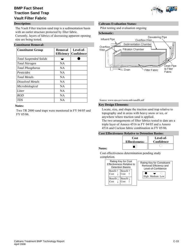
BMP Fact Sheet
Vault Filter FabricTraction Sand Trap
Description:The Vault Filter traction sand trap is a sedimentation basin with an outlet structure protected by filter fabric. Currently, layers of fabrics of decreasing apparent opening size are being tested.
Removal Efficiency
Level-of-Confidence
Total Suspended SolidsTotal NitrogenTotal PhosphorusPesticidesTotal MetalsDissolved MetalsMicrobiologicalLitterBODTDS
Constituent GroupConstituent Removal:
NANANANANANANANANA
Notes:Two TR 2000 sand traps were monitored in FY 04/05 and FY 05/06.
Key Design Elements:Locate, size, and shape the traction sand trap relative to topography and in areas with heavy snow or ice, or anywhere where traction sand is applied.The two arrangements of filter fabrics tested to date are a triple layer of Amoco 4516 in FY 04/05 and a Amoro 4516 and Coclean fabric combination in FY 05/06.
CostEffectiveness:
Level-of-Confidence
Cost Effectiveness Relative to Detention Basins:
Benifit ↑Cost ↓
Benefit ↓Cost ↓
Benefit ↑Cost ↑
Benefit ↓Cost ↑
High Medium Low
Rating Key for ConstituentRemoval Efficiency and
Level-of-Confidence
Rating Key for CostEffectiveness Relative to
Detention Basins
Source: www.epa.gov/owm.mtb/sandflt.pdf
Notes:Cost effectiveness determination pending study completion.
Schematic:
Caltrans Evaluation Status:Pilot testing and evaluation ongoing
C-33Caltrans Treatment BMP Technology ReportApril 2008

BMP Fact Sheet
Vault Filter FabricTraction Sand Trap
Requirements:Annual maintenance includes removing traction sand.Training:Vactor equipment may be used; front end loaders are being tested.
Maintenance Issues:
Project Development Issues:Right-of-Way-Requirements:Requires more space than double barrel traps.Siting Constraints:High head requirement. Devices tested to date have at least 6 ft. of head.Construction:No special requirements identified.
Constraints: High head requirement, removal of other pollutants is not targeted.Invert 3 to 6 ft above groundwater if drainage is allowed through base (CMP riser type) (PPDG 2007).
Advantages:TR 2000 sand traps require more space than approved sand traps, but the capacity is much larger.Requires very little or no hydraulic head to operate.
Literature Sources of Performance Demonstrations:Caltrans. 2006. Final Report Caltrans Tahoe Basin Highway 267 Sand Trap with Filter Fabric 2-Year Pilot Study 2004-2006 Monitoring Report. October 2006. CTSW-RT-06.157.01.2
Design, Construction, Maintenance and Cost SourcesCaltrans. 2007. Stormwater Quality Hanbooks: Project Planning and Design Guide. May 2007. CTSW-RT-07-172.19.1
Certifications, Verifications, or Designations:None identified.
C-34Caltrans Treatment BMP Technology ReportApril 2008

Caltrans Treatment BMP Technology Report D-1 April 2008
APPENDIX D: CALTRANS APPROVED BMP FACT SHEETS Appendix D presents fact sheets for BMPs approved for installation on Caltrans facilities. Implementation of these BMPs should follow the guidelines in the Storm Water Management Plan and the Storm Water Project Planning and Design Guide.
TABLE OF CONTENTS
Technology Type Available Stormwater Products Page No. Biofiltration Biofiltration Strips D-3 Bioretention Biofiltration Swales D-5 Detention Basins D-7 Dry Weather Flow Diversion D-9 Filtration Bed Austin Sand Filter D-11 Delaware Sand Filter D-13 Infiltration Basins D-15 Trenches D-17 Litter and Debris Removal GSRD - Inclined Screen D-19 GSRD - Linear Radial D-21 Multi-Chambered Treatment Trains D-23 Traction Sand Trap Double Barrel D-25 Wet Basin D-27

blank for double sided printing
Caltrans Treatment BMP New Technology Report D-2 April 2008

BMP Fact SheetBiofiltration
Description:Biofiltration strips are relatively flat vegetated areas that accept sheet flow from stormwater runoff. Removal mechanisms include filtration and infiltration. Strips can be used as pretreatment to infiltration trenches and basins, and sand filters.
Removal Efficiency
Level-of-Confidence
Total Suspended SolidsTotal NitrogenTotal PhosphorusPesticidesTotal MetalsDissolved MetalsMicrobiologicalLitterBODTDS
Constituent GroupConstituent Removal:
NA
NA
Notes:Three biofiltration strips were sited, constructed, and monitored as part of the Caltrans BMP retrofit pilot program (2004).Total nitrogen load removal is highly dependent on infiltration losses.Export of higher phosphorus concentrations resulted in low P load removal.BOD based on Young et. al. (1996).Pesticide reduction based on “Evaluation of Factors Controlling Herbicide Runoff to Surface Water” (Caltrans, 2005).
Key Design Elements:Locate, size, and shape biofiltration strips relative to topography and allow for extended flow paths to maximize treatment. Specify vegetation that occurs naturally to minimize establishment and maintenance costs. Install strips at a time when supplemental irrigation will not be needed to minimize establishment. Sized as long (in direction of flow) and flat as the site will reasonably allow up to sheet flow boundaries (maximum length of Biofiltration Strips is approximately 100 ft); an HRT is not required. Caltrans designers should follow the Project Planning and Design Guide.
CostEffectiveness:
Level-of-Confidence
Cost Effectiveness Relative to Detention Basins:
Benifit ↑Cost ↓
Benefit ↓Cost ↓
Benefit ↑Cost ↑
Benefit ↓Cost ↑
High Medium Low
Rating Key for ConstituentRemoval Efficiency and
Level-of-Confidence
Rating Key for CostEffectiveness Relative to
Detention Basins
Notes:
Schematic:
Caltrans Evaluation Status:Approved
D-3Caltrans Treatment BMP Technology ReportApril 2008
BMP Fact SheetBiofiltration
Requirements:Maintenance requirements include regular inspections for side slope stability, debris and sediment accumulation, vegetation height, vegetative cover, and presence of burrowing animals. Woody vegetation is also removed. If acceptable cover is not achieved, re-seeding or some type of erosion control will be needed.Training:No special requirements identified.
Maintenance Issues:
Project Development Issues:Right-of-Way-Requirements:Space requirements are relatively low for biofiltration strips.Siting Constraints:Biofiltration strips require sheet flow, so site in areas where sheet flow predominates. Consider using as pretreatment for devices that may be prone to clogging, such as sand filters and infiltration basins or trenches.Construction:No special requirements identified.
Constraints: Strips, in order to function, require sheet flow. Strips must be placed in areas with large amounts of sheet flow.Soil at project site needs to be amenable to selected vegetation. It may need to be conditioned to allow vegetation to establish.
Advantages:Requires less land space and incorporates well into the environment.Strips have high removal efficiencies for total suspended solids and total metals.Generally inexpensive relative to other BMPs to operate and maintain.
US Environmental Protection Agency. Infitlration Trench Fact Sheet. www.epa.gov/owm/mtb/infltrenc.pdf
Schueler, T.R., 1987. Controlling Urban Runoff: A Practical Manual for Planning and Designing Urban BMPs, Dept. of Environmental Programs, Metropolitan Washington Council of Governments, Washington, DC
Young, G.K., et al. 1996, Evaluation and Management of Highway Runoff Water Quality, Publication No. FHWA-PD-96-032, U.S. Dept. of Transportation, Federal Highway Administration, Office of Environment and Planning.
Caltrans, 2005. Evaluation of Factors Controlling Herbicide Runoff to Surface Water, May 2005, CTSW-RT-03-084-73.04.Caltrans. 2003. "SR-73 Stormwater BMP Replacement Project at CSF System 1149L Bioretention Area: Basis of Design Report." November 2003. CTSW-RT-03-006.51.39Caltrans. 2003. "Roadside Vegetated Treatment Sites (RVTS) Study Final Report." November 2003. CTSW-RT-03-028
Literature Sources of Performance Demonstrations:Caltrans, 2004. BMP Retrofit Pilot Program Final Report, CTSW-RT-01-050 available at www.dot.ca.gov/hq/env/stormwater
Design, Construction, Maintenance and Cost SourcesCaltrans. 2007. Stormwater Quality Hanbooks: Project Planning and Design Guide. May 2007. CTSW-RT-07-172.19.1
Certifications, Verifications, or Designations:None identified.
D-4Caltrans Treatment BMP Technology ReportApril 2008

BMP Fact Sheet
Biofiltration SwalesBioretention
Description:Biofiltration swales are vegetated areas, similar to conveyance channels, which accept concentrated flow from stormwater runoff via storm drain inlets. Removal mechanisms include filtration and infiltration as stormwater flows through the grass.
Removal Efficiency
Level-of-Confidence
Total Suspended SolidsTotal NitrogenTotal PhosphorusPesticidesTotal MetalsDissolved MetalsMicrobiologicalLitterBODTDS
Constituent GroupConstituent Removal:
NA
NA
Notes:Six biofiltration swales were sited, constructed, and monitored as part of the Caltrans BMP retrofit pilot program. Of metals, only dissolved zinc was significantly removed. Total nitrogen load removal is highly dependent on infiltration losses. Export of higher phosphorus concentrations resulted in low P load removal. BOD based on Young et. al. (1996). Pesticide reduction based on “Evaluation of Factors Controlling Herbicide Runoff to Surface Water” (Caltrans, 2005)
Key Design Elements:Locate, size, and shape biofiltration strips relative to topography and allow for extended flow paths to maximize treatment. Use a mixture of drought-tolerant grass species, and select native vegetation to minimize establishment and maintenance costs.Energy dissipaters may be used, but do not use those that include standing water, as this could lead to vector problems. Side slopes constructed of fill are not recommended, which are prone to gopher damage or other burrowing animals. Longitudinal slopes should be less than that which causes scour or transport of sediment. Swales constructed in cut are preferred to minimize gopher damage.Caltrans designers should follow the Project Planning and Design Guide.
CostEffectiveness:
Level-of-Confidence
Cost Effectiveness Relative to Detention Basins:
Benifit ↑Cost ↓
Benefit ↓Cost ↓
Benefit ↑Cost ↑
Benefit ↓Cost ↑
High Medium Low
Rating Key for ConstituentRemoval Efficiency and
Level-of-Confidence
Rating Key for CostEffectiveness Relative to
Detention Basins
Notes:
Schematic:
Caltrans Evaluation Status:Approved
D-5Caltrans Treatment BMP Technology ReportApril 2008

BMP Fact Sheet
Biofiltration SwalesBioretention
Requirements:Maintenance requirements include regular inspections for side slope stability, debris and sediment accumulation, vegetation height, vegetative cover, and presence of burrowing animals. Woody vegetation is also removed. If acceptable cover is not achieved, re-seeding or some type of erosion control will be needed.Training:No special requirements identified.
Maintenance Issues:
Project Development Issues:Right-of-Way-Requirements:Space requirements are relatively low for biofiltration swales.Siting Constraints:Biofiltration swales should be placed in areas of natural lows or cut section to minimize damage caused by gophers or other burrowing animals.Construction:No special requirements identified.
Constraints: Swales should be located in areas that are naturally low or in cut sections to minimize structural damage caused by gophers or burrowing animals.Soil at project site needs to be amenable to selected vegetation. It may need to be conditioned to allow vegetation to establish.
Advantages:Requires less land space and incorporates well into the environment.Swales have good removal efficiencies for total suspended solids and total metals.Generally inexpensive relative to other BMPs to operate and maintain.Infiltration enhances reduction of pollutant load.
Stormwater Authority Organization. Grassed Swales. http://www.stormwaterauthority.org/assets/Grassed%20Swales.pdfwww.Filtrexx.com
Schueler, T.R., 1987. Controlling Urban Runoff: A Practical Manual for Planning and Designing Urban BMPs, Dept. of Environmental Programs, Metropolitan Washington Council of Governments, Washington, DC.
Young, G.K., et al. 1996, Evaluation and Management of Highway Runoff Water Quality, Publication No. FHWA-PD-96-032, U.S. Dept. of Transportation, Federal Highway Administration, Office of Environment and Planning.
Caltrans, 2005. Evaluation of Factors Controlling Herbicide Runoff to Surface Water, May 2005, CTSW-RT-03-084-73.04.Caltrans. 2003. "SR-73 Stormwater BMP Replacement Project at CSF System 1149L Bioretention Area: Basis of Design Report." November 2003. CTSW-RT-03-006.51.39
Literature Sources of Performance Demonstrations:Caltrans, 2004. BMP Retrofit Pilot Program Final Report, CTSW-RT-01-050 available at www.dot.ca.gov/hq/env/stormwater
Design, Construction, Maintenance and Cost SourcesCaltrans. 2007. Stormwater Quality Hanbooks: Project Planning and Design Guide. May 2007. CTSW-RT-07-172.19.1
Certifications, Verifications, or Designations:None identified.
D-6Caltrans Treatment BMP Technology ReportApril 2008
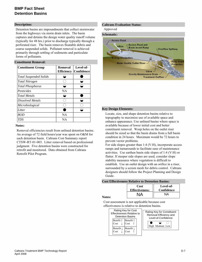
BMP Fact SheetDetention Basins
Description:Detention basins are impoundments that collect stormwater from the highways via storm drain inlets. The basin captures and detains the design water quality runoff volume (typically for 48 hrs.) prior to discharge typically through a perforated riser. The basin removes floatable debris and coarse suspended solids. Pollutant removal is achieved primarily through settling of sediments and particulate forms of pollutants.
Removal Efficiency
Level-of-Confidence
Total Suspended SolidsTotal NitrogenTotal PhosphorusPesticidesTotal MetalsDissolved MetalsMicrobiologicalLitterBODTDS
Constituent GroupConstituent Removal:
NA
NANA
Notes:Removal efficiencies result from unlined detention basins. An average of 72 field hours/year was spent on O&M for each detention basin. Caltrans Cost Summary report CTSW-RT-01-003. Litter removal based on professional judgment. Five detention basins were constructed for retrofit and monitored. Data obtained from Caltrans Retrofit Pilot Program.
Key Design Elements:Locate, size, and shape detention basins relative to topography to maximize use of available space and enhance appearance. Use unlined basins where space is available because of lower initial cost and better constituent removal. Weep holes on the outlet riser should be sized so that the basin drains from a full basin condition in 24 hours. Maximum would be 72 hours to prevent vector problems. For side slopes greater than 1:4 (V:H), incorporate access ramps and turnarounds to facilitate ease of maintenance activities. Use earthen basin side slopes of 1:4 (V:H) or flatter. If steeper side slopes are used, consider slope stability measures where vegetation is difficult to establish. Use an outlet design with an orifice in a riser, surrounded by a screen mesh for debris control. Caltrans designers should follow the Project Planning and Design Guide.
CostEffectiveness:
NA
Level-of-Confidence
NA
Cost Effectiveness Relative to Detention Basins:
Benifit ↑Cost ↓
Benefit ↓Cost ↓
Benefit ↑Cost ↑
Benefit ↓Cost ↑
High Medium Low
Rating Key for ConstituentRemoval Efficiency and
Level-of-Confidence
Rating Key for CostEffectiveness Relative to
Detention Basins
Notes:Cost assessment is not applicable because cost effectiveness is relative to detention basins.
Schematic:
Caltrans Evaluation Status:Approved
D-7Caltrans Treatment BMP Technology ReportApril 2008

BMP Fact SheetDetention Basins
Requirements:Maintenance requirements include regular inspections for standing water, side slope stability, debris and sediment accumulation, and vegetation height and vegetative cover. If vegetative cover of the basin invert or side slopes are not established to acceptable thresholds, re-seeding or erosion control measures may need to be implemented.Training:No special requirements identified.
Maintenance Issues:
Project Development Issues:Right-of-Way-Requirements:Space requirements are relatively high for detention basins.Siting Constraints:Should not be sited where there may be insufficient hydraulic head to facilitate complete drainage, or in areas where groundwater contamination is a concern.Construction:No special requirements identified.
Constraints: Limited pollutant removal for nutrients and dissolved constituents.Can only be placed in areas with sufficient hydraulic head.
Advantages:The detention basins have good constituent removal for suspended solids, and total metals.Compared to other BMPs, detention basins are relatively easy to operate and maintain.Infiltration enhances reduction of pollutant load.
Glick, R., Chang, G. C., and Barrett, M. E., Monitoring and evaluation of stormwater quality control basins, in Watershed Management: Moving from Theory to Implementation, Denver, CO, May 3-6, 1998, pp. 369-376.
The US Dept. of Transportation "Evaluation and Management of Highway Runoff Water Quality" Young et al. 1996 - contains info. on siting, design, and performance.
Literature Sources of Performance Demonstrations:Caltrans, 2004. BMP Retrofit Pilot Program Final Report, CTSW-RT-01-050 available at http://www.dot.ca.gov/hq/env/stormwater/special/newsetup/_pdfs/new_technology/CTSW-RT-01-050.pdf
Design, Construction, Maintenance and Cost SourcesCaltrans. 2007. Stormwater Quality Hanbooks: Project Planning and Design Guide. May 2007. CTSW-RT-07-172.19.1
Certifications, Verifications, or Designations:None identified.
D-8Caltrans Treatment BMP Technology ReportApril 2008

BMP Fact SheetDry Weather Flow Diversion
Description:Low, dry weather flows in urban areas can be diverted from the storm drain system to the sanitary sewer system and conveyed to a publicly owned treatment works (POTW). During wet weather, this diversion is suspended since stormwater flows can be greater than normally managed by a POTW.
Removal Efficiency
Level-of-Confidence
Total Suspended SolidsTotal NitrogenTotal PhosphorusPesticidesTotal MetalsDissolved MetalsMicrobiologicalLitterBODTDS
Constituent GroupConstituent Removal:
Notes:Removal efficiency is based on low stormwater flow and dry weather flow events. Device does not treat stormwater flows when closed during wet weather.
Key Design Elements:Caltrans designers should follow the Project Planning and Design Guide
CostEffectiveness:
Level-of-Confidence
Cost Effectiveness Relative to Detention Basins:
Benifit ↑Cost ↓
Benefit ↓Cost ↓
Benefit ↑Cost ↑
Benefit ↓Cost ↑
High Medium Low
Rating Key for ConstituentRemoval Efficiency and
Level-of-Confidence
Rating Key for CostEffectiveness Relative to
Detention Basins
Notes:
Schematic:
Caltrans Evaluation Status:Approved
D-9Caltrans Treatment BMP Technology ReportApril 2008
BMP Fact SheetDry Weather Flow Diversion
Requirements:Depends on complexity of diversion.Training:May require special training for inspection and maintenance of pumped diversions.
Maintenance Issues:
Project Development Issues:Right-of-Way-Requirements:Space requirements are relatively low for dry weather flow diversions.Siting Constraints:Must be able to convey diverted flow to POTW sewer.Construction:Coordination required with local POTW.
Constraints: Must have agreement with POTW.Cost is highly variable depending site conditions.
Advantages:Advanced treatment of the diverted flow.
U.S. Environemntal Protection Agency. Sand Filter Fact Sheet. www.epa.gov/owm/mtb/sandfltr.pdf
Literature Sources of Performance Demonstrations:Caltrans, 2004. BMP Retrofit Pilot Program Final Report, CTSW-RT-01-050 available at www.dot.ca.gov/hq/env/stormwater
Design, Construction, Maintenance and Cost SourcesCaltrans. 2007. Stormwater Quality Hanbooks: Project Planning and Design Guide. May 2007. CTSW-RT-07-172.19.1
Certifications, Verifications, or Designations:None identified.
D-10Caltrans Treatment BMP Technology ReportApril 2008

BMP Fact Sheet
Austin Sand FilterBedFiltration
Description:The Austin sand filter includes a sedimentation basin and a sand media filter. The sedimentation basin captures and detains the design water quality runoff volume (typically for 24 hrs.) prior to discharge to the filter chamber. The sedimentation basin removes floatable debris and coarse suspended solids and prevents premature clogging of the filter media surface. Sedimentation chamber effluent discharges to the sand filtration basin typically through a perforated riser. In the sand filter, the water passes through an 18” sand layer, a geotextile layer, and into a gravel underdrain. Pollutant removal is achieved primarily by physical filtration of pollutants through the filtration media and settling of solids in the sedimentation basin.
Removal Efficiency
Level-of-Confidence
Total Suspended SolidsTotal NitrogenTotal PhosphorusPesticidesTotal MetalsDissolved MetalsMicrobiologicalLitterBODTDS
Constituent GroupConstituent Removal:
NA
NA
Notes:Except where noted, performance obtained from Caltrans Retrofit Pilot Program Final Report (2004). Five Austin sand filters were constructed and monitored. While Nitrate concentrations increase by 35%, total N decreased by 32%. Phosphorus based on average of Caltrans result and Glick, et. al. BOD based on Young et. al. (metadata). Litter removal based on professional judgment
Key Design Elements:Pollutant storage capacityOrifice plate for media contact time.Media area and depth.Caltrans designers should follow the Project Planning and Design Guide.
CostEffectiveness:
Level-of-Confidence
Cost Effectiveness Relative to Detention Basins:
Benifit ↑Cost ↓
Benefit ↓Cost ↓
Benefit ↑Cost ↑
Benefit ↓Cost ↑
High Medium Low
Rating Key for ConstituentRemoval Efficiency and
Level-of-Confidence
Rating Key for CostEffectiveness Relative to
Detention Basins
Notes:
Schematic:
Caltrans Evaluation Status:Approved
D-11Caltrans Treatment BMP Technology ReportApril 2008

BMP Fact Sheet
Austin Sand FilterBedFiltration
Requirements:Media scraping.Sediment removal.Media replacement.Training:Training required for media removal and replacement.
Maintenance Issues:
Project Development Issues:Right-of-Way-Requirements:Space requirements are relatively high for sedimentation basin and sand filter.Siting Constraints:Should not be sited where runoff from bare soil or construction activities will be allowed to enter the filter. Head requirement of 1.2 meters.Construction:No special requirements identified.
Constraints: Sand filters can be relatively expensive to construct and maintain.Limited pollutant removal for nutrients.
Advantages:The Austin sand filters have good constituent removal for suspended solids, total metals, and bacteria. They can provide consistent pollutant removal when properly maintained.They can treat runoff from drainage areas up to 20 hectares.They can be added to retrofit highly developed existing sites.
Caltrans. 2007. Stormwater Quality Hanbooks: Project Planning and Design Guide. May 2007. CTSW-RT-07-172.19.1US Environmental Protection Agency. Sand Filter Fact Sheet. www.epa.gov/owm/mtb/sandfltr.pdfBarrett, M. University of Texas at Austin
Glick, R., Chang, G. C., and Barrett, M E., Monitoring and evaluation of stormwater quality control basins, in Watershed Management: Moving from Theory to Implementation, Denver, CO, May 3-6, 1998, pp. 369-376.
Erickson, A. J., Gulliver, J. S., and Weiss, P. T., "Enhanced Sand Filtration for Storm Water Phosphorus Removal," Journal of Environmental Engineering, 10.1061, (ASCE) 0733-9372 133:5(485) May 2007.
Caltrans. 2007. Caltrans Statewide [Austin] Sand Filter Study Final 2006 Stormwater Monitoring Report. January. 2007. CTSW-RT-06-128.01.1
Literature Sources of Performance Demonstrations:Caltrans, 2004. BMP Retrofit Pilot Program Final Report, CTSW-RT-01-050 available at www.dot.ca.gov/hq/env/stormwaterThe US Department of Transportation "Evaluation and Management of Highway Runoff Water Quality" Young et al. 1996 - contains information on siting, design, and metadata on performance.
Design, Construction, Maintenance and Cost SourcesCaltrans. 2007. Caltrans Statewide [Austin] Sand Filter Study Final 2006 Stormwater Monitoring Report. January. 2007. CTSW-RT-06-128.01.1
Certifications, Verifications, or Designations:None identified.
D-12Caltrans Treatment BMP Technology ReportApril 2008

BMP Fact Sheet
Delaware Sand FilterBedFiltration
Description:Delaware sand filters are often located at the curbside edge of a paved area or parking lot and include two parallel concrete chambers, a sedimentation chamber, and a sand media filter chamber. The sedimentation chamber holds a permanent pool of water. The sedimentation basin removes the coarse suspended solids and prevents premature clogging of the filter media surface. The sedimentation effluent discharges over a weir into the sand filter chamber where water is filtered through a 12- to 18-inch sand filter, geotextile layer, and into an underdrain. Delaware sand filters are on-line facilities; they process all runoff leaving the site up to the point where the overflow limit is reached.Typical shape of Delaware Sand Filter is narrower (but longer) than some other treatment BMP’s, which can be advantageous in some situations.
Removal Efficiency
Level-of-Confidence
Total Suspended SolidsTotal NitrogenTotal PhosphorusPesticidesTotal MetalsDissolved MetalsMicrobiologicalLitterBODTDS
Constituent GroupConstituent Removal:
NA
NA
Notes:A Delaware sand filter was sited as part of the Caltrans BMP Retrofit Pilot Program. Although Delaware sand filters are not thought to be effective for removing dissolved constituent, some removal was observed. Litter removal based on professional judgment. Nitrate concentrations increase by 78%. High dissolved Zn removal efficiency. BOD based on Young et. al. (metadata)
Key Design Elements:The Delaware unit evaluated was designed and installed according to the guidelines described by Young et al. (1996), which requires the sedimentation volume to equal 5 mm of runoff (0.2 inches). Consequently, if it is desired to treat a larger water quality volume, the unit must act as a flow-through device. The filter is sized using unit values for the sedimentation chamber volume and filter bed area per acre of tributary area treated. Caltrans designers should follow the Project Planning and Design Guide.
CostEffectiveness:
Level-of-Confidence
Cost Effectiveness Relative to Detention Basins:
Benifit ↑Cost ↓
Benefit ↓Cost ↓
Benefit ↑Cost ↑
Benefit ↓Cost ↑
High Medium Low
Rating Key for ConstituentRemoval Efficiency and
Level-of-Confidence
Rating Key for CostEffectiveness Relative to
Detention Basins
Notes:
Schematic:
Caltrans Evaluation Status:Approved
D-13Caltrans Treatment BMP Technology ReportApril 2008

BMP Fact Sheet
Delaware Sand FilterBedFiltration
Requirements:Maintenance for smaller, underground filters is usually best done manually. Normal maintenance requirements include disposal of accumulated trash and replacement of the upper few inches of sand when the filter clogs.Training:Training required for media removal.
Maintenance Issues:
Project Development Issues:Right-of-Way-Requirements:Space requirements are relatively high for sedimentation basin and sand filter.Siting Constraints:Delaware sand filters should not be sited where runoff from bare soil or construction activities will be allowed to enter the filter. Minimum head requirement of 1.0 meters.Construction:No special requirements identified
Constraints: The sedimentation basin holds a permanent pool of water and has the potential to provide breeding opportunities for mosquitoes..Delaware sand filters are relatively expensive to construct.Sand filters have only limited pollutant removal capability for nutrients.
Advantages:Delaware sand filters can be installed underground in urban settings with covers appropriate for the intended above ground land use, such as sidewalk or landscaping. They are similar in performance to the Austin design with the principal advantage being narrower footprint that requires less head. Waste media from the filters does not appear to be toxic and is likely to be environmentally safe for landfill disposal.
US Environmental Protection Agency. Sand Filter Fact Sheet. www.epa.gov/owm/mtb/sandfltr.pdf
Young et al. Evaluation and Management of Highway Runoff Water Quality. 1996 contains information on the citing, design, and performance (metadata) of Delaware sand filters. The US Department of Transportation
Bell, W., Stokes, L., Gavan, L. J., Nguyen, T. N. 1995. Assessment of the Pollutant Removal Efficiencies of Delaware Sand Filter BMP’s. Department of Transportation and Environmental Services. Alexandria, V.A. 140pp
Horner, R. R. and Horner, C. R. 1995. Design, Construction, and Evaluation of a Sand Filter Stormwater Treatment System. Part III. Performance monitoring. Report to Alaska Marine Lines, Seattle, WA.Shaver, E. and Baldwin, R. 1991. Sand Filter Design for Water Quality Treatment. Delaware Dept. of Natural Resources and Environmental Control. Dover, DE. 14pp.
Literature Sources of Performance Demonstrations:Caltrans, 2004. BMP Retrofit Pilot Program Final Report, CTSW-RT-01-050 available at www.dot.ca.gov/hq/env/stormwater
Design, Construction, Maintenance and Cost SourcesCaltrans. 2007. Stormwater Quality Hanbooks: Project Planning and Design Guide. May 2007. CTSW-RT-07-172.19.1
Certifications, Verifications, or Designations:None identified.
D-14Caltrans Treatment BMP Technology ReportApril 2008

BMP Fact Sheet
BasinsInfiltration
Description:Infiltration basins are depressions used to detain stormwater runoff until it percolates into the groundwater table. Pollutant removal occurs through the infiltration of runoff and the adsorption of pollutants to the soil and vegetation. To prevent vector problems due to standing water, infiltration basins are designed to infiltrate within 72 hours. There needs to be sufficient space between the basin invert and the seasonally high groundwater elevation to allow infiltration to occur.
Removal Efficiency
Level-of-Confidence
Total Suspended SolidsTotal NitrogenTotal PhosphorusPesticidesTotal MetalsDissolved MetalsMicrobiologicalLitterBODTDS
Constituent GroupConstituent Removal:
Notes:Constituent removal is considered 100% for the design water quality volume since the entire water quality volume is infiltrated and no water is discharged to surface waters.
Key Design Elements:Locate, size, and shape the infiltration basin relative to topography. Pretreatment may be required if high sediment loads are expected. Include energy dissipaters at the inlet that will not promote vector problems (i.e. standing water). Include access ramps and turnarounds for ease of maintenance. Caltrans designers should follow the Project Planning and Design Guide.
CostEffectiveness:
Level-of-Confidence
Cost Effectiveness Relative to Detention Basins:
Benifit ↑Cost ↓
Benefit ↓Cost ↓
Benefit ↑Cost ↑
Benefit ↓Cost ↑
High Medium Low
Rating Key for ConstituentRemoval Efficiency and
Level-of-Confidence
Rating Key for CostEffectiveness Relative to
Detention Basins
Source: California Department of Transportation
Notes:
Schematic:
Caltrans Evaluation Status:Approved
D-15Caltrans Treatment BMP Technology ReportApril 2008

BMP Fact Sheet
BasinsInfiltration
Requirements:Include regular inspections for standing water, vegetation height, debris and sediment accumulation, and slope stability.Training:Avoid rubber tired vehicles in basin. Tracked equipment recommended for major maintenance.
Maintenance Issues:
Project Development Issues:Right-of-Way-Requirements:Space requirements are relatively high for infiltration basins.Siting Constraints:Infiltration basins can only be placed in areas where soil type is hydrologic soil groups (HGS) type “A”, “B”, and type “C” soils that meet permeability requirements. Soil shall not have more than 30 percent clay or more than 40 percent clay and silt combined. Minimum infiltration rate of 12 mm/hr is preferred. Distance between the groundwater elevation and the basin invert should be at least 1.2 meters, but 3 meters is preferable.Construction:Before construction begins, ensure that sufficient borings are conducted to determine the presence of any subsurface unsuitable materials, undocumented buried material and utility lines. Stabilize area draining into the facility. If possible, place a diversion berm to prevent sediment from entering the facility. Build the basin without driving heavy equipment over the infiltration surface. Any equipment should have “low pressure” treads or tires. After final grading, deeply till the infiltration surface. Use appropriate erosion control seed mix.
Constraints: Infiltration basins are sited in areas with the appropriate soil type/content, and distance from the groundwater elevation to facilitate infiltration.Restrict use if the runoff does not meet the requirement of a RWQCB-issued Basin Plan, or if the potential site is above a known pollutant plume
Advantages:Due to the infiltration of the entire water quality volume, the constituent removal is considered 100%.
Hilding, K. 1993 A Study of Infiltration Basins in the Puget Sound Region. ME Thesis. Dept. of Biological and Agricultural Engineering. Univ. of California, Davis.
Young et al. Evaluation and Management of Highway Runoff Water Quality. 1996 contains information on the citing, design, and performance (metadata) of Delaware sand filters. The US Department of Transportation
Gaus, J. 1993. Soils of Infiltration Basins in the Puget Sound Region: Trace Metals and Concentrations. ME thesis. Univ. of Washington.
Literature Sources of Performance Demonstrations:Caltrans, 2004. BMP Retrofit Pilot Program Final Report, CTSW-RT-01-050 available at www.dot.ca.gov/hq/env/stormwater
Design, Construction, Maintenance and Cost SourcesCaltrans. 2007. Stormwater Quality Hanbooks: Project Planning and Design Guide. May 2007. CTSW-RT-07-172.19.1
Certifications, Verifications, or Designations:None identified.
D-16Caltrans Treatment BMP Technology ReportApril 2008
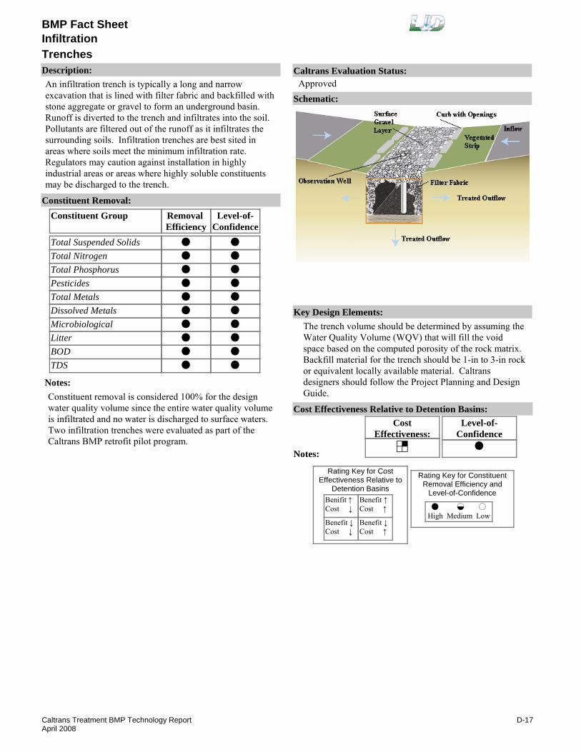
BMP Fact Sheet
TrenchesInfiltration
Description:An infiltration trench is typically a long and narrow excavation that is lined with filter fabric and backfilled with stone aggregate or gravel to form an underground basin. Runoff is diverted to the trench and infiltrates into the soil. Pollutants are filtered out of the runoff as it infiltrates the surrounding soils. Infiltration trenches are best sited in areas where soils meet the minimum infiltration rate. Regulators may caution against installation in highly industrial areas or areas where highly soluble constituents may be discharged to the trench.
Removal Efficiency
Level-of-Confidence
Total Suspended SolidsTotal NitrogenTotal PhosphorusPesticidesTotal MetalsDissolved MetalsMicrobiologicalLitterBODTDS
Constituent GroupConstituent Removal:
Notes:Constituent removal is considered 100% for the design water quality volume since the entire water quality volume is infiltrated and no water is discharged to surface waters. Two infiltration trenches were evaluated as part of the Caltrans BMP retrofit pilot program.
Key Design Elements:The trench volume should be determined by assuming the Water Quality Volume (WQV) that will fill the void space based on the computed porosity of the rock matrix. Backfill material for the trench should be 1-in to 3-in rock or equivalent locally available material. Caltrans designers should follow the Project Planning and Design Guide.
CostEffectiveness:
Level-of-Confidence
Cost Effectiveness Relative to Detention Basins:
Benifit ↑Cost ↓
Benefit ↓Cost ↓
Benefit ↑Cost ↑
Benefit ↓Cost ↑
High Medium Low
Rating Key for ConstituentRemoval Efficiency and
Level-of-Confidence
Rating Key for CostEffectiveness Relative to
Detention Basins
Notes:
Schematic:
Caltrans Evaluation Status:Approved
D-17Caltrans Treatment BMP Technology ReportApril 2008
BMP Fact Sheet
TrenchesInfiltration
Requirements:Trash and debris should be removed from the site on a regular basis. Sediment accumulation should be inspected and, if visible on top of the trench, the top layer of trench, silt, filter fabric and stone should be removed. Fabric and stone can be reinstalled after stone is washed.Training:No special requirements identified.
Maintenance Issues:
Project Development Issues:Right-of-Way-Requirements:Space requirements are relatively high for infiltration trenches.Siting Constraints:Infiltration trenches should not be sited within 30 meters of building or bridge foundations. Infiltration trenches sited within 30 meters would require detailed site structural and geotechnical investigation. Infiltration trenches are suitable for drainage areas up to 4 hectares. Trenches work best at sites with a upgradient drainage area slope of less then 5%. Trenches should be sited where infiltration rates are at least 14mm/hr and there is at least 3.0 meters separation between trench invert and the groundwater. Trenches are not recommended in industrial land use areas or in locations were soluble constituents may impact ground water quality.Construction:During excavation for trench construction, light equipment should be used to avoid compaction of the soil. Field conditions, such as structurally unsuitable soils, and existing utilities lines may be encountered, and detailed geotechnical investigation prior to construction is recommended. Retrofit of infiltration trenches at maintenance stations impacts the operation of the facility during construction. During design, sufficient borings are required to determine the presence of unsuitable materials. Stabilize the entire area draining to the facility before construction begins. If impossible, place a diversion berm around the perimeter of the infiltration site to prevent sediment entrance during construction. Stabilize the entire contributing drainage area before allowing any runoff to enter once construction is complete.
Constraints: Infiltration trenches must have soils with a high enough permeability rate and suitable groundwater separation.Major maintenance (removal and replacement of the rock matrix) is relatively costly.Pretreatment is required to reduce the amount of influent sediment.May have higher construction costs per capture volume
Advantages:Due to the infiltration of the entire water quality volume, the constituent removal is considered 100%. Infiltration trenches take up little land area and are not highly visible.
than infiltration basins.If not properly maintained they will prematurely clog.
US Environmental Protection Agency. Infiltration Trench Fact Sheet. http://www.epa.gov/OW-OWM.html/mtb/infltrenc.pdf
Young, G.K., et al. 1996, Evaluation and Management of Highway Runoff Water Quality, Publication No. FHWA-PD-96-032, U.S. Dept. of Transportation, Federal Highway Administration, Office of Environment and Planning.
Literature Sources of Performance Demonstrations:Caltrans, 2004. BMP Retrofit Pilot Program Final Report, CTSW-RT-01-050 available at www.dot.ca.gov/hq/env/stormwater
Design, Construction, Maintenance and Cost SourcesCaltrans. 2007. Stormwater Quality Hanbooks: Project Planning and Design Guide. May 2007. CTSW-RT-07-172.19.1
Certifications, Verifications, or Designations:None identified.
D-18Caltrans Treatment BMP Technology ReportApril 2008

BMP Fact Sheet
GSRD - Inclined ScreenLitter and Debris Removal
Description:The Inclined Screen (IS) Gross Solids Removal Devices (GSRDs) are non-proprietary devices whose primary function is to remove gross solids (litter and vegetative material) from stormwater runoff. Currently there is one IS configuration approved as a full capture treatment device:
Configuration #1. This IS GSRD tested a 3 mm spaced parabolic wedge-wire screen (The PPDG allows spacing up to 5 mm). The device is configured with an influent trough to allow some solids to settle. See picture to the right.
Configurations #2, #3, and #4 were not approved.
Removal Efficiency
Level-of-Confidence
Total Suspended SolidsTotal NitrogenTotal PhosphorusPesticidesTotal MetalsDissolved MetalsMicrobiologicalLitterBODTDS
Constituent GroupConstituent Removal:
NANANANANANANA
NANA
Notes:Litter is the target constituent for the device. No long-term water quality monitoring studies have been conducted to evaluate treatment effectiveness of the inclined screen GSRDs on other water quality constituents.
Key Design Elements:Inclined screen GSRDs should be sized to hold gross solids to be deposited during a 1-year period and pass the design flow (e.g., 25-year flow). TMDL may have a lower design storm than is associated with the drainage of the highway, and if upstream diversion is used, the design event given in the TMDL could be used. Hydraulic Head - Annual Estimated Gross Solids - Loading Rate. Caltrans designers should follow the Project Planning and Design Guide
CostEffectiveness:
Level-of-Confidence
Cost Effectiveness Relative to Detention Basins:
Benifit ↑Cost ↓
Benefit ↓Cost ↓
Benefit ↑Cost ↑
Benefit ↓Cost ↑
High Medium Low
Rating Key for ConstituentRemoval Efficiency and
Level-of-Confidence
Rating Key for CostEffectiveness Relative to
Detention Basins
Notes:
Schematic:
Caltrans Evaluation Status:Approved
D-19Caltrans Treatment BMP Technology ReportApril 2008
BMP Fact Sheet
GSRD - Inclined ScreenLitter and Debris Removal
Requirements:Periodic inspections required to ensure that the device is functional. Routine maintenance may include sediment/debris removal.Training:No special requirements identified.
Maintenance Issues:
Project Development Issues:Right-of-Way-Requirements:Small footprint.Siting Constraints:Must provide sufficient hydraulic head to operate by gravity.Construction:Traffic control may be required for retrofits due to close proximity to roadway.
Constraints: Hydraulic head requirement.
Advantages:The inclined screen GSRDs are a “small footprint device” that can be installed in existing right of way.Based on pilot studies, the devices remove nearly all the gross solids from stormwater runoff with minimal maintenance requirements.
California Department of Transportation, Phase II Gross Solids Removal Devices Pilot Study: 2001-2003, Final Report. CTSW-RT-03-097.31.22
California Department of Transportation, Phase III Gross Solids Removal Devices Pilot Study: 2002-2003, Interim Report. CTSW-RT-03-099.31.24
Literature Sources of Performance Demonstrations:California Department of Transportation, Phase I Gross Solids Removal Devices Pilot Study: 2000-2002, Final Report. CTSW-RT-03-072.31.22
Design, Construction, Maintenance and Cost SourcesCaltrans. 2007. Stormwater Quality Hanbooks: Project Planning and Design Guide. May 2007. CTSW-RT-07-172.19.1
Certifications, Verifications, or Designations:LA RWQCB: Full Capture certification for trash.
D-20Caltrans Treatment BMP Technology ReportApril 2008

BMP Fact Sheet
GSRD - Linear RadialLitter and Debris Removal
Description:The Linear Radial (LR) Gross Removal Devices (GSRDs) are non-proprietary devices whose primary function is to remove gross solids (litter and vegetative material) from stormwater runoff. Currently, there is one LRD configuration approved as a full capture treatment device:
Configuration #1. This LR GSRD utilizes a modular well casing with 5 mm x 64 mm louvers to serve as the screen. The LR GSRD is placed on a 2-percent slope. See picture to the right.
Configurations #2 and #3 were not approved.
Removal Efficiency
Level-of-Confidence
Total Suspended SolidsTotal NitrogenTotal PhosphorusPesticidesTotal MetalsDissolved MetalsMicrobiologicalLitterBODTDS
Constituent GroupConstituent Removal:
NANANANANANANA
NANA
Notes:Litter is the target constituent for the device. No long-term water quality monitoring studies have been conducted to evaluate treatment effectiveness of the linear radial GSRDs on other water quality constituents.
Key Design Elements:Annual estimated gross solids loading rate. Linear radial GSRDs should be sized to hold gross solids to be deposited during a 1-year period and pass the design flow (e.g., 25-year flow). TMDL may have a lower design storm than is associated with the drainage of the highway, and if upstream diversion is used, the design event given in the TMDL could be used. Caltrans designers should follow the Project Planning and Design Guide.
CostEffectiveness:
Level-of-Confidence
Cost Effectiveness Relative to Detention Basins:
Benifit ↑Cost ↓
Benefit ↓Cost ↓
Benefit ↑Cost ↑
Benefit ↓Cost ↑
High Medium Low
Rating Key for ConstituentRemoval Efficiency and
Level-of-Confidence
Rating Key for CostEffectiveness Relative to
Detention Basins
Notes:
Schematic:
Caltrans Evaluation Status:Approved
D-21Caltrans Treatment BMP Technology ReportApril 2008

BMP Fact Sheet
GSRD - Linear RadialLitter and Debris Removal
Requirements:Periodic inspections required to ensure that the device is functional. Routine maintenance may include sediment/debris removal.Training:No special requirements identified.
Maintenance Issues:
Project Development Issues:Right-of-Way-Requirements:Small footprint.Siting Constraints:Must provide sufficient area to accommodate the length of linear radial GSRD required. Low head requirement.Construction:Traffic control may be required for retrofits due to close proximity to roadway.
Constraints: Surface area requirement.
Advantages:The linear radial GSRDs are a “small footprint device” that can be installed in existing right of way.Based on pilot studies, the devices remove nearly all the gross solids from stormwater runoff with minimal maintenance requirements.
Caltrans. 2007. Stormwater Quality Hanbooks: Project Planning and Design Guide. May 2007. CTSW-RT-07-172.19.1
Literature Sources of Performance Demonstrations:California Department of Transportation, Phase I Gross Solids Removal Devices Pilot Study: 2000-2002, Final Report. CSTW-RT-03-072.31.22
Design, Construction, Maintenance and Cost SourcesRoscoe Moss Company, www.roscoemoss.com/gsrd.html
Certifications, Verifications, or Designations:LA RWQCB: Full Capture certification for trash.
D-22Caltrans Treatment BMP Technology ReportApril 2008

BMP Fact SheetMulti-Chambered Treatment Trains
Description:Multi-Chambered Treatment Trains (MCTTs) use three treatment mechanisms. The first chamber is a catch basin used to remove large, grit-sized material. The second chamber is a settling chamber that removes settleable solids with plate separators and oil and grease with sorbent pads. The third chamber is a sand/peat filter. These devices were originally designed to reduce toxicity in the runoff from critical stormwater source areas and can be implemented where toxicity in runoff is an identified problem.
Removal Efficiency
Level-of-Confidence
Total Suspended SolidsTotal NitrogenTotal PhosphorusPesticidesTotal MetalsDissolved MetalsMicrobiologicalLitterBODTDS
Constituent GroupConstituent Removal:
NA
NANA
Notes:Two MCTTs were sited, constructed, and monitored as part of the Caltrans' BMP retrofit pilot program. Analysis of the influent and effluent water quality data for the filters indicated that there was no significant difference among the sites for the constituents monitored; therefore, the data for all sites were treated as if they came from a single site.High TSS removal was based on Pitt et. al. Caltrans data showed 75% removal, but average influent was only 41 mg/L. Nitrate concentrations increase by 62%. High dissolved Zn removal. Litter removal based on professional judgment
Key Design Elements:The filtration chamber consists of 450-mm filter media layer consisting of a 50/50 mixture of sand and peat moss. The layer is separated from a gravel-packed underdrain by a layer of filter fabric. The filter area is determined from the recommended solids loading rate of the peat/sand mixture of 5000 g TSS/m2/year. Gravity draining can be used to return the filtered runoff to the drainage system. Caltrans designers should follow the Project Planning and Design Guide.
CostEffectiveness:
Level-of-Confidence
Cost Effectiveness Relative to Detention Basins:
Benifit ↑Cost ↓
Benefit ↓Cost ↓
Benefit ↑Cost ↑
Benefit ↓Cost ↑
High Medium Low
Rating Key for ConstituentRemoval Efficiency and
Level-of-Confidence
Rating Key for CostEffectiveness Relative to
Detention Basins
Notes:
Schematic:
Caltrans Evaluation Status:Approved
D-23Caltrans Treatment BMP Technology ReportApril 2008
BMP Fact SheetMulti-Chambered Treatment Trains
Requirements:Periodic cleaning and replacement of media. The MCTTs maintain a permanent pool of water below the tops of the tube settlers; this pool of water provides a breeding site for mosquitoes.Training:Training required for media replacement.
Maintenance Issues:
Project Development Issues:Right-of-Way-Requirements:Space requirements are relatively high for MCTTs.Siting Constraints:MCTTs should be sited where there is a small, impervious contributing watershed. They should not be sited where runoff from bare soil or construction activities will be allowed to enter the filter. MCTTs should be sited where enough vertical clearance (head) is provided, about 2 meters.Construction:Material availability for the filter, excavation for the device/unknown field conditions, and interface with existing activities at the site are the primary issues to be addressed in the construction of the MCTTs. The tube settler system is a special-order item with a significant lead-time.
Constraints: MCTTs are significantly more expensive to construct than gravity-drained Austin Sand Filters, which provide comparable performance.The presence of tube settlers in the sedimentation basin impedes maintenance activities.A permanent pool of water is maintained in the MCTT, which increases vector concerns.
Advantages:The MCTTs have constituent removal for suspended solids, metals, and bacteria similar to that for an Austin Sand Filter. They can provide consistent pollutant removal when properly maintained. The target area for use of MCTTs are vehicle service facilities, parking areas, paved storage areas, and fueling stations with drainage areas up to 1 hectare.
Design guidelines for MCTTs and performance evaluation are presented in the report entitled, Stormwater Treatment at Critical Areas, Volume 1: The Multi-Chambered Treatment Train (MCTT), by Robert Pitt, et. al., March 1999. EPA/600/R-99/017. http://lakes.chebucto.org/SWT/epa99017.PDF
Claytor, R. A. and Schueler, T. 1996. Design of Stormwater Filtering Systems. Center for Watershed Protection. Prepared for the Chesapeake Research Consortium. 250pp.
Corsi Greb, S. S. and Waschbusch, R. 1998. Evaluation of Stormceptor and Multi-Chamber Treatment Train as Urban Retrofit Strategies. Presented at Retrofit Opportunities for Water Resource Protection in Urban Environments. Westin Hotel. Chicago, IL. 10-Feb-98.Pitt, R. M. 1996. The Control of Toxicants at Critical Source Areas. The University of Alabama at Birmingham. 22pp. Paper presented at the ASCE/Engineering Foundation Conference, Snowbird, UT. Aug-96.Schueler, T. 1994 "Hydrocarbon Hotspots in the Urban Landscape-Can They Be Controlled?" Watershed Protection Techniques 1(1): 1-5.
Literature Sources of Performance Demonstrations:Caltrans, 2004. BMP Retrofit Pilot Program Final Report, CTSW-RT-01-050 available at www.dot.ca.gov/hq/env/stormwater
Design, Construction, Maintenance and Cost SourcesCaltrans. 2007. Stormwater Quality Hanbooks: Project Planning and Design Guide. May 2007. CTSW-RT-07-172.19.1
Certifications, Verifications, or Designations:None identified.
D-24Caltrans Treatment BMP Technology ReportApril 2008

BMP Fact Sheet
Double BarrelTraction Sand Trap
Description:Traction sand traps are depressions in the ground or a vault-type structure that temporarily detain runoff to settle out traction sand that was previously applied to snowy or icy roads.
Removal Efficiency
Level-of-Confidence
Total Suspended SolidsTotal NitrogenTotal PhosphorusPesticidesTotal MetalsDissolved MetalsMicrobiologicalLitterBODTDS
Constituent GroupConstituent Removal:
NA
NANANANA
Notes:Two sand traps were evaluated as part of the Tahoe Sand Trap Effectiveness Study.
Key Design Elements:Locate, size, and shape the traction sand trap relative to topography and in areas with heavy snow or ice, or anywhere where traction sand is applied. Invert 3 to 6 ft above groundwater if drainage is allowed through base (CMP riser type). Caltrans designers should follow the Project Planning and Design Guide.
CostEffectiveness:
Level-of-Confidence
Cost Effectiveness Relative to Detention Basins:
Benifit ↑Cost ↓
Benefit ↓Cost ↓
Benefit ↑Cost ↑
Benefit ↓Cost ↑
High Medium Low
Rating Key for ConstituentRemoval Efficiency and
Level-of-Confidence
Rating Key for CostEffectiveness Relative to
Detention Basins
Notes:
Schematic:
Caltrans Evaluation Status:Approved
D-25Caltrans Treatment BMP Technology ReportApril 2008

BMP Fact Sheet
Double BarrelTraction Sand Trap
Requirements:Annual maintenance includes vectoring out the traction sand traps.Training:No special requirements identified.
Maintenance Issues:
Project Development Issues:Right-of-Way-Requirements:Space requirements are relatively low for traction sand traps.Siting Constraints:Low head requirement.Construction:No special requirements identified.
Constraints:
Advantages:Sand traps require very little land space.Requires very little or no hydraulic head to operate.
Literature Sources of Performance Demonstrations:California Department of Transportation, Caltrans Tahoe Highway Runoff Characterization and Sand Trap Effectiveness Studies. CTSW-RT-03-054.36.02. 2003 http://www.dot.ca.gov/hq/env/stormwater/pdf/CTSW-RT-03-054.pdf
Design, Construction, Maintenance and Cost SourcesCaltrans. 2007. Stormwater Quality Hanbooks: Project Planning and Design Guide. May 2007. CTSW-RT-07-172.19.1
Certifications, Verifications, or Designations:None identified.
D-26Caltrans Treatment BMP Technology ReportApril 2008

BMP Fact SheetWet Basin
Description:A wet basin holds a permanent pool of water designed to detain and treat a runoff water quality volume. The basins support plant species, which may provide constituent removal by biological processes. In addition, the vegetation may help reduce erosion of the sides slopes and help trap sediments. Sedimentation processes also occur in the basin. The basins are usually deep enough to prevent resuspension of particles. Wet basins should be sited where a permanent pool of water can be maintained from a dry weather flow source.
Removal Efficiency
Level-of-Confidence
Total Suspended SolidsTotal NitrogenTotal PhosphorusPesticidesTotal MetalsDissolved MetalsMicrobiologicalLitterBODTDS
Constituent GroupConstituent Removal:
NA
NANA
Notes:A wet basin was evaluated as part of the Caltrans BMP Retrofit Pilot Program.Nitrate concentrations from discharges after storm events was 132% greater than stormwater influent, however dry weather flow reductions caused a net annual removal of total nitrogen.94% removal efficiency for dissolved Pb.Litter removal based on professional judgment.
Key Design Elements:The water quality volume above the permanent pool should drain within 24-48 hours. The basin should have a minimum length to width ratio of 1:1 and a preferred ratio of 3:1. The maximum depth of 2.4 meters and average depth of 1-2 meters. The volume of the permanent pool should be one to three times the water quality volume. Basin side slopes should be 3:1 or flatter. Wet basin should include a sediment forebay and a main pool. The sediment forebay should be sized to be 15-25% of the permanent pool volume and at least 1 meter deep, separated from the main pool by a earthen berm, gabion, or loose riprap wall. The berm should have a 1.5-meter top width and an elevation 1-foot lower than the design water surface. Vegetation should be planted around the perimeter of the basin. Caltrans designers should follow the Project Planning and Design Guide.
CostEffectiveness:
Level-of-Confidence
Cost Effectiveness Relative to Detention Basins:
Benifit ↑Cost ↓
Benefit ↓Cost ↓
Benefit ↑Cost ↑
Benefit ↓Cost ↑
High Medium Low
Rating Key for ConstituentRemoval Efficiency and
Level-of-Confidence
Rating Key for CostEffectiveness Relative to
Detention Basins
Notes:
Schematic:
Caltrans Evaluation Status:Approved
D-27Caltrans Treatment BMP Technology ReportApril 2008
BMP Fact SheetWet Basin
Requirements:Inspections should be conducted to ensure that the structure operates as intended. The embankment should be checked for subsidence, erosion, leakage, cracking, and tree growth. Debris and litter should be removed from the basin to prevent clogging of the outlet. Sediment accumulation in the basin will reduce the storage capacity and removal performance of the basin. Sediment should be removed when it accumulates to 10% of the basin volume. Wet basin plant material should be harvested on an annual basis to maintain efficiency of mosquito fish.Mechanical removal of vegetation was unsuccessful so hand removal with machetes were used.Training:No special requirements identified.
Maintenance Issues:
Project Development Issues:Right-of-Way-Requirements:Space requirements are high for wet basins.Siting Constraints:Significant off-site drainage with year round base flow is needed. A wet basin usually has an area of 1 to 3 percent of the contributing drainage area. Since the basin required a permanent pool of water, the soil should have a low infiltration rate or be lined with a clay of geotextile liner. Wet basins should be sited where a permanent pool of water can be maintained from a dry weather flow source.Construction:Excavated soil surface should be suitable to support plant life. If a pond liner is used, it must be carefully constructed to avoid punctures.
Constraints: There are potential problems associated with mosquitoes and the device may become a regulated wetland if not consistently maintained per an established schedule.A permanent pool of water must be maintained and therefore may have limitations on siting.They require more area than an extended detention basin.Wet basins must be properly maintained to prevent stratification and anoxic conditions, which would allow resuspension of solids and release of nutrients and metals.
Advantages:Wet basins have good removal efficiencies providing stormwater quality benefits.They can also have recreational and aesthetic benefits.
US Environmental Protection Agency. " Wet Detention Pond" Fact Sheet. www.epa.gov/owm/mtb/wetdtnpn.pdfKing County. 2005. Surface Water Design Manual , King County Surface Water Management Division, Washington. http://dnr.metrokc.gov/wlr/dss/2005SWDM/2005ManualwithErrata.pdf
Urbonas, B.R., et al., 1992, Urban Storm Drainage Criteria Manual, Volume 3 - Best Management Practices, Stormwater Quality, Urban Drainage and Flood Control District, Denver, CO.
Schueler, T.R., 1987, Controlling Urban Runoff: A Practical Manual for Planning and Designing Urban BMPs, Department of Environmental Programs, Metropolitan Washington Council of Governments, Washington, DC.
Literature Sources of Performance Demonstrations:Caltrans, 2004. BMP Retrofit Pilot Program Final Report, CTSW-RT-01-050 available at www.dot.ca.gov/hq/env/stormwater
Design, Construction, Maintenance and Cost SourcesCaltrans. 2007. Stormwater Quality Hanbooks: Project Planning and Design Guide. May 2007. CTSW-RT-07-172.19.1
Certifications, Verifications, or Designations:None identified.
D-28Caltrans Treatment BMP Technology ReportApril 2008