Embed Size (px)
Citation preview
Reprinted from August 2012HYDROCARBON ENGINEERING
Amine gas treating is one of the most common processes in refineries, petrochemical plants, onshore/offshore natural gas processing plants and other industries. The process is also known as acid
gas removal or gas sweetening, and refers to the removal of hydrogen sulfide (H2S) and carbon dioxide (CO2) from gases, using aqueous solutions of various alkylamines (commonly called amines). Selecting the correct type of heat exchangers for the heat transfer duties involved in the process has a great impact on the effectiveness and the economy of the amine plant.
The processGases containing H2S and/or CO2 are referred to as acid gases or sour gases. The chemistry involved varies somewhat depending on the type of amine being used. Diethanolamine (DEA) is one of the more common amines for refinery gas treating. Denoted here as RNH2, the chemistry may be simply expressed according to Equation 1:
RNH2 + H2S ↔ RNH3HS (1)
The properties of the amine allow it to absorb the H2S and CO2 at low temperature and high pressure, and then release them at high temperature and low pressure. More and more DEA is now being replaced by methyl diethanolamine (MDEA). Using MDEA instead of DEA results in reduced absorption of CO2, thus increasing the content of H2S in the acid gas improving the efficiency of the sulfur recovery unit (SRU).
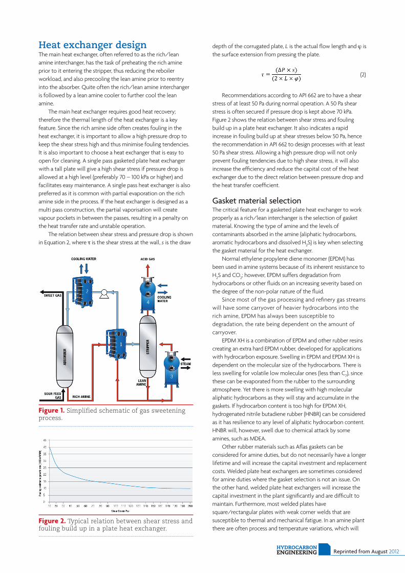
A typical amine gas treating process (Figure 1) includes an absorber and a regenerator as well as accessory equipment (i.e. heat exchangers). Many refineries have multiple absorbers
and a common regenerator. In the absorber, the amine solution absorbs H2S and CO2 from the sour gas, producing sweetened gas, and a rich amine solution containing the acidic components. The rich amine is then routed into the regenerator, which is a stripper column with a steam generated reboiler. Here, the acidic components are stripped from the amine, producing regenerated lean amine that is recycled for reuse in the absorber and a stripped overhead gas containing concentrated H2S and
CO2. In refineries, the stripped gas is mostly H2S, much of which often comes from a sulfur removing process called hydrodesulfurisation. This H2S rich stripped gas stream is then usually routed into a Claus process to convert it into elemental sulfur.
Amine gas treating is an energy consuming process
because the amine absorbs the components at low temperature and high pressure and then releases the components at high temperature and low pressure. The primary operating objectives for refineries are to maintain the condition of the amine (as this will prevent hydrocarbon carryover to the sulfur plant), control the amine circulation rate, control the lean amine temperature and pressure entering the absorber, and regulate the amount of generated steam needed for the stripper reboiler. The heat exchangers employed in the gas sweetening process are therefore crucial devices for temperature control, obtaining an effective acid gas removal and for reducing energy consumption.
The main objective is to gain an optimum balance between capacity, energy and corrosion. Tranter has suitable heat transfer equipment for all the duties involved in the main process such as rich/lean amine interchanger, lean amine cooler, stripper reboiler and overhead condenser.
A SWEET
Thomas Cassirer, Tranter International AB, Sweden,
provides an overview of heat exchangers for amine gas
treating applications.
treat
HYDROCARBON ENGINEERING Reprinted from August 2012
Heat exchanger designThe main heat exchanger, often referred to as the rich/lean amine interchanger, has the task of preheating the rich amine prior to it entering the stripper, thus reducing the reboiler workload, and also precooling the lean amine prior to reentry into the absorber. Quite often the rich/lean amine interchanger is followed by a lean amine cooler to further cool the lean amine.
The main heat exchanger requires good heat recovery; therefore the thermal length of the heat exchanger is a key feature. Since the rich amine side often creates fouling in the heat exchanger, it is important to allow a high pressure drop to keep the shear stress high and thus minimise fouling tendencies. It is also important to choose a heat exchanger that is easy to open for cleaning. A single pass gasketed plate heat exchanger with a tall plate will give a high shear stress if pressure drop is allowed at a high level (preferably 70 – 100 kPa or higher) and facilitates easy maintenance. A single pass heat exchanger is also preferred as it is common with partial evaporation on the rich amine side in the process. If the heat exchanger is designed as a multi pass construction, the partial vaporisation will create vapour pockets in between the passes, resulting in a penalty on the heat transfer rate and unstable operation.
The relation between shear stress and pressure drop is shown in Equation 2, where τ is the shear stress at the wall, s is the draw
depth of the corrugated plate, L is the actual flow length and ϕ is the surface extension from pressing the plate.
(2)
Recommendations according to API 662 are to have a shear
stress of at least 50 Pa during normal operation. A 50 Pa shear stress is often secured if pressure drop is kept above 70 kPa. Figure 2 shows the relation between shear stress and fouling build up in a plate heat exchanger. It also indicates a rapid increase in fouling build up at shear stresses below 50 Pa, hence the recommendation in API 662 to design processes with at least 50 Pa shear stress. Allowing a high pressure drop will not only prevent fouling tendencies due to high shear stress, it will also increase the efficiency and reduce the capital cost of the heat exchanger due to the direct relation between pressure drop and the heat transfer coefficient.
Gasket material selectionThe critical feature for a gasketed plate heat exchanger to work properly as a rich/lean interchanger is the selection of gasket material. Knowing the type of amine and the levels of contaminants absorbed in the amine (aliphatic hydrocarbons, aromatic hydrocarbons and dissolved H2S) is key when selecting the gasket material for the heat exchanger.
Normal ethylene propylene diene monomer (EPDM) has been used in amine systems because of its inherent resistance to H2S and CO2; however, EPDM suffers degradation from hydrocarbons or other fluids on an increasing severity based on the degree of the non-polar nature of the fluid.
Since most of the gas processing and refinery gas streams will have some carryover of heavier hydrocarbons into the rich amine, EPDM has always been susceptible to degradation, the rate being dependent on the amount of carryover.
EPDM XH is a combination of EPDM and other rubber resins creating an extra hard EPDM rubber, developed for applications with hydrocarbon exposure. Swelling in EPDM and EPDM XH is dependent on the molecular size of the hydrocarbons. There is less swelling for volatile low molecular ones (less than C7), since these can be evaporated from the rubber to the surrounding atmosphere. Yet there is more swelling with high molecular aliphatic hydrocarbons as they will stay and accumulate in the gaskets. If hydrocarbon content is too high for EPDM XH, hydrogenated nitrile butadiene rubber (HNBR) can be considered as it has resilience to any level of aliphatic hydrocarbon content. HNBR will, however, swell due to chemical attack by some amines, such as MDEA.
Other rubber materials such as Aflas gaskets can be considered for amine duties, but do not necessarily have a longer lifetime and will increase the capital investment and replacement costs. Welded plate heat exchangers are sometimes considered for amine duties where the gasket selection is not an issue. On the other hand, welded plate heat exchangers will increase the capital investment in the plant significantly and are difficult to maintain. Furthermore, most welded plates have square/rectangular plates with weak corner welds that are susceptible to thermal and mechanical fatigue. In an amine plant there are often process and temperature variations, which will
Figure 2. Typical relation between shear stress and fouling build up in a plate heat exchanger.
Figure 1. Simplified schematic of gas sweetening process.
Reprinted from August 2012HYDROCARBON ENGINEERING
reduce the lifetime of square/rectangular plates significantly and increase the total cost of ownership.
Shell and plate reboilerIn the stripper reboiler, the amine is heated to the requisite temperature for the acidic components to be evaporated and to allow stripping of components from the amine. Accurate temperature control is required for an efficient stripper operation. An overview optimisation of the heat exchangers involved (mainly the rich/lean amine interchanger, lean amine cooler and the reboiler) can help reduce the reboiler duty and thus reduce capital investment and the running costs of the amine plant. Using a shell and plate heat exchanger as a reboiler allows a small temperature difference between the hot and cold sides. This will prevent the amine from becoming overheated and suffering degradation, thereby increasing the overall efficiency of the amine plant.
The stripper reboiler is designed either with forced circulation or natural circulation. The latter is called a thermosyphon reboiler, which is an energy efficient system as it contains no pumps to drive the reboiler. Natural circulation due to gravity drives the reboiler with condensing steam on one side and evaporating process fluids on the other. Circulation is established through the reboiler by the difference between the static head of the liquid in the stripper column and the two phase mixture inside the reboiler. When the liquid level in the stripper column increases relative to the reboiler, it creates a difference in hydrostatic head and thus increases the flow rate at which the fluid to be vaporised flows through the reboiler. Hence, hydraulic characteristics as well as heat transfer capabilities must be taken into consideration when designing thermosyphon reboilers.
Tranter has extensive experience with applications where shell and plate heat exchangers are used as thermosyphon reboilers. The circular plates with their short flow pattern are notable both in terms of mechanical strength, as there are no weak corner welds, and also in terms of thermal design as the short paths are excellent for two phase flow and create a low pressure drop over the plate.
Stripper overhead condenserIn the stripper overhead condenser, condensable gases are partially condensed at the top of the stripper column and the non-condensable acid gases (H2S and CO2) exit at the top and are transported for further treating. The condensate is reintroduced into the stripper column for regeneration.
As the gas stream contains non-condensable gases, the condensing temperature will not be constant. The sum of the partial pressures of the condensing vapour and the non-condensable gases is almost constant. During condensation, the inert content increases percentage wise, meaning the partial pressure does also. The stream’s partial pressure will thus be reduced and the condensation temperature will decrease throughout the process. As condensate is formed from the stream close to the wall, a layer of vapour/gas mix with a higher inert content will be built up. The inert content from this layer must go back into the main stream by diffusion and this slow process reduces the heat transfer coefficient, sometimes dramatically. This, together with the sliding condensation temperature, makes the process quite complicated.
Condensate has to be separated from the non-condensable acid gases. This is best achieved by using a separator vessel following the heat exchanger. Separation can also be achieved in the condenser itself by using a reflux condenser. The main disadvantage of reflux condensers is the limited flooding velocity allowed. To achieve reflux in a condenser, the maximum velocity of the gas where the condensate will be able to fall back into the column against the counter current gas stream has to be known. The velocity in the condenser’s channels needs to be lower than the flooding velocity to avoid flooding and to allow for condensate runback.
Experimental work on flooding has been performed concerning the operation of wetted columns, falling film evaporators, reflux condensers, etc. However, as there are numerous factors affecting the phenomenon, a definitive theory has not yet emerged. It is known that when the velocity of the falling liquid film (relative to a counter current gas stream) reaches a certain value, a wave occurring on the film surface becomes unstable and its amplitude quickly increases, bridging the channel and causing flooding. Equation 3 is derived from the Hewitt-Wallin equation, which is the most common model for calculating flooding velocity, where F1 and F2 are constant. F2 is dependent on the liquid properties, and when Vg = Vflood or above, F1 = 1 and F2 is usually 0,75 – 1, based on experimental works. Common practice is to add a margin of at least 30% on the calculated flooding velocity to ensure that flooding does not occur.
(3)
Due to the narrow channels in a plate heat exchanger, the low velocity needed to avoid flooding can be hard to achieve. This results in a larger heat exchanger with more plates in order
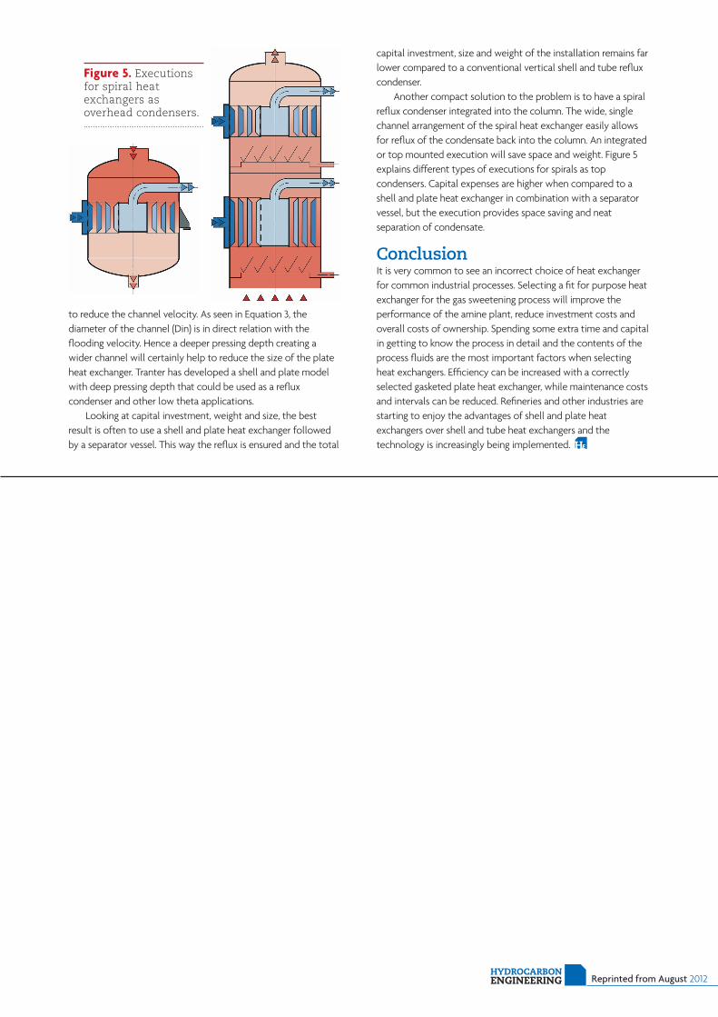
Figure 4. Shell and plate reboiler.
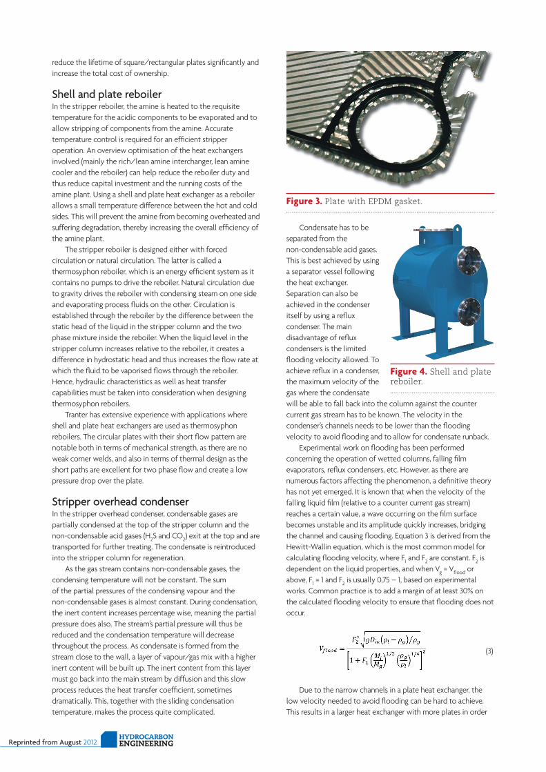
Figure 3. Plate with EPDM gasket.
to reduce the channel velocity. As seen in Equation 3, the diameter of the channel (Din) is in direct relation with the flooding velocity. Hence a deeper pressing depth creating a wider channel will certainly help to reduce the size of the plate heat exchanger. Tranter has developed a shell and plate model with deep pressing depth that could be used as a reflux condenser and other low theta applications.
Looking at capital investment, weight and size, the best result is often to use a shell and plate heat exchanger followed by a separator vessel. This way the reflux is ensured and the total
capital investment, size and weight of the installation remains far lower compared to a conventional vertical shell and tube reflux condenser.
Another compact solution to the problem is to have a spiral reflux condenser integrated into the column. The wide, single channel arrangement of the spiral heat exchanger easily allows for reflux of the condensate back into the column. An integrated or top mounted execution will save space and weight. Figure 5 explains different types of executions for spirals as top condensers. Capital expenses are higher when compared to a shell and plate heat exchanger in combination with a separator vessel, but the execution provides space saving and neat separation of condensate.
ConclusionIt is very common to see an incorrect choice of heat exchanger for common industrial processes. Selecting a fit for purpose heat exchanger for the gas sweetening process will improve the performance of the amine plant, reduce investment costs and overall costs of ownership. Spending some extra time and capital in getting to know the process in detail and the contents of the process fluids are the most important factors when selecting heat exchangers. Efficiency can be increased with a correctly selected gasketed plate heat exchanger, while maintenance costs and intervals can be reduced. Refineries and other industries are starting to enjoy the advantages of shell and plate heat exchangers over shell and tube heat exchangers and the technology is increasingly being implemented.
Figure 5. Executions for spiral heat exchangers as overhead condensers.
HYDROCARBON ENGINEERING Reprinted from August 2012