Embed Size (px)
Citation preview
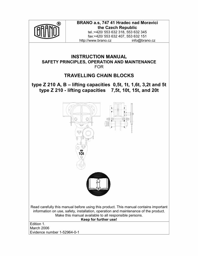
BRANO a.s, 747 41 Hradec nad Moravicí
the Czech Republic
tel.:+420/ 553 632 318, 553 632 345 fax:+420/ 553 632 407, 553 632 151
http://www.brano.cz [email protected]
INSTRUCTION MANUAL SAFETY PRINCIPLES, OPERATION AND MAINTENANCE
FOR
TRAVELLING CHAIN BLOCKS
type Z 210 A, B – lifting capacities 0,5t, 1t, 1,6t, 3,2t and 5t type Z 210 - lifting capacities 7,5t, 10t, 15t, and 20t
Read carefully this manual before using this product. This manual contains important information on use, safety, installation, operation and maintenance of the product.
Make this manual available to all responsible persons. Keep for further use!
Edition 1. March 2006 Evidence number 1-52964-0-1

2
CONTENT 1 DEFINITION ....................................................................................................................... 3 2 DEVICE PURPOSE............................................................................................................ 3 3 SAFETY PRINCIPLES........................................................................................................ 4 3.1 SAFETY SUMMARY ....................................................................................................................... 4 3.2. SAFETY PRINCIPLES ................................................................................................................... 4 3.2.1 Prior to use ................................................................................................................................... 4 3.2.2 When in use.................................................................................................................................. 5 3.2.4 Risk analysis................................................................................................................................. 5 3.2.5 Maintenance ................................................................................................................................. 5
4 PACKING, STORAGE AND MANIPULATION .................................................................... 5 4.2 STORAGE ....................................................................................................................................... 6 4.3 MANIPULATION.............................................................................................................................. 6
5 MAIN TECHNICAL PARAMETERS .................................................................................... 6 5.1 MECHANICAL CLASSIFICATION ................................................................................................ 10 5.2 MATERIAL AND DESIGN ............................................................................................................. 11 5.3 DATA ON PRODUCT.................................................................................................................... 11
6 INSTALLATION OF THE CHAIN BLOCK ......................................................................... 11 6.1 CHECKING BEFORE THE INSTALLATION................................................................................. 11 6.1.1 Load carrying structure............................................................................................................... 11 6.1.2 (CRANE) TROLLEY BEAM TRACK........................................................................................... 12 6.2 ASSEMBLY OF THE CHAIN BLOCK ........................................................................................... 12 6.2.1 Condition for the correct travel of the trolley............................................................................... 12 6.2.2 Installation onto trolley beam track of lifting capacities 0,5t , 1t ................................................. 13 6.2.3 SETTING OF THE HAND CHAIN .............................................................................................. 14 6.2.4 Installation onto trolley beam track of lifting capacities 15 and 20t ............................................ 14 6.2.5 Lubrication of the chain .............................................................................................................. 14 6.2.6 Checking of the chain position ................................................................................................... 14 6.3 CHECK BEFORE USE.................................................................................................................. 14
7 SERVICE AND OPERATION OF THE CHAIN BLOCK..................................................... 15 7.1 USE OF THE CHAIN BLOCK........................................................................................................ 15 7.2 LIFTING, LOWERING ................................................................................................................... 15 7.3 SAFETY WORKING ENVIRONMENT .......................................................................................... 16
8 INSPECTION OF THE CHAIN BLOCK............................................................................. 17 8.1 INSPECTION................................................................................................................................. 17 8.1.1 Inspection classification.............................................................................................................. 17 8.1.2 Daily inspection .......................................................................................................................... 17 8.1.3 Regular inspection...................................................................................................................... 17 8.1.4 The chain block occasionally used............................................................................................. 17 8.1.5 Inspection record ........................................................................................................................ 17 8.2 Inspection procedure..................................................................................................................... 18
9 TROUBLE-SHOOTING..................................................................................................... 21 10 LUBRICATION................................................................................................................ 22 10.1 GENERALLY ............................................................................................................................... 22 10.2 GEARINGS.................................................................................................................................. 22 10.3 LOAD CHAIN............................................................................................................................... 22
11 MAINTENANCE.............................................................................................................. 22 11.1 SAFETY PRINCIPLES ................................................................................................................ 22 11.2 REPLACEMENT OF THE LOAD CHAIN .................................................................................... 23 11.2.1 SINGLE FALL CHAIN............................................................................................................... 23 11.2.2 MULTI-FALL CHAIN................................................................................................................. 23 11. 3 BRAKE ADJUSTMENT .............................................................................................................. 23 11.4 GENERAL INSTRUCTIONS ....................................................................................................... 24 11.5 CHECK ........................................................................................................................................ 24 11.6 REPAIR ....................................................................................................................................... 24 11.7 TEST............................................................................................................................................ 24
12 PUTTING OUT OF OPERATION – LIQUIDATION ......................................................... 24 14 FINAL REQUIREMENTS OF THE MANUFACTURER TO THE CUSTOMER ................ 25 EC DECLARATION OF CONFORMITY....................................................................... 26

3
1 DEFINITION ! DANGER Danger: is used to indicate the presence of hazard, which will cause
death or severe injury, if the warning is ignored. ! WARNING Warning: is used to indicate a possible hazard, which could cause
death or severe injury, if the warning is ignored. ! CAUTION Caution: is used to indicate a possible hazard, which could
cause light injury, if the warning is ignored. Caution can warn against dangerous practices as well.
Lifting capacity (Q): indicates the maximum permitted mass of a load (working load limit), which a chain block is designed to support in general service under conditions defined in this manual. 2 DEVICE PURPOSE 2.1 The travelling chain block type Z 210 of lifting capacities 0,5t, 1t, 1,6t, 3,2t, 5t, 7,5t, 10t, 15t, and 20t (hereinafter referred to as „chain block“) has been designed solely for hand vertical lifting, lowering and moving of free loads in working area of travel under normal atmospheric conditions in the workplace. The load mass must not exceed the specified nominal lifting capacity. 2.2The chain block has been designed to meet requirements provided by the Directive 98/37/EC of the European Parliament and of the Council as amended by the Czech technical regulation – ministerial order No. 24/2003 of the Coll. of Laws as amended as well as requirements of the ČSN EN ISO 12100-1, ČSN EN ISO 12100-2, ČSN EN 1050 and ČSN EN 13157 harmonized technical standards. 2.3 The chain block has been designed to meet requirements defined for the group I of devices (mine) category M2 according to the Directive 94/9/EC of the European Parliament and of the Council as amended by the Czech technical regulation – ministerial order No. 23/2003 of the Coll. of Laws as amended as well as requirements of the ČSN EN 13463-1 harmonized Czech technical standard and fulfils the conditions for use in the „dangerous atmospheric conditions 2“ environment according to the ČSN EN 1127-2 standard with the limitation according to the national regulation – CBM (Czech Bureau of Mine) regulation No.22/89 of Coll. of Laws § 232 section (1) c) up to 1,5% of mine gas accumulation. 2.4. The chain block has been designed to meet requirements specified for the group II of devices (non-mine) category 2 and 3 according to the Directive 94/9/EC of the European Parliament and of the Council as amended by the Czech technical regulation – ministerial order No. 23/2003 of the Coll. of Laws as amended as well as requirements of the ČSN EN 13463-1 harmonized Czech technical standard and fulfils the conditions for use in the „zone 1 and zone 21“, „zone 2 and zone 22“ environments according to the ČSN EN 1127-1 standard. Note: 2.3 and 2.4 articles apply for the chain block designed for use in environment with explosion hazard.

4
3 SAFETY PRINCIPLES
3.1 SAFETY SUMMARY Danger exists when lifting and travelling with loads, particularly when the chain block is not used properly or is poorly maintained. Since an accident or serious injury could result, special safety precautions apply to the operation with the chain block during its assembly, maintenance and inspection.
! WARNING NEVER use chain block for lifting and transporting people.
NEVER lift or transport loads over or near people.
NEVER load the chain block more than the lifting capacity shown on the chain block
nameplate.
ALWAYS make sure the load carrying structure will provide adequate support to handle fully loaded chain block and all the lifting operations.
ALWAYS let people around to know when a lift is about to begin.
ALWAYS read instruction manual and safety instructions.
Remember proper that rigging, lifting and pulling techniques are the responsibility of the operating staff. Therefore check all applicable national directions, regulations and standards for further information on the safety use of your chain block.
3.2. SAFETY PRINCIPLES
! WARNING
3.2.1 Prior to use ALWAYS ensure, physically fit, qualified and instructed persons over 18 years of
age, familiarized with this manual and trained in safety conditions and way of work, operate the chain block.
ALWAYS check the chain block daily before use according to the section 8.2.(1) „Daily inspection“.
ALWAYS make sure the ends of track are fitted with the end stops. ALWAYS make sure the track is free from any object. ALWAYS make sure the length of chains is long enough for the intended job. ALWAYS check the brake function of the chain block before use. ALWAYS use original chain only. ALWAYS ensure the load chain is not corroded, is cleaned and oiled. ALWAYS make sure the last link of load chain is strongly fastened to the body. NEVER use damaged or worn out chain block. NEVER use chain block with jumped out, damaged or missing hook’s safety
latch. NEVER connect or lengthen the load chain. NEVER use a chain block without a visible marking of the lifting capacity. NEVER use modified or deformed hooks. NEVER use a chain block marked by the label „OUT OF OPERATION“.
5
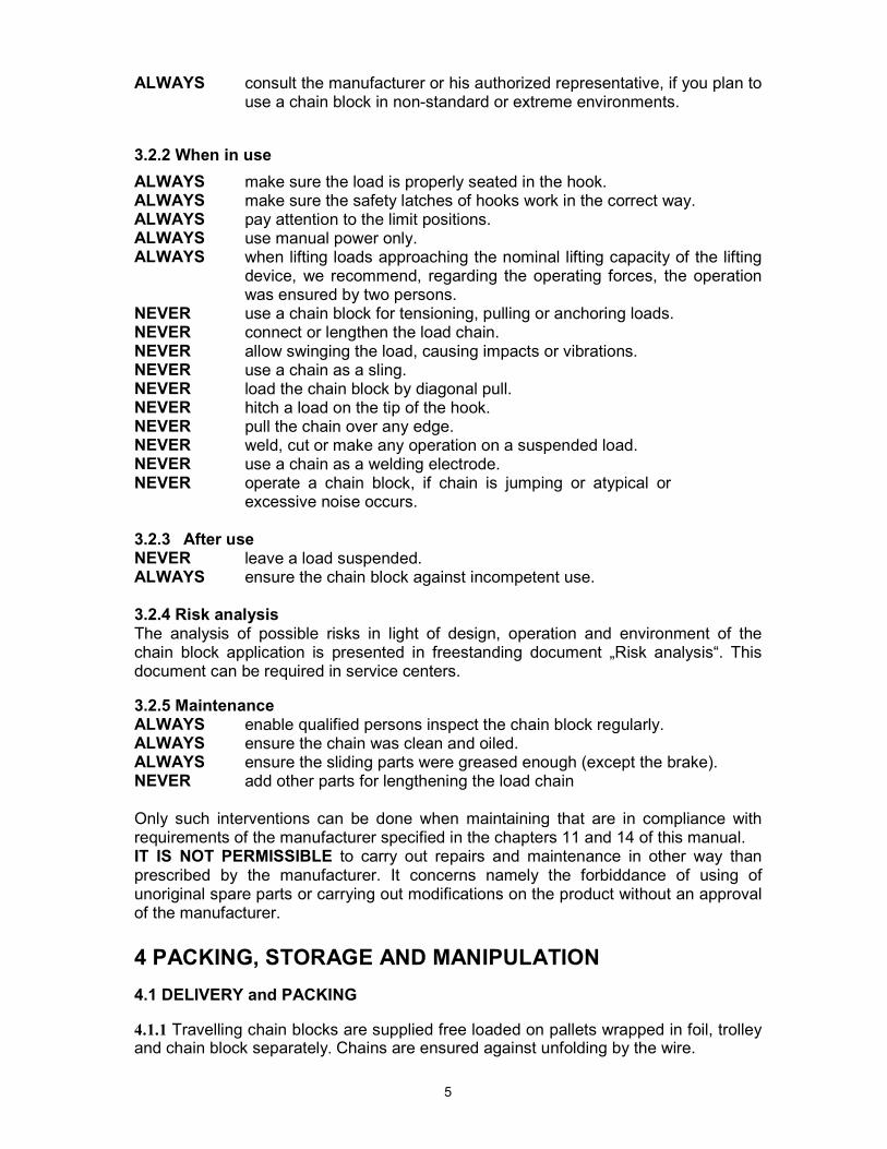
ALWAYS consult the manufacturer or his authorized representative, if you plan to use a chain block in non-standard or extreme environments.
3.2.2 When in use ALWAYS make sure the load is properly seated in the hook. ALWAYS make sure the safety latches of hooks work in the correct way. ALWAYS pay attention to the limit positions. ALWAYS use manual power only. ALWAYS when lifting loads approaching the nominal lifting capacity of the lifting
device, we recommend, regarding the operating forces, the operation was ensured by two persons.
NEVER use a chain block for tensioning, pulling or anchoring loads. NEVER connect or lengthen the load chain. NEVER allow swinging the load, causing impacts or vibrations. NEVER use a chain as a sling. NEVER load the chain block by diagonal pull. NEVER hitch a load on the tip of the hook. NEVER pull the chain over any edge. NEVER weld, cut or make any operation on a suspended load. NEVER use a chain as a welding electrode. NEVER operate a chain block, if chain is jumping or atypical or
excessive noise occurs. 3.2.3 After use NEVER leave a load suspended. ALWAYS ensure the chain block against incompetent use. 3.2.4 Risk analysis The analysis of possible risks in light of design, operation and environment of the chain block application is presented in freestanding document „Risk analysis“. This document can be required in service centers.
3.2.5 Maintenance ALWAYS enable qualified persons inspect the chain block regularly. ALWAYS ensure the chain was clean and oiled. ALWAYS ensure the sliding parts were greased enough (except the brake). NEVER add other parts for lengthening the load chain Only such interventions can be done when maintaining that are in compliance with requirements of the manufacturer specified in the chapters 11 and 14 of this manual. IT IS NOT PERMISSIBLE to carry out repairs and maintenance in other way than prescribed by the manufacturer. It concerns namely the forbiddance of using of unoriginal spare parts or carrying out modifications on the product without an approval of the manufacturer.
4 PACKING, STORAGE AND MANIPULATION
4.1 DELIVERY and PACKING
4.1.1 Travelling chain blocks are supplied free loaded on pallets wrapped in foil, trolley and chain block separately. Chains are ensured against unfolding by the wire.

6
4.1.2 The following accompanying documentation is a part of the delivery: a) Instruction Manual b) EC Declaration of Conformity c) Certificates of Quality and Completeness and Guarantee Card. c1) Guarantee period is stated in the Guarantee Card.
c2) The guarantee does not apply to defects caused by infringement of the instructions stated in this Instruction Manual and defects occurred owing to improper use and unskilled intervention.
c3) The guarantee does not apply also to modifications on the product or using of unoriginal spare parts without an approval of the manufacturer.
c4) Claim of product defects is carried out according to applicable provisions of commercial code eventually as amended.
d) List of service centers (for the Czech and Slovak Republics only).
4.2 STORAGE Store the traveling chain blocks in dry and clean stocks free from chemical influences and vapours. (1) Always store the chain block without any suspended load. (2) Remove all dust, water and impurities from the chain block. (3) Lubricate chain, pivots of pulley, pivots of hook and spring of safety latch of hook. (4) Store the chain block in a dry place. (5) During further use follow instructions of the article No. 8.1.2 „Daily inspection” or 8.1.4 „The traveling chain block occasionally used“.
4.3 MANIPULATION During transportation and manipulation follow the applicable technical regulations and standards for work with heavy loads.
5 MAIN TECHNICAL PARAMETERS
LIFTING CAPACITIES 0,5t, 1t, 1,6t, 3,2t and 5t
Table 5.A - Technical parameters
Type L
ifting
capacity
(t)
Number
of load
chain
falls
Chain ČSN
EN 818-7
(strength
class 8)
Operatin
g force
for travel
(N)
Operatin
g force
for lift
(N) Travel1)
speed (m/min)
Lifting1)
speed (m/min) R
ange of
operating
temperat
ure
Lift (m) Weight (kg)
Z210-A 0,5 250 300 4,8 1,1 16,8
Z210-B 0,5 ∅5x15
250 300 4,8 1,1 20
Z210-A 1 250 350 4,8 0,7 22
Z210-B 1 ∅7x21
250 350 4,8 0,7 24
Z210-A 1,6 150 320 2,25 0,36 44
Z210-B 1,6 ∅9x27
150 320 2,25 0,36 45
Z210-A 3,2 280 400 2,3 0,29 70,3
Z210-B 3,2
1
∅11x31 280 400 2,3 0,29 71
Z210-A 5 350 400 1,8 0,145 101
Z210-B 5 2 ∅11x31
350 400 1,8 0,145
-20°C to +50°C
3
103
Notes:
1) Calculated on presumption of winding off 30m of the hand chain per minute. 2) Maximum standard lift is 15m. Required lift is necessary to be specified in the order.
Lifts exceeding 15 m must be consulted with the manufacturer.

7
Table 5.B - Dimensions
Main dimensions – informative (mm) I – beam Type / Lifting capacityt
a d d1 D emin Lmin E b R
Z210-A/0,5t 157 30 55 108 18,5 290 89-144 58-113 1000
Z210-B/0,5t 157 30 55 108 18,5 290 89-253 58-226 1000
Z210-A/1 t 157 36 55 108 23,5 340 89-144 58-113 1000
Z210-B/1t 157 36 55 108 23,5 340 89-253 58-226 1000
Z210-A/1,6t 259 43 100 230 29,5 457 148-172 90-113 1700
Z210-B/1,6t 259 43 100 230 29,5 457 148-284 90-226 1700
Z210-A/3,2t 326 50 133 280 35,5 515 168-187 106-125 2500
Z210-B/3,2t 326 50 133 280 35,5 515 168-288 106-226 2500
Z210-A/5t 399 56 148 345 39,5 660 183-214 106-137 2800
Z210-B/5t 399 56 148 345 39,5 660 183-304 106-226 2800
Travelling chain blocks with great length of lift can be equipped upon special request with a chain container.

8
LIFTING CAPACITIES 7,5t and 10t
Table 5.C - Technical parameters
Type Li
fting
capacity
(t)
Number of
load chain
falls
Chain ČSN
EN 818-7
(strength
class 8)
Operating
power for
travel
(N)
Operating
power for lift
(N) Lifting1)
speed (m/min)
Range of operating temperature
Lift (m) Weight (kg)
7,5 2 500 480 0,15 203 Z210
10 3 ∅11x31
500 390 0,1
-20°C to +50°C
3 260
Notes:
1) Calculated under presumption of unwinding 30m of hand chain per minute. 2) Maximum standard lift is 15m. The required lift is necessary to be specified in the order.
Lifts over 15 m must be consulted with the manufacturer.
Table 5.D - Dimensionsy Main dimensions – informative (mm) I – beam
Lifting capacity (t)
a d d1 D emin Lmin E b R
7,5 530 56 196 345 43 875 242 – 314 113 – 185 3200
10 615 63 228 428 47 920 259 – 327 113 – 185 3500
Travelling chain blocks with great length of lift can be equipped upon special request with a chain container.
E

9
ba
LOAD CAPACITIES 15t and 20t
Table 5.E - Technical parameters
Type
Lifting capacity
(t)
Number of
load chain falls
Chain ČSN
EN 818-7
(strength
class 8)
Operating
power for
travel
(N)
Operating
power for lift
(N) Lifting1)
speed (m/min)
Range of operating temperature
Lift2) max. (m)
Weight without chain (kg)
Increase in weight per 1m of lift (kg)
15 4 500 480 0,15 12 280 13 Z210
20 6 ∅11x31
500 400 0,1
-20°C to +50°C 8 340 19,2
Notes:
1) Calculated under presumption of unwinding 30m of hand chain per minute on each chain block. 2) Lift according to the order. Lifts over the values stated in the table must be consulted with the
manufacturer.
Table 5.F - Dimensions Main dimension – informative (mm)
Lifting capacity (t)
a d d1 D emin Lmin
15 1100 71 196 375 50 780
20 1320 80 237 428 62 720
Travelling chain blocks of lifting capacities 15 and 20t are usually equipped with chain containers and are designated just for assembly to beams with flat flange. The possibility of track curving is not supposed.
b = width of beam’s flange sets the customer, when placing the order for travelling chain block
10
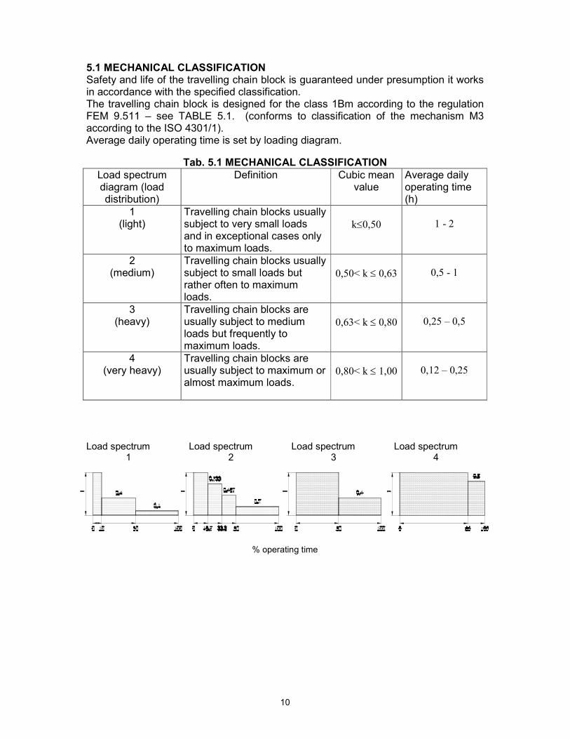
5.1 MECHANICAL CLASSIFICATION Safety and life of the travelling chain block is guaranteed under presumption it works in accordance with the specified classification. The travelling chain block is designed for the class 1Bm according to the regulation FEM 9.511 – see TABLE 5.1. (conforms to classification of the mechanism M3 according to the ISO 4301/1). Average daily operating time is set by loading diagram.
Tab. 5.1 MECHANICAL CLASSIFICATION
Load spectrum diagram (load distribution)
Definition Cubic mean value
Average daily operating time (h)
1 (light)
Travelling chain blocks usually subject to very small loads and in exceptional cases only to maximum loads.
k≤0,50
1 - 2
2 (medium)
Travelling chain blocks usually subject to small loads but rather often to maximum loads.
0,50< k ≤ 0,63
0,5 - 1
3 (heavy)
Travelling chain blocks are usually subject to medium loads but frequently to maximum loads.
0,63< k ≤ 0,80
0,25 – 0,5
4 (very heavy)
Travelling chain blocks are usually subject to maximum or almost maximum loads.
0,80< k ≤ 1,00
0,12 – 0,25
Load spectrum Load spectrum Load spectrum Load spectrum 1 2 3 4
% pracovního času
% operating time

5.2. MATERIAL AND DESIGN 5.2.1 Main parts of the chain block are manufactured from steel and cast iron, braking inserts
of brake from brass or ceramic-metallic material. 5.2.2. . Materials inclinable to creation of an incendiary spark in terms of the annex No. 2
article 1.3.1 to the ministerial order No. 23/2003 of the Coll. of Laws and the ČSN EN 1127-2 article 6.4.4 and ČSN EN 13 463-1 article 8.1 harmonized technical standards are not used.
5.2.3 Materials with dangerous effects of static electricity within the meaning of the ČSN EN
1127-2 article 6.4.7, ČSN EN 13463-1 article 7.4.3 and ČSN 33 2030 are not used in the chain block.
5.2.4 The chain block does not exceed the noise values specified in the annex 2 article 1.7.4
letter f of the MO No. 24/2003 of the Coll. of Laws (EP and RE directive No. 98/37/EC) Note: Articles 5.2.2 and 5.2.3 apply for chain block design to environment with explosion risk.
5.3 DATA ON PRODUCT Every product is fitted with label with specified data as follows: Standard design: Design to environment with explosion risk:
Manufacturer’s identification
Manufacturer’s identification
Address of the manufacturer
Address of the manufacturer
Type of product Type of product Lifting capacity Lifting capacity Serial number Serial number Year of production Year of production CE marking CE marking Symbol of protection type(I M2 for group I , II 2G for
group II)
6 INSTALLATION OF THE CHAIN BLOCK 6.1 CHECKING BEFORE THE INSTALLATION Prior to installation check the chain block for possible damages. 6.1.1 Load carrying structure The (crane) trolley beam track and related load carrying structure (parts of buildings, etc.) determined for operation of the travelling chain block shall be supported by drawings and static calculation. ! WARNING ALWAYS make sure the trolley beam track and related load carrying structure is firm
enough to support the weight of the load and the travelling chain block. The

12
installation must not be provided onto the structure, where carrying capacity cannot be checked.
ALWAYS make sure the ends of travel rail are fitted with end stops. ALWAYS make sure the flatness of the trolley beam track is kept. ALWAYS the user is responsible for the load carrying structure! 6.1.2 (CRANE) TROLLEY BEAM TRACK
! CAUTION The travelling chain block can be installed to beams with inclination of the lower flange to 20% or with a straight flange. At lifting capacities 15 and 20t only to the straight flange. Range of width of lower flange of beam (b) and minimum radius of curve of the trolley beam track (R) for particular lifting capacities are mentioned in the table 5 - Dimensions. At lifting capacities 15 and 20t the curve of the trolley beam track is not permitted. ! WARNING The permissible maximum deflection of the trolley beam track from loading by own mass and nominal loading capacity is 1/500 of distance between suspending (supports). Permitted maximum gradient of running surface is 0,3%. Maximum height of the trolley beam track above the floor is 20m. An application of the chain block on higher trolley beam tracks is necessary to be consulted with the manufacturer. 6.2 ASSEMBLY OF THE CHAIN BLOCK
! CAUTION Be careful during suspending the chain block on the suspension element and ensure appropriate conditions for safety installation according to the character of the environment (working platform, auxiliary lifting device, etc.) to avoid endanger or injury of people. Use safety equipment, when suspending the chain block in heights to avoid fall from heights. User is responsible for creating conditions for installations and providing installation of the chain block.
! WARNING Assembly of the chain block of lifting capacities 7,5t and 10t can be provided only by qualified persons. User is responsible for creating conditions for assembly and providing assembly of the chain block. Assembly of the chain block of lifting capacities 15t a 20t can be provided only by specialized factory-authorized firm.
6.2.1 Condition for the correct travel of the trolley A) Tolerance (x) between tyres of travelling wheels and flange of beam shall be approximately 2 mm. For curvature tracks the tolerance must be increased adequately.
xx

13
B) Suspension shackle of the trolley must be in the centre of the beam.
C) Attachment bolts (at capacities 1,6 – 10t) place to centres of openings in sides in such a way, the condition of tolerance between the bolt and lower flange of beam was 3 - 6mm was fulfilled.
6.2.2 Installation onto trolley beam track of lifting capacities 0,5t , 1t 1) Remove the retaining rings from the crossbar, remove distance washers and pull out the crossbar from side plates of the trolley. This will cause disconnection between the chain block and trolley. Take off distance washers and lifting loop with the chain block.
2) Put on the lower flange of I – beam side plate with geared wheels and hand chain wheel and ensure against the possible fall.
3) Insert the crossbeam into side plate bushing and ensure by the cotter pin. 4) Set on the crossbeam the relevant number of distance washers so that the chain block was placed in axe of the beam and the condition for the correct function was thus fulfilled according to the 6.3.1.
5) Set on the crossbeam the lifting loop with the chain block. 6) The same number of distance washers set on the other side of the lifting loop (sheave fork).
7) Put on the lower flange of I – beam the other side plate and set on the cross beam all remaining distance washers and ensure by cotter pin.
8) Stretch ends of both cotter pins so that they cannot fall out. Straighten hand chain and test rail of travelling chain block without the load.
6.2.3 Installation onto trolley beam track of lifting capacities 1,6t; 3,2t; 5t; 7,5t and 10t
1) Remove the cotter pins from the crossbeam, take off the distance washers and move the cross beam out of the side plates of the trolley. Thus you disconnect the chain block and trolley. Take off the distance washers and lifting loop with the chain block.
2) Screw off outer nuts of distance bolts of the trolley and dismantle side plate of trolley on side without geared wheels.
3) Put on the lower flange of I – beam the side plate with geared wheels and hand chain wheel and ensure against the possible fall.
4) Put the other side plate of the trolley on the flange of beam and distance bolts and ensure with nuts of the distance bolts to prevent fall of the trolley from the beam.
5) Insert the crossbeam into side plate bushing with plain wheels. 6) Set on the crossbeam the relevant number of distance washers so that the chain block is placed in axe of the beam and the condition for the correct function was thus fulfilled according to the 6.3.1.
7) Set on the crossbeam the lifting loop with the chain block. 8) The same number of distance washers set on the other side of the sheave fork. 9) Put the crossbeam into bushing of the other side plate and ensure by the cotter pin. 10) All remaining distance washers put on the crossbeam out of the side plate with plain wheels and ensure by cotter pin.
11) Stretch ends of both cotter pins so that they cannot fall out once. 12) Straighten hand chain and test the rail without the load.

14
Lift
6.2.4 Installation onto trolley beam track of lifting capacities 15 and 20t The iInstallation requires special assembly jigs and can be performed only by a specialized factory-authorized firm.
6.2.5 Lubrication of the chain Put the thin layer of oil on the chain preferably by means of a spray. Regular lubrication will avoid wear and corrosion of the chain and lengthen its life. 6.2.6 Checking of the chain position Check, whether the hook is not turned over and chain kinked or twisted as illustrated in the pictures 1 and 2. If the chain is kinked, return it to the correct position. Never suspend load onto kinked or twisted chain. Chain is not kinked, if the welded parts of links are in one row. It applies for lifting capacities 5t and more. Pay increased attention to checking of the chain position of lifting capacities 15 and 20t.
6.3 CHECK BEFORE USE
6.2.3 SETTING OF THE HAND CHAIN After the installation of the chain block in the workplace we check the position of the hand chain. The distance of the end of bottom loop of the hand chain over the level of the surface, on which operation staff of the chain block stands during the operation, must be in the range 500 –1000mm. Chain blocks are supplied with hand chains, the length of which is proportional to the lift of the chain block and during the standard installation meets condition of correct setting of the chain end. In other cases, where regarding the way of use of the chain block, the length of the hand chain does not meet prescribed conditions, the chain must be shortened or lengthened. Shortening of the chain: we disconnect the chain in place of the coupling link by buckling free ends of the links. We shorten the chain by required length and connect again by coupling link. Free ends of the coupling link we bend to one another. Lengthening of the chain: we disconnect the chain in place of the coupling link by buckling free ends of the links. We attach other part of chain of required length by means of
CHAIN MUST BE STRAIGHTEN SO THAT THE LUGS AFTER WELDING WERE ON ONE SIDE ONLY
Pic. 1 Kinked chain
TURNING OVER THE PULLEY CAUSE TWISTING OF THE CHAIN. BY ITS TAKING BACK THE CHAIN IS STRAIGHTENED
Pic. 2 Chain twisting
15
two coupling links. Free ends of coupling links we bend to one another. Coupling links and hand chain of required length can be bought as spare parts. Note: the requirement for hang chain of other length than standard one can be given just in the order. ! CAUTION (1) First see again through the previous articles of this manual and make sure all steps were correctly done and all parts are safely assembled.
(2) Check over visually, whether the load carrying structure or pendant elements are without defects. (3) By pulling the hand chain of the chain block check the function of the travelling chain block without any load.
(4) By pulling the hand chain of the trolley check the travel of the chain block. (5) Provide several lifting and lowering with a suitable load (10% to 50% of lifting capacity). At the same time, check the brake, whether it holds the load without slipping during lowering and stopping.
7 SERVICE AND OPERATION OF THE CHAIN BLOCK
7.1 USE OF THE CHAIN BLOCK The travelling chain block is the multipurpose device, determined for lifting and lowering of loads and horizontal movement of loads in working space of the crane track under normal atmospheric conditions in the workplace and in environments with an explosive risk as well, if there is a symbol of the protection type on the label – see articles 2.3 and 2.4 of this instruction manual. It is operated by means of hand chains. It is determined for organisations and private persons as well. When installed outside, protect the chain block against the direct climatic influences.
! WARNING Since work with heavy loads may present an unexpected danger, it is necessary to follow all the “Safety instructions” according to the chapter 3.
! WARNING The last link of the load chain is anchored on the body of the traveling chain block. The anchorage just prevents against release of the load chain and is not determined for holding load. Do not continue to work if tensioning of the anchored end of the load chain takes place. Any damage of the anchorage can cause fall of the load. 7.2 LIFTING, LOWERING Lifting and lowering is provided by pulling the hand chain of the chain block. Lifting and lowering can be interrupted in any height of lift. ! WARNING At chain blocks with a great lift (15 m and more) a danger of heating of the brake can happen when lowering load in exceptional cases (uninterrupted and quick lowering). In such cases it is necessary to lower loads slowly and step-wise).

16
! CAUTION When lifting loads that will be in the lifted state hanged over to other lifting device (crane, lift
truck etc.) it is necessary to relieve the load chain (chains) of the chain block by means of the hand chain, not by lifting load by means of the other lifting device. Just defined procedure guarantees the trouble free release of the brake of the chain block after taking of the load.
! WARNING Travelling chain blocks of lifting capacities 15t and 20t are determined for multimember operating staff. Speed of unwinding of chain during lifting or lowering has to be the same on both chain blocks – synchronised so that the same length of chain remain in both containers. The operating staff must check straightening of colour marked parts of the central part of the chain on the block (Z210/20t) or at the top pulley (Z210/15t) - see pic. 7.2.
7.3 SAFETY WORKING ENVIRONMENT
! WARNING (1) The operating staff must be demonstrably familiarized with this manual, must follow safety and hygienic regulations and must be authorized to the operation of this equipment.
(2) The operating staff must be equipped with helmet, gloves and suitable footwear. (3) Only verified binding means of appropriate lifting capacity are to be used for binding loads.
(4) When more persons take part in the operation, only one of them must be determined who is trained in safety work instructions and responsible for manipulation with the travelling chain block.
(5) He must have a clear and unobstructed view of the working area before starting the work. When it is not possible, one or more persons must help to supervise in the nearby area of the chain block.
(6) The operating staff must check, whether the entire work place is safe and whether there is a possibility of escaping from this area in case of endanger, before starting to operate the chain block.
(7) The free space for the operating staff shall be ensured when using the travel of the chain block.
(8) During the work with the chain block the suitable distance of the operating staff from the load must be kept. It is prohibited to lift or lower bulky loads preventing to keep sufficient distance.
(9) When operating the chain block in limited areas you must prevent the hook or load would not hit into obstacles or to the chain block body.
Z210/20t
Pic. 7.2
17
8 INSPECTION OF THE CHAIN BLOCK 8.1 INSPECTION 8.1.1 Inspection classification (1) Initial inspection: it precedes prior to initial use. All new or repaired travelling chain blocks shall be inspected by a designated qualified person to ensure qualified compliance with the applicable provisions of this manual. (2) Inspections of chain blocks in regular service are generally divided into two classifications according to intervals at which should be performed. The intervals depend upon the nature of the critical components of the chain block and the degree of their exposure to wear, deterioration or malfunction. The two general classifications are herein designated as daily and regular. The respective intervals are defined as follows: (a) Daily inspection: visual inspection provided by the operating staff designed by the user at the beginning of each usage. (b) Regular inspection: visual inspection provided by the qualified person designated by the user. 1) normal operation – annually, 2) heavy operation – twice per year, 3) special or infrequent operation – as recommended by a qualified person at first usage and according to the directions of the qualified employees (maintenance workers). 8.1.2 Daily inspection Check, at parts such as those listed in section 8.2(1) “Daily inspection”, whether chain blocks are not damaged or are without any defect. Provide this inspection also during the operation in the interval between regular inspections. Qualified employees shall determine, whether any defect or damage can constitute a hazard or more detailed inspection is required. 8.1.3 Regular inspection Complete inspections of the travelling chain block perform as recommended regular inspections. These inspections may be performed with the travelling chain block in its normal location and do not require dismantling the chain block. The recommended regular inspection defined in the section 8.2(2) shall be performed under the supervision of competent persons who determine, whether the complete disassembly is necessary. These inspections shall include the requirements of the daily inspection as well.
8.1.4 The chain block occasionally used (1) The chain block that has been idle for a period of one month or more but less than one year shall be put through a detailed inspection conforming to the requirements of the section 8.1.2 before it is placed again in operation. (2) The chain block that has been idle for a period of one year shall be put through a detailed inspection conforming to the requirements of section 8.1.3 before it is placed again in operation. 8.1.5 Inspection record Always keep the record on the performed tests, repairs, inspections and maintenance of travelling chain blocks. Dated inspection records should be performed at time intervals specified in sections 8.1.1 (2) (b) and such records are stored available in the place designated by the user. Defects found by the inspection or recorded during the operation must be announced to the person responsible for safety and designated by the user.

18
8.2 Inspection procedure
(1) Daily inspection (provided by the operating staff or competent person)
PART INSPECTION METHOD
LIMIT/CRITERIA FOR DISCARD
REMEDY
1. Function of chain
block.
Visually, by listening. Chain binds, jumps,
make an excessive
noise, etc.
Clean and lubricate
the chain, if the
problem is not solved,
replace the chain.
2. Fastening parts. Visual check of all
bolts, nuts, rivets etc.
Defective or missing
parts.
Released parts.
Replace by new ones.
Tighten released
parts.
2. Hooks
(1) Appearance
(2) Hook rotation
(3) Safety latch
Visually.
Turn the hook around
its axis.
Manual springing of
safety latch
Safety latch jump out
from the hook top.
Bent shank of the
hook, other visible
hook deformations.
Hook does not rotate
fluently or scrub.
Safety latch does not
return after pushing
Professional
inspection of lifting
device – replacing the
hook and other
damaged parts.
Clean and lubricate.
Clean, lubricate,
repair or replacement
PART INSPECTION METHOD
LIMIT/CRITERIA FOR DISCARD
REMEDY
3. Load chain
(1) Appearance
Check visually the
whole chain.
Cracks in the place of
welding, deformation,
excessive wear,
corrosion.
Chain replacement.
Note:
The complete wear of
the chain cannot be
determined by the
visual inspection.
When wear sign is
found check the chain
according to “Regular
inspection”.
Wear in this part
Welded part Diameter

19
(2) Lubrication
(3) Setting of chain
(4) Overturning of
pulley (valid only
for two strand
models).
Visually
Visual inspection
according to the
picture 1, whether the
chain is not twisted.
Visually according to
the picture 2.
The chain is not
lubricated.
Chain is turned over
or twisted, welds are
not in line.
Chain is twisted by
overturning of pulley,
welds are not in line.
Clean and lubricate
the chain.
Straight up the chain
and set to normal
position.
Straight up the chain
by overreturning the
pulley to the correct
position. 4. Hand chain
Visually Chain is overturned or
twisted.
Chain is deformed or
damaged and do not
enter correctly the
chain wheel.
Straight up the chain
and set it to normal
position.
Replace the chain.
5. Trolley side plate
Visually Visible deformation of the side plate.
Replace of the side
plate.
(2) Regular inspection (provided by qualified person)
PART INSPECTION METHOD
LIMIT/CRITERIA FOR DISCARD
REMEDY
1. Fastening parts.
Visual check of all
bolts, nuts, rivets,
etc.
Defective or missing
parts.
Released parts.
Replace by new ones.
Fasten released parts.
2. All parts Visual check. Worn or damaged
parts.
Dirty and non
lubricated parts.
Replace by new ones.
Dismount, clean,
lubricate and
assemble again.
3. Name plate –
marking of the lifting
capacity on the chain
block
Visual check Lifting capacity is
illegible
Repair or replace by
the new one.
Repair marking on the
chain block.
4. Hooks
(1) Deformation of
hook (opening)
(2) Wear of hook
Measure dimension
„C“ by slide calliper.
Visual check.
Measure dimension
„A“ and „B“ by slide
calliper.
Measured value is
higher than set by
table.
Deformation is visible
during visual check..
Do not use hook.,
if the dimensions
„A“ or „B“ get
smaller about more
than 10%.
Qualified check of
lifting device –
replacement of hooks
and other damaged
parts.
Replace worn out or
deformed hook by a
new one.

20
5. Chain - elongation
- colour marking
(applicable for 15 and
20t)
Pitch measuring by
slide calliper,
measure in place,
where the contact
with pulley and nut
is the most frequent.
Visual check.
Dimensions „p“ must
not exceed limit
values mentioned in
the following table.
Colour is not visible
If limit criteria are
exceeded ask for
replacing the chain.
Paint the center of the
chain with red colour
in the length about
600 mm
6. Brake - function Suspend the load equal
to nominal lifting
capacity; lift it at min.
by 250 mm and lower
down.
After interrupting the
operation, the brake
must keep the load in
any position of lifting
or lowering.
If it does not happen,
ask for repairing and
adjusting the brake.
7. Anchoring the
chain.
Visual check. The end of the chain
is not fastened to the
body enough..
Fasten the fixing
screw; repair the
damaged joint or
replace.
8. Pawl - function Visual check during
lifting.
Pawl does not snap to
ratchet wheel teeth.
Clean, lubricate or
replace the spring.
p p pp p
Standart Limit
∅5 5 75 77,3 4,5∅7 5 105 108,2 6,3∅9 5 135 139,1 8,1∅11 5 155 159,7 9,9
Chain size (d)
Number of measured linksů
Pitch of measured linksů p x 5
Discard limit for (
d )
Standard Lim it Standard Lim it
0,5 17,5 15,8 16 14,5
1 22 19,8 19 17
1,6 26 23,4 23 20
3,2 36,5 32,8 34 30,5
5 42 37,8 35 31,5
7,5 48 43,2 38 34,2
10 58 52,2 45 40,5
15 67 60,3 53 47.720 75 67,5 60 54
5966
Capacity ( t )
Dimension"A" (mm) Dimension "B" (mm) Dimension "C" (mm)
Lim it
52
47
24
35
41
45
29

21
9. Block sheave
rotating (at lifting
capacity 7,5t)
Rotate with block
sheave by pulling the
chain.
Block sheave does not
rotate fluently.
Clean, lubricate or
repair.
10. Side plate
Visual check
Visual deformation of
slide plates.
Revision of the
hoister; putting out of
operation
11. Travel of
trolley
Visual check Failure of the
condition 6.3.1
Set up the travel.
12. Deformation
and wear of
crossbeam and load
bar
Visual check or check
by means of slide
calliper
Curved or worn out
crossbeam or load bar
more than by 10%
Revision of the
hoister,
discard.
9 TROUBLE-SHOOTING
Situation Cause Remedy
1. The chain block doe not
keep the load.
Brake slips. Setting the brake or repair
according to the chapter
„Maintenance“.
2. The chain block lifts hard
or fails to lift the load.
(1) The chain block is
overloaded.
(2) Damaged gearing.
(1) Decrease the weight of
load to nominal lifting
capacity.
(2) Check parts according to
the chapter „Maintenance.“
3. The chain has a bad
approach, jams.
Damaged or worn chain or
nut.
Check the chain or parts
according to the „Regular
inspection“ or provide repair
according to the chapter
„Maintenance.“
4. Abnormal sounds comes
from the chain block.
1) Chain is not lubricated
enough.
2) Gear is not lubricated
enough.
3) Worn block sheave.
1) Lubricate the chain.
2) Lubricate the gear.
3) Replace the sheave.
5. Inaudible characteristic
sound during falling the pawl
to claw of ratchet wheel.
Loose of pawl function.
Rust, impurities, broken
spring.
Clean, replace the spring by
new one.
22
6. Safety latch does not work. (1) Damaged safety latch.
(2) Deformed hook.
(1) Repair the safety latch.
(2) Check the hook – see
„Daily inspection“.
10 LUBRICATION 10.1 GENERALLY Remove the old lubricant before the application of a new one. Clean parts by the dissolvent and put the new lubricant. Use the lubricant prescribed by the manufacturer. 10.2 GEARINGS Remove the cover on the opposite side of the chain wheel. Remove the old lubricant and put a new one. Use lubricating grease PM – A2 or its equivalent. 10.3 LOAD CHAIN
! WARNING The wrong maintenance and inappropriate lubrication of the chain can be a cause of a serious accident. ALWAYS lubricate the chain 1 x per week or more often according to the exigency of the
operation. ALWAYS lubricate more often in corrosive environment than under normal circumstances
(salt water, sea environment, acids, etc.). ALWAYS use engine oil according to the ISO – VG 46 or VG 48 or their equivalents. 11 MAINTENANCE 11.1 SAFETY PRINCIPLES
! WARNING Except for the chain replacement and brake adjusting, maintenance, inspections and tests can be carried out only by qualified persons (service organizations) trained in safety and maintenance of these travelling chains blocks. ALWAYS use only original parts supplied by the manufacturer. It is not permitted to perform repairs or maintenance in the other way than prescribed by the manufacturers. It concerns especially the forbiddance of using unoriginal spare parts or carrying out modifications on the product without any approval of the manufacturer. ALWAYS check the function of the travelling chain block after providing the maintenance. ALWAYS mark the defective or repaired travelling chain block by the suitable label (for
example „OUT OF OPERATION“). NEVER do maintenance when a load is suspended on the chain block. NEVER use a travelling chain block, which is under repair!

23
Pic. 11.2 – Replacement of the load chain
11.2 REPLACEMENT OF THE LOAD CHAIN 11.2.1 SINGLE FALL CHAIN Unscrew the bolt on the body of the chain block and remove the free end of the chain (at lifting capacity 3,2t after previous dismantling the cotter pins and sliding out the pin). Hitch C – link after the last link of the free end – see pic. 11.2. Provide lowering until the end of the new chain is slipped enough. Free end of the chain fasten again by the bolt or pin and cotter pins to the body of the chain block. Fix the coupling with the hook to the other end of the chain. Check, whether the chain is not twisted. 11.2.2 MULTI-FALL CHAIN Take off the free end of the chain on the chain block body after previous dismantling of cotter pins and sliding off the pin. Hook C – link and end link of the new chain after the last link of the free strand - see pic. 11.2. Provide lowering until the end of the new chain is slipped enough. Last link of the free end of the new chain set on the pin and mount again to the chain block body. Ensure the pin properly by the cotter pins. Slipped out end pass through the pulley in the pulley block (lifting capacities 5 and 10t) or pulleys in the pulley block (lifting capacities 5 and 10t) and via pulley in tackle block or coupling beam (only at lifting capacity 10, 15 and 20t), set on the pin and properly ensure by the safety rings. Check, whether the chain is not twisted.
11. 3 BRAKE ADJUSTMENT Remove the cover (1) on the side of the chain wheel together with the hand chain. Bend off (unlock) the tab of the tab washer (3) and nut (2) tighten slightly. Teeth of segment (4) must be seated in the mesh with teeth of the chain wheel (6). Thus retightened nut release by 1/6 of a turn, i.e. 60° and ensure with the tab washer (3). Put on the hand chain on the chain wheel and screw down the cover. Check the brake with a suitable load.
NUT
FREE STRAND
END LINK OF THE OLD
CHAIN
LOADED STRAND
END LINK OF THE NEW
CHAIN
C - LINK
Pic. 11.3 – Brake adjustment
Legend:
1- cover 2- nut 3- tab washer 4- screw segment
5- spring 6- chain wheel 7- braking insert 8- ratchet wheel 9- thrust washer
6
4
3
7
9
8
2
5
24
11.4 GENERAL INSTRUCTIONS The following instructions give general important information on dismantling, inspection, repair and assembly. If the travelling chain block was dismantled from any reason, proceed according to the following instructions. 1. The maintenance shall be provided in a clean environment. 2. NEVER dismantle the travelling chain block more, than it is necessary for repair. 3. NEVER use excessive power during dismantling parts. 4. NEVER use heat as a means during dismantling parts, if these parts are determined for further use.
5. Keep the working place clean and free from foreign substances that could get to bearings or other moving elements.
6. If using the vice, always use a suitable insert to protect the surface of the parts.
11.5 CHECK Check all the dismantled parts, whether they are suitable for further use. 1. Check all gears including the shaft, whether they are not worn out and have no scratches or cracks.
2. Check, whether the treaded parts have undamaged tread. 3. Braking inserts, ratchet wheel and the thrust washer (position 7, 8, 7 and 9 according to the picture 11.3) clean by the wire brush and check their condition.
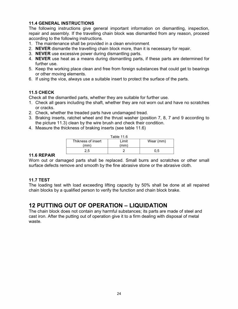
4. Measure the thickness of braking inserts (see table 11.6)
Table 11.6
11.6 REPAIR Worn out or damaged parts shall be replaced. Small burrs and scratches or other small surface defects remove and smooth by the fine abrasive stone or the abrasive cloth. 11.7 TEST The loading test with load exceeding lifting capacity by 50% shall be done at all repaired chain blocks by a qualified person to verify the function and chain block brake. 12 PUTTING OUT OF OPERATION – LIQUIDATION The chain block does not contain any harmful substances; its parts are made of steel and cast iron. After the putting out of operation give it to a firm dealing with disposal of metal waste.
Thikness of insert (mm)
Limit (mm)
Wear (mm)
2,5 2 0,5

25
13. RELATED DOCUMENTATION 13.1 EC declaration of conformity
13.2 This Instruction Manual was elaborated in accordance with following technical regulations, technical standards and national regulations:
• Ministerial order No.24/2003 of the Coll. of Law as amended (EP and Council directive 98/37/EC) • Ministerial order No.23/2003 of the Coll. of Laws as amended (EP and Council directive 94/9/EC) • ČSN EN ISO 12100 - 1 • ČSN EN ISO 12100 - 2 • ČSN EN 13157 • ČSN EN 1050 • ČSN EN 1127 - 2 • ČSN EN 1127 - 1 • ČSN EN 13463 - 1 • Regulation of CBM (Czech Bureau of Mine) No.22/89 of the Coll. of Laws • ČSN 33 2030.
14 FINAL REQUIREMENTS OF THE MANUFACTURER TO THE CUSTOMER Any changes of the product, eventually usage of unoriginal spare parts can be realized only based on the approval of the manufacturer. When not observing this condition the producer does not guarantee safety of his product. In this case, any manufacturer’s guarantees do not apply to the product.

26
EC Declaration of conformity
Manufacturer BRANO a.s. 747 41 Hradec nad Moravicí, Opavská 1000
The Czech Republic ID No.: 45193363 TIN: CZ45193363
We declare under our sole responsibility that the product
Name: Type: Parameters:
Travelling chain block
Z 210, Z 210A, Z210B Lifting capacities 0,5t; 1t; 1,6t; 3,2t; 5t; 7,5t; 10t; 15t; 20t
Description and purpose of use: Hand lifting device destined solely for manual lifting, lowering and travelling on the beam with free load by means of link chain under normal atmospheric conditions in the workplace upon observance of the maximum lifting capacity of the chain block. Is in conformity with following directives and standards: MO CR No. 24/2003 of the Coll. of Laws, RE directive No. 98/37/EC, ČSN EN ISO 12100-1:2004(EN ISO 12100-1:2003), ČSN EN ISO 12100-2:2004(EN ISO 12100-2:2003), ČSN EN1050:2001(EN1050:1996,ČSN EN 953:1998(EN 953:1997). The following authorized body had a share in conformity assessment: ----------- Hradec nad Moravicí 1.9.2004 Ing. Alena Šimečková Ing.Zdeněk Pavlíček ………………………………………………………………………………………………………………. Place Date Director of SBU ZZ Manager of Q SBU