Embed Size (px)
Citation preview
Traveling Wave Fault Location on HVDC Lines
Alberto Becker Soeth Jr - GE Grid Solut ions LLC, Brasil
Paulo Renato Freire de Souza - GE Grid Solut ions LLC, Brasil
Diogo Tot t i Custódio - Interligação Elét rica do Madeira S.A, Brazil
Ilia Voloh - GE Grid Solut ions LLC, Canada
2018 Texas A&M Protective Relaying Conference
• Introduction
• Locating faults by using traveling waves
• Traveling waves measurements in AC and DC lines.
• Real TWFL installation on bipole HVDC ± 600 kVdc line.
• Staged testing
• Conclusions
Agenda
2
Introduction• HVDC lines used to transfer large amounts of power over long
distances • Downtime of these lines as a result of the line fault is critical and
has to be reduced to the minimum. • Accurate fault location is a paramount and TWFL can achieve
this • TWFL currently available on the market rely on measurements
from inductive CTs and inductive/capacitive VTs, which are not applicable to HVDC lines.
• Paper presents real application of the TWFL on the longest in the world 2375 kilometers long IE Madeira HVDC overhead line.
3
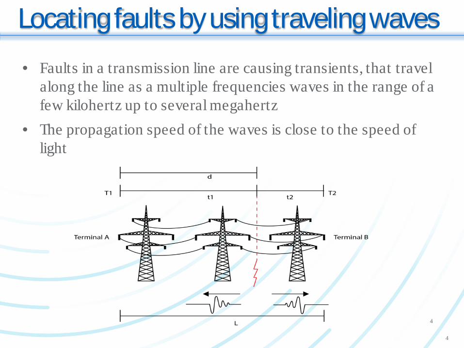
Locating faults by using traveling waves• Faults in a transmission line are causing transients, that travel
along the line as a multiple frequencies waves in the range of a few kilohertz up to several megahertz
• The propagation speed of the waves is close to the speed of light
4
4
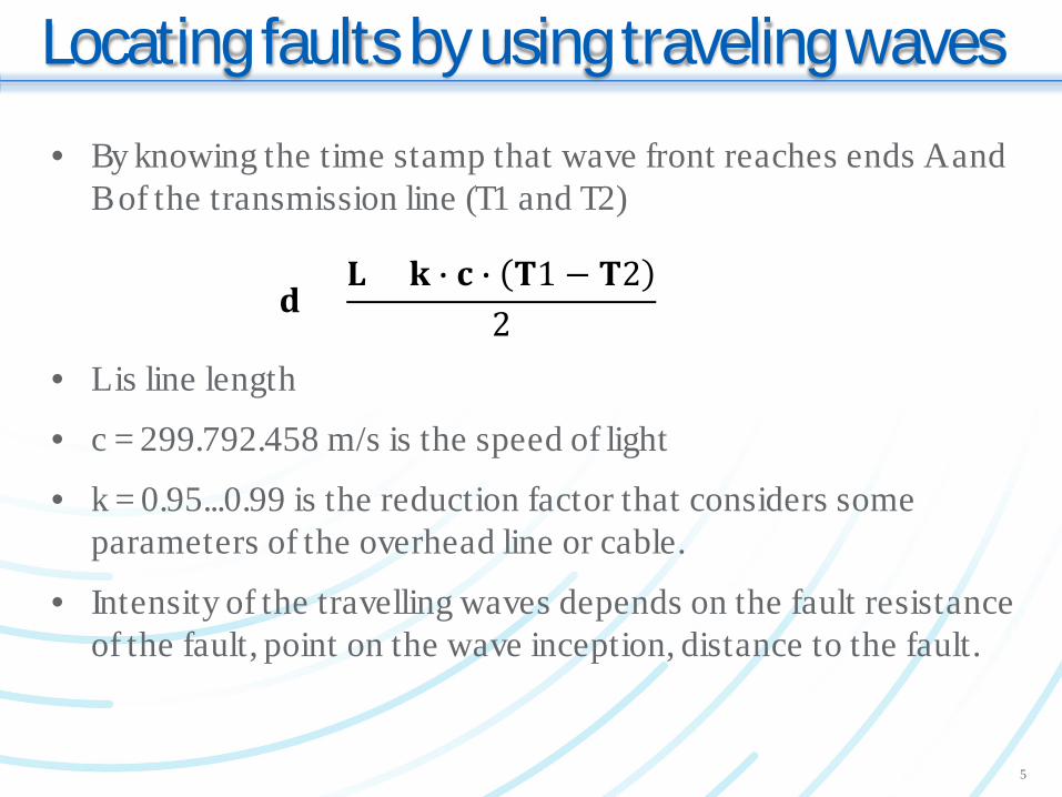
Locating faults by using traveling waves• By knowing the time stamp that wave front reaches ends A and
B of the transmission line (T1 and T2)
• L is line length
• c = 299.792.458 m/s is the speed of light
• k = 0.95...0.99 is the reduction factor that considers some parameters of the overhead line or cable.
• Intensity of the travelling waves depends on the fault resistance of the fault, point on the wave inception, distance to the fault.
𝐝𝐝 =𝐋𝐋 + 𝐤𝐤 � 𝐜𝐜 � 𝐓𝐓1 − 𝐓𝐓2
2
5
Locating faults by using traveling waves• Calibration of the TWFL System is needed to adjust two
parameters.
• The factor K; each conducting media has different physical properties, that influences the speed of the traveling wave.
• The second parameter is the line length (L) which should consider the total length of the physical conductor.
• These two parameters are adjusted with a linear regression process based on the true fault location value.
• It is known that the conventional CTs and VTs are able to reproduce the traveling wave to their secondary circuits.
• But what about application of the TWFL on the HVDC line???
6
Traveling waves in AC and DC lines• In AC power transmission both travelling wave signal can come
from either CTs or VTs, which reproduce primary high frequency waves quite well to their secondary circuits.
• Instrument transformers are not applicable to DC measurements.
• DC voltage measurement is achieved by either a resistive DC voltage divider or an optical voltage VT (divider).
• DC current measurement is achieved by either optical CT or by Zero Flux Current Transducer (ZFCT).
7
Traveling waves in AC and DC lines
8
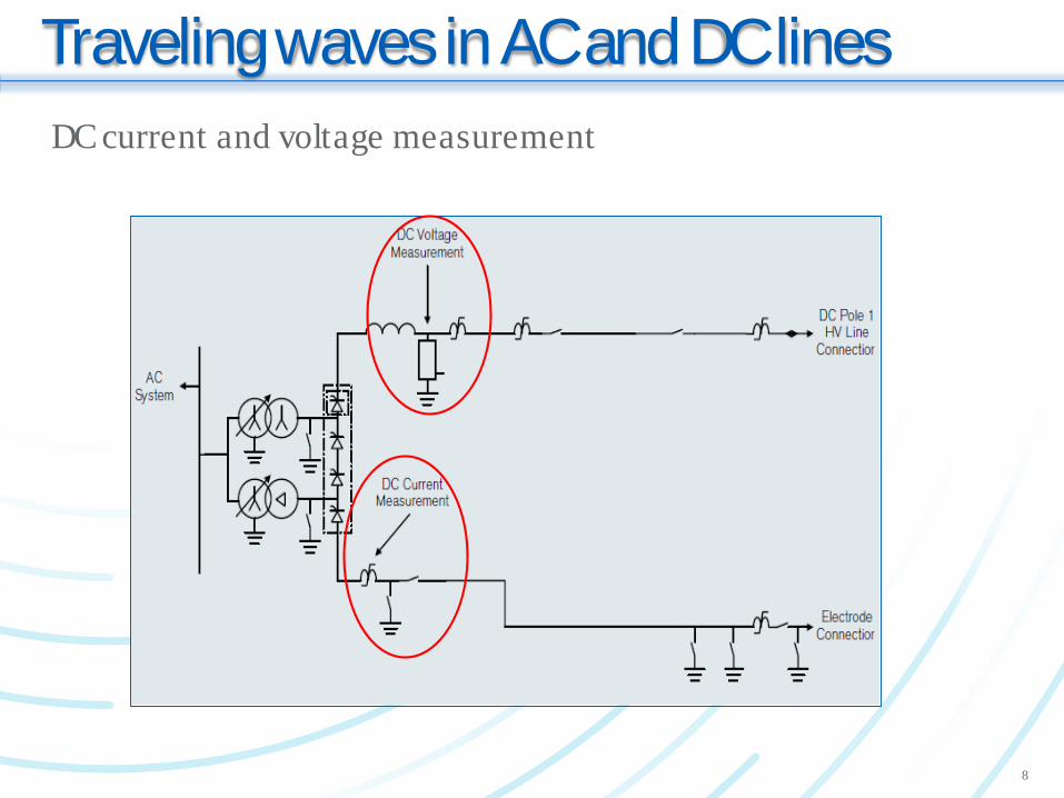
DC current and voltage measurement
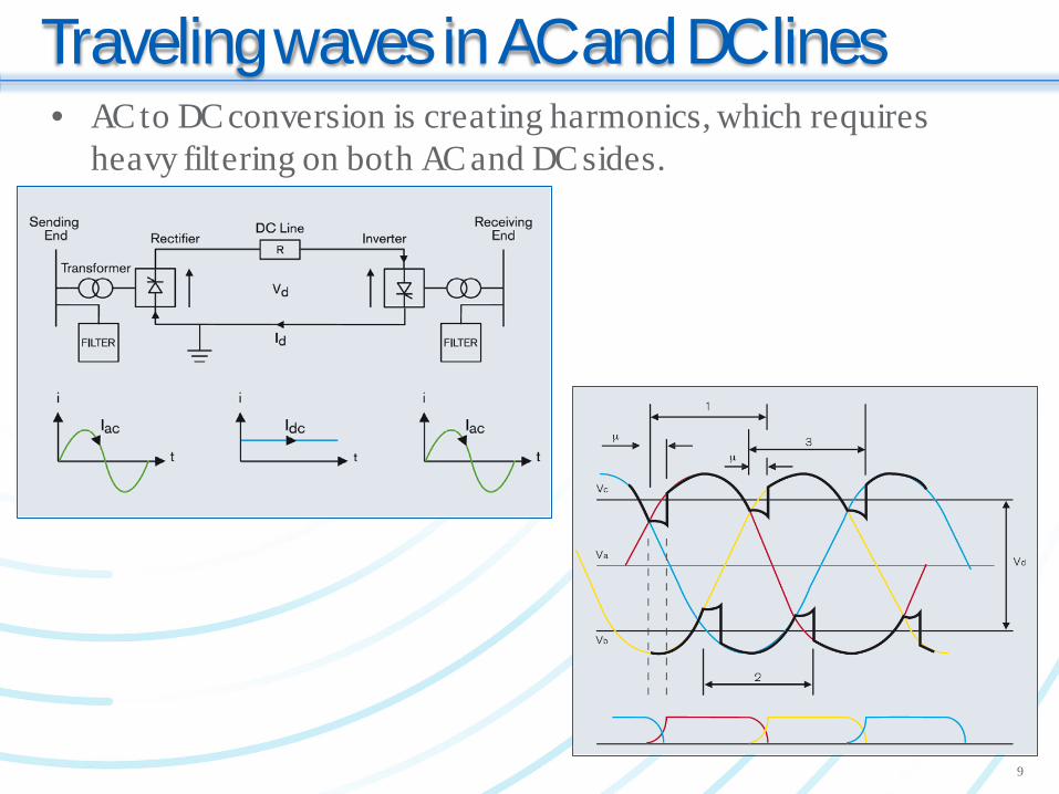
Traveling waves in AC and DC lines• AC to DC conversion is creating harmonics, which requires
heavy filtering on both AC and DC sides.
9
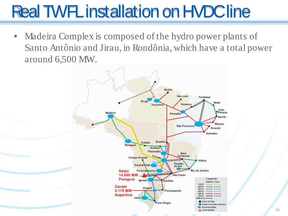
Real TWFL installation on HVDC line• Madeira Complex is composed of the hydro power plants of
Santo Antônio and Jirau, in Rondônia, which have a total power around 6,500 MW.
10
Real TWFL installation on HVDC line• In order to transmit such amount of power, a DC transmission
system is composed of bipole HVDC ± 600 kVdc line.• Line length is 2375 km from Madeira to São Paulo, and two
Back-to Backs converters of 2 x 400 MW, installed in Porto Velho.
• The installation uses the resistive divider method for DC voltage measurement where the TWFL IED is connected to capture the TW data.
• As the TW is severely damped as a result of the overhead line length and voltage resistive divider, the A/D converter is designed to have a higher gain than the usual AD for TW in AC overhead lines.
11
Real TWFL installation on HVDC line
ETHERNET
Data acquisition
unit
IEDUV
Data acquisition
unit
IEDUV
GPS satellite system
GPS satellite system
`
DC Line Protection
Trigger DC Line Protection
Trigger
Comtrade Comtrade
12
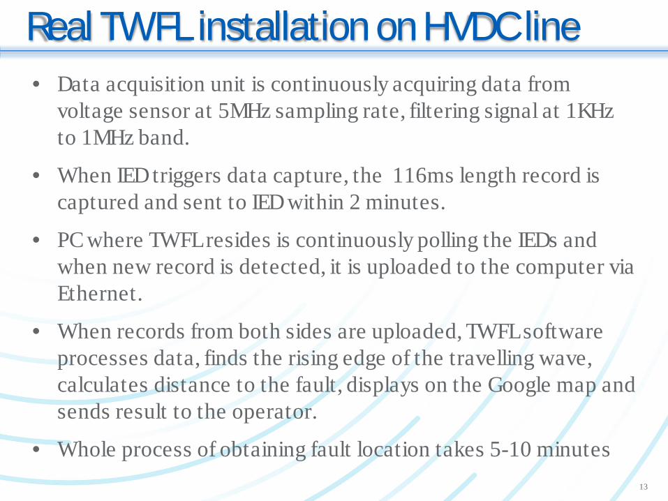
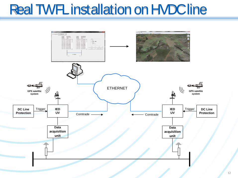
Real TWFL installation on HVDC line• Data acquisition unit is continuously acquiring data from
voltage sensor at 5MHz sampling rate, filtering signal at 1KHz to 1MHz band.
• When IED triggers data capture, the 116ms length record is captured and sent to IED within 2 minutes.
• PC where TWFL resides is continuously polling the IEDs and when new record is detected, it is uploaded to the computer via Ethernet.
• When records from both sides are uploaded, TWFL software processes data, finds the rising edge of the travelling wave, calculates distance to the fault, displays on the Google map and sends result to the operator.
• Whole process of obtaining fault location takes 5-10 minutes 13
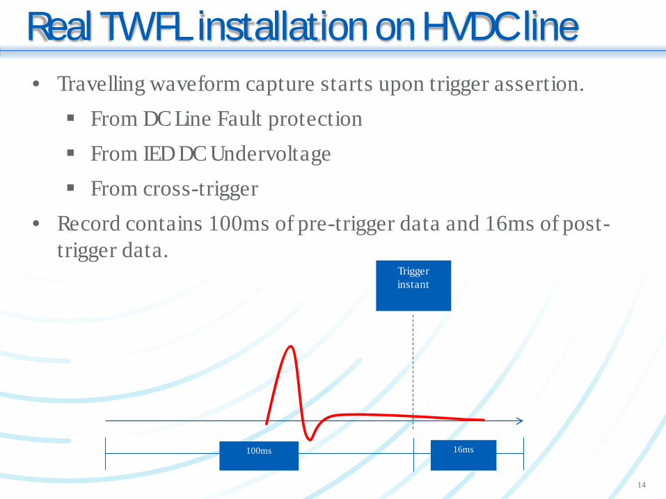
Real TWFL installation on HVDC line• Travelling waveform capture starts upon trigger assertion. From DC Line Fault protection From IED DC Undervoltage From cross-trigger
• Record contains 100ms of pre-trigger data and 16ms of post-trigger data.
Trigger instant
100ms 16ms
14

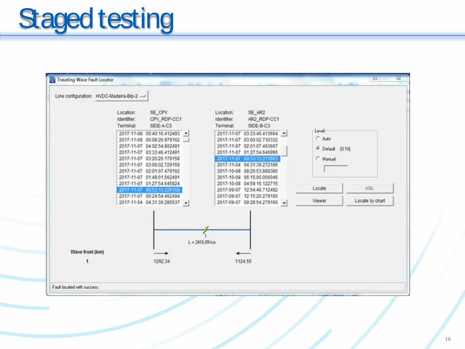
Staged testing• Staged short-circuit tests were performed in the HVDC line on
the early hours of November 7 to 8, 2017.
• 8 low-impedance short-circuit tests were performed at predetermined points along the line in order to validate and calibrate the DC fault locating system.
• The location of each short circuit was only disclosed after verification of the location results of the DC TWFL system.
• Span between line towers is 490m average, therefore error within 400m would be considered acceptable.
15
Staged testing
16
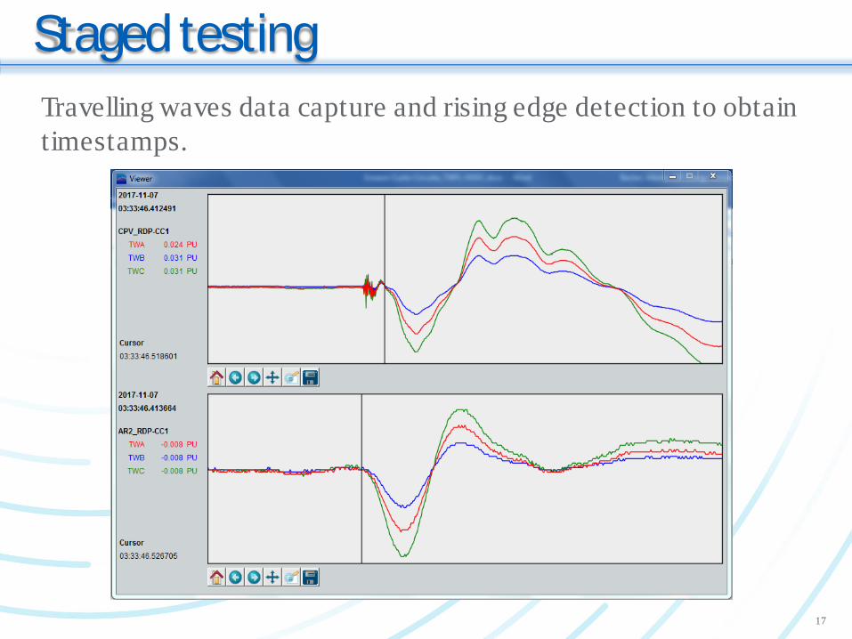
Staged testingTravelling waves data capture and rising edge detection to obtain timestamps.
17
Staged testing
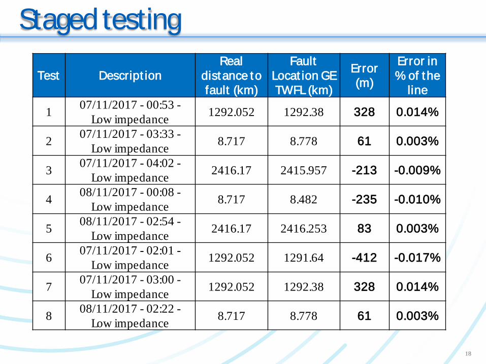
Test Descript ionReal
distance to fault (km)
Fault Locat ion GE TWFL (km)
Error (m)
Error in % of the
line
1 07/11/2017 - 00:53 -Low impedance 1292.052 1292.38 328 0.014%
2 07/11/2017 - 03:33 -Low impedance 8.717 8.778 61 0.003%
3 07/11/2017 - 04:02 -Low impedance 2416.17 2415.957 -213 -0.009%
4 08/11/2017 - 00:08 -Low impedance 8.717 8.482 -235 -0.010%
5 08/11/2017 - 02:54 -Low impedance 2416.17 2416.253 83 0.003%
6 07/11/2017 - 02:01 -Low impedance 1292.052 1291.64 -412 -0.017%
7 07/11/2017 - 03:00 -Low impedance 1292.052 1292.38 328 0.014%
8 08/11/2017 - 02:22 -Low impedance 8.717 8.778 61 0.003%
18
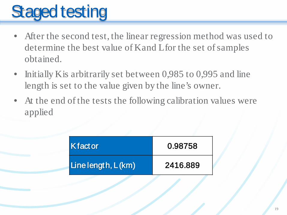
Staged testing• After the second test, the linear regression method was used to
determine the best value of K and L for the set of samples obtained.
• Initially K is arbitrarily set between 0,985 to 0,995 and line length is set to the value given by the line’s owner.
• At the end of the tests the following calibration values were applied
K factor 0.98758
Line length, L (km) 2416.889
19
Conclusions
• The staged tests demonstrated that it is possible to locate faults with a high accuracy on the long HVDC transmission lines
• Capturing the traveling waves from the line resistive voltage divider is possible, without the need for additional switchyard equipment and sensors.
• The DC TWFL technology located the faults with average accuracy of less than 0.01% of the 2375 line length.
20
Conclusions
• Even on such long HVDC line, faults generate travelling waves with enough intensity to be usable by TWFL.
• Calibration improves TWFL accuracy, which can be dine during staged testing or after each fault.
• All travelling wave data uploaded to the operator computer via Ethernet eliminating the need of the dedicated high-speed channel between line ends.
21
Thank You
Questions?
22


![Fault-Line Identification of HVDC Transmission Lines by ...ppong/manuscripts/fault line identification HVDC transmission...HVDC system which was established in PSCAD/EMTDC [12] based](https://img.pdfslide.us/doc/110x75/5e69f3c1518f27522a452b9a/fault-line-identification-of-hvdc-transmission-lines-by-ppongmanuscriptsfault.jpg)