Embed Size (px)
Citation preview
ANES 2004 Paper 3a4-IMA03, October 3 – 6, 2004, Miami, FL
TRASH TO TREASURE: CONVERTING COLD WAR LEGACY WASTE INTO WEAPONS AGAINST CANCER
Authors Robert G. Nicholas, PE – Burns and Roe Enterprises, Inc. Norman H. Lacy, PE – Burns and Roe Enterprises, Inc. Todd R. Butz, PhD – Duratek, Inc. Norman E. Brandon, PE – Nuclear Fuel Services, Inc. Abstract As part of its commitment to clean up Cold War legacy sites, the U.S. Department of Energy (DOE) has initiated an exciting and unique project to dispose of its inventory of uranium-233 (233U) stored at Oak Ridge National Laboratory (ORNL), and extract isotopes that show great promise in the treatment of deadly cancers. In addition to increasing the supply of potentially useful medical isotopes, the project will rid DOE of a nuclear concern and cut surveillance and security costs. For more than 30 years, DOE’s ORNL has stored over 1,200 containers of fissile 233U, originally produced for several defense-related projects, including a pilot study that looked at using 233U as a commercial reactor fuel. This uranium, designated as special nuclear material, requires expensive security, safety, and environmental controls. It has been stored at an ORNL facility, Building 3019A, that dates back to the Manhattan Project. Down-blending the material to a safer form, rather than continuing to store it, will eliminate a $15 million a year financial liability for the DOE and increase the supply of medical isotopes by 5,700 percent. During the down-blending process, thorium-229 (229Th) will be extracted. The thorium will then be used to extract actinium-225 (225Ac), which will ultimately supply its progeny, bismuth-213 (213Bi), for on-going cancer research. The research includes Phase II clinical trials for the treatment of acute myelogenous leukemia at Sloan-Kettering Memorial Cancer Center in New York, as well as other serious cancers of the lungs, pancreas, and kidneys using a technique known as alpha-particle radioimmunotherapy. Alpha-particle radioimmunotherapy is based on the emission of alpha particles by radionuclides. 213Bi is attached to a monoclonal antibody that targets specific cells. The bismuth then delivers a high-powered but short-range radiation dose, effectively killing the cancerous cells but sparing the surrounding tissue. Production of the actinium and bismuth would be a private venture at no cost to the government. Isotek Systems, LLC, was commissioned by the DOE to execute the project, known as the 233U Disposition, Medical Isotope Production, and Building 3019 Complex Shutdown Project. Isotek is a partnership between Duratek Federal Services, Burns and Roe Enterprises, and Nuclear Fuel Services. By pooling their pioneering experiences in nuclear engineering and design, nuclear recycling, and waste management, the partnership has developed a novel process to meet this clean-up milestone. The project is not only important for its cancer treatment potential, but also for setting the stage for reducing global threats through the down-blending of materials.
R. Nicholas, PE, Burns and Roe Enterprises, Inc. 1
ANES 2004 Paper 3a4-IMA03, October 3 – 6, 2004, Miami, FL
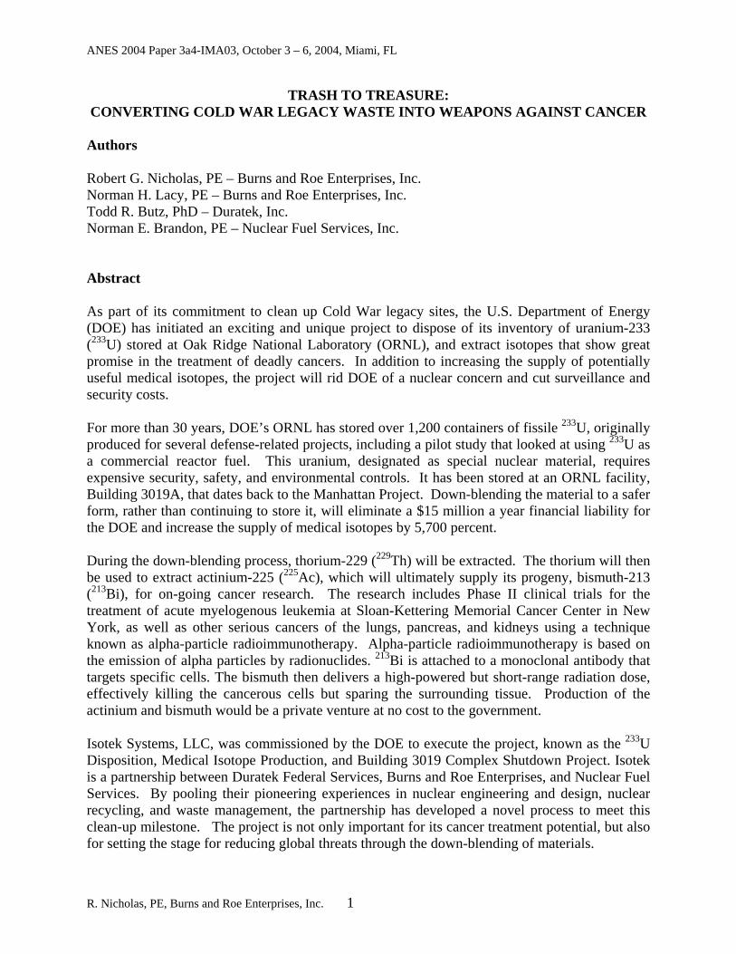
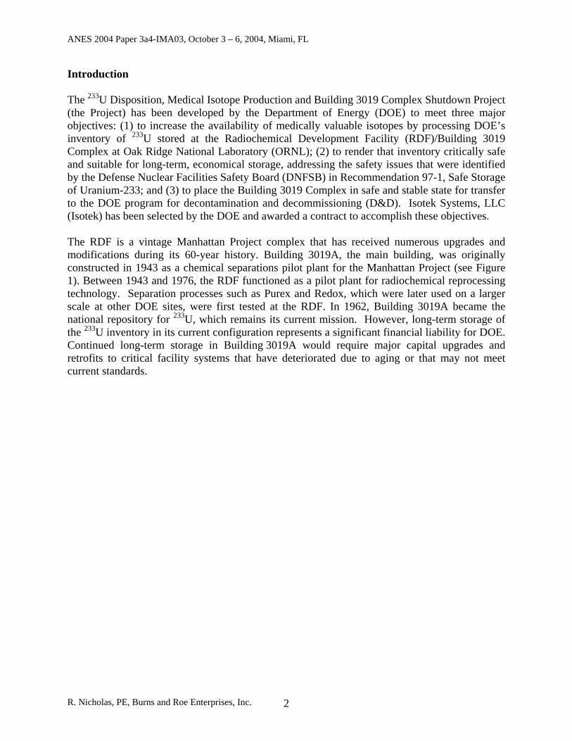
Introduction The 233U Disposition, Medical Isotope Production and Building 3019 Complex Shutdown Project (the Project) has been developed by the Department of Energy (DOE) to meet three major objectives: (1) to increase the availability of medically valuable isotopes by processing DOE’s inventory of 233U stored at the Radiochemical Development Facility (RDF)/Building 3019 Complex at Oak Ridge National Laboratory (ORNL); (2) to render that inventory critically safe and suitable for long-term, economical storage, addressing the safety issues that were identified by the Defense Nuclear Facilities Safety Board (DNFSB) in Recommendation 97-1, Safe Storage of Uranium-233; and (3) to place the Building 3019 Complex in safe and stable state for transfer to the DOE program for decontamination and decommissioning (D&D). Isotek Systems, LLC (Isotek) has been selected by the DOE and awarded a contract to accomplish these objectives. The RDF is a vintage Manhattan Project complex that has received numerous upgrades and modifications during its 60-year history. Building 3019A, the main building, was originally constructed in 1943 as a chemical separations pilot plant for the Manhattan Project (see Figure 1). Between 1943 and 1976, the RDF functioned as a pilot plant for radiochemical reprocessing technology. Separation processes such as Purex and Redox, which were later used on a larger scale at other DOE sites, were first tested at the RDF. In 1962, Building 3019A became the national repository for 233U, which remains its current mission. However, long-term storage of the 233U inventory in its current configuration represents a significant financial liability for DOE. Continued long-term storage in Building 3019A would require major capital upgrades and retrofits to critical facility systems that have deteriorated due to aging or that may not meet current standards.
R. Nicholas, PE, Burns and Roe Enterprises, Inc. 2
ANES 2004 Paper 3a4-IMA03, October 3 – 6, 2004, Miami, FL
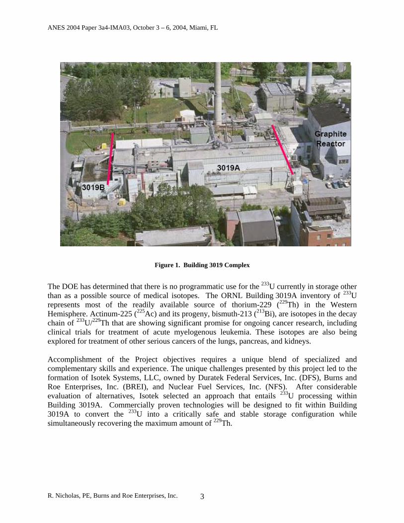
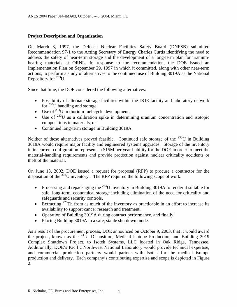
Figure 1. Building 3019 Complex
The DOE has determined that there is no programmatic use for the 233U currently in storage other than as a possible source of medical isotopes. The ORNL Building 3019A inventory of 233U represents most of the readily available source of thorium-229 (229Th) in the Western Hemisphere. Actinum-225 (225Ac) and its progeny, bismuth-213 (213Bi), are isotopes in the decay chain of 233U/229Th that are showing significant promise for ongoing cancer research, including clinical trials for treatment of acute myelogenous leukemia. These isotopes are also being explored for treatment of other serious cancers of the lungs, pancreas, and kidneys. Accomplishment of the Project objectives requires a unique blend of specialized and complementary skills and experience. The unique challenges presented by this project led to the formation of Isotek Systems, LLC, owned by Duratek Federal Services, Inc. (DFS), Burns and Roe Enterprises, Inc. (BREI), and Nuclear Fuel Services, Inc. (NFS). After considerable evaluation of alternatives, Isotek selected an approach that entails 233U processing within Building 3019A. Commercially proven technologies will be designed to fit within Building 3019A to convert the 233U into a critically safe and stable storage configuration while simultaneously recovering the maximum amount of 229Th.
R. Nicholas, PE, Burns and Roe Enterprises, Inc. 3
ANES 2004 Paper 3a4-IMA03, October 3 – 6, 2004, Miami, FL
Project Description and Organization On March 3, 1997, the Defense Nuclear Facilities Safety Board (DNFSB) submitted Recommendation 97-1 to the Acting Secretary of Energy Charles Curtis identifying the need to address the safety of near-term storage and the development of a long-term plan for uranium-bearing materials at ORNL. In response to the recommendation, the DOE issued an Implementation Plan on September 29, 1997 in which it committed, along with other near-term actions, to perform a study of alternatives to the continued use of Building 3019A as the National Repository for 233U. Since that time, the DOE considered the following alternatives:
• Possibility of alternate storage facilities within the DOE facility and laboratory network for 233U handling and storage,
• Use of 233U in thorium fuel cycle development, • Use of 233U as a calibration spike in determining uranium concentration and isotopic
compositions in materials, or • Continued long-term storage in Building 3019A.
Neither of these alternatives proved feasible. Continued safe storage of the 233U in Building 3019A would require major facility and engineered systems upgrades. Storage of the inventory in its current configuration represents a $15M per year liability for the DOE in order to meet the material-handling requirements and provide protection against nuclear criticality accidents or theft of the material. On June 13, 2002, DOE issued a request for proposal (RFP) to procure a contractor for the disposition of the 233U inventory. The RFP required the following scope of work:
• Processing and repackaging the 233U inventory in Building 3019A to render it suitable for safe, long-term, economical storage including elimination of the need for criticality and safeguards and security controls,
• Extracting 229Th from as much of the inventory as practicable in an effort to increase its availability to support cancer research and treatment,
• Operation of Building 3019A during contract performance, and finally • Placing Building 3019A in a safe, stable shutdown mode.
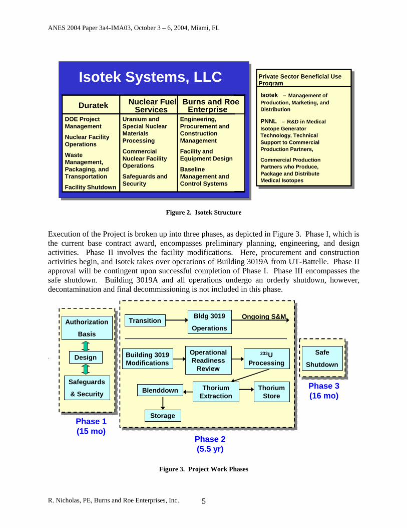
As a result of the procurement process, DOE announced on October 9, 2003, that it would award the project, known as the 233U Disposition, Medical Isotope Production, and Building 3019 Complex Shutdown Project, to Isotek Systems, LLC located in Oak Ridge, Tennessee. Additionally, DOE’s Pacific Northwest National Laboratory would provide technical expertise, and commercial production partners would partner with Isotek for the medical isotope production and delivery. Each company’s contributing expertise and scope is depicted in Figure 2.
R. Nicholas, PE, Burns and Roe Enterprises, Inc. 4
ANES 2004 Paper 3a4-IMA03, October 3 – 6, 2004, Miami, FL
Isotek Systems, LLC
Engineering, Procurement and Construction Management
Facility and Equipment Design
Baseline Management and Control Systems
Uranium and Special Nuclear Materials Processing Commercial Nuclear Facility Operations Safeguards and Security
DOE Project Management Nuclear Facility Operations Waste Management, Packaging, and Transportation Facility Shutdown
Burns and Roe Enterprise
Nuclear Fuel ServicesDuratek
Use Program Isotek – Management of Production, Marketing, and Distribution PNNL – R&D in Medical Isotope Generator Technology, Technical Support to Commercial Production Partners, Commercial Production Partners who Produce, Package and Distribute Medical Isotopes
Private Sector Beneficial Use Program
Isotek – Management of Production, Marketing, and Distribution PNNL – R&D in Medical Isotope Generator Technology, Technical Support to Commercial Production Partners, Commercial Production Partners who Produce, Package and Distribute Medical Isotopes
Figure 2. Isotek Structure
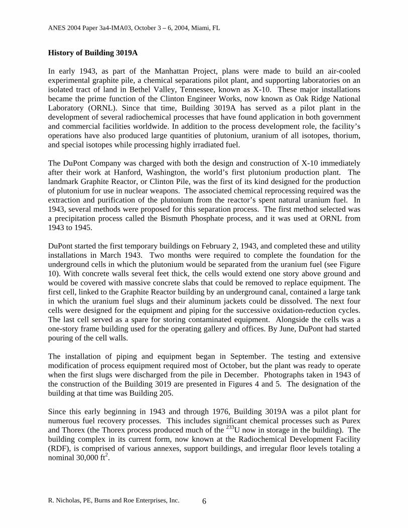
Execution of the Project is broken up into three phases, as depicted in Figure 3. Phase I, which is the current base contract award, encompasses preliminary planning, engineering, and design activities. Phase II involves the facility modifications. Here, procurement and construction activities begin, and Isotek takes over operations of Building 3019A from UT-Battelle. Phase II approval will be contingent upon successful completion of Phase I. Phase III encompasses the safe shutdown. Building 3019A and all operations undergo an orderly shutdown, however, decontamination and final decommissioning is not included in this phase. .
• •
Figure 3. Project Work Phases
Design
Authorization Basis
Safeguards & Security
Operational Readiness
Review
233U Processing
Blenddown
Storage
Safe
Shutdown
Thorium Store
Phase 1 (15 mo)
Bldg 3019
OperationsTransition Ongoing S&M
Building 3019 Modifications
Thorium Extraction
Phase 2(5.5 yr)
Phase 3(16 mo)
R. Nicholas, PE, Burns and Roe Enterprises, Inc. 5
ANES 2004 Paper 3a4-IMA03, October 3 – 6, 2004, Miami, FL
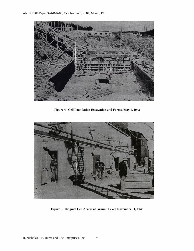
History of Building 3019A In early 1943, as part of the Manhattan Project, plans were made to build an air-cooled experimental graphite pile, a chemical separations pilot plant, and supporting laboratories on an isolated tract of land in Bethel Valley, Tennessee, known as X-10. These major installations became the prime function of the Clinton Engineer Works, now known as Oak Ridge National Laboratory (ORNL). Since that time, Building 3019A has served as a pilot plant in the development of several radiochemical processes that have found application in both government and commercial facilities worldwide. In addition to the process development role, the facility’s operations have also produced large quantities of plutonium, uranium of all isotopes, thorium, and special isotopes while processing highly irradiated fuel. The DuPont Company was charged with both the design and construction of X-10 immediately after their work at Hanford, Washington, the world’s first plutonium production plant. The landmark Graphite Reactor, or Clinton Pile, was the first of its kind designed for the production of plutonium for use in nuclear weapons. The associated chemical reprocessing required was the extraction and purification of the plutonium from the reactor’s spent natural uranium fuel. In 1943, several methods were proposed for this separation process. The first method selected was a precipitation process called the Bismuth Phosphate process, and it was used at ORNL from 1943 to 1945. DuPont started the first temporary buildings on February 2, 1943, and completed these and utility installations in March 1943. Two months were required to complete the foundation for the underground cells in which the plutonium would be separated from the uranium fuel (see Figure 10). With concrete walls several feet thick, the cells would extend one story above ground and would be covered with massive concrete slabs that could be removed to replace equipment. The first cell, linked to the Graphite Reactor building by an underground canal, contained a large tank in which the uranium fuel slugs and their aluminum jackets could be dissolved. The next four cells were designed for the equipment and piping for the successive oxidation-reduction cycles. The last cell served as a spare for storing contaminated equipment. Alongside the cells was a one-story frame building used for the operating gallery and offices. By June, DuPont had started pouring of the cell walls. The installation of piping and equipment began in September. The testing and extensive modification of process equipment required most of October, but the plant was ready to operate when the first slugs were discharged from the pile in December. Photographs taken in 1943 of the construction of the Building 3019 are presented in Figures 4 and 5. The designation of the building at that time was Building 205. Since this early beginning in 1943 and through 1976, Building 3019A was a pilot plant for numerous fuel recovery processes. This includes significant chemical processes such as Purex and Thorex (the Thorex process produced much of the 233U now in storage in the building). The building complex in its current form, now known at the Radiochemical Development Facility (RDF), is comprised of various annexes, support buildings, and irregular floor levels totaling a nominal 30,000 ft2.
R. Nicholas, PE, Burns and Roe Enterprises, Inc. 6
ANES 2004 Paper 3a4-IMA03, October 3 – 6, 2004, Miami, FL
Figure 4. Cell Foundation Excavation and Forms, May 1, 1943
Figure 5. Original Cell Access at Ground Level, November 11, 1943
R. Nicholas, PE, Burns and Roe Enterprises, Inc. 7
ANES 2004 Paper 3a4-IMA03, October 3 – 6, 2004, Miami, FL
At the core of the complex are the original building structures, which are seven shielded processing cells positioned from east to west. Above the processing cell is a high-bay structure (the Penthouse). These cells are described in detail in subsequent sections. Building 3019A also contains operational laboratories with gloveboxes and hoods and several areas with out-of-service equipment.
R. Nicholas, PE, Burns and Roe Enterprises, Inc. 8
ANES 2004 Paper 3a4-IMA03, October 3 – 6, 2004, Miami, FL
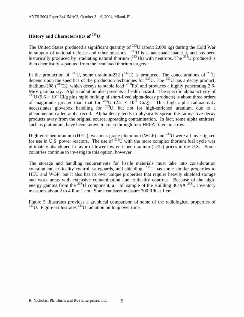
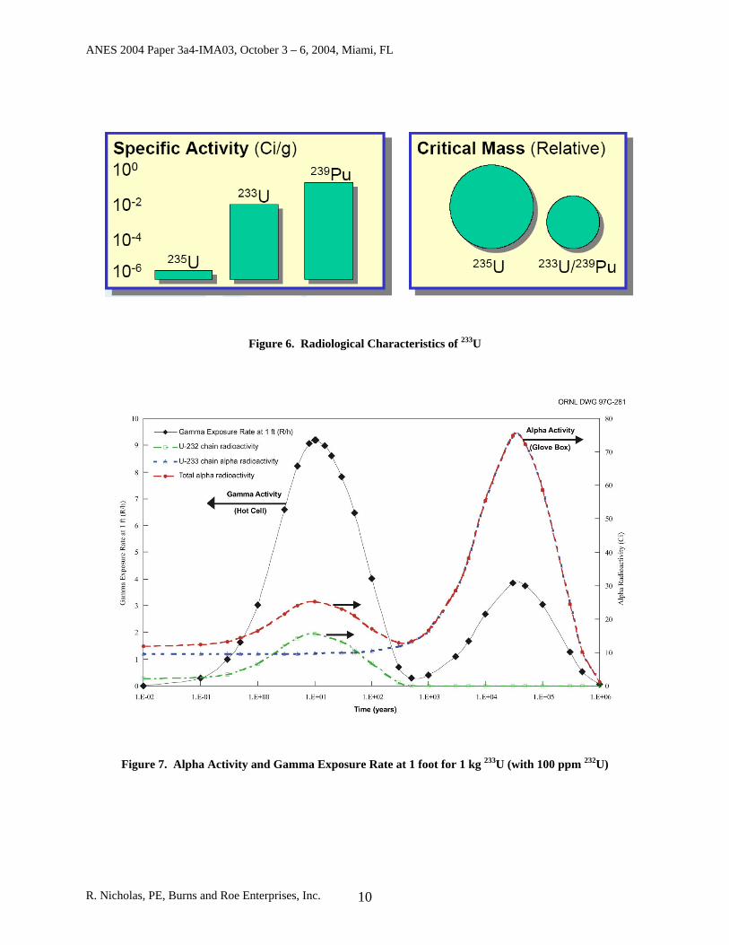
History and Characteristics of 233U The United States produced a significant quantity of 233U (about 2,000 kg) during the Cold War in support of national defense and other missions. 233U is a man-made material, and has been historically produced by irradiating natural thorium (232Th) with neutrons. The 233U produced is then chemically separated from the irradiated thorium targets. In the production of 233U, some uranium-232 (232U) is produced. The concentrations of 232U depend upon the specifics of the production techniques for 233U. The 232U has a decay product, thallium-208 (208Tl), which decays to stable lead (208Pb) and produces a highly penetrating 2.6-MeV gamma ray. Alpha radiation also presents a health hazard. The specific alpha activity of 233U (9.6 × 10⁻³ Ci/g plus rapid buildup of short-lived alpha-decay products) is about three orders of magnitude greater than that for 235U (2.2 × 10⁻⁶ Ci/g). This high alpha radioactivity necessitates glovebox handling for 233U, but not for high-enriched uranium, due to a phenomenon called alpha recoil. Alpha decay tends to physically spread the radioactive decay products away from the original source, spreading contamination. In fact, some alpha emitters, such as plutonium, have been known to creep through four HEPA filters in a row. High-enriched uranium (HEU), weapons-grade plutonium (WGP) and 233U were all investigated for use in U.S. power reactors. The use of 233U with the more complex thorium fuel cycle was ultimately abandoned in favor of lower low-enriched uranium (LEU) prices in the U.S. Some countries continue to investigate this option, however. The storage and handling requirements for fissile materials must take into consideration containment, criticality control, safeguards, and shielding. 233U has some similar properties to HEU and WGP, but it also has its own unique properties that require heavily shielded storage and work areas with extensive contamination and criticality controls. Because of the high-energy gamma from the 208Tl component, a 1 ml sample of the Building 3019A 233U inventory measures about 2 to 4 R at 1 cm. Some canisters measure 300 R/h at 1 cm. Figure 5 illustrates provides a graphical comparison of some of the radiological properties of 233U. Figure 6 illustrates 233U radiation buildup over time.
R. Nicholas, PE, Burns and Roe Enterprises, Inc. 9
ANES 2004 Paper 3a4-IMA03, October 3 – 6, 2004, Miami, FL
Figure 6. Radiological Characteristics of 233U
Figure 7. Alpha Activity and Gamma Exposure Rate at 1 foot for 1 kg 233U (with 100 ppm 232U)
R. Nicholas, PE, Burns and Roe Enterprises, Inc. 10
ANES 2004 Paper 3a4-IMA03, October 3 – 6, 2004, Miami, FL
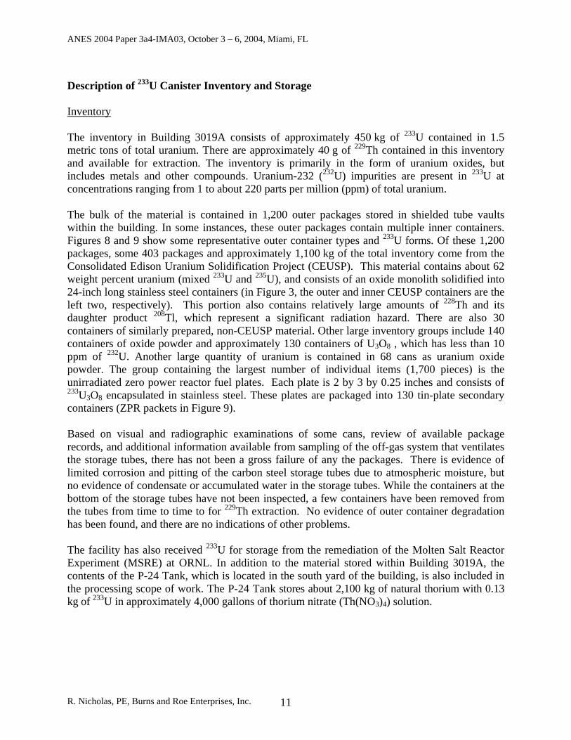
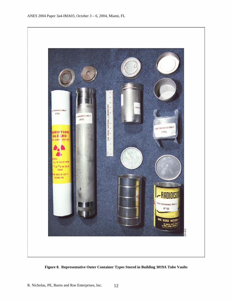
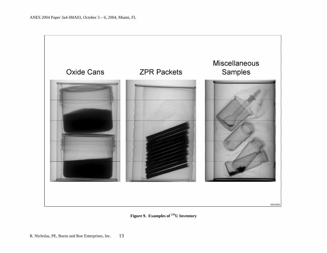
Description of 233U Canister Inventory and Storage Inventory The inventory in Building 3019A consists of approximately 450 kg of 233U contained in 1.5 metric tons of total uranium. There are approximately 40 g of 229Th contained in this inventory and available for extraction. The inventory is primarily in the form of uranium oxides, but includes metals and other compounds. Uranium-232 (232U) impurities are present in 233U at concentrations ranging from 1 to about 220 parts per million (ppm) of total uranium. The bulk of the material is contained in 1,200 outer packages stored in shielded tube vaults within the building. In some instances, these outer packages contain multiple inner containers. Figures 8 and 9 show some representative outer container types and 233U forms. Of these 1,200 packages, some 403 packages and approximately 1,100 kg of the total inventory come from the Consolidated Edison Uranium Solidification Project (CEUSP). This material contains about 62 weight percent uranium (mixed 233U and 235U), and consists of an oxide monolith solidified into 24-inch long stainless steel containers (in Figure 3, the outer and inner CEUSP containers are the left two, respectively). This portion also contains relatively large amounts of 228Th and its daughter product 208Tl, which represent a significant radiation hazard. There are also 30 containers of similarly prepared, non-CEUSP material. Other large inventory groups include 140 containers of oxide powder and approximately 130 containers of U3O8 , which has less than 10 ppm of 232U. Another large quantity of uranium is contained in 68 cans as uranium oxide powder. The group containing the largest number of individual items (1,700 pieces) is the unirradiated zero power reactor fuel plates. Each plate is 2 by 3 by 0.25 inches and consists of 233U3O8 encapsulated in stainless steel. These plates are packaged into 130 tin-plate secondary containers (ZPR packets in Figure 9). Based on visual and radiographic examinations of some cans, review of available package records, and additional information available from sampling of the off-gas system that ventilates the storage tubes, there has not been a gross failure of any the packages. There is evidence of limited corrosion and pitting of the carbon steel storage tubes due to atmospheric moisture, but no evidence of condensate or accumulated water in the storage tubes. While the containers at the bottom of the storage tubes have not been inspected, a few containers have been removed from the tubes from time to time to for 229Th extraction. No evidence of outer container degradation has been found, and there are no indications of other problems. The facility has also received 233U for storage from the remediation of the Molten Salt Reactor Experiment (MSRE) at ORNL. In addition to the material stored within Building 3019A, the contents of the P-24 Tank, which is located in the south yard of the building, is also included in the processing scope of work. The P-24 Tank stores about 2,100 kg of natural thorium with 0.13 kg of 233U in approximately 4,000 gallons of thorium nitrate (Th(NO3)4) solution.
R. Nicholas, PE, Burns and Roe Enterprises, Inc. 11
ANES 2004 Paper 3a4-IMA03, October 3 – 6, 2004, Miami, FL
Figure 8. Representative Outer Container Types Stored in Building 3019A Tube Vaults
R. Nicholas, PE, Burns and Roe Enterprises, Inc. 12
ANES 2004 Paper 3a4-IMA03, October 3 – 6, 2004, Miami, FL
Figure 9. Examples of 233U Inventory
R. Nicholas, PE, Burns and Roe Enterprises, Inc. 13
ANES 2004 Paper 3a4-IMA03, October 3 – 6, 2004, Miami, FL
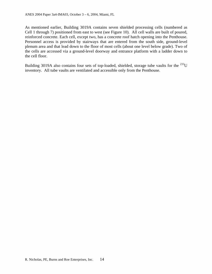
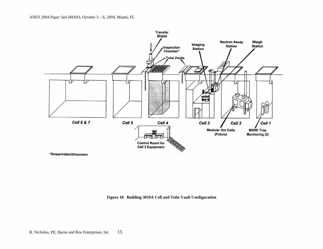
As mentioned earlier, Building 3019A contains seven shielded processing cells (numbered as Cell 1 through 7) positioned from east to west (see Figure 10). All cell walls are built of poured, reinforced concrete. Each cell, except two, has a concrete roof hatch opening into the Penthouse. Personnel access is provided by stairways that are entered from the south side, ground-level plenum area and that lead down to the floor of most cells (about one level below grade). Two of the cells are accessed via a ground-level doorway and entrance platform with a ladder down to the cell floor. Building 3019A also contains four sets of top-loaded, shielded, storage tube vaults for the 233U inventory. All tube vaults are ventilated and accessible only from the Penthouse.
R. Nicholas, PE, Burns and Roe Enterprises, Inc. 14
ANES 2004 Paper 3a4-IMA03, October 3 – 6, 2004, Miami, FL
Figure 10. Building 3019A Cell and Tube Vault Configuration
R. Nicholas, PE, Burns and Roe Enterprises, Inc. 15
ANES 2004 Paper 3a4-IMA03, October 3 – 6, 2004, Miami, FL
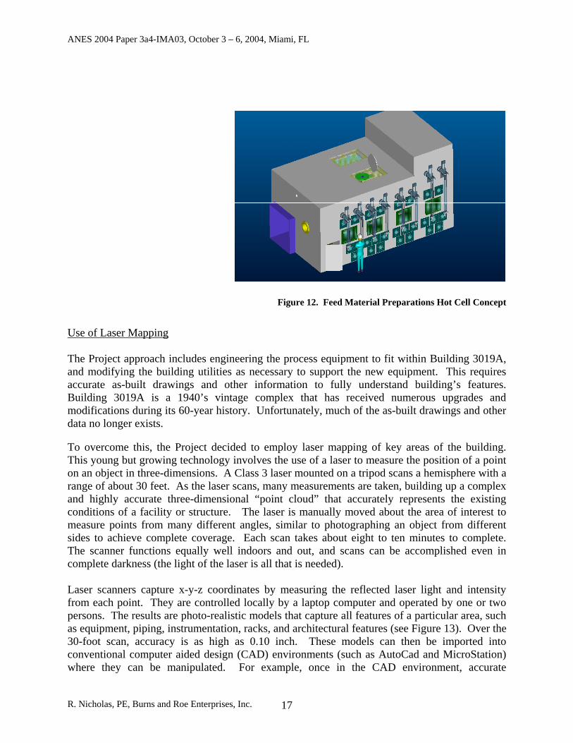
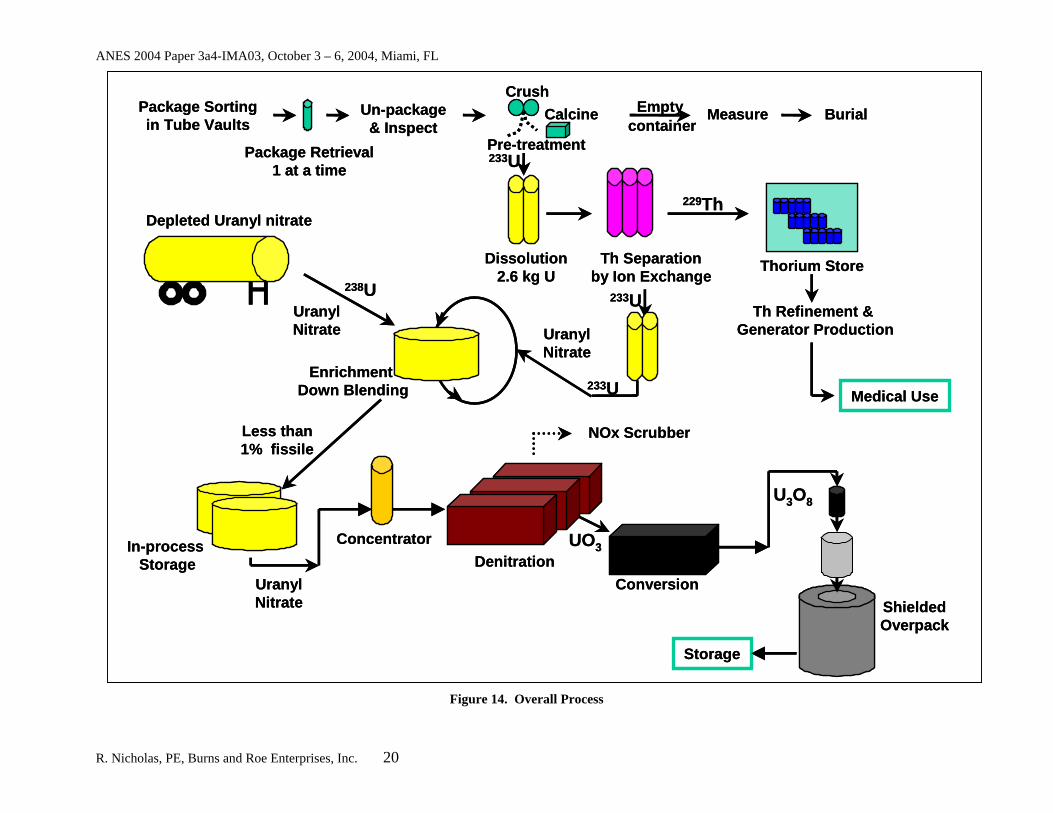
Process Description and Design Building 3019A will be modified to accept the new Project processing equipment necessary to support the scope of work. The overall process to downblend 233U materials and extract thorium is shown in Figure 14. Use of Hot Cells Due to the nature of the 233U material, the major processes of the Project will be conducted within Hot Cells. Hot Cells provide two principal functions; confinement of radioactive contamination, and shielding from direct radiation. The common features of such structures include massive walls, thick viewing windows, remote operations with the aid of manipulators, and complex entry and egress ports for material throughput. The Project will employ the use of three Hot Cells as follows: Feed Material Preparations Hot Cell: Dedicated to accept, open, and pre-treat the wide
variety of containers that are removed from the storage vaults. Thorium Hot Cell: Dedicated to the separation, purification, packaging, and storage of
the 229Th contained in the uranyl nitrate solution prepared in, and transferred from, Cell 301.
Denitrator Furnace Cell: Dedicated to dedicated to the final processing steps of denitration and drying of the downblended, thorium depleted uranium.
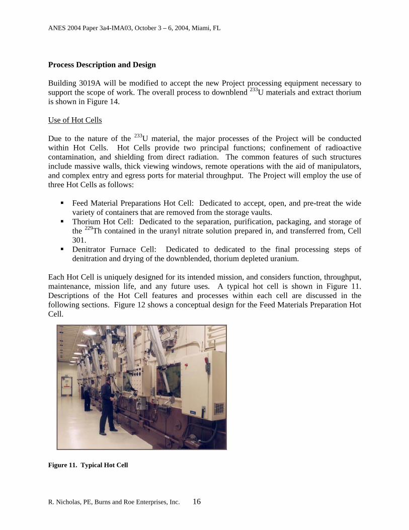
Each Hot Cell is uniquely designed for its intended mission, and considers function, throughput, maintenance, mission life, and any future uses. A typical hot cell is shown in Figure 11. Descriptions of the Hot Cell features and processes within each cell are discussed in the following sections. Figure 12 shows a conceptual design for the Feed Materials Preparation Hot Cell. F
R
igure 11. Typical Hot Cell
. Nicholas, PE, Burns and Roe Enterprises, Inc. 16
ANES 2004 Paper 3a4-IMA03, October 3 – 6, 2004, Miami, FL
Figure 12. Feed Material Preparations Hot Cell Concept
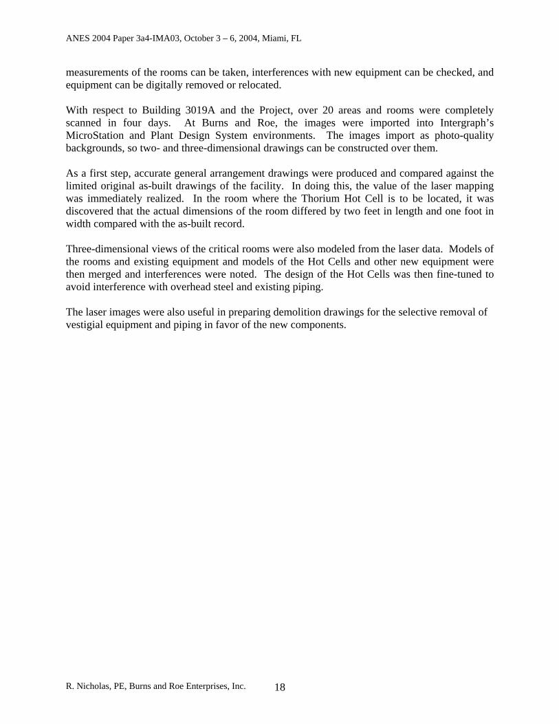
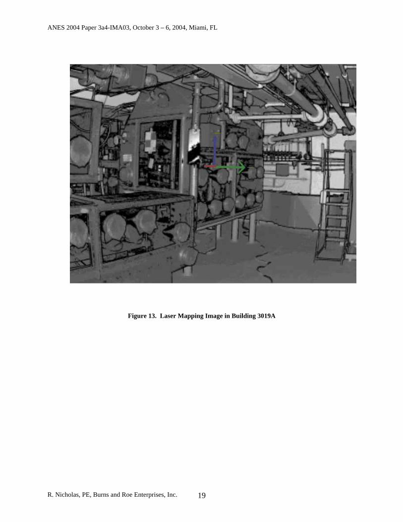
Use of Laser Mapping The Project approach includes engineering the process equipment to fit within Building 3019A, and modifying the building utilities as necessary to support the new equipment. This requires accurate as-built drawings and other information to fully understand building’s features. Building 3019A is a 1940’s vintage complex that has received numerous upgrades and modifications during its 60-year history. Unfortunately, much of the as-built drawings and other data no longer exists. To overcome this, the Project decided to employ laser mapping of key areas of the building. This young but growing technology involves the use of a laser to measure the position of a point on an object in three-dimensions. A Class 3 laser mounted on a tripod scans a hemisphere with a range of about 30 feet. As the laser scans, many measurements are taken, building up a complex and highly accurate three-dimensional “point cloud” that accurately represents the existing conditions of a facility or structure. The laser is manually moved about the area of interest to measure points from many different angles, similar to photographing an object from different sides to achieve complete coverage. Each scan takes about eight to ten minutes to complete. The scanner functions equally well indoors and out, and scans can be accomplished even in complete darkness (the light of the laser is all that is needed). Laser scanners capture x-y-z coordinates by measuring the reflected laser light and intensity from each point. They are controlled locally by a laptop computer and operated by one or two persons. The results are photo-realistic models that capture all features of a particular area, such as equipment, piping, instrumentation, racks, and architectural features (see Figure 13). Over the 30-foot scan, accuracy is as high as 0.10 inch. These models can then be imported into conventional computer aided design (CAD) environments (such as AutoCad and MicroStation) where they can be manipulated. For example, once in the CAD environment, accurate
R. Nicholas, PE, Burns and Roe Enterprises, Inc. 17
ANES 2004 Paper 3a4-IMA03, October 3 – 6, 2004, Miami, FL
measurements of the rooms can be taken, interferences with new equipment can be checked, and equipment can be digitally removed or relocated. With respect to Building 3019A and the Project, over 20 areas and rooms were completely scanned in four days. At Burns and Roe, the images were imported into Intergraph’s MicroStation and Plant Design System environments. The images import as photo-quality backgrounds, so two- and three-dimensional drawings can be constructed over them. As a first step, accurate general arrangement drawings were produced and compared against the limited original as-built drawings of the facility. In doing this, the value of the laser mapping was immediately realized. In the room where the Thorium Hot Cell is to be located, it was discovered that the actual dimensions of the room differed by two feet in length and one foot in width compared with the as-built record. Three-dimensional views of the critical rooms were also modeled from the laser data. Models of the rooms and existing equipment and models of the Hot Cells and other new equipment were then merged and interferences were noted. The design of the Hot Cells was then fine-tuned to avoid interference with overhead steel and existing piping. The laser images were also useful in preparing demolition drawings for the selective removal of vestigial equipment and piping in favor of the new components.
R. Nicholas, PE, Burns and Roe Enterprises, Inc. 18
ANES 2004 Paper 3a4-IMA03, October 3 – 6, 2004, Miami, FL
Figure 13. Laser Mapping Image in Building 3019A
R. Nicholas, PE, Burns and Roe Enterprises, Inc. 19
ANES 2004 Paper 3a4-IMA03, October 3 – 6, 2004, Miami, FL
Dissolution2.6 kg U
Th Separationby Ion Exchange
Package Retrieval1 at a time
Un-package& Inspect
Emptycontainer
Measure Burial
Thorium Store
Th Refinement &Generator Production
229Th
Package Sortingin Tube Vaults
Pre-treatment
CrushCalcine
Medical Use
233U
Depleted Uranyl nitrate
Enrichment Down Blending 233U
Storage
ShieldedOverpack
DenitrationIn-process
Storage
U3O8
NOx Scrubber
233U
238UUranyl Nitrate Uranyl
Nitrate
Uranyl Nitrate
Less than 1% fissile
Conversion
UO3Concentrator
Figure 14. Overall Process
R. Nicholas, PE, Burns and Roe Enterprises, Inc. 20
ANES 2004 Paper 3a4-IMA03, October 3 – 6, 2004, Miami, FL
Feed Material Preparations Hot Cell – Pretreatment, Dissolution, and Downblending Pretreatment As a first step, the 233U containers will be retrieved, one at a time, and brought to Cell 3 were they will be inspected and weighed. Once inspected, the canisters will be transferred into the Feed Material Preparations Hot Cell where the cans will be opened with the use of a Class 4 laser. Cans will be processed in two separate campaigns; CEUSP and non-CEUSP. The wide variety of uranium-bearing materials will require different pretreatment steps. Non-CEUSP material is present in various canister types. In each case the canisters will be opened with the use of the laser. Any packaging materials present will be removed to a waste drum after inspection confirms that no significant 233U material is present. Inner containers, which mainly contain U3O8 powder, will be transferred to the dissolution system. The empty container will be vacuumed or rinsed with a weak nitric acid solution or water, with any rinse solution added to the dissolver. The empty container will be allowed to air-dry and internally inspected before placement inside a waste drum. A small percentage of the packages contain uranium metal foil and fluoride-bearing materials. These material will require calcining in a small furnace before proceeding to the next step, which is dissolution. The calcining step oxidizes metal material to U3O8, and removes residual fluoride and/or trace organics. Size reduction techniques (e.g., crushing) to enhance dissolution will also be used as necessary. The inner contains will then be inspected for remaining material and rinsed if necessary. Once empty, the inner containers/cans will be transferred to a waste drum. The CEUSP containers represent about 75% of the total uranium inventory. These cans will be pre-drilled so that a core exists for the nitric acid to circulate through when they are placed into the dissolvers. The core drilling from the can will also be poured (through a screen atop the dissolver) into the dissolver. Dissolution After any necessary pretreatment, the uranium-bearing material will be placed into dissolver columns. An average of seven dissolution batches per week will be input. For the CEUSP material, this is typically one canister. The CEUSP container will be placed inside of a basket and then the basket into the column dissolver via a remote manipulator hook. Hot nitric acid will be down-flow circulated through the dissolver. The hook will then open the dissolver and remove the emptied basket/can. The can will be verified empty by either tare weight comparison to its stated tare weight or borescope inspection. Once the can has been determined to be sufficiently empty, it will go to a waste drum. For the non-CEUSP, high-grade material, multiple canisters will be added until the process batch size is achieved. Water and nitric acid will be added to the dissolver columns to form a highly-enriched uranyl nitrate solution. The dissolver columns will be heated, as required, to achieve efficient dissolution rates. The columns will also be mixed or agitated by recirculation pumps and an air sparge. Once dissolution is complete, the solution will be pumped through bag filters to a
R. Nicholas, PE, Burns and Roe Enterprises, Inc. 21
ANES 2004 Paper 3a4-IMA03, October 3 – 6, 2004, Miami, FL
nuclear materials control and accountability (NMC&A) columns for measurements to verify material concentrations and quantities. The uranyl nitrate will be mixed within the columns. From the NMC&A columns, the uranyl nitrate will be transferred to the next Hot Cell for thorium extraction. Downblending The Feed Material Preparations Hot Cell also encompasses the downblending process, which occurs after thorium separation described in the next section. In the downblending process, the highly-enriched, thorium depleted uranyl nitrate (HEUN) from the Thorium Hot Cell is blended with depleted uranyl nitrate (DUN) to produce a non-fissile product that is equivalent to not more than 0.96 weight percent 235U. The DUN solution will be manufactured by NFS using depleted UO3 obtained from DOE’s Savannah River Site. A quantity of HEUN solution will be transferred from the measurement columns in the Thorium Extraction System to the HEU Feed Columns and then metered into the HEU Head Columns. The Down Blend tank will initially be filled to a specified level with DUN, which has been sampled and analyzed for gU/liter verification. The DUN solution will be transferred through a mass flow totalizer from the DUN Storage Tank located outside of Building 3019A. The Down Blend Tank level and density will be monitored to assure the correct quantity and concentration of DUN has been added to the tank. The correct quantity of DUN depends on the assay and isotopic properties of the HEU material. One of the two magnetic-drive, seal-less centrifugal recirculation pumps will be operated, and the DUN will be re-circulated through an eductor, where it will be mixed with a small stream of HEUN coming from a predetermined volume held in the HEU Head Columns. The eductor is utilized so that a HEUN addition to an empty Blend Tank cannot occur. A reduction orifice will be located on the HEUN feed line to limit the flow rate of HEUN. Recirculation and mixing will continue until all the HEU has been added to a batch. After blending, a small amount of de-ionized water will be used to flush the HEU feed columns and feed pipe as required. After all HEUN and flush water has been added, the resulting solution will be mixed and sampled. Once the analysis is complete with an acceptable result, the downblended uranyl nitrate solution will be transferred to the Evaporator Feed Tanks. Thorium Hot Cell – Thorium Extraction and Purification Once the dissolution of the 233U into uranyl nitrate is completed, the solution will be passed to the Thorium Hot Cell. This Cell is a remotely operated hot cell serving to extract, purify, and package 229Th from HEUN generated in the dissolution processes. An identical system to extract 229Th is provided for secondary streams produced in spills, flushing, and samples. Both extraction processes (secondary and primary) are served by a single thorium purification process.
R. Nicholas, PE, Burns and Roe Enterprises, Inc. 22
ANES 2004 Paper 3a4-IMA03, October 3 – 6, 2004, Miami, FL
Extraction In general, the HEUN solution produced in the dissolution step will be transferred from the UN storage columns to the Feed Storage/Acid Adjustment Column, where the nitric acid concentration in the feed column will be adjusted. A series of resin-filled ion-exchange columns will be used for primary 229Th extraction, polishing, and eluting. Column duties will rotate as necessary to achieve thorium removal from the feed solution. After the thorium is removed the resulting HEUN solution will be collected in a storage column for downblending. Thorium-bearing secondary streams will be processed in a near identical fashion as primary streams. Secondary streams will be concentrated in an evaporator and the nitric acid concentration in the feed column will be adjusted, as required. Once the resin is spent, it will be disposed. Purification The eluent from the thorium extraction ion-exchange processes (primary and secondary) will be concentrated by evaporation. The resulting solution will be passed through an ion-exchange column for thorium separation. The column will then be eluted with hydrochloric acid (HCl) to selectively remove thorium. The resulting solution will be diluted with HCl and re-concentrated by evaporation to ensure all the thorium is present in the chloride form. The resulting solution will be acid adjusted with HCl and passed through a final ion-exchange column to remove trace quantities of plutonium and uranium. Packaging Thorium product from purification step will be dispensed into vials. The product in the vial will be dried to a solid in an oven overnight. After drying, the vial will be capped, labeled for tracking purposes, and prepared for storage to await shipment. The vials would be placed in shielded containers and staged, prior to shipment to commercial customers, at a thorium storage area in hot cell space at ORNL. Denitrator Furnace Cell – Denitration and Packaging The final steps in Project process is denitration and packaging. Here, the down blended non-fissile uranyl nitrate solution is converted to a stable oxide (U3O8) through thermal denitrification, where moisture and other volatile materials are driven off. This Cell will contain process systems that will be required to convert down blended uranyl nitrate solution to U3O8. This is accomplished in several steps. First, the down blended uranyl nitrate solution stored in the Evaporator Head Tank is concentrated from approximately 485 to 1,000 g of uranium per liter in the Evaporator. The concentrated solution is then sent to the Denitrator Feed Tank. From this tank, the concentrated solution is fed to four Denitration Furnaces that remove residual water and convert the solution to solid UO3 by heating it to
R. Nicholas, PE, Burns and Roe Enterprises, Inc. 23
ANES 2004 Paper 3a4-IMA03, October 3 – 6, 2004, Miami, FL
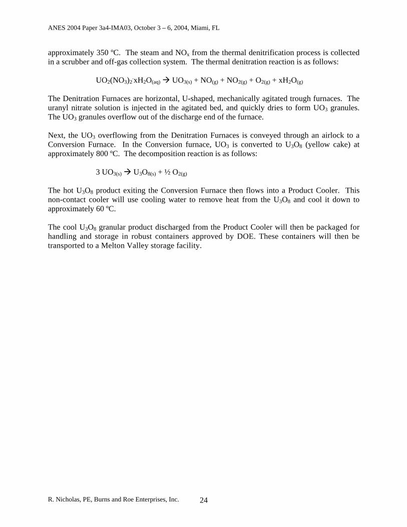
approximately 350 ºC. The steam and NOx from the thermal denitrification process is collected in a scrubber and off-gas collection system. The thermal denitration reaction is as follows:
UO2(NO3)2.xH2O(aq) UO3(s) + NO(g) + NO2(g) + O2(g) + xH2O(g)
The Denitration Furnaces are horizontal, U-shaped, mechanically agitated trough furnaces. The uranyl nitrate solution is injected in the agitated bed, and quickly dries to form UO3 granules. The UO3 granules overflow out of the discharge end of the furnace. Next, the UO3 overflowing from the Denitration Furnaces is conveyed through an airlock to a Conversion Furnace. In the Conversion furnace, UO3 is converted to U3O8 (yellow cake) at approximately 800 ºC. The decomposition reaction is as follows:
3 UO3(s) U3O8(s) + ½ O2(g) The hot U3O8 product exiting the Conversion Furnace then flows into a Product Cooler. This non-contact cooler will use cooling water to remove heat from the U3O8 and cool it down to approximately 60 ºC. The cool U3O8 granular product discharged from the Product Cooler will then be packaged for handling and storage in robust containers approved by DOE. These containers will then be transported to a Melton Valley storage facility.
R. Nicholas, PE, Burns and Roe Enterprises, Inc. 24
ANES 2004 Paper 3a4-IMA03, October 3 – 6, 2004, Miami, FL
Cancer Research and Alpha-Particle Radioimmunotherapy A Brief History Cancer is the second-ranking cause of death in the world today. In the United States, approximately 38 percent of the population contracts the disease and 17 percent succumbs to it. Today, physicists and physicians are working closely together to devise new methods for exploiting the power of ionizing radiation in the fight against this deadly disease. One such method, known as alpha-particle radioimmunotherapy, has become a promising strategy. Here, monoclonal antibodies are used to deliver radioactive isotopes directly to tumor cells. Radiation was first used to treat cancer around the turn of the century. In the 1920s, it was first used to cure laryngeal (voice box) cancer. This was a treatment breakthrough because surgery to treat this disease results in the loss of speech while radiation treatment can spare the ability to speak. During the ensuing 60 years, advances in both the radiation itself that made it possible to treat deep tumors and in the methods used to locate and evaluate tumors, brought about the evolution of radiation into a powerful form of cancer treatment. Today, about half of all cancer patients are treated with radiation. Recent advances have made it even more useful. Radioactive implants allow delivery of radiation to localized areas with less injury to surrounding tissues than radiation from an external source that must pass through those tissues. Proton radiation also causes less injury to surrounding tissues than traditional photon radiation because proton rays can be more tightly focused. Current research with radioimmunotherapy and neutron capture therapy provide ways to direct radiation exclusively to cancer cells, and in the case of radioimmunotherapy, to cancer cells that have spread to many sites throughout the body. Until the mid-1990s, the only way to treat cancer that has spread to multiple locations throughout the body has been with traditional chemotherapy, which uses drugs that preferentially kill dividing cells in a non-specific way. Modern radioimmunotherapy, in which monoclonal antibodies are used to deliver radioactive isotopes directly to tumor cells, has been under development for two decades. Nearly all of this work has focused on the use of agents that carry beta particle–emitting isotopes. Beta particles have relatively low energy and long ranges, which make them most useful for radiosensitive tumors of considerable size, such as lymphomas. As an alternative, alpha-particle emitters such as actinium-225 (225Ac) and bismuth-213 (213Bi) are capable of extraordinarily potent single-cell kill of a wide variety of tumor types, including leukemias and lymphomas. Unlike beta-particles, alpha-particles are extremely effective at killing cells through radioactive decay, and they deposit their energy over microscopic dimensions of only a few cell diameters. Therefore, antibodies “tagged” with alpha-emitters deliver a potent dose of radiation directly to the cancer with minimal or no exposure of healthy tissue. Phase II human clinical trials for treatment of a type of leukemia using 213Bi are underway at New York City’s Memorial Sloan-Kettering Cancer Center. ORNL is studying 213Bi for lung cancer therapy, and the National
R. Nicholas, PE, Burns and Roe Enterprises, Inc. 25
ANES 2004 Paper 3a4-IMA03, October 3 – 6, 2004, Miami, FL
Cancer Institute is conducting studies to determine the value of this therapy in treating various cancers as well as transplant conditioning. Alpha–emitters are significant for the following reasons:
• High local damage. Alpha emitters compared to other radiation sources (x-ray, gamma, beta, etc.) deposit most of their energy in a very small volume within a few cell diameters. The large local energy deposition provides a higher assurance that the specific cell is destroyed, not just damaged. It is estimated that one to two 213Bi decays will kill a cancer cell.
• Auxiliary damage control. In most types of radiation therapy, the radiation is concentrated on cancer cells, but healthy cells also receive high radiation doses. For example, if x-rays are used, many of the x-rays will be absorbed into healthy cells. Because alpha damage is very localized, secondary damage is minimized. This outcome is particularly important in treatment of certain cancers (e.g., leukemia) and other diseases (e.g., meningitis) where single cells or small clusters of cells are the targets that are interdispersed among healthy cells. Conventional radiation therapy will kill large numbers of healthy cells and have the potential to harm the patient.
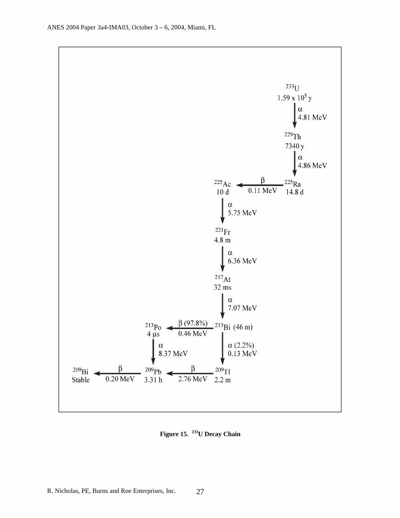
• Minimal long-term damage. Most alpha emitters decay through many additional decays to a stable isotope. Each of these subsequent decays creates radiation damage beyond the cancerous cell that was destroyed. These longer-term effects can adversely impact the health of both patients and doctors. 213Bi, however, has the desirable characteristic in that it and its decay products all have short half-lives and quickly decay after destroying the cancer. The half-life of 213Bi is 46 minutes. It primarily decays by beta emission to 213Po, which, in turn, decays to 209Pb by alpha emission in 4 × 10⁻⁶ s. Both decays are simultaneous in terms of the destruction of cancer cells. The 209Pb, with a half-life of 3.31 hours, decays in turn by low-energy beta emission to stable 209Bi.
The 233U decay chain is given in Figure 15.
R. Nicholas, PE, Burns and Roe Enterprises, Inc. 26
ANES 2004 Paper 3a4-IMA03, October 3 – 6, 2004, Miami, FL
Figure 15. 233U Decay Chain
R. Nicholas, PE, Burns and Roe Enterprises, Inc. 27
ANES 2004 Paper 3a4-IMA03, October 3 – 6, 2004, Miami, FL
DOE’s Contribution For over 50 years, DOE has led the development of isotopes for medical diagnosis and treatment and for industrial uses. Examples of such developments are technetium-99m (used annually for about 85 percent of all diagnostic nuclear medicine imaging procedures worldwide), thallium-201 (for myocardial stress tests, iodine-123 (determination of thyroid disease), copper-67 (cancer therapy and imaging), tin-117m (promising agent for bone pain treatment and bone cancer therapy), and fluorine-18 (most sensitive radiotracer for detection and diagnosis of cancer). The DOE often partners with private industry by making its facilities and expertise available for the development of therapeutics. Each year, 600 deliveries of over 215 types of isotopes are made to over 300 domestic and international customers, including hospitals, pharmaceutical companies, and industrial customers. With respect to 213Bi, the DOE has been providing modest quantities of this radioisotope for the past several years. This work began in 1995 when the Nuclear Science and Technology Division of ORNL received funding to extract thorium from the sludge from the Building 3019A waste tanks. Waste from the original 233U production during the Manhattan Project and Cold War days was stored in these tanks for 30 years. Fortunately, the extraction of the thorium proved relatively easy. Over that time, it was discovered that the thorium encrusted the boron-rich glass rings, called raschig rings, that had been placed in the waste tanks as a neutron absorber. Simply washing the rings in an acid bath retrieved much of the useful thorium. After preliminary purification, thorium from the 233U processing sludge was sent to a special hot cell in ORNL Building 3047 for further processing. The final product in the process, the 213Bi, was then demonstrated by the Life Sciences Division to be an effective killer of mouse cancer cells. That work went on to show that 213Bi treatment could cure mice of lung cancers. In the past three years, ORNL’s Isotope Program has been able to take advantage of inspections of the uranium-233 packaging by the Defense Nuclear Facilities Safety Board to retrieve some additional thorium-229 while some of the containers are being opened and inspected. Currently, the 229Th is “milked” every 60 days to extract the 225Ac. It is purified and sent to Memorial Sloan Kettering Cancer Center in New York and other institutions. At Sloan Kettering, about half a milliliter 225Ac is loaded on a small column called a generator. The final product, 213Bi, with a half-life of only 46 minutes, is eluted from the generator and incorporated into a monoclonal antibody, which is immediately injected into patients. The 46-minute half-life of bismuth-213 means it must be generated on demand and on-site in the clinical trials and for future therapy programs. The short half-life of 213Bi fits well for the treatment of leukemia, however. The antibodies can find the leukemic cells in the blood within a few minutes. One or two alpha particles from 213Bi are sufficient to kill the cell to which it is attached. Cells within a radius of about 100 micrometers (about 10 cell diameters) will also receive get a large radiation dose, but cells outside the 100-micrometer sphere will receive very little radiation. The treatments has been liked to a guided nuclear weapon on a cellular level, effectively performing the most precise of micro-surgeries.
R. Nicholas, PE, Burns and Roe Enterprises, Inc. 28
ANES 2004 Paper 3a4-IMA03, October 3 – 6, 2004, Miami, FL
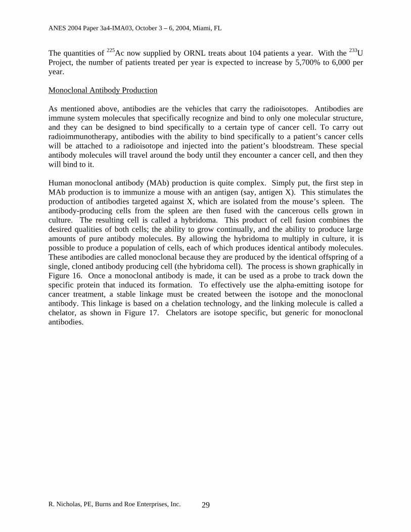
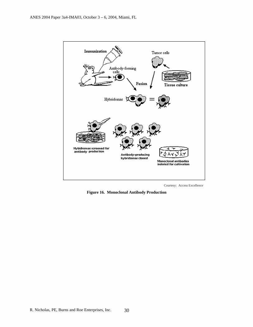
The quantities of 225Ac now supplied by ORNL treats about 104 patients a year. With the 233U Project, the number of patients treated per year is expected to increase by 5,700% to 6,000 per year. Monoclonal Antibody Production As mentioned above, antibodies are the vehicles that carry the radioisotopes. Antibodies are immune system molecules that specifically recognize and bind to only one molecular structure, and they can be designed to bind specifically to a certain type of cancer cell. To carry out radioimmunotherapy, antibodies with the ability to bind specifically to a patient’s cancer cells will be attached to a radioisotope and injected into the patient’s bloodstream. These special antibody molecules will travel around the body until they encounter a cancer cell, and then they will bind to it. Human monoclonal antibody (MAb) production is quite complex. Simply put, the first step in MAb production is to immunize a mouse with an antigen (say, antigen X). This stimulates the production of antibodies targeted against X, which are isolated from the mouse’s spleen. The antibody-producing cells from the spleen are then fused with the cancerous cells grown in culture. The resulting cell is called a hybridoma. This product of cell fusion combines the desired qualities of both cells; the ability to grow continually, and the ability to produce large amounts of pure antibody molecules. By allowing the hybridoma to multiply in culture, it is possible to produce a population of cells, each of which produces identical antibody molecules. These antibodies are called monoclonal because they are produced by the identical offspring of a single, cloned antibody producing cell (the hybridoma cell). The process is shown graphically in Figure 16. Once a monoclonal antibody is made, it can be used as a probe to track down the specific protein that induced its formation. To effectively use the alpha-emitting isotope for cancer treatment, a stable linkage must be created between the isotope and the monoclonal antibody. This linkage is based on a chelation technology, and the linking molecule is called a chelator, as shown in Figure 17. Chelators are isotope specific, but generic for monoclonal antibodies.
R. Nicholas, PE, Burns and Roe Enterprises, Inc. 29
ANES 2004 Paper 3a4-IMA03, October 3 – 6, 2004, Miami, FL
R. Nicholas, PE, Bur
Courtesy: Access Excellence
Figure 16. Monoclonal Antibody Production
ns and Roe Enterprises, Inc. 30
ANES 2004 Paper 3a4-IMA03, October 3 – 6, 2004, Miami, FL
F
Summary and Conclusions The continued safe storage of 233
significant financial liability for thsafeguards, security, and criticaliORNL will be downblended to aisotopes will be extracted. This nwhich is a collaboration between BFederal Services. There is a long history, experienceradioisotope and radiopharmaceuback over the last 30 years. radioimmunotherapy in fighting ccancer treatment potential, but alsdown-blending of materials “DOmaterials and old contaminated sSpencer Abraham said. “That wethe fight against cancer is an excit
R. Nicholas, PE, Burns and Roe Enterpri
Chelator
Courtesy: Innovation & Technology Transfer
igure 17. Monoclonal Antibody
U in the Manhattan Project-era Building 3019A represents a e DOE. 233U is a special nuclear material requiring stringent
ty controls. This expensive and unwanted nuclear legacy at safe and stable form, and in the process, life-saving medical ine-year project is being performed by Isotek Systems, LLC, urns and Roe Enterprises, Nuclear Fuel Services, and Duratek
, and significant record of accomplishments in DOE-supported tical research, particularly at the national laboratories, going This includes the promise of 213Bi and alpha-particle
ertain deadly cancers. The Project is not only important for its o for setting the stage for reducing global threats through the E has an important responsibility to clean up the dangerous tructures left over from the Cold War,” Secretary of Energy can fulfill this mission while producing valuable new tools in ing and unique opportunity.”
ses, Inc. 31
ANES 2004 Paper 3a4-IMA03, October 3 – 6, 2004, Miami, FL
References
1. Defense Nuclear Safety Board Recommendation 97-1, Safe Storage of Uranium-233, dated March 3, 1997.
2. ISO-FDD-001, Facility Design Description for the 233U Disposition, Medical Isotope Production, and Building 3019 Complex Shutdown Project, Rev. B.
3. ORNL/TM-12720, Historical and Programmatic Overview of Building 3019, Brooksbank, R. E., et al., August 1994.
4. ORNL/TM-2002/167, Oak Ridge National Laboratory Site Assessment Report on the Storage of 233U, D. Craig, et al., July 2002.
5. ORNL/TM-2004/21, Summary Report on DNFSB 97-1 Inspections of 233U Storage at Oak Ridge National Laboratory, T. B. Conely, et al., April 2004.
6. ORNL/TM-13517, Definition of Weapons Usable Uranium-233, C. Forsberg, et al., March 1998.
7. ORNL/TM-13524, Isotopic Dilution Requirements for 233U Criticality Safety in Processing and Disposal Facilities, K. Elam, et al., November 1997.
8. American Cancer Society Presentation, Cancer Statistics 2004, Copyright 2004 9. ORNL-6952, Uses for Uranium-233: What Should Be Kept For Future Needs?, C.
Forsberg, et al., September 24, 1999. 10. ORNL/M-6606, Uranium-233 Storage Alternative Trade Study, J. Rushton, et al., Final
Report, September 1998. 11. Disposal of 233U in the Waste Isolation Pilot Plant, C. Forsberg, et al., Prepared for the
2001 Waste Management Symposium, Tuscon, AZ, February 28, 2001. 12. Report to Congress on the Extraction of Medical Isotopes from Uranium-233, U.S.
Department of Energy, Office of Nuclear Energy, Science and Technology, Office of Isotopes for Medicine and Science, March 2001.
13. Duratek Federal Services Presentation, Reducing the Risk of Legacy Fissile Material – Downblending the Oak Ridge U-233 Inventory, presented by T. Butz.
14. DOE/EA-1488, Environmental Assessment for the U-233 Disposition, Medical Isotope Production, and Building 3019 Complex Shutdown at the Oak Ridge National Laboratory, Oak Ridge, Tennessee, April 2004, Preliminary Draft.
15. DOE Presentation, Briefing for the External Independent Review, April 6, 2004. 16. DOE This Month, Project Will Boost Supply of Medical Isotopes, January 2004. 17. UT-Battelle Presentation, Building 3019A Radiochemical Development Facility,
Department of Energy National Repository for 233U, November 2003. 18. DOE NEPA Review and Environmental Assessment fact sheet, Uranium-233
Disposition, Medical Isotope Production, and Building 3019 Complex Shutdown at ORNL.
19. DOE Medical Isotopes Program fact sheet. 20. NFS Innovation Extra, NFS To Play Key Role in Oak Ridge Uranium Downblending and
Recycling To Produce Cancer Fighting Medicine, October 10, 2003.
R. Nicholas, PE, Burns and Roe Enterprises, Inc. 32