Embed Size (px)
DESCRIPTION
COUPLING
Citation preview

1
Flexible Shaft Couplings
TRANZ-LOCK semi-elastic couplings have readily available solutions for user requirements of misalignment, installation, environmental conditions (corrosives, temperature, etc), torsional and vibration dampening, noise reduction, reaction force reduction and more. The couplings are made of high grade cast iron. The simple three piece design permits quick and easy assembly by means of either industry standard taper fit bushes or custom bores. TRANZ-LOCK couplings:
• Absorb shock and operate noiselessy
• Do not require lubrication of maintenance of any kind
• Have an elastomer insert which has a long life and which cannot wear or break the other components
• Can accommodate angular and parallel misalignment
• Are easy to install and line up

2
Tranz-lock Flexible Shaft Couplings - Specifications
Technical Data
Torque Size of Coupling Bush Size
Nom. Max. Max. Speed1) Moment of inertia2) Weight of Coupling2)
Kgm2 kg Type Bush No. Nm Nm r.p.m. Bush
Type Std. Type
Bush Type
Std. Type
7 1008 33 73 7700 0.00085 0.00078 1.0 1.1 9 1108 84 185 6300 0.00115 0.00108 1.7 1.7 11 1610 168 370 5000 0.00400 0.00344 5.0 4.2 13 1610 331 728 4100 0.00780 0.00850 5.5 6.3 15 2012 630 1490 3600 0.01810 0.02112 7.1 9.5 18 2517 998 2300 3000 0.04340 0.04820 16.6 15.0 23 3020 2100 4800 2600 0.12068 0.14052 26.0 28.0 28 3525 3308 7000 2200 0.44653 0.5479 50.0 63.0
1) At speeds exceeding allowable max. speed, consult distributor. 2) Incl. Bush with medium bore.
Permissible misalignment tolerances in mm Size of coupling 7 9 11 13 15 18 23 28
Axial misalignment +0.2 +0.5 +0.6 +0.8 +0.9 +1.1 +1.3 +1.7 Radial misalignment 0.3 0.3 0.3 0.4 0.4 0.4 0.5 0.5
Angular misalignment 0.5 0.5 1.0 1.0 1.5 1.5 2.0 2.5
Dimensions in mm
Size of
coupling Max. bore D dn a b c L1 L21)
7 32 69 55 21 25 31 25 68 9 38 85 60 20 34 32 31 91 11 48 112 80 19 44 45 45 117 13 55 130 90 18 50 50 53 136 15 65 150 104 25 58 62 60 155 18 75 180 120 35 68 77 73 184 23 95 225 150 40 85 99 86 229 28 130 275 206 51 106 119 106 286
1) Approx. total length

3
Tranz-lock Flexible Shaft Couplings - Specifications
Dimensions in mm, bush type
Bores Size of
coupling Bush ref. Min. Max.
D dn a b c L1 L21)
7 1008 9 25 69 60 21 24 31 25 65 9 1108 9 28 85 70 20 24 32 31 70 11 1610 12 42 112 100 19 27 45 45 82 13 1610 12 42 130 105 18 27 50 53 89 15 2012 14 50 150 115 24 24 62 60 107 18 2517 16 65 180 125 35 47 77 73 142 23 3020 25 75 225 155 40 53 99 86 165 28 3525 28 90 275 206 51 67 119 106 208
1) Approx. total length 2) U = Flange for external mounting of bush 3) I = Flange for internal mounting of bush
Flexible Pebax® elements Size of coupling 7 9 11 13 15 18 23 28
Black Pebax® for general use KE7 KE9 KE11 KE13 KE15 KE18 KE23 KE28 Yellow Pebax® soft element KE7 KE9 KE11 KE13 KE15 KE18 KE23 KE28
Flexible element: Characteristics
Type Material Temperature °C
Pebax® Polyether-Block-Amides -40 up to +85
Resistant to oil – Low absorption of liquids – Partially resistant to chemicals
Coupling Selection procedure
1. Select service factor (see table)
2. Nominal power multiplied by service factor equals temporary design power K
3. Designed power K should then be multiplied by factor L (operating hours – see table) and S (start frequency – see table). K x L x S gives the design power which is used for coupling selection (size of coupling – see table)
4. Check from dimensional tables that chosen coupling can be fitted
4
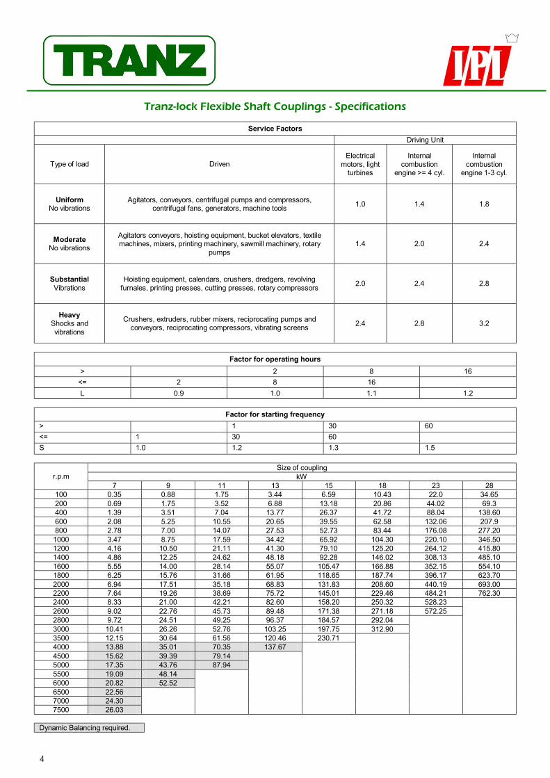
Tranz-lock Flexible Shaft Couplings - Specifications
Service Factors Driving Unit
Type of load Driven Electrical
motors, light turbines
Internal combustion
engine >= 4 cyl.
Internal combustion
engine 1-3 cyl.
Uniform No vibrations
Agitators, conveyors, centrifugal pumps and compressors, centrifugal fans, generators, machine tools 1.0 1.4 1.8
Moderate No vibrations
Agitators conveyors, hoisting equipment, bucket elevators, textile machines, mixers, printing machinery, sawmill machinery, rotary
pumps 1.4 2.0 2.4
Substantial Vibrations
Hoisting equipment, calendars, crushers, dredgers, revolving furnales, printing presses, cutting presses, rotary compressors 2.0 2.4 2.8
Heavy Shocks and vibrations
Crushers, extruders, rubber mixers, reciprocating pumps and conveyors, reciprocating compressors, vibrating screens 2.4 2.8 3.2
Factor for operating hours
> 2 8 16 <= 2 8 16 L 0.9 1.0 1.1 1.2
Factor for starting frequency
> 1 30 60 <= 1 30 60 S 1.0 1.2 1.3 1.5
Size of coupling kW r.p.m
7 9 11 13 15 18 23 28 100 0.35 0.88 1.75 3.44 6.59 10.43 22.0 34.65 200 0.69 1.75 3.52 6.88 13.18 20.86 44.02 69.3 400 1.39 3.51 7.04 13.77 26.37 41.72 88.04 138.60 600 2.08 5.25 10.55 20.65 39.55 62.58 132.06 207.9 800 2.78 7.00 14.07 27.53 52.73 83.44 176.08 277.20 1000 3.47 8.75 17.59 34.42 65.92 104.30 220.10 346.50 1200 4.16 10.50 21.11 41.30 79.10 125.20 264.12 415.80 1400 4.86 12.25 24.62 48.18 92.28 146.02 308.13 485.10 1600 5.55 14.00 28.14 55.07 105.47 166.88 352.15 554.10 1800 6.25 15.76 31.66 61.95 118.65 187.74 396.17 623.70 2000 6.94 17.51 35.18 68.83 131.83 208.60 440.19 693.00 2200 7.64 19.26 38.69 75.72 145.01 229.46 484.21 762.30 2400 8.33 21.00 42.21 82.60 158.20 250.32 528.23 2600 9.02 22.76 45.73 89.48 171.38 271.18 572.25 2800 9.72 24.51 49.25 96.37 184.57 292.04 3000 10.41 26.26 52.76 103.25 197.75 312.90 3500 12.15 30.64 61.56 120.46 230.71 4000 13.88 35.01 70.35 137.67 4500 15.62 39.39 79.14 5000 17.35 43.76 87.94 5500 19.09 48.14 6000 20.82 52.52 6500 22.56 7000 24.30 7500 26.03
Dynamic Balancing required.