Embed Size (px)
Citation preview
13
STRUCTU
RESTransverse web stiffeners and shear momentinteraction for steel plate girder bridges
1. Background
It has been known since the 1930s that transversely stiffened web panels in bending and shear had a post-critical resistance, but only in the 1950s was the behaviour properly investigated1&2. Since then, many investigations have been carried out and many different theories have been proposed. The shear resistance theories behind most codes assume that the web operates in pure shear until elastic critical buckling occurs; subsequently, bands of tension form to carry further increases in shear. What is not agreed at present is the role of intermediate transverse stiffeners when these tension fields develop and, in particular, the forces they attract.
Rockey’s tension field theory3-5 places a much greater demand on stiffener strength than does Höglund’s rotated stress field theory6. Rockey’s theory requires the stiffeners to play the role of compression members in a truss, with the web plate acting as the tension diagonals. Höglund’s theory does not require the stiffeners to
carry any load other than that due to the small part of the tension field anchored by the flanges at collapse; no force is induced in the stiffeners in mobilising the post-critical resistance of the web. In the absence of a stiff flange to contribute to the shear resistance, the stiffeners simply contribute to elevating the elastic critical shear stress of the web. This has led to some European countries adopting a stiffness-only approach to stiffener design in the past. Adequate stiffness is simply required to ensure that the theoretical elastic critical shear resistance of the panel is achieved, or at least very nearly achieved since no stiffener can be completely rigid.
Earlier drafts of prEN 1993-1-57 required web stiffeners to be designed for a force loosely (but not exactly) based on Höglund’s theory, together with a check for adequate stiffness. These early drafts raised concern in the UK as the rules led to much smaller forces in the stiffeners than would be derived from the tension field theory approach
Abstract
Many investigations have been carried out to date into the behaviour of transversely stiffened web panels in bending and shear and many different theories have been proposed. Different code rules have been developed based on these theories. The UK’s steel bridge code, BS 5400 Part 3, based its design rules for transverse stiffeners on the work of Rockey et al., while early drafts of Eurocode prEN 1993-1-5 were based on the work of Höglund. The formers tension field theory places a much greater demand on stiffener strength than does the latter’s rotated stress field theory. Due to a lack of European agreement, EN 1993-1-5 was modified late in its drafting to include a stiffener force criterion more closely aligned to that in BS 5400 Part 3. The rules for stiffener design in EN 1993-1-5 are thus no longer consistent with the rotated stress field theory and lead to a greater axial force acting in the stiffener. The rules for the design of the web panels themselves in shear however remain based on Höglund’s rotated stress field theory, creating an inconsistency.
Recent investigations by the authors have suggested that the rules in BS 5400 Part 3 and, to a lesser extent, in the current version of EN 1993-1-5 can be unduly pessimistic. This paper investigates the behaviour of transversely stiffened plate girders in bending and shear using non-linear finite element analyses. It considers slender symmetrical steel girders with and without axial force and also steel-concrete composite plate girders, which are therefore asymmetric. It discusses the observed web post-buckling behaviour, compares it with the predictions of current theories and recommends modified design rules. It includes investigation into whether a stiffness-only approach to stiffener design can be justified, rather than a combined stiffness and force approach. The shear-moment interaction behaviour of the girders is also investigated and compared to the codified predictions of EN 1993-1-5.
017
Middle East & IndiaAtkinsAbu Dhabi, UAE
Head of Bridge Design and Technology
Senior Engineer
MA (Cantab) CEng FICE CEng, MIStructE
Chris R Hendy Francesco Presta
Highways & TransportationAtkinsEpsom, UK
Main Body.indd 13Main Body.indd 13 03/03/2009 15:50:1603/03/2009 15:50:16
14
STRU
CTU
RES
017 Transverse web stiffeners and shear momentinteraction for steel plate girder bridges
2. Guidance on Highway Asset Management
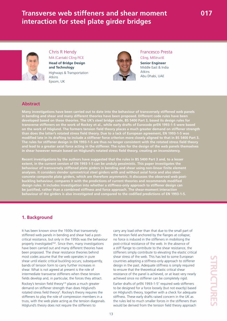
Experimental studies have indicated that, when a thin walled plate girder is loaded in shear, failure occurs when the web plate yields under the joint action of the post-buckling membrane stress and the initial elastic buckling stress of the web panel, and plastic hinges develop in the flanges, as shown in Figure 1.
2.1 Cardiff tension field theory
According to the Cardiff tension field theory developed by Rockey et al.3-5, transverse stiffeners have to fulfill two main functions. The first is to increase the elastic critical buckling resistance, Vcr, of the web plate. The second is to act as part of a truss when the web develops a diagonal tension field when the shear force exceed Vcr. This effectively leads to the stiffener force being equal to VEd – Vcr for a given shear loading VEd > Vcr. This theory is not explained further here as it was not found to be a good predictor of stiffener force or behaviour in this study.
2.2 Stockholm rotated stress field theory
The rotated stress field theory developed by Höglund6 forms the basis of the design rules in EN 1993-1-5 for the calculation of the ultimate shear resistance of plate girders.
The ultimate shear resistance Vult can be expressed as:
(1)
where Vu,w is the load carrying resistance of the web due to its membrane behaviour and Vu,f is the resistance provided
traditionally used in BS 5400:Part 38. As a result, EN 1993-1-5 was modified late on its drafting to include a stiffener force criterion more closely aligned to that in BS 5400:Part 3. The rules for stiffener design in EN 1993-1-5 are thus no longer consistent with the rotated stress field theory and lead to a significantly greater axial force acting in the stiffener, with a consequent loss of economy. The rules for the design of the web panels themselves in shear however remain based on Höglund’s rotated stress field theory, creating an inconsistency.
It is undesirable that EN 1993-1-5 should contain a rule for stiffener design that is incompatible with its rules for shear design. It is also undesirable to have a rule that is unnecessarily conservative, particularly if employed to assess existing structures, although it is noted that assessment is strictly outside the scope of the Eurocodes. This paper therefore studies, with the use of a non-linear finite element analysis package, the behaviour of transversely stiffened plate girders and seeks to determine:
1) The true mechanism for resisting shear and its interaction with moment
2) A prediction of the true forces generated in stiffeners and the potential adequacy of a “stiffness-only” approach to stiffener design, based on the stiffness criterion already given in EN 1993-1-5
3) The effects of panel aspect ratio on the collapse load
4) The effects of the ratio M/V of bending moment to shear force on the collapse load and comparison with moment-shear interaction diagrams produced by Eurocode EN 1993-1-5
FIGURE 1. HIGH SHEAR TEST9
fu,wu,ult VVV +=
Main Body.indd 14Main Body.indd 14 03/03/2009 15:50:1703/03/2009 15:50:17
15
STRUCTU
RESTransverse web stiffeners and shear momentinteraction for steel plate girder bridges
017
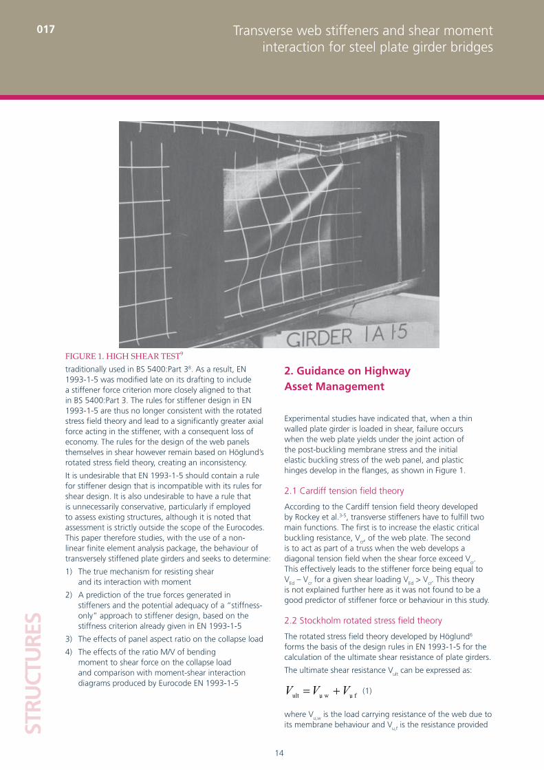
greater the dimension c. The stiffener force is thus equal to Vu,f; no force is predicted in mobilising the post-critical resistance of the web plate alone.
2.3 Design rules for transverse stiffeners in EN 1993-1-5
For the reasons discussed above, the design rules for transverse web stiffeners in EN 1993-1-5 are based on the Cardiff theory, even though the basis for its shear resistance rules is the Stockholm theory. Specifically, the stiffener effective section must resist the force from shear tension field action according to clause 9.3.3, together with any externally applied forces and moments. The tension field force is essentially equal to the difference between the web applied shear and elastic critical shear
force:
although a material factor is introduced on Vcr.
An additional stiffness criterion is given to ensure that the panel boundaries are sufficiently stiff to produce very nearly the full elastic critical shear resistance of a panel with pinned boundaries.
by an additional tension field anchored by the flanges. In determining Vu,w the web panels are represented, in the post-buckling stage, with a system of perpendicular bars in compression and in tension, as shown in Figure 2.
When the load increases, the stress σc in the compression bars is constant and equal to the buckling stress τcr while the tension bars stress σt increases when the angle θ decreases. This behaviour produces a net axial membrane tension in the web. The value Vu,w is obtained when plasticity is reached at the intersection between bars, according to the Von Mises yield criterion.
At failure, four hinges form at the top and bottom flange, with an additional tension stress field developed in the web as shown in Figure 3. The moment at each hinge is assumed to be equal to the plastic moment of the flanges.
The shear force Vu,f which is transmitted by the additional tension stress field is obtained from the equilibrium of the flange portion c. This equation gives:
(2)
where c is the distance at which plastic hinges form in the flanges. The stronger the flanges, the
FIGURE 3. SHEAR FORCE CARRIED BY TRUSS ACTION
FIGURE 2. SHEAR FORCE CARRIED BY THE WEB
crEd VV −
Main Body.indd 15Main Body.indd 15 03/03/2009 15:50:1703/03/2009 15:50:17
16
STRU
CTU
RES
Transverse web stiffeners and shear momentinteraction for steel plate girder bridges
017
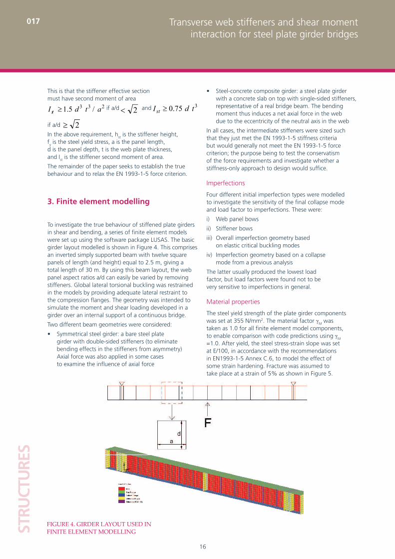
Steel-concrete composite girder: a steel plate girder • with a concrete slab on top with single-sided stiffeners, representative of a real bridge beam. The bending moment thus induces a net axial force in the web due to the eccentricity of the neutral axis in the web
In all cases, the intermediate stiffeners were sized such that they just met the EN 1993-1-5 stiffness criteria but would generally not meet the EN 1993-1-5 force criterion; the purpose being to test the conservatism of the force requirements and investigate whether a stiffness-only approach to design would suffice.
Imperfections
Four different initial imperfection types were modelled to investigate the sensitivity of the final collapse mode and load factor to imperfections. These were:
i) Web panel bows
ii) Stiffener bows
iii) Overall imperfection geometry based on elastic critical buckling modes
iv) Imperfection geometry based on a collapse mode from a previous analysis
The latter usually produced the lowest load factor, but load factors were found not to be very sensitive to imperfections in general.
Material properties
The steel yield strength of the plate girder components was set at 355 N/mm2. The material factor γM was taken as 1.0 for all finite element model components, to enable comparison with code predictions using γM =1.0. After yield, the steel stress-strain slope was set at E/100, in accordance with the recommendations in EN1993-1-5 Annex C.6, to model the effect of some strain hardening. Fracture was assumed to take place at a strain of 5% as shown in Figure 5.
This is that the stiffener effective section must have second moment of area
if a/d and
if a/d
In the above requirement, hst is the stiffener height, fy is the steel yield stress, a is the panel length, d is the panel depth, t is the web plate thickness, and Ist is the stiffener second moment of area.
The remainder of the paper seeks to establish the true behaviour and to relax the EN 1993-1-5 force criterion.
3. Finite element modelling
To investigate the true behaviour of stiffened plate girders in shear and bending, a series of finite element models were set up using the software package LUSAS. The basic girder layout modelled is shown in Figure 4. This comprises an inverted simply supported beam with twelve square panels of length (and height) equal to 2.5 m, giving a total length of 30 m. By using this beam layout, the web panel aspect ratios a/d can easily be varied by removing stiffeners. Global lateral torsional buckling was restrained in the models by providing adequate lateral restraint to the compression flanges. The geometry was intended to simulate the moment and shear loading developed in a girder over an internal support of a continuous bridge.
Two different beam geometries were considered:
Symmetrical steel girder: a bare steel plate • girder with double-sided stiffeners (to eliminate bending effects in the stiffeners from asymmetry) Axial force was also applied in some cases to examine the influence of axial force
233 /5.1 atdIst ≥ 2<
2≥
375.0 tdIst ≥
FIGURE 4. GIRDER LAYOUT USED IN FINITE ELEMENT MODELLING
Main Body.indd 16Main Body.indd 16 03/03/2009 15:50:1803/03/2009 15:50:18

17
STRUCTU
RES017Transverse web stiffeners and shear moment
interaction for steel plate girder bridges
4.2 Symmetrical steel girder
The layout used, shown in Figure 6, produces a high ratio of bending to shear force. This led to the provision of thick flanges to prevent premature failure in flexure, which in turn gave rise to large boundary rotational restraint to the web panel longitudinal edges. Adjustment of the bending/shear ratio was conducted by applying moments at the beam ends but. Most cases investigated were carried out at high shear stress and relatively low flexural stress.
Eleven different beams and/or load cases were considered and for each case, stiffeners were checked according to EN 1993-1-5. The girder ultimate load was generally well in excess of that predicted on the basis of stiffener failure to EN 1993-1-5. Only one representative case (Case 2-1) is discussed in detail.
4. Non-linear finite element study
4.1 Calibration
Calibration of the non-linear modelling techniques proposed above was achieved by modelling plate girders used in physical tests by Rockey et al in 1981. This confirmed the accuracy of the approach and will be discussed more in the conference presentation.
FIGURE 6. SYMMETRICAL STEEL BEAM SECTION AND LOADING
FIGURE 5. MATERIAL BEHAVIOUR ASSUMED IN EN1993-1-5 ANNEX C.6
Main Body.indd 17Main Body.indd 17 03/03/2009 15:50:1903/03/2009 15:50:19
18
STRU
CTU
RES
Transverse web stiffeners and shear momentinteraction for steel plate girder bridges
017
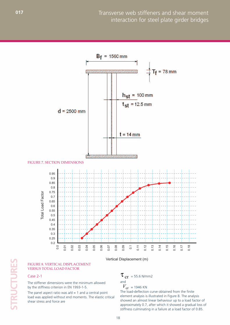
= 55.6 N/mm2
and
= 1946 KNThe load-deflection curve obtained from the finite element analysis is illustrated in Figure 8. The analysis showed an almost linear behaviour up to a load factor of approximately 0.7, after which it showed a gradual loss of stiffness culminating in a failure at a load factor of 0.85.
Case 2-1
The stiffener dimensions were the minimum allowed by the stiffness criterion in EN 1993-1-5.
The panel aspect ratio was a/d = 1 and a central point load was applied without end moments. The elastic critical shear stress and force are
FIGURE 7. SECTION DIMENSIONS
FIGURE 8. VERTICAL DISPLACEMENT VERSUS TOTAL LOAD FACTOR
Tota
l Loa
d Fa
ctor
Vertical Displacement (m)
0.950.9
0.850.8
0.750.7
0.650.6
0.550.5
0.450.4
0.350.3
0.250.2
0.010.0
0.02
0.03
0.04
0.05
0.06
0.07
0.08
0.09 0.1
0.11
0.12
0.13
0.14
0.15
0.16
0.17
0.18
crV
crτ
Main Body.indd 18Main Body.indd 18 03/03/2009 15:50:1903/03/2009 15:50:19
19
STRUCTU
RES017Transverse web stiffeners and shear moment
interaction for steel plate girder bridges
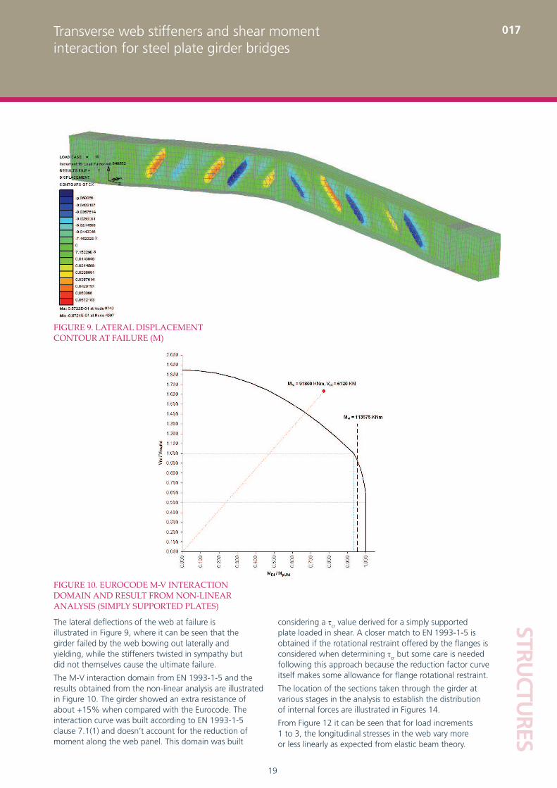
considering a τcr value derived for a simply supported plate loaded in shear. A closer match to EN 1993-1-5 is obtained if the rotational restraint offered by the flanges is considered when determining τcr but some care is needed following this approach because the reduction factor curve itself makes some allowance for flange rotational restraint.
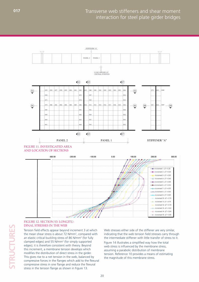
The location of the sections taken through the girder at various stages in the analysis to establish the distribution of internal forces are illustrated in Figures 14.
From Figure 12 it can be seen that for load increments 1 to 3, the longitudinal stresses in the web vary more or less linearly as expected from elastic beam theory.
The lateral deflections of the web at failure is illustrated in Figure 9, where it can be seen that the girder failed by the web bowing out laterally and yielding, while the stiffeners twisted in sympathy but did not themselves cause the ultimate failure.
The M-V interaction domain from EN 1993-1-5 and the results obtained from the non-linear analysis are illustrated in Figure 10. The girder showed an extra resistance of about +15% when compared with the Eurocode. The interaction curve was built according to EN 1993-1-5 clause 7.1(1) and doesn’t account for the reduction of moment along the web panel. This domain was built
FIGURE 9. LATERAL DISPLACEMENT CONTOUR AT FAILURE (M)
FIGURE 10. EUROCODE M-V INTERACTION DOMAIN AND RESULT FROM NON-LINEAR ANALYSIS (SIMPLY SUPPORTED PLATES)
Main Body.indd 19Main Body.indd 19 03/03/2009 15:50:2003/03/2009 15:50:20
20
STRU
CTU
RES
017 Transverse web stiffeners and shear momentinteraction for steel plate girder bridges
Web stresses either side of the stiffener are very similar, indicating that the web tension field stresses carry through the intermediate stiffener with little transfer of stress to it.
Figure 14 illustrates a simplified way how the total web stress is influenced by the membrane stress, assuming a parabolic distribution of membrane tension. Reference 10 provides a means of estimating the magnitude of this membrane stress.
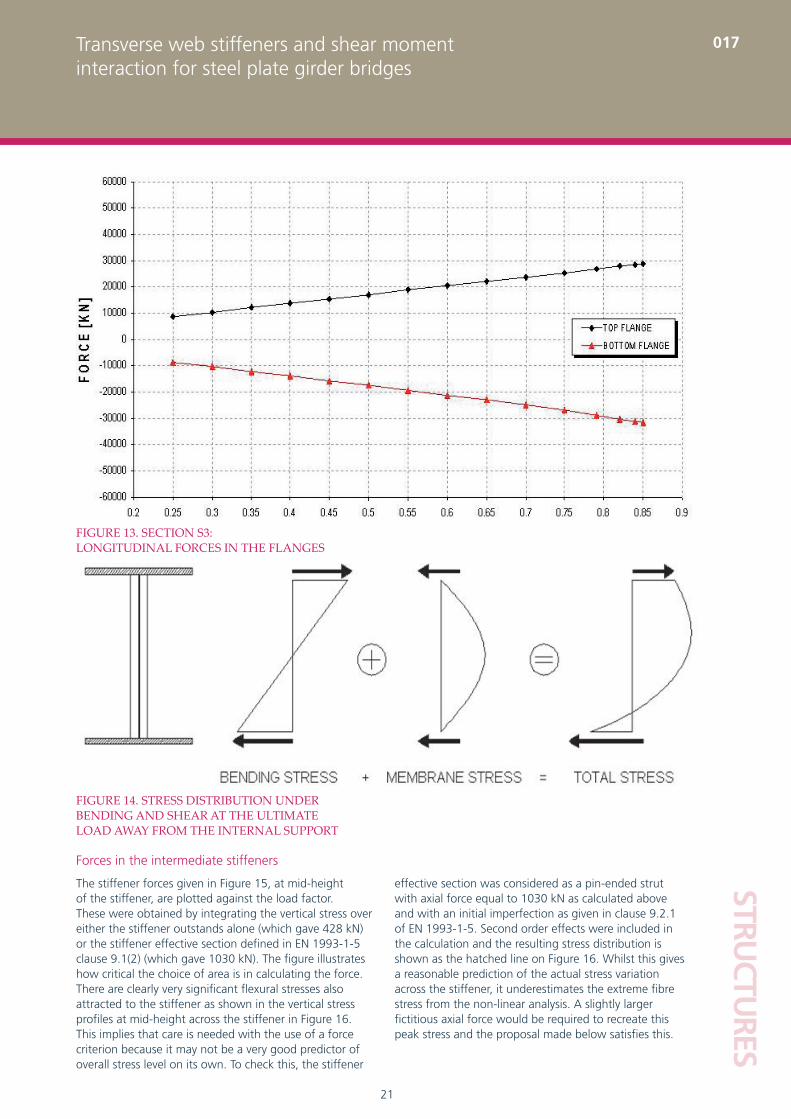
Tension field effects appear beyond increment 3 at which the mean shear stress is about 72 N/mm2, compared with an elastic critical buckling stress of 86 N/mm2 (for fully clamped edges) and 55 N/mm2 (for simply supported edges); it is therefore consistent with theory. Beyond this increment, a membrane tension develops which modifies the distribution of direct stress in the girder. This gives rise to a net tension in the web, balanced by compressive forces in the flanges which add to the flexural compressive stress in one flange and reduce the flexural stress in the tension flange as shown in Figure 13.
FIGURE 11. INVESTIGATED AREA AND LOCATION OF SECTIONS
FIGURE 12. SECTION S3: LONGITU-DINAL STRESSES IN THE WEB
Main Body.indd 20Main Body.indd 20 03/03/2009 15:50:2103/03/2009 15:50:21
21
STRUCTU
RES017Transverse web stiffeners and shear moment
interaction for steel plate girder bridges
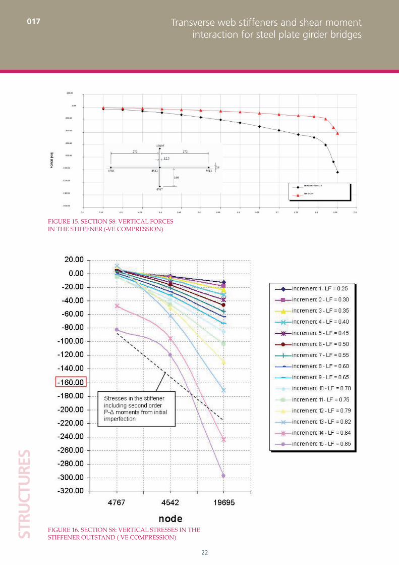
effective section was considered as a pin-ended strut with axial force equal to 1030 kN as calculated above and with an initial imperfection as given in clause 9.2.1 of EN 1993-1-5. Second order effects were included in the calculation and the resulting stress distribution is shown as the hatched line on Figure 16. Whilst this gives a reasonable prediction of the actual stress variation across the stiffener, it underestimates the extreme fibre stress from the non-linear analysis. A slightly larger fictitious axial force would be required to recreate this peak stress and the proposal made below satisfies this.
Forces in the intermediate stiffeners
The stiffener forces given in Figure 15, at mid-height of the stiffener, are plotted against the load factor. These were obtained by integrating the vertical stress over either the stiffener outstands alone (which gave 428 kN) or the stiffener effective section defined in EN 1993-1-5 clause 9.1(2) (which gave 1030 kN). The figure illustrates how critical the choice of area is in calculating the force. There are clearly very significant flexural stresses also attracted to the stiffener as shown in the vertical stress profiles at mid-height across the stiffener in Figure 16. This implies that care is needed with the use of a force criterion because it may not be a very good predictor of overall stress level on its own. To check this, the stiffener
FIGURE 13. SECTION S3: LONGITUDINAL FORCES IN THE FLANGES
FIGURE 14. STRESS DISTRIBUTION UNDER BENDING AND SHEAR AT THE ULTIMATE LOAD AWAY FROM THE INTERNAL SUPPORT
Main Body.indd 21Main Body.indd 21 03/03/2009 15:50:2103/03/2009 15:50:21
22
STRU
CTU
RES
017 Transverse web stiffeners and shear momentinteraction for steel plate girder bridges
FIGURE 15. SECTION S8: VERTICAL FORCES IN THE STIFFENER (-VE COMPRESSION)
FIGURE 16. SECTION S8: VERTICAL STRESSES IN THE STIFFENER OUTSTAND (-VE COMPRESSION)
Main Body.indd 22Main Body.indd 22 03/03/2009 15:50:2203/03/2009 15:50:22
23
STRUCTU
RES017Transverse web stiffeners and shear moment
interaction for steel plate girder bridges
Also shown in Table 1 are the predicted stiffener forces calculated in accordance with Höglund’s6 theory, which are those based solely on the final part of the shear resistance mobilised by the flange contribution Vbf,Rd. Also based on Höglund’s6 theory is a proposed design value of Vult – Vbw,Rd which allows for the fact that the shear carried in the non-linear analysis exceeded the codified shear resistance. For design in accordance with EN 1993-1-5, Vult – Vbw,Rd ≤ Vbf,Rd, unlike in Table 1.
It can be seen that the approach used in EN 1993-1-5 gives high values for the forces in the stiffeners compared to the ones obtained from the non-linear analyses. In order to get a better correlation with the FE results, an alternative criterion is required. From the evidence that the tension field passes through the stiffeners after elastic buckling has occurred, it appears reasonable to base the stiffener forces on the difference between the applied shear force and the shear strength of the web Vbw,Rd. The force in the stiffener, applied in the plane of the web, can then be expressed as follows:
F = VEd – α Vbw,Rd ≥ 0 (3)
which contrasts with a value of VEd – Vcr as implicit in the EN 1993-1-5 approach.
The enhancement factor α was intended to allow for secondary compatibility bending stresses that develop in the stiffeners due to their function of keeping the panel straight along its boundaries. For this purpose, it would be expected that α would be less than unity. However, all the results except those for case 11, indicate that α is greater than unity and can conservatively be taken as unity. The reason for the greater than unity value of α is likely to result from an underestimate of Vbw,Rd in EN 1993-1-5 and the beneficial effects of strain hardening. The lack of conservatism of the proposal for case 11 is mitigated by the additional stiffness criterion in EN 1993-1-5 which would not be met if a stiffener was designed for the very small force predicted by the FE model.
TABLE 1. FORCES IN STIFFENERS IN KN
Case
Vult Vcr Vbw,Rd Stiffener force according to:
FE Modelsimply supported boundaries
EN1993-1-5 Vult –Vcr Vbf,Rd 6 Vult – Vbw,Rd FE Model
1-1 9009 4864 6306 4145 1665 2703 425
1-2 8811 4864 6306 3947 1665 2505 175
2-1 6120 1946 3750 4174 1545 2370 1030
2-2 6120 1946 3750 4174 1545 2370 1075
4 8613 4864 6306 3749 1048 2307 290
11 4653 4864 6306 0* 0** 0** 130* Vult <Vcr
** Vult < Vbw,Rd
The stiffener force predicted by EN 1993-1-5, calculated as the difference between the observed ultimate shear force (6120 KN) and the elastic critical shear force (1946 KN), amounts to 4174 KN compared with a value derived from the observed stresses of about 1030 KN for the effective area at mid-height of the stiffener. If the above second order calculation is repeated for the stiffener using the force from the design standard, it leads to a predicted stiffener extreme fibre stress of over 1000 MPa which is far in excess of that predicted by the non-linear model (and indeed yield) and implies that the Rockey approach is very conservative.
Results for some of the other model cases are shown in Table 1. The stiffener forces derived from the non-linear analyses were compared to those predicted by EN 1993-1-5, which assume that the forces equate to the observed ultimate shear forces minus the critical shear forces, Vult – Vcr.
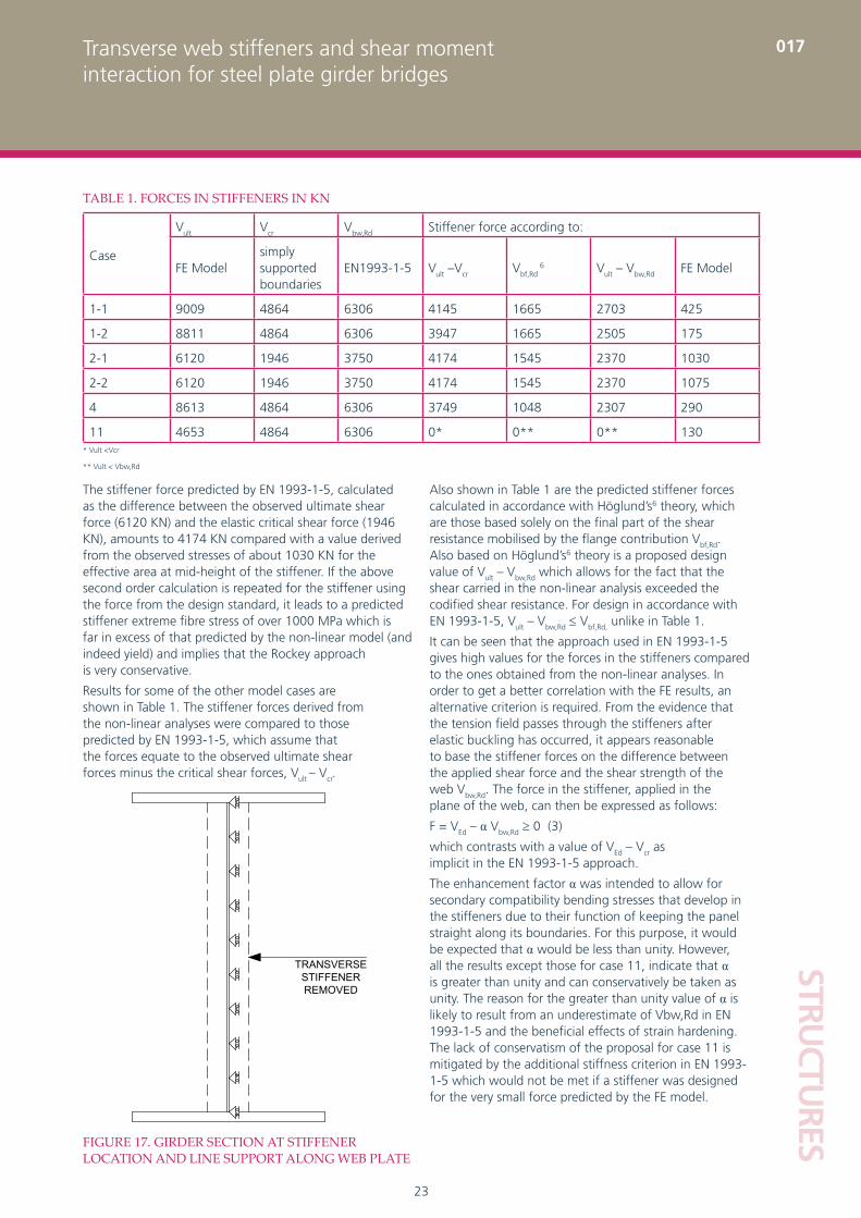
FIGURE 17. GIRDER SECTION AT STIFFENER LOCATION AND LINE SUPPORT ALONG WEB PLATE
TRANSVERSESTIFFENER REMOVED
Main Body.indd 23Main Body.indd 23 03/03/2009 15:50:2303/03/2009 15:50:23
24
STRU
CTU
RES
017 Transverse web stiffeners and shear momentinteraction for steel plate girder bridges
This is effectively a transverse stiffener with no capacity to carry axial force but with a rigid out of plane bending stiffness.
It is interesting to note that the non-linear analysis stops when it fails to find equilibrium beyond a load factor 0.88, which is slightly larger than the load factor obtained when a transverse stiffener with the minimum EN 1993-1-5 stiffness was provided. The load factor in that case was 0.85 and the failure was by panel yield rather than by stiffener buckling. This means that the girder still achieves a shear of Vbw, Rd to EN 1993-1-5 even if the stiffener cannot carry any axial force in a truss mechanism and that out of plane bending stiffness is more important than axial resistance. The mechanism predicted by Rockey does not actually occur and the development of stiffener axial force in a truss behaviour is not necessary for loading beyond Vcr.
Steel-concrete composite girder
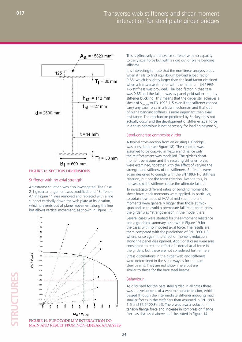
A typical cross-section from an existing UK bridge was considered (see Figure 18). The concrete was assumed to be cracked in flexure and hence only the reinforcement was modelled. The girder’s shear-moment behaviour and the resulting stiffener forces were examined, together with the effect of varying the strength and stiffness of the stiffeners. Stiffeners were again designed to comply with the EN 1993-1-5 stiffness criterion, but not the force criterion. Despite this, in no case did the stiffener cause the ultimate failure.
To investigate different ratios of bending moment to shear force, ends moments were applied. In particular, to obtain low ratios of M/V at mid-span, the end moments were generally bigger than those at mid-span and so to avoid a premature failure at beam ends, the girder was “strengthened” in the model there.
Several cases were studied for shear-moment resistance and a graphical summary is shown in Figure 19 for the cases with no imposed axial force. The results are there compared with the predictions of EN 1993-1-5 where, once again, the effect of moment reduction along the panel was ignored. Additional cases were also considered to test the effect of external axial force in the girders, but these are not considered further here.
Stress distributions in the girder web and stiffeners were determined in the same way as for the bare steel beams. They are not shown here but are similar to those for the bare steel beams.
Behaviour
As discussed for the bare steel girder, in all cases there was a development of a web membrane tension, which passed through the intermediate stiffener inducing much smaller forces in the stiffeners than assumed in EN 1993-1-5 and BS 5400:Part 3. There was also a reduction in tension flange force and increase in compression flange force as discussed above and illustrated in Figure 14.
Stiffener with no axial strength
An extreme situation was also investigated. The Case 2-1 girder arrangement was modified, and “Stiffener A” in Figure 11 was removed and replaced with a line support vertically down the web plate at its location, which prevents out of plane movement along the line but allows vertical movement, as shown in Figure 17.
FIGURE 18. SECTION DIMENSIONS
FIGURE 19. EUROCODE M-V INTERACTION DO-MAIN AND RESULT FROM NON-LINEAR ANALYSES
Main Body.indd 24Main Body.indd 24 03/03/2009 15:50:2303/03/2009 15:50:23
25
STRUCTU
RES017Transverse web stiffeners and shear moment
interaction for steel plate girder bridges
The axial stress, considered in some of the analyses, had an influence on the final load bearing resistance of the girder as one would expect, but had limited effect on the stiffener forces
A revised proposal for the design force, FEd, in a stiffener has been made in order to get a better correlation with the finite element results: FEd = VEd – Vbw,Rd ≥ 0;
The effects of different M-V ratios were investigated and compared with the moment-shear interaction diagram predicted by EN 1993-1-5. The results of EN1993-1-5 were found to be conservative
Girder behaviour under shear and moment is well described by Höglund’s theory
Girder resistances were relatively insensitive to initial imperfections in the stiffeners and web panels
Evidence was produced for the adequacy of designing the stiffeners for a stiffness-only criterion, but this requires further investigation before such a proposal could be made
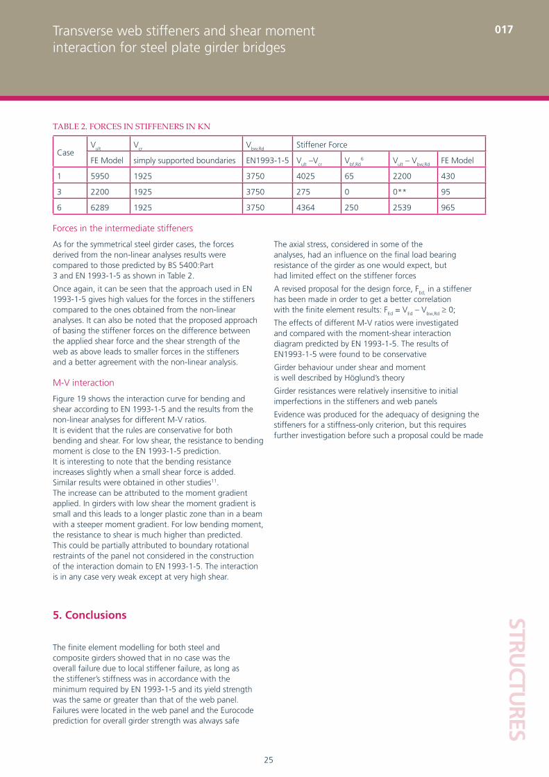
TABLE 2. FORCES IN STIFFENERS IN KN
CaseVult Vcr Vbw,Rd Stiffener Force
FE Model simply supported boundaries EN1993-1-5 Vult –Vcr Vbf,Rd6 Vult – Vbw,Rd FE Model
1 5950 1925 3750 4025 65 2200 430
3 2200 1925 3750 275 0 0** 95
6 6289 1925 3750 4364 250 2539 965
Forces in the intermediate stiffeners
As for the symmetrical steel girder cases, the forces derived from the non-linear analyses results were compared to those predicted by BS 5400:Part 3 and EN 1993-1-5 as shown in Table 2.
Once again, it can be seen that the approach used in EN 1993-1-5 gives high values for the forces in the stiffeners compared to the ones obtained from the non-linear analyses. It can also be noted that the proposed approach of basing the stiffener forces on the difference between the applied shear force and the shear strength of the web as above leads to smaller forces in the stiffeners and a better agreement with the non-linear analysis.
M-V interaction
Figure 19 shows the interaction curve for bending and shear according to EN 1993-1-5 and the results from the non-linear analyses for different M-V ratios. It is evident that the rules are conservative for both bending and shear. For low shear, the resistance to bending moment is close to the EN 1993-1-5 prediction. It is interesting to note that the bending resistance increases slightly when a small shear force is added. Similar results were obtained in other studies11. The increase can be attributed to the moment gradient applied. In girders with low shear the moment gradient is small and this leads to a longer plastic zone than in a beam with a steeper moment gradient. For low bending moment, the resistance to shear is much higher than predicted. This could be partially attributed to boundary rotational restraints of the panel not considered in the construction of the interaction domain to EN 1993-1-5. The interaction is in any case very weak except at very high shear.
5. Conclusions
The finite element modelling for both steel and composite girders showed that in no case was the overall failure due to local stiffener failure, as long as the stiffener’s stiffness was in accordance with the minimum required by EN 1993-1-5 and its yield strength was the same or greater than that of the web panel. Failures were located in the web panel and the Eurocode prediction for overall girder strength was always safe
Main Body.indd 25Main Body.indd 25 03/03/2009 15:50:2303/03/2009 15:50:23
26
STRU
CTU
RES
Transverse web stiffeners and shear momentinteraction for steel plate girder bridges
017
References
BASLER K., YEN B.T., MUELLER J.A. AND THÜRLIMANN B, ‘Web buckling tests on welded 1. plate girders’, Welding Research Council Bulletin, No. 64, September 1960
BASLER K., ‘Strength of plate girders in shear’, Journal of the Structural Division, Proceedings 2. of the American Society of Civil Engineers, No. 2967, p 151-180, October 1961
PORTER D. M., ROCKEY K.C. AND EVANS H.R., ‘The collapse behaviour of plate girders loaded 3. in shear’, The Structural Engineer, August 1975, No. 8, Volume 53, p 313-325
PORTER D.M., ROCKEY K.C. AND EVANS H.R., ‘A design method for predicting the collapse behaviour 4. of plate girders’, Proceedings of the Institution of Civil Engineers, Part 2, 1978, 65, March, p 85-112
ROCKEY K.C., VALTINAT G. AND TANG K.H., ‘The design of transverse stiffeners on 5. webs loaded in shear - an ultimate load approach’, Proceedings of the Institution of Civil Engineers, Part 2, 1981, 71, December, p 1069-1099
HÖGLUND T., ‘Design of thin plate I girders in shear and bending with special 6. reference to web buckling’, Bulletin No. 94, Division of Building Statics and Structural Engineering, Royal Institute of Technology, Stockholm, Sweden, 1973
CEN, Eurocode 3: Design of Steel Structures, Part 1.5: Plated structural 7. elements, Milton Keynes, BSI, 2004, ENV 1993-1-5
BRITISH STANDARDS INSTITUTION, Code of Practice for Design of Steel 8. Bridges, Milton Keynes, BSI, 1982, BS 5400:Part 3
HORNE M.R., HOLLOWAY B. G.R., Structural action in steel box girders, London, CIRIA GUIDE 3, April 19779.
HENDY C.R., MURPHY C.J., Designers’ Guide to EN1993-2 – Eurocode 3, Design of 10. steel structures, Part 2, Steel bridges, London, Thomas Telford, 2007
VELJKOVIC M. and JOHANSSON B., ‘Design for buckling of plates due to direct stress’, 11. Proceedings of the Nordic Steel Construction Conference, Helsinki, 2001
This paper was published in The Structural Engineer, Novermber 2008.
Main Body.indd 26Main Body.indd 26 03/03/2009 15:50:2303/03/2009 15:50:23


![Assessment of Cellular Beams with Transverse Stiffeners ...eprints.whiterose.ac.uk/85944/3/Paper_v5_GG_KDT.docx[1].pdf · Assessment of Cellular Beams with Transverse Stiffeners and](https://img.pdfslide.us/doc/110x75/5b33d3f97f8b9a6b548b717f/assessment-of-cellular-beams-with-transverse-stiffeners-1pdf-assessment.jpg)


![EDGE EFFECTS IN THIN FILM DELAMINATION€¦ · used for stiffeners has been used to describe thin films [8]. In the membrane model, only shear traction on the interface is considered](https://img.pdfslide.us/doc/110x75/5e8ea19d938cfe69eb777391/edge-effects-in-thin-film-delamination-used-for-stiffeners-has-been-used-to-describe.jpg)