Embed Size (px)
Citation preview

T r a n s P o r t ® W R 4 1 U t i l i t y
Installation Guide
90001276_B July 22, 2013

TransPort® WR41 Utility Installation Guide
Page 2
Disclaimer
Digi International makes no representations or warranties with respect to the contents or use of this manual, any software drivers or associated application software provided with this product and specifically disclaims any expressed or implied warranties of merchantability or fitness for any particular purpose.Digi International reserves the right to modify or revise all or part of this document, its contents, and any products described herein at any time without prior notification and shall not be responsible for any loss, cost or damage, including consequential damage, caused by reliance on these materials.
Digi Technical Support Contact Information
United States: (952) 912-3444 or (877) 912-3444
Other Locations: +1 (952) 912-3444 or (877) 912-3444
EMEA +44 870 35 000 35
Safety Notices
1. Please read all instructions before installing and powering the unit. You should keep these instructions in a safe place for future reference. When installing and using this electrical equipment, always follow basic precautions.
2. If the power supply shows signs of damage or malfunction, stop using it immediately, turn off the power and disconnect the power supply before contacting your supplier for a repair or replacement.
3. Changes or modifications not expressly approved by the party responsible for compliance could void the user’s authority to operate the equipment. Use only the accessories, attachments, and power supplies provided by the manufacturer – connecting non-approved antennas or power supplies may damage the unit, cause interference or create an electric shock hazard, and will void the warranty.
4. Do not attempt to repair the product. The unit contains no electronic components that can be serviced or replaced by the user. Any attempt to service or repair the unit by the user will void the product warranty.
5. Products in the TransPort WR® family are designed for indoor use (except for the WR44 R) and should be used in an environment that is suitable for computers and other electronic equipment.
6. Ports that are capable of connecting to other apparatus are defined as SELV ports. To ensure conformity with IEC60950 ensure that these ports are only connected to ports of the same type on other apparatus.
Note: A licensed electrician may be required to install or perform maintenance on this equipment. Always follow applicable local, state and federal codes and guidelines.
DANGER - RISK OF ELECTRIC SHOCK: Always disconnect the mains AC voltage prior to any work on this equipment.
WARNING - An appropriate external disconnect device must be installed and properly marked to ensure that an electrical hazard is not present.
WARNING - Bonding between conduit and Protected Earth (PE) is required and must be part of the installation.
WARNING - Conduit hub.
WARNING - Mounting the device in a vertical orientation will ensure proper orientation. Cover screws are required as part of the safety rating.

TransPort® WR41 Utility Installation Guide
Page 3
Special notes on safety for wireless routers
Digi International products are designed to the highest standards of safety and international standards compliance for the markets in which they are sold. However, cellular-based products contain radio devices which require specific consideration. Please take the time to read and understand the following guidance. Digi International assumes no liability for an end user’s failure to comply with these precautions.
Wireless routers incorporate a wireless radio module. Users should ensure that the antenna(s) is (are) positioned at least 1 meter away from themselves and other persons in normal operation.
When in a hospital or other health care facility, observe the restrictions on the use of mobile phones. Do not use the unit in areas where guidelines posted in sensitive areas instruct users to switch off mobile phones. Medical equipment may be sensitive to RF energy.
The operation of cardiac pacemakers, other implanted medical equipment and hearing aids can be affected by interference from cellular terminals such as the wireless routers when places close to the device. If in doubt about potential danger, contact the physician or the manufacturer of the device to verify that the equipment is properly shielded. Pacemaker patients are advised to keep the wireless router away from the pacemaker while it is on.
Wireless routers must NOT be operated on aircraft. The operation of wireless appliances in an aircraft is forbidden to prevent interference with communications systems. Failure to observe these instructions may lead to the suspension or denial of cellular services to the offender, legal action, or both.
As with any electrical equipment, do not operate the unit in the presence of flammable gases, fumes or potentially explosive atmospheres. Radio devices should not be used anywhere that blasting operations are taking place.
Wireless routers receive and transmit radio frequency energy when power is on. Interference can occur if used close to TV sets, radios, computers or inadequately shielded equipment. Follow any special regulations and always power off your unit wherever forbidden or when it may cause interference or danger.
SOS IMPORTANT! - Wireless routers operate using radio signals and cellular networks cannot be guaranteed to connect in all possible conditions. Therefore, never rely solely upon any wireless device for life critical communications.
Product Disposal Instructions
The WEEE (Waste Electrical and Electronic Equipment: 2002/96/EC) directive has been introduced to ensure that electrical/ electronic products are recycled using the best available recovery techniques to minimize the impact on the environment.
This product contains high quality materials and components which can be recycled. At the end of its life this product MUST NOT be mixed with other commercial waste for disposal. Check with the terms and conditions of your supplier for disposal information.
Digi International Ltd WEEE Registration number: WEE/HF1515VU

TransPort® WR41 Utility Installation Guide
Page 4
Table of Contents
1 Package Contents ..................................................................................... 5
2 Introduction ................................................................................................ 6
3 Product Features ....................................................................................... 7
3.1 Exterior Features ...............................................................................................7
3.2 Interior Features ................................................................................................9
4 Mounting ..................................................................................................... 10
4.1 Cable Installation ...............................................................................................10
5 Installation ................................................................................................... 11
5.1 Install SIM Card(s) ............................................................................................11
5.2 Connect Antenna(s) ..........................................................................................12
5.3 Connect Power ..................................................................................................13
5.4 Battery Installation .............................................................................................14
6 Device Initialization .................................................................................... 15
7 Configuration ............................................................................................. 16
7.1 Network Settings ..............................................................................................16
7.2 Web Interface ....................................................................................................16
7.3 Command Line Interface (CLI) ..........................................................................19
8 Troubleshooting ........................................................................................ 21
8.1 Troubleshooting Resources .............................................................................21
8.2 Unable to open the Web Interface ....................................................................21
8.3 Unable to log in to the Web Interface ...............................................................21
TransPort® WR41 Utility Installation Guide
Page 5
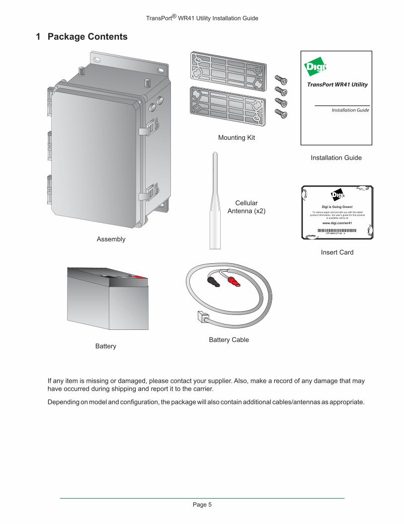
1 Package Contents
If any item is missing or damaged, please contact your supplier. Also, make a record of any damage that may have occurred during shipping and report it to the carrier.
Depending on model and configuration, the package will also contain additional cables/antennas as appropriate.
Insert Card
Installation Guide
TransPort WR41 Utility
Installation Guide
To reduce paper and provide you with the latestproduct information, the user’s guide for this product
is available online at:
www.digi.com/wr41
Digi is Going Green!
A(1P):90001277-88 Assembly
Battery
Battery Cable
Cellular
Antenna (x2)
Mounting Kit

TransPort® WR41 Utility Installation Guide
Page 6
Preface
This guide describes the installation procedure for the TransPort WR41 Utility. It is intended to provide sufficient information to be able to connect the unit to terminal equipment and power-on the unit. A complete reference guide to the software features that are available on the product is available separately in PDF format and can be downloaded from the Digi International web site (www.digi.com).
2 Introduction
The Digi Utility Communications Hub offers utilities and energy management service providers a customizable remote command center. Each hub is built around one of Digi’s three proven cellular routing platforms. The Digi Connect® WAN provides cellular/WiMAX connectivity to remote serial and IP devices. The Digi TransPort® offers advanced routing and security features such as VRRP, IPv6 and 256-bit AES. The ConnectPort® X offers dual radios to support a cellular and WLAN connection such as license-free RF and ZigBee Smart Energy.
The router options allow customers to design a hub to match their application requirements. Serial options include RS-232 and Modbus to Modbus TCP conversion. The hub can also include 1, 4 or 7 additional Ethernet ports and supports several ISM and proprietary RF protocols. Battery backup options are available.
The Digi Utility Communications Hub is NEMA 4x/IP66 rated and can accommodate additional customer hardware.
TransPort® WR41 Utility Installation Guide
Page 7
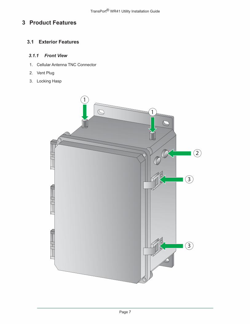
3 Product Features
3.1 Exterior Features
3.1.1 Front View
1. Cellular Antenna TNC Connector
2. Vent Plug
3. Locking Hasp
3
3
1
1
2

TransPort® WR41 Utility Installation Guide
Page 8
3.1.2 Back View
1. Cellular Antenna TNC Connector
2. Mounting Bracket
3. 1” Conduit Hole
4. 1/2” Conduit Hole
Note: Some of the conduit holes shown below may not be accessible.
1
1
2
2
3
4
4

TransPort® WR41 Utility Installation Guide
Page 9
3.2 Interior Features
1. Primary Cellular Antenna Cable
2. Secondary Cellular Antenna Cable
3. SIM Slot
4. Ethernet Switch
5. RS232 (RJ45) Connector
6. Battery Mounting Bracket
7. Protected Bonding Ground
8. AC Wiring Terminal Block/Protected Earth Ground (PE)
9. Battery Terminal
4
8
5
63
7 7
1 2
9

TransPort® WR41 Utility Installation Guide
Page 10
4 Mounting
A mounting kit is provided which includes:
• 2 x Mounting flanges
• 4 x Screws, 1/4” Phillips flat head
Step 1) Fasten the mounting brackets to the top and bottom of the rear side of the enclosure with the 1/4”-20 x .25” SS Phillips screws provided. Torque limit -20 in. lb.
Step 2) Select the location to mount the device.
Note: The TransPort WR41 Utility should be mounted to a rigid vertical surface with the knockout holes facing down and the dual cellular antennas facing up. There are two mounting flanges on the base of the unit. Dimensions are approximately 10” x 12” x 6”.
Step 3) Remove the seal plugs on either the bottom or rear surface of the device. Hole sizes are as follows:
• 3 holes at 1/2” NPT
• 3 holes at 1” NPT
Note: Conduits or fittings are not provided. It is the responsibility of the installer to determine which hardware to use.
Note: Bonding between conduit is not automatic and must be provided as part of the installation.
Step 4) Secure the device to the vertical surface with mounting hardware (not provided). The cover is secured by four corner screws. Torque limit -5 in. lb.
• Operating temperature: -15° C to +55° C (+5° F to +131° F)
• Storage temperature: -20° C to +60° C (-4° F to +140° F)
• Altitude maximum: 2000 meters (6561 ft.)
4.1 Cable Installation
The RJ45 connector in the TransPort WR41 Utility is pre-wired to be straight through to the RS232 connection.
Note: If you require an RS232 connection you must provide your own cable.
RJ45 Serial PinoutRJ45 RS232
1 RTS2 DTR3 RxD4 NC5 GND6 TxD7 DCD8 CTS

TransPort® WR41 Utility Installation Guide
Page 11
5 Installation
5.1 Install SIM Card(s)
When installing the SIM card(s) the primary SIM card should be installed in the upper SIM slot (SIM 1), and the contacts should be face down.
The secondary SIM card (if applicable) should be installed in the lower slot (SIM 2), and the contacts should be face up.
In both cases, the end of the SIM card with the chamfered corner should be inserted first.
The TransPort WR41 Utility also allows for dual network installations where one wireless service can be used as a back-up in the event that the primary service fails. These installations cannot be used to access two networks simultaneously. By default, SIM 1 is used for access to the primary network and SIM 2 is used for the back-up network.
Note: See “3.2 Interior Features” on page 9 for SIM slot location.
SIM 1SIM 2

TransPort® WR41 Utility Installation Guide
Page 12
5.2 Connect Antenna(s)
Connect one cellular antenna to each of the cellular antenna TNC connectors. It is highly recommended to utilize an additional antenna for diversification. Dual antennas will provide improved signal strength resulting in better performance. The cellular antenna cables come pre-installed.
Note: For most applications, the antenna(s) included with the unit will provide suitable reception, but some circumstances/environments may require a higher quality antenna or one mounted in a different location. If this is the case, Digi has many antenna options to chose from -- please contact us or visit www.digi.com. If antennas other than the supplied antenna(s) are used, the separation between the two should be no less than eight inches (8”).

TransPort® WR41 Utility Installation Guide
Page 13
5.3 Connect Power
Note: It is recommended that an external IEC 61643-series Certified surge protector is to be used with this product. The surge protector should be rated for the operating voltage of the AC Mains circuit that powers the product and have a clamping voltage not exceeding 2500 V.
Note: The device is intended to be connected to an AC power source that is separately protected by a building branch circuit rated at 20A. Consult the local, state and federal codes and guidelines.
The device is rated for 105-277 VAC power, single phase. The installer will need to connect power to the device using the AC Wiring Terminal Block.
L N
AC WiringTerminal
Block
Battery Terminal

TransPort® WR41 Utility Installation Guide
Page 14
5.4 Battery Installation
WARNING - For all installations: Precautions are needed to avoid risk of electrostatic charge/ discharge. Always practice proper grounding techniques prior to servicing the device.
The battery is shipped in a separate cardboard box inside the container. Remove it from its packaging and mount it into the battery slot on the side of the unit using the following instructions:
Step 1) Gently insert the battery into the battery mounting bracket as shown.
Note: The battery terminals should be facing upwards.
Battery Mounting Bracket
TransPort® WR41 Utility Installation Guide
Page 15
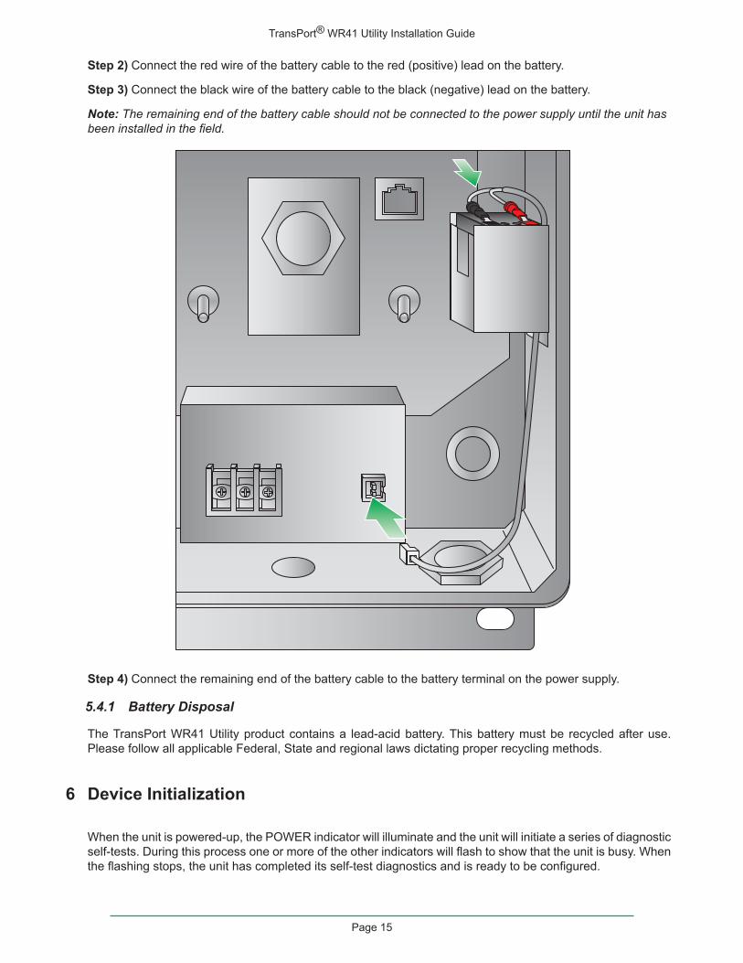
Step 2) Connect the red wire of the battery cable to the red (positive) lead on the battery.
Step 3) Connect the black wire of the battery cable to the black (negative) lead on the battery.
Note: The remaining end of the battery cable should not be connected to the power supply until the unit has been installed in the field.
Step 4) Connect the remaining end of the battery cable to the battery terminal on the power supply.
5.4.1 Battery Disposal
The TransPort WR41 Utility product contains a lead-acid battery. This battery must be recycled after use. Please follow all applicable Federal, State and regional laws dictating proper recycling methods.
6 Device Initialization
When the unit is powered-up, the POWER indicator will illuminate and the unit will initiate a series of diagnostic self-tests. During this process one or more of the other indicators will flash to show that the unit is busy. When the flashing stops, the unit has completed its self-test diagnostics and is ready to be configured.

TransPort® WR41 Utility Installation Guide
Page 16
7 Configuration
Once the unit has been installed and powered up, it needs to be configured to communicate with the LAN and WAN. Configuration is performed either using the Command Line Interface (CLI) or the Web Interface. The Web Interface (accessed via a web browser e.g. Firefox, IE, Chrome) is the recommended configuration option for most users.
Note: You will not be able to use the unit for remote communication until you have subscribed to a suitable mobile/cellular wireless network service.
7.1 Network Settings
The default IP address for the LAN port is 192.168.1.1 with a subnet mask of 255.255.255.0. The unit has a DHCP server enabled by default which can assign an appropriate IP address to your PC if the PC is configured to get an IP address automatically. Alternatively you can manually configure your PC to be on the 192.168.1.x network, for example, with an IP address of 192.168.1.2 and subnet mask of 255.255.255.0. Care should be taken to ensure that the unit does not conflict with other devices that may already be on the network.
7.2 Web Interface
Step 1) Connect to the Web Interface: Open a Web browser (e.g. Firefox, IE, Chrome) on your PC and navigate to http://192.168.1.1. If successful, you will be prompted to enter a username and password. The default username is “username”, and the default password is “password”. After you have logged in, it is strongly recommended that you immediately change the default username and password.
If you are unable to connect to the Web Interface, please refer to the Troubleshooting section on page 21.
Step 2) ConfiguretheUnit:The easiest way to perform the initial configuration of the unit is by using the Quick Start Wizard. This wizard allows you to configure the following items where applicable:
• Username and password
• LAN IP settings
• DHCP Server
• Mobile module and connection
• Wi-Fi Access Point

TransPort® WR41 Utility Installation Guide
Page 17
The Quick Start Wizard is located in the Getting Started section on the Home menu.
7.2.1 Cellular: CDMA
If your unit is to be used on a CDMA network, the embedded module must be provisioned on the network before it can make a connection.
Note: If your unit uses a Gobi module (indicated by a model number of WR41-U5xx-xxx-xx), and you did not select the appropriate CDMA carrier via the Quick Start Wizard, you must run the GOBI Module Carrier Wizard before provisioning can be successfully completed.
To provision the CDMA mobile device, navigate to the CDMA Provisioning section by clicking on Network > Mobile > CDMA Provisioning.

TransPort® WR41 Utility Installation Guide
Page 18
7.2.1.1 CDMA Provisioning
CDMA provisioning is different from GSM since CDMA (in most cases) does not use a SIM card.
The CDMA modem provisioning process creates a CDMA data connection to the mobile carrier network. This authenticates the modem and retrieves account information which is written to flash memory on the modem module itself, not the Digi’s configuration file. As the mobile account information is stored on the CDMA module, performing a factory reset on the unit will not remove provisioning information from the CDMA module.
Important points:
• The modem must be provisioned on the network before it will communicate.
• The modem must be in coverage area of the native carrier. It cannot be roaming.
• There must be sufficient signal strength available to provision the modem.
• Always use MIP Profile 1 for manual provisioning unless specified otherwise by your carrier or Digi Technical Support.
7.2.1.2 Automatic vs. Manual Provisioning
There are two types of CDMA provisioning: Automatic and Manual. This varies between carriers and even within carriers. Settings in the Web Interface vary based on carrier plan. Below are examples for Verizon Wireless and Sprint:
Verizon Wireless always uses Automatic. This means that no further settings are required in the Web Interface - simply press Start in the Automatic section and leave the fields blank.
Sprint has two types of plans, Vision for standard Internet connections and DataLink for private IP plans:
1. Sprint Vision uses Automatic provisioning. There are three fields of information that may need to be populated in the Automatic screen. Check with Sprint for correct values (if required).
2. Sprint DataLink requires Manual provisioning. The required fields in the Web Interface vary based on plan and type of embedded modem. As noted above, always use MIP Profile 1 unless otherwise specified by your carrier or Digi Technical Support.
Check with your carrier for information about the type of provisioning required and what, if any, data is required to be entered.
For more information on configuring the unit, please refer to the Digi TransPort User Guide which is available at www.digi.com.
7.2.2 Cellular: GSM
To configure the Wireless WAN/mobile interface on non-CDMA routers (GPRS/UMTS/HSPA), please refer to the Application Guide “QN02 - Configure the wireless WAN (PPP) interface” which can be found on the Digi Support site (http://www.digi.com/support/).
It is also essential to configure a dead link detection mechanism for routers using a Wireless WAN/mobile interface (such as GPRS/HSDPA/CDMA). Please refer to the Application Guide “AN07 - Wireless - Wide Area Network (W-WAN) Problem Detection and Recovery” which can also be found on the Digi Support site (http://www.digi.com/support/).

TransPort® WR41 Utility Installation Guide
Page 19
7.3 Command Line Interface (CLI)
In order to configure the unit serially, ensure that the unit is connected to a PC. Also, terminal emulation software (such as HyperTerminal) will be required.
7.3.1 CLI Notes
• To view the current configuration settings, enter the command CONFIG C SHOW.
• To save changes made to the unit, enter the command CONFIG 0 SAVE.
• All entered commands will take effect immediately.
7.3.2 Communication Settings
Step 1) Configure the following settings for the unit:
COM Port: [select the appropriate port; typically COM1]
Baud Rate: 11500
Data Bits: 8
Stop Bits: 1
Parity: No Parity
Flow Control: None
Step 2) Ensure the connection is active by entering the command AT. If the device is functioning properly, it will return the response OK.
Step 3) Ensure the COM port is setup correctly by entering the command ATI5.
7.3.3 Network Settings
To configure the unit with an IP address as part of an existing network, use the commands below.
Note: The DHCP server will still operate unless it is disabled.
Command DescriptionETH 0 IPADDR XXX.XXX.XX.XXX Sets the Eth 0 IP addressETH 0 MASK XXX.XXX.XX.XXX Sets the Eth 0 subnet mask
As an example, to assign the IP address 192.168.10.254/24, the following commands would be entered:
ETH 0 IPADDR 192.168.10.254
ETH 0 MASK 255.255.255.0
Note: When setting the mask to the above 255.255.255.0 value, it will not appear in the output of the CONFIG C SHOW command as it is a default value.

TransPort® WR41 Utility Installation Guide
Page 20
To stop the DHCP server from serving addresses, use the following command:
Command DescriptionDHCP 0 IPMIN X Removes the minimum IP address that will be server via
DHCP, disabling the DHCP server
As an example, to stop the DHCP sever from DHCP requests, enter the command DHCP 0 IPMIN !. The ! variable is used to remove a value or set it back to its default.
To retain the DHCP server, but on a different subnet, the following parameters will need to be configured:
Command DescriptionDHCP 0 IPMIN x.x.x.x Minimum IP address to assign, the start of the DHCP poolDHCP 0 IPRANGE The number of IP addresses in the DHCP poolDHCP 0 GATEWAY x.x.x.x The IP gateway address the DHCP clients should use
(normally this router’s LAN IP address)DHCP 0 MASK x.x.x.x The subnet mask DHCP clients should useDHCP 0 DNS The DNS server DHCP clients should use
For more information on CLI commands, visit http://www.digi.com/support/ and view the various reference manuals available.
TransPort® WR41 Utility Installation Guide
Page 21
8 Troubleshooting
8.1 Troubleshooting Resources
There are several resources available to you for support of your Digi product or resolving configuration difficulties at Digi’s Support site, http://www.digi.com/support/. Try these troubleshooting steps to eliminate your problem. After working through these steps and your problem is not solved, try the resources listed below.
1. Digi’s Support knowledge base: http://www.digi.com/support/kbase.
2. Digi TransPort support documents: http://ftp1.digi.com/support/documentation/transport/technicalnotes.htm.
3. If the knowledge base or support forums do not have the information you need, fill out an Online Support Request via: http://www.digi.com/support/eservice/login.jsp?p=true. You will need to create a user account if one is not already set up.
When submitting a support request, please include a copy of the debug.txt file from the unit’s flash. This will greatly improve the quality of the initial response you receive. Without this file, it is often very difficult for the support team to provide accurate answers to your queries.
For instructions on how to download the debug.txt file from the unit, view the online document “QN24 - Extracting the debug.txt file from a Digi TransPort or Sarian router”.
8.2 UnabletoopentheWebInterface
Ensure that the LAN cable is properly connected to the LAN port and that the “LAN” status indicator on the front of the unit is illuminated. If it is not, then there is a problem with either the LAN cable or the device it is connecting to. If the status indicator is illuminated, check that the PC can communicate with the unit. To do this, open the Command Prompt window on your PC and enter the command “ping 192.168.1.1”. If you do not get a response, then the problem could be one of the following:
• The IP address of the unit has been changed from its default of 192.168.1.1. Use the Digi TransPort Connection Wizard (which can be downloaded from the Support area at Digi.com or the Digi Device Discovery Tool). It can usually discover the unit on a network as long as the unit’s firewall has not been enabled.
• PC IP configuration. The PC’s LAN interface that is connected to the unit should be configured to “Obtain an IP address automatically”. If required, the Digi TransPort Connection Wizard can be used to configure the PC.
• Check the PC’s LAN connection and any LAN device (e.g. Ethernet switch) that is used to interconnect to the unit.
• Refresh the PC’s IP settings by opening a command window and enter “ipconfig /release” then “ipconfig /renew”.
• ARP resolution. Clear the PC’s ARP cache with the command “arp –d *”, then retry the ping command. If you do get a response but are unable to view the Web Interface, then there is most likely a problem with your web browser configuration.
8.3 UnabletologintotheWebInterface
Access to the unit can be achieved via any of the asynchronous serial ports. Connect your PC to the unit using a “straight through” RS232 serial cable. This will allow you to change the configuration via the Command Line Interface (CLI). Please refer to the Digi TransPort User Guide for information on how to use the CLI. The User Guide can be downloaded from the Digi Support site. If you have further questions about your product please contact Digi Technical Support (see page 2 for contact information).

Copyright
© 2013 Digi International Inc. All rights reserved.
Digi, Digi International, the Digi logo, a Digi International Company, the Digi web site, ConnectPort X, Digi Connect, Digi Connect WAN, Digi TransPort, and Digi TransPort WR are trademarks or registered trademarks of Digi International, Inc. in the United States and other countries worldwide.
All other trademarks are the property of their respective owners.
Information in this document is subject to change without notice and does not represent a commitment on the part of Digi International.
Digi provides this document “as is,” without warranty of any kind, either expressed or implied, including, but not limited to, the implied warranties of fitness or merchantability for a particular purpose. Digi may make improvements and/or changes in this manual or in the product(s) and/or the program(s) described in this manual at any time.
This product could include technical inaccuracies or typographical errors. Changes are periodically made to the information herein; these changes may be incorporated in new editions of the publication.
No part of this document covered by copyright may be reproduced or copied in any form or by any means graphic, electronic, or mechanical, including photocopying, recording, taping, or information and retrieval systems without written permission of Digi International.
Digi International
11001 Bren Road East
Minnetonka, MN 55343
952-912-3444 or 877-912-3444