Embed Size (px)
Citation preview

Transport SafetyManual
Issue Number: 2 Date: 01/06/14
2 TransporT safeTy manual
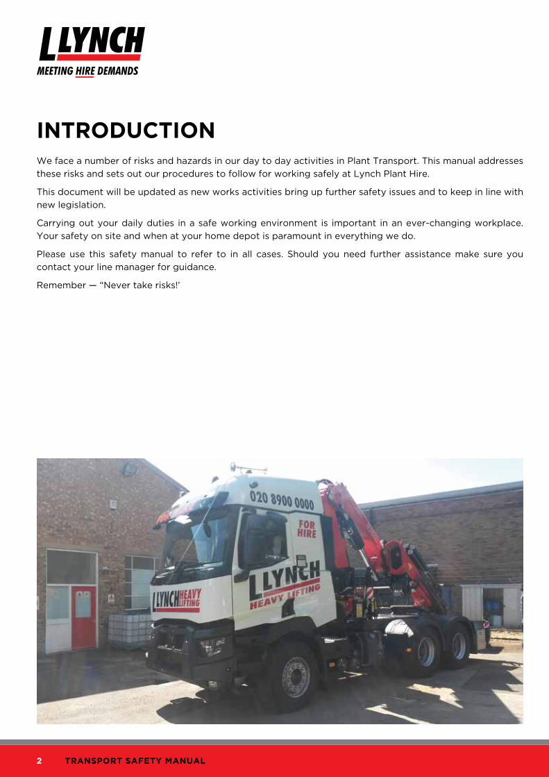
IntroductIonWe face a number of risks and hazards in our day to day activities in Plant Transport. This manual addresses
these risks and sets out our procedures to follow for working safely at Lynch Plant Hire.
This document will be updated as new works activities bring up further safety issues and to keep in line with
new legislation.
Carrying out your daily duties in a safe working environment is important in an ever-changing workplace.
Your safety on site and when at your home depot is paramount in everything we do.
Please use this safety manual to refer to in all cases. Should you need further assistance make sure you
contact your line manager for guidance.
Remember — “Never take risks!’

3© L.Lynch Plant (Hire & Haulage) Ltd. 2014
Transport Safety ManualIssue Number: 2 Date: 01/06/14
contentsrisk assessments and safe system of work
Loading and unloading . . . . . . . . . . . . . . . . . . . . . . . . . . . . . . . . . . . . . . . . . . . . . . . . . . . . . . . . . . . . . . . . . . . . . . . . . . . 03
Securing plant items to the transporter . . . . . . . . . . . . . . . . . . . . . . . . . . . . . . . . . . . . . . . . . . . . . . . . . . . . . . . . . . . . 06
General guidance on loading, unloading and securing plant . . . . . . . . . . . . . . . . . . . . . . . . . . . . . . . . . . . . . . . . . . 08
Use of crane lorry . . . . . . . . . . . . . . . . . . . . . . . . . . . . . . . . . . . . . . . . . . . . . . . . . . . . . . . . . . . . . . . . . . . . . . . . . . . . . . . .16
Transport driver delivery procedures . . . . . . . . . . . . . . . . . . . . . . . . . . . . . . . . . . . . . . . . . . . . . . . . . . . . . . . . . . . . . . .19
Driving safely . . . . . . . . . . . . . . . . . . . . . . . . . . . . . . . . . . . . . . . . . . . . . . . . . . . . . . . . . . . . . . . . . . . . . . . . . . . . . . . . . . . 22
Department of Transport code of practice — safety of loads on vehicles . . . . . . . . . . . . . . . . . . . . . . . . . . . . . . 24
Winch safety . . . . . . . . . . . . . . . . . . . . . . . . . . . . . . . . . . . . . . . . . . . . . . . . . . . . . . . . . . . . . . . . . . . . . . . . . . . . . . . . . . . . 27
Plant body safety. . . . . . . . . . . . . . . . . . . . . . . . . . . . . . . . . . . . . . . . . . . . . . . . . . . . . . . . . . . . . . . . . . . . . . . . . . . . . . . . 27
Guidance to the safe usage of plant transporter type body fitted with electric winch & hydraulic loading ramp . 28
Ramp operation . . . . . . . . . . . . . . . . . . . . . . . . . . . . . . . . . . . . . . . . . . . . . . . . . . . . . . . . . . . . . . . . . . . . . . . . . . . . . . . . . 29
Transporter winch operation . . . . . . . . . . . . . . . . . . . . . . . . . . . . . . . . . . . . . . . . . . . . . . . . . . . . . . . . . . . . . . . . . . . . . . . . . 31
Safe System Of Work (SSOW): loading/unloading plant transporters – RA09 . . . . . . . . . . . . . . . . . . . . . . . . . . 35
Safe System Of Work (SSOW): loading/unloading plant transporters – RA21 . . . . . . . . . . . . . . . . . . . . . . . . . . 36
Safe System Of Work (SSOW): use of quick hitch attachments – RA14 . . . . . . . . . . . . . . . . . . . . . . . . . . . . . . . . 37
Safe System Of Work (SSOW): working at height – RA20 . . . . . . . . . . . . . . . . . . . . . . . . . . . . . . . . . . . . . . . . . . . 38
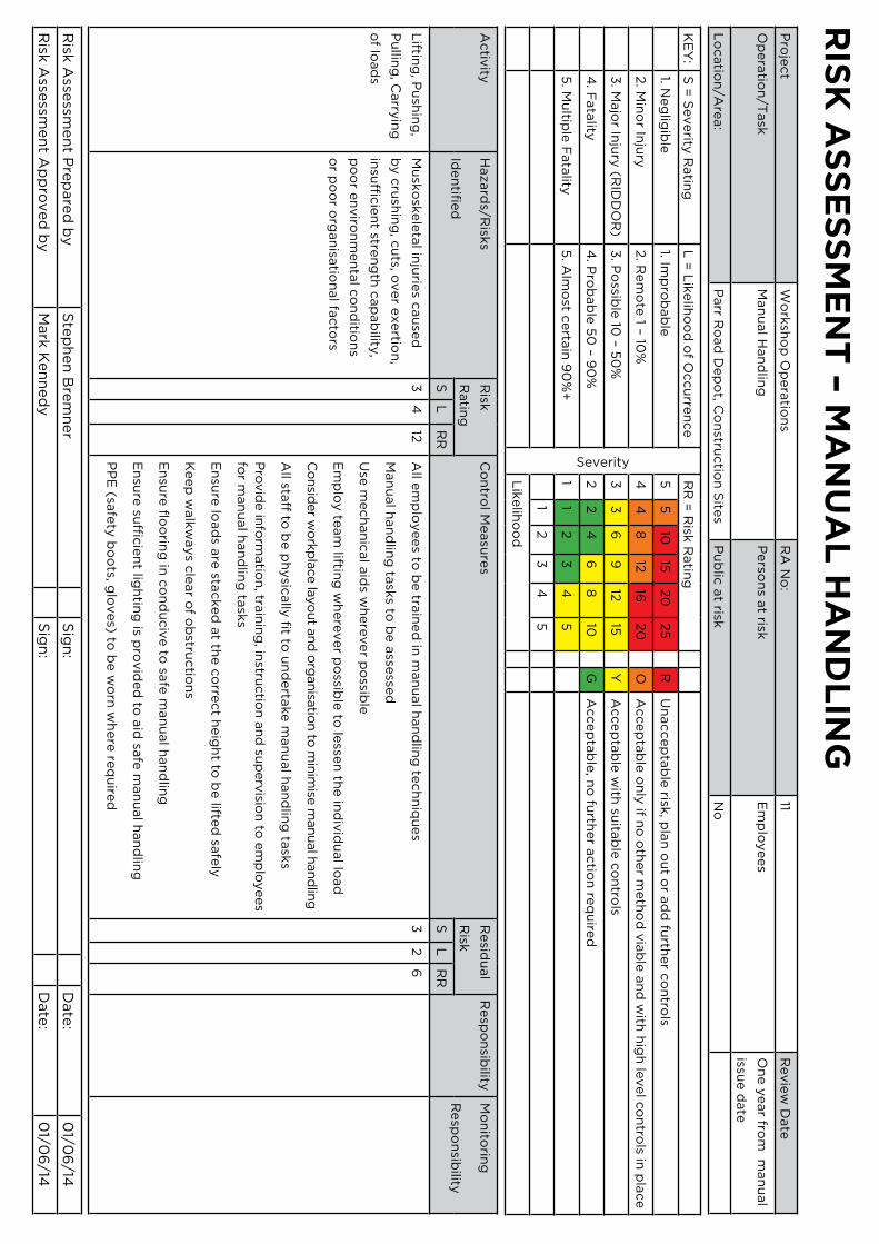
Risk assessment – manual handling . . . . . . . . . . . . . . . . . . . . . . . . . . . . . . . . . . . . . . . . . . . . . . . . . . . . . . . . . . . . . . . . 39
Risk assessment – quick hitch attachments . . . . . . . . . . . . . . . . . . . . . . . . . . . . . . . . . . . . . . . . . . . . . . . . . . . . . . . . . 40
Risk assessment – vehicle and plant movements . . . . . . . . . . . . . . . . . . . . . . . . . . . . . . . . . . . . . . . . . . . . . . . . . . . . 42
Risk assessment – loading and unloading of plant transporters . . . . . . . . . . . . . . . . . . . . . . . . . . . . . . . . . . . . . . . 43
Risk assessment – use of HIAB lorries . . . . . . . . . . . . . . . . . . . . . . . . . . . . . . . . . . . . . . . . . . . . . . . . . . . . . . . . . . . . . . 46
4 TransporT safeTy manual
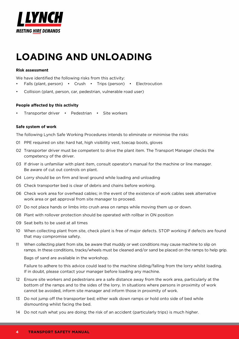
LoAdInG And unLoAdInGrisk assessment
We have identified the following risks from this activity:
• Falls (plant, person) • Crush • Trips (person) • Electrocution
• Collision (plant, person, car, pedestrian, vulnerable road user)
People affected by this activity
• Transporter driver • Pedestrian • Site workers
safe system of work
The following Lynch Safe Working Procedures intends to eliminate or minimise the risks:
01 PPE required on site: hard hat, high visibility vest, toecap boots, gloves
02 Transporter driver must be competent to drive the plant item. The Transport Manager checks the
competency of the driver.
03 If driver is unfamiliar with plant item, consult operator’s manual for the machine or line manager.
Be aware of cut out controls on plant.
04 Lorry should be on firm and level ground while loading and unloading
05 Check transporter bed is clear of debris and chains before working.
06 Check work area for overhead cables; in the event of the existence of work cables seek alternative
work area or get approval from site manager to proceed.
07 Do not place hands or limbs into crush area on ramps while moving them up or down.
08 Plant with rollover protection should be operated with rollbar in ON position
09 Seat belts to be used at all times
10 When collecting plant from site, check plant is free of major defects. STOP working if defects are found
that may compromise safety.
11 When collecting plant from site, be aware that muddy or wet conditions may cause machine to slip on
ramps. In these conditions, tracks/wheels must be cleaned and/or sand be placed on the ramps to help grip.
Bags of sand are available in the workshop.
Failure to adhere to this advice could lead to the machine sliding/falling from the lorry whilst loading.
If in doubt, please contact your manager before loading any machine.
12 Ensure site workers and pedestrians are a safe distance away from the work area, particularly at the
bottom of the ramps and to the sides of the lorry. In situations where persons in proximity of work
cannot be avoided, inform site manager and inform those in proximity of work.
13 Do not jump off the transporter bed; either walk down ramps or hold onto side of bed while
dismounting whilst facing the bed.
14 Do not rush what you are doing; the risk of an accident (particularly trips) is much higher.

5© L.Lynch Plant (Hire & Haulage) Ltd. 2014
Transport Safety ManualIssue Number: 2 Date: 01/06/14
Lorry / pedestrian risk area
Exercise caution at all times (keep clear)
1.5 times the length of ramp
crush zone on ramp

6 TransporT safeTy manual
A clean deck with straps stowed away properly
Lorry bed
a. Sweep down after drop off.
b. Sweep down plant before loading.
c. Secure chain / straps in a safe place.
d. Tools must be stowed away correctly.
e. Report defects on the bed to workshops / line manager.
f. Handrails to be fixed and secure at all times unless carrying oversize plant.
g. Chain / shackles / straps must be certified at all times.
h. Remember – correct tools for the job!
If in doubt and you need help contact your line manager

7© L.Lynch Plant (Hire & Haulage) Ltd. 2014
Transport Safety ManualIssue Number: 2 Date: 01/06/14
securInG PLAnt IteMs to tHe trAnsPorterrisk assessment
We have identified the following risks from this activity:
• Crush • Trip
• Impact • Plant fall from lorry
People affected by this activity
• Transporter driver • Pedestrian • Site workers
safe system of work
The following Lynch Safe Working Procedures intends to eliminate or minimise the risks:
01 PPE required on site: hard hat, high visibility vest, toecap boots, gloves.
02 Use care when loosening ratchets, they can snap back causing injury.
03 Keep area clear.
04 Extreme caution when walking on or around transporter bed, looking out for potential trip hazards.
05 Use official guidelines on chain positioning.
chain positioning for securing plant
a. All machines must be secured using enough chains or straps rated to the weight of the machine, multiple
chains/straps might be needed. The Department of Transport code of practice for safety of loads an
vehicles advises that we always fallow the manufacturers recommendations for securing plant.
b. The following pages contain diagrams specific to individual machines, showing the correct way to
secure them.
8 TransporT safeTy manual
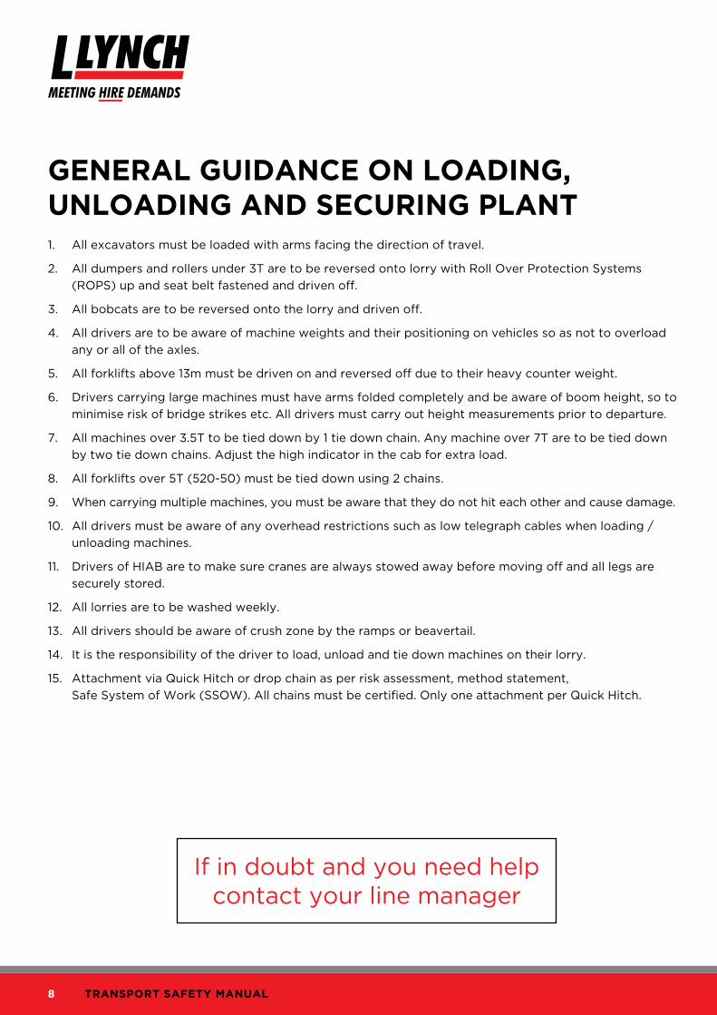
GenerAL GuIdAnce on LoAdInG, unLoAdInG And securInG PLAnt1. All excavators must be loaded with arms facing the direction of travel.
2. All dumpers and rollers under 3T are to be reversed onto lorry with Roll Over Protection Systems
(ROPS) up and seat belt fastened and driven off.
3. All bobcats are to be reversed onto the lorry and driven off.
4. All drivers are to be aware of machine weights and their positioning on vehicles so as not to overload
any or all of the axles.
5. All forklifts above 13m must be driven on and reversed off due to their heavy counter weight.
6. Drivers carrying large machines must have arms folded completely and be aware of boom height, so to
minimise risk of bridge strikes etc. All drivers must carry out height measurements prior to departure.
7. All machines over 3.5T to be tied down by 1 tie down chain. Any machine over 7T are to be tied down
by two tie down chains. Adjust the high indicator in the cab for extra load.
8. All forklifts over 5T (520-50) must be tied down using 2 chains.
9. When carrying multiple machines, you must be aware that they do not hit each other and cause damage.
10. All drivers must be aware of any overhead restrictions such as low telegraph cables when loading /
unloading machines.
11. Drivers of HIAB are to make sure cranes are always stowed away before moving off and all legs are
securely stored.
12. All lorries are to be washed weekly.
13. All drivers should be aware of crush zone by the ramps or beavertail.
14. It is the responsibility of the driver to load, unload and tie down machines on their lorry.
15. Attachment via Quick Hitch or drop chain as per risk assessment, method statement,
Safe System of Work (SSOW). All chains must be certified. Only one attachment per Quick Hitch.
If in doubt and you need help contact your line manager

9© L.Lynch Plant (Hire & Haulage) Ltd. 2014
Transport Safety ManualIssue Number: 2 Date: 01/06/14
Correct chain positioning for an excavator
1. Secure the machine to the trailer.
Fasten the undercarriage to the trailer using chains at four positions A (two each side). Make sure the
chains are strong enough for the purpose.
Chain the arm to the trailer using either the hook, shackle or link as appropriate (item B).
2. Measure the machine height.
Measure the maximum height of the machine from the ground. Make sure that the transport driver knows
the clearance height before he drives away.
3. Unloading the machine from the trailer.
Unloading is a reversal of the procedures described in steps 1 and 2.
10 TransporT safeTy manual
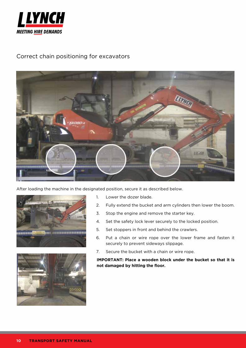
Correct chain positioning for excavators
After loading the machine in the designated position, secure it as described below.
1. Lower the dozer blade.
2. Fully extend the bucket and arm cylinders then lower the boom.
3. Stop the engine and remove the starter key.
4. Set the safety lock lever securely to the locked position.
5. Set stoppers in front and behind the crawlers.
6. Put a chain or wire rope over the lower frame and fasten it
securely to prevent sideways slippage.
7. Secure the bucket with a chain or wire rope.
IMPortAnt: Place a wooden block under the bucket so that it is
not damaged by hitting the floor.
11© L.Lynch Plant (Hire & Haulage) Ltd. 2014
Transport Safety ManualIssue Number: 2 Date: 01/06/14
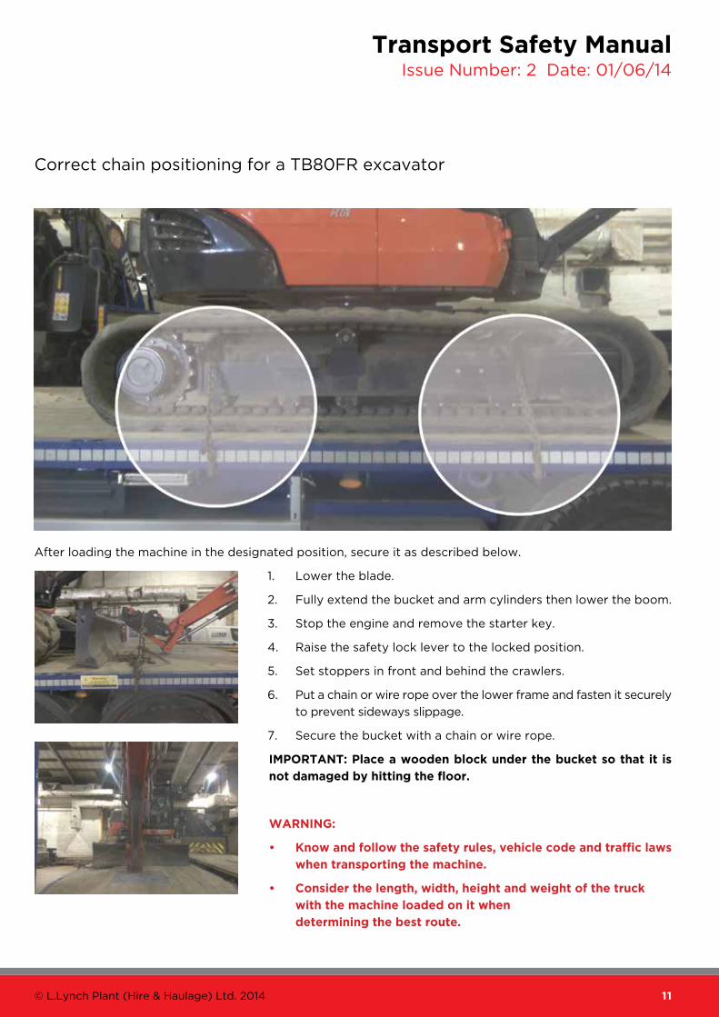
Correct chain positioning for a TB80FR excavator
After loading the machine in the designated position, secure it as described below.
1. Lower the blade.
2. Fully extend the bucket and arm cylinders then lower the boom.
3. Stop the engine and remove the starter key.
4. Raise the safety lock lever to the locked position.
5. Set stoppers in front and behind the crawlers.
6. Put a chain or wire rope over the lower frame and fasten it securely
to prevent sideways slippage.
7. Secure the bucket with a chain or wire rope.
IMPortAnt: Place a wooden block under the bucket so that it is
not damaged by hitting the floor.
WArnInG:
• Know and follow the safety rules, vehicle code and traffic laws
when transporting the machine.
• consider the length, width, height and weight of the truck
with the machine loaded on it when
determining the best route.

12 TransporT safeTy manual
Correct chain positioning for Excavators
securing the machine
1. Move the safety bar down to lock the systems securely.
2. Stop the engine and remove the starter key.
3. Turn OFF the battery master switch.
4. Lock the door and the access covers.
5. Cover the exhaust pipe to prevent turbocharger damage.
6. Block each track and secure the machine with tie downs of adequate load rating so that the
machine cannot move.
shipping the machine with installed attachments
Although arms are folded when the machine is shipped with attachments, arm cylinders are given excessive
forces caused by self-gravity.
Insert a stay (A) between arm and boom for shipment.
A

13© L.Lynch Plant (Hire & Haulage) Ltd. 2014
Transport Safety ManualIssue Number: 2 Date: 01/06/14
Correct chain positioning for 8 tons and above excavators
Load the machine onto a trailer as follows:
1. Extend the bucket and arm cylinders fully, then lower the
boom slowly.
2. Set the lock lever securely to the LOCK position (L).
3. Stop the engine then remove the key from the starting switch.
4. Close all doors, windows and covers. Lock the covers, caps
and doors fitted with locks.
5. Place blocks under both ends of the tracks to prevent the
machine from moving during transportation. Secure the
machine with chains or wire rope of suitable strength.
Be particularly careful to secure the machine in position
so it does not slip to the side.
storing radio antenna
• Loosen bolt (2) of radio antenna (1) at the rear of the cab, lower
the antenna, then tighten bolt (2) again to secure radio antenna
in position.
• When unloading the machine from the trailer and operating it,
follow the opposite procedure from stowing to set radio antenna
(1) vertical, then secure it in position with bolt (2).
12
14 TransporT safeTy manual
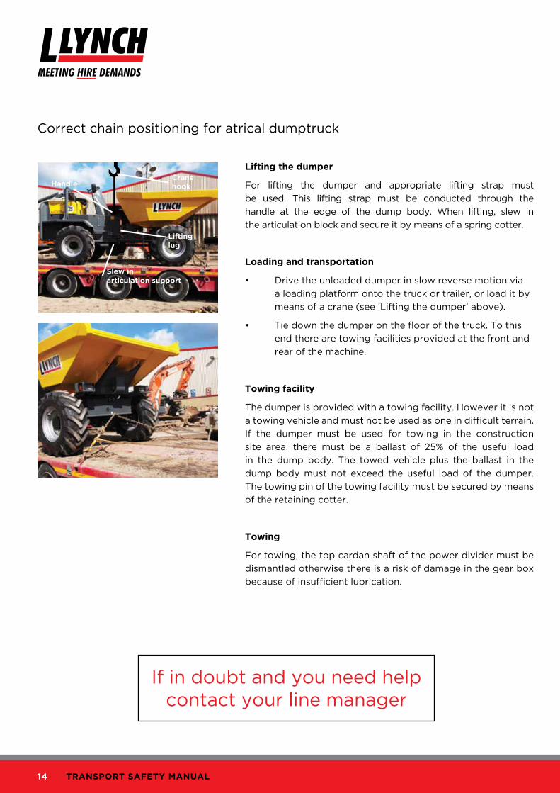
Correct chain positioning for atrical dumptruck
Lifting the dumper
For lifting the dumper and appropriate lifting strap must
be used. This lifting strap must be conducted through the
handle at the edge of the dump body. When lifting, slew in
the articulation block and secure it by means of a spring cotter.
Loading and transportation
• Drive the unloaded dumper in slow reverse motion via
a loading platform onto the truck or trailer, or load it by
means of a crane (see ‘Lifting the dumper’ above).
• Tie down the dumper on the floor of the truck. To this
end there are towing facilities provided at the front and
rear of the machine.
towing facility
The dumper is provided with a towing facility. However it is not
a towing vehicle and must not be used as one in difficult terrain.
If the dumper must be used for towing in the construction
site area, there must be a ballast of 25% of the useful load
in the dump body. The towed vehicle plus the ballast in the
dump body must not exceed the useful load of the dumper.
The towing pin of the towing facility must be secured by means
of the retaining cotter.
towing
For towing, the top cardan shaft of the power divider must be
dismantled otherwise there is a risk of damage in the gear box
because of insufficient lubrication.
Lifting lug
slew in articulation support
crane hookHandle
If in doubt and you need help contact your line manager
15© L.Lynch Plant (Hire & Haulage) Ltd. 2014
Transport Safety ManualIssue Number: 2 Date: 01/06/14
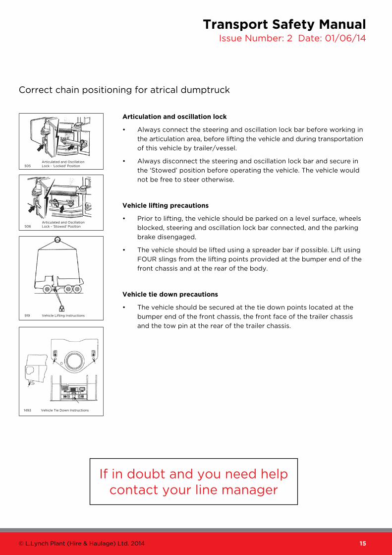
Correct chain positioning for atrical dumptruck
Articulation and oscillation lock
• Always connect the steering and oscillation lock bar before working in
the articulation area, before lifting the vehicle and during transportation
of this vehicle by trailer/vessel.
• Always disconnect the steering and oscillation lock bar and secure in
the ‘Stowed’ position before operating the vehicle. The vehicle would
not be free to steer otherwise.
Vehicle lifting precautions
• Prior to lifting, the vehicle should be parked on a level surface, wheels
blocked, steering and oscillation lock bar connected, and the parking
brake disengaged.
• The vehicle should be lifted using a spreader bar if possible. Lift using
FOUR slings from the lifting points provided at the bumper end of the
front chassis and at the rear of the body.
Vehicle tie down precautions
• The vehicle should be secured at the tie down points located at the
bumper end of the front chassis, the front face of the trailer chassis
and the tow pin at the rear of the trailer chassis.
Articulated and Oscillation Lock - ‘Locked’ Position
Articulated and Oscillation Lock - ‘Stowed’ Position
Vehicle Lifting Instructions
505
506
919
Vehicle Tie Down Instructions1493
If in doubt and you need help contact your line manager

16 TransporT safeTy manual
Correct chain positioning for a telehandler
Load the machine onto a trailer as follows:
1. Place blocks at the front and rear of the trailer wheels.
2. Move the machine onto the trailer
a. Make sure the ramps are correctly in place and secure.
b. Set the boom.
c. Carefully drive the machine onto the trailer.
d. Engage the park brake and set the drive to neutral.
e. Lower the carriage onto the trailer.
f. Secure the stabilisers in the raised position.
g. Check that the overall height of the load is within
regulations. Adjust if necessary.
h. Switch off the engine and remove the starter key.
i. Secure the cab.
j. Cover the exhaust stack.
3. Put blocks at the front and rear of all four tyres.
Anchor the machine to the trailer with chains.
17© L.Lynch Plant (Hire & Haulage) Ltd. 2014
Transport Safety ManualIssue Number: 2 Date: 01/06/14
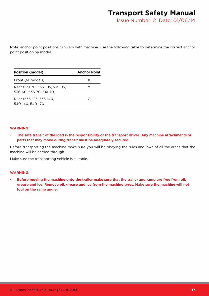
Note: anchor point positions can vary with machine. Use the following table to determine the correct anchor
point position by model.
WArnInG:
• the safe transit of the load is the responsibility of the transport driver. Any machine attachments or
parts that may move during transit must be adequately secured.
Before transporting the machine make sure you will be obeying the rules and laws of all the areas that the
machine will be carried through.
Make sure the transporting vehicle is suitable.
WArnInG:
• Before moving the machine onto the trailer make sure that the trailer and ramp are free from oil,
grease and ice. remove oil, grease and ice from the machine tyres. Make sure the machine will not
foul on the ramp angle.
Position (model) Anchor Point
Front (all models) X
Rear (531-70, 533-105, 535-95, Y
536-60, 536-70, 541-70)
Rear (535-125, 535-140, Z
540-140, 540-170

18 TransporT safeTy manual
Transporting a telehandler
Load the machine onto a trailer as follows:
1. Place chocks at the front and rear of the trailer wheels.
2. Move the machine onto the trailer
a. Make sure the ramps are correctly in place
and secure.
b. Set the boom.
c. Carefully drive the machine onto the trailer.
d. When the machine is safely in position engage
the park brake and set the drive to neutral.
e. Lower the carriage onto the trailer.
f. Switch off the engine and remove the starter key.
Secure the cab and cover the exhaust stack.
g. Check that the overall height of the load is within regulations. Adjust if necessary.
h. Put blocks at the front and rear of all four tyres. Anchor the machine to the trailer with chains.
The anchor points (X) are shown on the illustration.
i. Measure the maximum height of the machine from the ground. Try to ensure the truck driver knows
the clearance height before he drives away.
WArnInG:
• the safe transit of the load is the responsibility of the transport contractor and driver. Any machine
attachments or parts that may move during transit must be adequately secured.
Before transporting the machine make sure you will be obeying the rules and laws of all the areas that the
machine will be carried through.
Make sure the transporting vehicle is suitable.
WArnInG:
• Before moving the machine onto the trailer make sure that the trailer and ramp are free from oil,
grease and ice. remove oil, grease and ice from the machine tyres. Make sure the machine will not
foul on the ramp angle.

19© L.Lynch Plant (Hire & Haulage) Ltd. 2014
Transport Safety ManualIssue Number: 2 Date: 01/06/14
trAnsPort drIVer deLIVery Procedures It is likely that vehicles will have been loaded the night before but it’s still your responsibility to check you
have the right machines and attachments etc.
Your daily driver’s run sheet is to be filled out when you get to each individual job. The only information you
need to put down while you are in the depot is the start mileage, registration and your start time – you are not
to sit in the yard filling out the day’s work in advance. I expect all drivers to get out and on the road as soon
as possible and fill out the sheet when waiting out on site.
If your ticket is a handover it must be signed and printed by the customer – machines can’t be dropped unless
this is signed or agreed by the customer and the office.
Delivery tickets that don’t have the handover stamp can be dropped early as long as you are 100% sure it’s in
the right place and not causing problems with the traffic. Machines that are dropped early are to be locked
and the keys put on the roof. If you’re not sure phone your line manager or the office.
If the machine you’re delivering has additions that aren’t on the ticket (e.g. extra buckets) please write these
on the ticket and the office will amend when the ticket comes back into the office.
When delivering or collecting, if you are held up on site for anything longer than 20 minutes you must call
your line manager or the office to assist or sort out the problem so you can carry on with your other work.
PDIs must be filled out for deliveries and collections. When collecting machines, PDI sheets must be filled out
and fuel must be checked and signed off by the customer on site. If there is no one on site you must phone the
Hire Administration Team who will let the customer know, also, if there are any shortages, e.g. buckets please
contact the office before leaving site so we can establish if they have been stolen or just lost.
ALL damage MUST be written on the PDI. If the machine you are collecting is kept on hire, there is a sheet
attached that needs to be filled out stating the reason why and signed by the customer. If the machine is not
collected for any other reason, e.g. no keys, broken down etc., YOU MUST write this on the ticket so the office
knows when the ticket comes back in.
All lorries are to be fuelled at the end of every shift unless your tank is already full. All drivers must clock in
and out every day if you want to be paid all your hours worked. All trucks will have fuel fobs. These must stay
with each truck. If your truck doesn’t have a fuel fob then speak to your manager / supervisor but do not swap
the fobs as this interferes with the mileage for the original vehicle allocated to that fob.
When doing machine moves or day work, these tickets MUST be signed at the end of the day – failure to do
this will result in us not getting paid and if this happens, maybe YOU, so this is very important! Time on and
off should also be written down for all these jobs.
20 TransporT safeTy manual
use oF crAne Lorry
Hazard assessment
the following hazards have been identified in this activity:
• difficult or awkward loads • uneven ground • close proximity of pedestrians
• close proximity of other vehicles or machines • Maintenance of vehicle crane and slings
• Falls from height • tools or materials falling from a working platform, containers or the structure
• Movement of vehicles or cranes • electricity
risk assessment
We have identified the following risks from this activity:
• overturning of vehicle when carrying awkward loads.
• overturning of vehicle on uneven or potholed ground.
• Personal injury from collision between vehicle and pedestrian.
• Personal injury and damage from collision between particular vehicle and other site vehicles.
• Personal injury by falls from height.
• Being struck by falling tools containers or material.
• Being struck or crushed by overhead structures or piping.
• electrical shock through contact with electrical units or sources.

21© L.Lynch Plant (Hire & Haulage) Ltd. 2014
Transport Safety ManualIssue Number: 2 Date: 01/06/14
use oF crAne Lorry (cont.)
safe system of work
The following Lynch Safe Working Procedures intends to eliminate or minimise the risks:
1. Only trained and certificated employees authorised drive the specified HIAB LGV vehicle. Driver will
produce CSCS Card and LGV Licence.
2. Driver to wear hard hat and high visibility vest at all times whilst on site.
3. Flashing lights fitted to vehicle.
4. Reversing bleeper fitted to vehicle.
5. Daily safety checks to be made by driver and documented.
6. Mechanical maintenance is to be carried out only by authorised personnel.
7. Thorough examination conducted on vehicle and crane annually. Test certificate of crane will be produced.
8. Driver to be Inducted by site on arrival.
9. First Aid information and emergency procedures to be given to driver by site on arrival.
10. Site manager or supervisor must be notified before any intended work is begun.
11. The crane is to be moved to a safe area to allow access.
12. Work area to be cordoned off and pedestrian and vehicular traffic diverted away from the work area
(cones or safety tape and signage).
13. If any overhead power cables above, power must be tested to ensure that all power is off before
work commences.
14. Any loose items that are on top of or inside the item to be lifted should be removed before lift.
15. All tools and other items inside containers to be cleared by site before commencing work.
16. All works must be managed, supervised and instructed by site; any new hazards found or that may
occur on the day work commences must be assessed by site before any work commences and notified
to persons who perform the tasks.
17. Crane support legs must be fully extended on working side before any lift can be completed.
18. If crane support legs cannot be fully extended due to site restrictions, the appointed person and your
manager must be informed.
19. The site agent/site foreman must sign an indemnity form before any lift can be performed if the crane
legs cannot be fully extended.

22 TransporT safeTy manual
drIVInG sAFeLyClearly the penalties and consequences to you, your employer and the general public of not driving safely can
range from the inconvenient to the very serious and, sometimes to the catastrophic.
As the driver of a heavy goods vehicle, you have a special responsibility – not just to yourself, but to all other
road users. You can set a good example to others by driving safely, courteously and with consideration for
everyone else on our busy roads.
Employers should take great care to ensure that the vehicles you use are safe and maintained to an appropriately
high standard. Alternatively, you may be self-employed and responsible for the safety and maintenance of
your own vehicles. However, this on its own is not enough to ensure safety. It is up to you, as the driver, to:
• check your vehicle regularly / daily walk round checks.
• know the route you are driving.
• be aware of weather forecasts.
• drive safely.
Many accidents are caused by driver error and the majority are preventable. Therefore it is important that you
take time to assess what potential dangers your next journey involves and what you need to do to complete
the journey safely and efficiently.
Make sure you plan your route when oversized loads are carried. You need to make sure you have your movement
border and escorts where necessary.
23© L.Lynch Plant (Hire & Haulage) Ltd. 2014
Transport Safety ManualIssue Number: 2 Date: 01/06/14
drIVInG sAFeLy: BAsIc PrIncIPLesMirrors
It is important to know as much about the traffic and obstacles around you as possible. Before starting your
journey, you should always check your mirrors to make sure they are in the correct position for you to be able
see around the vehicle. You should always make full use of your mirrors before making a manoeuvre.
You should be aware of blind spots, both for yourself and others. Many larger goods vehicles are fitted
with ‘close proximity’ and ‘wide angle’ mirrors to survey the driver’s blind spot on the passenger side of the
vehicle. It is particularly important that these mirrors are properly adjusted so that you can see (for example)
cyclists close to the nearside of the vehicle. Keep a defensive space around your vehicle to enable you to react.
You should use your mirrors frequently so that you are constantly aware of what is happening around you.
route planning
Route planning is an important part of any journey. The length, width, weight and height of your vehicle will
sometimes dictate the route you take. If possible you should also plan routes to avoid congestion at peak
times.
Before starting a journey plan your route including rest breaks, and identify the potential hazards. This will
enable you to avoid or minimise the risk of being involved in dangerous or risky situations.
Planning your journey will help you select the safest and most efficient route. Always plan an alternative route
to allow for accidents or bad weather conditions.
Forward planning
Use the visibility advantage provided by the high seating position in a cab to your advantage. Plan ahead for
every manoeuvre you need to make, understand the road and consider the other road users around you.
speed limits
Excessive (i.e. above the speed limit) and inappropriate speed continues to be a contributory factor in around
13% of all accidents; around 30% of fatal car accidents; and around half of fatal motorcycling injuries.
Observing speed limits is part of your responsibility. Speeding is illegal, dangerous and puts your life and the
life of other road users at risk. Speed limits exist for your protection.
Your vehicle may be fitted with a speed limiter, which normally is set for motorway speed limits. It does not
function within lower speed limits, so it is important to watch your speed carefully in these situations.

24 TransporT safeTy manual
dePArtMent oF trAnsPort code oF PrActIce — sAFety oF LoAds on VeHIcLes
13.1
This section provides guidance on the measures
necessary for the safe carriage of tracked and
wheeled engineering plant by vehicles constructed to
comply fully with the Motor Vehicles (Construction
and Use) Regulations 1986 and thereby permitted
unrestricted use of the roads. It does not deal with
the carriage of large machines etc. on special
purpose vehicles whose use on the roads is restricted
by current regulations.
However, the general advice contained in this section
will apply in many cases.
13.2
It is recommended that manufacturers of plant
equipment either fit lashing points or provide a
recommended lashing scheme for each of their vehicles.
13.3
Heavy engineering plant is normally transported on
purpose built vehicles which are specifically designed
to provide easy loading and unloading facilities and
are usually provided with adequate anchorage
points for attaching the lashings. Lighter engineering
plant may in some circumstances be carried on
general-purpose vehicles. However, in these cases
the method used to secure the load should provide
equal security to that obtained by using purpose
built vehicles.
13.4
High loads may endanger bridges etc. over roads, so
when these are carried it is essential that the driver
know the exact height of the load, and the width of
the load at that height. Also, loads with a high centre
of gravity can seriously affect the vehicle’s stability
and such items of engineering plant should only be
transported on vehicles with a low platform height.
13.5
A wheeled or tracked vehicle must be lashed down
in position on the carrying vehicle, with the parking
brake applied. The effectiveness of the parking brake
on its own will be limited by the frictional resistance
between the vehicle and the deck of the carrying
vehicle, and even in normal driving conditions this
will be inadequate and the vehicle will therefore
require additional restraint. This additional restraint
should take the form of a lashing system and some
arrangement whereby the load is prevented from
moving either forward or to the rear by an obstacle
(or obstacles) securely fixed to the vehicle. These
should butt against the wheels or tracks or some
other part of the equipment carried.
13.6
Engineering plant should be dismantled as far as is
necessary to keep its overall dimensions within the
length, width and height (see para. 3.5) limits of
the carrying vehicle. Where this is not possible, the
conditions and restrictions contained in Regulations
10, 81 and 82 of the Motor Vehicles (Construction
and Use) Regulations 1986: SI 1986 No 1078, and the
relevant provision of the Motor Vehicles (Authorisation
of Special Types) General Order l979: SI 1979 No 1198,
concerning the carriage of wide or long loads should
be complied with.
13.7
All movable assemblies such as jibs, brackets, booms
and cabs etc. must be left in the position recommended
for transportation by the manufacturer and must be
secured to prevent movement relative to the main
body of the machine.
25© L.Lynch Plant (Hire & Haulage) Ltd. 2014
Transport Safety ManualIssue Number: 2 Date: 01/06/14
13.8
Before the machine is moved onto the trailer all loose
dirt that may otherwise come off and obstruct the
highway or damage other vehicles must be removed.
The ramp, the tyres of the machine and the bed of
the trailer itself should all be free from oil, grease, ice
etc. so that the machinery cannot slip. The transporter
wheels should be chocked at the front and rear.
13.9
When the machine has been stowed and the engine
stopped, the pressure in the hydraulic system should
be relieved by moving all of the control levers through
all their positions.
This operation should be done at least twice. Controls
should be set so as to prevent movement of ancillary
items during transit.
13.10
Bags, tool kits, or other heavy objects should not be
left loose in the operator’s cab of the plant being carried.
13.11
The positioning of the engineering plant and any of
its detached assemblies should be arranged so
that the legal axle weight limits are not exceeded
and the safe handling of the vehicle is not impaired.
The clearance between the undersides of low loading
vehicles and the road surface should be checked
before moving off (see Section 3.6).
13.12
The machine should be positioned on the carrying
vehicle’s platform so that forward movement is
prevented either by part of the main body of the
vehicle, e.g. swan neck, step or headboard, or by an
attached transverse member securely attached through
the platform to the vehicle’s chassis frame.
13.13
All items removed from the machine such as buckets,
grabs, blades, shovels and lifting appliances should
be lashed to the deck of the vehicle.
13.14
Wheeled and light tracked machines should be
restrained so that the effect of bouncing caused by
road shocks transmitted from the carrying vehicle
and amplified by the machine’s tyres or suspension
units is minimised. Where possible the suspension
unit of the machine should be locked and vertical
movement limited by lashings or other means of
restraint.
Otherwise the machine’s frame or chassis should be
supported on blocks.
13.15
Unless the machine is supported, the full contact
area of its tyres, tracks, or drums should rest on the
deck of the carrying vehicle. If the tracks extend outside
the frame of the carrying vehicle then the machine’s
frame or chassis should be supported.
13.16
The machine should be restrained against forward,
backward and sideways movement by chain or
webbing lashings attached to anchorage points on
the vehicle. All lashings should incorporate some form
of tensioning device.
13.17
In deciding the number of anchorage points to be used
when arranging a restraint system, the following factors
should be considered:
a. The need to position the machine to achieve
the correct load distribution to meet the legal
axle load requirements and to ensure that
the vehicle’s handling is not impaired.
b. The extent to which other load restraint
features is incorporated in the design of the
vehicle.
c. Whether the machine has wheels, tracks or
rollers.
d. The weight of the machine to be carried.
e. A minimum of four separate anchorage
points should be used.

26 TransporT safeTy manual
dePArtMent oF trAnsPort code oF PrActIce — sAFety oF LoAds on VeHIcLes (cont.)
13.18
The following guidelines apply to mobile engineering
plant, that is vehicles fitted with hoists, working
platforms, support legs and so on.
a. High loads may endanger bridges and it is
essential that the driver knows the height of
the vehicle and has it displayed inside the
vehicle cab.
b. All movable assemblies must be placed in
the position and locked, where possible,
as recommended for transportation by their
manufacturer.
restraining devices
13.19
Apart from specialised fixing devices, the selection
of materials for use in tie down schemes for
engineering plant will be limited to chains, steel
wire rope, webbing and their associated tensioning
and coupling devices.
13.20
Where a transverse (side to side) beam is used as a
baulk it should be securely fixed so that all loads
imposed on it are transmitted to the carrying vehicle’s
chassis frame. Where individual wheels or drums are
chocked with blocks or scotches these must be robust
enough to resist crushing and be securely attached
to the vehicle’s platform where possible.
13.21
The lashings or securing devices should only be
attached to those parts of the engineering plant,
which are of sufficient strength to withstand the
stresses likely to be imposed on them.
13.22
Where engineering plant comes equipped with
dedicated lashing points for use when being
transported, these points should be used and the
vehicle secured as per manufacturer instructions.
Care should be taken before lashing to lifting points
as these may not be suitable for restraint purposes.
13.23
The loaded machine should be inspected after the
vehicle has been driven for a short distance in
order to check that no movement has taken place
and that restraining devices are fully secure.
Periodic inspections should be made during the
course of the journey.

27© L.Lynch Plant (Hire & Haulage) Ltd. 2014
Transport Safety ManualIssue Number: 2 Date: 01/06/14
WIncH sAFetyBAsIc reQuIreMents
1. Keep yourself and all personnel clear of the winch rope.
2. Never step over, stand near or touch a winch rope under tension.
3. Always wear protective clothing: riggers gloves, safety boots, safety helmet, high visibility clothing and goggles or visor.
4. Always check the winching layout and capacities of equipment (‘walk the line’).
5. Do not use the winch rope as a tow rope.
6. Always obey rope-handling procedure.
7. Never wrap winch ropes around loads or attach rope hook back onto rope to form loop.
8. Carry out regular inspections of winch rope.
9. Always locate position of emergency stop before attempting to use winch.
10. Always maintain 5 wraps of rope around winch drum.
11. Never operate winch drum free spool with winch rope attached to load.
12. Always survey site for potential hazards before deploying winching equipment.
13. Always survey path load will be winched through for potential hazards.
14. Do not use winch for movement of persons.
PLAnt Body sAFetyBAsIc reQuIreMents
1. Keep yourself and all personnel clear of ‘downhill side of load’.
2. Keep yourself and all personnel clear of area behind loading ramp.
3. Keep yourself and all personnel clear of moving ramp.
4. Unlock loading ramp.
5. Do not move vehicle unless ramp is fully stowed and locking stays engaged.
6. Ensure machine being loaded/unloaded cannot roll away, chock if necessary.
7. Do not ride on machine being loaded/unloaded unless it technically requires driving.
8. Do not allow yourself or other personnel to be positioned between load and body headboard.
9. Do not walk up body alongside machine being loaded/unloaded.
10. A minimum of 4 load restraints shall be used to secure machines to body.
11. Always ‘dump air’ from suspension before loading/unloading.
12. Ensure suspension is restored to ‘ride’ position before moving vehicle.
13. Always ensure that area to load/unload is safe and act to minimise collision risks.
14. If jacklegs are fitted to vehicle they must always be in firm contact with ground whilst loading. If the
ground is too uneven for this then the jacklegs must be blocked to ensure they are supported.

28 TransporT safeTy manual
GuIdAnce to tHe sAFe usAGe oF PLAnt trAnsPorter tyPe Body FItted WItH eLectrIc WIncH And HydrAuLIc LoAdInG rAMP
tHe FoLLoWInG Is For GuIdAnce onLy
Each user must carry out a risk assessment for the type of operation the equipment is used for and act to
minimise the risks identified.
When operating at the roadside the danger from other road users place operators at high risk.
Before attempting to load/unload the body, ensure the area to work in is safe and secure. This may involve
deploying warning beacons (light bars), cones, or requesting help from your supervisor. Ensure your actions
do not cause a hazard to other road users.
PoWer IsoLAtIon
A power isolation switch is fitted on the vehicle. Ensure this is off when the winch or ramp is not in use.
Both the winch and the ramp draw power from the vehicle battery. When operating either, ensure engine is
running to prevent battery discharging.
eMerGency stoP
Before operation locate position of Emergency Stop on vehicle. In an emergency depress stop button, to
reset twist button.
oPerAtIon oF HydrAuLIc LoAdInG rAMP
The control station for the ramp is situated at the nearside of the vehicle. Stays are fitted to restrain ramp
during travel.

29© L.Lynch Plant (Hire & Haulage) Ltd. 2014
Transport Safety ManualIssue Number: 2 Date: 01/06/14
rAMP oPerAtIonstAndArd & FLIP-oVer rAMPs
Lowering ramps
Lower jacklegs.
‘Dump’ air from air suspension.
note: Never lower ramps before dumping suspension, always dump suspension first.
When ramp is in use or being deployed keep area behind ramp clear of all personnel.
Release the stays at each side of the ramp.
WHen reLeAsInG stAys do not stAnd BeHInd tHe rAMP, stAnd to tHe sIde cLeAr oF tHe
rAMP. reLeAse oFFsIde stAy FIrst.
Ensure area behind ramp is clear.
Lower ramp. Continue to lower until ramp tip is firmly on the ground. If flip-over ramps are fitted then the
feet on the end of the upper section must also be firmly on the ground.
The ramp is now ready for loading.
raising ramp
When ramp is in use or being deployed keep area behind ramp clear of all personnel.
Ensure no part of the load will obstruct the ramp when, raised to the stowed position.
Ensure all personnel are kept clear when stowing ramp.
Raise ramp. Continue to raise until ramp is firmly against stops.
Keep all personnel and limbs away from moving ramp.
Engage stay on nearside first.
WHen enGAGInG stAys do not stAnd BeHInd rAMP, stAnd to tHe sIde cLeAr oF tHe rAMP.
enGAGe neArsIde stAy FIrst.
Under no circumstances attempt to drive without stays being engaged.
Return air suspensions to ‘ride’ condition.
Raise jacklegs.
sLIdInG rAMPs
1. Ensure ramps are fully vertical.
2. Remove stays.
3. Slide ramps.
Never use slider when ramps are lowered. Always slide ramps out level with side of body and fit stays
before travelling.

30 TransporT safeTy manual
rAMP oPerAtIon (cont.)
usInG cHeeseWedGe rAMPs
On vehicles fitted with folding cheesewedge ramps, operate as follows:
• Dump air suspension and ensure jacklegs are in firm contact with the ground.
• When in straightened position. the ramps are to be operated with the same method as standard ramps.
BUT operator MUST ensure the locking pins are fully engaged on both sides of ramp before use with a
visual check.
to FoLd rAMPs
• Ensure straightened ramps are vertical and fully against stops.
• Operate folding control button or spool.
• Locking pins will automatically retract and ramp will fold.
• To reverse operation, operate opposite control, ramps will straighten, and locking pin will engage.
ALWAys:
Visually check the locking pins have fully engaged before use.
HydrAuLIc BeAVertAIL
to raise tall:
1. Ensure ramps are fully vertical.
2. Raise tail to full height.
3. Engage travel stays.
to lower tall:
1. Release travel stays.
2. Lower tail onto chassis.
Always ensure travel stays are engaged before raised.
When loading through from a trailer ensure the jacklegs fully grounded. There is a 5T limit on vehicles
through the ramps from a trailer.

31© L.Lynch Plant (Hire & Haulage) Ltd. 2014
Transport Safety ManualIssue Number: 2 Date: 01/06/14
trAnsPorter WIncH oPerAtIon As with any powerful tool there are hazards involved with winching operations. However with proper training
and risk awareness coupled with well-maintained equipment and respect for the power available, the operator
should come to regard winching equipment as a most versatile and efficient tool.
The winch may be controlled by either a wanderlead/spool valve control or by a radio remote handset, which
gives the operator freedom of movement without the encumbrance of trailing wires.
note: The winch will only ‘winch out’ if there is a load on the winch rope. To avoid a badly spooled winch
drum and rope damage do not ‘winch out’ without tension on the rope.
A free spool control is provided on the end of the winch. This control disconnects all braking and drive from
the drum producing a drum, which is free to rotate. It is useful if a long length of rope requires to be pulled
out by hand.
Under no circumstances attempt to engage free spool with a load attached to the winch rope.
At all times it should be remembered that winching operations involve tensile forces, which are difficult
to restrain in the event of a failure within the winching system. In the event of a failure the tensile forces will
suddenly be released causing the winching equipment and winch rope to ‘whiplash’, as a piece of released elastic.
Bodily contact with a winch rope suddenly released in this manner may cause serious injury. In addition the load
will be released and may move uncontrollably possibly causing further injury.
Before using a winch, identify the location of the emergency stop/isolator switch.
To prevent discharge of vehicle battery. ensure engine is running when using an electric winch.
The maximum power available from a winch is when the rope is on the bottom layers of the drum.Therefore avoid
‘overloading’ the drum with excessive length of rope.
When handling the winch rope always wear good rigger gloves.
To maintain the winch rope in a safe condition good rope management is essential – keep the rope as square
to the drum as possible – maintain tension on rope by hand when powering ‘out’ under no load – maintain
tension on rope by hand when powering ‘in’ under no load periodically pull all the rope off the drum and
rewind under hand tension to achieve neat and tightly packed wraps of rope on the drum.
Never allow the winch rope to slide through the hands. Always handle winch rope ‘hand over hand’.
Inspect the rope and end fittings daily for damage and deformation. Check regularly for signs of wear in the
form of broken strands or severe kinks along its length. If there are more than 6 strands broken in any length
of 100mm the rope is severely weakened and must be replaced.
Safety catches must be in place on hooks.
Keep yourself and all personnel clear of the winch rope.
Never step over, stand near or touch a winch rope under tension.
Never wrap the winch rope around a load or hook the rope back in itself.
Never pass the winch rope around any object other than a snatch block or sheave specially designed for the purpose.
Always maintain 5 wraps of rope on the drum – the rope anchor on the drum will not withstand the winch pull
without these 5 wraps on the drum. This is of particular importance when winching “out’.

32 TransporT safeTy manual
trAnsPorter WIncH oPerAtIon (cont.)
Always ensure that the drive is fully engaged to the winch and that the free spool is not partially selected
before attempting to winch a load.
Never operate the winch drum to free spool if the rope is attached to the load.
Always survey the site for potential hazards before deploying the winching equipment.
Ensure that any additional equipment used such as shackles, webbing straps etc are compatible to the
winch capacity.
Always survey the path the load will be winched along for potential hazards.
Do not use the winch for the movement of persons.
Always keep the ‘down hill side’ of the load clear of persons.
Do not use the winch rope as a towrope or pull the rope of the drum by engaging free spool, attaching
the rope to the load and driving away.
When repositioning the rope on the load always stabilise the load before removing winch rope.
Ensure attachment point to load is secure and will forces.
Position winch rope attachment to load centrally. The use of ‘brothers’ on two webbing straps is often required.
Before applying tension to the load check winch rope is not fouling other components and all attachments
are secure.
Do not use the winch to secure the load on the body. After securing the load with cargo restrain equipment
operate winch ‘out’ to just release the winch tension. When unloading first ensure tension is replaced in winch
rope by momentarily operating winch ‘in’ before removing cargo restraints.
The operator should not be positioned between the load and the winch or on the ‘downhill’ side of the load
When unloading do not allow the load to ‘snatch’ or operate the winch ‘out’ in a series of ‘blips’. This will cause
severe shock loading to the rope and winch resulting in possible failure.
Before releasing the winch rope from the load ensure the load is stabilised and that there is no danger of the
load ‘running away’.
Apply machine handbrake if fitted. Ensure machine is secure, loose items secured etc.
‘Blip’ winch ‘out’ control to just release tension on winch rope.
Stow hydraulic loading ramps and ensure their security.
Return air suspension to ‘ride’ condition.
Turn battery isolator switch/emergency stop to ‘off’.
During journeys periodically check security of load restraints.
unLoAdInG trAnsPorter Body
Beware gradients; will the machine roll forward on the body during unloading when load restraints removed?
In general attempt to unload with the transporter facing ‘uphill’.
Dump air suspension.

33© L.Lynch Plant (Hire & Haulage) Ltd. 2014
Transport Safety ManualIssue Number: 2 Date: 01/06/14
Deploy ramp to load position. Ensure ground end of the ramp tip is in contact with ground. If jacklegs are
fitted they must ALWAys be in firm contact with the ground. Block if necessary.
Ensure there is sufficient space at base of ramps to unload machine.
‘Blip’ winch ‘in’ control to restore tension on the winch rope.
Do not drive machine off transporter, use the winch. Some machines require being driven and winched.
Take great care not to shock load the winch. When machine passes over change of angle between beavertail
and flat part of body the machine may roll rearwards. Carry out this part of the operation as slowly as possible
ensuring that the winch rope does not go slack.
do not WALK doWn ALonGsIde tHe MAcHIne BeInG LoAded on tHe steerInG WHeeL.
THERE ARE ONLY TWO PLACES AN OPERATOR SHOULD BE POSITIONED:
1. ALONGSIDE THE BODY ON THE GROUND.
2. IN THE NORMAL DRIVING POSITION OF THE MACHINE BEING UNLOADED IF IT REQUIRES TO BE
DRIVEN AND WINCHED AT THE SAME TIME.
Keep ‘downhill’ side of operation clear of all personnel.
Release handbrake.
Ensure machine is in neutral gear. Release steering lock if fitted.
Release load restraints.
Commence winch ‘out’ operation, do no operate winch in a series of ‘blips’, and load in one continuous operating.
Ensure that machine rolls off body controlled by winch rope.
IF MAcHIne stoPs. IMMedIAteLy stoP WIncH oPerAtIon.
When machine is clear of ramps. secure machine, apply handbrake and remove winch rope.
Stow winch rope and load restraints. Stow loading ramps.
Return air suspension to ‘ride’ condition.
LoAdInG tHe trAnsPorter Body
Beware gradients; will the machine roll forward on the body during loading? In general attempt to load with
the transporter facing ‘uphill’.
Turn battery isolator switch/emergency stop to ‘on’.
Dump air suspension if vehicle fitted with air suspension.
Deploy ramp to load position. (See operation of Hydraulic Loading Ramps).
Ensure ground end of the ramp tip is in contact with ground.
If jacklegs are fitted they must always be in firm contact with ground. Block if necessary.
Position machine to be loaded centrally at base of ramps with wheels touching ramps.
Do not drive machine onto transporter, use the winch.
Ensure machine to be loaded has handbrake ‘on’ or if not fitted with handbrake will not roll away whilst
preparing for loading, check if necessary.

34 TransporT safeTy manual
trAnsPorter WIncH oPerAtIon (cont.)
Deploy winch rope (See the Transporter Winch section).
Select attachment point on machine and fit winch rope hook – it may often be necessary to use a strop or
shackle onto the attachment point before fitting hook. Ensure attachment point is secure. If in doubt use
brothers for central pull from secure parts of the machine.
Operate bypass valve on hydraulic: driven machines if fitted.
Ensure vehicle is in neutral gear. Release steering lock if fitted.
Release machine handbrake.
Commence winch operation: do not operate winch in a series of ‘blips’ and load in one continuous operation.
Keep ‘downhill’ side of operation clear of all personnel.
Operators shall not position themselves between machine and transporter body headboard.
During loading it may be required to steer the machine, this may be done by pushing the front wheels of the
machine from the ground whilst the operator stands on the ground alongside the body.
do not WALK uP tHe Body ALonGsIde tHe MAcHIne BeInG LoAded WItH A HAnd on tHe
steerInG WHeeL.
tHere Are onLy tWo PLAces An oPerAtor sHouLd Be PosItIoned:
1. ALONGSIDE THE BODY ON THE GROUND.
2. IN THE NORMAL DRIVING POSITION OF THE MACHINE BEING LOADED IF IT REQUIRES TO BE DRIVEN
AND WINCHED AT THE SAME TIME.
Once machine is positioned on transporter body fit load restraints to each wheel or lashing points on machine.
First restraint fitted should restrain machine from roll ‘off’. Load restraints should restrain the machine in
all directions.

35© L.Lynch Plant (Hire & Haulage) Ltd. 2014
ssoW: Loading/unloading Plant transportersIssue Number: 02 Date of Issue: 01/06/14 Based on: RA09
PPe to Be Worn• High-vis Vest / Jacket
• Safety Boots
• Safety Gloves
• Safety Helmet
sAFe systeM oF WorK• All lifting appliances are to be serviceable with no defects and fit for task
• All lifting appliances are to be load tested as per statutory requirements and a valid thorough examination and load test certificate held in the plant office
• Daily user checks and inspections are to be carried out on all machines and lifting accessories prior to lifting. If defects are found the machine or accessory is not to be used and must be quarantined out of service until repaired. All lifting accessories are to have a valid thorough examination certificate held in the plant office
• All lifting operations are to be carried out by competent operatives
• All lifting operations are to be planned and supervised by a competent person except for generic or repetitive small scale lifts
• Operators are to ensure that ASLIs or RCIs fitted to lifting appliances are working and switched on at all times during lifting operations to ensure that the Safe Working Load of the lifting appliance is not exceeded
• Operators are to ensure that the lifting appliance is operated at all times in accordance with the manufacturers handbook and within the recommended safe working limits and duties chart displayed in cab
• All suspended loads are to be controlled by using tag lines where practicable
• Exclusion zones which prohibit entry by unauthorised personnel are to be imposed where practicable, especially when lifting near or over pedestrian walkways
• PPE – Safety boots, Hi-Vis, safety helmet, gloves to be worn by all during lifting operations
IdentIFIed rIsKs• Failure of lifting appliance
• Failure of lifting accessories
• Incorrect slinging techniques leading to loads or parts of loads dropping or slipping whilst being lifted
• 3rd party intrusion into dangerous areas during lifting
• Contact with overhead cables
• Contact with structures
• Personnel being struck or crushed by suspended loads
For More InForMAtIon PLeAse reFer to rIsK AssessMent 09
For this activity, the following PPE must be worn
The SSOW above has been compiled after identifying the following risks from this activity

36 TransporT safeTy manual
ssoW: Loading/unloading Plant transportersIssue Number: 02 Date of Issue: 01/06/14 Based on: RA21
PPe to Be Worn• High-vis Vest / Jacket
• Safety Boots
• Safety Gloves (As req’d)
• Safety Helmet (As req’d)
sAFe systeM oF WorK• Load bed and ramps to be kept free of debris, mud, oil, grease, waste, ice etc. Sand to be spread where necessary
to aid grip. Tracks/Wheels of plant to be cleaned if necessary before loading.
• Lashing chains, slings, timber, ropes etc to be stowed safely when not in use so as not to create trip or falling hazards.
• Maintain 3 points of contact if possible, when working near the edge of the load bed.
• Only competent, authorised personnel to load/unload.
• Staff to follow safe loading procedures for each machine type in the Transport Safety Manual when loading/unloading.
• Plant to be secured to Transporters as per manufacturer’s procedures and Transport Safety Manual procedures and guidance.
• Keep unauthorised personnel away from transporter. Use banksmen where possible to control pedestrian movement.
• Plant to be guided by a competent banksman standing in a safe place during loading/unloading.
• Drivers to receive familiarisation training for each item of plant being transported. Training records to be maintained.
• Ensure transporter is parked on firm level ground during loading/unloading.
• Anti – Roll bars fitted to dumpers, rollers and mini excavators etc. are to be locked in the raised position at all times during loading/unloading. Seat belts are to be worn on all machines at all times.
• To prevent drivers/operators being crushed in the event of a plant machine rolling over – Never try to jump clear – stay in the seat with the seat belt fastened
• Do not jump off the transporter load bed. Walk down the ramps or sit down and lower yourself gently off the edge.
• Never work directly underneath overhead power cables.
• Never work within 9 metres horizontally of overhead power cables supported on wooden poles
• Never work within 15 metres horizontally of overhead power cables supported on steel pylons or structures
• Always follow safe systems of work and routes provided on construction sites when driving under overhead power cables
• Keep hands clear of pinch points and crush zones on ramps and trailers
• All loading/unloading to be carried out slowly and safely – do not rush
• When collecting plant from sites ensure plant is free from defects which could affect safe loading. If in doubt stop work, do not move plant and seek advice from the transport office
• Always liaise with our clients site staff to ensure on site risks are understood and controlled
IdentIFIed rIsKs• Falls of people or objects from the transporter load bed and ramps
• Falls of vehicles from the transporter load bed and ramps
• Slips & Trips
• Personnel being struck by moving or falling vehicles
• Electrocution from contact with overhead power cables
• Hand injuries
For More InForMAtIon PLeAse reFer to rIsK AssessMent 21
For this activity, the following PPE must be worn
The SSOW above has been compiled after identifying the following risks from this activity

37© L.Lynch Plant (Hire & Haulage) Ltd. 2014
ssoW: use of Quick Hitch AttachmentsIssue Number: 02 Date of Issue: 01/06/14 Based on: RA14
PPe to Be Worn• High-vis Vest / Jacket
• Safety Boots
• Safety Gloves
• Safety Helmet
• Safety Glasses
sAFe systeM oF WorK
• Operation of Quick Hitch is limited to trained and competent staff. Additional training provided by means of toolbox talks for site specific safety issues
• Quick Hitch to be placed in position and plant turned off prior to disengagement. Quick Hitch to be disengaged in a slow/steady motion to reduce the frequency of the buckets “rocking” motion. Use of Semi-Automatic Quick Hitches have been prohibited by L Lynch.
• OPERATOR TO CHECK HITCH IS FULLY AND CORRECTLY ENGAGED PRIOR TO USE – If in doubt seek advice from L Lynch Management
• Staff to use the disengagement tool provided and to report any faults immediately
• Ensure that bucket is left at a safe height to reduce bending or over reaching
• Operator to utilise hand rails and steps to enter and leave the cab safely
• Operator to ensure that hydraulic control isolation lever is engaged before leaving the cab to change Quick Hitch
• Specific Quick Hitch Training is provided for every Lynch Plant Operator
• Prohibition of any Site Worker in risk area of excavator, defined as area underneath the bucket
• Quick Hitch Operator Manual in cab of machine to be followed at all times
IdentIFIed rIsKs• Machine dipper arm striking site worker
• Bucket / Attachment detaching from Quick Hitch and striking an operative
• Bucket “swing back” when Quick Hitch released
• Caught fingers / hand in Quick Hitch
• Upper limb strains from disengaging Quick Hitch
• Falls from cab
• Unauthorised operation of plant while changing quick hitch
For More InForMAtIon PLeAse reFer to rIsK AssessMent 14
For this activity, the following PPE must be worn
The SSOW above has been compiled after identifying the following risks from this activity

38 TransporT safeTy manual
ssoW: Working at HeightIssue Number: 02 Date of Issue: 01/06/14 Based on: RA20
PPe to Be Worn• High-vis Vest / Jacket
• Safety Boots
• Safety Helmet
sAFe systeM oF WorK• Some machines/vehicles are fitted with limited integral fall protection measures
• Mobile Steps are to be fitted with guardrails
• Avoid work at height where possible
• Prevent falls by using suitable working platforms with integral edge protection and toe boards which conform to the Work at Height Regulations
• All personnel to be competent in work at height procedures
• Provide access scaffolding, mobile towers or podium steps before using ladders or step ladders
• Work off ladders only in areas where site conditions cannot be altered and other platforms cannot be used because space is restricted
• Any work off ladders to be of short duration (max 30 mins in 1 position) and light in nature (max 10kgs)
• No working from the top 3 steps
• Maintain 3 points of contact at all times when on ladders
• All ladders to be Class 1 and conform to BS EN 131
• Inspect ladders before use
• Surfaces to be firm, level, dry, clear of obstructions
• Ladder locking devices to be engaged at all times
• No side on working or loading
• No over-reaching in any direction
IdentIFIed rIsKs
• Falls of people from height from lorry bed, plant machines or when working from mobile steps, towers or ladders
• Falls of objects or materials from height as above
For More InForMAtIon PLeAse reFer to rIsK AssessMent 20
For this activity, the following PPE must be worn
The SSOW above has been compiled after identifying the following risks from this activity
rIs
K A
ss
es
sM
en
t – M
An
uA
L H
An
dL
InG
Pro
ject
Wo
rksh
op
Op
era
tion
sR
A N
o:
11R
evie
w D
ate
Op
era
tion
/Task
Man
ual H
an
dlin
gP
erso
ns a
t riskE
mp
loyees
On
e y
ear fro
m m
an
ual
issue d
ate
Lo
catio
n/A
rea:
Parr R
oad
Dep
ot, C
on
structio
n S
ites
Pu
blic
at risk
No
KE
Y:
S =
Severity
Ratin
gL
= L
ikelih
oo
d o
f Occu
rren
ce
Severity
RR
= R
isk R
atin
g
1. Neg
ligib
le1. Im
pro
bab
le5
510
1520
25
RU
naccep
tab
le risk
, pla
n o
ut o
r ad
d fu
rther c
on
trols
2. M
ino
r Inju
ry2. R
em
ote
1 – 10%
44
812
1620
OA
ccep
tab
le o
nly
if no
oth
er m
eth
od
via
ble
an
d w
ith h
igh
level c
on
trols in
pla
ce
3. M
ajo
r Inju
ry (R
IDD
OR
)3
. Po
ssible
10 – 5
0%
33
69
1215
YA
ccep
tab
le w
ith su
itab
le c
on
trols
4. F
ata
lity4
. Pro
bab
le 5
0 – 9
0%
22
46
810
GA
ccep
tab
le, n
o fu
rther a
ctio
n re
qu
ired
5. M
ultip
le F
ata
lity5
. Alm
ost c
erta
in 9
0%
+1
12
34
5
12
34
5
Lik
elih
oo
d
Activ
ityH
azard
s/Risk
s
Iden
tified
Risk
Ratin
g
Co
ntro
l Measu
res
Resid
ual
Risk
Resp
on
sibility
Mo
nito
ring
Resp
on
sibility
SL
RR
SL
RR
Liftin
g, P
ush
ing
,
Pu
lling
, Carry
ing
of lo
ad
s
Mu
sko
skele
tal in
jurie
s cau
sed
by c
rush
ing
, cu
ts, over e
xertio
n,
insu
fficie
nt stre
ng
th c
ap
ab
ility,
po
or e
nviro
nm
en
tal c
on
ditio
ns
or p
oo
r org
an
isatio
nal fa
cto
rs
34
12A
ll em
plo
yees to
be tra
ined
in m
an
ual h
an
dlin
g te
ch
niq
ues
Man
ual h
an
dlin
g ta
sks to
be a
ssesse
d
Use
mech
an
ical a
ids w
here
ver p
ossib
le
Em
plo
y te
am
lifting
wh
ere
ver p
ossib
le to
lesse
n th
e in
div
idu
al lo
ad
Co
nsid
er w
orkp
lace
layo
ut a
nd
org
anisa
tion to
min
imise
manual h
and
ling
All sta
ff to b
e p
hysic
ally
fit to
un
derta
ke m
an
ual h
an
dlin
g ta
sks
Pro
vid
e in
form
atio
n, tra
inin
g, in
structio
n a
nd
sup
erv
ision
to e
mp
loyees
for m
an
ual h
an
dlin
g ta
sks
En
sure
load
s are
stacked
at th
e c
orre
ct h
eig
ht to
be lifte
d sa
fely
Keep
walk
ways c
lear o
f ob
structio
ns
En
sure
flo
orin
g in
co
nd
uciv
e to
safe
man
ual h
an
dlin
g
En
sure
suffi
cie
nt lig
htin
g is p
rovid
ed
to a
id sa
fe m
an
ual h
an
dlin
g
PP
E (sa
fety
bo
ots, g
loves) to
be w
orn
wh
ere
req
uire
d
32
6
Risk
Asse
ssmen
t Pre
pare
d b
yS
tep
hen
Bre
mn
er
Sig
n:
Date
:0
1/06
/14
Risk
Asse
ssmen
t Ap
pro
ved
by
Mark
Ken
ned
yS
ign
:D
ate
:0
1/06
/14
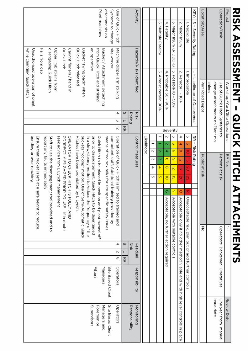
rIs
K A
ss
es
sM
en
t – Q
uIc
K H
Itc
H A
tt
Ac
HM
en
ts
Pro
ject
Wo
rksh
op
/Yard
/Site
Op
era
tion
sR
A N
o:
14R
evie
w D
ate
Op
era
tion
/Task
Use
of Q
uic
k H
itch
Syste
ms to
ch
an
ge a
ttach
men
ts on
Pla
nt m
a-
ch
ines
Perso
ns a
t riskO
pera
tors, B
an
ksm
en
, Op
era
tives
On
e y
ear fro
m m
an
ual
issue d
ate
Lo
catio
n/A
rea:
Parr R
oad
Dep
ot
Pu
blic
at risk
No
KE
Y:
S =
Severity
Ratin
gL
= L
ikelih
oo
d o
f Occu
rren
ce
Severity
RR
= R
isk R
atin
g
1. Neg
ligib
le1. Im
pro
bab
le5
510
1520
25
RU
naccep
tab
le risk
, pla
n o
ut o
r ad
d fu
rther c
on
trols
2. M
ino
r Inju
ry2. R
em
ote
1 – 10%
44
812
1620
OA
ccep
tab
le o
nly
if no
oth
er m
eth
od
via
ble
an
d w
ith h
igh
level c
on
trols in
pla
ce
3. M
ajo
r Inju
ry (R
IDD
OR
)3
. Po
ssible
10 – 5
0%
33
69
1215
YA
ccep
tab
le w
ith su
itab
le c
on
trols
4. F
ata
lity4
. Pro
bab
le 5
0 – 9
0%
22
46
810
GA
ccep
tab
le, n
o fu
rther a
ctio
n re
qu
ired
5. M
ultip
le F
ata
lity5
. Alm
ost c
erta
in 9
0%
+1
12
34
5
12
34
5
Lik
elih
oo
d
Activ
ityH
azard
s/Risk
s Iden
tified
Risk
Ratin
g
Co
ntro
l Measu
res
Resid
ual
Risk
Resp
on
sibility
Mo
nito
ring
Resp
on
sibility
SL
RR
SL
RR
Use
of Q
uic
k H
itch
Syste
ms to
ch
an
ge
atta
ch
men
ts on
Pla
nt m
ach
ines
Mach
ine d
ipp
er a
rm strik
ing
site w
ork
er
Bu
cket / A
ttach
men
t deta
ch
ing
from
Qu
ick H
itch
an
d strik
ing
an
op
era
tive
Bu
cket “sw
ing
back” w
hen
Qu
ick H
itch
rele
ase
d
Cau
gh
t fin
gers / h
an
d in
Qu
ick H
itch
Up
per lim
b stra
ins fro
m
dise
ng
ag
ing
Qu
ick H
itch
Falls fro
m c
ab
Un
au
tho
rised
op
era
tion
of p
lan
t
wh
ile c
han
gin
g Q
uic
k H
itch
43
12O
pera
tion
of Q
uic
k H
itch
is limite
d to
train
ed
an
d
co
mp
ete
nt sta
ff. Ad
ditio
nal tra
inin
g p
rovid
ed
by
mean
s of to
olb
ox ta
lks fo
r site sp
ecifi
c sa
fety
issues
Qu
ick H
itch
to b
e p
laced
in p
ositio
n a
nd
pla
nt tu
rned
off
prio
r to d
isen
gag
em
en
t. Qu
ick H
itch
to b
e d
isen
gag
ed
in a
slow
/stead
y m
otio
n to
red
uce th
e fre
qu
en
cy o
f the
bu
ckets “ro
ckin
g” m
otio
n. U
se o
f Sem
i-Au
tom
atic
Qu
ick
Hitc
hes h
ave b
een
pro
hib
ited
by L
Lyn
ch
.
OP
ER
AT
OR
TO
CH
EC
K H
ITC
H IS
FU
LL
Y A
ND
CO
RR
EC
TL
Y E
NG
AG
ED
PR
IOR
TO
US
E – If in
do
ub
t
seek a
dvic
e fro
m L
Lyn
ch
Man
ag
em
en
t
Sta
ff to u
se th
e d
isen
gag
em
en
t too
l pro
vid
ed
an
d to
rep
ort a
ny fa
ults im
med
iate
ly
En
sure
that b
ucket is le
ft at a
safe
heig
ht to
red
uce
ben
din
g o
r over re
ach
ing
42
8O
pera
tors
Site
Base
d C
lien
t
Man
ag
ers
Fitte
rs
Op
era
tors
Site
Base
d C
lien
t
Man
ag
ers a
nd
Fo
rem
en
or
Su
perv
isors
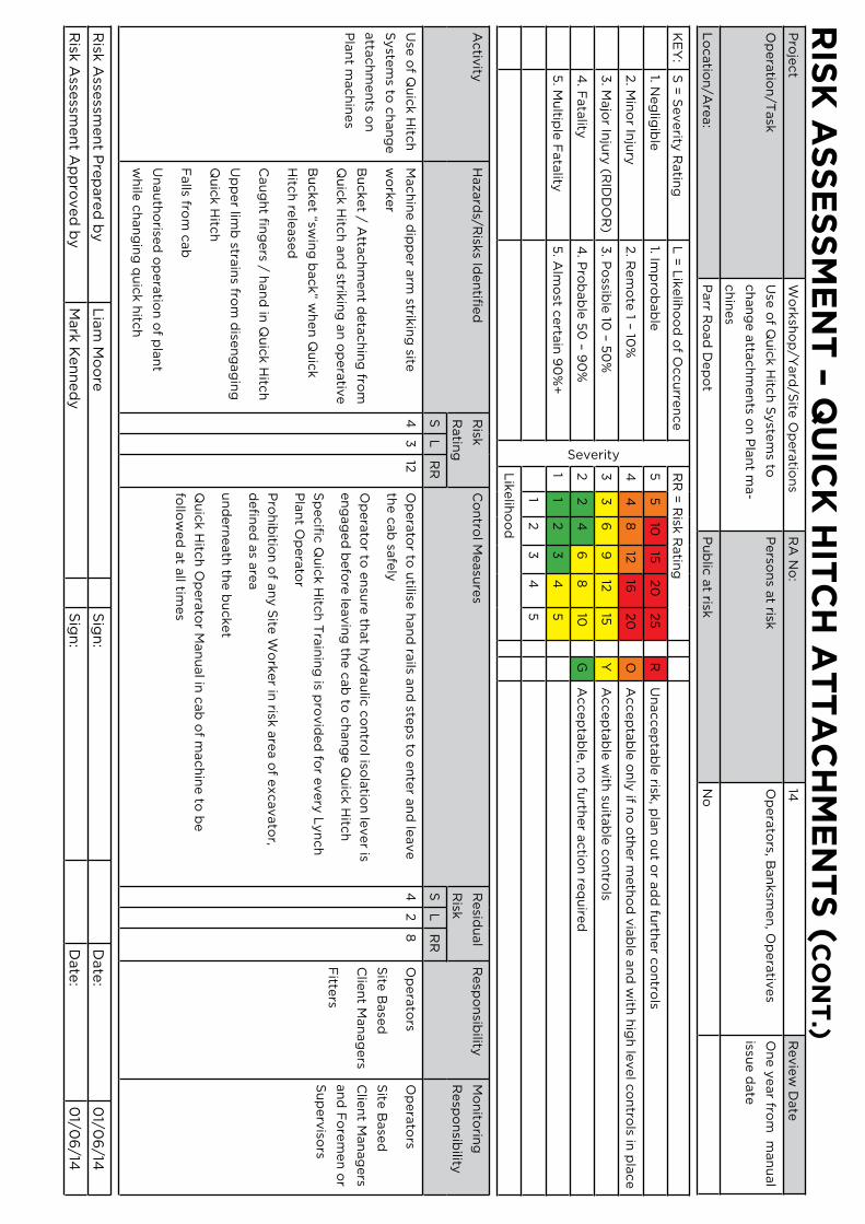
rIs
K A
ss
es
sM
en
t – Q
uIc
K H
Itc
H A
tt
Ac
HM
en
ts
(c
on
t.)
Pro
ject
Wo
rksh
op
/Yard
/Site
Op
era
tion
sR
A N
o:
14R
evie
w D
ate
Op
era
tion
/Task
Use
of Q
uic
k H
itch
Syste
ms to
ch
an
ge a
ttach
men
ts on
Pla
nt m
a-
ch
ines
Perso
ns a
t riskO
pera
tors, B
an
ksm
en
, Op
era
tives
On
e y
ear fro
m m
an
ual
issue d
ate
Lo
catio
n/A
rea:
Parr R
oad
Dep
ot
Pu
blic
at risk
No
KE
Y:
S =
Severity
Ratin
gL
= L
ikelih
oo
d o
f Occu
rren
ce
Severity
RR
= R
isk R
atin
g
1. Neg
ligib
le1. Im
pro
bab
le5
510
1520
25
RU
naccep
tab
le risk
, pla
n o
ut o
r ad
d fu
rther c
on
trols
2. M
ino
r Inju
ry2. R
em
ote
1 – 10%
44
812
1620
OA
ccep
tab
le o
nly
if no
oth
er m
eth
od
via
ble
an
d w
ith h
igh
level c
on
trols in
pla
ce
3. M
ajo
r Inju
ry (R
IDD
OR
)3
. Po
ssible
10 – 5
0%
33
69
1215
YA
ccep
tab
le w
ith su
itab
le c
on
trols
4. F
ata
lity4
. Pro
bab
le 5
0 – 9
0%
22
46
810
GA
ccep
tab
le, n
o fu
rther a
ctio
n re
qu
ired
5. M
ultip
le F
ata
lity5
. Alm
ost c
erta
in 9
0%
+1
12
34
5
12
34
5
Lik
elih
oo
d
Activ
ityH
azard
s/Risk
s Iden
tified
Risk
Ratin
g
Co
ntro
l Measu
res
Resid
ual
Risk
Resp
on
sibility
Mo
nito
ring
Resp
on
sibility
SL
RR
SL
RR
Use
of Q
uic
k H
itch
Syste
ms to
ch
an
ge
atta
ch
men
ts on
Pla
nt m
ach
ines
Mach
ine d
ipp
er a
rm strik
ing
site
wo
rker
Bu
cket / A
ttach
men
t deta
ch
ing
from
Qu
ick H
itch
an
d strik
ing
an
op
era
tive
Bu
cket “sw
ing
back” w
hen
Qu
ick
Hitc
h re
lease
d
Cau
gh
t fin
gers / h
an
d in
Qu
ick H
itch
Up
per lim
b stra
ins fro
m d
isen
gag
ing
Qu
ick H
itch
Falls fro
m c
ab
Un
au
tho
rised
op
era
tion
of p
lan
t
wh
ile c
han
gin
g q
uic
k h
itch
43
12O
pera
tor to
utilise
han
d ra
ils an
d ste
ps to
en
ter a
nd
leave
the c
ab
safe
ly
Op
era
tor to
en
sure
that h
yd
rau
lic c
on
trol iso
latio
n le
ver is
en
gag
ed
befo
re le
avin
g th
e c
ab
to c
han
ge Q
uic
k H
itch
Sp
ecifi
c Q
uic
k H
itch
Tra
inin
g is p
rovid
ed
for e
very
Lyn
ch
Pla
nt O
pera
tor
Pro
hib
ition
of a
ny S
ite W
ork
er in
risk a
rea o
f excavato
r,
defi
ned
as a
rea
un
dern
eath
the b
ucket
Qu
ick H
itch
Op
era
tor M
an
ual in
cab
of m
ach
ine to
be
follo
wed
at a
ll times
42
8O
pera
tors
Site
Base
d
Clie
nt M
an
ag
ers
Fitte
rs
Op
era
tors
Site
Base
d
Clie
nt M
an
ag
ers
an
d F
ore
men
or
Su
perv
isors
Risk
Asse
ssmen
t Pre
pare
d b
yL
iam
Mo
ore
Sig
n:
Date
:0
1/06
/14
Risk
Asse
ssmen
t Ap
pro
ved
by
Mark
Ken
ned
yS
ign
:D
ate
:0
1/06
/14

rIs
K A
ss
es
sM
en
t – V
eH
IcL
e A
nd
PL
An
t M
oV
eM
en
ts
Pro
ject
Wo
rksh
op
or Y
ard
Op
era
tion
sR
A N
o:
19R
evie
w D
ate
Op
era
tion
/Task
Veh
icle
/Pla
nt M
ovem
en
ts in a
nd
aro
un
d th
e w
ork
sho
p o
r yard
Perso
ns a
t riskE
mp
loyees/V
isitors
On
e y
ear fro
m m
an
ual
issue d
ate
Lo
catio
n/A
rea:
Parr R
oad
Yard
/Wo
rksh
op
Pu
blic
at risk
No
KE
Y:
S =
Severity
Ratin
gL
= L
ikelih
oo
d o
f Occu
rren
ce
Severity
RR
= R
isk R
atin
g
1. Neg
ligib
le1. Im
pro
bab
le5
510
1520
25
RU
naccep
tab
le risk
, pla
n o
ut o
r ad
d fu
rther c
on
trols
2. M
ino
r Inju
ry2. R
em
ote
1 – 10%
44
812
1620
OA
ccep
tab
le o
nly
if no
oth
er m
eth
od
via
ble
an
d w
ith h
igh
level c
on
trols in
pla
ce
3. M
ajo
r Inju
ry (R
IDD
OR
)3
. Po
ssible
10 – 5
0%
33
69
1215
YA
ccep
tab
le w
ith su
itab
le c
on
trols
4. F
ata
lity4
. Pro
bab
le 5
0 – 9
0%
22
46
810
GA
ccep
tab
le, n
o fu
rther a
ctio
n re
qu
ired
5. M
ultip
le F
ata
lity5
. Alm
ost c
erta
in 9
0%
+1
12
34
5
12
34
5
Lik
elih
oo
d
Activ
ityH
azard
s/Risk
s
Iden
tified
Risk
Ratin
g
Co
ntro
l Measu
res
Resid
ual
Risk
Resp
on
sibility
Mo
nito
ring
Resp
on
sibility
SL
RR
SL
RR
Veh
icle
an
d p
lan
t
mo
vem
en
ts in
an
d a
rou
nd
yard
an
d w
ork
sho
p
Perso
nn
el b
ein
g
struck, c
rush
ed
or
run
over b
y m
ovin
g
veh
icle
s or p
lan
t
resu
lting
in m
ajo
r
inju
ry o
r death
Dam
ag
e to
veh
icle
s resu
lting
from
co
llision
s
44
16O
ne w
ay tra
ffic sy
stem
to b
e e
nfo
rced
an
d o
bse
rved
by a
ll driv
ers
Site
speed
limit o
f 5 m
ph
to b
e e
nfo
rced
Tra
ffic sig
nag
e to
be o
beyed
by a
ll driv
ers
Elim
inate
the n
eed
for re
versin
g w
here
ver p
ossib
le. A
ll oth
er re
versin
g to
be
sup
erv
ised
by b
an
ksm
en
wh
ere
ver p
ossib
le
Seg
reg
ate
veh
icle
s an
d p
ed
estria
ns b
y u
sing
rob
ust p
hysic
al b
arrie
rs
Pro
vid
e a
deq
uate
sign
ag
e a
t en
try/e
xit p
oin
ts
Driv
ers to
sound
ho
rn w
hen e
nte
ring
or e
xiting
the w
orksh
op
to w
arn
ped
estria
ns
Pro
vid
e sa
fe w
alk
ing
rou
tes a
nd
cro
ssing
po
ints fo
r ped
estria
ns
Am
ber fl
ash
ing
beaco
ns w
here
fitte
d a
re to
be o
n a
t all tim
es w
hen
veh
icle
s are
m
ovin
g a
rou
nd
the y
ard
or w
ork
sho
p
Hi v
is waistc
oats o
r jackets to
be w
orn
by a
ll perso
nn
el o
utsid
e o
f the o
ffices
Safe
ty fo
otw
ear to
be w
orn
by a
ll ou
tside o
f the o
ffices
Pro
vid
e d
esig
nate
d p
ark
ing
are
as fo
r priv
ate
veh
icle
s
En
sure
bu
ildin
g e
xits d
o n
ot o
pen
on
to tra
ffic ro
ute
s. Pro
vid
e sig
nag
e to
warn
p
ed
estria
ns o
f hazard
s of p
assin
g tra
ffic
42
8T
ran
spo
rt
Man
ag
er
Tra
nsp
ort
Serv
ice
Man
ag
er
Wo
rksh
op
Man
ag
er
Driv
ers
Pla
nt O
pera
tors
Fitte
rs
SH
E m
an
ag
er
Tra
nsp
ort
Man
ag
er
Tra
nsp
ort
Serv
ice
Man
ag
er
Wo
rksh
op
Man
ag
er
Driv
ers
Pla
nt O
pera
tors
Fitte
rs
SH
E m
an
ag
er
Risk
Asse
ssmen
t Pre
pare
d b
yS
ign
:D
ate
:
Risk
Asse
ssmen
t Ap
pro
ved
by
Sig
n:
Date
:

rIs
K A
ss
es
sM
en
t –
Lo
Ad
InG
An
d u
nL
oA
dIn
G o
F P
LA
nt
tr
An
sP
or
te
rs
Pro
ject
Wo
rksh
op
/Yard
/Site
Op
era
tion
sR
A N
o:
21
Revie
w D
ate
Op
era
tion
/Task
Lo
ad
ing
& U
nlo
ad
ing
of P
lan
t Tra
ns -
po
rters
Perso
ns a
t riskD
rivers, W
ork
ers,
On
e y
ear fro
m m
an
ual
issue d
ate
Lo
catio
n/A
rea:
Lyn
ch
Dep
ots / C
usto
mers C
on
struc-
tion
Site
s/Pu
blic
Hig
hw
ay
Pu
blic
at risk
Yes
KE
Y:
S =
Severity
Ratin
gL
= L
ikelih
oo
d o
f Occu
rren
ce
Severity
RR
= R
isk R
atin
g
1. Neg
ligib
le1. Im
pro
bab
le5
510
1520
25
RU
naccep
tab
le risk
, pla
n o
ut o
r ad
d fu
rther c
on
trols
2. M
ino
r Inju
ry2. R
em
ote
1 – 10%
44
812
1620
OA
ccep
tab
le o
nly
if no
oth
er m
eth
od
via
ble
an
d w
ith h
igh
level c
on
trols in
pla
ce
3. M
ajo
r Inju
ry (R
IDD
OR
)3
. Po
ssible
10 – 5
0%
33
69
1215
YA
ccep
tab
le w
ith su
itab
le c
on
trols
4. F
ata
lity4
. Pro
bab
le 5
0 – 9
0%
22
46
810
GA
ccep
tab
le, n
o fu
rther a
ctio
n re
qu
ired
5. M
ultip
le F
ata
lity5
. Alm
ost c
erta
in 9
0%
+1
12
34
5
12
34
5
Lik
elih
oo
d
Activ
ityH
azard
s/Risk
s
Iden
tified
Risk
Rat-
ing
Co
ntro
l Measu
res
Resid
ual
Risk
Resp
on
sibility
Mo
nito
ring
Re-
spo
nsib
ility
SL
RR
SL
RR
Lo
ad
ing
& U
n-
load
ing
of P
lan
t
Tra
nsp
orte
rs
Falls o
f peo
ple
or
ob
jects fro
m th
e
tran
spo
rter lo
ad
bed
an
d ra
mp
s
Falls o
f veh
icle
s from
the tra
nsp
orte
r load
bed
an
d ra
mp
s
Slip
s & T
rips
Perso
nn
el b
ein
g stru
ck
by m
ovin
g o
r fallin
g
veh
icle
s
Ele
ctro
cu
tion
from
co
nta
ct w
ith o
verh
ead
po
wer c
ab
les
Han
d in
jurie
s
44
16L
oad
bed
an
d ra
mp
s to b
e k
ep
t free o
f deb
ris, mu
d, o
il, gre
ase
, waste
, ice
etc
wh
ich
co
uld
cau
se slip
pag
e o
f peo
ple
or m
ach
ines. S
an
d to
be sp
read
wh
ere
necessa
ry to
aid
grip
. Tra
cks/W
heels o
f pla
nt to
be c
lean
ed
if
necessa
ry b
efo
re lo
ad
ing
.
Lash
ing
ch
ain
s, sling
s, timb
er, ro
pes e
tc to
be sto
wed
safe
ly w
hen
no
t in
use
so a
s no
t to c
reate
trip o
r fallin
g h
azard
s.
Main
tain
3 p
oin
ts of c
on
tact if p
ossib
le w
hen
wo
rkin
g n
ear th
e e
dg
e o
f
the lo
ad
bed
.
Access to
Tra
nsp
orte
rs is limite
d to
co
mp
ete
nt, a
uth
orise
d p
erso
nn
el.
Sta
ff to fo
llow
safe
load
ing
pro
ced
ure
s in T
ran
spo
rt Safe
ty M
an
ual w
hen
load
ing
/un
load
ing
.
Pla
nt to
be se
cu
red
to T
ran
spo
rters a
s per m
an
ufa
ctu
rer’s p
roced
ure
s
an
d T
ran
spo
rt Safe
ty M
an
ual p
roced
ure
s an
d g
uid
an
ce.
42
8D
rivers
Pla
nt
Op
era
tors
Tra
nsp
ort
Man
ag
ers
Tra
nsp
ort
Man
ag
ers
Cu
stom
ers site
sup
erv
isors

Lo
Ad
InG
An
d u
nL
oA
dIn
G o
F P
LA
nt
tr
An
sP
or
te
rs
(c
on
t.)
Pro
ject
Wo
rksh
op
/Yard
/Site
Op
era
tion
sR
A N
o:
21
Revie
w D
ate
Op
era
tion
/Task
Lo
ad
ing
& U
nlo
ad
ing
of P
lan
t
Tra
nsp
orte
rs
Perso
ns a
t riskD
rivers, W
ork
ers
On
e y
ear fro
m m
an
ual
issue d
ate
Lo
catio
n/A
rea:
Ly
nch
De
po
ts / Cu
stom
ers
Co
nstru
ctio
n S
ites/P
ub
lic H
igh
way
Pu
blic
at risk
Yes
KE
Y:
S =
Severity
Ratin
gL
= L
ikelih
oo
d o
f Occu
rren
ce
Severity
RR
= R
isk R
atin
g
1. Neg
ligib
le1. Im
pro
bab
le5
510
1520
25
RU
naccep
tab
le risk
, pla
n o
ut o
r ad
d fu
rther c
on
trols
2. M
ino
r Inju
ry2. R
em
ote
1 – 10%
44
812
1620
OA
ccep
tab
le o
nly
if no
oth
er m
eth
od
via
ble
an
d w
ith h
igh
level c
on
trols in
pla
ce
3. M
ajo
r Inju
ry (R
IDD
OR
)3
. Po
ssible
10 – 5
0%
33
69
1215
YA
ccep
tab
le w
ith su
itab
le c
on
trols
4. F
ata
lity4
. Pro
bab
le 5
0 – 9
0%
22
46
810
GA
ccep
tab
le, n
o fu
rther a
ctio
n re
qu
ired
5. M
ultip
le F
ata
lity5
. Alm
ost c
erta
in 9
0%
+1
12
34
5
12
34
5
Lik
elih
oo
d
Activ
ityH
azard
s/Risk
s
Iden
tified
Risk
Ratin
g
Co
ntro
l Measu
res
Resid
ual
Risk
Resp
on
sibility
Mo
nito
ring
Resp
on
sibility
SL
RR
SL
RR
Lo
ad
ing
&
Un
load
ing
of
Pla
nt
Tra
nsp
orte
rs
Falls o
f peo
ple
or o
bje
cts
from
the tra
nsp
orte
r
load
bed
an
d ra
mp
s
Falls o
f veh
icle
s from
the tra
nsp
orte
r load
bed
an
d ra
mp
s
Slip
s & T
rips
Perso
nn
el b
ein
g
struck b
y m
ovin
g o
r
fallin
g v
eh
icle
s
Ele
ctro
cu
tion
from
co
nta
ct w
ith o
verh
ead
po
wer c
ab
les
Han
d in
jurie
s
44
16D
o n
ot ju
mp
off th
e tra
nsp
orte
r load
bed
. Walk
do
wn
the ra
mp
s or sit
do
wn
an
d lo
wer y
ou
rself g
en
tly o
ff the e
dg
e.
Never w
ork
dire
ctly
un
dern
eath
overh
ead
po
wer c
ab
les.
Never w
ork
with
in 9
metre
s ho
rizo
nta
lly o
f overh
ead
po
wer c
ab
les su
p-
po
rted
on
wo
od
en
po
les
Never w
ork
with
in 15
metre
s ho
rizo
nta
lly o
f overh
ead
po
wer c
ab
les su
p-
po
rted
on
steel p
ylo
ns o
r structu
res
Alw
ays fo
llow
safe
syste
ms o
f wo
rk a
nd
rou
tes p
rovid
ed
on
co
nstru
ctio
n
sites w
hen
driv
ing
un
der o
verh
ead
po
wer c
ab
les
Keep
han
ds c
lear o
f pin
ch
po
ints a
nd
cru
sh z
on
es o
n ra
mp
s an
d tra
ilers
All lo
ad
ing
/un
load
ing
to b
e c
arrie
d o
ut slo
wly
an
d sa
fely
– do
no
t rush
Wh
en
co
llectin
g p
lan
t from
sites e
nsu
re p
lan
t is free fro
m d
efe
cts w
hic
h
co
uld
affe
ct sa
fe p
erfo
rman
ce. If in
do
ub
t stop
wo
rk, d
o n
ot m
ove p
lan
t
an
d se
ek a
dvic
e fro
m th
e tra
nsp
ort o
ffice
42
8D
rivers
Pla
nt O
pera
tors
Tra
nsp
ort
Man
ag
ers
Tra
nsp
ort
Man
ag
ers
Cu
stom
ers
site su
perv
isors
Risk
Asse
ssmen
t Pre
pare
d b
yS
tep
hen
Bre
mn
er (G
rou
p T
ran
spo
rt an
d S
erv
ice M
an
ag
er)
Sig
n:
Date
:0
1/06
/14
Risk
Asse
ssmen
t Ap
pro
ved
by
Mark
Ken
ned
y (O
pera
tion
s Dire
cto
r)S
ign
:D
ate
:0
1/06
/14
Lo
Ad
InG
An
d u
nL
oA
dIn
G o
F P
LA
nt
tr
An
sP
or
te
rs
(c
on
t.)
Pro
ject
Wo
rksh
op
/Yard
/Site
Op
era
tion
sR
A N
o:
21
Revie
w D
ate
Op
era
tion
/Task
Lo
ad
ing
& U
nlo
ad
ing
of P
lan
t
Tra
nsp
orte
rs
Perso
ns a
t riskD
rivers, W
ork
ers
On
e y
ear fro
m m
an
ual
issue d
ate
Lo
catio
n/A
rea:
Lyn
ch
Dep
ots / C
usto
mers
Co
nstru
ctio
n S
ites/P
ub
lic H
igh
way
Pu
blic
at risk
Yes
KE
Y:
S =
Severity
Ratin
gL
= L
ikelih
oo
d o
f Occu
rren
ce
Severity
RR
= R
isk R
atin
g
1. Neg
ligib
le1. Im
pro
bab
le5
510
1520
25
RU
naccep
tab
le risk
, pla
n o
ut o
r ad
d fu
rther c
on
trols
2. M
ino
r Inju
ry2. R
em
ote
1 – 10%
44
812
1620
OA
ccep
tab
le o
nly
if no
oth
er m
eth
od
via
ble
an
d w
ith h
igh
level c
on
trols in
pla
ce
3. M
ajo
r Inju
ry (R
IDD
OR
)3
. Po
ssible
10 – 5
0%
33
69
1215
YA
ccep
tab
le w
ith su
itab
le c
on
trols
4. F
ata
lity4
. Pro
bab
le 5
0 – 9
0%
22
46
810
GA
ccep
tab
le, n
o fu
rther a
ctio
n re
qu
ired
5. M
ultip
le F
ata
lity5
. Alm
ost c
erta
in 9
0%
+1
12
34
5
12
34
5
Lik
elih
oo
d
Activ
ityH
azard
s/Risk
s
Iden
tified
Risk
Ratin
g
Co
ntro
l Measu
res
Resid
ual
Risk
Resp
on
sibility
Mo
nito
ring
Resp
on
sibility
SL
RR
SL
RR
Lo
ad
ing
&
Un
load
ing
of
Pla
nt
Tra
nsp
orte
rs
Falls o
f peo
ple
or o
b-
jects fro
m th
e tra
nsp
ort-
er lo
ad
bed
an
d ra
mp
s
Falls o
f veh
icle
s from
the tra
nsp
orte
r load
bed
an
d ra
mp
s
Slip
s & T
rips
Perso
nn
el b
ein
g
struck b
y m
ovin
g o
r
fallin
g v
eh
icle
s
Ele
ctro
cu
tion
from
co
nta
ct w
ith o
verh
ead
po
wer c
ab
les
Han
d in
jurie
s
44
16L
oad
ing
are
a to
be se
gre
gate
d fro
m u
nau
tho
rised
perso
nn
el u
sing
tap
e, c
on
es,
barrie
rs. Driv
er a
nd
mach
ine o
pera
tor o
nly
to b
e w
ithin
the e
xclu
sion
zo
ne. U
se
ban
ksm
en
wh
ere
po
ssible
to c
on
trol p
ed
estria
n m
ovem
en
t.
Pla
nt to
be g
uid
ed
by a
co
mp
ete
nt b
an
ksm
an
stan
din
g in
a sa
fe p
lace d
urin
g
load
ing
/un
load
ing
.
Man
dato
ry P
PE
to b
e w
orn
as p
er th
e sa
fe sy
stem
of w
ork
instru
ctio
n fo
r ind
i-
vid
ual a
ctiv
ities.
Driv
ers to
receiv
e fa
milia
risatio
n tra
inin
g fo
r each
item
of p
lan
t bein
g tra
nsp
ort-
ed
. Tra
inin
g re
co
rds to
be m
ain
tain
ed
.
En
sure
tran
spo
rter is p
ark
ed
on
firm
level g
rou
nd
du
ring
load
ing
/un
load
ing
.
An
ti – Ro
ll bars fi
tted
to d
um
pers, ro
llers a
nd
min
i excavato
rs are
to b
e lo
cked
in th
e ra
ised
po
sition
at a
ll times d
urin
g lo
ad
ing
/un
load
ing
. Seat b
elts a
re to
be
wo
rn o
n a
ll mach
ines a
t all tim
es.
To
pre
ven
t driv
ers/o
pera
tors b
ein
g c
rush
ed
in th
e e
ven
t of a
pla
nt m
ach
ine ro
ll-
ing
over – N
ever try
to ju
mp
cle
ar – sta
y in
the se
at w
ith th
e se
at b
elt fa
sten
ed
42
8D
rivers
Pla
nt O
pera
tors
Tra
nsp
ort
Man
ag
ers
Tra
nsp
ort
Man
ag
ers
Cu
stom
ers
site
sup
erv
isors

Lo
Ad
InG
An
d u
nL
oA
dIn
G o
F P
LA
nt
tr
An
sP
or
te
rs
(c
on
t.)
Pro
ject
Wo
rksh
op
/Yard
/Site
Op
era
tion
sR
A N
o:
21
Revie
w D
ate
Op
era
tion
/Task
Lo
ad
ing
& U
nlo
ad
ing
of P
lan
t
Tra
nsp
orte
rs
Perso
ns a
t riskD
rivers, W
ork
ers
On
e y
ear fro
m m
an
ual
issue d
ate
Lo
catio
n/A
rea:
Ly
nch
De
po
ts / Cu
stom
ers
Co
nstru
ctio
n S
ites/P
ub
lic H
igh
way
Pu
blic
at risk
Yes
KE
Y:
S =
Severity
Ratin
gL
= L
ikelih
oo
d o
f Occu
rren
ce
Severity
RR
= R
isk R
atin
g
1. Neg
ligib
le1. Im
pro
bab
le5
510
1520
25
RU
naccep
tab
le risk
, pla
n o
ut o
r ad
d fu
rther c
on
trols
2. M
ino
r Inju
ry2. R
em
ote
1 – 10%
44
812
1620
OA
ccep
tab
le o
nly
if no
oth
er m
eth
od
via
ble
an
d w
ith h
igh
level c
on
trols in
pla
ce
3. M
ajo
r Inju
ry (R
IDD
OR
)3
. Po
ssible
10 – 5
0%
33
69
1215
YA
ccep
tab
le w
ith su
itab
le c
on
trols
4. F
ata
lity4
. Pro
bab
le 5
0 – 9
0%
22
46
810
GA
ccep
tab
le, n
o fu
rther a
ctio
n re
qu
ired
5. M
ultip
le F
ata
lity5
. Alm
ost c
erta
in 9
0%
+1
12
34
5
12
34
5
Lik
elih
oo
d
Activ
ityH
azard
s/Risk
s
Iden
tified
Risk
Ratin
g
Co
ntro
l Measu
res
Resid
ual
Risk
Resp
on
sibility
Mo
nito
ring
Resp
on
sibility
SL
RR
SL
RR
Lo
ad
ing
&
Un
load
ing
of
Pla
nt
Tra
nsp
orte
rs
Falls o
f peo
ple
or o
bje
cts
from
the tra
nsp
orte
r
load
bed
an
d ra
mp
s
Falls o
f veh
icle
s from
the tra
nsp
orte
r load
bed
an
d ra
mp
s
Slip
s & T
rips
Perso
nn
el b
ein
g
struck b
y m
ovin
g o
r
fallin
g v
eh
icle
s
Ele
ctro
cu
tion
from
co
nta
ct w
ith o
verh
ead
po
wer c
ab
les
Han
d in
jurie
s
44
16D
o n
ot ju
mp
off th
e tra
nsp
orte
r load
bed
. Walk
do
wn
the ra
mp
s or sit
do
wn
an
d lo
wer y
ou
rself g
en
tly o
ff the e
dg
e.
Never w
ork
dire
ctly
un
dern
eath
overh
ead
po
wer c
ab
les.
Never w
ork
with
in 9
metre
s ho
rizo
nta
lly o
f overh
ead
po
wer c
ab
les su
p-
po
rted
on
wo
od
en
po
les
Never w
ork
with
in 15
metre
s ho
rizo
nta
lly o
f overh
ead
po
wer c
ab
les su
p-
po
rted
on
steel p
ylo
ns o
r structu
res
Alw
ays fo
llow
safe
syste
ms o
f wo
rk a
nd
rou
tes p
rovid
ed
on
co
nstru
ctio
n
sites w
hen
driv
ing
un
der o
verh
ead
po
wer c
ab
les
Keep
han
ds c
lear o
f pin
ch
po
ints a
nd
cru
sh z
on
es o
n ra
mp
s an
d tra
ilers
All lo
ad
ing
/un
load
ing
to b
e c
arrie
d o
ut slo
wly
an
d sa
fely
– do
no
t rush
Wh
en
co
llectin
g p
lan
t from
sites e
nsu
re p
lan
t is free fro
m d
efe
cts w
hic
h
co
uld
affe
ct sa
fe p
erfo
rman
ce. If in
do
ub
t stop
wo
rk, d
o n
ot m
ove p
lan
t
an
d se
ek a
dvic
e fro
m th
e tra
nsp
ort o
ffice
42
8D
rivers
Pla
nt O
pera
tors
Tra
nsp
ort
Man
ag
ers
Tra
nsp
ort
Man
ag
ers
Cu
stom
ers
site su
perv
isors
Risk
Asse
ssmen
t Pre
pare
d b
yS
tep
hen
Bre
mn
er (G
rou
p T
ran
spo
rt an
d S
erv
ice M
an
ag
er)
Sig
n:
Date
:0
1/06
/14
Risk
Asse
ssmen
t Ap
pro
ved
by
Mark
Ken
ned
y (O
pera
tion
s Dire
cto
r)S
ign
:D
ate
:0
1/06
/14

rIs
K A
ss
es
sM
en
t – u
se
oF
HIA
B L
or
rIe
sP
roje
ct
Wo
rksh
op
/Yard
/Hau
lag
e &
Tra
nsp
ort O
pera
tion
s
RA
No
:22
Revie
w D
ate
Op
era
tion
/Task
Use
of H
iab
Lo
rries
Perso
ns a
t riskD
rivers/C
usto
mers
On
e y
ear fro
m m
an
ual
issue d
ate
Lo
catio
n/A
rea:
Lyn
ch
Dep
ots /C
usto
mer S
ites/
Pu
blic
Hig
hw
ay/L
an
dfi
ll sites
Pu
blic
at risk
Yes
KE
Y:
S =
Severity
Ratin
gL
= L
ikelih
oo
d o
f Occu
rren
ce
Severity
RR
= R
isk R
atin
g
1. Neg
ligib
le1. Im
pro
bab
le5
510
1520
25
RU
naccep
tab
le risk
, pla
n o
ut o
r ad
d fu
rther c
on
trols
2. M
ino
r Inju
ry2. R
em
ote
1 – 10%
44
812
1620
OA
ccep
tab
le o
nly
if no
oth
er m
eth
od
via
ble
an
d w
ith h
igh
level c
on
trols in
pla
ce
3. M
ajo
r Inju
ry (R
IDD
OR
)3
. Po
ssible
10 – 5
0%
33
69
1215
YA
ccep
tab
le w
ith su
itab
le c
on
trols
4. F
ata
lity4
. Pro
bab
le 5
0 – 9
0%
22
46
810
GA
ccep
tab
le, n
o fu
rther a
ctio
n re
qu
ired
5. M
ultip
le F
ata
lity5
. Alm
ost c
erta
in 9
0%
+1
12
34
5
12
34
5
Lik
elih
oo
d
Activ
ityH
azard
s/Risk
s
Iden
tified
Risk
Ratin
g
Co
ntro
l Measu
res
Resid
ual
Risk
Resp
on
sibility
Mo
nito
ring
Resp
on
sibility
SL
RR
SL
RR
LIF
TIN
G
WIT
H
CR
AN
E
Overtu
rn o
f veh
icle
du
ring
load
ing
or
un
load
ing
op
era
tion
s
du
e to
excessiv
e lo
ad
s
or u
nsta
ble
gro
un
d
Cru
shin
g/c
ollisio
n
betw
een
load
, perso
nn
el
or site
veh
icle
s
Falls fro
m h
eig
ht o
f
op
era
tor o
r mate
rials
form
ing
the lo
ad
Ele
ctro
cu
tion
from
co
nta
ct w
ith
overh
ead
cab
les
Brid
ge strik
es o
r strikin
g
overh
ead
structu
res
44
16A
ll driv
ers to
have a
valid
CP
CS
card
for lo
rry lo
ad
ers, o
r oth
er v
alid
co
mp
ete
ncy
All d
rivers to
have a
valid
cat C
LG
V lic
en
ce
At a
ll times th
e lo
rry cra
ne sh
ould
be o
pera
ted
in a
ccord
ance
with
the m
anufa
cture
rs
reco
mm
en
ded
safe
pro
ced
ure
s an
d w
ithin
specifi
ed
load
s an
d lim
its
Fo
llow
specifi
c S
SO
W fo
r lifting
op
era
tion
s as p
er in
Lyn
ch
Man
ual
Gra
b a
nd
tipp
er a
re o
nly
to b
e o
pera
ted
wh
en
on
firm
level g
rou
nd
an
d in
acco
r-
dan
ce w
ith L
Lyn
ch
safe
syste
m o
f wo
rk
Wh
en
usin
g th
e c
ran
e, if u
nsu
re o
f gro
un
d b
earin
g c
ap
acity
, driv
er is to
exte
nd
the sta
bilise
r leg
s bu
t no
t low
er th
em
.
Wo
rk a
rea a
rou
nd
lorry
to b
e c
ord
on
ed
off w
hen
usin
g th
e g
rab
to p
reven
t un
au
-
tho
rised
access. S
top
wo
rk if a
nyo
ne e
ncro
ach
es in
to th
e e
xclu
sion
zo
ne
All w
ork
near o
verh
ead
po
wer c
ab
les is to
be in
acco
rdan
ce w
ith L
Lyn
ch
safe
syste
m o
f wo
rk. O
bse
rve sa
fety
dista
nces fro
m o
verh
ead
cab
les a
t all tim
es
42
8T
ran
spo
rt
Hau
lag
e
Man
ag
er
Tra
nsp
ort
Su
perv
isor
Tra
nsp
ort
Hau
lag
e
Man
ag
er
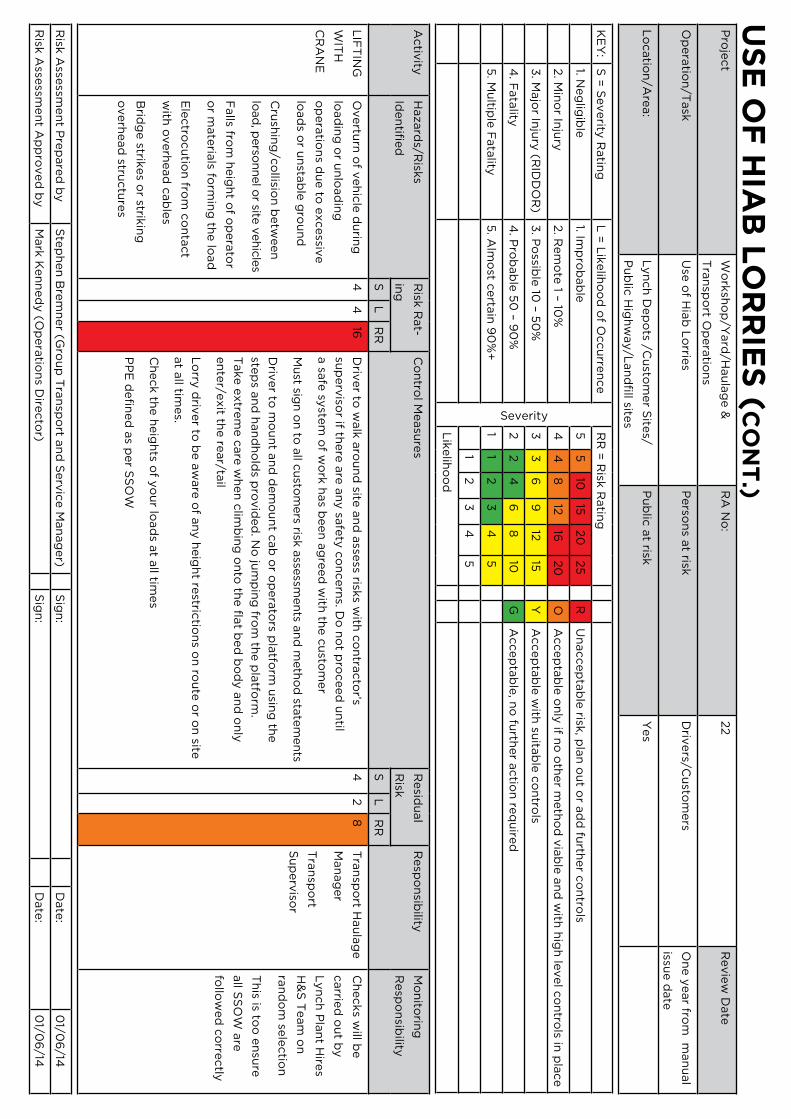
us
e o
F H
IAB
Lo
rr
Ies
(c
on
t.)
Pro
ject
Wo
rksh
op
/Yard
/Hau
lag
e &
Tra
nsp
ort O
pera
tion
s
RA
No
:22
Revie
w D
ate
Op
era
tion
/Task
Use
of H
iab
Lo
rries
Perso
ns a
t riskD
rivers/C
usto
mers
On
e y
ear fro
m m
an
ual
issue d
ate
Lo
catio
n/A
rea:
Lyn
ch
Dep
ots /C
usto
mer S
ites/
Pu
blic
Hig
hw
ay/L
an
dfi
ll sites
Pu
blic
at risk
Yes
KE
Y:
S =
Severity
Ratin
gL
= L
ikelih
oo
d o
f Occu
rren
ce
Severity
RR
= R
isk R
atin
g
1. Neg
ligib
le1. Im
pro
bab
le5
510
1520
25
RU
naccep
tab
le risk
, pla
n o
ut o
r ad
d fu
rther c
on
trols
2. M
ino
r Inju
ry2. R
em
ote
1 – 10%
44
812
1620
OA
ccep
tab
le o
nly
if no
oth
er m
eth
od
via
ble
an
d w
ith h
igh
level c
on
trols in
pla
ce
3. M
ajo
r Inju
ry (R
IDD
OR
)3
. Po
ssible
10 – 5
0%
33
69
1215
YA
ccep
tab
le w
ith su
itab
le c
on
trols
4. F
ata
lity4
. Pro
bab
le 5
0 – 9
0%
22
46
810
GA
ccep
tab
le, n
o fu
rther a
ctio
n re
qu
ired
5. M
ultip
le F
ata
lity5
. Alm
ost c
erta
in 9
0%
+1
12
34
5
12
34
5
Lik
elih
oo
d
Activ
ityH
azard
s/Risk
s
Iden
tified
Risk
Rat-
ing
Co
ntro
l Measu
res
Resid
ual
Risk
Resp
on
sibility
Mo
nito
ring
Resp
on
sibility
SL
RR
SL
RR
LIF
TIN
G
WIT
H
CR
AN
E
Overtu
rn o
f veh
icle
du
ring
load
ing
or u
nlo
ad
ing
op
era
tion
s du
e to
excessiv
e
load
s or u
nsta
ble
gro
un
d
Cru
shin
g/c
ollisio
n b
etw
een
load
, perso
nnel o
r site v
ehic
les
Falls fro
m h
eig
ht o
f op
era
tor
or m
ate
rials fo
rmin
g th
e lo
ad
Ele
ctro
cu
tion
from
co
nta
ct
with
overh
ead
cab
les
Brid
ge strik
es o
r strikin
g
overh
ead
structu
res
44
16D
river to
walk
aro
un
d site
an
d a
ssess risk
s with
co
ntra
cto
r’s
sup
erv
isor if th
ere
are
an
y sa
fety
co
ncern
s. Do
no
t pro
ceed
un
til
a sa
fe sy
stem
of w
ork
has b
een
ag
reed
with
the c
usto
mer
Mu
st sign
on
to a
ll cu
stom
ers risk
asse
ssmen
ts an
d m
eth
od
state
men
ts
Driv
er to
mo
un
t an
d d
em
ou
nt c
ab
or o
pera
tors p
latfo
rm u
sing
the
step
s an
d h
an
dh
old
s pro
vid
ed
. No
jum
pin
g fro
m th
e p
latfo
rm.
Take e
xtre
me c
are
wh
en
clim
bin
g o
nto
the fl
at b
ed
bo
dy a
nd
on
ly
en
ter/e
xit th
e re
ar/ta
il
Lo
rry d
river to
be a
ware
of a
ny h
eig
ht re
strictio
ns o
n ro
ute
or o
n site
at a
ll times.
Ch
eck th
e h
eig
hts o
f yo
ur lo
ad
s at a
ll times
PP
E d
efi
ned
as p
er S
SO
W
42
8T
ran
spo
rt Hau
lag
e
Man
ag
er
Tra
nsp
ort
Su
perv
isor
Ch
ecks w
ill be
carrie
d o
ut b
y
Lyn
ch
Pla
nt H
ires
H&
S T
eam
on
ran
do
m se
lectio
n
Th
is is too
en
sure
all S
SO
W a
re
follo
wed
co
rrectly
Risk
Asse
ssmen
t Pre
pare
d b
yS
tep
hen
Bre
mn
er (G
rou
p T
ran
spo
rt an
d S
erv
ice M
an
ag
er)
Sig
n:
Date
:0
1/06
/14
Risk
Asse
ssmen
t Ap
pro
ved
by
Mark
Ken
ned
y (O
pera
tion
s Dire
cto
r)S
ign
:D
ate
:0
1/06
/14
Head office
Lynch House, Parr Road, Stanmore, London HA7 1 LE
Tel: 020 8900 0000 Fax: 020 8733 2020